ISSN (Print) : 0974-6846 ISSN (Online) : 0974-5645 INDIAN JOURNAL OF SCIENCE AND TECHNOLOGY January 2020, Vol 13(04), 439 – 452 DOI: 10.17485/ijst/2020/v13i04/149530, © 2020 The Author(s). This is an open access article distributed under the terms of the Creative Commons Attribution License, which permits unrestricted use, distribution, and reproduction in any medium, provided the original author and source are credited. Design a Perturb & Observe MPPT Algorithm for PV System Based Asymmetric Cascaded Half- Bridge Multilevel Inverter Muzamil Hussain Solangi*, Mukhtiar Ahmed Mahar, Abdul Sattar Larik and Mohsin Raza Mahessar Department of Electrical Engineering, Mehran University of Engineering Technology Jamshoro, Pakistan Abstract Objectives/methods: This research proposes a Perturb and Observe (P&O) algorithm to extract maximum power point for photovoltaic (PV) system which then used as a direct current (DC) source for an asymmetrical cascaded half-bridge (ACHB) multilevel inverter (MLI). The whole system is modelled in MATLAB/SIMULINK. An approach is used to give input DC sources to asymmetrical cascaded half- bridge MVI with two PV systems. For PV system, a P&O maximum power point tracking (MPPT) algorithm is used to control the duty cycle of DC to DC boost converter for maintaining the constant output voltage. The switching pattern of MLI done by using pulse width modulation (PWM) technique. Findings: The proposed switching sample based on Multi Carrier (MC) PWM which reduces the voltage of components, decrease size, cost and also switching losses. ACHB MLI is attractive for its features as it gives higher level of output voltage by using fewer number of switching devices. Finally, two PV systems of different output voltages are integrated with asymmetrical cascaded half-bridge MVI. The results of the proposed model are verified in MATLAB/SIMULINK. Novelty: Dual P&O MPPT algorithms based PV system is used as input DC source for asymmetric cascaded half-bridge MLI which provides higher level output voltage as compared to conventional two-level inverter. Keywords: P&O, MPP, Photovoltaic, Asymmetric Cascaded Half- Bridge Multilevel Inverter. 1. Introduction Solar Energy; nowadays have improved and grown tremendously as compared to other renewable sources due to its abundance, freely available and sustainable almost throughout the year [1]. e solar panel has PV (array) which performs the process of conversion Article Type: Article Article Citation: Muzamil Hussain Solangi, Mukhtiar Ahmed Mahar, Abdul Sattar Larik, Mohsin Raza Mahessar. Design a perturb & observe MPPT algorithm for PV system based asymmetric cascaded half bridge multilevel inverter. Indian Journal of Science and Technology. 2020; 13(04), 439-452. DOI: 10.17485/ijst/2020/ v013i04/149530 Received date: December 9, 2019 Accepted date: January 1, 2020 *Author for correspondence: Muzamil Hussain Solangi @ muzamilhussain19.mh@gmail. com Department of Electrical Engineering, Mehran University of Engineering Technology Jamshoro, Pakistan

Welcome message from author
This document is posted to help you gain knowledge. Please leave a comment to let me know what you think about it! Share it to your friends and learn new things together.
Transcript
ISSN (Print) : 0974-6846 ISSN (Online) : 0974-5645
INDIAN JOURNAL OF SCIENCE AND TECHNOLOGY January 2020, Vol 13(04), 439 – 452
DOI: 10.17485/ijst/2020/v13i04/149530,
© 2020 The Author(s). This is an open access article distributed under the terms of the Creative Commons Attribution License, which permits unrestricted use, distribution, and reproduction in any medium, provided the original author and source are credited.
Design a Perturb & Observe MPPT Algorithm for PV System Based Asymmetric Cascaded Half-Bridge Multilevel InverterMuzamil Hussain Solangi*, Mukhtiar Ahmed Mahar, Abdul Sattar Larik and Mohsin Raza Mahessar
Department of Electrical Engineering, Mehran University of Engineering Technology Jamshoro, Pakistan
AbstractObjectives/methods: This research proposes a Perturb and Observe (P&O) algorithm to extract maximum power point for photovoltaic (PV) system which then used as a direct current (DC) source for an asymmetrical cascaded half-bridge (ACHB) multilevel inverter (MLI). The whole system is modelled in MATLAB/SIMULINK. An approach is used to give input DC sources to asymmetrical cascaded half-bridge MVI with two PV systems. For PV system, a P&O maximum power point tracking (MPPT) algorithm is used to control the duty cycle of DC to DC boost converter for maintaining the constant output voltage. The switching pattern of MLI done by using pulse width modulation (PWM) technique. Findings: The proposed switching sample based on Multi Carrier (MC) PWM which reduces the voltage of components, decrease size, cost and also switching losses. ACHB MLI is attractive for its features as it gives higher level of output voltage by using fewer number of switching devices. Finally, two PV systems of different output voltages are integrated with asymmetrical cascaded half-bridge MVI. The results of the proposed model are verified in MATLAB/SIMULINK. Novelty: Dual P&O MPPT algorithms based PV system is used as input DC source for asymmetric cascaded half-bridge MLI which provides higher level output voltage as compared to conventional two-level inverter.
Keywords: P&O, MPP, Photovoltaic, Asymmetric Cascaded Half-Bridge Multilevel Inverter.
1. IntroductionSolar Energy; nowadays have improved and grown tremendously as compared to other renewable sources due to its abundance, freely available and sustainable almost throughout the year [1]. The solar panel has PV (array) which performs the process of conversion
Article Type: Article
Article Citation: Muzamil Hussain Solangi, Mukhtiar Ahmed Mahar, Abdul Sattar Larik, Mohsin Raza Mahessar. Design a perturb & observe MPPT algorithm for PV system based asymmetric cascaded half bridge multilevel inverter. Indian Journal of Science and Technology. 2020; 13(04), 439-452. DOI: 10.17485/ijst/2020/v013i04/149530
Received date: December 9, 2019
Accepted date: January 1, 2020
*Author for correspondence: Muzamil Hussain Solangi
@ [email protected] Department of Electrical Engineering, Mehran University of Engineering Technology Jamshoro, Pakistan
Design a Perturb & Observe MPPT Algorithm for PV System Based Asymmetric Cascaded Half-Bridge Multilevel Inverter
440 / 452 Indian Journal of Science and Technology Vol 13(04), DOI: 10.17485/ijst/2020/v13i04/149530, January 2020
of light energy into electrical energy [2]. The most efficient PV cell has an efficiency of 30%, which seems to be not satisfactory as output is one-third as compared to the input which is one-seventh [1]. So, it should be needed that PV cell work on Maximum Power Point (MPP) to achieve high effectiveness. The solar cells depend on the irradiance of light which is nonlinear, so power changes nonlinearly by means of current and voltage [3]. Perturb and Observe (P&O) algorithm is executed for the quest of MPP [4–6]. It was demonstrated that the purpose of maximum power is constantly situated at the normal position, is promptly followed, and kept up by moment increments and diminishes in voltage [5]. When contrasted with other sustainable power sources, the PV vitality is DC control basis and the lot in partnership with the inverter to change over the vitality to AC [6].
The expansive part of PV systems requires inverters as interfacing units. The inverter has different applications at modern dimension and additionally residential dimension, and are considered as an innovative technology in the field of power electronics, for example, power drives, uninterruptable power supply (UPS), Flexible AC transmission (FACTS) framework, and so on [7]. There are three crucial parts that choose the adequacy panel capability, converter efficiency, and capability of MPPT estimation [1]. Until now, numerous MPPT techniques have been proposed. The MPPT methods like constant voltage [8], sliding mode control, and fuzzy logic control, P&O [9–12]. Direct control, incremental resistance, ripple correlation control, incremental conductance artificial neural network, artificial bee colony, practical swarm optimization, etc. are described in the literature [13–18]. Each algorithm differs from the other in terms of complexity tracking speed, accuracy control variables, and economical operation [15]. To improve the yield effectiveness of PV framework, a P & O technique is proposed to locate the greatest power purpose of PV framework because of its simplicity and of less cost.
Conventionally, half-bridge inverters are utilized to give mean output voltage with respect to input DC source but the efficiency of such type inverters is not satisfactory, which is due to considering their distorted output waveform [19]. For getting the increased number of output level with reference to input DC sources, multilevel inverters (MLI) are employed. The broad types of MLIs are, diode-clamped (neutral-clamped), capacitor-clamped (flying capacitors), and cascaded H-bridge inverter [20]. The most eye-catching topology in MLI is Cascaded Half-Bridge (CHB) topology. Because of its simple construction-wise and output can be governed with multiple methods. The general topology of CHB-MLI (Cascaded Half-Bridge Multilevel Inverter) is given in Figure 1(a–b). In which two-level series-connected H-Bridge Inverter each has its own DC source. The main downside Cascaded Half-Bridge topology is number DC voltage sources required are more which deliberately increases cost due to the increasing number of sources. Therefore, MLIs are generally categorized on the choice DC sources values used as they provide improved harmonic spectrum for AC (alternating current) [21–22]. The two main configurations regarding input DC sources are symmetrical MLI and Asymmetrical MLI. In symmetric MLI, all input DC sources are of the same amplitude. Therefore, the output is summing up all DC input voltages means a number of levels are the same as total DC sources. This is obviously not a successful methodology for getting the desired output voltage level.

441 / 452
Muzamil Hussain Solangi, Mukhtiar Ahmed Mahar, Abdul Sattar Larik and Mohsin Raza Mahessar
Indian Journal of Science and Technology Vol 13(04), DOI: 10.17485/ijst/2020/v13i04/149530, January 2020
2. Photovoltaic ProcessA model of a single photovoltaic (PV) cell is shown in Figure 2; solar power can be approximated as current sources with dependable voltage sources.
The output of photovoltaic current Ipv can be found by using Kirchhoff ’s current law as under
Ipv = Iph − ID − Ish (1)
where ID = Current across diode, Ish = Shunt resistor current, and Iph = Photo-generated current. The characteristics of a diode is given current as following equations
(a)
(b)
FIGURE 1. (a) Illustration of full-bridge MLI. (b) Illustration of half-bridge MLI.
IL
ID Ish
I
Rsh
Rs
+
-
V
FIGURE 2. Single solar cell.
Design a Perturb & Observe MPPT Algorithm for PV System Based Asymmetric Cascaded Half-Bridge Multilevel Inverter
442 / 452 Indian Journal of Science and Technology Vol 13(04), DOI: 10.17485/ijst/2020/v13i04/149530, January 2020
1
Vpv IpvRsqnKT
DI Io e (2)
where OI = Dark saturation current (A), q = Electron charge (1.602 × 10⁻¹⁹C, T = Junction
temperature (K), ), K = Boltzmann’s constant (1.381 × 10⁻²³ j/K), and n = Diode ideality factor (close to 1.0)
The current Ish can be obtained as follows
PV PV Ssh
V I RI
Rsh
(3)
Photo generated current Iph depends on ambient temperature T and irradiance of light G can be given as
( ) ph shr i refref
GI I K T TG
= − − (4)
Now if Ns are series connected cells and Np are parallel connected PV cells then PV cell can be defined by the following equation as
1
pv spv
V RINs Npq p
nKT pv ss
pv p ph p osh
NVpv I R
NI N I N I e
R
(5)
where Iph: Photo-generated cell current (A) Ishr = Reference PV cell short circuit current (A), Ipv: PV generated current (A), T: PV Cell temperature in Kelvin (K), Vpv: PVr cell output voltage (V), Rs: PV cell series resistance (Ω), Ki = Temperature coefficient of Ish, Gref = Reference solar irradiation, Rsh: PV shunt resistance (Ω).
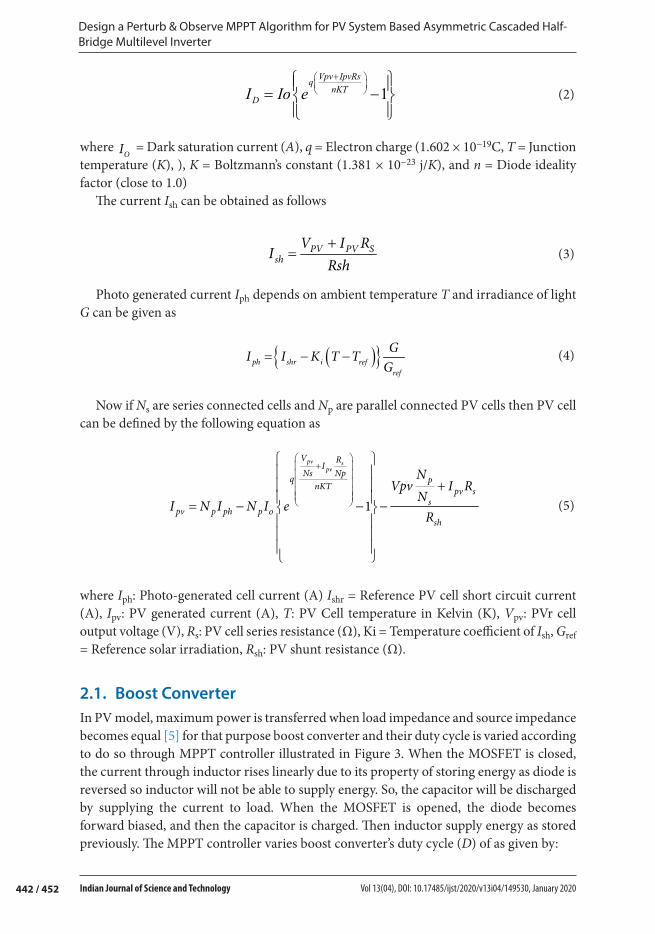
2.1. Boost ConverterIn PV model, maximum power is transferred when load impedance and source impedance becomes equal [5] for that purpose boost converter and their duty cycle is varied according to do so through MPPT controller illustrated in Figure 3. When the MOSFET is closed, the current through inductor rises linearly due to its property of storing energy as diode is reversed so inductor will not be able to supply energy. So, the capacitor will be discharged by supplying the current to load. When the MOSFET is opened, the diode becomes forward biased, and then the capacitor is charged. Then inductor supply energy as stored previously. The MPPT controller varies boost converter’s duty cycle (D) of as given by:

443 / 452
Muzamil Hussain Solangi, Mukhtiar Ahmed Mahar, Abdul Sattar Larik and Mohsin Raza Mahessar
Indian Journal of Science and Technology Vol 13(04), DOI: 10.17485/ijst/2020/v13i04/149530, January 2020
1
1out pvV VD
= − (6)
1out pvI D I (7)
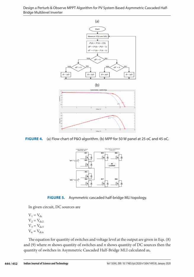
1.2. Perturb and Observe AlgorithmThe MPP is achieved by perturbing the PV parameters (voltage and current) and detect a change in output power in P&O [1,3,5,9]. Proper step size selection is important for achieving MPP. To decrease the response to noise, when making a direction decision averaging the PV power value is a must. Whenever the system is not at operating at the MPP, it is not functioning at the peak point. The flow chart of P&O algorithm is presented in Figure 4(a). By varying the duty cycle in the certain direction, this algorithm first perturbs the voltage and check deviation in power. If dP< 0, then duty cycle is more varied in reverse path till MPP is achieved. But if dP > 0, the change in the duty cycle will be done in the same direction. Hence, by following this procedure the MPP is tracked. It can be seen from equation (6) that, for dc to dc conversion boost converter is used; solar voltage fluctuates inversely as the duty cycle, i.e. PV voltage decrease by increasing the duty cycle D and vice versa. The plot of PV output current and voltage and power voltage are presented in Figure 4(b).
3. Asymmetric Cascaded Half-Bridge Multilevel Inverter Topology
The ACHB MLI comprises of a level generator and polarity changer. The each cell of level generator has two switches with DC source. The general form asymmetric cascaded half-bridge is given in Figure 5. The polarity changer circuit is a full bridge converter which consists of four switches such that two in branch form an H bridge. The DC sources are Vdc, Vdc2 Vdc3…Vdc.
BOOST CONVERT0R
MPPT
V
A
-
Vo
+
PWM
FIGURE 3. MPPT-based PV module with boost converter.
Design a Perturb & Observe MPPT Algorithm for PV System Based Asymmetric Cascaded Half-Bridge Multilevel Inverter
444 / 452 Indian Journal of Science and Technology Vol 13(04), DOI: 10.17485/ijst/2020/v13i04/149530, January 2020
In given circuit, DC sources are
V1 = VdcV2 = Vdc2V3 = Vdc3Vn = Vdcn
The equation for quantity of switches and voltage level at the output are given in Eqs. (8) and (9) where m shows quantity of switches and n shows quantity of DC sources then the quantity of switches in Asymmetric Cascaded Half-Bridge MLI calculated as,
(a)
(b)
FIGURE 4. (a) Flow chart of P&O algorithm. (b) MPP for 50 W panel at 25 oC and 45 oC.
S1 S5
S7
S6
S8
S2
V2
S3
S4
V1
R LOAD
CASCADED HALF BRIDGE MLI
POLARITY CHANGER CIRCUIT
FIGURE 5. Asymmetric cascaded half-bridge MLI topology.
445 / 452
Muzamil Hussain Solangi, Mukhtiar Ahmed Mahar, Abdul Sattar Larik and Mohsin Raza Mahessar
Indian Journal of Science and Technology Vol 13(04), DOI: 10.17485/ijst/2020/v13i04/149530, January 2020
m = 2*n (8)
The equation for number of voltage levels at output is given as
12 1nk += − (9)
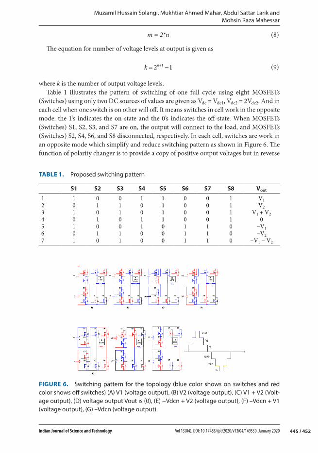
where k is the number of output voltage levels.Table 1 illustrates the pattern of switching of one full cycle using eight MOSFETs
(Switches) using only two DC sources of values are given as Vdc = Vdc1, Vdc2 = 2Vdc2. And in each cell when one switch is on other will off. It means switches in cell work in the opposite mode. the 1’s indicates the on-state and the 0’s indicates the off-state. When MOSFETs (Switches) S1, S2, S3, and S7 are on, the output will connect to the load, and MOSFETs (Switches) S2, S4, S6, and S8 disconnected, respectively. In each cell, switches are work in an opposite mode which simplify and reduce switching pattern as shown in Figure 6. The function of polarity changer is to provide a copy of positive output voltages but in reverse
TABLE 1. Proposed switching pattern
S1 S2 S3 S4 S5 S6 S7 S8 Vout
1 1 0 0 1 1 0 0 1 V12 0 1 1 0 1 0 0 1 V23 1 0 1 0 1 0 0 1 V1 + V24 0 1 0 1 1 0 0 1 05 1 0 0 1 0 1 1 0 −V16 0 1 1 0 0 1 1 0 −V27 1 0 1 0 0 1 1 0 −V1 − V2
FIGURE 6. Switching pattern for the topology (blue color shows on switches and red color shows off switches) (A) V1 (voltage output), (B) V2 (voltage output), (C) V1 + V2 (Volt-age output), (D) voltage output Vout is (0), (E) −Vdcn + V2 (voltage output), (F) –Vdcn + V1 (voltage output), (G) –Vdcn (voltage output).
Design a Perturb & Observe MPPT Algorithm for PV System Based Asymmetric Cascaded Half-Bridge Multilevel Inverter
446 / 452 Indian Journal of Science and Technology Vol 13(04), DOI: 10.17485/ijst/2020/v13i04/149530, January 2020
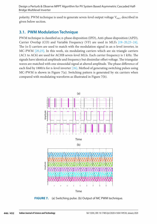
polarity. PWM technique is used to generate seven-level output voltage Vout., described in given below section.
3.1. PWM Modulation TechniquePWM technique is classified as; n-phase disposition (IPD), Anti-phase disposition (APD), Carrier Overlap (CO) and Variable Frequency (VF) are used in MLI’s [19–20,23–24]. The (n-l) carriers are used to match with the modulation signal in an n-level inverter, in MC-PWM [20,25]. In this work, six modulating carriers which are six triangle carriers (AC1 to AC6) are used for ACHB seven-level MLIs. Each carrier frequency is 1 kHz. The signals have identical amplitude and frequency but dissimilar offset voltage. The triangular waves are matched with one sinusoidal signal at altered amplitude. The phase difference of each find by 1800/n for n-level inverter [26]. Method of generating switching pulses using MC-PWM is shown in Figure 7(a). Switching pattern is generated by six carriers when compared with modulating waveform as illustrated in Figure 7(b).
(a)
Am
plitu
de
Time
(b)
Am
plitu
de
Time
FIGURE 7. (a) Switching pulse. (b) Output of MC PWM technique.
447 / 452
Muzamil Hussain Solangi, Mukhtiar Ahmed Mahar, Abdul Sattar Larik and Mohsin Raza Mahessar
Indian Journal of Science and Technology Vol 13(04), DOI: 10.17485/ijst/2020/v13i04/149530, January 2020
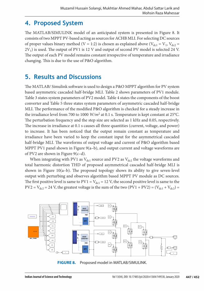
4. Proposed SystemThe MATLAB/SIMULINK model of an anticipated system is presented in Figure 8. It consists of two MPPT PV-based acting as sources for ACHB MLI. For selecting DC sources of proper values binary method (V = 1:2) is chosen as explained above (Vdc1 = V1, Vdc2 = 2V1) is used. The output of PV1 is 12 V and output of second PV model is selected 24 V. The output of each PV model remains constant irrespective of temperature and irradiance changing. This is due to the use of P&O algorithm.
5. Results and DiscussionsThe MATLAB/ Simulink software is used to design a P&O MPPT algorithm for PV system based asymmetric cascaded half-bridge MLI. Table 2 shows parameters of PV1 module. Table 3 states system parameters of PV2 model. Table 4 states the components of the boost converter and Table 5 three states system parameters of asymmetric cascaded half-bridge MLI. The performance of the modified P&O algorithm is checked for a steady increase in the irradiance level from 700 to 1000 W/m2 at 0.1 s. Temperature is kept constant at 25°C. The perturbation frequency and the step size are selected as 1 kHz and 0.05, respectively. The increase in irradiance at 0.1 s causes all three quantities (current, voltage, and power) to increase. It has been noticed that the output remain constant as temperature and irradiance have been varied to keep the constant input for the asymmetrical cascaded half-bridge MLI. The waveforms of output voltage and current of P&O algorithm based MPPT PV1 panel shown in Figure 9(a–b), and output current and voltage waveforms are of PV2 are shown in Figure 9(c–d).
When integrating with PV1 as Vdc1 source and PV2 as Vdc2 the voltage waveforms and total harmonic distortion THD of proposed asymmetrical cascaded half-bridge MLI is shown in Figure 10(a–b). The proposed topology shows its ability to give seven-level output with perturbing and observes algorithm based MPPT PV module as DC sources. The first positive level is same to PV1 = Vdc1 = 12 V, the second positive level is same to the PV2 = Vdc2 = 24 V, the greatest voltage is the sum of the two (PV1 + PV2) = (Vdc1 + Vdc2) =
FIGURE 8. Proposed model in MATLAB/SIMULINK.
Design a Perturb & Observe MPPT Algorithm for PV System Based Asymmetric Cascaded Half-Bridge Multilevel Inverter
448 / 452 Indian Journal of Science and Technology Vol 13(04), DOI: 10.17485/ijst/2020/v13i04/149530, January 2020
36 V and 0 V at the end of a positive cycle. The negative half cycle is similar in amplitudes to a positive half cycle but its polarity is reversed. Negative half cycle created by subtracting the Vdc3 from the Vdc2 to produce the first PV1 = Vdc1 = −12 V, then from the Pdc = Vdc1 to produce the PV2 = Vdc2 = −24 V and finally produce the greatest reverse voltage – (PV1
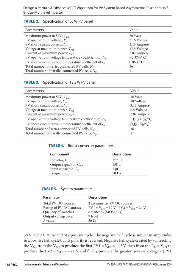
TABLE 2. Specification of 50 W PV panel
Parameters Value
Maximum power at STC, Pmp 50 WattPV open-circuit voltage , Voc 21.6 VoltagePV short-circuit current, Isc 3.13 AmpereVoltage at maximum power, Vmp 17.5 VoltageCurrent at maximum power, IMP 2.87 AmperePV open-circuit voltage temperature coefficient of VOc −0.37%/°CPV short-circuit current temperature coefficient of Isc 0.06%/°CTotal number of series connected PV cells, Ns 36Total number of parallel connected PV cells, Np 1
TABLE 3. Specification of 18.5 W PV panel
Parameters Value
Maximum power at STC, Pmp 18 WattPV open-circuit voltage, Voc 10 VoltagePV short-circuit current, Isc 3.13 AmpereVoltage at maximum power, Vmp 6.5 VoltageCurrent at maximum power, IMP 2.87 AmperePV open-circuit voltage temperature coefficient of VOc −0.37 %/°CPV short-circuit current temperature coefficient of Isc 0.06 %/°CTotal number of series connected PV cells, Ns 36Total number of parallel connected PV cells, Np 1
TABLE 4. Boost converter parameters
Component Description
Inductor, L 177 μHOutput capacitor, Cout 158 μfInput capacitor, Cin 1 μfFrequency, f 50 Hz
TABLE 5. System parameters
Parameter Description
Total PV DC sources 2 asymmetric PV DC sourcesRating of PV DC sources PV1 = Vdc1 = 12 V , PV2 = Vdc2 = 24 VQuantity of switches 8 switches (MOSFETs)Output voltage level 7 levelR value 50 Ω

449 / 452
Muzamil Hussain Solangi, Mukhtiar Ahmed Mahar, Abdul Sattar Larik and Mohsin Raza Mahessar
Indian Journal of Science and Technology Vol 13(04), DOI: 10.17485/ijst/2020/v13i04/149530, January 2020
(a)
Curr
ent (
I)
Time
(b)
Volta
ge (V
)
Time
(c)
Curr
ent (
I)
Time
(d)
Volta
ge (V
)
Time
FIGURE 9. (a) 12 V panel output current. (b) 12 V PV panel output voltage. (c) 24 V PV panel output current. (d) 24 V PV panel output voltage.

Design a Perturb & Observe MPPT Algorithm for PV System Based Asymmetric Cascaded Half-Bridge Multilevel Inverter
450 / 452 Indian Journal of Science and Technology Vol 13(04), DOI: 10.17485/ijst/2020/v13i04/149530, January 2020
+ PV2) = −(Vdc1 + Vdc2) = −36. The output is equated with shifted six carriers to create suitable gating signals. The total harmonic distortion as shown in Figure 10b is 15.81. It is worth saying that the THD of the proposed topology is less.
6. ConclusionThis study presents the P&O MPPT algorithm for PV-based ACHB-MLI topology. PV modules are used as asymmetric PV DC sources for the converter configuration are utilized to increase number of output voltage levels. Polarity changer circuit let the given system to yield both cycles (Positive and Negative). The proposed model consists of two PV modules which are P&O algorithm based to track maximum power point Tracking. It can track the MPPT with good performance as the output of each PV module remains constant irrespective of change in temperature and irradiance. The given topology is
(a)
Time
(b)
Time
FIGURE 10. (a) Output voltage wave form. (b). THD of proposed topology.
451 / 452
Muzamil Hussain Solangi, Mukhtiar Ahmed Mahar, Abdul Sattar Larik and Mohsin Raza Mahessar
Indian Journal of Science and Technology Vol 13(04), DOI: 10.17485/ijst/2020/v13i04/149530, January 2020
simple and modular in constructing cells. The proposed topology has improved harmonic spectrum with PV as sources.
References 1. Alik R, Jusoh A, Sutikno T. A review on perturb and observe maximum power point tracking in
photovoltaic system. Telkomnika. 2015; 13(3), 745. DOI: 10.12928/TELKOMNIKA.v13i3.1439 2. Jones DC, Erickson RW. Probabilistic analysis of a generalized perturbs and observe algorithm
featuring robust operation in the presence of power curve traps. IEEE Transactions on Power Electronics. 2012; 28(6), 2912–2926. DOI: 10.1109/TPEL.2012.2224378.
3. Abdelsalam AK, Massoud AM, Ahmed S, Enjeti PN. High-performance adaptive perturbs and observes MPPT technique for photovoltaic-based microgrids. IEEE Transactions on Power Electronics. 2011; 26(4), 1010–1021. DOI: 10.1109/TPEL.2011.2106221.
4. Alik R, Jusoh A. An enhanced P&O checking algorithm MPPT for high tracking efficiency of partially shaded PV module. Solar Energy. 2018; 163, 570–580. DOI:10.1016/j.solener.2017.12.050.
5. Almi M, Belmili H, Arrouf M, Bendib B. A novel adaptive variable step size P&O MPPT algorithm. Academic Journal of Science. 2016; 6(1), 533–540. DOI: 10.1109/UPEC.2016.8114046.
6. Elgendy MA, Zahawi B, Atkinson DJ. Assessment of perturb and observe MPPT algorithm implementation techniques for PV pumping applications. IEEE Transactions on Sustainable Energy. 2011; 3(1), 21–33. DOI: 10.1109/TSTE.2011.2168245.
7. Esram T, Chapman PL. Comparison of photovoltaic array maximum power point tracking techniques. IEEE Transactions on Energy Conversion. 2007; 22(2), 439–449. DOI: 10.1109/TEC.2006.874230.
8. Ishaque K, Salam Z, Amjad M, Mekhilef S. An improved particle swarm optimization (PSO)–based MPPT for PV with reduced steady-state oscillation. IEEE Transactions on Power Electronics. 2012; 27(8), 3627–3638. DOI: 10.1109/TPEL.2012.2185713.
9. Chu CC, Chen CL. Robust maximum power point tracking method for photovoltaic cells: a sliding mode control approach. Solar Energy. 2009; 83(8), 1370–1378. https://doi.org/10.1016/j.solener.2009.03.005
10. De Brito MAG, Galotto L, Sampaio LP, e Melo GDA, Canesin CA. Evaluation of the main MPPT techniques for photovoltaic applications. IEEE Transactions on Industrial Electronics. 2012; 60(3), 1156–1167. DOI: 10.1109/TIE.2012.2198036.
11. Ghazanfari J, Maghfoori Farsangi M. Maximum power point tracking using sliding mode control for photovoltaic array. Iranian Journal of Electrical and Electronic Engineering. 2013; 9(3), 189–196. http://ijeee.iust.ac.ir/article-1-523-en.html
12. Safari A, Mekhilef S, editors. Incremental conductance MPPT method for PV systems. In: 24th Canadian conference on electrical and computer engineering. 2011. DOI: 10.1109/CCECE.2011.6030470.
13. Casadei D, Grandi G, Rossi C. Single-phase single-stage photovoltaic generation system based on a ripple correlation control maximum power point tracking. IEEE Transactions on Energy Conversion. 2006; 21(2), 562–568. DOI: 10.1109/TEC.2005.853784.
14. Iradiasi V. Implementasi maximum power point tracking (MPPT) berbasis perturb and observe (P&O) pada photovoltaic (PV) dengan. Departemen Teknik Elektro dan Teknologi Informasi. 2019; 1–5. https://pdfs.semanticscholar.org/cfe0/8b16e53d45f4d4a93a3052d762174c080358.pdf

Design a Perturb & Observe MPPT Algorithm for PV System Based Asymmetric Cascaded Half-Bridge Multilevel Inverter
452 / 452 Indian Journal of Science and Technology Vol 13(04), DOI: 10.17485/ijst/2020/v13i04/149530, January 2020
15. Mei Q, Shan M, Liu L, Guerrero JM. A novel improved variable step-size incremental-resistance MPPT method for PV systems. IEEE Transactions on Industrial Electronics. 2010; 58(6), 2427–2434. DOI: 10.1109/TIE.2010.2064275.
16. Miyatake M, Toriumi F, Endo T, Fujii N, editors. A Novel maximum power point tracker controlling several converters connected to photovoltaic arrays with particle swarm optimization technique. In: 2007 European conference on power electronics and applications. 2007. DOI: 10.1109/EPE.2007.4417640.
17. Soufyane Benyoucef A, Chouder A, Kara K, Silvestre S. Artificial bee colony based algorithm for maximum power point tracking (MPPT) for PV systems operating under partial shaded conditions. Applied Soft Computing. 2015; 32, 38–48. https://doi.org/10.1016/j.asoc.2015.03.047
18. Tey KS, Mekhilef S. Modified incremental conductance MPPT algorithm to mitigate inaccurate responses under fast-changing solar irradiation level. Solar Energy. 2014; 101, 333–342. https://doi.org/10.1016/j.solener.2014.01.003
19. Alishah RS, Hosseini SH. A new multilevel inverter structure for high-power applications using multi-carrier PWM switching strategy. International Journal of Power Electronics and Drive Systems. 2015; 6(2), 318–325. http://citeseerx.ist.psu.edu/viewdoc/download?doi=10.1.1.1023.279&rep=rep1&type=pdf
20. Choi WS, Nam HK, Park SJ. Single-phase multilevel PWM inverter based on H-bridge and its harmonics analysis. Journal of Power Electronics. 2015; 15(5), 1227–1234. http://www.academia.edu/download/38885344/9_JPE-14-12-120.pdf
21. Mahar MA, Larik AS, Shah A. Impacts on power factor of ac voltage controllers under non-sinusoidal conditions. Mehran University Research Journal of Engineering and Technology. 2012; 31(2), 297–300. http://publications.muet.edu.pk/research_papers/pdf/pdf634.pdf
22. Mahar MA, Uqaili MA, Larik AS. Harmonic analysis of ac-dc topologies and their impacts on power systems. Mehran University Research Journal of Engineering & Technology. 2011; 30(1), 173–178. https://pdfs.semanticscholar.org/3415/9e0ee1619c0e9041fb3496cdf8efc5426bcf.pdf
23. Chattopadhyay SK, Chakraborty C. Performance of three-phase asymmetric cascaded bridge (16: 4: 1) multilevel inverter. IEEE Transactions on Industrial Electronics. 2015; 62(10), 5983–5992. DOI: 10.1109/TIE.2015.2424191.
24. Gowd GE, Sreenivasarao D. Nonlinear controller for maximum power extraction in asymmetric multilevel DC link reduced switch count inverter‐based grid connected PV system. International Transactions on Electrical Energy Systems. 2019. https://doi.org/10.1002/2050-7038.12206
25. Ahmed M, Sheir A, Orabi M. Asymmetric cascaded half-bridge multilevel inverter without polarity changer. Alexandria Engineering Journal. 2018; 57(4), 2415–2426. https://doi.org/10.1016/j.aej.2017.08.018
26. Prabaharan N, Palanisamy K. Comparative analysis of symmetric and asymmetric reduced switch MLI topologies using unipolar pulse width modulation strategies. IET Power Electronics. 2016; 9(15), 2808–2823. DOI: 10.1049/iet-pel.2016.0283.
Related Documents