Građevinar 5/2013 435 GRAĐEVINAR 65 (2013) 5, 435-448 UDK 624.72.32+678.7:699.84 Seismic upgrade of RC buildings using CFRP sheets Primljen / Received: 26.6.2012. Ispravljen / Corrected: 15.4.2013. Prihvaćen / Accepted: 22.5.2013. Dostupno online / Available online: 10.6.2013. Prof. Ahmet Murat Turk, PhD. CE Istanbul Kultur University Department of Civil Engineering [email protected] Mustafa Comert, M.Sc. CE Istanbul Technical University Faculty of Civil Engineering [email protected] Cumhur Cosgun, Istanbul Kultur University Department of Civil Engineering [email protected] Scientific paper (Subject review) Ahmet Murat Turk, Mustafa Comert, Cumhur Cosgun Seismic upgrade of RC buildings using CFRP sheets The seismic upgrade of existing reinforced-concrete frame buildings usually calls for evacuation of occupants, and the time available for construction works is often quite limited. These problems usually cause time delays and additional costs on seismic rehabilitation projects. One of the ways of improving seismic resistance of structures is to use CFRP (carbon fibre-reinforced polymer) sheets and steel fuse elements. The cost-effectiveness and practical value of this technical solution is proven in the paper through appropriate analyses. Key words: reinforced concrete, frame structures, seismic upgrade, strengthening, CFRP Pregledni rad Ahmet Murat Turk, Mustafa Comert, Cumhur Cosgun Protupotresno poboljšanje a/b građevina primjenom CFRP traka Protupotresno poboljšanje postojećih građevina s armiranobetonskom okvirnom konstrukcijom obično zahtijeva iseljenje stanara, a često su i kratki vremenski rokovi za izvođenje građevinskih radova. Ovakvi problemi uglavnom dovode do kašnjenja i dodatnih troškova u projektima protupotresne obnove. Jedan od načina poboljšanja seizmičke otpornosti konstrukcije je uporaba CFRP (ugljičnim vlaknima ojačanog polimera) traka i čeličnih spona. U radu je na temelju provedenih analiza dokazana ekonomičnost i praktičnost ovog tehničkog rješenja. Ključne riječi: armirani beton, okvirne konstrukcije, protupotresno poboljšanje, ojačanje, CFRP Übersichtsarbeit Ahmet Murat Turk, Mustafa Comert, Cumhur Cosgun Seismische Nachrüstung von Stahlbetonbauten durch die Anwendung von CFRP Streifen Die seismische Nachrüstung bestehender Gebäude mit Rahmenkonstruktionen aus Stahlbeton verlangt normalerweise den vorübergehenden Auszug der Einwohner. Außerdem sind die verfügbaren Zeitfristen für die Ausführung der Bauarbeiten oft begrenzt. Diese Probleme können zu Verspätungen und zusätzlichen Kosten in Projekten seismischer Ertüchtigung führen. Ein möglicher Weg, die seismische Beständigkeit zu verbessern, ist die Anwendung von Streifen aus CFRP (kohlenstofffaserverstärktem Polymer) und Stahlverbindungen. In der vorliegenden Arbeit ist auf Grund durchgeführter Analysen die Wirtschaftlichkeit und Verwendbarkeit dieser technischen Lösung nachgewiesen. Schlüsselwörter: Stahlbeton, Rahmenkonstruktionen, seismische Nachrüstung, Verstärkung, CFRP Authors:

Welcome message from author
This document is posted to help you gain knowledge. Please leave a comment to let me know what you think about it! Share it to your friends and learn new things together.
Transcript

Građevinar 5/2013
435GRAĐEVINAR 65 (2013) 5, 435-448
UDK 624.72.32+678.7:699.84
Seismic upgrade of RC buildings using CFRP sheets
Primljen / Received: 26.6.2012.
Ispravljen / Corrected: 15.4.2013.
Prihvaćen / Accepted: 22.5.2013.
Dostupno online / Available online: 10.6.2013.
Prof. Ahmet Murat Turk, PhD. CE Istanbul Kultur UniversityDepartment of Civil [email protected]
Mustafa Comert, M.Sc. CE Istanbul Technical UniversityFaculty of Civil [email protected]
Cumhur Cosgun, Istanbul Kultur UniversityDepartment of Civil [email protected]
Scientific paper (Subject review)Ahmet Murat Turk, Mustafa Comert, Cumhur Cosgun
Seismic upgrade of RC buildings using CFRP sheets
The seismic upgrade of existing reinforced-concrete frame buildings usually calls for evacuation of occupants, and the time available for construction works is often quite limited. These problems usually cause time delays and additional costs on seismic rehabilitation projects. One of the ways of improving seismic resistance of structures is to use CFRP (carbon fibre-reinforced polymer) sheets and steel fuse elements. The cost-effectiveness and practical value of this technical solution is proven in the paper through appropriate analyses.
Key words:reinforced concrete, frame structures, seismic upgrade, strengthening, CFRP
Pregledni radAhmet Murat Turk, Mustafa Comert, Cumhur Cosgun
Protupotresno poboljšanje a/b građevina primjenom CFRP traka
Protupotresno poboljšanje postojećih građevina s armiranobetonskom okvirnom konstrukcijom obično zahtijeva iseljenje stanara, a često su i kratki vremenski rokovi za izvođenje građevinskih radova. Ovakvi problemi uglavnom dovode do kašnjenja i dodatnih troškova u projektima protupotresne obnove. Jedan od načina poboljšanja seizmičke otpornosti konstrukcije je uporaba CFRP (ugljičnim vlaknima ojačanog polimera) traka i čeličnih spona. U radu je na temelju provedenih analiza dokazana ekonomičnost i praktičnost ovog tehničkog rješenja.
Ključne riječi:armirani beton, okvirne konstrukcije, protupotresno poboljšanje, ojačanje, CFRP
ÜbersichtsarbeitAhmet Murat Turk, Mustafa Comert, Cumhur Cosgun
Seismische Nachrüstung von Stahlbetonbauten durch die Anwendung von CFRP Streifen
Die seismische Nachrüstung bestehender Gebäude mit Rahmenkonstruktionen aus Stahlbeton verlangt normalerweise den vorübergehenden Auszug der Einwohner. Außerdem sind die verfügbaren Zeitfristen für die Ausführung der Bauarbeiten oft begrenzt. Diese Probleme können zu Verspätungen und zusätzlichen Kosten in Projekten seismischer Ertüchtigung führen. Ein möglicher Weg, die seismische Beständigkeit zu verbessern, ist die Anwendung von Streifen aus CFRP (kohlenstofffaserverstärktem Polymer) und Stahlverbindungen. In der vorliegenden Arbeit ist auf Grund durchgeführter Analysen die Wirtschaftlichkeit und Verwendbarkeit dieser technischen Lösung nachgewiesen.
Schlüsselwörter:Stahlbeton, Rahmenkonstruktionen, seismische Nachrüstung, Verstärkung, CFRP
Authors:
Građevinar 5/2013
436 GRAĐEVINAR 65 (2013) 5, 435-448
Ahmet Murat Turk, Mustafa Comert, Cumhur Cosgun
1. Introduction
Over the last two decades, major earthquakes like Erzincan (1992), Dinar (1995), Ceyhan (1998), Kocaeli and Duzce (1999), Elazig (2010), Simav (2011) resulted in considerable human loss and extensive structural damage in Turkey. Especially the 1999 Kocaeli and Duzce earthquakes caused extensive damage in a very large region extending from Tekirdag to Eskisehir, while cities mostly affected are Sakarya, Duzce, Yalova, Kocaeli, Bolu and Istanbul. The number of earthquake damaged buildings exceeds 25,000. 15000 people were killed and more than 20000 were injured in Kocaeli (17 August 1999) and Duzce (12 November 1999) earthquakes. Finally, two earthquakes, one on 23 October 2011 (magnitude 7.2) and the other on 9 November (magnitude 5.7), flattened some 2,000 buildings and resulted in the death of 645 people in Van, Turkey. Inspections made after the earthquakes showed that the performance of low and medium rise RC framed residential, office and public buildings was generally poor due to their flexible frame systems of inadequate ductility. The examinations revealed that these buildings had the following common deficiencies: low concrete strength, low yield strength of reinforcement, inadequate lateral stiffness, inadequate ductility (ends of members and beam-column joints were not properly confined), and inadequate length of lapped splices in column longitudinal bars spliced near the joints. Many different techniques have been tested and applied over the past 30 years in the scope of rehabilitation of existing reinforced concrete frame structures [1-10]. These methods can be classified as improvements on the structural level or member level, such as jacketing of columns and beams, addition of wing walls, addition of infill walls like monolithic RC infill walls or multiple precast reinforced concrete panel walls or steel plated infill walls, addition of steel bracings, external steel framing, and post tensioning. In Turkey, there are very many existing seismically deficient RC buildings. A great majority of residential and office buildings, which are normally low-rise to mid-rise reinforced concrete frames, including public buildings like schools and hospitals, have not been engineered to resist even moderate earthquakes. Therefore, rapid strengthening of these existing reinforced concrete buildings before the possible upcoming earthquakes, and repair of damaged ones after earthquakes, are the activities that are extensively encountered in practice. An another major problem, in terms of seismic rehabilitation of existing buildings, is the need to evacuate the occupants from the zone of construction works. In most cases, it is very expensive and burdensome for the users/owners of the buildings, especially in case of public buildings. The second problem is the often limited time frame available for actual construction works. The last but not the least problem are the so called hidden problems, such as changes made to the building system after contracting, which are not shown in the as-built drawings. All these problems often cause time delays and cost overruns on seismic rehabilitation projects. State schools and hospitals in Turkey are the most common structures in this category, and they require rapid and reliable seismic rehabilitation techniques. A typical low-rise reinforced
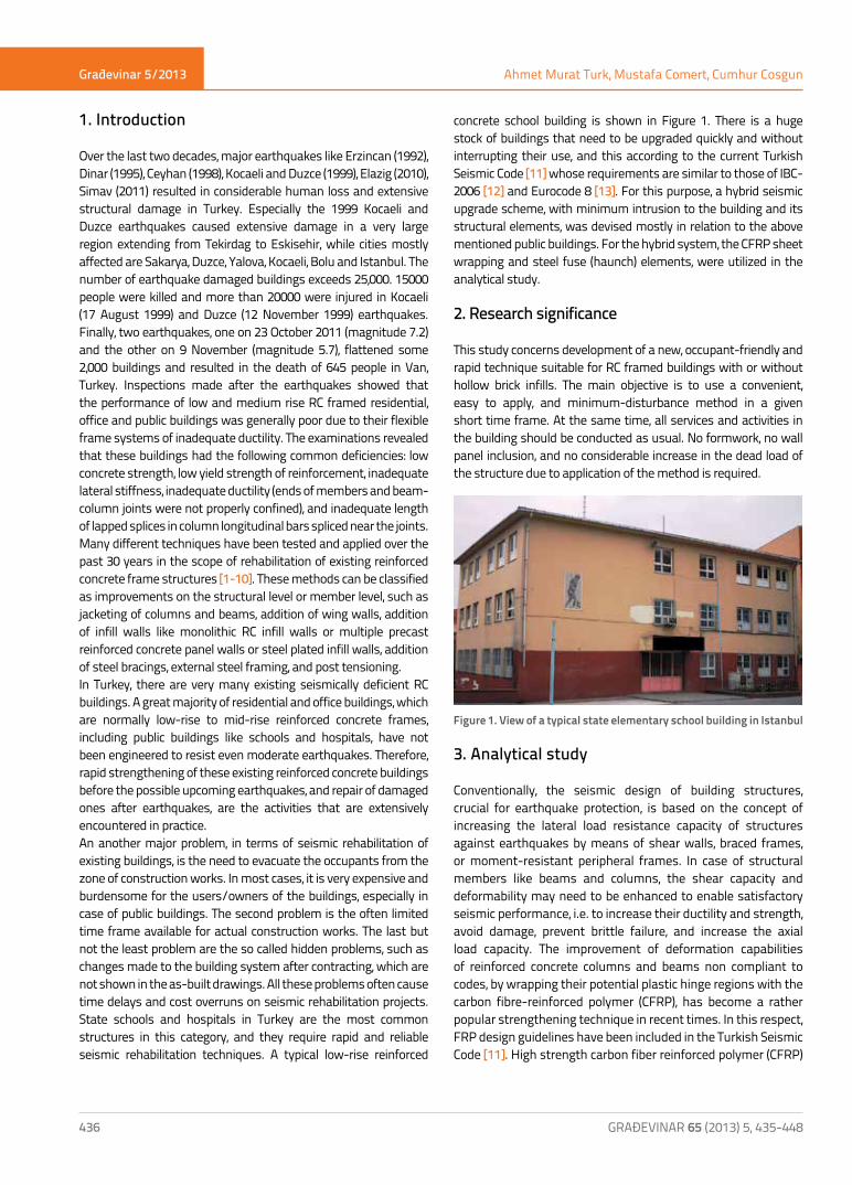
concrete school building is shown in Figure 1. There is a huge stock of buildings that need to be upgraded quickly and without interrupting their use, and this according to the current Turkish Seismic Code [11] whose requirements are similar to those of IBC-2006 [12] and Eurocode 8 [13]. For this purpose, a hybrid seismic upgrade scheme, with minimum intrusion to the building and its structural elements, was devised mostly in relation to the above mentioned public buildings. For the hybrid system, the CFRP sheet wrapping and steel fuse (haunch) elements, were utilized in the analytical study.
2. Research significance
This study concerns development of a new, occupant-friendly and rapid technique suitable for RC framed buildings with or without hollow brick infills. The main objective is to use a convenient, easy to apply, and minimum-disturbance method in a given short time frame. At the same time, all services and activities in the building should be conducted as usual. No formwork, no wall panel inclusion, and no considerable increase in the dead load of the structure due to application of the method is required.
Figure 1. View of a typical state elementary school building in Istanbul
3. Analytical study
Conventionally, the seismic design of building structures, crucial for earthquake protection, is based on the concept of increasing the lateral load resistance capacity of structures against earthquakes by means of shear walls, braced frames, or moment-resistant peripheral frames. In case of structural members like beams and columns, the shear capacity and deformability may need to be enhanced to enable satisfactory seismic performance, i.e. to increase their ductility and strength, avoid damage, prevent brittle failure, and increase the axial load capacity. The improvement of deformation capabilities of reinforced concrete columns and beams non compliant to codes, by wrapping their potential plastic hinge regions with the carbon fibre-reinforced polymer (CFRP), has become a rather popular strengthening technique in recent times. In this respect, FRP design guidelines have been included in the Turkish Seismic Code [11]. High strength carbon fiber reinforced polymer (CFRP)
Građevinar 5/2013
437GRAĐEVINAR 65 (2013) 5, 435-448
Seismic upgrade of RC buildings using CFRP sheets
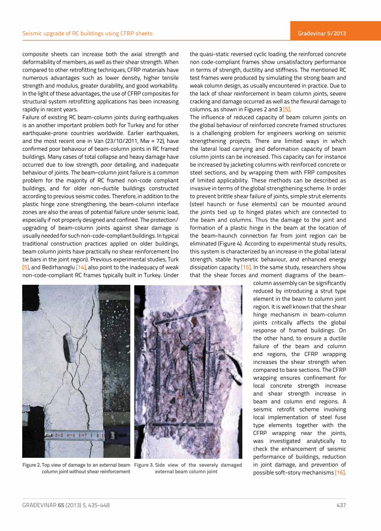
composite sheets can increase both the axial strength and deformability of members, as well as their shear strength. When compared to other retrofitting techniques, CFRP materials have numerous advantages such as lower density, higher tensile strength and modulus, greater durability, and good workability. In the light of these advantages, the use of CFRP composites for structural system retrofitting applications has been increasing rapidly in recent years.Failure of existing RC beam-column joints during earthquakes is an another important problem both for Turkey and for other earthquake-prone countries worldwide. Earlier earthquakes, and the most recent one in Van (23/10/2011, Mw = 72), have confirmed poor behaviour of beam-column joints in RC framed buildings. Many cases of total collapse and heavy damage have occurred due to low strength, poor detailing, and inadequate behaviour of joints. The beam–column joint failure is a common problem for the majority of RC framed non-code compliant buildings, and for older non-ductile buildings constructed according to previous seismic codes. Therefore, in addition to the plastic hinge zone strengthening, the beam-column interface zones are also the areas of potential failure under seismic load, especially if not properly designed and confined. The protection/upgrading of beam-column joints against shear damage is usually needed for such non-code-compliant buildings. In typical traditional construction practices applied on older buildings, beam column joints have practically no shear reinforcement (no tie bars in the joint region). Previous experimental studies, Turk [5], and Bedirhanoglu [14], also point to the inadequacy of weak non-code-compliant RC frames typically built in Turkey. Under
the quasi-static reversed cyclic loading, the reinforced concrete non code-compliant frames show unsatisfactory performance in terms of strength, ductility and stiffness. The mentioned RC test frames were produced by simulating the strong beam and weak column design, as usually encountered in practice. Due to the lack of shear reinforcement in beam column joints, severe cracking and damage occurred as well as the flexural damage to columns, as shown in Figures 2 and 3 [5]. The influence of reduced capacity of beam column joints on the global behaviour of reinforced concrete framed structures is a challenging problem for engineers working on seismic strengthening projects. There are limited ways in which the lateral load carrying and deformation capacity of beam column joints can be increased. This capacity can for instance be increased by jacketing columns with reinforced concrete or steel sections, and by wrapping them with FRP composites of limited applicability. These methods can be described as invasive in terms of the global strengthening scheme. In order to prevent brittle shear failure of joints, simple strut elements (steel haunch or fuse elements) can be mounted around the joints tied up to hinged plates which are connected to the beam and columns. Thus the damage to the joint and formation of a plastic hinge in the beam at the location of the beam-haunch connection far from joint region can be eliminated (Figure 4). According to experimental study results, this system is characterized by an increase in the global lateral strength, stable hysteretic behaviour, and enhanced energy dissipation capacity [15]. In the same study, researchers show that the shear forces and moment diagrams of the beam-
column assembly can be significantly reduced by introducing a strut type element in the beam to column joint region. It is well known that the shear hinge mechanism in beam-column joints critically affects the global response of framed buildings. On the other hand, to ensure a ductile failure of the beam and column end regions, the CFRP wrapping increases the shear strength when compared to bare sections. The CFRP wrapping ensures confinement for local concrete strength increase and shear strength increase in beam and column end regions. A seismic retrofit scheme involving local implementation of steel fuse type elements together with the CFRP wrapping near the joints, was investigated analytically to check the enhancement of seismic performance of buildings, reduction in joint damage, and prevention of possible soft-story mechanisms [16].
Figure 2. Top view of damage to an external beam column joint without shear reinforcement
Figure 3. Side view of the severely damaged external beam column joint
Građevinar 5/2013
438 GRAĐEVINAR 65 (2013) 5, 435-448
Ahmet Murat Turk, Mustafa Comert, Cumhur Cosgun
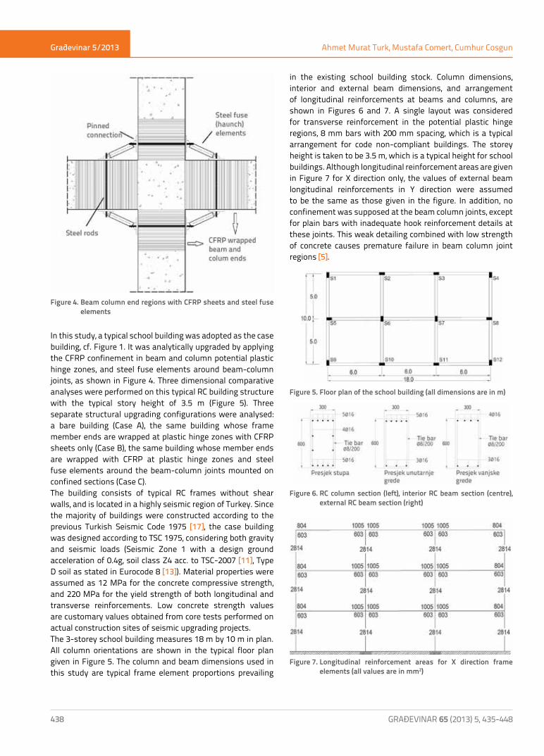
Figure 4. Beam column end regions with CFRP sheets and steel fuse elements
In this study, a typical school building was adopted as the case building, cf. Figure 1. It was analytically upgraded by applying the CFRP confinement in beam and column potential plastic hinge zones, and steel fuse elements around beam-column joints, as shown in Figure 4. Three dimensional comparative analyses were performed on this typical RC building structure with the typical story height of 3.5 m (Figure 5). Three separate structural upgrading configurations were analysed: a bare building (Case A), the same building whose frame member ends are wrapped at plastic hinge zones with CFRP sheets only (Case B), the same building whose member ends are wrapped with CFRP at plastic hinge zones and steel fuse elements around the beam-column joints mounted on confined sections (Case C). The building consists of typical RC frames without shear walls, and is located in a highly seismic region of Turkey. Since the majority of buildings were constructed according to the previous Turkish Seismic Code 1975 [17], the case building was designed according to TSC 1975, considering both gravity and seismic loads (Seismic Zone 1 with a design ground acceleration of 0.4g, soil class Z4 acc. to TSC-2007 [11], Type D soil as stated in Eurocode 8 [13]). Material properties were assumed as 12 MPa for the concrete compressive strength, and 220 MPa for the yield strength of both longitudinal and transverse reinforcements. Low concrete strength values are customary values obtained from core tests performed on actual construction sites of seismic upgrading projects. The 3-storey school building measures 18 m by 10 m in plan. All column orientations are shown in the typical floor plan given in Figure 5. The column and beam dimensions used in this study are typical frame element proportions prevailing
in the existing school building stock. Column dimensions, interior and external beam dimensions, and arrangement of longitudinal reinforcements at beams and columns, are shown in Figures 6 and 7. A single layout was considered for transverse reinforcement in the potential plastic hinge regions, 8 mm bars with 200 mm spacing, which is a typical arrangement for code non-compliant buildings. The storey height is taken to be 3.5 m, which is a typical height for school buildings. Although longitudinal reinforcement areas are given in Figure 7 for X direction only, the values of external beam longitudinal reinforcements in Y direction were assumed to be the same as those given in the figure. In addition, no confinement was supposed at the beam column joints, except for plain bars with inadequate hook reinforcement details at these joints. This weak detailing combined with low strength of concrete causes premature failure in beam column joint regions [5].
Figure 5. Floor plan of the school building (all dimensions are in m)
Figure 6. RC column section (left), interior RC beam section (centre), external RC beam section (right)
Figure 7. Longitudinal reinforcement areas for X direction frame elements (all values are in mm2)

Građevinar 5/2013
439GRAĐEVINAR 65 (2013) 5, 435-448
Seismic upgrade of RC buildings using CFRP sheets
4. Nonlinear static analysis
Three dimensional analyses were conducted using the structural analysis program SAP 2000 [18] for static and dynamic analysis of structures. The cross-section properties like moment-curvature capacities for beam and column ends, and normal force – moment (P-M) interaction curves, were calculated by using the XTRACT software [19]. A description of the modelling details is provided as follows. A three-dimensional model of the structure was created with the software to carry out the nonlinear static analysis. Beam and column elements were modelled as nonlinear frame elements with lumped plasticity by defining plastic hinges at both ends of the beams and columns with the theoretical zero length. The user defined flexural hinge properties were determined by the moment–curvature and P-M interaction analyses of each structural element by means of the section analysis software (cf. Figure 8).
Figure 8. Three dimensional structural model of the case building and structural members including beams, columns and steel fuse elements (Case C)
The Mander model [20] for the unconfined concrete, and the typical steel stress–strain model with strain hardening for steel, were used in the moment–curvature analyses (Figures 9 and 10). The cracked section stiffness for RC beams was assumed as 0.4 times of EI (flexural rigidity of cross section) according to TSC 2007, whereas the same value was taken as 0.5 EI for all RC columns [11]. Normal force-moment (P-M) interaction analyses were carried out for each column, considering section properties for different orientations, cf. Figure 11. Axial forces were neglected for the interior and external beams, and flexural capacities were represented by moment-curvature relationships only (Figures 12 and 13). Because of the data input limitations of the software used, the capacity relationships were represented by the moment–rotation relationship instead of the moment–curvature. Moment–rotation data were reduced to a five point input that brings some simplifications in the analysis. The plastic hinge length was assumed to obtain ultimate rotation values from ultimate curvatures. For the user defined hinge properties, the plastic hinge length was considered to be 0.5H, where H is the section depth for beams and columns alike. The shear failure of structural members should be taken into consideration for the existing reinforced-concrete buildings, and especially for those with low concrete strength and inadequate confinement. For this purpose, shear hinges were introduced for beams and columns. Because of the brittle failure of concrete in shear, no ductility was considered for this type of hinge. Shear hinge properties are defined so that the member fails immediately when the shear force in the member reaches its shear capacity, as calculated according to TS-500 [21]. The member shear capacity is defined as follows:
V= 0.65. fctd.bw
.d (1+g.(Nd/Ac))
where:fctd - tensile strength of concretebw - width of the cross sectiond - effective depth of the sectiong - 0,07 (under compression), -0.3 (under tension)Nd - Normal force on the cross section Ac - Cross sectional area
Figure 9. Material model assumed for unconfined concrete of C12 (fc=12 MPa) proposed by Mander [20]
Figure 10. Material model assumed for reinforcing steel for S220 (fy=220 MPa)

Građevinar 5/2013
440 GRAĐEVINAR 65 (2013) 5, 435-448
Ahmet Murat Turk, Mustafa Comert, Cumhur Cosgun
Figure 11. P-M Interaction curves for plain RC columns by considering different orientations
Figure 12. Moment-curvature diagram for external beam section
Figure 13. Moment-curvature diagram for interior beam section
As can be seen in Figure 4, the transverse reinforcement in beam and column end regions was applied by confinement with CFRP for Case B and Case C. In order to obtain the confinement effect for low compressive strength of concrete by CFRP wrapping, a concrete material model proposed by Ilki et al. was used in the analysis of composite column sections. According to the proposed model, which was verified by testing, CFRP confined cross sections can resist at least 1.5 times higher axial compressive stresses, and a ten-fold increase in axial strain, even for the low
concrete strength of 12 MPa [22]. Figure 14 shows the stress-strain relationship of the CFRP wrapped concrete section derived using the Ilki’s model, which is given as follows:
ff
ff
hb
cc
co
l
co
cc
co
= + = +1 2 54 1 19 27. . εε
fff
fK E
K
l
co
la f h rup frp
=
0 53
2
.
,ρ ε aa
f
A A
A b r h rbh
A r rbh
= − − −
=− + −
=−
=
1
2 23
4
2
1 2
1
2 2
2
2 2
ρ
θπ
ρη
( ) ( ) tan
ff ft b hbh( )+
In these equations, fcc is the maximum compressive strength of the FRP wrapped concrete, εcc is the maximum axial strain of the FRP wrapped concrete, fco is the compressive strength of an unconfined concrete, b is the section width, h is the section depth of the section, r is the radius of edges around the FRP wrapped section, ηf is the number of wrapped FRP plies, tf is the FRP thickness. P-M interaction analyses were carried out for RC sections with the CFRP wrapping, considering section properties of columns on weak axis, and columns on strong axis, and CFRP mechanical properties, with the assumption of full bond between the concrete and CFRP material. Mechanical and geometrical properties of the CFRP material used in the analysis are shown in Table 1. Calculated P-M interaction curves for the plain and CFRP wrapped columns on both axes, are given in Figures 15 and 16. Three layers of CFRP sheets were assumed to exist around the beam and column members during calculation of cross sectional properties with full bond assumption.
Table 1. Mechanical and geometrical properties of CFRP sheets
Figure 14. Stress-strain relationship of CFRP wrapped concrete section according to model
Characteristic tensile
strength [MPa]
Characteristic tensile
modulus [MPa]
Maximum tensile strain
[mm/mm]
Effective area
per unit width
[mm²/mm]
Unit weight [kg/m³]
3430 230000 0.015 0.165 1820

Građevinar 5/2013
441GRAĐEVINAR 65 (2013) 5, 435-448
Seismic upgrade of RC buildings using CFRP sheets
Figure 15. P-M Interaction curves of plain and CFRP wrapped column’s strong direction
Figure 16. P-M Interaction curves of plain and CFRP wrapped column’s weak direction
In the Case C, in addition to CFRP confinement, beam and column joints were strengthened by steel strut elements hinged at both ends, which results in the reduction of joint shear because the shear transfers to fuse elements between beams and columns. These elements were mounted around the interior and external joints for the chosen frame, at an angle of 300 with RC beams. Steel fuse elements were defined as steel tube elements (S220, fy=220 MPa) 100 mm in external diameter, and 20 mm in wall thickness (Figure 4).In the nonlinear static (pushover) analysis, the behaviour of the structure is characterized by the capacity curve that represents the relationship between the base shear force and top displacement. This is a very convenient representation in practice, and can easily be visualized by structural engineers [23]. It is recognized that the structure’s roof displacement is used for the capacity curve because it is widely accepted in practice. Pushover analysis results, including plastic hinge mechanisms at last steps for both directions, are shown for the Case A (Figures 17 and 18). Plastic hinge formation mechanisms were obtained at displacement points corresponding to the global yielding and ultimate displacements. The global yielding point corresponds to the displacement along the capacity curve in which the system starts to soften. Plastic hinge formation starts at beam ends at
lower stories, then propagates to upper stories, and continues with the yielding of base columns. The hinge locations seem to be consistent, with significant damage or failure occurring at columns for all cases.No shear failure of structural members was detected in case of the bare frame, except at some joint regions. This was primarily due to the assumed low compressive strength of concrete and weak joint detailing. Thus, the overall behaviour was dominated by the flexure and joint shear. As shown in Figures 19 and 20, lateral stiffness values for the three cases (A, B, and C) were almost similar in both directions. The base shear capacity increased noticeably due to introduction of upgrading schemes with respect to the bare frame. This variation is due to the increase in the ductility of members and reduction in joint shear. When compared to the bare frame, the increase in the base shear capacity is 10 % for Cases B and C in the direction X, whereas it is 6 % in the direction Y.
Figure 17. Plastic hinge formation pattern for the Case A in X direction in the last step of the analysis
Figure 18. Plastic hinge formation pattern for the Case A in Y direction in the last step of the analysis

Građevinar 5/2013
442 GRAĐEVINAR 65 (2013) 5, 435-448
Ahmet Murat Turk, Mustafa Comert, Cumhur Cosgun
Figure 19. Nonlinear static analysis curves for three different cases in X direction (A, B, and C)
As can be seen in Figure 21, the design earthquake given by the Turkish Seismic Code demands approximately 210 and 200 mm as target displacement for Y and X directions, respectively.
Figure 21. Deflection demand curve for the design earthquake for three cases
In the current Turkish Seismic Code 2007 [11], three different damage levels are defined in terms of plastic strain of concrete and steel for the evaluation of structural performance. Details of these damage limits are given below.
a) Minimum damage limit (MN): Upper limit of the ultimate compression fibre strain of the reinforced concrete section (εcu) and the strain of steel reinforcement (εs)
(εcu)MN = 0,0035; (εs)MN = 0,010
b) Safety limit (SL): Upper limit of the ultimate compressive strain of core concrete (εcg) and the tensile strain of steel reinforcement;
(εs)SL = 0,040; (εcg)SL = 0,0035 + 0,010 (rs/rsm) ≤ 0,0135
c) Failure limit (FL): Upper limit of the ultimate compressive strain of core concrete (εcg) and the strain of steel reinforcement;
(εs)FL = 0,060; (εcg)FL = 0,004 + 0,014 (rs/rsm) ≤ 0,0180
In these equations, rhos is defined as the volumetric ratio of transverse reinforcement and rhosm is the required volumetric ratio of transverse reinforcement, according to TSC 2007 [11]. The code describes four different performance levels: Light Damage, Moderate Damage, Heavy Damage and Collapse, as shown in Figure 22.
Figure 22. TSC-2007 performance levels for buildings [11]
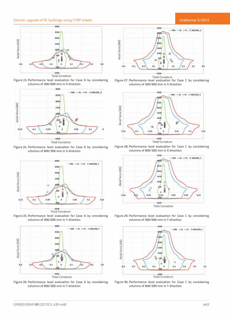
In order to evaluate the seismic performance of columns, axial force-total curvature diagrams were established by indicating the previously mentioned damage limits [11]. Then the performance of all columns for Case A and Case C was established as shown in Figures 23, 24, 25, 26, 27, 28, 29 and 30. In Figures 23 and 24, for X direction load, the total of 15 columns out of 36 (18 columns of 300x600 mm, 18 columns of 600x300 mm) were located either close to or above the failure limit (as marked by red line on the charts). For Case C and the same direction, all columns were located within safety limits, as shown in Figures 27 and 28. If the same comparison is made for Y direction, 8 columns out of 36 are beyond of or adjacent to the safety limit for the bare frame, whereas only one column appeared to have suffered heavy damage for Case C (Figure 25, 26, 29, and 30). The Case C did not have any collapsed columns, while the bare frame (Case A) had many, which could result in the total collapse of the building. This analysis shows that the performance of structural members, columns in particular, is considerably improved if the proposed rehabilitation techniques are applied.
Figure 20. Nonlinear static analysis curves for three different cases in Y direction (A, B, and C)
Građevinar 5/2013
443GRAĐEVINAR 65 (2013) 5, 435-448
Seismic upgrade of RC buildings using CFRP sheets
Figure 23. Performance level evaluation for Case A by considering columns of 300/600 mm in X direction
Figure 24. Performance level evaluation for Case A by considering columns of 600/300 mm in X direction
Figure 27. Performance level evaluation for Case C by considering columns of 300/600 mm in X direction
Figure 28. Performance level evaluation for Case C by considering columns of 600/300 mm in X direction
Figure 25. Performance level evaluation for Case A by considering columns of 300/600 mm in Y direction
Figure 29. Performance level evaluation for Case C by considering columns of 300/600 mm in Y direction
Figure 26. Performance level evaluation for Case A by considering columns of 600/300 mm in Y direction
Figure 30. Performance level evaluation for Case C by considering columns of 600/300 mm in Y direction

Građevinar 5/2013
444 GRAĐEVINAR 65 (2013) 5, 435-448
Ahmet Murat Turk, Mustafa Comert, Cumhur Cosgun
As previously mentioned, the joint shear failure, which can be defined as brittle failure, causes premature failures while the capacity of other plastic hinge regions of columns and beams is still sufficient. The failure of the complete structure, caused by joint panel degradation, can occur before any substantial damage is inflicted on beams and columns. For the beam-column joints, the combination of low strength of concrete and poor detailing, like the use of hooked tension bar anchorage, is damaging to the structures. In order to ensure better performance of frame type structures, a proper behaviour of joint elements should be assured [24, 25]. In this respect, the use of steel fuse elements in the structural system results in significant reduction of joint failure, especially in case of external joints [15]. For this study, a previously proposed equation drawn from experimental research was used to check the external joint shear capacity, as shown in Figure 31 [14]. In this research, the analysis was focused on typical beam column joints with different weaknesses, such as: no confinement around joints, use of hooked type bar anchorage and plain bars, and use of low strength concrete.
Figure 31. Internal forces and stresses that cause shear cracking at external beam column joints
The following formula is proposed for the shear stress capacity of external joints made of low strength concrete:
τ τm cc g
j m ef Nf A
V A= − =0 5 10 5
. ´. ´
where: fc´ = Compressive strength of the concrete (MPa)N = Normal force (Compression force has negative sign, N)Ag = Column cross-section (mm2)Ae = Effective shear area (mm2)tm = Joint shear stress capacity (MPa)Vj = Joint shear force capacity (N)
In addition, the ASCE 41 proposes the following equation for calculating the shear strength of joints:
tm = 0.083.g. (fc)1/2
where g =12 for interior joints with transverse beams, 8 for external joints with transverse beams, and 4 for knee joints [26]. In Tables 2 and 3, joint shear forces and capacities for the Case A and Case C are compared using the ASCE 41 equation for all types of joints, and the equation given in Reference [14] derived for external joints. Joint numbers are given in Figure 32 for the entire structure. The smallest capacity obtained between the two equations is indicated in the table for external joints only. As can be seen in this table, joint shear capacities increase with the application of fuse system because of the axial load variation in beam column joints. In Case A, 11 out of 36 joints had joint failure in X direction whereas 14 out of 36 joints failed in Y direction. In Case C, all failed joints except one were determined to be safe for Case A in X and Y directions. During the evaluation of JSF/JSC ratios, values greater than 0.96 were assumed as joint failure.
Figure 32. Joint numbers given on the 3D structural model
5. Conclusions
A typical three-storey school building was considered in pushover analyses as an example of low rise reinforced concrete (RC) school buildings. Nonlinear static pushover analyses were performed both in the X and Y directions on the 3D structural model of the building. The following conclusions can be drawn from the analysis:a) The total base shear capacity of frames upgraded with fibre
reinforced composites, and with steel fuses at joints, and also with the CFRP wrapping, with the user defined hinges, increased by 10 and 6 % with respect to the bare frame in the X and Y directions, respectively.
b) All three cases present almost the same flexural stiffness prior to yielding. The upgrading schemes utilized do not increase the lateral stiffness. In order to increase the lateral stiffness, different strengthening methods can be applied such as the addition of infill walls, wing walls, steel bracing, and column jacketing if indispensable.
c) In terms of performance level assessments according to the Turkish Seismic Code, the use of CFRP wrapping and steel fuse elements on the structure improved the column

Građevinar 5/2013
445GRAĐEVINAR 65 (2013) 5, 435-448
Seismic upgrade of RC buildings using CFRP sheets
Joint Jointtype
CaseA and B
CaseC
Joint cross section area
[mm2]
Joint shear capacity
(JSC)[26][kN]
Theoretical exterior joint
shearcapacity
[14][kN]
CaseA and B
CaseC
Joint shear force(JSF)[kN]
Joint shear force(JSF)[kN]
RatioJSF/JSC
RatioJSF/JSC
1A1 Exterior 189 109 90000 207 192 0.98 0.56
1A2 Exterior 199 114 90000 207 192 0.96 0.59
1A3 Exterior 199 88 90000 207 192 1.03 0.46
1B1 Exterior 109 74 180000 414 383 0.28 0.19
1B2 Exterior 159 79 180000 414 383 0.38 0.19
1B3 Exterior 159 39 180000 414 383 0.38 0.09
1C1 Exterior 109 109 180000 414 383 0.26 0.26
1C2 Exterior 139 114 180000 414 383 0.34 0.28
1C3 Exterior 139 2 180000 414 383 0.34 0.00
1D1 Exterior 169 149 90000 207 192 0.82 0.72
1D2 Exterior 179 169 90000 207 192 0.93 0.82
1D3 Exterior 179 107 90000 207 192 0.93 0.52
2A1 Exterior 139 149 180000 414 383 0.34 0.36
2A2 Exterior 205 153 180000 414 383 0.50 0.37
2A3 Exterior 205 59 180000 414 383 0.50 0.14
2B1 Interior 354 125.2 90000 310 - 1.14 0.40
2B2 Interior 363 153.2 90000 310 - 1.17 0.49
2B3 Interior 363 105.2 90000 310 - 1.17 0.34
2C1 Interior 343 125.2 90000 310 - 1.11 0.40
2C2 Interior 359 195.2 90000 310 - 1.16 0.63
2C3 Interior 359 110.2 90000 310 - 1.16 0.36
2D1 Exterior 135 184 180000 414 383 0.33 0.44
2D2 Exterior 172 194 180000 414 383 0.42 0.47
2D3 Exterior 172 129 180000 414 383 0.42 0.31
3A1 Exterior 120 108 90000 207 192 0.58 0.52
3A2 Exterior 192 114 90000 207 192 1.00 0.59
3A3 Exterior 192 87 90000 207 192 1.00 0.45
3B1 Exterior 111 74 180000 414 383 0.27 0.18
3B2 Exterior 154 80 180000 414 383 0.37 0.19
3B3 Exterior 154 29 180000 414 383 0.37 0.07
3C1 Exterior 104 109 180000 414 383 0.25 0.26
3C2 Exterior 139 114 180000 414 383 0.34 0.28
3C3 Exterior 139 2 180000 414 383 0.34 0.00
3D1 Exterior 170 159 90000 207 192 0.88 0.77
3D2 Exterior 179 179 90000 207 192 0.93 0.87
3D3 Exterior 179 106 90000 207 192 0.93 0.51
Table 2. Joint shear forces and calculated shear force capacities of frames in X direction

Građevinar 5/2013
446 GRAĐEVINAR 65 (2013) 5, 435-448
Ahmet Murat Turk, Mustafa Comert, Cumhur Cosgun
Table 3. Joint shear forces and calculated shear force capacities of frames in Y direction
Joint Jointtype
CaseA and B
CaseC
Joint cross section area
[mm2]
Joint shear capacity
(JSC)(according [26])
[kN]
Theoretical exterior joint
shear capacity(according [14])
[kN]
CaseA and B
CaseC
Joint shear force
(JSF)[kN]
Joint shear force
(JSF)[kN]
RatioJSF/JSC
RatioJSF/JSC
1A1 Exterior 135 194 90000 207 192 0.65 1.01
1A2 Exterior 186 179 90000 207 192 0.96 0.87
1A3 Exterior 186 119 90000 207 192 0.96 0.58
1B1 Exterior 171 169 180000 414 383 0.41 0.41
1B2 Exterior 173 169 180000 414 383 0.42 0.41
1B3 Exterior 173 109 180000 414 383 0.42 0.26
1C1 Exterior 170 169 180000 414 383 0.41 0.41
1C2 Exterior 173 169 180000 414 383 0.42 0.41
1C3 Exterior 173 110 180000 414 383 0.42 0.27
1D1 Exterior 135 169 90000 207 192 0.70 0.82
1D2 Exterior 186 176 90000 207 192 0.97 0.85
1D3 Exterior 186 119 90000 207 192 0.97 0.58
2A1 Exterior 155 8 180000 414 383 0.37 0.02
2A2 Exterior 163 19 180000 414 383 0.39 0.05
2A3 Exterior 163 81 180000 414 383 0.39 0.20
2B1 Interior 320 275 90000 310 - 1.03 0.89
2B2 Interior 331 275 90000 310 - 1.07 0.89
2B3 Interior 331 100 90000 310 - 1.07 0.32
2C1 Interior 320 270 90000 310 - 1.03 0.87
2C2 Interior 331 274 90000 310 - 1.07 0.88
2C3 Interior 331 95 90000 310 - 1.07 0.31
2D1 Exterior 157 2 180000 414 383 0.38 0.00
2D2 Exterior 163 19 180000 414 383 0.39 0.05
2D3 Exterior 163 69 180000 414 383 0.39 0.17
3A1 Exterior 146 150 90000 207 192 0.71 0.73
3A2 Exterior 205 154 90000 207 192 1.06 0.74
3A3 Exterior 205 125 90000 207 192 1.06 0.60
3B1 Exterior 182 104 180000 414 383 0.44 0.25
3B2 Exterior 189 114 180000 414 383 0.46 0.28
3B3 Exterior 189 49 180000 414 383 0.46 0.12
3C1 Exterior 182 104 180000 414 383 0.44 0.25
3C2 Exterior 189 114 180000 414 383 0.46 0.28
3C3 Exterior 189 62 180000 414 383 0.46 0.15
3D1 Exterior 146 149 90000 207 192 0.71 0.72
3D2 Exterior 205 158 90000 207 192 1.07 0.76
3D3 Exterior 205 126 90000 207 192 1.07 0.61
Građevinar 5/2013
447GRAĐEVINAR 65 (2013) 5, 435-448
Seismic upgrade of RC buildings using CFRP sheets
performance with respect to the bare structure, so that nearly all columns displayed moderate damage apart from collapse risk.
d) The displacement capacity increases with the CFRP confinement in the potential hinge regions. The observations clearly show that the Case C behaves better than the Case A (bare frame) in reflecting nonlinear behaviour compatible with element properties. However, if the Case C model is preferred as the seismic retrofit method due to its simplicity and effectiveness in terms of time and economy, the engineer should be aware of joint shear failure and possible storey mechanisms.
e) External beam column joints can be particularly vulnerable due to their weak structural details such as plain bars, low strength of concrete, inadequate confinement, and poor anchorage detailing. Thus, they can collapse before any considerable damage occurs in beams and columns. Additionally, it has been shown by tests that the existence of poor structural detailing triggers brittle behaviour at
interior joints, and the formation of shear hinges. The initiation of joint damage at an early stage of loading leads to the loss of vertical load bearing capacity of the global structure, and to rapid degradation of strength. This study shows that the steel fuse element mounted around beam and column joints reduces the joint failure hazard considerably. The easy and quick application of this joint strengthening technique seems especially attractive for the RC buildings with poor detailing and low strength of concrete.
In conclusion, the proposed method seems to be a viable solution for reinforced-concrete buildings, especially for those with many deficiencies such as no shear reinforcement at beam-column joints considered in terms of global performance. By introducing this upgrading scheme, possible problems, i.e. the need to evacuate occupants during construction works, limited time availability, time delays, and cost overruns, can be reduced considerably on seismic rehabilitation projects.
REFERENCES[1] Yuzugullu, O.: Strengthening of reinforced concrete frames
damaged by earthquake using precast panel elements, Turkish Scientific and Technical Council, Project No. MAG-494. Ankara, Turkey, 1979.
[2] Altin, S., Ersoy, U., Tankut, T.: Hysteretic response of reinforced concrete infilled frames, Journal of Structural Engineering, ASCE. 118 (1992) 8, 2133-2150.
[3] Frosch, RJ., Li, W., Jirsa, JO., Kreger, ME.: Retrofit of non-ductile moment-resisting frames using precast infill wall panels, Earthquake Spectra 12 (1996) 4, 741-760.
[4] Matsumoto, T.: Structural performance of SRC multi-story shear walls with infilled precast concrete panels, Japan Concrete Institute, 20 (1998), 187-194.
[5] Turk, A.M.: Rehabilitation of reinforced concrete frames by reinforced concrete infill walls. PhD. Thesis, Bogazici University. Istanbul, Turkey, 1998.
[6] Moehle, J.P.: State of research on seismic retrofit of concrete building structures in the US. In: Proceedings US-Japan Symposium and Workshop on Seismic Retrofit of Concrete Structures, USA, 2000.
[7] Canbay, E., Ersoy, U., Ozcebe, G.: Contribution of RC infills to the seismic behavior of structural systems. ACI Structural Journal, 100 (2003) 5, 637-643.
[8] Sonuvar, MO., Ozcebe, G., Ersoy, U.: Rehabilitation of reinforced concrete frames with reinforced concrete infills. ACI Structural Journal, 101 (2004) 4, 494-500.
[9] Turk, A.M., Ersoy, U., Ozcebe, G.: Effect of introducing RC infill on seismic performance of damaged RC frames, Structural Engineering and Mechanics, 23 (2006) 5, 469-486.
[10] Baran, M., Tankut, T.: Experimental study on seismic strengthening of RC frames by precast concrete panels. ACI Structural Journal. 108 (2011) 2, 227-237.
[11] TSC-2007, Turkish earthquake resistant design code. Ministry of Public Works. Ankara, Turkey, 2007.
[12] IBC-2006, International Building Code, 2006. [13] EUROCODE-8 Design of structures for earthquake resistance,
1998-1, 2004.[14] Bedirhanoglu, I.: The behavior of reinforced concrete columns
and joints with low strength concrete under earthquake loads: An investigation and improvement. PhD. Thesis, Istanbul Technical University. Istanbul, Turkey, 2009.
[15] Pampanin, S., Christopoulos, C., Chen, TH.: Development and validation of a metallic haunch seismic retrofit solution for existing under-designed RC frame buildings, Earthquake Engineering Structural Dynamics, 35 (2006), 1739–1766.
[16] Turk, A.M., Comert, M., Cosgun, C.: Increasing seismic capacity of existing reinforced concrete buildings by the use of FRP and steel fuse elements. In: 3rd FIB Congress 2010, The Third International fib Congress and Exhibition “Think Globally, Build Locally”, Paper No:621 (2010), Washington D.C., USA.
[17] TSC-1975: Turkish earthquake resistant design code, Ministry of Public Works. Ankara, Turkey (1975).
[18] SAP 2000 Integrated software structural analysis and design, V.12, Computers and Structures Inc., California, USA, 2008.
[19] XTRACT V3.0.1.: Cross sectional structural analysis of components, IMBSEN software systems, 2004.
[20] Mander, J.B., Priestley, M.J.N., Park, R.: Theoretical stress-strain model for confined concrete, Journal of Structural Division (ASCE), 114 (1988) 8, 1804-1826.
[21] TS500 Requirements for design and construction of reinforced concrete structures (Previous version). Turkish Standards Institute. Ankara, Turkey, 2000.

Građevinar 5/2013
448 GRAĐEVINAR 65 (2013) 5, 435-448
Ahmet Murat Turk, Mustafa Comert, Cumhur Cosgun
[22] Ilki, A., Peker, O., Karamuk, E., Demir, C.; Kumbasar, N.: FRP retrofit of low and medium strength circular and rectangular reinforced concrete columns, Journal of Materials in Civil Engineering (ASCE), 20 (2008), 169-188.
[23] ATC-40 Seismic evaluation and retrofit of concrete buildings. Applied Technology Council. California, USA, 1996.
[24] Mosier, G.: Seismic assessment of reinforced concrete beam-column Joints. MsCE thesis, University of Washington, Seattle. 2000.
[25] Calvi, G.M., Magenes, G., ve Pampanin, S.: Relevance of beam-column joint damage and collapse in RC frame assessment. Journal of Earthquake Engineering, Imperail Collage Press. 6 (1), (2002), 75-100.
[26] ASCE/SEI 41-06, Seismic rehabilitation of existing buildings. American Society of Civil Engineers SCE/SEI, 2006.
Related Documents


![Seminarski-Helena Pesic Ispravljen[1]](https://static.cupdf.com/doc/110x72/5571fabb497959916992f5eb/seminarski-helena-pesic-ispravljen1.jpg)


![Kakanjske novine [broj 211, 15.4.2013]](https://static.cupdf.com/doc/110x72/577cd7cb1a28ab9e789fbd73/kakanjske-novine-broj-211-1542013.jpg)