Intrusion Alarm Systems | ISP-EMIL-120 / ISP-PCBA-EMIL Expansion Modules LSN ISP-EMIL-120 / ISP-PCBA-EMIL Expansion Modules LSN www.boschsecurity.com u Connecting 6 detector zones (conventional detector or monitoring contact inputs) u Connecting 4 free control outputs u Connecting arming devices (e.g. NBS 10) with associated system components u Monitoring the primary lines for alarms, short circuits or wire interruptions u Expanded system limiting values in the "improved version" LSNi mode The LSN expansion modules are used • for connecting 6 detector zones (conventional detectors or monitoring contact inputs) • for control purposes (4 control outputs) • for connecting arming devices (e.g. NBS 10) with associated system components to the local security network (LSN). The expansion modules have been developed for connection to LSN control panels, e.g. MAP 5000, and provide the extended functionality of LSN improved technology. The "classic" LSN mode can be selected via an integrated DIP switch, enabling the connection of all classic LSN emergency call detector control panels such as NZ 300 LSN, UEZ 2000 LSN and UGM 2020. A maximum of 2 IMS-RM Relay Modules can be installed in the expansion module housing version if the high power requirement of the connected control elements results in these becoming impossible to actuate directly from the expansion module, or in order to provide dry contacts. IMS-RM Relay Module with 2 relays, 2 switching contacts per relay for dry contacts. System overview Connecting conventional detectors and control outputs In local security networks, detection and control functions are performed via the LSN line. This means additional primary lines in the control panel are not required for control procedures. Conventional detectors such as contact detectors, magnetic contacts or bolt contacts are grouped together on a primary line for one detector zone. 3 3 3 3 3 2 5 1 4 6 1 LSN control panel 2 LSN loop 3 LSN elements

Welcome message from author
This document is posted to help you gain knowledge. Please leave a comment to let me know what you think about it! Share it to your friends and learn new things together.
Transcript

Intrusion Alarm Systems | ISP-EMIL-120 / ISP-PCBA-EMIL Expansion Modules LSN
ISP-EMIL-120 / ISP-PCBA-EMILExpansion Modules LSN
www.boschsecurity.com
u Connecting 6 detector zones (conventional detectoror monitoring contact inputs)
u Connecting 4 free control outputs
u Connecting arming devices (e.g. NBS 10) withassociated system components
u Monitoring the primary lines for alarms, shortcircuits or wire interruptions
u Expanded system limiting values in the "improvedversion" LSNi mode
The LSN expansion modules are used• for connecting 6 detector zones (conventional
detectors or monitoring contact inputs)• for control purposes (4 control outputs)• for connecting arming devices (e.g. NBS 10) with
associated system componentsto the local security network (LSN).The expansion modules have been developed forconnection to LSN control panels, e.g. MAP 5000, andprovide the extended functionality of LSN improvedtechnology. The "classic" LSN mode can be selectedvia an integrated DIP switch, enabling the connectionof all classic LSN emergency call detector controlpanels such as NZ 300 LSN, UEZ 2000 LSN andUGM 2020.A maximum of 2 IMS-RM Relay Modules can beinstalled in the expansion module housing version ifthe high power requirement of the connected controlelements results in these becoming impossible toactuate directly from the expansion module, or inorder to provide dry contacts. IMS-RM Relay Modulewith 2 relays, 2 switching contacts per relay for drycontacts.
System overview
Connecting conventional detectors and controloutputsIn local security networks, detection and controlfunctions are performed via the LSN line. This meansadditional primary lines in the control panel are notrequired for control procedures. Conventionaldetectors such as contact detectors, magneticcontacts or bolt contacts are grouped together on aprimary line for one detector zone.
3 3
3
3 3
2
5
1
4
6
1 LSN control panel
2 LSN loop
3 LSN elements

4 LSN Expansion Module
5 6 detector zones with conventional detectors or monitoringcontacts
6 4 control outputs
Connecting arming devices and conventionaldetectorsIn local security networks, arming devices (block-typelock; for example, NBS 10, coded arming device) areconnected to the associated system componentsthrough the LSN Expansion Module.
3 3
3
3 3
2
8
1
4
5
6
7
1 LSN control panel
2 LSN loop
3 LSN elements
4 LSN Expansion Module
5 Arming device (for example, NBS 10 block-type lock)
6 Code switching unit
7 Bolt contact
8 2 detector zones with conventional magnetic contacts (forexample, door contact)
Functions
18
17
16
15
14
13
12
11
10
31
32
33
34
35
36
37
38
39
40
41
42
43
44
45
46
47
48
9
8
7
6
5
4
3
2
1
19 20 21 22 23 24 25 26 27 28 29 30
60 59 58 57 56 55 54 53 52 51 50 49
PL 1 – PL6 Primary lines PL 1 – PL 6
S1 – S4 Control outputs S1 – S4
SP Free connection points e.g. for looping terminalresistors at detector zones
WT Optional wall tamper contact
Primary lines PL 1 – PL 6• Primary lines PL 1 – 6 are used to connect
conventional detectors such as contact detectors,magnetic contacts and bolt contacts. The detectors ofa primary line are grouped together in one detectorzone.
• Detector zones can be programmed as hold-up,intrusion, tamper, closure or entry, as required. Theanalysis of a message can be programmed in thecontrol panel.
• PL 5 – 6 can be used to connect line-fed glass breakdetectors.
Control outputs S1 – S4• There are 4 free control outputs available, whose use
and control depend on the connected detectors.• In local security networks, detection and control
functions are performed via the LSN line. This meansadditional primary lines in the control panel are notrequired for control procedures. Control outputs thatare not needed can be freely programmed with thepanel functions.
When connecting an arming device (for example,NBS 10), or coded arming device
• Primary lines PL 1, 2, 5, 6 can be programmed ashold-up, intrusion, tamper, closure, or entry, asrequired.
• Primary line PL 3 is used to connect a block-type lockor coded arming devices.Programmable message types: block-type lock,conventional lock, coded arming device, SE 50 GLT,SE 100 GLT. Alternatively, it is possible to connect hold-up,intrusion, tamper, closure, or entry message types.
• Primary line PL 4 is used to connect coded armingdevices.Programmable message type: coded arming device. Alternatively, it is possible to connect hold-up,intrusion, tamper, closure, or entry message types.
• Control output S1 (activation of "BLL" block-type locklamp):The BLL block-type lock lamp lights up when thedetector or block-type lock area is in armingreadiness mode.
• Control output S2 (activation of "BLA" block-type locklamp):The BLA block-type lock lamp lights up when thedetection area is disarmed.
• Control output S3 is freely configurable.• Control output S4 (activation of block-type lock
magnet): Arming in conjunction with the PL 3 detector zone forblock-type locks is carried out only if the magnet isengaged while the block-type lock area is in armedmode.
2 | ISP-EMIL-120 / ISP-PCBA-EMIL Expansion Modules LSN

Tamper contact/wall tamper contact• The expansion module has a tamper contact that, if
triggered, sends a unique message and is evaluatedas a tamper alert. An integrated buzzer can be usedto signal status changes (for example, for tests).
• A wall tamper contact can be installed in the housingversion of the expansion module (optional). A tamperalarm is transmitted if the housing is torn off the wall.
Local Security Network (LSN)In the event of wire interruptions or short-circuits, allLSN elements in the LSN loop continue to bemonitored. In this case, the system automaticallycreates two stub lines that continue to monitor fromboth sides up to the location of the fault.
Address switchAutomatic or manual addressing with or withoutautomatic LSN configuration (programming) can beselected via the integrated DIP switch on theexpansion module circuit board.The following settings are possible:
Operating mode (mode) Control panels
"Improved version" LSNi modewith automatic address assignment(T branches not possible)
- MAP 5000
"Improved version" LSNi modewith manual address assignment(T branches possible)
- MAP 5000
"Classic" LSN mode - NZ 300 LSN- UEZ 2000 LSN- UGM 2020- MAP 5000
Features of the "improved version" LSNi mode• Up to 254 LSN improved elements per loop or divided
into 2 stub lines per LSN gateway can be connectedto the MAP 5000.
• Automatic or manual addressing via DIP switch canbe selected, in each case with or without automaticLSN configuration.
• Flexible network structures including "T tapping" (Tbranches) without additional elements.
• Downward compatibility to existing LSN systems andcontrol panels.
Certifications and approvals
Region Certification
Germany VdS G 109078 ISP-EMIL-120
Europe CE ISP-EMIL-120
EN50131
ISP-EMIL-120
Installation/configuration notes
Control panelsCan be connected to both the MAP 5000 and theclassic LSN control panels NZ 300 LSN, UEZ 2000 LSNand UGM 2020. Programming is carried out via thecontrol panel's programming software (PC).
Power supplyThe outputs are supplied with power via the expansionmodule's power supply or via an external powersupply. External power supply units must begrounded.All LSN elements are designed to loop through thepower supply (+V, -V) of subsequent LSN elements.The maximum cable length of the separate powersupply (+V, -V) depends on the current consumption ofthe LSN elements to be supplied and their peripherals,if not powered by an external source. The applicablevoltage range must be taken into account to ensurecorrect operation of the expansion module. Possiblevoltage range: 9 V to 30 V.
+12 V outputAn output of +12 V / 0 V is available for supplyingexternal 12 V devices (note the max. output current).
Optional IMS-RM Relay ModuleIMS-RM Relay Module with 2 relays, 2 switchingcontacts per relay for dry contacts. The IMS-RM RelayModule is installed in the housing version of theexpansion module if the high power requirement ofthe connected control elements results in thesebecoming impossible to actuate directly from the ISP-EMIL-120 LSN Expansion Module, or in order toprovide dry contacts. Up to 2 IMS-RM Relay Modulescan be installed in the ISP-EMIL-120 LSNExpansion Module.
+12V 0V +12V 0V
COM NC NO COM NO NC
NO
C
OM
N
C
NO
C
OM
N
C Rel 1
Rel 1
Rel 2
Rel 2
S1 – S4 S1 – S4
Rel 1 Rel 2
Rel 1 Rel 2
3 | ISP-EMIL-120 / ISP-PCBA-EMIL Expansion Modules LSN
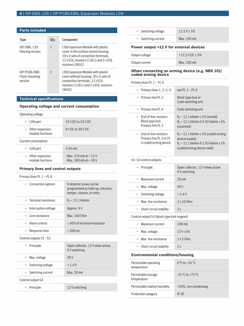
Parts included
Type Qty. Component
ISP-EMIL-120Housing version
1 LSN Expansion Module with plasticcover in the surface-mount housing,20 x 3 sets of connection terminals,12 x EOL resistors (12k1) and 2 x EOLresistors (3k92)
ISP-PCBA-EMILFlush-mountingversion
1 LSN Expansion Module with plasticcover without housing, 20 x 3 sets ofconnection terminals, 12 x EOLresistors (12k1) and 2 x EOL resistors(3k92)
Technical specifications
Operating voltage and current consumption
Operating voltage
• LSN part 15 V DC to 33 V DC
• Other expansionmodule functions
9 V DC to 30 V DC
Current consumption
• LSN part 4.95 mA
• Other expansionmodule functions
- Max. 370 mA at + 12 V- Max. 180 mA at + 28 V
Primary lines and control outputs
Primary lines PL 1 – PL 6
• Connection options 6 detector zones can beprogrammed as hold-up, intrusion,tamper, closure, or entry
• Terminal resistance RE = 12.1 kilohm
• Interruption voltage Approx. 6 V
• Line resistance Max. 100 Ohm
• Alarm criteria ± 40% of terminal resistance
• Response time < 200 ms
Control outputs S1 - S3
• Principle Open collector, 12 V when active0 V switching
• Max. voltage 30 V
• Switching voltage < 1.4 V
• Switching current Max. 20 mA
Control output S4
• Principle 12 V switching
• Switching voltage 12.5 V ± 5%
• Switching current Max. 100 mA
Power output +12 V for external devices
Output voltage +12.5 V DC ± 5%
Output current Max. 100 mA
When connecting an arming device (e.g. NBS 10)/coded arming device
Primary lines PL 1 – PL 6
• Primary lines 1, 2, 5, 6 see PL 1 – PL 6
• Primary line PL 3 Block-type lock or Code switching unit
• Primary line PL 4 Code switching unit
• End-of-line resistorsBlock type lockPrimary line PL 3
RE = 12.1 kilohm ±1% (armed)RE = 12.1 kilohm II 3.92 kilohm ±1%(unarmed)
• End-of-line resistorsPrimary line PL 3 or PL4 coded arming device
RE = 12.1 kilohm ±1% (coded armingdevice invalid)RE = 12.1 kilohm II 3.92 kilohm ±1%(coded arming device valid)
S1–S3 control outputs
• Principle Open collector, 12 V when active0 V switching
• Maximum current 20 mA
• Max. voltage 30 V
• Switching voltage < 1.4 V
• Max. line resistance 2 x 10 Ohm
• Short-circuit stability 2 s
Control output S4 (block-type lock magnet)
• Maximum current 100 mA
• Max. voltage 12 V ±5%
• Max. line resistance 2 x 5 Ohm
• Short-circuit stability 2 s
Environmental conditions/housing
Permissible operatingtemperature
0 °C to +55 °C
Permissible storagetemperature
-25 °C to +75 °C
Permissible relative humidity <93%, non-condensing
Protection category IP 30
4 | ISP-EMIL-120 / ISP-PCBA-EMIL Expansion Modules LSN
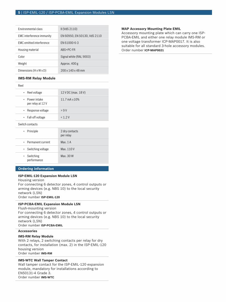
Environmental class II (VdS 2110)
EMC interference immunity EN 60950, EN 50130, VdS 2110
EMC emitted interference EN 61000-6-3
Housing material ABS+PC-FR
Color Signal white (RAL 9003)
Weight Approx. 400 g
Dimensions (H x W x D) 200 x 140 x 48 mm
IMS-RM Relay Module
Reel
• Reel voltage 12 V DC (max. 18 V)
• Power intake per relay at 12 V
11.7 mA ±10%
• Response voltage > 9 V
• Fall-off voltage < 1.2 V
Switch contacts
• Principle 2 dry contactsper relay
• Permanent current Max. 1 A
• Switching voltage Max. 110 V
• Switchingperformance
Max. 30 W
Ordering information
ISP-EMIL-120 Expansion Module LSNHousing versionFor connecting 6 detector zones, 4 control outputs orarming devices (e.g. NBS 10) to the local securitynetwork (LSN)Order number ISP-EMIL-120
ISP-PCBA-EMIL Expansion Module LSNFlush-mounting version For connecting 6 detector zones, 4 control outputs orarming devices (e.g. NBS 10) to the local securitynetwork (LSN)Order number ISP-PCBA-EMIL
Accessories
IMS-RM Relay ModuleWith 2 relays, 2 switching contacts per relay for drycontacts, for installation (max. 2) in the ISP-EMIL-120housing versionOrder number IMS-RM
IMS-WTC Wall Tamper ContactWall tamper contact for the ISP-EMIL-120 expansionmodule, mandatory for installations according toEN50131-4 Grade 3.Order number IMS-WTC
MAP Accessory Mounting Plate EMILAccessory mounting plate which can carry one ISP-PCBA-EMIL and either one relay module IMS-RM orone voltage transformer ICP-MAP0017. It is alsosuitable for all standard 3-hole accessory modules.Order number ICP-MAP0021
5 | ISP-EMIL-120 / ISP-PCBA-EMIL Expansion Modules LSN
6 | ISP-EMIL-120 / ISP-PCBA-EMIL Expansion Modules LSN
Represented by:
North America: Europe, Middle East, Africa: Asia-Pacific: China: Latin America and Caribbean:Bosch Security Systems, Inc.130 Perinton ParkwayFairport, New York, 14450, USAPhone: +1 800 289 0096Fax: +1 585 223 [email protected]
Bosch Security Systems B.V.P.O. Box 800025617 BA Eindhoven, The NetherlandsPhone: + 31 40 2577 284Fax: +31 40 2577 [email protected]
Robert Bosch (SEA) Pte Ltd, SecuritySystems11 Bishan Street 21Singapore 573943Phone: +65 6571 2808Fax: +65 6571 [email protected]
Bosch (Shanghai) Security Systems Ltd.203 Building, No. 333 Fuquan RoadNorth IBPChangning District, Shanghai200335 ChinaPhone +86 21 22181111Fax: +86 21 22182398www.boschsecurity.com.cn
Robert Bosch Ltda Security Systems DivisionVia Anhanguera, Km 98CEP 13065-900Campinas, Sao Paulo, BrazilPhone: +55 19 2103 2860Fax: +55 19 2103 [email protected]
© Bosch Security Systems 2016 | Data subject to change without notice1417214731 | en, V9, 12. May 2016
Related Documents