
Welcome message from author
This document is posted to help you gain knowledge. Please leave a comment to let me know what you think about it! Share it to your friends and learn new things together.
Transcript


Cover photograph © Buenos Dias

ISOTOPES IN WATER RESOURCES
MANAGEMENT

PROCEEDINGS SERIES
ISOTOPES IN WATER RESOURCES
MANAGEMENT
PROCEEDINGS OF A SYMPOSIUM ON ISOTOPES IN WATER RESOURCES MANAGEMENT ORGANIZED IN CO-OPERATION WITH
THE UNITED NATIONS EDUCATIONAL, SCIENTIFIC AND CULTURAL ORGANIZATION
AND HELD IN VIENNA, 20-24 MARCH 1995
In two volumes
VO LUM E 2
INTERNATIONAL ATOMIC ENERGY AGENCY VIENNA, 1996

VIC Library Cataloguing in Publication Data
International Symposium on Isotopes in Water Resources Management (1995 : Vienna, Austria)
Isotopes in water resources management : proceedings of a Symposium on Isotopes in Water Resources Management / organized in co-operation with the United Nations Educational, Scientific and Cultural Organization and held in Vienna, 20-24 March 1995. — In 2 vols. — Vienna : International Atomic Energy Agency, 1996.
2 v. ; 24 cm. — (Proceedings series, ISSN 0074-1884)Contents: v. 2.STI/PUB/970ISBN 92-0-100796-5Includes bibliographical references.
1. Radioisotopes in water resources development. I. International Atomic Energy Agency. П. Unesco. HI. Series: Proceedings series (International Atomic Energy Agency).
VICL 96-00143
Printed by the IAEA in Austria March 1996
STI/PUB/970

FOREWORD
In recent years isotope applications in hydrology and water resources assessment have reached a level of maturity. Adequate investigations have been carried out to provide sufficient examples for practical applications in combination with other hydrological methods. The IAEA contributed to this development through field projects implemented in Member States within the framework of the Agency’s Technical Co-operation programme. At present, the thrusts of the IAEA involvement are towards improved management of water resources in regions suffering from water scarcity, assessment of human impact on water resources, e.g. water pollution, and exploration and management of geothermal resources. Lately, novel isotope based techniques have been evolving from specialized laboratories. While the techniques have emerged, efforts need to be concentrated on more practical work to accomplish a visible impact on water resources management.
These trends and challenges are reflected by the scientific contributions to the International Symposium on Isotopes in Water Resources Management, held from 20 to 24 March 1995 in Vienna. The main themes of the symposium were groundwater resources management, with about two thirds of the contributions addressing origin and recharge of groundwater, groundwater dynamics and pollution, modelling approaches, and geothermal and palaeowater resources. The remaining third of the contributions were concerned with surface water and sediments, unsaturated zones and methodological aspects. On the occasion of World Water Day, 22 March, a special session was held, with speeches by representatives from UNESCO, the government of the host country and from the IAEA, as well as an address by the International Association of Hydrological Sciences.
These proceedings contain the 43 papers presented and the extended synopses of over 100 poster presentations. It is hoped that they will contribute to widespread integration of isotope techniques in projects tackling water and environmental problems, and also foster further developments in isotope hydrology.

EDITORIAL NOTE
The Proceedings have been edited by the editorial staff o f the IAEA to the extent considered necessary for the reader’s assistance. The views expressed remain, however, the responsibility o f the named authors or participants. In addition, the views are not necessarily those of the governments of the nominating Member States or of the nominating organizations.
Although great care has been taken to maintain the accuracy of information contained in this publication, neither the IAEA nor its Member States assume any responsibility for consequences which may arise from its use.
The use of particular designations of countries or territories does not imply any judgement by the publisher, the IAEA, as to the legal status o f such countries or territories, o f their authorities and institutions or of the delimitation of their boundaries.
The mention o f names of specific companies or products (whether or not indicated as registered) does not imply any intention to infringe proprietary rights, nor should it be construed as an endorsement or recommendation on the part o f the IAEA.
The authors are responsible for having obtained the necessary permission for the IAEA to reproduce, translate or use material from sources already protected by copyrights.
Material prepared by authors who are in contractual relation with governments is copyrighted by the IAEA, as publisher, only to the extent permitted by the appropriate national regulations.

CONTENTS OF VOLUME 2
DYNAMICS OF GROUNDWATER (Session 5)
Chemical and environmental isotope study of the fissuredbasaltic aquifer systems of the Yarmouk Basin (Syrian Arab Republic)(IAEA-SM-336/28) ................................................................................. 3Z Kattan
Hydrochemical studies in the Errachidia Basin: Application of environmental isotope techniques and geochemical models to the characterization of arid zone deep aquifer systems(IAEA-SM-336/6) .................................................................... ............. 29Y. Bouabdallaoui, J.-L. Michelot, A. Long
Application of environmental isotope methods in assessing groundwater dynamics of an intensively exploited coastalaquifer in Portugal (IAEA-SM-336/9) ................................................... 45P.M. Carreira, A.M.M. Soares, M.A. Marques da Silva,L. Araguás-Araguás, К. Rozanski
Caractérisation géochimique et isotopique des eaux souterrainesdans le bassin du Chott Chergui (Algérie) (IAEA-SM-336/13) ............. 59D. Daoud, J.-C. Fontes, J.-L. Michelot
Hydrogeological investigations on the groundwater situation in the Dôsenbach Valley, Austria, with special regard toisotopic measurements (IAEA-SM-336/18) ............................................ 77P. Ramspacher, W. Drost, L. Kovac, P. Trimbom
Geohydrological and mineralization studies with environmental isotopes in a large Kalahari ranching development(IAEA-SM-336/41) ................................................................................. 91B.T. Verhagen, C. Marobela, G. Sawula, B. Kgarebe
Controls on the geochemistry of sulphur in the East MidlandsTriassic aquifer, United Kingdom (IAEA-SM-336/20) ......................... 107W.M. Edmunds, P.L. Smedley, B. Spiro
Uranium-234/238 and chlorine-36 as tracers of inter-aquifermixing: Otway Basin, South Australia (IAEA-SM-336/27) ................... 123A.L. Herczeg, A.J. Love, G. Allan, L.K. Fifield
Use of artificial and environmental tracers to study storage and drainage of groundwater in the Franconian Alb, Germany, and the consequences for groundwater protection (IAEA-SM-336/4) .... 135 K.-P. Seiler, H. Behrens, M. Wolf

Intercomparison of different tracers in the evaluation of groundwater dynamics in heterogeneous porous aquifers:A study in the alluvial plain of Venice (IAEA-SM-336/40) .................. 147G.S. Tazioli, P.M. Cantori, G.F. Ciancetti, R. Dazzi,G. Gatto, B. Matticchio, G. Mozzi, G. Zambón
Poster Presentations
Radioactive gauging of groundwater flow direction in a single well by means of a double-collimated scintillation detector(IAEA-SM-336/6P) ............................................................................... 161S. Amataj
Characterization of the groundwater circulation of tectonically active areas in western Turkey by the 3 6C1 method(IAEA-SM-336/12P) .............................................................................. 164W. Balderer, A. Synal
Isotopic and chemical investigations of water/rock interaction processes in fluids and gases occurring in a seismically active area of the Irpinia-Basilicata Apennine region insouthern Italy (IAEA-SM-336/13P) ........................................................ 168W. Balderer, G. Martinelli, W. Aeschbach, R. Kipfer,G. Kahr, R. Niiesch, M. Wolf
Some results on the use of environmental isotope techniquesin groundwater resources studies in Mongolia (IAEA-SM-336/39P) ..... 171K. Frôhlich, S. Sanjdorj
Groundwater mining study by simplified sample collectionin the Jakarta Basin aquifer, Indonesia (IAEA-SM-336/47P) ................ 174M.A. Geyh, B. Sojher
New aspects of isotope-hydrological studies of the Finne Buntsandstein aquifer in Saxony-Anhalt, Germany(IAEA-SM-336/54P) .............................................................................. 177D. Hebert, O. Nitzsche, W. Rauert, M. Wolf, S. Geyer,W. Graf, S. Schuhbeck, P. Trimbom
Application of environmental isotopes in hydrological researchin the western Tatra mountains, Slovakia (IAEA-SM-336/57P) ........... 181L. Holko
Colloidal radionuclide migration in sand aquifer systems(IAEA-SM-336/66P) .............................................................................. 184P. Zeh, D. Klotz, D. Lazik
Hydrogeochemical and isotope studies of groundwater in theSamkwang mine area, Republic of Korea (IAEA-SM-336/69P) ........... 188Yong Kwon Koh, Chan Ho Jeong, Chun Soo Kim

Stable isotopes in karstic groundwaters of the Vel’ká Fatramountains, Slovakia (IAEA-SM-336/81P) ............................................. 191P. Malik, J. Michalko, S.J. Mansell, M. Fendeková
Estimation of underground water flow and age according to3H and 14C in some regions of Lithuania (IAEA-SM-336/85P) ........... 193J. Mazeika, R. Petrosius
Radiocarbon groundwater dating on dissolved organic carbon:Case of a shallow unconfined aquifer (IAEA-SM-336/90P) .................. 198C. Montjotin, J.-L. Michelot, V. Moulin, C. Tuniz, T. Merceron
Long term chemical and isotopic studies of spring waterin the Transvaal dolomites, South Africa (IAEA-SM-336/95P) ............. 200A.S. Talma, J.C. Vogel, B.M. Eglington, D.B. Bredenkamp,M. Simonic
Research on the groundwater flow dynamics in Milas Plainusing isotope methods (IAEA-SM-336/100P) ......................................... 203E. Ônhon, N. Ba$aran, S. Yüzereroglu, A.R. Ôzdamar,S. Giiler
Isotopic research on groundwater in the basin of the Natisoneriver (northeast Italy) (IAEA-SM-336/106P) .......................................... 209J. Pezdic, S. Lojen, V. Barbina, L. Quarin, J. Urbane
An isotopic and hydrochemical study of the groundwater inflowinto the North-Muya Tunnel (IAEA-SM-336/109P) .............................. 214V.A. Polyakov, S.A. Medvedev, N.V. Pyatnitskij
Application of tracer techniques to characterize hydraulics and solute transport of the epikarst zone of a karst aquifer (IAEA-SM-336/112P) ............................................................................ 217B. Reichert, P. Trimbom
Isotopic study of the effect of Tarbela reservoir on thegroundwater system in downstream areas (IAEA-SM-336/115P) .......... 220M.I. Sajjad, M.A. Tasneem, S.D. Hussain, I.H. Khan, M. Ali
Age distribution in near surface and deep groundwaters using environmental tracers and numerical models(IAEA-SM-336/118P) ........................................... ................................ 223K.-P. Seiler, P. Maloszewski
Estimation du temps de séjour, par le carbone 14, des eaux profondes des formations carbonatées de la région deSaïda, Algérie (IAEA-SM-336/122P) .................................................... 224M. Souag
GROUNDWATER POLLUTION (Session 6)
Groundwater model for management and remediation of a highly polluted aquifer (organo-chlorine compounds) in an urban area, using radioactive tracers ( 1 3 1I) for hydrodynamic parametersand dispersivity measurements (LAEA-SM-336/7) ................................. 229M. Bersano Begey, M. Cargnelutti, E. Pirastru
Use of isotopic methods to identify the source (location, timeand duration) of a groundwater contamination (IAEA-SM-336/16) ...... 249H. Dôrr, U. Werner
Integration of environmental isotopes, hydrochemical and mineralogical data to characterize groundwaters from apotential repository site in central Switzerland (IAEA-SM-336/39) ...... 263A, Scholtis, F.J. Pearson, Jr., H.H. Loosli, L. Eichinger,H.N. Waber, B.E. Lehmann
Investigación hidrogeológica, isotópica e hidroquímica de lacuenca del Lago de Valencia, Venezuela (IAEA-SM-336/1) ................ 281J. Alvarado, K.-P. Seiler, P. Trimbom
Poster Presentations
Groundwater ô15N studies in Hungary (IAEA-SM-336/26P) ..................... 301E. Deseo, J. Deák, E. Hertelendi
Interconnection of environmental isotope contents ofgroundwater with their vulnerability to technogeniccontaminants (IAEA-SM-336/30P) ......................................................... 302V.T. Dubinchuk, V.A. Polyakov
Origen del arsénico en el acuífero granular de la Comarca Lagunera,México (IAEA-SM-336/50P) .................................................................. 305L. González-Hita, L.F. Sanchez
Pattern investigations to provide a concept for groundwater management: A case study on groundwater resources in ahighly industrialized area (IAEA-SM-336/55P) ..................................... 308M. Heidinger, B. Bertleff, L. Eichinger, S. Ertl, W. Graf,A. Voropaev
Stable isotopes and I4C for estimating sustainable use of groundwater in the western Murray Basin, Australia(IAEA-SM-336/70P) .............................................................................. 314F. W. Leaney, A.L. Herczeg, A.J. Love, A. Telfer
Isotopic investigations of possible groundwater pollution inthe karstic system of South Dobrogea (Romania) (IAEA-SM-336/127P) 317A. Tenu, F. Davidescu, S. Simionas, L. Eichinger, S. Voerkelius,W. Michel, B. Bertleff

A radiotracer study of groundwater pollution and bioremediationby a pesticide passing through different soils (IAEA-SM-336/129P) .... 321 R. Tykva, T. Ruml, D. Klotz, V. Vlasáková
MODELLING APPROACHES (Session 7)
Use of a mechanistic model to simulate soil moisture andtritiated water transport in a wheat field (IAEA-SM-336/38) ................. 321R.K. Saxena
Calibration of a numerical groundwater model using environmentalisotopes (IAEA-SM-336/43) ................................................................... 339R. Watzel, B. Bertleff
Analyse des lois de passage d’un traceur artificiel par des méthodes numériques de décomposition en écoulements élémentaires pour caractériser des modes de transport dans les aquifèreset appréhender la vulnérabilité de captage (IAEA-SM-336/42) .............. 355X. Vitart, B. Gaillard
Transport of radionuclides in the groundwater environment(LAE A-SM-336/21) ................................................................................. 371H.j4. El-Naggar, M.R. Ezz El-Din, A.S. Abdel-Gawad
A comparison of groundwater ages based on 14C data and three dimensional advective transport modelling of the Lower Chao Phraya Basin: Palaeohydrology and implicationsfor water resources development in Thailand (IAEA-SM-336/37) ......... 383W.E. Sanford, S. Buapeng
Poster Presentation
Results of tritium activity modelling in a Bunter Sandstoneaquifer (IAEA-SM-336/142P) ................................................................. 3 9 5
V. Dunger, O. Nitzsche
GEOTHERMAL AND PALAEOWATERS (Session 8 )
Palaeoclimatic controls on hydrological systems: Evidence from U-Th dated calcite veins in the Fennoscandian andCanadian shields (IAEA-SM-336/32) ..................................................... 401F. McDermott, M. Ivanovich, S.K. Frape, C.J. Hawkesworth
Fluid isotopic composition in the Palinpinon I geothermal system(Philippines) (IAEA-SM-336/12) ............................................................ 417F. D ’Amore, J.Y. Gerardo, J.S. Seastres, Jr., E. Calvi

Regional investigation of cold groundwater for determination of the recharge conditions in geothermal areas ofnorthwestern Turkey (IAEA-SM-336/22) .............................................. 431T. Eisenlohr, C. Jeckelmann, W. Balderer, S. Bemasconi,W. Rauert, P. Trimbom
Effect of the Holocene climate on composition of groundwaterin parts of Haryana, India: Isotopic evidence (IAEA-SM-336/36) ........ 439K.M. Kulkami, S. V. N avada, S.M. Rao, A.R. Nair,U.P. Kulkami, Suman Sharma
Poster Presentations
Méthode de contrôle de l’étanchéité d’un puits géothermiqueà l’aide d’un radiotraceur (IAEA-SM-336/19P) ..................................... 455P. Calméis, D. Getto, P. Ungemach
Evolution de la contamination fluorurée dans la zone des lacs du rift éthiopien: Approches chimiques et isotopiques(IAEA-SM-336/21P) .............................................................................. 457T. Chemet, Y. Travi
Approches chimiques et isotopiques des eaux thermo-minéralesdu karst de Moneasa (Roumanie) (IAEA-SM-336/27P) ........................ 459L. Timofte, L. Dever, C. Marlin, I. Oraseanu, P. Vachier
Sulphur isotopes in the Dead Sea and in thermal-salinebrines along the shores (IAEA-SM-336/45P) ........................................ 461I. Gavrieli, A. Bein
The influence of the Palaeo Lake Chad on the high isotopicdepletion of eastern Sahel groundwaters (IAEA-SM-336/53P) .............. 467M. Grôning
A study of geothermal waters in northwest Croatia andeast Slovenia (IAEA-SM-336/58P) ...................................... ................... 470N. Horvatincic, D. Srdoc, I. Krajcar Bronic, J. Pezdic,S. Kapelj, A. Sliepcevic
Study of old groundwaters’ circulation in the Lake Chad Basin(Niger) using isotopic tracers (IAEA-SM-336/71P) .............................. 475C. Le Gal la Salle, J.-C. Fontes, J.N. Andrews, C. Tuniz, A. Karbo
Isotope hydrology study of areas in eastern Macedoniaand Thrace, northern Greece (IAEA-SM-336/73P) ................................ 477I.L. Leontiadis, S. Vergis, T. Christodoulou
Climate signals in tree ring cellulose of Tamarix jordanis collected in various climatic zones of Israel: A surveyusing ô1 3C, ô2 H, and ô180 (IAEA-SM-336/75P) .................................. 483J. Lipp, P. Trimbom, T. Edwards, D. Yakir, Y. Waisel

Noble gas, environmental and radium isotopes in thermal springsof southern Tuscany (Italy) (IAEA-SM-336/78P) .................................. 487G. Magro, K. Frôhlich, A. Battaglia, A. Ceccarelli, A. Ridolfi
Water resources assessment within the Main Rift and fluorideconcentration mapping in the lake region (IAEA-SM-336/82P) ........... 490A.M. Wessenu
Application of stable isotopes in evaluating the impact of a reinjection strategy at the Palinpinon geothermal field,Philippines (IAEA-SM-336/116P) .......................................................... 493J.S. Seastres, Jr., D.Z. Hermoso, J.Y. Gerardo
Isotopic and geochemical evolution of deep groundwaters from the Laxemar borehole (0-1700 m), southeast Sweden(IAEA-SM-336/12 IP) ............................................................................ 496J.A.T. Smellie, M. Laaksoharju, A. Ludin
Reprise des conditions humides vers 11 000 ans BP dans lesud tunisien (IAEA-SM-336/137P) ......................................................... 498K. Zouari
List of Chairpersons of Sessions and Secretariat of the Symposium .......... 503List of Participants ..................................................................................... 505Author Index ............................................................................................... 523Index of Papers and Posters by Number .................................................... 529


Chairpersons
H. MOSERGermany
Y. BOUABDALLAOUIMorocco
Z. KATTANSyrian Arab Republic
DYNAMICS OF GROUNDWATER
(Session 5)


IAEA-SM-336/28
CHEMICAL AND ENVIRONMENTAL ISOTOPE STUDY OF THE FISSURED BASALTIC AQUIFER SYSTEMS OF THE YARMOUK BASIN (SYRIAN ARAB REPUBLIC)
Z. KATTANDepartment of Geology and Nuclear Ores,Atomic Energy Commission,Damascus, Syrian Arab Republic
Abstract
CHEMICAL AND ENVIRONMENTAL ISOTOPE STUDY OF THE FISSURED BASALTIC AQUIFER SYSTEMS OF THE YARMOUK BASIN (SYRIAN ARAB REPUBLIC).
The water in the fissured basaltic aquifer of the Yarmouk Basin has been investigated using chemical and environmental isotope techniques. The groundwaters flowing through the different aquifers are differentiated by their chemical ratios and their isotopic composition. The evolution of chemical facies of groundwater from the recharge area towards the basin outlet is characterized by the increasing sodium and magnesium contents as a result of silicate leaching. The stable isotope compositions of spring waters match the Mediterranean meteoric water line, while the groundwaters from the central zone and from the major springs of the Yarmouk Basin are mixtures of fresh water, which is isotopically depleted, and salty groundwater of the Laja plateau area. The interpretations of tritium and radiocarbon ( l4C) data indicate that the recharge zones of the groundwater in the Yarmouk Basin occur on land of more than 1000 m altitude. The residence time of the mountainous springs is short (about 100 a or less). However, water ages corrected by Vogel’s concept and Gonfiantini’s model show, in general, a range from 1000 to 10 000 a for the central zone groundwater. The groundwater moves from Mt Hermon and Mt Arab towards the central zone and from the northeast (i.e. the Laja plateau) towards the southwest (i.e. the major springs). The radiometric flow velocities range from 20 to 60 m/a within the central zone, while the flow velocities from both sides of Mt Hermon and Mt Arab are lower (1-7 m/a).
1. INTRODUCTION
The fissured basaltic aquifer systems of the Yarmouk Basin are among the most important aquifer systems in the Syrian Arab Republic. In fact, the continuously increasing demand for water for the drinking water supply and irrigation in this area, which is considered important for agricultural production in the country, was the main reason for conducting this study. This work was initiated within the framework of the ongoing IAEA Regional Technical Co-operation Project entitled Isotope Hydrology in the Middle-East (RER/8/002), with the aim of making a supplementary
3

4 KATTAN
FIG. 1. Location map of the Yarmouk Basin showing the hydrographic network.
assessment of the availability of water resources on the basis of a better understanding of the hydrological and hydrogeological features such as the localization of recharge zones, estimation of the groundwater flow dynamics in terms of velocity and direction, residence time and groundwater ages, as well as the identification of hydraulic interconnection between the aquifer systems.
2. GENERAL CHARACTERISTICS OF THE STUDY AREA
The Yarmouk Basin is situated in the southwestern part of Syria and located between 32°15' and 33°20'N and between 35°45' and 36°45'E. (Fig. 1). This basin

IAEA-SM-336/28 5
is located in both Syria and Jordan. In Syria it covers an area of about 5700 km2. The remaining 25% of the basin land belongs to Jordan.
The relief of the study area is dominated by the presence of the piedmont and slopes of Mt Hermon in the northwest (1100-2200 m.a.s.l), the Golan Heights with numerous volcanic cones in the west (up to 1200 m.a.s.l), Mt Arab in the east (up to 1790 m.a.s.l) and the volcanic plateau in the central part. The elevation ranges from 0 m in the deep erosion river valley up to 2200 m at the slopes of Mt Hermon (Ash-Sheikh).
The climate of the Yarmouk Basin is of Mediterranean type, characterized by a rainy cool winter and a dry hot summer. The mean annual air temperature varies from 11.3°C in the mountainous region to 17.4°C in the plain. The relative air humidity ranges between 73 and 81 % in winter and between 39 and 55% in summer.
The amount of precipitation in the studied area is characterized by its irregularity and a considerable change from year to year. The maximum precipitation amounts to 800 mm/a, while it is even higher in the western part of the basin at the Golan Heights and the piedmont of Mt Hermon. The amount of precipitation decreases eastward and ranges between 230 and 270 mm/a in the central flat plain. Farther to the east, the amount of precipitation increases again on the slopes of Mt Arab, reaching 530 mm/a near its top.
The hydrological network of the Yarmouk Basin is controlled mainly by the Yarmouk River and its tributaries: Raqqad, Allane, Hreer, Dahab and Zeidi (Fig. 1). The flow patterns of Raqqad, Dahab and Zeidi follow the seasonal pattern of rainfall, with floods during winter and spring. These tributaries become dry in summer. The Yarmouk and Hreer Rivers are characterized by a mixed regime of recharge, mainly influenced by the presence of several springs, The average discharge of Yarmouk tributaries is estimated to be about 171.8 million m3/a [1].
3. GEOLOGY AND HYDROGEOLOGY
As a result of intensive cyclic volcanic activities during the Neogene and Quaternary, the effusive formations are widespread in the study area. About 95% of the area is covered by the pillow lava with a thickness varying from a dozen to several hundreds of metres. The rock exposures in the Yarmouk Basin are represented by the Upper Jurassic, Cretaceous, Palaeogene, Neogene and Quaternary [2-4]. The Upper Jurassic deposits outcrop on the slopes of Mt Hermon as thick layers (1150 m) of carbonate rocks. The Cretaceous deposits are found in limited localities in the northwestern part of the slopes of Mt Hermon as layers of grey limestone interbedded with clay, argillite, quartz, sandstone, limestone, dolomite and basalt. The Palaeogene deposits outcrop in the piedmont of Mt Hermon and along the slopes of Jordan uplift. These deposits are composed of marl and clayey limestone. The Neogene formation is subdivided into sedimentary and volcanic deposits.

6 KATTAN
The outcrops of the sedimentary Neogene are recognized in the Yarmouk River Valley and represented by a thick conglomerate layer up to 20 m. The volcanic Neogene (/3N) deposits are widespread in the eastern and the western parts of the basin. These deposits reach a thickness of 800 m in Mt Arab. The Quaternary formation is represented by lacustrine, alluvial and proluvial deposits, developed in the valley of the Yarmouk River and its tributaries and the volcanic series, widely developed and predominant on a considerable portion of the investigated land. The effusive formations are mostly composed of basalt.
From a hydrogeological point of view, the effusive formations of Pliocene- Lower Quaternary age (/3N-/3Q1), contain the most important groundwater resources in the area. The Palaeogene, Cretaceous and Jurassic deposits have secondary importance as water resources [4]. Several groundwater bearing systems (aquifers) are distinguished in the effusive formations of the Yarmouk Basin [1, 4-6]:
Upper Quaternary Basalt (0Q4): The groundwater occurs in the northwestern part of the area, where several shallow lava layers exist with high but isotropic permeability. The basalt is fissued with a polygonal system of joints. The Nourieh, Fawar and Halasse springs are the largest and representative for this aquifer.
Middle Quaternary (¡3Q2): The basalt of Middle Quaternary is developed in the northwestern part of the basin and characterized by the presence of polygonal joints filled with clay. The total thickness of these deposits is up to 60 m. Numerous springs such as N. Sakher and A. Dakar represent this aquifer.
Pliocene-Lower Quaternary (j3N-(3Ql): The basalt of Pliocene and Lower Quaternary ages constitutes a formation which is widely developed in the east and the west of the basin. The total thickness varies between 530 m in the Mt Arab piedmont and 20-80 m in the area between the Yarmouk and Hreer Rivers. The permeability of the basalt is rather non-uniform; the transmissivity of water bearing zones ranges from 12 to 2600 m2 /d. Many springs with high discharge emerge from this aquifer: the springs of Badeer and Irah in Mt Arab, the springs of Mzeireeb, Hreer, Ashaary and Ziezoun, the so-called major springs of the Yarmouk Basin and the springs of Cheikh Saade, Der-Labo and Soraya in the central part.
4. SAMPLING AND ANALYSES
Chemical and isotopic investigations were started in July 1989. Two sampling campaigns were undertaken in the study area. The first one started on 2 July 1989 for a period of one month, during which samples from 56 selected springs and shallow wells were collected, representing the dry period. Figure 2 shows the location map of the sampling sites in the Yarmouk Basin. The second campaign of sampling was started on 15 January 1990, during which samples were collected from the same sites but representing the rainy season. Moreover, the major springs (Mzeireeb, Hreer and Ashaary) of the Yarmouk Basin were sampled monthly from January to

IAEA-SM-336/28 7
FIG. 2. Location map showing the sampling sites in the Yarmouk Basin.
April 1990. In addition, 14C and <513C samples were taken from 27 shallow wells and springs with tritium values below the detection limit of 2 TU. The total dissolved inorganic carbon was precipitated from 120 L of water according to the IAEA procedures (reaction with barium chloride at high pH). The temperature, electrical conductivity and pH of water samples were determined during sampling in the field. The ô 180, <52H and tritium analyses, together with 013C and 14C analyses, were performed in the Laboratory of Amman, Jordan. The chemical analyses of these samples were carried out in the Laboratory of the Ein-El-Figeh Establishment in Damascus.
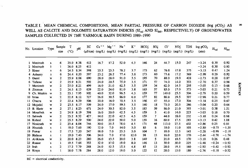
TABLE I. MEAN CHEMICAL COMPOSITIONS, MEAN PARTIAL PRESSURE OF CARBON DIOXIDE (log pC02) AS WELL AS CALCITE AND DOLOMITE SATURATION INDICES (SI^ AND SIdo), RESPECTIVELY) OF GROUNDWATER SAMPLES COLLECTED IN THE YARMOUK BASIN DURING 1989-1990
Mo. Location Type Samplesize
T
(°C)pH
EC(/iS/cm)
Ca + + (mg/L)
Mg + + (mg/L)
Na + (mg/L)
K +(mg/L)
HCO3-(mg/L)
SO4(mg/L)
СГ(mg/L)
NO3(mg/L)
TDS(mg/L)
log pC 02 (atm)
Sica) SIdol
1 Mzeireeb s 6 25.0 8.38 412 16.7 17.2 52.0 4.3 146 24 44.7 15.0 247 -3 .2 4 0.30 0.922 Mzeireeb 1 1 26.0 8.25 412 -3 .2 4 0.30 0.923 Hreer s 6 24.5 8.34 598 25.3 25.5 78.2 3.7 175 62 76.0 17.0 375 -3 .1 5 0.47 1.244 Ashaary s 6 24.4 8.20 597 23.2 26.2 77.4 3.8 173 60 73.6 17.2 369 -2 .9 9 0.29 0.925 Daeel w 2 25.9 8.06 690 28.0 28.0 91.0 3.5 195 70 88.0 19.0 428 -2 .7 3 0.28 0.876 Tafasse w 2 25.9 8.21 592 24.0 20.5 75.0 3.5 171 57 74.0 14.0 353 -2 .7 0 0.37 0.987 Mzeireeb w 2 25.0 8.21 499 16.0 21.0 62.5 3.5 159 34 62.0 14.5 295 -3 .0 3 0.13 - 0.688 Ziezoun s 2 24.5 8.13 639 22.0 24.0 81.0 3.8 165 57 85.0 17.0 373 -3 .0 3 0.21 0.739 Ch. Meskin w 2 23.1 7.95 902 40.0 32.0 96.5 4.3 159 77 149.0 25.5 504 -2 .7 9 0.20 0.59
10 Izraa w 2 22.8 8.12 727 26.0 30.5 86.0 6.0 177 82 86.0 29.5 397 -2 .9 0 0.21 0.7711 Chacra w 2 22.4 8.29 506 20.0 16.0 70.5 3.5 146 47 55.0 17.0 304 -3 .1 8 0.25 0.6712 Mojedel w 2 23.5 8.17 509 24.0 17.0 59.5 3.5 140 18 73.0 20.5 286 -3 .0 4 0.20 0.6413 B. Harir w 2 27.1 8.23 671 24.0 30.5 82.0 3.5 183 59 86.0 21.0 393 -3 .0 1 0.38 1.2114 Mosefreh w 2 24.9 8.19 398 16.0 20.0 42.5 4.5 159 5 41.0 14.0 223 -3 .0 3 0.16 0.7015 Sahweh w 2 25.2 8.32 427 14.0 22.0 42.5 4.5 159 7 44.0 18.0 232 -3 .1 8 0.24 0.9816 Koheel w 2 25.3 8.29 500 24.0 22.0 50.0 5.0 159 16 68.0 17.5 283 -3 .1 3 0.42 1.0817 Nouimeh w 2 23.4 8.04 746 30.0 35.5 78.0 4.5 171 48 113.0 27.5 432 -2.86 0.23 0.8118 Nourieh s 1 19.0 7.65 190 12.0 7.0 14.0 3.0 85 6 10.0 11.0 105 -2 .8 0 -0 .7 5 -1 .5 119 Fawar s 2 17.5 7.20 247 18.0 7.0 23.5 5.0 104 7 18.0 12:5 145 -2 .2 8 -0 .9 9 -2 .1 820 Halasse s 1 19.0 7.43 306 24.0 7.0 17.0 12.0 98 13 16.0 22.0 170 -2 .4 4 -0 .7 0 -1 .7 421 Al-Koum w 2 20.0 8.23 280 26.0 13.5 20.0 3.8 140 5 21.0 10.5 170 -3 .1 0 0.26 0.4822 Rsasse s 1 19.5 7.64 355 32.0 17.0 19.0 8.0 146 13 30.0 30.0 225 -2 .4 8 -0 .2 4 -0 .5 223 Irah s 2 17.2 7.79 268 24.0 12.5 15.5 4.8 85 13 28.0 19.5 160 -2 .9 2 -0 .4 2 -0 .9 224 Kraya s 1 18.0 7.78 284 28.0 12.0 19.0 3.0 122 12 28.0 15.0 180 -2 .7 6 -0 .1 8 -0 .5 2
EC = electrical conductivity.

25 Badeer s 2 13.0 7.72 148 18.0 6.0 7.0 0.8 67 7 10.0 8.5 90 -2 .8 9 -0 .6 7 -1 .7 826 Qineh s 2 11.5 7.38 138 18.0 6.0 5.5 0.5 61 7 9.0 10.0 85 -2 .7 0 -1 .1 4 -2 .6 427 Al-Sijen w 2 21.0 7.38 555 56.0 30.5 31.0 1.5 262 14 50.0 31.5 347 -2 .4 3 0.42 0.8428 Nijran w 1 25.0 8.58 270 8.0 10.0 42.0 2.0 134 6 20.0 11.0 170 -3 .5 0 0.19 0.7729 Smeed w 2 20.7 8.36 326 24.0 11.0 50.0 3.3 147 20 41.0 14.5 237 -3 .2 9 0.42 0.7530 Majadel w 1 18.0 8.46 265 24.0 7.0 26.0 8.0 110 11 26.0 16.0 175 -3 .5 2 0.39 0.4631 Brekeh w 1 21.0 8.08 640 64.0 27.0 44.0 4.0 244 31 80.0 30.0 405 -2 .7 7 0.73 1.3432 Bouidan w 2 22.3 7.95 1403 34.0 41.5 240.0 2.3 250 203 255.0 17.5 919 -2 .6 1 0.23 0.8233 Bourak w 2 24.7 7.81 1257 70.0 68.5 125.0 4.0 207 215 230.0 15.0 831 -2 .5 4 0.45 0.9834 Sawarah K. w 1 28.0 8.03 1032 40.0 56.5 120.0 2.0 238 160 154.0 19.0 670 -2 .6 5 0.43 1.3435 Barkah s 2 15.5 8.08 ,399 44.0 21.0 21.5 33 208 13 28.0 16.5 252 - 2.86 0.45 0.7636 Lowisseh w 2 18.8 8.27 263 12.0 9.5 34.0 2.0 110 8 25.0 13.0 158 -3 .2 7 -0 .1 7 - 0.2237 Bidda s 2 13.8 7.70 209 50.0 7.0 9.5 1.3 171 5 15.0 13.0 187 -2 .5 4 0.04 -0 .6 138 Hadar w 1 15.0 8.03 513 48.0 5.0 82.0 1.5 305 50 10.0 7.0 355 -2 .5 9 0.53 0.2639 Bet-Jeen s 2 11.3 8.19 211 40.0 7.0 3.3 0.5 134 8 6.0 8.5 142 -3 .1 1 0.27 - 0 .1140 Emeh s 2 12.0 7.96 222 44.0 5.0 3.0 0.5 146 3 6.5 6.5 141 - 2.86 0.16 -0 .5 041 Jabah w 2 17.5 8.37 207 12.0 7.0 22.5 3.8 92 7 14.0 12.5 125 -3 .4 9 -0 .0 7 -0 .1 642 N. Sakher s 1 19.0 7.27 233 20.0 10.0 16.0 3.0 85 11 22.0 16.0 140 -2 .4 1 -0 .9 5 -1 .9 743 Rafid s 1 20.0 7.27 248 20.0 10.0 16.0 3.0 85 11 22.0 16.0 140 -2 .4 0 -0 .9 4 -1 .9 344 G. Boustan w 2 20.0 8.20 301 12.0 13.5 39.0 3.5 146 6 29.0 11.5 189 -3 .0 8 -0 .0 8 0.1645 A. Dakar s 2 21.0 7.91 320 24.0 11.0 39.0 3.5 153 8 32.0 12.5 206 -2 .7 5 -0 .0 3 -0 .1 346 Ch. Saade s 1 22.0 8.18 388 28.0 12.0 40.0 4.0 171 11 40.0 11.0 235 -2 .8 0 0.19 0.2947 Der-Labo s 2 19.0 7.95 419 30.0 14.5 45.5 3.8 171 14 45.5 19.0 258 -2 .7 7 0.13 0.1648 Nawa w 1 21.0 7.98 505 36.0 15.0 60.0 2.0 195 36 58.0 12.0 320 -2 .7 5 0.31 0.5049 Khabab w 2 22.3 7.98 424 24.0 12.0 48.0 3.0 147 19 42.0 28.5 251 -2 .8 7 0.07 0.0650 Mousmieh w 2 23.9 7.71 1076 52.0 43.5 125.0 3.0 232 178 145.0 14.0 678 -2 .3 8 0.19 0.5951 Harah w 2 20.5 8.29 327 18.0 13.5 41.0 4.0 159 8 30.0 12.5 205 -3 .1 5 0.25 0.6252 D. Adasse w 2 21.8 8.04 499 40.0 14.5 48.0 3.5 146 16 71.0 23.5 290 -2 .9 3 0.31 0.4353 Soraya s 2 18.3 8.23 395 28.0 16.0 38.5 5.0 165 11 39.0 17.5 239 -3 .0 9 0.37 0.7154 Hadar s 1 13.0 7.75 326 64.0 7.0 5.0 0.5 207 13 6.0 9.0 207 -2 .5 6 0.30 - 0.2055 Dama w 1 21.2 8.12 325 16.0 15.0 35.0 8.0 146 8 26.0 16.0 194 -2 .9 7 - 0.01 0.2056 Sawarah S. w 1 29.8 8.30 722 8.0 22.0 130.0 5.0 159 80 106.0 16.0 446 -3 .1 0 -0 .0 5 0.67
Where: s, spring; w, well; and 1, lake.
IAE
A-S
M-336/28

10 KATTAN
FIG. 3. Spatial distribution of the groundwater temperature (°C) in the Yarmouk Basin.
5. RESULTS AND DISCUSSION
5.1. Chemistry of the groundwater
The hydrochemical properties of the groundwater samples from the Yarmouk Basin are compiled in Table I. The majority of the samples were fresh water since the total dissolved solids (TDS) did not exceed 500 mg/L [7]. Five exceptions are reported for well Nos 32, 33, 34, 50 and 56, located on the Laja plateau northwest of the basin. Their TDS content varies between 670 and 920 mg/L. The groundwaters emerging along the slopes of Mt Hermon and Mt Arab aare characterized

IAEA-SM-336/28 11
FIG. 4. Spatial distribution of the TDS content (mg/L) of the groundwater in the Yarmouk Basin.
by a low solute content (TDS < 200 mg/L). The average water temperature of most of the water samples ranges from 11.5°C to 25°C. The mean water temperatures of the major springs of Yarmouk Basin (springs Nos 1, 3, 4 and 7) scatter around 25°C. An exceptional high water temperature of 30°C was observed for two groundwaters of the Laja area, covered by recent Quaternary basalt (well Nos 34 and 56), which is attributed to the recent volcanic activity [1]. Figure 3 shows that the temperature over the Yarmouk Basin increases gradually from the mountainous regions of Mt Hermon and Mt Arab towards the central zone and the basin outlet. The pH values range from 7.25 (spring Nos 42 and 43) to 8.60 (well No. 28). The pH values of groundwater emerging along the slopes of Mt Hermon and Mt Arab
12 KATTAN
- Major springs
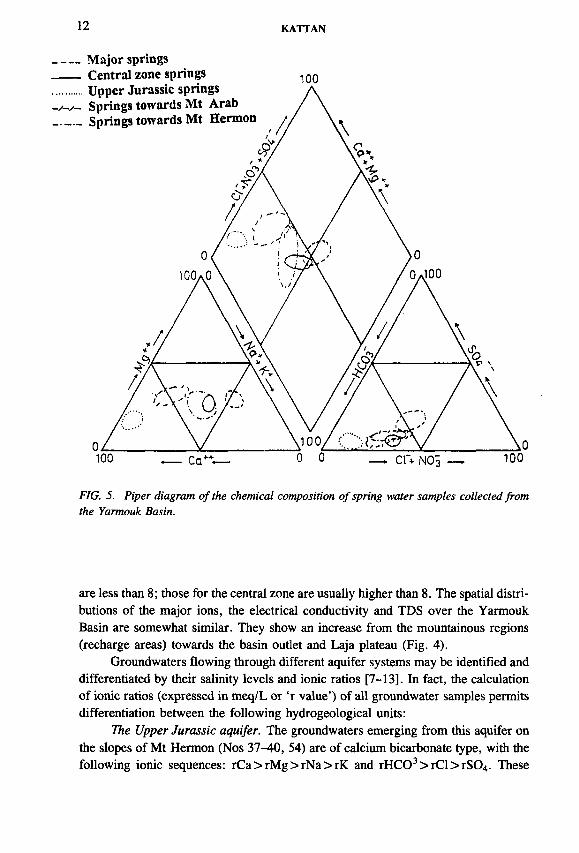
FIG. 5. Piper diagram o f the chemical composition o f spring water samples collected from the Yarmouk Basin.
are less than 8 ; those for the central zone are usually higher than 8 . The spatial distributions of the major ions, the electrical conductivity and TDS over the Yarmouk Basin are somewhat similar. They show an increase from the mountainous regions (recharge areas) towards the basin outlet and Laja plateau (Fig. 4).
Groundwaters flowing through different aquifer systems may be identified and differentiated by their salinity levels and ionic ratios [7-13]. In fact, the calculation of ionic ratios (expressed in meq/L or ‘r value’) of all groundwater samples permits differentiation between the following hydrogeological units:
The Upper Jurassic aquifer. The groundwaters emerging from this aquifer on the slopes of Mt Hermon (Nos 37-40, 54) are of calcium bicarbonate type, with the following ionic sequences: rCa>rM g>rN a>rK and rHC03> rC l> rS 04. These

IAEA-SM-336/28 13
____ Central zone wells
FIG. 6. Piper diagram of the chemical composition o f well water samples collected from the Yarmouk Basin.
groundwaters are characterized by a low rMg/rCa ratio (0.17-0.30), which is below the range of 0.5-0.9 given for limestone and dolimite aquifers [8 , 9, 11]. However, our results are comparable to those for rain water [11]. Thus, the transit time of the infiltrated rain water is too short to approach chemical equilibrium with the rocks.
The Pliocene-Lower Quaternary aquifer. The groundwater emerging from the Pliocene-Lower Quaternary aquifer on the slopes of the Mt Arab (spring Nos 25 and 26) is of the calcium-magnesium and bicarbonate type: rCa>rM g>rN a>rK and rHC03> rC l> rS 04. The chemistry of the groundwater discharged from the same aquifer at the outlet of the basin (spring Nos 1, 3, 4-8) and from the central zone (spring Nos 46, 47, 53) is on the contrary, of sodium-magnesium and bicarbonate- chloride type: rN a>rM g>rC a>rK and rHC03 > rCl > rS04 in the case of major

14 KATTAN
springs and of sodium-calcium and bicarbonate-chloride type: rN a>rC a>rM g>rK and rHC03 > rCL > rS04 in the case of the central zone springs. The rMg/rCa and rNa/rCl ratios of the water from the basaltic aquifers show an additional source of magnesium and sodium. In fact, the basaltic rocks often containing silicate minerals are frequently distinguishable by high (rMg/rCa>0.9) and (rNa/rCl> 1) ratios [10, 14]. The groundwater of the Pliocene-Lower Quaternary basalt on the Laja plateau (well Nos 32, 33, 34, 50, 56) is generally characterized by a sodium-magnesium and chloride-sulphate or bicarbonate-chloride types: rNa> rMg > rCa> rK and rCl > rS04> rHC03 or rHC03 > rCl > rS04. The chemical behaviour of these groundwaters seems to be different from that of groundwaters from the same aquifer of Pliocene-Lower Quaternary and also from all the basaltic aquifers in the Yarmouk Basin. In fact, the rMg/rCa (1.4-4.5), rNa/rK (44-177) and rS04/rHC03 (0.64-1.03) ratios are the highest ratios in the basin. Meanwhile, the rNa/rCl ratio (0.84-1.9) fills in the above estimated range for the basaltic aquifers in the basin. The particularity of the Laja plateau wells may be attributed to the dissolution process of salt accumulated in the soil horizon, as will be seen further.
The Middle Quaternary aquifer. The groundwater discharged from this aquifer (spring Nos 42 and 45) is of calcium-magnesium and bicarbonate type: rCa>rM g>rN a>rK and rHC03> rC l> rS 04. The rMg/rCa (0.76-0.83) ratio is somewhat lower than the characteristic ratio of basalt (0.9), while the rNa/rCl ratio (1.12-1.88) is similar to the above estimated ratios for the Pliocene-Lower Quaternary aquifer.
The Upper Quaternary aquifer. The chemistry of groundwaters of the Upper Quaternary aquifer (spring Nos 19, 20, 21) located in the northwestern part of the Yarmouk Basin is of calcium-magnesium and bicarbonate type: rC a>rM g>rN a>rK and rHC03> rC l> rS 04. The rMg/rCa ratio varies from 0.5 to 0.97, while the rNa/rCl ratio ranges from 1 to 2.2. These characteristic ratios seem to be similar to those of the Middle Quaternary aquifer. The Piper diagrams of the investigated groundwater from the Yarmouk Basin are shown in Figs 5 and6 . The chemical evolution of groundwater from the mountainous region towards the major springs area and the central zone is marked by a progressive decrease in calcium and bicarbonate with an increase of sodium, magnesium and chloride.
The hydrochemical equilibrium conditions controlling the Yarmouk groundwater were studied with the program WATEQF [15]. The saturation index (SI) of a water sample with respect to a mineral precipitation is expressed by
SI = log (IAP/Ksp(T)) (1)
where LAP is the ion activity product of the solution and Ksp(T) is the equilibrium constant of the reaction considered at the temperature T (K).
The calculated partial pressure of carbon dioxide (log pC02), calcite saturation index (Sljai ) and dolomite saturation index (SId0i.) are compiled in Table I. The

IAEA-SM-336/28 15
partial pressure of carbon dioxide is within the range of 10~28 atm (16 times higher than that of the atmosphere) to 10' 3 52 atm (identical to that of the atmosphere). The spatial distributions of calcite and dolomite saturation indices show similar trends. The saturation indices increase from the highland regions towards the central zone of the basin. The groundwaters of the mountainous regions are undersaturated with respect to both calcite and dolomite, while the groundwaters of the central zone show an equilibrium state, or oversaturated with respect to calcite and dolomite. The oversaturated groundwaters occur in the central zone area, where the partial pressure of carbon dioxide is close to that of the atmosphere.
5.2. Stable isotopes composition of groundwater
The average isotopic composition of the groundwater samples collected at various sites of the Yarmouk Basin is summarized together with deuterium excess (d) in Table П. The ¿¡2H-ô180 plot of the groundwater samples is shown in Fig. 7. The isotopic compositions scatter widely between the Mediterranean meteoric water line (MMWL) and the global meteoric water line (GMWL). It is also possible that a few samples were affected by evaporation (well Nos 24, 27, 48). One sample (No. 48) was enriched as a consequence of admixed evaporated surface water. This sample was collected from a shallow well close to a small dam. The least square of the data points is given by
5D = (5.3 ± 0.26)-ô180 + (1.7 ± 1.7) (n = 56, R2 = 0.89) (2)
The intersection of this line with the MMWL corresponds to 6 l80 = -7 .52 ± 0.17 00 and <5D = -36.16 ± 2.9700. These values correspond more or less to the isotopic compositions of the groundwaters emerging from both Mt Hermon and Mt Arab springs as well as the groundwaters of the Upper Quaternary basalt springs. Figures 8 and 9 are plots of the <5D values versus the <5180 values of the samples of springs and wells in the Yarmouk Basin. The Upper Jurassic springs and the springs discharged towards Mt Hermon and Mt Arab match the MMWL. However, the data for the major springs deviate significantly from the MMWL. The data for the central zone springs represent an intermediate position between major springs and the mountainous springs. In fact, the deviation of these data from MMWL implies a combination of both mixing and evaporation processes rather than an evaporative effect only. In other words, it may be said that the groundwaters in the central zone are a mixture of the groundwater recharged in the mountainous region and the evaporated irrigation water recharged by vertical infiltration with the central zone and Laja plateau [16-18].
The spatial distribution of deuterium excess in the Yarmouk Basin shows a gradual decrease from the western and eastern regions towards the flat plain. This result is in agreement with the observations of Gat and Carmi [19] for the eastern

TABLE II. MEAN ISOTOPIC COMPOSITIONS OF GROUNDWATER SAMPLES COLLECTED IN THE YARMOUK BASIN DURING 1989-1990 AS WELL AS MEAN ISOTOPIC VALUES OF CARBON ISOTOPES, UNCORRECTED RADIOMETRIC AGES (AGE 1) AND CORRECTED ONES USING VOGEL’S CONCEPT (AGE 2) AND GONFIANTINI’S MODEL (AGE 3)
No. Location Type Sample Altitude i l80 62H 3H d l4C i 13C Age 1 Age 2 Age 3size (m.a.s.l.) C U (TU) C U (pMC) Cloo PDB) (Years) (Years) (Years)
1 Mzeireeb s 6 435 - 6.00 -29.6 0.60 18.40 48.40 ± 1.60 -14.52* 6000 ± 280 4655 ± 280 4775 ± 24102 Mzeireeb 1 1 435 -5 .7 6 -2 9 .6 16.483 Hreer s 6 445 -5 .9 3 -31 .1 0.60 16.34 43.75 ± 0.80 -14.52* 6835 ± 150 5490 ± 150 5610 ± 2285A Ashaary s 6 440 -5 .9 9 -3 1 .4 0.80 16.52 43.40 ± 1.30 -14.52* 6900 ± 250 5555 ± 250 5675 ± 23805 Daeel w 2 520 -5 .8 5 -3 2 .3 1.10 14.50 40.70 ± 1.40 -14.52* 7430 ± 290 6090 ± 290 6220 ± 24206 Tafasse w 2 490 -5 .8 8 -31 .1 0.90 15.94 40.40 ± 2.20 -14.52* 7490 ± 465 6150 ± 465 6270 ± 25957 Mzeireeb w 2 460 -6 .0 0 -2 9 .7 0.50 18.30 53.10 ± 1.40 -14.52* 5235 ± 220 3890 ± 220 4010 ± 23508 Ziezoun s 2 400 -5 .8 5 -3 0 .0 0.70 16.80 52.40 ± 1.50 -14.52* 5340 ± 240 4000 ± 240 4120 ± 23709 Ch. Meskin w 2 540 -5 .0 0 -2 6 .3 0 13.70 50.50 ± 2.40 -14.52* 5650 ± 400 4305 ± 400 4435 ± 2530
10 Izraa w 2 580 -5 .2 0 -2 4 .9 0 16.70 60.40 ± 1.70 -14 .52 4170 ± 235 2825 ± 235 2955 ± 2365
11 Chacra w 2 590 -5 .9 7 -3 0 .3 0 17.46 38.15 ± 1.56 -1 1 .8 8 7965 ± 345 6625 ± 345 5095 ± 2645
12 Mojedel w 2 610 -6 .1 5 -3 1 .0 0.20 18.20 44.05 ± 1.98 -1 3 .2 6 6780 ± 380 5435 ± 380 4815 ± 258513 B. Harir w 2 650 -5 .8 6 -3 0 .7 1.90 16.18 32.06 ± 1.23 -9 .7 6 9405 ± 325 8060 ± 325 4910 ± 282014 Mosefreh w 2 690 -5 .5 6 -2 6 .5 0.10 17.98 67.32 ± 1.90 -1 4 .6 0 3270 ± 240 1930 ± 240 2105 ± 236015 Sahweh w 2 735 -5 .7 0 -2 7 .6 1.00 18.00 71.50 ± 2.20 -13 .02 2775 ± 260 1430 ± 260 660 ± 247516 Koheel w 2 615 -5 .5 2 -26 .7 0 17.46 65.90 ± 2.60 -12 .36 3450 ± 335 2105 ± 335 905 ± 259517 Nouimeh w 2 555 -4 .7 6 -26.1 0.20 11.98 22.40 ± 1 .1 0 -12 .36 * 12370 ± 415 11025 ± 415 9825 ± 268018 Nourieh s 1 943 -7 .0 0 -3 4 .4 15.20 21.60
19 Fawar s 2 940 -7 .2 1 -3 6 .6 14.80 21.08
20 Halasse s 1 690 -6 .9 1 -3 4 .3 11.00 20.98
21 Al-Koum w 2 995 -6 .6 1 -3 1 .5 8.40 21.38
22 Rsasse s 1 1005 -6 .8 9 -3 3 .2 15.90 21.92
23 Irah s 2 960 -6 .8 0 -3 4 .3 13.90 20.10
24 Kraya s 1 1220 -4 .9 7 -2 4 .6 21.3 15.1625 Badeer s 2 1570 -7 .3 0 -3 5 .8 12.00 22.60

26 Qineh s 2 1700 -6 .9 8 -3 4 .5 10.10 21.3427 Al-Sijen w 2 800 -4 .4 4 - 22.0 1.80 13.52 95.72 ± 2.08 -1 3 .8 4 360 ± 180 R R28 Nijran w 1 760 -6 .4 4 -3 2 .0 5.90 19.5229 Smeed w 2 780 - 6.20 -3 2 .0 1.10 17.60 74.72 ± 2.20 -8 .6 0 2410 ± 245 1065 ± 245 R30 Majadel w 1 840 - 6.21 -3 0 .0 10.30 19.6831 Brekeh w 1 870 -5 .7 5 -28 .1 5.50 17.9032 Bouidan w 2 615 -6 .6 1 -3 7 .4 0.70 15.4833 Bourak w 2 620 -5 .0 9 -2 8 .4 0.20 12.32 42.52 ± 2.66 -8 .5 4 7070 ± 535 5725 ± 535 1470 ± 319034 Sawarah K. w 1 665 -5 .7 7 -3 0 .5 0.60 15.6635 Barkah s 2 1350 -6 .1 8 -3 0 .2 9.60 19.2436 Lowisseh w 2 940 -6 .7 6 -3 4 .6 5.30 19.4837 Bidda s 2 980 -6 .9 8 -3 3 .5 13.30 22.3438 Hadar w 1 1300 -7 .4 8 -3 8 .5 8.60 21.3439 Bet-Jeen s 2 1280 -8 .1 6 -4 3 .4 13.70 21.8840 Emeh s 2 1440 -8 .1 8 -4 4 .0 16.30 21.4441 Jabah w 2 980 -7 .0 0 -3 4 .0 6.40 22.042 N. Sakher s 1 815 -6 .5 3 -3 3 .2 11.20 19.0443 Rafid s 1 690 -6 .3 2 -2 9 .2 13.50 21.3644 G. Boustan w 2 575 -6 .4 7 -2 9 .4 1.70 22.36 62.63 ± 1.88 -1 5 .9 4 3870 ± 250 2525 ± 250 3430 ± 231045 A. Dakar s 2 500 -6 .2 5 -2 8 .3 1.90 21.70 66.40 ± 1.80 -14.52* 3385 ± 225 2040 ± 225 2160 ± 235546 Ch. Saade s 1 510 -5 .8 7 -2 8 .0 3.20 18.9647 Der-Labo s 2 500 -5 .9 9 -28 .1 3.80 19.8248 Nawa w 1 540 -2 .6 9 - 10.6 7.40 10.9249 Khabab w 2 610 -6 .1 4 -3 2 .9 0.40 16.22 49.10 ± 1.60 -13 .26 5880 ± 275 4540 ± 275 3920 ± 247550 Mousmieh w 2 615 -6 .6 7 -3 7 .5 0 15.86 39.90 ± 1 . 3 1 -8 .5 4 7595 ± 265 6250 ± 265 1995 ± 300051 Harah w 2 780 -6 .3 9 -2 9 .8 1.40 21.32 75.75 ± 1.98 -14.01 2295 ± 220 950 ± 220 790 ± 237552 D. Adasse w 2 730 -5 .8 0 -2 9 .7 1.00 16.70 32.57 ± 2.10 -13 .22 9275 ± 550 7930 ± 550 7285 ± 275553 Soraya s 2 590 -6 .3 1 -3 0 .3 1.60 20.18 89.10 ± 2.40 -14.52* 955 ± 225 R R54 Hadar s 1 1300 -7 .3 7 -3 6 .9 11.40 22.0655 Dama w 1 720 -6 .0 4 -2 9 .4 3.70 18.92 93.53 ± 2.98 -12 .39 555 ± 270 R R56 Sawarah S. w 1 745 -5 .9 2 -3 0 .6 0 16.76
Where: s, spring; w, well; 1, lake; R, recent; and *, values are assumed. -J
IAEA-SM-336/28

18 KATTAN
8lSO(%o)FIG. 7. Relationship between 0I80 and 5D values o f the groundwater samples collected from the Yarmouk Basin.
6 1 8 0 (%o)FIG. 8. Relationship between ô180 and &D values o f spring water samples collected from the Yarmouk Basin.
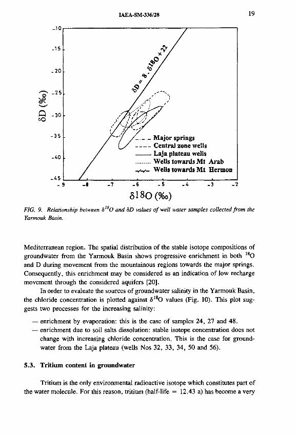
IAEA-SM-336/28 19
5 1 8 0 (% o)
FIG. 9. Relationship between b,80 and ÔD values o f well water samples collected from the Yarmouk Basin.
Mediterranean region. The spatial distribution of the stable isotope compositions of groundwater from the Yarmouk Basin shows progressive enrichment in both 180 and D during movement from the mountainous regions towards the major springs. Consequently, this enrichment may be considered as an indication of low recharge movement through the considered aquifers [20].
In order to evaluate the sources of groundwater salinity in the Yarmouk Basin, the chloride concentration is plotted against <5180 values (Fig. 10). This plot suggests two processes for the increasing salinity:
— enrichment by evaporation: this is the case of samples 24, 27 and 48.— enrichment due to soil salts dissolution: stable isotope concentration does not
change with increasing chloride concentration. This is the case for groundwater from the Laja plateau (wells Nos 32, 33, 34, 50 and 56).
5.3. Tritium content in groundwater
Tritium is the only environmental radioactive isotope which constitutes part of the water molecule. For this reason, tritium (half-life = 12.43 a) has become a very

20 KATTAN
300
250
200
iS 150I
CJ 10°
50
0-9 -8 -7 -6 -5 -4 -3 -2
5 1 8 0 (% o)
FIG. 10. Relationship between ôl80 and chloride concentration o f the groundwater in the Yarmouk Basin.
valuable radioactive tracer for the estimation of groundwater residence time of less than 150 years [21, 22]. The average tritium content of groundwater samples collected from the Yarmouk Basin is compiled in Table П. It ranges from the detection limit (tritium free) up to 16.3 TU (spring No. 40). The highest tritium content was found for the groundwater emerging on the slopes of both Mt Hermon and Mt Arab, while the lowest tritium content was found for the groundwaters of the central part of the basin. The relatively high tritium content for well No. 48 (7.4 TU), located in the central zone close to a small reservoir, is attributed to admixture of surface water having high tritium content. The tritium content of the samples from the groundwater of mountainous regions is higher than that of the present atmospheric precipitation (7-8 TU in 1989-1990 [23]). The spatial distribution of tritium values over the Yarmouk Basin (Fig. 11) shows a gradual decrease from the Hermon and Arab mountainous regions towards the central zone of the basin, where the tritium content falls below the detection limit of 2 TU. A few exceptions are spring 46, 47 and 53, for which the tritium content is significantly above 2 TU. Consequently, it may be said that groundwater recharge is identified in limited catchment areas of the high land and the piedmont of both Mt Hermon and Mt Arab. The con-
48- a
£vap°ratl°n

IAEA-SM-336/28 21
FIG. 11. Spatial distribution o f tritium (TV) values o f the groundwater in the Yarmouk Basin.
tribution of local vertical infiltration on the high discharge of several springs in the central zone, such as Soraya (d = 207oo with presence of tritium), may not be excluded.
5.4. Carbon isotope content in groundwater
The dissolved inorganic carbon (DIC) compounds are presented as dissolved C02, carbonate and bicarbonate, depending upon the pH, total alkalinity and temperature of the solution [24]. The 13C content of the total DIC compounds is used to estimate the quantities of different carbon sources within the carbon chemistry.

22 KATTAN
The idea is that the constituted dissolved biogenic carbon (soil carbon dioxide derived from the decomposition of organic matter and root respiration) has a lower 13C content than that of the solid carbonates. In the delta-PDB (Peedee belemnite) scale, the soil carbon dioxide is about - 2 2 ± 1700, while the solid carbonate has a value of about 0 ± 2°/00. Thus, the <513C value of the total dissolved inorganic carbon (TDIC) compounds may be corrected for the dilution of the initial 14C activity of the total DIC.
As can be seen from Table II the <513C values range from -8 .54 to -15 .94700. Low <513C values occur in the groundwater of the Laja area (well Nos 29 and 33). They may reflect admixture of volcanic carbon dioxide, as reported by Gasparini et al. [25] for the volcanic basalt in the Canary Islands, since the Laja plateau was also subject to recent volcanic activity [1]. On the other hand, the high ô 13C values of sample No. 44 (from the only confined well in the Yarmouk Basin) may reflect an isotopic exchange with atmospheric C02. The measured 14C activity of the groundwater samples from the Yarmouk Basin (Table II) ranges from 22 pmC for sample 17, collected very close to the Jordanian border, up to 95.7 pmC in sample No. 27 from the slopes of Mt Arab.
5.5. Groundwater dating
Radiocarbon ( 14C) is the most often used environmental radioactive isotope for groundwater dating of more than 1000 years. Tritium, with its short half-life, can just be used to calculate the mean residence time (exponential model) up to 150 years[21]. According to the fundamental law of radioactive decay it is possible to determine the time t of groundwater elapsed in a closed reservoir by measuring its 14C activity (At). Knowing the initial 14C activity (Ao) then the groundwater age is calculated from
t = - J— log ^ (3)log 2 A,
where, т is the half-life of 14C ( t = 5730 ± 30 years).The estimation of the initial 14C activity (Ao) is still difficult [21, 26-28]. In
fact, the radiometric age of groundwater is referred to that óf the TDIC compounds. For this reason several models are proposed to correct conventional 14C ages. These models consider either chemical mixing between the carbon compounds only or isotopic mixing, or also chemical and isotopic mixing together with isotopic fractionation [21, 26, 27].
In this study, 27 groundwater ages were determined from samples without detectable tritium. These groundwaters are supposed to be recharged before 1952. We applied two approaches: Vogel’s concept and Gonfiantini’s model for the correction of the initial 14C activity. In Vogel’s concept the initial 14C activity was pro
IAEA-SM-336/28 23
posed to be 85 ± 5 pmC, an empirically determined value for groundwater in Europe and South Africa. Gonfiantini’s model, widely used in several IAEA studies[29], is also based on isotopic mixing but considers the isotopic fractionation between the bicarbonate and the dissolved C02:
fA0 = ----- 1------5------ ( 1 + 2 e„/1000) (4)
i g - eg - i c
where ô is the <513C value; t, с and g refer to TDIC, solid carbonate and soil C02, respectively, and eg is the 13C fractionation factor between bicarbonate and C02. The following values were used: ôc = 0 ± l°/0o, ôg = -2 2 + l °/00 and eg = 7.92 ± 0.57oo at 25°C.
The 013C and 14C values, the conventional ages (i.e. Aq = 100 pmC) and the corrected groundwater ages are compiled in Table П. The missing <5 I3C values were adopted from the available 13C data of the groundwater samples by taking the <513Cvalue of the nearest sample being analysed. The minimum initial 14C values of50-56 pmC calculated by Gonfiantini’s model were obtained for the groundwater from the Laja area. All other Ao values range from 70 to 95 pmC. This difference in Ao is the reason that groundwater ages calculated by the two models differ by up to 3000-4000 a for the Laja plateau wells. Groundwater ages of less than 1000 a are found along the slopes of the mountainous regions and the Golan Heights. Groundwater ages for the central zone rise from 1000 a to 11 000 a. Low groundwater ages in the east (i.e. from Mt Arab), the west (from the Golan Heights and Mt Hermon) and the northeast (from the Laja plateau) rise to the south, where ages of 5000 a are found for the major springs. Farther to the south, groundwater ages approach 10 000-11 000 a (well No. 17) close to the Jordanian border. These results show that the recharge of groundwater in the Yarmouk Basin occurred in a steady state condition and has continued since 10 000 a BP. The palaeoclimatic humid conditions prevailing during the Holocene period (4500-6000 a BP), as reported by Gat and Magaritz [30], may have changed the recharge rate, which is not detectable.
5.6. Groundwater movement and flow velocity
On the basis of the spatial distribution of tritium values (Fig. 11), two main directions of groundwater flow are defined: from the northwest and the west towards the southeast and the east (i.e. from Mt Hermon and the Golan Heights towards the central zone) and from the east towards the west (i.e. from Mt Arab towards the central zone). These two flow paths are in agreement with the piezometric map of the Yarmouk Basin [1,4].
As regards the spatial distribution of groundwater ages, corrected values yield similar isochrons which reflect groundwater flow from west and east towards the

24 KATTAN
FIG. 12. Spatial distribution of the groundwater 14С ages, corrected by Gonflantini's model, in the Yarmouk Basin.
central zone and from the Laja area towards the southern part of the central zone (Fig. 12). Hence, two main directions from both sides of the mountainous regions towards the central zone and from the northeastern part of the central zone (Laja area) towards the southwest and the south (i.e. towards the major springs). This result agrees also with the piezometric map of the Yarmouk Basin.
The trace velocities calculated with the radiometric ages along flow movement range from 1 to 7 m/a in both mountainous regions. The flow velocity within the central zone along the north-south axis is much higher (20-60 m/a). This result agrees also with the hydrogeological investigations (pumping tests) showed highly productive wells in the Laja plateau and a high discharge from the major springs [1, 4].
IAEA-SM-336/28 25
The combination of both hydrochemical and environmental isotope methods for the study of the fissured basaltic aquifer systems of the Yarmouk Basin has provided the following information.
The groundwater resources in the Yarmouk Basin can be distinguished by their solute contents and ionic ratios. The groundwaters from the mountainous regions have low water temperature, low pH, low solute content and high partial pressure of carbon dioxide, and are undersaturated with respect to calcite and dolomite. Contrariwise, the groundwaters from the central zone, including the major springs, are characterized by high water temperature, high pH, high solute content, low partial pressure of carbon dioxide, and are in equilibrium or oversaturated with respect to calcite and dolomite. The geochemical evolution of groundwater facies from the mountainous regions towards the basin outlet is marked by a gradual increase of sodium and magnesium as a consequence of silicate leaching.
The main groundwater recharge occurs both in the Mt Hermon and Mt Arab regions, where the mean residence time of mountainous springs is less than 100 years. The groundwater found in the central zone and discharged from the major springs is a mixture of groundwater recharged in the mountains and groundwater being recharged by vertical infiltration within the central zone and Laja plateau. The 14C groundwater ages range from 1000 to 10 000 a within the central zone of the Yarmouk Basin. This result proves that the recharge of groundwater occurs in a steady state condition.
The spatial distribution of the tritium values and radiocarbon groundwater ages reflect two main directions of flow: from both sides of mountainous regions towards the central zone and from the northeast (i.e. from Laja plateau) towards the southwest (i.e. the major springs). The tracer velocity within the central zone amounts to 20-60 m/a and is higher than that (1-7 m/a) for both sides of Mt Hermon and Mt. Arab. This result is in good agreement with results for the highly productive wells and large springs in the central zone.
A C K N O W L E D G E M E N T S
The author would like to express gratitude to the Atomic Energy Commission of the Syrian Arab Republic for the facilities provied during this study. He is also very grateful to Y. Yurtsever, IAEA staff member, for his useful and continuous help during the implementation of this project. Special thanks are due to M. Geyh for corrections to the manuscript, to M. Mouty, C. Safadi and A. Droubi for valuable discussions. Thanks are due to the Isotope Laboratory of the Jordanian Water Authority and the Laboratory of the Establishment of Ain-El-Figeh for the isotopic and chemical analyses. Finally, thanks are due to the staff of the Geology and Nuclear Ores Department who contributed to this study.
6. CONCLUSIONS
REFERENCES
[1] BAJBOUJ, M.K., Le bassin du Yarmouk Etude hydrologique et hydrogéologique, Thèse Doct.-Ingénieur, Institut national polytechnique du Lorraine, Nancy, France (1982).
[2] BURDON, D.J., Geological Features of the Yarmouk Valley Scheme, FAO Int. Rep. No. 61, Food and Agriculture Organization of the United Nations, Rome (1952)
[3] PONIKAROV, V.O., The Geology of Syria, Explanatory Notes on the Map of Syria, Scale 1/500 000, Part II, Mineral Deposits and Underground Water Resources, Technoexport, Moscow (1967).
[4] SELKHOZPROMEXPORT, Report on Hydrological and Hydrogeological Surveys for the Development Scheme of Water Resources in Yarmouk River Basin, Syrian Arab Republic, Vol. II, Hydrogeological and Engineering Geological Conditions, Ministry of Irrigation, Damascus (1982).
[5] SAFADI, C., Hydrogeologie des terrains volcaniques de la Syrie méridionale (Hau- ran), Thèse Doct.-Ingénieur, Faculté des Sciences, Univ. Nancy, France (1956).
[6] KHOURI, J., Groundwater Resources of Yarmouk River Bàsin, Part П, Arab Centre for the Study of Arid Zones and Dry Lands, Damascus (1969).
[7] DROUBI, A., Geochemical and Isotopic Study of the Yarmouk Basin, Arab Centre for the Study of Arid Zones and Dry Lands, unpublished report, Damascus (1991).
[8] SCHOELLER, H., Géochimie des eaux souterraines, Application aux eaux des gisements de pétrole, Soc. des Editions “ Technip” , Paris (1956).
[9] HSU, K. J . , Solubility of dolomite and composition of Florida groundwaters, J. Hydrol. 1 (1963) 288-310.
[10] HEM, J.D., Study and Interpretation of the Chemical Characteristics of Natural Waters, US Geological Survey, Water-Supply Paper 1473, 2nd edn, USGS, Reston, VA (1970).
[11] ROSENTHAL, E., Chemical composition of rainfall and groundwater in recharge areas of Bet Shean-Harod multiple aquifer system, Israel. J. Hydrol. (1987) 329-352.
[12] KRONFELD, J., ROSENTHAL, E., In search of characteristic signature for groundwater aquifers, A case study from Israel, comment, J. Hydrol. 93 (1987) 359-377.
[13] WHITE, D.E., HEM, J.D., WARING, G.A., “ Chemical composition of subsurface water” , Data of Geochemistry, 6th edn, US Geological Survey Prof. Paper 440 F, USGS, Reston, VA (1963).
[14] SCHOELLER, H., “ Geochemistry of groundwaters” , Groundwater Studies — An International Guide for Research and Practice, Ch. 15, UNESCO, Paris (1977) 1-18.
[15] PLUMMER, N.L., JONES, B.F., TRUESDELL, A.H., WATEQF-A FORTRAN IV Version of WATEQ, US Geological Survey Water Resour. Investigation 13, USGS, Reston, VA (1976).
[16] GAT, J.R., DANSGAARD, W., Stable isotope survey of the fresh water occurrence in Israel and the northern Jordan rift valley, J. Hydrol. 16 (1972) 177-212.
[17] GAT, J.R., “ Local variability of the isotopic composition of groundwater” , Isotope Techniques in Groundwater Hydrology 1974 (Proc. Symp. Vienna 1974), Vol. 1, IAEA, Vienna (1974) 51-68.
26 KATTAN

IAEA-SM-336/28 27
[18] FONTES, J.C ., “ Groundwater in fractured rocks” , Guidebook on Nuclear Techniques in Hydrology, 1983 Edition, Technical Reports Series No. 91, IAEA, Vienna (1983) 337-350.
[19] GAT, J.R., CARMI, I., Evolution of the isotopic composition of atmospheric water in the Mediterranean Sea area, J. Geophys. Res. (1970) 3039-3048.
[20] FONTES, J .C ., POUCHON, P ., SALIEGE, J .F ., ZUPPI, G .M ., ‘‘Environmental isotope study of groundwater systems in the Republic of Djibouti” , Arid Zone Hydrology: Investigations with Isotope Techniques (Proc. Advisory Group Mtg Vienna, 1978), IAEA, Vienna (1980) 237-262.
[21] FONTES, J.C., “ Dating of groundwater” , Guidebook on Nuclear Techniques in Hydrology, Technical Reports Series No. 91, IAEA, Vienna (1983) 285-318.
[22] YURTSEVER, Y., “ Models for tracer data analysis” , Guidebook on Nuclear Techniques in Hydrology, Technical Reports Series No. 91, IAEA, Vienna (1983).
[23] KATTAN, Z., Chemical and Environmental Isotope Study of Precipitation in Syria, Syrian Arab Republic Atomic Energy Commission (AECS), Damascus, unpublished report, 1994.
[24] STUMM, W., MORGAN, J.J., Aquatic Chemistry: An Introduction Emphasizing Chemical Equilibria In Natural Waters, Wiley, New York (1981).
[25] GASPARINI, A., CUSTODIO, E., FONTES, J.C., JIMENEZ, J., NUNEZ, J.A., Exemple d ’étude géochimique et isotopique de circulations aquifères en terrain volcanique sous climat semi-aride (Amurga, Gran Canaria, Iles Canaries), J. Hydrol. 114 (1990) 61-91.
[26] FRITZ, P., et al., The carbon isotope geochemistry of a small groundwater system in north Ontario, Water Resour. Res. 14 6 (1978) 1059-1067.
[27] FONTES, J.C., GARNIER, J.M ., Determination of the initial 14C activity of total dissolved carbon: a review of the existing models and a new approach, Water Resour. Res. 15 2 (1979) 399-413.
[28] GEYH, M.A., Hydrogeologic interpretation of the 14C content of groundwater — A status report, Fizika 12 52 (1980) 87-106.
[29] SALEM, O., VISSER, J.H., DRAY, М., GONFIANTINI, R., “ Groundwater flow patterns in the western Libyan Arab Jamahiriya, evaluated from isotopic data” , Arid Zone Hydrology: Investigations with Isotope Techniques (Proc. Advisory Group Mtg Vienna, 1978), IAEA, Vienna (1980) 165-180.
[30] GAT, J.R., MAGARITZ, М., Climatic variations in the Eastern Mediterranean Sea area, Naturwissenschaften 67 (1980) 60-87.


IAEA-SM-336/6
HYDROGEOCHEMICAL STUDIES IN THE ERRACHIDIA BASINApplication o f environmental isotope techniques and geochemical models to the characterization o f arid zone deep aquifer systems
Y. BOUABDALLAOUIInstitut Agronomique et Vétérinaire Hassan П,Rabat, Morocco
J.-L. MICHELOTLaboratoire d’hydrologie et de géochimie isotopique,Université de Paris-Sud,Orsay, France
A. LONGDepartment of Geosciences,University of Arizona,Tucson, Arizona,United States of America
Abstract
HYDROGEOCHEMICAL STUDIES IN THE ERRACHIDIA BASIN: APPLICATION OF ENVIRONMENTAL ISOTOPE TECHNIQUES AND GEOCHEMICAL MODELS TO THE CHARACTERIZATION OF ARID ZONE DEEP AQUIFER SYSTEMS.
The non-availability of sufficient quantities of high quality water will soon be a serious problem in the pre-Saharan zones of Morocco, where the population is increasing and demand is growing rapidly for domestic and irrigation water supplies. This study focuses on the Errachidia Basin, which has a desert to arid climate. Thus, successful water resources management in this basin requires a quantitative understanding of its hydrological cycle. Because of its arid climate and irregular precipitation, existing data on climate are insufficient for reliable conventional hydrological modelling. Hydrogeochemical investigations employing environmental isotopes can yield data useful for calibrating hydrological models. The present study examined water samples from selected wells and boreholes in order to characterize the different aquifers chemically and isotopically, and to assess their water quality. We developed geochemical and isotopic models to identify chemical and isotopic reactions involved during hydrogeochemical evolution of the groundwaters. This study identified two distinct chemical trends in groundwater from recharge areas to discharge. The major reactions are(1) dissolution of gypsum and anhydrite, dolomite dissolution and calcite precipitation, and(2) ion exchange and halite dissolution. Isotopic characterization reveals two distinct water types corresponding to near-surface (open system), containing thermonuclear tritium and relatively high l4C and deep (closed system) groundwater, which has low 14C and no measurable tritium.
29

30 BOUABDALLAOUI et al.
Recent droughts have accentuated the natural climatic aridity in southern Morocco and adversely affected agricultural and living conditions in this area. The Moroccan Government has increased water resources programmes [1] in response to these needs. Previous to these recent programmes, climatic and hydrological records are sparse and discontinuous. Thus, a sufficient database of precipitation and runoff records is not available for conventional hydrological modelling and prediction. In this study, we have employed environmental isotopes and geochemical modelling in an attempt to quantify the current hydrological cycle in the Errachidia aquifer system.
The objectives of the project are to:
(1) Identify the recharge and discharge zones(2) Estimate water flow rates and ages of groundwater(3) Identify possible inter-aquifer mixing.
In this study we selected representative wells and boreholes in Errachidia for sampling water for major chemical species, 14C, 3H, <5D, <5180 and ô34S analysis, with the intent of characterizing the water in the Cretaceous aquifers. These data allowed the construction of geochemical reaction models along three selected flow paths.
This study consisted of three phases:
(1) Selection of sampling sites and field sampling(2) Chemical and isotopic analyses of water and aquifer carbonates, pyrite,
gypsum and barite(3) Geochemical modelling.
1. INTRODUCTION
2. METHODOLOGY AND APPROACH
During the past four decades applications of natural environmental isotopes have evolved into valuable tools for groundwater studies [2]. For site studies, they provide additional dimensions of information regarding sources of water and solutes, time, amounts, altitude or climate regime of recharge and rates of travel of water in aquifers. Environmental isotopes can also provide an independent test for numerical hydrological flow models for specific sites. In this study, we entered the geochemical data from the Errachidia aquifer system into the program NETPATH [3] and tested models of geochemical evolution of groundwaters.

IAEA-SM-336/6 31
3. GEOLOGICAL AND GEOHYDROLOGIC AL SETTING
The study area is in the southeastern part of Morocco (Fig. 1), where the climate is arid to desert. The southern part of the basin receives less than 100 mm of annual precipitation, while the potential evaporation is 2000 mm/a [1]. The area of the Errachidia Basin (Fig. 2) is 10 000 km2. It is a narrow Mesozoic filling trough, bordered by the Saharan Platform to the south and the High Atlas mountain belt to the north. Structurally, it is a subsident and asymmetric synclinorium in its north to south cross-section, flanked toward the High Atlas mountains by a set of overthrust faults. These faults are a part of a complex called the South Atlassic Accident (SAA). The north flank is near horizontal, whereas the south flank dips 10° to 18° northward.

N)
feelogical and structural key Facies
e s E " * ”а д м«&впв & ¡ SenonianШ Turn°nman°-1 aroman ffiï'nfre-
R om anian ES3 Jurassic
Palaeozoic
Structure
Л/ A%%%lassi' Л,- Mar< j, • Inferred Anticline
'v f e £
/ V
f/G. 2. Generalized geological map o f the Errachidia Basin.
BO
UA
BD
ALLA
OU
I et
al.

IAEA-SM-336/6 33
The Mesozoic rocks range from 1000 m to 15 000 m in thickness, filling the tectonic depression. They overlie the deformed and eroded Palaeozoic strata and extend in age throughout the Mesozoic. Five Mesozoic formations are distinguishable:
(1) Lower and Middle Jurassic dense and tight dolomite alternating with clay, and thick dolomite with interbedded anhydrite and clay, 150 m.
(2) Lagoonal and continental sand, sandstone, clays and marl, 200 m thick in the north and south of the basin, and 500 to 600 m thick along the axis of the Upper Jurassic and Lower Cretaceous, called the Infracenomanian Formation. This is equivalent to the ‘Continental Intercalaire’.
(3) Red sands or sandstones, silts and varicoloured marine clays and marls interbedded with gypsum and anhydrite, 100 m thick, of the Cenomanian.
(4) Marine sandstone and dolomite, partly biogenic, 100 to 150 m thick, of the Turanian.
(5) Alternating continental siltstones, clays, red sandstones, anhydrite and thin salts underlying continental Quaternary conglomerates and continental lacustrine alluvium and soils, 300 m thick, of the Cenomanian.
Overlying the Palaeozoic and Triassic aquitards are five distinctive layers: the Jurassic, Infracenomanian, Turanian, and Senonian are aquifers; the Cenomanian is an aquitard.
The Infracenomanian (Fig. 3) is the most utilized aquifer, whereas the Turanian and Senonian are restricted to the north and east of the basin. Infracenomanian waters become highly saline toward the south of the basin.
The piezometric contours of the Infracenomanian aquifer derived from observed data [1] indicate a NW-SW flow direction (Fig. 3). Transmissivity measured during pumping tests ranges from 10 2 to 10-4 m2/s for the Infracenomanian aquifer and from 10 3 to 2 X 10⁻³ m2/s for the Turanian aquifer. Specific yield data are not available.
In general, argillaceous successions separate the aquifers. Secondary cementation and clays lower the porosity. Infiltration through bedding planes rather than vertical infiltration seems to replenish the sandstone and limestone aquifers. Recharge is possible from the Jurassic aquifer in the north basin to the other aquifers, but the fault systems (Fig. 2) diminish water movement owing to the damming effect the fault displacement induces by placing clay beds in vertical contact with limestones and sands.
We assume that recharge occurs by direct infiltration of rainfall on the outcrops and by infiltration through river beds. Recharge no doubt occurs from the Jurassic mountains, but this needs further assessment. The Turanian aquifer discharges through springs and leakage into riverbeds. The Infracenomanian aquifer, which becomes artesian in the south of the basin, discharges into alluvium.

Features key
Surface
/V Infracenomanian potentiometric contour
a Sampled we/is
a Artesian u well
u>-t*
Spring
T.1 : Transect No. 1
T.2 : Transect No. 2
T.3 : Transect No. 3
FIG. 3. Infracenomanian potentiometric contours and sampled transects.
BO
UA
BD
ALLA
OU
l et
al.

IAEA-SM-336/6 35
4.1. Sampling and field preparation
Figure 3 shows the three flowpaths sampled downgradient in this study. Sampling and field parameter determination were conducted following standard protocol. In January 1991 samples were taken for 2H, 180 and chemical analyses; in December 1991 samples were taken for 2H, 180 , 3H, 14C, sulphate and water and rock specimens for chemical analyses. Parameters such as temperature, pH and specific conductance were determined in the field. Samples for major element analysis were filtered through 0.45 /mi membrane filters and were analysed in the ONEP Laboratory (Moroccan Water Supply Bureau). For ÔD, ¿>180 and 3H, 250 mL of unñltered water was collected. Preparation for 14C analysis required field precipitation of SrC03. Limestone, soil, gypsum, barite and pyrite samples were collected for 513C and ô34S determination. All isotopic measurements were made in the Laboratory of Isotope Geochemistry, Department of Geosciences, University of Arizona, Tucson, AZ. The data obtained is summarized in Table I.
4. DATA COLLECTION
5. RESULTS AND DISCUSSION
5.1. Hydrogeochemistry
A NW to SE gradient around Goulima is superposed on a general N to S gradual increase in specific conductance. This pattern is also apparent in a Stiff diagram. It shows southward and eastward increases in sulphate and chloride concentrations. High concentrations correspond to artesian water of Ain El Ati. The observed pattern can be explained by mineral dissolution which occurs along the flow direction and reflects a parallel concentration variation of the major elements. The trilinear diagram reveals two partial principle trends from the recharge area to the outlet. This is also corroborated by thermodynamic calculations. Calcite and gypsum saturation indices reflect the same N-S trend.
The results reveal two primary geochemical trends in the aquifer systems: dedolomitization and ion exchange. Figure 4 shows a plot of saturation indices for calcite, dolomite and gypsum versus sulphate concentration. Note that gypsum approaches saturation as sulphate concentration increases downgradient along all three profiles. This suggests that gypsum dissolution downgradient increases the Ca concentration and the Ca/Mg ratio. When this ratio exceeds 1.0, it thermodynamically drives the dedolomitization [4]. The apparent calcite and dolomite oversaturation in Fig. 4 may partly result from analytical errors in pH measurement due to degassing of Co2 in the field [5].
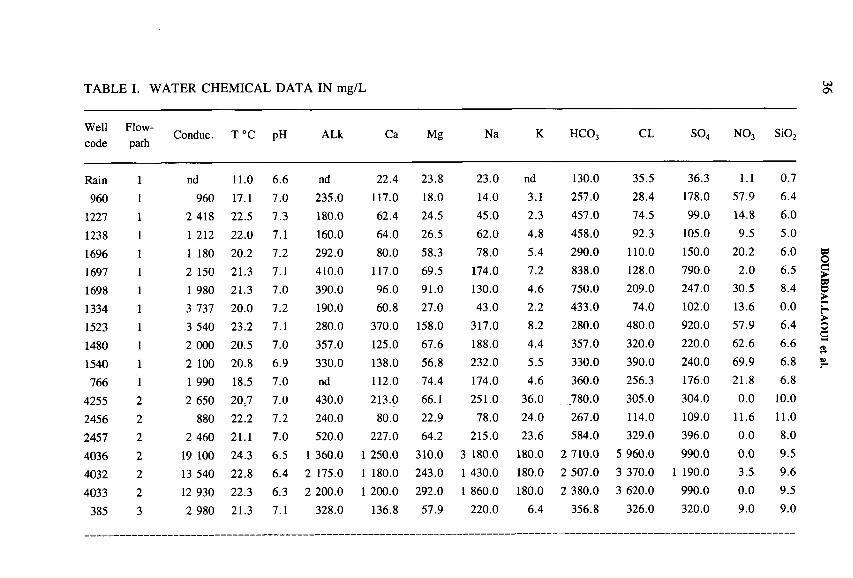
TABLE I. WATER CHEMICAL DATA IN mg/L U )On
Wellcode
Flowpath
Conduc. H o o pH ALk Ca Mg Na K HCOj CL
OGO N03 Si02
Rain 1 nd 11.0 6.6 nd 22.4 23.8 23.0 nd 130.0 35.5 36.3 1.1 0.7
960 1 960 17.1 7.0 235.0 117.0 18.0 14.0 3.1 257.0 28.4 178.0 57.9 6.4
1227 1 2 418 22.5 7.3 180.0 62.4 24.5 45.0 2.3 457.0 74.5 99.0 14.8 6.0
1238 1 1 212 22.0 7.1 160.0 64.0 26.5 62.0 4.8 458.0 92.3 105.0 9.5 5.0
1696 1 1 180 20.2 7.2 292.0 80.0 58.3 78.0 5.4 290.0 110.0 150.0 20.2 6.0
1697 1 2 150 21.3 7.1 410.0 117.0 69.5 174.0 7.2 838.0 128.0 790.0 2.0 6.5
1698 1 1 980 21.3 7.0 390.0 96.0 91.0 130.0 4.6 750.0 209.0 247.0 30.5 8.4
1334 1 3 737 20.0 7.2 190.0 60.8 27.0 43.0 2.2 433.0 74.0 102.0 13.6 0.0
1523 1 3 540 23.2 7.1 280.0 370.0 158.0 317.0 8.2 280.0 480.0 920.0 57.9 6.4
1480 1 2 000 20.5 7.0 357.0 125.0 67.6 188.0 4.4 357.0 320.0 220.0 62.6 6.6
1540 1 2 100 20.8 6.9 330.0 138.0 56.8 232.0 5.5 330.0 390.0 240.0 69.9 6.8
766 1 1 990 18.5 7.0 nd 112.0 74.4 174.0 4.6 360.0 256.3 176.0 21.8 6.8
4255 2 2 650 20.7 7.0 430.0 213.0 66.1 251.0 36.0 780.0 305.0 304.0 0.0 10.0
2456 2 880 22.2 7.2 240.0 80.0 22.9 78.0 24.0 267.0 114.0 109.0 11.6 11.0
2457 2 2 460 21.1 7.0 520.0 227.0 64.2 215.0 23.6 584.0 329.0 396.0 0.0 8.0
4036 2 19 100 24.3 6.5 1 360.0 1 250.0 310.0 3 180.0 180.0 2 710.0 5 960.0 990.0 0.0 9.5
4032 2 13 540 22.8 6.4 2 175.0 1 180.0 243.0 1 430.0 180.0 2 507.0 3 370.0 1 190.0 3.5 9.6
4033 2 12 930 22.3 6.3 2 200.0 1 200.0 292.0 1 860.0 180.0 2 380.0 3 620.0 990.0 0.0 9.5
385 3 2 980 21.3 7.1 328.0 136.8 57.9 220.0 6.4 356.8 326.0 320.0 9.0 9.0
BO
UA
BD
ALLA
OU
I et
al.

TABLE I. (cont.)
Wellcode
Flow-path
Conduc. H o n pH ALk Ca Mg Na K HC03 CL so4 N 03 Si02
800 3 2 540 19.0 6.9 280.0 140.0 48.0 269.0 5.3 320.0 454.0 210.0 31.2 6.4
921 3 2 990 20.5 6.9 224.0 256.0 214.0 177.0 5.4 208.0 258.0 860.0 4.4 13.0
2426 3 1 940 21.2 7.0 250.0 0.0 83.2 36.5 99.0 4.5 530.0 180.0 125.0 16.6
4227 3 2 190 22.0 6.7 344.0 253.0 45.7 134.0 6.6 775.0 200.0 460.0 12.7 7.8
2198 3 2 020 21.3 6.6 470.0 164.8 56.9 90.0 10.0 677.3 81.1 269.0 10.0 14.0
Conduc. = specific conductance in piS/cm. ALk = field alkalinity in mg/L. nd = not determined.
IAEA-SM
-336/6

0.5
0
-0.5
-1
-1.5
-2
1SI of calcite SI o f dolomite
* * *
* % * *i rd-
2
1* * *
. % * *
*u
*- * -1 - #
- -2 -
-3*
-410 15 20
Concentration of SO.
25 30 10 15 20Concentration of SO.
u>00
25 30
FIG. 4. Log PC02 and saturation indices (SI) of calcite, dolomite and gypsum versus S04 concentrations in mmol.
BO
UA
BD
ALLA
OU
I et
al.

IAEA-SM-336/6 39
In addition, ion exchange occurs on clays, such as illite, smectite, kaolinite and chlorite. In addition, halite is highly unsaturated, and its dissolution would be expected, if present. Chloride might also derive from alteration of the shales.
5.2. Isotopic composition
Isotopic compositions of waters collected from the two sampling campaigns did not show significant differences in isotopic compositions. Our results agree with those of Louvat and Bichara [6] and Michelot [7]. Deuterium, 180 , tritium and carbon isotopes offer three distinct but complementary parameters for aquifer characterization.
5.2.1. ô2H and bI80
As shown in Fig. 5(a), the observations fall along the global meteoric water line (GMWL). The plot also shows the geological formations from which the water was sampled. Note that the Senonian and Infracenomanian exhibit depleted isotopes, contrary to the Turanian, which resembles rain water isotopically. The Senonian seems to be closed [8], whereas the Infracenomanian could receive recent waters in the north and northwest. With the isotopically heaviest water (most enriched in deuterium and 180), the Turanian seems to represent more or less mixing of older aquifer water with more recent precipitation or with water from behind the dam. Unfortunately no isotopic analyses on precipitation are available to confirm or refute this hypothesis.
The waters from the Jurassic formations are represented here by only a few samples. These include three wells near the reservoir dam and one high mountain spring. The samples are isotopically similar to water from the Turanian aquifer. Water from well 48/1238 exhibits higher values, and differs from the others from the same aquifer. This is possibly due to leakage of evaporated water from seepage from the reservoir dam. On the other hand, wells 1540 and 1480 yield infiltrated and evaporated irrigation water.
Recharge most probably occurs from the mountains, but is not clearly apparent at this stage. More determinations of stable isotopes in precipitation are needed to investigate the altitude effect.
5.2.2. Tritium
Table II shows the tritium data. Waters from Turanian and Jurassic aquifers contain thermonuclear tritium. Except for well 48/960 and 47/921, located in the recharge area with a small amount of tritium, Infracenomanian waters are tritium free. The exceptions suggest a mixing with recent waters. This is supported by stable isotope values and by 14C activities.

■t»о
ф Senonian □ Turanian ~k Infracenomanian ▼ M ixing—
100
80
g 60 3О 40
20
- W
100
80 - * * <C>
* * * j— %- * * * * ^ 60 - * *
* *__ О 40*
* 20 *He •k
-------- ------------------------------------ 0 --------------------------- ----------- **---12 -10 -8 -6
ô130 %o versus SMOW
-12 -10 -8 -6 -4 -25130 %o versus PDB
FIG. 5. (a) Isotopic composition of Errachidia water; (b) Evolution of l4C versus I80 of Errachidia water; (c) Carbon isotopic composition of Errachidia water.
BO
UA
BD
ALLA
OU
I et
al.

41
TABLE II. ISOTOPIC COMPOSITION OF GROUNDWATER
Well No. 0D700 Ôl80 TU 513C700 14C% 634S700
SMOW SMOW PDB pmC CDT
385/47b -48 -7.3921/47a -61 -9.32198/56a -69 -10.3800/47b -49 -6.25921/47b -62 -9.5 2.2 ± 0.4 -9.3 61.1 ± 0.5 13.34226/56b -57 -8.5 1.1 ± 0.5 -7.9 70.5 ± 14227/56b -59 -9 bd -5.9 25.6 ± 1.3766/48a -46 -81540/48a -47 -6.723/48a -48 -7.84256/57a -49 -8.54257/57a -58 -9.44036/57a -64 -104032/57a -63 -9.84033/57a -64 -9.71480/48a -47 -7.14255/57a -64 -9.1960/47b -52 -9.1 8.1 ± -10.3 58.7 11.34255/57b -60 -9.3 bd -3.3 1.9 13.74256/57b -53
OOOO1 bd4257/57b -63 -10.2 bd -2.9 1.1 12.24036/57b -64 -9.9 bd 0.3 0.8 16.14032/57b -63 -9.7 bd 0.8 0.5 16.0 ± 0.244033/57b -62 -10 bd 0.8 0.8 16.11227/48b -48 -7.4 12.2 + 0.61238/48b -38 -5.8? 13.5 ± 0.7 -7.6 70.11696/48b -46 -7.2 11.6 ± 0.91697/48b -68 -9.61698/48b -55 -8.21334/48b -47 -7.4 12.4 ± 0.9 -8.2 78.9 ± 11523/48b -64 -9.2 bd1480/486 -46 -6.4 15.4 ± 0.8 -9.71540/48b -42 -6.4 15.9 ± 0.7 -9.7 81.3 + 0.61227/48a -47 -7.81523/48a -65 -9.4
Rainwater composition: 5D 5180 ÔD ô18oRl Errachidia -14 ■-3.3 R3 Gheris river —44 -7.4R2 Errachidia -28 ■-2.3 R4 Goulmima -48 -7.4
for tritium.bd = below detection. Detection limit 0.7 TU.1523/48a sampled in January 1991 and 1523/48b sampled in December 1991. PDB: Peedee belemnite. CDT: Canyon Diablo troilites.

42
The ô13C°/oo versus Peedee belemnite and the 14C pmC activity distribution shows that 13C/12C increases from north to south along the flowpath, whereas 14C activity decreases, suggesting that carbon isotopic chemistry and radioactive decay dominated the 14C content of dissolved carbon. Figures 5(b) and 5(c) show the evolution of 14C with respect to I3C and 180.
Waters from Turonian aquifers exhibit the highest 14C pmC and tritium contents and low values of <513C. This aquifer is receiving near-surface water either from the river or from the dam, or from the Jurassic limestone beds, which are hydrologically connected with the Turonian beds. Conversely, the wells penetrating the Infracenomanian aquifer in the north or northwest, despite their upgradient location, have a lower 14C activity. This is possibly due to mixing with recent and less recent water. Except for this particular area, the Infracenomanian aquifer seems to be closed to any external influence. Owing to the low hydrological conductivity of clays, water should reflect the set of reactions it has undergone along the flowpath. The water we sampled downgradient has low 14C activity, depleted in the stable isotopes 180 and 2H, and is tritium free.
Near zero 14C could suggest very old water. These findings are similar to the isotopic investigations in eastern Morocco and in the Continental Intercalaire in Algeria, and contribute to the controversy about palaeorecharge in the Sahara [8].
Because of the chemical reactions discussed above, which strongly affect the isotopic carbonate chemistry, 14C activity must be corrected for these processes. Geochemical modelling permits these corrections.
6 . GEOCHEMICAL MODELLING
NETPATH [3] was used to test the hypothetical chemical reactions discussed above, and to correct for water age by mass balance. The selected phases as suggested by the pétrographie data and revealed by clay X ray analysis are: calcite, dolomite, anhydrite, gypsum, halite, chlorite, pyrite and geothite. Ion exchange (Ca/Mg, Mg/Na) also played a major role. These hypothetical phases were tested with the following constraints: measured ô13C in water and rocks, ô34S, dissolved sulphate and of gypsum and pyrite. Other parameters assumed by the model are C02 gas and the fractionation factors.
Despite modelling difficulty and uncertainty, we obtained preliminary data. The model indicates a correction of 40 to 60% of the initial 14C activity.
7. CONCLUSION
Interpretation of the isotopic and chemical data reveals two facies, corresponding respectively to surficial aquifers (high 14C activity and the presence of tritium)
5.2.3. Carbon isotopes

43
and deeper aquifers with lower 14C activity and no tritium. The salinization observed downgradient is related to gypsum and anydrite and minor halite dissolution. Evapotranspiration had no effect, contrary to first assumptions. Further improvement is warranted, especially to quantify the inter-aquifer mixing that is probably responsible for the observed chemical complexity. The ongoing chemical modelling will provide further insight into hydrological flow systems and allow evaluation of processes controlling the hydrogeochemistry of Errachidia.
ACKNOWLEDGEMENTS
This work greatly benefited from financial and logistical support from many Agencies to whom we adress our thanks. La Direction de la recherche et de la planification de l’eau (DRPE) allowed access to sampling wells and data. L’Office national de l’eau potable (ONEP) contributed to chemical analyses. This work was partially funded by IAV Hassan П-Minnesota Project and by the Office régional de mise en valeur agricole de Tafilalt.
REFERENCES
[1] DIRECTION DE LA RECHERCHE ET DE LA PLANIFICATION DE L ’EAU, Project PNUD/DTCD/MOR/1986/004, Office régional de mise en valeur agricole, Rabat, Morocco (1990).
[2] INTERNATIONAL ATOMIC ENERGY AGENCY, Technical Reports Series Nos 96, 117, 129, 147, 165, 192, 226, 264 and 311.
[3] PLUMMER, L.N., PRESTEMON, E.C., PARKHURST, D.L., An Interactive Code (NETPATH) for Modeling Net Geochemical Reactions Along a Flow Path, Water- Resources Investigations Report 91-4078, US Geological Survey, Reston, VA (1990).
[4] PEARSON, F.J., Jr., FISHER, D.W., PLUMMER, L.N., Correction of Groundwater Chemistry and Carbon Isotopic Composition for Effects of C 0 2 Outgassing, US Geological Survey, Reston, VA (1978).
[5] PLUMMER, L.N., BUSBY, J.F., LEE, R.W., HANSHAW, B.B., Geochemical modeling of the Madison aquifer in parts of Montana, Wyoming, and South Dakota, Water Resour. Res. 26 (1990).
[6] LOUVAT, D., BICHARA, S., Etudes de plusieurs systèmes aquifères du Maroc à l ’aide des isotopes du milieu, Mission préliminaire au projet MOR/8/004, IAEA, Vienna (1990).
[7] MICHELOT, J.L., Hydrogéologie isotopique des systèmes aquifères de Fes-Meknes, Errachidia et Kheng-el-Hammam, Projet MOR/8/004, IAEA, Vienna (1991).
[8] FONTES, J.C., “ Groundwater dating” , Handbook of Environmental Isotope
Geochemistry, 1. The Terrestrial Environment, Elsevier, Amsterdam (1980) 75-140.


IAEA-SM-336/9
APPLICATION OFENVIRONMENTAL ISOTOPE METHODS IN ASSESSING GROUNDWATER DYNAMICS OF AN INTENSIVELY EXPLOITED COASTAL AQUIFER IN PORTUGAL
P.M. CARREIRA, A.M.M. SOARES Departamento de Química,Instituto Tecnológico e Nuclear,Sacavém, Portugal
M.A. MARQUES DA SILVA Departamento de Geociéncias,Universidade de Aveiro,Aveiro, Portugal
L. ARAGUÁS ARAGUÁS, K. ROZANSKI Isotope Hydrology Section,Division of Physical and Chemical Sciences,International Atomic Energy Agency,Vienna
Abstract
APPLICATION OF ENVIRONMENTAL ISOTOPE METHODS IN ASSESSING
GROUNDWATER DYNAMICS OF AN INTENSIVELY EXPLOITED COASTAL AQUIFER IN PORTUGAL.
As a result of intense exploitation over the last thirty years, a significant decrease in the piezometric levels of the Aveiro confined aquifer, located on the northwest coast of Portugal, has been reported. Hydrochemical and environmental isotope techniques were applied to evaluate the effects of this intense pumping. Prolonged over-exploitation of the confined aquifer may lead to deterioration of water quality in the system as a result of mixing
with highly polluted shallow groundwaters and/or due to seawater intrusion. An insight into the dynamics of the confined aquifer was gained by investigation of the distribution of l4C
content in the total dissolved inorganic carbon (TDIC) along the general direction of groundwater flow. Between 7 and 12 km from the recharge area the 14C content decreases almost
linearly with the increasing distance, indicating an apparent flow velocity of around 1 m/a. However, between 12 and 19 km the concentration of l4C remains almost constant, indicating the much higher apparent flow velocity (around 5 m/a) resulting from intense flushing of the aquifer during the last glacial period. This flushing was induced by the decrease in the sea level by about 100 m during this period, and the corresponding higher hydraulic gradient in the aquifer. Chemical and isotopic evidence points to a good isolation of the deeper aquifer; all waters collected from the deep aquifer are tritium free. The changes in hydrochemistry of groundwater along the flow paths can be accounted for by water/rock interaction processes.
45

46 CARRE IRA et al.
An enrichment in 180 and in 2H downgradient from the recharge area can be observed along the major flow paths, with more positive 5 values for higher apparent l4C ages. This appar
ent enrichment in heavy isotopes observed for Aveiro palaeowaters probably reflects the fact that the global ocean was enriched in both l80 and 2H during the glacial period.
1. INTRODUCTION
The Aveiro region, situated on the northwest coast of Portugal (Fig. 1(a)), is one of the most industrialized areas of Portugal, with a high demographic density and intense agriculture, looking forward to further development in the forthcoming years. The Aveiro Cretaceous aquifer (Aveiro aquifer) represents the main water resource of this region.
As a consequence of the industrial development in the region and the growing pollution of the shallow aquifer, the Aveiro aquifer has been intensively exploited over the last thirty years as a major source of good quality water. As a result of the intense exploitation, a decrease in the piezometric level has been reported reaching, in some areas, 40 m below sea level [1]. There is a growing concern that further intense exploitation of the system may result in deterioration of water quality due to mixing with highly polluted shallow groundwaters and/or due to seawater intrusion.
In order better to understand the present flow pattern and groundwater dynamics of the Aveiro aquifer, an isotope aided study was initiated in March 1993. This paper presents the results obtained so far within the framework of the project.
2. HYDROGEOLOGICAL SETTING
Outcropping in the eastern part of the Lower Vouga Sedimentary Basin, the Cretaceous system represents one of the most important water bearing formations in the northwest coastal area of Portugal. The Cretaceous layers overlying the Palaeozoic schist-graywacke consist of a thick and complex sedimentary sequence (up to 350 m), mainly made up of sandstones, clays and limestones. The Cretaceous sediments underlay a detrital sedimentary sequence of Quaternary age with an average thickness of 40 m. The Mesozoic sediments show asymmetric synclinal structure in the study area, dipping gently to NW (less than 10°), crossed by a major N-S fault and by a NW-SE fault system, which however, does not reach the surface [2].
Two main groundwater aquifers have been identified in the Lower Vouga Sedimentary Basin: the shallow Quaternary system and the Cretaceous multilayer system. The shallow system consists mainly of detrital sediments of Pleistocene and Holocene age (dunes, fluvial terraces and ancient beaches) related to different marine
IAEA-SM-336/9 47
regression events. These fluvial terraces are found at different altitudes, acting as local aquifers recharged through existing outcrops and/or through other Quaternary sediments. Owing to easy exploitation and high productivity, these water bearing units represented, until the late nineteen-sixties, the main groundwater resource in the region.
The second groundwater system, the so-called Aveiro aquifer, consists of a confined multilayer sequence of Cretaceous age with an overall thickness of around 100 m, mainly made up of sandstones and clays, where the carbonate layers make up only 1 to 8 % of the total thickness. This multilayer aquifer is mainly made up of stratified layers of quartz sandstones and clay sediments overlying the schist- gray wacke complex. The sedimentary sequence is composed of a sandstone formation (C1-2) from the Aptian-Albian age, underlain by a thin and discontinuous Cenomanian carbonate layer (C2) followed by a micaceous sandstone unit from the Turonian age (C3). In the whole area, these layers represent the permeable Cretaceous formations, i.e. the multilayer confined aquifer. An aquitard made up of sands and clays (C4) that in some areas has a thickness of 150 m, is located between the Cretaceous permeable layer and the impermeable clay layer (C5) from the Upper Cretaceous (Fig. 1(b)).
As a consequence of the asymmetric synclinal structure of the sedimentary basin, where the northern flank of the syncline shows a higher slope than the southern, several flow paths can be defined in the deeper aquifer: some of them descend from the synclinal flanks and a main flow path with a SE-NW direction along the synclinal axis (with a higher hydraulic gradient). The recharge area of the SE-NW flow path is located about 25 km from the coast, occupying a narrow strip in the eastern part of the basin.
As a result of the intensive exploitation of the deeper aquifer in the last thirty years a significant decrease in the piezometric levels has been reported. Along the major flow path, this depression has reached in some areas 40 m below sea level. The area of more intense groundwater exploitation is located around 9 km from the coastline and extends over an area of about 9 km2. The modem recharge rate is around 200 mm/a and represents approximately 2 0% of the mean annual precipitation in the region [3]. Considering that the average pumping rate of the deep wells located in the area (more than 40 operational wells with a depth higher than 180 m) is around 25 L/s and operating a daily mean of 12 h, a deficit in the water balance of about 1 x 10⁶ m3/a was estimated for the confined aquifer, assuming that the lowering of the piezometric levels down to 40 m below sea level occurred over the last 20 years of exploitation of the deeper aquifer.
The Cretaceous layers dip gently NW, spreading out towards the sea, but the total length of the aquifer is not known. Assuming minimum dimensions for the aquifer (length of 25 km, average lateral extension of 5 km, mean thickness of 100 m, mean porosity of 10%), less than 1.5% of the total volume of groundwater has been exploited so far.
48 CARREIRA et al.
The intensive pumping can be responsible for the local inversion of the natural flow which, in a further perspective, may lead to seawater intrusion problems in the coastal area.
3. SAMPLING AND METHODS
Four sampling campaigns were carried out in Aveiro from March 1993 to December 1994, between Vagos and Torreira (Fig. 1(a)). Groundwater samples were collected from wells exploiting both the confined and the shallow aquifers for isotope (ô2H, ô180 , 3H, ô13C and 14C) and chemical analysis. The 2H , 13C and 180 results are reported in Ô notation and were measured with an accuracy of 1700 for <52H and 0.1700 for ô13C and ô180 . The S2H and <5180 values were determined three times for each sample in order to increase the precision of analysis. The tritium content was determined using the electrolytic enrichment and a liquid scintillation counting method. The 14C analyses were done on the TDIC of groundwater, extracted in the field. In laboratory, the C02 derived from the precipitated carbonate was transformed into benzene and measured by the liquid scintillation method.
The chemical analyses, including major ionic species, were carried out on all samples collected from the confined aquifer and on selected samples from the shallow aquifer.
The results presented in this work will focus only on the isotopic and chemical results obtained in the wells located along the main flow path, i.e. along the SE-NW axis of the synclinal structure, from the recharge area in the eastern part of the basin towards the sea.
4. RESULTS AND DISCUSSION
Although the study has not yet been concluded, the results obtained so far permit a description of basic features of the Aveiro aquifer based on combined information provided by hydrochemistry, carbon isotopes in TDIC and stable isotopes in groundwater.
4.1. Hydrochemical evolution along the SE-NW flow path
The hydrochemical evolution of groundwater from the recharge area towards the coastline along the SE-NW flow direction is characterized by a gradual change from a HC03-Ca type in the recharge area to a HC03-Na and to a Cl-Na type in the deeper parts of the aquifer. This general hydrochemical evolution is accompanied by a progressive increase of the total dissolved solids from 175 up to 738 mg/L.

IAEA-SM-336/9 49
FIG. 1. (a) Location of sampled wells in the Aveiro Cretaceous aquifer; (b) Cross-section of the Cretaceous aquifer.

rCa/
rNa
Calci
um
,(mg/
L)
50 CARREIRA et al.
10 12 14 16 18 20 22 24Distance from recharge area (km)
0.00Distance from recharge area (km)
FIG. 2. (a) Calcium content as a function o f distance from the recharge area. Two parallel evolution pathways can be identified; (b) CaiNa ratio as a function o f distance from the recharge area.

IAEA-SM-336/9 51
10 12 14 16 18 20Distance from recharge area (km)
22 24 26
4.00-
3.50-
3.00-
2.50-О■a 2.00-7 .
1.50-
1.00-
0.5a
0.00
3 6
12
18
13
17 4
1514
10 12 14 16 18 20Distance from recharge area (km)
22 24 26
FIG. 3. (a) Bicarbonate content as a function of distance from the recharge area. The increase o f HCO~3 in wells 5, 14 and 15 represents a possible different flow path; (b) Na/Ca ratio as a function of distance from the recharge area. Wells 5, 14 and 15 point to a different type o f water.
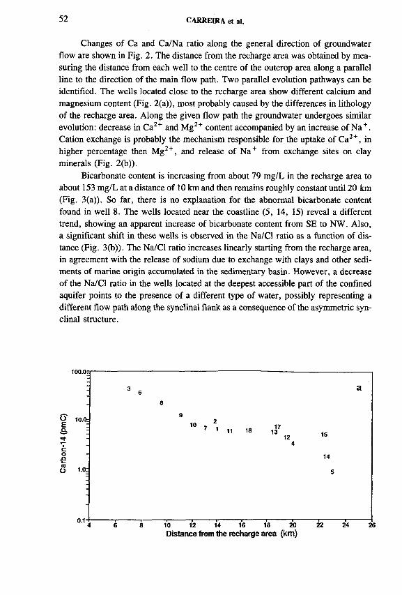
52 CARREIRA et al.
Changes of Ca and Ca/Na ratio along the general direction of groundwater flow are shown in Fig. 2. The distance from the recharge area was obtained by measuring the distance from each well to the centre of the outcrop area along a parallel line to the direction of the main flow path. Two parallel evolution pathways can be identified. The wells located close to the recharge area show different calcium and magnesium content (Fig. 2(a)), most probably caused by the differences in lithology of the recharge area. Along the given flow path the groundwater undergoes similar evolution: decrease in Ca2+ and Mg2+ content accompanied by an increase of Na + . Cation exchange is probably the mechanism responsible for the uptake of Ca2+, in higher percentage then Mg2+, and release of Na+ from exchange sites on clay minerals (Fig. 2(b)).
Bicarbonate content is increasing from about 79 mg/L in the recharge area to about 153 mg/L at a distance of 10 km and then remains roughly constant until 20 km (Fig. 3(a)). So far, there is no explanation for the abnormal bicarbonate content found in well 8 . The wells located near the coastline (5, 14, 15) reveal a different trend, showing an apparent increase of bicarbonate content from SE to NW. Also, a significant shift in these wells is observed in the Na/Cl ratio as a function of distance (Fig. 3(b)). The Na/Cl ratio increases linearly starting from the recharge area, in agreement with the release of sodium due to exchange with clays and other sediments of marine origin accumulated in the sedimentary basin. However, a decrease of the Na/Cl ratio in the wells located at the deepest accessible part of the confined aquifer points to the presence of a different type of water, possibly representing a different flow path along the synclinal flank as a consequence of the asymmetric synclinal structure.
100.0a
3 a68
910 2
a.
соn
7 11 18 1713 1512
4
14
5
0.1”*----------«----------1----------«--------- ■---------1--------- i--------- 1----------1----------1---------- «----------4 6 8 10 12 14 16 18 20 22 24 26
Distance from the recharge area (km )

IAEA-SM-336/9 53
-7.0
10 12 14 16 18 20 22
Distance from the recharge area (km)
FIG. 4. (a) Carbon-14 content in the sampled wells plotted versus distance from the recharge area; (b) Carbon-13 content o f TDIC in the sampled wells plotted as a Junction o f distance from the recharge area; (c) The apparent flow rates calculated from the difference in I4C content and the distance between adjacent wells along the given flow path.

54 CARREIRA et al.
Radiocarbon content was measured in the wells shown in Fig. 1(a). The values obtained range between 43.6 ± 0.4 pmC at the distance of about 7 km from the recharge area and 0.9 + 0.3 pmC at the deepest accessible part of the confined aquifer (approximately 20 km from the recharge area).
The relation between the 14C concentration in the sampled wells and the distance from the recharge area reveals an interesting pattern (Fig. 4(a)). Between 7 and 12 km from the recharge area, the radiocarbon content decreases almost linearly when plotted on the logarithmic scale with the increasing distance. Between 12 and 19 km the 14C content remains almost constant.
Apparent 14C groundwater ages were calculated by using the <513C correction equation of Gonfiantini [4]. The application of this simple model to estimate the apparent 14C ages was chosen because all the analysed samples are subsaturated in calcite (the saturation index, SIcalcite, ranges from -2.33 to -0.41) and the <5I3C values are almost constant (Fig. 4(b)). The apparent 14C ages range from 5.9 ± 2.4 to 35.0 ± 6.2 ka (+2cr), near the recharge area and in the deepest accessible part of the confined aquifer, respectively. Using the apparent 14C age of the groundwater, flow velocities downgradient were calculated between adjacent wells along the given flow paths. When plotted as a function of the distance from the recharge area, the apparent flow velocities of around 1 m/a were obtained for the region between 7 and 12 km from the recharge area, and around 5 m/a between 12 and19 km, decreasing again further downgradient (Fig. 4(c)). The 14C content found in wells 4, 14 and 15 indicates the presence of substantially older groundwater, most probably representing different flow paths along the synclinal flanks of the aquifer.
4.2. Radiocarbon in groundwater along the SE-NW flow path

Oxy
gen-
18
(°/0
0) O
xyge
n-18
(°
/0o)
IAEA-SM-336/9 55
-4.3»
Distance from the recharge area (Km)
-4.30
-4.40-
-4.50-
-4.60-
-4.70-
•4.8»16 20
Age (ka)
FIG. 5. (a) ô2H-ôl80 diagram showing two different types o f waters; (b) Oxygen-18 content in the sampled wells in the confined portion o f the aquifer plotted versus distance from the recharge area; (c) Oxygen-18 content as a function of age.

56 CARREIRA et al.
This hypothesis is supported by the distinctly different hydrochemistry of the groundwater in these wells.
The average flow velocity of about 1 m/a, derived for the part of the aquifer close to the recharge area, probably represents typical flow conditions for Holocene. Much higher apparent flow velocity derived from the 14C data for the central part of the aquifer was most probably induced by changes in the sea level. During the last glacial maximum the sea level was lowered by about 100 m [5]. This, in turn, imposed a much higher hydraulic gradient on the aquifer during this period, leading to substantially higher velocities of groundwater, when compared to present-day conditions. The apparent 14C age of groundwater between 12 and 19 km from the recharge area clusters around 18 ka BP, confirming the glacial origin of this water.
4.3. Stable isotopes along the SE-NW flow path
No significant differences were observed in the isotopic composition of groundwater from the deeper aquifer between the three sampling campaigns carried out in the region. The heavy isotope content of these waters varied between -2 7 to —23700 and from —4.8 to —4.3700 for <52H and for ô180 , respectively.
Two distinct groups of waters can be recognized on the ô2H-ôlsO diagram (Fig. 5(a)). One group represents groundwater from the deeper aquifer, more enriched in heavy isotopes, while the other consists of water samples from the shallow aquifer, representing the isotopic composition of modem recharge water in the region. The isotopic composition of the shallow aquifer varies between -29 .2 and -2 4 .8 7 00 for <52H and from -5 .03 to —4.49700 for ô180 . In this diagram, the long term weighted mean value of precipitation collected at Porto meteorological station (approximately 65 km north of Aveiro), ¿>2H = -30 .77 00 and <5180 = —5.11700, is also shown [6].
Both <5180 and <52H became progressively enriched along the SE-NW flow path (Fig. 5(b)). The observed enrichment in heavy isotope content downgradient of the recharge area is also apparent when the ô2H or ô180 values are plotted against the 14C content (Fig. 5(c)): the higher apparent 14C age of the water corresponds to more positive ô180 and ô2H values. The isotopic composition of groundwater collected in the confined aquifer near the recharge area (Holocene) shows similar ô2H or ô180 values to the groundwater from the shallow aquifer, while older groundwaters are systematically more enriched in both 180 and 2H (Fig. 5(a)).
The stable isotope enrichment found in Aveiro palaeowaters is unique on the European continent: groundwaters from the United Kingdom and from western and central Europe recharged during the last glaciation are depleted in both 180 and 2H in comparison with modem precipitation in the region [7-9]. On the other hand, the heavy isotope enrichment in palaeowaters in comparison with modem infiltration waters has also been observed in other coastal aquifers in Namibia [10], Florida [11] and in the Carrizo Aquifer, Texas [12]. One possible explanation for this effect
IAEA-SM-336/9 57
suggests heavy isotope enrichment of the global ocean during glacial times, due to the preferential storage of isotopically depleted water in polar ice caps. The ocean isotopic composition changed by 1.3 to 1.6700 in 180 and up to 107oo in 2H [7, 13]. Thus, if a coastal aquifer was recharged mainly by precipitation originating from the first-step condensate, the newly formed groundwater may reflect, in the first instance, the fluctuations of the isotopic composition of the ocean in the source regions.
5. CONCLUSIONS
The main goal of this study was the characterization of the Aveiro coastal aquifer through the application of environmental isotope techniques and hydrochemistry in assessing groundwater dynamics. Although the study has not yet been concluded, some important results have already been obtained:
(1) So far, the Aveiro confined aquifer is effectively isolated from the shallow groundwater system and there is no evidence for recent seawater intrusion related to the pumping of deep groundwater;
(2) The hydrochemical evolution of the groundwater in the aquifer is the result of continuous interaction of infiltrating waters with the rock matrix. Different hydrochemical flow paths, superimposed on the general direction of groundwater flow, can be identified on the basis of chemical data. They most probably reflect spatial inhomogeneities of the geological structure and lithology of the Cretaceous sediments;
(3) During the glacial period a decrease of the sea level by about 100 m imposed a more intense flushing of the aquifer, reflected in the 14C content of the analysed water samples. Between 12 and 19 km from the recharge area, the radiocarbon content in these wells remains almost constant, with the apparent 14C ages around 18 ka BP, pointing to the glacial origin of this water;
(4) The 2H and 180 content in Aveiro palaeowaters increase along the general direction of groundwater flow. The enrichment in heavy isotopes downgradient is also apparent when the <52H and ô180 values are plotted as a function of apparent 14C ages. This enrichment was most probably caused by isotopically heavier ocean water during glacial time. If a coastal aquifer is recharged mainly by precipitation originating from the first-step condensate, the newly formed groundwater may reflect, in the first instance, the fluctuations of the isotopic composition of the ocean in the source regions.

58 CARRE IRA et al.
ACKNOWLEDGEMENTS
This work was carried out within the framework of the IAEA Technical Assistance Project (POR/8/007) accorded to the Instituto Tecnológico e Nuclear, Sacavém. P. Carreira acknowledges the grant from the Junta Nacional Investigacâo Científica Tecnológica Programa Ciência, Lisbon.
REFERENCES
[1] MARQUES DA SILVA, M.A., Hidrogeologia del sistema multiacuífero Cretácico del Bajo Vouga — Aveiro, PhD Thesis, Universidad de Barcelona, Vol. 1 (1990).
[2] MARQUES DA SILVA, M .A ., Camadas-guia do Cretácico de Aveiro e sua importân- cia hidrogeológica, Rev. U. Aveiro 7 1-2 (1992) 111-124.
[3] Atlas of World Water Balance (GALINA, M.B., KOPYLOV, A.P., Eds), Hydrometeorological Publishing House, Leningrad; UNESCO Press, Paris (1977).
[4] SALEM, O., VISSER, J.M., DRAY, М., GONFIANTINI, R., “Groundwater flow
patterns in the Western Libyan Arab Jamahiriya evaluated from isotopic data” , Arid- zone Hydrology: Investigation with Isotope Techniques (Proc. Advisory Group Mtg
Vienna 1978), IAEA, Vienna (1980) 165-179.[5] FAIRBANKS, R.G., A 17,000-year glacio-eustatic sea level record: influence of gla
cial melting rates on the Younger Dryas event and deep-ocean circulation, Nature (London) 342 (1989) 637-642.
[6] INTERNATIONAL ATOMIC ENERGY AGENCY, Statistical Treatment of Data on Environmental Isotope Data in Precipitation, Technical Reports Series No. 331, IAEA, Vienna (1992).
[7] ROZANSKI, K., Deuterium and oxygen-18 in European groundwaters — links to
atmospheric circulation in the past, Chem. Geol. 52 (1985) 349-363.[8] BATH, A.H., “ Stable isotopic evidence for palaeo-recharge conditions of ground
water” , Palaeoclimates and Palaeowaters: A Collection of Environmental Isotope Studies, Panel Proceedings Series, IAEA, Vienna (1983) 169-186.
[9] STUTE, М., DEÁK, J., Environmental isotope study (l4C, 13C, 180, D, noble gases) on deep groundwater circulation systems in Hungary with reference to paleoclimate,
Radiocarbon 31 (1989) 902.[10] VOGEL, J.C., TALM A, A.S., HEATON, T.H.E., The Age and Isotopic Composition
of Groundwater in Stampriet Artesian Basin, South West Africa, Report to the Steering Committee for Water Research in South West Africa, National Physical Research Laboratory, Pretoria (1982).
[11] PLUMMER, L.N., Stable isotope enrichment in paleowaters of the Southeast Atlantic
coastal plain, United States, Science 262 (1993) 2016-2020.[12] STUTE, М., Lamont-Doherty Earth Observatory of Columbia University, personal
communication, 1994.[13] CHAPPELL, J., SHACKLETON, N.J., Oxygen isotopes and sea level, Nature (Lon
don) 324 (1986) 137-140.

IAEA-SM-336/13
CARACTERISATION GEOCHIMIQUE ET ISOTOPIQUE DES EAUX SOUTERRAINES DANS LE BASSIN DU CHOTT CHERGUI (ALGERIE)
D. DAOUD, J.-C. FONTES1, J.-L. MICHELOT Laboratoire d’hydrologie et de géochimie isotopique,Université de Paris-Sud,Orsay, France
Abstract-Résumé
GEOCHEMICAL AND ISOTOPIC CHARACTERIZATION OF GROUNDWATER IN THE CHOTT CHERGUI BASIN (ALGERIA).
The Chott Chergui hydrological basin is an endorheic basin forming part of a vast geographic unit, the steppe-like Hautes Plaines. This is a semi-desert region located between
the Tell in the North and the Saharan Atlas in the South. This study is based on chemical and
isotopic analysis of around 70 samples taken from three aquifers (middle Jurassic, Senonian
and Tertiary). The Chergui groundwater is generally characterized by a chemical facies of the
chloride, sulphate, calcium and magnesium type. Two different salinity zones may be distinguished. One corresponds to the upstream part (margins of the basin and its western part), where mineralization is limited, the other to the downstream part (eastern side of the basin), where mineralization is stronger. The spatial distribution of the salinity thus follows a centripetal gradient towards the eastern side of the Chott proper, in line with what could be
expected from an endorheic flow. A study of the mode of acquisition of the mineralization of the groundwater shows that it is governed largely by dissolution of gypsum and halite, particularly in the lower part of the basin. An isotopic study (l80, 2H, 3H, 13C and l4C) shows that the groundwater of the Chergui can be subdivided into two blocks, (a) a block of relatively recent water (0-3000 years) with quite scattered isotopic contents, sampled in the superficial horizons or at the margins; and (b) a homogeneous mass of old water (>10 ka), with lower isotopic contents, deriving from the aquifer formations of the middle Jurassic, Senonian and deep Tertiary, sampled in the axis of the basin. An intercommunication has been
identified between the aquifers of the middle Jurassic, Senonian and deep Tertiary. Comparison of the isotopic and chemical data shows that the salt concentration is acquired principally through dissolution of minerals. This is clear for deep old water, whereas for the superficial groundwater collected in the Tertiary, the phenomena of dissolution and evaporation are closely linked. The existence of an ascending flux of deep water through the Tertiary formations can be deduced from the relation ô2H vs 6I80. The ascending water is then subjected to evaporation in the superficial levels of the Tertiary. To complement this work, a study to
quantify the evaporative flux, involving modelling of the isotopic profiles obtained in the unsaturated zone, is under way.
59

60 DAOUD et al.
CARACTERISATION GEOCHIMIQUE ET ISOTOPIQUE DES EAUX SOUTERRAINES
DANS LE BASSIN DU CHOTT CHERGUI (ALGERIE).
Le bassin hydrologique du Chott Chergui est un bassin endoréique qui fait partie d’une vaste unité géographique, les Hautes Plaines steppiques. Il s’agit d’un domaine semi- désertique, compris entre le Tell, au nord, et l’Atlas saharien, au sud. Cette étude repose sur l’analyse chimique et isotopique de près de 70 échantillons, prélevés dans trois niveaux aquifères (le jurassique moyen, le sénonien et le tertiaire). Les eaux souterraines du Chergui sont, dans l’ensemble, caractérisées par un faciès chimique du type choruré sulfaté, calcique et mag
nésien. Deux domaines différents de salinité peuvent être distingués. L ’un correspond à la partie amont (bordures du bassin et sa partie ouest), où la minéralisation est faible, l ’autre à la
partie aval (partie orientale du bassin), où la minéralisation est plus forte. La distribution
spatiale de la salinité obéit donc à un gradient centripète vers la partie orientale du Chott stricto sensu, conformément à ce que l’on pouvait attendre d’un écoulement endoréique. L ’étude du mode d’acquisition de la minéralisation des eaux souterraines montre que celle-ci est surtout régie par la dissolution du gypse et de la halite, notamment, dans la partie basse du bassin. L ’étude isotopique (180, 2H, 3H, 13C, ,4C) montre que les eaux souterraines du Chergui peuvent être subdivisées, en deux ensembles: a) un ensemble d’eaux relativement récentes (0-3000 ans), aux teneurs isotopiques assez dispersées, prélevées dans les horizons superficiels ou en bordures; b) une masse homogène d’eaux anciennes (> 10 ka), aux teneurs isotopiques plus basses, issues des formations aquifères du jurassique moyen, sénonien et tertiaire profond, prélevées dans l’axe du bassin. Une intercommunication est mise en évidence entre
les niveaux aquifères du jurassique moyen, sénonien et tertiaire profond. La confrontation des données isotopiques avec les données chimiques montre que la concentration en sels est acquise principalement par voie de dissolution des minéraux. Ceci est clair pour les eaux
anciennes profondes alors que, pour les eaux souterraines superficielles, collectées dans le tertiaire, les phénomènes de dissolution et d’évaporation sont étroitement liés. L ’existence d’un flux ascendant des eaux profondes au travers des formations tertiaires peut être déduite de la relation ô2H vs ôl80. Les eaux ascendantes sont ensuite soumises à l’évaporation dans les niveaux superficiels du tertiaire. En complément de ce travail, une étude de quantification
du flux évaporatoire est en cours, fondée sur la modélisation de profils isotopiques obtenus dans la zone non saturée.
Cette étude repose sur l’analyse chimique (ions majeurs et traces) et isotopique (2H, 180 , 3H, 13C, 14C) de près de 70 échantillons, prélevés dans les niveaux aquifères (le jurassique moyen, le sénonien, et le tertiaire) du bassin endoréique du Chott Chergui.
Les eaux souterraines du Chergui sont, dans l’ensemble, caractérisées par un faciès chimique du type chloruré sulfaté, calcique et magnésien. La salinité des eaux trouve essentiellement son origine dans la mise en solution de minéraux évapori- tiques chlorurés (NaCl) et sulfatés (CaS04), notamment dans la partie basse du bassin. L’étude isotopique permet de subdiviser les eaux souterraines en deux ensembles: un ensemble d’eaux récentes (0 à 3000 ans) prélevées dans les horizons

IAEA-SM-336/13 61
superficiels du tertiaire ou en bordures, et un ensemble d’eaux anciennes (10 ka à 30 ka) issues des formations aquifères du jurassique, du sénonien et du tertiaire profond, prélevées dans l’axe du bassin. Des intercommunications entre les différents niveaux aquifères profonds et un possible flux ascendant des eaux profondes au travers des formations tertiaires sont mis en évidence.
1. INTRODUCTION
Les ressources en eaux souterraines du bassin du Chott Chergui constituent des réserves potentielles nécessaires au développement de quatre grands départements algériens du Nord: Saïda, Sidi-Bel-Abbès, Tiaret, El Bayadh.
Le déficit hydrique, lié à la sécheresse qui sévit dans la région depuis près d’un demi-siècle, rend cruciale une meilleure évaluation et gestion de ces réserves. Il est en particulier indispensable de caractériser la ressource tant au plan de la quantité (individualisation des différentes masses d’eau, intercommunications, taux de renouvellement, pertes par évaporation) qu’à celui de la qualité (salinité: origine et répartition spatiale).
C’est dans cette optique qu’a été entreprise l’étude géochimique et isotopique dont nous présentons les premiers résultats.
2. CADRE GENERAL
L’Algérie septentrionale est subdivisée en trois unités géomorphologiques principales: deux domaines montagneux, actifs depuis le mésozoïque, l’Atlas tellien au nord et l’Atlas saharien au sud, encadrent une zone plane, les Hauts Plateaux, où se sont déposées des séries sédimentaires de plus de 1600 m d’épaisseur. L’état final de ces structures, orientées NE-SO, est issu de déformations tectoniques de distention au cours du trias et du jurassique et d’une tectonique de compression au cours de la phase atlasique (alpine). Des dépressions intramontagneuses et prémontagneuses sont héritées du pliocène supérieur (phase alpine tardive).
Le bassin du Chergui (Fig. 1) occupe l’une de ces dépressions, située dans la partie occidentale des Hauts Plateaux. L’axe de ce bassin endoréique est occupé par un Chott très étendu (le Chott Chergui), caractérisé par une altitude moyenne relativement élevée (1000 m). Au nord et au sud du bassin sont présents les affleurements jurassiques et crétacés. Au centre affleurent les dépôts continentaux du tertiaire, revêtus d’une carapace calcaire. La topographie, horizontale au centre du bassin, à des côtes voisines de 1030-1040 m, s’élève lentement à 1100-1200 m vers les bordures.

62 DAOUD et al.
0° 3 0 ’ 1°
FIG. 1. Localisation des points de prélèvement d'eaux.(1): ouvrage et son numéro (triangle plein = eau du jurassique, cercle = eau du sénonien, étoile = eau du tertiaire, triangle vide = source), (2): limite nord du bassin, (3): sens d ’écoulement, (4): Chott ou Sebkha, (5): quaternaire, carapace calcaire, (6): tertiaire, (7): sénonien, (8): turonien-cénomanien, (9): albien, (10): néocomien, (11): kimmeridjien- lusitanien, (12): Dogger, (13): lias.
Les formations qui présentent un intérêt hydrogéologique dans le bassin du Chott Chergui, sont les niveaux carbonatés du jurassique moyen (Dogger) et du sénonien, ainsi que le remplissage continental du tertiaire.
Le jurassique moyen est constitué de dolomies et calcaires blancs fissurés. Il affleure largement au nord du bassin et plonge vers le sud, sous les termes supérieurs (jurassique supérieur, crétacé et tertiaire) où on le retrouve parfois à une profondeur de 800 m. La mise en charge de la nappe du jurassique moyen par les formations qui le recouvre lui confère un caractère artésien.
Le sénonien est constitué par un calcaire blanc ou gris clair. Son extension est limitée à un lambeau de près de 2000 km2, reconnu dans la partie nord-est du bassin. La nappe du sénonien est également artésienne dans les parties basses du terrain étudié.

IAEA-SM-336/13 63
Les formations continentales du tertiaire sont transgressives sur tous les termes antérieurs. Ce remplissage est essentiellement constitué d’argiles sableuses avec des intercalations gypseuses; il comporte une nappe superficielle de faible importance.
Les différents aquifères du Chergui présentent des comportements hydrodynamiques similaires, avec les mêmes directions générales d’écoulement et le même exutoire: la piézométrie, imparfaitement connue, montre un drainage des eaux souterraines à partir des bordures vers la dépression du bassin puis un écoulement SO-NE suivant l’axe de celui-ci. Les eaux semblent converger vers la partie la plus orientale du Chott proprement dit que nous désignerons par «Chott stricto sensu».
Du point de vue climatique, le bassin du Chott Chergui appartient à une zone semi-aride. Sa situation est marquée par des températures extrêmes (—10 °C à 40° C), la moyenne annuelle des précipitations n’excédant pas 250 mm. La végétation y est de type steppique.
3. ECHANTILLONNAGE ET TECHNIQUES ANALYTIQUES
Près de 70 échantillons d’eaux ont été prélevés dans les trois niveaux aquifères (tertiaire, sénonien et jurassique moyen) (Fig. 1). Les paramètres physico-chimiques (pH, température et conductivité) ont été mesurés sur le terrain. Les échantillons ont ensuite été conditionnés selon le type d’analyse visé (filtration, acidification, précipitation des carbonates). Au laboratoire, les analyses chimiques ont porté sur les éléments majeurs et quelques traces (chromatographie ionique, photométrie de flamme et émission spectrométrique de plasma) et les analyses isotopiques sur l’eau et les composés inorganiques dissous du carbone (spectrométrie de masse et spectrométrie /3 en scintillation liquide).
4. RESULTATS ET DISCUSSION
4.1. Hydrochimie
4.1.1. Classification statistique et faciès chimique des eaux
Un traitement statistique par analyse en composante principale (ACP) permet de distinguer trois groupes d’eaux (Fig. 2):
— des eaux faiblement minéralisées bicarbonatées prélevées en amont, dans les bordures nord et sud ou dans la région d’El-Kheither;
— des eaux caractérisées par une charge saline plus élevée, principalement de type chloruré-sodique et par des températures élevées, prélevées dans l’axe du bassin à des niveaux plus ou moins profonds;

64 DAOUD et al.
US
FIG. 2. Teneurs ioniques des eaux du Chergui: analyse en composantes principales.US: Unités statistiques.
— des eaux également chargées en sels mais avec un faciès plus sulfaté-calcique, prélevées dans des puits peu profonds qui captent le tertiaire dans la partie basse du bassin.
La représentation graphique de Piper (Fig. 3) confirme que les eaux prélevées dans les différents niveaux aquifères sont, dans l’ensemble, caractérisées par des faciès où dominent chlorure, sulfate, sodium et calcium. Dans le détail, ces eaux se répartissent entre trois pôles hydrochimiques:
— un pôle bicarbonaté caldque et magnésien qui correspond aux eaux du jurassique et du sénonien prélevées en bordures;
— un pôle chloruré sulfaté, sodique et potassique, représenté par des échantillons d’eaux du jurassique prélevées dans l’axe du bassin, notamment dans les niveaux les plus profonds;
— un pôle chloruré sulfaté, caldque et magnésien correspondant aux eaux prélevées dans le tertiaire, en particulier dans les niveaux peu profonds.

IAEA-SM-336/13 65
Dans le domaine des cations, on peut remarquer que les échantillons de l’ensemble jurassique-sénonien se répartissent dans une zone où le rapport Mg/Ca est voisin de 1, ce qui suggère l’intervention d’une mise en solution de dolomite. Les eaux du tertiaire, notamment celles qui sont prélevées à une faible profondeur, dans la partie basse du bassin (Chott stricto sensu), se distinguent par un faciès plus franchement calcique.
Dans le domaine des anions, la dominance du bicarbonate dans les eaux prélevées en bordures passe, dans le sens de l’écoulement, à une dominance du chlorure dans les eaux profondes du jurassique et du sénonien, alors que les eaux superficielles du tertiaire, prélevées dans la partie basse du bassin, présentent un faciès principalement sulfaté.
100
FIG. 3. Représentation des compositions chimiques des eaux souterraines du Chott Chergui dans le diagramme de Piper (carré = échantillon du jurassique, cercle = échantillon du sénonien, triangle = échantillon du tertiaire).
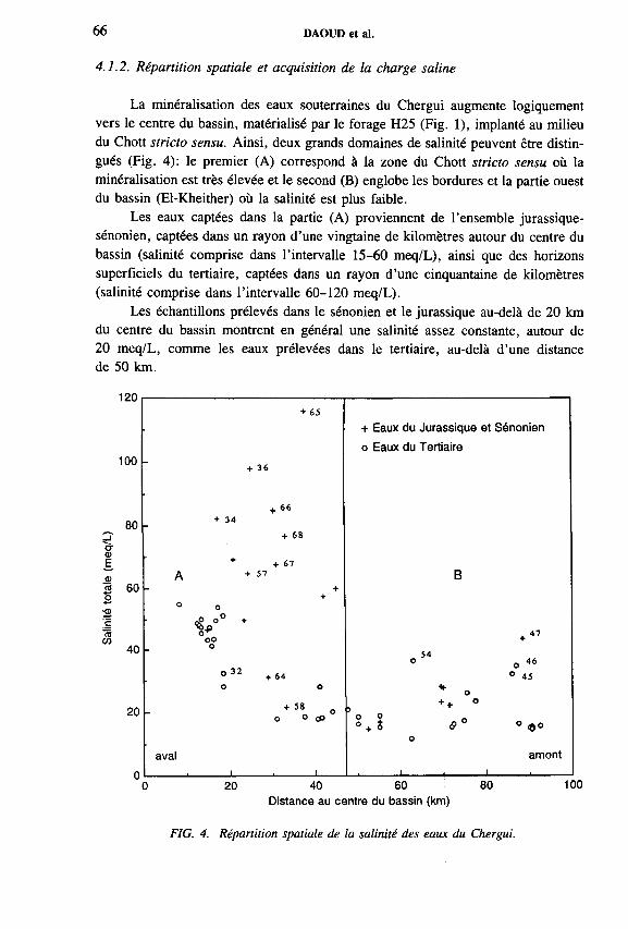
66 DAOUD et al.
4.1.2. Répartition spatiale et acquisition de la charge saline
La minéralisation des eaux souterraines du Chergui augmente logiquement vers le centre du bassin, matérialisé par le forage H25 (Fig. 1), implanté au milieu du Chott stricto sensu. Ainsi, deux grands domaines de salinité peuvent être distingués (Fig. 4): le premier (A) correspond à la zone du Chott stricto sensu où la minéralisation est très élevée et le second (B) englobe les bordures et la partie ouest du bassin (El-Kheither) où la salinité est plus faible.
Les eaux captées dans la partie (A) proviennent de l’ensemble jurassique- sénonien, captées dans un rayon d’une vingtaine de kilomètres autour du centre du bassin (salinité comprise dans l’intervalle 15-60 meq/L), ainsi que des horizons superficiels du tertiaire, captées dans un rayon d’une cinquantaine de kilomètres (salinité comprise dans l’intervalle 60-120 meq/L).
Les échantillons prélevés dans le sénonien et le jurassique au-delà de 20 km du centre du bassin montrent en général une salinité assez constante, autour de20 meq/L, comme les eaux prélevées dans le tertiaire, au-delà d’une distance de 50 km.
120
100
~ 80 3 Ъг a>Sa>я 60o
'Sc
20
00 20 40 60 80 100
Distance au centre du bassin (km)
FIG. 4. Répartition spatiale de la salinité des eaux du Chergui.
+ 65
+ Eaux du Jurassique et Sénonien
o Eaux du Tertiaire
+ 36
+ 66+ 34
+ 68
+ + 6 7A + 57 B
++
° 0
V " * . 47oo +o
54O 0 46
° 32 + 64 ° 45o o * o
+ 58 o °
o o ъ O o _° + S в ° ° e »
O
aval
i , i..
amont
i . i .

IAEA-SM-336/13 67
40
~ 30 '— o*ФÉ. 20
лО
10
20
сг ф £ 10«2
ФE
О01
+ + • Jurassique +0 Sénonien ++ Tertiaire
++ +
++ ++ +
+ +
+ • <Sr
* *
+\ ++ + .% + + +
; 4
.* + +
<*» +
+
M%••
*• ° +
•- ^ • л * +* « %. +
- + + + +j - + . 1 . 1 . 1 . fr . 1 .
+ + +
+ ++ +"
A . ^ + + +
■ & * +. 1 . 14...................
40
30
a-ф20 E
10
20
N *Осо
CT10 I
О
фю £
0 20 40 60 80 100 120 20 40 60 80 100 120
Salinité totale (meq/L)
FIG. 5. Evolution des teneurs en ions majeurs (meq/L) en fonction de la salinité totale (meq/L) des eaux du Chergui.
La variation spatiale de la concentration de chaque élément chimique majeur peut être déduite de la corrélation de cet élément avec la salinité totale (Fig. 5). Une rupture nette apparaît pour une salinité totale proche de 70 meq/L, qui permet de distinguer les eaux des puits qui captent le tertiaire dans la partie du Chott stricto sensu (ST >70 meq/L).
Pour les eaux du jurassique et du sénonien, ainsi que pour les eaux du tertiaire «distal» (hord du Chott stricto sensu), les teneurs en СГ, Na + , SO4", Ca2+ et Mg2+ augmentent régulièrement de l’amont vers l’aval. L’augmentation des teneurs
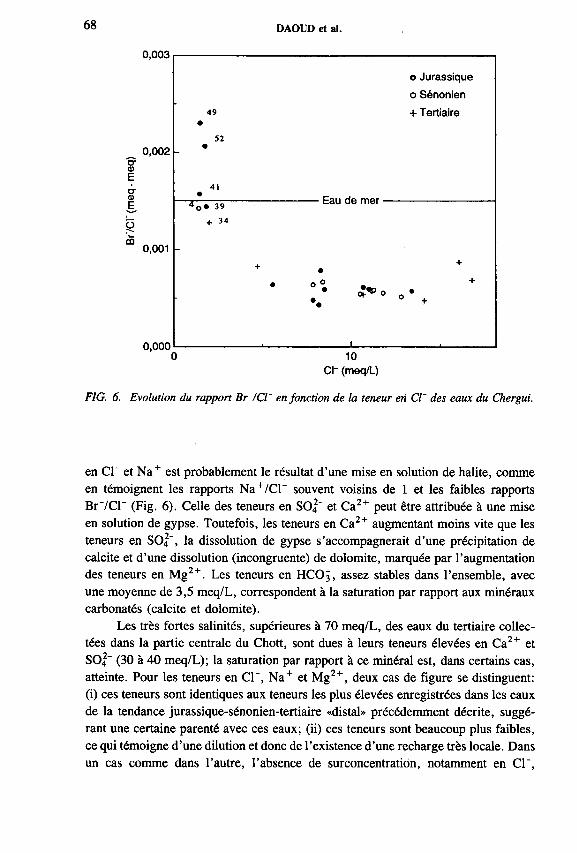
68 DAOUD et al.
0,003
0,002O'фEcrtuE
Оm 0,001
0,000
49
52
l o » 39 • Eau de mer ■
o
o Jurassique
o Sénonien
+ Tertiaire
10Ch (meq/L)
FIG. 6. Evolution du rapport Br /СГ en fonction de la teneur en СГ des eaux du Chergui.
en СГ et Na+ est probablement le résultat d’une mise en solution de halite, comme en témoignent les rapports Na+/СГ souvent voisins de 1 et les faibles rapports Вг'/СГ (Fig. 6). Celle des teneurs en SO|~ et Ca2+ peut être attribuée à une mise en solution de gypse. Toutefois, les teneurs en Ca2+ augmentant moins vite que les teneurs en SO2", la dissolution de gypse s’accompagnerait d’une précipitation de calcite et d’une dissolution (incongruente) de dolomite, marquée par l’augmentation des teneurs en Mg2+. Les teneurs en HCO3, assez stables dans l’ensemble, avec une moyenne de 3,5 meq/L, correspondent à la saturation par rapport aux minéraux carbonatés (calcite et dolomite).
Les très fortes salinités, supérieures à 70 meq/L, des eaux du tertiaire collectées dans la partie centrale du Chott, sont dues à leurs teneurs élevées en Ca2+ et SO2" (30 à 40 meq/L); la saturation par rapport à ce minéral est, dans certains cas, atteinte. Pour les teneurs en СГ, Na+ et Mg2+, deux cas de figure se distinguent: (i) ces teneurs sont identiques aux teneurs les plus élevées enregistrées dans les eaux de la tendance jurassique-sénonien-tertiaire «distal» précédemment décrite, suggérant une certaine parenté avec ces eaux; (ii) ces teneurs sont beaucoup plus faibles, ce qui témoigne d’une dilution et donc de l’existence d’une recharge très locale. Dans un cas comme dans l’autre, l’absence de surconcentratión, notamment en СГ,

IAEA-SM-336/13 69
TABLEAU I. «AGES» DES EAUX DU CHERGUI, SELON LES DIFFERENTS MODELES DE CORRECTION, ET TENEURS EN TRITIUM
EchantillonAge
apparentTammers
[1]
I et P
[2]
Salem et al.
[3]
F et G
[4]
Evans et al.
[5]
3H (UT)
±0,5
MED/4 3300 actuel actuel 3200 3000 actuel 6,8
F19/12 23000 18000 16000 20000 19000 15300
H45/13 21000 16000 13000 16500 16000 12000
F24/15 22000 16500 14000 18000 17500 13400
C2/18 21000 15000 14000 17500 17300 13300
F34/23 19000 14000 10000 13500 13000 9100
H4/25 22000 17000 13000 17000 16300 12500
F22/26 19000 14000 11000 15000 14000 10500 <2
SED 1/29 20000 15000 11000 15000 14500 10500 <2
F32/33 32000 27000 27000 31000 30500 27000 <2
ASO/36 6000 1100 actuel 2200 1400 actuel 2,2
ELK1/38 26000 21500 18000 22000 21000 17400
FSB1/39 26000 20000 18000 22000 22000 17500
FSK/40 19000 14500 12500 17000 16000 12200 <2
H38/45 21000 16500 12000 15000 15000 10500 <2
GRA/49 9000 3500 3300 7500 7500 3000
F39/50 6000 1500 600 4800 3500 400
MOR/51 5000 actuel actuel 3400 3300 actuel
F36/52 4500 1000 actuel 3200 3000 actuel 2,7
KEF2/53 7500 2500 1500 6000 5500 1300 13,2
H 13/54 30000 25000 21500 25000 24000 21000
FR2/55 6500 1500 900 5000 4700 600 3,5
PI/56 5500 400 actuel 2500 1900 actuel <2
P7/61 6500 1500 1100 5500 5300 900
P9/63 8500 3000 1200 5600 5400 900 8,1
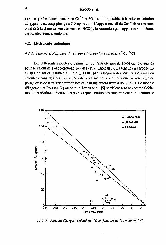
70 DAOUD et al.
montre que les fortes teneurs en Ca2+ et SO4 " sont imputables à la mise en solution de gypse, beaucoup plus qu’à l’évaporation. L’apport massif de Ca2+ dans ces eaux conduit à la chute de leurs teneurs en HCO 3 , la saturation par rapport aux minéraux carbonatés étant maintenue.
4.2. Hydrologie isotopique
4.2.1. Teneurs isotopiques du carbone inorganique dissous (I3C, 14C)
Les différents modèles d’estimation de l’activité initiale [1-5] ont été utilisés pour le calcul de Г «âge-carbone 14» des eaux (Tableau I). La teneur en carbone 13 du gaz du sol est estimée à — 21 °/00 PDB, par analogie à des teneurs mesurées ou calculées pour des régions situées dans les mêmes conditions que la zone étudiée [6- 8]; celle de la matrice carbonatée est classiquement fixée à 07oo PDB. Le modèle d’Ingerson et Pearson [2] ou celui d’Evans et al. [5] semblent rendre compte fidèlement des résultats obtenus: les points représentatifs des eaux contenant du tritium se
FIG. 7. Eaux du Chergui: activité en 14C en fonction de la teneur en l3C.
IAEA-SM-ЗЗб/13 71
situent effectivement à proximité immédiate d ’une droite de mélange entre carbone actif biogénique et carbone mort minéral dans un diagramme teneur en 14C-teneur en 13C (Fig. 7).
Les âges calculés selon ces modèles couvrent une large gamma (0 à près de 30 ka), qui peut être subdivisée en trois tranches:
— la tranche 0 à 3000 ans qui correspond aux eaux à forte contribution récente (tritiées) prélevées sur les bordures ou dans les horizons superficiels du tertiaire. Elles contiennent éventuellement une partie d ’eaux anciennes, à mettre en relation avec la phase humide holocène générale issue du réchauffement pré-boréal [9], ou avec des phases humides secondaires, par analogie à deux phases locales successives définies au Maroc (vallée Moulouya), d ’abord entre 8500 et 7500 ans BP puis entre 5000 et 3000 ans BP [10-12].
— la tranche 10 000 à 15 000 ans qui correspond à la majorité des échantillons prélevés dans l ’axe du bassin, aussi bien pour le jurassique et le sénonien que pour le tertiaire. En termes paléoclimatiques, ces eaux pourraient être issues de la phase humide du tardiglaciaire qui débute à environ 14 500 ans BP dans la région située au sud de l ’Atlas saharien [13].
— la tranche 18 000 à 27 000 ans qui correspond à quatre échantillons d ’eaux particulièrement profondes du jurassique prélevées dans la zone déprimée du bassin. Par leurs «âges» calculés, ces eaux sont similaires à celles des grands réservoirs fossiles tels que le Continental Intercalaire [6], les réservoirs de Libye, de Qatar, d ’Arabie Saoudite et d ’Egypte [6]. D ’après certaines études[6], ces eaux correspondraient à une phase pluviale du pléistocène supérieur (20 000-38 000 ans BP), mais des études plus récentes [14] repoussent le dernier humide pléistocène à 80 000-100 000 ans BP, du moins pour le Sahara occidental. Les «âges» calculés sont donc douteux. Ils pourraient correspondre à des mélanges comportant une part d ’eaux très anciennes. Il convient toutefois de noter que les activités mesurées se situent à la limite des possibilités de la méthode carbone 14. En outre, l ’échantillon le plus «vieux» (F 32/33, environ 27 000 ans d ’après le modèle de Pearson) se distingue plus par sa faible teneur en 13C que par sa teneur en 14C. Il a été prélevé à proximité d ’une zone où l ’exploration pétrolière a identifié la présence d ’hydrocarbures. Une modification des teneurs isotopiques du carbone dissous, qui conduirait à une surestimation de l ’«âge», liée à cette présence, reste possible.
4.2.2. Teneurs en isotopes stables de l ’eau (2H, I80 )
L ’étude des teneurs en isotopes stables de la molécule d ’eau permet de retrouver (Fig. 8) les deux grands types d ’eaux distingués par les teneurs isotopiques du carbone (Fig. 9): les eaux relativement récentes (0-3000 ans) des bordures et des horizons superficiels du tertiaire qui présentent des teneurs en 180 et en 2H assez

DAOUD et al.
§О2w
-10
-10 -9 -8 -7 8 ,sO (%o SMOW)
FIG. 8. Teneurs en isotopes stables des
-6 -5
eaux du Chergui.
• Jurassique
o Sénonien>
+ + Tertiaire
"+•
■ +
•
••O
• o
o•°
•
•
•
________ 1________ 1________ _ ________ i________10 000 20 000
Age 14C corrigé selon le modèle de Pearson (ans)30 000
FIG. 9. «Age 14C» des eaux du Chergui en fonction de leur teneur en lsO.

IAEA-SM-336/13 73
dispersées, et les eaux anciennes (10 à 30 ka) situées dans l ’axe du bassin, aux teneurs en 180 et en 2H groupées et plus faibles. Ces faibles teneurs, ainsi qu’un excès en deutérium nettement inférieur à +10°/oo, traduisent selon toute vraisemblance un effet paléoclimatique.
Les eaux de bordures ne sont, pour la plupart, que peu ou pas évaporées. Leurs teneurs en isotopes stables reflètent parfois un mélange de vapeurs condensantes océanique et méditerranéenne de type actuel, avec un excès en deutérium compris entre + 10 et +18°/00.
Les eaux du tertiaire ont tendance à sa répartir autour d ’une droite d ’évaporation de pente assez forte (5 à 6) dont le point d ’origine peut correspondre aux eaux anciennes.
La distribution des échantillons prélevés dans le jurassique et dans le sénonien, sur un diagramme de corrélation entre la salinité totale et la teneur en oxygène 18 (Fig. 10), montre que les eaux prélevées dans l ’axe du bassin présentent des teneurs en I80 qui varient peu autour de —8 7 00 vs SMOW (Standard Mean Ocean Water),
120
100
~ 80
aE.o3 60 o-a>.-t:ç«СО
40
20
0-9,5 -8,5 -7,5 -6,5 -5,5
8 180 %o SMOW
FIG. 10. Eaux du Chergui: salinité totale en fonction de la teneur en lsO.
• Jurassique
o Sénonien
+ Tertiaire
Tertiaire superficiel au centre du bassin +
+
Bordures (tous aquifères) _i_______ .________i____

74 DAOUD et al.
tandis que leur salinité totale augmente de l’amont à l’aval, de 15 meq/L à 55 meq/L, ce qui montre clairement une acquisition de la salinité par dissolution.
En revanche, pour les eaux prélevées dans les formations du tertiaire, notamment dans la partie basse du bassin, l ’augmentation de la salinité totale s ’accompagne d ’un enrichissement en 180 (Fig. 10), ce qui pourrait suggérer que le mécanisme responsable de la concentration en sel est l ’évaporation. Toutefois, deux arguments s ’opposent à cette hypothèse: (i) l ’effet isotopique est trop modéré (enrichissement en 180 de 2 / oo environ au maximum) pour correspondre à une augmentation de la salinité (multipliée par 3 au maximum) qui impliquerait une réduction de volume considérable, (ii) l ’augmentation de la salinité est presque exclusivement la conséquence de celle des teneurs en Ca2+ et S O |“ (voir 4 .1 .2 .), les teneurs en С Г évoluant de façon indépendante. L ’évaporation ne joue donc pas le rôle principal dans l ’accroissement de la salinité qui semble en grande partie due à la mise en solution de gypse. Les phénomènes de dissolution et d ’évaporation sont pourtant liés. Il est possible que ce soit par l ’intermédiaire du temps de résidence des solutions dans les formations tertiaires superficielles, selon le schéma suivant: une migration ascendante dans le tertiaire des eaux de type jurassique-sénonien-tertiaire profond rendrait compte de l ’origine de la tendance d ’évaporation, décrite par les eaux du tertiaire superficiel, dans le groupe homogène des points représentatifs des eaux profondes; au cours de cette migration vers la surface, les solutions se chargeraient par mise en solution de gypse et évolueraient vers un caractère faiblement évaporé; une recharge récente interviendrait toutefois localement, mise en évidence par certaines des teneurs en tritium et carbone 14, ce mélange compliquant le schéma de drainance.
5. CONCLUSION
Une évolution centripète régit le caractère des eaux souterraines du Chergui,comme attendu pour un bassin endoréique.
Cette évolution se manifeste par des salinités qui croissent vers le centre dubassin et qui trouvent en grande partie leur origine dans la mise en solution de haliteet de gypse.
Elle apparaît également dans la distribution des «âges» des eaux, qui augmentent vers le centre.
Les comportements géochimiques et isotopiques des systèmes du jurassique,du sénonien et du tertiaire profond sont identiques, ce qui suggère l’existence delarges interconnexions entre ces différents niveaux aquifères. Ce système profondabrite le gisement d ’eaux le plus important du bassin dont le temps de résidence moyen est vraisemblablement supérieur à 10 000 ans.
Une proportion non négligeable d ’eaux récentes est mise en évidence sur lesbordures du bassin mais aussi dans les horizons peu profonds en général, et en

IAEA-SM-336/13 75
particulier dans le tertiaire de la partie centrale du bassin, qui semble alimenté, dans des proportions variables localement, à la fois par cette recharge récente et par une migration ascendante de solutions en provenance du système profond. Cette ascendance pourrait soutenir une évaporation au travers de la zone non saturée, notamment dans les parties basses du bassin.
Dans le souci de quantifier ce taux d’évaporation, une modélisation de profils isotopiques obtenus dans la zone non saturée est actuellement en cours.
REFERENCES
[1] TAMMERS, M .A., «Radiocarbon ages of groundwater in arid zone unconfinedaquifer», Isotope Techniques in the Hydrological Cycle, Am. Geophys. UnionMonogr., 11 (1967) 143-152.
[2] INGERSON, E ., PEARSON, F.J., «Estimation of age and rate of motion of groundwater by the l4C method», Recent Researches in the Field of Hydrosphere,Atmosphere and Nuclear Geochemistry (MYAKE, Y ., KOYAMA, T ., Eds), Maruzen, Tokyo (1964) 263-283.
[3] SALEM, O., VISSER, J.H., DRAY, М ., GONFIANTINI, R ., «Groundwater flow patterns in the western Libyan Arab Jamahirya», Arid-Zone Hydrology: Investigations with Isotope Techniques, IAEA, Vienna (1980) 165-179.
[4] FONTES, J.-C., GARNIER, J.M ., Determination of the initial 14C activity o f the total dissolved carbon: a review of the existing models and a new approach, Water Resour. Res. 15 (1979) 399-413.
[5] EVANS, G .V ., OTLET, R.L., DOWNING, A ., MONKHOUSE, R .A ., RAE, G., «Some problems in the interpretation o f isotope measurements in United Kingdom aquifers», Isotope Hydrology П, IAEA, Vienna (1979) 679-708.
[6] GUENDOUZ, A ., Contribution à l ’étude géochimique et isotopique des nappes profondes du Sahara Nord-Est septentrional, Algérie, Thèse de Doctorat 3 ème cycle, Univ. de Paris-Sud, Centre d’Orsay (1985) 243 pp.
[7] OUSMANE, B ., Etude géochimique et isotopique des aquifères du socle de la bande sahélienne du Niger (Liptaco, Sud-Maradi et Zinder-Est), Thèse de Docteur ès sciences, Univ. de Niamey (1988) 148 pp.
[8] TAUPIN, J .D ., Evaluation isotopique de l ’évaporation en zone non saturée sous climat sahélien, et évolution géochimique des solutions du sol (vallée du moyen Niger), Thèse de Docteur ès sciences, Univ. de Paris-Sud, Centre d’Orsay (1990) 172 pp.
[9] GIBERT, E ., ARNOLD, M ., CONRAD, G., DE DECKKER, P., FONTES, J.-C., GASSE, F ., KASSIR, A ., Retour des conditions humides au tardiglaciaire au Sahara septentrional (Sebkha Mellal, Algérie), Bull. Soc. Geol. Fr. VI 3 (1990) 497-504.
[10] LEFEVRE, D ., Nouvelles données sur l ’évolution plio-pléistocène du bassin de Ksabi (Moyenne Moulouya, Maroc), C.R.Acad. Sci. Paris, 299 (1984) 1411-1414.
[11] LEFEVRE, D ., Les formations plio-pléistocène du bassin de Ksabi (Moyenne Moulouya, Maroc), Thèse, Univ. de Bordeaux (1985) 243 pp.
76 DAOUD et al.
[12] FONTES, J.-C., GASSE, F ., On the ages o f humid Holocene and late Pleistocenephases in North Africa — Remarks on «Late Quaternary climatic reconstruction for the Maghreb (North Africa)» by P. Rognon, Palaeogeogr. Palaeoclimatol. Palaeoecol., 70 (1989) 393-398.
[13] GIBERT, E ., Géochimie et paléohydrologie des bassins lacustres du Nord-Ouestsaharien; programme Palhydaf, site 2 , Thèse, Univ. Paris XI (1989) 244 pp.
[14] CAUSSE, C., CONRAD, G., FONTES, J.-C., GASSE, F ., GIBERT, E.,KASSIR, A ., Le dernier «Humide» pléistocène du Sahara nord-occidental daterait de 80-100 000 ans. Géochimie et géochronologie isotopiqùes, C.R. Acad. Sci. Paris, 306, série II (1988) 1459-1464.

IAEA-SM-336/18
HYDROGEOLOGICAL INVESTIGATIONS ON THE GROUNDWATER SITUATION IN THE DÓSENBACH VALLEY, AUSTRIA, WITH SPECIAL REGARD TO ISOTOPIC MEASUREMENTS
P. RAMSPACHERInstitute of Hydrogeology and Geothermics,Joanneum Research,Graz, Austria
W. DROST, L. KOVAC, P. TRIMBORN Institut für Hydrologie,GSF-Forschungszentrum fiir Umwelt und Gesundheit Neuherberg, Oberschleissheim, Germany
Abstract
HYDROGEOLOGICAL INVESTIGATIONS ON THE GROUNDWATER SITUATION IN THE DÓSENBACH VALLEY, AUSTRIA, WITH SPECIAL REGARD TO ISOTOPIC MEASUREMENTS.
Analyses of 2H, 3H, and 180 contents of water and single well tracer tests were performed in order to investigate the recharge conditions in porous sediments of rockfall origin and in the bedrock prasinite. The isotopic results analysis reveals that the groundwater in the northern part of the valley is recharged by infiltration at different altitudes from the northern rock slope and in the southern part by creek water infiltration. The hydraulic conductivities derived from single well tracer results show optimum correlation with groundwater ages, which were calculated by the exponential model.
1. INTRODUCTION
As part of the Austrian Tauem railway net, the Kaponig Tunnel is planned over a length of 5 km between Mallnitz and Obervellach in Carinthia (Fig. 1). The main part of the tunnel is situated in hard rock formations of the Kaponig massif. The crossing o f the Dôsenbach Valley at the northern slope of the Kaponig massif will create particular geotechnical problems since the tunnel will intersect permeable sediments of rockfall origin. The aim of the study is to investigate the hydro- geological conditions of the valley.
The main objectives of the study were to quantify the hydraulic parameters which govern groundwater movement in the valley fill and to elucidate whether(a) the groundwater is recharged by creek water infiltration, or (b) by infiltration from both slopes. A drilling programme was undertaken in 1992 and 1993 after the
77
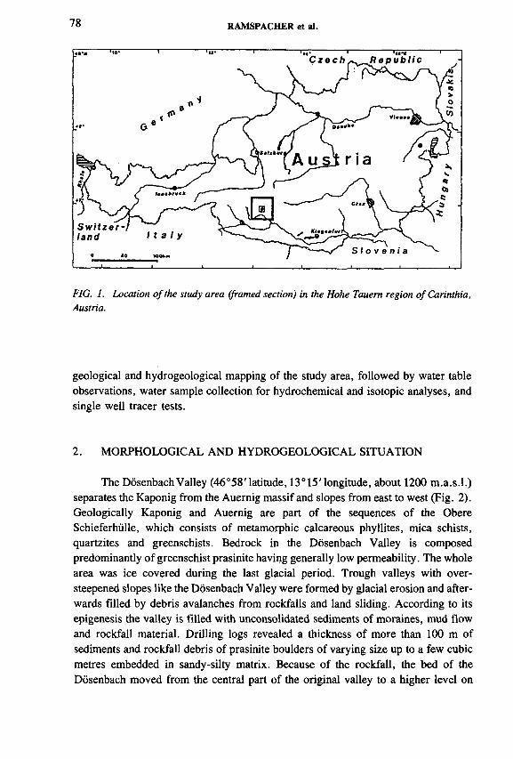
78 RAMSPACHER et al.
FIG. 1. Location o f the study area (framed section) in the Hohe Tauem region o f Carinthia, Austria.
geological and hydrogeological mapping of the study area, followed by water table observations, water sample collection for hydrochemical and isotopic analyses, and single well tracer tests.
2. MORPHOLOGICAL AND HYDROGEOLOGICAL SITUATION
The Dôsenbach Valley (46°58' latitude, 13° 15' longitude, about 1200 m .a.s.l.) separates the Kaponig from the Auernig massif and slopes from east to west (Fig. 2). Geologically Kaponig and Auernig are part o f the sequences of the Obere Schieferhiille, which consists of metamorphic calcareous phyllites, mica schists, quartzites and greenschists. Bedrock in the Dôsenbach Valley is composed predominantly of greenschist prasinite having generally low permeability. The whole area was ice covered during the last glacial period. Trough valleys with oversteepened slopes like the Dôsenbach Valley were formed by glacial erosion and afterwards filled by debris avalanches from rockfalls and land sliding. According to its epigenesis the valley is filled with unconsolidated sediments of moraines, mud flow and rockfall material. Drilling logs revealed a thickness of more than 100 m of sediments and rockfall debris of prasinite boulders of varying size up to a few cubic metres embedded in sandy-silty matrix. Because of the rockfall, the bed of the Dôsenbach moved from the central part of the original valley to a higher level on

IAEA-SM-336/18 79
the northern slope of the Kaponig. The present creek bed is incised into the underlying prasinites. The tunnel will transverse the valley-fill sediments over a distance of about 140 m, with minimum overburden thickness of only 12 m below the creek in the valley (Fig. 3).
The water tables in the Do wells have been monitored since January 1993 (Fig. 4). Only well Do9 develops groundwater in prasinite south o f the creek. The water table in Do9 was observed to be independent of creek discharge and precipitation until it dropped 4 m after flood events in summer 1994. This inverse effect is apparently an impact of scaling of preferential seepage paths by suspended load of the creek flood. All other wells are located north of the creek. Wells Do6 and Do7 develop groundwater in the rockfall aquifer; Do5, Do8 and DÔ12 in the prasinite.
DÔ5 • Borehole■ Tunnel alignement
FIG. 2. Site plan o f the Dôsenbach Valley between the Auemig and Kaponig massifs and o f the location o f the Do wells along this section o f the tunnel between Mallnitz (MA) and Obervellach (OV) (after Ref. [1]).

80 RAMSPACHER et al.
LEGEND
005/93
006/П OOSa/91
MoraineRockfall sediments:praslnlte boulders of varying sizemainly In sandy-silty matrixPraslnlteFault zone;nearly, vertical fractured praslnltes and mylonltes
NW
Tunnel
—i— 250
—I 500n50 100 1S0 200 300 350 400 450
FIG. 3. Geological cross-section o f the Dôsenbach Valley in the NW-SE direction with location o f the Do wells and groundwater tables indicated (after Ref [I]).
The groundwater table declines with a gradient of about 0.4 from NW to SE and reaches its deepest level 15 m below creek level in well DÓ8 (« 1 1 5 4 m .a.s.l.) on the northern bank of the Dôsenbach. The heads in the wells were observed to be independent of creek discharge but exhibit a tendency to drop with time, apparently reflecting deficits o f recharge due to shortage of winter precipitation during recent years. No response to precipitation events or snowmelt was observed; presumably such fluctuations are dampened by the storage capacity of the system. The water table contours provided only first order estimates of the hydraulic gradient, as shown by differing piezometric heads encountered during drilling. Hydraulic testing of the rockfall and the prasinite matrix in a few borehole depth intervals during drilling obtained hydraulic conductivities of the order of 10~5 m/s.

Prec
ipita
tion
(mm
) Gr
ound
wat
er
table
flu
ctua
tion
(m)
FIG. 4. Fluctuations o f the groundwater table in wells Dô6, Dô7, Dô8 and Dô9 and creek discharge o f Dôsenbach and precipitation at Mallnitz station during the observation period in 1993 and 1994.
oo
IAE
A-SM
-336/18

82 RAMSPACHER et al.
Months
-e- DÔ7 T»,- DÓ8 -e- DÓ9 DÔ12 -t- Dôsenbach
FIG. 5. Results o f isotopic analyses. Annual variation o f the 5180 values, 3H contents and electrical conductivities EC from water samples collected in March 1993, February, May, July, October and December 1994 from wells Dô7, Dô8, Dô9 and D ôl2 and from Dôsenbach. The groundwater data are mean values for samples collected at different depths in each well.

IAEA-SM-336/18 83
The hydrogeological investigations of the Dôsenbach Valley test site included the use of isotope and nuclear tracer techniques. Sampling for isotopic analysis was performed in March 1993, and February, May, July, October and December 1994. Single well tracer logging was undertaken in March 1993 and July 1994. Groundwater samples were collected from wells Dô5, Dô6, Dô7, Dô8, Do9 and Do 12 at different depths and creek water samples from Dôsenbach, Seebach and Wolsgen- bach. All samples were analysed for 2H, 3H, and 180 content. Single well tests [2] were carried out at different depths in all of the wells to measure specific discharge, q, of groundwater by tracer dilution logging, flow direction (FD) of groundwater by tracer direction logging, and vertical fluid movement of groundwater in the well by point to point tracer logging.
3.1. Isotopic results analysis
Groundwater was observed to flow downwards in all wells. This vertical flow precludes any downhole differentiation of the isotopic contents o f the water samples taken at various depths in each well. Therefore it is assumed that all samples represent unconfined groundwater in each well from the local water table horizon. Results of the isotopic analyses and of in situ logging of electrical conductivity (EC) for each sampling campaign are represented as a function of time in Fig. 5 and the overall means are listed in Table I.
The mean stable isotope data are plotted on a <52H-<5180 diagram in Fig. 6. The <52H and <5I80 values of groundwater have a spread along the meteoric water line, and the regional altitude gradient of —0 .1 6 7 oo á 180/100 m [3] indicates different altitudes o f the catchments for the groundwater in this relatively small area. The contents lie well within the ranges obtained for spring water sampled at different orographic altitudes during other studies in the Kaponig and Dôsenbach valleys [4]. Annual fluctuations in the stable isotope content of the springs are not observed, suggesting that the system has a high storage capacity, which rules out short turnover times. Owing to the higher altitude of the catchment area in the central part of the Hohe Tauem the stable isotope contents o f the Seebach and Wolsgenbach are more depleted than the contents of the Dôsenbach.
The 3H contents of groundwater and creek water ranged between 10 and 30 TU. The 3H contents of groundwater tend to correlate with the ECs but there is no apparent relation to the stable isotope contents. The code MULTIS was used for the calculation of groundwater ages given by Table I. The 3H input function was given by the concentrations in precipitation measured at the Villacher Alpe station (46°36' latitude, 13°40' longitude, 2150 m .a.s.l. altitude) of the Austrian Federal Environment Agency network [3].
3. ISOTOPIC AND NUCLEAR TRACER STUDIES

00
TABLE I. RESULTS OF ISOTOPIC AND SINGLE WELL TRACER MEASUREMENTS
Well FormationEC (/iS/cm) 5'®0 (7 00) ô2H (°/00) 3H (TU)
n ± a n ± a n ± a n p ±a
DÔ5 Prasinite 4 317 10 4 -1 2 .2 4 0.04 4 -8 9 .1 1.1 4 21 0.8D66 Sediments 12 316 16 12 - 12.20 0.13 12 -8 9 .5 1.5 12 31 3.8
D67 Sediments 6 343 15 6 -1 1 .7 9 0.10 6 -8 5 .6 1.8 6 28 2.0DÔ8 Prasinite 18 242 17 18 -1 2 .0 8 0.11 18 -8 7 .2 1.5 15 24 2.2Do9 Prasinite 24 98 13 24 -1 2 .2 9 0.30 24 -8 7 .8 2.1 24 16 2.2DÔ12 Prasinite 7 250 17 7 -1 1 .4 0 0.17 7 -8 2 .0 1.7 5 13 1.0
Dôsenbach 6 94 18 6 -1 2 .3 3 0.25 6 -8 7 .9 2.3 6 17 3.1
Seebach 6 50 14 6 -1 2 .6 2 0.52 6 -9 0 .2 3.8 6 15 1.6Wolsgenbach 6 159 30 6 -1 2 .5 5 0.62 6 -8 9 .8 4.8 6 14 2.5
RAMSPACHER
et al.

Well Formationq (m/d) FD (°)
НС К (m/s)MRT (a)
n —a + <7 n ±ff PFM DM EM
DÔ5 Prasinite 3 1 . 6 2 . 1 2 . 8 5 125 65 1.4 x 10"4 14.5 14 10.5
DÔ6 Sediments 6 1 . 1 1.4 1 . 8 6 245 40 1.6 X 10' 5 2 1 16.5 26
Prasinite 7 0.5 0 .6 0 .8 7 135 80 7.4 x 10' 5
DÔ7 Sediments 4 0.5 0 .8 1.3 4 250 40 3.0 x 10“5 16.5 17 42
DÔ8 Prasinite 1 0 0.7 1.7 4.1 4 135 75 1 . 2 x 1 0 " 4 14.5 15 12.5
DÔ9 Prasinite 8 1.7 3.1 5.5 1 2 85 50 2.8 x lO-4
DÔ12 Prasinite 6 0 . 1 0 .2 0.4 5 320 65 1 . 0 x 1 0 ' 5 5.5 58 140
Means (ц) and standard deviations (a) of electrical conductivities (EC) of the isotope contents ô2H, 3H and 6 180 , of flow direction (FD) and of lognormal distributed specific discharge (q) for each well. Means are calculated over the entire observation time. The mean residence times (MRT) are estimated by the piston flow model (PFM), by the dispersion model (DM) and by the exponential model (EM). Hydraulic conductivities (НС) К are average values derived from q values and flowmeter values by applying Darcy’s law. n = number of observations.
00Ln
IAEA
-SM-336/18
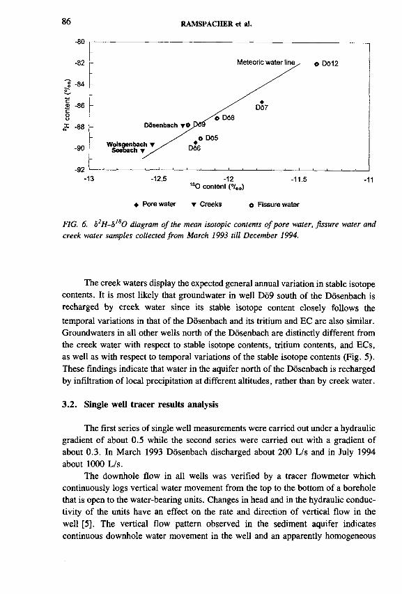
86 RAMSPACHER et al.
180 content (<700)
♦ Porewater ▼ Creeks o Fissure water
FIG. 6. ô2H-6,80 diagram o f the mean isotopic contents o f pore water, fissure water and creek water samples collected from March 1993 till December 1994.
The creek waters display the expected general annual variation in stable isotope contents. It is most likely that groundwater in well Do9 south of the Dôsenbach is recharged by creek water since its stable isotope content closely follows the temporal variations in that of the Dôsenbach and its tritium and EC are also similar. Groundwaters in all other wells north of the Dôsenbach are distinctly different from the creek water with respect to stable isotope contents, tritium contents, and ECs, as well as with respect to temporal variations of the stable isotope contents (Fig. 5). These findings indicate that water in the aquifer north of the Dôsenbach is recharged by infiltration of local precipitation at different altitudes, rather than by creek water.
3.2. Single well tracer results analysis
The first series of single well measurements were carried out under a hydraulic gradient o f about 0.5 while the second series were carried out with a gradient of about 0.3. In March 1993 Dôsenbach discharged about 200 L/s and in July 1994 about 1000 L/s.
The downhole flow in all wells was verified by a tracer flowmeter which continuously logs vertical water movement from the top to the bottom of a borehole that is open to the water-bearing units. Changes in head and in the hydraulic conductivity of the units have an effect on the rate and direction of vertical flow in the well [5]. The vertical flow pattern observed in the sediment aquifer indicates continuous downhole water movement in the well and an apparently homogeneous

IAEA-SM-336/18 87
permeability profile (e.g. see well Do6 in Fig. 7). However the flow patterns in wells in prasinite indicate significant downhole discontinuities in fracture permeability that were not generally apparent from the drilling logs (e.g. see well DÔ9 in Fig. 7).
The measurement of horizontal specific groundwater discharge and direction by tracer dilution was performed using packer tools which isolate a measuring volume from vertical flow. In the unconsolidated sediments the distance was about1 m between the measuring points. In the prasinite aquifer the measurements were only performed in fractured zones indicated by the drilling logs. The results are summarized by the mean values given by Table I for the lognormal distributed q values and the normal distributed FDs. In the overburden sediments the flow vectors indicate groundwater flow with an average q of about 1 m/d towards the southwest, following the slope o f the Dôsenbach valley. In the fissures and fractures of the prasinite aquifer groundwater flows to the southeast perpendicular to the Dôsenbach Valley and the specific discharge q varies between 0.5 and 3 m/d.
Q (l/min)
0 0,5 1 1,5 2
Q (L/min)
0 2 4 6 8
FIG. 7. Logs o f vertical downhole flow Q in wells Do6 and Do9.
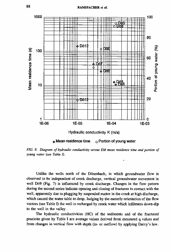
88 RAMSPACHER et al.
1000
10003,<DE<DOCФ*o
I 10
o D<o l>0
Й-i
0 D6 1 :><> )QE
l r ft r<>
<У >Q0
fe
О Dub
100
80
60
40
20
01E-03
©a5O)c3o>.
cotoCL
1E-06 1E-05 1E-04
Hydraulic conductivity K (m/s)
« Mean residence time о Portion of young water
FIG. 8. Diagram o f hydraulic conductivity versus EM mean residence time and portion of young water (see Table I).
Unlike the wells north of the Dôsenbach, in which groundwater flow is observed to be independent of creek discharge, vertical groundwater movement in well Do9 (Fig. 7) is influenced by creek discharge. Changes in the flow pattern during the second series indicate opening and closing of fractures in contact with the well, apparently due to plugging by suspended matter in the creek at high discharge, which caused the water table to drop. Judging by the easterly orientation of the flow vectors (see Table I) the well is recharged by creek water which infiltrates down-dip to the well in the valley.
The hydraulic conductivities (HC) of the sediments and of the fractured prasinite given by Table I are average values derived from measured q values and from changes in vertical flow with depth (in- or outflow) by applying Darcy’s law.

IAEA-SM-336/18 89
Mean residence times based on exponential model (EM) ages display the best linear correlation with HC values, as well as do mixing proportions of young groundwater in the recharge area of each well (Fig. 8). Hydraulic conductivities and EM ages correlate with stable isotope contents o f groundwater (see Table I); depleted isotope contents are found in areas of higher conductivities having more direct connection to recharge occuring at higher altitudes. The mean altitude of recharge for the groundwater of each well is found to vary from * 1200 m .a.s.l. (D612) to *= 1700 m .a.s.l. (DÔ5).
4. CONCLUSIONS
The following conclusions may be drawn based on groundwater discharge measurements, groundwater and creek water sampling for isotopic analysis for evaluation of the recharge conditions, and the hydrogeological reconnaissance along the line of the planned Kaponig Tunnel through the Dôsenbach Valley.
(1) Groundwater in the unconsolidated sediments o f the rockfall valley fill infiltrates from the northern rock slope, and is apparently recharged by precipitation at different altitudes. It is very unlikely that Dôsenbach water contributes to groundwater flow in the sediments under natural boundary conditions.
(2) Groundwater in the valley sediments flows towards the southwest in the direction of the valley slope and the mean conductivity is К » 2.10~5 m/s if calculated from single well tracer results.
(3) Groundwater in the prasinite aquifer north of the Dôsenbach is also recharged by groundwater infiltration from the Auemig massif, with no evidence of creek water infiltration.
(4) Groundwater in well Do9 in the prasinite aquifer south of the Dôsenbach is recharged by creek water.
(5) Groundwater in the prasinite aquifer flows towards the southeast in the direction of the slopes of the fractured and fissured layers, which apparently dip from north to south. The hydraulic conductivities in the prasinite fractures are greater than that in sediments (with the exception of Do 12) and vary significantly within short distances. Such changes in rock mass permeability are a common feature of fractured hard rock [6].
(6) The flow measurements reveal a very discontinuous hydraulic conductivity pattern in the prasinite aquifer (especially in well Do9), which warrants further investigations prior to tunnel construction.
(7) The best fit for the correlation between HCs and tritium ages enables critical evaluation of the models applied. This permits a realistic age determination of groundwater in well DÓ12, in spite of an ambiguous age calculation based on tritium.

9 0 RAMSPACHER et al.
(8) The HCs also correlate with the stable isotope contents of groundwater, providing information about the recharge conditions for the groundwater regime at each well. The differing 180 contents of the groundwater in each well reflect altitude effects with the small scale study area.
ACKNOW LEDGEM ENTS
Thanks are due to the technical staff of the Institut für Hydrologie and Johanneum Research who collected the samples, performed the field campaigns and carried out the isotope analysis.
REFERENCES
[1] RIEDMÜLLER, G., Kaponigtunnel, Baugeologischer Bericht des Inst. f. Techn. Geologie u. angew. Mineralogie, TU Graz (1993).
[2] DROST, W ., Single-well and multi-well nuclear tracer techniques — A critical review, UNESCO, Paris (1989).
[3] HUMER, G., Niederschlagsmessstellennetz Ósterreichs, Monographien Bd. xx, Bundesmin. f. Umwelt, Jugend und Familie, Vienna (in press).
[4] KNOLL, P., RAMSPACHER, P., RIEDMÜLLER, G., STEIDL, A ., Effects o f the Kaponig pilot tunnel on groundwater, 43rd Geomechanics-Colloquium, Salzburg (1994).
[5] KEYS, W .S., MacCARY, L.M ., Application of borehole geophysics to water- resources investigations, Techniques of Water-Resources Investigations of the United States Geological Survey, Book 2, Chapter E l, US Gov. Printing Office, Washington, DC (1971).
[6] BROCH, E., KJ0RHOLT, H., Verification of large scale permeability tests in hardrocks, Appl. Hydrogeol. 2 (1994) 9-16.
IAEA-SM-336/41
GEOHYDROLOGICAL AND MINERALIZATION STUDIES WITH ENVIRONMENTAL ISOTOPES IN A LARGE KALAHARI RANCHING DEVELOPMENT
B.T. VERHAGEN Schonland Research Centre,University of the Witwatersrand,Johannesburg, South Africa
C. MAROBELA Geoflux (Pty) Ltd,Gaborone, Botswana
G. SAWULA, B. KGAREBE Department of Chemistry,University of Botswana,Gaborone, Botswana
Abstract
GEOHYDROLOGICAL AND MINERALIZATION STUDIES WITH ENVIRONMENTAL ISOTOPES IN A LARGE KALAHARI RANCHING DEVELOPMENT.
Geohydrological, hydrochemical and environmental isotope studies in the Toteng- Sehitwa Grazing Lands area in northern Botswana were aimed at improving groundwater supply, on which the region is exclusively dependent. The area is sand-covered and flat, with the regional piezometric baseline lying inside the study area. It presents difficulties in geohydrological interpretation due to the absence of clear regional trends and the generally poor (total dissolved solids = 500 to 52 000 m g-L '1) groundwater quality. Environmental isotope data on a wide spread of some 100 samples were able to clarify the regional geohydrology considerably. The sluggishness of the hydrological system is reflected in the observed isotope values and hydrochemical types. Stable isotope values for groundwater in both the Kalahari and bedrock aquifers reflect evaporation before infiltration, and an increase in dissolved solid concentration, probably due to ponding in numerous small surface pans. The 14C frequency distribution suggests a continuum, ranging from unconfined conditions to completely confined groundwater, where mineralization and ô 13C values become more uniform. In general, mineralization shows no age dependence. Rain recharge is proven, in spite o f poor groundwater quality and lack of regional drainage. These apparently conflicting conclusions can be reconciled by invoking evapotranspirative losses from the saturated zone, resulting in an ongoing increase in overall groundwater mineralization. Such closed basin conditions without hypersalinity suggest that the aquifers are periodically, if partially, flushed during ‘pluvial’ episodes. Recharge can only be quantified in general terms, as aquifer porosity and saturated thickness, as well as initial radiocarbon activity, can only be estimated. Results from the study predict that exploitation should improve groundwater quality with time. This was confirmed by the historical records of a number o f supply boreholes.
91

92 VERHAGEN et al.
1. INTRODUCTION
The Toteng-Sehitwa Grazing Lands ranching area of the northern Kalahari is totally reliant on groundwater for human and stock watering supply. This area presents particular difficulties in geohydrological interpretation on account of the generally poor quality of the groundwater and the absence of clear regional hydro- logical trends, which could reveal groundwater dynamics. As a result, it was assumed that the area was receiving no significant present-day recharge. An environmental isotope study was undertaken to assist in clarifying the regional geohydrology and improve planning for the rational exploitation of the groundwater resource.
2. THE STUDY AREA
The area of study, some 7400 km2 in extent, annual rainfall 350 to 450 mm, is situated in north-central Botswana (Fig. 1). It lies to the south of the Boteti river, which drains the Okavango Delta. In order to stimulate commercial ranching, the
FIG. 1. Map o f Toteng-Sehitwa Grazing Lands area, showing ranch boundaries, sampling points, bedrock outcrops and Kalahari aquifer boundary.

IAEA-SM-336/41 93
W
Bedrock aquifers +|*— Kalahari aqu ifer— ►]
E1050
950
850
900
0 15 30km800 800
FIG. 2. An E-W section through the study area, showing groundwater standing in the Kalahari aquifer in the east and in the bedrock aquifer in the west.
Toteng-Sehitwa Grazing Lands area was subdivided into a number of farming units, which require adequate water supply for cattle and for human consumption.
The area is covered by Kalahari deposits, consisting of a sequence of aeolian, calcareous, and argillaceous sands and marls. These deposits are relatively shallow in the west, averaging some 40 m, but thicken in the east, reaching 150 m and more in places (Fig. 2). Here, the groundwater stands in the Kalahari beds, which are essentially unconsolidated and form a more or less continuous, primary aquifer. Groundwater may be locally confined by clay lenses.
In the west, groundwater stands in the underlying late Proterozoic sediments, which consist of mudstones, sandstones and diabase, and are exposed above the sand in isolated hills. This highly metamorphized bedrock has little primary porosity, and aquifers consist of fracture systems which are neither laterally extensive nor hydrau- lically continuous.
The surface topography is rather flat in the east, especially along the N -S axis, but rises in the west. Groundwater levels (30-80 m) conform to the surface topography, with gradients up to 0.015 in the west, levelling out to 0.0005 to 0.0002 in the east in the Tertiary to recent Kalahari deposits. This is depicted in the E-W section (Fig. 2). The regional piezometric baseline lies inside the study area, to the northwest, forming a groundwater level depression, or apparent sink. This depression coincides with a pattern of usually poorly defined surface drainages, which are centripetal and do not relate to the Boteti river in the north.

94 VERHAGEN et al.
The apparent sluggishness of the hydrological system is reflected in the hydrochemistry. There is some increase in groundwater mineralization from east to west in the Kalahari beds, and from southwest to northeast in the bedrock. A number of boreholes have shown some increase of mineralization with depth in the Kalahari aquifer. As the system is devoid of clear spatial hydrochemical trends, the chemical data (as well as the isotopic data; Section 4) will be treated semi-statistically. Most samples were taken from boreholes in regular production or from long term pumping tests on exploration boreholes.
The following principal hydrochemical types have been identified in the area:
3. HYDROCHEMISTRY
Type I Ca, Mg-НСОз (Cl, S 0 4)Type П Mg, Na, C a-H C 0 3 (Cl, S 0 4)Type Ш Na-НСОз (Cl, S 0 4)Type IVA N a-Cl (H C 03, S 0 4)Type IVB N a-C l (S 04, HCO 3 )Type V N a-S 0 4 (Cl, HCO 3 )
100
90
80
70
60
ф 50 £
40
30
20
10
0
И И
o Cl meq/L
♦ S 0 4 meq/L
в »
IBв в
■ ■*
9 *♦• ♦♦ и * * ч *
500 1000ЕС (mS/m)
FIG. 3. Scattergram o f Cl and S04 ion concentrations in groundwater as a junction o f the electrical conductivity.

IAEA-SM-336/41 95
FIG. 4. Scattergram o f the ionic ratio (Ca + Mg)/Na fo r groundwater as a function o f the H C 03 concentration. Also shown is an exponential f it to the points.
In the Kalahari beds, Types I to IVB are found, Type I having been encountered in only one borehole, which evolved into Type IVA with time. In the bedrock aquifers the same types were found, with the exception of Type П. The only case of Type I was shown to be very recent, with a high N 0 3 content. There is an additional, localized bedrock Type V which probably develops through oxidation of sulphides.
The total dissolved solids concentration of the groundwater in the study area ranges from 500 to 52 000 m g-L -1, the overwhelming majority of cases being brackish to saline. Both S 0 4 and Cl show strong, near linear correlations with total dissolved solids (TDS) (or electical conductivity; Fig. 3), which indicates that these conservative constituents of groundwater are being steadily enriched up to high overall mineralizations. These facts again suggest very little solute loss through drainage, and that lateral movement of groundwater is minimal.
Alkalinity values range from 1.2 to 35.3 m e q -L 1. The lowest values are for very low residence time, low mineralization groundwater. The values are plotted against the ratio (Ca + Mg)/Na in Fig. 4. This shows the classical relationship, where the low alkalinity values are associated with Ca and Mg. High H C 03 alkalinity can only exist in the presence of Na dominance, which can develop through(1) cation exchange, (2) calcite precipitation, both of which decrease the (Ca + Mg)/Na ratio, and (3) evapotranspirative enrichment of all ions. This relationship, and the high alkalinity values achieved, support the model of effectively immobile water, with a considerable enrichment in mineralization through évapotranspiration. Such high H C 03 values which develop in the aquifer have an effect on the observed 14C values and their interpretation.

96 VERHAGEN et al.
Along with a hydrochemical survey, close on 100 samples for comprehensive environmental isotope analysis ( 14C, 13C, 3H, 2H and 180 ) were taken from some existing deep production wells and project observation boreholes. The geographic distribution of all the parameters shows very few clear trends, as was the case with the chemical data. The isotope data is therefore also treated semi-statistically.
4.1. Stable isotopes
Groundwater stable isotope values are displayed on a ôD -ô180 diagram in Fig. 5(a). The values fall between the world meteoric water line (WMWL) and a regression line of slope 5.5, characterizing evaporation. Recharge therefore occurs through a range of surface mechanisms: direct rain infiltration, various degrees of surface evaporation before infiltration, and mixtures of these. The same data are also plotted in Fig. 5(b), which shows results for two samples taken at different times from the Boteti river. These reflect the extreme evaporation of the surface water in the vast Okavango inland drainage [1, 2], and fall on a similar evaporation trend line.
It might be concluded that the groundwater reflects diluted remnants of water infiltrated during earlier, widespread transgressions of the area by water from the delta and/or the river. Such a model would however require a degree of time dependence of ô 180 data, for example. Figure 6 shows that, except for a few high ¿¡180 values in the range 45-60 pmC, there is no correlation between ô 180 and radiocarbon values as a measure of groundwater residence time. The stable isotope values must therefore be mainly established by ongoing processes. The evaporation trend can be understood in terms of the temporary storage or ponding of rain water in, and partial evaporation from, a few larger and numerous smaller pans or ephemeral playa lakes which characterize the area. The common evaporation trend may be ascribed to the similarity in climate for the study area and the delta, generating similar enrichment factors during open surface evaporation.
The electrical conductivity values are plotted against ô 180 for all sampling points in Fig. 7. There is a general positive correlation, but with wide scatter. This scatter appears to be grouped around several correlation trends. The upper and the lower have been emphasized by straight lines. These trends are interpreted as follows: low concentrations of some of the ions enter the system dissolved in rain water, which dissolves further ions deposited from aerosols on the surface. Some concentration of these dissolved constituents occurs due to évapotranspiration from the unsaturated zone, which has only a minor effect on the stable isotope composition of the infiltrating water. Surface evaporation in areas of rainwater ponding (e.g. in pans) has a major effect on the stable isotope composition of the residual water and
4. ENVIRONMENTAL ISOTOPES

IAEA-SM-336/41 97
30
20
10
0
~ -10 Оé.О -20СО
-30
-40
-50
-60-8 -6 -4 -2 0 2 4 6 85’80 (%o)
FIG. 5(a). Scattergram o f SD-8,s0 fo r all groundwater, showing the world meteoric water line (WMWL) and an evaporation trend line (see also (b)); (b) Scattergram o f ¡>D-ôls0 for all groundwater, including two samples from the Boteti river. Also shown are the world meteoric water line (WMWL) and the same evaporation trend line as shown in (a).

98 VERHAGEN et al.
14C (pmC)
FIG. 6. Scattergram o f ô'8О plotted against 14C values.
FIG. 7. Scattergram o f electrical conductivity plotted against ôI80 . Upper and lower bounding lines are shown to emphasize trends.

IAEA-SM-336/41 99
increases the mineralization. Biogenic activity generates dissolved inorganic carbon, balanced by cations dissolved from soil carbonates and residual feldspars.
These various constituents are transported to the saturated zone during recharge. In the present climate there is little or no lateral groundwater transport, as seen from the very low piezometric gradients, and no significant hydrochemical or isotopic trends, except for the outcrop areas. There are no identifiable ‘recharge’ or ‘discharge’ areas. The only possible regional loss factor is general évapotranspiration from the saturated zone, producing an increase in mineralization with time, but without isotope fractionation. This loss factor is probably variable by area. Superimposed on this are evaporation centres where significant surface concentration of dissolved constituents occurs. These introduce the evaporation signal on the groundwater, accompanied by higher than average mineralization.
4.2. Radiocarbon and tritium
The 14C frequency distribution (Fig. 8) shows a continuum from a sharp cutoff at 80-85 pmC, with a maximum around 60 pmC and extending to near zero values. The two cases at > 100 pmC are found at the rock outcrops in the southwest, and clearly represent post-bomb recharge. These two cases can be understood in
14
12
10
■й'Зй'УЛ'Л
15 25 35 45 55 65 14C (pmC)
75 85 95 105
FIG. 8. Frequency distribution histogram for 14С values in groundwater.

100 VERHAGEN et al.
FIG. 9. Scattergram o f 14C against 3H values fo r available data pairs. Also shown is a line defining the locus o f data points calculated with the exponential mixing model [3].
FIG. 10. Scattergram o f à’3С plotted against 14С values in groundwater.

IAEA-SM-336/41 101
terms of lateral, and relatively shallow, drainage, induced by the very local topographic relief. All the other cases are for deeper groundwater, mostly with very low rest level gradients, and are interpreted as mixtures between deeper and shallower groundwater.
Tritium in southern African rain has declined to near natural values. A selection of samples was analysed for tritium, as it is still a useful indicator of shorter term groundwater turnover rates. Figure 9 shows the radiocarbon values plotted against available 3H data. Also shown is the theoretical relationship produced by the exponential mixing model [3], which calculates the locus of points for different mean residence times assuming a uniformly recharged, isotropic, phreatic aquifer. The input functions are the time dependent 3H values in rain [4] and atmospheric 14C [5]. The observed 14C values all lie well below this theoretical curve, which is ascribed to:
(1) dissolution of ‘dead’ carbon from the aquifer(2) dilution of biogenic H C 0 3 with ‘fossil’ alkalinity (see Section 3) and(3) mixing of water with widely differing mobilities in individual boreholes.
Higher 14C values, up to 85 pmC, are taken to represent relatively shallow, unconfined conditions. A number of these cases are found in the bedrock aquifer. The peak of the distribution at around 60 pmC is ascribed to deep phreatic conditions, generally encountered in the Kalahari aquifer. The lower values represent increasing confinement in both aquifers. Values of < 10 pmC all occur in the thicker Kalahari deposits, with argillaceous horizons. The influence of post-bomb radiocarbon is masked by the various dilution factors enumerated above, as is suggested
FIG. 11. Scattergram o f electrical conductivity plotted against 14С values for groundwater.

102 VERHAGEN et al.
by the just measurable tritium in some cases. This model is supported by the relationship between 513C and 14C (Fig. 10). The <513C values are seen to have their greatest scatter and most negative values at higher 14C; for lower 14C, i.e. more confined conditions, ô13C values become less negative and more uniform, suggesting maximum equilibration with aquifer material, and minimal potential for dilution through recharge.
Overall mineralization, as represented by the electrical conductivity, shows practically no correlation with 14C values (Fig. 11). The two values for 14C > 100 pmC, at the rock outcrops, are for relatively low mineralization. As was observed for <513C, mineralization becomes more uniform for very low values of 14C. This suggests stable, confined conditions which average out the large fluctuations between saline and fresh cases, such as observed for groundwater with shorter turnover time.
Estimates of recharge can be made on the basis o f the 14C data. Only in the bedrock aquifer were some radiocarbon values obtained for boreholes for which detailed logs are available. It is however impossible to assess its effective porosity. Numerous detailed logs are available for boreholes in the Kalahari beds, for none o f which, coincidentally, are 14C values available.
The approach taken was to assess the thickness of saturated sand from 22 observation borehole logs. Values ranged from 10 to 100 m with a mean of 31 m. The range of I4C values of 60 to 80 pmC for a different set o f similarly constructed production boreholes in the Kalahari aquifer, was taken as relevant. Lower 14C values are ascribed to increasing groundwater confinement. An initial concentration for 14C cannot readily be calculated, and is likely to be variable in this environment. The relevant 14C values are therefore rather arbitrarily taken to represent a range of mean residence times of 1000 to 3000 a. The porosity of unconsolidated sand is conservatively estimated at 20%.
The relationship used is
R = p H/T
where R is the recharge rate, p the porosity, H the saturated thickness of aquifer penetrated by the borehole, and T the mean residence time. The values estimated above give a range of possible recharge values of 0.7-12 m m -a '1, with a mean value of 3 m m -a’1. Similar values have been arrived at in other studies of the Kalahari, based on isotopic and water balance considerations [6, 7].
5. CONCLUSIONS
(1) Environmental isotopes and hydrochemical data show qualitatively thatgroundwater in the the area is a renewable resource. Except where confined,

IAEA-SM-336/41 103
the groundwater cannot be regarded as fossil. The area as a whole is receiving ongoing rain recharge much higher than the poor groundwater quality and drainage would suggest. Recharge can be schematically quantified at some 3 m m -a”1, based on estimates of Kalahari sand porosity and depth and initial 14C activities.
(2) The poor quality of groundwater in the presence of rain recharge can only be reconciled by evapotranspirative losses from the saturated zone. Water demand of phreatophytes and upward vapour transport through the unsaturated zone have been suggested [7] elsewhere in the Kalahari basin. Similar loss mechanisms have been invoked in northwest Africa [8] to explain the existence of large scale depressions in the phreatic surface. Such a depression is also observed in the Toteng-Sehitwa study area. The similarity of stable isotope and chemical data for the Kalahari and bedrock aquifers show that surface conditions and water loss mechanisms are the prime factors controlling mineralization, rather than aquifer lithology.
TABLE I. HISTORICAL DATA OF BOREHOLES
Borehole YearTDS
(mg/L)Year
TDS(mg/L)
Comments
A 1982 1858 1991 1620 All major ions decreased
В 1990 1812 1991 1340 All major ions decreased
С 1982 11866 1991 9720 Ca, K increased, other ions decreased
D 1981 2596 1991 2340 Ca, K, H C 0 3 increased and other ions decreased
E 1981 2736 1991 2720 No change
F 1984 6056 1991 1380 H C 0 3 increased but other ions decreased
G 1981 7562 1991 7180 All ions decreased except for К
H 1985 3800 1991 3640 S 0 4 increased but other ions decreased
I 1986 2048 1991 1500 Cl increased but other ions decreased
J 1981 4402 1991 4800 HCO3 increased but other ions decreased
K 1982 4282 1991 3900 HCO3 , Cl increased but other ions decreased
L 1984 352 1991 1 2 1 2 HCO3 decreased but other ions increased
M 1982 4262 1991 5880 All ions increased, H C 03 constant
N 1984 1882 1991 1700 HCO3 , Cl increased but other ions decreased
O 1981 3560 1991 2760 HCO3 increased but other ions decreased

104 VERHAGEN et al.
(3) The mechanism proposed in Section 4.2 implies that, whilst groundwater is being turned over, its mineralization is conservative. The area therefore develops a palaeosalinity, for which there is no external sink, which invalidates mass balance considerations. The isotopes of the water molecule are non- cumulative. Carbon-14 retains a certain qualitative validity, on account of its having a sink: radioactive decay and partial precipitation in calcrete. On the other hand, ô 13C is cumulative and reflects long term development of alkalinity, inasfar as it is coupled to Na. The chloride mass balance method applied to the saturated zone will produce unrealistically low estimates for rain recharge. This problem has been pointed out in an isotope study of the Serowe area, Botswana [7].
(4) Closed basin conditions without hypersalinity suggest that the aquifers are periodically flushed during ‘pluvial’ episodes, as was proposed for the rest of the Kalahari [6]. However, the sluggish present-day hydrology suggests that even pluvial episodes cannot completely reset the mineralization, especially of the deep groundwater. This is in accord with the observed increase in mineralization with depth.
(5) A very effective way of removing dissolved solids is groundwater exploitation. If the model for the mineralization of the groundwater is tenable, ongoing exploitation in the presence of ongoing recharge should reduce the mineralization. This proposition was tested with historical data (Table I) on a number of production boreholes. Time spans involved ranged from six to ten years in most cases, with a minimum of one year and a maximum of 25 years. Of the 15 production boreholes in the data set, 11 show significant reduction in overall mineralization, ranging from 5% to 77%, three show an increase, and one remains unchanged.
REFERENCES
[1] MAZOR, Б ., et al., Northern Kalahari ground waters: Hydrologie, isotopic and chemical studies at Orapa, Botswana, J. Hydrol. 34 (1977) 203-234.
[2] DINÇER, T., HUTTON, L.G., KUPEE, B.B.J., “ Study, using stable isotopes, of flow distribution, surface-ground water relations and évapotranspiration in the Okavango swamp, Botswana” , Isotope Hydrology 1978 (Proc. Symp. Neuherberg, 1978), Vol. 1, IAEA, Vienna (1979) 3-24.
[3] VERHAGEN, B.T., GEYH, M.A., FROEHLICH, K., WIRTH, K., Isotope Hydro- logical Methods for the Quantitative Evaluation of Ground Water Resources in Arid and Semi-Arid Regions, Research Reports of the Federal Ministry for Economic Cooperation, Bonn (1991).
[4] INTERNATIONAL ATOMIC ENERGY AGENCY, Statistical Treatment of Data on Environmental Isotopes in Precipitation, Technical Reports Series No. 331, IAEA, Vienna (1992).
IAEA-SM-336/41 105
[5] ZUBER, A., “ Mathematical models for the interpretation of environmental radioisotopes in groundwater systems” , Handbook of Environmental Isotope Geochemistry, Vol. 2, Elsevier, New York (1986) 1-59.
[6 ] VERHAGEN, B.T., “ Isotope hydrology of the Kalahari: Recharge or no recharge?” , Palaeoecology of Africa (HEINE, K., Ed.), Balkema, Rotterdam (1990) 143-158.
[7] VERHAGEN, B.T., “ Detailed geohydrology with environmental isotopes: A case study at Serowe, Botswana” , Isotope Techniques in Water Resources Development 1991, IAEA, Vienna (1992) 345-362.
[8 ] NDIAYE, B., ARANYOSSY, J.F., FAYE, A., “ Le rôle de l ’évaporation dans la formation des dépressions piezométriques en Afrique sahélienne: hypothèses et modélisation” , Les ressources en eau au Sahel, IAEA-TECDOC-721, IAEA, Vienna (1993) 53-64.


IAEA-SM-336/20
CONTROLS ON THE GEOCHEMISTRY OF SULPHUR IN THE EAST MIDLANDS TRIASSIC AQUIFER, UNITED KINGDOM
W .M . EDMUNDS, P.L . SMEDLEY British Geological Survey,Wallingford, Oxfordshire
B. SPIRONatural Environment Research Council
Isotope Geology Laboratory,Keyworth, Nottingham
United Kingdom
A bstract
CONTROLS ON THE GEOCHEMISTRY OF SULPHUR IN THE EAST MIDLANDS TRIASSIC AQUIFER, UNITED KINGDOM.
Changes in downgradient sulphate concentrations in the East Midlands aquifer fall into three categories: (1) modem inputs; (2) pre-industrial inputs; (3) palaeowater undergoing evaporite dissolution. The relative importance of sulphur derived from external (atmospheric and anthropogenic) inputs and water/rock interaction are investigated using sulphur isotopes and other hydrogeochemical indicators (S04, Cl, Br/CI, N 03, Sr and B). In the mainly unconfmed modem groundwaters the wide spectrum of 6 34Ss04 values (ranging from 3.1 to 20.97oo) indicates a variety of input sources. Waters with the lowest values of 534SS04 (3 to 5700) are associated with high Cl and high Br/CI values and must contain a component derived from the oxidation of pyrite; their source is Coal Measures mine drainage which recharges the aquifer via rivers crossing the outcrop. Other likely sources of sulphur include rainfall and dry deposition, inorganic agricultural chemicals and possibly sewage sludge. A zone of waters of pre-industrial age may be recognized in the aquifer by their low chloride (6-10 m g-L-1) and S04 concentrations (< 1 0 m g-L '1). In these waters the 534Ss04 ratios (around 9°/00) are significantly higher than present-day rainfall, which is dominated by heavier industrial emissions. These waters represent the composition of Holocene rainfall. Sulphate increases markedly in the oldest (Late Pleistocene) waters in some of which gypsum saturation is reached. The 534Ss04 in the sulphate-rich waters is relatively constant at around 20°/oo and indicates an evaporite source derived either from the topmost Sherwood Sandstone or the lowest Mercia Mudstone strata.
107

108 EDMUNDS et al.
1. INTRODUCTION
The East Midlands aquifer is a red-bed formation of Triassic age situated in a densely populated, mainly industrial area of eastern England. It is a well calibrated groundwater system on account of the many hydrogeological and geochemical studies, from which the residence times and the geochemical processes are reasonably well understood [1-3]. Its straightforward hydrogeology and clear sequential hydrogeochemical changes along the flow gradient have made it the focus of several studies where isotopic techniques can be tested. Investigations using 36C1 [4] have been used to assist the palaeoclimatic interpretation of the palaeowaters found in the confined aquifer.
Despite the amount of research already conducted, this aquifer still contains a number of unresolved problems which are significant in terms of managing the water resources and their quality. The water is remarkably pure and of low salinity to a distance of up to 15 km from the outcrop but it is vulnerable to incoming pollution. Owing to the absence of reduced mineral phases and organic carbon, dissolved oxygen has persisted for several thousands of years, creating a large reservoir of aerobic groundwater near the outcrop. This produces problems as well as benefits since conditions do not exist for denitrification [5] and the attenuation of pollution. It has also been shown that sulphate reduction is unlikely to have been significant [6].
The main objectives of this paper are to investigate a number of problems pertaining to the behaviour of sulphur in the East Midlands aquifer which are of importance in terms of water resources. These include (1) identification of the sources of sulphur at the outcrop (atmospheric deposition, agricultural as well as human and industrial wastes), (2) the capacity, if any, for sulphate reduction, (3) the characterization of palaeogroundwaters and (4) the source(s) of sulphate increase in the deep aquifer. In fact, the limits to potability in this aquifer come not from chloride but from sulphate. The sulphate concentrations and origins may also give some indication as to the possibility of leakage from overlying or underlying aquifers. Sulphur isotopes are used with other geochemical parameters to help solve these questions.
2. HYDROGEOLOGY AND MINERALOGY
The Sherwood Sandstone dips gently to the east but thickens from around 120 m in the south of the area to around 300 m in the north (Fig. 1). The hydrogeology is described in detail in references cited above and the description here is restricted to that needed to explain the sulphur geochemistry.
The lower half of the formation consists of red or pink uncemented sandstone with occasional mudstone partings. The upper half contains false-bedded and pebbly horizons. Detrital dolomite and/or a freshwater calcite cement may form up to 3% of the rock and this has a strong influence on the hydrochemistry. The lithology is

IAEA-SM-336/20 109
FIG. 1. Outcrop o f the East Midlands (Sherwood Sandstone aquifer) with sites sampled and the distribution o f sulphate; numbers correspond to Table I. The division between Holocene and Late Pleistocene groundwaters, based on oxygen isotopes (ô isOH20), is also shown. UK national grid co-ordinates are indicated.
deficient in organic carbon, pyrite and other reducing material, except in occasional grey-green horizons near the base of the aquifer. The Sherwood Sandstone is over- lain by a transitional sequence of sands and mudstones containing thin gypsum bands, the Colwick Formation, with which it is generally in hydraulic continuity. This in turn is overlain by the main aquiclude, the Mercia Mudstone, which contains significant evaporite deposits.
The sulphur isotope ratios of Triassic evaporites have been investigated and summarized by several authors [7-9]. The main Triassic evaporites in the United Kingdom (Mercia Mudstone Group), which are of Norian age, are considered to be

TABLE I. CHEMICAL AND ISOTOPIC DATA FOR GROUNDWATERS FROM THE EAST MIDLANDS TRIASSIC SANDSTONEData are grouped into modern waters (1-10), pre-industrial (Holocene) waters (11-15), late Pleistocene (16-30) and Mercia Mudstone waters (31). Subscript m denotes molar ratios. Isotopic ratios are given in / OO relative to CDTa, SMOWb and PDBC for S34S, <5180 and <513C respectively.
No. Locality Temp.(°C)
Welldepth(m)
Ehd(mV)
so4(mg-L-1)
Cl(m g-L"1)
N 0 3-N(m g-L"1)
so4/cim Br/Clm Sr(m g-L"1)
В
(MS'L-1)a34s(°/oo)
О "5
OO 0
5 13C
C U
<5Iegypsum
1 Budby 2 9.6 67 399 102 156 9.2 0.24 0.0034 0.027 25 3.26 -7 .2 -1 3 .8 -1 .6 32 Far Baulker 9.8 143 394 63.7 30.5 13.5 0.77 0.0013 0.020 13 4.75 - 8.0 -1 3 .5 -1 .8 9
3 Amen Comer 1 9.9 131 419 64.2 46.0 12.0 0.51 0.0014 0.022 17 5.29 -8 .7 -1 3 .2 -1 .9 04 Clipstone 1 10.1 91 363 139 285 11.6 0.18 0.0046 0.278 50 5.39 -7 .7 -1 3 .6 -1 .4 4
5 Sunnyside 4 10.5 97 452 136 70.5 15.6 0.71 0.0012 0.044 60 20.92 - 8.0 -1 6 .1 -1 .3 96 Rufford 4 10.2 125 400 46.9 31.0 5.3 0.56 0.0021 0.009 8.8 16.48 - 8.1 -1 2 .3 -2 .1 6
7 Rufford 3 10.6 123 280 45.9 126 2.8 0.13 0.0036 0.017 33 3.1 - 8.1 -1 2 .7 - 2.028 Elkesley 5 10.6 101 340 65.7 138 6.7 0.17 0.0028 0.034 38 2.6 - 8.1 -1 3 .9 -1 .9 3
9 Everton 3 11.4 138 168 81.9 72.8 3.2 0.41 0.0027 0.420 24 13.69 - 7 .9 -1 3 .8 -1 .6 2
10 Ordsall 1 10.9 198 266 38.8 35.4 8.9 0.40 0.0011 0.035 12 8.55 -8 .5 -1 1 .7 -2 .0 9
11 Ompton 3 1 1 .1 176 426 5.1 13.5 1.5 0.14 0.0016 0.042 9.2 - 8.1 -1 3 .2 -3 .1 7
12 Halam 1 11.4 171 380 4.4 10.0 2.5 0.16 0.0016 0.027 8.1 9.0 -7 .8 -9 .7 -3 .3 6
13 Markham Clinton 1 11.8 230 416 7.6 7.8 0.64 0.36 0.0016 0.103 7.5 8.3 - 7 .9 - 11.6 -3 .1 9
14 Hayton 11.9 396 90.3 6.1 5.5 < 0.01 0.0025 0.43 16.4 - 8.1 -1 2 .4 -1 .8 4
15 Grove 2 13.3 335 104 22.7 6.3 0.04 1.32 0.0020 0.289 10 14.27 -8 .5 - 11.8 -2 .5 5
EDMUNDS
et al.

16 Corringham Road 14.0 309 -9 9 356 54.5 < 0.01 2.40 0.0029 1.94 36 23.22 - 8.6 -1 0 .3 -0 .9 7
17 Rampton 14.1 306 101 55.5 7.0 0.11 2.91 0.0023 0.356 13 17.93 -9 .5 - 8.8 -2 .0 4
18 Peartree Hill 14.3 204 39 74.5 9.7 0.50 2.82 0.0022 0.606 10 19.38 -9 .0 - 9 .9 -1 .7 919 West Burton 15.6 395 129 101 15.1 0.13 2.45 0.0025 0.713 9.5 16.83 -9 .1 -1 0 .5 - 1.6620 Gainsborough 5 17.0 61 453 11.3 0.24 14.7 0.0020 2.08 42 20.55 - 9 .0 -1 0 .3 -0 .8 1
21 Newton 2 17.0 431 107 80 10.0 0.14 2.93 0.0022 0.479 11 20.96 -8 .7 -1 0 .4 -1 .8 122 Gainsborough 2 17.4 462 164 201 24.9 0.37 2.96 0.0025 0.983 23 19.37 -8 .9 -1 0 .4 -1 .2 8
23 Gainsb’ Humble Carr 17.6 610 139 154 19.7 0.14 2.87 0.0040 0.706 12 20.18 -8 .9 - 10.0 -1 .4 5
24 Clay Lane 1 17.8 7 76 15.1 < 0.01 1.85 0.0028 0.625 < 30 14.6 -9 .1 - 8 .9 -1 .7 5
25 Clay Lane 2 17.6 63 43.7 14.8 0.07 1.08 0.609 < 30 14.3 - 8 .9 - 8.1 -2 .0 6
26 Cottam 17.9 430 96 89.2 10.4 0.04 3.15 0.0022 0.428 11 19.64 -9 .3 - 10.8 -1 .7 6
27 Gainsborough 3 18.6 498 133 116 18.8 0.13 2.26 0.0025 0.565 10 18.95 - 8 .9 -9 .9 -1 .6 128 South Scarle 18.6 354 122 113 9.2 0.94 4.51 0.0022 0.826 19 5.54 -9 .1 -9 .8 -1 .5 9
29 Yawthorpe 21.6 406 15 1330 22.1 0.04 22.1 0.0025 5.26 134 19.5 - 8 .9 -1 6 .0 -0 .2 5
30 Welton 21.5 804 -68 1500 5000 0.02 0.11 0.0016 25.9 192 23.5 - 8.6 -1 7 .2 -0 .0 7
31 Caddow Hill Farm 10.0 40 1250 41.6 3.88 11.0 0.0013 5.03 240 15.8 -7 .1 -1 3 .3 -0 .0 7
a CDT: Canyon Diablo troilites. b SMOW: Standard mean ocean water. c PDB: Peedee belemnite. d Eh: Redox potential. e SI: Saturation index.
IAE
A-SM
-336/20

112 EDMUNDS et al.
derived from earlier continental evaporites with <534SSq4 of around 12°/00 as opposed to the probable marine ratio of 19700. In the lower stages of the Mercia Mudstone Group from the Cheshire Basin (Spiro, unpublished data) the <534Ss04 ranges from 15-18°/0o and there is evidence that the ratios become more enriched near to the contact with the Sherwood Sandstone.
3. ANALYTICAL PROCEDURES
Sampling was carried out for sulphur isotopes as part of a regional study intended to update the hydrogeochemistry of the Sherwood Sandstone aquifer with data from a number of new boreholes drilled since the initial investigations in the late nineteen-seventies. The network of 45 accessible sources, some multiple sources at the same site, is shown in Fig. 1 and samples for sulphur isotope determination were collected at 27 representative sites which are numbered on Fig. 1. One sample of groundwater was collected from a domestic well from the Mercia Mudstone to investigate the characteristics of groundwater in the overlying aquiclude. Field hydrogeochemical analysis was carried out and Eh results are reported. Sulphate (and any other sulphur species) were measured as total sulphur by inductively coupled plasma (ICP) optical emission spectroscopy. This method was also used to measure cations and minor elements. Bromide, nitrate and chloride were measured by automated colorimetry. Oxygen and hydrogen isotopes were determined with a VG 602E mass spectrometer using standard techniques. Boron and strontium were determined by ICP mass spectrometry.
Barium sulphate precipitates were prepared for sulphur isotope analysis following the method of Coleman and Moore [10]. Analysis was carried out with a VG SIRA 10 mass spectrometer. Results are reported as <534SCDT with an overall analytical reproducibility of + 0 .1 7 00.
4. HYDROGEOCHEMISTRY OF SULPHUR
Sulphate concentrations and sulphur isotope ratios are shown in Table I together with other hydrochemical data relevant to the interpretation of sulphur in the Sherwood Sandstone aquifer. The data points used in this study are shown in Fig. 1 together with the distribution of sulphate. A group of low sulphate groundwaters in the confined aquifer, but near to the outcrop, separates two areas with higher sulphate. This demarcates three distinct facies which can be recognized on the basis of sulphate and by other hydrochemical indicators:
(1) M odem waters in which the sulphate concentrations are mainly related toanthropogenic inputs. Other indicators of human activity include high nitrateand chloride [2]. The groundwater is aerobic throughout.

IAEA-SM-336/20 113
(2) Pre-industrial waters in which the concentrations of sulphate may be as low as 5.0 m g-L _1 S 0 4. These waters are mainly aerobic and also contain Cl concentrations lower than those in present-day rainfall. The sulphate concentrations are considered to represent the pristine baseline conditions which predated the industrial era.
(3) Late Pleistocene groundwaters in which the sulphate increases progressively with residence time. These waters are mildly reducing (Eh 10 to 150 mV), and with total Fe present but at concentrations generally below 0.2 m g-L -1 and traces of H2S only detectable (by smell) in a few sites. One sample is included from the deeper saline aquifer (30) but otherwise the Cl remains below 30 m g-L _1.
This subdivision of the aquifer is well illustrated in cross-section (Fig. 2) in which the sulphate (<534S) isotope ratios are also shown, using well-head temperature as a proxy for depth/distance from the outcrop. There is a relatively narrow
Temperature (°C)
FIG. 2. Sulphate occurrence and b34Ss04 values for the East Midlands Triassic aquifer. Data are plotted against groundwater temperature, which acts as a proxy fo r sample depth and distance downgradient.

114 EDMUNDS et al.
— -8 ОO'01
оGOСО
-9
-10О 10 20 30
(%о)
FIG. 3. Plot o f 634Ss04 against Ь180 Нг0 to distinguish modem and Holocene from Late Pleistocene groundwaters. The composition o f modem rainfall is plotted from sources mentioned in the text.
100
cnJE
ó 10
1
FIG. 4. Plot o f Cl against &34Ss04 fo r East Midlands groundwaters. The composition o f modem local rain (Mg) and groundwater after allowing fo r évapotranspiration (Mc) are plotted; also plotted are the corresponding range o f values fo r Holocene rain calculated using the results from Ref. [4].
■ ■ ■ ---- ----1 ■ • I
0
<g
0 0
! 0 1 v ¡ 0 j °I ! Л
Mel- 1 A *A -■------- -
H,PG- _____ „ e A
Mr L _ _ J
H.PR _
-1---- d—
0 10 20 30
b ^ S s o A 0/™)
LA T E C20RAINFALL
MODERN AND PRE-INDUSTRIAL
0 (HOLOCENE) RECHARGE
%0 0 А О О
о AA # LATE
A PLEISTOCENE RECHARGE
IAEA-SM-336/20 115
range of enriched compositions of ô34SSq4 in the palaeowaters, which contrasts with the much wider range of isotope ratios in the modern waters, representing a range of sources of sulphur. A number of key parameters (S 04, Cl, Br/Cl, N 0 3, Sr and B) may be used to assist in constraining the origins and reactions of sulphur.
A plot of <534SSo4 versus <5180 H2o (H20 ) (Fig. 3) separates the palaeowaters (Late Pleistocene) with 0180 Нг0 more negative than - 8 .5 7 00 (signifying Late Pleistocene recharge under a colder climatic regime) from Holocene or Modern recharge. The 0 180 Нг0 of late 20th century rainfall for the East Midlands [11], having a value of 8.0 + 0.2, is shown in Fig. 3. Some gradation between these two groups is the result of inevitable mixing due to pumping of water from a range of depths. The main group of palaeowaters has <534SSOl values between 14 and 22°/00, indicative of an evaporite origin.
The low concentrations of Cl are also a characteristic of the palaeowaters (Fig. 4), all but one having concentrations lower than the modern group. Several of the latter group have high Cl but with correspondingly depleted <534Ss04, as discussed below. The probable ô34Ssc,4 of modern rainfall is shown in Fig. 4 using data from Canada [12] but which is also likely to apply generally to present-day northern hemisphere rain and corresponds to values recorded in northern England, 3.5-5.6°/oo (Spiro, unpublished results). The likely composition of Holocene/Late Pleistocene rain and groundwater recharge is shown in Fig. 4 as calculated in Ref. [4] using a 36C1 model. The <534Ss04 values of the samples with the lowest Cl (and S 0 4) concentrations are significantly higher than those for modem rainfall and almost certainly represent the signature of Holocene rainfall which must have had virtually no dilution from sulphur as a result of water/rock interaction.
Waters with the highest S 0 4 concentrations also contain the heaviest isotopic compositions, indicating a probable evaporite source (Fig. 5). The most evolved groundwaters (e.g. at Yawthorpe and also shallow water in the evaporite bearing Mercia Mudstone-Caddow Hill Farm) are at or close to saturation with gypsum. Gypsum saturation is reached rapidly in the Mercia Mudstone, where gypsum is unquestionably present. On the other hand saturation is reached only after a residence time of 20 000-30 000 a in the deepest Sherwood Sandstone groundwater. This indicates that gypsum is unlikely to be present as a discrete mineral in the aquifer but that either (1) there is a very slow diffusive flux of groundwater from the overlying mudstone or (2) that interstitial water is being displaced from the Sherwood Sandstone. The compositions of S 0 4 in rainfall are shown in Figs 5 and 6 are derived from Ref. [13].
The high molar S 0 4/C1 ratios in the palaeowaters (Fig. 6) also strongly suggest that gypsum dissolution alone (from whatever source) is responsible for the salinity increase. The m S04/Cl ratios (Fig. 5) of all the modern waters are close to or less than 1. These also have a wide range of sulphur isotope ratios which suggest that origins other than evaporite dissolution are likely. Several of the waters lie close to the S 0 4/C1 ratio (0.3) of modem rain.

116 EDMUNDS et al.
834S so 4 (%»)
FIG. 5. Plot o f sulphate in groundwater against b34Ssc¡4. The compositions o f modem i (MfJ and modem groundwater (MG), after allowing fo r évapotranspiration, are shown.
S ^S so , (%°)
FIG. 6. Plot o f S04/Cl against 834SSOi for East Midlands groundwaters.

IAEA-SM-336/20 117
8“Sso4(%-)FIG. 7. Plot o f the molar Br/Cl ratio against 634Ss04fo r the East Midlands groundwaters. Selected sites are numbered according to Table I. Line С is modem sea water. Line A is local rainfall in the East Midlands and В is the range o f composition o f rainfall at unpolluted sites in the UK (Edmunds, unpublished data).
The mBr/Cl ratios (Fig. 7) of three of the highest chloride waters (1, 4 and 7) are considerably enriched in bromide. This supports an origin incorporating a mine drainage component in which the Br is derived by interaction with organic-rich sediments. Local collieries discharge mine drainage water into rivers which cross the sandstone aquifer and may recharge the unconfmed part of the aquifer. This explanation is consistent with the relatively light sulphur isotope ratio, which reflects sulphide oxidation in the Coal Measures arising from mining operations. The mBr/Cl ratio is low (< 0.002) in some of the modem waters. This indicates that halite or some other Br depleted source has influenced the composition. Two of these groundwaters also have high N 0 3-N and a source for the Cl as well as the sulphate (which has a relatively light sulphur isotope ratio) is likely to be related to pollution. One modem low mBr/Cl and high N 0 3 source (sample No. 5, Table I) has a ô34SSq4 of 2 1 7 00, which is likely to reflect fertilizer inputs derived from evaporite origin.
Strontium may be used as an indicator of carbonate- and sulphate-mineral reactions. Incongruent dissolution of carbonate minerals leads to Sr release and precipitation of a purer calcite. Gypsum and anhydrite should dissolve congruently to give roughly stoichiometric proportions of Ca and Sr. Sr may also be enriched in barite and is present in celestite. Whereas Sr may increase to tens of mg • L _1 in solution until celestite saturation is reached, Ba concentrations are limited by the
118 EDMUNDS et al.
lower solubility of barite. Sr concentrations are plotted relative to S 0 4 in Fig. 8. The S r/S 04 ratio produced by the dissolution of gypsum (line A) is also shown in Fig. 8 where the average of mainly Triassic samples is used, taken from Müller, quoted by Usdowski [14]. The sulphate in palaeowaters is roughly correlated with Sr by a line parallel to the gypsum dissolution line but the Sr concentrations are higher than those expected if derived directly from gypsum. It is likely therefore that gypsum alone is not responsible for the sulphate increase but that a small component of celestite (found elsewhere in Triassic evaporites) or the reaction of detrital dolomite may be responsible for the enrichment in Sr. The enrichment in Sr in Holocene waters at low S 0 4 concentrations is likely to be linked to the preferential dissolution of dolomite [2].
Most of the modem groundwaters from the unconfined aquifer have relatively high sulphate but contain low Sr. This group is unlikely to be influenced by evaporites from overlying formations. The compositions of rainfall — the background (marine) component as well as the total sulphate deposition — are shown in Fig. 8 after allowing for a local évapotranspiration factor of 3.46. The industrial (non-marine) component is over an order of magnitude higher than this baseline concentration [13], but the S 0 2 derived industrial excess will not be correspondingly enriched in Sr. The groundwater sulphate for some samples has a similar concentration to the rain and it is likely that a significant proportion of the sulphate is derived from atmospheric inputs. In contrast the S 0 4 concentration of the pre-industrial waters lies close to pristine rainfall inputs and may have changed little since the Holocene. The Sr enrichment in these low sulphate waters indicates the extent of water/rock reaction, probably with carbonates.
Boron also highlights differences between the groups of waters (Fig. 9). The pre-industrial group of groundwaters contain B /S 04 ratios which are close to a background marine aerosol value but with increasing S 0 4 they approach the compositions of the main group in which an evaporite signature (depleted in В relative to sea water) is found. The В/Cl in modem groundwater is intermediate between the maritime ratio and the evaporites. However it is possible that some enrichment in В may occur due to contamination from domestic wastes containing detergents. The gypsum saturated Mercia Mudstone groundwater has high В concentrations, higher than those found in the Sherwood Sandstone (Fig. 9). This suggests that main lithologies of Mercia Mudstone are not the immediate source of the sulphate and lends support to the lack of hydraulic continuity between these two formations.
Reduced sulphur is detectable by smell in several of the anaerobic deeper sources but the <534SSOl ratios provide little evidence of in-situ reduction. The two deepest waters contain isotopically light <513СНСОз ratios (Table I) which are possibly evidence of bacterially mediated sulphate reduction; if this is the case then the process of evaporite dissolution must be predominant, since the S34SSo4 values are diagnostic of an evaporite source. One groundwater (28, situated in the southeast of the area) shows a distinct enrichment in 32S, which must indicate an additional sul-

IAEA-SM-336/20 119
1000
т 100 _iслE
Oœ10
10.01 0.10 1.00 10.00
Sr (mg-L-’)
FIG. 8. Plot o f SO4 against Sr fo r East Midlands groundwaters. The compositions o f the marine (M) and non-marine (N) components o f rainfall are plotted, concentrated for évapotranspiration as described in the text. Also plotted (line A) is the S 0 4/Sr ratio for gypsum as described in the text.
1000
100
o>£+
Осл
10 100 в ( u g - L - 1)
FIG. 9. Plot o f S 0 4 against В fo r the East Midlands aquifer. The likely composition o f B&/CI in rain is also shown.

120 EDMUNDS et al.
TABLE П. PRINCIPAL ORIGIN OF SULPHUR IN GROUNDWATERS FROM THE EAST MIDLANDS TRIASSIC SANDSTONE AQUIFER
Sulphate origins Samples Diagnostic indicators
Carboniferous mine drainage (sulphide oxidation)
1, 4, 7, 8 Br/Cl, Cl, 034S
Modem (industrial) rainfall 10, 6, 2, 3 Sr, á34S
Industrial/agricultural pollution 5 N03
Evaporites (modem waters) 9, 4 034S, Sr
Evaporites (palaeowaters) 14, 16-27, 28, 29 <534S, S04, Sr, В
Sulphide oxidation (in situ) 28 634S
Sulphate reduction plus evaporite dissolution
29, 30 ô13c , 0MS
Holocene/Late Pleistocene rainfall
11, 12, 13, 15 S04, B, Sr
phur source, possibly the local oxidation of traces of sulphide minerals. Otherwise it is clear that generation of S 0 4 by evaporite dissolution is likely to have swamped the pool of dissolved sulphur and hence to have masked any sulphate reduction that may have occurred. It is concluded that sulphate reduction, especially within the active flow regime, must be localized and insignificant.
5. DISCUSSION AND CONCLUSIONS
Using sulphur isotope ratios in combination with other element ratios andconcentrations it is possible to assign the origins of sulphur to a number of sources,which are summarized in Table П. Several groundwaters have mixed origins ofsulphate but for most, a single main influence can be recognized. Many of the unconfined modem groundwaters have ô34SSOl values between 1 and 10 and cannot havebeen influenced significantly by overlying evaporites. It is possible to separate origins for most of these using mBr/Cl ratios, Sr, Ba and N 0 3 in conjunction with thesulphur isotope ratios. A contribution from coalmine drainage is clearly seen in three samples. At one site (Rufford), where results from two boreholes (6,7) are available, only one borehole (7) is affected by this source as can clearly be seen from the combination of the Br/Cl and the ô34Sso„. Many of the other modem waters may have atmospheric deposition as their main sulphur source, although the high nitrate

IAEA-SM-336/20 121
concentrations in some of them suggest the main source to be agricultural chemicals; it is likely that artificial fertilizers would also have low ô34SSq4 similar to modern rain.
The enriched 034S in most of the palaeowaters (mean value of around 19700) used together with the increasing S 0 4 and S 04/C1, S r/S04 and B /S04 relationships can be taken as strong evidence that an evaporite has been the source of the sulphur. From a hydrogeological viewpoint, it is desirable to know the exact stratigraphie location of this sulphate since three hypotheses may be presented: (1) groundwater is moving downwards from the Mercia Mudstone; (2) the aquifer is in hydraulic continuity with the lowest formations of the Mercia Mudstone (Colwick Formation) such that these horizons should be treated as part of the aquifer; and (3) the sulphate is added slowly from sources within the aquifer (cements or interstitial waters). The first of these hypotheses can be discounted on account of the sulphur isotope evidence but there is not yet any evidence to decide firmly between the other two. No core material was available for a detailed study of local gypsum in a stratigraphie context. The presence of fresh water so far to the east and to such a depth implies that there was an outlet to the east, water discharging in response to head differentials via the aquiclude or along faults both in the Pleistocene and at the present day [15]. From a hydraulic point of view, therefore, the third hypothesis is favoured and this is supported geochemically by the progressive buildup in sulphate downgradient.
The very low concentrations of sulphate in the pre-industrial waters are considered to have originated from rainfall during the Holocene. Both the Cl and the S 0 4 in waters with the lowest sulphate and chloride are considered to be derived from pre-industrial rain without the influence of water/rock interaction. The S 0 4/C1 of these waters is also in the range of what might be expected from unpolluted rainfall and their ô34Ssc,4 would have been in the range 8 -1 0 7 oo- The increase in Sr in these palaeowaters with only a very small increase in S 0 4 is consistent with the earlier geochemical model in which carbonate reactions represent the main process taking place over the period of the Holocene.
ACKNOW LEDGEM ENTS
The authors would like to thank Severn Trent Region of the National Rivers Authority for financial support towards the study of the East Midlands Triassic Aquifer. They also wish to thank staff of Severn Trent pic for providing samples of low sulphate water for reanalysis of some sites. This study is published with the permission of the Director, British Geological Survey, Natural Environment Research Council.

122 EDMUNDS et al.
REFERENCES
[1] BATH, A.H., EDMUNDS, W.M., ANDREWS, J.N., “ Palaeoclimatic trends deduced from the hydrochemistry of a Triassic sandstone aquifer, United Kingdom” , Isotope Hydrology 1978 (Proc. Symp. Vienna, 1978), Vol. 2, IAEA, Vienna (1979) 545-568.
[2] EDMUNDS, W.M., BATH, A.H., MILES, D.L., Hydrochemical evolution of the East Midlands Triassic aquifer, England, Geochim. Cosmochim. Acta 46 (1982) 2069-2081.
[3] ANDREWS, J.N., et al., “ Environmental isotope studies in two aquifer systems: a comparison of groundwater dating methods” , Isotope Hydrology 1983 (Proc. Symp. Vienna, 1983), IAEA, Vienna (1984) 535-576.
[4] ANDREWS, J.N., et al., Chlorine-36 in groundwater as a palaeoclimatic indicator: the East Midlands Triassic sandstone aquifer (UK), Earth Planet. Sci. Lett. 122 (1994) 159-171.
[5] WILSON, G.B., ANDREWS, J.N., BATH, A.H., The nitrogen isotope composition of groundwater nitrate from the East Midlands Triassic Sandstone aquifer, England, J. Hydrol. 157 (1994) 35-46.
[6 ] EDMUNDS, W.M., COOK, J.M ., MILES, D.L., “ A comparative study of sequential redox processes in three British aquifers” , Hydrochemical Balances of Freshwater Ecosystems (ERIKSSON, E., Ed.), Int. Assoc. Hydrological Sciences Publication No. 150, IAHS, Wallingford, UK (1984) 55-70.
[7] CLAYPOOL, G.E., HOLSER, W.T., KAPLAN, I.R., SAKAI, H., ZAK, I., The age curves of sulphur and oxygen isotopes in marine sulphate and their mutual interpretation, Chem. Geol. 28 (1980) 199-260.
[8 ] HOLSER, W .T., KAPLAN, I.R., Isotope geochemistry of sedimentary sulphates, Chem. Geol. 1 (1966) 93-135.
[9] TAYLOR, S.R., A stable isotope study of the Mercia Mudstone (Keuper Marl) and associated sulphate horizons in the English Midlands, Sedimentology 30 (1983) 11-31.
[10] COLEMAN, M.L., MOORE, M.P., Direct reduction of sulphates to sulphur dioxide for isotopic analysis, Anal. Chem. 50 (1978) 1594-1595.
[11] DARLING, W.G., TALBOT, J.C., BROWNLESS, M.A., These Proceedings, Poster IAE A-SM-336/24P.
[12] CARON, F., TESSIER, A., KRAMER, J.R., SCHWARCZ, H.P., REES, C.E., Sulfur and oxygen isotopes of sulphate in precipitation and lakewater, Quebec, Canada, Appl. Geochem. 1 (1986) 601-606.
[13] DEPARTMENT OF THE ENVIRONMENT, Acid Deposition in the United Kingdom 1986-1988, DOE, London (1990).
[14] USDOWSKI, E., Das geochemische Verhalten des Strontiums bei der Genese und Diagenese von Ca-Carbonat und Ca-Sulphat Mineralen, Contrib. Mineral. Petrol. 38 (1973) 177-195.
[15] DOWNING, R.A., EDMUNDS, W.M., GALE, I.N ., “ Regional groundwater flow in sedimentary basins in the UK” , Fluid Flow in Sedimentary Basins and Aquifers (GOFF, J.C., WILLIAMS, B.P.J., Eds), Geol. Soc. London Special Publ. 34 (1987) 105-125.

IAEA-SM-336/27
URANIUM-234/238 AND CHLORINE-36 AS TRACERS OF INTER-AQUIFER MIXING: OTWAY BASIN, SOUTH AUSTRALIA
A.L. HERCZEGCentre for Groundwater Studies and CSIRO Division of Water Resources, Glen Osmond, South Australia
A.J. LOVECentre for Groundwater Studies and South Australian Department
of Mines and Energy,Eastwood, South Australia
G. ALLAN and L.K. FIFIELD Research School of Physical Sciences,Australian National University,Canberra, ACT
Australia
A bstract
URANIUM-234/238 AND CHLORINE-36 AS TRACERS OF INTER-AQUIFER MIXING: OTWAY BASIN, SOUTH AUSTRALIA.
Uranium isotopes and 36C1 may be useful for the study of mixing of waters from different aquifers provided that the isotopes behave conservatively. This study applies these isotopes to investigate the location and amount of vertical transport of water between the two aquifer systems within the Otway Basin of South Australia — an unconfined karstic limestone aquifer (The Gambier aquifer) — and the confined Dilwyn sand aquifer. Downward transport to the confined sand aquifer can be clearly identified by waters with relatively high U concentrations and low 234U /238U activity ratios, in contrast to the much lower U concentrations and high activity ratios in the ‘native’ confined system. Despite the large variations in 238U concentration (and redox conditions) between and within both aquifers, U isotope ratios appear to maintain their integrity, particularly in the northern part of the study area. Results for 36C1 are consistent with a conceptual model of local recharge to the unconfined aquifer system using current estimates of atmospheric 36C1/C1 fallout in southeast Australia. Higher than expected ratios measured in some of the ‘upgradient’ parts of the system may be due to the palaeoclimatic effect from migration of the coastline during the last glacial maximum. Both 36C1 data and U isotopes suggest a hydraulic discontinuity in the northern Dilwyn flow system.
123
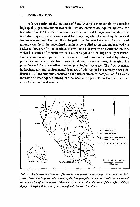
124 HERCZEG et al.
A large portion of the southeast of South Australia is underlain by extensive high quality groundwater in two main Tertiary sedimentary aquifer systems: the unconfined karstic Gambier limestone, and the confined Dilwyn sand aquifer. The unconfined system is extensively used for irrigation, while the sand aquifer is used for town water supplies and flood irrigation in the artesian areas. Extraction of groundwater from the unconfined aquifer is controlled to an amount renewed via recharge; however for the confined system there is currently no restriction on use, which is a source o f concern for the sustainable yield of that high quality resource. Furthermore, several parts of the unconfined aquifer are contaminated by nitrate, pesticides and chemicals from agricultural and industrial uses, increasing the possible need for the confined system as a backup resource. The flow systems, hydrochemistry and environmental isotopes of this region have already been published [1 ,2 ] and this study focuses on the use of uranium isotopes and 36C1 as an indicator of inter-aquifer mixing and delineation o f possible preferential recharge areas to the confined aquifer.
1. INTRODUCTION
FIG. 1. Study area and location of boreholes along two transects depicted as A-A ' and B-B' respectively. The isopotential contours of the Dilwyn aquifer in metres are also shown as well as the location of the zero head difference. West of that line, the head of the confined Dilwyn aquifer is higher than that of the unconfined Gambier limestone.
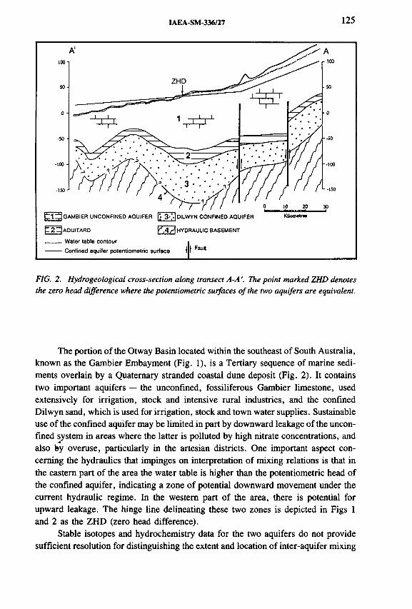
IAEA-SM-336/27 125
FIG. 2. Hydrogeological cross-section along transect A-A '. The point marked ZHD denotes the zero head difference where the potentiometric surfaces of the two aquifers are equivalent.
The portion o f the Otway Basin located within the southeast of South Australia, known as the Gambier Embayment (Fig. 1), is a Tertiary sequence of marine sediments overlain by a Quaternary stranded coastal dune deposit (Fig. 2). It contains two important aquifers — the unconfined, fossiliferous Gambier limestone, used extensively for irrigation, stock and intensive rural industries, and the confined Dilwyn sand, which is used for irrigation, stock and town water supplies. Sustainable use of the confined aquifer may be limited in part by downward leakage of the unconfined system in areas where the latter is polluted by high nitrate concentrations, and also by overuse, particularly in the artesian districts. One important aspect concerning the hydraulics that impinges on interpretation of mixing relations is that in the eastern part of the area the water table is higher than the potentiometric head of the confined aquifer, indicating a zone of potential downward movement under the current hydraulic regime. In the western part of the area, there is potential for upward leakage. The hinge line delineating these two zones is depicted in Figs 1 and 2 as the ZHD (zero head difference).
Stable isotopes and hydrochemistry data for the two aquifers do not provide sufficient resolution for distinguishing the extent and location of inter-aquifer mixing

126 HERCZEG et al.
between the Dilwyn and Gambier aquifers. This paper presents data on uranium isotopes and 36C1 as a way of identifying possible interactions between these two aquifers. The advantages of these systems are that they are more stable in time and measurements of present-day compositions may serve as end members for the past1 Ma or so.
Uranium concentration and isotopic ratios (234U /238U) have been used successfully elsewhere (see Ref. [3] for a review) for delineating mixtures of groundwaters in oxidizing systems where uranium can be treated as conservative. Work done in a small area near Mt Gambier by Ramamurthy [4] indicated that the oxidizing unconfmed aquifer has relatively high 238U concentrations and 234U /238U activity ratios (ARs) between 1 and 2. In contrast, the ‘uncontaminated’ confined sand aquifer was found to have much lower 238U concentrations and ARs > 2 . The possible caveat in using the U isotopes here is that there is the possibility of nonconservative behaviour of uranium in moving from one aquifer to another, and that reduction of U when moving from the oxidizing system to areas where the confined aquifer has low redox potential, which may make this technique invalid.
Chlorine-36 is a naturally occurring isotope of chlorine with a half-life « 3 x 10⁵ a and produced in the atmosphere via cosmic ray spallation of 40Ar. Additional 36C1 produced during atmospheric nuclear weapons testing in the nineteen-sixties and -seventies greatly increased the inventory of 36C1 in the atmosphere. This was rapidly rained out and serves as a potential tracer for hydro- logical systems over the past 30 a. Ratios of 36C1/C1 have been estimated as a function of distance from the coastline of southeast Australia [5], and these range from 20 x 10~15 to 80 X 10~15. Although in situ production via neutron bombardment is an additional source of 36C1, it is not important here due to the short time- scales and low U and Th concentrations in the aquifer materials. As a first approximation, variation in 36C1/C1 ratios of the unconfined system should reflect an integration of the flow systems contributing to the sampling point. In contrast, the confined aquifer 36C1/C1 ratio is a combination o f recharge from the upgradient areas, plus additional recharge at possible points along the flow system. Radioactive decay of 36C1 is not significant considering the short (< 3 0 ka) residence time of groundwater relative to the half-life of 36C1.
2. RESULTS AND DISCUSSION
2.1. Uranium -238 concentrations and uranium -234/238 activity ratios
Uranium concentrations and activity ratios for waters collected from two transects shown as A-A' and B-B' in Fig. 1. are given in Table I and depicted in graphical form in Fig. 3. These transects are approximately perpendicular to present- day isopotentials, and represent approximate increases in ‘age’ with decreasing

IAEA-SM-336/27 127
TABLE I. URANIUM ISOTOPE DATA FOR GROUNDWATERS FROM THE DILWYN (CONFINED) AND GAMBIER (UNCONFINED) AQUIFERS
NameDistance3
(km)
238u
(mBq/kg)234u
(mBq/kg)238u/234u
(AR)
Transect A-A': Dilwyn aquifer
DIL 62 118 3.12 ± 0.15 3.02 ± 0.15 0.97 ± 0.06DIL 2 90 5.95 ± 0.27 7.27 ± 0.32 1.22 ± 0.06DIL 64 81 9.30 ± 0.23 9.60 ± 0.23 1.03 ± 0.02DIL 11 63 0.87 ± 0.07 1.27 ± 0.08 1.35 ± 0.12DIL 60 54 0.80 ± 0.05 1.45 ± 0.07 1.80 ± 0.08DIL 3 50 0.25 ± 0.03 1.27 ± 0.07 5.25 ± 0.66DIL 31 46 0.60 ± 0.05 1.12 ± 0.07 1.05 ± 0.18DIL 4 35 4.12 ± 0.17 5.32 ± 0.18 1.29 ± 0.06DIL 5 27 0.43 ± 0.03 0.48 ± 0.03 1.11 ± 0.13DIL 7 18 0.40 ± 0.05 0.88 ± 0.07 2.24 ± 0.27DIL 37 8 0.53 ± 0.08 1.03 ± 0.12 1.90 ± 0.40DIL 56 8 0.60 ± 0.01 1.83 ± 0.02 3.25 ± 0.40DIL 53 3 1.22 ± 0.10 2.75 ± 0.17 2.24 ± 0.22
Transect A-A': Gambier aquifer
GAM 50 118 17.90 ± 0.55 15.82 ± 0.50 0.88 ± 0.02GAM 49 108 32.36 ± 0.87 31.19 ± 0.83 0.96 ± 0.02GAM 39 78 4.18 ± 0.17 5.25 ± 0.18 1.26 ± 0.06GAM 38 67 4.32 ± 0.17 4.58 ± 0.18 1.06 ± 0.05GAM 3 2 18.17 ± 0.13 19.12 ± 1.3 1.05 ± 0.07
Transect B-B': Dilwyn aquifer
DIL 55 67 7.90 ± 0.25 8.64 ± 0.27 1.09 ± 0.04DIL 23 48 3.80 ± 0.57 4.05 ± 0.33 1.07 ± 0.19DIL 12 47 0.20 ± 0.05 0.57 ± 0.08 2.83 ± 0.19DIL 14 45 7.12 ± 0.23 12.17 ± 0.1 1.71 ± 0.04DIL 52 24 0.38 ± 0.07 0.52 ± 0.07 1.33 ± 0.21DIL 16 20 3.17 ± 0.01 15.03 ± 0.03 4.75 ± 0.20DIL 22 10 0.97 ± 0.07 0.92 ± 0.07 0.95 ± 0.01
Transect B-B': Gambier aquifer
GAM 30 67 18.39 ± 0.50 28.76 ± 0.72 1.56 ± 0.03GAM 5 53 13.33 ± 0.67 15.820.83 1.19 ± 0.06GAM 23 50 4.17 ± 0.17 5.83 ± 0.17 1.40 ± 0.31GAM 12 47 9.67 ± 0.35 12.09 ± 0.32 1.24 ± 0.04GAM 14 36 3.98 ± 0.18 3.60 ± 0.17 0.91 ± 0.05GAM 40 27 1.98 ± 0.10 2.18 ± 0.11 1.10 ± 0.08GAM 6 29 8.34 ± 0.33 9.84 ± 0.50 1.18 ± 0.08GAM 31 7 4.15 ± 0.17 4.12 ± 0.17 0.99 ± 0.05
Distance in km refers to the distance upgradient from the coastline along the respective transects depicted in Fig. 1.

Transect A-A'
128 HERCZEG et al.
Distance from coast (km)
Transect B-B’
— ■ — Dilwyn 238 U
□ Gambier 238U
Dilwyn AR
о Gambier AR
о
k_£>о<
Distance from coast (km)
FIG. 3. Concentrations o f 238Uand activity ratios along the two transects A-A ' and B-B' for the Dilwyn aquifer (points connected) and Gambier aquifer.

IAEA-SM-336/27 129
0 4Ï5I-
! 3 .
1 о2-
1-
Otway Basin: Gambier Embaymeni
T□f lT t
X
CD
о
□ D ilw yn A -A ’
о Gambier A -A ’
о D ilw yn B-B '
д Gambier B-B '
“ i3010 20
(m B q/kg)
40
FIG. 4. Plot o f the l34UÍ¿lsU AR versus 238U concentrations for all groundwater samples.
distance to the coast. Uranium-238 concentrations are generally much higher in the Gambier aquifer than in the Dilwyn. For transect A-A ', the highest concentrations for both aquifers were measured upgradient of km point (KP) 81; 238U concentrations as high as 32.36 mBq/kg and ARs between 0.88 and 1.22. Downgradient of KP 81, U concentrations in the Dilwyn tend to be much lower, and ARs range up to 5.25 for DIL 3 at KP 50. The variability o f uranium concentrations in the Gambier aquifer most likely represents variations in the content o f U bearing clay material in the aquifer lithology, while, for the Dilwyn, very low activities may represent areas of low redox potential.
Uranium-238 concentrations along transect B-B' are highly variable in the Dilwyn aquifer along the inferred flow direction, though generally concentrations are considerably higher in the most upgradient portions. Waters displaying relatively high 238U concentration and with ARs close to unity may be indicative of downward movement of water from the Gambier aquifer. Samples from the Gambier aquifer show a similar sort o f range as those for transect A -A ', with relatively higher concentrations in the upgradient areas.
A plot o f AR versus 238U concentration for samples from two transects shows a distribution that is divided into two groups (Fig. 4); one group has relatively low 238U concentrations ( < 2 mBq/kg) and contains exclusively groundwaters from the

130 HERCZEG et al.
Dilwyn aquifer with a range of ARs from 1 to > 5 . The second group has 238U concentrations from 2 to —32 mBq/kg and ARs between 0.9 and 1.8. This group includes mostly unconfined groundwater samples but also some samples from the Dilwyn, although these have 238U concentrations at the lower end of the scale. These Dilwyn waters indicate some component of downward leakage from the Gambier to the Dilwyn and occur only in the upgradient parts of the basin where present-day head gradients favour downward transport of water via advection.
If we recast the U isotopic data in terms of excess 234U, where 234UXS = (234U /238U - 1) x 238U, we can delineate potential mixing lines on an 234UXS versus 238U plot (Fig. 5). If it is assumed that mixing of U is conservative, and end member compositions are constant at least on the time scale of the half-life of 234U, then it appears that waters from the unconfined Gambier lie on mixing lines (for the respective transects). That is, progressive addition of water having lower 238U concentration and low 234UXS. Those waters from the Dilwyn that lie within the range of these ‘mixing lines’ indicate recharge from the Gambier system. Two Dilwyn samples with very high 234UXS appear to be anomalies that are best explained by local geochemical processes (such as leaching) rather than through physical mixing with an end member derived from the Gambier aquifer.
2.2. Chlorine-36 data
The majority of groundwaters sampled from both the Dilwyn and Gambier aquifers have 36C1/C1 ratios around 15 x 10"15 (Table П). The notable exceptions are the four samples from the upgradient portion of the Dilwyn transect A -A ', which show a decreasing trend along the flow system from 28 x 10“15 to 21 x 10~15 at KP 81. A plot of 36C1/C1 versus Cl shows a cluster o f values between 12 x 10“15 and 19 x 10~15 and < 500 mg/kg Cl. The group of four Dilwyn samples from transect A-A' that have a higher 36C1/C1 ratio ranges up to 1672 mg/kg chloride, which probably results from évapotranspiration in the soil zone prior to recharge. Higher 36C1/C1 ratios measured in the upgradient Dilwyn system aquifer along transect A-A' could be a remnant of higher values in rainfall during the last glacial maximum. At « 18 ka BP, sea level was « 120 m lower than present and the coastline 200 km further west, resulting in less ‘dead’ oceanic Cl to dilute the 36C1 fallout.
Two samples were analysed from a dual completion well in the Dilwyn aquifer (at 170 m and 354 m, denoted as ‘Greenways’). The upper sample plots within the cluster o f samples at ~ 19 x 10~15 while the deeper sample has a relatively low 36C1/C1 ratio and a high Cl concentration. This low ratio could be the result of upward leakage of more saline, and very old water from the hydraulic basement, or possibly a very much older flow system which has undergone decay of 36C1 (say up to 300 ka).

IAEA-SM-336/27 131
TABLE II. CHLORINE-36 AND CHLORIDE DATA FOR GROUNDWATERS FROM THE DILWYN (CONFINED) AND GAMBIER (UNCONFINED) AQUIFERS
Distance 36C1/C1 36C1 x 105 ClName
(km) (x lO "15) (atoms/L) (mg/L)
Transect A-A': Dilwyn aquifer
DIL 62 118 28 ± 2 782 ± 76 1672DIL 59 108 25 ± 3 360 ± 42 849DIL 2 90 23 ± 2 207 ± 19 527DIL 64 81 2 1 ± 2 233 ± 29 651DIL 60 54 16 ± 2 61 ± 8 231DIL 5 27 14 ± 2 54 ± 7 2 2 2
DIL 38 6 14 ± 2 6 6 ± 9 277DIL 53 3 13 ± 2 79 ± 10 346
Transect A-A': Gambier aquifer
GAM 50 118 15 ± 3 77 ± 11 312GAM 43 63 15 ± 3 188 ± 17 731
Greenways double completionb
DIL 9 170 m 19 ± 3 72 ± 14 229DIL 10 354 m 1 0 ± 2 150 ± 28 8 6 6
Transect B-B': Dilwyn aquifer
DIL 55 67 14 ± 2 35 ± 5 152DIL 23 48 8.7 ± 1.5 33 ± 6 2 2 1
DIL 52 24 18 ± 2 45 ± 6 150DIL 16 2 0 1 2 ± 2 35 ± 5 168DIL 22 1 0 14 ± 2 6 6 ± 9 277
a Distance in km refers to the distance upgradient from the coastline along the respective transects depicted in Fig. 1.
b Samples from Greenways represent a bore in the Dilwyn aquifer with two completions at 170 and 354 m depth respectively.
The 36C1 data support both U isotopes and 14C data [1] that groundwaters within the Dilwyn aquifer along transect A-A' can be effectively considered as two hydraulically distinct flow systems divided approximately by the Kanawinka Fault. A significant input of water to the Dilwyn aquifer, having much lower 36C1/C1 ratios, occurs downgradient of KP 81.

132 HERCZEG et al.
238U (mBq/kg)
FIG. 5. Excess 234 U versus 238U concentration. The lines refer to areas o f proposed mixing o f Gambier and Dilwyn wells along the respective transects.
Otway Basin - Gambier Embayment35-
30 -
T 25 о
XоО
20-
15
10-
evaporation
TId I 1
-T—
1 Ti
T01
T01
Q Dilwyn A-A'
О Gambier A-A'
О Greenways
A Dilwyn B-B'
0 500 1000 1500 2000
Cl (mg/kg)FIG. 6. 36Cl/Cl ratio versus Cl concentration for Dilwyn aquifer and two Gambier aquifer samples. The two samples from Greenways represent those from the dual completion o f the Dilwyn at 170 m and 354 m respectively.
IAEA-SM-336/27 133
Uranium isotope data has provided useful indications on the location of recharge through the unconfmed Gambier aquifer to the confined Dilwyn aquifer in the Otway basin. This data and 3 6 C1 data indicate a zone of significant recharge to the Dilwyn aquifer through the Gambier aquifer between KP 81 and KP 54 along
transect A-A' (Fig. 1). Variations in 238U concentration and isotopic composition however precluded its use as a quantitative tracer for mixing ratios. The 3 6 C1/C1 ratios are essentially uniform except in some of the upgradient parts of the Dilwyn system. There is some indication from 3 6 C1 and U isotope data for a discontinuity within the Dilwyn flow system in the A-A' transect in the northern part of the study area.
3. CONCLUSIONS
ACKNOWLEDGEMENTS
The authors thank A. Chapman for analysis o f uranium isotope samples. They are also grateful to E. Mazor for encouraging sampling for 3 6 C1 in the first place.
REFERENCES
[1] LOVE, A. J., HERCZEG, A.L., ARMSTRONG, D., STADTER, F., MAZOR, E., Groundwater flow regime within the Gambier Embayment of the Otway Basin, Australia: evidence from hydraulics and hydrochemistry, J. Hydrol. 143 (1993) 297-338.
[2] LOVE, A. J., et al., Groundwater residence time and palaeohydrology in the Otway Basin, South Australia: 2H, l80 and l4C data, J. Hydrol. 153 (1994) 157-187.
[3] OSMOND, J. K., COWART, J.K., “Ground water” , Uranium-Series Disequilibrium: Application to Earth, Marine, and Environmental Sciences, 2nd edn (IVANOVICH, М., HARMON, R.S., Eds.), Oxford University Press, Oxford (1992) 290-332.
[4] RAMAMURTHY, L.M., Environmental Isotope and Hydrogeochemical Studies of Selected Catchments in South Australia, PhD Dissertation, Flinders University, South Australia (1983).
[5] DAVIE, R.F., et al., Chlorine-36 measurements in the Murray Basin: preliminary results from the Victorian and South Australian Mallee region, BMR J. Aust. Geol. Geophys. 11 (1989) 261-272.


IAEA-SM-336/4
USE OF ARTIFICIAL AND ENVIRONMENTAL TRACERS TO STUDY STORAGE AND DRAINAGE OF GROUNDWATER IN THE FRANCONIAN ALB, GERMANY,AND THE CONSEQUENCESFOR GROUNDWATER PROTECTION
K.-P. SEILER, H. BEHRENS, M. WOLF Institut fur Hydrologie,GSF-Forschungszentrum fur Umwelt und Gesundheit Neuherberg, Obserschleissheim, Germany
Abstract
USE OF ARTIFICIAL AND ENVIRONMENTAL TRACERS TO STUDY STORAGE AND DRAINAGE OF GROUNDWATER IN THE FRANCONIAN ALB, GERMANY, AND THE CONSEQUENCES FOR GROUNDWATER PROTECTION.
The evaluation of about 150 tracer experiments with the fluorescent dyes uranine and eosine and of the environmental tracer tritium (3H) in groundwaters of the karst in the southern Franconian Alb area demonstrates the importance of facies of limestones on tracer dilution and mean residence times (MRTs) or ages of groundwaters. In bedded facies tracers propagate quickly and are detected at high recovery rates and concentrations; in the reef facies, however, tracers propagate in a different way and are diluted below their detection limits (20 to 2 ng/L) within 1.5 to 2 km. These differences in tracer dilution are attributed to a considerable matrix porosity in the reef facies that is missing in the bedded facies. Depending on the hydrological model and tritium input function, groundwaters in the reef facies show ages/MRTs of about 25 to 35 years (piston flow model) and about 100 to 200 years (exponential model), respectively. These ages/MRTs are, as expected from an aquifer with double porosity behaviour, not in agreement with the MRTs (about 11 to 22 a) derived from geological considerations. The existence of a matrix porosity in reef limestones, and the resulting accumulation of pollutants in it, may lead to serious long term groundwater contamination problems for most of the persistent pollutants. Although degrading microbiological activity as for nitrates has been found recently in the matrix system, persistent pollutants can be stored and re-emitted from the matrix to groundwater users over long periods.
1. INTRODUCTION
Bedrock and hard rock aquifers are commonly highly heterogeneous. The frequency distribution of individual flow velocities in these aquifers covers a wide range and is mostly discontinuous or bimodal. This is due to a matrix porosity and
135

136 SEILER et al.
to fissures with large apertures which cause the well known differences between total and hydrodynamic effective porosities.
Flow velocities may differ by several orders of magnitude in heterogeneous aquifers and thus create storage and drainage conditions for seepage as well as groundwater flow. From this, many well known problems related to groundwater exploration and less well known problems related to both short term and long term aspects of groundwater protection arise because the usual judgement of aquifer behaviour is mostly based on average hydraulic parameters from hydraulic tests.
Hydraulic tests are based on pressure equilibration as well as on mass transport. Tracer tests and environmental isotopes, however, provide information exclusively about mass transport, which is a particularly important consideration for short term and long term groundwater protection: short term problems of groundwater protection arise from high flow velocities; long term problems, however, are linked to low flow velocities as well as to the mode of diffusive tracer/pollution exchanges between storage and drainage volume.
2. THE UPPER JURASSIC CARBONATES OF THE FRANCONIAN ALBAND THEIR DIFFERENT FORMS OF POROSITIES
The carbonates of the Franconian Alb, Germany, belong to two consecutive cycles of sedimentation, each of which starts with marls or marly limestones and ends with bedded limestones (Fig. 1). In the upper cycle, however, reefs replace limestones over significant stratigraphie intervals. These reefs have been transformed diagenetically into dolomites with formation of pores as a consequence. In the area under study, the thickness of the carbonates reaches 1 0 to 280 m.
Bedded limestones typically lack syngenetic porosity, but are characterized by fissures that may be narrow or open and solution channels. Unlike the bedded limestones, the reef dolomites commonly have porosity:
— of sedimentary and early diagenetic age— from fissures of post-sedimentation age— from solution processes— due to weathering of dolomites.
These porosities of different origin in the reef facies lead to a broader spectrum of individual hydraulic conductivities than in the bedded facies and also to a pronounced dead end porosity. As a result, flow velocities in the reef facies range from less than metres per year to many kilometres per day, whereas velocities in the bedded facies range from metres per day to kilometres per day. Tracer experiments and an observation of the environmental tracer tritium have been conducted to obtain facies dependant information on tracer dilution.

IAEA-SM-336/4 137
FIG. I. Schematic geological profile o f carbonates in the Franconian Alb and their typical porosities.
2.1. Results of tracer tests
The area of research covers about 1000 km 2 of an extensive karst area within the Upper Jurassic. About 150 tracer tests have been executed with the fluorescent dyes uranine and eosine (Fig. 2), which behave conservatively with respect to flow velocities of the water [1]. The amounts of injected dyes in the individual tracer tests were typically between 3 and 5 kg. The tracing distances ranged from 1 to 12 km.
About half the tracer tests were performed in the bedded tracer facies: tracer recovery and flow velocities were mostly high. Tracer tests in the reef facies, however, ended as a rule without recovery at distances exceeding 1.5 to 2 km during an observation time of more than 7 a.
Groundwater recharge and the non-reactive tracer behaviour is the same in both facies. Therefore differences in the tracer dilution must be attributed to the respective facies.
Statistical evaluation o f measured flow velocities leads to the following classification:
Group I Group П Group Ш
0.6 ± 0.3 km/d2.1 ± 0.5 km/d4.2 ± 0.9 km/d

138 SEILER et al.
FIG. 2. Tracer tests with ( о ) and without (* ) recovery in the research area o f the Franconian Alb. Tritium evaluation has been done for the encircled areas (B = Birktal, G = Grôfidorf, P = Pfiinz, S = Schamhaupten).
FIG. 3. Flow velocities (km/d), which are dominated by bedded facies, in the area between Altmiihl and Anlauter.

IAEA-SM-336/4 139
----- FAULT
FIG. 4. Results o f tracer tests along a vertical, non-tectonic interface between bedded and reef facies. Experiments with ( ü j and without ( я ) recovery.
Flow velocities of Group I result in an average hydraulic conductivity of about 5 x 10“ 3 m/s, which agrees well with results from pumping tests [2, 3]. Higher flow velocities exceeding 1 km/d probably reflect the existence of preferential flow paths which are not clearly manifested in time dependent drawdown during pumping tests [4]. On the other hand, low hydraulic conductivities are also known from pumping tests, which do not appear to be consistent with tracer experiments; this could be attributed to more pronounced dilution o f tracers at low flow velocities.
The bedded facies is prevalent in the area between the rivers Altmühl and Anlauter (Fig. 3). Flow velocities by means of tracer tests group between about1.3 and 2.5 km/d. Little regional variation occurs, even though the determinations were made under different infiltration/exfiltration conditions over a period of five years. Isolated examples of high flow velocities occur; according to discharge analysis [5] they reflect flow in solution channels. Low flow velocities occur only in small areas dominated by the reef facies.
In a neighbouring area (Fig. 4) the catchment is crossed by a steep, vertical boundary between bedded and reef facies of non-tectonic origin. Here, all injected tracers in the bedded facies have been recovered. In the reef facies, however, recovery and flow velocities were low at distances below 2 km and recovery was not observed at greater distances (see below).

140 SEILER et al.
Obviously the kind of carbonate facies strongly influences tracer propagation as well as tracer dilution. Although groundwater recharge is similar in both areas, the groundwater table slopes more steeply in the bedded facies than in the reef facies. A comparison of Assuring in both areas revealed that high fissure intensities and low fissure apertures characterize the bedded facies; in contrast, Assuring in the reef facies is less intensive and fissures have larger openings [2 ].
Permeabilities in the reef facies should thus exceed those of the bedded facies. This, however, seems to contradict results o f tracer tests with low flow velocities and scarce recovery in the reef facies and high flow velocities and abundant recovery in the bedded facies. This apparent contradiction may be explained if groundwater volumes in fissures in the reef facies are small in relation to groundwaters stored in the matrix, whereas a higher portion of the water contained in the bedded facies is discharged by fissures. If so, such differences in facies properties should lead to differences in tracer dilution and to corresponding differences in the distribution of environmental isotopes in both facies types.
FIG. 5. Types o f concentration versus time curves in the Franconian Alb. Results from tracer propagation in 1 = solution channels, in 2 = fissures o f the bedded facies, and in 3 = reef facies (for curve 3 time scale is 100 times greater and concentration scale is 100 times smaller than in cases 1 and 2).

IAEA-SM-336/4 141
2.2. Dilution of dye tracers
The concentration time curves for tracer tests in the study area can be subdivided into three categories (Fig. 5).
— Curves with high concentration maxima and narrow geometry (curve 1 in Fig. 5) that indicate high flow velocities (> 1 .5 km/d) and low dispersivities, respectively. Such tracer experiments yielded recovery rates exceeding 50% and are attributed to flow in solution channels or opened fissures.
— Curves with lower concentration maxima and less narrow in their width (curve 2 in Fig. 5). These experiments yielded recoveries of more than 25% and are attributed to flow in fissures with some diffusive tracer exchange between large and narrow fissures.
— Curves with very low concentration maxima over short distances (< 1 .5 to2 km) or undetectable tracer maxima at longer distances (detection limit of fluorescent dyes 2 to 20 ng/L) and a pronounced tailing (curve 3 in Fig. 5). The recovery in these experiments was usually less than 1 %. These curves have been produced by a diffusive tracer exchange between a small volume of water in fissures and a large volume of water in a matrix of low permeability additionally to hydrodynamic dispersion.
2.3. Tritium in groundwaters out of both facies
Tracer tests provide information about small sectors of the groundwater flow field. In contrast, environmental isotopes such as 3H can be used to add areal information on the groundwater flow field and storage properties of the aquifer. For example, during dry weather discharge, a clear difference exists in 3H concentrations of groundwaters from bedded and from reef facies:
— In the bedded facies, 3H concentrations in groundwaters are very similar tothe mean 3H contents in precipitation of the last few years (Fig. 6 ).
— In areas with less than 1 % of tracer recovery, 3H concentrations are significantly lower than mean 3H contents for local precipitation.
Low 3H concentrations under dry weather discharge conditions are attributed to long residence times; these groundwater observation points, however, also respond to tracer tests.
Tritium concentrations were determined by liquid scintillation counting with or without preceding electrolytic enrichment of 3H [6 ]. The results are expressed as TUs (tritium units) where 1 TU corresponds to a 3 H/H ratio of 10“18.
The recharge area of the Gróssdorf spring — as an example — is characterized by reef facies. This spring has relatively low 3H concentrations (Fig. 6 ) and some of the tracers injected here arrived with low flow velocities and a recovery of less

142 SEILER et al.
FIG. 6. Distribution o f tritium concentrations in bedded and reef facies. Results are from the dry weather discharge during autumn 1982. A similar but less pronounced tritium distribution was registered in 1992 and 1994.
FIG. 7. The size o f the subsurface catchment area o f the Grofidorf spring by means o f tracer tests (encircled white area) and calculations (encircled white and hatched area) on the bases o f mean discharge and mean recharge.
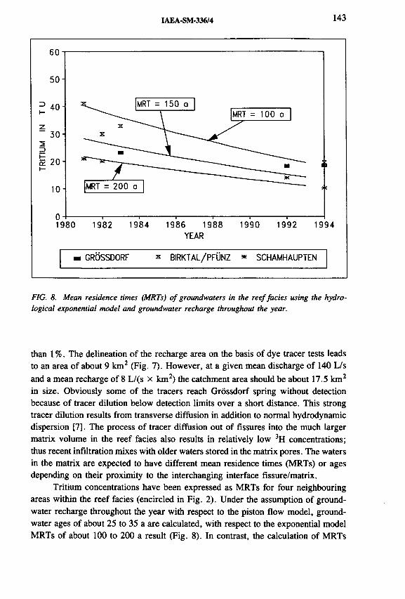
IAEA-SM-336/4 143
60-1
5 0 -
- 4 0 -
z3 0 -
23E 2 0 - f-
1 0 -
o -1 9 8 0 1 9 8 2 1 9 8 4 1 9 8 6 1 9 8 8 1 9 9 0 1 9 9 2 1 9 9 4
YEAR
m GROSSDORF * BIRKTAL/PFÜNZ * SCHAMHAUPTEN
FIG. 8. Mean residence times (MRTs) o f groundwaters in the reef facies using the hydro- logical exponential model and groundwater recharge throughout the year.
than 1 %. The delineation of the recharge area on the basis of dye tracer tests leads to an area of about 9 km 2 (Fig. 7). However, at a given mean discharge of 140 L/s and a mean recharge of 8 L/(s x km 2) the catchment area should be about 17.5 km 2
in size. Obviously some of the tracers reach Grôssdorf spring without detection because of tracer dilution below detection limits over a short distance. This strong tracer dilution results from transverse diffusion in addition to normal hydrodynamic dispersion [7]. The process of tracer diffusion out o f fissures into the much larger matrix volume in the reef facies also results in relatively low 3H concentrations; thus recent infiltration mixes with older waters stored in the matrix pores. The waters in the matrix are expected to have different mean residence times (MRTs) or ages depending on their proximity to the interchanging interface fissure/matrix.
Tritium concentrations have been expressed as MRTs for four neighbouring areas within the reef facies (encircled in Fig. 2). Under the assumption of groundwater recharge throughout the year with respect to the piston flow model, groundwater ages of about 25 to 35 a are calculated, with respect to the exponential model MRTs of about 100 to 200 a result (Fig. 8 ). In contrast, the calculation of MRTs
“ 1-------------I-------------I-------------I-------------1-

144 SEILER et al.
using hydrogeological data on the porosity of the matrix (p about 5 vol. %), the average thickness of the reef aquifer (H about 40 to 80 m) in the respective area and the groundwater recharge (q about 0.18 m/a [5]) related to the matrix leads to a MRT (MRT = p -H -q "1) of about 11 to 22 a. These low calculated MRTs suggest that the matrix porosity will be higher than 5 % and that the unsaturated zone of the karst also possesses a considerable storage capacity of recharged subsurface waters.
3. CONCLUSIONS
Contamination in bedded limestones commonly causes rapid and serious responses in the groundwater. As a consequence, accidental spills are often difficult to detect with the usual sampling frequency for chemical and bacteriological analyses, because of limited dispersion and short residence times.
In the reef facies, in contrast, the response to accidental and permanent pollution may be slow or impossible to detect for long periods. Persistent pollutants, however, may accumulate gradually in matrix pores and may result in significant long term risks for groundwater because of large matrix pore volume. Therefore, conventional water quality surveys may in time provide misleading information on the development of contamination of groundwater resources.
On the other hand, the long term storage of pollutants in the large matrix volumes of heterogeneous aquifers may also offer an advantage as far as degrading microbial activities exist. Ongoing observations abundantly indicate such microbial activities for nitrate reduction and are the subject of a current research programme.
REFERENCES
[1] BEHRENS, H., Untersuchungen zum quantitative!» Nachweis von Fluoreszenzfarb- stoffen bei ihrer Anwendung als hydrologische Markierungsstoffe, Geologica Bavarica 6 4 (1971) 120-131.
[2] SEILER, K.-P., BEHRENS, H., HARTMANN, H.-W., Das Grundwasser im Malm der Siidlichen Frankenalb und Aspekte seiner Gefahrdung durch anthropogene Ein- flüsse, Dtsch. Gewàsserkd. Mitt. 35 (1991) 171-179.
[3] HARTMANN, H.-W., Untersuchungen zur Durchlàssigkeitsverteilung des Malma- quifers der Südlichen Frankenalb unter Anwendung hydrogeologischer, gefiige- kundlicher und femerkundlicher Methoden, GSF-Bericht 23/94, GSF-Institut fiir Hydrologie, Oberschleissheim (1994).
[4] BERGMANN, H., SEILER, K.-P., Hydrometrische und radiohydrometrische Untersuchungen an einem Entnahme- und Schluckbrunnen im kliiftig-porosen Burg- und Blasensandstein von Erlangen-Bruck, Geologica Bavarica 6 4 (1972) 197-209.

IAEA-SM-336/4 145
[5] SEILER, K.-P., PFAFF, T., BEHRENS, H., Ergebnisse von Karstgrundwasserunter- suchungen im Malm der Siidlichen Frankenalb, Z. Dtsch. geol. Ges. 138 (1987) 377-386.
[6] EICHINGER, L., FORSTER, М., RAST, H., RAUERT, W., WOLF, М., “Experience gathered in low-level measurement of tritium in water”, Low-level Tritium Measurement, IAEA-TECDOC-246, IAEA, Vienna (1981) 43-46.
[7] SEILER, K.-P., MALOSZEWSKI, P., BEHRENS, H., Hydrodynamic dispersion in karstified limestones and dolomites in the Upper Jurassic of the Frankonian Alb,F.R.G., J. Hydrol. 108 (1989) 235-247.

IAEA-SM-336/40
INTERCOMPARISON OF DIFFERENT TRACERS IN THE EVALUATION OF GROUNDWATER DYNAMICS IN HETEROGENEOUS POROUS AQUIFERS A study in the alluvial plain of Venice
G.S. TAZIOLI, P.M . CANTORIDipartimento di Scienze dei Materiali e della Terra,Université di Ancona, Ancona
G.F. CIANCETTIDipartimento di Scienze della Terra,Université di Pavia, Pavia
R. DAZZI, G. GATTO, B. MATTICCHIO, G. MOZZI, G. ZAMBON Istituto per lo Studio della Dinamica delle Grandi Masse,Consiglio Nazionale delle Ricerche, Venice
Italy
Abstract
INTERCOMPARISON OF DIFFERENT TRACERS IN THE EVALUATION OF GROUNDWATER DYNAMICS IN HETEROGENEOUS POROUS AQUIFERS: A STUDY IN THE ALLUVIAL PLAIN OF VENICE.
The paper deals with experiments carried out with artificial tracers on a site of the alluvial plain of Venice. The area has 13 boreholes 5-15 m in depth. The aquifer is very permeable and consists of gravel and coarse sand, the thickness of which reaches 450 m within the area. The experiments were made using 131I, 3H, NH4C1, LiCl and Rhodamine WT. Because of the absence of fine matrix in the sediment, the tracer behaviour in the aquifer is nearly the same for all the tracers used; however the results are affected by the different detection methods and sensitivities. In practice 131I and 3H were detected at levels of 5 x 10"10 Ci-L~', while LiCl and NH4C1 were measured at levels of 10“8 and 10‘6 kg ■ L~'. Rhodamine WT also gave good results; its detection limit was 10"9 L -L"1.
1. INTRODUCTION
The development of industrial activities and of agriculture followed by the development of general social welfare has led during recent decades to an increase in the demand for water as well as to the production of a great quantity of pollutants, with a serious risk for the conservation of surface and groundwater quality.
147

148 TAZIOLI et al.
The alluvial plains run a high risk of pollution because of the high density of urbanization and intense agricultural activities. Rivers crossing the alluvial plains are another source of pollution. The same areas often contain the most important groundwater resources.
In these situations a pollutant released on the ground surface may rapidly reach the aquifer and travel long distances in a very short time through preferential pathways.
Experiments have been made in a study of heterogeneous alluvial aquifers using different tracers for the evaluation of the hydrodynamic parameters which describe the behaviour of pollutants in the underground environment.
For this purpose 13 boreholes were drilled on an alluvial aquifer site and experiments have been carried out with various chemical, fluorescent and radioactive tracers, as well as pumping tests.
The site is also equipped with a meteorological station and a recording level gauge.
FIG. 1. Location o f the experimental site in the Venetian alluvial plain and traces o f the hydrogeological section (A-A ') o f Fig. 2. Arrows show the leakage from the river Piave.

IAEA-SM-336/40 149
The study area is located in the Venetian plain, which extends from the Pre-alpine chain to the Adriatic Sea. This plain is constituted by an alluvial formation made by the old fans of the rivers Brenta and Piave, which cross it (Fig. 1).
The whole surface of the alluvial plain is quite flat, about 90 m .a.s.l. at the apex, and 3-4 m .a.s.l. near Venice.
In the first 18 km in the upper plain the sediment is mostly gravel and coarse sand; from there seawards the sediment becomes finer, with a decrease o f its granulometric diameter. So the aquifer can be considered unconfined in the upper part of the plain and as a multilayered confined aquifer in the medium and lower plain (Fig. 2). This last area is characterized by a series of aquifer layers interbedded with silty clay layers exceeding 850 m in thickness. The alluvial deposits date from the Lower Pleistocene to the Upper Pleistocene-Holocene, while the basement of the aquifer consists o f marine calcareous formations outcropping on the Pre-alpine chain border.
The water table in the upper plain is about 40 m below the ground surface with annual fluctuations ranging from 11m near the rivers to 1.5 m in the experimental site of Treviso.
The recharge of the aquifer o f the Venetian plain is mostly due to the leakage from the rivers Brenta and Piave crossing it, which drain the waters o f the Alpine watersheds (Fig. 1), having <5180 values of - 1 2 to - 1 0 7 oo [1], and to local precipitations which are 1100 mm per year and display ô 180 values around - 7 to - 6 7 , e.
2. HYDROGEOLOGICAL SITUATION
FIG. 2. Hydrogeological section o f the Venetian alluvial plain from the Pre-alps to the Adriatic Sea. 1: coarse sediment; 2: fine sediment; 3; clayey layers; 4: Pre-Quaternary substratum.

150 TAZIOLI et al.
The relationship between the rivers Brenta and Piave and the aquifer is evidenced by the water contour lines and confirmed by river discharge variations [2 ] and by <5,80 and ô2H determinations [1].
3. THE EXPERIMENTAL SITE
The area of the experiments is located on the mean alluvial plain, 30 km from the sea, 45 m .a.s.l. Here the thickness of the sediments is about 450 m and the water
FIG. 3. Experimental site and location o f boreholes.

IAEA-SM-336/40 151
table is 23 m below the ground surface. Groundwater flows SSE and is influenced by the presence of palaeothalwegs of the rivers Brenta and Piave.
The experimental site, which is a disused gravel quarry 350 m wide and 500 m long, has 13 boreholes penetrating from 5 to 15 m into the aquifer. The particular location of the boreholes permits following tracer clouds for a path of 25 m, also giving the possibility of evaluating the transversal dispersion coefficient DT (Fig. 3).
Along the walls of the quarry it is possible to observe the upper part of the alluvial formation up to about 20 m in thickness. Here the stratigraphy is represented by polygenetic coarse gravel in a sandy matrix with lenses of sand and discontinuous beds of conglomerate. Prevailing elements are calcareous and dolomitic with some tuffs and porphyrites deriving from the basin of the river Piave. The coarse elements are rounded, with diameters of 60-70 mm. The matrix is siliceous sand. The stratigraphy of the boreholes has also been checked with gamma ray logs which have permitted the coarse gravel layers to be localized.
The dio grain size distribution ranges between 0.5 and 1 mm, with a very high coefficient of uniformity, Uc. The particular sedimentary structure implies big variations of porosity, n, and permeability, K, both laterally and vertically.
The water table at the bottom of the quarry is about 2-3 m below the ground surface and its annual fluctuation is in the range of 1.5 m. Groundwater flow direction in the experimental site fits the general SSE flow direction of the plain. The hydraulic gradient, i, is around 0.7°/oo, with fluctuations up to 1 .3700.
Groundwater circulation is affected by the presence of discontinuous layers of coarse gravel in which water velocity greatly varies, also over short distances.
4. EXPERIMENTS
The experiments were carried out with the use of single well and multiwell tracer techniques and various artificial tracers, such as 1 3 1 I, 3 H, Rhodamine WT, NH4 C1 and LiCl.
Iodine-131 and NH 4 C1 were measured directly in the boreholes with gamma scintillation Nal(Tl) detectors and with electroconductivity probes, while the other tracers were sampled with peristaltic pumps and measured in the laboratory.
The quantities of tracer utilized for each experiment were: 25 mCi of 1 3 1 I,3 /¿Ci of 3 H, 10 mL of Rhodamine WT and 200 g for NH 4 C1 and for LiCl . 1
Iodine-131 and Rhodamine were detected up to 25 m from the injection, LiCl up to 15 m, while tritium and ammonium chloride were detected only at a distance of 5 m from the injection.
1 1 Ci = 3.7 x 10¹⁰Bq.

152 TAZIOLI et al.
Time (h)
FIG. 4. Evolution o f tracer concentration in borehole I as a junction o f time for 1311, Rhodamine WT and ammonium chloride for measuring Darcy filtration velocity. The experiment with 1311 was made in June 1994 and the experiments with Лит, 3H and NH4Cl in April 1994.
4.1. Single well technique
The measurement of Darcy filtration velocity, V, was made by labelling the total water column of the injection borehole I, whose water column is 7 m long (Fig. 3). The tracer was injected with a peristaltic pump and was mixed continuously with an electric pump being used in order to maintain its concentration homogeneous during the dilution.
The functions log of tracer concentrations versus time were elaborated with the integration of the different logs of tracer concentrations recorded at different times, following the method proposed by Tazioli [3] and by Calméis et al. [4]. The evolution of tracer concentrations is indicated in Fig. 4.
The value of the mean Darcy filtration velocity, V, varies from V =0.7 m -d~’, in the experiments o f April 1994 with Rhodamine, ammonium chloride and tritium, to V = 0.5 m -d ' 1 in the experiments of June 1994 with the use o f 1 3 1 I.
Different tracers have given the same results for the mean Darcy filtration velocity when they had the same density as that o f groundwater and were continuously mixed during the experiments.

I_______________________________L-------------------------------------------------------1--------------------------------------------------------1-----------------------------------------------------------------------------------------------------------------0 5 10 15 25
Distance (m)
FIG. 5. Hydrogeological cross-section o f the experimental site and the preferential flow pathway as deduced from the maximum activity o f tracer logs.
Lf\U>

cou
nts/
s
154 TAZIOLI et al.
3
FIG. 6. Pulse injection o f radioactive 1311 in borehole I and recordings o f the tracer cloud in the boreholes 1, Z, A, B, 2, 3 and 6. The diagrams o f the activities o f the boreholes Z, A and В have been corrected because o f the different geometries o f measurement.

IAEA-SM-336/40 155
Many experiments were made with pulse injections of different tracers in borehole I (Fig. 3), and with the measurement of the tracer cloud downstream from the injection up to a distance of 25 m.
Use of the multiwell technique made it possible to evaluate the behaviour of the different tracers and to calculate the main hydrodynamic aquifer parameters. The best results were obtained using 1 3 1 I. The experiment carried out in June 1994 was preceded by an injection of 200 g of inactive Nal, 24 hours before. The tracer activity was measured simultaneously in five boreholes with several tracer logs and continuous recordings which made it possible to localize the different flow pathways and to calculate the mean effective velocity, u, related to the whole labelled thickness o f the aquifer as well as the effective velocity, u, corresponding to the most permeable layers (Fig. 5).
4 .2 . M u ltiw ell tech n iq u e
Tracer injection
FIG. 7. Groundwater flow direction and vectors o f effective velocity, u.
156 TAZIOLI et al.
The transit of the tracer cloud through the boreholes of the experimenal site is shown in Figs 6 and 7.
The values of effective velocity, u, obtained with the experiment of June 1994 with the use of 1 3 1 I, vary from 11 to 33 m -d " 1 (Fig. 6 ).
The longitudinal dispersion coefficient, DL, was evaluated through the expression [5]:
Y 2 - t 2 . l l 2 гл х uUL - ------Г---------
2 ím
where x is the distance between the injection and the measuring section, tM the time of transit o f the maximum concentration at a distance x, and u the effective flow velocity. The values of DL are (1-1.3) x 10“ 3 m 2 -s“'.
The longitudinal dispersivity coefficient, a L, calculated with the expression [5, 6 ],
Dl« L = -----
U
varies linearly with the distance from the injection, a L, ranging from 2 to 4.2 m, 15 m downstream.
The aquifer mean permeability, K, and the dynamic porosity, n,j, calculated by using the values of Darcy filtration velocity, V, the mean effective flow velocity,u, and the local hydraulic gradient, i, are as follows:
К = — = 0.8 x 10 - 2 m -s ' 1
i
Vn<j = — = 0.02-0.05
u
The permeability obtained with pumping tests is slightly lower, ranging from (0 .2 - 0 .6 ) x IQ’ 2 m -s4 .
4.3. Intercomparison between tracers
Intercomparison between the different tracers exhibits the same results in measuring Darcy filtration velocity with the point dilution method in all cases where the density of chemical tracers was equal to that o f the groundwater and the tracers were continuously homogenized during the dilution. The experiments made with dense

IAEA-SM-336/40 157
FIG. 8. Decrease o f the peaks o f concentration as a junction o f the distance from the injection point for different tracers.
TABLE I. VALUES OF THE EFFECTIVE FLOW VELOCITY OF GROUNDWATER MEASURED ON THE PREFERENTIAL PATHWAYS USING 131I AND LiCl
BoreholeDistance from
the injection point
Depth of ground surface
(m)
13,Iu(m-d_1)
LiClu(m-d~')
1 5 4.5 33 34
A 10 4.5 24 26
Z 10 4.5 29 32
Z 10 6.0 37
3 15 6 27
2 15 5.5 11
6 25 6 13
u = Effective groundwater flow velocity.

158 TAZIOLI et al.
saline solutions gave values of effective velocity much higher than those of the natural flow.
The variation of the different tracer concentrations with the distance from the injection borehole is shown in Fig. 8 . The same figure indicates that at a distance of 15 m from the injection 131I is diluted 110 times the initial concentration C0, while Rwr and LiCl are diluted 103 times.
Table I indicates a comparison between the values of effective velocity calculated with the experiments with l31I in June 1994, and LiCl in September 1994.
The most important problems regarding the use of chemical tracers with the multiwell technique relate to the great volumes of the solutions that have to be used for the injections and on the density of the tracer solutions. As an example, an injection made in the experimental site with the use of a big quantity of NaCl detected with geoelectric measurements has increased the effective velocity of the natural flow by a factor of five.
Another problem is represented by the tracer detection limits. The mean transit time, t,, calculated with a curve which is cut at the lower concentrations, may be very different from that calculated with a curve obtained with tracers of high sensitivity of detection.
5. CONCLUSIONS
In the experimental site all the tracers used behaved well in the underground environment but their use has clearly shown the difficulties which may be met when measuring groundwater flow velocity in natural conditions.
In a heterogeneous porous aquifer like the one tested, the best results are obtained with gamma emitter tracers which are detected directly in the boreholes. In these hydrogeological situations, chemical tracers may give bad results when the preferential pathways are not localized. Fluorescent tracers can be successfully used in some cases.
The values of effective flow velocity with LiCl in September 1994 were slightly higher than those obtained using 131I in June 1994. This could be due to the different hydraulic conditions characterizing the site when the experiments were carried out.
Finally it must be pointed out that, whilst chemical tracers require lengthy and delicate operations to provide a correct measurement, radioactive tracers allow a direct measurement in situ. As a consequence, unless the groundwater flow field is already well known in its detailed hydrogeological patterns, only this technique enables the performing of adequate fieldwork.

IAEA-SM-336/40 159
ACKNOWLEDGEMENTS
The authors wish to thank E. Conchetto, U. Brocea, G. Dal Missier, L. Dametto, M. Loffredo, G. Maffei and V. Polenta for their help during the field and laboratory experiments. Particular thanks are due to the Ditta Calcestruzzi S.p.A. of Treviso, which permitted the use of the experimental site.
The work was done with the financial support o f the Special Project VAZAR of the ‘Gruppo Nazionale Difesa Catastrofi Idrogeologiche’ of the Consiglio Nazionale delle Ricerche and by the Project ‘Difesa del Suolo e Gestione Risorse Idriche Sotterranee’ of MURST, Ancona.
REFERENCES
[1] BORTOLAMI, G., FONTES, J.C., PANICHI, C., Résultats préliminaires sur les teneurs en isotopes de l’environnement et circulation dans les aquifères du sous-sol venitien, Consiglio Nazionale delle Ricerche, Lab. Studio Dinamica Grandi Masse, Arti Grafiche Gasparoni, Venice (1973) 1-28.
[2] DAL PRA’, G., ANTONELLI, R., “ Indagini idrogeologiche sulle falde di subálveo di alcuni fiumi veneti e friulani” , Quaderni dell’Ist. di Rie. sulle Acque 34 11, Consiglio Nazionale delle Ricerche, Rome (1979) 265-280.
[3] TAZIOLI, G.S., Metodologie e techniche radioisotopiche in idrogeologia, Geol. Appl. e Idrogeol. 8 Part 2 (1973) 209-229.
[4] CALMELS, P., et al., Méthodes de traçage radioactif pour mesures des très faibles vitesses de filtration dans un forage profond et pour déterminer la fissuration de la roche, Isotope Hydrology 1983 (Proc. Symp. Vienna 1983), IAEA, Vienna (1984) 719-740.
[5] SAUTY, J.P., Contribution à l’identification des paramètres de dispersion dans les aquifères par interprétation des expériences de traçage, Thèse docteur-ingenieur, USM et ING Grenoble, 77 SGN 515 HYD (1977).
[6] MARGRITA, R., GAILLARD, B., “ Use of artificial tracers for determination of aquifer parameters” , Use of Artificial Tracers in Hydrology (Proc. Adv. Group Mtg Vienna, 1990), IAEA-TECDOC-601, IAEA, Vienna (1991) 131-143.
[7] ZUBER, A ., “ Models for tracers flow” , Tracer Methods in Isotope Hydrology (Proc. Adv. Group Mtg Vienna, 1982), IAEA-TECDOC-291, IAEA, Vienna (1983) 67-112.

Poster Presentations
IAEA-SM-336/6P
RADIOACTIVE GAUGING OF GROUNDWATER FLOW DIRECTION IN A SINGLE WELL BY MEANS OF A DOUBLE-COLLIMATED SCINTILLATION DETECTOR
S. AMATAJInstitute of Nuclear Physics,Tirana, Albania
1. INTRODUCTION
Groundwater movement direction provides important information for hydrogeological and civil engineering studies [1]. In order to investigate possible leakages along contact lines of Vjosa river gravels with the limestones of Mt Pocemi we have projected and constructed a new directional probe which is more convenient in some respects than other gauges used for this purpose.
2. DESCRIPTION
The central component of this probe consists of a scintillation detector (1) collimated along its sensitive part by a lead cylinder (2 ) that has a side window in front of the Nal(Tl) crystal and another one on its base (Fig. 1). An electric micromotor (3) of variable speed constantly spins the collimator, which is kept centred on the axis of the outer tube (4) by two special bearings. The detector-collimator system remains coaxial via a ring (5) used also to adjust vertical distances, and by a bearer (6 ) which holds the micromotor in a fixed position. The orientation part of the gauge is realized in two variants. The first one consists of a magnetic needle with one of its arms made radioactive and dropped freely in a spherical cavity half filled with mercury. Such a simple compass can be made easily, but the application of the direction probe should be limited in this case to wells without metallic casing.
The other solution was to use a gyroscopic micromotor (7) of about 24 000 rev/min. On one of its axis ends a very small 137Cs source is incorporated, which emits gamma rays of higher energy than the radiation energy of the radionuclides usually applied in tracing the groundwater flow direction ( 1 9 8 Au, " T c m, 5 1 Cr).
161

162 POSTER PRESENTATIONS
The measuring and recording equipment on the soil surface consists of two parallel connected ratemeters and a two way plotter. A 12 V battery supplies the micromotor, and another one with 27 V provides through a transformer three phase AC at 400 Hz and 36 V for the gyroscopic micromotor.
The gauge is portable and can be lowered into wells by means of a flexible cable which fulfils all the power supply functions and provides the necessary mechanical resistance at the same time.

SESSION 5 163
After having injected the groundwater radiotracer into the water column at the appropriate depth and after this tracer has been totally absorbed in the rock, one can orientate the locked axis of the gyroscopic micromotor to a known geographical point and afterwards rotate it. Once the full number of rotations is reached, this axis is unlocked by a special device (8 ), then the gauge is closed by the lid (9) and lowered into the well.
The collimator can be revolved uniformly at a suitable angular velocity by changing the voltage; accordingly the scintillation detector produces a periodical signal each time the side window is situated in front of the tracer (the ‘direction signal’) and another one each time the bottom window allows gamma quanta of 137Cs to reach its sensitive part (the ‘orientation signal’). Knowing the collimator spinning sense and measuring on the recording paper strip the distances between two consecutive orientation peaks L and the direction peak between them 1, one can easily calculate the angle the groundwater flow direction forms to the reference direction (Fig. 2 ).
Should the direction and orientation signals overlap or interfere with each other one can separate them by applying in the ratemeter two individual discrimination thresholds, for instance 50 keV (both signals) and 400 keV (reference or orientation signal only).
3. METHOD
FIG. 2. Diagram for calculating, under laboratory conditions, the direction o f simulated groundwater movement.
164 POSTER PRESENTATIONS
The best positioning of the collimator windows is when they are situated on the same vertical plane as the rotation axis.
A pattern of an experimental measurement carried out under laboratory conditions is shown in Fig. 2. Outside the gauge we fixed a very small amount of 1 1 3 Inm with low activity and measured geometrically the radial angle (true) it formed to the gyroscope axis ( 137Cs source). This same angle was measured afterwards by the method described in Section 3 (calculated). A very good agreement was always found between these two values, the deviation never exceeding ± 8 ° from the true direction.
4. RESULTS
REFERENCE
[1] DROST, W., et al., Informationsheft Eurisotop, Brussels (1972) 39.
IAEA-SM-336/12P
CHARACTERIZATION OF THE GROUNDWATER CIRCULATION OF TECTONICALLY ACTIVE AREAS IN WESTERN TURKEY BY THE “ Cl METHOD
W. BALDERER Geological Institute,Engineering Geology
A. SYNALPaul Scherrer Institute,Institute for Particle Physics
Eidgenôssische Technische Hochschule-Hônggerberg,Zurich, Switzerland
Within the joint interdisciplinary project Marmara of the Eidgenôssische Technische Hochschule (ETH) Zurich and the Istanbul Technical University (ITÜ) the effects of active tectonics as evidenced by geology, geodesy and seismology on groundwater circulation and on the heat flow pattern are being studied for selected
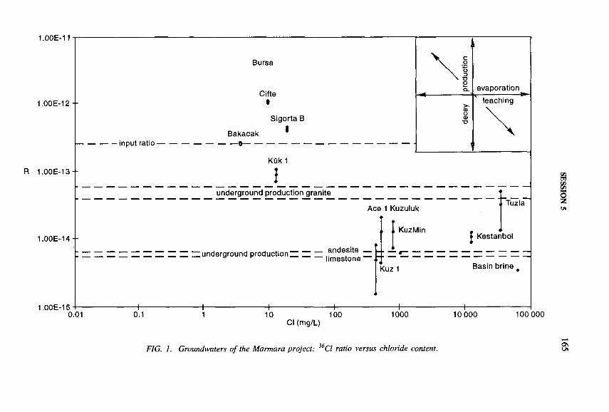
1.00E-11
1.00E-
R 1.00E-
1.00E-
1.00E-
I2 --
----------------- input ratio ■
I3--
Bursa
Cifte0
Bakacak
Sigorta В
I
Kük 1
underground production granite
I 4 - -
15
Ace 1 Kuzuluk
, KuzMin
I underground production ~ ~ ~ andesite a r — limestone
Tuzla
Kestanbol
0 . 0 1 0 . 1 1 0 1 0 0
Cl (mg/L)1 0 0 0 1 0 0 0 0 1 0 0 0 0 0
FIG. 1. Groundwaters o f the Marmara project: 36Cl ratio versus chloride content.
SESSION 5
166 POSTER PRESENTATIONS
areas along the North Anatolian Fault zone, which is characterized by active crustal movements and very high seismicity [1, 2]. For groundwaters of such tectonically active regions the problem of the determination of the residence time beyond the range of the tritium method arises, as the isotope techniques usually applied are often not appropriate because of ( 1 ) the high amount of water/rock interaction, (2 ) the underground production of nuclides in crystalline fissured rocks in geothermal conditions, (3) the occurrence of highly saline waters at boiling temperature affected by water/rock interaction processes, and (4) the high fluxes of C 0 2. Therefore the application of the 3 6 C1 method looks very promising. Figure 1 shows the results of 3 6 C1 determinations of three study areas along the North Anatolian Fault zone (from east to west): Kuzuluk/Adapazari, Bursa and Tuzla/Kestanbol. By considering for each area the sources of 3 6 C1 and the water/rock interactions with respect to the chloride cycle, additional information on the ongoing processes of groundwater circulation and evolution and also on the ranges of residence times of these waters was gained, compatible with the results of geological, hydrogeological and hydrochemical investigations [3-9] and the conceptual models already developed.
From the results for the different areas the following first conclusions can be drawn:
Dating with 3 6 C1 is only possible if the local input ratio and exact evolution (and the rock environment along the flow path and including the geological evolution of the area) are known.
The main effects of underground processes which affect 3 6 C1 in groundwater in tectonically active areas are: ( 1 ) underground production, (2 ) leaching of rock salt (including fluid inclusions) due to water/rock interaction, (3) dissolution of limestone, especially in areas of high C 0 2 activity related to thermometamorphic processes, and (4) processes of mixing of fluids with different origin/evolution with different chloride concentrations and 3 6 C1 ratios.
Additional information, independent hydrodynamic and coupled geothermal modelling, and also the results of environmental isotopes, give additional support to the achieved interpretation.
Residence times of geothermal fluids, especially in tectonically active areas, are greater than those of the present water cycle, if the recharge under current climatic conditions is considered.
In this case, only if the same cycle is maintained (steady state situation) can these geothermal resources be sustainably exploited.
However, if these hot waters originate from reservoirs which under current conditions are closed to recharge (e.g. if they represent tectonically squeezed or pressurized fluids, as is suspected for the Kuzuluk waters flowing mainly because of the maintained C 0 2 flux), enhanced exploitation, which cannot be in steady state with recharge, could result in drastic changes in hydraulic head (e.g. loss of artesian overpressure), lowering of flow rate and eventually also in long term changes of the chemical composition of the fluid concerned. With high C 0 2 upflow and periodi-

SESSION 5 167
cally strong seismic activity, even a complete loss of the thermal water of an entirearea being exploited could result.
REFERENCES
[1] SCHINDLER, C., et al., The MARMARA Poly-Project: Tectonics and recent crustal movements revealed by space-geodesy and their interaction with the circulation of groundwater, heat flow and seismicity in north-western Turkey, Terra Nova 5 (1993) 164-173.
[2] STRAUB, C., KAHLE, H.G., Global Positioning System (GPS) estimates of crustal deformation in the Marmara Sea region, Northwestern Anatolia, Earth Planet. Sci. Lett. 121 (1994) 495-502.
[3] BALDERER, W., et al., “ Environmental isotope study of thermal, mineral and normal groundwater within the Bursa and Kuzuluk/Adapazari areas of northwestern Turkey” , Isotope Techniques in Water Resources Development 1991 (Proc. Symp. Vienna, 1991), IAEA, Vienna (1991) 720-723.
[4] GREBER, E., Das Geothermalfeld von Kuzuluk/Adapazari (NW-Türkei): Geologie, aktive Tektonik, Hydrogeologie, Hydrochemie, Gase und Isotope, Diss. ETH-Zürich No. 9984 (1992).
[5] GREBER, E., Deep circulation of C 0 2-rich paleowaters in a seismically active zone (Kuzuluk/Adapazari, North Western Turkey), Geothermics 23 2 (1994) 151-174.
[6] IMBACH, T., Thermalwasser von Bursa: Geologische and hydrogeologische Untersuchungen am Berg Uludag (NW-Türkei), Diss. ETH-Zürich No. 9988 (1992).
[7] IMBACH, T., BALDERER, W., “ Environmental hydrogeology of a karstic system with thermal and normal groundwaters: Examples from the Bursa Region (Turkey)” , Hydrogeological Processes in Karstic Terrains (Proc. Symp. Antalya, 1990), IAHS Publication No. 207, Inti Assoc. Hydrological Sciences, Wallingford, UK (1990).
[8] MÜTZENBERG, S., Westliche Biga-Halbinsel: Geologie, Tektonik und Thermal- quellen (Canakkale, Türkei), Mitt. Geol. Inst, der ETH und der Univ. Zürich, No. 287 (1989).
[9] MÜTZENBERG, S., BALDERER, W., RAUERT, W., “ Environmental isotope study of saline geothermal systems in Western Anatolia (Canakkale, Turkey)” , Water Rock Interaction (Proc. 7th Symp. Park City, UT, 1992), Balkema, Rotterdam (1992).
168 POSTER PRESENTATIONS
ISOTOPIC AND CHEMICAL INVESTIGATIONS OF WATER/ROCK INTERACTION PROCESSES IN FLUIDS AND GASES OCCURRING IN A SEISMICALLY ACTIVE AREA OF THE IRPINIA-BASILICATA APENNINE REGION IN SOUTHERN ITALY
W. BALDERER Geological Institute,Engineering Geology,Eidgenôssische Technische Hochschule-Hônggerberg,Zurich, Switzerland
G. MARTINELLI Regione Emilia-Romagna,Servizio Cartográfico,Bologna, Italy
W. AESCHBACH, R. KIPFERIsotope Laboratory of the Institute of Crystallography,Eidgenôssische Technische Hochschule-Hônggerberg, Zurich,
and Swiss Federal Institute for Environmental Science and Technology (EAWAG),
Dübendorf, Switzerland
G. KAHR, R. NÜESCH Institut für Geotechnik,Eidgenôssische Technische Hochschule-Hônggerberg,Zurich, Switzerland
WOLF, M.Institut für Hydrologie,GSF-Forschungszentrum fur Umwelt und Gesundheit Neuherberg, Oberschleissheim, Germany
On 23 November 1980 the largest (MS = 6.9) and most destructive earthquake to strike southern Italy for over 100 years occurred in the Irpinia-Basilicata Apennine region.
From historical records it is evident that within or in the vicinity of this region in southern Italy very strong earthquakes have occurred periodically throughout the
IAEA-SM-336/13P
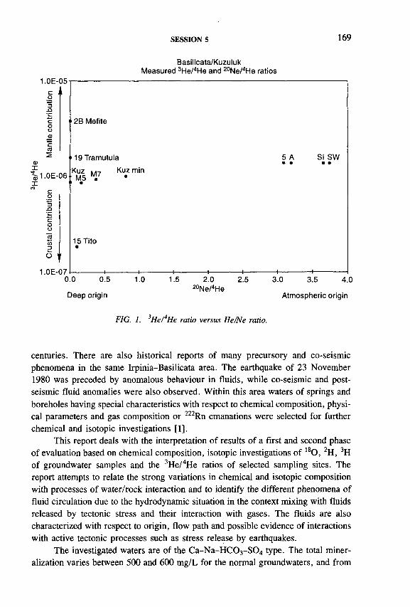
SESSION 5 169
1.0E-05соD
.Q
СОошссо
фI^ 1 .0 Е -0 6X
о
JOсоо«м3О
1.0Е-070.0 0.5 1.0 1.5 2.0 2.5 3.0 3.5 4.0
20Ne/4HeDeep origin Atmospheric origin
FIG. 1. 3H e/4He ratio versus He/Ne ratio.
Basilicata/Kuzuluk Measured 3He/4He and 20Ne/4He ratios
1 2B Mefite
119 Tramutula 5 A • •SI SW
• •Kuz Kuz min
M5 M/•
15 Tito •
------------ \--------------1------------— 1--------------
centuries. There are also historical reports of many precursory and co-seismic phenomena in the same Irpinia-Basilicata area. The earthquake of 23 November 1980 was preceded by anomalous behaviour in fluids, while co-seismic and post- seismic fluid anomalies were also observed. Within this area waters of springs and boreholes having special characteristics with respect to chemical composition, physical parameters and gas composition or 222Rn emanations were selected for further chemical and isotopic investigations [ 1 ].
This report deals with the interpretation of results of a first and second phase of evaluation based on chemical composition, isotopic investigations of 1 8 0 , 2 H, 3H of groundwater samples and the 3 H e/4He ratios of selected sampling sites. The report attempts to relate the strong variations in chemical and isotopic composition with processes of water/rock interaction and to identify the different phenomena of fluid circulation due to the hydrodynamic situation in the context mixing with fluids released by tectonic stress and their interaction with gases. The fluids are also characterized with respect to origin, flow path and possible evidence of interactions with active tectonic processes such as stress release by earthquakes.
The investigated waters are of the C a-N a-H C 0 3 -S 0 4 type. The total mineralization varies between 500 and 600 mg/L for the normal groundwaters, and from

170 POSTER PRESENTATIONS
1 g/L up to 3.8 g/L for the mineral waters. The Mefite d’Ansanto muddy waters are also highly mineralized of up to 9 g/L of total dissolved solids (TDS). As already observed [2], they present a very peculiar chemical composition with very low pH (2.7 to 3.0). These mud pool waters are of a different, very distinct C a-N a-S 0 4
type and contain high amounts of dissolved sulphates (up to 4842 mg/L), and also high concentrations of heavy metals such as Al, Mn, Fe, Ni, which can be attributed to the unusually low pH values, probably due to a water/gas interaction process as indicated by the strong degassing activity of C 0 2 and H2 S.
Most of the studied waters reveal, on the basis of their 2H and 180 contents, an origin by infiltration during current climatic conditions.
The only exception is the Mefite d ’Ansanto water 2B (see Fig. 1), originating from the big pool mouth of the natural spring. For this water, of mud volcano type, unusually low values (<52H of - 2 3 .6 7 00 and <5I80 of -1 3 .3 8 7 00) are found.
The only other possible explanation is to attribute this double shift in both stable isotopes of the water to the influence of an isotope exchange reaction which involves the hydrogen and oxygen in reaction with the gas phases of C 0 2 and H2S and possibly also to the influence of amounts of CH4.
At selected sites samples of gases (or gases and water) were collected in September 1992 and March 1994 for 3 H e/4He analyses. From the corrected 3 H e/4He ratios of the already analysed four samples the following proportions of mantle originated helium can be deduced: 15 Tito 1.4%, 19 Tramutola 13%, and for 2B Mefite spring (mud volcano type) 31.1%, the highest value (Fig. 1). The analysed 3 H e/4He ratios show contributions of mantle derived helium. According to Ref. [3] such values can be attributed to a degassing of the mantle. The mantle helium is supposed to be transported by derived fluids due to extensional processes along fault zones (e.g. Rhinegraben). Other authors [4] relate the high 3 H e/4He ratios (observed in southern Italy) to the degassing of magmatic material, related to subduction zones or upwelling of the mantle (e.g. the Tyhrrenian Bathyal Plain). Another author [5] confirms this hypothesis on the basis of further 3 H e/4He analysis carried out in southern Italy.
REFERENCES
[1] BALDERER, W., MARTINELLI, G., Geochemistry of groundwaters and gases occurring in the November 23, 1980 earthquake area (South Italy), J. Geochem. Health (1995).
[2] ORTOLANI, F ., et al., Prospettive geothermiche del’Irpinia Centrale (Appennino Méridionale) studio geologico-struturale e geochemico, Boll. Soc. Geol. It. 100 (1981) 139-159.
[3] O’NIONS, R.K., OXBURGH, E.R., Helium, volatile fluxes and the development of continental crust, Earth Planet. Sci. Lett. 90 (1988) 331-347.
SESSION 5 171
[4] HOOKER, P.J., BERTRAMI, R., LOMBARDI, S., O ’NIONS, R.K., OXBURGH, E.R., Helium — anomalies and crust-mantle interactions in Italy, Geochim. Cosmochim. Acta 49 (1985) 2505-2513.
[5] SANO, Y., WAKITA, H., ITALIANO, F., NUCCIO, M.P., Helium isotopes and tectonics in Southern Italy, Geoph. Res. Lett. 16 6 (1989) 511-514.
IAEA-SM-336/39P
SOM E RESULTS ON TH E USE OFENVIRONM ENTAL ISO TO PE TECHNIQUESIN GROUNDW ATER RESOURCES STUDIES IN M ONGOLIA
K. FRÔHLICH Isotope Hydrology Section,Division of Physical and Chemical Sciences,International Atomic Energy Agency,Vienna
S. SANJDORJ Institute of Water Policy,Ulaanbaatar, Mongolia
Mongolia is faced with complicated problems related to water supply in the Steppe and Gobi zones. Rational development of the water resources and their assessment in terms of quantity and quality is becoming an important issue for the social and economic development of the country. In the following, some results derived from environmental isotope and geochemical investigations of groundwater resources in the Dundgobi province of Mongolia are presented. The study is part of a technical co-operation project supported by the IAEA.
Several areas in the Steppe and Gobi zones of Mongolia were selected for this study. So far 100 wells and some individual rains of the Mandalgobi have been sampled for chemical and isotope analyses. Carbon-14, 1 3 C, 1 8 0 , 3 H, 2H and major/minor ions of the samples were determined in the Isotope Hydrology Laboratory of the IAEA.
The samples depleted in 50 and D content are spread along the world meteoric water line (WMWL), which is characterized by the relation D = 8 X 180 + 10 [1]. The samples with higher 180 and D content are below the WMWL (Fig. 1).

172 POSTER PRESENTATIONS
P l o t o f r a i n a n d g r o u n d w a t e rOxygen-18 vs deuterium
1 0 - 1
0
- 1 0 - s '
- 2 0 -s ' 1
- 3 0 - . s ' *y S 0
- 4 0 - «
S ^ b
m) СЛ о
â - 6 0 - s ' *
im (
о
•= - 8 0 -ш O f f А йзУ
3Ul
СО 0 1
S x m B E ^ 2
Q - 1 0 0 -
- 1 1 0 - * S ¿ * ^ a G r o u n d w a t e r
- 1 2 0 - о + S h a l l o w g r o u n d w a t e r
- 1 3 0 - s ' о R a i n w a t e r
- 1 4 0 - ¿ S S
- 1 5 0 - *
- 1 6 0 - , 1 r (.. . . y .-.J.. . ... ! _ 1 I I 1 1 .. . . . .- 2 0 - 1 8 - 1 6 - 1 4 - 1 2 - 1 0 - 8 - 6 - 4 - 2 0
O x y g e n - 1 8 ( p p m )
FIG. 1. Relationship between &D and &,80 values in precipitation at Mandalgobi and in groundwater in the Dundgobi province o f Mongolia.
In comparison with the 3H content in precipitation of other continental stations for the same period, the Mandalgov values are rather high.
The 3H content ranges from 0 TU to about 200 TU.Carbon-14 values of about 0-100 pmC were found. In general, the deep
groundwater of the Ulsit (Gobi zone) area is virtually free of 3H and 1 4 C.The replenishment of the groundwater resources estimated by the 3H and 14C
results indicates that there is virtually no replenishment of the deeper aquifers of the Ulsit study area.
However, it is not only the quantity of groundwater which limits the water supply in that area, but also the water quality.
The mean value of <5180 and ÔD of the groundwater samples collected from the Steppe zone shows that the climatic conditions between the Steppe and Gobi zones are slightly different.
In this area, the shallow groundwater is isotopically heavier than the deeper one. This result indicates fairly good infiltration conditions at the sites, which could be due to fractures in the matrix rock (granite). Assuming an initial С content of

SESSION 5 173
about 85 pmC (well D-16) and employing the dating formula for well mixed groundwater, 1 4 C(T) = I4 C(0)/(1 + X X T), where X is the decay rate of 1 4 C, the mean residence time of these three groundwaters can be estimated. The values obtained are in the range 4000-8000 a [2]. The occurrence of bomb tritium in such old groundwater provides evidence that infiltration of recharge as well as groundwater flow in the study area is facilitated by fractures and fracture zones.
In general, the 3H and 14C results indicate that fairly good infiltration conditions prevail in the Steppe zone.
The discussion and interpretation of the hydrochemical and isotopic data of samples collected in the Dundgobi province of Mongolia permit the following conclusions:
— The recharge is mainly due to the infiltration of the precipitations into shallow unconfined aquifers and into the outcrop area of confined aquifers.
— The variation of the 180 and 2H content observed in groundwater reflects different climatic conditions during formation of the groundwater and evaporation effects on shallow groundwater.
— In the Ulsit area the use of groundwater is very limited. The age of groundwater is rather high; often it exceeds 35 000 years, so the exploitable groundwater resources are very small.
REFERENCES
[1] INTERNATIONAL ATOMIC ENERGY AGENCY, Stable Isotope Hydrology, Technical Reports Series No. 210, IAEA, Vienna (1981) 122-129.
[2] FROEHLICH, K., Current aspects in groundwater dating, Freiberger Forschungshefte C417, VEB Deutscher Verlag für Grundstoffmdustrie, Leipzig (1986) 18-32.

174 POSTER PRESENTATIONS
GROUNDWATER MINING STUDY BY SIMPLIFIED SAMPLE COLLECTION IN THE JAKARTA BASIN AQUIFER, INDONESIA
M.A. GEYHNiedersâchsisches Landesamt fur Bodenforschung
B. SÓFNERBundesanstalt fiir Geowissenschaften und Rohstoffe (BGR)
Hannover, Germany
The groundwater of the Jakarta Basin aquifer is heavily exploited for the drinking water supply. The 7.5 million population of Jakarta used 450 X 106 m 3 in 1985. About 200 x 106 m 3 were pumped from shallow wells and 50 x 106 m 3
from deep wells, 50 times more than before 1945. The pressure head of the deep groundwater system in the northern and central districts of Jakarta has dropped locally by more than 1 m/a since 1970.
The aquifer system of Jakarta extends to the Java Sea in the north, the Cisadane and Cikeas Rivers in the west and east, respectively, and the Depok area in the south. The base of the aquifer system consists of consolidated Miocene sediments, which crop out at the southern boundary. The basin fill consists of marine Pliocene and Quaternary fan and delta sediments from 0 to > 300 m thick. Djaeni et al. [1] assumed that 1-5 m thick sandy aquifer layers intercalated by predominantly silty, clayey sedimentary sequences form a rather homogeneous and isotropic aquifer system. The lateral hydraulic conductivity of 0.1 to 40 m/d is 100-5000-fold larger than the vertical one, hampering replenishment of the deeper aquifer system. Deep groundwater generally moves from the recharge area in the south (precipitation > 2900 mm/a) to the discharge area of the coastal plain (precipitation c. 1700 mm/a). The horizontal inflow across the hinge line, estimated to be 15 X 106 m 3 /a, does not counterbalance the pumping rate of c. 50 X 106 m 3/a [2].
In 1985, environmental isotope analyses ( 1 4 C, 1 3 C, 1 8 0 , 2 H, 3 H) were made on 21 samples from selected wells in the Jakarta city district for which construction details were available [3]. A trend of increasing and quite large 14C water ages from south to north was found without obvious relationship between 14C age and sampling depth. Several 14C water ages of the deepest groundwater were even lower than those of the shallower groundwater.
A tracer velocity of 1 m/a was calculated from the 14C data, compared with 1.6 m/a obtained from Darcy’s law using a mean gradient o f the groundwater table of 1/1500 and a mean conductivity of 1.5 x 10~ 5 m/s. Total porosity was assumed to be 2 0 % [ 1 ].
I AE A-SM-366/47P

TABLE I. REPRESENTATIVE RESULTS OF BOTH ISOTOPE AND HYDROCHEMICAL ANALYSES OF GROUNDWATERSAMPLES FROM THE JAKARTA AREA COLLECTED IN 1985 AND 1991
Lab. code SiteDECwell
Depth(m.b.s.l.)
ô18o 700 SMOW
á 13C 7 00 PDB
Conventional 14C age (a BP)
14C value (pmC)
H C03(mg/L)
13821 Pondok Gede 1766 117-140 -6 .2 3 -1 4 .2 18 100 ± 480 10.5 ± 0.6 30917158 117-140 -6 .0 6 -1 5 .5 17 940 ± 700 10.7 ± 1.0 318
13820 Pasar Mingu 1 1836 193-250 -5 .6 0 -1 5 .3 14 300 ± 400 16.9 + 0.8 26217155 193-250 -6 .6 5 -2 0 .6 885 ± 180 89.6 ± 2.0 230
12817 Wisma Harapan 8567 141-168 -6 .2 5 -1 3 .5 31 200 ± 1900 2.0 ± 0.6 34917166 141-168 -6 .2 6 -1 4 .9 28 160 ± 2240 3.0 ± 0.9 390
13814 Cakung 1 1824 75-81 -4 .8 9 -1 5 .4 29 500 ± 1740 2.6 ± 0.5 85017159 34 -5 .9 7 -1 0 .0 0 106.9 + 2.7 318
13816 Parkir Jay a 1800 177-193 -6 .1 8 -1 6 .2 24 500 ± 900 4.8 ± 0.6 34917157 128 -6 .2 8 -3 .3 4 750 ± 200 55.3 ± 1.4 390
13804 Pedong-kelan 4 1851 42-45 -5 .5 9 -14 .1 5 400 ± 160 51.0 ± 1.1 34217168 42-45 -5 .8 6 -1 6 .9 3 285 ± 145 66.5 ± 1.4 300
13802 Pedong-kelan 1 1844 231-234 -5 .3 4 -1 2 .4 32 700 ± 2600 1.7 + 0.6 126117154 231-234 -5 .9 9 -1 2 .8 29 290 ± 2400 2.6 ± 0.8 1160
13809 Tonkol 4 1867 76-86 -4 .8 9 -1 5 .6 31 000 ± 2100 2.1 ± 0.6 6717165 !GW mining! 76-86 -3 .5 9 -1 4 .3 6 295 ± 230 45.7 + 1.4 315
SMOW = standard mean ocean water. PDB - Pedee belemnite.
-a
SESSION 5
176 POSTER PRESENTATIONS
The bicarbonate content of freshwater samples from southern and central areas is rather constant (c. 300 mg/L) for groundwater older than 10 000 a. The spatial distribution of both the hydrochemical data and 14C water ages reflects the palaeo- hydrogeological situation during the last 30 000 a. At the beginning of this period, the sea level was about 1 0 0 m lower than today and the surface consisted of both calcareous and volcanic sediments. In recharge areas formed by calcareous sediments, groundwater with rather high bicarbonate values was recharged compared to groundwater from volcanic areas. After that, the sea level rose and volcanic sediments covered most of the calcareous sediments. Hence, the old groundwater with high <513C and bicarbonate values might be a relic of former times.
In the centre of Jakarta both the <5I3C and H C 0 3 values, as well as low 14C water ages at a depth of 150 m, reflect the disturbance of the natural groundwater system due to over exploitation. Groundwater with low 14C ages from the shallow aquifer appears to have already entered the deeper part o f the system.
Groundwater sampling for 14C measurements was repeated in 1992 during a short term visit. Instead of using costly submersible pumps we took 1 L samples with a simple sample collector, a sufficient amount for 14C measurements with miniature 14C counters. The 14C ages of samples taken from the deepest part of the wells agree with the previously obtained ones (Table I). Only the well with obvious groundwater mining and those which could not be sampled at maximum depth yielded disparate 14C ages.
We conclude that 14C water age determinations can be used to monitor groundwater mining, and costly pre-pumping of wells before water sampling can be avoided if small samples are collected for accelerator mass spectrometry measurements or counting with miniature counters.
REFERENCES
[1] DJAENI, A., HOBLER, М., SCHMIDT, G., SOEKARDI, P., SÔFNER, B., “ Hydrological investigations in the Greater Jakarta Area of Indonesia” , Proc. Salt Water Intrusion Meeting, Delft (1986) 165-176.
[2] SÓFNER, B., HOBLER, М., SCHMIDT, G., Jakarta Groundwater Study — Final Report, German Hydrogeological Advisory Group (СТА 40), Directorate of Environmental Geology, Bandung and Federal Institute of Geosciences and Natural Resources, Hannover (1986) 1-71.
[3] GEYH, M.A., SOFNER, B., Groundwater analysis of environmental carbon and other isotopes from the Jakarta Basin aquifer, Indonesia, Radiocarbon 31 3 (1989) 919-925.
SESSION 5 177
NEW ASPECTS O F ISO TO PE-H Y D RO LO G ICA L STUDIES O F TH E FINNE BUNTSANDSTEIN AQUIFER IN SAXONY-ANHALT, GERMANY
D. HEBERT, O. NITZSCHE TU Bergakademie Freiberg,Freiberg, Saxony
W. RAUERT, M. WOLF, S. GEYER, W. GRAF,S. SCHUHBECK, P. TRIMBORN Institut für Hydrologie,GFS-Forschungszentrum für Umwelt und Gesundheit Neuherberg, Oberschleissheim
Germany
Groundwater resources used for drinking water supply require protection against over-exploitation (mining) as well as against pollution. The vulnerability of aquifers can be studied by combining isotope-hydrological, chemical and hydro- geological investigations.
Long term observations of characteristic aquifer parameters are indispensable for prediction of future trends of water quality and quantity. Thus the Finne aquifer was chosen for a new combined approach (1992-1994) on the basis of extended earlier isotope investigations (e.g. [1 ,2 ]). This aquifer consists o f a more than 200 m thick Buntsandstein formation, the southwestern boundary being the Finne ridge and fault zone, and the northwestern boundary being the Unstrut valley (Fig. 1). The main groundwater flow is directed from SW toward NE. The altitude of the investigation area is between 280 and 110 m .a.s.l. The permeability and effective porosity vary greatly depending on location and depth, particularly because of the existence of flow in both fractures and matrix. The water budget o f the area remains unbalanced. Declining yields with time are accompanied by an increasing lowering of the groundwater table in the upper catchment area and decreasing hydraulic head, which was artesian in the past in the Bad Bibra depression. The hydrochemistry of the groundwaters with electrical conductivities between 300 and 1300 /¿S/cm and pH values between 6.3 and 7.6 is characteristic for Buntsandstein groundwaters: mainly C a-H C 03, partly C a-M g-H C 0 3 and in special cases C a-H C 0 3 - S 0 4 type. In areas of intensive agricultural cultivation relatively high concentrations of NO 3 and of the pesticide Lindane were measured in these groundwaters.
IAEA-SM-336/54P
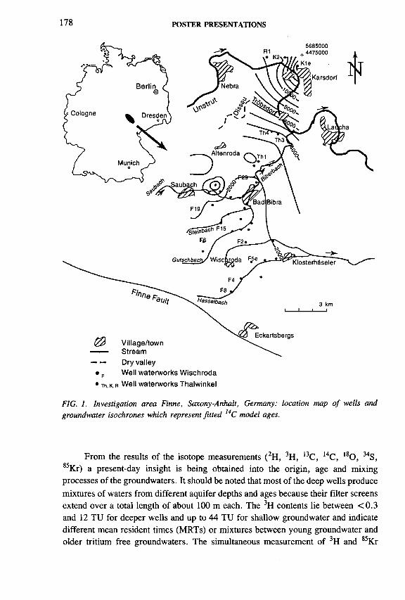
178 POSTER PRESENTATIONS
• p Well waterworks Wischroda
• Th, к, r Well waterworks Thalwinkel
FIG. 1. Investigation area Finne, Saxony-Anhalt, Germany: location map o f wells and groundwater isochrones which represent fitted 14С model ages.
From the results of the isotope measurements (2 H, 3 H, 1 3 C, 1 4 C, 1 8 0 , 3 4 S, 8 5 Kr) a present-day insight is being obtained into the origin, age and mixing processes of the groundwaters. It should be noted that most o f the deep wells produce mixtures of waters from different aquifer depths and ages because their filter screens extend over a total length of about 100 m each. The 3H contents lie between < 0 .3 and 12 TU for deeper wells and up to 44 TU for shallow groundwater and indicate different mean resident times (MRTs) or mixtures between young groundwater and older tritium free groundwaters. The simultaneous measurement of 3H and 85Kr
SESSION 5 179
contents in groundwater makes it possible to verify the applicability of flow models to given hydrogeological situations and to resolve ambiguous tritium based results (MRTs) (e.g. [3]). Thus MRTs between about 5 and 15 a were calculated from the isotope data (1992: 17-44 TU and 21-34 decays per min (dpm) per mL Kr) applying the exponential and linear model on shallow groundwater in unconfined aquifers, which are situated in recharge areas and tapped by four domestic wells. In one case (4 TU, 4 dpm/mL Kr) the different dating approaches resulted only in the same order of magnitude for the MRT (> 4 0 a). The ages of the groundwaters were also estimated based on the 14C contents (13 to 97 pmC) and the ô 13C values ( - 1 8 to —12.5°/00) of dissolved inorganic carbon (DIC). Figure 1 shows fitted groundwater isochrones with 14C model ages which are calculated under the assumption of 85 pmC as the initial 14C content yielding a mean piston flow velocity of 10 m/a. All ages fall in the time span of the Holocene and Late Pleistocene. Hydraulic calculations for the area show a higher flow velocity of about 70 m/a. However, the mobile phase is only a small part of the total water volume. Transport modelling was done accounting for this double porosity behaviour of the aquifer and linear exchange of 14C in the matrix by means of the model TReAC [4]. A good accordance with the measured values was reached by fitting a linear exchange parameter.
As 14C dating based on DIC can be affected seriously in the aquifer by geochemical processes (e.g. isotope exchange), 14C measurements on the fulvic acid fraction of dissolved organic carbon (DOC) were carried out for groundwater samples from two selected wells (Th4 and K le) by accelerator mass spectrometry (Eidgenôssische Technische Hochschule-Ziirich). Under the assumption of an initial 1 4 C-DOC content of 85 pmC according to Ref. [5], 1 4 C-DOC groundwater model ages of 3 and 13 a, respectively, were obtained, which confirm the age ranges derived from 1 4 C-DIC dating. The groundwaters having the highest 14C model ages show lower <52H and ô180 values (about -7 1 .6 to - 6 9 .7 7 00 and -1 0 .2 to —9.9°loo, respectively) than the other groundwater samples ( -6 8 .5 to - 6 4 .5 7 00 and —9.8 to — 9 .2 7 00, respectively). This is possibly due to admixture of Pleistocene groundwater, which was recharged under cooler climatic conditions, to Holocene groundwater, and interpretation which is also supported by the modelling considerations mentioned above.
Measurable 3H concentrations have been detected in some of the formerly tritium free groundwaters of the deep wells. This indicates that young groundwater is increasingly mixing with old tritium free groundwater, possibly due to overexploitation of the aquifer or to relatively long travel times of the water in the unsaturated zone. In other cases the temporal variation of 3H concentrations might be caused by changes of the hydraulic flow conditions depending on pumping rate variations. A detailed investigation of this dependence requires further 3H time series.
As indicated by the ¿>34S and ô180 values, the sulphate in most of the waters (SO4 = 18 to 6 8 mg/L, <534S = 2.3 to 9 .0 7 oo, <5180 = 4.2 to 9 .8 7 00) originates
180 POSTER PRESENTATIONS
from atmospheric fallout or agricultural activity. High SO4 concentrations (275 to 585 mg/L) and ô34S values (20.3 to 23 .8700) in some waters can be attributed to dissolution of Buntsandstein evaporites. No evidence exists for ascending waters that might carry dissolved Zechstein sulphate.
Attempts are under way to derive further hydrological and hydrochemical information from selected analyses of 3 H e/4He as well as from flow studies by tracer tests and single-well measurements. All these efforts are to support modelling of the groundwater flow and transport phenomena in this rather complicated aquifer system.
ACKNOW LEDGEM ENT
The project was financially supported by the Deutsche Forschungsgemein- schaft (DFG) (Contract Nos Jo 196/1-1, D. Hebert, and Fr 726/6-1, P. Fritz).
REFERENCES
[1] HEBERT, D., JORDAN, H., FRÔHLICH, К., “ Kombinierte Tritium- und 14C- Untersuchungen an Wássern eines klüftig-porôsen Grundwasserleiters” , Z. Angew. Geol. 28 (1977) 571.
[2] FRÔHLICH, К., GELLERMANN, R., HEBERT, D., “ Uranium isotopes in a sandstone aquifer” , Isotope Hydrology 1983 (Proc. Symp. Vienna, 1983), IAEA, Vienna (1984) 447-466.
[3] HELD, J., SCHUHBECK, S., RAUERT, W., A simplified method of 85Kr measurement for dating young groundwaters, Appl. Radiat. Isot. 43 7 (1992) 939.
[4] NITZSCHE, O., MERKEL, B., HEBERT, D., “ Transport modelling of radiocarbon in groundwater systems” , accepted for presentation at the Inti Assoc. Hydrological Sciences Conference on Comparison of Tracer Technologies for Hydrological Systems, Boulder, CO, 1995.
[5] GEYER, S., et al., “ Isotope investigations on fractions of dissolved organic carbon for 14C groundwater dating” , Isotope Techniques in the Study of Past and Current Environmental Changes in the Hydrosphere and the Atmosphere (Proc. Symp. Vienna, 1993), IAEA, Vienna (1993) 359-380.

SESSION 5 181
APPLICATION OF ENVIRONMENTAL ISOTOPESIN HYDROLOGICAL RESEARCH INTHE WESTERN TATRA MOUNTAINS, SLOVAKIA
L. HOLKO Institute of Hydrology,Slovak Academy of Sciences,Liptovsky Mikulas, Slovakia
Sampling of natural waters in a mountainous catchment of Jalovecky creek in the hydrological years 1991-1993 was carried out to investigate the isotopic composition of precipitation, snow cover including snow layers, soil water and runoff and application of environmental isotopes in runoff separation. The catchment area is 23 km 2 and the mean altitude 1500 m .a.s.l. It is made up mainly of crystalline schists and granitoids. Forests (mainly spruce), dwarf pine and meadows extend over 44, 32 and 24% of the catchment area, respectively. The mean annual precipitation is 1466 mm, runoff 874 mm and air temperature 3.5°C (see Table I).
Monthly weighted means of ¿>180 and <52H in precipitation samples collected at three sampling points apparently show an altitude effect. Altitude gradients calculated as the ratio of differences between the highest and the lowest stations are - 0 .1 4 7 oo per 100 m of altitude for ¿>180 and - 0 .7 7 oo per 100 m for 02 H. Both gradients seem to vary seasonally, with lower values in summer and higher values in spring and autumn. Reverse altitude gradients occurred in several winter months. Altitude gradients are apparent also by deuterium excess, with a mean value of 0 .4 7 oo per 100 m (see Table П).
IAEA-SM-336/57P
TABLE I. MEAN ISOTOPIC COMPOSITION OF PRECIPITATION, PRECIPITATION DEPTH AND AIR TEMPERATURE IN THE PERIOD NOVEMBER 1990-OCTOBER 1993
Altitude ô180 ô2H Deuterium excess Precipitation depth Air temperature (m.a.s.l.) (•/.„) (7 00) (»/..) (mm) (°C)
570 -1 0 .1 3 -7 1 .9 9.1 45.7 7.2
1500 -1 1 .2 1 -7 6 .7 12.9 108.5 3.2

182 POSTER PRESENTATIONS
TABLE II. MEAN VALUES OF ô 1 8 0 , 02H AND DEUTERIUM EXCESS IN PRECIPITATION IN SUMMER 1992 (JULY 1-AUGUST 16) AND 1993 (JULY 9-SEPTEMBER 8 )
Altitude(m.a.s.l.)
1992 1993
Ô180C U
Ô2H(“/со)
Excess(°/..)
á18or u
Ô2H( 0/oo)
Excess(°/.o)
750 -4 .0 6 -2 4 .9 7.2 -7 .11 -4 8 .9 8.01100a — — — -8 .6 9 -5 8 .2 11.31100 — — — -8 .85 -59 .1 11.71500 -5 .8 8 -3 6 .9 13.3 -9 .3 2 -6 0 .9 13.61500 -6 .0 5 -3 6 .9 11.6 -9 .8 6 -6 3 .8 15.11700 — — -10.28 -6 6 .8 15.41900 -6 .8 9 40.8 14.3 -10 .44 -6 7 .9 15.6
a The raingauge was situated in the forest.
TABLE III. CONTRIBUTIONS OF PRE-EVENT COMPONENTS IN SPRING 1992 AND 1993(The results are not considered reliable i f the difference in d2H o f stream and snowmelt water is less than 6°loa.)
Date
Difference in deuterium
contents
r u
Contribution of pre-event
water (%)
Date
Difference in deuterium
contents
C Ü
Contribution of pre-event
water
(%)
1992-4-05- 1992-4-10 35.2-20.2 100-90 1993-3-19 12:25 34.7 93.3
1992-4-14 7:45 12.2 87.8 1993-3-22 12:00 27.4 95.8
1992-4-15 10:00 17.0 96.0 1993-4-20 11:50 21.8 86.2
1992-4-16 7:20 11.4 100.9 1993-4-21 13:15 28.1 94.0
1992-4-17 9:35 6.2 69.7 1993-4-22 11:45 27.4 90.4
1992-4-27 7:00 5.3 53.0 1993-4-23 12:30 19.8 79.5
1992-4-28 8:00 9.3 86.1 1993-4-24 12:40 17.0 75.2
1992-4-28 10:00 8.2 78.8 1993-4-25 12:30 8.6 62.3
1992-4-28 12:00 4.9 59.8 1993-4-26 12:40 3.1 41.3
1992-4-28 14:00 5.2 63.4 1993-4-27 12:40 6.2 51.2
1992-4-28 16:00 1.1 31.4 1993-4-28 13:15 8.0 61.1

SESSION 5 183
The isotopic composition of precipitation was well correlated with local air temperatures. Slopes of regression lines expressing the relationships with air temperatures decrease with altitude. Summer precipitation in the forest was enriched by 0 .1 6 °/o o for ô 180 ( 0 .9 7 oo for <52 H) on the average compared to precipitation in an open area.
The isotopic composition of snow cover measured at 5 to 11 sites did not show any altitude effect. The snow cover became isotopically heavier during the winter. Particular snow layers sampled at two sites preserved their isotopic composition for a long time, also during the snowmelt.
Soil water was collected at six sampling points in summer 1993. In comparison with rainfall it was very damped in isotopic composition. However, magnitudes of 180 and 2H contents in soil water at the highest altitudes were comparable with those of rainfall.
Runoff separations were based on the two component model with deuterium used as the tracer. Table 1П shows that the pre-event component dominated in snowmelt as well as in rainfall events. The two-component model provided unrealistic results for one rainfall event, indicating a higher contribution of soil water, which
was also suggested by changes of isotopic composition of soil water at two sampling points situated on the same hillslope. The preceding rainfall event was contributed mainly by the pre-event component (88-98%).
Application of the dispersion model to catchment mean monthly input-output deuterium concentrations gave a mean transit time of 31 months, which corresponds to a water reservoir with average depth of water 2036 mm.

184 POSTER PRESENTATIONS
IAEA-SM-336/66P
COLLOIDAL RADIONUCLIDE MIGRATION IN SAND AQUIFER SYSTEMS*
P. ZEHInstitut für Radiochemie,Technische Universitat München,Garching
D. KLOTZ,Institut für Hydrologie,GSF-Forschungszentrum für Umwelt und Gesundheit Neuherberg, Oberschleissheim
D. LAZDCUmweltforschungszentrum Leipzig-Halle GmbH,Bad Lauchstàdt
Germany
Column experiments have been designed for migration studies of trivalent 1 5 2 E u/241Am and hexavalent 233U in the presence of humic colloids. Groundwater of a selected organic rich aquifer from the Gorleben site is used, as this has been well characterized during earlier work and it contains substantial amounts of humic colloids [1]. In such groundwaters tracer amounts of trivalent and hexavalent metal ions are found to be mainly bound on humic colloids [1]. The transport behaviour of such colloids through sand columns from a Gorleben aquifer system is being investigated.
Microstructure parameters (sediment surface, grain size and pore size distribution) of the groundwater-sand columns used for the radionuclide migration experiments are well determined. During the experiment the change of hydraulic properties (filtration velocity, effective porosity) both as a function of time and of column length is studied carefully. For the determination of the hydraulic properties 3HHO and 8 2 B r- are used. The tracer distribution along the column is measured with a collimated gamma detector, scanning the activity distribution in the vertical direction. The tracer concentration of each effluent fraction is determined by activity measurement with a liquid scintillation counter.
* This work has been funded within the frame of the European Commission’s R&D programme on Management and Storage of Radioactive Waste under contract FI2W/0084.

SESSION S
Time (d)
FIG. 1. Time dependent variation o f effective porosity n ^ and longitudinal dispersivity a.
To maintain stable hydraulic conditions, groundwater is circulated through the columns for several months, measuring the hydraulic properties by tracer experiments. The results show that the effective porosity tends to decrease as a function of time, whereas dispersion tends to increase with time (Fig. 1). Determination of the effective porosity along the column length shows increasing values from the inflow to the outflow region of the column, indicating a clogging in the inflow part of the column, which may be caused by precipitation of humic substances.
When stable hydraulic conditions are attained, further experiments using Еи(Ш), А т(Ш ) and U(VI) as injected migrants in the presence of humic colloids give information on the potential mobility of humic colloids and colloid-borne radionuclides. Prior to the column experiments, the radionuclides are equilibrated with the groundwater used and are pulse injected. The investigations are made at different flow velocities in order to examine the influence of groundwater flow rate on the migration behaviour of radionuclides. The results from Eu tracer experiments at different flow velocities show that the retardation factor Rf of the mobile part is not influenced by flow velocity, whereas the recovery increases from 64 to 92% by increasing the filter velocity from 5 X 10“ 5 cm -s ' 1 to 1 X 1 0 3 cm -s " 1 (Fig. 2). All results with trivalent 1 5 2 Eu/241Am and hexavalent 233U indicate that in the presence of humic colloids a substantial part of metal ions appears mobile. The retardation factor of the mobile fraction is close to 1 , indicating that the migration of colloid-borne metal ions is comparable to that of 8 2 Br~ or 3 HHO. For trivalent 1 5 2 E u/2 4 1 Am, which are almost quantitatively sorbed on humic colloids, the recovery is above 64%, whereas the recovery of hexavalent 233U is only about 9.4% , due to the fact that a major part of the injected uranyl ion becomes carbonate species,
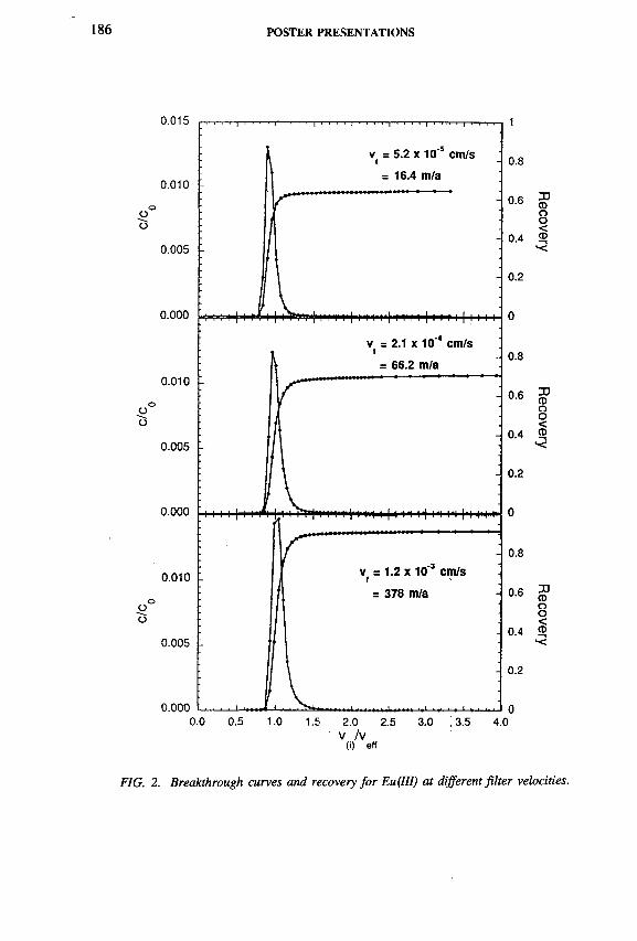
POSTER PRESENTATIONS
V /V(i) eff
FIG. 2. Breakthrough curves and recovery fo r Eu(III) at different filter velocities.
Recovery
Recovery
Recovery

SESSION 5 187
not bound on humic colloids. The mobile uranium species found in the column effluent is quantitatively bound on colloids. The results show a high mobility of colloidal radionuclides which should be taken into account for the assessment of radionuclide migration behaviour in the presence of natural humic colloids.
R EFEREN CE
[1] KIM, J.I., ZEH, P., DELAKOWITZ, B., Chemical interactions of actinide ions with groundwater colloids in Gorleben aquifer systems, Radiochim. Acta 58/59 (1992) 147-154.

188 POSTER PRESENTATIONS
IAEA-SM-336/69P
HYDROGEOCHEMICAL AND ISOTOPE STUDIES OF GROUNDWATER IN THE SAMKWANG MINE AREA, REPUBLIC OF KOREA
Yong Kwon KOH, Chan Ho JEONG, Chun Soo KIM Department of Hydrology,Korea Atomic Energy Research Institute,Taejon, Republic of Korea
Groundwaters in the Samkwang mine area (Fig. 1), situated in granitic gneiss, have been analysed for chemical and isotope compositions in order to characterize the geochemical composition of groundwater in the crystalline rocks. The groundwater consists of three general types (Fig. 2): a typical discharge (drip) water of
FIG. 1. Geological map o f the Samkwang mine area including water sampling sites. Dashed lines show tunnels o f the mine.

SESSION 5 189
— Caz+ C l"—
FIG. 2. Trilinear plot o f the major ion composition (milliequivalents) o f waters from the Samkwang mine area. Solid circles indicate Ca-HC03 type water, open circles surface water, solid triangles Ca-S04 type water, and rectangular forms Na-H C03 type water.
C a-H C 0 3 type and C a-S 0 4 type and a borehole groundwater of N a-H C 0 3 type. The chemical composition of the water from the upper part in the mine shows that Ca2+, H C 03, M g2+, SO4 and N a+ concentrations increase very rapidly from about 100 mg/L total dissolved solids (TDS) up to a maximum of 760 mg/L. The sulphate concentration of the water in the mine is due to the oxidation of sulphide to sulphate. However, the pH (1.8 to 8.1) of C a-S 0 4 type waters was considerably buffered by the dissolution of calcite that occurred in the Samkwang mine. The high Mg content is leached from ferromagnesium silicates such as chlorite, which is common in gneiss matrix and intermediate to mafic dykes ubiquitously occurring in the area studied. The N a-H C 0 3 type waters of the borehole are characterized by the dissolution of albite and calcite.

190 POSTER PRESENTATIONS
FIG. 3. Variations ofôD values o f water samples with ôlsO values from the Samkwang mine area. The global meteoric water line is shown.
The 2H and 180 contents of all types of waters (Fig. 3) are clustered along the world meteoric water line (<5D = ô 180 + 10). Therefore, it is evident that all types of waters have a common meteoric origin. The borehole groundwaters have a slightly lower 180 and 2H content than the discharge water in the mine. The high deuterium excess values (> 1 0 °/oo) of waters sampled can be explained by the evaporation and mixing processes of flowing tunnel waters in the mine. The tritium content ( « 1 0 TU) shows that the C a-H C 0 3 type water is discharged as recent waters. The C a-S 0 4 type waters in the mine and the N aH C0 3 type waters in the boreholes have tritium contents which suggest that they were recharged prior to the bomb test period.
On the mineral stability diagram based on cation/hydrogen ion activity, kaolinite and smectite are thermodynamically stable in the mine waters. On the basis of the thermodynamic equilibrium state of waters with respect to major minerals and mineralogical evidence, it can be concluded that the chemistry of groundwater in the studied area is controlled by the dissolution and precipitation of calcite, chlorite, plagioclase, sulphide and oxide minerals.

SESSION 5 191
STABLE ISOTOPES IN KARSTIC GROUNDW ATERS O F TH E V EL’KÁ FATRA M OUNTAINS, SLOVAKIA
P. MALÍK, J. MICHALKO Dionÿz Stur Institute of Geology,Bratislava, Slovakia
S.J. MANSELLLeominster, Hereford, United Kingdom
M. FENDEKOVÁ Department of Groundwaters,Faculty of Natural Sciences,Comenius University,Bratislava, Slovakia
IAEA-SM-336/81P
Oxygen isotopic compositions in the Vel’ká Fatra mountains were monitored in 30 springs and one brook which represented all major karst fissure springs and hydrogeological structures in each part o f the mountain range. The regime monitoring lasted from December 1991 to July 1993, the sampling frequency being roughly every two months (a total of nine series of samples were collected for each spring).
A comparison between rainfall isotopic compositions in Slovakia and Austria reveals that the gradual increase in the average heavy oxygen content is caused by its substantial increase in summer rainfall. The pattern of oxygen isotopic composition in precipitation displays a seasonal effect; precipitation in winter is much lighter than in summer. The precipitation distribution in Slovakia also seems to be affected by altitude, although variations in <5 180 content calculated from annual averages for stations Chopok, Stará Lesná and Mochovce (which together form a profile) are only 0 .03-0 .06°/00 per 100 m change in elevation. It has been shown by the Ô1 8 0/ÔD plots that the groundwaters of the Vel’ká Fatra have not undergone any isotopic fractionation nor exchange with the aquifer rock. This allowed the ô180 variations with time to be utilized: light <5180 water from spring time snowmelt has been used as a natural water tracer to help define the hydrogeological character of 30 springs.
The average <5180 contents from all analyses were then added into the altitude/ ô 180 relationship. We thus resolved a parametric equation expressing the linear relationship between ô ,80 and altitude of the recharge area. The value calculated by us for waters from Vel’ká Fatra springs (0.17 00) is similar to data from northern
192 POSTER PRESENTATIONS
Switzerland, where Pearson et al . 1 determined a change in the oxygen isotopic composition around 0 .2 ° / 0 0 per 100 m. As the duration of the measurements was relatively long and its frequency short, the calculated average isotopic composition of waters from individual sources could fairly reliably indicate the reality.
Nevertheless, variations in oxygen isotopic composition in investigated springs suggest considerable stability of the otherwise variable values in karst structures, probably due to extensive mixing of waters from large water bearing regions. Moreover, their average composition corresponds to the average altitude of known springs and/or their recharge areas.
This technique allowed us to rule out or confirm some potential recharge areas of certain groundwater sources (springs Jazierce, Hradská-Podhradie, Salatín 1 and 4, Malá and Vel’ké Cenovo, Rakytov) or indicated that some springs were recharged from surface streams (Lazce, Pri starej priehrade, Havranovo, Stary Mlyn, Generál Cunderlik). The hydrological time series analysis also showed important differences in their yield regime. Springs Stary Mlyn and especially Generál Cunderlik have much higher amplitudes of yield fluctuation over a one year period and also react much faster and more frequently to external impulses. The time series of the Generál Cunderlik spring yields probably indicate a strong influence of Starohorsky potok brook discharges on the spring yields regime. On the other hand, Vel’kÿ Sturec 1 spring has a typical yield regime depending on snow melting water infiltration and the influence of heavy precipitation.
As most sulphur in groundwaters of the area concerned came from Werfenian and Keuper sediments, we decided to verify this fact by isotopic analyses of dissolved sulphatic sulphur. Cartesian diagrams were employed to indicate how the sulphate content in spring water depends on the sulphur isotopic composition. We expected a bimodal distribution with projection points clustered around two ô34S values typical of the Keuper and Rot. However, the actual pattern shows very clearly that the curve is a mixed one, one member being sulphate-rich waters with heavy isotope sulphur and the other waters low in sulphate with negative ô34S values. Sulphates in the first group came from Lower-Middle Triassic marine evaporites, but the source of sulphur in the other member is unclear — the sulphur could have been derived from sulphides or it could be of biogenic origin. We also assume that the three springs represent another mixing line of Keuper sulphates and waters low in sulphate with negative S34S values. Other springs, whose groundwaters circulate in carbonate masses without obvious sulphur occurrences, cluster on a single point. Both sulphate contents and isotopic composition of their sulphate sulphur (S 0 4 content is approx. 20 mg/L, ô34S » 5 -7 7 00) do not exceed background values. The origin of this sulphur is difficult to explain. It could have come from minerals (pyrite)
1 Pearson, F.J., Jr., et al., “ Applied isotope hydrology: a case study in Northern Switzerland” , Studies in Environmental Science 43, Technical Report 88-01, Elsevier, Amsterdam (1991).

SESSION 5 193
disseminated in rock, but such rock types contain very little sulphur. Another possible source of sulphur is precipitation. The average sulphate content in winter precipitation at Donovaly is 4.19 mg/L. An analysis of sulphates dissolved in snow precipitation in Bratislava yielded results similar to those from the above springs. Further dissolution of sulphates from the traditional source rocks in the West Carpathian Mesozoic (Permian, Lower Triassic shales, Carpathian Keuper shales) subsequently increases the soluble sulphate content, reflecting the isotopic composition typical of the respective source rocks modified by mixing with the ‘background’ isotopic composition. In accordance with the mixing rule, this also changes Ô3 4 values.
IAEA-SM-336/85P
ESTIM ATION OF UNDERGROUND W ATER FLO W AND AGE ACCORDING TO 3H AND 14C IN SOM E REGIONS O F LITHUANIA
J. MAZEIKA, R. PETROSIUS Institute of Geology,Vilnius, Lithuania
Since 1980 the environmental radioisotopes 3H and 14C have been investigated in the active exchange zone of underground water of the Baltic artesian basin, the thickness of which reaches 300-400 m in Lithuania. These investigations are of two kinds — first, to obtain information on the isotopic composition of natural water, as an environmental component; secondly, to obtain isotopic data, to study various problems of underground water formation. Regular observations of 3H and 14C are carried out in atmospheric humidity and precipitation into the water of rivers and lakes, the Baltic Sea and the Curonian Bay, in aeration zones, groundwater and artesian water. On the basis of these investigations, peculiarities of radioisotope distribution in artesian geohydrodynamical systems are studied, e.g. the pre-Quatemary rock mass of southwestern Lithuania and the Quaternary in south and east Lithuania. Isotopic investigations have permitted estimation of the duration parameters of water exchange in hydrogeological systems in the above mentioned cases. Rates of water flow in aquiferous horizons have been established, zones of active tectonic faults, from the hydrogeological standpoint, have been identified and the tendencies to seasonal exchange of 3H and 14C concentrations in underground water, over many years, have been studied.

194 POSTER PRESENTATIONS
m abs.
Distance, km
FIG. 1. D istribution o f radioisotopes and helium in the groundwater along hydrogeological section in the Virinta river basin: 1 , aquifer (sand and gravel); 2, Quaternary aquitard (morainic loam); 3, M iddle Devonian aquitard (clay); 4, sampling intervals in Quaternary and Devonian aquifers; 5, concentrations o f 14C, 3H and He in groundwater from the Quaternary aquifer; 6, concentration o f l4C, 3H and He in groundwater from the Devonian aquifer.
In the artesian aquiferous horizon, covered by a water-resistant bed, the concentration of radioisotopes decreases in the direction from the water recharge region to its discharge. Such a 3H and 14C distribution is characteristic of the Permian and Devonian aquiferous horizons of west Lithuania, covered by Triassic and Jurassic clay mass. In the Upper Permian aquiferous horizon the 14C concentration changes from 31.85 to 5.36 pmC. In the water underlying Upper Devonian rocks, the 14C concentration changes in the same direction from 17.82 to 10.65 pmC. Carbon-14 concentration is highest in the water-resistant bed and fluctuates around 60 pmC over the whole section. The 3H distribution in this section is similar to that of 1 4 C.
In river valleys the underground water of Quaternary deposits is widely spread; the isotopic composition ( 3 H, 1 4 C) has been investigated on the River Neris terrace in the environs of Vilnius. Here the following aquiferous horizons have been established: groundwater of fluvioglacial deposits and two of intermorainic horizons.

SESSION 5 195
In the groundwater of fluvioglacial deposits the 3H concentration changes from8.4 TU in areas with a thick aeration zone (25-30 m) to 20-40 TU, where it is three times less (9-10 m). Here the 14C concentration changes from 69.17 to 87.7 pmC. In the underground water of intermorainic horizons the concentration of these isotopes depends on alteration of thicknesses in sections of low permeable beds. The average 14C concentration is similar in both intermorainic horizons (about 60 pmC). The 3H of thermonuclear origin penetrates to a depth of 50-60 m in these
FIG. 2. Time parameters o f groundwater from the Upper Devonian aquifer in Ignalina district (A: tectonic scheme, B: water residence time isohypses according 3H, years, C: radiocarbon age isohypses, 10s a, D: helium concentration isohypses, 10"5 mLIL): 1, observation well; 2, location o f the Ignalina nuclear power plant; 3, area ofpalaeo-incision through the Upper Devonian aquifer; 4, tectonic fault.
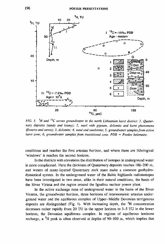
196 POSTER PRESENTATIONS
3H, TU
20 60 100 14C, pmC
FIG. 3. 3H and 14С versus groundwater in the north Lithuanian karst district: 1, Quaternary deposits (sandy and loamy); 2, marl with gypsum, dolomite and karst phenomena (fissures and caves); 3, dolomite; 4, sand and sandstone; 5, groundwater samples from active karst zone; 6, groundwater samples from transitional zone. PDB = Peedee belemnite.
conditions and reaches the first artesian horizon, and where there are lithological ‘windows’ it reaches the second horizon.
In the districts with elevations the distribution of isotopes in underground water is more complicated. Here the thickness of Quaternary deposits reaches 180-200 m, and waters of many-layered Quaternary rock mass make a common geohydro- dynamical system. In the underground water of the Baltic highlands radioisotopes have been investigated in two areas, alike in their natural conditions, the basin of the River Virinta and the region around the Ignalina nuclear power plant.
In the active exchange zone of underground water in the basin of the River Viranta, the groundwater horizon, three horizons of intermorainic artesian underground water and the aquiferous complex of Upper-Middle Devonian terrigenous deposits are distinguished (Fig. 1). With increasing depth, the 3H concentration decreases rather rapidly from 20 TU in the upper horizon to 3-5 TU in the lower horizon, the Devonian aquiferous complex. In regions of aquiferous horizons recharge, a 3H peak is often observed at depths of 90-100 m, which implies that

SESSION 5 197
atmospheric precipitation, containing a 3H maximum of thermonuclear origin, has penetrated to great depths over several decades. Carbon-14 concentration is rather high in water of this district and varies from 49.2 to 69.8 pmC, depending on the distribution of low permeable beds and palaeo-incisions. The concentration of radiogenic helium (4He + 3He) in the underground water of all sections is similar to the atmospheric level (5.2 X 10'5 mL/L). On most of this territory a deepening flow of underground water prevails, with the exception of the incision zone of the deepest rivers (Virinta and Sventoji) and Lake Neveza, where some water from deep horizons gets into the upper aquiferous horizons.
Other geohydrodynamical conditions are found in the district of Ignalina nuclear power plant. Here, because of the geostructural peculiarities — three Earth crust structures (Baltic syncline, Mazurian-Byelorussian antecline and Latvian Saddle), shallow occurrence of the crystalline basement, tectonic activity over most of the territory, with the exception of the axial zone of elevations, the water flow is directed upwards — water from deeper beds rises towards the Earth’s surface (Fig. 2). Peculiarities of radioisotope distribution demonstrate this feature, too [1].
A more complicated distribution of radioisotopes (3H, 14C) in underground water is observed in the karst district of north Lithuania (Fig. 3). Not only is it characterized by diversity of water exchange in natural systems, but there is also intensive physical and chemical interaction between water and rocks [2]. The measured 14C concentration in the underground water of the karst district is less than in other districts. It is related to the dissolution of carbonate and sulphate rocks. Dissolution of carbonate rocks is estimated from the amount of 13C.
REFERENCES
[1] MAZEIKA, J., PETROSIUS, R., Application of isotope-geochemical methods to underground water protection in the vicinity of Ignalina NPP, Geokhimiya 2 (1994) 164-174 (in Russian with English summary).
[2] MAZEIKA, J., PETROSIUS, R., “ Isotope-geochemical peculiarities of natural water in North-Lithuanian Karst region” , Vilnius (1994) 126-128 (in Lithuanian with English summary).
198
IAEA-SM-336/90P
POSTER PRESENTATIONS
RADIOCARBON GROUNDWATER DATING ON DISSOLVED ORGANIC CARBON Case of a shallow unconfined aquifer
C. MONTJOTIN, J.-L. MICHELOT Laboratoire d’hydrologie et de géochimie isotopique,Université de Paris-Sud,Orsay, France
V. MOULINCEA, Division du cycle du combustible,Fontenay-aux-Roses, France
C. TUNIZAntares Mass Spectrometry,Australian Nuclear Science and Technology Organisation (ANSTO), Menai, New South Wales, Australia
T. MERCERONDépartement études expérimentation et calculs,Agence nationale pour la gestion des déchets radioactifs, Fontenay-aux-Roses, France
Carbon-14 groundwater dating with the conventional method using dissolved inorganic carbon (DIC) presents some difficulties when carbonated minerals dissolution and/or precipitation occur. Thus, a new groundwater dating method is being investigated by using dissolved organic carbon (DOC). A few authors have already tried to explore the advantages and difficulties of using DOC fractions to estimate a groundwater residence time with different approaches [1-3].
For this study, a sandy shallow unconfined aquifer (Soulaines, France) has been chosen for a comparison of radiocarbon activities of DOC and DIC. This site has been selected for two reasons: first, it is a sandy aquifer with few interactions between water and matrix so that the ages calculated from radiocarbon activities of DIC are probably reliable; secondly, this system gives an opportunity to measure the initial radiocarbon activities of DOC and DIC in the recharge zone of an unconfined aquifer.
In this work, both humic acids (HA) and fulvic acids (FA), as the major fractions of DOC, have been isolated using sorption onto an anionic exchange resin

SESSION 5 199
(diethylaminoethyl cellulose) and characterized by elementary analyses and spectroscopic techniques [4]. Isotopic measurements, e.g. ô13C and 14C activities, have been performed both on DIC and DOC.
With a mean value of <513C below -1 6 ° /00 Peedee belemnite (PDB) and 14C activities close to modern (93 to 105 pmC), the DIC appears to be controlled by open system conditions. As for the DOC, no difference in <513C can be noted between HA and FA with a quite constant S13C value of -2 7 .5 7 00 but HA present 14C activities always lower (66 to 89 pmC) than those of FA (80 to 107 pmC).
The HA fraction of DOC seems to be partly derived from solid organic carbon (SOC) constitutive of the aquifer so that 14C values cannot be interpreted in terms of water residence time.
The general ranges of 14C contents for FA and for DIC are comparable. However, for some samples, 14C contents of FA are lower than those of DIC. This may be explained either by a slight contribution of old organic matter to FA, or by a stratification of the aquifer (the amount of water needed for a DOC analysis is 1000 times higher than that needed for a DIC analysis).
Anyway, in the worst hypothesis, if we assume that radiocarbon content of DIC is fully representative of water age, radiocarbon dating with DOC could give a maximum overestimation of residence times of about 1000 years. For recent water, e.g. at Soulaines, this overestimation is quite important but for old water it would become comparable to analytical uncertainties.
By assuming an initial radiocarbon value between 80 and 100 pmC, radiocarbon dating of groundwater with fulvic acids appears to be a good alternative dating method when DIC is affected by geochemical processes that interfere with pure radioactive decay.
REFERENCES
[1] GEYER, S., WOLF, М., FRITZ, P., BUCKAU, G., KIM, J.I., “ Isotope investigations on dissolved organic carbon for 14C groundwater dating” , Isotope Techniques in the Study of Past and Current Environmental Changes in the Hydrosphere and the Atmosphere (Proc. Symp. Vienna, 1993), IAEA, Vienna (1993) 359-380.
[2] MURPHY, E.M ., DAVIS, S.N., LONG, A., DONAHUE, D.J., JULL, A.J.T., Characterization and isotopic composition of organic and inorganic carbon in the Milk River Aquifer, Water Resour. Res. 25 8 (1989) 1893-1905.
[3] WASSENAAR, L., ARAVENA, R., Radiocarbon in dissolved organic carbon, a possible groundwater dating method: case studies from Western Canada, Water Resour. Res. 27 8 (1991) 1975-1986.
[4] DELLIS, T ., MOULIN, V., “ Isolation and characterization of natural colloids, particularly humic substances, present in a groundwater” , Water-Rock Interaction (Proc. 6th Int. Symp. Malvern, 1989), Balkema, Rotterdam (1989) 197-201.

200 POSTER PRESENTATIONS
LONG TERM CHEMICAL AND ISOTOPIC STUDIES OF SPRING WATER IN THE TRANSVAAL DOLOMITES, SOUTH AFRICA
A.S. TALMA, J.C. VOGEL, B.M. EGLINGTON Division of Earth, Marine and Atmospheric Science
and Technology,Council for Scientific and Industrial Research (EMATEK/CSIR)
D.B. BREDENKAMPWater Resources Evaluation and Management
M. SIMONICDepartment of Water Affairs and Forestry
Pretoria, South Africa
The Transvaal dolomites form an important karst aquifer over a distance of some 500 km in the South African interior. The water is contained in fractures within the dolomite, which is divided into compartments by intrusive dolerite dykes. Free flowing springs occur in various parts of the aquifer due to the obstruction of water flow by these dykes. These springs are important water supplies for local communities. The discharge of each spring represents a mixture of water from the entire compartment [1].
Isotope studies started in the late 1960s [1,2]. Since that time spring water has been collected on an irregular basis and analysed for environmental isotopes and chemistry to examine regional patterns and to record the throughflow of bomb 14C and possibly associated chemical changes with varying water flow rates.
The water quality is very good, being essentially Ca-M g-HC03 water with minor occurrences of higher S04, N 03 and Cl due to localized pollution. Regionally the salinity and 14C increases from east to west, indicative of changing recharge/storage ratios westwards. Strontium isotope ratios (87Sr/86Sr) in the water vary between 0.721 and 0.740 over the entire aquifer with, in some areas, some regional grouping. This grouping, once properly understood, has potential for tracing water leakages through confining dykes separating adjacent compartments.
Over the 25 years of monitoring, the spring water chemistry has not changed significantly. Radiocarbon content (in the range of 55 to 110 pmC) has also changed very little (Fig. 1). Smaller compartments do, however, indicate additions of bomb 14C, but the larger compartments have quite stable and low 14C concentrations. In only a few cases are very small 14C increases evident, which may suggest the breakthrough of bomb 14C into spring water.
IAEA-SM-336/95P

SESSION 5
C A L E N D A R Y E A R
FIG. 1. Radiocarbon variations in a few typical spring waters.
FIG. 2. Comparison o f 14С and water flow in the Kuruman spring.

202 POSTER PRESENTATIONS
In the Kuruman compartment a two box model was applied to interpret the rapid pulse of high 14C which accompanied the increasing spring discharge of 1978 (Fig. 2). In this case, using a recharge of 8% derived from soil chloride profiles, a storage/recharge ratio of 30 was derived from the 14C time series.
There are clear indications of regular recharge in most of the aquifer [3, 4] which support the existing spring discharge. The low presence of bomb 14C in the spring water indicates that vast amounts of water are available in this aquifer system and enable limits to be placed on the recharge/storage ratio of some of the compartments of this aquifer.
REFERENCES
[1] VOGEL, J.C., BREDENKAMP, D.B., “ Study of a dolomitic aquifer with carbon-14 and tritium” , Isotope Hydrology (Proc. Symp. Vienna, 1970), IAEA, Vienna (1970) 349-372.
[2] BREDENKAMP, D.B., SCHUTTE, J.M ., DU TOIT, G.J., “ Recharge of a dolomitic aquifer as determined from tritium profiles” , Isotope Techniques in Groundwater Hydrology 1974 (Proc. Symp. Vienna, 1974), Vol. 1, IAEA, Vienna (1974) 73-96.
[3] BREDENKAMP, D.B., VAN RENSBURG, H.J., VAN TONDER, G.J., BOTHA, I.J., Manual on Quantitative Estimation of Groundwater Recharge and Aquifer Storativity, Report to the SA Water Research Commission (in press).
[4] KRONFELD, J., VOGEL, J.C., TALMA, A.S., A new explanation for extreme 234U /238U disequilibria in a dolomitic aquifer, Earth Plan. Sci. Lett. 123 (1994) 81-93.

SESSION 5 203
RESEARCH ON T H F GROUNDWATER FLOW DYNAMICS IN MILAS PLAIN USING ISOTOPE METHODS
E. ÓNHON, N. BA§ARANGeotechnical Services and Groundwater Department
S. YÜZEREROGLU, A.R. ÔZDAMAR DSÏ XXI Regional District
S. GÜLERTechnical Research and Quality Control Department
General Directorate of State Hydraulic Works (DSÍ),Ankara, Turkey
I AE A-SM-ЗЗб/ ÎOOP
1. GENERAL
Selimiye-Milas-Ekinambari basin, which is known in brief as the Milas Plain, is located in western Turkey on the Aegean Sea coast and covers 2200 km2. The highlands reach up to 1270 m in the east and north and 768 m to the northwest. The Aegean Sea lies west of the plain. Increasing agriculture, tourism and summer houses require additional water. Using isotope techniques, two important karst springs, each discharging 2-5 m3/s brackish water, were investigated to clarify their recharge areas and origins.
1.1. Geology
The area of investigation is located on a tectonic belt (Fig. 1). The strati- graphical settlement can be described in terms of autochthonous units, allochthonous units and neoautochthonous units.
Autochthonous units. Gneiss (Pzg) forms the core of the Menderes massif and is surrounded by schists (Pzs) of Palaeozoic, Milas limestones (Mzm) and Kalmagil limestone (Ktk) of Mesozoic.
Allochthonous units. The tectonic melange with a predominant serpentine matrix (Ktm) was brought into the region during the settlement of Lycian nappes. The Güllük formation consists of conglomerates, shales, tuffs, mudstone, clay (Pg) and limestones (Pgk). Gôkova limestone (TRjg) occurs conformitably over the Güllük formation.

204 POSTER PRESENTATIONS
i
M IO C EN E
LYCIAN NAPPES
PERIDOTITE
OVERTHRUST FAULT
FIG. 1. A general tectonic map o f the area investigated.
■' •UJ « * iQ COz <ш 2 ? ¡ w ?' Л Л ч
QUATERNARYNEOGENE
COVER
• BASE

SESSION 5 205
The autochthonous and allochthonous units were unconformably covered by thick sedimentation of the Neogene over 600 m in thickness with conglomerate, clay, marl, limestone and peat.
Epirogenetic movements increased the erosion, and the subsidence of the valleys resulted in thick alluvium deposition in the Quaternary.
The karstification of the autochthonous and allochthonous carbonate rocks is also related to the evolution of the area. The allochthonous carbonate rocks were deeply affected by tectonic movements and were more karstified compared to the autochthonous rocks. Additionally, the orogenesis of the region and the following vertical faultings are the main reasons for deep and effective karstification. The erosion phase following the tectonic activities permitted the rapid invasion of the sea water towards the bays and the lowlands and thus movements of fresh and sea waters resulted in the occurrence of brackish water karst springs (Fig. 1).
2. HYDROLOGY
The Mediterranean type of climate is predominant in the project area. The mean annual precipitation is 984.1 mm in Kozagaç, 801.1 mm in Çamkôy and713.8 mm in Milas.
Runoff of streams is observed only in the wet period.Savrankôy springs (Sites 2, 3 and 4) discharge from the contact of alluvium
and Milas limestone, the mean base flow being 116.72 hm3/a or 3.37 m3/s.
P R E C I P I T A T I O N
A UTOCHTHONOUS
TER TIAR Y DEPO SITS
A L L O C H T H O N O U S (UNSCALED)
C D .?«** 'f t f S H A L E -L IM E S T O N E
MESOZOIC LIMESTONE
PALAEOZOIC SCHIST ANO LIM ESTONE
9 K A R S T SPRING <3» CROUNOWATER PLOW
s SEA WATER INTRUSION
45251 ORILLEO WELL
FIG. 2. General cross-section o f the Milas Plain and groundwater flow.

206 POSTER PRESENTATIONS
Ekinamaban spring (Site 5) discharges from uncountable points of a buried hill of Güllük limestone (Pgk). According to the records, the mean base flow is153.8 hm3/a or 4.83 m3/s.
Other springs are Akarca (Site 7) and Gümbüldek (Site 8) discharging 1 m3/s, Su Çikti (Site 11) 0.4 m3/s and Akyol (Site 13) 0.110 m3/s.
The drilled wells are distributed all over the plain. Six exploration wells were drilled reaching a depth of 908 m, thus producing sufficient data for the isotope survey. The water level difference between Site 43 and Site 40 is 90 m, with a natural allochthonous barrier (Fig. 2).
3. ENVIRONMENTAL ISOTOPE APPROACH ANDTHE ISOTOPE DATA COLLECTED FROMTHE INVESTIGATION AREA
In the Milas region, the recharge to the karst aquifer is mainly by direct infiltration of precipitation. The relationship between the recharge and discharge is being investigated by collection of data on input (precipitation) and output (springs and groundwater consumption etc.) to identify clearly:
— The process of recharge and replenishment of the aquifers;— The dynamics of groundwater flow and sea water encroachment;— The effect of the allochthonous aquifer on sea water encroachment.
Sampling at the Kozagaç DSI meteorological observation station started in 1987 to provide the basic isotopic data. Over the investigation period, 196 samples were collected and analysed from 18 springs, 33 drilled wells, 1 stream, 2 lakes and the sea.
Samples for chemical analysis were collected in conformity with the isotope samples, showing that the sea water encroachment has reached northwest of Milas and east of the Ekinamban springs. The electrical conductivity of Savrankôy springs is between 7600 and 18 000 and that of Ekinamban 5090 to 15 000 micromhos/cm.
4. INTERPRETATION OF THE ISOTOPE RESULTS
The samples of Kozagaç and Milas precipitation stations were analysed for ô180 , ôD and tritium. The weighted means of ô180 and <5D for Kozagaç and Milas stations are -5 .8 9 and -37 .52 , and -5 .2 4 and -2 7 .6 0 7 oo, respectively. The tritium content of precipitation was maximum 30 TU in June 1987 and minimum5.8 TU in December 1990.

SESSION 5 207
180 (%o)
FIG. 3. 6 ,sO-ôD plot fo r all samples.
The stable isotope results of the samples were corrected by taking Beypinari spring (Site 1) as the base and by using the formula
f% = Clm ~ Ch x 100 Clj - Cl2
where Cl is the C l' content of the mixture, Cl™ is the СГ content of the sea water and Cl2 is the Cl“ content of the original water sample.
The <5180-<5D plot of all the sampling points (Fig. 3) shows a distribution between the Craig and Mediterranean precipitation lines. By taking Sites 6, 12 and 47 as representative points for the Milas region, a regression line can be drawn with a fit of
ÔD = 7.75 0180 + 13.61 and r2 = 0.99
The majority of the sampling points are condensed between —6.0 and - 4 . 5 ° / o o ô180 collected from north of the Milas region, especially from deep wells in alluvium.

208 POSTER PRESENTATIONS
The values of Savrankôy (Sites 2, 3 and 4) and Ekiriambari (Site 5) are condensed between —6.0 and —7.39°/00 S180 , nearly on the Mediterranean line. However, some are shifted with the influence of wet (before 1990) and dry (after 1990) periods.
The tritium contents of the groundwater samples are between 0-15 TU in the alluvium aquifer and range from 6 to 15.2 TU in the carbonate rock aquifer.
5. CONCLUSIONS
Taking into consideration the hydrogeological evaluation and isotope data,
— Three types of precipitation have been distinguished in the region: (a) Continental type, (b) Milas type, (c) Mediterranean type. When these data are combined with the locations and characteristics of the sampling points, the recharge areas and groundwater flow directions can be identified.
— The infiltration to the eastern drainage area is travelling northwest and west to Savrankôy springs and in the direction of Milas.
— The effect of Continental type (Kozagaç) precipitation has been observed on Milas limestones and on alluvium.
— The Mediterranean type of precipitation infiltrating into the allochthonous is travelling west and north, in the direction of the Ekinambari and Savrankôy springs.
— The exploration well Site 43, drilled on the basis of initial results and data provided from the hydrogeological and isotope hydrology evaluations, indicates that the freshwater electrical conductivity in the area is 650 micromhos/cm.
— The allochthonous formations thrust over the autochthonous from the south and extending in the east-west direction provide a barrier and a considerable water level difference of 90 m which can be used to prevent sea water encroachment. The area east of Site 43 extending to the south of Milas will be investigated separately for groundwater production facilities.
As the result of this project, the recharge areas and origins of all springs, together with the sea water encroachment and flow dynamics, have been clearly identified; a solution has been found regarding the development of brackish water springs, and fresh water is being provided.

SESSION 5 209
ISOTOPIC RESEARCH ON GROUNDWATER IN THE BASIN OF THE NATISONE RTVER (NORTHEAST ITALY)
J. PEZDIC, S. LOJEN Jozef Stefan Institute,Ljubljana, Slovenia
V. BARBINA, L. QUARINCentro di Ricerca Applicata e Documentazione,Udine, Italy
J. URBANC Geological Survey,Institute for Geology, Geotechnics and Geophysics,Ljubljana, Slovenia
IAEA-SM-336/106P
Different types of physicochemical research using isotope techniques can be employed to determine the recharge characteristics of aquifers [1] and their sensitivity to anthropogenic influence, especially in highly industrialized and agriculturally intensive areas.
In the Natisone river basin, the possibilities of water supply and defining risks from particular types of pollution were studied. The main task of the research was to determine the recharge and storage of groundwater in the Natisone watershed, especially in the lower part, where the water bearing layers are composed of different granulated and permeable alluvial clastic sediments. To estimate the potential environmental risks for the groundwater, the influence of surface streams and precipitation on the aquifers has to be determined.
Stable isotopes of hydrogen, oxygen and carbon in water or in dissolved species, as well as tritium content in water and precipitation, were used as natural tracers to follow the recharge and discharge of surface streams and aquifers. Together with hydrogeological and other chemical data (concentrations of Ca2+, Mg2+ and N a+) they give useful information about water mass transport, storage, refilling of aquifers and mixing of groundwater.
The Natisone river basin belongs to the Soca (Isonzo) river catchment area. In the lower flow of the Natisone (downstream from Cividale) the piezometric levels are even lower than the river bed and further downstream to Manzano (15 km) the river flux decreases by about 200 L/s, i.e. about 10% (Fig. 1).

210 POSTER PRESENTATIONS
FIG. 1. Schematic view o f the lower flow o f the Natisone river with typical profiles; negative numbers indicate isotopic composition o f oxygen (6,80 [SMOW]) in the river water and nearby aquifers.

SESSION 5 211
-в -7.5 -7 -6,5 -вI s o t o p e c o m p o s it io n o f o x y g e n (%o)
FIG. 2. Relation between isotopic composition o f oxygen (b,80 [SMOW]) and hydrogen (&D [SMOW]) in the Natisone river water and sampled aquifers.
The recharge of aquifers was followed during a period of 18 months. To detect the ‘base flow’, the sampling was performed at least 7-10 days after heavier precipitation. The precipitation was sampled in the middle part of the catchment area (San Pietro al Natisone) while in the plain part (around 100 m.a.s.l., near Oleis) one spring with a small catchment area was followed to simulate the precipitation characteristics (isotopic composition of H, О and tritium content (Fig. 2)). Several additional small catchments of different altitude in the vicinity provide sufficient data to allow us to construct the altitude function of ô180 (Fig. 3):
Д0180 = 0.29°/оо/100 m
The isotopic composition of oxygen and hydrogen in the river water (Natisone) indicates that the river is mostly recharged from a mean altitude between 450 and 500 m.a.s.l. Local precipitation in the flow area downstream from Cividale has no

212 POSTER PRESENTATIONS
Altitude ( m )
FIG. 3. Recharging altitudes o f the Natisone river and sampled aquifers estimated from the common altitude effect o f S,sO in Slovenia.
significant effect on the river; however, it recharges the nearby aquifers. No significant communication between river water and aquifers could be detected as far downstream as San Lorenzo, where the groundwater is obviously mixed with river water (around 30%).
The isotopic composition of oxygen (ô180 ) and hydrogen (<5D) in water enables us to estimate the recharging mode. Tritium content in the water was measured because it is mostly independent of <5180 and ÔD. In the precipitation, the tritium concentration ranges between 4.2 and 21.2 TU with a weighted mean of 10.4 TU. In the river water, values between 8.0 and 13.9 TU were found (mean 10.8 TU), while in the aquifers tritium concentrations between 9.7 and 15.7 TU were measured. In the last 30 years, the amount of tritium in the precipitation has shown an exponential decreasing tendency [2]. For the investigated area, data from the last decade are more relevant. The nearest location for which such data exist is Ljubljana (Slovenia), and they were used for estimation of retention times of groundwater in the investigated area. Using corrected values of tritium content in water (Fig. 4) we found that non-exploited aquifers are quickly recharged with recent precipitation.

SESSION 5 213
The mean retention time was found to be less than a year in some sampling points. In intensively exploited aquifers, where the pumping rate in dry periods exceeds the infiltration, the piezometric depression thus formed causes an inflow of older waters (up to ten years old), arriving from partly isolated, less permeable layers of aquifers. This result is supported also by results of ¿>180 measurements, since the isotopic composition of oxygen in groundwater does not follow the seasonal cycle of precipitation.
Since the river is mostly isolated from the nearby aquifers, the river contamination cannot affect them to a great extent. The main pollution risk for aquifers is vertical infiltration of precipitation, flushing pollutants from the soil. The pollution risk is increased in intensively exploited aquifers where the pumping capacity exceeds the average amount of infiltrated precipitation. The target distance limit varies because of different flow rates due to the changeable porosity and permeability of the aquifers. It can take some years before acute pollution affects aquifers. Because of long water retention times, once pollution has reached the aquifer the water quality may be affected for decades.
Year
Щ Mean yearly tritium concentration in precipitation | Cross points fitted-calculated
FIG. 4. Age determination o f aquifer waters from actual tritium concentrations using data from Ref. [2].

214 POSTER PRESENTATIONS
REFERENCES
[2] HORVATINCIC, N „ KRAJCAR-BRONIC, I., PEZDIC, J., SRDOC, D., OBELIC, B., The distribution of radioactive (3H, l4C) and stable (2H, 180 ) isotopes in precipitation, surface and groundwater of NW Yugoslavia, Nucl. Instrum. Methods Phys. Res., Sect. В 17 (1986) 550-553.
[1] PEZDIC, J., DOLENEC, T., KRIVIC, P., URBANC, J., Environmental isotope studies related to groundwater flow in the Central Slovenia Karst Region, Yugoslavia, Underground Water Tracing (Proc. 5th. Int. Symp. Athens, 1986) 91-100.
IAEA-SM-336/109P
AN ISOTOPIC AND HYDROCHEMICAL STUDY OF THE GROUNDWATER INFLOW INTO THE NORTH-MUYA TUNNEL
V.A. POLYAKOV, S.A. MEDVEDEV, N.V. PYATNITSKU All-Russian Research Scientific Institute of Hydrology
and Engineering Geology,Zeleny Village, Noginsk District, Moscow Oblast,Russian Federation
Presented by V.I. Ferronsky
Results are presented of isotopic and hydrogeological investigations of groundwater inflow (GWI) made in the North-Muya Tunnel (NMT) constructed in the northeast Bajkal mountain part of the Bajkal Amur Railway (BAR). It is the longest tunnel on the BAR (15.3 km). It has to go through the Angarokansky Pass of the North-Mujsky mountain ridge, which consists of granitoids of the Proterozoic- Lower Palaeozoic ages. The granitoids are partially overlapped by Quaternary deposits [1]. Their thickness is about 40-200 m. They fulfil a tectono-erosion depression (graben) which is characterized by the valleys of creeks Vtykit and Okusikan. The Pereval’noe Lake is situated (Fig. 1) in the highest superior part of the depression.
To estimate the sources of GWI in the part of the tunnel which has already been constructed, the groundwater isotopic content (ô180 ) as well as tritium and helium were measured in the drainage water. It can be seen from ô180 values that no altitude effect along the major part of the NMT is observable. An increase of ¿>180 values from —21.2°/00 to —23.5°/00 can be noted within the central part of the
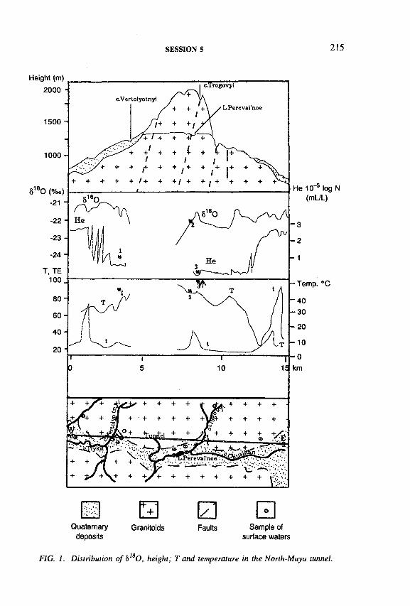
SESSION 5 215
Quaternarydeposits
Granitoids□ ИFaults Sample of
surface waters
FIG. 1. Distribution o f b18 О, height, T and temperature in the North-Muya tunnel.
216 POSTER PRESENTATIONS
NMT. In that part of the NMT where the highest GWI is found, S180 values vary from - 2 0 . 8 ° / o o to —2 1 . 5 7 0 0 . Thus it may be concluded that aged water storage played a part in GWI which had been collected within those Quaternary deposits where the depression is layered as well as in the fissured zone of the crystalline rock massif contacting with the depression. Comparing ô l80 values of groundwater samples taken from the creeks Vertoletnyi and Trogovyi, and Pereval’noe Lake, one can see that their water does not contribute to GWI. The Pereval’noe Lake water is practically identical to the groundwaters of the depression zone.
In the portal parts of the tunnel, a number of thermal water outputs were found with groundwater temperature of 45° С but their ô180 values appear to be identical to those of the cold waters (2-3 °C) although the thermal waters have an increased content of helium (up to 1005 x 10“5 mL/L) that suggests their deep circulation.
The minimum tritium contents (< 3 0 TU) are characteristic for the thermal groundwater that, in turn, provides information on their relatively high residence time in the heated part of the rock massif. Nevertheless, ô180 values indicate that whether cold or thermal water is investigated the recharge area is the same. In their chemical composition both waters are similar, although the mineralization of the thermal groundwater is higher (up to 0.3 g/L) than the cold groundwater (0.02-0.05 g/L). The tritium contents in the drainage waters and cold groundwater are between 83 and 121 TU. It is interesting that a direct interrelation between the altitude of sampling and tritium content in groundwater can be noted. Similarly, an inverse dependency between <5180 and tritium can be traced in the central part of the NMT. Mean residence times of groundwater in the disturbed (by the tunnel construction) area is about 90 years although the value for modern groundwater involved in the tunnel inflow is not more than one year.
As the main part of the territory of the Angarokansky Pass and the whole mountain massif contacting is frozen by the permafrost, the major part of the meteoric waters may feed the GWI only within the above mentioned tectono-erosion depression where the permafrost is absent.
FURTHER READING
[1] SHABYNIN, L .L ., PINNEKER, E. V ., The regime of water inflow in the North MuyaTunnel, Geol. Geophys. 6 (1988) 42-51 (in Russian).

SESSION 5 217
APPLICATION OF TRACER TECHNIQUES TO CHARACTERIZE HYDRAULICS AND SOLUTE TRANSPORT OF THE EPIKARST ZONE OF A KARST AQUIFER
B. REICHERTDepartment of Applied Geology,University of Karlsruhe,Karlsruhe
P. TRIMBORN Institut fur Hydrologie,GSF-Forschungszentrum für Umwelt und Gesundheit Neuherberg, Oberschleissheim
Germany
The vadose zone of a karst system, termed the epikarst or subcutaneous zone, extends from the upper weathered part of the bedrock, above the permanently saturated zone, up to the soil. This zone is of particular hydrological importance for a karst aquifer with respect to quantification of recharge, storage and discharge processes, because of its high secondary permeability, arising from considerable chemical solution during downward percolation of water. Reliable estimation of the influence of the subcutaneous zone requires detailed characterization of its hydro- geological and hydraulic properties, and of solute transport. Cave systems provide excellent opportunities for intercepting water in the unsaturated zone and monitoring solute movement.
Intensive investigations of the c. 30 m thick epikarst zone above the Cerna Jama, in the classical karst area of Slovenia, were started in summer 1993 within the framework of the current research project of the International Association of Tracer Hydrology (ATH). An observation network was established on the basis of the results of previous detailed geological and speleological research [1]. About 15 trickles and dripping points with varying discharge behaviour were selected for the tracer hydrological investigations in the cave. Rainwater was collected in two pans above the cave being investigated. Event monitoring was carried out during autumn 1993, and summer and autumn 1994. Daily measurements of discharge, temperature, pH, electrical conductivity (EC), and carbon dioxide and bicarbonate concentrations were carried out for the selected trickles and dripping points over periods of two to eight weeks. Additional water samples were taken daily for analysis of 180 content and weekly for analysis of selected anions and cations. Point source
I AE A-SM-ЗЗб/112P

218 POSTER PRESENTATIONS
-8.8
-8.9 ' 1 Л 1
-8.0-,
-8.1 ■
Й -9 0 •ЧлЛ / Ш л N H
Й -8.2- i . , , \ n& -9.1 •Ю
. W/ïJY s fv ° -8.3CO f \ A „ A ( 4 г ь-9.2 1 -8.4 ■
-9.3 ----------1---------- 1----------1--------- 1- -8.5-94-06-13 94-06-28 94-07-13 94-07-28 944)8-13 94-06-13 94-06-28 94-07-13 94-07-28 94-08-13
Ê" ?COA 400 ■
С/)я 400> 390 • &> 390-О3 380 •
оэ 380-соо 370соо 370
ло 360 у ^ 75о 360о 350 о 350-Ш 340 • ш 340-
94-06-13 94-06-28 94-07-13 94-07-28 94-08-13 94-06-13 94-06-28 94-07-13 944)7-28 94-08-13
94-06-13 94-06-28 94-07-13 94-07-28 94-08- 94-06-13 94-06-28 94-07-13 94-07-28 94-08-13
60.0 60.0
-
л . .......... L l . , ......U .94-06-13 94-07-03 94-07-23 94-08-12 94-06-13 94-07-03 94-07-23 94-08-12
FIG. 1. CemaJama, Slovenia: 18 О content, electrical conductivity, runoff and precipitation rate o f trickle 7 (left) and trickle 1 (right).
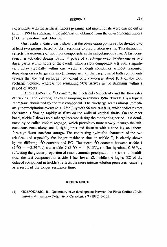
SESSION 5 219
experiments with the artificial tracers pyranine and naphthionate were carried out in autumn 1994 to supplement the information obtained from the environmental tracers (180 , temperature and chloride).
Our results to date clearly show that the observation points can be divided into at least two groups, based on their response to precipitation events. This distinction reflects the existence of two flow components in the subcutaneous zone. A fast component is activated during the initial phase of a recharge event (within one or two days, partly within hours of the event), while a slow component acts with a significant delay (typically within one week, although sometimes without response, depending on recharge intensity). Comparison of the baseflows of both components reveals that the fast recharge component only comprises about 10% of the total recharge volume, whereas the remaining 90% arrives in the drippings within a period of weeks.
Figure 1 shows the 180 content, the electrical conductivity and the flow rates of trickles 1 and 7 during the event sampling in summer 1994. Trickle 1 is a typical shaft flow, dominated by the fast component. The discharge reacts almost immediately to precipitation events (e.g. 28th July with 56 mm rainfall), which indicates that the water is flowing rapidly as films on the walls of vertical shafts. On the other hand, trickle 7 shows no discharge increase during the monitoring period. It is dominated by so-called vadose seepage, which percolates more slowly through the subcutaneous zone along small, tight joints and fissures with a time lag and therefore significant transient storage. The contrasting hydraulic characters of the two trickles, and especially the longer residence time in trickle 7, is clearly shown by the differing 180 contents and EC. The mean 180 contents between trickle 1 (<5180 = -8 .29°/00) and trickle 7 (0180 = -9 .1 5 7 00) differ by about 0.86°/oo, reflecting the greater proportion of recent summer precipitation in trickle 1. In addition, the fast component in trickle 1 has lower EC, while the higher EC of the delayed component in trickle 7 reflects the more intense solution processes occurring as a result of the longer residence time.
REFERENCE
[1] GOSPODARIC, R., Quaternary cave development between the Pivka Cotlina (Pivkabasin) and Planinsko Polje, Acta Carsologica 7 (1976) 5-135.

220 POSTER PRESENTATIONS
ISOTOPIC STUDY OF THE EFFECT OF TARBELA RESERVOIR ON THE GROUNDWATER SYSTEM IN DOWNSTREAM AREAS
M.I. SAJJAD, M.A. TASNEEM, S.D. HUSSAIN,I.H. KHAN, M. ALIPakistan Institute of Nuclear Science and Technology,P.O. Nilore, Islamabad, Pakistan
Presented by A. Tanweer
IAEA-SM-336/115P
Isotopic studies were carried out on the right banks of the River Indus, downstream of Tarbela, to study the effect of Tarbela reservoir on the groundwater system. Tarbela dam, the giant multipurpose dam, completed in 1976, has been built across the River Indus. The reservoir is 97 km long, 260 km2 in area and has a gross storage capacity of 17 109 000 m3 at the maximum lake elevation of 472 m, a residual capacity of 2 802 000 m3 at the assumed level of maximum drawdown of 396 m and a net capacity of 14 307 000 m3. The total catchment area above Tarbela is spread over 168 000 m 2, which largely brings in snowmelt supplies in addition to some monsoon rains [1].
Initially, hundreds of sinkholes and cracks developed in the dam site bed during the first filling of the reservoir. Excessive seepage through the dam foundation and its abutment also presented serious problems. These were, later on, rectified. However, it is observed that the water table rises in the downstream areas when the reservoir attains its highest level in the monsoon season. The water table rise may be associated with the rise of the reservoir level and the creation of sinkholes in the dam/reservoir bed. Another incident was the appearance of water in the ponds near Gadoon Amazai on the right side of Tarbela reservoir, related to the (probable) seepage from the reservoir. Bearing this in mind, it was decided to apply isotopic techniques to attempt to determine the situation.
The main objectives of the study were to determine the hydraulic connection, if any, between Tarbela Lake and the groundwater appearing in the ponds near Gadoon Amazai, to see the effect of Tarbela dam on the groundwater system in the downstream areas, and to estimate the relative contribution of different recharge sources to the groundwater system.
Environmental isotope (2H, 180 and 3H) techniques along with major ion chemistry were employed to study the problem. Sixty water sampling stations, selected from the existing open wells, tubewells, springs, drains, the River Indus and Tarbela reservoir were established. Water samples were collected from these

LEGEND
TUBE W E L L S -------------- •
OPEN W ELLS--------------- e
SPRING»-.--------------------- *
&/CHANNEL----------------— ■LAKE /RIVER SAM PLE- ■NULLAH.......................... ARIVER--------------------------pBZ.TOWNS---------------------------- 0KILLS -
FIG. I. Spatial distribution o f 6lsO in the project area.
SESSION 5
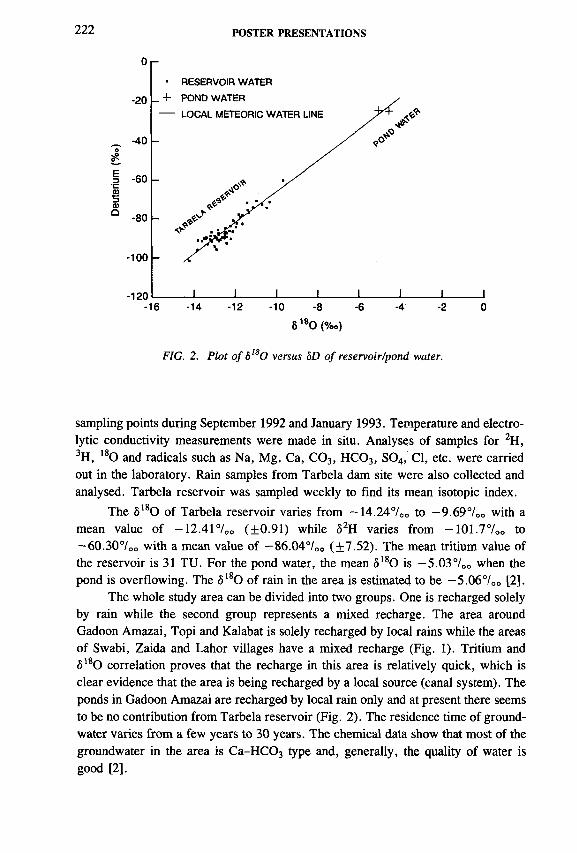
222 POSTER PRESENTATIONS
6 180 (%o)
FIG. 2. Plot o f bI80 versus Ю o f reservoir/pond water.
sampling points during September 1992 and January 1993. Temperature and electrolytic conductivity measurements were made in situ. Analyses of samples for 2H, 3H, 180 and radicals such as Na, Mg, Ca, C 03, H C 03, S04, Cl, etc. were carried out in the laboratory. Rain samples from Tarbela dam site were also collected and analysed. Tarbela reservoir was sampled weekly to find its mean isotopic index.
The ô180 of Tarbela reservoir varies from -14.24°/00 to -9 .6 9 7 00 with a mean value of -1 2 .4 1 7 00 (+0.91) while <52H varies from -101 .7°/oo to —60.307oo with a mean value of —86.047oo (±7.52). The mean tritium value of the reservoir is 31 TU. For the pond water, the mean <5180 is -5 .0 3 7 oo when the pond is overflowing. The ô180 of rain in the area is estimated to be — 5.067oo [2].
The whole study area can be divided into two groups. One is recharged solely by rain while the second group represents a mixed recharge. The area around Gadoon Amazai, Topi and Kalabat is solely recharged by local rains while the areas of Swabi, Zaida and Lahor villages have a mixed recharge (Fig. 1). Tritium and ô180 correlation proves that the recharge in this area is relatively quick, which is clear evidence that the area is being recharged by a local source (canal system). The ponds in Gadoon Amazai are recharged by local rain only and at present there seems to be no contribution from Tarbela reservoir (Fig. 2). The residence time of groundwater varies from a few years to 30 years. The chemical data show that most of the groundwater in the area is Ca-H C03 type and, generally, the quality of water is good [2].

SESSION 5 223
REFERENCES
[1] PAKISTAN WATER AND POWER DEVELOPMENT AUTHORITY (WAPDA), Tarbela Dam Project Completion Report on Design and Construction — Volume I (General), Tippetts-Abbett-McCarthy-Stratton Consulting Engineers (1984).
[2] SAJJAD, M .I., TASNEEM, M.A., HUSSAIN, S.D., KHAN, I.H., ALI, M., Isotopic Study of the Effect of Tarbela Reservoir on the Groundwater System in the Downstream Areas, Rep. PINSTECH/RIAD-133, Pakistan Institute of Nuclear Science and Technology, Islamabad (1993).
IAE A-SM-336/118P
AGE DISTRIBUTION IN NEAR SURFACE AND DEEP GROUNDWATERS USING ENVIRONMENTAL TRACERS AND NUMERICAL MODELS
K.-P. SEILER, P. MALOSZEWSKI Institut für Hydrologie,GSF-Forschungszentrum für Umwelt und Gesundheit Neuherberg, Oberschleissheim, Germany
Hydrodynamic, isotopic and chemical properties of groundwaters change with depth. This results from activity of groundwaters within the water cycle and the time of interaction between waters and rocks. One pronounced change frequently occurs in most climatic zones of the world. This change is linked to a sharp decline of tritium concentrations to its detection limit, and occurs between zero and about 100 m depth. It is used to separate the hydrodynamically near surface zone from the passive zone of deep groundwaters.
Parallel to field observations many numerical runs have been performed; these results indicate that more than 85% of groundwater recharge remains in the near surface active zone of groundwaters or recharge of deep groundwaters is less than 15 %. These findings and the large volume of deep groundwaters as compared to near surface groundwaters account for the better protection of deep groundwaters against contaminants.
The exploitation of deep groundwaters mostly causes long term non-steady- state conditions for groundwater flow and may induce hydraulic short cuts to shallow aquifers. In this way persistent contaminants can reach wells that discharge from deep groundwaters only after many years of well operation. Therefore changes in groundwater quality as a consequence of exploitation of deep groundwaters should

224 POSTER PRESENTATIONS
be monitored in a different way than is usual, and could be based on an environmental isotope survey.
According to numerical modelling, a pronounced age stratification exists in groundwaters. A comparable environmental tracer stratification must also exist and could be used to predict and judge changes of hydrodynamic behaviour of exploited deep groundwaters before the contaminants reach deep groundwaters. Among such environmental tracers 39Ar, 85Kr and 3H seem to be as promising as do certain chemical components, e.g. Mg.
IAEA-SM-336/122P
ESTIMATION DU TEMPS DE SEJOUR, PAR LE CARBONE 14, DES EAUX PROFONDES DES FORMATIONS CARBONATEES DE LA REGION DE SAÏDA, ALGERIE
M. SOUAGDivision datation et hydrologie isotopique,Centre de développement des techniques nucléaires,Alger, Algérie
La région d’étude est soumise à un climat semi-aride à pluviométrie annuelle moyenne de 400 mm. La majorité des forages captent les aquifères des formations carbonatées fissurées et karstifiées (dolomies et calcaires) du jurassique inférieur et moyen.
Dans la partie aval de la vallée de Saïda, les eaux souterraines sont thermales (26 à 45 °C). L’exploitation de ces eaux par des nouveaux ouvrages a causé une diminution considérable du débit des forages anciens et particulièrement de celui de la station thermale de Hammam Rabbi. C’est la raison essentielle de cette étude réalisée sur la base des radiotraceurs au tritium et carbone 14.
Les teneurs en carbone 14 d’une trentaine de points d’eaux souterraines varient de 0 à 92% de carbone moderne et semblent décroître avec l’augmentation du carbone 13 du carbone isotopique total dissous (CITD) (Fig. 1). Les activités initiales calculées donnent, pour les modèles de Gonfiantini, de Fontes et Garnier, des âges très proches:
— Eaux récentes à activité initiale en carbone 14 inférieure à celle du CITD. Ces eaux modernes sont confirmées par des teneurs élevées en tritium supérieures à 6 U.T. (Fig. 2), et résulteraient d’une minéralisation du carbone en système

Car
bone
14
(pcm
) C
arbo
ne
14 (p
cm)
SESSION 5
- Pole minéral
FIG. 1. Relation carbone 14-carbone 13.
Eaux récentes
Tritium (UT)
FIG. 2. Relation carbone 14-tritium (mai).

226 POSTER PRESENTATIONS
«ouvert» sur le C 02 gaz du sol. Ce dernier implique une signature isotopique de la phase gazeuse indépendamment de celle des carbonates solides.
— Eaux à composante ancienne représentée par la majorité des eaux (70%) avec un temps de séjour qui varie de 60 à 21 600 ans. Les valeurs du tritium (Fig. 2) ont mis en évidence l ’existence d’un mélange par les eaux récentes d’un certain nombre de points d’eau en fonction de leur proximité des zones de recharge et de la tectonique.
— Eaux très anciennes, présentant des activités nulles en carbone 14. Ces eaux ne permettent pas d’envisager une quelconque continuité hydraulique avec les autres nappes et constituent par conséquent au moins une unité bien individualisée au sein des autres systèmes très compartimentés de circulations souterraines. Il s’agit des eaux des trois forages situés les plus en aval de la vallée de Saïda.
La distribution géographique des teneurs en tritium indique que la recharge potentielle est localisée dans la moitié nord des affleurements carbonatés. Les eaux infiltrées des saisons humides se manifestent aux émergences plutôt en fin d’étiage (octobre) qu’en période des hautes eaux (mai).
A la différence des activités élevées des eaux récentes, les faibles activités reflètent bien le caractère ancien et très ancien de cette réserve faite dans des conditions climatiques différentes de celles de nos jours. Ces aquifères sont probablement isolés et dépendent peu ou pas de la recharge actuelle.
BIBLIOGRAPHIE
FONTES, J.-C., GARNIER, J.M ., Determination of the initial carbon 14 content activity of the total dissolved carbon: a review of the existing models and a new approach, Water Resour. Res. 15 2 (1979) 399-413.
FONTES, J.-C., «Some considerations on groundwater dating using environmental isotopes», Hydrology in the Service of Man, Mem. Int. Assoc. Hydrogeologists, Cambridge (1985).
OLIVE, P., A propos de la datation des eaux par le radiocarbone, Publ. n° 190, Univ. de Paris 6 (1977) 34 pp.
STUIVER, M., POLACH, H.A., Discussion reporting of carbon-14 data, Radiocarbon 19 3 (1977) 355-363.
WALLICK, E.I., «Isotopic and chemical considerations in radiocarbon dating of groundwater within the semi-arid Tucson basin, Arizona», Interpretation of Environmental Isotope and Hydrochemical Data in Groundwater Hydrology, IAEA, Vienna (1976) 195-212.

Chairpersons
S. SANJDORJMongolia
GROUNDWATER POLLUTION
(Session 6)
T. FLORKOWKSIPoland


IAEA-SM-336/7
GROUNDWATER MODEL FOR MANAGEMENT AND REMEDIATION OF A HIGHLY POLLUTED AQUIFER (ORGANO-CHLORINE COMPOUNDS) IN AN URBAN AREA, USING RADIOACTIVE TRACERS (131I) FOR HYDRODYNAMIC PARAMETERS AND DISPERSIYITY MEASUREMENTS
M. BERSANO BEGEY, M. CARGNELUTTI Hydrodata S.p.A., Turin
E. PIRASTRUENEA, Centro Ricerche di Saluggia, Vercelli
Italy
Abstract
GROUNDWATER MODEL FOR MANAGEMENT AND REMEDIATION OF A HIGHLY POLLUTED AQUIFER (ORGANO-CHLORINE COMPOUNDS) IN AN URBAN AREA, USING RADIOACTIVE TRACERS ( 131I) FOR HYDRODYNAMIC PARAMETERS AND DISPERSIVITY MEASUREMENTS.
The paper presents the methodology and results of a flow transport model (organo- chlorine compounds, mainly trichloroethylene, TCE). Pollution was discovered in 1989 and has been widely monitored in a medium sized Italian industrial town. It involved the contamination of areas where several wells of the municipal water system were located. The monitoring data showed that the source of the pollution was in the industrial part of the town, where a chemical plant is located. The breakdown responsible for the pollution was identified (industrial sewage pipeline damaged) so that the TCE mass lost in the aquifer (from 1988 to 1992) was accurately evaluated (252.3 kg). A numerical model was realized with the following aims:(1) to simulate the polluted area evolution (up to 2020), with and without remediation systems;(2) to define which other public wells would be reached by the contaminant from and to calculate the concentration versus time curves in these wells; (3) to define the maximum extension of the contaminated area in order to drill new wells as alternative sources of supply for the polluted area; (4) to define wellhead protection areas and the location of monitoring wells around public exploitation wells. Aquifer parameters were mainly evaluated using the radioactive tracer 131I, by means of dilution point tests (single well method) and multiwell tests. The main results of the simulations were as follows: (1) the contaminant front will reach the public wells supplying the southeast part of the town and the concentration will be over potability limits (/¿g/L) in about five years; (2) the benefit of any remediation system (reasonable from the cost point of view) is appreciable but only partial, since the pollution is very widespread; (3) the leaky confined aquifer pollution is mainly due to the overexploitation of the aquifer, causing strong depression of the piezometric surface (several metres below phreatic level) increasing leakage from the highly polluted phreatic aquifer.
229

230 BERSANO BEGEY et al.
A case of pollution since 1989 by organo-chlorine compounds was discovered in a medium sized industrial town in northwest Italy (Piedmont district). Water quality has been widely monitored, using both public water wells (all located in the urban area) and new piezometric wells, drilled for a better assessment of the polluted area.
The pollutant consisted of a ‘cocktail’ of organo-chlorine compounds, with the main one being trichloroethylene (TCE). Analysis enabled two different sources of pollution to be identified in the neighbourhood of an industrial plant, between 1.2 and 2.2 km upvalley in the direction of a group of public water wells supplying the southeast of the town.
Since the study has to be kept strictly confidential, in this report all references to the exact location of industrial plants and subjects involved are omitted.
The level of pollution was up to 10 000 /¿g/L close to the industrial area (the Italian legal limit for drinkable water is 30 /¿g/L).
Using the analytical data, a numerical model was realized with the followingaims:
— To simulate the evolution of the polluted area (up to 2020), with and without remediation systems;
— To define which other public wells will be reached by the contaminant front and calculate the concentration versus time curves in these wells;
— To define the maximum extension of the contaminated area in order to drill new wells as alternative sources of supply for the polluted area;
— To define wellhead protection areas and the location of monitoring wells around public wells.
At the starting time of the provisional model (December 1993) the area exceeding the 30 fig/L legal limit for drinkable water extended about 2 km in the direction of flow, very close to the public wells.
1. INTRODUCTION
2. GEOLOGICAL AND HYDROGEOLOGICAL SETTING
The stratigraphie conditions were accurately reconstructed using data from more than 50 boreholes. The general features of the area are as follows:
— The area is composed of an alluvial sequence, mainly gravels and sands, about 10 m deep, with clay levels of low thickness;
— At the bottom of this aquifer sequence, blue clays with less sandy levels are present (transitional deposits known in geological literature as ‘Villafranca Unit’;

IAEA-SM-336/7 231
— Below the alluvial phreatic aquifer, a fairly thick and continuous clay level is present (at a depth of about 25-30 m from the surface); this level separates the superficial aquifer itself by a deep leaky confined one;
— All the other clay levels are not continuous or only locally continuous;— The top of the blue clay formation (‘Villafranca Unit’) is inclined SW, with
a few degrees of dip;— Piezometric measurements show a S-SW water table dip (hydraulic gradient
i « 0.4%);— Large scale previous studies available indicate a local aquifer permeability
value of к » 10“3 m/s.
3. FIELD TESTS
Parameters have been evaluated, for both phreatic and leaky confined aquifers mainly by means of field tests. Groundwater tests carried out are listed below:
(1) tracer tests— Dilution point tests (single well method)— Multi well tests.As radioactive tracer 13 *1 has been mainly used.
(2) pumping tests— Non-equilibrium regime tests (Theis and Walton methods)— Steady state tests (Dupuit methods).
Tracer tests have been carried out in the chemical plant area, since the highest possible level of accuracy in parameter determination was required by the model to simulate the initial dilution of TCE mass. Moreover, tracer tests are the only procedures allowing the measurement of the hydrodynamic parameters referred to in every single layer and not only an average aquifer value (as, for example, in pumping tests). In this area non-equilibrium pumping tests have also been carried out, so a comparison of the results is possible.
3.1. Tracer tests
Tracer tests have been carried on using three groups of injection-observation wells specifically designed for this purpose. The description and results here reported refer to tracer tests carried on one of these wells, located in the industrial area.
This group of wells was drilled in the area where the TCE mass was lost (by a damaged industrial sewage pipeline); only the phreatic aquifer has been tested, since the leaky confined aquifer (studied by means of pumping tests) is only rather weakly polluted ( < 30 /xg/L) in the industrial area (where the clay layer at the top
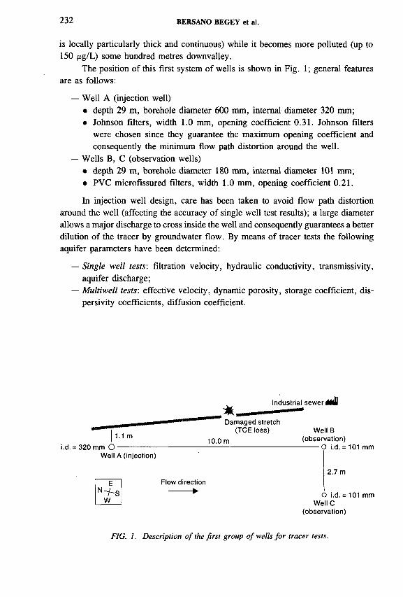
232 BERSANO BEGEY et al.
is locally particularly thick and continuous) while it becomes more polluted (up to 150 ng/L) some hundred metres downvalley.
The position of this first system of wells is shown in Fig. 1; general features are as follows:
— Well A (injection well)• depth 29 m, borehole diameter 600 mm, internal diameter 320 mm;• Johnson filters, width 1.0 mm, opening coefficient 0.31. Johnson filters
were chosen since they guarantee the maximum opening coefficient and consequently the minimum flow path distortion around the well.
— Wells В, С (observation wells)• depth 29 m, borehole diameter 180 mm, internal diameter 101 mm;• PVC microfissured filters, width 1.0 mm, opening coefficient 0.21.
In injection well design, care has been taken to avoid flow path distortion around the well (affecting the accuracy of single well test results); a large diameter allows a major discharge to cross inside the well and consequently guarantees a better dilution of the tracer by groundwater flow. By means of tracer tests the following aquifer parameters have been determined:
— Single well tests: filtration velocity, hydraulic conductivity, transmissivity,aquifer discharge;
— Multiwell tests: effective velocity, dynamic porosity, storage coefficient, dispersivity coefficients, diffusion coefficient.
1.1 m
i.d. = 320 mm О ■
*Damaged stretch
(TCE loss)
10.0 m
Industrial sewer
Well A (injection)
N^ Sw
Flow direction ---------►
Well В (observation)
---------О i.d. = 101 mm
2.7 m
О i.d. = 101 mm Well С
(observation)
FIG. 1. Description o f the first group of wells for tracer tests.

IAEA-SM-336/7 233
о vd (m/d)
0.6 0.7 0.8 0.9 1.1
-5 Water table
■ 10 - Sands (73%) with gravels
-20
-15
V(i¡min=l
Sands (81%) with gra\
Clean sands
V(timax=1.05 m/d
-25 Aquifer bottom (clay layers)
FIG. 2. Single well test: filtration velocity (Vd) measurements.
3 .1 .1 . Single well test (dilution po in t test)
3.1.1.1. Description of method
By an appropriate injection device, some kilobecquerels of a radioactive tracer (mainly 13II, as no great amount of organic matter was present, but also 82Br in some cases) was injected in well A. The tracer concentration decrease was followed using Nal scintillation counters and a SILENA 201 SNIP computer. Packers were used to prevent vertical flow in the well. After transformation of the counts into concentration values, curves of concentration versus time were obtained.
3.1.1.2. Test results
• Filtration velocity
Filtration velocity has been evaluated using the equation below; calculation results are reported in Fig. 2
( 1)
where /3 is 0.975 (coefficient depending on volume of the instrument over the dilution volume); a is 3 (a coefficient corrects distortion of flow lines and relates

234 BERSANO BEGEY et al.
horizontal in-well flow in the porous aquifer); r is the well radius; C0 is the initial tracer concentration; and С is the tracer concentration after time interval At.
Mean filtration velocity: 0.84 m/d.
• Hydraulic conductivity
Hydraulic conductivity was evaluated using Darcy’s law, considering a constant mean hydraulic gradient of 0.004. Mean value к = 2.4 X 10~3 m/s (typical of clean sands).
• Transmissivity
The local depth of the saturated aquifer is 20 m. Mean value T = 2.4 X
10~3 m/s = 4.8 x 10'2 m2/s.
• Aquifer discharge
Aquifer discharge was calculated using Darcy’s law, Q = k-i-S , where i is the hydraulic gradient and S is a 1 m2 aquifer section. Mean value Q = 9.6 x 10'6 m3/s = 0.83 m3/d.
3.1 .2 . M ultiwell test
The radioactive tracer was injected in well A and detected in wells В and С(Fig- I)-
FIG. 3. Multiwell test: effective velocity (Vrj calculation.
IAEA-SM-336/7 235
• Effective velocity (Fig. 3)
Taking into account time intervals between tracer injection in well A and peak arrival in well В the following mean effective velocity values were calculated.
Mean value 4.0 m/d.
• Dynamic porosity
Dynamic porosity (ed, adimensional) was calculated using the following equation:
ed = Vd/Vr = 0.84/4.0 = 0.21 (2)
In the phreatic aquifer, dynamic porosity can be approximately considered equal to the storage coefficient.
• Dispersion coefficients
The longitudinal dispersion coefficient (D,) was calculated using Eq. (3).
C(x,y = 0,t) _____ - ( x - vt)2 , (x - vt)2“ _ exp i
Стах 1 4D]T 4Dj tmax
Considering the test results (t = 1.8 d, tmax = 2.5 d, v = 4.0 m/d,x = 10.0 m, C/Cmax = 0.1, the following value was calculated:
D, = 2.73 x 10"6 m2/s (4)
Longitudinal dispersivity:
orL = Dj/Vj = (2.73 x 10~6 m 2/s)/(9.7 X 10~6 m/s) = 28 m (5)
• Diffusivity
Diffusivity was calculated using the following equation:
D = T/ed = 6.7 X 10'2/0.21 = 0.32 m2/s (6)
3.2. Pumping tests: comparison of results
Non-equilibrium pumping tests were carried on in the study area, both in the phreatic and the leaky confined aquifer. For the phreatic aquifer the pumping tests
3.1.2.1. Test results

236 BERSANO BEGEY et al.
were conducted on the same group of wells where tracer tests had been carried out, so a comparison of results is possible; well A is the pumping well, while wells В and С are observation wells.
3.2.1. Phreatic aquifer
Since well A has been pumping at a constant rate of discharge for long periods, hydraulic conductivity has been evaluated starting from dynamic levels in observation wells В and C, by means of the usual equilibrium regime equations (Dupuit method). Different values were calculated for each obsrvation well, as shown in Table I.
TABLE I. RESULTS OF PHREATIC AQUIFER PUMPING TESTS
Pumping wellObservation well Hydraulic conductivity
(Q = 0.02 m3/s) (m/s)
A В 1.6 x 10'3
A С 1.2 x 10⁻³
A comparison between the pumping test and the single well tracer test is possible: both pumping test results are of the same dimensional order as the tracer test average result (2.4 x 1СГ3 m/s).
Those values are representative of the industrial area, where all the tests were carried out. Transmissivity in the remainder of the study area has been evaluated starting from specific discharge values, available for 11 wells in the study area itself. These values have been interpreted by means of CASSAN equations for transmissivity calculation from specific discharge and the hydraulic gradient [1]. The mean value obtained is T = 8.16 x 10~3 m 2-s_1, corresponding to a mean hydraulic conductivity к = 8.16 x 10 3 m2-s_1/20 m -s"1 = 0.41 X 10~3 m -s '1. This value, lower than the values calculated for the industrial area, shows a tendency for the hydraulic conductivity to decrease downvalley in the study area, as is also confirmed by stratigraphie data (increase of clay layers frequency and consequent decrease in aquifer level thickness).
3.2.2. Leaky confined aquifer
A non-equilibrium regime pumping test was carried out using two wells located in the industrial area, exploiting water only by the leaky confined aquifer, using one as pumping well and the other as observation well (11.2 m apart). Interpretation by Walton sample curves gives a transmissivity value T = 2.6 x 10'3 m2-s_1;

IAEA-SM-336/7 237
of course this value cannot be compared with tracer test values, calculated only for the phreatic aquifer.
This value is representative of the industrial area where the test was carried out. Transmissivity in the remainder of the study area was evaluated starting from specific discharge values, available for 31 wells in the study area itself. These values have been interpreted by means of С ASS AN equations [1], for calculation of transmissivity from specific discharge and hydraulic gradient. The mean value obtained is T = 6.55 X 10'3 m2-s_1.
4. SIMULATION MODELS
Since a two dimensional model approximation has been chosen, for the finest representation of the pollution event the following models have been run:
(a) 2-D horizontal model (phreatic aquifer)(b) 2-D horizontal model (undifferentiated aquifer)(c) 2-D cross-sectional model.
The output of models (a) and (b) is the planimetric distribution of the pollutant, represented as lines of iso-concentration in each of the simulated aquifers.
The output of model (c) consists of the pollutant distribution on a vertical section parallel to the groundwater flow direction, from the pollution source (industrial sewerage) to the municipal water system group of wells.
4.1. Model description
Sutra (saturated-unsaturated transport), by the US Geological Survey, is a computer model which simulates fluid movement and transport of dissolved substances in a subsurface environment. Energy transport simulation is also possible.
The model employs a two dimensional hybrid finite element and integrated finite difference method to approximate the governing equations that describe the two interdependent processes that are simulated:
(1) Fluid density dependent saturated or unsaturated groundwater flow;(2) Transport of a solute in the groundwater, in which the solute may be sub
jected to:— Equilibrium adsorption on the porous matrix (linear isotherms and non
linear Freundlich or Langmuir sorption isotherms);— First order and zero order production or decay;
(3) Transport of thermal energy in groundwater and solid matrix of the aquifer.

238 BERSANO BEGEY et al.
¡¡•s ! тт ,\ ! !!!! ш\\\.i!! ■ НИ i mu..!! ! !!!!!1111111111 ■! ! üüpiiiiiiiiii И ! >ü! iiiiiiiiiiii ■8 ! !!!! пиши [| !! ! Шпшпшп i I n u nFIG. 4. Horizontal model grid. FIG. 5. Cross-sectional model grid.
4.2. Model set-up
4.2.1. Simulation area: grid definition
4.2.1.1. Horizontal models
Both horizontal models (phreatic and undifferentiated aquifers) were based upon the same discretization grid. A two dimensional discretization on a horizontal plane was obtained using a finite element ‘mesh’ made by 2100 nodes and 2009 elements realized starting from a regular grid (elements side =» 75 m) adapted to fit grid nodes with all wells and piezometric wells present in the area, leading to good accuracy in data input and output. The horizontal model grid is shown in Fig. 4.
4.2.1.2. Cross-sectional model
For the horizontal model a finite element grid was used, with 2020 nodes and 1900 elements, minimum dimensions 5 x 10 m and maximum dimensions 5 X 50 m.
The major sides were deformed to obtain a 0.4% dip, equal both to the hydraulic gradient and to the gradient of slope of the layer at the bottom of the aquifer sequence. The vertical model grid is shown in Fig. 5.
4.2.2. Input parameters
4.2.2.1. Permeability
For the industrial area (source of pollution) the tracer test value (k = 2.4 X 10~3 m s '1) was taken as input for the model. In the SW part, pumping test results

IAEA-SM-336/7 239
(С ASS AN method interpretation of specific discharge data, see Section 3.2), showed a significant difference (mean value: к = 0.41 x 10~3 m -s '1) between the values downvalley and the industrial area. The downvalley values were taken as input for the model. Distribution of data in the study area involved linear kriging, checking elaboration results with stratigraphical reconstruction data.
4.2.2.2. Dynamic porosity
The value resulting from tracer tests (ed = 0.21) was taken as input for the model.
4.2.2.3. Longitudinal dispersivity (aL)
The longitudinal dispersivity value strongly depends on the distance travelled by the groundwater. Experimental studies show a linear or quasi-linear relation between the two factors [2].
By testing solute diffusion in alluvial aquifers one obtains the following equation:
aL (x) = 0.181 X x0 86 (7)
where x is the flowpath distance.Results of the dispersivity field measurement are shown in Fig. 6.
10'1 10° 101 102 103 104 10s 106
s(m)
FIG. 6. Results o f dispersivity field measurements [2].

240 BERSANO BEGEY et al.
Dissolved concentration (цд/L)
FIG. 7. Rate o f adsorption o f some organochlorine compounds [3].
A great mistake would be to apply the results of a small scale dispersivity test to simulate pollutant transport on a much wider scale. The distance between the pollution source and the main simulation ‘target’, that is pumping station No. 65 of the public water system, is about 2100 m. Plotting small scale test results (0.28 m) parallel to regression lines in Fig.6 the value of about 120 m can be estimated, very similar to the value obtained by using Eq. (1). This value has been used for a rough model simulation, as an input parameter that can be calibrated by means of back analysis.
4.2.2.4. Adsorption factor
Adsorption has been considered as a linear function of concentration in accordance with linear isotherms shown in Fig. 7, tested for alluvial aquifers in a concentration range between 1 and 150 /ig/L. A tendency to non-linear adsorption behaviour (Freundlich isotherms) probably occurring for much higher concentrations (adjacent to the pollution source) has been neglected, considering model scale.
4.2.2.5. Pollutant density
Pollutant density is taken into account by the cross-sectional model. Of course, in 2-D horizontal models density does not influence output results, since the simulated pollution is considered not variable with depth.
Pollutant density has been evaluated as the weighted mean value of all organochlorine compounds, considering their percentage of use in that factory (Table II):

IAEA-SM-336/7 241
TABLE II. POLLUTANT DENSITY
Pollutant % of use Density at 20°C (g/cm3)
T richloroethy lene 15.2 1.46
Trichloroethane 82.9 1.32
Methylene chloride 1.9 1.33
The weighted value is 1.34 g/cm 3
4 .2 .2 .6 . Volume o f pollutant lost in the aquifer
The breakdown responsible for the pollution was identified (damaged industrial sewage pipeline) so that the TCE mass lost in the aquifer (from 1988 to 1992) could be accurately evaluated.
Four pollution periods can be distinguished:
(a) 1988-4-1 to 1989-3-31 = 177 kg(b) 1992-4-1 to 1992-12-31 = 74 kg(c) 1993-1-1 to 1993-2-28 = 1.3 kg(d) since 1993-1-1 = 0 kg.
FIG. 8. Well 1: measured and calculated concentration values.

242 BERSANO BEGEY et al.
Model calibration was carried out by a back analysis of monitoring data (from April 1988 to July 1993). Only minor adjustments to input parameters had to be made:
• Flow models: exploitation rate of discharge was adjusted for some wells in the industrial area (six wells out of 81);
• Transport models: longitudinal dispersivity (a) was decreased from 120 m to 100 m in the horizontal model.
No other adjustments were made.Back analysis results are shown in Fig. 8 regarding well No. 1, 1080 m from
the pollution source, in the direction of the groundwater flow.
4.2.3. Model calibration
5. SIMULATION RESULTS
5.1. Provisional modelling without remediation systems
The vertical distribution of hydraulic heads is shown in Fig. 9 (cross-sectional model). Note that heads (expressed as absolute values in m.a.s.l.) results are mostly higher (up to 4.5 m) in the phreatic aquifer than in the leaky confined aquifer. This is caused by the overexploitation typical of the area; the main consequence is a significant flow from the superficial aquifer (highly polluted) towards the leaky confined one through the semi-permeable layer.
Overexploitation can thus be considered the main cause of pollution of the deep aquifer, strongly decreasing its natural protection by the low permeability layer. Figure 10 shows the cross-sectional model condition on 1989-4-1 (calculated by back analysis and calibrated with monitoring data); pumping station No. 65 (municipal water system), supplying the southwest part of the town is not yet involved in the pollution. In January 2000 (Fig. 11) the contaminant front will reach the pumping station, with concentration values close to potability legal limits. Without remediation actions by January 2000 pollution will be very widespread, and a very large area with concentrations >100 цg/L will be present in both aquifers.
Figure 12 represents the superficial model output for January 2000. Calculated concentration values are somewhat overestimated since all the pollutant mass is supposed to be transported only in the superficial aquifer, with no transfer in the leaky confined one. The two dimensional cross-sectional approximation represents with much more accuracy pollutant spreading and can so be considered very useful for provisional models between the pollution source and a ‘target’ downvalley, in this case pumping station No. 65. Planimetric 2-D approximation (phreatic aquifer),

IAEA-SM-336/7
1 50 “ I POLLUTION SOURCE (DAMAGED PIPELINE)
WELL No.65 (PUBLIC WATER SYSTEM)
0 1000 2000 3000 4000 (m)
FIG. 9. Vertical distribution o f hydraulic heads.
WELL No.65 (PUBLIC WATER SYSTEM)
0 1000 2000 3000 4000 (m)
FIG. 10. Cross-sectional model output for April 1989.
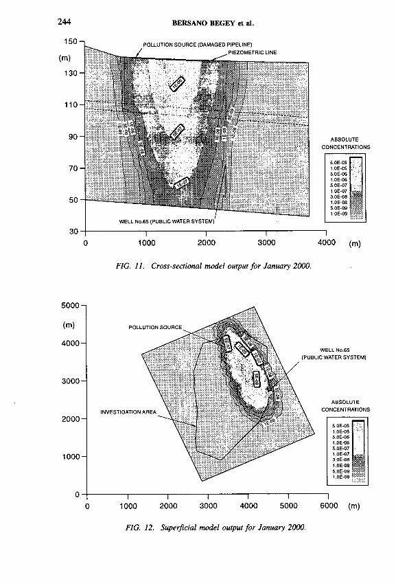
244 BERSANO BEGEY et al.
POLLUTION SOURCE (DAMAGED PIPELINE), PIEZOMETRIC LINE
ABSOLUTECONCENTRATIONS
i5.0E-051.0E-055.0E-061.0E-065.0E-071.0E-073.0E-08 iss1.0E-085.0E-091.0E-09
1000 2000 3000 4000 (m)
FIG. 11. Cross-sectional model output for January 2000.
FIG. 12. Superficial model output for January 2000.
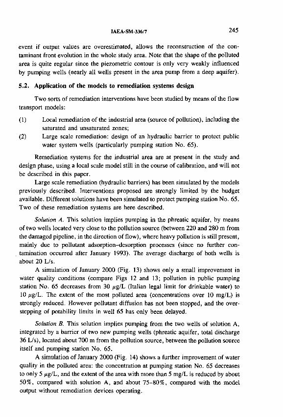
IAEA-SM-336/7 245
event if output values are overestimated, allows the reconstruction of the contaminant front evolution in the whole study area. Note that the shape of the polluted area is quite regular since the piezometric contour is only very weakly influenced by pumping wells (nearly all wells present in the area pump from a deep aquifer).
5.2. Application of the models to remediation systems design
Two sorts of remediation interventions have been studied by means of the flow transport models:
(1) Local remediation of the industrial area (source of pollution), including the saturated and unsaturated zones;
(2) Large scale remediation: design of an hydraulic barrier to protect public water system wells (particularly pumping station No. 65).
Remediation systems for the industrial area are at present in the study and design phase, using a local scale model still in the course of calibration, and will not be described in this paper.
Large scale remediation (hydraulic barriers) has been simulated by the models previously described. Interventions proposed are strongly limited by the budget available. Different solutions have been simulated to protect pumping station No. 65. Two of these remediation systems are here described.
Solution A. This solution implies pumping in the phreatic aquifer, by means of two wells located very close to the pollution source (between 220 and 280 m from the damaged pipeline, in the direction of flow), where heavy pollution is still present, mainly due to pollutant adsorption-desorption processes (since no further contamination occurred after January 1993). The average discharge of both wells is about 20 L/s.
A simulation of January 2000 (Fig. 13) shows only a small improvement in water quality conditions (compare Figs 12 and 13; pollution in public pumping station No. 65 decreases from 30 /ig/L (Italian legal limit for drinkable water) to 10 /ig/L. The extent of the most polluted area (concentrations over 10 mg/L) is strongly reduced. However pollutant diffusion has not been stopped, and the overstepping of potability limits in well 65 has only been delayed.
Solution B. This solution implies pumping from the two wells of solution A, integrated by a barrier of two new pumping wells (phreatic aquifer, total discharge 36 L/s), located about 700 m from the pollution source, between the pollution source itself and pumping station No. 65.
A simulation of January 2000 (Fig. 14) shows a further improvement of water quality in the polluted area: the concentration at pumping station No. 65 decreases to only 5 /ig/L, and the extent of the area with more than 5 mg/L is reduced by about 50%, compared with solution A, and about 75-80%, compared with the model output without remediation devices operating.

246 BERSANO BEGEY et al.
О 1000 2000 3000 4000 5000 6000 (m)
FIG. 13. Remediation solution A: simulation for January 2000.
FIG. 14. Remediation solution B: simulation for January 2000.
IAEA-SM-336/7 247
On the basis of the results of this study, several conclusions can be drawn, both on model outputs and the use of radioactive tracers for hydrodynamic parameter estimation and setting up groundwater models.
On the applicability of radioactive tracer techniques the following observations may be made:
— Single well and multiwell methods allow the estimation of hydrodynamic parameters related to every single aquifer layer; their application is very useful for 2-D cross-sectional models (like the one here applied), or 3-D models. Tracer methods are highly recommended for multilayer aquifer characterization.
— The pumping tests carried out allowed only the calculation of average values of some hydrodynamic parameters; in general, pumping test results often referred to more than one aquifer and are therefore of very little use for setting up cross-sectional or 3-D models. If existing wells are used, very often the filters’ position is unknown and test results may not be reliable.
— Dispersivity parameters calculated by multiwell tracer tests can be used for setting up models only if the distance between injection and observation wells is on the same scale as the aquifer simulated. For large scale models the field test values only give indications of the dispersivity values, needing however to be adjusted for the relationship between dispersivity and flow distance, as discussed in Section 4.2.2.
Results from the models provide the following indications:
— The contaminant front will reach the public wells supplying the southeast of the town and the concentration will be over potability limits (30 pig/L) in about five years;
— The benefit of any remediation system (reasonable from the cost point of view), is appreciable but limited since the pollution is very widespread;
— The leaky confined aquifer pollution is mainly due to the overexploitation of that aquifer, causing depression of the piezometric surface (several metres below phreatic level) increasing leakage from the phreatic highly polluted aquifer.
6. CONCLUDING REMARKS
REFERENCES
[1] CASSAN, M ., Les essais d’eau dans la reconnaissance des sols, Eyrolles, Paris (1980).[2] SCHROTER, J., “ Micro- und Macrodispersivitat porôser Grundwasserleiter” ,
Meyniana, Vol. 36, Kiel (1984).

248 BERSANO BEGEY et al.
[3] CURTIS, G.P., ROBERTS, P.V., REINHARD, М., “ Sorption of organic solute and its influence on mobility, A Natural Gradient Experiment on Solute Transport” , Technical Report No. 22, Dept. Civil Engineering, Stanford University, Palo Alto, CA (1986).

IAEA-SM-336/16
USE OF ISOTOPIC METHODS TO IDENTIFY THE SOURCE (LOCATION, TIME AND DURATION) OF A GROUNDWATER CONTAMINATION
H. DORR, U. WERNER Trischler und Partner GmbH,Darmstadt, Germany
Abstract
USE OF ISOTOPIC METHODS TO IDENTIFY THE SOURCE (LOCATION, TIME AND DURATION) OF A GROUNDWATER CONTAMINATION.
A concept has been developed that enables the identification of the source of a groundwater contamination. Environmental isotope methods (stable isotopes, tritium, 3He) are used to describe the hydrogeological system, to obtain representative and accurate hydrogeological parameters in a case study where the location, time and duration of an input of soluble organochlorine compounds to the groundwater has to be identified. The practical application of the concept is demonstrated. In this special case, isotope methods lead, for example, to a decrease of the variability of the piston velocity of the groundwater from about one order of magnitude (derived from standard methods) to about ±25% standard deviation from a representative average of the piston velocity in the entire investigation area.
1. INTRODUCTION
Groundwater pollution is one of the key environmental problems in the industrialized world. Among the various pollutants soluble organochlorine compounds (CHCs), aromatic hydrocarbons such as benzene, toluene, ethylbenzene and xytene (BTEX) and mineral oil hydrocarbons (HCs) are of special relevance. Owing to their ecotoxicological effects and to aspects of human toxicology (many of these pollutants are carcinogenic) groundwater concentrations are restricted by the authorities. For example, in Hessen tolerable groundwater concentrations, of CHCs are 10 /¿g/L, of BTX 30 /¿g/L, and of mineral oil HCs 200 /¿g/L [1]. At many former industrial sites and former landfill sites in Germany the groundwater concentration, for example, of CHCs, BTEX or mineral oil HCs exceeds these back- ground/threshhold values by far. In these cases protective or remedial measures have to be checked to avoid the further spreading of the contaminants with the groundwater and to protect humans and the environment against possible impacts of these pollutions.
One step in the global approach to groundwater protection in Germany is the principle: ‘The Polluter Pays’. This stipulates that whoever causes groundwater
249

250 DORR AND WERNER
pollution has to take care, and also pay for protective and remedial measures. If direct responsibility cannot be attributed to a person or a company, the public has to take the responsibility.
The contaminant concentration in groundwater is the result of the initial and boundary conditions of various processes as well as the geological and hydrogeological characteristics of the aquifer. Thus the origin of the pollution is often not obvious. Even if the location of the contaminant input is known from the spatial distribution of the contaminants, the time and duration of contaminant input to the groundwater can be in question. The identification of the location, time and duration of contaminant input is not only important for the attribution of responsibility but also for the planning of efficient protective and remedial measures.
The aim of the presented concept was to investigate possibilities and limitations of identifying the source of a groundwater contamination. This concept is integrated in the general plan of an environmental remediation project. One powerful tool in this concept is the use of isotopic methods to determine the origin of groundwater, mean residence time, piston velocities and other relevant hydrogeological parameters.
2. METHODS
2.1. Standard investigation methods
Standard methods in environmental engineering to identify via a so-called historical investigation [2] the region of highest contamination are to evaluate possible sites and single spots, for example, where solvents or mineral oil were handled. As a result of the historical investigation the location of investigation points and groundwater monitoring wells are determined. Usually groundwater monitoring wells are screened over the total aquifer to obtain representative samples and reproducible results. Chemical analyses of the groundwater give a rough estimate of the chemical composition, amount and spatial distribution of the contamination.
The information obtained from standard investigation methods is in many cases not appropriate to identify clearly the location or spots of the contaminant input. Information about the dynamic, temporal aspects (time and duration of contaminant input) cannot be obtained from standard investigation methods. Special additional investigation methods are applied in big remediation projects and at a later stage when protective and remedial measures are initiated and have to be optimized. During an environmental remediation project normally investigations are not carried out to evaluate the location, time and duration of contaminant input.

IAEA-SM-336/16 251
FIG. 1. Schematic diagram o f the concept.
2.2. Conceptual procedure
From knowledge of the geological/hydrogeological site situation obtained from historical investigations, evaluation of borings, profiles and from site investigations (drilling of groundwater monitoring wells) an investigation programme for an isotopic study in the investigation area is planned [3]. The results of the isotopic studies will be used together with the results of the standard investigation to evaluate a site model. The site model must have, at the least, a plausible, self-consistent set of relevant hydrogeological and transport parameters. With the results of the historical site investigation and the infrastructural boundary conditions a set of plausible scenarios will be developed. The scenarios describe the time, duration and place of possible, reasonable contaminant input. The scenarios are used as initial conditions for the calculation of the contaminant transport. These calculations are based on the parameters of the site model. It is assumed that the contaminants behave conservatively, which means that retardation, decomposition and chemical and physical transformation are excluded. These assumptions have to be discussed and checked for

252 DORR AND WERNER
each individual case. The calculations can be done using numerical simulation models and analytical solutions, depending on the boundary conditions and the hydrogeological site situation. An important step in the calculation procedure is the determination of the precision, accuracy and confidence intervals of the calculated results. Therefore, the hydrogeological parameters of the site model have to be assessed with respect to their individual errors and variability. This needs statisti- cal/geostatistical data evaluation. The results of the scenario calculations are compared with the current contaminant distribution. By this comparison scenarios can be excluded. The remaining scenarios describe the contaminant input scenarios which can lead to the observed distribution. Depending on the precision and significance of the calculated and measured concentrations the responsibility for the contaminant input can be attributed to a single company, owner or person or the responsibility can be shared. In the latter case the results can help to define the individual contributions. The general concept is shown schematically in Fig. 1.
In the following section this concept is presented and discussed. As an example a case is described of a CHC contamination in a groundwater system in the recharge area of a drinking water facility and the investigation of the contaminant input history is discussed.
3. IDENTIFICATION OF THE LOCATION, TIME AND DURATION OF CHC INPUT INTO THE GROUNDWATER OF THE LANGEN FOREST SITE
3.1. Case description
During several sampling campaigns between 1990 and 1992 at different groundwater monitoring wells in a forested area south of Frankfurt (Langener Stadt- wald) elevated CHc concentrations (and adsorbable halogenized hydrocarbons, AOX, concentrations) in the groundwater were detected. Due to the fact that borate and phosphate were also sporadically found in the groundwater, the municiple purification plant ‘Klàranlage Langen’ was named as the source of the groundwater contamination. The concept described in Section 2 was applied to investigate if and to what extent the sewage cleaning plant was responsible for the observed contamination in the Langen forest. The procedure is shown schematically in Fig. 2. A site map is shown in Fig. 3.
As a first step in the project we reviewed the existing data in the investigation area with respect to
— The technical condition of the monitoring wells (diameter, depth and length of screening);
— The geological situation (vertical and spatial structure of the aquifer);

IAEA-SM-336/16 253
FIG. 2. Investigative procedure.
FIG. 3. Map o f site.

TABLE I. COMPARISON OF HYDROGEOLOGICAL PARAMETERS
254 DORR AND WERNER
Standard methods Isotopic methods
Groundwater recharge rate (mm/a) 175-265 137 ± 24
Hydraulic conductivity (m/s) 7.0 x 10^-1.4 x 10'3 (2.4 ± 0.8) x 10"4
Piston velocity (m/a) 130-880 106 ± 33
Effective porosity (%) 15-20 17.5 ± 2.5
Filter velocity (m/s) 8.4 x 10“7-4.2 x 10"6 (5.9 ± 2 .1 ) x 10"7
TABLE II. RESULTS OF ISOTOPIC ANALYSES
Location Depth of screening (from-to)
(mbs) (mbs)
0,80 (•/„.)
( ± 2)
S180 (7 00) Tritium (± )
(±0.2) (TU)
3He
(Decayed TU)
507175 12.50 19.50 -6 0 .9 -9 .1 2 37.7 2.2
527262 (MI) 7.60 16.60 -6 1 .9 -8 .6 9 35.1 0.5 —
527291 11.00 13.00 -6 0 .9 -9 .6 9 21.3 0.3 27.49
527292 13.50 20.50 -60 .2 -8 .7 9 42.4 0.6 —
527298 11.50 29.50 -60 .8 -8 .25 21.6 0.3 14.87
527400 (42) 11.50 31.50 -63 .2 -8 .7 8 30.4 0.5 28.17
527401 (43) 11.50 31.50 -6 3 .0 -8 .5 32.8 2.1 32.61
527405 (46) 14.50 24.50 -5 7 .8 -8 .1 4 29.1 0.4 49.57
527406 (40) 10.50 15.50 — — — — —
527409 (30) 13.00 19.00 -5 7 .5 -8 .8 3 35.8 0.5 34.25
527411 (A9W) 17.00 20.00 -6 2 .4 -8 .7 4 28.8 0.4 59.23
M5 (M32) 7.50 12.50 -4 6 .9 -6 .5 2 20.7 1.4 6.84
M8 -6 1 .7 -9 .3 2 30.8 0.5
Well С 20.00 33.00 -6 1 .4 -8 .7 8 42.5 0.5 58.06
mbs = m below surface.

IAEA-SM-336/16 255
— The hydrogeological situation (temporal variations of piezometer levels, evaluation of hydraulic gradients at different times);
— The water balance (annual precipitation, évapotranspiration, infiltration, use of groundwater for drinking water);
— The operation of the purification plant (technical data of the plant, in- and output of waste water and cleaned water, concentration of constituents in the cleaned water).
From these data and information a rough hydrogeological site model was developed. The evaluated hydrogeological parameters, hydraulic conductivity (kf), porosity (n), groundwater recharge rate, piston and filter velocity showed large variabilities and uncertainties which, for example, for the hydraulic conductivity are about one order of magnitude. The relevant set of hydrogeological parameters and their range of variability are given in Table I.
From these comparatively uncertain parameters and the available information the investigation programme for the isotopic study is being planned.
The relative importance of the groundwater recharge from the Hundsgraben, which carries the cleaned water from the purification plant, is being identified. A programme is being set up to investigate the loss of water from the Hundsgraben into the groundwater and the length of the Hundsgraben at which recharge occurs.
3.2. Isotopic studies
The following environmental isotopes were analysed at selected groundwater wells downstream of the sewage cleaning plant and upstream of the drinking water wells of Môrfelden-Walldorf (see map, Fig. 3).
— Stable isotopes of water (deuterium, 180): for a possible identification of the contribution of the recharge water from the Hundsgraben into the groundwater; to identify admixture of groundwater to the Hundsgraben as an indicator of recharge from the groundwater.
— Tritium: to determine the mean residence time of water in the aquifer.— Tritium/3He: to evaluate more accurate groundwater ages at different dis
tances from the Hundsgraben.
The results of the isotope studies as well as technical data of the groundwater wells and sampling are summarized in Table II.
3.3. Results and interpretation of isotopic investigations
3 .3 .1 . Stable isotopes
The results of stable isotope analyses are shown graphically in the <5D-ôl80 diagram in Fig. 4. The isotope data from groundwater samples are all close to the

256 DORR AND WERNER
FIG. 4. Stable isotope results.
meteoric water line at an average <5I80 value of —8.8 ± 0 .57oo and an average <5D value o f -61.9 ± 1.90/Oo. The points indicated by ‘in’, ‘out’, and ‘AB’ are the results from water samples of the input water into the sewage cleaning plant (in), of the output of the sewage cleaning plant (out) and of the water of the Hundsgraben at the point AB (see map, Fig. 3). From the different isotopic composition of the Hundsgraben water at the output of the purified water and at the point downstream of the Hundsgraben the contribution of groundwater to the Hundsgraben water at the point AB can be estimated. Together with the measurements of the flow rate at different points downstream of the Hundsgraben the amount of Hundsgraben water that infiltrates into the groundwater is determined as 6.5 x 10⁵ m3/a at about 2 km downstream of the purification plant.
The groundwater in the investigated area now shows significant differences in stable isotopic concentrations. This shows that the influence of infiltrated Hundsgraben water is homogeneously distributed in the aquifer in the investigated area.
3.3 .2 . Tritium
The tritium concentration in the groundwater is between 21.3 tritium units (TU) and 42.4 TU, indicating that in the entire aquifer system the mean residence time of the water is less then about 30 a. Contributions of older water with low or zero tritium content (recharge before about 1960) cannot be detected in considerable

IAEA-SM-336/16 257
25
2 0
15О) w <d
1 0
5
0-2500 -2000 -1500 -1000 -500 0 500 1000
Distance (m)
FIG. 5. Average groundwater ages along a groundwater flo w path from the purification plant to the drinking w ater wells.
amounts, nor are different tritium concentrations at various depth intervals in the aquifer observable. This indicates that there is no significant vertical age structure in the groundwater.
3.3.3. Tritium-3He
Tritium -3He groundwater ages are calculated from the measured tritium and tritiogenic 3He concentrations.
A detailed discussion of this method may be found in Ref. [4].The tritium- 3He groundwater ages are compared with groundwater ages
obtained from tritium concentrations alone using a piston flow and exponential model assumption, respectively. Within the range of accuracy both groundwater ages are in agreement with the tritium -3He groundwater ages. Figure 5 shows the average groundwater ages along a cross-section through the investigation area in the direction of groundwater flow. The figure clearly shows an increase of mean groundwater ages with increasing distance from the Hundsgraben. From the slope of a straight line approximation of the data the piston velocity Va can be calculated to be 106 ± 33 m/a.
3.3.4. Evaluation o f hydrogeological parameters
From the piston flow velocity Va and the measured hydraulic gradient ofi = 2 .5 ° / 0 0 and an assumed porosity of n = 17.5 ± 0.5% the hydraulic conductivity
Well С ■ Shallow measuring point- ■ ■ 527211 • Deep measuring point
- ■ 527409
-
• 527401
■ 527298
i i
■ M5. «527291
Purification plant
i - i i ...... i

258 DORR AND WERNER
kf can be calculated using
kf = Vf/i = Va-n/i
With Va = 106 ш/a, the hydraulic conductivity is kf = (2.4 ± 0.8) x 10- 4 m/s. This is within the range of hydraulic conductivities determined from grain size distribution and pumping tests at individual wells in the investigated area. The uncertainty, however, is considerably less then the range of kf values.
The modified hydrogeological parameters obained from additional isotope investigations are shown in Table I. By comparing the variability of the data obtained from standard hydrogeological methods and from additional isotope methods more accurate data can be obtained.
The hydraulic conductivity determined from the piston velocity can be considered as representative for the area in which tritium and 3He groundwater ages are determined and used for the determination of the piston velocity. The standard deviation of this kf value is a result of the uncertainty of the groundwater age determination at each point. Thus, it represents the uncertainty of the spatial average kf value. The kf values determined from grain size distribution and pumping tests each represent the hydraulic conductivity at an individual point. Thus, the range of these kf values represents the variability of kf values but it does not consider their spatial distribution. From that point of view isotopic methods not only give more accurate parameters but also give spatially averaged representative kf values in the investigated area.
The average groundwater recharge is determined from classical hydrological methods using meteorological data from near meteorological stations as well as from lysimeter data. The values obtained are compared with recharge rates obtained from groundwater balance considerations using average kf values, gradients and geometric site data. The individual data were averaged using their uncertainty as a weighting factor. As a result the groundwater recharge rate was determined to be 115 ± 4 7 mm/a.
3.3.5. Scenarios
Two different scenarios are identified as relevant from the review of the existing data and from the operation of the purification plant:
— Point source scenario: this scenario describes the contaminant input from the site of the purification plant or from a spot at the site.
— Line source scenario: this scenario describes the contaminant input by infiltration of water from the Hundsgraben.
Contaminant input from a point source leads to high concentrations along a flow path in groundwater direction through the site of the purification plant. Outside
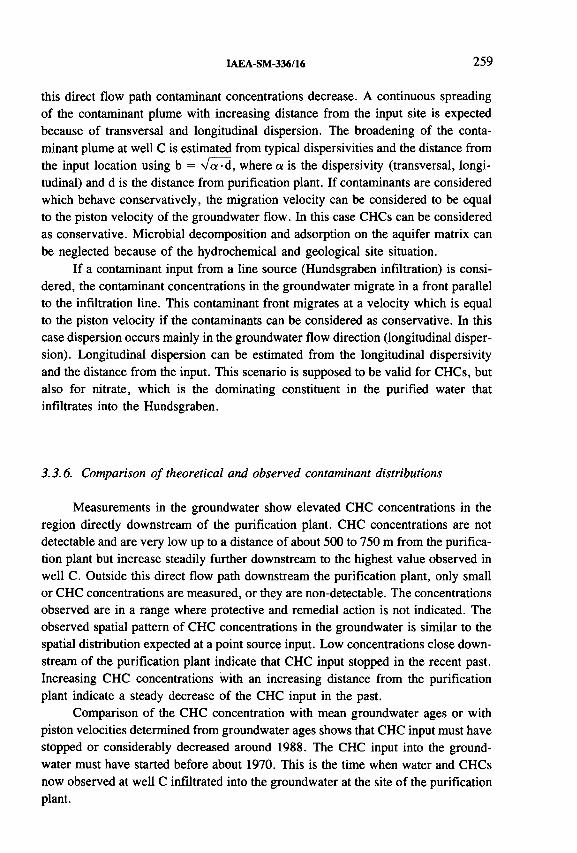
IAEA-SM-336/16 259
this direct flow path contaminant concentrations decrease. A continuous spreading of the contaminant plume with increasing distance from the input site is expected because of transversal and longitudinal dispersion. The broadening of the contaminant plume at well С is estimated from typical dispersivities and the distance from the input location using b = V a -d , where a is the dispersivity (transversal, longitudinal) and d is the distance from purification plant. If contaminants are considered which behave conservatively, the migration velocity can be considered to be equal to the piston velocity of the groundwater flow. In this case CHCs can be considered as conservative. Microbial decomposition and adsorption on the aquifer matrix can be neglected because of the hydrochemical and geological site situation.
If a contaminant input from a line source (Hundsgraben infiltration) is considered, the contaminant concentrations in the groundwater migrate in a front parallel to the infiltration line. This contaminant front migrates at a velocity which is equal to the piston velocity if the contaminants can be considered as conservative. In this case dispersion occurs mainly in the groundwater flow direction (longitudinal dispersion). Longitudinal dispersion can be estimated from the longitudinal dispersivity and the distance from the input. This scenario is supposed to be valid for CHCs, but also for nitrate, which is the dominating constituent in the purified water that infiltrates into the Hundsgraben.
3.3.6. Comparison o f theoretical and observed contaminant distributions
Measurements in the groundwater show elevated CHC concentrations in the region directly downstream of the purification plant. CHC concentrations are not detectable and are very low up to a distance of about 500 to 750 m from the purification plant but increase steadily further downstream to the highest value observed in well C. Outside this direct flow path downstream the purification plant, only small or CHC concentrations are measured, or they are non-detectable. The concentrations observed are in a range where protective and remedial action is not indicated. The observed spatial pattern of CHC concentrations in the groundwater is similar to the spatial distribution expected at a point source input. Low concentrations close downstream of the purification plant indicate that CHC input stopped in the recent past. Increasing CHC concentrations with an increasing distance from the purification plant indicate a steady decrease of the CHC input in the past.
Comparison of the CHC concentration with mean groundwater ages or with piston velocities determined from groundwater ages shows that CHC input must have stopped or considerably decreased around 1988. The CHC input into the groundwater must have started before about 1970. This is the time when water and CHCs now observed at well С infiltrated into the groundwater at the site of the purification plant.

260 DORR AND WERNER
From a review of the technical processes applied in the purification plant, it is unlikely that CHCs were used. Moreover, no changes in the operation of the purification plant were made around 1988, so the decrease or cessation of CHC input cannot thus be explained.
It is plausible that the CHCs originate from a former waste disposal site which has been identified on the site of the purification plant. Integration of total CHC mass in the aquifer in the investigated area gives a total o f 25 kg CHC entering the aquifer between 1970 and 1988. If it is assumed that CHC input from the waste disposal site started about 1950 and if CHCs are asssumed to be conservative (no microbial decomposition) the annual input rate into the groundwater is estimated to be of the order of 1 kg/а. These are typical total amounts of CHCs in waste disposal sites and the comparatively low release rate indicates that CHC input into the groundwater is due to the washout by precipitation and seepage water. Such small CHC infiltration rates are not typical, for example, for an input o f liquid solvents into the groundwater. The cessation or decrease of CHC input around 1988 is supposedly due to the end of the leaching of the waste.
3.4. Summary and outlook
The comparison of observed and theoretical CHC distributions in the investigation area together with the plausibility checks showed that the contamination input is at the site o f the purification plant. The input is possibly due to the leaching of CHC spills in a former waste disposal pit. The input stopped around 1988 and started before about 1970. From the Hundsgraben, CHCs are not infiltrated into the groundwater.
In the future, the CHC concentration in the groundwater of the investigated area will decrease (if no new contamination input occurs). At an average groundwater residence time of 10 to 15 years and assuming that CHCs behave conservatively, the contamination will be negligible 10 to 20 years from now on. Beside the routine monitoring of the drinking water wells (well C) and the output from the purification plant no further monitoring in the investigated area is suggested. The comparatively high groundwater residence time will ensure that the monitoring interval of one month is sufficient to detect contaminations originating from the investigated area.
4. CONCLUSIONS
The study presented shows that the concept o f identifying the location, time and duration of a contaminant input to the groundwater is appropriate and useful. Isotopic methods are a powerful tool for obtaining information about the dynamic

IAEA-SM-336/16 261
behaviour of a hydrogeological system and more accurate and representative parameters to describe groundwater flow and contaminant transport.
The concept presented is applicable for contaminations with chemical substances that behave in a sufficiently conservative manner, i.e. substances which are not microbially decomposable and which show no relevant adsorption or desorption within the aquifer system. Especially tritium /3He groundwater age determination is very helpful in the determination of piston velocities and in the characterization of contaminant input within the past 20 to 30 years. A review of existing data and information and an adequate evaluation of standard investigation methods are necessary to select appropriate isotopic methods and to determine the accuracy achievable. The results o f this study can further be used if remedial actions prove to be necessary. With accurate data on the hydrogeological system hydraulic remediation can be planned and optimized.
REFERENCES
[1] Verwaltungsvorschrift zu 77 des Hessischen Wassergesetzes fiir die Sanierung von Grundwasser- und Bodenverunreinigungen im Hinblick auf den Gewâsserschutz (Gw-VwV), 19.05.1994, Hessisches Ministerium fiir Umwelt-Energie und Bundes- angelegenheiten.
[2] KOMMUNALVERBAND RUHRGEBIET, Erfassung moglicher Bodenverunreinigungen auf Altstandorten, Essen (1990).
[3] GELLERMANN, et. al., “Isotope studies for assessing groundwater contamination at the sites of uranium mill tailings in Saxony and Thuringia” (Proc. Isotopenkolloquium Freiberg, 1994).
[4] SCHLOSSER, P., STUTE, H., DORR, H., SONNTAG, C., MÜNNICH, K.O., Tritium/3He dating of shallow groundwater, Earth Planet. Sci. Lett. 89 3/4 (1988).


IAEA-SM-336/39
INTEGRATION OF ENVIRONMENTAL ISOTOPES, HYDROCHEMICAL AND MINERALOGICAL DATA TO CHARACTERIZE GROUNDWATERS FROM A POTENTIAL REPOSITORY SITE IN CENTRAL SWITZERLAND
A. SCHOLTIS*, F.J. PEARSON, Jr.**, H.H. LOOSLI***,L. EICHINGER+ , H.N. WABER + + , B.E. LEHMANN***
♦National Cooperative for the Storage of Radioactive Waste (Nagra), Wettingen, Switzerland
**Ground-Water Geochemistry,Irving, Texas, United States of America
***Physikalisches Institut,Universitat Bern,Bern, Switzerland
+Hydroisotop GmbH,Schweitenkirchen, Germany
+ +Rock-W ater Interaction Group,Geologisches und Mineralogisch-Petrographisches Institut,Universitat Bern,Bern, Switzerland
Abstract
INTEGRATION OF ENVIRONMENTAL ISOTOPES, HYDROCHEMICAL AND MINERALOGICAL DATA TO CHARACTERIZE GROUNDWATERS FROM A POTENTIAL REPOSITORY SITE IN CENTRAL SWITZERLAND.
An understanding of the origin, evolution and model ages of groundwater is important in evaluating the suitability of sites proposed for radioactive waste repositories. Such understanding cannot be derived from hydrochemical or isotopic data alone, but requires integration of both, with mineralogical, chemical and isotopic data on the host rock. This paper describes such an integrated study being carried out by Nagra at the Wellenberg, a potential repository site south of Lake Lucerne in central Switzerland. The repository host rock is a strongly deformed, slightly metamorphosed, Cretaceous marl of the Helvetic Drusberg nappe. Studies involve five boreholes to depths from 470 m to 1870 m, with geological and geophysical logging, packer testing, fluid logging and water and gas sampling during drilling. Multipacker systems are now in place for long term formation pressure measurements and fluid sampling.
263

264 SCHOLTIS et al.
Water samples were analysed for the composition of their dissolved solids and for 2H, 3H and l80 , for l3C and 14C in dissolved organic carbon, for the 87Sr/86Sr ratio of dissolved Sr, for the 2H and l3C concentrations of hydrocarbon gases, and for 37Ar, 39Ar and 85Kr. In most cases all isotopic data can be explained consistently; for one water, however, discrepancies between some data have not yet been accounted for.
1. INTRODUCTION
Geological disposal is being considered by many countries as an option for the long term management of radioactive wastes. The hydrological character of proposed sites must be determined to support the design and construction of disposal facilities and to assess the long term safety of disposal. These hydrological characteristics generally include quantitative descriptions of the fluid flow system and the chemistry of those fluids. Description of the flow system requires information on the paths, rates and volumes of groundwater flow. An understanding of the fluid chemistry includes not only the in situ concentrations of dissolved constituents, but also the origins of and water/rock interactions exerting control on these constituents.
This paper describes the integration of isotopes into the hydrological characterization of a potential repository site by Nagra, the Swiss National Cooperative for the Storage of Radioactive Waste. To characterize the Wellenberg site (Fig. 1), a potential repository for low and intermediate level radioactive waste, five boreholes were drilled with geological and geophysical logging, packer testing, fluid logging and water and gas sampling during drilling. Multipacker systems are now in place for long term formation pressure measurements and fluid sampling. Water samples were analysed for the composition of their dissolved solids and for 2 H, 3H and 1 8 0 , for 13C and 14C in dissolved organic carbon (DIC), for the 8 7 Sr/86Sr ratio of dissolved Sr, for the 2H and l3C concentrations of hydrocarbon gases, and for 3 7 Ar, 39Ar and 8 5 Kr.
2. GEOLOGICAL AND HYDROGEOLOGICAL SETTING
The region of interest is the Wellenberg, a few kilometres south of Lake Lucerne in central Switzerland (Fig. 1). The host rock is a strongly deformed, slightly metamorphosed Cretaceous marl (Palfris-Formation and Vitznau-Mergel, referred to as Valanginian Marl [1]) of the Helvetic Drusberg nappe. It consists of a series of highly consolidated argillaceous marls with thin clayey or silty banks and thin layers of limestones and calcareous marl. The thickness of the Valanginian Marl can exceed 1000 m at the site location due to overthrusting and folding [1]. Table I shows the mean mineralogical composition of the marl [2 ].
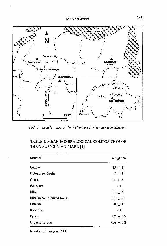
IAEA-SM-336/39 265
FIG. 1. Location map o f the Wellenberg site in central Switzerland.
TABLE I. MEAN MINERALOGICAL COMPOSITION OF THE VALANGINIAN MARL [2]
Mineral Weight %
Calcite 45 ± 21
Dolomite/ankerite 8 + 5
Quartz 14 ± 5
Feldspars <1
Illite 12 + 6
Illite/smectite mixed layers 1 1 + 5
Chlorite 8 + 4
Kaolinite <1
Pyrite 1.2 ± 0.8
Organic carbon 0.6 + 0.3
Number of analyses: 115.

266 SCHOLTIS et al.
FIG. 2. Groundwater characteristics pro jected onto geological cross-section (NNW-SSE) jro m the Wellenberg area.
Figure 2 is a geological cross-section of the site. Because the site lies within the contact zone between the Axen and Drusberg nappes, its structural geology is very complex [1]. The location of the groundwater samples from the boreholes, which were drilled to depths of 470 m to 1870 m, have been projected onto the section. Two boreholes, SB1 and SB3, fully penetrated the c. 1000 m thick marl body. Packer testing data and long term monitoring observations indicate a strong depletion of pressure below hydrostatic conditions, increasing towards the centre of the marl body. Hydraulic head and transmissivity data correlate well with depth below the top of the marl, indicating a distinct underpressure zone within the Valanginian Marl (Fig. 3). Among the various scenarios or combinations of scenarios that can be invoked to explain the observed underpressures, stress release caused by glacier retreat at the end of the Würm glaciation approximately 20 000 a BP and/or tectonic thrusting appear, at present, to be the most plausible [3].
Hydrogeological units, defined using information from hydrogeology, litho- stratigraphy, structural geology and hydrochemistry, are shown in Fig. 3 for the borehole SB3 [4]. The superficial groundwaters in the region from shallow wells and

IAEA-SM-336/39 267
Geology
Transmissivity (m /s) Head (m.a.s.l.)
~nr
Watertype
Hydrogeological units and hydraulic conductivities
sURc
200-
■c 4 00 -
" 600- o ffi g£ 800- a . a Q
1 0 0 0 •
1 2 0 0 -
| vm= "“4 j :
Са-НСОз
Na-HCOj
N* 0
v ......
*
-s
Na-Cl *
t i i 'i1'-1 y ' ‘v ■ i1E-12 1E-10 1E-8 1E-6 1E-4
—Г .»
medium:
tow
«ягу lew
200 500 800 1100
UR : Unconsolidated rock LS : Landslide VM : Valanginian Marl
FIG. 3. Transmissivities, hydraulic head distributions, w ater types and related hydro- geological units in borehole SB3 /57-
springs are dominantly of the C a-H C 0 3 type with 3H concentrations consistent with ages of less than 35 a (type 1 in Fig. 2). In the upper part of the marl, N a-H C 0 3
waters (type 2 in Fig. 2) are found, generally under artesian conditions. Deeper in the marl in a region of low hydraulic conductivity, highly mineralized Na-Cl water occurs (type 3 in Fig. 2). No sample of this water containing less than about 20% drilling fluid could be collected [5, 6 ].
Waters of different characters were recovered from the Kieselkalk, which was the formation encountered in borehole SB2. The uppermost sample from this limestone was o f C a-M g-H C 0 3 water (type 4 in Fig. 2) with affinities both to young superficial groundwater and deeper, older waters. The second sample is of a N a-H C 0 3 water (type 5 in Fig. 2) which can be clearly differentiated from similar water from the marl on the basis of stable water isotopes.
The remainder of this paper discusses the application of isotopic techniques to the characterization of these waters. The discussion is arranged by isotope group rather than by the hydraulic and geochemical properties that were inferred from them.

268 SCHOLTIS et al.
FIG. 4. 2H and I80 concentration o f groundwater and precipitation from the Wellenberg site showing the global meteoric water line and an extension o f the regression line though the saline Na-Cl (dashed line) illustrating the possible in situ composition o f these formation- waters (the sample Nos refer to Fig. 2).
3. WATER ISOTOPES (3 H, 2H and 1 8 0 )
Analyses of the water isotopes 3 H, 2H and l80 provided information on the quality of the samples, the geographic origins of groundwaters and the age structure of the groundwater system.
The distribution of 2H and l80 in the groundwaters is shown in Fig. 4 (see also Table II). The shallow C a-H C 0 3 waters (type 1 in Fig. 2), the C a-M g-H C 0 3
water from the Kieselkalk (type 4 in Fig. 2) and all samples of N a-H C 0 3 water from the marl (type 2 in Fig. 2) have 2H and l80 concentrations that are closely similar and are in the centre of the range of values measured in precipitation in the region. The groundwaters of types 1 and 4 contain tritium, while the type 2 waters are tritium free. The isotopic compositions of these waters indicate that they were recharged locally [7].
The N a-H C 0 3 water from the Kieselkalk (type 5 in Fig. 2) has a water isotopic composition that, while it is on the global meteoric water line, is depleted in the heavy isotopes relative to the shallow groundwaters and to the N a-H C 0 3 waters

IAEA-SM-336/39 269
in the marl. This indicates that this water has a component that either was recharged at a higher elevation or during a period of colder climate.
The water isotopes of the saline N a-Cl waters in the marl (type 3 in Fig. 2) are more enriched in the heavy isotopes than any of the other waters and plot off the meteoric water line. All the samples could be considered as mixtures of shallow groundwaters, like the mixture used in the drilling fluid, with a more enriched water of isotopic composition along the heavy dashed line in Fig. 4. Such an enriched water must have a source entirely different from that of any of the other waters sampled. This enrichment could be explained as a mixture of meteoric and connate waters and/or by extensive water/rock exchange with the formation. In either case, the water isotopic concentrations of the saline waters indicate that they have had a very long residence time.
4. RADIOISOTOPES OF ARGON AND KRYPTON
Large volume water samples for the measurement of the rare noble gas radionuclides 37Ar (T , / 2 = 35 d), 85Kr (T 1 / 2 = 10.7 a) and 39Ar (T 1 / 2 = 269 a) were collected from superficial groundwaters (four flowing surface wells) and pumped from four intervals in three different deep boreholes [7]. The water was degassed in the field and compressed gas samples were taken to the laboratory for the separation of noble gases followed by low level gas proportional counting. The results are summarized in Table II.
The superficial C a-H C 0 3 groundwaters W134 and W325 (Table II, see type 1 in Fig. 2) can consistently be dated by both 3H and 8 5 Kr. On the basis of an exponential model, the mean residence times for samples W134 and W325 are3.5-4 .5 and 5-6.5 a respectively (when using the 3H time series o f the past 3-4 a), whereas 85Kr indicates 4-6 and 5-7 a respectively [8 ].
In contrast, the 3H and 85Kr results of the C a-H C 0 3 groundwaters of sample W044 and W367 (Table II, see type 1 in Fig. 2) are inconsistent at first sight. For both groundwaters 85Kr yields a considerably younger model age than 3 H, namely,1.5-2.5 a instead of 7-9 a for sample W044 and 1-2 a instead of 6-9 a for sample W367. Various possible reasons for this disagreement have been listed and discussed [8 , 9]. For sample W367 it seems likely that gas exchange with the atmosphere close to or at the well site is responsible for the discrepancy. The 85Kr value might just represent such a contamination. For sample W044, however, it appears more likely that the water itself came into contact with the atmosphere at a certain point on its flow path before a ‘second’ infiltration into the underground. A gas exchange may also have occurred through the unsaturated zone during part o f the flow history. Such a hypothesis is supported by the local geology near this site. As a consequence, the two radionuclides yield different information in this case: the 3H indicates the time since initial infiltration of the groundwater; the 85Kr age
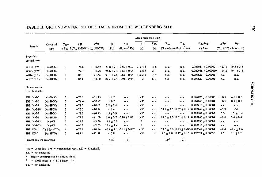
TABLE II. GROUNDWATER ISOTOPIC DATA FROM THE WELLENBERG SITE N>-JO
SampleChemical
typeType
in Fig. 2 (°/0а2н a18oSMOW) (°/„ SMOW)
3H(TU)
85Kr (Bq/cm3 Kr)
Mean residence time
3H 85Kr (a) (a)
39Ar 37Ar (% modern) (Bq/cm3 Ar)
87Sr/86Sr 513C l4C (±2 cr) (°/00 PDB) (% modern)
Superficialgroundwater
W134 (VM) Са-НСОз 1 -74.8 -10.49 23.8 ± 2.1 0.69 ± 0.03 3.5-4.5 4-6 n.a. n.a. 0.708041 ±0.000021 -13.8 79.2 ±3.2W325 (VM) Ca-HCOj 1 -72.7 -10.26 24.6 ±2.4 0.61 ±0.04 5-6.5 5-7 n.a. n.a. 0.707986 ± 0.000019 -14.2 79.1 ±3.4W044 (KK) Са-НСОз 1 -82.7 -11.63 30.1 ±2.5 0.85 ±0.04 1.5-2.5 7-9 n.a. n.a. 0.707651 ±0.000017 n.a. n.a.W367 (KK) Са-НСОз 1 -85.6 -12.00 27.2 ±2.4 0.90 ±0.04 1-2 6-9 n.a. n.a. 0.707659 ± 0.00002 n.a. n.a.
Groundwaters from boreholes
SB1 ; VM-5 Na-НСОз 2 -77.5 -11.15 <1.2 n.a. >35 n.a. n.a. n.a. 0.707875 ± 0.00006 -0 .9 4.6 ±0.6SB3; VM-1 Na-НСОз 2 -78.6 -10.92 <0.7 n.a. >35 n.a. n.a. n.a. 0.707963 ± 0.00004 -0 .5 0.8 ±0.8SB3; VM-9 Na-НСОз 2 -73.2 -10.02 3.8 ± 1.4 n.a. >35 n.a. n.a. n.a. 0.707915 ±0.00004 n.a. n.a.SB4; VM-10 Na-НСОз 2 -76.5 -10.84 <1.4 n.a. >35 n.a. 33.8 ±3.5 0.77 ±0.18 0.707868 ± 0.00003 -5 .9 0-8SB6; RM-7 Na-НСОз 2 -78.0 -10.95 1.5 ±0.9 n.a. >35 n.a. n.a. n.a. 0.708107 ±0.00005 0.3 1.0 ± 0.4SB6; VM-1 Na-НСОз 2 -77.8 -11.00 1.0 ±0.7 0.80 ± 0.03 >35 n.a. 95.0 ± 8.0 0.31 ±0.14 0.707865 ± 0.00004 -0 .6 0.6 ±0.4SB1; VM-13 Na-CI 3 -39.8 -3.36 11.9 ±0.9 n.a. * n.a. n.a. n.a. 0.707896 ± 0.00003 n.a. n.a.SBI ; VM-23 Na-Cl 3 -60.2 -7.03 17.4 ± 1.4 n.a. * n.a. n.a. n.a. 0.707916 ± 0.00004 n.a. n.a.SB2; KK-1 Ca-Mg-HCO, 4 -75.1 -10.84 46.9 ±2.1 0.11 ±0.007 <35 n.a. 79.3 ±2 .6 0.95 ± 0.083 0.707649 ± 0.00004 -9 .4 44.4 ± 1.6SB2; KK-2 Na-НСОз 5 -93.0 -12.88 <0.8 n.a. >35 n.a. 8.3 ± 3 .0 0.17 ± 0.10 0.707677 ± 0.00002 1.7 3.1 ± 1.2
Present-day air reference = 20 ~1 100a -0 .1
RM = Landslide. VM = Valanginian Marl. KK = Kieselkalk. n.a. = not analysed.* Highly contaminated by drilling fluid.a = 100% modern » 1.78 Bq/m5 Ar.n.a. = not analysed.
SCHOLTIS et al.
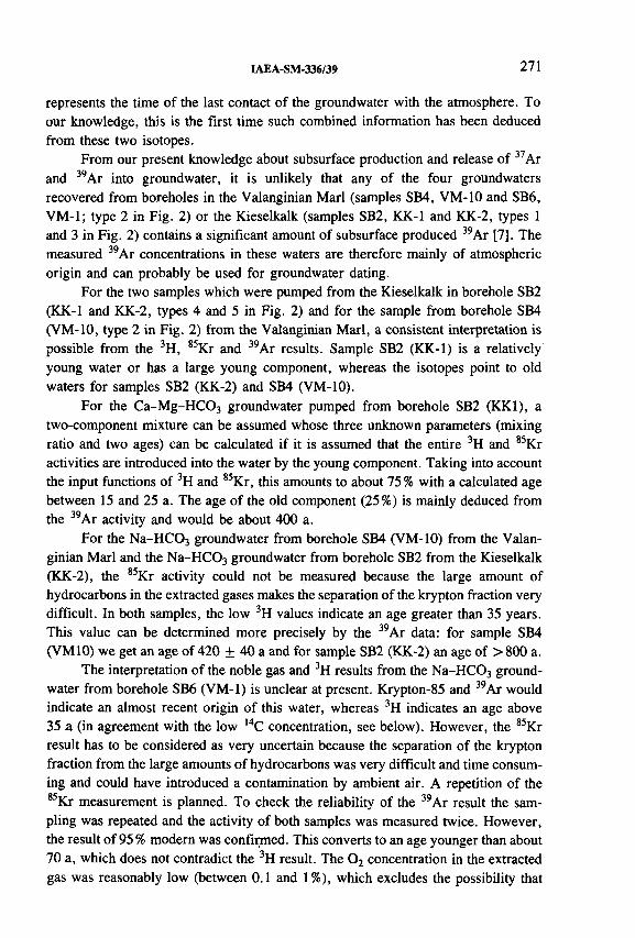
IAEA-SM-336/39 271
represents the time of the last contact o f the groundwater with the atmosphere. To our knowledge, this is the first time such combined information has been deduced from these two isotopes.
From our present knowledge about subsurface production and release of 37Ar and 39Ar into groundwater, it is unlikely that any of the four groundwaters recovered from boreholes in the Valanginian Marl (samples SB4, VM-10 and SB6 , VM-1; type 2 in Fig. 2) or the Kieselkalk (samples SB2, KK-1 and KK-2, types 1 and 3 in Fig. 2) contains a significant amount of subsurface produced 39Ar [7]. The measured 39Ar concentrations in these waters are therefore mainly of atmospheric origin and can probably be used for groundwater dating.
For the two samples which were pumped from the Kieselkalk in borehole SB2 (KK-1 and KK-2, types 4 and 5 in Fig. 2) and for the sample from borehole SB4 (VM-10, type 2 in Fig. 2) from the Valanginian M arl, a consistent interpretation is possible from the 3 H, 85Kr and 39Ar results. Sample SB2 (KK-1) is a relatively young water or has a large young component, whereas the isotopes point to old waters for samples SB2 (KK-2) and SB4 (VM-10).
For the C a-M g-H C 0 3 groundwater pumped from borehole SB2 (KK1), a two-component mixture can be assumed whose three unknown parameters (mixing ratio and two ages) can be calculated if it is assumed that the entire 3H and 85Kr activities are introduced into the water by the young component. Taking into account the input functions of 3H and 8 5 Kr, this amounts to about 75 % with a calculated age between 15 and 25 a. The age of the old component (25%) is mainly deduced from the 39Ar activity and would be about 400 a.
For the N a-H C 0 3 groundwater from borehole SB4 (VM-10) from the Valanginian Marl and the N a-H C 0 3 groundwater from borehole SB2 from the Kieselkalk (KK-2), the 85Kr activity could not be measured because the large amount of hydrocarbons in the extracted gases makes the separation of the krypton fraction very difficult. In both samples, the low 3H values indicate an age greater than 35 years. This value can be determined more precisely by the 39Ar data: for sample SB4 (VM10) we get an age of 420 ± 40 a and for sample SB2 (KK-2) an age of > 800 a.
The interpretation of the noble gas and 3H results from the N a-H C 0 3 groundwater from borehole SB6 (VM-1) is unclear at present. Krypton-85 and 39Ar would indicate an almost recent origin of this water, whereas 3H indicates an age above 35 a (in agreement with the low l4C concentration, see below). However, the 85Kr result has to be considered as very uncertain because the separation of the krypton fraction from the large amounts of hydrocarbons was very difficult and time consuming and could have introduced a contamination by ambient air. A repetition of the 85Kr measurement is planned. To check the reliability of the 39Ar result the sampling was repeated and the activity of both samples was measured twice. However, the result of 95 % modern was confirmed. This converts to an age younger than about 70 a, which does not contradict the 3H result. The 0 2 concentration in the extracted gas was reasonably low (between 0 . 1 and 1 %), which excludes the possibility that

272 SCHOLTIS et al.
the high 39Ar activity is introduced entirely by contamination during sampling. Only two interpretations of this inconsistency can be advanced, but both remain unsatisfactory:
(a) The 39Ar activity for this sample cannot be used for dating, because it is produced underground. This is in contradiction to our knowledge and experience for such a geological situation. Or
(b) The 39Ar is correct and the groundwater is indeed very young, so that the l4C values are too low (suggested by the high Ô '3C value and the large amounts of hydrocarbons).
5. CARBONATE AND HYDROCARBON ISOTOPES (2 H, l3C and 1 4 C)
Analyses of the 13C and 14C concentrations of DIC in the water samples provided information on the origin and water/rock interactions of the DIC and on the model 14C ages of the waters. Analyses of the 2H and 13C concentrations of hydrocarbon gases and C 0 2 produced in the boreholes indicated their source conditions.
The 13C and 2H concentrations of the CH4, C 2 H6, and C 3 H 8 of borehole gases indicated a thermogenetic origin from a marine source rock of high maturity [ 1 0 ]. The average ô 13C value of CH4 in borehole gas, soil and fluid inclusion gases, and dissolved in the groundwaters, ranges from -3 1 .4 to - 3 3 .7 ° / 0 0 (Fig. 5). This
SampleNumber
ofanalysis -60 -50
513C-DIC (%o)-40 -30 -20 -10 1 0
Rock carbonate
DIC deep groundwater
DIC superficial groundwaters
C 0 2from fluid inclusions
C 0 2from soil gas
CHifrom fluid Inclusions
CH4from groundwaters
CH.free gas from boreholes
CH4from soil gas
197
16
24
19
44
2 1
23
18
DIC = dissolved inorganic carbon
FIG. 5. b‘3C values for different samples, with mean, maximum and minimum values and number o f analysis.

IAEA-SM-336/39 273
similarity suggests a possible origin of CH 4 in the system is stored in the fluid inclusions (Fig. 5).
The <5I3C values of the rock carbonate are from —1.8 to + 4 .4 7 00, matrix calcite has ô 13C values from —1.8 to + 2 .0 7 oo, typical of marine carbonate (Fig. 5, Table II). The S I3C values of DIC range from —6.5 to —14.2700 in the 14C bearing superficial waters and the C a-M g-H C 0 3 water from the Kieselkalk, and from - 5 .9 to + 1 .7 7 0 0 in the N a-H C 0 3 waters from the marl and Kieselkalk, most of which contain no l4C (Fig. 5, Table II). Geochemical modelling shows that the 13C enriched N a-H C 0 3 waters evolve from the C a-H C 0 3 waters by dissolving C aC 0 3
and C 0 2(g), accompanied by Ca for Na cation exchange. To achieve the high 13C concentrations of these waters, the <5 l3C value of both the dissolving C aC 0 3 and C 0 2(g) must be about 0 7 oo. This is the measured value for rock carbonate. The source of the 13C enriched C 0 2(g) is currently unknown.
Assuming that the measured 39Ar concentrations cannot be explained by in situ production, or by contamination with atmospheric Ar, the measured 14C concentrations are too low to be explained by radioactive decay only. The following factors may also be responsible for lowering the l4C concentration:
— Increase in the DIC concentration due to dissolution of carbonate after ion exchange
— Increase in the DIC concentration due to a 1 4 C-free C 0 2(g) source and dissolution of rock carbonate
— Displacement of DIC containing 14C by l4 C-free C 0 2(g)— С isotope exchange between DIC and С in the rock.
Carbon isotope exchange between DIC and С in the rock has been described widely in the literature [11, 12]. It is effective only in the case of groundwaters in the age range of several thousand years and more. The process should not occur to a recognizable extent in the case of young groundwaters.
There are several possibilities by which the measured 13C and 14C concentrations could occur from dissolution of carbonates and release of C 0 2(g) without the need to call on С isotope exchange between water and rock for interpretation purposes.
According to its 3 H, 85Kr and 39Ar concentrations, the groundwater from the Kieselkalk in borehole SB2 (KK-1, type 4 in Fig. 2) has a compositional age of a young and old component (cf. Section 4). The 14C concentration of 44.4% modern (Table II) can be achieved by dilution with 14C free C 0 2(g) and dissolution of C aC 03, which raise the DIC concentration from 2.5 mmol/L, estimated from the superficial C a-H C 0 3 waters, to 5.1 mmol/L, the DIC of this water. To reach the 13C concentration of — 9 .4 7 0 0 of this water (Fig. 6 ), at least a proportion of the C 0 2 should have a high 13C concentration. Such C 0 2 can originate from anaerobic degradation of organics or from fluid inclusions, with 13C concentrations of about - 1 1 to — 8 7 00.

274 SCHOLTIS et al.
- О -
- 2 -
<jr - 4 -'S 0 s*WOûIüm
- 6 -
- 8 -
- 1 0 -
- 1 2 -
- 1 4 -
♦SB2 (KK-2) SB6 (RM-7)
♦ SB6(VM-1)
♦ • *
♦ SB4 (VM-10)X W375
♦ SB2 (KK-1)
X
W134
£ XW 325
♦ Groundwater from boreholes X Superficial groundwaters
1 0
H C 0 3 ( m m o l / L )
1“1 5
T
2 0 2 5
FIG. 6. Relationship between С concentrations and HC03 (DIC) concentrations in groundwaters from Wellenberg. The increase in l3C concentrations with increasing HC03 concentrations may be explained by dissolution of rock carbonate and/or by a C02(g) source with a high ,3C concentration.
The water sampled deeper in borehole SB2 (KK-2, type 5 in Fig. 2) is, according to the 39Ar results, about 800 years old, or is a mixed water with a component similar to the upper groundwater from borehole SB2 (KK-1) and a significantly older component. The measured 39 Ar concentration of 8 % modern and the measured 14C concentration of 3.1% modern can be explained by assuming that 10% of the type SB2 (KK-1) water is mixed with an older 39Ar free and l4C free water. This is supported by the results o f the 2H and 180 measurements of —93.0°/oo and —12.88700 respectively, which indicate a component of groundwater recharged during the Pleistocene. It is much more difficult to explain the 6 1 3 C-DIC value of + 1 .7 7 0 0 of this sample (Fig. 6 ). For the proposed mixture of two groundwater components, the old component would need to have a very high ô 1 3 C-DIC value of about 2 .6 7 00.

IAEA-SM-336/39 275
Such a high value could be a result of С isotope exchange between DIC and C aC 0 3
with high ô 13C values of about 2 to 3 ° / 0 0 (e.g. as displayed by the latest carbonate vein infills) or an admixture of C 0 2(g) with positive ô l3C values. Such C 0 2 can be produced by auto-oxidation of organic matter (2 CH20 = C 0 2 + CH4) resulting in a high <5 l3C value for C 0 2 and a low value for CH4. That this is reasonable can be supported by the result of the <51 3 C-CH 4 measurement from this groundwater of -57.7°/oo (Fig. 5). In all other groundwaters the ô 1 3 C-CH 4 values are more positive, about - 3 4 7 00.
According to its 39Ar concentration, the N a-H C 0 3 marl groundwater from borehole SB4 (VM-10, type 2 in Fig. 2) has an age of about 400 a. This age could indicate a mixed water system, in which a young groundwater is mixed with an old groundwater component. By assuming a mixture of 40% of young groundwater (with estimated 39Ar = 80% modern, 14C = 44% modern, ô 1 3 C-D IC = — 9 .4 7 0 0 and DIC = 5.1 mmol/L) with an old groundwater (with no 3 9 Ar, 14C = 3% modern, ô 1 3 C-DIC = - 5 .4 7 0 0 and DIC = 24.3 mmol/L) one can obtain the measured values for 39Ar of 32% modern, 14C of 8 % modern, <5l3 C-DIC of — 5 .9 7 0 0 and DIC of 16.6 mmol/L. The measured and estimated ô 1 3 C-DIC values of the sample and proposed old component of —5.4 and —5 .5 7 0 0 are low relative to their high DIC concentrations of 16.6 and 24.3 mmol/L (Fig. 6 ). Such a <51 3 C-DIC concentration could be associated with C 0 2(g) from fluid inclusions (Fig. 5). The l4C concentration of this groundwater, proposed 3% modern, indicates a groundwater age between 8000 and 10 000 a, calculated with an initial l4C concentration of 8 to 10% modern. This age is in agreement with the 02H and ô l80 values of —76.5 and —10.487 00, which indicate a groundwater recharged during a warm climatic period.
The N a-H C 0 3 marl groundwater from borehole SB6 (VM-1) has an 39Ar concentration of 95 ± 8 % modern, which indicates a groundwater age of less than 70 a. This 39Ar concentration cannot be reconciled with its 14C concentration of max. 1% modern. The initial 14C concentration resulting from dilution calculated using the increase in the DIC concentration from 2.5 mmol/L for the superficial C a-H C 0 3 groundwaters to 15.5 mmol/L for the N a-H C 0 3 water is around 15% modern (Fig. 6 , Table II). Since the result of the 39Ar measurement indicates that a lowering of the 14C concentration due to radioactive decay can be ruled out, the lowering of the 14C can only be explained by a С isotope exchange. This is the only groundwater sample for which a С isotope exchange appears to be necessary for interpreting the l4C and 39Ar concentration. Whether such an interpretation is actually appropriate here can only be determined by further investigations.
6 . STRONTIUM ISOTOPES
Strontium isotope analyses on groundwaters, whole rock and vein minerals provided information on the quality of samples, the equilibrium conditions between groundwaters, rock matrix and vein minerals, the provenance o f formation water

276 SCHOLTIS et al.
100.0 -fc-гGroundwater type* : j
О Spring waters IO Na-HCOj type
ф Na-Cl type
T---1---1---1---1---П
SB6 VM-1
Valanginian Marl
SB3VM-9 +
SB4 VM-10
8Quaternary
0 . 1
SBl VM-5 .o
Q Q -| ___I___ I___I___ I___j___I___ I___I___J___I___I___ I___I___ I___j___I___ I___I___ I___j___I___ I___I___ I___| 1 1 1___ L
0.7076 0.7077 0.7078 0.7079 0.7080 0.7081 0.7082
FIG. 7. s?S r /86S r ra tio s versus S r con cen tra tion s o f g ro u n dw aters fro m the b oreh o les S B l,
SB3, SB 6 a n d SB2 a n d spr in g w a ters; sh a d ed a re a s in d ica te the g eo lo g ic a l environm ent fro m
w hich the g rou n d w a ters w ere sam pled .
from which vein minerals precipitated, and possible effects of recent infiltration of meteoric water into the system [7].
The Sr concentrations of seven analysed superficial groundwaters from springs vary between < 0 .3 and 2.5 mg/L. The lowest 8 7 S r/86Sr ratios are recorded for the springs (type 1 in Fig. 2) in contact with the Kieselkalk (samples W367 and W044, Fig. 7, Table II). The 8 7 S r/86Sr ratios of these waters are virtually identical to the deeper circulating groundwater types C a-M g-H C 0 3 and N a-H C 0 3 (types 4 and 5 in Fig. 2) from the Kieselkalk sampled from the borehole SB2 (Fig. 7, Table II).
The deep groundwaters sampled within the Kieselkalk (SB2, KK-1 and KK-2 of borehole SB2) have Sr concentrations intermediate between the N a-H C 03- and Na-Cl type waters of the other boreholes (Fig. 7). Their 8 7 Sr/86Sr ratios are characteristically low. These data are consistent with the different chemical composition, geology and therefore different evolution of these groundwaters compared to the N a-H C 03- and Na-Cl type waters in the marl.
87 S r / 86 Sr

IAEA-SM-336/39 277
The waters from the springs W134 and W325 (type 1 in Fig. 2), both discharging from the Quaternary ‘Rutschmasse von Altzellen’ (a landslide located on top of the Valanginian Marl), have more radiogenic 8 7 S r/86Sr ratios, similar to the ones found in the N a-H C 0 3 water o f the marl and deeper in the ‘Rutschmasse von Altzellen’ (Fig. 7). The fact that recent spring waters have nearly identical 8 7 S r/86Sr ratios to more evolved deep groundwaters from the same units indicates that the Sr isotope systematics are established very rapidly in the young groundwaters at the Wellenberg.
Strontium (and also Rb) concentrations are strongly enhanced in the Na-Cl groundwaters from the Valanginian Marl compared to the N a-H C 0 3 marl waters. The differences in the chemical and stable isotope compositions of the two water types are, however, not reflected in their Sr isotopic composition and the two water types have very similar 8 7 Sr/86Sr ratios between 0.707865 and 0.707963 (Fig. 7).
The groundwater sampled within the Quaternary Rutschmasse von Altzellen (sample SB6 RM-7) has a significantly higher 8 7 Sr/86Sr ratio of 0.708170, with Sr concentrations very similar to the N a-H C 0 3 waters of the marl (Table II). The contamination of this groundwater sample by drilling fluid is low (3-10% [6 ]) and the high 8 7 S r/86Sr ratio can only be attributed to water/rock interactions different from the ones the marl groundwaters experienced. At least part of this groundwater appears to have evolved in the fluvio-glacial gravel environment of the Engelberger Aa Valley.
0.708200
i*OOvooo
t-i0 0
r~oo
0.708000-■
0.707800-■
0.707600-•
0.707400
SB 6 R M -7
О
; О • л ♦ ♦ ♦
SB 6 R M -7
О
л..♦ ♦ ♦ ....................
. v o o- Valanginian Marl -
open veins
Groundwater types : ^ Na-НСОз type ¿ Na-Q type
• Valanginian Marl { whole rock ¿
FIG. 8. Relationship o f s7Sr/86Sr ratios between groundwaters and the whole rocks and the latest vein infills from which the waters were sampled.
278 SCHOLTIS et al.
In Fig. 8 the 8 7 S r/86Sr ratios of groundwaters sampled from the deep boreholes are plotted onto the range of 8 7 Sr/86Sr ratios of the rock matrices and vein calcite from open structures. The N a-H C 0 3 waters and the N a-Cl waters sampled within the marl are clearly not in Sr isotopic equilibrium with the respective rock matrix, i.e. the Sr system of the waters is not buffered by the rock matrix [2].
Calcite that has grown in open veins from the Valanginian Marl has much more radiogenic 8 7 S r/86Sr ratios than calcite in the Kieselkalk. The differences observed in the ratios between calcites in open veins from the Valanginian Marl and the Kieselkalk are reflected in the groundwaters (Fig. 8 ). With respect to the Sr system, the groundwaters sampled in these lithostratigraphic units are in equilibrium with the latest vein fillings in open structures, independent of the water type. Also, the very low 8 7 S r/86Sr ratios of the Kieselkalk groundwaters sampled in SB2 cannot be derived by mixing Kieselkalk spring water with either of the deep groundwater types encountered at the Wellenberg. Even an admixing of less than 10% of an N a-H C 0 3
water from the marl would require the 8 7 Sr/86Sr ratio of the other end member to be lower than the measured ratio of the Kieselkalk spring waters.
This distinguishes the Valanginian Marl and the Kieselkalk as two independent hydrochemical systems and, according to the Sr system, the Kieselkalk groundwaters must have evolved independently of the marl groundwaters.
7. CONCLUSIONS
The isotopic composition of samples from the proposed Wellenberg site, in combination with each other and with hydrochemical and rock data, provide information on groundwater sample quality, origin, ages and the age structure of the flow system, the provenance of dissolved solids, and the type and extent of water/rock reactions.
The superficial C a-H C 0 3 waters have ages between a few years and one decade. The 39Ar concentrations of waters from formations in which negligible 39Ar is produced in situ can be used to date unmixed waters from a few decades to a few centuries old. 39Ar yields ages of 420 ± 40 years for the marl N a-H C 0 3
water and an age of > 800 a for the Kieselkalk N a-H C 0 3 water. Inconsistent 3 H, 85Kr and 39Ar concentrations indicate samples that are mixtures of waters of various ages. The Kieselkalk C a-M g-H C 0 3 water (SB2, KK-1) is a mixture of about 75% water between 15-25 years old, based on the 2H and 85Kr concentration and 25 % water of about 400 a, based on the 39Ar concentration.
The 14C concentration of a groundwater is determined both by its age and by geochemical reactions between dissolved and formation carbonate. The 13C concentration and geochemistry of a water indicates the extent to which its l4C concentration has been lowered by rock/water reactions.
IAEA-SM-336/39 279
The C a-M g-H C 0 3 water from the Kieselkalk has a 14C concentration of 44% modern, although its 3 H, 85Kr and 39Ar concentrations show that its age is less than 400 years. The <5 l3C value of the sample, —9 .4 7 00, is consistent with geochemical reactions that lower the l4C from about 70-90 to about 44% modern. The 14C concentration is thus consistent with the other isotopes.
The <513C values of all but one of the N a-H C 0 3 groundwaters from the Valan- ginian Marl are close to 0°/oo. They are consistent with chemical evolution of these waters from superficial C a-H C 0 3 waters by dissolution of C 0 2(g), mineral carbonate, and Na for Ca cation exchange. The 14C concentrations of most of them, adjusted for these geochemical reactions, lead to ages older than those indicated by 39Ar data or by their 2H and 180 concentrations. This may be due to water/rock isotopic exchange or to interference with the sample water 14C by drilling fluid.
Groundwater ages or geographic origins can also be deduced from 2H and l80 measurements. All N a-H C 0 3 waters from the marl have 2H and 180 values similar to the means of atmospheric precipitation on the Wellenberg and to those of the superficial C a-H C 0 3 groundwaters, which are dated less than a decade old. Although many of these waters are too old for dating by 39Ar and have little or no 14C because of water/rock interactions, their 2H and l80 concentrations indicate that they were recharged locally during the present climatic cycle and so are less than about 10 000 years old. The 2H and 180 concentrations of the N a-Cl waters from the marl are enriched relative to other waters in the system and are to the right of the meteoric water line. This is consistent with extensive water/rock reaction, requiring either very long times or high temperatures. These waters may represent metamorphic fluids associated with the last stages of alpine activity.
The Kieselkalk N a-H C 0 3 water (SB2, KK-2) is depleted in 2H and 180 relative to superficial C a-H C 0 3 waters. The 14C concentration of its older component is consistent with an age of > 1 0 0 0 0 a and indicates recharge during a period of colder climate than the present. This would give rise to the depleted 2H and 180 concentrations measured.
Groundwaters from the Kieselkalk, from the marl and from spring discharges from these formations can be distinguished on the basis of their Sr isotope ratios. This indicates both that water/rock Sr equilibration occurs rapidly and that there is little cross-formational flow. An enriched 87Sr value in a sample o f the N a-H C 0 3
marl water from borehole SB6 (RM-7) indicates possible mixture with Quaternary groundwater.
REFERENCES
[1] N A TIO N A LE G E N O SSEN SC H A FT FÜ R D IE L A G E R U N G RAD IO A K TIV ER A B FÀ LLE, U ntersuchungen zur Standorteignung im H inblick au f die Endlagerung schwach- und m ittelaktiver Abfalle: G eologische G rundlagen und D atensatz zur Beur-

280 SCHOLTIS et al.
teilung der Langzeitsicherheit des Endlagers fiir schwach- und mittelaktive Abfàlle am Standort Wellenberg, Nagra Technical Report 93-28, Nagra, Wettingen, Switzerland (1993).
[2] MAZUREK, M., WABER, H.N., BLÀSI, H.R., Geology, Mineralogy and Geochemistry of the Wellenberg, unpublished Internal Report, Nagra, Wettingen, Switzerland, 1994.
[3] VINARD, P., BLÜMLING, P., McCORD, J.P., ARISTONENAS, G., Evaluation of hydraulic underpressures at Wellenberg, Switzerland, Int. J. Rock Mech. Min. Sci. Geomech. Abst. 30 7 (1993) 1143-1150.
[4] VINARD, P., LAVANCHY, J.M ., WLB: Final Results of the Hydraulic Testing, Phase 1 and Hydrgeological Synthesis of Borehole Data, unpublished Internal Report, Nagra, Wettingen, Switzerland, 1994.
[5] PEARSON, F.J., SCHOLTIS, A., WLB: Hydrochemical characterisation and geochemical modelling of groundwater from Wellenberg, unpublished Internal Report, Nagra, Wettingen, Switzerland, 1994.
[6] BLASER, P., WLB: Dokumentation der Wasser- und Gasprobenentnahmen und der hydrochemischen und isotopenhydrologischen Rohdaten in den Sondierbohrungen SB4, SB3, SB1, SB6 und SB2, unpublished Internal Report, Nagra, Wettingen, Switzerland, 1993.
[7] PEARSON, F. J . , et a l., Stable and radioactive isotopes in groundwaters at Wellenberg, unpublished Internal Report, Nagra, Wettingen, Switzerland, 1994.
[8] SCHIFFMANN CH., Messung und Interpretation von 85Kr-Aktivitaten in Hydrologie- und Bodengasproben, Lizentiatsarbeit, Universitat Bern, unpublished, 1993.
[9] SCHMASSMANN, H., et al., Hydrochemische und isotopenhydrologische Untersuchungen an Quellen und oberflâchennahen Grundwàssern der Standortgebiete Wellenberg und Oberbauenstock, unpublished Internal Report, Nagra, Wettingen, Switzerland, 1993.
[10] EICHINGER, L., WLB: Gasuntersuchungen am Wellenberg: Zusammensetzung der Gase, unpublished Internal Report, Nagra, Wettingen, Switzerland, 1994.
[11] FONTES, J.C ., GARNIER, J.M ., Determination of the initial 14C activity of total dissolved carbon — A review of the existing models and a new approach, Water Resour. Res. 27 (1979) 199-214.
[12] EICHINGER, L., A contribution to the interpretation of 14C groundwater ages considering the example of a partially confined sandstone aquifer, Radiocarbon 25 2 (1983) 347-356.

IAEA-SM-336/1
INVESTIGACION HIDROGEOLOGICA, ISOTOPICA E HIDROQUIMICA DE LA CUENCA DEL LAGO DE VALENCIA, VENEZUELA
J. ALVARADOMinisterio del Ambiente y de los Recursos Naturales Renovables,Dirección General Sectorial de Información Ambiental,Dirección de Hidrología y Meteorología,Caracas, Venezuela
K.-P. SEILER, P. TRIMBORN Institut für Hydrologie,GSF Forschungszentrum für Umwelt und Gesundheit Neuherberg, Oberschleissheim, Alemania
A bstract-R esum en
HYDROLOGICAL, ISOTOPIC AND HYDROCHEMICAL STUDY OF THE BASIN OF LAKE VALENCIA, VENEZUELA.
The basin of Lake Valencia lies in a tectonic graben in the coastal cordillera to the southwest of Caracas. It is an endorheic valley with an area of 3250 km2. For a number of years the groundwater quality has been deteriorating, especially through an increase in sulphur content. This may be related to the following factors: (a) penetration of sulphate-containing water from the lake into the aquifers; (b) penetration into the shallow aquifers of high- sulphate-content deep groundwater; (c) recharge of the aquifers with irrigation water enriched in chemical components by evaporation and containing agrochemicals. By combining the conventional methods of study with interpretation of stable environmental isotopes, the present paper seeks to contribute to a better understanding of groundwater movements and the water balance. In the eastern zone of the lake one can clearly differentiate the mixture of three components in the water: (1) water with low mineralization coming from the topmost parts of the aquifers; (2) water stored in the Taguaiguay dam contributing evaporated water to the aquifers; (3) deep groundwater with high sulphate concentrations but without tritium and about 10 000 years old. No contributions from the lake to the aquifers are observed. The western part of Lake Valencia, between La Culebra and Flor Amarilla, shows the presence of evaporated water resulting from the mixture of the lake water and local groundwater; there are also underground outflows to the river Paito. To the north and northwest of the lake there is a geothermal zone with hot or tepid water enriched in l80 .
INVESTIGACION HIDROGEOLOGICA, ISOTOPICA E HIDROQUIMICA DE LA CUENCA DEL LAGO DE VALENCIA, VENEZUELA.
La cuenca del Lago de Valencia está situada dentro de un “graben” tectónico ubicado en la Cordillera de la Costa, al suroeste de Caracas. Constituye una cuenca endorreica, con una superficie de 3250 Km2. Desde muchos años atrás, la calidad de las aguas subterráneas viene deteriorándose, expecialmente por el incremento del contenido de azufre. Las causas de este deterioro podrían estar relacionadas con los siguientes factores: a) penetración de las
281

282 ALVARADO et al.
aguas sulfatadas del lago hacia los acuíferos; b) penetración en los acuíferos someros de aguas subterráneas profundas altamente sulfatadas; c) recarga de los acuíferos con agua de riego, enriquecida en sus componentes químicos por evaporación y con elementos agroquímicos. Combinando los métodos de investigación tradicionales con la interpretación de los isótopos estables ambientales, el presente estudio pretende contribuir a una mejor comprensión de los flujos de las aguas subterráneas y del balance hídrico. En la zona este del lago se puede diferenciar perfectamente la mezcla de tres componentes en las aguas: 1) aguas de baja mineraliza- ción, provenientes de la parte más superficial de los acuíferos; 2) aguas almacenadas en el embalse de Taguaiguay, las cuales aportan al acuífero aguas evaporadas; 3) aguas profundas con altas concentraciones de sulfatos, sin contenido de tritio y con edades cercanas a los 10 000 años. No se observan aportes del lago hacia los acuíferos. En la parte oeste del Lago de Valencia, entre La Culebra y Flor Amarilla, se observan aguas evaporadas resultantes de la mezcla de aguas del lago y aguas subterráneas locales; además, se manifiestan salidas subterráneas hacia el río Paito. Al norte y noroeste del lago se manifiesta una zona geotermal con aguas calientes o tibias enriquecidas con l80 .
1. INTRODUCCION
La cuenca del Lago de Valencia está situada dentro de un “graben” tectónico situado en la cordilera de la Costa, al suroeste de Caracas (Fig. 1). El lago no tiene salidas superficiales de agua; por el contrario, muchos ríos y quebradas aportan la descarga superficial de la cuenca al lago.
El área actual del lago cubre una superficie de unos 360 km 2 y se encuentra dentro de una planicie intramontana, cubierta de sedimentos fluvio-lacustres que cubren una superficie de aproximadamente 1200 km2. El área de la cuenca hidrográfica, incluido el Lago de Valencia, tiene una extensión cercana a los 2600 km2. En 1981, los aportes artificiales de agua al lago, estimados en en unos 5 m 3 /s, ampliaron la superficie de la cuenca a 3250 km2.
Desde el punto de vista morfológico y geológico, existen evidencis de que en el pasado geológico, el Lago de Valencia descargaba superficialmente sus aguas en el Orinoco. Estas posibles salidas superficiales se producían probablemente a través de valles sin escurrimiento superficial actual, conectando la cuenca del Lago de Valencia con cuencas vecinas (Fig. 2).
El descenso de los niveles y la pérdida de la descarga superficial del lago podrían estar relacionados con factores climatológicos y/o sísmicos. Los descensos o ascensos de niveles de otros lagos similares al Lago de Valencia también se conocen en algunos países de América Central [1]. El cambio de los volúmenes de precipitación influyó en la descarga de estos lagos, aunque no se tiene evidencias del tiempo en que se produjo esta variación climatológica. De todas maneras, la finalización de la descarga superficial no implica el fin automático de la descarga subterránea.

IAEA-SM-336/1 283
FIG. 1. Ubicación del área de estudio.
FIG. 2. Red de drenaje de la cuenca del Lago de Valencia. Pozos con análisis isotópicos.

284 ALVARADO et al.
Existen evidencias de que la cota del Lago de Valencia en el año 1700 era del alrededor de 425 msnm. Por razones desconocidas, el nivel del lago sufrió un descenso hasta el año 1952, llegando a una cota de 409 msnm. Debido al incremento del uso de los recursos hídricos para consumo humano, riego e industrial, el nivel del lago sufrió un descenso considerable entre los años 1952 y 1981, hasta alcanzar una cota de 402 msnm. Como resultado de aportes artificiales de agua provenientes de una cuenca vecina, desde el año 1981 hasta el año 1990, el nivel del lago subió hasta la cota 406 msnm.
Por otro lado, la composición litológica del relleno fluvio-lacustre de la planicie evidencia que en el pasado geológico esta zona también pertenecía a un salar. Mediante observaciones tanto morfológicas como geológicas, se puede deducir que en el pasado geológico el lago sirvió como embalse natural y, en algunos tiempos, también como último sitio de salida de las aguas de la cuenca.
El Lago de Valencia recibe aguas negras no tratadas, provenientes de la industria maderera y química, así como de la cría de ganado porcino. Se estima una entrada anual de aproximadamente 10 ton de nitrógeno y 3 ton de azufre, eutrofi- zando el lago al punto de que no es recomendable utilizar estad aguas con fines balnearios ni de pesca.
En la planicie alrededor del lago se desarrolla una gran actividad agrícola con riego. En la mayor parte de la región el agua para riego proviene de las aguas subterráneas, causando localmente un descenso de los niveles freáticos a cotas por debajo del nivel del Lago de Valencia.
Solamente en dos zonas estrechas, al sur y sureste de Maracay, se encuentran dos embalses para almacenar aguas superficiales; el más importante de éstos es el embalse de Taguaiguay, el cual abastece con agua de riego a las zonas agrícolas ubicadas entre los centros poblados de Palo Negro y Magdaleno.
Desde muchos años atrás, la calidad de las aguas subterráneas destinadas al abastecimiento tanto de agua potable como de riego se viene deteriorando, especialmente por el incremento del contenido de azufre. Las causas de este deterioro podrían estar relacionadas con los siguientes factores:
— la penetración de las aguas sulfatadas del lago en los acuíferos fuertemente explotados o sobreexplotados;
— por efecto de la explotación intensiva y debido al descenso de los niveles, se produce la penetración en los acuíferos someros de aguas subterráneas profundas, es decir, aguas viejas con mucho tiempo de residencia y muy sulfatadas;
— la recarga de los acuíferos con agua de riego, enriquecida en sus componentes químicos por evaporación y con elementos agroquímicos.
Combinando los métodos de investigación tradicionales con la interpretación de los isótopos estables ambientales, el presente estudio hidrogeológico de la cuenca del Lago de Valencia pretende contribuir a una mejor comprensión de los flujos de las aguas subterráneas y en una primera aproximación al balance hídrico de esta región.

IAEA-SM-336/1 285
2. GEOLOGIA GENERAL DEL AREA DE INVESTIGACION Y USO DELOS RECURSOS HIDRICOS
La cuenca del Lago de Valencia está compuesta en su mayor parte de rocas metamórficas. Los productos de alteración y erosión de estas rocas fueron transportados y se acumularon en los valles y en las planicies intramontanas. Estos sedimentos se componen de materiales gruesos y finos.
Los sedimentos del relleno fluvio-lacustre cambian de composición litológica a cortas distancias, pasando de facies predominantemente gruesas a facies preponde- rantemente finas, lo cual significa que las permeabilidades de estos sedimentos también cambian en la misma proporción.
En algunos lugares afloran capas de yeso, lo que indica que la planicie en el pasado geológico fue un salar. Por el contrario, actualmente el agua del Lago de Valencia tiene una salinidad muy baja (« 2 0 0 0 mg/L), lo cual sugiere que actualmente dispone no solamente de aportes superficiales y lo subterráneos en proceso de evaporación, con el consecuente enriquecimiento de los componentes químicos y el aumento de los minerales disueltos, sino también de salidas subterráneas de aguas del Lago de Valencia, dando como resultado una dilución de los residuos químicos, producto de la evaporación.
Por experiencia general, se conoce que las aguas de precipitación por infiltración directa en rocas metamórficas aportan muy poco a la recarga de las aguas subterráneas; sin embargo, producen una escorrentía superficial rápida, la cual está confirmada por la densa red de drenaje superficial existente en la cuenca.
En la planicie y en los valles intramontanos de la cuenca existen suelos muy fértiles con un gran potencial agrícola, cuya explotación requiere agua de riego. Debido a la alta permeabilidad de los sedimentos gruesos del relleno fluvio-lacustre, en la planicie intramontana se encuentran acuíferos importantes, donde se estima que existen más de 3000 pozos someros y profundos, con una producción total cercana a los 14 m 3 /s. Aproximadamente el 58% de la extracción de aguas subterráneas sirve para riego, el 32% como agua potable y el 10% para la industria.
Normalemente, las aguas negras no tratadas llegan a los ríos y quebradas, para finalemente ser vertidas en el Lago de Valencia. Se considera que aproximadamente el 1 0 % del agua de riego se infiltra y recarga los acuíferos.
La recarga de los acuíferos del relleno fluvio-lacustre se produce principalmente por infiltración de las aguas de escorrentía superficial, provenientes de la zona montañosa, que al llegar a la planicie se percolan, particularmente en los conos aluvionales. Debido a la distribución desuniforme de las quebradas en la zona de investigación, se producen grandes variaciones en la recarga de las aguas subterráneas. Existen evidencias de que la descarga es mayor en la zona de Maracay que en la zona entre Palo Negro y Magdaleno.
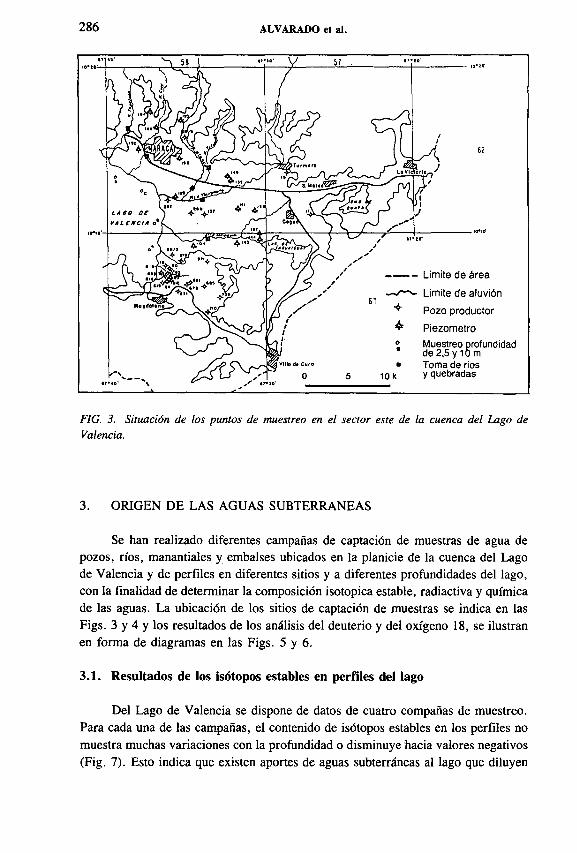
286 ALVARADO et al.
FIG. 3. Situación de los puntos de muestreo en el sector este de la cuenca del Lago de Valencia.
3. ORIGEN DE LAS AGUAS SUBTERRANEAS
Se han realizado diferentes campañas de captación de muestras de agua de pozos, ríos, manantiales y embalses ubicados en la planicie de la cuenca del Lago de Valencia y de perfiles en diferentes sitios y a diferentes profundidades del lago, con la finalidad de determinar la composición isotopica estable, radiactiva y química de las aguas. La ubicación de los sitios de captación de muestras se indica en las Figs. 3 y 4 y los resultados de los análisis del deuterio y del oxígeno 18, se ilustran en forma de diagramas en las Figs. 5 y 6 .
3.1. Resultados de los isótopos estables en perfiles del lago
Del Lago de Valencia se dispone de datos de cuatro compañas de muestreo. Para cada una de las campañas, el contenido de isótopos estables en los perfiles no muestra muchas variaciones con la profundidad o disminuye hacia valores negativos (Fig. 7). Esto indica que existen aportes de aguas subterráneas al lago que diluyen

IAEA-SM-336/1 287
M61
oe' /„----- . / 60
* / y '' 59■■ ,<•
“ ••Limite de área ( '-'Limite de aluvión p •ф- Pozo productor \ ■ Piezómetron Muestro a profundidad 4_RI i
de 2,5 y 10 M■ Toma de ríos y quebradas^
0 5 10K'\ívj^; Escala gráfica -
u i r á -AGUANAOUA í \ ^ Г A i
)
s \ ^— ■— i ) ¿ * y/ tVALENCIA S / «*/ ■
' - " V \♦?* ^
J e0LA f O 0 £ V Л L С N С t Л
\\Л / f ) y
Y ^
•d »e»e i . . El f ч/ v \ .MÍV ov/ •M,oe* V ’ a[<L -, \ Vм wNti ynpe4f«MIT» 1 л \ s' л . A 1 Paren* r^ ) ’СлмВ1опсо J V 4
F'* +"1' л *....л 4'v2Zp-—
El Eneoeto*' Cv -4-PomorotO ♦ fV"
\ »»•
. wkl1® * /*-=íttг— 61
s ♦ s Clç-f fn J i 1¿s- > ¿¿¿-J
- ^ / .........-
FIG. 4. Situación de los puntos de muestreo en el sector oeste de la cuenca del Lago de Valencia.
la concentración isotópica de sus aguas enriquecidas por evaporación (Fig. 8 ). Además, las concentraciones isotópicas estables muestran variaciones estacionales (Fig. 9). En una primera aproximación, el Lago de Valencia se comporta como un pozo de gran diámetro, con aportes y salidas de aguas subterráneas.
Los aportes superficiales y subterráneos, con respecto al volumen del lago, dan un tiempo promedio de residencia de aproximadamente 50 años, lo cual está acorde con las concentraciones del carbono 14 en el lago, cuyos valores sobrepasan las 100 partes de carbono moderno (pcm) (Cuadro I).
3.2. Deuterio y oxígeno 18 en las aguas subterráneas de la zona este del Lago de Valencia (Maracay-Magdaleno)
Para la zona de Maracay las aguas subterráneas, como las superficiales, se agrupan a lo largo de la recta meteórica (Fig. 5), lo que corresponde a la siguiente ecuación:
<52H = 8 ól80 + 10

288 ALVARADO et al.
Oxígeno 18 (%o)
FIG. 5. Relación entre oxígeno 18 y deuterio en las aguas superficiales y subterráneos del sector este del Lago de Valencia.
FIG. 6. Relación entre oxígeno 18 y deuterio en las aguas superficiales y subterráneas del sector oeste del Lago de Valencia.

IAEA-SM-336/1 289
- Aguas evaporadas -
ос<¡> .i о> 1 Я О
II
- Aguas subterráneas -
JL.
I2 4 10 20
Profundidad en m
Perfil A Perfil F Perfil I
FIG. 7. Variación de oxígeno 18 en tres perfiles en el Lago de Valencia (agosto de 1991).
Evaporación
FIG. 8. Modelo conceptual del balance hídrico en el sistema hídrico de la cuenca del Lago de Valencia.

290 ALVARADO et al.
FIG. 9. Variaciones estacionales de oxígeno 18 en el lago de Valencia.
Por el contrario, los valores isotópicos estables de todos los puntos, pertenecientes al área bajo riego (entre Palo Negro y Magdaleno) con aguas del embalse de Taguaiguay, se dispersan a la derecha de la recta meteórica (Fig. 5).
Todas las concentraciones desviadas a la derecha de la recta meteórica resultan del enriquecimiento isotópico por evaporación de las aguas antes de su infiltración y/o de la mezcla de las aguas evaporadas con las no evaporadas.
La dispersión de los valores isotópicos estables a lo largo de la recta meteórica es muy fuerte, lo cual puede estar relacionado con los siguientes factores:
— Por una parte, se observa disminución de las concentraciones isotópicas estables en las aguas subterráneas, desde la zona montañosa hacia el área de desembocadura de los ríos en el lago, lo cual indica que existe un efecto de altura en los contenidos isotópicos.
— Por otro lado, se debe suponer que la infiltración de las aguas superficiales en los conos aluvionales se produce en forma muy rápida, causando variaciones estacionales en las concentraciones isotópicas estables de las aguas subterráneas.
Como se esperaba desde el inicio de las investigaciones, en la cuenca del Lago de Valencia existe un enriquecimiento isotópico estable muy fuerte, tanto en las aguas del lago como en los embalses, tales como el de Taguaiguay (Fig. 5).

IAEA-SM-336/1 291
CUADRO I. CONTENIDO DE TRITIO, CARBONO 14 Y CARBONO 13 EN LOS POZOS UBICADOS EN LA ZONA ESTE Y OESTE DEL LAGO DE VALENCIA
_ , , .л— Profundidad_ Fecha de Unidades C ô СP°zo , • • , . muestreomuestreo de tritio (pcm) ( /00)
(m)
Lago, perfil G 17.03.93 116,75 ± 6,21 0,03 2
AR 6158 578A 17.03.93 39,43 ± 2,60 -11 ,07 70
AR 6158 615A 17.03.93 3,6 ± 0,7 68,22 ± 4,47 -8 ,9 9 82
AR 6158 616A 17.03.93 1,8 ± 0,7 51,05 ± 3,25 -10 ,52 60
AR 6258 288A 17.03.93 <1 56,45 ± 3,31 -11,43 80
AR 6258 132A 21.06.91 0,6 ± 0,7 80
AR 6258 SN20 21.06.91 0,9 ± 0,7 48
AR 6258 149A 21.06.91 0,5 ± 0,7 100
CA 6160 003A 17.03.93 0,9 ± 0,7 11,85 ± 1,44 75
C A 6160 029A 17.03.93 <0,7 11,87 ± 1,49 80
CA 6160 069A 17.03.93 0,9 ± 0,7 45,60 ± 4,65 105
CA 6160 137A 17.03.93 <0,7 7,09 ± 2,14 70
CA 6169 SN04 17.03.93 <0,7 80
CA 6161 052A 21.09.91 3,8 ± 0,7 60
CA 6259 SN01 21.06.91 0,3 ± 0,7 60
CA 6259 SN02 21.06.91 0,8 ± 0,7 16
CA 6260 080A 21.06.91 3,5 ± 0,7 82
CA 6260 097A 21.06.91 0,6 ± 0,7 160

292 ALVARADO et al.
Las concentraciones isotópicas de las aguas subterráneas en la zona comprendida entre Palo Negro y Magdaleno están enriquecidas. Este enriquecimiento se observa tanto en las áreas donde los niveles freáticos se encuentran por debajo de la cota del lago como en las áreas con niveles freáticos por encima de ella. Como se mencionó anteriormente, esta zona se encuentra bajo riego con las aguas provenientes del embalse de Taguaiguay, por lo tanto se puede considerar que las concentraciones isotópicas son el resultado de una mezcla entre las aguas de precipitación y un reciclaje parcial de las aguas de riego, que ya tienen un cierto grado de evaporación en el embalse de Taguaiguay (Fig. 5).
Aun existiendo un fuerte descenso de los niveles freáticos de las aguas subterráneas cerca del lago, no se manifiesta en éstas ningún aporte de las aguas evaporadas del Lago de Valencia (dentro de la precisión de mediciones del contenido isotópico de las aguas subterráneas). Considerando que el descenso de los niveles se produce desde hace unos 15 años, este tiempo es lo suficientemente largo como para ser detectada, en caso de existir, la influencia del lago sobre las aguas subterráneas.
3.2.1. Hidroquímica y tritio en las aguas subterráneas de la zona este de la cuenca del Lago de Valencia
De todos los sitios donde se realizaron determinaciones isotópicas, se dispone también de datos de análisis físico-químicos, entre los que se pueden mencionar los cloruros, bicarbonatos y sulfatos, así como sodio, potasio, calcio, magnesio y la conductividad eléctrica.
En la zona comprendida entre Palo Negro y Magdaleno las aguas son muy sulfatadas y con alto contenido de magnesio y de cloruros. Las concentraciones de los sulfatos alcanzan valores de hasta 2000 mg/L, la del magnesio de 350 mg/L y las de los cloruros entre 10 y 150 mg/L. Los valores de la conductividad eléctrica de las aguas subterráneas en esta zona, muchas veces sobrepasan los de las conductividades de las aguas del Lago de Valencia y del embalse de Taguaiguay (Fig. 10).
Los cloruros en la parte este de la región bajo estudio provienen de las aguas del embalse de Taguaiguay, puesto que no existe ninguna fuente sedimentaria para que de origen a este elemento. Por esta razón, una correlación entre los cloruros y los valores de los isótopos estables debe indicar la misma mezcla de las aguas subterráneas con las aguas de riego del embalse Taguaiguay. Esta relación entre los cloruros y los isótopos estables está demostrada en la Fig. 11, la cual también indica que en esta zona no hay contribuciones significativas de agua del Lago de Valencia hacia los acuíferos (dentro de la sensibilidad de medida de los parámetros), puesto que en esta área los niveles freáticos se encuentran por debajo de la cota del nivel del lago. Sin embargo, la evaporación en el embalse de Taguaiguay no puede producir concentraciones de sulfatos cercanas a 2 0 0 0 ppm, por lo que no existe ninguna correlación entre el contenido isotópico y la concentración de sulfatos, referida a la

IAEA-SM-336/1 293
pS/cm3000
ra• | 2 0 0 0 О
Ф*oXJ■>
I 1 0 0 0
о
(g) Lago de Valencia
# Cl < 45 mg/L
(g) Cl >85 mg/L
+3 + 2 + 1
® 612A
® 85A ®603A
# 8 3 A
ф 118
И04А
(g) Taguaiguay 681A
685A#® • 619A 631 A #
144N Л
0 - 1
(5 180 '-3 -5
FIG. 10. del sector
Relación entre la conductividad eléctrica y oxígeno 18 en las aguas subterráneas este de la cuenca del Lago de Valencia.
Cl mg/L
FIG. 11. Relación entre el contenido de cloruros y el oxígeno 18 en las aguas subterráneas de la cuenca del Lago de Valencia.

294 ALVARADO et al.
conductividad (Fig. 10). Este hecho sugiere un fuerte aporte de aguas subterráneas sulfatadas.
Se considera que estas aguas subterráneas sulfatadas provienen de aguas profundas, es decir, aguas subterráneas con alto tiempo de residencia, que se encuentran por debajo de las aguas subterráneas someras.
Las aguas profundas deben pertenecer a un campo de flujo lento de aguas subterráneas, puesto que la solubilidad del yeso, el cual se encuentra en forma de capas entre los sedimentos del relleno fluvio-lacustre, es alrededor de 2 g/L. Esta alta solubilidad y la presencia de capas de evaporitas indican que el flujo del agua subterránea es bajo, de lo contrario el yeso ya estaría totalmente disuelto.
La existencia de estas aguas profundas se manifiesta también por las medidas del tritio, cuyos valores en los pozos profundos (> 80 m) se encuentran por debajo del límite de precisión de la medida (Cuadro I). Por otro lado, las medidas de 14C[3] en las mismas aguas dan una edad no corregida de aproximadamente 10 000 años. Estas aguas viejas son cubiertas por aguas jóvenes no sulfatadas (Fig. 12). El espesor del agua joven (somera) depende de la intensidad de la recarga, siendo mayor en la zona de Maracay-Turmoro y menor en la zona de Palo Negro-Magdaleno. En consecuencia, en la zona entre Palo Negro y Magdaleno existen pozos con alto contenido de sulfatos desde tiempos anteriores a la construcción del sistema de riego de Taguaiguay. Por lo tanto, las aguas subterráneas ya eran sulfatadas, independientemente del uso intensivo de los recursos subterráneos.
Cerca de superficie
V/MI Profundas y parcialmente sulfatadas
Lagos y lagunas
“ í - Agua subterránea
FIG. 12. Perfil esquemático preliminar de la interacción de los diferentes componentes del sistema hidrogeológico de la cuenca del Lago de Valencia.

IAEA-SM-336/1 295
En la actualidad las concentraciones de los sulfatos en las aguas subterráneas han aumentado. Por efecto de la sobreexplotación de las aguas subterráneas, el potencial de estos recursos disminuye, provocando el ascenso de las aguas profundas, para luego mezclarse con las aguas subterráneas someras (Fig. 12).
De lo anteriormente expuesto se deduce que, desde el punto de vista isotópico y químico, en la zona este del Lago de Valencia hay una mezcla de tres componentes:
— aguas de riego, provenientes del embalse Taguaiguay,— aguas subterráneas someras con baja concentración de sulfatos y de
magnesio, y— aguas subterráneas profundas fuertemente sulfatadas y magnésicas.
En este sistema, tanto el agua de riego, que contiene agroquímicos, como las aguas profundas ejercen una influencia considerable en la calidad de las aguas someras, utilizadas para el consumo humano y para la actividad agrícola e industrial.
3.3. Las aguas subterráneas en el norte, oeste y sur del Lago de Valencia
Las aguas subterráneas en estas zonas contienen la misma estratificación vertical que en la zona este. Por lo tanto, existen las mismas fuentes de deterioro de la
FIG. 13. Localización de la zona de descarga del flujo subterráneo de la cuenca del Lago de Valencia.
296 ALVARADO et al.
calidad que las aguas someras. Adicionalmente, el análisis de isótopos estables muestra salidas de aguas del Lago de Valencia y presencia de aguas geotermales. En contraposición a la zona este, en las partes norte, oeste y sur de la cuenca no se utilizan aguas de embalses como agua de riego, o sea que no hay infiltración hacia los acuíferos de aguas de riego con evaporación.
En una zona muy estrecha entre La Culebra y Flor Amarilla se observan aguas evaporadas (Figs. 6 , 13), las cuales resultan de la mezcla de aguas del lago y aguas subterráneas locales. Como ya se mencionó en la Sección 3.1, el bajo contenido de sales del agua del lago, que no tiene salidas superficiales desde hace más de 1 0 0
años, sugiere que existen salidas subterráneas del Lago de Valencia hacía cuencas adyacentes. La zona de salida es muy estrecha y conectada con la zona de fallas de La Victoria, la cual cruza a través del Lago de Valencia en su parte media en dirección este-oeste. Con los resultados obtenidos hasta la fecha, no está muy bien definido si estas salidas se producen a través de un cañón rellenado con sedimentos fluvio-lacustres, o a través de fisuras de la misma zona de fallas. Por el afloramiento de rocas metamórficas en la zona de La Culebra parece muy probable que las salidas subterráneas se producen a través de fisuras.
Los caudales de las salidas subterráneas parece que no son altos por dos razones:
— Existe poca diferencia entre el nivel del lago y la altura de la zona de resurgen- cias de estas aguas subterráneas, posiblemente en las cercanías del río Paito, ubicado a unos 23 km hacia el oeste del lago;
— El sistema del lago parece ser muy sensible a las variaciones de las precipitaciones, o sea que el lago sirve más como reservorio qúe como zona de tránsito rápido de aguas (véase la Sección 4).
3.4. Aguas geotermales en la zona norte del Lago de Valencia
En el diagrama del oxigeno 18 y deuterio (Fig. 6 ) se observan puntos que se desvían a la derecha de la línea de mezcla de aguas del lago con aguas locales. Estos valores no se pueden explicar como mezcla de aguas, debido a que faltan los valores isotópicos bajos, que es lo que se exige para explicar un fenómeno de mezcla. Estos valores de los isótopos estables pertenecen a una zona coherente, agrupados en un área restringida, y pueden estar relacionados con aguas tibias (Fig. 13). Por esta razón se supone que estas aguas son de origen geotermal y se han enriquecido solamente en oxigeno 18 por intercambio con las rocas a temperaturas superiores a 100°C. Lamentablemente, los pozos existentes en esta zona con altas temperaturas (entre 93 °C y 41,5 °C) no contienen el mismo enriquecimiento en oxigeno 18, lo cual no se puede considerar contradictorio como lo anteriormente explicado, puesto que para el intercambio isotópico son necesarias no solamente elevadas temperaturas, sino también mayor tiempo de retención de las aguas, es decir, que sean más viejas.

IAEA-SM-336/1 297
El Cuadro I muestra para los pozos con elevadas temperaturas (CA 6259 S/N 01 y С A 6259 S/N 02) que las aguas en estos pozos, dentro de los límites de precisión de las mediciones, contienen tritio y, por lo tanto, no tienen mucho tiempo de residencia y son relativamente jóvenes.
4. BALANCE HIDRICO ACTUAL
La precipitación media anual de la cuenca en el período 1962-1981 es de 1110 mm y la del Lago de Valencia de 1000 mm. El 80% de las lluvias se producen en la época húmeda, o sea desde el mes de mayo hasta el mes de noviembre.
En el balance hídrico se deben considerar los aportes naturales (lluvias) y artificiales a la cuenca, los gastos por evaporación o salidas artificiales de aguas y las salidas subterráneas de la cuenca. El balance hídrico, considerando los valores de precipitación en la superficie del lago y en la parte terrestre de la cuenca, sin tomar en cuenta las importaciones o exportaciones de aguas, da una descarga ( 1 ) de:
D = (PL - EP) AL + (PT -ETR) AT
donde PL (lluvia sobre el lago) = 1,0 m 3 /m 2/a EP (evporación potencial) = 2,28 m 3 /m 2/a AL (área del lago) = 360 X 108 m 2
PT (lluvia sobre zona terrestre de la cuenca) = 1,11 m 3 /m 2/a ETR (evapotranspiración) = ?AT (área zona terrestre de la cuenca) = 2200 x 108 m 2
Suponiendo una descarga subterránea de cero para la cuenca, el valor máximo de evapotranspiración real (ETR) es menor de 892 mm/a.
Como ya se ha analizado anteriormente, las salidas subterráneas de la cuenca no son muy grandes. Suponiendo una ETR = 850 mm/a, que estaría de acuerdo con observaciones en otros países [4, 5, 1] se obtiene una descarga de:
D < 3,5 m 3 /s, o seaD < 43 mm/a.
Este valor de la descarga, con respecto a la extracción de aguas subterráneas, que es de 14 m 3 /s, significa que los límites de explotación de los recursos de aguas subterráneas (la cual ha contribuido al descenso acelerado del nivel del Lago de Valencia hasta el año 1981) ya están afectados y, por lo tanto, hay sobre-explotación en muchas áreas. A partir del año 1981, debido a los aportes de agua de cuencas vecinas como la del embalse Pao-Cachine (8,7 m 3 /s) y la de la zona de Valencia (3,5 m 3 /s), se paralizó el descenso de los niveles del lago, experimentando incluso

298 ALVARADO et al.
una recuperación. Estos aportes artificiales sumados al balance hídrico dan una descarga al Lago de Valencia de 15,7 m 3 /s, lo cual con respecto a la extracción de las aguas subterráneas, que es de 14 m 3 /s, da un exceso de aportes de 0,5 m 3 /s, contribuyendo de esta manera al ascenso del nivel del lago desde el año 1981.
5. CONCLUSIONES Y RECOMENDACIONES
Los acuíferos alrededor del Lago de Valencia se encuentran sobre-explotados. Las aguas subterráneas son utilizadas para consumo humano, riego y actividades industriales.
En zonas donde los sedimentos tienen baja permeabilidad, el riego por bombeo de aguas subterráneas es complementado con aguas almacenadas por descarga de ríos.
En las aguas de la zona este del lago se puede diferenciar perfectamente la mezcla de tres componentes:
— Aguas de baja mineralización, provenientes de la parte más superficial de los acuíferos.
— Aguas almacenadas en el embalse de Taguaiguay, las cuales aportan al acuífero aguas evaporadas.
— Aguas profundas con altas concentraciones de sulfatos, las cuales ascienden penetrando en los acuíferos someros, que se encuentran por encima de los acuíferos profundos. Estas aguas profundas no contienen tritio y alcanzan edades de aproximadamente 1 0 0 0 0 años, debido a que pertenecen a una zona profunda con poca dinámica de las aguas. Este ascenso se produce como consecuencia de la disminución de los potenciales hídricos, producto de la sobre- explotación local de las aguas subterráneas.
En el área ubicada al este del Lago de Valencia no se observan aportes del lago hacia los acuíferos, donde localmente los niveles freáticos se encuentran por debajo de la cota del lago. Esta ausencia de aportes del lago hacia el acuífero está relacionada muy probablemente con una colmatación de los sedimentos del relleno fluvio- lacustre en la interfase entre el lago y los acuíferos.
En la parte oeste del Lago de Valencia se observan salidas subterráneas cerca de los sitios La Culebra y Flor Amarilla, hacia el río Paito. Estas salidas posiblemente están relacionadas con una zona muy fisurada en conexión con la falla de La Victoria y alcanzan una descarga menor de 43 mm/a. A diferencia de los sedimentos del relleno fluvio-lacustre, las rocas Asuradas permiten el flujo de material fino en suspensión que se encuentra en el lago.
Al norte y noroeste del lago se manifiesta una zona geotermal con aguas calientes o tibias enriquecidas con 1 8 0 . Esta evidencia está confirmada con los resultados de análisis químicos. De esta zona salen tanto aguas frías como aguas calientes
IAEA-SM-336/1 299
enriquecidas en oxigeno 18; de donde resulta que las zonas geotermales profundas pertenecen a un sistema con poca dinámica, mientras que las someras presentan una alta dinámica.
Un balance hídrico debe considerar adicionalmente los aportes artificiales a la cuenca, las salidas subterráneas de la cuenca y las variaciones del nivel del Lago de Valencia. Un cálculo aproximado da una evapotranspiración real superior a 850 mm/a e inferior a 892 mm/a; una evaporación potencial de 2000 mm/a; unas salidas subterráneas inferiores a 43 mm/a; unos aportes artificiales de 2,2 m 3/s y un ascenso del nivel del lago de Valencia (a partir de la desviación de cursos de agua superficial hacia el lago) de 401 a 406 msnm.
Se recomienda continuar las mediciones mensuales de los niveles en la red de pozos de observación. Al mismo tiempo, se deben realizar análisis físico-químicos de las aguas subterráneas, por lo menos una vez al año. Esto permitirá ejercer un control permanente sobre el comportamiento del acuífero, tanto en lo que respecta a sus reservas como a la calidad de sus aguas.
AGRADECIM IENTOS
Para la ejecución del presente trabajo de investigación se recibió aporte financiero y asesoramiento técnico del Gobierno de la República Federal de Alemania, así como del Organismo Internacional de Energía Atómica. Expresamos nuestro agradecimiento por este aporte, haciéndolo extensivo a los científicos de la Sección de Hidrología Isotópica del OIEA en Viena.
REFERENCIAS
[1] BALDISON, R., SEILER, K.-P., Estudio Isotópico e Hidrogeológico en la Cuenca del Lago Atitlán, Guatemala, informe interno, OIEA, Viena, 1994.
[2] SEILER, K.-P., Tiefe Grundwaesser, Z. dt. Geol. Ges. (1983).[3] TAMERS, M. A ., “Surface-water infiltration and groundwater movement in arid zones
of Venezuela” , Isotopes in Hydrology (Proc. Symp. Vienna, 1966), IAEA, Vienna (1967) 339-351.
[4] FEBRILLET, J., BUENO, E., SEILER, K.-P., STICHLER, W., “Estudios Isotópicos e Hidrogeológicos en la Región Suroeste de la República Dominicana” , Estudios de Hidrología Isotópica en América Latina, IAEA-TECDOC-502, OIEA, Viena (1989) 237.
[5] BALDISON, R., SEILER, K.-P., Estudio Isotópico e Hidrogeológico en la Cuenca del Río Samala, Guatemala, informe interno, OIEA, Viena, 1989.


Poster Presentations
IAEA-SM-336/26P
GROUNDW ATER Ô,SN STUDIES IN HUNGARY
E. DESEÓ, J. DEÁKWater Resources Research Centre (VITUKI),Budapest
E. HERTELENDI Institute of Nuclear Research,Hungarian Academy of Sciences,Debrecen
Hungary
Nitrogen (N 0 3 and NH4) pollution in groundwater is an important environmental problem in Hungary. Main sources of shallow groundwater pollution are the unsewered settlements, the livestock farms and in agricultural regions overuse of artificial fertilizer. In some areas of Hungary the deeper aquifers also contain high amounts of ammonium migrating from shallower depth or originating from the aquifer. A preliminary condition for prevention is to determine the origin of nitrogen dissolved in groundwater. The usability of the <5 l5N method for this purpose in Hungary was investigated.
The first step of investigation was to determine the <5 15N values characterizing the different nitrogen sources. We found significant differences of stable nitrogen isotope composition of artificial fertilizer, animal manure and ammonium of deep origin.
The first case study in Hungary was in the Great Plain in the region of the Korôs-Maros rivers. The Regional Water Supply of Ujkigyós was established on the alluvial fan of the River Maros. The regular water quality control indicated a high content of ammonium, and sometimes the arsenic and methane content exceeded the limit for drinking water, too. The main aquifer of exploitation is shallow (18-80 m), so surface contamination by NH 4 might be a factor.
The shallowest groundwater ( < 15 m) of the area shows different local effects. The high N 0 3 content (up to 600 mg/L) and high ô 15N (+ 1 0 to + 2 0 7 oo) relate to the main role of human and animal origin of nitrogen in many unsewered villages. Regarding agricultural activity the ¿>15N of the shallowest aquifer (0 to + 5 7 00) relates to the effect of artificial fertilizer. The main aquifer (18-80 m) is more
301

302 POSTER PRESENTATIONS
homogeneous (3-5 mg/L ammonium content without any detectable nitrate and + 6
to + 8 7 00 <51 5 N). The average ô ,5N (+ 7 .5 7 00) relates to ammonium of natural origin in this aquifer. It is supported by combined environmental isotope studies proving that the shallow groundwater is old, and that the aquifer has not been reached by contaminated fresh water in the last 40 years.
The other area of investigation is in the northwest of Hungary. The groundwater flow system of Miocene limestone aquifers recharges in Austria and was discharged in natural conditions by karst springs. The waterworks built in the area of these springs have been exploiting more than double the original yield. As a result of the additional recharge from potentially contaminated shallow groundwater, the nitrate content of the supplied water has increased. Tritium data indicate a 20% input of fresh groundwater.
The ô I5N values of nitrate dissolved in the groundwater are in the range of 0 to +4°/oo in agricultural areas and from + 8 to 15°/00 in the neighbourhood of unsewered settlements. These prove the mixing of agricultural and communal wastewater in the groundwater respectively. The <515N values of ammonium dissolved in the karst water of the deepest wells are between 0 and + 3 7 00, representing natural, non-surface origin.
IAEA-SM-336/30P
INTERCONNECTION OF ENVIRONMENTAL ISOTOPE CONTENTS OF GROUNDWATER WITH THEIR VULNERABILITY TO TECHNOGENIC CONTAMINANTS
V.T. DUBINCHUK, V.A. POLYAKOV All-Russian Research Scientific Institute of
Hydrogeology and Engineering Geology,Zeleny, Moscow, Russian Federation
Presented by V.I. Ferronsky
Results o f the comparative measurements of isotopic (D, 1 8 0 , T, 1 3 ,1 4 C) ¡groundwater contents and their technogenic contamination are presented and discussed.
Environmental tritium, like nearly all technogenic contaminants, enters underground aquifers from the Earth’s surface mainly via atmospheric precipitation (rain, melting snow) infiltrating through the aeration zone and/or due to the filtration/inflow from surface channels, reservoirs and sinkholes.

SESSION 6 303
FIG. 1. Relationship between environmental tritium and 137Cs concentrations in groundwater in the Chernobyl area (A = artesian well, D = dug well, S = spring, W = well).
This means that the tritium groundwater content, compared with that in the precipitation/surface water, can yield data on the recharge pathway and sources, replenishment velocity and residence time of water (RTW) in a given hydrogeological system. Thus, the environmental tritium traces directly those locally and regionally released contaminants (onto the Earth’s surface or into environmental water bodies) which migrate without notable retardation (retardation factor R = 1). Pesticides, nitrates, herbicides, some other substances and, of course, tritium itself, as a radioactive tracer or pollutant, belong to this group of contaminants.
The same can be said of 13,14C and some other environmental isotopes if the difference in the fate of water (tritium) and dissolved carbonate or other related components in geological bodies is taken into account. Other technogenic substances such as bomb and Chernobyl radionuclides ( 1 3 4 ,1 3 7 Cs, 90Sr and others) as well as a majority of the chemical pollutants due to interphase exchanges (sorption- desorption, etc.) in geological media are retarded in them and have R values more or much more than 1 .
Adding to the tritium data such information on the retardation factor, which can directly or indirectly be determined by any known technology (isotope tracer; batch, column or field sorption experiments; method of analogy, geochemical and/or lithological mapping; nuclear well logging, etc.), residence times of any possible contaminants in a given hydrogeological system can be easily estimated as RTC = RTwater x R, if, of course, the interphase exchanges can be characterized by the Henry sorption isotherm.

304 POSTER PRESENTATIONS
By comparing the lifetime of a contaminant with its mean RTC and taking into account actual or eventual spatial-temporal regimes of the contamination impact, the groundwater vulnerability can in principle and in practice be evaluated. Moreover, on the basis of data on tritium plus D, l80 and 13'14C and other environmental isotopes, the local and regional pattern of groundwater vulnerability may be imagined and related maps/models constructed or improved. These may be used for the prediction of possible changes of the groundwater quality following an arbitrary impact.
It may also be concluded that a contaminant may more likely contaminate a groundwater body if the contaminant residence time is less or comparable with its total lifetime on its way from the surface to this body. Hence, the contamination spatial-temporal impact regime should be taken into account.
Using the general basis outlined above, groundwater vulnerability assessment has been considerably improved compared with former work [ 1 , 2 ] and developed further. This approach has successfully been realized and is demonstrated in a report containing a number of case studies conducted in various regions of the former USSR and some neighbouring countries concerning different technogenic or natural contaminants such as organic pollutants from pig farms, radionuclides from the Chernobyl accident, seawater intrusion, etc.
In Fig. 1 the relationship between tritium and 137Cs concentrations measured in shallow and deep aquifers is given for the Chernobyl area by way of example.
REFERENCES
[1] DUBINCHUK, V.T., et al., Nuclear Geophysical Methods in Hydrogeology and Engineering Geology, Nedra, Moscow (1988) (in Russian).
[2] DUBINCHUK, V.T., et al., “ Field and laboratory nuclear techniques in radionuclide transport studies” , Isotope Techniques in the Study of Past and Current Environmental Changes in the Hydrosphere and the Atmosphere (Proc. Symp. Vienna, 1993), IAEA, Vienna (1993) 101-146.

SESSION 6 305
O M G E N DEL ARSENICO EN EL ACUIFERO GRANULAR DE LA COM ARCA LAGUNERA, M EXICO
L. GONZALEZ-HITA, L.F. SANCHEZ Instituto Mexicano de Tecnología del Agua,Jiutipec, Morelos, México
Se presentan los resultados de un estudio de caracterización hidrogeoquímica e isotópica del acuífero granular de la Comarca Lagunera.
El estudio se realizó con el propósito de: a) dilucidar el origen y evolución del arsénico en el acuífero; b) estimar la vulnerabilidad de las zonas de reserva cuya agua es aún de buena calidad; y c) actualizar el conocimiento hidrogeoquímico del sistema.
La metodología utilizada se fundamentó en el análisis del marco físico (geología, hidrología e hidrogeología), en la actualización hidrogeoquímica del acuífero (23 parámetros fisicoquímicos) y en la caracterización isotópica de los cuerpos de agua superficiales y subterráneos (ô 1 8 0 , ô2 H, 3H y 1 4 C).
La sobreexplotación del agua subterránea y el deterioro de su calidad, por la presencia de arsénico y otros elementos químicos nocivos, han ocasionado efectos adversos en la salud pública, en la infraestructura hidráulica y en la calidad productiva del suelo [ 1 , 2 ].
La Fig. 1 muestra los isovalores de arsénico del agua subterránea. Las zonas con concentraciones altas de arsénico también presentan valores elevados de sulfato, fluoruro, cloruro, sodio, boro y litio.
Los resultados del estudio indican que el movimiento del agua en el acuífero (velocidad y dirección) depende de las diferencias de presión existentes en cada punto, de los parámetros hidrológicos de los sedimentos y de la intensidad de extracción de agua subterránea. Las observaciones piezométricas muestran que el nivel estático en el acuífero, en 50 años de explotación, registró abatimientos totales de 10 a 95 m y medios anuales de 0,22 a 2,11 m.
La información hidrogeoquímica e isotópica permitió establecer las siguientes conclusiones: a) los eventos geológicos que dieron origen a la Comarca Lagunera generaron procesos magmáticos que, probablemente en la fase de consolidación del magma, formaron un sistema hidrotermal acuoso que aportó diversos oligoe- lementos: arsénico, flúor, boro y litio [3]; y b) los sedimentos continentales transportados por los ríos Nazas y Aguanaval, durante la etapa de formación del acuífero, parecen ser las causas del hidroarsenicismo en la región.
La hipótesis es consistente con las evidencias siguientes: a) los pozos con alta concentración de arsénico están localizados cerca de cuerpos ígneos; b) las aguas con
IAEA-SM-336/50P
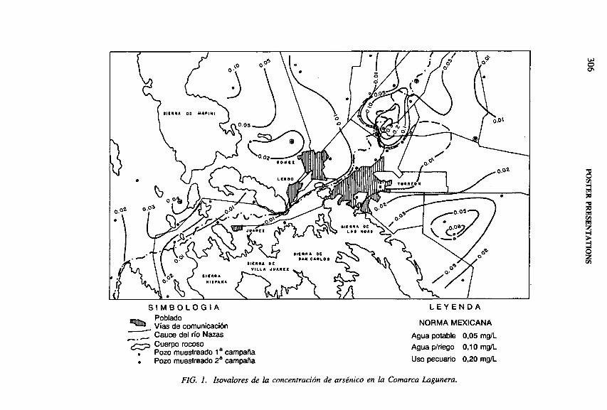
u>g
S I M B O L O G I A L E Y E N D A
C ï f d ï comunicación NORMA MEXICANA
Cauce del río Nazas Agua potable 0,05 mg/LCuerpo rocoso _ Agua p/riego 0,10 mg/L
. Pozo muestreado 1 campana« Pozo muestreado 2a campaña Uso pecuario 0,20 mg/L
FIG. 1. Isovalores de la concentración de arsénico en la Comarca Lagunera.
POSTER PRESEN
TATIO
NS
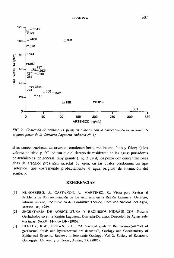
SESSION 6 307
1 2 0 -,
1 0 0 -
OZom 11 < O
80-
6 0 -
4 0 -
2 0 -
3345□ □ 2679
a 2408
□ 520
□ 374
□ 297
m 2 5 7 a ^--2 62 4
11’ — 2240 268
a 901
□ □ 2344 774
□ 116
□ 368□ 847
□ 186 □ 2016
,331I-------------- 1------------- 1--------------1------
50 100 150 200
ARSENICO (ng/mL)
250 300 350
FIG. 2. Contenido de carbono 14 (pcm) en relación con la concentración de arsénico de algunos pozos de la Comarca Lagunera (subárea № 1).
altas concentraciones de arsénico contienen boro, molibdeno, litio y flúor; c) los valores de tritio y l4C indican que el tiempo de residencia de las aguas portadoras de arsénico es, en general, muy grande (Fig. 2); y d) los pozos con concentraciones altas de arsénico presentan mezclas de agua, en las cuales predomina un tipo isotópico, que corresponde probablemente al agua original de formación del acuífero.
REFERENCIAS
[1] HUNGSBERG, U., CASTAÑON, A., MARTINEZ, R., Visita para Revisar el Problema de Sobreexplotación de los Acuíferos en la Región Lagunera, Durango, informe interno, Coordinación del Consultivo Técnico, Comisión Nacional del Agua, México DF, 1989.
[2] SECRETARÍA DE AGRICULTURA Y RECURSOS HIDRÁULICOS, Estudio Geohidrológico en la Región Lagunera, Coahuila-Durango, Dirección de Aguas Subterráneas, SARH, México DF (1986).
[3] HENLEY, R.W., BROWN, K.L., “ A practical guide to the thermodynamics of geothermal fluids and hydrothermal ore deposits” , Geology and Geochemistry of Epithermal Systems, Reviews in Economic Geology, Vol. 2, Society of Economic Geologists, University of Texas, Austin, TX (1985).

308 POSTER PRESENTATIONS
PATTERN INVESTIGATIONS TO PROVIDE A CONCEPT FOR GROUNDW ATER M ANAGEM ENTA case study on groundwater resources in a highly industrialized area
M. HEIDINGER*, B. BERTLEFF**, L. EICHINGER*,S. ERTL*, W. GRAF***, A. VOROPAEV*
*Hydroisotop GmbH,Schweitenkirchen
**Geologisches Landesamt Baden-Württemberg,Freiburg
***Institut für Hydrologie,GSF-Forschungszentrum für Umwelt und Gesundheit Neuherberg, Oberschleissheim
Germany
1. INTRODUCTION
The investigation area is the Quaternary basin of Singen near Lake Constance, an aquifer system of three connected pore groundwater storeys and an underlying confined karstified aquifer (Fig. 1).
The exploited groundwater resources are very vulnerable to pollution from old depositories and pollutants released by industry or waste water from sewers. During recent decades, rising concentrations (СГ, NH4+) were registrated in groundwaters of water wells used for industry and the drinking water supply of the city.
In the light of future development and predictions of the transport of solutes in the groundwater system, it was necessary to provide a concept for groundwater management including a mathematical-numerical model for the whole aquifer system.
2. METHODICAL APPROACH
Practical applications of isotopes such as 3 H, 8 5 Kr, 1 8 0 , 2 H, 1 3 C-DIC (dissolved inorganic carbon), 1 5 N-NH4, 1 5 N -N 0 3, 1 8 0 - N 0 3, 3 4 S -S 0 4, 1 8 0 - S 0 4
studies as a part of hydrogeological investigations were performed to gain knowledge of the inhomogeneous hydrological system (85Kr was measured at the Universitat Bern, H.H. Loosli).
IAEA-SM-336/55P

SESSION 6 309
After the interpretation of existing data as a first step, a groundwater inventory (250 water wells) was conducted by means of hydrochemistry, isotope hydrology ( 1 8 0 , 3 H) and measurements of the hydraulic parameters (pumping tests) to obtain a quantitative and qualitative assessment of the groundwater resources. Long range isotopic measurements ( 1 8 0 , 3 H) were carried out in different groundwater storeys, in local precipitation and lysimeter waters to separate and locate the components of groundwater recharge.
3. RESULTS
The results of isotope investigations ( lsO, 3 H, 8 5 Kr) show that up to 50% of the groundwater in the deeper pore groundwater storey has its origin in the underlying confined karstified aquifer. In contrast to this, the major water wells situated in the deeper pore groundwater storey are connected to the upper exposured aquifer zones and show mixing water systems, indicated by 3H and 85Kr values. In order to locate the zones of hydraulic connection, the geology of the aquifer had to be interpreted in a new way.

310 POSTER PRESENTATIONS
80
70 -
60 -
50
40
30 -
2 0 -
1 0 -
ó “O—N0 j(%„)o aquifer E И oquifer D + E, D о aquifer C + D x aquifer C
□ gwm g s
NO3
ra în
gwm 3 ж
Br. Múnchried VI,
Rîelaslngen B 1
Überlïngen B 5
0
Alus. Gûterbahn O
□ GWM 9 SO
Kompostwerk
W 1 ❖
^ . » 6 F. Múnchried IV
Ф f r. Maggî 1939a Rielasingen P 9Br. Alu ТВ III ° °8 r. Alu ТВ I
Alu KB 7 S 14 ^Xworb lingen DP 3
O -normal dénitrification
0 - y / ♦ ♦ > ♦ + ♦ ♦ ♦ t.
- 1 0
voporization of ammonia
- 1 0 1 0 2 0
—i— 30 40
FIG. 2. Results o f ô15N -N 03 and ô 0 -N 0 3 determinations.
For the calibration of the numerical transport model the dilution and decomposition of pollutants of various sources were observed systematically by means of hydrochemical and isotopic studies ( 1 3 C-D IC, 1 5 N-N H 4, 1 5 N -N 0 3, 1 8 0 - N 0 3, 3 4 S -S 0 4, 1 8 0 - S 0 4 investigations) inside the landfills and in the surrounding groundwater as well as in industrial areas.
4. ô 1 3 C-DIC INVESTIGATIONS
Samples for the determination of ô 1 3 C-DIC were taken in highly mineralized landfill waters and show marked <51 3 C-DIC in the range between 0 to 2 0 7 oo caused by active anaerobic decomposition. Surrounding groundwaters and most deep groundwaters indicate mixing systems with dominating portions of unmarked and normal mineralized groundwaters having <51 3 C-DIC in the range between - 1 2 to - 1 5 7 00. However, in some parts of the deeper aquifer system where highly mineralized groundwaters are found, the 8 1 3 C-DIC value is similar to that of landfill waters.

SESSION 6 311
The aim of ô 15N measurements of NH 4 or N 0 3 and ô 180 of N 0 3 is to determine the origin of NH 4 and N 0 3 dissolved in groundwaters of the Singen aquifer system.
Landfill waters with high NH 4 and NaCl contents show <5 l5 N-N H 4 values ranging from 5 to 7°/00. Similar ô 15N values and high 3H contents are also observed in NaCl groundwaters of the deeper aquifers С and С + D with high NaCl and NH 4
values.In contrast to this, high <515N and ô l80 values of N 0 3 (Fig. 2) indicated a
strong process of decomposition by denitrification, affecting the penetrated landfill waters in the upper aquifer E. High levels of dissolved N 0 3 correlated closely with low ¿>’5N and ô 180 values arising from the intensive use of artificial fertilizers. Partial mixing of various N 0 3 sources (landfill waters, agricultural areas and waste waters) occurs in groundwaters of different groundwater storeys.
Under recent conditions the influence of N 0 3 derived from landfill waters is very low because of decomposition and dilution effects.
50
5. Ô15N-NH4, ô15N-N03 AND ô180 -N 0 3 INVESTIGATIONS
40
30
2 0
1 0
0
- 1 0
- 2 0
10 -5 0 5 10 15 20
d " S -S O .^ o )
<> aquifer E □ aquifer D + E, D О aquifer С + D К aquifer С
оRKB 3 /Seew.
Bildstockle 2 Ф
evaporite sulphate
GWU 9 /Seew.Ш о
GWM 40 lPК ж %
о * « □ ф ;V ^
Bildstockle 5 0® ^ И АDp 4 0 x rf) w<>8
^Bildstôckle 6
secondary sulphate
p dh О ’ W 1
d 180 - S 0 4 (% .)
FIG. 3. Results of b34S-S04 and h,80 -S 0 4 determinations.

312 POSTER PRESENTATIONS
40
30
50
2 0
1 0
0
- 1 0
- 2 0
6 . ô3 4 S -S 0 4 and ô 1 8 0 - S 0 4 INVESTIGATIONS
Isotope measurements of ¿>3 4 S -S 0 4 and <5l80 - S 0 4 are being made to clear up the origin of S 0 4 contents in groundwaters of the Singen basin (ô3 4 S -S 0 4 and ô 1 8 0 - S 0 4 were measured at the Institut fiir Hydrologie).
Owing to dominating anaerobic conditions, waters of the studied landfills generally show detectable H2S concentrations. However, referring to specific material in some parts of the landfills, high S 0 4 concentrations occur with the enriched signature of evaporite sulphate (Fig. 3). The influence of those components can be observed in the surrounding groundwaters. But for S 0 4 concentrations in the deeper aquifer zones secondary sulphate (aquifer material, landfill H2 S) is of major importance (Fig. 4).
7. MATHEMATICAL-NUMERICAL MODEL
For the simulation of groundwater flow and the transport of solutes a finite element (FE) model was created by the Geologisches Landesamt Baden-Württemberg
d 14S - S 0 4 (%=)
Ф aquifer E □ aquifer D + E, D О aquifer С + D К aquifer С
RKB 3 /Seew.
❖Bildstôckle 2
q GWM 9 /Seew. 0GWM 4
GWM*3 0 «
« V o о 9 * mо
□ ❖ 0 . O k X и
X
SO + (m g / L )I .... I ■ i ■ ■■ i !
0 100 200 300
FIG. 4. Correlation o f S 0 4 concentration and ô34S -S04 values.
SESSION 6 313
in Freiburg. Hydraulic investigations and steady state calibration show that under the recent hydraulic conditions the distribution of pollutants in the deeper aquifers is not comprehensible. In contrast, calculated scenarios with increased groundwater withdrawal indicated different flow paths for penetrating landfill waters which also lead to a better fitting of the results of isotope and hydrochemical investigations.
8 . CONCLUSION
Isotope investigations using 3 H, 8 5 Kr, 180 and 2H are a major tool for the separation of different groundwater components in inhomogeneous aquifer systems such as the Singen basin.
From the results it can be assumed that under recent conditions in the exposed aquifer zones pollutants from depository waters such as NH 4 (with specific isotope values) are strictly decomposed and high N 0 3 levels are caused by fertilizers in other parts of the groundwater catchment area.
The distribution of the pollutants in the deeper groundwater storeys and the isotope ratios of 1 5 N -N H 4, 1 5 N -N 0 3, 1 8 0 - N 0 3, 3 4 S -S 0 4 and 1 8 0 - S 0 4 show, however, concrete influences of pure landfill waters on groundwater resources correlated with higher 3H contents or mixing water systems. Therefore, the pollutants from depositories probably used direct flow paths in the past. The current state of investigations suggests that this was caused by increased groundwater withdrawal of industrial water wells with lowered groundwater levels in the mid-1970s.
Because of the inhomogeneous aquifer systems, with various sources of groundwater pollution and resulting problems of groundwater balance and transport of solutes, hydrogeological investigations should be performed in combination with isotope studies as a useful tool for modelling and groundwater management.

314 POSTER PRESENTATIONS
STABLE ISOTOPES AND 14C FORESTIM A TIN G SUSTAINABLE USE OF GROUNDW ATERIN TH E W ESTERN MURRAY BASIN, AUSTRALIA
F.W . LEANEY, A.L. HERCZEG Division of Water Resources,Commonwealth Scientific and Research Organization,Glen OsmondI
A.J. LOVEDepartment of Mines and Energy,Adelaide
A. TELFERDepartment of Environment and Natural Resources,Adelaide
South Australia, Australia
IAEA-SM-336/70P
Groundwater salinization in Australia is an increasing problem. A major cause is saline soilwater flushed from the unsaturated zone into the groundwater as a result of enhanced recharge after removal of native vegetation. This is already recognized in areas where water tables are close to the land surface, but more and more areas will become affected over time. Results are presented of a project aimed at determining the time scale for salinization of low salinity groundwaters within the Mallee region of the Murray Basin, southeastern Australia.
About 15 000 km 2 o f the semi-arid western Murray Basin has relatively fresh groundwater (total dissolved solids (TDS) < 1500 mg/L) and depth to water between 20 and 60 m (Fig. 1). Over the last decade, development of irrigation in the area has steadily increased and the potential for further development is being explored. Hence, the age and origin of the water need to be evaluated in order to assess the sustainable use of this resource. Further, we need to evaluate the potential decline in water quality as increased recharge flushes saline soilwater into the groundwater. It has already been shown that land clearing over the last century and increases in irrigation may significantly increase recharge [1]. A combination of isotopic techniques (carbon dating and stable isotope analysis of groundwater) and recharge estimation (using chloride concentration and stable isotope analysis of soilwater) has been used to achieve these aims.

SESSION 6 315
A
Sampling sites
6D, S 1bO and/or 6 13C (1-32)
,4C, 6 ,3C, ÔD, 6 ,sO (A-H)
Unsaturated zone Groundwater 14C, S 13C
A -В Geological cross-section
FIG. 1. Site location and salinity map.
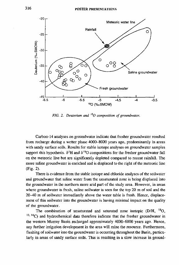
316 POSTER PRESENTATIONS
180 (%oSMOW)
FIG. 2. Deuterium and l80 composition o f groundwater.
Carbon-14 analyses on groundwater indicate that fresher groundwater resulted from recharge during a wetter phase 4000-8000 years ago, predominantly in areas with sandy surface soils. Results for stable isotope analyses on groundwater samples support this hypothesis. ô2H and <5I80 compositions for the fresher groundwater fall on the meteoric line but are significantly depleted compared to recent rainfall. The more saline groundwater is enriched and is displaced to the right of the meteoric line (Fig. 2).
There is evidence from the stable isotope and chloride analyses of the soilwater and groundwater that saline water from the unsaturated zone is being displaced into the groundwater in the northern more arid part of the study area. However, in areas where groundwater is fresh, saline soilwater is seen for the top 2 0 m of soil and the 20-40 m of soilwater immediately above the water table is fresh. Hence, displacement of this soilwater into the groundwater is having minimal impact on the quality of the groundwater.
The combination of unsaturated and saturated zone isotopic (D/H, 1 8 0 , 1 3 , 1 4 C) and hydrochemical data therefore indicate that the fresher groundwater in the western Murray Basin recharged approximately 4000-6000 years ago. Hence, any further irrigation development in the area will mine the resource. Furthermore, flushing of soilwater into the groundwater is occurring throughout the Basin, particularly in areas of sandy surface soils. This is resulting in a slow increase in ground

SESSION 6 317
water salinity for groundwater already marginal in quality. Fortunately, in the area of fresher groundwater, the soilwater being flushed into the groundwater is a remnant of the last period of high recharge and is quite fresh. No substantial increase in groundwater salinity is expected until all fresher soilwater is flushed into the aquifer.
REFEREN CE
[1] ALLISON, G.B., et al., Land clearance and river salinisation in the Western Murray Basin, Australia, J. Hydrol. 119 (1990) 1-20.
IAEA-SM-336/127P
ISO TO PIC INVESTIGATIONS O F POSSIBLE GROUNDW ATER PO LLU TIO N IN TH E KARSTIC SYSTEM O F SOUTH DOBROGEA (ROMANIA)
A. TENU, F. DAVIDESCU, S. SIMIONAS National Institute of Meteorology and Hydrology,Bucharest, Romania
L. EICHINGER, S. VOERKELIUS Hydroisotop,Schweitenkirchen
W. MICHEL, B. BERTLEFF Geologisches Landesamt Baden-Württemberg,Freiburg
Germany
The groundwaters of South Dobrogea (SD), both those of the Sarmatian (Sa) limestone aquifer and especially those of the regional lmestone-karstic Barremian- Jurassic (B-J) aquifer, have a special economic significance, representing the country’s greatest hydrostructure with fresh water. At the same time, in this region there are multiple anthropic influences.

FIG. 1. Distribution o f the NOJ (mg/L) in the Barremian-Jurassic aquifer during spring 1993.
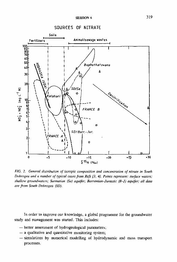
SESSION 6 319
Soils
SOURCES OF NITRATE
Fertilizers Animal/sewage wastes
S1SN (%„)
FIG. 2. General distribution of isotopic composition and concentration of nitrate in South Dobrogea and a number of typical cases from Refs [3, 4]. Points represent: surface waters; shallow groundwaters; Sarmatian (Sa) aquifer; Barremian-Jurassic (B-J) aquifer; all data are from South Dobrogea (SD).
In order to improve our knowledge, a global programme for the groundwater study and management was started. This includes:
— better assessment of hydrogeological parameters;— a qualitative and quantitative monitoring system;— simulations by numerical modelling of hydrodynamic and mass transport
processes.

320 POSTER PRESENTATIONS
The hydrogeological conceptual model for the B-J aquifer was carried out previously, mainly by means of isotopic environmental methods [1].
The first hydrochemical results obtained within the framework of this programme [2] showed for the N 0 3 contents in the B-J aquifer a gradual increase from Siutghiol Lake and Constanta town, i.e. from the downstream area of the underground flow southwest, towards the Bulgarian border, where the recharge area is also focused (Fig. 1). This increase is significant; the values start below 1 mg/L and reach 45 mg/L, locally exceeding even 60 mg/L.
The regularity of this evolution, in accordance with the regional flow pattern of the conceptual model, shows that there is no accidental or local pollution and suggests a regional scale causality having its origin in the recharge area.
The situation presented has raised two significant problems to be solved;
— determination of the NOJ source and origin within the B -J aquifer;— identification of the phenomenon responsible for the gradual decrease of the
nitrate content downstream.
Isotopic methods were used. Analyses of 180 in water samples as well as 15N and 180 in nitrates have been carried out. All types of surface water and groundwaters in the area were considered, with a focus on the significant aquifers.
The <5i5N results, correlated with nitrogen amounts, were used to create Fig. 2. This figure also includes some additional elements such as the characteristic ô15N ranges for the main nitrate sources as well as some further representative cases.
For the B -J aquifer the diagram suggests some conclusions that represent partial but very useful answers.
Concerning NOJ sources and implicitly their origin, it must be mentioned that the contribution of fertilizers is not as great in the area as for the aquifers in France or the United States of America. The main contribution comes from the soil, the nitrogen origin being predominantly natural, organic.
The regional process of gradual decrease of the nitrates downstream, illustrated in Fig. 1, seems to be identical to that of other similar large aquifers (Fig. 2). The reduced number and the regional distribution of our ô 15N determinations make it difficult to draw conclusions concerning the nature of this process. However, we consider that it is at least partially due to a denitrification phenomenon.
REFERENCES
[1] TENU, A., DAVIDESCU, F., SLAVESCU, A., “Recherches isotopiques sur les eaux souterraines des formations calcaires dans la Dobroudja Méridionale (Roumanie)” , Isotope Techniques in Water Resources Development (Proc. Symp. Vienna, 1987), IAEA, Vienna (1987) 439-453.

SESSION 6 321
[2] TENU, A., et al., “Assessment of the pollution impact on the groundwater quality in South Dobrogea, first results” , Proc. Int. Hydrogeol. Symp. Constanta, Romania (1994) 557-571.
[3] MARIOTTI, A., “Utilisation des variations naturelles d’abondance isotopique en 15N pour tracer l’origine des pollutions des aquifères par les nitrates” , Isotope Hydrology 1983 (Proc. Symp. Vienna, 1983), IAEA, Vienna (1984) 605-633.
[4] HEATON, T.H.E., Isotopic studies of nitrogen pollution in the hydrosphere and atmosphere: a review, Chem. Geol. 59 (1986) 87-102.
IAEA-SM-336/129P
A RADIOTRACER STUDY OF GROUNDWATER POLLUTION AND BIOREMEDIATION BY A PESTICIDE PASSING THROUGH DIFFERENT SOILS
R. TYKVAInstitute of Organic Chemistry and Biochemistry,Academy of Sciences of the Czech Republic,Prague, Czech Republic
T. RUMLDepartment of Biochemistry and Microbiology,Institute of Chemical Technology,Prague, Czech Republic
D. KLOTZInstitut für Hydrologie,GSF-Forschungszentrum für Umwelt und Gesundheit Neuherberg, Oberschleissheim, Germany
V. VLASÁKOVÁInstitute of Experimental Botany,Academy of Sciences of the Czech Republic,Prague, Czech Republic
Radiotracer methodology has made it possible to study the fate of radiolabelled pesticides (e.g. methoprene [1], carbofuran [2] or others [3]) in soils. However, their migration has been analysed without a complex evaluation of the present biodégradation active microorganisms on one hand, and, on the other, it has been limited mainly to the upper soil layers.

322 POSTER PRESENTATIONS
Retention time (min)
FIG. 1. Radiochromatographic detection of (14C) W328 degradation in a sterilized soil at pH5.0 using the methanol gradient.
The main goal of this laboratory study is to analyse the persistence, movement and degradation of a radiolabelled insect growth regulator in deeper zones of two different soils. Each of the active yeast, bacterial and fungal strains responsible for the observed biodégradation was isolated and identified to consider its application for the remediation of groundwater. The degradation products induced by each active strain were analysed using radio-HPLC.
The labelled juvenile hormone analogue 2-(4-(2-(ethoxycarbamato)- ethoxy)[benzene-U-14C]benzyl)-l-cyclohexanone ethylene acetal (sign. W328, 2.294 GBq/mmol) [4] was applied. The mode of its action has been studied [5] to prove its activity on reproduction and/or development of different insects, e.g. in the present IAEA Tsetse Project.
Two investigated soils were rather different: Tertiary sand (sign. T) and Quaternary gravel (sign. Q). The effects (overall degradation, sorption) of samples collected at a depth of approximately 6 m below surface on the ( 14C) W328 solution, passing through the individually filled columns (50 mm diameter, 500 mm length), were measured in a modified version of procedures described recently [6].
According to its origin, the overall degradation was separated into biodégradation and chemical degradation. From T, one yeast, six bacterial and two fungal strains were isolated and from Q, 22 bacterial and two fungal strains. For biodégradation of ( 14C) W328 all fungal strains as well as the yeast were active, but from all bacterial strains only Arthobacter nicotianae took part in degradation.
The compositions of degradation products were individually analysed for all six active strains using radio-HPLC (Waters 600 multisolvent delivery system with a 490 E UV detector and a Beckman 171 radioisotope detector). A reversed phase system with methanol gradient was used. For all six degradation compositions, ethyl-N-{2-[4-(2-oxo-1 -cyclohexylmethyl)phenoxyl]ethyl}carbamate (sign. W329)

SESSION 6 323
was found in different relative abundances as the main peak. The different minor peaks were found partly in the polar region, partly in the region of the linear gradient (30-80 vol% of methanol).
The non-biodegradation is strongly dependent on pH inducing only one degradation product which is identical with the main peak of biodégradation (Fig. 1).
Generally, the developed methodical approach makes it possible to judge the influence of the pesticide sorption and degradation in the soil on pollution and/or remediation of groundwater using microorganisms which are naturally present in the appropriate soil conditions.
ACKNOWLEDGEMENT
The work has been partly supported by the Grant Agency of the Czech Republic under grant No. 204/93/0387.
REFERENCES
[1] SCHOOLEY, D.A., et al., “ Environmental degradation of the insect growth regulator isopropyl(2E, 4E)-ll-methoxy-3,7,ll-trimethyl-2,4-dodecadienoate (Methoprene), IV: Soil metabolism” , J. Agrie. Food Chem. 22 (1975) 369-373.
[2] KARNS, J.S., et al., “ Metabolism of Carbofuran by a pure bacterial culture” , Pesticide Biochem. Physiol. 25 (1986) 211-217.
[3] FREDERICK, E.K., et al., Degradation of Chloroneb, Triadimefon, and Vinclozolin in soil, thatch, and grass clippings, Bull. Environ. Contam. Toxicol. 53 (1994) 536-542.
[4] ELBERT, T., et al., Synthesis of the 14C-labelled juvenoid W328, J. Label. Comp. Radiopharm. 34 (1994) 377-382.
[5] TYKVA, R., BENNETOVÁ, B., “Quantitative analysis of the fate of a pesticide after its application to insects’ ’, Management of Insect Pests: Nuclear and Related Molecular and Genetic Techniques (Proc. Symp. Vienna, 1992), IAEA, Vienna (1993) 529-536.
[6] DÔRFLER, V ., et al., Aufklàrung der Vorgànge, die zum Eintrag von Pflanzenschutz- mitteln in das Grundwasser fiihren, das für die Trinkwasserversorgung genutzt wird, GSF Bericht Nr. 19/94, Neuherberg (1994).


MODELLING APPROACHES
(Session 7)
Chairpersons
E. ADARIsrael
W.G. DARLINGUnited Kingdom


IAEA-SM-336/38
USE OF A MECHANISTIC MODEL TO SIMULATE SOIL MOISTURE AND TRITIATED WATER TRANSPORT IN A WHEAT FIELD
R.K. SAXENA Section of Hydrology,Institute of Earth Sciences,Uppsala University, Uppsala, Sweden
Abstract
USE OF A MECHANISTIC MODEL TO SIMULATE SOIL MOISTURE AND TRITIATED WATER TRANSPORT IN A WHEAT FIELD.
A mechanistic model of water movement and transport of non-reactive solutes has been used to simulate soil moisture and tritiated water flow in the unsaturated zone in a wheat field. In two microplots, each 1 m2 in size, tritiated water was injected at 30 cm depth in a square grid in an experimental wheat field. After tritium injections, 10 cm long soil cores were taken down to 1 m depth at monthly intervals. The soil cores were vacuum distilled to obtain soil moisture for analysis of tritium activity. The main features of the model (MACRO) are that it can be run in either one or two flow domains using the same values for hydraulic properties characterizing the soil. In two flow domains, the total soil porosity in each layer is divided into interacting flow regions termed here micropores and macropores, each characterized by a water content and a flux. Water and solute movement in the micropores is calculated with Richards’ and convection-dispersion equations, which are coupled to fluxes of water and solute in macropores by empirical interaction terms. Simulated tritium concentrations in a one- domain flow showed a closer agreement with observations than the two-domain simulations. Thus, the one-domain model was sufficient to explain the moisture and tracer (tritiated water) movement in the soil profile. Simulations of soil moisture in one and two-domain flow gave almost identical results. The observed average water particle velocities agreed fairly well with corresponding simulated values. This implied a piston-like movement of the tracer and the soil moisture. In model sensitivity analysis, a proper choice of parameters such as dispersivity and root distribution was found to be critical.
1. INTRODUCTION
Information on pathways of water flow and solute transport through the unsaturated zone is of importance for understanding and predicting movement and impacts of pollutants in small and large catchments. The problems of acidification of ground-
327

328 SAXENA
water and increasing concentrations of nutrients/pollutants can be treated in a theoretically correct manner only if the processes of water and pollutant transport are properly known.
Tracer techniques offer a direct method to trace the movement of soil moisture. In tritium tagging, a soil layer below the root zone is spiked with tritiated water (НТО). Since НТО behaves physically like ordinary water, it is generally neither retarded nor adsorbed in the soil matrix but moves with the same velocity as ordinary water. Assuming a piston-like flow, the tritium tagged moisture layer acts like a boundary between the old soil moisture and the fresh incoming water contributed by precipitation and cannot be bypassed in the vertical direction. From the temporal displacement of the tracer cloud, mean particle velocities of the soil moisture can be estimated. The piston flow concept was demonstrated in Central European forest soils [1]. This concept was later validated in subtropical alluvial soils in India [2, 3]. In Swedish till soils free from clay lenses, it was possible to trace the temporal displacements of a tritium tagged layer in the unsaturated zone [4].
In contrast, the tritium tagging method did not prove to be equally successful in some Scandinavian till soils [5] because of lateral flow paths taken by soil moisture, presumably due to clay lenses. In structured soils, preferential flow pathways termed macropores (e.g. root and earthworm channels, shrinkage cracks, etc.) may allow rapid non-equilibrium fluxes of water and solutes to considerable depths in the soil [6, 7]. Preferential flow has also been observed in sandy soils with no apparent structure. In such cases, the physical causes may be different, including small scale variations in bulk density [8], large scale profile heterogeneities such as textural boundaries and soil layering [9] and trapped air or hydrophobicity. Field evidence of preferential flow has been obtained through direct observations of excavated pits or trenches in dye experiments [9-11]. Although these types of studies may provide qualitative information on the occurrence of preferential flow in contrasting soil types and under different management practices, it is not easy to quantify the significance of such processes in this way. More quantitative information may be gained by using models to interpret and evaluate tracer transport experiments. A physically based dual porosity model MACRO, described in detail in Refs [12, 13], which accounts for water and solute transport under transient field conditions, is used in this study. The MACRO model may be run in either one or two flow domains, allowing quantitative evaluation of preferential flow and solute transport in field soils. To date, this model has been evaluated in fine-textured, structured soils characterized by a well developed macropore system [13, 14]. In a recent study [15], this model has been used to interpret non-steady transport of 36C1 in clay and sand filled lysimeters.
This paper discusses the simulated movement of НТО in a cultivated wheat field using the MACRO model. The main objective was to test whether the soil moisture movement in a clay dominant till soil is predominantly by piston flow and, if not, to quantify the role played by macropore flow.

IAEA-SM-336/38 329
2.1. Site description
The present study was carried out in an experimental agricultural field in Vihti, 45 km west of Helsinki, Finland. The till soil in Vihti is sandy clay down to 30 cm from the soil surface. Between 30 and 60 cm the soil is fine textured, with 59% clay content. The crop was spring wheat, sown on 14 May 1988. Precipitation and potential evaporation from class A pan and temperature data were recorded at a meteorological station about 4 km from Vihti.
2.2. Tritium injections
Two microplots, 1 m 2 each, were treated with НТО. Each microplot had nine injection points in a square grid, 20 cm inside the boundaries of the plots. НТО was injected on 3 June 1988, 30 cm below the soil surface. Tritium activity was 19.24 kBq per 8 mL and the total activity applied to each plot was 173.9 kBq. Soil samples were collected down to 1 m depth by a corer, each soil core being 10 cm in length. The soil sampling was carried out in July, August, September and October 1988. The microplots are hereafter referred to as Plot (A) and Plot (B).
2.3. Extraction of soil moisture
Soil samples were heated electrically in desiccators and moisture was collected in cold traps continuously kept at —55°C by a compressor. The traps were further connected to a rotary pump. In this arrangement [4] six desiccators could be operated simultaneously. The moisture content of the soil samples was determined by measuring the wet and dry weight of the soil cores before and after the extraction.
2.4. Tritium analysis
Ten millilitres of extracted soil moisture were mixed with 10 mL of a scintillation cocktail and the samples were counted for 60 min each on a liquid scintillation spectrometer. The instrument background was about 0.8 counts/min and tritium counting efficiency was about 20%. The standard deviation of measured tritium concentrations was about 2% of the count rate.
2. MATERIALS AND METHODS
3. MODEL DESCRIPTION
MACRO is a two-domain, finite difference model of water flow and solute transport in a layered soil. Only a brief description of those components of the model

330 SAXENA
relevant to this study (moisture and non-reactive tracer transport in a cultivated field) is presented here, since the model has been described already in detail in Refs [12, 13]. The model may be run in either one or two flow domains. In two domains, the total porosity is partitioned at a boundary water content/potential into macropores and micropores. Each domain is characterized by a degree of saturation, a conductivity and a flux while interaction terms account for convective and diffusive exchange between the flow domains. In one domain, the interaction terms are redundant and the model is simply reduced to the standard numerical solutions of the Richards and convection-dispersion equations.
3.1. Soil water flow
Unsaturated water flow in the micropores is calculated with Richards’ equation:
дв _ _ ^
dt dz dz ± Tw - Tm (1)
where в is the soil water content, t is time, z is the vertical distance, ф is the soil water pressure head, К is the hydraulic conductivity, Tw is a source/sink term for water exchange between the pore systems and Tm is root water uptake. In two flow domains, the soil hydraulic functions в(ф) and K(0) in the micropore system are given by the Brooks-Corey/Mualem model [16, 17]
ni - OrVw = Фь / л (2)
/ О . _ O V +2+!
where the subscript mi refers to micropores, вь, фь and Kb are the water content, pressure head and the hydraulic conductivity at the boundary between micropores and macropores, X is the pore size distribution index, 0r is the residual water content and n is the tortuosity factor. In the macropores, water flow is calculated with Darcy’s law, assuming a unit hydraulic gradient and a simple power law function to represent the unsaturated hydraulic conductivity:
- № - « (4)

IAEA-SM-336/38 331
where the subscript ma refers to macropores, Ks is the saturated hydraulic conductivity, 6S is the saturated water content and n* reflects pore size distribution and tortuosity in the macropore system. The advantage of using such a simplified empirical approach to model water flow in the macropores is that knowledge of ф is not required. This is useful since (3(ф) cannot be measured with precision close to saturation, while К(в) values predicted from fitted water retention curves are extremely sensitive to small errors/changes in в within this range. If the model is run in one flow domain and /3 < вь, then the hydraulic functions are given by Eqs (2) and (3).
If в > вь, then a linear в(ф) function between 6b and 6S is assumed, while К is calculated by an expression equivalent to Eq. 4:
In two flow domains, the surface boundary condition in MACRO partitions the net rainfall into an amount taken up by micropores and the excess water flowing into macropores. This partitioning is determined by a simple description of the infiltration capacity of the micropores.
The bare soil evaporation rate Ea is calculated by comparing the maximum rate of water supply qmix to the surface with the potential evaporation Ep:
where <ymax is calculated by differentiating Darcy’s law with respect to the soil water pressure head at the soil surface.
3.2. Solute transport
For non-reactive solutes such as 3H, solute transport is predicted from the convection-dispersion equation:
where с is the solute concentration, q is the water flow rate, Ts is a source/sink term for solute exchange between the pore systems, Trs is solute uptake by roots, and D is the dispersion coefficient given by:
(5)
(6)
(7)
D = Dv v + D0 f (8)

332 SAXENA
where D0 is the diffusion coefficient of the tracer in free water, / is the impedance factor, £>„ is the dispersivity and v is the pore water velocity given by q/в. Solute transport is treated in the same way in micropores and macropores, except that dispersion is neglected in the macropores, where convection is assumed to dominate. The evaporation loss of tritium from the soil surface is simply given by the product of the water evaporation rate Ea and the solute concentration in the top layer of the profile.
3.3. Mass exchange between domains
In the two domain case, mass transfer is obtained using physically based expressions [13] derived by equating exact diffusion models with approximate first order approaches. The source/sink term Ts for mass transfer of solute is given by a combination of a diffusion component and a mass flow component [18, 19]:
where d is an effective diffusion pathlength, the subscripts ma and mi refer to macropores and micropores respectively, while the prime notation indicates either macropores or micropores depending upon the direction of water flow Tw, and Da is an effective diffusion coefficient given by:
where Sma is the degree of saturation in the macropores. The rate o f lateral water exchange is also treated as a diffusion type process [20]. Assuming that gravity has negligible influence, Tw is given by:
where Dw is an effective water diffusivity and y w is a scaling factor used to match the approximate and exact solutions to the diffusion problem [21, 22]. The scaling factor y w varies with the initial water content and hydraulic properties, but not strongly [22], so for simplicity and convenience, y w is set within the program to an average value (= 0 .8 ). The effective water diffusivity is assumed to be given by:
( 9 )
Da — D0f Sm , (10)
(11)

IAEA-SM-336/38 333
where Deb and DBm, are the water diffusivities at the boundary water content and the current micropore water content respectively. Using the Mualem/Brooks-Corey model for soil hydraulic properties, Demi is given by:
n + 1 + 1Г) _ КьФь$т,
“ ■ м » , - «,) (13)
while Deb is given by setting Sml in Eq. (13) to unity.If the micropores become oversaturated (i.e. 6mi > 6b), then the excess water
is routed instantaneously into the macropores and the second term on the right hand side of Eq. (9) is adjusted accordingly.
4. MODEL APPLICATION
4.1. Driving variables and initial conditions
In the present study, model driving variables consisted of daily rainfall data and daily potential evaporation estimated by Penman’s equation. Rainfall and the meteorological variables required by Penman’s equation were measured at a weather station located about 4 km from Vihti. The model assumes that the total daily rainfall is distributed throughout the day, the mean rainfall intensity was set to 2 m m -lT1 in the simulations. Soil moisture content and tritium concentration in the soil profile observed in the first sampling on 6 July 1988 were used as the start values in the simulations. The 1 m thick soil profile was divided into eleven layers. The thickness of the first layer was set to 10 mm, the second layer to 90 mm, while each of the remaining nine layers was 100 mm thick. Time steps are automatically calculated in the model in order to maintain stability of the numerical solution.
4.2. Assessment of model performance
Objective methods of assessing model performance are required, if one domain and two domain representations are to be compared. In this study, the sums of the squared differences between model predictions and measurements are calculated, the minimum value of which dictates the best fit.
4.3. Parameter estimation
It is rare that all input parameters required by the model are known a priori. Furthermore, some model parameters are difficult to measure directly. Thus, model input parameter values were obtained by a combination of direct measurements and
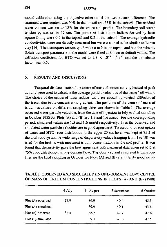
334 SAXENA
model calibration using the objective criterion o f the least square difference. The saturated water content was 50% in the topsoil and 55% in the subsoil. The residual water content was set to 15% for the entire soil profile. The boundary soil water tension i/ъ was set to 12 cm. The pore size distribution indices derived by least square fitting were 0.5 in the topsoil and 0.2 in the subsoil. The average hydraulic conductivities were not directly measured but were assumed to be similar to Lanna clay [14]. The macropore tortuosity n* was set to 3 in the topsoil and 6 in the subsoil. Solute transport parameters in the model were fixed at known or default values. The diffusion coefficient for НТО was set to 1.8 X 10~9 m 2-s“' and the impedance factor was 0.5.
5. RESULTS AND DISCUSSIONS
Temporal displacements of the centre of mass of tritium activity instead of peak activity were used to calculate the average particle velocities of the tracer/soil water. The choice of the centre o f mass reduces the error caused by vertical diffusion of the tracer due to its concentration gradient. The positions of the centre of mass of tritium activities on different sampling dates are shown in Table I. The average observed water particle velocities from the date of injection in July to final sampling in October 1988 for Plots (A) and (B) are 1.7 and 1.6 mm/d. For the corresponding period, simulated values are 1.5 and 1.6 mm/d respectively. Thus the observed and simulated water particle velocities are in good agreement. To account for root uptake of water and НТО, root distribution in the upper 25 cm layer was kept at 75% of the total root system. A wide range of dispersivity values (ranging from 1 to 10) was tried for the best fit with measured tritium concentrations in the soil profile. It was found that dispersivity gave the best agreement with measured data when set to 3 at 75% root distribution in one-domain flow. The observed and simulated tritium profiles for the final sampling in October for Plots (A) and (B) are in fairly good agree-
TABLE I. OBSERVED AND SIMULATED (IN ONE-DOMAIN FLOW) CENTRE OF MASS OF TRITIUM CONCENTRATIONS IN PLOTS (A) AND (B) (1988)
6 July 11 August 7 September 6 October
Plot (A) observed 29.9 36.9 40.4 45.3
Plot (A) simulated 39.9 40.1 43.6
Plot (B) observed 32.8 38.7 42.7 47.6
Plot (B) simulated 39.1 43.6 47.5

IAEA-SM-336/38 335
dis-min 1-10 mL
FIG. I. Observed and simulated (one-domain flow) tritium concentration in the soil in Plot (A) on 6 Oct. 1988.
dis-min 1 -10 mL
FIG. 2. Observed and simulated (one-domain flow) tritium concentration in the soil in Plot (B) on 6 Oct. 1988.

336 SAXENA
dis-min 1 -10 mL
FIG. J. Observed and simulated tritium concentrations in one-domain and two-domain flow in Plot (B) on 7 Sep. 1988.
Eо
CLФ
О
20
40
60
80-
100
Moist, m icropores |\ \ Moist, m acropores аш • Moist, one-domain Д j Moist, observed
\I \ \• А ЯI w
10 20 30 40 50
vol.°/o60
FIG. 4. Observed and simulated soil moisture in one-domain and two-domain flow, i.e. moisture content in micropores and macropores in Plot (B) on 7 Sep. 1988.

IAEA-SM-336/38 337
ment and are shown in Figs 1 and 2 respectively. Although simulations with two-domain flow agreed quite well with the observations, in comparison with one-domain flow the agreement was less good. In two-domain flow, the simulated tritium concentrations were lower than those observed down to 50 cm depth and higher than those observed at greater depths (Fig. 3). The simulated and observed soil moisture profiles for the entire period agreed equally well in both flow domains (Fig. 4).
6. CONCLUSIONS
The one-domain model seems to describe fairly well the movement of НТО and soil moisture. This indicates that the transport of soil moisture was piston-like and, under the prevailing field conditions, macropore flow was not substantial. The problem of spreading of the tracer cloud is reduced when the vertical movement of tracer/soil moisture is relatively faster than longitudinal diffusion. The model does not account for the lateral spread of the tracer, i.e. from the main plot towards the edges. A more rigorous test of the contribution of macropore flow can be made if water and tracer fluxes are also measured, as is possible, for example, in lysimeter studies.
ACKNOWLEDGEMENTS
The author would like to thank the Swedish Natural Science Research Council for financial support during the course of this study. Warm thanks are due to N. Jarvis for his help in the initial stages of this study. Special thanks are due to A. Lepistô and P. Seuna of the National Board of Waters and Environment, Hydro- logical Office, Helsinki, Finland, for their active collaboration and field work. Thanks are also due to Kemira OY, Helsinki, Finland, for making available their experimental field in Vihti.
REFERENCES
[1] ZIMMERMANN., U., MÜNNICH, K.O., ROETHER, W., “Downward movement of soil moisture traced by means of hydrogen isotopes”, Geophysical Monograph No. 11, Isotope Techniques in Hydrological Cycle (STOUT, G.E., Ed.), American Geophysical Union, Washington, DC (1967) 221-230.
[2] BAHADUR, J., SAXENA, R.K., MOOKERJEE, P., Soil moisture movement and groundwater recharge by tritium tracer tagging technique, Proc. Indian Acad. Sci., Section A 85 (1977) 462-471.
[3] ATHAWALE, R.N., MURTI, G.S., CHAND, R., Estimation of recharge to the phreatic aquifers of the Lower Maner basin, India, by using tritium injection method, J. Hydrol. 45 (1980) 185-202.

338 SAXENA
[4] SAXENA, R.K., DRESSIE, Z., “Estimation of groundwater recharge and moisture movement in sandy formations by tracing natural oxygen-18 and injected tritium profiles in the unsaturated zone” , Isotope Hydrology 1983 (Proc. Symp. Vienna, 1983), IAEA, Vienna (1984) 139-150.
[5] LUNDIN, L., Soil and Groundwater in Moraine and Influence of Soil Type on Run-Off, UNGI Rep. 56, Phys. Geography Dept., Uppsala Univ. (1982) (in Swedish).
[6] THOMAS, G.W., PHILLIPS, R.E., Consequences of water movement in macropores, J. Environ. Qual. 8 (1979) 149-152.
[7] BEVEN, K., GERMANN, P., Macropores and water flow in soils, Water Resour. Res. 18 (1982) 1311-1325.
[8] OMOTI, U., WILD, A., Use of fluorescent dyes to mark the pathways of solute movement through soils under leaching conditions, Soil Sci. 128 (1979) 98-104.
[9] KUNG, K.-J.S., Preferential flow in a sandy vadose zone, Geoderma 46 (1990) 51-58.[10] STARR, J.L., DeROO, H.C., FRINK, C.R., PARLANGE, J.-Y., Leaching charac
teristics of a layered field soil, Soil Sci. Soc. Am. J. 42 (1978) 386-391.[11] GHODRATI, М ., JURY, W.A., A field study using dyes to characterise preferential
flow of water, Soil Sci. Soc. Am. J. 54 (1990) 1558-1563.[12] JARVIS, N.J., MACRO-A Model of Water Movement and Solute Transport in Macro-
porous Soils, Reports and Discussions No. 9, Dept. Soil Sci., Swedish Univ. Agrie. Sci., Uppsala, Sweden (1991).
[13] JARVIS, N.J., MACRO version 3.1— Technical Description, Sample Simulations and Evaluation Against Field Measurements, Reports and Discussions No. 17, Dept. Soil Sci., Swedish Univ. Agrie. Sci., Uppsala, Sweden (1994).
[14] JARVIS, N.J., BERGSTROM, L., DIK, P.E., Modelling of water and solute transport in macroporous soil, J. Soil Sci. 42 (1991) 71-81.
[15] SAXENA, R.K, JARVIS, N.J., BERGSTROM, L., Interpreting non-steady state tracer breakthrough experiments in sand and clay soils using a dual-porosity model, J. Hydrol. 162 (1994) 279-298.
[16] BROOKS, R.H., COREY, A.T., Hydraulic Properties of Porous Media, Hydrology Paper No. 3, Colorado State University, Fort Collins, CO (1964).
[17] MUALEM, Y., A new method for predicting the hydraulic conductivity of unsaturated porous media, Water Resour. Res. 12 (1976) 513-522.
[18] VAN GENUCHTEN, M.T., DALTON, F.N., Models for simulating salt movement in aggregated field soils, Geoderma 38 (1986) 165-183.
[19] VALOCCHI, A.J., Use of temporal moment analysis to study reactive solute transport in structured soils, Geoderma 46 (1990) 233-247.
[20] BOOLTINK, H.G., HAT ANO, R., BOUMA, J., Measurement and simulation of bypass flow in a structured clay soil, J. Hydrol. 148 (1993) 149-168.
[21] VAN GENUCHTEN, M.T., A general approach for modelling solute transport in structured soils” , Mem. Int. Assoc. Hydrogeol. 17 (1985) 513-526.
[22] GERKE, H.H., VAN GENUCHTEN, M.T., Evaluation of lst-order water transfer term for variably saturated dual-porosity flow models, Water Resour. Res. 29 (1993) 1225-1238.

IAEA-SM-336/43
CALIBRATION OF A NUMERICAL GROUNDWATER MODEL USING ENVIRONMENTAL ISOTOPES
R. WATZEL, B. BERTLEFF Geologisches Landesamt Baden-Württemberg,Freiburg,Germany
Abstract
CALIBRATION OF A NUMERICAL GROUNDWATER MODEL USING ENVIRONMENTAL ISOTOPES.
Tritium input and behaviour in a shallow unconfmed gravel aquifer of Quaternary age (Argendelta aquifer) at the northern border of Lake Constance (southern Germany) are described using an advection/dispersion model based on finite element techniques. Groundwater flow was calibrated for a steady state in 1986 and transient flow for the hydrological years 1987-1989 using monthly time steps. The model simulates all observed spatial and temporal piezometric variations very well. Tritium concentrations in precipitation were recorded in monthly averages at the neighbouring station Bregenz between 1973 and 1992. Concentrations between 1953 and 1972 were simulated by calculating correlations with Ottawa and Vienna. Tritium concentrations in the investigated aquifer and an infiltrating river were recorded between May 1987 and November 1992. They range between 30 and 88 tritium units (TU) in 1987 and between 20 and 55 TU in 1992. The simulator can describe advective transport, two dimensional dispersion, diffusion, radioactive decay and sorption. Spatial tritium distribution in the aquifer can be simulated accurately, when tritium transport is mainly advective and recharge flux through the unsaturated zone is separated into two components: a slow component (matrix flow), which can be described as piston flow with residence times between 4 and 20 a, and a fast one (bypass flow), which passes the unsaturated zone within days. Effects of diffusion and sorption can be neglected. The simulations indicate that effects of dispersion have less importance, due to spatial tritium input into the system. Infiltration fluxes from a river could be quantified during the model calibration process. They are substantiated by 180 and hydrochemical data.
1. INTRODUCTION
Tritium (3H) has been used as a hydrological tool and as an environmental tracer since the early 1950s. In groundwater science it has been used for groundwater dating, determination of flow velocities (e.g. [1, 2]), study of groundwater recharge (e.g. [3, 4]), dispersion and diffusion phenomena in aquifers (e.g. [5-8]). Only in
339
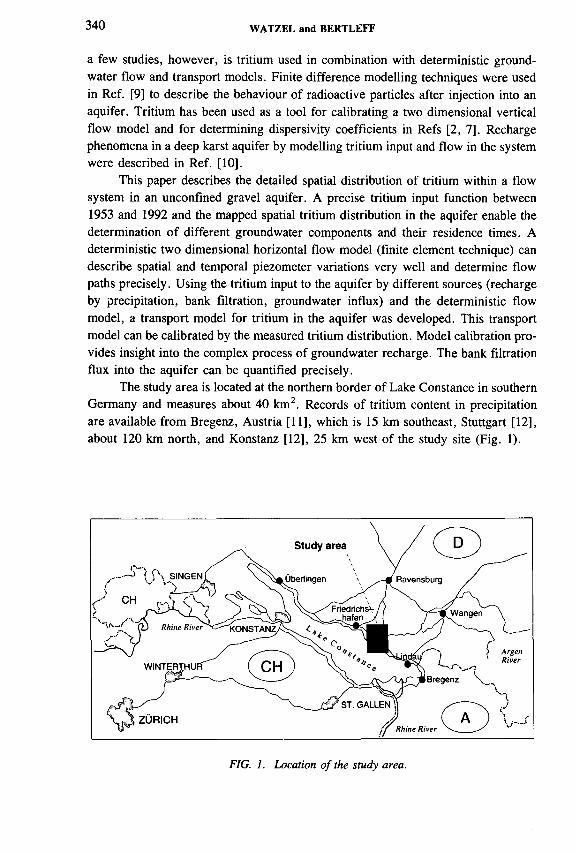
340 WATZEL and BERTLEFF
a few studies, however, is tritium used in combination with deterministic groundwater flow and transport models. Finite difference modelling techniques were used in Ref. [9] to describe the behaviour of radioactive particles after injection into an aquifer. Tritium has been used as a tool for calibrating a two dimensional vertical flow model and for determining dispersivity coefficients in Refs [2, 7]. Recharge phenomena in a deep karst aquifer by modelling tritium input and flow in the system were described in Ref. [10].
This paper describes the detailed spatial distribution of tritium within a flow system in an unconfined gravel aquifer. A precise tritium input function between 1953 and 1992 and the mapped spatial tritium distribution in the aquifer enable the determination o f different groundwater components and their residence times. A deterministic two dimensional horizontal flow model (finite element technique) can describe spatial and temporal piezometer variations very well and determine flow paths precisely. Using the tritium input to the aquifer by different sources (recharge by precipitation, bank filtration, groundwater influx) and the deterministic flow model, a transport model for tritium in the aquifer was developed. This transport model can be calibrated by the measured tritium distribution. Model calibration provides insight into the complex process of groundwater recharge. The bank filtration flux into the aquifer can be quantified precisely.
The study area is located at the northern border of Lake Constance in southern Germany and measures about 40 km2. Records of tritium content in precipitation are available from Bregenz, Austria [11], which is 15 km southeast, Stuttgart [12], about 120 km north, and Konstanz [12], 25 km west of the study site (Fig. 1).
FIG. 1. Location of the study area.

IAEA-SM-ЗЗб/43 341
The study site is located in the flat delta of the Argen river (Fig. 1) where surficial deposits consist of thick glacial and postglacial sediments. More than 200 drillings in the study area indicate that the upper 10 to 45 m consists of gravel, sandy gravel and sand, which form the aquifer. This layer covers an aquitard of up to 150 m thickness which consists of silt and silty fine sand laterally changing with till. The maximum north-south extent is about 7 km, the east-west extent about 6 km. The northeast-southwest flowing Argen river divides the study area into two parts. The field site contains 63 monitoring wells for water level and groundwater quality observation.
2. HYDROGEOLOGICAL SITUATION
The Argendelta aquifer is a shallow unconfined gravel aquifer of Quaternary age. Parts o f Pleistocene gravel terraces build a uniform porous medium aquifer. The
FIG. 2. Aquifer bottom elevation (m.a.s.l.).

342 WATZEL and BERTLEFF
F IG . 3. M e a su re d a n d ca lc u la te d w a te r ta b le co n to u r lin es f o r m ea n w a te r level.
northern and eastern aquifer border is formed by till layers, the western border is defined by the uprising aquifer bottom and the southern limit is given by Lake Constance. The aquifer bottom is composed of till in the northern and eastern part of the basin and by silt and silty fine sand in the southern part. The bottom shows a distinct morphology (see Fig. 2) with several gravel channels, one reaching from the northern border to the centre of the basin (Oberdorf village) and continuing south-westward (Langenargen village) and another southeast of the Argen river (Gohren village). The elevation of the aquifer bottom rises from about 370 m .a.s.l. north of the village of Langenargen to about 415 m .a.s.l. at the northern border.
Groundwater flow direction is from the northern and northeastern edge to the centre of the basin (see Fig. 3) and continues perpendicular to the shore line of Lake Constance. The Argen river is mainly infiltrating, especially in the northeastern part. Exfiltrating areas are located at the southern part where the Argen river

IAEA-SM-336/43 343
flows into Lake Constance. The water table rises from about 395 m .a.s.l. at Lake Constance to about 414 m .a.s.l. at the northern edge and about 423 m .a.s.l. at the northeastern edge. Annual variations of the water table are 1-2 m in the basin and up to 4 m at the border of the lake. Groundwater input consists o f three components: recharge by precipitation, bank filtration from the Argen river and influx. It amounts to « 0 .2 7 m 3/s recharge (« 4 0 % of 1031 mm/a precipitation), = 0 .58 m 3/s bank filtration and « 0 .0 1 m 3/s influx at the northern border and « 0 .0 6 m 3/s influx at the northeastern border. Groundwater outfluxes amount to « 0 .0 3 m 3/s well discharge, « 0 .1 1 m 3/s bank exfiltration and « 0 .7 8 m 3/s outflux into Lake Constance. Well discharge is concentrated at a single waterworks at the northeastern border of the village of Langenargen (Fig. 4; well 2/623). The distance between surface and water table in the study area ranges from 2 to 20 m. In most parts of the study site values between 4 and 8 m are found.
FIG. 4. Monitoring wells.

344 WATZEL and BERTLEFF
FIG. 5. b2H values versus 6,80 values o f groundwater and surface water in the study area.
Hydraulic conductivity was determined by several long term pumping tests. Conductivity values show a spatial distribution pattern which fits the pattern of the aquifer bottom elevation. High conductivity (kf = (2-6) x 10"3 m - s '1; T = (100-1000) x 10~4 m 2-s~') is restricted to the gravel channels, low conductivity (kf = (1-10) x 10~4 m -s’1; T = (1-100) x 10"4 m 2-s_1) is bound to the marginal areas. Specific yield values could be determined between 0.01 and 0.20.
Isotope investigations show a spatial variation of 180 and 3H concentrations in the aquifer. Groundwater from precipitation recharge (local component) shows mean <5,80 values of -1 0 .6 ° /oo, whereas surface water (filtration component) shows a mean value of - 1 1 .0 7 oo. The ô 180 values for groundwater with bank filtration range between —10.6 and — 11.07oo (Fig. 5). The tritium concentrations of the local component ranged between 50 and 88 tritium units (TU) in May 1987 and between 35 and 55 TU in November 1992. Groundwater and surface water are very similar with regards to the chemical composition. They are of Ca + Mg — H C 03 type which is typical for groundwater in glacial sediments in southern Germany. Looking at the total dissolved solids provides the same spatial distribution pattern as isotope concentrations. Areas of local precipitation recharge (total dissolved solids (TDS) = 400 mg/L under a forest area north of the village of Tuniswald, TDS «

IAEA-SM-336/43 345
600 mg/L under agricultural acreage north of the village of Langenargen) can be precisely separated from areas with bank filtration ( = 500 mg/L under agricultural land northeast o f the village of Langenargen). The isotopic and hydrochemical distinction of different groundwater components is proved by the very well known flow pattern in the aquifer [13].
3. GOVERNING EQUATIONS
Transport of a conservative radioactive solute in a single phase system of constant density can be described by the advection-dispersion model [14]. As describedin Ref. [15] it may be expressed as
dh da.S - + - f - Qh = 0 (1)
dt dXj
dhq. = ev. = K¡jM— ■ (2)
dxj
R y + q ¡ ~ ( d ^ ) + (R \ + Qh)C - Qc = 0 (3)dt dx, \ dXjJ
Equations (1) to (3) are solved within a domain Q for h = h{x¡, t), q = q(x¡, t) and С = C(x¡, t) with:
5 = e0 + SsM (4)
Du = (tDd + 0 TV )6U + (fiL - 0 T) ^ (5)
Л = Л /[е + ( 1 — e)/c] (6)
where
0L = longitudinal dispersivity [L] к = Henry sorption coefficient [—]0T = transversal dispersivity [L] X = decay rate [T"1]С = solute concentration [ML-3] M = aquifer thickness [L]
= hydrodynamic dispersion [L3T ''] 4i = volumetric Darcy flux [L2T _1]D, = molecular diffusion coefficient [L2T _I] Qh = hydraulic source/sink [L3T~']
*</ = Kronecker delta [ —] Qc = conc. source/sink [ML2T"']fo = drainable porosity [ - ] R = specific retardation [L]e = volumetric porosity [—] S = storage coefficient [—]h = hydraulic head [L] Ss = specific storage [ - ]
= indices ( 1 , 2 for two dimensions) [—] ", = specific discharge [LT_I]
K¡; = hydraulic conductivity [LT_I] V = specific Darcy flux [L2T_1]

346 WATZEL and BERTLEFF
The flow and transport equations are solved numerically with the finite element technique. As well as the start and border conditions and the parameters constant in space and time (longitudinal and transversal dispersivity ¡3L, (3T, molecular diffusion coefficient Dd, decay rate X, sorption coefficient /с) the model respects the variation of the following parameters variable in space and time: hydraulic conductivity K¡j, thickness of saturated zone M, specific yield Ss, drainable porosity e0, hydraulic source/sinks Qh, hydraulic transfer rate Фл, mass source/sinks Qc and mass transfer rate Фс. The demand for input data on hydraulic parameters, water fluxes and their variations in space and time is very high. All deterministic model simulations were carried out with the finite element FEFLOW code [15].
Conceptual box models to determine groundwater residence times or mean residence times were proposed in Refs [16, 17] and in a more sophisticated way in Refs [1] and [18]. Box models of different types can be combined as described in Ref. [19], which leads to a better approximation of the hydraulic system behaviour. Box models demand only few data to present an overview of residence times and ages. However, they are not able to describe a hydraulic system with different water components in the same detailed way that deterministic models do. All box model simulations used here were carried out with the MULTIS code [19].
4. FLOW MODEL
For the simulation of groundwater flow, a two dimensional horizontal finite element (FE) model was created. As observations of piezometric values and tritium concentrations are not three dimensional, a horizontal problem description was assumed to be sufficient. The FE mesh consists of 2656 nodes and 5061 elements. A conceptual model of the Argendelta aquifer is shown in Fig. 6. Groundwater influxes at the northern and northeastern aquifer border were defined as borderwise influx. Recharge by precipitation was defined as nodewise influx and the Argen river was defined as mixed boundary condition (surface water table and leakage coefficient). Outflux occurs at the Lake Constance border (constant head border) and in several wells (single node discharges).
Groundwater levels of 63 monitoring wells were used for a steady state calibration (mean water level, November 1986). Figure 3 displays the results with contour lines drawn from measured and calculated water table elevations. During the calibration process, transmissivities in areas without measured values were used to adapt calculated water table values to measured values. Constant head values as well as predefined input and output fluxes were assumed to be correct.
Transient flow calibration for the hydrological years 1987-1989 over monthly intervals shows a good representation of different types of water level curves (Fig. 7). In areas with only recharge from precipitation, water level changes are very smooth and occur in annual cycles (well 114/623). Under the influence of bank filtra-

IAEA-SM-336/43 347
tion, water level changes occur with a higher frequency due to surface water level changes (e.g. monitoring well 124/623). At the southern border, groundwater level changes are controlled by the piezometric surface of Lake Constance (e.g. monitoring well 104/624). To calibrate the annual cycles in areas with only precipitation recharge, the monthly recharge values according to Refs [20, 21] had to be changed. This method delivers monthly recharge values at the bottom of the soil zone; the model demands time series of values entering the groundwater table. Thus, storage and delay effects in the unsaturated zone could be considered.
The groundwater flow model can simulate all observed variations of the water table (spatially and temporally) very well. To reach this result by calibration, several assumptions were made. First, the leakage coefficient and thus the bank filtration flux were estimated. Second, recharge by precipitation was calculated with the

348 WATZEL and BERTLEFF
1987 1988 1989
FIG. 7. Characteristic water level curves.
method of Refs [20, 21], which may differ up to 30% from measured values (e.g. in lysimeters). A transport model based on this flow model and on precisely measured, study area wide tracer concentrations (3H) should minimize uncertainty about the water budget assumptions.
5. TRANSPORT MODEL
Tritium behaviour in the aquifer was assumed to be non-diffusive, without sorption and with known decay rate (X = 0.0565 a -1, T 1/2 = 12.46 a [22]). Although Refs [8, 23] describe diffusion and sorption of tritium in groundwater, these effects were neglected due to the high advection in the aquifer.
Tritium input and transport in the aquifer system were simulated with steady state flow conditions and transient concentration conditions. Tritium in precipitation was measured in monthly samples at the Bregenz station between 1973 and 1992 [11]. For the period from 1953 to 1972, tritium concentrations in precipitation of the study area were estimated by correlations with tritium values of the Stuttgart, Vienna and Ottawa stations. The derived tritium curve is shown in Fig. 8. To

IAEA-SM-336/43 349
FIG. 8. Tritium concentration of precipitation in the study area 1953-1992.
calculate tritium concentrations in recharge water, monthly tritium concentrations in precipitation were weighted with a monthly groundwater recharge coefficient and summed up to annual mean values. These mean annual tritium concentrations were weighted with mean annual precipitation sums. The monthly recharge coefficient for the study area was calculated on the base of meteorological observations for more than 30 years. A 40 year time series of tritium concentration in the surface water o f the Argen river was estimated by a coupled box model. Tritium concentration in the river can be described by a piston flow/exponential model which was calibrated at 11 measured tritium values between 1986 and 1992. The 40 year time series of tritium concentrations at the groundwater influxes were calculated in a similar way. Exponential models were calibrated at several measured tritium concentrations in monitoring wells at the influx borders. No border conditions were defined at out- fluxes and discharges.
Calculated tritium distributions in the aquifer were calibrated to two measured distributions in May 1987 and November 1992. Calibration showed that the model is not very sensitive for porosity variations and not sensitive for dispersivities. It proved to be very sensitive for bank filtration concentrations and recharge concentrations. Measured tritium concentrations in groundwater influenced by bank filtration were fitted very well by the model and leakage coefficients of the Argen river were calibrated. Using the tritium concentrations of groundwater recharge by precipitation did not lead to satisfying results, as these values do not take into account the transit time of groundwater in the unsaturated zone. The simulated tritium values were much lower than the measured ones. In a second step, the storage and delay effects in the unsaturated zone were simulated by a coupled box model (piston flow and exponential) which should respect the phenomena of bypass flow (rapid component)

350 WATZEL and BERTLEFF
and matrix flow (slow component) as described in Ref. [24]. The mean residence time of the exponential component depends on the thickness of the unsaturated zone. The fractions of bypass and matrix flow are of the same order. These fractions were estimated from monthly recharge rates calibrated with the flow model. The flow model demanded in each time step a minimum recharge rate from 15 mm per month to simulate the water table variations well. This value was assumed to represent the matrix flow. All offsets were assumed to represent bypass flow.
6. CONCLUSIONS
Environmental isotope studies ( 180 , 3He) detect different groundwater components in the saturated zone of the unconfined, shallow Argendelta gravel aquifer.
FIG. 9. Measured and calculated tritium concentrations (TU) in May 1987.
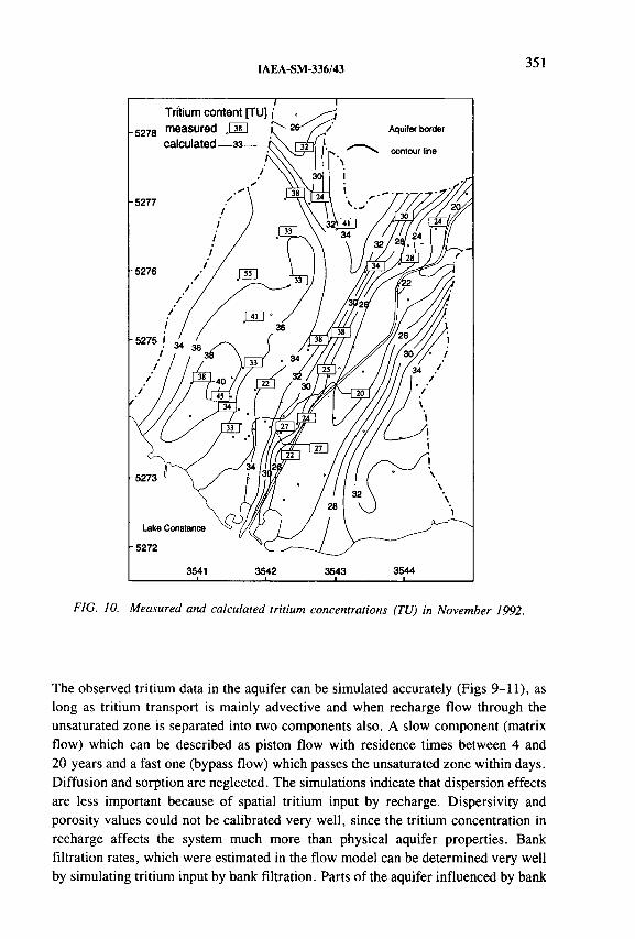
IAEA-SM-336/43 351
F IG . 10. Measured and calculated tritium concentrations (TU ) in November 1992.
The observed tritium data in the aquifer can be simulated accurately (Figs 9-11), as long as tritium transport is mainly advective and when recharge flow through the unsaturated zone is separated into two components also. A slow component (matrix flow) which can be described as piston flow with residence times between 4 and 20 years and a fast one (bypass flow) which passes the unsaturated zone within days. Diffusion and sorption are neglected. The simulations indicate that dispersion effects are less important because of spatial tritium input by recharge. Dispersivity and porosity values could not be calibrated very well, since the tritium concentration in recharge affects the system much more than physical aquifer properties. Bank filtration rates, which were estimated in the flow model can be determined very well by simulating tritium input by bank filtration. Parts o f the aquifer influenced by bank

352 WATZEL and BERTLEFF
J measured values —— — . calculated values
FIG. 11. Measured and calculated tritium concentrations (TU) versus time in selected monitoring wells: 106/623, 116/623 and 29/623.
filtration can be recognized. These results correspond with earlier 180 investigations [13].
Transport simulations were carried out with steady state flow conditions and monthly and annually weighted tritium data. Field observations indicate tritium oscillations in groundwater in a much higher frequency, but the present data set restricts a more precise simulation.
Deterministic modelling of tritium transport in the aquifer improves the understanding of mean residence times of groundwater samples derived from conceptual

IAEA-SM-336/43 353
box models, because different water components can be distinguished. Such modelling permits one to analyse whether ‘residence’ of groundwater in the system occurs in the unsaturated zone and the saturated zone and/or outside the observed aquifer system. Conceptual box models may be a useful tool to simulate concentration curves as border conditions of a deterministic transport model.
A C K N O W L E D G E M E N T S
The authors thank the Bundesversuchs- und Forschungsanstalt Arsenal (BVFA), Vienna, for kindly providing them with 3H data in precipitation at the Bregenz monitoring station. At various stages during this investigation the authors benefited from discussions with W. Stichler, L. Eichinger and G. Teutsch. Computing support for the study was provided by the Research Institute for Applied Knowledge Processing (FAW Ulm), Germany.
R E F E R E N C E S
[1] MALOSZEWSKI, P., ZUBER, A., Determining the turnover time of groundwater systems with the aid of environmental tracers: I. Models and their applicability, J. Hydrol. 57 (1982) 207-231.
[2] EGBOKA, B.C.E., CHERRY, J.A., FARVOLDEN, R.N., FRIND, E.O., Migration of contaminants in groundwaters at a landfill, a case study, 3, Tritium as an indicator of dispersion and recharge, J. Hydrol. 63 (1983) 51-80.
[3] YURTSEVER, Y., PAYNE, B.R., “ Application of environmental isotopes to groundwater investigations in Qatar” , Isotope Hydrology 1978 (Proc. Symp. Neuherberg, 1978), IAEA, Vienna (1979) 465-490.
[4] LARSON, G.J., DELCORE, M.R., OFFER, S., Application of the tritium interface method for determining recharge rates to unconfined drift aquifers, I, Homogeneous case, J. Hydrol. 91 (1987) 59-72.
[5] ATAKAN, Y., Bomben-Tritium-Hydrologie in einem Grundwasserkôrper mit freier Grundwasseroberflache, Thesis, University of Heidelberg (1972).
[6 ] HOEHN, E., SANTSCHI, P.H., Interpretation of tracer displacement during infiltration of river water to groundwater, Water Resour. Res. 23 4 (1987) 633-640.
[7] ROBERTSON, W.D., CHERRY, J.A., Tritium as an indicator of recharge and dispersion in a groundwater system in Central Ontario, Water Resour. Res. 25 6 (1989) 1097-1109.
[8 ] JACOB, H., Vergleich von 3H, Chlorid-, Bromid- und Lithium-Ionen als Tracer für die Wasserbewegung and den Stofftransport in der ungesàttigten Zone, Steir. Beitr. Hydrogeol. 42 (1991) 151-154.
[9] ROBERTSON, J.B ., ‘ ‘Application of digital modelling to the prediction of radioisotope migration in groundwater” , Isotope Techniques in Groundwater Hydrology (Proc. Symp. Vienna, 1974), Vol. 2, IAEA, Vienna (1974) 451-477.

354 WATZEL and BERTLEFF
[10] BARMEN, G., “ Simulation of distributed environmental tritium concentrations in the Alnarp aquifer system, Sweden” , Mathematical Models for Quantitative Evaluation of Isotope Data in Hydrology (IAEA Research Coordination Project), IAEA, Vienna (1991).
[11] BUNDESVERSUCHS- UND FORSCHUNGSANSTALT ARSENAL, 3H- und l80-Gehalte in den Monatssummen der Niederschlâge der Station Bregenz-Rieden, BVFA, Vienna (1993).
[12] INTERNATIONAL ATOMIC ENERGY AGENCY, Statistical Treatment of Environmental Isotope Data in Precipitation, Technical Reports Series No. 206, IAEA, Vienna(1987).
[13] BERTLEFF, B., WATZEL, R., EICHINGER, L., TRIMBORN, P., “ Isotope investigations and hydraulic measurements for the delineation of a groundwater protection area” , Isotope Techniques in Water Resources Development 1991 (Proc. Symp. Vienna, 1991), IAEA, Vienna (1991) 671-673.
[14] BEAR, J., Hydraulics of Groundwater, Wiley Interscience, New York (1979).[15] DIERSCH, H.-J., FEFLOW — An Interactive, Graphics-Based Finite Element Simula
tion System for Modeling Groundwater Contamination Processes, User Manual Vers. 3.20, WASY Co., Berlin (1992).
[16] SIEGENTHALER, U ., Bestimmung der Verweildauer von Grundwasser im Boden mit radioaktiven Isotopen, GWF Wasser-Abwasser 52 (1972) 283-290.
[17] MOSER, H., RAUERT, W., Isotopenmethoden in der Hydrologie, Lehrbuch der Hydrogeologie, Vol. 8 , Bomtraeger, Berlin (1980).
[18] ZUBER, A., “ Mathematical models for the interpretation of environmental radioisotopes in groundwater systems” , Handbook of Environmental Isotope Geochemistry (FRITZ, P., FONTES, J.C ., Eds), Elsevier, Amsterdam (1986).
[19] RICHTER, J., SZYMCZAK, P., MULTIS — Ein Computerprogramm zur Auswer- tung isotopenhydrologischer Daten auf der Grundlage gekoppelter Boxmodelle, Handbuch, Freiberg (1991).
[20] HAUDE, W., Zur Bestimmung der Verdunstung of môglichst einfache Weise, Mitt, deutsch. Wetterd. 2 11 (1955) 1-24.
[21] RENGER, М., STREBEL, O., GIESEL, W., Beurteilung bodenkundlicher, kultur- technischer and hydrogeologischer Fragen mit Hilfe von klimatischer Wasserbilanz und bodenphysikalischer Kennwerte, Z. Kulturtechn. Flurbereinigung 15 (1974) 353-366.
[22] TAYLOR, C.B., ROETHER, W., A uniform scale for reporting low-level tritium measurements in water, Int. J. Appl. Rad. Isot. 33 (1982) 377-382.
[23] KNUTSSON, G., GORSBERG, H.G., “ Laboratory evaluation of 5 1Cr-EDTA as a tracer for groundwater flow” , Isotopes in Hydrology (Proc. Symp. Vienna, 1966), IAEA, Vienna (1967) 629-652.
[24] BURGER, H.M., Sickerwasserbewegung und Grundwassemeubildung in fein- und grobkornigen Lockergesteinen aus dem Tertiàrhügelland nordlich von München, Ober- bayem, Thesis, University of Munich (1993).

IAEA-SM-ЗЗб/42
ANALYSE DES LOIS DE PASSAGE D’UN TRACEUR ARTIFICIEL PAR DES METHODES NUMERIQUES DE DECOMPOSITION EN ECOULEMENTS ELEMENTAIRES POUR CARACTERISER DES MODES DE TRANSPORT DANS LES AQUIFERES ET APPREHENDER LA VULNERABILITE DE CAPTAGE
X. VITART, B. GAILLARD Section d ’application des traceurs,Centre d ’études nucléaires de Grenoble,Grenoble, France
A bstract-R ésum é
ANALYSIS OF THE LAWS OF MOVEMENT OF AN ARTIFICIAL TRACER BY NUMERICAL METHODS OF DECOMPOSITION INTO ELEMENTARY FLOWS, IN ORDER TO CHARACTERIZE MODES OF TRANSPORT IN AQUIFERS AND DETERMINE RECHARGE VULNERABILITY.
The paper presents the conditions for the practical application of artificial tracer techniques for protecting water resources. The problem described here is that of interpreting tracer experiments performed in a very heterogeneous sedimentary milieu. The aim of these field measurements is to study qualitatively and quantitatively the relation between a point of potential pollution release and a sampling point: study of the impact, determination of the recharge protection perimeter, study of vulnerability, setting up of a management and protection model. Analysis of these phenomena calls for the acquisition of representative and reliable field data which can be obtained only by observing rigorous conditions of application of tracer methods: choice of tracer (representativity of water labelling), quality of the observation tools (interception of flows without disturbing them, sensitivity of analytical methods), choice of the experimental step (knowledge of effects of scale), recording of the conditions at the margins such as input and output functions of the system (interpretation of the labelling). The data acquired in such conditions are directly extrapolable by the water resources manager according to systems analysis principles for the purpose of predicting and quantifying the transfer of pollution whatever the conditions of discharge: characteristic times (appearance, disappearance, mean time, duration), material balance of the contamination. These values can also be used for adjusting and validating numerical management or forecasting models. The authors describe some tools for interpreting experiments performed in a very heterogeneous milieu, such as an alluvial sedimentary milieu, by decomposition methods. The aim at this stage is not to model the milieu but, in the light of the particular context outlined, to assess the characteristics of transfer of a potential pollution: conditions of movement, characteristic times, pathway and dilution effects.
355

356 VITART et GAILLARD
ANALYSE DES LOIS DE PASSAGE D’UN TRACEUR ARTIFICIEL PAR DES METHODES NUMERIQUES DE DECOMPOSITION EN ECOULEMENTS ELEMENTAIRES POUR CARACTERISER DES MODES DE TRANSPORT DANS LES AQUIFERES ET APPREHENDER LA VULNERABILITE DE CAPTAGE.
Cette publication présente les conditions d ’application pratiques de la méthodologie des traceurs artificiels, dans le contexte de la protection des ressources en eau. Le problème évoqué et détaillé ici est celui de l’interprétation d’expériences de traçage opérées en milieu sédimentaire très hétérogène. Ces mesures sur site ont pour objectif d ’étudier qualitativement et quantitativement la relation entre un point de déversement potentiel de pollution et un point de prélèvement: étude d’impact, détermination du périmètre de protection d ’un captage, étude de vulnérabilité, calage d’un modèle de gestion et de prévention. L ’analyse de ces phénomènes nécessite l’acquisition de données de terrain représentatives et fiables qui ne sont obtenues qu’en observant une méthodologie rigoureuse d ’application des méthodes de traceurs: choix du traceur (représentativité du marquage de l’eau), qualité des outils d ’observation (interception des écoulements sans les perturber, sensibilité des méthodes d ’analyse), choix du pas expérimental (maîtrise des effets d ’échelle), enregistrement des conditions aux limites, telles les fonctions d ’entrée et de sortie du système (condition d ’interprétation du marquage). Les données acquises dans de telles conditions sont directement extrapolables par le gestionnaire de la ressource en eau, selon les principes de l ’analyse système, pour prévoir et quantifier le transfert d ’une pollution, quelles que soient les conditions de déversement: temps caractéristiques (arrivée, disparition, temps moyen, durée), bilan matières de la contamination. Ces valeurs sont également utilisables pour caler et valider des modèles numériques de gestion ou de prévision. Cette communication s’attache à présenter quelques outils d ’interprétation d’expériences réalisées en milieu très hétérogène, tels les milieux sédimentaires alluvionnaires, par des méthodes de décomposition. La finalité n’est pas, à ce niveau, de modéliser le milieu mais bien, compte tenu du contexte décrit plus haut, d ’appréhender les caractéristiques du transfert d ’une éventuelle pollution: modalités de passage, temps caractéristiques, emprise, effets de dilution.
1. INTRODUCTION
Le recours à des méthodes de traceurs artificiels apparaît aujourd’hui comme un outil essentiel pour gérer les ressources en eau. En ce qui concerne plus précisément la protection des champs captants en nappe alluvionnaire, deux motivations ont généré, ces dernières années, des développements très importants:
— Les études d ’impact. Le souci est ici de se préoccuper a priori de l’impact d ’un projet potentiel (route, autoroute, ouvrage de génie civil, décharge, centre d ’enfouissement technique, etc.) sur des ressources en eau.
— Les études de vulnérabilité. On se place là du point de vue du gestionnaire et de l ’exploitant pour étudier a posteriori la vulnérabilité d ’un captage face à une pollution accidentelle susceptible de se produire dans un périmètre proche (cours d ’eau, aménagements routiers, sites industriels).

IAEA-SM-336/42 357
Ces deux thématiques se rapportent à l ’étude d ’un transfert de masse (d’eau en général ou de substances en solution) entre un point réel ou estimé de déversement et un point de prélèvement, à travers.des systèmes divers souvent complexes. Les méthodes de traceurs artificiels (radioactifs, chimiques ou fluorescents), développées depuis plus de 30 ans au sein du Commissariat à l ’énergie atomique par la Section d ’application des traceurs, sont des techniques spécifiques particulièrement adaptées à la résolution qualitative et quantitative de ces problèmes [1] et [2]. Elles requièrent l ’observation d ’une méthodologie de mise en œuvre et d ’interprétation scrupuleuse, basée sur l ’analyse système dont les conditions d ’application sont le choix du traceur, l ’analyse des conditions aux limites (fonction d ’entrée dans le système et courbe de restitution) et la qualité du traitement de l ’information, qui dans certains cas conduit à la modélisation du système. Une étude de cas très récente [3] a révélé l ’importance de l’observation d’une telle méthodologie pour l’acquisition de données représentatives. La plupart des expériences de traçages dites «fiables» mentionnées dans cette publication ont été réalisées par notre laboratoire.
La présente communication s’attachera à décrire le contexte des applications de traceurs artificiels dédiées à la solution de problèmes de transfert de masse, à présenter les outils de mise en œuvre en ce qui concerne les études de transfert dans les aquifères, à analyser les principes de modélisation pour présenter les méthodes de décomposition en écoulements élémentaires. Ces techniques permettent de caractériser des modes de transfert dans des milieux très complexes et de dégager, sur la base d ’expériences de traçage, des données réalistes, en terme de vitesse, dispersion, mode d ’écoulement, paramètres temporels. Ces données sont extrapolables de façon intrinsèque pour prévoir et quantifier le transfert d ’une pollution suivant les principes et la méthodologie de l’analyse système, ou sont directement utilisables pour valider et caler des modèles numériques de gestion ou de prévision.
2. CHAMP D ’APPLICATION DES TRACEURS ARTIFICIELS. METHODES DE MISE EN ŒUVRE
En ce qui concerne précisément les questions liées à l ’hydrologie et à la gestion des ressources en eau, lés méthodes de traceurs artificiels ont connu de très larges développements pour:
— Les applications liées aux transferts dans les eaux de surface: mesures de débit, localisation de fuites (barrages, retenues, bassins), vulnérabilité de captage prélevant directement dans des eaux de surface, optimisation de points de rejet, détermination de la localisation optimale de station de contrôle et de surveillance, études des modalités de transfert de pollution.
— Les applications liées aux transferts dans les eaux souterraines: caractéristiques hydrodispersives des aquifères souterrains (milieux sédimentaires, karstiques,

358 VITART et GAILLARD
fissurés), détermination du périmètre de protection de captage en aquifère, étude de vulnérabilité, emprise et impact d ’une zone polluée, validité de solution de confinement (décharges, centre d ’enfouissement technique, puits de production géothermique ou pétrolière, etc.) vis-à-vis des aquifères sous- jacents ou sollicités.
La présente communication s’intéressera plus particulièrement à la deuxième catégorie d ’application. Les méthodes décrites sont néanmoins directement trans- posables au premier domaine.
La mise en œuvre des méthodes de traceurs et l'interprétation des résultats obtenus sont basées sur «l’approche système» qui consiste à étudier un ensemble à partir des relations qui relient son entrée et sa sortie, ou plus précisément à le caractériser par l’action qu’il exerce pour transformer une fonction d ’entrée en une fonction de sortie. La restitution, en sortie du système d ’une tranche d ’eau élémentaire (fonction d ’entrée de type impulsion ou «Dirac») entrée à une date donnée, caractérise la distribution des temps de séjour de l’eau dans l ’ensemble considéré. Elle est affectée par la nature du milieu et les conditions hydrodispersives qui y résident (géologie, degré d ’hétérogénéité, distribution des perméabilités, gradient de charge hydraulique, niveau de saturation, etc.). C ’est l ’information la plus complète que l ’on puisse souhaiter pour décrire irt situ les modalités de transfert: les paramètres temporels caractéristiques (temps d ’arrivée, du maximum, de fin de passage) sont obtenus directement et les paramètres hydrodispersifs (vitesse moyenne, coefficient de dispersion, dispersivité) le sont après ajustement à un modèle dispersif. Les propriétés opératoires du système étant ainsi caractérisées, on peut appréhender quantitativement sa réponse à n ’importe quelle stimulation à l’entrée, par les méthodes classiques de convolution.
La figure 1 présente les dispositifs instrumentaux, adaptés aux conditions d ’application de la méthode des traceurs pour caractériser et quantifier un aquifère. Ce sont des ouvrages de type piézomètres, qui interceptent la nappe et qui sont connus pour ne pas perturber l’écoulement, ou plus précisément de la modifier selon des règles et des paramètres quantifiables par le calcul et par des abaques, en fonction des caractéristiques de l ’ouvrage (techniques de foration, géométrie et densité des crépines, nature de la couronne filtrante, cf. section 4). On distinguera ainsi les méthodes en écoulement naturel et les méthodes en écoulement influencé par pompage. La figure 1 présente les paramètres caractéristiques de l’aquifère qui peuvent être calculés par la mise en œuvre d’expériences de traceurs dans ces conditions opératoires, à partir de l ’enregistrement d ’une fonction d ’entrée, d ’une fonction d’entrée associée à des courbes de restitution, d ’une fonction de restitution influencée par pompage. De plus amples détails sur la mise en œuvre de la méthode sont reportés dans l ’étude de cas décrite dans la section 4.

IAEA-SM-336/42 359
Unipuits
Vitesse moyenne de filtration
Profil vertical des vitesses de filtration
Interpuits
Vitesse moyenne réelle
Porosité ciném atique
Dispersionlongitudinale
Dispersiontransversale
Multi-puitsavec
pompage
Dispersivité
Porositécinématique
FIG. 1. Dispositifs expérimentaux pour la mise en œuvre d ’expériences de traceurs artificiels pour déterminer les caractéristiques d ’un aquifère.

360 VIT ART et GAILLARD
La variabilité du cheminement des cours d ’eau et de la nature des sédiments transportés au cours des ères géologiques ont conduit à une grande hétérogénéité structurale des milieux poreux constitués d ’alluvions fluviátiles ou fluvio-glaciaires.
Toutes les expériences de traceurs, convenablement mises en œuvre dans ces aquifères, conduisent à des résultats difficilement interprétables par les techniques classiques initialement développées pour l ’étude des milieux homogènes et isotropes.
La simple détermination, sur un puits crépiné, du profil vertical des vitesses horizontales de filtration de l ’eau (au sens de Darcy), c ’est-à-dire du profil vertical des perméabilités relatives, traduit très souvent une hétérogénéité verticale de un, voire deux ordres de grandeur.
Mais cette hétérogénéité verticale ne signifie pas simplement la présence de strates de perméabilités différentes, identiquement superposées à plus ou moins grande échelle.
Comme le montrent généralement les mesures effectuées sur plusieurs puits voisins, même très proches les uns des autres, cette hétérogénéité est également très importante dans le plan horizontal et n ’autorise pas, sauf à de rares exceptions, à parler de stratification homogène.
Dans de tels milieux, la définition d ’un pas expérimental représentatif n ’est pas aisée et conduirait souvent, pour vouloir intégrer les hétérogénéités de grandes dimensions, à choisir un pas expérimental au moins hectométrique qui se révélerait bien souvent incompatible avec les durées expérimentales (ou les coûts) possibles.
Mais l ’observation dans des délais raisonnables de la fonction de passage d ’un traceur dans un puits implanté à une distance décamétrique à l’aval d ’un puits d ’injection conduit souvent à la mise en évidence de plusieurs pics traduisant les modalités distinctes des circulations de l’eau et des cheminements différents au sein de l’aquifère entre puits d ’injection et puits d ’observation.
Quelques exemples ci-après, obtenus sur une parcelle expérimentale aménagée sur le Centre d ’études nucléaires de Grenoble (CENG), illustrent notre propos.
3.1. Le site expérimental
La plaine de l ’Isère au droit du CENG est orientée SE-NO sur une longueur de l’ordre de 10 km entre les massifs du Vercors et de la Chartreuse. L ’Isère, rivière principale, longe le flanc droit de cette plaine alluviale. Le Drac, en grande partie canalisé dans l ’axe de la plaine, borde l ’enceinte gauche du CENG avant sa confluence avec l’Isère environ 1 km à l ’aval.
Les nombreux aménagements hydroélectriques des cours amont de l’Isère et du Drac régularisent leurs débits qui ne présentent en conséquence que d ’assez faibles variations saisonnières.
3. EXPERIENCE DE TRACEURS EN MILIEU SEDIMENTAIRE

IAEA-SM-336/42
• • • •F9 F10 F i l F12
Direction• deF8
/ \ 1
• •F5 F6 u
5,50 m
• •FI F2
< ----- ----->
F13
Temps (h)5,50 m
FIG. 2. Site expérimental de la Section d ’application des traceurs à Grenoble.

362 VIT ART et GAILLARD
La parcelle expérimentale (Fig. 2) est située à environ 100 m du Drac.Les 13 forages réalisés sur la parcelle expérimentale lors de l ’implantation des
puits crépinés ont montré que les alluvions perméables superficielles ont une épaisseur de l ’ordre de 14 m et reposent sur une strate d ’argile d ’épaisseur variable mais d ’au moins 2 m.
Ces alluvions sont très hétérogènes et principalement constituées de galets, graviers et sables au sein desquels on observe quelques horizons de faible épaisseur à forte teneur en argiles, voire aussi de très gros blocs de calcaire.
Les cotes du plan d ’eau moyen du Drac, toujours supérieures à celles de l’Isère, engendrent dans ces alluvions superficielles un gradient piézométrique de l’ordre de 2% orienté sensiblement au nord.
Les 13 puits crépinés de caractéristiques identiques sont implantés selon la figure 2.
Chaque puits est équipé sur toute sa hauteur d ’une crépine «BOODE» en éléments PVC vissés de 3 m de longueur en diamètres 113 x 125 mm. Le crépinage est constitué par 56 fentes longitudinales de 0,5 mm de large et 48 mm de long, équidistantes sur la circonférence. Les secteurs ainsi crépinés sont équidistants de 20 mm en tube plein. Le taux moyen de crépinage est de 4%.
Pour chaque puits, le trou de foration d ’un diamètre de 220 mm a été réalisé par le procédé «ODEX» (outil de rotation excentrique dans un tube) afin de garantir un diamètre constant sur toute la hauteur. La crépine est centrée dans le trou de foration par garnissage de gravier calibré, 2-4 mm dans le volume annulaire entre crépine et trou de foration. Les crépines sont toutes implantées à une profondeur de l ’ordre de 14,5 m.
3.2. Profil vertical des vitesses horizontales de filtration
Ces mesures ont été effectuées à l ’aide du rhéomètre développé par la Section d ’application des traceurs depuis de très nombreuses années, conjointement et selon le même principe (méthode de dilution) que l ’appareil initialement proposé par [4]. L ’appareil mis en œuvre délimite, entre deux isolateurs, une chambre de mesure de1 m de hauteur, au sein du volume d ’eau libre dans un puits crépiné. L ’analyse montre que, si le volume d ’eau contenu dans la chambre de mesure est maintenu homogène, l ’évolution, en fonction du temps, de la concentration d ’un traceur injecté dans ce volume, varie, sous l’effet de la dilution dans l’écoulement intercepté, de façon exponentielle selon la relation:

IAEA-SM-336/42 363
11
?8 0 0
•aь 7 0 0
1 6 0 0
NU 5 0 0•ae 4 0 0co
■■s3 0 0
(Hf3
2 0 0ooc 1 0 0o
U 0
u|Н•aM■s4>*aaсо'U24-*СооeоU
20 ООО
17 500
15 ООО
12 500
10 000 7 500
5 ООО
2 500
О
Temps (h)
5 0 6 0
Temps (h)
Fil\SYA --
i/ 310 20 3 0 4 0 5 0 6 0
Temps (h)
FIG . 3. A n a ly se d e s ré p o n ses en reg is trées d a n s le s p u its F 6 , F 1 0 e t F i l p a r d e s co m b in a iso n s d e m o d è le s «p iston -d ispersion» .
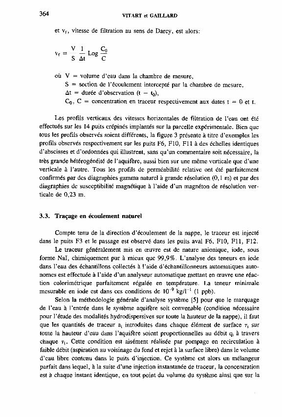
364 VITART et GAILLARD
et vf , vitesse de filtration au sens de Darcy, est alors:
V 1 T C0vf = ------- Log —S At C
où V = volume d ’eau dans la chambre de mesure,S = section de l’écoulement intercepté par la chambre de mesure,At = durée d ’observation (t - to),C0, C = concentration en traceur respectivement aux dates t = 0 et t.
Les profils verticaux des vitesses horizontales de filtration de l’eau ont été effectués sur les 14 puits crépinés implantés sur la parcelle expérimentale. Bien que tous les profils observés soient différents, la figure 3 présente à titre d ’exemples les profils observés respectivement sur les puits F6, F10, F i l à des échelles identiques d ’abscisses et d ’ordonnées qui illustrent, sans qu’un commentaire soit nécessaire, la très grande hétérogénéité de Г aquifère, aussi bien sur une même verticale que d ’une verticale à l ’autre. Tous les profils de perméabilité relative ont été parfaitement confirmés par des diagraphies gamma naturel à grande résolution (0,1 m) et par des diagraphies de susceptibilité magnétique à l ’aide d ’un magnéton de résolution verticale de 0,23 m.
3.3. Traçage en écoulement naturel
Compte tenu de la direction d ’écoulement de la nappe, le traceur est injecté dans le puits F3 et le passage est observé dans les puits aval F6, F10, F i l , F12.
Le traceur généralement mis en œuvre est de nature anionique, iode, sous forme Nal, chimiquement pur à mieux que 99,9%. L ’analyse des teneurs en iode dans l’eau des échantillons collectés à l ’aide d’échantillonneurs automatiques autonomes est effectuée à l ’aide d ’un analyseur automatique mettant en œuvre une réaction colorimétrique parfaitement régulée en température. La teneur minimale mesurable en iode est dans ces conditions de 10“9 kg/l-1 (1 ppb).
Selon la méthodologie générale d’analyse système [5] pour que le marquage de l ’eau à l’entrée dans le système aquifère soit convenable (condition nécessaire pour l ’étude des modalités hydrodispersives sur toute la hauteur de la nappe), il faut que les quantités de traceur a¡ introduites dans chaque élément de surface r, sur toute la hauteur d ’eau dans l ’aquifère soient proportionnelles au débit q¡ à travers chaque r¡ . Cette condition est aisément réalisée par pompage en recirculation à faible débit (aspiration au voisinage du fond et rejet à la surface libre) dans le volume d ’eau libre contenu dans le puits d ’injection. Ce système est alors un mélangeur parfait dans lequel, à la suite d ’une injection instantanée de traceur, la concentration est à chaque instant identique, en tout point du volume du système ainsi que sur la

IAEA-SM-336/42 365
surface de sortie (surface d ’entrée dans l’aquifère). Alors, à chaque instant, pour une valeur de concentration en traceur C dans le volume d ’eau libre du puits, dans chaque élément r¡ de la surface d ’entrée dans l’aquifère, a¡ = C x q¡.
Il est de plus montré dans ce cas que la loi d ’entrée du traceur dans l’aquifère est d ’allure exponentielle (cf. méthode de dilution pour la mesure de la vitesse de filtration) et permet ainsi de déterminer la vitesse moyenne de filtration de l ’eau sur toute la hauteur de nappe interceptée par le puits d ’injection.
En aval du puits d ’injection, pour que la détection du traceur dans les puits d ’observation soit, elle aussi, convenable, c ’est-à-dire représentative des modalités de transfert de l’eau sur toute la hauteur de la nappe, ces puits doivent également être équipés d ’un dispositif d ’homogénéisation par pompage en recirculation à faible débit. C ’est sur ces dispositifs d ’homogénéisation qu’est effectué l ’échantillonnage périodique pour la détermination, après analyse, des fonctions concentration-temps de passage du traceur. Sur la parcelle expérimentale, les puits F6, F10, F i l sont équipés d ’un dispositif unique d ’homogénéisation sur toute la hauteur de leur volume d ’eau libre. Le puits F12, qui présente de forts contrastes de perméabilité, est équipé d ’obturateurs disposés respectivement à 6, 8 et 10 m de profondeur. Le volume d ’eau dans chacune des chambres ainsi délimitées est maintenu homogène par un léger pompage en recirculation périodique pour la détermination de la fonction correspondante traduisant le passage du traceur.
3.4. Résultats, in terprétation
A titre d ’exemple, la figure 4A présente le résultat d ’ajustement à un seul modèle «piston-dispersion» (vitesse moyenne réelle ïï = 0,76 m/h, dispersivité longitudinale a L = 4,6 m) des valeurs expérimentales discrètes des concentrations en traceur observées sur toute la hauteur d ’eau dans le puits F10. Ce graphe montre que, globalement, ce modèle unique décrit assez bien l’allure de la fonction expérimentale mais ne représente absolument pas l ’évolution réelle des valeurs observées. Il doit dès à présent être noté que la répétabilité de ces mêmes expériences, dans des conditions hydrauliques identiques, ont toujours montré la même variabilité des valeurs expérimentales et que celles-ci ne résultent absolument pas d ’artefacts de mesures (fluctuations, dérive de l’appareillage, précision des analyses, etc).
La figure 4B présente l ’ajustement optimal de la fonction observée en traceur sur le puits F10. Celui-ci est obtenu par composition de 4 «piston-dispersion» de paramètres, ü (vitesse moyenne réelle) et a L (dispersivité longitudinale) notablement différents (par exemple, en ce qui concerne ü des valeurs égales à 2,7 m/h, 1 m/h, 0,5 m/h, 0,3 m/h).
De la même manière, la figure 3 montre que les ajustements optimisés des valeurs expérimentales observées sur les puits F6 et F12 sont également obtenus par
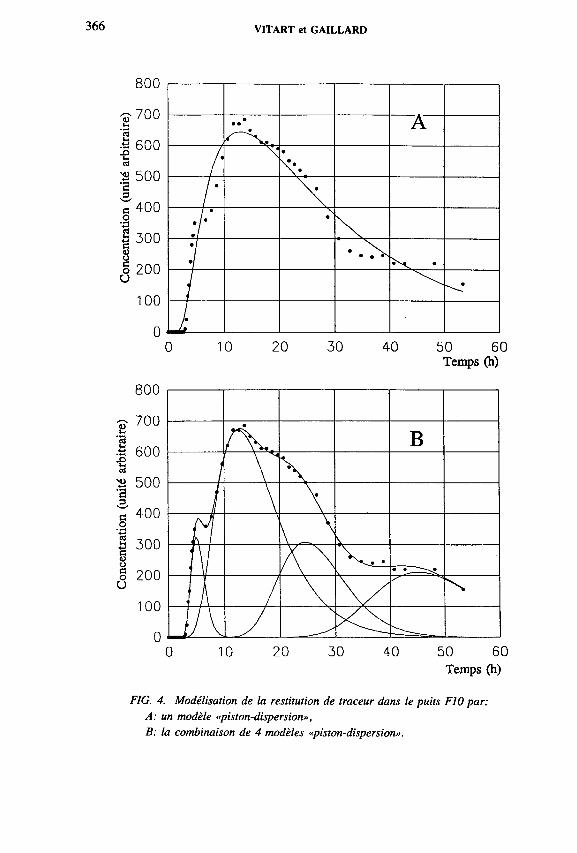
VITART et GAILLARD
0 10 20 30 40 50 60Temps (h)
Temps (h)
FIG. 4. Modélisation de la restitution de traceur dans le puits F10 par: A: un modèle «piston-dispersion»,B: la combinaison de 4 modèles «piston-dispersion».
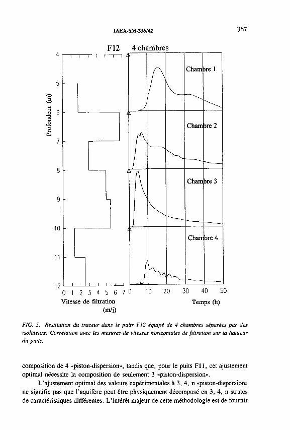
IAEA-SM-336/42 367
S 6чэс<2о
10
11
120 1 2 3 4 5 6 7 0Vitesse de filtration
(m/j)
10 20 30 40 50Temps (h)
F IG . 5. R estitu tio n d u tra c e u r d a n s le p u its F 12 éq u ip é d e 4 ch a m b res sé p a rées p a r d es
iso la teu rs. C orréla tion a vec le s m esu res d e v itesses h o rizo n ta le s d e fi l tra tio n su r la h a u teu r
d u p u its .
composition de 4 «piston-dispersion», tandis que, pour le puits F i l , cet ajustement optimal nécessite la composition de seulement 3 «piston-dispersion».
L ’ajustement optimal des valeurs expérimentales à 3, 4, n «piston-dispersion» ne signifie pas que l’aquifère peut être physiquement décomposé en 3, 4, n strates de caractéristiques différentes. L ’intérêt majeur de cette méthodologie est de fournir

368 VIT ART et GAILLARD
les paramètres caractéristiques et l ’intensité relative de chacun des modèles «piston- dispersion» élémentaires à associer pour représenter au mieux la fonction expérimentale et en extraire le maximum d ’information en vue de calage ou de validation de modèles prévisionnels de transfert d ’eau ou de substances toxiques. L ’intérêt second est aussi de s’affranchir de la nécessaire opération de lissage et d ’écart moyen acceptable, lors de l’ajustement à un modèle dispersif unique. Cette procédure conduit généralement, si l ’expérimentateur en a la possibilité, à conclure à un effet d ’échelle, la dispersivité mesurée a L tendant à croître avec le pas expérimental.
A titre d ’exemple, la figure 5 regroupe le profil vertical des vitesses de filtration (perméabilités relatives) enregistré dans le puits F12 ainsi que les fonctions observées en traceur dans les chambres verticales délimitées entre les obturateurs disposés à 6, 8 et 10 m de profondeur. Les fonctions observées en traceur dans les différentes chambres apparaissent toutes différentes mais ne traduisent pas, proportionnellement, le même contraste que les vitesses de filtration observées dans chacune d ’elles. Ceci, de même que les fonctions très différentes observées dans les puits F10 et F l 1 à une même distance que F12 ( » 11 m) en aval du puits F3 d ’injection, confirme l’hétérogénéité des perméabilités dans le plan horizontal de l ’aquifère.
3o Milieu karstique
Distance del’injection détection: 15 km
Temps (h)
Г
Aquifère sédimentaire
oo 2 4 ^ O 7 Z 9 © T 2 0 1 6 S
Temps (h)
FIG. 6. Interprétation de courbe de restitution de traceurs artificiels en milieu karstique et sédimentaire par un modèle composite.

IAEA-SM-336/42 369
La décomposition en fonctions élémentaires de type hydrodispersif, si elle est justifiée par la géologie du milieu, d ’une courbe de restitution de traceur est une méthode très puissante pour accéder aux paramètres d ’un aquifère, dans le cadre de l’étude des modes de transfert d ’une pollution et de la protection des ressources en eau. Les informations recueillies n ’ont pas de valeur déterministe. Elles ne caractérisent le milieu que globalement, en mettant en évidence les différents modes de circulation du vecteur de la pollution, l ’eau, et les paramètres hydrodispersifs (paramètres temporels, vitesses, dispersivités) des différentes composantes. Celles- ci moyennent les effets dus à l’hétérogénéité du milieu: strates, circulations préférentielles, composition de différentes perméabilités, etc. La figure 6 illustre la généralité de la méthode. Le cas qualifié de milieu sédimentaire concerne l ’acquisition de données représentatives d ’un aquifère sous-jacent d ’un site industriel pour caler un modèle de prévention. Le second concerne une étude de vulnérabilité de ressources en eau en milieu karstique. Ces deux cas sont détaillés en [6].
4. CONCLUSION
REFERENCES
[1] GAILLARD, B., Méthode de traceur pour la modalité de transfert de substances en solution dans l’eau des aquifères, Thèse Univ. Grenoble (1976).
[2] VIT ART, X., MARGRITA, R., «Methodologies and approaches in experimental studies, using radioisotope tracers, of pollutant transport in hydrological environment», Working Group on Pollutant Transport in the Environment, IAEA, Vienna (1992).
[3] GELHAR, L., WELTY, C., REHFELDT, H.R., A critical review of data on field scale dispersion in aquifers, Water Resour. Res. 28 7 (1992) 1955-1974.
[4] MOSER, H., NEUMAIER, F., RAUERT, W., Die Anwendung radioaktiver Isotope in der Hydrologie, Atomkernenergie, 2 (1957) 225.
[5] GUIZERIX, J., MARGRITA, R., GAILLARD, B., COROMPT, P., «Analyse des informations fournies par les traceurs naturels ou artificiels dans l’étude des systèmes aquifères en hydrogéologie», Isotope Techniques in Groundwater Hydrology, Vol. 2, IAEA, Vienna (1974) 377-404.
[6] GAILLARD, В., CALMELS, P., MARGRITA, R., «Tracers performances for water management», Conf. HYDROTOP 94, Marseille, France, 1994, non publié.


IAEA-SM-336/21
TRANSPORT OF RADIONUCLIDES IN THE GROUNDWATER ENVIRONMENT
H.A. EL-NAGGARHot Laboratories Centre
M.R. EZZ EL-DIN, A.S. ABDEL-GAWADNational Centre for Nuclear Safety and Radiation Control
Atomic Energy Authority,Cairo, Egypt
Abstract
TRANSPORT OF RADIONUCLIDES IN THE GROUNDWATER ENVIRONMENT.Various factors influencing the transport of radionuclides by groundwater were studied.
Sorption of 137Cs, “ Co, 24lAm and <l52 l54)Eu by soil samples of the Inshas area was carried out. Mineralogical analyses of the soil samples were carried out. The amount sorbed per gram soil, (X/m), increased as the carrier concentration (C) increased from 10'9 to 1СГ1 mol) following a Freundlich type isotherm. The distribution coefficient, Kd, of the radionuclides was found to be affected by pH. The presence of K + , Ca2+ and Fe3+ as competing ions decreases the sorption capacity of the radioisotopes studied. The presence of complexing agents has a significant effect on the mobility of these radioisotopes. On the basis of the results obtained an attempt is being made to calculate the different transport rates of the relevant isotopes in the investigated media. A mathematical model for the dispersion of the investigated radioisotopes in the groundwater environment was also elucidated. It is concluded that the choice of the Inshas area, as a repository site, for disposal of low level radioactive waste is to be recommended.
1. INTRODUCTION
The acquisition of the scientific and technical knowledge needed to assess the risks due to movement of radionuclides dissolved in and transported by groundwater is one of the major needs of any successful nuclear waste isolation programme.
In Egypt, there are plans to construct some repositories in the Inshas area, an Atomic Energy Authority site, because of the expected increase in nuclear activities. For safe construction of such waste repositories special physicochemical data for various radioisotopes, especially for those with a long half-life, are needed. The study of sorption behaviour and complex formation of such radionuclides on geological materials surrounding a radioactive waste repository is thus a most important part of the overall investigations required for the potential sites for low level waste (LLW) disposal [1, 2]. In this work, the sorption behaviour o f the radionuclides
371

372 EL-NAGGAR et al.
137Cs, ^C o , (152'154)Eu and 241 Am was investigated, using synthetic groundwater. The effect of a complexing agent (humic acid, HA) on the sorption and transport processes was also studied. On the basis of the data obtained, a mathematical model for the dispersion of the investigated radioisotopes in the groundwater environment was also elucidated.
2. MATERIALS AND METHODS
The soil and rock samples obtained from the Inshas site were collected at different depths from wells Nos 1 and 2. Table I shows the lithology of the collected samples. Mineralogical analyses of these samples were carried out using X ray diffraction technique using a Philips X ray spectrometer model PW-1050.
Synthetic groundwater having the same chemical composition and pH as the groundwater at the Inshas site was prepared, see Table II.
Commerical humic acid ‘Fluka-AG’ was purified by a procedure described elsewhere [3].
Sorption of the different radioisotopes by the soil and rock samples was carried out according to the procedures described previously [4].
The effect o f the presence of humic acid was assessed by dissolving different concentrations in the synthetic groundwater solution which contained the investigated radioisotope. After adjusting the pH, the procedure was continued as previously described [4]. The radioactivity of the respective tracer before and after shaking was determined radiometrically using a well type Nal(Tl) crystal connected to a multichannel analyser of the type Canberra Series 20, model 8010 A.
TABLE I. LIST OF SOIL SAMPLES COLLECTED FROM THE INSHAS AREA
Sample code Depth (m) LithologyThickness
(m)Remarks
Bed 1 0 .0 0 - 2 . 2 0 Sandy clay 2.50 Well No. 1
Bed 3 3.00-6.00 Sand 2 . 0 0 Well No. 1
Bed 5 7.60-10.35 Shale 2.75 Well No. 1
Bed 8 14.07-16.92 Sand 2.85 Well No. 1
Bed 12 31.47-33.47 Coare sand 2 . 0 0 Well No. 1
Bed 27 67.42-68.24 Basalt 0.80 Well No. 1
Bed 4' 7.22-9.22 Silt 2 .0 0 Well No. 2
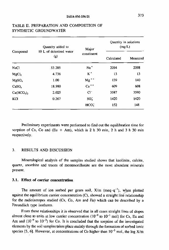
IAEA-SM-336/21 373
TABLE II. PREPARATION AND COMPOSITION OFSYNTHETIC GROUNDWATER
CompoundQuantity added to
10 L of deionized water (g)
Majorconstituent
Quantity in solutions (mg/L)
Calculated Measured
NaCl 53.285 Na + 2094 2098
MgCl2 4.736 K + 13 13
MgS04 1 . 0 0 M g++ 139 140
CaSO„ 18.980 Ca + + 609 608
Ca(HC03)2 2.025 ci- 3587 3590
KC1 0.267 so; 1420 1420
HCOj 152 148
Preliminary experiments were performed to find out the equilibration time for sorption of Cs, Co and (Eu + Am), which is 2 h 30 min, 2 h and 3 h 30 min respectively.
3. RESULTS AND DISCUSSION
Mineralogical analysis o f the samples studied shows that kaolinite, calcite,quartz, anorthite and traces of montmorillonite are the most abundant mineralspresent.
3.1. Effect of carrier concentration
The amount of ion sorbed per gram soil, X/m (m eq -q '1), when plotted against the equilibrium carrier concentration (C), showed a straight line relationship for the radioisotopes studied (Cs, Co, Am and Eu) which can be described by a Freundlich type isotherm.
From these relationships it is observed that in all cases straight lines of slopes almost close to units at low carrier concentration (10~9 to 10_l mol) for Cs, Eu and Am and (10‘9 to 10"3) for Co. It is concluded that the sorption of the investigated elements by the soil samples takes place mainly through the formation of sorbed ionic species [5, 6]. However, at concentrations of Co higher than 10“3 mol, the log X/m

374 EL-NAGGAR et al.
value tends to approach limiting values, which suggests more than one reaction mechanism [4, 7].
The Kd showed a significant decrease with increasing metal concentration of these elements. The highest Kd values were observed for Eu, Am and Cs, while those of Co were substantially lower. The Kd varied from sample to sample, depending on the difference in physicochemical properties as well as mineralogical and elemental contents.
3.2. Effect of pH
The Kd of 137Cs and ^C o showed a gradual increase as pH increased with maximum values of pH8.5, while the Kd for 241 Am and (152'154)Eu showed a relatively sharp increase as pH increased, with maximum values around 6.0, and then showed a slight decrease to pH8.5. Generally, the Kd values obtained were in the order Eu « Am > Cs > Co (at pH » 6.0).
Allard and Beall [7] reported that the sorption of Am3+ is strongly influenced by increase in pH at values between 4 and 6, but shows a slight decrease with increasing pH values above 6.0. Serne and Relyea [8] found that the sorption of Am3+ generally increases with the increase of pH. On the other hand, Sanchez et al. [9] showed that there was a sharp increase in Kd values of Am3+ between pH4.0 and 6.0, and that the Kd continued to increase with higher pH values. They suggest the formation of polymeric or colloidal species that are strongly removed from solution, similar to cation sorption characteristics on glass and on an anion exchanger [10, 11]. In the study on the sorption of 134Cs and 241Am by some minerals and rocks, it was found that 134Cs sorption increases with increasing pH, while 241Am sorption starts to increase at a pH value where hydrolysis becomes important, indicating that the degree of hydrolysis affects the sorption behaviour of 241 Am [12].
3.3. Effect of competing ion concentration
The uptake of 137Cs, “ Co, 241Am and n52,|54)EU by different soil samples decreases if N a+ or K + , Ca2 + , Fe3+ ions are present. It is observed that K + has the highest competing effect on the sorption of 137Cs, while Fe3+ ions have the least effect. It is suggested by Tamura and Jacobs [13] that K + present in solution reduces the ion exchange between C s+ and К + at the edges of sediment lattice. In the sorption of ^C o , in all samples, the competing cations suppress the sorption of the radiocobalt, where calcium ions have the greatest effect. Generally, the divalent cations showed the highest competing effect while the monovalent cations such as Na and К had no effect on the sorption process of CO [14]. Similarly, F e3+ showed the highest competing effect for both Am(III) and Eu(III), which may be attributed to similarity in the valency and ionic radii.

IAEA-SM-336/21 375
The effect of the presence of different concentrations of humic acid on sorption of l37Cs, ^C o , 24'Am and (152 I54)Eu was investigated at pH = 7.85, Fig. 1. The Kd of 137Cs and 60Co does not change to a notable extent even when the humic acid concentration is increased up to 100 mg/L, which means that humic acid has no tendency to complex either caesium or cobalt in solution. The Kd showed a gradual decrease in the case of Eu and AM with increasing humic acid transport up to 100 mg/L. This is mainly related to the formation of Eu- or Am-humic acid complexes in solution. Kim et al. [15] studied the complexation behaviour of actinide
3.4. Effect of complexing agent (humic acid)
Humic acid concentration (mg/L)
FIG. 1. Effect of humic acid on sorption of radioisotopes by soil sample No. 1.

376 EL-NAGGAR et al.
ions with humic substances in a natural aquifer system and found that the aquatic humic substances commonly found in all groundwater in different concentrations have a strong tendency towards complexation with actinide ions. Moulin et al. [16] found that the metal-humate complex is the dominant species present in the pH range 4 to 8 and humic acid concentration 0.1 to 10 ppm.
3.5. Transport of radionuclides in groundwater
3.5.1. Estimation o f radionuclide velocity
The velocity V¡ of a radionuclide through porous media can be related to groundwater velocity, Vw, by the following equation [2]:
V¡/Vw = (1 + (D/P) К*)'* (1)
where D is the soil density, g/cm 3; P is the soil porosity and Kd is the distributionbetween the soil and aqueous phase in the presence of a complexing agent (i.e. humic acid). For any cation and soil combination the Kd value is less than that for a soil without significant amounts of humic acid [2]. The exact reduction is difficult to predict because the actual amount of soluble humic matter is generally variable and unknown. But if the radioactive cation complexing takes place, Eq. (2) may well be applicable:
Kd = K ^ /0 + B[HA]) (2)
where В is the humic acid formation constant, [HA] is the humic acid concentration and Kjq is the Kd in the absence of [НА]. Substitution of Eq. (2) into Eq. (1) gives
V¡/Vw = (1 + B[HA])/(1 + В [HA] + (D/P) K ^) (3)
When the humic acid concentration is zero, the cation flow velocity is determined by the corresponding but in the presence of increasing [HA], that is, when
(D/P) > В [HA] 1, Eq. (3) simplifies to
V¡/Vw = B[HA]/(D/P) (4)
Equation (4) suggests that:
(1) the cation flow velocity is directly proportional to the humic acid concentration(2) the transport rate of the elements is inversely proportional to their respective
Kd values(3) the cation flow velocity depends on the magnitude of the complexing constant.

IAEA-SM-336/21 377
From Eqs (1) and (4), the velocity of the radionuclides (Cs, Co, Am and Eu) in all six layers relative to the velocity range of the groundwater at Inshas (2-4 cm/d), was calculated assuming the media to be porous, and the data obtained showed that the travel rates (migration rates) of l37Cs, 60Co, 241 Am and <l52,l54iEu are respectively about 3442, 1107, 8201 and 9501 times slower than the groundwater velocity. On the other hand, the migration rates of the radionuclides Am and Eu in the presence of humic acid are respectively about 549 and 578 times slower than that of the groundwater. Comparing the data obtained in two cases, the migration rates of Am and Eu are higher in the presence of [HA] than in its absence by about 15 orders of magnitude (8201/549 = 14.9, 9501/578 = 16.4). This indicates that humic acid, and other complexing agents, accelerate the transport o f actinide ions as well as lanthanide ions in groundwaters.
According to the travel rates of Cs, Co, Am and Eu, the time required for the investigated radionuclides to reach the point of water use at the Ismailia canal with maximum groundwater velocity, assuming a porous media, in the absence of HA, is 587 084, 186 799, 1 712 328 and 1 956 947 years for Cs, Co, Am and Eu respectively and 149 439, and 141 709 years for Am and Eu respectively in the presence of HA. The migration time necessary for the radionuclides studied to reach the Ismailia canal (3 km away) will be sufficient for the maximum sorption of the isotopes. It respresents several orders of the longest half-life of the studied isotopes (i.e. after these migration time periods almost no activity will be present in the water). On the other hand, if humic acid is present the migration time is less by about ten orders of magnitude (17123/1494 = 11.46). It is concluded that the time for an isotope to reach a discharge point is inversely proportional to the humic acid concentration.
3.6. Computer modelling of radionuclide transport in groundwater
The equation which describes the transport and dispersion of radionuclides by groundwater through an aquifer or other substratum can be written as [17]:
a(dC/dt) = - Vx(dC/dx) - Vy(dC/dy) - Vz(dC/dz) + £>x(d2C/d2)
+ 3Dy(d2C/dy) + £>z(d2C /d2) - L a С + a S(t) (5)
where a is the retention factor o f the radionuclide for the substratum under consideration, a = 1 + (D/P) K^; С is the average concentration of the radionuclide in the water and the substratum; Vx, Vy, Vz is the magnitude of the groundwater velocity in the X, Y, Z direction; L is the radioactive decay constant o f the radionuclide; and S(t) is the rate of the release of the radionuclide into the water.
Geological forms are usually rather irregular; however, the detailed information which would be required for a model are not generally available. Consequently,

378 EL-NAGGAR et al.
EiîcrS-co
c<DOCo
Distance, X (cm)
FIG. 2. Concentration of radioisotopes at différent distances in the X direction.
the equation which is used as basis for all analytical models described in this study was formulated under several assumptions that are summarized here for emphasis: constant permeability, constant dispersion coefficient (3DX, 3Dy, 2DZ) and constant retention factors. The physicochemical interactions between the soil/rock and the radionuclides in solution are taken to be adequately described by an equilibrium condition; the solution of the equation is given in Ref. [18]. A computer program using these equations to calculate the concentration of radioactive nuclide in the X, Z directions is constructed.

IAEA-SM-336/21 379
The concentration of the radioisotopes studied decreases as the distance increases in both the X and Z directions, Figs 2-4. The concentrations of radioisotopes Cs, Co, Eu, after five half-lives, and 500 years for Am, are 10 8, 10“2, 10“3 and 10“4 Bq/cm3 at distances 10, 5, 3, 10 m respectively, in the X direction, Fig. 2. The concentrations in the Z direction, Fig. 3, are 10“9, 10-7, 10"4 and 10~4 Bq/cm3 at distances 3, 2, 1 ,3 m for Cs, Co, Eu and Am respectively, after the same time period. On the other hand, the effect of humic acid concentration on the transport rate of 241Am, for example, in groundwater is shown in Fig. 4. The
Distance, Z (cm)
FIG. 3. Concentration of radioisotopes at different distances in the Z direction.

380 EL-NAGGAR et al.
[HA] (mg/L)
FIG. 4. Influence of humic acid concentration on rate of Am transport in groundwater.
Am concentration decreases with increasing [HA] concentration, at different distances, indicating that as the [HA] increases the transport rate is increased and the measured [Am] at the same point decreases. This emphasizes the importance of humic acid as a complexing agent for actinides and lanthanides in groundwater transport. But many man-made complexing agents such as ethylene diamine tetra acetic acid (EDTA) and nitrilotriacetic acid (NTA) have even larger formation constants, and therefore greater capacities to accelerate the transport of different radioisotopes. This suggests that radioactive wastes containing such strong complexing agents should be chemically treated to destroy these mobilizing agents.
The above data treatments confirm the suitability of the Inshas site for the construction of a repository for the disposal o f the radioisotopes studied as well as for other LLW isotopes.
IAEA-SM-336/21 381
REFERENCES
[1] WOLSFBERG, К., Sorption-desorption Studies of Nevada Test Site, Alluvium and
Leaching Studies of Nuclear Test Debris, Los Alamos Scientific Laboratory Rep. LA-7216-MS, Los Alamos, NM (1978).
[2] SGEPPARD, J.C., KITTRICK, J.A., Factors influencing the Transport of Actinides
in the Groundwater Environment, Final Rep., Contract DE-AT 06 — 76 EV 73012, Washington State University, Pullman, WA (1983).
[3] BOGGS, S., Jr., SEITZ, M.G., The Influence of Dissolved Organic Substances in Groundwater on Sorption Behavior of Americium and Neptunium, Argonne National Laboratory Rep. ANL-83-84, Argonne, IL (1984).
[4] EL-NAGGAR, H.A., SHEHATA, M.K., ABDEL SABOUR, M.F., EZZ EL-DIN, M.R., “ Sorption and desorption studies of ^Co and 137Cs on some Egyptian shales” , Nuclear Science and Applications (Proc. 5th Conf. Cairo, 1992), Vol. 2, Atomic
Energy Assoc., Cairo (1992) 999-1009.[5] KHALIFA, S.М., El-ATRASH, A.M., HELAL, A.A., ALY, H.F., Sorption of
europium (III), cobalt (II) and cesium (I) by fresh water sediment fractions, Isotopen-
praxis 26 2 (1990).[6] ERTEN, H.N., AKSOYOGLU, S., HATIPOGLU, S., GOKTORK, H., “Sorption of
cesium and strontium on montmorillonite and kaolinite” , Radiochim. Acta 44/45(1988).
[7] ALLARD, B., BEALL, G.W., Sorption of americium on geologic media, J. Environ. Sci. Health A 14 6 (1979) 507-518.
[8] SERNE, R.J., RELYEA, J.F., The Status of Radionuclide Sorption-Desorption
Studies Performed by the WRIT Program, Pacific Northwest Laboratory Rep. PNL-3997, Richland, WA (1983).
[9] SANCHEZ, A.L., SCHELL, W.R., SIBLEY, Т.Н., “ Distribution coefficients for plutonium and americium on particulates in aquatic environments” , Environmental Migration of Long-lived Radionuclides (Proc. Symp. Knoxville, 1981), IAEA, Vienna
(1982) 188-203.[10] STRIK, I.E., GINZBURG, F.L, State of micro amounts of radioelements in dilute
solutions. XVI. Investigation of the state of americium by ion exchange method, Sov. Radiochem. 3 1 (1961).
[11] SAMARTSETEVA, A.G., Study of the adsorption of americium on the surface of polished platinum, Sov. Radiochem. 11 5 (1969).
[12] ANDERSSON, K., TORSTENFELT, B., ALLARD, B., “ Sorption behaviour of long- lived radionuclides in igneous rock” , Environmental Migration of Long-lived Radionuclides (Proc. Symp. Knoxville, 1981), IAEA, Vienna (1982) 111-131.
[13] TAMURA, T., JACOBS, D.G., Health Phys. 2 (1960) 391.[14] CARLSON, L., BO, P., “ Sorption of radionuclides on clay materials” , Environmental
Migration of Long-lived Radionuclides (Proc. Symp. Knoxville, 1981), IAEA, Vienna
(1982) 97-109.[15] KIM, J.I., BUCKAU, G., KIENZE, R., RHEE, D.S., WIMMER, H., Characteriza
tion and Complexation of Humic Acid, CEC Rep. EUR 13181 EN, Commission of the
European Communities, Brussels (1991).

382 EL-NAGGAR et al.
[16] MOULIN, V., et al., Complexation behaviour of humic substances towards actinides and lanthanides studied by time-resolved, laser-induced spectrofluorometry, Radiochim. Acta 58/59 (Part 1) (1992).
[17] UNITED STATES NUCLEAR REGULATORY COMMISSION, Liquid Pathway Generic Study, NUREG 0440, Appendix В (LPGS, 1978) USNRC, Washington, DC (1978).
[18] NIEMEZYK, S., et al., NUREG/CR-1596, United States Nuclear Regulatory Commission, Washington, DC (1981).

IAEA-SM-336/37
A COMPARISON OF GROUNDWATER AGES BASED ON 14C DATA AND THREE DIMENSIONAL ADVECTIVE TRANSPORT MODELLING OF THE LOWER CHAO PHRAYA BASIN Palaeohydrology and implications fo r water resources development in Thailand
W.E. SANFORD Water Resources Division,U.S. Geological Survey,Reston, Virginia,United States of America
S. BUAPENG Groundwater Division,Department of Mineral Resources,Bangkok, Thailand
Abstract
A COMPARISON OF GROUNDWATER AGES BASED ON 14C DATA AND THREE
DIMENSIONAL ADVECTIVE TRANSPORT MODELLING OF THE LOWER CHAO PHRAYA BASIN: PALAEOHYDROLOGY AND IMPLICATIONS FOR WATER
RESOURCES DEVELOPMENT IN THAILAND.A study has been undertaken to simulate the groundwater flow system of the Lower
Chao Phraya Basin, Thailand. The study was performed using a three dimensional computer model of groundwater flow and advective transport. Results from these simulations include travel time analyses obtained through backward pathline tracking. The simulated ages were compared with observed 14C ages at over fifty discrete locations within the aquifer system. The comparisons reveal a major difference between 14C ages and ages predicted by steady
state groundwater flow. Carbon-14 analyses generally indicate that the groundwater in the
Bangkok area is 10 000 to 30 000 years old. Steady state flow and transport simulations imply that groundwater in this region should be 50 000 to 100 000 years old. One potential reason for the discrepancy between l4C and computer simulated ages is the assumption of steady
state flow. Groundwater in the basin that is > 10 000 years old would have been affected by
flow conditions that existed during the last glacial maximum. We hypothesize that groundwater velocities in the region during that time would have been greater because of both the
absence of the Bangkok Clay and the more distal position of the coastline. These palaeoflow
conditions were incorporated into a second set of simulations that assume current steady state flow conditions existed for the last 10 000 years, but were preceded by steady state conditions representative of flow during the last glacial maximum. This transient simulation yielded mean
groundwater ages that were in much closer agreement with mean observed 14C ages. Carbon-14 ages from the basin have suggested slow natural groundwater replenishment rates
383

38 4 SANFORD and BUAPENG
to the Bangkok area, where groundwater extraction rates are currently high. Simulation results from this study imply that replenishment of groundwater to the basin may be even slower than
previously thought.
1. INTRODUCTION
1.1. Hydrological setting of the Chao Phraya Basin
The Bangkok Metropolitan Area is situated on the flood plain and delta of the Chao Phraya river, which traverses the Lower Central Plain of Thailand, also known as the Chao Phraya Basin (Fig. 1). The basin is bounded by mountains to the east and west, by the Gulf of Thailand to the south, and by small hills to the north that divide it from the Upper Central Plain. The mean annual rainfall in the Chao Phraya
FIG. 1. Locations o f observation wells around Bangkok and groundwater ages calculated from I4C concentrations in water samples collected from those wells.

IAEA-SM-336/37 385
Basin is about 1.2 m. Alluvial deposits constitute the principal aquifers in the study area. The aquifers are divided by thick clay and sandy clay confining units. Large groundwater withdrawals during recent years around Bangkok have produced significant problems related to piezometric water level declines, such as land subsidence and salt water encroachment [1 ].
1.2. Previous work on environmental isotopes
Groundwater studies using environmental isotopes have been under way in Thailand since 1987. Most of this work has been done under contract from the IAEA. More than 150 samples were collected from groundwater around Thailand and analysed for 180, 2 H, 3H, 13C and 14C [2]. Oxygen and deuterium data have been analysed in the context of a mixing cell flow model to assess the extent of groundwater/river water interaction [3]. Carbon-14 and tritium data have been analysed to determine the age distribution of Thai groundwater. According to uncorrected 14C data, nearly all groundwater in the Bangkok Metropolitan Area is > 10 000 years old (Fig. 1). The same data also show an absence of tritium, and the oldest samples are light in deuterium and 18 0 — indicative of a cooler climate.
1.3. Purpose of this paper
The purpose of this paper is to describe a computer modelling study of groundwater flow and advective transport in the Chao Phraya Basin. A major focus of the study has been to use 14C based ages of groundwater in the basin to help calibrate a three dimensional transport model. First, a steady state groundwater flow model is described that has incorporated readily available hydrogeological descriptions of the aquifer system. A second transient simulation is then described that attempts to reproduce more closely the 14C ages of groundwater in the basin. Final discussions include the effects of palaeohydrology on the flow regime and the implications of these effects on water resources development in Thailand.
2. STEADY STATE COMPUTER SIMULATION
2.1. Groundwater flow
Groundwater flow in the Chao Phraya Basin has been simulated using the three dimensional finite difference model MODFLOW [4]. Transmissivities predicted from a model calibration study of land subsidence in the Bangkok aquifer system [5] were used in the MODFLOW model. The basin was discretized into 52 columns, 55 rows and 9 layers (Fig. 2), and, as a first approximation, flow was assumed to be steady state. Heterogeneity of the geological material was represented by an

386 SANFORD and BUAPENG
FIG. 2. Representative transmissivity map o f values used for the upper layers in the MODFLOW simulations. The horizontal grid resolution applies to all nine layers o f the model.

IAEA-SM-336/37 387
observation well with pathline to recharge location
FIG. 3. Backward-tracked pathlines from observation well locations projected onto the horizontal plane and superimposed onto a map showing surface exposures o f aquifer units. Each aquifer unit is equivalent to one model layer.
Inactive Щ Ц Phra Pra Daeng
Nonthaburi I Bangkok Aquifer
Nakhon Luang I 1 Bangkok Clay

388 SANFORD and BUAPENG
FIG. 4. Groundwater age distribution around the Bangkok Metropolitan Area based on calculations from a MODPATH simulation assuming a steady state flow field under current hydrological conditions.
equivalent homogeneous yet anisotropic medium. Some of the deeper layers outcrop along the edges of the basin and provide the primary avenue for recharge (Fig. 3). The top boundary surface of the model was assumed to be a constant-head condition reflecting the land surface and approximate water table altitude. Results of the model were used as input for the advective transport model.
2.2. Advective transport
Steady state advective transport in the basin was simulated using the pathline tracking model MODPATH [6 ]. Given cell-by-cell flow rates from MODFLOW, MODPATH will calculate backward pathlines and travel times from any given point in an active model cell. Pathlines and travel times were obtained using this model for the wells in the basin for which data on 14C in groundwater are available. Two dimensional projections of these pathlines are illustrated in Fig. 3. Four separate potential recharge areas are identified. An effective porosity value of 20% was used for all layers of the model. Travel times were also calculated for all cells in the most heavily pumped aquifer, layer 4; the groundwater age distribution for that layer is illustrated in Fig. 4.

IAEA-SM-336/37 389
Simulated groundwater ages can be compared directly with observed 14C ages (Table 1). Discrepancies are immediately apparent not only between ages at individual wells but between the average overall ages. The mean 14C age is 17 000 a, whereas the mean age from the steady state simulation is 34 000 a. Age discrepancies could be due to errors in (1) 14C analyses, (2) mixing of atmospherically derived carbon with ‘dead’ carbon (though there is little carbonate in the basin), (3) transmissivity data, (4) porosity data, (5) boundary conditions, (6 ) the steady state assumption, (7) the pure advection assumption, and (8 ) the neglect of recent groundwater withdrawals. We hypothesize that the age differences are primarily due to errors in items (5) and (6 ). If the groundwater is older than 10 000 a, an accurate simulation may need to include flow conditions as they existed during the last glacial maximum.
2.3. Comparison with 14C ages
3. TRANSIENT COMPUTER SIMULATION
3.1. Groundwater flow
In order to test the hypothesis that groundwater in the Bangkok area has been affected by palaeoflow regimes, two different steady state simulations were made with MODFLOW. The two simulations were then used consecutively to create a transient transport simulation. The first flow simulation incorporated current conditions in the Chao Phraya Basin, as simulated previously. The second simulation attempted to reconstruct flow conditions that existed 10 000 to 30 000 years ago. At that time, the Bangkok clay (dated to be about 7000 years old) did not exist, and the entire Gulf of Thailand was above sea level [7]. To account for these conditions, the Bangkok Clay (top model layer) was removed and the boundary condition at the Gulf of Thailand was changed from no flow to vertical hydrostatic head (horizontal flow only).
3.2. Advective transport
For transport we used the latest version of MODPATH [8 ] to calculate pathlines backward in space and through (1 ) the current steady state velocity field for 1 0 0 0 0 a, and then (2 ) the palaeo steady state velocity field that is presumed to have existed previously. Model calculations reveal that groundwater velocities during that period would have been greater than current velocities. Two reasons are offered for this: first, the topographic and water table gradients were much steeper when the

390 SANFORD and BUAPENG
TABLE I. OBSERVATION WELL DATA INCLUDING 14C AND SIMULATED GROUNDWATER AGES
Hydrogeological Model Carbon-14 Steady state Transientunit in which layer age simulated age simulated age
well is screened No. (a) (a) (a)
1 Nonthaburi 5 12 100 29 033 21 5073 Nakhon Luang 4 15 500 88 432 24 2714 Phra Pradaeng 3 13 500 40 197 12 5445 Nonthaburi 5 17 200 66 564 26 6446 Nakhon Luang 4 14 200 49 120 15 3997 Nakhon Luang 4 16 900 70 285 15 8248 Phra Pradaeng 3 17 400 54 870 16 2559 Phra Pradaeng 3 13 900 9 990 9 990
и Phra Pradaeng 3 34 500 10 106 10 00912 Bangkok 2 39 200 12 206 11 61113 Phra Pradaeng 3 10 100 60 741 15 11814 Bangkok 2 <100 31 036 18 32015 Phra Pradaeng 3 6 300 20 251 15 42716 Phra Pradaeng 3 13 100 2 169 2 16917 Nakhon Luang 4 1 300 24 618 19 77019 Bangkok 2 6 700 83 109 14 37220 Phra Pradaeng 3 18 200 16 756 10 67221 Pak Nam 9 31 700 158 571 41 98139 Nakhon Luang 4 36 000 30 478 15 10240 Phra Pradaeng 3 18 700 30 887 21 35845 Nakhon Luang 4 34 500 3 466 3 46646 Phra Pradaeng 3 9 900 18 957 11 14447 Nakhon Luang 4 10 500 16 997 11 34252 Phra Pradaeng 3 <100 38 470 11 97853 Phra Pradaeng 3 15 800 2 945 2 94554 Nakhon Luang 4 40 000 24 784 17 75355 Bangkok clay 1 2 400 0a 0a56 Phra Pradaeng 3 34 000 11 807 10 00057 Bangkok 2 8 700 0a 0a58 Phra Pradaeng 3 35 000 15 083 10 66759 Phra Pradaeng 3 13 000 7 608 7 60860 Nakhon Luang 4 37 100 23 930 11 96961 Nakhon Luang 4 38 000 23 760 12 83262 Nakhon Luang 4 <100 22 357 12 67763 Phra Pradaeng 3 19 000 3 675 3 67565 Phra Pradaeng 3 14 700 16 118 10 85366 Bangkok 2 <100 18 930 13 52269 Nothaburi 5 16 300 18 284 17 690
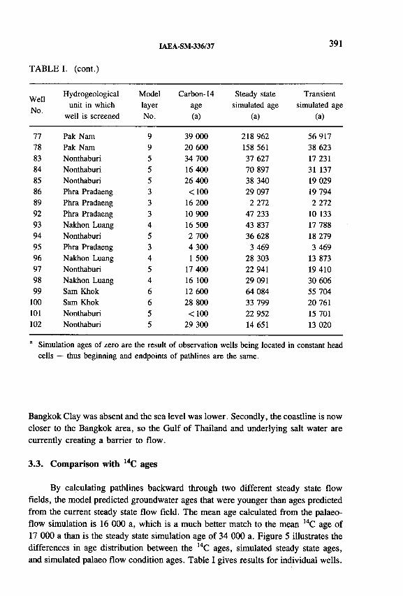
IAEA-SM-336/37 391
TABLE I. (cont.)
WellNo.
Hydrogeological unit in which
well is screened
Modellayer
No.
Carbon-14
age
(a)
Steady state
simulated age
(a)
Transient simulated age
(a)
77 Pak Nam 9 39 000 218 962 56 91778 Pak Nam 9 20 600 158 561 38 62383 Nonthaburi 5 34 700 37 627 17 23184 Nonthaburi 5 16 400 70 897 31 13785 Nonthaburi 5 26 400 38 340 19 02986 Phra Pradaeng 3 <100 29 097 19 79489 Phra Pradaeng 3 16 200 2 272 2 27292 Phra Pradaeng 3 10 900 47 233 10 13393 Nakhon Luang 4 16 500 43 837 17 78894 Nonthaburi 5 2 700 36 628 18 27995 Phra Pradaeng 3 4 300 3 469 3 46996 Nakhon Luang 4 1 500 28 303 13 87397 Nonthaburi 5 17 400 22 941 19 41098 Nakhon Luang 4 16 100 29 091 30 60699 Sam Khok 6 12 600 64 084 55 704
100 Sam Khok 6 28 800 33 799 20 761101 Nonthaburi 5 <100 22 952 15 701102 Nonthaburi 5 29 300 14 651 13 020
a Simulation ages of zero are the result of observation wells being located in constant head cells — thus beginning and endpoints of pathlines are the same.
Bangkok Clay was absent and the sea level was lower. Secondly, the coastline is now closer to the Bangkok area, so the Gulf of Thailand and underlying salt water are currently creating a barrier to flow.
3.3. Comparison with 14C ages
By calculating pathlines backward through two different steady state flow fields, the model predicted groundwater ages that were younger than ages predicted from the current steady state flow field. The mean age calculated from the palaeo- flow simulation is 16 000 a, which is a much better match to the mean 14C age of 17 000 a than is the steady state simulation age of 34 000 a. Figure 5 illustrates the differences in age distribution between the 14C ages, simulated steady state ages, and simulated palaeo flow condition ages. Table I gives results for individual wells.

392 SANFORD and BUAPENG
AGE (000 a)
FIG. 5. Frequency distribution o f groundwater ages from (1) ,4C data, (2) simulations assuming a steady state flow field under current hydrological conditions, and (3) simulations assuming transient hydrological conditions representative o f conditions fromO to 30 000years ago.
4. SUMMARY AND CONCLUSIONS
4.1. Effects of palaeohydrology and heterogeneity
Groundwater ages based on 14C dating in the Chao Phraya Basin are typicallyolder than 1 0 0 0 0 a, indicating that most of the groundwater in the basin has beenaffected, to some extent, by flow conditions that existed more than 1 0 0 0 0 years ago(during the last glacial maximum). Computer simulations of advective groundwatertransport were performed that attempted to account for these older flow conditions,and the resulting mean simulated ages were much more consistent with meanobserved 14C ages. Table I reveals, however, that observed and simulated ages atindividual wells are typically not in good agreement. We attribute these individualdiscrepancies to (1 ) the great degree of heterogeneity in the aquifer materials that could not be simulated on an appropriate scale, and (2 ) the complexity of the transient boundary conditions over the last 30 000 a that could only crudely be approximated.

IAEA-SM-336/37 393
4.2. Implications for water resources development in Thailand
The Bangkok Metropolitan Area is currently facing many serious groundwater problems associated with piezometric water level declines, such as land subsidence and salt water encroachment. Water use for the area is projected to increase with increasing population and economic development. A good estimate of the groundwater budget is important for planning long term development in Thailand. Carbon-14 ages of groundwater in the basin suggest that natural replenishment of groundwater there occurs slowly. Transport simulations suggest that current natural rates of replenishment may be even lower than 14C ages have suggested.
ACKNOWLEDGEMENTS
This work has been supported by IAEA research grant THA/08/011-02. Initial versions of some of the MODFLOW data sets were provided by Kokusai Kogyo Co. Ltd under JICA (Japan International Cooperation Agency). Transmissivity distribution data for the basin was provided by Ashim Das Gupta of the Asian Institute of Technology.
REFERENCES
[1] RAMNARONG, V., BUAPENG, S., Mitigation of groundwater crisis and land subsidence in Bangkok, J. Thai Geosci. 2 (1991) 125-137.
[2] BUAPENG, S., The Use of Environmental Isotopes in Groundwater Hydrology in the
Selected Areas in Thailand: Final Report to the International Atomic Energy Agency on project RB/4803/R1/R3 (1990).
[3] YURTSEVER, Y., BUAPENG, S., “Compartmental modelling approach for simulation of spatial isotopic variations in the study of groundwater dynamics” , Isotope Techniques in Water Resources Development 1991 (Proc. Int. Symp. Vienna, 1991), IAEA, Vienna (1992) 291-308.
[4] McDONALD, M.G., HARBAUGH, A.W., “A modular three dimensional finite- difference groundwater flow model” , Techniques of Water Resources Investigations of the US Geological Survey, Chap. 1A, Book 6, USGS, Reston, VA (1988).
[5] DAS GUPTA, A ., RAJ ONTA, P., MAHADEVA, K .T., DHUNGEL, S., Simulation Study of Bangkok Aquifer System, Asian Institute of Technology Research Report No. 251, prepared for the Department of Mineral Resources, Bangkok, Thailand (1991).
[6] POLLOCK, D.W., Documentation of Computer Programs to Compute and Display Pathlines Using Results from the US Geological Survey Modular Three-dimensional Finite Difference Ground-water Flow Model, Open File Report 89-381, USGS, Reston, VA (1989).

394 SANFORD and BUAPENG
[7] JAPAN INTERNATIONAL COOPERATIVE AGENCY, Study on Management of Groundwater and Land Subsidence in the Bangkok Metropolitan Area and its Vicinity, Interim Report (2) prepared for the Department of Mineral Resources, Bangkok, Thailand (1993).
[8] POLLOCK, D.W., User’s Guide for MODPATH/MODPATH-PLOT, Version 3: A Particle Tracking Post-processing Package for MODFLOW, the US Geological Survey Finite-Difference Groundwater Flow Model, Open File Report 94-464, USGS, Reston, VA (1994).

Poster Presentation
I AEA-SM-ЗЗб/ 142P
RESULTS OF TRITIUM ACTIVITY MODELLING IN A BUNTER SANDSTONE AQUIFER
V. DUNGER Institute of Geology
O. NITZSCHE Institute of Applied Physics
Freiberg University of Mining and Technology,Freiberg, Germany
Water and tritium movement in unsaturated and saturated zones is complicated, especially in areas with inhomogeneous conditions of geology, morphology
FIG. 1. Model structure and main hydrological processes underground.
395

396 POSTER PRESENTATIONS
FIG. 2. Vertical tritium activity distribution CT(i) in aeration zone, tritium activity in precipitation (CTP) and tritium input into groundwater (CTRU) (uncovered aquifer in the Finne region, all tritium activities in TU).
and anthropogenic utilization. A lot of transport and storage processes in the atmosphere, pedosphere and geosphere have to be taken into consideration.
The modelling of water and tritium balance in the unsaturated soil zone, especially when the aeration zone is thick and inhomogeneous, should consider infiltration, percolation, discharge and groundwater recharge. This poster shows a method of modelling tritium distribution in an unsaturated zone, tritium input into groundwater and tritium transport in groundwater by means of a coupled system aeration/ groundwater model (see Fig. 1), developed at Freiberg University of Mining and Technology.
The model was tested on a sandstone aquifer in the Finne region, on the northeast edge of the Thuringia basin (Germany). In the early 1970s Freiberg physicists and hydrogeologists started isotopic investigations in the Finne region. Long term isotopic results are now available. Therefore a comparison of simulated and measured tritium activities in groundwater is possible.
Tritium activity in Finne aquifers shows a wide variation. Water and tritium balance in the unsaturated and saturated zone depends little on surface morphology and filtration capacity, on non- or semi-conducting layers within the aeration zone,

SESSION 7 397
on land use or on aquifer parameters such as tectonics, matrix conductivity and porosity (Finne Bunter Sandstone aquifer is a double porosity system).
Vertical distance velocity in the unsaturated zone in general is very low (less than 1 m/a) because of low precipitation rates (about 600 mm/a only) and therefore low percolation intensity. The vertical distance velocity depends on runoff, évapotranspiration and interflow rates and on the pedological situation in the unsaturated zone (different permeable soil layers, clay horizons, etc.). For example, in covered aquifer areas vertical distance velocity is much lower than 1 m/a, about 0.3 m/a.
Also, tritium activity distribution in the unsaturated zone varies in relation to aeration zone thickness and pedological conditions (see Figs 2 and 3). In areas with uncovered aquifers, the tritium activity distribution (see Fig. 2) differs from the distribution with a covered aquifer. Tritium input into groundwater in the case of an uncovered aquifer with the groundwater level near the surface is time variable (see Fig. 2). In the case of a covered aquifer with deep groundwater level there is no bomb tritium input into groundwater (see Fig. 3).
FIG. 3. Vertical tritium activity distribution CT(i) in aeration zone, tritium activity in precipitation (CTP) and tritium input into groundwater (CTRU) (covered aquifer in the Finne region, all tritium activities in TU).

398 POSTER PRESENTATIONS
Groundwater flow also shows a high variation in water and tritium transport velocity, and depends on tectonic structures, matrix porosity and hydraulic gradient. However, the natural hydraulic gradient in the most areas of the Finne region is influenced by anthropogenic activities (groundwater works).
A comparison of simulated tritium activities in groundwater with measured activities in wells and springs shows a reasonable correspondence.

Chairperson
R. GONFIANTINIItaly
GEOTHERMAL AND PALAEOWATERS
(Session 8)


IAEA-SM-336/32
PALAEOCLIMATIC CONTROLS ON HYDROLOGICAL SYSTEMS:Evidence from U-Th dated calcite veins in the Fennoscandian and Canadian shields
F. McDERMOTT Department of Geology,University College Dublin, Belfield,Dublin, Ireland
M. IVANOVICH AEA Technology,Harwell, Didcot, Oxfordshire,United Kingdom
S.K. FRAPEDepartment of Earth Sciences,University of Waterloo,Waterloo, Ontario, Canada
C.J. HAWKESWORTH Department of Earth Sciences,The Open University,Milton Keynes, United Kingdom
Abstract
PALAEOCLIMATIC CONTROLS ON HYDROLOGICAL SYSTEMS: EVIDENCE FROM U-Th DATED CALCITE VEINS IN THE FENNOSCANDIAN AND CANADIAN SHIELDS.
The purpose of this paper is to present mass spectrometric U-Th age data for eleven weak acid leachates of calcite bearing fracture fillings from three sites on the Fennoscandian and Canadian shields (Stripa, Sweden; the Underground Research Laboratory, Canada, and Olkiluoto, Finland). These age data define a bimodal distribution with ranges of 84-90 ka and 173-203 ka. In detail, four leachates from the Group I fractures at Stripa yield an age of 87.2 ± 3.2 ka, and three from open fractures (Group III) yield ages in the range 178 ± 8 to 201 ± 6 ka. The latter age range is identical to that defined by samples from the Canadian site (202.8_*6604 ka). Taken together, these ages coincide with the end of the interglacials o f the marine oxygen isotope stages V and VII, and are interpreted as reflecting the shutoff of meteoric recharge due to the onset o f permafrost at these high latitudes. Five leachates from another group of closed, fluorite bearing fractures at Stripa (Group II) are close to secular equilibrium but show evidence for U uptake during the last 1 Ma.
401

402 McDERMOTT et al.
1. INTRODUCTION
High salinity groundwaters occur widely in granitic basements (e.g. in Canada, Sweden, Finland, the United Kingdom, Australia, Central and Eastern Europe, the Baltic and the Kola Peninsula), and a better understanding of the time-scales over which their flow regimes remain stable is critical for models of heat and mass transport in the continental crust, the development of mineralization, and the potential use of granitic rocks as hosts for long term radioactive waste disposal. Fractures in crystalline rocks can provide major and relatively rapid pathways for the migration of radionuclides, but the presence of surficial mineral coatings can have a dramatic effect on their hydraulic properties and sorption characteristics. Such coatings and veins yield useful information on the chemistry and origin of the groundwater, the nature of water/rock interactions [1], and the timing of active flow [2-4]. In particular, an improved understanding of the behaviour of natural actinides (U, Th and Ra isotopes) in both the fracture filling minerals [5, 6 ] and associated groundwaters [7, 8 ] may provide further insights into the behaviour of waste radionuclides in this environment.
The purpose of this paper is to present U-Th age data obtained by mass spectrometry for several vein calcites from the Stripa granite (central Sweden), the Underground Research Laboratory (URL) in the Superior Province of Canada and the Olkiluoto research site in Finland. These dates record the timing and duration of shallow to intermediate level ( = 400-1000 m) fluid circulation through these sections of the Fennoscandian and Canadian shields. More significantly, these data demonstrate that fluid circulation at these depths is episodic and that it is restricted to interglacial periods.
2. GEOLOGICAL AND ISOTOPIC BACKGROUND
For more than two decades the Stripa site has been the subject of extensive hydrogeological, geochemical and geophysical investigations to assess the suitability of granitic bedrock as a high level radioactive waste repository. Descriptions of the geological background and summaries of recent research can be found in a series of papers reporting the results of the International Stripa Project [9] (and references therein). The Rb-Sr and К-Ar data indicate that the Stripa granite is Proterozoic in age [1 0 , 1 1 ] but it is cut by several generations of calcite bearing fractures.
Following Fritz et al. [12], three groups of fractures are distinguished on the basis of the coexisting mineralogy; namely, silicate bearing (chlorite/epidote + mica, feldspar and quartz) veins which occur in both open and closed fractures, fluorite/epidote bearing veins which occur as massive closed fractures, and finally a group of calcite coated open fractures with no associated silicate minerals. Consistent with the nomenclature of previous studies, the silicate bearing veins are herein

IAEA-SM-336/32 403
referred to as Group I, the fluorite/epidote bearing massive veins are Group II, and the calcite coated open fractures are Group III.
The URL is situated in the Lac du Bonnet batholith, within the Archaean Superior Province of the Canadian shield. The batholith is composed of pink to grey porphyritic granites, granodiorites and quartz monzonites [13]. Several large, open, subvertical fracture zones dominate the hydrogeology of the site, and the pink colouration is associated with hydrothermal weathering in the vicinity of the fracture zones. Fracture filling minerals consist of high temperature silicates (chlorite, quartz, epidote, illite), and later low temperature minerals such as haematite, kaolinite and occasionally calcite [14].
The Olkiluoto site is located about 225 km northwest of Helsinki, within the 2.1 to 1.75 Ga old Proterozoic, Svekokarelian crust of Finland. At this site, low to medium grade intermediate to felsic metavolcanics are intruded by a variety of granitoid stocks and batholiths, and the associated metasediments include mica schists, gneisses and migmatites [15]. The geology of the Olkiluoto area is described in detail in Ref. [16].
Stripa carbonates had been analysed previously for oxygen and carbon isotopes[12], and a selection of these were also analysed for 8 7 Sr/86Sr [1].
These isotope data and mineralogical association of all calcites for which uranium and thorium isotope data given in this paper are summarized in Ref. [17]. In addition, Fig. 1 is a plot of ¿>l80 against ô l3C depicting the stable isotope systematics of all the calcites considered in this work. Thus, with the exception of sample N1 74.6 (see below), the Group I calcites studied here are characterized by very low <5,80 (-14.8 to -23.4700) and restricted <5,3C (-4.5 to -3.8 0/Oo), and so they define the subvertical trend seen in Fig. 1 (see also Ref. [1]). By contrast, the Group II veins have variable <5I3C (-0.38 to -20.77oo), and <5180 is in the range -15.05 to -19.5700 • The Group 1П calcites define a subhorizontal trend (see Fig. 1), reflecting their very wide range of <5I3C (6.75 to -25.65 700) and relatively narrow range in <5i80 (-10.58 to -13.21700). Fritz et al. [12] demonstrated that below a depth of approximately 100 m, the groundwater at Stripa may become supersaturated with respect to calcite, and argued that the ôl80 data for Groups П and III are consistent with low temperature deposition from groundwaters similar to those of the present day.
Prior to this study, the age of the Stripa, Canadian and Finnish veins was largely unknown, although the very low ô180 of the Group I veins led Fritz et al.[11] to conclude that this group represents high temperature (>200°C) fillings, possibly associated with metamorphic events at 1.4 or 0.8 Ga. An attempt to date the Group III veins by the Rb-Sr method [11] met with only limited success because the Rb-Sr systematics of the granite and the fracture fillings appear to have been disturbed by post-crystallization alteration. However, it should be noted that the fracture fillings analysed had a silicate mineral paragenesis identical to that of the granite, and the authors did not attempt to analyse the calcite separately. Thus, the

TABLE I. MASS SPECTROMETRIC U SERIES DATA FOR SELECTED CALCITE BEARING FRACTURE COATINGS FROM THE FENNOSCANDIAN AND CANADIAN SHIELDS
Sample% insoluble
detritus238U (Mg/g) (230Th/234U) (230Th/232Th) (234U /238U)
(230Th/234U)corrected
Uncorrected age (ka)
Corrected age (ka)
Stripa Group I
N1 16.30 3.0 1.5089 ± 0.0005 0.792 ±0.006 6.67 ± 0 .0 6 1.1442 ± 0.0013 0.5532 ± 0.0084 161.06±1;| 87.22 ±3.21
N1 160.7 17.9 21.8419 ± 0.0005 0.598 ±0.025 16.70 ±0.23 1.0049 ±0.0014 0.5532 ± 0.0084 99.0 ; 76 | 87.22 ±3.21
V2 59.37 13.8 4.1230 ± 0.0003 0.938 ±0.007 3.93 ±0 .04 1.0203 ±0.0010 0.5532 ± 0.0084 292.8 34 87.22 ±3.21
V2 565.85 12.2 0.1170 ± 0.0005 0.766 ±0.015 6.24 ±0 .06 1.0024 ±0.0018 0.5532 ± 0.0084 157.8 i | o 87.22 ±3.21
N1 74.60* 2.1 3.6183 ± 0.0005 1.137 ±0.007 13.63 ±0 .08 1.0205 ±0.0018 - - -
Stripa Group II
N1 161.OA L l + 17.1 17.0960 ±0.0002 1.043 ±0.004 10.33 ±0 .06 1.0269 ±0.0013 1.0070 ±0.0027 4 5 7 .9 Í^ ; |
N1 161.0B L l f 96.5 8.2756 ± 0.0074 1.220 ± 0.002 1.75 ±0.006 0.9981 ±0.0024 1.0070 ± 0.0027 - 457.9
N1 161.0B L2f 98.3 10.7303 ± 0.0034 1.074 ±0.001 7.47 ±0 .04 1.0201 ±0.0030 1.0070 ± 0.0027 - 457.9 Í j};®
N1 272f 4.4 78.1900 ± 0.0080 1.028 ±0.003 6027.09 ±22.94 1.0773 ± 0.0009 1.0070 ± 0.0027 - 457.91^1.1
N1 293.45* 7.7 27.6220 ± 0.0004 1.024 ±0.003 48.29 ±0 .26 1.0028 ± 0.0006 1.0070 ± 0.0027 — -
Stripa Group III
V2 31.5 3.3 60.529 ±0.070 0.926 ± 0.004 16.53 ±0.12 1.3099 ± 0.0027 0.8589 ± 0.0062 224.811.1 184.1 Í 50
V2 355.33L1 3.7 16.8166 ± 0.0003 0.929 ± 0.007 22.31 ±0 .16 1.0925 ±0.0013 0.8589 ± 0.0062 258.4 200.6 ±HV2 355.33L2 2.1 16.8150 ±0.014 0.899 ±0.010 33.95 ±0 .06 1.4380 ± 0.0080 0.8589 ± 0.0062 198.5 Í jog 178.21^2
V2 416.08* 3.2 570.16 ±0.87 1.033 ±0.006 197.324 ±0 .04 0.9929 ± 0.0024 — — —
404 M
cDER
MO
TT et
al.

TABLE I (cont.)
Canada
URL13/11.35 23.8 19.489±0.014 1.001 ±0.002 40.95 ±0 .04 2.4214 ± 0.0008 0.964 ±0.0122 2 2 1 .9 t ', j 202.8 t&o
URL13/51.35L1 3.9 2.787 ±0.001 0.955 ± 0.001 3.09 ± 0.02 2.5616 ± 0.0001 - - -
URL13/51.35L2 42.7 0.9593 ±0.005 0.296 ± 0.001 4.28 ± 0.03 2.8805 ± 0.0027 - - -
URL12/146.5* 7.6 178.000 ±0.990 1.038 ±0.011 58.74 ± 0.10 1.0061 ±0.0006 - - -
Finland
OLKR1 58.8 22.95 1.2257 ± 0.0010 0.929 ±0.003 145.49±0.167 3.7930± 0.0040 0.9191 ±0.0044 -Г.9
238U and 230Th concentrations were measured by isotope dilution using 235U and 229Th tracers. 234U /238U ratios were measured in static mode with 234U on the ion counting channel o f a multicollector mass spectrometer, t denotes a sample close to secular equilibrium and * indicates open system (excess 230Th) behaviour. Corrected ( 230Th/234U) ratios for the Stripa samples were calculated from the slope of the leachate-leachate data on ( 230Th/232Th) against (234U /232Th) diagrams (see text). The Canadian and Finnish samples for which ages have been calculated (2) have high ( 230Th/232Th) ratios (40.95-145.49), and so their corrected ages are relatively insensitive to the choice of detrital (230Th/232Th). A (230Th/232Th) ratio o f 1.5 ± 0 .5 has been assumed for these samples. The errors quoted for the 238U concentrations (230T h/234U), (230Th/232Th) and (234U /238U) ratios are ± 1 a, based on counting statistics. The errors quoted for ( 230Th/234U) ‘corrected’ and the ‘corrected age’ also take into account uncertainties in estimates o f the slope of the regression lines on Figs 3(a) and 3(b), using a least-squares technique [25]. Atomic ratios measured by mass spectrometry were converted to activity ratios using X230Th = 9.195 x 10~ 6 a -1 , X238U = 1.551 x 10 -10 a -1 , X232Th = 4.9475 x 1 0 a - 1, and X234U = 2.835 X 10~6 a" 1.
оL/l
IAE
A-S
M-336/32

406 McDERMOTT et al.
FIG. I. Plot o f 513C against ô ,80 showing the stable isotope systematics fo r the shield calcites studied. Note that sample N1 74.6 has a low 6 ,3C value compared with the other Group I samples.
bulk samples of fracture fillings plotted along the same c. 1.63 Ga Rb-Sr reference line as minerals separated from the granite.
A previous attempt to obtain U-Th ages for the Group III Stripa veins provided the first unequivocal evidence that some of the calcites at Stripa are relatively young [2]. This alpha-spectrometric study yielded two relatively imprecise ages of 95 ± 10 ka and 209 ± 10 ka for the Group III samples N1 259.35 and N1 275.09, respectively.
3. ANALYTICAL METHODS
Samples from all three sites were scraped from calcite bearing fracture fillings and coatings intersected in drill core, ranging in depth from 300 to 765 m at Stripa and 11 to 147 m at the Olkiluoto and URL sites.
The 2 3 8 U, 2 3 0 Th, 2 3 4 U/238U and 2 3 0 Th/232Th measurements were carried out at the Open University using a multicollector mass spectrometer equipped with a secondary electron multiplier and a pulse counter. The chemical separation techniques have been described previously [18]. Total procedural blanks of <2 x 10¹⁰ atoms of 238U and 2 3 2 Th, < 1 x 10⁶ atoms of 230Th and <5 x 10⁶
atoms of 234U were negligible for all the samples analysed. The decay constants used to convert the measured atomic ratios to activity ratios are listed in Table I. Parentheses are used throughout this paper to denote nuclide activity ratios.

IAEA-SM-336/32 407
Several of the Group I and II samples contained appreciable amounts of non-carbonate material (e.g. chlorite, epidote, micas, feldspars and fluorite) and careful dissolution procedures were essential to minimize dissolution and leaching of the coexisting non-carbonate minerals. Thus, » 100-500 mg of lightly crushed samples were dissolved gently in cold weak acid ( * 2 N HNO3) in order to dissolve preferentially the calcite, and the residual silicate detritus was removed by centrifuging for 20 min at 4000 rev/min. In practice some leaching of the non-carbonate material was unavoidable, and unlike pure carbonates, several of the leachates contained significant amounts of 232Th (0.6-13.6 /¿g/g 2 3 2 Th), and so exhibit relatively low (2 3 0Th/2 3 2Th) activity ratios (Table I).
The effects of non-carbonate detritus on 2 3 0 Th/234U ages, and the use of various correction techniques, have been discussed in detail by several authors [19-24]. In summary, the correction schemes rely on either (1) assuming a (2 3 0Th/2 3 2Th) ratio for the detrital fraction, and then combining this with the measured 232Th concentration to calculate the amount of extraneous (detrital) 2 3 0Th, or (2 ) combining the data for two or more leachates, leachate/residue pairs or totally dissolved coeval sample aliquots to construct carbonate-detritus mixing lines, and so infer the (2 3 0 Th/2 3 4 U) and (2 3 4 U/2 3 8 U) ratios, and hence the age, of the pure carbonate end member. Since several of the samples analysed here have relatively low (2 3 0 Th/2 3 2 Th) it was necessary to apply corrections for the detrital contributions.
The leachate-leachate method [19] was employed here to correct for the effects of non-carbonate detritus. Thus, weak acid leachates of several samples from the previously defined groups (e.g. Stripa Groups I and II) define tight linear arrays on( 230и / 232Т Ь ) p lo ts [1 7 ] j and so th e ('230T h / 234U ) m d ( 2 3 4 ^ 2 3 8 ^ ratk)S o f the p u re
calcite end members could be inferred. The errors quoted here on the calcite ages inferred using the leachate-leachate technique [17] reflect the (2a) errors on the slope and intercept derived from a least squares fitting procedure which takes account of correlated errors [25].
In the case of one Canadian and one Finnish sample, it was necessary to assume an initial (2 3 0Th/2 3 2 Th) ratio for the detrital component. Uncertainties in the initial ( Th/ Th) ratio are more critical for some samples than for others, because these depend on several factors, including: the amount of 232Th present, the U concentration, the (2 3 4 U/2 3 8 U) ratio and the age of the sample. In previous studies of impure calcites many authors have assumed an initial (2 3 0 Th/2 3 2 Th) ratio, typically in the range 1-2 (see Ref. [25] and references therein).
4. RESULTS
Weak acid leachates for four Group I samples from Stripa (N1 160.7, N1 16.30, V2 59.37 and V2 565.85) yield finite ages, but they all have relatively low (2 3 0 Th/2 3 2Th) ratios (3.9-16.7, Table I), indicating that significant quantities of Th

40 8 McDERMOTT et al.
(a) N1 272
(2 3 4 |j/2 3 2 T h )
FIG. 2. (a) Plot o f (230Th/232Th) against (234U /232Th) fo r Group I (open squares), Group II (open circles) and Group III (filled circles) leachates from Stripa. Leachates from within each group define tight linear arrays, the slope o f which reflects the (230Th/234U) ratio o f the pure calcite end member, (b) Plot o f (234U /232Th) against (23SU/232Th) fo r the Stripa Group I and II leachates, the slope o f which reflects the (234U /238U) ratio o f the carbonate end member. The Group III leachates (not shown) are not collinear in Fig. 2(b).

IAEA-SM-336/32 409
were leached from the coexisting silicates (chlorite and epidote ± quartz, feldspar and mica). Thus, the calculated ages are likely to be too old, because some of the 230Th was leached, along with 2 3 2 Th, from the associated silicates.
Fortunately, the (2 3 0 Th/2 3 4 U) ratio of the pure calcite end member can be inferred by plotting the leachate data on a (2 3 0Th/2 3 2 Th) against (2 3 4 U/2 3 2Th) diagram. In this diagram, Fig. 2(a), four Group I leachates are collinear (R2 = 0.999), indicating that they are approximately coeval, and that they have incorporated detrital Th with similar (2 3 0 Th/2 3 2 Th) ratios. Thus, the slope of the regression line in Fig. 2(a) is 0.5532 ± 0.0084, reflecting the (2 3 0 U/2 3 4 U) ratio of the pure calcite end member. Similarly, on a plot of (2 3 4 U/2 3 2 Th) against (2 3 8 U/2 3 2 Th) the four points are collinear (R2 = 0.996) and the slope of the line which defines the 2 3 4 U/238U of the carbonate end member is 1.0282 ± 0.0067 (Fig. 2(b)). These observations indicate that all four Group I leachates are coeval, and together they define an age of 87.22 ± 3.21 ka, which coincides with the end of the last interglacial period (end of marine isotope stage V).
The fifth Group I leachate (N1 74.6) has 2 3 0 Th/234U > 1, indicative of open system behaviour. Significantly, this sample differs from the other Group I samples because it has unusually low 8 7Sr/86Sr (0.73396 ± 0.00007) [1], relatively high <5180 (-13.997oo) and exceptionally low <5I3C (-21.3700) (see Fig. 1). Moreover, in addition to the massive calcite of the four other Group I samples, it contains platy calcite, indicative of a multistage growth history.
Five weak acid leachates of the Goup II Stripa samples (N1 161.0A Ll, N1 1610BL1,N1 161.1BL2,N1 293.45 and N1 272) also define tight linear arrays on (2 3 0 Th/2 3 2 Th) against (2 3 4 U/2 3 2 Th) and (2 3 4 U/2 3 2 Th) against (2 3 8 U/2 3 2 Th) diagrams (see Fig. 2). On the (2 3 0 Th/2 3 2Th) against (2 3 4 U/2 3 2 Th) diagram (Fig. 2(a)), the data define a straight line with a slope close to one. Thus, the (2 3 0Th/2 3 4 U) ratio inferred for the pure carbonate end member is 1.0070 ± 0.0027, indicating that the Group II samples are relatively old ( — 220 to > 600 ka depending on their initial 2 3 4 U/238U ratios). However, the (2 3 4 U/2 3 8 U) ratio inferred for the carbonate end member is 1.0531 ± 0.0011 (Fig. 2(b)), which indicates that the Group П samples may be younger than « 1.25 Ma, the time required to achieve a (2 3 4 U/2 3 8 U) ratio of unity. Combining the (2 3 0 Th/2 3 4 U) and (2 3 4 U/2 3 8 U) ratios inferred for the pure calcite end member (see Fig. 2) yields an age of 4 7 5 .9 *3 it 9 2 ka for the Group II samples. An alternative interpretation is that the Group II calcites had reached secular equilibrium, but have experienced uranium uptake, possibly from present- day groundwaters found at those levels (see below).
None of the Group III leachates from Stripa (V2 31.5 and V2 355.33L1, V2 355.33L2 and V2 416.08) have very low (2 3 0 Th/2 3 2 Th) ratios (16.53, 22.31, 33.84 and 197.32, respectively, Table I), and so the calculated ages are relatively insensitive to the correction for the detrital component. Excluding sample V2 416.08, which exhibits unsupported 2 3 0Th, indicative either of open system behaviour or unusual differential isotope fractionation (see below), the Group 1П leachates are collinear

410 McDERMOTT et al.
(R2 = 0.999) on a diagram of (2 3 0Th/2 3 2Th) against (2 3 4 U/2 3 2Th) (dashed line, Fig. 2(a)), and together they yield a slope of 0.8589 ± 0.0062, corresponding to the (2 3 0 Th/2 3 4 U) ratio of the pure carbonate end member. However, on a diagram of (2 3 4 U/2 3 2Th) against (2 3 8 U/2 3 2 Th) the three leachates are not collinear (R2 = 0.846, not shown), reflecting the low (2 3 4 U/2 3 8 U) ratio measured in leachate V2 355.33L2 (Table I). Taking the (2 3 0 Th/2 3 4 U) ratio inferred for the carbonate end member, along with the individual measured (2 3 4 U/2 3 8 U) ratios yields ages of 184.1+4 9 , 200.6Í 5 3 and 178.2Í 7 4 for leachates V2 31.5, V2 355.33L1 and V2 355.33L2 respectively. Therefore, it can be concluded that the Group III calcites were deposited at the end of the interglacial conditions of marine isotope stage VII (Fig. 3).
Three of the Canadian samples (URL13/11.35, URL13/51.35L1 and URL13/51.35L2) yield finite U-Th ages, while the fourth (URL12/146.5) exhibits open system behaviour (Table I). Sample URL13/11.35 has relatively high (2 3 0Th/2 3 2Th) (40.95, Table I), and yields an uncorrected age of 221.9 ± 1.5 ka, or 202.8i f 0 ka if a detrital correction is applied, assuming a (2 3 0 Th/2 3 2 Th) ratio of 1.5 ± 0.5 for the detrital end member (Table I). However, both leachates from the other URL13 borehole sample (51.35 m) have low (2 3 0Th/2 3 2 Th) ratios (3.09 and 4.28, Table I), indicating extensive detrital contamination. This, combined with the narrow range in (2 3 8 U/2 3 2Th) precludes the possibility of any age calculation.
Stripa Group I Canadian and Finnish veins stripa Group III
0 20 40 60 80 100 120 140 160 180 200 220 240 260 280 300Age (ka)
FIG. 3. Summary o f the U-Th age data for the Stripa, Canadian and Finnish calcite veins. Also shown are Milton's ages [2] fo r two Stripa Group III calcites (rectangles). The horizontal arrow indicates the effect o f applying a detrital correction ((230Th/232Th) = 1.5) to this sample. Note that the calcite ages appear to be confined to, or post-date by < 10 ka, the interglacial conditions o f isotope stages V and VII (stippled areas). The chronology o f the isotope stages is taken from Ref [26].
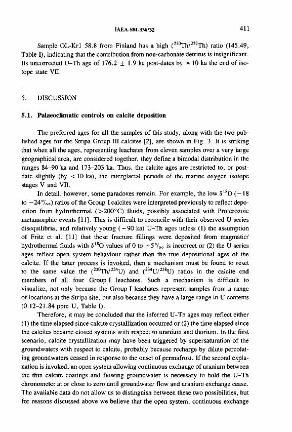
IAEA-SM-336/32 411
Sample OL-Krl 58.8 from Finland has a high (2 3 0 Th/2 3 2 Th) ratio (145.49, Table I), indicating that the contribution from non-carbonate detritus is insignificant. Its uncorrected U-Th age of 176.2 ± 1.9 ka post-dates by = 10 ka the end of isotope state VII.
5. DISCUSSION
5.1. Palaeoclimatic controls on calcite deposition
The preferred ages for all the samples of this study, along with the two published ages for the Stripa Group III calcites [2], are shown in Fig. 3. It is striking that when all the ages, representing leachates from eleven samples over a very large geographical area, are considered together, they define a bimodal distribution in the ranges 84-90 ka and 173-203 ka. Thus, the calcite ages are restricted to, or postdate slightly (by < 1 0 ka), the interglacial periods of the marine oxygen isotope stages V and VII.
In detail, however, some paradoxes remain. For example, the low ô180 (-18 to -24°/00) ratios of the Group I calcites were interpreted previously to reflect deposition from hydrothermal (>200°C) fluids, possibly associated with Proterozoic metamorphic events [11]. This is difficult to reconcile with their observed U series disequilibria, and relatively young (~90 ka) U-Th ages unless (1) thé assumption of Fritz et al. [11] that these fracture fillings were deposited from magmatic/ hydrothermal fluids with <5 l80 values of 0 to +57 0 0 is incorrect or (2) the U series ages reflect open system behaviour rather than the true depositional ages of the calcite. If the latter process is invoked, then a mechanism must be found to reset to the same value the (2 3 0 Th/2 3 4 U) and (2 3 4 U/2 3 8 U) ratios in the calcite end members of all four Group I leachates. Such a mechanism is difficult to visualize, not only because the Group I leachates represent samples from a range of locations at the Stripa site, but also because they have a large range in U contents (0.12-21.84 ppm U, Table I).
Therefore, it may be concluded that the inferred U-Th ages may reflect either(1 ) the time elapsed since calcite crystallization occurred or (2 ) the time elapsed since the calcites became closed systems with respect to uranium and thorium. In the first scenario, calcite crystallization may have been triggered by supersaturation of the groundwaters with respect to calcite, probably because recharge by dilute percolating groundwaters ceased in response to the onset of permafrost. If the second explanation is invoked, an open system allowing continuous exchange of uranium between the thin calcite coatings and flowing groundwater is necessary to hold the U-Th chronometer at or close to zero until groundwater flow and uranium exchange cease. The available data do not allow us to distinguish between these two possibilities, but for reasons discussed above we believe that the open system, continuous exchange
412 McDERMOTT et al.
model is unlikely, at least for the Stripa Group I samples. Irrespective of the preferred mechanism, the calcite ages record a perturbation in either the chemistry or the flow regime of the groundwater, which appears in turn to be linked to the onset of colder, glacial conditions. The apparent absence of ages in the colder periods (marine oxygen isotope stages IV and VI) is taken to indicate the onset of permafrost which inhibits meteoric recharge of these relatively shallow fractured systems [26].
5.2. Initial (234U/238U)0 activity ratios
Initial (2 3 4 U/2 3 8 U) 0 ratios have been calculated from the present-day measured values and the U-Th ages inferred for the Stripa calcites. Thus, the Group I calcites have a (2 3 4 U/2 3 8 U) 0 ratio of 1.096 ± 0.093, and the Group 1П veins have higher (2 3 4 U/2 3 8 U) 0 ratios in the range 1.454 ± 0.283. All are significantly lower than those which characterize present-day shallow (< 80 m) groundwaters at Stripa (2.18 to 4.8) and groundwaters at depths (>360 m) similar to those at which the Stripa drill hole calcites were obtained ((2 3 4U/2 3 8 U) = 3 -8 ; [2, 27]). Thus, the Stripa calcites cannot have been deposited from groundwaters which had U isotope ratios similar to those of the present-day groundwaters.
In principle, such elevated (2 3 4 U/2 3 8 U) ratios in groundwater can reflect preferential dissolution of 234U from recoil damaged sites and/or 234U addition to the groundwater via alpha recoil addition of its short lived (t1/2 = 24 d) parent, 234Th [28, 29]. At relatively deep levels, away from oxidizing recharge zones, the latter process is usually dominant, and in a simple model which ascribes the 234U excess to alpha recoil processes, Andrews et al. [27] have calculated a maximum residence age of 30 000 years for the present-day deep Stripa groundwaters. This calculation serves simply to illustrate that alpha recoil enrichment of 234U can account readily for the high (2 3 4 U/2 3 8 U) ratios observed in the deep Stripa groundwaters over relatively short periods.
Another striking feature of the Stripa calcites is their rather high U contents (Table I), and these contrast sharply with the relatively low U contents of present- day groundwaters at these depths (< 1 ppb, [27]). Milton [2] argued that the process of calcite deposition, even in the presence of iron hydroxides, could not account for the observed U enrichment, and therefore the groundwaters from which the Stripa calcites were deposited had significantly higher U contents than the present-day groundwaters at the same depths. Thus, the shift to high (2 3 4 U/2 3 8 U) in the present- day Stripa groundwaters appears to have been accompanied by a marked decrease in U contents.
5.3. Evidence for U mobility and open system behaviour
In addition to the Group П samples, four leachates (N1 74.6, N1 293.45, V2 416.08 and URL12/146.5) are close to secular equilibrium, but exhibit
IAEA-SM-336/32 413
(2 3 0 Th/2 3 4 U) ratios which are higher than the values expected at equilibrium. In principle, such excess 230Th might reflect either preferential leaching of 230Th relative to 234U during sample dissolution or, more likely, recent leaching of uranium from the fracture coatings by groundwaters. The role of non-carbonate detrital contamination in causing the 230Th excess is thought to be minimal because this has been corrected for in the case of the Group II leachates, and with the exception of N1 74.6 the other open system leachates exhibit high (2 3 0 Th/2 3 2 Th) ratios (Table I). In general the disturbances from equilibrium are relatively small (<4%) apart from N1 74.6, which exhibits a 230Th excess of —15%. This, in part, may reflect the effect of detrital contamination because this leachate has a relatively low (2 3 0 Th/2 3 2 Th) ratio (Table I).
It is noticeable that many of the leachates which exhibit open system behaviour have unusually high uranium contents (up to 570 ppm in the case of V2 416.08, Table I). Using the U-Th disequilibrium data it is possible to make some first order estimates of the amount of uranium which was remobilized. In practice these are minimum estimates because they assume (1 ) that the system was in secular equilibrium prior to uranium remobilization and (2 ) that no time has elapsed since the mobilization event. Clearly, a larger uranium remobilization which occurred several hundred ka ago could have the same pair of activity ratios as a smaller, more recent remobilization; hence the need for the second simplification above.
In the case of sample V2 416.08, for example, a loss of at least 15 g of U per gram of calcite is required to generate its elevated (2 3 0 Th/2 3 8 U) ratio, if this is ascribed solely to uranium loss (possible adsorption of 230Th generated by in situ decay of 234U dissolved in groundwater is ignored). Thus, in a simple illustrative model, a 1 km x 1 km fracture covered uniformly on both sides with a 1 0 0 /¿m thick coating of calcite could have lost = 8 kg of uranium. Estimates for the other samples (URL12/146.5 and N1 293.45) are approximately an order of magnitude lower, reflecting their lower U contents. There are no constraints on the rate at which such a loss might have occurred, other than that it must have been fast relative to the half- life of 230Th (75 200 a) in order to generate and maintain a measurable 230Th excess.
6 . CONCLUSIONS
(1) The new U-Th age data for Stripa indicate that the previously defined threefold mineralogical classification [1 2 ], which in the case of the samples analysed here is reflected in their stable isotope geochemistry (see Fig. 1), is robust. Thus, each group defines a characteristic U-Th age range.
(2) U-Th ages for the Fennoscandian and Canadian shield calcites form a bimodal distribution ranging from 84 to 90 ka and 173 to 203 ka respectively. The two previously available alpha spectrometric dates of 95 ± 10 and 209 ± 60 ka
414 McDERMOTT et al.
for the Stripa site are consistent with the new mass spectrometric age data. These ages coincide with the end of the interglacial conditions of the marine oxygen isotope stages V and VII, and are taken to indicate calcite precipitation in response to the shutoff of meteoric recharge due to the onset of permafrost at these latitudes.
(3) The Group II samples are close to secular equilibrium but exhibit evidence of uranium uptake in the last million years.
ACKNOWLEDGEMENTS
P. van Calsteren, M. Johnston and D. Wright are thanked for all their help in the radiogenic isotope laboratory at the Open University. A. Blyth had the time consuming task of separating the calcite bearing fracture coatings from the URL and Olkiluoto drill cores. Frank McDermott gratefully acknowledges support from the Natural Environmental Research Council (NERC), Swindon, United Kingdom, during the laboratory stage of this project at the Open University, and more recently from the Newman Trust at University College Dublin. The radiogenic isotope laboratory at the Open University is supported by NERC.
REFERENCES
[1] CLAUER, N ., FRAPE, S.K., FRITZ, B ., Calcite veins of the Stripa granite (Sweden) as records of the origin of the groundwaters and their interactions with the granite body, Geochim. Cosmochim. Acta 53 (1989) 1777-1781.
[2] MILTON, G.M ., Paleohydrological inferences from fracture calcite analyses: an example from the Stripa Project, Sweden, Appl. Geochem. 2 (1987) 33-36.
[3] IVANOVICH, М ., MILODOWSKI, A .E., HASLER, S.E., Uranium/Thorium Series Studies in Fracture Infill and Matrix Carbonates from the Dounreay Area, Nirex Rep. NSS/R334, UK Nirex Ltd, Harwell (1995).
[4] BLYTH, A .R ., The Study o f Fracture Calcite in the Fennoscandian and Canadian Shields as an Indicator of the Past Thermal and Fluid History, MSc dissertation, Univ. Waterloo, Waterloo, Ontario, Canada (1993).
[5] GASCOYNE, М ., “ The use of uranium series disequilibrium to determine radionuclide migration on geological timescales” (Proc. Can. Nucl. Soc. Int. Conf. Radioactive Waste Management, Winnipeg, 1982), Canadian Nuclear Society, Toronto (1982) 162-166.
[6] SCHWARCZ, H.P., GASCOYNE, М., FORD, D .C ., “ Uranium-series disequilibrium studies of granitic rocks” , Geochemistry o f Radioactive Waste Disposal (BIRD,G.W ., FYFE, W .S., Eds), Chem. Geol. 36 (1982) 87-102.

IAEA-SM-336/32 415
[7] GASCOYNE, М ., High levels o f uranium and radium in groundwaters at Canada’s Underground Research Laboratory, Lac du Bonnet, Manitoba, Canada, Appl. Geochem. 4 (1989) 577-591.
[8] GASCOYNE, M ., WUSCHKE, D .M ., DURRANCE, E.M ., Fracture detection and groundwater flow characterisation using He and Rn in soil gases, Manitoba, Canada, Appl. Geochem. 8 (1993) 223-234.
[9] NORDSTROM, D .K., OLSSON, T., CARLSSON, L., FRITZ, P ., Introduction to the hydrogeochemical investigations within the International Stripa Project, Geochim. Cosmochim. Acta 53 (1989) 1717-1726.
[10] WOLLENBERG, H., FLEXSER, S., ANDERSON, L., Petrology and Radiogeology of the Stripa Pluton, Rep. LBL 11654, Lawrence Berkeley Laboratory, Swedish- American Cooperative-36, CA (1980).
[11] FRITZ, B ., CLAUER, N ., KAM, М ., “ Strontium isotopic data and geochemical calculations as indicators for the origin of saline waters in crystalline rocks” , Saline Waters and Gases in Crystalline Rocks (FRITZ, P., FRAPE, S.K., Eds), Geol. Assoc. Canada Spec. Paper 33 (1987) 121-126.
[12] FRITZ, P., et al., The isotope geochemistry o f carbon in groundwater at Stripa, Geochim. Cosmochim. Acta 53 (1989) 1765-1775.
[13] BROWN, A ., SOONAWALA, N .M ., EVERITT, R .A ., KAMINENI, D .C ., Geology and geophysics o f the Underground Research Laboratory site, Lac du Bonnet batholith, Manitoba, Can. J. Earth Sci. 26 (1989) 404-425.
[14] GRIFFAULT, L .Y ., GASCOYNE, М., KAMINENI, D .C ., KERRICH, R., VANDERGRAFF, T .T., Actinide and rare earth element characteristics o f deep fracture zones in the Lac du Bonnet granitic batholith, Manitoba, Canada, Geochem. Cosmochim. Acta 57 (1993) 1181-1202.
[15] GAAL, G ., 2200 million years of crustal evolution: The Baltic Shield, Bull. Geol. Soc. Finland 158 Part 1 (1986) 149-168.
[16] BLOMQVIST, R., NISSENIN, P., FRAPE, S.K., Dating of fracture minerals from Olkiluoto, S.W. Finland, Industrial Power Technical Report 631 (1992).
[17] McDERMOTT, F., FRAPE, S., IVANOVICH, M ., HAWKESWORTH, C.J., Uranium-series systematics o f calcite-bearing fractures in the Fennoscandian and Canadian shields; a palaeoclimatic control? (in preparation).
[18] McDERMOTT, F., GRÜN, R., STRINGER, C.B., HAWKESWORTH, C.J., Mass- spectrometric U-series dates for Israeli Neanderthal/early modern hominid sites, Nature (London) 363 (1993) 252-254.
[19] SCHWARCZ, H.P., LATHAM, A .G ., Dirty calcites I. Uranium-series dating of contaminated calcite using leachates alone, Chem. Geol. 80 (1989) 35-43.
[20] PRZYBYLOWICZ, W ., SCHWARCZ, H.P., LATHAM, A .G ., Dirty calcites II. Uranium-series dating of artificial calcite-detritus mixtures, Chem. Geol. (Isot. Geosc. Sect.) 86 (1991) 161-178.
[21] BISCHOFF, J .L ., FITZPATRICK, J .A ., Uranium-series dating of impure carbonates: An isochron technique using total-sample dissolution, Geochim. Cosmochim. Acta 55 (1991) 543-554.
[22] LUO, S., KU, T .L., Uranium series dating: A generalised model employing total- sample dissolution, Geochim. Cosmochim. Acta 55 (1991) 555-564.

416 McDERMOTT et al.
[23] IVANOVICH, М ., LATHAM, A .G ., KU, T .L., “ Uranium-series disequilibrium applications in geochemistry” , Uranium Series Disequilibrium: Applications to Earth, Marine and Environmental Sciences (IVANOVICH, М ., HARMON, R.S., Eds), Clarendon Press, Oxford (1992) 62-94.
[24] KAUFMAN, A ., An evaluation of several methods for determining 230Th/U ages in impure carbonates, Geochim. Cosmochim. Acta 57 (1993) 2303-2317.
[25] YORK, D ., Least squares fitting of a straight line with correlated errors, Earth Planet. Sci. Lett. 5 (1969) 320-324.
[26] MARTINSON, D .G ., et al., Age dating and the orbital theory of the ice ages: Development of a high resolution 0 to 300 000-year chronostratigraphy, Quat. Res. 27 (1987) 1-29.
[27] ANDREWS, J.N ., FORD, D .J., HUSSAIN, N ., TRIVEDI, D ., YOUNGMAN, M.J., Natural radioelement solution by circulating groundwaters in the Stripa granite, Geochim. Cosmochim. Acta 53 (1989) 1791-1802.
[28] KIGOSHI, K., Alpha recoil 234Th: dissolution into water and the 234U /238U disequilibrium in nature, Science 173 (1971) 47-49.
[29] ROSHOLT, J.N ., SHIELDS, W .R., GARNER, E.L., Isotopic fractionation of uranium in sandstone, Science 139 (1963) 224-226.

IAEA-SM-336/12
FLUID ISOTOPIC COMPOSITIONIN THE PALINPINON I GEOTHERMAL SYSTEM(PHILIPPINES)
F. D’AMORE*, J.Y. GERARDO**,J.S. SEASTRES, Jr.***, E. CALVI*
* International Institute for Geothermal Research (CNR),Pisa, Italy
** Isotope Hydrology Section,Division of Physical and Chemical Sciences,International Atomic Energy Agency,Vienna
*** PNOC-Energy Development Corporation,Makati, Philippines
Abstract
FLUID ISOTOPIC COMPOSITION IN THE PALINPINON I GEOTHERMAL SYSTEM (PHILIPPINES).
A new set o f chemical and isotopic data of rocks, waters and gases sampled in 1993 in the Palinpinon (Philippines) geothermal system from nine deep wells indicates that the production fluids show very different chemical and physical characteristics. The relative concentrations of N2, Ar and He reveal three components o f different origins: a magmatic andesitic component (25%), a meteoric component tied to natural recharge (44%) and gas of crustal origin (31 %). 5 I3C values of primary deep limestone samples and of C 0 2 suggest that the geothermal system is close to a magmatic source. The application o f the H20 -H 2 isotopic geothermometer based on deuterium fractionation in the system produces values of temperatures that are correlated with those computed from S i0 2 concentrations. The trend indicates a progressive equilibration towards a final temperature of 310°C. This value can be considered the temperature in the reservoir where the chemical and isotopic equilibria are both attained.
417
418 D’AMORE et al.
1. INTRODUCTION
Isotopic investigation of the Palinpinon geothermal system was first performed between 1980-1983, prior to the exploitation of the reservoir [1]. The stable isotope data obtained at that time for cold springs, rivers and discharges from geothermal wells have been useful in establishing the pre-exploitation isotopic state of the geothermal reservoir [2 ].
The isotopic investigation after several years of exploitation also allowed [2] hypotheses to be made on:
— The location of the meteoric water recharge to the geothermal system, which has a <5180 value of -8 .5 7 0 0 and of ÔD value of -5 4 7 00;
— The origin of the parent geothermal water due to a mixing between meteoric water and a heavy end member inferred to be a magmatic water associated with andesitic volcanism (with <3180 and ÔD respectively of the order of +107oo and -2 0 7 oo);
— The identification of the upflow zone where some wells are tapping fluids that come directly from the deep high temperature zone with an isotopic composition of <5180 = -4 .5 7 0 0 and 5D = -4 2 700.
In the present work a new set of chemical and isotopic data of fluids sampledin 1993, for nine selected wells of the field located as in Ref. [3], is interpreted. Ithas also been possible to investigate the origin of gas species, and some of the main phenomena affecting the fluid in the reservoir. In particular, the original deep fluid is affected by dilution in different proportion by the reinjection brine, acidic condensate waters and locally recharged meteoric water. New for the Philippines is the use of the isotopes of the reactive gas species as geothermometers, as discussed in this paper. That this technique has not been used previously is mostly due to difficulties found in the application of techniques in the determination of deuterium content of H2 in geothermal gases, because of the generally low content of this species (less than 5% in volume).
2. GAS ORIGIN
The origin of different gas species has been investigated. From Ref. [2] it is demonstrated by stable isotopes of water that the deep magmatic component contributes to the geothermal system. From the relative contents of N2 -He-Ar, the mean values (and standard deviation) in percentages, are calculated (Fig. 1) as follows:
crustal (local limestone): 31 + 3%; magmatic (andesitic): 25 + 12%;meteoric: 44 + 15%.

IAEA-SM-336/12 419
О 2000 4000 6000 8000 10000 12000
Cl (mg/kg)
FIG. 1. Diagram o f ô lsO (°/00 versus standard mean ocean water, SMOW) versus Cl content (mg/kg) for wells o f Palinpinon I. RW: reinjection water; AC: acidic condensate with an isotopic composition as determined in Ref. [2].
While the standard deviation value for the crustal component is small, indicating for all samples an almost constant contribution, the standard deviation values for the other two components suggest a large variability in the origin of gases. This is attributed to a mixture of the magmatic component and the meteoric components, mostly due to the argon content linked to the local recharge water (ASW in Fig. 2). In Palinpinon this component is larger than the magmatic contribution.
After water, carbon dioxide is the main component of the geothermal fluid. The isotopic composition of this species is quite homogeneous (Table I), representing a mean value of — 2.2 ± 0.47oo in ô l3 C. The analysed carbonates of the limestone of marine origin in the Philippines have a mean value of —0.6 ± 0.87oo in ô13C (Table I). The C02 that originated from the thermo-metamorphism of the carbonates in first approximation can be considered equal to the mean value obtained for carbonates without any change due to fractionation. We can then consider for the produced C02 two end members with the following value for ô 13C:
a magmatic component at —7.5 ± 1.07oo a metamorphic component at - 0 . 6 + 0.87oo.

42 0 D’AMORE et al.
n2/ ioo
FIG. 2. Triangular diagram showing the relative positions in the system N2-A r-H e fo r nine wells o f Palinpinon I. V: magnetic gas; ASW: air saturated water at about 20°C.
Thus, the mean value of -2 .2 7 00 represented by the sample of C02 gas can be produced by the contribution of a more negative component, presumably of magmatic origin. Considering only the mean values from the two end members, we obtain a mixing of about 23 % for the magmatic component and 77 % for the metamorphic component. In Ref. [2] stable isotopes of water evidenced similar results, with a computed magmatic contribution of about 2 0 %.
3. PHYSICAL PHENOMENA IN THE RESERVOIR
The main component of the fluid in the reservoir, H2 0, can have different origins, and its isotopic and chemical composition is a marker of phenomena affecting the fluid.

IAEA-SM-336/12 421
TABLE I. ISOTOPIC COMPOSITION OF THE FLUID FOR SELECTED WELLS OF PALINPINON I GEOTHERMAL FIELD
Well Date
versus—
d180H20
SMOW
d2Hh 2o
SMOW
d2 H H2
SMOW
d2HCH4
SMOW
d,3CCH4PDB
Э180c o 2PDB
a 13cc o 2PDB
PN23D 93-05-28 -4.27 -43.3 -461 -156 -23.8 -17.4 -2.39
OK5 93-06-07 -5.69 -43.8 -443 -157 -22.0 -17.6 -2.39
OK9D 93-05-29 -4.43 -42.8 -453 -152 -22.8 -17.4 -2.30
PN24D 93-05-28 -4.30 -41.9 -443 -148 -21.5 -18.0 -1.77
PN28 93-06-04 -3.14 -39.5 -500 -157 -25.9 -18.2 -2.18
PN22D 93-06-01 -4.72 -42.4 -480 -148 -19.5 -21.9 -2.37
PN30D 93-05-28 -5.22 -44.2 -450 -150 -21.8 -18.8 -1.95
PN15D 93-05-28 5.53 -40.3 -469 -149 -24.3 -19.0 -2.90
PN19D 93-06-03 -3.79 -40.6 -446 -147 -22.0 -17.2 -1.59
Carbonates isotopic compositionWell Depth
(m)OP4D 1865 -11.3 -0.12
OP3D 2802 -10.4 -0.22
OP5DA 2810 -14.4 -1.74
2500 -18.1 -2.07
2430 -20.7 -0.52
2220 -13.7 -2.56
2130 -19.9 -2.74
OP3D 2528 -12.1 -0.11PN19D 1750 -26.4 -1.05
OK4 1695 -25.7 -3.78
PDB = Peedee belemnite.SMOW = Standard mean ocean water.
One of the main phenomena affecting the fluid composition in Palinpinon is the mixing of the original fluid with a reinjection brine [4]. From wells maintaining an almost undisturbed composition in the ratio <5I80/C1 (wells 24 and 9 at the upflow zone) a straight line is obtained toward the composition of the reinjected brine (RW in Fig. 1).
This water is reinjected at a pressure of 0.7 MPa at about 165°C. It has an average chloride content close to 1 0 0 0 0 mg/kg, and a ¿ > 18 0 value of - 2 .8 ° / 0 0 [2 ]. Well 28 is the most affected by reinjection. Despite the high correlation factor (r2 = 0.89), using all the data in Fig. 1, the relative position of a few points is out of the above alignment. Well 30 deviates towards lower values in both parameters.

Dis
char
geen
thal
py
K/M
g N
a/Li
C
l/S0
4 S
O^L
i C
l/Ca
422 D’AMORE et al.
16000-,
1 2 0 0 0 -8 0 0 0 -
4 0 0 0 -
0 -
2 6 0 0 -,
2 2 0 0 - 1 8 0 0 -
1 4 0 0 -
1 0 0 0 -i--------1-------- ;-------- 1-------- 1-------- 1--------1--------1-------- 1
28 30 22 19 9 24 23 5 15
W e ll
FIG. 3. Selected ratios of chemical species from Ref. [4] and wellhead enthalpy values (measured by PNOC) for the nine selected wells o f Palinpinon I.

IAEA-SM-336/12 423
This can be simply explained by a contribution of extraneous steam to the original fluid. The position of well 22 can be explained by a mixing with acidic condensate water (point AC in Fig. 2); indeed the pH of the water of well 22 is 5.2, much lower than the pH of the other wells (ranging from 6 . 8 to 7.9). Well 20, whose pH is close to 3, is located very close to line AC. Although the position of well 5 (Fig. 2) is close to well 22, the value of the pH close to 8 suggests a different mechanism of dilution. The low content in ôl80 and in Cl is likely to be due to a mixing with meteoric water having <5180 close to — 8 7 0 0 -
Several chemical parameters and discharge enthalpy for the nine wells are shown Fig. 3. They can help to discriminate the different phenomena. Wells 5, 22, 28 and 30 mix respectively with meteoric water, gas-rich acidic condensate, reinjection brine and gas-rich exotic steam. Well 28, the most affected by reinjection, shows the lowest value of Cl/Ca and enthalpy because of dissolution of Ca carbonates and sulphate. Sodium/lithium is relatively high in well 15, indicating a low equilibration temperature in the reservoir [5]. Well 22 shows the maximum values for Cl/Ca,
FIG. 4. Correlation diagram between &,80 (°/00 versus SMOW) and gas/total water molar ratio expressed as C02/H20 x 105 (PNOC measurements) for wells o f Palinpinon I.

D’AMORE et al.
FIG. 5. ôD (°/00 versus SMOW) versus ôl80 (°/00 versus SMOW) for wells o f Palinpinon I. AW: acidic waters; RW: reinjection waters; PW(91): undisturbed pre-exploitation conditions up to 1991 [2].
S04 /Li, and the minimum for C1/S04 as well as for K/Mg. It shows a high enthalpy with respect to the other wells. This chemistry is determined by the high content of SO4 . The high value of Cl/Ca can be due to precipitation of anhydrite. The high content of Mg can be related to the contribution of acidic water. Well 30 shows the maximum enthalpy value (close to 2400 kJ/kg) consistent with some input of steam. From the point of view of water chemistry the hottest wells are 24 and 5, despite the fact that reservoir water of well 5 is diluted by meteoric water. These two wells show the maximum values of silica content and K/Mg ratio, with the lowest values of Na/Li and Na/К ratios.
The differentiation between mixing with meteoric water, reinjection brine and extraneous steam is evident in Fig. 4, where ¿>180 of the water is reported versus C02 /H20 ratio, corresponding closely to the gas/water ratio of the wells. It is evident that well 5 is not on the straight line (with r 2 = 0.78). This is due to the entry of meteoric water to the system. Points for wells 22 and 30 show a large increase of gas content with a corresponding decline in the ô180 value. Some condensate fluid consisting of exotic gas and steam depleted in <5180 could be contributing to the production.
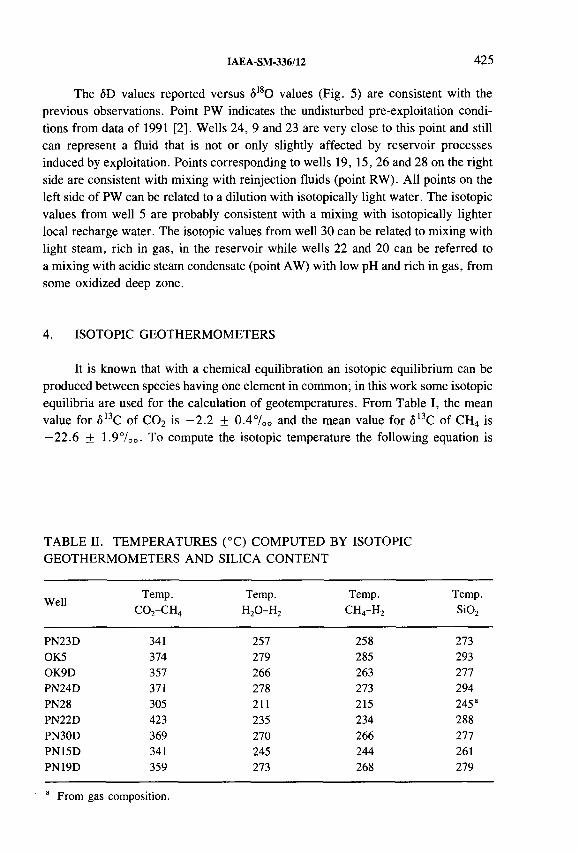
IAEA-SM-336/12 425
The SD values reported versus ô180 values (Fig. 5) are consistent with the previous observations. Point PW indicates the undisturbed pre-exploitation conditions from data of 1991 [2]. Wells 24, 9 and 23 are very close to this point and still can represent a fluid that is not or only slightly affected by reservoir processes induced by exploitation. Points corresponding to wells 19, 15, 26 and 28 on the right side are consistent with mixing with reinjection fluids (point RW). All points on the left side of PW can be related to a dilution with isotopically light water. The isotopic values from well 5 are probably consistent with a mixing with isotopically lighter local recharge water. The isotopic values from well 30 can be related to mixing with light steam, rich in gas, in the reservoir while wells 2 2 and 2 0 can be referred to a mixing with acidic steam condensate (point AW) with low pH and rich in gas, from some oxidized deep zone.
4. ISOTOPIC GEOTHERMOMETERS
It is known that with a chemical equilibration an isotopic equilibrium can be produced between species having one element in common; in this work some isotopic equilibria are used for the calculation of geotemperatures. From Table I, the mean value for ô13C of C02 is —2.2 + 0.47oo and the mean value for ô13C of CH4 is —22.6 ± 1.9700. To compute the isotopic temperature the following equation is
TABLE II. TEMPERATURES (°C) COMPUTED BY ISOTOPIC GEOTHERMOMETERS AND SILICA CONTENT
WellTemp.
C0 2-CH4Temp.
H20-H 2Temp.
CH4-H2Temp.Si02
PN23D 341 257 258 273OK5 374 279 285 293OK9D 357 266 263 277PN24D 371 278 273 294PN28 305 211 215 245“PN22D 423 235 234 288PN30D 369 270 266 277PN15D 341 245 244 261PN19D 359 273 268 279
“ From gas composition.

426 D’AMORE et al.
used for the pair of species; approximated by 1 0 0 0 In a whose temperature dependence for the case of the C02 -CH4 pair is expressed as in Ref. [6 ], where T is in kelvin:
103 In a = -9.56 + 15.25 X 10³ T ' 1 + 2.432 X 10⁶ T ~ 2 (1)
The resulting mean computed temperature from the C02 -CH4 geothermometer (Table II) is 352 + 23°C. This value can be referred to the zone beneath the actually exploited reservoir (having pre-exploitation temperatures between 270 and 320 °C) where limestone has been mapped and from where a large part of the C02
can be produced.A possible calculation of the temperature beneath the limestone zone, related
to the volcanic contribution, can be made considering the following values for the pair C02 -CH4: —7.5 7 0 0 for <513C of C02 (magmatic component) and —19.5700 for S13C of CH4 (which is the most positive observed value, Table I). A temperature close to 540°C is computed. Then, it is possible to say that the maximum temperature in the andesitic system beneath the local limestone can have a value of 540°C.
From Table I, the temperatures from the pairs H2 0-H 2 and CH4 -H2 are calculated using the following equations (Refs [6 , 7]):
(H2 0-H 2): 103 In a = -217.3 + 396.8 X 10³ T " 1 + 11.76 x 10⁶ T “ 2
(2 )
(CH4-H2): 103 In a = -90.9 + 181.27 X 10⁶ T~ 2 - 8.95 X 10¹² T " 4
(3)
From Table I, it is evident that ¿>D changes very little for both H20 and CH4
respectively in the range -39.5 to -43.8700 and -147 to - 157700. Then the value of ÔD of H2 (ranging from -500 to -443700) seems to control mostly the isotopic temperature. Chemical temperature from Si02 (Table II) [8 ] has been assumed to be the most reliable temperature value for the fluid in the reservoir with the exception of well 28, which is strongly affected by returns of the injected brine. For this well a value of 245° has been selected from data related to gas chemistry [3], considering a failure in the equilibration of silica. Figure 6 shows these values of reservoir temperature versus temperatures computed from the H20-H 2 isotopic geothermometer. With the exception of well 22, all the points follow a straight line:
t (Si02) = 95.5 + 0.691 t (H20 - H2) at r2 = 0.91 (4)

IAEA-SM-336/12 427
t (н2о-н2) -с
FIG. 6. Temperature in the reservoir computed from silica content (quartz [8]) versus temperature computed with the isotopic geothermometer H20-H 2 based on ÔD values. Isotherm line indicates the same temperature value from both geothermometers.
The isotopic temperatures for all wells are lower than those computed from silica. The difference between the two temperatures approaches zero as the temperature value increases. The temperature would be the same at about 310°C. A possible explanation could be an active phenomenon of kinetics affecting to a differing extent the isotopic composition of H2 of the different wells. First of all we have to consider that the amount of hydrogen is in general very low with respect to vapour dominated systems (the molar ratio H2 /H20 is of the order of 1 X 10' 5 in Palinpinon and of 50 x 10~ 5 in Larderello, Italy, geothermal field). If we infer a full isotopic equilibration between the two species (H20 and H2), the resulting isotopic temperature is not that of the bulk of the reservoir, but that of the well bottom considering the temperature of the local flashing liquid water. Wells 24 and 5 seem almost to show a correspondence between these two temperatures. Well 22, affected by mixing with acidic water, shows a very light value of deuterium for hydrogen; this may explain the low value of computed temperature. Temperatures computed with the CH4 -H2 isotopic geothermometer are very close to that computed with H2 0-H2. It can be assumed that the isotopic composition of hydrogen controls the computed temperatures in a full isotopic equilibration between H2 and CH4.

428 D’AMORE et al.
Despite the limited number of wells studied, accuracy in selecting the sampling points together with the quality of the isotopic data (resulting from repeated determinations) allowed the understanding of different processes.
The relative concentrations of the non-reactive gases (N2, Ar, He) show the presence of three components. First, a magmatic andesitic component evaluated in the order of 25%. A magmatic component is commonly present in geothermal systems associated with active andesitic volcanic arcs [9]. Secondly, there is a meteoric component tied to natural recharge. This component contributes to the system by 44%. Its relatively high amount is linked to a fast recharge of the geothermal field. In the vapour dominated field of Larderello, characterized by slow recharge and very low permeability, the meteoric component is much less important (in the order of 5%). On the contrary in Wairakei geothermal field the very fast recharge produces points that cluster around to the ASW end member. The third component is represented by a gas of crustal origin in the order of 31%.
The study of 13C of primary limestone and the values of <513C of the C02 gas from the wells suggests that the system is close to a magmatic source. In fact the C02 results from a mixture of 23% of magmatic component and 77% meteoric waters produced by the thermometamorphic reaction of crustal marine sediments (limestone) because of subduction.
The main physical phenomena affecting the fluid in the reservoir seem not to disturb wells located in the upflow zone (e.g. wells 24 and 9). Several wells are affected to differing degrees from returns of the reinjected brine, as evidenced by the study of the relations of ôlsO-ôD, ô180-Cl and ô1 80-C 0 2 /H20 molar ratio. One well (30) is clearly affected by steam addition, which causes the depletion of heavy isotopes and Cl, with a corresponding increase of gas content and enthalpy. Other wells (e.g. 20 and 22) are strongly affected by acidic waters. These wells are characterized by low pH, high content in S04 and Si02, low content in Cl and high enthalpy. The presence of highly reactive and corrosive acidic fluids is due to the siting of the wells close to the magmatic body emplaced at shallow depth.
Direct temperature measurements in the pre-exploitation conditions in the Palinpinon geothermal system give reservoir temperatures in the range of 270-320°C. The application of the isotopic geothermometer based on ô13C content of the C02 -CH4 pair gives an average value of temperature close to 350°C. Since C02 originated mostly from thermometamorphic reaction of limestone, this temperature can refer to the subducted sedimentary levels close to the exploited main reservoir. A higher temperature of 540°C is evaluated considering a value of ¿>13C in C02 that corresponds to a deep magmatic contribution (<513C = —7 .5 I OO ). This temperature can refer to the cooling andesitic magma cooling zone beneath the limestone level.
5. CONCLUSIONS

IAEA-SM-336/12 429
t (С02-С Н 4) ”С
FIG. 7. Isotopic temperature computed from the H20-H 2 pair versus the C02-CH4 pair.
The application of the H2 0-H 2 isotopic geothermometer based on deuterium fractionation in the system gives temperature values strongly correlated with that produced from I3C in the C02 -CH4 pair (as in Fig. 7) but lower by about 90°C. This can be due to the fact that the H2 0-H 2 system refers to the thermodynamic conditions close to the well bottom. Moreover we observed that the temperature values given by the pair CH4 -H2 are almost the same as for the H20-H 2 pair (Table II).
Temperatures computed from Si02 content are very well correlated with the system H2 0-H 2 (Fig. 6 ). The correlation does not correspond with an isotherm, but the trend of the alignment of the points is towards a point at 310°C. This value can be considered the temperature in the reservoir where the chemical and isotopic equilibria are attained.
ACKNOWLEDGEMENTS
The authors are grateful to the management of the Philippine National Oil Company-Energy Development Corporation for permitting the publication of the data.

4 3 0 D’AMORE et al.
REFERENCES
[1] CLEMENTE, V.C., Stable Isotope Chemistry of Selected Mineral Samples from
Southern Negros Geothermal Project, Internal Report, Philippine National Oil Co.-
Energy Development Corp. (1986).[2] GERARDO, J.Y., NUTI, S., D ’AMORE, F., SEASTRES, J.S., GONFIANTINI, R.,
Isotopic evidence for magmatic and meteoric water recharge and the processes affecting
reservoir fluids in the Palinpinon geothermal system, Philippines, Geothermics 22
(1993) 521-533.[3] D ’AMORE, F., RAMOS-C ANDELARIA, M.N., SEASTRES, J.S., RUAYA, J.R.,
NUTI, S., Applications of gas chemistry in evaluating physical processes in the
Southern Negros (Palinpinon) geothermal field, Philippines, Geothermics 22 (1993)
535-553.[4] SEASTRES, J.S., Reservoir Chemistry Response to Changes in Reinjection Strategy
During Ten Years of Exploitation at Puhagan Sector, Southern Negros Geothermal Field, Unpublished Internal Report, Philippine National Oil Co.-Energy Development
Corp., 1993.[5] FOUILLAC, C., MICHARD, G., Sodium/lithium ratios in water applied to geo
thermometry of geothermal reservoirs, Geothermics 10 (1981) 55-70.[6] RICHET, P., BOTTINGA, Y., JAVOY, М., A review of hydrogen, carbon, nitrogen,
oxygen, sulfur and chlorine stable isotope fractionation among gaseous molecules, Ann.
Reg. Earth Planet. Sci. S (1977) 65-110.[7] CRAIG, H., Oral presentation to the IAEA Advisory Group on the application of
nuclear techniques to geothermal studies, Pisa, Italy, 8-12 Sep. 1975.[8] FOURNIER, R.O., A method of calculating quartz solubilities in aqueous sodium
chloride solutions, Geochim. Cosmochim. Acta 47 (1983) 579-586.[9] GIGGENBACH, W.F., Isotopic shifts in waters from geothermal and volcanic systems
along convergent plate boundaries and their origin, Earth Planet. Sci. Lett. 113 (1992)
495-510.
IAEA-SM-336/22
REGIONAL INVESTIGATION OF COLD GROUNDWATER FOR DETERMINATION OF THE RECHARGE CONDITIONS IN GEOTHERMAL AREAS OF NORTHWESTERN TURKEY
T. EISENLOHR, C. JECKELMANN, W. BALDERER, S. BERNASCONI Geologisches Institut, Ingenieurgeologie,Eidgenôssische Technische Hochschule-Hônggerberg,Zurich, Switzerland
W. RAUERT, P. TRIMBORN Institut fur Hydrologie,GSF-Forschungszentrum fiir Umwelt und Gesundheit Neuherberg, Oberschleissheim, Germany
Abstract
REGIONAL INVESTIGATION OF COLD GROUNDWATER FOR DETERMINATION OF THE RECHARGE CONDITIONS IN GEOTHERMAL AREAS OF NORTHWESTERN
TURKEY.Cold groundwater systems in different geothermal areas of northwestern Turkey have
been characterized by chemical analysis, stable isotopes and tritium to determine the composition of the recharge of deep groundwater circulation. The ÔD and 6180 values of the cold springs plot on a meteoric waterline (MWL: SD = 8 X ô180 + 15), which is situated between the continental and the eastern Mediterranean MWL. A significant isotopic trend from west to east can be observed. In the western part the heavy atmospheric moisture of the
Aegean Sea influences the air masses. Infiltration water in the eastern part is more depleted and represents a more continental type. A correlation between infiltration altitude and deuterium content can be demonstrated locally. The gradient (ôD/altitude) varies in the different parts of the Marmara region from —0.6 to —1.3°/00 SD/100 m. On the Armutlu
peninsula (eastern Marmara Sea) cold springs close to the shoreline have higher chlorine contents due to salty sea spray. Furthermore ÔD and á180 values on the outer peninsula are less depleted, which indicates a local influence of the atmospheric moisture of the surrounding
sea. The tritium contents of cold springs in the Marmara region increase from 4 to 15 tritium units (TU) (1992) in the western part and up to 14-24 TU (1992) in the east. The main water reservoirs, the Aegean Sea (2 TU, 1994), the Marmara Sea (14 TU, 1993) and the Black Sea (21 TU, 1994), show the same trend. The low values in the western part can be explained
by a dilution of the air masses by atmospheric moisture from the Aegean Sea. This influence is decreasing to the east, as we have seen already from stable isotopes. The rather high values in the Black Sea region probably indicate an additional tritium source in the east. The investigations showed that the isotopic composition of groundwater recharge varies significantly across the Marmara region. For the interpretation of the deep groundwater circulation it is therefore necessary to evaluate the local average input conditions.
431

432 EISENLOHR et al.
The main goal of the interdisciplinary MARMARA Project of the ETH Zurich (Swiss Federal Institute of Technology) is the investigation of the relationship between deep groundwater circulation, active crustal movements, seismicity and heat flow in northwestern Turkey (Marmara region) [1]. Hydrogeological investigations have been focused on six limited areas with high geothermal activity (Ber- gama, Tuzla [2], Gônen, Bursa [3, 4], Armutlu and Kuzuluk [3, 5]; see Fig. 1). In the different areas qualitative flow models of the thermal waters have been evaluated by geological mapping, field measurements at the spring sites, and chemical and isotopic analysis of water and gas samples. Cold groundwaters can be used to constrain the isotopic composition of the recent recharge. Therefore in each geothermal area some shallow groundwaters have been sampled in addititon to the thermal waters. The isotope analyses have been carried out in Germany (Institut für Hydrologie: ô1 80 , ôD and tritium) and Switzerland (Geological Institute, ETH Zurich: ô180, ôD). Oxygen and hydrogen data were normalized to the SMOW-SLAP (standard mean ocean water — standard light Arctic precipitation) scale. Analytical reproducibility (twofold standard deviation) is ±0.157oo for oxygen, ±1700 for hydrogen and ±1.1 to 1.7 TU for tritium.
1. INTRODUCTION
¡¡«B lack Seal!
ОCOCIю
-3 0 .0
-4 0 .0 -Œ t f u z la ^ ônen ^ U R S A
1 ^ e r g a m a 1 22 Í2
' '50 0 + • Tuziâo Bergam a ▲ G ônen
6 0 o -L A ArmiJtlu ♦ Bursa □ Kuzuluk
-7 0 .0
-8 0 .0
SD = 8 x 81sO + 22 Eastern Mediterr.
6D = 8 x 8180 + 15 Marm ara region = Я x S18Q + 10 Continental M W L i . Ill v VII IX XI
-12.00 -10.00 -8.005180 (SMOW)
-6.00 -4.00
FIG. 1. Location o f the study areas, the mean monthly precipitation of three representative stations and the correlation of bI80 and ÔD o f cold groundwaters (spring discharge > 10 L/min) in the Marmara region.
IAEA-SM-336/22 433
Northwestern Turkey is situated in a transition zone between the semi-arid climate of the eastern Mediterranean, the continental climate of eastern Europe and the humid climate of the Black Sea region. A pronounced climatic gradient exists across the Marmara region, as shown by the distribution of mean monthly precipitation at three representative stations (Fig. 1). Mean annual precipitation increases from about 600 mm/a in the west to 900 mm/a in the east, in company with a decrease in mean annual temperature from about 17° to 14°C. In the west, close to the Aegean Sea, precipitation (and hence groundwater recharge) occurs mainly during the winter months, whereas rainfall is more evenly seasonally distributed in the Black Sea region. The air masses responsible for precipitation come in the region of Istanbul during the winter months mostly from a westerly direction and during the rest of the year from a northwesterly direction [6 ].
2. CLIMATE
3. ISOTOPIC COMPOSITION OF COLD GROUNDWATER
The <5D and 0180 values of cold groundwaters from the Marmara region plot on a meteoric waterline (MWL: SD = 8 X ôl80 + 15) that is situated between the continental and the eastern Mediterranean MWL [7] (Fig. 1). Springs with a discharge smaller than 10 L/min show an 180 enrichment due to evaporation and are therefore not included in Fig. 1. From west to east a significant isotopic trend can be observed. The ÔD values decrease from —35 to — 707oo and the <5180 values from — 6 to —11700 as a result of the decreasing influence of atmospheric moisture of the Aegean Sea. Owing to their upwind locations, the Aegean Sea, Marmara Sea and Black Sea can be expected to have a significant influence on the isotopic composition of regional atmospheric moisture (see discussion of tritium, below). Isotopic data for samples from the three water bodies are presented in Table I.
TABLE. I. 0180, <5D AND TRITIUM VALUES OF THE MAIN WATER RESERVOIRS IN THE MARMARA REGION (POINT MEASUREMENTS)
Waterreservoir
Location
(coastline, water surface)Date of
sampling0180
(700)ÔD
(°/.o)
Tritium(TU)
Aegean Sea
Marmara Sea
Black Sea
Dikili near Bergama
Outer Armutlu peninsula
Upper Bosphorus
Sep. 1994
Aug. 1993
Aug. 1994
+ 1.69
-1.75
-2.79
+ 8.7
-18.8 -25.1
1.5 + 1.1
13.7 ± 1.1
21.4 + 1.7

434 EISENLOHR et al.
In addition to regional trends, altitude effects on the stable isotope composition of precipitation are also evident on a local scale. As an example, Fig. 2 shows data from the Bergama area, which has a gradient of about 1.370 0 ôD/100 m, and the Armutlu peninsula, which has a gradient between —0.6 and — 1.07oo <52 H/100 m. Deuterium values on the Armutlu peninsula show a spatial variation. On the outer peninsula deuterium values are about 107oo less depleted than in the southeastern part. For the determination of the local altitude/deuterium correlations it was necessary to distinguish three sub-areas (Fig. 2). Imbach [4] observed a somewhat shallower gradient of about -0 .6 7 oo SD/100 m at Uludag Mountain near Bursa, which is more than 2500 m high. A tendency exists for gradients to be steeper close to the sea, perhaps reflecting enhancement of altitude effects by local rain out (i.e. continental) effects.
The local deuterium/altitude correlations can be used to estimate the average altitude of the infiltration areas of thermal and karstic springs. The distinctly negative ÔD values of three karstic springs (see Fig. 2) in the southeastern part of the Armutlu peninsula, for example, indicate an infiltration area at about 800 m.a.s.l., which is well in accordance with geological observations.
The chemical and isotopic composition trends of cold springs on the Armutlu peninsula indicate a direct influence of the sea. With increasing altitude and horizontal distance of the infiltration area from the shoreline, chlorine contents decrease from almost 100 mg/L to values around 5 mg/L (Fig. 3(a)). Since no relationship between chlorine content and aquifer lithology is apparent, the enrichment in chlorine is probably caused by salty sea spray. With increasing chlorine content the ô180 value becomes more positive (Fig. 3(b)). The most common wind direction in this region leads us to expect a local influence of the atmospheric moisture of the surrounding sea.
Tritium contents of shallow groundwaters also vary in the Marmara region. In 1992 shallow springs around Bergama were characterized by tritium contents between 4 and 15 TU and on the Armutlu peninsula between 8 and 22 TU. Measurements in 1990 around Kuzuluk gave values between 16 and 28 TU [5]. Values between 14 and 24 TU result after correction for decay from 1990 to 1992. The only measured rain sample from the Armutlu peninsula (August 1994, 800 m.a.s.l.) contained 21.1 ± 1.7 TU. Figure 4 shows the existence of an apparent relationship between the tritium content of shallow groundwaters at Bergama, Armutlu, and Kuzuluk and the Aegean, Marmara, and Black Sea, respectively, which suggests that local precipitation is strongly influenced by these water reservoirs. The low tritium values in the western part of the Marmara region can be explained by dilution of the air masses from western Europe with atmospheric moisture from the Aegean Sea. The influence of the Aegean Sea is decreasing more to the east, as we have seen already from stable isotopes. The tritium values in the central Marmara region are in the expected range of continental air masses. In the Black Sea region tritium values are rather high, which may indicate an additional tritium source in the east.

IAEA-SM-336/22 435
-70.0 -65.0 -60.0 -55.0 -50.0 -45.0 -40.0 -35.0 -30.05 D (SMOW)
FIG. 2. Infiltration altitude/deuterium plot o f cold springs in the Bergama area and on the Armutlupeninsula (correlations estimated); sampling locations on theArmutlu peninsula with three hatched sub-areas: NE, SE and W (small map).
Distance of infiltration area from sea (m) 6 1 8 0
FIG. 3. (a) Chlorine contents (in mg/L) o f cold springs on the Armutlu peninsula in relationship to the infiltration altitude and the horizontal distance from the shoreline (shortest distance); (b) Chlorine (logarithmic scale) - 8,sO plot o f cold springs on the Armutlu peninsula.
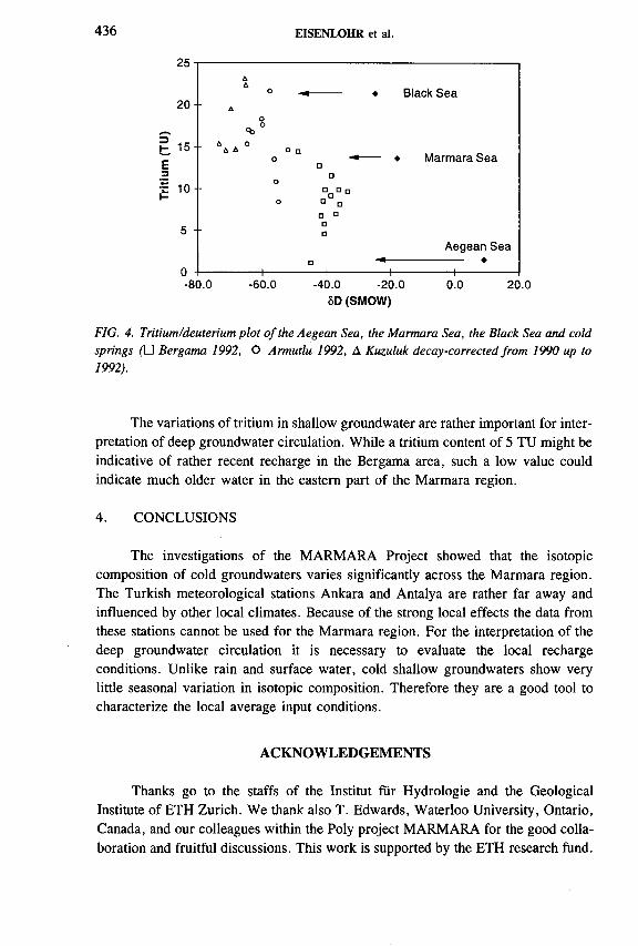
436 EISENLOHR et al.
25
2 0
t 1 5
£
5
0
-80.0 -60.0 -40.0 -20.0 0.0 20.08D (SMOW)
FIG. 4. Tritium/deuterium plot o f the Aegean Sea, the Marmara Sea, the Black Sea and cold springs (□ Bergama 1992, О Armutlu 1992, Д Kuzuluk decay-corrected from 1990 up to 1992).
The variations of tritium in shallow groundwater are rather important for interpretation of deep groundwater circulation. While a tritium content of 5 TU might be indicative of rather recent recharge in the Bergama area, such a low value could indicate much older water in the eastern part of the Marmara region.
4. CONCLUSIONS
The investigations of the MARMARA Project showed that the isotopic composition of cold groundwaters varies significantly across the Marmara region. The Turkish meteorological stations Ankara and Antalya are rather far away and influenced by other local climates. Because of the strong local effects the data from these stations cannot be used for the Marmara region. For the interpretation of the deep groundwater circulation it is necessary to evaluate the local recharge conditions. Unlike rain and surface water, cold shallow groundwaters show very little seasonal variation in isotopic composition. Therefore they are a good tool to characterize the local average input conditions.
ACKNOWLEDGEMENTS
Thanks go to the staffs of the Institut für Hydrologie and the Geological Institute of ETH Zurich. We thank also T. Edwards, Waterloo University, Ontario, Canada, and our colleagues within the Poly project MARMARA for the good collaboration and fruitful discussions. This work is supported by the ETH research fund.
Aо я ♦ Black S e a
AО
<ъ °ЛД A ° О
О □ ♦ Ma r m a r a S e a
о □
□□□□
о ° а а * □□
A eg e a n Sea
— ... . □i
----------- !--- ♦___ 1_______ i_1________

IAEA-SM-336/22 43 7
REFERENCES
[1] SCHINDLER, C., The MARMARA-Project: tectonics and recent crustal movements revealed by space-geodesy and their interaction with the circulation of groundwater, heat flow and seismicity in Northwestern Turkey, Terra Nova 5 (1993) 164-173.
[2] MÜTZENBERG, S.R., BALDERER, W., RAUERT, W., “ Environmental isotope study of saline geothermal system in western Anatolia, Canakkale, Turkey” , Water- Rock Interaction, Balkema, Rotterdam (1992) 1317-1320.
[3] BALDERER, W., et. al., “ Environmental isotope study of thermal, mineral and normal groundwater within the Bursa and Kuzuluk/Adapazari areas in northwestern
Turkey” , Isotope Techniques in Water Resources Development 1991 (Proc. Symp. Vienna, 1991), IAEA, Vienna (1992) 720-724.
[4] IMBACH, T ., Thermalwàsser von Bursa, Geologische und hydrogeologische Untersu
chungen am Berg Uludag (NW-Tiirkei), Thesis No. 9988, ETH Zurich, (1992).[5] GREBER, E., Deep circulation of C0 2-rich palaeowaters in a seismically active zone
(Kuzuluk/Adapazari, Northwestern Turkey), Geothermics 23 2 (1994) 151-174.[6] ERINC, S., Monthly sequence and frequencies of weather types in Istanbul, Rev.
Geograph. Inst. Univ. Istanbul 9-10 (1963-1964) 85-106.[7] GAT, J.R., “Precipitation, groundwater and surface waters: Control of climate par
ameters on their isotopic composition and their utilization as palaeoclimatological tools” , Palaeoclimates and Palaeowaters: A Collection of Environmental Isotope Studies (Proc. Advisory Group Mtg Vienna, 1980), IAEA, Vienna (1983) 3-12.


IAEA-SM-336/36
EFFECT OF THE HOLOCENE CLIMATE ON COMPOSITION OF GROUNDWATER IN PARTS OF HARYANA, INDIA Isotopic evidence
K.M. KULKARNI, S.V. NAVADA, S.M. RAO,A.R. NAIR, U.P. KULKARNI, SUMAN SHARMA Isotope Division,Bhabha Atomic Research Centre,Trombay, Bombay,India
Abstract
EFFECT OF THE HOLOCENE CLIMATE ON COMPOSITION OF GROUNDWATER IN
PARTS OF HARYANA, INDIA: ISOTOPIC EVIDENCE.Haryana State occupies a central position on the Indo-Gangetic plain and lies astride
the low watershed between the Indus and Ganga river systems. Over 60% of the groundwater in the State is either brackish or saline. The Quaternary Alluvium covers about 97% of Haryana. These deposits, over 3000 m deep, are laid down by present and ancestral rivers in the foredeep between the Himalayas and the Peninsular Shield. These alluvial deposits, which show considerable lateral and vertical variation in lithology and sequence, contain
saline aquifers. Environmental isotopes along with chemical constituents are measured for about 100 samples from southern parts of Haryana to study the causes of salinity. Isotopic interpretation is carried out in conjunction with hydrochemical and hydrogeological information. It is observed that there is a significant influence of canal waters on groundwater replenishment. In general, the response of the groundwater system to replenishment is not a very rapid process. The brackish groundwaters have originated from evaporation of irrigation waters. The shallow saline groundwaters showing highly enriched stable isotope composition
are thought to be stagnated, recycled, old salt pan waters. Deeper saline groundwaters also show evaporitic enrichment in stable isotope content but with a depleted initial isotope composition compared to that of present-day precipitation. The 14C content of these groundwaters ranges from 72.5% modem carbon (pmC) to 30.9 pmC (uncorrected ages from 2700 to 9700 BP). The ô34S results indicate that the source of sulphate in all groundwaters is common and most likely terrestrial evaporitic. It is concluded that saline groundwaters originated from the evaporation of surface waters in the playas during interpluvial phases in the Holocene. Amelioration of climate helped to flush out saline waters from shallow aquifers. However, a few shallow aquifers and most of the deeper aquifers have still retained former saline waters. On the global scale, these findings correspond to humid phases pointing to
lacustrine episodes followed by desertification as in adjacent Rajasthan and the Sahara of northeastern Mali.
439
440 KULKARNI et al.
Haryana State, in the northwest of India, is about 44 200 km2 in extent. It is bounded by latitudes 27°39'N to 30°55'N and longitudes 74°28'E to 77°38'E. It occupies a central position within the Indo-Gangetic plain. The State is unfavourably situated with regard to availability of surface water and quality of groundwater. Whereas the leeway between the requirements and availability from surface water is 1 0 0 %, there is a serious constraint on the exploitation of groundwater, of which over 60% is brackish or saline in quality. Over 60% of the area of Haryana is underlain by deep ( > 50 m) saline aquifers and about 10% and 50% of the area are characterized by shallow saline and brackish aquifers, respectively.
The conditions are further worsened as in saline terrain the rise in the water table is taking place at an alarming pace, causing a positive change in the salt balance of the soil profile, a decrease in the fertility status of soils and consequently a danger to agricultural production. The threat of aggression from such deteriorating groundwater conditions and waterlogging is so severe that agricultural production systems of the area are now in jeopardy and measures to mitigate the effect of the present system, reclaim the badly affected areas and utilize saline water have become a matter of urgency. Knowledge of the cause of salinity is important for taking effective remedial measures.
The geographical location of Haryana is mainly determined by the climatic conditions. The climatic zones are classified as arid, semi-arid and dry subhumid. About 80% of annual rainfall occurs in the monsoon season of five months from June to October. The rainfall decreases from northeast to southwest according to topographic controls and varies between 2000 mm to 300 mm, respectively. The pan evaporation is up to a maximum of 13 mm per day in the hot months of May and June and up to 2 to 3 mm in the months of December and January [1].
Environmental isotope geochemistry of over 100 samples from southern parts of Haryana has been studied. The results of isotopic interpretation in conjunction with hydrochemical and hydrogeological data are discussed in brief in the following sections.
1. INTRODUCTION
2. HYDROGEOLOGICAL SETTING
The geological formations of Haryana belong to three main groups: Quaternary Alluvium, Tertiary rocks represented by the Siwalik Group and Precambrian rocks represented by the Aravalli and Delhi Supergroups.
The Precambrian rocks belong to the Peninsular Shield and are exposed in the southern and southwestern districts of Mahendragarh, Gurgaon, Faridabad and Bhiwani as disconnected hills. The rocks belonging to the Siwalik Group are present in the extreme north of the State and are known to have deposited under fresh water

IAEA-SM-336/36 441
H I M A C H A L P R A D E S H
- i , • ROHTAK ~J r * '
• BHIWANI J j j o E L H i/£• j I frL GURGAON 'i
4 ^ ' УQUATERNARY ALLUVIUM SIWALIK GROUPARAVALLI AND DELHI SUPERGROUPS
»MAHENDRAGARH,• FAftiOABAO
FIG. 1. Geological map o f Haryana.
FIG. 2. A generalized geological section NE-SW across Haryana.

442 KULKARNI et al.
terrestrial environment. The Quaternary Alluvium, forming a part of the Indo- Gangetic alluvial system, covers about 97% of Haryana (Fig. 1). The alluvial deposits have been laid down by present and ancestral river systems from the Pleistocene in the foredeep formed between the Himalayan ranges and the Peninsular Shield [2]. These deposits, estimated to be over 3000 m in thickness, are made up of a heterogeneous series of gravel, sand, silt and clay with considerable lateral and vertical variation in lithology and sequence. A generalized geological section across the State from northeast to southwest is shown in Fig. 2. The succession from coarse to fine sediment overlying a thick deposit of clay at a depth from 50 to 150 m below the ground surface is clearly discernible, although complicated by successive lenticular clay horizons. The accumulation of clays in the lower part of the section coincides with the present saline areas. The subsurface sediment distribution, depicted through fence diagrams, reflects the changes in the mode of deposition of alluvial sediments by shifting streams and rivers. In the regions where clay predominates, caliche is mixed with it and also occasionally is present with sand. It is most commonly present in the areas covered by saline groundwater.
Haryana State forms a watershed between the Ganga and Indus river systems. The River Yamuna, which forms the eastern boundary of the State, is a tributary of the Ganga. The River Ghaggar, which flows along the State’s northwestern boundary, belongs to the Indus system. In addition to the basins of these two rivers, there is an internal drainage basin in the State, which has no natural drainage outlet (Fig. 1).
Fresh groundwater mainly occurs in the northern parts of the State, where there is a greater thickness of coarse sediments, whereas saline groundwaters are found in southern parts where the thickness of the sand horizons is small and clay predominates.
In the study area the water bearing formations are composed of low permeable, unconsolidated sand of varying grain size, often interbedded with clay and caliche. The groundwater in the study area occurs mainly under water table conditions. At places semi-confined to confined conditions are also observed. The perched water table is also observed in the sand dunes located near saline areas. The depth to water varies from about 2 m to 16 m below ground level. The area under investigation is now semi-arid and receives annual rainfall of about 2 0 0 mm.
Various aspects of geology and hydrogeology in Haryana and adjoining areas have been studied by many researchers in the past [3-9]. However, the Late Quaternary history of southern Haryana is inadequately documented.
3. METHODOLOGY AND SAMPLING
Over 100 samples were collected from tubewells, shallow handpumps, dug wells and canals for analyses of environmental isotopes (D, 80 , 3 H) as well as for

IAEA-SM-336/36 443
major, minor, and trace ion chemistry. Samples were also collected and analysed for ô34S and 14C. The locations of these samples are shown in Fig. 3.
The groundwaters in Haryana are generally classified on the basis of electrical conductivity (EC) for most practical purposes. Therefore, in the present study groundwater with EC less than 2000 /¿S/cm is termed as fresh and water having EC from 2000 to 6000 /xS/cm is classified as brackish. The groundwater with EC exceeding 6000 /¿S/cm is categorized as saline. The shallow depth defines the depth of samples less than 15 m below the ground surface whereas those samples with depth more than 15 m are referred to as deeper ones.
The water samples, filtered through a 0.45 /xm membrane filter, are analysed for chemistry by following the Standard Methods [10]. The stable isotope measurements are carried out on isotope ratio mass spectrometers. Tritium was measured in samples using electrolytic enrichment followed by liquid scintillation counting. Sampling for 14C was carried out in the field by the C02 gas evolution method and measurements are made using the C0 2 absorption method.
FIG. 3. Sample location map.

444 KULKARNI et al.
The EC of samples drawn from the study area shows a wide variation and ranges from about 300 to 72 000 /¿S/cm. The results of chemical analyses are summarized here. The major ion chemical data, when plotted on Piper’s trilinear diagram, shows transition from ‘neutral type’ exhibited by surface waters and fresh groundwaters to ‘primary saline type’ shown by saline groundwaters, indicating that the groundwaters, have derived their salinity in the environment of the surrounding formation, i.e. the alluvium.
In most of the saline groundwaters sodium is a dominant cation with subordinate calcium and magnesium and chloride as a dominant anion with subordinate sulphate. In general, the EC and chemical type vary as follows:
EC (/¿S/cm) Chemical type
4. HYDROCHEMISTRY
The chloride distribution in the samples is shown in Fig. 4. Three distinct saline areas could be seen from Fig. 4, viz. Farrukhnagar (Gurgaon), Nuh and Kalanaur. These areas form depressional areas, playas and/or interdunal depressions, where groundwater salinization occurred.
< 2 0 0 0
2000-6000>6000
HC0 3> Cl > so 4 HC03 > S04 > Cl Cl > S04 > HCO3
• HtSAR- • • 1
NEW DELHI
GURGAON
FARttABÁD
в : -
\ \
FIG. 4. Map showing chloride distribution in groundwaters in the study area.
IAEA-SM-336/36 445
The strontium content of saline waters is high (up to 70 mg/L). The enrichment of strontium may be due to incongruent dissolution of aragonite and Mg calcite accompanied by the removal of sulphates and carbonates. The process is expected to be slow and therefore points to the long contact of water with the aquifer matrix.
The boron content of samples ranges from about 0.1 to 7.6 mg/L. Samples from saline aquifers show no correlation with chloride content. The leaching of boron from clays, heterogeneous sediment distribution and rapid facies changes coupled with evaporitic environment might have given rise to such a distribution of boron in the study area.
The bromide content of a few samples was measured using neutron activation analysis [11]. In some of the saline samples the Cl/Br ratios are higher than those of sea water, whereas in some samples the ratio is less than that for sea water. The evaporitic enrichment of bromide in the past as well as dissolution of chlorides from sediments could be the cause for the observed ratios in the groundwaters.
The iodide content in groundwaters of the study area is considerably higher (up to 0.79 mg/L). Decomposition of organic matter and release of iodide to the groundwater is the possible cause of enrichment.
In general, the saline groundwaters exhibit evaporitic chemical nature. It appears the enrichment of minor and trace ions is probably due to high evaporation, solution of salts from sediments during long residence in aquifers in this case although such an enrichment is not priori to the long residence.
5. ENVIRONMENTAL ISOTOPE STUDIES
5.1. 6 D and 6180 results
About 100 samples have been analysed for D and 180 content. The meteorological station at New Delhi has co-operated in the global IAEA/WMO network operational since 1960. The data on stable isotope composition for monthly precipitation are available [12]. These values provide basic data for the study area in order to define the local meteoric water line and stable isotope composition of recharge by precipitation. The long term annual weighted means of stable isotope composition for precipitation at New Delhi are <5180 = -5.81°/00 and ¿>D = -37.2700.
The stable isotope composition of two rivers, Ghaggar and Yamuna, diverted through canal systems for irrigation, is depleted compared to precipitation and the two differ from each other also. The mean stable isotope composition of these river systems, deduced from samples from irrigation canals receiving water from each of these rivers, is S180 = —9.71700, <5D = -62.9700 and ô180 = -7.95700, <5D = — 48.4700, respectively.
The stable isotope composition of wells sampled in the study area shows wide variation, ranging from ô180 = -8 .51700 to ¿>180 = +2.87700. A substantial

446 KULKARNI et al.
number of wells sampled in the study area have a more depleted stable isotope composition than the of mean value of precipitation, indicating the significant influence of the contribution from canal waters in the replenishment of groundwater.
It is observed that, generally, the stable isotope content of groundwater does not change between pre- and post-monsoon seasons in spite of the fact that surface waters show wide variations. This would indicate that the response of a groundwater system to replenishment, regardless of its source, is not usually a very rapid process [13].
The long term weighted means for stable isotope data for precipitation at New Delhi define the local meteoric water line as
<5D = (8.0 ± 0.34) 0180 + (8.42 ± 3.37) (1)
with correlation coefficient r = 0.98 and n = 23. This line is close to the global meteoric water line.
FIG. 5. ôD-ôIS0 plot o f groundwater samples from southern Haryana.

8d
(%o
) 6
d(
7
IAEA-SM-336/36 447
FIG. 6. &D-&IS0 plots of (a) shallow saline, (b) deeper saline groundwaters.

448 KULKARNI et al.
The surface water samples plot well above the meteoric water line and are represented by the equation:
ÔD = 7.95 0180 + 14.5 (2)
with correlation coefficient r = 0.98 and n = 11. This is shown by a dashed line on ôD-ôi80 plots. Thus the hydrometeorological conditions prevailing in the catchment areas of the Yamuna and Ghaggar rivers define a slightly different <5D-ôl80 relation. The line represented by Eq. (2) represents the regional line for irrigation water supplied through the canal network.
The <5D-ô180 plot of groundwater samples from the study area is shown in Fig. 5. The line of best fit calculated from the observed values is
ÔD = 4.9 0180 - 11 (3)
with correlation coefficient r = 0.90 and n = 89. The slope of this line is characteristic of the evaporation process. This suggests that evaporation could be the mechanism of salinization.
As can be seen from Fig. 5, the points scatter around the mean precipitation value and canal waters. The fresh and brackish waters show this scatter prominently, irrespective of depth. The evaporation and évapotranspiration during the replenishment of groundwater could be the main reason for such a pattern. Some of the shallow saline groundwater samples show highly enriched stable isotopic composition (Fig. 6 (a)). It is interesting to note that these samples represent the areas where salt extraction activity was in vogue in the past century. These waters indicate extremely high evaporation, which is expected around salt pan activities. It appears that these depressional areas still store the stagnated old saline water mixed with modern waters.
Most of the deep saline groundwaters also show evaporation effect and depleted original stable isotope composition (Fig. 6 (b)). Some of the deep saline samples fall close to the meteoric water line. Such samples could have acquired their salinity by leaching of salts from sediments.
5.2. ¿>34S results
The <534S values of aqueous sulphate are measured for 32 samples. The values show wide variation from 8.4 to 26°/00. However, most of the values fall in a narrow range of 8.4 to 12.6 irrespective of sulphate content (Fig. 7). A few outlying values were observed.
It could be seen from Fig. 7 that the source of sulphate in groundwaters, irrespective of age, is common and is most likely terrestrial evaporitic in nature. This also suggests that concentration of salts by evaporation could be the chief mechanism

IAEA-SM-336/36 449
10*
адВс о •а
ё ю 3соо1-13Æсх
10
SEA WATER В
i —i—i—i—i—i—i—i—i—i—i—i—i—i—i—i—i в 12 16 20
i—i—i—i—i—i 24 28
S34s %о CDT
FIG. 7. Sulphate concentration versus S34S (S04) graph o f groundwaters.
of salinization in Haryana. Bacterial reduction of sulphate is the cause of observed enrichment in ô34S content at a few places where groundwater is stagnated. This is confirmed by the presence of H2S in these waters. These sites match the shallow, highly enriched, saline groundwaters (Fig. 6 (a)) which strengthens the observation that these groundwaters are recycled, stagnated, old salt pan waters.
5.3. Tritium and 14C results
The observations made from the analysis of samples for 3H content are noted here. Most of the fresh and brackish groundwaters have tritium levels in the range of 5 to 25 TU. A few brackish groundwaters show a tritium content in the range of 30 to 45 TU, confirming the presence of bomb tritium; the residence time of these waters could be about 30 years. Most of the deep saline and some shallow saline groundwaters show a tritium content of less than 5 TU and some show negligible tritium. In general, a decrease in tritium content with increase in depth is observed. The exponential transit time model [14] gives the residence time of 5 to 60 years in the case of shallow fresh and brackish groundwaters. Some mixing of old, deep saline groundwaters with groundwaters in intermediate and shallow depths is also inferred.

450 KULKARNI et al.
TABLE I. RADIOCARBON DISTRIBUTION IN SALINE GROUNDWATERSAMPLES FROM PARTS OF HARYANA
SampleNo.
PlaceDepth
(m)EC
(/¿S/cm)3H
(TU ± 2a)0 13C
(7 .0 PDB)
14C(pmC)
U ncorrected age (BP)
32 H arsaru 20 17 000 0.9 ± 1.0 -5 .7 0 30.9 9 70079 N aseerbas 63 8 150 0.9 ± 1.0 -8 .2 3 72.5 2 70086 K alanaur 27 71 700 0.0 ± 1.0 -5 .3 9 64.4 3 60090 Daboda 20 51 100 0.0 ± 1.0 -9 .7 5 61.2 4 10091 Sam pla 20 68 100 0.0 ± 1.0 -8 .1 5 94.0 50098 C hhapar 62-84 30 000 1.3 ± 1.0 -4 .5 0 35.9 8 500
PDB: Peedee belemnite.
The measurements of 14C carried out on a few samples and results for saline groundwaters are presented in Table I. The results indicate that most of the shallow fresh, brackish and some shallow saline groundwaters are modern. The 14C content ranges from about 31 % modem carbon (pmC) to 72.5 pmC for deeper saline groundwaters. Uncorrected 14C ages calculated for deeper saline groundwaters range from 2700 to 9700 BP. It appears that saline groundwaters were formed during the Holocene. .
6 . CONCLUDING DISCUSSION
In southern Haryana, comprising the districts of Hisar, Bhiwani, Rohtak, Mahendragarh, Gurgaon and Faridabad, the Late Quaternary history is inadequately known. In adjoining Rajasthan State the same is well documented [15-18]. A detailed chronology of the Holocene palaeoclimatic and palaeoecological events in southern Haryana, based on fossil, floral and faunal evidence and its radiometric dating, is now available [19]. The present study and past studies form a comprehensive multidisciplinary approach which enables us to make a few remarks on the effect of the Holocene events on groundwater salinization in southern Haryana.
The stable isotope composition of shallow brackish groundwaters shows an evaporation effect. Most of the samples have tritium levels ranging from 5 to 25 TU, indicating modern recharge. These groundwater samples show a lot of scatter on the ôD -ô180 plot and fall off the meteoric water line. This could be due to evaporation of the irrigation water supplied to the area through the canal network either during replenishment or from the shallow water table itself. The salinization of these brackish groundwaters is due to concentration of salts by evaporation. Earlier, similar con-

IAEA-SM-336/36 451
elusions were also drawn by Haryana [13] on the causes for salinity of shallow groundwaters. The shallow and deeper saline groundwaters also exhibit an evaporation effect, as can be seen from <5D-ô180 plots. When plotted on the <5180-C1 graph these samples fall along a regression line which is different from the one for the fresh and brackish groundwaters. The deeper and some shallow saline groundwaters show low to negligible tritium. A few shallow saline groundwaters show highly enriched stable isotope composition. These samples represent the areas where salt extraction activity was in vogue in the last century. These are thought to be stagnated, recycled, old salt pan waters. Over a period of time some mixing with modern waters is apparent, as these waters have modern tritium and 14C content. But it appears they still have retained stable isotope signatures of old evaporated waters. The <534S (S 04) values of these samples show enrichment which is due to bacterial reduction of sulphates in the stagnated waters. The presence of H2S in these samples confirms this. The deeper saline groundwaters show evaporitic trends in their chemical as well as in their isotopic characteristics. The uncorrected 14C ages calculated for these waters range from 2700 BP to 9700 BP. The contribution of modern recharge is expected to modify and complicate the scenario to some degree, as is observed at places such as Naseerbas and Sampla.
The origin of salinity due to contribution from the aeolian transport of salts is very remote, as the area is far from the sea. Also, no evidence of marine transgression in the area is known. No evaporite deposits during the Late Tertiary have been reported from the Quaternary Alluvium [2]. The study of the chemistry of salts and ionic ratios in brines of Haryana suggest terrestrial origin for the saline waters [20]. In the Rechna Doab area in the Punjab region of Pakistan the terrestrial origin of salts is also inferred [21]. It is thought that concentration of salt by evaporation of water in terrestrial basins/playas in the past is the cause of observed salinity in groundwaters of Haryana.
The evidence of Late Pleistocene-Holocene transgressions is recorded on the eastern coastline of India [22-25]. It is expected that the corresponding lacustrine episodes might have occurred in the inland depressions in the northern parts of India. The palaeoclimatic reconstruction for the Quaternary by Rognon and Williams is well known [26]. It is also observed that the palaeohydrological situation in the arid and semi-arid belt stretching from North Africa to India apparently underwent similar changes [27]. In Haryana, also, fossil flora, fauna and their radiometric dating suggest a lacustrine episode between 5500 and 3600 BP [19]. Brackish water taxa such as Cyprideis torosa, Cyprinotus cingalensis, Pseudoeponides whittakeri, Lam- prothamnium cf. L. papulosum and Chara aspera are recorded from the marls in the alluvial deposits in the study area. The findings of the study are in harmony with occurrence of humid phase IV with the development of lacustrine basins in adjoining Rajasthan [19]. The areas of the occurrence of fossils indicating mesohaline lacustrine environment match with those areas on the chloride distribution map where salinity is high. On the chloride distribution map of the study area the patterns are

452 KULKARNI et al.
interpreted as interdunal depressions and/or playas. In the study area the uncorrected 14C ages for saline groundwaters range from 2700 to 9700 BP. The oscillations of the pluvial and non-pluvial phases in the Holocene, leading to the evaporation of surface waters as well as from the near surface water table, have probably resulted in the high salinity in the region. On the global scale, both in the central Sahara of northeastern Mali and in Haryana the dominant ostracode taxa are Cyprideis torosa and Cyprinotus cirtgalensis while, as far as charophytic flora are concerned, Lam- prothamnium cf. L. papulosum and Chara aspera are common to Haryana and the central Sahara [19]. In the central Sahara of Mali the earliest Holocene lacustrine episode occurred between during 9500 and 6500 BP [19]. This corresponds broadly to humid phases II and III [17] in adjacent Rajasthan. The second episode in the Sahara (5500-4500 BP) corresponds to humid phase IV (5000-3000 BP) in Rajasthan. Therefore it is thought from the radiocarbon ages of fossils and saline groundwaters that in Haryana these phases might also have occurred. The desertification in the Sahara dates from about 4000 BP. In Rajasthan this arid phase is represented by subzone SM 3b of phase IV (3800-3400 BP) [17] during which sedges and freshwater swamp species disappeared completely, indicating the lakes had started turning saline and the arid phase preceding desertification had commenced.
Hence it is appropriate to conclude that the presence of lacustrine conditions coupled with non-pluvial phases, leading to evaporation and increase in concentration of salts, in the Holocene gave rise to the saline groundwaters in Haryana. Amelioration of the climatic conditions helped to flush out the saline waters from most of the shallow aquifers and a few deeper aquifers. However, a few shallow aquifers and most of the deeper saline aquifers have still retained the former saline waters.
ACKNOWLEDGEMENTS
The authors express their gratitude to B.B.S. Singhal and B. Parkash, Department of Earth Sciences, University of Roorkee, Roorkee, for their co-operation and guidance during the research project. The Atomic Minerals Division, Department of Atomic Energy, made the ô34S measurements. The analytical Chemistry Division of Bhabha Atomic Research Centre analysed some of the samples for minor and trace ion chemistry. Thanks are also due to Shreekant Sharad, K. Shivanna and T.B. Joseph for laboratory help.
REFERENCES
[1] KANGLE, A.M., “ Climatology and hydrometeorology” , Studies for Use of Saline Water in the Command Areas of Irrigation Projects, Haryana, India (Working Papers, HSMITC/UNDP/FAO Workshop New Delhi, 1983), Haryana State Minor Irrigation Tubewells Corporation, Chandigarh (1983) 11-15.
IAEA-SM-336/36 453
[2] KULKARNI, К.М ., et al., “ Origin of saline groundwaters of Haryana State, India” , Regional Characterisation of Water Quality (Proc. Symp. Baltimore, 1989) (RAGONE, S., Ed.), Int. Assn Hydrological Sciences, Pub. No. 182, IAHS, Wallingford, UK (1989) 125-132.
[3] DAS, B.K., KAKAR, Y.P., MOSER, М., STICHLER, W., Deuterium and oxygen-18 studies in groundwater of the Delhi area, Indian J. Hydrol. 98 (1988) 133-146.
[4] SHARMA, R.C., ABROL, I.P., BHUMBLA, D.R., Quality of Groundwaters of Karnal District, Rep. Central Soil Salinity Research Institute, Kamal, India (1976).
[5] TANWAR, B.S., Groundwater Studies of the Alluvial Belt of Yamuna and Ghaggar Doab in Haryana, PhD Thesis, Kurukshetra University, Kurukshetra, India (1983).
[6] CHACHADI, A.G., Hydrogeological Studies in Sohna Block, Gurgaon District, Haryana, with Reference to the Chemical Quality of Groundwater, MTech Thesis, University of Roorkee, Roorkee, India (1981).
[7] CHACHADI, A.G., SONI, B., “ Identification of subsurface brines using statistical techniques” (Proc. Int. Conf. Oklahoma, 1984) (DURHAM, N.N., REDELFS, A.E., Eds), University Press, Oklahoma City, OK (1984) 191-193.
[8] KHABYA, N.K., Hydrogeological Studies of Gurgaon Block, Gurgaon District, Haryana with Special Reference to its Subsurface Brines, MTech Thesis, University of Roorkee, Roorkee, India (1980).
[9] GOEL, P.S., DATTA, P.S., TANWAR, B.S., Measurement of vertical recharge to groundwater in Haryana State (India) using tritium tracer, Nordic Hydrol. 8 (1977) 211-224.
[10] AMERICAN PUBLIC HEALTH ASSOCIATION, Standard Methods for Examination of Water and Wastewater, 14th edn, American Public Health Association, Boston, MA (1976).
[11] NAVADA, S. V ., KULKARNI, U .P ., The value of bromide and iodide in characterisation of saline groundwaters, J. Appl. Hydrol. 3 1 (1990) 11-19.
[12] INTERNATIONAL ATOMIC ENERGY AGENCY, Statistical Treatment of Data on Environmental Isotopes in Precipitation, Technical Reports Series No. 331, IAEA, Vienna (1992).
[13] INTERNATIONAL ATOMIC ENERGY AGENCY, Final Report on Environmental Isotope Studies in Irrigation Areas of Haryana (India), IAEA, Vienna (1985).
[14] YURTSEVER, Y., Concepts and Mathematical Models for Quantitative Evaluation of Natural Isotopes in Hydrology, Lecture Note, IAEA, Vienna (1990) 33.
[15] WASSON, J.R., RAJAGURU, S.N., MISRA, V.N., AGARWAL, D.P., DHIR, R.P., Geomorphology, late Quaternary stratigraphy and paleoclimatology of the Thar dunefield, Z. Geomorphol. 45 (1983) 117-151.
[16] BRYSON, R.A., BAERRIES, D.A., Possibilities of major climatic modification andtheir implications: northwest India, a case for study, Bull. Am. Meteorol. Soc. 48 3(1967) 136.
[17] SINGH, G., JOSHI, R.D., CHOPRA, S.K., SINGH, A.B., Late Quaternary history of vegetation and climate of the Rajasthan Desert, India, Phil. Trans. R. Soc. London 267 (1974) 467.
[18] AGARWAL, D .P ., Reconstructing the Past Climate and Environment, 23rd Sir Albert Charles Seward Memorial Lecture, Birbal Sahni Institute of Paleobotany, Lucknow (1976).
454 KULKARNI et al.
[19] BHATIA, S.B., SINGH, NEENA, Middle Holocene paleoclimatic and paleoenviron- mental events in Southern Haryana, Proc. Indian Natl. Sci. Acad. S4A 4 (1988) 574-584.
[20] BOKIL, K.K., Feasibility of Salt Extraction as a Means to Control the Soil Salinity and Groundwater Levels in Saline Belt of Haryana, Rep. Haryana State Minor Irrigation Tubewells Corporation, Chandigarh (1985).
[21] BACK, W., RIGHTMIRE, C.T., SEABER, P.R., CHERRY, R.N., “ The geological evolution of groundwater in the Punjab Region of Pakistan” , Water Rock Interaction (Proc. Int. Symp. Prague, 1976) 45-53.
[22] MERH, S.S., Quaternary sea level changes: The present status vis à vis records along coasts on India, Indian J. Earth Sci. 14 3-4 (1987) 235-251.
[23] BANERJEE, М., SEN, P.K., Paleobiology in understanding the change of sea level and coastline in Bengal basin during Holocene period, Indian J. Earth Sci. 14 3-4 (1987) 307.
[24] SHIV ANNA, K., NAVADA, S.V., NAIR, A.R., RAO, S.M., “ Isotope and geochemical evidence of past seawater salinity in Midnapore groundwaters” , Isotope Techniques in the Study of Past and Current Environmental Changes in the Hydrosphere and the Atmosphere (Proc. Symp. Vienna, 1993), IAEA, Vienna (1993) 199-212.
[25] KULKARNI, K.M., RAO, S.М., NAVADA, S.V., Isotopic studies on groundwaters in Southwestern Mahanadi Delta, Orissa State, India (Abstracts Int. Conf. Berkeley, 1994), U.S. Geological Survey Circular, USGS, Reston, VA 1107 (1994) 183.
[26] ROGNON, P., WILLIAMS, M.A.J., Late Quaternary climatic changes in Australia and North Africa: Preliminary interpretation, Palaeogeogr. Palaeoclimatol. Palaeoecol. 21 (1977) 285-327.
[27] GEYH, M.A., “ The 14C time scale of groundwater: Correction and linearity” , Isotope Techniques in Water Resources Development (Proc. Symp. Vienna, 1991), IAEA, Vienna (1991) 167-177.

Poster Presentations
IAEA-SM-336/19P
M E T H O D E D E C O N T R O L E D E L ’E T A N C H E IT E D ’UN PU IT S G E O T H E R M IQ U E A L ’A ID E D ’UN R A D IO T R A C E U R
P. CALMELS, D. GETTO Section d’application des traceurs,CEA, Centre d’études nucléaires de Grenoble,Grenoble
P. UNGEMACH Géoproduction Consultants,Roissy-Charles de Gaulle
France
En France, la géothermie «basse énergie» s’est particulièrement développée dans le Bassin parisien et le Bassin aquitain.
A quelques exceptions près, l’eau chaude produite par les puits géothermiques a généralement des caractéristiques physico-chimiques telles qu’elle est impropre à la consommation.
Par sa présence dans les équipements des puits géothermiques, cette eau induit un risque de pollution des nappes phréatiques traversées. La pollution de ces nappes est provoquée soit par un défaut d ’étanchéité du tubage et de sa cimentation, soit, plus occasionnellement, par une remontée de l’eau chaude le long de la paroi extérieure du tubage.
Pour prévenir ce risque, la protection des nappes d’eau potable et la sécurité des installations font l ’objet d’une réglementation qui comporte notamment la vérification périodique de l’intégrité des forages.
Une méthode simple, ne nécessitant ni l’arrêt de longue durée de l’exploitation, ni le démontage des équipements lourds du puits contrôlé est proposée (Fig. 1). Cette méthode est basée sur la mesure du bilan de restitution d’un traceur radioactif utilisé pour marquer tout ou partie du volume d’eau contenu dans le puits contrôlé. La méthodologie des marquages est adaptée aux équipements des sites et des puits ainsi qu’aux informations recherchées.
Selon l’aménagement du site, l ’eau marquée, produite par le puits contrôlé, pourra être, soit injectée dans un puits de réinjection voisin (cas général des doublets géothermiques), soit stockée dans des bâches (50 à 150 m3) avant d’être réinjectée dans le puits contrôlé.
455

456 POSTER PRESENTATIONS
FIG. 1. Injection en tête du puits — Dispositif de mesure.
Selon l’équipement du puits, le marquage de l’eau sera réalisé par injection du traceur, soit en pied de puits (par la ligne d’injection des agents inhibiteurs de corrosion), soit en tête de puits (Fig. 1), en inversant le mode de fonctionnement du puits à l’aide d’une pompe extérieure.
Selon les informations recherchées (perte globale, localisation de la zone de fuite, estimation du débit de fuite), le marquage de l’eau sera réalisé en pied ou en tête de puits et concernera tout ou partie du volume total du puits.
Le traceur mis en œuvre est l’iode 131 («7,9 MBq).Après marquage de l’eau du puits, l’installation est remise en fonctionnement.
La mesure est ensuite faite par comptage sur un échantillon d’eau, de grand volume ( * 300 1) collecté à débit constant durant le temps de passage de la fonction de restitution du traceur et d’étalonnage du dispositif de mesure par un ajout dosé.
La précision de la mesure est directement liée à celle de la mesure du débit de fonctionnement du puits ou de son pompage. Cette dernière incertitude est palliée par une mesure utilisant la méthode d’Allen qui consiste à exploiter les temps de passage d’une petite quantité de traceur radioactif ( l3 1I) injectée dans le circuit d’exhaure du puits et détectée en aval, dans deux sections de mesure, suffisamment éloignées l’une de l’autre.
La méthode proposée a été mise en œuvre sur le doublet géothermique de Tremblay en France et a mis en évidence la bonne étanchéité des équipements.

SESSION 8 457
EVOLUTION DE LA CONTAMINATION FLUORUREE DANS LA ZONE DES LACS DU RIFT ETHIOPIEN Approches chimiques et isotopiques
T. CHERNET1
Université d’Addis Abeba,Addis Abeba, Ethiopie
Y. TRAVILaboratoire d’hydrogéologie,Université d’Avignon,Avignon, France
IAEA-SM-336/21P
Dans la zone des lacs du rift éthiopien, les eaux de surface et les eaux souterraines présentent des teneurs très élevées en fluorures (0,1 à 200 mg/1 [1]. Ce site, très particulier, constitue une dépression fermée, limitée au sud-est et au nord-ouest par des reliefs très élevés qui bordent le rift. Les nappes circulent sur les versants dans des séries volcaniques, ignimbrites pour l’essentiel, et dans des formations volcano-sédimentaires lacustres au fond de la dépression. Cinq lacs, étagés en altitude et plus ou moins reliés entre eux, présentent une minéralisation croissante vers l’aval. Quelques sources thermales participent à l’alimentation des zones lacustres. La quasi-totalité des eaux présente un faciès de type bicarbonaté-sodique.
D’une manière générale, l’origine et les mécanismes de la minéralisation fluorurée sont connus [2]. Dans le cas présent, les formations acides et alcalines (en place ou détritiques) constituent la principale source de fluor. Les concentrations sont ensuite contrôlées par l’équilibre thermodynamique [Ca + +] [F' ] 2 = K. Ainsi, lorsque la saturation est atteinte, toute modification de l’activité en Ca + + peut entraîner une modification inverse des quantités de fluorures en solution. Ceci peut expliquer les fortes teneurs reconnues sur les eaux des sources thermales car la solubilité de CaF2 croît avec la température alors que, dans le même temps, la solubilité du carbonate de calcium décroît, entraînant une diminution des activités en calcium. De même, les eaux qui possèdent un rapport HC03 (CA + Mg) > 1 évoluent au cours de l’évaporation vers des eaux de type NaHC03 renfermant de très faibles quantités de calcium; les teneurs en F ' peuvent alors atteindre des niveaux très élevés [3].
1 Actuellement, Université d ’Avignon, France

458 POSTER PRESENTATIONS
Dans un tel système, les quantités de fluor en solution vont évoluer en relation avec les échanges actuels ou anciens entre eaux de surface et eaux souterraines, ainsi qu’avec les processus de «dilution-concentration» liés au bilan hydrique.
Ces problèmes ont été abordés sous le double aspect, chimique et isotopique (СГ, Br“, 180, 2 H, 13C, 14C). Les premières interprétations s’appuient sur les mesures effectuées sur environ 50 sites (pluies, eaux de surface et eaux souterraines), en décembre 1992 et juillet 1993. L’existence de données antérieures datant de 1976[1] et 1979 [4] permettent, en outre, d’établir un état comparatif une vingtaine d’années plus tard.
Les précipitations étudiées sur la station d’Addis Abeba (Agence internationale de l’énergie atomique-Organisation météorologique mondiale (AIEA-OMM), 1961-1976) montrent que, sur un diagramme 2 H-180, les points s’alignent sur une droite de type ô2H = 8ô180 + 15, avec des teneurs relativement élevées. Ces dernières ne sont pas dues à l’évaporation mais caractérisent les eaux de pluie de cette région. Les échantillons prélevés sur trois stations étagées en altitude en 1993 confirment que la zone du rift répond au même système, avec quelques valeurs plus positives dans les zones basses et une nette différenciation entre les pluies du début de l’année et celles de pleine saison des pluies. Ces dernières alimentent la quasi- totalité des écoulements de surface et souterrains.
Les eaux des lacs, en particulier les plus en aval, présentent un caractère fortement évaporé ( 180, СГ, Br"). Les teneurs maximales en oxygène 18 (> 8 ° / 0 0 au lac Abyata) marquent des conditions atmosphériques particulièrement favorables à l’évaporation si on les compare aux valeurs obtenues sur les lacs situés plus au sud. Depuis 20 ans, la minéralisation paraît cependant avoir globalement diminué. Par ailleurs, les lacs, sur leurs parties moyennes et aval, alimentent la nappe des sédiments lacustres.
A l’exception de quelques sources situées au cœur du rift, l’effet thermal ne paraît pas influencer les teneurs en 180 des eaux de ce type rencontrées sur le bord nord-ouest. Ces eaux se différencient cependant par des teneurs en isotopes stables inférieures à celles des précipitations actuelles et des âges plus anciens.
Dans un tel contexte, dans les sédiments lacustres, les fortes teneurs en fluorures des eaux souterraines apparaissent fortement liées aux infiltrations actuelles ou anciennes de l’eau des lacs. Le milieu n’étant pas entièrement confiné, la concentration en fluorures des eaux de surface ne s’élèvera pas systématiquement. Elle restera sous la dépendance du bilan: flux entrant, flux sortant et concentration par évaporation. Le flux entrant et l’évaporation sont accessibles; une modélisation de ce système permettra donc d’estimer les flux qui s’en échappent.
REFERENCES
[1] CHERNET, T., Hydrogeology of the Lakes Region, Ministry of Mines and Energy, Ethiopian Institute of Geological Surveys, Memoir n° 1 (1982) 95 pp.

SESSION 8 459
[2] TRAVI, Y ., Hydrogéologie et hydrochimie des aquifères du Sénégal. Hydrogéochimie du fluor dans les eaux souterraines, Mém. Sci. Géol., Strasbourg, n° 95 (1993) 165 pp.
[3] CHERNET, T., TRAVI, Y., «Preliminary observations concerning the genesis of high fluoride contents in the Ethiopian Rift Geoscientific Research in North East Africa (TORWEIHE et SCHANDELMEIER, Eds)», Balkema, Rotterdam (1993) 651-655.
[4] SCRIPPS INSTITUTION OF OCEANOGRAPHY, Isotope geochemistry and hydrology of geothermals waters in the Ethiopian rift valley, Isotope Lab. Univ. of California, SIO 77-14 (1977) 140 pp.
IAEA-SM-336/27P
APPROCHES CHIMIQUES ET ISOTOPIQUES DES EAUX THERMO-MINERALES DU KARST DE MONEASA (ROUMANIE)
L. TIMOFTEInstitut de physique atomique,Bucarest, Roumanie
L. DEVER, C. MARLINLaboratoire d’hydrologie et de géochimie isotopique,Université de Paris-Sud,Orsay, France
I. ORASEANU S.C. Prospectiuni,Bucarest, Roumanie
P. VACHIERLaboratoire Sciences du sol,Institut national agronomique,Thiverval-Grignon, France
Les émergences du karst de subsurface de Moneasa (Roumanie) apparaissent le long d’accidents tectoniques dans une zone de chevauchement de nappes de charriage. La température des eaux varie de 9 à 32 °C pour des conductivités s’échelonnant de 20 à 520 /xS/cm. Les eaux les plus froides sont les plus minéralisées. Les analyses physico-chimiques et isotopiques ( 180 , 2 H, 1 3C, 1 4C) ont permis d’individualiser deux types de circulation des eaux (Fig. 1):
— Une circulation rapide des eaux météoriques, «froides», à travers le karst (<5180 = —97oo, ô2H = - 6 8 °/oo); ces eaux ont un faciès chimique bicarbonaté calcique.
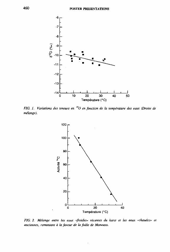
460 POSTER PRESENTATIONS
Température (°С)
FIG. 1. Variations des teneurs en ,sO en fonction de la température des eaux (Droite de mélange).
Température (°C)
FIG. 2. Mélange entre les eaux «froides» récentes du karst et les eaux «chaudes» et anciennes, remontant à la faveur de la faille de Moneasa.

SESSION 8 461
— Une circulation plus profonde «d’eaux chaudes» dont la résurgence a lieu sur la faille de Moneasa (<5180 = — 1 1 7 00, <52H = — 7 7 7 00); ces eaux ont un faciès chimique silicaté.
Le mélange des deux types d ’eau s ’effectue lors de la remontée des eaux le long de faille. Les températures rendent compte des parts de mélange qui varient dans le temps en rapport avec la réponse du karst aux événements pluviométriques.
Les teneurs en 13C permettent d ’individualiser deux types de minéralisation des eaux:
— Un type en système ouvert vis-à-vis du C 0 2 biogénique (<5I3C = - 1 4 7 00) pour les eaux du karst;
— Un type en système en voie de fermeture (<5I3C = —9 7 00) pour les eaux de circulation profonde. Les activités 14C mesurées rendent bien compte des parts de mélange entre une eau récente issue du karst et une eau d ’origine ancienne où l ’activité 14C est inférieure à 10% (Fig. 2).
Ces eaux à faibles activités 14C présentent les teneurs en 180 les plus appauvries. Elles peuvent rendre compte d ’une recharge de l ’aquifère profond au pléistocène récent durant un épisode froid.
IAEA-SM-336/45P
SULPHUR ISOTOPES IN THE DEAD SEA AND IN THERMAL-SALINE BRINES ALONG THE SHORES
I. GAVRIELI, A. BEIN Geological Survey o f Israel,Jerusalem, Israel
1. INTRODUCTION
The Dead Sea (Fig. 1) is a terminal lake characterized by its high salinity (350 g/L ), relatively low sulphate concentration (0.5 g/L) and calcium chloride composition, i.e . C a/(S04 + H C 03) < 1. Until 1979 the Dead Sea was stratified with an anoxic lower water body in which bacterial sulphate reduction took place [1]. In 1979 the Dead Sea overturned and the entire water column was oxidized, thereby ending the reducing condition within the lake.

462 POSTER PRESENTATIONS
FIG. 1. Location map.

SESSION 8 463
FIG. 2. Chemical composition o f the Dead Sea brines, thermal-saline springs, drill holes and sea water.
Thermal (up to 42 °C), H2S containing springs with salinity about half that of the Dead Sea emerge on the western shores of the lake. Other H2S containing brines with different salinities are found in shallow drill holes further south, close to the shores of the now dry southern Dead Sea (Figs 1, 2).
2. RESULTS
The isotopic composition of the sulphur in sulphate in the Dead Sea and in sulphate and H2S in the thermal-saline springs and the shallow drill holes was determined (Fig. 3). The isotopic composition of sulphate in the Dead Sea was found to be ô34S = 14. In the thermal-saline springs and drill holes, despite the wide variability in the isotopic compositions, a consistent difference of 27-35 7 0 0 was found between the sulphur isotopes in sulphate and H2 S. This implies that the H2S is derived from the sulphate via bacterial reduction.
High ammonia concentrations of up to several tens of ppm were measured in the springs and drill holes, attesting to the reducing conditions at depth. The ammonia is believed to be liberated from the organic matter during the reduction of the sulphate.

464 POSTER PRESENTATIONS
FIG. 3. ô34S o f the S 0 4 and H2S in the thermal-saline brines around the Dead Sea.
3. DISCUSSION
The calcium chloride brines in the Dead Sea rift valley are believed to have developed from Miocene-Pliocene Mediterranean sea water that occupied the area and evaporated to the extent of gypsum and halite precipitation (Fig. 4). Further modification took place via interaction with the carbonate country rock to which these brines percolated. Currently the brines flush back into the rift as the thermal springs. These springs are thought to be the major source of the dissolved salts in the Dead Sea [2].
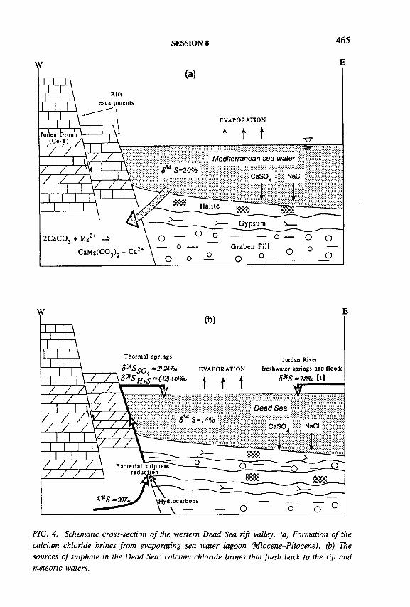
SESSION 8
FIG. 4. Schematic cross-section o f the western Dead Sea rift valley, (a) Formation o f the calcium chloride brines from evaporating sea water lagoon (Miocene-Pliocene). (b) The sources o f sulphate in the Dead Sea: calcium chloride brines that flush back to the rift and meteoric waters.
466 POSTER PRESENTATIONS
The ô3 4 SSq4 contents of the thermal-saline springs (21-24700) are only slightly heavier than present-day marine sulphate of 20700, a value which has not changed much since the Miocene. It is therefore proposed that the sulphate in the springs is a remnant from the Miocene-Pliocene sea water and/or is derived from dissolution of gypsum or anhydrite that were deposited by that sea water. This implies that no significant bacterial sulphate reduction took place during the early stages of the formation of the calcium chloride brines in the Dead Sea rift valley. Furthermore, present-day sulphate reduction must also be restricted or else the sulphate composition could not maintain its close-to-marine composition. A more intense reduction, in a closed or partially closed system, would leave the remaining sulphate heavier, as is believed to be the case in the shallow drill hole of En Boqeq beach (03 4 Sso, = 38.27oe).
The higher salinity and lower sulphate concentration in the Dead Sea as compared to that in the thermal-saline brines indicate that gypsum precipitates from the lake. However, despite the accepted model that the major source of salts in the Dead Sea is the thermal-saline springs, the sulphur isotopic compositions indicate that about 50% of the sulphate in the Dead Sea is derived from meteoric sources, whose sulphur isotopic composition in the area is ô34S = 7-8700 (Fig. 4).
4. CONCLUSIONS
(1) No major sulphate reduction occurred during the formation of the calcium chloride brines in the Dead Sea rift valley.
(2) Fifty per cent of the sulphate in the Dead Sea is derived from the thermal- saline springs and 50% from meteoric sources (Jordan river, floods and freshwater springs). In view of this conclusion a re-evaluation of the sources of other elements in the Dead Sea is required.
REFERENCES
[1] NISSENBAUM, A., KAPLAN, I., “ Sulphur and carbon isotopic evidence for biogeochemical processes in the Dead Sea ecosystem” , Environmental Biogeochemistry (NRIAGU, J., Ed.), Ann Arbor Sci. Publ., Ann Arbor, MI (1975) 309-325.
[2] STARINSKY, A., Relationship between Ca-chloride Brines and Sedimentary Rocks in Israel, PhD Thesis, Hebrew Univ., Jerusalem (in Hebrew).

SESSION 8 467
THE INFLUENCE OF THE PALAEO LAKE CHAD ON THEHIGH ISOTOPIC DEPLETION OF EASTERN SAHEL GROUNDWATERS
M. GRÔNING Institut für Umweltphysik,Heidelberg,Germany
IAEA-SM-336/53P
Several isotopic groundwater studies in the eastern Sahel zone in Africa have shown a surprisingly high depeletion in stable isotopes down to values of — 807oo for <518H and 11 °/о о for ¿>180 (i.e. in Sudan/Dongola, Sudan/Bara basin, Sudan/Darfur, northern Chad, Libya/Kufra). So far such depleted values were known only from the temperate westwind zone and from the northern Sahara, the latter reflecting a southward shift of the westwind belt during the last ice age. In these studies no satisfying isotopic process could be identified which would produce such a high depletion in latitudes below 2 0 °.
A recent case study in the provinces Darfur and Kordofan in Sudan also confirmed this isotopic depeletion and proved the Early Holocene origin of these groundwaters [1]. Furthermore it was shown that nowadays no significant groundwater recharge (>0.5 mm/a) exists in the investigated areas on a regional scale. These results are in accordance with numerical simulations of the instationary groundwater lowering in Sudan since the Early Holocene, caused by drainage towards the Nile without any replenishment.
In the following the important role of the Palaeo Lake Chad on the isotopic composition of Early Holocene groundwaters in the eastern Sahel is described. The key for understanding the high depletion of stable isotopes during the pluvial period of the Early Holocene is the fact that the Palaeo Lake Chad itself was isotopically depleted at that time. Thus Palaeo Lake Chad replenished the monsoonal air masses from the Gulf of Guinea with great amounts of isotopically depleted water vapour and enabled precipitation in nowadays dry parts of the eastern Sahel.
In a qualitative model the isotopic development of monsoonal air masses was calculated along their course from the Gulf of Guinea to Lake Chad and further on towards the eastern Sahel. In this model the isotopic depletion of precipitating air masses is described by a Raleigh process interrupted by a supply of isotopically depleted water vapour from Lake Chad (see Fig. 1).
Assuming reasonable climatic parameters, the calculated results are in accordance with great amounts of isotopic depleted rainfall in Sudan which could have refilled the aquifers in a short time during the Early Holocene.
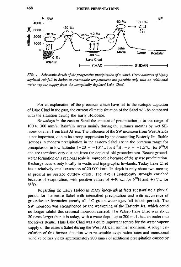
468 POSTER PRESENTATIONS
E,фTJ3.t:
0 % oAtlantic
h
-30 %»
Lake Chad
— C H A D +
Darfur Kordofan
S U D A N
FIG. 1. Schematic sketch of the progressive precipitation o f a cloud. Great amounts of highly depleted rainfall in Sudan at reasonable temperatures are possible only with an additional water vapour supply from the isotopically depleted Lake Chad.
For an explanation of the processes which have led to the isotopic depletion of Lake Chad in the past, the current climatic situation of the Sahel will be compared with the situation during the Early Holocene.
Nowadays in the eastern Sahel the amount of precipitation is in the range of 100 to 300 mm/a. Rainfalls occur mainly during the summer months by wet SE- monsoonal air from East Africa. The influence of the SW monsoon from West Africa is not important, due to its strong suppression by the descending Easterly Jet. Stable isotopes in modern precipitation in the eastern Sahel are in the common range for precipitation in low latitudes ( —20 ± —1 0 7 oo for <5l8 H, —3 + —1 .5 7 00 for ô1 80) and are therefore very distinct from the depleted old groundwaters. Recent groundwater formation on a regional scale is improbable because of the sparse precipitation. Recharge occurs only locally in wadis and topographic lowlands. Today Lake Chad has a relatively small extension of 20 000 km2. Its depth is only about two metres; at present no surface outflow exists. The lake is isotopically strongly enriched because of evaporation, with positive values of + 4 0 7 oo for ¿>18H and + 8 7 00 for 0180 .
Regarding the Early Holocene many independent facts substantiate a pluvial period for the entire Sahel with intensified precipitation and with occurrence of groundwater formation (nearly all 14C groundwater ages fall in this period). The SW monsoon was strengthened by the weakening of the Easterly Jet, which could no longer inhibit this seasonal monsoon current. The Palaeo Lake Chad was about 20 times larger than it is today, with a water depth up to 200 m. It had an outlet into the River Benue. Thus Lake Chad was a quite important source for the water vapour supply of the eastern Sahel during the West African summer monsoon. A rough calculation of this former situation with reasonable evaporation rates and monsoonal wind velocities yields approximately 2 0 0 mm/a of additional precipitation caused by
SESSION g 469
Lake Chad in all the eastern Sahel — up to the Nile in the East and up to the Tibesti mountains and the Egyptian border in the north [2]. Therefore, the total annual precipitation of about 400 mm/a could have caused groundwater formation and may explain the widespread occurrence of 14C ages of Early Holocene time in Sudan. The former isotopic composition of Lake Chad probably was in the range of —407oo for <5I8H and -5 to 6 /oo for ô O, which can be concluded from three facts.
— first, the similar values for old groundwaters in the Chad basin;— second, the period renewal of the lake water by a balance between the annual
precipitation and the water outflow into the River Benue;— third, the minor seasonal isotopic change of the huge lake water reservoir
by evaporation, resulting in an isotopic composition like that of local precipitation.
Thus, the evaporating lake water replenished the monsoonal clouds with isotopically depleted vapour and enabled the occurrence of higher depleted precipitation in the eastern Sahel.
REFERENCES
[1] GRÔNING, М., SONNTAG, C., SUCKOW, A., THORWEIHE, U., “ Isotopic evidence for extremely low groundwater recharge in the Sahel zone of Sudan” , Geoscien- tific Research in Northeast Africa (Proc. Conf. Berlin, 1993) (THORWEIHE, U., SCHANDELMEIER, H., Eds), Balkema, Rotterdam (1993) 671-676.
[2] GRONING, М., Noble gases and isotopic tracers in groundwater: palaeo-climatic changes and dynamics of regional groundwater flow systems, PhD Thesis, Institut fur Umweltphysik, Univ. Heidelberg (1994) (in German).

470 POSTER PRESENTATIONS
A STUDY OF GEOTHERMAL WATERS IN NORTHWEST CROATIA AND EAST SLOVENIA
N. HORVATINCIC, D. SRDOC, I. KRAJCAR BRONIC Rudjer Boskovic Institute,Zagreb, Croatia
J. PEZDICJozef Stefan Institute,Ljubljana, Slovenia
S. KAPELJ Institute of Geology,Zagreb, Croatia
A. SLIEPCEVICFaculty of Veterinary Medicine,Zagreb, Croatia
The investigated area in northwest Croatia and east Slovenia encompasses the peripheral southwestern part of the Pannonian basin with altitudes between 140 and 190 m above sea level. Three distinct hydrogeological units are located in this area: bedrock formations of the central uplifted basin, deep artesian basins (Drava River and Sava River basins) and shallow Quaternary water-bearing horizons in the flat plains. Thermal springs are associated with the waters which issue out of bedrock formations (Fig. 1). This study aims to determine whether the geothermal systems in this area that have been most exploited are independent or form a large geothermal system.
Samples of water were taken from 11 sampling sites (springs, boreholes or water catchments) that belong to the six geothermal systems represented in Fig. 1. The depth of wells ranged from 50 to 500 m. Physico-chemical properties (T, pH, conductivity, alkalinity, concentration of Ca2+, Mg2+, СГ, SOf~, dissolved C02
and 0 2) and isotopic composition (2H, 180, 13C, 3 H) have been determined. The radiocarbon activity of four tritium free samples, as well as of travertine deposited at the thermal spring at Varazdinske toplice spa (No. 5), was measured.
Water temperature ranged from 25 to 64°C. The pH values indicate slightly acid water at sampling points Nos 1, 2, 3 and 5 due to the relatively high concentration of free C02. Samples Nos 4 and 6 , with low free C02 concentration, have pH slightly above 7. According to chemical analyses (Fig. 2) geothermal waters from
IAEA-SM-336/58P

SESSION 8 471
FIG. I. Sk.etch.map o f hydrogeological units with main structural relationships.
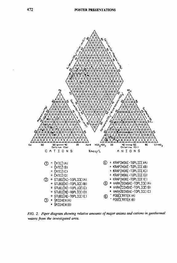
472 POSTER PRESENTATIONS
® o ÈATEZ(А) o CATEZ(B)о Cate2 io » cate2 io )
© ° STUBICKE-TOPLICE (А) D STUBICKE-TOPLICE(В) ° STUB1CKE-T0PL1CE1C) ° STUBICKE-TOPLICE(D)0 STUBICKE-TOPLICE(E)
(D • SMIOHEN(A)• SniDHENlB)
© * KRAPINSKE-TOPLICE(A)» KRAPINSKE-TOPLICE(B)1 KRAPINSKE-TOPLICE1C)* KRAPINSKE-TOPLICE(0)* KRAPINSKE-TOPLICE(El
(D ■ vara?dinske- toplice(A)• VARaI dINSKE-TOPLICE(B) ■ VARAZDINSKE-TOPLICE(C)
© • POOCETRTEKIA)• PODCETRTEK(B)
FIG. 2. Piper diagram showing relative amounts o f major anions and cations in geothermal waters from the investigated area.

SESSION 8 473
g,<N60
-70 -i 1-------»— 1— '-------1— ' " T -----r - ¡ 1 — Г... ------1----- Ч” "
Ж-72 - -
ж-74 - “
-76■ /
-78 n 0/ O Q о (1) Óatez
r\ □ (2) Stubiôke
-80
\J□ • (3) èmidhen
л (4) Krapinske■ (5) Varazdinske
-82 - ж (6) Podcetrtek□ MWL, Zagreb '
-84. — i . i I , 1 , 1 , 1 1 i . i
-11.2 -11.0 -10.8 -10.6 -10.4 -10.2 -10.0 -9.8 -9.6 -9.4
S180 (%o)
FIG. 3. Stable isotope composition o f investigated geothermal waters. The line represents the meteoric water line (MWL) for Zagreb.
Catez (1), Stubicke toplice (2), Krapinske toplice (4) and Podcetrtek (6 ) belong to the Ca-Mg-HC03 type and are generally characterized by low total mineralization (400-600 mg/L) and low conductivity (430-650 /¿S/cm).
Waters from Smidhen (3) and Varazdinske toplice spa (5) with high mineralization and elevated sodium content (conductivity 999 and 1200 /xS/cm, respectively) represent mixed waters of Ca-Mg-Na-HC03-S0 4 type, and may be characterized as thermomineral waters. The CaC03 saturation index is in most cases <1, showing that thermal waters in the spring vents are undersaturated with respect to CaC03.
The stable isotope composition (2 H, 180) of thermal waters (Fig. 3) is compared to the meteoric water line (MWL) for Zagreb based on stable isotope composition of monthly precipitation in the period 1978-1991. Deuterium content in all geothermal waters ranges between —71 and — 8370O standard mean ocean water (SMOW) and is slightly lower than the mean prepipitation <52H values (-62 + 27oo), indicating that a slightly higher percentage of water is recharged during colder periods. Water samples Nos 3, 4 and 5 lie on the MWL; they are tritium-free, and their 14C activity ranges between 0 and 21 pmC. The oxygen isotopic composition of other thermal waters is shifted by 0 . 2 to 0.87oo towards higher ô180 values as a consequence of thermal water carbonate/rock interaction. Among

474 POSTER PRESENTATIONS
them, water from a borehole at Stubicke toplice (2) has the lowest ô2H value, the largest shift in <5180 from the MWL, contains no tritium, and is warmer than water from two other sampling points at the same location. Hence, we conclude that this water is not mixed with recent surface water or precipitation, as might be the case at two other sampling points. None of the three boreholes at Catez spa contain tritium, even though they are very close to the Sava River. Water from boreholes at Podcetrtek (6 ) contains tritium even at depths between 250 and 500 m, indicating mixing of deep and shallow waters. The ô13C of dissolved inorganic carbon at sampling points 1, 2, 3, 4 and 6 ranged from —6.4 to — 11.77O 0 Peedee belemnite (PDB), indicating that carbon originated from both top soil and aquifer carbonate minerals. Water from Varazdinske toplice spa (5) had <513C of -6 .1 7 00, and 14C activity of both older and recent calcareous deposits in the thermal spring environs was <2 pmC.
According to their position, and hydrogeological and physico-chemical data in the investigated geothermal area of the southwestern border region between the Alps and the Pannonian basin, two different groups of geothermal systems occur: (1) geothermal systems (1, 2, 4, 6 ) connected with carbonaceous-Mesozoic geothermal reservoirs, and (2) thermomineral systems (3, 5) situated at the contact of deep artesian basins and the central uplifted basin with a carbonate reservoir. The stable isotope composition of most investigated aquifers is close to the local MWL, indicating the predominant meteoric water influence. Recharge and retention time ranged from old waters with 14C activity of 0 pmC to younger, tritium containing water. The present limited isotopic data cannot resolve whether the investigated geothermal systems are related to each other, and thus more detailed investigation is needed.
ACKNOWLEDGEMENT
The work was supported by Grant 1-07-064 from the Ministry of Science, Republic of Croatia.

SESSION 8 475
STUDY OF OLD GROUNDWATERS’ CIRCULATION IN THE LAKE CHAD BASIN (NIGER) USING ISOTOPIC TRACERS
C. LE GAL LA SALLE, J.-C. FONTESt Laboratoire d’hydrologie et de géochimie isotopique,Université de Paris-Sud,Orsay, France
J.N. ANDREWSPostgraduate Research Institute for Sedimentology,University of Reading,Reading, United Kingdom
C. TUNIZAntares Mass Spectrometry,Australian Nuclear Science
and Technology Organisation,Menai, New South Wales, Australia
A. KARBODirection des ressources en eaux,Ministère de l’hydraulique et de l’environnement,Niamey, Niger
IAEA-SM-336/71P
Deep groundwaters of the confined aquifer of the Pliocene sandy formation in the Lake Chad Basin (southeast Niger) have been exploited from about 60 boreholes for both domestic and agricultural supplies for 30 years. Since the beginning of the exploitation, no extensive hydrodynamical studies have been performed. At present the current flux of the artesian boreholes is decreasing. This can be related either to the decrease of the hydraulic charge or to the deterioration of the boreholes. As knowledge of groundwater renewal is problematic in the Sahelian zone, chemical and isotopic studies have been carried out to define groundwater origin and time residence.
Chemical and isotopic ( 180, 2 H, 1 3C, 14C) analyses were performed on water samples from nine artesian boreholes in the confined aquifer and three wells in the Quaternary shallow aquifer. The two groundwater bodies are well differentiated as regards both mineralization and isotopes. The groundwaters of the confined aquifer
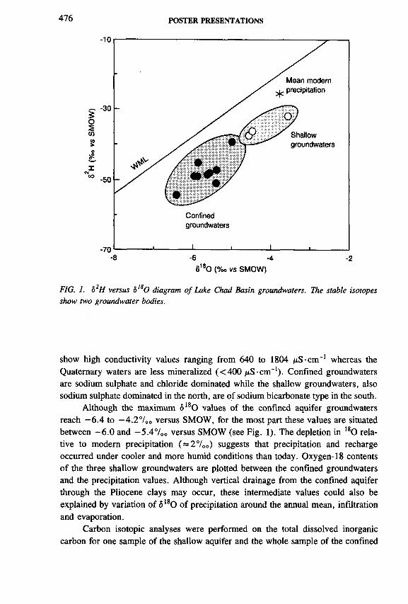
476 POSTER PRESENTATIONS
6180 (%o vs SMOW)
FIG. 1. h2H versus ól80 diagram o f Lake Chad Basin groundwaters. The stable isotopes show two groundwater bodies.
show high conductivity values ranging from 640 to 1804 /¿S-спГ1 whereas the Quaternary waters are less mineralized (<400 /xS-спГ1). Confined groundwaters are sodium sulphate and chloride dominated while the shallow groundwaters, also sodium sulphate dominated in the north, are of sodium bicarbonate type in the south.
Although the maximum S180 values of the confined aquifer groundwaters reach —6.4 to — 4.2700 versus SMOW, for the most part these values are situated between -6 .0 and -5 .4 7 0 0 versus SMOW (see Fig. 1). The depletion in 180 relative to modern precipitation ( = 2700) suggests that precipitation and recharge occurred under cooler and more humid conditions than today. Oxygen-18 contents of the three shallow groundwaters are plotted between the confined groundwaters and the precipitation values. Although vertical drainage from the confined aquifer through the Pliocene clays may occur, these intermediate values could also be explained by variation of <5180 of precipitation around the annual mean, infiltration and evaporation.
Carbon isotopic analyses were performed on the total dissolved inorganic carbon for one sample of the shallow aquifer and the whole sample of the confined

SESSION 8 All
aquifer. The 14C activity and 13C content of the shallow groundwater sample are 63 pmC and -3 .8 ° / 0 0 respectively. Unless the activity is less than 100 pmC, these values more likely indicate a recent water recharge and probably geochemical evolution. The confined groundwaters have low 14C contents ranging from 5 to 10 pmC and it has been estimated that the last period of recharge must have been at the earliest 25 000 a BP.
IAEA-SM-336/73P
ISOTOPE HYDROLOGY STUDY OF AREAS IN EASTERN MACEDONIA AND THRACE, NORTHERN GREECE
I.L. LEONTIADISNational Centre for Scientific Research “ Demokritos” , Aghia Paraskevi Attikis
S. VERGISInstitute of Geology and Mineral Exploration,Xanthi
T. CHRISTODOULOUInstitute of Geology and Mineral Exploration,Athens
Greece
Depending upon the altitude effect on the isotopic composition of precipitation, isotopes may be used for the identification of waters coming from each of the potential sources of recharge to the groundwater. The so-called precipitation altitude effect, derived by sampling of the precipitation at different elevations, is not always useful without further assumptions. As another approach one may investigate, even if this is more tedious, the effect of the altitude on the isotopic composition of the groundwater directly, by sampling of springs with well defined recharge areas, at different elevations [1-5]. The so-called groundwater isotope effect is undoubtedly more accurate for the determination of the origin of the groundwater, especially in cases of intense évapotranspiration.

'•••оава•••••••вВООООО
A: Marbles or crystalline limestones B: Cohesive conglomerates С Loose conglomerates D; Alluvial deposits
• • • * • • • • ( • • • • • • • • a ■ a 1111 ШШ rf »?» Tf f f fr ? t f f
EIgoeous rocksF: Volcanic rocks of Eoceoe-Oligocene Or. Molassic formations of Oligocene H: Amphibolites and gneisses
I: Molassic formations of Eocene-Oligocene J: Lacustrine and continental deposits K: Marbles and phyliites L: Chlorite, mica, quartz, schists
FIG. 1. Geological map o f the area under investigation, based on the geological map o f Greece, scale 1:500 000, published by IGME, 1983.
478 POSTER
PRESENTA
TION
S

SESSION 8 479
The objective of the present study was the definition of the altitude effect on the <5180 value of groundwater in eastern Macedonia and Thrace and, as case studies, the investigation of the mechanism of recharge of the aquifers feeding the main springs and/or developed in the plains at different levels in the Lekani Mountains and the island of Thassos, with special consideration, in the case of the Lekani Mountains, to the eventual contribution of waters leaking from the River Nestos.
The geology of the area under investigation is discussed in detail in Refs [6-9]. In general terms it is shown in Fig. 1.
The sampling of the present isotope programme covers several springs at different elevations with well defined recharge areas, the River Nestos at three locations, all important springs, and finally a number of boreholes at different locations in the Lekani Mountains and Thassos. The sampling locations are shown in Fig. 2.
In total, 618 samples from 56 sampling points were collected. The samples were analysed in the Demokritos Institute for the 1 80, D, T and СГ . One sample per sampling point was also analysed by the Institute of Geology and Mineral Exploration (IGME) for its chemical composition.
The results and conclusions of the study may be summarized as follows:
(1) The altitude effect on the <5180 value of the groundwater in the continental part of the studied districts is uniform in each but it differs considerably between them (-0 .217oo ô180 per 100 m in Thrace and -0 .447oo in eastern Macedonia). Slight differences in both the slope and the intercept of the lines expressing the regression of elevation against ô180 values between the continental part of the water district of Thrace and Thassos were also observed. The prediction of the mean recharge altitude (mean altitude of the recharge area weighted by the surface and the precipitation, Mra) from the <5180 value of groundwater can be based on the following equations; (1) for the continental part of Thrace, (2) for eastern Macedonia and(3) for the island of Thassos.
Mra = (-2800 ± 115) - (459 ± 15) 0180 (r = 0.9926) (1)
Mra = (-1026 ± 130) - (221 ± 15) <5180 (r = 0.9821) (2)
Mra = (-3159 ± 190) - (474.5 ± 23.5) 0180 (r = 0.9958) (3)
The standard deviation in calculating the mean recharge altitudes by the aboveequations varies between 45 and 65 m for <5180 values between —10.5 and— 6.5 700.
(2) The River Nestos, between the sites of Paschalia (point 26) and Stavroupolis (point 17), does not seem to be replenished by groundwater originating from the carbonate rocks of the Lekani Mountains. On the contrary, there are strong indications that aquifers in the karstic system of the Lekani Mountains are enriched by the river.
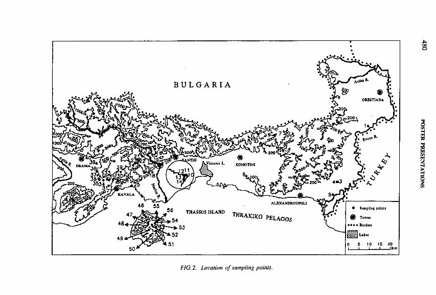
00о
FIG. 2. Location o f sampling points.
POSTER PRESEN
TATIO
NS
SESSION 8 481
(3) The contribution of groundwater originating from the carbonate rocks of the Lekani Mountains to the yield of the River Nestos occurs from Stavroupolis (point 17) to Galani (point 12). This contribution is estimated at 27 ± 8 % of the river yield.
(4) The carbonate rocks located on the eastern side of the River Nestos, apart from their contribution to the yield of the river, form a unique aquifer, feeding mainly the springs in the site of Galani (points 10 and 11). The extent of the area effective in recharge to this aquifer is estimated at about 43 km2 (amount of precipitation effective in recharge 21 x 106 + 13% m3 -a_1).
(5) A part of the carbonate rocks on the eastern side of the River Nestos is replenishing the aquifer developed in the plain of Stavroupolis (point 15). The extent of this part is estimated at about 7 km2 (amount of precipitation effective in recharge 3 x 10⁶ ± 14% m3 -a_1). The aquifer developed in the site of Komnina (point 16) is replenished by the river water by a percentage variable over time.
(6 ) Leakages of water from the River Nestos are contributing to the yield of the springs of Paradissos (points 13 and 14) by 43 + 10%, assuming that the leakages occur before Stavroupolis (point 17).
(7) The aquifer developed in the band of folded marbles at the northwestern borders of the Lekani Mountains is receiving 54 + 12% of its water from the River Nestos. This aquifer feeds the spring of Aghios Athanassios (point 38). Some contribution of the river water to the feeding of the spring at the site of Pirgos Filippon (point 35) and to the replenishment of the aquifers tapped by the boreholes of Kefalari (point 37) and Lydia (point 36) was also indicated. On the other hand, the aquifer tapped by a borehole northwest of Aghios Athanassios (point 39) is locally recharged.
(8 ) The spring Krinides (point 34) is fed by the aquifer developed in the band of folded marbles, where the spring is located, and limited by the surface water divide (57 km2, amount of precipitation effective in recharge 27 x 106 ± 13% m3 -a_1). The same aquifer is tapped by the boreholes at the sites of Krioneri (point 32) and Filippi (point 33). Water from this aquifer is transfused to the marbles to the south, thus contributing to the recharge of the aquifer tapped by the borehole at the site of Amigdaleon (point 31).
(9) The marbles effective in recharge of the saline spring of Nea Karvali (point 25) are the ones east-northeast to the spring limited by the surface water divide (23 km2, amount of precipitation effective in recharge 9 X 10⁶ + 14% m3 -a*1).
(10) The areas effective in recharge to the aquifers tapped by the boreholes at Stenopos (point 19) and Xerias (point 18) are the ones limited by the surface water divide (3.5 and 5.2 km2, amount of precipitation effective in recharge 1.5 X 10⁶
and 2 X 10⁶ ± 14% m3 -a_1, respectively).

482 POSTER PRESENTATIONS
(11) In the northeastern part of Thassos the hydraulic connection between the carbonate rocks of the higher regions and the ones of lower altitude is confirmed.
REFERENCES
[1] KALLERGIS, G., LEONTIADIS, I.L., Isotope hydrology study of Kalamos Attikis and Assopos river plain areas in Greece, J. Hydrol. 6 0 (1983) 209-225.
[2] LEONTIADIS, I.L ., et al., “ Isotope hydrology study of Kato Nevrokopi of Dramas” , Isotope Hydrology 1983 (Proc. Symp. Vienna, 1983), IAEA, Vienna (1984) 193-206.
[3] LEONTIADIS, I.L., PAYNE, B.R., CHRISTODOULOU, T., Isotope hydrology of the Aghios Nikolaos area of Crete, Greece, J. Hydrol. 9 8 (1988) 121-132.
[4] LEONTIADIS, I.L., SMYRNIOTIS, C., “ Isotope hydrology study of the Louros Riverplain area, Epirus, Greece” , in Proc. 5th Symp. Underground Water Tracing, Athens, 1986, pp. 75-90.
[5] CHRISTODOULOU, T., LEONTIADIS, I.L., MORFIS, A., PAYNE, B.R., TZIMOURTAS, S., Isotope hydrology study of Axios River plain in northern Greece, J. Hydrol. 1 4 6 (1993) 391-404.
[6] PAPANIKOLAOU, G., PANAGOPOULOS, A., On the structural style of Southern Rhodope, Greece, Geol. Bale. 11 3 (1981) 13-22.
[7] ZACHOS, S., DIMADIS, E., The geotectonic position of the Skaloti-Echinos granite and its relationship to the metamorphic formation of Greek Western and Central Rhodope, Geol. Bale. 13 5 (1983) 17-24.
[8] DIMADIS, E., ZACHOS, S., Geological and tectonic structure of the Metamorphic basement of Greek Rhodope, Proc. 1st Bulgarian in Greek Symp. Geological Geographical Problems of the Rhodope Massif, Smolyan, 1987.
[9] DIMADIS, E., KOSMAS, C., Geological and tectonic structure of the ‘Lekani Mountains’ syncline, ibid.

SESSION 8 483
CLIMATE SIGNALS IN TREE RING CELLULOSE OF Tamarix jordanis COLLECTED IN VARIOUS CLIMATIC ZONES OF ISRAEL:A survey using b13C, b2H, and b180
J. LIPP, P. TRIMBORN, T. EDWARDS Institut fiir Hydrologie,GSF-Forschungszentrum für Umwelt und Gesundheit Neuherberg, Oberschleissheim, Germany
D. YAKIRDepartment of Environmental Sciences and Energy Research,Weizmann Institute of Science,Rehovot, Israel
Y. WAISEL Department of Botany,Tel Aviv University,Tel Aviv, Israel
IAEA-SM-336/75P
1. INTRODUCTION
Tamarisks ( Tamarix jordanis) were collected in a reconnaissance survey across Israel in five climate zones from the temperate north to the hot and dry south. Cellulose was prepared from a single ring (1991-1992) of each of the trees, and the stable isotope ratios 13C/12C, 2 H/*H and 1 80 / 160 were measured mass spectrometrically. Climatic data for the time of growth was obtained from five stations in the respective climate zones (see Table I). Tamarix jordanis was selected because it is widespread and has well characterized water usage patterns. As an adaptation to arid conditions, Tamarix jordanis excretes salt crystals, forming a highly hygroscopic coating on the exterior of the plant that effectively increases the relative humidity of the plant microclimate [1]. It is also commonly preserved in archaeological contexts, where it has demonstrated value for palaeoclimatic interpretation [2 ].
The <52H and the <5,80 values clearly reflect the existence of a general climatic gradient from north to south. Lower numbers correspond to more temperate climate (north), whereas higher numbers correspond to hot and dry conditions (south). The <513C values also reflect this climatic gradient, except for the samples from the Arava Rift Valley (climate zone C3), which have more negative values than those from the Central Negev, in spite of the hotter and drier climate of the Arava.
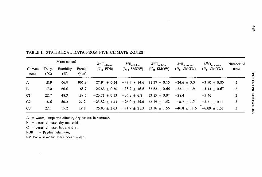
TABLE I. STATISTICAL DATA FROM FIV E CLIM ATE ZONES
Climatezone
Mean annual 113p° '-'cellulose(7 0„ PDB)
^ cellulose(°/00 SMOW)
^ 180 CelluIose(700 SMOW)
c2m° n stemwater
(7 00 SMOW)
£ 1 8pv^ stemwater(7 00 SMOW)
Number of treesTemp.
(°C)Humidity
(%)Precip.(mm)
A 18.9 66.9 905.8 -27 .94 ± 0.24 -4 3 .7 ± 14.6 31.27 ± 0.15 -2 4 .6 ± 3.3 -3 .9 0 ± 0.85 2
В 17.0 60.0 165.7 -25 .83 ± 0.50 -3 8 .2 ± 16.6 32.62 ± 0.66 -23 .1 ± 1.9 -3 .1 3 ± 0.67 3
Cl 22.7 48.3 189.6 -23.21 ± 0.33 -3 5 .8 ± 6.2 33.15 ± 0.07 -2 8 .4 -5 .4 6 2
C2 18.6 50.2 22.2 -23 .82 ± 1.43 -2 6 .0 ± 25.0 32.19 ± 1.52 - 8 .7 ± 1.7 -2 .7 ± 0.11 3
C3 22.1 35.2 19.8 -25 .83 ± 2.03 -2 1 .9 ± 21.3 33.26 ± 1.56 -4 6 .8 ± 11.6 -6 .0 9 ± 1.51 3
A = warm, temperate climate, dry season in summer. В = desert climate, dry and cold.С = desert climate, hot and dry.PDB = Peedee belemnite.SMOW = standard mean ocean water.
484 POSTER
PRESENTA
TION
S
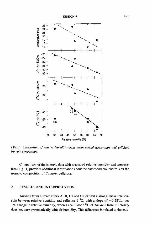
SESSION 8 485
2<uо .e
23222120191817
-200 -25 И -30 S? -351 -40 ^ -45 H
33 -
32 -
4------ 1------h 4 -------h
30 35 40 45 50 55 60 65 70Relative humidity (%)
FIG. 1. Comparison o f relative humidity versus mean annual temperature and cellulose isotopic composition.
Comparison of the isotopic data with measured relative humidity and temperature (Fig. 1) provides additional information about the environmental controls on the isotopic composition of Tamarix cellulose.
2. RESULTS AND INTERPRETATION
Tamarix from climate zones A, B, Cl and C2 exhibit a strong linear relationship between relative humidity and cellulose 0 13C, with a slope of —0.287oo per1 % change in relative humidity, whereas cellulose Ô13C of Tamarix from C3 clearly does not vary systematically with air humidity. This difference is related to the exis
486 POSTER PRESENTATIONS
tence of abundant groundwater at shallow depth in the Arava Rift Valley (climate zone C3), which acts as a ‘leimann’ collecting runoff from the surrounding hills, leading to a general (but variable) reduction in moisture stress for the trees growing in this area. The remarkably tight linear clustering of the data points from climate zones A, B, Cl, and C2 reflects the existence of a carbon source for all trees having the same l3 C/12C ratio (namely atmospheric C02).
Taken as a whole, Tamarix from all five climate zones exhibit scattered, but statistically significant, inverse relations between relative humidity and both 8 , 8 0
and ô2H (Table I). The data points define general linear trends, having apparent sensitivities of about —0.06 and —0.737oo per 1% change in relative humidity, respectively, as compared with expected sensitivities for leaf water enrichment during évapotranspiration of about -0 .3 and -0 .1 700 per 1% change in relative humidity. It is clear from the scattering of the points (analogous to that of temperature versus humidity) and the low humidity sensitivities that source waters of differing oxygen and hydrogen isotopic compositions were used by these trees. The apparent dampening of the humidity response probably reflects plant adaptation to the low humidities (particularly in climate zone C), perhaps enhanced by a general north-to-south decline in the <5I80 and <52H values of source waters.
3. CONCLUSIONS
— Strong environmental signals exist in the isotopic composition of Tamarix cellulose. Cellulose ¿>180 and ô2H both respond directly to the atmospheric humidity around the plant, while <5I3C reflects the water balance of the entire plant, which is also affected by soil moisture status.
— Potential exists to use the observed systematic humidity/5 l3C relation for plants that lived under moisture stress to reconstruct past humidity or atmospheric C0 2 ô13C from fossil desert plants.
— Further studies are needed to quantify adequately the humidity sensitive signals in <5180 and <52H of Tamarix cellulose, which may be affected by the adaptations of the plant to desert environments.
ACKNOWLEDGEMENT
These studies were funded by the German-Israel Foundation.
REFERENCES
[1] WAISEL, Y., POLLAK, G., COHEN, Y., The Ecology of Vegetation of Israel, Division of Ecology, Petah Tikva (1978) (in Hebrew).
SESSION 8 487
[2] YAKIR, D., et al., I3C and l80 of wood from the Roman siege rampart in Masada, Israel (AD 70-73): Evidence for a less arid climate for the region, Geochim. Cosmochim. Acta 58 (1994) 3535-3539.
IAEA-SM-336/78P
NOBLE GAS, ENVIRONMENTAL AND RADIUM ISOTOPES IN THERMAL SPRINGS OF SOUTHERN TUSCANY (ITALY)
G. MAGROIstituto di Geocronologia e Geochimica Isotopica,Consiglio Nazionale delle Ricerche,Pisa, Italy
K. FRÔHLICH Isotope Hydrology Section,Division of Physical and Chemical Sciences,International Atomic Energy Agency,Vienna
A. BATTAGLIACISE Tecnologie Innovative SpA,Segrate (Mi), Italy
A. CECCARELLI, A. RIDOLFI ENEL SpA DPT-VDT/G,Pisa, Italy
The hydrological path of some thermal waters in southern Tuscany was studied in order to elucidate the connection with central Italian thermal anomalies. Radium isotopes, tritium and environmental isotopes (<5D, <5I80) were measured in thermal waters, together with the chemical and isotopic (3 He/4 He, 4 0 Ar/36Ar and 2 2 2Rn) composition of the associated free gases.
The uranium and thorium decay series include many radionuclides with different geochemical properties and mean lives; significant radioactive disequilibria can exist in groundwater that can be useful in transport studies because the rates at which the radionuclides enter the water may be estimated. A water/rock interaction model was applied in order to estimate parameters such as partition coefficients, radium

488 POSTER PRESENTATIONS
retardation factors and residence times in the reservoir and the origin of fluids, as derived by the model [1 , 2 ].
Environmental isotope analyses were carried out: tritium concentration may indicate the order of magnitude of the water residence time in the reservoirs. Deuterium and 1 8 0 may give information on the alteration produced by a long contact time with hot rocks. The isotopic composition of noble gases is typical of the sources they come from (mantle, crust and atmosphere) and permits distinction between the different sources and estimation of the grade of mixing.
The thermal manifestations considered (B. Osa, Saturnia, S. Filippo, Petriolo, Bagnaccio and C. Broco) are located in a region characterized from a geological point of view by the superposition of several sedimentary and metamorphic complexes; from the hydrological point of view, all the geothermal fields of the region are featured by low permeability cap rock overlaying the reservoir formations; the cover consists mainly in flysch complexes and neo-authoctonous sediments. The geothermal reservoir is represented by mostly carbonatic evaporitic composition.
Tritium analyses were carried out by low background liquid scintillation counting after electrolytical enrichment. Radium isotopes were collected by a preconcentration device; the water was filtered and treated by three sequential barium sulphate activated alumina beds. The analysis of filters, alumina beds and rocks was performed by low background gamma spectrometry. Radon in gas phase and dissolved in water was measured by emanometry and Lucas cells. The overall statistical error of radioactivity measurements was generally 5-10%.
The chemical composition (C02, N2, H2S and CH4) of free gases was determined by gas chromatography; isotopic measurements of noble gases were carried out on a quadrupole mass spectrometer (Spectralab 200, VG-Micromass) for Ar and Ne, and on a magnetic mass spectrometer (MAP 215-50) for 3 He/4He ratio determination after separation in a high vacuum metallic line of quite pure fractions of He, Ne and Ar. The overall statistical error of the isotopic ratios is below 3%.
The chemical composition of waters and associated tree gases gives information on the geochemical environment and on the maturity level. The main free gases component is C02, except for two samples (B. Osa and Saturnia), which are N2
enriched [3]. A deep origin of part of the N2 has to be considered accordingly, with N2/Ar ratios which are higher than air and water typical values; sediments degassing due to heating can account for the N2 excess found.
The deep originating fraction of fluids is also evidenced by the presence of radiogenic 4He and 4 0 Ar, originating from U and Th series decay and from 40K decay, respectively. The 3He/4He ratios (R/Ra < 1) range from atmospheric to crustal typical values, reaching a minimum (R/Ra = 0.09) corresponding to a maximum of radiogenic 4He for the Osa manifestation, where the associated water shows a high radioactivity level compared with the other manifestations.
Small excesses of radiogenic 40Ar are present in two samples (B. Osa and S. Filippo), since the 4 0 Ar/36Ar ratio is slightly higher than in air. Long residence
SESSION 8 489
times of the fluids in reservoirs, where the decay of parents permits 4He and 40Ar radiogenic enrichment, is the most likely explanation, which is corroborated by the tritium content, less than a few TU, indicating a fairly high residence time of these waters.
Whereas no radiogenic 40Ar is recorded for other samples, the deep formed gases passing through shallow aquifers saturated in air dissolved components (ASW) gave rise to an ‘atmospheric contamination’ which strongly affects Ar isotopic composition and masks the possible 40Ar radiogenic fraction. The presence of ASW components is further indicated by the stable isotopes D and I80; the recorded data indicate that the spring waters fall close to the meteoric water lines and are isotopically not altered by water/rock interaction.
The radium isotope concentrations were found to range from a few Bq/m3 up to more than 1000 Bq/m3. This is due to several parameters: host rock uranium concentrations, water chemical composition, and secondary uranium enrichment due to phreatic aquifer fluctuations in the redox conditions or to a mixing with seawater (B. Osra spring).
The 2 2 8 Ra/226Ra ratio was of practical interest since it is expected to represent the Th/U ratio in the host rock and thus to provide information on the water circulation path. 2 2 4 Ra/223Ra ratios are expected to give information on the host rock composition in the proximity of the outlet of the springs, because these isotopes decay in a very short time, as compared to 228Ra and 2 2 6 Ra.
The water/rock interaction model, which requires 222Rn and Ra isotope concentrations dissolved in waters, provided information on the physico-chemical parameters involved in the transfer of these isotopes from the rock into the liquid phase.
The evaluations obtained from the gas studies, geochemical parameters, and environmental and radium isotopes combine to describe the circulation path of the thermal waters.
REFERENCES
[1] FROHLICH, К., BATTAGLIA, A., CECCARELLI, A., RIDOLFI, A., PANICHI, C., “ Radium isotopes contribution to geothermal exploration in Central Italy” , submitted to World Geothermal Congress, Florence, 1995.
[2] IVANOVICH, M.K., FROHLICH, K., HENDRY, J.M ., Uranium-series, radionuclides in fluid and solid forms from the Milk River Aquifer, Alberta, Canada, Appl. Geochem. 6 (1991) 405-418.
[3] MINISSALE, A., EVANS, W.C., MAGRO, G., VASELLI, О., DUCHI, V., “ Gas manifestation in Central Italy” , submitted to World Geothermal Congress, Florence, 1995.
490 POSTER PRESENTATIONS
WATER RESOURCES ASSESSMENT WITHIN THE MAIN RIFT AND FLUORIDE CONCENTRATION MAPPING IN THE LAKE REGION
A.M. WESSENUWater Supply and Sewerage Agency,Addis Abbaba,Ethiopia
1. INTRODUCTION
The Main Ethiopian Rift is part of the East African Rift System. The proposed project area is within the Main Rift extending from Chew Bahir (37°E and 4°33'N) in the south to 41°10'E and 12°N in the north.
The purpose of this project is to identify the regional groundwater regime configuration within the project area and to detect the source of the high concentration of fluoride within the lake region.
Full understanding of the groundwater regime configuration and the source of fluoride within the study area could not be obtained from previous hydrological, geophysical, geochemical and geothermal geophysics results. This paper therefore highlights new exploration methods on a regional basis.
The validity of hydrological analysis and possible methods are put forward. Nevertheless, because of the small number of hygrométrie networks within the region, water balance formulation will probably not provide reliable information.
The use of nuclear techniques for water resources assessment on a regional level is of interest mainly for two reasons. First, it involves only minimum project costs and a small volume of work compared to conventional methods. Secondly, it gives more valuable information on the dynamics of both surface water and groundwater in the region. The extent of aquifers and stratification could also be well delineated using these methods. In addition, it is useful for determining palaeoclimatic conditions in the region, which is hardly possible using conventional methods.
2. BACKGROUND
2.1. Hydrogeological studies
2.1.1. Geological setting
The Main Ethiopian Rift runs approximately in a NE-SW direction. Following the regression of the Mesozoic sea to the southeast, a major uplift, known as the
IAEA-SM-336/82P

SESSION 8 491
Arabo-Ethiopian swell, occurred which subsequently resulted in the formation of the East African Rift as well as the Red Sea and the Gulf of Aden.
The Tertiary uplift and formation of the rift was associated and followed by extrusion of large masses of basaltic magma through fissures. Although the magnitude of Tertiary uplift was affected by later tectonic events, it can be observed that tremendous uplift occurred where the present valley lies.
The basement was probably uplifted over 2.8 km. Possibly Arabia and the Horn of Africa were uplifted as one unit, the Red Sea and Gulf of Aden rifts not then being in existence. Most of the main rift is covered by volcanic rocks, such as basalt, ignimbrites, trachytes, rhyolite and pumiceous pyroclastics. In the lowlands, extensive areas of lacustrine and alluvial sediments are found overlying the ignimbrites and basaltic flows of the rift floor.
2.1.2. Use of geophysical techniques
Owing to the complex geology, structures and tectonics, using hydrogeological/geophysical studies was a very inefficient method to achieve understanding of the regional groundwater regime configuration of the area.
Efforts have been made to conduct geophysical surveys within the proposed project area for different purposes. However, since the rift is an active tectonic regime, seismic surveys do not give clear data because of some coherent and incoherent noises.
It should be emphasized at this point that resistivity survey results depend on a number of factors (such as water content, lithostatic pressure, thermal gradient, density of formations and salinity). Indirect measurements are made of this physical parameter (resistivity); attempts are made to correlate the various factors with existing geological/hydrogeological data.
In principle, any resistivity survey has its limitations as regards detecting a layer of a certain resistivity value within a geometric model and suppression of layers as if they do not exist (principle of equivalence and suppression).
In addition, due to technological drawbacks coherent elastic waves in an ongoing seismic survey cannot be filtered. Also, the data is poor, owing to incoherent noise in active tectonic areas such as the rift. Therefore, such traditional geophysical exploration methods can hardly yield good information unless they are accompanied by more integrated survey plans.
2.1.3. Regional geochemical analysis
Even though saline waters are detected mainly in deep aquifers all over the main rift, especially when one gets closer to the lake region, emphasis is given to the fluoride problem in relation to this proposed project.

492 POSTER PRESENTATIONS
According to K.L. von Dam and J.M. Edmond1, in closed basin lakes displaying intermediate degrees of evaporative concentration relative to their inputs the only simple salts that can precipitate are calcite (usually the low Mg variety) and minor gypsum. Hence, more complex removal processes affecting the major cations and alkalinity can be investigated using mass balance techniques. Application of this approach to the lakes of the main rift demonstrates that formation of alumino-silicate minerals or reverse weathering is a major process, accounting for over half the alkalinity deficit in the mass balance. The process does not go to completion, however, and alkaline pH > 9 NaHC03, Cl waters result. Notwithstanding the problem of high fluoride concentration, this process indicates the strikingly rapid removal of Ca from carbonates and the formation of CaF2 that alleviates the fluoride problem. This was the paradox about the high fluoride concentration that exists around the lake region. On the other hand, the post-tectonic volcanic activity is a typical feature of the African Rift System. According to petrogenetic analysis, the fluoride is associated with acidic products, including pumice, ignimbrite, obsidian and rhyolite.
Moreoever, thermal springs and fumaroles associated with rift volcanism are believed to supply large quantities of fluoride to both surface water and groundwater bodies.
It is commonly known that the capacity of groundwater to dissolve fluoride increases if it has low calcium and high sodium, which is totally in contrast to the reverse weathering hypothesis.
On the other hand, the petrogenetic analysis compared with the hydrogeological map of the lake region does not provide confirmation. The map rather shows a high concentration of fluoride residing within the lacustrine sediment on the periphery of the lakes (Shala, Abiyata, Langano). Even though these sediments overlie the ignimbrite, the high fluoride concentration does not seem to be associated with the ignimbrite. Boreholes sunk in the ignimbrite formation show about twenty times less fluoride concentrated water than do the lakes. The fluoride concentration decreases radially outwards from these lakes.
The hydrogeological report for the lake region shows that within the lakes high salinity is associated with low calcium and magnesium content and consequently a very high concentration of fluoride. Since the source of the fluoride (F~) is not currently known, these studies call for an appraisal and consolidation.
3. OBJECTIVES
In the light of the relevance and socioeconomic importance of water resources to the nation, the value of nuclear techniques in their assessment is unquestioned.
1 VON DAM, K.L., EDMOND, T.M ., Reverse weathering in the closed basin lakes of the Ethiopian Rift, Am. J. Sci. 284 (1984) 835-862.

SESSION 8 493
Determination of the water balance and the fluoride source is the basic problem to be solved.
Even though the question of water balance formulation remains to the fore (crucial but unlikely unless a number of hygrométrie networks are available) in groundwater hydrology, determining the position of aquifers in a geological section and obtaining reliable data on the properties of each aquifer are most important both on the regional and the local level.
Virtually all groundwater of economic interest originates as precipitation. The only other known source is of magmatic origin, but these waters are quantitatively insignificant and generally too highly mineralized to be of value for water supply and irrigation.
Thus the problem of the origin and distribution of subsurface water becomes a matter of defining the time, place and amount of replenishment, and distinguishing lateral and vertical differences in groundwater movement from points of recharge to points of discharge.
Several of the components of input, output and storage can be measured indirectly, and generally at least one component must be calculated by the difference. Moreover, although the broad relations of groundwater occurrence may be expressed by a simple equation, inhomogeneities in the system greatly complicate the detailed analysis. Therefore, catchment and aquifer modelling is not an easy task unless hygrométrie networks are available.
IAEA-SM-336/116P
APPLICATION OF STABLE ISOTOPES IN EVALUATING THE IMPACT OF A REINJECTION STRATEGY AT THE PALINPINON GEOTHERMAL FIELD, PHILIPPINES
J.S. SEASTRES, Jr., D.Z. HERMOSO PNOC-Energy Development Corporation,Makati, Philippines
J.Y. GERARDO Isotope Hydrology Section,Division of Physical and Chemical Sciences,International Atomic Energy Agency,Vienna
Stable isotope studies were conducted to evaluate the impact of past reinjection strategy on the production sector in Palinpinon. Reservoir processes such as

494 POSTER PRESENTATIONS
5оs«>Й -3 .5 —
ШООС<Xоюа_|Íоt-о00
С О
О 50 100 1S0 200 250 300 350 400 450 500 550 600 650 700
СО /Н О х 1СГ5 (molar ratio)
FIG. I. ô О versus С 02/Н20 diagram during exploitation, illustrating the mixing o f reservoir fluid with reinjection waters and steam addition for wells relatively unaffected by reinjection fluid returns. The mixing line is defined by dlsO = —4.5 X I 0 3 (C02/H20) — 3.4.
reinjection fluid returns, pressure drawdown and acidic fluid inflows have affected the capability o f the field to provide steam supply for power generation. A reinjection well utilization strategy has been adopted to optimize steam production and to minimize thermal deterioration caused by rapid reinjection fluid returns.
Mass breakthrough o f reinjection fluids has been detected at the Puhagan production field in Palinpinon since commercial steam extraction for electrical generation started in 1983. From 1983 to 1989, several production wells were enriched in stable isotopes owing to dilution with reinjection waters, which is attributed to the proximity o f the reinjection sector to the production field (c. 500 m aerial distance). Wastewater injection was eventually shifted in 1989 to the Ticala/Malaunay sector, which is 4 km farther northeast o f the production field, to arrest the bore output deterioration caused by massive reinjection fluid returns. As a consequence, the ô 180 composition and chloride levels o f the reservoir fluids showed a decline in response to reduced reinjection fluid inflow. Such decline facilitated thermal recovery in most production wells.
The shift o f fluid injection to the Ticala/Malaunay sector induced the flow of reinjection fluids to some production wells with an acidic fluid component. This condition caused the suppression o f acidic fluid inflows. This led to the optimum utilization o f these wells for steam production. Their ô 180 and ÔD composition indicate enrichment (by as much as 1 .1 7 00 <5I80 and 4 .7 7 00 SD) caused by mixing with isotopically enriched reinjection waters.

SESSION 8 495
To evaluate the effect of field pressure drawdown in the reservoir when the bulk of fluid injection was transferred from Puhagan to the Ticala/Malaunay sector, the ô180 composition was correlated with the C02 /H20 (total discharge) molar ratio (Fig. 1). The results indicate that several production wells are still sufficiently recharged by reinjection fluids. The reinjection component in the discharge fluids ranged from 40 to 90%. However, some wells have deviated much from the baseline range of the ô l80-C 0 2 /H20 composition of Palinpinon production wells. Wells PN28, PN14, PN21D and PN13D are highly shifted towards the isotopically enriched and degassed reinjection fluid, while others (PN22D, PN30D and PN32D) have been diluted by isotopically depleted steam characterized by discharge enthalpies ranging from 2100 to 2800 kJ/kg. The major effect of field pressure drawdown appears to be confined to some wells with insufficient fluid recharge resulting in the expansion of the reservoir’s steam zone due to exploitation.
Correlation of isotopic data with the geochemical monitoring parameters applied in field management indicates that the shift of fluid injection to the Ticala/Malaunay sector resulted in the following reservoir changes.
(1) Production wells that are closest to this sector are highly affected by reinjection fluid returns (c. 80-90% reinjection fluid fraction) and have encountered major bore output deteriorations.
(2) Wells located farther from this sector, but with substantial reinjection fluid components (i.e. within 40%), appear stable with no substantial decline in bore output.
(3) Production wells farthest from the Ticala/Malaunay sector, which are unaffected by reinjection fluids, encountered field pressure drawdown. These wells are primarily producing from the high enthalpy steam zone.
(4) The inflow of reinjection fluids from this sector has suppressed the entry of acidic fluids into some production wells.

496 POSTER PRESENTATIONS
ISOTOPIC AND GEOCHEMICAL EVOLUTION OFDEEP GROUNDWATERS FROM THELAXEMAR BOREHOLE (0-1700 m), SOUTHEAST SWEDEN
J.A.T. SMELLIE Conterra AB, Uppsala,Sweden
M. LAAKSOHARJU GeoPoint AB, Sollentuna,Sweden
A. LUDINColumbia University, Palisades, New York,United States of America
IAEA-SM-336/121P
The Laxemar deep borehole, KLX02, located in southeast Sweden, has been drilled to a depth of 1700.5 m in crystalline rock typical of the Fennoscandian basement. The siting of the borehole forms part of a much larger regional groundwater study which includes the Àspo underground facility (Hard Rock Laboratory) some 2.5 km ENE. These studies constitute an important part of the Swedish programme to dispose of spent nuclear fuel in crystalline bedrock. At Laxemar priority has been given to studying the composition and derivation of deep basement groundwaters which are considered near-stagnant and possibly of regional origin. Groundwaters have been sampled from the total borehole length during open borehole conditions, and subsequently from predetermined isolated borehole sections. Downhole flowmeter measurements have ascertained bedrock hydraulic conductivity; these data have been supported by downhole electrical conductivity and temperature logging and detailed fracture mapping of the drillcores.
Available data show that the upper 800 m of the borehole is characterized by brackish type groundwaters (< 1000 mg/L Cl and HC03 from 90 to 223 mg/L); these may have resulted from groundwater mixing, naturally by rapid recharge along deep conducting fractures, or contamination from near surface waters during open- hole conditions. These alternatives have been addressed. However, at depths greater than 800 m the groundwaters become stable and distinctly Ca-Na Cl in type, with sharp increases in chloride content to 15 000 mg/L (at 1090 m), with maxima at the deepest level (1420 m) of 46 000 mg/L Cl. Sulphate is not particularly high (800-1000 mg/L); Ca and Na show sympathetic trends with Cl with maxima of19 400 and 8 170 mg/L S04 respectively at the 1420 m level.

SESSION 8 497
FIG. 1. Stable isotope plot o f the Laxemar data (KLX02-Tu.be and KLX02-Packer refer to different sampling methods).
The stable isotope data (Fig. 1) support the presence of two major groundwater types at Laxemar. The shallow groundwaters (¿>180 = —12.1 to —0.97oo; ô2H = -85.2 to -73.4°/00) tend to plot close to the global meteoric water line (GMW); in contrast the deep saline varieties (ô l80 = —10.4 to —8.9°/00; <52H = —60.2 to -44.9700) show significant deviation from the meteoric water line. Even though there is undoubtedly mixing of meteoric and highly saline groundwater types, there is a distinct trend, with increasing salinity, along a line of greater slope. This is in accordance with some of the deep Canadian brines which show similar characteristics. The trend towards increasing salinity also reflects a greater dependence on water/rock interactions and increasing thermal temperature in combination with minimal influence from past marine and glacial melt fluctuations.
In addition to hydrogeochemically characterizing the groundwaters using routine analysis of major and minor ions and environmental isotopes such as 2 H,3 H, 180, 13C, 14C, 34S and 8 7 Sr, the uniqueness of these deep, highly salinegroundwaters has warranted the use of less frequently measured noble gases such as 3 He, 4 He, 3 7 Ar, 3 9Ar, 4 0 Ar, 85Kr and even 8 1 Kr, which need more effort forcollection' and measurement. Initial results point to very large quantities of4He ( ~ 10~ 2 cm3 /cm3) and an extreme 4 0 Ar/36Ar ratio greater than 1000 at the

498 POSTER PRESENTATIONS
deepest sampled level (1420 m). These preliminary data support the long residence times (i.e. stagnant character) of the groundwaters and the importance of water/rock interaction processes in interpreting their composition. Many of these isotopic analyses are still under way and a complementary sampling campaign, in conjunction with hydraulic pump tests, is currently being carried out.
IAEA-SM-336/137P
REPRISE DES CONDITIONS HUMIDES VERS 11 000 ANS BP DANS LE SUD TUNISIEN
K. ZOUARILaboratoire de géochimie isotopique et de paléoclimatologie,Ecole nationale d’ingénieurs de Sfax,Sfax, Tunisie
INTRODUCTION - METHODOLOGIE
Les études interdisciplinaires réalisées depuis plus de dix ans sur les formations continentales du quaternaire supérieur, notamment dans la basse vallée de l’oued el Akarit (sud tunisien) [1-3] ont permis l’acquisition d’informations précieuses sur la reconstitution détaillée des conditions de fonctionnement de ce système aquatique ancien pendant l’holocène.
A cet effet, les sédiments recueillis dans la zone d’étude (Fig. 1) ont été soumis à des analyses sédimentologiques, minéralogiques, géochimiques et isotopiques ( 180, 13C et 14C).
Ces méthodes d’analyse ont fourni des informations permettant de discuter les rapports entre la sédimentation et les variations climatiques [1, 3].
RESULTATS OBTENUS
Sédimentologie
Les dépôts holocènes étudiés se distinguent par des sédiments composites, constitués de limons avec passées riches en СаСОз et quelques lentilles tourbeuses. Ces dépôts, également riches en faune et flore, témoignent de l’installation d’une séquence lacustre-palustre.
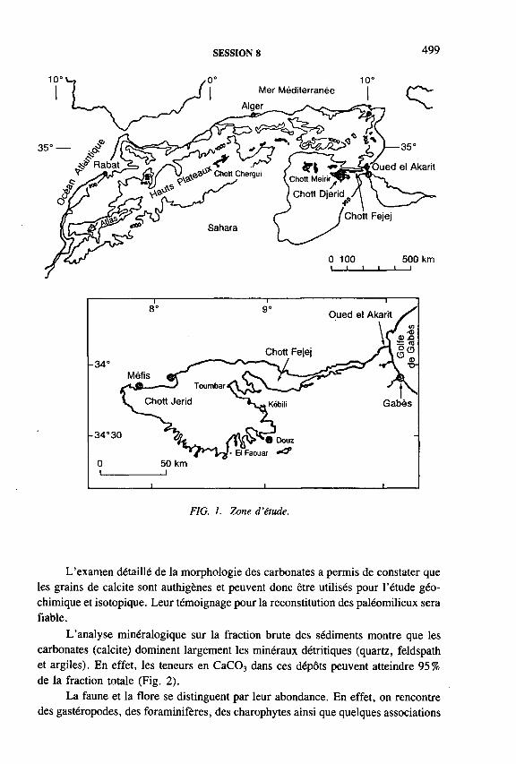
SESSION 8 499
FIG. 1. Zone d ’étude.
L’examen détaillé de la morphologie des carbonates a permis de constater que les grains de calcite sont authigènes et peuvent donc être utilisés pour l’étude géochimique et isotopique. Leur témoignage pour la reconstitution des paléomilieux sera fiable.
L’analyse minéralogique sur la fraction brute des sédiments montre que les carbonates (calcite) dominent largement les minéraux détritiques (quartz, feldspath et argiles). En effet, les teneurs en CaC03 dans ces dépôts peuvent atteindre 95% de la fraction totale (Fig. 2).
La faune et la flore se distinguent par leur abondance. En effet, on rencontre des gastéropodes, des foraminifères, des charophytes ainsi que quelques associations

500 POSTER PRESENTATIONS
100
œ■oсооoí 1,95
2,35
H H Quartz
I I I *H Calcite
Feldspath
Ш Halite
■ i Argiles
Limons
I— I Marnes
0 Charophytes
Ô Gastéropodes
e* O stracodes
w Cardium
• Foraminifères
B Tourbe
10 530 + 340
FIG. 2. Evolution sédimentologique et minéralogique des sédiments étudiés.
de diatomées. La diversité et l’abondance de ces biomarqueurs témoignent d’environnements allant des marécages plus ou moins permanents jusqu’à des mares salées mimant le milieu marin. L’un des faits les plus saillants est la cohabitation dans un même niveau d’espèces à exigences écologiques différentes. Ceci pourrait rendre compte des fluctuations du chimisme du cycle hydrologique.
Géochimie isotopique
Les données chronométriques obtenues sur l’ensemble des échantillons datés montrent un bon accord entre eux. Les âges apparents obtenus sur les carbonates lacustres de ces dépôts ont été corrigés suivant un modèle tenant compte de la composante fossile en provenance de la nappe, de celle de l’atmosphère et des teneurs en 1 3C.

SESSION 8 501
Les âges 14C obtenus sur différents matériaux (matière organique, coquilles et calcite inorganique) s’échelonnent entre 11 000 et 3500 ans BP (Fig. 2).
Les teneurs en l80 des carbonates authigènes sont homogènes et basses (-6,80 à -6,00°/oo versus PDB). Elles sont compatibles avec une précipitation en équilibre avec les eaux des sources et des nappes captives de l’oued (teneurs en l 8 0
comprises entre -7 ,5 et - 6 7 00 versus SMOW (Standard Mean Ocean Water) à20 °C). Les eaux de l’holocène ne montrent aucune marque d’évaporation. Les dépôts de cette zone correspondraient donc à un débit plus fort, soutenu par des conditions climatiques plus humides qu’actuellement (Fig. 3).
Ces constatations, notamment sur l’absence d’évaporation et l’importance du débit d’eau en provenance des nappes profondes, sont en accord avec les résultats géochimiques. En effet, la comparaison des teneurs en 180 et des rapports molaires Sr/Ca et Mg/Ca ne montre aucune corrélation. La stabilité des teneurs Sr/Ca et Mg/Ca laisse penser à une recharge continue de l’eau (Fig. 3).
Les teneurs en 13C le long de cette zone montrent une grande variabilité, contrairement aux teneurs en l80. En effet, les teneurs en 13C fluctuent, si l’on écarte la valeur relativement enrichie de l’horizon 1,3 m (—1,67700), entre 2,33 et —5,7370 0 versus PDB (Fig. 3).
La grande instabilité manifestée par les teneurs en 13C peut rendre compte de la complexité des conditions de précipitation des carbonates. On pourrait ainsi interpréter ces variations par la conjonction de plusieurs facteurs: (a) respiration des plantes et des micro-organismes; (b) mélange entre le C02 atmosphérique et celui produit par l’activité des plantes et des micro-organismes; (c) mélange entre des bicarbonates dissous véhiculés par la nappe et le C02 de l’atmosphère.
Ages 14C 6’80 vs PDB 5’3C vs PDB -8 -4 0I------- 1--------- 1
Sr/Ca Mg/Ca0,005 0,01 0 0,1
---- 1--------1 I----------------- 1
FIG. 3. Variations de la composition chimique et isotopique.
502 POSTER PRESENTATIONS
Les résultats sédimentologiques et géochimiques obtenus sur les dépôts carbonatés du sud tunisien suggèrent fortement la reprise des écoulements vers11 000 ans BP.
L’abondance de différents matériaux carbonatés et leur caractère authigène ont permis l’établissement d’une chronologie 14C cohérente pendant l’holocène inférieur et moyen. Les âges obtenus suggèrent:
— une phase de mise en eau qui démarre vers 11 000 ans BP,— un optimum lacustre qui semble correspondre à la période 8500-8000 ans BP,— l’installation d’une période régressive aux alentours de 3500 ans BP.
Les teneurs en isotopes stables (très faibles et en équilibre avec l’eau de la nappe profonde) et les biomarqueurs (riches et diversifiés) ne montrent pas de phases régressives franches entre 11 000 et 3500 ans BP. En revanche, l’ensemble des marqueurs utilisés suggère une phase lacustre continue et permanente le long de cet intervalle de temps. Toutefois, l’existence de fluctuations saisonnières importantes se traduit par le mélange d’espèces à exigences écologiques différentes dans le même milieu, ce qui est probablement en relation avec les variations du chimisme du cycle hydrologique.
REFERENCES
[1] FONTES, J.-C., COQUE, R., DEVER, L., FILLY, A., MAMOU, A., Paléohydrologie isotopique de l’oued el Akarit (Sud Tunisie) au pléistocène supérieur et à l’holocène, Palaeogeogr., Palaeociimatol., Palaeoecol. 43 (1983) 41-62.
[2] ZOUARI, K., Géochimie et sédimentologie des dépôts continentaux d ’origine aquatique du quaternaire supérieur du sud-tunisien: interprétations paléohydrologiques et paléoclimatiques, Thèse Doct. Etat, Univ. Paris XI (1988) 321 p.
[3] CAUSSE, C., COQUE, R., FONTES, J.-C., GASSE, F., BEN OUEZDOU, H., ZOUARI, K., Two high levels of continental waters in southern Tunisian chotts at about 90 and 150 ka, Geology 17 (1989) 922-925.
CONCLUSION

CHAIRPERSONS OF SESSIONS
Session 6
Session 7
Session 8
Session 5 H. MOSERY. BOUABDALLAOUI Z. KATTANS. SANJDORJ T. FLORKOWKSIE. ADAR W.G. DARLING R. GONFIANTINI
GermanyMoroccoSyrian Arab RepublicMongoliaPolandIsraelUnited Kingdom Italy
SECRETARIAT OF THE SYMPOSIUM
K. FROHLICH T. NIEDERMAYR R. PENISTON-BIRD M .HAMENDE T. BRYABRINA
Scientific Secretary Symposium Organizer Proceedings Editor French Editor Russian Editor
503


LIST OF PARTICIPANTS
Amataj, S.
Abidin, Z.
Abou Zakhem, B.
Abtahi, M.
Adar, E.
Adorni-Braccesi, A.
Alvarado Rivas, J.
Amundson, R.
Araguás Araguás, L.
Aranyossy, J.-F.
Institute of Nuclear Physics,Tirana, Albania
Centre for the Application of Isotopes and Radiation, National Atomic Energy Agency (BATAN),Jl. Ciñere Ps. Jumat, P.O. Box 7002 jkskl,Jakarta 12070, Indonesia
Syrian Atomic Energy Commission,P.O. Box 6091, Damascus, Syrian Arab Republic
United Nations Educational,Scientific and Cultural Organization,
Liaison Office in Vienna,Wagramerstrasse 5, A-1400 Vienna, Austria
Water Resources Research Centre,The Jacob Blauenstein Institute for Desert Research,Ben Gurion University of the Negev,M. Sede Boker Campus 84993, Israel
Dipartimento di Scienze della Terra, Université di Pavia, Via Abbiategrasso 207, 1-27100 Pavia, Italy
Dirección de Hidrología y Meteorología,Ministerio del Ambiente y de
Recursos Naturales Renovables,Esquina Camejo, Edif. Camejo, Torre Norte, Piso 5,El Silencio, Caracas, Venezuela
Division of Ecosystem Sciences, University of California, 108 Hilfard, Berkeley, CA 94720,United States of America
Isotope Hydrology Section,Division of Physical and Chemical Sciences,International Atomic Energy Agency,Wagramerstrasse 5, P.O. Box 100,A-1400 Vienna, Austria
Agence nationale pour la gestion des déchets radioactifs, P.B. 38, F-92266 Fontenay-aux-Roses, France
505

506 LIST OF PARTICIPANTS
Aravena, R.
Artinger, R.
Balderer, W.
Barnes, C.J.
Barth, S.R.
Beaudoing, G.
Benitez Escóbar, M.
Bergelson, G.
Bersano Begey, M.
Bertleff, B.
Bilyi, I.
Birks, S.J.
Bohlke, J.K.
Department of Earth Sciences, University of Waterloo, Waterloo, Ontario N2L 3G1, Canada
Institut für Radiochemie,Technische Universitat München,Walther-Meissnerstrasse, D-85747 Garching, Germany
Geologisches Institut,Eidgenôssische Technische Hochschule-Hônggerberg, CH-8093 Zurich, Switzerland
Division of Water Resources, CSIRO,P.O. Box 1666, Canberra, ACT 2601, Australia
Institut für Isotopengeologie und mineralische Rohstoffe, ETH-Zentrum,Sonneggstrasse 5, CH-8092 Zurich, Switzerland
Centre d’études nucléaires de Grenoble, DAMRI/SAR/SAT, 17 rue des martyrs, F-38054 Grenoble Cedex 9, France
Corposana,José Berges 516, Asunción, Paraguay
The Seagram Center for Soil and Water Sciences,Faculty of Agriculture, Hebrew University of Jerusalem, P.O. Box 12, Rehovot 76100, Israel
Hydrodata,Via Pomba, 23, Torino, Italy
Geologisches Landesamt Baden-Württemberg,Albertstrasse 5, D-79104 Freiburg, Germany
Ukrainian Hydrometeorological Institute,Nauka Av. 37, 252 650 Kiev, Ukraine
Department of Geology, Queen’s University,Kingston, Ontario K7L 3N6, Canada
U.S. Geological Survey, 431 National Center,12201 Sunrise Valley Drive,Reston, VA 22092, United States of America
Bombonato, C., Jr. Companhia de Saneamento Básico do Est. Sâo Paulo, Rua Costa Carvalho, 300, 298-001 Sâo Paulo, Brazil

LIST OF PARTICIPANTS 507
Bouabdallaoui, Y.
Buapeng, S.
Buaphan, C.
Buhay, W.M.
Buonaiuto, E.
Calméis, P.
Carreira, P.M.
Chery, L.
Chevalier, M.R.
Clark, I.
Cook, P.G.
Copien, T.
Institut agronomique et vétérinaire Hassan П,B.P. 6202, Rabat Instituts, Rabat, Morocco
Groundwater Division, Department of Mineral Resources, Rama 6 Road, Bangkok 10400, Thailand
Department of Geotechnology,Faculty of Technology, Khon Kaen University,Khon Kaen 40002, Thailand
The Freshwater Institute,501 University Crescent,Winnipeg, Manitoba R3T 2N6, Canada
Dipartimento di Scienze della Terra, Université di Torino, Via Valperga Caluso, 37, 1-10125 Torino, Italy
Centre d’études nucléaires de Grenoble, DAMRI/SAR/SAT, 17, rue des martyrs, F-38054 Grenoble Cedex 9, France
с/o Isotope Hydrology Section,Division of Physical and Chemical Sciences,International Atomic Energy Agency,Wagramerstrasse 5, P.O. Box 100,A-1400 Vienna, Austria
BRGM,B.P. 6009, F-45060 Orléans Cedex 2, France
Centre international de recherche sur l’eau et l ’environnement,
Lyonnaise des eaux,38, rue du Président Wilson,F-78230 Le Pecq, France
Department of Geology, University of Ottawa,365 Nicholas Street, Ottawa, Ontario KIN 6N5, Canada
Division of Water Resources, CSIRO,Private Bag No. 2, Glen Osmond, SA 5064, Australia
U.S. Geological Survey,431 National Center, 12201 Sunrise Valley Drive,Reston, VA 22092, United States of America

508 LIST OF PARTICIPANTS
Cornett, R.J.
Cortes, S.A.
Custodio, E.
D’Amore, F.
Dórr, H.
Danesi, P.R.
Daoud, D.
Darling, W.G.
Davisson, M.L.
De Paepe, A.R.A.
Deák, J.
Deseó, E.
AECL Research, Chalk River Laboratories,Chalk River, Ontario KOJ 1J0, Canada
Instituto de Geofísica, UNAM,Circuito Exterior, Ciudad Universitaria,04510 Mexico, D .F., Mexico
Departamento de Ingeniería del Terreno,Polytechnic University of Catalonia, d o Gran Capita s/n, Mod D-2, E-08034 Barcelona, Spain
International Institute for Geothermal Research,Piazza Solferino 2, 1-56126 Pisa, Italy
Trischler und Partner,Berliner Allee 6 , D-64295 Darmstadt, Germany
Agency’s Laboratories Seibersdorf,Department of Research and Isotopes,International Atomic Energy Agency,Wagramerstrasse 5, P.O. Box 100,A-1400 Vienna, Austria
с/o Laboratoire d ’hydrologie et de géochimie isotopique, Université de Paris-Sud, Bâtiment 504,F-91405 Orsay Cedex, France
British Geological Survey,Maclean Building,Wallingford, Oxon 0X10 8BB, United Kingdom
Lawrence Livermore National Laboratory,P.O. Box 808 L-231,Livermore, CA 94550, United States of America
Centre de recherche et de contrôle des Eaux de Paris,1 voie du Bouvray, F-94310 Orly, France
Water Resources Research Centre (VITOKI),Kvassay 7 út. 1, H-1095 Budapest, Hungary
Water Resources Research Centre (VITUIO),Kvassay 7 út. 1, H -1095 Budapest, Hungary

LIST OF PARTICIPANTS 509
Dinescu, L.
Dorcioman, D.
Drimmie, R.J.
Drost, W.
Duarte Amado, G.
Dunger, V.
Edmunds, W.M.
Edwards, T.W.D.
Egger, R.
Eichinger, L.
Eisa, M.
Dever, L. Laboratoire d ’hydrologie et de géochimie isotopique, Université de Paris-Sud, Bâtiment 504,F-91405 Orsay Cedex, France
Institute of Physics and Nuclear Engineering,Institute of Atomic Physics, P.O. Box MG-6 ,R-76900 Bucharest, Romania
Institute of Physics and Nuclear Engineering, Magurele, P.O. Box MG-6 , R-76900 Bucharest, Romania
Department of Earth Sciences, University of Waterloo, Waterloo, Ontario N2L 3G1, Canada
Institut für Hydrologie,GSF-Forschungszentrum für Umwelt und
Gesundheit Neuherberg,Ingolstâdter Landstrasse 1,D-85764 Oberschleissheim, Germany
Corposana,José Berges 516, Asunción, Paraguay
Institute of Geology,Freiberg University of Mining and Technology,B. von Cotta-Str. 4, D-9596 Freiberg, Germany
Hydrogeology Group, British Geological Survey, Crowmarsh Gifford,Wallingford, Oxon 0X10 8BB, United Kingdom
Department of Earth Sciences, University of Waterloo, Waterloo, Ontario N2L 3G1, Canada
Bayerisches Landesamt für Wasserwirtschaft, Lazarettstrasse 67, D-80636 Munich, Germany
Hydroisotop,Woelkestrasse 9, D-85301 Schweitenkirchen, Germany
Environment Branch,United Nations Industrial Development Organization, P.O. Box 300, A-1040 Vienna, Austria

El-Naggar, Н.А.
Fórizs, I.
Fôrstel, H.
Fendeková, М.
Ferraris, М.М.
Ferronsky, V.I.
Fischer, M.
Florkowski, T.
Forster, M.
Fourneaux, J.C.
Frape, S.K.
510
Eisenlohr, T. Geologisches Institut,Eidgenôssische Technische HochschuleHônggerberg, CH-8093 Zurich, Switzerland
Nuclear Chemistry Department,Atomic Energy Authority,101 Kasr El-Einy Street, Cairo, Egypt
Laboratory for Geochemical Research,Budaórsi út. 45, H-1112 Budapest, Hungary
Forschungszentrum Jülich, Radioagronomie,Postfach 1913, D-5245 Jülich, Germany
Department of Groundwaters,Faculty of Natural Sciences, Comenius University, Mlynská Dolina 6 , SK-842 15 Bratislava, Slovakia
Permanent Mission of the Holy See to the International Organizations in Vienna,
Theresianumgasse 33/4, A-1040 Vienna, Austria
Water Problems Institute of the Russian Academy of Sciences,
Novobasmannaya 10, 107078 Moscow, Russian Federation
Institut für Hydrologie,GSF-Forschungszentrum für Umwelt und
Gesundheit Neuherberg,Ingolstadter Landstrasse 1,D-85764 Oberschleissheim, Germany
Faculty of Physics and Nuclear Techniques,Academy of Mining and Metal,Al. Mickiewicza 30, PL-30-059 Cracow, Poland
Hydroisotop,Woelkestrasse 9, D-85301 Schweitenkirchen, Germany
Institut Dolomieu, Université J. Fourier,15 rue M. Gignoux, F-38031 Grenoble Cedex, France
с/o CSIRO, Western Australian Laboratories,Private Bag, Wembley, WA 6014, Australia
LIST OF PARTICIPANTS

LIST OF PARTICIPANTS 511
Fritz, P.
Gaal, P.
García Agudo, E.
Gat, J.R.
Gavrieli, I.
Gerardo, J.Y.
Geyer, S.
Geyh, M.A.
Gibert, E.
Gibson, J.J.
French, H.K. Department of Soil and Water Sciences,Agricultural University of Norway,P.O. Box 5028, N-1432 Às, Norway
UFZ-Umweltforschungszentrum,Permoserstrasse 15, Postfach 2, D-04301 Leipzig, Germany
National Institute of Hygiene and Epidemiology,Trnavská 52, SK-821 08 Bratislava, Slovakia
Isotope Hydrology Section,Division of Physical and Chemical Sciences,International Atomic Energy Agency,Wagramerstrasse 5, P.O. Box 100,A-1400 Vienna, Austria
Department of Environmental Science and Energy Research, Weizmann Institute of Science, Rehovot 76100, Israel
Geological Survey of Israel,30 Malkhe Israel St., Jerusalem 95501, Israel
Isotope Hydrology Section,Division of Physical and Chemical Sciences,International Atomic Energy Agency,Wagramerstrasse 5, P.O. Box 100,A-1400 Vienna, Austria
Institut für Hydrologie,GSF-Forschungszentrum fiir Umwelt und
Gesundheit Neuherberg,Ingolstàdter Landstrasse 1,D-85764 Oberschleissheim, Germany
Niedersâchsisches Landesamt fiir Bodenforschung,Postbox 510153, D-30631 Hannover, Germany
Laboratoire d’hydrologie et de géochimie isotopique, Université de Paris-Sud, Bâtiment 504,F-91405 Orsay Cedex, France
Department of Earth Sciences,University of Waterloo,Waterloo, Ontario N2L 3G1, Canada
512 LIST OF PARTICIPANTS
Goldbrunner, J.
Gonfiantini, R.
González-Hita, L.
Goslar, T.
Grôning, M.
Hachach, A.
Harum, T.
Heidinger, M.M.
Heinz-Arvand, M.
Herczeg, A.L.
Herlicska, H.
Hoehn, E.H.
Weizerstrasse 19, A-8200 Gleisdorf, Austria
Laboratoire d ’hydrologie et de géochimie isotopique, Université de Paris-Sud, Bâtiment 504,F-91405 Orsay Cedex, France
Instituto Mexicano de Tecnología del Agua (IMTA),Col. Oxtopulco Universidad,Av. Universidad 1900, E5-102,C.P. 04350 Mexico, D.F., Mexico
Radiocarbon Laboratory, Silesian Technical University, ul. Krzywoustego 2, PL-44-100 Gliwice, Poland
Institut für Umweltphysik,Ruprecht-Karls-Universitàt Heidelberg,Im Neuheimer Feld 366, D-69120 Heidelberg, Germany
Office National du Litani,P.O. Box 3732, Beirut, Lebanon
Institute of Hydrogeology and Geothermics,Joanneum Research,Elisabethstrasse 16/11, A-8010 Graz, Austria
Hydroisotop,Woelkestrasse 9, D-85301 Schweitenkirchen, Germany
Bundesumweltamt,Spittelauer Lande 5,A-1090 Vienna, Austria
Division of Water Resources, CSIRO,Private Bag No. 2, Glen Osmond, SA 5064, Australia
Abteilung fur Wasser- und Abfallwirtschaft, Landhaus-Neu, Freiheitsplatz 1,A-7000 Eisenstadt, Austria
Swiss Federal Institute for Environmental Science and Technology (EAWAG),
Überlandstrasse 133, CH-8600 Dubendorf, Switzerland
Holko, L. с/o Experimental Hydrological Base, IH SAS, Ondrasovecka 16, SK-031 05 Liptovsky Mikulas, Slovakia
LIST OF PARTICIPANTS 513
Horvatincié, N.
Hussein, M.F.
Ivanovich, M.
Jameel, M.
Jasiulionis, R.
Jeckelmann, C.
Jurina, V.
Kato, K.
Kattan, Z.
Kendall, C.
Kim, Chun Soo
Kinney, S.P.
Ruder Boskovic Institute,Bijenicka 54, P.O. Box 1016, CRO-41000 Zagreb, Croatia
Middle Eastern Regional Radioisotope Center for the Arab Countries (MERRCAC),
Sh. Malaeb El-Gamaa, Dokki, Cairo 12311, Egypt
Analytical Services Group, AEA Technology,Harwell Laboratory,551 Harwell, Didcot,Oxon 0X11 ORA, United Kingdom
Permanent Mission of Pakistan to the IAEA,Hofzeile 13, A-1190 Vienna, Austria
Institute of Physics,Savanoriu 231, 2600 Vilnius, Lithuania
Geologisches Institut,Eidgenôssische Technische Hochschule-Hônggerberg, CH-8093 Zurich, Switzerland
Ministry of Health of the Slovak Republic,Limbová 2, SK-813 05 Bratislava, Slovakia
National Nagoya University,Chikusa, 464-01 Nagoya, Japan
Department of Geology and Nuclear Ores,Atomic Energy Commission,P.O. Box 6091, Damascus, Syrian Arab Republic
Water Resources Division, U.S. Geological Survey, 345 Middlefield Road, MS 434,Menlo Park, С A 94025, United States of America
Department of Hydrology,Nuclear Environment Management Centre,Korea Atomic Energy Research Institute,P.O. Box 105, Taejon, Republic of Korea
Department of Earth Sciences, University of Waterloo, Waterloo, Ontario N2L 3G1, Canada
514 LIST OF PARTICIPANTS
Kollmann, W.F.H.
Kononovitch, A.
Le Gal La Salle, C.
Leaney, F.W.J.
Lehmann, B.E.
Leontiadis, I.L.
Lichner, L.
Lipp, J.
Lojen, S.
Long, B.F.
López-Vera, F.
Knief, K. Institut fur Hydrologie,GSF-Forschungszentrum für Umwelt und
Gesundheit Neuherberg,Ingolstâdter Landstrasse 1,D-85764 Oberschleissheim, Germany
Geologische Bundesanstalt,Rasumofskygasse 23, A-1031 Vienna, Austria
All-Russia Research Institute for Nuclear Power Plants, ul. Franskaya 25, Moscow 109507, Russian Federation
Laboratoire d’hydrologie et de géochimie isotopique, Université de Paris-Sud, Bâtiment 504,F-91405 Orsay Cedex, France
Division of Water Resources, CSIRO,Private Bag No. 2, Glen Osmond, SA 5064, Australia
Physikalisches Institut, Universitat Bern,Sidlerstrasse 5, CH-3012 Bern, Switzerland
National Centre for Scientific Research “ Demokritos” , P.O. Box 60228, GR-153 10 Aghia Paraskevi Attikis, Greece
Institute of Hydrology, Slovak Academy of Sciences, Trnavská 32, SK-826 51 Bratislava, Slovakia
Institut fur Hydrologie,GSF-Forschungszentrum für Umwelt und
Gesundheit Neuherberg,Ingolstâdter Landstrasse 1,D-85764 Oberschleissheim, Germany
Jozef Stefan Institute,Jamová 39, SL-61 111 Ljubljana, Slovenia
INRSÔcéanologie,310, Allée des Ursulines,Rimouski, Quebec G5L 3A1, Canada
Facultad de Ciencias, C-VI,Universidad Autónoma de Madrid,Cantoblanco, E-28049 Madrid, Spain

LIST OF PARTICIPANTS
Loosli, H.H.
Love, A.J.
Machi, S.
Maciejewski, S.
Magro, G.
Malik, P.
Maloszewski, P.
Manurung, S.
Marlin, C.
Matray, J.M.
Mayer, B.
Mazeika, J.
Physikalisches Institut, Universitat Bern,Sidlerstrasse 5, CH-3012 Bern, Switzerland
South Australian Department of Mines and Energy, P.O. Box 151, Eastwood, SA 5063, Australia
Department of Research and Isotopes,International Atomic Energy Agency, Wagramerstrasse 5, P.O. Box 100,A-1400 Vienna, Austria
Institute of Hydroengineering of the Polish Academy of Sciences,
Koscierska 7, PL-80-953 Gdansk, Poland
Istituto di Geocronologia e Geochimica Isotopica, Consiglio Nazionale delle Ricerche,Via C. Maffi, 36, Pisa, Italy
Dionyz Stur Institute of Geology,Mlynská Dolina 1, SK-817 04 Bratislava, Slovakia
Institut fur Hydrologie,GSF-Forschungszentrum für Umwelt und
Gesundheit Neuherberg,Ingolstàdter Landstrasse 1,D-85764 Oberschleissheim, Germany
Centre for the Application of Isotopes and Radiation, National Atomic Energy Agency (BATAN),Jl. Ciñere Ps. Jumat, P.O.Box 7002 jkskl,Jakarta 12070, Indonesia
Laboratoire d’hydrologie et de géochimie isotopique, Université de Paris-Sud, Bâtiment 504,F-91405 Orsay Cedex, France
Direction de la recherche, (DR/HYT), BRGM,B.P. 6009, F-45060 Orléans Cedex 2, France
Lehrstuhl für Sediment- und Isotopengeologie,Institut für Geologie, Ruhr-Universitàt Bochum, Universitàtsstrasse 150, D-44780 Bochum, Germany
Institute of Geology,Shevchenko 13, 2600 Vilnius, Lithuania

516 LIST OF PARTICIPANTS
McNeill, G.W.
Mensforth, L.
Meyer, G.
Michalko, J.
Michel, R.L.
Michelot, J.-L.
Monge Suarez, A.
Montjotin, C.
Moser, H.
Motz, J.E.
Moutonnet, P.
Postgraduate Research Institute for Sedimentology, University of Reading,Whiteknights, P.O. Box 227,Reading RG6 2AB, United Kingdom
Division of Water Resources, CSIRO,Private Bag No. 2, Glen Osmond, SA 5064, Australia
CEA/DTA/DAMRI/SAR,B.P. 52, F-91193 Gif-sur-Yvette Cedex, France
Dionyz Stur Institute of Geology,Mlynská Dolina 1, SK-817 04 Bratislava, Slovakia
Water Resources Division, U.S. Geological Survey, 345 Middlefield Road, MS 434,Menlo Park, CA 94025, United States of America
Laboratoire d’hydrologie et de géochimie isotopique, Université de Paris-Sud, Bâtiment 504,F-91405 Orsay Cedex, France
Departamento de Química, Instituto Tecnológico, Laboratorio de Isótopos Ambientáis,Estrada Nacional 10, P-2685 Sacavem, Portugal
Laboratoire d ’hydrologie et de géochimie isotopique, Université de Paris-Sud, Bâtiment 504,F-91405 Orsay Cedex, France
Institut für Hydrologie,GSF-Forschungszentrum für Umwelt und
Gesundheit Neuherberg,Ingolstâdter Landstrasse 1,D-85764 Oberschleissheim, Germany
Department of Earth Sciences, University of Waterloo, Waterloo, Ontario N2L 3G1, Canada
Joint FAO/IAEA Division of Nuclear Techniques in Food and Agriculture,
International Atomic Energy Agency,Wagramerstrasse 5, P.O. Box 100,A-1400 Vienna, Austria

LIST OF PARTICIPANTS 517
Nair, A.R.
Nitzsche, O.
Obenholzner, J.H.
Oesselmann, J.
Osenbrück, K.
Owczarczyk, A.
Padden, M.C.
Papesch, W.
Pascu, A.
Pascu, M.
Peindl, P.
Pezdic, J.
Pirastru, E.B.
Isotope Division,Bhabha Atomic Research Centre, Trombay,Bombay 400 085, India
Institute of Applied Physics,Freiberg University of Mining and Technology,B. von Cotta-Str. 4, D-9596 Freiberg, Germany
Institut für Geowissenschaft, Montanuniversitât, Franz-Josef-Strasse 18, A-8700 Leoben, Austria
Finnigan MAT GmbH,Barkhausenstrasse 2, Postfach 140 162,D-28197 Bremen, Germany
Institut für Umweltphysik,Ruprecht-Karls-Universitat Heidelberg,Im Neuenheimer Feld 366, D-69120 Heidelberg, Germany
Institute of Nuclear Chemistry and Technology,Dorodna 16, PL-03-195 Warsaw, Poland
Department of Earth Sciences, University of Waterloo, Waterloo, Ontario N2L 3G1, Canada
Bundesforschungs- und Prüfzentrum Arsenal,Faradaygasse 3, Postfach 8 , A-1031 Vienna, Austria
Laser Department, Institute of Physics of Radiation Devices, P.O. Box MG-6 , R-76900 Bucharest, Romania
Institute of Physics and Nuclear Engineering, Magurele, P.O. Box MG-6 , R-76900 Bucharest, Romania
Zivilingenieurbüro, Gruppe Wasser,Hohlweggasse 40/25, A-1030 Vienna, Austria
Jozef Stefan Institute,Jamova 39, SL-61111 Ljubljana, Slovenia
ENEA, Centro Ricerche di Saluggia,1-13040 Saluggia (VC), Italy

518 LIST OF PARTICIPANTS
Poitevin, G.
Purtschert, R.
Ramspacher, P.
Rank, D.
Révész, К.
Reichert, В.
Richtig, G.
Rossi, A.P.
Rozanski, K.
Sacchi, E.
Sanford, W.E.
Centre international de recherche sur l’eau et l ’environnement,
Lyonnaise des eaux,38, rue du Président Wilson,F-78230 Le Pecq, France
Physikalisches Institut, Universitat Bern,Sidlerstrasse 5, CH-3012 Bern, Switzerland
Institute of Hydrogeology and Geothermics,Joanneum Research,Elisabethstrasse 16/11, A-8010 Graz, Austria
Bundesversuchs- und Forschungsanstalt Arsenal, Geotechnisches Institut, Arsenal Objekt 210,Faradaygasse 3, Postfach 8 , A-1031 Vienna, Austria
U.S. Geological Survey,431 National Center, 12201 Sunrise Valley Drive,Reston, VA 22092, United States of America
Department of Applied Geology,University of Karlsruhe,P.O. Box 6980, D-76128 Karlsruhe, Germany
Technische Universitat Graz,Mandellstrasse 9/1, A-8010 Graz, Austria
Department of Earth Sciences, University of Waterloo, Waterloo, Ontario N2L 3G1, Canada
Isotope Hydrology Section,Division of Physical and Chemical Sciences,International Atomic Energy Agency,Wagramerstrasse 5, P.O. Box 100,A-1400 Vienna, Austria
Dipartimento di Scienze della Terra, Université di Torino, Via Valperga Caluso, 37, 1-10125 Torino, Italy
U.S. Geological Survey,431 National Center, 12201 Sunrise Valley Drive,Reston, VA 22092, United States of America

LIST OF PARTICIPANTS 519
Sanjdorj, S.
Saxena, R.
Schônfelder, H.
Scholtis, A.
Seiler, K.-P.
Silar, J.
Smellie, J.A.T.
Souag, M.
Spandre, R.
Stichler, W.
Stuckless, J.S.
Institute of Water Policy,Baraun Selbe-13, Ulaanbaatar 210638, Mongolia
Section of Hydrology, Institute of Earth Sciences, Uppsala University,Vàstra Agatan 24, S-753 09 Uppsala, Sweden Fa. Rost,Màrzstrasse 7, A-1150 Vienna, Austria
National Co-operative for the Storage of Radioactive Waste (Nagra),
Hardstrasse 73, CH-5430 Wettingen, Switzerland
Institut für Hydrologie,GSF-Forschungszentrum für Umwelt und
Gesundheit Neuherberg,Ingolstâdter Landstrasse 1,D-85764 Oberschleissheim, Germany
Department of Hydrology, Faculty of Sciences,Charles University,Albertov 6 , CZ-12843 Prague 2, Czech Republic
Conterra AB,Box 493, S-751 06 Uppsala, Sweden
Division datation et hydrologie isotopique,Centre de développement des techniques nucléaires,2, Bd. Frantz Fanon, B.P. 1017,Alger-Gare 16000, Algeria
Università di Pisa,Via S. Maria 53, 1-56126 Pisa, Italy
Institut für Hydrologie,GSF-Forschungszentrum für Umwelt und
Gesundheit Neuherberg,Ingolstâdter Landstrasse 1,D-85764 Oberschleissheim, Germany
U.S. Geological Survey,431 National Center, P.O. Box 25046,MS 245, Denver, СО 80225, United States of America
520 LIST OF PARTICIPANTS
Szollosi-Nagy, A.
Szpilowski, S'.
Talma, A.S.
Tanweer, A.
Taupin, J.D.
Tazioli, G.S.
Tenu, A.
Tesch, R.
Travi, Y.
Trettin, R.
Trimbom, P.
United Nations Educational, Scientific and Cultural Organization,
7, Place de Fontenoy, F-75700 Paris, France
National Atomic Energy Agency,Krucza 36, PL-00-921 Warsaw, Poland
Council for Scientific andIndustrial Research EMATEK/CSIR,
P.O. Box 395, 0001 Pretoria, South Africa
Isotope Hydrology Laboratory,Division of Physical and Chemical Sciences,International Atomic Energy Agency,Wagramerstrasse 5, P.O. Box 100,A-1040 Vienna, Austria
ORSTOM,P.O. Box 11416, Niamey, Niger
Department of Science of Earth Materials,University of Ancona,Via Brecce Bianche, 1-60131 Ancona, Italy
National Institute of Meteorology and Hydrology,Sos. Bucuresti-Ploiesti, 97, R-71552 Bucharest, Romania
Bundesforschungs- und Priifzentrum Arsenal, Faradaygasse 3, Postfach 8 , A-1031 Vienna, Austria
Laboratoire d ’hydrogéologie, Faculté des Sciences, Université d ’Avignon,33, rue Pasteur, F-84000 Avignon, France
Umweltforschungszentrum, Leipzig-Halle GmbH,Sektion Hydrologie,Hallesche Strasse 44, D-06246 Bad Lauchstadt, Germany
Institut fiir Hydrologie,GSF-Forschungszentrum für Umwelt und
Gesundheit Neuherberg,Ingolstâdter Landstrasse 1,D-85764 Oberschleissheim, Germany

LIST OF PARTICIPANTS 521
Vôlkl, G.
Vachier, P.
Vaikmae, R.
Verhagen, B.T.
Vitart, X.
Voerkelius, S.
Wachniew, P.
Wang, Y.
Watzel, R.
Wessenu, A.M.
Wierzchnicki, R.
Wimmer, H.
Tykva, R. Institute of Organic Chemistry and Biochemistry,Academy of Sciences of the Czech Republic,Flemingovo 2, CZ-166 10 Prague 6 , Czech Republic
Bundesministerium fur Land- und Forstwirtschaft, Stubenring 1, A-1010 Vienna, Austria
Laboratoire des sols,F-78850 Thiouval Grignon, France
Institute of Geology, Estonian Academy of Science, Estonia pst. 7, EE-0100 Tallinn, Estonia
Schonland Research Centre,University of the Witwatersrand,P.O. Wits 2050, Johannesburg, South Africa
Centre d ’études nucléaires de Grenoble, DAMRI/SAR/SAT, 17, rue des martyrs, F-38054 Grenoble Cedex 9, France
Hydroisotop,Woelkestrasse 9, D-85301 Schweitenkirchen, Germany
Faculty of Physics and Nuclear Techniques,University of Mining and Metallurgy,al. Xickiewicza 30, PL-30-059 Cracow, Poland
Division of Ecosystem Sciences, University of California, 108 Hilfard, Berkeley, CA 94720, United States of America
Geologisches Landesamt Baden-Württemberg,Albertstrasse 5, D-79104 Freiburg, Germany
Water Supply and Sewerage Agency,P.O. Box 5744, Addis Ababa, Ethiopia
Institute of Nuclear Chemistry and Technology,Dorodna 16, PL-03-195 Warsaw, Poland
Osterreichische Gesellschaft für Hydrologie,Amt der Oberôsterreichischen Landesregierung, Kamtnerstrasse 12, A-4020 Linz, Austria

522 LIST OF PARTICIPANTS
Wolfe, B.B.
Yakir, D.
Yehdegho, B.
Zeh, P.
Zojer, H.
Zouari, K.
Zouridakis, N.
Zuppi, G.M.
Wolf, M. Institut fiir Hydrologie, GSF-Forschungszentrum fur Umwelt und Gesundheit Neuherberg,
Ingolstâdter Landstrasse 1,D-85764 Oberschleissheim, Germany
Department of Earth Sciences, University of Waterloo, Waterloo, Ontario N2L 3G1, Canada
Department of Environmental Science and Energy Research, Weizmann Institute of Science, Rehovot 76100, Israel
Joanneum Research,Gôstingerstrasse 136/26, A-8051 Graz, Austria
Institut für Radiochemie,Technische Universitat München,Walther-Meissnerstrasse, D-85747 Garching, Germany
Institute of Hydrogeology and Geothermics,Joanneum Research,Elisabethstrasse 16/11, A-8010 Graz, Austria
Ecole nationale d ’ingénieurs de Sfax,Laboratoire de géochimie isotopique et de paléoclimatologie, Route de Soukra, B.P. “ W ” , 3038 Sfax, Tunisia
National Centre for Scientific Research “ Demokritos” , P.O. Box 60228, GR-153 10 Aghia Paraskevi Attikis, Greece
Laboratoire d’hydrologie et de géochimie isotopique, Université de Paris-Sud, Bâtiment 504,F-91405 Orsay Cedex, France

AUTHOR INDEX
Upright numerals refer to the first page of a paper or poster presentation by the author concerned. Bold Arabic numerals are volume numbers.
Abdel-Gawad, A.S.: 2 371 Bilyi, I.Y.: 1 117Abidin, Z.: 1 189, 233 Blomqvist, R.: 1 19Abou Zakhem, В.: 1 351 Bobkov, A.F.: 1 127Acutis, М.: 1 353 Bohlke, J.K.: 1 419Adorni Braccesi, A.: 1 353 Bombonato, C., Jr.: 1 157Aeschbach, W.: 2 168 Bouabdallaoui, Y.: 2 29Ali, М.: 2 220 Bowser, C.J.: 1 209Alip: 1 189 Bredenkamp, D.V.: 2 200Allan, G.L.: 1 98 Brezgunov, V.S.: 1 127Allan, G.: 2 123 Brisset, P.: 1 177Almomani, М.: 1 433 Brownless, M.A.: 1 434Alvarado, J.: 2 281 Briihl, D.: 1 444Amataj, S.: 2 161 Bryant, G.: 1 19Amundson, R.: 1 315 Buapeng, S.: 2 383Andrews, J.N.: 1 3; 2 475 Buckau, G.: 1 57Aoki, P.E.: 1 157 Buhay, W.M.: 1 104, 198Araguás Araguás, L.: 1 355; 2 45 Buonaiuto, E.: 1 251Aranyossy, J.-F.: 1 98, 216, 358 Burns, D.A.: 1 167Aravena, R.: 1 31, 264, 361 Caillot, A.: 1 177Artinger, R.: 1 57 Calméis, P.: 2 455Atta, S.: 1 219 Calvi, E.: 2 417Baedecker, M.J.: 1 381 Campbell, D.H.: 1 167Bajjali, W.T.: 1 43 Cantori, P.M.: 2 147Balderer, W.: 2 164, 168, 431 Cargnelutti, М.: 2 229Barbina, V.: 2 209 Carreira, P.M.: 2 45Ba§aran, N.: 2 203 Ceccarelli, A.: 2 487Battaglia, A.: 2 487 Chang, C.C.Y.: 1 167Beaudoing, G.: 1 193 Chaouq, N.: 1 87Behrens, H.: 2 135 Charentus, T.: 1 193Bein, A.: 1 194; 2 461 Chernet, T.: 2 457Bergelson, G.: 1 194 Chery, L.: 1 98Berliner, P.: 1 267 Christodoulou, T.: 2 477Bernasconi, S.: 2 431 Ciancetti, G.F.: 2 147Bersano Begey, М.: 2 229 Clark, I.D.: 1 43Bertleff, B.: 2 308, 317, 339 Cook, P.G.: 1 397Betcher, R.N.: 1 198 Copien, T.: 1 381, 438
523

524 AUTHOR INDEX
Cortes, S.A.: 1 199 Cossio, R.: 1 353 Costa e Silva, R.O.: 1 244 Cresswell, R.G.: 1 98 Criss, R.E.: 1 405 D’Amore, F.: 2 417 da Silva, С.: 1 444 Daoud, D.: 2 59 Darling, W.G.: 1 434 Davidescu, F.: 2 317 Dazzi, R.: 2 147 Deák, J.: 1 419, 438; 2 301 Dehnert, J.: 1 457 Deseo, E.: 1 419; 2 301 Detay, М.: 1 247 Dever, L.: 2 459 Devito, К.: 1 361 Diaconu, V.: 1 91 Dinescu, A.: 1 91 Dinescu, L.: 1 91 Dinescu, М.: 1 91 Djiono: 1 189, 233 Dorcioman, R.: 1 91 Dorcioman, D.: 1 202, 206 Dôrr, H.: 2 249 Doussan, С.: 1 247 Drapeau, G.: 1 87 Drimmie, R.J.: 1 31, 141 Drost, W.: 2 77 Dubinchuk, V.T.: 2 302 Dufour, D.: 1 230 Dunger, V.: 2 395 Durka, W.: 1 110 Edmunds, W.M.: 2 107 Edwards, T.: 2 483 Edwards, T.W.D.: 1 104, 213, 241,
264, 449 Eggenkamp, H.G.M.: 1 101 Eglington, B.M.: 2 200 Eichinger, L.: 2 263, 308, 317 Eisenlohr, T.: 2 431 El-Naggar, H.A.: 2 371
Ertl, S.: 2 308Ezz El-Din, M.R.: 2 371Facetti-Femandez, J.F.: 1 439Fendekovà, M.: 2 191Ferronsky, V.I.: 1 127Fifíeld, L.K.: 1 98; 2 123Fischer, М.: 1 363Fontes, J.-C.: 1 446; 2 59, 475Forster, М.: 1 444Fouillac, С.: 1 98Frangi, J.P.: 1 358Frape, S.K.: 1 19, 31, 141; 2 401French, H.К.: 1 333Freyer, К.: 1 457Frischkom, H.: 1 444Fritz, P.: 1 279Frôhlich, К.: 1 219; 2 171, 487Gaillard, В.: 2 355Gallaire, R.: 1 446Gaspar, E.: 1 202, 206Gaspar, R.D.: 1 202Gat, J.R.: 1 209Gatto, G.: 2 147Gavrieli, I.: 2 461Gentelle, P.: 1 211Gerardo, J.Y.: 2 417 , 493Getto, D.: 2 455Geyer, S.: 1 57, 363; 2 177Geyh, M.A.: 2 174Gibert, E.: 1 211Gibson, J.J.: 1 213Glynn, P.D.: 1 381González-Hita, L.: 2 305Goslar, T.: 1 366Gourcy, L.: 1 216Graf, W.: 1 279; 2 177, 308Graves, R.E.: 1 117Gregor, D.: 1 449Grenet, В.: 1 247Grischek, T.: 1 457Grôning, M.: 2 467Gu, Wei-Zu: 1 261, 355, 459

AUTHOR INDEX 525
Gudelis, A.: 1 223Güler, S.: 2 203Hawkesworth, C.J.: 2 401Head, J.: 1 251Hebert, D.: 2 177Heidinger, М.: 2 308Herczeg, A.L.: 1 73; 2 123, 314Hermoso, D.Z.: 2 493Herrmann, A.: 1 391Hertelendi, E.: 2 301Hertkom, N.: 1 363Hoehn, E.: 1 112Hôhener, P.: 1 112Holko, L.: 2 181Horvatincic, N.: 2 470Hoslin, R.: 1 177Huit, М.: 1 381Hunkeler, D.: 1 112Hussain, S.D.: 2 220Hussein, M.F.: 1 219Indroyono: 1 189, 233Ivanovich, М.: 2 401Jasiulionis, R.: 1 223Jeckelmann, C.: 2 431Jeong, Chan Ho: 2 188Jin, F.: 1 355Joseph, A.: 1 358Joseph, T.B.: 1 451Kahr, G.: 2 168Kapelj, S.: 2 470Karbo, A.: 2 475Kattan, Z.: 2 3Kendall, С.: 1 167Kgarebe, B.: 2 91Khan, I.H.: 2 220Kim, Chun Soo: 2 188Kim, J.I.: 1 57Kinney, S.P.: 1 449Kipfer, R.: 2 168Kitterad, N.O.: 1 333Klotz, D.: 1 303 ; 2 184, 321Knief, К.: 1 279
Koh, Yong Kwon: 2 188 Kolonovich, A.L.: 1 270 Koltik, I.I.: 1 270 Kovac, L.: 2 77 Krajcar Bronic, I.: 2 470 Krimissa, М.: 1 98 Krouse, H.R.: 1 372 Kulkami, K.M.: 2 439 Kulkami, U.P.: 1 451; 2 439 Laaksoharju, М.: 2 496 Langsholt, E.: 1 333 Lantermann, E.: 1 444 Lazik, D.: 2 184 Le Gal la Salle, C.: 2 475 Leaney, F.W.: 2 314 Lee Davisson, М.: 1 405 Legge, A.H.: 1 372 Lehmann, B.E.: 1 3; 2 263 Leontiadis, I.L.: 2 477 Lian, Y.: 1 355 Liang, Kuang-Yi: 1 211 Lichner, L.: 1 369 Lipp, J.: 2 483 Lojen, S.: 2 209 Long, A.: 2 29 Long, B.F.: 1 87, 230, 253 Loosli, H.H.: 1 3; 2 263 López-Vera, F.: 1 454 Love, A.J.: 1 73; 2 123, 314 Ludin, A.: 2 496 Maciejewski, S.: 1 303 Mafflotti, A.: 1 251 Magro, G.: 2 487 Malciu, V.: 1 91 Malik, P.: 2 191Maloszewski, P.: 1 157, 303, 391;
2 223 Mansell, S.J.: 2 191 Manurung, S.: 1 233 Margrita, R.: 1 193 Marlin, C.: 2 459 Marobela, C.: 2 91

526 AUTHOR INDEX
Marques da Silva, M.A.: 2 45Martinelli, G.: 2 168Matray, J.M.: 1 101Matticchio, B.: 2 147Mayer, В.: 1 372Mazeika, J.: 2 193McDermott, F.: 2 401Medvedev, S.A.: 2 214Mensforth, L.: 1 376Merceron, T.: 2 198Meyer, G.: 1 177Michalko, J.: 2 191Michel, R.L : 1 293Michel, W.: 2 317Michelot, J.-L.: 1 98; 2 29, 59, 198Monteiro Filho, R.G.: 1 244Montjotin, C.: 2 198Moore, B.J.: 1 31Motz, J.E.: 1 104Moulin, V.: 2 198Mouyon, P.: 1 193Mozzi, G.: 2 147Nada, A.: 1 219Nae, I.: 1 91Nair, A.R.: 1 451; 2 439Nativ, R.: 1 194Navada, S.V.: 1 451; 2 439Nestler, W.: 1 457Nitzsche, O.: 2 177, 395Nüesch, R.: 2 168Olivry, J.-C.: 1 216Ônhon, E.: 2 203Onishi, Y.: 1 117Oraseanu, I.: 2 459Osenbrück, K.: 1 106Owczarczyk, A.: 1 239Ôzdamar, A.R.: 2 203Padden, М.: 1 241Pafikov, E.M.: 1 270Papesch, W.: 1 379Pascu, М.: 1 202, 206Pearson, F.J., Jr.: 2 263
Peterman, Z.E.: 1 108Petrosius, R.: 2 193Pezdic, J.: 2 209, 470Phipps, G.C.: 1 43Picat, P.: 1 247Piovesana, F.: 1 244Pirastru, E.: 2 229Poitevin, G.: 1 247Polyakov, V.A.: 1 127; 2 214, 302Prowse, T.D.: 1 213Pruszak, Z.: 1 239Purtschert, R.: 1 3Pyatnitskij, N.V.: 2 214Quarin, L.: 2 209Quijano, J.L.: 1 199Rackwitz, R.: 1 279Rajner, V.: 1 379Ramspacher, P.: 2 77Rank, D.: 1 379Rao, S.М.: 1 451; 2 439Rauert, W.: 2 177, 431Rech, T.I.: 1 270Reichert, B.: 2 217Révész, К.: 1 381, 419Ridolfi, A.: 2 487Romanov, V.V.: 1 127Rosoi, S.: 1 91Rozanski, К.: 1 355; 2 45Ruml, T.: 2 321Ruskeeniemi, T.: 1 19Sacchi, E.: 1 251Sajjad, M.I.: 2 220Sanchez, L.F.: 2 305Sanford, W.E.: 2 383Sanjdorj, S.: 2 171Santiago, М.: 1 444Savickaite, I.: 1 223Sawula, G.: 2 91Saxena, R.K.: 2 321Scarpelli, S.: 1 244Schiff, S.L.: 1 361Schmitt, P.: 1 363
AUTHOR INDEX 527
Scholtis, A.: 2 263 Schuhbeck, S.: 2 177 Seastres, J.S., Jr.: 2 417, 493 Seiler, K.-P.: 1 433; 2 135, 223, 281 Seka, J.: 1 253 Shanley, J.B.: 1 167 Sharma, Suman: 2 439 Silar, J.: 1 454 Silva, R.P.: 1 244 Silva, S.R.: 1 167 Simionas, S.: 2 317 Simonie, М.: 2 200 Sliepcevic, A.: 2 470 Smedley, P.L.: 2 107 Smellie, J.A.T.: 2 496 Soares, A.M.М.: 2 45 Sôfner, B.: 2 174 Sonntag, С.: 1 106 Souag, М.: 2 224 Spandre, R.: 1 454 Spiro, B.: 2 107 Srdoc, D.: 2 470 Stichler, W.: 1 391, 439 Strauch, G.: 1 457 Stuckless, J.S.: 1 108 Syafalni: 1 233 Synal, A.: 2 164 Talbot, J.C. : 1 434 Talma, A.S.: 2 200 Tanweer, A.: 1 219 Tasneem, M.A.: 2 220 Taupin, J.D.: 1 388 Tazioli, G.S.: 1 257; 2 147 Telfer, A.: 2 314 Tenu, A.: 2 317 Teren, L.: 1 91 Timofte, L.: 2 459 Travi, Y.: 2 457 Trettin, R.: 1 457 Treutler, H.-C.: 1 457 Trimbom, P.: 1 303; 2 77, 177, 217,
281, 431, 483 Trumbore, S.E.: 1 361
Tuniz, С.: 1 251; 2 198, 475Turk, J.T.: 1 293Tykva, R.: 2 321Ungemach, P.: 2 455Urbane, J.: 2 209Vachier, P.: 2 459Van Warmerdam, E.M.: 1 31Vance, R.: 1 241Vergis, S.: 2 477Verhagen, B.T.: 1 459; 2 91Vitale, A.: 1 251Vitart, X.: 2 355Vlasáková, V.: 2 321Vlasova, L.S.: 1 127Voerkelius, S.: 1 110, 444; 2 317Vogel, J.C.: 2 200Voitsekhovitch, O.V.: 1 117Voropaev, A.: 2 308Waber, H.N.: 2 263Wachniew, P.: 1 366Waisel, Y.: 2 483Walker, G.: 1 73, 376, 397Wandow: 1 189Wang, X.F.: 1 267Wang, Y.: 1 315Warner, B.: 1 361Watzel, R.: 2 339Werner, U.: 2 249Wessenu, A.M.: 2 490Wierzchnicki, R.: 1 239Wolf, М.: 1 57, 363; 2 135, 168, 177Wolfe, B.B.: 1 264Yakir, D.: 1 267; 2 483Yurtsever, Y.: 1 355Yüzereroglu, S.: 2 203Zambón, G.: 2 147Zeh, P.: 2 184Zeyer, J.: 1 112Zhao, W.G.: 1 267Zouari, K.: 2 498Zuppi, G.M.: 1 216, 244, 251,
353, 446 Zweifel, H.R.: 1 112


INDEX OF PAPERS AND POSTERS BY NUMBER
Papers
IAEA-SM-336/ Volume Page IAEA-SM-336/ Volume Page
1 2 281 24 12 1 315 25 13 1 31 26 14 2 135 27 25 1 117 28 26 2 29 29 17 2 229 30 18 1 177 31 19 2 45 32 2
10 1 43 33 111 1 397 34 112 2 417 35 113 2 59 36 214 1 405 37 215 1 419 38 216 2 249 39 217 1 141 40 218 2 77 41 220 2 107 42 221 2 371 43 222 2 431 44 123 1 127
P osters
IAEA-SM-336/ Volume Page IAEA-SM-336/ Volume
IP 1 189 15P 12P 1 351 17P 14P 1 353 18P 15P 1 433 19P 26P 2 161 20P 17P 1 355 21P 28P 1 358 22P 19P 1 361 24P 1
12P 2 164 25P 113P 2 168 26P 214P 1 193 27P 2
1933357
1233
167279
7340130315729343938332126314791
355339
3
Page
194230198 455
87457199 434 438 301 459
529
Page
376198104200451203106239241209244214247379217381251220493253223454496224108388257317457321459110261264267498391395112270
ininоо(Óо
INDEX OF PAPERS AND POSTERS BY NUMBER
ilume Page IAEA-SM-336/ Voli
1 91 86P 12 302 90P 21 439 91P 11 444 95P 22 171 96P 11 446 100P 21 202 101P 11 206 102P 11 209 103P 12 461 106P 21 363 107P 12 174 109P 21 211 110P 11 213 111P 12 305 112P 21 366 113P 11 216 114P 12 467 115P 22 177 116P 22 308 117P 12 181 118P 22 470 120P 11 219 121P 21 223 122P 22 184 124P 11 449 125P 11 98 126P 12 188 127P 22 314 128P 12 475 129P 22 477 131P 11 369 132P 12 483 133P 12 487 134P 11 233 135P 12 191 137P 22 490 141P 11 101 142P 21 372 143P 12 193 144P 1

HOWTO ORDER IAEA PUBLICATIONSNo. 2, January 1996
☆ ☆ In the United States of America and Canada, the exclusive sales agents for IAEA publications, to whom all orders and inquiries should be addressed, is:
UNIPUB, 4611-F Assembly Drive, Lanham, MD 20706-4391, USA
☆ ☆ In the following countries IAEA publications may be purchased from the sources listedbelow, or from major local booksellers. Payment may be made in local currency or with UNESCO coupons.
A U S TR A LIABELGIUM
CHINA
C ZEC H REPUBLIC
DENM ARK
E G Y P TFR AN CE
GERM AN Y
H UNGARYINDIA
ISRAELITALY
JAPANN ETH ER LAN D S
POLAND
SLOVAKIASPAIN
SW EDEN UN ITED KINGDOM
Hunter Publications, 58A Gipps Street, Collingwood, Victoria 3066 Jean de Lannoy, 202 Avenue du Roi, B-1060 Brussels IAEA Publications in Chinese:China Nuclear Energy Industry Corporation, Translation Section,P.O. Box 2103, BeijingArtia Pegas Press Ltd., Palác Metro, Narodni tr. 25, P.O. Box 825, CZ-111 21 Prague 1Munksgaard International Publishers Ltd., P.O. Box 2148,DK-1016 Copenhagen КThe Middle East Observer, 41 Sherif Street, CairoOffice International de Documentation et Librairie, 48, rue Gay-Lussac,F-75240 Paris Cedex 05UNO-Verlag, Vertriebs- und Verlags GmbH, Dag Hammarskjold-Haus, Poppelsdorfer Allee 55, D-53115 Bonn Librotrade Ltd., Book Import, P.O. Box 126, H-1656 Budapest Viva Books Private Limited, 4325/3, Ansari Road, Darya Ganj,New Delhi-110002YOZMOT Literature Ltd., P.O. Box 56055, IL-61560 Tel Aviv Librería Scientifica Dott. Lucio di Biasio “AEIOU”,Via Coronelli 6, 1-20146 MilanMaruzen Company, Ltd., P.O. Box 5050, 100-31 Tokyo International Martinus Nijhoff International, P.O. Box 269, NL-2501 AX The Hague Swets and Zeitlinger b.v., P.O. Box 830, NL-2610 SZ Lisse Ars Polona, Foreign Trade Enterprise,Krakowskie Przedmiescie 7, PL-00-068 WarsawAlfa Press Publishers, Hurbanovo námestie 3, SQ-815 89 BratislavaDiaz de Santos, Lagasca 95, E-28006 MadridDiaz de Santos, Balmes 417, E-08022 BarcelonaFritzes Customer Service, S-106 47 StockholmHMSO, Publications Centre, Agency Section,51 Nine Elms Lane, London SW8 5DR
☆ ☆ Orders (except for customers in Canada and the USA) and requests for information may also be addressed directly to:
Sales and Promotion Unit International Atomic Energy Agency Wagramerstrasse 5, P.O. Box 100, A-1400 Vienna, Austria
Telephone: +43 1 2060 22529 (or 22530)Facsimile: +43 1 2060 29302Electronic mail: [email protected]

INTERNATIONAL ATOMIC ENERGY AGENCY VIENNA
ISBN 92-0-100796-5 ISSN 0074-1884
Related Documents


