CADWorx ® Video Training Series Module Three Isogen – Implementation and Customization Written by Anthony W. Horn © 2011 CAD Training Technologies, LLC Houston, TX USA 238 • You will cover many aspects of working with the Isogen module in CADWorx • Many HELP Files are available Module Three Isogen® - Implementation and Customization In this lesson you will learn how to: • Set up an Isogen Main Directory • Set up Isogen Project Folders • Select example Borders for your isometrics • Test and run Isogen for the first time on your system • Set up your own border, or a client’s border • Automate text updating in your own title block • Adjust the drawing settings o Dimension settings o North Arrow orientation o Changing the North Arrow symbol o Continuation notes o User fonts o Part number enclosures o Rolled offset representation o Force drawing into one isometric • Include Detail sketches • Illustrate Restraints (supports, hangers, etc.) • Modify the Bill of Materials • Show Welding information • Include Valve Operators, Dummy Legs, Field Welds Note: There are many HELP Files that ship with CADWorx Plant Pro’s Isogen. Look in the CADWorx Plant 2008\Isogen folder. You’ll see several sub folders. In these sub folders will be a collection of .pdf help files. You can use these as needed for further detailed information.

Isogen Lesson
Oct 24, 2015
isogen details
Welcome message from author
This document is posted to help you gain knowledge. Please leave a comment to let me know what you think about it! Share it to your friends and learn new things together.
Transcript
CADWorx® Video Training Series Module Three
Isogen – Implementation and Customization
Written by Anthony W. Horn © 2011 CAD Training Technologies, LLC Houston, TX USA
238
• You will cover many
aspects of working with the Isogen module in CADWorx
• Many HELP Files
are available
Module Three Isogen® - Implementation and Customization
In this lesson you will learn how to:
• Set up an Isogen Main Directory • Set up Isogen Project Folders • Select example Borders for your isometrics • Test and run Isogen for the first time on your system • Set up your own border, or a client’s border • Automate text updating in your own title block • Adjust the drawing settings
o Dimension settings o North Arrow orientation o Changing the North Arrow symbol o Continuation notes o User fonts o Part number enclosures o Rolled offset representation o Force drawing into one isometric
• Include Detail sketches • Illustrate Restraints (supports, hangers, etc.) • Modify the Bill of Materials • Show Welding information • Include Valve Operators, Dummy Legs, Field Welds
Note: There are many HELP Files that ship with CADWorx
Plant Pro’s Isogen. Look in the CADWorx Plant 2008\Isogen folder. You’ll see several sub folders. In these sub folders will be a collection of .pdf help files. You can use these as needed for further detailed information.

CADWorx® Video Training Series Module Three
Isogen – Implementation and Customization
Written by Anthony W. Horn © 2011 CAD Training Technologies, LLC Houston, TX USA
239
• Starting Isogen’s
Project Manager
• Project Manager
controls all the Isogen settings
• Now you’ll set the
main folder for all of your Isogen project drawings
• You can set the main
folder on the local drive, or on the network
Setting up an Isogen Main Directory Folder on your system 1. Click the Start button (lower left of your screen). 2. Click Programs 3. Click CADWorx Plant 2009 Isogen 4. Click Project Manager 5. Click Project Manager This starts the Isogen Project Manager Program. You should see the following dialog box.
Setting the main folder for all of your Isogen projects and
isometric drawings. 6. Click the Create New
Isometric Directory button (the first button on the left, gray in color).
CADWorx® Video Training Series Module Three
Isogen – Implementation and Customization
Written by Anthony W. Horn © 2011 CAD Training Technologies, LLC Houston, TX USA
240
• Specifying the main
Isometric Directory for all of your Isogen Projects and drawings
• You can create the
main directory on a local drive or on a network drive
• Under the main
directory (called the Isometric Directory), you can create multiple project directories
• These Project
Directories are your various projects, or jobs. They can contain client borders or settings specific to each particular project
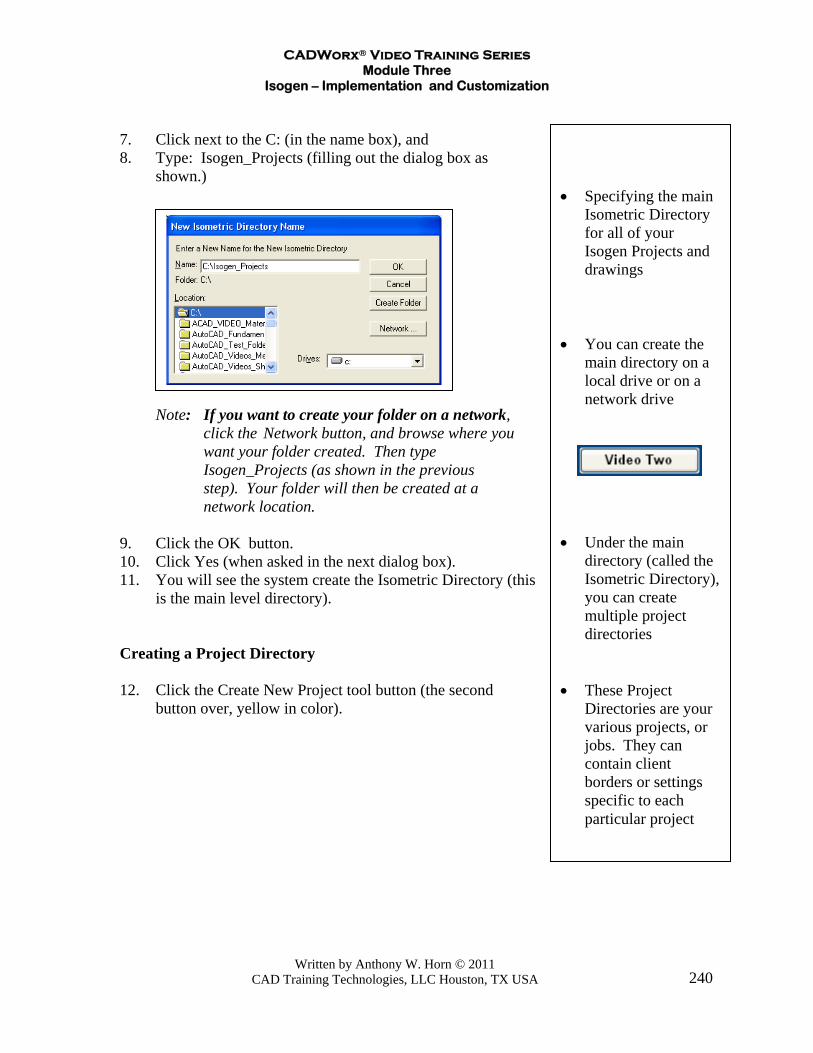
7. Click next to the C: (in the name box), and 8. Type: Isogen_Projects (filling out the dialog box as
shown.) Note: If you want to create your folder on a network,
click the Network button, and browse where you want your folder created. Then type Isogen_Projects (as shown in the previous step). Your folder will then be created at a network location.
9. Click the OK button. 10. Click Yes (when asked in the next dialog box). 11. You will see the system create the Isometric Directory (this
is the main level directory). Creating a Project Directory 12. Click the Create New Project tool button (the second
button over, yellow in color).

CADWorx® Video Training Series Module Three
Isogen – Implementation and Customization
Written by Anthony W. Horn © 2011 CAD Training Technologies, LLC Houston, TX USA
241
• This is where you
select the Borders you want to use, and tell the system to output the isos as DWG files (recommended)
13. Fill out the New Project dialog box as shown. Name it Project_1
Highlight Metric_Inch_A1, A2, and A3 (as shown). Set the Output Format to AutoCAD DWG. 14. Click the OK button after filling out the dialog box as
shown. 15. The system will create sub-folders for each of the
drawing borders you selected, as shown next.
CADWorx® Video Training Series Module Three
Isogen – Implementation and Customization
Written by Anthony W. Horn © 2011 CAD Training Technologies, LLC Houston, TX USA
242
• This is where you
select the Borders you want to use, and tell the system to output the isos as DWG files (recommended)
• If you’re doing a
network installation, you can “deploy” the project information to the various workstations
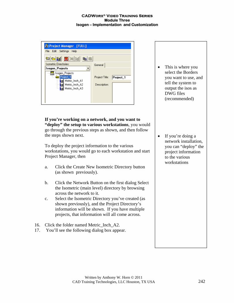
If you’re working on a network, and you want to
“deploy” the setup to various workstations, you would go through the previous steps as shown, and then follow the steps shown next.
To deploy the project information to the various
workstations, you would go to each workstation and start Project Manager, then
a. Click the Create New Isometric Directory button
(as shown previously). b. Click the Network Button on the first dialog Select the Isometric (main level) directory by browsing across the network to it. c. Select the Isometric Directory you’ve created (as shown previously), and the Project Directory’s information will be shown. If you have multiple projects, that information will all come across. 16. Click the folder named Metric_Inch_A2. 17. You’ll see the following dialog box appear.
CADWorx® Video Training Series Module Three
Isogen – Implementation and Customization
Written by Anthony W. Horn © 2011 CAD Training Technologies, LLC Houston, TX USA
243
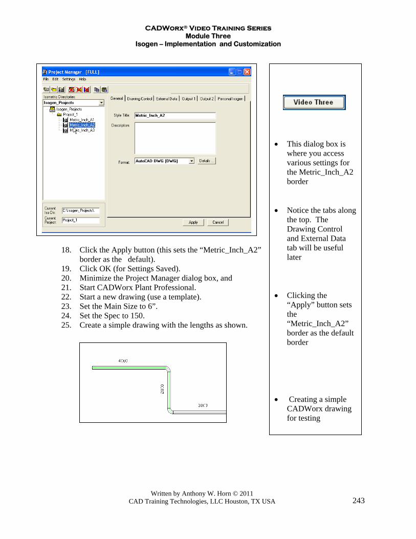
• This dialog box is
where you access various settings for the Metric_Inch_A2 border
• Notice the tabs along
the top. The Drawing Control and External Data tab will be useful later
• Clicking the
“Apply” button sets the “Metric_Inch_A2” border as the default border
• Creating a simple
CADWorx drawing for testing
18. Click the Apply button (this sets the “Metric_Inch_A2”
border as the default). 19. Click OK (for Settings Saved). 20. Minimize the Project Manager dialog box, and 21. Start CADWorx Plant Professional. 22. Start a new drawing (use a template). 23. Set the Main Size to 6”. 24. Set the Spec to 150. 25. Create a simple drawing with the lengths as shown.
CADWorx® Video Training Series Module Three
Isogen – Implementation and Customization
Written by Anthony W. Horn © 2011 CAD Training Technologies, LLC Houston, TX USA
244
• Sending a drawing
out to Isogen for testing
• On this dialog box
you’ll click OK for the test, but you can also select different borders here, and also different projects (if available)
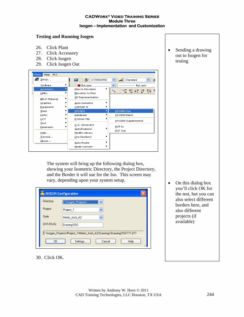
Testing and Running Isogen 26. Click Plant 27. Click Accessory 28. Click Isogen 29. Click Isogen Out
The system will bring up the following dialog box,
showing your Isometric Directory, the Project Directory, and the Border it will use for the Iso. This screen may vary, depending upon your system setup.
30. Click OK.

CADWorx® Video Training Series Module Three
Isogen – Implementation and Customization
Written by Anthony W. Horn © 2011 CAD Training Technologies, LLC Houston, TX USA
245
• Sending a drawing
out to Isogen for testing
• Viewing the
generated Isogen isometric
31. Press <Enter> (to select components). 32. Window the objects in the drawing, and 33. Press <Enter>. 34. The system will show the following dialog box.
Note: If you got an error message, or a “disconnect”
message, you probably did not draw the pipes and elbows touching each other. See the first video lesson in the Piping Module on how to connect components correctly.
35. Click the Open Plot Files button to view the Isogen iso
created by the system.
CADWorx® Video Training Series Module Three
Isogen – Implementation and Customization
Written by Anthony W. Horn © 2011 CAD Training Technologies, LLC Houston, TX USA
246
• Sending a drawing
out to an A3 sized border for testing
• Viewing the
generated A3 sized isometric
• In a later section
you’ll see how to bring in your own border, or a client’s border
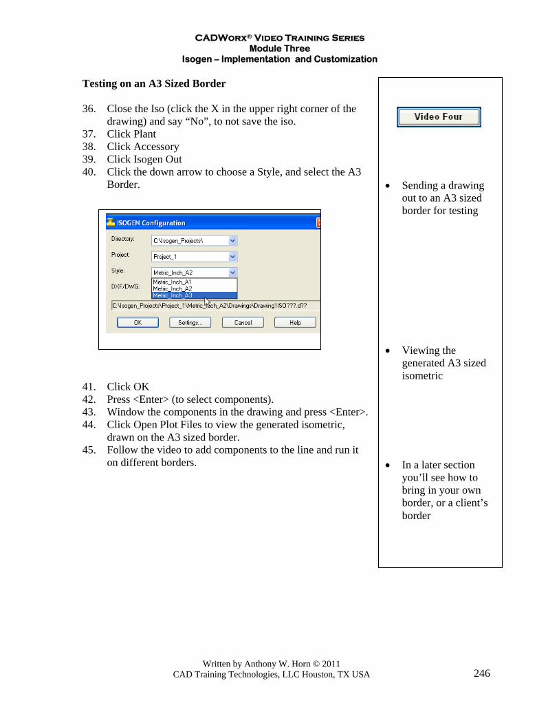
Testing on an A3 Sized Border 36. Close the Iso (click the X in the upper right corner of the
drawing) and say “No”, to not save the iso. 37. Click Plant 38. Click Accessory 39. Click Isogen Out 40. Click the down arrow to choose a Style, and select the A3
Border. 41. Click OK 42. Press <Enter> (to select components). 43. Window the components in the drawing and press <Enter>. 44. Click Open Plot Files to view the generated isometric,
drawn on the A3 sized border. 45. Follow the video to add components to the line and run it
on different borders.
CADWorx® Video Training Series Module Three
Isogen – Implementation and Customization
Written by Anthony W. Horn © 2011 CAD Training Technologies, LLC Houston, TX USA
247
• Restarting the
Project Manager program
• Clicking on the
Drawing Control tab
• This example uses
an A2 border. You can set the switches to change Isogen settings on any of the borders available
• This will open up
the drawing options that you can change to make the isometric look the way you want
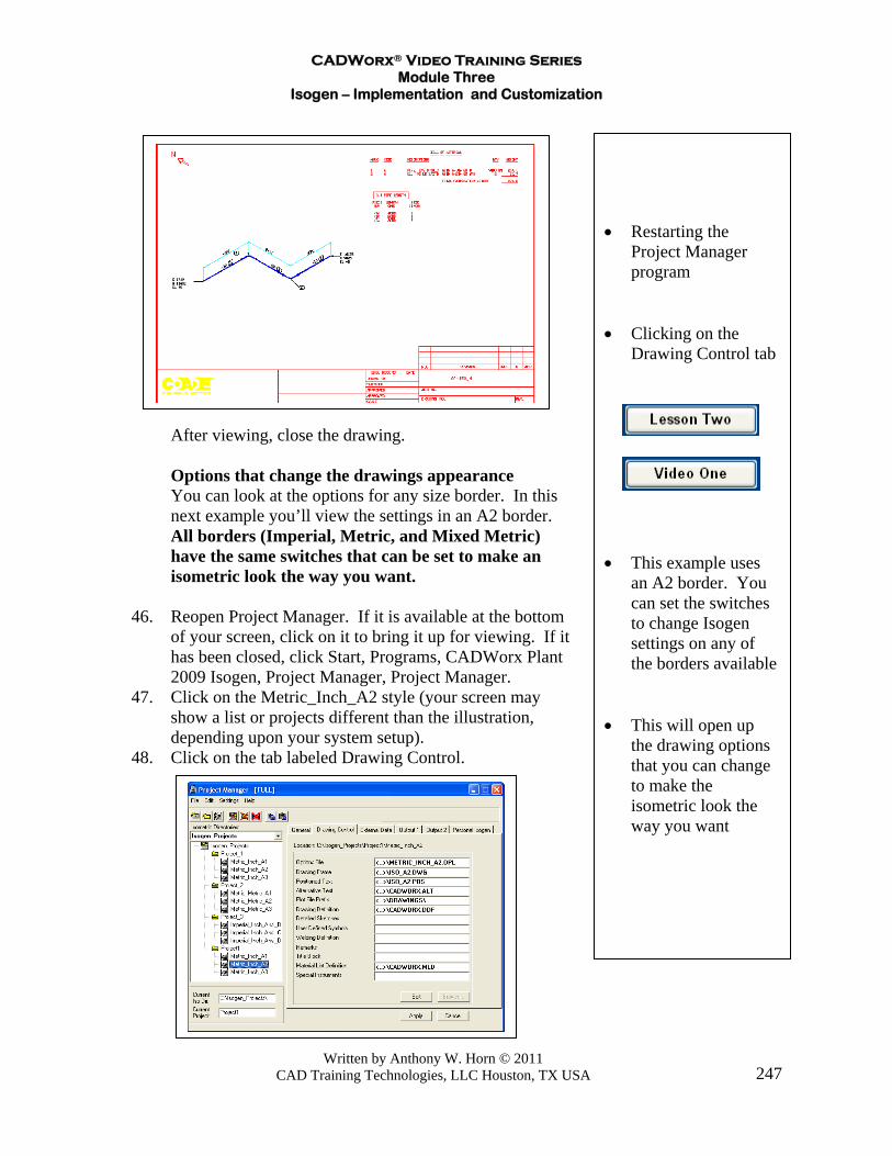
After viewing, close the drawing. Options that change the drawings appearance You can look at the options for any size border. In this
next example you’ll view the settings in an A2 border. All borders (Imperial, Metric, and Mixed Metric) have the same switches that can be set to make an isometric look the way you want.
46. Reopen Project Manager. If it is available at the bottom
of your screen, click on it to bring it up for viewing. If it has been closed, click Start, Programs, CADWorx Plant 2009 Isogen, Project Manager, Project Manager.
47. Click on the Metric_Inch_A2 style (your screen may show a list or projects different than the illustration, depending upon your system setup).
48. Click on the tab labeled Drawing Control.

CADWorx® Video Training Series Module Three
Isogen – Implementation and Customization
Written by Anthony W. Horn © 2011 CAD Training Technologies, LLC Houston, TX USA
248
• Restarting the
Project Manager program
• Clicking on the
Drawing Control tab • This will open up
the drawing options that you can change to make the isometric look the way you want
• You can see there is
more than one page for each of the tabs
• On page 2 there are
switches to change the appearance of rolled offsets on the isometrics
49. Click on the Options File and Click Edit.
This will bring up the Options Editor for the Drawing Options.
The margins at the top right area of the dialog box can be
changed to modify the position of the plotted iso on the page.
This can be useful later when you see how to bring in your own border.
Notice the figure at the lower right
corner of the dialog box. This will take you to the next page of settings. Each tab can
have multiple pages of settings. 50. You can change any or all of the following settings. 51. This next section is to show you some of the many options
that can be set in Isogen to change the appearance of a drawing.

CADWorx® Video Training Series Module Three
Isogen – Implementation and Customization
Written by Anthony W. Horn © 2011 CAD Training Technologies, LLC Houston, TX USA
249
• Changing how the
dimensions across gaskets are shown
• On page 2 you can
suppress the dimensions across small branches
• On page 3 you can
turn on overall dimensions
Click on the Dimensioning tab at the top of the screen.
52. Click on the down arrow the lists the choices for
dimensioning gaskets (under area with the 9 shown – this is “switch 9”.) See the figure below.
53. Set it to have the Gaskets Included in Component
Dimensions. 54. Click on the area in the lower right of the dialog box to
go to page 2. 55. Notice on this page you can tell the system you want to
turn off dimensions across small branches. 56. On page three you can instruct the system to add overall
dimensions. 56. Click on the Iso Style tab.
CADWorx® Video Training Series Module Three
Isogen – Implementation and Customization
Written by Anthony W. Horn © 2011 CAD Training Technologies, LLC Houston, TX USA
250
• This area lets you
change the way Part Numbers look, which way the North Arrow points, and how a Spec Break will look
• On page 2 you can
change how a Rolled Offset looks
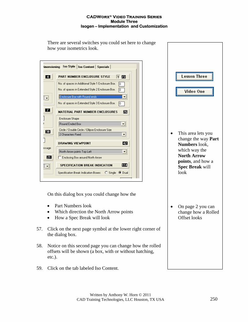
There are several switches you could set here to change
how your isometrics look.
On this dialog box you could change how the
• Part Numbers look • Which direction the North Arrow points • How a Spec Break will look
57. Click on the next page symbol at the lower right corner of
the dialog box. 58. Notice on this second page you can change how the rolled
offsets will be shown (a box, with or without hatching, etc.).
59. Click on the tab labeled Iso Content.

CADWorx® Video Training Series Module Three
Isogen – Implementation and Customization
Written by Anthony W. Horn © 2011 CAD Training Technologies, LLC Houston, TX USA
251
• This area lets you
enable Spool callouts
• You can modify how the Instruments are shown
• You can turn on Valve Tab labeling
• Isogen will label text
in the TAG field on Nozzles or “existing” Long Weld Neck Flanges
60. The first page has options for changing how the coordinates
on the isometrics are labeled. 61. Click on the area at the bottom to go to page 2. 62. Page 2 has switches to turn on and modify how the system
can label spool pieces in the isometric. 63. There’s also a switch to modify how the instruments are
depicted. 64. There’s a switch to turn on Valve Tags. Isogen will also label the text that is put into the TAG field on
a Nozzle drawn in the Equipment Module. Also it will label any text put in the TAG field on any Long Weld Neck Flange that is set as “Existing” in a model.
65. Page 3 has a switch to have Insulation and Tracing appear on
the isometric. 66. There is also a switch to turn on Flow Direction Arrows over
check valves on this page.
CADWorx® Video Training Series Module Three
Isogen – Implementation and Customization
Written by Anthony W. Horn © 2011 CAD Training Technologies, LLC Houston, TX USA
252
• Enabling User Fonts
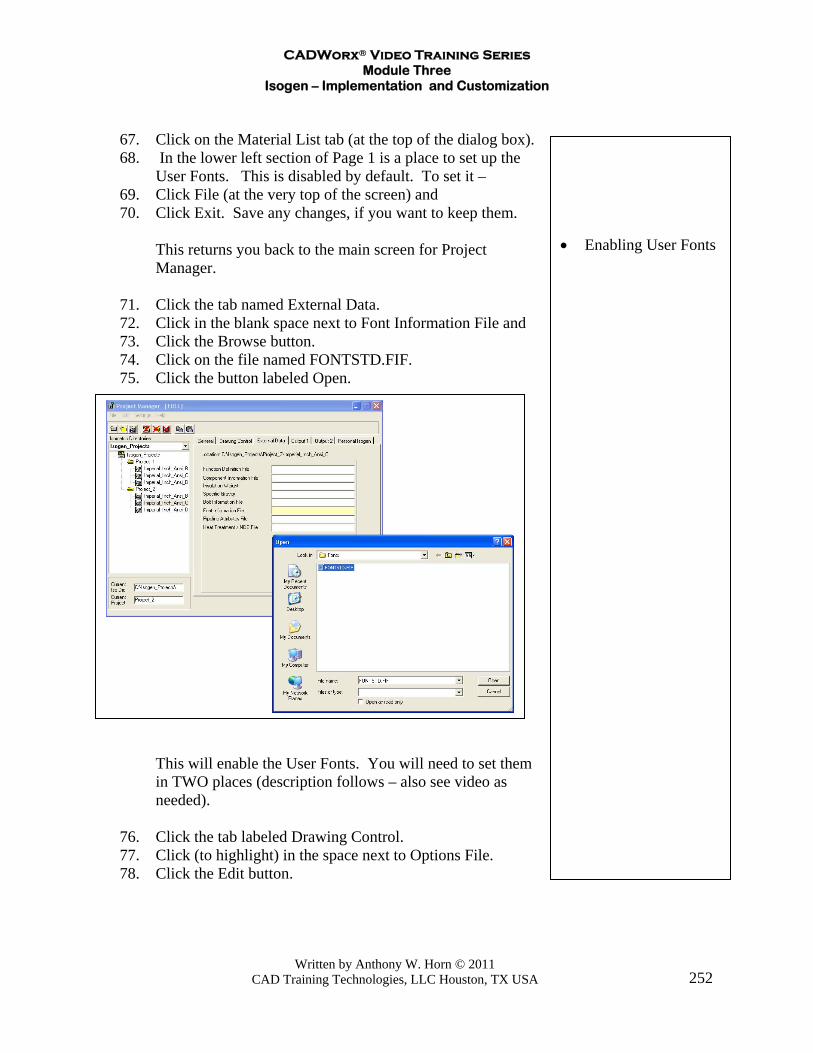
67. Click on the Material List tab (at the top of the dialog box). 68. In the lower left section of Page 1 is a place to set up the
User Fonts. This is disabled by default. To set it – 69. Click File (at the very top of the screen) and 70. Click Exit. Save any changes, if you want to keep them. This returns you back to the main screen for Project
Manager. 71. Click the tab named External Data. 72. Click in the blank space next to Font Information File and 73. Click the Browse button. 74. Click on the file named FONTSTD.FIF. 75. Click the button labeled Open.
This will enable the User Fonts. You will need to set them
in TWO places (description follows – also see video as needed).
76. Click the tab labeled Drawing Control. 77. Click (to highlight) in the space next to Options File. 78. Click the Edit button.
CADWorx® Video Training Series Module Three
Isogen – Implementation and Customization
Written by Anthony W. Horn © 2011 CAD Training Technologies, LLC Houston, TX USA
253
• Setting User Fonts
for dimensions and labels
• Setting User Fonts
for the Bill of Materials
• Suppressing the
cutting list • Adding a cutting
allowance for Field Fit Welds
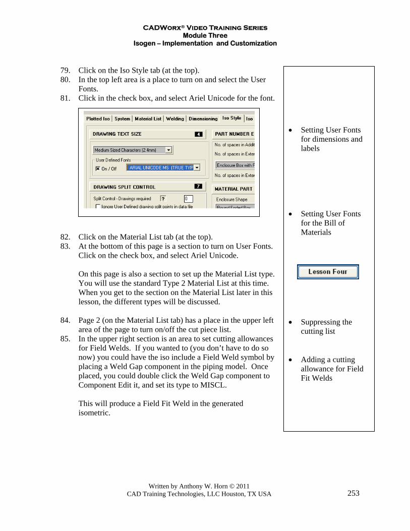
79. Click on the Iso Style tab (at the top). 80. In the top left area is a place to turn on and select the User
Fonts. 81. Click in the check box, and select Ariel Unicode for the font. 82. Click on the Material List tab (at the top). 83. At the bottom of this page is a section to turn on User Fonts.
Click on the check box, and select Ariel Unicode. On this page is also a section to set up the Material List type. You will use the standard Type 2 Material List at this time.
When you get to the section on the Material List later in this lesson, the different types will be discussed.
84. Page 2 (on the Material List tab) has a place in the upper left
area of the page to turn on/off the cut piece list. 85. In the upper right section is an area to set cutting allowances
for Field Welds. If you wanted to (you don’t have to do so now) you could have the iso include a Field Weld symbol by placing a Weld Gap component in the piping model. Once placed, you could double click the Weld Gap component to Component Edit it, and set its type to MISCL.
This will produce a Field Fit Weld in the generated
isometric.
CADWorx® Video Training Series Module Three
Isogen – Implementation and Customization
Written by Anthony W. Horn © 2011 CAD Training Technologies, LLC Houston, TX USA
254
• Using your own
Border • Specifying your
Border • The border drawing
you use must be saved as a 2004 dwg
The Welding tab has settings for how Welds are displayed on the iso. See the section on Welding Information in a later part of this lesson.
86. At the top of the dialog box, click File and click Save. 87. Then click File and click Exit. 88. Click the Apply button to save your settings.
Lesson Five in the Isogen videos discusses the Project File Structure.
Bringing in your Company border or a Client border You can have Isogen use your own specific border, or a
client’s border. You can also have Isogen fill out text entries within the
border’s title block, or elsewhere on the drawing. A couple of important things you must do:
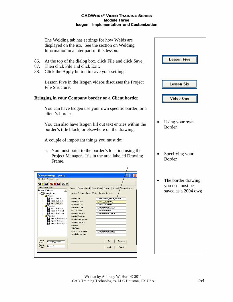
a. You must point to the border’s location using the Project Manager. It’s in the area labeled Drawing Frame.
CADWorx® Video Training Series Module Three
Isogen – Implementation and Customization
Written by Anthony W. Horn © 2011 CAD Training Technologies, LLC Houston, TX USA
255
• Opening the border
and saving it as an AutoCAD 2004 version
• Specifying your
Border • The border drawing
you use must be saved as a 2004 dwg
• Testing the border
b. The border you use must be saved as an AutoCAD
2004 drawing. Isogen will not work if you use a border that is an AutoCAD 2005, 2006, 2007, 2008, or 2009 drawing.
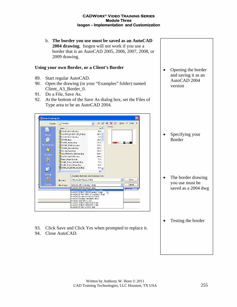
Using your own Border, or a Client’s Border 89. Start regular AutoCAD. 90. Open the drawing (in your “Examples” folder) named
Client_A3_Border_0. 91. Do a File, Save As. 92. At the bottom of the Save As dialog box, set the Files of
Type area to be an AutoCAD 2004.
93. Click Save and Click Yes when prompted to replace it. 94. Close AutoCAD.
CADWorx® Video Training Series Module Three
Isogen – Implementation and Customization
Written by Anthony W. Horn © 2011 CAD Training Technologies, LLC Houston, TX USA
256
• Setting up the new
border
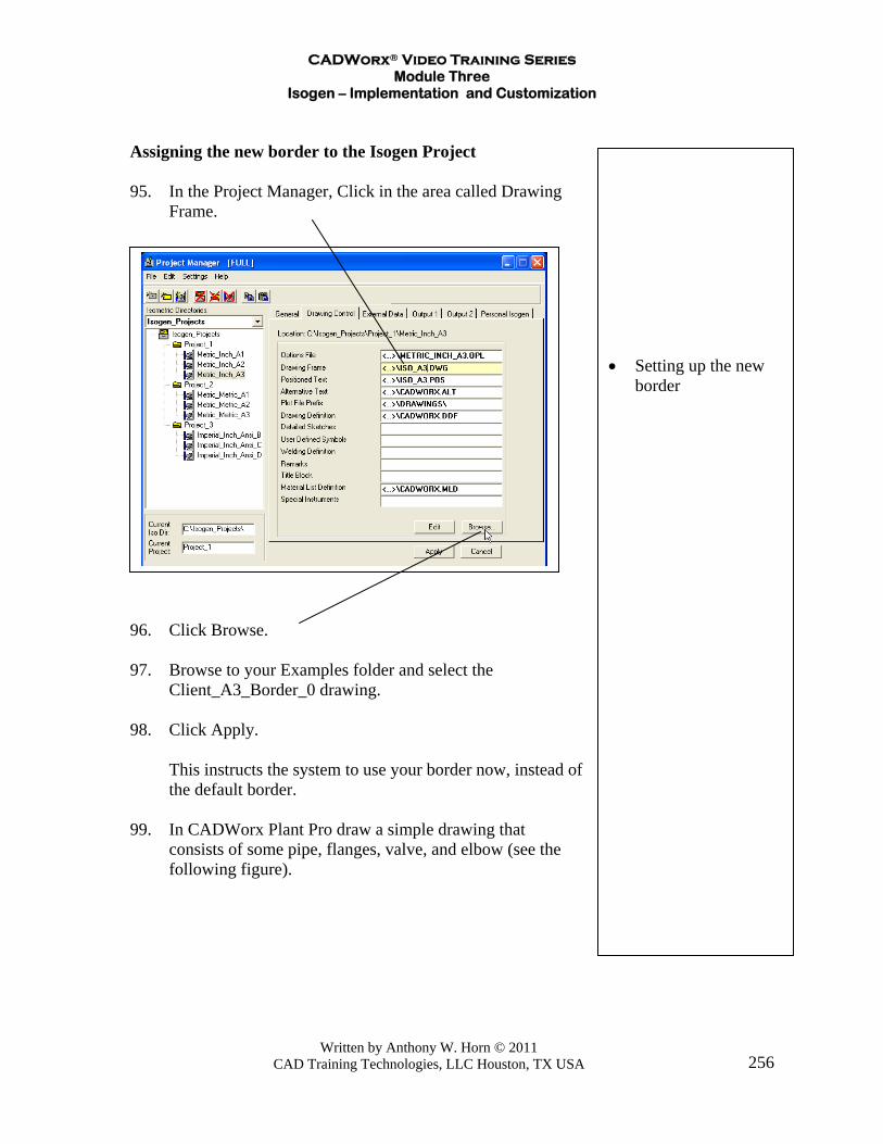
Assigning the new border to the Isogen Project 95. In the Project Manager, Click in the area called Drawing
Frame.
96. Click Browse.
97. Browse to your Examples folder and select the Client_A3_Border_0 drawing. 98. Click Apply. This instructs the system to use your border now, instead of
the default border. 99. In CADWorx Plant Pro draw a simple drawing that
consists of some pipe, flanges, valve, and elbow (see the following figure).

CADWorx® Video Training Series Module Three
Isogen – Implementation and Customization
Written by Anthony W. Horn © 2011 CAD Training Technologies, LLC Houston, TX USA
257
• Creating a small test
model • Generating an iso on
the new border
100. Test the border by running a simple iso using it as the
drawing frame.

CADWorx® Video Training Series Module Three
Isogen – Implementation and Customization
Written by Anthony W. Horn © 2011 CAD Training Technologies, LLC Houston, TX USA
258
• Positioned Text –
used to place text in a drawing
• Opening the
Positioned Text file
Developing the Border – Filling out the Title Block Area Isogen does not use normal attributes to fill out the title
block area like a regular AutoCAD drawing. Isogen uses “Positioned Text” for this function. In Project Manager – 101. Click in the Positioned Text area.
102. Click the Edit button.

CADWorx® Video Training Series Module Three
Isogen – Implementation and Customization
Written by Anthony W. Horn © 2011 CAD Training Technologies, LLC Houston, TX USA
259
• Looking at the
contents of the Iso_A3 sheet’s positioned text file
• Opening the
Positioned Text help file
• You can Justify the
text (Left, Center, Right) and you can Rotate the text as needed.
This opens up the Positioned Text file that you can adjust to map the locations of pieces of text onto your border.
103. Close Notepad now, don’t save any changes.
Note: Open the Positioned Text help file (a pdf file). It is found at C:\CADWorx Plant 2008\Isogen\Isogen_Utils\POS_Help.pdf
You should print out this file, since it is only six pages and has
some useful information in it. You can see from the file we opened in the previous figure
that there is an item named -6. It has an X position, a Y position, a Character Width, and a Character Height.
The numbers for position and height are in hundredths of a
millimeter. Since Isogen was originally developed in Great Britain the values are in metric.
The Positioned Text file can actually have more columns than shown above. This can be useful, because you can specify the text’s justification and rotation angle as well. Here’s an expanded version of one of the lines with the item labeled -6.

CADWorx® Video Training Series Module Three
Isogen – Implementation and Customization
Written by Anthony W. Horn © 2011 CAD Training Technologies, LLC Houston, TX USA
260
• Some of the fields
that can be brought into your title block and drawing
• This area allows
you to create User Fields that can be mapped into your drawing. You can create as many as 100 fields
A Justification (column 11) of 0 is Left, 1 is Center, 2 is Right. The Rotation (column 12) can be set as needed (usually 0 or 90). If you look at the following figures, you can see that the item
labeled -6 is what Isogen uses to place the drawing title (it uses the pipeline name).
The Positioned Text help file has the following information in it.
You will use this information to map some values into your title block.

CADWorx® Video Training Series Module Three
Isogen – Implementation and Customization
Written by Anthony W. Horn © 2011 CAD Training Technologies, LLC Houston, TX USA
261
• Opening the Project
defaults dialog box • The project defaults
is where you can put text that can be mapped into the title block area, or anywhere in the drawing
• In the Specifications
area are some fields you can fill out and have them get placed into your isometrics automatically
Note: What they are calling a “User Defined Attribute
Block” in the figure above is not something that comes from AutoCAD. This is Alias’ own naming, and it is used differently than attributes and blocks are used in AutoCAD.
104. In Project Manger – 105. Click the Project Name (above the Metric_Inch_A1 – this
example is showing an Ansi_B sized border. All units work the same here.)
Click Project Defaults. This brings up the Project Defaults dialog box. 106. Click on the tab labeled Specification. The Specifications area of the Project Defaults

CADWorx® Video Training Series Module Three
Isogen – Implementation and Customization
Written by Anthony W. Horn © 2011 CAD Training Technologies, LLC Houston, TX USA
262
• The Miscellaneous
tab has additional fields you can store text information in, and then have it mapped into your title block area, or anywhere on the drawing.
Any values in these fields (Piping-Spec, Insulation-Spec, etc.) can be mapped into the drawing or title block.
For instance the Piping-Spec would be brought in using the
code of -11. You would add a line to the ANSI_B.pos file (shown in a previous figure) starting with an -11 entry. Then you would add its X and Y position, and its height.
You could do the same for the other specs, like Insulation-
Spec, Tracing-Spec, etc. Next you’ll map in some examples to see how this works. 107. Click the Miscellaneous tab.
108. In the Revision field - Type: A. 109. In the Project Identifier field – Type: COADE 001-A25. 110. In the Batch/Area field – Type: 3400.

CADWorx® Video Training Series Module Three
Isogen – Implementation and Customization
Written by Anthony W. Horn © 2011 CAD Training Technologies, LLC Houston, TX USA
263
• The Attributes tab
gives you User Defined fields you can fill out as needed and have them mapped into your title block or elsewhere on your drawing
• Setting up values to
be mapped into the title block
• You can create as
many as 100 text fields to map into your title block or drawing
111. Click on the Attributes tab. 112. Fill out the values as shown. These are User Definable fields. You can create as many as 100 fields to use for text that can be mapped into your title block. The dialog box shows 10 fields, but if you click the Append button (shown in the previous figure) you can keep adding new ones.
113. Click OK when done.
CADWorx® Video Training Series Module Three
Isogen – Implementation and Customization
Written by Anthony W. Horn © 2011 CAD Training Technologies, LLC Houston, TX USA
264
• Opening the border
and looking at the title block area
• Scaling up the
border into metric for an easy way to locate points for text placement
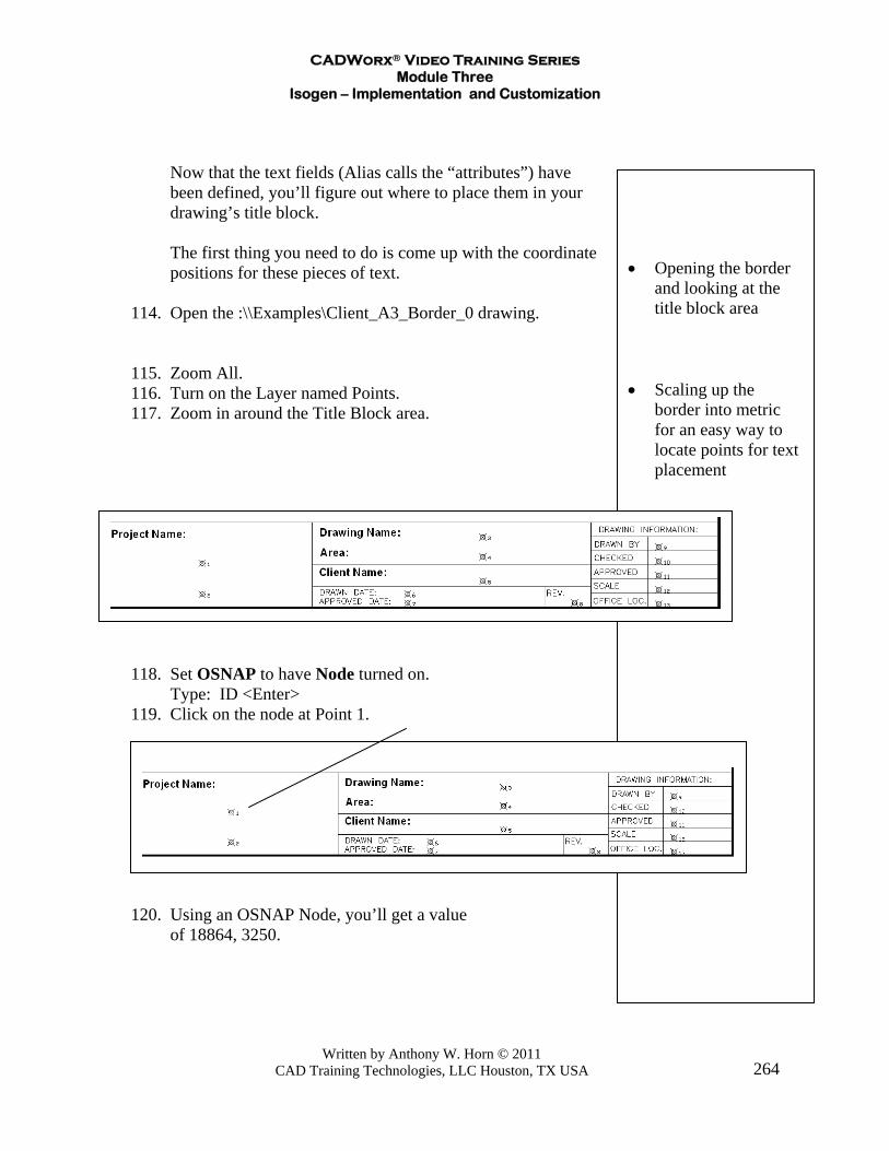
Now that the text fields (Alias calls the “attributes”) have been defined, you’ll figure out where to place them in your drawing’s title block.
The first thing you need to do is come up with the coordinate
positions for these pieces of text. 114. Open the :\\Examples\Client_A3_Border_0 drawing. 115. Zoom All. 116. Turn on the Layer named Points. 117. Zoom in around the Title Block area.
118. Set OSNAP to have Node turned on.
Type: ID <Enter> 119. Click on the node at Point 1.
120. Using an OSNAP Node, you’ll get a value of 18864, 3250.

CADWorx® Video Training Series Module Three
Isogen – Implementation and Customization
Written by Anthony W. Horn © 2011 CAD Training Technologies, LLC Houston, TX USA
265
• Getting the location
of the point where a text label will be placed (mapped to)
• Locating various
point locations to place text
Repeat for the other points, and make a list. Point Number Location Pt 1 X = 18864 Y = 3250 Pt 2 X = 18864 Y = 1867 Pt 3 X = 31375 Y = 4409 Pt 4 X = 31375 Y = 3667 Pt 5 X = 31375 Y = 2451 Pt 6 X = 28017 Y = 1875 Pt 7 X = 28017 Y = 1465 Pt 8 X = 35463 Y = 1478 Pt 9 X = 39211 Y = 3972 Pt 10 X = 39211 Y = 3337 Pt 11 X = 39211 Y = 2702 Pt 12 X = 39211 Y = 2067 Pt 13 X = 39211 Y = 1432 121. Save the drawing and close it. Now you’ll edit the Position Text file to set up the mapping
In Project Manager, 122. Click on the Imperial_Inch_Ansi_B (or the border you’re
working with). 123. Click in the area for Positioned Text.
CADWorx® Video Training Series Module Three
Isogen – Implementation and Customization
Written by Anthony W. Horn © 2011 CAD Training Technologies, LLC Houston, TX USA
266
• The completed
Positioned Text file • You’ll need to save
it as a .pos file (not a .txt type file)
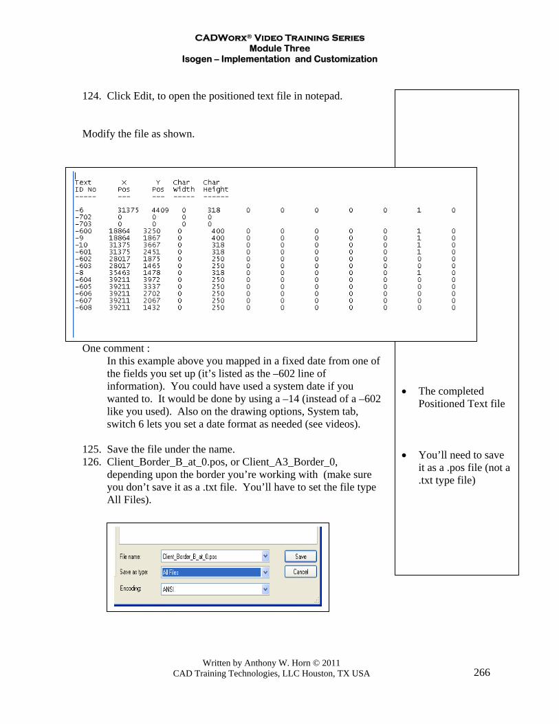
124. Click Edit, to open the positioned text file in notepad. Modify the file as shown.
One comment : In this example above you mapped in a fixed date from one of
the fields you set up (it’s listed as the –602 line of information). You could have used a system date if you wanted to. It would be done by using a –14 (instead of a –602 like you used). Also on the drawing options, System tab, switch 6 lets you set a date format as needed (see videos).
125. Save the file under the name. 126. Client_Border_B_at_0.pos, or Client_A3_Border_0,
depending upon the border you’re working with (make sure you don’t save it as a .txt file. You’ll have to set the file type All Files).

CADWorx® Video Training Series Module Three
Isogen – Implementation and Customization
Written by Anthony W. Horn © 2011 CAD Training Technologies, LLC Houston, TX USA
267
• Using the new
Positioned Text file you just modified
• Testing and viewing
the results
127. Close Notepad
In Project Manager, 128. Click in the area for the Positioned Text file.
129. Click Browse and select the file you just saved. 130. Click the Apply button. 131. Click OK 132. Test the border by running a simple example through it.
So you can see that Isogen allows you to fill out your title block as needed.
If you wanted to use a border that had the title block running up
the side of the drawing, you would use the same procedure. The only thing you’d need to do differently is have a 90 for the
rotation angle in the positioned text file.

CADWorx® Video Training Series Module Three
Isogen – Implementation and Customization
Written by Anthony W. Horn © 2011 CAD Training Technologies, LLC Houston, TX USA
268
For example , the following line would map a text string into the title block area, but rotate it at 90 degrees instead of leaving it a 0 degrees. -601 31375 2451 0 318 0 0 0 0 0 1 90 Video Seven illustrates how to have the system set up your layer colors to match the standard Isogen borders. Lesson Seven Video One Video Two Video Three The Lesson Seven videos cover how to use and modify the different Bill of Materials Styles available with CADWorx and Isogen. Lesson Eight Video One Video Two These videos discuss Line Numbering and how to run the Isogen Batch command. Also the graphic symbols for a floor or deck penetration, flow arrows, etc. are covered and you will see how they can be sent from the model to Isogen automatically.
CADWorx® Video Training Series Module Three
Isogen – Implementation and Customization
Written by Anthony W. Horn © 2011 CAD Training Technologies, LLC Houston, TX USA
269
Lesson Nine Video One Video Two Video Three In this lesson you will how to place restraints (hangers, base supports, anchors, etc.) in the model and have them come into Isogen. You’ll also see how to get Detail Sketches of a Base Support to be drawn in the isometric. Finally, this section illustrates how to get a Reference Dimension and Note to appear in an Isometric.
CADWorx® Video Training Series Module Three
Isogen – Implementation and Customization
Written by Anthony W. Horn © 2011 CAD Training Technologies, LLC Houston, TX USA
270
• Setting the system
for welding information on isometrics
Additional information (no videos associated with this section) Welding Information It is possible to have Isogen display Welding information
on an isometric. It can list and number the welds in the drawing.
The easiest way to see how this happens is to use one of
the samples that are shipped in CADWorx (available in Imperial versions only at this time).
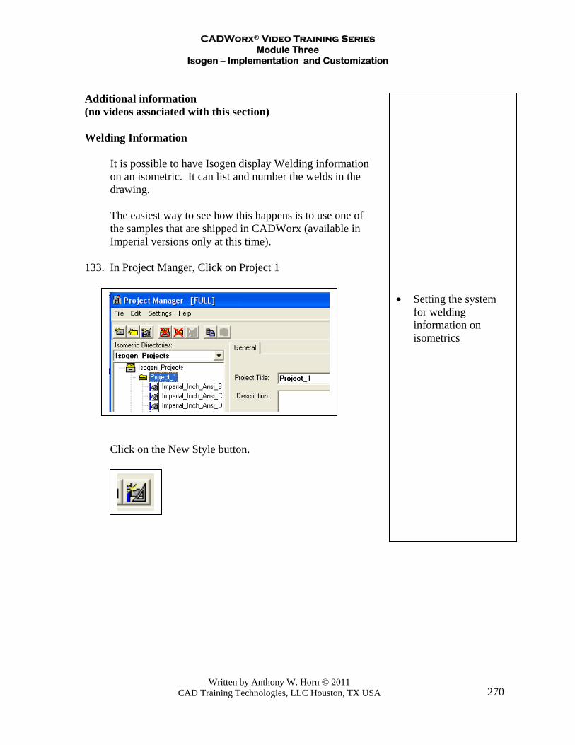
133. In Project Manger, Click on Project 1
Click on the New Style button.
CADWorx® Video Training Series Module Three
Isogen – Implementation and Customization
Written by Anthony W. Horn © 2011 CAD Training Technologies, LLC Houston, TX USA
271
• Use the Welding
videos to see how to bring welding data into your own user border
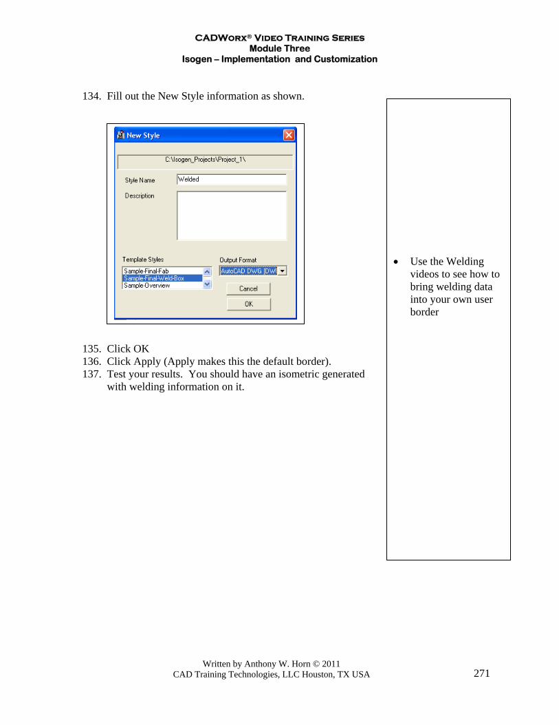
134. Fill out the New Style information as shown. 135. Click OK 136. Click Apply (Apply makes this the default border). 137. Test your results. You should have an isometric generated
with welding information on it.
CADWorx® Video Training Series Module Three
Isogen – Implementation and Customization
Written by Anthony W. Horn © 2011 CAD Training Technologies, LLC Houston, TX USA
272
• You can change
some of the labeling that Isogen puts on an isometric drawing
• This is handled
through a feature called Alternative Text
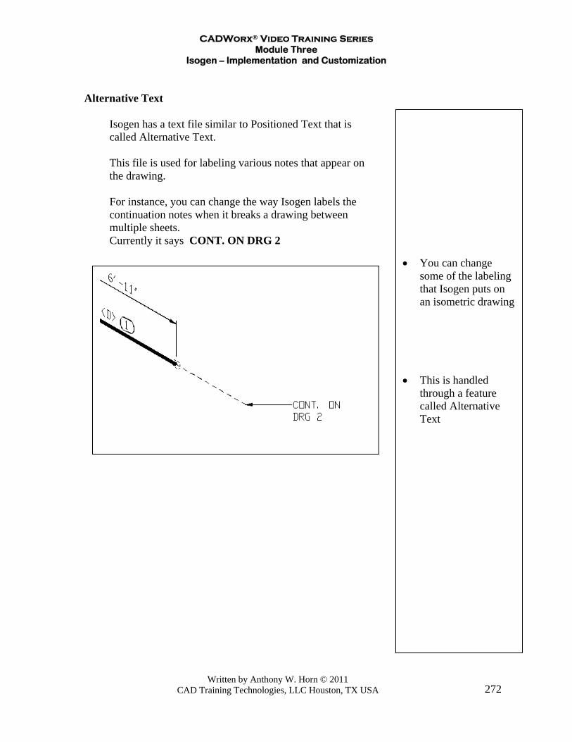
Alternative Text Isogen has a text file similar to Positioned Text that is called Alternative Text. This file is used for labeling various notes that appear on the drawing.
For instance, you can change the way Isogen labels the continuation notes when it breaks a drawing between multiple sheets.
Currently it says CONT. ON DRG 2

CADWorx® Video Training Series Module Three
Isogen – Implementation and Customization
Written by Anthony W. Horn © 2011 CAD Training Technologies, LLC Houston, TX USA
273
• Opening the
Alternative Text file • Looking at the Title
Block Group in the Alternative Text file
Let’s say you wanted to change the DRG over to DWG.
In Project Manager,
138. Click in the area for Alternative Text. 139. Click Edit. 140. Click on the Group pull
down menu (at the top of the screen).
141. Click on the Title Block group.
This shows all the text in this particular group that Isogen uses
for labeling.

CADWorx® Video Training Series Module Three
Isogen – Implementation and Customization
Written by Anthony W. Horn © 2011 CAD Training Technologies, LLC Houston, TX USA
274
• Changing the way
Isogen labels “CONT ON DWG” instead of “CONT ON DRG”
• It’s worth taking a
look at the other groups in this file
Change DRG to DWG.
Look over the other Groups in the Alternative Text file. This
file contains many labels that are open for you to change as needed.
142. Close the file (Click File, Save, and Exit) and click the Apply
button. 143. You can test this by drawing a router line in CADWorx with
multiple changes of direction, then running Plant, Accessory, Auto Route, Buttweld LR.
144. When you run Isogen the system will break it into multiple
isometrics. You will then see that it changed the continuation notes to CONT. ON DWG .

CADWorx® Video Training Series Module Three
Isogen – Implementation and Customization
Written by Anthony W. Horn © 2011 CAD Training Technologies, LLC Houston, TX USA
275
• Viewing the change
to the way Isogen labels the drawing continuation note
• Setting up Square
Elbows
The Data Definition File The Project Manager also has an are where you can modify the Data Definition File (similar to the Positioned Text file). This file contains settings that affect the appearance of how Isogen draws some of its components – for instance rounded elbows or square elbows. This file also contains information on what thickness of lines it will use, and how big it will scale some of the fittings. Also, there is a section in this file for defining layers,

CADWorx® Video Training Series Module Three
Isogen – Implementation and Customization
Written by Anthony W. Horn © 2011 CAD Training Technologies, LLC Houston, TX USA
276
• Opening the
Drawing Definition File
• Noting the area
where Square Elbows are defined
Telling the System to Draw Square Elbows In Project Manager, 145. Click in the area for the Drawing Definition. 146. Click Edit. 147. Change the word for ELBOW from ROUND to SQUARE.
CADWorx® Video Training Series Module Three
Isogen – Implementation and Customization
Written by Anthony W. Horn © 2011 CAD Training Technologies, LLC Houston, TX USA
277
148. Save the file (make sure it keeps a .ddf extension). 149. Test it on your previous drawing and verify the iso came
out with square elbows. The help file that comes in the
CADWorx\Isogen\Isogen_Utils folder contains further information on this file. The help file is titled DDF_Help.pdf.
Related Documents


