Isochronets: a High-Speed Network Switching Architecture (Thesis Proposal) Danilo Florissi Advisor: Prof. Yechiam Yemini Technical Report CUCS-020-93 Abstract Traditional switching techniques need hundred- or thousand-MIPS processing power within switches to support Gbit/s transmission rates available today. These techniques anchor their decision-making on control information within transmitted frames and thus must resolve routes at the speed in which frames are being pumped into switches. Isochronets can potentially switch at any transmission rate by making switching decisions independent of frame contents. Isochronets divide network bandwidth among routing trees, a technique called Route Division Multiple Access (RDMA). Frames access network resources through the appropriate routing tree to the destination. Frame structures are irrelevant for switching decisions. Consequently, Isochronets can support multiple framing protocols without adaptation layers and are strong candidates for all-optical implementations. All network-layer functions are reduced to an admission control mechanism designed to provide quality of service (QOS) guarantees for multiple classes of traffic. The main results of this work are: (1) A new network architecture suitable for high-speed transmissions; (2) An implementation of Isochronets using cheap off-the- shelf components; (3) A comparison of RDMA with more traditional switching techniques, such as Packet Switching and Circuit Switching; (4) New protocols necessary for Isochronet operations; and (5) Use of Isochronet techniques at higher layers of the protocol stack (in particular, we show how Isochronet techniques may solve routing problems in ATM networks). brought to you by CORE View metadata, citation and similar papers at core.ac.uk provided by Columbia University Academic Commons

Welcome message from author
This document is posted to help you gain knowledge. Please leave a comment to let me know what you think about it! Share it to your friends and learn new things together.
Transcript
Isochronets: a High-Speed NetworkSwitching Architecture
(Thesis Proposal)
Danilo Florissi
Advisor: Prof. Yechiam Yemini
Technical Report CUCS-020-93
Abstract
Traditional switching techniques need hundred- or thousand-MIPS processing power within
switches to support Gbit/s transmission rates available today. These techniques anchor their
decision-making on control information within transmitted frames and thus must resolve routes
at the speed in which frames are being pumped into switches. Isochronets can potentially switch
at any transmission rate by making switching decisions independent of frame contents.
Isochronets divide network bandwidth among routing trees, a technique called Route Division
Multiple Access (RDMA). Frames access network resources through the appropriate routing tree
to the destination. Frame structures are irrelevant for switching decisions. Consequently,
Isochronets can support multiple framing protocols without adaptation layers and are strong
candidates for all-optical implementations. All network-layer functions are reduced to an
admission control mechanism designed to provide quality of service (QOS) guarantees for
multiple classes of traffic. The main results of this work are: (1) A new network architecture
suitable for high-speed transmissions; (2) An implementation of Isochronets using cheap off-the-
shelf components; (3) A comparison of RDMA with more traditional switching techniques, such
as Packet Switching and Circuit Switching; (4) New protocols necessary for Isochronet
operations; and (5) Use of Isochronet techniques at higher layers of the protocol stack (in
particular, we show how Isochronet techniques may solve routing problems in ATM networks).
brought to you by COREView metadata, citation and similar papers at core.ac.uk
provided by Columbia University Academic Commons

1
1 Introduction
Until recently, networks have been able to afford massive processing loads. Complex functions
could be executed within the network due to the gap between processing and transmission effi-
ciency. The scenario is reversed in current high-speed networks (HSNs). Transmission speeds of
Gigabits or even Terabits per second are a reality. At these rates, processing inside the network
must be minimized. For example, at 2.4Gb/s transmission rates, a processor has 177ns to switch
an ATM cell. During this period, a 100MIPS processor can execute only 17 instructions.
Recent HSN architectures [2, 8, 11, 12, 14, 18, 21, 22, 24, 30, 31, 32, 33, 34, 35, 36, 38]
have directly addressed these issues by standing to a new design paradigm: relieve intelligence
from the network, relaying functionality to its periphery. Network-layer functions [29] such as
routing and congestion control are shifted to the Media-Access sublayer (MAC), being per-
formed at the sources. Nevertheless, functions such as switching, quality of service (QOS) pa-
rameter policing, and media (electronic/optical and vice-versa) conversion still incur consider-
able demands at network nodes. HSNs must further minimize processing at intermediate nodes,
possibly trading communication bandwidth for processing bandwidth.
A wide spectrum of QOS requirements are expected to emerge in future applications en-
abled by the enormous bandwidth available in HSNs. Examples of such applications include live
video multicasting, multimedia conferencing, high-quality image retrieval, and virtual reality
environments. Live video has hard timing constraints: one frame should be delivered every 33ms
for low-resolution video and the loss rate should be on the order of 10-9. Multimedia conferenc-
ing adds constraints on the maximum end-to-end delay to accomplish acceptable interaction.
High-quality image retrieval must be able to allocate big chunks of bandwidth on demand with
the added complexity of a maximum end-to-end delay tolerance. Virtual realities unite all these
requirements. QOS requirements thus span different domains: end-to-end delay, bandwidth
reservation, jitters between frames, loss rate, etc. HSNs require means to control, finely tune, and
strictly guarantee QOS.
2
Traditional networks techniques relied on substantial traffic multiplexing to operate.
Issues such as buffer sizing at intermediate nodes, bandwidth allocation, capacity assignment,
and network design are handled using theories that assume operations in equilibrium and traffic
demands resulting from the combination of large numbers of independent and uncorrelated
sources. New methods must be developed to address these issues in HSNs. One single source
may generate correlated traffic comparable to all other sources multiplexed, thus undermining
both the stability and the multiplexing assumptions. HSNs must handle operations in dynamic
transient traffic regimes.
In traditional networks, propagation delays used to be negligible when compared to
transmission delays. In HSNs, propagation delay is the most visible latency component. For ex-
ample, the cross-country propagation delay is about 30ms. During this period, at 2.4Gb/s,
9Mbytes can be transmitted. Protocols based on global feedback for flow control or recovery
from loss do not work properly in this scenario. New open-loop protocols are being used for
HSNs. The network protects itself through admission-control policies and guarantees smooth
motion for accepted traffic.
Finally, traditional network challenges must be addressed by HSNs with new goals. First,
interconnection of multiple (homogeneous or heterogeneous) networks must be simple. Second,
adaptation among different protocol stacks must be avoided inside the network, being relayed to
its periphery. Third, new technologies must be scalable with respect to size and speed.
We propose a new switching architecture for HSNs: Isochronets [37]. Isochronets divide
bandwidth among routing trees using the new Route Division Multiple Access (RDMA) tech-
nique. Isochronets avoid any computation inside the network whose execution is dependent on
transmission speeds. The objectives of this work are: (1) characterize the performance of
Isochronets; (2) build an Isochronets prototype; and (3) develop protocols to operate Isochronets.
This work is structured as follows. In Section2, we define Isochronets and RDMA.
Section3 addresses related work. Section4 describes our performance evaluation. Two possible
implementations of Isochronets are discussed in Section5. In Section6, we present the protocols
3
that must be implemented to operate Isochronets. Finally, Section7 describes the thesis work
schedule.
2 Isochronets Operations
Isochronets substantially differ from other HSN architectures. Isochronets virtually eliminate the
network layer, reducing it to the media-access layer. As a result: (1) no frame processing (for
routing, switching, etc.) is required in the network; (2) there is no need for adaptation layer be-
tween different protocol stacks at network interfaces; (3) internetworking is reduced to media-
layer bridging; (4) the network can adapt to the frame sizes and arrival statistics of sources.
In Isochronets, network control functions are entirely separated from transmission activi-
ties, which render them capable of: (1) transmission-speed elasticity—transmission speeds can be
arbitrarily faster than control speeds; (2) distance elasticity—the network can extend over local,
metropolitan, and wide areas; (3) accomplish control decisions at traffic motion times locally; (4)
bandwidth-heterogeneity—the network can incorporate links of different transmission speeds;
(5) using all-optical implementations.
In this section, we present the rationale behind Isochronets. In Section 2.1, we discuss
how traditional switching techniques operate and identify their core problems when applied to
HSN environments. Our solution is addressed in Section 2.2. Section 2.3 presents RDMA.
Section 2.4 summarizes other advantages of using RDMA as a switching technique.
2.1 Routing on Trees
Consider the motion of a frame in a store-and-forward network. The frame follows a path
to its destination on a routing tree maintained by routers. It experiences random processing and
queueing delays at nodes on its way, due to contention traffic. This is depicted in Figure2.1.
Store-and-forward networks permit arrival randomness to propagate into network nodes.
Network resources are efficiently utilized at the cost of QOS. To support QOS, the very sources
of traffic randomness need be suppressed via global admission controls. Admission delays and
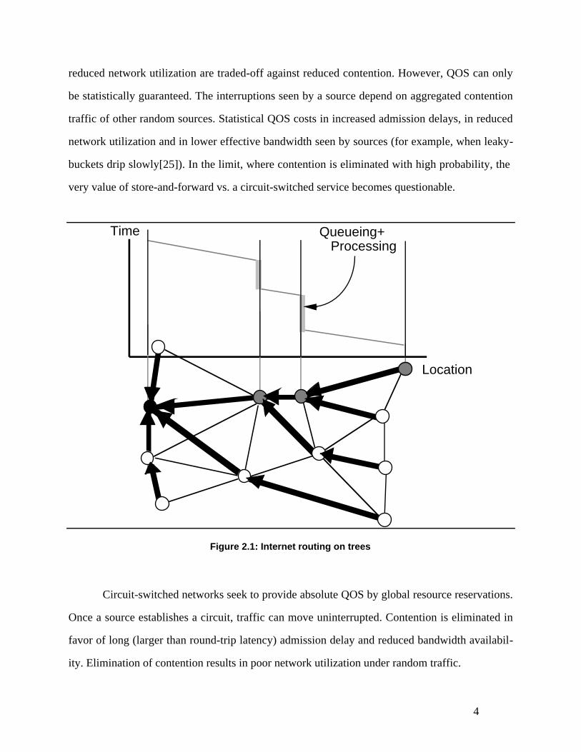
4
reduced network utilization are traded-off against reduced contention. However, QOS can only
be statistically guaranteed. The interruptions seen by a source depend on aggregated contention
traffic of other random sources. Statistical QOS costs in increased admission delays, in reduced
network utilization and in lower effective bandwidth seen by sources (for example, when leaky-
buckets drip slowly[25]). In the limit, where contention is eliminated with high probability, the
very value of store-and-forward vs. a circuit-switched service becomes questionable.
Time
Location
Queueing+ Processing
Figure 2.1: Internet routing on trees
Circuit-switched networks seek to provide absolute QOS by global resource reservations.
Once a source establishes a circuit, traffic can move uninterrupted. Contention is eliminated in
favor of long (larger than round-trip latency) admission delay and reduced bandwidth availabil-
ity. Elimination of contention results in poor network utilization under random traffic.

5
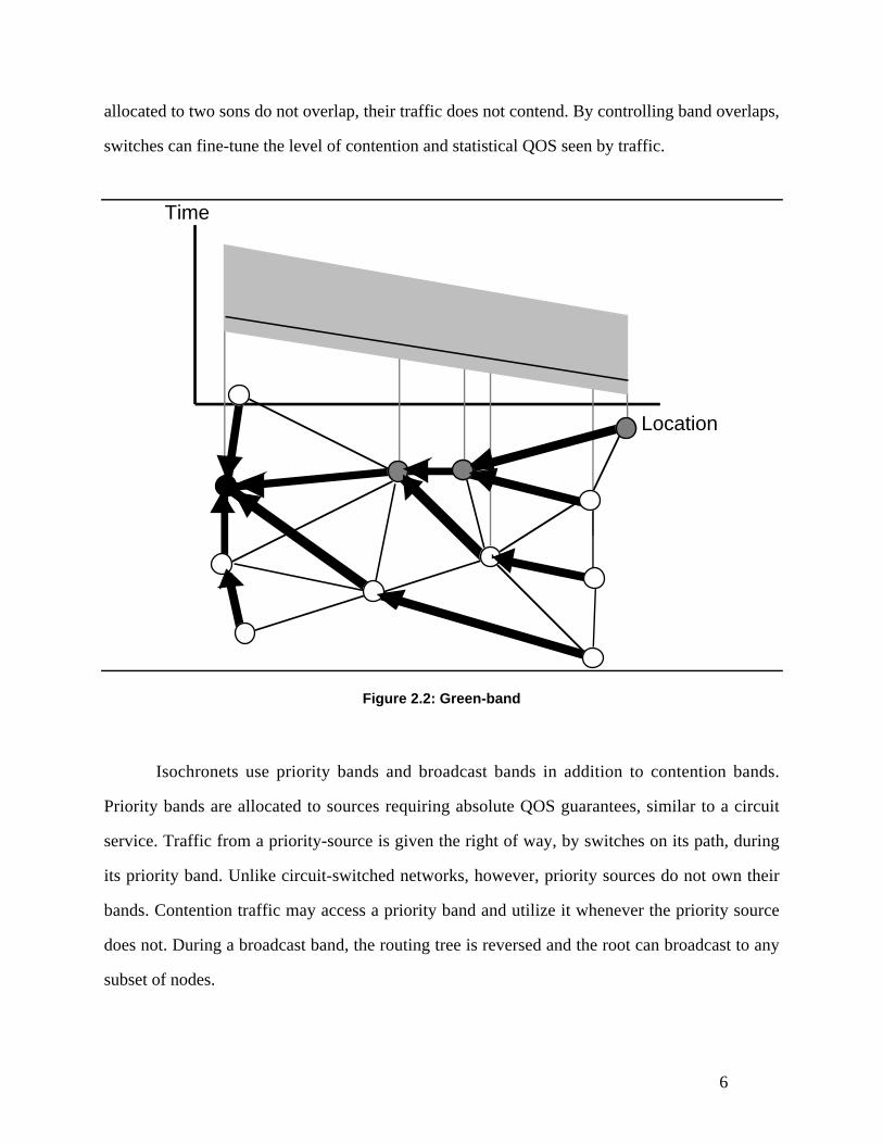
2.2Motion via Green Bands
Isochronets seek to provide flexible control of contention to accomplish desired QOS.
The basic construct used to schedule traffic motion is a time-band (green-band) assigned to a
routing tree (Figure2.2). During the green-band (shaded), a frame transmitted by a source will
propagate down the routing tree to the destination root. If no other traffic contends for the tree, it
will move uninterrupted, as depicted by the straight line.
The green-band is maintained by switching nodes through timers synchronized to reflect
latency along tree links. Synchronization is per band size, which is large compared to frame
transmission time. It can thus be accomplished through relatively simple mechanisms.
Furthermore, synchronization errors can be easily contained. Routing along a green-band is ac-
complished by configuration of switch resources to schedule frames on incoming tree links to the
respective outgoing tree link. A source sends frames by scheduling transmissions to the green
bands of its destination.
In similarity to circuit-switched or burst-switched networks, green-bands allocate re-
served network resources. However, the units to which resources are allocated are neither point-
point connections, nor traffic bursts, but routes. Routes represent long-lived entities and, thus,
processing and scheduling complexities can be resolved over time scale much longer than la-
tency.
2.3 Route Division Multiple Access (RDMA)
Frames arriving simultaneously to a switching node contend for the outgoing tree link.
The allocation of synchronized time bands to routing trees and resolution of frame collisions are
the primitive constructs used by Isochronets to control traffic motions and QOS.
Bands need not occupy the same width throughout the network. Indeed, one can view a
green band as a resource which is distributed by a node to its up-stream sons (as long as the
bands allocated to sons are scheduled within the band of the parent). In particular, if the bands
6
allocated to two sons do not overlap, their traffic does not contend. By controlling band overlaps,
switches can fine-tune the level of contention and statistical QOS seen by traffic.
Time
Location
Figure 2.2: Green-band
Isochronets use priority bands and broadcast bands in addition to contention bands.
Priority bands are allocated to sources requiring absolute QOS guarantees, similar to a circuit
service. Traffic from a priority-source is given the right of way, by switches on its path, during
its priority band. Unlike circuit-switched networks, however, priority sources do not own their
bands. Contention traffic may access a priority band and utilize it whenever the priority source
does not. During a broadcast band, the routing tree is reversed and the root can broadcast to any
subset of nodes.
7
One may view these mechanisms to schedule traffic motions via band allocations as a
media-access technique. The entire network is viewed as a routing medium consisting of routing
trees. Bandwidth is time- and space-divided among these routes. Sources need access respective
trees during their band times, seeing the network as a time-divided medium, much like Time
Division Multiple Access (TDMA)[29]. We call this technique, accordingly, Route Division
Multiple Access (RDMA).
We designate the collision resolution mode used in terms of signs “-”, “+”, and “++”. In
RDMA- one of the colliding frames is discarded. In RDMA+, when collision occurs during a
band, one is buffered and the other proceeds. RDMA++ stores frames beyond band termination,
rescheduling them during the next band.
2.4 Further Remarks
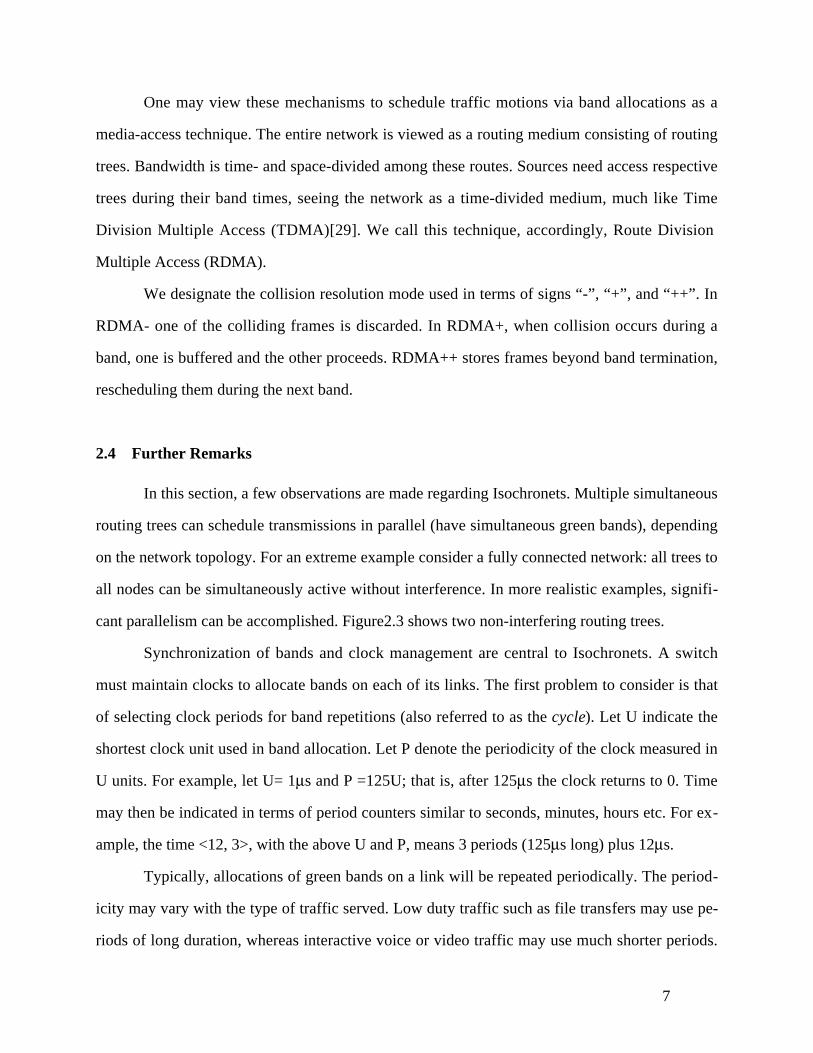
In this section, a few observations are made regarding Isochronets. Multiple simultaneous
routing trees can schedule transmissions in parallel (have simultaneous green bands), depending
on the network topology. For an extreme example consider a fully connected network: all trees to
all nodes can be simultaneously active without interference. In more realistic examples, signifi-
cant parallelism can be accomplished. Figure2.3 shows two non-interfering routing trees.
Synchronization of bands and clock management are central to Isochronets. A switch
must maintain clocks to allocate bands on each of its links. The first problem to consider is that
of selecting clock periods for band repetitions (also referred to as the cycle). Let U indicate the
shortest clock unit used in band allocation. Let P denote the periodicity of the clock measured in
U units. For example, let U= 1μs and P =125U; that is, after 125μs the clock returns to 0. Time
may then be indicated in terms of period counters similar to seconds, minutes, hours etc. For ex-
ample, the time <12, 3>, with the above U and P, means 3 periods (125μs long) plus 12μs.
Typically, allocations of green bands on a link will be repeated periodically. The period-
icity may vary with the type of traffic served. Low duty traffic such as file transfers may use pe-
riods of long duration, whereas interactive voice or video traffic may use much shorter periods.
8
Traffic may also vary in terms of typical frame sizes. Consider the choices of U and P above over
a 2.4Gb/s link. During a period of P=125μs, some 300kb can be transmitted. If the link is equally
shared among 3–6 trees, this means that each tree can be allocated an average of 50–100Kb.
Additionally, since link speeds may vary greatly, Isochronets may wish to use different periodic-
ity over links. For example, a link of 155Mb/s may use a period of 16P=2ms. Arrivals over this
link will be buffered and delivered to higher speed links. Discussion of this general case, how-
ever, is beyond the scope of this work.
Figure 2.3: Multiple non-interfering trees
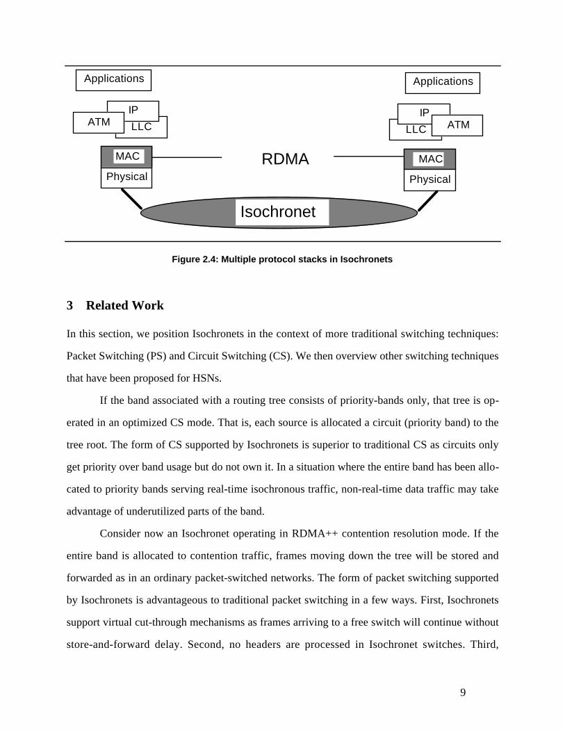
All stack layers above the media-access layer are delegated to interfaces at the network
periphery. A typical stack organization for Isochronets is depicted in Figure4.
Finally interconnection of Isochronets can be accomplished via media-layer bridges using
extensions of current well-understood technologies. Conversions need only handle physical layer
interfaces and media-access control. Above the media access layer, interconnection becomes
transparent. Contrast this with the problem of internetworking two distinct high-speed network
architectures via higher-layer gateways.
9
LLC
Isochronet
Physical
MAC
IPATM
Applications
RDMA
LLC
Physical
MAC
IPATM
Applications
Figure 2.4: Multiple protocol stacks in Isochronets
3 Related Work
In this section, we position Isochronets in the context of more traditional switching techniques:
Packet Switching (PS) and Circuit Switching (CS). We then overview other switching techniques
that have been proposed for HSNs.
If the band associated with a routing tree consists of priority-bands only, that tree is op-
erated in an optimized CS mode. That is, each source is allocated a circuit (priority band) to the
tree root. The form of CS supported by Isochronets is superior to traditional CS as circuits only
get priority over band usage but do not own it. In a situation where the entire band has been allo-
cated to priority bands serving real-time isochronous traffic, non-real-time data traffic may take
advantage of underutilized parts of the band.
Consider now an Isochronet operating in RDMA++ contention resolution mode. If the
entire band is allocated to contention traffic, frames moving down the tree will be stored and
forwarded as in an ordinary packet-switched networks. The form of packet switching supported
by Isochronets is advantageous to traditional packet switching in a few ways. First, Isochronets
support virtual cut-through mechanisms as frames arriving to a free switch will continue without
store-and-forward delay. Second, no headers are processed in Isochronet switches. Third,

10
buffered frames are aggregated into larger units and transmitted at once, improving the efficiency
of buffer retrieval. Fourth, contention happens only among frames to the same destination (and
not among uncorrelated traffic).
Isochronets, it may be argued, could potentially under-perform packet-switched networks
due to the time-division of bandwidth among routes. In situations where significant traffic bursts
are randomly generated at different routes with other routes empty, the bandwidth committed to
unused routes will be underutilized while the routes serving a burst may have insufficient band-
width to handle it. A packet switched network would have permitted the traffic burst to move
into the network and utilize its entire band without pre-allocation. Typically, however, admis-
sion-control policies will prevent large bursts from entering the network. Such mechanisms as
leaky-bucket[25] reduce the effective bandwidth available to any given source. A packet -
switched network governed by admission policies which limit source bandwidth, presents no ad-
vantage over an Isochronet which limits the bandwidth to sources through pre-allocation to
routes.
In summary, at the two extremes, Isochronets compare favorably with circuit or packet
switched networks. In-between, Isochronets can be operated to span a spectrum of switching
techniques of superior performance characteristics to both, as evidenced by the report of perfor-
mance (Section 4).
Burst Switching (BS) [3, 13] is an extension of the PS concept to switch bursts of infor-
mation. The aim of the BS project is to integrate digitized voice and data characters. Bursts are
generated from talk spurts or data messages and are embedded into a frame (burst) with a header
which identifies its destination address and a trailer (bursts have variable size). The novel aspect
of BS networks is that they disperse switching decisions into hundreds and thousands of proces-
sors connected through shorter link lengths (thus permitting higher bandwidth links). The links
use time division multiplexing (TDM). When a burst is sent, one of the TDM slots is allocated to
the burst. The approach taken in BS is opposite to the one we propose for Isochronets. Instead of
loading the network with more processing power, we suggest relieving the network from any

11
processing demands. Also, BS networks suffer from the same limitations in QOS offerings as PS
do.
We now compare Isochronets with non-traditional high-speed switching techniques in-
cluding wavelength division multiplexing (WDM)[1, 7, 10], Highball[19], and linear lightwave
networks (LLN) [26]. WDM networks, like Isochronets, provide dedicated access to destinations
via appropriate allocation of wavelength. Routing is accomplished by configuring nodes to
switch wavelength to provide source-destination connectivity. Contention among simultaneous
transmissions to the same destination must, in similarity to Isochronets, be resolved at switches.
WDM networks too may be configured to support circuit-like services and multicasting. In simi-
larity to Isochronets, WDM provide media-access layer networking. One can view Isochronets as
a time-domain allocation of bandwidth among destinations, of similarity to the frequency-do-
main allocation used by WDM networks. The two architectures are orthogonal rather than com-
peting alternatives. The main advantage of Isochronets over WDM is their independence of the
transmission medium technologies. Also, optical tuning of switches at incoming traffic rates is
beyond the current state of the art. To cope with this limitation, current implementations of
WDM use dedicated wavelengths between node pairs. Packets may only be sent directly to a
node's peer. At the peer, packets need to be processed in order to determine the destination route.
Isochronets do not require such processing and switch routing configurations over sufficiently
long time periods to permit use of optical switches and, thus, all-optical networks.
The Highball network proposal[19] bears some similarity to Isochronets. Nodes schedule
traffic bursts by configuring the switches to support uninterrupted motion similar to train motions
through intersections. Nodes broadcast requests to all other nodes, specifying their data transmis-
sion needs to all possible destinations. This information is then used to compute a train schedule
at each node and establish time intervals during which output links are dedicated to specific input
links. The scheduling problems are NP-complete and are thus solved through heuristics.
Additionally, the schedules computed by different nodes must be consistent and nodes must
maintain fine synchronization on time scales much shorter than used by Isochronets. Highball

12
networks are geared to serve traffic that can tolerate the latency delays between requests to
transmit and their granting. Regulating traffic motions through switch configurations is similar to
the approach taken by Isochronets. However, this is where the similarity ends. Trying to switch
configurations to match the structure of bursty demands is in contrast with the Isochronet solu-
tion of switching routes, independent of immediate demand patterns. The complexity of burst
scheduling, the need for fine synchronization, and other derivatives of the approach do not arise
in Isochronets. Isochronets do not require non-conflicting global schedules. Instead, they settle
for contention resolution by local switches and myopic scheduling by sources. Nor are
Isochronets restricted to serve the kind of traffic targeted by Highball networks.
LLN communicate using wavebands. When two nodes want to communicate, the same
waveband can be assigned to both only if their paths are disjoint. When combined, different
wavebands cannot be separated at switches. Thus, the assignment of different wavebands for
connections becomes even more complicated than in WDM, since it is necessary to make sure
that all combined wavelength in a given link do not interfere with the new wavelength that is
being assigned. The scheduling of wavebands to incoming calls is NP-complete and thus heuris-
tics are used to solve the problem. This technique also divides bandwidth in the waveband do-
main, in similarity to WDM. Nevertheless, no processing or buffering is necessary at intermedi-
ate switches in similarity to Isochronets. It is designed to serve applications that can tolerate the
long call set up delay to find a proper wavelength for the call. No such delays are incurred in
Isochronets. Also, since the perfect schedule is not attainable, the bandwidth may be underuti-
lized.
Finally, we would like to relate Isochronets to ATM networks [6, 27]. ATM networks
combine the packet switching and the virtual-circuit switching concepts[29]. ATM nodes switch
cells of information which are identified by the virtual circuit they pertain to. Before sending
ATM cells, a virtual circuit must be established. These networks inherit all the delays associated
with circuit establishment and then need to incur further delays when switching ATM cells to
map the virtual circuit identifiers to the correct switch input or output ports. These are the very
13
inefficiencies that Isochronets avoid. We further expand on the limitations of ATM networks in
Section 6.5.
4 Performance Evaluation
The time-dependent behavior of Isochronets complicates the performance study. Usual perfor-
mance analysis techniques (Markov chains, Queueing Theory, Renewal Theory, etc.) ignore
time-dependent (or transient) behaviors when simplifying models in search for tractable solu-
tions. Besides, servers are usually work-conservative, that is, servers do not sit idle when there is
work to be done. A useful model for Isochronets must undermine both assumptions. Consider a
model for RDMA++ from the point of view of a destination site. Such system can be approxi-
mated as an M/D/1 system that serves costumers when the tree to the destination node is active,
and sits idle (goes on vacation) otherwise. The transition from active server to vacationing server
and vice-versa are time-dependent (they occur when the associated band becomes active and
when it terminates, respectively). Also, the server is not work-conservative. As we will see, these
characteristics render analysis of Isochronets extremely complex and, in many cases, beyond the
current domain of formal techniques.
The natural rescue when analysis fails is simulation. Even though completely realizable,
simulation studies must be carefully implemented to avoid extremely long executions. The rela-
tive long bands may delay steady behaviors. Also, the fact that Isochronets target networks in
which transmission speeds are negligible when compared with propagation delays may render
the system state prohibitively large. For example, at 2.4Gb/s, a 30ms propagation delay link may
store 72 million ATM cells. Each ATM cell needs state information such as time when it was
sent, time when it arrived at each node, etc. Even with a few links and a few bytes to represent
the state of each cell, the simulation becomes unfeasible. Since all these states must also be exe-
cuted, more constraints are added to the simulation execution time.
14
We now study the performance of Isochronets using both analytical tools and simula-
tions. The main objective is to locate RDMA in the spectrum of performance provided by the
two most common switching techniques: Packet Switching (PS) and Circuit Switching (CS).
4.1Analysis
In this section we consider a performance model of RDMA. Consider RDMA serving ATM cell
traffic generated from Poisson sources. Sources sending traffic to a given destination compete for
the use of a shared band subject to RDMA contention resolution. For simplicity, assume that the
same band is provided to all sources (in the more general case, the band can be divided to a few
sub-bands where arrival rates will vary, depending on source access provided).
In the study of RDMA- and RDMA+, we consider Poisson arrivals within a band, since
there is no buffering beyond the band limits within the network. For RDMA-, one can consider
the band as a shared service mechanism. Cell arrivals to the band represent a renewal process.
During transmission of cell, arrivals of other cells will be discarded by the RDMA- mechanism at
switching nodes. One can use, therefore, Type-I Counter models[16] to represent RDMA-. In
other words, a cell arrival may be considered as a counter mechanism which is blocked by a suc-
cessful cell transmission. The process of interest is the arrivals of cells whose transmissions are
successful. This process is, again, renewal process whose interarrivals are defined as the sum of
two independent random variables representing cell interarrivals and cell transmission times.
With time measured in cell-transmission duration units, a traffic arrival rate to a given band of λ
(cells per cell transmission period), the distribution of successful interarrivals is given, therefore,
by the convolution of the interarrival and cell duration distributions:
FRDMA− (t) = Pr[Interarrival of successful cell ≤ t] = 1 − e−λ (t −1) .
One can compute the average rate of successful cell transmissions (from the expectation of
FRDMA− (t)) to be SRDMA− = λλ + 1
. Thus, the expected cell loss rate is given by
LRDMA− = λ − λλ + 1
. The percentage loss amounts to:

15
LPRDMA− = 1 − 1λ + 1
.
When the load is low, the loss rate is almost 0. It approaches 50% when the load reaches satura-
tion (λ = 1), giving a very impressive result for a system without buffering. The cell delay will
be just the transmission and propagation delay, since no queueing is incurred in this system.
Thus,
WRDMA− = 1.
WRDMA− measures the average queueing delay seen by a cell between arrival and departure from a
switch. In addition to this queueing delay, a cell sees a latency delay through the network. So the
average delay seen by a cell is given by:
TRDMA− = 1 + L ,
where L represents the average latency1.
In the case of RDMA+, cells are lost only when they are queued beyond band termina-
tion. We want to compute the number of queued elements at the end of a slot. If we consider the
band to be large enough, the problem reduces to finding the average queue size in a M/D/1
queueing system, which is simply[17] q = λ1 − λ
− λ2
2(1 − λ ). The loss rate is just the mean queue
size found at the end of a band divided by the number of packets sent during a band ( λB, where
B is the band size). Thus,
LPRDMA+ = 2 − λ2B(1 − λ )
.
We expect the mean cell delay in this system to be the same as the one for M/D/1 system in
equilibrium, if the band is large enough. Then, we may write:
WRDMA+ = λ2(1 − λ )
.
1 The same observation is valid for all queueing delays in this section, and T may be obtained from W by adding
L in all cases.

16
Let us analyze operations under RDMA++ discipline. The band may be viewed as a ser-
vice mechanism with periodic vacations. This can be modeled as an M/D/1 queue with periodic
vacations. The solution of such models is generally very difficult (see, for example, [23] for a
discussion on the subject). For the mean queueing delay, we approximate the solution by the
same method to compute the mean queueing time for M/G/1 systems with vacations[5]. In
RDMA++ the vacation periods are generated only due to the ending of a band. With the vacation
period between bands of duration V (cells), the queueing delay of a contention band using
RDMA++ may be approximated by:
WRDMA++ = λ2(1 − λ )
+ V
2⋅ V
V + B⋅ 11 − λ
.
The calculation of this formula is as follows. We compute the mean residual service time for the
busy and vacationing periods. For the busy period, the calculation is the same and gives the
queueing delay for an M/D/1 type of system[5]. For the idle period, the mean residual service
time is the mean vacation period (V
2) times the probability of being on vacation (
V
V + B). We
then divide the mean residual service time by the idle period (1 − λ ), to obtain the mean waiting
time [5]. This last term can also be interpreted as the penalty in the delay incurred by the burst of
cells generated during the vacations, present when the band begins.
If the band is divided (in part or in whole) among priority bands devoted to certain
sources, the average delay will not change as long as the network resolves contention in a work-
conserving manner (for example, pre-emptive resume or non-pre-emptive priority mechanisms).
This is where the shared circuit switching (SCS) greatly improves on classical time-division cir-
cuit switching (CS). Indeed, suppose traffic to the band is divided among n sources using tradi-
tional circuit switching. Suppose, further, that traffic is uniformly generated by each source at a
rate of λn
. The utilization of a given circuit remains ρ = λn
⋅ n = λ . However, the vacation time
increases and circuit bandwidth available decreases to result in:
WCS = nλ2(1 − λ )
+ V + B(n − 1) n
2⋅ V + B(n − 1) n
V + B⋅ 11 − λ
.
17
In other words, the queueing delay increases by a factor of n with additional delay in waiting for
the circuit band. Therefore, the SCS allocation of priority bands by Isochronets greatly outper-
forms traditional circuit switching, while providing sources so desiring the same performance
guarantees as circuit switching does.
4.2Simulation Studies
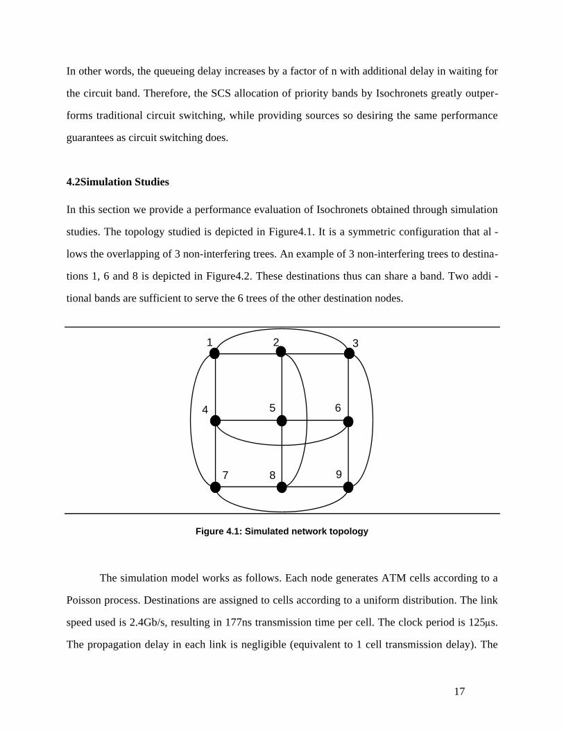
In this section we provide a performance evaluation of Isochronets obtained through simulation
studies. The topology studied is depicted in Figure4.1. It is a symmetric configuration that al -
lows the overlapping of 3 non-interfering trees. An example of 3 non-interfering trees to destina-
tions 1, 6 and 8 is depicted in Figure4.2. These destinations thus can share a band. Two addi -
tional bands are sufficient to serve the 6 trees of the other destination nodes.
1 2 3
4 5 6
7 8 9
Figure 4.1: Simulated network topology
The simulation model works as follows. Each node generates ATM cells according to a
Poisson process. Destinations are assigned to cells according to a uniform distribution. The link
speed used is 2.4Gb/s, resulting in 177ns transmission time per cell. The clock period is 125μs.
The propagation delay in each link is negligible (equivalent to 1 cell transmission delay). The

18
bands to all destinations are of the same size, since the traffic is uniformly distributed. Each cell
waits for the proper destination band at the source nodes and then moves through the network
down the respective tree. Our goal is to give a broad comparison of PS, CS, and RDMA++.
1 2 3
4 5
6
7
8
9
Spanning tree for destination 1
Spanning tree for destination 8
Spanning tree for destination 6
Figure 4.2: Allocation of trees in one band
The PS simulation uses the same trees allocated for RDMA++ (see Figure4.2) and cut-
through. Processing delays at nodes are included. The CPU at each switch was assumed to oper-
ate at the same rate of one input link. This means, for example, that if 50 instructions are neces-
sary to process each ATM cell, we are simulating a 283 MIPS machine for PS, an unrealistic as-
sumption. The CS simulation queues cells for that circuit until the circuit becomes available.
The simulation was run for periods where 10,000 ATM cells per input node were gener-
ated. After each of these periods, all statistics were saved and reset. Two RDMA++ experiments
were conducted. In the first, all traffic had the same priority (RMDA++<c>). In the second, pri-

19
ority traffic was generated as follows. Each band was equally partitioned to priority sub-bands,
one for each input node (RDMA++<p>).
Figure4.3 depicts the mean packet delay (in μs) for the experiments we have conducted.
The input traffic load is given as a percentage of the 2.4Gb/s maximum input rate at each node.
As it can be seen, PS has a steady performance until the input load 50% saturates the CPU ca-
pability at the nodes with network delays growing unbounded. CS has a similar behavior, the un-
stable point being 30%. RDMA++ has a stable performance. Both RDMA++<c> and
RDMA++<p> have the same mean packet delay characteristics, as expected from queueing anal-
ysis [17], and thus overlap in the figure. The “Pr.” curve plots the mean delay for priority traffic
generated for the RDMA++<p> experiment. Priority was assigned randomly to ATM cells ac-
cording to an uniform distribution. Priority traffic was scheduled to access the network during its
priority band, thus not incurring admission delays. The delay incurred by the priority traffic is
thus only the propagation delay and contention with other cells scheduled at the beginning of the
priority band.
0
100
200
300
400
500
600
700
800
0.1 0.2 0.3 0.4 0.5 0.6 0.7 0.8 0.9 1
Mea
n P
acke
t Del
ay
Input Traffic Load
RDMA++<c>RDMA++<p>
Pr.PSCS
Figure 4.3: Mean network ATM cell delay for Poisson arrivals (in μs)
20
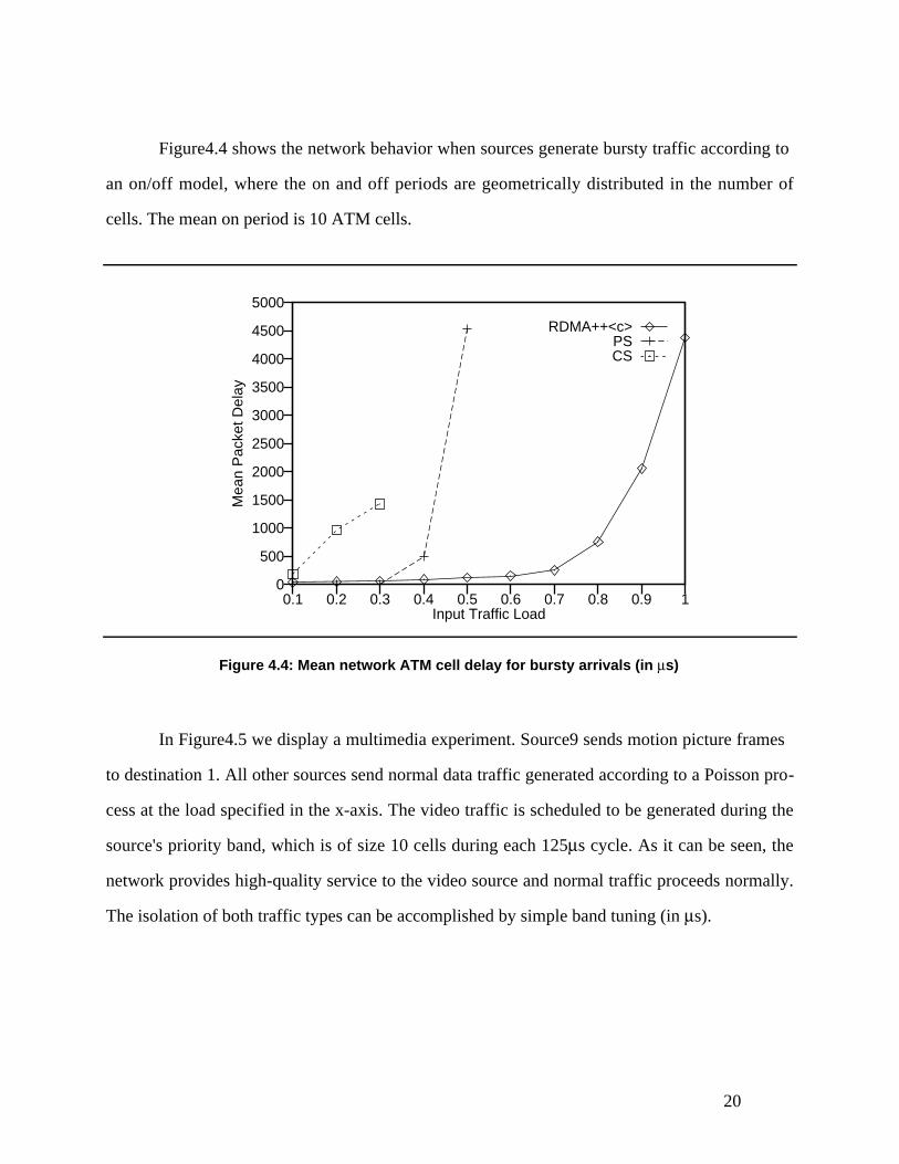
Figure4.4 shows the network behavior when sources generate bursty traffic according to
an on/off model, where the on and off periods are geometrically distributed in the number of
cells. The mean on period is 10 ATM cells.
0
500
1000
1500
2000
2500
3000
3500
4000
4500
5000
0.1 0.2 0.3 0.4 0.5 0.6 0.7 0.8 0.9 1
Mea
n P
acke
t Del
ay
Input Traffic Load
RDMA++<c>PSCS
Figure 4.4: Mean network ATM cell delay for bursty arrivals (in μs)
In Figure4.5 we display a multimedia experiment. Source9 sends motion picture frames
to destination 1. All other sources send normal data traffic generated according to a Poisson pro-
cess at the load specified in the x-axis. The video traffic is scheduled to be generated during the
source's priority band, which is of size 10 cells during each 125μs cycle. As it can be seen, the
network provides high-quality service to the video source and normal traffic proceeds normally.
The isolation of both traffic types can be accomplished by simple band tuning (in μs).

21
0
5
10
15
20
25
30
35
40
45
0.1 0.2 0.3 0.4 0.5 0.6 0.7 0.8 0.9 1
Mea
n P
acke
t Del
ay
Input Traffic Load
Data SourcesVideo Source
Figure 4.5: Mean network ATM cell delay when operating with video source
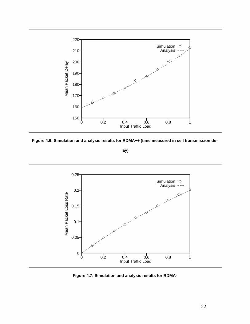
In Figure4.6, we show the comparison 2 of analysis and simulation results for the
RDMA++ mean packet delay. As it can be seen, the results are in good agreement. Figure4.7
compares3 the simulation and analysis results for the RDMA- mean packet loss rate.
2 The final destinations in the simulation did not incur transfer delay. Thus, the maximum service rate in the
simulation is 4 times the maximum input rate, since there are 4 incoming links at the destination node (see Figure
4.2). The input load in Figure 4.6 is a percentage of the 2.4Gb/s maximum input rate and, thus, λ in the formula for
WRDMA++ should vary from 0% to 25%.
3 Each tree is active only 1/3 of the cycle. Thus λ in the formula for LPRDMA− should be scaled between 0 and 1/3
(thus the loss rate never reaches the 50% loss upper bound).
22
150
160
170
180
190
200
210
220
0 0.2 0.4 0.6 0.8 1
Mea
n P
acke
t Del
ay
Input Traffic Load
SimulationAnalysis
Figure 4.6: Simulation and analysis results for RDMA++ (time measured in cell transmission de-
lay)
0
0.05
0.1
0.15
0.2
0.25
0 0.2 0.4 0.6 0.8 1
Mea
n P
acke
t Los
s R
ate
Input Traffic Load
SimulationAnalysis
Figure 4.7: Simulation and analysis results for RDMA-
23
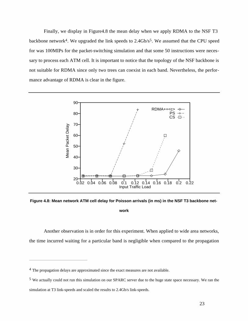
Finally, we display in Figure4.8 the mean delay when we apply RDMA to the NSF T3
backbone network4. We upgraded the link speeds to 2.4Gb/s5. We assumed that the CPU speed
for was 100MIPs for the packet-switching simulation and that some 50 instructions were neces-
sary to process each ATM cell. It is important to notice that the topology of the NSF backbone is
not suitable for RDMA since only two trees can coexist in each band. Nevertheless, the perfor-
mance advantage of RDMA is clear in the figure.
20
30
40
50
60
70
80
90
0.02 0.04 0.06 0.08 0.1 0.12 0.14 0.16 0.18 0.2 0.22
Mea
n P
acke
t Del
ay
Input Traffic Load
RDMA++<c>PSCS
Figure 4.8: Mean network ATM cell delay for Poisson arrivals (in ms) in the NSF T3 backbone net-
work
Another observation is in order for this experiment. When applied to wide area networks,
the time incurred waiting for a particular band is negligible when compared to the propagation
4 The propagation delays are approximated since the exact measures are not available.
5 We actually could not run this simulation on our SPARC server due to the huge state space necessary. We ran the
simulation at T3 link-speeds and scaled the results to 2.4Gb/s link-speeds.
24
delays. For instance, the waiting time for the band in our NSF backbone simulation is at most
125μs (a complete cycle), but the cross-country propagation delay is of the order of 30ms (240
times larger). Thus, the immediate admission seen by frames in a packet switched implementa-
tion is a negligible component of the total frame delay.
5 Architecture
The novel aspect of the Isochronets architecture is simplicity. Most architectures for HSNs are
characterized by overly complex implementations. Control functions in Isochronets are com-
pletely detached from transmission, thus making simple implementations possible. All network-
layer functions and controls are accomplished through a simple unifying mechanism: band allo-
cation. This means that by controlling band timers all network functions—routing, switching,
flow and admission controls—are obtained. Isochronets may be implemented using simple off-
the-shelf components and techniques commonly used to build microcomputers. Finally, due to
the de-coupling of control from transmission, all-optical Isochronets are also possible.
In this section, we describe two possible designs of Isochronets: an electronic implemen-
tation and an all-optical implementation. We describe both implementations in details, but this
work will only pursue the implementation of the electronic version. For this reason, the protocols
and measurements that will be developed are designed for the electronic Isochronets.
5.1 Electronic Organization
We begin by describing the electronic RDMA+ Isochronet switch implementation. The switch
architecture is depicted in Figure5.1. Input fiber lines feed the input line cards which convert se -
rial optical signals into parallel electronic signals and store them in internal FIFO buffers while
contention for the switching fabric is being resolved. There is no protocol processing at the inter-
faces, thus simplifying their implementation. Fiber rates are on the order of Gb/s.

25
Switching
Fabric
Control Unit
Input Line Cards Output Line Cards
Processor Memory
Ethernet Line Card
System Bus
Input Fiber Output FiberParallelLines
ParallelLines
Switching & Control Unit
Figure 5.1: Overall electronic design
The converted parallel electronic bits plus control information from the input line cards
are input to the switching and control unit whose main function is to enable the required in-
put/output connection plus resolve contention. The unit is subdivided into a control unit and a
switching fabric.
The switching fabric outputs are connected to the output line cards where they will be
converted into sequential optical signals for transmission. The output cards may also need to de-
lay the signals before transmission, as it will be explained later.
The switch and control unit is connected to the system bus of a microcomputer. The CPU
in the microcomputer interact with the switching and control unit to update configuration infor-

26
mation stored in the control unit registers. The CPU also retrieves status information to be used
in the protocols it runs. The CPU in each switch exchange control information using the Ethernet
line card connected to their bus. We decided to implement this separate Ethernet channel for the
exchange of control information to simplify the implementation and to achieve more flexibility
in the prototype.
The switch control and management software runs in the CPU. The primary function of
such software is to compute the allocation and switching of bands. During its priority band, an
incoming trunk will gain pre-emptive access to the switching fabric. A pre-empted frame is re-
transmitted by the source trunk card when the priority transmission completes. Configuration and
switching of bands, execution of protocols for band synchronization and allocation, and other
control and management functions processed by the CPU are relatively slow and can be entirely
accomplished by software.
Isochronet switches thus separate high-speed transmission path and access arbitration
functions, handled by trunk interfaces and switching fabric, from network control and manage-
ment functions, handled by slower-speed logic. This separation allows Isochronets to scale fa-
vorably for a broad spectrum of trunk speeds without requiring changes of the network control
mechanisms.
In the next sections, we describe each of these components in greater detail.
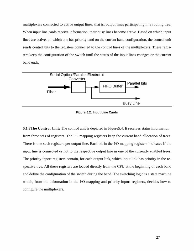
5.1.1Input Line Cards: The input line card is depicted in Figure 5.2. The optical signals in the
input fiber are converted to electronic parallel bits which feed a FIFO buffer. The busy control
line indicates to the control unit when new information has arrived and the control unit decides
which of the input line cards will be granted access to the respective output line card.
5.1.2Switching Fabric: The switching fabric is implemented using multiplexing modules as de-
picted in Figure 5.3. Each multiplexing module is a set of multiplexers controlled by a register
which is loaded from the control unit. When a new band begins, the control unit enables the
27
multiplexers connected to active output lines, that is, output lines participating in a routing tree.
When input line cards receive information, their busy lines become active. Based on which input
lines are active, on which one has priority, and on the current band configuration, the control unit
sends control bits to the registers connected to the control lines of the multiplexers. These regis-
ters keep the configuration of the switch until the status of the input lines changes or the current
band ends.
FIFO Buffer
Serial Optical/Parallel ElectronicConverter
Fiber
Busy Line
Parallel bits
Figure 5.2: Input Line Cards
5.1.3The Control Unit: The control unit is depicted in Figure5.4. It receives status information
from three sets of registers. The I/O mapping registers keep the current band allocation of trees.
There is one such registers per output line. Each bit in the I/O mapping registers indicates if the
input line is connected or not to the respective output line in one of the currently enabled trees.
The priority inport registers contain, for each output link, which input link has priority in the re-
spective tree. All these registers are loaded directly from the CPU at the beginning of each band
and define the configuration of the switch during the band. The switching logic is a state machine
which, from the information in the I/O mapping and priority inport registers, decides how to
configure the multiplexers.

28
From Input Line CardsControl
To Output Line
Cards
MultiplexingModules
Figure 5.3: Switching fabric
Switching Logic
From InputLine Cards
To MultiplexModules
From CPU From CPU
I/O mapping Priority Inport
Clock
Arrival
Departure
Figure 5.4: Control Unit
29
The third set of registers are the arrival and departure registers which are used to set the
delay elements in the output line cards. When a new band begins, the CPU resets all the input
line cards (since this implementation operates in RDMA+ mode). When the first bits in each line
arrive, the switching logic downloads the current time in the respective arrival register.
Equivalently, when the first bits are sent through an output line, the current time is downloaded
in the respective departure register. By exchanging arrival and departure register information
through the Ethernet control channel, the switches can tell what is the propagation delay in each
line and thus set the delay elements properly. The protocols that set and use the delay elements
are discussed in Section6.
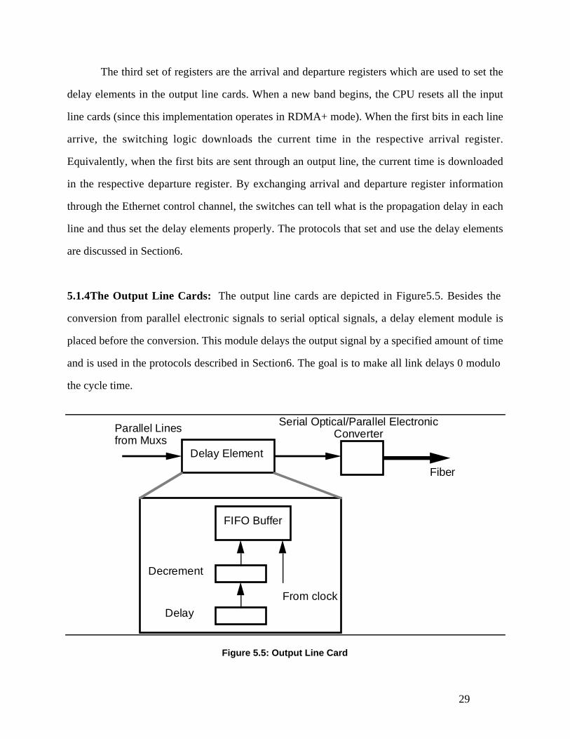
5.1.4The Output Line Cards: The output line cards are depicted in Figure5.5. Besides the
conversion from parallel electronic signals to serial optical signals, a delay element module is
placed before the conversion. This module delays the output signal by a specified amount of time
and is used in the protocols described in Section6. The goal is to make all link delays 0 modulo
the cycle time.
Serial Optical/Parallel ElectronicConverter
Fiber
Delay Element
Parallel Linesfrom Muxs
FIFO Buffer
From clock
Decrement
Delay
Figure 5.5: Output Line Card

30
The delay register is loaded from the CPU in the microcomputer. Every time a frame is to
be transferred to the output line, the control unit downloads the contents of the delay register into
the decrement register, which, when reaches 0, enables the FIFO queue outputs. While such out-
puts are not enabled, the FIFO blocks all inputs, thus achieving the necessary delay.
5.1.5Other Approaches: In this section, we discuss other alternatives to the design presented.
Specifically, we describe candidates for the interconnection and for the control channel.
The interconnection network presented is simple, but scalability may be an issue. If the
number of input and output lines needs to be increased, it is necessary to increase the size of the
registers and to incorporate more multiplexing modules. One solution is to interconnect many
switches together in a hub-like fashion. Each switching board would be connected to another
switching board through one of its input or output ports using a backbone hub bus.
Another choice for the interconnection network would have avoided such problem: use a
time-divided bus. If n trees can simultaneously cross the switch, the bandwidth supported by the
switching fabric is at least n times larger than the respective trunk bandwidth. Such design is eas-
ier to scale, since all that is necessary to increase the bandwidth in the bus is to provide new
buses in parallel. Nevertheless, the design is more complex than the interconnection network pre-
sented. Timers must be used to time-divide the bus. The timers must coordinate the use of the
bus among all the trees in the same band. Also, appropriate output links must be enabled at each
bus slot. All these control functions must be handled at speeds dependent on the bus time slot du-
ration and the maximum number of trees in a band.
As explained, the control functions are handled by a completely separated channel. This
design is possible because Isochronets separate control functions from transmission. Thus, it is
completely legitimate to see the high-speed transmission links as a precious resource which must
be controlled by low-speed separated control channels. The design increases reliability, since the
channels are physically separated, and is more robust to synchronization errors.
31
The transfer of control information could have been incorporated in two alternative ways:
allocating special control bands or allocating a special channel within the existing high-speed
links. Special control bands are less reliable when synchronization errors happen. Nodes in the
network need to understand when the current band is a control one. If some nodes are not syn-
chronized with the others, it may be difficult to re-synchronize them since synchronization con-
trols are exchanged through the very control bands. Special signals may be sent at the beginning
of bands or clock cycles, but this would complicate the design of the switches and potentially
slow them down (since they would need to be prepared to recognize such signals). Finally, since
control signals are directed to the switch rather than to the host connected to it as it is the case for
information frames, the switch must be designed to transfer such signals to the CPU in the mi-
crocomputer. The design of such interface between the microcomputer and the switching fabric
is a further complication.
The allocation of a special channel within the existing network is possible. Such alloca-
tion could be done through the use of a separate low-speed link parallel to the high-speed link. Or
else, a special low-bandwidth frequency could be allocated within the high-speed link with the
necessary frequency division hardware at the switches. Nevertheless, hardware must be provided
at the switches to send control information to the switch microcomputer and all information
frames to the host machine. Such hardware would basically consist of an interface unit between
the switching fabric and the microcomputer bus. One possibility is to use a memory module
which could be used to store the control information and later could be read by the CPU.
We choose to use a completely separate channel directly connected to the buses in the
microcomputers for simplicity of design, since this kind of technology (e.g., Ethernet cards or
RS-232 interfaces) is readily available off-the-shelf. Also, we believe that the prototype is more
flexible for studying new control protocols, because the hardware enables direct interconnection
of the CPUs in the microcomputers without any connection to the switching fabric.

32
5.2Optical Organization
An all-optical realization of Isochronets must avoid buffering at intermediate switches. We use
wavelength division multiplexing (WDM) and allocate one wavelength for each band, imple-
menting RDMA-. The architecture for a single tree per band is depicted in Figure5.6. Each
wavelength is depicted using a different gray scale. Incoming wavelengths are first fed into a se-
lection box (explained later) and then multiplexed through a single optical broadcast link (the
interconnection fabric) connecting all source and destination links. At each output link, a slowly-
tunable receiver picks the wavelength of the trees sharing the link. The receiver is directly con-
nected to a slowly-tunable transmitter that regenerates the wavelength in its output link.
Transmitter
Receiver
Transmitter
Receiver
Tree 1 Tree 2
Output links
Input links
Figure5.6: All-optical switch implementation: one tree per band
Contention in the all-optical implementation is resolved by discarding one of the frames.
When a frame is sent together with a previous frame sharing the same wavelength, the second is
rejected. This functionality is achieved through the selection box, the only electronic component
in this architecture. Its function is to detect incoming signals from the links and immediately
grant access to one of them, shutting the others.

33
Priority bands are implemented by further dividing wavelengths within a particular tree.
These bands are exclusive to the source/destination port and are not utilized when the source is
idle. Use of idle priority bands is difficult to achieve unless some sort of arbitration mechanism is
provided at the contention point (the tunable receiver, in this case). Unfortunately, arbitration
translates to optic/electronic conversions which we must avoid in this implementation.
Multiple trees per band are implemented by extending the architecture in Figure5.6 into
multiple broadcast links. Each input link is connected to all the broadcast links, but optical filters
are placed between each input link and each broadcast link to select the wavelengths of the input
link that may proceed through each broadcast link. The filters are set so that after the filtering
phase no two input links broadcast the same wavelength through the same fabric at the same
time. Receivers are placed in each broadcast link (one per broadcast link) at each output link.
Only one tree for each wavelength is mapped in each broadcast link. Receivers listen to the
wavelength of the tree they represent. All the detected wavelengths are multiplexed into the out-
put link and regenerated by the transmitter.
The implementation has many advantages when compared with traditional WDM. First, a
small number of wavelengths (at most n, where n is the number of switches in the network) are
needed. Second, no allocation of wavelength is necessary prior to communication. Most recent
schemes (see [15] for a survey of such schemes) need to provide a special control channel for the
reservation of wavelength prior to communication. These schemes suffer the drawbacks of reser-
vation schemes, such as round-trip allocation delay, necessity for rapidly-tunable re-
ceivers/transmitters, and dedicated bandwidth. Third, the implementation described is cheaper
since it only needs to tune when allocating priority bands, or adjusting the band sizes, which oc-
curs at much slower rates than the speed of incoming frames.
It is important to notice that even though the all-optical implementation uses RDMA-, all
bands are opened all the time, avoiding synchronization of bands.
Nevertheless, frame loss may occur in this scheme during contention bands. The frame-
loss probability is computed in Section4.1 for the case of non-slotted links. We suggest that an

34
all-optical implementation uses slots in each link to decrease the probability of frame loss. We
now analyze the frame-loss probability for the slotted implementation when arrivals are Poisson
and suggest an extension of the basic implementation to reduce the frame-loss probability.
Let λn
be the input rate (as a percentage of the peak rate 1) of each input link to a particu-
lar switch, and n be the number of input links to the switch. The probability of no transmission
from a source link during a slot is 1 − λn
. Thus, the average successful transmission rate during a
slot is 1 − 1 − λn
⎛⎝
⎞⎠
n
(that is, if at least one source transmits). As n → ∞ , the rate becomes 1 − e−λ .
The expected success probability is 1 − e−λ( )
λ. Finally, the expected loss probability is
1 −1 − e−λ( )
λ. When λ → 1 (loaded system), the expected loss is e−1 (less than 37%).
It is possible to improve the performance of this scheme. Multiple copies of the same
frame may be sent, thus decreasing the loss probability for the frame. If each frame is repeated
m times, the loss probability becomes e−m. Thus, m may be computed from the maximum loss
rate r that can be tolerated in the system: r ≤ e−m so that m ≥ − ln r . For example, m = 4 insures
less than 2% loss rate when the system is heavily loaded and the number of input sources is big.
To complete the design using the analysis above, a filter is placed at the traffic sources
(before the traffic enters the network), which disturbs the input traffic frames interarrival times to
the network and makes them exponentially distributed (thus generating a Poisson arrival process
to the network). Each source sends m copies of the same frame, where m is computed from the
tolerated loss rate.
6 Isochronets Protocols
Usually, network architectures define suites of control mechanisms and protocols necessary for
their operations. Isochronets are new in that a single unifying mechanism can be used to ac-
complish all network layer functions: band allocation. Furthermore, the same mechanism may be
used to provide a range of services and guarantees—reserved circuits, contention-based band-
35
width, multicast. Key to Isochronets are three problems: tree allocation, band allocation, and
band synchronization.
In this section, we define a formal model of Isochronets. Using the model, we define the
three problems that any Isochronets implementation needs to address. Then, we state a solution
for each problem.
6.1 The Model
We view the network as a directed graph [4] G = VG , EG , where VG is the set of nodes and EG
is the set of edges. The following property must hold in G : ∀u,v ∈VG ⋅ (u,v) ∈EG ⇒ (v,u) ∈EG .
That is, only edges in both directions connect pairs of nodes. Each edge e has positive real-val-
ued capacity c(e) and propagation delay d(e).
A spanning tree T = VT , ET is a connected subgraph of G where VT = VG , ET ⊆ EG ,
and T does not contain a cycle. Of interest are spanning trees that have a distinguished node r
which can be reached from all other nodes. Such tree is a routing tree and the node r is the root
of the tree. We sometimes label the contention tree with root r as Tr .
Associated with each node we define a clock. The clock ranges from 0 to a maximum cy-
cle time C . A band for a set of disjoint trees Γ on node n is an interval bn (Γ),en (Γ)[ ], where
0 ≤ bn (Γ) ≤ en (Γ) ≤ C .
In the sequel, we now formally define operational issues related to Isochronets.
6.2Tree Allocation
It is necessary to allocate trees so that interference among the trees is minimized. The general
tree allocation problem in Isochronets can be stated as follows.
36
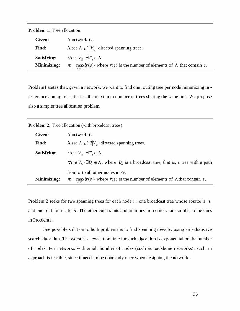
Problem 1: Tree allocation.
Given: A network G .
Find: A set Λ of VG directed spanning trees.
Satisfying: ∀n ∈VG ⋅ ∃Tn ∈Λ .
Minimizing: m = maxe∈EG
{r(e)} where r(e) is the number of elements of Λ that contain e .
Problem1 states that, given a network, we want to find one routing tree per node minimizing in -
terference among trees, that is, the maximum number of trees sharing the same link. We propose
also a simpler tree allocation problem.
Problem 2: Tree allocation (with broadcast trees).
Given: A network G .
Find: A set Λ of 2 VG directed spanning trees.
Satisfying: ∀n ∈VG ⋅ ∃Tn ∈Λ .
∀n ∈VG ⋅ ∃Bn ∈Λ , where Bn is a broadcast tree, that is, a tree with a path
from n to all other nodes in G .
Minimizing: m = maxe∈EG
{r(e)} where r(e) is the number of elements of Λ that contain e .
Problem 2 seeks for two spanning trees for each node n : one broadcast tree whose source is n ,
and one routing tree to n . The other constraints and minimization criteria are similar to the ones
in Problem1.
One possible solution to both problems is to find spanning trees by using an exhaustive
search algorithm. The worst case execution time for such algorithm is exponential on the number
of nodes. For networks with small number of nodes (such as backbone networks), such an
approach is feasible, since it needs to be done only once when designing the network.

37
6.3Synchronization
There are two kinds of synchronization necessary for Isochronets operations: clock synchroniza-
tion and band synchronization. To solve the clock synchronization problem, any of the traditional
protocols such as the Network Time Protocol [20] may be used. We approach in this section the
band synchronization mechanisms.
Synchronization must ascertain that the bands on incoming links must be strictly con-
tained (when propagation delay is added) within the band time of outgoing link (we call this the
band constraint) and, additionally, ensure the following overlap constraints: the intervals of dif-
ferent trees on the same link do not intersect. The goal of band synchronization is to establish
band initialization values that satisfy both the band constraints and the overlap constraints for all
links. The latency delay parameter in each link can be tuned to meet the band constraints by the
switching node at which the link is incident.
Formally, we view the propagation delays as elements of a group [28]. The domain of the
group is the set of real-valued elements s (or shifts) in the interval 0 ≤ s ≤ C (where C is the
clock cycle size at each link) with the operation of sum modulo C (which we denote by the dot
symbol “ ⋅”). We denote the shift representing the delay d(e) on edge e by se . We now define
the band synchronization problem.
Problem 3: Band synchronization.
Given: A network G and a collection Φ of sets Γ of spanning trees of G that do
not interfere.
Find: For each node n in VG , for each Γ in Φ , a band bn (Γ),en (Γ)[ ].For each edge e in Φ , a shift se .
Satisfying: For each node n and for each t ree T i n Γ ,
bn (Γ),en (Γ)[ ] ⋅ s(n,m) ,s(n,m)[ ] ⊆ bm (Γ),em (Γ)[ ], where m is a node immediately
following n in T .
38
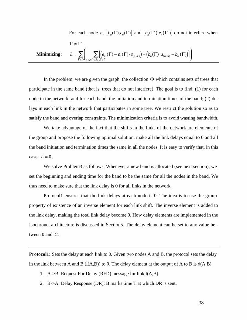
For each node n , bn (Γ),en (Γ)[ ] and bn (Γ' ),en (Γ' )[ ] do not interfere when
Γ ≠ Γ' .
Minimizing: L = em (Γ) − en (Γ) ⋅ s(n,m)( ) + bn (Γ) ⋅ s(n,m) − bm (Γ)( )[ ](n,m)∈ET ,T ∈Γ
∑⎛
⎝⎜⎞
⎠⎟Γ∈Φ∑
In the problem, we are given the graph, the collection Φ which contains sets of trees that
participate in the same band (that is, trees that do not interfere). The goal is to find: (1) for each
node in the network, and for each band, the initiation and termination times of the band; (2) de-
lays in each link in the network that participates in some tree. We restrict the solution so as to
satisfy the band and overlap constraints. The minimization criteria is to avoid wasting bandwidth.
We take advantage of the fact that the shifts in the links of the network are elements of
the group and propose the following optimal solution: make all the link delays equal to 0 and all
the band initiation and termination times the same in all the nodes. It is easy to verify that, in this
case, L = 0.
We solve Problem3 as follows. Whenever a new band is allocated (see next section), we
set the beginning and ending time for the band to be the same for all the nodes in the band. We
thus need to make sure that the link delay is 0 for all links in the network.
Protocol1 ensures that the link delays at each node is 0. The idea is to use the group
property of existence of an inverse element for each link shift. The inverse element is added to
the link delay, making the total link delay become 0. How delay elements are implemented in the
Isochronet architecture is discussed in Section5. The delay element can be set to any value be -
tween 0 and C .
Protocol1: Sets the delay at each link to 0. Given two nodes A and B, the protocol sets the delay
in the link between A and B (l(A,B)) to 0. The delay element at the output of A to B is d(A,B).
1. A->B: Request For Delay (RFD) message for link l(A,B).
2. B->A: Delay Response (DR); B marks time T at which DR is sent.

39
3. A marks arrival time R of DR. A measures the offset O=R-T.
4. If d(A,B) > O, set d(A,B) to d(A,B)-O. Otherwise, set d(A,B) to d(A,B)+O.
6.4Band Allocation
The goal of band allocation protocols is to establish appropriate band duration. The allocation
must satisfy the band and the overlap constraints.
Problem 4: Band allocation.
Given: A set Φ of sets Γ of spanning trees of G that do not interfere and a band
size ΔΓ for each Γ ∈Φ .
Find: For each node n in VG , for each Γ in Φ , a band bn (Γ),en (Γ)[ ].For each edge e in Φ , a shift se .
Satisfying: For each node n and for each t ree T i n Γ ,
bn (Γ),en (Γ)[ ] ⋅ s(n,m) ,s(n,m)[ ] ⊆ bm (Γ),em (Γ)[ ], where m is a node immediately
following n in T .
For each node n , bn (Γ),en (Γ)[ ] and bn (Γ' ),en (Γ' )[ ] do not interfere when
Γ ≠ Γ' .
For each node n and each set Γ ∈Φ , bn (Γ) − en (Γ) ≥ ΔΓ .
Minimizing: L = em (Γ) − en (Γ) ⋅ s(n,m)( ) + bn (Γ) ⋅ s(n,m) − bm (Γ)( )[ ](n,m)∈ET ,T ∈Γ
∑⎛
⎝⎜⎞
⎠⎟Γ∈Φ∑
We first observe that, since all the trees are spanning, all the nodes must know where
each band is allocated in the cycle. Thus, in order to allocate bands, we need to communicate the
allocation to all the nodes in the network.
The band allocation problem can be solved in a manner similar to band synchronization.
By setting the link delays to 0 and the band initiation and termination values to be the same at
each node, L = 0. To complete band allocation, it is necessary to set what the band initiation and
40
termination times should be. There are many solutions to this problem. One solution is to allocate
bands according to traffic demands, which can be easily pursued: a band of size X on a link with
bandwidth B allocates XB
C bandwidth to the band. Other solutions may dynamically adapt the
size of the bands according to demand. We leave the study of such algorithms for future work.
6.5Application: ATM Routing
In this section, we illustrate the use of Isochronets as a higher-layer in an existing network archi-
tecture. Specifically, we apply Isochronets to solve the routing problem in ATM networks[6,
27].
ATM networks switch traffic using virtual paths (VPs) and virtual circuits (VCs). A VP is
a channel that may contain one or more VCs. Each ATM cell contains two identifiers: a virtual
path identifier (VPI) and a virtual circuit identifier (VCI). Within a VP, switches use only VPIs
in each cell to switch. When a switch connects different VPs, both VPIs and VCIs are used in
switching a cell.
Three main problems may be identified in ATM switching. First, the number of possible
VPs and VCs is limited by the size of the VPI and VCI. In the current standard, these sizes are 8
bits for VPIs and 16 bits for VCIs, thus enabling a maximum of 256 VPs and 65,536 VCs. These
numbers are expected to be too small for future networks.
Second, connectionless services are extremely inefficient. When a cells is to be sent in
connectionless mode, it is switched at each intermediate ATM switch to find a path to the desti-
nation. At switches where no VP or VC in the proper direction is set, cells suffer unbound delays
waiting. One possible solution for this problem is to allocate VCs for connectionless traffic a pri-
ori. Nevertheless, such solution would considerably lessen the statistical multiplexing that con-
nectionless networks enable.
Third, switching of high-level frames is extremely inefficient. For example, when Internet
packets (IPs) need to be send through an ATM network, IPs addresses need to be mapped into
VPs or VCs at each intermediate switch. Such mapping can only be implemented at the

41
Adaptation Layer, above the ATM layer. Since the format of the packets is not set a priory, many
ATM cells need to be gathered at each switch before the mapping can proceed. Notice that the
destination address is included in the payload of the initial ATM cells that comprise the packet.
When enough cells are assembled and the mapping is done, the cells are once again disassembled
and transmitted individually using the mapped ATM VP or VC address in each cell header.
Isochronets provide a solution for these problems as follows. Trees are allocated in the
network and time-tables when the trees are enabled are generated, as usual. At each switch,
switching means mapping input ports to output ports based on the current time (no cell or packet
processing is necessary). At the network periphery, cells or packets are scheduled to be transmit-
ted when trees to the proper destination are enabled.
This solution has the added advantage of creating a new kind of ATM service: guaranteed
QOS. This kind of QOS is ensured when priority bands are allocated in the network. VCIs may
still be allocated at the sources for admission control based on negotiated connection parameters.
We will study this problem further and show the performance gains of using Isochronets
for ATM routing. We leave a complete study of this problem for further investigation during the
thesis work.
References
[1] Acampora, A.S. and Karol, M.J., “An overview of light-wave packet networks,” IEEENetwork Magazine, vol. 3, 29-41, January 1989.
[2] Ahmadi, H. and Denzel, W.E., “A survey of modern high-performance switching tech-niques,” IEEE Journal of Selected Areas in Communications, vol. 7, no. 7, 1091-1103,January 1989.
[3] Amstutz, S.R., “Burst switching - a method for dispersed and integrated voice and dataswitching,” in Proceedings of International Conference on Communications, IEEE,Boston, Massachussets, USA, June 1983, pp. 288-292.
[4] Behzad, M., Chartrand, G., and Lesniak-Foster, L., Graphs & Digraphs. WadsworthInternational Group, 1979.
[5] Bertsekas, D. and Gallager, R., Data networks, Second Edition. Prentice Hall, 1992.
[6] Boudec, J.Y.L., “Asynchronous Transfer Mode: a tutorial,” Computer Networks andISDN Systems, vol. 24, no. 4, May 1992.

42
[7] Brackett, C.A., “Dense wavelength division multiplexing networks: principles and appli-cations,” IEEE Journal of Selected Areas in Communications, vol. 8, no. 6, 948-964,August 1991.
[8] Chao, H.J., “A recursive modular terabit/second ATM switch,” IEEE Journal on SelectedAreas in Communications, vol. 9, no. 8, 1161-1172, October 1991.
[9] Cormen, T.H., Leiserson, C.E., and Rivest, R.L., Introduction to algorithms. McGrawHill, 1991.
[10] Dono, N.R., Green, P.E., Liu, K., Ramaswami, R., and Tong, F., “A wavelength divisionmulti-access network for computer communications,” IEEE Journal on Selected Areas inCommunications, August 1990.
[11] Eng, K.Y., Karol, M.J., and Yeh, Y.S., “A growable packet (ATM) switch architecture:design principles and applications,” in Proceedings of GLOBECOM, IEEE, Dallas,Texas, USA, November 1989, pp. 1159-1164.
[12] Giacopelli, J.N., Hickey, J.J., Marcus, W.S., Sincoskie, W.D., and Littlewood, M.,“Sunshine: a high-performance self-routing broadband packet switch architecture,” IEEEJournal on Selected Areas in Communications, vol. 9, no. 8, 1161-1172, October 1991.
[13] Haselton, E.F., “A PCM switching concept leading to burst switching network architec-ture,” in Proceedings of International Conference on Communications, IEEE, Boston,Massachussets, USA, June 1983, pp. 1401-1406.
[14] Hui, J.Y. and Arthurs, E., “Starlite: a wideband digital switch,” in Proceedings ofGLOBECOM, IEEE, Atlanta, Georgia, USA, December 1984, pp. 121-125.
[15] Humblet, P.A., Ramaswami, R., and Sivarajan, K.N., “An efficient communication pro-tocol for high-speed packet-switched multichannel networks,” in Proceedings ofSIGCOMM, ACM, Baltimore, Maryland, USA, August 1992.
[16] Karlin, S. and Taylor, H.M., A first course in stochastic processes, Second Edition.Academic Press, 1975.
[17] Kleinrock, L., Queueing systems, vol. I. Wiley, 1975.
[18] Lee, T.T., “A modular architecture for very large packet switches,” IEEE Transactions onCommunications, vol. 38, no. 7, 1097-1106, July 1990.
[19] Mills, D.L., Boncelet, C.G., Elias, J.G., Schragger, P.A., and Jackson, A.W., “Highball: ahigh speed, reserved-access, wide area network,” Tech. Rep. 90-9-1, ElectronicEngineering Department, University of Delaware, September 1990.
[20] Mills, D.L., “Internet time synchronization: the Network Time Protocol,” IEEETransactions on Communications, vol. 39, no. 10, 1482-1493, August 1991.
[21] Nojima, S., “Integrated services packet network using bus matrix switch,” IEEE Journalof Selected Areas in Communications, vol. 5, no. 8, 1284-1291, 1987.
[22] Oie, Y., Suda, T., Murata, M., Kolson, D., and Miyahara, H., “Survey of switching tech-niques in high-speed networks and their performance,” in Proceedings of INFOCOM,IEEE, San Francisco, California, USA, June 1990, pp. 1242-1251.

43
[23] Ott, T.J., “The single-server queue with independent GI/G and M/G input streams,” Adv.Appl. Prob., vol. 19, 266-286, 1987.
[24] Pattavina, A., “A multistage high-performance packet switch for broadband networks,”IEEE Transactions on Communications, vol. 38, no. 9, 1607-1615, September 1990.
[25] Sidi, M., Liu, W., Cidon, I., and Gopal, I., “Congestion control through input rate regula-tion,” in Proceedings of GLOBECOM, IEEE, Dallas, Texas, USA, May 1989, pp. 1764-1768.
[26] Stern, T.E., “Linear lightwave networks: how far can they go?,” in Proceedings ofGLOBECOM, IEEE, San Diego, California, USA, 1990.
[27] ISDN Experts of Study Group XVIII, “Recommandations to be submitted at the rules ofresolution no. 2,” Tech. Rep. R 23, CCITT, February 1990.
[28] Suzuki, M., Group theory I. Springer-Verlag, 1977.
[29] Tanenbaum, A.S., Computer networks, Second Edition. Prentice Hall, 1988.
[30] Tobagi, F.A., “Fast packet switching architectures for broadband integrated services digi-tal networks,” Proc. of the IEEE, vol. 78, no. 1, 133-167, January 1980.
[31] Tobagi, F.A., Kwok, T., and Chiussi, F.M., “Architecture, performance, and implementa-tion of the tandem banyan fast packet switch,” IEEE Journal on Selected Areas inCommunications, vol. 9, no. 8, 1173-1193, October 1991.
[32] Turner, J.S., “Design of an integrated services packet network,” IEEE Journal of SelectedAreas in Communications, vol. 4, no. 8, 1373-1379, 1986.
[33] Turner, J.S., “Design of a broadcast packet switching network,” IEEE Transactions onCommunications, vol. 36, no. 6, 734-743, June 1988.
[34] Venkatesan, R., “Balanced gamma network - a new candidate for broadband packetswitch architectures,” in Proceedings of INFOCOM, IEEE, Florence, Italy, May 1992,pp. 2482-2488.
[35] Widjaja, I. and Leon-Garcia, A., “The Helical switch: a multipath ATM switch whichpreserves cell sequence,” in Proceedings of INFOCOM, IEEE, Florence, Italy, May1992, pp. 2489-2498.
[36] Yeh, Y.S., Hluchyj, M.G., and Acampora, A.S., “The Knockout switch: a simple, modu-lar architecture for high-performance packet switching,” IEEE Journal of Selected Areasin Communications, vol. 5, no. 8, 1274-1282, 1987.
[37] Yemini, Y. and Florissi, D., “Isochronets: a high-speed network switching architecture,”in Proceedings of INFOCOM, IEEE, San Francisco, California, USA, April 1993.
[38] Yum, T.S. and Leung, Y.W., “A TDM-based multibus packet switch,” in Proceedings ofINFOCOM, IEEE, Florence, Italy, May 1992, pp. 2509-2515.
Related Documents