Pneumatic Symbols For system diagrams and component identification

ISO Symbols
Jan 26, 2016
Fluid Power Symbols
Welcome message from author
This document is posted to help you gain knowledge. Please leave a comment to let me know what you think about it! Share it to your friends and learn new things together.
Transcript
Pneumatic Symbols
For system diagrams and component identification
Contents Standards Actuators
Basic symbols Functional elements Flowlines Connections Conditioners and plant Pressure regulators Relief valves
Valve symbol structure Valve functions
Three position valves
Operators Port marking Function components
Symbol Library
Graphic Symbols Standards
Pneumatic symbols conform to and are devised from the International Standard ISO 1219-1 1991
This covers graphical symbols for Fluid Power Systems and Components
Port markings for fluid power valves are not covered by the ISO standard. These are taken from the recommendations of CETOP RP 68 P
Basic Symbols
Shapes
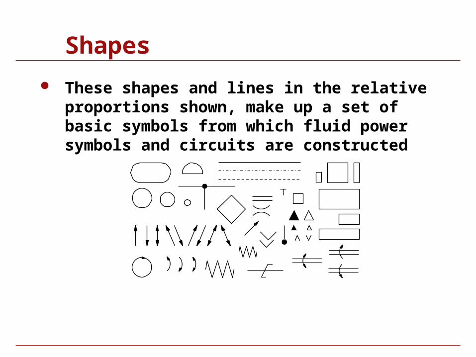
These shapes and lines in the relative proportions shown, make up a set of basic symbols from which fluid power symbols and circuits are constructed
Basic Symbols (shapes)
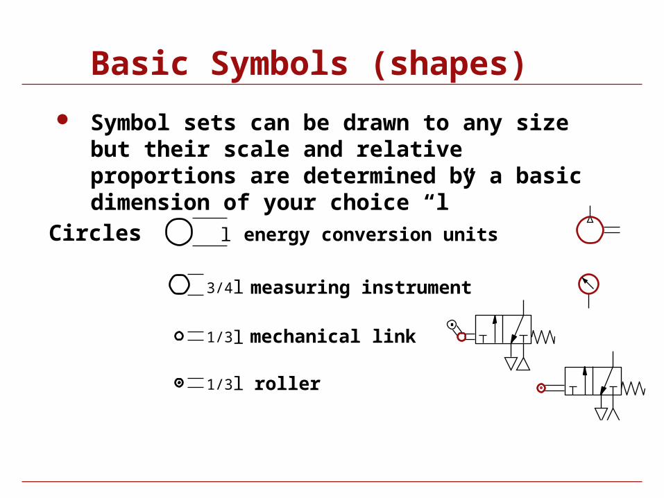
Symbol sets can be drawn to any size but their scale and relative proportions are determined by a basic dimension of your choice “l”
Circles l energy conversion units
l3/4 measuring instrument
l1/3 mechanical link
l1/3 roller
Basic Symbols (shapes)
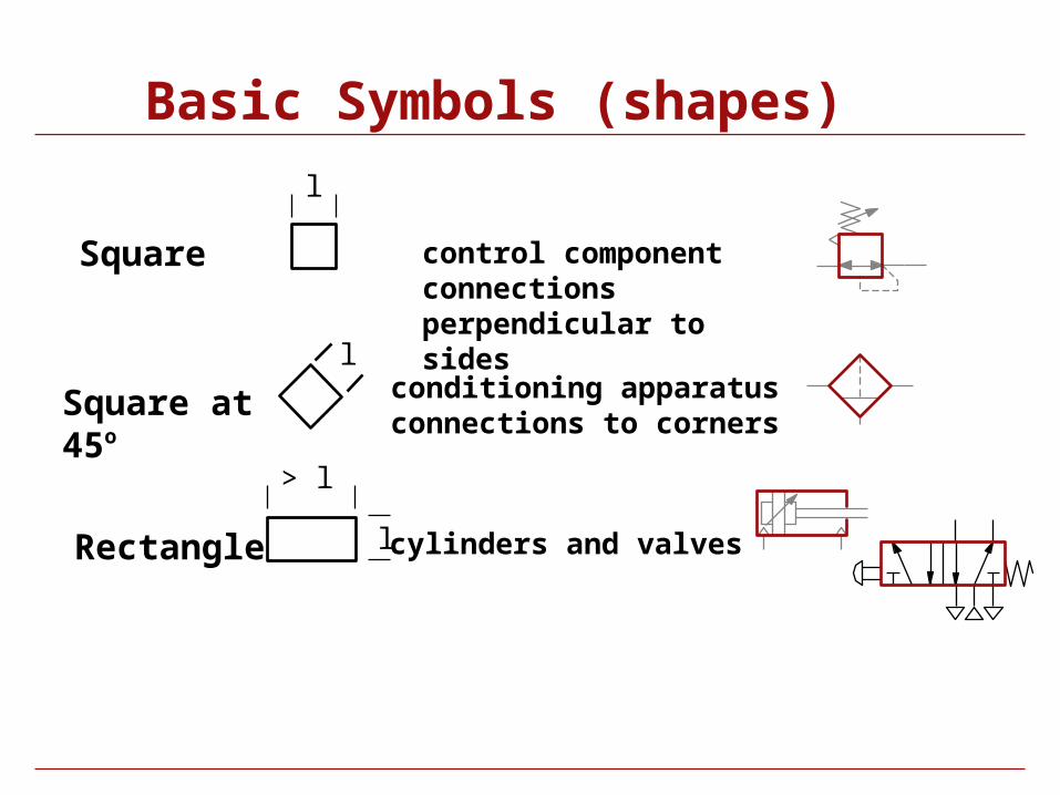
Square at 45o
conditioning apparatusconnections to corners
Square control componentconnections perpendicular to sides
Rectangle cylinders and valves
l
l
l
> l
Basic Symbols (shapes)
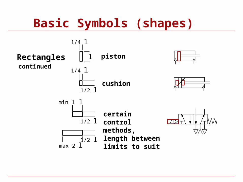
certain control methods, length between limits to suit
Rectangles
cushion
continued
piston
max 2 l
min 1 l
1/2 l
l
1/4 l
1/4 l
1/2 l
1/2 l
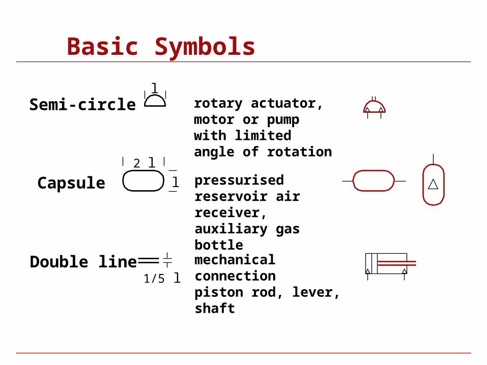
Basic Symbols
rotary actuator, motor or pump with limited angle of rotation
Semi-circle
mechanical connectionpiston rod, lever, shaft
Double line
Capsule pressurised reservoir air receiver, auxiliary gas bottle
l
1/5 l
2 ll
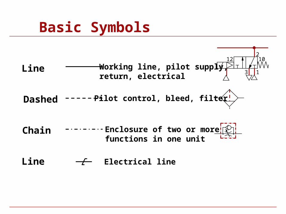
Basic Symbols
Line Working line, pilot supply,return, electrical
Chain Enclosure of two or morefunctions in one unit
Dashed Pilot control, bleed, filter
Line Electrical line
1
2
3
12 10
Functional Elements
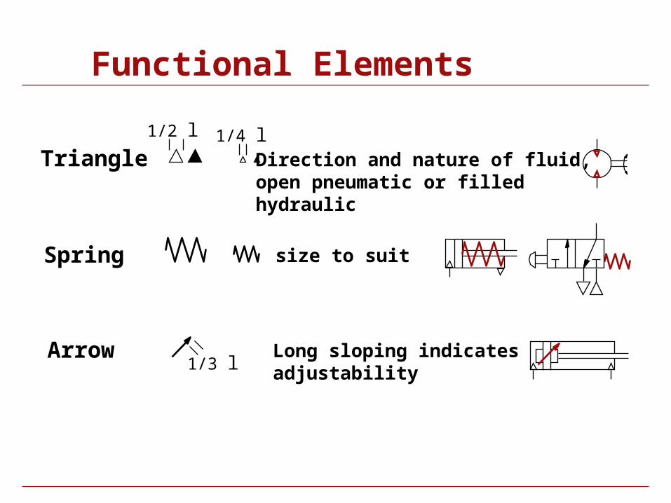
Functional Elements
Long sloping indicatesadjustability
Arrow1/3 l
size to suitSpring
Triangle Direction and nature of fluid,open pneumatic or filled hydraulic
1/4 l 1/2 l
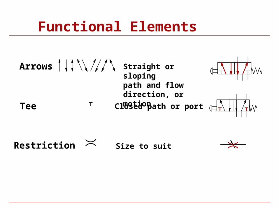
Functional Elements
Straight or slopingpath and flow direction, or motion
Arrows
Size to suitRestriction
Tee Closed path or port
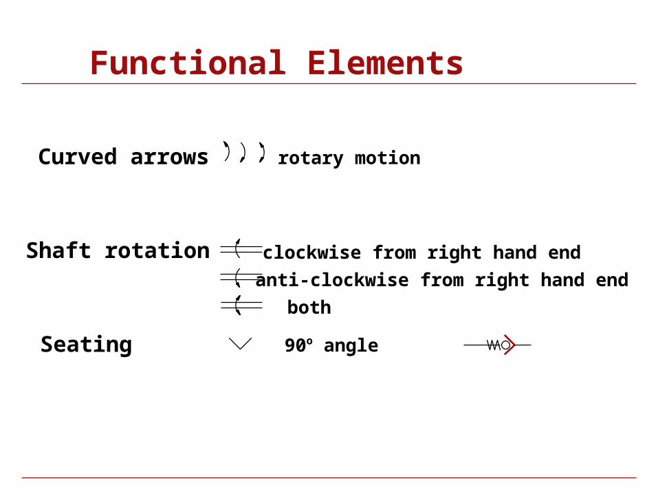
Functional Elements
90o angleSeating
rotary motionCurved arrows
clockwise from right hand endShaft rotationanti-clockwise from right hand end
both
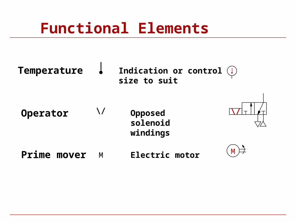
Functional Elements
Indication or controlsize to suit
Temperature
Operator Opposed solenoid windings
Prime mover M MElectric motor
Flowlines and Connections
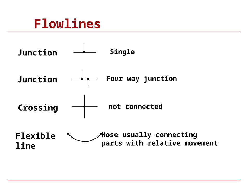
Flowlines
not connectedCrossing
Junction Single
Hose usually connectingparts with relative movement
Flexibleline
Junction Four way junction
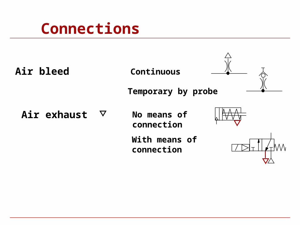
Connections
ContinuousAir bleed
Air exhaust No means of connection
Temporary by probe
With means of connection
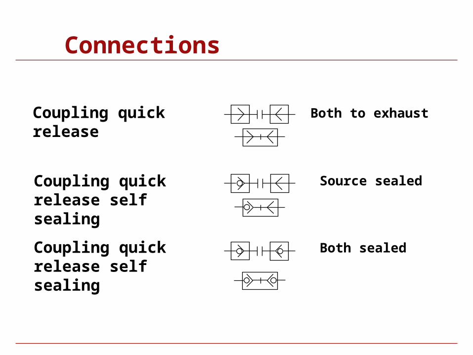
Connections
Both to exhaustCoupling quick release
Coupling quick release self sealing
Source sealed
Coupling quick release self sealing
Both sealed
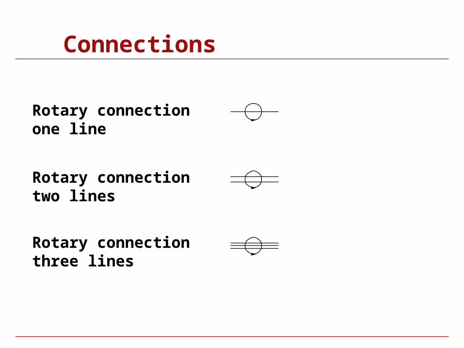
Connections
Rotary connection one line
Rotary connection two lines
Rotary connection three lines
Conditioners and Pressure Producing Plant
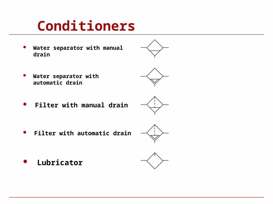
Conditioners Water separator with manual drain
Water separator with automatic drain
Filter with manual drain
Filter with automatic drain
Lubricator
Conditioners
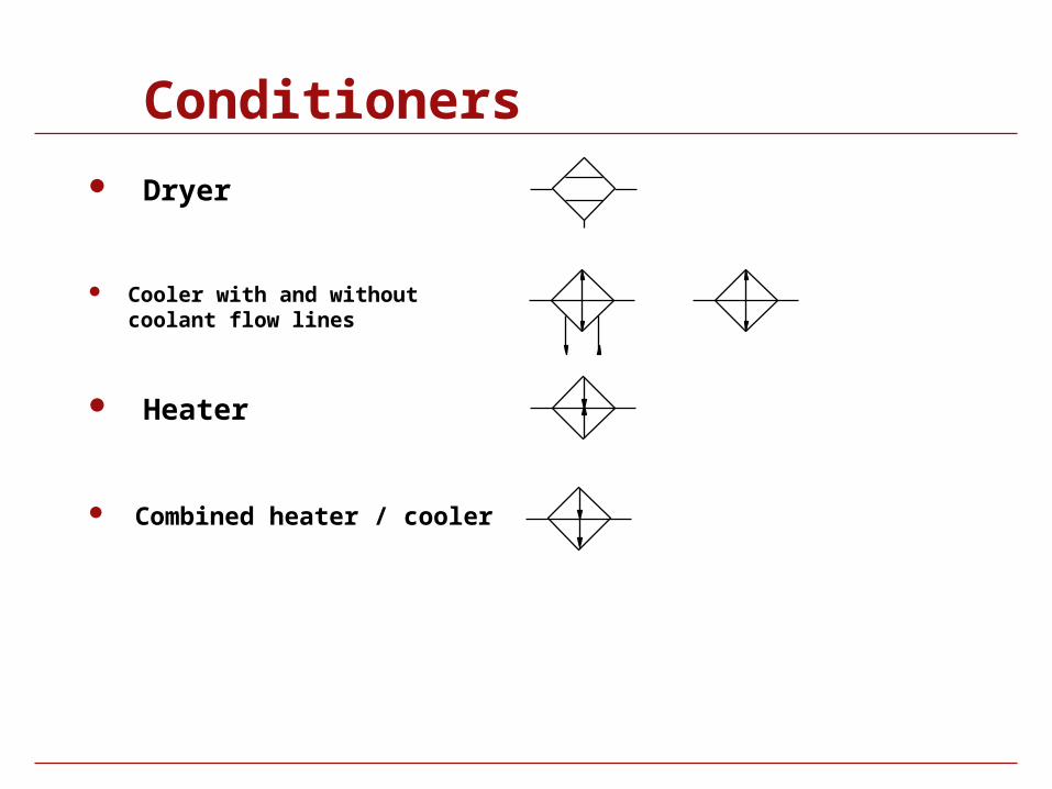
Dryer
Cooler with and without coolant flow lines
Heater
Combined heater / cooler
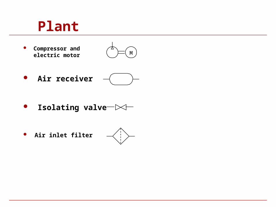
Plant Compressor and
electric motor
Air receiver
Isolating valve
Air inlet filter
M
Pressure Control
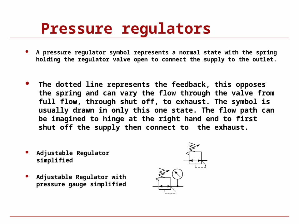
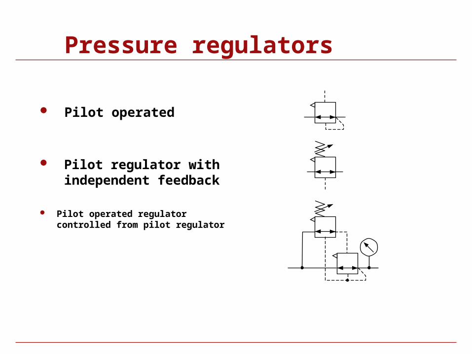
Pressure regulators A pressure regulator symbol represents a normal state with the spring holding the
regulator valve open to connect the supply to the outlet.
The dotted line represents the feedback, this opposes the spring and can vary the flow through the valve from full flow, through shut off, to exhaust. The symbol is usually drawn in only this one state. The flow path can be imagined to hinge at the right hand end to first shut off the supply then connect to the exhaust.
Adjustable Regulator with pressure gauge simplified
Adjustable Regulator simplified
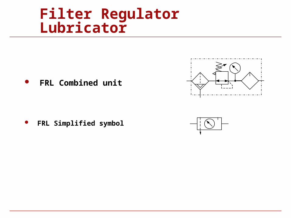
Filter Regulator Lubricator
FRL Combined unit
FRL Simplified symbol
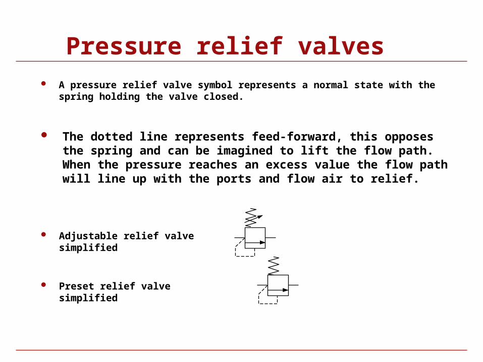
Pressure relief valves A pressure relief valve symbol represents a normal state with the spring
holding the valve closed.
Adjustable relief valve simplified
The dotted line represents feed-forward, this opposes the spring and can be imagined to lift the flow path. When the pressure reaches an excess value the flow path will line up with the ports and flow air to relief.
Preset relief valve simplified
Actuators
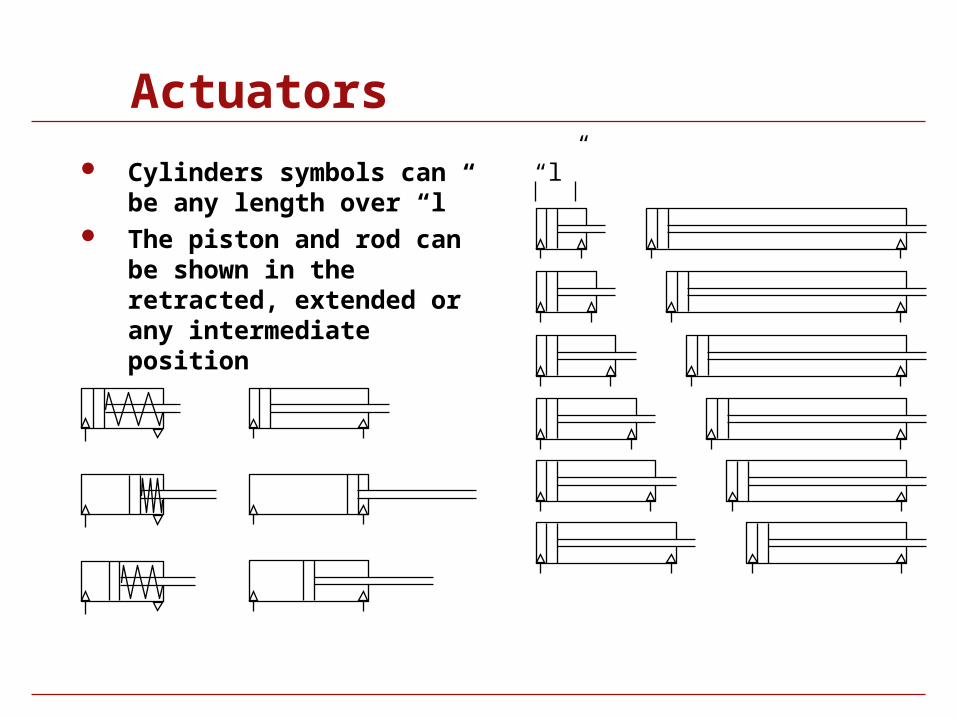
Actuators
Cylinders symbols can be any length over “l”
The piston and rod can be shown in the retracted, extended or any intermediate position
“l”
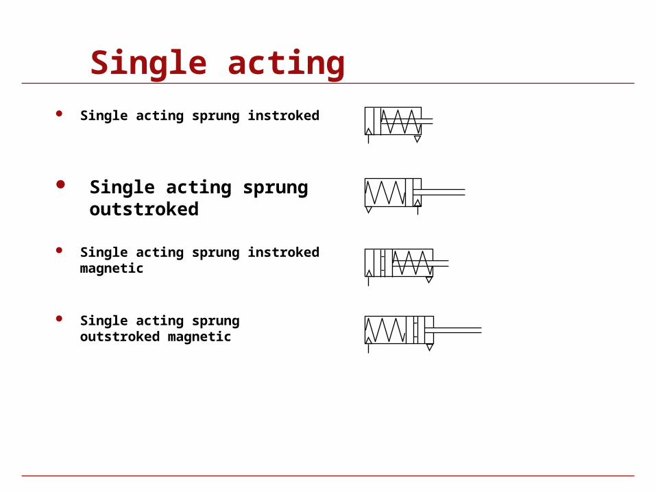
Single acting Single acting sprung instroked
Single acting sprung outstroked
Single acting sprung instroked magnetic
Single acting sprung outstroked magnetic
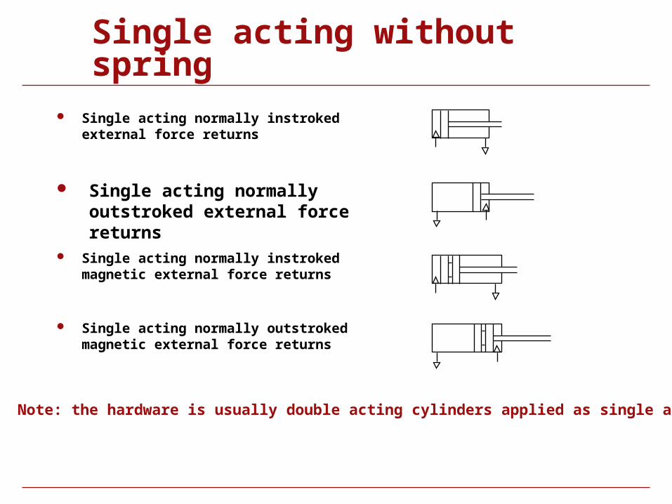
Single acting without spring Single acting normally instroked external force
returns
Single acting normally outstroked external force returns
Single acting normally instroked magnetic external force returns
Single acting normally outstroked magnetic external force returns
Note: the hardware is usually double acting cylinders applied as single acting
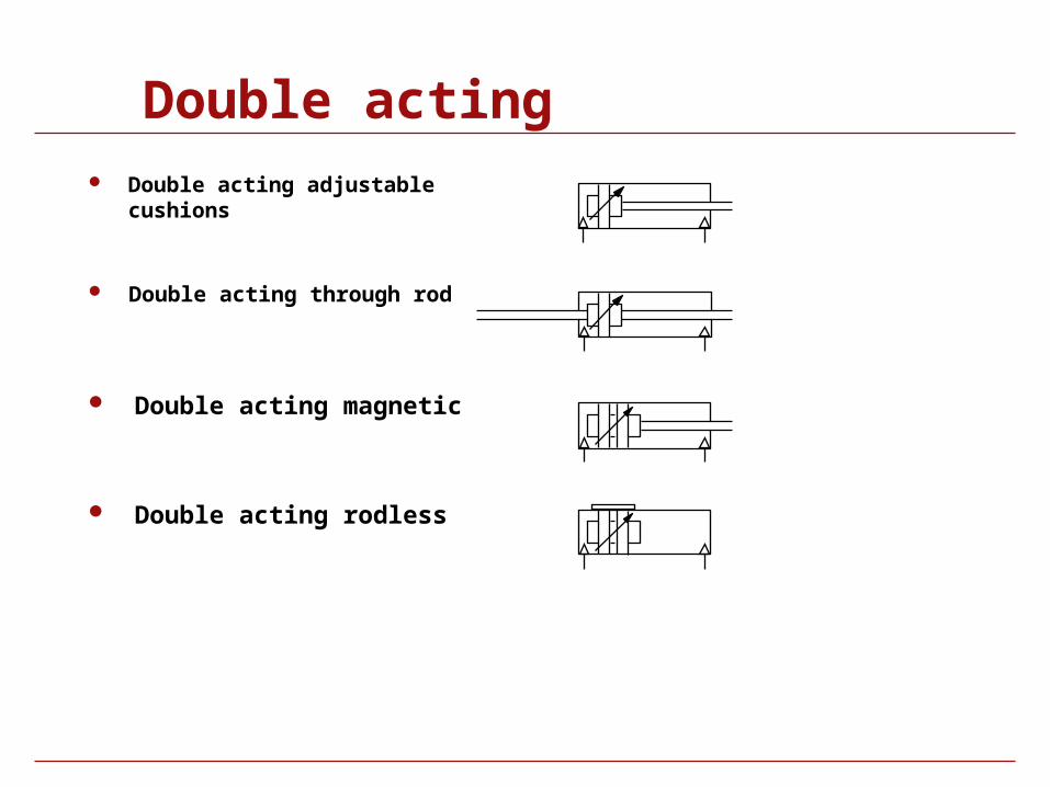
Double acting Double acting adjustable cushions
Double acting through rod
Double acting magnetic
Double acting rodless
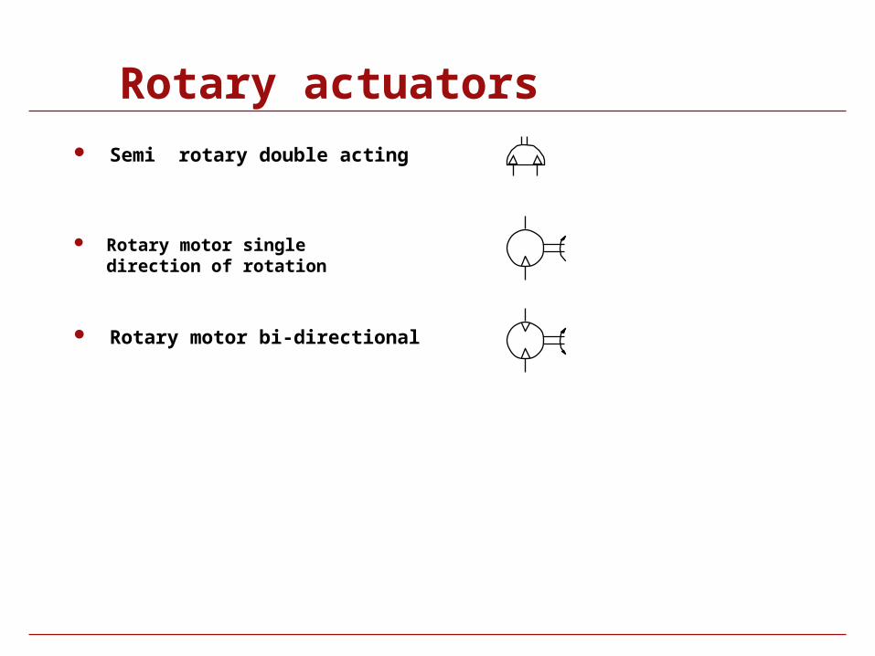
Rotary actuators Semi rotary double acting
Rotary motor single direction of rotation
Rotary motor bi-directional
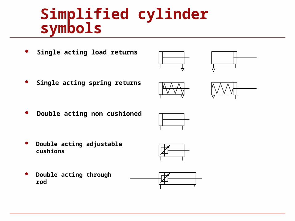
Simplified cylinder symbols
Single acting load returns
Single acting spring returns
Double acting non cushioned
Double acting adjustable cushions
Double acting through rod
Valve symbol structure
Valve symbol structure
The function of a valve is given by a pair of numerals separated by a stroke, e.g. 3/2..
The first numeral indicates the number of main ports. These are inlets, outlets and exhausts but excludes signal ports and external pilot feeds.
The second numeral indicates the number of states the valve can achieve.
Valve symbol structure
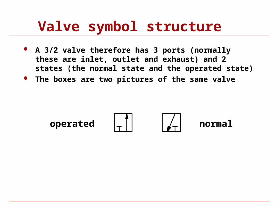
A 3/2 valve therefore has 3 ports (normally these are inlet, outlet and exhaust) and 2 states (the normal state and the operated state)
The boxes are two pictures of the same valve
normaloperated
Valve symbol structure
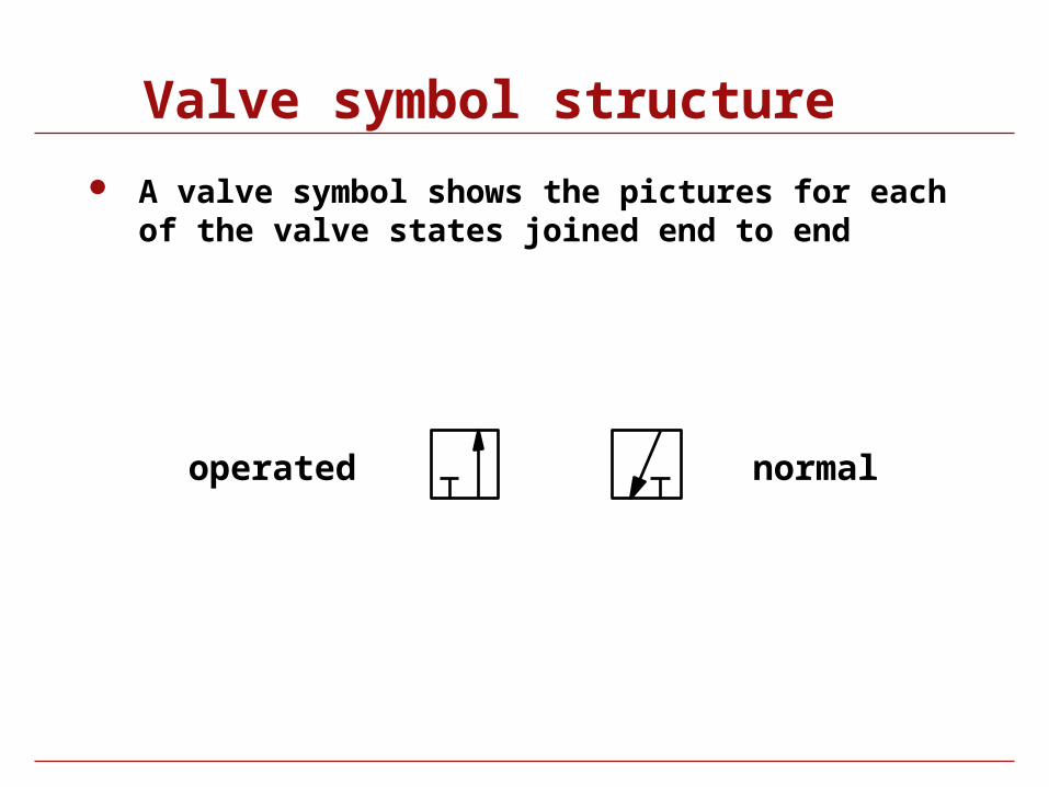
A valve symbol shows the pictures for each of the valve states joined end to end
normaloperated
Valve symbol structure
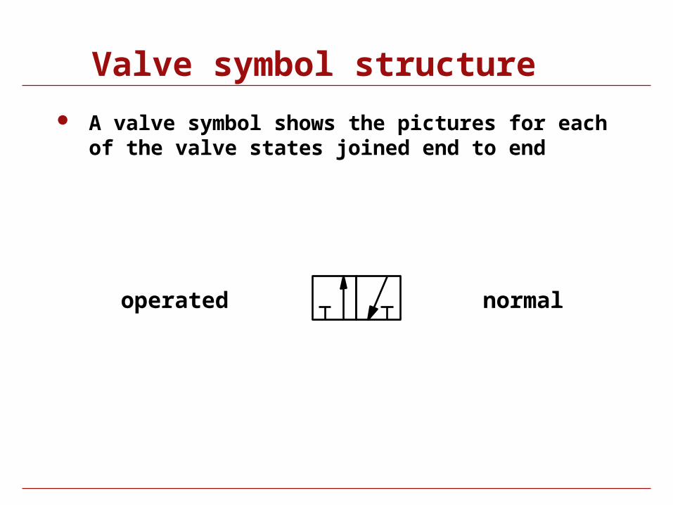
A valve symbol shows the pictures for each of the valve states joined end to end
normaloperated
Valve symbol structure
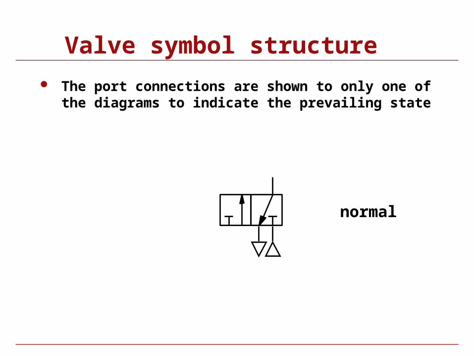
The port connections are shown to only one of the diagrams to indicate the prevailing state
normal
Valve symbol structure
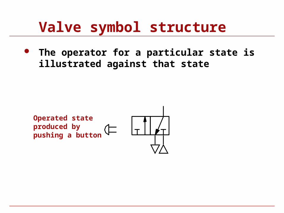
The operator for a particular state is illustrated against that state
Operated state produced bypushing a button
Valve symbol structure
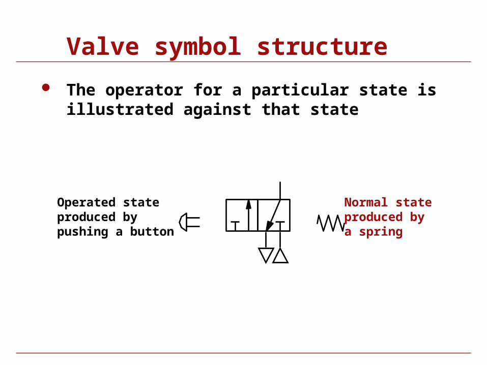
The operator for a particular state is illustrated against that state
Operated state produced bypushing a button
Normal state produced bya spring
Valve symbol structure
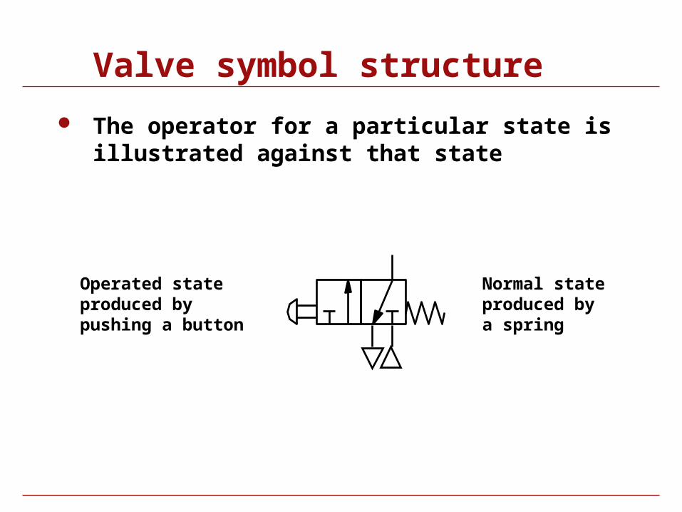
The operator for a particular state is illustrated against that state
Operated state produced bypushing a button
Normal state produced bya spring

Valve symbol structure
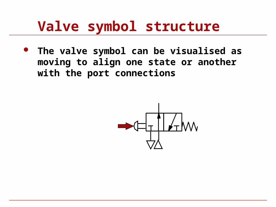
The valve symbol can be visualised as moving to align one state or another with the port connections
Valve symbol structure
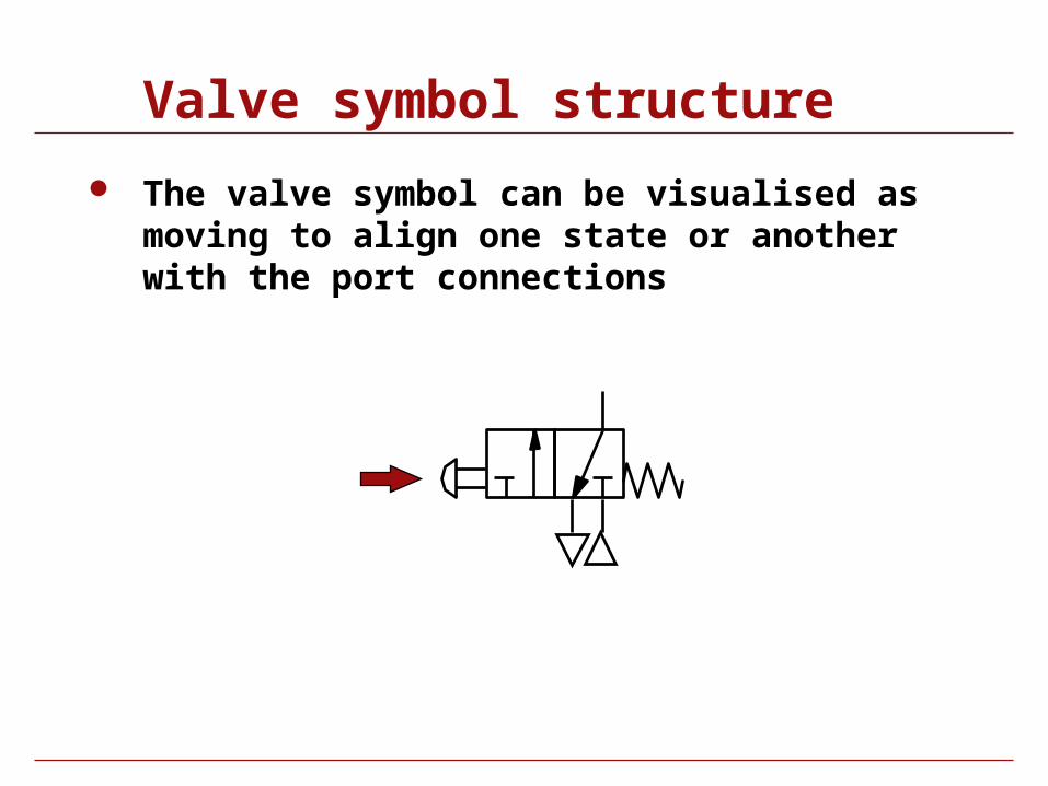
The valve symbol can be visualised as moving to align one state or another with the port connections
Valve symbol structure
The valve symbol can be visualised as moving to align one state or another with the port connections
Valve symbol structure
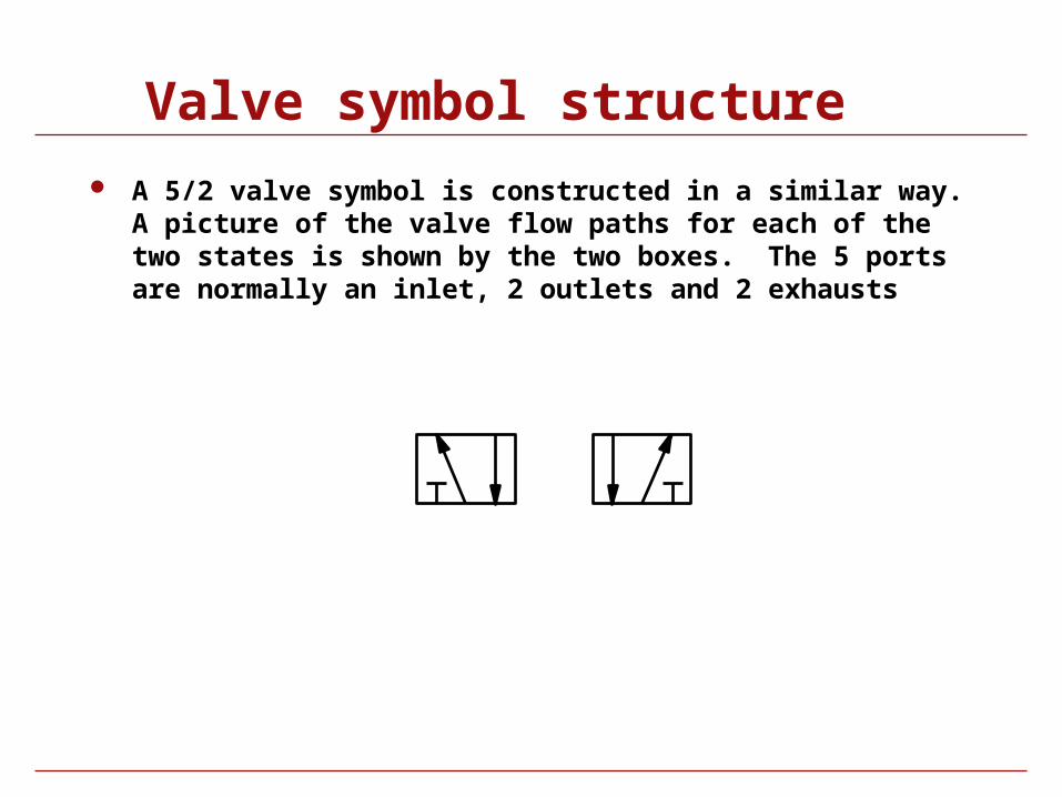
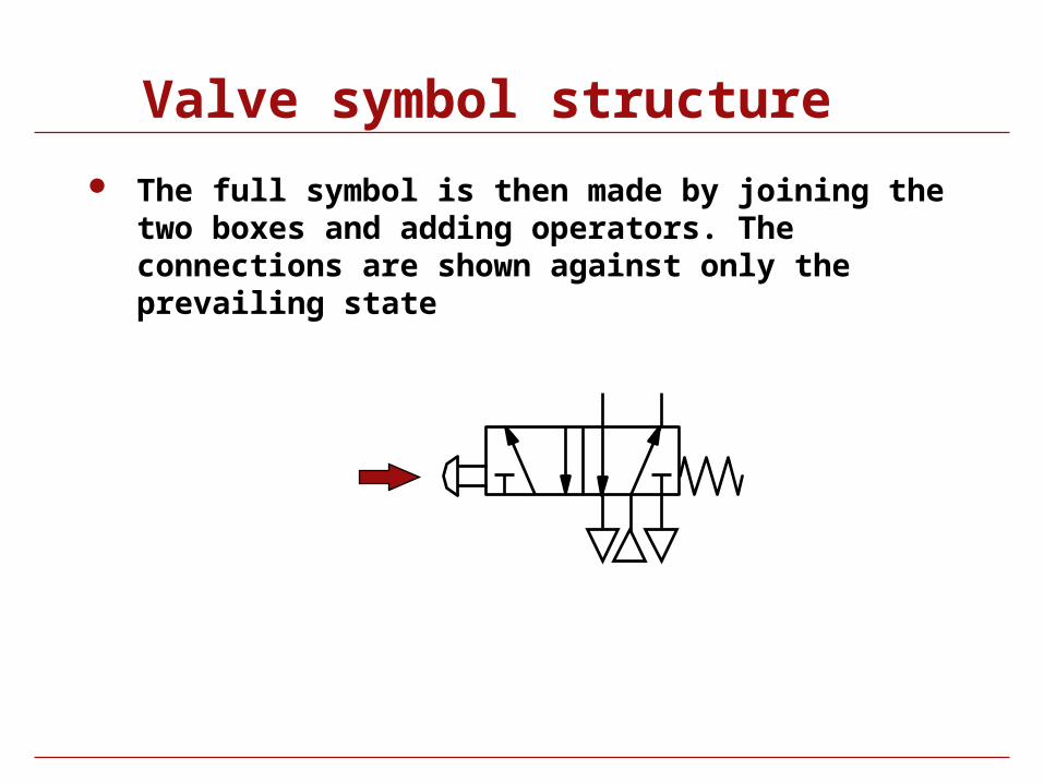
A 5/2 valve symbol is constructed in a similar way. A picture of the valve flow paths for each of the two states is shown by the two boxes. The 5 ports are normally an inlet, 2 outlets and 2 exhausts

Valve symbol structure
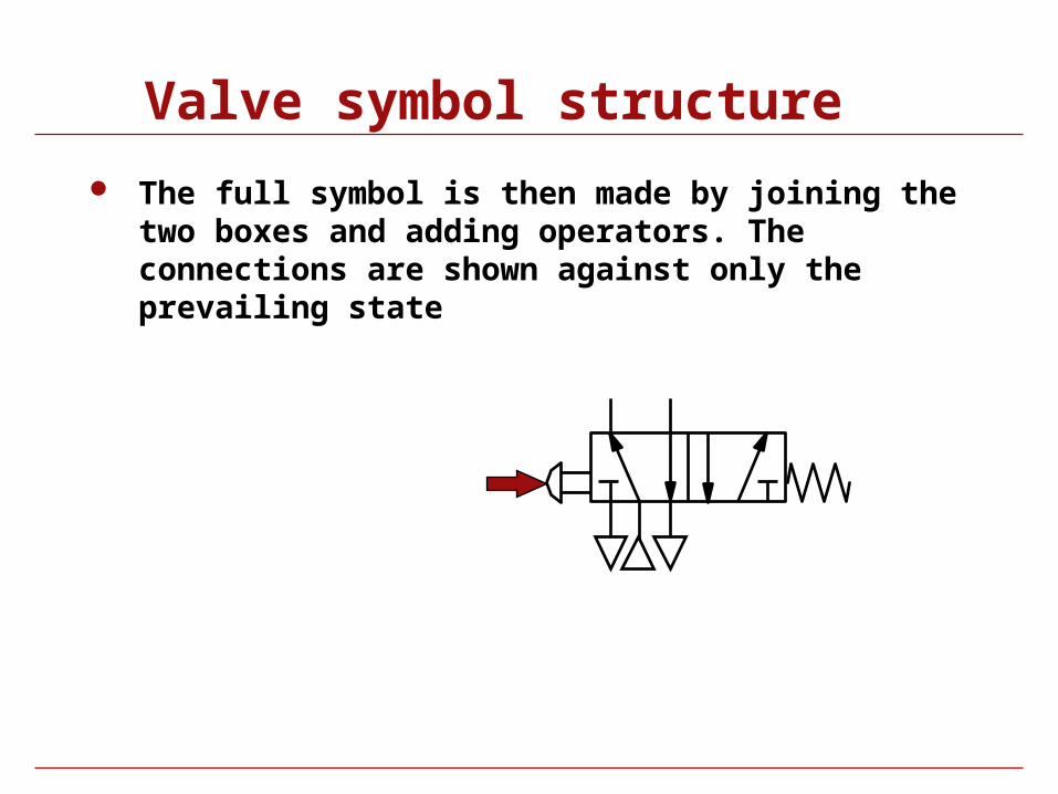
The full symbol is then made by joining the two boxes and adding operators. The connections are shown against only the prevailing state
Valve symbol structure
The full symbol is then made by joining the two boxes and adding operators. The connections are shown against only the prevailing state
Valve symbol structure
The full symbol is then made by joining the two boxes and adding operators. The connections are shown against only the prevailing state
Valve symbol structure
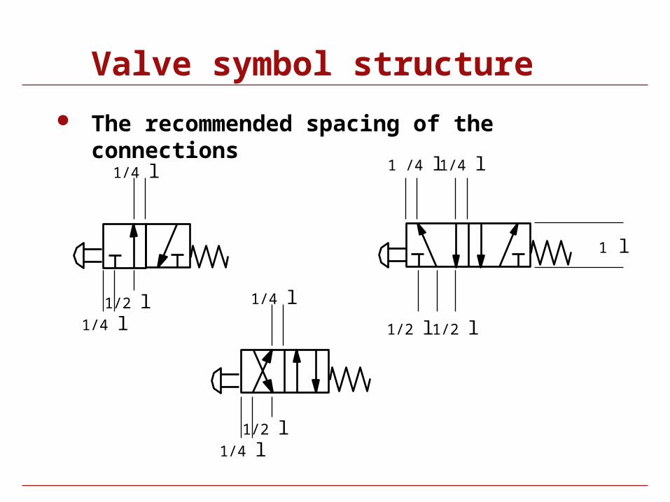
The recommended spacing of the connections
1/4 l
1/4 l
1/2 l
1 l
1 /4 l
1/2 l
1/4 l
1/2 l
1/4 l
1/4 l
1/2 l
Valve symbol structure
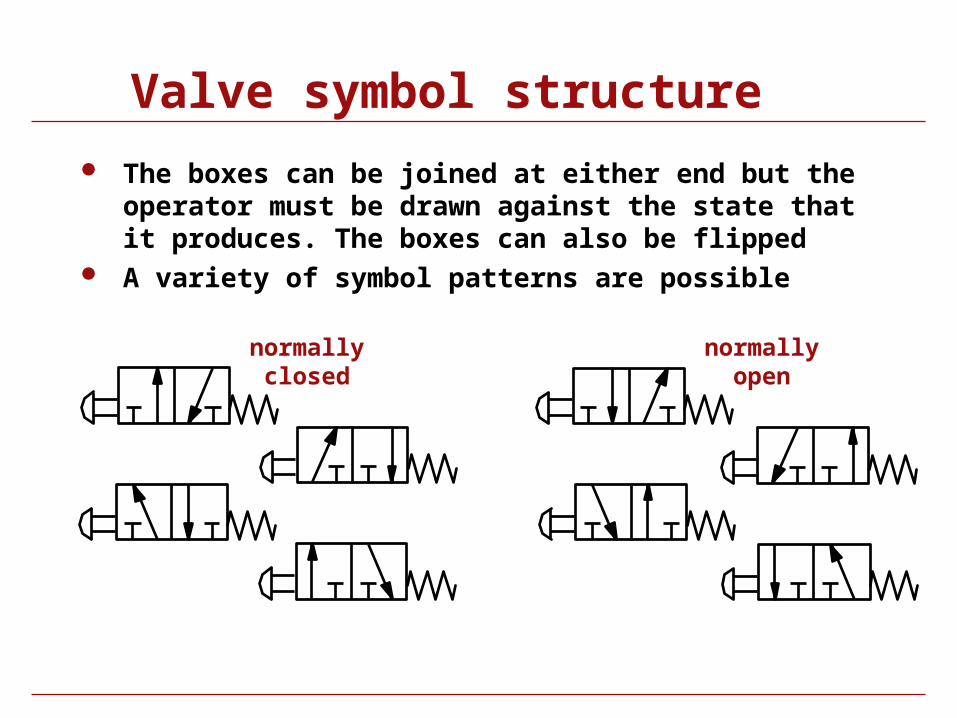
The boxes can be joined at either end but the operator must be drawn against the state that it produces. The boxes can also be flipped
A variety of symbol patterns are possible
normallyclosed
normallyopen
Valve symbol structure
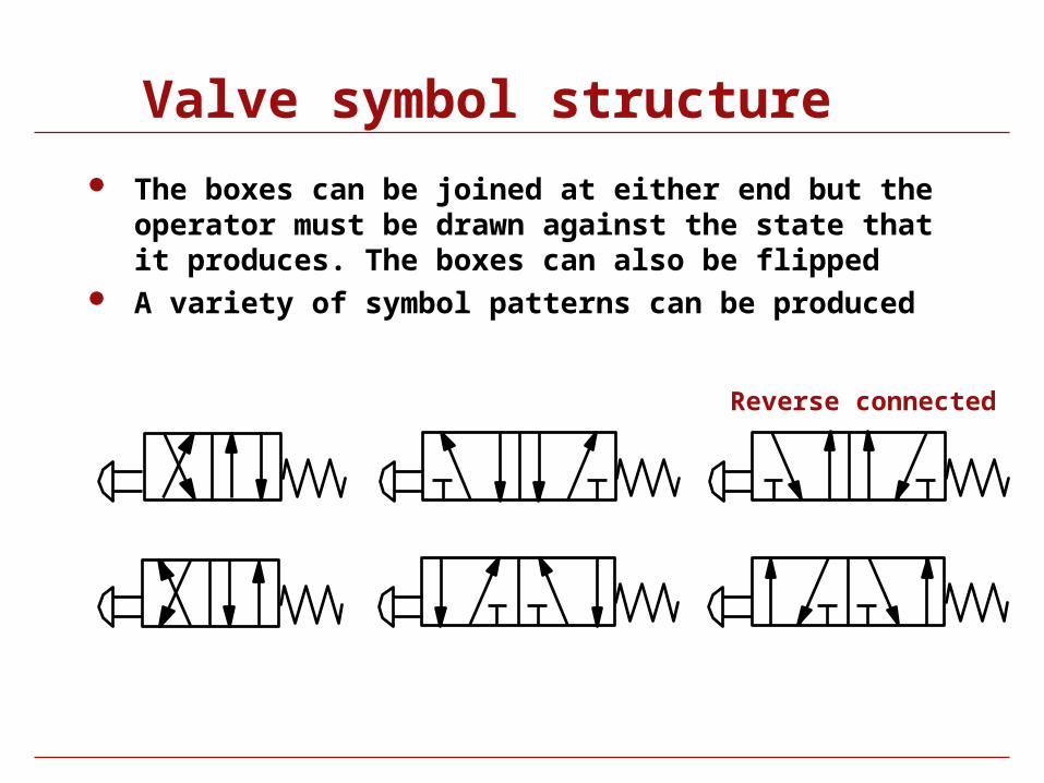
The boxes can be joined at either end but the operator must be drawn against the state that it produces. The boxes can also be flipped
A variety of symbol patterns can be produced
Reverse connected
Valve functions
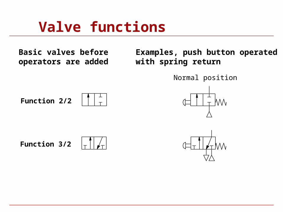
Valve functions
Function 2/2
Function 3/2
Normal position
Basic valves beforeoperators are added
Examples, push button operatedwith spring return
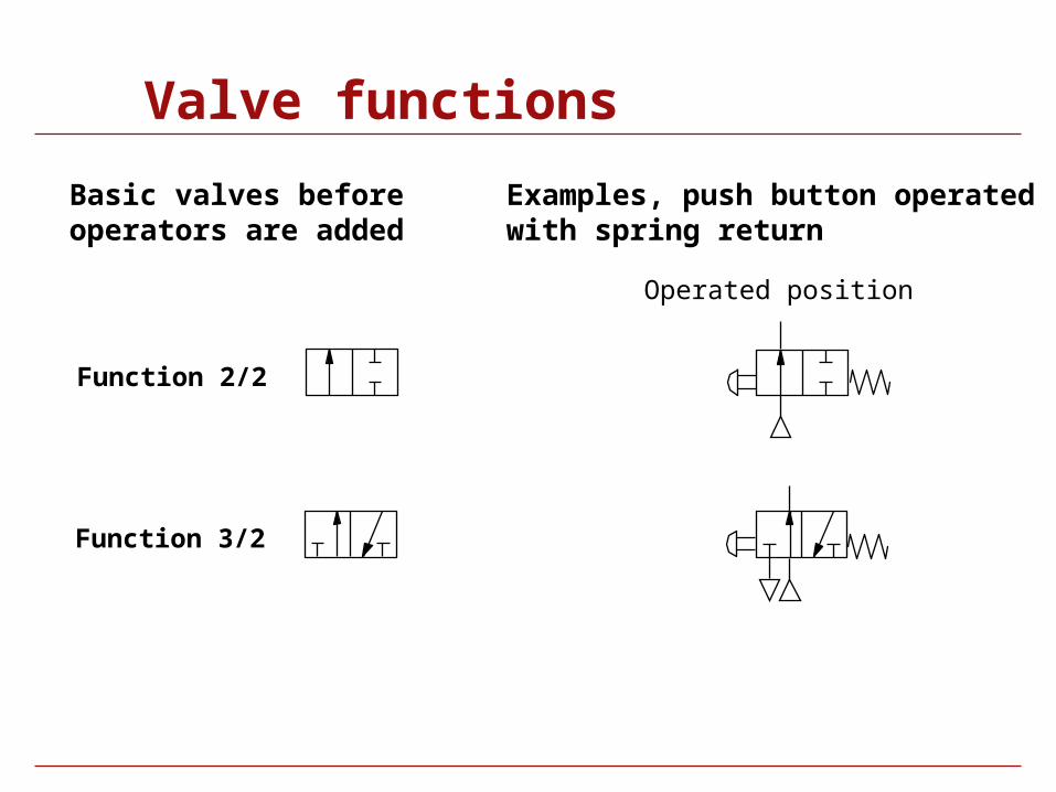
Valve functions
Function 2/2
Function 3/2
Operated position
Basic valves beforeoperators are added
Examples, push button operatedwith spring return
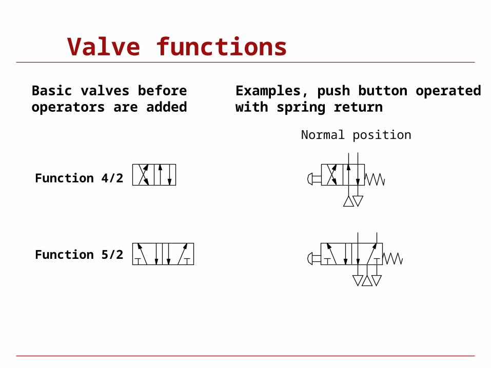
Valve functions
Function 5/2
Function 4/2
Normal position
Basic valves beforeoperators are added
Examples, push button operatedwith spring return

Valve functions
Function 5/2
Function 4/2
Operated position
Basic valves beforeoperators are added
Examples, push button operatedwith spring return
Valve functions 5/3
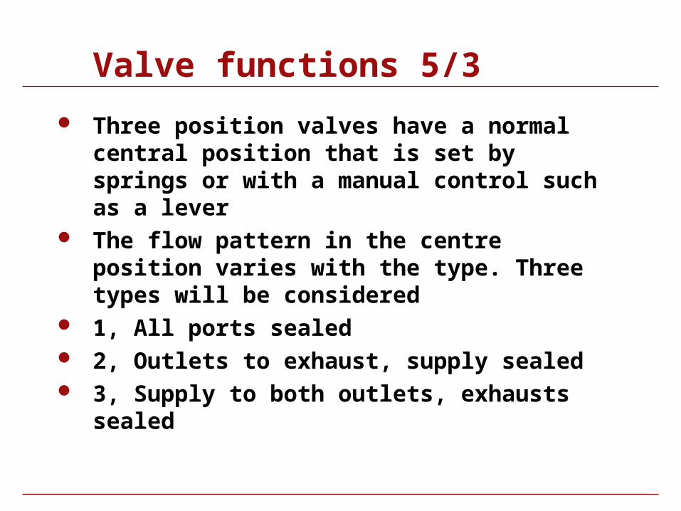
Three position valves have a normal central position that is set by springs or with a manual control such as a lever
The flow pattern in the centre position varies with the type. Three types will be considered
1, All ports sealed 2, Outlets to exhaust, supply sealed 3, Supply to both outlets, exhausts sealed
Valves 5/3
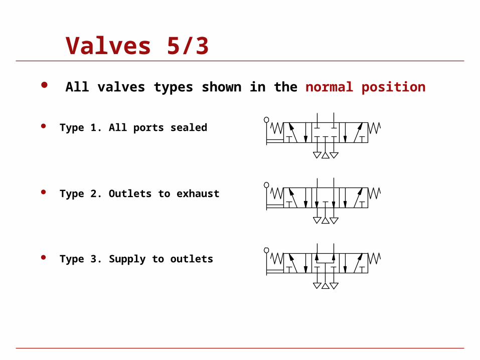
All valves types shown in the normal position
Type 1. All ports sealed
Type 2. Outlets to exhaust
Type 3. Supply to outlets
Valves 5/3
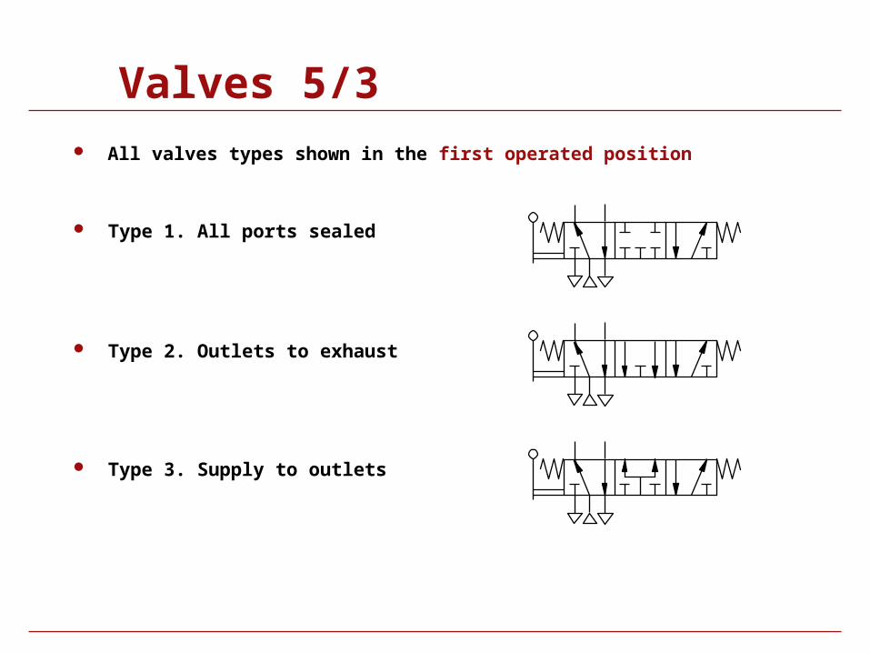
All valves types shown in the first operated position
Type 1. All ports sealed
Type 2. Outlets to exhaust
Type 3. Supply to outlets

Valves 5/3
All valves types shown in the normal position
Type 1. All ports sealed
Type 2. Outlets to exhaust
Type 3. Supply to outlets
Valves 5/3
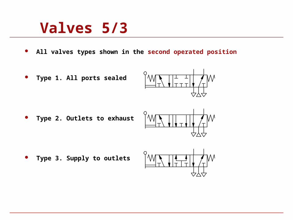
All valves types shown in the second operated position
Type 1. All ports sealed
Type 2. Outlets to exhaust
Type 3. Supply to outlets

Valves 5/3
All valves types shown in the normal position
Type 1. All ports sealed
Type 2. Outlets to exhaust
Type 3. Supply to outlets
Operators
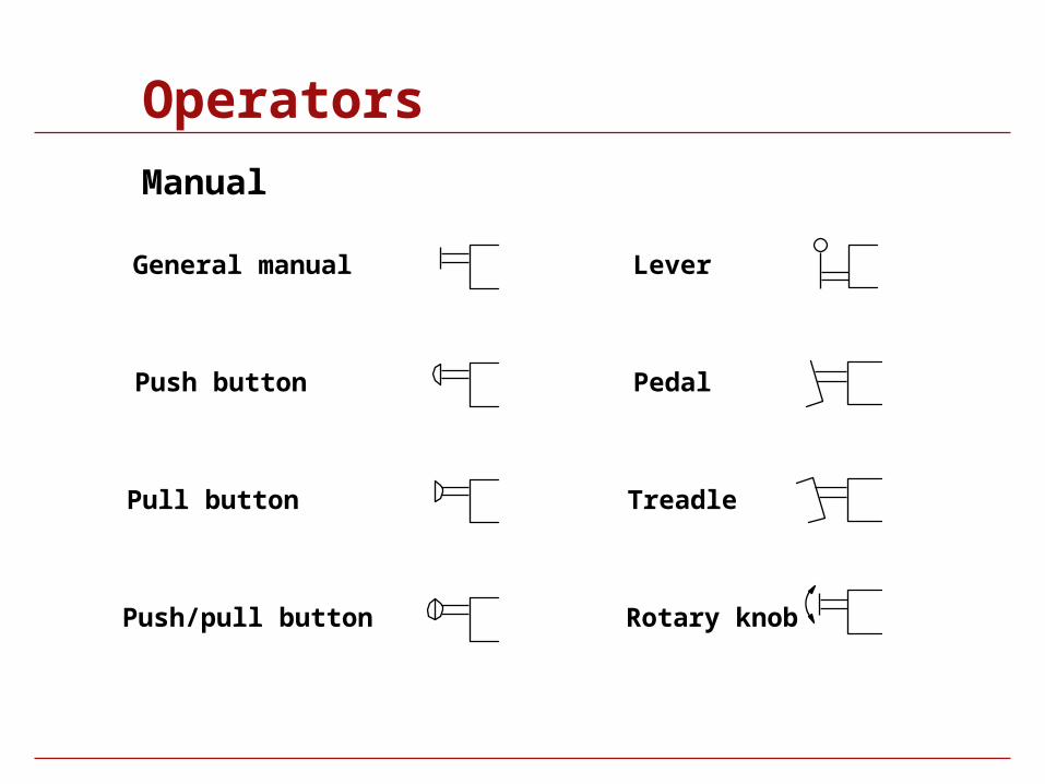
Operators
General manual
Push button
Pull button
Push/pull button
Lever
Pedal
Treadle
Manual
Rotary knob
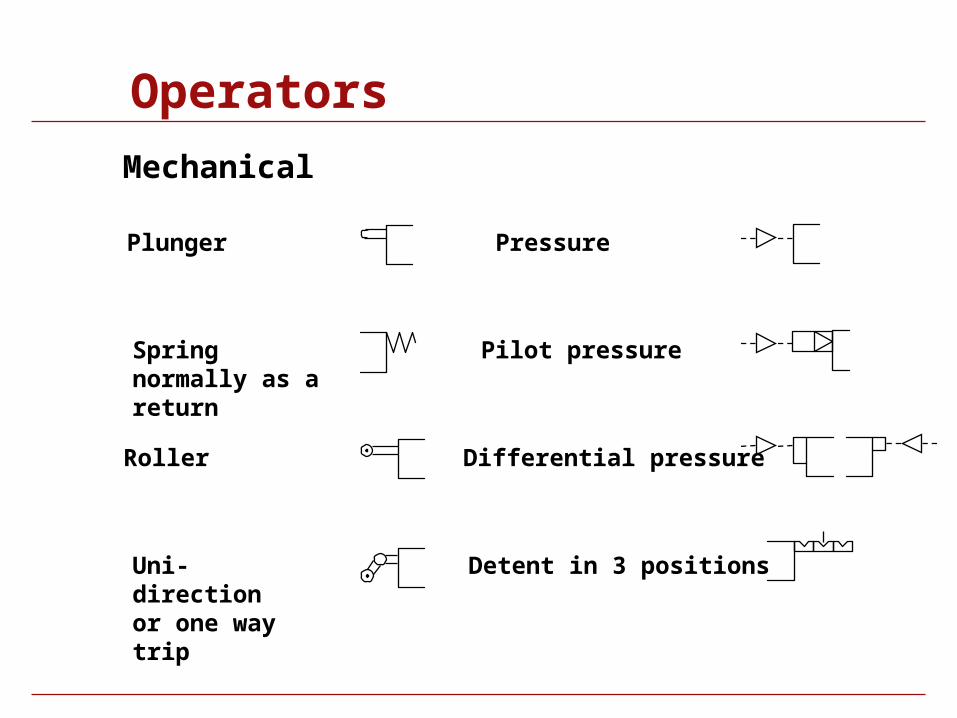
Operators
Mechanical
Plunger
Spring normally as a return
Roller
Uni-direction or one way trip
Pressure
Pilot pressure
Differential pressure
Detent in 3 positions
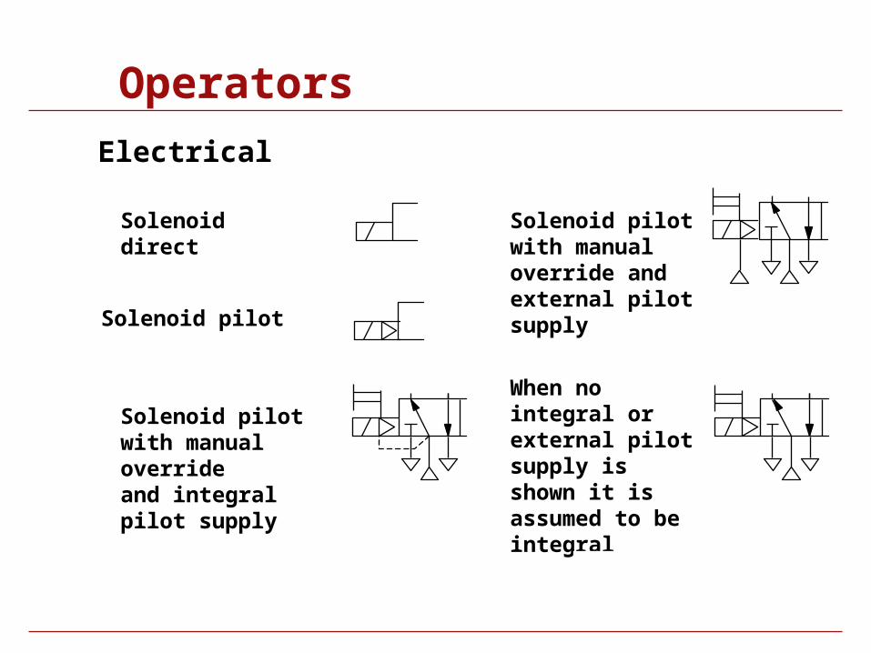
Operators
Solenoid direct
Solenoid pilot
Solenoid pilotwith manual overrideand integral pilot supply
Solenoid pilotwith manual override and external pilot supply
Electrical
When no integral or external pilot supply is shown it is assumed to be integral
Port markings
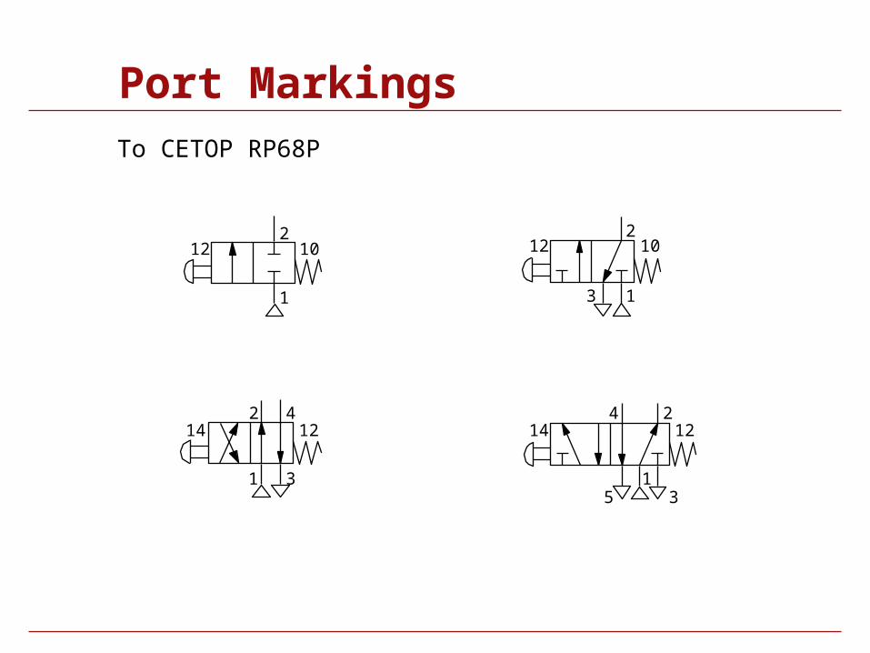
Port Markings
1
212 10
1
24
5 3
14 12
1
2
3
12 10
To CETOP RP68P
1
2 4
3
14 12
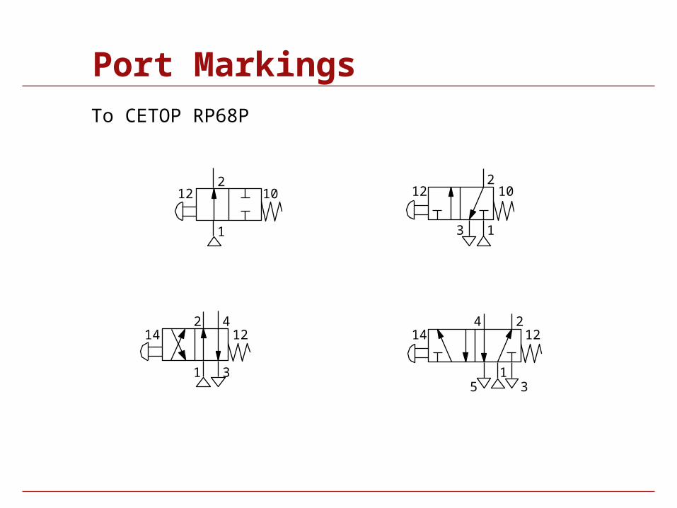
Port Markings
1
212 10
1
24
5 3
14 12
1
2
3
12 10
1
2 4
3
14 12
To CETOP RP68P
Port Markings
1
212 10
1
24
5 3
14 12
1
2
3
12 10
1
2 4
3
14 12
To CETOP RP68P
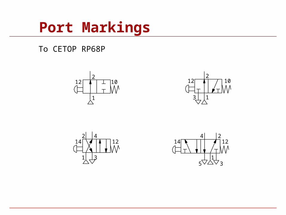
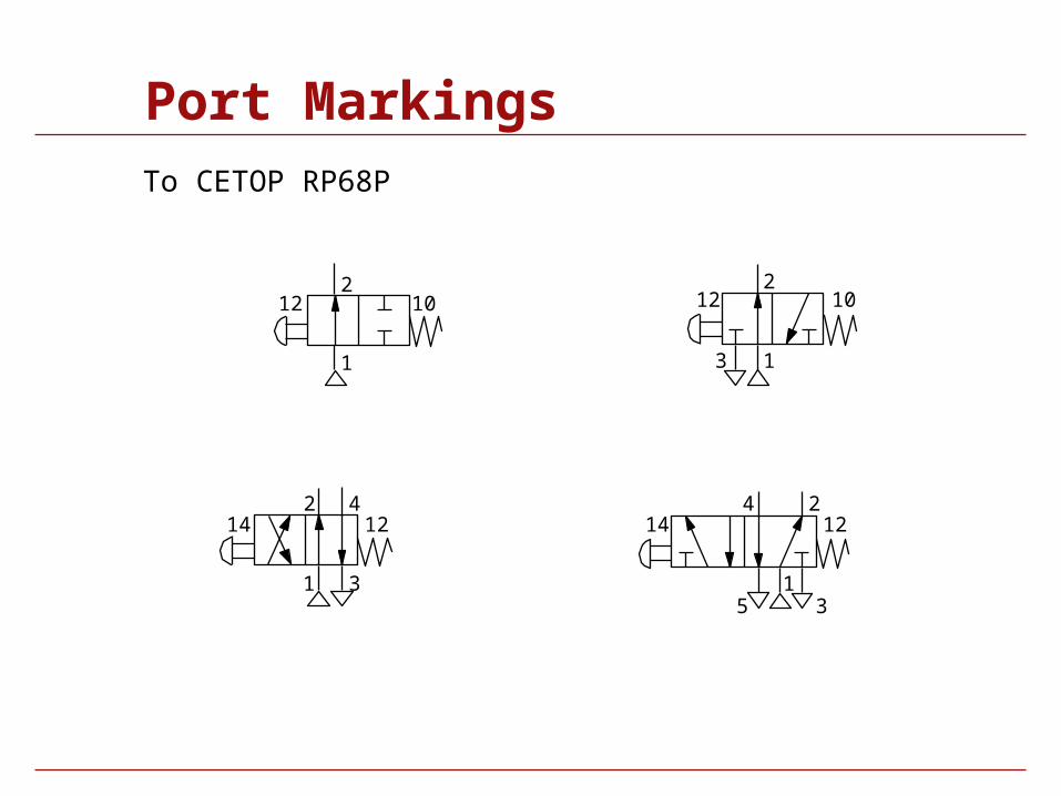
Port Markings
1
212 10
1
24
5 3
14 12
1
2
3
12 10
1
2 4
3
14 12
To CETOP RP68P
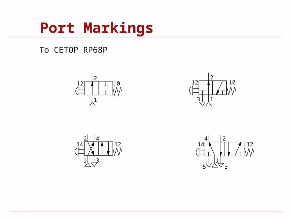
Port Markings
1
212 10
1
24
5 3
14 12
1
2
3
12 10
1
2 4
3
14 12
To CETOP RP68P
Function components
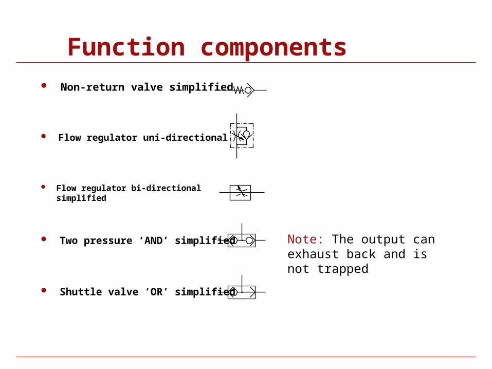
Function components Non-return valve simplified
Flow regulator uni-directional
Flow regulator bi-directional simplified
Note: The output can exhaust back and is not trapped
Two pressure ‘AND’ simplified
Shuttle valve ‘OR’ simplified
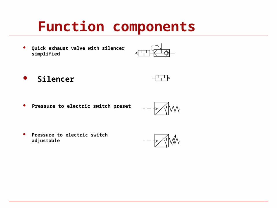
Function components Quick exhaust valve with silencer
simplified
Silencer
Pressure to electric switch preset
Pressure to electric switch adjustable
Symbol Library
Actuators
Solenoid Valves
Valves
Air Line
Function Components
Vacuum
Electrical and electronic
Symbol Library
Actuators
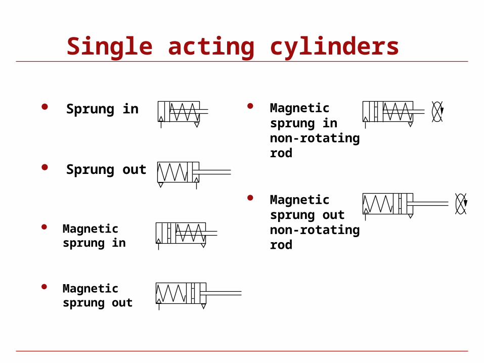
Single acting cylinders
Sprung in
Sprung out
Magnetic sprung in
Magnetic sprung out
Magnetic sprung in non-rotating rod
Magnetic sprung out non-rotating rod
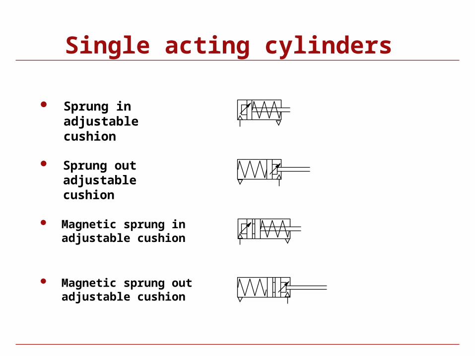
Single acting cylinders
Sprung in adjustable cushion
Sprung out adjustable cushion
Magnetic sprung in adjustable cushion
Magnetic sprung out adjustable cushion
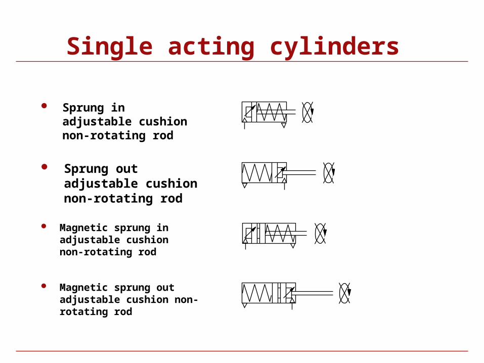
Single acting cylinders
Sprung in adjustable cushion non-rotating rod
Sprung out adjustable cushion non-rotating rod
Magnetic sprung in adjustable cushion non-rotating rod
Magnetic sprung out adjustable cushion non-rotating rod
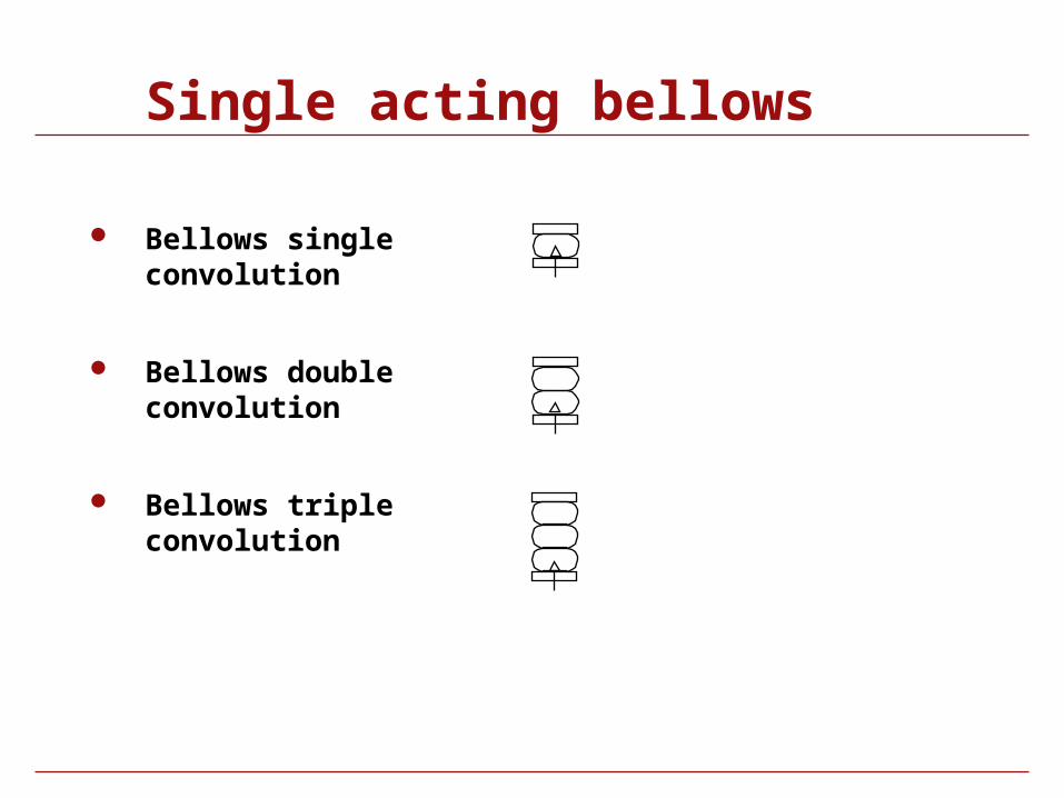
Single acting bellows
Bellows single convolution
Bellows double convolution
Bellows triple convolution
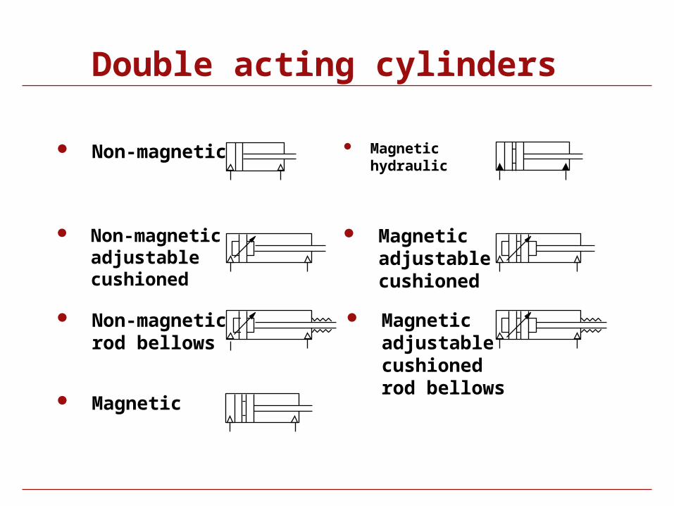
Double acting cylinders
Non-magnetic
Non-magnetic adjustable cushioned
Non-magnetic rod bellows
Magnetic hydraulic
Magnetic adjustable cushioned
Magnetic adjustable cushioned rod bellows
Magnetic
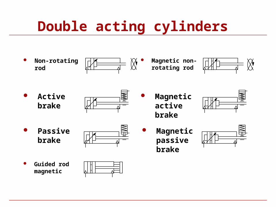
Double acting cylinders
Non-rotating rod
Active brake
Passive brake
Magnetic non-rotating rod
Magnetic active brake
Magnetic passive brake
Guided rod magnetic
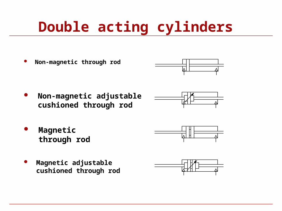
Double acting cylinders
Non-magnetic through rod
Non-magnetic adjustable cushioned through rod
Magnetic through rod
Magnetic adjustable cushioned through rod
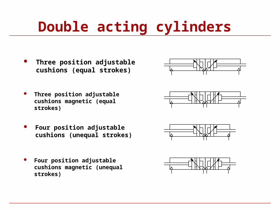
Double acting cylinders
Three position adjustable cushions (equal strokes)
Three position adjustable cushions magnetic (equal strokes)
Four position adjustable cushions (unequal strokes)
Four position adjustable cushions magnetic (unequal strokes)
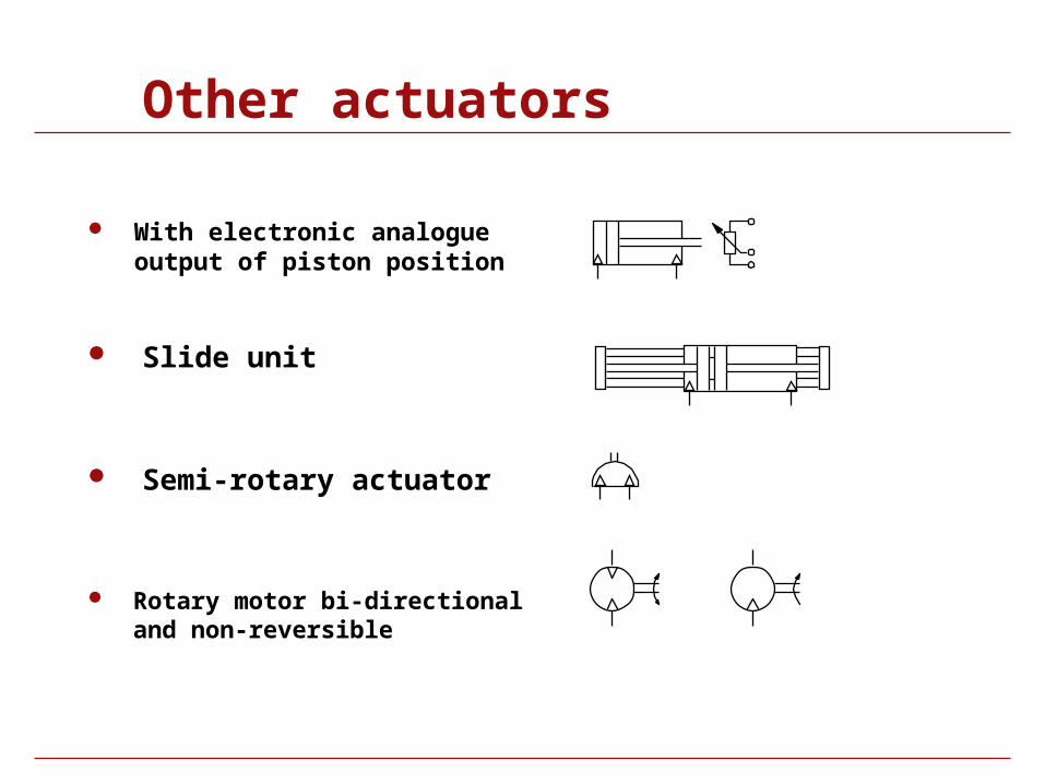
Other actuators
With electronic analogue output of piston position
Slide unit
Semi-rotary actuator
Rotary motor bi-directional and non-reversible
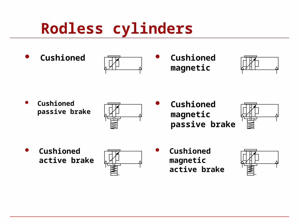
Rodless cylinders
Cushioned Cushioned magnetic
Cushioned passive brake
Cushioned magnetic passive brake
Cushioned active brake
Cushioned magnetic active brake
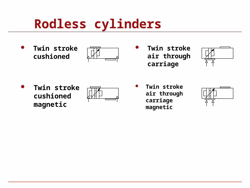
Rodless cylinders
Twin stroke cushioned
Twin stroke cushioned magnetic
Twin stroke air through carriage
Twin stroke air through carriage magnetic
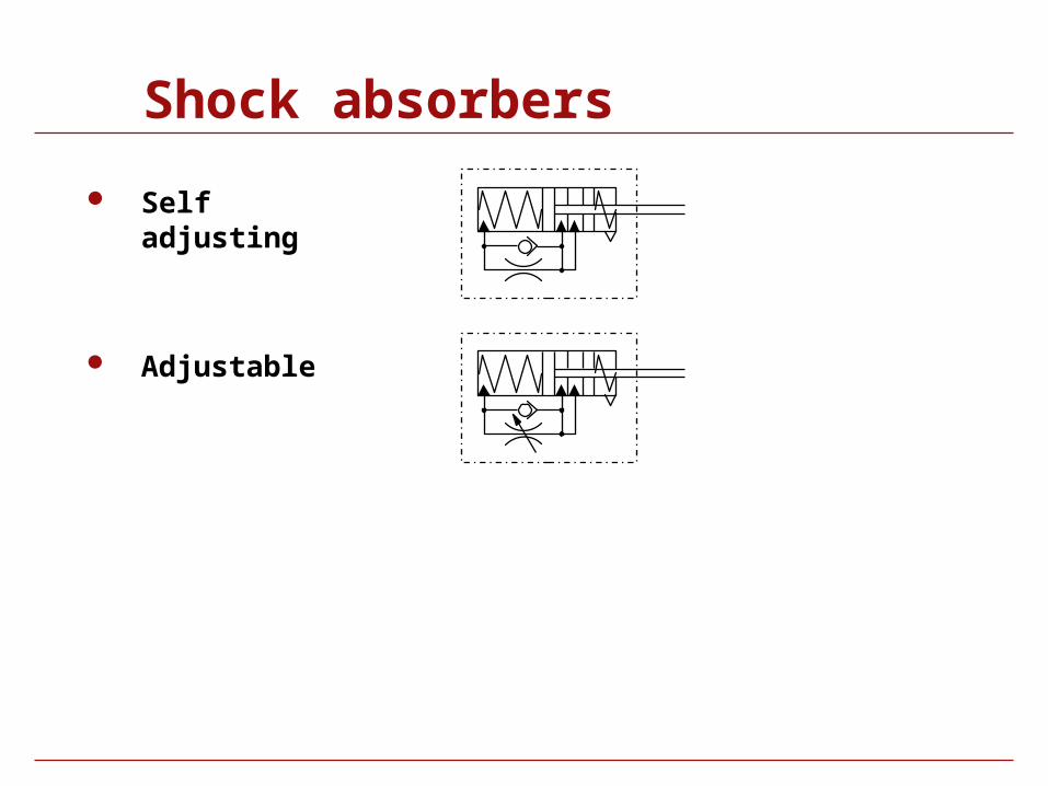
Shock absorbers
Self adjusting
Adjustable
Symbol Library
Air Line Equipment
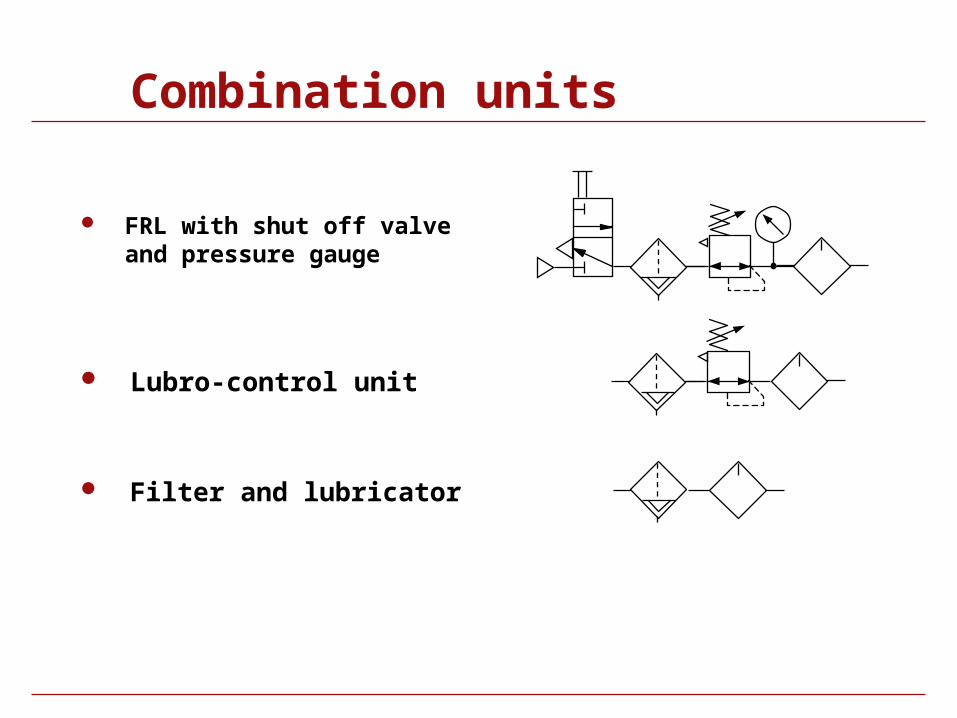
Combination units
FRL with shut off valve and pressure gauge
Lubro-control unit
Filter and lubricator
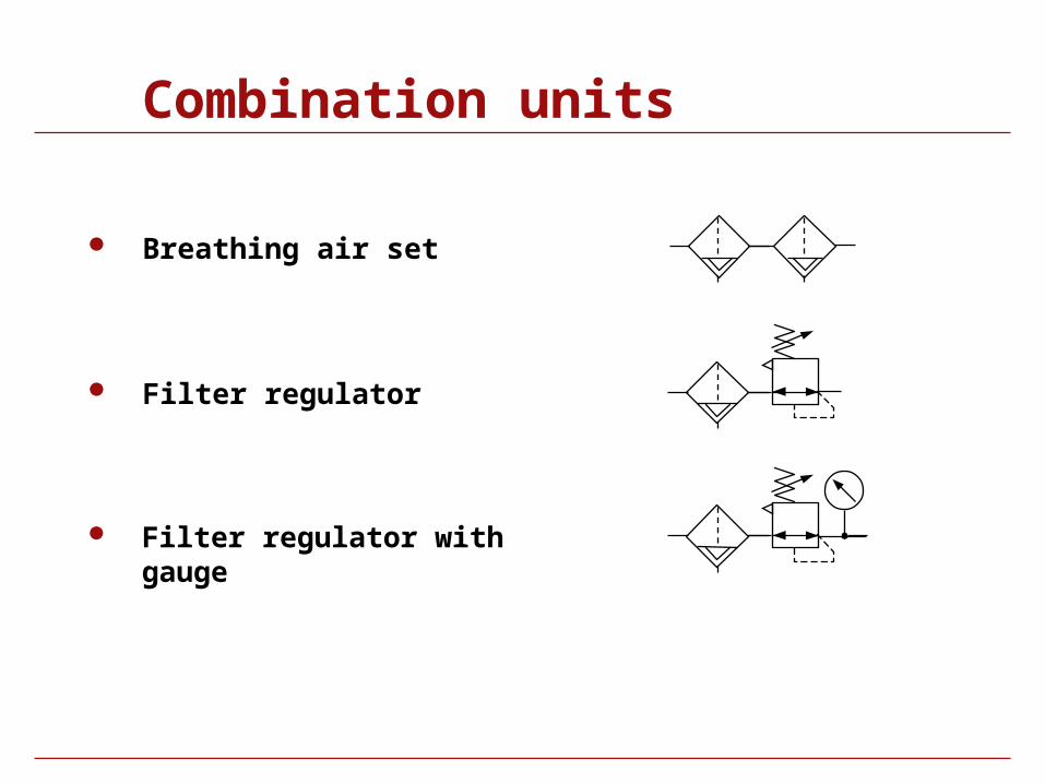
Combination units
Breathing air set
Filter regulator
Filter regulator with gauge
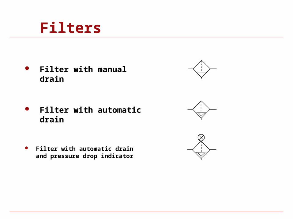
Filters
Filter with manual drain
Filter with automatic drain
Filter with automatic drain and pressure drop indicator
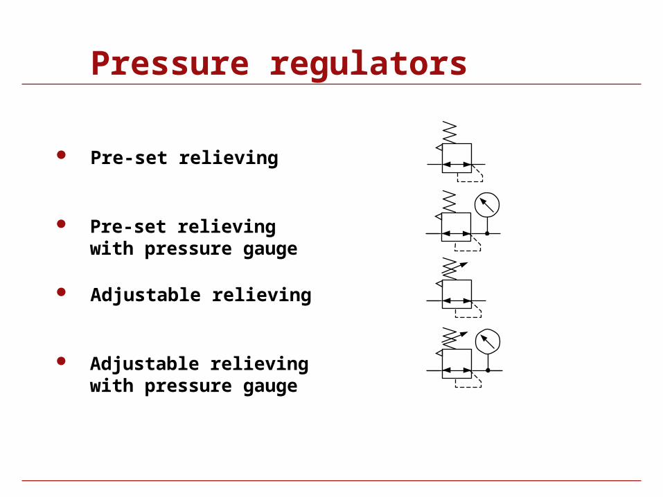
Pressure regulators
Pre-set relieving
Adjustable relieving
Adjustable relieving with pressure gauge
Pre-set relieving with pressure gauge
Pressure regulators
Pilot operated
Pilot operated regulator controlled from pilot regulator
Pilot regulator with independent feedback
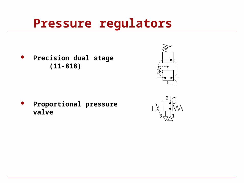
Pressure regulators
Precision dual stage (11-818)
Proportional pressure valve
1
2
3
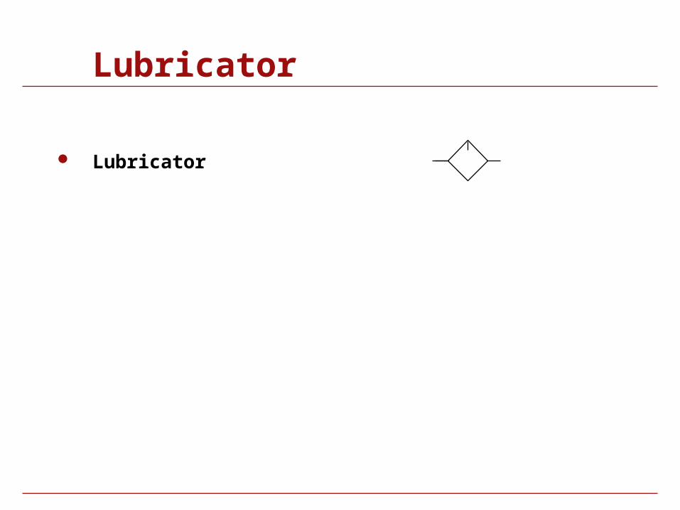
Lubricator
Lubricator
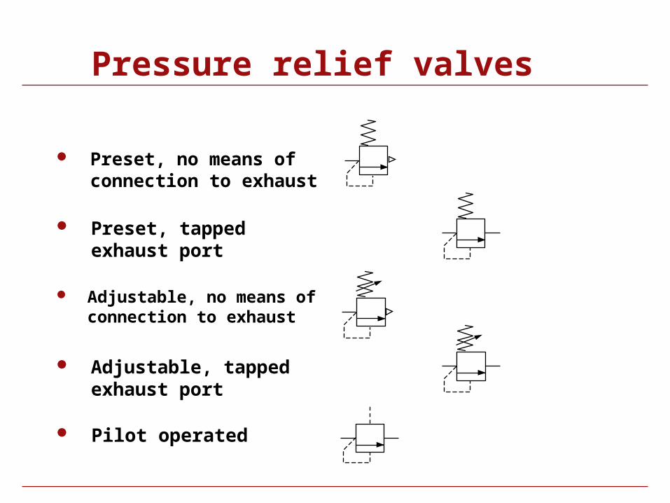
Pressure relief valves
Preset, no means of connection to exhaust
Adjustable, no means of connection to exhaust
Preset, tapped exhaust port
Pilot operated
Adjustable, tapped exhaust port
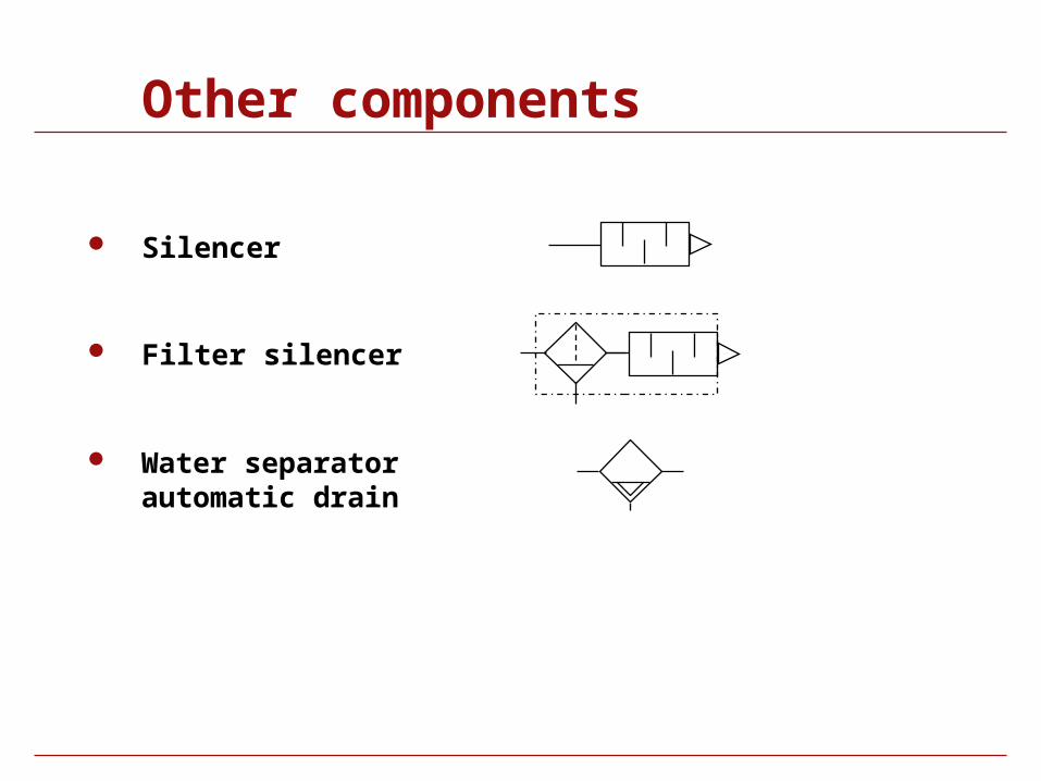
Other components
Silencer
Water separator automatic drain
Filter silencer
Symbol Library
Electrical and Electronic
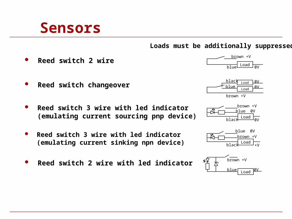
Sensors
Reed switch 2 wire
Reed switch changeover
Reed switch 3 wire with led indicator (emulating current sinking npn device)
Reed switch 3 wire with led indicator (emulating current sourcing pnp device)
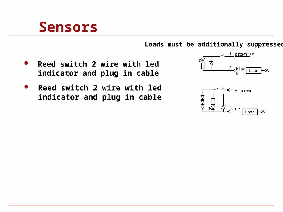
Reed switch 2 wire with led indicator
blue
brown +V
Load0V
brown +V
blue black
0V 0V Load
Load
brown +Vblue 0V
Load0V black
brown +Vblue 0V
Load+V black
brown +V
blue Load 0V
Loads must be additionally suppressed
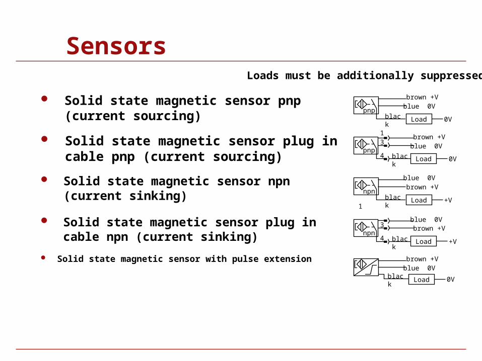
Sensors
Solid state magnetic sensor pnp (current sourcing)
Solid state magnetic sensor plug in cable pnp (current sourcing)
Solid state magnetic sensor plug in cable npn (current sinking)
Solid state magnetic sensor npn (current sinking)
Solid state magnetic sensor with pulse extension
brown +Vblue 0V
blackpnp
Load 0V
13
4pnp
brown +Vblue 0V
black Load 0V
1
brown +V
blacknpn
Load +V
blue 0V
3
4npn
brown +V
black Load +V
blue 0V
black Load 0V
brown +Vblue 0V
Loads must be additionally suppressed
Sensors
Reed switch 2 wire with led indicator and plug in cable
Reed switch 2 wire with led indicator and plug in cable
1
+ brown
blue
1
4
brown +V
black Load 0V
Load 0V
Loads must be additionally suppressed
Electrical Symbols
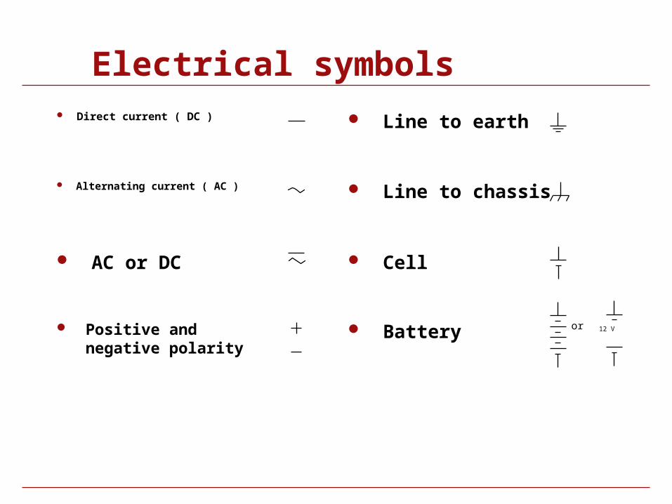
Electrical symbols Direct current ( DC )
Alternating current ( AC )
AC or DC
Positive and negative polarity
Line to earth
Line to chassis
Cell
Battery 12 Vor
Electrical Components
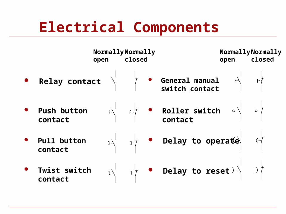
Relay contact General manual switch contact
Push button contact
Pull button contact
Twist switch contact
Roller switch contact
Delay to operate
Delay to reset
Normallyopen
Normallyclosed
Normallyopen
Normallyclosed
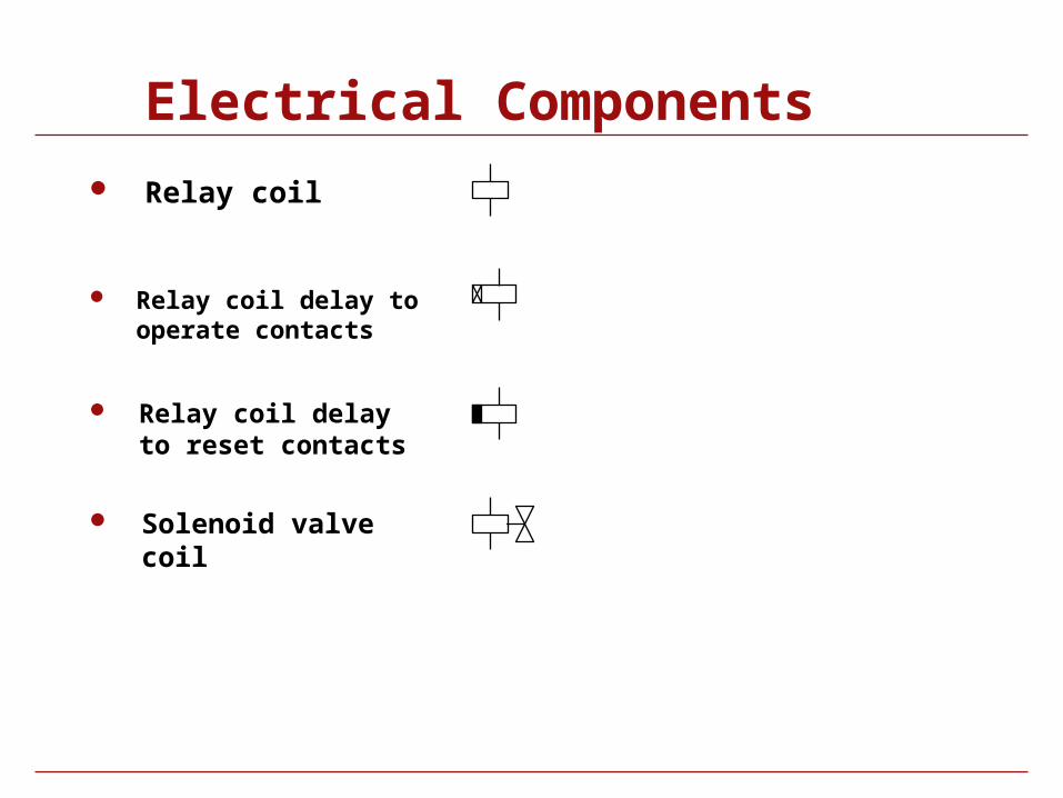
Electrical Components
Relay coil
Relay coil delay to operate contacts
Relay coil delay to reset contacts
Solenoid valve coil
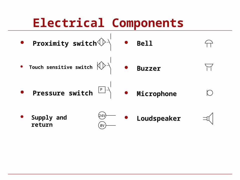
Electrical Components
Supply and return
Proximity switch
Touch sensitive switch
Pressure switch
Bell
Buzzer
Microphone
Loudspeaker
P
24V
0V
Electronic Component Symbols
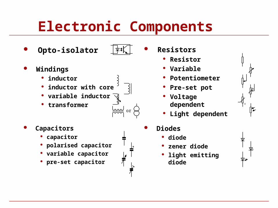
Electronic Components
Opto-isolator
Windings inductor inductor with core variable inductor transformer
Capacitors capacitor polarised capacitor variable capacitor pre-set capacitor
Diodes diode zener diode light emitting diode
or
V
Resistors Resistor Variable Potentiometer Pre-set pot Voltage dependent Light dependent
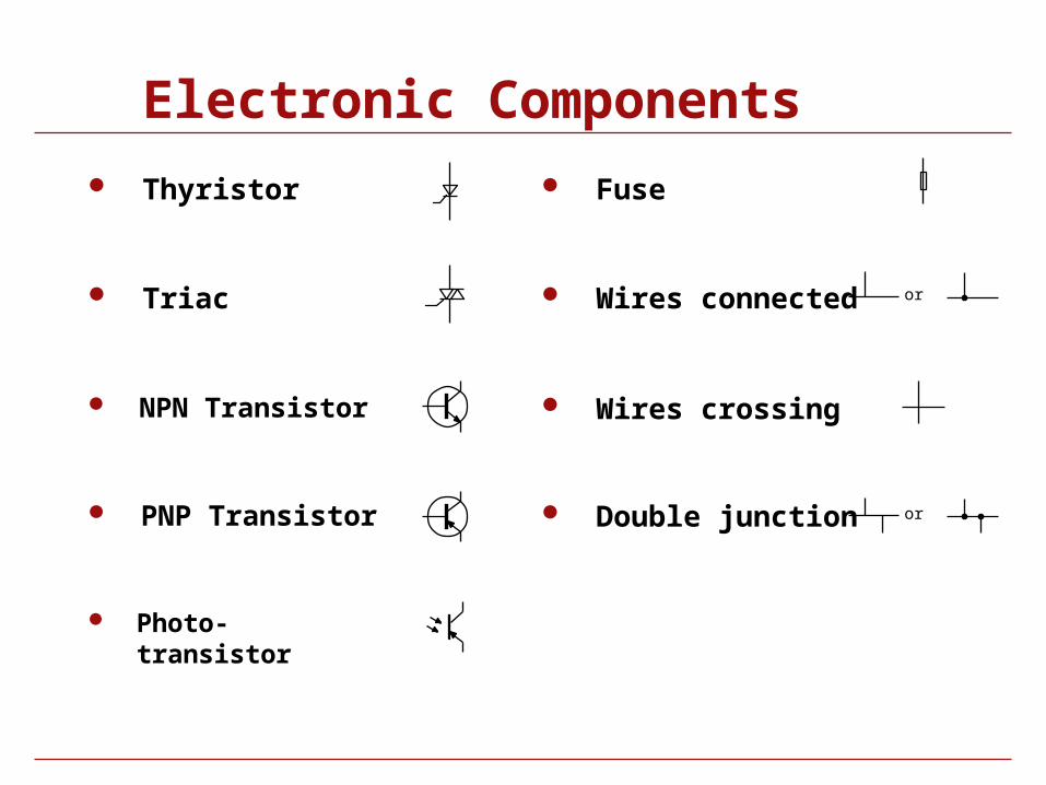
Electronic Components
Thyristor
Photo-transistor
Triac
NPN Transistor
PNP Transistor
Fuse
Wires connected
Wires crossing
Double junction
or
or
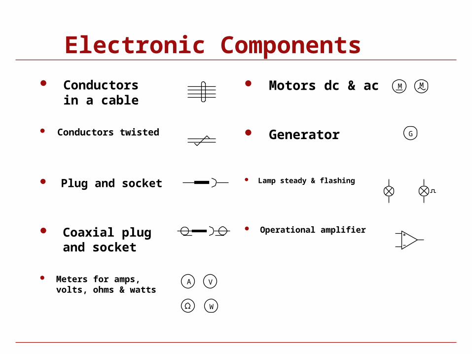
Electronic Components
Conductors in a cable
Meters for amps, volts, ohms & watts
Conductors twisted
Plug and socket
Coaxial plug and socket
Motors dc & ac
Generator
Lamp steady & flashing
Operational amplifier
MM
A
W
V
G
Symbol Library
Function Fittings and Components

Function fittings
Blocking fitting1
212
1
2
1
2
Pressure reducing fitting
Pneumatic sensor fitting
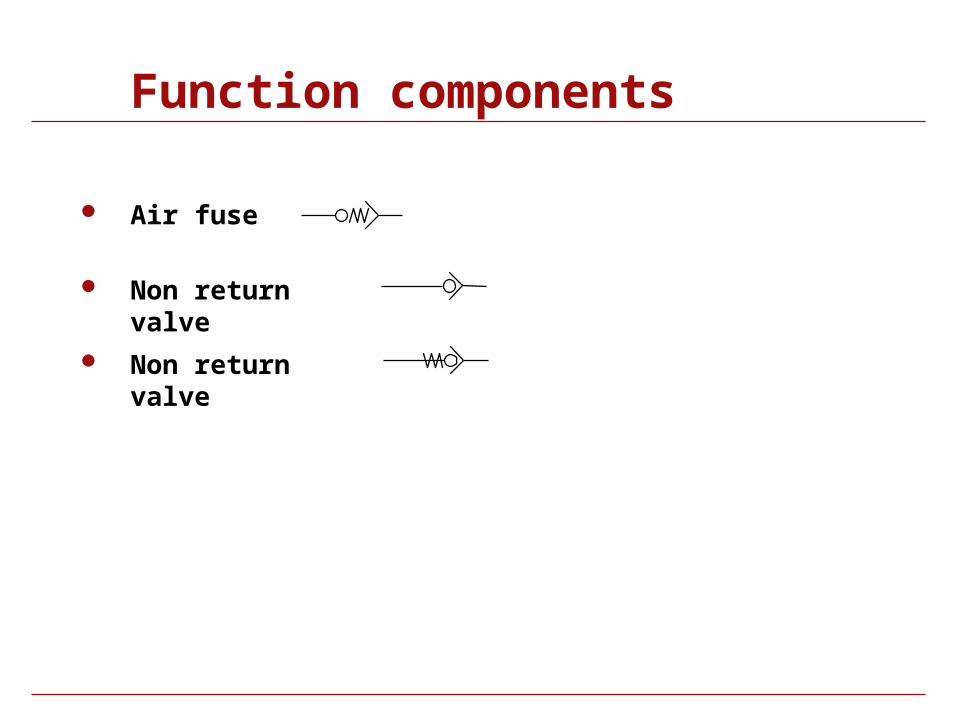
Function components
Air fuse
Non return valve
Non return valve
Function components
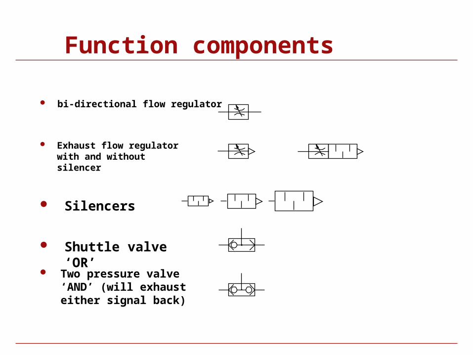
bi-directional flow regulator
Exhaust flow regulator with and without silencer
Shuttle valve ‘OR’
Silencers
Two pressure valve ‘AND’ (will exhaust either signal back)
Function components
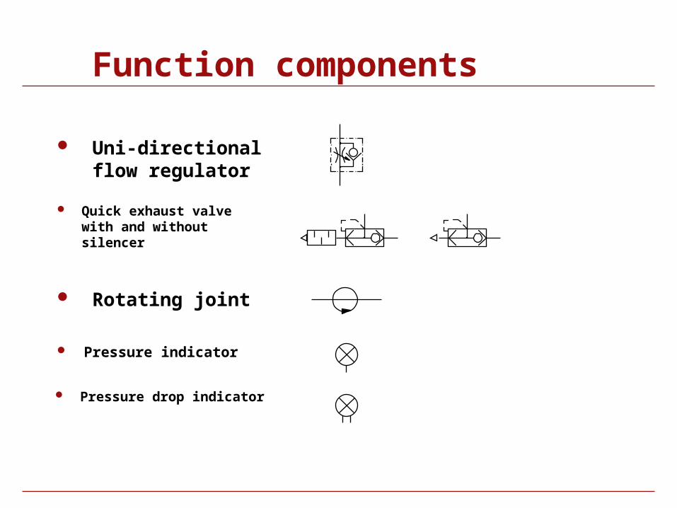
Uni-directional flow regulator
Rotating joint
Quick exhaust valve with and without silencer
Pressure indicator
Pressure drop indicator
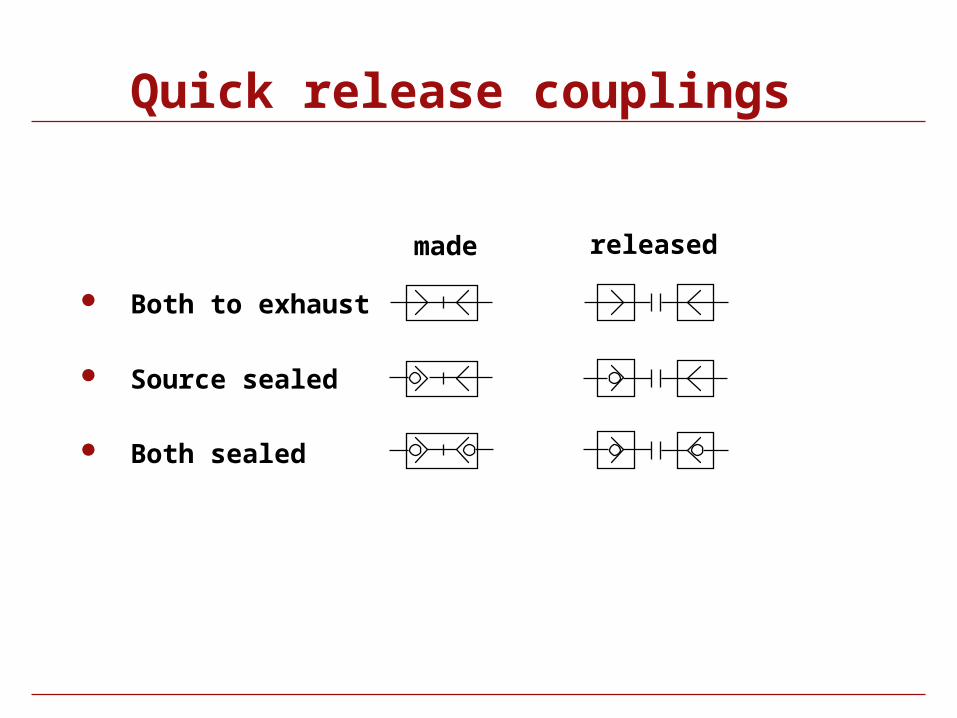
Quick release couplings
Both sealed
Source sealed
Both to exhaust
made released
Symbol Library
Solenoid Valves
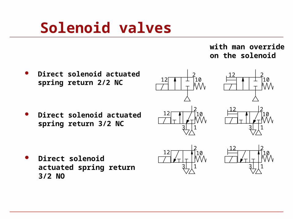
Solenoid valves
Direct solenoid actuated spring return 2/2 NC
Direct solenoid actuated spring return 3/2 NC
Direct solenoid actuated spring return 3/2 NO
with man override on the solenoid
2
12 210
21012
210
12
13
1
2
3
1012
1
2
3
12 10
13
12 10
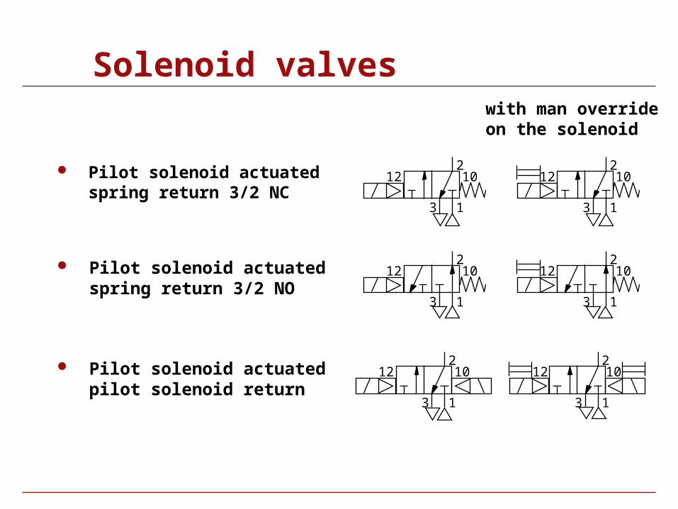
Solenoid valves
Pilot solenoid actuated spring return 3/2 NC
Pilot solenoid actuated spring return 3/2 NO
Pilot solenoid actuated pilot solenoid return
1
2
3
12 10
1
2
3
1012
1
2
3
12 10
1
2
3
12 10
1
2
3
12 10
1
2
3
12 10
with man override on the solenoid
Solenoid valves
1
24
5 3
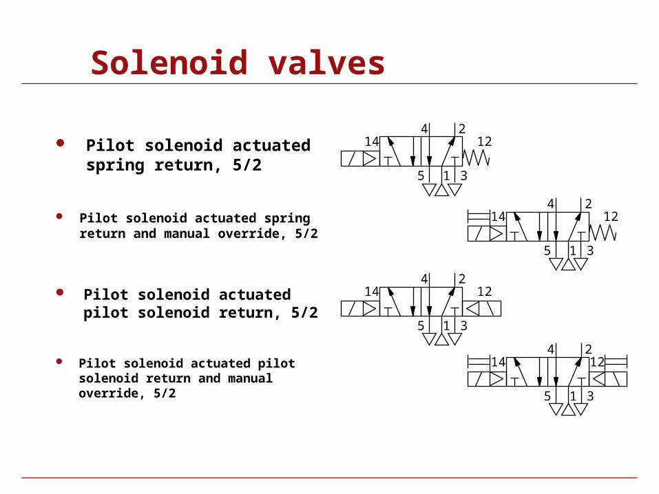
14 12 Pilot solenoid actuated spring return, 5/2
Pilot solenoid actuated spring return and manual override, 5/2
Pilot solenoid actuated pilot solenoid return, 5/2
Pilot solenoid actuated pilot solenoid return and manual override, 5/2
1
24
5 3
14 12
1
24
5 3
14 12
1
24
5 3
14 12
Solenoid valves
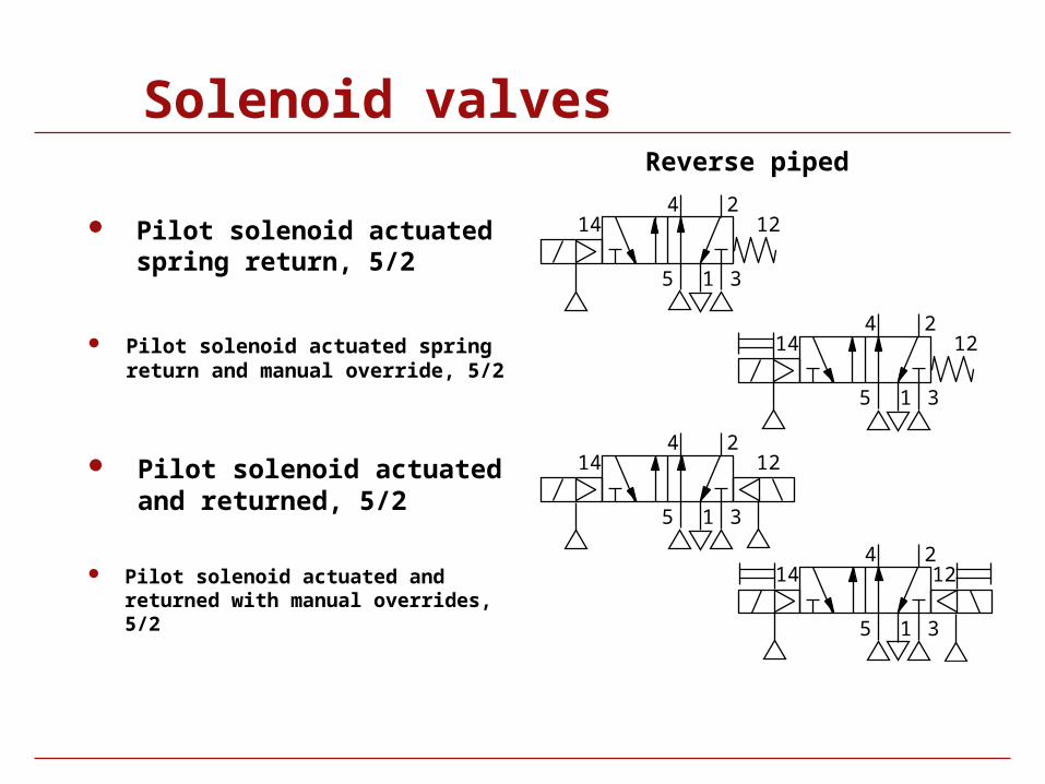
24 Pilot solenoid actuated
spring return, 5/2
Pilot solenoid actuated spring return and manual override, 5/2
Pilot solenoid actuated and returned, 5/2
Pilot solenoid actuated and returned with manual overrides, 5/2
15 3
14 12
1
24
5 3
14 12
24
15 3
14 12
1
24
5 3
14 12
Reverse piped
Solenoid valves
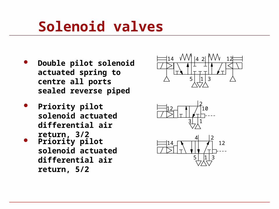
Double pilot solenoid actuated spring to centre all ports sealed reverse piped
1
2
3
1012
1
24
5 3
14 12
Priority pilot solenoid actuated differential air return, 3/2
Priority pilot solenoid actuated differential air return, 5/2
1
24
5 3
14 12
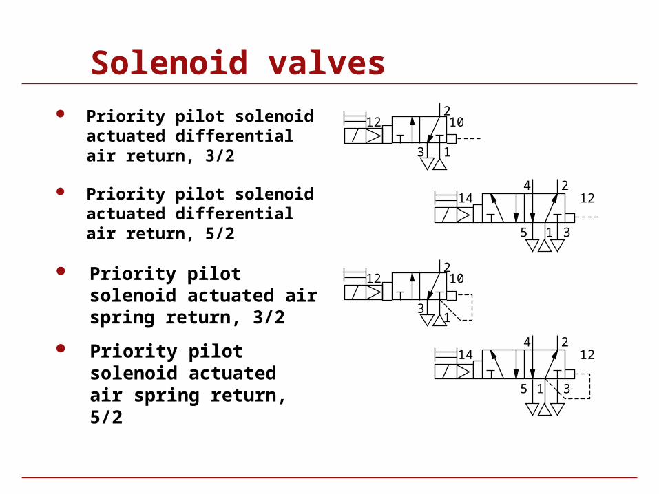
Solenoid valves Priority pilot solenoid
actuated differential air return, 3/2
Priority pilot solenoid actuated air spring return, 5/2
1
2
3
1012
24
15 3
14 12
1
2
3
1012
1
24
5 3
14 12 Priority pilot solenoid actuated differential air return, 5/2
Priority pilot solenoid actuated air spring return, 3/2
Solenoid valves
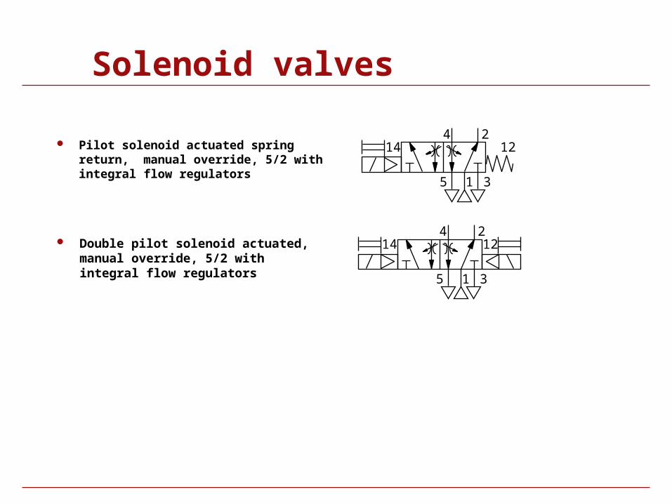
Pilot solenoid actuated spring return, manual override, 5/2 with integral flow regulators
Double pilot solenoid actuated, manual override, 5/2 with integral flow regulators
1
24
5 3
14 12
1
24
5 3
14 12
Solenoid valves
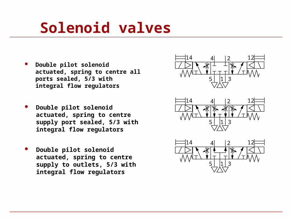
Double pilot solenoid actuated, spring to centre all ports sealed, 5/3 with integral flow regulators
Double pilot solenoid actuated, spring to centre supply port sealed, 5/3 with integral flow regulators
Double pilot solenoid actuated, spring to centre supply to outlets, 5/3 with integral flow regulators
1
24
5 3
14 12
1
24
5 3
14 12
1
24
5 3
14 12
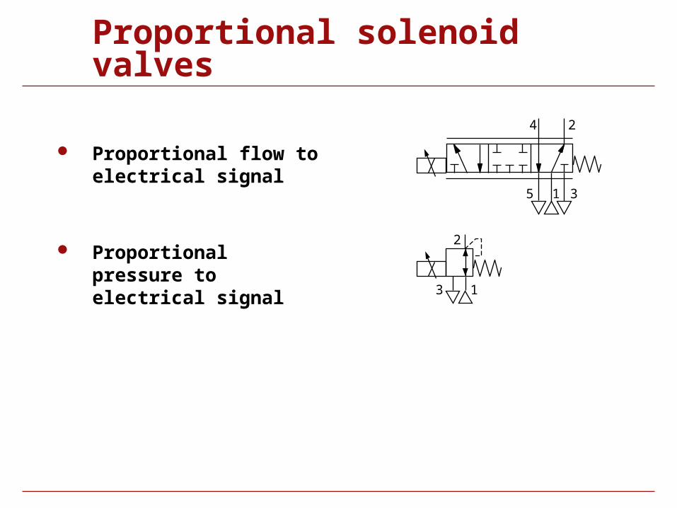
Proportional solenoid valves
Proportional flow to electrical signal
Proportional pressure to electrical signal
24
15 3
1
2
3
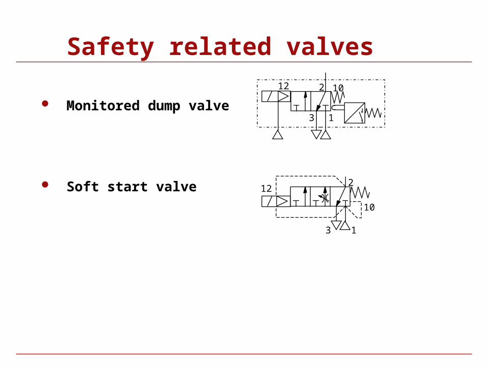
Safety related valves
Monitored dump valve1
2
3
1012
Soft start valve
1
2
3
12
10

Symbol Library
Valves
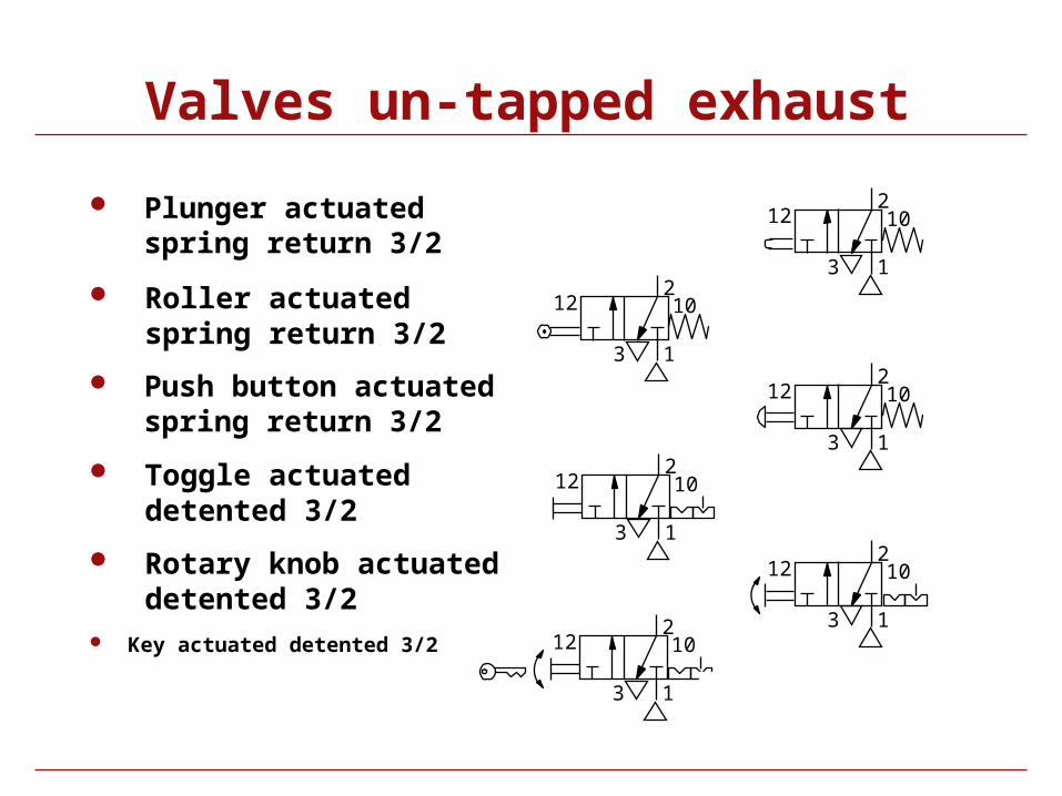
Valves un-tapped exhaust
Plunger actuated spring return 3/2
Rotary knob actuated detented 3/2
Key actuated detented 3/2
1
2
3
12 10
1
2
3
12 10
1
2
3
12 10
1
2
3
12 10
1
2
3
12 10
Push button actuated spring return 3/2
Roller actuated spring return 3/2
Toggle actuated detented 3/2
1
2
3
12 10
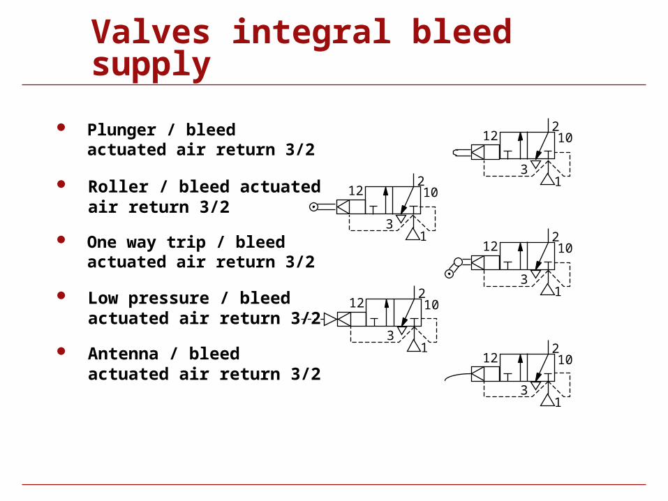
Valves integral bleed supply
Plunger / bleed actuated air return 3/2
Antenna / bleed actuated air return 3/2
One way trip / bleed actuated air return 3/2
Roller / bleed actuated air return 3/2
Low pressure / bleed actuated air return 3/2
212 10
13
212 10
13
212 10
13
212 10
13
212 10
13
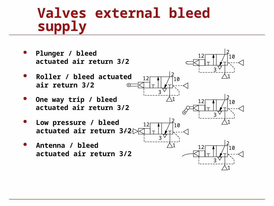
Valves external bleed supply
Plunger / bleed actuated air return 3/2
Antenna / bleed actuated air return 3/2
2
One way trip / bleed actuated air return 3/2
Roller / bleed actuated air return 3/2
Low pressure / bleed actuated air return 3/2
212 10
31
212 10
31
12 10
31
212 10
31
212 10
31
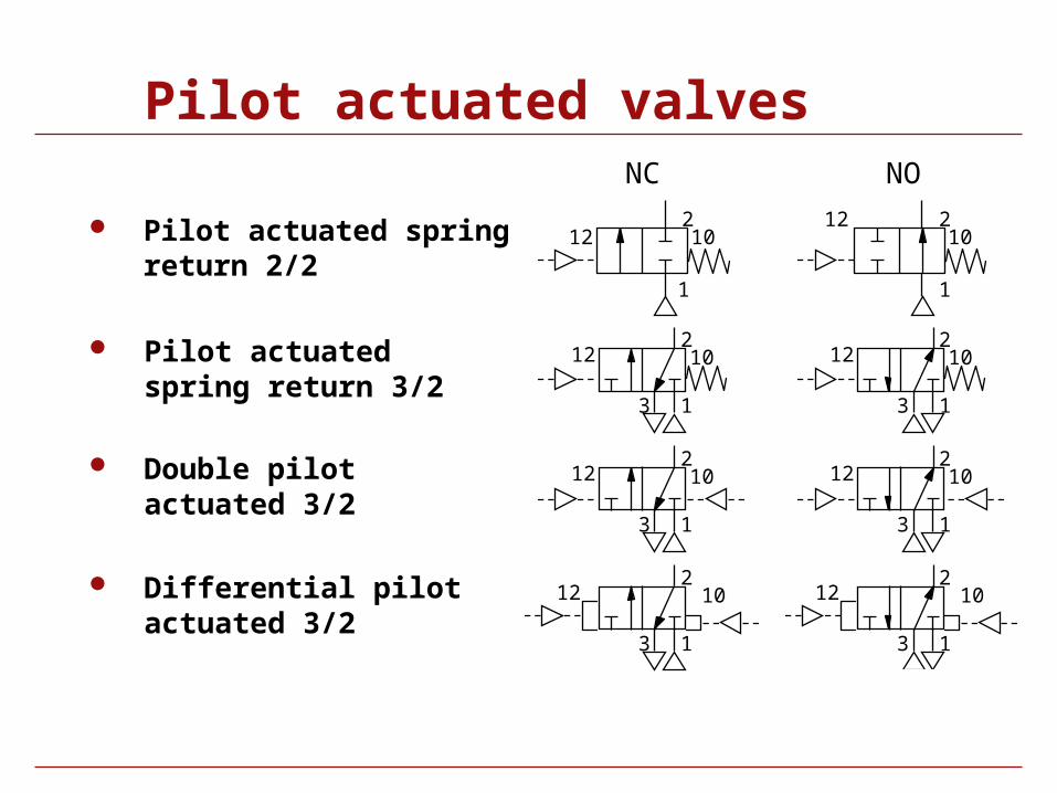
Pilot actuated valves
Pilot actuated spring return 2/2
Pilot actuated spring return 3/2
Differential pilot actuated 3/2
1
2
3
12 10
21012
1
12 210
1
NC NO
2
13
12 10
1
2
3
12 102
13
12 10 Double pilot actuated 3/2
2
13
12 10
1
2
3
12 10
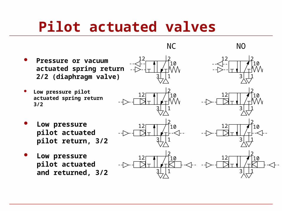
Pilot actuated valves
Pressure or vacuum actuated spring return 2/2 (diaphragm valve)
Low pressure pilot actuated spring return 3/2
Low pressure pilot actuated and returned, 3/2
NC NO
Low pressure pilot actuated pilot return, 3/2
1
2
3
1210
2
13
1210
2
13
12 10
1
2
3
12 10
2
13
12 10
1
2
3
12 102
13
12 10
1
2
3
12 10
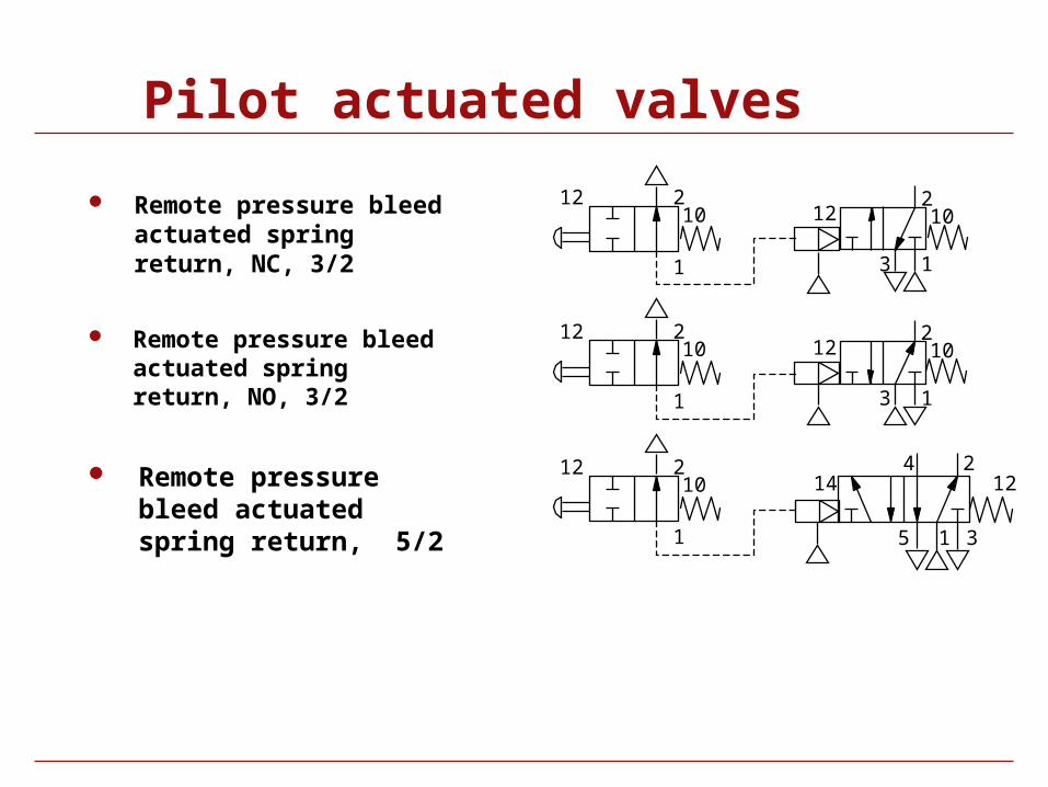
Pilot actuated valves
Remote pressure bleed actuated spring return, NC, 3/2
Remote pressure bleed actuated spring return, NO, 3/2
Remote pressure bleed actuated spring return, 5/2
1
2
3
12 1012 2
10
1
12 210
1 1
24
5 3
14 12
2
13
12 1012 2
10
1
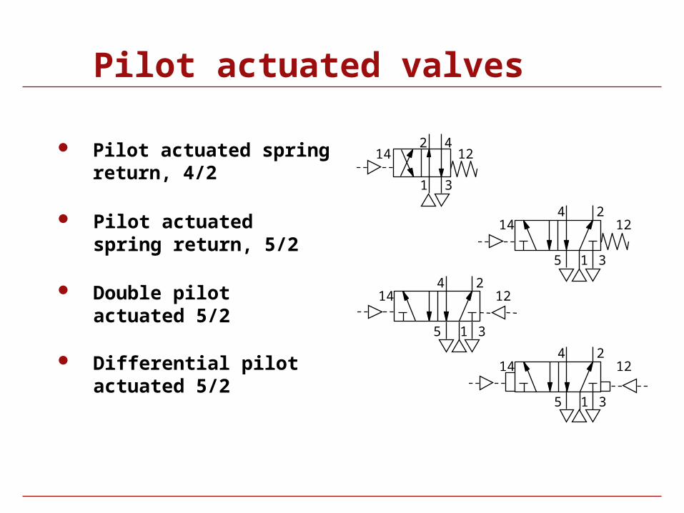
Pilot actuated valves
Pilot actuated spring return, 4/2
Pilot actuated spring return, 5/2
Double pilot actuated 5/2
24 Differential pilot actuated 5/2
1
2 4
3
14 12
15 3
14 12
1
24
5 3
14 12
1
24
5 3
14 12
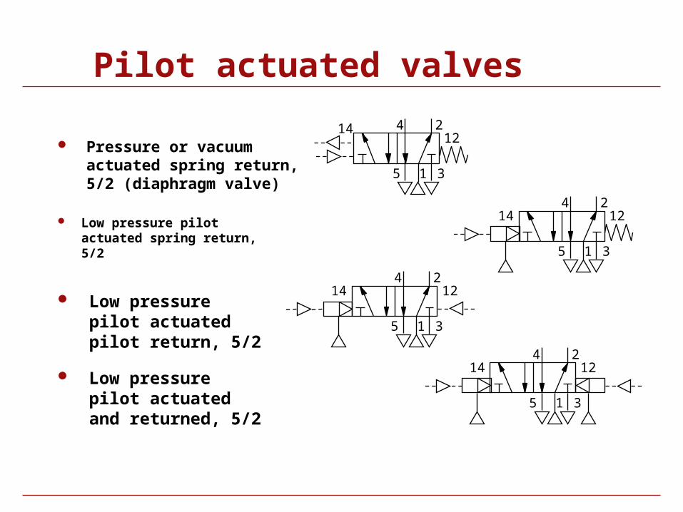
Pilot actuated valves
Pressure or vacuum actuated spring return, 5/2 (diaphragm valve)
Low pressure pilot actuated spring return, 5/2
Low pressure pilot actuated and returned, 5/2
Low pressure pilot actuated pilot return, 5/2
1
24
5 3
1412
1
24
5 3
14 12
1
24
5 3
14 12
1
24
5 3
14 12
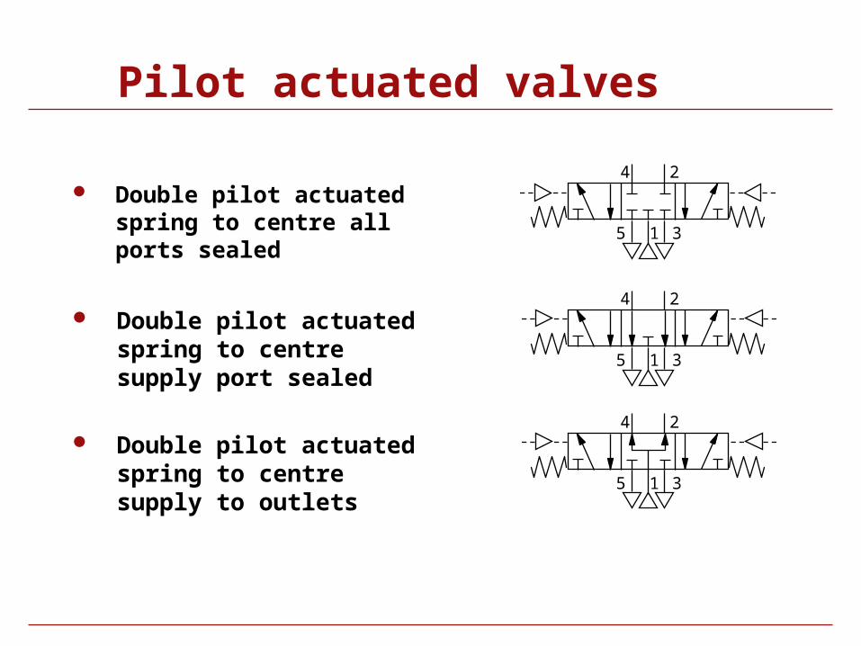
Pilot actuated valves
Double pilot actuated spring to centre all ports sealed
Double pilot actuated spring to centre supply port sealed
Double pilot actuated spring to centre supply to outlets
1
24
5 3
1
24
5 3
1
24
5 3
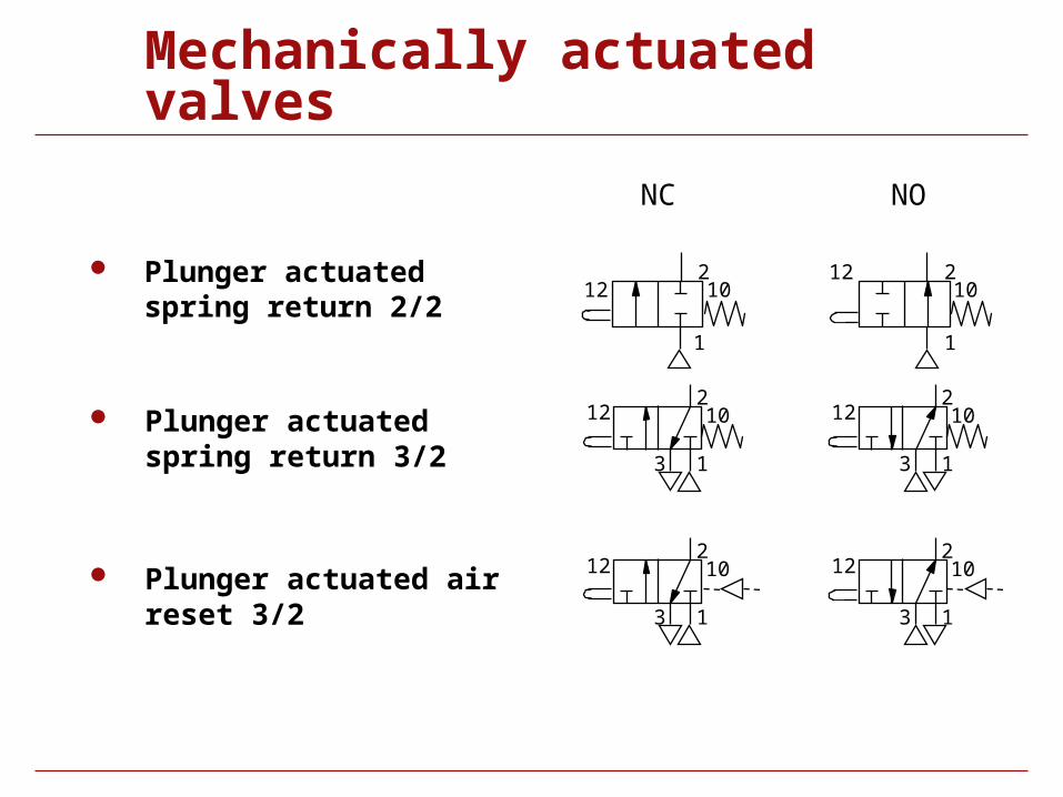
Mechanically actuated valves
Plunger actuated spring return 2/2
Plunger actuated spring return 3/2
Plunger actuated air reset 3/2
NC NO
2
13
12 10
12 210
1
1
2
3
12 10
21012
1
1
2
3
12 102
13
12 10
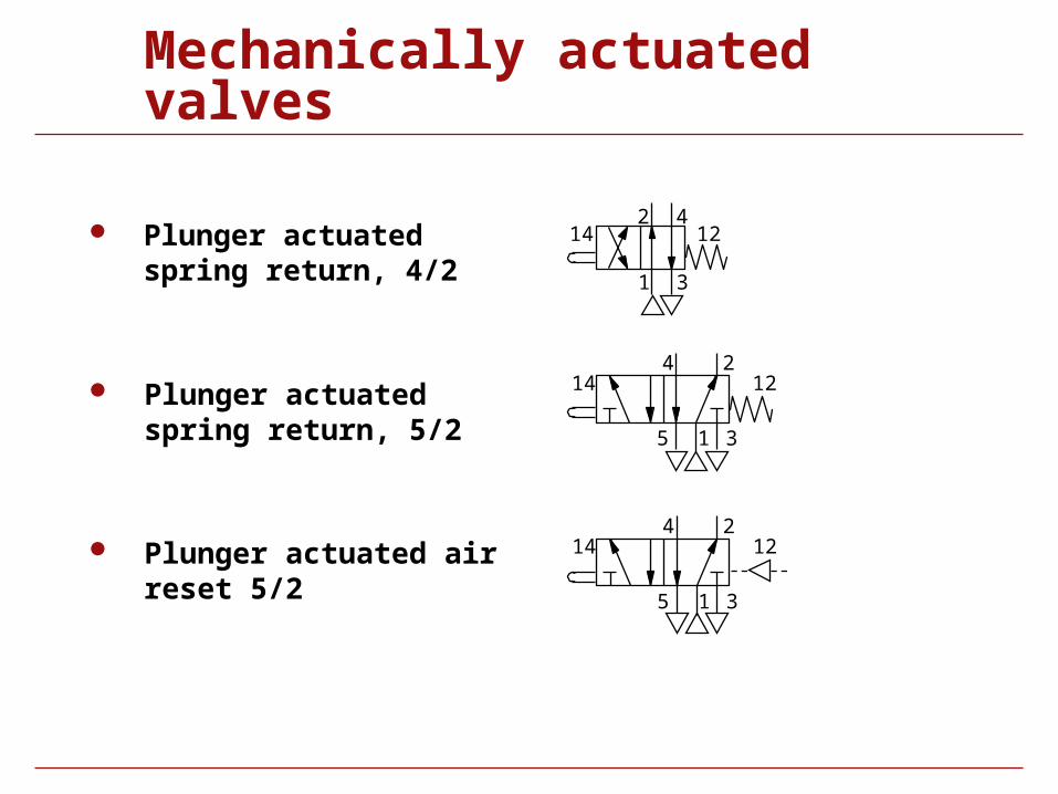
Mechanically actuated valves
Plunger actuated spring return, 4/2
Plunger actuated spring return, 5/2
Plunger actuated air reset 5/2
1
24
5 3
14 12
1
2 4
3
14 12
1
24
5 3
14 12
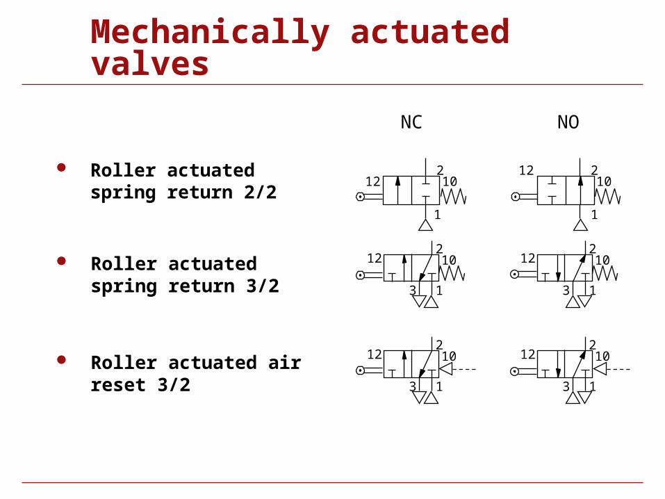
Mechanically actuated valves
Roller actuated spring return 2/2
Roller actuated spring return 3/2
Roller actuated air reset 3/2
2
NC NO
2
13
12 10
13
12 10
2
13
12 10
1
2
3
12 10
12 210
1
21012
1
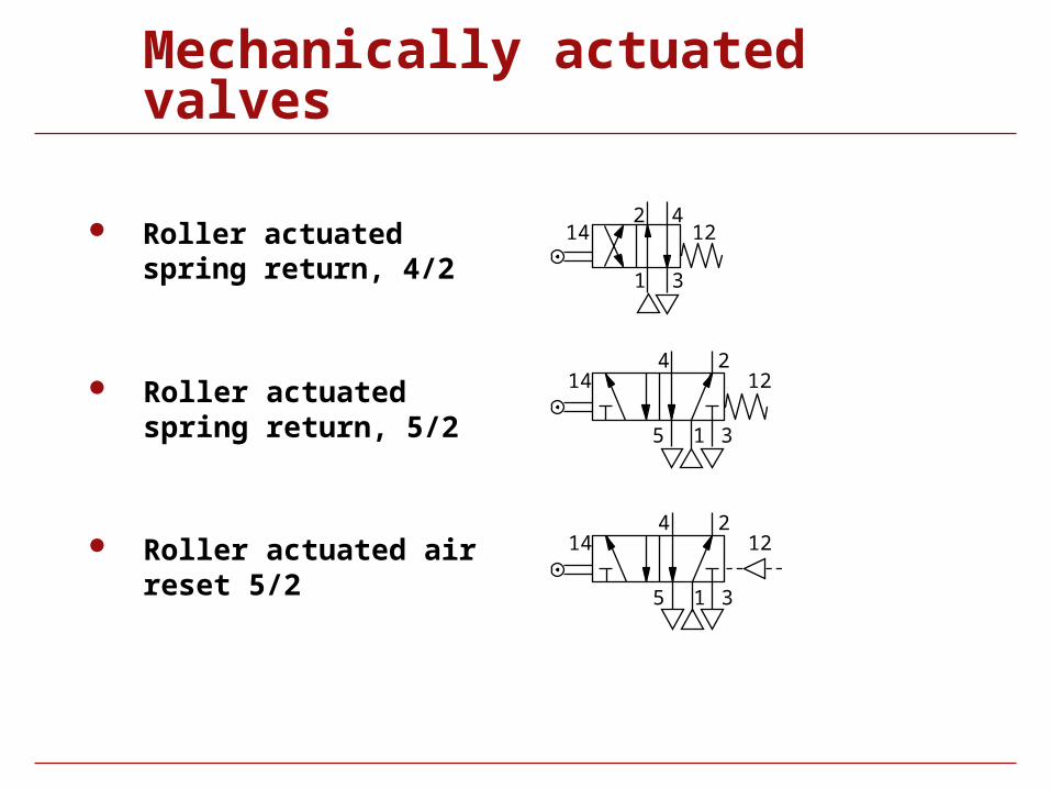
Mechanically actuated valves
Roller actuated spring return, 4/2
Roller actuated spring return, 5/2
Roller actuated air reset 5/2
1
24
5 3
14 12
1
2 4
3
14 12
1
24
5 3
14 12
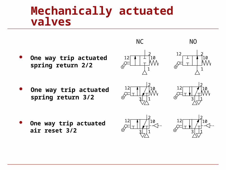
Mechanically actuated valves
One way trip actuated spring return 2/2
One way trip actuated spring return 3/2
One way trip actuated air reset 3/2
NC NO
1
2
3
12 102
13
12 10
12 210
1
21012
1
1
2
3
12 102
13
12 10
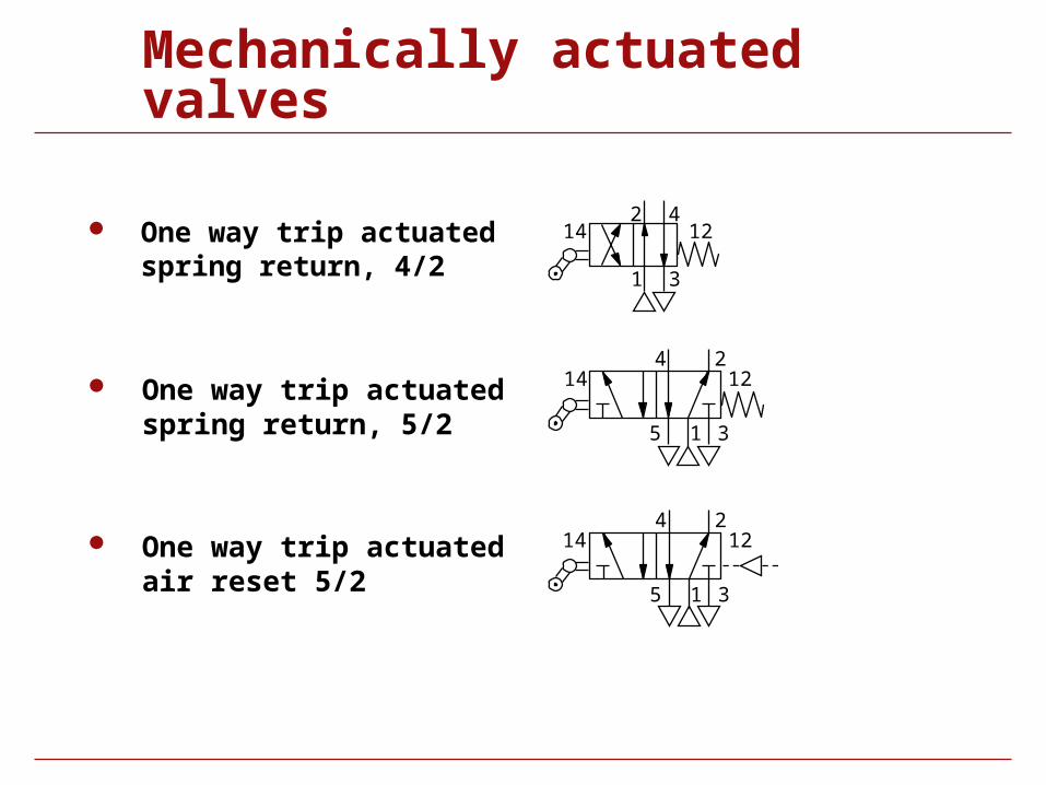
Mechanically actuated valves
One way trip actuated spring return, 4/2
One way trip actuated spring return, 5/2
One way trip actuated air reset 5/2
1
24
5 3
14 12
1
2 4
3
14 12
1
24
5 3
14 12
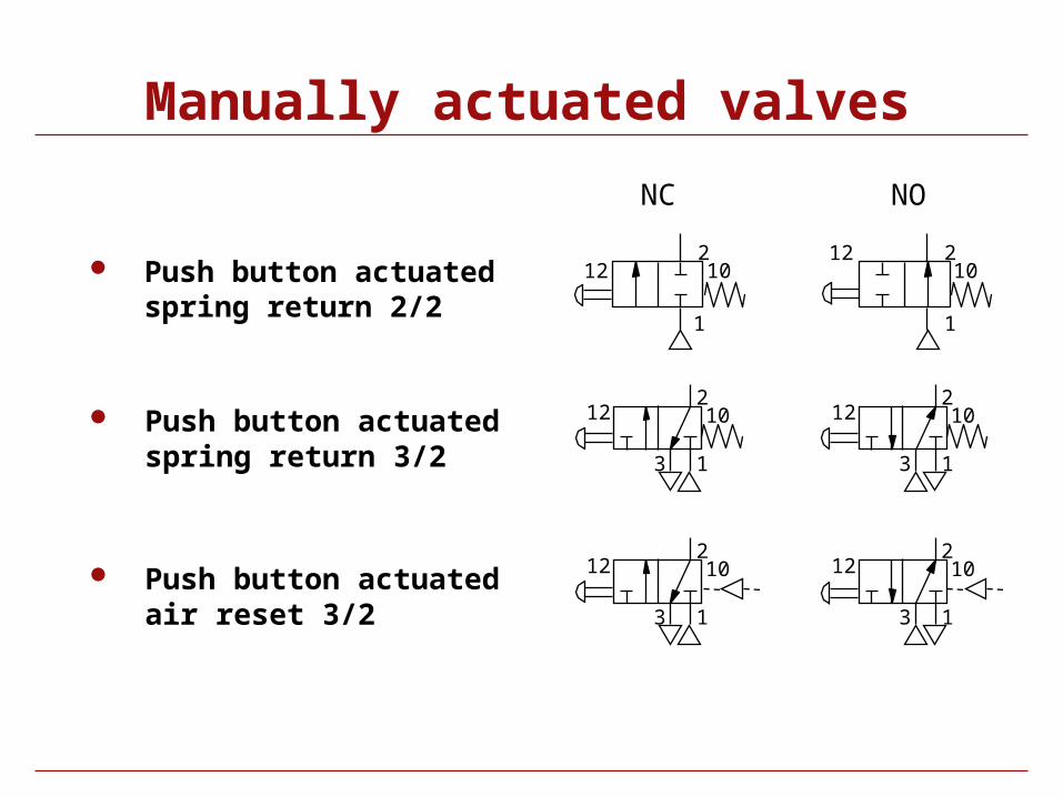
Manually actuated valves
Push button actuated spring return 2/2
Push button actuated spring return 3/2
Push button actuated air reset 3/2
NC NO
21012
1
12 210
1
2
13
12 10
1
2
3
12 10
1
2
3
12 102
13
12 10
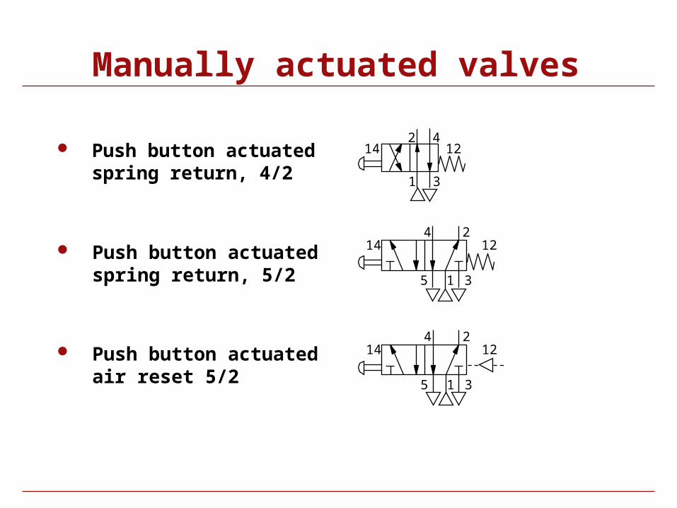
Manually actuated valves
Push button actuated spring return, 4/2
Push button actuated spring return, 5/2
Push button actuated air reset 5/2
1
24
5 3
14 12
1
2 4
3
14 12
1
24
5 3
14 12
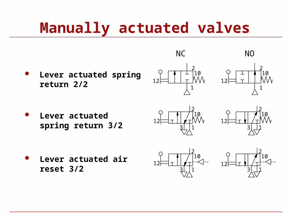
Manually actuated valves
Lever actuated spring return 2/2
Lever actuated spring return 3/2
Lever actuated air reset 3/2
NC NO
12
210
1
2
1312
10
1
2
312
10
210
121
1
2
312
1012
2
13
10
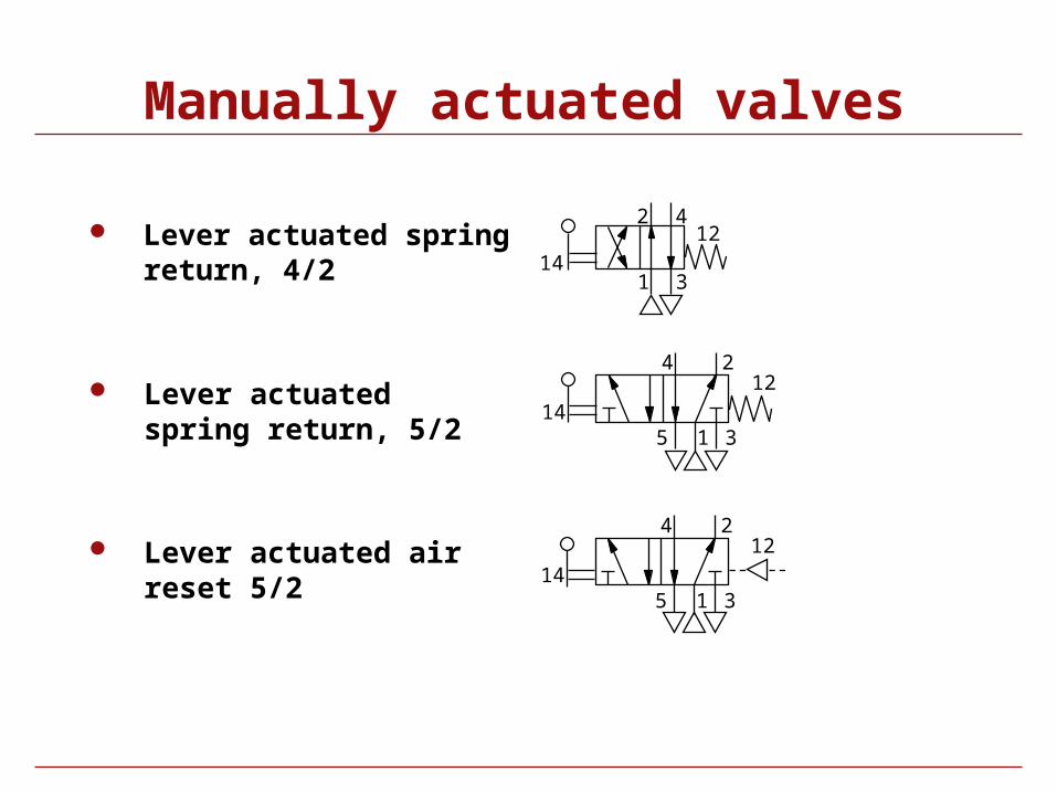
Manually actuated valves
Lever actuated spring return, 4/2
Lever actuated spring return, 5/2
Lever actuated air reset 5/2 1
24
5 314
12
1
24
5 314
12
1
2 4
314
12
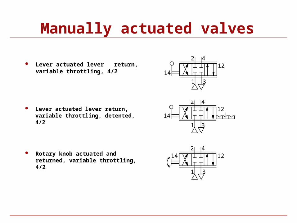
Manually actuated valves
Lever actuated lever return, variable throttling, 4/2
Lever actuated lever return, variable throttling, detented, 4/2
Rotary knob actuated and returned, variable throttling, 4/2
14
2 4
1 3
12
142 4
1 3
12
2 412
1 3
14
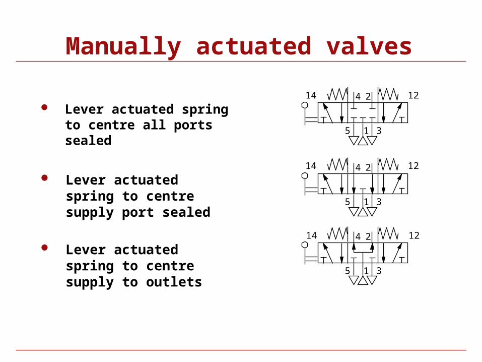
Manually actuated valves
Lever actuated spring to centre all ports sealed
Lever actuated spring to centre supply port sealed
Lever actuated spring to centre supply to outlets
1
24
5 3
1
24
5 3
1
24
5 3
14 12
14 12
14 12
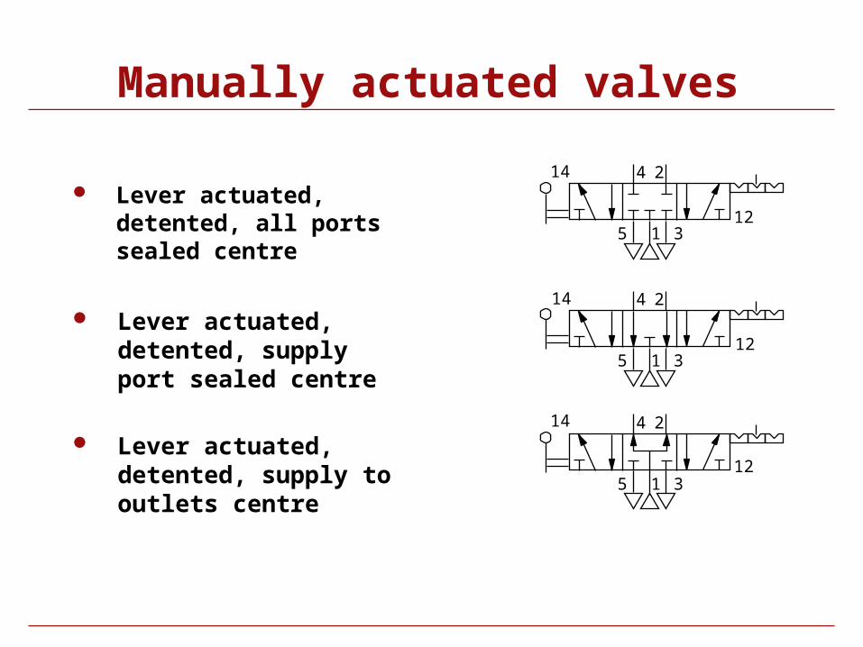
Manually actuated valves
Lever actuated, detented, all ports sealed centre
Lever actuated, detented, supply port sealed centre
Lever actuated, detented, supply to outlets centre 1
24
5 3
14
12
1
24
5 3
14
12
1
24
5 3
14
12
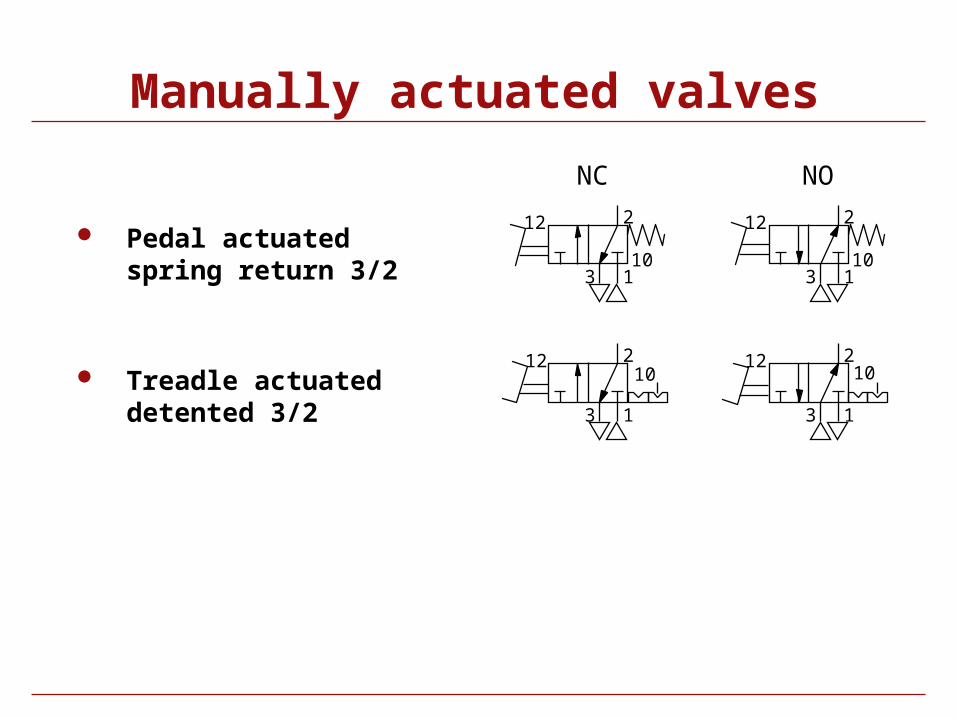
Manually actuated valves
NC NO
Pedal actuated spring return 3/2
Treadle actuated detented 3/2
1
2
3
12
10
2
13
12
10
1
2
3
1210
2
13
1210
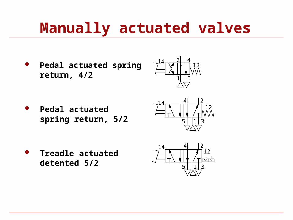
Manually actuated valves
Pedal actuated spring return, 4/2
Pedal actuated spring return, 5/2
Treadle actuated detented 5/2
1
2 4
3
1412
1
24
5 3
1412
1
24
5 3
1412
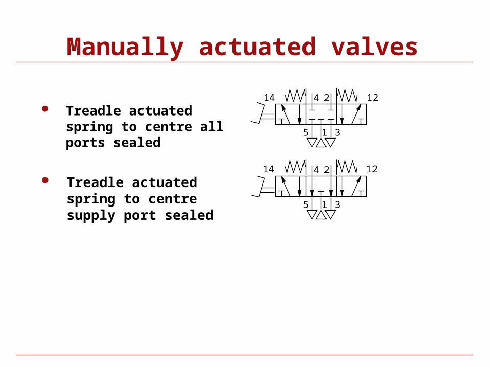
Manually actuated valves
Treadle actuated spring to centre all ports sealed
Treadle actuated spring to centre supply port sealed
1
24
5 3
14 12
1
24
5 3
14 12
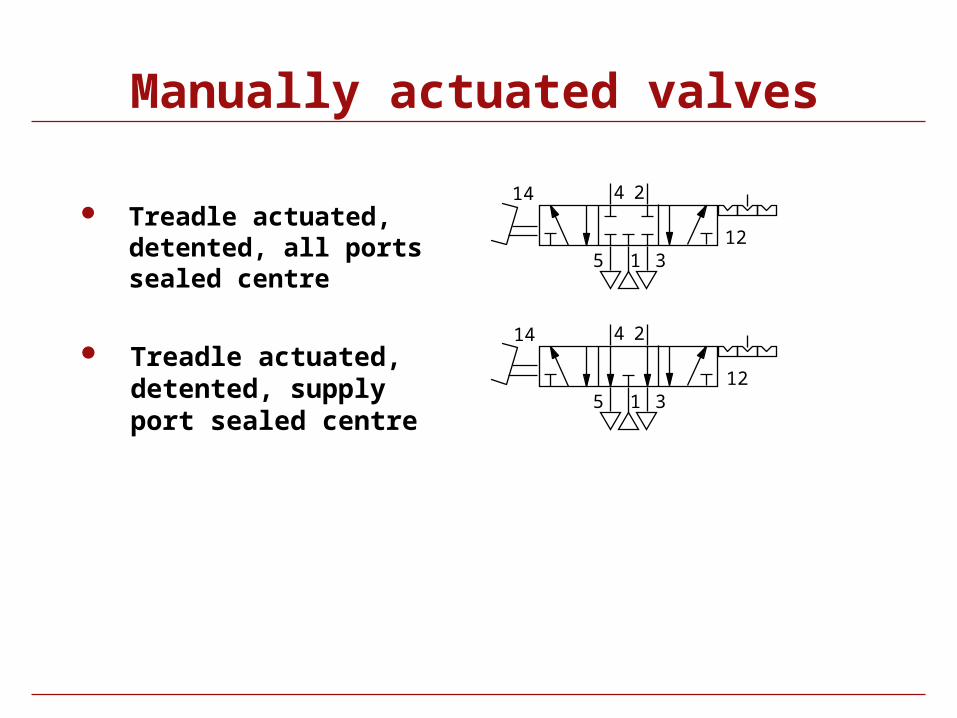
Manually actuated valves
Treadle actuated, detented, all ports sealed centre
Treadle actuated, detented, supply port sealed centre
1
24
5 3
1
24
5 3
14
12
14
12
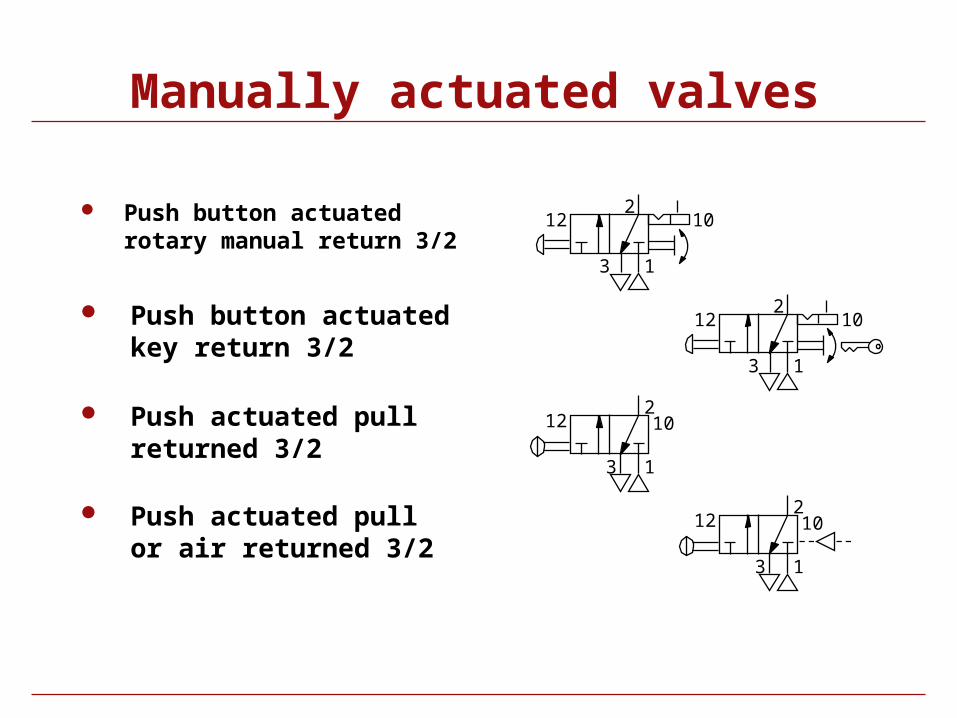
Manually actuated valves
Push button actuated rotary manual return 3/2
Push button actuated key return 3/2
Push actuated pull or air returned 3/2
1
2
3
12 10
1
2
3
12 10 Push actuated pull returned 3/2
1
2
3
12 10
1
2
3
12 10
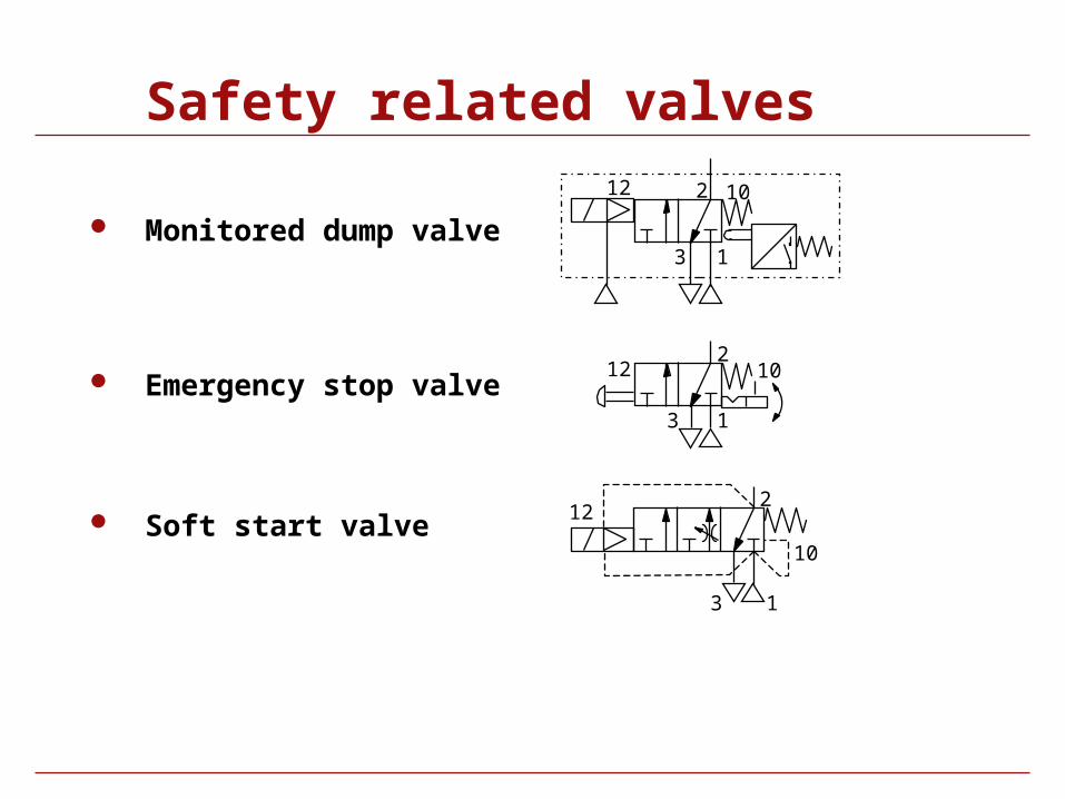
Safety related valves
Monitored dump valve1
2
3
1012
Emergency stop valve
Soft start valve
1
2
3
12
10
1
2
3
12 10
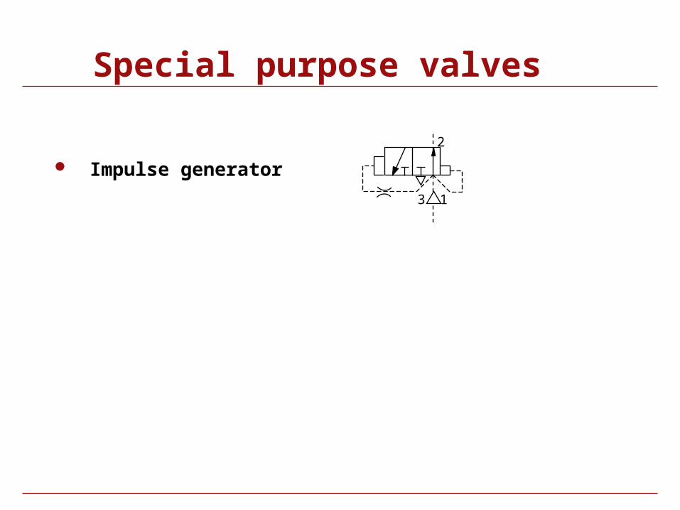
Special purpose valves
Impulse generator
1
2
3
Symbol Library
Vacuum Equipment
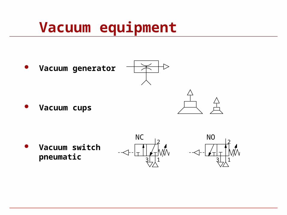
Vacuum equipment
Vacuum generator
Vacuum cups
Vacuum switch pneumatic 1
2
3
2
13
NONC
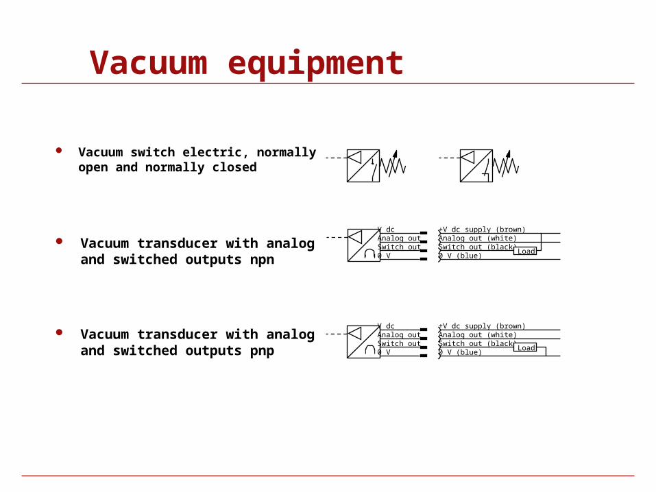
Vacuum equipment
Vacuum switch electric, normally open and normally closed
Vacuum transducer with analog and switched outputs npn
Vacuum transducer with analog and switched outputs pnp
V dcAnalog outSwitch out 0 V
+V dc supply (brown)Analog out (white)Switch out (black)0 V (blue)
Load
+V dc supply (brown)Analog out (white)Switch out (black)0 V (blue)
Load
V dcAnalog outSwitch out 0 V
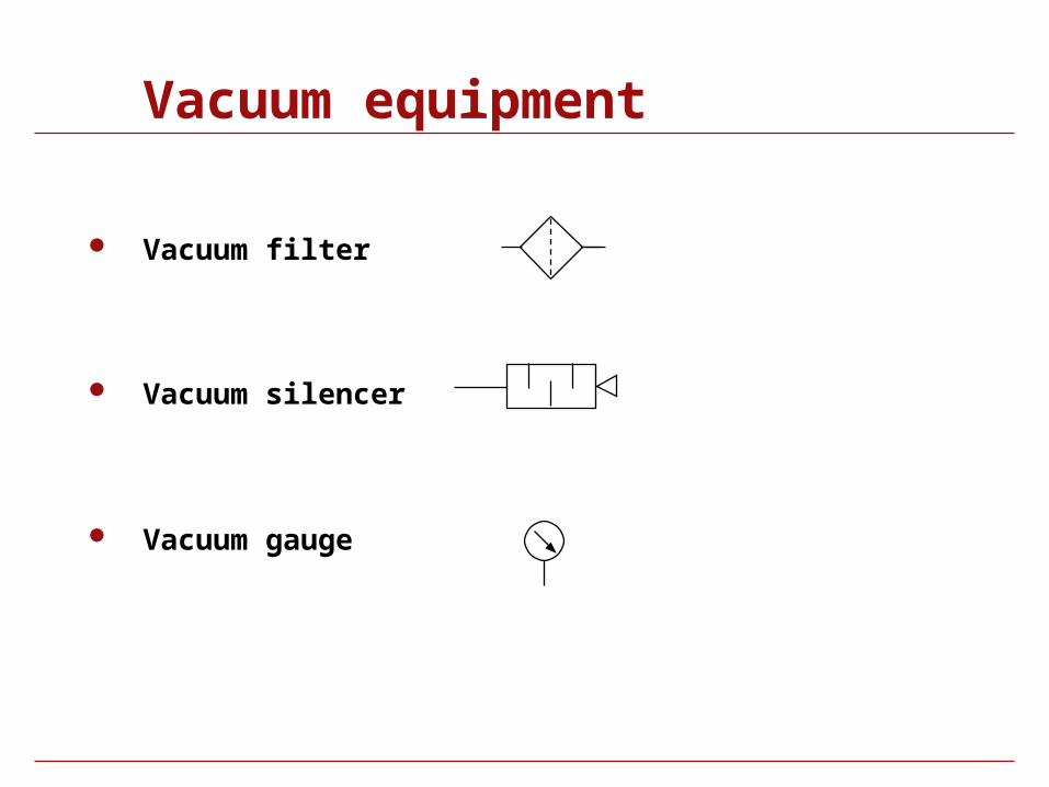
Vacuum equipment
Vacuum filter
Vacuum silencer
Vacuum gauge
End
Related Documents


