03-12-98 version1.0 Integrated IS-IS Design and Deployment Guide 1 Integrated IS-IS Design and Deployment Guide Authors: Stefano Previdi - Cisco Systems Paul Horrocks - Cisco Systems

Welcome message from author
This document is posted to help you gain knowledge. Please leave a comment to let me know what you think about it! Share it to your friends and learn new things together.
Transcript

8/3/2019 Isis Design Guide
http://slidepdf.com/reader/full/isis-design-guide 1/37
03-12-98 version1.0
Integrated IS-IS Design and Deployment Guide 1
Integrated IS-IS
Design and Deployment Guide
Authors: Stefano Previdi - Cisco Systems
Paul Horrocks - Cisco Systems

8/3/2019 Isis Design Guide
http://slidepdf.com/reader/full/isis-design-guide 2/37
03-12-98 version1.0
Integrated IS-IS Design and Deployment Guide 2
Contents:
1 Executive summary.................................................................................................. 3
2. IS-IS overview ........................................................................................................ 3
2.1 Integrated IS-IS................................................................................................. 4
2.2 Integrated IS-IS and CLNS addressing............................................................... 5
2.3 Shortest Path First Algorithm............................................................................. 6
2.3.1 Databases.................................................................................................... 6
2.3.2 The Algorithm............................................................................................. 7
2.4 IS-IS in a backbone environment........................................................................ 8
3. IS-IS guidelines ..................................................................................................... 10
3.1 Single Area Vs. Area routing ........................................................................... 10
3.2 Level-1 Vs. Level-2 routing ............................................................................. 10
3.3 CLNS addressing............................................................................................. 10
3.4 IP addressing ................................................................................................... 11
3.5 Flooding and Timers ........................................................................................ 11
3.6 Mesh Groups ................................................................................................... 12
3.7 Summarization................................................................................................. 13
3.8 Default Routing ............................................................................................... 13
3.9 Redistribution .................................................................................................. 133.10 Multiple paths load balancing......................................................................... 14
3.11 Other advanced IS-IS configuration commands.............................................. 14
4. Migration Strategy................................................................................................. 15
5. Migration example ................................................................................................. 17
5.1 Purpose ........................................................................................................... 17
5.2 Network Topology .......................................................................................... 17
5.3 Test plan.......................................................................................................... 17
5.4 Configuration and outputs – Phase 1 ................................................................ 18
5.5 Configuration and outputs – Phase 2 ................................................................ 265.6 Configuration and outputs – Phase 3 ................................................................ 35

8/3/2019 Isis Design Guide
http://slidepdf.com/reader/full/isis-design-guide 3/37
03-12-98 version1.0
Integrated IS-IS Design and Deployment Guide 3
1. Executive summary
This documents aims to describes recommendations and guidelines for the deployment
of Integrated IS-IS routing protocol within an ISP backbone network.
Integrated IS-IS is an extension of the IS-IS protocol used in OSI environments. The
extension is described in RFC1195 while the IS-IS protocol is described in ISO/IEC
10589.
This document is divided in following parts:
• IS-IS routing protocol overview, including Integrated IS-IS extension, as well as
the Shortest Path First algorithm (Dijkstra). These descriptions are excerpted form
ISO/IEC 10589 and RFC1195 documents.
• Guidelines for the deployment of Integrated IS-IS on a backbone network. This
includes:
• CLNS addressing
• IP addressing
• Routing strategy (single area vs. area routing)
• Routing level strategy (level-1 vs. level-2)
• Timers
• Migration strategy. Covers the migration aspects of Integrated IS-IS when
deployed in a routing domain where another IGP is currently used.
• Migration example. A set of tests simulating a migration from OSPF towards
Integrated IS-IS. Configuration files, topology databases, routing tables and
connectivity tests are included.
2. IS-IS overview
Following section gives a summarized description of IS-IS routing protocol and its
components. Protocol description and algorithm specification are excerpted from
ISO/IEC 10589 and RFC1195 documents.
Intermediate System to Intermediate System protocol (IS-IS) is an intra-domain OSI
dynamic routing protocol specified in ISO 10589. The protocol is designed to operate
in OSI Connection-less Network Service (CLNS). Data is carried using the protocol
specified in ISO 8473.

8/3/2019 Isis Design Guide
http://slidepdf.com/reader/full/isis-design-guide 4/37
03-12-98 version1.0
Integrated IS-IS Design and Deployment Guide 4
The intra-domain IS-IS routing protocol is intended to support large routing domains
consisting of combinations of many types of subnetworks (i.e.: media types).
In order to support large routing domains, provision is made for Intra-domain routing
to be organized hierarchically. A large domain may be administratively divided intoareas. Each system resides in exactly one area. Routing within an area is referred to as
Level 1 routing . Routing between areas is referred to as Level 2 routing . Level 2
Intermediate Systems keep track of the paths to destination areas. Level 1
Intermediate Systems keep track of the routing within their own area. For a packet
destined to another area, a level 1 Intermediate System sends the packet to the nearest
level 2 IS in its own area, regardless of what the destination area is. Then the packet
travels via level 2 routing to the destination area, where it again travels via level 1
routing to the destination.
On broadcast media’s a DIS (Designated Intermediate System) is elected and will
conduct the flooding over the media.
2.1 Integrated IS-IS
Intra-Domain IS-IS Routing Protocol, which may be used as an interior gateway,
protocol (IGP) to support TCP/IP as well as OSI. This allows a single routing
protocol to be used to support pure IP environments, pure OSI environments, and
dual environments. This specification (RFC1195) was developed by the IS-IS
working group of the Internet Engineering Task Force.
There are two main methods that are available for routing protocols to support dual
OSI and IP routers. One method, known as "Ships in the Night", makes use of
completely independent routing protocols for each of the two protocol suites. This
specification presents an alternate approach, which makes use of a single integrated
protocol for interior routing (i.e., for calculating routes within a routing domain) for
both protocol suites.
By supporting both IP and OSI traffic, this integrated protocol design supports traffic
to IP hosts, OSI end systems, and dual end systems. This approach is "integrated" in
the sense that the IS-IS protocol can be used to support pure-IP environments, pure-
OSI environments, and dual environments. In addition, this approach allowsinterconnection of dual (IP and OSI) routing domains with other dual domains, with
IP-only domains, and with OSI-only domains.

8/3/2019 Isis Design Guide
http://slidepdf.com/reader/full/isis-design-guide 5/37
03-12-98 version1.0
Integrated IS-IS Design and Deployment Guide 5
2.2 Integrated IS-IS and CLNS addressing
ISO/IEC 10589 distinguishes only 3 fields in the NSAP format. This simplifies the
address structure originally defined in ISO/IEC 8348 appendix A. The 3 components
are:
• Area Address. This is a Variable Length field composed of high order octets of the
NSAP excluding the SystemID and SEL fields. The area address is associated with
a single area within the routing domain.
• SystemID. The System Identifier defines an ES or IS in an area. Cisco implements
a fixed length of 6 octets for the System ID, in compliance with version 2.0 of US
GOSIP.
• NSEL. This is the NSAP selector, also designated as N-selector. It is the last byteof the NSAP and identifies a network service user. A network service user is a
transport entity or the IS network entity itself.
NSAP Format for use with Integrated IS-IS
An NSAP with 0 NSEL value is called a Network Entity Title (NET). A NET is used
to denote the network entity or the routing layer.
Note that the AFI filed describes format and length of the IDI (and therefore the
format of the rest of the NSAP). There are some predefined AFI, here follows some
examples:
• AFI =49 Addresses starting with value 49 are considered as local addresses (as
network 10.0.0.0/8 in IP). These addresses are routed by IS-IS routing protocol.
However, there should not be advertised to other CLNS networks. With AFI 49
the IDI value is null and IDP length is 2 digits.
• AFI=39 Data Country Code. In this case the address assignment is done per
country and a local authority will assign IDI codes.

8/3/2019 Isis Design Guide
http://slidepdf.com/reader/full/isis-design-guide 6/37
03-12-98 version1.0
Integrated IS-IS Design and Deployment Guide 6
• AFI=47 International Code Designator. The IDI consist of 4 digits identifying a
particular organization. IDP length is 6 digits.
Note that in most cases the IDI has to be registered to an OSI/CLNS authority. But
since, there is no “global” OSI internetwork (as the Internet for IP), the choice of aparticular address format is less critical than in IP.
2.3 Shortest Path First Algorithm
This section specifies an SPF Algorithm for calculating routes with the IS-IS routing
protocol, for support of both TCP/IP and OSI. This is based on an extension to the
algorithm specified in ISO/IEC 10589.
An algorithm invented by Dijkstra known as shortest path first (SPF) is used as the
basis for the route calculation. It has a computational complexity of the square of the
number of nodes, which can be decreased to the number of links in the domain times
the log the number of nodes for sparse networks (networks which are not highly
connected).
2.3.1 Databases
• PATHS: This represents an acyclic directed graph of shortest paths from the
system S performing the calculation. It is stored as a set of triples of the form
<N,d(N),{Adj(N)}>, where:
N is a system identifier. In the level 1 algorithm, N is a 6 octet ID for OSI end
systems, a 7 octet ID for routers, or an 8 octet IP Internal Reachability
Information entry. For a router which is not a pseudonode, it is the 6 octet system
ID, with a 0 appended octet. For a pseudonode it is a true 7 octet quantity,
comprised of the 6 octet Designated Intermediate System ID and the extra octet
assigned by the Destinated Router. The IP Internal Reachability Information
entries consist of a 4 octet IP address plus a 4 octet subnet mask, and will always
be a leaf, i.e., "End System" in PATHS.
In the level 2 algorithm, N is either a 7 octet router or pseudonode ID (as in the
level 1 algorithm); a variable length OSI address prefix; an 8 octet IP InternalReachability Information Entry, or an 8 octet IP External Reachability
Information entry. The variable length OSI address prefixes, and 8 octet IP
Reachability Information entries will always be a leaf, i.e., "End System" in
PATHS. As above, the IP Reachability Information entries consist of an [IP
address, subnet mask] combination.
8/3/2019 Isis Design Guide
http://slidepdf.com/reader/full/isis-design-guide 7/37
03-12-98 version1.0
Integrated IS-IS Design and Deployment Guide 7
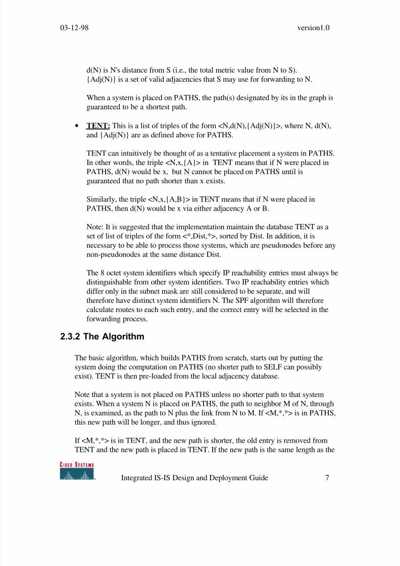
d(N) is N's distance from S (i.e., the total metric value from N to S).
{Adj(N)} is a set of valid adjacencies that S may use for forwarding to N.
When a system is placed on PATHS, the path(s) designated by its in the graph isguaranteed to be a shortest path.
• TENT: This is a list of triples of the form <N,d(N),{Adj(N)}>, where N, d(N),
and {Adj(N)} are as defined above for PATHS.
TENT can intuitively be thought of as a tentative placement a system in PATHS.
In other words, the triple <N,x,{A}> in TENT means that if N were placed in
PATHS, d(N) would be x, but N cannot be placed on PATHS until is
guaranteed that no path shorter than x exists.
Similarly, the triple <N,x,{A,B}> in TENT means that if N were placed inPATHS, then d(N) would be x via either adjacency A or B.
Note: It is suggested that the implementation maintain the database TENT as a
set of list of triples of the form <*,Dist,*>, sorted by Dist. In addition, it is
necessary to be able to process those systems, which are pseudonodes before any
non-pseudonodes at the same distance Dist.
The 8 octet system identifiers which specify IP reachability entries must always be
distinguishable from other system identifiers. Two IP reachability entries which
differ only in the subnet mask are still considered to be separate, and will
therefore have distinct system identifiers N. The SPF algorithm will therefore
calculate routes to each such entry, and the correct entry will be selected in the
forwarding process.
2.3.2 The Algorithm
The basic algorithm, which builds PATHS from scratch, starts out by putting the
system doing the computation on PATHS (no shorter path to SELF can possibly
exist). TENT is then pre-loaded from the local adjacency database.
Note that a system is not placed on PATHS unless no shorter path to that systemexists. When a system N is placed on PATHS, the path to neighbor M of N, through
N, is examined, as the path to N plus the link from N to M. If <M,*,*> is in PATHS,
this new path will be longer, and thus ignored.
If <M,*,*> is in TENT, and the new path is shorter, the old entry is removed from
TENT and the new path is placed in TENT. If the new path is the same length as the

8/3/2019 Isis Design Guide
http://slidepdf.com/reader/full/isis-design-guide 8/37
03-12-98 version1.0
Integrated IS-IS Design and Deployment Guide 8
one in TENT, then the set of potential adjacencies {Adj(M)} is set to the union of the
old set (in TENT) and the new set {Adj(N)}. If M is not in TENT, then the path is
added to TENT.
Next the algorithm finds the triple <N,x,{Adj(N)}> in TENT, with minimal x.
Note: This is done efficiently because of the optimization described above. When the
list of triples for distance Dist is exhausted, the algorithm then increments Dist until it
finds a list with a triple of the form <*,Dist,*>.
N is placed in PATHS. We know that no path to N can be shorter than x at this point
because all paths through systems already in PATHS have already been considered,
and paths through systems in TENT still have to be greater than x because x is
minimal in TENT.
When TENT is empty, PATHS is complete.
Note that external metrics can only occur in "IP External Reachability Information"
entries, which correspond to a leaf (i.e., End System in PATHS). Any route utilising
an entry with an external metric will always be considered to be less desirable than
any entry which uses an internal metric. This implies that in the addition of systems to
PATHS, all systems reachable via internal routes are always added before any system
reachable via external routes.
2.4 IS-IS in a backbone environment
When deploying large ISP backbones some point are critical and the routing protocol
that will have to be deployed has to have strengths in following areas:
• Scalability: an ISP backbones evolves every day (if not every hour) and therefore
several changes occur in terms of routing changes, new routes/paths, topology
(physical and/or logical). These changes will be reflected in the routing protocol
that will have to converge on the new topology. Such routing protocol must be
flexible enough to support these changes and be (as less as possible) topology
dependent in order to ensure more flexibility on the backbone evolution.
• Fast-Convergence: ISP backbones may include several hundreds of routers andreasonable fast convergence time should be ensured by the routing protocol
without costing too many resources (CPU/memory/routing update transmissions)
• Loop-free: as any other network, ISP backbones need to have a way to avoid any
routing loop. Or if such loop exist, it has to be detected as fast as possible.
• Easy troubleshooting: the routing protocol should be designed and implemented in
such a way to allow operational teams to be able to troubleshoot any routing

8/3/2019 Isis Design Guide
http://slidepdf.com/reader/full/isis-design-guide 9/37
03-12-98 version1.0
Integrated IS-IS Design and Deployment Guide 9
problem in the network without having to spend too much time in complex
operations.
• Less resources usage: the routing protocol has to be capable to handle large
topologies, routing changes, without having a significant impact on the CPU and
memory resources of the router.
It appears that most of these requirements are satisfied by link-state technology
protocols such as IS-IS and OSPF. However, IS-IS has some strong points that make
it preferable over OSPF when deployed on large ISP backbones.
• Scalability: IS-IS has a different routing hierarchy than OSPF. The backbone
concept still exist (and has same functionality: connecting areas) but the way it is
implemented is different and allows more flexibility, especially when the backbone
has to be extended. The backbone (in IS-IS) is not an area but the contiguous
collection of area border routers.
• Fast-convergence: IS-IS uses SPF algorithm (Dijkstra) to compute the topologytree. Link-state technology ensures the fastest convergence, loop-free in terms of
route calculation. However, IS-IS uses less packet types to propagate routing
information and (especially on broadcast media) the flooding is more optimal.
• Easy Troubleshooting: Link-State protocols are easier to troubleshoot since all
routers have the same link-state database. The advantage of IS-IS is that a router
will insert all of the prefixes it announces on one single protocol packet. Thus, it's
easier to find all routing information announced by a particular router.
• Less resource usage: IS-IS databases contain one LSP (Link-State Packet) per
router in the routing domain or in the area (depending on the routing hierarchy).
All prefixes announced by a router (local prefixes, redistributed from other
protocols) will be part of the unique LSP that this router will flood on the
network. In total
IS-IS has four different packet types:
• Level-1 non-pseudonode LSP: generated by an intra area router
• Level-1 pseudonode LSP: an intra-area designated router (on broadcast
media’s)
• Level-2 non-pseudonode LSP: generated by an area router
• Level-2 pseudonode LSP: generated by an area router, which also cats
as designated router
The packet type depends on the router type and NOT on the nature of the prefixannounced on it.
Therefore, the computation of SPF tree is facilitated by the fact that all the routing
information is on a limited number of LSP per router. As an example, in OSPF the
area border router will create one single type-3 LSA (summary LSA) for each IP
prefix it founds on all type-1 LSAs (Router LSAs).

8/3/2019 Isis Design Guide
http://slidepdf.com/reader/full/isis-design-guide 10/37
03-12-98 version1.0
Integrated IS-IS Design and Deployment Guide 10
3. IS-IS guidelines
This section describes the guidelines when deploying Integrated IS-IS.
3.1 Single Area Vs. Area routing
Integrated IS-IS is a routing protocol, which can be deployed in very large backbone
networks. It is not mandatory to implement Area routing, however, it is
recommended in order to reduce the routing information propagated throughout the
domain. Area routing has to be considered in conjunction with summarization and
default routing. In a first step the deployment may be done in one single area and
areas can be defined in the future as soon as the topology allows it.
3.2 Level-1 Vs. Level-2 routing
While deploying Integrated IS-IS with one single area, a choice can be made between
a single level-1 Area and a single Level-2 Area. In both cases all routers are
configured as part of the same area and will maintain a single Link-State Database.
In a single level-1 area all routers will be configured in order to behave as level-1-only
routers, while in a level-2 configuration, all routers will behave as level-2 routers. All
routers will have to maintain a single database (level-1 or level-2).
The recommendation is to run (at least on a first phase) a single area where all routersare configured as Level-2-only routers.
This will allow an easier migration towards area routing when possible.
3.3 CLNS addressing
CLNS addresses have to be defined according to the inter-connection policy. If the
backbone where IS-IS will be deployed will not have any connection to another OSI
network, the local address (AFI=49) can be used. In the other cases, an IDI should berequested and registered to the addressing authority.

8/3/2019 Isis Design Guide
http://slidepdf.com/reader/full/isis-design-guide 11/37
03-12-98 version1.0
Integrated IS-IS Design and Deployment Guide 11
3.4 IP addressing
IS-IS does not have any specific requirements in terms of IP addressing. The usage of
loopback interfaces is recommended for management purposes. The loopback IP
addresses should not be summarized across areas.
3.5 Flooding and Timers
For a better deployment of Integrated IS-IS, it is recommended to modify the default
setting in terms of IS-IS timers:
• Lsp-refresh timer: specifies the number of seconds (0 to 65535) the router will
wait before refreshing (re-create and re-0flooding) its own LSP
• Max-lsp-lifetime: specifies the value of lifetime in the LSP header. Lifetime is
used by all IS-IS routers in order to age out (and purge) old LSPs.
By increasing these values to their maximum we will reduce significantly the flooding
over the routing domain. The maximum value will allow a router not to re-generate
its LSP for about 18.7 hours.
• Prc-interval: specifies the number of seconds between two consecutive PRC
calculations. PRC is Partial Route Calculation, a process executed by the router
after having completed SPF algorithm and used to insert in the LSDB all the IP
routing information.• Spf-interval: specifies the number of seconds between two consecutive SPF
calculations. SPF is Shortest Path First, a process executed by the router after
having received new LSPs and that will build the SPF (Dijkstra) tree.
These two timers have to be tuned according to the level of stability we want to
achieve in the routing domain. Slow values will trigger a fast convergence with a
potential risk of flapping routes. High values will keep the network stable with the
slower convergence.
The timers have not to be adjusted from day one but will have to be tuned based on
the observed network stability.
• Hello-interval: number of seconds during two consecutive transmission of IIH
packets (Intermediate To Intermediate Hello). The default is 10 seconds and may
be decreased on interfaces where adjacency status changes have to be detected as
soon as possible (according to the hello-multiplier value).
8/3/2019 Isis Design Guide
http://slidepdf.com/reader/full/isis-design-guide 12/37
03-12-98 version1.0
Integrated IS-IS Design and Deployment Guide 12
• Hello-multiplier: integer (from 1 to 300) which will be used to calculate the hold
time. The hold time is the amount of seconds during which the router will wait an
IIH before declaring the neighbor lost. The router multiplies the hello interval by
the hello-multiplier in order to obtain the hold time. The default value is 3 and
should be increased on interfaces where frequent losses of IIH packets aredetected. This will avoid unnecessary adjacency resets.
• Isis-retransmit-interval: number of seconds between retransmission of IS-IS link-
state PDU retransmission for point-to-point links.
The different Hello timers will have to be adapted according to the adjacency
convergence time required for each subnet. Where a rapid adjacency loss has to be
detected, the timers will have to be reduced.
Again, these timers may be modified if necessary after the deployment and after an
accurate monitoring of the network stability/convergence.
• Csnp-interval: specifies the number of seconds between two consecutive
transmissions of CSNP packets. CSNP are Complete Sequence Number Packets,
generated by the DIS (Designated Router) in order for all routers connected to a
broadcast media, to synchronize their databases. CSNPs are used to maintain all
routers database up to date. The smaller is, the faster will be the synchronization.
However, a too small value will trigger intensive PSNP packet transmissions. All
routers that need additional LSPs in their database send PSNPs (i.e.: routers that
are not synchronized with the DIS).
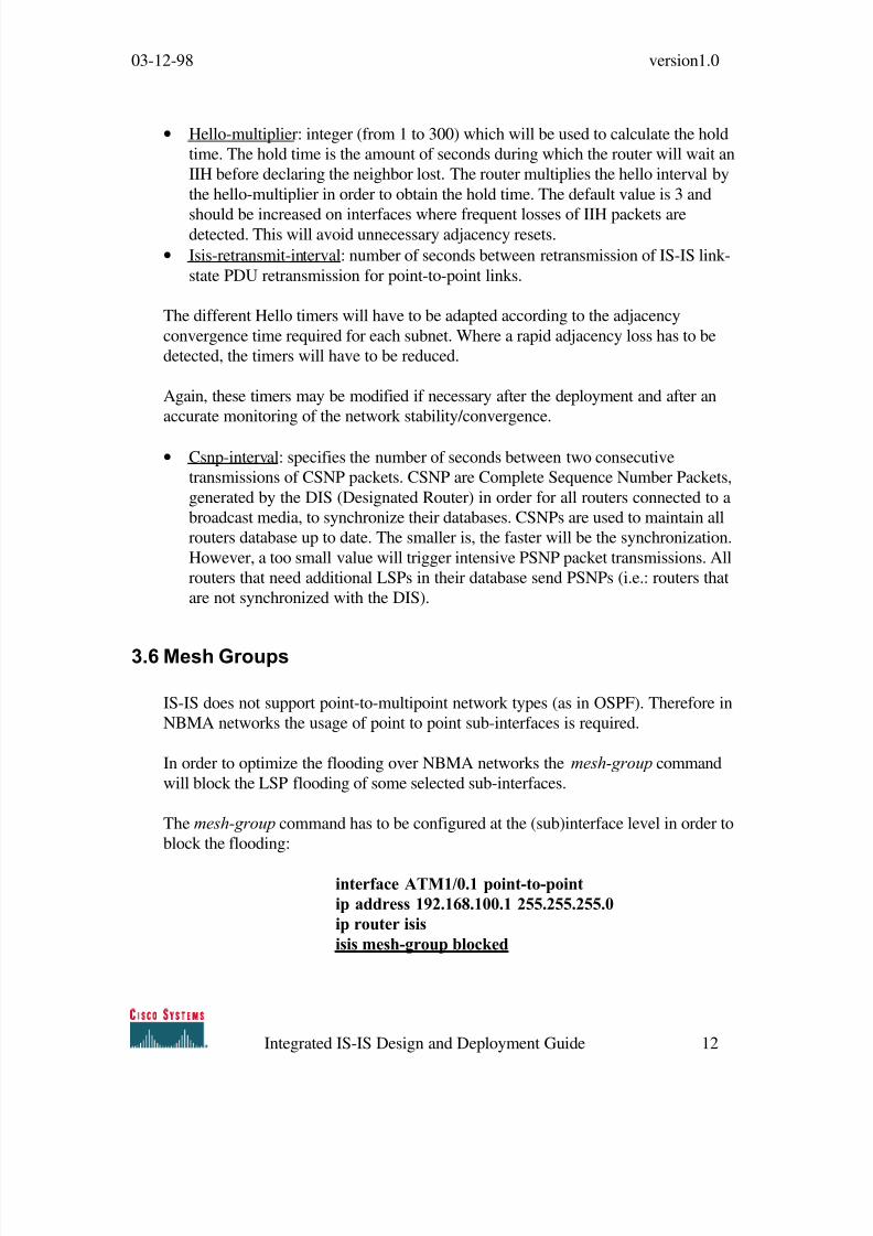
3.6 Mesh Groups
IS-IS does not support point-to-multipoint network types (as in OSPF). Therefore in
NBMA networks the usage of point to point sub-interfaces is required.
In order to optimize the flooding over NBMA networks the mesh-group command
will block the LSP flooding of some selected sub-interfaces.
The mesh-group command has to be configured at the (sub)interface level in order to
block the flooding:
interface ATM1/0.1 point-to-point
ip address 192.168.100.1 255.255.255.0
ip router isis
isis mesh-group blocked

8/3/2019 Isis Design Guide
http://slidepdf.com/reader/full/isis-design-guide 13/37
03-12-98 version1.0
Integrated IS-IS Design and Deployment Guide 13
This command will optimize flooding but it is not required in the first step of the
deployment phase.
3.7 Summarization
Summarization is one of the key points for any kind of routing protocol.
Summarization will reduce the amount of routing updates that will be flooded across
the areas and/or the routing domain.
The usage of IS-IS (and especially with area routing) requires a good summarization
in order not to have a Level-2 database (coming for Level-1 derived information) too
big.
However, Integrated IS-IS is more flexible in the sense that it allows a level-2 router
to summarize level-1 prefixes, whatever their origin is (internal prefixes, localredistribution, or coming form a level-1 router redistribution).
3.8 Default Routing
Default routing is achieved in two distinct ways with Integrated IS-IS:
• Attached-bit: set by a level-1-2 router in its own Level-1 LSP and used to indicate
all Level-1 routers (within the area) that this router is a potential exit point of the
area.• Default information originating: configured in any kind of router (level-1 as well
as level-2). The default route (0.0.0.0/0) is inserted in the router LSP (level-1 or
level-2, according to the configuration command) and the LSP is flooded
according to the router type (level-1 or level-2).
Level-1 routers will always prefer the explicit default route (0.0.0.0/0) found in an
LSP before considering the attached bit.
3.9 Redistribution
Integrated IS-IS specification describes the way the routers are allowed to redistribute
external prefixes. Cisco implementation differs from the specification and allows more
flexibility.

8/3/2019 Isis Design Guide
http://slidepdf.com/reader/full/isis-design-guide 14/37
03-12-98 version1.0
Integrated IS-IS Design and Deployment Guide 14
Redistribution from any other routing protocol, static configuration or connected
interfaces is allowed in any type of router (level-1 and level-2). By default the metric-
type will be set as internal, which means that the metric of the route will compete with
all other internal routes. Metric-type may be set to external . In that way the prefix will
have a metric equal to the cost specified in the redistribution command plus a value of 128.
Routers acting as level-1-2 are able to summarize all level-1 prefixes regardless their
origin.
3.10 Multiple paths load balancing
IS-IS supports up to 6 parallel paths over which the router can forward packets for
the same destination address.
In some cases the load balancing may be not optimal. Assume that a router has 3
parallel paths, 2 of them are pointing to one interface and the other one points to
another one. In a normal situation the router will not be able to differentiate among
them and will select the 3 paths in a round-robin fashion (per source/destination or per
packet).
Cisco has implemented a special command: traffic-share min across-interfaces
This command allows the router to take into account the different interfaces used
when load balance traffic over multiple path routes.
3.11 Other advanced IS-IS configuration commands
In order to optimize IS-IS configuration and behavior, following commands can be
configured:
• Log-adjacency-changes: causes IS-IS to generate a log message when an IS-IS
adjacency changes state (up or down).
• Ignore-lsp-errors: allow the router to ignore IS-IS link-state packets that are
received with internal checksum errors rather than purging the link-state packets.
This will avoid purge and flood storms in case of bad checksums LSPs.• Passive-interface: allow IS-IS to include the IP prefix of an interface in its own
LSP as internal but no IS-IS packets will be send over the interface (IIH or LSPs).

8/3/2019 Isis Design Guide
http://slidepdf.com/reader/full/isis-design-guide 15/37
03-12-98 version1.0
Integrated IS-IS Design and Deployment Guide 15
4. Migration Strategy
Link-State protocols allow an easier migration since the flooding is independent from
the routing table.
IS-IS behaves in a different fashion with area routing (level-2 routing): an IP prefix
present in the level-1 database will be inserted in the level-2 LSP (by the level-1-2
router) only if it is present in the routing table as an IS-IS route. Thus, in case of area
routing the migration should be performed in a per-area base.
Since a router may have on its routing table prefixes coming from different routing
protocols, the discrimination between prefixes (done before the metric lookup) is done
based on the administrative distance value. The administrative distance is a numerical
value assigned to all routes coming form the same routing protocol. Here follow the
distances assigned to protocols on cisco routers:
• Connected interface 0
• Static route 1
• EIGRP summary route 5
• External BGP 20
• Internal EIGRP 90
• IGRP 100
• OSPF 110
• IS-IS 115
• RIP 120
• EGP 140• External EIGRP 170
• Internal BGP 200
While deploying IS-IS, the administrative distance should be set to 255, in order for
the router not to taking into account IS-IS routes during the deployment phase.
Here follow the deployment steps:
a) All routers will be configured as level-2 only.
b) All router will have the distance set to 255 for IS-IS. Thus no IS-IS routing
information will interfere in the current routing table.
8/3/2019 Isis Design Guide
http://slidepdf.com/reader/full/isis-design-guide 16/37
03-12-98 version1.0
Integrated IS-IS Design and Deployment Guide 16
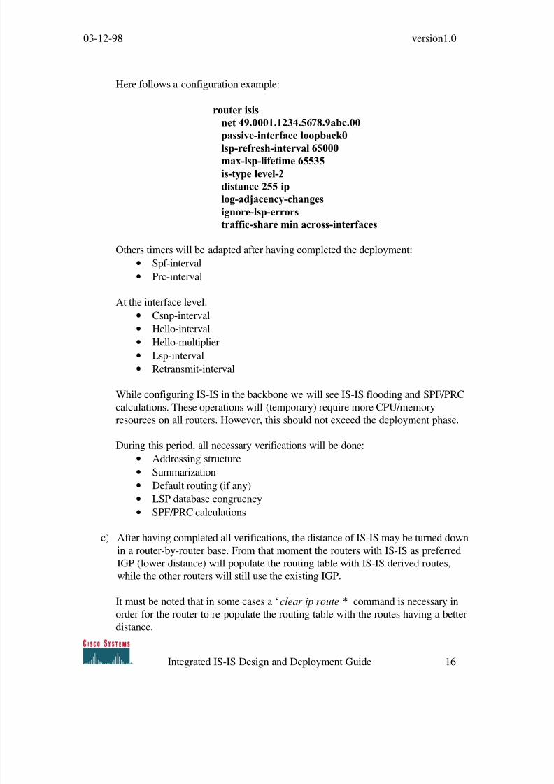
Here follows a configuration example:
router isis
net 49.0001.1234.5678.9abc.00
passive-interface loopback0lsp-refresh-interval 65000
max-lsp-lifetime 65535
is-type level-2
distance 255 ip
log-adjacency-changes
ignore-lsp-errors
traffic-share min across-interfaces
Others timers will be adapted after having completed the deployment:
• Spf-interval
• Prc-interval
At the interface level:
• Csnp-interval
• Hello-interval
• Hello-multiplier
• Lsp-interval
• Retransmit-interval
While configuring IS-IS in the backbone we will see IS-IS flooding and SPF/PRC
calculations. These operations will (temporary) require more CPU/memoryresources on all routers. However, this should not exceed the deployment phase.
During this period, all necessary verifications will be done:
• Addressing structure
• Summarization
• Default routing (if any)
• LSP database congruency
• SPF/PRC calculations
c) After having completed all verifications, the distance of IS-IS may be turned down
in a router-by-router base. From that moment the routers with IS-IS as preferredIGP (lower distance) will populate the routing table with IS-IS derived routes,
while the other routers will still use the existing IGP.
It must be noted that in some cases a ‘clear ip route *’ command is necessary in
order for the router to re-populate the routing table with the routes having a better
distance.

8/3/2019 Isis Design Guide
http://slidepdf.com/reader/full/isis-design-guide 17/37
03-12-98 version1.0
Integrated IS-IS Design and Deployment Guide 17
5. Migration example
5.1 Purpose
The test below will show the 5-router network running OSPF as the IGP, in a single
AREA 0. ISIS will be configured to run 'no-top-off' the existing IGP. ISIS will then be
configured as the IGP of choice on a single router and interoperate with the existing
OSPF network.
5.2 Network Topology
5.3 Test plan
• Phase 1: Network running OSPF as the IGP, in a single AREA 0.
• Phase 2: We will introduce ISIS but apply an administrative distance of 255, allowing
the database to be populated but the routes never entering the routing table, all
routers are configured as level-2 only.
• Phase 3: We will migrate R5 to running 'full' iISIS as the IGP, to interwork with the
existing OSPF routers.
R3 R2
R1
R5 R4

8/3/2019 Isis Design Guide
http://slidepdf.com/reader/full/isis-design-guide 18/37
03-12-98 version1.0
Integrated IS-IS Design and Deployment Guide 18
5.4 Configuration and outputs – Phase 1
R3:
hostname R3!
interface Loopback0
ip address 3.3.3.3 255.255.255.255
!
interface Ethernet0
ip address 10.1.1.3 255.255.255.0
!
router ospf 1
passive-interface Loopback0
network 10.1.1.0 0.0.0.255 area 0
network 3.3.3.3 0.0.0.0 area 0
R3#sh ip ospf database
OSPF Router with ID (3.3.3.3) (Process ID 1)
Router Link States (Area 0)
Link ID ADV Router Age Seq# Checksum Link count
1.1.1.1 1.1.1.1 119 0x8000000F 0xC3D6 62.2.2.2 2.2.2.2 140 0x80000004 0x9848 2
3.3.3.3 3.3.3.3 248 0x80000004 0x884B 2
4.4.4.4 4.4.4.4 1038 0x80000004 0x429 4
5.5.5.5 5.5.5.5 119 0x80000003 0x2052 4
100.1.1.1 100.1.1.1 172 0x80000002 0xC804 4
Net Link States (Area 0)
Link ID ADV Router Age Seq# Checksum
10.1.1.3 3.3.3.3 248 0x80000003 0xAE52
R3#sh ip route
Codes: C - connected, S - static, I - IGRP, R - RIP, M - mobile, B - BGP
D - EIGRP, EX - EIGRP external, O - OSPF, IA - OSPF inter area
N1 - OSPF NSSA external type 1, N2 - OSPF NSSA external type 2
E1 - OSPF external type 1, E2 - OSPF external type 2, E - EGP

8/3/2019 Isis Design Guide
http://slidepdf.com/reader/full/isis-design-guide 19/37
03-12-98 version1.0
Integrated IS-IS Design and Deployment Guide 19
i - IS-IS, L1 - IS-IS level-1, L2 - IS-IS level-2, * - candidate default
U - per-user static route, o - ODR
Gateway of last resort is not set
1.0.0.0/32 is subnetted, 1 subnets
O 1.1.1.1 [110/11] via 10.1.1.1, 00:02:16, Ethernet0
2.0.0.0/32 is subnetted, 1 subnets
O 2.2.2.2 [110/11] via 10.1.1.2, 00:02:16, Ethernet0
3.0.0.0/32 is subnetted, 1 subnets
C 3.3.3.3 is directly connected, Loopback0
4.0.0.0/32 is subnetted, 1 subnets
O 4.4.4.4 [110/75] via 10.1.1.1, 00:02:16, Ethernet0
5.0.0.0/32 is subnetted, 1 subnets
O 5.5.5.5 [110/75] via 10.1.1.1, 00:02:16, Ethernet0
10.0.0.0/24 is subnetted, 1 subnetsC 10.1.1.0 is directly connected, Ethernet0
50.0.0.0/24 is subnetted, 1 subnets
O 50.1.1.0 [110/74] via 10.1.1.1, 00:02:17, Ethernet0
60.0.0.0/24 is subnetted, 1 subnets
O 60.1.1.0 [110/74] via 10.1.1.1, 00:02:17, Ethernet0
100.0.0.0/24 is subnetted, 1 subnets
O 100.1.1.0 [110/84] via 10.1.1.1, 00:02:17, Ethernet0
O 200.1.1.0/24 [110/84] via 10.1.1.1, 00:02:17, Ethernet0
R2:
hostname R2
!
interface Loopback0
ip address 2.2.2.2 255.255.255.255
!
interface Ethernet0
ip address 10.1.1.2 255.255.255.0
!
router ospf 1
passive-interface Loopback0
network 10.1.1.0 0.0.0.255 area 0
network 2.2.2.2 0.0.0.0 area 0
R2#sh ip ospf database
8/3/2019 Isis Design Guide
http://slidepdf.com/reader/full/isis-design-guide 20/37
03-12-98 version1.0
Integrated IS-IS Design and Deployment Guide 20
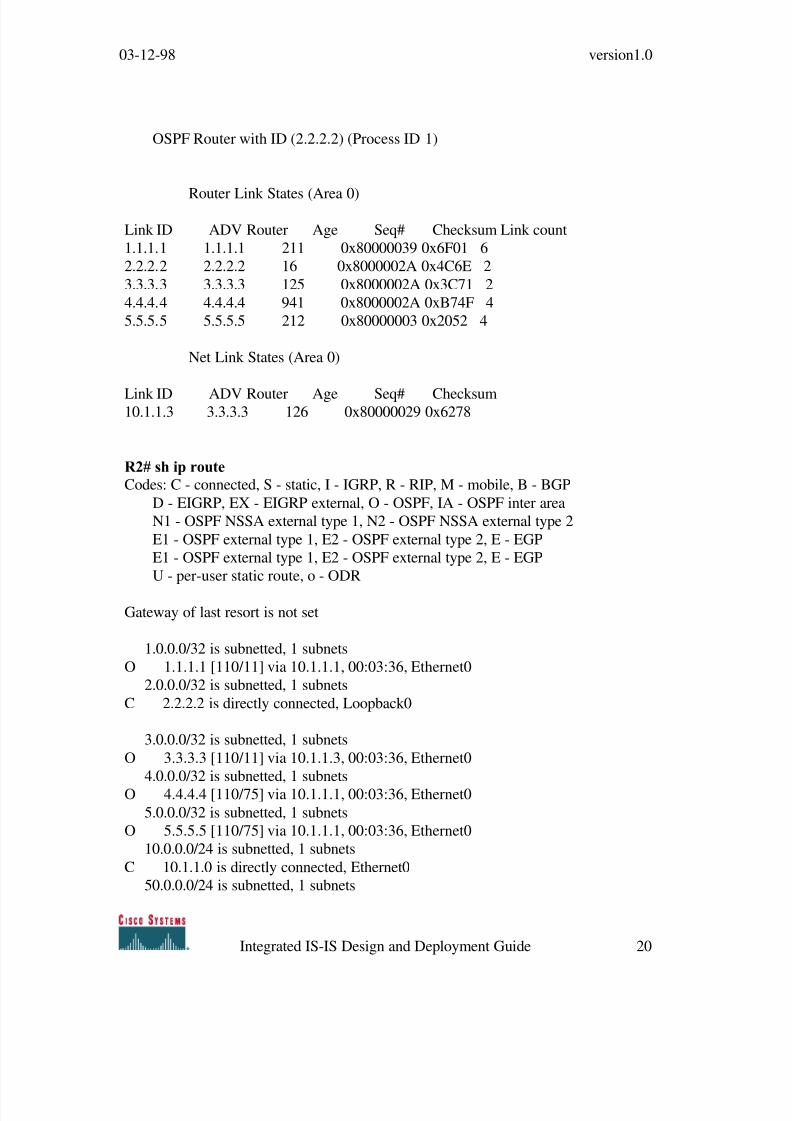
OSPF Router with ID (2.2.2.2) (Process ID 1)
Router Link States (Area 0)
Link ID ADV Router Age Seq# Checksum Link count
1.1.1.1 1.1.1.1 211 0x80000039 0x6F01 6
2.2.2.2 2.2.2.2 16 0x8000002A 0x4C6E 2
3.3.3.3 3.3.3.3 125 0x8000002A 0x3C71 2
4.4.4.4 4.4.4.4 941 0x8000002A 0xB74F 4
5.5.5.5 5.5.5.5 212 0x80000003 0x2052 4
Net Link States (Area 0)
Link ID ADV Router Age Seq# Checksum10.1.1.3 3.3.3.3 126 0x80000029 0x6278
R2# sh ip route
Codes: C - connected, S - static, I - IGRP, R - RIP, M - mobile, B - BGP
D - EIGRP, EX - EIGRP external, O - OSPF, IA - OSPF inter area
N1 - OSPF NSSA external type 1, N2 - OSPF NSSA external type 2
E1 - OSPF external type 1, E2 - OSPF external type 2, E - EGP
E1 - OSPF external type 1, E2 - OSPF external type 2, E - EGP
U - per-user static route, o - ODR
Gateway of last resort is not set
1.0.0.0/32 is subnetted, 1 subnets
O 1.1.1.1 [110/11] via 10.1.1.1, 00:03:36, Ethernet0
2.0.0.0/32 is subnetted, 1 subnets
C 2.2.2.2 is directly connected, Loopback0
3.0.0.0/32 is subnetted, 1 subnets
O 3.3.3.3 [110/11] via 10.1.1.3, 00:03:36, Ethernet0
4.0.0.0/32 is subnetted, 1 subnets
O 4.4.4.4 [110/75] via 10.1.1.1, 00:03:36, Ethernet0
5.0.0.0/32 is subnetted, 1 subnets
O 5.5.5.5 [110/75] via 10.1.1.1, 00:03:36, Ethernet0
10.0.0.0/24 is subnetted, 1 subnets
C 10.1.1.0 is directly connected, Ethernet0
50.0.0.0/24 is subnetted, 1 subnets

8/3/2019 Isis Design Guide
http://slidepdf.com/reader/full/isis-design-guide 21/37
03-12-98 version1.0
Integrated IS-IS Design and Deployment Guide 21
O 50.1.1.0 [110/74] via 10.1.1.1, 00:03:37, Ethernet0
60.0.0.0/24 is subnetted, 1 subnets
O 60.1.1.0 [110/74] via 10.1.1.1, 00:03:37, Ethernet0
100.0.0.0/24 is subnetted, 1 subnets
O 100.1.1.0 [110/84] via 10.1.1.1, 00:03:37, Ethernet0O 200.1.1.0/24 [110/84] via 10.1.1.1, 00:03:37, Ethernet0
R1:
hostname R1
!
interface Loopback0
ip address 1.1.1.1 255.255.255.255
!
interface Ethernet0ip address 10.1.1.1 255.255.255.0
!
interface Serial0
ip address 50.1.1.1 255.255.255.0
clockrate 64000
!
interface Serial1
ip address 60.1.1.1 255.255.255.0
!
router ospf 1
passive-interface Loopback0network 10.1.1.0 0.0.0.255 area 0
network 1.1.1.1 0.0.0.0 area 0
network 60.1.1.0 0.0.0.255 area 0
network 50.1.1.0 0.0.0.255 area 0
R1#sh ip ospf database
OSPF Router with ID (1.1.1.1) (Process ID 1)
Router Link States (Area 0)
Link ID ADV Router Age Seq# Checksum Link count
1.1.1.1 1.1.1.1 255 0x80000039 0x6F01 6
2.2.2.2 2.2.2.2 62 0x8000002A 0x4C6E 2

8/3/2019 Isis Design Guide
http://slidepdf.com/reader/full/isis-design-guide 22/37
03-12-98 version1.0
Integrated IS-IS Design and Deployment Guide 22
3.3.3.3 3.3.3.3 170 0x8000002A 0x3C71 2
4.4.4.4 4.4.4.4 984 0x8000002A 0xB74F 4
5.5.5.5 5.5.5.5 256 0x80000003 0x2052 4
Net Link States (Area 0)
Link ID ADV Router Age Seq# Checksum
10.1.1.3 3.3.3.3 170 0x80000029 0x6278
R1#sh ip route
Codes: C - connected, S - static, I - IGRP, R - RIP, M - mobile, B - BGP
D - EIGRP, EX - EIGRP external, O - OSPF, IA - OSPF inter area
N1 - OSPF NSSA external type 1, N2 - OSPF NSSA external type 2
E1 - OSPF external type 1, E2 - OSPF external type 2, E - EGP
i - IS-IS, L1 - IS-IS level-1, L2 - IS-IS level-2, * - candidate defaultU - per-user static route, o - ODR
Gateway of last resort is not set
1.0.0.0/32 is subnetted, 1 subnets
C 1.1.1.1 is directly connected, Loopback0
2.0.0.0/32 is subnetted, 1 subnets
O 2.2.2.2 [110/11] via 10.1.1.2, 00:04:12, Ethernet0
3.0.0.0/32 is subnetted, 1 subnets
O 3.3.3.3 [110/11] via 10.1.1.3, 00:04:12, Ethernet0
4.0.0.0/32 is subnetted, 1 subnetsO 4.4.4.4 [110/65] via 50.1.1.2, 00:04:12, Serial0
5.0.0.0/32 is subnetted, 1 subnets
O 5.5.5.5 [110/65] via 60.1.1.2, 00:04:12, Serial1
10.0.0.0/24 is subnetted, 1 subnets
C 10.1.1.0 is directly connected, Ethernet0
50.0.0.0/24 is subnetted, 1 subnets
C 50.1.1.0 is directly connected, Serial0
60.0.0.0/24 is subnetted, 1 subnets
C 60.1.1.0 is directly connected, Serial1
100.0.0.0/24 is subnetted, 1 subnets
O 100.1.1.0 [110/74] via 60.1.1.2, 00:04:13, Serial1
O 200.1.1.0/24 [110/74] via 50.1.1.2, 00:04:13, Serial0
R4:

8/3/2019 Isis Design Guide
http://slidepdf.com/reader/full/isis-design-guide 23/37
03-12-98 version1.0
Integrated IS-IS Design and Deployment Guide 23
hostname R4
!
interface Loopback0
ip address 4.4.4.4 255.255.255.255
!interface Ethernet0
ip address 200.1.1.1 255.255.255.0
no keepalive
!
interface Serial1
ip address 50.1.1.2 255.255.255.0
!
router ospf 1
passive-interface Loopback0
network 200.1.1.0 0.0.0.255 area 0
network 4.4.4.4 0.0.0.0 area 0network 50.1.1.0 0.0.0.255 area 0
R4#sh ip ospf database
OSPF Router with ID (4.4.4.4) (Process ID 1)
Router Link States (Area 0)
Link ID ADV Router Age Seq# Checksum Link count1.1.1.1 1.1.1.1 282 0x80000039 0x6F01 6
2.2.2.2 2.2.2.2 89 0x8000002A 0x4C6E 2
3.3.3.3 3.3.3.3 197 0x8000002A 0x3C71 2
4.4.4.4 4.4.4.4 1010 0x8000002A 0xB74F 4
5.5.5.5 5.5.5.5 283 0x80000003 0x2052 4
Net Link States (Area 0)
Link ID ADV Router Age Seq# Checksum
10.1.1.3 3.3.3.3 197 0x80000029 0x6278
R4#sh ip route
Codes: C - connected, S - static, I - IGRP, R - RIP, M - mobile, B - BGP
D - EIGRP, EX - EIGRP external, O - OSPF, IA - OSPF inter area
E1 - OSPF external type 1, E2 - OSPF external type 2, E - EGP
i - IS-IS, L1 - IS-IS level-1, L2 - IS-IS level-2, * - candidate default
8/3/2019 Isis Design Guide
http://slidepdf.com/reader/full/isis-design-guide 24/37
03-12-98 version1.0
Integrated IS-IS Design and Deployment Guide 24
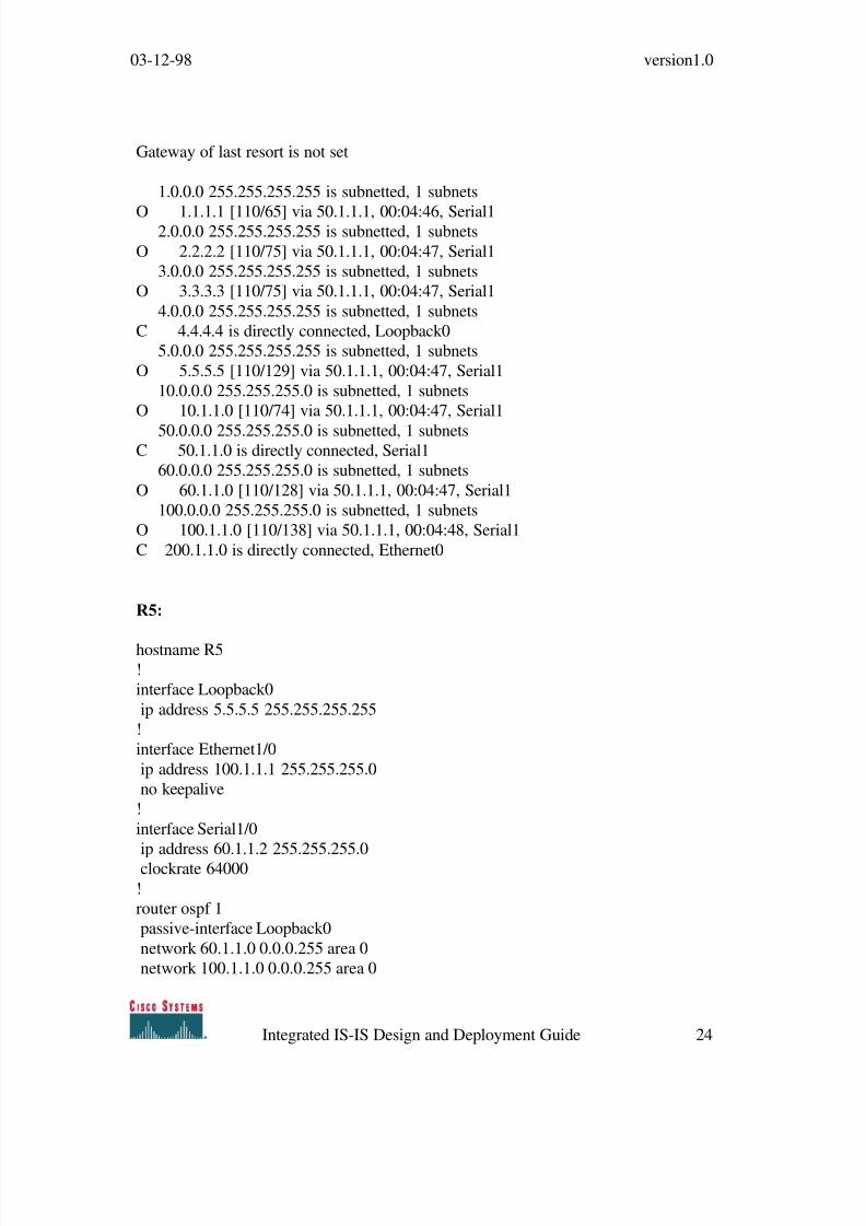
Gateway of last resort is not set
1.0.0.0 255.255.255.255 is subnetted, 1 subnets
O 1.1.1.1 [110/65] via 50.1.1.1, 00:04:46, Serial12.0.0.0 255.255.255.255 is subnetted, 1 subnets
O 2.2.2.2 [110/75] via 50.1.1.1, 00:04:47, Serial1
3.0.0.0 255.255.255.255 is subnetted, 1 subnets
O 3.3.3.3 [110/75] via 50.1.1.1, 00:04:47, Serial1
4.0.0.0 255.255.255.255 is subnetted, 1 subnets
C 4.4.4.4 is directly connected, Loopback0
5.0.0.0 255.255.255.255 is subnetted, 1 subnets
O 5.5.5.5 [110/129] via 50.1.1.1, 00:04:47, Serial1
10.0.0.0 255.255.255.0 is subnetted, 1 subnets
O 10.1.1.0 [110/74] via 50.1.1.1, 00:04:47, Serial1
50.0.0.0 255.255.255.0 is subnetted, 1 subnetsC 50.1.1.0 is directly connected, Serial1
60.0.0.0 255.255.255.0 is subnetted, 1 subnets
O 60.1.1.0 [110/128] via 50.1.1.1, 00:04:47, Serial1
100.0.0.0 255.255.255.0 is subnetted, 1 subnets
O 100.1.1.0 [110/138] via 50.1.1.1, 00:04:48, Serial1
C 200.1.1.0 is directly connected, Ethernet0
R5:
hostname R5!
interface Loopback0
ip address 5.5.5.5 255.255.255.255
!
interface Ethernet1/0
ip address 100.1.1.1 255.255.255.0
no keepalive
!
interface Serial1/0
ip address 60.1.1.2 255.255.255.0
clockrate 64000
!
router ospf 1
passive-interface Loopback0
network 60.1.1.0 0.0.0.255 area 0
network 100.1.1.0 0.0.0.255 area 0

8/3/2019 Isis Design Guide
http://slidepdf.com/reader/full/isis-design-guide 25/37
03-12-98 version1.0
Integrated IS-IS Design and Deployment Guide 25
network 5.5.5.5 0.0.0.0 area 0
R5#sh ip ospf database
OSPF Router with ID (5.5.5.5) (Process ID 1)
Router Link States (Area 0)
Link ID ADV Router Age Seq# Checksum Link count
1.1.1.1 1.1.1.1 605 0x80000010 0xC1D7 6
2.2.2.2 2.2.2.2 853 0x80000004 0x9848 2
3.3.3.3 3.3.3.3 961 0x80000004 0x884B 2
4.4.4.4 4.4.4.4 1750 0x80000004 0x429 4
5.5.5.5 5.5.5.5 829 0x80000003 0x2052 4100.1.1.1 100.1.1.1 883 0x80000002 0xC804 4
Net Link States (Area 0)
Link ID ADV Router Age Seq# Checksum
10.1.1.3 3.3.3.3 962 0x80000003 0xAE52
R5#sh ip route
Codes: C - connected, S - static, I - IGRP, R - RIP, M - mobile, B - BGPD - EIGRP, EX - EIGRP external, O - OSPF, IA - OSPF inter area
E1 - OSPF external type 1, E2 - OSPF external type 2, E - EGP
E1 - OSPF external type 1, E2 - OSPF external type 2, E - EGP
U - per-user static route
Gateway of last resort is not set
1.0.0.0/32 is subnetted, 1 subnets
O 1.1.1.1 [110/65] via 60.1.1.1, 00:13:20, Serial1/0
2.0.0.0/32 is subnetted, 1 subnets
O 2.2.2.2 [110/75] via 60.1.1.1, 00:13:21, Serial1/0
3.0.0.0/32 is subnetted, 1 subnets
O 3.3.3.3 [110/75] via 60.1.1.1, 00:13:21, Serial1/0

8/3/2019 Isis Design Guide
http://slidepdf.com/reader/full/isis-design-guide 26/37
03-12-98 version1.0
Integrated IS-IS Design and Deployment Guide 26
4.0.0.0/32 is subnetted, 1 subnets
O 4.4.4.4 [110/129] via 60.1.1.1, 00:13:21, Serial1/0
5.0.0.0/32 is subnetted, 1 subnets
C 5.5.5.5 is directly connected, Loopback0
10.0.0.0/24 is subnetted, 1 subnetsO 10.1.1.0 [110/74] via 60.1.1.1, 00:13:21, Serial1/0
50.0.0.0/24 is subnetted, 1 subnets
O 50.1.1.0 [110/128] via 60.1.1.1, 00:13:21, Serial1/0
60.0.0.0/24 is subnetted, 1 subnets
C 60.1.1.0 is directly connected, Serial1/0
100.0.0.0/24 is subnetted, 1 subnets
C 100.1.1.0 is directly connected, Ethernet1/0
O 200.1.1.0/24 [110/138] via 60.1.1.1, 00:13:21, Serial1/0
5.5 Configuration and outputs – Phase 2
R3:
hostname R3
!
clns routing
!
interface Loopback0
ip address 3.3.3.3 255.255.255.255
!
interface Ethernet0
ip address 10.1.1.3 255.255.255.0
ip router isis
!
router ospf 1
passive-interface Loopback0
network 10.1.1.0 0.0.0.255 area 0
network 3.3.3.3 0.0.0.0 area 0
!
router isispassive-interface Loopback0
distance 255 ip
net 49.0003.0003.0003.0003.00
is-type level-2-only
display-route-detail

8/3/2019 Isis Design Guide
http://slidepdf.com/reader/full/isis-design-guide 27/37
03-12-98 version1.0
Integrated IS-IS Design and Deployment Guide 27
R3#sh isis database
IS-IS Level-2 Link State Database
LSPID LSP Seq Num LSP Checksum LSP Holdtime ATT/P/OL0001.0001.0001.00-00 0x0000000E 0x5C4D 519 0/0/0 (3)
0001.0001.0001.02-00 0x00000002 0x4FEB 813 0/0/0 (1)
0002.0002.0002.00-00 0x0000000A 0x278C 854 0/0/0 (5)
0003.0003.0003.00-00* 0x00000009 0x3A6E 796 0/0/0 (2)
0003.0003.0003.01-00* 0x00000003 0x9B54 0 (107) 0/0/0 (4)
0004.0004.0004.00-00 0x00000007 0x093A 991 0/0/0 (6)
0005.0005.0005.00-00 0x00000009 0x65A0 525 0/0/0 (7)
R3#sh isis database 0003.0003.0003.00-00 detail
IS-IS Level-2 LSP 0003.0003.0003.00-00LSPID LSP Seq Num LSP Checksum LSP Holdtime ATT/P/OL
0003.0003.0003.00-00* 0x00000009 0x3A6E 783 0/0/0 (2)
Area Address: 49.0003
NLPID: 0xCC
IP Address: 10.1.1.3
Metric: 10 IS 0003.0003.0003.01
Metric: 10 IS 0001.0001.0001.02
Metric: 0 IP 3.3.3.3 255.255.255.255
Metric: 10 IP 10.1.1.0 255.255.255.0
R3#sh ip route
Codes: C - connected, S - static, I - IGRP, R - RIP, M - mobile, B - BGP
D - EIGRP, EX - EIGRP external, O - OSPF, IA - OSPF inter area
N1 - OSPF NSSA external type 1, N2 - OSPF NSSA external type 2
E1 - OSPF external type 1, E2 - OSPF external type 2, E - EGP
E1 - OSPF external type 1, E2 - OSPF external type 2, E - EGP
U - per-user static route, o - ODR
Gateway of last resort is not set
1.0.0.0/32 is subnetted, 1 subnets
O 1.1.1.1 [110/11] via 10.1.1.1, 00:11:10, Ethernet0
2.0.0.0/32 is subnetted, 1 subnets
O 2.2.2.2 [110/11] via 10.1.1.2, 00:11:11, Ethernet0
3.0.0.0/32 is subnetted, 1 subnets
C 3.3.3.3 is directly connected, Loopback0
8/3/2019 Isis Design Guide
http://slidepdf.com/reader/full/isis-design-guide 28/37
03-12-98 version1.0
Integrated IS-IS Design and Deployment Guide 28
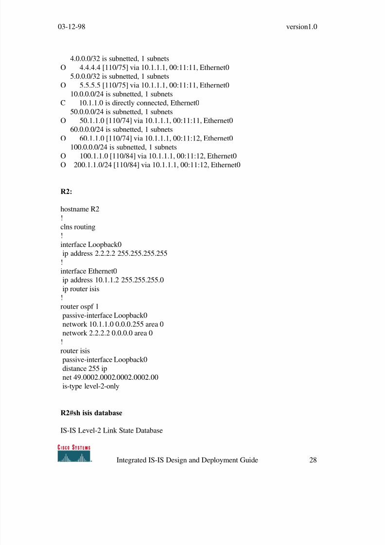
4.0.0.0/32 is subnetted, 1 subnets
O 4.4.4.4 [110/75] via 10.1.1.1, 00:11:11, Ethernet0
5.0.0.0/32 is subnetted, 1 subnets
O 5.5.5.5 [110/75] via 10.1.1.1, 00:11:11, Ethernet0
10.0.0.0/24 is subnetted, 1 subnetsC 10.1.1.0 is directly connected, Ethernet0
50.0.0.0/24 is subnetted, 1 subnets
O 50.1.1.0 [110/74] via 10.1.1.1, 00:11:11, Ethernet0
60.0.0.0/24 is subnetted, 1 subnets
O 60.1.1.0 [110/74] via 10.1.1.1, 00:11:12, Ethernet0
100.0.0.0/24 is subnetted, 1 subnets
O 100.1.1.0 [110/84] via 10.1.1.1, 00:11:12, Ethernet0
O 200.1.1.0/24 [110/84] via 10.1.1.1, 00:11:12, Ethernet0
R2:
hostname R2
!
clns routing
!
interface Loopback0
ip address 2.2.2.2 255.255.255.255
!
interface Ethernet0
ip address 10.1.1.2 255.255.255.0
ip router isis!
router ospf 1
passive-interface Loopback0
network 10.1.1.0 0.0.0.255 area 0
network 2.2.2.2 0.0.0.0 area 0
!
router isis
passive-interface Loopback0
distance 255 ip
net 49.0002.0002.0002.0002.00
is-type level-2-only
R2#sh isis database
IS-IS Level-2 Link State Database
8/3/2019 Isis Design Guide
http://slidepdf.com/reader/full/isis-design-guide 29/37
03-12-98 version1.0
Integrated IS-IS Design and Deployment Guide 29
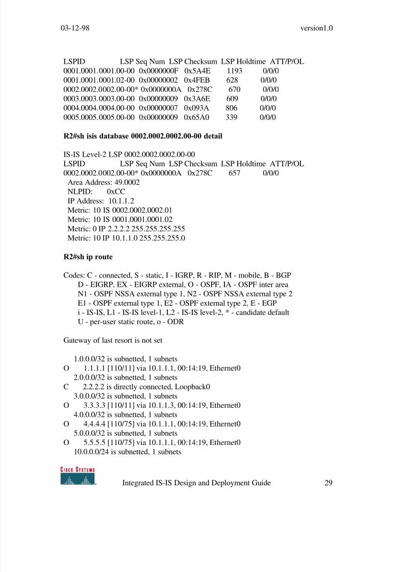
LSPID LSP Seq Num LSP Checksum LSP Holdtime ATT/P/OL
0001.0001.0001.00-00 0x0000000F 0x5A4E 1193 0/0/0
0001.0001.0001.02-00 0x00000002 0x4FEB 628 0/0/0
0002.0002.0002.00-00* 0x0000000A 0x278C 670 0/0/0
0003.0003.0003.00-00 0x00000009 0x3A6E 609 0/0/00004.0004.0004.00-00 0x00000007 0x093A 806 0/0/0
0005.0005.0005.00-00 0x00000009 0x65A0 339 0/0/0
R2#sh isis database 0002.0002.0002.00-00 detail
IS-IS Level-2 LSP 0002.0002.0002.00-00
LSPID LSP Seq Num LSP Checksum LSP Holdtime ATT/P/OL
0002.0002.0002.00-00* 0x0000000A 0x278C 657 0/0/0
Area Address: 49.0002
NLPID: 0xCC
IP Address: 10.1.1.2Metric: 10 IS 0002.0002.0002.01
Metric: 10 IS 0001.0001.0001.02
Metric: 0 IP 2.2.2.2 255.255.255.255
Metric: 10 IP 10.1.1.0 255.255.255.0
R2#sh ip route
Codes: C - connected, S - static, I - IGRP, R - RIP, M - mobile, B - BGP
D - EIGRP, EX - EIGRP external, O - OSPF, IA - OSPF inter area
N1 - OSPF NSSA external type 1, N2 - OSPF NSSA external type 2
E1 - OSPF external type 1, E2 - OSPF external type 2, E - EGPi - IS-IS, L1 - IS-IS level-1, L2 - IS-IS level-2, * - candidate default
U - per-user static route, o - ODR
Gateway of last resort is not set
1.0.0.0/32 is subnetted, 1 subnets
O 1.1.1.1 [110/11] via 10.1.1.1, 00:14:19, Ethernet0
2.0.0.0/32 is subnetted, 1 subnets
C 2.2.2.2 is directly connected, Loopback0
3.0.0.0/32 is subnetted, 1 subnets
O 3.3.3.3 [110/11] via 10.1.1.3, 00:14:19, Ethernet0
4.0.0.0/32 is subnetted, 1 subnets
O 4.4.4.4 [110/75] via 10.1.1.1, 00:14:19, Ethernet0
5.0.0.0/32 is subnetted, 1 subnets
O 5.5.5.5 [110/75] via 10.1.1.1, 00:14:19, Ethernet0
10.0.0.0/24 is subnetted, 1 subnets

8/3/2019 Isis Design Guide
http://slidepdf.com/reader/full/isis-design-guide 30/37
03-12-98 version1.0
Integrated IS-IS Design and Deployment Guide 30
C 10.1.1.0 is directly connected, Ethernet0
50.0.0.0/24 is subnetted, 1 subnets
O 50.1.1.0 [110/74] via 10.1.1.1, 00:14:20, Ethernet0
60.0.0.0/24 is subnetted, 1 subnets
O 60.1.1.0 [110/74] via 10.1.1.1, 00:14:20, Ethernet0100.0.0.0/24 is subnetted, 1 subnets
O 100.1.1.0 [110/84] via 10.1.1.1, 00:14:20, Ethernet0
O 200.1.1.0/24 [110/84] via 10.1.1.1, 00:14:20, Ethernet0
R1:
hostname R1
!
enable password cisco
!clns routing
!
interface Loopback0
ip address 1.1.1.1 255.255.255.255
!
interface Ethernet0
ip address 10.1.1.1 255.255.255.0
ip router isis
!
interface Serial0
ip address 50.1.1.1 255.255.255.0ip router isis
clockrate 64000
!
interface Serial1
ip address 60.1.1.1 255.255.255.0
ip router isis
!
router ospf 1
passive-interface Loopback0
network 10.1.1.0 0.0.0.255 area 0
network 1.1.1.1 0.0.0.0 area 0
network 60.1.1.0 0.0.0.255 area 0
network 50.1.1.0 0.0.0.255 area 0
!
router isis
passive-interface Loopback0
8/3/2019 Isis Design Guide
http://slidepdf.com/reader/full/isis-design-guide 31/37
03-12-98 version1.0
Integrated IS-IS Design and Deployment Guide 31
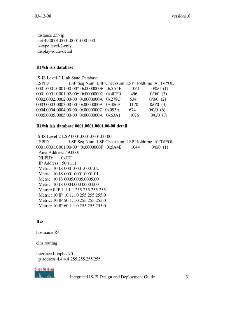
distance 255 ip
net 49.0001.0001.0001.0001.00
is-type level-2-only
display-route-detail
R1#sh isis database
IS-IS Level-2 Link State Database
LSPID LSP Seq Num LSP Checksum LSP Holdtime ATT/P/OL
0001.0001.0001.00-00* 0x0000000F 0x5A4E 1061 0/0/0 (1)
0001.0001.0001.02-00* 0x00000002 0x4FEB 496 0/0/0 (3)
0002.0002.0002.00-00 0x0000000A 0x278C 534 0/0/0 (2)
0003.0003.0003.00-00 0x0000000A 0x386F 1170 0/0/0 (4)
0004.0004.0004.00-00 0x00000007 0x093A 674 0/0/0 (6)
0005.0005.0005.00-00 0x0000000A 0x63A1 1076 0/0/0 (7)
R1#sh isis database 0001.0001.0001.00-00 detail
IS-IS Level-2 LSP 0001.0001.0001.00-00
LSPID LSP Seq Num LSP Checksum LSP Holdtime ATT/P/OL
0001.0001.0001.00-00* 0x0000000F 0x5A4E 1044 0/0/0 (1)
Area Address: 49.0001
NLPID: 0xCC
IP Address: 50.1.1.1
Metric: 10 IS 0001.0001.0001.02
Metric: 10 IS 0001.0001.0001.01Metric: 10 IS 0005.0005.0005.00
Metric: 10 IS 0004.0004.0004.00
Metric: 0 IP 1.1.1.1 255.255.255.255
Metric: 10 IP 10.1.1.0 255.255.255.0
Metric: 10 IP 50.1.1.0 255.255.255.0
Metric: 10 IP 60.1.1.0 255.255.255.0
R4:
hostname R4
!
clns routing
!
interface Loopback0
ip address 4.4.4.4 255.255.255.255

8/3/2019 Isis Design Guide
http://slidepdf.com/reader/full/isis-design-guide 32/37
03-12-98 version1.0
Integrated IS-IS Design and Deployment Guide 32
!
interface Ethernet0
ip address 200.1.1.1 255.255.255.0
ip router isis
no keepalive!
interface Serial1
ip address 50.1.1.2 255.255.255.0
ip router isis
!
router ospf 1
passive-interface Loopback0
network 200.1.1.0 0.0.0.255 area 0
network 4.4.4.4 0.0.0.0 area 0
network 50.1.1.0 0.0.0.255 area 0
!router isis
passive-interface Loopback0
distance 255 ip
net 49.0004.0004.0004.0004.00
is-type level-2-only
display-route-detail
R4#sh isis database
IS-IS Level-2 Link State DatabaseLSPID LSP Seq Num LSP Checksum LSP Holdtime ATT/P/OL
0001.0001.0001.00-00 0x0000000F 0x5A4E 976 0/0/0 (5)
0001.0001.0001.02-00 0x00000002 0x4FEB 411 0/0/0 (4)
0002.0002.0002.00-00 0x0000000A 0x278C 449 0/0/0 (3)
0003.0003.0003.00-00 0x0000000A 0x386F 1085 0/0/0 (1)
0004.0004.0004.00-00* 0x00000007 0x093A 593 0/0/0 (2)
0005.0005.0005.00-00 0x0000000A 0x63A1 991 0/0/0 (6)
R4#sh isis database 0004.0004.0004.00-00 detail
IS-IS Level-2 LSP 0004.0004.0004.00-00
LSPID LSP Seq Num LSP Checksum LSP Holdtime ATT/P/OL
0004.0004.0004.00-00* 0x00000007 0x093A 582 0/0/0 (2)
Area Address: 49.0004
NLPID: 0xCC
8/3/2019 Isis Design Guide
http://slidepdf.com/reader/full/isis-design-guide 33/37
03-12-98 version1.0
Integrated IS-IS Design and Deployment Guide 33
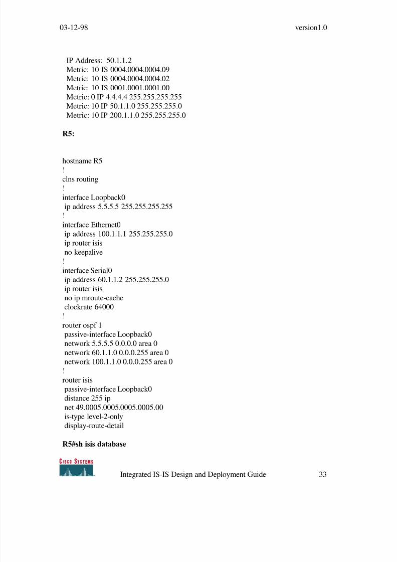
IP Address: 50.1.1.2
Metric: 10 IS 0004.0004.0004.09
Metric: 10 IS 0004.0004.0004.02
Metric: 10 IS 0001.0001.0001.00
Metric: 0 IP 4.4.4.4 255.255.255.255Metric: 10 IP 50.1.1.0 255.255.255.0
Metric: 10 IP 200.1.1.0 255.255.255.0
R5:
hostname R5
!
clns routing
!
interface Loopback0ip address 5.5.5.5 255.255.255.255
!
interface Ethernet0
ip address 100.1.1.1 255.255.255.0
ip router isis
no keepalive
!
interface Serial0
ip address 60.1.1.2 255.255.255.0
ip router isis
no ip mroute-cacheclockrate 64000
!
router ospf 1
passive-interface Loopback0
network 5.5.5.5 0.0.0.0 area 0
network 60.1.1.0 0.0.0.255 area 0
network 100.1.1.0 0.0.0.255 area 0
!
router isis
passive-interface Loopback0
distance 255 ip
net 49.0005.0005.0005.0005.00
is-type level-2-only
display-route-detail
R5#sh isis database

8/3/2019 Isis Design Guide
http://slidepdf.com/reader/full/isis-design-guide 34/37
03-12-98 version1.0
Integrated IS-IS Design and Deployment Guide 34
IS-IS Level-2 Link State Database
LSPID LSP Seq Num LSP Checksum LSP Holdtime ATT/P/OL
0001.0001.0001.00-00 0x0000002B 0x226A 1128 0/0/0 (6)
0001.0001.0001.02-00 0x00000009 0x62D1 1007 0/0/0 (5)0002.0002.0002.00-00 0x00000014 0x1396 982 0/0/0 (4)
0002.0002.0002.02-00 0x00000004 0xB040 0 (1137) 0/0/0 (7)
0003.0003.0003.00-00 0x00000011 0x2A76 973 0/0/0 (3)
0004.0004.0004.00-00 0x0000000B 0x013E 811 0/0/0 (2)
0005.0005.0005.00-00* 0x00000015 0x8F6A 1137 0/0/0 (1)
R5#sh isis da 0005.0005.0005.00-00 detail
IS-IS Level-2 LSP 0005.0005.0005.00-00
LSPID LSP Seq Num LSP Checksum LSP Holdtime ATT/P/OL0005.0005.0005.00-00* 0x00000015 0x8F6A 1133 0/0/0 (1)
Area Address: 49.0005
NLPID: 0xCC
IP Address: 5.5.5.5
Metric: 10 IS 0001.0001.0001.00
Metric: 10 IP 100.1.1.0 255.255.255.0
Metric: 0 IP 5.5.5.5 255.255.255.255
Metric: 10 IP 60.1.1.0 255.255.255.0
R5#sh ip routeCodes: C - connected, S - static, I - IGRP, R - RIP, M - mobile, B - BGP
D - EIGRP, EX - EIGRP external, O - OSPF, IA - OSPF inter area
N1 - OSPF NSSA external type 1, N2 - OSPF NSSA external type 2
E1 - OSPF external type 1, E2 - OSPF external type 2, E - EGP
i - IS-IS, L1 - IS-IS level-1, L2 - IS-IS level-2, * - candidate default
U - per-user static route, o - ODR
Gateway of last resort is not set
1.0.0.0/32 is subnetted, 1 subnets
O 1.1.1.1 [110/65] via 60.1.1.1, 00:00:55, Serial0
50.0.0.0/24 is subnetted, 1 subnets
O 50.1.1.0 [110/128] via 60.1.1.1, 00:00:56, Serial0
2.0.0.0/32 is subnetted, 1 subnets
O 2.2.2.2 [110/75] via 60.1.1.1, 00:00:56, Serial0
100.0.0.0/24 is subnetted, 1 subnets

8/3/2019 Isis Design Guide
http://slidepdf.com/reader/full/isis-design-guide 35/37
03-12-98 version1.0
Integrated IS-IS Design and Deployment Guide 35
C 100.1.1.0 is directly connected, Ethernet0
3.0.0.0/32 is subnetted, 1 subnets
O 3.3.3.3 [110/75] via 60.1.1.1, 00:00:56, Serial0
4.0.0.0/32 is subnetted, 1 subnets
O 4.4.4.4 [110/129] via 60.1.1.1, 00:00:56, Serial05.0.0.0/32 is subnetted, 1 subnets
C 5.5.5.5 is directly connected, Loopback0
O 200.1.1.0/24 [110/138] via 60.1.1.1, 00:00:57, Serial0
10.0.0.0/24 is subnetted, 1 subnets
O 10.1.1.0 [110/74] via 60.1.1.1, 00:00:57, Serial0
60.0.0.0/24 is subnetted, 1 subnets
C 60.1.1.0 is directly connected, Serial0
5.6 Configuration and outputs – Phase 3
R5:
R5#conf t
Enter configuration commands, one per line. End with CNTL/Z.
R5(config)#no router ospf 1
R5(config)#
R5(config)#^Z
Config:
hostname R5
!
clns routing
!
interface Loopback0
ip address 5.5.5.5 255.255.255.255
!
interface Ethernet0
ip address 100.1.1.1 255.255.255.0
ip router isisno keepalive
!
interface Serial0
ip address 60.1.1.2 255.255.255.0
ip router isis
no ip mroute-cache

8/3/2019 Isis Design Guide
http://slidepdf.com/reader/full/isis-design-guide 36/37
03-12-98 version1.0
Integrated IS-IS Design and Deployment Guide 36
clockrate 64000
!
router isis
passive-interface Loopback0
net 49.0005.0005.0005.0005.00is-type level-2-only
display-route-detail
R5#sh ip route
Codes: C - connected, S - static, I - IGRP, R - RIP, M - mobile, B - BGP
D - EIGRP, EX - EIGRP external, O - OSPF, IA - OSPF inter area
N1 - OSPF NSSA external type 1, N2 - OSPF NSSA external type 2
E1 - OSPF external type 1, E2 - OSPF external type 2, E - EGP
i - IS-IS, L1 - IS-IS level-1, L2 - IS-IS level-2, * - candidate default
U - per-user static route, o - ODR
Gateway of last resort is not set
1.0.0.0/32 is subnetted, 1 subnets
i L2 1.1.1.1 [115 /20] via 60.1.1.1, Serial0, from LSP 6
50.0.0.0/24 is subnetted, 1 subnets
i L2 50.1.1.0 [115 /20] via 60.1.1.1, Serial0, from LSP 6
Backup ix/lvl/metric: 2/L2/30
2.0.0.0/32 is subnetted, 1 subnets
i L2 2.2.2.2 [115 /30] via 60.1.1.1, Serial0, from LSP 4
100.0.0.0/24 is subnetted, 1 subnets
C 100.1.1.0 is directly connected, Ethernet0
3.0.0.0/32 is subnetted, 1 subnets
i L2 3.3.3.3 [115 /30] via 60.1.1.1, Serial0, from LSP 3
4.0.0.0/32 is subnetted, 1 subnets
i L2 4.4.4.4 [115/30] via 60.1.1.1, Serial0, from LSP 2
5.0.0.0/32 is subnetted, 1 subnets
C 5.5.5.5 is directly connected, Loopback0
i L2 200.1.1.0/24 [115/30] via 60.1.1.1, Serial0, from LSP 2
10.0.0.0/24 is subnetted, 1 subnets
i L2 10.1.1.0 [115/20] via 60.1.1.1, Serial0, from LSP 6
Backup ix/lvl/metric: 3/L2/30 4/L2/30
60.0.0.0/24 is subnetted, 1 subnets
C 60.1.1.0 is directly connected, Serial0

8/3/2019 Isis Design Guide
http://slidepdf.com/reader/full/isis-design-guide 37/37
03-12-98 version1.0
Ping all other routers in the network that are running OSPF:
R5#pi 1.1.1.1
Type escape sequence to abort.Sending 5, 100-byte ICMP Echos to 1.1.1.1, timeout is 2 seconds:
!!!!!
Success rate is 100 percent (5/5), round-trip min/avg/max = 28/28/28 ms
R5#pi 2.2.2.2
Type escape sequence to abort.
Sending 5, 100-byte ICMP Echos to 2.2.2.2, timeout is 2 seconds:
!!!!!
Success rate is 100 percent (5/5), round-trip min/avg/max = 32/32/36 ms
R5#pi 3.3.3.3
Type escape sequence to abort.
Sending 5, 100-byte ICMP Echos to 3.3.3.3, timeout is 2 seconds:
!!!!!
Success rate is 100 percent (5/5), round-trip min/avg/max = 28/31/32 ms
R5#pi 4.4.4.4
Type escape sequence to abort.
Sending 5, 100-byte ICMP Echos to 4.4.4.4, timeout is 2 seconds:
!!!!!
Success rate is 100 percent (5/5), round-trip min/avg/max = 56/56/56 ms
Related Documents