Disclosure to Promote the Right To Information Whereas the Parliament of India has set out to provide a practical regime of right to information for citizens to secure access to information under the control of public authorities, in order to promote transparency and accountability in the working of every public authority, and whereas the attached publication of the Bureau of Indian Standards is of particular interest to the public, particularly disadvantaged communities and those engaged in the pursuit of education and knowledge, the attached public safety standard is made available to promote the timely dissemination of this information in an accurate manner to the public. इंटरनेट मानक “!ान $ एक न’ भारत का +नम-ण” Satyanarayan Gangaram Pitroda “Invent a New India Using Knowledge” “प0रा1 को छोड न’ 5 तरफ” Jawaharlal Nehru “Step Out From the Old to the New” “जान1 का अ+धकार, जी1 का अ+धकार” Mazdoor Kisan Shakti Sangathan “The Right to Information, The Right to Live” “!ान एक ऐसा खजाना > जो कभी च0राया नहB जा सकता ह ै” Bhartṛhari—Nītiśatakam “Knowledge is such a treasure which cannot be stolen” IS/IEC 60947-4-1 (2000): Low-Voltage Switchgear and Controlgear, Part 4: Contractors and Motor-Starters, Section 1: Electromechanical Contactors and Motors-Starters [ETD 7: Low Voltage Switchgear and Controlgear]

Welcome message from author
This document is posted to help you gain knowledge. Please leave a comment to let me know what you think about it! Share it to your friends and learn new things together.
Transcript

Disclosure to Promote the Right To Information
Whereas the Parliament of India has set out to provide a practical regime of right to information for citizens to secure access to information under the control of public authorities, in order to promote transparency and accountability in the working of every public authority, and whereas the attached publication of the Bureau of Indian Standards is of particular interest to the public, particularly disadvantaged communities and those engaged in the pursuit of education and knowledge, the attached public safety standard is made available to promote the timely dissemination of this information in an accurate manner to the public.
इंटरनेट मानक
“!ान $ एक न' भारत का +नम-ण”Satyanarayan Gangaram Pitroda
“Invent a New India Using Knowledge”
“प0रा1 को छोड न' 5 तरफ”Jawaharlal Nehru
“Step Out From the Old to the New”
“जान1 का अ+धकार, जी1 का अ+धकार”Mazdoor Kisan Shakti Sangathan
“The Right to Information, The Right to Live”
“!ान एक ऐसा खजाना > जो कभी च0राया नहB जा सकता है”Bhartṛhari—Nītiśatakam
“Knowledge is such a treasure which cannot be stolen”
“Invent a New India Using Knowledge”
है”ह”ह
IS/IEC 60947-4-1 (2000): Low-Voltage Switchgear andControlgear, Part 4: Contractors and Motor-Starters,Section 1: Electromechanical Contactors and Motors-Starters[ETD 7: Low Voltage Switchgear and Controlgear]

ISIIEC 60947-4-1 : 2000[Superseding IS 13947 (Part 4ISec 1) : 1993]
'JfN ff) 2/ 11FtC/5
~-cil(l'CCiI ~~~ -r:1£i~OlfTllI'<
1Wr 4 Cf)1~Cfe'< 3fR ~~~ 1 ~q(14i8lCb Cbl~cre'( 3tR~~
Indian Standard
LOW-VOLTAGE SWITCHGEAR AND CONTROLGEARPART 4 CONTACTORS AND MOTOR-STARTERS
Section 1 Electromechanical Contactors and Motor-Starters
ics 29 .120 .99; 29 .130.20
©SIS 2008
BUREAU OF INDIAN STANDARDSMANAK SHAVAN. 9 SAHADUR SHAH ZAFAR MARG
NEW DELHI 110002
July 2008 Price Group 20
ISIIEC 60947-4-1 : 2000
CONTENTS
IScope and object ........................................................................... 1
1.1 AC and d.c. contactors 11.2 AC motor-starters 1
2 Normative references ...... ...... ............... ............................ .......... ..... ....... ........................ 4
3 Defin itions ....... ........................................... ......... .................................. ....... 6
3.1 Definitions concerning contactors .. 63.2 Definitions concerning starters.... ....... 73.3 Charac ter istic quantities , 10
4 Classification 10
5 Characteristics of contactors and starters 10
5.1 Summary of characteristics 105.2 Type of equipment , 115.3 Rated and limiting values for main circuits , 125.4 Utilization category 195.5 Control circuits 225.6 Auxiliary circu its ........................ .................... ....... 225.7 Characteristics of relays an~ releases (overload relays) 225.8 Co-ordination with short-circuit protective devices 245.9 Switching overvoltages 255.10 Types and characterist ics of automatic change-over devices
and automatic acceleration control devices 255.11 Types and characteristics of auto-transformers
for two-step auto-transformer starters ............ .... 255.12 Types and characteristics of starting resistors for rheostatic rotor starters 26
6 Product information 26
6.1 Nature of information 266.2 Marking ................... ................. ................................................ .... ...... 266.3 Instruct ions for installation, operat ion and maintenance 28
7 Normal serv ice, mounting and transport conditions 28
8 Constructional and performance requirements 28
8.1 Constructional requirements 288.2 Performance requirements 308.3 Electromagnetic compatibility (EMC) 42
9 Tests 43
9.1 Kinds of test 43
9.2 Compl iance with constructional requirements 459.3 Compliance with performance requirements 459.4 EMC Tests 59
ISIIEC 60947-4-1 : 2000
Annex A (normative) Marking and identification of terminals
of centactors and associated overload relays ·.·· ·········,,·· ········ 70
Annex B (normative) Special tests 74
Annex C Void 82
Annex 0 (informative) Items subject to agreement between manufacturer and user 83
Annex E (informative) Examples of control circuit configurations 84
Annex F (normative) Requirements for auxiliary contact linkedwith power contact (mirror contact) 87
Bibliography 90
Figure 1 - Typical curves of currents and torques during a star-delta start (see 1.2.2.1) .... . 63
Figure 2 - Typical curves of currents and torques during an auto -transformer start(see 1.2.2.2) 64
Figure 3 - Typical variants of combination starters (see 3.2.7) and protected starters(see 3.2.8) 65
Figure 4 - Example of three-phase diagram of a rheostatic rotor starterwith thUle starting steps (see 3.2.16) and one direction of rotat ion(in the case when all the mechanical switching devices are contactors) 66
Figure 5 - Typical methods and diagrams of starting alternating-current inductionmotors by means of auto-transformers 67
Figure 6 - Examples of speedltime curves corresponding to cases a), b), c), d), e)and f) of 5.3.5.5 (the dotted parts of the curves correspond to the periodswhen no current flows through the motor) 68
Figure 7 - Multiple of current setting limits for ambient air temperature compensatedtime-delay overload relays (see 8.2.1.5.1) 69
Figure B.1 - Examples of time-current withstand characteristic 81
Figure F.1 - Mirror contact.. 88
Table 1 - Utilization categories 21
Table 2 - Trip classes of thermal, time-delay magnetic or solid state overload relays .......... 23
Table 3 - Umits of operation of time-delay overload relays when energized on all poles ..... 33
Table" - Umits of operation of three-pole thermal overload relayswhen energized on two poles only 34
Table 5 - Temperature rise limits for insulated coils in air and in oil 35
Table 6 -Intermittent duty test cycle data 36
Table 7 - Making and breaking capacities - Making and breaking conditionsaccording to utilization category 37
Table 7a - Relationship between current broken Ie and off-time for the verificationor rated making and breaking capacities 38
Table 7b - Operational current determination for utilization categories AC-ea.nd AC-8b when derived from AC·3 r.tinga 39
ii
ISIIEC 60947-4-1 : 2000
Table 8 - Convent ional operational performance - Making and breaking conditionsaccording to utilizat ion category 40
Table 9 - Overload current withstand requ irements 41
Table 10 - Specific acceptance criteria for immunity tests 43
Table 12 - Value of the prospective test current accordingto the rated operat ional current 56
Table 13 - EMC immunity tests 60
Table 14 - Conducted radio-frequency emission test limits 61
Table 15 - Radiated emission test limits 62
Table B.1 - Verification of the number of on-load operating cycles -Conditions for making and breaking corresponding to the several utilization categories 77
Table B.2 - Test conditions 80
Table F 1 - Test voltage according to altitude 89
iii
ISJlEC 60947-4--1 : 2000
Low-Voltage Switchgear and Controlgear Sectional Committee, ETD 07
NATIONAL FOREWORD
This Indian Standard (Part 4/Sec 1) which is identical with IEC 60947-4-1 : 2000 'Low-volt~ge
switchgear and controlgear - Part 4-1: Contactors and motor-sta~ers - ~Ie~tromechanlcalcontactors and motor-starters' issued by the International Electrotechmcal Commission (lEG) wasadopted by the Bureau of Indian Standards on the recommendation ~f the. ~o:,,-Voltage. Switchgearand ControlgearSectional Committee and approval of the Electrotechmcal DIVISion Council,
This standard supersedes IS 13947 (Part 4/Sec 1) : 1993 'Specification for low-voltage switchgearand controlgear. Part 4 Contactors and motor-starters, Section 1 Electromechanical contactors andmotor-starters'. It also incorporates Amendment No.1 published in 2002 and Technical Corrigendum 1publishedin 2001.
The text of IEC Standard has been approved as suitable for publication as an Indian Standard withoutdeviations. Certain conventions are, however, not identical to those used in Indian Standards.Attention is pa~icularly drawn to the following:
a) Wherever the words 'Intemational Standard' appear referring to this standard, they shouldbe read as 'Indian Standard'.
b) Comma (,) has been used as a decimal marker, while in Indian Standards, the currentpractice is to use a point (.) as the decimal marker.
In this adopted standard, reference appears to certain International Standards for which IndianStandards also exist. The corresponding Indian Standards, which are to be substituted in theirrespective places, are listed below along with their degree of equivalence for the editions indicated:
International Standard
IEC 60034-1 : 2004 Rotating electricalmachines - Part 1: Rating andperformance
IEC 60050 (441) : 1984 InternationalElectrotechnical Vocabulary (lEV) Chapter 441 : Switchgear, controlgearand fuses
IEC 60076-1 : 1993 Power transformers- Part 1: General
IEC 60112 : 2003 Method for thedetermination of the proof and thecomparative tracking indices of solidinsulating materials
IEC 60255-8 : 1990 Electrical relays Part B: Thermal electrical relays
IEC 60269-1 : 1998 Low-voltage fuses- Part 1: General requirements
Corresponding Indian Standard
IS 4722 : 2001 Rotating electricalmachines Specification (secondrevision)
IS 1885 (Part 17) : 1979 Electrotechnicalvocabulary: Part 17 Switchgear andcontrolgear (first revision)
IS 2026 (Part 1) : 19n Powertransformers: Part 1 General (firstrevision)
IS 2824 : 1975 Method for determiningthe comparative tracking index of solidinsulating materials under moistconditions (first revision)
IS 3842 (Part 4) : 1966 Application guidefor electrical relays for ac systems:Part 4 Thermal relays
IS 13703 (Part 1) : 1993 Low-voltagefuses for voltages not exceeding 1 000 Vac or 1 500 V dc: Part 1 Generalrequirements
iv
Degree ofEquivalence
TechnicallyEquivalent
do
do
do
do
do
ISIIEC 60947-4-1 : 2000
do
TechnicallyEquivalent
Degree ofEquivalence
Identical
Corresponding Indian Standard
IS 13703 (Part 21Sec 1) : 1993 Lowvoltage fuses for voltages not exceeding1 000 V ac or 1 500 V dc: Part 2 Fusesfor use by authorized persons, Section 1Supplementary requirements
IS 13703 (Part 21Sec 2) : 1993 Lowvoltage fuses for voltages not exceeding1 000 V ac or 1 500 V dc: Part 2 Fusesfor use by authorized persons, Section 2Examples of standardized fuses
International Standard
IEC 60269-2 : 1986 Low-voltage fuses- Part 2: Supplementary requirementsfor fuses for use by authorized persons(fuses mainly for industrial application)
IEC 60269-2-1 : 2004 Low-voltage fuses- Part 2-1: Supplementary requirementsfor fuses for use by authorized persons(fuses mainly for industrial application)- Sections I to V: Examples of types ofstandardized fuses
IEC 60410 : 1973 Sampling plans and IS 10673 : 1983 Sampling plans andprocedures for inspection by attributes procedures for inspection by attributes
for electronic items
IEC 60947-1 2004 Low-voltage IS/IEC 60947 (Part 1) : 2004 Lowswitchgear and control gear - Part 1: voltage switchgear and controlgear:General rules Part 1 General rules
IEC 60947-2 2003 Low-voltage IS/IEC 60947 (Part 2) : 2003 Low-switchgear and controlgear - Part 2: voltage switchgear and controlgear:Circuit-breakers Part 2 Circuit-breakers
Identical
do
IEC 60947-3 : 1999') Low-voltageswitchgear and controlgear - Part 3:Switches, disconnectors, switchdisconnectors and fuse-combinationunits
IS/IEC 60947 (Part 3) : 2005 Low-voltageswitchgear and controlgear: Part 3Switches, disconnectors, switchdisconnectors and fuse-combinationunits
TechnicallyEquivalent
IEC 60947-5-1 : 2003 Low-voltageswitchgear and controlgear - Part 5:Control circuit devices and switchingelements Section 1: Electromechanical control circuit devices
IEC 61000-4-2 : 1995 Electromagneticcompatibility (EMC) - Part 4: Testingand measurement techniquesSection 2: Electrostatic dischargeimmunity test
IEC 61000-4-4 : 1995 Electromagneticcompatibility (EMC) - Part 4: Testingand measurement techniques - Section4: Electrical fast transient/burst immunitytest
CISPR 11 : 2003 Industrial, scientific andmedical (ISM) radio-frequency equipment
Electromagnetic distu rbancecharacteristics - Limits and methods ofmeasurement
IS/IEC 60947 (Part 5/Sec 1) : 2003 Lowvoltage switchgear and controlgear:Part 5 Control circuit devices andswitching elements, Section 1Electromechanical control circuit devices
IS 14700 (Part 4/Sec 2) : 1999Electromagnetic compatibility (EMC):Part 4 Testing and measurementtechniques, Section 2 Electrostaticdischarge immunity test
IS 14700 (Part 4/Sec 4) : 1999Electromagnetic compatibility (EMC):Part 4 Testing and measurementtechniques, Section 4 Electrical fasttransientlburst immunity test
IS 6873 (Part 4) : 1999 Limits andmethods of measurement of radiodisturbance characteristics: Part 4Industrial, scientific and medical (ISM)radio-frequency equipment (first revision)
Identical
TechnicallyEquivalent
do
do
I) Since revised in 2005 .v
ISIIEC 60947-4-1 : 2000
The technical committee responsible for the preparation of this standard has reviewed ~he provisionsof the following Intemational Standards referred in this adopted standard and has decided that theyare acceptable for use in conjunction with this standard:
International Standard
lEG 60034-11 : 2004
lEG 60085 : 2004
lEG 61000-4-3 : 2002
lEG 61000-4-5 : 1995
lEG 61095 : 1992
lEG 61810-1 : 2003
Title
Rotating electrical machines - Part 11: Thermal protection
Electrical insulation - Thermal classification
Electromagnetic compatibility (EMC) - Part 4-3: Testing andmeasurement techniques - Radiated, radio-frequency electromagneticfield immunity test
Electromagnetic compatibility (EMC) - Part 4: Testing and measurementtechniques - Section 5: Surge immunity test
Electromechanical contractors for household and similar purposes
Electromechanical elementary relays - Part 1: General and safetyrequirements
Amendment No.2 to the above Intemational Standard has been given at the end of this publication.
Only the English text of the International Standard has been retained while adopting it as an IndianStandard, and as such the page numbers given here are not the same as in the lEG Publication.
For the purpose of deciding whether a particular requirement of this standard is complied with, thefinal value, observed or calculated, expressing the result of a test or analysis , shall be rounded off inaccordance with IS 2 : 1960 'Rules for rounding off numerical values (revised)' . The number ofsignificant places retained in the rounded off value should be the same as that of the specified valuein this standard.
..,;
ISIIEC 60947-4-1 : 2000
Indian Standard
LOW-VOLTAGE SWITCHGEAR AND CONTROLGEARPART 4 CONTACTORS AND MOTOR-STARTERS
section 1 Electromechanical Contactors and Motor-Starters
1 Scope and object
This part of IEC 60947 applies to the types of equipment listed in 1.1 and 1.2 whose maincontacts are intended to be connected to circuits the rated voltage of which does not exceed1 000 V a.c. or 1 500 V d.c.
Starters and/or contactors dealt with in this standard are not normally designed to interruptshort-circuit currents. Therefore, suitable short-circuit protection (see 9.3.4) shall form part ofthe installation but not necessarily of the contactor or the starter.
In this context, this standard gives requirements for:
- contactors associated with overload and/or short-circuit protective devices;
- starters associated with separate short-circuit protective devices and/or with separateshort-circuit and integrated overload protective devices;
- contactors or starters combined, under specified conditions, with their own short-circuitprotective devices. Such combinations, e.g. combination starters (see 3.2.7) or protectedstarters (see 3.2.8) are rated as units.
Circuit-breakers and fuse-combination units used as short-circuit protective devices incombination starters and in protected starters shall comply with the requirements ofIEC 60947-2 and IEC 60947-3, as the case may be.
Equipment covered by this standard is as follows.
1.1 AC and d.c. contactors
AC and d.c. contactors intended for closing and opening electric circuits and, if combined withsuitable relays (see 1.2), for protecting these circuits against operating overloads which mayoccur therein.
NOTE Contactors combined with suitable relays and which are Intended to provide short-cIrcuit protection she"additionally satisfy the relevant condition. specified for circuit-breakers (IEC 80947-2).
This standard applies also to the actuators of contactor relays and to the contacts dedicatedexclusively to the coil circuit of a contactor.
Contactors or starters with an electronically controlled electromagnet are also covered by thisstandard.
1.2 AC motor-starters
AC motor-starters intended to start and accelerate motors to normal speed, to ensurecontinuous operation of motors, to switch off the supply from the motor and to provide meansfor the protection of motors and associated circuits against operating overloads.
IS/IEC 60947-4-1 : 2000
Starters the operation of which depends on thermal electrical rel~ys for. motor prot~cti~ncomplying with IEC 60255-8, or motor-incorporated therm.al protective .devlces dealt WIth In
IEC 60034-11 do not necessarily meet all the relevant requirements of thls standard.
Overload relays for starters, including those based on solid state technology, shall meet therequirements of this standard.
1.2.1 Direct·on-Iine (full voltage) a.c . starters
Direct-an-line starters intended to start and accelerate a motor to normal speed, to providemeans for the protection of the motor and its associated circuits against operating overloads,and to switch off the supply from the motor.
This standard applies also to reversing starters.
1.2.2 Reduced voltage a.c. starters
Reduced voltage a.c. starters intended to start and accelerate a motor to normal speed byconnecting the line voltage across the motor terminals in more than one step or by graduallyincreasing the voltage applied to the terminals, to provide means for the protection of themotor and its associated circuits against operating overloads, and to switch off the supplyfrom the motor.
Automatic change-over devices may be used to control the successive switching operationsfrom one step to the others. Such automatic change-over devices are, for example. time-delaycontactor relays or specified time all-or-nothing relays , under-current devices and automaticacceleration control devices (see 5.10).
1.2.2.1 Star-delta starters
Star-delta starters intended to start a three-phase motor in the star connection, to ensurecontinuous operation in the delta connection , to provide means for the protection of the motorand its associated circuits against operating overloads, and to switch off the supply from themotor.
The star-delta starters dealt with in this standard are not intended for reversing motors rapidlyand, therefore, utilizat ion category AC-4 does not apply .
NOTE In Ihe star conneclion, the current in the line and the torque of the molor are about one-third of \hecorresponding values for delta connection. Therefore, star-delta starters are used when the inrush current due tothe . starting is to be limited, or when the driven machine requires a limited torque for starting. Figure 1 Indlc:lltestypical curves of starting current, of starting torque of the motor and of torque of the driven machine.
1.2.2.2 Two-step auto-transformer starters
Two-step auto-transformer starters, intended to start and accelerate an a.c. induction motorfrom rest with reduced torque to normal speed and to provide means for the protection of themotor and its associated circuits against operating overloads, and to switch off the supplyfrom the motor.
This standard applies to auto-transformers which are part of the starter or which constitute 8unit specially designed to be associated with the starter. ..
2
IS/lEe 60947-4-1 : 2000
Auto-transformer starters with more than two steps are not covered by this standard.
The auto-transformer starters dealt with in this standard are not intended for inching duty orreversing motors rapidly and, therefore, utilization category AC-4 does not apply.
NOTE In the starting position. the current in the line and the torque of the motor related to the motor starting withrated voltage are reduced approximately as the square of the ratio (starting voltage):(rated voltage) . Therefore.auto-transformer starters are used when the inrush current due to the starting is to be limited or when the drivenmachine requires a limited torque for starting. Figure 2 indicates typical curves of starting current. of startingtorque of the motor and of torque of the driven machine .
1.2.3 Rheostatic rotor starters
Starters intended to start an a.c . induction motor having a wound rotor by cutting out resistorspreviously inserted in the rotor circuit , to provide means for the protection of the motor againstoperating overloads and to switch off the supply from the motor.
In the case of asynchronous slip-ring motors (wound-rotors), the highest voltage betweenopen slip-rings shall be not greater than twice the rated insulation voltage of the switchingdevices inserted in the rotor circuit (see 5.3.1.1.2).
NOTE This requ irement is based on the fact that the electric stresses are less severe in the rotor than in thestator and are of short duration.
This standard applies also to starters for two directions of rotation when reversal ofconnections is made with the motor stopped (see 5.3 .5.5) . Operations including inching andplugging necessitate additional requirements and shall be SUbject to agreement betweenmanufacturer and user.
This standard applies to resistors which are part of the starter or constitute a unit speciallydesigned to be associated with the starter .
1.3 This standard does not apply to :
d.c . starters;
star-delta starters, rheostatic rotor starters, two-step auto-transformer starters intended forspecial applications and designed for continuous operation in the starting position;
unbalanced rheostatic rotor starters, i.e . where the resistances do not have the samevalue in all phases;
equipment designed not only for starting, but also for adjustment of speed;
liqUid starters and those of the "liquid-vapour" type;
semiconductor contactors and starters making use of semiconductor contactors in themain circuit;
rheostatic stator starters;
contactors or starters designed for special applications;
auxiliary contacts of contactors and contacts of contactor relays. These are dealt with inIEC 60947-5-1.
3
ISilEe 60947-4-1 : 2000
1.4 The object of this standard is to state :
a) the characteristics of contactors and starters and associated equipment;
b) the conditions with which contactors or starters shall comply with reference to :
1) their operation and behaviour ,
2) their dielectric properties,3) the degrees of protection provided by their enclosures, where applicable,
4) their construction;c) the tests intended for confirming that these conditions have been met, and the methods to
be adopted for these tests;
d) the information to be given with the equipment or in the manufacturer's literature.
2 Nonnative references
The following referenced documents are indispensable for the appl ication of this docu~~nt.For dated references, only the edition cited applies. For undated references, the latest editionof the referenced document (including any amendments) applies.
IEC 60034-1:1996, Rotating electrical machines - Part 1: Rating and performanceAmendment 1 (1997)Amendment 2 (1999)
IEC 60034-11 :1978, Rotating electrical machines - Part 11: Built-in thermal protection Chapter 1: Rules for protection of rotating electrical machines
IEC 60050(441 ):1984, International Electrotechnical Vocabulary (lEV) - Chapter 441:SWitchgear. controlgear and fuses
IEC 60076-1 :1993, Power transformers - Part 1: GeneralAmendment 1 (1999)
IEC 60085 :1984, Thermal evaluation and classification of electrical insulation
IEC 60112: .1979, Method for determining the comparative and the proof tracking indices ofsolid insulating materials under moist conditions
IEC 60255-8:1990, Electrical relays - Part 8: Thermal electrical relays
lEe 60269-1 :1998, Low-voltage fuses - Part 1: General requirements
IEC 60269-2:1986, Low-voltage fuses - Part 2: Supplementary requirements for fuses for useby authoriZed persons (fuses mainly for industrial application)Amendment 1 (1995)Amendment 2 (2001)
IEC 60269-2-1 :1998, Low-voltage fuses - Part 2-1: Supplementary requirements for fuses foruse by authoriZed persons (fuses mainly for industrial application) - Sections I to V: Examplesof types of standardized fusesAmendment 1 (1999)Amendment 2 (2002)
IEC 60410:1973, Sampling plans and procedures for inspection by attributes
4
ISIIEC 60947-4-1 : 2000
IEC 60947-1 :1999, Low-voltage switchgear and contralgear - Part 1: General rulesAmendment 1 (2000)Amendment 2 (2001)
IEC 60947-2:1995, Low-voltege sWitchgear and controlgear - Part 2: Circuit-breakers·Amendment 1 (1997)Amendment 2 (2001)
IEC 60947-3:1999, Low-voltage sWitchgear and controlgear - Part 3: Switches, disconnectors,switch-disconnectors and fuse-combination unitsAmendment 1 (2001)
IEC 60947-5-1:1997 , Low-voltage switchgear and controlgear - Part 5: Control circuit devicesand switching elements - Sect ion 1: Electromechanical control circuit devices"Amendment 1 (1999)Amendment 2 (1999)
IEC 61000-4-2:1995, Electromagnetic compatib ility (EMC) - Part 4: Testing and measurementtechniques - Section 2: Electrostatic discharge immunity test - Basic EMC publication·"Amendment 1 (1998)Amendment 2 (2000)
IEC 61000-4-3:1995, Electromagnetic compatibility (EMC) - Part 4: Testing and measurementtechniques - Section 3: Radiated radio-frequency electromagnetic field immunity tes"···Amendment 1 (1998)Amendment 2 (2000)
IEC 61000-4 -4:1995, Electromagnetic compatibility (EMC) - Part 4: Testing and measurementtechniques - Section 4: Electrical fast transient/burst immunity test - Basic EMC publicationAmendment 1 (2000)Amendment 2 (2001)
IEC 61000-4-5:1995, Electromagnetic compatibility (EMC) - Parl 4: Testing and measurementtechniques - Section 5: Surge immunity testAmendment 1 (2000)
IEC 61095:1992 , Electromechanical contactors for household and similar purposesAmendment 1 (2000)
IEC 61810-1 :1998, Electromechanical a/l-or-nothing relays - Part 1: General reqUirements
CISPR 11:1997, Industrial, scientific and medical (ISM) radio-frequency equipment Electromagnetic disturbance characteristics - Limits and methods of measurementAmendment 1 (1999)
There Is a consolidated edtion 2.1 (1998) that includes IEC 60947-2 (1995) and its amendment 1 (1997) .
There Is a consolidated edtlon 2.1 (1999) that includes IEC 80947·5-1 (1997) and its amendment 1 (1999) .
••• There Is a consolidated edtlon 1.1 (1999) that includes IEC 81000-<t-2 (1995) and its amendment 1 (1998) .
There is a consolidated edtlon 1.1 (1998) that inchldes IEC 81000-<t-3 (1995) and its amendment 1 (1998) .
S
ISIIEe 60947-4-1 : 2000
3 Definitions
f th O art of IEC 60947 the definitions of clause 2 of IEC 60947-1 togetherFor the purpose 0 IS P . . 'with the following additional definitions apply.
3.1 Definitions concerning contactors
3.1.1contactor (mechanical) d th 'se than bymechanical switching device having only one position of rest , operate 10
. e~~ cond itionshand capable of making, carrying and breakmg currents under norma ClrCUIincluding operating overload conditionsNOTE ContactolS may be designated according to the method by which the force for closing the main contacts Is
provided.
[lEV 441-14-33]
The followings notes are not included in lEV 441-14-33 :
NOTE 1 The term ·operated otherwise than by hand" means that the device Is intended to be controlled and kept, in working position from one or more external supplies .
NOTE 2 In French, a contactor the main contacts of which are closed in the position of rest is usually called a"rupteur" . The word "rupteur" has no equivalent in the English language .
NOTE 3 A contactor is usually intended to operate frequently.
3.1.2electromagnetic contactorcontactor in which the force for closing the normally open main contacts or opening thenormally closed main contacts is provided by an electromagnetNOTE The electromagnet may be electronically controlled (see 3.1.8) .
3.1.3pneumatic contactorcontactor in which the force for closing the normally open main contacts or opening thenormally closed main contacts is provided by a device using compressed air, without the useof electrical means
3.1.4etectro-pneumatlc contactorcontactor in which the force for closing the normally open main contacts or opening thenormally closed main contacts is provided by a device using compressed air under the controlof electrically operated valves
3.1.5latched contactorcont3ctor, the moving elements of which are prevented by means of a latching arrangementfrom returning to the position of rest when the operating,:means are de-energizedNOTE 1 The latching, and the release of the latch ing, may be mechanical, electromagnetic:, pneumatic, etc .
NOTE J Because of the latching. the latChed contactor actually acquires a second position of rest and. accordingto the ~nition of a contactor, It is not, strictly speaking, a eentaeter . However since the latched contactor in bothita .utilization .and , ~ desig!' is more closely related to eontaeters in general'than to any other classification ofswitching devICe, It IS considered proper to require that it complies with the specifications for contactors whereverthey are appropriate.
{lEV 441-14-34]
6
ISIIEC 60947-4·1 : 2000
3.1.6vacuum contactor (or starter)contactor (or starter) in which the main contacts open and close within a highly evacuatedenvelope
3.1.7position of rest (of a contactor)position which the moving elements of the contactor take up when its electromagnet or itscompressed-air device is not energized [lEV 441-16-24]
3.1.8electronically controlled coil for electromagnetcoil controlled by a circu it with active electron ic elements
3.2 Definitions concerning starters
3.2.1startercombination of all the sWitching means necessary to start and stop a motor in combinationwith suitable overload protection [IEV 441-14-38]
3.2.2direct-on-Iine starterstarter which connects the line voltage across the motor terminals in one step [lEV 441-14-40]
3.2.3reversing starterstarter intended to cause the motor to reverse the direction of rotation by reversing the motorprimary connections while the motor may be running
3.2.4two-direction starterstarter intended to cause the motor to reverse the direction of rotation by reversing the motorprimary connections only when the motor is not running
3.2.5reduced voltage starterstarter which connects the line voltage across the motor terminals in more than one step or bygradually increasing the voltage applied to the terminals
3.2.5.1star-delta starterstarter for a three-phase induction motor such that in the starting position the statorwindings are connected in star and in the final running position they are connected in delta[lEV 441-14-44]
3.2.5.2auto-transformer starterstarter for an induction motor which uses for starting one or more reduced voltages derivedfrom an auto-transformer [lEV 441-14-45]NOTE (not included in lEV 441-14-45) An auto-transformer is defined 8S follows in 3.1 .2 of lEe 80076-1 :
"A transformer in which at least two windings have a common part."
7
ISIIEC 60947-4-1 : 2000
3.2.6rheostatic starter . .starter utilizing one or several resistors for obtaining , dUring starting, stated motor torquecharacteristics and for limiting the current [lEV 441-14-42]NOTE (not included in lEV 441-14-42) A rheostatic starter generally consists of three ~~sic. pa.rts which may besupplied either as a composite unit or as separate units to be connected at the place of utilization. .
_ the mechanical switching devices for supply ing the stator (generally associated with an overload protective
device);
_ the resistor(s) inserted in the stator or rotor circuit;
_ the mechanical switching devices for cutting out the resistor(s) successively.
3.2.6.1rheostatic stator starterrheostatic starter for a squirrel cage motor which, during the starting period, cuts outsuccessively one or several resistors previously provided in the stator circuit
3.2.6.2rheostatic rotor starterrheostatic starter for an asynchronous wound-rotor motor which, during the starting period,cuts out successively one or several resistors previously provided in the rotor circuit(lEV 441-14-43)
3.2.7combination starter (see figure 3)equipment consisting of a starter, a manual externally operated SWitching device and a shortcircuit protective device, mounted and wired in a dedicated enclosure. The switching andshort-circuit protective devices may be a fuse combination unit , a switch with fuses or acircuit-breaker with or without an isolating functionNOTE 1 A dedicated enclosure is an enclosure specifically designed and dimensioned lor its application in wh ichall teats are conducted.
NOTE 2 The manually operated switching device and the short-circuit protective device may be just one deviceand may Incorporate the overload protection as well .
3.2.8protected starterequipment consisting of a starter, a manually operated switching device and a short-circuitprotective device, mounted and wired, enclosed or unenclosed according to the instructions ofthe starter manufacturer
NOTE The manually operated switching device and the short-circu it protective dev ice may be one single deviceand may incorporate the overload protection as well .
3.2.1manual starterst8rter in which the force for closing the main contacts is provided exclusively by manualenergy [lEV 441-14-39]
3.2.10electromagnetic starterstarter in which the force for closing the main contacts is provided by an electromagnet
8
ISIIEC 60947-4-1 : 2000
3.2.11motor-operated starterstarter in which the force for closing the main contacts is provided by an electric motor
3.2.12pneumatic starterstarter in which the force for closing the main contacts is provided by using compressed air,without the use of electrical means
3.2.13electro-pneumatic starterstarter in which the force for closing the main contacts is provided by using compressed airunder the control of electrically operated valves
3.2.14single-step starterstarter in which there is no intermediate accelerating position between the OFF and ONpositionsNOTE This starter is a direct-on·line starter (see 3.2.2) .
3.2.15two-step starterstarter in which there is only one intermediate accelerating position between the OFF and ONposit ions
Example : A star-delta starter is a two-step starter.
3.2.16n-step starter (see figure 4)starter in which there are (n-1) intermediate accelerating positions between the OFF and ONpositions
Example : A three-step rheostatic starter has two sections of resistors used for starting.
[lEV 441-14-41]
3.2.17phase loss sensitive thermal overload relay or releasemultipole thermal overload relay or release which operates in the case of overload and also incase of loss of phase in accordance with specified requirements
3.2.18under-current (under-voltage) relay or releasemeasuring relay or release which operates automatically when the current through it (or thevoltage applied to it) is reduced below a pre-determined value
3.2.19starting time (of a rheostatic starter)period of time during which the starting resistors or parts of them carry current
9
ISIIEC 60947-4-1 : 2000
3.2.20starting time (of an auto-transformer starter)period of time during which the auto-transformer carries currentNOTE to 3.2.19 and 3.2.20 The starting time of a starter Is shorter than the total starting time of the motor which18k.. into account the last period of ace-Ie ration following the switching operat ion ON posit ion .
3.2.21open transition (with an auto-transformer starter or star-delta starter)circuit arrangement such that the supply to the motor is interrupted and reconnected whenchanging over from one step to anotherNOTE The tr8nsition stage is not considered an additional step.
3.2.22closed transition (With an auto-transformer starter or star-delta starter)circuit arrangement such that the supply to the motor is not interrupted (even momentarily)when changing over from one step to another
NOTE The tr8nsition stage is not considered an additional step.
3.2.23Inching Oogglng)energizing a motor or solenoid rel1eatedly for short periods to obtain small movements of thedriven mechanism
3.2.24pluggingstopping or reversing a motor rapidly by reversing the motor primary connections while themotor is running
3.3 Characteristic quantities
3.3.1 Transient recovery voltage (abbreviation: TRY) [lEV 441-17-26]
Subclause 2.5.34 of part 1 applies with the following addition .
NOTE 3 (not Included In lEV «1-17-2tJ) In a vacuum contaetor or starter . the highest transient recovery ~ltagemayoccur on an other po" than the first pole to clear.
4 C....meation
Subclause 5.2 gives all the data which may be used as criter ia for classification.
I C"'rac:teristies of eontactors and starters
5.1 Summary of characteristics
The characteristics of a contactor or starter shall be stated in the follOwing terms where suchterms are applicable: •
- type of equipment (5.2);
- rated and limiting values for main circuits (5.3);
- utilization category (5.4);
- control circuits (5.5);
10
ISIIEC 60947-4-1 : 2000
- auxiliary circuits (5.6);
- types and characteristics of relays and releases (5.7);
- co-ordination with short-circuit protective devices (5.8);
- switching overvoltages (5.9) ;
- types and characteristics of automatic change-over devices and automatic accelerationcontrol devices (5.10);
- types and characteristics of auto-transformers for two-step auto-transformer starters(5.11) ; .
- types and characteristics of starting resistors for rheostatic rotor starters (5.12).
5.2 Type of equipment
The following shall be stated (see also clause 6).
5.2.1 Kind of equipment
- contactor;
- direct-on-Iine a.c. starter;
- star-delta starter;
- two-step auto-transformer starter;
- rheostatic rotor starter;
- combination or protected starter.
5.2.2 Number of poles
5.2.3 Kind of current (a.c. or d.e.)
5.2.4 Interrupting medium (air, oil. gas. vacuum, etc.)
5.2.5 Operating conditions of the equipment
5.2.5.1 Method of operation
For example: manual, electromagnetic, motor-operated, pneumatic, electro-pneumatic.
5.2.5.2 Method of control
For example:
- automatic (by pilot switch or sequence control) ;
- non-automatic (such as by hand operation or by push-buttons);
- semi-automatic (i.e . partly automatic, partly non-automatic).
5.2.5.3 Method of change-over for particular types of starters
The change-over for star-delta starters, rheostatic rotor starters or auto-transformer startersmay be automatic, non-automatic or semi-automatic (see figures 4 and 5).
5.2.5.4 Method of connecting for particular types of starters
For example: open transition starter, closed transition starter (see figure 5).
11
IsnEC 60947-4-1 : 2000
5.3 Rated and limiting values for main circuits
The rated values established for a contactor or starter shall be stated in ~ccordance withsubclauses 5.3.1 to 5.4, and 5.8 and 5.9, but it may not be necessary to specify all the valueslisted.
NOTE The rated values established for a rheostat ic rotor starte.r are stated in a~cordance with 5.3.1.2, 5.3.2 .3,5.3.2.4,5.3.2.6,5.3.2.7 and 5.3.5.5 but it is not necessary to specIfy all the values listed.
5.3.1 Rated voltages
A contactor or starter is defined by the following rated voltages .
5.3.1.1 Rated operational voltage (Ue)
Subclause 4.3.1.1 of part 1 applies.
5.3.1.1.1 Rated stator operational voltage (Ues)
For rheostatic rotor starters, a rated stator operational voltage is a value of voltage which ,when combined with a rated stator operational current, determines the application of thestator circuit including its mechanical switching devices and to which are referred the makingand breaking capacities , the type of duty and the starting characteristics . In no case shall themaximum rated operational voltage exceed the corresponding rated insulation voltage.
NOTE The rated stlltor operat ional voltage is expressed as the voltage between phases.
5.3.1.1.2 Rated rotor operational voltage (Usr)
For rheostatic rotor starters , the value of rated operational voltage is that of the voltagewhich, when combined with a rated rotor operational current , determines the application of therotor circuit inclUding its mechanical switching devices and to which are referred the makingand breaking capacities, the type of duty and the starting characteristics.
This voltage is taken as equal to the voltage measured between slip-rings, with the motorstopped and the rotor open-circuited, when the stator is supplied at its rated voltage.
The rated rotor operational voltage is only applied for a short duration during the startingperiod. For this reason, it is permissible that the rated rotor operational voltage exceed therated rotor insulation voltage by 100 ."'.
The ma.ximum voltage between the different live parts (e.g . switch ing devices, resistors,connectl~g parts,.etc.) of the rotor circuit of the starter will vary and account may be taken ofthis fact 10 chooslOg the equipment and its disposition.
5.3.1.2 Rated Insulation voltage (U~
SUbclause 4.3.1.2 of part 1 applies.
12
ISIIEC 60947-4-1 : 2000
5.3.1.2.1 Rated stator insulation voltage (Ui.)
For rheostatic rotor starters. the rated stator insulation voltage is the value of voltage which isdesignated for the devices Inserted in the stator supply as well as the unit they are part of,and to which dielectric tests an.: ,..,e> p":,." ,:r, distances are referred .
Unless otherwise stated, the rated stator insulation voltage is the value of the maximum ratedstator operational voltage of the starter
5.3.1.2.2 Rated rotor insulation voltage (Uir)
For rheostatic rotor starters, the rated rotor insulation voltage is the value of voltage which isdesignated to the devices inserted in the rotor circuit as well as the unit they are part of(connecting links, resistors, enclosure). and to which dielectric tests and creepage distancesare referred .
5.3.1.3 Rated impulse withstand voltage (Uimp)
Subclause 4.3.1.3 of part 1 applies .
5.3.1.4 Rated starting voltage of an auto-transformer starter
The rated starting voltage of an auto-transformer starter is the reduced voltage derived fromthe transformer.
Preferred values of rated starting voltage are 50 %, 65 % or 80 % of the rated operationalvoltage.
5.3.2 Currents or powers
A contactor or a starter is defined by the following currents .
NOTE In the case of a star -delta starter. these currents relate to the delta connection and . In the ca.. of a two·step auto-transformer or rheostatic rotor starter, to the ON posit ion.
5.3.2.1 Conventional free air thermal current (/th)
Subclause 4.3.2.1 of part 1 applies.
5.3.2.2 Conventional enclosed thermal current (/the>
Subclause 4.3.2.2 of part 1 applies.
5.3.2.3 Conventional stator thermal current (/tha)
The conventional stator thermal current of a starter may be either free air current Iths orenclosed current 'thas. in line with 5.3.2.1 and 5.3.2.2.
For a rheostatic rotor starter, the stator thermal current is the maximum current it can carry oneight-hour dUty (see 5.3.4.1) without the temperature rise of its several parts exceeding thelimits specified in 8.2.2 when tested in accordance with 9.3.3.3.
13
IS/lEe 60947-4-1 : 2000
5.3.2.4 Conventional rotor thermal current (lthr)
The conventional rotor thermal current of a starter may be either free air current Ithr orenclosed current Ither, in line with 5.3.2.1 and 5.3.2.2.
For rheostatic rotor starters, the rotor thermal current is the maximum current that those partsof the starter through which the rotor current flows in the ON position ,' viz. after cutting outresistors , can carryon eight-hour duty (see 5.3.4.1) without their temperature rise exceedingthe limits specified in 8.2 .2 when tested in accordance with 9.3.3 .3.
NOTE 1 For those elements (switch ing devices, connecting links , resistors) through which a current of pract icallyno value flows in the ON posit ion, it should be verified that, for the rated duties (see 5.3.4) stated by themanufacturer, the value of integral
Ifi 2 dto
does not lead to temperature rises higher than those appearing in 8.2.2.
NOTE 2 When resistors are built-in into the starter, the temperature rise should be taken into account.
5.3.2.5 Rated operational currents (Ie) or rated operational powers
A rated operational current of a co'ntactor or a starter is stated by the manufacturer and takesinto account the rated operational voltage (see 5.3.1.1) , the conventional free air or enclosedthermal current, the rated current of the overload relay , the rated frequency (see 5.3.3), therated duty (see 5.3.4), the utilization category (see 5.4) and the type of protective enclosure,if any. '
In. the case of equipment for direct switching of indiv idual motors, the indication of a ratedoperational current may be replaced or supplemented by an indication of the maximum ratedpower output, at the rated operational voltage considered, of the motor for which theequipment is intended. The manufacturer shall be prepared to state the relationship assumedbetween the current and the power.
For starters, the rated operational current (Ie) is the current in the ON position of the starter.
5.3.2.6 Rated stator operational current (les) or rated stator operational power
For rheostatic rotor starters, a rated stator operational current is stated by the manufacturerand takes into account the rated current of the overload relay installed in this starter, therated stator operational voltage (see 5.3.1 .1.1) , the conventional free air or enclosed thermalcurrent, the rated frequency (see 5.3.3), the rated duty (see 5.3.4) , the starting characteristics(see 5.3.5.5) and the type of protective enclosure.
The indication of a rated stator operational current may be replaced by the indication of themaximum rated power output, at the rated stator operational voltage considered, of the motor
, for which the stator elements of the starter are intended. The manufacturer shall be preparedto state the relationship assumed between the motor power and the stator current.
14
5.3.2.7 Rated rotor operational current (/er)
IS/lEe 60947-4-1 : 2000
For rheostatic rotor starters , a rated rotor operational current is stated by the manufacturerand takes into account the rated rotor operational voltage (see 5.3.1.1.2) , the conventionalfree air or enclosed rotor thermal current, the rated frequency (see 5.3.3), the rated duty(see 5.3.4), the starting characteristics (see 5.3.5.5) and the type of protective enclosure .
It is taken as equal to the current flowing in the connections to the rotor when the latter isshort-circuited and the motor is, runn ing at full load and the stator is suppl ied at its ratedvoltage and rated frequency.
When the rotor part of a rheostatic rotor starter is rated separately, the indication of a ratedrotor operational current may be supplemented by the rhaxlmum rated power output, formotors having the rated rotor operational voltage cons idered, of the motor for which that partof the starter (switching devices, connecting links, relays , resistors) is intended. This powervaries in particular with the breakaway torque foreseen and consequently takes into accountthe starting characteristics (see 5.3.5.5).
5.3.2.8 Rated uninterrupted current (/u)
Subclause 4.3.2.4 of part 1 applies.
5.3.3 Rated frequency
Subclause 4.3 .3 of part 1 applies .
5.3.4 Rated duties
Subclause 4.3.4 of part 1 applies .
5.3.4.1 Eight-hour duty (continuous duty)
Subclause 4.3.4.1 of part 1 appl ies with the following addition.
For a star-delta starter, ' a two-step auto-transformer starter or a rheostatic rotor-starter, thecontinuous duty is the duty in which the starter is in the ON position and the main contacts ofthe switching devices which constitute it, which are closed in this position , remain closedwhile each of them carries a steady current long enough for the starter to reach thermalequilibrium, but not for more than 8 h without interruption.
5.3.4.2 Uninterrupted duty
Subclause 4.3.4.2 of part 1 applies with the following addition .
For a star-delta starter, a two-step auto-transformer starter or a rheostatic rotor starter, theuninterrupted duty is the duty in which the starter is in the ON position and the main contactsof the switching devices which constitute it, which are closed in this position, remain closedwithout interruption while each of them carries a steady current for per iods of more than 8 h(weeks, months or even years) .
15
IsnEC 60947-4-1 : 2000
5.3....3 Intermittent periodic duty or intermittent duty
Subclause 4.3.4.3 of part 1 applies with the following addition .
For a reduced ~oltage starter, the intermittent duty is the duty in which the starter is in the ONposition and the main contacts of the switching dev.ices which c~nstitut~ it remain closed forperiods bearing a definite relation to the no-load penods, both penods being too short to allowthe starter to reach thermal equilibrium.
Preferred classes of intermittent duty are:
_ for contactors: 1,3, 12,30, 120, 300 and 1 200 (operating cycles per hour) ;
- for starters : 1,3, 12 and 30 (operating cycles per hour) .
It is recalled that an operating cycle is a complete working cycle comprising one closing .operation and one opening operation.
For starters, an operating cycle comprises starting , running to full speed and sWitching off thesupply from the motor.
NOTE In the case of starters for intermittent duty, the difference between the thermal time-constant of theoverload relay and that of the motor may render a thermal relay unsuited for overload protection. It isrec:ommended thet, for installations intended for intermittent duty, the question of overload protection be subject toIllfeement between manufacturer and user.
5.3...... Temporary dUty
Subclause 4.3.4.4 of part 1 applies.
5.3....5 Periodic duty
Subclause 4.3.4.5 of part 1 applies.
5.3.5 Normal load and overload characteristics
Subclause 4.3.5 of part 1 applies with the following additions .
5.3.5.1 Ability to withstand motor SWitching overload currents
Requirements to meet these conditions are given for contactors in 8.2.4.4.
5.3.5.2 Rated making capacity
Req~irements for .the variou~ utilization categories (see 5.4) are given in 8.2.4 .1. The ratedmaking and b~eaklng capacrttes are only valid when the contactor or the starter is operated inaccordance WIth the requirements of 8.2.1.1 and 8.2.1.2.
5.3.5.3 Rated breaking capacity
Req~irements for .the vario~~ utilization categories (see 5.4) are given in 8.2.4.1 . The ratedmaking and b~eaklng capacrttes are only valid when the contactor or the starter is operated inaccordance With the reqUirements of 8.2.1.1 and 8.2.1.2.
16
5.3.5.4 Conventional operational performance
ISIIEC 60947-4-1 : 2000
This performance is specified as a series of making and breaking operations in 8.2.4.2.
5.3.5.5 Starting and stopping characteristics of starters (see figure 6)
Typical service conditions for starters are:
a) one direction of rotation with the motor being switched off during running in normal serviceconditions (utilization categories AC-2 and AC-3) ;
b) two directions of rotation, but the running in the second direction is realized after thestarter has been switched off and the motor has completely stopped (utilization categoriesAC-2 and AC-3) ;
c) one direction of rotation, or two directions of rotation as in item b) , but with the possibilityof infrequent inching (jogging). For this service condition, direct-an-line starters areusually employed (utilization category AC-3) ;
d) one direction of rotation with frequent inching (jogging). Usually direct-an-line starters(utilization category AC-4) are used for this duty;
e) one or two directions of rotation, but with the possibility of infrequent plugging for stoppingthe motor , plugging being associated, if so provided , with rotor resistor braking (reversingstarter with braking). Usually a rheostatic rotor starter is used for this duty condition(utilization category AC-2);
f) two directions of rotation , but with the possibility of reversing the supply connections tothe motor while it is running in the first direction (plugging), in order to obtain its rotation inthe other direction, with switching off the motor running in normal service condition• .Usually a direct-an-line reversing starter is used for this duty condition (utilization categoryAC-4) .
Unless otherwise stated, starters are designed on the basis of the starting characteristics ofthe motors compatible with the making capacities of table 7. These making capacities coverboth the transient and steady-state starting currents of the great majority of standard motors .However , the starting currents for some large motors may attain peak values corresponding topower factors considerably lower than those specified for the test circuit in table 7. In thesecases, the operational current of the contactor or starter should be decreased to a value lowerthan its rated value such that the making capacity of the contactor or starter is not exceeded.
5.3.5.5.1 Starting characteristics of rheostatic rotor starters
A distinction shall be drawn between the currents and voltages in the stator and rotor circuitsof slip-ring motors . However, the changes of the current values in stator and rotor circuits,caused by the various steps of the starting process, are nearly proportional under normaloperating conditions.
17
u., =
I. =
Zr =where
ISIIEC 60947-4-1 : 2000
The following definitions deal mainly with the characteristics of the rotor circuit:
rated rotor operational voltage;
rated rotor operational current;
characteristic impedance of the rotor of an a.c. slip-ring induction motor;
Z -~·r - r.:; ,.,,3·/er
/1 is the current in the rotor circuit immediately before shorting out a resistor section;
~ is the current in the rotor circuit immediately after shorting out a resistor section;
1m = 1/2 (/1 + IV;
T. is the rated motor operational torque;
t. is the starting time (see 3.2.19);
IIe is the severity of start =T- '
er
It is recognized that many rheostatic rotor starter applications have very specific startingrequirements which may result not only in a different number of starting steps and differentvalues of 11 and 12. but also in the values of 11 and 12 being different for individual resistorsections. Therefore, no attempt has been made to lay down standard parameters, but thefollowing factors should be taken into consideration:
- for most applications, between two and six starting steps are adequate depending uponload torque, inertia and the severity of start required;
- the resistor sections should be designed to have adequate thermal ratings bearing in mindthe starting time of the drive, which will be dependent upon load torque and load inertia.
1.3.5.5.2 Standard conditions for making and breaking corresponding tothe starting characteristics for rheostatic rotor starters
These conditions are given in table 7 and apply to starting with high torque. (For thedesignation of the mechanical switching devices, see figure 4.)
NOTE ConclltloM for _rtIng wllh full torque and hII" torque ar. under consideratIon.
The conditions for making and breaking as given in table 7 for AC-2 utilization category areconsidered aa atandard.
The s~rter circ~it shall be des.igned to open all rotor resistor switching devices before orapproximately Simultaneously WIth the opening of the stator switching device. Otherwise. theatator switching device shall comply with AC-3 requirements .
18
ISIIEC 60947-4-1 : 2000
5.3.5.5.3 Starting characteristics for two-step auto-transformer starter.
Unless otherwise stated, the auto-transformer starters and specifically the auto-transformersare designed on the condition that the starting time (see 3.2.20) for all classes of duty(see 5.3.4) shall not exceed 15 s. The number of starting cycles per hour assumes equalperiods between starts except that , in the event of two operating cycles being made in rapidsuccession, the starter and the auto-transformer shall be allowed to cool to ambient airtemperature before a further start is made.
When a starting time in excess of 15 5 is required, this shall be the subject of agreementbetween manufacturer and user.
5.3.8 Rated conditional short-circuit current
Subclause 4.3 .6.4 of part 1 applies.
5.4 Utilization category
Subclause 4.4 of part 1 applies with the following additions.
For contactors and starters, the utilization categories as given in table 1 are consideredstandard. Any other type of utilization shall be based on agreement between manufactureraad user, but information given in the manufacturer's catalogue or tender may constitute suchan agreement.
Each utilization category is characterized by the values of the currents, voltages, powerfactors or time-constants and other data of tables 7 and 8, and by the test conditions specifiedin this standard.
For contactors or starters defined by their utilization category, it is therefore unnecessary tospecify separately the rated making and breaking capacities as these values depend directlyon the utilization category as shown in table 7.
The voltage for all utilization categories is the rated operational voltage of a contactor or astarter other than a rheostatic rotor starter, and the rated stator operational voltage for arheostatic rotor starter.
All direct-on-Iine starters belong to one or more of the following utilization categories: AC-3,AC-4 , AC-7b, AC-8a and AC-8b .
All star-delta and two-step auto-transformer starters belong to utilization category AC-3 .
Rheostatic rotor starters belong to utilization category AC-2.
5....1 Assignment of utilization categories based on the results of tests
a) A contactor or starter which has been tested for one utilization category or at anycombination of parameters (such as highest operational voltage and current, etc.) can beassigned other utilization categories without testing prov!ded that the test currents,voltages, power-factors or time-constants, number of operating cycles, on and off timesgiven in tables 7 and 8, and the test circuit for the assigned utilization categories are notmore severe than those at which the contactor or starter has been tested and thetemperature rise has been verified at a current not less than the highest assigned ratedoperational current in continuous dUty.
19
ISIIEC 60947-4-1 : 2000
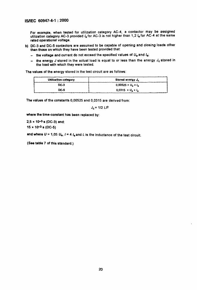
For example, when tested for utilization category AC-4, a contactor may be assignedutilization category AC-3 provided I. for AC-3 is not higher than 1,2 I. for AC-4 at the samerated operational voltage .
b) DC-3 and DC-S contactors are assumed to be capable of opening and closing loads otherthan those on which they have been tested provided that:
- the voltage and current do not exceed the specified values of U.and I. :- the energy J stored in the actual load is equal to or less than the energy Jc stored in
the load with which they were tested .
The values of the energy stored in the test circuit are as follows :
Utilization c.tegory Stored energy Jc
OC-3 0,00525 • U• • '.
OC-5 0,0315 • U• • '.
The values of the constants 0,00525 and 0,0315 are derived from :
Jc = 1/2 LJ2
where the time-constant has been replaced by:
2,5 • 1()-3 s (DC-3) and:
15. 1Q-3s (DC-5)
and where U =1,05 U., I =4 I. and L is the inductance of the test circuit.
(See table 7 of this standard.)
20
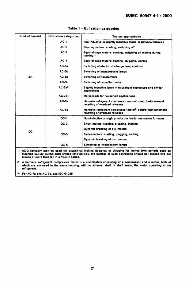
Table 1 - Utilization categories
ISIIEC 60947-4-1 : 2000
Kind of current Utilization categories Typ ical applications
AC-l Non· lnductlve or slightly inductive loads, realstance fumeces
AC-2 Slip.ring motors : starting, switching off
AC-3 Squlrrel-cage motors : starting, switching off motora duringrunning 11
AC-4 Squlrrel-cage motors : starting , plugg ing. Inching
AC-Sa SWitching of electric discharge Ismp controls
AC-Sb SWitching of incandescant lamps
AC AC-6a Switch ing of transformers
AC-6b Switching of capacitor banks
AC-7a 3) Slightly inductive loads in household appliances and similarapplications
AC-7b31 Motor-loads for household applications
AC-8a Hermetic refrigerant compressor motor21 control with manualresetting of overload releassa
AC-8b Hermetic refr igerant compressor motor21 control with automaticresetting of overload releases
DC-1 Non-inductive or slightly inductive loads. resistance fumeces
DC-3 Shunt-motors: starting. plugging . Inching
Dynemic breaking of d.c. motoraDC
DC-S Series -motors : starting. plugging. Inching
Dynsmic breaking of d.c . motora
DC-6 Switching of Incandescent lampe
1) AC-3 category may be used for occas lonel inching (jogging) or plugging for limited time periods .uch a.machine set-up; during such limited time periods . the number of such operations .hould not excH<l five perminute or mora than ten In a lD-mln period.
2) A hermetic rafr lgerent compressor motor Is a combination consisting of a compre.sor and a motor. both ofwhich are enclosed In the same housing . with no extemel shaft or shaft ..a". the motor operating In therefrlge rant.
3) For AC-7a and AC-7b...eIEC 61095.
21
ISIIEC 60947-4-1 : 2000
5.5 Control circuits
Subclause 4.5 of IEC 60947-1 applies; moreover, for an electronically controlled electromagnet, 4.5.1 of IEC 60947-1 applies with the following addition.
The electronic part may form an integral part or a separate part pr~vide~ it is an i ~trinsicfunction of the device. In both cases, the device shall be tested WIth this electronic partmounted as in normal use.
The characteristics of electronic control circuits are as follows :
- type of current;
- power consumption ;
- rated frequency (or d.c.);
- rated control circuit voltage, Uc (nature: a.c./d.c.);
- rated control supply voltage, Us (nature: a.c.ld.c.);
- nature of external control circuit devices (contacts , sensors, optocouplers, electronicactive components, etc).
Annex E gives examples and illustrations of different circu it configurations.
NOTE ,., distinction is made between the control circuit voltage Uc• which is the controlling input signal. and thecontrol supply voltage Us. which Is the voltage applied to energize the power supply term inals of the control circuitequipment .nd m.y be different from Uc due to the presence of bUill-in transformers. rectifiers, resistors. electroniccln:uItry. etc.
5.1 Auxiliary circuits
Subclause 4.6 of part 1 applies.
5.7 Characteristics of relays and releases (overload relays)
NOTE In ttle remainder of this standard. the words ·overlo.d relay- will be taken to apply equally to an overload....y or .n overload re.......s appropriate.
5.7.1 Summary of characteristics
The characteristics of relays and releases shall be stated in the following terms, wheneverapplicable:
- types of relay or release (see 5.7.2);
- characteristic values (see 5.7.3);
- designation and current settings of overload relays (see 5.7.4);
- time-current characteristics of overload relays (see 5.7.5);
- influence of ambient air temperature (see 5.7.6).
5.7.2 Types of relay or rei....
• ) Release with shunt coil (shunt trip).
b) Under-voltage and under-current opening relay or release.
c) Overload time-delay relay the time-lag of which is:
22
ISIIEC 60947-4-1 : 2000
1) substantially independent of previous load (e.g. time-delay magnetic overload relay) ;
2) dependent on previous load (e. g. thermal overload relay);
3) dependent on previous load (e.g. thermal overload relay) and also sens itive to phaseloss (see 3.2.17) .
d) Instantaneous over-current relay or release (when applicable).
e) Other relays or releases (e.g. phase loss sensitive relay, control relay associated withdevices for the thermal protection of the starter) .
NOTE Types refer red to in items d) and e) require consultation between manufacturer and user aecording to theparticular application.
5.7.3 Characteristic values
a) Release with shunt coil , under -voltage (under-current) opening relay or release :
rated voltage (current);
rated frequency;
operating voltage (current) .
b) Overload relay :
designation and current settings (see 5.7.4) ;
rated frequency, when necessary (fo r example in the case of a current transformeroperated overload relay) ;
time-current characteristics (or range of characteristics) , when necessary;
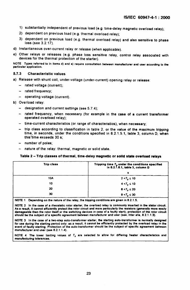
trip class according to classification in table 2, or the value of the maximum trippingtime, in seconds, under the conditions specified in 8.2.1.5.1, table 3, column 0, whenthis'time exceeds 30 s;
number of poles;
nature of the relay : thermal , magnetic or solid state .
Table 2 - Trip classes of thermal, tlme-delay magnetic or aolld atate overtoad relays
Tr ip cia.. Tripping time Tf
under the conditione epee lfledIn 8.2 . .1.1, "ble 3, column D
5
10A 2<TpS10
10 4 «t, S 10
20 II -r, S 20
30 9 <Tp S 30
NOTE 1 Depending on the nature of the relay, the tripping conditions are given in 8.2.1.5.
NOTE 2 In the case of a rheostatic rotor shlrter. the overload relay Is commonly Inserted In the stator circuit .As a result, it cannot efficiently protect the rotor circuit end more particUla rly the resmors (generally mora easilydamageable than the rotor itself or the switching devlc.. in case of a faulty start) ; protection of the rotor circuitshould ~ the SUbject of a specific agreement ~tw..n manufacturer and usar (see , inter alia, 8.2 .1.1.3) .
NOTE 3 In the case of a two-step auto-transformer starter, the shirting auto-transformer Is normally designedfor use dur ing the starting period only : as a result, it cannot ~ effICiently protected by the overloed relay in theevent of faulty starting. Protection of the auto-transformer should be the subject of specifIC agreement betweenmanufacturer and user (see 8.2.1.1.4) .
NOTE 4 The lower limiting values of TD are selected to allow for differing heater characteristics andmanufacturing tolerances.
23
ISIIEC 60947-4-1 : 2000
5.7." Designation and current settings of overload relays
Overload relays are designated by their current setting (or the upper and lower limits of thecurrent setting range, if adjustable) and their trip class .
The current setting (or current setting range) shall be marked on the relays.
However if the current setting is influenced by the conditions of use or other factors whichcannot r~8dilY be marked on the relay, then the relay or any interchangeable pa~ts th.er~of(e.g. heatera, operating coils or current transformers) shall carry a number or an IdentlfYI~gmark which makes it possible to obtain the relevant information from the manufacturer or hiscatalogue or, preferably, from data furnished with the starter .
In the case of current transformer operated overload relays, the marking may refer either tothe primary current of the current transformer through which they are supplied or to thecurrent setting of the overload relays. In either case, the ratio of the current transformer shallbe stated.
5.7.5 Time-current characteristics of overload relays
Typical time-current characteristics shall be given in the form of curves supplied by themanufacturer. These curves shall indicate how the tripping time , starting from the cold state(aee 5.7.6), varies with the current up to a value of at least eight times the full-load current ofthe motor with which it is intended that the relay be used. The manufacturer shall be preparedto indicate, by suitable means, the general tolerances applicable to these curves and theconductor cross-sections used for establishing these curves (see 9.3.3.2.2, item cj) .
NOTE It II IKOmmended that the current be plotted as abscissae and the time as ordinates, using logarithmic_ .... It II IKOmmended that the current be plotted as multiples of the setting current and the time in seconds ontile atanclard graph sh..t detailed in 5.6.1 of IEC 60269-1 , in IEC 60269-2 (figure -1) and in figures 4(1), 3(11) and4(11) of lEe 80289-2· 1.
5.7.8 Influence of ambient air temperature
The time-current characteristics (see 5.7.5) refer to a stated value of ambient air temperature,and are baaed on no previous loading of the overload relay (viz . from an initial cold state).This value of the ambient air temperature shall be clearly given on the time curves; thepreferred values are +20 'C or +40 ·C.
The OV~r10ad relaya shall be able to operate within the ambient air temperature range of -5 ·Cto +40 C, and the manufacturer shall be prepared to state the effect of variation in ambientair temperature on the characteristics of overload relays .
5.8 Co-ordlnatlon with short-circuit protective devices
The co-o.rd~nation of conta~ors. and st~rters is characterized by the type, ratings andcharactenstica of the Sho~-clrcult pr~tec~lve devices (SCPO) that provide protection of thecontactor a~d starter against snert-etrcuit currents . Requirements are given in 8.2 .5 .1 and8.2.5.2 of th.s standard, and in 4.8 of IEC 60947-1 .
24
ISIIEC 60947-4-1 : 2000
5.9 Switching overvoltages
Subclause 4.9 of part 1 applies.
Requirements are given in 8.2.6.
5.10 Types and characteristics of automatic change-over devices andautomatic acceleration control devices
5.10.1 Types
a) Time-delay devices, e.g. time-delay contactor relays (see IEC 60947-5-1) applicable tocontrol-circuit devices or specified-time all-or-nothing relays (see IEC 61810-1).
b) Undercurrent devices (undercurrent relays) .
c) Other devices for automatic acceleration control :
- devices dependent on voltage;
- devices dependent on power;
- devices dependent on speed .
5.10.2 Characteristics
a) The characteristics of time-delay devices are:
the rated time-delay or its range, if adjustable;
- for time-delay devices fitted with a coil, the rated voltage, when it differs from thestarter line voltage.
b) The characteristics of the undercurrent devices are:
- the rated current (thermal current and/or rated short-time withstand current, accordingto the indications given by the manufacturer);
- the current setting or its range, if adjustable.
c) The characteristics of the other devices shall be determined by agreement betweenmanufacturer and user.
5.11 Types and characteristics of auto-transformers for two-stepauto-transformer starters
Account being taken of the starting characteristics (see 5.3.5.5.3), starting auto-transformersshall be characterized by:
- the rated voltage of the auto-transformer;
- the number of taps available for adjusting the starting torque and current;
the starting voltage, Le. the voltage at the tapping terminals, as a percentage of the ratedvoltage of the auto-transformer;
- the current they can carry for a specified duration;
the rated duty (see 5.3.4);
the method of cooling
The auto-transformer can be:
{
air-cooling;
oil-cooling.
either built-in into the starter, in which case the resulting temperature rise has to be takeninto account in determining the ratings of the starter;
or provided separately. in which case the nature and dimension. of the connecting link.have to be specified by agreement between the manufacturer of the transformer and themanufacturer of the starter.
25
free air;
forced air;
oil-immersion.
ISIIEC 60947-4-1 : 2000
5.12 Types and characteristics of starting resistors for rheostatic rotor starters
Account being taken of the starting characteristics (see 5.3.5.5.1), the starting resistors shallbe characterized by:
- the rated rotor insulation voltage (Uir);
- their resistance value;
the mean thermal current, defined by the value of steady current they can carry for aspecified duration ;
- the rated duty (see 5.3.4);
- ... method of oooHo. IThey can be:
- either built-in into the starter, in which case the resulting temperature rise has to be limitedin order not to cause any damage to the other parts of the starter;
- or provided separately, in which case the nature and dimensions of the connecting linkshave to be specified by agreement between the manufacturer of the resistors and themanufacturer of the starter.
6 Product information
8.1 Nature of Information
The following information shall be given by the manufacturer.
8.1.1 Identification
a) manufacturer's name or trade mark;
b) type designation or serial number;
c) number of this standard, If the manufacturer claims compliance .
8.1.2 Characteristics, basic rated values and utilization
Characteristics:
d) rated operational voltages (see 5.3.1.1);
e) utiliza~on category and rated operational currents (or rated powers), at the ratedoperational voltages of the equipment (see 5.3.2.5 and 5.4);
f) either the value of the rated frequencylfrequencies e.g. 50 Hz or 50 HzJ60 Hz or theindication -d.c.- (o~ the symbol =);' ,
g) rated duty with the indication of the class of intermittent duty, if any (see 5.3.4) .
Associated values:
h) rate~ making an~ ~re~king capacit ies. These indications may be replaced, whereapphcable. by the indication of the utilization category (see table 7).
Safety and installation:
i) rated insulation Yoltage (see 5.3.1.2);
j) rated impulse withstand voltage (see 5.3.1.3);
26
ISIIEC 60947-4-1 : 2000
k) IP code, in case of an enclosed equipment (see 8.1.11);
I) pollution degree (see 7.1.3.2) ;
m) rated conditional short-circu it current (see 5.3.6) and type of co-ordination of the contactoror starter (see 8.2.5 .1) and the type , current rating and characteristics of the associatedSCPO;
rated conditional short-circuit current (see 5.3.6) of the combination starter or protectedstarter and type of co-ord ination (see 8.2.5.1);
n) switching overvoltages (see 5.9).
Control circuits:
The following information concerning control circuits shall be placed either on the coil or onthe equipment:
0) rated control circu it voltage (Uc>, nature of current and rated frequency;
p) if necessary, nature of current, rated frequency and rated control supply voltage (Ua>.
Air supply systems for starters or contactors operated by compressed air:
q) rated supply pressure of the compressed air and limits of variation of this pressure, if theyare different from those specified in 8.2.1.2.
Auxiliary circuits :
r) ratings of auxiliary circuits (see 5.6).
Overload relays and releases :
s) characteristics according to 5.7.
Additional information for certain types of contactor and starter:
Rheostatic rotor starters:
t) circuit diagram;
u) severity of start (see 5.3.5.5.1) ;
v) starting time (see 5.3.5 .5.1).
Auto-transformer starters:
w) rated starting voltage(s), i.e. voltage(s) at the tapping terminals .NOTE This velue mey be expressed .. e percentllge of the reted operetlone' voltege of the stener.
Vacuum contactors and starters:
x) maximum permissible altitude of the site of installation, if less than 2 000 m.
EMC:
y) environmentAor B: see 7.3.1 ofIEC60947-1 ;
z) special requirements, if applicable, for example shielded or twisted conductors.
NOTE Unsh ielded or untwisted conductors ere considered es normei instelletion conditions.
27
ISIIEC 60947-4-1 : 2000
8.2 Marking
Subclause 5.2 of part 1 applies to contactors, starters and overload relays with the followingadditions.
Data under items d) to x) in 6.1.2 shall be included on the nameplate or on the equipment orin the manufacturer's published literature . .
Data under items c) and k) in 6.1.2 shall preferably be marked on the equipment.
In the case of electronically controlled electromagnets, information other than that given in 0)and p) of 6.1.2 may also be necessary; see also 5.5 and annex E.
8,3 Instructions for installation, operation and maintenance
Subclause 5.3 of part 1 applies with the following addition .
Information shall be provided by the manufacturer to advise the user on the measures to betaken with regard to the equipment in the event of a short-circuit and the measures to betaken with regard to the equipment, if any, concerning EMC.
In the case of protected starters (see 3.2.8), the manufacturer shall also provide thenecessary mounting and Wiring instructions.
7 Normal service, mounting and transport conditions
Clause 6 of part 1 applies with the following additions .
7.1.3.2 Degrees of pollution
Unless otherwise stated by the manufacturer, a contactor or a starter is for use in pollutiondegree 3 environmental conditions, as defined in 6.1.3.2 of part 1. However, other pollutiondegrees may be considered to apply, depending upon the micro-environment.
• Constructional and performance requirements
1.1 Constructional requirements
NOTE FllIther requirements concerning materials and current-earrying parts are under consideration forsubcla_ 7.1.1 and 7.1.2 of part 1. Their application to thi$ standard will be subject to further consleleratlon.
1.1.1 Materials
Subclause 7.1.1 of part 1 applies (see note to 8.1).
1.1.2 Currentoe.rrylng parts and their connections
Subclause 7.1.2 of part 1 applies (see note to 8.1).
1.1.3 Clearances and creepage distances
Subclause 7.1.3 of IEC 60947-1 applies.
28
ISIIEe 60947-4-1 : 2000
8.1." Actuator
Subclause 7.1.4 of part 1 applies when the actuator is manually operated with the followingaddition .
The operating handle of the manually operated switching device of a combination starter shallbe provided with means for padlocking it in the OFF position .
8.1....3 Mounting
Actuators mounted on removable panels or opening doors shall be so designed that, when thepanels are replaced or the doors closed , the actuator will engage correctly with the associatedmechanism .
8.1.5 Indication of the contact position
8.1.5.1 Indicating means
Subclause 7.1.5 .1 of part 1 applies to manually operated starters.
8.1.5.2 Indication by the actuator
Subclause 7.1.5.2 of part 1 applies.
8.1.8 Additional safety requirements for equipment with Isolating function
Subclause 7.1.6 of lEe 60947-1 applies with the addition of the following paragraphs toSUbclause 7.1.6.1 of that standard.
Devices provided with positions like trip position or stand-by position which are not theindicated open position shall be clearly marked.
An actuator having only one position of rest shall not be considered as appropriate to indicatethe position of the main contact.
8.1.7 Terminals
Subclause 7.1 .7 of part 1 appl ies with, however, the following additional requirement.
8.1.7." Terminal Identification and marking
Subclause 7.1.7.4 of part 1 applies with additional requirements as given in annex A.
8.1.8 Additional requirements for contactors or starters prOVided with a neutral pole
Subclause 7.1 .8 of part 1 applies.
8.1.8 Provisions for earthing
Subclause 7.1.9 of part 1 applies.
29
ISIIEC 60947-4-1 : 2000
8.1.10 Enclosures for equipment
Subclause 7.1.10 of part 1 applies with the following additions.
Starting resistors mounted within an enclosure sh~1I be . s~ located or guarded that issuingheat is not detrimental to other apparatus and matenals within the enclosure.
For the specific case of combination starters, the cover or doo~ shall .be ~nterlocked so t~~t itcannot be opened without the manually operated switching device ~elng In the open position.However, provision may be made to open the door or cover WIth the manually operatedswitching device in the ON position by the use of a tool.
8.1.11 Degrees of protection of enclosed contactors and starters
Subclause 7.1.11 of part 1 applies.
8.2 Performance requirements
8.2.1 Operating conditions
8.2.1.1 General
Subclause 7.2.1.1 of part 1 applies with the following additions.
8.2.1.1.1 Starters shall be so constructed that they:
a) are trip free;
b) can be caused to open their contacts by the means provided when running and at any timeduring the starting sequence;
c) will not function in other than the correct starting sequence.
8.2.1.1.2 Starters employing contactors shall not trip due to the shocks caused by operationof the contactors when tested according to 9.3.3.1, after the starter has carried its rated fullload current at the reference ambient temperature (Le. +20 'e) and has reached thermalequilibrium at both minimum and maximum settings of the overload relay, if adjustable.
8.2.1.1.3 For rheostatic starters, the overload relay shall be connected in the stator circuit.Special arrangements may be made to protect the rotor contactors and resistors againstoverheating, if requested by the user.
8.2.1.1.4 When starters are used in conditions in which the overheating of the startingr"i.tors or transformers would represent an exceptional hazard , it is recommended that asuitable device be fitted to switch off the starter automatically before a dangeroustemperature i. reached.
1.2.1.1.5 The moving contacts of multipole equipment intended to make and break togethershall be so mechanically coupled that all poles make and break sUbstantially together,whether operated manually or automatically .
30
ISIIEC 60947-4-1 : 2000
8.2.1.2 Limits of operation of contactors and power-operated starters
8.2.1.2.1 Electromagnetic contactors and starters
Electromagnetic contactors, whether used separately or in starters, shall close satisfactorily atany value between 85 % and 110 % of their rated control supply voltage U
I. Where a range is
declared, 85 % shall apply to the lower value and 110 % to the higher.
The limits between which contactors shall drop out and open fully are 75 % to 20 % for a.c.and 75 % to 10 % for d.c. of their rated control supply voltage UI . Where a range ~ declared,20 % or 10 %, as the case may be, shall apply to the higher value and 75 % to the lower.
Limits for closing are applicable after the coils have reached a stable temperaturecorresponding to indefinite application of 100 % Us in an ambient temperature equivalent tothe ambient temperature declared by the manufacturer but not less than +40 ·C.
Limits for drop-out are applicable with the coil circuit resistance at -5 ·C. This can be verifiedby calculation using values obtained at normal ambient air temperature.
The limits apply to d.c. and a.c. at declared frequency .
8.2.1.2.2 Contactors and starters with electronically controlled electromegnet
Subclause 8.2.1.2.1 applies with the following modification.
Replace the second paragraph as follows :
The limits between Which contactors with an electronically controlled electromagnet shall dropout and open fully are
- for d.c.: 75 % to 10 % of their rated control supply voltage UI ,
- for a.c.: 75 % to 20 % of their rated control supply voltage UI ,
- for a.c.: 75 % to 10 % of their rated control supply voltage UI if specified by themanufacturer,
- for a.c., where a range is declared with limits between 75 % to 10 % of their rated controlsupply voltage Us' the contactor shall , in addit ion, be submitted to the capacitive drop outtest of 8.2.1.2.4.
Where a range is declared, 20 % or 10% as the case may be, shell apply to the higher valueof the range and 75 % to the lower value of the range.
8.2.1.2.3 Electro-pneumatic contactors and starter.
Electro-pneumatic and pneumatic contactors shall close satisfactorily with the air supplypressure between 85 % and 110 % of the rated pressure and open between 75 % and 10 % ofthe rated pressure.
31
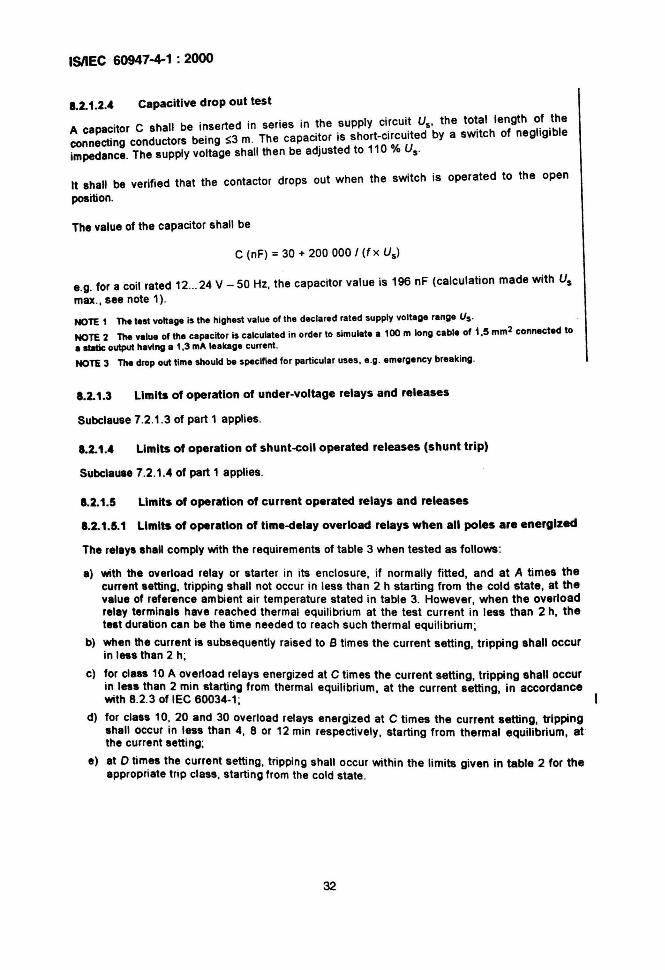
ISIIEC 60947-4-1 : 2000
1.2.1.2." Capacitive drop out test
A ca acitor C shall be inserted in series in the supply ci!cui~ Us' the to~al length o.f .thePcting conductors being ~3 m. The capacitor is short-circuited by a switch of negligible
conne . d 110 % Uimpedance. The supply voltage shall then be adJuste to s-
It shall be verified that the contactor drops out when the switch is operated to the open
position.
The value of the capacitor shall be
C (nF) = 30 + 200 000 I (fx Us)
e.g. for a coil rated 12...24 V-50 Hz, the capacitor value is 196 nF (calculation made with Usmax., see note 1).
NOTE 1 The test voltage is the highest value of the declared rated supply voltage range Us'
NOTE 2 The value of the capacitor is calculated in order to simulate a 100 m long cable of 1,5 mm2 connected toa static: output having a 1,3 mA leakage current .
NOTE 3 The drop out time should be specified for particular uses , e.g. emergency break ing .
1.2.1.3 Limits of operation of under-voltage relays and releases
Subclause 7.2 .1.3 of part 1 applies.
1.2.1.• Limits of operation of shunt-coll operated releases (shunt trip)
Subclause 7.2.1.4 of part 1 applies .
1.2.1.5 Limits of operation of current operated relays and releases
1.2.1.5.1 Limits of operation of tlme-(lelay overload relays when all poles are energized
The relays shall comply with the requirements of table 3 when tested as follows:
a) with the overload relay or starter in its enclosure , if normally fitted, and at A times thecurrent setting, tripping shall not occur in less than 2 h starting from the cold state, at thevalue of reference ambient air temperature stated in table 3. However, when the overloadrelay terminals have reached thermal equilibr ium at the test current in less than 2 h, thetest duration can be the time needed to reach such thermal equilibrium;
b) when the current is subsequently raised to B times the current setting, tripping shall occurin less than 2 h;
c) for class 10 A overload relays energized at C times the current setting, tripping shall occurin less than 2 min starting from thermal eqUilibrium, at the current setting, in accordancewith 8.2 .3 of IEC 60034-1;
d) for class 10, 20 and 30 overload relays energized at C times the current setting, trippingshall occur in less than 4, 8 or 12 min respectively, starting from thermal equilibrium, atthe current setting;
e) at D times the current setting, tripping shall occur within the limits given in table 2 for theappropriate trip class , starting from the cold state .
32
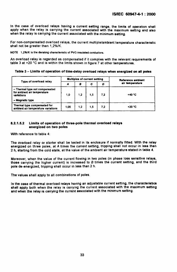
ISIIEC 60947-4-1 : 2000
In the case of overload relays having a current setting range, the limits of operation shallapply when the relay is carrying the current associated with the maximum setting and alsowhen the relay is carrying the current associated with the minimum setting.
For non-compensated overload relays, the current mUltiple/ambient temperature characteristicshall not be greater than 1,2%/K.
NOTE 1,2'l(,/K is the derating characteristic of PVC·insulated conductors.
An overload relay is regarded as compensated it it complies with the relevant requirements oftable 3 at +20 ·C and is within the limits shown in figure 7 at other temperatures.
Table 3 - Limits of operation of tlme-delay overload relays when energized on "I pol••
Type of overload relayMultiples of current setting Reference a",blent
A S C D air temperature
- Thermal type not compensatedfor ambient air temperature
1.0 1.2 1.5 7.2 +40 ·Cvariations
- Magri.tlc type
Thermal type compensated for1.05 1.2 1.5 7.2 +20'C
ambient air temperature var iat ions
8.2.1.5.2 Limits of operation of three-pole thermal overload relaysenerg iZed on two poles
With reference to table 4:
The overload relay or starter shall be tested in its enclosure if normally fitted . With the relayenergized on three poles, at A times the current setting, tripping shall not occur in les8 than2 h, starting from the cold state , at the value of the ambient air temperature stated in table 4.
Moreover, when the value of the current flowing in two poles (in phase lo&s sensitive relays ,those carrying the higher current) is increased to B times the current setting, and the thirdpole de-energized, tripping shall occur in less than 2 h.
The values shall apply to all combinations of poles.
In the case of thermal overload relays having an adjustable current sett ing, the characteristicsshall apply both when the relay is carrying the current associated with the maximum settingand when the relay is carrying the current associated with the minimum setting.
33
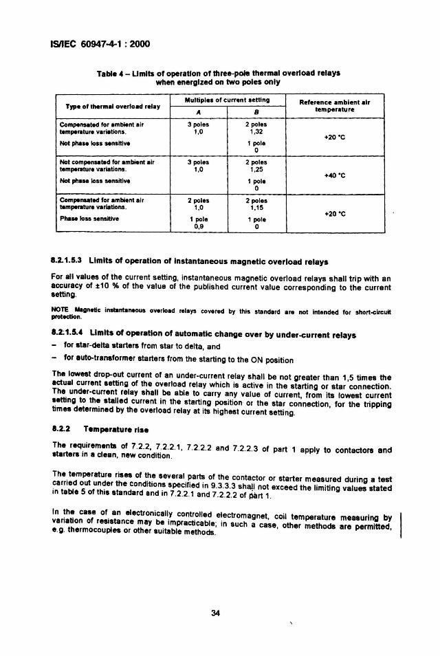
ISIIEC 60947-4-1 : 2000
Table 4 - Limits of operation of three-pole thermal overload relayswhen energized on two poles only
Multiple. of current letting Reference ambient airType of tlMrmal overload relay
A B temperature
Compen.ated for ambient air 3 poles 2 polestemperature variations. 1.0 1.32
+20 'CNot phase loss sensitive 1 pole
0
Not compensated for ambient air 3 poles 2 polestemperature variations . 1.0 1.25
+40 ·CNot phase loss sensitive 1 pole
0
Compenseted for ambient air 2 poles 2 polestemperature variations. 1.0 1.15
+20 'CPhase loss sensitive 1 pole 1 pole
0,9 0
8.2.1.5.3 limits of operation of instantaneous magnetic overload relays
For all values of the current setting. instantaneous magnetic overload relays shall trip with anaccuracy of :t10 % of the value of the published current value corresponding to the currentsetting.
NOTE Magnetic instantaneous overload relays covered by this standard are not Intended for short-circuitprotection.
1.2.1.5.4 Limits of operation of automatic change over by under-current relays
- for atar-delta starters from star to delta, and
- for auto-tranaformer starters from the starting to the ON position
The low..t drop-out current of an under-current relay shall be not greater than 1,5 times theactual current aetting of the overload relay which is active in the starting or star connection.The under-current relay shall be able to carry any value of current , from its lowest currentsetting to the atalled current in the starting position or the star connection, for the trippingtim.. determined by the overload relay at its highest current setting.
1.2.2 Temperature rise
The requirements of 7.2.2, 7.2.2.1, 7.2.2.2 and 7.2.2.3 of part 1 apply to contactons andstartens in a clean, new condition .
The temperature ris.. of the several parts of the contactor or starter measured during a testcarried out under the conditions specified in 9.3.3.3 shatl not exceed the limiting values statedin table 5 of this standard and in 7.2.2.1 and 7.2.2.2 of part 1.
In the case of an electronically controlled electromagnet, coil temperature measuring byvariation of resistance may be impracticable; in such a case, other methods are permitted,e.g. thermocouples or other suitable methods.
34
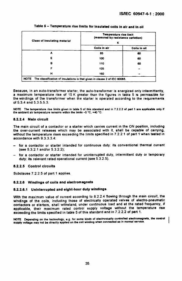
ISIIEC 60947-4-1 : 2000
Table 5 - Temperature rise limits for Insulated colis In air and In 011
Temperatura rI.. limit
CI... of in.ulatlng material(m...ured by re.i.unee variation)
K
Coil. In air Coli. In 011
A 85 eoE 100 60
B 110 60
F 135 -H 160 -
NOTE The classification of insulations is that given in clause 2 of IEC 6OOll5.
Because , in an auto-transformer starter, the auto-transformer is energized only intermittently,a maximum temperature rise of 15 K greater than the figures in table 5 is permissible forthe windings of the transformer when the starter is operated according to the requirementsof 5.3.4 and 5.3.5.5.3.
NOTE The temperature rise limits given in table 5 of this stand.rd and in 7.2 .2.2 of pert 1 are applicable only Ifthe ambient air temperature remains with in the limits -5 ·C. +<40 ·C.
8.2.2.4 Main circuit
The main circu it of a contactor or a starter which carries current in the ON position, includingthe over-current releases which may be associated with it, shall be capable of carrying,without the temperature rises exceed ing the limits specified in 7.2.2.1 of part 1 when tested inaccordance with 9.3 .3.3.4:
for a contactor or starter intended for continuous dUty: its conventional thermal current(see 5.3.2.1 and/or 5.3.2.2);
for a contactor or starter intended for uninterrupted duty, intermittent dUty or temporarydUty: its relevant rated operational current (see 5.3.2.5).
8.2.2.5 Control circuits
Subclause 7.2.2.5 of part 1 appl ies.
8.2.2.8 Windings of colis and electromagnets
8.2.2.8.1 Uninterrupted and eight-hour duty windings
With the maximum value of current according to 8.2.2.4 flowing through the main circuit, thewindings of the coils, including those of electrically operated valves of electro-pneumaticcontactors or starters, shall withstand, under continuous load and at the rated frequency, ifapplicable, their maximum rated control supply voltage without the temperature riseexceeding the limits specified in table 5 of this standard and in 7.2.2.2 of part 1.
NOTE Depending on the technology, e.g. for some kinds of e"ctronic811y controlled electromagnets. the control.upply voltage may not be directly applied on the coil winding when connectsd a. In normll ..!VIc•.
35
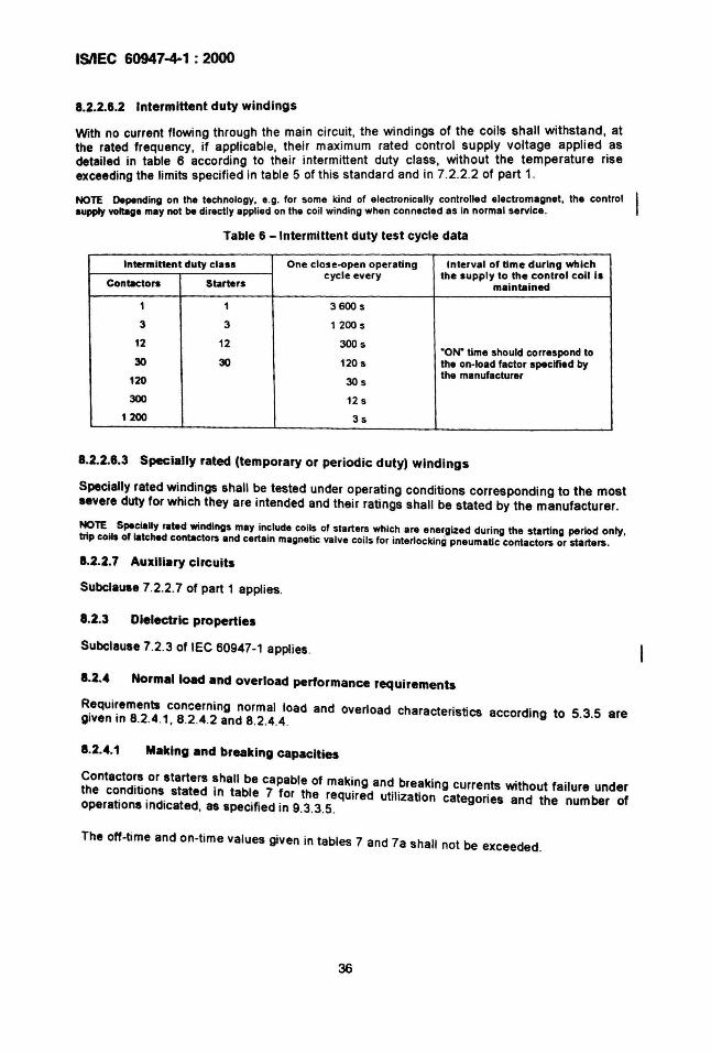
IsnEC 60947-4-1 : 2000
8.2.2.6.2 Intermittent duty windings
With no current flowing through the main circuit, the windings of the coils shall withst~nd. atthe rated frequency, if applicable, their max.imum rated control . supply voltage applied .asdetailed in table 6 according to their intermittent duty cla~s , WIthout the temperature riseexceeding the limits specif ied in table 5 of this standard and In 7.2.2.2 of part 1.
NOTE Depending on the technology, e.g. for some kind of electronically cont~olled electr0":lagnet. the controlsupply voltage may not be directly applied on the coil winding when connected as In normal service.
Table 6 - Intermittent duty test cycle data
Intermittent duty class One close-open operating Interval of time during whichcycle every the supply to the control coil is
Contactors Starters maintained
1 1 3600 s
3 3 1200 s
12 12 300 s'ON' time should correspond to
30 30 120 s the on-load factor specified bythe manufacturer120 30s
300 12 s
1200 3s
8.2.2.6.3 Specially rated (temporary or periodic duty) windings
Specially rated windings shall be tested under operating conditions corresponding to the mostsevere duty for which they are intended and their ratings shall be stated by the manufacturer.
NOTE Specially rated windings may include coils of starters which are energized during the starting period only,trip coils of latched contactors and certain magnetic valve coils for interlocking pneumatic contactors or starters.
8.2.2.7 AUXiliary circuits
Subclause 7.2.2.7 of part 1 applies.
8.2.3 Dielectric properties
SUbclause 7.2.3 of IEC 60947-1 applies.
8.2.4 Normal load and overload performance reqUirements
Requirements concerning normal load and overload characteristics according to 5.3.5 aregiven in 8.2.4.1, 8.2.4.2 and 8.2.4.4.
8.2.4.1 Making and breaking capacities
Contactors or starters ~hall be capable of making and breaking currents without failure underthe conditions stated In table 7 for the required utilization categories and the number ofoperations indicated, as specified in 9.3.3.5.
The off·time and on-time values given in tables 7 and 7a shall not be exceeded .
36
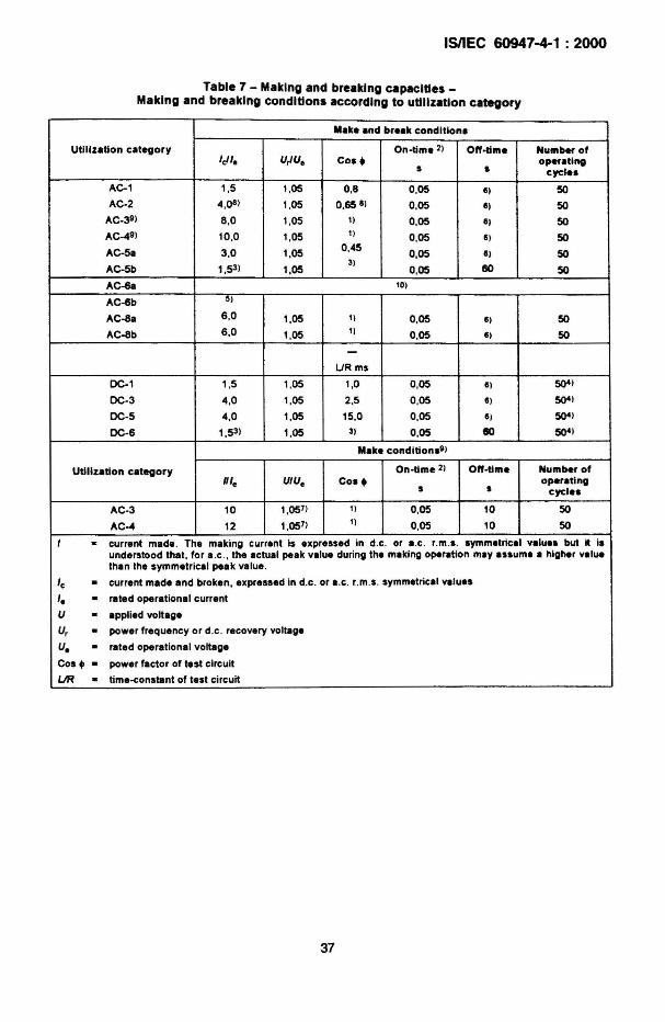
IsnEC 60947-4-1 : 2000
Table 7 - MakIng and breaking capacIties _Making and breaking conditions accordIng to utilizatIon category
Make and break conditiona
Utilization category On-time 21 O"·tlme Number ofIdl. U,IU. Co•• operating
s • cycle.
AC-1 1,5 1,05 0,8 0,05 I I 50AC-2 4,08 ) 1.05 0.65 I ) 0,05 I I 50
AC-39) 8.0 1.05 11 0.05 II 50AC-49) 10,0 1.05 1)
0.05 I ) 50AC-5a 3,0 1.05
0.450.05 II 50
AC-5b 1.53) 1.053)
0.05 80 50
AC-6a 10)
AC-6b 5 )
AC-8a 6.0 1.05 1) 0.05 I ) 50
AC-8b 6.0 1.05 ') 0,05 I ) 50
-URms
DC-1 1,5 1.05 1,0 0,05 I I 50"1
DC-3 4,0 1.05 2.5 0,05 I ) 50"1
DC-5 4,0 1,05 15.0 0.05 I I 5Q41
DC-6 1,53) 1,05 3) 0.05 80 5Q41
Make condltion.VI
Utilization category On. time 2) O"·t1me Number of111. UIU. Co••
s soperating
cycle.
AC·3 10 1.057) 11 0.05 10 50
AC--4 12 1.057)1) 0.05 10 50
I · current made . The making current Is expressed in d.c . or a.c. r.m.s. symmetrical values but It isunderstood that . for a.c., the actual peak value during the making operat ion may ..sume a higher valuethan the symmetrical peak value .
'e · current made and broken, expressed in d.c. or a.c. r.m.s. symmetrical valu..
I. · rated operat ional current
U · applied voltage
U, · power frequency or d.c . recovery voltage
U. · rated operational voltage
Cos •• power facto r of test circu it
L.IR · time-constant of test circu it
37
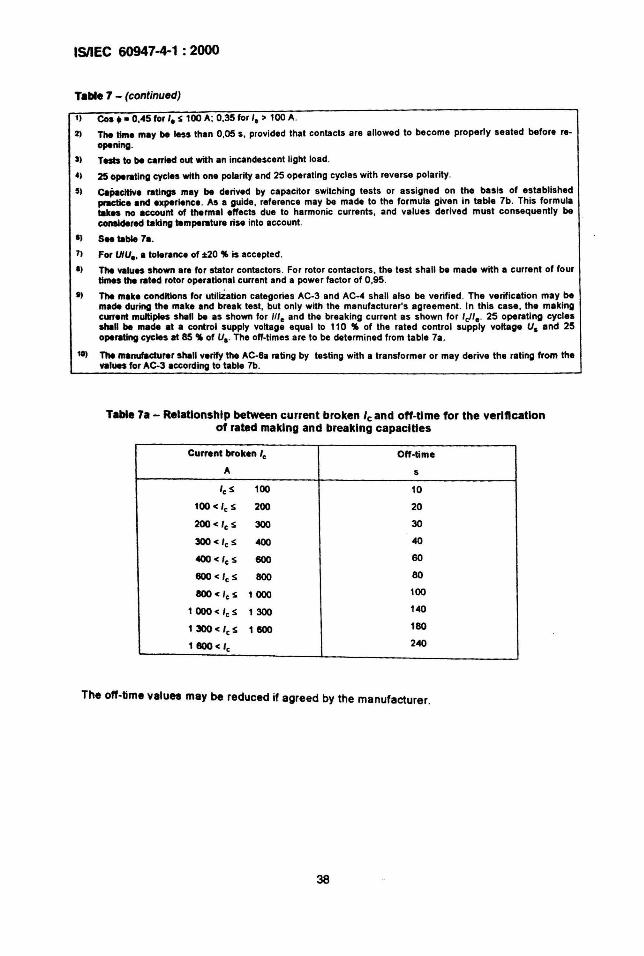
ISIIEC 60947-4-1 : 2000
Table 7 - (continued)
II Cos •• 0,45 for I. S 100 A; 0,35 for I. > 100 A.
2) The time may be less than 0,05 5 , provided that contacts are allowed to become properly seated before re-opening.
3) Tests to be carried out with an Incandescent light load.
41 25 operating cycles with one polarity and 25 operat ing cycles with reverse polar ity .
5) CBp.cltIva ratings may be derived by capacitor SWitching tests or assigned on the basis of establishedpractice and experience. As a gUide, reference may be made to the lormula given in table 7b. This formulatakes no ac:c:ount of thermal effects due to harmonic currents , and values derived must consequently beconalderad talclng temperature rise into account.
I) S" table 7a.
7) For UIU., a tolerance of:t20 " is accepted.
I) The values shown are for stator contactors . For rotor contactors, the test shall be made with a current of fourtilllQ the rated rotor operational current and a power lactor of 0,95 .
I) The make conditions for utiliZation categories AC-3 and AC-4 shall also be verified. The verification may bemade during the make and break test , but only with the manufacturer's agreement. In th is case, the makingcurrent multiples shall be as shown for ,''. and the breaking current as shown for Ie!' • . 25 0lMlrating cyclesshill be made at a control supply voltage equal to 110 " of the rated control supply voltage UI and 25operating cycles at 85 " of UI . The off·tlmes are to be determined from table 7a.
10) The manufacturer shall verify the AC-6a rating by testing with a transformer or may derive the rating from thevalues for AC-3 according to table 7b.
Table 7a - Relationship between current broken Ieand off-time for the verlftcatlonof rated making and breaking capacities
Current broken I. Off-time
A 5
Ie S 100 10
100 < 'e S 200 20
200 < 'eS 300 30
300 < 'e S 400 40
400 < 'e S 600 60
600 < 'eS 800 80
800 < 'e S 1000 100
1 000 < I. S 1300 140
1300< 'e S 1600 180
1600< Ie 240
The off-time values may be reduced if agreed by the manufacturer.
38
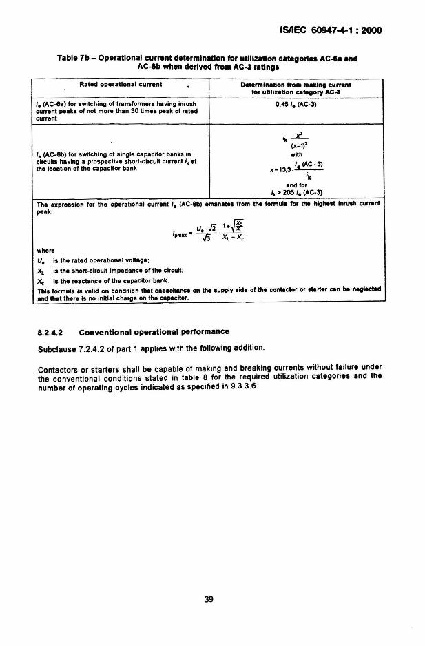
ISIIEC 60947-4-1 : 2000
Table 7b - Operational current determination for utlllzatton categories AC~a andAC-6b when derived from AC-3 rattngs
Rated operational current . Detennlnallon frolll lIIa1d", curnntfor utilization CII~oryAC4
I. (AC-6a) for switching of transformers having inrush 0.4S I. (AC-3)current peaks of not more than 30 times peak of ratedcurrent
4c ..L..(X_1)2
I. (AC-6b) for switching of single capacitor banks in withcircuits having a prospective short-circuit current it at I (AC.3)the location of the capacitor bank x=13.3 . e .
'kand for
4c > 205 I. (AC·3)
The express ion for the operational current I. (AC.6b) emanates from the formula for the highest Inruah currentpeak:
U .../2 1+&I •• .pmox --;p;- XL - x,
where
U. is the rated operational voltage ;
XL is the short-circuit impedance of the circuit;
x, is the ,eactanee of the capacitor bank.
This formula is valid on condition that capacitance on the supply side of the contactor or starter can be neglectedand that there is no initial charge on the capacitor .
8.2....2 Conventional operational performance
Subclause 7.2.4.2 of part 1 applies with the following addit ion.
Contactors or starters shall be capable of making and breaking currents without failure underthe conventional cond itions stated in table 8 for the required utilization categories and thenumber of operating cycles indicated as specified in 9.3.3 .6.
39
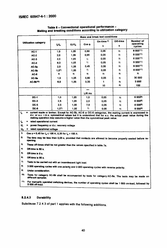
ISIIEC 60947-4-1 : 2000
Table 8 - Conventional operational performance -Making and breaking conditions according to utilization category
Make anti break tes t conditions
On-time 2) Off-time Number ofU1Il1zlltlon ategory
IJI. U,IU. Cos. operatings 5 cycles
AC-' 1,0 1,05 0,80 0.05 3) 600011)
AC-2 2,0 1,05 0,65 0,05 3) 600011)
AC-3 2.0 1.05 1) 0,05 3) 600011)
AC-4 6,0 1,05 1) 0,05 3) 600011)
AC-511 2,0 1.05 0,45 0,05 3) 6000")
AC-5b 1,07) 1,05 71 0,05 4) 6000'1)AC-6 9) 9) 9) 9 ) 9 ) 9)
Ae-8a 1,0 1,05 0,80 0,05 3) 30000
Ac.&'0) 6,0 1,05 0,35 1 5) 5900
10 6) 100
-URms
DC-1 1,0 1,05 1,0 0,05 3) 6 ()()()81
DC-3 2,5 1,05 2,0 0,05 3) 6 ()()()8)
DC-5 2,5 1.05 7,5 0,05 3) 6 ()()()8)
DC-6 1,07) 1.05 7) 0,05 4) 6 ()()()8)
'e · current made or broken. Except for AC-5b, AC-6 or DC-6 categor ies , the making current is expressed ind.c. or a.c. r.m.s. symmetrical values but it is understood that for a.e. the actual peak ' value during themaking operation may assume a higher value than the symmetrical peak value .
'. · rated operational current
Ur · po_r frequency or d.c. recovery voltage
U. · rated operetional voltage
I ) Cos.· 0,45 for ' . S 100 A; 0,35 for I. > 100 A.
2) The time may be .... than 0,05 s, provided that contacts are allowed to become properly seated before re-opening.
3) TheM off-times ahall be not grelter than the values specified in table 7a.4) Off-time is eo a.
s, Off-tlme is 8 s.
I ) Off-time is 80 a.
7) rests to be carried out with In incandescent light Iold..,3000 operatlng cyclea with one pollrity Ind 3 000 operating cycles with reverse polarity.
I) Under consideration.
10' rests for category AC-llb shall be I ccompanied by tests for category AC-8a. The tests may be made ondifferent ..mp....
II,For manually operated awltc:hlngdevices, the number of operat ing cycles shall be 1 000 on-load followed by5000 off-Iold. '
8.2.4.3
Subclause 7.2.4.3 of part 1 applies with the follOWing additions .
40
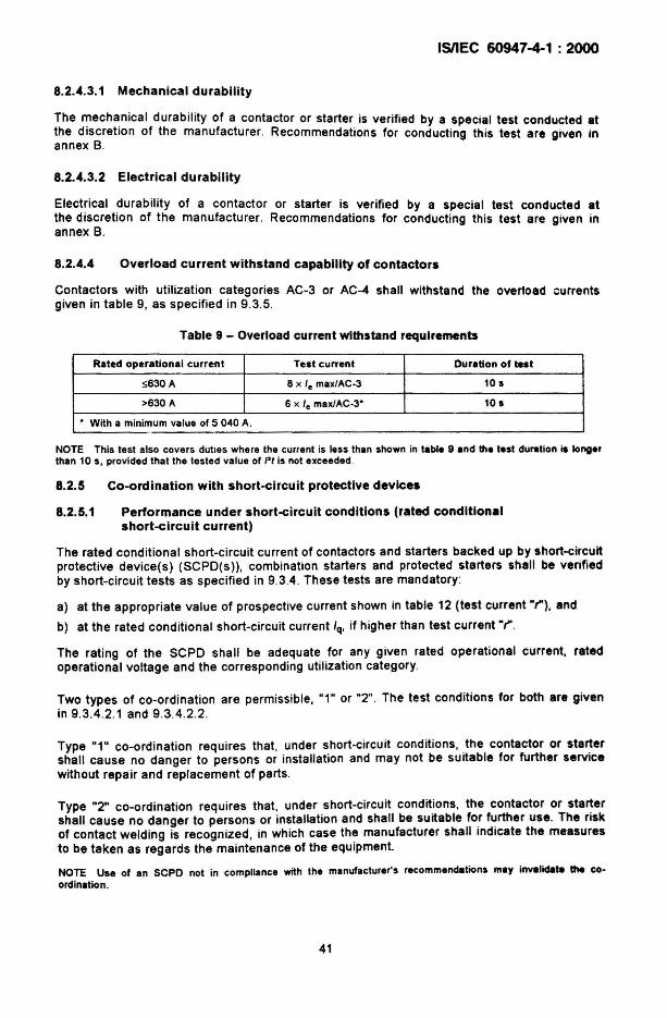
ISIIEC 60947-4-1 : 2000
8.2.4.3.1 Mechanical durability
The ~echa.nical durabil ity of a contactor or starter is verified by a special test conducted atthe discretion of the manufacturer. Recommendations for conducting this test are given inannex B.
8.2.4.3.2 Electrical durability
Electr ical durab ility of a contactor or starter is verified by a special test conducted atthe discretion of the manufacturer. Recommendations for conducting this test are given inannex B.
8.2.4.4 Overload current withstand capability of contactors
Contactors with utilization categories AC-3 or AC-4 shall withstand the overload currentsgiven in table 9, as spec ified in 9.3.5.
Table 9 - Overload current withstand requirements
Rated operational current Test current Duration of teat
~630A 8 x Ie max/AC-3 10 s
>630 A 6 x Ie maxlAC-3" 10 I
" With a minimum value of 5 040 A.
NOTE This test also covers duties where the current is less than shown in table 9 and the test duration is longerthan 105, provided that the tested value of Itt is not exceeded .
8.2.5 Co-ordination with short-circuit protective devices
8.2.5.1 Performance under short-circuit conditions (rated conditionalshort-circuit current)
The rated conditional short-circuit current of contactors and starters backed up by short-circuitprotective device(s) (SCPD(s)), combination starters and protected starters shall be verifiedby short-circuit tests as spec ified in 9.3.4. These tests are mandatory:
a) at the appropriate value of prospective current shown in table 12 (test current "t"), and
b) at the rated conditional short-circuit current Iq• if higher than test current "t" .
The rating of the SCPD shall be adequate for any given rated operational current, ratedoperational voltage and the corresponding utilization category .
Two types of co-ordination are permissible, "1" or "2" . The test conditions for both are givenin 9.3.4 .2.1 and 9.3.4 .2.2.
Type "1" co-ordination requires that, under short-c ircuit conditions, the contactor or startershall cause no danger to persons or installation and may not be suitable for further servicewithout repair and replacement of parts.
Type "2" co-ordination requires that , under short -circu it conditions, the contactor or startershall cause no danger to persons or installation and shall be suitable for further use. The riskof contact welding is recognized, in which case the manufacturer shall indicate the measuresto be taken as regards the maintenance of the equipment.
NOTE Use of an SCPO not in compliance with the manufacturer's recommendations may invalidate the coordination .
41
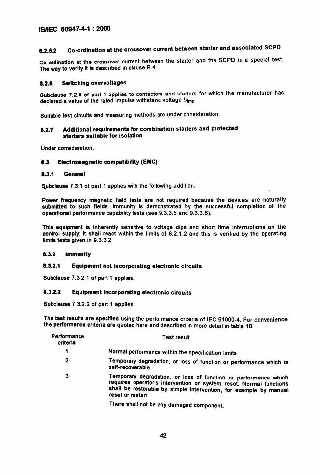
ISIIEC 60947-4-1 : 2000
1.2.5.2 Co-ordlnatlon at the crossover current between starter and associated SCPO
Co-ordination at the crossover current between the starter and the SCPO is a special test.The way to verify it is described in clause 8.4 .
1.2.1 SWitching overvoltages
Subclause 7.2.6 of part 1 applies to contactors and starters for which the manufacturer hasdeclared a value of the rated impulse withstand voltage Uimp·
Suitable test circuits and measuring methods are under consideration.
1.2.7 Additional requirements for combination starters and protectedstarters suitable for isolation
Under consideration.
1.3 Electromagnetic compatibility (EMC)
1.3.1 General
~ubclause 7.3.1 of part 1 applies with the following addition .
Power frequency magnetic field tests are not required because the devices are naturallysubmitted to such fields. Immunity is demonstrated by the successful completion of theoperational performance capability tests (see 9.3.3.5 and 9.3.3.6).
This equipment is inherently sensitive to voltage dips and short time interruptions on thecontrol supply; it shall react within the limits of 8.2.1 .2 and this is verified by the operatinglimits tests given in 9.3.3.2.
1.3.2 Immunity
1.3.2.1 Equipment not Incorporating electronic circuits
Subclliuse 7.3.2.1 of part 1 applies.
1.3.2.2 Equipment Incorporating electronic circuits
Subclause 7.3.2.2 of part 1 applies.
The test results are specified using the performance criteria of IEC 61000-4. For conveniencethe performance criteria are quoted here and described in more detail in table 10.
Performancecriteria
1
2
3
Test result
Normal performance within the specification limits
Temporary degradation. or loss of function or performance which isself-recoverable
Temporary degra~at.ion, or I.oss of function or performance whichrequires operator s intervention or system reset. Normal functionsshall be restorable by simple intervention, for example by manualreset or restart.
There shall not be any damaged component.
42
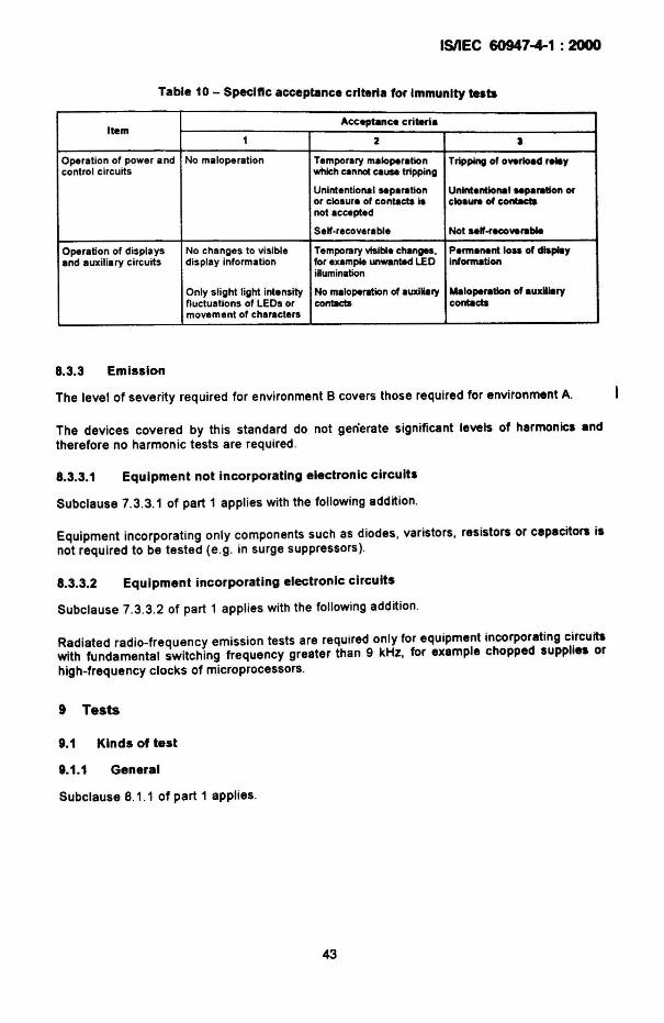
ISIIEC 60947-4-1 : 2000
Table 10 - Speclftc acceptance criteria for Immunity tests
ItemAcceptance crilierl.
1 2 I
Operation of power and No maloperation Temporary maloperation Tripping of overload relaycontrol circuits which cannot caUM tripping
Unintentional separation Unintentional separation oror closure of contacts ~ cloaura of contactanot accepted
Self-recoverable Not ..If-recoverable
Operation of displays No changes to visible Tempol1lry visible changes, Permanent 10.. of displayand auxiliary circuits display information for example unwanted l£O Information
iHumination
Only slight light Intensity No maloperation of auxiliary Maloperatlon of luxUlllryfluctuations of LEOs or contacts contllctsmovement of characters
8.3.3 Emission
The level of severity required for environment B covers those required for environment A.
The devices covered by this standard do not gen'erate significant levels of harmonics andtherefore no harmonic tests are required .
8.3.3.1 Equipment not incorporating electronic circuits
Subclause 7.3.3.1 of part 1 applies with the following addition.
EqUipment incorporating only components such as diodes, varistors, resistors or capacitors isnot required to be tested (e.g. in surge suppressors).
8.3.3.2 EqUipment incorporating electronic circuits
Subclause 7.3.3.2 of part 1 applies with the following addition .
Radiated radio-frequency emission tests are required only for equipment incorporating c~rcuitswith fundamental switching frequency greater than 9 kHz, for example chopped supplies orhigh-frequency clocks of microprocessors.
9 Tests
9.1 Kinds of test
9.1.1 General
Subclause 8.1.1 of part 1 applies.
43
(no defect accepted) ;
(if 1 defect, the entire lot shall be tested);
ISIIEC 60947-4-1 : 2000
1.1.2 Type tests
Type tests are intended to verify compliance ~~ th~ design of contactors and starters of alltypes with this standard. They comprise the venflcatlon of:
a) temperature rise limits (see 9.3.3.3);
b) dielectric properties (see 9.3.3.4);
c) rated making and breaking capacities (see 9.3.3.5);
d) change-over ability and reversibility, where applicable (see 9.3.3.5);
e) conventional operational performance (see 9.3.3.6);
1) operation and operating limits (see 9.3.3.1 and 9.3.3.2);
g) ability of contactors to withstand overload current (see 9.3.5);
h) performance under short-circuit conditions (see 9.3.4);
i) mechanical properties of terminals (see 8.2.4 of part 1);
j) degrees of protection of enclosed contactors and starters (see annex C of part 1).
k) EMC tests, where applicable (see 9.4) .
1.1.3 Routine tests
Subclause 8.1.3 of part 1 applies where sampling tests (see 9.1.4) are not made.
Routine tests for contactors and starters comprise:
- operation and operating limits (see 9.3.6.2) ;
- dielectric tests (see 9.3.6.3) .
1.1.4 Sampling tests
Sampling tests for contactors and starters comprise:
- operation and operating limits (see 9.3.6.2)
- dielectric tests (see 9.3.6.3).
Subclause 8.1.4 of part 1 applies with the following additions .
A manufacturer may use sampling tests instead of routine tests at his own discretion.Sampling shall meet or exceed the following requirements as specified in IEC 60410 (seetable II-A: Single sampling plans for normal inspection) :
- sampling based on AQL S 1;
- acceptance number Ac = 0
- rejection number Re =1
Sampling shall be made at regular intervals for each specif ic lot.
Alternat ive statistical methods that ensure compliance with the above IEC 60410requirements can be used, e.g. statistical methods controlling continuous manUfacturing orprocess control with capability index.
Sampling tests for clearance verification shall be performed according to 8.3.3.4.3 ofIEC 60947-1
44
ISIIEC 60947-4-1 : 2000
9.1.5 Special tests
Special tests are mechanical and electrical durability tests and verification of co-ordination atthe crossover current between the starter and the SCPO (see annex B).
9.2 Compliance with constructional requirements
Subclause 8.2 of part 1 applies (see, however, note to 8.1) .
9.3 Compliance with performance requirements
9.3.1 Test sequences
Each test sequence is made on a new sample.
NOTE 1 With Ihe agreemenl of the manufacturer, more Ihan one lesl sequence or ell test aequences mlY beconducled on one sample. However, the lesls are 10 be conducted in the sequence given for each Simple.
NOTE 2 Some lests are included in Ihe sequences solely to reduce the number of Simples required , the resubhave no significance for Ihe preceding or following lests in Ihe sequence. Therefore, for convenience of teatinQ Indby agreement wilh Ihe manufacturer, Ihese tesls may be conducted on separale new sample. and omitted from therelevanl sequence . This only applies to Ihe following lesls when called for :
Subclause 8.3.3 .4.1, item 7) of part 1 - Verification of creepage di$tanca.
Subclause 8.2.4 of part 1 - Mechanical propertie$ of terminal$ ;
Annex C of part 1 - Degree$ of protection of enc1c»ed equipment.
The test sequence shall be as follows .
a) Test sequence 1
(i) verification of temperature rise (see 9.3.3.3)
(ii) verification of operation and operating limits (see 9.3.3.1 and 9.3.3.2)
(iii) verification of dielectric properties (see 9.3.3.4)
b) Test sequence 2
(i) verification of rated making and breaking capacities, change-over ability andreverSibility, where appl icable (see 9.3.3.5)
(ii) verification of conventional operational performance (see 9.3.3.6)
c) Test sequence 3
performance under short-circuit conditions (see 9.3.4);
d) Test sequence 4 (applicable to contactors only)
verification of ability to withstand overload currents (see 9.3.5);
e) Test sequence 5
(i) verification of mechanical properties of terminals (see 8.2.4 of part 1);
(ii) verification of degrees of protection of enclosed contactors and starters (see annex Cof part 1).
There shall be no failure in any of the tests .
45
ISIIEC 60947-4-1 : 2000
1.3.2 General test conditions
Subclause 8.3.2 of part 1 applies with the following addition .
Unless otherwise specified in the relevant test clause, the clamping torqu~ for .connectionsshall be that specified by the manufacturer or, if not specified, the torque given rn table 4 ofpart 1.
1.3.3 Performance under no load, normal load and overload conditions
1.3.3.1 Operation
It shall be verified that contactors and starters operate according to the requirements of8.2.1.1.2.
To verify the insensitivity of the starter to contactor operation , the starter shall be loaded toattain a steady state temperature as stated in 8.2.2 and the contactor operated in the normalswitching sequence three times without intentional delay between operations. The startershall not trip due to the contactor operation.
When the overload relay has a combined stop and reset actuating mechanism, with thecontactor closed, the resetting mechanism shall be operated and this shall cause thecontactor to drop out. When the overload relay has either a reset only or separate stop andreset actuating mechanisms, with the contactor closed and the resetting mechanism in thereset position, the tripping mechanism shall be operated and the contactor shall have beencaused to drop out. These tests are to verify that the overload tripping action cannot bedefeated by holding the resetting mechanism in the reset posit ion.
In the case of rheostatic rotor starters, tests shall be performed to verify that the time settingof time-delay relays and the calibration of any other devices used for controlling the rate ofstarting are within the limits stated by the manufacturer.
The value of the starting resistors shall be verified for each section to be within ±10 % of thestated figures.
It shall also be verified that the rotor switching devices cut out the steps of resistors in ' thecorrect sequence.
It shall also be verified that the open-circuit voltages on the tapp ing terminals of the autotrensforme~ are in accordance with the designed figures and that the phase sequence at themotor termrnals of the two-step auto-transformer starter is correct in both the starting and ONpositions of the starter.
1.3.3.2 Operating limits
1.3.3.2.1 Power-operated equipment
Contactors and starters shall be tested to verify their performance according to therequirements given in 8.2.1.2.
46
I5nEC 60947-4-1 : 2000
9.3.3.2.2 Relays and releases
a) Operation of under-voltage relays and releases
Under-voltage relays or releases shall be tested for compliance with the requirementsof 8.2.1.3. Each limit shall be verified three times.
For the drop-out test, the voltage shall be reduced from the rated value to zero at anuniform rate in approximately 1 min.
b) Shunt-coil operated releases
Shunt-coil operated releases shall be tested for compliance with the requirementsof 8.2.1.4. Operation shall be verified at 70 % and 110 % of rated voltage under alloperating conditions of the starter.
c) Thermal and time-delay magnetic overload relays
Overload relays and starters shall be connected using conductors in accordance withtables 9, 10 and 11 of part 1 for test currents corresponding to:
- 100 % of the current setting of the overload relay for overload relays of trip class 10A;
- 125 % of the current setting of the overload relay for overload relays of trip classes 10,20 and 30 and for overload relays for which a maximum tripping time greater than 30 sis specified (see 5.7.3).
Thermal and time-delay magnetic overload relays with all poles energized shall be testedas stated in 8.2.1.5.1.
Moreover, the characteristics defined in 8.2.1.5.1 shall be verified by tests at -5 ·C,+20 ·C, +40 ·C and may be verified at minimum and maximum temperatures given by themanufacturer if larger. However, for relays or releases declared compensated for ambienttemperature, in case of temperature range declared by the manufacturer larger than thosegiven in figure 7, the characteristics at -5 ·C and/or +40 ·C need not be verified if, whentested at the declared minimum and maximum temperatures, the corresponding trippingcurrent values are in compliance with the limits specified for -5 ·C and/or +40 ·C in thatfigure.
Three-pole thermal overload relays energized on two poles only shall be tested as statedin 8.2.1.5.2 on all combinations of poles and at the maximum and minimum currentsettings for relays with adjustable settings.
d) Instantaneous magnetic overload relays
Each relay shall be tested separately. The current through the relay shall be increasedat a rate suitable for an accurate reading to be made. The values shall be as statedin 8.2.1.5.3.
e) Under-current relays in automatic change-over
The limits of operation shall be verified in accordance with 8.2.1.5.4.
9.3.3.3 Temperature rise
9.3.3.3.1 Ambient air temperature
Subclause 8.3.3.3.1 of part 1 applies.
9.3.3.3.2 Measurement of the temperature of parts
Subclause 8.3.3.3.2 of part 1 applies.
47
ISIIEC 60947-4-1 : 2000
t.3.3.3.3 Temperature rise of a part
Subclause 8.3.3.3.3 of part 1 applies.
t.3.3.3.4 Temperature rise of the main circuit
Subclause 8.3.3.3.4 of part 1 applies with the following additions :
The main circuit shall be loaded as stated in 8.2.2.4.
All auxiliary circuits which normally carry current shall be loade.d at their . maximum ratedoperational current (see 5.6) and the control circuits shall be energized at their rated voltages.
The starter shall be fitted with an overload relay complying with 5.7.4 and selected as follows:
- Non-adjustable relay
The current setting shall be equal to the maximum operational current of the starter andthe test shall be made at this current;
Adjustable relay
The maximum current setting shall be that which is nearest to but not greater than themaximum operational current of the starter .
The test shall be made with that overload relay for which the current setting is nearest tothe maximum of its scale.
NOTE The MlectIon method described above is designed to ensure that the temperature r1s!, of the field wiringtenIIlnela of the over\olld relay and the power dissipated by the starter are not less than those that will occur undera~ combination of relay and conlactor . In caMS where the effect of the overload relay on these values isInsIgnIIlcent (I.a. solid ltete overload relays), the tast current shall always be the maximum operational current ofthe .......
1.3.3.3.5 Temperature rise of control circuits
Subclause 8.3.3.3.5 of part 1 applies with the followi!'g addition.
The temperature rise shall be measured during the test of 9.3.3.3.4.
1.3.3.3.1 Temperature rise of colis and electromagnets
Subclause 8.3.3.3.6 of part 1 applies with the following additions.
a) Electromagnets of contactors or starters intended for uninterrupted or 8 h dUty areSUbjected only to the conditipns prescribed in 8.2.2.6.1, with the corresponding ratedcurrent flowing through the main circuit for the duration of the test. The temperature riseshall be measured during the test of 9.3.3.3.4.
b) Electromagnets of contactors or starters intended for intermittent duty shall be SUbjectedto the test as stated above, and also to the test prescribed in 8.2.2.6 .2 dealing with theirdUty class, with no current flowing through the main circuit.
c) Specially rated (temporary and periodic dUty) windings shall be tested as stated in8.2.2.6.3, without the current in the main circuit.
t.3.3.3.7 Temperature rise of aUXiliary circuits
Subclause 8.3.3.3.7 of part 1 applies with the following addition.
The temperature rise shall be measured during the test of 9.3.3.3.4.
48
ISIIEC 60947-4-1 : 2000
9.3.3.3.8 Temperature rise of starting resistors for rheostatic rotor starters
The temperature r ~se of resistors ~hall not exceed the limits specified in table 3 of part 1,when the starter IS operated at ItS rated duty (see 5.3.4) and according to its startingcharacteristics (see 5.3.5.5.1).
The current through each section of the resistors shall be thermally equivalent to tne currentduring the starting time when the controlled motor is operating with the maximum startingtorque and the starting time for which the starter is rated (see 5.3.4 and 5.3.5.5.1); in practice,the current value 1mcan be used .
Starting operations shall be evenly spaced in time according to the number of starts per hour.
The temperature rise of the enclosures and of the issuing air shall not exceed the limitsspecified in table 3 of part 1.
NOTE It is not practical to test the performance of starting resistors of every combination of motor output androtor voltage and current; it is required only that a sufficient number of tests be made to prove, by interpolation ordeduction. compliance with this standard.
9.3.3.3.9 Temperature rise of the auto-transformer for two-stepauto-transformer starters
The temperature rise of the auto-transformer shall not exceed the limits specified in table 5increased by 15 % (see 8.2.2) and those specified in table 3 of part 1, when the starter Isoperated at its rated duty (see 5.3.4) .
The current through each winding of the auto-transformer shall be thermally equivalent to thecurrent carried when the controlled motor is operating with the maximum starting current andstarting time for which the starter is rated (see 5.3.5.5 .3); this condition is assumed to bereached when the current drawn from the auto-transformer during the starting time is equal tothe maximum starting current specified in 5.3.5.5.3 multiplied by:
O8 startingvoltage ( 5 3 1 4), x see . . .Ue
The operating cycles shall be evenly spaced in time according to the number of starts perhour (see 5.3.4.3). .
In the event of two successive operating cycles (see 5.3.4.3), the temperature rise of theauto-transformer may exceed the maximum value given in 8.2.2 but no damage shall result tothe auto-transformer.
In the case of an auto-transformer with several sets of taps, the test shall be made with thetaps giving the highest power loss in the transformer; it shall be made over a period of timesufficient for the temperature rise to reach a constant value .
In order to facilitate this test, star-connected impedances may be used in place of a motor.
9.3.3.4 Dielectric properties
Subclause 8.3.3.4 of lEe 60947-1 applies with the following modifications.
49
IsnEC 60947-4-1 : 2000
9.3.3....1 Type tests
Subclause 8.3.3.4.1 of IEC 60947-1 applies with the addition of
- the following sentences, at the end of item 1):
The metal foil shall be applied to all surfaces where these are likely to be touched bypeo~e during normal operation or adjustment of the equipment and where such surfacescan also be touched by the standard test finger.
The metal foil shall not be applied for power frequency withstand verification afterSWitching and short-circuit tests.
- the following sentence, after the second paragraph of item 2) b):
Circuits of a contactor or starter inclUding devices which have been SUbjected to Uimp testvoltages lower than those specified in 7.2.3.1 and 8.3.3.4 .2 of IEC 60947-1 may bedisconnected for the test , according to the manufacturer's instructions.
- the following sentence, after the paragraph of item 2) c) ii):
Where the control circuit normally connected to the main circuit is disconnected (accordingto 8.3.3.4.1, item 2) b», the method used to maintain the main contacts closed shall beindicated in the test report.
- the following sentence at the end of 8.3.3.4.1, item 8):
For equipment suitable for isolation, the leakage current shall be measured through eachpole with the contacts in the open position, at a test Voltage of 1,1 Ue and shall not exceedO,5mA.
Verification of impulse withstand voltage across open contacts is not required for equipmentnot suitable for isolation (see 8.3.3.4.1, item 2) c) iv) of IEC 60947-1).
9.3.3.5 Making and breaking capacities
Subclause 8.3.3.5 of part 1 applies with the following additions.
9.3.3.5.1 General test conditions
The tests shall be made, under the operating conditions stated in table 7, without failure, see9.3.3.5.5 f).
The control supply voltage shall be 100 % of Us, except that for the make only test ofutilization categories AC-3 and AC-4, the control supply voltage ~hall be 110 % of Us for halfthe number of operating cycles and 85 % of Usfor the other half .
Connections to the main circuit shall be similar to those intended to be used when thec~nt~ctor or ~tarter. is in service. If necessary, or for convenience, the control and auxiliary~IfCUltS, and In particular the magnet coil of the contactor or starter, may be supplied by anmdependent source . Such a source shall deliver the same kind of current and the samevoltage as specified for service conditions.
The ?verload relay and t~e SCPO of the starter may be short-circuited for the purpose ofcarrymg out the rated making and breaking capacity tests .
50
ISIIEC 60947-4-1 : 2000
9.3.3.5.2 Test circuit
Subclause 8.3 .3.5 .2 of part 1 applies.
9.3.3.5.3 Characteristics of transient recovery voltage
Subclause 8.3.3.5.3 of part 1 applies to utilization categories AC-2, AC-3, AC-4, AC-811 and AC-8b(see table 1).
It is not necessary to adjust factor ror the oscillatory frequency for testing making capacityonly (in AC-3 and AC-4).
9.3.3.5.4 SWitching overvoltages
Subclause 8.3.3 .5.4 of part 1 applies with the following addition :
The switching overvoltages shall be verified on the load side between phases for multipoledevices and across the load for single-pole devices.
The test procedure is under consideration.
9.3.3.5.5 Rated making and breaking capacities
If the contactor in a starter has separately satisfied the requirements of item a) hereafter forthe utilization category of the starter, the starter need not be tested.
a) Rated making and breaking capacities of contactors
The contactor shall make and break the current corresponding to its utilization categoryand for the number of operating cycles given in table 7. See also item d) hereafter forreversing contactors.
Contactors of utilization categories AC-3 and AC-4 shall be SUbjected to 50 rneking onlyoperations followed by 50 making and breaking operations .
b) Rated making and breaking capacity of direct-on-Iine and two direction starters (AC-3) andstator switching devices of rheostatic rotor starters (AC-2)
The starter shall make and break the current corresponding to its utilization category forthe number of operating cycles given in table 7.
Starters of utilization category AC-3 shall be SUbjected to 50 making only operationsfollowed by 50 making and breaking operations .
c) Rated making and breaking capacities and change-over ability of star-delta starters (AC-3)and two-step auto-transformer starters (AC-3)
The starter shall make and break the currents corresponding to its utilization categorygive'n in table 7.
Both the starting and the ON or delta position of thE!. starters Shall.firs~ be sU~ject.d to 50making only operations, the current being broken by" separate switching devlca.
The starter shall then be SUbjected to the 50 making and breaking operations . Eachoperating cycle shall consist of the following sequences:
- make the current in the starting or star position;
- break the current in the starting or star position;
- make the current in the ON or delta position ;
- break the current in the ON or delta position;
- off period .
51
ISIIEC 60947.+1 : 2000
The load circuit shall be connected to the starter as would be the windings of ~ ~otor. Therated operational current of the starter (Ie) is the current In the ON or delta position.NOTE In tIM case of star-delta starters, it is important that the test .curre~ts be measured in star and deltaalnc. tIM supply Impadllnca has a signifICant effect on the transformatIon ratio .
When a transformer has more than one output voltage , it shall be connected to give thehighest starting voltage .The on-time in the start ing and ON positions and the off-time shall be as stated in table 7.
d) Rated making and breaking capacities of direct-on-Iine and reversing starters (AC-4)
The starters shall make and break the currents given in table 7.
The 50 making only operations shall be done first, the current being broken by a separateswitching device, followed by the 50 making and breaking operations.
The load circuit shall be connected to the starter as would be the windings of a motor.
For starters incorporating two contactors, two contactors A and S shall be used and wiredas in normal applicat ion. Each sequence of the 50 operations shall be:
close A - open A - close S -open S - off period
The change-over from "open A" to "close S" shall be made as fast as the normal controlsystem will allow.
Mechanical or electrical interlocking means provided in the starter or available forassociating contactors as reversing devices shall be used.
If the reversing circuit arrangement is such that both contactors can be energizedsimultaneously, ten additional sequences shall be conducted with both contactorsenergized simultaneously.
e) Rated making and breaking capacities of the rotor switching devices of a rheostatic rotorstarter
Verificat ion of the making and breaking capacities of the rotor switch ing dev ices shall beperformed as in 9.3.3.5.5 b) for AC-2 category where 'e = 'er, the maximum ratedrotor current for which the starter is designed. Ue =Uer (rated rotor operational voltage)and U1U. shall be 0,8. The power factor shall be 0,95. The starting resistors may bedisconnected for these tests and, for starters having more than two steps, the test shall beperformed on each switching device in turn. Since the rotor switching devices in startershaving more than two steps do not break and make at the full rotor voltage, the voltage forthese tests may be reduced in the ratio:
Starting resistance switchedTotalstarting resistance
When a . sta~er is ~o connected that the circuit is opened by the stator switch before therotor switching deVIces open, no verification of the breaking capacity is necessary.
For rotor switching devices which have previously satisfied the requirementscorresponding to those specified above, no further tests are needed.
52
ISIIEC 60947-4-1 : 2000
f) Behaviour and cond ition of the contactor or starter during and after the making andbreaking capacity, change-over and revers ing tests
During the tests within the limits of the specified making and breaking capacities of 9.3.3.5and the ver if ication of conventional operational performance of 9.3.3.6.1 to 9.3.3.6.6, thereshall be no permanent arcing , no flash-over between poles, no blowing of the fusibleelement in the earth circuit (see 9.3.3.5.2) and no welding ofthe contacts .
The contacts shall operate when the contactor or starter is switched by the applicablemethod of control.
9.3.3.6 Operational performance capability
Subclause 8.3.3.6 of part 1 applies with the following additions.
Tests concerning the ver ification of conventional operational performance are intended toverify that a contactor or starter is capable of fulfilling the requirements given in table 8.
Connections to the main circuit shall be similar to those intended to be used when thecontactor or starter is in service.
The overload relay and the SCPO of the starter may be short-circuited for the purpose ofcarrying out the tests.
The test circuit given in 9.3.3.5.2 is applicable and the load is to be tuned according to 9.3.3.5.3.
The control voltage shall be 100 % of the rated control supply voltage .
If the contactor in a starter has separately satisfied the requirements of 9.3.3.6.1 for theutilization category of the starter, the starter need not be tested .
9.3.3.6.1 Conventional operational performance of contactors
The contactor shall make and break the current corresponding to its utilization category andfor the number of operating cycles given in table 8. See also 9.3.3.6.4.
9.3.3.6.2 Conventional operational performance of dlrect-on-Iine andtwo direction starters (AC-3) and stator switching devicesof rheostatic rotor starters (AC.Z)
The starter shall make and break the current corresponding to its utilization category and forthe number of operating cycles given in table 8.
9.3.3.6.3 Conventional operational performance of star-delta starters (AC·3)and two-step auto-transformer starters (AC-3)
The starter shall make and break the current corresponding to its utilization category for thenumber of operating cycles given in table 8.
The test procedure shall be as stated in 9.3.3.5.5, item c), except that the 50 making onlyoperations are not done .
53
ISIIEe 60947-4-1 : 2000
8.3.3.6.4 Conventional operational performance of direct-on-Iineand reversing starters (AC-4)
The starter shall make and break the current corresponding to its utilization category for thenumber of operating cycles given in table 8.
The test procedure shall be as stated in 9.3.3.5.5, item d), except that the 50 making onlyoperations and the 10 additional sequences of simultaneous energizing are not done.
8.3.3.6.5 Conventional operational performance of the rotor SWitching devicesof a rheostatic rotor starter
Verification of convent ional operational performance of the rotor switching devices shall beperformed as in 9.3.3.6.1 for the AC-2 category given in table 8.
The test procedure shall be as stated in 9.3.3.5.5, item e).
9.3.3.8.8 Behaviour of the contactor or starter during, and its condition after,the conventional operational performance tests
The requirements of 9.3.3.5.5. item fl , shall be fulfilled and then the verification of powerfrequency withstand according to 8.3.3.4.1, item 4), of IEC 60947-1 shall be made .
For equipment suitable for isolation, .the leakage current shall be measured through eachpole. with the contacts in the open position, at a test voltage of 1,1 Ue and shall not exceed2mA
8.3.4 Performance under short-circuit conditions
This subclause specifies test condit ions for verification of compliance with the requirementsof 8.2.5.1. SpecifIC requirements regarding test procedure, test sequences, condition ofeqUipment after the test and types of co-ordination are given in 9.3.4 .1 and 9.3.4.2 .
8.3.4.1 General conditions for short-circuit tests
8.3.4.1.1 Genera' reqUirements for short-circuit tests
The general requirements of 8.3.4.1.1 of part 1 apply.
9.3.4.1.2 Test circuit for the verification of short-circuit ratings
Subclause 8.3.4.1.2 o~ part 1 applies except that, for type "1" co-ordination, the fusibleelement F and the reslstor RLare replaced by a solid 6 mm2 wire of 1,2 m to 1,8 m in length,connected to the neutral, or with the agreement of the manufacturer, to one of the phases .
NOTE This larger size of wire is not used u • detector but to establish an 'earth' condition allowing the damageto be enlllllted.
9.3.4.1.3 Power-factor of the test cirCUit
Subclause 8.3.4.1.3 of part 1 applies .
54
9.3.4.2
ISIIEC 60947-4-1 : 2000
9.3.4.1.4 Time-constant of the test circuit
Subclause 8.3.4.1.4 of part 1 applies.
9.3.4.1.5 Calibration of the test circuit
Subclause 8.3.4.1.5 of part 1 applies.
9.3.4.1.6 Test procedure
Subclause 8.3.4 .1.6 of part 1 applies with the following additions .
The contactor or the starter and its associated SCPO, or the combination or protected starter,shall be mounted and connected as in normal use. They shall be connected in the test circuitusing a maximum of 2,4 m of cable (corresponding to the operational current of the starter) foreach main circuit.
If the SCPO is separate from the starter, it shall be connected to the starter using the cablespecified above . (The total length of cable shall not exceed 2,4 m.)
Three-phase tests are considered to cover single-phase applications .
9.3.4.1.7 Vacant.
9.3.4.1.8 Interpretation of records
Subclause 8.3.4 .1.8 of part 1 applies .
Conditional short-circuit current of contactors, starters,combination starters and protected starters
The contactor or starter and the associated SCPO, or the combination or the protected starter,shall be SUbjected to the tests given in 9.3.4.2.1 and 9.3.4.2.2. The tests shall be soconducted that conditions of.maximum I. and of maximum U. for utilization category AC-3 arecovered .
For a magnetically operated contactor or starter, the magnet shall be held closed by IIseparate electrical supply at the rated control supply voltage Us' The SCPO used shall be asstated in 8.2.5.1 . If the SCPO is a circuit-breaker with an adjustable current setting, the testshall be done with the circuit-breaker adjusted to the maximum setting for the declared type ofco-ordination and discrimination .
Ouring .the test, all openings of the enclosure shall be closed as in normal service and thedoor or cover secured by the means provided.
A starter covering a range of motor rat ings and equipped with interchangeable overload rela.ysshall be tested with the overload relay with the highest impedance and the overload relay WIththe lowest impedance together with the corresponding SCPOs.
For type "1" co-ordination, a new test sample may be used for each operation stated in9.3.4.2.1 and 9.3.4 .2.2.
For type "2" co-ord ination, one sample shall be used for the tests at the prospective current"1" (see 9.3.4 .2.1) and one sample for the tests at current Iq (see 9.3.4.2.2).
55
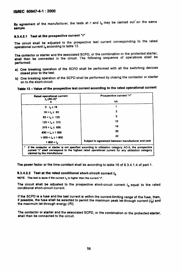
ISIIEC 60947-4-1 : 2000
By agreement of the manufacturer, the tests at rand Iq may be carried out ' on the same
ample.
••3....2.1 Test at the prospective current rrThe circuit shall be adj~sted to the prospective test current corresponding to the ratedoperational current I. according to table 12.
The contactor or starter and the associated SCPO, or the combination or the protected starter,shall then be connected in the circuit. The following sequence of operations shall beperformed:
a) One breaking operation of the SCPO shall be performed with all the switching devicesclosed prior to the test.
b) One breaking operation of the SCPO shall be performed by closing the contactor or starteron to the short-circuit.
Table 12 - V"ue of the prospective test current according to the rated operational current
Rated operational current Prospective current "r"I. (AC-3r
11 kA
0 '. S 16 1
18 < '. s 83 3
83 < '. S 125 5
125 < '. s 315 10
315 < '. s 83018
830 < '. s 1 00030
1 000 < '. s 1 llOO42
1800< ' •SUbject to egreement between manufacturer and user
. If the ~nbIetor or starter is not spe~ified accord ing to utiliZlltion category IIC-3, the prospectivecurrent ". ahall correspond to the highest fIIted opeflltlonal current for any utilization categoryclaimed by the manufacturer.
The power factor or the time-constant shall be according to table 16 of 8.3.4.1 .4 of part 1.
1.3.4.2.2 Test .. the rated conditional short-cIrcuit current'qNOTE Thla te.1 is done if the current 'q is higher than the current or.
The circuit shall be adjusted to the prospective short-circuit current I equal to the ratedconditional short-circuit current. q
~f the ~CPO is a fuse and the teat current is within the current-limiting range of the fuse thenif poaal~le, the fuse shall be selected to permit the maximum peak let-through current (; ) andthe maximum let-through energy (f2t) . p
The contactor or atarter and the associated SCPO, or the combination or the protected starterahall then be connected to the circuit. '
56
ISIIEC 60947-4-1 : 2000
The following sequence of operations shall be performed:
a) One breaking operation of the SCPO shall be performed with all the switching devicesclosed prior to the test.
b) One breaking operation of the SCPO shall be performed by closing the contactor or starteron to the short-circuit.
If, in the cas~ of a .combinat ion starter or a protected starter, the switching device of theSCPO. complies WIth I.~C 60947-2 .or !EC 60947-3 and has a short-circuit breakingcapacity or rated conditional short-circuit current less than the rated conditional shortcircu it current of the combination starter or protected starter the following additional testshall be made.
c) One breaking operation of the SCPO shall be performed by closing the switching device(switch or circuit-breaker) on to the short-circuit. This operation may be performed eitheron a new sample (starter and SCPO) or on the first sample with the agreement of themanufacturer.
After this operation only conditions A to G of 9.3.4.2 .3 shall be verified.
9.3.4.2.3 Results to be obtained
The contactor, starter, or the combination or protected starter, shall be considered to havepassed the tests at the prospective current "t" and, where applicable, the prospective current'q, if the following conditions are met for the claimed type of co-ordination.
Both types of co-ordination (all aevices):
A The fault current has been successtully interrupted by the SCPO or the combinationstarter and the fuse or fusible element or solid connection between the enclosure andsupply shall not have melted.
B The door or cover of the enclosure has not been blown open and it is possible to open thedoor or cover. Deformation of the enclosure is considered acceptable provided that thedegree of protection by the enclosure is not less than IP2X.
C There is no damage to the conductors or terminals and the conductors have not beenseparated from the terminals .
D There is no cracking or breaking of an insulating base to the extent that the integrity ofmounting of a live part is impaired.
Both types of co-ordination (comb ination starters and protected starters only) :
E The circuit-breaker or the switch is capable of being opened manually by its operatingmeans.
F Neither end of the SCPO is completely separated from its mounting means to an exposedconductive part.
G If a circuit-breaker with rated ultimate short-circuit breaking capacity less than the ratedconditional short-circuit current assigned to the combination or protected starter isemployed, the circuit-breaker shall be tested to trip as follows :
a) Circuit-breakers with instantaneous trip relays or releases: at 120'" of the trip current.
b) Circuit-breakers with overload relays or releases: at 250 % of the rated current of thecircuit-breaker.
Type "1" co-ordination (all dev ices) :
H There has been no discharge of parts beyond the enclosure. Damage to the contactor andthe overload relay is acceptable. The starter may be inoperative after each operation. Thestarter shall therefore be inspected and the contactor and/or the o~erload relay and therelease of the circuit-breaker shall be reset if necessary and, In the case of fuseprotection, all fuse-links shall be replaced.
57
IsnEC 60947-4-1 : 2000
Type ·1" co-ordination (combination and protected starters only) :
The adequacy of insulation in accordance with 8.3.3.4.1.. item .4), of IEC 60947-1 isverified after each operation (at currents "r" and " /q") by a dielectric test on the completeunit under test (SCPO plus contactorlstarter but before replacement of parts) usmg apower frequency withstand voltage of twice the rated ~pera~ional voltage U.e but not lessthan 1 000 V. The test voltage shall be applied to the incoming supply terminals, with theswitch or the circuit-breaker in the open posit ion, as follows:
_ between each pole and all other poles connected to the frame of the starter;
_ between all live parts of all poles connected together and the frame of the starter;
_ between the terminals of the line side connected together and terminals of the otherside connected together.
For equipment suitable for isolation , the leakage current shall be measured through eachpole, with the contacts in the open position , at a test voltage of 1,1 Ue and shall notexceed 6 mAo
Type "2" co-ordination (a/l devices) :
J No damage to the overload relay or other parts has occurred, except that welding ofcontactor or starter · contacts is permitted, if they are easily separated (e.g. by ascrewdriver) without significant deformation , but no replacement of parts is permittedduring the test, except that , in the case of fuse protection, all fuse-links shall be replaced.
In the case of welded contacts as described above , the functionality of the device shallbe verified by carrying out 10 operating cycles under the conditions of table 8 for theapplicable util ization category.
K The tripping of the overload relay shall be verified at a multiple of the current setting andshall conform to the publ ished tripping characterist ics, according to 5.7.5, both before andafter the short-circuit test.
l The adequacy of the insulation in accordance with 8.3.3.4 .1, item 4) , of IEC 60947-1 shallbe ver ified by a dielectric test on the contactor, starter, combination or protected starterusing a power frequency withstand voltage of twice the rated operational voltage Ue butnot less than 1 000 V.
In the case of combination and protected starters, additional tests according to 8.3 .3.4.1.item 3), of IEC 60947-1 shall be made across the main poles of the device with thecontacts of the switch or of the circuit-breaker open and the contacts of the starter closed.
For equipment suitable f~r isolation, the leakage current shall be measured through eachpole, WIth the contacts In the open position, at a test voltage of 1,1 U and shall notexceed 2 mAo e
Fuse-links, if any, are shorted.
8.3.5 Overload current withstand capability of contactors
For the test. the contactor shall be mounted , wired and operated as specified in 9.3 .2.
All poles of the contactors are simultaneously subjected to one test with the overload currentand duration values stated in 8.2.4 .4. The test is performed at any convenient voltage and itstarts with the contactor at room temperature.
Aft.er.the t~st , the contactor shall be substantiatly in the same condition as before the test.This IS venfied by visual Inspection.
NOTE The f't value (~oule int.Il~I) calculated from this test cannot be used to estimate the performance of thecont8ctor under short-CIrcuit conditions.
58
ISIIEC 60947-4-1 : 2000
9.3.6 Routine tests and sampling tests
9.3.6.1 General
The tests shall be carried out under the same conditions as those specified for type tests in~he relevant parts of. 9.1.2 or under ~~uivalen! conditions. However, the limits of operationIn 9.3.3.2 may be veritied at the prevailing ambient air temperature and on the overload relayalone, but a correction may be necessary to allow for normal ambient conditions.
9.3.6.2 Operation and operating limits
For electromagnetic, pneumatic and elect ro-pneumatic contactors or starters, tests are carriedout to ver ify operation within the limits specified in 8.2.1.2.
For manual starters, tests are carr ied out to verify the proper operation of the starter(see 8.2.1.2, 8.2.1.3 and 8.2.1.4).
NOTE In these tests it is not necessary to reach thermal equilibrium. The lack of thermal equilibrium may becompensated by using a series resistor or by appropriately decreasing the voltage limit .
Tests shall be made to verify the calibration of overload relays. In the case of a thermal or atime -delay magnetic overload relay , this may be a single test with all poles equally energizedat a multiple of the current setting, to check that the tripping time conforms (within tolerances)to the curves supplied by the manufacturer; in the case of an instantaneous magneticoverload relay, the test shall be carried out at 1,1 times the current setting .
NOTE In the case of a time -delay magnetic overload relay comprising a time·delay device working with a fluiddashpot , cal ibration may be carr ied out with the dashpot empty, at a percentage of the current setting indicated bythe manufacturer and capable of being just ified by a special test.
9.3.6.3 Dielectric tests
Subclause 8.3 .3.4.2 of IEC 60947-1 applies with the following addition .
In the case of a rheostatic rotor starter, all the poles of the rotor switching devices willnormally be connected through the start ing resistors ; the dielectric test is therefore confinedto the application of the testvottaae between the rotor circuit and the frame of the starter.
The use of the metal foil is not necessary.
NOTE The combined test of 8.3.3.4 .2 of lEe 60947-1 is permitted .
9,4 EMC Tests
9.4.1 General
Subclauses 8.3.2.1,8.3.2.3 and 8.3.2.4 of part 1 apply with the following additions.
With the agreement of the manufacturer, more than one EMC test or all EMC tests may beconducted on one and the same sample, which may initially be new or may have passed testsequences according to 9.3.1. The sequence of the EMC tests may be any convenientsequence.
The test report shall include any special measures that have been taken to ~chievecompliance, for example the use of shielded or spe.cial. cables . If auxlli.ary equipment IS usedwith the contactor or starter in order to comply WIth Immunity or emtssron requirements, Itshall be included in the report.
59
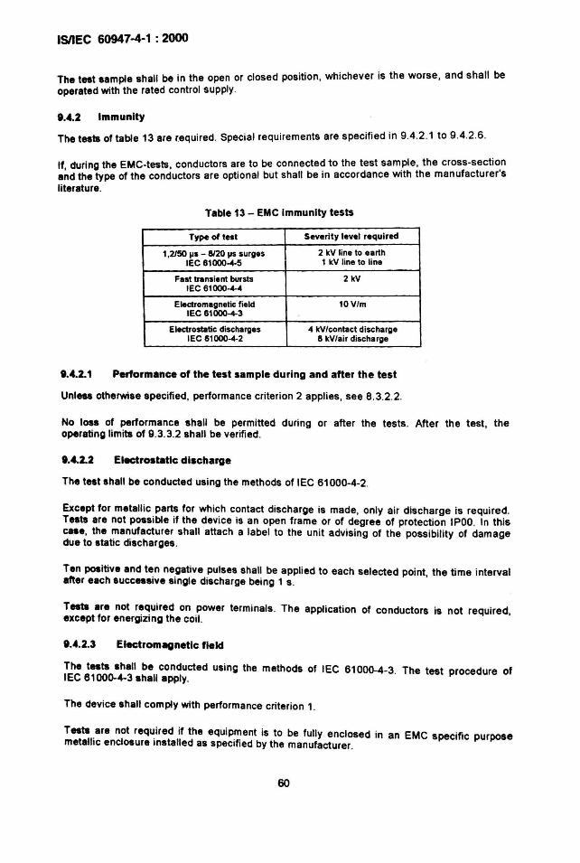
ISIIEC 60947-4-1 : 2000
The test sample shall be in the open or closed position, whichever is the worse, and shall beoperated with the rated control supply.
IU.2 Immunity
The tests of table 13 are r.equired. Special requirements are specified in 9.4.2.1 to 9.4.2.6 .
If, during the EMC-tests, conductors are to be connected to the test sample , the cross-secti~nand the type of the conductors are optional but shall be in accordance WIth the manufacturer sliterature .
Table 13 - EMC Immunity tests
Type of test Severity level required
1,2150 liS - 8120 liS surges 2 kV line to earthIEC 61000....5 1 kV line to line
Fast transient bursts 2 kVIEC61ooo....4
Electromagnetic field 10V/mIEC61OOO....3
Electrostatic discharges 4 kV/contact dischargeIEC61ooo.... 2 6 kV/air discharge
1.4.2.1 Performance of the test sample during and after the test
Unl888 otherwise specified, performance criterion 2 applies, see 8.3.2.2.
No loss of performance shall be permitted during or after the tests . After the test, theoperating limits of 9.3.3.2 shall be verified .
1.4.2.2 Electrostatic discharge
The test shall be conducted using the methods of IEC 61000-4-2 .
Except for metallic parts for which contact discharge is made, only air discharge is required.Tests are not possible if the device is an open frame or of degree of protection IPOO. In thiscase, the manufacturer shall attach a label to the unit advising of the possibility of damagedue to static discharges.
Ten positive and ten negative pulses shall be applied to each selected point, the time intervalafter each successive single discharge being 1 s.
Testa are not required on power terminals. The application of conductors is not required,except for energizing the coil.
1....2.3 Electromagnetic field
The tests shall be conducted using the methods of IEC 61000-4-3. The test procedure ofIEC 61000-4-3 shall apply.
The device shall comply with performance criterion 1.
Tests are not required if the equipment is to be fUlly enclosed in an EMC specific purposemetallic enclosure installed as specified by the manufacturer.
60
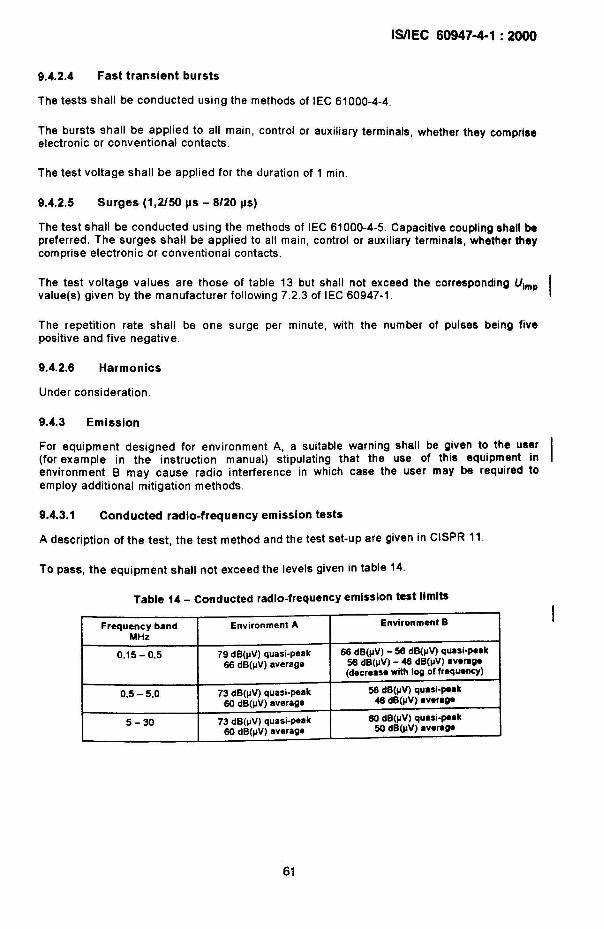
9.4.2.4 Fast transient bursts
ISIIEC 60947-4-1 : 2000
The tests shall be conducted using the methods of IEC 61000-4-4.
The bursts shall be applied to all main, control or auxiliary terminals, whether they compriseelectronic or conventional contacts.
The test voltage shall be applied for the duration of 1 min.
9.4.2.5 Surges (1,2/50 ~s - 8/20 us)
The test shall be conducted using the methods of IEC 61000-4-5 . Capacitive coupling shall bepreferred. The surges shall be applied to all main, control or auxiliary terminals, whether theycomprise electronic or conventional contacts.
The test voltage values are those of table 13 but shall not exceed the corresponding U1mpvalue(s) given by the manufacturer fo!lowing 7.2.3 of IEC 60947-1.
The repetition rate shall be one surge per minute, with the number of pulses being fivepositive and five negative.
9.4.2.6 Harmonics
Under consideration.
9.4.3 Emission
For equipment designed for environment A. a suitable warning shall be given to the user(for example in the instruction manual) stipulating that the use of this equipment inenvironment B may cause radio interference in which case the user may be required toemploy additional mitigation methods.
9.4.3.1 Conducted radio-frequency emission tests
A description of the test, the test method and the test set-up are given in CISPR 11.
To pass, the equipment shall not exceed the levels given in table 14.
Table 14 - Conducted radio-frequency emission test limits
Frequency band Environment A Environment B
MHz
0,15 - 0,5 79 dB(IlV) quasi-peak 66 dB(IlV) - 56 dB(IlV) qUllsi-peak66 dB(IlV) average 56 dB(IlV) - 46 dB(IlV) avere~
(decreese with log offrequency)
0.5 - 5.0 73 dB(IIV) quasi.~ak 56 dB(IlY) quasi-peak60 dB(IlV) average 46 dB(IlY) avera~
5-30 73 dB(IlY) quasi-peak 60 dB(IlV) quasi-peak60 dB(IlV) average 50 dB(IlY) avere~
61
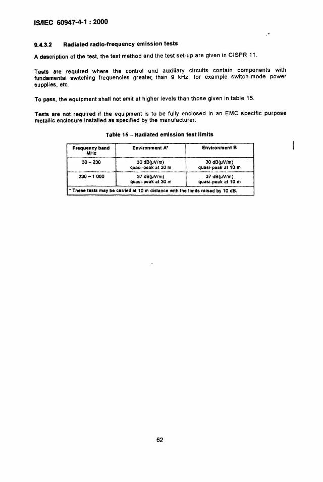
IsnEC 60947-4-1 : 2000
9.4.3.2 Radiated radio-frequency emission tests
A description of the test , the test method and the test set-up are given in CISPR 11.
Tests are required where the control and auxiliary circuits contain components withfundamental switching frequencies greater, than 9 kHz, for example switch-mode powersupplies, etc.
To pass, the equipment shall not emit at higher levels than those given in table 15.
Tests are not required if the equipment is to be fully enclosed in an EMC specific purposemetallic enclosure installed as specified by the manufacturer.
Table 15 - Radiated emission test limits
Frequency band Environment A* Environment BMHz
30-230 30 dB(JJVlm) 30 dB(IIV/m)quasi-peak at 30 m quasi -peak at 10 m
230 -1000 37 dB(JNlm) 37 dB(IIV/m)quasi-peak at 30 m quasi-peak at 10 m
• Th.se t.sts may be carr ied at 10 m distance with the limits raised by 10 dB.
62
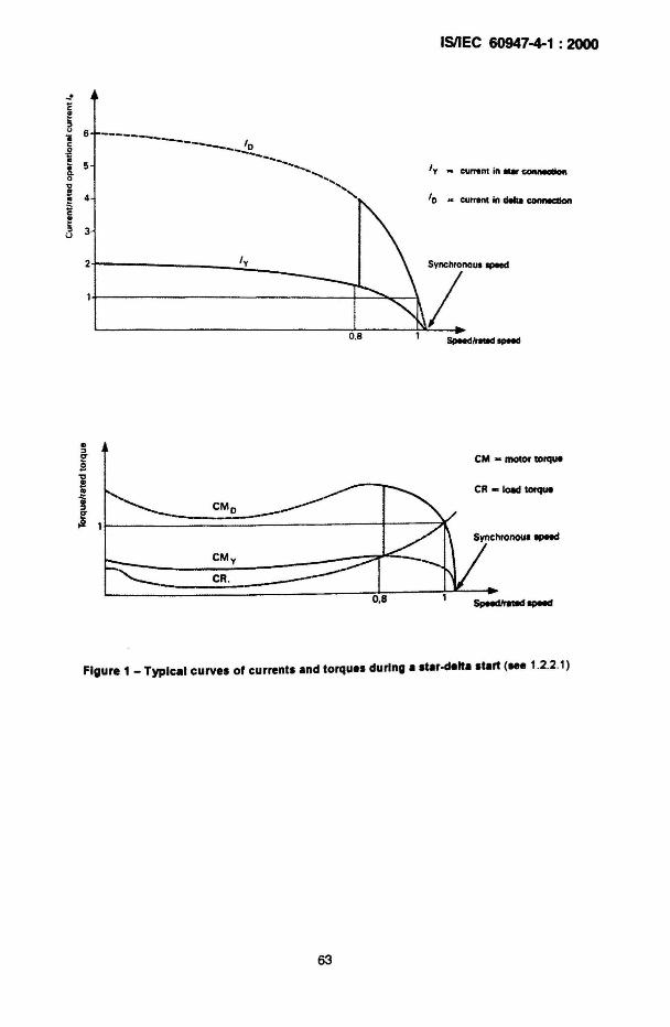
ISIIEC 60947-4-1 : 2000
I y _ ClIfNnl in _ c:ontllIClloft
' 0 - currenlIn deIuI COIIMClIon
0,8
------------- I-------~--................
..........................<,
Cft - 10811 tofqUe
CM - motor torque
CR.
CM y
Figure 1 _ TypIcal curves of currents and torques during a .tar-delta .tart (see 1.2.2 .1)
63
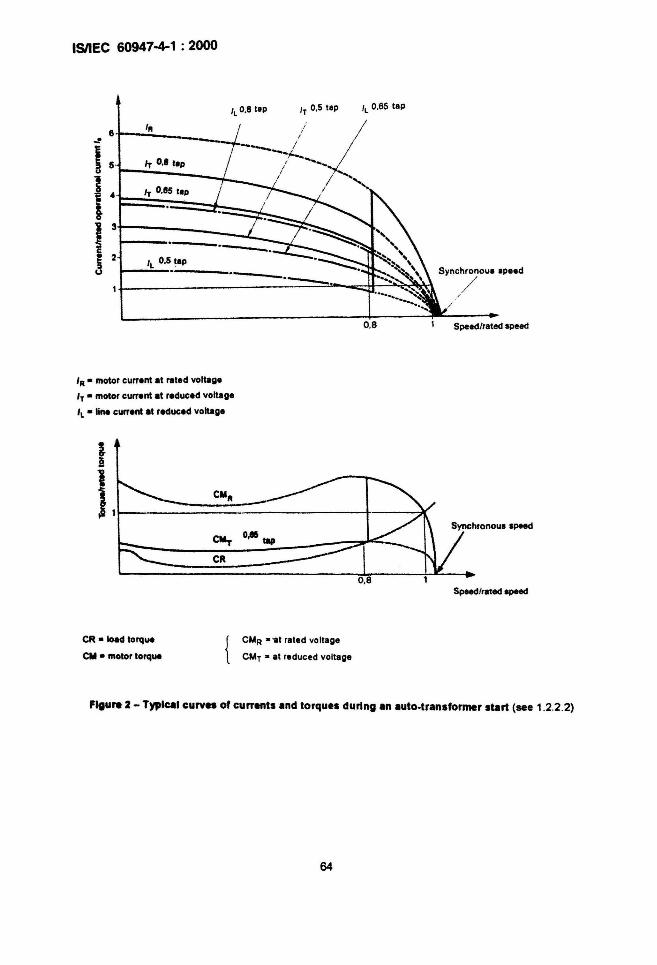
ISilEe 60947-4-1 : 2000
/lO.8Iep
IT 0.' lep
IT O.es lep
/L 0.5._le_p _
'R •motor current at I'1ItedYollage
IT • motor current at reduced yollage
' L • lina current at reduced Yoltage
IT 0.5 tep
0.8
Synchronoue epeed
,/
Speed/rated speed
i
ISpeed/rated apeed
CR • load torque
CM • motor torque { CMR • '81rated Yollage
CMT • al reduced voltage
Figure 2 - TypIcal curves of currents and torques during an auto·transformer start (see 1.2.2.2)
64
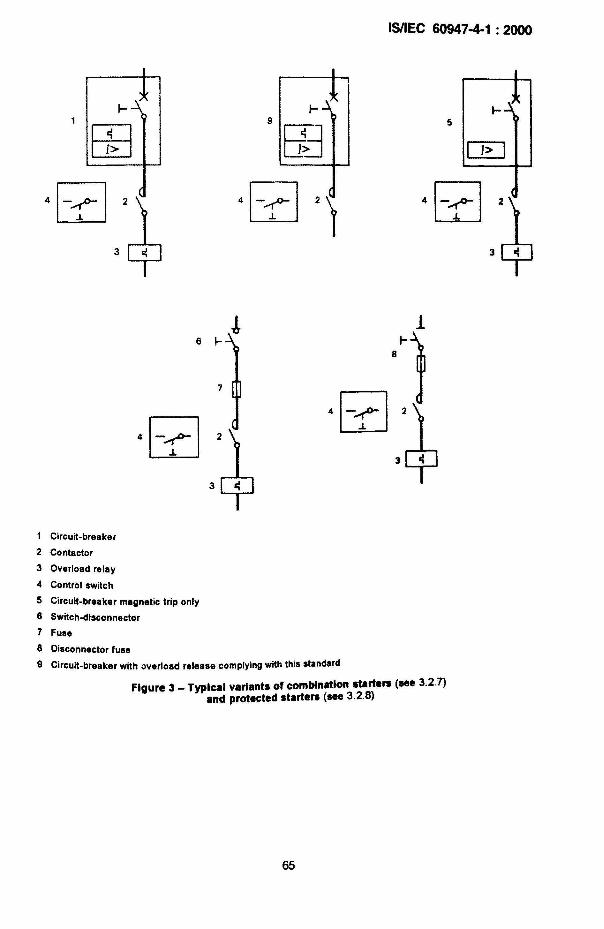
ISIIfe 60947-4-1 : 2000
9 5
6
1 Circuit-breaker
2 Contactor
3 Overload relay
4 Control switch
5 Circuit-breaker magnetic trip only
8 SWitch-dlsconnector
7 Fuse
8 Disconnector fuse
9 Circuit-breaker with overload release complying with this standard
Figure 3 _ Typical variants of combination starters (see 3.2.7)and protected starters (see 3.2.8)
65
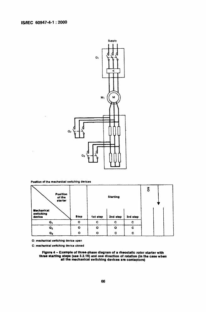
ISIIEC 60947·4-1 : 2000
Supply
Position of the mechanlcal switching devices
z0
Po.ltlonof the Startingltartlf r
llachanlcalIwltetllng
Stopdevice 1at Itap 2nd ltap 3rd Itep
0, 0 C C C
02 0 0 0 C
03 0 0 C C
0 : mech8nlcal switching device open
C: mech8nlcli switching davice closed
Figure 4 - Exampl. or three·phase diagram or a rheostatic rotor starter withthree sUrtlng ".ps (s•• 3.2 .18) and one direction or rotation (In the ca.e whllll
all the mechanical switching device. are conta~ors)
66
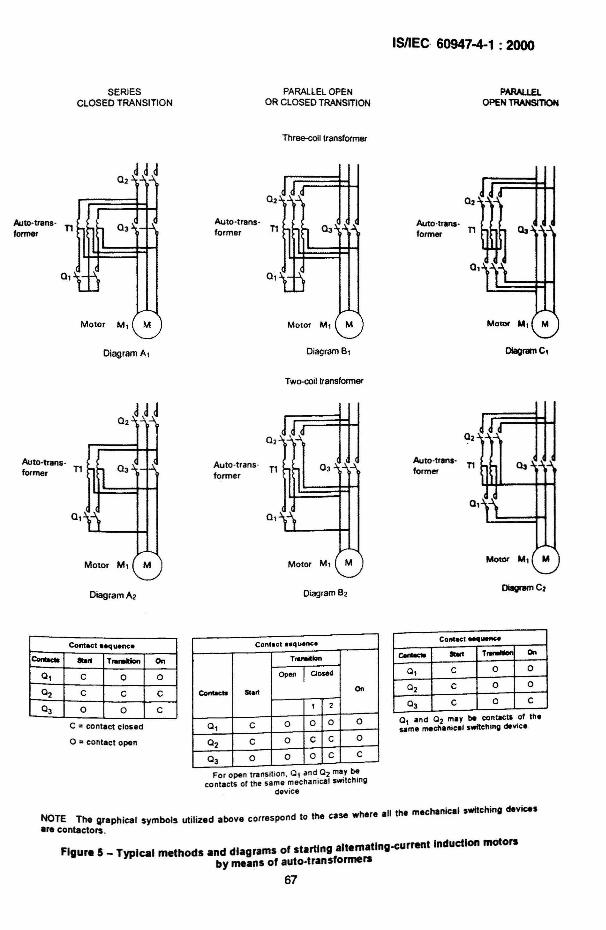
SERIESCLOSED TRANSITION
PARALLEL OPENOR CLOSED TRANSITION
Three-coil transtormer
ISnEc. 60947-4-1 : 2000
PARALlElOPENTRANSITION
Auto-transforme'
Auto -t,ansformer
Qnz;n=r=l=W03Auto-trans - n1 _.JJJformer
0,
Motor M, M
Diagram A,
Motor M, M
DiagramB1
TWlKOillransformer
MolO< M, M
OIagramC,
Auto-transformer
Auto -transformer
Aulo-tranlformer
Motor M, M
DiagramA2
Cont.ct eeq uenee
Corac:la lbrt T.....1on On
a, C 0 0
a2 C C C
L °3 0 0 C
C = contact closad
o = conlact open
Motor M, M
Diagram B2
Contact ••qulne.
T..noltlon
Open 1aosed
Contaeta Stort On
1 2
a1 C 0 0 0 0
02 C 0 C C 0
°3 0 0 0 C C
For open tra nsition, a, and 02 may becontacts of the same mechanical switching
dev ice
Motor "', '"
DilIgnIm C2
Contact MII-.
eoro- - ~ On
01 C 0 0
°2 C 0 0
°3 C 0 C
0, and 02 may be contacts of theSlIme mectl.nical switchtng device
NOTE The graphical symbols utilized above correspond to the case where all the mechanical switching device.
are contactors _
Figure 5 _ Typical methods and diagrams of starting altematlng-c:urrent Induction motorsby means of auto-transformers
67
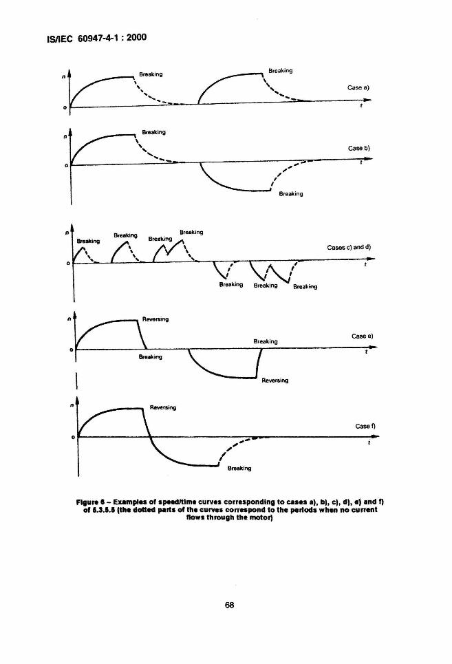
ISIIEC 60947-4-1 : 2000
BreakingBreaking
n\ \, , Case a).. ' ...........
"'- ...-0
Breakingn
\,Case b)...
' ... ...- ;.-
,,',,,Breaking
" Breaking
Break ing
r; ,/I"J
Breaking Break ing
Cases c) and d)
Case e)
Breaking
Case f)
Figure' - Examples of spHdltlme curves corresponding to cases a), b), C), d), ., andf)of 1.3.1.1 (the dotted parts of the curves correspond to the periods when no current
nows through the motor)
68
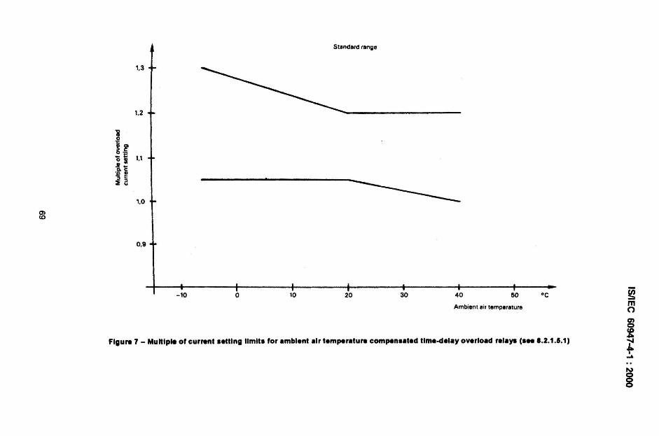
Standard ranlle
1.3
l.2
'i.g~ ~'0 ~ 11.!.. .
~~:l t:2 a
0>
1.0
<0
0.9
Figure 7 - Multiple of current letting IImltl for .mblent .Ir temper.ture compen••ted t1me.del.y overlo.d rel.ys ,... ' .2.1.5.1)
Ambient ail temperature
- 10 o 10 20 30 40 60 °C ~mo
~~....~
8
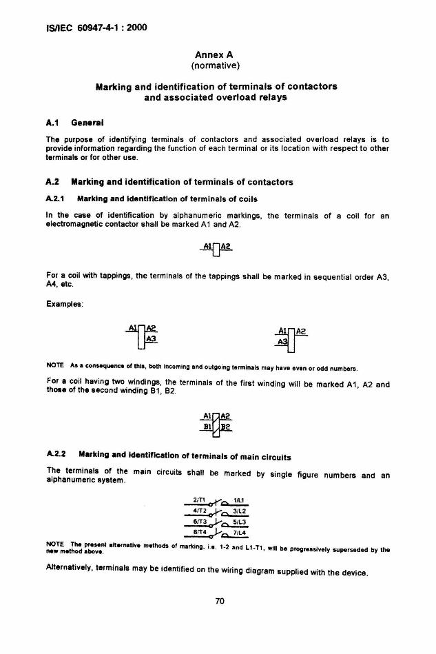
ISilEe 60947-4-1 : 2000
Annex A(normative)
Marking and identification of terminals of contactorsand associated overload relays
A.1 General
The purpose of identifying terminals of contactors and associated overload relays is toprovide information regarding the function of each terminal or its locat ion with respect to otherterminals or for other use.
A.2 Marking and identification of tenninals of contactors
A.2.1 Marking and identification of terminals of coils
In the case of identifi cation by alphanumeric markings, the terminals of a coil for anelectromagnetic contactor shall be marked A1 and A2.
For a coil with tappings, the terminals of the tappings shall be marked in sequential order A3,A4, etc.
Examples:
NOTE As. consequence of this, both incoming end outgoing term insls msy hsve even or odd numbers.
For a coil having two windings, the terminals of the first winding will be marked A1, A2 andthose of the second winding 81, 82.
~~
A.2.2 M.rklng and Identification of terminals of main circuits
The terminals of the main circuits shall be marked by single figure numbers and analphanumeric system .
2mo-r~
4fT2~~
6rr3aY~
8;T4;'y~
NOTE The present slternstive methods of msrk ing, i.e. 1·2 snd L1-Tl, will be progressively superseded by thenew method .bove.
Alternatively, terminals may be identified on the wiring diagram supplied with the device.
70
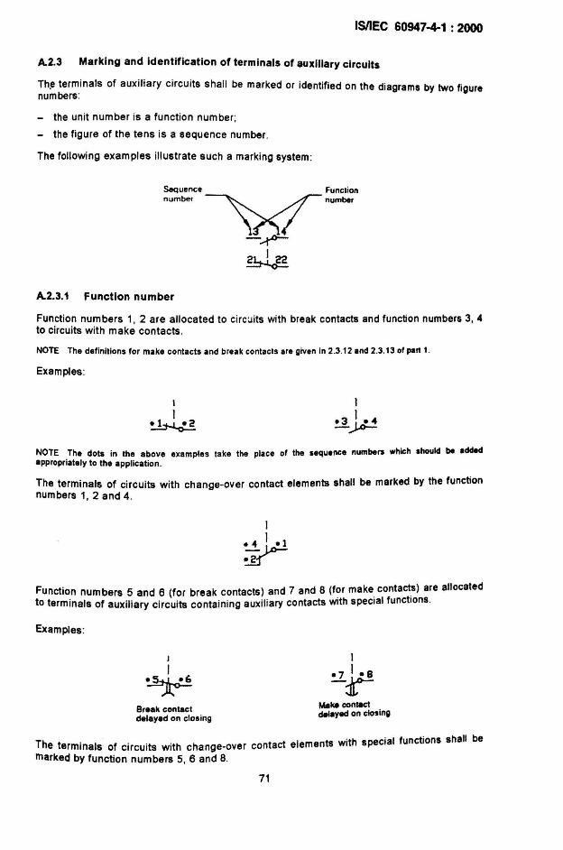
IMEC 60947-4-1 : 2000
A.2.3 Marking and identification of terminals of auxiliary circuits
Th.e terminals of auxiliary circuits shall be marked or identified on the diagrams by two fi urenumbers: g
- the unit number is a function number;
- the figure of the tens is a sequence number.
The following examples illustrate such a marking system:
Sequence FunClion
number ~"-.
-~
*A.2.3.1 Function number
Function numbers 1, 2 are allocated to circuits with break contacts and function numbers 3, 4to circuits with make contacts.
NOTE The definitions for make contacts and break conlacls are given in 2.3.12 and 2.3.13 of part 1.
Examples:
I
I~
NOTE The dots in the above examples take the place of the sequence numbers which should be addedappropriately to the appl ication.
The terminals of circuits with change-over contact elements shall be marked by the functionnumbers 1, 2 and 4.
1
~~~
Function numbers 5 and 6 (for break contacts) and 7 and 8 (for make contacts) are allocatedto terminals of auxiliary circuits contain ing auxiliary contacts with special functions.
Examples :
I
I
~Break contacldelayed on clos ing
Make conlllCtdelayed on closing
The terminals of circuits with change-over contact elements with special functions shall bemarked by function numbers 5, 6 and 8.
71
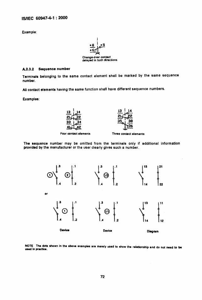
ISIIEC 60947-4-1 : 2000
Example:
I
-8 I -5
~Change-Clver contactdelayed in both direc tions
A.2.3.2 Sequence number
Terminals belonging to the same contact element shall be marked by the same sequencenumber.
All contact elements having the same function shall have different sequence numbers.
Examples:
Four contact elements
13 I 1.-
~~~
Jl,~
Three conlect elemotnts
The sequence number may be omitted from the terminals only if addit ional informationprovided by the manufacturer or the user clearly gives such a number.
0~~ of: r r fa r\[email protected] \. 22
or
1"3 r 1'3 r fa r\.0.2
[email protected] 1" 12
Devk:e Device Diagram
NOTE The <Iota aIlown in the lbove examples Ire merely used to show the relationship and do not need to beuaed In prac:tlce .
72
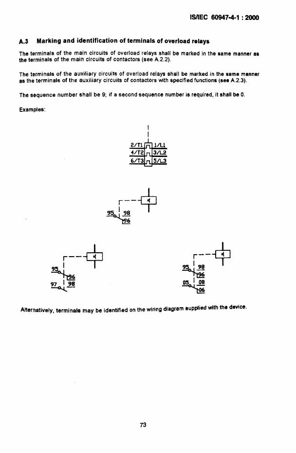
ISIIEC 60947-4-1 : 2000
A.3 Marking and identification of terminals of overload relays
The terminals of the main circuits of overload relays shall be marked in the same manner 81the terminals of the main circu its of contactors (see A.2.2).
The terminals of the auxiliary circuits of overload relays shall be marked in the same manneras the terminals of the auxiliary circuits of contactors with specified functions (see A.2.3).
The sequence number shall be 9; if a second sequence number is required, it shall be O.
Examples:
r---r!.95'98 T~
r---rl:.9:5 1 T~97 198~-
Alternatively. terminals may be identified on the wiring diagram supplied with the device.
73
ISIIEC 60947-4-1 : 2000
Annex B(normative)
Special tests
B.1 General
Special tests are done at the discretion of the manufacturer.
B.2 Mechanical durability
8.2.1 General
8y convention, the mechanical durability of a design of contactor or starter is defined as thenumber of no-load operating cycles which would be attained or exceeded by 90 % of all theapparatus of this design before it becomes necessary to service or replace any mechanicalparts; however, normal maintenance including replacement of contacts as specified in 8 .2.2.1and 8.2 .2.3 is permitted .
The preferred numbers of no-load operating cycles, expressed in millions. are:
0,001 - 0,003 - 0,01 - 0,03 - 0,1 - 0,3 - 1 - 3 and 10.
8 .2.2 Verification of mechanical durability
8.2.2.1 Condition of the contactor or starter for tests
The contactor or starter shall be installed as for normal service; in particular, the conductorsshall be connected in the same manner as for normal use.
During the teat, there shall be no voltage or current in the main circuit. The contactor orstarter may be lubricated before the test if lubrication is prescribed in normal service.
8 .2.2.2 Operating conditions
The coila of the control electromagnets shall be supplied at their rated voltage and . ifapplicable, at their rated frequency.
If a resistance or an impedance is provided in series with the coils , whether short-circuitedduring the operation or not, the tests shall be carried out with these elements connected as innormal operation.
Pneumatic and electro-pneumatic contactors or starters shall be supplied with compressed airat the rated pressure.
Manual starters shall be operated as in normal service .
8.2.2.3 Test procedure
a) The teats are carried out at the frequency of operations corresponding to the class ofintermittent duty. However , if the manufacturer considers that the contactor or starter cansatisfy the required condit ions when using a higher frequency of operations, he may do so .
74
ISIIEC 60947-4-1 : 2000
b) In the ca.se ~f electromagnetic and electro-pneumatic contactors or starters, the durationof energlzatlon of the contro! con shall be grea<er than the time of operation of thecontactor or starter and the time for which the coil is not energized shall be of such aduration that the contactor or starter can come to rest at both extreme positions.
The number of operating cycles to be carried out shall be not less than the number of noload operating cycles stated by the manufacturer.
The ver ification of mechanical durability may be made separately on the variouscomponents of the starter which are not mechanically linked together, unless a mechanicalinterlock not previously tested with its contactor is involved.
c) For contactors or starters fitted with releases with shunt coils or undervoltage releases, atleast 10 % of the total number of opening operations shall be performed by thesereleases .
d) After each tenth of the total number of operating cycles given in 8.2.1 has been carriedout, it is permissible before carrying on with the test:
- to clean the whole contactor or starter without dismantling ;
- to lubricate parts for which lubrication is prescribed by the manufacturer for normalservice;
- to adjust the travel and the pressure of the contacts if the design of the contactor orstarter enables this to be done .
e) This maintenance work shall not include any replacement of parts.
f) In the case of star-delta starters, the built-in device causing time-delay between closing onstar connection and closing on delta connection, if adjustable, may be set at its lowestvalue.
g) In the case of rheostatic starters, the built-in device causing time-delay between closing ofthe rotor switching devices, if adjustable, may be set at its lowest value.
h) In the case of auto-transformer starters, the built-in device causing time-delay betweenclosing on the starting position and closing on the ON position, if adjustable, may be set atits lowest value.
8.2.2.4 Results to be obtained
Following the tests of mechanical durability, the contactor or starter shall still be capable ofcomplying with the operating cond itions specified in 8.2.1.2 and 9.3.3.2 at room temperature.There shall be no loosening of the parts used for connecting the conductors.
Any timing relays or other devices for the automatic control shall still be operating.
8.2.2.5 Statistical analysis of test results for contactors or starters
The mechanical durability of a design of a contactor or starter is assigned by themanufacturer and verified by a statistical analysis of the results of the tests .
For contactors or starters which are produced in small quantities, the tests described in8.2.2.6 and 8 .2.2.7 do not apply .
75
ISIIEC 60947-4-1 : 2000
However, for contactors or starters which are produced in s~all quantiti.es. ~nd whic~ ~Isodiffer from a basic design only by detailed variations (l.e. Without any slgm~lcant vanatl.on)without notable influence on characteristics, the manufacturer. may aS~lgn mecha~lcaldurability on the basis of experience with similar designs, analysl~, propertl~s of matenals,etc., and on the basis of the analysis of test results on large quantity production of the samebasic design.
After this assignment, one of the two tests describ.ed bel.ow shall be performed. It should .be.elected by the manufacturer as being the most .sUltable In each ~ase , for example accordingto the quantities of planned production or according to the conventional thermal current.
NOTE Th'- tast Is not Intandad to ba a lot-by-Iot or production acceptance test for application by the user.
8.2.2.6 Single 8 test
Eight contactors or starters shall be tested to the assigned mechanical durability.
If the number of failures does not exceed two, the test is considered passed .
8.2.2.7 Double 3 test
Three contactors or starters shall be tested to the assigned mechanical durability.
The teet i. considered passed if there is no failure, and failed if there is more than one failure.Should there be one failure, then three additional contactors or starters are tested up toauigned mechanical durability and, providing there is no additional failure, the test iscon.idered passed. The test is failed if at any time there is a total of two or more failures.
£xpIenetoty /lID:
The N\gIa II test and the double 3 tast Ira both givan In IEC 60410 (see lables X-C-2 Ind X-D-2) .
TheM two t..ts hava bean choMn with tha obJactive of basing them on tasting a limited number of contactors ormrtent on ....ntlally the ..ma statlsticil chlracteristics (Icceplanca quality level : 10 '!Il).
B.3 Electrical durability
8.3.1 Gene,al
With rupect to ita resistance to electrical wear, a contactor or starter is by conventioncharacterized by the number of on-load operating cycles corresponding to the differentutilization categories given in table B.1 which can be made without repair or replacement.
Since, for star-delta, two-step auto-transformer and rheostatic rotor starters, .the operation issubjected to large variations in the service conditions, it is deemed convenient not to givestandard values for the test conditions . However, it is recommended that the manufacturerindicate the electrical durability of the starter for stated service conditions' this electricaldurability may be estimated from the results of tests on the component parts of the starter.
For categories AC-3 and AC-4, tne test circuit shall comprise inductors and resistors soarranged as to give the appropriate values of current, voltage and power factor given intable B.1; moreover, for AC-4, the test circuit testing the making and breaking capacity shallbe used, see 9.3.3.5.2.
76
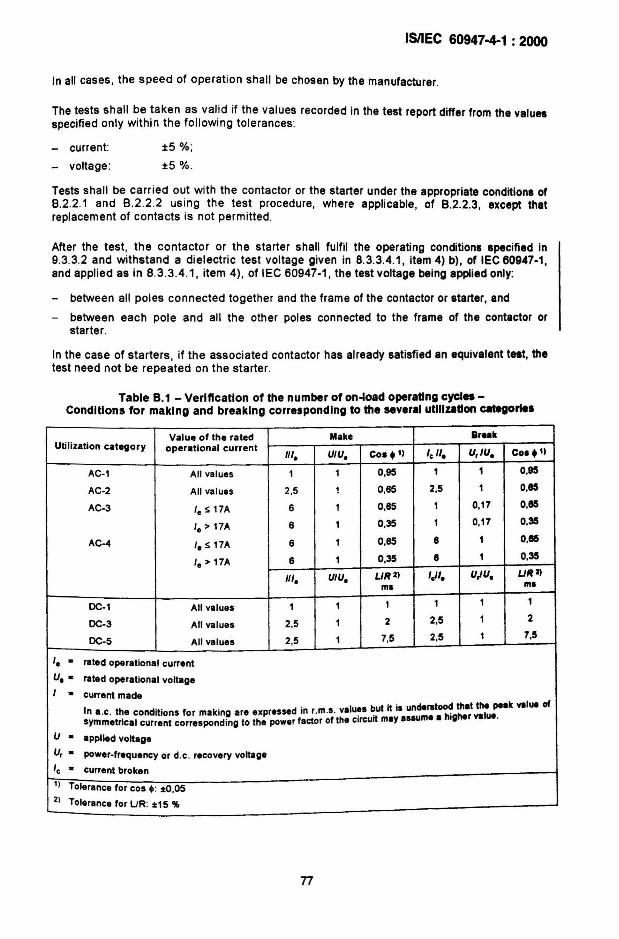
ISIIEC 60947-4-1 : 2000
In all cases, the speed of operation shall be chosen by the manufacturer.
The tests shall be taken as val id if the values recorded in the test report differ from the valuesspecified only within the following tolerances:
- current:
- voltage:
±5 %;
±5 %.
Tests shall be carr ied out with the contactor or the starter under the appropriate conditions of8.2.2.1 and 8 .2.2 .2 using the test procedure, where applicable, of B.2.2.3, except thatreplacement of contacts is not permitted .
After the test , the contactor or the starter shall fulfil the operating conditions specified in9.3.3.2 and withstand a dielectric test voltage given in 8.3.3.4.1, item 4) b), of IEC 60947-1,and applied as in 8.3.3.4.1, item 4), of IEC 60947-1, the test voltage being applied only:
- between all poles connected together and the frame of the contactor or starter, and
- between each pole and all the other poles connected to the frame of the contactor orstarter.
In the case of starters , if the associated contactor has already satisfied an equivalent test, thetest need not be repeated on the starter.
Table B.1 - Verification of the number of on-load operating cycles Conditions for making and breaking corresponding to the several utilization catego.....
Value of the rated Make BreakUtilization category operational current
III. UIU. cos.l) '.". U,IU. Cos .1)
AC-1 All values 1 1 0,95 1 1 0,95
AC-2 All values 2,5 1 0,65 2,5 1 0,85
AC-3 Ie S 17A 6 1 0,65 1 0,17 0,85
'. > 17A 6 1 0,35 1 0,17 0.35
AC-4 '. S 17A 6 1 0,65 8 1 0,85
Ie> 17A 8 1 0,35 8 1 0,35
III. UlU. UR2) Icil. U,JU. UR2)
ms ms
DC-1 All values 1 1 1 1 1 1
DC-3 All values 2,5 1 2 2,5 1 2
DC-5 All values 2,5 1 7,5 2,5 1 7,5
Ie a rated operational current
U. a rated operational voltageI a current made
. I but it 's undsrstood that the peak value ofIn a.c . t~e cond itions for making are expressed In r.m.s. va u~s . I me a hi her value.symmetncal current corresponding to the power factor of the cIrcuit may ISSU g
U a applied voltlgeU, a power-frequency or d.c . recovery voltage
'. a Current broken1) Tolerance for cos ~: :t0 ,052) Tolerance for UR: :t15 'll>
77
ISilEe 60947-4-1 : 2000
B.4 Co-ordination at the crossover current between the starterand associated SCPD
8.4.1 General and definitions
8.4.1.1 General
This annex states different methods of verifying the performance of starters and theassociated SCPO(s) at currents below and above the intersection fco of their respective timecurrent characteristics, provided by the starter and SCPD manufacturer(s), and the corresponding types of co-ordination described in 8.2.5.1 .
Co-ord ination at the crossover current between the starter and the SCPO can be verifiedeither by the direct method with the special test of 8 .4.2 or, for type "2" co-ordination, by theindirect method as in B.4.5.
8.4.1.2 Definitions
8.4.1.2.1crossover current leocurrent corresponding to the crossover point of the mean or published curves representing thetime-current characteristics of the overload relay and the SCPD respectively
NOTE The maan curves ara the curves corresponding to the average values calculated from the tolerances on thelIme-c:urrent characteristics given by the manufacturer. .
B.4.1.2.2test current ledtett current greater than leo, tolerances included, designated by the manufacturer and ver if iedby the requirements given in table B.2
8.4.1.2.3tlme-current withstand characteristic capability of contactors/starterslocus of the currents a contactorlstarter can withstand as a function of time
8.4.2 Condition for the test for the verification of co-ordination atthe crossover current by a direct method
The starter and its associated SCPO shall be mounted and connected as in normal use. Allthe tests shall be performed starting from the cold state.
8.4.3 Test currents and test circuits
The test circuit shall be according to 8.3.3.5.2 of part 1 except that the oscillatory transientvoltage need not be adjusted. The currents for the tests shall be:
(i) 0,75 leo _g % and
(ii) 1.25 leo~ %
The power factor of the test circuit shall be in accordance with table 7. In the case of smallrelays having a high resistance, inductors should be mainly used in order to have a value ofpower factor as low as possible. The recovery voltage shall be 1 05 times the ratedoperational voltage. '
78
ISIIEC 60947-4-1 : 2000
The SCPO shall be as stated in 8.2 5.1 and of the same rating and characteristics as used inthe tests of 9.3.4.2.
If the switching device is a contactor, its coil shall be energized from a separate source at therated control supply voltage of the contactor coil and connected so that the contactor openswhen the overload relay operates.
8.4.4 Test procedure and results to be obtained
8.4.4.1 Test procedure
With the starter and the SCPO closed, the test currents stated in 8.4.3 shall be applied by aseparate closing device. In each case the device tested shall be at room temperature.
After each test, it is necessary to inspect the SCPO, reset the overload relay and the rei....of the circuit-breaker, if necessary, or to replace all fuses if at least one of them has melted.
8.4.4.2 Results to be obtained
After the test at the lower current. (i) in 8.4.3, the SCPO shall not have operated and theoverload relay or release shall have operated to open the starter. There shall be no damageto the starter.
After the test at the higher current (ii) in 8.4.3, the SCPO shall have operated before thestarter. The starter shall meet the conditions of 9.3.4.2.3 for the type of co-ordination statedby the manufacturer.
8.4.5 Verification of co-ordination at the crossover current by an Indirect method
~OTE For type "1" co-ordination, the indirect method may be different from the method described in annex BendIS under consideration. For this reason, the indirect method for the verifICation of co-ordlnetlon at the er~"point is only applicable for type "2" co-ordination.
The indirect method consists in verifying on a diagram (see figure 8.1) that the followingconditions for the verification of co-ordination at the crossover current are met:
- the time-current characteristic of the overload relay/release, starting from cold state,supplied by the manufacturer, shall indicate how the tripping time varies with the ~u~rentup to a value of at least I . this curve has to lie below the time-current charactenstic of
co'the SCPO up to Ico;
- 'Cd of the starter, tested as in 8.4.5.1, shall be higher than 'eo;- the time-current withstand characteristic of the contactor, tested as in 8.4.5.2, shall
be above the time-current characteristic (starting from cold state) of the overload relay upto Ico.
8.4.5.1 Test for 'cd
Subclause 9.3.4.1 applies with the following addition.
- Test procedure' the contactor or starter shall make and break the test current (Icd) f~r t~enumber of oper~ting cycles given in table 8.2 below. This is made without the SCPO In t ecircuit.
79
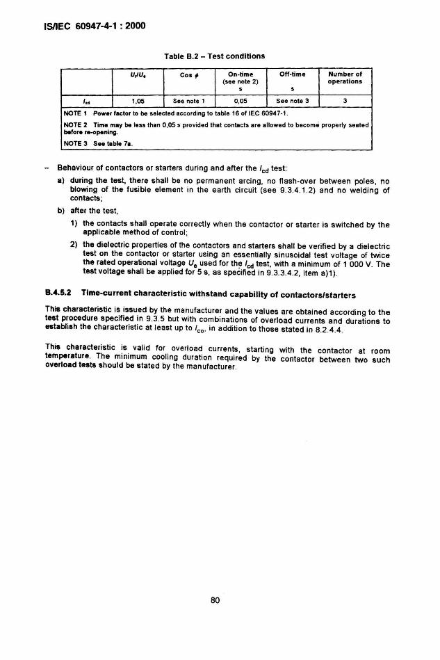
IsnEC 60947-4-1 : 2000
Table 8.2 - Test conditions
U,lU. Cos ~ On ·time Off·time Number of(see note 2) operations
s s
, c• 1,05 See note 1 0,05 See note 3 3
NOTE 1 Power factor to be selected according to lable 16 of lEe 60947·1 .
NOTE 2 Time may be less than 0,05 s provided that contacts are allowed to become properly sealedbefore re·opening.
NOTE 3 See table 7a.
- Behaviour of contactors or starters during and after the 'ed test:
a) during the test, there shall be no permanent arcing . no flash·over between poles , noblowing of the fusible element in the earth circuit (see 9.3.4 .1.2) and no welding ofcontacts;
b) after the test,
1) the contacts shall operate correctly when the contactor or starter is switched by theapplicable method of control ;
2) the dielectric properties of the contactors and starters shall be ver ified by a dielectrictest on the contactor or starter using an essentially sinuso idal test voltage of twicethe rated operational voltage Ue used for th~ 'ed test , with a minimum of 1 000 V. Thetest voltage shall be applied for 5 s, as specified in 9.3.3.4.2, item a)1) .
8.4.5.2 Time-current characteristic withstand capability of contactors/starters
This characteristic is issued by the manufacturer and the values are obtained according to thetest procedure specified in 9.3.5 but with combinations of overload currents and durations toestablish the characteristic at least up to leo. in addition to those stated in 8.2.4.4 .
This characteristic is valid for overload currents, starting with the contactor at roomtemperature. The minimum cooling duration required by the contactor between two suchoverload tests should be stated by the manufacturer.
80
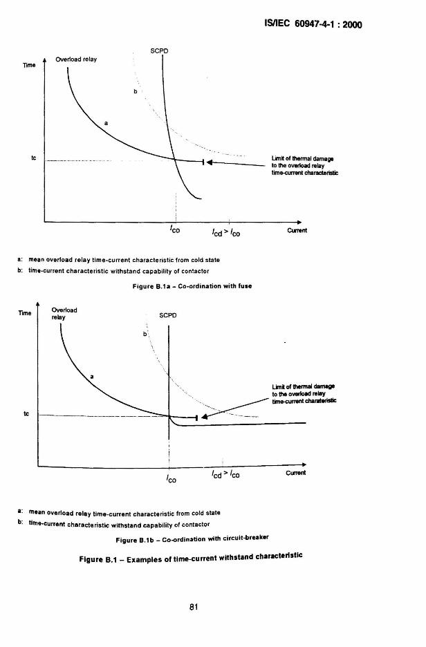
Time
Ie
ISIIEC 60947-4-1 : 2000
SCPOOverload relay
Lim~ of thermal damageto theoverload relaytime-current characteristic
leo led> leo CuTent
a: mean overload relay time-current characte ristic from cold state
b: time-current characteristic withstand capability of contactor
Figure B.1a - Co-ordination with fuse
Tune
Ie
Overloadrelay SCPO
linl of thermal damage. to the overload relay'~. time-cumsntchallllteristic
' ."'-"
" ~'1r'"---1 ,._-- ,.._-_..._--
leoled> leo Cl.ITenl
a: mean overload relay time-current characteristic from cold state
b: time-current characteristic withstand capability of contactor
Figure B.1b _ Co-ordination with circuit-breaker
Figure B.1 _ Examples of time-current withstand characteristic
81
ISIIEC 60947-4-1 : 2000
Annex C
Void
82
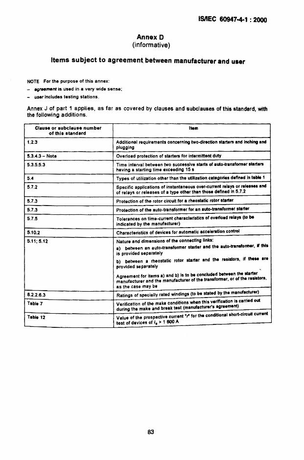
ISIIEC 60947-4-1 : 2000
Annex 0(informative)
Items subject to agreement between manufacturer and user
NOTE For the purpose of this annex :
_ /lflreement is used in a very wide sense ;
- u.se,Includes testing stations .
Annex J of part 1 applies, as far as covered by clauses and subclauses of this standard withthe following additions. •
Claus. or subclau.e number Itemof this standard
1.2.3 Additional requirements concerning two-directlon start.rs .nd Inchingandplugging
5.3.4.3 - Note Overload protect ion of starters for intermittent duty
5.3.5.5.3 Time interval between two succ.ssive starts of auto-transform.r start.rshaving a starting lime exceeding 15 s
5.4 Types of utilization other than the utilization categories d.flned In t.ble 1
5.7.2 Specific applications of instantaneous over-current relays or r.I......ndof relays or releases of a type other than tho.. defined in 5.7.2
5.7.3 Protect ion of the rotor circuit for a rh.ostatic rotor start.r
5.7.3 Protect ion of the auto-transformer for en auto-transform.r starter
5.7.5 Tolerances on time-current characteristics of ov.rload r.lays (to beindicated by the manufactur.r)
5.10.2 Characteristics of devices for automatic acc.l.ration control
5.11; 5.12 Nature and dimensions of the conn.cting link.:
a) between an auto-transformer starter and the auto-transformer, " thisis provided separately
b) between a rheostatic rotor starter and the rasistors, if the.. ar.provided separately
-,
Agreement for items a) and b) is to be conclud.d between the startermanufacturer and the manufacturer of the transform.r, or of the r.slstora,as the case may be
8.2.2.6.3 Ratings of specially rated windings (to b. stat.d by the manufacturer)
Table 7 Verification of the make conditions when this v.riflcation is carried outduring the make and break test (manufacturer'S agr••m.nt)
Table 12 Value of the prospective curr.nt .~ for the conditional short-circuit curr.nt
test of devices of I. > 1 600 A
83
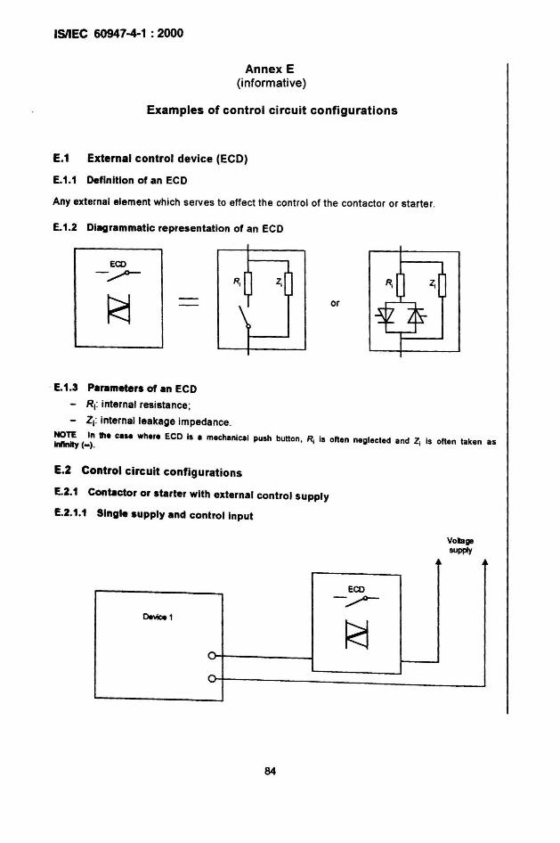
ISIIEC 60947-4-1 : 2000
Annex E(informative)
Examples of control circuit configurations
E.1 External control device (ECD)
E.1.1 Definition of an ECD
Any external element which serves to effect the control of the contactor or starter.
E.1.2 Diagrammatic representation of an ECD
Ea>- .".,-
R11~
ZIIr J
~II
or
. E.1.3 Parameters or an ECD
- R1: internal resistance;
- ZI: internal leakage impedance .
NOTE In the Ce.. where ECD Is • mechanical push button, RI is often neglected and Zi is often taken asInftnlty(-).
E.2 Control circuit configurations
E.2.1 Conlactor or starter with external control supply
E.2.1.1 Single supply and control Input
• •
Ea>r.>:
0e\IicIe 1
~f"\
f"'\.-
Vobgesupply
84
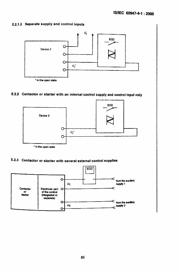
I5nEe 60947-4-1 : 2000
E.2.1.2 separate supply and control inputs
u•ECO
0--",.-0-
Device 2
R:j"-"-
Ju·c,...-• In the open slate
E.2.2 Contactor or starter with an internal control supply and control input only
ECO
r.>:Device 3
R:j0
Ju·e0
• in the open stale
E.2.3 Contactor or starter with several external control supplies
IEcol..,
-Uc -Contactor Electronic parl
or ofthe controlstarter (mlegraled or
separate)....-,.,- Us
fromtheauxiiarysupply1
fromtheaUldla!Ysupply2
85
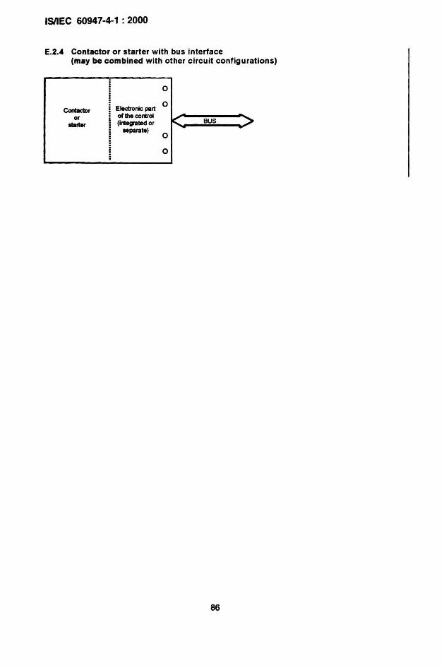
ISIIEC 60947-4-1 : 2000
E.2.4 Contaetor or starter with bus interface(may be combined with other circuit configurations)
0
Eledronic part0
Cont8ctIoror of the conlrol
I<altar (inl~llldor BUS
separate)0
0
86
ISIIEC 60947-4-1 : 2000
Annex F(normative)
Requirements for auxiliary contact linked withpower contact (mirror contact)
F.1 Scope and object
F.1.1 Scope
This annex applies to auxiliary contacts mechanically linked with power contacts of 8contactor and designated as mirror contacts in order to avoid any confusion with mechanicallylinked contact elements dealt within annex L of IEC 60947-5-1. However, that does notprevent a given auxiliary contact to comply with both requirements for mirror contact of thisannex and for mechanically linked contact of annex L of IEC 60947-5-1.
NOTE 1 A typical application of mirror contacts is 10 have. in Ihe machine control circuit. I highly rllliblemonitoring of the stalus of the contactor. However. mirror contact should not be rllied upon Ixclusively as a meansto ensure safety.
NOTE 2 Mirror contacts have previously been referred 10 as positively safety contacts. forced contacts, linkedcontacts or positively driven contacts .
F.1.2 Object
This annex prov ides additional specifications (defin ition, requirements and tests) which ~hallbe used for stating the requ ired design characteristics, marking and performance of mirrorcontact.
F.2 Definitions
The following additional definition applies.
F.2.1mirror contactnormally closed auxiliary contact which cannot be in closed position simultaneously with thenormally open main contact under cond itions defined in clause F.7
NOTE One contactor may have more than one mirror contact .
F.3 Characteristics
All mirror contacts shall also comply with the relevant requirements given in this standard.
F.4 Product information
Clause 6 applies with the following addition.
87
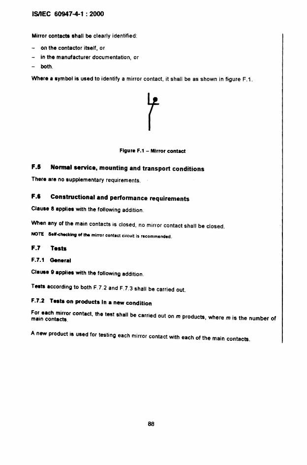
ISIIEC 60947-4-1 : 2000
Mirror contacts shall be clearly identified:
- on the contactor itself, or
- in the manufacturer documentation, or
- both.
Where a symbol is used to ident ify a mirror contact, it shall be as shown in figure F.1.
Figure F.1 - Mirror contact
F.5 Normal service, mounting and transport conditions
There are no supplementary requirements . .
F.' Constructional and performance requirements
Clause 8 applies with the following addition .
When any of the main contacts is closed, no mirror contact shall be closed.
NOTE se'-checldng of the mirror cont.et circuit is recommended.
F.7 Tests
F.7.1 Gen.,a'C'au.a 9 applies with the following addition.
Tests according to both F.7.2 and F.7.3 shall be carried out.
F.7.2 Tes.. on products In a new condition
For each mirror contact, the test shall be carried out on m products, where m is the number ofmain contacts.
A new product is used for testing each mirror contact with each of the main contacts.
88
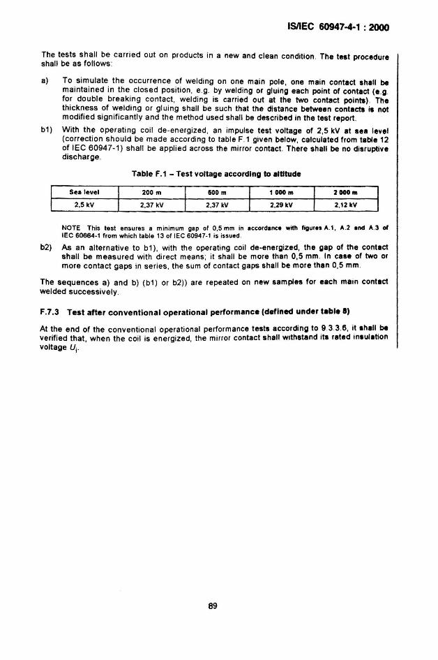
ISIIEC 60947-4-1 : 2000
The tests shall be carried out on products in a new and clean condition. The test procedureshall be as follows:
a) To simulate the occurrence of welding on one main pole, one main contact shall bemaintained in the closed position, e.g. by welding or gluing each point of contact (e.g.for double breaking contact, weld ing is carried out at the two contact points) . Thethickness of welding or gluing shall be such that the distance between contacts is notmodified significantly and the method used shall be described in the test report .
b1) With the operating coil de-energized, an impulse test voltage of 2,5 kV at sea level(correction should be made according to table F.1 given below, calculated from table 12of lEe 60947-1) shall be applied across the mirror contact. There shall be no disruptivedischarge.
Table F.1 - Test voltage according to altitude
Sea level
2.5kV
200 m
2.37 kV
500 m
2.37 kV
1000 m
2.29kV
2oo0m
2,12 kV
NOTE This test ensures a minimum gap of 0,5 mm in accordance with figures A.l, A.2 and A.3 oflEe 60664-1 from which table 13 of lEe 60947-1 is issued.
b2) As an alternative to b1) , with the operating coil de-energized. the gap of the contactshall be measured with direct means; it shall be more than 0,5 mm. In case of two ormore contact gaps in series. the sum of contact gaps shall be more than 0,5 mm.
The sequences a) and b) (b1) or b2)) are repeated on new samples for each main contactwelded successively.
F.7.3 Test after conventional operational performance (defined under t.bl. 8)
At the end of the conventional operational performance tests according to 93.3.6. it shall beverified that, when the coil is energized, the mirror contact shall withstand its rated insulationvoltage Vi '
89
ISIIEC 60947-4-1 : 2000
Bibliography
lEe 60664-1:1992, Insulation coordination for equipment within low-voltage systems - Part 1:Principles, requirements and tests
90
AMENDMENT NO.2
Change, throughout the standard, "solid state" by "electronic".
Page 3 and amendment 1, page 3
CONTENTS
Modify the title of Clause 3 to read:
3 Terms. definitions. symbols and abbreviations
Insert the following:
3.4 Symbols and abbrev iations
Replace "5.9 Switching overvoltages" by"S.9 Vacant".
91
ISIIEC 60947-4-1 : 2000
ISIIEC 60947-4-1 : 2000
Add, on page 5, the title of the new Annexes G, H and I:
Annex G (informative) Rated operational currents and rated operational powers of switchingdevices for electrical machines
Annex H (normative) Extended functions within electronic overload relays
Annex I (informative) AC1 contactors for use with semiconductor controlled motor loads
Add, on page 5, the title of new Figures 8 and H.1:
Figure 8 - Thermal memory test
Figure H.1 - Test circuit for the verification of the operating characteristic of a residual currentelectronic overload relay
Modify, on page 5, the title of Table 2 to read:
Table 2 - Trip classes of overload relays
Modify, on page 5, the title of Table 4 to read:
Table 4 - Limits of operation of three-pole time-delay overload relays when energized on twopoles only
Add. on page 7. the title of new Tables G.1 and H.1
Table G.1 - Rated operational power and currents
Table H.1 - Operating time of residual current electronic' overload relays
Page 9
FOREWORD
Replace, on page 11. the two last paragraphs, by the following:
Annexes A, 8 . F and H form an integral part of this standard.
Annexes D. E. G and I are for information only.
92
ISIIEe 60947-4-1 : 2000
Page 19 and amendment 1, page 5
2 Normative references
Replace the existing text of the first paragraph by the fof/owing:
The following referenced documents are indispensable for the application of this document.For dated references. only the edition cited applies . For undated references, the latest editionof the referenced document (including any amendments) applies.
Replace the reference to lEG 60034-1 :1996 by the following:
lEG 60034-1 :2004, Rotating electrical machines - Part 1: Rating and performance
Replace the reference to lEG 60034-11: 1978 by the fof/owing:
lEG 60034-11 :2004, Rotating electrical machines - Part 11: Thermal protectio~
Add, after lEG 60050(441), the fof/owing reference :
Amendment 1 (2000)
Replace the reference to lEG 60085:1984 by the following:
lEG 60085 :2004, Electrical insulation - Thermal classification
Replace the reference to lEG 60112 :1979 by the following:
lEG 60112 :2003, Method for the determination of the proof and the comparative trackingindices of solid insulating materials
Replace the reference to lEG 60269-2-1:1998 by the fof/owing :
lEG 60269-2-1 :2004, Low-voltage fuses - Part 2-1: supplement~ry ~quirement~ for fuses fo~use by authorized persons (fuses mainly for industrial applIcatIon) - secuon« I to VI.Examples of types of standardized fuses
Replace the reference to lEG 60947-1 :1999 by the following:
lEG 60947-1 :2004, Low-voltage switchgear and controlgear - Part 1: General rules
Replace the reference to lEG 60947-2:1995 by the following:
lEG 60947-2:2003, Low-voltage switchgear and controlgear- Part 2: Circuit-breakers
93
ISilEe 60947-4-1 : 2000
Replace the reference to IEC 60947-5-1 :1997 by the following:
IEC 60947-5-1:2003, Low-voltage switchgear and controlgear - Part 5-1: Control circuitdevices and switching elements - Electromechanical control circuit devices
Replace the reference to IEC 61000-4-3:1995 by the following:
IEC 61000-4-3:2002, Electromagnetic compatibility (EMC) - Part 4-3: Testing and measurement techniques - Radiated radio-frequency electromagnetic field immunity testAmendment 1 (2002)
Replace the reference to IEC 61810-1:1998 by the following:
IEC 61810-1 :2003, Electromechanical elementary relays - Part 1: General and safetyrequirements
Replace the reference to CISPR 11:1997, by the following:
CISPR 11:2003, Industrial, scientific and medical (ISM) radio-frequency equipment Electromagnetic disturbance characteristics - Limits and methods of measurementAmendment 1 (2004)
Page 21
3 Definitions
Replace the existing title by the following:
3 Terms, definitions. symbols and abbreviations
Insert, after the first paragraph, the following alphabetical index of definitions:
ReferenceA
Auto-transformer starter ..
CClose trans ition (with an auto-transformer starter or star-delta starter) ..Combination starter ..Combination switching device .Contactor (mechan ical) .
DDirect-on-line starter .
EElectromagnetic contactor .Electromagnetic starter .Electronic overload relay with current or voltage asymmetry function .Electronic overload relay with phase reversal function ..Electronic overload relay with residual current (earth faUlt) function .Electronically controlled coil for electromagnet ..Electro-pneumatic contactor .Electro-pneumatic starter .
94
3.2 .5.2
3.2.233.2 .8
3.2.273.1 .1
3 .2.2
3.1 .23.2 .10H.2 .2H.2 .3H.2 .13.1 .83.1.4
3.2 .13
ISIIEC 60947-4-1 : 2000
Inching (jogging) ..Inhibit current ..Inhibit time ..
JJam sensitive electronic overload relay .
LLatched contactor .
MManual starter ..Mirror contact .Motor-operated starter ..
Nn-step starter ..
aOpen transition (with an auto-transformer starter or star-delta starter) ..Over-voltage sensitive electronic overload relay ..
PPhase loss sensitive thermal overload relay or release ..Plugging ..Pneumatic contactor .Pneumatic starter ..Position of rest (of a contactor) .Protected starter ..Protected switching device ..
RReduced voltage starter .Reversing starter ···· ··· ···· ··· ..·· · ·..·· ·· .Rheostatic rotor starter ..Rheostatic starter ·..··..· ..Rheostatic stator starter , .
SSingle-step starter ·. ··· .·· ..·..··· ·..····· ·..·· ..··..··· ··· ·· ..·..··..·········..Stall sensitive electronic overload relay · · ·· ·..····.. ·..··..· ···Star-delta starter · · ·..·· · .Starter ..Starting time (of a rheostatic starter) · · ·..· · ·..Starting time (of an auto-transformer starter) ..
TTwo-direction starter .Two-step starter , .
UUnder-current rel.ay or release .Under-voltage relay or release .
VVacuum contactor (or starter) ..
95
3.2.2"H.2.5
3.2.30
3.2.29
3.1.5
3.2.9F.2.1
3.2.11
3.2.16
3.2.22H.2."
3.2.173.2.25
3.1.33.2.12
3.1.73.2.7
3.2.26
3.2.53.2.3
3.2.6.23.2.8
3.2.6.1
3.2.143.2.28
3.2.5.13.2.1
3.2.203.2.21
3.2."3.2.15
3.2.183.2.19
3.1.6
IsnEC 60947-4-1 : 2000
Page 23
3.2 Definitions concerning starters
Replace , on page 27, the existing definitions 3.2.7 and 3.2.8 by the following:
3.2.7protected starter . .. . .equipment consisting of a starter. a manually-operated sWltchmg device and a short-circuitprotective device , rated as a unit by the manufacturer
NOTE 1 The protected starter mayor may net be enclosed.
NOTE 2 In the context of this standard . the term 'manufacturer" means any person . company or organ ization withultimate responsibili ty as follows :
to verify compliance with the appropriate standard;
to provide the product information accord ing to Clause 6.
NOTE 3 The manually operated switching device and the short-circu it protective device may be just one dev iceand may also incorporate the starter overload protection.
3.2••combination starter (see Figure 3)equipment consisting of a protected starter, as defined in 3.2.7, incorporating an isolatingfunction
Replace. on page 29, the existing definition 3.2.18 by the following:
3.2.18under-current relay or releasemeasuring relay or release which operates automat ically when the current through it isreduced below a predetermined value
Add to the definition 3.2.19 the following note:
NOTE The start ing time of a starter is shorter than the total starting time of the motor Which also takes intoaccount the last period of acceleration following the switching operation to the ON position .
Replace, on definition 3.2.20, the existing note by the following:
NOTE The start ing time of a starter is shorter than the total starting time of the motor which also takes intoaccount the lISt period of acceleration following the switching operation to the ON position .
Renumber definitions 3.2.19 to 3.2.24 as 3.2.20 to 3.2.25 .
Insert. on page 29, after defin ition 3.2.18, the following new definition 3.2.19:
3.2.11under-yoltage relay or releasemeasuring relay or release which operates automatically when the voltage applied to it isreduced below a predetermined value
96
ISIIEC 60947-4-1 : 2000
Add. on page 29, after definition 3.2.25. the following new definitions 3.2.26 to 3.2.30:
3.2.26protected switching deviceequipment (for non motor loads) consisting of a contactor or a semiconductor controlleroverload protection, a manually operated switching device and a short-circuit protectiv~device, rated as a unit by the manufacturer
NOTE 1 The protected switching device mayor may not be enclosed.
NOTE 2 In the context of this standard, the term 'manufacturer" means any person, company or orOlinization withultimate responsibility as follows:
to verify compliance with the appropriate standard;
to provide the product information according to Clause 6.
NOTE 3 The manually operated switch ing device and the short·circuit protective device may be just one deviceand may incorporate the overload protection as well.
3.2.27combination SWitching deviceequipment consisting of a protected switching device, as defined in 3.2.26. incorporating anisolating function
3.2.28stall sensitive electronic overload relayelectronic overload relay which operates when the current has not decreased below apredetermined value for a specific period of time during start-up or when the relay receivesthe input indicating there is no rotation of the motor after a predetermined time in accordancewith specified requirements
NOTE Explanation of stall : rotor locked during start.
3.2.29jam sensitive electronic overload relayelectronic overload relay which operates in the case of overload an~ also ~hen the ~urre~thas increased above a predeterm ined value for a specific period of time dUring operanon. Inaccordance with specified requirements
NOTE Explanation of jam : high overload occurring after the completion of starting which cause. the current toreach the locked rotor current value of the motor being controlled .
3.2.30inhibit timetime-delay period during which the tripping function of the relay is inhibited (may beadjustable)
Page 31
Add, after definition 3.3.1, the following new subclause:
3.4 Symbols and abbreviations
AQL Acceptable quality level
EMC Electromagnetic compatibility
Ic Current made and broken (Table 7)
Ie Rated operational current (5.3.2.5)
ler Rated rotor operational current (5.3.2.7)
97
ISIIEC 60947-4--1 : 2000
le5
liC
Ith
Ithe
Ith r
Ithl
lu
SCPO
Tp
Uc
Ue
Uer
U".
Ui
Uimp
u;Uil
u.UI
Rated stator operational current (5.3.2.6)
Inhibit current (H.2.5)
Conventional free air thermal current (5.3.2.1)
Convent ional enclosed thermal current (5.3.2.2)
Conventional rotor thermal current (5.3.2.4)
Conventional stator thermal current (5.3.2.3)
Rated uninterrupted current (5.3.2.8)
Short-circuit protective device
Tripping time (Table 2)
Rated control circuit voltage (5.5)
Rated operational voltage (5.3.1.1)
Rated rotor operational voltage (5.3.1.1.2)
Rated stator operational voltage (5.3.1.1.1)
Rated insulation voltage (5.3.1.2)
Rated impulse withstand voltage (5.3.1.3)
Rated rotor insulation voltage (5.3.1.2.2)
Rated stator insulation voltage (5.3.1.2.1)
Power frequency or d.c. recovery voltage (Table 7)
Rated control supply voltage (5.5)
5.1 Summary of characteristics
Delete the eighth dashed item: "- switching overvoltages (5.9);"
Page 37
5.3.2.5 Rated operational currents (I.) or rated operational powers
Insert. after the second paragraph, the following note :
NOTE Annex G glvel valu". concern ing the relat ionsh ip between rated operat ional currents and rated operationalpo~.
Page 45
5.3.5.5.1 Starting charact.tlstlcs of rheostatic rotor starters
Replace, for tl , '(see 3.2.19)" by '(see 3.2.20)".
Page 47
5.3.5.5.3 Starting characteristics for two-step auto-transformer starts,.
Replace, in the first sentence, '(see 3.2.20)" by '(see 3.2.21)" .
98
ISIIEC 60947-4-1 : 2000
Page 53
5.7.2 Types of relay or release
Replace under item c) , items 2) and 3) by the following new items 2) and 3):
2) dependent on previous load (e.g. thermal or electronic overload relay);
3) dependent on previous load (e.g. thermal or electronic overload relay) and alsosensitive to phase loss (see 3.2.17).
Replace items d) and e) by the following new items d) and e):
d) Instantaneous over-current relay or release (e.g. jam sensitive, see 3.2.29).
e) Other relays or releases (e.q. control relay associated with devices for the thermalprotection of the motor) .
Delete the existing note.
Add, after item e), the following new item f):
f) Stall relay or release.
5.7.3 Characteristic values
Replace the existing item a) by the following new item a):
a) Release with shunt coil, under-voltage (under-current), over-voltage (instantaneous overcurrent), current or voltage asymmetry and phase reversal opening relay or release:
- rated voltage (current);
- rated frequency;
- operating voltage (current);
- operating time (when applicable);
- inhibit time (when applicable).
Replace, in item b) , fourth dashed item, "30 s" by "40 s",
Modify, in item b), the text of the sixth dashed item to read:
"nature of the relay : thermal, magnetic, electronic or electronic without thermal memory."
Add, after item b), the following new item c):
c) Release with residual current sensing relay:
- rated current;
- operating current;_ operating time or time-current characteristic according to Table H.1 ;
- inhibit time (when applicable);
- type designation (see Annex H).
99
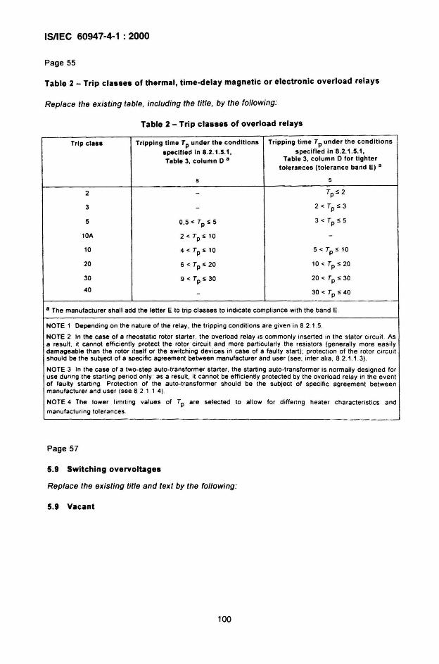
ISIIEC 60947-4-1 : 2000
Page 55
Table 2 - Trip classes of thermal, time-delay magnetic or electronic overload relays
Replace the existing table, including the title, by the following:
Table 2 - Trip classes of overload relays
Trip class
2
3
5
lOA
10
20
30
40
Tripping time Tp under the conditions
specified In 8.2 .1 .5.1,Table 3, column D a
s
0,5 < Tp S 5
2<TpSl0
4<TpSl0
6<Tps20
9<TpS30
Tripping t ime Tp under the conditions
specified in 8.2.1 .5.1 ,Table 3. column D for tighter
tolerances (tolerance band E) a
5
TpS 2
2 < Tp S 3
3<TpS5
5 < Tp S 10
10 < Tp S 20
20 < Tp S 30
30 < Tp S 40
a The manufacturer shall add lhe letter E to lrip classes to indicate compliance wilh lhe band E.
NOTE 1 Depending on lhe natu re of lhe relay , lhe tripping conditions are given in 8.2.1.5.
NOTE 2 In the case of a rheostatic rotor starter, the overload relay is commonly inserted in the stator circuit. Asa result, .1 cannot eff,cienlly protect lhe rotor clrcult and more particularly lhe resistors (generally more easilydamageable lhan lhe rotor ,tself or the switch ing dev ices in case of a faulty start) ; p rotection of the rotor circuitshou ld be the subject of a spec ific agreement between manufacturer and user (see , inter alia , 8.2.1.1 .3) .
NOTE 3 In the case of a two-step auto-transformer starter, the starting auto -transtcrmer is normally des igned foruse dunng the starting penod only : as a result, it cannot be efficiently protected by the overload relay in the eventof faulty starting Protecllon of the auto-transformer should be the subject of spec ific agreement betwee.nmanufacturer and user (see 82 1 1 4).
NOTE 4 The lower limning values of Tp are selected to allow for differing heater characteristics and
manufacturing tolerances
Page 57
5.9 Switching overvoltages
Replace the existing title and text by the following:
5.9 Vacant
100
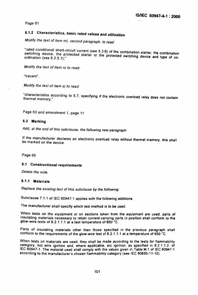
ISIIEC 60947-4-1 : 2000
Page 61
6.1.2 Characteristics. basic rated values and utilization
Modify the text of item m), second paragraph, to read:
· ra!ed .cond i t i ~na l short-circu it current (see 5.3.6) of the combination starter the combinationsWI!chl~g device, the protected starter or the protected switching device ' and type of coordination (see 8.2.5.1 ) ;" -
Modify the text of item n) to read:
"Vacant".
Modify the text of item s) to read:
·characteristics according to 5.7, specifying if the electronic overload relay does not containthermal memory."
Page 63 and amendment 1, page 11
6.2 Marking
Add, at the end of this subclause, the foffowing new paragraph:
If the manufacturer declares an electronic overload relay without thermal memory , this shallbe marked on the device.
Page 65
8.1 Constructional requirements
Delete the note .
8.1.1 Materials
Replace the existing text of this subclause by the foffowing:
SUbclause 7.1.1 of lEG 60947-1 applies with the following additions.
The manufacturer shall specify which test method is to be used.
When tests on the equipment or on sections taken from the equipment are used. parts ofinsulating materials necessary to retain current-carrying parts in position shall conform to theglow-wire tests of 8.2.1.1.1 at a test temperature of 850 ·C .
Parts of insulating materials other than those specified in the previous paragraph shallconform to the requirements of the glow-wire test of 8.2.1.1.1 at a temperature of 650 ·C .
When tests on materials are used , they shall be made according to the tests for flammabilitycategory, hot wire ignition and , where applicable, arc ignit ion , as specified in 8.2.1.1.2. ofIEC 60947 -1. The material used shall comply with the values given in Table M.l of IEC 60947-1according to the manufacturer's chosen flammab ility category (see IEC 60695-11 -10) .
101
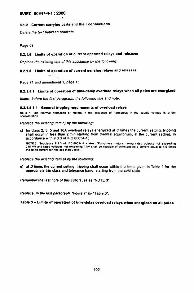
ISIIEC 60947-4-1 : 2000
8.1.2 Current-carrying parts and their connections
Delete the text between brackets.
Page 69
8.2.1.5 Limits of operation of current operated relays and releases
Replace the existing title of this subclause by the following:
8.2.1.5 Limits of operation of current sensing relays and releases
Page 71 and amendment 1, page 15
8.2.1.5.1 Limits of operation of time-delay overload relays when all poles are energized
Insert. before the first paragraph. the following title and note :
8.2.1 .5.1.1 General tripping requirements of overload relaysNOTE 1 The thermal protection of motors in the presence of harmonics in the supply voltage is underconsideration.
Replace the existing item c) by the following:
c) for class 2, 3, 5 and 10A overload relays energized at C times the current setting, trippingshall occur in less than 2 min starting from thermal equilibrium, at the current setting, inaccordance with 9.3.3 of IEC 60034-1 :NOTE 2 Subdause 93.3 of lEe 60034-1 states: 'Polyphase motors having rated outputs not exceeding315 kW and rated voltages not exceed ing 1 kV shall be capable of withstanding a current equal to 1,5 timesthe rated current for not less than 2 min.' .
Replace the existing item e) by the follow ing:
e) at 0 times the current setting, tripp ing shall occur with in the limits given in Table 2 for theappropriate trip class and tolerance band , starting from the cold state .
Renumber the last note of this subclause as "NOTE 3".
Replace, in the last paragraph. "figure r by "Table 3".
Table 3 - Limits of operation of time-delay overload relays when energized on all poles
102
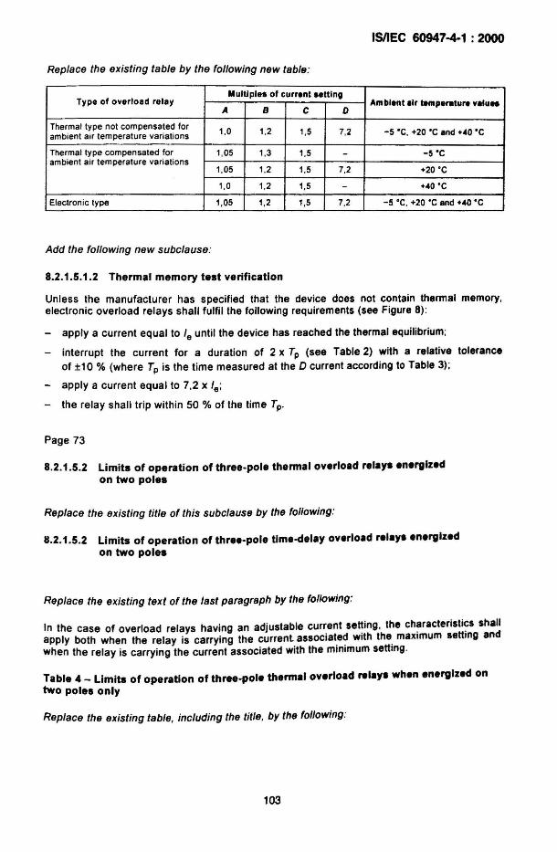
ISIIEC 60947-4-1 : 2000
Replace the existing table by the following new table:
Type of overload relayMultiple. of current .etting
A B C DAmbient Ilr temperttufl vllu..
Thermal type not compensated for 1,0 1,2 1.5 7.2 -5 ·C. +20 'C Ind +40 'Cambient air temperature variat ions
Thermal type compensated for 1,05 1,3 1.5 - -S'Cambient air temperature variat ions
1,05 1.2 1,5 7,2 +20 ' C
1,0 1.2 1.5 - +40 'C
Electronic type 1,05 1,2 1,5 7,2 -5 'C , +20 'C and +40 'C
Add the following new subclause:
8.2.1.5.1.2 Thermal memory test verification
Unless the manufacturer has specified that the device does not contain thermal memory.electronic overload relays shall fulfil the following requirements (see Figure 8):
- apply a current equal to Ie until the device has reached the Ihermal equilibrium :
- interrupt the current for a duration of 2 x Tp (see Table 2) with a relative toleranceof ±10 % (where Tp is the time measured at the D current according to Table 3);
- apply a current equal to 7,2 x Ie:
- the relay shall trip within 50 % of the time Tp.
Page 73
8.2.1.5.2 Limits of operation of three-pole thermal overload relays energizedon two poles
Replace the existing title of this subclause by the following :
8.2.1.5.2 Limits of operation of three-pole tlme-delay overload relays energizedon two poles
Replace the existing text of the last paragraph by the following:
In the case of overload relays having an adjustable cur~ent se~ing. the ch~racterjsti~s shallapply both when the relay is carrying the current associated with the maximum settmg andwhen the relay is carrying the current associated with the minimum setting.
Table 4 _ Limits of operation of three-pole thermal overload relays when energized ontwo poles only
Replace the existing table, including the title , by the following :
103
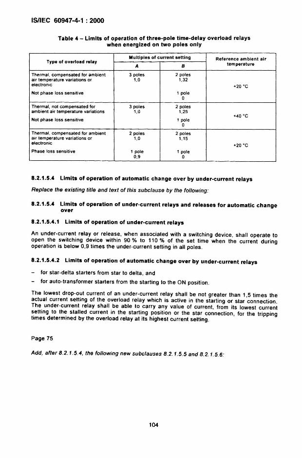
ISIIEC 60947-4-1 : 2000
Table 4 - Limits of operation of three-pole time-delay overload relayswhen energized on two poles only
Multiples of current setting Reference ambient airType of overload relay
A B temperature
Thermal , compensated for ambient 3 poles 2 polesair temperature var iations or 1,0 1,32electronic +20 ' C
Not phase loss sens itive 1 pole0
Thermal, not compensated for 3 poles 2 polesambient air temperature variations 1,0 1,25
+40 ' CNot phase loss sensitive 1 pole
0
Thermal , compensated for ambient 2 poles 2 polesair temperature variations or 1,0 1,15electronic +20 ' CPhase loss sensitive 1 pole 1 pole
0,9 0
8.2.1.5.4 Limits of operation of automatic change over by under-current relays
Replace the existing title and text of this subclause by the following:
8.2.1.5.4 Limits of operation of under-current relays and releases for automatic changeover
8.2.1.5.4.1 Limits of operation of under-current relays
An under-current relay or release, when associated with a switching device. shall operate toopen the switching device with in 90 % to 110 % of the set time when the current duringoperation is below 0.9 times the under-current setting in all poles ,
8.2.1.5.4.2 Limits of operation of automatic change over by under-current relays
for star -delta starters from star to delta , and
- for auto-transformer starters from the starting to the ON position ,
The lowest drop-out current of an under -current relay shall be not greater than 1.5 times theactual current setting of the overload relay which is active in the starting or star connection.The under-current relay shall be able to carry any value of current. from its lowest currentsetting to the stalled current in the start ing position or the star connection, for the trippingtimes determined by the overload relay at its highest current setting.
Page 75
Add, after 8.2 .1.5 .4, the following new subclauses 8.2.1.5 .5 and 8.2.1.5.6:
104
ISIIEC 60947-4·1 : 2000
8.2.1.5.5 Limits of operation of stall relays
A stall relay, when associated with a switching device. shall operate to open the switchingdevice within 80 % to 120 % of the set time (stall inhibit time) or within the accuracy specifiedby the manufacturer, when :
a) current sens ing relays : the current is 20 % higher than the set stall current value;
EXAMPLE: Set current of the stall relay : 100 A; set time : 6 s: accuracy : f10 %, the relay shall trip within 5,4.and 6,6 s when the curre nt is equal to or greater than 100 A x 1.2 = 120 A.
b) rotation sensing relays : an input signal indicating no motor rotation exists .
8.2.1.5.6 Limits of operation of jam relays and releases
A jam relay or release , when associated with a switching ,device, shall operate to open thesWitching device within 80 % to 120 % of the set time (jam inhibit time) or within the accuracyspecified by the manufacturer, when the current is above 1,2 times the set current value ofthe jam relay. during running after completion of the starting .
8.2.2 Temperature rise
Replace the existing text of the first paragraph by the following:
The requirements of 7.2.2 of lEG 60947-1 apply to contactors and starters in a clean, newcondition .
Add, after the note , the following new subclauses 8.2.2.1, 8.2.2.2 and 8.2.2.3:
8.2.2.1 Terminals
Subclause 7.2 .2 .1 of lEG 60947-1 applies.
8.2.2.2 Accessible parts
Subclause 7.2.2.2 of lEG 60947-1 applies.
8.2.2.3 Ambient air temperature
Subclause 7.2.2 .3 of lEG 60947-1 applies .
Table 5 _ Temperature rise limits for Insulated coils In aIr and In 011
Modify the heading of the first column to read:
'Class of Insulating material (according to lEG 60085)"
Delete the existing note .
105
ISIIEC 60947-4-1 : 2000
Page 87
8.2.5.1 Performance under .hort-circuit condition. (rated conditional short-circuitcurrent)
Modify the first paragraph to read:
• ... by short-circuit protective device(s) (SCPD(s.», .combi~ation starters, .~ombinati?nswitching devices , protected starters and protected sWltchmg devices shall be verified by ...
Page 89
8.2.6 Switching overvoltage.
Replace the existing title and text by the fol/owing:
8.2.6 Vacant
8.2.7 Additional requirements for combination .tarters and protected .tarters suitablefor Isol.tion
Modify the title to read:
8.2. '1 Additional r.qulrements for combination starters, combination SWitchingd.vlces, protect.d starters and protected switching device••uitable for isolation
Page 93
'.1 .3 Routln. tests
Correction in French only.
Page 99 and amendment 1, page 19
'.3.3.2.2 R.lay••nd rei•••••
Replace, in item a), the reference to subclause "8.2.1.3' by "8.2.1.3 .1'.
Replace the existing title and text of item c) by the fol/owing :
c) Thermal, electronic and time-delay magnetic overload relays
Overload relays and starters shall be connected using conductors in accordance withTables 9, 10 and 11 of IEC 609-i7-1 for test currents corresponding to:
- 100 % of the current setting of the overload relay for overload relays of trip classes 2,3, 5 and 10 A for all overload relay types (see Table 2) and 10, 20, 30 and 40 forelectronic overload relay types;
106
ISIIEC 60947-4-1 : 2000
- 125 % of the current setting of the overload relay for thermal overload relays of tripclasses 10, 20, 30 and 40 (see Table 2) and for overload relays for which a maximumtripping time greater than 40 s is spec ified (see 5.7.3).
It shall be verified that relays and releases operate according to the requirements of8.2.1 .5.1 with all poles energized.
Moreover, the characteristics defined in 8.2.1.5.1 shall be verified by tests at -5 ·C ,+20 ·C, +40 ·C and may be verified at minimum and maximum temperatures given by themanufacturer if larger. However, for relays or releases declared compensated for ambienttemperature, in case of temperature range declared by the manufacturer larger than thosegiven in Figure 7, the characteristics at -5 ·C and/or +40 ·C need not be verified if, whentested at the declared minimum and maximum temperatures, the corresponding trippingcurrent values are in compliance with the limits specified for -5 ·C and/or +40 °C in thatfigure .
For electronic overload relays, the thermal memory test verification of 8.2.1.5.1.2 shall becarried out at +20 ·C.
Three-pole thermal or electronic overload relays energized on two poles only shall betested as stated in 8.2.1.5.2 on all combinations of poles and at the maximum andminimum current sett ings for relays with adjustable settings.
Replace the existing title and text of item e) by the following:
e) Under-current relays
The limits of operation shall be verified in accordance with 8.2.1.5.4 .1.
Add, after item e), the following new items f) to h):
f} Under-current relays in automatic Change-over
The limits of operation shall be verified in accordance with 8.2.1.5.4.2.
g) Stall relays
The limits of operation shall be verified in accordance with 8.2.1.5.5.
For current sens ing stall relays , the verification shall be made for the minimum and for themaximum set current values and for the minimum and maximum stall inhib it time (foursettings) .
For stall relays operating in conjunction with a rotation sensing mean, the verificat ion shallbe made for the minimum and maximum stall inhibit time. The sensor can be simulated byan appropriate signal on the sensor input of the stall relay .
h) Jam relays
The limits of operation shall be verified in accordance with 8.2 .1.5.6 .
The verification shall be made for the minimum and for the maximum set current vatuesand for the minimum and maximum jam inhibit time (four settings) .
For each of the four settings, the test shall be made under the follow ing conditions :
_ apply a test current of 95 % of the set current value . The jam relay shall not trip ;
_ increase the test current to 120 ." of the set current value . The jam relay shall tripaccording to the requirements given in 8.2.1.5.6 .
107
ISIIEC 60947-4-1 : 2000
Page 109
9.3.3.5.4 Switching overvoltages
Replace the existing title and text by the following:
9.3.3 .5.4 Vacant
Page 115 and amendment 1, page 21
9.3.3.6.6 Behaviour of the contactor or starter during, and its condition after,the conventional operational performance tests
Add. at the end of this subclause, the following:
For equipment provided with mirror contacts, the additional test of F.7.3 shall be carried out.
Page 117
9.3.4.1.6 Test procedure
Modify the existing text of the second paragraph to read:
"The contactor or the starter and its associated SCPO, or the combination starter, thecombination switch ing device , the protected starter or the protected switching device , shall bemounted and connected ...•
9.3.4.2 Conditional short-circuit current of contactors, starters, combination startersand protected starters
Modify the title to read :
9.3.4.2 Conditional short-circuit current of contactora, starters, combination starters,combination switching devices, protected starters and protected switchingdevices
Modify the existing text of the first paragraph to read :
"The contactor or starter and the associated SCPO, or the combination starter, thecombination switching device, the protected starter or the protected switching device, shall besubjected to the tests given ...•
Page 119
9.3.4.2.1 Test at the prospective current "t"
Modify the existing text of the second paragraph to read:
"The contactor or starter and the associated SCPO, or the combination starter", thecomb inat ion switching device . the protected starter or the protected switching device. shallthen be connected ...•
108
ISIIEC 60947-4-1 : 2000
9.3.4.2.2 Test at the rated conditional short-circuit current Iq
Replace the existing text of the third paragraph as follows:
Th~ c~ntactor .or starter and the associated SCPO, or the combination starter, the combinationsWltchmg device,. the. protected starter or the protected sWitching device, shall then beconnected to the CirCUIt.
Replace, on page 121, item b), the existing text of the second paragraph, as follows:
If, in the case of a combination starter, a combination switching device, a protected starteror a protected switching device , the switching device of the SCPO complies withIEC 60~47~2 or IEC 60947-3 and has a short-circuit breaking capacity or rated conditionalshort-circuit current less than the rated conditional short-circuit current of the combinationstar.ter, the combination SWitching device, the protected starter or the protected SWitchingdev ice , the follOWing additional test shall be made.
Page 121
9.3.4.2.3 Results to be obtained
Modify the existing text of the first paragraph to read:
"The contactor, starter, or the combination starter, the combination switching device, theprotected starter or the protected switching device, shall be considered to have passed thetests at ... "
MOdify the existing text of paragraph "A" to read :
"A The faull current has been successfully interrupted by the SCPO, the combination starteror the combination switching device and the fuse or fusible element ....
Replace the sentence between paragraph "0 " and paragraph "E" by the following:
Both types of co-ordination (combination starters, combination switching devices, protectedstarters and protected switching devices only) :
MOdify the existing text of paragraph "G" to read :
"G If a circuit-breaker with rated ultimate short-circuit breaking capacity less than the ratedconditional short-circuit current assigned to the combination starter. the combinationswitching device. the protected starter or the protected switching device is employed. thecircuit-breaker ..."
Modify. on page 123 and amendment 1, page 23. the existing text of paragraph "L" to read:
"L The adequacy of the insulation in accordance with 8.3.3.4.1. item 4). of. IE~ 60947-1 shallbe verified by a dielectric test on the contactor. the starter. the combmah.on .starter. .thecombination switching device, the protected starter or the protected SWitching deVIce.using a power frequency withstand voltage of twice the rated operational vo"age Ue butnot less than 1 000 V.
In the case of combination starters. combination switch ing dev ices . protected startersand protected switching devices, additional tests accord ing to 8.3.3.4.1, item 3). ofIEC 60947-1 shall be made ... "
109
ISIIEC 60947-4-1 : 2000
Page 125
9.3 .6.2 Operation and operating limits
Replace the existing text of the third paragraph by the following:
Tests shall be made to verify the calibration of relays. In the case of a time delay overloadrelay , this may be a single test with all poles equally energized at a multiple of the currentsett ing, to check that the tripping time conforms (within tolerances) to the curves supplied bythe manufacturer; in the case of an instantaneous magnetic overload relay, the test shall becarried out at 1,1 times the current setting. For under-current relays, stall relays and jamrelays, tests shall be carried out to verify the proper operation of these relays (see 8.2.1 .5.4 ,8.2.1 .5.5 and 8.2.1.5.6).
Page 127
Table 13 - EMC immunity tests
Replace, in the first column, "IEC 61000-4-5" by "IEC 61000-4-5 a"
Introduce, in the table , the following new footnote 8:
a Nol applicable for ports with a rated voltage of 24 V d.c . or less.
Page 137
Figure 3 - Typical variants of combination starters (see 3.2.7) and protected starters(see 3.2.8)
Replace the title by the following:
Figure 3 - Typical variants of protected starters (see 3.2.7), combination starters(see 3.2.8), protected SWitching devices (see 3.2.26) and combination SWitching devices(see 3.2.27)
110
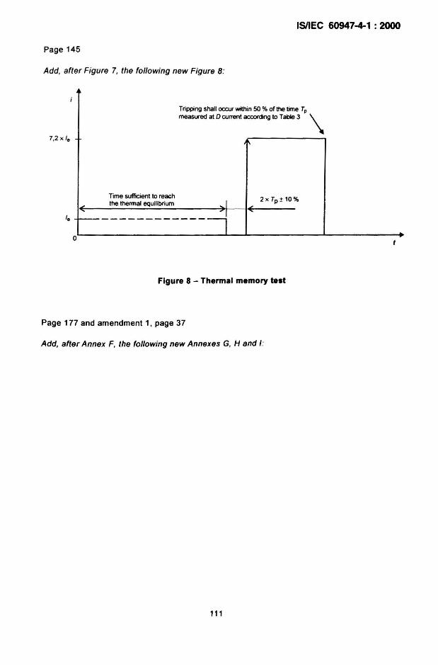
ISIIEC 60947-4-1 : 2000
Page 145
Add, after Figure 7, the following new Figure 8:
7,2 x /e
Tripping shall occur within 50 % of the time Tpmeasured at 0 current according to Table 3 \
"
Time sufficient to reachthe thennal equilibrium
.....
Ie 1----------------o
(2x Tp ± 10%
Figure 8 - Thermal memory test
Page 177 and amendment 1, page 37
Add, after Annex F, the following new Annexes G, H and I:
111
ISIIEC 60947-4-1 : 2000
Annex G(informative)
Rated operational currents and rated operational powersof switching devices for electrical machines
G.1 General
The given values in Table G.1 are guide values for the relationship between rated operationalcurrents and rated operational powers . They should be considered for use when informationconcerning products has to be given to the customers.
The statements of this annex are applicable to all kind of switching devices for electricalmachines.
The figures are harmonized within the lEe and therefore state the basis for all the productinformation given by the manufacturer.
The values given in the Table G.1 are typical rated operational currents of motors for thecorresponding rated operational powers .
If the devices are in compliance with these values. they are able to switch on and off most ofthe existing electrical machines .
These values state a harmonized guideline for design of switching devices.
G.2 Rated operational powers and rated operational currents
Rated operational power is linked with individual rated operational currents at differentvoltages according to Table G.1 .
The guide values for rated operational currents are determined on the basis of a four-pole
squirrel-cage motor at 400 V, 1 500 min-1 and 50 Hz. The rated operational currents for theother voltages are calculated on the basis of values at 400 V.
112
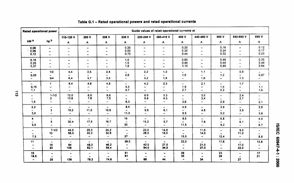
-"-"(0)
rable G.1 - Rated operational powers and rated operational currents
Rated opel'lltiona' power Guide value. of rated operational current. at
110·120 V 200 V 208 V 230 V 220·240 V 380-415 V 400 V 440-480 V 500 V 550·600 V 690 V
kW' hp II A A A A A A A A A A A
0,06 - - - - 0,35 - - 0,20 - 0,16 - 0,12. 0,09 - - - - 0,52 - - 0,30 - 0,24 - 0,17
0,12 - - - - 0,70 - - 0,44 - 0,32 - 0,23
0,18 - - - - 1,0 - - 0,60 - 0,48 - 0,350,25 - - - - 1.5 - - 0,85 - 0,68 - 0,490,37 - - - - 1,9 - - 1,10 - 0,88 - 0,64
- 1/2 .,. 2,5 2,. - 2,2 1,3 - 1,1 - 0,9 -0.55 - - - - 2,6 - - 1,5 - 1,2 - 0,87- 3/. 6,. 3,7 3,5 - 3,2 1,8 - 1,6 - 1,3 -- 1 8,. . ,8 . ,6 - . ,2 2,3 - 2,1 - 1,7 -0,75 - - - - 3,3 - - 1,9 - 1,5 - 1,11,1 - - - - 4,7 - - 2,7 - 2,2 - 1,6
- 1-1/2 12,0 6 ,9 6,6 - 6 ,0 3,3 - 3,0 - 2,. -- 2 13,6 7,8 7,5 - 6 ,6 4.3 - 3,4 - 2,7 -1,5 - - - - 6,3 - - 3,6 - 2,9 - 2,1
2,2 - - - - 8,5 - - 4,9 - 3,9 - 2,8- 3 19,2 11,0 10,6 - 9,6 6,1 - 4,8 - 3.9 -3,0 - - - - 11,3 - - 6,5 - 5,2 - 3,8
• - - - - 15 - - 6,5 - 6,8 - 4,9- 5 30,. 17,5 16,7 - 15,2 9,7 - 7,6 - 6,1 -5,5 - - - - 20 - - 11,5 - 9,2 - 6.7
- 7-1/2 4.,0 25,3 24,2 - 22,0 14,0 - 11,0 - 9,0 -- 10 56,0 32,2 30,8 - 28,0 18,0 - 14,0 - 11,0 -7,5 - - - - 27 - - 15,5 - 12,. - 8.9
11 - - - - 38,0 - - 22 ,0 - 17,6 - 12,8- 15 U 48,3 4&,2 - .2,0 27,0 - 21,0 - 17,0 -- 20 108 82.1 59,4 - 64.0 34,0 - 27,0 - 22,0 -
15 - - - - 51 - - 28 - 23 - 171a ,5 - - - - 81 - - 35 - 211 - 21- 25 138 78,2 7.,a - ea ... - 34 - 27
~moen
i~...N
§
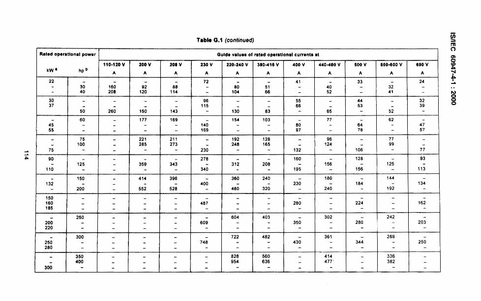
.........~
TableG.1 (continued)
Rated operatlona' power Guide valu.. of rlted operltlonll curre nt. It
110·120 V 200 V 201 V 230 V 220-240 V 310-4111 V 400 V 440-480 V 1100 V 5110-600 V lliO VkW· hp b
'" '" '" '" '" '" A A A A A
22 - - - - 72 - - 41 - 33 - 24- 30 160 92 88 - 80 51 - 40 - 32 -- 40 208 120 114 - 104 66 - 52 - 41 -
30 - - - - 96 - - 55 - 44 - 3237 - - - - 115 - - 66 - 53 - 39
50 260 150 143 - 130 83 - 65 - 52 -- 60 - 177 169 - 154 103 - 77 - 62 -
45 - - - - 140 - - 80 - 64 - 4755 - - - - 169 - - 97 - 76 - 57
- 75 - 221 211 - 192 128 - 96 - 77 -- 100 - 285 273 - 248 165 - 124 - 99 -75 - - - - 230 - - 132 - 106 - 77
90 - - - - 278 - - 160 - 128 - 93- 125 - 359 343 - 312 208 - 156 - 125 -
110 - - - - 340 - - 195 - 156 - 113
- 150 - 414 396 - 360 240 - 180 - 144 -132 - - - - 400 - - 230 - 184 - 134
- 200 - 552 528 - 480 320 - 240 - 192 -150 - - - - - - - - - - - -160 - - - - 487 - - 280 - 224 - 162185 - - - - - - - - - - - -- 250 - - - - 604 403 - 302 - 242 -
200 - - - - 609 - - 350 - 280 - 203220 - - - - - - - - - - - -
- 300 - - - - 722 482 - 361 - 289 -250 - - - - 748 - - 430 - 344 - 250280 - - - - - - - - - - - -
- 350 - - - - 828 560 - 414 - 336 -- 400 - - - - 954 636 - 477 ' - 382 -
300 - - - - - - - - - - - -
~mo0'1o~";'I~I....
I\)
g
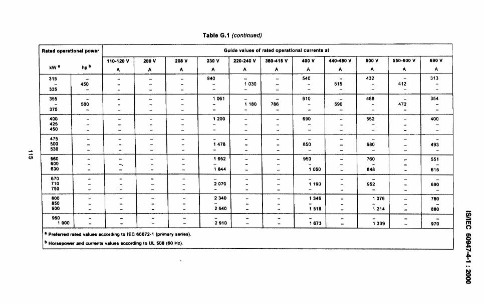
~
~
UI
Table G.1 (continued)
Rated operational power Guide value. of rated operational currents at
110·120 V 200 V 208 V 230 V 220·240 V 380-415 V 400 V 440-480 V 500 V 550-600 V 690 V
kW· hp b A A A A A A A A A A A
315 - - - - 940 - - 540 - 432 - 313
- 450 - - - - 1030 - - 515 - 412 -335 - - - - - - - - - - - -355 - - - - 1061 - - 610 - 488 - 354
- 500 - - - - 1 180 786 - 590 - 472 -375 - - - - - - - - - - - -400 - - - - 1200 - - 690 - 552 - 400425 - - - - - - - - - - - -450 - - - - - - - - - - - -
475 - - - - - - - - - - - -500 - - - - 1478 - - 850 - 680 - 493530 - - - - - - - - - - - -560 - - - - 1652 - - 950 - 760 - 551600 - - - - - - - - - - - -630 - - - - 1 8-44 - - 1060 - 8-48 - 615
670 - - - - - - - - - - - -710 - - - - 2070 - - 1 190 - 952 - 690750 - - - - - - - - - - - -800 - - - - 2340 - - 1346 - 1076 - 780850 - - - - - - - - - - - -900 - - - - 2640 - - 1518 - 1214 - 880
950 - - - - - - - - - - - -, 000 - - - - 2910 - - '673 - ' 339 - 970
• Pref~ reted velues eccordlng to lEe 60072 - ' (primery series) .
bHor~ and cu"ents values eccoRllng to Ul 508 (60 Hz) .
~mn
I-§
IsnEC 60947-4-1 : 2000
Annex H(normative)
Extended functions within electronic overload relays
H.1 Scope
H.1.1 General
This annex is intended to cover extended functions included in electronic overload relays notdirectly related to the overload protection.
All functions included in these overload relays not covered by this standard, should complywith the requirements of relevant standards specifically covering these functions (e .g.lEG 60255, lEG 60947-5 series) .
This annex applies only to electronic relays intended for use in a.c. circuits.
H.1.2 Residual current function
Devices reacting to residual differential currents are used as protective systems. Suchdevices are frequently used in conjunction with or as an integral part of electronic overloadrelays to detect residual current in the installation or the motor in order to provide additionalprotection against fire and other hazards which may develop as a result of an earth fault of alasting nature which cannot be detected by the over-current protective function . Thebehaviour due to the presence of a d.c. component is not cons idered .
H.2 Definitions
For the purposes of this annex , the following definitions apply.
H.2.1electronic overload relay with residual current (earth faUlt) functionmultipole electronic relay which operates when the vectorial sum of the currents flowing in themain circuit has increased above a predetermined value in accordance with specifiedrequirements
H.2.2electronic overload relay with current or voltage asymmetry functionelectronic overload relay which operates in the case of current or voltage magnitudeunbalance in accordance with specified requirements
H.2.3electronic overload relay with phase reversal functionmultipole electronic overload relay which operates in the case of improper phase sequence atthe line side of the starter in accordance with specified requirements
H.2.4over-voltage sensitive electronic overload relayelectronic overload relay which operates in the case of overload and when the voltage hasincreased above a predetermined value in accordance with specified requirements
116
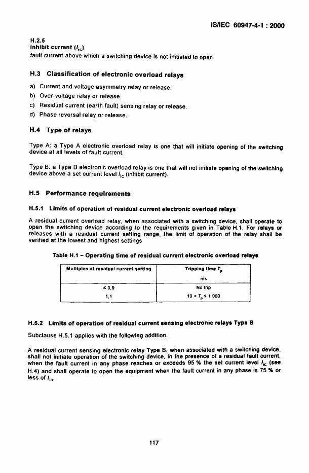
ISIIEC 60947-4-1 : 2000
H.2.5inhibit current (/ ic )
fault current above which a switching device is not initiated to open
H.3 Classification of electronic overload relays
a) Current and voltage asymmetry relay or release .
b) Over-voltage relay or release.
c) Residual current (earth fault) sensing relay or release .
d) Phase reversal relay or release.
H.4 Type of relays
Type A: a Type A electronic overload relay is one that will initiate opening of the switchingdevice at all levels of fault current.
Type B: a Type B electronic overload relay is one that will not initiate opening of the switchingdevice above a set current level/ic (inhibit current) .
H.5 Performance requirements
H.5.1 Limits of operation of residual current electronic overload ,.'ay.
A residual current overload relay, when associated with a switching device, shall operate toopen the switching device according to the requirements given in Table H.1. For relays orreleases with a residual current setting range, the limit of operation of the relay shall beverified at the lowest and highest settings
Table H.1 - Operating time of residual current electronic overload ,.'aya
Multiples of residual current setting Tripping time Tp
ms
s 0,9 No trip
1,1 10 < Tp S 1 000
H.5.2 Limits of operation of residual current .ensing electronic relay. Type B
Subclause H.5.1 applies with the following addition.
A residual current sensing electronic relay Type B, when associated with a switching device,shall not initiate operation of the switching device, in the presence of a residual fault current.when the fault current in any phase reaches or exceeds 95 % the set current level 'ie (seeH.4) and shall operate to open the equipment when the fault current in any phase is 75 % orless of 'ic'
117
ISI1EC 60947-4-1 : 2000
H.5.3 Limits of operation of voltage asymmetry relays
A voltage asymmetry relay, when associated with a switching device , shall operate to openthe switching device within 120 % of the time setting and s~all operate to p.revent the closingof the switching device when the voltage asymmetry IS above 1,2 times the voltageasymmetry setting .
H.5.4 Limits of operation of phase reversal relays
A phase reversal relay, when associated with a switching device, shall permit the clos ing ofthe equipment when the voltage sequence of phases on the line side of the starter is thesame as the voltage sequence settlng . After interchanging two phases, the phase reversalrelay shall prevent the closing of the equipment.
H.5.5 Limits of operation of current asymmetry relays
A current asymmetry relay , when associated with a SWitching device, shall operate to openthe equipment within 120 % of the time setting when the current asymmetry is above 1,2times the current asymmetry setting.
H.5.6 Limits of operation of over-voltage relays and releases
a) Operating voltage
An over-voltage relay or release, when associated with a switching device, shall operateto open the equipment and shall operate to prevent the closing of the equipment when thesupply voltage is above the set value, if any, or above 110 % of the rated voltage of therelay or release for a defined duration.
b) Operating time
For a lime-delay over-voltage relay or release, the time-lag shall be measured from theinstant when the voltage reaches the operating value until the instant when the relay orrelease actuates the tripping device of the equipment,
H.6.1 Limits of operation of residual current sensing electronic relays Type A
The limits of operation shall be in accordance with H.5.1 and verified as follows.
For overload relays with an adjustable residual current setting, the test shall be made at theminimum and at the maximum current settings.
The test circuit shall be in accordance with Figure H.1. The test shall be made at a powerfactor ~ 0,8, at any convenient voltage and any convenient current.
The .test .circuit being calibrated ~t each of the values of the residual operating currentspecified In the Table H.1, as applicable, and the switch 51 being in the closed position, theresidual current is suddenly established by closing switch 52 .
118
ISIIEC 60947-4-1 : 2000
H.6.2 Limits of operation of residual current sensing electronic relays Type B
Subclause H.6.1 applies with the following addition .
The limits of operation under over-current condition shall be in accordance with H.5.2 andverified as follows .
The test shall be made with a three-phase load, the connections being made according toFigure H.1 . The test shall be made at a power factor ~ 0,8, at any convenient voltage and anyconvenient current in the main poles .
For overload relays with an adjustable residual current setting, the test shall be made at thelowest setting.
For overload relays with an adjustable inhibit current setting lie' the test shall be made at theminimum and at the maximum lie settings.
The impedance Z1 is adjusted so as to let a current flow in the circuit equal to:
a) 95 % the inhibit current lie
The switch S1 being in the closed position, the residual current is established by closingswitch S2.
The overload relay shall not trip .
b) 75 % the inhibit current lie
The switch S1 being in the closed position, the residual current is established by closingswitch S2.
The overload relay shall trip .
H.6.3 Current asymmetry relays
The limits of operation shall be verified in accordance with H.5.5.
H.6.4 Voltage asymmetry relays
The limits of operation shall be verified in accordance with H.5.3.
H.6.5 Phase reversal relays
The limits of operation shall be verif ied in accordance with H.5.4.
H.6.6 Over-voltage relays
The limits of operation shall be verified in accordance with H.5.6.
H.7 Routine and sampling tests
Electronic overload relays with extended functions shall. i~ addition .to tests of 9.3 .~ . besubmitted to additional tests to verify the proper operanon of their relevant additIonalfunctions, according to H.5
119
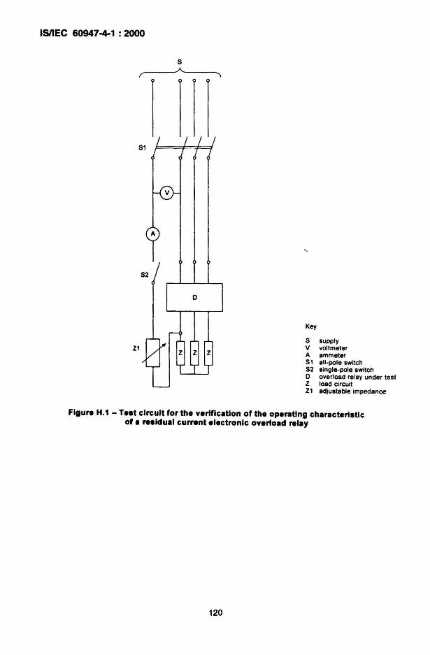
ISIIEC 60947-4-1 : 2000
S,,- A....__~"\
S2
o
Z1
Key
S supplyV voltmeterA ammeterS1 all-pole switchS2 single-pole switcho overload relay under testZ load circuitZ1 adjustable impedance
Figure H.1 - Te.t circuit for the verification of the operating characteristicof a re.ldual current electronic overload relay
120
IsnEC 60947-4-1 : 2000
Annex I(informative)
AC1 contactors for use with semiconductor controlled motor lo.d.
Contactors are often used with semiconductor controllers, starters or drives. Contactors forsuch applications are not intended to make or break motor load currents at the stated systemvoltage.
The intended use is to carry motor currents either on the line or load side of such controllers.and allow the controller to be removed from the line andlor load in the off condition . A furtheruse is to by-pass controllers, usually for the purpose of redu'cing thermal losses, in the up-tospeed condition. In such applications the contactors should be so controlled and interlockedso as to prevent them being opened or closed when the load current is present.
When the above conditions are met, the contactors may be chosen according to categoryAC1 .
Amendment 1, page 37
Bibliography
Replace the reference to lEG 60664-1 :1992 by the following:
IEC 60664-1, Insulation coordination for equipment within low-voltage systems - Part 1:Principles, requirements and tests
Add the following references:
IEC 60072-1, Dimens ions and output series for rotating electrical machines - Part 1: Framenumbers 56 to 400 and (fange numbers 55 to 1080
UL 508, Industrial Control Equipment
121
Bureau of Indian Standards
81S is a statutory institution established under the Bureau of Indian Standards Act, 1986 to promoteharmonious development of the activities of standardization, marking and quality certification of goodsand attending to connected matters in the country.
Copyright
81S has the copyright of all its publications. No part of these publicat ions may be reproduced in anyform without the prior permission in writing of BIS. This does not preclude the free use, in course ofimplementing the standard, of necessary details, such as symbols and sizes, type or gradedesignations. Enquiries relating to copyright be addressed to the Director (Publications), 81S.
Review of Indian Standards
Amendments are issued to standards as the need arises on the basis of comments. Standards arealso reviewed periodically; a standard along with amendments is reaffirmed when such reviewindicates that no changes are needed; if the review indicates that changes are needed , it is taken upfor revision. Users of Indian Standards should ascertain that they are in possession of the latestamendments or edition by referring to the latest issue of 'BIS Catalogue' and 'Standards: MonthlyAdditions'.
This Indian Standard has been developed from Doc: No. ETD 07 (5637).
Amendments Issued Since Publication
Amendment No. Date of Issue
BUREAU OF INDIA~ STANDARDS
Text Affected
Headquarters:
Manak Bhavan, 9 8ahadur Shah Zafar Marg, New Delhi 110 002Telephones: 23230131, 2323 3375, 23239402 Website: www.bis.org.in
Regional Offices:
Central : Manak Bhavan, 9 Bahadur Shah Zafar MargNEW DELHI 110 002
Telephones
{2323761723233841
Eastern: 1/14, C.I.T. Scheme VII M, V.I.P. Road, KankurgachiKOLKATA 700 054
Northern: SCO 335-336, Sector 34.A, CHANDIGARH 160 022
Southern: C.I.T. Campus, IV Cross Road, CHENNAI 600 113
Western: Manakalaya, E9 MIDC, Marol, Andheri (East)MUM8AI 400 093
{23378499,233785612337 8626, 2337 9120
{260 38432609285
{22541216,2254144222542519,22542315
{2832 9295, 2832 78582832 7891, 2832 7892
Branches: AHMEDABAD. BANGALORE. 8HOPAL. BHUBANESHWAR. COIMBATORE. FARIDABAD.GHAZIA8AD. GUWAHATI. HYDERABAD. JAIPUR. KANPUR. LUCKNOW. NAGPUR.PARWANOO. PATNA. PUNE. RAJKOT. THIRUVANANTHAPURAM. VISAKHAPATNAM.
Pooled at PrabhatOffset Press. N_ Delhi-2
Related Documents