ISDN ISDN Lecture 5 Paul Flynn 1

ISDN Lecture 5 Paul Flynn 1. Functional Architecture 2 High-layer Capabilities TE TE or Service Provider Local Functional Capabilities Broadband Capabilities.
Dec 19, 2015
Welcome message from author
This document is posted to help you gain knowledge. Please leave a comment to let me know what you think about it! Share it to your friends and learn new things together.
Transcript

ISDNISDN
Lecture 5
Paul Flynn
1

Functional ArchitectureFunctional Architecture
2
High-layer Capabilities
TETE or
Service Provider
Local Functional Capabilities
Local Functional Capabilities
Broadband Capabilities
Inter-exchange Signaling
Capabilities
64 kbps basedCapabilities
Low-layer capabilities OSIB-ISDN
N-ISDN
SS7User-to-Network Signaling
User-to-User Signaling
I.327

3
Component Functionality ModelComponent Functionality Model
SwitchingSwitching
TransportTransport
AccessAccess
End User
End User
Co
ntr
ol
Co
ntr
ol
Co
ntr
ol
Co
ntr
ol
4
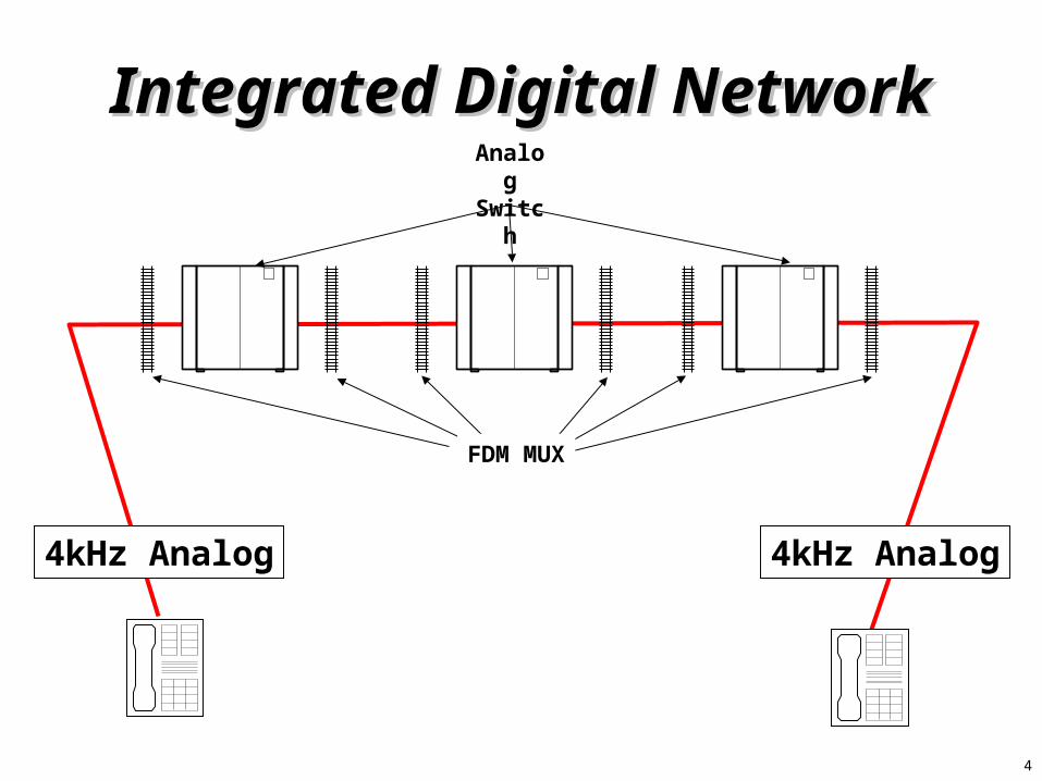
Integrated Digital NetworkIntegrated Digital NetworkAnalog Switch
FDM MUX
4kHz Analog 4kHz Analog
5
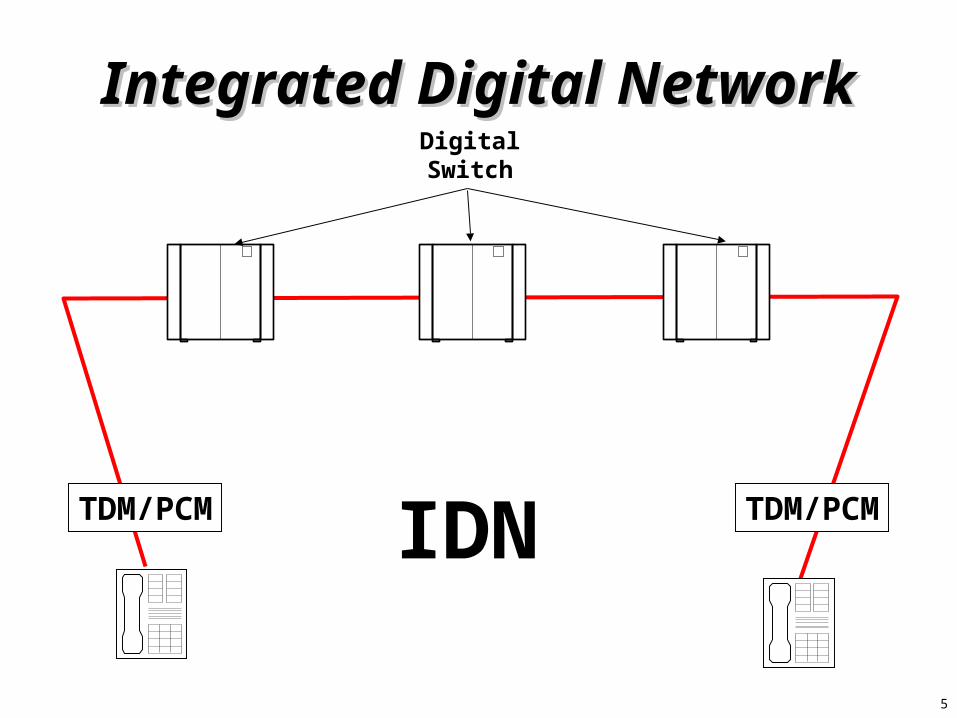
Integrated Digital NetworkIntegrated Digital NetworkDigital Switch
IDNTDM/PCM TDM/PCM
6
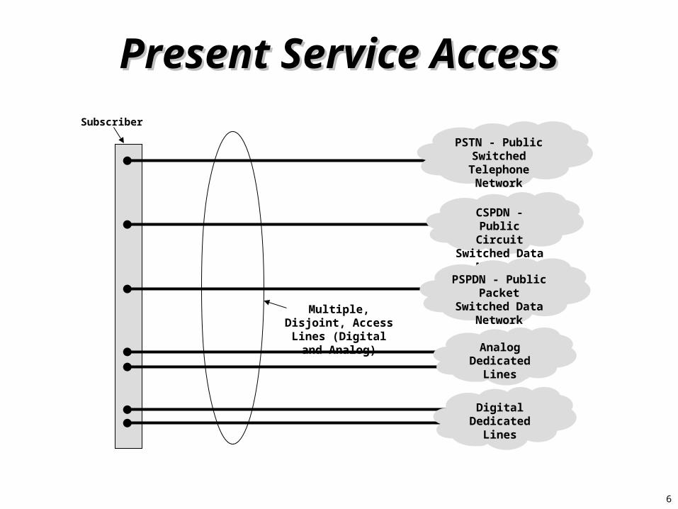
Present Service AccessPresent Service AccessSubscriber
PSTN - Public Switched
Telephone Network
CSPDN - Public Circuit Switched
Data Network
PSPDN - Public Packet Switched
Data Network
Analog Dedicated
Lines
Digital Dedicated
Lines
Multiple, Disjoint, Access Lines (Digital
and Analog)
7
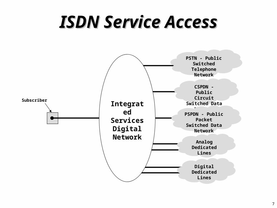
ISDN Service AccessISDN Service Access
Subscriber
PSTN - Public Switched
Telephone Network
CSPDN - Public Circuit Switched
Data Network
PSPDN - Public Packet Switched
Data Network
Analog Dedicated
Lines
Digital Dedicated
Lines
IntegratedServicesDigital
Network
8
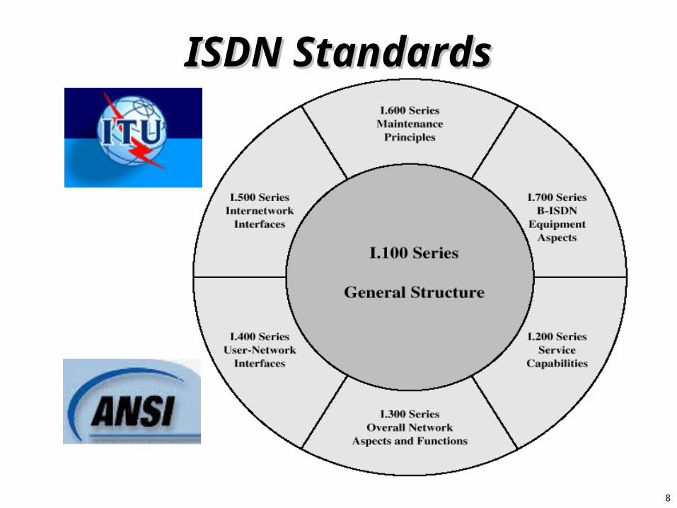
ISDN StandardsISDN Standards

9
Line EncodingLine Encoding2 Binary, 1 Quaternary (2B1Q)2 Binary, 1 Quaternary (2B1Q)
• Two bits select one of four voltage levels• Amplitude and polarity vary• Utilizes up to 392 kHz• NO room for concurrent POTS voice as separate
entity
11
01
00
10
11
00
+3
+1
0
+1
+3

10
ISDN Channel StructureISDN Channel Structure
B-Channel-Bearer Services
D-Channel-Signaling-LBR telemetry-LBR data
H-Channel-HBR Data / Fax-Video-Hi-quality Audio

11
User Interface StructuresUser Interface Structures
Basic Access
BRI:2B+D160 kbps =2 B @ 64k eachD: 16 k+ 16 k overhead
Primary Access
PRI: (NA)23B+D1.544 kbps =23 B @ 64k eachD: 64k+ 8 k framing

12
PRI Channel StructuresPRI Channel Structures• North America Primary Rate Interface (PRI)
– B8ZS Line Coding
– AMI Signals
F
1193 bits (125 Microseconds)
• ITU-T PRI
Time # 0
8 bits
256 bits (125 Microseconds)
Time # 1 Time # 2 Time #16 Time #17 Time #18 Time #31
8 bits 8 bits 8 bits8 bits 8 bits 8 bits
Timing & Sync B-Channels
Time # 0 Time # 1 Time # 2
8 bits 8 bits 8 bits
B-Channels
Time#23
D-Channel
D-Channel

13
ISDN Reference PointsISDN Reference Points& Functional Groups& Functional Groups
• Architecture on subscriber premises is divided functionally into groupings separated by reference points
• Functional Groupings: arrangements of physical equipment or combinations of equipment
• Reference points: conceptual points used to separate groups of functions
• Separation permits development of interface standards at each reference point
14
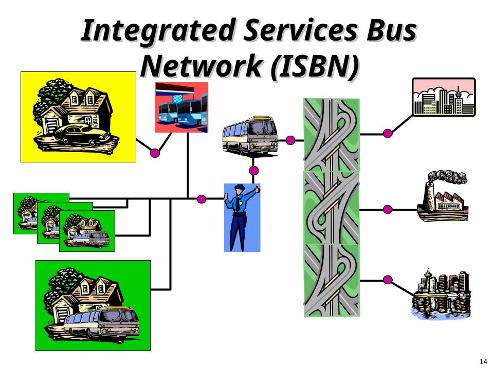
Integrated Services Bus Integrated Services Bus Network (ISBN)Network (ISBN)
15
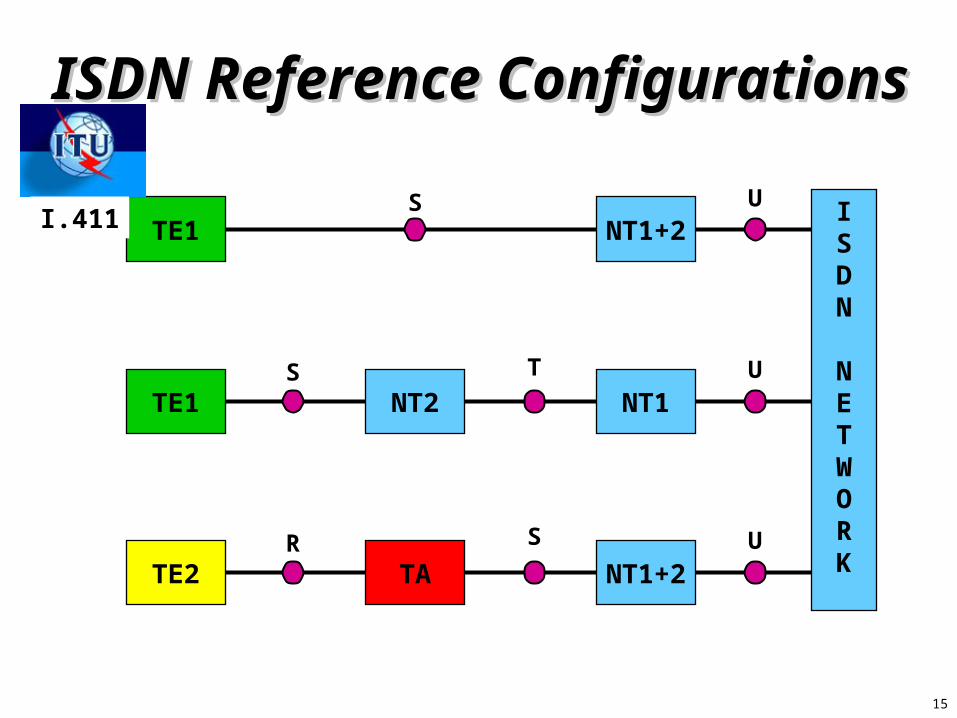
ISDN Reference ConfigurationsISDN Reference Configurations
NT1+2ISDN
NETWORK
NT1
TE2
TE1
TA
NT2
TE1
NT1+2
S
S T
R S
U
U
U
I.411
16
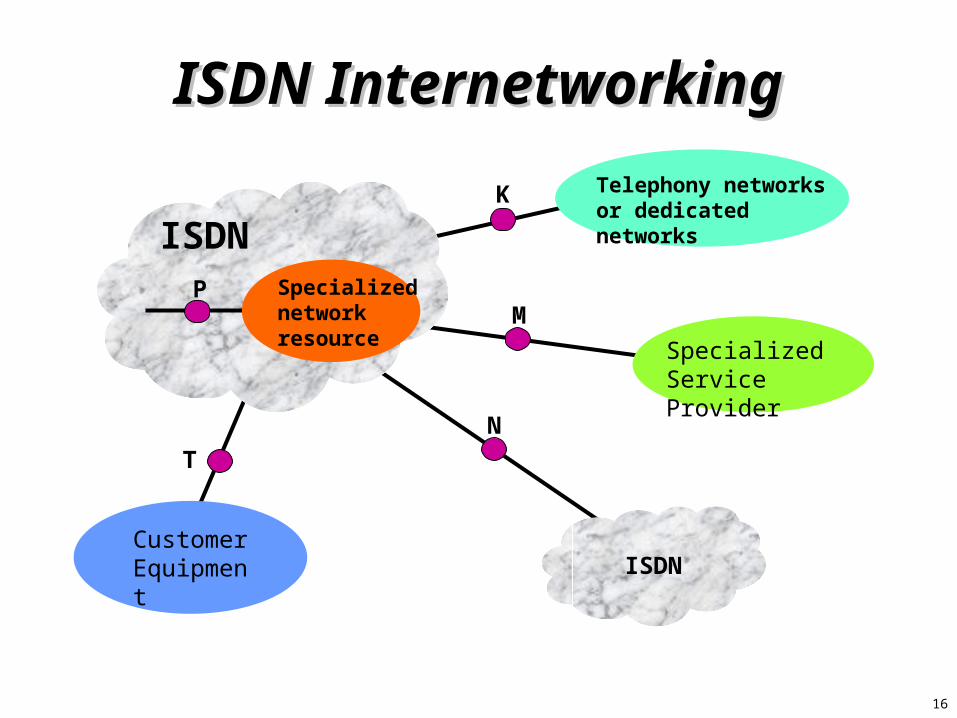
ISDN InternetworkingISDN Internetworking
ISDN
ISDNCustomer Equipment
Specialized Service Provider
Telephony networks or dedicated networks
Specialized network resource
K
M
N
T
P
17
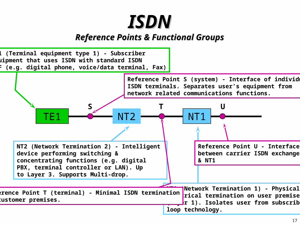
ISDNISDNReference Points & Functional GroupsReference Points & Functional Groups
TE1 NT1NT2
TE1 (Terminal equipment type 1) - Subscriber equipment that uses ISDN with standard ISDN I/F (e.g. digital phone, voice/data terminal, Fax)
NT1 (Network Termination 1) - Physical &Electrical termination on user premises(Layer 1). Isolates user from subscriberloop technology.
NT2 (Network Termination 2) - Intelligent device performing switching & concentrating functions (e.g. digital PBX, terminal controller or LAN). Upto Layer 3. Supports Multi-drop.
S UT
Reference Point S (system) - Interface of individual ISDN terminals. Separates user’s equipment from network related communications functions.
Reference Point T (terminal) - Minimal ISDN terminationon customer premises.
Reference Point U - Interface between carrier ISDN exchange & NT1

18
The U-InterfaceThe U-Interface
G.961, Digital Transmission System for Metallic Local Lines for ISDN Basic Rate Access, 1993
ANSI T1.601, Integrated Services Digital Network – Basic Access Interface for Use on Metallic Loops for Application on the Network Side of the NT, 1992

19
ISDNISDNReference Points & Functional GroupsReference Points & Functional Groups
S UT
R
Reference Point R (rate) - Defines interface tonon-ISDN equipment (e.g. RS232)
S
TE1 NT1NT2
TATE2
TA (Terminal adapter) - interfacesnon-ISDN equipment to NT2
TE2 (Terminal equipment type 2) - Non-ISDNequipment. Require terminal adapter (TA)

20
ISDNISDNReference Points & Functional GroupsReference Points & Functional Groups
T U
R
Reference Point S – Occurs between NT2 capable device and terminal devices.
S
Reference Point T – Same description as S, occurs between NT1 and NT2 devices.
TE1 NT2+1
TATE2
Functional Groups can be combined into single devices.
21
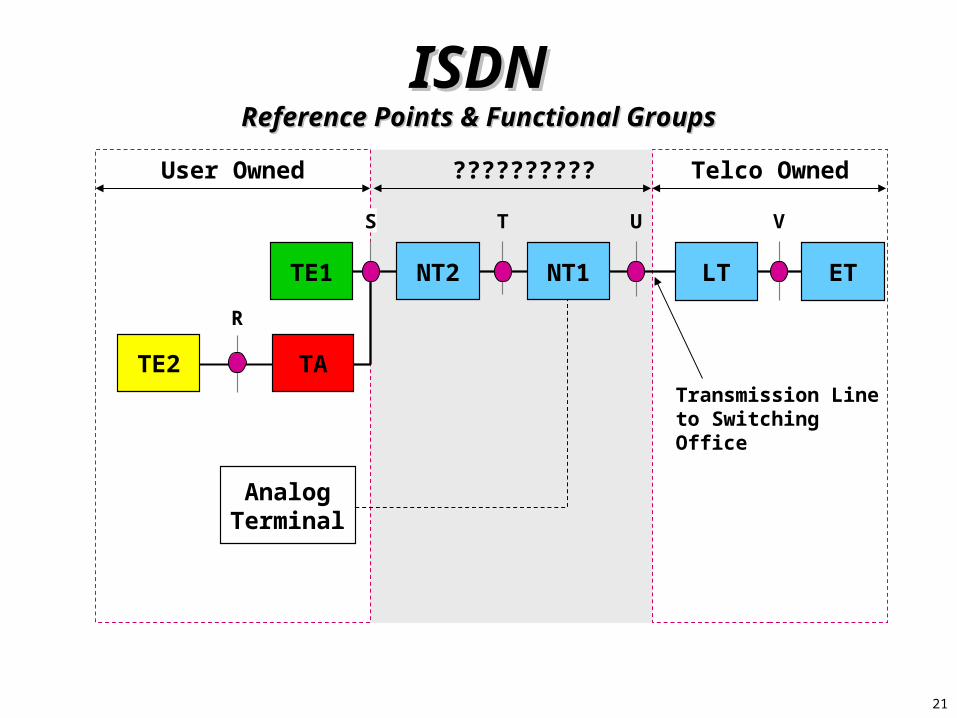
?????????? Telco OwnedUser Owned
ISDNISDNReference Points & Functional GroupsReference Points & Functional Groups
TE1 NT2 NT1
TE2 TA
AnalogTerminal
R
S T
LT ET
VU
Transmission Line to Switching Office

22
ISDN User InterfaceISDN User InterfaceLayered ModelsLayered Models
3 3
2 2 2 2
1 1 1 1 1 1
1 1 1 1 1 1
Procedural Model
D-Channel
B-Channel
Reference Model
NT1TE1 NT2S T U
LT ETV
C.O.
3
23
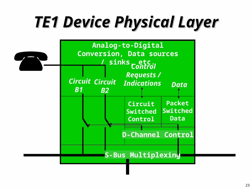
TE1 Device Physical LayerTE1 Device Physical LayerAnalog-to-Digital Conversion,
Data sources / sinks, etc.
Circuit Switched Control
Packet Switched
Data
S-Bus Multiplexing
D-Channel Control
Control Requests / Indications Data
Circuit
B1 Circuit
B2
24
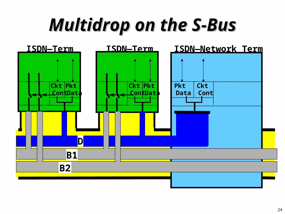
Multidrop on the S-BusMultidrop on the S-Bus
D
ISDN—Term ISDN—Term ISDN—Network Term
Pkt Data
Ckt Cont
Pkt Data
Ckt Cont
Pkt Data
Ckt Cont
B1B2

25
ISDN Packet Switched ServiceISDN Packet Switched ServiceCircuit-Switched ModeCircuit-Switched Mode
X.25 Terminal
Terminal Adapter
ISDN Central Office
Used for X.25 Data on B-Channel
X.25 Packet Switched
PDN

26
How does it work?How does it work?ISDN CO Switch
Bonding
U Ref Point
X.25
TE1
NT
D InterfaceD Interface
PSPDNX.25
TE1
NT
27
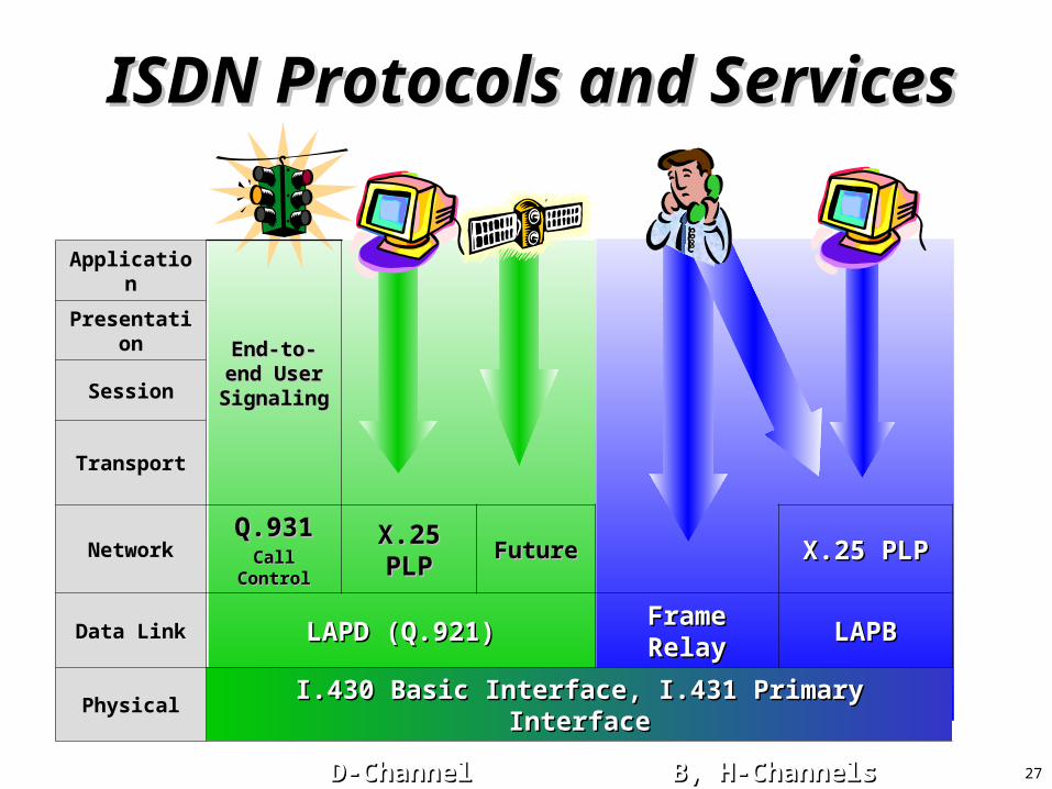
ISDN Protocols and ServicesISDN Protocols and Services
Application
End-to-end End-to-end User User
SignalingSignaling
Presentation
Session
Transport
Network Q.931Q.931Call ControlCall Control
X.25 PLPX.25 PLP FutureFuture X.25 PLPX.25 PLP
Data Link LAPD (Q.921)LAPD (Q.921) Frame RelayFrame Relay LAPBLAPB
Physical I.430 Basic Interface, I.431 Primary InterfaceI.430 Basic Interface, I.431 Primary Interface
D-ChannelD-Channel B, H-ChannelsB, H-Channels
28
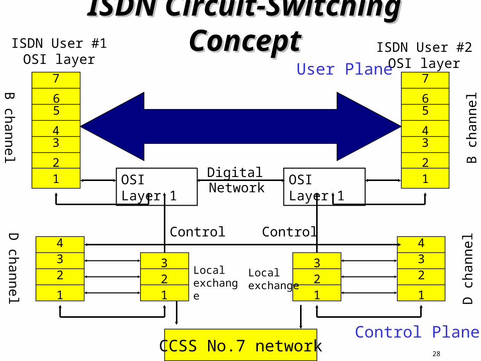
ISDN Circuit-Switching ISDN Circuit-Switching ConceptConcept
OSI Layer 112
34
56
7
1
234
123
Localexchange
D channel
B channel
Control
OSI Layer 1 12
34
56
7
1
234
123
Localexchange D
cha
nnel
B c
hann
el
Control
CCSS No.7 network
DigitalNetwork
ISDN User #1OSI layer
ISDN User #2OSI layer
Control Plane
User Plane

29
ISDN Protocol ArchitectureISDN Protocol Architectureat the User-Network at the User-Network
InterfaceInterfaceNetwork Call control
Q.931X.25
Packet level
Data Link LAPD (Q.921) V.120 or frame relay LAPB
Physical I.430 basic interface + I.431 primary interface
Signal Packet Circuit-switeched
Semi-permanent
Packet-switched
D channel B channel
30
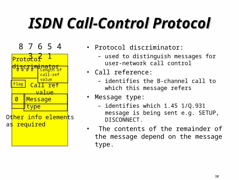
ISDN Call-Control ProtocolISDN Call-Control Protocol
• Protocol discriminator:– used to distinguish messages for user-
network call control
• Call reference:– identifies the B-channel call to which this
message refers
• Message type: – identifies which 1.45 1/Q.931 message is
being sent e.g. SETUP, DISCONNECT.
• The contents of the remainder of the message depend on the message type.
8 7 6 5 4 3 2 1
Protocol discriminator
Call ref value
Message type
Other info elementsas required
Length ofcall-ref value
0 0 0 0
Flag
0

31
Q.931 MessagesQ.931 Messages
• Circuit-mode connection control:– refers to the functions needed to set up, maintain, and
cleara circuit-switched connection on a B channel. This function corresponds to call control in existing circuit-switching telecommunications networks.
• Packet-mode access-connection control:– refers to the functions needed to set up a circuit-
switched connection (called an access connection in this context) to an ISDN packet-switching node; this connects the user to the packet-switching network furnished by the ISDN provider.

32
Functions of Q.931 Functions of Q.931 messagesmessages
• Call establishment: – used to set up a call initially. This group includes messages
between the calling terminal and the network and between the network and the called terminal.
• Call information: – sent between user and network once a call has been set up
but prior to the disestablishment (termination) phase. One of the messages in that group allows the network to relay, without modification, information between the two users of the call.
• Call clearing: – sent between user and network in order to terminate a call.
• Miscellaneous:– to negotiate network features (supplementary services).
Related Documents