Disclosure to Promote the R ight To Information Whereas the Parliament of India has set out to provide a practical regime of right to information for citizens to secure access to information under the control of public authorities, in order to promote transparency and accountability in the working of every public authority, and whereas the attached publication of the Bureau of Indian Standards is of particular interest to the public, particularly disadvantaged communities and those engaged in the pursuit of education and knowledge, the attached public safety standard is made available to promote the timely dissemination of this information in an accurate manner to the public. !" #$%& # '(%) “ !"# $ %& #' (")* &" +#,-. ” Satyanarayan Gangaram Pitroda “Invent a New India Using Knowledge” “ /0 )"1 &2 324 #' 5 *)6 ” Jawaharlal Nehru “Step Out From the Old to the New” “ 7"#1 &" 8+9&") , 7:1 &" 8+9&") ” Mazdoor Kisan Shakti Sangathan “The Right to Information, The Right to Live” “ !"# %& ;<" =7"#" > 72 &(: ?0 )"@" #AB 7" <&*" A * ” Bhart+hari—N,ti-atakam “Knowledge is such a treasure which cannot be stolen” IS 4968-2 (1976): Method for subsurface sounding for soils, Part 2: Dynamic method using cone and bentonite slurry [CED 43: Soil and Foundation Engineering]

Welcome message from author
This document is posted to help you gain knowledge. Please leave a comment to let me know what you think about it! Share it to your friends and learn new things together.
Transcript

8/21/2019 Is.4968.2.1976 Dynamic Cone Penetration Method Using Bentonite Slurry
http://slidepdf.com/reader/full/is496821976-dynamic-cone-penetration-method-using-bentonite-slurry 1/14
Disclosure to Promote the Right To Information
Whereas the Parliament of India has set out to provide a practical regime of right to
information for citizens to secure access to information under the control of public authorities,in order to promote transparency and accountability in the working of every public authority,
and whereas the attached publication of the Bureau of Indian Standards is of particular interest
to the public, particularly disadvantaged communities and those engaged in the pursuit of
education and knowledge, the attached public safety standard is made available to promote the
timely dissemination of this information in an accurate manner to the public.
!"#$%&# '(%)
“ !"# $ %& #' (")* &" +#,-. ”Satyanarayan Gangaram Pitroda
“Invent a New India Using Knowledge”
“ /0 )"1 &2 324 #' 5 *)6 ” Jawaharlal Nehru
“Step Out From the Old to the New”
“ 7"#1 &" 8+9&") , 7:1 &" 8+9&") ”Mazdoor Kisan Shakti Sangathan
“The Right to Information, The Right to Live”
“ !"# %& ;<" =7"#" > 72 &(: ?0 )"@" #AB 7" <&*" A *”Bhart+hari—N,ti-atakam
“Knowledge is such a treasure which cannot be stolen”
IS 4968-2 (1976): Method for subsurface sounding for soils,
Part 2: Dynamic method using cone and bentonite slurry [CED
43: Soil and Foundation Engineering]

8/21/2019 Is.4968.2.1976 Dynamic Cone Penetration Method Using Bentonite Slurry
http://slidepdf.com/reader/full/is496821976-dynamic-cone-penetration-method-using-bentonite-slurry 2/14

8/21/2019 Is.4968.2.1976 Dynamic Cone Penetration Method Using Bentonite Slurry
http://slidepdf.com/reader/full/is496821976-dynamic-cone-penetration-method-using-bentonite-slurry 3/14

8/21/2019 Is.4968.2.1976 Dynamic Cone Penetration Method Using Bentonite Slurry
http://slidepdf.com/reader/full/is496821976-dynamic-cone-penetration-method-using-bentonite-slurry 4/14
Gr 3
IS : 4968 ( Part II ) - 1976 ( Reaffirmed 2007 )
Indian Standard
METHOD FOR
SUBSURFACE SOUNDING FOR SOILS
PART II DYNAMIC METHOD USING CONE ANDBENTONITE SLURRY
( First Revision )
Second Reprint JUNE 1990
( Incorporating Amendment N o . I )
UDC 624.131. 381
Copyright 1982
BUREAU OF INDIAN STANDARDS
MANAK BHAVAN, 9 BAHADUR SHAH ZAFAR MARG
NEW DELHI110002
Apri l 1977

8/21/2019 Is.4968.2.1976 Dynamic Cone Penetration Method Using Bentonite Slurry
http://slidepdf.com/reader/full/is496821976-dynamic-cone-penetration-method-using-bentonite-slurry 5/14
IS I 4968 ( Part II ) • 1976-
Indian Standard
METHOD FORSUBSURFACE SOUNDING FOR SOILS
PART It DYNAMIC METHOD USING CONE ANDBENTONITE SLURRY
( First Revision)
Soil Engineering Sectional Committee, BDO 23
Claai ,.all
Pao:r DlNUH MOHAK
R /lres lling
Central Building Research Ins ti tu te (CSIR) .Roorkee
5aBI A. N. JANOLE( Allmtal,)DR SHAlJKI K GULHATI Indian Institute of Technology, New Delhi
DR G. V. RAo ( Altmaal, )SaRI V. G. HKODJt National Buildings Organization, New Delhi
5aBI S. H. BALCHA1 I DANI ( AU nale )
In personal capacity (P-820, P , No» Allpo .Qz ndta 700053 )
In personal capacity (5, HunR.rjo,J Ceurt, 12/JH II,./o d Streit, Calcutta 700017 )
Irrigation Research In-titute, Khagaul, PatnaIrrigation Department, Government of Punjab
Radio Foundation Engineering Ltd; and Hazarat :Co, Bombay
M_ sAUDl J IOKAL DJRECTOR RUUBeR Railway Board ( Ministry of Railways)
ROSa
uV Y DlRlECroR RESEA.RCH
(anso ) (.4llf 14I1 )Pao:r ALAI(SnfOK Universi.y ofJodhpur JodhpurLT-CoLAVTAaSINOH Engineer.in.Chief , Branch, Army Headquarters
MAl R. R. SUDBINDBA ( ,llana,. )DR A. BANIEBIEE The Cementation Co Ltd, Calcutta
SHal S. GUPTA ( tmud. )SJnn K. N. DADIN...
SHIl l A. O. D.uTIDAB
SRBI R. L. DEWAN
*Da o. S. DRILLON
RF:lIEABCH ORI E SOIL. )( IPRI) ( Altml4l. )
SR1\1 A. H DIVANJI
( Continued 011 page 2 )
-Allo represents Indian Geotechnical Society, New Delhi
(() COPJ ,ht 98
BUREAU OF INDIAN STANDAllDS
Th,. publieatrcn i. p r o e ~ e d under the Indian eo yrlgJu 4 (XIV of 1957) andl qM odUC. OD to whole or In part by any meant except with wriuen permIssion ofdie publisher ahall be deeQled to be an infriDlemC D of coPyrilhl under the lIlid Act.

8/21/2019 Is.4968.2.1976 Dynamic Cone Penetration Method Using Bentonite Slurry
http://slidepdf.com/reader/full/is496821976-dynamic-cone-penetration-method-using-bentonite-slurry 6/14
IS : 4968 Par t II ) • 1976
CQntwueJfrom page I )
Members
J l I l I O. P. l:\iALHOTItA
>1I111 J. S. MAItYA
ReprtScnting
Public Works Depanment, Government of PunjabRoad, Wing, MlDiSlry of Shipping and Transport,
NewDdhi5J1111 N. S':N Alternate
>Hl<1 G. D, \ 'l 'llUIt Public Works Department, Government of UttarPradesh
S H I D. C. Gil l L R\ CD I Altemat«,)JlIt , R. S. M J ~ I K 0 1 E Ccnu al Water Commission. New Delhi
SHHl C, S U I I I l I ~ D H A Alternate
')1I1l1 T, 1 ., NA'[AIIAJ.\N Central Road Research Institute CSIF ), New Delhi
R I l I t ~ : > J I N T A T I \ F: Hindustan Construcuon Co Ltd, Bombay'j { ~ I J ; M U I OurJn:n Buildmg and Roads Research Laboratory,
Chandigarh])11 K. R, S,XI::-iA Engineering Research Laboratory, Hyderabad'>1.Cll' T \ I t Y Central Board of Irrigarion Power, New Delhi
D, l 'UTY St;r ' l<CT\IlY Altsrnat« )1 o D I ~ SIIA \ ~ ~ J P I l \KASn University of Roorkee, Roorkee tGOI'AL R \ fJ,\ 'O .Illernole
1I1l1 II . V SI{Al{) l Irrigation Research Institute, RoorkeePI Hl.'/TJ.:-lJJINO LN(IDIEEn Pubhc Works Department, Government of Tamil
Nadu1: : I '1'1\'' ' ' I::-H.'KEhH Alternat«
Snur B. T, L' ' 'W\IoLA Concrete Association of India, Bombay
SlIl t t 1 . M. MI' 'OON .1fternole
'>Hm H. C. VUDI \ All India Instruments Manufacturers Dealer.Association, Bombay
SHil l V, K, VA<;cnr; \ Alternat« )..,II III D, A Jl I II \ SI\ IHA, Di l l ctor General, lS I Ex-officio M,mblT )
DIrector Civ Lngg )
Seer.tary
SHRI G. RAMAN
Deputy Director elv Engg), lSI
Site Exploration and Investigation for FoundationsSubcommittee, BDC 23 : 2
ConDener
SHRI R. S. MELKOTB Central Water CommilSian, New Delhi
Memb,rs
SHRI C. SUDHJ lDRA AltlTntd to
Shri R. S. Me/kate)PRO)' ALAM SINOH Univenity ofjoclhpur, JodhpurLT-CoL AVTAB SINOH EnSinccr.in.Cbief'. BraDch, Army Headquanen
MAl R. R. SUDBINDBA ( ..tIm )
CotUiIfIIM. . , . , . 9 )
-Abo repmcatalattitutioa En,inccn (.Iadia), Delhi CcDtre.
2

8/21/2019 Is.4968.2.1976 Dynamic Cone Penetration Method Using Bentonite Slurry
http://slidepdf.com/reader/full/is496821976-dynamic-cone-penetration-method-using-bentonite-slurry 7/14
IS 4968 P a r t II ) • 197.
Indian Standard
METHOD FOR
SUBSURFACE SOUNDING FOR SOILS
PART II DYNAMIC M ETHO D USING CONE ANDBENTONITE SLURRY
Firs t Re vis ion
FOREWOR
0.1 This Indian Standard Par t II First Revision) was adopted by
the Indian Standards Institution on 22 December 1976, a ft er t he drafrfinalized by th e Soil Engineering Sectional Committee had been approved
by the Civil Engineering Division Council.
0.2 Dynamic cone penetration tes t is a simple device for probing the soilstrata and it ha s an advantage over th e standard penetration test thatmaking of a bore hol e is avoided. Moreover, th e data obtained by C01:P,
test pr ovide s a c on ti nu ou s r ec or d o f soil resistance. The resistanceNeb see Note) to penetration in terms of blows pe r 30 em of penetrationof th e cone specified in this standard and devel oped by t he C en tr al
Building Research Institute, Roorkee, has been co-related quantitatively
to the standard p en et ra ti on v al ue N obtained in accordance with
IS : 2131-1963*. Studies with a view to establish a definite co-relationbetween Ntb, and N val ues for different regions of t he c ou nt ry are inprogress. The Sectional Committee responsible for th e preparation o f
this standard decided to publish this standard in the meantime so thatit could serve as a basis of test to various investigators an d others engaged
in subsurface exploration for foundations an d thus make th e results o finvestigations comparable.
NOTE - The resistanee to penetration in the standard penetration test IS : 2 3 -
1963· ) shall be designated as N that to a 50 mm cone t t IS: 4968 Part I ) -1976t ] as Ne d a nd t ha t to a 62 5 mm cone using bentonite s lu rr y as NCb
O.SThis standard
was firstpublished
in 1968.In
this revisionseveral
changes have been m ad e t ak in g i nt o consideration the experience gained
in conducting th e test an d in th e manufacture of th e equipment. Themajor changes made r ela te to th e material of th e cone an d t he h am me r,
·Melhod for standard penetration tell for soil,.
tMcthod for subsurface lOunqin,; for soils .. Pal t Dynamic method u n 50 mm conewithout bentonite Ilurry.l firsl misitm
3
8/21/2019 Is.4968.2.1976 Dynamic Cone Penetration Method Using Bentonite Slurry
http://slidepdf.com/reader/full/is496821976-dynamic-cone-penetration-method-using-bentonite-slurry 8/14
IS . 6 1 ( Part D ) • 1 7
and the criteria for stopping of the driving of the cone. The diameter of
the cone has been changed to 62'5mm and the provision permitting theuse of cones of other diameters has been withdrawn. Additionalinformation has been given on the bentonite slurry used in the teat.Correlations between Nd r and N value. have allo been included.
•• Correlation between cone penetration value. obtained using 62·5 mmcone ( No6r , and penetration values obtained by other method. may be-developed for a given site by conducting the latter tesll adjacent( about 3 to 5 m) to the location of the cone telt. However, for medium
to fine Jands the following relationships between the standard penetrationvalue X obta ined in accordance with IS: 2131-1963· and the conepenetration value (No.r) in accordance with method specified in thisstandard [ IS: 4968 ( Part II ) 1 have been developed by the Central
Building Research Institute, Roorkee, These relationships when utilized..hall be used with caution.
a) When the 62·5 mm cone is driven dry up to 9 m withoutbentonite .Iurry ):
N I'S X upto a depth of4 m
X r - 1'75 X for depths of 4 to 9 m
b) When the 62'5 mm cone is penetrated by circulating slurry:
Ne6r - N
00 5 In the formulation of this standard due weightage has been liven to
International co-ordination among the Itandards and practices prevaiUngin different countries in addition to relating it to the practice in the fieldin this country.
0.6 In reporting the result of a telt or analYlis made in accordance withthis standard, if the final value, observed or calculated, is to be roundedoff, it shall be done in accordance with 18:2-19601.
'I. SCOPE
1.1 This standard ( Part II ) covers the procedure of dynamic ,driving of
a 62'5 mm cone and thereby obtaining a record of resistance of the soil. The cone is directly driven into the ground and for eliminating thefriction on the driving rods. bentonite slurry is used. The use ofbentoniteslurry may not be necessary when the investigation required is up to adepth of 6 m only.
-Method for ltaDdard penetration teat for soils.tRulea for roundinl oft' numerical valuea ( r M S I ~

8/21/2019 Is.4968.2.1976 Dynamic Cone Penetration Method Using Bentonite Slurry
http://slidepdf.com/reader/full/is496821976-dynamic-cone-penetration-method-using-bentonite-slurry 9/14
IS I Part II • 197
2. EQ,UIPMENT
2.1 The cone shan be of suitable steel wit h the tip hardened.The dimensions and the shape of the cone shall be as given in F i ~ 1.The cone should be suitably threaded to enable it to be attached toA rods used {or driving.
r10
•A SIZE DRILL AOD
VAN S THE LACIOF V N S A GR V L
T I t ~ Milt BE ~ R O Y I O £ I
THAUOED
8/21/2019 Is.4968.2.1976 Dynamic Cone Penetration Method Using Bentonite Slurry
http://slidepdf.com/reader/full/is496821976-dynamic-cone-penetration-method-using-bentonite-slurry 10/14
IS : 4968 ( Par t II ) .. 1976
2.2 Driving Rods - The rods used for the test should be rods of
suitable lengths with threads for joining rod coupling at either end.The rods should be marked at every 100 rnrn
NOT - The outer and internal diameter of rods are 41 27 and 28·57 mmrcspcun vcIv
2.2.1 Four mild steel vanes as shown in Fig. 1 see also2.6 shall bewelded to the drrving rod immediately above the cone. As an alternative
a gravel trap about 150 mm high of wire gauze of 5 mm mesh may be
provided 011 the rod immediately above the cone.
2.3 Driving Head - The driving head shall be of mild steel with
threads at either end for rods coupling et Note under 2.2 . shall
have a diameter of 100 mm and a length of to 150 mm.
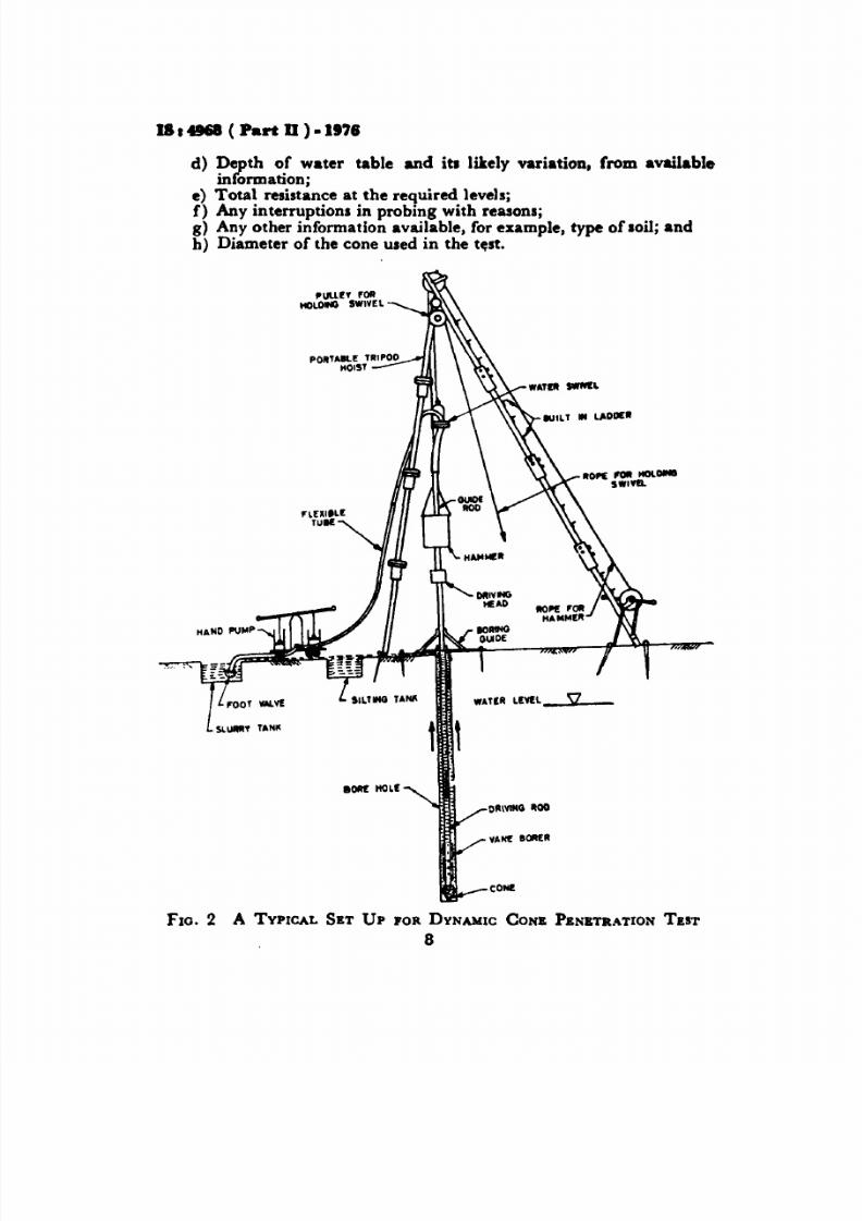
2.4 Hoi. ti ng Equ ipment - Any suitable hoisting equipment like at ripod may be used. The equipment shall be designed to be stable underconditions of impact of the hammer over the driving head when the cone
is driven during the test. Provision shall be made to enable the operator
to climb up the equipment for fixing the pulley, ropes, etc. A typical setup using a tripod is shown in Fig. 2. Suitable guides shall be provided
for keeping the driving rods vertical and in position.
2.5 Hammer - The hammer used for driving the cone shall be of mild
steel or cast iron with a base of mild steel. It shall be 250 mm high and
of suitable diameter. The weight of the hammer together with the chain
shall be 65 kg. It shall have a hole at the centre running throughout its
length and of suitable diameter for the rod seeNote under 2.2 ) and/orguide to pass freely through it . The clearance between the rod and/or..guide and the hole in the hammer shall be about 5 mm.
Nor» - An automatic arrangement for controlling the drop of the hammer may bepreferred if available.
2.6 Pumping Unit for Bentonite Slurry - consists of slurry pump
of capacity 35 to 45 Ilmin at a pressure of 700 to 8 0 kN/m l 7 to8·5 kgf/cm 2
) with a suction hose assembly and a swivel assembly. For
better circulation of slurry at greater depths a vane borer consisting offour vanes and a number of drill holes for the escape of slurry may beprovided in between the driving rod and the cone see Fig. 1 and1 ig. 2 ).
3. PROCEDURE
3.1 The vane shall be connected to the driving rods with the vane
borerjgvavel trap in position. The driving head with the guide rod shall
be fixed all the driving rods. This assembly shall be kept in posit ion with
the cone resting vertically on th e ~ r o u at the point to be tested. For
the circulation of slurry the guide rod shall be connected to a water
6

8/21/2019 Is.4968.2.1976 Dynamic Cone Penetration Method Using Bentonite Slurry
http://slidepdf.com/reader/full/is496821976-dynamic-cone-penetration-method-using-bentonite-slurry 11/14
IS : 4968 Part II • 1976
swivel preferably through a flexible tube connection and then through
another flexible tube to the pumping unit for bentonite slurry. The
swivel assembly shall be held in position by a rope passing over the pulley
provided for that purpose. The slurry tank shall be filled with bentonite
slurry of suitable consistency see Note . The s lurry should general ly
be prepared separately and stored in drums. The tank end of the inlettube to the pump shall be provided with sui table protection against
entry of debris and it shall be kept immersed in the slurry tank. Thehammer, to which a rope has been attached for operation, shall be slid
over the guide rod, to rest on the driving head. A typical assembly ofthe equipment for test using a tripod is shown in FiK. 2.
NOTB - In the case of medium to fine sand, 5 percent bentonite slurry has beenfound useful, In the case of coarse sand, slurry of thicker consistency subject tocirculation requirements may be needed. In the case of hard water, addition of
I percent soap solution has been found useful to get a bett ,·· suspension of thebentonite.
3.2 The cone shall be driven by allowing the 65 kg hammer to drop
freely through a height of 750 mm on the driving head. A drum type
winch fixed to central leg of the t ripod may be used for lifting the dropweight provided the free fall of the hammer is not affected. The driving
of the cone and the pumping in of the slurry shall be started
simultaneously. Driv ing shall not be done for more than 30 r at atime after which it shall be stopped for a minute or two. Pumping shall,
however, be continued. This helps in keeping the hole lined and alsoavoids the choking of the holes provided in the cone. The driving rods
shall be given a few turns about 4 or 5 turns every now and then so
tbat the hole above the cone is maintained. Efficient circulation ofslurry is necessary for eliminating friction on the rods. The number ofblows for every mm penetration of the cone shall be recorded. Theprocess shall be repeated till the cone is driven to the required depth s ,e Note .
NOTE - In order to avoid damage to the equipment, driving may be stopped whenthe number of blows exceeds 35 fo r 100 mm penetration when the cone is driven dry
and 20 for 100 mm penetration when the cone is penetrated by circulating slurry.
4. REPORT
4.1 The number of blows NCb,. should be reported as a continuous
record for every3
mm penetration either in a tabular form or as agraph between and depth. Records of the test shall also include
the following:
a Date of probing;
b Location;
c Elevation of pouncl-eurCace;
7
8/21/2019 Is.4968.2.1976 Dynamic Cone Penetration Method Using Bentonite Slurry
http://slidepdf.com/reader/full/is496821976-dynamic-cone-penetration-method-using-bentonite-slurry 12/14
u Part D ) - I .
d) ~ p t o.f water table and it l likely variation, from availablemfOrmabOnj
e) Total resistance at the required levels;f Any interruptions in probing with reasons;g) Any other information available, for example, type of loilj andh) Diameter of the cone used in the test.
110 1 11 1 11 Wlwe.
1.,
OIl O f
Olll l1llG 1100
YAN 1011£11
CON
FlO. 2 A TYPICAL SET Up FOR DYNAMIC CONE PENETR TION TEST
8

8/21/2019 Is.4968.2.1976 Dynamic Cone Penetration Method Using Bentonite Slurry
http://slidepdf.com/reader/full/is496821976-dynamic-cone-penetration-method-using-bentonite-slurry 13/14
IS 4968 rt II • 1976
Hindustan Construction Co Ltd, Bombay
Roads Wing , Min ist ry of Shipping Transport,
New Delhi
R,pr,senling
Cementation Company Ltd, Bombay
Public Works Department, Government of Uttar
PradeshRodio Foundation Engineering Ltd; and Hazarat
Co, Bombay
Railway B oard Ministry of RailwaysEl UTY DIRECTOR RE :ARCH
FE ROSa )
ASSISTANT D I R C TOR
RES EAR C H SOILS ) RDSO ) Allmlal, )
DIRECTOR Maharashtra Engineering Research Institute, NasikRIllSEARCH OFFICER Alumat« )
DIRECTOR GENERAl, Geological Survey of India
SUBI S. K SHOlrIE Alumat« )SHBI P. N. MEHTA Almnal )
EXECUTIVE ENGINEER SOIL Public Works Department. Governrnent of TamilMECHANICS DIVI8ION) Nadu
SHBI T. K. NATARAJAN Central Road Research Institute CSIR ). New DelhiSHRI H. R. PRAMANIX River Research Inst itute. West Bengal
SKRI H. L. SABA Alternate )REl ltESENTATIVESHRI N. SEN
SHRI R. C. DESAI
CotdinwdJrom pag2 )
M,mbns
DR A. BANERJEEDR A. K CHATTERJEE
SKRI P. K. THOMAS Altemat« )SUPERINTENDING SURVEYOR OJ Central Public Works Department, New Delhi
WORKS I
SHBI D. SHARMA Central Building Resea rch Ins ti tu te CSIR ),Roorkee
SHKI V. S. AOGARWAL Alt rnat
SHRI H C. VERMA Associated Instruments Manufacturers India Pvt L td ,
New DelhiPsOI T. S. NAO l\ J Altmult )

8/21/2019 Is.4968.2.1976 Dynamic Cone Penetration Method Using Bentonite Slurry
http://slidepdf.com/reader/full/is496821976-dynamic-cone-penetration-method-using-bentonite-slurry 14/14
BURE U OF I ND I N ST ND RDS
261 71
62436
231083
1218433 1641
{
41 244241 26 1941 2916
6329295
{e 34 7169832
{21 687621 829262306
{6 21 04621 17
He dquenefl:
Manak Bhavan, 9 Bahadur Shah Zafar Marg, NEW DELHI 110002
Telephones: 331 01 31. 331 1375 Telegrams:Manlksln,tha( Common to III Offices)
re/ephone
{331 01 31l3311375
362499
Southern: C. I. T. Campus. MADRAS 600113
Regional Offices:
Central Manak Bhavan, 9 Bahadur Shah Zafar Marg.NEW DELHI 0002
tEastern : 1 4 C. I. T. SchemeVII M. V. I. P. Road.Maniktola, CALCUTTA 700064
Northern : SCO 445·446, Sector 36-C,CHANDIGARH 160036
tW.stern : Man1l ltlllYA. E9 MIDC. Maro\. Andheri ( elst ).BUM8AY 400(;93
Slanch Office :
·Pushpak . Nurmohamed Shaikh Marg, Khanpur, l 2 63 48AHMADABAD 380001 1 2 63 49
:Peenya Industrial ,6rea 1st Stage, Bangalor. Tumkur Road {38 4955BANGALORE 660068 l 49 66
Gangotr, Complex. 6th Floor. Bhadbhada Road. T. T. Nagar. 6 67 18BHOPAL 462003
Plot No. 82/83. Lewis Road. BHUBANESHWAR 751002 6 36 2763j6 Ward No 29, R G Barua Road. 6th Bvelane, 3 31 77
GUWAHATI7810036·8-56C L. N. Gupta Marg ( Nampallv Station Road ).HYOERABAO600001
R14 Yudhister Marg. C Scheme. JAIPUR 302006
117/418 B SarvodayaNagar. KANPUR 208005
Patliputra Industrial Eltat., PATNA 800013T.C. No. 14/1421. University P.O., Palayam
TRIVANORUM 696036
In pection Offlc ( With Sal. Point ):
Pushpanjali. Fir t Floor, 206·A W.st High Court Road,
Shankar Nagar Squar•• NAGPUR 440010Institution of Engineers ( India) Building, 1332 Shiv.jl N.glr,PUNE 411006
5 Ofllc. in C,lcuU,I, I t 5 Chowrln. . . . . Approlch. P. O. Prineep 27 I I 00I r• • t. C.lcu 700072
t5.. . . Oflie. In Bombay I. •• Nov.lty Ch. , Grin Road. I t 28Bombay 400007
t5 Otflc. in Ilng,IOII i t unity lullding. NIt.li , r.j. SqUIt•• 22 3 71I.ng.lor. 560002
Reprography Unit. 8IS. New Delhi. India
Related Documents