22871 Revision 06 Rev. Date: 4/2004 TP 400-7050-06-1Z-F Ferris Industries 5375 North Main Street Munnsville, NY 13409 800-933-6175 PARTS MANUAL IS1000Z Series Zero-Turn Riding Mower Model Number: IS1000ZKAV21/48 IS1000ZKAV23/52

Welcome message from author
This document is posted to help you gain knowledge. Please leave a comment to let me know what you think about it! Share it to your friends and learn new things together.
Transcript

22871Revision 06
Rev. Date: 4/2004TP 400-7050-06-1Z-F
Ferris Industries5375 North Main StreetMunnsville, NY 13409800-933-6175
PARTSMANUAL
IS1000Z SeriesZero-Turn Riding Mower
Model Number:IS1000ZKAV21/48IS1000ZKAV23/52

1TP 400-7050-02-1Z-F© Copyright 2004 Ferris Industries. All Rights Reserved.
Table of Contents
RIDER COMPONENTS
Main Frame, Suspension & Caster Group . . . . . . . . . . . . . . . . . . . . . . . . . . . . . . . . . . . . . . . . . . . . . . .2Floor & Brake Cover Group . . . . . . . . . . . . . . . . . . . . . . . . . . . . . . . . . . . . . . . . . . . . . . . . . . . . . . . . . . .4Seat & Seat Mount Group . . . . . . . . . . . . . . . . . . . . . . . . . . . . . . . . . . . . . . . . . . . . . . . . . . . . . . . . . . . . .6Fuel Tank, Mount & Fan Shield Groups . . . . . . . . . . . . . . . . . . . . . . . . . . . . . . . . . . . . . . . . . . . . . . . . . .8Fuel Supply Hose Groups . . . . . . . . . . . . . . . . . . . . . . . . . . . . . . . . . . . . . . . . . . . . . . . . . . . . . . . . . . .12Fuel Tank Replacement Parts . . . . . . . . . . . . . . . . . . . . . . . . . . . . . . . . . . . . . . . . . . . . . . . . . . . . . . . . .18Instrument & Control Panel Groups . . . . . . . . . . . . . . . . . . . . . . . . . . . . . . . . . . . . . . . . . . . . . . . . . . .20Engine & PTO Groups . . . . . . . . . . . . . . . . . . . . . . . . . . . . . . . . . . . . . . . . . . . . . . . . . . . . . . . . . . . . . .26Engine Service Replacement Parts . . . . . . . . . . . . . . . . . . . . . . . . . . . . . . . . . . . . . . . . . . . . . . . . . . . .32Pump Drive Group . . . . . . . . . . . . . . . . . . . . . . . . . . . . . . . . . . . . . . . . . . . . . . . . . . . . . . . . . . . . . . . . .34Rear Bumper, Shield & Battery Retainer Group . . . . . . . . . . . . . . . . . . . . . . . . . . . . . . . . . . . . . . . . . .36Motion Control Group . . . . . . . . . . . . . . . . . . . . . . . . . . . . . . . . . . . . . . . . . . . . . . . . . . . . . . . . . . . . . . .38Hydraulic Groups . . . . . . . . . . . . . . . . . . . . . . . . . . . . . . . . . . . . . . . . . . . . . . . . . . . . . . . . . . . . . . . . . .40Hydraulic Tank Mount Group . . . . . . . . . . . . . . . . . . . . . . . . . . . . . . . . . . . . . . . . . . . . . . . . . . . . . . . . .44Parking Brake Group-Upper . . . . . . . . . . . . . . . . . . . . . . . . . . . . . . . . . . . . . . . . . . . . . . . . . . . . . . . . . .46Parking Brake Group-Lower . . . . . . . . . . . . . . . . . . . . . . . . . . . . . . . . . . . . . . . . . . . . . . . . . . . . . . . . . .48Deck Lift Group . . . . . . . . . . . . . . . . . . . . . . . . . . . . . . . . . . . . . . . . . . . . . . . . . . . . . . . . . . . . . . . . . . . .50Tire & Wheel Group . . . . . . . . . . . . . . . . . . . . . . . . . . . . . . . . . . . . . . . . . . . . . . . . . . . . . . . . . . . . . . . . .52Electrical Schematics . . . . . . . . . . . . . . . . . . . . . . . . . . . . . . . . . . . . . . . . . . . . . . . . . . . . . . . . . . . .54-69
(see serial number breaks listed on bottom of pages)Decals - Brand & Model . . . . . . . . . . . . . . . . . . . . . . . . . . . . . . . . . . . . . . . . . . . . . . . . . . . . . . . . . . . . .70Decals - Safety & Operation . . . . . . . . . . . . . . . . . . . . . . . . . . . . . . . . . . . . . . . . . . . . . . . . . . . . . . . . . .72
MOWER DECK COMPONENTS
48” & 52”Mower Decks - Housings, Covers, Spindles and Blades . . . . . . . . . . . . . . . . . . . . . . . . . .7648” & 52” Mower Decks - Pulleys, Belts & Idler Arm . . . . . . . . . . . . . . . . . . . . . . . . . . . . . . . . . . . . . .7848” & 52” Mower Decks - Rollers . . . . . . . . . . . . . . . . . . . . . . . . . . . . . . . . . . . . . . . . . . . . . . . . . . . . . .8048” & 52” Mower Decks - Rear Mount Bars . . . . . . . . . . . . . . . . . . . . . . . . . . . . . . . . . . . . . . . . . . . . .82
REFERENCE INFORMATION:
Torque Specification Chart . . . . . . . . . . . . . . . . . . . . . . . . . . . . . . . . . . . . . . . . . . . . .Inside Back Cover

2 TP 400-7050-00-1Z-F© Copyright 2004 Ferris Industries. All Rights Reserved.
The above parts group applies to the following Model Nos.:IS1000ZKAV21/48IS1000ZKAV23/52
Main Frame, Suspension & Caster Group
NOTE: Unless noted otherwise,use the standard hardware torquespecification chart.
1
2
3 4 5
67
8
2 3
48
910
11
1213
16
1
17
1310
11
18
19
20
21
8
4
32
4
32
17
22
23
24
23
25
2627
15
14
See Wheels & Tires Group
7
7

3TP 400-7050-03-1Z-F
The above parts group applies to the following Model Nos.:IS1000ZKAV21/48IS1000ZKAV23/52
REF NO. PART NO. QTY. DESCRIPTION
Main Frame, Suspension & Caster Group
Footnotes:
1 22842 1 SHOCK & SPRING ASSEMBLY2 25013-16 4 CAPSCREW, Hex Head, 3/8-16 x 23 25156 4 WASHER, 3/84 25096 4 NUT, Hex Nylon Lock, 3/8-165 47449 1 MAIN FRAME6 47457 1 UPPER SHOCK MOUNT7 25160 3 WASHER, 3/48 25284 5 NUT, Hex Nylon Lock, 3/4-169 46093 2 SPACER, .75 x 1.50 x 1.00
10 22039 4 BALL JOINT, 3/4-1611 47461 6 SPACER, .76 x 1.00 x .2512 25265-32 2 CAPSCREW, Hex Head, 3/4-16 x 413 25093 4 NUT, Hex, Jam, 3/4-1614 25095 2 NUT, Hex Nylon Lock, 1/4-2015 22673 2 RUBBER BUMPER16 47445 1 SUSPENSION ARM-LH17 47049 2 CASTER YOKE18 25265-24 2 CAPSCREW, Hex Head, 3/4-16 x 319 25265-48 1 CAPSCREW, Hex Head, 3/4-16 x 620 47489 1 SPACER, .75 x 1.00 x 2.3821 22852 1 PIVOT BEARING22 21072 2 SEAL, Grease23 20884 4 BEARING, Tapered Roller24 47452 1 SUSPENSION ARM-RH25 25104 2 NUT, Hex, SLotted, 3/4-1626 21073 2 CAP27 25203-10 2 Pin, Cotter

4 TP 400-7050-02-1Z-F© Copyright 2004 Ferris Industries. All Rights Reserved.
The above parts group applies to the following Model Nos.:IS1000ZKAV21/48IS1000ZKAV23/52
Floor & Brake Cover Group
NOTE: Unless noted otherwise,use the standard hardware torquespecification chart.
1617
17
18
18
1
2
3 4
5
6
IS1000ZKAV21/48 - S/N: 1906 & aboveIS1000ZKAV23/52 - S/N: 1401 & above
9
8
10
11
12
14
13
7
14
12
12
1213
13
13
15
1213

5TP 400-7050-03-1Z-F
The above parts group applies to the following Model Nos.:IS1000ZKAV21/48IS1000ZKAV23/52
REF NO. PART NO. QTY. DESCRIPTION
Floor & Brake Cover Group
Footnotes:
1 49240 1 BRAKE COVER PANEL ASSEMBLY2 22030 1 FUEL SHUTOFF VALVE3 49181 1 FUEL LINE GUIDE4 25095 2 NUT, Hex Nylon Lock, 1/4-205 21029 2 TIE WRAP, 11”6 25144-6 2 CARRIAGE BOLT, 1/4-20 x 3/47 47069 1 BRAKE COVER PANEL8 25013-16 2 CAPSCREW, Hex Head, 3/8-16 x 29 25156 2 WASHER, 3/8
10 47125 2 SPACER, .39 x 1.00 x .8811 25128 2 NUT, Hex Serrated Flange, 3/8-1612 25011-8 6 CAPSCREW, Hex Head, 5/16-18 x 113 25155 6 WASHER, 5/1614 22308 4 BODY CLIP, 5/16-1815 47480 1 FLOOR PLATE16 47483 1 SAFETY WALK17 47139 2 SAFETY WALK18 25127 2 NUT, Hex Serrated Flange, 5/16-18

6 TP 400-7050-00-1Z-F© Copyright 2004 Ferris Industries. All Rights Reserved.
The above parts group applies to the following Model Nos.:IS1000ZKAV21/48IS1000ZKAV23/52
Seat & Mount Group
NOTE: Unless noted otherwise,use the standard hardware torquespecification chart.
1
32
4
5
6
7
8
9
10
11
12
12
151413
16
17
7TP 400-7050-03-1Z-F
The above parts group applies to the following Model Nos.:IS1000ZKAV21/48IS1000ZKAV23/52
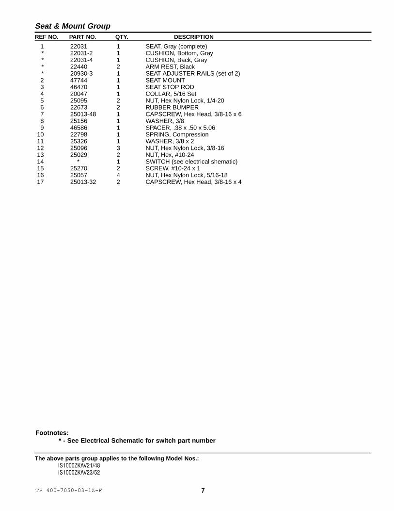
REF NO. PART NO. QTY. DESCRIPTION
Seat & Mount Group
Footnotes:* - See Electrical Schematic for switch part number
1 22031 1 SEAT, Gray (complete)* 22031-2 1 CUSHION, Bottom, Gray* 22031-4 1 CUSHION, Back, Gray* 22440 2 ARM REST, Black* 20930-3 1 SEAT ADJUSTER RAILS (set of 2)2 47744 1 SEAT MOUNT3 46470 1 SEAT STOP ROD4 20047 1 COLLAR, 5/16 Set5 25095 2 NUT, Hex Nylon Lock, 1/4-206 22673 2 RUBBER BUMPER7 25013-48 1 CAPSCREW, Hex Head, 3/8-16 x 68 25156 1 WASHER, 3/89 46586 1 SPACER, .38 x .50 x 5.06
10 22798 1 SPRING, Compression11 25326 1 WASHER, 3/8 x 212 25096 3 NUT, Hex Nylon Lock, 3/8-1613 25029 2 NUT, Hex, #10-2414 * 1 SWITCH (see electrical shematic)15 25270 2 SCREW, #10-24 x 116 25057 4 NUT, Hex Nylon Lock, 5/16-1817 25013-32 2 CAPSCREW, Hex Head, 3/8-16 x 4

8 TP 400-7050-02-1Z-F© Copyright 2004 Ferris Industries. All Rights Reserved.
The above parts group applies to the following Model Nos.:IS1000ZKAV21/48 (S/N: 1905 & below)IS1000ZKAV23/52 (S/N: 1400 & below)
Fuel Tank, Mount & Fan Shield Group
See Floor & Brake Panel Groupfor Components & Hardware
13, 14
3 2
1 2
4
56 7
8
78
978
10 11
16
15
1712
8
16
15
8
See Hydraulic Group for Components
7
8
12
18
12
NOTE: Unless noted otherwise,use the standard hardware torquespecification chart.
9TP 400-7050-02-1Z-F
The above parts group applies to the following Model Nos.:IS1000ZKAV21/48 (S/N: 1905 & below)IS1000ZKAV23/52 (S/N: 1400 & below)
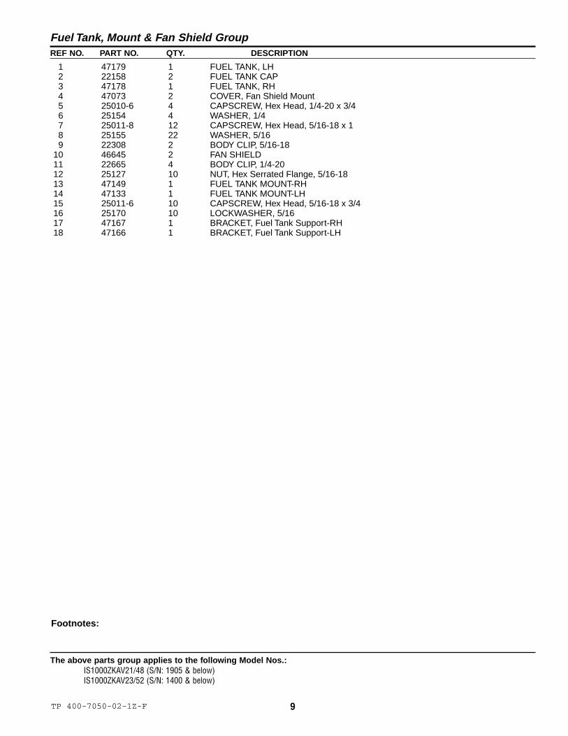
REF NO. PART NO. QTY. DESCRIPTION
Fuel Tank, Mount & Fan Shield Group
Footnotes:
1 47179 1 FUEL TANK, LH2 22158 2 FUEL TANK CAP3 47178 1 FUEL TANK, RH4 47073 2 COVER, Fan Shield Mount5 25010-6 4 CAPSCREW, Hex Head, 1/4-20 x 3/46 25154 4 WASHER, 1/47 25011-8 12 CAPSCREW, Hex Head, 5/16-18 x 18 25155 22 WASHER, 5/169 22308 2 BODY CLIP, 5/16-18
10 46645 2 FAN SHIELD11 22665 4 BODY CLIP, 1/4-2012 25127 10 NUT, Hex Serrated Flange, 5/16-1813 47149 1 FUEL TANK MOUNT-RH14 47133 1 FUEL TANK MOUNT-LH15 25011-6 10 CAPSCREW, Hex Head, 5/16-18 x 3/416 25170 10 LOCKWASHER, 5/1617 47167 1 BRACKET, Fuel Tank Support-RH18 47166 1 BRACKET, Fuel Tank Support-LH
10 TP 400-7050-02-1Z-F© Copyright 2004 Ferris Industries. All Rights Reserved.
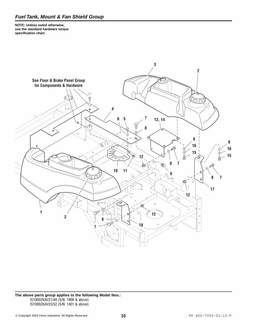
The above parts group applies to the following Model Nos.:IS1000ZKAV21/48 (S/N: 1906 & above)IS1000ZKAV23/52 (S/N: 1401 & above)
Fuel Tank, Mount & Fan Shield Group
See Floor & Brake Panel Groupfor Components & Hardware
13, 14
32
12
4
56 7
8
78
978
10 11
16
15
1712
8
16
15
8
7
812
18
12
NOTE: Unless noted otherwise,use the standard hardware torquespecification chart.

11TP 400-7050-02-1Z-F
The above parts group applies to the following Model Nos.:IS1000ZKAV21/48 (S/N: 1906 & above)IS1000ZKAV23/52 (S/N: 1401 & above)
REF NO. PART NO. QTY. DESCRIPTION
Fuel Tank, Mount & Fan Shield Group
Footnotes:
1 49149 1 FUEL TANK, LH* 46273 1 Filler Neck2 22158 2 FUEL TANK CAP3 49150 1 FUEL TANK, RH* 46273 1 Filler Neck4 47073 2 COVER, Fan Shield Mount5 25010-6 4 CAPSCREW, Hex Head, 1/4-20 x 3/46 25154 4 WASHER, 1/47 25011-8 12 CAPSCREW, Hex Head, 5/16-18 x 18 25155 22 WASHER, 5/169 22308 2 BODY CLIP, 5/16-18
10 46645 2 FAN SHIELD11 22665 4 BODY CLIP, 1/4-2012 25127 10 NUT, Hex Serrated Flange, 5/16-1813 47149 1 FUEL TANK MOUNT-RH14 47133 1 FUEL TANK MOUNT-LH15 25011-6 10 CAPSCREW, Hex Head, 5/16-18 x 3/416 25170 10 LOCKWASHER, 5/1617 47167 1 BRACKET, Fuel Tank Support-RH18 47166 1 BRACKET, Fuel Tank Support-LH

12 TP 400-7050-01-1Z-F© Copyright 2004 Ferris Industries. All Rights Reserved.
The above parts group applies to the following Model Nos.:IS1000ZKAV21/48 (S/N: 410 & below)IS1000ZKAV23/52 (S/N: 555 & below)
Fuel Supply Hose Group
Connect to Engine
LH Fuel Tank RH Fuel Tank43
12
5
7
6
NOTE: Unless noted otherwise,use the standard hardware torquespecification chart.

13TP 400-7050-01-1Z-F
The above parts group applies to the following Model Nos.:IS1000ZKAV21/48 (S/N: 410 & below)IS1000ZKAV23/52 (S/N: 555 & below)
REF NO. PART NO. QTY. DESCRIPTION
Fuel Supply Hose Group
Footnotes:
1 22030 1 VALVE, Fuel Shut Off2 20835 6 CLAMP, Hose3 50831-45 1 HOSE, 45”4 50833-43 1 WIRE LOOM, 43”5 50831-6.5 1 HOSE, 6-1/2”6 50833-40 1 WIRE LOOM, 40”7 50831-42 1 HOSE, 42”

14 TP 400-7050-02-1Z-F© Copyright 2004 Ferris Industries. All Rights Reserved.
The above parts group applies to the following Model Nos.:IS1000ZKAV21/48 (S/N: 411 - 1905)IS1000ZKAV23/52 (S/N: 556 - 1400)
Fuel Supply Hose Group
NOTE: Unless noted otherwise,use the standard hardware torquespecification chart.
Connect to Engine
LH Fuel Tank RH Fuel Tank43
1 2
5
7
6

15TP 400-7050-02-1Z-F
The above parts group applies to the following Model Nos.:IS1000ZKAV21/48 (S/N: 411 - 1905)IS1000ZKAV23/52 (S/N: 556 - 1400)
REF NO. PART NO. QTY. DESCRIPTION
Fuel Supply Hose Group
Footnotes:
1 22030 1 VALVE, Fuel Shut Off2 20835 6 CLAMP, Hose3 50831-7.5 1 HOSE, 7-1/2”4 50833-34 1 WIRE LOOM, 34”5 50831-36 1 HOSE, 36”6 50833-46 1 WIRE LOOM, 46”7 50831-48 1 HOSE, 48”
16 TP 400-7050-02-1Z-F© Copyright 2004 Ferris Industries. All Rights Reserved.
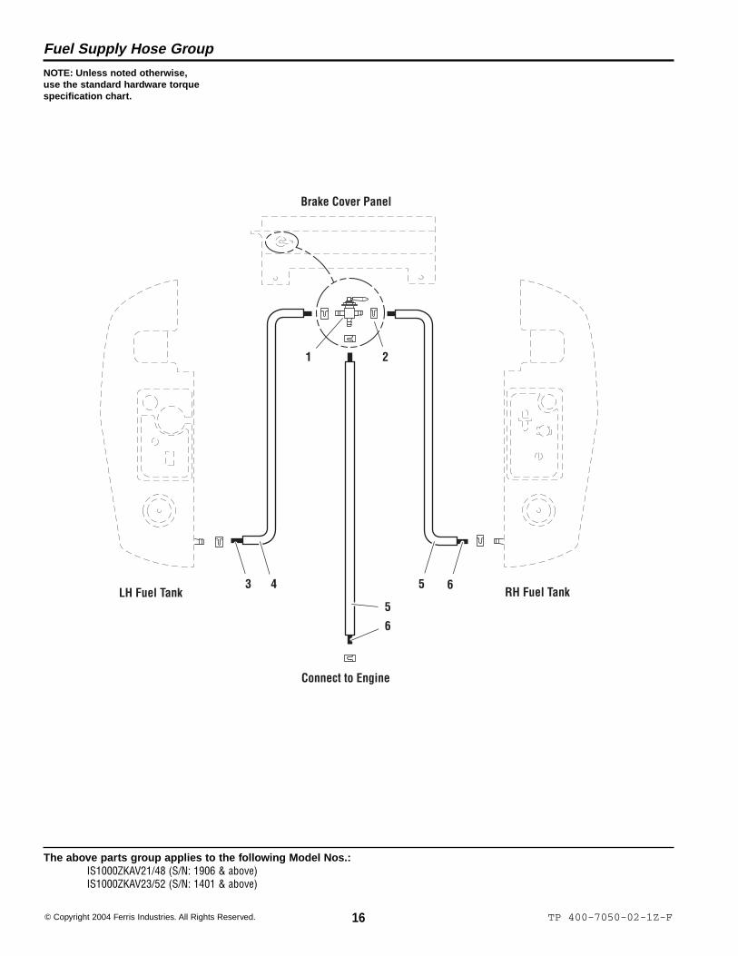
The above parts group applies to the following Model Nos.:IS1000ZKAV21/48 (S/N: 1906 & above)IS1000ZKAV23/52 (S/N: 1401 & above)
Fuel Supply Hose Group
NOTE: Unless noted otherwise,use the standard hardware torquespecification chart.
Connect to Engine
LH Fuel Tank RH Fuel Tank53 6
6
5
Brake Cover Panel
1 2
4
17TP 400-7050-02-1Z-F
The above parts group applies to the following Model Nos.:IS1000ZKAV21/48 (S/N: 1906 & above)IS1000ZKAV23/52 (S/N: 1401 & above)
REF NO. PART NO. QTY. DESCRIPTION
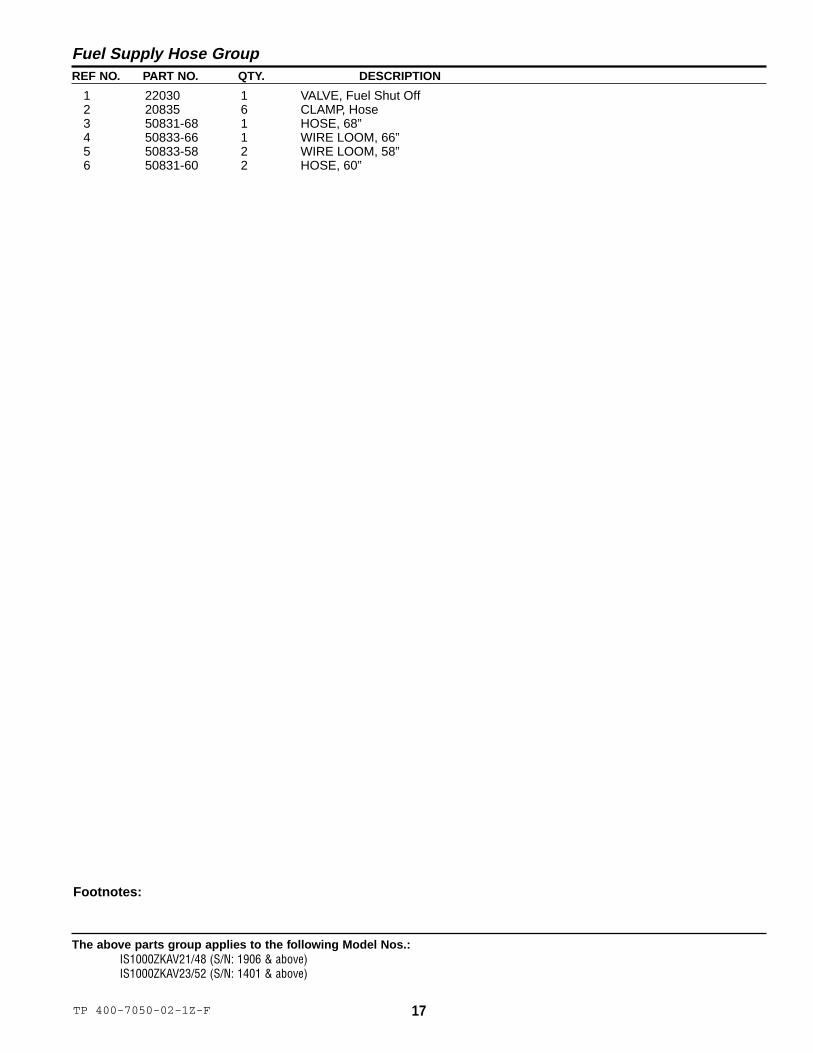
Fuel Supply Hose Group
Footnotes:
1 22030 1 VALVE, Fuel Shut Off2 20835 6 CLAMP, Hose3 50831-68 1 HOSE, 68”4 50833-66 1 WIRE LOOM, 66”5 50833-58 2 WIRE LOOM, 58”6 50831-60 2 HOSE, 60”

18 TP 400-7050-01-1Z-F© Copyright 2004 Ferris Industries. All Rights Reserved.
The above parts group applies to the following Model Nos.:IS1000ZKAV21/48IS1000ZKAV23/52
Fuel Tank Replacement Parts
NOTE: Unless noted otherwise,use the standard hardware torquespecification chart.
LH Fuel Tank RH Fuel Tank
3
4
2
5
1 1
2
2 2
3
4

19TP 400-7050-05-1Z-F
The above parts group applies to the following Model Nos.:IS1000ZKAV21/48IS1000ZKAV23/52
REF NO. PART NO. QTY. DESCRIPTION
Fuel Tank Replacement Parts
Footnotes:
1 23067 2 SCREEN FITTING2 23069 4 HOSE CLAMP3 50925-26 2 HOSE, 26”4 1726400 2 GROMMET5 23061 2 ELBOW FITTING
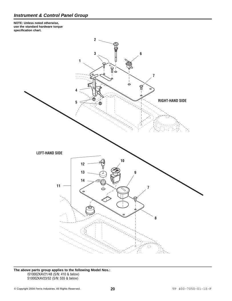
20 TP 400-7050-01-1Z-F© Copyright 2004 Ferris Industries. All Rights Reserved.
The above parts group applies to the following Model Nos.:IS1000ZKAV21/48 (S/N: 410 & below)S1000ZKAV23/52 (S/N: 555 & below)
Instrument & Control Panel Group
2
3
4
5
7
7
9
12
13
1411
10
8
1
6
LEFT-HAND SIDE
RIGHT-HAND SIDE
NOTE: Unless noted otherwise,use the standard hardware torquespecification chart.

21TP 400-7050-01-1Z-F
The above parts group applies to the following Model Nos.:IS1000ZKAV21/48 (S/N: 410 & below)IS1000ZKAV23/52 (S/N: 555 & below)
REF NO. PART NO. QTY. DESCRIPTION
Instrument & Control Panel Group
Footnotes:
1 47140 1 PANEL, Control-RH2 47143 1 CABLE, Choke Control3 25010-6 2 CAPSCREW, Hex Head, 1/4-20 x 3/44 20811 1 CABLE, Throttle Control5 25126 2 NUT, Hex Nylon Lock, 1/4-206 22030 1 VALVE, Fuel Shut Off7 25299-4 8 SCREW, Allen Head, 1/4-20 x 1/28 46492 1 PANEL, Control-LH9 20060 1 HOURMETER
10 22180 1 SWITCH, PTO11 20927 1 SWITCH, Ignition, Complete (includes Ref 12-14)12 22789 1 KEY, Ignition, Molded (Set of 2)13 22790 1 COVER14 22791 1 PLASTIC NUT

3
5
6
8
11
12
14
10
1
2
4
7 8
9
LEFT-HAND SIDE
RIGHT-HAND SIDE
13
22 TP 400-7050-02-1Z-F© Copyright 2004 Ferris Industries. All Rights Reserved.
The above parts group applies to the following Model Nos.:IS1000ZKAV21/48 (S/N: 411 - 1905)IS1000ZKAV23/52 (S/N: 556 - 1400)
Instrument & Control Panel Group
NOTE: Unless noted otherwise,use the standard hardware torquespecification chart.

23TP 400-7050-02-1Z-F
The above parts group applies to the following Model Nos.:IS1000ZKAV21/48 (S/N: 411 - 1905)IS1000ZKAV23/52 (S/N: 556 - 1400)
REF NO. PART NO. QTY. DESCRIPTION
Instrument & Control Panel Group
Footnotes:
1 47858 1 CONTROL PANEL-RH2 25010-6 2 CAPSCREW, Hex Head, 1/4-20 x 3/43 22180 1 SWITCH, PTO4 20927 1 SWITCH, Ignition, Complete (includes Ref 5-7)5 22789 1 KEY, Ignition, Molded (Set of 2)6 22790 1 COVER7 22791 1 PLASTIC NUT8 25299-4 8 SCREW, Allen Head, 1/4-20 x 1/29 20811 1 CABLE, Throttle Control
10 25126 2 NUT, Hex Nylon Lock, 1/4-2011 47860 1 CONTROL PANEL-LH12 47779 1 CABLE, Choke Control13 22030 1 VALVE, Fuel Shut Off14 20060 1 HOURMETER

24 TP 400-7050-02-1Z-F© Copyright 2004 Ferris Industries. All Rights Reserved.
The above parts group applies to the following Model Nos.:IS1000ZKAV21/48 (S/N: 1906 & above)IS1000ZKAV23/52 (S/N: 1401 & above)
Instrument & Control Panel Group
5
7
8
12
14
6
9
LEFT-HAND SIDE
RIGHT-HAND SIDE
2
1
2
3
10
11
10
13
14
15
NOTE: Unless noted otherwise,use the standard hardware torquespecification chart.

25TP 400-7050-02-1Z-F
The above parts group applies to the following Model Nos.:IS1000ZKAV21/48 (S/N: 1906 & above)IS1000ZKAV23/52 (S/N: 1401 & above)
REF NO. PART NO. QTY. DESCRIPTION
Instrument & Control Panel Group
Footnotes:
1 22917 2 FUEL GAUGE2 22917-1 2 GROMMET3 2849109 1 CONTROL PANEL-RH4 25010-6 2 CAPSCREW, Hex Head, 1/4-20 x 3/45 22180 1 SWITCH, PTO6 20927 1 SWITCH, Ignition, Complete (includes Ref No. 7-9)7 22789 1 KEY, Ignition, Molded (Set of 2)8 22790 1 COVER9 22791 1 PLASTIC NUT
10 25299-4 8 SCREW, Allen Head, 1/4-20 x 1/211 20811 1 CABLE, Throttle Control12 25126 2 NUT, Hex Nylon Lock, 1/4-2013 23244 1 HOURMETER, Digital14 23239 1 CABLE, Choke Control15 2849108 1 CONTROL PANEL-LH

26 TP 400-7050-01-1Z-F© Copyright 2004 Ferris Industries. All Rights Reserved.
The above parts group applies to the following Model Nos.:IS1000ZKAV21/48 (S/N: 410 & below)IS1000ZKAV23/52 (S/N: 555 & below)
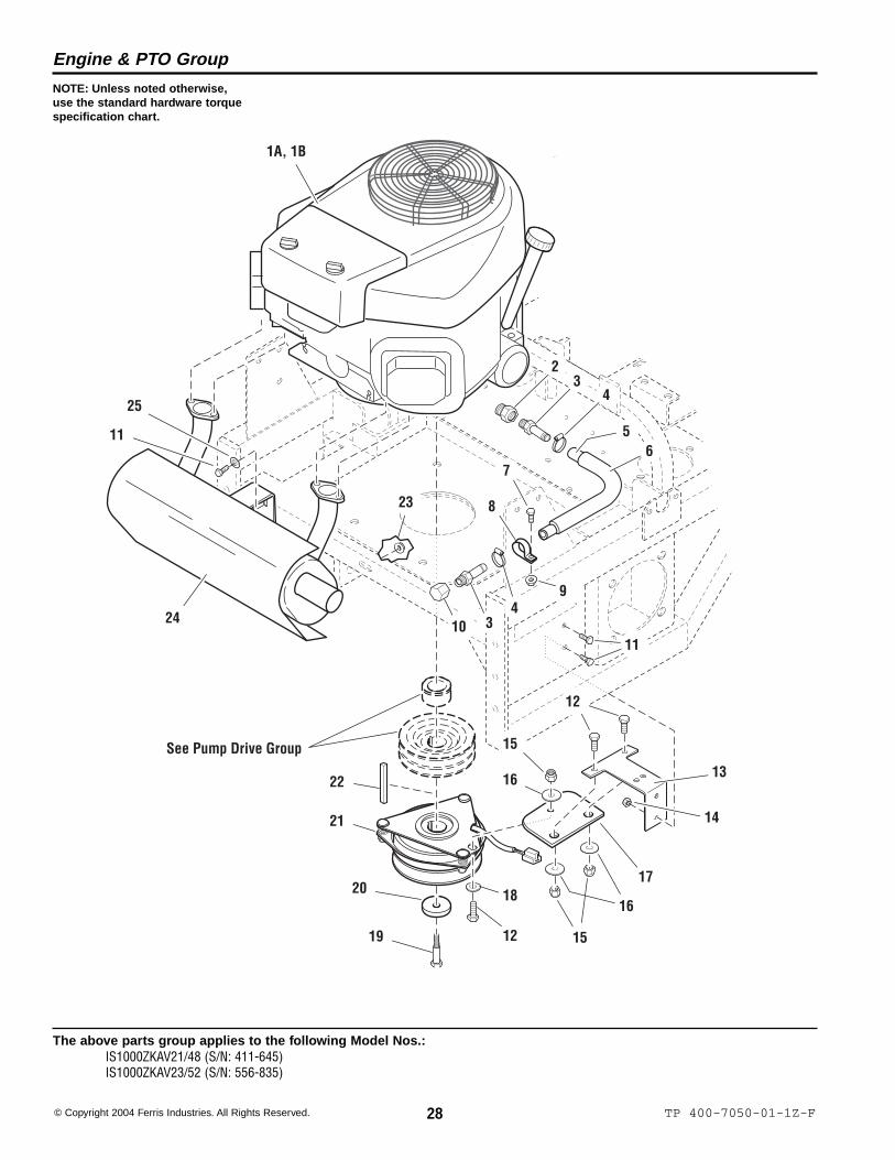
Engine & PTO Group
13
19
16
17
1A, 1B
15
14
18
11
See Pump Drive Group
34
5
67
10
9
8
45
12
13
20
21
22
23
17
16
2
12
24
2526
12
24
25
NOTE: Unless noted otherwise,use the standard hardware torquespecification chart.
27TP 400-7050-03-1Z-F
The above parts group applies to the following Model Nos.:IS1000ZKAV21/48 (S/N: 410 & below)IS1000ZKAV23/52 (S/N: 555 & below)
REF NO. PART NO. QTY. DESCRIPTION
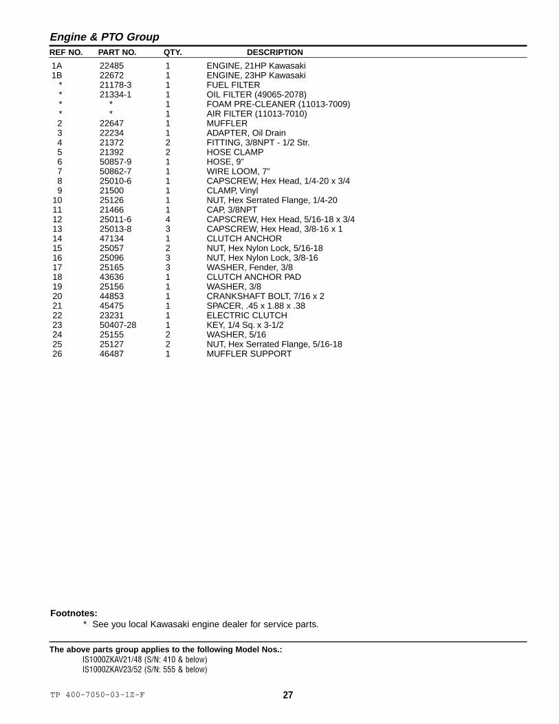
Engine & PTO Group
Footnotes:* See you local Kawasaki engine dealer for service parts.
1A 22485 1 ENGINE, 21HP Kawasaki1B 22672 1 ENGINE, 23HP Kawasaki
* 21178-3 1 FUEL FILTER* 21334-1 1 OIL FILTER (49065-2078)* * 1 FOAM PRE-CLEANER (11013-7009)* * 1 AIR FILTER (11013-7010)2 22647 1 MUFFLER3 22234 1 ADAPTER, Oil Drain4 21372 2 FITTING, 3/8NPT - 1/2 Str.5 21392 2 HOSE CLAMP6 50857-9 1 HOSE, 9”7 50862-7 1 WIRE LOOM, 7”8 25010-6 1 CAPSCREW, Hex Head, 1/4-20 x 3/49 21500 1 CLAMP, Vinyl
10 25126 1 NUT, Hex Serrated Flange, 1/4-2011 21466 1 CAP, 3/8NPT12 25011-6 4 CAPSCREW, Hex Head, 5/16-18 x 3/413 25013-8 3 CAPSCREW, Hex Head, 3/8-16 x 114 47134 1 CLUTCH ANCHOR15 25057 2 NUT, Hex Nylon Lock, 5/16-1816 25096 3 NUT, Hex Nylon Lock, 3/8-1617 25165 3 WASHER, Fender, 3/818 43636 1 CLUTCH ANCHOR PAD19 25156 1 WASHER, 3/820 44853 1 CRANKSHAFT BOLT, 7/16 x 221 45475 1 SPACER, .45 x 1.88 x .3822 23231 1 ELECTRIC CLUTCH23 50407-28 1 KEY, 1/4 Sq. x 3-1/224 25155 2 WASHER, 5/1625 25127 2 NUT, Hex Serrated Flange, 5/16-1826 46487 1 MUFFLER SUPPORT
12
18
15
16
1A, 1B
14
13
17
10
See Pump Drive Group
23
4
56
9
8
7
34
11
12
19
20
21
22
16
15
23
25
24
11
28 TP 400-7050-01-1Z-F© Copyright 2004 Ferris Industries. All Rights Reserved.
The above parts group applies to the following Model Nos.:IS1000ZKAV21/48 (S/N: 411-645)IS1000ZKAV23/52 (S/N: 556-835)
Engine & PTO Group
NOTE: Unless noted otherwise,use the standard hardware torquespecification chart.

29TP 400-7050-03-1Z-F
The above parts group applies to the following Model Nos.:IS1000ZKAV21/48 (S/N: 411-645)IS1000ZKAV23/52 (S/N: 556-835)
REF NO. PART NO. QTY. DESCRIPTION
Engine & PTO Group
Footnotes:* See you local Kawasaki engine dealer for service parts.
1A 22485 1 ENGINE, 21HP Kawasaki1B 22672 1 ENGINE, 23HP Kawasaki
* 21178-3 1 FUEL FILTER* 21334-1 1 OIL FILTER (49065-2078)* * 1 FOAM PRE-CLEANER (11013-7009)* * 1 AIR FILTER (11013-7010)2 22234 1 ADAPTER, Oil Drain3 21372 2 FITTING, 3/8NPT - 1/2 Str.4 21392 2 HOSE CLAMP5 50857-9 1 HOSE, 9”6 50862-7 1 WIRE LOOM, 7”7 25010-6 1 CAPSCREW, Hex Head, 1/4-20 x 3/48 21500 1 CLAMP, Vinyl9 25126 1 NUT, Hex Serrated Flange, 1/4-20
10 21466 1 CAP, 3/8NPT11 25011-6 3 CAPSCREW, Hex Head, 5/16-18 x 3/412 25013-8 3 CAPSCREW, Hex Head, 3/8-16 x 113 47134 1 CLUTCH ANCHOR14 25057 2 NUT, Hex Nylon Lock, 5/16-1815 25096 3 NUT, Hex Nylon Lock, 3/8-1616 25165 3 WASHER, Fender, 3/817 43636 1 CLUTCH ANCHOR PAD18 25156 1 WASHER, 3/819 44853 1 CRANKSHAFT BOLT, 7/16 x 220 45475 1 SPACER, .45 x 1.88 x .3821 23231 1 ELECTRIC CLUTCH22 50407-28 1 KEY, 1/4 Sq. x 3-1/223 25127 1 NUT, Hex Serrated Flange, 5/16-1824 22953 1 MUFFLER25 25155 1 WASHER, 5/16

30 TP 400-7050-04-1Z-F© Copyright 2004 Ferris Industries. All Rights Reserved.
The above parts group applies to the following Model Nos.:IS1000ZKAV21/48 (S/N: 646 & above)IS1000ZKAV23/52 (S/N: 836 & above)
Engine & PTO Group
1425
2728
26
21HP MODEL - S/N: 856 & ABOVE23HP MODEL - S/N: 1186 & ABOVE
12
18
15
16
1A, 1B
14
13
17
10
See Pump Drive Group
23
4
56
9
8
7
34
11
12
19
20
21
22
16
15
23
25
24
11
See Engine ServiceParts Group
NOTE: Unless noted otherwise,use the standard hardware torquespecification chart.

31TP 400-7050-04-1Z-F
The above parts group applies to the following Model Nos.:IS1000ZKAV21/48 (S/N: 646 & above)IS1000ZKAV23/52 (S/N: 836 & above)
REF NO. PART NO. QTY. DESCRIPTION
Engine & PTO Group
Footnotes:* See you local Kawasaki engine dealer for service parts.
1A 23114 1 ENGINE, 21HP Kawasaki1B 23115 1 ENGINE, 23HP Kawasaki
* 21178-3 1 FUEL FILTER* 21334-1 1 OIL FILTER (49065-2078)2 22234 1 ADAPTER, Oil Drain3 21372 2 FITTING, 3/8NPT - 1/2 Str.4 21392 2 HOSE CLAMP5 50857-9 1 HOSE, 9”6 50862-7 1 WIRE LOOM, 7”7 25010-6 1 CAPSCREW, Hex Head, 1/4-20 x 3/48 21500 1 CLAMP, Vinyl9 25126 1 NUT, Hex Serrated Flange, 1/4-20
10 21466 1 CAP, 3/8NPT11 25011-6 3 CAPSCREW, Hex Head, 5/16-18 x 3/412 25013-8 3 CAPSCREW, Hex Head, 3/8-16 x 113 47134 1 CLUTCH ANCHOR14 25057 4 NUT, Hex Nylon Lock, 5/16-1815 25096 3 NUT, Hex Nylon Lock, 3/8-1616 25165 3 WASHER, Fender, 3/817 43636 1 CLUTCH ANCHOR PAD18 25156 1 WASHER, 3/819 44853 1 CRANKSHAFT BOLT, 7/16 x 220 45475 1 SPACER, .45 x 1.88 x .3821 23231 1 ELECTRIC CLUTCH22 50407-28 1 KEY, 1/4 Sq. x 3-1/223 25127 1 NUT, Hex Serrated Flange, 5/16-1824 22953 1 MUFFLER25 25155 3 WASHER, 5/1626 23162 1 MUFFLER27 43815 2 SPACER, 39 x 1.00 x .7528 25011-12 2 CAPSCREW, Hex Head, 5/16-18 x 1-1/2

32 TP 400-7050-01-1Z-F© Copyright 2004 Ferris Industries. All Rights Reserved.
The above parts group applies to the following Model Nos.:IS1000ZKAV21/48 (S/N: 646 & above)IS1000ZKAV23/52 (S/N: 836 & above)
Engine Service Replacement Parts
1
2
3
4
5
6
7
8
9 10
11
12
13
2
2
NOTE: Unless noted otherwise,use the standard hardware torquespecification chart.

33TP 400-7050-01-1Z-F
The above parts group applies to the following Model Nos.:IS1000ZKAV21/48 (S/N: 646 & above)IS1000ZKAV23/52 (S/N: 836 & above)
REF NO. PART NO. QTY. DESCRIPTION
Engine Service Replacement Parts
Footnotes:* See you local Kawasaki engine dealer for service parts.
1 23143 1 RAIN CAP2 23146 3 CLAMP3 23138 1 AIR FILTER ASSEMBLY, Complete (includes Ref No. 4 - 8)4 23139 1 CASE, Air Filter5 23140 1 AIR FILTER, Secondary6 23141 1 AIR FILTER, Primary7 23147 2 CLAMP, Cap8 23144 1 CAP, FIlter Case9 23145 1 CASE BRACKET, Complete
10 23142 1 BRACKET PLATE11 21334-1 1 OIL FILTER (49065-2078)12 23148 1 BREATHER TUBE13 23149 1 AIR INLET TUBE

34 TP 400-7050-01-1Z-F© Copyright 2004 Ferris Industries. All Rights Reserved.
The above parts group applies to the following Model Nos.:IS1000ZKAV21/48IS1000ZKAV23/52
Pump Drive Group
1
2
3
4
5
4
6
7
8
10
9
12
13
14
1516
17 18
23
25
11
19
9
9
26
24
20
21
10
22
NOTE: Unless noted otherwise,use the standard hardware torquespecification chart.

35TP 400-7050-03-1Z-F
The above parts group applies to the following Model Nos.:IS1000ZKAV21/48IS1000ZKAV23/52
REF NO. PART NO. QTY. DESCRIPTION
Pump Drive Group
Footnotes:
1 47033 1 SPACER, 1.13 x 1.75 x 1.032 47075 1 CRANKSHAFT PULLEY3 45090 1 SPACER, Idler Pivot4 22157 2 BUSHING, Brass5 46430 1 PUMP DRIVE IDLER ARM6 45135 1 SHAFT, Idler Pivot7 25305 1 WASHER, 3/8 x 1-3/48 25013-32 1 CAPSCREW, Hex Head, 3/8-16 x 49 25096 3 NUT, Hex Nylon Lock, 3/8-16
10 25156 2 WASHER, 3/811 22621 1 PULLEY, Idler (Single Flange)12 25013-14 1 CAPSCREW, Hex Head, 3/8-16 x 1-3/413 25128 1 NUT, Hex Serrated Flange, 3/8-1614 22847 1 SPRING, Extension, Swivel End15 25100 1 NUT, Hex, Side Lock, 3/8-1616 25013-18 1 CAPSCREW, Hex Head, 3/8-16 x 2-1/417 25321 1 SCREW HOOK, 3/8-16 x 4-1/418 25034 2 NUT, Hex, 3/8-1619 22314 1 BELT, Pump Drive (Set)20 46446 1 SPACER, .39 x 1.00 x .7921 22620 1 PULLEY, Idler22 25013-22 1 CAPSCREW, Hex Head, 3/8-16 x 2-3/423 22586 2 PULLEY, Pump Drive24 22156 2 KEY, 5mm x 25mm25 22587 2 BUSHING, Tapered Hub26 25010-8 4 CAPSCREW, Hex Head, 1/4-20 x 1

36 TP 400-7050-02-1Z-F© Copyright 2004 Ferris Industries. All Rights Reserved.
The above parts group applies to the following Model Nos.:IS1000ZKAV21/48IS1000ZKAV23/52
Rear Bumper, Shield & Battery Retainer Group
1A, 1B
4
23
5A, 5B
4
2
7
9
8
7
34
2
3
13
12
11
8, 8A
8A
9
9
43
10A, 10B
6
NOTE: Unless noted otherwise,use the standard hardware torquespecification chart.

37TP 400-7050-02-1Z-F
The above parts group applies to the following Model Nos.:IS1000ZKAV21/48IS1000ZKAV23/52
REF NO. PART NO. QTY. DESCRIPTION
Rear Bumper, Shield & Battery Retainer Group
Footnotes:
1A 47114 1 BUMPER BAR(48” model - S/N: 1905 & below)(52” model - S/N: 1400 & below)
1B 49142 1 BUMPER BAR(48” model - S/N: 1906 & above)(52” model - S/N: 1401 & above)
2 25139 4 NUT, Hex Serrated Flange, 5/16-183 25155 4 WASHER, 5/164 25011-8 4 CAPSCREW, Hex Head, 5/16-18 x 1
5A 47071 1 BUMPER SHIELD(48” model - S/N: 1905 & below)(52” model - S/N: 1400 & below)
5B 49147 1 BUMPER SHIELD(48” model - S/N: 1906 & above)(52” model - S/N: 1401 & above)
6 47485 4 COUNTERWEIGHT (52” model only)7 25128 6 NUT, Hex Serrated Flange, 3/8-16 (48” model)* 25128 8 NUT, Hex Serrated Flange, 3/8-16 (52” model)8 25013-8 6 CAPSCREW, Hex Head, 3/8-16 x 1 (48” model)* 25013-8 4 CAPSCREW, Hex Head, 3/8-16 x 1 (52” model)
8A 25013-16 4 CAPSCREW, Hex Head, 3/8-16 x 2 (52” model only)9 25156 6 WASHER, 3/8 (48” model)* 25156 8 WASHER, 3/8 (52” model)
10A 47115 1 BUMPER(48” model - S/N: 1905 & below)(52” model - S/N: 1400 & below)
10B 47851 1 BUMPER(48” model - S/N: 1906 & above)(52” model - S/N: 1401 & above)
11 22596 2 BATTERY HOLDDOWN BOLT12 22595 1 BATTERY HOLDDOWN13 50831-3 2 HOSE, 3”

38 TP 400-7050-01-1Z-F© Copyright 2004 Ferris Industries. All Rights Reserved.
The above parts group applies to the following Model Nos.:IS1000ZKAV21/48IS1000ZKAV23/52
Motion Control Group
7
8
9
2
34
5
6
1
12
13
14
1715
16
5
1011
35
1011
11
9
18
19
20
212223
2425
14
26
34
30
36
34
11
31
32
5
27
3328
29
36
9
29
35
5
NOTE: Unless noted otherwise,use the standard hardware torquespecification chart.
NOTE: RH side shown. Unlessotherwise noted, componentsare identical for the LH side.
39TP 400-7050-02-1Z-F
The above parts group applies to the following Model Nos.:IS1000ZKAV21/48IS1000ZKAV23/52
REF NO. PART NO. QTY. DESCRIPTION
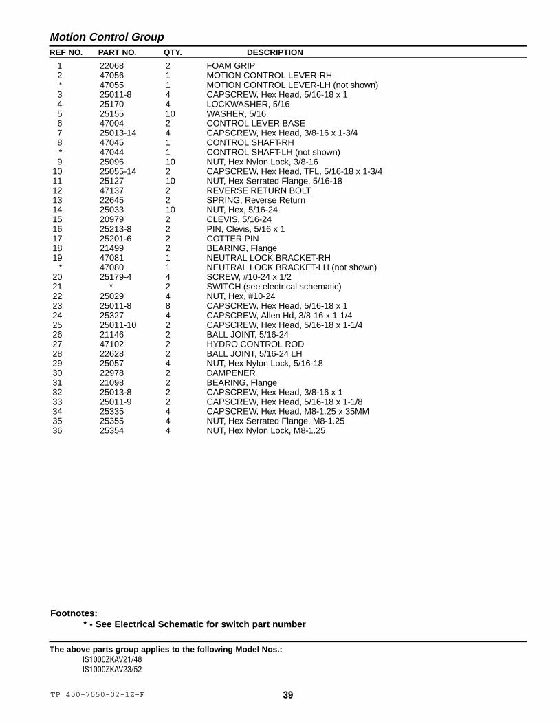
Motion Control Group
Footnotes:* - See Electrical Schematic for switch part number
1 22068 2 FOAM GRIP2 47056 1 MOTION CONTROL LEVER-RH* 47055 1 MOTION CONTROL LEVER-LH (not shown)3 25011-8 4 CAPSCREW, Hex Head, 5/16-18 x 14 25170 4 LOCKWASHER, 5/165 25155 10 WASHER, 5/166 47004 2 CONTROL LEVER BASE7 25013-14 4 CAPSCREW, Hex Head, 3/8-16 x 1-3/48 47045 1 CONTROL SHAFT-RH* 47044 1 CONTROL SHAFT-LH (not shown)9 25096 10 NUT, Hex Nylon Lock, 3/8-16
10 25055-14 2 CAPSCREW, Hex Head, TFL, 5/16-18 x 1-3/411 25127 10 NUT, Hex Serrated Flange, 5/16-1812 47137 2 REVERSE RETURN BOLT13 22645 2 SPRING, Reverse Return14 25033 10 NUT, Hex, 5/16-2415 20979 2 CLEVIS, 5/16-2416 25213-8 2 PIN, Clevis, 5/16 x 117 25201-6 2 COTTER PIN18 21499 2 BEARING, Flange19 47081 1 NEUTRAL LOCK BRACKET-RH
* 47080 1 NEUTRAL LOCK BRACKET-LH (not shown)20 25179-4 4 SCREW, #10-24 x 1/221 * 2 SWITCH (see electrical schematic)22 25029 4 NUT, Hex, #10-2423 25011-8 8 CAPSCREW, Hex Head, 5/16-18 x 124 25327 4 CAPSCREW, Allen Hd, 3/8-16 x 1-1/425 25011-10 2 CAPSCREW, Hex Head, 5/16-18 x 1-1/426 21146 2 BALL JOINT, 5/16-2427 47102 2 HYDRO CONTROL ROD28 22628 2 BALL JOINT, 5/16-24 LH29 25057 4 NUT, Hex Nylon Lock, 5/16-1830 22978 2 DAMPENER31 21098 2 BEARING, Flange32 25013-8 2 CAPSCREW, Hex Head, 3/8-16 x 133 25011-9 2 CAPSCREW, Hex Head, 5/16-18 x 1-1/834 25335 4 CAPSCREW, Hex Head, M8-1.25 x 35MM35 25355 4 NUT, Hex Serrated Flange, M8-1.2536 25354 4 NUT, Hex Nylon Lock, M8-1.25
40 TP 400-7050-01-1Z-F© Copyright 2004 Ferris Industries. All Rights Reserved.
The above parts group applies to the following Model Nos.:IS1000ZKAV21/48 (S/N: 660 & below)IS1000ZKAV23/52 (S/N: 880 & below)
Hydraulic Group
2
3
4 5
6
5
7 8
8
9
910
10
14
15
13
12 1312 13
10
13
16 16
2317
11
23
181918 19
21
26 27 28
20
22
3231A, 31B
29
25
30
24
2934A, 34B
32
25
24
30
1
27
33 33
NOTE: Unless noted otherwise,use the standard hardware torquespecification chart.

41TP 400-7050-01-1Z-F
The above parts group applies to the following Model Nos.:IS1000ZKAV21/48 (S/N: 660 & below)IS1000ZKAV23/52 (S/N: 880 & below))
REF NO. PART NO. QTY. DESCRIPTION
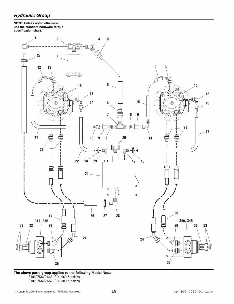
Hydraulic Group
Footnotes:
1 22723 1 FITTING, 1/2” NPT, 90 Deg.2 21356 1 FILTER HEAD3 21357 1 FILTER4 22720 1 FITTING, 1/2” NPT, 45 Deg.5 22719 2 FITTING, Hydraulic, Straight Swivel6 50848-7.5 1 HOSE, Hydraulic, 7-1/2”7 22718 1 FITTING, Tee8 22716 2 ADAPTER, Tee9 22717 2 NUT, Adapter
10 22713 3 FITTING, Hydraulic, Straight Swivel11 50860-13.75 1 HOSE, Hydraulic, 13-3/4”12 22714 2 FITTING, Hydraulic, 45 Deg. Swivel13 22712 4 FITTING, Hydraulic, O-Ring, 90 Deg.14 22715 1 FITTING, Hydraulic, 90 Deg. Swivel15 50860-6.75 1 HOSE, Hydraulic, 6-3/4”16 22571 2 HYDRAULIC PUMP w/ FAN
* 22571-2 2 Fan17 50860-29 1 HOSE, Hydraulic, 29”18 21392 2 HOSE CLAMP, #619 22708 2 FITTING, 1/4” NPT, 90 Deg.20 22705 1 BREATHER21 47108 1 HYDRAULIC RESERVOIR22 50860-20 1 HOSE, Hydraulic, 20”23 22633 4 FITTING, Hydraulic, O-Ring Adapter24 22710 2 HYDRAULIC HOSE ASSEMBLY, 25”25 22711 2 HYDRAULIC HOSE ASSEMBLY, 21”26 50848-16.5 1 HOSE, Hydraulic, 16-1/2”27 21164 1 HOSE CLAMP, #1028 22707 1 FITTING, 1/2” NPT, 90 Deg.29 22709 2 FITTING, Hydraulic, O-RIng, 45 Deg.30 22634 2 FITTING, Hydraulic, O-Ring Adapter31A 22662L 1 HYDRAULIC WHEEL MOTOR-LEFT, Complete (includes Ref 32 & 33)
(48” - S/N: 410 & below)(52” - S/N: 555 & below)
31B 22974L 1 HYDRAULIC WHEEL MOTOR-LEFT, Complete (includes Ref No. 32 & 33)(48” - S/N: 411 & above)(52” - S/N: 556 & above)
32 22042-2 2 KEY33 22042-3 2 NUT & COTTER PIN34A 22662R 1 HYDRAULIC WHEEL MOTOR-RIGHT, Complete (includes Ref 32 & 33)
(48” - S/N: 410 & below)(52” - S/N: 555 & below)
34B 22974R 1 HYDRAULIC WHEEL MOTOR-RIGHT, Complete (includes Ref No. 32 & 33)(48” - S/N: 411 & above)(52” - S/N: 556 & above)

2
3
4 5
6
510
14
15
13
12 1312 13
10
13
16 16
30
1711
30
25
29 2837 36 35 33
31
34
32
33 38 36 37
31
32
34
1
28
788 9910
18
26
27
19 21 18
22
2324
20
42 TP 400-7050-01-1Z-F© Copyright 2004 Ferris Industries. All Rights Reserved.
The above parts group applies to the following Model Nos.:IS1000ZKAV21/48 (S/N: 661 & above)IS1000ZKAV23/52 (S/N: 881 & above)
Hydraulic Group
NOTE: Unless noted otherwise,use the standard hardware torquespecification chart.

43TP 400-7050-01-1Z-F
The above parts group applies to the following Model Nos.:IS1000ZKAV21/48 (S/N: 661 & above)IS1000ZKAV23/52 (S/N: 881 & above)
REF NO. PART NO. QTY. DESCRIPTION
Hydraulic Group
Footnotes:
1 21233 1 FITTING, 1/2” NPT, 90 Deg.2 21356 1 FILTER HEAD3 21357 1 FILTER4 22720 1 FITTING, 1/2” NPT, 45 Deg.5 22719 2 FITTING, Hydraulic, Straight Swivel6 50848-7.5 1 HOSE, Hydraulic, 7-1/2”7 22718 1 FITTING, Tee8 22716 2 ADAPTER, Tee9 22717 2 NUT, Adapter
10 22713 3 FITTING, Hydraulic, Straight Swivel11 50860-13.75 1 HOSE, Hydraulic, 13-3/4”12 22714 2 FITTING, Hydraulic, 45 Deg. Swivel13 22712 4 FITTING, Hydraulic, O-Ring, 90 Deg.14 22715 1 FITTING, Hydraulic, 90 Deg. Swivel15 50860-6.75 1 HOSE, Hydraulic, 6-3/4”16 22571 2 HYDRAULIC PUMP w/ FAN
* 22571-2 2 Fan17 50860-16.5 1 HOSE, Hydraulic, 16-1/2”18 21392 4 HOSE CLAMP, #619 22920 1 FITTING, TEE, 3/8”20 50860-6 1 HOSE, Hydraulic, 6”21 50860-17.5 1 HOSE, Hydraulic, 17-1/2”22 23118 1 FITTING, Elbow, 3/8”23 23120 1 GROMMET24 23191 1 CAP, Hydraulic Oil Only25 48111 1 HYDRAULIC OIL RESERVOIR, Complete (includes Ref. No. 22, 23, 26 & 27)26 23121 1 GROMMET27 23119 1 FITTING, Elbow, 5/8”28 21164 2 HOSE CLAMP, #1029 50848-18 1 HOSE, Hydraulic, 18”30 22633 4 FITTING, Hydraulic, O-Ring Adapter31 22711 2 HYDRAULIC HOSE ASSEMBLY, 21”32 22710 2 HYDRAULIC HOSE ASSEMBLY, 25”33 22709 2 FITTING, Hydraulic, O-RIng, 45 Deg.34 22634 2 FITTING, Hydraulic, O-Ring Adapter35 22974L 1 HYDRAULIC WHEEL MOTOR-LEFT, Complete (includes Ref No. 36 & 37)36 22042-2 2 KEY37 22042-3 2 NUT38 22974R 1 HYDRAULIC WHEEL MOTOR-RIGHT, Complete (includes Ref No. 36 & 37)

44 TP 400-7050-01-1Z-F© Copyright 2004 Ferris Industries. All Rights Reserved.
The above parts group applies to the following Model Nos.:IS1000ZKAV21/48 (S/N: 661 & above)IS1000ZKAV23/52 (S/N: 881 & above)
Hydraulic Tank Mount Group
NOTE: Unless noted otherwise,use the standard hardware torquespecification chart.
See Fuel Tank & Mount
6
7
5
1 2 3
8
See Hydraulic Group
4
3
45TP 400-7050-01-1Z-F
The above parts group applies to the following Model Nos.:IS1000ZKAV21/48 (S/N: 661 & above)IS1000ZKAV23/52 (S/N: 881 & above)
REF NO. PART NO. QTY. DESCRIPTION
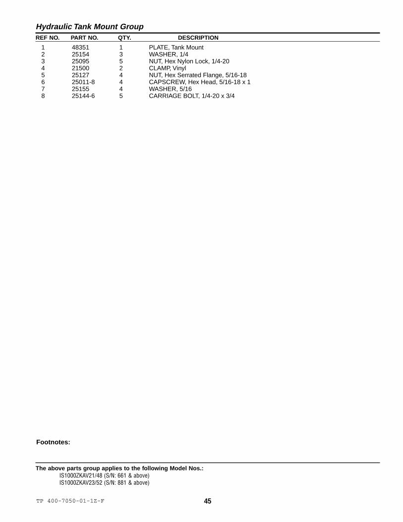
Hydraulic Tank Mount Group
Footnotes:
1 48351 1 PLATE, Tank Mount2 25154 3 WASHER, 1/43 25095 5 NUT, Hex Nylon Lock, 1/4-204 21500 2 CLAMP, Vinyl5 25127 4 NUT, Hex Serrated Flange, 5/16-186 25011-8 4 CAPSCREW, Hex Head, 5/16-18 x 17 25155 4 WASHER, 5/168 25144-6 5 CARRIAGE BOLT, 1/4-20 x 3/4

46 TP 400-7050-03-1Z-F© Copyright 2004 Ferris Industries. All Rights Reserved.
The above parts group applies to the following Model Nos.:IS1000ZKAV21/48IS1000ZKAV23/52
Parking Brake Group - Upper
NOTE: Unless noted otherwise,use the standard hardware torquespecification chart.
15
23
4
7
6
8
9
6 10
12
1615
171118
19202122
23
2413
14

47TP 400-7050-03-1Z-F
The above parts group applies to the following Model Nos.:IS1000ZKAV21/48IS1000ZKAV23/52
REF NO. PART NO. QTY. DESCRIPTION
Parking Brake Group - Upper
Footnotes:* - See Electrical Schematic for switch part number
1 45616 1 BRAKE HANDLE MOUNT2 45619 1 BRAKE HANDLE3 1722302 1 GRIP4 25011-8 2 CAPSCREW, Hex Head, 5/16-18 x 15 25127 2 NUT, Hex Serrated Flange, 5/16-186 21098 2 BEARING, Flange7 25013-6 4 CAPSCREW, Hex Head, 3/8-16 x 3/48 25128 6 NUT, Hex Serrated Flange, 3/8-169 47083 1 BRAKE HANDLE SHAFT
10 25010-14 2 CAPSCREW, Hex Head, 1/4-20 x 1-3/411 25095 2 NUT, Hex Nylon Lock, 1/4-2012 45618 1 BRAKE LINKAGE PIVOT13 47119 1 BRAKE CONNECTING ROD14 25035 1 NUT, Hex, 3/8-2415 25013-16 1 CAPSCREW, Hex Head, 3/8-16 x 216 21171 1 CLEVIS, 3/8-2417 25034 1 NUT, Hex, 3/8-1618 25096 1 NUT, Hex Nylon Lock, 3/8-1619 25010-6 2 CAPSCREW, Hex Head, 1/4-20 x 3/420 25154 2 WASHER, 1/421 45621 1 SWITCH MOUNT BRACKET22 * * SWITCH (see electrical schematic)23 25126 2 NUT, Hex Serrated Flange, 1/4-2024 25058-14 1 CAPSCREW, Hex Head, TFL, 3/8-16 x 1-3/4
48 TP 400-7050-02-1Z-F© Copyright 2004 Ferris Industries. All Rights Reserved.
The above parts group applies to the following Model Nos.:IS1000ZKAV21/48IS1000ZKAV23/52
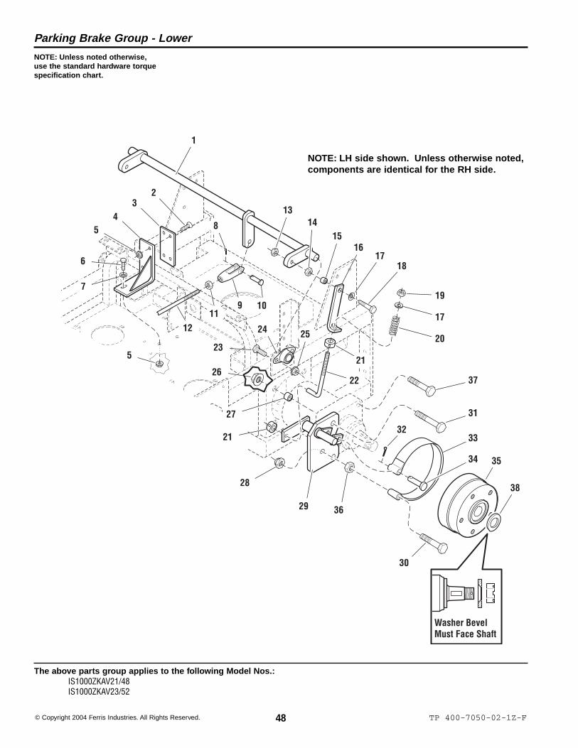
Parking Brake Group - Lower
NOTE: Unless noted otherwise,use the standard hardware torquespecification chart.
Washer BevelMust Face Shaft
1
23
45
6
7
5
8
9 1011
12
1314
1516
1718
19
17
2024
23
26
25
21
22
27
21
28
29
32
37
31
33
34
30
36
35
38
NOTE: LH side shown. Unless otherwise noted,components are identical for the RH side.

49TP 400-7050-03-1Z-F
The above parts group applies to the following Model Nos.:IS1000ZKAV21/48IS1000ZKAV23/52
REF NO. PART NO. QTY. DESCRIPTION
Parking Brake Group - Lower
Footnotes:
1 47128 1 BRAKE CROSS SHAFT2 25303 2 SCREW, Flat Head, Socket, 5/16-18 x 13 45990 1 FRICTION PLATE4 47153 1 SUPPORT, Brake Shaft5 25127 4 NUT, Hex Serrated Flange, 5/16-186 25011-8 2 CAPSCREW, Hex Head, 5/16-18 x 17 25155 2 WASHER, 5/168 25201-6 1 COTTER PIN9 21171 1 CLEVIS, 3/8-24
10 25214-8 1 PIN, Clevis, 3/8 x 111 25035 1 NUT, Hex, 3/8-2412 47119 1 BRAKE CONNECTING ROD13 25100 2 NUT, Hex, Side Lock, 3/8-1614 25034 2 NUT, Hex, 3/8-1615 41930-009 2 PIVOT SLEEVE16 47084 2 BRAKE LINK17 25156 4 WASHER, 3/818 25013-12 2 CAPSCREW, Hex Head, 3/8-16 x 1-1/219 25046 2 NUT, Hex, Top Lock, 3/8-1620 22361 2 BRAKE SPRING21 10546 4 COLLAR, Set, 3/822 47091 2 ROD, Brake Adjustment23 25013-6 4 CAPSCREW, Hex Head, 3/8-16 x 3/424 21098 2 BEARING, Flange25 25128 4 NUT, Hex Serrated Flange, 3/8-1626 25387 8 NUT, Hex Flange Lock, 1/2-2027 47027 8 SPACER, .51 x .75 x .5628 25056 2 NUT, Hex Nylon Lock, 1/2-1329 47089 1 BRAKE BAND SHAFT-LH
* 47090 1 BRAKE BAND SHAFT-RH (not shown)30 25017-24 2 CAPSCREW, Hex Head, 1/2-13 x 331 25018-28 4 CAPSCREW, Hex Head, 1/2-20 x 3-1/232 25202-10 2 COTTER PIN33 22607 2 BRAKE BAND34 25328-16 2 PIN, Clevis, 1/2 x 235 47052 2 BRAKE HUB36 25038 2 NUT, Hex, 1/2-1337 25018-24 4 CAPSCREW, Hex Head, 1/2-20 x 338 23249 2 WASHER, 1 x 2

50 TP 400-7050-00-1Z-F© Copyright 2004 Ferris Industries. All Rights Reserved.
The above parts group applies to the following Model Nos.:IS1000ZKAV21/48IS1000ZKAV23/52
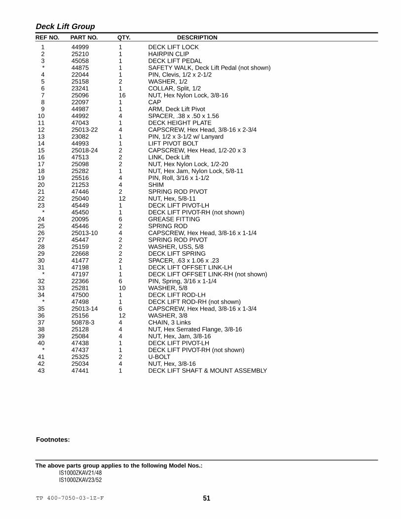
Deck Lift Group
NOTE: Unless noted otherwise,use the standard hardware torquespecification chart.
1 2
34
6
7
12
13
1416
17
18
15
19
208
9
11
5
10
3022
34
2019
3233
24
7
2722
22
43
26
24
28
29
35
36
3637
38
3240
37
25
33
36
35
41
39
7
42
31
32
36
39
35
7
2122
23
7
24
33
NOTE: LH side shown. Unless otherwise noted,components are identical for the RH side.
51TP 400-7050-03-1Z-F
The above parts group applies to the following Model Nos.:IS1000ZKAV21/48IS1000ZKAV23/52
REF NO. PART NO. QTY. DESCRIPTION
Deck Lift Group
Footnotes:
1 44999 1 DECK LIFT LOCK2 25210 1 HAIRPIN CLIP3 45058 1 DECK LIFT PEDAL* 44875 1 SAFETY WALK, Deck Lift Pedal (not shown)4 22044 1 PIN, Clevis, 1/2 x 2-1/25 25158 2 WASHER, 1/26 23241 1 COLLAR, Split, 1/27 25096 16 NUT, Hex Nylon Lock, 3/8-168 22097 1 CAP9 44987 1 ARM, Deck Lift Pivot
10 44992 4 SPACER, .38 x .50 x 1.5611 47043 1 DECK HEIGHT PLATE12 25013-22 4 CAPSCREW, Hex Head, 3/8-16 x 2-3/413 23082 1 PIN, 1/2 x 3-1/2 w/ Lanyard14 44993 1 LIFT PIVOT BOLT15 25018-24 2 CAPSCREW, Hex Head, 1/2-20 x 316 47513 2 LINK, Deck Lift17 25098 2 NUT, Hex Nylon Lock, 1/2-2018 25282 1 NUT, Hex Jam, Nylon Lock, 5/8-1119 25516 4 PIN, Roll, 3/16 x 1-1/220 21253 4 SHIM21 47446 2 SPRING ROD PIVOT22 25040 12 NUT, Hex, 5/8-1123 45449 1 DECK LIFT PIVOT-LH
* 45450 1 DECK LIFT PIVOT-RH (not shown)24 20095 6 GREASE FITTING25 45446 2 SPRING ROD26 25013-10 4 CAPSCREW, Hex Head, 3/8-16 x 1-1/427 45447 2 SPRING ROD PIVOT28 25159 2 WASHER, USS, 5/829 22668 2 DECK LIFT SPRING30 41477 2 SPACER, .63 x 1.06 x .2331 47198 1 DECK LIFT OFFSET LINK-LH
* 47197 1 DECK LIFT OFFSET LINK-RH (not shown)32 22366 6 PIN, Spring, 3/16 x 1-1/433 25281 10 WASHER, 5/834 47500 1 DECK LIFT ROD-LH
* 47498 1 DECK LIFT ROD-RH (not shown)35 25013-14 6 CAPSCREW, Hex Head, 3/8-16 x 1-3/436 25156 12 WASHER, 3/837 50878-3 4 CHAIN, 3 Links38 25128 4 NUT, Hex Serrated Flange, 3/8-1639 25084 4 NUT, Hex, Jam, 3/8-1640 47438 1 DECK LIFT PIVOT-LH
* 47437 1 DECK LIFT PIVOT-RH (not shown)41 25325 2 U-BOLT42 25034 4 NUT, Hex, 3/8-1643 47441 1 DECK LIFT SHAFT & MOUNT ASSEMBLY

52 TP 400-7050-00-1Z-F© Copyright 2004 Ferris Industries. All Rights Reserved.
The above parts group applies to the following Model Nos.:IS1000ZKAV21/48IS1000ZKAV23/52
Tire & Wheel Group
12
4
3
5
6
7
8
9
10
11
12
NOTE: Unless noted otherwise,use the standard hardware torquespecification chart.
Front Wheels & Tires
Rear Wheels & Tires

53TP 400-7050-00-1Z-F
The above parts group applies to the following Model Nos.:IS1000ZKAV21/48IS1000ZKAV23/52
REF NO. PART NO. QTY. DESCRIPTION
Tire & Wheel Group
Footnotes:
1 22631S 2 WHEEL & TIRE ASSEMBLY, Front, 13 x 5.0 x 6, Complete (includes Ref 2-5)2 22029-1 2 TIRE, Front, 13 x 5.0 x 63 22631S-1 2 WHEEL ASSEMBLY, Front, for 13 x 5.0 x 6 Tire, Complete (includes Ref 4 & 5)4 22631S-2 4 BEARING, Taper Roller (2 per wheel)5 22631S-3 4 GREASE SEAL (2 per wheel)6 47103 4 ADAPTER, Caster Wheel (2 per wheel)7 25017-60 2 CAPSCREW, Hex Head, 1/2-13 x 7-1/28 25056 2 NUT, Hex Nylon Lock, 1/2-139 22646S 2 WHEEL & TIRE ASSEMBLY, Rear, 23 x 9.5 x 12, Complete (Includes Ref 10 & 11)
10 22646S-1 2 TIRE, Rear, 23 x 9.5 x 1211 22646S-2 2 WHEEL ASSEMBLY, Rear, for 23 x 9.5 x 12 Tires12 22215 10 WHEEL LUG, 1/2 x 1-5/8

54 TP 400-7050-01-1Z-F© Copyright 2004 Ferris Industries. All Rights Reserved.
The above parts group applies to the following Model Nos.:IS1000ZKAV21/48 (S/N: 410 & below)IS1000ZKAV23/52 (S/N: 555 & below)
Ignition Grounding Circuit/Operator Presence
LH
NE
UT
RA
LS
WIT
CH
2209
5
STA
RT
ER
M
OTO
R
EN
GIN
E M
AG
NE
TO
ALT
ER
NA
TOR
FU
EL
SO
LE
NO
ID
BA
TT
ER
Y
PTO
SW
ITC
H22
180
M
LG
B
S
IGN
ITIO
NS
WIT
CH
2092
7A S
TAR
TE
R
SO
LE
NO
ID20
801
PAR
KIN
G B
RA
KE
SW
ITC
H22
182
PAR
KIN
G B
RA
KE
SW
ITC
H22
182
RH
NE
UT
RA
LS
WIT
CH
2209
5
SE
AT
SW
ITC
H22
095
HO
UR
ME
TE
R20
060
PTO
CL
UT
CH
2258
4
20A
FU
SE
2160
3
20A
FU
SE
2160
3
20A
FU
SE
2160
3
EN
GIN
E H
AR
NE
SS
WH
ITE
WHITE/GREEN
WH
ITE
WHITE/GREEN
WHITE/RED
WH
ITE
/RE
DW
HIT
E/R
ED
WH
ITE
WH
ITE
WH
ITE
WH
ITE
WHITE WHITE
WH
ITE
WHITE
WHITE
WH
ITE
WH
ITE
WH
ITE
WHITE/RED
YE
LLO
W
YELLOW
YE
LLO
W
YE
LLO
W
YELLOW
YE
LLO
W
YELLOW
YE
LLO
W
YE
LLO
W
YE
LLO
W
YE
LLO
W
YELLOW
GR
AY
GR
AY
RE
D
RED
BLU
E
BLU
E
BLUE BLACK BLACK
BLA
CK
GR
EE
N
GR
EE
N
GR
EE
N
GREEN
GREEN
GR
EE
NG
RE
EN
RE
D
RED RED
WH
ITE
WH
ITE
YE
LLO
W
VIO
LET
VIOLET
VIO
LET
RE
D
IGN
ITIO
N S
WIT
CH
PO
SIT
ION
CIR
CU
IT M
AK
E1.
OF
FG
& M
& A
2. R
UN
B &
L &
A3.
STA
RT
B &
L &
S
NEGATIVE BATTERY CABLE21406
PO
SIT
IVE
BA
TT
ER
Y C
AB
LE
4713
6
STARTER CABLE44471
GROUND CABLE44014
NC NO
NC NO
NC NO
NC NO
NC NO
1000
Z W
IRE
HA
RN
ES
S47
151
CO
MN
ON
C

55TP 400-7050-01-1Z-F
The above parts group applies to the following Model Nos.:IS1000ZKAV21/48 (S/N: 410 & below)IS1000ZKAV23/52 (S/N: 555 & below)
Charging Circuit
LH
NE
UT
RA
LS
WIT
CH
2209
5
STA
RT
ER
M
OTO
R
EN
GIN
E M
AG
NE
TO
ALT
ER
NA
TOR
FU
EL
SO
LE
NO
ID
BA
TT
ER
Y
PTO
SW
ITC
H22
180
M
LG
B
S
IGN
ITIO
NS
WIT
CH
2092
7A S
TAR
TE
R
SO
LE
NO
ID20
801
PAR
KIN
G B
RA
KE
SW
ITC
H22
182
PAR
KIN
G B
RA
KE
SW
ITC
H22
182
RH
NE
UT
RA
LS
WIT
CH
2209
5
SE
AT
SW
ITC
H22
095
HO
UR
ME
TE
R20
060
PTO
CL
UT
CH
2258
4
20A
FU
SE
2160
3
20A
FU
SE
2160
3
20A
FU
SE
2160
3
EN
GIN
E H
AR
NE
SS
WH
ITE
WHITE/GREEN
WH
ITE
WHITE/GREEN
WHITE/RED
WH
ITE
/RE
DW
HIT
E/R
ED
WH
ITE
WH
ITE
WH
ITE
WH
ITE
WHITE WHITE
WH
ITE
WHITE
WHITE
WH
ITE
WH
ITE
WH
ITE
WHITE/RED
YE
LLO
W
YELLOW
YE
LLO
W
YE
LLO
W
YELLOW
YE
LLO
W
YELLOW
YE
LLO
W
YE
LLO
W
YE
LLO
W
YE
LLO
W
YELLOWG
RAY
GR
AY
RE
D
RED
BLU
E
BLU
E
BLUE BLACK BLACK
BLA
CK
GR
EE
N
GR
EE
N
GR
EE
N
GREEN
GREEN
GR
EE
NG
RE
EN
RE
D
RED RED
WH
ITE
WH
ITE
YE
LLO
W
VIO
LET
VIOLET
VIO
LET
RE
D
IGN
ITIO
N S
WIT
CH
PO
SIT
ION
CIR
CU
IT M
AK
E1.
OF
FG
& M
& A
2. R
UN
B &
L &
A3.
STA
RT
B &
L &
S
NEGATIVE BATTERY CABLE21406
PO
SIT
IVE
BA
TT
ER
Y C
AB
LE
4713
6
STARTER CABLE44471
GROUND CABLE44014
NC NO
NC NO
NC NO
NC NO
NC NO
1000
Z W
IRE
HA
RN
ES
S47
151
CO
MN
ON
C

56 TP 400-7050-01-1Z-F© Copyright 2004 Ferris Industries. All Rights Reserved.
The above parts group applies to the following Model Nos.:IS1000ZKAV21/48 (S/N: 410 & below)IS1000ZKAV23/52 (S/N: 555 & below)
Cranking Circuit
LH
NE
UT
RA
LS
WIT
CH
2209
5
STA
RT
ER
M
OTO
R
EN
GIN
E M
AG
NE
TO
ALT
ER
NA
TOR
FU
EL
SO
LE
NO
ID
BA
TT
ER
Y
PTO
SW
ITC
H22
180
M
LG
B
S
IGN
ITIO
NS
WIT
CH
2092
7A
STA
RT
ER
S
OL
EN
OID
2080
1PA
RK
ING
BR
AK
ES
WIT
CH
2218
2
PAR
KIN
G B
RA
KE
SW
ITC
H22
182
RH
NE
UT
RA
LS
WIT
CH
2209
5
SE
AT
SW
ITC
H22
095
HO
UR
ME
TE
R20
060
PTO
CL
UT
CH
2258
4
20A
FU
SE
2160
3
20A
FU
SE
2160
3
20A
FU
SE
2160
3
EN
GIN
E H
AR
NE
SS
WH
ITE
WHITE/GREEN
WH
ITE
WHITE/GREEN
WHITE/RED
WH
ITE
/RE
DW
HIT
E/R
ED
WH
ITE
WH
ITE
WH
ITE
WH
ITE
WHITE WHITE
WH
ITE
WHITE
WHITE
WH
ITE
WH
ITE
WH
ITE
WHITE/RED
YE
LLO
W
YELLOW
YE
LLO
W
YE
LLO
W
YELLOW
YE
LLO
W
YELLOW
YE
LLO
W
YE
LLO
W
YE
LLO
W
YE
LLO
W
YELLOWG
RAY
GR
AY
RE
D
RED
BLU
E
BLU
E
BLUE BLACK BLACK
BLA
CK
GR
EE
N
GR
EE
N
GR
EE
N
GREEN
GREEN
GR
EE
NG
RE
EN
RE
D
RED RED
WH
ITE
WH
ITE
YE
LLO
W
VIO
LET
VIOLET
VIO
LET
RE
D
IGN
ITIO
N S
WIT
CH
PO
SIT
ION
CIR
CU
IT M
AK
E1.
OF
FG
& M
& A
2. R
UN
B &
L &
A3.
STA
RT
B &
L &
S
NEGATIVE BATTERY CABLE21406
PO
SIT
IVE
BA
TT
ER
Y C
AB
LE
4713
6
STARTER CABLE44471
GROUND CABLE44014
NC NO
NC NO
NC NO
NC NO
NC NO
1000
Z W
IRE
HA
RN
ES
S47
151
CO
MN
ON
C

57TP 400-7050-01-1Z-F
The above parts group applies to the following Model Nos.:IS1000ZKAV21/48 (S/N: 410 & below)IS1000ZKAV23/52 (S/N: 555 & below)
PTO Clutch Circuit
LH
NE
UT
RA
LS
WIT
CH
2209
5
STA
RT
ER
M
OTO
R
EN
GIN
E M
AG
NE
TO
ALT
ER
NA
TOR
FU
EL
SO
LE
NO
ID
BA
TT
ER
Y
PTO
SW
ITC
H22
180
M
LG
B
S
IGN
ITIO
NS
WIT
CH
2092
7A S
TAR
TE
R
SO
LE
NO
ID20
801
PAR
KIN
G B
RA
KE
SW
ITC
H22
182
PAR
KIN
G B
RA
KE
SW
ITC
H22
182
RH
NE
UT
RA
LS
WIT
CH
2209
5
SE
AT
SW
ITC
H22
095
HO
UR
ME
TE
R20
060
PTO
CL
UT
CH
2258
4
20A
FU
SE
2160
3
20A
FU
SE
2160
3
20A
FU
SE
2160
3
EN
GIN
E H
AR
NE
SS
WH
ITE
WHITE/GREEN
WH
ITE
WHITE/GREEN
WHITE/RED
WH
ITE
/RE
DW
HIT
E/R
ED
WH
ITE
WH
ITE
WH
ITE
WH
ITE
WHITE WHITE
WH
ITE
WHITE
WHITE
WH
ITE
WH
ITE
WH
ITE
WHITE/RED
YE
LLO
W
YELLOW
YE
LLO
W
YE
LLO
W
YELLOW
YE
LLO
W
YELLOW
YE
LLO
W
YE
LLO
W
YE
LLO
W
YE
LLO
W
YELLOW
GR
AY
GR
AY
RE
D
RED
BLU
E
BLU
E
BLUE BLACK BLACK
BLA
CK
GR
EE
N
GR
EE
N
GR
EE
N
GREEN
GREEN
GR
EE
NG
RE
EN
RE
D
RED RED
WH
ITE
WH
ITE
YE
LLO
W
VIO
LET
VIOLET
VIO
LET
RE
D
IGN
ITIO
N S
WIT
CH
PO
SIT
ION
CIR
CU
IT M
AK
E1.
OF
FG
& M
& A
2. R
UN
B &
L &
A3.
STA
RT
B &
L &
S
NEGATIVE BATTERY CABLE21406
PO
SIT
IVE
BA
TT
ER
Y C
AB
LE
4713
6
STARTER CABLE44471
GROUND CABLE44014
NC NO
NC NO
NC NO
NC NO
NC NO
1000
Z W
IRE
HA
RN
ES
S47
151
CO
MN
ON
C
58 TP 400-7050-01-1Z-F© Copyright 2004 Ferris Industries. All Rights Reserved.
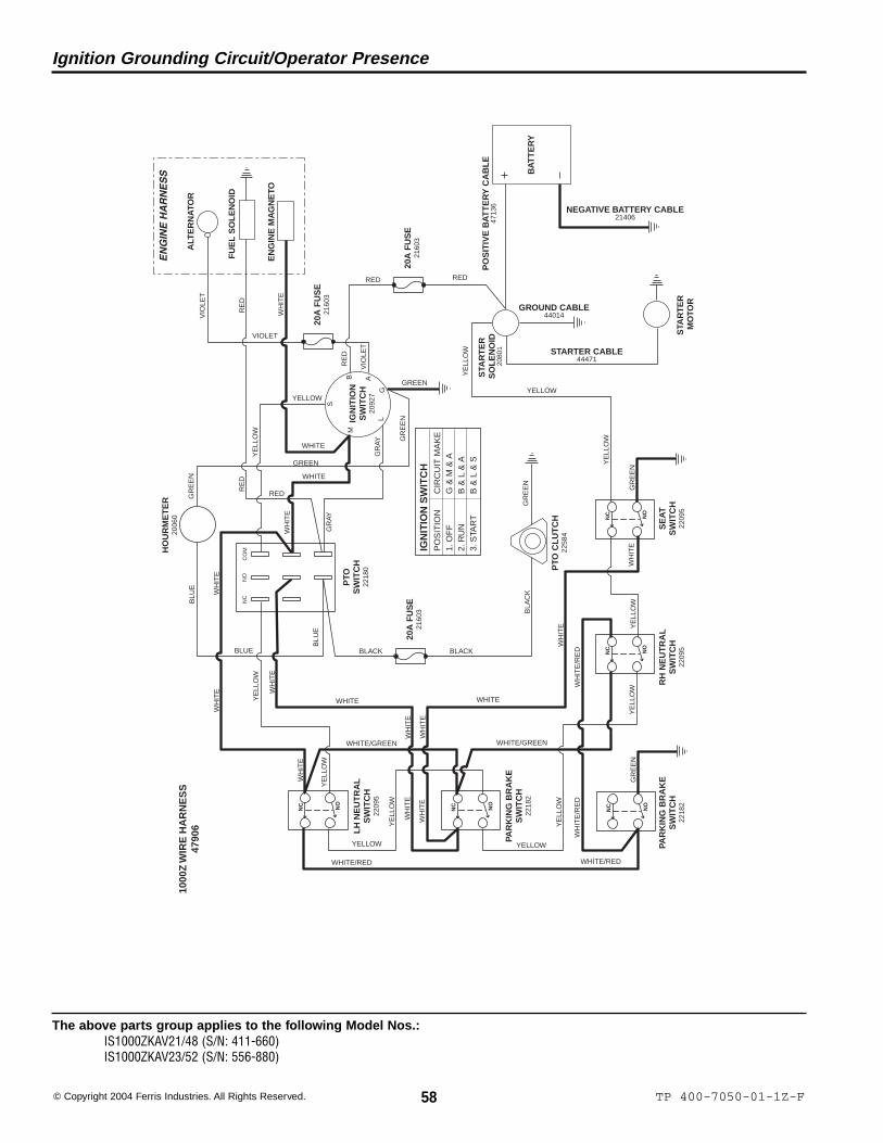
The above parts group applies to the following Model Nos.:IS1000ZKAV21/48 (S/N: 411-660)IS1000ZKAV23/52 (S/N: 556-880)
Ignition Grounding Circuit/Operator Presence
LH
NE
UT
RA
LS
WIT
CH
2209
5
STA
RT
ER
M
OTO
R
EN
GIN
E M
AG
NE
TO
ALT
ER
NA
TOR
FU
EL
SO
LE
NO
ID
BA
TT
ER
Y
PTO
SW
ITC
H22
180
M
LG
B
S
IGN
ITIO
NS
WIT
CH
2092
7A S
TAR
TE
R
SO
LE
NO
ID20
801
PAR
KIN
G B
RA
KE
SW
ITC
H22
182
PAR
KIN
G B
RA
KE
SW
ITC
H22
182
RH
NE
UT
RA
LS
WIT
CH
2209
5
SE
AT
SW
ITC
H22
095
HO
UR
ME
TE
R20
060
PTO
CL
UT
CH
2258
4
20A
FU
SE
2160
3
20A
FU
SE
2160
3
20A
FU
SE
2160
3
EN
GIN
E H
AR
NE
SS
WH
ITE
WHITE/GREEN
WH
ITE
WHITE/GREEN
WHITE/RED
WH
ITE
/RE
DW
HIT
E/R
ED
WH
ITE
WH
ITE
WH
ITE
WH
ITE
WHITE WHITE
WH
ITE
WHITE
WHITE
WH
ITE
WH
ITE
WH
ITE
WHITE/RED
YE
LLO
W
YELLOW
YE
LLO
W
YE
LLO
W
YELLOW
YE
LLO
W
YELLOW
YE
LLO
W
YE
LLO
W
YE
LLO
W
YE
LLO
W
YELLOW
GR
AY
GR
AY
RE
D
RED
BLU
E
BLU
E
BLUE BLACK BLACK
BLA
CK
GR
EE
N
GR
EE
N
GR
EE
N
GREEN
GREEN
GR
EE
NG
RE
EN
RE
D
RED RED
WH
ITE
WH
ITE
YE
LLO
W
VIO
LET
VIOLET
VIO
LET
RE
D
IGN
ITIO
N S
WIT
CH
PO
SIT
ION
CIR
CU
IT M
AK
E1.
OF
FG
& M
& A
2. R
UN
B &
L &
A3.
STA
RT
B &
L &
S
NEGATIVE BATTERY CABLE21406
PO
SIT
IVE
BA
TT
ER
Y C
AB
LE
4713
6
STARTER CABLE44471
GROUND CABLE44014
NC NO
NC NO
NC NO
NC NO
NC NO
1000
Z W
IRE
HA
RN
ES
S47
906
CO
MN
ON
C

59TP 400-7050-01-1Z-F
The above parts group applies to the following Model Nos.:IS1000ZKAV21/48 (S/N: 411-660)IS1000ZKAV23/52 (S/N: 556-880)
Charging Circuit
LH
NE
UT
RA
LS
WIT
CH
2209
5
STA
RT
ER
M
OTO
R
EN
GIN
E M
AG
NE
TO
ALT
ER
NA
TOR
FU
EL
SO
LE
NO
ID
BA
TT
ER
Y
PTO
SW
ITC
H22
180
M
LG
B
S
IGN
ITIO
NS
WIT
CH
2092
7A S
TAR
TE
R
SO
LE
NO
ID20
801
PAR
KIN
G B
RA
KE
SW
ITC
H22
182
PAR
KIN
G B
RA
KE
SW
ITC
H22
182
RH
NE
UT
RA
LS
WIT
CH
2209
5
SE
AT
SW
ITC
H22
095
HO
UR
ME
TE
R20
060
PTO
CL
UT
CH
2258
4
20A
FU
SE
2160
3
20A
FU
SE
2160
3
20A
FU
SE
2160
3
EN
GIN
E H
AR
NE
SS
WH
ITE
WHITE/GREEN
WH
ITE
WHITE/GREEN
WHITE/RED
WH
ITE
/RE
DW
HIT
E/R
ED
WH
ITE
WH
ITE
WH
ITE
WH
ITE
WHITE WHITE
WH
ITE
WHITE
WHITE
WH
ITE
WH
ITE
WH
ITE
WHITE/RED
YE
LLO
W
YELLOW
YE
LLO
W
YE
LLO
W
YELLOW
YE
LLO
W
YELLOW
YE
LLO
W
YE
LLO
W
YE
LLO
W
YE
LLO
W
YELLOW
GR
AY
GR
AY
RE
D
RED
BLU
E
BLU
E
BLUE BLACK BLACK
BLA
CK
GR
EE
N
GR
EE
N
GR
EE
N
GREEN
GREEN
GR
EE
NG
RE
EN
RE
D
RED RED
WH
ITE
WH
ITE
YE
LLO
W
VIO
LET
VIOLET
VIO
LET
RE
D
IGN
ITIO
N S
WIT
CH
PO
SIT
ION
CIR
CU
IT M
AK
E1.
OF
FG
& M
& A
2. R
UN
B &
L &
A3.
STA
RT
B &
L &
S
NEGATIVE BATTERY CABLE21406
PO
SIT
IVE
BA
TT
ER
Y C
AB
LE
4713
6
STARTER CABLE44471
GROUND CABLE44014
NC NO
NC NO
NC NO
NC NO
NC NO
1000
Z W
IRE
HA
RN
ES
S47
906
CO
MN
ON
C

60 TP 400-7050-01-1Z-F© Copyright 2004 Ferris Industries. All Rights Reserved.
The above parts group applies to the following Model Nos.:IS1000ZKAV21/48 (S/N: 411-660)IS1000ZKAV23/52 (S/N: 556-880)
Cranking Circuit
LH
NE
UT
RA
LS
WIT
CH
2209
5
STA
RT
ER
M
OTO
R
EN
GIN
E M
AG
NE
TO
ALT
ER
NA
TOR
FU
EL
SO
LE
NO
ID
BA
TT
ER
Y
PTO
SW
ITC
H22
180
M
LG
B
S
IGN
ITIO
NS
WIT
CH
2092
7A
STA
RT
ER
S
OL
EN
OID
2080
1PA
RK
ING
BR
AK
ES
WIT
CH
2218
2
PAR
KIN
G B
RA
KE
SW
ITC
H22
182
RH
NE
UT
RA
LS
WIT
CH
2209
5
SE
AT
SW
ITC
H22
095
HO
UR
ME
TE
R20
060
PTO
CL
UT
CH
2258
4
20A
FU
SE
2160
3
20A
FU
SE
2160
3
20A
FU
SE
2160
3
EN
GIN
E H
AR
NE
SS
WH
ITE
WHITE/GREEN
WH
ITE
WHITE/GREEN
WHITE/RED
WH
ITE
/RE
DW
HIT
E/R
ED
WH
ITE
WH
ITE
WH
ITE
WH
ITE
WHITE WHITE
WH
ITE
WHITE
WHITE
WH
ITE
WH
ITE
WH
ITE
WHITE/RED
YE
LLO
W
YELLOW
YE
LLO
W
YE
LLO
W
YELLOW
YE
LLO
W
YELLOW
YE
LLO
W
YE
LLO
W
YE
LLO
W
YE
LLO
W
YELLOWG
RAY
GR
AY
RE
D
RED
BLU
E
BLU
E
BLUE BLACK BLACK
BLA
CK
GR
EE
N
GR
EE
N
GR
EE
N
GREEN
GREEN
GR
EE
NG
RE
EN
RE
D
RED RED
WH
ITE
WH
ITE
YE
LLO
W
VIO
LET
VIOLET
VIO
LET
RE
D
IGN
ITIO
N S
WIT
CH
PO
SIT
ION
CIR
CU
IT M
AK
E1.
OF
FG
& M
& A
2. R
UN
B &
L &
A3.
STA
RT
B &
L &
S
NEGATIVE BATTERY CABLE21406
PO
SIT
IVE
BA
TT
ER
Y C
AB
LE
4713
6
STARTER CABLE44471
GROUND CABLE44014
NC NO
NC NO
NC NO
NC NO
NC NO
1000
Z W
IRE
HA
RN
ES
S47
906
CO
MN
ON
C
61TP 400-7050-01-1Z-F
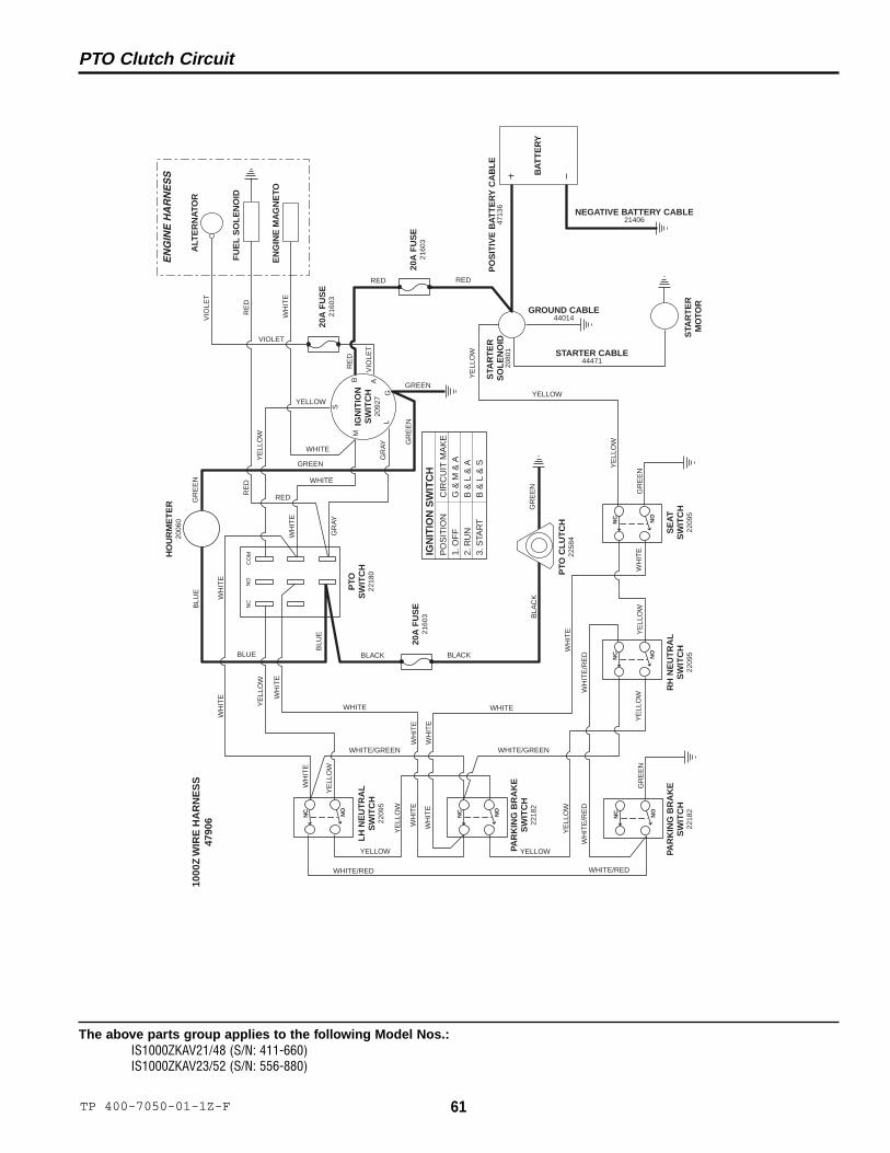
The above parts group applies to the following Model Nos.:IS1000ZKAV21/48 (S/N: 411-660)IS1000ZKAV23/52 (S/N: 556-880)
PTO Clutch Circuit
LH
NE
UT
RA
LS
WIT
CH
2209
5
STA
RT
ER
M
OTO
R
EN
GIN
E M
AG
NE
TO
ALT
ER
NA
TOR
FU
EL
SO
LE
NO
ID
BA
TT
ER
Y
PTO
SW
ITC
H22
180
M
LG
B
S
IGN
ITIO
NS
WIT
CH
2092
7A S
TAR
TE
R
SO
LE
NO
ID20
801
PAR
KIN
G B
RA
KE
SW
ITC
H22
182
PAR
KIN
G B
RA
KE
SW
ITC
H22
182
RH
NE
UT
RA
LS
WIT
CH
2209
5
SE
AT
SW
ITC
H22
095
HO
UR
ME
TE
R20
060
PTO
CL
UT
CH
2258
4
20A
FU
SE
2160
3
20A
FU
SE
2160
3
20A
FU
SE
2160
3
EN
GIN
E H
AR
NE
SS
WH
ITE
WHITE/GREEN
WH
ITE
WHITE/GREEN
WHITE/RED
WH
ITE
/RE
DW
HIT
E/R
ED
WH
ITE
WH
ITE
WH
ITE
WH
ITE
WHITE WHITE
WH
ITE
WHITE
WHITE
WH
ITE
WH
ITE
WH
ITE
WHITE/RED
YE
LLO
W
YELLOW
YE
LLO
W
YE
LLO
W
YELLOW
YE
LLO
W
YELLOW
YE
LLO
W
YE
LLO
W
YE
LLO
W
YE
LLO
W
YELLOW
GR
AY
GR
AY
RE
D
RED
BLU
E
BLU
E
BLUE BLACK BLACK
BLA
CK
GR
EE
N
GR
EE
N
GR
EE
N
GREEN
GREEN
GR
EE
NG
RE
EN
RE
D
RED RED
WH
ITE
WH
ITE
YE
LLO
W
VIO
LET
VIOLET
VIO
LET
RE
D
IGN
ITIO
N S
WIT
CH
PO
SIT
ION
CIR
CU
IT M
AK
E1.
OF
FG
& M
& A
2. R
UN
B &
L &
A3.
STA
RT
B &
L &
S
NEGATIVE BATTERY CABLE21406
PO
SIT
IVE
BA
TT
ER
Y C
AB
LE
4713
6
STARTER CABLE44471
GROUND CABLE44014
NC NO
NC NO
NC NO
NC NO
NC NO
1000
Z W
IRE
HA
RN
ES
S47
906
CO
MN
ON
C
62 TP 400-7050-02-1Z-F© Copyright 2004 Ferris Industries. All Rights Reserved.
The above parts group applies to the following Model Nos.:IS1000ZKAV21/48 (S/N: 661-1905)IS1000ZKAV23/52 (S/N: 881 -1400)
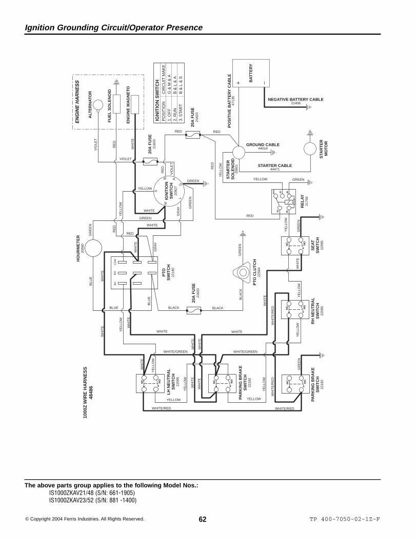
Ignition Grounding Circuit/Operator Presence
LH
NE
UT
RA
LS
WIT
CH
2209
5
STA
RT
ER
M
OTO
R
EN
GIN
E M
AG
NE
TO
ALT
ER
NA
TOR
FU
EL
SO
LE
NO
ID
BA
TT
ER
Y
PTO
SW
ITC
H22
180
M
LG
B
S
IGN
ITIO
NS
WIT
CH
2092
7A S
TAR
TE
R
SO
LE
NO
ID20
801
PAR
KIN
G B
RA
KE
SW
ITC
H22
182
PAR
KIN
G B
RA
KE
SW
ITC
H22
182
RH
NE
UT
RA
LS
WIT
CH
2209
5
SE
AT
SW
ITC
H22
095
HO
UR
ME
TE
R20
060
PTO
CL
UT
CH
2258
4
20A
FU
SE
2160
3
20A
FU
SE
2160
3
20A
FU
SE
2160
3
EN
GIN
E H
AR
NE
SS
WH
ITE
WHITE/GREEN
WH
ITE
WHITE/GREEN
WHITE/RED
WH
ITE
/RE
DW
HIT
E/R
ED
WH
ITE
WH
ITE
WH
ITE
WH
ITE
WHITE WHITE
WH
ITE
WHITE
WHITE
WH
ITE
WH
ITE
WH
ITE
WHITE/RED
YE
LLO
W
YELLOW
YE
LLO
W
YE
LLO
W
YELLOW
YE
LLO
W
YELLOW
YE
LLO
W
YE
LLO
W
YE
LLO
W
YELLOWG
RAY
GR
AY
RE
D
RED
BLU
E
BLU
E
BLUE BLACK BLACK
BLA
CK
GR
EE
N
GR
EE
N
GR
EE
N
GREEN
GREEN
GR
EE
NG
RE
EN
RE
D
RED RED
WH
ITE
WH
ITE
YE
LLO
W
VIO
LET
VIOLET
VIO
LET
RE
D
IGN
ITIO
N S
WIT
CH
PO
SIT
ION
CIR
CU
IT M
AK
E1.
OF
FG
& M
& A
2. R
UN
B &
L &
A3.
STA
RT
B &
L &
S
NEGATIVE BATTERY CABLE21406
PO
SIT
IVE
BA
TT
ER
Y C
AB
LE
4713
6
STARTER CABLE44471
GROUND CABLE44014
NC NO
NC NO
NC NO
NC NO
NC NO
1000
Z W
IRE
HA
RN
ES
S48
486
CO
MN
ON
C
YE
LLO
W85
86
30
87A
87
RE
LA
Y21
766
GREEN
RE
DRED

63TP 400-7050-02-1Z-F
The above parts group applies to the following Model Nos.:IS1000ZKAV21/48 (S/N: 661-1905)IS1000ZKAV23/52 (S/N: 881 -1400)
Charging Circuit
LH
NE
UT
RA
LS
WIT
CH
2209
5
STA
RT
ER
M
OTO
R
EN
GIN
E M
AG
NE
TO
ALT
ER
NA
TOR
FU
EL
SO
LE
NO
ID
BA
TT
ER
Y
PTO
SW
ITC
H22
180
M
LG
B
S
IGN
ITIO
NS
WIT
CH
2092
7A S
TAR
TE
R
SO
LE
NO
ID20
801
PAR
KIN
G B
RA
KE
SW
ITC
H22
182
PAR
KIN
G B
RA
KE
SW
ITC
H22
182
RH
NE
UT
RA
LS
WIT
CH
2209
5
SE
AT
SW
ITC
H22
095
HO
UR
ME
TE
R20
060
PTO
CL
UT
CH
2258
4
20A
FU
SE
2160
3
20A
FU
SE
2160
3
20A
FU
SE
2160
3
EN
GIN
E H
AR
NE
SS
WH
ITE
WHITE/GREEN
WH
ITE
WHITE/GREEN
WHITE/RED
WH
ITE
/RE
DW
HIT
E/R
ED
WH
ITE
WH
ITE
WH
ITE
WH
ITE
WHITE WHITE
WH
ITE
WHITE
WHITE
WH
ITE
WH
ITE
WH
ITE
WHITE/RED
YE
LLO
W
YELLOW
YE
LLO
W
YE
LLO
W
YELLOW
YE
LLO
W
YELLOW
YE
LLO
W
YE
LLO
W
YE
LLO
W
YELLOWG
RAY
GR
AY
RE
D
RED
BLU
E
BLU
E
BLUE BLACK BLACK
BLA
CK
GR
EE
N
GR
EE
N
GR
EE
N
GREEN
GREEN
GR
EE
NG
RE
EN
RE
D
RED RED
WH
ITE
WH
ITE
YE
LLO
W
VIO
LET
VIOLET
VIO
LET
RE
D
IGN
ITIO
N S
WIT
CH
PO
SIT
ION
CIR
CU
IT M
AK
E1.
OF
FG
& M
& A
2. R
UN
B &
L &
A3.
STA
RT
B &
L &
S
NEGATIVE BATTERY CABLE21406
PO
SIT
IVE
BA
TT
ER
Y C
AB
LE
4713
6
STARTER CABLE44471
GROUND CABLE44014
NC NO
NC NO
NC NO
NC NO
NC NO
1000
Z W
IRE
HA
RN
ES
S48
486
CO
MN
ON
C
YE
LLO
W85
86
30
87A
87
RE
LA
Y21
766
GREEN
RE
DRED
64 TP 400-7050-02-1Z-F© Copyright 2004 Ferris Industries. All Rights Reserved.
The above parts group applies to the following Model Nos.:IS1000ZKAV21/48 (S/N: 661-1905)IS1000ZKAV23/52 (S/N: 881 -1400)
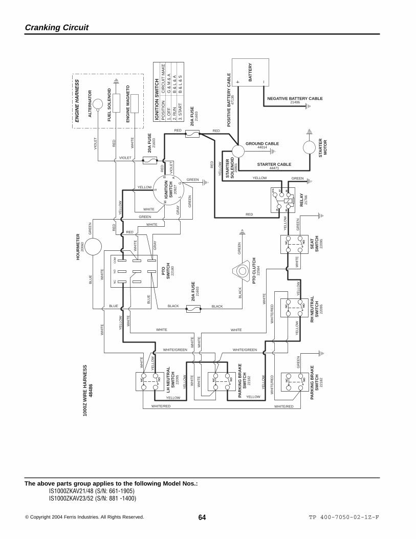
Cranking Circuit
LH
NE
UT
RA
LS
WIT
CH
2209
5
STA
RT
ER
M
OTO
R
EN
GIN
E M
AG
NE
TO
ALT
ER
NA
TOR
FU
EL
SO
LE
NO
ID
BA
TT
ER
Y
PTO
SW
ITC
H22
180
M
LG
B
S
IGN
ITIO
NS
WIT
CH
2092
7A S
TAR
TE
R
SO
LE
NO
ID20
801
PAR
KIN
G B
RA
KE
SW
ITC
H22
182
PAR
KIN
G B
RA
KE
SW
ITC
H22
182
RH
NE
UT
RA
LS
WIT
CH
2209
5
SE
AT
SW
ITC
H22
095
HO
UR
ME
TE
R20
060
PTO
CL
UT
CH
2258
4
20A
FU
SE
2160
3
20A
FU
SE
2160
3
20A
FU
SE
2160
3
EN
GIN
E H
AR
NE
SS
WH
ITE
WHITE/GREEN
WH
ITE
WHITE/GREEN
WHITE/RED
WH
ITE
/RE
DW
HIT
E/R
ED
WH
ITE
WH
ITE
WH
ITE
WH
ITE
WHITE WHITE
WH
ITE
WHITE
WHITE
WH
ITE
WH
ITE
WH
ITE
WHITE/RED
YE
LLO
W
YELLOW
YE
LLO
W
YE
LLO
W
YELLOW
YE
LLO
W
YELLOW
YE
LLO
W
YE
LLO
W
YE
LLO
W
YELLOWG
RAY
GR
AY
RE
D
RED
BLU
E
BLU
E
BLUE BLACK BLACK
BLA
CK
GR
EE
N
GR
EE
N
GR
EE
N
GREEN
GREEN
GR
EE
NG
RE
EN
RE
D
RED RED
WH
ITE
WH
ITE
YE
LLO
W
VIO
LET
VIOLET
VIO
LET
RE
D
IGN
ITIO
N S
WIT
CH
PO
SIT
ION
CIR
CU
IT M
AK
E1.
OF
FG
& M
& A
2. R
UN
B &
L &
A3.
STA
RT
B &
L &
S
NEGATIVE BATTERY CABLE21406
PO
SIT
IVE
BA
TT
ER
Y C
AB
LE
4713
6
STARTER CABLE44471
GROUND CABLE44014
NC NO
NC NO
NC NO
NC NO
NC NO
1000
Z W
IRE
HA
RN
ES
S48
486
CO
MN
ON
C
YE
LLO
W85
86
30
87A
87
RE
LA
Y21
766
GREEN
RE
DRED

65TP 400-7050-02-1Z-F
The above parts group applies to the following Model Nos.:IS1000ZKAV21/48 (S/N: 661-1905)IS1000ZKAV23/52 (S/N: 881 -1400)
PTO Clutch Circuit
LH
NE
UT
RA
LS
WIT
CH
2209
5
STA
RT
ER
M
OTO
R
EN
GIN
E M
AG
NE
TO
ALT
ER
NA
TOR
FU
EL
SO
LE
NO
ID
BA
TT
ER
Y
PTO
SW
ITC
H22
180
M
LG
B
S
IGN
ITIO
NS
WIT
CH
2092
7A S
TAR
TE
R
SO
LE
NO
ID20
801
PAR
KIN
G B
RA
KE
SW
ITC
H22
182
PAR
KIN
G B
RA
KE
SW
ITC
H22
182
RH
NE
UT
RA
LS
WIT
CH
2209
5
SE
AT
SW
ITC
H22
095
HO
UR
ME
TE
R20
060
PTO
CL
UT
CH
2258
4
20A
FU
SE
2160
3
20A
FU
SE
2160
3
20A
FU
SE
2160
3
EN
GIN
E H
AR
NE
SS
WH
ITE
WHITE/GREEN
WH
ITE
WHITE/GREEN
WHITE/RED
WH
ITE
/RE
DW
HIT
E/R
ED
WH
ITE
WH
ITE
WH
ITE
WH
ITE
WHITE WHITE
WH
ITE
WHITE
WHITE
WH
ITE
WH
ITE
WH
ITE
WHITE/RED
YE
LLO
W
YELLOW
YE
LLO
W
YE
LLO
W
YELLOW
YE
LLO
W
YELLOW
YE
LLO
W
YE
LLO
W
YE
LLO
W
YELLOWG
RAY
GR
AY
RE
D
RED
BLU
E
BLU
E
BLUE BLACK BLACK
BLA
CK
GR
EE
N
GR
EE
N
GR
EE
N
GREEN
GREEN
GR
EE
NG
RE
EN
RE
D
RED RED
WH
ITE
WH
ITE
YE
LLO
W
VIO
LET
VIOLET
VIO
LET
RE
D
IGN
ITIO
N S
WIT
CH
PO
SIT
ION
CIR
CU
IT M
AK
E1.
OF
FG
& M
& A
2. R
UN
B &
L &
A3.
STA
RT
B &
L &
S
NEGATIVE BATTERY CABLE21406
PO
SIT
IVE
BA
TT
ER
Y C
AB
LE
4713
6
STARTER CABLE44471
GROUND CABLE44014
NC NO
NC NO
NC NO
NC NO
NC NO
1000
Z W
IRE
HA
RN
ES
S48
486
CO
MN
ON
C
YE
LLO
W85
86
30
87A
87
RE
LA
Y21
766
GREEN
RE
DRED
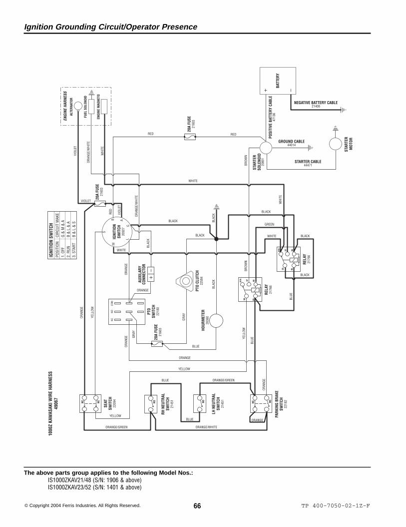
66 TP 400-7050-02-1Z-F© Copyright 2004 Ferris Industries. All Rights Reserved.
The above parts group applies to the following Model Nos.:IS1000ZKAV21/48 (S/N: 1906 & above)IS1000ZKAV23/52 (S/N: 1401 & above)
Ignition Grounding Circuit/Operator Presence
RH N
EUTR
ALSW
ITCH
2145
1
STAR
TER
MOT
OR
ENGI
NE M
AGNE
TO
ALTE
RNAT
OR
FUEL
SOL
ENOI
D
BATT
ERY
PTO
SWIT
CH22
180
M
LG
B
S
IGNI
TION
SWIT
CH20
927
A
STAR
TER
SOLE
NOID
2080
1
PARK
ING
BRAK
ESW
ITCH
2218
2
SEAT
SWIT
CH22
094
HOUR
MET
ER20
060
PTO
CLUT
CH22
584
20A
FUSE
2160
3
ENGI
NE H
ARNE
SS
WHI
TE
YELL
OW
RED
RED RED
VIOL
ET
VIOLET
VIOL
ET
IGNI
TION
SW
ITCH
POSI
TION
CIRC
UIT
MAK
E1.
OFF
G &
M &
A2.
RUN
B &
L &
A3.
STA
RTB
& L
& S
NEGATIVE BATTERY CABLE21406
POSI
TIVE
BAT
TERY
CAB
LE47
136
STARTER CABLE44471
GROUND CABLE44014
NO NC NO
1000
Z KA
WAS
AKI W
IRE
HARN
ESS
4906
7
COM
NONC
8586
30
87A
87
RELA
Y21
766
NC NC
LH N
EUTR
ALSW
ITCH
2145
1
NO
8586
30
87A
87
RELA
Y21
766
AUXI
LARY
CONN
ECTO
R
BLACK
GREEN
20A
FUSE
2160
3
20A
FUSE
2160
3
BLUE
BLUE
ORAN
GE
ORANGE
BLAC
K
ORAN
GE
ORAN
GE/W
HITE
ORAN
GE/W
HITE
ORANGE/GREEN ORANGE/WHITE
ORAN
GEORANGE/GREEN
YELLOW
YELL
OW
YELLOW
ORANGE
BROW
N
WHI
TE
WHITE
WHITE
BLACK
BLACK
WHITE
BROW
N
GRAY
GRAY
BLUE
BLAC
KBL
ACK
BLACK
BLACK
BLUE
BLUE
ORAN
GE
ORANGE

67TP 400-7050-02-1Z-F
The above parts group applies to the following Model Nos.:IS1000ZKAV21/48 (S/N: 1906 & above)IS1000ZKAV23/52 (S/N: 1401 & above)
Charging Circuit
RH N
EUTR
ALSW
ITCH
2145
1
STAR
TER
MOT
OR
ENGI
NE M
AGNE
TO
ALTE
RNAT
OR
FUEL
SOL
ENOI
D
BATT
ERY
PTO
SWIT
CH22
180
M
LG
B
S
IGNI
TION
SWIT
CH20
927
A
STAR
TER
SOLE
NOID
2080
1
PARK
ING
BRAK
ESW
ITCH
2218
2
SEAT
SWIT
CH22
094
HOUR
MET
ER20
060
PTO
CLUT
CH22
584
20A
FUSE
2160
3
ENGI
NE H
ARNE
SS
WHI
TE
YELL
OW
RED
RED REDVI
OLET
VIOLET
VIOL
ET
IGNI
TION
SW
ITCH
POSI
TION
CIRC
UIT
MAK
E1.
OFF
G &
M &
A2.
RUN
B &
L &
A3.
STA
RTB
& L
& S
NEGATIVE BATTERY CABLE21406
POSI
TIVE
BAT
TERY
CAB
LE47
136
STARTER CABLE44471
GROUND CABLE44014
NO NC NO
1000
Z KA
WAS
AKI W
IRE
HARN
ESS
4906
7
COM
NONC
8586
30
87A
87
RELA
Y21
766
NC NC
LH N
EUTR
ALSW
ITCH
2145
1
NO
8586
30
87A
87
RELA
Y21
766
AUXI
LARY
CONN
ECTO
R
BLACK
GREEN
20A
FUSE
2160
3
20A
FUSE
2160
3
BLUE
BLUE
ORAN
GE
ORANGE
BLAC
K
ORAN
GE
ORAN
GE/W
HITE
ORAN
GE/W
HITE
ORANGE/GREEN ORANGE/WHITE
ORAN
GEORANGE/GREEN
YELLOW
YELL
OW
YELLOW
ORANGE
BROW
N
WHI
TE
WHITE
WHITE
BLACK
BLACK
WHITE
BROW
N
GRAY
GRAY
BLUE
BLAC
KBL
ACK
BLACK
BLACK
BLUE
BLUE
ORAN
GE
ORANGE

68 TP 400-7050-02-1Z-F© Copyright 2004 Ferris Industries. All Rights Reserved.
The above parts group applies to the following Model Nos.:IS1000ZKAV21/48 (S/N: 1906 & above)IS1000ZKAV23/52 (S/N: 1401 & above)
Cranking Circuit
RH N
EUTR
ALSW
ITCH
2145
1
STAR
TER
MOT
OR
ENGI
NE M
AGNE
TO
ALTE
RNAT
OR
FUEL
SOL
ENOI
D
BATT
ERY
PTO
SWIT
CH22
180
M
LG
B
S
IGNI
TION
SWIT
CH20
927
A
STAR
TER
SOLE
NOID
2080
1
PARK
ING
BRAK
ESW
ITCH
2218
2
SEAT
SWIT
CH22
094
HOUR
MET
ER20
060
PTO
CLUT
CH22
584
20A
FUSE
2160
3
ENGI
NE H
ARNE
SS
WHI
TE
YELL
OW
RED
RED RED
VIOL
ET
VIOLET
VIOL
ET
IGNI
TION
SW
ITCH
POSI
TION
CIRC
UIT
MAK
E1.
OFF
G &
M &
A2.
RUN
B &
L &
A3.
STA
RTB
& L
& S
NEGATIVE BATTERY CABLE21406
POSI
TIVE
BAT
TERY
CAB
LE47
136
STARTER CABLE44471
GROUND CABLE44014
NO NC NO
1000
Z KA
WAS
AKI W
IRE
HARN
ESS
4906
7
COM
NONC
8586
30
87A
87
RELA
Y21
766
NC NC
LH N
EUTR
ALSW
ITCH
2145
1
NO
8586
30
87A
87
RELA
Y21
766
AUXI
LARY
CONN
ECTO
R
BLACK
GREEN
20A
FUSE
2160
3
20A
FUSE
2160
3
BLUE
BLUE
ORAN
GE
ORANGE
BLAC
K
ORAN
GE
ORAN
GE/W
HITE
ORAN
GE/W
HITE
ORANGE/GREEN ORANGE/WHITE
ORAN
GEORANGE/GREEN
YELLOW
YELL
OW
YELLOW
ORANGE
BROW
N
WHI
TE
WHITE
WHITE
BLACK
BLACK
WHITE
BROW
N
GRAY
GRAY
BLUE
BLAC
KBL
ACK
BLACK
BLACK
BLUE
BLUE
ORAN
GE
ORANGE
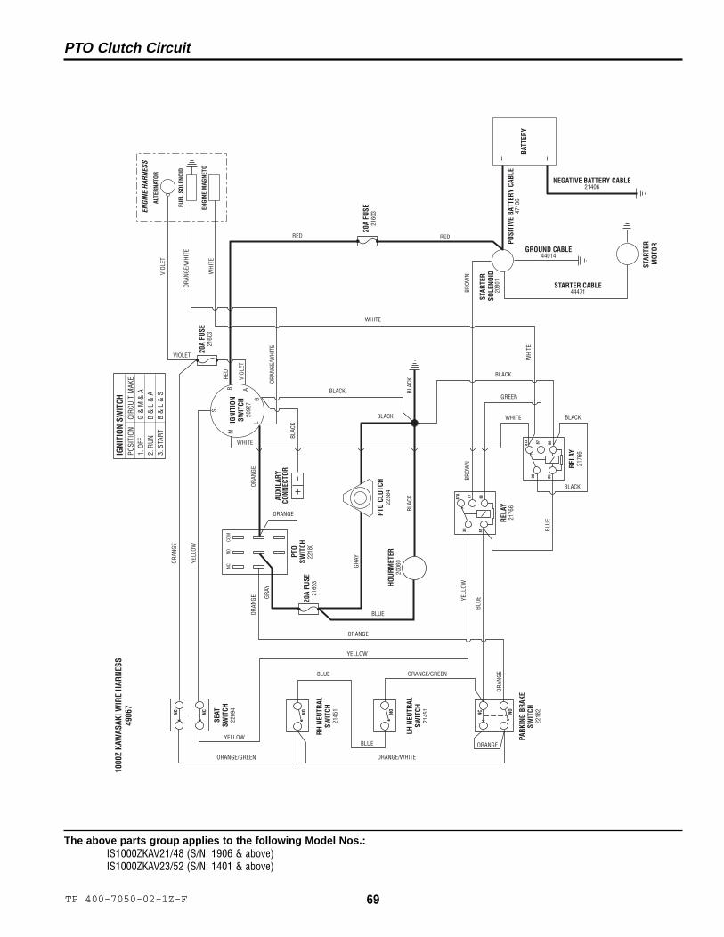
69TP 400-7050-02-1Z-F
The above parts group applies to the following Model Nos.:IS1000ZKAV21/48 (S/N: 1906 & above)IS1000ZKAV23/52 (S/N: 1401 & above)
PTO Clutch Circuit
RH N
EUTR
ALSW
ITCH
2145
1
STAR
TER
MOT
OR
ENGI
NE M
AGNE
TO
ALTE
RNAT
OR
FUEL
SOL
ENOI
D
BATT
ERY
PTO
SWIT
CH22
180
M
LG
B
S
IGNI
TION
SWIT
CH20
927
A
STAR
TER
SOLE
NOID
2080
1
PARK
ING
BRAK
ESW
ITCH
2218
2
SEAT
SWIT
CH22
094
HOUR
MET
ER20
060
PTO
CLUT
CH22
584
20A
FUSE
2160
3
ENGI
NE H
ARNE
SS
WHI
TE
YELL
OW
RED
RED REDVI
OLET
VIOLET
VIOL
ET
IGNI
TION
SW
ITCH
POSI
TION
CIRC
UIT
MAK
E1.
OFF
G &
M &
A2.
RUN
B &
L &
A3.
STA
RTB
& L
& S
NEGATIVE BATTERY CABLE21406
POSI
TIVE
BAT
TERY
CAB
LE47
136
STARTER CABLE44471
GROUND CABLE44014
NO NC NO
1000
Z KA
WAS
AKI W
IRE
HARN
ESS
4906
7
COM
NONC
8586
30
87A
87
RELA
Y21
766
NC NC
LH N
EUTR
ALSW
ITCH
2145
1
NO
8586
30
87A
87
RELA
Y21
766
AUXI
LARY
CONN
ECTO
R
BLACK
GREEN
20A
FUSE
2160
3
20A
FUSE
2160
3
BLUE
BLUE
ORAN
GE
ORANGE
BLAC
K
ORAN
GE
ORAN
GE/W
HITE
ORAN
GE/W
HITE
ORANGE/GREEN ORANGE/WHITE
ORAN
GEORANGE/GREEN
YELLOW
YELL
OW
YELLOW
ORANGE
BROW
N
WHI
TE
WHITE
WHITE
BLACK
BLACK
WHITE
BROW
N
GRAY
GRAY
BLUE
BLAC
KBL
ACK
BLACK
BLACKBL
UE
BLUE
ORAN
GE
ORANGE

70 TP 400-7050-00-1Z-F© Copyright 2004 Ferris Industries. All Rights Reserved.
The above parts group applies to the following Model Nos.:IS1000ZKAV21/48IS1000ZKAV23/52
Decals - Brand & Model
NOTE: Unless noted otherwise,use the standard hardware torquespecification chart.
First with Independent Suspension
1
2
3
1
2
3
NOTE: Decals are NOT shown to scale.

71TP 400-7050-00-1Z-F
The above parts group applies to the following Model Nos.:IS1000ZKAV21/48IS1000ZKAV23/52
REF NO. PART NO. QTY. DESCRIPTION
Decals - Brand & Model
Footnotes:
1 22227 1 DECAL, Ferris Logo (back of seat)2 22239 1 DECAL, First w/ Independent (back of seat)3 22556 1 DECAL, Ferris Logo

72 TP 400-7050-02-1Z-F© Copyright 2004 Ferris Industries. All Rights Reserved.
The above parts group applies to the following Model Nos.:IS1000ZKAV21/48 (S/N: 1905 & below)IS1000ZKAV23/52 (S/N: 1400 & below)
Decals - Safety & Operation
NOTE: Unless noted otherwise,use the standard hardware torquespecification chart.
1, 2
3, 4
5
7
8
9
NOTE: Decals are NOT shown to scale.
16, 176
��������
���� � �� ����������
����������� ����� ���� �����
���
��
���
��
���
��������
���� � �� ����������
��������� ��� ������ �������� ������
�����
���
���
OPERATIONTo Start Engine:
To Stop Engine:
Seat must be occupied, PTOSwitch OFF, Parking Brake ONand both control handles arelocked in Neutral.
Engage Parking Brake, Throttle athalf to full, turn Ignition Switch Off.
Before Leaving Machine:Turn PTO switch off, shut off engine,remove key, and set ParkingBrake
To Operate PTO Clutch:Operator must be in seat.Pull up to Engage.Push down to Disengage.
When Operator Leaves Seat:Engine will shut off if PTO is on.Engine will shut off of Parking Brakeis off.Engine will shut off if both controllevers are not locked in neutral.
GROUND SPEED ANDSTEERING LEVERSRight lever controls speedand direction of right drivewheel. Notch is neutrallock.Left lever controls speed anddirection of left drive wheel.Notch is neutral lock.Steer by slowing the lever inthe direction of the turn.
PARKING BRAKELEVER
Pull to set Parking Brake.Push to release ParkingBrake.
DECK LIFT PEDALPush to raise deck.
CUTTING HEIGHTADJUSTMENT PIN DO NOT TOW!
Damage may result toHydrostatic Transmission.
WARNINGBEWARE OF
POWER DRIVEN PARTS
KeySwitch
20A
ChargeCircuit
20A
PTOClutch
20AAuxiliary
20A46503
47138
AVOID SERIOUS INJURY OR DEATHREAD OPERATOR'S MANUAL.DO NOT ALLOW OPERATION OF MACHINERY BY UNTRAINED PERSONNEL.KEEP SAFETY DEVICES (GUARDS, SHIELDS, & SWITCHES) IN PLACE AND WORKING.DO NOT MOW WHEN CHILDREN OR OTHERS ARE AROUND.WHEN LEAVING MACHINE, SHUT OFF ENGINE, REMOVE KEY AND SET PARKING BRAKE.
THROWN OBJECTS AND BLADE CONTACT CAN CAUSE SERIOUS INJURY OR DEATH.BE SURE BLADES AND ENGINE ARE STOPPED BEFORE PLACING HANDS OR FEET NEAR BLADES.DISENGAGE PTO, ENGAGE PARKING BRAKE, SHUT OFF ENGINE AND REMOVE KEY BEFORE MAKING ADJUSTMENTS, SERVICING, CLEANING OR LEAVING THE MACHINE.
AVOID SERIOUS INJURY OR DEATH
OPERATING ON SLOPES CAN BE DANGEROUSIF YOU CANNOT BACK UP A HILL, DO NOT OPERATE ON IT.AVOID SUDDEN TURNS.DO NOT MOW SLOPES IF GRASS IS WET.IF MACHINE LOSES TRACTION ON A SLOPE, STOP THE BLADES AND PROCEED SLOWLY DOWN THE SLOPE.
AVOID CARBON MONOXIDE POISONINGDO NOT OPERATE THE ENGINE IN UNVENTILATED AREA.
WARNING DANGER
47171
1
3
5
6
7
8
9
13
14
15
2
4
48" 52"16
17
10
11
12
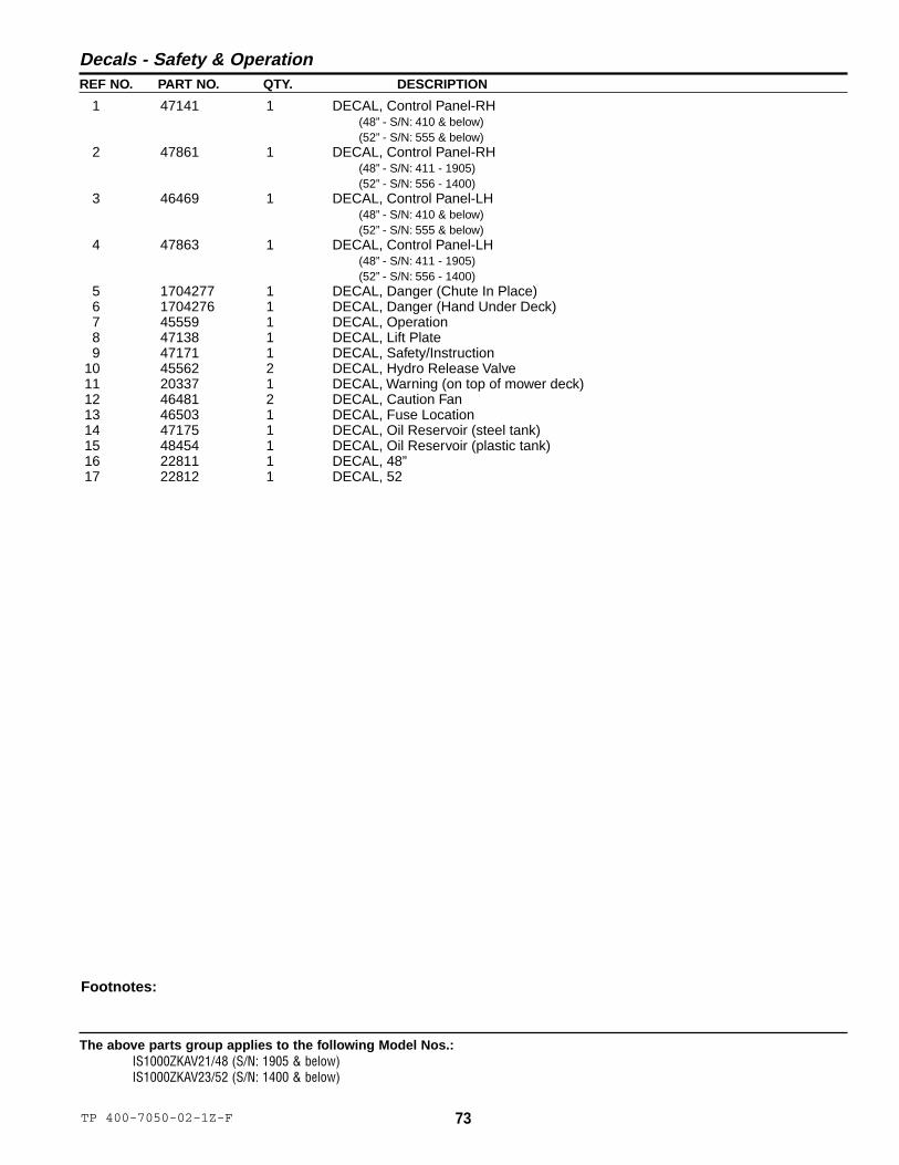
73TP 400-7050-02-1Z-F
The above parts group applies to the following Model Nos.:IS1000ZKAV21/48 (S/N: 1905 & below)IS1000ZKAV23/52 (S/N: 1400 & below)
REF NO. PART NO. QTY. DESCRIPTION
Decals - Safety & Operation
Footnotes:
1 47141 1 DECAL, Control Panel-RH(48” - S/N: 410 & below)(52” - S/N: 555 & below)
2 47861 1 DECAL, Control Panel-RH(48” - S/N: 411 - 1905)(52” - S/N: 556 - 1400)
3 46469 1 DECAL, Control Panel-LH(48” - S/N: 410 & below)(52” - S/N: 555 & below)
4 47863 1 DECAL, Control Panel-LH(48” - S/N: 411 - 1905)(52” - S/N: 556 - 1400)
5 1704277 1 DECAL, Danger (Chute In Place)6 1704276 1 DECAL, Danger (Hand Under Deck)7 45559 1 DECAL, Operation8 47138 1 DECAL, Lift Plate9 47171 1 DECAL, Safety/Instruction
10 45562 2 DECAL, Hydro Release Valve11 20337 1 DECAL, Warning (on top of mower deck)12 46481 2 DECAL, Caution Fan13 46503 1 DECAL, Fuse Location14 47175 1 DECAL, Oil Reservoir (steel tank)15 48454 1 DECAL, Oil Reservoir (plastic tank)16 22811 1 DECAL, 48”17 22812 1 DECAL, 52
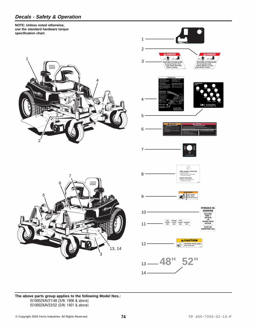
74 TP 400-7050-02-1Z-F© Copyright 2004 Ferris Industries. All Rights Reserved.
The above parts group applies to the following Model Nos.:IS1000ZKAV21/48 (S/N: 1906 & above)IS1000ZKAV23/52 (S/N: 1401 & above)
Decals - Safety & Operation
NOTE: Unless noted otherwise,use the standard hardware torquespecification chart.
OPERATIONTo Start Engine:
To Stop Engine:
Seat must be occupied, PTOSwitch OFF, Parking Brake ONand both control handles arelocked in Neutral.
Engage Parking Brake, Throttle athalf to full, turn Ignition Switch Off.
Before Leaving Machine:Turn PTO switch off, shut off engine,remove key, and set ParkingBrake
To Operate PTO Clutch:Operator must be in seat.Pull up to Engage.Push down to Disengage.
When Operator Leaves Seat:Engine will shut off if PTO is on.Engine will shut off of Parking Brakeis off.Engine will shut off if both controllevers are not locked in neutral.
GROUND SPEED ANDSTEERING LEVERSRight lever controls speedand direction of right drivewheel. Notch is neutrallock.Left lever controls speed anddirection of left drive wheel.Notch is neutral lock.Steer by slowing the lever inthe direction of the turn.
PARKING BRAKELEVER
Pull to set Parking Brake.Push to release ParkingBrake.
DECK LIFT PEDALPush to raise deck.
CUTTING HEIGHTADJUSTMENT PIN DO NOT TOW!
Damage may result toHydrostatic Transmission.
KeySwitch
20A
ChargeCircuit
20A
PTOClutch
20AAuxiliary
20A46503
47138
AVOID SERIOUS INJURY OR DEATHREAD OPERATOR'S MANUAL.DO NOT ALLOW OPERATION OF MACHINERY BY UNTRAINED PERSONNEL.KEEP SAFETY DEVICES (GUARDS, SHIELDS, & SWITCHES) IN PLACE AND WORKING.DO NOT MOW WHEN CHILDREN OR OTHERS ARE AROUND.WHEN LEAVING MACHINE, SHUT OFF ENGINE, REMOVE KEY AND SET PARKING BRAKE.
THROWN OBJECTS AND BLADE CONTACT CAN CAUSE SERIOUS INJURY OR DEATH.BE SURE BLADES AND ENGINE ARE STOPPED BEFORE PLACING HANDS OR FEET NEAR BLADES.DISENGAGE PTO, ENGAGE PARKING BRAKE, SHUT OFF ENGINE AND REMOVE KEY BEFORE MAKING ADJUSTMENTS, SERVICING, CLEANING OR LEAVING THE MACHINE.
AVOID SERIOUS INJURY OR DEATH
OPERATING ON SLOPES CAN BE DANGEROUSIF YOU CANNOT BACK UP A HILL, DO NOT OPERATE ON IT.AVOID SUDDEN TURNS.DO NOT MOW SLOPES IF GRASS IS WET.IF MACHINE LOSES TRACTION ON A SLOPE, STOP THE BLADES AND PROCEED SLOWLY DOWN THE SLOPE.
AVOID CARBON MONOXIDE POISONINGDO NOT OPERATE THE ENGINE IN UNVENTILATED AREA.
WARNING DANGER
47171
2
3
4
5
6
7
8
10
11
12
48" 52"13
14
1
9
1
2
4
5
6
13, 143
7

75TP 400-7050-02-1Z-F
The above parts group applies to the following Model Nos.:IS1000ZKAV21/48 (S/N: 1906 & above)IS1000ZKAV23/52 (S/N: 1401 & above)
REF NO. PART NO. QTY. DESCRIPTION
Decals - Safety & Operation
Footnotes:
1 49199 1 DECAL, Control Panel2 1704277 1 DECAL, Danger (Chute In Place)3 1704276 1 DECAL, Danger (Hand Under Deck)4 45559 1 DECAL, Operation5 47138 1 DECAL, Lift Plate6 47171 1 DECAL, Safety/Instruction7 49148 1 DECAL, Fuel Selector8 45562 2 DECAL, Hydro Release Valve9 20337 1 DECAL, Warning (on top of mower deck)
10 48454 1 DECAL, Oil Reservoir11 46503 1 DECAL, Fuse Location12 46481 2 DECAL, Caution Fan13 22811 1 DECAL, 48”14 22812 1 DECAL, 52

76 TP 400-7050-02-1Z-F© Copyright 2004 Ferris Industries. All Rights Reserved.
The above parts group applies to the following Model Nos.:IS1000ZKAV21/48IS1000ZKAV23/52
48 “ & 52” Mower Decks - Housings, Covers, Spindles & Blades
See Mower Drive
See Deck Rollers
9
16
17
18
15
10
11
12
10
13
14
6 7 8
3
5
4
2
1
Torque Capscrewsto 70 Ft. Lbs.
(95 Nm)
5
NOTE: Unless noted otherwise,use the standard hardware torquespecification chart.

77TP 400-7050-02-1Z-F
The above parts group applies to the following Model Nos.:IS1000ZKAV21/48IS1000ZKAV23/52
REF NO. PART NO. QTY. DESCRIPTION
Footnotes:
48 “ & 52” Mower Decks - Housings, Covers, Spindles & Blades
1 47453 1 48” MOWER DECK* 47467 1 52” MOWER DECK2 47129 2 MOWER DECK GUARD3 46445 1 DISCHARGE CHUTE4 25011-8 2 CAPSCREW, Hex Head, 5/16-18 x 15 25057 14 NUT, Hex Nylon Lock, 5/16-186 22308 6 BODY CLIP, 5/16-187 25155 6 WASHER, 5/168 25011-6 6 CAPSCREW, Hex Head, 5/16-18 x 3/49 46363 3 SPINDLE ASSEMBLY, Complete (includes Ref 10-14)
10 46363-5 6 BEARING, Roller11 46363-4 3 SPACER, Bearing12 46363-1 3 SPINDLE HOUSING13 46363-3 3 TRASH SHIELD14 46363-2 3 SPINDLE SHAFT15 23156 12 CAPSCREW, Hex Flange Head, 5/16-18 x 1-1/416 20843 3 MOWER BLADE (48” Deck)
* 21227 3 MOWER BLADE (52” Deck)17 25159 3 WASHER, USS, 5/818 25320-14 3 CAPSCREW, Hex Head, 5/8-11 x 1-3/4

78 TP 400-7050-00-1Z-F© Copyright 2004 Ferris Industries. All Rights Reserved.
The above parts group applies to the following Model Nos.:IS1000ZKAV21/48IS1000ZKAV23/52
48 “ & 52” Mower Decks - Pulleys, Belts & Idler Arm
NOTE: Unless noted otherwise,use the standard hardware torquespecification chart.
2
3
4
5
1
6
8
7
9
1010
11
12
13
14
15
16
14
19
7
8
17
18
12
17
20
2122
23
24
256
6
Torque Lock Nuts (3)to 85-90 Ft. Lbs.
(115-122 Nm)

79TP 400-7050-06-1Z-F
The above parts group applies to the following Model Nos.:IS1000ZKAV21/48IS1000ZKAV23/52
REF NO. PART NO. QTY. DESCRIPTION
48 “ & 52” Mower Decks - Pulleys, Belts & Idler Arm
Footnotes:
1 22667 1 BELT (48” Deck)* 22148 1 BELT (52” Deck)2 22622 3 PULLEY, Spindle, Gold (48” Deck, S/N: 855 & below)* 23175 3 PULLEY, Spindle, Black (48” Deck, S/N: 856 & above)* 22721 3 PULLEY, Spindle, Gold (52” Deck, S/N: 1185 & below)* 23178 3 PULLEY, Spindle, Black (52” Deck, S/N: 1186 & above)3 50407-5 3 KEY, 1/4” x 1-1/4”4 25318 3 WASHER, Spring5 25319 3 NUT, Hex Nylon Lock, 5/8-186 25056 4 NUT, Hex Nylon Lock, 1/2-137 25158 3 WASHER, 1/28 21976 3 PULLEY, Idler9 47142 2 SPACER, .52 x 1.25 x .70
10 25017-24 2 CAPSCREW, Hex Head, 1/2-13 x 311 25017-36 1 CAPSCREW, Hex Head, 1/2-13 x 4-1/212 25150 2 WASHER, USS, 1/213 45022 1 IDLER ARM PIVOT SHAFT14 21541 2 BUSHING, Flange15 45106 1 IDLER ARM16 20095 1 GREASE FITTING17 45023 3 SPACER, .52 x 1.00 x .4418 21811 1 EYEBOLT19 25017-28 1 CAPSCREW, Hex Head, 1/2-13 x 3-1/220 45200 1 SPRING ANCHOR21 25013-8 1 CAPSCREW, Hex Head, 3/8-16 x 122 22788 1 SPRING, Compression, 2”23 25156 1 WASHER, 3/824 25096 1 NUT, Hex Nylon Lock, 3/8-1625 25128 1 NUT, Hex Serrated Flange, 3/8-16
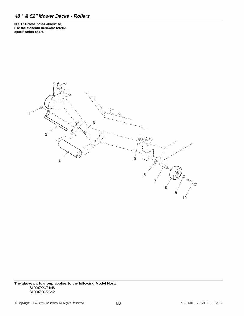
80 TP 400-7050-00-1Z-F© Copyright 2004 Ferris Industries. All Rights Reserved.
The above parts group applies to the following Model Nos.:IS1000ZKAV21/48IS1000ZKAV23/52
48 “ & 52” Mower Decks - Rollers
NOTE: Unless noted otherwise,use the standard hardware torquespecification chart.
1
2
3
4
10
5
6
7
89

81TP 400-7050-00-1Z-F
The above parts group applies to the following Model Nos.:IS1000ZKAV21/48IS1000ZKAV23/52
REF NO. PART NO. QTY. DESCRIPTION
48 “ & 52” Mower Decks - Rollers
Footnotes:
1 25128 1 NUT, Hex Serrated Flange, 3/8-162 41655 1 ROLLER PIN3 25013-8 1 CAPSCREW, Hex Head, 3/8-16 x 14 20785 1 ROLLER, Nose5 25096 2 NUT, Hex Nylon Lock, 3/8-166 25305 2 WASHER, Heavy, 3/87 45992 2 WHEEL AXLE8 1716353 2 WHEEL9 25165 2 WASHER, Fender, 3/8
10 25013-28 2 CAPSCREW, Hex Head, 3/8-16 x 3-1/2

82 TP 400-7050-04-1Z-F© Copyright 2004 Ferris Industries. All Rights Reserved.
The above parts group applies to the following Model Nos.:IS1000ZKAV21/48IS1000ZKAV23/52
48 “ & 52” Mower Decks - Rear Mount Bars
NOTE: Unless noted otherwise,use the standard hardware torquespecification chart.
10
11
12
12
3
4
56
7
6
8
9
1313
NOTE: LH side shown. Components areidentical for the RH side.

83TP 400-7050-04-1Z-F
The above parts group applies to the following Model Nos.:IS1000ZKAV21/48IS1000ZKAV23/52
REF NO. PART NO. QTY. DESCRIPTION
48 “ & 52” Mower Decks - Rear Mount Bars
Footnotes:
1 45009 2 DECK PUSHER BAR2 20095 2 GREASE FITTING3 25093 2 NUT, Hex, Jam, 3/4-164 25265-32 2 CAPSCREW, Hex Head, 3/4-16 x 45 25160 2 WASHER, 3/46 22111 4 ROD END SEAL7 22039 2 BALL JOINT, 3/4-168 46093 2 SPACER, .75 x 1.50 x 1.009 25284 2 NUT, Hex Nylon Lock, 3/4-16
10 45037 2 PUSHER BAR MOUNT PIN11 25013-10 2 CAPSCREW, Hex Head, 3/8-16 x 1-1/412 25096 2 NUT, Hex Nylon Lock, 3/8-1613 25156 4 WASHER, 3/8

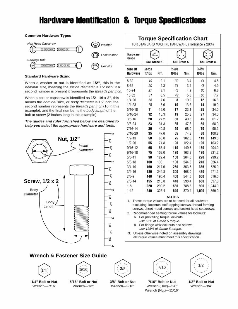
Torque Specification ChartFOR STANDARD MACHINE HARDWARE (Tolerance ± 20%)
HardwareGrade
SAE Grade 2 SAE Grade 5 SAE Grade 8
Size Of in/lbs in/lbs in/lbsHardware ft/lbs Nm. ft/lbs Nm. ft/lbs Nm.
8-32 19 2.1 30 3.4 41 4.68-36 20 2.3 31 3.5 43 4.910-24 27 3.1 43 4.9 60 6.810-32 31 3.5 49 5.5 68 7.71/4-20 66 7.6 8 10.9 12 16.31/4-28 76 8.6 10 13.6 14 19.05/16-18 11 15.0 17 23.1 25 34.05/16-24 12 16.3 19 25.8 27 34.03/8-16 20 27.2 30 40.8 45 61.23/8-24 23 31.3 35 47.6 50 68.07/16-14 30 40.8 50 68.0 70 95.27/16-20 35 47.6 55 74.8 80 108.81/2-13 50 68.0 75 102.0 110 149.61/2-20 55 74.8 90 122.4 120 163.29/16-12 65 88.4 110 149.6 150 204.09/16-18 75 102.0 120 163.2 170 231.25/8-11 90 122.4 150 204.0 220 299.25/8-18 100 136 180 244.8 240 326.43/4-10 160 217.6 260 353.6 386 525.03/4-16 180 244.8 300 408.0 420 571.27/8-9 140 190.4 400 544.0 600 816.07/8-14 155 210.8 440 598.4 660 897.61-8 220 299.2 580 788.8 900 1,244.01-12 240 326.4 640 870.4 1,000 1,360.0
Hex Head Capscrew
Hex Nut
Lockwasher
Washer
Carriage Bolt
NOTES1. These torque values are to be used for all hardware
excluding: locknuts, self-tapping screws, thread formingscrews, sheet metal screws and socket head setscrews.
2. Recommended seating torque values for locknuts:a. For prevailing torque locknuts:
use 65% of Grade 5 torque.b. For flange whizlock nuts and screws:
use 135% of Grade 5 torque.3. Unless otherwise noted on assembly drawings,
all torque values must meet this specification.
Hardware Identification & Torque SpecificationsCommon Hardware Types
Screw, 1/2 x 2
BodyDiameter
BodyLength
InsideDiameter
Nut, 1/2”
NoMarks
3/8” Bolt or NutWrench—9/16”
3/8
5/16” Bolt or NutWrench—1/2”
5/16
1/4” Bolt or NutWrench—7/16”
1/4
1/2” Bolt or NutWrench—3/4”
1/27/16
7/16” Bolt or NutWrench (Bolt)—5/8”
Wrench (Nut)—11/16”
Wrench & Fastener Size Guide
Standard Hardware Sizing
When a washer or nut is identified as 1/2”, this is thenominal size, meaning the inside diameter is 1/2 inch; if asecond number is present it represents the threads per inch.
When a bolt or capscrew is identified as 1/2 - 16 x 2” , thismeans the nominal size , or body diameter is 1/2 inch; thesecond number represents the threads per inch (16 in thisexample), and the final number is the body length of thebolt or screw (2 inches long in this example).
The guides and ruler furnished below are designed tohelp you select the appropriate hardware and tools.
01/4
3/41/2
11/4
3/41/2
21/4
3/41/2
31/4
3/41/2
4
Ferris Industries5375 North Main StreetMunnsville, NY 13409800-933-6175
www.ferrisindustries.com
© Copyright 2004 Ferris IndustriesAll Rights Reserved. Printed in USA.
PARTSMANUALIS1000Z SeriesZero-Turn Riding Mower
IT IS THE POLICY OF FERRIS INDUSTRIES, INC. TO IMPROVE ITS PRODUCTS WHENEVER ITIS POSSIBLE AND PRACTICAL TO DO SO. WE RESERVE THE RIGHT TO MAKE CHANGES ORADD IMPROVEMENTS AT ANY TIME WITHOUT INCURRING ANY OBLIGATION TO MAKE SUCHCHANGES ON PRODUCTS MANUFACTURED PREVIOUSLY.
Related Documents