Disclosure to Promote the Right To Information Whereas the Parliament of India has set out to provide a practical regime of right to information for citizens to secure access to information under the control of public authorities, in order to promote transparency and accountability in the working of every public authority, and whereas the attached publication of the Bureau of Indian Standards is of particular interest to the public, particularly disadvantaged communities and those engaged in the pursuit of education and knowledge, the attached public safety standard is made available to promote the timely dissemination of this information in an accurate manner to the public. इंटरनेट मानक “!ान $ एक न’ भारत का +नम-ण” Satyanarayan Gangaram Pitroda “Invent a New India Using Knowledge” “प0रा1 को छोड न’ 5 तरफ” Jawaharlal Nehru “Step Out From the Old to the New” “जान1 का अ+धकार, जी1 का अ+धकार” Mazdoor Kisan Shakti Sangathan “The Right to Information, The Right to Live” “!ान एक ऐसा खजाना > जो कभी च0राया नहB जा सकता ह ै” Bhartṛhari—Nītiśatakam “Knowledge is such a treasure which cannot be stolen” IS 9349 (2006): Recommendations for structural design of medium and high head slide gates [WRD 12: Hydraulic Gates and Valves]

Welcome message from author
This document is posted to help you gain knowledge. Please leave a comment to let me know what you think about it! Share it to your friends and learn new things together.
Transcript

Disclosure to Promote the Right To Information
Whereas the Parliament of India has set out to provide a practical regime of right to information for citizens to secure access to information under the control of public authorities, in order to promote transparency and accountability in the working of every public authority, and whereas the attached publication of the Bureau of Indian Standards is of particular interest to the public, particularly disadvantaged communities and those engaged in the pursuit of education and knowledge, the attached public safety standard is made available to promote the timely dissemination of this information in an accurate manner to the public.
इंटरनेट मानक
“!ान $ एक न' भारत का +नम-ण”Satyanarayan Gangaram Pitroda
“Invent a New India Using Knowledge”
“प0रा1 को छोड न' 5 तरफ”Jawaharlal Nehru
“Step Out From the Old to the New”
“जान1 का अ+धकार, जी1 का अ+धकार”Mazdoor Kisan Shakti Sangathan
“The Right to Information, The Right to Live”
“!ान एक ऐसा खजाना > जो कभी च0राया नहB जा सकता है”Bhartṛhari—Nītiśatakam
“Knowledge is such a treasure which cannot be stolen”
“Invent a New India Using Knowledge”
है”ह”ह
IS 9349 (2006): Recommendations for structural design ofmedium and high head slide gates [WRD 12: Hydraulic Gatesand Valves]


..-. —. — -—-.——....—-... .
IS 9349:2006
i-a* Gim-ra’
Indian Standard
RECOMMENDATIONS FOR STRUCTURAL DESIGNOF MEDIUM AND HIGH HEAD SLIDE GATES
(Second l?evision)
ICS 93.160
... ,
0 BIS 2006
BUREAU OF INDIAN STANDARDSMANAK BHAVAN, 9 BAHADUR SHAH ZAFAR MARG
NEW DELHI 110002 ,
Janua~ 2006Price Group 8

Hydraulic Gates and Valves Sectional Committee, WRD 12
FORE WORD
This Indian Standard (Second Revision) was adopted by the Bureau of Indian Standards, after the drafi finalizedby the Hydraulic Gates and Valves Sectional Committee had been approved by the Water Resources DivisionCouncil.
Slide gate, as the name implies, is that gate in which the operating member (gate leaf) slides on the seatingsurfaces provided on the frame consisting of bodies with or without bonnets. These gates are ‘generally installed inthe closed conduit and have sealing all around. Jet flow gate also falls in this category.
Use of slide gates as the control and guard or emergency gates in conduits and sluices for water head up to 100 mis gaining popularity because of comparative simple construction and better hydraulic performance resultingfrom narrow groove width. Jet flow gates are being used for heads up to 200 m. However, slide gates normally donot close under their own weight, under condition of unbalanced head, that is, water flowing through conduit orsluice, and have to be pushed down for closing. This factor dictates the location of hoist directly above the gateand Iimits the use of slide gates.
It is advisable, specially for high head gates, to get model of the gate tested in the hydraulic laboratory to determinethe following for various operating requirements:
a) Down pull and uplift force,
b) Air demand and its location,
c) Gate slot geometry,
d) Gate geometry — Special bottom shape, . ,.e) Vibration, and
f) Negative pressure and cavitation effects.
This standard was published in 1979. The first revision was taken up in 1986 in view of the experience gainedduring the course of these years in use of this standard. Two more conditions were added in Annex C, that is, threeedges fixed and one (longer) edge tiee, and three edges fixed and one (shorter) edge free to cover the mostcommonly occurring field conditions.
This standard is being brought out to incorporate changes and additional clauses in the light of experience gainedand the latest trends in design the worldover specially with reference to coacting width in case of panel construction,jet flow gates, requirement of aeration, figures showing rubber seal arrangement, etc.
There is no ISO standard on the subject. Assistance has been drawn from ASTM D2 137 ‘Standard test methodsfor rubber property — Brittleness point of flexible polymers and coated fabrics for the method of test for lowtemperature brittleness’.
The composition of the Committee responsible for the formulation of this standard is given in Annex J.
For the purpose of deciding whether a particular requirement of this standard is complied with, the final value,observed or calculated expressing the result of a test or analysis, shall be rounded off in accordance withIS 2:1960 ‘Rules for rounding ofinumerical values (revise~’. The number of significant places retained in therounded off value should be the same as that of the specified value in this standard.
IS 9349:2006
Indian Standard
RECOMMENDATIONS FOR STRUCTURAL DESIGNOF MEDIUM AND HIGH HEAD SLIDE GATES
(Second RevNion)
1 SCOPE
1.1 This standard provides recommendation forstructural design of medium and high head slide gates.
1.2 This standard does not cover bulkhead stoploggates and hoisting mechanism. “
2 REFERENCES
The standards listed in Annex A contain provisions,which through reference in this text, constituteprovisions of this standard. At the time of publication,the editions indicated were valid. All standards aresubject to revision and parties to agreements based onthis standard are encouraged to investigate thepossibility of applying the most recent additions of thestandards indicated in Annex A.
3 TERMINOLOGY
3.0 For the purpose of this standard the followingdefinitions shali apply.
3.1 Medium Head Gate — A gate which is subjectedto a head of water exceeding 15 m but less than 30.m,over sill.
3.2 High Head Gate — Agate which is subjected to ahead of water 30 m orabove, over sill.
4 TYPE AND”REQUIREMENT
4.1 ~pe
Slide gate for medium and high head installations areclassified into the following hvo types depending upontheir service conditions:
a)
b)
Emergency or guard gates — These aredesigned to be closed under unbalanced head,that is, with water flowing through the conduitor sluice, but are not meant for regulation.They are generally opened under balancedhead but may be designed to open underunbalanced head also. These are kept eitherfully open or fully closed.
Regulating gates — These are used forregulating flow of water. These are operatedunder unbalanced head conditions and aredesigned to be operated at any gate opening.
Jet flow gates are used as regulating gateseither at discharge end or at any intermediatepoint in a conduit. These can be usefhl forsmall size outlets under high head (150-200 m) installation.
4.2 Requirement
The principal requirements of slide gates shall be asgiven below:
a)
b)
c)
d)
e)
o
The gates shall be reasonably watertight.Leakage, if any, unless otherwise specified,shall not normally exceed 5 and 10 litre/min/mlength of periphery of the sealing surface, formedium and high head gates, respectively.
The gates shall be rigid, smooth, and straightat joints and reasonably free from vibration.
The bottom shape of the gates shall be suitablyddsigned to minimize downpull in the case ofdownstream sealing and to minimize uplift andvibrations in case of gates with upstreamsealing and to provide a converging fluid wayand definite spring flow discharge,
The slot of the gates shall be as narrow aspossible, in conformity with structural safetyof the gate.
The gates shall be capable of being raised orlowered by the hoisting mechanism provided,within the prescribed time.
Downstream edges in the opening of-the sloton top and side of the gates shall not be sharp.These may be suitably set back from theupstream edge of the slot and rounded off forbetter hydraulic performance.
5 DESCRIPTION AND ARRANGEMENT OFGATE
5.1 General
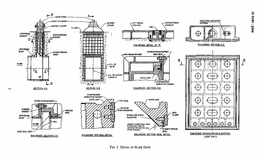
The typical installation of a slide gate for medium orhigh head is shown in Fig. 1. It consists of gate leaf,which moves, in a fkrne. The flame consists of bodywhich houses the gate in the open position. The bodyand bonnet are embedded in concrete. The bonnet iscovered by bonnet cover with a stuff]ng box throughwhich stem rod passes. The hoisting mechanism may
1
*B_ GATE STEM —z A-u
:.,uPsTREAMSOD, ,::
..:
J&< HOIST Cylinder—————a ‘---
BONNET COVERFLOOR~ /%%
- h-.”. DOWNSTREAM ......,. ...
: !.::! n BONNET :.,
.-l .,,, -DOWNSTREAM i“4-u-
11—(I II
h)
RU&!+ERWm.
uPsTREAMSOOY -
LBSECTION A-A
OC-)WNSTREAM SOOY 7
- GREASEPIPE
SIDE SEAL SEAT ~“’
~ ARGED SECTION C-C
HOLE FOR INOICATORruFSTREAM - DOWNSTREAM “SYSTEM
ENLARGEO DETAIL AT P
DOWNSTREAM SONNET
e uPSTREAM SONNET SIDE SEAL 7 7
SECTION B.S ENLARGED sEcTloN o-lj
COMPRESSEDASBESTOS GASKET >
‘L
QttiRGED SkCTION E-E
m....-”-.-.. L-. -.-1-.-:.; L----’----
,:..L.:-,J L--- -1- ,;; --,---- ‘,~--J-, -L-:: -_’ C,:-- . .
ENLARGED TOP SEAL DETAIL ENLARGED BOITOM SkAL DETAIL ENLARGED DOWNSTREAM ELEVATION
(LEAF ONLY)
FIG. 1 DETAILOF SLIDEGATE

be supported directly over the bonnet cover or over aseparate set of girders at higher level.
5.2 Gate Leaf
5.2.1 The gate leaf is a rigid frame structure consistingof a skin plate supported on stiffener and/or girderwhich transmits the water load tlom the skin plate tothe vertical end girder. The skin plate may be upstreamand/or downstream, according to design requirements.The gate leaf may be of cast steel or of structural steelin welded construction. Provision shall be made forconnecting the gate position indicator and connectionsfor the hoist to the gate leaf. Connections for the hoistshall be determined so that the gate shall remain trulyvertical in suspended condition.
5.2.2 The seals which are screwed on the downstreamface of the gate leaf transmit the water load on thegate leaf to the concrete through seal seats andembedded downstream body. Sutlicient number ofscrews should be provided to resist the frictionalforces during raising or lowering of gate undermaximum head of water. In addition shear plug toresist about 10 percent of shear force should beprovided. Alternatively rubber seals of suitable sizemay be fixed on sides and top with the help of sealclamps and G.I. or stainless steel bolts}stainless steelscrew so as to ensure a positive water pressurebetween the seal and the gate, and to bear tightly onthe seal seat to prevent leakage. For reducing the sealfriction fluorocarbon clad seal may be used. Edges ofseal clamp adjacent to seal bulb shall be rounded.Rubber seal shall be provided at the bottom of thegate leaf. Its projection shall be uniform and shouldnot be normally more than 3 mm. In the case of high
IS 9349:2006
head gates, the projection should be limited to 1.5 mm.Sealing arrangement showing rubber seals is shownin Fig. 2.
5.2.3 The gate shall have a narrow sill surface at thebottom with its upstream ordownstream face slopingupwards at an approximate angle of 45° with thehorizontal to reduce down pull or uplift respectively,especially when the gate is used for regulation.
5.2.4 For high head gates bottom sealing and slopingsurfaces of the gate should preferably be of stainlesssteel for better resistance to cavitation damage. Toreinforce it against cavitational pitting that may occur,the upstream edge of the gate leaf may be slightlyprojected and rounded off suitably for bettertiydraulicperformance. An overlay of corrosion resistant steelof thickness af not less than 3 mm on slopingplate or complete corrosion resistant bottom plateis recommended on the sloping plate as shown inFig. 1.
5.3 Frame
The frame consists of the following components:
a) Sill girder with bottom seal seat,
b) Body,
c) Bonnet, and
d) Bonnet cover. ... ,
5.3.1 Sill Girder with Bottom Seal Seat
Bottom seal seat should be flush with the bottom of theopening and should be fixed on to the sill girder eitherwith screwing or by welding to provide bottom sealingsurface for the gate. All flanged joints should beprovided with O-ringgasket.
v> m ci.AMP
SIDE RUSSER SEAL
INTELSSALSKIN PLATE
SEAL RETAINERSKW PIATE ~ frSEU CtAMP
‘vJ-”’”*IZ
FIG. 2 RUBBER
RMSION
SEALARRANGEMENT
3

IS 9349:2006
5.3.2 Body
The body which houses the gate leaf in closed positionmay be in sub-assemblies with joints. The body maybeof cast steel or structural steel in welded construction.In the latter case, proper care shall be taken to preventwarping during welding so that the tolerance of gapsaround the gate is strictly adhered to. These should beadequately ribbed to provide proper anchorage withthe surrounding concrete. The ribs so provided shouldhave enough openings for allowing good concretingbehind the groove bodies. The downstream portion ofthe body carries the bearing-cum-sealing plate in caseof metallic seals, which may be fixed-by welding orscrewing. It should be so designed that the maximumbearing pressure to which the concrete is subjectedshould not exceed the permissible stress specified inIS 456. The adequacy of embedded bearing plateshraclcsections shall be checked in bending and shear alsobased.on theory of bending of infinite berun on elasticfoundation. Guides are also fixed ‘to the body forguiding the gate. Separate seal seats should be providedfor rubber seals on u/s or d/s depending upon locationof seals.
5.3.3 Bonnet
The bonnet houses the gate leaf in open position. It hasflanges on the bottom for being bolted to the body andon the top for the bonnet cover. The bonnet may eitherbe of cast steel or structural steel in weldedconstruction. It should be adequately ribbed to provideproper anchorage with surrounding concrete. The ribsso provided should have enough openings for allowinggood concreting behind the groove bodies. Guides arefixed to the bonnet in continuity of the guides fixed onthe body for guiding the gates.
5.3.4 Bonnet Cover
Bonnet cover is provided to seal the gate slot andprovide a support for the hoist, in case the hoist ismounted directly over the bomet. It should be designedfor full hydrostatic pressure and also for the hoistcapacity if the hoist is directly mounted over it. It shouldbe in either one piece or more pieces according to therequirement. Provision for venting of air should bemade in the bonnet cover.
5.4 Jet Flow Gate
Jet flow gates are used as regulating gates either atdischarge end or at.any intermediate point in a conduit.They consist of a flat-bottomed leaf, a body and bonnetand a bonnet cover on which the operating hoist ismounted. The fluid way upstream of gate forms a nozzlein the shape of the frustum of a 45° cone with upstreamdiameter at least twenty percent greater thandownstream diameter or orifice diameter, causing, the
discharging jet to contract and spring free of the slot inthe gate body. The advantage in jet flow gates is thatthere is little or no pressure on the bonnet of gate. Thesecan be useful for small size outlets under high heads(150-200 m) installation. The arrangement is shown inFig. 3.
-6-MATERIALS
The material used for different components should beas specified in Annex B.
7 UNIT STRESS
7.1 The permissible value of stresses in the structuralparts should be as specified in ArmexC.
7.2 The permissible -value of stresses in weldedconnections should be the same as permitted for theparent material.
8 LOADING
8.1 The gate shall be designed for hydrostatic andhydrodynamic forces as determined from modelstudies.
8.2 In case of gates located in conduitshluices theminimum increase in head on account of subatmospheric pressure, downstream of gate, should be2 m for medium and 5 m for high head gates. ,.,,,
8.3 Earthquake forces shall be consideredin accordancewith IS 1893.
8.4 Silt load, if applicable, shall also be considered.
9 STRUCTURAL DESIGN
9.1 Gate Leaf
9.Ll”The skin plate and stiffeners should be designedtogether in a composite manner.
9.1.2 The skin plate should be designed for thefollowing two conditions, unless more precise methodsare available:
a) In bending across the stiffeners or girder asapplicable, or
b) As panels, in accordance with the procedureand support conditions as given in Annex D.
9.1.3 The-stresses in skin plates for conditions in 9.1.2should be determined as follows:
a)
b)
4
For determining the stresses for condition inbending across stiffener, or girders, as perprocedure in 9.1.2(a), bending moment shouldbe determined according to the conditions ofsupport.
For calculating the stresses in skin plates forcondition in bending as panel, in accordance

IS 9349:2006
PLAN ISECTION B-B
LEVER POSITION
+
(STUD ENGAGED)
.LEVER POSITION(STL!O DIS-ENGAGED
UPPER CYLINDER HEAD -
BLEED LINE TO PERMITREPACKING PISTONWITH GATE HELD -EN
t
BY OIL UNDER PISTON —
— GATE HANGERSTUD FOR HOLDING
L
GATE OPENMECHANICALLY IFDESIRED
V.PACKING
{
GATE POSITIONINDICATOR
-
T
I
1-
L PISTON RINGS
PISTON
/-o,L p,p~CONNECTION
‘CYLINCfR
GATE STEM
,r I%N?%ON
$PACKING-GIAND
~
.,. . ..,. ... .
,,, ,-V-PACKING
-ONNET COVERSEAL RING ~
DETAIL C
i
UPSTREAMBONNET
/%’’TEM- 00WNSTREM
1
T
IBOOY
AIR VENTCONDUIT
AIR VENTMANIFOLD
B—
‘JET LO BOUNDARY..-
UPSTREAMBONNET ~
CONICAL DIFFUSER
j
I
\
JET SPRING POINT
.—
Lc’
1
I+1
1A-..
/
HALF t HALFSECTIONAL DOWNSTREAMSECTIONAL ELEVATION A-A
ELEVATION ELEVATION
FIG. 3 JET-FLOWGATE
5

IS 9349:2006
with the procedure given in 9.1.2(b), thestresses as given in Annex D should beused.
9.1.4 In either of the cases specified in 9.1.2 whiledesigning the stiffener and girders the skin plate canbe considered to be coacting with them.
a) The coacting width of the skin plate in nonpanel fabrication as per 9.1.2(a) shall be takenby restricting to the least of the fo[lowingvalues:
1) 4ot+B,
where
t = thickness of skin plate, and
B = width of stiffener flange incontact with the skin plate;
2) 0.11 span; and
3) Centre-to-centre of stiffeners or girders.
b) When skin plate coacts with girder as well asstiffener to form a panel construction, widthof skin plate coacting w-ithhorizontal girderor stiffener should be worked out as illustratedin Annex E.
9.1.5 The stresses so computed shall be combined inaccordance with formula:
where
0“ =
Crx=
cry =
Tv =
d0, = 0: +0; – oxcry+3 Zxy=
comb-ined stress,
sum of stresses along x axis,
sum of stresses along y axis, and
sum of shear stresses along x – y plane.
NOTE — The appropriate signs should be taken for rJxandCJyin the above formula.
9.1.6 The permissible value of mono-axial as weIl ascombined stresses should not be greater than thosespecified in Annex C.
9.1.7 Permissible value of stresses in the welds shouldbe the same as permitted for the parent material. Forsite weld, efficiency should be considered 80 percentof shop weld.
9.1.8 To take care of corrosion, the actual thicknessof skin plate to be provided should be at least 1.5 mmmore than the theoretical thickness computed, basedon the stresses given in Annex C. The thickness of theskin plate should be not less than 8 mm, exclusive ofcorrosion allowance when considered.
9.1.9 The stiffeners may, if necessary, be of a built upsection or of standard rolled section, that is, tees, angles,channels, etc.
6
9.1.10 Horizontal and vertical stiffeners should bedesigned as simply supported or continuous -beams,depending upon the framing adopted for the gate. Thespacing between horizontal girders should preferablybe such that all the.girders carry ahnost equal loads.
9.1.11 The end vertical girders should be designed ascontinuous beams with concentrated loads, comingfrom horizontal girders, at points where they meet theend vertical girders.
9.1.12 Deflection of Gate
a) Maximum deflection of the gate under normalconditions of loading should be limited to1/2 000 of the span.
b) In case of bulkhead gates the maximumdeflection should be limited to 1/1 200 of thespan.
9.1.13 Whenever the gate is connected to the hoistingmechanism, at points other thanthe end vertical girders,care shall be taken to avoid stress concentrationparticularly on the web of-top horizontal girder. Thehoisting force should preferably be dispersed throughsuitable stiffeners to one or more “horizontal girdersbelow the top one. The extra stresses arising due tothis arrangement may be combined with the otherstresses to ensure that permissible limits are notexceeded. .,, ,
9.1.14 Gate Slot Geometry
Width of slot should be kept as small as practicable. ,The downstream edge of the gate slot should be offsetto reduce the cavitation hazard. In the absence of modelstudies a downstream offset of about 0.075 to 0.10 ofthe slot width with l/12 to 1/24 gradient downstreamof the gate slot and a rounded point of intersection “isrecommended.
9.1.15 Aeration Requirement
The location and sizing of air vent is critical forminimizing cavitation and vibration problemsassociated with regulating services of gated outlets.Such installation, should be provided with adequateair supply downstream of the gate. For determinationof air requirements and size of air vent IS 12804 maybe referred to.
9.2 Seals
9.2.1 The seal should be fixed to the gate leaf bymeans of countersunk screws made of corrosionresisting steel. The hole in the seal should be counterbored to accommodate the conical head of the screws.When assembled, the heads of the screws shouldremain 1.0 mm below the surface of the seal. Thescrews used for fixing of seals to the gate leaf, should
IS 9349:2006
be designed to take up full shear likely to developbetween the seal and the gate leaf due to friction forceencountered between the seal and seal seat duringraising or lowering of gates under maximum head ofwater. The screws should be adequately tightened toa constant torque and locked by punch marks. Acompressed asbestos/rubber gasket should b.eprovided between the seal and the Ieafiody to preventleakage. Shear plugs may be provided in addition, atthe discretion of the designer. The bottom seal shouldbe of wedge type and manufactured from rubber. “Forreducing the friction fluorocarbon cladded seals maybe used. Suitable groove for grease should be providedon the top and side seals as shown in Fig. 1 for metallicsealing.
9.2.2 The surface of the gate leaf over which seals arefixed, should be machined to a finish of 12.5 to 25 ~m(see IS 3073).
9.2.3 The surface finish of the sliding surface of metalseals should be within the range of 1.6 to 6.3 pm (seeIs 3073).
9.2.4 Minimum threaded length equivalent to one anda half times the diameter of the screws should bescrewed with the gate leaf to ensure against theirIooseningunder vibrations during operations.
9.2.5 Suitable chamfer should be provided at thebottom of the gate leaflclamp plate to accommodatethe bottom wedge seal in compressed position.
9.2.6 For regulating gates, the designer at hisdiscretion, may make the.seals effective throughout therange of travel of gates either by fixing the seals to theembedded parts or by providing a liner plate above, incontinuation of the top seal seats for the entire width ofthe gate and range of regulation.
9.3 Body
9.3.1 The body is embedded in concrete which shouldbe reinforced sufficiently to withstand the waterpressure. However, the gate body is made sut%cientlyrigid to prevent damage or distortion duringtransportation and installation by providingreinforcing ribs in longitudinal, as well as transversedirection. The ribs should be provided with enoughopening for good concreting. The body shall bechecked to withstand full external pressure with apermissible stress of 80 percent of yield point stressof the material and should have sutllcient anchoragewith the concrete to withstand the external pressure.In case sufficient anchorage length in concrete is notavailable, the body should be designed to withstandfidl external pressure on its own.
9.3.2 The downstream portion of the body carries thebearing plate and should be so designed that maximum
bearing pressure to which the concrete is subjected, shallnot exceed the permissible stress specified in IS 456.
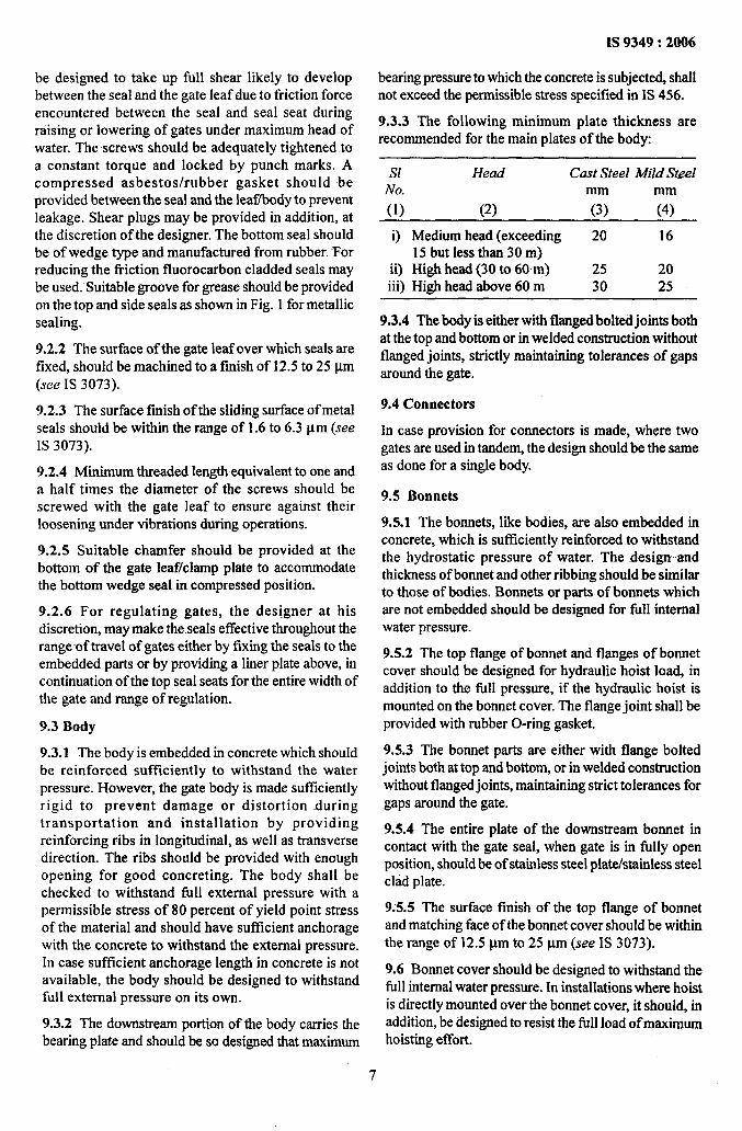
9.3.3 The following minimum plate thickness arerecommended for the main plates of the body:
sl Head Cast Steel Mild SteelNo. mm
(1) (2) (3) 747
i) Medium head (exceeding 20 1615 but less than 30 m)
ii) High head (30 to 60 m) 25 20iii) High head above 60 m 30 25
9.3.4 The body is either with flanged bolted joints bothat the top and bottom or in welded construction withoutflanged joints, strictly maintaining tolerances of gapsaround the gate.
9.4 Connectors
In case provision for connectors is made, where twogates are used in tandem, the design should be the sameas done for a single body.
9.5 Bonnets
9.5.1 The bonnets, like bodies, are also embedded inconcrete, which is sufficiently reinforced to withstandthe hydrostatic pressure of water. The design andthickness of bonnet and other ribbing should be similarto those of bodies. Bonnets or parts of bonnets whichare not embedded should be designed for fill internalwater pressure.
9.5.2 The top flange of bonnet and flanges of bonnetcover should be designed for hydraulic hoist load, inaddition to the full pressure, if the hydraulic hoist ismounted on the bonnet cover. The flange joint shall beprovided with rubber O-ring gasket.
9.5.3 The bonnet parts are either with flange boltedjoints both at top and bottom, or in welded constructionwithout flanged joints, maintaining strict tolerances forgaps around the gate.
9.5.4 The entire plate of the downstream bonnet incontact with the gate seal, when gate is in filly openposition, should be of stainless steel plate/stainless steelclad plate.
9.5.5 The surface finish of the top flange of bonnetand matching face of the bonnet cover should be withinthe range of 12.5 pm to 25 pm (see IS 3073).
9.6 Bonnet cover should be designed to withstand thefull internal water pressure. In installations where hoistis directly mounted over the bonnet cover, it should, inaddition, be designed to resist the full load of maximumhoisting effort.
7
IS 9349:2006
9.7 Gland stuffing-box should be provided on bonnetcover to prevent leakage of water around stem rod ofgate leaf passing through the bonnet cover. The glandstuffing box should be in two pieces, namely, hoistingor box proper and the cover gland. It should either beof cast steel or fabricated with structural steel. It shouldbe designed for fill hydrostatic pressure. The materialfor sealing should -be graphite impregnated asbestosrope, or chevron or equivalent, preferably of squarecross-section. The housing should have bushing of non-ferrous material, preferably phosphor bronze, tofacilitate the supporting of sealing rope and for freepassage of-stem rod. Cover of the box also should havesimilar arrangements. The housing box should havesuitable arrangements for fixing the assembly to thebonnet cover.
9.8 Seal Seats/Bearing -PJates/Sill Beam
9.8.1 The width of sealing surface should be so chosenthat the bearing pressure does not exceed thepermissible limit.
9.8.2 The bearing plate should be welded or fixed tothe downstream body by means of counter bore screwsmade of corrosion resistant steel. The holes in thebearing plate should be countersunk to accommodatethe conical.head of screw. When assembled, the headof screws should remain 1.0 mm”below the surface ofthe seal seat. The weld or the screws used for fixingthe bearing plates should be designed to take up thefull shear likely to develop between the seal and thebearing plate. These screws should be adequatelytightened and locked by punch marks. Suitable meansshall be provided for greasing the seal seats. It shouldbe ensured that the grease does not leak out of thejoints. A recommended method is the provision ofO-ring seals around the greasing holes to seal the jointbetween the seal seat and the downstream part of thebody.
9.8.3 The surface finish of bodies to which seal seatsare fixed should be machined to a finish of 12.5to 25 ~m(see IS 3073).
9.8.4 The surface finish of the bearing plate/side sealseat in sliding contact with metal seals during gateoperation should be within the range of 1.6 to 6.3 ~m(see IS.3073).
9.8.5 The surface finish of the bottom seal seatshould be within the range of 12.5 to 25 pm (seeIs 3073).
9.8.6 For regulating and emergency gates, wheremetal-to-metal seals are provided, same materialshould not be used for seals and seal seats. Thematerial for the seal should be softer than the materialfor seal seats so that the wearing is on seals and not
on seal seats and also for avoiding seizing whilesliding under load.
9.8.7 The sill beam may be provided with the corrosionresistant steel flats, welded or screwed with corrosionresistant steel screws. The surfaceof the sill beam maybe machined smooth, wherever required, and madeflush with the surrounding concrete.
9.9 Anchorage or Anchor Plates
Anchorages should be provided in the first stageconcrete, with suitable blockout openings, to hold theembedded parts of the second stage concrete. The-anchor bolts in the second stage concrete shall be withdouble nuts and washers. Yor adjustment purposesenlarged holes in the embedded parts of the secondstage concrete should be provided. Preferably theanchor plates may be embedded with first stageconcrete and anchor bolts welded subsequently. Theminimum size (diameter) of anchor bolts should not beless than 16 mm and the anchor plate thickness shouldnot be less than 8 mm. In order to limit the permissiblestress in shear in concrete suitably designed shearreinforcement may be necessary. A typical arrangementis given in Annex F.
9.10 Guides and Guide Bars
Guides are fixed on the gate leaf and guide bars on-thebodies and bonnets to guide the leaf properlythroughout its travel. The guides should be effective inboth directions, that is, longitudinal as well astransverse. The recommended clearance between theguide and guide bar is a maximum of 3 mm in eachdirection on either side.
9.11 Guide Rollers and Guide Shoes
9.11.1 Gate guide rollers/shoes should be-provided onthe sides of the gates to limit the lateral motion of gateto not more than 6 mm in either direction. The rollershould be flanged and travel on steel plates or railssecurely attached to anchor bolts. In case of rollers theyshould be provided with bronze -bushing or self-lubricating bushing turning on fixed steel pins. Suitablearrangement for lubrication of these rollers should alsobe provided. Where necessa~, counter guide rollersshould be provided to limit the transverse movementof gates.
9.11.2 A minimum of two guide rollers or shoes shouldbe provided on each side of the gate to resist thetransverse and lateral movement of the gate and at thesame time, to prevent gate from jamming. A clearanceof 3 to 6 mm between the guide rollers and guidesurface should be structurally adequate-to withstandthe load they are likely to be subjected to, dependingupon the type of installation, hoist and hydraulic
8

condition. Guide rollers may also be provided withsuitable springs, whenever required. Guide rollers maybe preferred for high head gates to be handled by Iiftiigbeams.
9.11.3 Suitable spring assembly may be providedbeneath the guide shoes or guide roller assembly torestore the gate to normal position after any deflection,specially for high head gates.
9.11.4 The guide roller/shoes should be designed forthe maximum load to which they may be subjectedduring operation. A minimum load of 5 percent of thetotal dead weight of the gate is recommended for thedesign of each guide roller.
9.12 Tolerance
The tolerance for embedded parts and in componentsof gate should be as given in Annex G (see also Fig. 4).
1 KnGl
IS 9349:2006
10 COEFFICIENT OF SLIDING FRICTION
10.1 Values of coet%cient of friction recommended fordesign of gates are given in Annex H.
10.2 Arrangement for lubricating the sliding surfaceof the gate seal and the bearing plate maybe providedat the discretion of the designer.
11 EARTHQUAKE EFFECT
11.1 Where the project lies in a seismic zone earthquakeforces should, be considered in accordance with IS1893, and the gate designed accordingly.
11.2 The allowable stresses as given in Annex C shallbe increased by 33.333 percent in case of earthquakeconditions subject to an upper limit of 85 percent ofthe yield point. In case of nuts and bolts, increase instress shall -not be more than 25 percent of allowablestress.
1/-SIDESEAL SEAT-CUM-{
/8!SLNIINGTRACK
/
BEARING-CUM-SLIDINGPLATE
/ -UPSTREAM WIDE . ,.
FIG. 4 SLOT SECTIONFORSLIDE-GATE
9

1S 9349:2006
11.2.1 The permissible values of stresses in weldedconnections should be the same as permitted for parentmaterial.
12 WAVE EFFECT
12.1 For very wide and big reservoirs, the effect ofwave height due to storms, etc, in causing increasedloading on the gate, should also be considered.
12.2 Increased stresses in various parts of the gate, asdescribed in 11.2 for earthquake forces, should beallowed for the wave effect.
12.3 The earthquake forces and the wave effect shouldnot be considered to act together while computing theincreased stresses in the gate.
13 ICE LOADS
13.1 Ice-Impact and Ice-Pressure
Provided local conditions do not impose other values,ice-impact and ice-pressure should be taken intoaccount in such a way that the water pressure triangleshall be replaced as given below:
.a) In waters with ice thickness greater than300 mm, by an even surface pressure of30000 N/mz up to 3 m depth; and
b) In waters with ice thickness upto 300 mm, byan even surface of 20000 N/mzup to 2 m depth.
14 MWL CONDITION
In case the gate is to be checked for MWL condition,the allowable stress shall be increased by 33.333percent of the values specified in Annex C subject to80 percent of upper limit of yield point. However, ifthe gates are required to be designed for MWLcondition, normal stresses should be taken inaccordance with Annex C.
15 STRESS RELIEVING
Stress relieving is required depending on the thicknessof the plate or size of weld. For plates with thicknessmore than 28 mm stress relieving should be done. Thestress relieving may be done according to the procedurementioned in IS 2825.
16 GROUTING
Provision for contact grouting, that is, groutingbetween gate body and bonnet and surroundingconcrete should be made to ensure a perfect -bondbetween them. Provision for suitably designed grouthole arrangement should be made in the liner andbonnet to avoid voids between various stages ofconcreting and between gate bodylbonnet andconcrete. Provision should also be made for escapeof air during grouting. Such grout holes should beplugged subsequently and ground flushed. ,,,,
ANNEX A
(Clause 2)
LIST OF REFFERED INDIAN STANDARDS
IS NO.
291:1989
305:1981
306:1983
318:1981
456:2000
800:1984
808:1989
1030:1998
Title
Machining purposesSpecification (third revision)
Aluminum bronze ingotscastings (second revision)
—
and
Tin bronze ingots and castings(third revision)
Leaded tin bronze ingots andcastings (second revision)
Plain and reinforced concrete —Code of practice (fourth revision)
Code of practice for generalconstructionin steel(secondrevision)
Dimensions for hot rolled steelbeam, column, channel and anglesections (third revision)
Carbon steel castings for generalengineering purposes (@h revision)
IS No.
1367
1570
(Part 1): 1978
(Part 2):1979
(Part 2/See 1):1979
(Part 2/See 2):1987
(Part 3): ‘1979
Title
Technical supply conditions forthreaded fasteners
Schedules for wrought steels forgeneral engineering purposes:
Steels specified by tensile and/oryield properties (#lrst revision)
Carbon steels (unalloyed steels)@rst revision)
Carbon steels (unalloyed steels),Section 1 Wrought products (otherthan wires) with specified chemicalcomposition and related properties(first revision)
Carbon steels (unalloyed steels),Section 2 Carbon steel wires withrelated properties @st revision)
Carbon and carbon managnese freecutting steels (jirst revision)
10

IS 9349:2006
IS No.
(Part 4): 1988
(Part 5): 1985
(Part 6): 1996
(Part 7): 1992
1875:1992
“1893:1984
2004:1991
Title
Alloy steels (alloy constructionaland spring steels) with specifiedchemical composition andmechanical properties (@trevi,slon)
Stainless and heat-resisting steels(second revision)
Carbon and alloy tools steel @strevision)
Steels for elevated temperatureservice (creep resistant steels)
Carbonsteel billets, blooms, slabsand bars for forgings @fth revision)
Criteria for earthquake resistantdesign of structures (@rth revision)
Carbon steel forgings for generalengineering purposes (thirdmvkion)
IS No.
2062:1999
2825:1969
3073:1967
6911:1992
8500:1991
11855:2004
12804:1989
we
Steel for general structural purposes— Specification Vourth revision)
Code for unfired pressure vessels
Assessment of surface roughness
Stainless steel plate, sheet and strip@st revision)
Structural steel — Microalloyed(medium and high strengthqualities) @irst revision)
Guidelines for design and use ofdifferent types of rubber seals forhydraulic gates
Criteria for estimation of aerationdemand for spillway and outletstructure
ANNEX B
(Clause 6)
MATERIAL FOR THE COMPONENT OF MEDIUM AND HIGH HEAD SLIDE GATE
S1No.
i)
ii)
iii)
iv)
v)
vi)
Component Part
Gate leaf, sill girder bodies, bonnet,and bonnet cover
Seal seats, bearing plate and bottomseal seat
Guide bars
Guides
Clamps
Fixing screws/bolts
Gland stuffing box
a) Body and stuffing collar
b) Bushing and bushing collarc) Seals
Recommended Material
Forged steel
Structural steel
Cast steel
Bronze
Corrosion resistant steel
Bronze
Brass
Corrosion resistant steel
Structural steel
Corrosion resistant steel
Mild steel
Stainless steel
Structural steel
Cast steel
Bronze
Rubber
Chevron
Fluorocarboncoated
Ref to IS NO. ~~~
IS 1875, IS 2004
IS 808IS 2062, IS 8500
Is1030
IS305,IS306,IS318
IS1570,IS6911
1S318
IS291
IS1570
IS2062
IS1570
IS1367
Is1570
IS2062Is1030
IS318IS11855
11

IS 9349:2006
ANNEX C
(Foreword, Clauses 7.1,9 .1.6,9.1.8,11.2 and 14.1)
PERMISSIBLE MONOAXIAL STRESSES FOR STRUCTURALCOMPONENTS OF HYDRAULIC GATES
sl Material and Type of Wet Condition Dry ConditionNo.
i)
ii)
iii)
iv)
v)
vi)
Stress
Structural steel
Direct compression andcompression in bending
Direct temsion and tension inbending
Shear stress
Combined stress
Bearing stress bronze or brass
Direct bearing stress
A/ \
Accessible Inaccessible
.45YP .40YP
.45YP .40YP
.35YP .30YP
.60YP .50YP
.35UTS .25 UTS
.035 UTS .030 UTS
A/ \
Accessible Inaccessible
.55YP .45YP
.55YP .45YP
.40YP .35YP
.75YP .60YP
.40UTS .35 UTS
.040 UTS .035UTS
NOTES
1 YP stands for minimum guaranteed yield point stress. UTS stands for ultimate tensile strength. For materials which have no definiteyield point. The yield point may be taken at 0.2 percent proof stress.
2 When the members are subjected to direct compression/compression in bending, the //r ratio of members is to be considered and thestresses correspondingly reduced in proportion given in Annex C and shall be in accordance with IS 800.
3 The term wet condition applies to skin plates and those components of gate which may have a sustained contact with water, forexample, horizontal girder and other components located on upstream side of the skhr plate. The term dry condition applies to allcomponents which generally do not have a sustained contact with water, for example, girders, stiffeners, etc., on downstream side ofskin plate, even though there may be likelihood of their wetting due to occasional spray of water. Stoplogs are stored above water leVel’and are only occasionally used. Hence, stresses given under dry and accessible conditions should be applied to them in accordancewith 9.1.8,
4 The term accessible applies to gates which are kept in easily accessible locations and can, therefore, be frequently inspected andmaintained, for example, gates and stoplogs which are stored above water level and are lowered only during operations. The terminaccessible applies to gates which are kept below water level.and/or are not easily available for frequent inspection and maintenance.For example, gates kept below water level or in the bonnet space even while in the raised position or gates which on account of theirfrequent use are generally in water.
ANNEX D
[Clauses 9.1.2 (b) and 9.1.3 (b)]
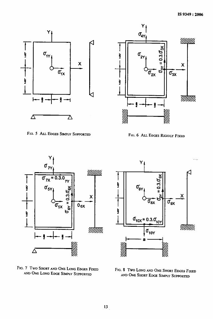
METHOD OF COMPUTATION OF BENDING STRESSES IN FLAT PLATES
D-1 STRESSES OF FLAT PLATES IN PANELS k = non-dimensional factor depending on values
Bending stresses in flat plates maybe computed fromof a and b;
the following formula: P = water pressure in N/mm* (relative to theplate centre);
~=~xpxa2 a, b = bay width in mm as in Fig. 5 to Fig. 10; and
100 S2 s = plate thickness, in mm.
where The values of K for the points and support conditionsgiven in Fig. 5 to Fig. 10 are given in Tables 1, 2
G = bending stress in flat plate in N/mm*; and 3.
12
IS 9349:2006
Y
u IAYL
Y
t
rulY
,+ Lx
ulx)
L +[l-g $-i
FIG. 5 ALL EDGESSIMPLYSUPPORTED
r!
+!)
L
Yt
%q
(r 7X=o.3.0nI
l-+-k-l
N!
x——0 6)(
s
FIG. 7 Two SHORTAND ONE LONG EDGESFIXED
AND ONE LONG EDGESIMPLYSUPPORTED
/ I ‘2XI‘3XI
LR
HFIG. 6 ALL EDGESRIGIDLY FIXED
_3-
(r lox= o“3.ul~y
l———a-—l
FIG. 8 Two LONG AND ONE SHORTEDGESFIXED
ANDONE SHORTEDGESIMPLYSUPPORTED

x////4
d12Y
512X
6,,)(L
tflly
513y %4Y
615X
-t
b
FIG. 9 THREEEDGESFIXEDANDONE (LONGER) EDGEFREE
‘1-+t
b
514)(
t
618y
!/
JJJl,.
x44
i-
FIG. 10 THREEEDGESFIXEDAND ONE (SHORTER)EDGEFREE

3S 9349:2006
Table 1 Values of k for Points and Supports Conditions Given in Fig. 5 to Fig. 8
(Clause D-1)
bla *U,, ●u]y *U2X +JU2Y iff4y *03X iu~x *CTSY *U7J *US, 2+ CT$X *UQ icr,~ *U*
(1) (2) (3) (4) (5) (6) (7) (8) (9) (lo) (11) (12) (13) (14) (15)
a 75 22.5 25 7.5 34.2 50 37.5 11.3 47.2 75 25 7.5 34.2 503 71.3 24.4 25 7.5 34.2 50 37.4 12.0 47.1 74.0 25 7.62.5 67.7
34.2 5025.8 25 8.0 34.3 50 36.6 13.3 47.0 73.2 25 8.0
2 61.0 27.8 -24.7 9.5 34.3 49.9 33.834.2 50
15.5 47.0 68.3 25 9,0 34.2 501.75 55.8 28.9 23.9 10.8 34.3 48.4 30.8 16.5 46.5 63.2 24.6 10.1 34.1 48.91.5 48.7 29.9 22.1 12.2 34.3 45.5 27.1 1-8.1 45.5 56.5 23.2 11.4 34.1 47.31.25 39.6 30.1 18.8 13.5 33.9 40.3 21.4 18.4 42.5 47.2 20.8 12,9 34.1 44.8I 28.7 28.7 13.7 13.7 30.9 30.9 14.2 16.6 36.0 32.8 16.6 14.2 32.8 36.0
NOTE — The edges over which the panels are continuous may, for all practical purposes, be treated as edges rigidly fixed. However,more exact analysis may be resorted to at tbe dkcretion of the designer.
Table 2 Values of k for Points and Supports Conditions Given in Fig. 9
(Clause D-1)
bla C711X u 11$ 0 12s G llY U 13x u uy 0141 u My u 1s1 c KY
(1) (2) (3) (4) (5) (6) (7) (8) (9) (lo) (11)
a 22.0 75.00 90.00 300.0 91.00 28.00 205,00 62.00 2.00 0
1.0 17.67 12.29 9.45 31.5 37.64 11.29 44.55 13.4 27.96 01.25 22.5 13.0 15.5 51.5 48.0 14.8 53.0 16.2 37.0 0
1.50 23.5 14.2 20.5 72.5 59.5 18.2 82.0 22.7 48.0 01.75 23.0 14.0 25.8 87.0 67.5 20.8 112.0 34.8 61.0 0..2.0 !9.49 6.72 33.98 113.28 72.96 12.89 134.4 40.32 69.88 02.5 18.37 2.88 42.05 140.16 51.84 15.55 124.4 37.44 52.42 03.0 19.78 7.68 44.93 149.76 65.28 19.59 109.44 32.84 52.41 0
Table 3 Values of &for Points and Supports Conditions Given in Fig. 10
(Clause D-1)
bla U 16s U 16y u 17X u 17y u 18, G Isy u 19s u 19y
(1) (2) (3) (4) (5) (6) (7) (8) (9) ;; ;;
a 29.00 9.00 9.00 30.00 50.00 15.00 51.00 16.00 29.00 0
1.0 17.67 12.29 9.45 31.05 37.64 11.29 44,55 13.40 27.96 0
1.25 20.80 11.70 8.96 29.87 28.00 8.40 34.5 10.35 28.53 01.50 25.S1 11.12 8.48 28.28 21.04 6.31 25.53 7.66 29.11 0
1.75 26.48 10.56 8.49 28.03 32.00 9.60 36.5 10.95 28.97 0
2.0 27.46 10.00 8.50 28.36 45.52 13.66 50.09 15.27 28.81 0
2.5 28.07 9.13 8.51 28.38 46.66 14.00 50.80 15.24 28.78 03.0 28.18 8.68 8.51 28.38 46.94 14.08 50.81 15.24 28.77 0
15
IS 9349:2006
ANNEX E
[Clause 9.1.4(b)]
METHOD OF CALCULATION OF COACTING WIDTH OF SKIN PLATEWITH BEAM OR STIFFENERS
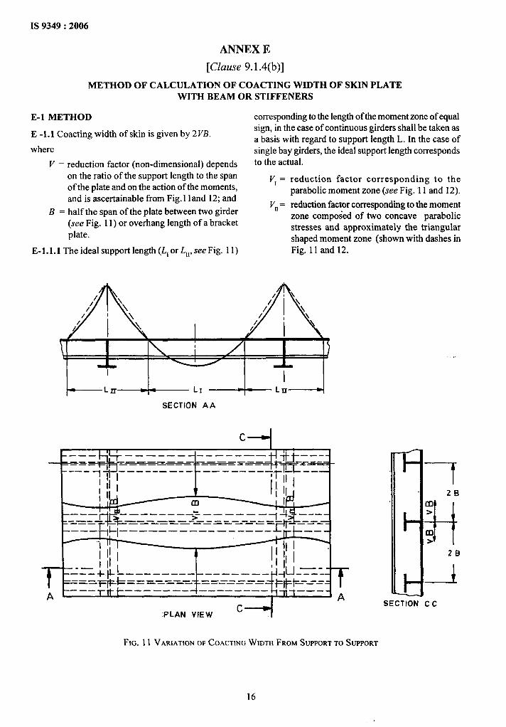
E-1 METHOD
E -1.1 Coacting width of skin is given by 2VB.
where
V = reduction factor (non-dimensional) dependson the ratio of the support length to the spanof the plate and on the action of the moments,and is ascertainable from Fig. 11and 12; and
B = half the span of the plate between two girder(see Fig. 11) or overhang length of a bracketplate.
E-1.l.l The ideal support length (L1or LII,see Fig. 11)
corresponding to the length of the moment zone of equalsign, in the case of continuous girders shall be taken asa basis with regard to support length L. In the case ofsingle bay girders, the ideal support length correspondsto the actual.
reduction factor corresponding to theparabolic moment zone (see Fig.”11 and 12).
reduction factor corresponding to the momentzone composed of two concave parabolicstresses and approximately the triangularshaped moment zone (shown with dashes inFig. 11 and 12.
A/ ‘,/’ \
c--+I
\ ——— ——— ———— -——- -——
-=—-+p–––––––––– –
A
PLAN VIEWc+
SECTION C C
FIG. 11 VARIATION OFCOACTINGWIDTH FROMSUPPORTTO SUPPORT
16

IS 9349:2006
t
1’0
0 ‘9
().& ). . . .
0“7
O●6 ‘
.-
, , ,I I YI
. 1 1 I
I
O*1L
O*’’’” 1 I I 1 1 I 1 t I 1 1 1 I 1 1 1 I I I , t , 1 I n # 1 I I 1
-0-7 ‘0’91 1,5 2 3 45 678910 15 20
FIG. 12 CURVESSHOWINGRELATIONSHIPBETWEEN~ AND
REDUCTIONFACTORSVI AND Vn
ANNEX F
(Clause 9.9)
ANCHORAGE OR ANCHOR PLATES
, ,,
F-1 The depth of second stage concrete shall be such allowable limits permitted by the IS 456. Wherethat the 45° degrees plane drawn from the inner edge excessive shear stress in the concrete is unavoidable,of the track base beam passes through anchors reinforcement properly designed for shear and placedprovided in first stage concrete. Diagonal shear stress in the first stage concrete can be taken into account.in the concrete due to maximum lead derived from In no case shall the alignment bolts be considered asthe bearing stress under the track base shall be within shear reinforcement.
17

IS 9349:2006
ANNEX G
(Clause 9.12)
TOLERANCE FOR EMBEDDED PARTS AND COMPONENTS OF GATES
SI ComponentsNo.
(1) (2)
A Embedded Parts
i) Side seal seat
a) Alignment in plane parallel to flowb) Distance between centreline of opening and seal seatc) Coplanemess
ii) Top seal seat:
a) Alignment parallel to flowb) Height above sillc) Coplanemess with side seal seat
iii) Upstream guide track:
a) Alignment in plane parallel to flowb) Distance between centreline of opening and guide trackc) Coplanemess
iv) Side guide track:
a) Alignment in plane normal to flowb) Distance between centreline of opening and guide trackc) Alignment in plane parallel to flow
v) Bottom seal seat:
Alignment in horizontal plane
vi) Critical dimensions:
a) Centre-to-centre distance-between side seal seatb) Face-to-face distance between side guide tracksc) Distance between face of upstream guide track and side
seal seatd) Centre-to-centre distance be~een upstream guide tracks
B -Gate
i) Side and top seal seatia) Alignment parallel to flowb) Coplanemess
ii) Side guide:
Alignment parallel to flow
iii) Upstream guide:
Alignment parallel to flow
iv) Gate leaf bottom edge:
Alignment in horizontal plane
v) Critical dimensions:
a) Centre-to-centre distance between side seal platesb) Centre-to-centre distance between upstream guidesc) Face-to-face distance between side guidesd) Face-to-face distance between side seal plate and
upstream guide
C[assijicationA
e
Medium head High head-mm
(3)
*0.5●1.50+1.5
* 0.5*1.5*0.5
+0.5+1.50ko.50
+1.00+1.00*1.00
kO.25
*3.00+2.00*1.00
*3.00
*0.50&o.50
+1.0
+0.50
kO.25
4=1.00+1.00+1.5+1 .00
mm
(4)
* 0.25*1 .00+0.25
*0.25+1.00+0.25
40.25*1 .00●0.25
*0.5+0.5+0.5 ,
*0.25
*2.00+1.00*0.50
*2.00
*0.25*0.25
+0.5
* 0.25
* 0.25
*0.5*0.5+1.00ko.50
18

ANNEX H
(Clause 10.1)
RECOMMENDED VALUES OF COEFFICIENTS OF FRICTIONTO BE USED IN THE DESIGN OF GATES
slNo.
i)
ii)
iii)
iv)
v)
vi)
vii)
viii)
Material
Rubber seal on steel
Brass on bronze
Brass or bronze on steel
Steel on steel
Stainless steel on steelWood on steel
Gun metal on gun metalFluoro-carbon on stainless steel
Coe@cient ofFrictionA/ \
Starting Moving
1.50 1.200.40 0.25
0.50 0.300.60 0.40
0.50 0.301.00 0.70
0.40 0.25
0.20 0.15
19
IS 9349:2006
ANNEX J
(Foreword)
COMMITTEE COMPOSITION
Hydraulic Gates and Valves, WRD 12
Organization
In Personal Capacity (2047, Pocket 2, Sector D, Vasant Kunj,
New Delhi 110070)
Bhakra Beas Management Board, Punjab
Bharat Heavy Electrical Ltd, Bhopal
Central Electricity Authority, New Delhi
Centrrd Water & Power Research Station, Pune
Centrrd Water Commission, New Delhi
Himachal Pradesh State Electricity Board, Sunder Nagar,Himachal Pradesh
Irrigation Department Government of MaharashtW -Nasik
Irrigation Research Institute, Roorkee
National Hydroelectric Power Corpmation Ltd, Faridabad
Orissa Construction Corporation Ltd, Bhubaneshwar
Texmaco Ltd, Kolkata
Triveni Stmcturals Ltd, Allahabad
Tungabhadra Steel Products Ltd, Karnataka
Water Resources Development Training Centre, Roorkee
BIS Directorate General
Representative(s)
Smo N. VISHWANATHAN(Chairman)
DaPUTYCmaF ErwawaRExsmnvs E~ (Alternate)
Sma A. S. SRSVASTAVA
Sms S. R. Rmsorus(Alternate)
SssssR. K. RUSTAQ
SHRSR. M. SSNNASUMSSriruS. L. PATSL(Alternate)
DIRSCMRGATS?S(E & NE)DUUMXOR (GAITS-NW& S) (Alternate)
CrmsFENOSNSSR(DasrGN)SrrraK. D. SNARMA(Alternate)
smramsmNG ENQNSSRSExecmsvs ENOINSSR(Alternate)
CmsF ENQNSSR(Dssm)Srmmlmmw Erwmmrt (Alternate)
SHRSG. S. SHARMASHRSA. K. ROY(Alternate)
D~R (MECHANICAL),>
SSNSORMANAOSR(DESIGN)(Alternate)
SsrsJ S. R. SrNS+ASrirrrUDAYANB.mmss (Alternate)
SHSOJ. P. ‘MrsriRASmu B. P. SINGSS(Alternate)
SHRIHUSSASNBrNALISsrruY. s+ criANDrwnmArwASS(Alternate)
PROFGOPALCHMJHAN
Director and Head (WRD)[Representing Director General (E&oficio Member)]
Member Secretary
SHRSMATSROSYDHAWAN
Joint Dkector (WRD), BIS
20

Bureau of Indian StandardsI
BIS is a statutory institution established under the Bureau of Indian Standards Act, 1986 to promoteharmonious development of the activities of standardization, marking and quality certification of goods andattending to connected matters in fhe country.
Copyright
BIS has the copyright of all its publications. No part of these publications may be reproduced in any formwithout the prior permission in writing of BIS. This does not preclude the free use, in the course of implementingthe standard, of necessary details, such as symbols and sizes, type or grade designations. Enquiries relating tocopyright be addressed to the Director (Publications), BIS.
Review of Indian Standards
Amendments are issued to standards as the need arises on the basis of comments. Standards are also reviewedperiodically; a standard along with amendments is reaffirmed when such review indicates that no changes areneeded; if the review indicates that changes are needed, it is taken up for revision. Users of Indian Standardsshould ascertain that they are in possession of the latest amendments or edition by referring to the latest issue of‘BIS Catalogue’ and ‘Standards: Monthly Additions’.
This Indian Standard has been developed from Dot: No. WRD 12 (377).
Amendments Issued Since Publication
Amend No. Date of Issue Tat Affected
BUREAU OF INDIAN STANDARDS
Headquarters:
Manak Bhavan, 9 Bahadur Shah Zafar Marg, New Delhi 110002Telephones: 23230131,23233375,2323 9402 website: www.bis.org.in
Regional Offices: Telephones
Central :{
2323761723233841
Eastern :
Northern :
Southern :
Western :
Man& Bhavan, 9 Bahadur Shah Zafar MargNEW DELHI 110002
1/14 C.I.T. Scheme VII M, V.I.P. Road, KankurgachiKOLKAT-A 700054 ~
SCO 335-336, Sector 34A, CHANDIGARH 160022
C.I.T. Campus, IV Cross Road, CHENNAI 600113
Manakalaya, E9 MIDC, Marol, Andheri (East)MUMBAI 400093
{23378499,2337856123378626,23379120
{26038432609285
{22541216,2254144222542519,22542315
{28329295,2832785828327891,28327892
Branches : AHMEDABAD. BANGALORE. BHOPAL. BHUBANESHWAR. COIMBATORE. FAWDABAD.GHAZIABAD. GUWAHATI. HYDERABAD. JAIPUR. KANPUR. LUCKNOW. NAGPUR.NALAGARH. PATNA. PUNE. RAJKOT. THIRUVANANTHAPURAM. VISAKHAPATNAM.
Printed at Simco Printing Press, ~lhi
Related Documents