Disclosure to Promote the Right To Information Whereas the Parliament of India has set out to provide a practical regime of right to information for citizens to secure access to information under the control of public authorities, in order to promote transparency and accountability in the working of every public authority, and whereas the attached publication of the Bureau of Indian Standards is of particular interest to the public, particularly disadvantaged communities and those engaged in the pursuit of education and knowledge, the attached public safety standard is made available to promote the timely dissemination of this information in an accurate manner to the public. इंटरनेट मानक “!ान $ एक न’ भारत का +नम-ण” Satyanarayan Gangaram Pitroda “Invent a New India Using Knowledge” “प0रा1 को छोड न’ 5 तरफ” Jawaharlal Nehru “Step Out From the Old to the New” “जान1 का अ+धकार, जी1 का अ+धकार” Mazdoor Kisan Shakti Sangathan “The Right to Information, The Right to Live” “!ान एक ऐसा खजाना > जो कभी च0राया नहB जा सकता ह ै” Bhartṛhari—Nītiśatakam “Knowledge is such a treasure which cannot be stolen” IS 5878-2-1 (1970): Code of Practice for Construction of Tunnels, Part II: Underground Excavation in Rock, Section 1: Drilling and Blasting [WRD 14: Water Conductor Systems]

Welcome message from author
This document is posted to help you gain knowledge. Please leave a comment to let me know what you think about it! Share it to your friends and learn new things together.
Transcript

Disclosure to Promote the Right To Information
Whereas the Parliament of India has set out to provide a practical regime of right to information for citizens to secure access to information under the control of public authorities, in order to promote transparency and accountability in the working of every public authority, and whereas the attached publication of the Bureau of Indian Standards is of particular interest to the public, particularly disadvantaged communities and those engaged in the pursuit of education and knowledge, the attached public safety standard is made available to promote the timely dissemination of this information in an accurate manner to the public.
इंटरनेट मानक
“!ान $ एक न' भारत का +नम-ण”Satyanarayan Gangaram Pitroda
“Invent a New India Using Knowledge”
“प0रा1 को छोड न' 5 तरफ”Jawaharlal Nehru
“Step Out From the Old to the New”
“जान1 का अ+धकार, जी1 का अ+धकार”Mazdoor Kisan Shakti Sangathan
“The Right to Information, The Right to Live”
“!ान एक ऐसा खजाना > जो कभी च0राया नहB जा सकता है”Bhartṛhari—Nītiśatakam
“Knowledge is such a treasure which cannot be stolen”
“Invent a New India Using Knowledge”
है”ह”ह
IS 5878-2-1 (1970): Code of Practice for Construction ofTunnels, Part II: Underground Excavation in Rock, Section1: Drilling and Blasting [WRD 14: Water Conductor Systems]


k‘a&
tIS : 5878 ( Part II/Se 1) - 1970
Indian StandardCODE OF PRACTICE FOR
CONSTRUCTION OF TUNNELSPART: II UNDERGROUND EXCAVATION IN ROCK
Section I Drilling and Blasting
Water Conductor Systems Sectional Committee, BDC 58
ChairmanSERI P. M. MANE
Ramalayam, Pedder Road, Bombay 26
Members RejremtingSHRI N. M. CEAI~RAVORTY Damodar Valley Corporation, DhanbadC HIEF C O N S T R U C T I O N ENOINEEI~ Tamil Nadu Electricity Board, Madras
SUPERINTENDINQ ENGINEERTECHNICAL ( CIVIL ) ( Alternate )
CHIEF ENCXNEER ( CIVIL ) Andhra Pradesh State Electricity Board, HyderabadSUPERINTENDINQ ENGINEER ( Alternate)
CHIEF ENQINEER ( CIVIL ) Kerala State Electricity Board, TrivandrumDEPUTY D IRECTOR ( DAMS I ) Central Water & Power Commission, New DelhiDIRECTOR Irrigation & Power Research Institute, Punjab,
AmritsarDR GAJINDER SINQEI (Alternate )
SRRI D. DODD~AH Public Works Department, Government of MysoreSHRI S. G. BAI;AKUNDRY ( Alternate )
SFIRI D. N. DUTTA Assam State Electricity Board, ShillongSHRI R. G. GANDHI The Hindustan Construction Co Ltd, Bombay .
&RI M. S. DEWAN ( Alternate)SHRI K.C. G H O S A L Sahu Cement Service, New DelhiSHRI B. S. KAPRE Irrigation & Power Department, Government of
^ i
Maharashtra /SHRI R. S. KALE (Alternate )
. SHRI V. S. KRISHNASWAMY Geological Survey of India, CalcuttaSHRI K. S. S. MURTHY Ministry of Irrigation & PowerSHRI Y. G. PATEL Pate1 Engineering Co Ltd, Bombay
SRRI C. K. CROKSHI ( Alrernate )SHRI P. B. PATIL Gammon India Private Ltd, BombaySHRI A. R. RAICHUR R. J. Shah & Co Ltd, BombaySECRETARY Central Board of Irrigation & Power, New Delhi
( Continued on page 2 )
I N D I A N S T A N D A R D S I N S T I T U T I O NMANAK BHAVAN, 9 BAHADUR SHAH ZAFAR MARG
NEW DELHI-l

IS : 5878 ( Paat II/!&c 1) - 1970
( Continued from page 1 )
Members Representing
SHRI G. N. TANDON Irrigation Department, Government of Uttar PradeshSHRI J. E. VAZ PublGadorks Department, Government of Tamil
SHRI J. WALTER ( Alternate)SHRI R. NAQARAJAN , Director General, IS1 ( Ex-o#cio Member)
Director ( Civ Engg )Secretary
SHRI BIMLESH KUMARAssistant Director ( Civ Engg ), IS1
Panel for Construction of Tunnels, BDC 58 : P2
Convener
SHRI B. S. KAPRE Irrigation & Power Department, Government ofMaharashtra
M e m b e r s
S#&c.K. CHOKiQII Pate1 Engineering Co Ltd, BombayDEPUTY DIRECTOR ( DAMII I ) Central Water & Power Commission, New DelhiSxnt~ M. S. DIGWAN The Hindustan Construction Co Ltd, BombaySE= K. C. GHOSAL Sabu Cement Service, New DelhiSHBI A. R. RAIOHUR R. J. Shah & Co Ltd, BombaySHRI K. SHAXA RA O Kerala State Electricity Board, Trivandrum
SHRI A. S. NA~AYANA~ (Alternate)SHEI G. N. TANDON Irrigation Department, Government of Uttar Pradesh
,
2
IS : 5878 ( Part II/Set 1) - 1970
Indian StandardCODE OF PRACTICE FOR
CONSTRUCTION OF TUNNELSPART II UNDERGROUND EXCAVATION IN ROCK
Section I Drilling and Blasting
0 . F O R E W O R D
0.X This Indian Standard (Part II/Section 1) was adopted by the IndianStandards Institution on 26 October 1970, after the draft finalized by theWater Conductor Systems Sectional Committee had been approved by theCivil Engineering Division Council.
0.2 The construction of tunnels involves a large number of problems.Because of the great longitudinal extent of the work many different kindsof conditions are encountered which for maximum economy should be treat-ed differently. This standard covers recommendations which would begenerally applicable to construction of tunnels, for the assistance of engi-neers engaged on such projects. This standard should, however, be usedwith caution since due to the very nature of the subject it is not possible tolay down detailed specifications to cover each and every possible case andthe discretion of the engineer-in-charge would be required in many case01
0.3 This standard will be published in parts. The other parts ok tI$standard are as follows:
Part I Precision survey and setting outPart III Underground excavation in soft strataPart IV Tunnel supportsPart V Concrete liningPart VI Steel lining
0.3.1 Part II will be published in sections. Other sections of this partwill cover ventilation, mucking, lighting, dewatering and tunnellingmethods for steeply inclined tunnels and shafts.
0.4 Other related standards printed so far on this subject are given below:
IS : 408 I-1967 Safety code for blasting and related drilling operationsIS : 4138-1967 Safety code for working in compressed airIS : 4756-1968 Safety code for tunnelling work
3

18: 5878 ( Part II/Set 1) - 1970
IS : 4880 (Part II )-1968 Code of practice for design of tunnels convey-ing water: Part II Geometric design
IS : 4880 (Part III)-1968 Code of practice for design of tunnels convey-ing water : Part III Hydraulic design
0.5 For the purpose of deciding whether a particular requirement of thisstandard is complied with, the final values, observed or calculated, express-ing the results of a test or analysis, shall be rounded off in accordance withIS: 2-1960*. The number of significant places retained in the rounded offvalue should be the same as that of the specified values in this standard. ‘.
1. SCOPE ‘x.J
1.1 This standard (Part II/Section 1) deals with drilling and blasting forunderground excavation of tunnels in rock.
2. TERMINOLOGY
2.0 For the purpose of this standard, the following definitions shall apply.
2.1 Adit - A tunnel or open cut driven from the surface to add to thenumber of working faces of the main tunnel.
2.2 Benching-The operation of removal of the lower pot tion of the tun-nel profile after the top heading has been excavation and where drillingvertically down is possible.
2.3 Cover- Cover on a tunnel in any direction is the distance from thete so63 to the rock surface in that direction.
j ,‘”2.4 &-,The group of holes fired first in a round to provide additionalfree faces for the succeeding shots.
NOTE - This definition applies only to drilling patterns.
2.5 Detonator - A device for producing detonation in a high explosivecharge, and initiated by a safety fuse or by electricity.
2.6 Drift - A horizontal tunnel usually of a small cross-section and length .driven either from surface for exploration purpose or from an undergroundface for any purpose.
2.7 Drill Carriages-A vehicle on which one or more drill booms aremounted to permit the drills to be brought easily to their work site and tobe removed before blasting.
2.8 Drilling Pattern- It is an arrangement showing location, directionand depth of the holes drilled into the face of a tunnel.
*Rules for rounding off numerical values ( revised ).
4
3 ..~-I
IS : 5878 ( Part II/&c 1) - 1970
2.9 Easer - Ring of holes drilled around cut holes and fired after cutholes.
q.10 Explosive - Any mixture or chemical compound which is capable ofproducing an expIosion by its own energy. This includes black powderdynamite, nitroglycerine compounds, fulminate or explosive substancehaving explosive power equal to or greater than black powder.
,2.11 Heading - The face of the tunnel where actual tunnelling operationsare in progress. However, when it is prefixed by ‘ top ’ or ‘ bottom’ it deno-tes a part section excavated in advance in the line of the intended tunnel.
2.12 High Explosive - An explosive which explodes with detonation anddetonates at velocities varying from about 1 500 to 7 500 m/s, and produceslarge volume of gases at exceptionally high pressure.
2.13 Jumbo - A mobile platform with number of decks used at the head-ing of large size tunnels for drilling and also for scaling, erection of roofsupports, guniting, shotcreting, etc.
2.14 Mucking- The operation of removal of the blasted stones/materialafter the blast has taken place.
2.15 Overbreak - The portion blasted beyond the lines of theintendedsection.
2.16 PrimerC&J& “‘Al ’
inserted.I-- The explosive cartridge into which the detonator has been
2.17 Scaling - An operation to remove all loose bits of rock from the blast-ed surface, after the blasting is over.
2.18 Shaft and Steeply Inclined Tunnels -These are vertical or inclin-ed tunnels in which self-propelled hauling equipment, running on the in-vert of the tunnel cannot be used.
2.19 Stemming - Inert material packed between the explosive charge and:he outer end of the shot hole.
2.20 Stoping - Operations for overhead excavation by drilling from anunderground face.
2.21 Trimmer - Holes at the periphery of an excavation, fired to give theexcavation its final outline.
3. GENERAL3.1 Preliminary work required to establish a tunnel face consists of mainlythe following items:
a) Open excavation in overburden and rock or excavation of a shaftfrom the bottom of which the tunnel excavation can start;
ES : 5878 (Part II/&c 1) - 1970
b) Arrangement for collection of surface water and. ts drainage bygravity or pumping;
c) Access roads or rail tracks to mucking areas;
d) Erection or winching and hauling equipment; and
e) Establishment of a field workshop, compressors, pumps, water lines,ventilation fans, ducts, etc.
3.2 Location of Portal-The portal, that is, the face from where a tunnel .,starts has to be decided with reference to the rock cover. T h e m i n i m u mcover with which tunnel can be started depends on the type and structure *of rock mass, the size and shape of the tunnel and the pressure of the waterin case of hydra-tunnels.
3.2.1 The length up to which it is economical to adopt an open cut inpreference to a tunnel depends on the cost of underground and open exca-vation, and the cost of protective works involved.
3.2.2 In some cases, the cost of protective works in open cuts becomesvery high. However, open excavation has to be continued up to a pointwhere adequate rock cover is available. Under such circumstances cutand cover sections are found more suitable.
3.2.3 Before taking up the excavation of a tunnel its face shall be estab-lished and alignment of the tunnel marked in accordance with IS:5878(Part I)-1970”.
3.3 Shape’ of Tunnel - The selection of shape of tunnel may be madeconforming to IS : 4880 ( Part II)-1968t.
3.4 Tunnelling Methods - The method of attacking the faces of tunneldepends on the size and shape of the tunnel, the equipment available, thecondition of the formation and the extent to which supports are necessaryand overall economics. The common methods of attack are given in 3.4Z,to 3.4.4.
3.4.1 Full Face - This method is generally recommended for tunnels ingood rock.
3.4.2 Top Heading and Benching- This method is generally recommendedwhere the tunnel section is very large and/or the rock is not structurallysound (see Fig. IA). The heading may be excavated to full length or partlength of the tunnel as may be suitable.
*Code of practice for construction of tunnels : Part I Precision survey and setting out.TCode of practice for design of tunnels conveying water : Part II Geometric design.
6
---- ~__ I .._ _. ._. d

Is:!5878 (Part II/SW I)-1970
3.4.3 Bottom Heading andStoping- This method is generally recommendedwhere the tunnel section is very large and the rock is consistent and sound(SIC Fig. 1B).
ORLUG HOLE
1A TOP HEADING 18 BOTTOM HEADINGAND BENCHING AND STOPING
FIQ. I HEADINQ AND BENCHINQ/STOPINO
CENTRAL DRIFT BOTTOM DRIFT
TOP DRIFT SIDE DRIFT
FI G. 2 DRIFT M ETHOD

IS:5878 (Part II/Set 1).1970
1 3.4.4 Drift Method-In driving a large tunnel, it may be economical todrive a small tunnel, called a drift or a pilot tunnel prior to excavating thefull bore. A drift may be classified as centre, bottom, side or top depend-ing on its position relative to the main bore (see Fig. 2). .
3.5 Sequence of Operations for Construction of tunnels
3.5.1 The actual operations in the construction of a tunnel may varywith the type and size of tunnel, method of attack and the kind of forma-tion encountered. . i4
’3.5.2 For a tunnel driven in rock, following operations are normallyrequired:
4b)C>4e)f-1dh)
Marking tunnel profile;Setting up and drilling;Loading explosives and blasting;Removing the foul gases;Checking misfires;Scaling;Mucking; andGuniting, erecting supports or rock bolting and lining, if and whennecessary.
4. DRILLING
4.1 General - For driving a tunnel through rock it is essential to drillholes for charging the explosives. The drilling pattern should be workedout by experiments for each particular work as it depends on the textureand formation of rock, size and shape of the tunnel, the strength of explo-sives and also the fragmentation of rock required so as to make it suitablefor handling by mucking equipment. The drilling should be such as trensure minimum overbreak and least amount of explosive per unit volumi .of excavation. Adequate safety precautions shall be taken during drillingoperations in accordance with IS : 4081-1967”.
NOTE - Presplitting is a recent technique of smooth blasting that offers possibilityof applying low ch-trges of instantaneous ignition, which develops a crack in apre-determined line of holes and results in reduction in overbreak and groundvibrations. Such cracks for the final contour are created by blasting prior to thedrilling of the rest of the holes for the blasting pattern. Once the crack is made,it screens off the surroundings to some extent from the ground vibrations due to themain round. The presplitting method involves extra meterage of drilling and is mostlyused in open cut excavation. This method has not SO far been used in tunnelling.
*Safety code of blasting and reIated drilling operations.
8

ISr!i878 (Part H/&c 1)~1970
4.2 Equipment - Holes shall be drilled by using pneumatically operatedrock drills in conjunction with pneumatic pushers and/or auto feeds withladders or drifters mounted on column bars or drill carriages, as may befound suitable. Only wet drilling shall be permitted. Number of drills isgoverned by the area of the face of the tunnel. It is generally recom-mended that one drill may be used for each 4 to 5 mr face area.
4.3 Diameter of Holes - The diameter of hole at its deepest point shallbe at least 6 mm more than the diameter of the cartridge.
4.4 Drilling Pattern -It consists of the following holes which are deto-nated in-the order given below:
a) Cut holes,b) Easers, andc) Trimmers.
4.4.1 Cut Holes -The cut holes are usually provided in the centre ofthe round 15 to 30 cm deeper than the other holes and are drilled converg-ing towards the centre of the face with the idea of producing an initialcone, or wedge as a free face for breaking off succeeding holes. The otherholes are arranged around the cut holes. The position of the cut holes isgoverned by the following factors:
a) In order to restrict the throw of the blasted rock from the cut holesthese should be placed as low as possible;
b) When electrical firing is adopted and the choice of different delayintervals is limited, cut holes should be placed in the centre;
c) In order to get the maximum possible advance in narrow tunnelscut holes placed on side should be tried.
4.4.2 Some of the general drilling patterns are given in 4.4.2.1to 4.4.2.6.
4.4.2.1 Horizontal wedge cut - The holes are placed symmetrically withrespect to the vertical centre line of the section (see Fig. 3). The drill holesare horizontal and the angle towards the working face is large, and, there-fore, is easy to drill. This cut is generally recommended for almost allsizes of tunnels except in very small tunnels. With wedge cut, it is notpossible to obtain advances more than half the width of the tunnel as it isnot possible to drill cut holes with the requisite angle to a greater depththan half the width of the tunnel.
4.4.2.2 Pyramid cut - In this type (see Fig. 4) three or four convergingholes are so directed that they meet at a point further in, This cut isgenerally recommended for small size shaft sinking.
4.4.2.3 Fan cut - In this type of cut (see Fig. 5 ) the cut holes are shiftedto one side of the tunnel, and the cut.,holes .and adjacent holes are drilled
.9

H&S878 (Part H/!&x I)-1979
CUT SHOTS c e
E A S E R S - 0
TRIMMERS ---- .
F I G. 3 HORIZONTAL W EDGE C U T
FIG. 4
C U T S H O T S = 0
E A S E R S - 0
TRIMMERS ____m .
h’RAMID CUT
10

2nd ROUND
1StS78 (PM U/8ec l)-1970
CUT SHOTS z 8EASERS -0
T R I M M E R S - - - - l
FULL DRIVE
CUT SHOTS Z8
EASERS -0
T R I M M E R S -v-- .
HALF DRIVE
Fro. 5 FAN CUT
11
*/

IS t 587% ( Part II/S& 1 j - 1970
into fan shape. This cut is generally recommended for small tunnels,when it is not possible to drill a deeper wedge cut due to the restrictedwidth. The cut holes should be drilled on alternate sides in each blast.
4.4.2.4 V-cut - This cut (see Fig, 6 ) is practically similar to horizontalwedge, but is suitable for tunnels of very large sections. It is generallyrecommended for tunnels for 30 to 100 rn+J in cross-sectional area. In thiscase the position of the cut holes is determined by the design of the drillingjumbo.
F I G. 6 V-Cur
4.4.2.5 Michigan or cylinder cut - In this type (see Fig. 7 ) a hole of largerdiameter as compared to other cuts, ranging from 7 to 10 cm is to bedrilled in the centre. Around this hole, another series of holes forming
0-
---f
-17
-08u-3
1l
I4 ,I3 . 1
+250-+- 2004
,411 dimensions in millimetres.
F I G. 7 M ICHIGAN C U T
II2

IS : 5878 ( Part II/Set 1) - 1970
two pentagons or two triangles are drilled close to the central holes. Therest of the holes are drilled as usual. The central hole is not to be loaded
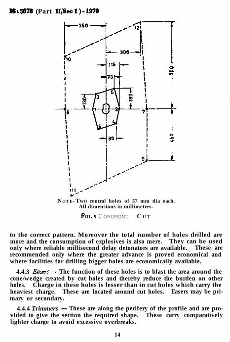
1while the rest are loaded and blasted in such a manner that the holes closeto the central holes blast first. By this method more advance can be achiev-ed in small tunnels of about 10 ma cross-sectional area, where on accountof less width the length of cut holes into wedge shape is limited. This typeof cut entails the largest drilling metrage per cut and a heavier consump-tion of explosives than the other types. Double spiral cut and coromontcut are similar to michigan cut and are illustrated in Fig. 8 and 9.
All dimensions in millimetres.
F I G. 8 DOUBLE SPIRAL CU T
4.4.2.6 Burn cut - This is somewhat similar to michigan or cylindertype cut ( see Fig. 10 ). All the holes are at right angle to the tunnel face.There are many variants in this type. In one variant the charged holesare located inside the cut holes and are broken towards the surroundinguncharged holes. In other variant the charged and uncharged holes alter-nate with one another according to the form of vertical seam. The typeof cut is easy to drill and is generally recommended for tunnels up to 20 msin cross-sectional area. For homogeneous rock this is more suitable.
4.4.2.7 The cylinder cuts and the burn cuts utilize parallel holes andusually give better advance per round than the wedge, V, pyramid and fancuts. The practical difficulties of these cuts, however, are that they requiretwo different types of equipment at the face, one for drilling the emptyholes (usually 75 to 125 mm) and one for drilling the loaded holes (usually30 to 35 mm). They require special templates to accurately drill the holes
13
-
fSs587s (Part llpec 1).qno
NOTE-TWO central holes of 57 mm dia each.All dimensions in millimetres.
FIG. 9 COROMONT C U T
to the correct pattern. Moreover the total number of holes drilled aremore and the consumption of explosives is also mere. They can be usedonly where reliable millisecond delay detonators are available. These arerecommended only where the greater advance is proved economical andwhere facilities for drilling bigger holes are economically available.
4.4.3 Earsrs - The function of these holes is to blast the area around thecone/wedge created by cut holes and thereby reduce the burden on otherholes. Charge in these holes is lesser than in cut holes which carry theheaviest charge. These are located around cut holes. Easers may be pri-mary or secondary.
4.4.4 Trimmers - These are along the perifery of the profile and are pro-vided to give the section the required shape. These carry comparativelylighter charge to avoid excessive overbreaks.
14

IS: 5978 ( Part II/kc 1) - 1970
r 520 C
NOTE -Burn cut with three 75-mm empty holes and six outer cut holes.All dimensions in millimetres.
F I G. 10 B URN CU T
5. BLASTING5.1 Explosives - High explosives are used for tunnelling operations. Thestrength of high explosives is expressed as a percentage of the strength ofblasting gelatine which is the most powerful of commercial explosives.
5.1.1nelling
a)
b)
c.
4
4
The following types of explosives are recommended for use in tun-operations:Blasting gelatine - It has the highest concentrated power and it isused for blasting very hard and tough rocks. This is fully water-proof and adaptable to wet work.Special gelatines 90 percent to 40 percent - These are characterised bygelatinous consistency, high density, freedom from noxious fumesand good storage properties. The requisite strength of gelatinemay be selected to suit the actual rock conditions which may varyfrom very hard to soft rock. For use at high altitudes, low freez-ing types of gelatines may be used.
Ammonia dynamite-These types of explosives contain equal amountof nitroglycerine and nitrate of ammonia. They are made instrengths from 15 to 60 percent. They are not so sensitive or soquick and shattering as straight dynamite. They are recommendedfor soft rock.Semi-gelatine - They contain nitrateofammonia, gelatinised nitrogly-cerine and nitro-cotton. They are bulkier than the other varietiesand come in only two strengths, 45 and 60 percent. They are
15
IS: 5878 ( Part II/Set 1) - 1970
water resistant and the fumes are not so bad as that of straight dy-namite. Because of their low density they are cheaper, and arerecommended for soft rock and limestone.
5.1.2 Almost all the types of explosives are packed in wooden/fibre boardboxes containing 25 kg net weight and are manufactured in cartridgesranging from 25 to 63 mm dia and 200 to 245 mm length.
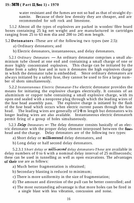
5.2 Detonators -These are of the following two types (see 2.5):a) Ordinary detonators; andb) Electric detonators, instantaneous, and delay detonators.
5.2.1 Ordinary Detonators - An ordinary detonator comprises a small alu- Lminium tube closed at one end and containing a small charge of one ormore highly concentrated explosives. This charge can be initiated by theflame from a safety fuse and in turn it detonates the high explosives chargein which the detonator tube is embedded. Since ordinary detonators are I
always initiated by a safety fuse, they cannot be used to fire a large num-ber of shots simultaneously.
5.2.2 Instantaneous Electric Detonator-The electric detonator provides themeans for initiating the explosive charges electrically. It consists of analuminium or copper tube containing a small explosive charge, with itsopen end sealed with a neoprene plug through which the leading wires ofthe fuse head assembly pass. The explosive charge is initiated by the flashof the fuse head which occurs when electric current passes through the fusehead. The leading wires are generally of 1.8 m length but detonators witslonger leading wires are also available. Instantaneous electric detonatorhpermit firing of a group of holes simultaneously.
5.2.3 DeCay Detonators - The delay detonator consists basically of an elec-tric detonator with the proper delay element interposed between the fuse-head and the charge. Delay detonators are of the following two types:
a) Short delay or milli-second delay detonators, andb) Long delay or half second delay detonators.
5.2.3.1 Short delay or milli-second delay detonators-These are available indelay numbers of 0 to 6 with a nominal delay interval of 25 milliseconds;these can be used in tunnelling as well as open excavations. The advantagesof their use are as follows:
a) Much better fragmentation is obtained;b) Secondary blasting is reduced to minimum;c) There is more uniformity in the size of fragmentation;d) The amount and direction of the pull can be better controlled; ande) The most outstanding advantage is that more holes can be fired in
a single blast with less vibration, concussion and noise.
16

IS : 5878 (Part IL/Set 1) - 1970
5.2.4 Long Delay or Half Second Delay Detonators - These are available indelay series or 0 to 10 numbers with a nominal delay interval of 300 milli-seconds (500 milliseconds in case of half second delays).
5.3 Safety Fuse - It consists of a train of black powder tightly wrappedand enclosed in various coverings and waterproofing materials and con-ducts a flame at uniform rate to a detonator for the firing of an explosivecharge. It has a limited use in tunnelling operation. The burning rateof fuse shall be not more than 60 cm/min.
5.4 Detonating Fuse- Contains a high explosive core with a waterproofIt has a high velocity (6 500 m/s), good tensile strength, is light
It is used for shooting a large number of holes in one blast.Detonating fuse is detonated by the use of one or two blasting caps securelyattached alongside it.
5.5 Primer -A primer is a cartridge containing the detonator. Thedetonator should be placed well within the cartridge and parallel toits axis.
5.6 Circuit Testers - It is absolutely necessary to test every electric deto-nator and also the circuit. For this purpose safety ohmmeters are avail-able. To test an electric detonator, it should be placed inside an iron potor tube to guard against accidental explosion. The open ends of the lead-ing wires are to be connected with the terminals of the ohmmeter and ifthe needle deflects, and shows the correct resistance of the detonator, itindicates that the circuit is complete, and detonator is in order.
5.7 Loading and Stemming
5.7.1 Loading- Before loading is started, each hole shall be blown outwith a high pressure air jet to remove loose cuttings and water. In tunnelsequipped with drill carriages when holes are loaded from the platforms,all light and power lines shall be disconnected from the carriage. For
/iL
lighting the face during loading, flood lights may be fixed at a safe distancefrom the loading zone. During loading, precautions in accordance withIS : 4081- 1967* shall be taken.
5.7.1.1 Primer cartridge may be placed next to the bottom. A fullcartridge should be inserted first, tamped well into the bottom, then primershall be inserted with the end containing detonator pointing towards thebottom of the hole; both the primer and the next placed cartridge shall betamped lightly to prevent jarring of the detonator. The remaining cart-ridges shall be then tamped firmly in place with a wooden pole, taking careto prevent breaking of the detonator wires. In no case, iron or steel deviceshall be used for tamping.
*Safety code for blasting and related drilling operations.
17

IS : 5878 ( Part II/Set 1) - 1970
5.7.2 Stemming- The remainder of the hole not occupied by explosivesshall be filled with an inert material ( see 2.19 ) and tightly tamped. Theuse of soft rolled plugs of clay is recommended. A dam mixture of sandand clay, either packed in paper bags or loose may also ge used. A rubberplug with a wooden core is also often used.
5.8 Electrical Wiring Used for Blasting- The different wires used inelectric blasting circuits are mentioned below:
Leading Wires or Leg Wires-These are insulated wires that extendfrom the end of a detonator. Lengths of leading wires range from1.8 m to 20 m depending upon requirements. The bare ends of, ’leading wires shall be kept short circuited as a precaution against __accidental detonation due to stray currents.
Connecting Wires-These are insulated wires which are sometimesrequired to complete the circuit between the leading wires of adja-cent detonators or between the detonators and the shot firingcable.
Shot Firing Cable - It is used to connect the source of power to thedetonator circuit. The cable should be well insulaled two corecable approximately 300 m long, each core consisting of a conduc-tor of at least 4 copper wires of not less than 0.46 mm diameter.
5.9 Blasting Circuits - There are three general types of blasting circuits,namely, (a) series, (b) parallel, and (c) combination, that is parallel series.
5.9.1 In series circuit, the leg wires from adjacent holes are SO connectedthat the path of current is through each blasting cap or detonator in suc-cession. This circuit is used for small number of caps ( see Fig. 11 ).
CONNECTING WIf
I-TO POWER LINE-
FIG. 11 SERIES CIRCUIT
18
._
L-
IS: 5878 (Part II/Set 1) - 1970
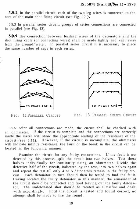
5.9.2 In the parallel circuit, each of the two leg wires is connected to thecore of the main shot firing circuit (see Fig. 12 ).
5.9.3 In parallel series circuit, groups of series connections are connectedin parallel (see Fig. 13).
5.9.4 The connection between leading wires of the detonators and theshot firing cable (or connecting wires) shall be made tightly and kept awayfrom the ground/water. In parallel series circuit it is necessary to placethe same number of caps in each series.
TO POWER LINE - - T O P O W E R LlNE--
FIG. 12 PARALLEL CIRCUIT FIG. 13 PARALLEL-SERIES CIRCUIT
5.9.5 After all connections are made, the circuit shall be checked withan ohmmeter. If the circuit is complete and the connections are correctlymade the meter will show the appropriate reading of the resistance of thecircuit (see 5.11). However, if the circuit is incomplete, the ohmmeterwill indicate infinite resistance; the fault or the break in the circuit can belocated in the following manner:
Examine the circuit for any faulty connections. If the fault is notdetected by this process, split the circuit into two halves. Test thesehalves individually for continuity using an ohmmeter. Divide thedefective half of the circuit, indicated by the test, into two halves againand repeat the test till only 4 or 5 detonators remain in the faulty cir-cuit. Each detonator in turn should then be tested to find the fault.Having located the faulty detonator in this manner, the remainder ofthe circuit should be connected and fired leaving out the faulty detona-tor. The undetonated shot should be treated as a misfire and dealtwith accordingly. Until the circuit is tested and found correct, ncattempt shall be made to fire the round.
.19
IS : 5878 ( Part lI/Sec 1) - 1970
5.9.6 Connecting wires shall be connected to the two cores of the mainshot firing cable that is carried on the side of the tunnel opposite to thelocation of light and power lines.
5.10 Firing Circuit - The location of the firing stations should be safe.In short tunnels where heading is short, the firing switch shall be locatedoutside the tunnel at the top of shaft or outside the portal clear of possibleflying rock. In long headings, the switch shall be at least 300 metres awayfrom the face.
5.10.1 Current for firing the blast may be obtained from (a) power cir-cuits, (b) an exploder, that is, an electric generator, operated by hand, or
I
storage, or dry cell batteries& Power circuit voltage may be 440 V, though ’220 V and 110 V are also often used. L
5.10.1.1 Storage or dry cell batteries are not recommended generallybecause of their low voltage and because they are subject to constantdeterioration.
5.10.1.2 In case of firing from power lines, in order to avoid fluctua-tions in the voltage and current, it is advisable to use an individual un-grounded circuit and not the same line that supplies current to otherequipment.
5.10.1.3 The so called 30 and 50 shot machines which are actuatedby vigorously pushing down a rack bar; can fire 30.and 50 caps connectedin series respectively.
5.10.1.4 The newer portable machines are ‘Condenser-discharge’machines designed to fire multiple shots at one time. The condensers arecharged by turning a hand crank, to spin the armature of a dc generator.When the condensers are full charged as indicated by a lamp, the blastingcircuit may’be fired by closing a switch on the blasting machine to dis-charge the condensers.
5.11 Electrical Resistance - In case of a series Circuit, a current of atleast 1.5 A of dc or 3 A of ac is suggested. Resistance of various caps,andthe leg wires attached to them are specified by the suppliers. Knowingthe total resistance in the circuit caps, leg wires, connecting and shot firingcable together, voltage required to fire the blast is arrived at by usingOhm’s law:
where
E = IR
E = voltage in V,
I = current in A, and
R = resistance in 8.
20

IS : 5878 ( Part II/Set 1) - 1970
5.11.1 Either direct or alternating current may be used; but alternatingcurrent of less than 50 cycle frequency is not recommended.
5.11.2 In case of parallel circuit, each cap require 0.6 A current.Connecting in parallel reduces the resistance of the system.
5.11.3 In case of parallel series circuit, each series required a current ofl-5 A; the total current required will be 1.5 A x No. of series. The capresistance of each series may be calculated. The total, resistance of thesystem will be resistance of each series divided by the number of series.
5.12 Adequate safety precautions shall be taken during transportation,storage and use of explosive, firing, shooting with fuse, etc, in accordancewith IS : 4081-1967* and IS : 4756-1968t.
5.13 Inspection and Handling Misfires - Immediately after the smokeis cleared away from a blast, the results shall be inspected by a competentexperienced tunnel-foreman.
All loose rock shall be removed carefully by barring, so as to ensurethat the access to the face is safe.
A careful inspection of the face shall then be made to check misfires.Working near a misfired hole is the most dangerous operation in tunnelling.Investigations and correction shall be, therefore, left to a careful andexperienced man.
Misfires may be due to improper primers, use of non-water resistantexplosives in wet conditions, improper loading causing injuries to fuse orleg wire, bad connections, etc. Inspection of blasting and misfires shall becarried out in accordance with IS : 4756-1968t.
*Safety code for blasting and related drilling operations.*Safety code for tunnelling work.
21
AMENDMENT NO. 1 MARCH 1977
TO
IS:5878(Part II/Set l)-1970 CODE OFPRACTICE FOR CONSTRUCTION OF TUNNELS
PART II UNDERGROUND EXCAVATION IN ROCK
Section 1 Drilling and Blasting
Alteration
(Fipst cover page, pages 1 and 3 ,title) - Substitute the following for theexisting title:
‘ I n d i a n S t a n d a r dCORE OF PRACTICE FOR CONSTRUCTION
OF TUNIV‘ELS CONVEYING WATER
PART 11 UNDERGROUND EXCAVATION IN ROCK
Section 1 Drilling and Blasting'
(BDC 58)
Reprography Unit, ISI,New Delhi
Related Documents