Disclosure to Promote the Right To Information Whereas the Parliament of India has set out to provide a practical regime of right to information for citizens to secure access to information under the control of public authorities, in order to promote transparency and accountability in the working of every public authority, and whereas the attached publication of the Bureau of Indian Standards is of particular interest to the public, particularly disadvantaged communities and those engaged in the pursuit of education and knowledge, the attached public safety standard is made available to promote the timely dissemination of this information in an accurate manner to the public. इंटरनेट मानक “!ान $ एक न’ भारत का +नम-ण” Satyanarayan Gangaram Pitroda “Invent a New India Using Knowledge” “प0रा1 को छोड न’ 5 तरफ” Jawaharlal Nehru “Step Out From the Old to the New” “जान1 का अ+धकार, जी1 का अ+धकार” Mazdoor Kisan Shakti Sangathan “The Right to Information, The Right to Live” “!ान एक ऐसा खजाना > जो कभी च0राया नहB जा सकता ह ै” Bhartṛhari—Nītiśatakam “Knowledge is such a treasure which cannot be stolen” IS 4410-4 (1982): Glossary of terms relating to river valley projects, Part 4: Drawings [WRD 6: Water Resources Planning, Management and Evaluation]

Welcome message from author
This document is posted to help you gain knowledge. Please leave a comment to let me know what you think about it! Share it to your friends and learn new things together.
Transcript

Disclosure to Promote the Right To Information
Whereas the Parliament of India has set out to provide a practical regime of right to information for citizens to secure access to information under the control of public authorities, in order to promote transparency and accountability in the working of every public authority, and whereas the attached publication of the Bureau of Indian Standards is of particular interest to the public, particularly disadvantaged communities and those engaged in the pursuit of education and knowledge, the attached public safety standard is made available to promote the timely dissemination of this information in an accurate manner to the public.
इंटरनेट मानक
“!ान $ एक न' भारत का +नम-ण”Satyanarayan Gangaram Pitroda
“Invent a New India Using Knowledge”
“प0रा1 को छोड न' 5 तरफ”Jawaharlal Nehru
“Step Out From the Old to the New”
“जान1 का अ+धकार, जी1 का अ+धकार”Mazdoor Kisan Shakti Sangathan
“The Right to Information, The Right to Live”
“!ान एक ऐसा खजाना > जो कभी च0राया नहB जा सकता है”Bhartṛhari—Nītiśatakam
“Knowledge is such a treasure which cannot be stolen”
“Invent a New India Using Knowledge”
है”ह”ह
IS 4410-4 (1982): Glossary of terms relating to rivervalley projects, Part 4: Drawings [WRD 6: Water ResourcesPlanning, Management and Evaluation]


I ( I)( Reaffirmed 2001 )
·7 : 7
T
IS: 4410 (Part IV) • 1982
Indian StandardGLOSSARY OF TERMS
RELATING TO RIVER VALLEY PROJECTS
PART IV DRAWINGS
( First Revision)
Terminology Relating to River Valley ProjectsSectional Committee, BDC 46
Chairman
SHRI I. P. KAPILA
Representing
Ministry of Agriculture & Irrigation, New Delhi
Members
CHIEF ENGINEER (DRAINAGE) Irrigation Works, Government of Punjab,Chandigarh
DIRECTOR WATER RESOURCES (Alternate)CHIEF ENGINEER (IRRIGATION) Public Works Department, Government of Tamil
Nadu, MadrasSENIOR DEPUTY CHIEF ENGINEER ( Alternate)
SHRI S. M. DEB Irrigation & Water Works Department, Govern-ment of West Bengal, Calcutta
DIRECTOR Irrigation Department, Go v ern men t ofMaharashtra, Bombay
DIRECTOR (CDO ) Irrigation Department, Government of MadhyaPradesh, Bhopal
SHRI K. K. DHRUVE (Alternate)DIRECTOR (HYDROLOGY) Central Water Commission, New DelhiSHRI N. K. DWIVEDI Irrigation Department, Government of Uttar
Pradesh, LucknowSHRI I. C. GUPTA Beas Designs Organization, Nangal Township
(Punjab)SHRI H. G. JOSHI ( Alternate)
DR R. C. HOON
J OINT COMMISSIONERSHRI K. V. KRISHNAMURTHY
SHRI P. N. KUMRA (Alternate)PROF P. NATARAJANSHRI G. PANT
SHRl R. P. SINGH ( Alternate)
In personal capacity (M-18 NDSE, Part II, NewDelhi 110049 )
Ministry of Agriculture and Irrigation, New DelhiHydro-Consult International Pvt Ltd, New Delhi
Indian Institute of Technology, New DelhiGeological Survey of India, Calcutta
( Continued on page 2 )
@ Copyright 1983
INDIAN STANDARDS INSTITUTION
This publication is protected under the Indian Copyright Act (XIV of 1957) andreproduction in whole or in part by any means except with written permission of thepublisher shall be deemed to be an infringem<'nt of copyright under the said Act.

IS : 4410 ( Part IV ) • 1982
( Continued from page 1 )
MembersSDRl]. RAJA RAG
RepresentingIrrigation & Power Department, Government of
Andhra Pradesh, Hyderabad
Director General, lSI (Ex-officio Member)
DR P. P. SEHGALSENIOR DIRECTOR
DEPUTY DlRECTon ( Alternate )SHlU G. RAMAN.
Director ( Civ Engg )
DR]. PtT.RUSHOTTAM (Alternate)SHRl DAMODAR SAHU Irrigation & Power Department,
Orissa, BhubaneshwarUniversity of Roorkee, RoorkeeSurvey of India, Dehra Dun
SecretarySum V. KALYANASUNDARAM
Assistant Director (Civ Engg), lSI
2
Government of
IS : 4410 ( Part IV ) • 1982
Indian StandardGLOSSARY OF TERMS
RELATING TO RIVER VALLEY PROJECTS
PART IV DRAWINGS
( First Revision )
o. FOREWORD
0.1 This Indian Standard (Part IV) ( First Revision) was adopted bythe Indian Standards Institution on 6 May 1982, after the draft finalizedby the Terminology Relating to River Valley Projects SectionalCommittee had been approved by the Civil Engineering Division Council.
0.2 A number of Indian Standards have already been published coveringvarious aspects of river valley projects and a large number of similarstandards are in the process of formulation. These standards includetechnical terms, the precise definitions of which are required to avoidambiguity in their interpretation. To achieve this end, the TerminologyRelating to River Valley Projects Sectional Committee is bringing out'Indian Standard Glossary of terms relating to river valley projects'( IS: 4410) which will be published in parts. This part containsdefinitions of terms relating to drawings, commonly used in river valleyprojects.
0.3 This standard was first issued in 1967. The present revision of thestandard has been taken up in light of the experience gained during thelast few years in use of this standard. This standard incorporatesAmendment No.1 issued to the earliest version of this standard.
0.3.1 In this revision, definitions of many terms have been modified.
0.4 In the formulation of this standard, due weightage has been given tointernational co-ordination among standards and practices prevailing indifferent countries, in addition to relating it to the practices in the field inthis country. This has been met by deriving considerable assistance from'Multilingual technical dictionary on irrigation and drainage' publishedby the International Commission on Irrigation and Drainage and manyother sources. All the definitions taken from the 'Multilingual technicaldictionary on irrigation and drainage' are marked with an asterisk(*).
3

IS : 4410 ( Part IV ) • 1982
1. SCOPE
1.1 This standard contains definitions of terms relating to lines, scales,types of drawings, sections, projections, perspectives, charts, diagrams andmaps, commonly used in river valley projects.
2. TERMS RELATING TO LINES
2.0 Terms relating to lines are defined in 2.1 to 2.9. For furtherinformation reference may be made to 8 of IS : 962-l967t.
NOTE - Other types of Iines which are used in maps are defined in 9.
2.1 Break Line - A line used in drawing to show break of continuity.
2.2 Centre Line - A line on the drawing about which there is full orpartial symmetry. Usually it is shown by a line consisting of alternatelong and short dashes, closely and evenly spaced, the length of the formerbeing four to six times that of the latter. The centre line projects a shortdistance outside the outline of the object shown.
2.3 Cutting Plane Line - A line showing the plane in which a sectionhas been taken. It usually consists of a thick long dash and two thickshort dashes alternately and evenly spaced with arrows at right angle tothe line of cutting plane.
2.4 DiDlension Line - A line for indicating a measurement which isdenoted by figures in the space left in the dimension line, or above theunbroken dimension line. It usually consists of a thin full line its endsbeing indicated by arrows or dots.
2.5 Extension Lines - Full lines extending beyond the outline andused where the dimension line is placed outside the object.
2.6 Hachures - Short lines drawn on a map parallel to the direction ofslope. They are drawn closest and thickest when the slope is steepest soas to give an effect of relief ( see Fig. I ).
2.7 Hatching Line - Line used in a drawing to indicate work ormaterials like brickwork, concrete, etc.
2.8 Hidden Line - Line showing interior or hidden surface. It usuallyconsists of short dashes closely and evenly spaced.
2.9 Leader - A line drawn from note or figure to show where thenote or figure applies. It usually consists of a thin straight or curved lineending in an arrow or dot.
tCode of practice for architectural and building drawings (first revision).
4

IS : 4410 ( Part IV ) - 1982
FIG. I HACHURES
3. TERMS RELATING TO SCALES
3.0 Terms relating to scales are defined in 3.1 to 3.3. For furtherinformation reference may be made to 6 of IS : 962-1 967t•
3.1 Drawn Scale - A scale actually drawn on the sheet for referencein case of shrinkage or expansion of the sheet due to changes in itsmoisture content ( as distinct from scales only indicated in words ). Alsocalled' Graphic Scale'.
3.2 Dual Scale - A convenient method much used in the case of framedstructures. The layout of the centrelines of the members is drawn to onescale, while super-imposing on the drawing the details of membersforming the framed structure to a larger scale on the intersection pointsof these centrelines. Other views of the parts detailed are drawn inconvenient positions ( see Fig. 2 ).
3.3 Graphic Scale - See 3.1.
4. TERMS RELATING TO TYPES OF DRAWINGS
4.1 Amended Drawing - A drawing incorporating changes to theearlier drawing, in respect of general layout or details.
4.2 Assembly Drawing - A drawing to show the construction detailsof a structure or building; linkages between elements, between elementsand components, and between components.
4.3 Design Drawing - The general drawing which defines broadly thelayout of the scheme and its component works, and gives broad
tCode of practice for architectural and building drawings (first revision).
5

S:
~=sl!!?~ea
03:
~=
sJaqwaIN
lOG
Unej~ueJ
t---.IIIII,I

IS : 4410 ( Part IV ) • 1982
dimensions of structures or building on which the scope of work can beused, after the general ideas have been determined by freehand sketchesand calculations.
4.4 Detail Drawing - Drawing gIvmg the dimensions of separate orcomponent structure and features, details about the materials, reinforcement if necessary, for construction purposes.
4.5 Elevation - The projection of an object on to a vertical plane, forexample, front elevation, rear elevation, side elevation, upstream elevationand downstream elevation, depending on the position of the plane onwhich the projection is taken.
4.5.1 Front Elevation - The projection of an object on a vertical plane,showing the front view of a structure.
4.5.2 Rear Elevation - The projection of a object on a vertical plane,showing the rear view of a structure.
4.5.3 Side Elevation - The projection of an object on a vertical plane,showing the side view of a structure.
4.5.4 Upstream Elevation - The projection of a structure on an upstreamvertical plane, showing the upstream view of a structure.
4.5.5 Downstream Elevation - The projection of a structure on adownstream vertical plane, showing the downstream view of a structure.
4.6 Foundation Drawing - A drawing relating to the preparation of afoundation.
4.6.1 Foundation Exploration Drawing - A drawing showing the detailsof foundation explorations that have been carried out for a project.
4.6.2 Foundation Treatment Drawing - A drawing giving the details oftreatment to be adopted on a project.
4.7 Installation Drawing - A drawing containing only particularsrelating to the installation or erection ofa structure.
4.8 Location Drawings
4.8.1 Block Plans - Drawings to identify sites and locate outline ofbuildings or structures, in relation to town plan or other wider context.
4.8.2 General Location Drawings - Drawings to show the positionoccupied by the various spaces in a building or a structure, the general
7
IS : 4410 ( Part IV ) • 1982
construction and location of principal elements, components and assemblydetails.
4.8.3 Site Plans - Drawings to locate the position of buildings orstructures in relation to setting out points, means of access and generallayout of site. It may also contain information on services, drainagenetwork, orientation, etc.
4.9 Outline Assembly Drawing* - A drawing to give a general ideaof a structure or a machine containing only the principal dimensions.
4.10 Plan - A detailed projection on a horizontal plane of a site, abuilding or a structure, including installations.
4.11 Preliminary Drawings - Drawings sufficient to serve as a basisfor a more definitive drawing, showing the designer's general intentionsand giving the scope of work on which to base broadly the estimate ofquantities and cost of the work.
4.12 Quotation Drawings - A drawing in amplification of a tenderor the submission ofquotation.
4.13 Sketch Drawing - Drawings showing only the designer's generalintentions.
4.14 Supplementary Drawing - A drawing used to supplementanother drawing, for example, a drawing containing additional detailsfor a specific component of the building or structure.
4.15 Tabular Drawing* - The drawing, either assembly or detail, onwhich the dimension lines are given reference letters and an accompanyingtable on tile drawing lists the corresponding dimensions for a series ofsizes of the structural parts or the machine parts.
4.16 View - Representation on a plane of how an observer, situated atinfinity and perpendicular to the plane, sees a building, a structure or itspart.
4.17 Working Drawings - A set of drawings for the construction of abuilding or a structure, usually including site drawings, detailed assemblydrawings and detailed drawings, completely dimensioned, bearing all theinformation required for construction and giving details about lifts andembedments, etc.
8

IS : 4410 ( Part IV ) - 1982
5. TERMS RELATING TO SECTIONS
5.0 Terms relating to sections are defined in 5.1 to 5.15. For furtherinformation reference may be made to 12 of IS: 962-l967t.
5.1 Auxiliary Section* - A sectional view, projected upon an auxiliaryplane, to show the shape of surface cut by a plane, or to show the crosssectional shape of an object.
5.2 Broken Section - See 5.11.
5.3 Cross-Section* - Section cut crosswise or vertically. Also called, Transverse Section'.
5.4 Detailed Section* - A section similar to a revolved section, exceptthat it does not appear on an external view but, instead is drawn out ofplace and appears adjacent to it. Also called' Removed Section'.
5.5 Full Section* - Section in which the cutting plane passes entirelythrough an object.
5.6 Half Section* - A view which shows half of the object in sectionand half as elevation or other exterior view.
5.7 Hidden Section* - A regular exterior view upon which the interiorconstruction is emphasized by cross-hatching an imaginary cut sarfacewith dotted section lines.
5.8 Horizontal Section* - Section cut through the object horizontally.
5.9 Longitudinal Section* - Section representing an object as cutthrough its centre ( or as specified) lengthwise and vertically.
5.10 Outline Sectioning* - Shading, stipling, hatching or otherwiseemphasizing the section outlined only of very large surface.
5.11 Partial Section* - A view which shows part of the object insection and part in elevation, or other exterior view. Also called' BrokenSection '.
5.12 Rem.oved Section - See 5.4.
5.13 Revolved Section* - Section showing the true shape of the crosssection of some elongated object or some feature of an object shownsuperimposed on the elevation, that is, as if the section were revolvedthrough 90° on its axis.
tCode of practice for architectural and building drawings (first reviSIon).
9

IS : 4410 ( Part IV) • 1982
5.14 Section* - The description or representation of any object as itwould appear if cut through by any intersecting plane, the depiction ofwhich is beyond a plane passing or supposed to pass through an object.
5.15 Transverse Section - See 5.3.
6. TERMS RELATING TO PROJECTIONS
6.0 Terms relating to projections are defined in 6.1 to 6.16. For furtherinformation reference may be made to 7 of IS : 962-1967t.
6.1 Auxiliary Projection* - A projection of an object on a planewhich is perpendicular to one of the principal planes of projection, andinclined to the other two.
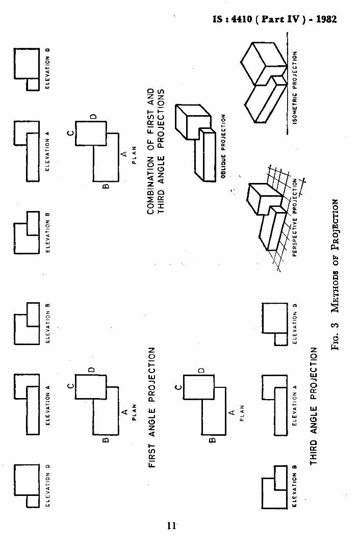
6.2 AxonoIIletric Projection* - The representation ofobjects by meansof their perpendicular projection on a single plane, so placed thatrectangular solid projected upon it would show three faces. When allthree faces are equally inclined to the plane of projection, so that all theedges and the three principal axes are equally foreshortened, the methodis called' Isometric Projection' ( see Fig. 3). It is ' Dimetric Projection •when only two faces are equally inclined, and' Trimetric Projection'when no faces are equally inclined.
6.3 Cabinet Projection - See 6.11.
6.4 Cavaliers Projection - See 6.11.
6.5 COIIlbination of First and Third Angle Projections - Aprojection in which the elevation and end views are placed in third angleprojection and the plan in the first angle projection (see Fig. 3).
6.6 DiIIletric Projection - See 6.2.
6.7 First-Angle Projection - This is the projection in which each viewis so placed that it represents the side of the object remote from it in theadjacent view ( see Fig. 3 ).
6.8 Isomers-lc Projection - See 6.2.
6.9 Multiplaner Projection - See 6.10.
6.10 Multiview Projection- A method of projection by means ofwhich the exact shape of an object can be represented by, two or moreseparate views produced on projection planes which are usually at rightangles to each other. It is also called' Multiplaner Projection'.
tCode of practice for architectural and building drawings (first revision).
10
OB
LIQ
UE
PR
OJE
CT
ION
"""rI) •• ... ~ N.. .... .... Q ~ • ... .. ... <- -
EL
EV
AT
ION
D
cD
D
ISO
ME
TRIC
PRO
JEC
TIO
N
A1c
PL
AN
EL
EV
AT
ION
A
IS
]
B
CO
MB
INA
TIO
NO
FF
IRS
TA
ND
THIR
DA
NG
LEP
RO
JEC
TIO
NS
EL
EV
AT
ION
B
C2J
PER
SPE
CT
IVE
PR
OJE
CT
ION
»<
;
FIG
.3
ME
TH
OD
SO
FP
RO
JEC
TIO
N
TH
IRD
AN
GLE
PR
OJE
CTI
ON
cDI
5JC2
JE
LE
VA
TIO
N0
EL
EV
AT
ION
AE
LE
VA
TIO
NB
C I0
BI~
I
AP
LA
N
FIR
ST
AN
GLE
PR
OJE
CT
ION
- -c I
0-B
I--=
rI
AP
LA
N
C2J
ILL
JcD
E:L
EV
AT
ION
BE
LE
VA
llO
NA
EL
EV
AT
ION
D

IS: 4410 (Part IV) • 1982
6.11 Oblique Projection* - The representation of objects on a singleplane by means of their projections, the projecting lines making anglesother than 90~ with the plane. The object is usually placed with thefront face, or two of the principal axes, parallel to the plane of projection.The angle of the projections with the plane is usually 45° and the drawingis then called a ' Cavaliers Projection'. To overcome the distortion oftendisagreeably apparent in this projection, dimensions parallel to the third( receding) axis of the object are often arbitrarily shortened to one-half,the projection being then called a ' Cabinet Projection' ( see Fig. 3 ).
6.12 Orthogonal Projection - See 6.13.
6.13 Orthographic Projection· - Method of representing the exactshape of an object in two or more planes generally at right angles to eachother by extending perpendiculars from the object to the planes. Theterm 'Orthogonal Projection' is sometimes used for this system ofdrawing.
6.14 Perspective Projection* - The representation of an object on aplane or curved surface as it appears to the eye (see Fig. 3 ).
6.15 Third-Angle Projection - This is the projection in which eachview is so placed that it represents the side of the object near to it in theadjacent view ( see Fig. 3 ).
6.16 Trimetric Projection - See 6.2.
7. TERMS RELATING TO PERSPECTIVES
7.1 Angular Perspective* - Perspective in which some of the principallines are oblique and some are not. Also called' Two-Point Perspective'.
7.2 Bird's-Eye Perspective* - Perspective of objects seen from a greatheight.
7.3 ClIrvilinear Perspective* - Perspective in which the picture ismade on a concave cylindrical surface as in a panorama. Also called, Cylindrical Perspective' or' Panoramic Perspective'.
7.4 Cylindrical Perspective - See 7.3.
7.5 Diagonal Perspective* - Angular perspective in which the obliquelines make an angle of 45° with the picture plane.
7.6 Linear Perspective* - Perspective projection by means of which atrue picture of an object is reduced upon a surface anywhere in spacefrom the actual dimensions on the object, as given in a suitably chosenorthographic projection.
12

IS; 4410 ( Part IV) -1982
7.7 Oblique Perspective* - Perspective in which all the principallines are oblique. Also called' Three-Point Perspective ',
7.8 One-Point Perspective - See 7.10.
7.9 Panoearrric Perspective - See 7.3.
7.10 Parallel Perspective* - Perspective in which the principal linesof the picture are either parallel or perpendicular to the picture plane.Also called' One-Point Perspective '.
7.11 Three-Point Perspective - See 7.7.
7.12 Two-Point Perspective - See 7.1.
8. TERMS RELATING TO CHARTS
~
I I
I\
II
tL III ,II,ll II
L- L--
55
15
20
z 50Q::: 45~
~ 40z
~ 35<....J:J 30n,o0.. 25
8.1 Alignlllent Chart - See 8.9.
8.2 Bar Chart* - Chart in which length of each bar is proportioned tothe magnitude of the quantity represented ( see Fig. 4 ).
60
1935 1940 1945 1950 1955 1960 1965 1.970
YEAR
FIG. 4 A TYPICAL BAR CHART
8.3 Classification Chart* - Chart showing the subdivision of a whole,and the inter-relation of its parts to each other.
8.4 Cornpound Bar Chart* - Bar chart showing two or morecomponents in each bar.
13
IS : 4410 ( Part IV ) • 1982
8.5 Graph - This is a symbolic representation usually by a curve lineshowing the relationship between two variables.
8.6 Grid Chart - See 8.14.
8.7 Histogram - A frequency diagram in which rectangles proportional in area to the class freq uencies are erected on sections of thehorizontal axis, the width of each section representing the correspondingclass interval of the variate.
8.8 Logarithmic Chart - Chart having both abscissas and ordinatesspaced logarithmically.
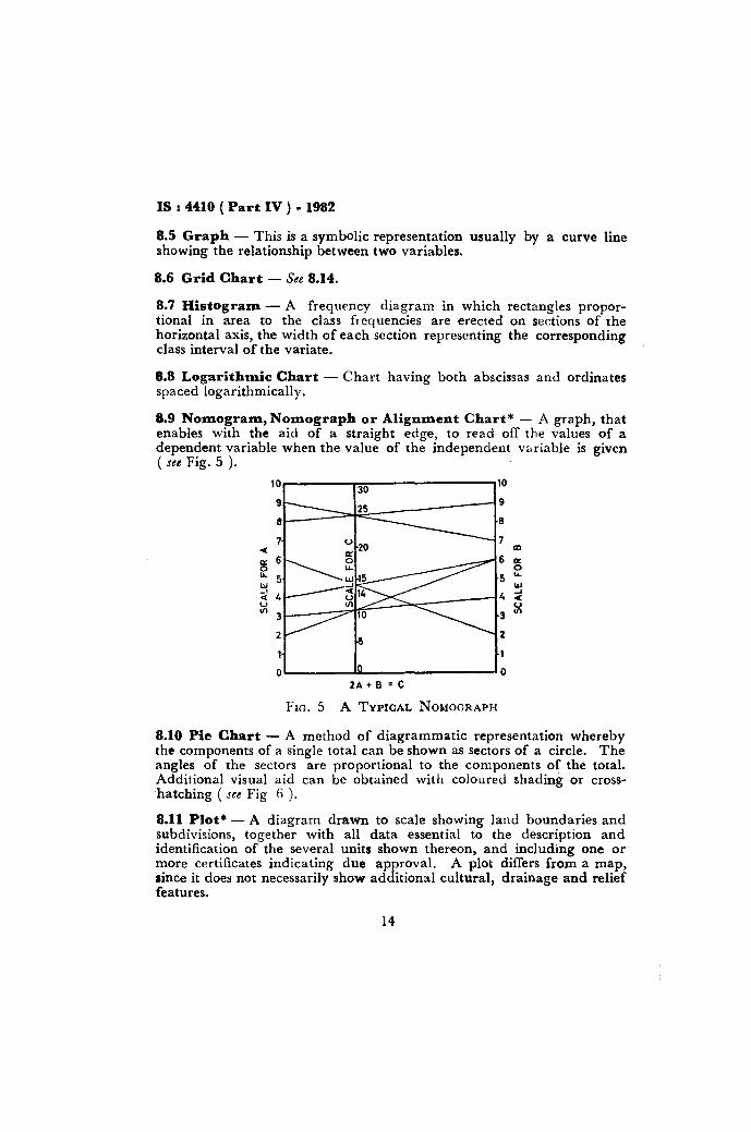
8.9 Nomogram, Nomograph or Alignment Chart* - A graph, thatenables with the aid of a straight edge, to read off the values of adependent variable when the value of the independent variable is given( see Fig. S ).
10 3010
9 259
8 8
7 70« III
0:: 6 6 IX0 0LJ.. 5 5 LJ..
W W_.4 4
..J0« 0«U
~1Il3 3
2 2
0 02A + B = C
FIG. S A TYPICAL NOMOGRAPH
8.10 Pie Chart - A method of diagrammatic representation wherebythe components of a single total can be shown as sectors of a circle. Theangles of the sectors are proportional to the components of the total.Additional visual aid can be obtained with coloured shading or crosshatching ( see Fig fj).
8.11 Plot* - A diagram drawn to scale showing land boundaries andsubdivisions, together with all data essential to the description andidentification of the several units shown thereon, and including one ormore certificates indicating due approval. A plot differs from a map,since it does not necessarily show additional cultural, drainage and relieffeatures.
14

IS : 4410 ( Part IV ) • 1982
RAW MATERIAL35 -I.
MISCELLANEOUS25 ./.
FIG. 6 A TYPICAL PIE CHART
8.12 Polar Chart* - Chart on a polar co-ordinate paper frequentlyused for representing intensity of illumination, intensity of heat, polarforms of curves, etc. Also called' Polar Diagram'.
8.13 Polar Diagrarn - See 8.12.
8.14 Rectilinear Chart* - Chart made on a sheet ruled withequi-spaced horizontal lines crossing equi-spaced vertical lines. Alsocalled ' Grid Chart'.
8.15 SeJllilogarithIDic Chart - A chart having one axis cartesian andother logarithmic.
8.16 Triaxial Diagz-am - A chart for studying the properties ofcompounds or mixtures containing three variables. The chart has theform of an equilateral triangular diagram each side being divided intohundred equal parts representing three characteristics of quantity; forexample triangular classification chart for soils ( see Fig. 7). Also called, Trilinear Chart'.
8.17 Trilinear Chart - See 8.16.
9. TERMS RELATING TO MAPS
9.1 Contour - An imaginary line on the ground, all points on whichare at the same geospherical elevation above a specific datum, usuallymean sea level.
15

IS : 4410 ( Part IV ) • 1982
'0":....'_~_~:"""""~L-----:~--:Jl-_~_~_-:?,-_~r--~o ~
PERCENT SILT
FIG.7 A TYPICAL TRIAXIAL DIAGRAM
9.2 Contour Interval* - The difference in elevation between theadjacent contours on a map.
9.3 Contour Map - A map showing the configuration of the groundor terrain b) means of contour lines drawn generally at regular intervalsof elevation.
9.4 Engineering Map - Working maps for engineering projects whichare designed for specific purposes to aid construction.
9.5 Geographic Map - A small scale general map of a large areadepicting natural and manmade features, for example, cities, roads,railways, streams, open water bodies, embankments, canals, drams,administrative and international boundaries, names, relief, etc, in ageneralised form together with latitudes and longitudes.
9.6 Geologic Map - A map which shows the boundaries and distribution of rock formations, geologic structures, strikes and dip, orebearing formations, quaries, etc.
16

IS : 4410 (Part IV) • 1982
9.7 Hydroisopleth Map - A map showing fluctuation of the underground water table with respect to time and space.
9.8 Hydrographic Map· - A map showing information concerningbodies of water, such as shore lines, sounding depths, subaqueouscontours, navigation aids and water control measures.
9.9 Index Map - A small scale skeleton map of a large area, generallyused for depicting the location of a project on a large scale map.
9.10 Isohyet - A line connecting points of equal precipitations. Alsocalled' Isohyetal Line' or ' Isopluvial Line'.
9.11 Isohyetal Line - See 9.10.
9.12 Isopluvial Line - See 9.10.
9.13 Isohyetal Map - A map showing lines of equal precipitation orisohyets over an area during a given period. Also called 'IsopluvialMap'.
9.14 Isopiestic Line - A line on a map connecting all points of equalelevation, to which water pressure in a water-bearing formation wouldrise if free to do so; a line connecting all points of equal pressure in awater-bearing formation under pressure; or a line connecting all points ofequal altitude on the upper surface of an unconfined aquifer.
9.15 Isopiestic Map -- A map showing isopiestic lines.
9.16 Isopluvial Map - See 9.13.
9.17 Land Use Map - A map showing the use of the land or area at atime.
9.18 Mosaic Or Photo Mosaic - An aerial mosaic is an assembly ofaerial photographs, the edges of which have been cut and matched toform a continuous photographic representation of a portion of the earth'ssurface. A controlled mosaic is one which is oriented and scaled tohorizontal ground control.
9.19 Photograuunetric Map - A map depicting topographical andother features of a part of the earth's surface, prepared by measurementfrom photographs of the area taken with cameras or other photographicsensors mounted in an aircraft.
17
IS: 4410 ( Part IV) ·1982
9.20 Photo Index Map - A map on a suitable scale depicting positionand coverage on the territory of every photograph of an assembly ofadjoining aerial or satellite imagery of about the same photo scale.
9.21 PlaniJ:netric Map* - A map which presents the horizontalpositions only for the features represented, distinguished from atopographic map by the omission of relief in measurable form. Thenatural features usually shown on a planimetric map include rivers,lakes, mountains, valleys, plains, forests, prairies, marshes and deserts..The culture features include cities, farms, transportation routes, publicutility facilities, political and private boundary lines.
9.22 Relief Map - A m<ip incorporating vertical dimension of theground or terrain, for example, hills, mountains, valleys, by means ofhectures, contours, hill shading or by combination of these methods.
9.23 Satellite Map - A map depicting topographical and other featuresof a part of the earth's surface, prepared by measurement from imageryof the area taken using sensors mounted on a satellite.
9.24 Soil Map - A map showing different types of soils in an area andis useful for agricultural, irrigation and engineering purposes.
9.25 Synoptic Weather Map - A map showing the weather conditionsprevailing over an area at a given time.
9.26 Topographic Map - A general map on sufficiently large scale,showing all important features and relief on which individual groundfeatures can be identified by their shape and position.
9.27 Vicinity Map - A general map depicting pertinent information ofan area in the vicinity.
9.28 Water Table Map - A contour map of the upper surface of thezone of saturation ( Set also 9.15 ).
9.29 Weather Map - A map showing the conditions of the principalmeteorological elements at a given time.
10. SYMBOLS IN MAPPING
10.1 In addition to symbols for land surveying given in Fig. 20 ofIS : 962-1967t, the symbols given in Appendix A may be used in themaps for river valley projects.
tCode of practice for architectural and building drawings (firlt revision).
18

IS : 4410 ( Part IV ) • 1982
APPENDIX A
( Clause 10.1 )
SYMBOLS IN MAPPING
1. Airfield ( inters ection of lines indicates location)
2. Helicopter landing field
3. Prohibited flying area~///////////////////'l.
~ PROHIBITED ~~///////////////////;.:;
o
(S = Steel )
W = Wood4. Truss bridge
6. Arch bridge
5. Suspension bridge
7. Factory chimney
8. Watch-tower
9. Oil-well
10. Oil-tank
11. Mine-shaft •~) t('
)'1 ./:-1vf" .r. rr'"12. Dry nala (a) with broken ground along bank ( as surveyed ) \~l)t:j~~;:tk:
(b) ravines ( as surveyed ) .:;'~.:J,.<; ..,;/:/}:.l!J~~~';;~~i-~
19

IS : 4410 (Part IV) • 1982
13. Stream bank, north bank shows continuous, unbroken, steep or precipitous bankfrom 1 m to 30 m orover in height and '24, 3D, (I) 23,
south bank shows the -":'''", ... . '.../
:~;::;'~~'H~~::;O~ ;;~~responding with thoseon the north bank: (a), '~
(b) and (c) show treat-ment of side stream junctions in accordance with the extent to which the river bankis broken, (d) breaks in banks that extend down" to river bed level, (e) small breaksthat have not been eroded down to river bed level, (f), (g) and (h) types of gorges ornarrow rivers with high banks
14. Double-line stream (a) perennial, with arrow showing directionof flow, (b) dry with sandy beds
15. Water fall with height ( perennial and non-perennial)
16. Rapids
(e) (b)~ ,:;.",,:1
~'.::...x' .. ~16mFAllS 6m
RAPIDS RAPIDS
~
17. Sluice ~LUIC E
~ SLUICE"==,*=1=
18. Perennial or non-perennial canals (a) single line ( thickness accordingto importance) (b) double line according to width and with embankment shown by relative height
"ie,'r (b)
19. Canals disused or under construction with appropriate descriptive '''Cremark ( thickness of the lines according to importance ) ======~=.=:~':=
CANAL DISUSED!UNDER CONSTRUCTION
20. Canal: (a) with navigation lock (b) withlock or weir carrying (i) road (ii) foot-path(iii) aqueduct
21. Dam or weir '''''''''''",,,.''''
22. Sand river bed showing:channels
(a) perennial channels (b)
23. River-bed showing: (a) sheet rock (b) rounded rocksS~(c) edged rock (d) rock ribs a ~" c .,
• u. (4)
20

IS : 4410 ( Part IV ) • 1982
24. Heights:
a) Triangulation stationb) Triangulation intersected point or permanent transverse station or
intersected point with ground level accurately fixed or measuredc) Approximate
d) Relative
25. Bench Mark:a) Geodeticb) Tertiaryc) Canal
26. Post Office
27. Telegraph Office
28. Combined Post & Telegraph Office
29. Police Station
30. Dak or Travellers Bungalow'[
31. Rest Houset
32. Inspection Bungalowt
33. Circuit House'[
34. Camping Ground
35. Railway Station
36. Reserve Forest
37. Protected Forest
!:l 200
.200.200.20,
.BM 633
.BM 63'3
.63'3
PO
TO
PTO
PS
DB
RH
IB
CH
CG
RS
RF
l'F
tThe name of the department that maintains the building may be given in brackets.
21
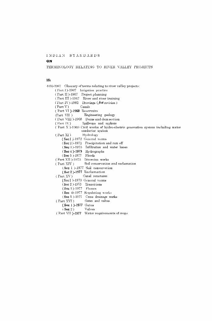
INDIAN STANDARDS
ON
TERMINOLOGY RELATING TO RIVER VALLEY PROJECTS
IS:
4410-1967 Glossary of terms relating to river valley projects:(Part I )-1967 Irrigation practice(Part II )-1967 Project planning( Part III )-1967 River and river training(Part IV)-1982 Drawings (first revision)( Part V) Canals( Part VI )-1968 Reservoirs(Part VII ) Engineering geology( Part VIII )-1968 Dams and dam section( Part IX ) Spillways and syphons( Part X )-1969 Civil works of hydro-electric generation system including water
conductor system( Part XI ) Hydrology
(Sed j-1972 General terms(Sec 2 )-1972 Precipitation and run off(Sec 3 )-1973 Infiltration and water losses(Sec 4 )-1973 Hydrographs( Sec 5 )-1977 Floods
( Part XII )-1973 Diversion works( Part XIV) Soil conservation and reclamation
(Sec I )-1977 Soil conservation(Sec 2 )-1977 Reclamation
( Part XV ) Can al stru ctures(Sed )-1973 General terms(Sec 2 )-1973 Transitions(Sec 3 )-1977 Flumes(Sec 4)-1977 Regulating works(Sec 5 )-1977 Cross drainage works
( Part XVI) Gates and valves(Sec 1 )-1977 Gates(Sec 2) Valves
(Part VII )-1977 Water requirements of crops

INTE ATIONAL SYSTEM OF UNITS (SI UNITS)
Ba e UnJt.
QUA TITY UNIT SYMBOL
Len gth metr e m
Mau kilogram kg
T ime seco nd
Electric current ampe re A
Thermodynamic: kelvin Ktemperatu re
Luminous intewity candela cd
Amount of substance mole mol
SupplelDeutary Uniu
QUANTITY UNIT SYMBOL
Plane an gle radian rad
Solid ang le steradiaD sr
Derived Units
Q U AN TI TY UNIT SYMBOl. DJlI'INlTIO.
Force newton N 1 N 1 Ilc.m/ls
Energy jou le J 1 J I N.m
Power watt W lW 1 s»Flux weber Wb I Wb I v s
Flux density tella T IT I Wb/ml
Frequency hertz Hz I Hx I c:/s (...1)
Electric c:onductance siemens S I 5 1 AIV
EI"ctromotive for ce volt V IV I W/A
Pressur .., Itress pascal p" I Pa I N/ms
INDIAN STANDARDS INSTITUTION
Manak Bhavan, 9 Bahadur Shah Zatar Marg, NEW DELHI 110002
Telephone.: 26 60 2', 27 01 3' Telegrams: M.anaksansthaRegional Offices: Telephone
Western : Novelty Cha mbers, Grant Road BOMBAY 400007 37 97 29Eastern : 5 Chowrlnghee Approach CALCUTTA 700072 27 5090Southern : C.1. T.Campus MADRAS 600113 412442Northern : B69, Phase VII S.A.S . NAGAR
( MOHAll) 160051
Branch Offic es:' Push pak', Nurmohamed Shaikh Marg, Khllnpur'f' Block, Unit y Bldg, Naras lmhllrala SquareGangotri Complex, Bhadbhada Road , T. T. Nagar22E Kal pana A reaS-8-56C L. N. Gupta MargR 14 Yudhlster Marg, C Scheme117'418 B Sarvodaya Nag arPBl llputra Industrial EstateHantax Bldg (lind Floor), Rlv Station Road
AHMADABAD 380001 20391BANGALORE 560002 2248 05BHOPAL 462003 6 27 1eBHUBANESHWAR 751014 53627HYDERABAD 500001 221083JAIPUR 302005 69832KANPUR 208005 47282PATNA 800013 II 28 08TRIVANDRUM 1195001 3227
Prlnled al Arc:eo Prell, New Deihl, India
Related Documents