IS 3589 : 2001 Edition 4.2 (2003-10) Indian Standard STEEL PIPES FOR WATER AND SEWAGE 'C (168.3 TO 2 540 mm OUTSIDE DIAMETER) - SPECIFICATION ( Third Revision ) (Incorporating Amendment Nos. 1 & 2) ICS 77.140.30:41.140.60;91.140.80 0 BIS 2003 BUREAU OF INDIAN STANDARDS MANAK BHAVAN, 9 BAHADUR SHAH ZAFAR MARG NEW DELHI 110002 Price Group 7

IS 3589 - 2001
Nov 08, 2014
standard
Welcome message from author
This document is posted to help you gain knowledge. Please leave a comment to let me know what you think about it! Share it to your friends and learn new things together.
Transcript
IS 3589 : 2001 Edition 4.2
(2003-10)
Indian Standard
STEEL PIPES FOR WATER AND SEWAGE 'C (168.3 TO 2 540 mm OUTSIDE DIAMETER) -
SPECIFICATION
( Third Revision ) (Incorporating Amendment Nos. 1 & 2)
ICS 77.140.30:41.140.60;91.140.80
0 BIS 2003
B U R E A U O F I N D I A N S T A N D A R D S MANAK BHAVAN, 9 BAHADUR SHAH ZAFAR MARG
NEW DELHI 110002
Price Group 7
Steel Tubes, Pipes and Fittirigs Sectional Committee, MTD 19
FOREWORD
This Indian Standard (Third Revision) was adopted by the Bureau of Indian Standards, after the draft finalized by the Steel Tubes. Pipes and Fittings Sectional Committee had been approved by the Metallurgical Engineering Division Council. This standard was originally published in 1966, first revised in 1981 and subsequently in 1991. While reviewing this standard in the light of the experience gained during these years, the committee felt to revise the same, taking note of the present practices being followed in the country and also overseas standards existing on the subject. In the revision of this standard the following main modifications have been made:
a) Provision of outside diameters and thicknesses of pipes have been revised in accordance with the provisions, of International Standards.
b) Exhaustive tables for chemical composition of steels to be used and tensile properties of the pipes have been incorporated.
b C) Annexes A to D as the guideline for 'Protection Against Corrosion' have been added which recommend methods of protecting pipes against corrosion. It covers external as well as internal protection. Separate Indian Standards incorporating various types of protective coatings and materials thereof are expected to be published in due course of time.
In the formulation of this standard due weightage has been given to international coordination among the standards prevailing in different countries in addition to the practices in the country. This has been met by deriving assistance from the following publications:
ISO559-1991 Steel tubes for water and sewage (second edition), International Organization for Standardization.
IS0 4200 : 1991 Plain end steel tubes, welded and seamless - General tables of dimensions and masses per unit length. International Organization for standardization.
BS 534 : 1990 Steel pipes and specials for water and sewage. British Standards Institution.
This edition 4.2 incorporates Amendment No. 1 (May 2002) and Amendment No. 2 (October 2003). Side bar indicates modification of the text as the result of incorporation of the amendments. For the purpose of deciding whether a particular requirement of this standard is complied with, the final value, observed or calculated, expressing the result of a test or analysis, shall be rounded off in accordance with IS 2 : 1960 'Rules for rounding off numerical values ( revised)'. The number of significant places retained in the rounded off value should be the same as that of the specified
b value in this standard.
Indian Standard
STEEL PIPES FOR WATER AND SEWAGE (168.3 TO 2 540 mm OUTSIDE DIAMETER) -
SPECIFICATION
( Third Revision ) 1 SCOPE
This standard applies to seamless and welded carbon steel pipes for water and sewage of outside diameter from 168.3 to 2 540 mm.
2 REFERENCES
Cc The following Indian Standards contain provisions which through reference in this text constitute provisions of this standard. At the time of publication, the editions indicated were valid. All standards are subject to revision and parties to agreements based on this standard are encouraged to investigate the possibility of applying the most recent editions of the standards indicated below:
IS No. Title
228 Methods of chemical analysis of steels (issued in various parts)
1608: I995 Methods for tensile testing of steel products ( second revision )
2328: 1983 Method for flattening test on metallic tubes ( first revision )
3803 (Part 1) : Method for elongation 1989lIS0 2566 :conversions for steel: Part 1 1984 Carbon and low alloy steels
b ( second revision )
4711 : 1974 Methods for sampling of steel pipes, tubes and flttings (first revision )
4736 : 1986 Hot-dip zinc coatings on mild steel tubes ( h t revision )
3 TERMINOLOGY
For the purpose of this standard, the following definitions shall apply.
3.1 Pipe (Tube)
A long hollow open ended object of circular cross-section. The term tube is synonymous with the term pipe. 3.2 Hydrostatic Test Pressure
Test pressure for hydraulic testing a t the works.
3.3 Random Lengths
The term random length denotes the normal manufacturing length falling within a range agreed to between the purchaser and the manufacturer.
3.4 Exact Lengths
Pipes cut to a specified length on which only a small tolerance is allowed.
3.5 Effective Length
The actual length that a pipe contributes when correctly assembled in a run of piping. This dimension excludes the additional length contributed by a slip-on type coupling when that is used.
4 INFORMATION TO BE SUPPLIED BY THE PURCHASER WHILE PLACING ORDER
4.1 Mandatory Informations
a) the quantity ordered (total tonnage, total I length or number of tubes);
b) the number of this standard; C) the grade of steel; d) the outside diameter and thickness; e) the length of pipes: f ) the end preparation (bevelled ends or
special joints); and g) the type of external coating andlor interior
lining as agreed previously with the manufacturer.
4.2 Optional Requirements
Certain optional and supplementary requirements may also be specified as under:
a) the steel making processes and deoxidation procedures:
b) the tube making process: C) delivery condition; d) ladle analysis; e) delivery lengths; and f ) end preparation.
5 DESIGNATION
5.1 The pipes shall be designated by the method of manufacture followed by the grade number corresponding to the minimum specified tensile strength in MPa following the symbol Fe as given in Table 1.
Example: ERW - Fe410 indicates electric resistance welded or induction welded steel pipe having a minimum tensile strength of 410 MPa.
Table 1 Designation of t h e Grades of t h e P i ~ e s
Method of Refe- Steel Grades Manufacture of rence Applicable
Pipe
11) 12) 13) (4) 151 Seamless S Fe330 Fe41O Fe450 Electric resistance ERW Fe330 Fe410 Fe450
ec including induction welded
Submer ed arc SAW Fe330 Fe410 Fe450 weldef(inc1uding spirally welded)
NOTE - Method of manufacture of pipe and steel grades other than specified above shall be as agreed to between the manufacturer and the purchaser.
5.2 The size of the pipes shall be designated by their outside diameters in mm.
6 QUALITY O F STEEL
Pipes shall be manufactured with the steel produced by the open hearth or electric furnace or one of the basic oxygen processes. Other processes may be used by agreement between the purchaser and the manufacturer.
7 MANUFACTURE O F THE PRODUCT
The pipes shall be manufactured by one of the following processes. 7.1 Seamless Pipes
'cr The pipes shall be manufactured by using a seamless process and shall either be hot or cold finished. 7.2 Electric Resistance Welded Pipes
The pipes shall be manufactured from plate, sheet or strip welded continuously by the passage of an electric current across the abutting edges longitudinally or spirally. The finished pipes shall not include welds used for joining lengths of the hot or cold, flat rolled strips prior to tube forming. The external weld bead shall be removed completely. 7.3 Submerged Arc Welded Pipes
The pipes shall be manufactured from plate, sheet or strip with either a single or double longitudinal seam or a spiral seam and welded across the abutting edges by an automatic
submerged arc welding process using at least two runs, one of which shall be on the inside of the pipes. 7.4 Repair by Welding
7.4.1 Injurious defects in pipe wall, provided their depth does not exceed one third of the specified wall thickness, shall be repaired by welding. 7.4.1.1 Defects in the welds, such a s sweats and leaks, unless otherwise specified may be repaired or piece rejected a t the option of the manufacturer for submerged arc welded pipes. 7.4.1.2 Welds of the electric resistance welded pipes may be repaired only by agreement between the purchaser and the manufacturer. 7.4.1.3 Repairs of this nature shall be made by completely removing the defect, cleaning the cavity and then welding. 7.4.2 All repaired pipes shall be retested hydraulically in accordance with 10.
8 CHEMICAL COMPOSITION
8.1 Ladle Analysis
The ladle analysis of steel shall be a s given in Table 2. The analysis of steel shall be carried out either by the method specified in IS 228 and its relevant parts or any other established instrumental/chemical method. In case of dispute the procedure given in IS 228 and its relevant parts, shall be the referee method. However, where the method is not given in IS 228 and its relevant parts, the referee method shall be as agreed to between the purchaser and the manufacturer. 8.2 Produc t Analysis
Permissible variations in the case of product analysis from the limits specified in Table 2 shall be a s given in Table 3.
9 MECHANICAL PROPERTIES
9.1 Tensile St rength
The tensile properties of strip cut longitudinally (excluding the weld) from selected pipes shall show the properties as given in Table 4 in respect to specific type of pipes a s manufactured. The percentage elongation shall be determined on a gauge length of 5.65p0. If other gauge lengths are used conversion shall be made as in IS 3803 (Part 1).
9.2 Fla t tening o r Bend Test
9.2.1 Flattening Test for ER W Pipes At the option of the manufacturer flattening or bend test shall be carried out depending upon the thickness and outer diameter of the pipes.
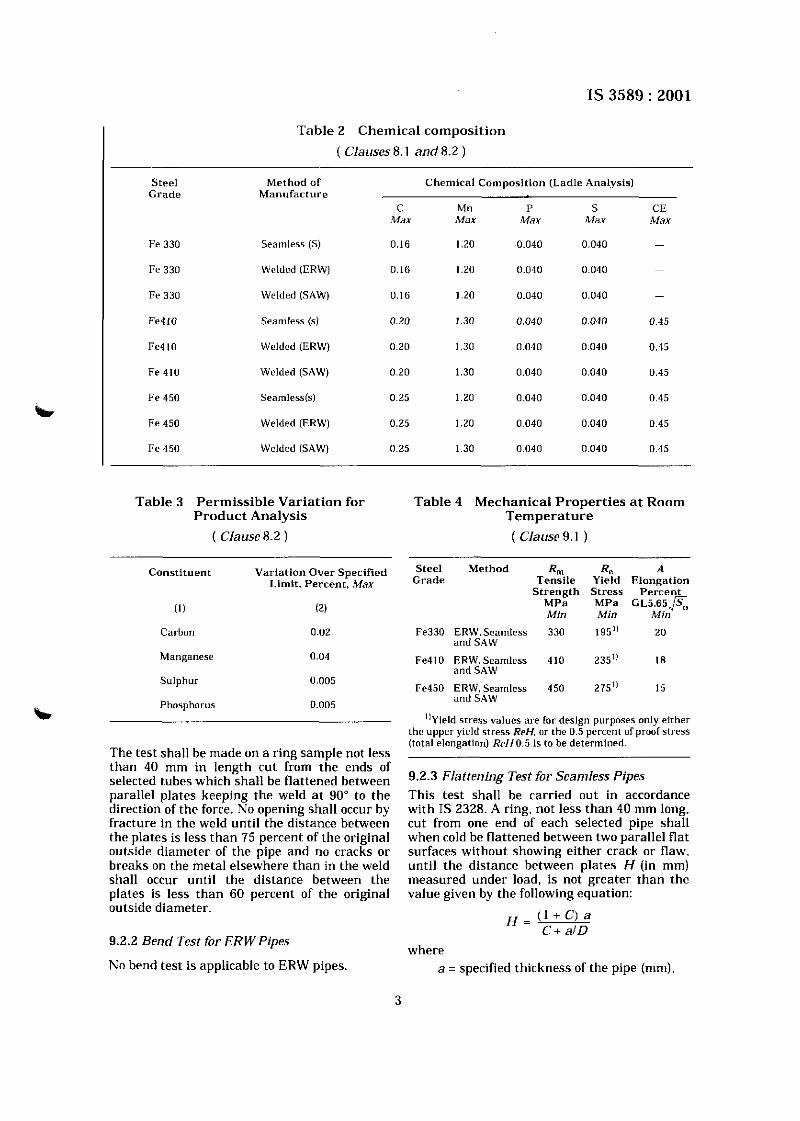
Table 2 Chemical composition
( Clauses8.1 and8.2 )
I - - --
Steel Method of Chemical Composit ion (Ladle Analysis) Grade Manufacture
Seamless (S)
Welded IERW)
Welded (SAW)
Seamless (s)
Welded IERW)
Welded (SAW)
Searnlebs(s)
Welded IERW)
Welded (SAW)
C Mn P S CE Max Max Max .Max Max
Table 3 Permissible Variation for Product Analysis
( Clause 8.2 )
Table 4 Mechanical Propert ies at Room Temperature
( Clause 9.1 )
Const i tuent Var ia t lan Over Specified Limit. Percent , Max
(1) 12)
Carbon 0.02
Manganese 0.04
Sulphur 0.005
Phosphorus 0.005
The test shall be made on a ring sample not less than 40 mm in length cut from the ends of selected tubes which shall be flattened between parallel plates keeping the weld a t 90" to the direction of the force. No opening shall occur by fracture in the weld until the distance between the plates is less than 75 percent of the original outside diameter of the pipe and no cracks or breaks on the metal elsewhere than in the weld shall occur until the distance between the plates is less than 60 percent of the original outside diameter.
9.2.2 Bend Test for ERW Pipes
No bend test is applicable to ERW pipes
Steel Method R m Ra A Grade Tensile Yield Elongation
S t r eng th S t r e s s Pe rcen t M P a MPa G ~ 5 . 6 5 p ~ Mln Min Mln
Fe330 ERW, Seamless and SAW
Fe410 ERW.Searnless 410 235" I8 and SAW
Fe450 ERW, Seamless 450 275" 15 and SAW
']yield stress values are for design purposes only either the upper yield stress ReH. or ihe 0.5 percent of proof stress (total elongation) ReHO.5 is to be determined.
9.2.3 Flattening Test for Seamless Pipes This test shall be carried out in accordance with IS 2328. A ring. not less than 40 mm long. cut from one end of each selected pipe shall when cold be flattened between two parallel flat surfaces without showing either crack or flaw. until the distance between plates H (in mm) measured under load, is not greater than the value given by the following equation:
where a = specified thickness of the pipe (mm).
D = specified outside diameter of the pipe (mm).
C = a constant dependent on the steel grade value of C, = 0.09 for Fe330 = 0.07 for Fe410 and Fe450.
UOTES 1 If any flaw appears during flatterling test, it may
be removed by grinding or filing. In such cases if the remaining wall thickness is not less than the minimum permitted thickness as per clause the sample shall be accepted.
2 Superficial rupture resulting frorll surface imperfections shall not be a cause of rejection.
9.3 Guided Bend Tes t (For SAW Pipes)
Strios not less than 40 mm wide, cut i r c ~ i i f r r ~ ~ a l l fro111 pipes prrpendic~~li~r 1 0 wcbld seam w~tl i the weld near the ~ n ~ d d l c of the ~~-~~~ -~~
sample shall, without fracture, be doubled over b a round bar the diameter of which shall be
calculated as given below. The weld reinforcement shall be removed from the faces.
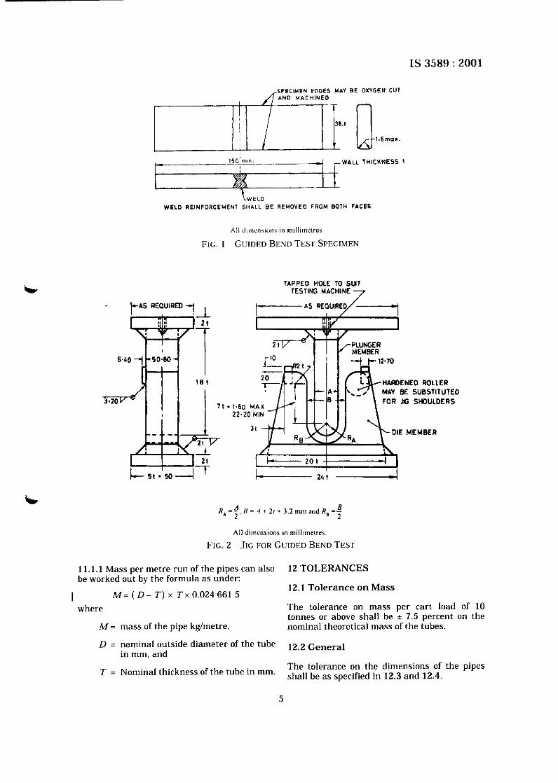
9.3.1 One face bend and one root bend % specimen, both conforming to Fig. I shall be 9% bent approximately 180" in a jig substantially
in accordance with Fig. 2 for any combination of diameter, wall thickness and grade. The maximum value for jig dimension A may be calculated by the formula given below. The manufacturer shall use a jig based on this dimension or a smaller dimension a t his option.
A = 1.15 (0- 2t) -- eD 2 e - I I
where
1.15 = peaking factor.
D = specified OD in mm,
t = specified wall thickness in mm, and
e = strain in mm
= 0.132 5 for Grade Fe330.
= 0.127 5 for Grade Fe410 and Grade Fe450.
9.3.2 The specimens shall not fracture completely. Cracks 6.35 mm or less in length a t the edge of the specimen or 3.18 mm or less in length in the centre of the specimen shall be disregarded. Any crack greater than 3.18 mm in length and regardless of depth located within the weld metal shall be a cause for rejection. Any pop~out greater than 3.18 mm in length (6.35 mm a t the edge) and 12.5 percent or less of the specified wall thickness in depth and located in the parent metal, the heat affected
zone, or the fusion line, shall not be the cause for rejection. Any test specimen that shows defective preparation, or material imperfection unrelated to the intent of the particular mechanical test whether observed before or after testing, may be discarded and replaced by another specimen from the same length of the pipe. 9.3.3 On examination of the bent specimen. opening out of a slight defect due to incomplete root penetration or lack of root fusion need not be considered a cause for rejection provided the defect has sound metal a t the back and on either side of it. In border line cases, further tests shall be made on specimens from the same weld adjacent to the original test specimen.
10 HYDRAULIC PRESSURE TEST
Each pipe shall be hydraulically tested a t the manufacturer's works before the pipe is coated. wrapped and lined. 10.1 The hydraulic test pressure shall be the pressure calculated a s per the following formula:
where
P = hydraulic test pressure MPa,
D = specfied outside dia of the pipe in mm.
T = specified thickness of the tube in mm, and
S = stress 60% of the specified minimum yield stress in MPa. T h e maximum test pressure to b e l imited t o 5 MPa wherever applicable.
10.1.1 The hydraulic test pressure shall be applied for 5 s. 10.2 The hydraulic test may be substituted by a Non-Destructive Test at the option of the manufacturer. 10.2.1 Method of NDT and the acceptance level shall be as agreed to between the manufacturer and the purchaser.
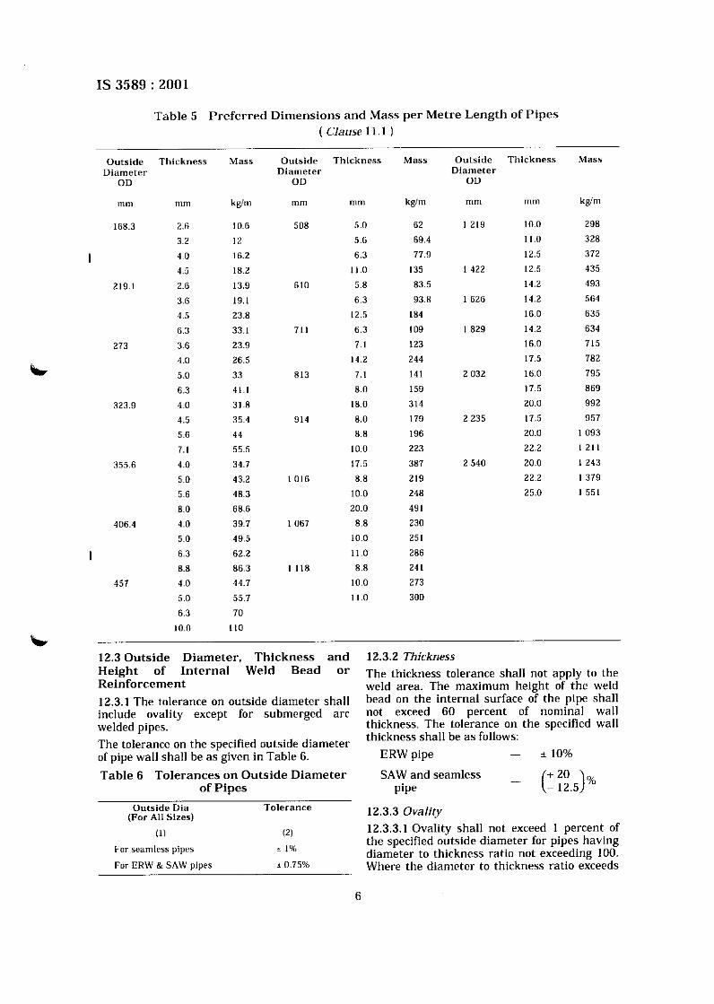
11 DIMENSIONS AND MASS P E R METRE RUN O F P I P E S
11.1 Preferred outside diameter and thickness of the pipes are specified in the Table 5. The table also provides the nominal mass per metre run of the pipes against each dimension.
NOTE - Table 5 gives a selection of preferred outside diameter7 and thicknesses, other sizes not included, in the table may be supplied as specified by the purchaser
SPECIMEN EDGES MAY BE OXYGEN CUT AN0 MACHINE0
1.6mox.
150 mln. -~ I r WALL THICHNESS I
WELD REINFORCEMEN1 SHALL BE REMOVE0 FROM BOTH FACES
All ~lhncn.~on\ In ~nlll~cnnrr,
FIG. 1 GUIDED BEND TEST SPECIMEN
TAPPED HOLE 10 SUT TESTING MACHINE 7
PLUNGER MEMBER
r- HAmENED ROLLER MAV BE SUBSTITUTED
+ 1.60 MAX FOR JG SHOULDERS
22.20 MIN
'4 R = A 1) = .I t 2, i 3.2 mm and Rg =- * 2 ' 2
All d ~ n ~ c n s ~ a n s in mill~tnetres.
FIG. 2 JIG FOR GUIDED BEND TEST
11.1.1 Mass per metre run of the pipes can also 12 TOLERANCES be worked out by the formula as under:
12.1 Tolerance o n Mass I M = ( D - T ) x T x 0 . 0 2 4 6 6 1 5
where The tolerance on mass per cart load of 10 tonnes or above shall be ? 7.5 percent on the
M = mass of the pipe kglmetre. nominal theoretical mass of the tubes.
D = nominal outside diameter of the tube 12.2 ~~~~~~l in mm, and
The tolerance on the dimensions of the pipes T = Nominal thickness of the tube in mm. Shall be as specified in 12,3 and 12,4,
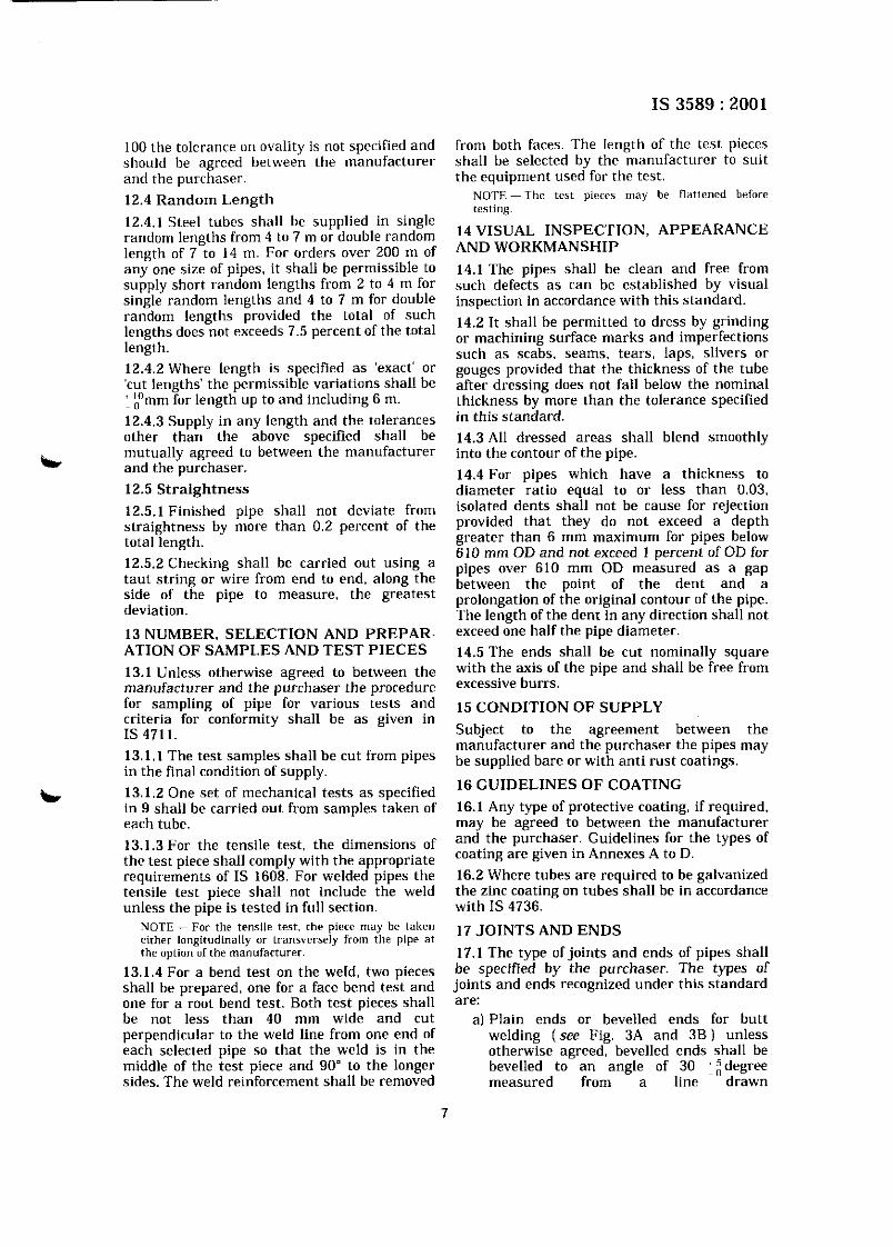
100 the tolerance on ovality is not specified and should be agreed between the manufacturer and the purchaser.
12.4 Random Length
12.4.1 Steel tubes shall be supplied in single random lengths from 4 to 7 m or double random length of 7 to 14 m. For orders over 200 m of any one size of pipes, it shall be permissible to supply short random lengths from 2 to 4 m for single random lengths and 4 to 7 m for double random lengths provided the total of such lengths does not exceeds 7.5 percent of the total length. 12.4.2 Where length is specified a s 'exact' or 'cut lengths' the permissible variations shall be ' r m m for length up to and including 6 m. 12.4.3 Supply in any length and the tolerances other than the above specified shall be
L mutually agreed to between the manufacturer and the purchaser. 12.5 Straightness
12.5.1 Finished pipe shall not deviate from straightness by more than 0.2 percent of the total length. 12.5.2 Checking shall be carried out using a taut string or wire from end to end, along the side of the pipe to measure, the greatest deviation.
13 NUMBER, SELECTION AND PREPAR- ATION OF SAMPLES AND TEST PIECES
13.1 Unless otherwise agreed to between the manufacturer and the ourchaser the ~rocedure
from both faces. The length of the lest pieces shall be selected by the manufacturer to suit the equipment used for the test.
NOTE - The te5t plecer may be f lntten~d before testing
14 VISUAL INSPECTION, APPEARANCE AND WORKMANSHIP
14.1 The pipes shall be clean and free from such defects as can be established by visual inspection in accordance with this standard.
14.2 It shall be permitted to dress by grinding or machining surface marks and imperfections such as scabs, seams, tears, laps, slivers or gouges provided that the thickness of the tube after dressing does not fall below the nominal thickness by more than the tolerance specified in this standard. 14.3 All dressed areas shall blend smoothly into the contour of the pipe. 14.4 For pipes which have a thickness to diameter ratio equal to or less than 0.03. isolated dents shall not be cause for rejection provided that they do not exceed a depth greater than 6 mm maximum for pipes below 610 mm OD and not exceed 1 percent of OD for pipes over 610 mm OD measured a s a gap between the point of the dent and a prolongation of (he original contour of the pipe. 1 he lcneth of the dent in an\( di~ection shall i~ot exceed tne half the pipe diaheter. 14.5 The ends shall be cut nominally square with the axis of the pipe and shall be free from excessive burrs.
for sampling of pipe for various tests and 15 CONDITION OF SUPPLY criteria for conformity shall be as given in IS 471 1. Subject to the agreement between the
manufacturer and the purchaser the pipes may 13.1.1 The test shall be cut pipes be supplied bare or with anti rust coatings. in the final condition of supply. 13.1.2 One set of mechanical tests as specified 16 GUIDELINES O F COATING sc in 9 shall be carried out from samples taken of 16.1 Any type of protective coating, if required, each tube. may be agreed to between the manufacturer
13.1.3 For the tensile test, the dimensions of and the p;rchaser. Guidelines for the types of
the test piece shall comply with the appropriate coating are given in Annexes A to D.
requirements of IS 1608:~or welded pipes the 16.2 Where tubes are required to be galvanized tensile test oiece shall not include the weld the zinc coating on tubes shall be in accordance unless the pipe is tested in full section. with IS 4736.
NOTE - For the tensile test. the piece may be taken eirher longitudinally or transx,erarly from the pipe at the option of the manufacturer.
13.1.4 For a bend test on the weld. two pieces shall be prepared, one for a face bend test and one for a root bend test. Both test pieces shall be not less than 40 mm wide and cut perpendicular to the weld line from one end of each selected pipe so that the weld is in the middle of the test piece and 90" to the longer sides. The weld reinforcement shall be removed
17 JOINTS AND ENDS
17.1 The type of joints and ends of pipes shall be specified by the purchaser. The types of joints and ends recognized under this standard are:
a) Plain ends or bevelled ends for butt welding (see Fig. 3A and 3B) unless otherwise agreed, bevelled ends shall be bevelled to an angle of 30 :;degree measured from a line drawn
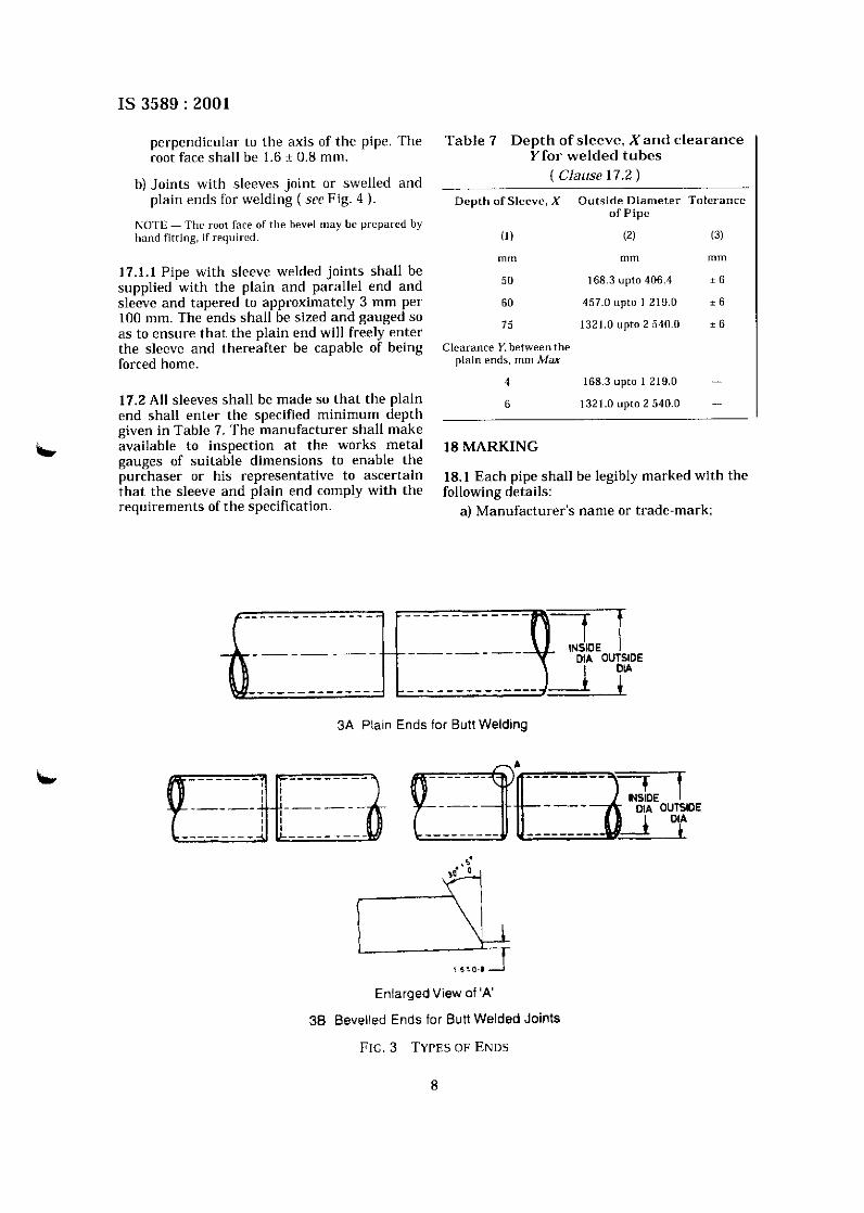
perpendicular to the axis of the pipe. The root face shall be 1.6 + 0.8 mm.
b) Joints with sleeves joint or swelled and plain ends for welding ( see Fig. 4 ).
KOTE - The root fare of the bevel may be prepared by hand fitting, if required.
17.1.1 Pipe with sleeve welded joints shall be supplied with the plain and parallel end and sleeve and tapered to approximately 3 mm per 100 mm. The ends shall be sized and gauged so as to ensure that the plain end will freely enter the sleeve and thereafter be capable of being forced home.
17.2 All sleeves shall be made so that the plain end shall enter the specified minimum depth given in Table 7. The manufacturer shall make
k. available to inspection a t the works metal gauges of suitable dimensions to enable the purchaser or his representative to ascertain that the sleeve and plain end comply with the requirements of the specification.
Table 7 Depth of sleeve. Xand c learance Y for welded tubes
( Clause 17.2 )
Depth of Sleeve. X Outside Diameter Tolerance of Pipe
(1) (2) (3)
rnlll mrn rnrn
50 168.3 upto 406.4 * 6
60 457.0 upto 1 219.0 * 6
75 1321.0 upto 2 540.0 1 6
Clearance Y. between the plain ends, rnm Max
4 168.3 upta 1 219.0 -
6 1321.0 upto 2 540.0 -
18 MARKING
18.1 Each pipe shall be legibly marked with the following details:
a) Manufacturer's name or trade-mark;
3A Plain Ends for Butt Welding
Enlarged View of 'A'
38 Bevelled Ends for Butt Welded Joints
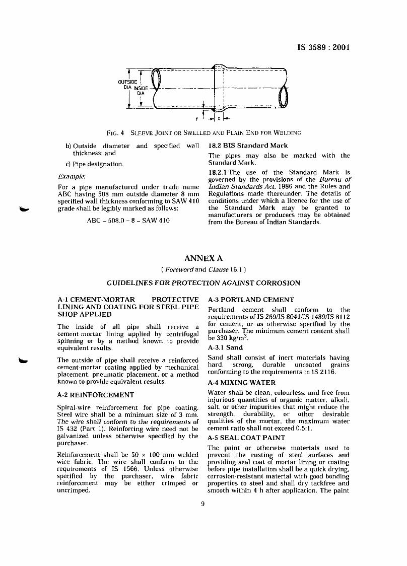
FIG. 4 SLEEVE JOINT OR SWELLED AND PLAIN END FOR WELDING
b) Outside diameter and specified wall 18.2 BIS S tandard Mark thickness: and The pipes may also be marked with the
C) Pipe designation. Standard Mark.
Example: 18.2.1 The use of the Standard Mark is governed by the provisions of the Bureau of
For a pipe manufactured under trade name Indian Standards Act, 1986 and the Rules and ABC having 508 mm outside diameter 8 mm Regulations made thereunder. The details of specified wall thickness conforming to SAW 410 conditions under which a licence for the use of
b grade shall be legibly marked as follows: the Standard Mark may be granted to manufacturers or producers may be obtained
ABC - 508.0 - 8 -SAW 410 from the Bureau of Indian Standards.
ANNEX A ( Foreword and Clause 16.1 )
GUIDELINES FOR PROTECTION AGAINST CORROSION
A-l CEMENT-MORTAR PROTECTIVE A-3 PORTLAND CEMENT
AND 'OATrNG STEEL 'IPE Portland cement shall conform to the SHOP APPLIED reauirements of IS 26911s 80411IS 14891IS 81 12 The inside of all pipe shall receive a for cement, or a s otherwise specified by the
cement~mortar lining applied by centrifugal purchaser. The minimum cement content shall
spinning or by a method known to provide be 330 kg/m3.
equivalent results. A-3.1 Sand
L. The outside of pipe shall receive a reinforced Sand shall consist of inert materials having cement-mortar coating applied by mechanical hard, strong, durable uncoated grains
placement, pneumatic placement, or a method conforming to the requirements to IS 21 16. known to equivalent results. A-4 MIXING WATER
A-2 REINFORCEMENT Water shall be clean, colourless, and free from injurious quantities of organic matter, alkali.
Spiral-wire reinforcement for pipe coating. salt, or other impurities that might reduce the Steel wire shall be a minimum size of 3 mm. strength, durability, or other desirable The wire shall conform to the requirements of qualities of the mortar, the maximum water IS 432 (Part I). Reinforcing wire need not be cement ratio shall not exceed 0.5:l. galvanized unless otherwise specified by the A-5 SEAL COAT PAINT purchaser.
The paint or otherwise materials used to Reinforcement shall be 50 x 100 mm welded prevent the rusting of steel surfaces and wire fabric. The wire shall conform to the providing seal coat of mortar lining or coating requirements of IS 1566. Unless otherwise before pipe installation shall be a quick drying, specified by the purchaser, wire fabric corrosion-resistant material with good bonding reinforcement may be either crimped or properties to steel and shall dry tackfree and uncrimped. smooth within 4 h after application. The paint
9
material applied to the interior of pipe or fittings shall be free from contaminants that may be harmful to the end user of the potable water.
A-6 LINING
A-6.1 Cement Mortar
Cement mortar shall be composed of cement. sand and water, well mixed and of proper consistency to obtain a dense, homogeneous lining that will adhere firmly to the pipe surface. Proportion 2 parts of sand to 1 part cement, by weight. The soluble chloride-ion (CI) content of the cement mortar mix shall not exceed 0.15 percent, expressed as a percentage of cement weight. A-6.2 Thickness of Lining
Cement mortar lining shall be uniform in thickness, except of joints or other
ft discontinuities in the pipe wall. Lining thickness shall be as listed in Table 8 or a s specified by the purchaser. Ends of lining shall be left square and uniform with regard to the longitudinal axis of the pipe. and the lining holdback shall be as specified by the purchaser for the type of joints required.
Table 8 Thickness of Cement Mortar Lining
Outside Dia of Minimum Thickness Tolerance Steel Pipe of Lining
mrn rnrn rnm
(1) (2) (3) 168.3 to 323.9 6 + 2
- 0
355.6 to610 7 + 2 - 0
1 321 to 2 540 12 + 3 - 0
b A-6.3 Equipment
A-6.3.1 Lining Straight sections of pipe shall be lined by use of a spinning machine specifically designed and built for the purpose of rotating the pipe section and centrifugally applying cement mortar lining to the interior of steel pipe or by a method known to provide equivalent result.
A-6.3.2 Mixing The mortar shall be mixed in batches. The amount of cement and sand entering into each batch shall be measured by weight. The quantity of water entering the mixer shall be measured automatically by an adjustable device, or it shall be otherwise measured to ensure that the correct quantity of water is being added.
A-6.4 Machine Lining
A-6.4.1 Bracing When required to prevent distortion or vibration during the spinning, each section of pipe shall be suitably braced with external or internal supports appropriate to the equipment.
A-6.4.2 Finish After the mortar has been distributed to a uniform thickness, the rotation speed shall be increased to produce a dense mortar with a smooth surface.
A-6.4.3 Surplus Water Provision shall be made for removal of surplus water by air blowing, tilting of the pipe or other methods approved by the purchaser. A-6.5 Defective Lining
A-6.5.1 General All defects, including but not restricted to sand pockets, voids, oversanded areas, blisters, and cracking a s a result of impacts, shall be cut out and replaced by hand or pneumatic placement to the same thickness a s required for the mortar lining. A-6.5.2 Lining Cracks Temperature and shrinkage cracks in the mortar lining less than 1.5 mm in width need not be repaired. A-6.6 Cur ing of Lining
Immediately after completion of spinning, the pipe sections, may be moved to a curing area. Care shall be exercised a t all time to prevent damage to the lining. At the option of the manufacturer, linings shall be either accelerated cured or moist cured.
A-6.6.1 Moist Curing On arrival a t the curing area, but not later than 30 min after completion of the lining operation, pipe ends shall be covered with plastic or wet burlap for a minimum period of 24 h before applying the exterior coating, if such coating is specified. If a cement mortar exterior coating is not specified, the lining shall be kept moist for four days before shipment. In either case, the lining shall be cured for a total period of four days before shipment. The ends of the pipe sections shall be kept closed during the curing period, with plasti'c end caps, except when sprinkling hands are used, the reinforcement and outside coatings are being applied or accelerated curing is being substituted. If the plastic end caps are installed a t that time, they can be used for shipping to the jobsite. The manufacturer shall exercise care and diligence to avoid drying to or cracking of the lining.
A-6.6.2 Accelerated Curir~g Accelerated curing may begin immediately on arrival of the pipe at the curing area, but the temperature of the pipe shall not exceed for 3 h or until the mortar has taken its initial set. whichever occures first. The ambient vapour shall then be maintained a t a temperature between 45°C and 65°C a t a relative humidity of not less than 85 percent for a minimum curing period of 6 h, after which the exterior coating may be applied, if such coating is specified. If cement mortar coating is not specified, the lining shall be cured for 18 h before shipment. In either case, the lining shall be cured for a total period of 18 h before shipment.
A-7 MORTAR LINING TEST CYLINDERS
A-7.1 Mortar Tes t Cylinders
A set of at least two standard test cylinders. 50 mm in diameter by 300 mm in length, shall be made each day. The test cylinders shall be cured with the pipe at the same temperature and for the same total length of time. Other sizes cylinders, such a s 50 mm x 100 mm may be used to test compressive strength. If the 7-day test requirements, then the 28-day test need not be completed. A-7.2 Centrifugal Tes t Cylinders
coating applied over the outer surfaces of the pipe sections. If the pipe has been mortar lined. the curing times specified above must elapse before the coating is applied.
A-8.2 Cement Mortar
Cement mortar applied by mechanical placement or by the steampneumatic process shall consist of not more than 3 parts sand to 1 part cement, by weight. The water in the mixture shall be carefully controlled so that the mortar will not run, sag, or segregate. The soluble chloride-ion (CI) content of the cement mortar mix shall not exceed 0.15 percent, expressed a s a percentage of cement weight. A-8.3 Thickness
Cement mortar coating shall be uniform in thickness except in joints or other discontinuities in the pipe. Coatings shall be 20 mm minimum thickness for all sizes of pipe up to unless otherwise specified by the purchaser. Ends of coatings shall be uniform and square to the longitudinal axis of the pipe, and the coating holdback shall be a s specified by the purchaser for the type ofjoint required.
A-9 REINFORCEMENT
A-9.1 General -
Centrifugally spun test cylinders may be Unless otherwise specified by the purchaser.
substituted for mortar test cylinders, at the the reinforcement of the coating of pipe sections
option of the manufacturer. Test cylinders shall may be wire, wire fabric, Or wire mesh
be spun about their longitudinal aves in (ribbon mesh). Reinforcement shall be free of
150 mm diameter by 300 mm long steel molds oil. grease, and other contaminants that might at a speed that will simulate the compaction of reduce the adherence between the coating and mortar in the lining to produce a spun cylinder reinforcement. All reinforcement shall be wall thickness of at least 35 mm, The net placed in the middle third of the coating. When cross-sectional area of the hollow cylinder shall cement is Over a be used to determine its compressive strength, dielectric undercoat, the reinforcement shall Damaged cylinders shall not be tested. not be attached to or otherwise be in contact
with the steel pipe. 't A-7.3 St rength of Mortar Lining
A-9.2 Spi ra l Wire Mortar test cylinders shall obtain a minimum comoressive streneth of 18 MPa in 7 davs and Attachment of ends and splices in the wire 31 ~p~ in 28 days. pipe with ;;lortar shall be by welding or other suitable means lining that does not meet the strength acceptable to the purchaser. Maximum spacing requirements setforth herein shall be subject to of the wire shall be 35 mm. The wires on 50 mm rejection. spacing on the 50 mm x 100 mm fabric shall
extend circumferentially around the pipe. The average of any 10 consecutive strength tests of cylinders representing each mortar mix A-9.3 Wire Mesh shall be equal to or greater than the specified ~~~~~h~~~~ of ends and splices in the wire strength, and more than 20 percent of the shall be as approved by the purchaser. When strength tests shall have values less than the 25 ,, 25 mm, 8 mm the spiral lap shall be specified strength. No cylinder test result shall 35 mm and the spliced lap mm be less than 80 oercent of the s~ecified streneth. - A-8 COATING A-10 APPLICATION O F MORTAR
COATING A-8.1 General When specified, the external protection of steel A-10.1 Application
pipe shall be a reinforced cement mortar Mortar coating shall be applied by mechanical
I I
or pneumatic placement to the specified thickness in one or more continuous application(s). Allowance shall be made for splices of reinforcing wire. If applied in more than one course, the interval between the first and last course shall be not more than 2 h. The mortar shall be projected a t high velocity against the exterior surfaces of the pipe or shall be applied by an equivalent method to produce a hard, tight adhering coating of the specified thickness.
A-10.2 Defective Coating
A-10.2.1 Sand Pockets a n d Porous Spots If any sand pockets or porous spots occur, they shall be completely cut out and replaced by pneumatic placement or hand application of mortar in the proportion of 2 parts sand to 1 part cement, by weight.
k A-10.2.2 Coating Cracks Care shall be exercised to minimize the occurrence of cracks in the mortar coating. However, hairline cracks need not be repaired. Repair procedures shall include the brushing or wiping of neat cement into the cracks. autogenous healing of the cracks by additional moist curing, the painting of the cracks with an epoxy coating, or a combination of these methods.
NOTE - Repair procedure involving extensive chipping or routing of the cracks should be avoided as this procedure tends to deepen and lengthen the existing cracks and may damage the bond or adhesion between the coaling and the cylinder.
A-10.3 Cur ing of Coating
A-10.3.1 General After the initial set has taken place, the mortar coating shall be cured by the moist or accelerated curing methods or unless otherwise specified by the purchaser, a membrane
b material may be applied immediately following the coating application. Moist and accelerated
curing may be used interchangeably on a time ratio basis of 5 h or moist curing to 1 h of accelerated curing, except curing temperatures shall not exceed the maximum allowable for dielectric undercoat material.
The coating shall be kept continually moist by intermittent or continuous spraying for a period of a t least four days. Moist curing may be used only if the minimum ambient temperature exceeds 5°C continuously during the minimum required curing period, and no credit shall be allowed for any time during which the temperature drops below 10°C.
A-10.4 Accelerated Cur ing
Accelerated curing of the pipe or special may begin immediately after completion of the coating operation or within 6 h thereafter. The temperature of the pipe or special shall not exceed 30°C until the cement mortar coating has taken its initial set or until a period of 3 h has elapsed, whichever occures first. The relative humidity shall be not less than 85 percent a t a temperature between 45 to 65'C for at least 18 h.
A-10.5 Membrane Cur ing
Membrane curing shall consist of the complete encapsulation of the coating by application of a material that will retain the moisture of the applied cement mortar coating.
A-10.6 Manufacture
During the entire period of the application of the lining and coating and the curing thereof. the section shall be carefully supported and handled to avoid damage to the mortar. If a pipe section must be moved, such operation shall be done with every reasonable precaution to protect against damage. Any damaged portion of the lining or coating shall be cut out and replaced.
ANNEX B ( Foreword and Clause 16.1 )
LIQUID-EPOXY COATING SYSTEMS FOR THE INTERIOR AND EXTERIOR O F STEEL PIPELINES
B- l COATING AND LINING SYSTEMS abrasive blast cleaned to achieve a white metal
Unless specified otherwise by the purchaser. surface. Abrasive blasting and coating shall only be performed when the metal temperature the coating and lining systems may consist of
any of the following three types: (1) two-part. is more than 3°C above dew point.
chemicallv cured eDoxv orimer and one or more B-2.3 Surface Inspection . ,. coatings bf a different two-part, chemically exterior and interior pipe surfaces shall be cured epoxy topcoat; (2) two or more coats of the inspected for surface imperfections, such as same two-Part, cured epoxy coating, slivers, scabs, burrs, weld spatter, and gouges. in which case the first coat shall be considered shall be removed by grinding, as the prime coat; or (3) a single coat of a two-part, solvent free, chemically cured epoxy B-2.4 Interior coating. If abrasives or other loose foreign matter has - B-1.1 Liquid-Epoxy Coatings The coatings used shall be based on liquid. chemically cured epoxies. The curing agent may be an amine, amine-adduct, or polyamide: and the epoxy may be modified with the coal rat, phenolic, or other modifiers. Materials used in both the primer and finish coat(s) shall be uroducts of one manufacturer.
entered the interior of the pipe, rhen clean, dry oil free compressed air shall be used to remove the loose foreign matter in a manner that does not adversely affect the cleaned surface. Alternatively, vacuum cleaning or other methods may be used in place of compressed air. B-2.5 P ipe E n d s fo r Non-welded Field J o i n t s
B-1.2 Coating Thickness When rubber gasketed joints or mechanical couplings are used, the coating shall extend to
Unless otherwise specified the purchaser, the ends of the pipe. ~h~ coating thickness on the minimum dry film thickness DFT provided the pipe surfaces that receive rubber sealing shall be at least 406 pm. gaskets shall not exceed what is recommended After curing but prior to burial, the coating by the manufacturer of the coupling. However, system shall be a continuous film, free of thin the coating system's dry film thickness shall spots and other imperfections a s defined and not be less than 406 pm. shall pass electrical inspection. B-2.6 Application Tempera tu re B-1.3 Coating Application The temperature of the mixed coating material B-1.3.1 General and of the pipe a t the time of application shall The pipe coating shall be applied in accordance "Ot be lower than lo"'. Preheating of the with the manufacturer,s recommendations, coating material, the use of in line heaters to
'c ~ ~ ~ l i ~ ~ ~ i ~ ~ by airless spray or centrifugal heat the coating material: or heating of the wheel equipment is preferred. pipe, fittings or specials may be used to
facilitate the application. Heating shall B-2 P I P E PREPARATION conform to the recommendations of the coating
manufacturer. B-2.1 Cleaning
B-2.7 Application of Epoxy Coat ing Prior to adbrasive blast cleaning, surfaces shall System be inspected and, if required, cleaned according to remove oil, grease, or other foreign matter. If more than one coat is applied, the second coat only approved solvents that do not leave a shall be applied within the time limits, surface residue shall be used. Preheating to remove oil, conditions, and temperature recommended by grease, mill scale, water and ice may be used the manufacturer, if the period between coats is provided all pipe is preheated in a uniform exceeded, then a repair procedure shall be manner to avoid distorting the pipe. obtained from the coating manufacturer and its
recommendations followed. B-2.2 Abrasive Blast Cleaning
The exterior pipe surfaces shall be abrasive B-3 CURE
blast cleaned to achieve a near white metal After application, the coating system shall be surface. The interior pipe surfaces shall be tested for cure.
13

B-4 ELECTRICAL INSPECTION FOR CONTINUITY
After curing, but prior to installation, the coating system applied to the pipe shall be tested for holidays according to the procedures and using the voltage settings. Any holidays indicated by the detector shall be marked with chalk or felt-tip marker to identify the area to be repaired.
B-5 COATING REPAIR
Accessible areas of pipe requiring coating repairs shall be cleaned to remove debris and damaged coating using surface grinders or other means acceptable to the purchaser. The adjacent coating shall be feathered by sanding, grinding, or other methods approved by the purchaser. Accumulated debris shall be removed by vacuum, blowing, or wiping with clean rags.
*r Areas not accessible by coating repair, such as interior surfaces of small diameter pipe, shall be reprocessed and recoated. Repairs shall be electrically inspected using a holiday detector. The coated pipe shipped from the plant shall be holiday free.
B-6 WELDED FIELD JOINTS
B-6.1 Prepara t ion
The weld joint shall be cleaned so as to be free from mud, oil, grease, welding flux, weld spatter, and other foreign contaminants. The cleaned metal surfaces of the weld joint shall then be abrasive blasted, vacuum blasted, or abraded using rotary abrading pads. The adjacent liquid epoxy coating shall be feathered by adbrading the coating surface for a distance of 25 mm. B-6.2 Electrical Inspection
After curing, the coating system applied to the welded joints shall be holiday tested. Any holidays indicated by the detector shall be marked with chalk or felt-tip marker to identify the area for repair. B-6.3 Beeding a n d Trench Backfill
Where the trench traverses rocky ground containing hard objects that could penetrate the protective coating, a layer of screened earth, sand, or rounded river run gravel not less than 150 mm thick with a maximum particle size of 20 mm shall be placed in the bottom of the trench orior to installation of the coated article.
ANNEX C ( Foreword and Clause 16.1 )
FUSION-BONDED EPOXY COATING FOR THE INTERIOR AND EXTERIOR OF STEEL PIPELINES
C-l MATERIAL
The epoxy powder shall consist of a one- component, fusion bonded material consisting of epoxy resin, curing agents, catalysts, fillers, colourants, flow control agents, and ultraviolet
b light resistant agents that when applied to the preheated substrate, will uniformly coalesce and cure to produce a homogeneous film that complies with the requirements of this standard. Application capability, when applied by electrostatic spray, fluidized bed, or air spray to the preheated article and subsequently cured. the epoxy powder shall produce a uniform protective coating.
C-2 PIPE COATING APPLICATION
C-2.1 General
When both an internal and an external coating are to be applied, it is preferable to preheat the pipe to the specified temperature and apply the internal coating first, immediately followed by the external coating, since elevated
temperatures are required during processing, fusion bonded epoxy coating must be applied prior to the application of other coatings or linings unless those coatings and linings are resistant to the processing heat. C-2.2 Surface Condition
Surfaces to be coated shall be free from mud, mill lacquer, wax, coal tar, asphalt, oil, grease, chlorides, or any other deleterious material. Prior to blast cleaning, surfaces shall be inspected and, if required, precleaned, to remove oil, grease, and loosely adhering deposits. Heating to remove oil, grease, mill scale, water, and ice may be used provided the pipe section, is preheated in a uniform manner to avoid distortion.
C-2.3 Blast Cleaning The pipe surfaces to be coated shall be blast cleaned to achieve a near white surface. C-2.4 Surface Inspection
The cleaned exterior and interior pipe surfaces shall be inspected for adequate surface
preparation. Surface imperfections such a s slivers, scabs, burrs, weld spatter, and gouges shall be removed by hand filing or grinding to prevent holidays in the applied coating. C-2.5 In ter ior Cleaning
If abrasives or other loose foreign matter have entered the interior of the pipe, then clean, dry, oil-free compressed air shall be used to remove the loose foreign matter in a manner that does not affect the surface of the pipe that is to be coated. Vacuum cleaning or other methods may be used in place of compressed air cleaning. C-2.6 P rehea t ing
Preheat temperature should be in accordance with the coating manufacturer's recommendations but shall not exceed 250°C. C-2.7 Pipe Ends
t Coating shall be held back in from the ends of pipe sections to be joined by field welding. This requirement applies to both the interior and exterior surfaces of the pipe. When rubber gasketed joints or mechanical couplings are used, the coating shall extend to the ends of the pipe unless otherwise specified by the purchaser. C-2.8 Thickness
The coating powder shall be applied to the preheated pipe at a uniform cured-film thickness of not less than 300 microns on the exterior and not less than 375 microns on the interior. C-2.9 Cooling After the coating has cured in accordance with the timeltemperature requirements of the coating manufacturer, the coating may be cooled with air or water spray to a temperature
below 90°C to facilitate handling for inspection and repair.
C-2.10 Imperfect ions
On completion of the coating operation, the coating shall be visually inspected for blisters. bubbles, voids, or other discontinuities. The coatings shall also be electrically inspected for holidays. Inspection and repair may commence after the pipe has cooled to 90°C or below.
C-3 COATING REPAIR
C-3.1 Minor Defects
Coating requiring repair due to scars, slivers, coating imperfections and other small defects shall be repaired using repair materials from the same manufacturer a s the fusion bonded epoxy or any other compatible material approved by the purchaser and the applicator. C-3.2 Major Defects Pipe sections with coating defects, such as particle coating, unbounded coating, or inadequate film thickness, shall be reprocessed starting with surface preparation procedures. C-3.3 Field Welded J o i n t s
The weld area shall be heated to a temperature not to exceed 260°C using a circumferential induction heating coil of sufficient size, width, and power to provide the required heat in the weld zone and 55 mm back under the fusion bonded pipe coating. Immediately after heating, the weld shall be coated with a powder coating. The welded joint coating shall overlap the original pipe coating by no less than 25 mm. The exterior of field welded joints may be coated with hot applied tape, cold applied tape. liquid epoxy, or heat shrinkable coatings.
ANNEX D ( Foreword and Clause 16.1 )
TAPE COATING SYSTEM
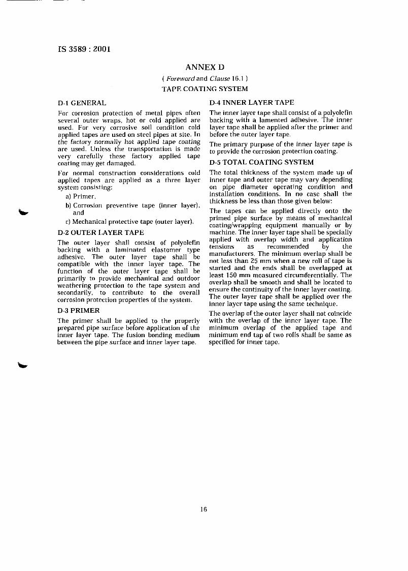
D- l GENERAL D-4 INNER LAYER TAPE
For corrosion protection of metal pipes often The inner layer tape shall consist of a polyolefin several outer wraps, hot or cold applied are backing with a lamented adhesive. The inner used. For very corrosive soil condition cold layer tape shall be applied after the primer and applied tapes are used on steel pipes a t site. In before the outer layer tape. . . the factory normally hot applied tape coating he primary purpose of the inner layer tape is are used. Unless the transportation is made to provide the corrosion protection coating. very carefully these factory applied tape coating may get damaged. D-5 TOTAL COATING SYSTEM
For normal construction considerations cold The total thickness of the system made up of applied tapes are applied a s a three layer inner tape and outer tape may vary depending system consisting: on pipe diameter operating condition and
a) Primer, installation conditions. In no case shall the thickness be less than those given below:
b) Corrosion preventive tape (inner layer), b and The tapes can be applied directly onto the
primed pipe surface by means of mechanical C) Mechanical protective tape (outer layer). coatingiwrapping equipment manually or by
D-2 OUTER LAYER TAPE machine. The inner laver tape shall be s~ecial ly
The outer layer shall consist of polyolefin applied with overlap widih and application tensions as recommended by the backing with a laminated type manufacturers. The minimum overlap shall be adhesive. The outer layer tape shall be
compatible with the inner layer tape. The not less than 25 mm when a new roll of tape is
function of the outer layer tape shall be started and the ends shall be overlapped a t
primarily to provide mechanical and outdoor least 150 mm measured circumferentially. The overlap shall be smooth and shall be located to
weathering the tape system and ensure the continuity of the inner layer coating. secondarily, to contribute to the overall corrosion protection properties of the system. The outer layer tape shall be applied over the
inner layer tape using the same technique. D-3 PRIMER The overlap of the outer layer shall not coincide The primer shall be applied to the properly with the overlap of the inner layer tape. The prepared pipe surface before application of the minimum overlap of the applied tape and inner layer tape. The fusion bonding medium minimum end tap of two rolls shall be same as between the pipe surface and inner layer tape. specified for inner tape.
B u r e a u of I n d i a n S t a n d a r d s
BIS is a statutory institution established under the Bureau of Indian Standards Act. I986 to promote harmonious development of the activities of standardization, marking and quality certification of goods and attending to connected matters in the country.
Copyr igh t
BIS has the copyright of all its publications. No part of these publications may be reproduced in any form without the prior permission in writing of BIS. This does not preclude the free use, in the course of ilnplementing the standard, of necessary details, such as symbols and sizes, type or grade designations. Enquiries relating to copyright be addressed to the Director (Publications), BIS.
Review of I n d i a n S t a n d a r d s
Amendments are issued to standards as the need arises on the basis of comments. Standards are also reviewed periodically: a standard along with amendments is reaffirmed when such review indicates that no changes are needed; if the review indicates that changes are needed, it is taken up for revision. Users of Indian Standards should ascertain that they are in possession of the latest amendments or edition by referring to the latest issue of 'BIS Catalogue' and 'Standards : Monthly Additions'.
This Indian Standard has been developed from Doc : No. MTD 19 (4194)
Amendmen t s I s sued S ince Pub l i c a t i on b
Amend No. D a t e of I ssue
Amd. No. 1 May 2002
Amd. No. 2 October 2003
BUREAU OF INDIAN STANDARDS
Headquarters: b
Manak Bhavan, 9 Bahadur Shah Zafar Marg. New Delhi 110002. Telegrams: Manaksanstha Telephones: 323 01 31 .323 33 75,323 94 02 (Common to all offices)
Regional Offices: Telephone
Central : Manak Bhavan, 9 Bahadur Shah Zafar Marg NEW DELHI 110002
Eastern : 1114 C. I. T. Scheme VII M, V. I. P. Road, Kankurgachi KOLKATA 700054
Northern : SCO 335-336. Sector 34-A. CHANDIGARH 160022 60 38 43 60 20 25
Southern : C. I. T. Campus, IV Cross Road. CHENNAI 6001 13 235 02 16.235 04 42 235 15 19, 235 23 15
Western : Manakalaya. E9 MIDC. Marol. Andheri (East) i 832 92 95, 832 78 58 MUMBAI 400093 832 78 91 ,832 78 92
Branches: A H M E D A B A D . B A N G A L O R E . B H O P A L . B H U B A N E S H W A R . C O I M B A T O R E . F A R I D A B A D . G H A Z I A B A D . G U W A H A T I . H Y D E R A B A D . J A I P U R . K A N P U R . LUCKNOW. NAGPUR. NALACARH. PATNA. PUNE. RAJKOT. THIRUVANANTHAPURAM. VISHAKHAPATNAM.

Amend No. 3 to IS 3589 : ZOO1
( Page 9, Annex 4 clause A-2 ) -Insert the following sentence at the end of para:
'Alternatively 4 mm wire with a pitch of 50 mm may be wrapped over lined steel cylinder pipe with the tension of 50 to 65 m a . '
( Page 13, A n n a B, clause B-1.1, line 4 ) - Substitute the words 'ccal tar' fbr 'wal ral'.
Rcpognphy Unit, BIS, New Dclhi, India 2
AMENDMENT NO. 3 MARCH 2006 TO
IS 3589 : 2001 STEEL PIPES FOR WATER AND SEWAGE (168.3 TO 2540 mm OUTSIDE
DIAMETER) - SPECIFICATION ( Third R a i s i n )
( Title & General ) - Delete the word 'gas' wherever it appears in the standard.
Substitute '168.3 mm outside diameter and above' for '168.3 to 2 032 nun outside diameter' wherever it appears.
( Page 2, clause 7.3 ) - InsRt the following new clause after 7.3:
'7.3.1 Whenever agreed behveen the manufacturer and the purchaser, a maximum of two circumferential welds are permissible to make a full length. The tests for such tubes shall be mutually agreed. Minimum length of jointed tubes shall not be less than 1.5 meter.'
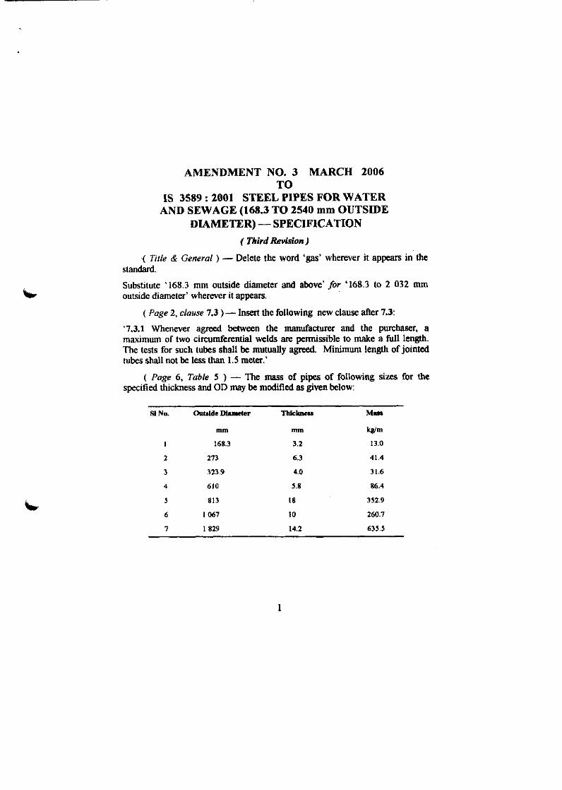
( Page 6, Table 5 ) - The mass of pipes of following sizes for the specified thickness and OD may be modified as given below:
Sl No. OutsLde Dhmeter l l ~ l c h u u M.u
mm mrn W m
Related Documents