Disclosure to Promote the Right To Information Whereas the Parliament of India has set out to provide a practical regime of right to information for citizens to secure access to information under the control of public authorities, in order to promote transparency and accountability in the working of every public authority, and whereas the attached publication of the Bureau of Indian Standards is of particular interest to the public, particularly disadvantaged communities and those engaged in the pursuit of education and knowledge, the attached public safety standard is made available to promote the timely dissemination of this information in an accurate manner to the public. इंटरनेट मानक “!ान $ एक न’ भारत का +नम-ण” Satyanarayan Gangaram Pitroda “Invent a New India Using Knowledge” “प0रा1 को छोड न’ 5 तरफ” Jawaharlal Nehru “Step Out From the Old to the New” “जान1 का अ+धकार, जी1 का अ+धकार” Mazdoor Kisan Shakti Sangathan “The Right to Information, The Right to Live” “!ान एक ऐसा खजाना > जो कभी च0राया नहB जा सकता ह ै” Bhartṛhari—Nītiśatakam “Knowledge is such a treasure which cannot be stolen” IS 3370-4 (1967): Code of practice for concrete structures for the storage of liquids, Part 4: Design tables [CED 2: Cement and Concrete]

Welcome message from author
This document is posted to help you gain knowledge. Please leave a comment to let me know what you think about it! Share it to your friends and learn new things together.
Transcript

Disclosure to Promote the Right To Information
Whereas the Parliament of India has set out to provide a practical regime of right to information for citizens to secure access to information under the control of public authorities, in order to promote transparency and accountability in the working of every public authority, and whereas the attached publication of the Bureau of Indian Standards is of particular interest to the public, particularly disadvantaged communities and those engaged in the pursuit of education and knowledge, the attached public safety standard is made available to promote the timely dissemination of this information in an accurate manner to the public.
इंटरनेट मानक
“!ान $ एक न' भारत का +नम-ण”Satyanarayan Gangaram Pitroda
“Invent a New India Using Knowledge”
“प0रा1 को छोड न' 5 तरफ”Jawaharlal Nehru
“Step Out From the Old to the New”
“जान1 का अ+धकार, जी1 का अ+धकार”Mazdoor Kisan Shakti Sangathan
“The Right to Information, The Right to Live”
“!ान एक ऐसा खजाना > जो कभी च0राया नहB जा सकता है”Bhartṛhari—Nītiśatakam
“Knowledge is such a treasure which cannot be stolen”
“Invent a New India Using Knowledge”
है”ह”ह
IS 3370-4 (1967): Code of practice for concrete structuresfor the storage of liquids, Part 4: Design tables [CED 2:Cement and Concrete]


IS : 3370 (Part IV) -1967(Reaffirmed 2008)
Indian StandardCODE OF PRACTICE FOR CONCRETE
STRUTURES FOR THE STORAGE OF LIQUIDS
PART IV DESIGN TABLES
Fifteenth Reprint AUGUST 2007(Incorporating Amendment No. 1 & 2)
UDC 621.642 : 669.982 : 624.043
© Copyright 1979BUREAU OF INDIAN STANDARDSMANAK BHAVAN, 9 BAHADUR SHAH ZAFAR MARG
NEW DELHI 110002
Gr 10 January 1969

IS I 3378(Part IV). 1117
Indian StandardCODE OF PRACTICE FOR CONCRETE
STRUCTURES FOR THB STORAGE OF LIQUIDSPAIlT IV DESIGN TABLES
Cement and Concrete Sectional Committee, BDO 2
C}u,irma"SRRI K. K. NAMBIAfC
R."."'i,,.The Concrete Association of India, Bombay
}\·I. N. Dastur & (4 (Pvt) Ltd. CalcuttaSahu Cement Service, New DelhiBhakrn & Beas Design. Organization, New DelhiCentral Uuilding Research Institute (CSIR).
Roorkee
AI;".6"sSRRl M. A. MEliTA (Allemtlt, to
Sbri K. K. Nambiar)SRat K. F. ANTIASRRI A. P. BAGeHtSHIU P. S. "HA1·NAOAR1). S. K. CHOPRA
The A!lsociated Cement Companit'l Ltd, Bombay
( CSIR),In.tituteS. B. Joshi It Co Ltd, BombayCentral Road Rrleareb
New Delhi
SHRI J. S. SJlARMA ( Alt,rnlll, )DtRsCTOR (CSl\{) (~nll2111Natt.'r& Power r..ommi.sion
DIRKCTOR ( DAMS III ) ( AlIt,,,al, )DR R. K. OIlOSH . Indian Road, Congress. New DelhiSR.I B. K. GUllA Central Publtc \Vorks Department
SUP.RINTENDING ENQJNif.R, 2ND
OJ.CLI. ( Alt""." )na R. R. HATrIANOADISRRI V. N. PAl ( Altn~.', )
JOINT DIRECTOR STANDARDS R~.e.rc:h, ~sjgnl at Standareb . Orluization( B I: S ) . ( Ministry of Railways)
DuUTY Dr.aero. STANDARDS( B &: S) (.4llnllll'.)
SR.I S. B. JOIHI .,.PRoP S. R. MaRRA
DR R. K. GHOIH ( AI,,,,,tllI )SRal S. N. Muu.aJI National Tnt Houle, Calcutta8..-. B. K. RAMCHANDR'AN (Allmual. )S... BaACH A. NADlasHAH Institute of EDlineen ( India ), CalcuttaBalo NAUlH PRASAD Enlineer-in·Chi~r·. Branch. Army HeadquarlenSRal C. B. PAT&L National Buildings Orpnization
SRa. RA8IMDU SINOH ( Al'mwd, )SHall. L. PAUL Dirtttorate Gen~ral ofSuppliei • DiapGlallS.a. T. N. S. IlAO Gammon India Ltd. Bombay
S... S. R. PacHltlaO ( If"."..,. )RaPaaaTAftva GeoloRical Surveyor India. CalcuttaRa•••aNTAn.. The India Cementl Ltd, MaclruS.al K. G. SALVI HiDdustan HoUlin, PactO!'J Ltd, New Delhi
SHaJ C. L. KAiLlWAL ( .41'""", ) (c.littMI.,.,. 2 )
BUltEAU OF INDIAN STANDARDSMANAK BHAVAN~ 9 BAHADUR SHAH ZAFAR MARG
NEW DELHI 110002

IIISS7I ( Part IV ) • 1967
( CortIiuMlft-,." I')M.ahrs ..
D.S. SARKA.Ill".",..,
Structural EOlineerinl Rae.rch Centre (CSla.).Roorkee
S.1It1 Z. Gaoao& ( AI"""",)SaCUTAIlY Ceatral Board of Irrilation .. Power, ~ew DeIhlSHRI L. SWAaoop Dalmia Cement ( Dharat ) Ltd, New Delhi
SHill A. V. RAIIANA (AI""..,.)SIIRI J. M. 1....RAN Roads Wing, Ministry of Transport
SRR' N. H. KUWANI ( .AI,.".." )Da H. C. VJlVaVAIlAYA Cement Research Institute or India, New DelhiSHRJ R. NAGARAJAN, Director General, lSI (Ea-oJfirio M""IJI,)
Directott (Civ Baal)81"".'7
SHR. Y. R. TANaJADeputy Director (Civ Engg) J lSI
Concrete Subcommittee, BDC 2: 2
National Buitdinli Organization
M. N. Dutur It Co ( Pvc) Ltd, Calcutta
s.B. Joshi at Co I..td, Bombay
Hydt'rabad Engineering Research LaboratoryH)'derabad
Dlaacroa·IN"CHARO& Geological Survey of India, LucknowSHU V. N. 'CUNAJI Public \Vorks ~partmcDt, .MaharuhtraSR.I V. K. GUPTA Enginr.cr.in-CbieC·s Branch, Army HeadquartenSIUlI K. K. N'.1lOIIAR The Oonerete Association of India, Bombay
SRRI C. L. N. IVUfOAR (A.lt.,ntl")DR M. L. 'PURl , Central Road Research Inltitute ( CSIR ),
Roorkec-Structural Engineering Research Centre (OSIR.),
Roorkee
Sahu Cement Service) New DelhiIn penonal capacity ( M-60 Cru,ow S." s..69)Central' Building Rete.reb IDititute (CSIR)
RoorkeeDa I. C. Dol M. PAil CUODOU Central Water It Power Commiaion
Dta&CTOR ( DAMS I ) ( Alima." )D&PUT~ DUtECToa STANDARDS Research, Design. and Standards Organiation
( B a. S) ( Mini.try of Railway.)ASSIITANT DIRECTOR STANDAltDl
( BitS) ( AIle,.,..', )D••aCTOR
1-.0' G. S. RAMASWAMY"
c.,.,rSURI S. B. JOIHe
Mltr.bnsSURI B. D. AHUJA
SRRI P. C. JAIN (AI"",,,,,)SRal K. F. AlmA
SHa, B. C. PATEL ( AI,."..", )'SHRI A. P. BAacR;SHRr B. K. eHOKIIDR S. K. CHO••A
Da S. SARKAR ( All,",,,,, )SHa. 'r, N. S. RA.o Gammon India Ltd, Bombay
SHaI S. R. PlNII&laO l.mllmal, )SUP&....TIUfDINO ENGJM&&R, 2ND Central Public Works Department
CulCLESRRI S. G. VAiDYA (AI"""")
SHRIJ. M. TRRHAN R.oads Win., MiDistry orTranaportSHIll R~ P. SI&KA ( AI"",,,,, Jn. H. C. VaVUYAIlAYA Cement Jleaearch Institute ollDdia, New Delhi
2

IS I 3378( Pan IV ) • 1117
Indian StandardCODE OF PRACTICE FOR CONCRETE
STRUCTURES FOR THE STORAGE OF LIQUIDSPART IV DESIGN TABLES
o. FOREWORD
0.1 This Indian Standard ( Part IV ) was adopted by the Indian StandardsInstitution on 7 December 1967, after the draft finalized by the Cement.md Concrete Sectional Committee had been approved by the Civil Engleucering Division Council.
0.2 The need Cor a code covering the design and construction of reinforcedconcrete and prestressed concrete structures for the storage of liquids hd\
been long felt in this country. So far, such structures have been designed tovarying standards adapted from the recommendations of the Institution ofCivil Engineers and of the Portland Cement Association with the resultthat the resultant structures cannot be guaranteed to possess a uniformsafety margin and dependability. Moreover, the design and constructionmethods in reinforced concrete and prestressed concrete are influenced OVthe prevailmg construction practices, the physical properties of the materialsand the climatic conditions. The need was. therefore, felt to lay downuniform requirements of structures for the storage of liquids givinR dueconsideration to these factors. In order to fulfil this need, formulationof this Indian Standard code of practice for cor-crete structures for thestorage of liquids ( IS : 3370) was undertaken. This part deals with designtables for rectangular and cylindrical concrete structures for stor~p'(; ofliquids. The other parts of the code are the following:
Part I General requirementsP....t II Reinforced concrete structuresPart III Prestressed concrete structures
0.3 The object of the design tables covered in this part is mainly to presentdata for ready reference of designers and as an aid to speedy design calculalions. The designer i", however, free to adopt any method of design depending upon his own discretion and judgement provided the requirementsregarding Parts I to III of IS : 3370 are complied with and the structuraladequacy and !afety are ensured.
0.3.1 Tables relating to design of rectangular as well as cylindrical tankshave bern given and by proper combination of various tables it may bepossible to design different types of tanks involving many sets of conditionsfor rectangular and cylindrical containers built in or on ground.
3

II, __ ( Itut IV). 1117
1.'.2 Some of the data presented for d~ip of rectangular tankamay beused for design of some of the earth retaining structures subject to earthpressure for which a hydrostatic type of loading may be substituted in thedesign calculations. The data for rectangular tanks may alia be applied todesign of circular reservoirs of large diameter in which the lateral stabilitydepends on the action of counterforts built integrally with the wall.
0.4 While the common methods of design and construction have beencovered in this code, design of structures of special forms or in unusualcircumstances should be left to the judgement of the engineer and in suchcases special systems of design and construction may be permitted on production of satisfactory evidence regarding their adequacy and safety byanalysis or test or by both.
0.5 In this standard it has been assumed that the design of liquid retainingstructures, whether of plain, reinforced or prestressed concrete is entrustedto a qualified engineer and that the execution of the work is carried outunder the direction of an experienced supervisor.
0.6 All requirements of 18:456·1964· and IS: 1343.1960t, in so far asthey apply, shall be deemed to form part of this code except where otherwise laid down in this code.
0.7 The" Sectional Committee responsible for the preparation of this standardhas taken into consideration the views of engineers and technologistsand has related the standard to the practices followed in the country in thisfield. Due weightage has also been given to the need for intertlational coordination among the standards prevailing ill" different countries of thflworld. These considerations led the Sectional Committee to derive'auistanC'(,:from published materials of the following organizations:
British Standards Institution;Institution of Civil Engineers, London; andPortland Cement Association, Chicago, USA.
~les have been reproduced from C Rectangular Concrete Tanks J
and C Circular Concrete Tanks without Prestressing' by courtesy of PortlandCement Assr.'ciati"n, USA.
0.8 For the purpose of deciding whether a particular requirement of thisstandard is complied with, the final value, observed or calculated, expressingthe result" of a test or analysis, shan be rounded off in accordance withIS: ~.1960t. The number of significant places retained in the roundedoff value should be the same as that of the specified value in this standard.
·Code or practice for plaia and reinror,ced concrete ($"0,,11 "v;l;on ).tCaclc ofpracticeCot prntraled concrete.~Rulet for rcNndi.."off numerical valua ( "PisItI ).
4

1113370 (Pan IV )-1117
1. ICOPB
1.1 This standard ( Part IV ) recommends design tables, which are intendedal an aid for the design of reinforced or prestressed concrete structure. forstorage of liquid.
2. RECTANGULAR TANKS
2.1 Momeat Coetlldeats for IacUvld••1 wan Pa.el. - Momentcoefficients for individual panels considered fixed along vertical edges buthaving different edge conditions at top and bottom are given in Tabla Ito 3. In arriving at these moments, the slabs have been assumed to actas thin plates under the various edge conditions indicated below:
Table 1 Top hinged, bottom hingedTable 2 Top Cree, bottom hingedTable 3 Top free, bottom fixed
2.1.1 Conditions in Table 3 are applicable to cases in which wall slab,counterfort and base slab are all built integrally.
2.1.2 Moment coefficients for uniform load on rectangular plates hingedat all four sides are given in Table 4. This table may be found useful indesigning cover slabs and bottom slabs for rectangular tanks with one cell.If the cover slab is made continuous over intermediate supports, the designmay be made in accordance with procedure for slabs supported on four,ides ( s" Appendix C of IS : 456-1964· ).
2.2 M.lDeat Coe.deat. lor Rect••plar T••k. - The coefficientsfor individual panels with fixed side edges apply without modification tocontinuous walls provided there is no rotation about the vertical edges. Ina square tank, therefore, moment coefficients may be taken direct fromTables I to 3. In a rectangular tank, however. an adjustment has to bemade in a manner similar to the modification of fixed end moments in aframe analysed by tile method of moment distribution. In this procedurethe common side edge of two adjacent panels is first considered artificiallyrestrained so that JUtrotation can take place about the edge. Fixed edgemoments taken from Tables 1, 2 or 3 are usually dissimilar in adjacentpanels and the differences, which correspond to unbalanced moments, tendto ratat!: the edge. When the artificial restraint is removed they will induceadditional moments in the panels. The final end moments may be obtainedby adding fnduced moments and the fixed end moment, at the edge. Thesefinal end moments should be identical on either side of the common edge.
2.2.1 The application of moment distribution to the case of co'ntinuoUitank walls is not al simple as that of the framed structures, because in the
~ -Code or practice Cor plain aDd reinforced r.ODcrete ( .'..4 MJiliM).

11.117I ( Part IV ). IN7
fonDer case the moments should be distributed simultan~oully all alongthe entire length of the side edge so "that moments become equal at bothsides at any point of the edge. A simplified approximation would be di...tribution of moments at five-points, namely, the quarter-points, the midpoint and the bottom, The end moments in the two intersecting slabsmay be made identical at these five-points and moments at interior pointsadjusted accordingly.
2.2.1.1 The moment coefficients computed in the manner described aretabulated in Tables 5 and 6 for top and bottom edge conditions as shownfor single-cell tanks with a large number of ratios of b]« and cla, b beingthe' larger and c the smaller of the horizontal tank dimensions.
2.2.2 Wh('n a tank is built underground, the walls should be investigatedfor both internal and external pressure. This may be due to earth pressureor to a combination of earth and ground water pressure. Tables 1 to 6may be applied in the case of pressure from either side but the signs willbe opposite. In the case of external pressure, the actual load distributionmay not necessarily be triangular, as assumed in Tables 1 to 6. For example, in case of a tank built below ground with earth covering the roof slab,there will be a trapezoidal distribution of lateral earth pressure on the walls.In this case it gives a fairly good approximation to substitute a trian,le withsame area as the trapezoid representing the actual load distribution.The intensity of load is the same at mid-depth in both cases, and when thewall is supported at both top and bottom edge, the discrepancy between thethe triangle and the trapezoid will have relatively little effect at and nearthe supported edges. Alternatively, to be more accurate, the coefficientsor moments and forces for rectangular and triangular distribution ofload may be added to get the final results.
2.3 Shear CoeSdeDt. - The values of shear force along the edge of •tank wall would be required for investigation of diagonal tension and bondatreIIeI. Along vertical edga, the ahear in one wall will cauae axial ten.ionin the adjacent wall and should be combined with the bending momentfor the purpose oC determining the tensile reinforcement. ~
2.1.1 Shear coefficients for a wan panel ( of width 6, height CI and subjected to hydrostatic pressure due to • HCJuid of density rD ) considered fisedat the two vertical edges and usumed &Inged at top and bottom edges arepftD in Fig. 1 and Table 7.
2.1.2 Shear coefficients for the lame wall ~el considered fixed at t~etwo vertical edges and auumed hinged at the bottom but free at top edgeare pven in Fig. 2 and Table 8.
2.s.s It would be evident &omTable 7, that the difFerence between theshear Cor 6/. - 2 and in8Dity DSO 11II&11 that there is no neceaity Cor computing coeflicients for intermediate values. When bJd is large, a verticalstrip ofthe slab near the mid-point orthe b.dimenuon will behave eesentially
6

IS : 3370 ( Part IV ) • 11&7
as a simply supported one-way slab. The total pressure on a strip of unitheight is 0·5 wa' ofwhich two-thirds, or 0·33 wat is the reaction at the bottomsupport and one-thirds, or 0·17 wall, is the reaction at the top. It may beseen from Table 17 that the shear at mid-point of the bottom edre is0-329 wat for bla == 2-0, the coefficient being very close to that of1/3 for infinity. In other words, the maximum bottom shear is practically constant for all values of b]« greater than 2. This is correct onlywhen the top edge is supported, not when it is free.
2.3.3.1 At the corner the shear at the bottom edge is negative and isnumerically greater than the shear at the mid-point- The change fromposrtive to negative shear occurs approximately at the outer tenth-pointsof the bottom edge. These high negative values at the corners arise from thefact that deforrnations in the planes of the supporting slabs arc neglectedin the basic equations and arc, therefore, of only theoretical significance.These shears may be disregarded for checking shear and bond stresses.
TOP HINGED~
~ ~~ ~I--~ 1 I t III1 ~ ~""
~ ~~~ ... ~ 1t.. Ii I,
'I..,-.- i
....b/a =INfiNITY~1'\1 't~~~
t--~~~ ~ , t'
I l'~ ~~-,
~~"- I~~~/a :2 ~ ~"'~ ~, ~,~ b/• • 1..J ~~~ ~
~~&I ~lI ~
~p-. ~~. ~r-.
G: '''b/a If 1/2 ~~ ~~ "'~ I"l
~, ~
~~ ~~~~
~
~,~ ~~
~ ~~
~~~ ~~~~j;i
"'~l.~~.-~ !! jill~
i-li 'J
..~ IJ'i~~~~9~ i~~?'~
0-2
0-9
1-0o 0-1 0-2 0-3 0-4
&HEAR PER UNIT LENGTH : COEFFICIENT x 'Ill.. _ hei,ht or the wall
, - width of the wall., _ density of the liquid causinl hydrostatic pressure
FlO. COBPPICIItNTI '"OR WALL PANEL, FIXBD AT' Va.TICAL Eooa.,HINOED AT Top AND BOTTOM EOOE5' · .
e-
o
7

II.U70 ( Pan IV ) .1117
TOP FREE
~"- ~~ "'~~'"
"-,.. 1111'1
~ ~ ~lIlI "'~Ill. 'J~b/••3~ ~"- ,...~ ~~,
r--~ ~~ "- ~"--.
~ ~. --~Ilrt. b/•• 2~~
llilI~~~
----,~~
.,t-.~ ~~ ~~
4b/•• 1 ~~ "'It.~ f ~
~~r--
~
~~fa ~~ ~ "~tS J,' · I ,~ ~~ ~
~u.
~t/••1/2 ~
,!Ill ~
, ,~ ~
\ ~ ~~
,~
~~,
~.J ......
---~~ ~
~ .. ",'" ~.•• ~~~'R~rpr, r~~~
01
o
1·0o 0-1 0-2 0-3 0e4SHEAR PER UNIT LENGTH • COEFFicIENT • • 1
• - beiabt of the: wallII - width 01 the wallIII - demity 01the liquid cauaing hydroltatic prasure
FlO. 2 eo.PftCJ&IITI 1'0R WALL PANBLt FIXBD AT Va.TICAL Eoo..,HINGED AT Bonoy EDO~ AND FREB AT Top EDGZ
2.3.3.2 The unit shears at the fixed edge in Table 7 have been usedfor plotting the curves in Fig. 1. It would be seen that there is practicallyno change in the shear curves beyond b[a== 2-0. The maximum value occunat a depth below the top somewhere between 0-6a and 0-&. Fig. 1 will befound useful for determination oCshear or axial tension for any ratio of /Jlaand at any point of a fixed side edge.
2.3.4 The total shear from top to bottom of one fixed edge in Table 7should be equal to the area within the correspondmg curve in Fig. 1. Thetotal shean computed and tabulated for hinged top may be used in makingcertain adjustments 10 as to determine approximate values of shear for wallswith free top. These are given in Table 8.
2.3.4.1 For /Jla fID l /2 in Table 7, total.shear at the top edge is so smallal to be practically zero, and for bla-I·O the total shear, 0·005 2, is onlyone percent of the total hydrostatic pressure, o-SO. Therefore, it wouldbe reasonable to assume that removing the top support will not Dl&tcriallychange the totallpean at any of the other three edges when IJ/.-1/2 and I.
S

III 3370 ( Part IV ) • 1967
At 6/1'-2-0 there isa substantial shear at the top edge when hinged, 0-053 8,so that the sum of the total shears on the other three sides is only 0-44 62.If the top support is removed, the other three sides should carry a total of0-50_ A reasonable adjustment would be to multiply each of the threeremaining total shears by 0-50/0-4462==1-12, an increase of 12 percent.This has been done in preparing Table 8 for 6/0-2-0_ A similar adjustmenthal been made for 6/a=t3·0 in which case the increase is 22 percent,
2.3.5 The total shears recorded in Table 8 have been used for determination ofunit shears which are also recorded in Table 8. Considering the shearcurves in Fig, 1 and assuming that the top is changed from hinged to free,for lIia=! and I, it would make little difference in the total shear, that is,in the area within the shear curves, whether the top is supported or not.Consequently, the curves for bjac=l and 1 remain practically unchanged.For 6/(,1==2 an adjustment has become necessary for the case with top free.A change in the support at the top has little effect upon the shear at thebottom of the fixed edge. Consequently, the curves in Fig. 1 and 2 arenearly identical at the bottom. Gradually, as the top is approached thecurves Cor the free top deviate more and more from those for the hingedtop as indicated in Fig. 2. By trial, the curve for b/a=2 has been so adjusted that the area within it equals the total shear for one fixed edge for6/.-2-0 in Table 8. A similar adjustment has been made for 6/G==3-0which is the limit for which moment coefficients are given.
2.3.5.1 Comparison of Fig_ 1 and Fig. 2 would show that whereasfor IJ/a ss2'Oand 3·0 the total shear is increased 12 and 22 percent respectivelywhen the top is free instead of hinged, the maximum shear is increased butslightly, 2 percent at the most. The reason for this is that most of the increase in shear is near the top where the shears are relatively slDall.
2.3.5.2 The same procedure has been applied, for adjustment of unitshear at mid-point of the bottom, but in this case the greatest change resuIting from making the top free is at the mid-point where the shetar is largefor the hinged top condition. For example, for 6/(1=-3-0, the unit shearat mid-point of the bottom is 0-33 wal with hinged top but 0·45 Will withfree top. an increase of approximately one-third.
2.3.6 Although the shear coefficients given in Tables 7 and 8 are forwall panels with fixed vertical edges, the coefficients may be applied withsatisfactorv results to any ordinary tank wall, even if the vertical edges arenot fully fixed.
3. CYUNDRICAL TANKS
3.1 RID. Tea.loa .Dd Momeat. I. Wall.
3.1.1 WQIl with Fi:cld Bas' alld Free Top, Subject,d ItI 'Irian..Il"lor Loa«( Fi,. 3 ) - Walls built continuous with their footings arc sometime d~~iJtnf'cl
as though the base was fixed and the top free, although ~tri(·tJy ~p«,akinJ·
9

IS I 3370 ( Pan IV ) • 1967
the base is seldom fixed) but it is helpful to start with this assumption andthen to go on to the design procedures for other more correct conditions.Ring tensions at various heights of walls oC cylindrical tanks fixed at base,free at top, and subjected to triangular load are given in Table 9.lvloments in cylindrical wall fixed at base, free at tcp and subjected totriangular load are given in Table 10. Coefficients for shear at base ofcylindrical wall are given in Table II.
FlO. 3 WALL WITH FIXED BAsa AND FREE Top SUBJECTBDTO TltlANOULAR LOAD
3.1.2 Wall ,oi," Hinged Bas« and Fre« Top, Su6jteted 10 Triangular Load( Fig. 4 ) - The values given in 3.1.1 are based on the assumption that thebase Joint is continuous and the footin, is prevented from even the smallestrotation of kind shown exaggerated In Fig. 4. The rotation required toreduce the fixed base moment from lome de6nite val~ to, say, zero i. muchsmaller than rotations that may occur when normal settlement takes placein subgrade. It may be difficult to predict the behaviour or the subgradeand its effect upon the restraint at the base, but it is more reasonable toassume that the bale is hinged than &xed, and the hinged-based assumptiongives a safer design. Ring tensions. and moments at different heights orwall or cylindrical tank are liven in Tables 12 and 13 respective1r.. Coefficients fOr shear at base or cylindrical wall are given in Table 1 •
FlO. 4 WALL WITB HDlO&D BAIS AND Fa.B Top SUBJBCT&D TOTRIANGULAR LoAD
10

U I 3370 ( Part IV ) • 1967
3.1.2.1 The actual condition of restraint at a wall footing as in Fig. 3and 4 is between fixed and hinged, but probably closer to hinged. The comparison of ring tension and moments in cylindrical walls with the end conditions in 3.1.1 and 3.1.2 shows that assuming the base hinged lives conservative although not wasteful design, and this assumption is, therefore,generally recommended, Nominal vertical reinrorcement in the insidecurtain lapped with short dowels across the bue joinIS will 8uif"tee.
This condition is considered satisfactory for open-top ranks with wallfootings that are not continuous with the tank bottom, except that allowanceshould usually be made for a radial displacement or the footing. Such adisplacement is discussed in 3.1.5. If the wall is made continuous ttt topor base. or at both, the continuity..should also be considered. 'These conditions are given. in 3.1.6.
3.1.3 Wall wilh Hingtd Base ontl Fret Top, Subjttlld 10 Trapezoidal Load( Fig. 5 ) - In tank used for storage of liquids subjected to vapour pressureand also in cases where liquid surface may rise considerably a.bove the topof the wall, as may accidently happen in case of underground tanks) thepressure on tank walls is a combination of the triangular hydrostatic pressure plus unifonnly distributed loading. This combined pressure willhave a trapezoidal distribution as shown in Fig. 5, \vhich only representsthe loading condition, without considering the effect of roof which is discussed in 3.1.4. In this case, the coefficients for ring' tension l"ftay be takenfrom Tables 12 and 1(~. Coefficients for shear at the base ere given inTable 11. Coefficients for moments per unit width are given in Table 13.
Fro. 5 WALL WITB HmGED BASE AND FREB Top SUBJECTED·TO TRAPEZOIDAL LOAD
'.1.4 Wall wi'" S. APllied at Top (Fig. 6 ) - ~'hen the top of thecylindrical wall is dowelled to the roof slab, it may hot be. able to movefreely as assumed in 3.1.1 to. 3.1.3..W~en displacement is prev~tedJ !hetop cannot expand and the nng tension IS zero at top. rf T kg IS the ringtension at 0·0 H when the top is free to expand as in 3.1.3, the. value ofshcarY can .be found from Table .15 as bdow:
f'RT== -~H or
11

~ I II" ( Pan .IV ) • 1117
Y NT--x;-where
• - the coefficient obtained from Table 15 depending upon
h · HIt erauom
FlO. 6 WALL WITH SHaAR ApPLIBD AT Top
3.1.5 JVal1 with Shear Applied at Btu« - Data given in Table 15 mayalso be approximately applied in cases where shear is at the base of thewall, ~ in Fig. 7J which illustrates a case in which the base of the wall isdisplaced radially by application of a horizontal shear Y having an inwMI'ddirection. Wh~n the base is hinged, the displacement will be zero and thereaction on wall will be inward in direction. When the base is sliding,there will be largest possible displacement but the reaction will be zero
Fro. 7 WALL WITH SHEAR ApPLIBD AT BAsa
. .3.1_6 J.~rQll wit" ~\lonu~' Applied at ,Top - When the top of the wall andf~, ltl~.,1"oofsial) are made continuo~s as shown in Fig. 8" the deflection of the
roof will tend to rotate the top j(xnt and introduce a moment at the-top ofthe ".a11. In such cases, data in Tables 16 and 17 will be found usefulalthough they are prepared fO.f moment applied at one end of tile wall when
12
D I 3370 ( Pan IV ). 1117
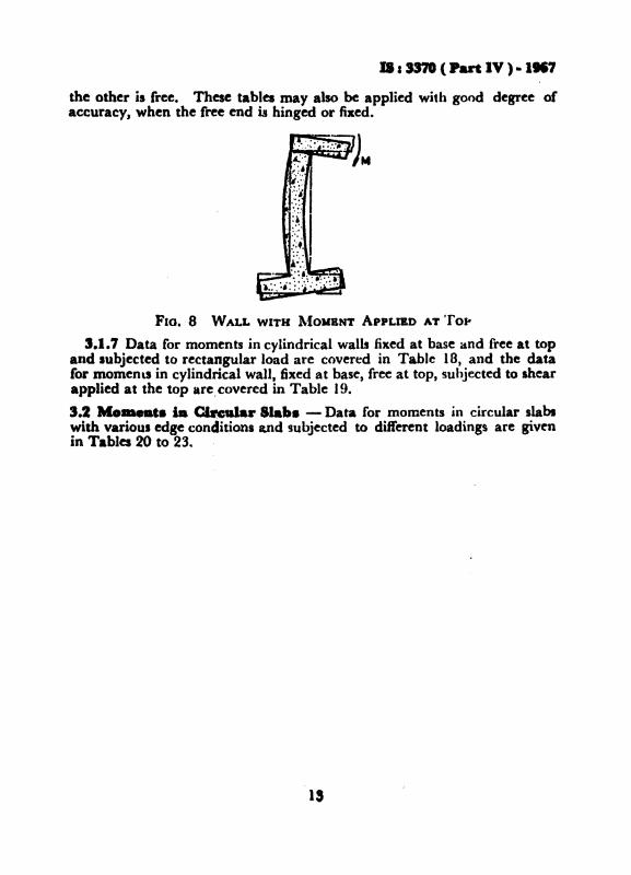
the other is free. These tables may also be applied with good degree ofaccuracy. when the free end is hinged or fixed.
FlO, 8 WALL WITH ~fO"BNT ApPLIED AT Tor-
3.1.7 Data for moments in cylindrical walls fixed at base and free at topalad subjected to rectangular load are covered in Table 18, and the datafor momene in cylindrical wall, fixed at base, free at top, subjected to shearapplied at the top arecovered in Table 19.
3.2 Mo...t. i. Clftular Slab. - Data for moments in circular slabswith varioul edge conditions and subjected to different loadings are givenin Tables 20 to 23.. .
IS

II. JS7I ( Part IV ) • 1967
TAo.U 1 MOMENT coanCIENTS FOR INDIVIDUAL WALL PANEL.TOP AND BOTTOM lUNGED. VERTICAL ItDOEI FIXED
(CltlftS's 2_1, 2.•2 .nd 2.2.2 )
t-td .& hrighi (If tl-e wall y
6 - width of the \"all
UI - density of the liquid
Hnnlontal moment 'C:' l\f" It,.3
\'c(tical moment .;::: ~V~ Uta'
X0/4 x]« -':LO J' -= 6/1t .1 CI 6/2
""--~ r . -4f "-----,
~Iz .1,1. M. M. Me Mfl(1) ,1..: (:i; (.f.) (5) (6) (7). (8)~-OO I,!'. +0·035 +0·010 +0·026 +0·011 -0·008 -0·039
! :~ +0·057 +0-016 +0·044 +0·017 -0-013 -0-063·i.:4 +O-Oil +0·013 +0-041 +0-014- -0-011 -0-055
2-50 1;'.1 +0-031 ·...0·011 +0-021 +0·010 -0-008 -0-0381 .;.) +O-O~2 +0-017 +0'03& +0-017 -0,012 -0,062:~/4 +0-0+7 +0'015 +0-036 +0,014 -0,011 -0-055
2,00 1:4- +0·025 +0-013 ...·0·015 +0-009 -0'007 -0,0371/2 +0-042 ...·0·020 +0'028 .... O·Ol.~ -0-012 -0,059:i/4 +O'04J +0-016 +0'029 +0·013 -0-011 -0·053
1-75 li4 +0-020 ..·0-013 +0-011 +0·008 -0-007 -0·035li2 +0·03(. ...·0·020 +0-023 +0·013 -0-011 -0·057~~/4 +0·036 +0·017 +0'025 +0·012 -0-010 -0-051
1·50 1;4- +0-015 -~O·OI3 +0·008 +0·007 -0-006 -0'''321/2 ".O·()28 4--0-021 +0·016 +0·011 -0-010 -O·0~2~J/4 +0·030 +0·017 +0020 of0·011 -0,010 -0-048
1·25 J,.. +0·009 +0·012 +°0115 +0·005 -0-006 -0-0281/2 +0-019 -i-O-OI9 +0·011 +0-009 -0·009 -0-0453/+ +0·023 +0-017 .....0·014 +0-009 -0-009 -0,043
1·00 If4 +0'005 ~·O·~) -1-0,002 +0-003 -0-004- -0-0201/2 +0'011 1·0-016 'f-O-OOb +0-006 -0,007 -0-0353/~ +0·016 +0·014- +O'U09 ,"0-007 -0,007 -0-035
0·75 1/4 ·to-OOI .. O·OOtj -.. 0·000 +0·002 -0·002 -0·0121/2 +0·005 +0'011 +0·002 +0-003 -0,004 -0-0223'4 +0·009 +0·011 +0·005 +0·005 -0-005 -0'025
0·50 J/4- +0.000 +O-O,l.J fl-OOU ~·O'OOJ --·0·001 -0·005li2 +0-001 -+-0005 -1.0·001 +0·001 --0·002 -0'0103/4 +0'004 +0·007 +0·002 +OltOO7 -0-003 -0-(n4
14

IS I 337' ( Part IV ) • IM7
TABLE 2 MOMENT COERICIENTS .OR INDlVmVAL WALL PANEL.TOP I'REE. BOTrOM HINGED, VERnCAL EDGES nXED
(Claw,s 2.1, 2.2 and 2.2.2 )
II ~ height of the wanr-- 1--r-1-,
V
II ~ width of the \vall
W &: d~nsity of the liquid
Horizont•.J moment -= Atl. wa3
Vertic;al moment -= ~l. wa3
~ wa J..-X
bla Mia y=o y =: b/~ y 1m 6/2""'---~ A.-_~ A
~
M~ Itl. AI.JJ AI. M~ M"(1) (2) (3) (4) (5) (6) (7) (8)3·00 0 0 +0-070 0 +0-027 0 -0·196
1/4 +o-O:la +0·061 +0·015 +0-028 -0-034 -0-1701/2 +0·M9 +0·049 +0-032 +0·026 -0-027 -0,1373/4 +0·046 +0-030 +0-03-1- +0-018 -0-017 -0,087
2-50 0 0 +0·061 0 +0-019 0 -0-1381/4 +0·024 +0·053 +0·010 -+ 0-022 -0-026 -0·1321/2 +0·042 +0·044 +-0·025 +O-g22 - 0·013 -0,1153/4 +0·041 +0·027 +0-030 +0·016 -O-()16 -0-07R
2-00 0 0 +0·045 () +0·011 0 -O-O!tl1/4 +0-016 +0·042 +(1-006 +0·014- -0'019 ·-O-O~
1/2 +0·033 +0·036 +0-020 +0·016 - 0·018 -0-0893/4 +0·035 +0·024 +0-025 -f-O'014 -0,013 -0-065
1·75 0 ° +0·036 0 +0·000 0 -0-071l/i +0·013 +0-035 +0·005 +0-011 -0,015 -0,0761/2 +0'028 +0·032 +0·017 +0-014 -0-015 -0,0763/4 +0·031 +0·022 -+-0-021 +0-012 - 0-012 -0,059
1·50 0 0 +0·027 0 +0·005 0 -0·0.521/4 +0·009 +0·028 +O·OO:i +0·008 -0012 --0-0591/2 +0-022 +0·027 +0·012 +0·011 -0·013 -0·0633/4 +0·027 +0·020 +0·017 +0-011 -0'010 -0'0~2
1·25 0 0 +0·017 () +0·003 0 -0,0341/4 +0·005 +0·020 +0-002 +0-005 -0-008 -O'O"~1/2 +0-017 +0·023 +0·009 +0-009 -0·010 -0,0493j4 +0·021 +0-017 +0·013 +0·009 -0-009 -0-(»4
)·00 0 ° +0·010 0 +0·002 0 -0·0191/4 +0·002 +0·013 +0-000 +0·003 -0·005 -0-0251/2 +0-010 +0·017 +0'005 +0-006 -0-007 --0'0363/4 +0·015 +0·015 ;-0'009 +0-007 -0'007 -0'036
0·75 0 0 +0-005 0 +0·001 0 -0,0081/4 +0·001 +0-008 +0'000 +0-002 -0·003 -0'0131/2 +0·005 +0·011 +0-002 +0·004 -0·004 -0·0223/4 +0·010 +0·012 +0·006 +0·00+ -0-005 -0,026
0'';0 0 0 +0·002 0 +0·000 0 -O·OO:i1/4 +0'000 +0·004 +0-000 +0-001 -0·001 -0·0051/2 +0·002 +0·006 +0·001 +0-002 -0-002 -0,0103/4 +0-007 +0·008 +0·002 +0-002 -0·003 -0,014
15

IS: 3370 (P...t IV ).1167
TAaLE 3 MOMENT COEIYICIENTI POR INDIVIDUAL WALL PANEL,TOP FREE, aO'lTOM AND VERTICAL EDGBS nXED
( Clmu,s 2.1, 2.1.1,2.2 and 2.2.2 )
II - heisht of the wall
IJ ~ width of th~ wall
u' :: dt'n~il>· of the liquid
I Jori7onlal moment ~ AI. Will
\ (OrtiC'"al moment == AI. u'tI'
X
bltl xla .7- 0 ,,- 6/4 ~- 6./2"...___..A._~r---..A....----~
,-__----A.
~/. M. AI. M. M. M.
(I) (2) (3) (4) (5) (6) (7) (8)
:l·00 0 0 +0'025 0 +0·014- 0 -0-082
1/.- ..1-0·010 +0·019 +0·007 +0·013 -0·014 -0·071
1/2 +0·005 +0·010 +0·008 +0·010 -0·011 -0,055
3/4 -0'033 -0·004 -0·018 -0,000 -0,006 -0-028
1 -0·126 -0,025 -0,092 -0,018 0 0
2·50 0 0 +0·027 0 +0·013 0 -0,074
1/4 +0·012 +0·022 +0·007 +0·013 -0-013 -0·066
1/2 +0·011 +0·014- +0·008 +0·010 -0·011 -0-053
3'4 .. -0·021 -4),001 -0,010 -0·001 -0·005 -0·027
I -0,108 -0·022 -0-077 -0·015 0 0
2·00 0 0 +0·027 0 +0·009 0 -0·060I,.. +0·013 +0·023 +0·006 +0·010 -0,012 -0·059
)/2 +0·015 +0-016 +0·010 +0·010 -0-100 -O·ott
3/4 -0·008 ....0-003 -0·002 +0·003 -0-005 -0-027
J -().086 -0-017 -0-059 -0-012 0 0
( CMlillw4:
16

IS I 3370 ( Part IV ) • 1117
TAIIL& I IIOMDJT counclENTI .0. INDIVIDUAL WALL PANEL,TOP ...., BOtTOM ANI) VERnCAL UJGEI I1XED- CMItl
I,. ./. ,==0 .J == 6/4 J- 6/2~~ -A._~ A
M. M. M. M. M. M.
(1) (2) (3) (4) (5) (6) (7) (8)
1·7' 0 0 +0·025 0 +0·907 0 -0-0501/4 +0-012 +0·022 +0-005 +0-008 -0·010 -0·0521/2 +0·016 +0-016 +0·010 +0·009 -0·009 -O·Oj63/4 -0-002 -0·005 +0-001 -0·004 -0·005 -0-0271 -0-074- -0-015 -0·050 -0-010 0 °
I-50 ° 0 +0-021 0 +0·005 0 -0·0401/4 +0-008 +0·020 +0·004 +0·007 -0·009 -0-0+'Ifl +o.())6 +0-016 +0·010 +0-008 -0·008 -0-0423/4 -0·003 -0·006 +0·003 -0·004 -0·005 ...0-026I -0-060 -0·012 -O·Of) -0-008 0 0
1-25 0 0 +0·015 0 +0·003 0 -0-029
II· +0-005 +0-015 +0-002 +0·005 -0·007 -0-03'1/2 +0-014 +0·015 +0·008 +0·007 -0·007 -0-0'73/4 +0-006 +0·007 +0-005 +0·005 -0·005 -O-02fI -0-047 -0,009 -0·031 -0-006 0 0
1-0 0 0 +0·009 0 +0-002 0 -0·018
1'4 +€J.OO2 +0-011 +0·000 +0-003 -0-005 -0·0251/2 +0-009 +0-013 to-005 +0-005 -0·006 -0-0293/f +0·008 -0-008 +0-005 +O·oot -O·oat -0-0201 -0-035 -0·007 -0·022 -0-005 0 0
"75 0 0 +0·004 0 +0·001 0 -0-0071/4 +0-001 +0-008 +0-000 +0-002 -o-0d2 -0-0111/2 +0·005 +0·010 +0-002 +0·003 -0-003 -0-0173/4 +0-007 +0-007 +0-003 +0·003 -0·003 -0-0131 -Oe02t -0-005 -0-015 -0-003 0 0
0-50 0 ° +0-001 0 +0'000 0 -0-0021/4 +0-000 +0-005 +0-000 +0-001 -0-001 -().004
I
1/2 +0·002 +0-006 +0-001 +0-001 -0-002 -0-0093/4 +o-oot +0.00& +0-001 +0-001 -0-001 -0-0071 -0-015 -0-003 -0·008 -0-002 0 0
17

IS I 3370( Part IV ) • 1967
TABLE 4 MOMENT COEFFICIENTS FOR UNlI'ORM LOAD ONRECTANGULAR PLATE HINGED AT I'OUll EDGES
(Clauses 2.1.2 lind2.2.2 )
« all height of the wall
6 == width of the wall JW all density of the liquidHorizontal moment :a M. wei
Vertical moment - M. ~~I • '-
b/" )'==0r--------'----~
M. AI"
y -= /)/4-,--__ .A. ~
AI. M.
(I)
"00
2-00
1·75
I-50
1-00
0-75
0·50
(2)
1/.1/2
1/41/2
1/41/2
1/41/2
1/41/2
1/41/2
1/41/2
1/4J/2
1/-11/2
(3)
+0·089+0-118
+0-085+0·112
+0-076+0·)00
+0·070+0·091
+0·061+0-078
+0·049+0-063-
+0·036+0-044-
+0·022+0'025
+0·010+0'009
18
(4)
+0·022+O·Ol9
;. 0·021+O·Oi2
+C·027-+~O-037
-f 0·029+0-04-0
+0·031+0-043
+0·033+O-OH
+0-033+0·044
+0-029+0-038
+0·020+0-025
(5)
+0·077;-O-JOI
+0-070+0·092
-to'061+0·078
",·0-054+0-070
+0·047+0-059
+0-010+0-047
+0·027+0'033
+0'016+0-018
+0·007+0-007
(6)
+0·025-+-0-034
+0-027+0-037
TO-028+0-038
+0·029+0-059
+0·029+0-040
+0·029+0039
+0·027-+ 0·036
+0'023+0-030
+0-015+0'019

... ~-I· (1
)
S-OO
2-50
TA
Ka
5II
OII
DIT_
_ft
Ja
T....
wrr
aW
AL
U....
AT
TO
PA
JID
iiIN
UD
IA
T8
OT
I01
I
(a
-.
2.2
.2)
•..
hei
lht0
1th
ew
all
•-
wid
tho
fthe
wal
l
•-
clea
sity
orth
eli
quid
Hor
izon
talm
omen
t-
M.
waI
Ver
tica
lIJ
lOID
eIll
=-M•••
~~-~
A
t.,-0
~..".
~..i(
2z-
=t'/
4Z-
o'
•A
t•
,...
••
A,
r---
----
",
,,,&
.,
M.
M.
M.
~M
.M
.M
.M
.M
.A
I.
(2)
<'l(+
)(S~
(6)
(7)
(8)
(9)
(10)
(II)
(12)
I •0
0+
0-07
00
+(H
)27
0-0
-19
60
+0·
027
0+
0-07
0I
1/.
+0-0
28+
0-0&
1+
0-01
5+0
-028
-(H
)Jf
-0-1
70
+O
·()l
S+
0-02
8+
0-02
8+0
-0&
11/
2+
O-0
t9+O~
+0-
032
+0.
026
-0-0
27
-0-1
37
+O.cm
+0.
026
+0-
049
+O
-0t9
~
3/4
+o-o
t6+
0-03
01-
0-03
4+
0-01
8-0
·01
7-(
HJ8
7+
0-05
4+
0·01
8+
0-04
6+
0-03
0
r0
0+0
-073
0+
0-03
30
-().
I69
0+CH)I~
0+0
-057
lit
+0-
028
+Oe0
6S+
0.01
6+G
-OSS
-~O30
-0-1
51~0-009
+0·
014
+0.
022
+0-0
50~
1/2
+(H
M9
.0·0
50
+0-
033
+0.
fJ29
-0-0
25-0
-1!6
+0
..02!
+0-
017
+0·
041
+0-
043
~
S'4
+0-
016
+0-0
30+
0-03
7+
0-02
0-0
-01
7-O
-o&
f+
0-02
9+
0-01
4+
0-04
0+
0-02
7J ..
(~)
!

T.Y
LB
5M
OM
EN
TC
O..
...C
IEN
TI
FO
ilT
AN
Ka
WIT
!IW
AU
.Sn
EE
AT
TO
P.- •
AN
DlU
NG
ED
AT
Ila
lTO
M-O
IIII
tl..
'I·./.
6/.=
-3'0
it
4,
.7==
0.1
-=6/
4.1
==6/
2z=
-e/4
~==O
......
f....
•f
-A.
---.
,A
~,
#t
.1t
"'"•
~M
.M
.M
.M
.M
eM
.M
.·M
.M
.M
.(1
)(2
)(3
)(4
)(5
)(6
)(7
)(8
)(9
)(1
0)(1
1)(1
2):l
2-00
·0
P,-
0-07
5°
+0-
039
0-0
-14
60
-0-0
05
0+
0·03
1~
1/4
+t...
.tf9
+U
·065
+0-
017
+0-
056
-0,0
27
-0·1
33
+0·
002
-0-0
02
+0-
013
+0·
032
.......
1/2
+0-
050
+0-
051
+0·
035
+0-
052
-O-O
2!-0
,11
3+
0-01
6+
0'00
5+
0-03
0+
0-02
9•
3/4
+0-
046
+0-
031
+0-
037
+0'
021.
-0,0
16
-0,0
78
+0·
022
+0-
008
+0
'03
4+
0'0
20
..1·
750
0+
0·07
60
+0-
041
0-0
·13
70
-0-0
18
°+
0-01
4-!
1/.
+0·
029
+0-
065
+0·
018
+0-
038
-0·0
25
-0-1
25
-0·0
03
-0-0
12
+0'
007
+0·
018
1/2
+0-
050
+0-
052
+0
'03
6+
0·03
3-0
,02
1-0
·10
6+
0'01
1-·
0·00
3+
0'0
23
+0'
020
3/4
+0-
046
+0-
031
+0-
037
+0
'02
1-0
·01
5-0
-07
4+
0·01
8+
0-00
4+
0-02
7+
0·01
51·
50
0+
0-07
70
+0-
043
0-0
-12
90
-0-0
33
0-0
·00
6
NI-
501/
4+
().0
35+
0-01
0+
0-02
7+
0'01
1-0
,00
7+
0-03
5+
0-00
7+
0·00
6+
0'01
4+
0·01
30
1/2
+0·
057
+0'
015
+0
·04
5+
0-01
7-0
-01
1-0
·05
7+
0·01
5+
0·01
0+
0'02
7+
0-02
03/
4+
0-05
1+
0·01
3+
0·04
2+
0'0
14
-0·0
10
-0·0
51
+0·
019
+0'
011
+0·
029
+0-
017
1·25
00
+0-
078
0+
0·04
50
-0·1
22
0-0
,05
20
-0-0
31
1-25
•1/
4+
0-03
5+
0-01
0+
0-02
7+
0-01
1-0
-00
6-0
·03
2+
0·00
3+
0·00
3+
0·00
8+
0·01
11/
2+
0-05
7+
0-01
5+
0·04
6+
0·01
7-0
-011
-0·0
53
+0·
008
+0·
006
+0·
011
+0·
017
3/4
+0'
051
+0·
013
+0
·04
2+
0·01
4--0
·01
0-0
·04
8+
0'0
13
+·0
·008
+0·
021
+0·
016
1·00
00
+0
07
90
+0'
047
°-0
·11
80
-0-0
7'4
0-0
·06
0l.o
G1/
4+
0-03
5+
0·0
10
+0-
027
+0-
011
-0·0
06
-0·0
29
-·0
·001
+0-
000
+0·
002
+0·
008
1/2
+()
.()5
7+
0-01
5+
0-04
6+
0-01
7-0
-01
0-0
-04
8+
0·00
2+
0·0
02
+0·
007
+0·
014
3/4
+0-
051
+0·
013
+0
·04
3+
0'01
4--0
-009
-0-0
44
+0·
007
+0·
004
+0-
013
+0
·01
30-
75°
0+
0'0
79
0+
0-04
70
-0·1
20
0-(
).09
80
-0-0
920.
751/
4+
0-03
5+
0'01
0+
0·02
8+
0·01
1-0
·00
5-0
·02
5-0
·00
3-0
·00
5-0
·00
2+
0·00
11/
2+
0·0
57
+0
'01
5+
0·0
46
+0
·01
7-0
,00
8-0
·04
2-0
·00
3-0
·00
5-0
·00
1+
0·00
73
/4+
0'0
52
+0·
013
+0
·04
3+
0-01
4-0
·00
8-0
·03
9+
0-00
2-0
-00
2+
0·00
6+
0-00
7().
SC)
00
+0-
078
0+
0-04
70
-0·1
30
0-0
·12
60
-0-1
23
0-50
1/4
+0-
036
+0
·01
0+
0-02
8+
0-01
1-0
-00
4-0
-021
.J..O
-Q04
-0-0
11-0
-00
5-0
·00
81/
2+
0'0
57
+0
·01
5+
0-04
7+
0·0
17
-0-0
07
-0-0
35
-0-0
07
-0·O
J6-0
1l0
6-0
-01
03/
4+
0-05
2+O
e013
+0-
043
+0-
014
-0-0
07
-0-0
53
-0·0
04
-0·0
10
-0-0
01-0
-00-
1(
C.,
bU
lltl)

TA
aa
5..
....
....
0W
i.-.rn...
T....
WII
BW
AU
a....
AT
TOIP
-~
__
AT
8O
ftO
II-C
MIt
I
,,.-I·
'/.-.z
2-5
,4
•.7
-0~-"4
,,-61
2~-'14
z-o
•.
•t
""9
,,.
•t
rA•
t•
•M
.M
.M
.M
.M
.M
.M
.M
.M
.M
.
(I)
(2)
(3)
(4)
(5)
(6)
~)(8
)(9
)(1
0)(I
I)(1
2)
2-50
09
+0-
061
0+
0-0
19
0-0
-158
0+
0-01
9°
+0-0
&1
1/4
+H
24
+0-
053
+0
-01
0+
0·02
2-0
-026
-0-1
32+
0-01
0+0
-022
+00
024
+H5S
1/2
+CH
M2
+0-
044
+0-
025
+0-
022
-().
023
-0-1
15
+0-
025
+0-
022
+0
-0.2
+CH
Mt
3/4
+CH
MI
+0-
027
+0-
030
+0
-01
6-0
-01
6-0
-078
+0-
030
+0-
016
+0-
011
+0-
027
to24
00
0+
0-0
65
0+
0-02
60
-0·1
18
0+G
-OO
S0
+0e
0SI
~
1/4
+0-
025
+(H)
55+
0-01
2+
0-02
7-0
-023
-0-1
13
+0-
005
+0-
006
+O-O
J5+0
e0S7
1/2
+O
·Of3
+O
·(H
6+
0-02
8+
0-02
5-0
·02
0-0
-102
+0·
018
+0-
011
+0-
052
+G-O
SSS/
4+
0-04
2+
0-02
8+
0-03
1+
0-01
8-0
-01
4-0
-070
+0-
023
+0-
011
+H
34+
(MJ2
2
1-75
00
+0-
0&7
0+
0-03
0°
-O-I
OS
0-0
-006
0..L
CHJ2
5•
+0-
025
+0-
057
+0-
013
+0
-03
0-0
-021
-0-1
04
+CH
)OI
-CH
J02
+0-
010
+0-
026
•1/
4
I1/
2+
0-04
4+o
-cM
7+
0.0
29
+0-
027
-0-0
19
-0·0
96
+0-
013
+G-O
Of
+0-
025
+H
253/
4+C
HM
S+
0-02
8+
0-03
3+
0·01
9-0
-01
3-0
e066
+0-
019
+CHJ
08+
0-02
9+
0-01
9~
I-SO
00
+0-
068
0+
0-03
50
-0-1
00
0-O
-OJ8
0+C
HJ08
I1/
4+
0-02
6+
0451
+0-
01.
+Oe0
32-0
-01
9-0
-09
7-(
;-00
3-0
-012
+o-o
ot+
0-01
3:f
1/2
+CH
M5
+0-0
+7+
0-03
0+
0-02
9-0
-01
8-0
'"+0
-008
-0-0
02+
0-01
7+
0-01
7~
3/.
+CH
MS
+0-0
29+
CH
)M+
0-01
9-0
-013
-0-0
63
+O-Ol~
+CHJ
OI+
H2
4+
0-01
5•
(Caa
,i.')
i

Td
LB
5M
OM
EN
TC
OE
IftC
IEN
TI
FO
RT
AN
KS
wrn
rWA
LlS...
AT
TO
P;; ..
AN
DlO
NG
ED
#.T
IIO
TrO
M-
Com
tl
=,I.
.,..,.=
2·5~
r-4
,•
.1--
0.,:
=11/
4.1
='/2
z..,
/4z=
o!
t~
•r
.A,.
A,
,A
'I,
A,
M.
M.
M.
M.
M.
M.
M.
M.
M.
M.
=! ~(I
)(2
)(3
).
(4)
(5)
(6)
(7)
(8)
(9)
(10)
(11)
(12)
• ...1-
250
0+
0-06
90
+0
·0'5
0-0
-092
0-0
-03
0°
-0-0
10
!1/
4+
0-02
6+
0-05
9+
0-01
5>+
0·03
4-0
·01
8-0
-08
9-0
·00
6-0
·02
4-0
·002
-0·0
03
1/2
+D
-0t5
+0-
048
+0-
031
+0-
031
-0·0
16
-0·0
82
+0-
003
-0-0
12+
0·00
8+
0-00
731
4+G
-OM
+0·
029
+0-
034
+0·
020
-0·0
12
.-0
·05
9+
0-01
1-0
·00
2+
0·01
8+
0·00
8.
~1·
000
0+
0·07
00
+0-
037
0-0
·08
70
-O·M
S0
-0-0
32N
1/4
+0·
026
+0-
060
+0
·01
5+
0·0
36
-0·0
17
-0-0
83
-0·0
10
-0·0
36
-0·0
08
-0·0
21
1/2
+0
-0t6
+O
·0f8
+0-
031
+0·
032
-0·0
15
-0·0
77
-0-0
03
-0·0
21
-0·0
01
-0·0
08
5/4
+0·
044
+0-
029
+0·
033
+0·
021
-0·0
11
-0·0
56
+0·
006
-0-0
08
+0·
011
-0·0
00
0-75
00
+0·
070
0+
0·03
80
-0·0
82
0-0
·06
20
-0·0
55
->Il
f+
0·02
5+
0·06
0+
0-01
5+
0·03
1-0
-01
6-0
-07
8-0
·01
4-0
·05
3-0
-01
4-0
-04
2
1/2
+0·
045
+0·
047
+0·
030
+0·
032
-0·0
14-
-0-0
71
-0·0
08
-0·0
35
-0·0
09
-0·0
25
3/4
+0·
043
+0·
029
+0·
033
+0
·02
0-0
·01
1-0
-05
4+
0·00
2-0
·01
6+
0-00
3-0
-011
0·50
0°
+0
·06
90
+0·
039
0-0
·08
0°
-0-0
810
-0·0
80
l/f
+0-
025
+0·
059
+0-
014
+0-
038
-0-0
15
-0·0
75
-0·0
19
-0·0
72
-0·0
19
-0·0
681/
2+
O-o
M+
0·04
6+
0-02
8+
0-03
2-0
·014
--0
·06
8-0
-01
4-0
·05
6-0
,01
7-0
·04
8
3/4
+0·
04-2
+0·
028
+0·
032
+0-
019
-0·0
10
-0,0
52
-0·0
03
-0-0
30
-0·0
02
-0-0
26
(CM
lil&w
tl)

...~
5II
OII
DIT
OW
Jiii
Cii
iNft
....
..~
WIl
lIW
AU
.&....
AT
Ta
P£
Ie.....
AT
8D
n'O
II-c.M
,/-a/
-".
-=2-
0,
A•
.7a&
O~-'/4
~=c.(2
z:a~/·
z~O
,•
,f
+.,
.....,.
A,
tA
•M
.M
.M
.~
M.
M.
M.
M.
M.
M.
(I)
(2)
(5)
(f)
(5)
(6)
(7)
(8)
(9)
(10)
(11)
(12)
2,00
0P
+00f~
0+
0-01
10
-0-0
910
+0-
011
0+G
-Of5
l/t
+0
01
6+O
eOf2+O~
+0-
01+
-0-0
19
-0-0
94+
0-0
06
+0-0
14-
+0-
016
+0-0
421/
2+
0e03
3+
O-0
S6+
0.-
0.+
0.01
6-0
-01
8-0
-08
9+
G-0
20+
(H)1
6+o
-os:
t+0
-036
SJ4
to-0
36+
0-02
4+~-025
+0-
014
-0-0
13
-0-0
65
+~025
+0-
014
+0-
056
+0-0
24
a1-
750
0·+
0-0
48
~+
0-01
50
-0-0
810
-0-0
010
+(H
)S2
114
+~1?
+0
e0t4
.+0-
007
+~-OI7
-0·0
17
-0-0
85
+CHJ
03+0
-00&
+0-
012
+(H
)S2
1/2
+...
+0-
038
+C
Hrl
l+
0-01
9-0
-01
7-Q
-08!
+0-
015
+0-0
1'1
+0-
027
+G-0
Z95/
4+1
)-036
+~-024
+~·p25
'+0
·01
5-0
-01
2-0
·06
1+
0-02
0+
0-01
2+
O.a
31+G
-021
J-5O
G8
tG-05
0.
0+
0-01
90
-:-0
072
0-M
IO0
+0
01
8
•1/
4+~J8
+0-
046
+O
.(J0
8+
0-02
1-0
-0J5
-;-0-
077
+0
-00
0-0
-002
+0-0
07+
0-02
0-
,I
1/2
+0-
035
+0
-03
9+
0-02
2+
0-0
2)
-0-0
15-0
-97
6+
0-00
9+
0-00
++0
-020
+O-~
3/4
+(H
)!6
+0-
025
+0-
026
+0-
016
-()o
012
-00
58
+C
HU
6+
0-00
1+0
-025
+0.0
17.....
.1-
25q
0+
0-05
20
+0-
025
0~
0-0
-021
0--
Ha
Or
1/4
+0-
009
+0-
048
+0
-00
9+
0·02
4--
lHU
t-O
«i8
-0-0
02-0
-01
5+
0-00
1+
H0
51/
2+
o-o2
S+0
-0'-1
"'+~3
+0-
025
-0-0
14
-0-0
&9
+0-
005
-0-0
0++
0-01
1+
0-01
2
=-3
/.+0
-026
+0.
025
+0·
_+
.0-0
17--
0-01
1-o
-ost
.+
0-01
1+
H02
+0-
016
+0-
011
."",
. •(G
'It)
I

.11 ..
TA
aU
5II
OII
&N
T_
lOll
TA
NK
IW
ITH
*A
U..
lI1
lIZ
AT
TO
P-w
AN
DII
ING
BD
AT
.alT
OII
-c:
..Mi ~
".-I·
6/..
.2-0
.,•
sA
.--
,.:l
..1
-0"..
6/4
~~6/2
~==tI4
~=O
~,
A•
I•
,r
..,.
A
••
Ae
,M
...
M.
M•
M.
M.
AI.
M.
M.
M.
.'A
I......
, • ....(1
)(2
)(3
)(f
)(5
)'(6
)(7
)(8
)(9
)(1
0):
(11)
(12)
I ---1-0
00
0+
0-05
40
+0-
027
0-0
-058
0-0
·03
70
-0·0
23
1/4
+0-0
19+
0-05
0+
0·0
10
+0-
027
-0-0
12-0
-06
2-0
-00
5-0
-02
5-0
-00
5-0
-01
3
=1/
2+(
).OS7
+0-
042
+0
·02
4+
0-02
5-0
·01
3-0
-064
-0-0
00-0
·01
5+
0·00
1+
0-00
0
3/4
+0·
037
+0
·02
6+
0-02
7+
0·01
8-0
-01
0-0
-051
+0·
006
-0·0
06
+0·
008
+0·
004
0·75
00
+(H
)5.5
0+
0-03
00
-0-0
58
0-0
-04
90
-0-0
44-
1'4
+0-
018
+0-
051
+0-
011
+0·
029
-().
OI2
-0-0
62-0
-009
-0.0
40
-0·0
10
-0-0
31
1/2
+00
038
+O
'M!
+0-
025
+0-
026
-0,0
12
-0·0
62
-0·0
05
-0·0
29
-0·0
07
-0-0
15
3/4:
+00
037
+0·
026
+0
·02
7+
0·01
8-0
·01
0-0
-04
9+
0·00
2-0
·01
5+
0-00
1-0
-00
4
0-50
00
+O~4
0+
0-03
00
-0-0
650
-0-0
640
-0-0
61
1/4
+0-
018
+0·
052
+0·
011
+0-
029
-0·0
14-
-0-0
68
-0-0
12
-0·0
56
-0-0
14
-0-0
51
1/2
+0·
038
+0·
044
+0
·02
5+
0·02
5-0
..013
-O·O
M-0
-01
0-0
-045
-0-0
12
-Q-0
S4
5/4
+G-0
37+
0-02
6+
0-02
6+O
.Q17
-0-0
10
-0-0
50-0
-003
--0-
026
-(M
)()4
0-C
Hi1
8
(~)
La
'_
_~_~
--

TA
aLB
5II
OID
NT
_nm
.TA
IIID
wrr
aW
AU
l....
AT
TO
PA
ND
IIIN
GB
DA
T~-c.M
,/-a/
·6/
_..1
'5s4
-.,
.1==
0.1
==6/
4.1
==6/
2~-'I•
z-=
o,
A:
.,•
,,-
-.,
.,A
tI
•+
•M
.M
.-
M.
M.
.M
.M
.M
itM
.M
.N
.
(I)
(2)
(3)
(+)
(5)
(6)
(1)
(8)
(9)
(10)
(11)
:(12)
.
1·50
00"
+0·
027
0+
0-00
50
-0-0
520
+0-0
050
+0.
027
1/4
+0·
009
+0-
028
+O~3
+0'
008
-0,0
12
-O-Q
Sg+
0-0
03
+0-0
08+
0-00
9+
0-02
81/
2+
0-0
22
+0·
027
+0·
012
+0·
011
-000
15-0
,06
3+
0-01
2+
0·01
1+0
-022
+0·
027
3/4
+0'
027
+0·
020
+0'
017
+0·
011
-0·0
10
-0-0
52
+00
017
+0-
011
+0-
027
+0-
020
1-25
00
+0
'0'1
0+
0-00
80
-O·M
S0
-0-0
050
+0·
0)J
N1/
4-+
0·01
0+
0-03
1+
0-00
5+
0-0
12
-0-0
10
-0-0
50
+0·
001
..0-
001
+O-O
CM+
0-01
5c..
.1/
2+
0-02
4+
O.(
)!O
+0-
014
+0·
014
-0·0
11
-0,0
56
+0-
007
+0-
006
+0-
014
+0-
020
3/4
+0·
027
+0-
021
+0
-91
8+
0·01
2-0
-01
0-0
·04
8+
0-01
5+0
e006
+0'
018
+0-
016
1·00
00
+0-
035
0+
0-01
30
-0,0
38
0-0
,01
60
-0-0
061/
4+
0-01
1+
0·03
4+
0-00
6+
0·01
6-0
,,008
-0,0
+2
-0,0
02
-0,0
10
-0,0
01
+0'
001
1/2
+0
..025
+0-
052
+0·
015
+0-
017
-0·0
10
-0·0
49
+0-
002
-0,0
03+
0·00
6+
0'01
0
•3/
4+
0·02
8+
0-02
2+
0-0
19
+0-
014
-0-0
09-0
,04
5+
0·00
8'+
0·00
2+
0·00
9+
0'01
0-
0·75
00
+0·
038
0+
0-01
60
-0,0
34
0-0
,02
40
-0.0
19
I1/
4+
&01
1+
0-0
56
+0
..007
+00
018
-0,,0
08-0
·03
8-0
-005
-0-0
20
-O'O
Of
-0-0
131/
2+
0-02
5+
00
35
+0-
016
+0
-01
9-0
-008
-0-0
42
-0-0
02-O
.o!4
-0,0
01-<
HJC
K3/
4+
0-0
28
+0-
022
+0·
019
+0·
015
-0,0
08
-O·()
4.1
+0-
003
-0-0
07+
0·0
02
+0·
001
~ i0·
500
0+0
-040
"0
+0-
017
0-0
·03
60
~O-O30
0-0
,02
81/
4+
0-01
0+
0-03
7+
0·00
7+
0-01
9-0
,008
-O·(
K()
-0·0
08
-O'O
Sl
-0·0
07-0
-027
1/2
+0·
024
+O·O
:M+
0·01
7+
0-02
0-0
·00
9-0
·()f
4-0
-006
-0,0
27
-0-0
06-8
-020
~3/
4+
0·02
8+
0·02
2+
0-01
8+
0-01
6-0
-008
-0,0
40
-0,0
02
-0-0
18
-0-0
04-0
-010
'-' •
(C
MIi
tMI)
.. 'I

TA
III&
I1
I0I&
IftC
OD
iKlD
l'n
lOa
TA
NK
SW
ITII
WA
LU....
AT
TO
PI -
AN
DII
DIG
BD
AT
ao
n'O
M-
CM
III
B-/-
-/-4/
.=:)
-0,..,.
,A
n,
I,7~O
,7-=
'/4;1
==6/
2z=
='/4
~..
o•
*',
r-A
sr\
r-£
.,.,A
"
••
,..,•
M.
M.
M.
M.
M.
M.
M.
M.
M.
M.
:a ~(I
)(2
)(3
)(4
)(5
)(6
)(7
)(8
)(9
)(1
0)(1
1)(1
2)• ...
1·00
00
+(H
)10
0+O
w00
20
--0-
019
0+
0-00
20
+0-
010
!1/
4+
0-00
2+
0·01
3+
0-00
0+
0-00
3-o-oo~
--0
02
5+
0-00
0+
0-00
3+
0-00
2+0
-C)l3
1/2
+0-
010
+0-
017
+0-
005
+0-
006
-0-0
07-0
-03
6+
0-00
5+0
-00&
+0-
010
+0-
017
•3/
..+
0-01
5+(
).(us
+0-
009
+0-
007
-O.Q
07-0
-03
6+
0-00
9+
0-00
7+
0-01
5+
0-01
5
0-75
00
+0-
016
0+
0-00
70
--0,
013
0-0
-00
40
+0-
003
IJ.
+0-
003
+0-
017
+O
.oD
l+
0-00
8-0
-00
4-0
·02
0-0
-001
-0·0
05
-0-0
01+
0-00
3
1/2
+0·
011
+0-
020
-rO
.a06
+0·
009
-0-0
07
-0,0
3)
+0·
002
-0-0
01+
0-00
5+C
HJ0
7
3/4
+0-
016
+0-
014
+0·
009
+0-
009
-0-0
06-0
-03
2+
0·00
4+
0·00
2+
0-00
9+
0-00
8
0-50
00
+0'
020
0+
0·01
]0
-0·0
110
-0·0
07
0-0
-00
5
1/..
+0-
003
+0·
018
+0-
001
+0-
010
-0·0
04
-0,0
18
-0-0
02-0
·01
2-0
-00
3-0
-007
1/2
+0-
012
+0-
016
+0·
008
+0·
010
-().
006
-0·0
32
+0·
001
-0·0
09
+0-
002
-0·0
05
3/4
+0-
017
+d·
OJ3
+0-
010
+0·
009
-0·0
06
-0·0
31
+0-
002
-0-0
05
+0·
006
+0-
001

TA
aL
E'
MO
ME
NT
CO
D'iC
IIIN
TI...
TA
NK
IW
IllI
WA
LU
IIIN
GE
DA
TT
OP
AN
DM
nT
OII
(aa
.2.2
.2)
•-
heig
htof
the
,,·al
l
,-
wid
thof
the
wal
l
~-
dens
ityof
the
liqu
id
Hor
izoD
talm
omea
t-=
M•..
.
Ver
tica
lm
omen
t..
AI....
c/_
-I.6,..
.Sil
I--
-~
7-0
"..6
'4:1
-'12
Z-."
z-o
N•
.....,.
.....,
,",
",
..,
,-A
,~
M.
M.
M.
M.
AI.
M.
M.
II.
M.
~
(I)
(2)
(3)
(4)
(5)
(6)
(7)
(8)
(9)
(10)
(II)
(121
'·00
1/4
+0·
035
+0-
010
+0-
026
+0-
911
-0-0
08-0
-03
9+
0-02
6+
0-01
1+
0-01
5+(
).OlO
I1/
2+
0-05
7+
04
16
+O
-oM
+0-
017
-G-C
)!!
-0-0
65
+CH
M4
+0
01
7+
0-05
7+
00
16
314
+<H
J51
+0
-01
'+C
HM
I+
0-01
4-0
-01
1-0
*055
+O-G
4!+
0-01
4+
0-05
1-t-
O-o
15•
2-50
1/4
+D-O
SS+
0-01
0+
0-02
6+
0-01
1-0
-00
8-0
-03
9+
0-02
1+
0-01
0+
0-03
1+
0-01
1I
112
+0-
057
+0-
016
+0-
044
+0.
017
-0-0
12-0
-062
+0-
036
+0-
017
+0-
052
+0-
017
~
3/4
+0-
051
+0-
613
+CH
MI
-0-0
14
-0-0
11-0
-05
5+
0-03
6+
0.01
4+
0-01
7+
0-01
4
i2-
00l/
t+
0-03
5+
0-01
0+
0-02
6+
CH
)l1
-<H
JOB
-0-0
38
+0-
015
+0-
010
+<
Hl2
5+
0-01
51/
2+
0-05
7+
0-6
16
+O·C
M5
+0-
017
-0-8
12-0
-0&
2+0
-028
+0-
015
+-CH
MS
+0-G
20~
314
+0-
051
+0-
013
+CH
M2
+0-
014
-CH
)11
-0-0
54
+O
CI
+8-
0IS
i-CH
MI
+0-0
1&~
•(~)
.. !

T......
MO
IIIN
TC
GU
iKD
NT
I.0
.T
AN
KS
wrr
sW
.AL
UII
ING
BD
AT
TO
PII -
AN
DB
OT
I'O
Jl'
-c..~
Ici
aat
.6/
,,==3
-0.....
--4
.,
r,,--
0.1
==6/
4;1
::=6/
21
-./4
~==O
i+
,t
,+
,,
vA
•I
r4,
tA
,M
.M
.M
.M
.M
JIM
.M
.M
,M
.M
.:a .....
,(I
)(2
)(3
)(4
)(5
)(6
)(7
)(8
)(9
)(1
0)(1
1)(1
2)• ...
1-75
1/4
+0-
035
+0
-01
0+
0-02
7+
0·01
1-0
·00
7-0
·03
7+
0-01
1+
0-00
8+
0-02
0+
0-01
3I
lrl
+0-
057
+0-
015
+0
-04
5.....
.0-0
17-0
-01
2-0
·06
0+
0-02
1+
0-0
13
+0-
036
+0-
020
3,'4
+0-
051
+0-
013
+0·
042
+0·
014
-0-0
11
-0-0
53
+0
-02
"+
0·01
2+
0-0
36
+0·
016
I-50
1/4
+0-
035
+0-
010
+0-
027
+0-
011
-0·0
07
+0-
035
+00
007
+0·
006
+0
-01
4+
0-01
31/
2+
0-0
57
+0
-01
5+
0-0
45
+0-
017
-0-0
11-0
-05
7+
0-C
U5
+0
-01
0+
0-02
7+
0-02
0~
3/4
+0-
051
+0
-01
3+
0-0
42
+0-
014-
-0-0
10
-0-0
51
+0
-01
9~O·OII
+0
-02
9+
0-0
17
CD
1-25
1/-1
+0-
055
+0
-01
0+
0-0
27
+~Oll
-0-0
06-0
-032
+0-
003
+0'
003
+0-
008
+0·
011
1/2
+(H
)57
+0
-01
5+
0-04
6+
0·01
7-0
-01
1-0
·OS3
+0-
008
+0-
006
+0-
017
+0-
017
3/4
+0-
051
+0-
013
+o-
ot2
+0·
014
-0-0
10
-0-0
48
+0-
013
+0'
008
+0-
021
+0-
016
1-00
1'4
+0-
035
+0
-01
0+
0-0
27
+0·
011
-0,0
06
-0'0
29
-0-0
01+
0-00
0+
0-0
02
+0-
008
1/2
+0·
057
+0-
015
+0-
046
+0·
017
-0-0
10
-0-0
t8+0
-002
+6-
002
+0-
007
+0·
014
3/4
+0
..051
+0
-01
3+
0·04
3+
0·01
4--0
-00
9-O
.()f
4+
0-00
7+O
-QO
t+O
-Gt3
+0·
013
0-75
•1/
4+
0·03
5+
0-0
10
+0-
028
+0·
011
-O-OO~
-u-0
25-O
-OO
S-0
-005
-0-0
02+
0-00
11/
2+
0-05
7+
0-01
5+
0-04
6+
0·01
7-0
-008
-0-0
42-0
-003
-0-0
05-O
-()(
n+
0-00
7"4
+0-
052
+0
-01
3+
0-0
+3
+0-
014
-0-0
08
-0·0
39
+0-
002
-0-0
02+
0-00
6+
0-00
7
0-50
1/4
+0-
036
+0-
010
+0-
028
+0-
011
-0-0
04
-0-0
21-0
-004
-0-0
11-0
-005
-0-0
081/
2+
0-05
7+
0-01
5+
O-(
M7
+0-
017
-0-0
07
-O-o~S
.-0
-00
7-0
-016
-0-0
06-0
,01
03
/4+
0-0
52
+0-
013
+o-
ot3
+0·
014
-0-0
07
-0-0
53
-O-O
M-0
-010
-0-0
01
-HO
t
(~)

TA
Ka
.1
10.
....
.C
O&
iiiC
lllN
ftfta
TA
NK
SW
ITB
WA
Lta
IIIN
GB
DA
TT
OP
AN
DM
rnO
II-
e.u
I1/
../-
i/.=
2·5
,.....
•.1
-=0
.1==
6/4
.1-=
'/2z=
-e/t
1:-
0,
-As
•I
.....\
,•
•I
-+\.
..,
AI.
M.
M.
M.
M.
M.
M.
M.
M.
M.
(I)
(2)
(3)
(4)
(5)
(6)
(7)
(8)
(9)
(10~
(11)
(12)
2-50
I,.+
.03
1+
0-01
1+
0-02
1+
8-01
0-8
-00
8-o
-osB
+0·
021
+0·
010
+0-
031
+0-
011
1/2
+0-
052
+0·
017
+0-
036
+0-
017
-0·0
12
-0-0
62+
0-03
6+
0-01
7+
0·05
2+
0-01
7S/
4+
(H)f
i+
0·01
5+
0-05
6+
0·0
14
-0·0
11
-0·0
55
+0-
036
+0-
014
+0-
0+7
+~-o15
2-00
1'4
+0·
031
+0-
011
+0-
021
+0-
010
-0-0
08
-o-o
sa+
0·01
5+
0-00
9+
0·02
5+
0-01
21/
2+
0-05
2+
0·01
7+
0-03
6+
0-01
7-0
·01
2-0
·061
+0-
028
+0·
015+O~
+0-
020
S/4
+G-C
M7
+0-
015
+0-
036
+0·
014-
-0-0
11-0
-05
4+
0·02
9+
0-01
3+
O-(
Ml
+0-
016
1-75
1/+
+0
·03
2+
0-01
1+
0·02
1+
0·01
0-0
·00
7-0
-037
+0-
011
+0-
008
+0·
020
~O12
:81/
2+
0·05
2+
0.01
8+
0·03
7+
0·01
7-0
·01
2-0
-0.1
)9+
0-02
2+
0·01
3+
0·03
5,f{
J·02
13
/4+
0·04
7+
0-01
5+
0·03
6+0
-014
--0
-011
-0-0
53
+0-
024
+0-
012
+O.Q
35+1
)-01
7I·S
O1/
4+
0·0
32
+0·
011
+0·
022
+0-
010
-0-0
07
-0-0
35+
0-00
7+
0-00
&+
0-01
4+
0-01
31/
2+
0-05
2+
0-01
8+
0-03
7+
0-01
7-0
-01
1-0
-05
7+
0·01
5+
0-01
0+
0-02
7+
0-02
13/
4+
0·04
7+
0·01
5+
0-03
6+
0-01
4-0
-01
0-0
-051
+0-
019
+0·
010
+0-
029
+0-
017
1-25
1/4
+0-
032
+0-
011
+0-
023
+0-
010
-0-0
06
-0·0
32
+0-
003
+O-O
CM+
0-00
7+
0-01
21/
2+
0-05
3+
0-01
8+
0·03
8+
0-01
7-0
-011
-0·0
53
+0
«1
8+
0-00
7+
0-01
8+
0-01
9II
3/4
+0-
048
+0·
015
+0-
038
+0-0
14-
-0·0
10
-0-0
48
+0-
01+
+0-
008
+0-
022
+0
·01
6-
1-00
1/4
+0-
032
+0-
011
+0
-02
'+
0-01
1-0
-00
6-0
·02
8-0
-001
+0-
000
+0·
002
+0-
008
I1/
2+
0-05
3+
0-01
8+
0·03
8+
0-01
7-0
-010
-0-0
48
+0-
002
+0-
002
+0-
007
+0.
Q14
3/4
+0-
048
+0·
015
+0-
038
+0-
015
-0-0
09
-O-O
M+
0-00
7+
0·00
4+
0-01
3+
0-01
3/fII
IIIfa
0·75
1/.
+0-
033
+0-
011
+0
·02
.+
0-01
1-0
-005
-0-0
24
-0-0
03
-0·0
05
-0-0
02+
0-00
2
i1/
2+
0·05
4+
0-01
8+
0-03
9+
0·01
7-0
-00
8-0
·04
1-O
·OO
!-0
-005
-0-0
00+
0·00
53/
4+
O-0
f9+
0·0
15
+O
-fb8
+0-
015
-0·0
08
-0·0
39
+0·
000
-0-0
02+
0·00
6+
0-00
60-
501'
4+
0-03
3+
0·01
2+
0-02
4+
0·01
1-0
-00
4-0
-021
-0-0
0+
-0·0
11-0
·005
-o-o
os~
1/2
+0-
054
+0-
018
+0-
040
+0-
017
-0-0
07-0
-035
-0·0
07
-0·0
16
-0-0
06-(
HU
O...,
Sit
+CHK
9+
0·01
5+
0-03
9+
0-01
5-0
-00
7-0
-0,.
-0-0
04-0
-010
-0-0
01-0
-004
•C
c..
-..)
i

TA
Ka
I..-.r
OU
U.......
1G
IlT
AII
IEIw
rra
WA
LL
a......
AT
....
..
AII
DII
On
Oll-c.-
I
,,. (1)
2-00
1-75
I-50
1-25 I" .75
0-50
-/- (2)
1'4 112
Sit
1/4
1/2
3/4
1'4
1/2
Sj4 114
1/2
5/4 114
1/2
Slf 1/4
112
514 I" 112 S/4
I'.-
21
J...A
...-
r~---
.1-0
--'-'I
f.I
rs'/2
~~J4
~-O·
FvA
\'
•.,
,.,"
+"
..,
M.
At.
M.
M.
M.
M.
M.
M.
M.
M.
(3)
(4)
(5)
(6)
(7)
(8)
(9)
(10)
.(I
I)(1
2)
+O-G
Z5+
0-0
.5+O
-CU
S+C
HJ09
-0-0
07-0
-037
+0-
015
+0-0
09+
0-02
5+
0-01
3+
0-cM
2+C
MJ2
0+C
Mrl8
+O.c
J15
-0-0
12-0
-059
+0-
028
+0-
015
+G
-Ot2
+0-0
20+C
HM
O+
1-01
6+
0-02
9+
0-01
3-0
-011
-0-0
53+
0-02
9+O
eOIS
+O·C
MO
+0-
016
+0.
025
+0-
813
+0-
015
+0-
009
-0-0
07-o
-os&
+H
l1+
0-00
8+0
-020
+0-
013
+lH
M2
+CH
J20
+0-
028
+O-C
US
-0-0
12
--0-
058
+0-
022
+0-
013
+0-
035
+0-
021
+O
-otO
+0-
016
+0-
029
+1-
013
-0-0
10--
G-0
52+
0.e2
4+
0·01
2+
0-03
5+
0-01
7
+O~
+0-(
»11
+0-
016
+(H
J09
-0-0
07-(
H)3
4+
0-00
7+0
-00&
+0-
014
+0-
013
+O-c
MS
+CH
t20
+0.
028
+0-
015
-0·0
11~.()S6
+0·
015
+0-
011
+0·
027
+0-
021
+lH
Ml
+0-
016
+0-0
29+
0·01
3-0
-01
0-0
-05
0+
6-01
9+
0-01
0+
0-02
9+
0-01
7
+0-
026
+0
.01
'+
0-01
6+
0-01
0-0
-006
~032
+0-
003
+0-
003
i..0
-007
+0-
011
+C).O
tS+
0-02
0+
0·02
9+
0-01
5-0
-010
--()
·052
+0·
008
+0-
007
-f.6
-018
+0·
()J9
+0-
011
+Oe0
16+
0-03
0+
0-01
3-0
·01
0...
..()-
(M8
+0-
013
+0-
008
+0-Q
21+
0-01
6
+0-
026
+0·
Cn5
+0-
017
+0.
010
-0-0
06-0
-02
8-0
·001
+0-
000
+0-
002
+0-
008
+O
.oM
+0e
020
+0-
030
+0-
016
-0·0
09
-0-0
46
+0-
002
+O.()
02+
0·00
7+
(H)1
4+
o-o
tl+
0-01
6+
0-03
1+
0·01
4-0
-009
-0-0
44
+0-
007
+0-
004
+0·
013
+0-
013
+0-
G27
+0-
013
+0-
018
+0·
010
-0-0
05-0
·02
4-0
-003
-O·O
M-O
~()(
)J+
0-00
2+
O-0
t5+
0-02
0+
0·03
1+
0-01
6-0
-00
8-0
-04
0-0
-002
-O.()
(M+
0-00
0+
0-00
5+
0-01
2+
0-01
6+o
-os2
+0-
014
-0-0
08-0
·04
1+
0-00
2-0
-002
+0-
005
+0-
008
+0-
G27
+.0
13
+0-
019
+0
..010
-O-O
CM-0
-021
-O-O
Of
-0-0
10-o
-oM
-0-0
07+O
-CM
6+
O.Q
2O+O
-OSS
+0-
017
-0-0
07-0
-03
4-0
-00
6-0
-015
-0-0
06-0
-00
9+
CH
K2
+0-
016
+tH
132
+8-
015
-04
07
-G-O
S7-0
-003
--0-
010
-0-0
02-o
.oos
(0
."#)
I • I ,.. r ~ ..., •• .. !

TA
aI:
IM
OM
EN
TC
OB
Frl
ClD
lnP
Oll
TA
NK
Sw
rra
WA
LU
BIN
GB
DA
TT
OP
AN
D1
I01
TO
M-
CoI
IIII
e/_
./-6/
_==1
-5,-
----
A
.1a=
O~=6/4
:1=
6/2
,..,
/4&=
-0•
A.,
.....,
...,
fA
s..
t...
.I...
•A
I.M
.M
.M
.M
il•'4
.M
.M
.M
•M
.
(I)
(2)
(3)
(4)
(5)
(6)
(7)
(8)
(9)
(10)
(11)
(12)
1·50
1/4
+0
-01
5+
0-0
13
+0-
008
+0-
007
-0-0
06
-0-0
32+
0'00
8+
0-00
7+
0-01
5+
0-0
13
1}2
+0
-02
8+
(H)2
1+
0·0
16
+0-
011
-0-0
10
-0-0
52
+(H
U6
+0-
011
+0-
028
+0-
021
9/4
+0
-03
0+
0-01
7+
0-02
0+
0-01
1-0
-01
0-0
-048
+0-
020
+0-
011
+0-
030
+0-
017
e.e-
1-25
1/4
+0
-01
6+
0-0
15
+0-
009
+0
-00
8-0
-006
-0-0
29+O
.aoc
+O.c
J04
+0-
009
+0-
012
...1/
2+
0-02
9+
0-02
1+
0-0
17
+0-
012
-0-0
10
-0-0
49
+0-
009
+0-
008
+0-
018
+0
-01
93
/.+
0-03
0+
0"01
7+
0·02
0+
0·01
2-0
,00
9-0
-0+
5+
0-01
++
0-'"
+O
'02!
+0-
016
1-00
1/4
+0
-01
6+
0-0
13
+0
-01
0+
0-00
9-0
,00
5-0
-025
+0·
000
+0-
001
+0
·00
3+0
-008
1/2
+0
-03
0+
0-02
1+
0-0
19
+0
·01
2-0
-009
-0-0
43+O
-OO
S+
0-00
3+
0-00
8+0
-014
-81
3/f
+0-
031
+0-
017
+0-
021
+0-
013
-0-0
08-0
,04
1+
0-00
8+
0-00
5+
0-01
4+
0-01
4-
0-75
1/4
+0
-01
8+
0-0
14
+0-
011
+0-
010
-0,0
04
-0-0
21-0
-00
2-0
-003
-0,0
01
+0-
002
I1/
2+
0·03
2+
0-02
2+
0-02
1+
0·01
4--C
HJ0
7-0
-03
6-6
-002
-0-0
0t
+0.
001
+0-
005
3/4
+0-
032
+0-
018
+0-
022
+0·
014
-0-0
07
-O·O
S6
+0·
002
-0,0
00
+O.()
()6
+0-
008
,... i0-
501/
4+
(H)2
0+
0-01
6'+
0-01
3+
0·01
2-0
-00
3-0
·01
7-0
-003
-0·0
09
-0·0
04
-0·0
06
1/2
+0
·03
5+
0·0
24
+0-
023.
+0-
018
-0·0
06
--0·
031
-0-0
06
-0·0
14
-0·0
05
-0-0
07-
S/4
+0·
034
+0
-02
0+
0'.0
24+
0-01
6-:O
eOO
7-0
-03
3-0
-003
-0-0
08
-0·0
01-·
0-00
1~~
•(C."'~)
... I

.......
IIO
IID
ITC
OU
laa
aN
n.a
.TA
NK
Sw
rra
WA
LL
IIII
NG
BD
AT
TO
PA
ND
IIO
TfO
M-C~
IS
,,. (I)
14
0
.75
-/- (2) I~ Ilf
I~ l~
,/.-=
1-0
vA
,,-
0.1
-614
Jra
6/2
z-,/
4z-O
'••~r
rA"
-4"
""'",.
4,
AI"
~A
I.M
.II
.~l.
M.
M.
M.
M.
(3)
(4)
(5)
(6)
(7)
(8)
(9)
(10)
(11)
(12)
+H
05
+CH
J09
+1-
002
+CH
JOS
-0-0
04-0
-020
+0-
002
+0·
003
+0-
005
+0.
009
+0-
011
+&
016
+G-0
06+
0-00
6-0
-007
-0-0
35+
0-00
6+
0-00
6+
0-01
1+
0-01
6+
1-01
6+
0-01
5+C
HJ0
9+
0·00
7-0
·007
-0-0
35+
0-00
9+
0-00
7+
0-01
6+
0-01
5
+,.
+0-0
10+
HO
S+O
eOOl
-o-O
OS
-0-0
16+
0-00
0+O
.aoo
+0-
001
+0-
005
+0-
011
+0-
017
+0-
008
+0-
008
-0-0
06-0
-029
+0-
001
+0-
001
+0-
005
+CHJ
09+
0-01
7+
M1
6+C
HU
O+C
HJ0
8-0
-006
-0-0
31+
0-00
4+
0-00
5+~008
+0-
010
II .. ~ ,... l ... ~ ~ • !
.50
l/t
+0
00
7+
0-01
1+0
-005
+0-
006
-0-0
02
-0-0
10
-0-0
02
-0-0
05-0
-003
-0-0
0211
2+
0-01
5+
0-01
8+
0-01
0+
(M)I
O-O
-OO
f-0
-021
-0-0
03
-0-0
07
-0-0
03
-0-0
02li
t+
0-0
'1+
0-01
6+
0-01
2+
0-01
0-0
-005
-0-0
26-0
-001
-o-o
M-0
-000
+O.Q
OI

x--IW
Q~
TA
BL
E7
IIIE
AIl
AT
ED
GE
SO
PW
AL
LP
AN
EL
HIN
GE
DA
TT
OP
AN
Da
oT
TO
M
'rPas
lJ2.
3.1,
2.3.
3,2.
3.3.
2,2.
3.4.
2.3.
4.1
...
2.3.
6)
t-f
.!.
f----1
i,
I~y
IC
l
~ w
6/4 ..L
I1
25
10In
fial
lV
(I)
(2)
(3)
(4)
(5)
(6)
(7)
Mid
-poi
ntof
bott
om+
0-14
07u
a!
+0
·24
19
wa2
+0
·32
90
u:(J
2+
0·33
33lt
al
ed~e
--
Co
me
rat
bott
omed
ge-0
·25
75
UlQ
I-0
·43
97
werl
-0·5
83
3Ulfl~
--
-0·6
00
0UJ
a2M
id-p
oint
orfix
edsi
de+
().1
280
lDdl
+0·
2582
ual
+0·
3604
wert
...ed
ge-
-+
0·3
912
W(I
'J•
Low
erth
ird-
poin
tof
..si
deed
ge+
0·1
73
6w
at+
0·31
13
a,,1
+0·
402
3ID
dI-
-+
0·41
16
",.1
t:L
ower
quar
ter-
poin
t+
0·1
91
9".'
at+
0·3
15
3w
eiCI
ofsi
deed
ge+
0-39
04
UNJ2
--
+0·
3980
fHl
Tot
alat
top
edge
0-00
00ID
a"0-
005
2rD
tll 6
0-05
38
_1
60
·12
03
,..'
0·14
35
",.1
60·
166
7W
GIb
""'"T
ota1
ofb
otto
med
ge0·
0480
w.~b
0·09
60
".•2
60
·18
18
U/tl
1 60·
2715
,..'
0·30
23
".1
60·
533
3""
,..
rT
ota
lat
one
fixed
side
T~t
allf
our
edae
s0-
226
0a"
,16
0·19
9..
&W
It,
0·13
22
UN
lt60
·05
41
,.1
.0·
O'L
7I-="
G-2
75..
.•0-
500
0w
II16
0·50
00
,.1
600
500
0,.
16
0·50
00
rvc'
60·
500
0IIM
I60-
5000
...,
~N
OT
a1
-N
epti
Ye
sip
iDdi
cata
that
reK
tio
aac
tsin
dire
ctio
no
floa
d.....,
No
n2-.
-D
easi
tyo
tdle
liqu
id.
• ...·B
ltim
ated
.!

II .. s o ~ ." I ~ .., • !
¥
x
'RE
f
TA
B1
B'
IIIE
Atl
AT
BD
Ga
01
'WA
LL
PA.N
BL
PaE
BA
.TT
OP
AN
DS
ING
ED
AT
BO
TrO
M·
(a--
2.3.
2.2.
S.4,
2.3.
4.1.
2..It
541
tJ2.
3.6
)
r--l
=t
-l---
, II,.~
I1
23
·C
It .,.
(1)
(2)
(S)
(4)
(5)
Mid
-poi
ntof
bo
tto
med
p+
0-14
1".
z+
0-24
2w
as+
().S
8w
"'t+
0-45
watt
Com
eror
bott
omed
F-0
-258
lIJtIJ
.-0
-+40
IIIt
lt-0
-58
3,.
.-0
-590
".s
Top
ofD
zed
side
cd
pw
.rl
+O
-o10
:Nt
+0
..100
II1CZ
S+
0-16
5aN
'M
id-p
oint
orb
ed
ride
edge
:+-0
-128
JNI
+0-
258
INZ
+0-
375.
411
+C
H0
6'"
Low
erth
ird.
poin
tols
idee
dge
+0-1
7411
:41'
+0-
311
UN
l2+
0-4
06
"'02
+0
-41
6,.
.
Low
erqu
arte
r·po
inlo
t,id
ecd
ee+
0-19
21
Hz
+0·
315
waS
+0-
390
UJ(
j2+
0·39
8..
.T
ota
lat
bott
omed
geO
e048
IIIc*
60-
096
w.26
0-20
4",
.:J
6-28
6~6
Tot
alat
one
fixed
side
edge
0·22
6..t
~0-
202
UN
il60·
148
wri
0-10
7,.
'6T
oW
atal
lfou
redg
eso-s
ooaN
260-
500
w.:
b0-
50011
1~6
Qe5
00an
a6
NO
TE1
-11
1S
&D
ensi
tyo
fthe
liqu
id.
Nam
2-
Dat
aar
ede
rive
dby
mo
dify
ing
valu
esco
mpu
ted
for
wal
lshi
ng,a
da
tto
pan
dbo
ttom
.
-Neg
ativ
elip
iDdi
cata
tha
trea
ctic
Dae
llin
clire
etio
noC
load
_tT
hi!v
alue
coul
dD
Ot
beat
imai
cdu
;cu
ra.t
cly
beyo
aclt
wo
deci
mal
plac
es_

TA
BL
E9
TE
NS
ION
INC
laC
OL
All
JUN
GW
AL
L,
IIX
ED
BA
SE,n
mE
TO
PA
ND
SU
BJE
CT
TO
TIl
LU
IOU
LA
aL
OA
D(C
lau
3.1.
1)
TC
I:Q
>eJ
lici
cnt
XIIJ
HR
kr/m
H2
COE~FrCIENTS
AT
PO
INT
Iii
A~
, 0-0
80
-IH
().2
H0
·3H
().4
H0
-5H
0-6
HO
·1H
O-S
H0·
9H
(1)
(2)
(3)
(4)
(5)
(6)
(7)
(8)
(9)
(10)
(11)
to+
0·13
4+
0·12
0+
0-10
1+
0·08
2+
0·0
66
+0·
049
+0-
029
+0·
014
+0-
004
UI
0·++
0-14
90·
8+
0·26
3+
0-23
9+
0-21
5+
0·10
9+
0-16
0+
0·13
0+
0·09
6+
0·06
3+
0·03
4+
0·0
10
1·2
+0-
283
+0-
271
+0-
254
+0-
234
+0-
209
+0
'18
0+
0·14
2+
0-09
9+
0·05
4+
0-01
61-
6+
0-26
5+
0·26
8+
0·26
8+
0·2
66
+0
·25
0+
0·2
26
+0
18
5+
0-13
4-+
0·07
5+
0-02
32-
0+
0·23
4+
0-25
1+
0-27
3+
0·28
5+
0-28
5+
0-27
4+
0-23
2+
0·17
2+
0·10
4+
0'03
1
3·0
+0·
154
+0-
203
+0·
267
+~322
+0-
357
+0-
362
+0-
330
+0-
262
+()
.157
+0·
052
m4-
0+
0-06
7+
0'1
64
+0-
256
+0-
339
+0-
403
+0·
429
+0·
409
+0-
334-
+0·
210
+0-
073
.. w5-
0+
0-02
5+
0-13
7+
0-24
5+
0·34
6+
0-42
8+
0-47
7+
0·46
9+
0'39
8+
0·25
9+
0·09
2w
600
+0-
018
+0-
119
+0·
234-
+0-
344
+0-
441
+0-
504-
+0·
514-
+0-
447
+0-
301
+0-
112
Cl8·
0-0
0001
+0-
104
+0-
218
+0-
335
+0-
4+3
+0-
53"-
+0
·57
5+
0·53
0+
0·38
1+
0'15
1~
10-0
-0·0
01+
0·09
8+
0-20
8+
0-32
3+
0-43
7+
0-54
2+
0-60
8+
0-58
9+O·~O
+0-
179
~J2
.()
-0-0
05+
0-09
7+
0-20
2+
0-31
2+
0-42
9+
0·54
3+
0-62
8+
0·63
3+
0'49
4-+
0·21
1:l
1.·0
-0-0
02+
0-09
8+
0-20
0+
0·50
6+
0-42
0+
0·5
39
+0-
639
+0-
666
+0-
541
+0'
241
:a16
·00·
000
+0·
099
+6-
199
+0·
304
+0-
412
+0-
531
+0·
641
+0-
687
+0·
582
+0·
265
NO
TE1
-_
-Der
uit
yoC
tile
liqu
id.
...., • ...N
arz
2-
Pos
itive
lip
iDcl
icat
Cit
e:D
lioo.
II

TA
aLB
.IM
OII
BN
TII
NC
lUN
DlU
CA
LW
AL
L,I
DB
DIW
IBJJI
lEB
TO
PA
ND
II -It
mjB
OT
TO
'I'IU
AN
GU
IAIl
LO
AD
i(a..
3.1.
1)~ I
~Ioment-Coellicientx
wH
Ikg
m/m
~lla
I~1
... -e~
• .. IC
OU
PIC
DtN
TI
AT
Pon
rr-a
HI
.4""
]5;r-
Q.9
HO
·IH
0e2H
OeS
HO
·4H
OeS
H0e
6H0
-7H
0-8
Hle
ON
(I)
(2)
(3)
(4)
(5)
(6)
(7)
(8)
{9}
(lO
)(1
1)
c. eft
0-4
+0·
0005
+0
·00
14
+0·
0021
+0·
0007
-0·0
04
2-0
,01
50
-0·0
30
2-0
,05
29
-0·0
81
6-0
·12
05
0·8
+0-
0011
+0·
0037
+0·
0063
+0·
0080
+0·
0070
+0·
0023
-0·0
068
-0,0
024-
-0·0
46
5-0
·07
95
1·2
+0·
0012
+0·
0042
+Q'O
O77
+0·
0103
+0·
0112
+0·
0090
+0·
0022
-0,0
10
8-0
,03
11
-0·0
60
21-
6+
0·00
11+O
·()(H
.l+
0'00
75+
0·01
07+
0·01
21+
0·01
11+
0·0
05
8-0
,00
51
-0·0
23
2-0
·05
05
2·0
+0·
0010
+0·
003:
>+
0·00
68+
0·0
09
9+
0·01
20+
0·0
11
5+
0·0
0'5
--0
,00
21
-0,0
18
5-0
,04
36
3·0
+0
·00
06
+00
024-
+0·
0047
+0'
0071
+0·
0090
+0·
0097
+0·
0077
+0·
0012
-0·0
11
9-0
,03
33
4·0
+0·
0003
+0·
0011
)..£
..O·()
()28
+0·
0047
+0
'00
66
+0·
0077
+0·
0069
+0·
0023
-0-0
08
0-0
·02
68
5·0
+0·
0002
+0
·00
08
+0·
0016
+0·
0029
+0
·00
46
+0·
0059
+0·
0059
+0'
0028
-0·0
05
8-0
·02
22
6·0
+0·
0001
+o·OOO~
+0-
0008
+0·
0019
+0·
0032
+O
·0C
k6+
0·00
51+
0·0
02
9-0
·00
41
-0·0
18
78·
0u-
eeoo
+0·
0001
+0·
0002
+0·
0008
+0
·00
16
+0
·00
28
+0·
0038
+0·
0029
-0·0
022
-0·0
146
)0-0
0·ססOO
o.oce
o+
0-00
01+
0·0
00
4+
0·00
07+
0·00
19+
0·00
29+
0·00
28-0
·001
2-0
,012
212
·00·ססOO
-0·0
00
1+
0·00
01+
0'00
02+
0-00
03+
0'00
13+
0·00
23+
0·00
26-0
-00
05
-0·0
UK
14-0
0-ססOO
oooo
e0-ססOO
0-ססOO
+0-
0001
+0-
0008
+0
·00
19
+0·
0023
-0-0
001
-0-0
090
16-0
0-ססOO
o-oee
o-0
-000
1-0
-000
2-0
·00
01
+0·
0004
+0·
0013
+0-
0019
+0·
0001
-0·0
07
9
NO
Ta
1-
ID=
=D
ensi
tyof
the
liqu
id.
No
n2
-PO
Iitiv
esi
gnin
dica
tC'S
tens
ion
onth
eou
tsid
e.

lSI S370(Put 1V)-IN7
TAIILB 11 III&AIt AT BAlE OP CYLINDRICAL WALL
(Cla.ru 3.1.1, 3.1.21U1t13.1.3)
{
.HI kg ( triangular )
• - ~fficient X 18ks ( rectangular )
MIN'q (moment at bue)
III TalANOULAa RItCTA.'tfOULAll TRIANGULAR OR MOIONT
Di LoADFIUD LoAD PlxaD RECTANOULAa LoAD ATBAI& B.ua HINoan B.u& Eoo.&
0·4 +().436 +0·755 +0'245 -)·58
0-8 +0·374 +0-552 +0-234 -1-75
1·2 +0·339 +0-460 +0·220 -2·00
1-6 +0·317 +0-407 +0-204 -2·28
2eO +0'299 +0·370 +0'189 -2-57
S-o +0·262 +0·310 +0·158 -9-18
"'0 +0·236 +0-271 +0-137 -3,68
5·0 +0·213 +0'243 +0·121 -4-10
6-0 +0·197 +0'222 +0-110 -4-+9
8-0 +0·174 +0·193 +0·096 -5·18
10-0 +0·158 +0·172 +0·087 -5-81
12·0 +0·145 +0-158 +0-079 -6-38
14-0 +0-135 +0-147 +0'073 -6-88
16-0 +0·127 +0-137 +0·068 -7-36
NOTa 1 - • - Denaity or the liquid.
Noft 2 - Positive lip indicates shear acting inward.
37

TA
JIL
a11
T-
Coe
f6ci
eDt
Xw
HR
q/m
(
I .. B ~ r =! 'wi' • ... I -..
~II
IC
oam
eJD
mA
TP
oD
IT
Iii
'o-O
H0
-IH
0-2H
o-'H
&4
H....
O-S
H0-
6H0-
7H0-
8H0-
9H'
(I)
(2)
(3)
(4)
(5)
(6)
(7)
(8)
(9)
(10)
(11)
0-4
+0-
474
+0-
440
+()
e395
+0-
352
+0·
308
+0-
264
+0
'21
5+
0-16
5+
0-11
1+
0-05
70-
8+
0-42
3+
0-40
2+
0-38
J+
0-35
8+O
·3SO
+0-
291
+0-
249
+0
'20
2+
0·14
5+
0-07
61·
2+
0-35
0+
0·35
5+
0-36
1+
fl.3
62+
0·35
8+
0·34
2+
0-30
9+
0·25
6+
0·18
6+
0-09
81-
6+
0-27
1+
0·30
3+
0-34
1+
0-36
9+
0-38
5+
0-38
5+
0-36
24-
0-31
4+
0-23
3+
0-12
42-
0+
0-20
5+
0-26
0+
0·32
1+
0-37
3+
0·41
1+
0-43
4+
0-41
9+
0·36
9+
0-28
0+
0-15
1
3·0
+0-
074
+0-
179
+0-
281
+0-
375
+0-
449
+0
..506
+0-
519
+0·
479
+0-
375
+0-
210
4-0
+O-G
17+
0-13
7+
&25
3+
0-36
7+
0-46
9+
0·54
5+
0·57
9+
0-55
3+
0-44
7+
0-25
65-
0-0
-008
+O
-H4
+0-
235
+0-
356
+0-
469
+0-
562
+0-
617
+0·
606
+0-
503
+0-
291
6-0
-0-0
11
+0-
103
+0-
223
+0-
343
+0-
463
+0-
566
+0-
639
+0-
643
+()
.5f7
+0-
327
8-0
-0-e
n5
+0-0
96+
0-20
8+
0-52
4+
0-44
3+
0-56
4+
0-66
1+
0-69
7+
0-62
1+
0-38
6
10-0
-0-0
08
+0·
095
+0-
200
+0-
311
+0-
428
+0·
552
+0-
666
+O
·i30
+0·
678
+0-
433
12-0
-0-0
02
+0-
097
+0-
197
+0-
302
+0-
417
+0-
541
+0-
664
+0-
750
+0-
720
+0-
477
14-0
(H)(
)()
+0-
098
+0·
197
+0-
299
+0-
408
+0-
531
+0-
659
+0-
761
+0-
752
+0-
513
16-0
+0-
002
+0-
100
+0-
198
+0-
299
+0-
403
+0-
521
+0-
650
+0-
764
+0-
776
+0-
536
NO
ft1-.
:II:
Den
sity
oft
heliq
uid_
No
n2
-P
olit
ive
siga
indi
cate
ste
nsio
n.

T.A
Bl&
ISII
OII
EN
TII
NC
YU
ND
lUC
AL
WA
LL
,lO
NG
ED
BA
SE,
'RE
ET
OP
AN
DS
UB
JEC
TT
OT
RA
PE
ZO
mA
LL
OA
D(
CU
VS
IS3.
1.2
cand
3_I.
3)
~R~
,f r
I
Mom
ent
=C
oeff
icie
ntX
(IIJ
Ha
+pH
")k
gm
/m
L~,
L..
...=
==
_l_
1:_;
..Jt'P
I-.w
H--I
(Jl
1C
OE
FF
ICIE
NT
SA
TP
OIN
T
DI
f.A
-t"
.)O
-IH
0-2H
0-3H
0-4H
O-S
H0
-68
0·7
H0-
8H0-
9HI·O
H.:J
(1)
(2)
(3)
(of)
(5)
~6)
(7)
(8)
(9)
(10)
(11)
0-4
+0-
002
0+
0·0
07
2+
0·01
51
+0
-02
30
+0-
030
1+
0·03
48
+0
·03
57
+0·
031
2+
0·0
19
70
0·8
+0·
001
9+
0·0
06
..+
0·0
13
3+
0·0
20
7+
0-02
7J
+0-
031
9+
0·0
32
9+
0·0
29
2+
0-01
870
1-2
+0·
001
6+
0-0
05
8+
0·01
1I
+0
'01
77
10
·02
37
+0
·02
80
+0-
029
61-
0·02
63+
0·01
1J
01-
6+
0·00
12
+0
·00
44
+0·
009
I+
0-0
14
5+
0·0
19
5-f
-0·0
236
+0
·02
55
+0
,02
32
'+
0·0
15
5°
;2·
0+
0·00
09
+0·
003
3+
0-00
73
+0
·01
14
+0
01
58
+0
'01
99
+0·
021
9+
0·0
20
5-J
-O-O
t45
0..
3·0
+0·
000
4+
0·00
18
+0-
004
0+
0'0
06
3+
0·0
09
2+
0·0
12
7+
0·0
15
24-
0'01
53+
0·01
1I
0tl
4·0
+0·
000
I+
0000
07
+0-
001
6+
0·0
03
3+
0-00
37
+0
'00
83
+1)
·010
9+
')·0
118
+0·
009
20
~
5·0
0·00
00
+0
·00
01
+0
·00
06
+0
·00
16
-+0
-00
34
+O
-()(
\57
+0
·00
80
+0
-00
94
-+0-
007
80
0
6'0
0·00
00
+0
·00
00
+0
·00
02
+0-
000
8+
0-0
01
9+
0·0
03
9..,
.0-0
062
+0·
007
8+v
·OO6
80
,.....
80
0-00
00
+0·
000
0-0
·00
02
+0·
0000
-+-0
·000
7+
0·0
02
0f-
0'00
38+
0·0
05
7+
0·0
05
40
:10
·00·
0000
0'0
00
0-0
,00
02
-0-0
00
1+
0·0
00
2+
O-Q
l,ll
+0
·00
25
-+'0
-004
3+
0·0
04
50
;l12
-00·
0000
0-00
00
-0-0
00
1-0
·00
02
0-00
00·+
0·00
05
+0-
001
7+
00
03
2+
0-0
03
90
...14
·00·
0000
0-00
00
-0·0
00
J-0
-00
01
-0-0
00
I0
·00
00
-t0·
001
J.+
00
02
6+
0·00
33
0--=
16·0
0-00
000
·00
00
0·00
00
-0·0
00
1-0
,00
02
-0·0
00
4+
0-0
00
8+
0·0
02
2+
0-00
2!I
0..
.,; •
NO
TEI
-",
-=D
ensi
tyo
fth
eli
quid
,...
NO
TE
2-
Pos
itiv
esi
gnin
dica
tes
tens
ion
onth
eOUt51d~.
I --a


TA
BL
E15
TE
NS
ION
INC
IRC
UL
AR
lUN
G,n
xE
DB
AS
E,
FR
EE
TO
.WIT
HS
IIE
AIl
'f"
PE
aM
ET
RE
AP
PL
IED
AT
TO
P(Clau'~J
3.J_
4and
3.1
.5)
v~
---
I,.~
tr:
::C
oeff
icie
ntX
JlR
IHk
gim
tH
!.C
OE
FF
ICIE
NT
SA
rP
OIN
T.
IJI
t-A
.,
..O
·OH
O·I
HO
·2H
O·3
HO
·4H
O·S
HO
·6H
0·7
H0
·8H
0·9
H
--(J
)(2
)(3
)(4
)(5
~\6
)(7~
(8)
(9)
(10)
(11)
0·4-
-1,5
7-1
,32
-1,0
8--
08
6-0
·65
-04
7-0
·31
-0,1
8-0
·08
-0·0
20·
8-3
-09
-2,5
5-2
·04
-15
7-1
,15
-0·8
0-0
,51
-0,2
8-0
-13
-0-0
31'
2-3
-95
-3,1
1-2
,44-
-1,7
9-1
,25
-o-e
i-0
·48
-0'2
5-0
·10
-0-0
2J
6-4
-57
-3'5
4-2
60
-)-8
0-}·I
i-0
-69
-0,3
6-0
,16
-0-0
5-0
,01
2·0
-5·1
2-3
'83
-2·6
8-1
,14
--1
,02
-0-5
2-0
,21
-0,0
5+
().O
l+
0·01
II3·
0-6
,32
-4,3
7-2
·70
-),
43
-0,5
8-0
'02
+0
·15
+0
·19
+0
'13
+0
·04
-4·
0-7
·34
-4·7
3-2
·60
-1,1
0-0
,19
+0
·26
+0·
38+
0·33
+0·
19+
0-06
g5·
0-8
·22
-4·9
9-2
,45
-07
9-+
0·11
+0
'41
+0
·50
+0
·37
+0
·20
+0
·06
C'O
-9·0
2-5
'17
-2,2
7-0
'50
+0
·34
+0
·5Q
-'-0·
53+
0·35
+0
·17
+0
·01
~
8·0
-10
·42
-5·3
6-1
·85
-0·0
1..L
O·6
3+
0'6
6+
0·4
6+
0·2
4+
0·0
9+
0·0
1
i10
·0-1
1·6
7-5
,43
-1,4
3+
0·3
6+
0·78
..J...O
·62+
0·3
3+
0·1
2+
0'0
20·
00J2
·0-1
2.7
5-5
'41
-1,0
3T
O·6
3-1
-0·8
3+
05
2+
0,2
1+
0·0
4-0
,02
0·00
14-0
-13
·77
-5,3
4-0
·68
+0
·80
+0
·81
-:-0
·42
+0
130·
00-0
,03
-0,0
1~
16
0-1
4·7
4-5
·22
-0-3
3+
0·9
6+
O·i
6+
0·32
.J-O
·05
-0,0
4-0
·05
-0-0
2N
OT
a--
POSI
ti\"e
sign
indi
cate
ste
nsi
on
...., •
-\\'
ben
this
tabl
eis
UIe
dfo
rsh
ear
appl
ied
atth
ebu
eaw
hile
the
top
isfix
efi t
O'O
Bis
the
bott
omo
fthe
wal
laD
dI-
ON
iIth
e...
top.
She
arac
ting
inw
ard
ispo
sitiv
e,ou
twar
disnqative~
II

TA
aLB
I'
'tBN
IIO
II1N
aaC
lJU
ll--lt
INa.
HIN
GE
DII
AIB
,,..
-to
Pw
rra
MO
IID
IT...
•M
ET
IlB
,••
.Aft
UB
DA
TlI
AR
-(a
..
3.1.
6)I" ~ I
,_C
oeili
c:ie
:a_
Xf,IR~
H2
ks/m
[j~~
-'-0
• •...
!M
HI
eo
aft
1C
l&N
Tl
AT
PO
INT-
D'
,A
..o-
OH
O'IH
0-2H
0-3
HO
·4H
0-5H
0-6
H0-
7H0
-88
&9
N~
(I)
(2)
(3)
(4r)
(5)
(6)
(7)
(8)
(9)
(10)
(11)
(H
+2·
70+
2·50
+2·
90+
2-12
+1·
91+
1-69
+1-
41+
1·13
+0-
80+
H4
0-8
+2-
02+
2-06
+2·
JO+
2-14
+2
·10
+2·
02+
1-95
+1·
75+
1·39
+0·
80)-
2+
1·0
6+
1·42
+1-
79+
2-03
+2·
46+
2.a
5+
2-8
0+
2-60
+2-
22+
I-S7
1-6
+0-
12+
0-79
+1-
43+
2-0
4+
2-72
+9·
25+
3·56
+5·
59+
3·13
+2-
012-
0-0
·68
+0
·22
+1-
10+
2-02
+2·
90+
3-6
9+
4-30
++
54
++
08+
2·75
3-0
-1·7
8-0
·71
+0·
43+
1-60
+2
·95
++
29+
5·6
6+
6·58
+6-
58+
+7
3+
0-)
·87
-1-0
0-0
-08
+1'
04-
+2-
47+
+31
+6
·34
+8·
19+
8-8
2+
6-81
5-0
-}·5
4-l
e0
3-0
-42
+0-
45+
1-86
+3
-93
+6-
60+
9·41
+11
-03
+9·
026-
0-1
-04
-0-8
6-0
-59
-0·0
5-t
-1-2
J+
3-34
+6·
54-
+10
-28
+1
3-0
8+
11-4
18-
0-0
-24
-().
S3
-0·7
3-0
·67
-0·0
2+
2·05
+5·
87+
11-3
2+1
&-5
2+
16·0
610
-0+
0-21
-0·2
3-0
-64
-0·9
4-0
-73
+0-
82++
-79
+11
·63
+9
9.4
8-+
20-8
712
·0+
0-32
-0-0
5-0
-46
-1)-
96-1
-15
-0·1
8+
3·52
+1
1-2
7-.+
-21.
80+
25-7
31
+0
+0-
26+
O-(
M-0
.28
-0·7
6-1
·29
-0-8
7+
2-29
+10
·55
+23
·50
+SG
-Sf
16-0
+0·
22+
0·07
-0·0
8-0
·64
-1·2
8-1
-30
+1·
12+
9-67
+24
·53
+S
f.6
5N
OD
-P
OIiu
vesip
indi
cate
ste
osiO
il.·W
hea
this
tabl
eis
used
Cor
mo
men
t~
at
the
top,
whi
leth
eto
pis
hing
ed,
&O
Hil
lhe
bo
tto
mor
the
wal
lm
ad1
-08
iIth
eto
p.M
om
ent
appl
ied
at
aD
edge
ispc
liti
vcw
Iaea
itca
uses
ou
twar
dro
tati
onat
that
edge
.

TA
BL
E17
IIO
ME
Nrl
INC
YL
IND
IUC
AL
WA
IL,
IIIN
CE
Dau
B,n
ta
To.
,WIT
HM
OM
EN
T...
IIB
TB
E,.
,A
PP
LIE
DA
TII
AIB
(a
....
2.5.
5a
l3.1
.6)
~Ioment
c:a
Coe
ftic
ient
xM
ksm
/m
II'
Co
un
cIu
rnA
TPO
Dft*
D'
rA
...0
-IH
&2
H0-
5H0
-4H
0-5
H0
-6H
0-7
H0-
8B{}
9H
1-0
8w
(1)
(2)
(3)
(4)
(5)
(6)
(7)
(8)
(9)
(10)
(11)
0...
+0·
013
+O.Q
51+
0-10
9+
0·19
6+
0·29
6+
0-41
4+
0-54
7+0
-692
+0-
8+3
+1-
000
0-8
+0-
009
+0-
040
+0-
090
+0-
164
+0-
253
+0·
375
+0-
503
+()
.659
+0-
824
+1-
000
1-2
+0-
006
+0-
027
+0-
063
+0·
125
+0
-20
6+
().3
16
+0-
45+
+0-
616
+0-
802
+1-
000
1~
+0·
003
+0-
011
+0-
0.35
+0-
078
+0-
152
+0-
255
+0-
393
+0-
570
+0-
775
+1-
000
2·0
-0-0
02
-0-0
02
+0-
012
+0-
034
+0·
096
+0-
193
+0-
340
+0-
519
+0-
748
+1-
000
FJ3-
0-0
-00
7-0
·02
2-0
-03
0-0
-02
9+
0-01
0+
0-08
7+
0-22
7+(
)'426
+0-
692
+1-
000
..4-
0-0
-00
8-0
-02
6-O
-OM
-0,0
51
-0-0
34-
+0-
023
+0-
150
+0-
354
+0-
645
+1-
000
I5-
0-0
,00
7-0
·024
--0
·04
5-0
·06
)-0
-05
7-0
-01
5+
0-09
5+
0-29
6+
0-60
6+
1-00
06·
0-0
,00
5-0
·01
8-0
-04
0-0
-05
8-0
-06
5-0
-037
+0-
057
+0-
252
+0-
572
+1-
000
8-0
-6·0
01
-0·0
09
-0·0
22
-0-0
44
-0-0
68
-0-0
62+
0-00
2+
0·17
8+
0-51
5+
1-00
0~
10·0
0-00
0-0
-002
-0-0
09-0
*028
-0·0
53
-0-0
67
-O-O
SI+
0*12
3+
H6
7+
1-00
0!
12-0
0-00
00·
000
-0·0
03
-0-0
16
-0-0
40
-0-0
64-0
-049
+O-o
BJ
+0-
424
+1.(J
OO
14-0
0·00
00·
000
0-00
0-0
-00
8-(
).02
9-0
-05
9-0
-060
+O
-otB
+()
e387
+1-
000
:a16
-00-
000
0·00
0+
0·00
2-0
·00
3-0
,021
-0-0
51-0
-06
6+
0-02
5+
0-35
4+
1-00
0N
on
.-PO
Iibve
aign
indi
cate
ste
Dlio
nin
oul8
icle
.~
•.W
hcr:
chis
tab
leis
used
for
IDO
IIle
Dtap
plie
dat
the~,
whi
leth
eto
pit
hiD
pd
Jo-
OH
isth
eb
ott
om
fIth
ew
aDaa
dle
ON
.-it
the
top
.M
om
ent
appl
ied
at
aD
edBe
ispo
Iiti
vew
h_
itcau
..o
utw
ard
rota
tioD
at
that
ed
p.
!,.
..


TA
IIL
EI'
MO
ME
NT
SIN
CY
LIN
DR
ICA
LW
AL
L,
PIX
ED
BA
SE,F
RE
ET
OP
WIT
HSH
EA
RP
ER
ME
TR
E,
VA
PP
LIE
DA
TT
OP
(C
last
3_I
.7)
V
Mo
men
t=
Coe
ffic
ient
XY
Hk
gm
/m
....
-... .,
CO
E.F
FIC
IEN
TS
AT
PO
INT
·H~
rA
~
Dl
O-I
H0
-2H
0-3
H0
-4H
O'5
H0
-68
0-7
H0
'8H
0-9
Hl-
OH
.. <.n
(1)
(2)
(3)
(4)
(5)
(6)
(7)
(8)
(9)
(10)
(11)
~·4
+0-
093
+0-
172
+0-
240
+0-
300
+0-
354-
+0-
402
+0-
448
+0
·49
2+
0·5
35
+0-
578
-0-8
+0-
085
+0
·14
5+
0-18
5+
0-2
08
+0
-22
0+
0-2
24
+0-
223
+0
-21
9+
0·21
4-+
0·20
8)·
2+
0-08
2+
0-1
32
+0·
157
+0·
164-
+0
-15
9+
0-1
45
+0-
127
+0-
106
+0-
084
+0-
062
)-6
+0-
079
+0
'12
2+
0-13
9+
0-1
38
+0-
125
+0
·10
5+
0·08
1+
0·0
56
+0
·03
0+
0-00
42-
0+
0-07
7+
0·1
15
+0·
126
+0
·11
9+
0·1
03
+0
·08
0+
0·0
56
+0·
031"
+O-(
)()h
-0-0
19
-fIJ3-
0+
0-07
2+
0·1
03
+0·
100
+0
-08
6+
0-06
6+
0-04
4+
0·02
5+
0·0
06
-0-0
10
-0-0
24-
..4-
0+
0·0
68
+0·
088
+0-
081
+0-
063
+0-
043
+0
-02
5+
0·0
10
-0·1
10
-0-0
10
-0-0
19
w w5-
0+
0-06
4+
0-07
8+
0-06
7+
0-04
7+
0·0
28
+0
·OJ3
+0-
003
-0·0
03
-0,0
07
-0-0
11~
6-0
+6-
062
+0
-07
0+
0-05
6+
0-03
6+
0-01
8+
0-00
600
{)()
()-0
-00
3-0
-00
5-0
-00
6'"
8-0
+0-
057
+0
·05
8+
0-04
1+
0-02
1+
0·0
07
0-00
0-0
·00
2-0
,00
3-0
,00
2-0
-001
':,
10-0
+0
'05
3·to
·049
+0-
029
+0-
012
+0
'00
2-0
,00
2-0
·00
2-0
-00
2-0
-00
10·
000
11·0
+0-
049
+0·
042
+0-
022
+0
·00
70·
000
-0,0
02
-0·0
02
-0,0
01
0·00
00·
000
:I14
-0+
0'0
46
+0
'03
6+
0·01
7+
0·00
4-0
·00
1-0
·00
2-0
,00
1-0
-00
10·
000
0·00
0...
16-0
+0
'04
4+
0·03
1+
0-01
2+
0·0
0]
-0·0
02
-0·0
02
-0-0
010·
000
0-00
00·
000
-eN
OTE
-Po
sitiv
esi
gnin
dica
tes
tens
ion
onou
tsid
e."'
-" •·W
hen
this
tabl
eis
used
for
shea
rap
plie
dat
the
base
,whi
leth
eto
pi\
fixe
d,O
·OH
isth
ebo
ttom
ofth
ew
all
and
1-0H
isth
e...
iop.
Sh
ear
acti
ng
inw
ard
ispo
siti
ve,
ou
twar
dis
nega
tive
,:I .....
.

ISI
33
70
(P
art
rv)
•19
67
TA
BL
E20
MO
ME
NT
SIN
CII
lCU
LA
RSL
AB
WIT
HO
UT
CE
NT
RE
suP
Po
RT
.I'
IXE
DE
DG
E,
AN
DS
UB
JEC
TT
OV
NU
'OR
ML
OA
D
(CltlUs~
3.2
)
Mo
men
t--
~fficif'nt
XfJ
R"
kg
mJm
i'OR
--O
-'l.
')--
01·0
25
0-9
0R
-0-0
87
-0·0
06
o-so
a-0
'05
3+
0-0
11
0-7
0R
-0-0
23
+0
-02
6
0-6
0R
+0
-00
3+
0-0
39
O'5
0R
+0
'02
.5+
0·0
50
l__
J
~-/-;}....
.!_~""'ot...
...·..!."I""
'If'....../-+
-,!T"
T!.L.....o~.~
I--
R--
-4t O
·40R
+0
-04
3+
0-0
59
O-g
OR
+0
·05
7+
0-0
66
O'2
0R
+0
·06
1+
0-0
11
O-I
OR
+0
-01
3+
0·0
74
O-O
OR
-f-0
-015
+0
-01
5
Coe
ffic
lenr
aat
Po
int
Rad
ialMomcnts~
Mr
Tan
gen
tial
Mom~nts.
}'~t
NO
Ta
-P
osit
iv»
sign
;ndi
calt
"sco
mpr
essi
onin
surf
ace
Ioad
ed,
TA
BL
E21
MO
ME
NT
SIN
CIR
CU
LA
RS
LA
BW
ITH
CE
NT
RE
SU
PP
OR
T,
ftX
ED
ED
GE
,A
ND
SU
BJE
CT
TO
'UN
IFO
RM
LO
AD
(Cla
use
3.2
)
Mo
men
t==
-C
od
fici
ent
X/J
R2
kg
mJm
tC
/D
O-J
OR
O-1
5R0
'20
RO
'25
R'J
I(0-
5011
0-6
0R
0-7
0R
O·o
oRl'O
OR
rR
AD
IAL
M:»
II&
HD
,M
r-~
-----
-0~O
589-
--'
0-05
-0,2
10
0-0
-07
29
-0-0
27
5-0
-00
26
+0
-01
33
+0
-02
38
+0
'03
42
+0
-03
47
+0
-02
71
+0
'01
42
-0-0
04
9-0
-02
94
0·1
0-
-0-1
43
3-0
'06
24
-0-0
23
9-0
-00
11
+0
-01
36
+O
-02!
fO+
0-0
32
6+
0-0
27
6+
0-0
15
8-0
,00
21
-0,0
25
5-0
-05
41
0·1
5-
--0
,10
89
-0'0
52
1-0
·02
00
+0
-00
02
+0
·02
20
+0
-02
93
+0
-02
69
+0
-01
69
+0
·00
06
-0·0
21
6-0
-04
90
0·2
0-
--
-0'0
86
2-0
'04
29
-0,0
16
1+
0·0
13
3+
0-0
24
'9+
0·0
25
4+
0-0
17
6+
0-0
02
9-0
-01
78
-0-0
44
10-
2S-
--
--0
·06
98
-0-0
35
1+
0'0
02
9+
0·0
19
4+
0·0
23
J+
0-0
17
7+
0-0
04
9-0
-01
+3
-0·0
39
3
TA
JIIO
&N
TlA
LM
e....
......
,N
tf
",",--.~
0-05
-0-0
41
7-0
,07
00
-0·0
54
1-0
'03
81
-0-0
25
1-0
-01
45
+0-
0002
+0
·00
85
+0
·01
18
+0
-01
09
+0
-00
65
~-OOO3
-0-0
11
80-
10-
-0,0
28
7-0
·04
21
-0-0
35
4-
-0-0
25
8-0
-01
68
-0-0
02,
+0
-00
59
+0
·00
99
+0
·00
98
+0
-00
61
-0·0
00
9-0
·01
08
0·15
--
-0·0
21
8-0
·02
84
-0-0
24
-3-0
-01
77
-O·Q
O!)
I+
0·0
03
1+
0-0
08
0+
().0
08
6+
0-0
05
7~'OOO6
-0·0
09
80-
20-
~-
-0·0
17
2-0
·02
03
-0·0
17
1-0
·00
70
+0
·00
13
+0
·00
63
+0
-00
75
+0
-00
52
-0·0
00
3-0
-00
88
0'2
5-
--
--0
·01
40
-0-0
15
0-0
·00
83
-O-Q
Q0
5t+0~004
6+
0·0
06
4+
0'0
04
80
-00
00
~'0078
NO
Ta
-PO
Iitiv
eli
pindica~
com
p..e
.ion
insu
rfac
elo
aded
.
47

·.1
17
I(......
).1
11
7
TA
aIS
IIII
OII
BN
nIN
aa
cI1
LA
Il&
All
wm
tc.N
TIm
...-
oaT..............
AN
DS
VII
,JZ
aI'T
OU
NIf
tJIl
IIL
OA
D
(a.u
.3.2
)
MO
IDeD
t-C
oe
8id
ea
tx
pR
llq
pD
/m
C/D
t
Co
un
aaJr
nA
TP
cmn
"--O
:OSR
-~O:If)R-
0·1
5R
0·2
0R
0·2
5R
0SO
RO
·4G
RO
-SO
R0·
6QR
a-70
BO
-SO
B00
90R
I·O
OR
"
R.A
DlA
LM
OII
mft
I,M
r,
---
A
~-0
-36
58
-0·1
38
8-0
'06
+0
-00
02
21
+0-
00.5
+0
.02
55
+00
050
I+
0-06
14-
+0
·06
29
+0
·05
66
+0
·04
37
+0
·02
47
0
0-10
--0
02
48
7-0
-11
80
-00
05
57
-0'O
J7'6
+0"
008
I+
OoO
S9J
+0
-05
39
+0
'05
78
+0
·05
S2
+O
.of1
6+
0'0
25
70
0-15
--
-().
18
69
-0-0
97
7-0
00
46
7-&
01
35
+0
·02
58
+0·
()4.
51+
0·0
51
8+
0·0
49
4+
o-O
!93
+&
-022
60
0020
--
--0
01
46
5-0
,08
00
-0:0
38
1+
0-0
10
9+
0.0
35
2+
0·0
45
2+
0·0
45
1+
0-0
36
8+
0-02
15°
.25
--
--
-0·1
17
2-0
00
64
5-0
-00.
5.5
+0
·02
45
+0
·03
81
+0
·04
04
+0
-03
40
+Q
0020
0°
TA
IIO
&N
TIA
LM
oIa
urn
,M
I•
."
0-05
-0-0
75
1-0
-12
77
-00
10
10
-CM
r18
6-C
HI5
69
-00
03
91
-()o
012
1+
0-0
06
1+0'017~
+0
.02
34
+Q
e025
1+
0002
28rO
Ol6
8
0-10
--O
-0f9
8-0
-07
68
-0-0
68
4-0
00
55
9-0
-03
94
-OeO
J5.9
+O
.()0
20+
0-0
13
4+
0001
97+
O-Q
218
+0
00
19
9+
Oo
OJf
5
0-1
'-
--C
J-O
S74
-0-0
51
6-0
'CK
70
-0-0
37
5-0
-01
7.5
-O-C
MU
4+
0000
97+
0-0
16
5+
0-0
18
6+
0001
72+
()o(
)12S
0020
--
--0
00
29
5-O
oOS6
7-0
00
35
3-0
'01
84
-0-0
01
2+
0000
65+
0-0
13
2+
00
01
58
+0
-01
48
+0
-01
03
~25
--
--
-00
02
34
-0-0
26
3-0
00
18
4-0
-00
&2
+0
-00
38
+00
0103
+00
0132
+00
0122
+00
0085
New
a-
PG
lid
ft,M
iPaia
dica
&a~
iaIU
I'fiK
eao
.ded
.
--48

••
_~
Part
IV).
11
17
T~
II
IIO
IIID
I'I8
III
aacu
LA
Il~
WIT
IIC
JBN
'DB
RJP
PO
RT
.BlN
GIr
DB
DG
BW
lTll
IIO
IIB
NT...
1IB
'IaB
.II
AP
PU
IDA
TB
DG
B
(a..
.S.2
)
MO
IDal
t-
Coe
ftic
ient
xM
ksm
/m
C/D
Coa
maa
ufto
aA
':P
oD
ftA
-
I(M
)5R
OeI
OR
O·1
5RO
·20R
0e25
RO
·3G
BO
·40R
O-S
OB
O·6
GR
0·70
BO
-SO
BG
-90R
leO
OR
-.
RA
DIA
LM
oII
Uft
'I,M
r"
0-05
-2-6
50
-1·1
21
-0·6
22
-0·3
33
-0·1
29
+0
·02
9+
0-26
8+
0e45
0+
0·5
96
+0
-71
8+
0-82
4-+
0-9
17
+1-
600
0-10
--1
-95
0-1
·02
6-0
,58
4-0
-80
5-0
-10
3+
0-18
7+
0-39
4-+
0-5
58
+006
92+
0·8
08
+0-
909
+1-
000
0015
--
-1·5
M-0
-93
0-D
-.H
5-(
)e28
0+
0-07
8+
0·'
23
+()
.SIO
+0
-66
5+
0-7
90
+0
·90
0+
1000
0
0·20
--
--1
·36
6-0
.84
2-0
·49
9-0
.05
7+
0·2
36
+0-
451
+0
·62
4+
0-7
68
+00
891
+1·
000
0-25
--
--
-1-2
Ot
-007
65-(
)e21
6-0
·ISO
+o-,~
+0-
577
+0
-74
0+
0-8
80
+1-
000
TA
N'J
EN
TIA
L~
All
o-os
.. -&5
30
-0-9
80-0
·M7
-0·6
88
-0-5
+t
.'0-
-003
88-O
-6fl
-0·6
08
-0-5
18
0·15
--
-0·3
19
-(H
72
-0-4
63
0.20
--
--0
·27
2-0
.31
2
()e2
5-
--
--0
·25
9
-(H
18
-0.2
11
-000
41+
0-0
95
+0-
212
+0
-31
4+0
-405
+C
H8
6"'"
-0·4
19
-()02~S
-0-0
12+
0.0
66
+0-
185
+0
.29
0+
00
'"+C
H69
-0·4
04
-0-2
51
-0·1
00
+0
·03
5-r
0a15
1+
0·2
63
+()
o!63
+C
H51
-0·3
68
-002
61-(
)o12
3+
0-00
7+
0-12
9+
0-24
0+
o-M
O+
0-43
3
-0·3
05
-0·2
59
-0-1
45
-0-0
20
+00
099
+0-
214
+0
-32
0+
0·4
14
No
n-
POIi
tiw:lip
iDdi
cata
CG
lDpr
e.ia
Din
top
aurf
'ace
.
49

BUREAU OFINDIAN STANDARDS_:Manak Bhlvan.9Bahadur Shah ZafarMarg. NEW DELHI 110002T_ephon..:23230131.23233375, 23239402 Fax:91+01123239399,23239382E• Mall: infoObis.org.in website: http://www.bis.org.in
Centr8'uboratory:PlotNo.2019, SiteIV. Sahibabad IndustrialArea, SAHIBABAD 201010
~/on.' Offices:central : Manak Bhl'lan, 9Bahadur Shah ZafarMarg, NEWDELHI 110002·Eastem : 1/14CITSchemeVIIM,V.I.P. Road, Kankurgachi, KOLKATA700054Northern : SeQ 335-336, Sector 34-A, CHANDIGARH 160022Southern: C.I.T. Campus,lVCross Road, CHENNAI600113twestern: Manakalaya, E9, MIDC, Behind Marol Telephone Exchange,
Andheri (East), MUMBAI400093
Branch Ollie.:'Pushpak', Nurmoharned Shaikh Marg, Khanpur,AHMEDABAD 380001Peenya IndustrialAre8, 1- Stage, Bangalore-Tumkur Road, BANGALORECommercial-eum.()fftce Complex, Opp. Dushera Maidan, Arera Colony,
Sittsn Market. BHOPAL46201662-63, Gangl Nagar, UnitVI,BHUBANESHWAR 7510015'"Floor, Kovai Towers, 44Bala Sundaram Road, COIMBATORE 641018SCO 21,Sedor12,Faridabad 1210078avitriComplex, 116 G.T. Road, GHAZIABAD 2010015315Wlrd No. 29,R.G Barua Road, 5thBy-lane, Apurba Sinha Path,
GUWAHAn 7810035-8-58C, L.N. Gupta Marg, Nampally Station Road, HYDERABAD 500001Prithavi Raj Road, Opposite Bharat Overseas Bank, C-Scheme, JAIPUR 30200111/418 B.Sarvodaya Nagar, KANPUR 208005Sethi ShaWln, 2nd Floor, Behind Leela Cinema. Naval Kishore Road,
LUCKNOW 226001H.No.15,Sector-3, PARWANOO, Distt. Solan (H.P.) 173220PlotNoA-2Q-21,lnstitutionaIArea, S.ctor62, Goutam Budh Nagar, NOIDA201307Patllputra Industrial Estate, PATNA800013PlotNos. 657-860, Market Ya~, Gultkdi, PUNE 411037"Sahajanand House" 3'"Floor, Bhaktinagar Circle, 80Feet Road,
RAJKOT 360002T.C. No.2/275 (1 &2),NearFood Corporation of India, Kesavadasapuram-Ulloor Road,
Kesavadasapuram, THIRUVANANTHAPURAM 695004111Floor, Udyog Shavan, VUDA, Siripuram Junction, VISHAKHAPATNAM-Q3
·S.'el Office is It 5ChowringheeApproach, P.O. Princep Street, KOLKATA 700072ts.'el Office (WRO) PlotNo.E-9, MiCe, RdNo.8,Behind Telephone Exchange,Andheri (Ellt), Mumbai-400 0093
Printed by the Manager. Governmentof India Press Farldabad, 2007
rel.phone2770032
23237617233786622609285
2254198428329295
560134883949552423452
2403139221 0141229217528614982456508
23201084222328222330122618923
23543624022062262808
242748042378251
25579142712833
23553243
28329295
Related Documents