IS 1893 (Part 4) :2005 Indian Standard CRITERIA FOR EARTHQUAKE RESISTANT DESIGN OF STRUCTURES PART 4 INDUSTRIAL STRUCTURES INCLUDING STACK-LIKE STRUCTURES ICS 91.120.25 (3 BIS 2005 BUREAU OF INDIAN STANDARDS MANAK BHAVAN, 9 BAHADUR SHAH ZAFAR MARG NEW DELHI 110002 August 2005 Price Group 9

Welcome message from author
This document is posted to help you gain knowledge. Please leave a comment to let me know what you think about it! Share it to your friends and learn new things together.
Transcript
IS 1893 (Part 4) :2005
Indian Standard
CRITERIA FOR EARTHQUAKE RESISTANTDESIGN OF STRUCTURES
PART 4 INDUSTRIAL STRUCTURES INCLUDINGSTACK-LIKE STRUCTURES
ICS 91.120.25
(3 BIS 2005
BUREAU OF INDIAN STANDARDSMANAK BHAVAN, 9 BAHADUR SHAH ZAFAR MARG
NEW DELHI 110002
August 2005 Price Group 9

Earthquake Engineering Sectional Committee, CED 39
FOREWORD
This Indian Standard (Part 4) was adopted by theEarthquake Engineering Sectional Committee had
Bureau of Indian Standards, after the draft finalized by thebeen approved by the Civil Engineering Division Council.
Hinlalayan-Naga Lushai region, Indo-Gangetic Plain, Western Indi%Kutch and Kathiawar regions are geologicallyunstable parts of the country where some devastating earthquakes of the world have occurred. A major part ofthe peninsular India has also been visited by strong earthquakes, but these were relatively few in number occurringat much larger time intervals at any site, and had considerably lesser intensity. The earthquake resistant-designof structures, taking into account seismic data from studies of these Indian earthquakes, has become very essential,particularly in view of heavy construction programme at present all over the country. It is to serve this purposethat IS 1893 : 1962 ‘Recommendations for earthquake resistant design of structures’ was published andsubsequently revised in 1966, 1970, 1975 and 1984.
in view of the present state of knowledge and in order to update this standard, the committee has decided tocover the provisions for different types of structures in separate parts. This standard has been split into fiveparts. Other parts in this series are :
Part 1 General provisions and buildings
Pafl.2 Liquid retaining tanks-elevated and ground supported
Part”3 Bridges and retaining walls
Part 5 Dams and embankments
Part I contains provisions that are general in nature and applicable to a[l types of structures. Also, it containsprovisions that are specific to buildings only. Unless stated otherwise, the provisions in Part 2 to Part 5 shall beread necessarily in conjunction with Part 1.
This standard contains provisions on earthquake resistant design of industrial structures including stack-likestructures. Industrial structures are covered in Section 1 and Stack-like structures are covered in Section 2.
All sub-clauses under the main clause 0.0 of 1S 1893 (Part 1) are also applicable to this part except the 0.4.1.
In the preparation of this standard considerable assistance has been provided by BHEL, IIT Roorkee, IIT Bombay,[IT Kanpur, NTPC, EIL, TCE, DCE, NPC and various other organizations.
For the purpose of deciding whether a particular requirement of this standard is complied with, the final value,observed or calculated, expressing the result of a test or analysis, shall be -rounded off in accordance withIS 2: 1960 ‘Rules for rounding off numerical values (revised)’. The number of significant places retained in therounded off value should be the same as that of the specified value in this standard.
IS 1893 (Part 4):2005
Indian Standard
CRITERIA FOR EARTHQUAKE RESISTANTDESIGN OF STRUCTURES
PART 4 INDUSTRIAL STRUCTURES INCLUDINGSTACK-LIKE
1 SCOPE
1.1 The industrial structures shall be designed andconstructed to resist the earthquake effects inaccordance with the requirements and provisions ofthis standard. This standard describes the proceduresfor earthquake resistant design of industrial structures.It provides the estimates of earthquake loading fordesign of such structures.
1.2 All sub-clauses under 1 of IS 1893 (Part 1) arealso applicable to this part except 1.1.
1.3 This standard deals with earthquake resistantdesign of the industrial structures (plant and auxiliarystructures) including stack-like structures associatedwith the following industries:
a)
b)
c)
d)
e)
f)
g.)
h)
j)
k)
in)
n)
P)
q)
r)
s)
t)
11)
v)
w)
Process industries;
Power plants;
Petroleum, fertilizers and petro-chemicalindustries;
Steel, copper, zinc and aluminum plants;
Pharmaceutical plants;
Cement industrie~
Automobile industries;
Sugar and alcohol industries;
Glass and ceramic industries;
Textile industries;
*Foundries;
Electrical and electronic industries;
Consumer product industries;
Structures for sewage and water treatmentplants and pump houses;
Leather industries;
Off-shore structures and marine/potiharbourstructures;
Mill structures;
Telephone exchanges;
Water and waste water treatment facilities; and
Paper plants.
This standard shall also be considered applicable tothe other industries not mentioned above.
STRUCTURES
In addition to the above, the following structures areclassified .as stack-like structures and are covered bythis standard:
a)
b)
c)
d)
e)
f)
Cooling towers and drilling towem;
Transmission and communication towers;
Chimneys and stack-like structures;
Silos (including parabolic silos used for ureastorage);
Support structures for refinery columns, boilers,crushers, etc; and
Pressure vessels and chemical reactor columns.
2 REFERENCES
The following standards contain provisions which,through reference in this text, constitute provisions ofthis standard. At the time of publication the editionsindicated were valid. All standards are subject torevision and parties to agreements based on thisstandard are encouraged to investigate the possibilityof applying the most recent editions of the standardsindicated ~elow:
1S No.
456:.2000
800:1984
875
(Part 1): 1987
(Part 2): 1987
(Part 3): 1987,
(Part 4): 1987
(Part 5): 1987
1343:1980
1888:1982
Title
Code of practice for plain andreinforced concrete ~ourth revision)
Code of practice for generalconstruction in steel (secondrevision)
Code of practics for design loads(other than earthquake) for buildingstructures:
Dead loads — Unit weights ofbuilding material and storedmaterials (second revision)
Imposed loads (second revision)
Wind loads (second revision)
SrTow loads (second revision)
Special loads and load combinations(second revision)
Code of practice for prestressedconcrete (second revision)
Method of load test on soils (secondrevision)
1

IS 1893 (Part 4) :2005
1S No.
1893 (Part 1) :2002”
4326: 1993
4998 (Part 1) :1992
6403: 1981
6533 (Part 2)1989
13920: 19C
SP 6 (6) :
3
972
Title
Criteria for earthquake resistantdesign ofstructures: Part lGeneralprovisions and buildings
Earthquake resistant design andconstruction of buildings — Code ofpractice (second revision)
Criteria for design of reinforcedconcrete chimneys: Part 1Assessment of loads (secondrevision)
Code of practice for determinationof bearing capacity of shallowfoundations (fh-st revision)
Code of practice for design andconstruction of steel chimney:Part 2 Structural aspects (firstrevision)
Ductile detailing of reinforcedconcrete structures subjected toseismic forces
Handbook for structural engrneers— Application of plastic theory indesign of steel structures
3 GENERAL TERM-INOLOGY FOREARTHQUAKE ENGINEERING
All sub-clauses under 3 of IS 1893 (Part 1) are alsoapplicable to this stan-dard.
4 TERMINOLOGY FOR INDUSTRIALSTRUCTURES
The following definition and the others givenin IS 1893 (Part 1) except 4.10 and .4.16 areapplicable.
4.1 Combined Structures
A structure with lateral load resisting element+constructed from a combination of reinforced/prestressed concrete and structural steel.
5 SYMBOLS
5. I Symbols and notations applicable to Section 1 aregiven as under:
/1,, —
b, —
c—
CQC —
DL —
Cd, —
Design horizontal seismic coefficient
Floor plan dimension of floor i,perpendicular to direction of force
Index for closely spaced modes
Complete quadratic combinationmethod
Response quantity due to dead load
Design eccentricity at floor, i
~
EL —
ELX —
EL, —
ELZ —
e. —s>
g—
[—
IL —
M—
M, —
IVICE —
M, —
h, —
MK —
M, —
R—
r—
s, —
S;g —
SIDL —
N—
SRSS —
T—
Wi —
z—
Oj —
ub —
Qik —
Q. —c1
Response quantity dueload
Response quantity dueloads in X-direction
Response quantity dueloads in Y-direction
Response quantity dueloads in Z-direction
to earthquake
to earthquake
to earthquake
to earthquake
Static eccentricity at floor, i
Acceleration due to gravity
Importance factor
Response quantity due to imposed loads
Mass matrix of the structural system
Mass matrix .of the primary system
Maximum considered earthquake
Total mass of all the equipment that areflexible mounted at different locationsin the structure
Modal mass of mode, k
Total mass of all the equipment that arerigidly mounted at different locationsin the structure
Total mass of structural system, whichsupports secondary system
Response reduction factor
Number of modes being considered
Spectral acceleration
Spectral acceleration coefficient
Super imposed dead loads
Standard penetration test value (SPTvalue) of the soil
Square root of sum of squares
Undamped natural period of vibrationof the structure
Seismic weight of floor, i
Zone factor
jth normalized mode shape
Influence vector-displacement vector ofthe structural system
Mode shape coefficient at floor, i, inmode, k
Mode vector value from the primary
IS 1893 (Part 4):2005
system’s modal displacement at thelocation where the secondary system isconnected
Peak response quantity due to closelyspaced modes
Cross-modal correlation co-efficient
Modal damping ratio@j
Frequency ratio = ~
Absolute value of qua~tity in mode k
Peak response due to all modesconsidered
Maximum value of deflection
Circular frequency, in rad/see, in ithmode
Response quantity in mode i, j, krespectively
Maximum value of deflection in X, Y,Z direction respectively
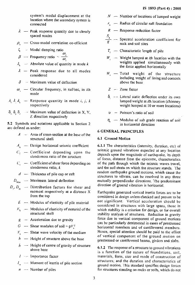
5.2 Symbols and notations applicable to Section 2are defined as under:
A—
Ah —
CT —
c“ —
d—
DMax —
Dvj D,m —
E—
E< -—
g—
G—
v, —
h—
h—
[—
l—,),
n—
Area of cross-section at the base of thestructural shell
Design horizontal seismic coefficient
Coefficient depending upon theslenderness ratio of the structure
Coefficient of shear force depending onslenderness ratio, k
Thickness of pile cap or rafl
Maximum lateral deflection
Distribution factors for shear andmoment respectively at a distance Xfrom the top
Modulus of elasticity of pile material
Modulus of elasticity of material of thestructural shell
Acceleration due to gravity
Shear modulus of soil = pV,2
Shear wave velocity of the medium
Height of structure above the base
Height of centre of gravity of structureabove base
Importance factor
Moment of inertia of pile section
Number of piles
3
N—
r—0
R—
s-——g
T, —
w, —
w, —
z—
i5i—
v—
0’, —
Number of locations of lumped weight
Radius of circular ratl foundation
Response reduction factor
Spectral acceleration coefficient forrock and soil sites
Characteristic length of pile
Weight lumped at ith location with theweights applied simultaneously withthe force applied horizontally
Total weight of the structureincluding weight .of lining and contentsabove the base
Zone factor
Lateral static deflection under its ownlumped weight at ith location (chimneyweight lumped at 10 or more locations)
Poisson’s ratio of soil
Modulus of sub grade reaction of soilin horizontal direction
6 GENERAL PRINCIPLES
6.1 Ground Motion
6.1.1 The characteristics (intensity, duration, etc) ofseismic ground vibrations expected at any locationdepends upon the magnitude of earthquake, its depthof focus, distance from the epicentre, characteristicsof the path through which the seismic waves travel,and the soil strata on which the structure stands. Therandom earthquake ground motions, which cause thestructures to vibrate, can be resolved in any threemutually perpendicular directions. The predominantdirection of ground vibration is horizontal.
Earthquake generated vertical inertia forces are to beconsidered in design unless checked and proven to benot significant. Vertical acceleration should beconsidered in structures with large spans, those inwhich stability is a criterion for design, w- for overallstability analysis of structures. Reduction in gravityforce due to vertical component of ground motionscan be particularly detrimental in cases of prestressedhorizontal members and of cantilevered members.Hence, special attention should be paid to the effectof vertical component of the ground motion onprestressed or cantilevered beams, girders and slabs.
6.1.2 The response of a structure to ground vibrationsis a function of the nature of foundations, soil,materials, form, size and mode of construction ofstructures; and the duration and characteristics ofground motion. This standard specifies design forcesfor structures standing on rocks or soiIs, which do not
IS 1893 (Part 4):2005
settle, liquify or slide due to loss of strength duringvibrations.
6.1.3 Thedesign approach adopted in this standardis to ensure that structures possess minimum strengthto withstand minor earthquakes (< DBE) which occurfrequently, without damage; resist moderateearthquakes (DBE) without significant structuraldamage though some non-structural damage mayoccur; and withstand a major earthquake (MCE)without collapse. Actual forces that appear onstructures during earthquakes are much greater thanthe design forces specified in this standard. However,clucti[ity, arising from inelastic material behaviour anddetailing, and overstrength, arising from the additionalreserve strength in structures over and above the designstrength, are relied upon to account for this differencein actual and design lateral loads.
Reinforced and prestressed concrete members shall besuitably designed to ensure that premature failure dueto shear or bond does not occur, subject to theprovisions of IS 456 and IS 1343. Provisions forappropriate ductile detailing of reinforced concretemembers are given in 1S 13920.
In steel structures, members and their connectionsshould be so proportioned that high ductility isobtained, as specified in SP 6 (6), avoiding prematurefailure due to elastic or inelastic buckling of any type.
6.1.4 The design force specified in this standard shallbe considered in-each of the two principal horizontaldirections of the structure and in vertical direction.
6.1.5 Equipment and other systems, which aresupported at various floor levels of the structure, shallbe subjected to motions corresponding to vibration attheir support points. in important cases, it may benecessary to obtain floor response spectra for analysisand design of equipment.
6.2 Assumptions
The following assumptions shall be made in theearthquake resistant design of structures:
a) Earthquake causes impulsive ground motions,which are complex and irregular in character,changing in period and amplitude each lastingfor a small duration. Therefore, resonance ofthe type as visualized under steady-state
b)
c)
sinusoidal excitations, will not occur, as ~ wouldneed titne to build up such amplitudes.
NOTE — ~xccptional,resonance-likeconditionshave been
seen to occur between long distance waves and tall structures
tbunded on deep soft soils.
Earthquake is not likely to occur simultaneouslywith maximum wind or maximum -flood ormaximum sea waves.
Tbe value of elastic modulus of materials,wherever required, may be taken as for static
4
analysis unless a more definite value is availablefor use in such condition (see IS 456, IS 800and IS 1343).
SECTION 1 INDUSTRIAL STRUCTURES
7 DESIGN CRITERIA
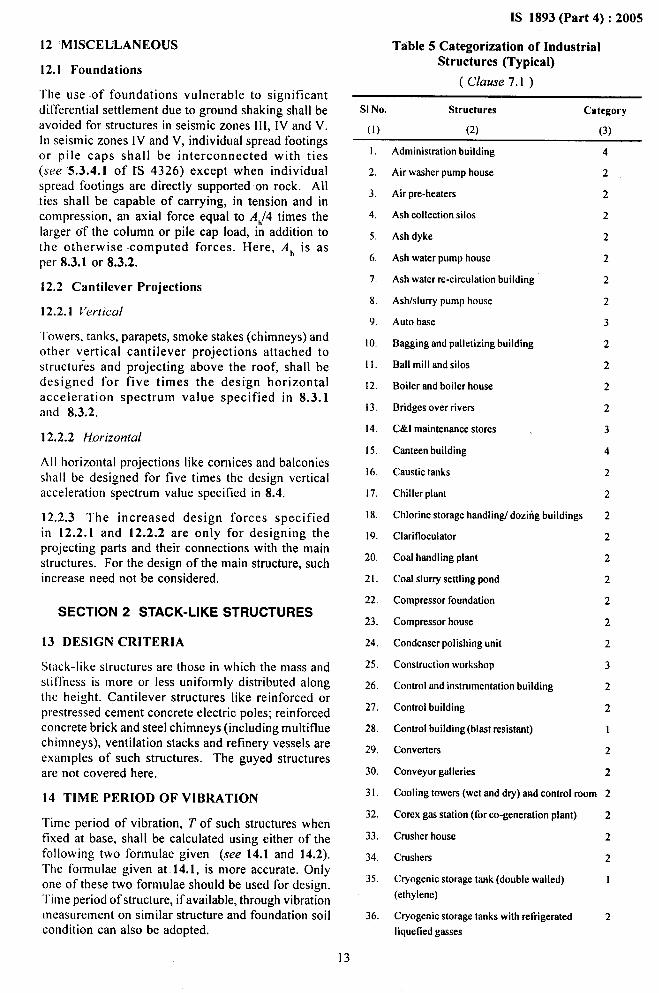
7.1 Categorization of Structures
To perform well in an earthquake, the industrialstructure should possess adequate strength, stiffness,and ductility. Generally structures have largecapacities of energy absorption in its inelastic region.Structures which are detailed as per IS 13920 orSP 6 (6) and equipment which are made of ductilematerials~art withstand earthquakes many fold higherthan the design spectra without collapse; and damagein such cases is restricted to cracking only.
Structures are classified into the following fourcategories:
a) Category 1 :
b) Category 2 :
c) Category 3 :
d) Category 4 :
Structures whose failure cancause conditions that -can leaddirectly or indirectly to extensive10ssof life/property to populationat large in the areas adjacent tothe plant complex.
Structures whose failure cancause conditions that can leaddirectly or indirectly to seriousfire hazard/extensive damagewithin the plant complex.Structures, which are required tohandle emergencies immediatelyafter an earthquake, are alsoincluded.
Structures whose failure,although expensive, does notlead to serious hazard within theplant complex.
All other structures.
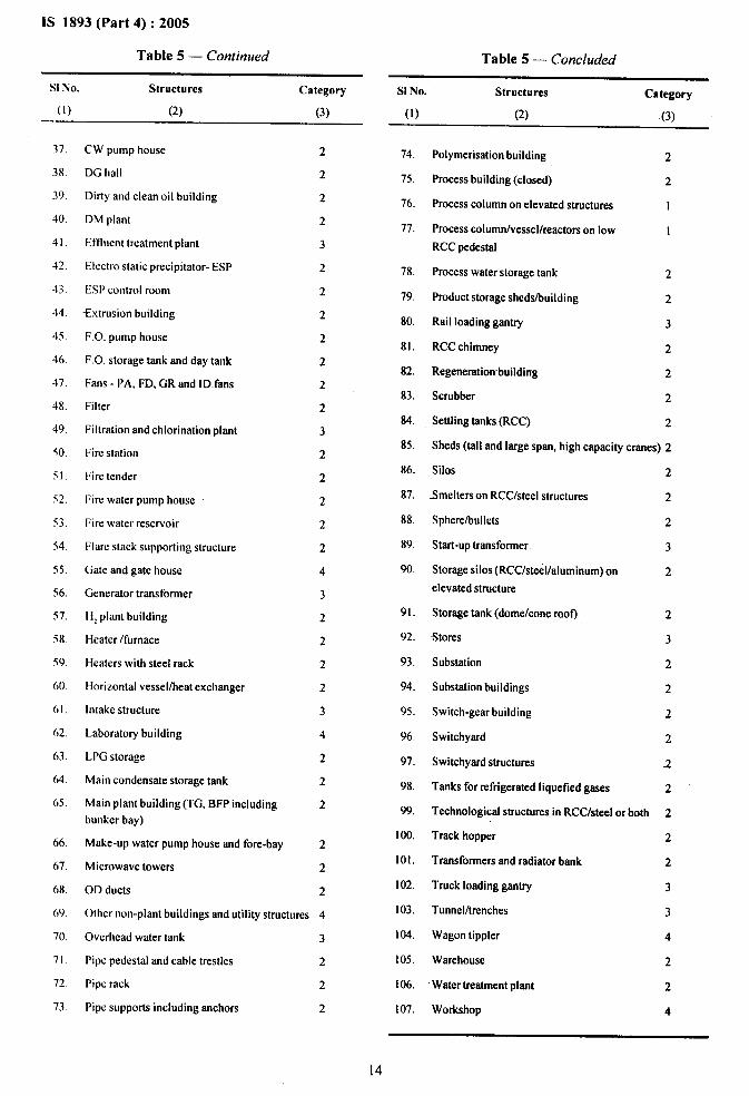
Typical categorization of industrial structures is givenin Table 5 .
NOTE — The term failure used in the definition of categories
implies loss of function and not complete collapse. Pressurized
equipment where cracking can lead to rupture may be
categorized by the consequences of rupture.
7.2 Design Loads
7.2.1 Dead Load (DL)
These shall be taken as per IS 875 (Part 1).
7.2.2 Super imposed Dead Loads (SIDL)
Industrial structures contain several equipment andassociated auxiliaries and accessories that are
IS 1893 (Part 4):2005
permanently mounted on the structures. These loads response due to earthquake force (EL) is the maximumshall be taken as per equipment specifications. of the following cases:
7.2.3 Imposed Loads (IL)r
+ ELX & 0.3 ELY =t 0.3 ELZ
These shall be taken as per 1S 87’5(Part 2). EL= * EL, + 0.3 ELX + 0.3 ELZ
7.2.4 Earthquake Loaak (EL) ~+ ELZ + 0.3 ELX * 0.3 EL,
The earthquake load on the different members of a where x and y are two orthogonal directions and z isstructure shall be determined by carrying out analysis the vertical direction.following the procedure described in 10 using thedesign spectra specified in 8. Earthquake loads in x 7.3.2.2 As an alternative to the procedure in 7.3.2.1,
and y (horizontal) directions are denoted by EL, and the response (EL) due to the combined effect of the
ELY and earthquake loads in vertical direction are three components can be obtained on the square root
denoted by ELZ. of the sum of the squares (SIMS’)basis, that is
7.3 Load Combinations EL = (ELK)2+ (ELY)2 + (ELZ)2
When earthquake-forces are considered on a structure,the response quantities due to dead load (DL), imposedload (lL), super imposed dead loads (SIDL) and designearthquake load (EL) shall be combined as per 7.3.1and 7.3.2. The factors defined in 7.3.1 and 7.3.2 areapplicable for Category 1 to 4 structures only underDBE (see 7.5).
7.3.1 Load Factors for Plastic Design of SteelStructures
NOTE — Thecombinationproceduresof7.3.2.1and7.3.2.2applytothesameresponse quantity (say, moment in a coI umnabout its major axis, or storey shear in a frame) due to different
components of the ground motion. These combinations arc to
be made at the member forcektress Iev-ets.
7.3.3 For structures under Category 1, which aredesigned under MCE (see 7.5.1) and checked underDBE, all load factors in combination with MCE shallbe taken as unity.
In the plastic design of steel structures, the following 7.4 Increase in Permissible Stresses
load combinations shall be accounted for: 7.4.1 Increase in Permissible Stresses in Materialsa) 1.7 (DL + SIDL + IL),
b) 1.7 (DL + S/DL) + EL, and
c) 1.3 (DL + SIDL + IL + EL).
NOTE — Imposed load (ff,) in load combination shall not
include erection loads and crane payload,
7.3.2 Partial Safety Factors for Limit State Design ofRcirrfor-ced Concrete and Prestressed ConcreteStructures
In the limit state design of reinforced and prestressedconcrete structures, the following load combinationsshall be accounted -for:
When earthquake forces are considered along withother normal design forces, the permissible stresses inmaterial, in the elastic method of design, may beincreased by one-third. However, for steels having adefinite yield stress, the stress be limited to the yieldstress, for steels without a definite yield point, the stresswill be limited to 80 percent of the ultimate strengthor 0.2 percent proof stress, whichever is smaller; andthat in pre-stressed concrete members, the tensile stressin the extreme fibers of the concrete may be permittedso as not to exceed two-thirds of the modulus of ruptureof concrete.
a) 1.5 (DL + SIDL + IL), 7.4.2 Increase in Allowable Pressures in Soils
b) 1.2 (DL + SIDL + IL + EL),
c) 1.5 (DL + SIDL * EL), and
d) 0.9 (DL + SIDL) + 1.5 EL.
NOTE — Imposed load (/[.) in load combination shall not
include erection load and crane payload,
7.3.2.1 When responses from the three earthquakecomponents are to be considered, the response due toeach component may be combined using theassumption that when the maximum response fromone component occurs, the responses from the othertwo components are 30 percent of the correspondingmaximum. All possible combinations of the threecomponents (ELX, EL and EL,) including variations
\in sign (plus or minus shall be considered. Thus, the
When earthquake forces are included, the allowablebearing pressure in soils shall be increased as perTable 1, depending upon type of foundation of thestructure and the type of soil.
In soil deposits consisting of submerged loose sandsand soils falling under classification SP with standardpenetration N values less than 15 in seism”iczones III,IV, V and less than 10 in seismic zone 11,the vibration-caused by earthquake may cause liquefaction orexcessive total and differential settlements. Such sitesshould preferably be avoided while locating newsettlements or important projects. Otherwise, thisaspect of the problem needs to be investigated andappropriate methods of compaction or stabilization
5

1S 1893 (Part 4) :2005
adopted to achieve suitable N values as indicatedin Note 3 under Table 1. Alternatively, deep pilefoundation may be provided and taken to depths wellinto the layer, which is not likely to Iiquify. Marineclays and other sensitive clays are also known toliquefy due to collapse of soil structure and will needspecial treatment according to site condition.
7.5 Design Basis Earthquake (DBE)
Design basis earthquake (DBE) for a specific site is tobe determined based on either : (a) site specificstudies, or (b) in accordance with provisions ofIS 1893 (Part 1).
7.5.1 Structures in Category 1 shall be designed formaximum considered earthquake (MCE) (which istwice of DBE).
7.5.2 Structures in Category 2, 3 and 4 shall bedesigned for DBE for the project site.
8 DESIGN SPECTRUM
8.1 For all important projects, and all industriesdeal ing with highly hazardous chemicals, evaluationof site-specific spectra for earthquake with probabilityof exceedence of 2 percent in 50 years (MCE) and10 percent in 50 years (DBE) is recommended. AllCategory 1 industrial structures shall be analyzed usingsite-specific spectra. However, if site-specific studiesarc not carried out, the code specified spectra may beused with modifications as per 8.3.2. If time-historyanalysis is to be carried out, spectra-compliant time-history shall be determined based on the site-specificspectra.
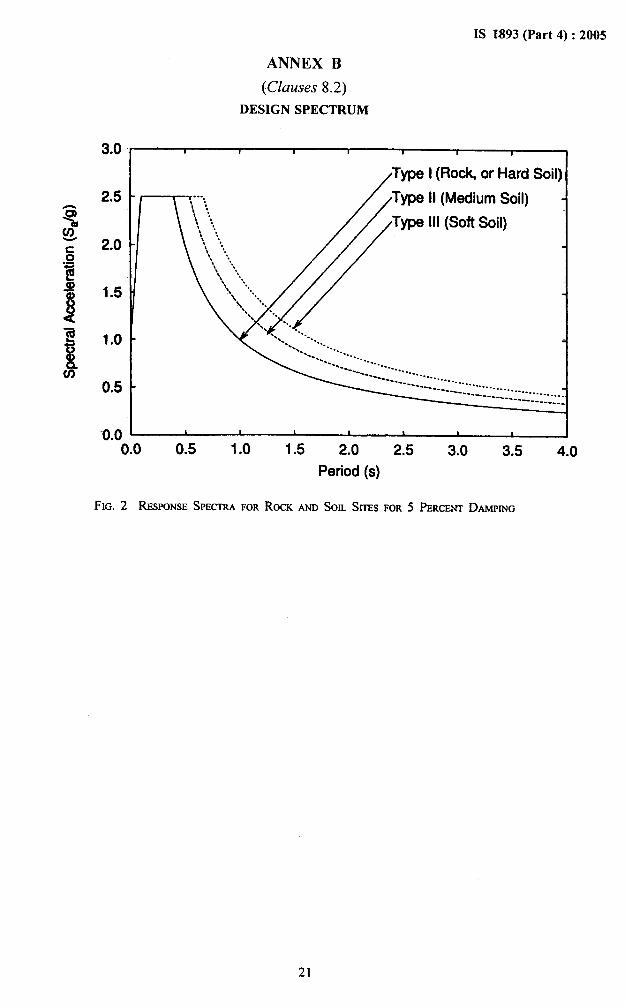
8.2 For all other structures not covered in 8.1, thespectra and seismic zone as given in Annex A andAnnex B is recommended [these are in accordancewith IS 1893 (Part 1) ].
8.3 Horizontal Seismic Force
The horizontal seismic coefficient Ah, shall beobtained using the period T, described as under.
8.3.1 When using site specific spectra, the seismiccoefficient shall be calculated from the expression :
[/1s=
A,, =(R;l)
s,where / g = spectral acceleration coefficient
corresponding to site specific spectra.
8.3.2 When using code specific spectra, the seismicco-efficient shall be calculated from the expression:
(RJI)
NOTE — Structures in Category 1 shall be designed for seismic
force twice that found using the provisions of this clause.
-wherez.
s~g =
I=
~.
zone factor, given in Annex A [This is inaccordance with Table 2 of IS 1893 (Part 1)].
spectral acceleration coefficient for rock andsoil sites given in Annex B [This is inaccordance with Fig. 1 of IS 1893 (Part l)].
importance factor given in TabIe 2 is relativeimportance assigned to the structure to take intoaccount consequences of its damage.
response reduction factor to take into accountthe’margins of safety, redundancy and ductilityof the structure given in Table 3.
Categorization of some individual structure andcomponents of typical industries are given h-tTable 5.
8.4 Vertical acceleration values are to be taken as2/3 of the corresponding horizontal accelerationvalues.
9 MATHEMATICAL MODELLING
9.1 Modelling Requirements
The mathematical model of the physkcal structure shallinclude all elements of the lateral force-resistingsystem. The model shall also include the stiffnessand strength of elements, which are significant to thedistribution of forces. The model shall properlyrepresent the spatial distribution of the mass andstiffness of the structures, as well as mass of equipmentcable trays and piping system along with associatedaccessories, 25 percent of the live load shall alsobe included as suitably distributed mass on thestructure.
9.1.1 Soil-Structure Interaction
The soil-structure interaction refers to the effects ofthe supporting foundation medium on the motion ofstructure. The soil-structure interaction may not beconsidered in the seismic analysis for structuressupported on rock or rock-like material.
9.2 Interaction Effects Bet-ween Structure andEquipment
Interaction effects between structure and equipmentshall be considered as under:
a) For Category 2, 3 and 4, simplified considera-tions as per 9.2.1 may be used.
b) For Category 1, detailed considerations as per9.2.2 shall be adopted.
9.2.1 For the purpose of 9.2, the following notationsshall be used:
M,= total mass of the structural system on which thesecondary system is supported,
6

IS 1893 (Part 4):2005
Table 1 Percentage of Permissible Increase in AllowableBearing Pressure, Resistance of Soils
( Clause 7.4.2 )
S1No. Foundation Type of Soil Mainly Constituting the Foundation
/ \
Type I Rock or Hard Soils: Type 1[ Medium Soils: All Type III Soft Soils:Well graded gravel and sand soils with N between 10 and All soils other than SP withgravel mixtures with or 30, and poorly graded sands
N<1Owithout clay binder, and or gravelly sands with little or
clnyey sands poorly graded no fines (SP) with N> 15
or sand clay mixtures (Cl),
CW, SB, SW and S(’)
having N above 30, where
N is the standard penetration
value
(1) (2) (3) (4) (5)
i) Piles passing through 50 so so
any soil but rcstiog on
soil Type I
ii) Piles not covered under 25
S1No. (i)
25
iii) Raft foundations 50 50 50
iv) Combined / Isolated 50 25 25
RC’C footings with tie
beams
v) Well foundations 50 25 25
NOTES
I The allowable bearing pressure shall be determined in accordance with IS 6403 or IS 1888,
2 If anv increase in bearing Dressure has alrcadv been Dermitted lor forces other than seismic forces. the total increase in allowable
bearing-pressure when seis;;c force is also inciuded shall not exceed the limits specified above
3 Desirable minimum field values of N are as follows:
S1No. Seismic Zone Depth Below N Values Remarks
Ground Level
(m)
i) Ill, IVand V <5 15For values of depths
210 25 between 5 m uod 10 m,
linear interpolation isii) II 55 15 recommended.
210 20
If soils of smaller Nvahses are met, compaction maybe adopted Io.achieve these values or deep pile foundations going to strooger
strata should be used.
4 The piles should be designed for lateral loads neglecting lateral resistance ofsoi[ layers liable to Iiquify.
S Following Indian Standards may also be referred:
a) IS 1498 Classification and identification of-soils for general engineering purposes.
b) IS2131 Method of standard penetration test for soils.
c) IS 6403 Code ~f practice for determination of bearing capidy of SIMI1OWfouodatioos.
d) 1S 1888 Method of load tests on soils.
6 Isolated RCC footing without tie beams or unreinftmced strip foundation shall not be permitted in sotl soils with N <10,
.4

IS 1893 (Part 4):2005
Table 2 Importance Factor for Various -Industrial Structures
(Clause 8.3.2)
S1No. Categories of Structures Importance Factnr
(see 7.1 )
(1) (2) (3)
O Structures in Category 1 2.00
ii) Structures in Category 2 1.75
iii) Structures in Category 3 1,50
iv) Structures in Category 4 1.00
NOTE — Higher importance factor may be assigned to different structures at the discretion of the project authorities
~R .
M,=
total mass of all the equipment that are rigidlymounted at different locations in the structure,and
total mass of all the equipment that are flexiblemounted at different locations in the structure.
9.2.1.1 Wherever equipment are rigidly fastened tothe floor, the equipment mass (MJ shall be taken aslumped mass at appropriate locations. No interactionbetween the structures and equipment shall beconsidered.
9.2.1.2
M,If < 0.25
Ms + M.
No interaction between the structures and equipmentshall be considered. In such case MF should beconsidered as lumped mass at appropriate locations.
9.2.1.3 If A4~/(A4~+ MS)20.25, interaction betweenthe flexibly mounted equipment and the structure shallbe considered by suitably modelling the flexibleequipment support system while considering theequipment as lumped mass.
9.2.2 Decoupling criteria as given below shall be usedfor all Category 1 systems.
9.2.2.1 For the purpose of this clause, the followingnotations shall be used.
‘r M .Ub
‘J= “;] M 01= Participation
where
A4= mass matrix of the structural system,
(3, = ,jth normalized mode shape, OjT MOj = 1, and
U,,= influence vector, displacement vector of thestructural system when the base is displaced byunity in the direction of earthquake motion.
9.2.2.2 All combinations of the dominant secondarysystem modes and the dominant primary modes must
be considered and the most restrictive combinationshall be used.
9.2.2.3 Coupled analysis of a primary structure andsecondary system shall be performed when the-effectsof interaction are significant based on 9.2.2.9 and9.2.2.11.
9.2.2.4 Coupling is not required, if the total mass ofthe equipment or secondary system is 1 percent orIem of the mass of the supporting primary structure.!fa coupled analysis will not increase the response ofthe primary system over that of a decoupled analysisby more than 10 percent, then a coupled analysis isnot required. However, the requirements of section9.2.2.11 regarding the multiple supports should beconsidered.
9.2.2.5 In applying sections 9.2.2.9 and 9.2.2.11, onesub-system at a time may be considered, unless thesub-systems are identical anti located together, inwhich case the sub-system masses shall be lumpedtogether.
9.2.2.6 When coupling is required, a detailed modelof the equipment or secondary system is not required,provided that the simple model adequately representsthe major effects of interaction between the two parts.When a simple model is used, the secondary systemshall be re-analyzed in appropriate detail using theoutput motions from the first -analysis as input at thepoints of connectivity.
9.2.2.7 For applying the criteria of this section tohave a modal mass greater than 20 percent of the totalsystem mass, the total system mass is defined by
M = ; (r,)’9.2.2.8 When carrying out simplified analysis (asper 9.3), equipment or secondary system shall beconsidered as per 9.2.2.4, 9.2.2.5 and 9.2.2.6.
9.2.2.9 When detailed analysis is to be carried out forstructures with equipment attached at a single point,
8
1S 1893 (Part 4):2005
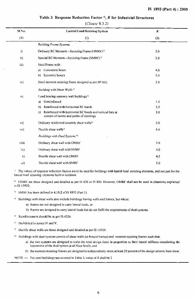
Table 3 Response Reduction Factor ‘), R for Industrial Structures
(Clause 8.3.2)
S1 No. Lateral Load Resisting System R
(1) (2) (3)
Building Frame Systems
O Ordinary RC Moment—Resisting Frame (OMRF)’)
ii) Special RC Moment—Resisting Frame (SMRF)’)
iii) Steel Frame with:
a) Concentric brace
b) Eccentric braces
iv) Steel moment resisting frame designed as per SP 6(6)
v)
Building with Shear Walls’~
Load bearing masonry wall buildings $
a) Unreinforced
b) Reinforced with horizontal RC bands
c) Reinforced with horizontal RC bands and vertical bars at
corners of rooms and jambs of openings
vi) Ordinary reinforced concrete shear walls!)
vii) Ductile shear walls7)
Bu//ding.r )vith Dual Sysrems’)
viii) Ordinary shear wall with OMRF
ix) Ordinary shear wall with SMRF
x) Ductile shear wall with OMRF
3.0
5.0
4,0
5,0
5.0
1.5
2.5
3.0
3.0
4,0
3.0
4.0
4.5
xi) Ductile shearwall with SMRF 5.0
I) The Va]ues of response reduction factors are to be used for buildings with lateral load resisting elements, and not just for the
lateral load resisting elements built in isolation.
‘) OMRF are those designed and detailed as per IS 456 or IS 800. However, OMRF shall not be used in situations explained
in IS 13920.
x)
4)
J)
1,)
7)
*)
SMRF has been defined in 4.15.2 oflS 1893 (Part l).
Buildings with shear walls also include boildings having walls and frames, but where:
a) frames are not designed to-carry lateral loads, or
b) frames are designed to carry lateral loads but do not fulfd the requirements of dual systems.
Reinforcement should be as per 1S 4326,
Prohibited in zones IV and V.
Ductile shear walls are those designed and detailed as per IS 13920,
Buildings with dual systems consist of shear walls (or braced frames) and moment resisting frames such that:
a) the two systems are designed to resist the total design force in proportion to their lateral stiffness considering the
interaction of the dual system at all floor levels, and
b) the moment resisting frames ar-edesigned to independently resist at least 25 percent of the design seismic base shear.
NOTE — For steel buildings not covered in Table 3, value oIJ{ shall be 2,

1S 1893 (Part 4):2005
the coupling criteria shown in Fig. 1 shall be used.The mass ratio in Fig. 1 is the modal mass ratiocomputed as per 9.2.2.10 and the frequency ratio isthe ratio of uncoupled modal frequencies of thesecondary and primary systems.
9.2.2.10 For a secondary system dominant mode andthe primary system mode i, the modal mass ratio canbe estimated by:
M,A=
,M.
PI
where
M,, =
@c,=
~,.
M, =
9.2.2.11
(I /Dci)’;
the mode vector value from the primarysystem’s modal displacement at the locationwhere the secondary system is connected,from the ith normalised modal vector, (aCi),
(3Tc,M,,@ci= 1;
mass matrix of the primary system; and
total mass of the secondary system.
Multisupport secondary system shall berev iewed for the possibi Iity of interac~ion of structureand equipment stiffness between the support points,and for the effect of equipment mass distributionbetween support points. When these effects cansignificantly influence the structure response, reference
3’~T
Eigen value analysis of the structural mathematicalmodel developed in accordance with 9.1 and 9.2.
9.3.2 For preliminary design, the time period can beestablished based on its static deflection under massproportional loading in each of the three principaldirections. This load is applied by applying a forceequal to the weight of the structure or equipment ateach mode in X, Y or Z direction. Where the foundingsoil is soft soil, the effect of the same shall beconsidered in the estimates for static deflection.
The time period T, would then be :
[T = 21T ~ sec
g
3.0
2.5
=1-~2.0
-s2
i~
1,5
Ii
1.0
0.5
00
$/MS
=J-’S$-M*
MP+MQ
%
9‘P
MCXMA ModelB Model C
4-
Explanetion
$ = frequency01 Uncoufxqd mode a of
secmdary system
f~ . Irequency 01 unccwpled mode I of
primary s@em
shall “bemade to specialized literature.
9.3 Time Period Estimation
The time period of different industrial structures wouldvary considerably depending on the type of soil, spanand height of the structure, distribution of load in thestructure and the type of structure (concrete, steel andaluminum). It would be difllcult to give one or twogeneralized formulae to cover all such structures.Accordingly, no simple guidelines can “be given forestimation of time periods of industrial structures.
9.3.1 The time period -shall be estimated based on
iical 0.010 0.100MS
Modal Mass Ratio ~
FIG.1 DECOUPLINGCRITERIAFOR EQUIPMENTOR SECONDARY SYSTEM
ATTACf{MENTTO Tf[EpRfMARY SYSTEM
10
1 .Om
WITH SINGLEPOINT

1S 1893 (Part 4) :2005
Where 6 is the maximum value of deflection at anymode out of 6X6Y6= and ‘g’ is acceleration due togravity in the corresponding unit.
9.4 Damping
The damping factor to be used in determining spectralacceleration coefficient (S,/g) depends upon thematerial and type of construction of the structure andthe strain level. The recommended damping factorsare given in Table 4.
10 ANALYSIS PROCEDURE
10.1 Classification of Analysis Techniques
10.1.1 Detailed analysis shall be carried out forstructures of Category 1, in aI1seismic zones.
10.1.2 Detailed analysis shall be carried out for allstructures of Category 2 and 3 in seismic zones III, IVand”V.
10.1.3 Simplified analysis may be used for structuresof Category 2 and 3 in seismic zone 11.
10.1.4 Simplified analysis may be used for structuresof Category 4 in all seismic zones. However, thosestructures of Category 4, which could be identified asbuildings, may be analysed as per provisions ofIS 1893 (Part 1),
10.2 Detailed Analysis
10.2.1 Seconda~ Effect
The analysis shall also include the influence ofP – A effect.
10.2.2 Torsion
The effect of accidental eccentricity shall beconsidered for rigid floors/diaphragms. This shall beapplied as an additional torsion force equal to productof the mass at floor level and 5 percent of the structuredimension perpendicular to the earthquake directionat the centre of mass of the floor.
10.2.2.1 The design eccentricity, ed to be used at floori shall be taken as:
——
[
1.5 e,i + 0.05 bi
or eti – 0.05 bi
whichever of these gives more severe effect.
e,i = static eccentricity at floor i, defined as thedistance between centre of mass and centre ofrigidity; and
b, = floor plan dimension of floor i, perpendicularto direction of force.
The factor 1.5 represents dynamic amplification factor,while the factor 0.05 represents the extent of accidentaleccentricity.
NOTE — For the purposes of this clause, all steel or aluminium
flooring system may be considered as flexible unless properly
designed floor bracings have been provided. Reinforced
concrete flooring systemat a level shall be considered rigid
only if the total area of all the cut-outs at that level is less than
25 percent of its plan floor area.
10.2.3 Seismic analysis shall be performed for thethree orthogonal (two horizontal and one vertical)components of earthquake motion. The earthquakemotion in each direction shall be combined as specifiedin 7.3.
10.2.4 Time-History Analysis Method
Time-history analysis of structures subjected toseismic loads shall be performed using linearanalysis technique. The analysis shall be based onwell-established procedures. Both direct solution ofthe equations of motion or model superpositionmethod can be used for this purpose.
10.2.4.1 In model superposition method, sufficientlylarge number 01 modes shall be used for analysis toinclude the influence of at least 90 percent of the totalseismic mass.
Table 4 Damping Ratio Coefficient for Different ConstructionMaterials for DBE and NICE Conditions
( Clause 9.4)
S1 No. Material DBE MCE
(1) (2) (3) (4)
O Aluminium 0.02 0.04
ii) Steel 0.02 0.04
iii) Reinforced Concrete 0.05 0.07
NOTE — For combined structures, damping ratio coefficient shall be determined based on well established procedures, if a composite
damping ratio coefficient is not evaluated, it shall be taken as that corresponding to material having lower damping.
II
IS 1893 (Part 4) :2005
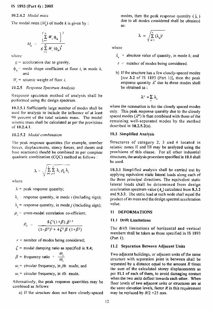
10.2.4.2 Modal mass
The modal mass (MJ of mode k is given by :
[12
5 w, @,k,=,
~i .
~ 5w, (O,k)’,..,where
acceleration due to gravity,
mode shape coefficient at floor i, in mode k,and
seismic weight of floor i.
I ().2.5 Response Spectrum Analysis
Response spectrum method of analysis shall be
performed using the design spectrum.
10.2.5.1 Sufficiently large number of modes shall beused for analysis to include the influence of at least90 percent of the total seismic mass. The modelseismic mass shall be calculated as per the provisionsof 10.2.4.1.
10.2.5.2 Modal combination
Tile peak response quantities (for example, memberforces, displacements, storey forces, and shears andbase reactions) should be combined as per completequadratic combination (CQC) method as follows :
modes, then the peak response quantity ( ~ )due to all modes considered shall be obtainedas:
/A = ~ (Q’
k= I
where
2, = absolute value of quantity, in mode k; and
r = number of modes being considered.
b) If the structure has a few closely-spaced modes[see 3.2 of IS 1893 (Part l)], then the peakresponse quantity 2“ due to these modes shallbe obtained as :
2 =x A=c
where the summation is for the closely spaced modesonly. This peak response quantity due to the closelyspaced modes (2*) is then combined with those of theremaining well-separated modes by the methoddescribed in 10.2.5.2(a).
10.3 Simplified Analysis
Structures of category 2, 3 and 4 located inseismic zones II and 111 may be analyzed using theprovisions of this clause, For all other industrialstructures, the analysis procedure specified in 10.1 shallbe used.
10.3.1 Simplified analysis shall be carried out byapplying equivalent static lateral loads along each of
where the three principal directions. The equivalent static. . . .
L=
?L=
x, =
g, =
r=
<=
p=
O.)j=
OJi=
peak response quantity;
response quantity, in mode i (including sign);
response quantity, in modej (including sign);
cross-modal correlation co-efficient;
P,, =8(2(l+fl).fl’5
(1-p’)’+ 4(’p (I+p’)
number of modes being considered;
modal damping ratio as specified in 9.4;a.
frequency ratio = --#t
circular frequency, inJh mode; and
circular frequency, in ith mode.
Alternatively, the ~ak response quantities may becombined as follows:
a) If the structure does not have closely-spaced
lateral loads shall be determined from designacceleration spectrum value (AJ calculated from 8.3.2and 9.3.2. The static load at each node shall equal theproduct of its mass and the design spectral accelerationvalue.
11 DEFORMATIONS
11.-1 Drift Limitations
The drift limitations of horizontal and verticalmembers shall be taken as those specified in 1S 1893(Part 1).
11.2 Separation Between Adjacent Units
Two adjacent buildings, or adjacent units of the samestructure with separation joint in between shall beseparated by a distance equal to the amount R timesthe sum of the calculated storey displacements asper 1“1.1of each of them, to avoid damaging contactwhen the two units deflect towards each other. Whenfloor levels of two adjacent units or structures are atthe same elevation levels, factor R in this requirementmay be replaced by R12+25 mm.
12
12 MISCELLANEOUS
12.I Foundations
The use of foundations vulnerable to significantdifferential settlement due to ground shaking shall beavoided for structures in seismic zones 111,IV and V.In seismic zones IV and V, individual spread footingsor pile caps shall be interconnected with ties(see 5.3.4.1 of 1S 4326) except when individualspread footings are directly supported on rock. All-ties shall be capable of carrying, in tension and incompression, an axial force equal to AJ4 times thelarger of the column or pile cap load, m addition tothe otherwise computed forces. Here, Ah is asper 8.3.1 or 8.3.2.
12.2 Cantilever Projections
12.2.1 Vertical
Towers, tanks, parapets, smoke stakes (chimneys) andother vertical cantilever projections attached tostructures and projecting above the roof, shall bedesigned for five times the design horizontalacceleration spectrum value specified in 8.3.1and 8.3.2.
12.2.2 H.orizonta[
AlI horizontal projections like cornices and balconiesshall be designed for five times the design verticalacceleration spectrum value specified in 8.4.
12.2.3 The increased design forces specifiedin 12.2.1 and 12.2.2 are only for designing theprojecting parts and their connections with the mainstructures. For the design of the main structure, suchincrease need not be considered.
SECTION 2 ‘STACK-LIKE STRUCTURES
13 DESIGN CRITERIA
Stack-1ike structures are those in which the mass andstiffness is more or less uniformly distributed alongthe height. Cantilever structures .Iike reinforced orprestressed cement concrete electric poles; reinforcedconcrete brick and steel chimneys (including multifluechimneys), ventilation stacks and refinery vessels areexamples of such structures. The guyed structuresare not covered here.
14 TIME PERIOD OF VIBRATION
Time period of vibration, T of such structures whenfixed at base, shall be calculated using either of thefollowing two formulae given (see 14.1 and 14.2).The formulae given at. 14.1, is more accurate. Onlyonc of these two formulae should be used for design.Time period of structure, if available, through vibrationmeasurement on similar structure and foundation soilcondition can also be adopted.
[S 1893 (Part 4) :2005
Table 5 Categorization of IndustrialStructures (Typical)
( Clause 7.1 )
S1No. Structures Category
(1) (2) (3)
1.
2.
3.
4.
5.
6.
7.
8.
9,
10.
11.
12.
13.
14.
15,
16.
17,
18.
19.
20.
21.
22.
23.
24.
25.
26.
27.
28.
29,
30.
31.
32.
33.
34.
35,
36.
Administration building
Air washer pump house
Air pre-heaters
Ash collection silos
Ash dyke
Ash water pump house
Ash water re-c.irculation building
Ash/slurry pump house
Auto base
Bagging and palletizing building
Ball mill and silos
Boiler and boiler house
Bridges over rivers
C&l maintenance stores
Canteen building
Caustic tanks
Chiller plant
Chlorine storage handling/ dozirig buildings
Clarifloculator
Coal handling plant
Coal slurry settling pond
Compressor foundation
Compressor house
Condenser polishing unit
Construction workshop
Control and instrumentation building
Control building
Control building (blast resistant)
Converters
Conveyor galleries
4
2.
2
2
2
2
2
2
3
2
2
2
2
3
4
2
2
2
2
2
2
2
2
2
3
2
2
1
2
2
Cooling towers (wet and dry) and control room 2
Corex gas station (tbr co-generation plant) 2
Crusher house 2
Crushers 2
Cryogenic storage tank (double walled) 1
(ethylene)
Cryogenic storage tanks with refrigerated 2
Iiquetied gasses
13
1S 1893 (Part 4):2005
Table 5 — Continued Table 5 — Concluded
S1No. Structures Category
(1) (2) (3)
S1No. Structures Category
(1) (2) (3)
37.
38.
39.
40.
41.
42,
43.
44.
45.
46.
47.
48.
49,
50.
51.
52.
53,
54
55.
56.
57.
58.
59.
60.
61,
62,
63.
64.
65.
66.
67.
68.
69.
70,
71.
72.
73.
CW pump house
DG hall
Dirty and clean oil building
DM plant
Eftlucnt treatment plant
Electro static precipitator- ESP
ESP control room
Extrusion building
F.O. pump house
F.O. storage tank and day tank
Fans - PA, FD, GR smd ID.fans
Filter
Filtration and chlorination plant
Fire station
Fire tender
Fire water pump house
Fire water reservoir
Flare stack supporting structure
Gate and gate house
Generator transformer
Hj plant building
Heater /furnace
Heaters with steel rack
}+orizontal vessel/heat exchanger
Intake structure
Laboratory building
LPG storage
Main condensate storage tank
Main plant building (TG, BFP including
bunker bay)
Make-up water pump house and fore-bay
Microwave towers
OD ducts
2
2
2
2
3
2
2
2
2
2
2
2
3
2
2
2
2
2
4
3
2
2
2
2
3
4
2
2
2
2
2
2
Other non-plant buildings and utility structures 4
Overhead wirter tank 3
Pipe pedestal and cable trestles 2
Pipe rack 2
Pipe supports including anchors 2
74.
75.
76.
77.
78.
79.
80.
81.
82.
83.
84.
85.
86.
87,
88.
89,
90.
91.
92.
93.
94.
95.
96.
97.
98.
99.
100.
10I.
102.
103,
104,
105.
106.
107.
Polymerisation building 2
Process building (closed) 2
Process column on elevated structures 1
Process column/vessel/reactors on low 1
RCC pedestal
Process water storage tank 2
Product storage shedtibuilding 2
Rail loading gantry 3
RCC chimney 2
Regeneration-building 2
Scrubber 2
Settling tanks (RCC) 2
Sheds (tall and huge span, high capacity cranes) 2
Silos 2
Smelters on RCC/steel structures 2
Sphere/bullets 2
Start-up transformer, 3
Storage silos (RCC/steel/aluminum) on 2
elevated structure
Storage tank (dome/cone roof) 2
-stores 3
Substation 2
Substation buildings 2
Switch-gear building 2
Switchyard 2
Switchyard structures 2
Tanks for refrigerated liquefied ,gases 2
Technological structures inRCC/steel or both 2
Track hopper 2
Transformers and radiator bank 2
Truck loading gantry 3
Tunnel/trenches 3
Wagon tippler 4
Warehouse 2
Water treatment plant 2
Workshop 4
14

IS 1893 (Part 4) :2005
14.1 The fundamental time period for stack-likestructures, ‘r is given by:
rT = C, ““hE,.A.g
where
Cl= coefficient depending upon the slenderness ratioof the structure given in Table 6,
W, = total weight of the structure including weightof lining and contents above the base,
h = height of structure above the base,
Es= modulus of elasticity of material of thestructural shell,
A = area of cross-section at the base of the structuralshell,
For circular sections, A = 2 ?rrt, where r is themean radius of structural shell and t itsthickness, and
g = acceleration due to gravity.
NOTE — This formula is only applicable to stack-like structure
in which the mass and stiffness are more or less uniformly
distributed along the height.
14.2 The fundamental time period, T of a stack-Iike structure can be determined by Rayleigh’sapproximation for fundamental mode of vibration asfollows :
where
Wi =
6, =
N.g.
weight lumped at ith location with theweights applied simultaneously with theforce applied horizontally,
lateral static deflection under its own lumpedweight at ith location (chimney weightlumped at 10 or more locations),
number of locations of lumped weight, and
acceleration due to gravity.
NOTES
i Any elastic analysis procedure like moment mea theorem
or column analogy or matrix method may be used for
determining the Iatcral static deflection dvalue.
2 For determining the time period of vibration of structures
resting on frames or skirts like bins, silos, hyperbolic cooling
towers, rctinery columns. only the formula given at 14.2 should
be used, Approxirnatc methods may be adopted to estimate
the Inferal stiffness ofthc frame or skirt in order to determine
the lateral static deflection. Dynamic response spectrum modal
analysis will be new?ssary in such cases.
15 DAMPING
The damping factor to be used in determining S./gdepends upon the material and type of construction ofthe structure and the strain level. The followingdamping factors are recommended as guidance fordifferent materials for fixed base condition and aregiven in the Table 7.
16 HORIZONTAL SEISMIC FORCE
Using the period T, as indicated in 14, the horizontalseismic coefficient Ah shall b-e obtained from thespectrum given in 1S 1893(-Part 1). The designhorizontal seismic coefficient for Ah design basisearthquake (DBE) shall be determined by the followingexpression -adopted in 1S 1893 (Part 1) :
where
Z = zone factor given in Annex A. This is inaccordance with Table 2 of 1S 1893 (PartI),
1 = importance factor as given in Table 8,
R = response reduction factor as given in Table9. The ratio (R/f) shall not be less than 1.0,and
Sa
/ g = spectral acceleration coefficient for rockand soil sites as given in Annex B. Thisis in accordance with Fig, 1 of 1S 1893(Part 1).
The horizontal earthquake force shall be assumed toact alone in one lateral direction at a time.
The effects due to vertical component of earthquakesare generally small and can be ignored. The verticalseismic coefficient where applicable may be taken as2/3 of horizontal seismic coefficient, unless evidenceof factor larger than above is available.
The effect of earthquake and maximum wind on thestructure shall not be considered simultaneously.
17 DESIGN SHEAR FORCE AND MOMENT
Either simplified method (that is, equivalent staticlateral force method) or the dynamic response spectrummodal analysis tnethod is recommended for calculatingthe seismic forces developed in such structures. Sitespectra compatible time history analysis may also becarried out instead of response spectrum arralysis.
17.1 Simplified Method (Equivalent Static LateralForce Method)
The simplified method can be used for ordinary stack-Iike structures. The design shear force, V,and design
15

IS 1893 (Part 4) :2005
Table 6 Values crfC, and Cv
(Clauses 14.1 and 17.1)
S1 No. k = hire Cocfticient, CT Coetllcicnt, Cv
(1) (2) (3) (4)
O 5 14.4 1.02
ii) 10 21.2 1.12
ii) 15 29.6 1.19
iv) 20 38.4
v) 25 47.2
vi) 30 56.0
vii) 35 65.0
.25
.30
.35
.39
viii) 40 73.8 I.43
ix) 45 82.8 1,47
x) 50 or more 1.8k 1,50
NOTE — k = slenderness ratio, and
rC= radius of gyration of the structural shel I at the bw.e section.
Table 7 Material Damping Factor
(Cfause 15)
S1 No. Material DIIE MCE
(1) (2) (3) (4)
O Steel 0.02 0.04
ii) Reinforced Concrete 0.05 0.07
iii) Brick Masonry and Plain Concrete 0.07 0.10
Noms
I [’or elastic base represented by raft on sofi soil or pile found~ltion, the damping may be worked out m weighted damping based on
modal strain energies in superstructure and substructures. As nn approximation the values may be assumed as 7 percent of critical
damping for reinforced concrete structures.
2 For riveted steel stsscks/chimneys, etc, a 5 percent of critical damping may be adopted to account for the frictional losses.
3 The damping values obtained from experimental tests on similar structures can also bc used.
4 in case of multi-flue RC chimneys, 3 percent of critical value for DBE and 5 percent for MCE is recommended.
bending moment, M, for such structures at a distanceX from the top, shall be calculated by the followingformulae:
a) V= Cv. Ah W,. D v
b) M = AhWtiDn,
where
C, = coefficient of shear force depending onslenderness ratio k given in Table 6,
Al, = design horizontal seismic coefficientdetermined in accordance with 16,
W,= total weight of structure including weightof lining and contents above the base,
h = height of centre of gravity of structureabove base, and
D,, D,m= distribution factors for shear and momentrespectively at a distance X from the topas given in Table 10. The expressions forthese distribution for moment and shearalong the height is given in Table 11 foruse in computer programme.
The appropriate foundation soil and pile group stift%essare given in Table 12.

1S 1893 (Part 4) :2005
Table 8 Importance Factor Applicable to Stack-Like Structures
(C/au.se 16)
S1 N(). Type of Structure importance Factor
(1) (2) (3)
O Reinforced concrete ventilation stacks 1.5
ii) Reinforced concrete chimneys 1.5
iii) Reinforced brick masonry chimney for industry 1.5
iv) Un-reinforced brick masonry chimney fbr industry t
v) Reinforced concrete “r.V, towers 1.5
vi) t3ectric/trzdlic Iigbt poles 1
vii) Steel stack 1.5
viii) Silos 1.5
Nor’Es
I In case of important factor given in Table 2 and Table 8 found different, higher values shall be considered.
2 Tbc valocs of irnpomancc factor, / given in this table are for goidance. A designer may choose suitable values depending on the
importance based on economy, strategy and other coosidcrations.
Table 9 Reduction Factor Applicable to .Stack-Like Structures
(Clause 16)
slmO. Type of Structure Reduction-Factor, R
(1) (2) (3).—
i) Reinforced concrete, T.V. tower 3,0
ii) Reinforced concrete ventilation stack 3.0
iii) Reinforced concrete chimney 3.0
iv) Reinforced brick masonry 2.0
v) Steel chimney 2.0
vi) Steel retinery vessels 2.0
vii) Un-reinforced brick masonry chimrrcy 1,0
viii) Reinforced electric/traffic pote 2.0
17.2 Dynam”ic Response (Spectrum ModalAnalysis)
The dynamic analysis using response spectrum methodshould be carried out for important stack-likestructures. The number of mode to be considered inthe analysis should be such that about 90 percent ofmodal mass is excited. The modes could then becombined by modal combination of correspondingrespcmse like shear, moment, etc, as suggested inIS 1893 (Part 1). The detailed dynamic analysis usingtime history shall be required where analysis is basedon site-specific response spectrum and compatible timehistory of ground motion. For combination of three-
component motion, see 7.3.2.2 of Section 1 ‘IndustrialStructures’.
17.2.1 Mathematical Model
The mathematical model of stack-like structures shouldbe able to represent sufficiently the variation in itsstiffness (variation in cross-section and thickness ofshell), lining mass and foundation .modelling (that -isfoundation stiffness, soil deformations). The numberof elements shot.dd be such as to capture the variationof stiffness and mass of the system. A minimum often beam elements should in general be sufficient. Foraxi-symmetric structures axi-symmetric finite elementsshall be used.
17

.1S 1-893(Part 4) :2005
Table 10 Digitized Moment and Shear DktributionFactors Dm and Dv along the Height
(Clause 17.1)
S1No. X/hi) Moment-Distribution (DJ Shear Distribution (D,)
~ - C—-—A-,F~xed Soil Pile Fixed Soil Pile
Foundation Foundation
(1) (2) (3) (4) (5) (6) (7) (8)
O 0.00 0.00 0,00 0.00
ii) 0.05 0.09 0.13 0.11
iii) 0.10 0.13 0.19 0.16
iv) 0.20 0.18 0.27 0.22
v) 0.30 0.22 0.33 0.28
vi) 0.40 0.27 0.39 0.33
vii) 0.50 0.32 0.45 0.38
viii) 0.60 0.39 0.52 0.45
ix) 0.70 0.48 0.60 0.54
x) 0.80 0.60 0.70 0.65
xi) 0.90 0.77 0.83 O.go
xii) 0.95 0.88 0.91 0.89
xiii) I .00 I .00 1.00 1.00
1)‘A- is the distance from top and ‘h’ is the height of chimney above the base.
0.00
0.28
0.42
0.64
0.83
1.00
I .00
I .00
I .00
1.00
1.00
I .00
1.00
0.00
0.21
0.27
0.34
0.38
0.41
0.44
0.49
0.55
0.65
0.80
0.89
I .00
0.00
0,14
0.19
0.26
0.31
0.35
0.40
0.46
0.54
0.65
0.80
0.89
I .00
Table 11 Values of Dm and D,
(Ckn.se 17.1)
S1No. Soil Foundation Condition D. Dv
(1) (2) (3) (4)
O Fixed base or rafi on hard soil
(based on N values) 04[H2 ‘06[34 ‘1[3’ ‘07’[3 ‘09[34
ii) Rali on soil
(based on N values)
iii) Pile foundation
but S I
‘%’” ‘04[+111[3’” -07’[3‘065[305[8’”‘05[$)4066[32-020[3+
18
IS 1893 (Part 4):2005
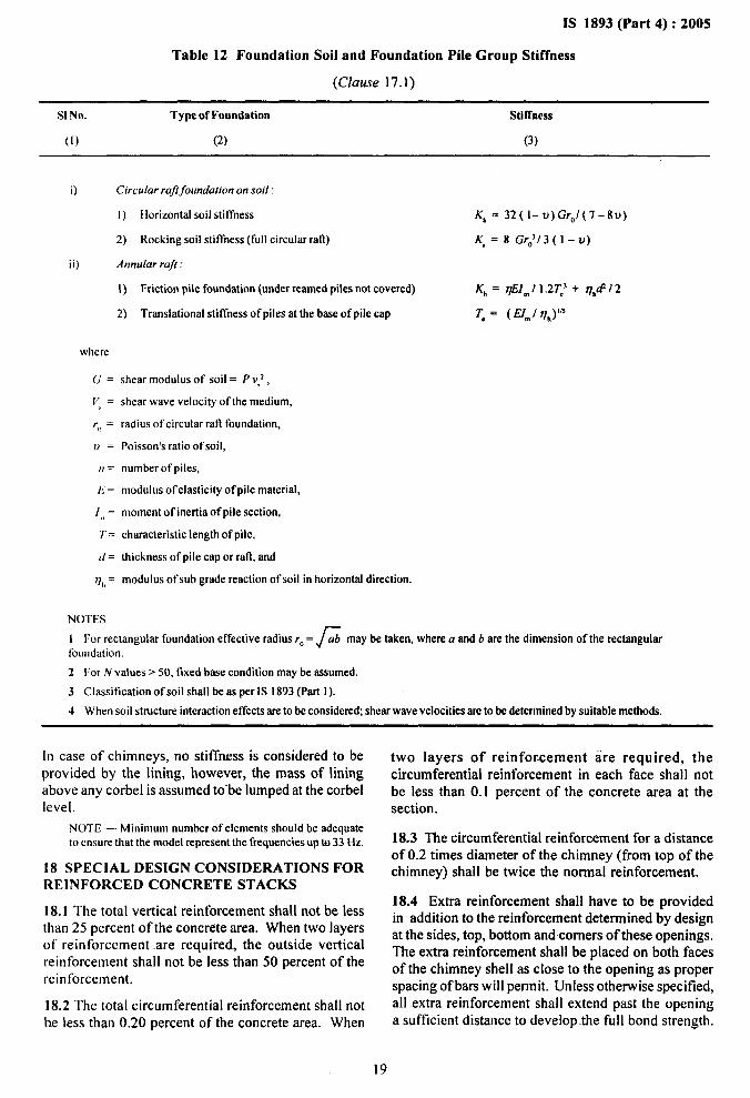
Table 12 Foundation Soil and Foundation Pile Group Stiffness
(Clause 17.1)
S1No. Type of Foundation Stiffness
(1) (2) (3)
O Circular raft~oundation on soil:
I) Horizontal soil stii~ness K, = 32( 1- u) Gr(,/(7-8u)
2) Rocking soil stiffness (full circular raft) Kr=8GrJ/3 (1-u)
ii) Annular raft:
1) Friction pile foundation (under rearned piles not covered) K~ = qEI~ 11 .2TC’ + r)hrf 12
2) Translational stiffness of piles at the base of pile cap To = (EJm/ Vh)’fi
shear modulus of soil = P V,2,
shear wave velocity of the medium,
radius of circular rafl foundation,
Poisson’s ratio ofsoit,
number of piles,
modulus ofelosticity of pile material,
moment of inertia of pile section,
characteristic length of pile,
thickness of pile cap or ratt, and
modulus of sub grade reaction of soil in horizontal direction.
I For rectangular foundation effective~adius r,, = f ab may be taken, where a and b are the dimension of the rectangular
foundation,
2 For N values >50, fixed base condition maybe assumed.
3 Classification of soil shall be as per IS 1893 (Part l).
4 When soil structure interaction effects are to be considered; shear wave velocities are to be determined by suitable methods.
[n case of chimneys, no stiffrtess is considered to be two layers of reinforcement are required, theprovided by the lining, however, the mass of lining circumferential reinforcement in each face shall notabove.any corbel is assumed to”be lumped at the corbel be less than O.I percent of the concrete area at thelevel. section.
NOTE — Minimum number of elements should be adequate
to ensure that the model remesent the frequencies UBto 33 Hz. 18.3 The circumferential reinforcement for a distance
18 SPECIAL DESIGN CONS1DERATIONS FORof 0.2 times diameter of the chimney (from top of thechimney) shall be twice the normal reinforcement.
REINFORC-ED CONCRETE STACKS
I-8.1 The total vertical reinforcement shall not be lessthan 25 percent of the concrete area. When two layersof reinforcement are required, the outside verticalreinforcement shall not be less than 50 percent of thereinforcement.
18.2 The total circutnferential reinforcement shall notbe less than 0.20 percent of the concrete area. When
18.4 Extra reinforcement shall have to be providedin addition to the reinforcement determined by designat the sides, top, bottom and corners of these openings.The extra reirrforcement shall be placed on both facesof the chimney shell as close to the opening as properspacing of bars will pennit. Unless otherwise specified,all extra reinforcement shall extend past the openinga sufficient distance to develop-the full bond strength.
19

IS 1893 (Part 4):2005
18.5 At each side of the opening, the additional verticalreinforcement shaIl have an area at least equal to theestablished design reinforcement for one-half of thewidth of the opening.
18.6 At both the top and bottom of each opening,additional reinforcement shall be placed havrng an areaat least equal to one-half of the established designcircumferential reinforcement interrupted by theopening.
One half of this extra reinforcement shall extendcompletely around the circumferential of the chimney,and the other half shall extend beyond the opening toa sufficient distance to develop the bars in bond. The
steel shall be placed as close to the opening aspracticable, but within a height not to exceed Wicethe thickness.
18.7 Deflection Criterion
The maximum lateral deflection of.the top of a stack-like structure under all service conditions, prior to theapplication of load factors, shall not exceed the limitsset forth by the following equation:
DMax = 0.003 h
where
D=Max maximum lateral -deflection, and
h = height of structure above the base.
ANNEX A
(Clauses 8.2 and 16)
ZONE FACTOR
Zone Factor Z for MCE
Seismic’) Zone 11 111 IV v
z 0.10 0.16 0.24 0.36
u Thezoningisasper IS 1893 (pafi l).
20
IS 1893 (Part 4):2005
ANNEX B
(Clauses 8.2)
DESIGN SPECTRUM
3.0 # t 1 I r 1 u
Type I (Rock, or Hard Soil)
2.5 ~..., Type II (Medium Soil)‘1 ‘.,i, ,,“,
: ~:
Type Ill (Soft Soil)‘1 ,.‘! ‘.2.0 ‘, “..
‘t ‘.‘! “.,.‘t ..‘, ,,
1.5‘\ ‘..‘. $.‘.\,, ““’......‘. ...
●. ..1.0 %. ‘%..%. .........-.. .........‘-..... ...---- .........---s-- “-......0.5 -
.........--”---------- .........-------- .................- ------------------
-0.0 I 1 1 I , 1 I0.0 0.5 1.0 1.5 2.0 -2.5 3.o 3.5 4.o
Period (s)
FIG. 2 RESPONSESPECTRAFORROCKANDSOILSims FOR5 PERCENTDAMPING
21

Bureau of Indian Standards
BIS is a statutory institution established under the Bureau of Indian Standards Act, 1986 to promoteharmonious development of the activities of standardization, marking and quality certification of goods andattending to connected matters in the country.
Copyright
BIS has the copyright of all its publications. No part of these publications -may be reproduced in any form
without the prior permission in writing of BIS. This does not preclude the free use, in the course of implementingthe standard, of necessary details, such as-symbols and sizes, type or grade designations. Enquiries relating tocopyright be addressed to the Director (Publications), BIS.
Review of Indian Standards
Amendments are issued to standards as the need arises on the b%sisof comments. Standards are also reviewedperiodically; a standard along with amendments is reaffirmed when such review indicates that no changes areneeded; if the review indicates that changes. are needed, it is taken up for revision. Users of Indian Standardsshould ascertain that they are in possession of the latest amendments or edition by referring to the latest issue of‘BIS Catalogue’ and ‘Standards: Monthly Additions’.
This Indian Standard has been developed from Dot: No. CED 39 (5743).
Amendments Issued Since Publication
Amend No. Date of Issue Text Affected
BUREAU OF INDIAN STANDARDS
Headquarters:
Manak Bhavan, 9 Bahadur Shah Zafar Marg, New Delhi 110002Telephones: 23230131,23233375,2323 9402 website: www.bis.org.in
Regional Offices: Telephones
Central :
Eastern :
Northern :
Southern :
Western :
Branches :
Manak Bhavan, 9 Bahadur Shah Zafar Marg{
23237617NEW DELHI 1-10002 23233841
1/14 C.I.T. Scheme VII M, V.I.P. Road, Kankurgachi{
23378499,23378561KOLKATA 700054 23378626,23379120
SCO 335-336, “Sector 34-A, CHANDIGARH 160022{
26038432609285
C.I,T. Campus, IV Cross Road, CHENNAI 600113{
22541216,2254144222542519,22542315
Manakalaya, E9 MIDC, Marol, Andheri (East){
28329295,28327858MUMBAI 400093 28327891,28327892
AHMEDABAD.-BANGALORE. BHOPAL. BHUBANESHWAR. COIMBATORE. FARIDABAD.GHAZIABAD. GUWAHATI. HYDERABAD. JAIPUR. KANPUR. LUCKNOW. NAGPUR.NALAGARH. PATNA. “PUNE. RAJKOT. THIRUVANANTHAPURAM. V.ISAKHAP-ATNAM.
Printed at Simco Printing Press, Delhi
Related Documents