Disclosure to Promote the Right To Information Whereas the Parliament of India has set out to provide a practical regime of right to information for citizens to secure access to information under the control of public authorities, in order to promote transparency and accountability in the working of every public authority, and whereas the attached publication of the Bureau of Indian Standards is of particular interest to the public, particularly disadvantaged communities and those engaged in the pursuit of education and knowledge, the attached public safety standard is made available to promote the timely dissemination of this information in an accurate manner to the public. इंटरनेट मानक “!ान $ एक न’ भारत का +नम-ण” Satyanarayan Gangaram Pitroda “Invent a New India Using Knowledge” “प0रा1 को छोड न’ 5 तरफ” Jawaharlal Nehru “Step Out From the Old to the New” “जान1 का अ+धकार, जी1 का अ+धकार” Mazdoor Kisan Shakti Sangathan “The Right to Information, The Right to Live” “!ान एक ऐसा खजाना > जो कभी च0राया नहB जा सकता ह ै” Bhartṛhari—Nītiśatakam “Knowledge is such a treasure which cannot be stolen” IS 14902-3 (2013): Performance of High-voltage direct current (HVDC) Systems, Part 3: Dynamic conditions [ETD 40: Electrotechnical]

Welcome message from author
This document is posted to help you gain knowledge. Please leave a comment to let me know what you think about it! Share it to your friends and learn new things together.
Transcript

Disclosure to Promote the Right To Information
Whereas the Parliament of India has set out to provide a practical regime of right to information for citizens to secure access to information under the control of public authorities, in order to promote transparency and accountability in the working of every public authority, and whereas the attached publication of the Bureau of Indian Standards is of particular interest to the public, particularly disadvantaged communities and those engaged in the pursuit of education and knowledge, the attached public safety standard is made available to promote the timely dissemination of this information in an accurate manner to the public.
इंटरनेट मानक
“!ान $ एक न' भारत का +नम-ण”Satyanarayan Gangaram Pitroda
“Invent a New India Using Knowledge”
“प0रा1 को छोड न' 5 तरफ”Jawaharlal Nehru
“Step Out From the Old to the New”
“जान1 का अ+धकार, जी1 का अ+धकार”Mazdoor Kisan Shakti Sangathan
“The Right to Information, The Right to Live”
“!ान एक ऐसा खजाना > जो कभी च0राया नहB जा सकता है”Bhartṛhari—Nītiśatakam
“Knowledge is such a treasure which cannot be stolen”
“Invent a New India Using Knowledge”
है”ह”ह
IS 14902-3 (2013): Performance of High-voltage directcurrent (HVDC) Systems, Part 3: Dynamic conditions [ETD 40:Electrotechnical]

Hkkjrh; ekud
ykbZu-dE;wVsVsM ifjorZd lfgr mPp-oksYVrkfn"V èkkjk (,p-oh-Mh-lh-) ç.kkfy;ksa dh dk;Zdkfjrk
Hkkx 3 xR;kRed fLFkfr;k¡
( igyk iqujh{k.k )
Indian Standard
PERFORMANCE OF HIGH-VOLTAGE DIRECTCURRENT (HVDC) SYSTEMS WITHLINE-COMMUTATED CONVERTERS
PART 3 DYNAMIC CONDITIONS
( First Revision )
ICS 29.200; 29.240.99
© BIS 2013
April 2013 Price Group 12
B U R E A U O F I N D I A N S T A N D A R D SMANAK BHAVAN, 9 BAHADUR SHAH ZAFAR MARG
NEW DELHI 110002
IS 14902 (Part 3) : 2013IEC/TR 60919-3 : 2009
HVDC Power Systems Sectional Committee, ETD 40
NATIONAL FOREWORD
This Indian Standard (Part 3) (First Revision) which is identical with IEC/TR 60919-3 : 2009‘Performance of high-voltage direct current (HVDC) systems with line-commutated converters —Part 3: Dynamic conditions’ issued by the International Electrotechnical Commission (IEC) was adoptedby the Bureau of Indian Standards on the recommendation of the HVDC Power Systems SectionalCommittee and approval of the Electrotechnical Division Council.
This standard was first published in 2005. The first revision of this standard has been undertaken toalign it with the latest version of IEC 60619-3 : 2009.
The text of the IEC Standard has been approved as suitable for publication as an Indian Standardwithout deviations. Certain terminology and conventions are, however, not identical to those used inIndian Standards. Attention is particularly drawn to the following:
a) Wherever the words ‘International Standard’ appear referring to this standard, they should beread as ‘Indian Standard’.
b) Comma (,) has been used as a decimal marker, while in Indian Standards the current practiceis to use a point (.) as the decimal marker.
In this adopted standard, references appear to certain International Standards for which IndianStandards also exist. The corresponding Indian Standards, which are to be substituted in theirrespective places are listed below along with their degree of equivalence for the editions indicated:
International Standard Corresponding Indian Standard Degree of Equivalence
IEC/TR 60919-1 : 20051)
Performance of high-voltage directcurrent (HVDC) systems with line-commutated converters — Part 1:Steady-state conditions
IEC/TR 60919-2 : 2008 Performanceof high-voltage direct current (HVDC)systems with l ine-commutatedconverters — Part 2: Faults andswitching
IS 14902 (Part 1) : 2013 Performanceof high-voltage direct current (HVDC)systems with l ine-commutatedconverters: Part 1 Steady-stateconditions (first revision)
IS 14902 (Part 2) : 2013 Performanceof high-voltage direct current (HVDC)systems with l ine-commutatedconverters: Part 2 Faults andswitching (first revision)
Technically Equivalent
Identical
The technical committee has reviewed the provisions of the following International Standards referredin this adopted standard and has decided that they are acceptable for use in conjunction with thisstandard:
International Standard Title
IEC 60146-1-1 Semiconductor converters — General requirements and line commutatedconverters — Part 1-1: Specification of basic requirements
IEC/TR 60146-1-2 Semiconductor convertors — General requirements and line commutatedconvertors — Part 1-2: Application guide
IEC 60146-1-3 Semiconductor convertors — General requirements and line commutatedconvertors — Part 1-3: Transformers and reactors
For the purpose of deciding whether a particular requirement of this standard is complied with, thefinal value, observed or calculated, expressing the result of a test, shall be rounded off in accordancewith IS 2 : 1960 ‘Rules for rounding off numerical values (revised)’. The number of significant placesretained in the rounded off value should be the same as that of the specified value in this standard.
1) Since revised in 2010.
1 Scope
This Technical Report provides general guidance on the dynamic performance of high-voltage direct current (HVDC) systems. Dynamic performance, as used in this specification, is meant to include those events and phenomena whose characteristic frequencies or time domain cover the range between transient conditions and steady state. It is concerned with the dynamic performance due to interactions between two-terminal HVDC systems and related a.c. systems or their elements such as power plants, a.c. lines and buses, reactive power sources, etc. at steady-state or transient conditions. The two-terminal HVDC systems are assumed to utilize 12-pulse converter units comprised of three-phase bridge (double way) connections. The converters are assumed to use thyristor valves as bridge arms, with gapless metal oxide arresters for insulation coordination and to have power flow capability in both directions. Diode valves are not considered in this specification. While multi-terminal HVDC transmission systems are not expressly considered, much of the information in this specification is equally applicable to such systems.
Only line-commutated converters are covered in this report, which includes capacitor commutated converter circuit configurations. General requirements for semiconductor line-commutated converters are given in IEC 60146-1-1, IEC 60146-1-2 and IEC 60146-1-3. Voltage-sourced converters are not considered.
This report (IEC 60919-3) which covers dynamic performance, is accompanied by publications for steady-state (IEC 60919-1) and transient (IEC 60919-2) performance. All three aspects should be considered when preparing two-terminal HVDC system specifications.
A difference exists between system performance specifications and equipment design specifications for individual components of a system. While equipment specifications and testing requirements are not defined herein, attention is drawn to those which would affect performance specifications for a system. There are many possible variations between different HVDC systems, therefore these are not considered in detail. This report should not be used directly as a specification for a specific project, but rather to provide the basis for an appropriate specification tailored to fit actual system requirements for a particular electric power transmission scheme. This report does not intend to discriminate between the responsibility of users and manufacturers for the work specified.
2 Normative references
The following referenced documents are indispensable for the application of this document. For dated references, only the edition cited applies. For undated references, the latest edition of the referenced document (including any amendments) applies.
IEC 60146-1-1, Semiconductor converters – General requirements and line commutated converters – Part 1-1: Specification of basic requirements
IEC/TR 60146-1-2, Semiconductor convertors – General requirements and line commutated convertors – Part 1-2: Application guide
IEC 60146-1-3, Semiconductor convertors – General requirements and line commutated convertors – Part 1-3: Transformers and reactors
Indian Standard
PERFORMANCE OF HIGH-VOLTAGE DIRECTCURRENT (HVDC) SYSTEMS WITHLINE-COMMUTATED CONVERTERS
PART 3 DYNAMIC CONDITIONS
( First Revision )
IS 14902 (Part 3) : 2013IEC/TR 60919-3 : 2009
1
IEC/TR 60919-1:2005, Performance of high-voltage direct current (HVDC) systems with line-commutated converters – Part 1: Steady-state conditions
IEC/TR 60919-2:2008, Performance of high-voltage direct current (HVDC) systems with line-commutated converters – Part 2: Faults and switching
3 Outline of HVDC dynamic performance specifications
3.1 Dynamic performance specification
A complete dynamic performance specification for an HVDC system should consider the following clauses:
– a.c. system power flow and frequency control (see Clause 4); – a.c. dynamic voltage control and interaction with reactive power sources (see Clause 5); – a.c. system transient and steady-state stability (see Clause 6); – dynamics of the HVDC system at higher frequencies (see Clause 7); – subsynchronous oscillations (see Clause 8); – power plant interaction (see Clause 9).
Clause 4 deals with using active power control of the HVDC system to affect power flow and/or frequency of related a.c. systems in order to improve the performance of such a.c. systems. The following aspects should be considered at the design of HVDC active power control modes:
a) to minimize the a.c. power system losses under steady-state operation;
b) to prevent a.c. line overload under steady-state operation and under a disturbance;
c) to coordinate with the a.c. generator governor control;
d) to suppress a.c. system frequency deviations under steady-state operation and under a disturbance.
In Clause 5, the voltage and reactive power characteristics of the HVDC substation and other reactive power sources (a.c. filters, capacitor banks, shunt reactors, SVC (static var compensator), synchronous compensators) as well as interaction between them during control of the a.c. bus voltage are considered.
In Clause 6, a discussion is provided concerning methods of controlling active and reactive power of an HVDC link to improve the steady-state and/or transient stability of the interconnected a.c. system by counteracting electromechanical oscillations.
Clause 7 deals with dynamic performance of an HVDC system in the range of half fundamental frequency and above due to both characteristic and non-characteristic harmonics generated by converters. Means for preventing instabilities are also discussed.
In Clause 8, the phenomenon of amplification of torsional, mechanical oscillations in turbine-generators of a thermal power plant at their natural frequencies, due to interaction with an HVDC control system (constant power and current regulation modes), is considered. Specifications for subsynchronous damping control are defined.
The interaction between a power plant and an HVDC system located electrically near to it is considered in Clause 9, taking into account some special features of the nuclear power plant and requirements for the reliability of the HVDC system.
2
IS 14902 (Part 3) : 2013IEC/TR 60919-3 : 2009
3.2 General comments
Any design requirements for future HVDC systems being specified should fall within the design limits covered in publications on steady-state (IEC 60919-1) and transient (IEC 60919-2) performance. It is recommended that during preparation of the dynamic HVDC system performance specification, the proper HVDC system control strategy should be identified based on detailed power system studies. The priorities of control signal inputs and the way they are processed should be specified.
4 AC system power flow and frequency control
4.1 General
Active power control of an HVDC system can be used to control the power flow and/or frequency in related a.c. systems in order to improve the performance of a.c. systems in steady-state operation and under disturbance.
In this clause, the HVDC active power operation modes, which are used to improve the a.c. system performance for the following purposes, will be covered:
– HVDC power control to minimize the total power system losses under steady-state operation;
– HVDC power control for prevention of a.c. line overload under a disturbance as well as steady state;
– coordinated HVDC power control with an a.c. system generator governor control; – HVDC power control for suppression of an a.c. system frequency deviation under a
disturbance as well as steady state.
HVDC active and/or reactive power modes used to improve a.c. system dynamic and transient stability or improve a.c. voltage control is discussed in Clauses 5 and 6.
4.2 Power flow control
4.2.1 Steady-state power control requirements
The power of an HVDC system is sometimes controlled to minimize overall power system losses, to prevent a.c. line overloading, and to coordinate with the governor control of a.c. system generators. Such power control requirements differ from time to time according to the role of HVDC systems in the overall power system.
When an HVDC system is used to transmit power from remote generating stations, the HVDC transmission power control is coordinated with the governor control of the power station generators. In this case, the generator voltage, frequency or the rotor speed may be used as a reference to the HVDC power control system.
When two a.c. power systems are connected by an HVDC link, the HVDC power is controlled to a pre-determined pattern under normal circumstances, but an additional function can be incorporated to this HVDC power control so that the frequency of either or both a.c. power systems is controlled. When one of the a.c. systems is an isolated system, such as one supplying a separate island, frequency control of this isolated a.c. system may have to be realized by the HVDC system.
The a.c. system frequency control by an HVDC system is discussed in 4.3.
When two a.c. systems are interconnected by more than one d.c. link or d.c. and a.c. links, or when a d.c. system exists within an a.c. system, HVDC power may be controlled in order to minimize the total transmission losses of the interconnected systems.
IS 14902 (Part 3) : 2013IEC/TR 60919-3 : 2009
3
In some cases of a.c./d.c. system configurations described above, the HVDC power change control can be used to prevent overloading of one or more transmission lines in the power system.
In certain special HVDC control schemes, such as the one designed to improve a.c. system performance by increasing the d.c. power during and after a disturbance, the steady-state d.c. transmission power may have to be set at a restricted value so that the d.c. power does not exceed the d.c. rated power, including overload capability, when the control is initiated. It is important to consider also the additional reactive power supply required both by the HVDC converters and the a.c. systems in such a situation.
The following items a) to g) need to be considered in the specification of steady-state control requirements. Note that at the time of preparing the specification, the complete steady-state control requirements may not have been determined or designed, but allowance for possible future inputs is necessary.
a) When a power flow control system is designed to have more than one function, including the a.c. system frequency control, the HVDC control system should be so designed that priorities are set between each control function.
b) Under steady-state conditions, the control for prevention of a.c. line overloading is usually given higher priority over other power flow controls. The control for minimization of power system losses is implemented either by setting the d.c. power to a pattern which has been pre-determined by the power system data, or in response to an on-line computation which is conducted in the central load dispatching office. Usually, its control response is relatively slow, being several seconds or several minutes, even in the latter case.
c) In isolated systems or systems with a relatively large d.c. infeed, frequency is often maintained by the HVDC power. In such a case, HVDC frequency control could have a priority over system loss minimization, but may be limited by overload protection.
d) The change in reactive power demand accompanying the power changes may result in frequent switching of reactive power equipment. In such a case, it is necessary to figure out particular a.c. voltage control measures such as reactive power control by converter units, or to set limits of the magnitude of HVDC power change.
e) The need for special power order adjustment signals unique to the power system should be identified, studied, and specified. The signals cannot be permitted to cause d.c. current or power, or a.c. voltage to deviate beyond equipment and system ratings and limits. The priority of two or more input signals having simultaneous demand on d.c. link power should be established and coordinated.
f) Bipolar d.c. links normally require that d.c. power and current be effectively shared between poles. For loss of one pole, an overload strategy for the remaining pole could be developed to minimize disruption to a.c. system power flow, voltage and frequency.
g) Disruption of the telecommunication link between the sending and receiving system of the d.c. link should not cause disruption to the a.c. power system. A minimum specification requirement is that power transmission is maintained at the same power level which existed before the telecommunication failure. If additional functions such as frequency control are required during temporary outage of the telecommunication link, these should be specified.
4.2.2 Step change power requirement
Under certain power system conditions, it may be required to change the HVDC power in steps in order to improve the performance of a.c. systems during and after power system disturbances. Under certain circumstances, the step change may involve d.c. power reversal.
A step change of d.c. power is realized by changing the set value of d.c. power order or by changing the power range in response to an input signal. The rate of change of power and limit to the magnitude of the d.c. power change demanded by the step change should be
4
IS 14902 (Part 3) : 2013IEC/TR 60919-3 : 2009
adjustable within specified limits according to a.c. system requirements. For example, different ramp rates may be required for different events. Special considerations may be required when the step change would include power reversal.
Power system disturbances to be considered in specifying d.c. power step changes may include: a.c. line trip, loss of large power supply source or large drop in a.c. system frequency and sudden increase or decrease of power system load with its corresponding large frequency deviation.
In some of the above cases of power system disturbances, the a.c. systems will also be supported by the a.c. frequency control provided by the d.c. system.
In specifying and designing HVDC control functions, the effects of the step change power functions should be surveyed in detail for various power system conditions. It is best to specify limits and ranges for power changes and ramp rates rather than specific settings. Setting adjustment can be made with the d.c. system in operation.
The signals for initiation of HVDC step power changes include overload relay signals or trip signals of particular transmission lines which are transmitted to the HVDC substation, or a.c. system frequency which is detected at the HVDC substation or at some point in a.c. systems.
The time delay involved in a telecommunication system which transmits these initiation signals may affect the a.c. or d.c. system performance. Therefore, in some cases, a high speed telecommunication system may be required. When the transmission delay time is large, this effect should be taken into account.
There are some cases in which signals are sent to both HVDC substations, or more than one signal is received by an HVDC substation. In these cases, it is necessary to set priorities of control functions.
The magnitude of d.c. power step change may be limited by a.c. and d.c. system conditions, and it may be required under certain circumstances to detect the changes in system conditions to update the values of such limits.
In particular, when there is a large step change in d.c. power, the a.c. voltage may change substantially. For this reason, it may be required to study the allowable range of a.c. voltage fluctuation to determine the limits on step power changes, or introduce special a.c. voltage control measures.
The allowable limits of a.c. voltage deviation can be different for steady-state operation and transient conditions and should be specified.
When an HVDC system is connected to a high impedance and/or low inertia a.c. system, the step change in d.c. power may have adverse effects on the voltage stability, transient stability, and frequency of the a.c. system. In such cases, the magnitude and rate of change of power may have to be limited, or other special measures may have to be provided, to prevent deterioration of the a.c. system dynamic performance. When an HVDC system interconnects two a.c. systems, the effect of d.c. power step change must be evaluated in detail not only for the a.c. system in which a disturbance occurs, but also for the other a.c. system in which a fault does not occur.
When the d.c. step change of power causes the d.c. current to fall below the minimum allowable operational current of the HVDC system, which is usually 5 % to 10 % of the rated current, the converter operation should be set to the positive minimum current. Otherwise the converter should be blocked after the allowable period of low current operation, or be specified to operate down to zero current. One possible measure to overcome minimum allowable operational current is to set the power flows of two poles in opposite direction and let the power flow of two poles cancel each other when the HVDC system configuration is
IS 14902 (Part 3) : 2013IEC/TR 60919-3 : 2009
5
bipolar. The difference in the power flows of each pole is the actual operating power flow of the overall HVDC system.
Because of inverter control limitations and possible risks to a.c. system operation, it is not advisable to request a current order step change larger than the current margin unless special control actions are taken upon loss of telecommunications.
Certain considerations may be required when an HVDC system is to be started up from a no load stand-by state in response to a step change power order (see Clause 7 of IEC 60919-1).
4.3 Frequency control
The a.c. system frequency control by the HVDC system can be applied for the following purposes:
a) frequency control of the receiving and/or sending end a.c. system for a d.c. transmission from remote power sources;
b) frequency control of an a.c. system in an isolated island or a small a.c. system when it is interconnected to a large a.c. system through a d.c. system;
c) frequency control of either of the a.c. systems interconnected by an HVDC system, also taking the frequency of the other system into account.
The a.c. system frequency control is executed either as a continuous function of frequency under steady-state conditions, or when the frequency deviation of the a.c. system exceeds certain limits. It may only be activated under certain circumstances such as when the local a.c. system connected to the HVDC substation is disconnected (islanded) from the main a.c. system. Accordingly, the specification should state the duties and performance requirements of the frequency control function.
If the frequency at the receiving end is controlled by varying or modulating the power transmitted by the d.c. link, there must be coordination of the d.c. link frequency control with any governor control on associated a.c. generators. It may be possible to use transient frequency deviation capability of an asynchronous sending end system for support of the receiving end, provided the a.c. generating equipment is designed accordingly.
When an HVDC substation is electrically far from the centre of the a.c. system, the phase angle of a.c. voltage at the HVDC substation changes substantially with power changes. In such circumstances, the speed of response of the frequency signal can be reduced. To avoid this lower speed of response, the frequency signal can be detected at the centre of the a.c. system and transmitted to the HVDC substation.
In frequency control it may be required to provide limits of power change and rate of power change which maintains the a.c. system voltage fluctuation within an allowable range, or utilize special voltage regulation measures such as reactive power control by converters or SVC. The allowable limits of voltage fluctuation during steady state frequency control should be specified.
When the d.c. contribution to a.c. system frequency control is implemented, it is possible that generator frequency control is degraded unless the controls are properly coordinated. When two different power systems are interconnected, it may be required to provide appropriate dead band or to select suitable gain in the frequency control by the HVDC system so that only large or fast frequency fluctuations are compensated by the d.c. power control, and small or slow frequency fluctuations are controlled by the power stations belonging to the individual a.c. systems.
The frequency control designed to correct for severe disturbances, such as those caused by the tripping of large generation units, may be realized more effectively if the generator unit trip signal is transmitted to the HVDC substation to initiate the control action.
6
IS 14902 (Part 3) : 2013IEC/TR 60919-3 : 2009
Fast and large magnitude of d.c. power change for frequency control may produce overvoltage or voltage dip in the a.c. systems. Such a situation may be relieved by limiting the rate of power change or by fast reactive power compensations. The allowable overvoltage or voltage dip, and the allowable duration time should be specified.
One possible measure for continuous and smooth operation of frequency control is to set the power flows of two poles in opposite direction and let the power flow of two poles cancel each other when the HVDC system configuration is bipolar. This special operation mode is called “Frequency control with zero power setting.” However, note that there is additional system loss and accompanying polarity reversals, which happen when crossing the border of minimum current.
It is sometimes difficult to set optimal parameters of frequency control since the power system configuration often changes due to outages of transmission lines and/or substations for maintenance. This could be accounted for by adopting multi variable frequency control.
When d.c. power control is performed for the purpose of frequency control, it is usually necessary to provide high speed telecommunication channels, such as a microwave channels or fiber optic channels, between two HVDC substations. In case of loss of telecommunication between the two substations, frequency control is usually limited to the network connected to the current controlling substation.
When the frequency detection point is located far from the HVDC substation control terminal, or when it is intended to initiate the frequency control action by special signals issued from the a.c. system, telecommunication channels are required.
In any case, the effect of telecommunication time delay should be taken into account.
For a discussion of telecommunication channels, refer to Clause 13 of IEC 60919-1.
5 AC dynamic voltage control and interaction with reactive power sources
5.1 General
Change in reactive power flow due to load change, switching operations or faults produce voltage fluctuations in the a.c. network. In high impedance a.c. systems, i.e. in systems with low short-circuit capacity, larger voltage fluctuation can be expected and the need for voltage control is more pronounced.
Sudden voltage changes in the network should be limited e.g. to less than 3 % if occurring frequently and to less than 10 % if happening seldom. Appropriate values should be specified.
High temporary overvoltages in excess of the normal operating range due to large load changes and load rejection in networks with low short-circuit capacity could risk endangering station equipment. High temporary overvoltages can be limited by tripping of reactive power sources. The acceptable limit and duration for temporary overvoltages should be specified.
5.2 Voltage and reactive power characteristics of an HVDC substation and other reactive power sources
5.2.1 General
Dynamic reactive power and voltage control on the a.c. bus of an HVDC substation can be obtained by using different equipment. Figure 1 shows schematically an HVDC substation with elements for reactive power compensation. Which of the depicted elements is used depends on the a.c. network characteristics and requirements on the data of the HVDC substation concerned, as well as on the economic evaluation of the different possible solutions.
IS 14902 (Part 3) : 2013IEC/TR 60919-3 : 2009
7
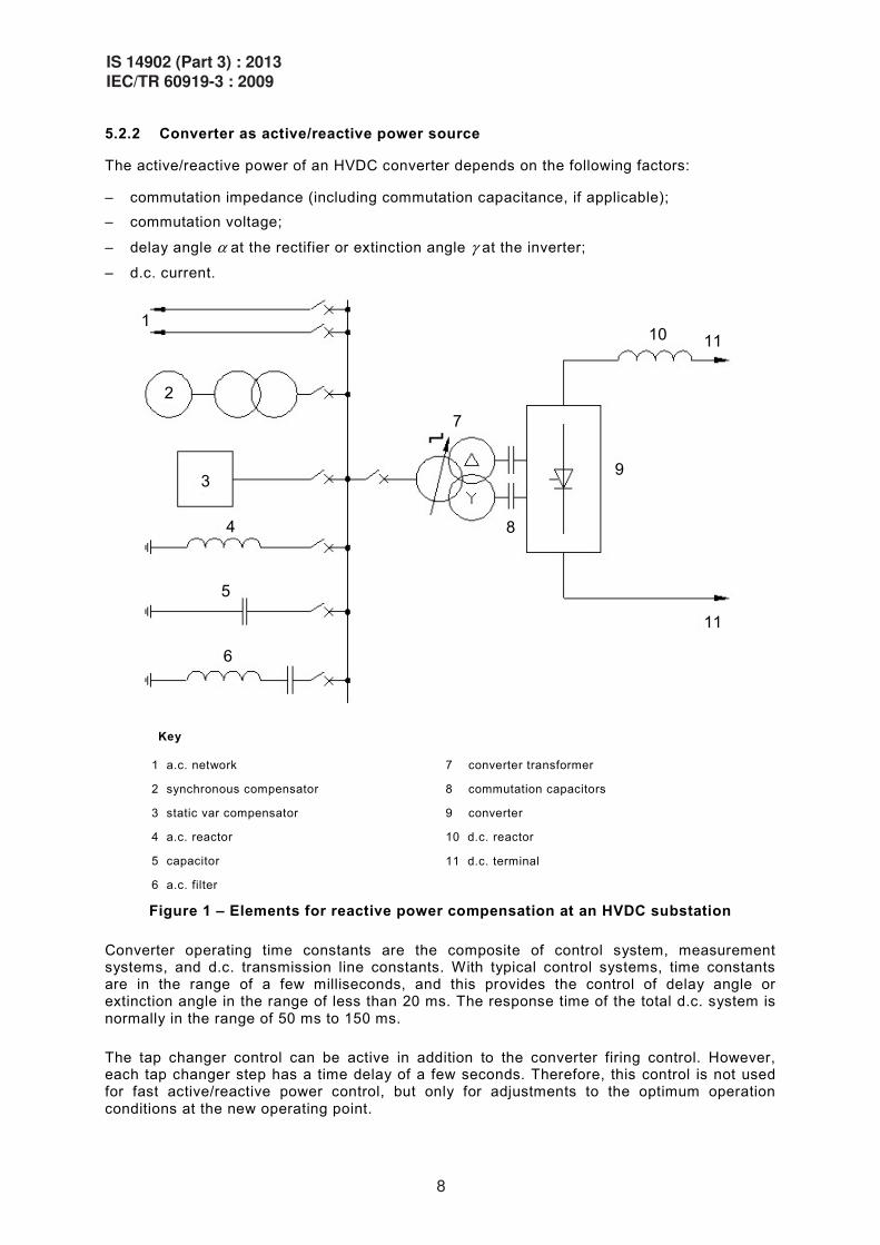
5.2.2 Converter as active/reactive power source
The active/reactive power of an HVDC converter depends on the following factors:
– commutation impedance (including commutation capacitance, if applicable); – commutation voltage;
– delay angle ! at the rectifier or extinction angle " at the inverter;
– d.c. current.
1
2
3
4
5
6
7
8
10 11
11
9
Key
1 a.c. network
2 synchronous compensator
3 static var compensator
4 a.c. reactor
5 capacitor
6 a.c. filter
7 converter transformer
8 commutation capacitors
9 converter
10 d.c. reactor
11 d.c. terminal
Figure 1 – Elements for reactive power compensation at an HVDC substation
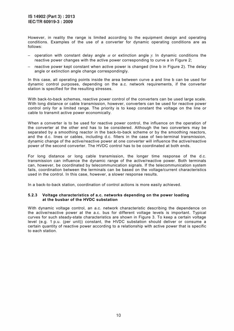
Converter operating time constants are the composite of control system, measurement systems, and d.c. transmission line constants. With typical control systems, time constants are in the range of a few milliseconds, and this provides the control of delay angle or extinction angle in the range of less than 20 ms. The response time of the total d.c. system is normally in the range of 50 ms to 150 ms.
The tap changer control can be active in addition to the converter firing control. However, each tap changer step has a time delay of a few seconds. Therefore, this control is not used for fast active/reactive power control, but only for adjustments to the optimum operation conditions at the new operating point.
8
IS 14902 (Part 3) : 2013IEC/TR 60919-3 : 2009

For consideration of dynamic conditions, the active/reactive power diagram of the converter shown in Figure 2 can be used (see also Figure 16 of IEC 60919-1). The valid range of operation for a given maximum d.c. current and delay angle between a few degrees and 90° as defined in Figure 2 could theoretically be used.
Q
5 10
20
30
40
50
60
70 80
! (")
0,1
0,5
0,7
a
b
1,25
1,00
0,75
0,50
0,25
0,00
0,00 0,25 0,50 0,75 1,00 1,25
Udn, Idn
P
Udn, Idn
Id/Idn
NOTE The diagram is valid for constant commutation voltage.
Key
Q reactive power of a converter
P real power of a converter
Udn, Idn rated d.c. voltage and current
! delay angle
" extinction angle
Figure 2 – P/Q diagram of a converter
IS 14902 (Part 3) : 2013IEC/TR 60919-3 : 2009
9
However, in reality the range is limited according to the equipment design and operating conditions. Examples of the use of a converter for dynamic operating conditions are as follows:
– operation with constant delay angle ! or extinction angle ". In dynamic conditions the reactive power changes with the active power corresponding to curve a in Figure 2;
– reactive power kept constant when active power is changed (line b in Figure 2). The delay angle or extinction angle change correspondingly.
In this case, all operating points inside the area between curve a and line b can be used for dynamic control purposes, depending on the a.c. network requirements, if the converter station is specified for the resulting stresses.
With back-to-back schemes, reactive power control of the converters can be used large scale. With long distance or cable transmission, however, converters can be used for reactive power control only for a limited range. The priority is to keep constant the voltage on the line or cable to transmit active power economically.
When a converter is to be used for reactive power control, the influence on the operation of the converter at the other end has to be considered. Although the two converters may be separated by a smoothing reactor in the back-to-back scheme or by the smoothing reactors, and the d.c. lines or cables, including d.c. filters in the case of two-terminal transmission, dynamic change of the active/reactive power at one converter will influence the active/reactive power of the second converter. The HVDC control has to be coordinated at both ends.
For long distance or long cable transmission, the longer time response of the d.c. transmission can influence the dynamic range of the active/reactive power. Both terminals can, however, be coordinated by telecommunication signals. If the telecommunication system fails, coordination between the terminals can be based on the voltage/current characteristics used in the control. In this case, however, a slower response results.
In a back-to-back station, coordination of control actions is more easily achieved.
5.2.3 Voltage characteristics of a.c. networks depending on the power loading at the busbar of the HVDC substation
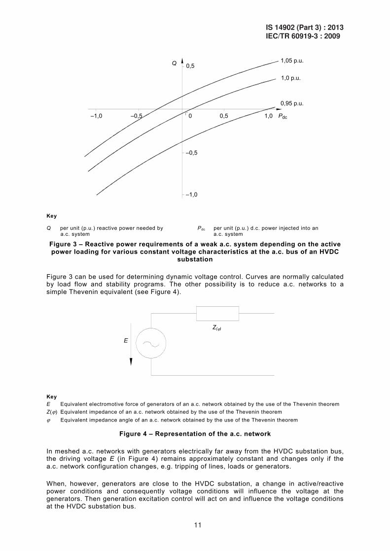
With dynamic voltage control, an a.c. network characteristic describing the dependence on the active/reactive power at the a.c. bus for different voltage levels is important. Typical curves for such steady-state characteristics are shown in Figure 3. To keep a certain voltage level (e.g. 1 p.u. (per unit)) constant, the HVDC substation should deliver or consume a certain quantity of reactive power according to a relationship with active power that is specific to each station.
10
IS 14902 (Part 3) : 2013IEC/TR 60919-3 : 2009
Q 0,5
0 0,5 1,0–1,0 –0,5
–0,5
–1,0
1,05 p.u.
1,0 p.u.
0,95 p.u.
Pdc
Key Q per unit (p.u.) reactive power needed by
a.c. system
Pdc per unit (p.u.) d.c. power injected into an a.c. system
Figure 3 – Reactive power requirements of a weak a.c. system depending on the active power loading for various constant voltage characteristics at the a.c. bus of an HVDC
substation
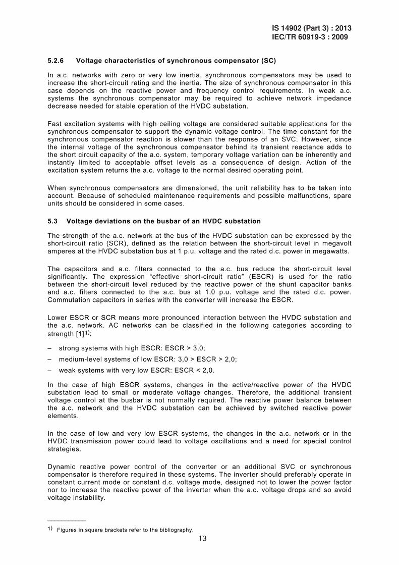
Figure 3 can be used for determining dynamic voltage control. Curves are normally calculated by load flow and stability programs. The other possibility is to reduce a.c. networks to a simple Thevenin equivalent (see Figure 4).
E
Z(#)
Key E Equivalent electromotive force of generators of an a.c. network obtained by the use of the Thevenin theorem Z(#) Equivalent impedance of an a.c. network obtained by the use of the Thevenin theorem # Equivalent impedance angle of an a.c. network obtained by the use of the Thevenin theorem
Figure 4 – Representation of the a.c. network
In meshed a.c. networks with generators electrically far away from the HVDC substation bus, the driving voltage E (in Figure 4) remains approximately constant and changes only if the a.c. network configuration changes, e.g. tripping of lines, loads or generators.
When, however, generators are close to the HVDC substation, a change in active/reactive power conditions and consequently voltage conditions will influence the voltage at the generators. Then generation excitation control will act on and influence the voltage conditions at the HVDC substation bus.
IS 14902 (Part 3) : 2013IEC/TR 60919-3 : 2009
11

The time constant for voltage change in this case is about 100 ms to 500 ms. The lower value is valid where the generators are electrically close to the HVDC substation, e.g. an isolated generator-HVDC network. However, this type of HVDC infeed needs more detailed consideration, as the HVDC control and generator voltage control should be closely coordinated.
5.2.4 Voltage characteristics of a.c. filters, capacitor banks and shunt reactors for power compensation at the HVDC substation
To meet reactive power requirements under steady-state conditions, a.c. filters, capacitor banks, commutation capacitors and shunt reactors may be installed. As a minimum, the a.c. filters required to fulfil the harmonic performance should be connected to the HVDC substation. The additional switchable reactive power elements can also be used for dynamic voltage control and adjustment of reactive power requirements of the system.
The size of reactive power elements is determined by the a.c. network requirements and to limit the voltage step at switching. Transient voltage change at switching during the operation of converters can be reduced with the aid of converter control which damps the change of reactive power. Binary switching, e.g. simultaneously switching in and out of different sizes and types of reactive power elements can also be used to reduce the reactive power change.
Considerations should be made in the planned deployment of reactive power compensation apparatus for the limitations of a.c. closing operating times, control system processing times, and discharge or duty cycles of such equipment. Special consideration also needs to be made for power circuit-breaker switching duties, including the transient recovery voltage (TRV) of the apparatus during mis-operation or fault conditions.
5.2.5 Voltage characteristics of static var compensator (SVC)
Dynamic voltage control in the a.c. network can be maintained by SVCs. At the HVDC substation bus, the SVC may be used for voltage control in the event that the HVDC substation is out of operation or the converter reactive power control capability is not available for other reasons. There is another option for dynamic voltage control: to use VSC technology but this technology is not covered by this report.
The size of SVC connected to the HVDC substation bus should be determined according to the expected voltage variation at the bus and the corresponding need for the reactive power to compensate it.
The reactive power rating of the SVC should be larger than the size of the largest switchable reactive power element being connected to the bus, to enable smooth voltage control.
The size of the SVC can also be determined depending on the requested overvoltage limitation, e.g. at load rejection. For this task, the overload capability of the SVC can be used.
When dimensioning the SVC for dynamic compensation, the operating point during continuous operation needs to be taken into account. Starting from continuous operation, the SVC should have enough regulation area to maintain voltage control.
An important aspect of SVC dimensioning is the question of availability. If dynamic performance of the SVC is also required during possible outages of the SVC, a spare unit should be considered or operating restrictions have to be accepted.
To meet the reactive power requirements under steady-state conditions, a.c. filters, capacitor banks, commutation capacitors and shunt reactors may be installed.
12
IS 14902 (Part 3) : 2013IEC/TR 60919-3 : 2009
5.2.6 Voltage characteristics of synchronous compensator (SC)
In a.c. networks with zero or very low inertia, synchronous compensators may be used to increase the short-circuit rating and the inertia. The size of synchronous compensator in this case depends on the reactive power and frequency control requirements. In weak a.c. systems the synchronous compensator may be required to achieve network impedance decrease needed for stable operation of the HVDC substation.
Fast excitation systems with high ceiling voltage are considered suitable applications for the synchronous compensator to support the dynamic voltage control. The time constant for the synchronous compensator reaction is slower than the response of an SVC. However, since the internal voltage of the synchronous compensator behind its transient reactance adds to the short circuit capacity of the a.c. system, temporary voltage variation can be inherently and instantly limited to acceptable offset levels as a consequence of design. Action of the excitation system returns the a.c. voltage to the normal desired operating point.
When synchronous compensators are dimensioned, the unit reliability has to be taken into account. Because of scheduled maintenance requirements and possible malfunctions, spare units should be considered in some cases.
5.3 Voltage deviations on the busbar of an HVDC substation
The strength of the a.c. network at the bus of the HVDC substation can be expressed by the short-circuit ratio (SCR), defined as the relation between the short-circuit level in megavolt amperes at the HVDC substation bus at 1 p.u. voltage and the rated d.c. power in megawatts.
The capacitors and a.c. filters connected to the a.c. bus reduce the short-circuit level significantly. The expression “effective short-circuit ratio” (ESCR) is used for the ratio between the short-circuit level reduced by the reactive power of the shunt capacitor banks and a.c. filters connected to the a.c. bus at 1,0 p.u. voltage and the rated d.c. power. Commutation capacitors in series with the converter will increase the ESCR.
Lower ESCR or SCR means more pronounced interaction between the HVDC substation and the a.c. network. AC networks can be classified in the following categories according to strength [1]1):
– strong systems with high ESCR: ESCR > 3,0; – medium-level systems of low ESCR: 3,0 > ESCR > 2,0; – weak systems with very low ESCR: ESCR < 2,0.
In the case of high ESCR systems, changes in the active/reactive power of the HVDC substation lead to small or moderate voltage changes. Therefore, the additional transient voltage control at the busbar is not normally required. The reactive power balance between the a.c. network and the HVDC substation can be achieved by switched reactive power elements.
In the case of low and very low ESCR systems, the changes in the a.c. network or in the HVDC transmission power could lead to voltage oscillations and a need for special control strategies.
Dynamic reactive power control of the converter or an additional SVC or synchronous compensator is therefore required in these systems. The inverter should preferably operate in constant current mode or constant d.c. voltage mode, designed not to lower the power factor nor to increase the reactive power of the inverter when the a.c. voltage drops and so avoid voltage instability.
___________
1) Figures in square brackets refer to the bibliography.
IS 14902 (Part 3) : 2013IEC/TR 60919-3 : 2009
13
At back-to-back stations, it is possible to use the HVDC converters to control the load rejection overvoltage on one side caused by loss of a.c. transmission on the other side (and vice versa). On the faulted side, valves continue to conduct direct current through a by-pass pair. On the unfaulted side, valve firing is set to control direct current in this short-circuited mode in order to draw reactive power, and to control overvoltage in the manner of a thyristor controlled reactor. The permissible duration of operation in this mode should be sufficient to allow time for reactive switching, or it can be as long as possible within equipment ratings to allow for possible a.c. system recovery and therefore rapid restoration of the d.c. transmission.
However, this strategy is not available if load rejection results from a fault in the HVDC substation. In this case, other measures for overvoltage reduction may be needed.
Temporary overvoltages at load rejection of HVDC transmission increase with the reduction of SCR. In high SCR systems, the overvoltage factor at load rejection is below 1,25 p.u. and in most cases lies under the critical stress level for the equipment. The duration of the overvoltage can last for a long time unless it is reduced by switching off the reactive power elements. This is the normal procedure to reduce the temporary overvoltages in HVDC substations supplied by strong networks.
In low and very low SCR networks, the overvoltage factor at load rejection, if not limited by other means, would reach high values which could endanger the a.c. and HVDC equipment or increase the substation costs.
In this case, reactive power control of the HVDC substation is usually required which would limit the overvoltage at complete and partial load rejection. However, additional measures are needed to reduce the overvoltages in the event that the HVDC substation is tripped because of failure in the substation. This can be done with an overvoltage limiter or additional SVC on the busbar or fast tripping of reactive power elements or synchronous compensators.
5.4 Voltage and reactive power interaction of the substation and other reactive power sources
5.4.1 HVDC converters, switchable a.c. filters, capacitor banks and shunt reactors
Switchable reactive power elements without controlled reactive power equipment offers reactive power change in steps. The size of the reactive power elements should be designed in such a way that the voltage change at switching does not exceed a certain specified limit. The configuration using only switchable reactive power elements is generally used for strong systems.
However, by making changes to the converter delay angle or extinction angle by a few degrees, d.c. control can oppose the reactive power change at switching. To permit use of the converter for additional reactive power control within a narrow range, which may be required in intermediate systems, only a small additional rating of the converters is required.
At full load, the change of delay angle or extinction angle by, say, 3o, means a reactive power change at the HVDC substation of 10 % of actual active power, which can be accommodated by a 2 % higher rating of equipment (see Figure 2). This solution is also suitable for long distance HVDC transmission if the coordination of both substations is available. At partial load, larger delay angle or extinction angle is necessary to achieve the same increase in reactive power consumption. This may result in operation at lower than nominal d.c. voltage and therefore will affect the operation of the other station. The lower d.c. voltage with its increased current will result in increased transmission line losses.
However, converters with a larger reactive power range are needed in weak systems to control the voltage. The reactive power range should be at least in the range of the largest switchable reactive power element. In such a case, the required overrating of the HVDC
14
IS 14902 (Part 3) : 2013IEC/TR 60919-3 : 2009
substation leads to considerably higher costs. This solution can be preferably used in back-to-back HVDC substations.
The voltage control time constant of the converters lies in the range of 10 ms to 20 ms. Both sides are controlled simultaneously: switching of reactive power elements, depending on the requirements of each a.c. side, can in principle be done in steps of 100 ms, though a certain decision time may be required in practice. If, due to the differing voltage conditions on each side, optimum operating conditions cannot be achieved by switching reactive power elements only, the condition can be corrected by tap changer operation on the converter transformers. This correction is quite slow, in the range of a few seconds per step.
5.4.2 HVDC converters, switchable reactive power sources, SVC
If voltage and reactive power control are required because the network is weak, but cannot be made available by the converter, an additional SVC may be installed at the bus of the HVDC substation. The advantage of this solution is that the voltage is controlled even while the HVDC is out of operation or is being tripped. One further SVC application arises when one a.c. side has to be voltage controlled without any influence on the other side of the d.c. transmission. In the case of a two-terminal HVDC system, voltage control by SVC can enable the HVDC to operate at an economic operating point irrespective of reactive power control.
The size of the SVC should be designed according to the required regulation range, which should be larger than the largest switchable reactive power element. As a starting point for the regulation, all possible operating points of the SVC during continuous operation of the scheme should be considered. In addition, attention should be given to conditions arising when the SVC is out of operation due to outages or maintenance. Either two units should be considered, or restrictions imposed by operation without SVC should be accepted.
HVDC schemes and SVCs each have their own controls with comparable time constants. As hunting effects can occur between them, careful coordination between the controls should be provided.
SVCs are used for counteraction of temporary voltage changes, while shunt capacitors or tap changer follows after the SVC action bringing a new steady state condition. This coordination helps to configure economical SVC rating.
Instead of SVCs, VSC technology can be used for better control of voltages and reactive power compensation, but this is not covered by this report.
5.4.3 HVDC converters, switchable reactive power sources and synchronous compensators
For dynamic voltage control at the bus of an HVDC substation, synchronous compensators can also be used. Synchronous compensators can be utilized in cases where inertia of the a.c. system is low and transient load changes or faults would lead to unacceptably large frequency deviations. Synchronous compensators can offer a part of the required reactive power compensation and voltage control. The voltage compensation time constant depends on the excitation system of the synchronous compensator and is in the range of about 100 ms to 200 ms, which is longer than the d.c. control time constant.
A synchronous compensator adds to the short-circuit capacity of the a.c. system and is therefore useful in preventing voltage instability in weak networks thanks to the resulting increase in short-circuit ratio.
The synchronous compensator regulation range should be rated for more than the largest switchable reactive power unit with due regard to the possible operating point of the synchronous compensator.
IS 14902 (Part 3) : 2013IEC/TR 60919-3 : 2009
15
Because of longer maintenance times and forced outages of a synchronous compensator, one or more spare units should be considered, or the restrictions imposed by operation without a synchronous compensator in service have to be accepted.
One major disadvantage of a synchronous compensator is its long maintenance period. Because it has rotating parts and massive mechanical components, its maintenance requires longer time.
6 AC system transient and steady-state stability
6.1 General
The possibility to control active and/or reactive power of an HVDC link can be used to improve the transient and steady-state stability of the connected a.c. networks if this is required to attain good operating conditions.
An electric power system is said to be in a condition of steady-state stability if, following any “small” disturbance, it reaches a condition of steady-state operation which is identical or close to its initial condition.
A power system is said to be in a condition of transient stability with respect to a sequence of disturbances (not “small” as in the above sense) if, following this sequence of disturbances, it returns to a condition of steady-state synchronous operation.
The phenomena dealt with in this clause concern electromechanical oscillations between different synchronous machines, groups of machines or areas of the power system following a disturbance in the network. If suitable precautions are not taken, such oscillations could be so large that the power system becomes unstable and generators fall out of synchronism. In other cases the system can be stable, but with low damping leading to a prolonged oscillation time. The electromechanical oscillations result in oscillations of active and reactive power in generators, transmission lines, etc. and of the voltage in the substations.
The frequencies of interest are in the range of 0,1 Hz to 2 Hz. Oscillations between large network areas normally fall in the lower part of the range, while oscillations involving a low inertia machine, such as a synchronous compensator, fall in the upper part of the range.
An HVDC link can sometimes be used to improve the stability performance of the connected a.c. systems by automatically controlling the active power of the link to counteract the oscillations. As an alternative or a complement, the reactive power consumption of the converter can, if necessary, be controlled to improve performance.
One control feature, which can be essential in the assistance of an HVDC link to maintain stability in an a.c. system is the step change power flow requirements discussed in Clause 4.
Other aspects of HVDC link performance that have an impact on stability but which are not treated here are power transfer during faults and the recovery following fault clearing. These matters are treated in 5.3.2 and 5.3.3 of IEC 60919-2.
6.2 Characteristics of active and reactive power modulation
6.2.1 General
Active and reactive power changes are achieved by control of the firing angles. Modulation control does not normally involve converter transformer tap changer operation since tap changers are too slow to react to oscillations over most of the frequency range of interest, or because the modulation levels are too low to initiate tap changer operation. It may also be possible to block tap changer operation during modulation action.
16
IS 14902 (Part 3) : 2013IEC/TR 60919-3 : 2009

During a disturbance, several oscillatory modes may occur simultaneously. In such cases, the controller may have to respond to several oscillation frequencies at the same time. In some cases, however, system conditions may be such that the controller should preferably not respond to certain frequencies. These aspects can be taken care of by proper filtering of the input signals to the controller.
The automatic control action can be effected either by large signal modulation or small signal modulation. These terms are related to active power modulation. Large signal modulation involves the simultaneous modulation of the current order in both rectifier and inverter, while small signal modulation is carried out locally in the current controlling station only. Large signal modulation is the most commonly applied method.
6.2.2 Large signal modulation
The short-term overload capability of the converter equipment can normally be utilized for large signal active power modulation, and can be an important factor in achieving an efficient damping action. It should therefore be specified if damping control action shall determine the amount of overload required, or if the control action shall be limited to using the inherently available overload capability. When specifying the overload requirements, it should be established if modulation for damping purposes shall be possible in combination with short-term or steady-state overload operation. Further aspects of overload requirements can be found in Clause 6 of IEC 60919-1.
In back-to-back stations, it may be possible to let the modulation cause power reversal. If power reversal during modulation is required in a two-terminal system, a high speed tele-communication system may be required.
In two-terminal HVDC system with cables, power reversal imposes a great stress on cable insulation since the polarity is changed, “consuming” insulation lifetime of HVDC cable. It is advisable to limit the number and speed of power flow reversal.
In a two-terminal HVDC system, large signal modulation usually requires telecommunication for transmission of current order and sometimes frequency information between the HVDC substations.
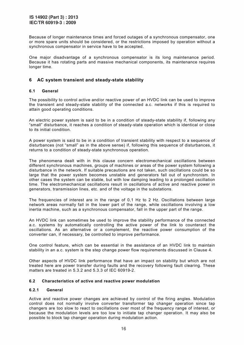
When the telecommunication is not available, active power modulation can still be performed in the current controlling station but should then be restricted in such a way that the current margin is not lost. This is illustrated in Figure 5.
IS 14902 (Part 3) : 2013IEC/TR 60919-3 : 2009
17
Ud
0 4
2
3
1
Id
" = "min
! = !min
Key
1 rectifier current order = value of d.c. current Id
2 current margin $I
Ud direct voltage
Id direct current
3 inverter current order = Id – $I
4 limits of current modulation range
Figure 5 – Example of voltage – current characteristic showing possible current modulation range in the absence of telecommunication
between rectifier and inverter
6.2.3 Small signal modulation
In some situations, it may not be practical or possible to use the telecommunication link to transmit modulated power or current orders. This is the case if the telecommunication delay is so large that it becomes significant compared to the period time of the modulation or if the telecommunication has failed. A small signal power modulation can then still be performed in the current controlling station. The modulation amplitude is normally limited to between 30 % and 50 % of the current margin. Such a small signal modulation can still provide considerable damping assistance in cases where oscillations can start growing spontaneously (steady-state instability).
6.2.4 Reactive power modulation
In most cases, active power modulation is sufficiently effective. However, modulation of reactive power can sometimes be beneficial, in particular for high impedance a.c. systems, or because of the location of the d.c. infeed. It should also be pointed out that modulation of active HVDC power may only lead to unwanted oscillations of the a.c. voltage, since a change in active power is always accompanied by a change in reactive power. This can sometimes be cured through a combined control of active and reactive power. Reactive power modulation
18
IS 14902 (Part 3) : 2013IEC/TR 60919-3 : 2009
can for example be performed to counteract a.c. voltage fluctuations. The input signal to the controller is, in this case, the a.c. voltage.
Reactive power modulation is achieved by altering the firing or extinction angle in the voltage controlling station. This is normally effected on the inverter. An increase of the extinction angle in order to increase the reactive power consumption of the inverter will result in a reduction of the direct voltage, and the firing angle in the rectifier will therefore also automatically increase in order to maintain constant d.c. current or power. Therefore, reactive power modulation at the inverter will also result in variation of the reactive power consumption of the rectifier. This can sometimes limit the modulation amplitude.
The mechanism described above indicates that reactive power modulation can be made at the voltage controlling station without any special telecommunication requirements. If reactive power modulation is needed at the current controlling station, the control action will still have to be carried out at the voltage controlling station, and the control signal should therefore be sent through the telecommunication channel. The resulting action in the current controlling station will be achieved indirectly through the constant current or power control.
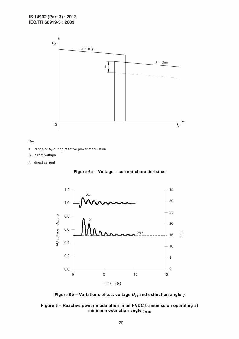
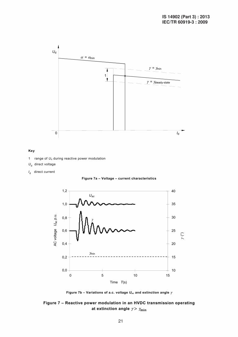
If the HVDC system is operating at its minimum extinction angle (maximum voltage), only an increase of the reactive power consumption from the steady-state value is possible during modulation. A decrease of the reactive power relative to the steady-state value can only be obtained if the HVDC system is being operated below the maximum direct voltage and with steady-state firing and extinction angles above the minimum values. Figures 6 and 7 show voltage-current characteristics and reactive power variation at inverter operation for both these situations.
It is important to specify if a decrease in the reactive power consumption during modulation is possible, since this will cause increased cost for valves, converter transformers and filters.
6.3 Classification of network situations
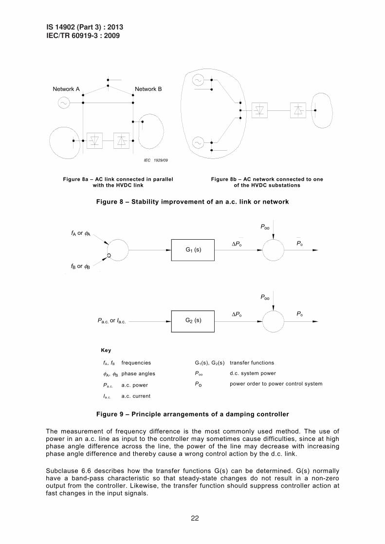
The degree of improvement of a.c. system stability that can be obtained depends on the size of the modulation amplitude relative to the strength of the network, the characteristics of the network and to what points in the network the HVDC link is connected. One can distinguish between two conceptually different situations. One of these is when stability improvement has to be provided for an a.c. line or an a.c. network in parallel with the HVDC link. The other situation is when the stability inside a network connected to one of the HVDC substations has to be improved. These two situations are shown in Figures 8a and 8b.
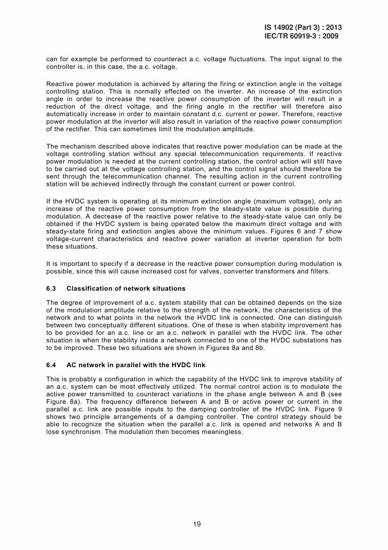
6.4 AC network in parallel with the HVDC link
This is probably a configuration in which the capability of the HVDC link to improve stability of an a.c. system can be most effectively utilized. The normal control action is to modulate the active power transmitted to counteract variations in the phase angle between A and B (see Figure 8a). The frequency difference between A and B or active power or current in the parallel a.c. link are possible inputs to the damping controller of the HVDC link. Figure 9 shows two principle arrangements of a damping controller. The control strategy should be able to recognize the situation when the parallel a.c. link is opened and networks A and B lose synchronism. The modulation then becomes meaningless.
IS 14902 (Part 3) : 2013IEC/TR 60919-3 : 2009
19
Ud
0
1
Id
" = "min
! = !min
Key
1 range of Ud during reactive power modulation
Ud direct voltage
Id direct current
Figure 6a – Voltage – current characteristics
1,2
Time T(s)
AC
vol
tage
U
ac p
.u.
0
5
10
15
20
25
30
35
" (°
)
Uac
"
1,0
0,8
0,6
0,4
0,2
0,0 0 5 10 15
"min
Figure 6b – Variations of a.c. voltage Uac and extinction angle "
Figure 6 – Reactive power modulation in an HVDC transmission operating at minimum extinction angle "min
20
IS 14902 (Part 3) : 2013IEC/TR 60919-3 : 2009
Ud
0
1
Id
" = "min
! = !min
" = "steady-state
Key
1 range of Ud during reactive power modulation
Ud direct voltage
Id direct current
Figure 7a – Voltage – current characteristics
40 1,2
Time T(s)
AC v
olta
ge
Uac
p.u
.
10
15
20
25
30
35
" (°
)
Uac
"
1,0
0,8
0,6
0,4
0,2
0,0 0 5 10 15
"min
Figure 7b – Variations of a.c. voltage Uac and extinction angle "
Figure 7 – Reactive power modulation in an HVDC transmission operating at extinction angle " > "min
IS 14902 (Part 3) : 2013IEC/TR 60919-3 : 2009
21
Network BNetwork A
IEC 1929/09
Figure 8a – AC link connected in parallel with the HVDC link
Figure 8b – AC network connected to one of the HVDC substations
Figure 8 – Stability improvement of an a.c. link or network
fB or %B
G1 (s)
G2 (s) $Po
Poo
Pa.c. or Ia.c.
fA or %A
Po
$Po
Poo
Po
Key
fA, fB frequencies
%A, %B phase angles
Pa.c. a.c. power
Ia.c. a.c. current
G1(s), G2(s) transfer functions
Poo d.c. system power
Po power order to power control system
Figure 9 – Principle arrangements of a damping controller
The measurement of frequency difference is the most commonly used method. The use of power in an a.c. line as input to the controller may sometimes cause difficulties, since at high phase angle difference across the line, the power of the line may decrease with increasing phase angle difference and thereby cause a wrong control action by the d.c. link.
Subclause 6.6 describes how the transfer functions G(s) can be determined. G(s) normally have a band-pass characteristic so that steady-state changes do not result in a non-zero output from the controller. Likewise, the transfer function should suppress controller action at fast changes in the input signals.
22
IS 14902 (Part 3) : 2013IEC/TR 60919-3 : 2009
In case of a parallel a.c. link, HVDC damping control can sometimes increase the amount of power that can be transmitted via the parallel a.c. circuit in a stable manner. The amount of improvement depends on what type of instability dictates the power limit. In a first swing instability situation, improvements can only be expected if the HVDC link is large or has a large short-time overload capability. Improved damping can, however, also be obtained in cases where the modulation amplitude is relatively small. Even small signal modulation performed locally in the current controlling station has made it possible to increase the amount of power in parallel a.c. lines in some cases.
6.5 Improvement of the stability within one of the connected a.c. networks
The ability of the HVDC link to improve stability in this case depends largely on the configuration and characteristics of the network requiring assistance and also on the possibility to obtain relevant input signals to the damping controller. In some cases, input signals may have to be transmitted to the HVDC substation from other stations in the a.c. network. Input signals to the controller can be frequency, voltage, a.c. line power, line current or a combination of these.
When specifying damping control in a case like this, consideration should be given to the ability of the network connected to the other HVDC substation to accept the resulting power swings.
The general considerations regarding the transfer function of the controller as given in 6.4 for the case of a parallel a.c. network apply also in this case.
6.6 Determination of the damping control characteristics
The need for and effectiveness of HVDC link damping control is normally studied using a transient stability computer program with the ability to model HVDC links and different controller characteristics. Such a study can reveal potential problems in the interaction at low frequencies between the HVDC link and other power system elements such as static var or synchronous compensators.
The controller environment includes many elements that are, however, modelled inaccurately or not at all. Thus model studies should be augmented by measurements and tests performed in the field when possible to do so.
It is important to stress the need for an accurate representation of the HVDC link and its control system when performing transient stability studies. An oversimplified model may give rise to misleading results. The d.c. link model in the stability programme should therefore be validated. The validation can be carried out preferably against an HVDC TNA or digital simulator and after construction, against measurements performed upon the HVDC system.
Note that the model used should give conservative results, even if it is modelled as a simple one. Also, it is very important to model the PLL (phase locked loop) for HVDC firing control as precise as possible.
HVDC simulators and equivalent programs can be used to validate the implemented transfer functions of the damping controller.
The real-time simulator is very useful for the study of validation of control. Closed-loop test using a real-time simulator enables a quasi-real condition. The real-time simulator can be of an analogue type like TNA or digital. Since it is a simulator test, various kind of disturbances can be initiated and help to verify the control scheme. Also, it is recommended to carry out artificial fault testing if it is possible, especially for new HVDC systems.
In spite of the fact that a damping controller is designed to act in a frequency range below about 2 Hz, it may have a detrimental effect on a controller for damping of subsynchronous oscillations (see Clause 8).
IS 14902 (Part 3) : 2013IEC/TR 60919-3 : 2009
23
The specification of the stability improvement feature of an HVDC link can be determined in two conceptually different ways. The difference between the two ways lies in who determines the transfer function and other characteristics of the damping controller, the utility purchasing the link, or the supplier of the HVDC substation equipment.
In the former case, the control-related aspects of the specification should specify the characteristics of the controller in terms of input quantities, transfer function(s), accessory logic and output quantities. The control equipment can then be designed to correctly implement the specified characteristics, and then verified by tests.
In the second case, the situation becomes more complex. The supplier should be provided with a full set of network and generator data to allow him to perform transient stability and related studies for an adequately broad range of operating conditions. In this case, the performance requirements are complex; it may be difficult to formulate clear performance criteria and negotiations may be required. If this method is selected, stability studies should also be performed prior to issuing the specification in order to establish the level of stability and/or damping that can be expected to be achieved by d.c. link control action.
In either case, the capability of the substation equipment, in particular the valves, should be considered in the determination of the gain and amplitude limitations of the controller. Explicit provisions should be made for engineering review of controller performance during commissioning tests and periodically thereafter.
6.7 Implementation of the damping controller and telecommunication requirements
The damping controller can easily be integrated into the HVDC control equipment. It is usually allocated to the HVDC substation control level (see Clause 12 of IEC 60919-1).
In the case of large signal modulation, consideration should be given to the capacity of the telecommunication link between the two HVDC substations, which should be able to transmit the modulation signals and in many cases also input signals (e.g. frequency) to the controller without causing too large phase displacements.
Where the modulation control requires telecommunication, the reliability of the communication link is of primary importance. The telecommunication system should be designed in such a way that “out of phase modulation” cannot result from communication failures, i.e. if there is an interruption in the telecommunication channel, the system should be designed so that modulation is resumed correctly when the channel resumes operation.
7 Dynamics of the HVDC system at higher frequencies
7.1 General
This clause addresses the dynamic performance of an HVDC system in the range of half fundamental frequency and above. HVDC converters generate and react to oscillations at both integer and non-integer multiples of fundamental frequency, and thus the converter performance is dependent on the impedance of the a.c. and d.c. systems. In some circumstances, instability can occur, so that the converter performance is unacceptable. For present purposes, the distinction between stability and instability is that in a stable system, effect (e.g. non-characteristic harmonics) is proportional to cause (e.g. unbalance in an a.c. system), whereas instability usually involves the generation of oscillations at non-integer multiples of fundamental frequency and can “grow from nothing” even in a perfectly balanced system. A detailed description of these subjects is covered in references listed in the biblio-graphy and in particular in CIGRE TF14-07/IEEE, Part 1 [1].
This technical report will therefore only provide brief descriptions, but it will outline the relevant required information and particular aspects of the specification of HVDC schemes.
24
IS 14902 (Part 3) : 2013IEC/TR 60919-3 : 2009
7.2 Types of instability
7.2.1 Loop instability (harmonic instability)
This instability was found on some early HVDC schemes, and was often referred to as harmonic instability. It can occur at both integer and non-integer multiples of the fundamental frequency and it involves the main power circuit and control circuit (including measurements) loop. It is strongly related to the control and measuring system parameters. Instability can occur, even if the a.c. system is perfectly balanced and without distortion, if unsuitable control characteristics are used and can be seen on both the a.c. and the d.c. side. It often starts from a near integer multiple of fundamental frequency, nearly always close to the main circuit resonance. It may then lock into the nearest harmonic frequency as the instability amplitude grows.
Instability rarely occurs with present day “equidistant firing” type of control.
7.2.2 Current loop instability
The speed of the response of an HVDC system is limited primarily by the capacitances and inductances of the a.c. and d.c. systems. The response of the converter itself is generally considerably faster than that of an a.c. system or machine. However, excessive forcing of the response by the use of high gains in the current control loop can lead to instability of the HVDC system, particularly if the response of the d.c. system with its measuring and control devices is comparable to the response time of the a.c. system. The need to provide a system which is stable overall may, in some cases, mean that the HVDC control response has to be slowed down.
7.2.3 Core saturation instability
This instability involves partial saturation of the converter transformers. A fundamental frequency component in the d.c. current causes second harmonic and d.c. in the valve winding current. If the d.c. component reaches a level comparable to say 50 % of the transformer magnetizing current, the partial saturation of the transformer may result in significant levels of additional harmonics (including second harmonic) in the magnetizing current. The various second harmonic current contributions enhance the second harmonic in the a.c. voltage, and under some circumstances a full instability can result.
A high impedance resonance near to the second harmonic on the a.c. side, and/or a low-impedance resonance near to fundamental frequency on the d.c. side makes the instability more likely. In some cases, it is practicable to design the main circuit parameters (e.g. d.c. reactor or a.c. filters) such that these resonances are avoided. In some cases however, the line impedance is so dominating that resonance at fundamental or harmonic frequencies cannot be avoided by selection of realistic parameters for HVDC substation equipment. In cases where such resonances cannot be avoided, the instability can be ”cured” either by modifying the control constants or by the provision of special feedback loops in the controls. However, in such cases special care should be taken to control transients, e.g. overvoltages, particularly if the resonance is lightly damped.
7.2.4 Harmonic interactions
Harmonics in the a.c. voltage will result in the generation of harmonics in the direct voltage at the two sideband frequencies, and thus in the flow of current on the d.c. side at these frequencies. Similarly, harmonics in the direct current will result in the generation of harmonic a.c. currents in the transformer valve windings and a.c. systems at the two sideband frequencies, and thus in the creation of harmonic voltage distortion on the a.c. side at these frequencies. Under resonance conditions this may result in unacceptable harmonic distortion on either the a.c. side or the d.c. side, or both.
Unlike the instabilities described in 7.2.1 to 7.2.2, this phenomenon occurs only if there is an internal driving source in either the a.c. or the d.c. system. One example of this phenomenon
IS 14902 (Part 3) : 2013IEC/TR 60919-3 : 2009
25
is the superimposition of a fundamental frequency component on the direct current, as may occur if an overhead d.c. line runs parallel to an a.c. line over a significant distance. The most severe case is that a.c. line and d.c. line are on the same tower. The fundamental frequency component will then cause direct current and second harmonic in the converter valve windings. It is not feasible to reduce the second resultant harmonic component injected into the a.c. system at the same time. Thus, it may be necessary to take actions such as transposing the a.c. line or by applying harmonic filtering on either the d.c. or the a.c. side of the converter.
Other driving sources are unbalances in the a.c. system (negative sequence fundamental frequency, or impedance unbalance) or inequality of leakage reactances of converter transformers; all of these cause second harmonic on the d.c. side, which reacts back on the a.c. side. One sideband of the latter is at third harmonic, and can sometimes require the addition of third harmonic filters to prevent excessive a.c. voltage distortion.
Because the mechanism for the generation of non-characteristic harmonics depends upon circulation of harmonics on the d.c. side of the converters, there may be an interaction between them. Unless the d.c. line or cable and the d.c. filters have a very low shunt impedance compared to the impedance of the other converter, the two converters are coupled at these frequencies. Therefore, the treatment of non-characteristic harmonics cannot be carried out independently for the two HVDC substations, since the coupling between them means that each contributes to the non-characteristic harmonic behaviour of the other. There is even the possibility that a standing wave may be set up on the d.c. line, magnifying the effect at both HVDC substations. Only an analysis in which the circuit parameters are deliberately distorted to expose this possibility is likely to be useful.
7.3 Information required for design purposes
In order to ensure that the HVDC system gives satisfactory dynamic performance at higher frequencies, the close interactions between the different parts of the overall system should be taken into account in the design. The overall system includes the a.c. systems at both HVDC substations, the transmission lines / cables, the HVDC substation main circuit, and the converter control system. It is unlikely that meaningful studies can be performed at the specification stage to define specific requirements for the HVDC substation components. Therefore, the specification should be functional, requiring that the manufacturer designs the HVDC substation so that satisfactory performance is achieved at higher frequencies for all practical combinations of system conditions. A disclosure of the procedures by which the manufacturer intends to demonstrate satisfactory dynamic harmonic performance at higher frequencies can be requested.
The conditions external to the HVDC substation which need to be taken into account when designing satisfactory dynamic performance of the HVDC system at higher frequencies are as follows:
– the impedance and phase angle of the a.c. system and the known d.c. system as seen from each converter. Both weak and strong a.c. system representations should be provided, and if possible, network configurations with probable outage contingencies;
– resonances on the a.c. or d.c. side, in particular whether complementary resonances can exist (e.g., ƒres,ac = ƒres,dc ± ƒ0, where ƒ0 is the fundamental frequency and ƒres,ac and ƒres,dc are a.c. and d.c. side resonant frequencies respectively);
– unbalances in the a.c. system impedance or voltage; – the presence of other harmonic sources with corresponding source impedances and non-
linear loads electrically close to the HVDC substation a.c. and/or d.c. terminals. The presence of a fundamental frequency source on the d.c. side is a special case of this;
– possible a.c. lines coupling to the d.c. line at fundamental frequency. This requires geometrical configuration of a.c. and d.c. lines when running in parallel, a.c. line maximum current and voltage, points of transposition, etc.;
26
IS 14902 (Part 3) : 2013IEC/TR 60919-3 : 2009
– impedance versus frequency characteristics, including variation of shunt capacitor numbers;
– possibility of islanding, remaining with nearby generators, isolated from rest of the a.c. network.
The above information should be included in the specification or alternatively, sufficient data describing the a.c. and d.c. system to enable this information to be devised should be provided. It can be seen that the above-listed information largely corresponds to that required also for the steady-state design of the HVDC substation (see IEC 60919-1). However, it should be noted that in some applications, the fundamental frequency ƒ0 can vary over a large range (e.g. for an isolated generating station), and that this may expose resonances not normally encountered.
7.4 Means available for preventing instabilities
Most instabilities at higher frequencies can be avoided or corrected by alterations to the control system. This may simply involve the selection of appropriate tuning. In other cases, it may be necessary to introduce additional feedback loops, e.g. from the a.c. or d.c. voltage or the a.c. valve winding currents or the d.c. current. The solution adopted may differ between manufacturers and indeed from scheme to scheme.
Control techniques are always investigated first, because they normally offer a relatively cheap solution to instability problems. However, there will be occasions in which the control system acting alone is insufficient to accomplish all of the desired activity. Once this stage has been reached, either a control target has to be compromised, or other means found.
Broadband damped filters can significantly improve the performance of the overall system by removing sharp resonances. However, the harmonic suppression at individual frequencies is much lower per kVAr for a damped filter than for a tuned filter. Therefore, this method of preventing instability can be very costly, particularly if the instability occurs at a relatively low frequency. However, in the case of significant external harmonic sources, such as an untransposed a.c. line being run in parallel to an overhead d.c. line over a great distance, it may not be possible to obtain satisfactory performance without the application of expensive fundamental frequency blocking filters on the d.c. side or second harmonic shunt filters on the a.c. side.
7.5 Damping of low order harmonics by control action
Modern (equidistant firing) control systems are able to actively damp low order non-characteristic harmonics, (e.g. from the a.c. network). This is achieved by suitable modulation of the delay angle (!) ҏThis can be beneficial under special circumstances, such as the application of HVDC to weak ҏ a.c. networks and/or to a.c. networks whose phase conductors are not transposed, or even during recovery from a.c. network faults when the waveform is temporarily distorted. Although it is often possible to adjust the control system to exert a restraining influence on the low ҏuncharacteristic harmonics, only ҏa single variable (!) is available to accommodate all such activity. Thus, the same technique may be incapable of restraining simultaneously the second harmonic on the d.c. network and the third harmonic on the a.c. network.
7.6 Demonstration of satisfactory performance at higher frequencies
Traditionally, HVDC simulators have been used to demonstrate during the design stage that an HVDC scheme is free from undesirable instabilities. Simulators are a convenient tool for such analysis, enabling a multiplicity of system conditions and configurations to be investigated relatively rapidly. The investigations are generally carried out as step response studies, with rapid damping of the response showing good resistance to instability. However, the accuracy of such investigations is subject to simulator component limitations.
IS 14902 (Part 3) : 2013IEC/TR 60919-3 : 2009
27
For example, many of the normal harmonics to be observed are so small that they tend to be buried by spurious harmonics caused by model component unbalances. Model converter transformers have reached a high degree of perfection in simulating real transformer B-H characteristics, but most models are not adequate to check for core saturation instability.
Computer simulation has become a viable alternative to the HVDC TNA simulator for demonstration of absence of instability. A computer simulation is likely to be more convenient than one undertaken by means of the HVDC TNA simulator, and the analysis can be potentially more accurate, since the actual system and component losses can be represented. Unless the computer simulator operates in real time it will not be practical to use the actual and complete control hardware. It is important that the simulation is validated by comparison of results with actual measurements performed on a real system.
Usefulness of the real-time simulator should be mentioned here. A closed-loop test can be performed before implementation of the controller, using real-time simulator. Variety of test cases can be demonstrated.
Since the converter interacts with its harmonic environment (harmonic impedances on the a.c. and d.c. sides as well as harmonic injection from other sources), it is important to demonstrate that the converter does not magnify low order non-characteristic harmonics to an unacceptable extent and that large amplitudes of such harmonics will not cause instability.
Studies can be undertaken by modelling the converter and its controls in a system with low order harmonic complementary resonances between the associated a.c. and d.c. networks. By appropriate tests, it is often possible to show that the behaviour of the converter and its controls are not unduly disturbed by harmonics, even when the harmonics exhibit substantial amplitude.
During commissioning it should be arranged (if applicable) for the a.c. system and/or the d.c. system to be in worst resonance with the converter station, and the adequacy of the instability counter measures should be demonstrated by measuring the system response to step changes and/or small signal modulation at the appropriate frequencies of the current order.
8 Subsynchronous oscillations
8.1 General
Only turbine-generator units located near a rectifier substation and having weak connection to the a.c. network are vulnerable to subsynchronous oscillations. Commonly, torsional natural frequencies lie in the range of 15 Hz to 40 Hz. For large nuclear turbine-generators, the lowest torsional frequency may be as low as 5 Hz, with other torsional modes at higher frequencies.
Torsional vibrations in a turbine-generator rotor may be stimulated by many common electrical disturbances in the transmission system. Furthermore, under certain conditions, torsional vibrations may be amplified, or reinforced, by a near resonant interaction between the turbine-generator rotor and a series compensated transmission line, or by interaction with an HVDC control system.
Since turbine-generator torsional modes have very little inherent damping, shaft oscillations persist for a considerable time after they are stimulated. Repeated stimulation of excessive magnitude can lead to loss of shaft life, and in the extreme, fatigue failure.
In an HVDC system, the constant power and constant current regulation modes may have a destabilizing influence on rotor torsionals. Within the typical bandwidth of an HVDC current control regulator, two or three subsynchronous torsional modes of oscillation may be present.
28
IS 14902 (Part 3) : 2013IEC/TR 60919-3 : 2009
To clearly identify the difference between SSR and subsynchronous torsional interaction, the latter is called an SSTI, which is an interaction between HVDC control and turbine-generator.
Subsynchronous resonance (SSR) involving series compensated a.c. transmission lines has some fundamental differences with the HVDC torsional instability phenomenon. SSR associated with series compensation affects primarily the higher range of torsional frequencies while torsional interaction with HVDC primarily affects the lower frequency torsional modes. SSR associated with series compensation can be much more severe than HVDC related torsional interaction in the magnitude of torsional destabilization.
8.2 Criteria for subsynchronous torsional interaction with an HVDC system
Negative damping to turbine-generator torsional modes of oscillation is inherent to the objective of controlling current in an HVDC system. Some degree of negative damping will exist within the bandwidth (BW) of the current control regulation loop.
Only turbine-generator units located near a rectifier substation and having a weak connection to the a.c. network are vulnerable to torsional interactions. Units near an inverter do not experience much destabilization since inverters react differently to phase angle variations than do rectifiers.
Turbine-generator rotor motion causes variations in both magnitude and phase angle of the a.c. voltage supplying the converter. The effect on converter angle of delay, and the closed loop control reaction to the apparent firing angle shift result in changes in direct voltage and current, thereby, d.c. power transfer. The ultimate effect of change in HVDC power is change in generator electrical torque. If the generator accumulated phase lags between the change in the generator shaft speed, and the resulting change in electrical torque on the generator rotor exceeds 90°, the torsional oscillation may become unstable.
A constant power load presents a negative characteristic to any deviation of generator shaft speed.
With the inverter controlling current, the d.c. voltage will follow the rectifier. When the generator rotor speed increases, so will a.c. voltage. If the rectifier is in an alpha control mode, d.c. voltage will also increase and lead to a power increase. Thus positive damping results within the current control BW and approaches the inherent positive damping characteristics associated with no control action.
Turbine generator units near the inverter of an HVDC system will always have a parallel a.c. interconnection to the load and hence experience less influence on the HVDC control than might a unit near a rectifier. Also, when shaft speed increases on a unit near the inverter, the voltage magnitude at the inverter increases, which causes a decrease in d.c. current magnitude (i.e. leading to an opposite damping effect compared to the rectifier).
A steady-state firing angle of operation of the converter has significant impact on the interaction. This arises from the inherent non-linearity cosine relationship between firing angle and d.c. voltage. Gain linearization for the current regulator firing angle will reduce but not eliminate the interaction.
Operation at large angles of delay can significantly reduce torsional stability. Therefore, consideration should be given in the HVDC system specifications when operation is planned at reduced voltage for voltage control purposes, or because of reduced insulation strength of the transmission system.
Torsional interaction does not occur on hydro generator units, only on thermal generator units. For very low and medium speed (low head) units, the very large hydro generator inertia with respect to turbine inertia reduces interaction with the electrical system and practically eliminates the possibility of torsional interaction problems both with the series compensated a.c. transmission and HVDC. For applications utilizing high speed (high head) units, the
IS 14902 (Part 3) : 2013IEC/TR 60919-3 : 2009
29

inertia ratio of hydro generator and turbines may not be large, increasing the possibility of torsional interaction. The specification should require clarification on whether an SSTI problem can occur in the given configurations. An example of the simplified method for screening possibilities for SSTI occurring is presented in 8.3. In the case where SSTI is possible, more detailed system studies are required.
Controls applied to the d.c. system to augment damping of power swing oscillations, typically in the frequency range of 0,1 Hz to 2,0 Hz, can interact with torsional modes and sometimes result in a significant destabilizing influence on nearby turbine generator units. This influence should be considered in the specification of any HVDC system whenever damping controls and subsynchronous resonance considerations exist. Since both controls are necessary in some installations, it is imperative that they coexist in a complimentary manner.
On series compensated lines that are torsionally stable, the addition of an HVDC system should have negligible effect on the torsional stability. The addition of the HVDC system adds a small positive damping to the torsional modes, especially if a subsynchronous damping controller is implemented. However, specifications should require that each such system be investigated to ensure that there is no SSTI problem.
On systems in which the potential for torsional instability exists, the specification should contain the information on torsional frequencies and damping of vibration and mechanical mode shapes for all the generator units of interest. If not available, SSTI frequencies can be obtained by a relatively simple field test. Pertinent transmission network data should also be supplied.
8.3 Screening criteria for identifying generator units susceptible to torsional interactions
Specifications for any new HVDC system in which there is a potential for torsional interaction with turbine-generators should contain provisions for screening studies to determine if in-depth subsynchronous resonance studies and possible subsynchronous damping controllers (SSDC) are required.
On HVDC systems where subsynchronous resonance may potentially be a problem, but no SSDC control is required initially, the specification should require appropriate HVDC control input provisions for addition of a future subsynchronous damping controller.
An approximate relationship between the magnitude of the interaction and a.c. system strength has been developed. This relationship, used as a quantitative screening tool to identify units and system contingencies which require detailed study, is as follows:
2
tot
i
i
HVDCi 1 &
&'
())*
+,=
SCSC
MVAMW
UIF
where
UIFi is the unit interaction factor of i th generating unit;
MWHVDC is the MW rating of the HVDC system; MVAi is the MVA rating of the ith unit; SCi is the short-circuit capability at HVDC commutating bus excluding i th unit (excluding
a.c. filters); SCtot is the short-circuit capability at HVDC commutating bus including i th unit (excluding
a.c. filters).
Results of extensive studies suggest that an interaction factor less than approximately 0,1 will not have significant interaction and can be neglected from further studies.
30
IS 14902 (Part 3) : 2013IEC/TR 60919-3 : 2009
If the UIF become larger than 0,1, further studies are needed. Such studies include eigenvalue analysis, frequency response analysis and power system simulation using EMTP-type software, and real-time simulator. In each study, precise modellings of HVDC firing control block (e.g. ACR and PLL), and turbine-generator mass system including mechanical damping are essential.
8.4 Performance considerations for utilizing subsynchronous damping controls
Subsynchronous damping controllers act to modulate the HVDC firing control in such a manner as to ensure positive damping of torsional oscillations on all nearby generator units for all practical system operating conditions.
Typical signals utilized from the a.c. system in the SSDC design include the rectifier a.c. bus frequency, generator shaft angular velocity or a synthesized signal from both converter voltages and currents.
The dynamic range of the SSDC should be wide enough to provide at least some positive damping to a torsional oscillation after it has been stimulated to the maximum amount possible by a system disturbance.
The specifications should include reliability requirements for the SSDC at least equal to the remainder of the controls, and the function should be fail-safe.
The SSDC controller should not be considered as a protective device, only a damping controller.
The SSDC controller should not degrade any other aspects of converter performance (i.e. harmonics, fault response, etc.).
Studies should consider the impact of SSDC and series capacitor compensation connected in the associated a.c. system.
8.5 Performance testing
Damping performance of the SSDC should be verified by conducting a series of controller field tests involving the HVDC system and the affected turbine generator units. Measurements of the torsional vibrations should be made at the generator units.
Gain margin of the SSDC should be checked by measurement (i.e. measure the open loop transfer functions through the SSDC and the system to which it is connected).
8.6 Turbine generator protection
Based on a combination of detailed system analysis, design of the control system and implementation with full redundancy, the experience from operation of HVDC systems with installed SSDC controllers has shown that it is not necessary to include SSR relay protections.
Torsional oscillations that may be damaging to a machine cannot be reliably and securely detected at the converter station. Based on the measurements, a SSTI supervision can be included in the control system, with the ability to trip the HVDC on both level and derivative criteria.
However, any turbine-generator that can potentially interact with an HVDC converter system may be protected with a torsional protective relay.
IS 14902 (Part 3) : 2013IEC/TR 60919-3 : 2009
31

9 Power plant interaction
9.1 General
The closer a power plant is connected electrically to a d.c. link, the more it will be affected by that link. A generating station may feed much or all of its power into the rectifier of a d.c. transmission system, or share its supply to a load with power being delivered from an inverter station. If the loading on the d.c. link comes directly from the generator of a power plant, there is bound to be significant interaction. This should be addressed in the design of the d.c. link and associated a.c. power system, including the specification of the turbine and generator. Where the power generated by the power plant also feeds an a.c. load or system, the interactions discussed in this clause are still present, but other aspects related to the influence of the a.c./d.c. system operation on this load or system should also be considered.
9.2 Specific interactions
9.2.1 General
Electric power is usually generated from a power plant which derives its energy from either hydro, thermal or nuclear sources. Interaction between a d.c. link closely associated with any of the various kinds of power plant will lead to common concerns identified in this clause. In cases where interactions may affect a particular kind of power plant in a different or more sensitive manner, specific reference is made accordingly.
It should be appreciated that a.c. transmission systems, as an alternative to d.c. transmission, interact with generators with similar and equal concerns as presented in this clause. This does not mean, however, that d.c. link interactions with a power plant should not be considered in preparing a specification for a d.c. link.
9.2.2 Frequency variation effects
Generators should operate within a specific frequency range, the limits of which are determined by whether it is synchronous or asynchronous to the main a.c. power system. Power loss in the d.c. transmission system because of commutation failure, faults or valve group blocking will result in frequency excursions in the power plant. Extreme frequency overshoot will occur when the d.c. link completely blocks and there is no alternate path for the power from the generation to reach the load, resulting in full load rejection for the power plant.
A more severe stress on generators is imposed when they are islanded with a d.c. inverter and separated from the load. Electric power reversal at the generator, due to power fed to it from the inverter that is not protected by a d.c. link power order reduction, could lead to rotor damage.
Studies should be undertaken to examine in detail the consequences of d.c. link outages. The power system should be planned so that full d.c. link load rejection if it occurs, does not impact on the power plant beyond its design limits. The type of power plant, whether hydro, thermal or nuclear, will dictate what additional transmission facilities and protection systems will be essential to lessen the impact of a d.c. link full load rejection on it. Nuclear plants may require the most stringent limits on transmission design for protection against full d.c. load rejection because of the lengthy delay in resuming full power production. An HVDC system which transmits a major part of the power of a nuclear plant to the load should be designed with high reliability. For pole outages, overload capability on the remaining pole(s) should be considered to avoid generator plant shutdown or facilitate an orderly power reduction in the plant.
9.2.3 Frequency controls interactions
Very low frequency instability (below 0,5 Hz) can develop as an interaction between machine speed control by turbine governors and the d.c. transmission system if no particular measures are taken to coordinate them. Studies and tests to optimize governor settings can be
32
IS 14902 (Part 3) : 2013IEC/TR 60919-3 : 2009
undertaken. HVDC link controls can also be developed to contribute to the damping at these instabilities by the addition of special control loops responding to measured incremental frequency of the a.c. systems. Further information is available in Clause 6.
9.2.4 Overvoltage effects
DC link load rejection overvoltages will affect a power plant when the load rejection is also transferred to its generator. Overvoltages can damage the generators and other equipment if filters and shunt capacitor banks remain on after load rejection. Overvoltages on the auxiliary service motor and excitation system have to be specially borne in mind. There is a possibility of self-excitation of the generator on load rejection unless suitable cross tripping is incorporated into the system design. Combining converter blocking controls with tripping of filters and shunt capacitor banks may be required.
When circuit-breakers are required to clear a.c. filter and shunt capacitor banks under conditions of load rejection overvoltages and self-excitation, breaker rating should be sized to accommodate the stresses imposed as discussed in 4.3 of IEC 60919-2. The sensitivity and speed of protection for switching filter and capacitor banks under conditions of self-excitation should be adequate to protect machine and station equipment against the overvoltages and also discriminate between a temporary and permanent d.c. link load rejection. This is because removal of filters and capacitors through a temporary d.c. link shutdown may leave the system with inadequate reactive power support to fully recover its pre-disturbance power level.
In such cases, the switching back in of filters and capacitors should be carefully coordinated with equipment capabilities and d.c. link recovery sequences, particularly when the duration of the temporary outage is to be minimized.
The combination of a generator station and an HVDC substation may exhibit low damping on the a.c. side in cases where local a.c. load is small or non-existent. Under such circumstances, resonances, overvoltages and transient recovery voltages for circuit-breakers may require special attention.
9.2.5 Harmonics
Characteristic and non-characteristic harmonic currents generated from a converter station not adequately filtered and damped may flow into the generator. Undesirable mechanical vibrations may result in hydro and thermal units, as well as develop internal heating, particularly on the rotor. In both instances, damage can be caused. Anticipated or permitted harmonic loading into generators at or close to d.c. links should be determined and used as input to generator specifications and a.c. filter design. Further discussion is found in Clause 16 of IEC 60919-1. In the case of a steam turbine generator, special attention should be given to the magnitude of the fifth and seventh harmonics. This is of special concern because the interaction of the magnetic field produces a pulsating torque at the sixth harmonic on the rotor. If coincident with a supersynchronous mechanical resonant frequency involving torsional oscillations of the rotor elements and flexing of the turbine buckets, fatigue in the turbine shafts and buckets may result.
9.2.6 Subsynchronous and shaft impact effects
Subsynchronous effects can be dangerously imposed upon the generator, shaft and turbine as discussed in Clause 8. Subharmonic currents generated by certain types of diesel generators can interact with d.c. links. If such a probability exists, system tests should be undertaken to determine the subsyschronous present in the system, and such information provided in the specification so that damping can be designed into the controls of the d.c. link. A related problem is the impact on a shaft of a generator of the step change in torque which can result from a d.c. link load rejection or even from a commutation failure. Even if the resulting mechanical oscillations between masses on the turbine and generator shaft are damped, some loss of shaft life may occur. Thermal and nuclear plant may be most sensitive to this concern. The potential for commutation failures contributing to loss of shaft life should be minimized if this is identified as being a possible problem.
IS 14902 (Part 3) : 2013IEC/TR 60919-3 : 2009
33
Shaft impact effects are also caused when d.c. link restart sequences are adopted. Each unsuccessful restart can impose additive stresses to the shaft of a turbine generator. This effect should be studied and anticipated in the specification of the d.c. link insofar as the restart strategy is concerned.
9.2.7 Resonance
The configuration of the a.c. system interconnecting the power station and converter, usually involving short lines, great concentration of reactive power equipment, etc. has a potential risk of pronounced resonance conditions and a very low degree of damping.
9.2.8 Overvoltages
As a result of the resonance conditions indicated in 9.2.7 above, as well as the low degree of damping, temporary overvoltages other than those caused by load rejection shall be considered. Among these overvoltages that can be mentioned are a.c. fault clearing over-voltages and overvoltages resulting from transformer energization.
9.2.9 Stresses in a.c. switching equipment
In addition to the problems discussed in 9.2.4 above, the a.c. system configuration with short lines mentioned in 9.2.7 may impose transient recovery voltage (TRV) requirements above the standard values for the circuit-breaker to be used in this application.
9.2.10 Under-frequency
Under-frequency conditions as a result of a major disturbance, such as the loss of generation units, should also be considered.
9.2.11 Starting procedure for an HVDC converter
Consideration should be given to frequency regulation of the sending end system and the generator reactive power capability requirements during the start-up procedure of a converter unit.
9.3 Special considerations for a nuclear plant
Those characteristics related to protective relays which can cause a nuclear reactor scram should be modelled in detail in simulation studies. If a steam bypass capacity is as much as a reactor capacity, a disturbance in a d.c. system or receiving end a.c. system may not cause a reactor scram.
When studying subsynchronous resonance phenomena, it should be noted that the mechanical resonance frequency of a turbine-generator of a nuclear power unit is usually lower than that of other types of steam turbine-generators.
34
IS 14902 (Part 3) : 2013IEC/TR 60919-3 : 2009
Bibliography
[1] “Guide for Planning D.C. Links Terminating at A.C. System Locations Having Low Short Circuit Capacity”. CIGRE document TF 14-07/IEEE 15.05.05, Parts I and II.
[2] ANDERSSON G., SVENSSON S., LISS G., “Digital and Analog Simulation of Integrated A.C. and D.C. Power Systems”. CIGRE paper 14-02, 1984.
[3] GRUND C.E., POLLARD E.M., PATEL H., NILSSON S.L., REEVE J., “Power Modulation Controls for HVDC Systems”. CIGRE paper 14-03, 1984.
[4] “Tentative Classification and Terminologies Relating to Stability Problems of Power Systems”. Electra, No. 56, Jan 1978, pp 57-67.
[5] “A.C. Harmonic Filters and Reactive Compensation for HVDC with Particular Reference to Non-characteristic Harmonics”. CIGRE publication no. 65 June 1990. Complement to the Electra paper of issue 63 (1979).
[6] KAUFERLE J., SADEK K., KOELSCH, A.C. “System Representation Relevant to A.C. Filtering and Overvoltages for HVDC Application”. CIGRE paper 14-08, 1984.
[7] SALGADO E., LIMA A.C.G., PILOTTO L.A.S., SZECHTMAN M., CUARINI A.P., ROITMAN M., “Technical and Economic Aspects of the Use of HVDC Converters as Reactive Power Controllers”. CIGRE paper 14-08, 1984.
[8] GAVRILOVIC A., “Interaction Between A.C. and D.C. Systems”. CIGRE paper 14-09, 1986.
[9] LAMBAIE T., HOLMBERG D., JONSSON U., AURANNE E., HAGMAN E., JAASKELAINEN K., “Fenno-Scan HVDC Link as a Part of Interconnected A.C./D.C. System”. CIGRE paper 14-02, 1988.
[10] TAAM M., PRACA A.S., PORANGABA F.D., DE TOLEDO F., MENZIES D., ERIKSSON K., “Itaipu HVDC Transmission System. Principal Aspects of A.C./D.C. Interaction”. CIGRE paper 14-03, 1988.
___________
IS 14902 (Part 3) : 2013IEC/TR 60919-3 : 2009
35

Bureau of Indian Standards
BIS is a statutory institution established under the Bureau of Indian Standards Act, 1986 to promote
harmonious development of the activities of standardization, marking and quality certification of goods
and attending to connected matters in the country.
Copyright
BIS has the copyright of all its publications. No part of these publications may be reproduced in any form
without the prior permission in writing of BIS. This does not preclude the free use, in course of imple-
menting the standard, of necessary details, such as symbols and sizes, type or grade designations.
Enquiries relating to copyright be addressed to the Director (Publications), BIS.
Review of Indian Standards
Amendments are issued to standards as the need arises on the basis of comments. Standards are also
reviewed periodically; a standard along with amendments is reaffirmed when such review indicates that
no changes are needed; if the review indicates that changes are needed, it is taken up for revision. Users
of Indian Standards should ascertain that they are in possession of the latest amendments or edition by
referring to the latest issue of ‘BIS Catalogue’ and ‘Standards: Monthly Additions’.
This Indian Standard has been developed from Doc No.: ETD 40 (6315).
Amendments Issued Since Publication______________________________________________________________________________________
Amendment No. Date of Issue Text Affected______________________________________________________________________________________
______________________________________________________________________________________
______________________________________________________________________________________
______________________________________________________________________________________
______________________________________________________________________________________
BUREAU OF INDIAN STANDARDSHeadquarters:
Manak Bhavan, 9 Bahadur Shah Zafar Marg, New Delhi 110002Telephones: 2323 0131, 2323 3375, 2323 9402 Website: www.bis.org.in
Regional Offices: Telephones
Central : Manak Bhavan, 9 Bahadur Shah Zafar Marg 2323 7617NEW DELHI 110002 2323 3841
Eastern : 1/14, C.I.T. Scheme VII M, V.I.P. Road, Kankurgachi 2337 8499, 2337 8561KOLKATA 700054 2337 8626, 2337 9120
Northern : SCO 335-336, Sector 34-A, CHANDIGARH 160022 260 3843260 9285
Southern : C.I.T. Campus, IV Cross Road, CHENNAI 600113 2254 1216, 2254 14422254 2519, 2254 2315
Western : Manakalaya, E9 MIDC, Marol, Andheri (East) 2832 9295, 2832 7858MUMBAI 400093 2832 7891, 2832 7892
Branches: AHMEDABAD. BANGALORE. BHOPAL. BHUBANESHWAR. COIMBATORE. DEHRADUN.FARIDABAD. GHAZIABAD. GUWAHATI. HYDERABAD. JAIPUR. KANPUR. LUCKNOW.NAGPUR. PARWANOO. PATNA. PUNE. RAJKOT. THIRUVANATHAPURAM. VISAKHAPATNAM.
Published by BIS, New Delhi
^^
^^^
Related Documents