IS 13095 : 1991 Indian Standard BUTTERFLY VALVES FOR GENERAL PURPOSES ( First Reprint JUNE 19% ) UDC 621.646.25 : 669*13/*14 @I BIS 1991 BUREAU OF INDIAN STANDARDS MANAK BHAVAN, 9 BAHADUR SHAH ZAFAR MAR0 - < NEW DELHI 110002 September 1991 Price Group 4

IS-13095.pdf
Jan 03, 2016
INDIAN STANDARD CI BUTTERFLY VALVE
Welcome message from author
This document is posted to help you gain knowledge. Please leave a comment to let me know what you think about it! Share it to your friends and learn new things together.
Transcript
IS 13095 : 1991
Indian Standard
BUTTERFLY VALVES FOR GENERAL PURPOSES
( First Reprint JUNE 19% )
UDC 621.646.25 : 669*13/*14
@I BIS 1991
BUREAU OF INDIAN STANDARDS MANAK BHAVAN, 9 BAHADUR SHAH ZAFAR MAR0
- < NEW DELHI 110002
September 1991 Price Group 4

Chemical Engineering Plants and Related EquipmerIt Sectional Committee, HMD 17
FOREWORD
This Indian Standard was adopted by the Bureau of Indian Standards, after the draft finalized by the Chemical Engineering Plants and Related Equipment Sectional Committee had been approved by the Heavy Mechanical Engineering Division Council.
The satisfactory performance of any valve depends on design, manufacture, correct installation and main- tenance. This standard specifies the requirements for design and manufacture but not installation or maintenance.
Particular requirements should be indicated by the purchaser in his purchase order or enquiry.
In the preparation of this standard assistance has been derived from BS 5155 : 198+ ‘Specification for butterfly valves’ issued by British Standards Institution ( BSI ).
For the purpose of deciding whether a particular requirement of this standard is complied with, the final value, observed or calculated, expressing the result ol a test or analysis, shall be rounded off in accordance with IS 2 : 1960 ‘Rules for rounding off numerical values ( reuised )‘. The number of significant places retained in the rounded off value should be the same as that of the specified value in this standard.

Indian Standard
BUTTERFLY VALVES FOR PURPOSES
GENERAL
1 SCOPE
1.1 This standard covers double flanged and wafer type of metal seated, resilient seated cast iron, ductile iron and carbon steel and lined butterfly valves for general purposes. Valves covered under this standard are manually, pneumatically, hydraulically or electrically ope- rated.
1.2 It covprs valves of nominal pressure designa- tions up to and including 4 MPa and Class 300 with ends flanged in accordance with appropriate tables of IS 6418 : 1971 ‘Cast iron and malleable cast iron flanges for general engineering purposes ’ or wafer type valves with bodies designed to be accommodated between pipe work flanges in accordance with appropriate tables of IS 6418 : 1971 or IS 6392 : 1971 ‘Steel pipe flanges’ in nominal sizes DN 40 to DN 2000. It also covers valves up to class 300 and flanges as per the pressure/temperature ratings given in IS 13159 ( Part 1 ) : 1991 ‘Steel pipe flanges and flanged fittings : Part 1 Dimensions’ and IS 6418 : 1971 ‘Cast iron and malleable cast iron flanges for general engineering purposes’.
2 REFERENCE
The Indian Standards listed in Annex A are necessary adjuncts to this standard.
3 TERMINOLOGY AND DEFINITIONS
Terminology and definitions covered in IS 4854 ( Part 3 ) : !974 are generally applicable.
4 VALVE END CONNECTIONS
4.1 Double Flanged Valves
A valve having flanged ends for connection to pipe flanges by individual bolting as shown in Fig. 1.
4.2 Wafer Valve
A valve for clamping between two pipe flanges using through bolting, This may be single flange,
FIG. 1 BUTTBRFLY VALVE, DOUBLE FLANGED TYPE
lug type, U-section or flangeless type as shown in Fig. 2, 3, 4, 5 and 6.
FJG. 2 BUTTBRFLY VALVB, SINGLE FLANGE WAFER TYPE
FIG. 3 WAFBR LUGGED SCREW
FIG. 4 WAPER LUGGED THROUGH BOLT
FIG. 5 BUTTBRFLY VALVB, FLANGBLBSS
FIG. 6 BUTTBRFLY VALVB, U.SECTION WhPBR TYPE
NOTE - This type of valve may be suitable for the individual bolting of each flange to the pipe work, but this may not be assumed.
( These figures are illustrative only ).

-1s 13095 Y l!m
5 SERVICE APPLICATIONS
5.1 Valves shall be suitable for one or more of the following applications:
a) Tight’shut off - A valve having no visi- ble leakage past the disc in closed position under teat conditions.
b) Regulating - A valve intended for regulating purposes and which may have a clea- rance between the disc and the body in close position.
c) Low leakage - A valve which has speci- fied maximum leakage rate past the disc in the closed position.
in Annex B. Flanges as per any other specific requirements of the purchaser may also be given as agreed to bttween the manufacturer and the purchaser or as per IS 13159 ( Part 1) : 1991.
9.1.1 Flanges shall be at right angles to the axis of the bore and concentric with the bore. Flanges shall be drilled unless otherwise specified and bolt holes shall be off centres. Tapped holes in the flanges may be used when required by the design of the valve.
5.2 Vacuum Condition
Where valves are to be used under vacuum conditions, purchaser shall mention specilically and the detailed design provision shall be mutu- ally agreed between the purchaser and the manu- facturer.
9.2 Wafer Body Enda
9.2.1 Body ends shall be capable of being fitted between the pipe flanges complying with the requirements of Annex B flange drilling.
9.2.2 The joint faces shall be at right angles to the axis of the bore and concentric with the bore.
6 NOMINAL SIZES
9.2.3 Holes may be provided, where required by the design, for the passage of the bolts securing the flanges and the valve. Where through bolting is not particable due to the presence of valve shaft, bearing housing, tapped holes may be provided for individual bolting of each flange.
The range of nominal valve size ( DN ) in mm shall be as follows:
10 FACE TO FACE DIMENSIONS
40, 50, 65, 80, 100, 125, 150, 200, 250, 300, 350, 400, 450, 500, 600, 700, 800, 900, 1000, 1 200, 1400, 1600, 1800 and 2 000.
10.1 Face to face dimensions of double Aanged and wafer types of valve shall be as per Table 1.
7 NOMINAL PRESSURES
7.1 Valves shall be designated by nominal pres- sure ( PN ) defined as the maximum permissible working pressure ( MPa ) at 20°C temperature as follows:
PN 0.25, PN 0.6, PN 1.0, PN 2.5 and PN 4.0
7.2 The class designations for valves specified by nominal pipe sixes shall be class 125, class 150 and class 300.
10.2 Face to face dimensions given in Table 1 are exclusive of the sealing gaskets at both ends.
10.3 The manufacturer shall ensure that adequate space will be available between valve flanges for bolting when flanged valve with short body face to face or wafer long face to face are manu- factured.
10.4 Tolerance on face to face dimensions in Table 1 shall be as follows:
8 PRESSURE/TEMPERATURE RATINGS
Maximum permissible gauge working pressure and operating temperatures shall be in accordance with IS 6418 : 1971 and IS 13159 ( Part 1 ) : 1991 except that restrictions on temperature may be placed by the manufacturer on valves in accordance with this standard by reason of valve type, trim materials or other factors. However, all valves shall be suitable for continuous use at their PN designation within the temperature range of - 1O’C to 65°C.
Face to Face Dimensions oj Unlined Valve
mm T___-__h,__-_~ Over Up to and
Including
0 250
250 500
500 800
800 1 000
1 000 2 400
9 BODY ENDS 11 BODIES
9.1 Double Flanged Body Endm
The dimensions of flanged body ends and drillings . shall be in accordance with the requirement given
Body end ports shall be circular and the numeri- cal values of the diameter shall be as close as possible to the value of DN.
Tolerance
mm
zt2
zt3
f4
zt5
&6
2
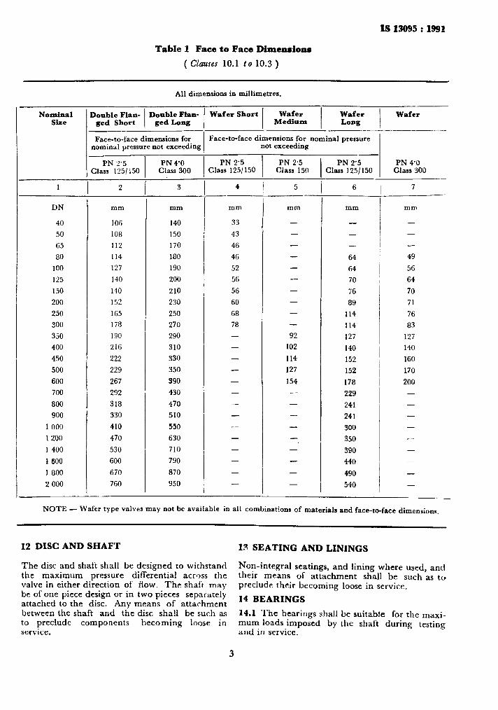
Table 1 Face to Face Dimensions
( Clauses 10.1 to 10.3 )
All dimensions in millimetres.
Nominal Size I
Doable Flaw Double Flan- Wafer Short ged Short ged Long
-- _I
Wafer Wafer Medium Long
Face-to-face dimensions for nominal pressure not exceeding
Face-to-face dimensions for nominal pressure not exceeding
PN 2’5 PN 4’0 PN 2’5 Class 125/:50 Class 300 Class 125/150
DN mm mm
40 106 140
50 108 150
65 112 170
80 114 180
100 127 190
125 140 200
150 140 210
200 152 230
250 165 250
300 178 270
350 190 290
400 216 310
450 222 330
500 229 350
600 267 390
700 292 430
800 318 470
900 330 510
1 000 410 550
1 200 470 630
1 400 530 710
1 600 600 790
I 800 670 870
2 000 760 950
-
-
-
Wafer
4
-
1 - mm
33
43
46
46
52
56
56
60
68
78 -
-
-
-
-
-
-
-
-
-
-
-
-
-
PN 2.5 Class 150
- 5
-
mm
-
-
-
-
-
-
-
-
-
-
92
102
114
127
154
-
-
-
-
-
-
-
-
If T
-- PN 2’5 PN 4’0
Class 125/150 Class 300
6
mm
-
-
-.
64
64
70
76
89
114
114
127
140
152
152
178
229
241
241
300
350
390
440
490
540
I - 7
mm
-
-
-
49
56
64
70
71
76
83
127
140
160
170
200 -
-
-
-
-
-
-
NOTE - Wafer type valves may not be available in all combinations of materials and face-to-face dimensions.
I2 DISC AND SHAFT IS SEATING AND LININGS
The disc and shaft shall be designed to withstand the maximum pressure differential across the valve in either direction of flow. The shaft may be of one piece design or in two pieces separately attached to the disc. Any means of attachment between the shaft and the disc shall be such as to preclude components becoming loose in service.
Non-integral seatings, and lining where used, and their means of attachment shall be such as to preclude their becoming loose in service.
I4 BEARINGS
14.1 The bearings shall be suitable for the maxi- mum loads imposed by the shaft during testing and in service.
3

IS 13095 : 1991
14.2 For valves DN 350 and above, a bearing shall be provided to take the axial thrust, spring retaining clips ( circlips ) shall not be used as thrust bearing.
14.3 Suitable sealing shall shaft where it passes outside ing enclosure.
be provided for the the pressure contain-
15 MATERIALS
This standard is based on materials specified in Table 2. Unless otherwise agreed, the mateiials shall be of a grade equivalent to those given in Table 2 or superior. Other material may be used as per agreement between the manufacturer and the purchaser.
Table 2 Basic Materials
Component Material IS Referred Grade
Body Cast iron 210 : 1978 FG 200, Min Spheroidal graphite iron 1865 : 1974 SG 400112 Carbon steel 2004 : 1978 Cl. 2 or Cl. 3
1875: 1978 Cl. 2 or Cl. 3 2856 : 1987 Gr 1 or Gr 2
Disc Cast iron 210 : 1978 FG 200, Min Spheroidal graphite iron 1865 : 1974 SG 400/12 Carbon steel 2004 : 1978 Cl. 2 or Cl. 3
1875 : 1978 Cl. 2 or Cl. 3 2856 : 1987 Gr 1 or Gr 2
Stainless steel 3444 : 1987 Gr 6 or Gr 7 Gun metal 318 : 1987 Gr - LTB, or
LTB, Aluminium bronze 305 : 1981 Gr 2
_ Shaft Stainless steel 6603 : 1972 12 Cr 13
15 Cr 16 Ni 2 04 Cr 18 Ni 10 04 Cr 17 N’i 12 MO 2
Carbon steel 1570 ( Part 2 ) : 1979 40 C8 Aluminium bronze 305 : 1981 Gr 2 Nickel copper alloy
Seating ring/ Stainless steel 6603 : 1972 04 Cr 18 Ni 10 Seal retaining ring 04 Cr 17 Ni 12 MO 2
3444 : 1987 Gr 2, Gr 6 or Gr 7 Gun metal 318 : 1981 Gr LTB, or LTBs Aluminium bronze 305 : 1981 Gr 2 Deposited metal-suitable for duty or resilient material ( see Note )
-.-_
Seat Elastomers - Nitrile, Neoprene, E. P. D. XI. Rubber
---
Shaft bearing Manufacturer’s standards; seals Suitable for duty
- -
Internal fastenings Stainless steel Manufacturers Suitable for dur\ standard
_-- -
Lxternal bolting Carbon steel; tensile - - strength 390 N/mm’ or MPa
- SOTE - When the resilient seals forms parts of:
a) the body and the disc is made of grey cast iron, spheroidal graphite iron, or carbon steel II IS rt~cc~rnrnrr~d~~~l that the disr should be provided with a disc facing, deposit on the edge, or roatrd all over.
1,) the disc and the body is madr of grey cast iron, spheroidal graphite iron or rarhon Etvel 11 I:, ret ~~rnmelldvd that tbe body should br provided with a facing rmg, deposit on diameter III contract MII~ rt.slllvut \c.~I (jr coated a11 over.
4
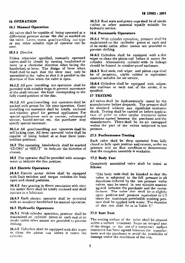
16 OPERATION
16.1 Manual Operation
All valves shall be capable of being operated at a differential pressure across the disc as marked on the valve. Lever, worm gearltravelling nut type or any other suitable type of operator can be used.
16.1.1 Direction
Unless otherwise specified, manually operated valves shall be closed by turning handwheel or iever in a clockwise direction when facing the handwheel or lever. The design of lever when fitted shall be such that the lever may only be assembled to the valve so that it is parallel to the direction of flow when the valve is open.
16.1.2 Al] gear travelling nut operators shall be provided with suitable stops to prevent movement of the shaft beyond the limit correspnding to the fully closed position of the disc.
16.1.3 All gear/travelling nut operators shall be packed with grease for life time operation. Gear/ travelling nut operators shall be totally enclosed and whether proof for general application. For special applications such as marine, submerged service, buried service etc. the purchaser may specify special enclosure.
16.1.4 All gearltravelling nut operators shall be self locking type. AI1 lever operated valve shall be capable of being locked at at least three inter- mediate positions.
16.2 The operating handwheels shall be marked ‘CLOSE’ or ‘SHUT’ to indicate the direction of closure.
16.3 The operator ahall be provided with arrange- ment to indicate the disc position.
16.4 Electric Operators
16.4.1 Electric motor drives shall be equipped with limit switches and torque switches for both open and closed positions.
16.4.2 Any gearing in direct association with elec- tric motor drive shall be totally enclosed and shall operate in a lubricant.
16.4.3 Each electric operator shall be provided with an auxiliary handwheel for manual operation.
16.5 Hydraulic Operators
16.5.1 With cylinder operation, pressure shall be maintained on cylinder piston at each end of its stroke unless other means are provided to prevent drifting.
16.5.2 Cylinders shall to clean the piston cylinder.
be equipped with dirt wiper rod befbre it enters the
IS 13095 : 1991
16.5.3 Rod seals and piston caps shall be of nitrile rubber or other material equally suitable for hydraulic service.
16.6 Pneumatic Operators
16.6.1 With cylinder operation, pressure shall be maintained on the cyclinder piston at each end of its stroke unless other means are provided to prevent drifting.
16.6.2 Cylinders shall be equipped with a dirt wiper to clean the piston rod before it enters the cylinder. Alternatively cylinder with its linkage should be housed in weather-proof enclosure.
16;6.3 Rod seals, rod wiper and piston caps shall be of neoprene, nitrile rubber or equivalent material suitable for air service,
16.6.4 Cylinders shall be equipped with adjust- able cushions at each end of the stroke, if so specified.
17 TESTING
All valves shall be hydrostatically tested by the manufacturer before despatch. The pressure shall be obtained without any significant hydraulic shock. Testing shall be carried on before applica- tion of paint or other similar treatment unless otherwise agreed between the purchaser and the manufacturer. There shall be no air entrapped within the part of the valves subjected to test pressure.
17.1 Performance Testing
Each valve shall be shop operated from fully closed to fully open position and reverse, under no pressure and no flow condition to demonstrate that the complete assembly is workable.
17.2 Body Test
Completely assembled valve shall be tested as follows:
‘The body ends shall be blanked so that the valve is subjected to the full pressure in all directions induced by the test pressure wafer valves may be tested in any suitable manner agreed between the purchaser and the manu- facturer. The valve disc shall be in slightly open position and pressure equivalent to 1.5 times the maximum permissible working pres- sure shall be applied with water. The duration of this test shall be as in Table 3.’
17.3 Seat Test
The seating surface of the valve shall he cleaned unless a surface treatment forms an integral part of the design or the use of a temporary surface treatment has been agreed between the manufac- turer and the purchaser to avoid the possibility of damage under the conditions of the test.
F
.
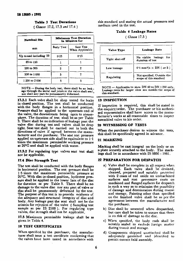
I8 19995 i 1991
Table 3 Test Durations
( Claue~ 17.2, 17.3 and 17.4 )
Nominal Dia I Mimimum Test Duration in Minutes for I
I I
mm Body Test I
Seat Test When Applicable
Up toand including 56 0.25 0’25
65 to 150 1 1
200 to 300 2 2
350 to 1006 5 2
1200 to 2 000 5 3
NOTE - During the body teat, there rhall be no leak _ age through the metal end joints or the valve shaft real, nor shall any part be permanently deformed.
this standard and stating the actual pressures and’ medium used in the test.
Table 4 Leakage Rates
( Clause 17.5 )
Valve Type Leakage Rate
Tight shut-off I
No visible leakage for duration of test
Low leakage 0’1 mms/s x DN ( scu 5 )
Regulating I
Not specified. Outside the scope of this standard
NOTE - Applicable to sizes DN 40 to DN 1200 only. Leakage rates for larger sizes are outside the scope of this standard.
17.3.1 Each valve shall be shop tested for leaks in closed position. The test shall be conducted with the body flanges in a horizontal position. Pressure shall be applied to the upstream end of the valve, the downstream being open to atmos- phere. The duration of test shall be as per Table 3. There shall be no indication of leakage past the valve disc during test and valves shall be drop tight. Seat test shall be carried out in both the directions of valve if agreed between the manu- facturer and the purchaser. The seat test pressure applied on upstream side shall be equivalent to l-1 times the maximum permissible working pressure at 20°C and shall be applied with water.
17.3.2 For regulating type valves seat test shall not be applicable.
17.4 Disc Strength Test
The test shall be conducted with the body flanges in horizontal position. The test pressure shall be 1.5 times the maximum permissible pressure at 20°C. With disc in closed position, hydrotest pres- sure shall be applied to the lower face of the disc for duration as per Table 3. There shall be no damage to the valve disc nor any part of valve or disc shall be permanently deformed by the test. The purpose of this test is to provide evidence of the adequacy and structural integrity of disc and body. Any leakage past the seat shall not be the criteria for rejection of the valve ( Sampling test sample as per IS 2500 ). For regulating type valves, disc strength shall not be applicable.
17.5 Maximum permissible leakage shall be as given in Table 4.
18 TEST CERTIFICATES
When specitied by the purchaser, the manufac- turer shall issue a test certificate confirming that the valves have been tested in accordance with
19 INSPECTION
If inspection is required, this shall be stated in the enquiry/order. The purchaser or his authori- sed representative shall have access to the manu- facturer’s works at all reasonable times to inspect assembled valve to his order.
20 WITNESSING OF TESTS
Whan the purchaser desires to witness the tests, this shall be specifically agreed in advance.
21 MARKXNG
Marking shall be cast integral on the body or. on a plate securely attached to the body. The mark- ings shall be in accordance with IS 9866 : 1981.
22 PREPARATION FOR DESPATCH
4
b)
4
4
Valve shall be complete in all respect when shipped. Each valve shall be drained, cleaned, prepared and suitably protected with 2 coats of red oxide on unmachined surfaces and rust preventive coats on machined and flanged surfaces for despatch in such a way as to minimise the possibility of damage and deterioration during transit and storage. Painting other than specified on the finished valve shall be as per the agreement between the manufacturer and the purchaser.
Disc shall be unseated when despatched, but care shall be taken to ensure that there is no risk of damage to the disc.
When specified, the body ends shall be suitably sealed to exclude foreign matter during transit and storage.
Components shipped unattached shall be adequately protected and iden tifed to permit correct field assembly.
6
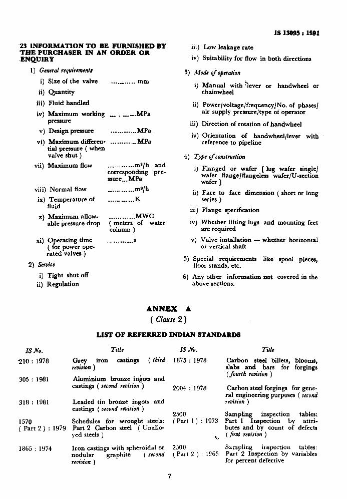
-23 lNFORMATION TO BE FURNISHED BY ‘THE PURCHASER IN AN ORDER OR .ENQUIRY
1) General requirements
9 ii)
iii)
iv)
Size of the valve
Quantity
Fluid handled
. . . . . . . . . . . mm
Maximum working . . . _ . . . --. MPa pressure
v) Design pressure . . . . . . . . . . . . MPa
vi) Maximum differen- . . . . . . . . . . . . MPa tial pressure ( when valve shut )
vii) Maximum flow . . . __. . . . . ..ms/ h and corresponding pre- ssure...MPa
viii) Normal flow . . . . . . . . . . . . ma/h
ix) Temnerature of . . . .-. . . . . . . K fluid *
4
xi)
Maximum allow- . . . . . . . . . . . . MWC able pressure drop ( meters of water
column )
Operating time . . . . . . . . . . . . S
( for power ope- rated valves )
2) Service
i) Tight shut off
ii) Regulation
IS No.
210 : 1978
305 : 1981
318 : 1981
1570 ( Part 2 ) : 1979
1865 : 1974
ANNEX A
IS 13o!l5 t 1981
iii) Low leakage rate
iv) Suitability for flow in both directions
3) Mode of operation
i) Manual with ‘fever or handwheel or chainwheel
ii) Power/voltage/frequency/No. of phases/ air supply pressure/type of operator
iii) Direction of rotation of handwheel
iv) Orientation of handwheelllever with reference to pipeline
4) 7-e of construction
i) Flanged or wafer [ lug wafer single/ wafer flangejflangeless wafer/U-section wafer J
ii) Face to face dimension ( short or long series )
iii) Flange specification
iv) Whether lifting lugs and mounting feet
5)
6)
are required
v) Valve installation - whether horizontal or vertical shaft
Special requirements like spool pieces, floor stands, etc.
Any other information not covered in the above sections.
( Clause 2 )
LIST OF REFERRED INDIAN STANDARDS
Title IS Ail.
Grey iron castings ( third 1875 : 1978 w&on )
Alumiaium bronze ingots and castings ( second revision ) 2004 : 1978
Leaded tin bronze ingots and castings ( second revision )
2500 Schedules for wrought steels: ( Part 1 ) : 1973 Part 2 Carbon steel ( Unallo- yed steels ) %
Iron castings with spheroidal or 2500 nodular graphite ( second (Part 2 ) : 1065 revision )
1
Title
Carbon steel billets, blooms, slabs and bars for forgings (fourth rtiion )
Carbon steel forgings for gene- ral engineering purposes ( second revision )
Sampling inspection tables: Part 1 Inspection by attri- butes and by count of defectr (&St revision )
Sampling inspection tables: Part 2 Inspection by variables for percent defective
4 c
.
. .
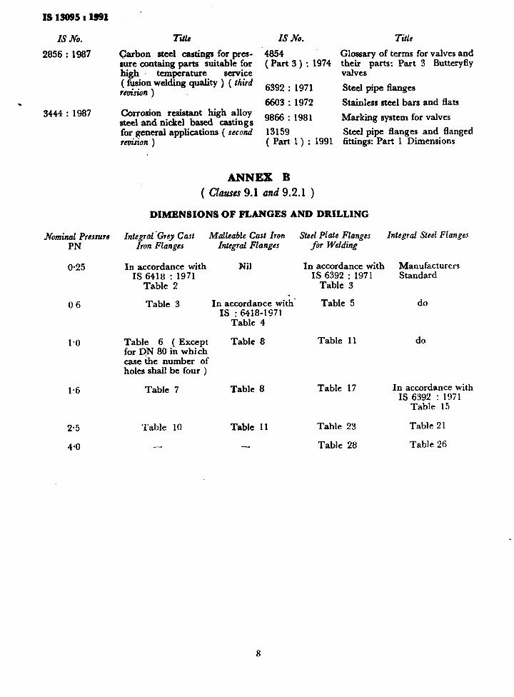
I&15095:1991
IS x0.
2856 : 1987
. 3444 : 1987
Nominal Pressure PN
0.25
06
1.0
1.6
2.5
4-O
Title
Garbon steel castings for pres- aure comaing parts suitable for high temperature service ( fusion welding quality ) ( third revision )
Corrosion resistant high alloy steel and nickel based castings for general applications ( second rekrion )
IS Jb.
4854 ( Part 3 ) : 1974
6392 : 1971
6603 : 1972
9866 : 1981
13159 ( Part 1) : 1991
ANNEX B
( Clauses 9.1 and 9.2.1 )
Title
Glossary of terms for valves and their parts: Part 3 Butteryfly valves
Steel pipe flanges
Stainless steel bars and flats
Marking system for valves
Steel pipe flanges and Banged fittings: Part 1 Dimensions
DIMENSIONS OF FLANGES AND DRILLING
Zntegtuf ‘Crey Cnst MnlLnble Cast Iron Iron Flanges Integral Flanges
In accordance with Nil IS 6418 : 1971
Table 2
Steel Plate Flanges for Welding
In accordance with Manufacturers IS 6392 : 1971 Standard
Table 3
Integral Steel Flanges
Table 3 4
In accordance with’ Table 5 do IS : 6418-1971
Table 4
Table 6 ( Except for DN 80 in which case the number of holes shall be four )
Table 8 Table 11 do
Table 7 Table 8 Table 17 In accordance with IS 6392 : 1971
Table 15
Table 10 Table 11 Table 23 Table 21
- - Table 28 Table 26
.
Bureau of Indian Standards
BIS is a statutory institution established under the Bureau of Indian Standards Act, 1986 to promote harmonious development of the activities of standardization, marking and quality certification of goods and attending to connected matters in the country.
Copyright ‘r
BIS has the copyright of&l1 its publications. No part of these publications may be reproduced in any form without the prior permis&ion in writing of BIS. This does not preclude the free use, in the course of implementing the standard, of necessary details, such aS symbols and sizes, type or grade designations. Enquiries relating to copyright be addressed to the Director (Publication), BIS.
Review of Indian Standards
Amendments are issued to standards as the need arises on the basis of comments. Standards are also reviewed periodically; a standard along with amendments is reaffirmed when such review indicates that no changes are needed; if the review indicates that changes are needed, it is taken up for revision. Users of Indian Standards should ascertain that they are in possession of the latest amendments or edition by referring to the latest issue of ‘BIS Handbook’ and ‘Standards Monthly Additions’.
This Indian Standard has been developed from Dot: No. HMD 17 ( 3744 )
Amendments Issued Since Publication
Amend No. Date of Issue Text Affected
BUREAU OF INDIAN STANDARDS Headquarters:
Manak Bhavafi, 9 Bahadur Shah Zafar Marg, New Delhi 110002 Telephones: 323 0131,323 83 75,323 94 02
Regional Offices:
Telegrams: Manaksanstha (Common to all offices)
Telephone
Central :
Eastern :
Northern :
Southern :
Western :
Branches :
Manak Bhavan, 9 Bahadur Shah Zafar Marg NEW DELHI 110002
323 76 17,323 38 41
l/14 C.I.T. Scheme VII M, V.I.P. Road, Maniktola CALCUTI-A 700054
SC0 335-336, Sector 34-A, CI-IANDIGARH 160022 ,;
C.I.T. Campus, IV Cross Road, MADRAS 60011’3
337 84 99,337 85 61 337 86 26,337 9120
{ 603843 _ 60 20 25
{ 235 02 16,235 04 42 235 15 19,235 23 15
Manakalaya, E9 MID5 Marol, Andheri (East) MUMBAI 400093 i
AHMADABAD. BANG&ORE. BHOPAL. BHUBANESHWAR. COIMBATORE. FARIDABAD. GHAZIABAD. GUWAHATI. HYDERABAD. JAIPUR. KANPUR. LUCKNOW. PATNA. THIRUVANANTHAPURAM.
( 832 92 95,832 78 58 832 78 91,832 78 92
Reprography Unit, BIS, New Delhi, India

AMENDMENT NO. 1 AUGUST 1996 TO
IS 13095 : 1991 BUTTERFLY VALVES FOR GENERAL PURPOSES
(Page 2, clause 7.1, line 5 ) - Substitute the following for the existing:
‘PN 0.25, PN 0.6, PN 1.0, PN 1.6, PN 2.5 and PN 4.0’.
(Hh4D17) Reprography Unit, BIS, New Delhi, India
Related Documents