Disclosure to Promote the Right To Information Whereas the Parliament of India has set out to provide a practical regime of right to information for citizens to secure access to information under the control of public authorities, in order to promote transparency and accountability in the working of every public authority, and whereas the attached publication of the Bureau of Indian Standards is of particular interest to the public, particularly disadvantaged communities and those engaged in the pursuit of education and knowledge, the attached public safety standard is made available to promote the timely dissemination of this information in an accurate manner to the public. इंटरनेट मानक “!ान $ एक न’ भारत का +नम-ण” Satyanarayan Gangaram Pitroda “Invent a New India Using Knowledge” “प0रा1 को छोड न’ 5 तरफ” Jawaharlal Nehru “Step Out From the Old to the New” “जान1 का अ+धकार, जी1 का अ+धकार” Mazdoor Kisan Shakti Sangathan “The Right to Information, The Right to Live” “!ान एक ऐसा खजाना > जो कभी च0राया नहB जा सकता ह ै” Bhartṛhari—Nītiśatakam “Knowledge is such a treasure which cannot be stolen” IS 12535-2 (1991): Automotive vehicles - Tranmission systems - Glossary, Part 2: Universal joints and driveshafts [TED 2: Automotive Primemovers]

Welcome message from author
This document is posted to help you gain knowledge. Please leave a comment to let me know what you think about it! Share it to your friends and learn new things together.
Transcript

Disclosure to Promote the Right To Information
Whereas the Parliament of India has set out to provide a practical regime of right to information for citizens to secure access to information under the control of public authorities, in order to promote transparency and accountability in the working of every public authority, and whereas the attached publication of the Bureau of Indian Standards is of particular interest to the public, particularly disadvantaged communities and those engaged in the pursuit of education and knowledge, the attached public safety standard is made available to promote the timely dissemination of this information in an accurate manner to the public.
इंटरनेट मानक
“!ान $ एक न' भारत का +नम-ण”Satyanarayan Gangaram Pitroda
“Invent a New India Using Knowledge”
“प0रा1 को छोड न' 5 तरफ”Jawaharlal Nehru
“Step Out From the Old to the New”
“जान1 का अ+धकार, जी1 का अ+धकार”Mazdoor Kisan Shakti Sangathan
“The Right to Information, The Right to Live”
“!ान एक ऐसा खजाना > जो कभी च0राया नहB जा सकता है”Bhartṛhari—Nītiśatakam
“Knowledge is such a treasure which cannot be stolen”
“Invent a New India Using Knowledge”
है”ह”ह
IS 12535-2 (1991): Automotive vehicles - Tranmissionsystems - Glossary, Part 2: Universal joints anddriveshafts [TED 2: Automotive Primemovers]


_____l_-,- -- .
IS 12535 ( Part 2 ) : 1991
AUTOMOTIVE VEHICLES - TRANSMISSION SYSTEMS - GLONSSARY
PART 2 UNIVERSAL JOINTS AND DRIVESHAFTS
L UDC 621’825’6 : 629’113 : 001’4
0 BIS 1991
BUREAU OF INDIAN STANDARDS MANAK BHAVAN, 9 BAHADUR SHAH ZAFAR MARG
NEW DELHI 110002
September 1991 Price Group 7
Automotive Transmission Systems Sectional Committee, TED 3
FOREWORD
This Indian Standard was adopted by the Bureau of Indian Standards, after the draft finalized by the Automotive Transmission Systems Sectional Committee had been approved by the Transport Engineering Division Council.
The other parts of this Indian Standards are:
IS 12535 (Part 1) : 1988 Automotive vehicles - Transmission systems - Glossary: Part 1 General
IS 12535 (Part 3) : 1991 Automotive vehicles - Transmission systems - Glossary: Part 3 Drive axle
In the preparation of this standard considerable assistance has been derived from SAE J 901 b “Universal joints and driveshafts - Nomenclature and terminology”.
ALJTOMOTIVE
IS 12535 ( Part 2 ) : 1991
Indian Standard
VEHICLES - TRANSMISSION SYSTEMS - GLOSSARY
PART 2 UNWERSAI. JOINTS AND DRIVESHAFTS
2.8 Swing Diameter 1 SCOPE
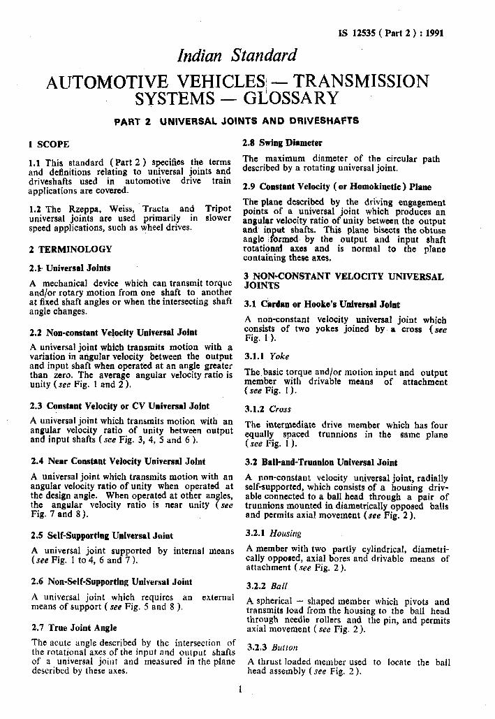
1.1 This standard (Part 2 ) specifies the terms and definitions relating to universal joints and driveshafts used in automotive drive train applications are covered.
1.2 The Rzeppa; Weiss, Tracta and Tripot universal joints are used primarily in slower speed applications, such as wheel drives.
2 TERMINOLOGY
2.k. Universal Joints
A mechanical device which can transmit torque and/or rotary motion from one shaft to another at fixed shaft angles or when the intersecting shaft angle changes.
2.2 Non-constant Velocity Universal Joint
A universal joint which transmits motion with a variation in angular velocity, between the output and input shaft when operated at an angle greater than zero. The average angular velocity ratio is unity (see Fig. 1 and 2).
2.3 Constant Velocity or CV Universal Joint
A universal joint which transmits motion with an angular velocity ratio of unity between output and input shafts (see Fig. 3, 4, 5 and 6 ).
2.4 Near Constant Velocity Universal Joint
A universal joint which transmits motion with an angular velocity ratio of unity when operated at the design angle. When operated at other angles, the angular velocity ratio is near unity (see Fig. 7 and 8).
2.5 Self-Supporting Universal Joint
A universal joint supported by internal means (see Fig. 1 to 4, 6 and 7 ).
2.6 Non-Self-Supporting Universal Joint
A universal joint which requires an external means of support ( see Fig. 5 and 8 ).
2.7 True Joint Angle
The acute angle described by the intersection of the rotational axes of the input and output shafts of a universal joint and measured in the plane described by these axes.
The maximum diameter of the circular path described by a rotating universal joint.
2.9 Constant Velocity ( or Homokinetic ) Plane
The plane described by the driving engagement points, of a universal joint which produces an angular velocity ratio of unity between the output and input shafts. This plane bisects the obtuse angle formed by the output and input shaft rotational axes and is normal to the plane containing these axes.
3 NON-CONSTANT VELOCITY UNIVERSAL JOINTS
3.1 Cardan or Hooke’s Universal Joint
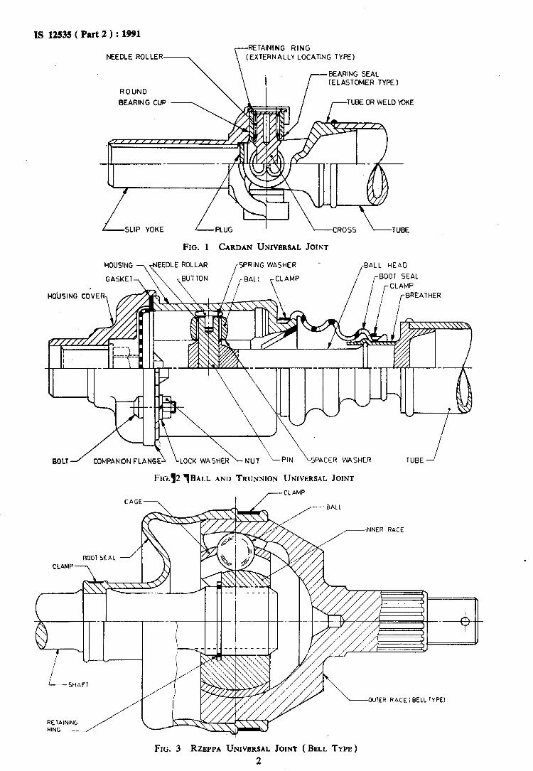
A no&constant velocity universal joint which consists of two yokes joined by a cross (see Fig. 1 ).
3.1.1 Yoke
The basic torque and/or motion input and output member with drivable means of attachment (see Fig. 1).
3.1.2 Cross
The intermediate drive member which has four equally spaced trunnions in the same plane (see Fig. 1 ).
3.2 Ball-and-Trunnion Universal Joint
A non-constant velocity universal joint, radially self-supported, which consists of a housing driv- able connected to a ball head through a pair of trunnions mounted in diametrically opposed balls and permits axial movement (see Fig. 2 ).
3.2.1 Housirlg
A member with two partly cylindrical, diametti- tally opposed, axial bores and drivable means of attachment (see Fig. 2 ).
3.2.2 BaN
A spherical - shaped member which pivots and transmits load from the housing to the ball head through needle rollers and the pin, and permits axial movement ( see Fig. 2).
3.2.3 Button
A thrust loaded member used to locate the ball head assembly ( see Fig. 2 ).
1
IS 12535 ( Part 2 ) : 1991 RETAINING RING
NEEDLE ROLLER LOCATING TYPE)
r BEARING SEAL (ELASTOMER TYPE 1
ROTUND
BEARING CUP - u, /TUBE OR WELD YOKE /
\-CROSS \-TUBE
JOINT
L- SLIP YOKE /PLUG ’
FIG. 1 CARDAN UNIVERSAL
HOUSING
/
SPRING WASHER
GASKET , /BALL \CLAMP
COMPANION FLANG SPACER WASHER
Fr0.~2 ~BAL~ AND TRUNNION UNIVERSAL JOINT
-CL AMP
aALL
-INNER RACE
-OUTER RACE (BELL TYPE)
c
FIG. 3 RZEPPA UNIVERSAL JOINT ( BELL TYPE)
2

IS 12535 ( Part 2 ) : 1991
MOUSING COVER /-r “d’ RING SEAL
INNER
RETAINING RING
RETAINING RING
GALLS - /
INNER RACE
.AET&lNING RING
f-
“d’ RING SEAL
RETAINING RING
Fxa. 4 BALL SPLINB RZEPPA UNIVERSAL JOINT
EXTERNAL CENTERING MECHANIS
THRUST &ND
“lN:T,“;L~~ON?-.&@--g
RADIAL BEARING
CENTERING BALL
I-BALL YOKE
SHAF 1
RETAINING PIN F-_
I I IJ /’
,,‘/,,l/ ” 9 /’ ” / P / /
T i THRUST BEARING
FE. 5 WEISS UNIVERSAL JOINT (CURVED GROOVED TYPE), WHEEL POSITION APPLICATION
3

IS 12535 ( Part 2 ) : 1991
RNATE CENTERING MEANS AT ENLARGED VIEW
BALL STUO SUPPORT
I \
SPRING WASHER q:zL STUD SEAL
FIG. 7 DOUBLE CARDAN UNWERSAL JOINT
EXTERiJAL CENTERING MECHANISM t KINGPIN CONSTRUCTION)
OROOVED COUPLING
THRUST AND RADIAL BEARING
THRUST AND RADIAL BEARING
_ --- --
GR’%ED COUPLING
FIG. 8 TKACTA UNIVERSAL JOINT, WHEEL POSITION APPLICATION
5
IS 12535 ( Part 2 ) : 1991
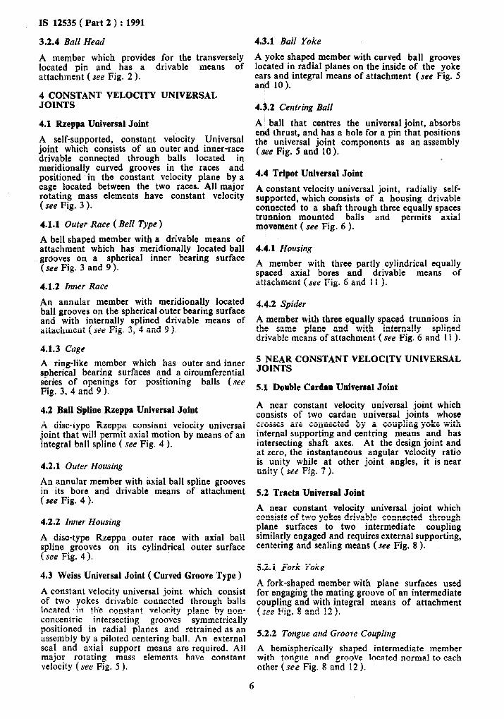
3.2.4 Ball Head
A member which provides for the transversely located pin and has a drivable means of attachment ( see Fig. 2 ).
4 CONSTANT VELOCITY UNIVERSAL JOINTS
4.1 Rzeppa Universal Joint
A self-supported, constant velocity Universal joint which consists of an outer and inner-race drivable connected through balls located in meridionally curved grooves in the races and positioned in the constant velocity plane by a cage located between the two races. All major rotating mass elements have constant velocity ( see Fig. 3 ).
4.1.1 Outer Race ( Bell Type )
A bell shaped member with a drivable means of attachment which has meridionally located ball grooves on a spherical inner bearing surface (see Fig. 3 and 9 ).
4.1.2 Inner Race
An annular member with meridionally located ball grooves on the spherical outer bearing surface and with internally splined drivable means of attachment ( see Fig. 3, 4 and 9 ).
4.1.3 Cage
A ring-like member which has outer and inner spherical bearing surfaces and a circumferential series of openings for positioning balls (see Fig. 3, 4 and 9 ).
4.2 Ball Spline Rzeppa Universal Joint
A disc-type Rzeppa constant velocity universal joint that will permit axial motion by means of an integral ball spline ( see Fig. 4 ).
4.2.1 Outer Housing
An annular member with axial ball spline grooves in its bore and drivable means of attachment (see Fig. 4 ).
4.2.2 Inner Housing
A disc-type Rzeppa outer race with axial ball spline grooves on its cylindrical outer surface ( see Fig. 4 ).
4.3 Weiss Universal Joint ( Curved Groove Type )
A constant velocity universal joint which consist of two yokes drivable connected through balls located ‘in the constant velocity plane by non- concentric intersecting grooves symmetrically positioned in radial planes and retrained as an assembly by a piloted centering ball. An external seal and axial support means are required. All major rotating mass elements have constant velocity ( see Fig. 5 ).
4.3.1 Ball Yoke
A yoke shaped member with curved ball grooves located in radial planes on the inside of the yoke ears and integral means of attachment (see Fig. 5 and 10).
4.6.2 Centring Ball
A ’ ball that centres the universal joint, absorbs end thrust, and has a hole for a pin that positions the universal joint components as an assembly (tie Fig. 5 and 10).
,
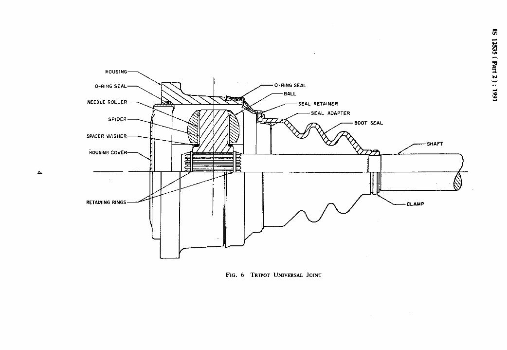
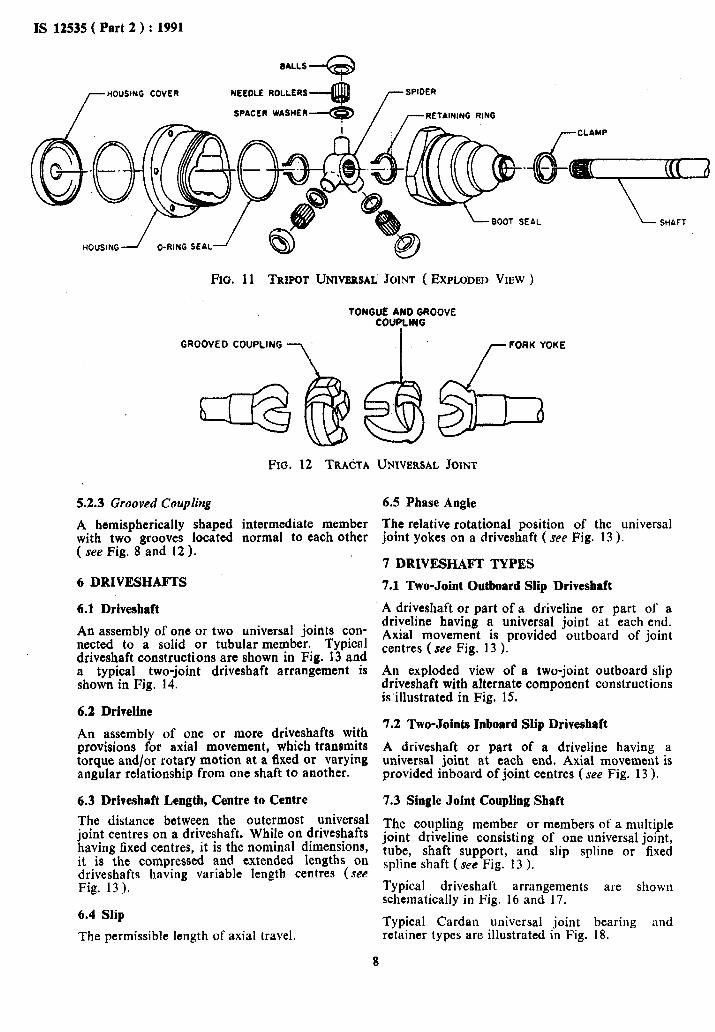
4.4 Tripot Universal Joint
A constant velocity universal joint, radially self- supported. which consists of a housing drivable connected to a shaft through three equally spaces trunnion mounted balls and permits axial movement ( see Fig. 6 ).
4.4.1 Housing
A member with three partly cylindrical equally spaced axial bores and drivable means of attachment (see Fig. 6 and 11 ).
4.4.2 Spider
A member with three equally spaced trunnions in the same plane and with internally splined drivable means of attachment (see Fig. 6 and 11 ).
5 NEAR CONSTANT VELOCITY UNIVERSAL JOINTS
5.1 Double Cardan Universal Joint
A near constant velocity universal joint which consists of two cardan universal joints whose crosses are connected by a coupling yoke with internal supporting and centring means and has intersecting shaft axes. At the design joint and at zero, the instantaneous angular velocity ratio is unity while at other joint angles, it is near unity ( see Fig. 7).
5.2 Tracta Universal Joint
A near constant velocity universal joint which consists of two yokes drivable connected through plane surfaces to two intermediate coupling similarly engaged and requires external supporting, centering and sealing means (see Fig. 8 ).
5.2.1 F’ork Yoke
A fork-shaped member with plane surfaces used for engaging the mating groove of an intermediate coupling and with integral means of attachment (see Fig. 8 and 12 ).
5.2.2 Tongue and Groove Coupling
A hemispherically shaped intermediate member with tongue and groove located normal to each other (see Fig. 8 and 12 ).
6

IS 12535 ( Part 2 ) : 1991
OUTER RACE (BELL TYPE1
RETAINING RING
FIG. 9 RZBPPA UNIVERSAL JOINT ( BELL TYPE )
,r----RE’AWNG PIN
FIG. 10 WEISS UNIVERSAL JOINT (CURVED GROOVED TYPE )
IS 12535 ( Part 2 ) : 1991
HOUSING COVER
8ALLS
NEEDLE ROLLERS
SPACER WASHER
FIG. 11 TR~POT UNIVERSAL JOINT ( EXPLODED VIEW )
TONCUEANOGROOVE COUPIAUG
GROOVED COUPLING
7
FORK YOKE
FIG. 12 TRA~TA UNIVERSAL JOINT
5.2.3 Grooved Coupling
A hemispherically shaped intermediate member with two grooves located normal to each other ( see Fig. 8 and 12 ).
6 DRIVESHAFTS
6.1 Driveshaft
An assembly of one or two universal joints con- nected to a solid or tubular member. Typical driveshaft constructions are shown in Fig. 13 and a typical two-joint driveshaft arrangement is shown in Fig. 14.
6.2 Driveline
An assembly of one or more driveshafts with provisions for axial movement, which transmits torque and/or rotary motion at a fixed or varying angular relationship from one shaft to another.
6.3 Driveshaft Length, Centre to Centre
The distance between the outermost universal joint centres on a driveshaft. While on driveshafts having fixed centres, it is the nominal dimensions, it is the compressed and extended lengths on driveshafts having variable length centres (see Fig, 13).
6.4 Slip
The permissible length of axial travel.
6.5 Phase Angle
The relative rotational position of the universal joint yokes on a driveshaft ( see Fig. 13 ).
7 DRIVESHAFT TYPES
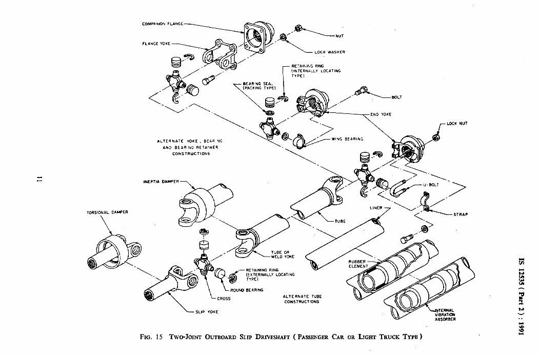
7.1 Two-Joint Outboard Slip Driveshaft
A driveshaft or part of a driveline or part of a driveline having a universal joint at each end. Axial movement is provided outboard of joint centres (see Fig. 13 ).
An exploded view of a two-joint outboard slip driveshaft with alternate component constructions is’illustrated in Fig. 15.
7.2 Two-Joints Inboard Slip Driveshaft
A driveshaft or part of a driveline having a universal joint at each end. Axial movement is provided inboard of joint centres (see Fig. 13 )-
7.3 Single Joint Coupling Shaft
The coupling member or members of a multiple joint driveline consisting of one universal joint, tube, shaft support, and slip spline or fixed spline shaft ( see Fig. 13 ).
Typical driveshaft arrangements are shown schematically in Fig. 16 and 17.
Typical Cardan universal joint bearing and retainer types are illustrated in Fig. 18.
8
T r ,

IS 12535 ( Part 2 ) : 1991
TWO JOINT OUTBOARD SLIP DRIVESHAFT
C_G-I_A_G~
TWO JOINT INBOARD SLIP DRIVESHAFT
SINGLE JOINT COUPLING SHAFT
1 UNIVERSAL JOIN’T A 2 SLIP YOKE (INTERNAL SPLINED)
3 TUBE B L END YOKE C 5 FLANGE YOKE. 0 6 TU.BE OR WELD YOKE E 7 SLIP SHAFTCEXTERNAL SPLINED) F 8 NON-SLIP SHAFT (EXTERNAL SPLINED) G
9 SLIP YOKE (EXTERNAL sPLINEiJ) H 10 SHAFT SIJPPORT r 11 SLIP SHAFT (INTERNAL SPLINED) J
K
FIXED OR COMPRESSED DRIVE SHAFT LENGTH
JOINT CENTER TO
TUBE DIAMETER WALL THICKNESS
JOINT ANGLE PHASE ANGLE
SWING DIAMETER OVER ALL LENGTH
SPLINDED LENGTI-i
CENTER
OF’ COMPONENT
OF COMPONENT AVAILABLE: SPLINE SLIP
LENGTH FFiOM JOINT CENTER TO CENTERLINE OF BEARING
LENGTH FROM JOINT CENTER TO SPLINED SHAFT END
FIG. 13 TYPICAL DRIVESHAFT CONSTRUCTION
9

COHPAHION FLANGE
LOCK WASHER
r
RETAINING RING
(INTERNALLY LOCATING
TYPE1
BEARING SEAL (PACKING TwEl
CONSTRUCTIONS
IwERT~A DAMPER --,
,.LBOLT ------TN0 YoKE
NC BEARING
LOCH NUT
-‘-SsLlP YOKE
FIG. 15 TWO-JOINT OUTBOARD SLIP DRIVESHAFT ( PASSENGER CAR OR LIGHT TRUCK TY~B )
N V
. .
Y
;o s

KEY
E - ENGINE
T -TRANSMISSION
RA- REAR AXLE
FIG. 16 TYPKAL MULTIJOINT DRIVESHAFT ARRANGEMESTS

DIFFE END
IS 12535 ( Part 2 ) : 1991
NON -STEERABLE AXLE SHAFT
( INDEPENDENT WHEEL SUSPENSION TYPE 1
-WHEEL END
DIFFERENTIAL END - -WHEEL END
STEERABLE OR NON-STEERABLE AXLE SHAFT
( INDEPENDENT WHEEL SUSPENSION TYPE 1
DIFFERENTIAL END - -WHEEL END
STEERABLE AXLE SHAFT
(RIGID AXLE TYPE)
l- CARD,AN 3- RZEPPA 5- WEISS 7- TRIPOT
2- DOUBLE CARDAN L- BALL SPClNE RZEPPA 6- BALL AND TRUNNION 8- TRACTA
UNIVE’RSAL JOINT KEY
FIG. 17 TYPICAL WHBEL DRIVESHAFT ARRANGEMENT
RETAINING RING--~, (iNlEt?NALLY LOCATING TYPE)
/--YOKE
RETAINING RING
(EXTERNALLY LOCATING TYPE) -7
RETAINING RUNG
(INJECTION MOLDEO PLASTICJ \SrRAP
ALTERNATE ROUNO BEARING AND RETAINER
THRU HOLE TYPE -, , ,-TAPPED HOLE TYPE ,
LOW HIGH
_ALTERNATE WING BEARING AND RETAINER
BEARING RETAINER (STAR TYPE 1
r RETAINER PLATE TYPE
DELTA
CONSTRUCTION
FIG. 18 UNIVERSAL JOINT BEARINCI AND RBTAINBR TYPE
13

1
Standard Mark
The use of the Standard Mark is governed by the provisions of the Bureau of Indian Standards Act, 1986 and the Rules and Regulations made thereunder. The Standard Mark on products covered by an Indian Standard conveys the assurance that they have been produced to comply with the requirements of that standard under a well defined system of inspection, testing and quality control which is devised and supervised by BIS and operated by the pro- ducer. Standard marked products are also continuously checked by BIS for conformity to that standard as a further safeguard. Details of conditions under which a licence for the use of the Standard Mark may be granted to manufacturers or producers may be obtained from the Bureau of Indian Standards.
Related Documents