Irreversibility analysis of cross flow heat exchangers R. Tug˘rul Og˘ulata a, *, Fu¨sun Doba a , Tuncay Yilmaz b a Department of Textile Engineering, C ° ukurova University, 01330 Adana, Turkey b Department of Mechanical Engineering, C ° ukurova University, 01330 Adana, Turkey Received 6 July 1999; accepted 5 January 2000 Abstract In this paper, a cross flow plate type heat exchanger, operating with unmixed fluids, was analysed with balanced cross flow. For this aim, a cross flow plate type heat exchanger was developed and manufactured in the laboratory. The heat exchanger was tested with an applicable experimental set up, and temperatures, velocity of the air and the pressure losses occurring in the system were measured so that the eectiveness of the heat exchanger has been determined. The minimum entropy generation number has been taken into consideration with respect to the second law of thermodynamics for the heat exchanger in this analysis. The minimum entropy generation number depends on parameters such as optimum flow path length, dimensionless mass velocity, dimensionless heat transfer area and dimensionless heat transfer volume. The variations between the entropy generation number and these parameters were analysed for the manufactured heat exchanger and introduced with their graphics. 7 2000 Elsevier Science Ltd. All rights reserved. 1. Introduction As known, heat exchangers are generally used for heat transfer between hot and cold fluids. There are a number of heat exchanger apparatus for dierent applications. Heat exchangers are classified with respect to many kinds of sizes, weights, shapes, flow patterns and dierent uses. Heat transfer and pressure losses and the optimization of size, weight and price should be taken into consideration while design of the heat exchanger is being performed. Energy Conversion & Management 41 (2000) 1585–1599 0196-8904/00/$ - see front matter 7 2000 Elsevier Science Ltd. All rights reserved. PII: S0196-8904(00)00020-0 www.elsevier.com/locate/enconman * Corresponding author. Fax: +90-322-3386-126. E-mail address: [email protected] (R.T. Og˘ulata).

Welcome message from author
This document is posted to help you gain knowledge. Please leave a comment to let me know what you think about it! Share it to your friends and learn new things together.
Transcript
Irreversibility analysis of cross ¯ow heat exchangers
R. TugÆ rul OgÆ ulataa,*, FuÈ sun Dobaa, Tuncay Yilmazb
aDepartment of Textile Engineering, C° ukurova University, 01330 Adana, TurkeybDepartment of Mechanical Engineering, C° ukurova University, 01330 Adana, Turkey
Received 6 July 1999; accepted 5 January 2000
Abstract
In this paper, a cross ¯ow plate type heat exchanger, operating with unmixed ¯uids, was analysedwith balanced cross ¯ow. For this aim, a cross ¯ow plate type heat exchanger was developed andmanufactured in the laboratory. The heat exchanger was tested with an applicable experimental set up,and temperatures, velocity of the air and the pressure losses occurring in the system were measured sothat the e�ectiveness of the heat exchanger has been determined. The minimum entropy generationnumber has been taken into consideration with respect to the second law of thermodynamics for theheat exchanger in this analysis. The minimum entropy generation number depends on parameters suchas optimum ¯ow path length, dimensionless mass velocity, dimensionless heat transfer area anddimensionless heat transfer volume. The variations between the entropy generation number and theseparameters were analysed for the manufactured heat exchanger and introduced with theirgraphics. 7 2000 Elsevier Science Ltd. All rights reserved.
1. Introduction
As known, heat exchangers are generally used for heat transfer between hot and cold ¯uids.There are a number of heat exchanger apparatus for di�erent applications. Heat exchangersare classi®ed with respect to many kinds of sizes, weights, shapes, ¯ow patterns and di�erentuses. Heat transfer and pressure losses and the optimization of size, weight and price should betaken into consideration while design of the heat exchanger is being performed.
Energy Conversion & Management 41 (2000) 1585±1599
0196-8904/00/$ - see front matter 7 2000 Elsevier Science Ltd. All rights reserved.PII: S0196-8904(00)00020-0
www.elsevier.com/locate/enconman
* Corresponding author. Fax: +90-322-3386-126.E-mail address: [email protected] (R.T. OgÆ ulata).
Nomenclature
a half bottom side of plate (m)A total heat transfer area (m2)C heat capacity of ¯uid (W/K)cp speci®c heat capacity (J/Kg K)D duct hydraulic diameter (m)f friction factor (±)G mass velocity (kg/sm2)K overall heat transfer coe�cient (W/m2 K)L length of duct, length of heat exchanger (m)_m mass ¯ow rate (kg/s)Ns entropy rate generation number (±)Ntu number of transfer unit (±)P pressure (Pa)Q heat transfer rate (W)R ideal gas constant (J/kg K)s plate thickness (m)S.
entropy (W/K)_Sgen rate of entropy generation (W/K)St Stanton number (±)T absolute temperature (K)v.
volume ¯ow rate (m3/s)V heat transfer volume (m3)DP pressure drop (Pa)DT temperature di�erence (K)r mean density of ¯uid in duct (kg/m3)e e�ectiveness (±)
Subscripts1 hot ¯uid2 cold ¯uidmax maximummin minimumi inleto outletcold cold ¯uidhot hot ¯uid
Superscript� dimensionless
R.T. OgÆulata et al. / Energy Conversion & Management 41 (2000) 1585±15991586
In this paper, a recuperative plate type heat exchanger was examined because it is moreapplicable than some others in industrial applications and waste heat recovery systems. Cross¯ow heat exchangers are generally used in air/gas heating and cooling applications. Theanalysed heat exchanger is a cross ¯ow plate type heat exchanger, and heat transfer occursbetween the hot and cold ¯uids with unmixed ¯uids.For this aim, the designed and manufactured plate type heat exchanger was tested with an
applicable experimental set up, the experimental e�ectivenesses were compared with thee�ectivenesses in the literature and the design criteria were examined based on the second lawof thermodynamics. There are many researches on this subject in the literature, the moreimportant of which have been reported below.Bejan [2] investigated a heat exchanger with two types of losses, heat transfer losses and
frictional pressure drops in channels, and reported heat exchanger e�ectiveness by using theentropy generation number.Bejan and Poulikakos [4] reported the minimization of entropy generation in forced
convection for the design of extended surfaces by use of the ®rst and second laws ofthermodynamics.EgÆ rican [7] investigated the LMTD (logarithmic mean temperature di�erence) method based
on the ®rst law of thermodynamics with e�ectiveness-transfer unit methods and entropygeneration units based on the second law of thermodynamics.Sekulic [14] examined the quality of energy transformation of a heat exchanger based on the
second law of thermodynamics and related this transformation to di�erent parameters, such asinlet temperature ratio, ¯uid ¯ow heat capacity rate ratio and e�ectiveness of the heatexchanger.Van Den Bulck [15] investigated the optimal design of a cross ¯ow heat exchanger and
determined the optimal distribution of transfer area for maximum e�ectiveness of the heatexchanger.A Bejan's number [12] was de®ned based on the duct entropy generation rates due to the
end-to-end pressure drop and the wall-stream temperature di�erence for second law analysis ofa heat exchanger.Ranganayakulu et al. [13] analysed a cross ¯ow plate ®n compact heat exchanger,
accounting for the e�ects of two dimensional nonuniform inlet ¯uid ¯ow distribution on boththe hot and cold ¯uid sides. A mathematical equation was developed to generate di�erent typesof ¯uid ¯ow maldistribution models to consider the possible deviations in ¯uid ¯ow. Usingthese ¯uid ¯ow maldistribution models, the exchanger e�ectiveness and its deterioration due to¯ow nonuniformity were calculated for an entire range of design and operating conditions. Inaddition to thermal analysis, the pressure drops and their variations were also calculated forthese models.
2. Plate type heat exchanger
Plate layers with fresh and waste air channels were separated airtight in the manufacturedplate type heat exchanger with ®xed members. Heat transfers directly between the hot waste airand cold fresh air ¯ow. This kind of heat exchanger generally operates on the cross ¯ow
R.T. OgÆulata et al. / Energy Conversion & Management 41 (2000) 1585±1599 1587
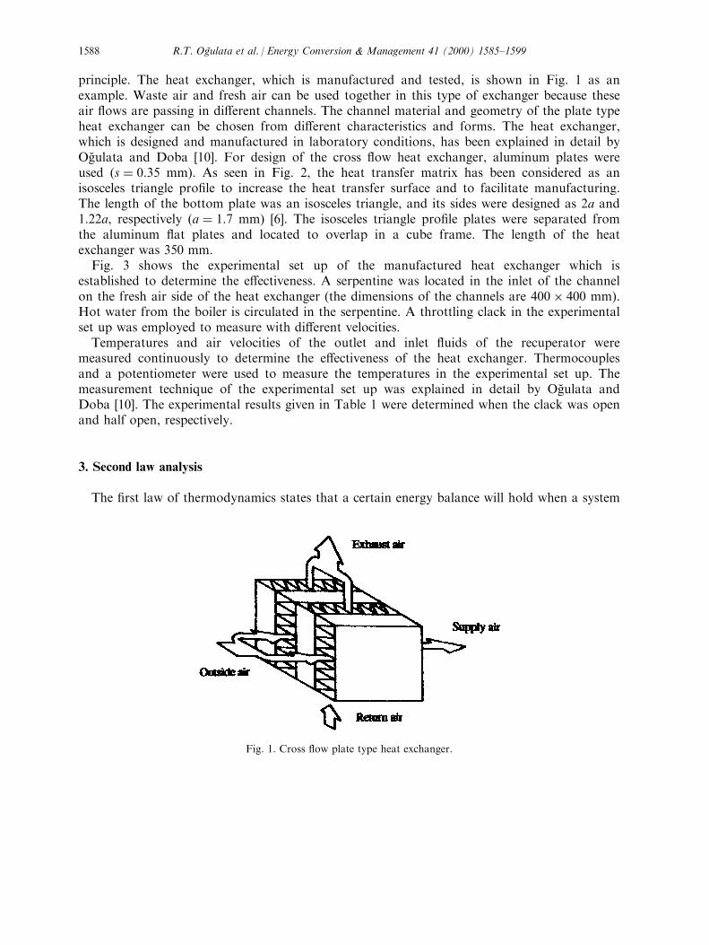
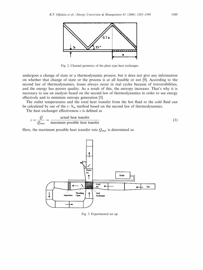
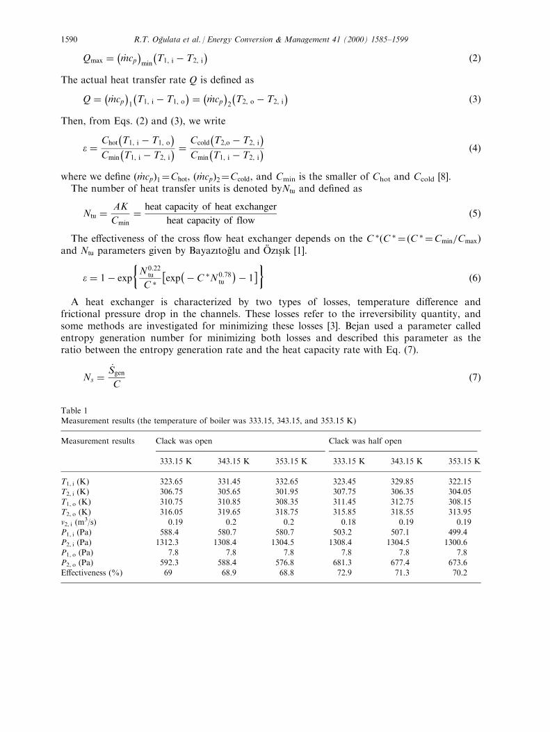
principle. The heat exchanger, which is manufactured and tested, is shown in Fig. 1 as anexample. Waste air and fresh air can be used together in this type of exchanger because theseair ¯ows are passing in di�erent channels. The channel material and geometry of the plate typeheat exchanger can be chosen from di�erent characteristics and forms. The heat exchanger,which is designed and manufactured in laboratory conditions, has been explained in detail byOgÆ ulata and Doba [10]. For design of the cross ¯ow heat exchanger, aluminum plates wereused �s � 0:35 mm). As seen in Fig. 2, the heat transfer matrix has been considered as anisosceles triangle pro®le to increase the heat transfer surface and to facilitate manufacturing.The length of the bottom plate was an isosceles triangle, and its sides were designed as 2a and1.22a, respectively �a � 1:7 mm) [6]. The isosceles triangle pro®le plates were separated fromthe aluminum ¯at plates and located to overlap in a cube frame. The length of the heatexchanger was 350 mm.Fig. 3 shows the experimental set up of the manufactured heat exchanger which is
established to determine the e�ectiveness. A serpentine was located in the inlet of the channelon the fresh air side of the heat exchanger (the dimensions of the channels are 400� 400 mm).Hot water from the boiler is circulated in the serpentine. A throttling clack in the experimentalset up was employed to measure with di�erent velocities.Temperatures and air velocities of the outlet and inlet ¯uids of the recuperator were
measured continuously to determine the e�ectiveness of the heat exchanger. Thermocouplesand a potentiometer were used to measure the temperatures in the experimental set up. Themeasurement technique of the experimental set up was explained in detail by OgÆ ulata andDoba [10]. The experimental results given in Table 1 were determined when the clack was openand half open, respectively.
3. Second law analysis
The ®rst law of thermodynamics states that a certain energy balance will hold when a system
Fig. 1. Cross ¯ow plate type heat exchanger.
R.T. OgÆulata et al. / Energy Conversion & Management 41 (2000) 1585±15991588
undergoes a change of state or a thermodynamic process, but it does not give any informationon whether that change of state or the process is at all feasible or not [9]. According to thesecond law of thermodynamics, losses always occur in real cycles because of irreversibilities,and the energy has poorer quality. As a result of this, the entropy increases. That's why it isnecessary to use an analysis based on the second law of thermodynamics in order to use energye�ectively and to minimize entropy generation [5].The outlet temperatures and the total heat transfer from the hot ¯uid to the cold ¯uid can
be calculated by use of the e±Ntu method based on the second law of thermodynamics.The heat exchanger e�ectiveness e is de®ned as
e � Q
Qmax
� actual heat transfer
maximum possible heat transfer�1�
Here, the maximum possible heat transfer rate Qmax is determined as
Fig. 2. Channel geometry of the plate type heat exchanger.
Fig. 3. Experimental set up.
R.T. OgÆulata et al. / Energy Conversion & Management 41 (2000) 1585±1599 1589
Qmax �ÿ
_mcp�
min
ÿT1, i ÿ T2, i
� �2�
The actual heat transfer rate Q is de®ned as
Q � ÿ _mcp�1
ÿT1, i ÿ T1, o
� � ÿ _mcp�2
ÿT2, o ÿ T2, i
� �3�
Then, from Eqs. (2) and (3), we write
e � Chot
ÿT1, i ÿ T1, o
�Cmin
ÿT1, i ÿ T2, i
� � Ccold
ÿT2,o ÿ T2, i
�Cmin
ÿT1, i ÿ T2, i
� �4�
where we de®ne � _mcp�1�Chot, � _mcp�2�Ccold, and Cmin is the smaller of Chot and Ccold [8].The number of heat transfer units is denoted byNtu and de®ned as
Ntu � AK
Cmin
� heat capacity of heat exchanger
heat capacity of flow�5�
The e�ectiveness of the cross ¯ow heat exchanger depends on the C ��C � � �C � �Cmin=Cmax�and Ntu parameters given by BayazõtogÆ lu and OÈ zõs° õk [1].
e � 1ÿ exp
�N0:22
tu
C ��exp
ÿÿ C �N0:78tu
�ÿ 1�� �6�
A heat exchanger is characterized by two types of losses, temperature di�erence andfrictional pressure drop in the channels. These losses refer to the irreversibility quantity, andsome methods are investigated for minimizing these losses [3]. Bejan used a parameter calledentropy generation number for minimizing both losses and described this parameter as theratio between the entropy generation rate and the heat capacity rate with Eq. (7).
Ns �_Sgen
C�7�
Table 1Measurement results (the temperature of boiler was 333.15, 343.15, and 353.15 K)
Measurement results Clack was open Clack was half open
333.15 K 343.15 K 353.15 K 333.15 K 343.15 K 353.15 K
T1, i (K) 323.65 331.45 332.65 323.45 329.85 322.15T2, i (K) 306.75 305.65 301.95 307.75 306.35 304.05T1, o (K) 310.75 310.85 308.35 311.45 312.75 308.15
T2, o (K) 316.05 319.65 318.75 315.85 318.55 313.95v2, i (m
3/s) 0.19 0.2 0.2 0.18 0.19 0.19P1, i (Pa) 588.4 580.7 580.7 503.2 507.1 499.4
P2, i (Pa) 1312.3 1308.4 1304.5 1308.4 1304.5 1300.6P1, o (Pa) 7.8 7.8 7.8 7.8 7.8 7.8P2, o (Pa) 592.3 588.4 576.8 681.3 677.4 673.6E�ectiveness (%) 69 68.9 68.8 72.9 71.3 70.2
R.T. OgÆulata et al. / Energy Conversion & Management 41 (2000) 1585±15991590
The entropy generation number limit Ns40 implies that these losses approach zero, and theselosses increase when Ns has high values. The entropy generation rate can be written for abalanced cross ¯ow �C � � 1� exchanger in which temperature di�erences and frictionalpressure drops are not ignored.The entropy generation rate is
_Sgen � _mcp lnT1, o
T1, i
� _mcp lnT2, o
T2, i
ÿ _mR lnP1, o
T1, i
ÿ _mR lnP2, o
T2, i
�8�
where the ®rst two terms on the right side of the equation represent the heat transferirreversibility, and the last two terms represent the ¯uid friction [11].The following equation can be written for outlet pressure.
P1, o � P1, i ÿ DP1 P2, o � P2, i ÿ DP2 �9�So, Eq. (8) can be rewritten by using Eq. (9) as
Ns �_S
C� ln
T2, i
T1, i
�1ÿ �1ÿ e�T2, i ÿ T1, i
T2, i
�� ln
T1, i
T2, i
�1� �1ÿ e�T2, i ÿ T1, i
T1, i
�ÿ R
cpln
"1
ÿ�DPP
�1
#ÿ R
cpln
"1ÿ
�DPP
�2
#�10�
Note that �1ÿ e), �DP=P)1 and �DP=P)2 are considerably smaller than unity in a nearly idealheat exchanger [3]. In this case, the entropy generation number can be rearranged as
Ns � �1ÿ e�ÿT2, i ÿ T1, i
�2T1, iT2, i
� R
cp
"�DPP
�1
��DPP
�2
#�11�
In Eq. (6), for a number of Ntu parameter values, �1ÿ e� values are obtained (the relativeerror is 10ÿ3� for the balanced cross ¯ow arrangement. The term �1ÿ e� in Eq. (11) isintroduced as [11].
1ÿ e � 0:477 N ÿ0:4tu �12�
So, Eq. (11) is converted to the equation below with the de®nition of dimensionlesstemperature di�erence DT� and the total pressure drop �DP=P�1, 2,
Ns � 0:477 N ÿ0:4tu
ÿDT �
2�� R
cp
�DPP
�1, 2
�13�
DT � � jT2, i ÿ T1, ij�����������������T1, iT2, i
p �14�
R.T. OgÆulata et al. / Energy Conversion & Management 41 (2000) 1585±1599 1591
DP1, 2 ��DPP
�1
��DPP
�2
�15�
The entropy generation number should be minimized to decrease the heat transfer losses.For this reason, the e�ects of construction dimensions should be considered for any heatexchanger design. Thus, the entropy generation of Eq. (13) is rewritten as Eq. (19) by use ofthe following equations [3].
DPP� f
4L
D
G 2
2rP�16�
Ntu � 4L
DSt �17�
G � � G���������2rPp �18�
Ns � 0:477�DT ��2�4L
D
�0:4
St0:4
� R
cpf
�4L
D
�G �
2 �19�
The friction factor ( f ) is 0.042 for the experiments, and the duct hydraulic diameter of theheat exchanger (D ) is 1.072 mm. The St number was explained by OgÆ ulata and Doba [10].
3.1. The optimum ¯ow path length
The optimum ¯ow path length (4L/D )opt which minimizes the entropy generation number Ns
is �4L
D
�opt
�"0:191
�DT ��2cpSt0:4RfG � 2
#1=1:4
�20�
The minimum entropy generation number is obtained by substituting Eq. (20) into Eq. (19) forthis optimum ¯ow path length.
Ns, min � 0:477�DT ��2�4L
D
�0:4
opt
St0:4
� R
cpf
�4L
D
�opt
G �2 �21�
3.2. The heat transfer area
The e�ects of the heat transfer area A and mass velocity G can be analysed to minimize theentropy generation number. In this case, the dimensionless heat transfer area A� was explained
R.T. OgÆulata et al. / Energy Conversion & Management 41 (2000) 1585±15991592
by Bejan [3] as
A� � 4L
DG ��22�
The entropy generation number given with Eq. (19) is determined as
Ns � 0:477�DT ��2St0:4A�0:4G �0:4
� R
cpfA�G �
3 �23�
The optimum dimensionless mass velocity G �opt which minimizes the entropy generationnumber can be determined as
G �opt �2640:191 �DT ��2
3A�1:4St0:4R
cpf
3751=3:4
�24�
So, the minimum entropy generation number is obtained with Eq. (24) as
Ns, min � 0:477�DT ��2St0:4A�0:4G �0:4opt
� R
cpfA�G �
3
opt �25�
3.3. The heat transfer volume
The e�ects of the heat transfer volume V and mass velocity G can be analysed to minimizethe entropy generation number. So, the dimensionless heat transfer volume V � was explainedby Bejan [3] as
V � � 4L Re
DG � 2�26�
where Re is the Reynolds number.The entropy generation number given with Eq. (19) is determined as
Ns � 0:477�DT ��2Re0:4St0:4V �0:4G �0:8
� R
cpfV �
ReG �
4 �27�
The optimum dimensionless mass velocity G �opt that minimizes the entropy generation numberin Eq. (27) is
G �opt �"0:095
�DT ��2Re1:4cpV �1:4R St0:4f
#1=4:8
�28�
The minimum entropy generation number for the heat transfer volume is obtained bysubstituting Eq. (28) into Eq. (27) for this G �opt as
R.T. OgÆulata et al. / Energy Conversion & Management 41 (2000) 1585±1599 1593

Ns, min � 0:477�DT ��2Re0:4St0:4V �0:4G�0:8opt
� R
cpfV �
ReG�
4
opt �29�
4. Conclusions
Kays and London have presented e�ectiveness ratios for cross ¯ow heat exchangerarrangements [9] and some of the results of their analysis are avaible in chart form in Fig. 4.The experimental values for the balanced cross ¯ow �C � � 1� exchanger are given in the same®gure. While the e±Ntu chart can be great practical utility in design problems, there areapplications where more precision is desired than can be obtained by reading the graphs [8]. Asseen in Fig. 4, the experimental e values agree with the theoretical values.The irreversibility of any heat exchanger is due to losses of heat transfer and frictional
pressure drop. Therefore, the entropy generation number should be minimized by decreasing
Fig. 4. E�ectiveness for cross ¯ow heat exchanger, both ¯uids unmixed.
R.T. OgÆulata et al. / Energy Conversion & Management 41 (2000) 1585±15991594
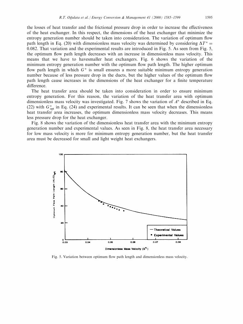
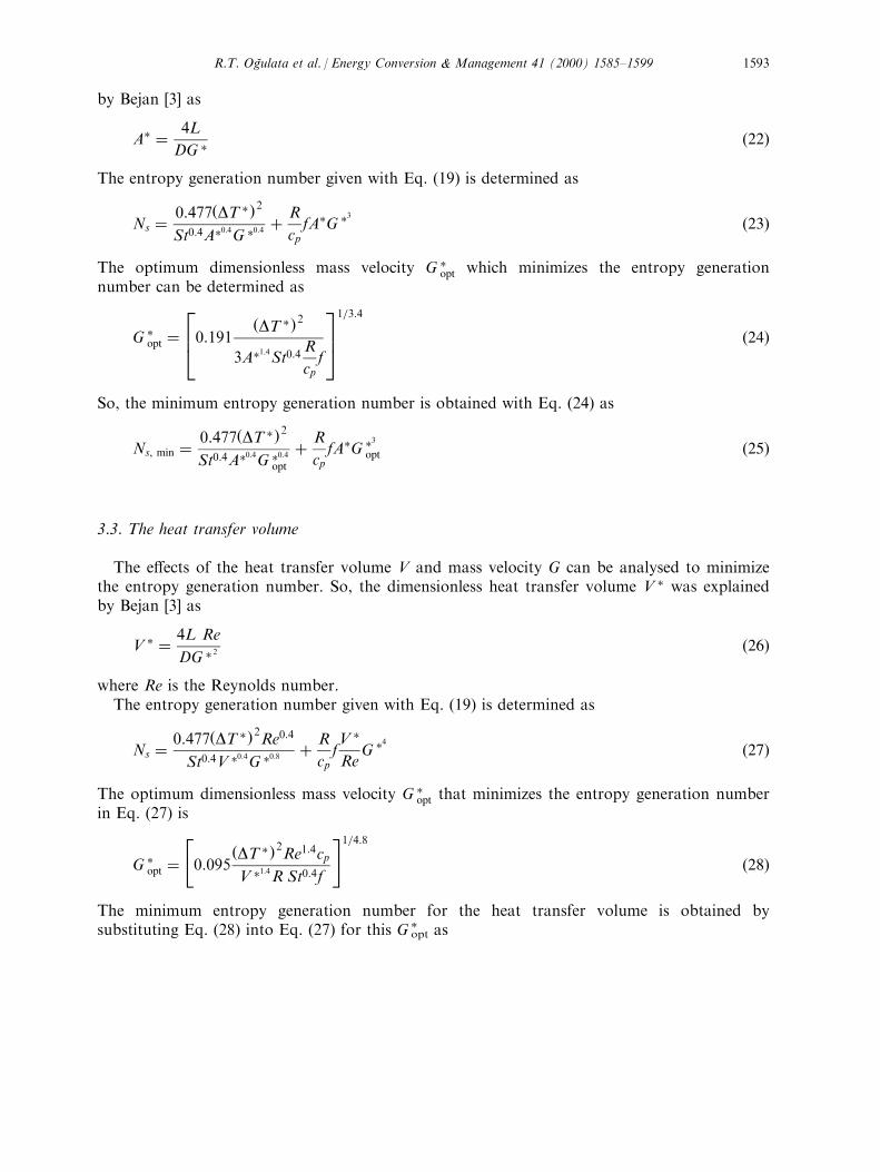
the losses of heat transfer and the frictional pressure drop in order to increase the e�ectivenessof the heat exchanger. In this respect, the dimensions of the heat exchanger that minimize theentropy generation number should be taken into consideration. The variation of optimum ¯owpath length in Eq. (20) with dimensionless mass velocity was determined by considering DT � �0:082: That variation and the experimental results are introduced in Fig. 5. As seen from Fig. 5,the optimum ¯ow path length decreases with an increase in dimensionless mass velocity. Thismeans that we have to havesmaller heat exchangers. Fig. 6 shows the variation of theminimum entropy generation number with the optimum ¯ow path length. The higher optimum¯ow path length in which G � is small ensures a more suitable minimum entropy generationnumber because of less pressure drop in the ducts, but the higher values of the optimum ¯owpath length cause increases in the dimensions of the heat exchanger for a ®nite temperaturedi�erence.The heat transfer area should be taken into consideration in order to ensure minimum
entropy generation. For this reason, the variation of the heat transfer area with optimumdimensionless mass velocity was investigated. Fig. 7 shows the variation of A� described in Eq.(22) with G �opt in Eq. (24) and experimental results. It can be seen that when the dimensionlessheat transfer area increases, the optimum dimensionless mass velocity decreases. This meansless pressure drop for the heat exchanger.Fig. 8 shows the variation of the dimensionless heat transfer area with the minimum entropy
generation number and experimental values. As seen in Fig. 8, the heat transfer area necessaryfor low mass velocity is more for minimum entropy generation number, but the heat transferarea must be decreased for small and light weight heat exchangers.
Fig. 5. Variation between optimum ¯ow path length and dimensionless mass velocity.
R.T. OgÆulata et al. / Energy Conversion & Management 41 (2000) 1585±1599 1595
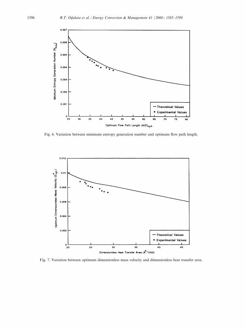
Fig. 6. Variation between minimum entropy generation number and optimum ¯ow path length.
Fig. 7. Variation between optimum dimensionless mass velocity and dimensionless heat transfer area.
R.T. OgÆulata et al. / Energy Conversion & Management 41 (2000) 1585±15991596
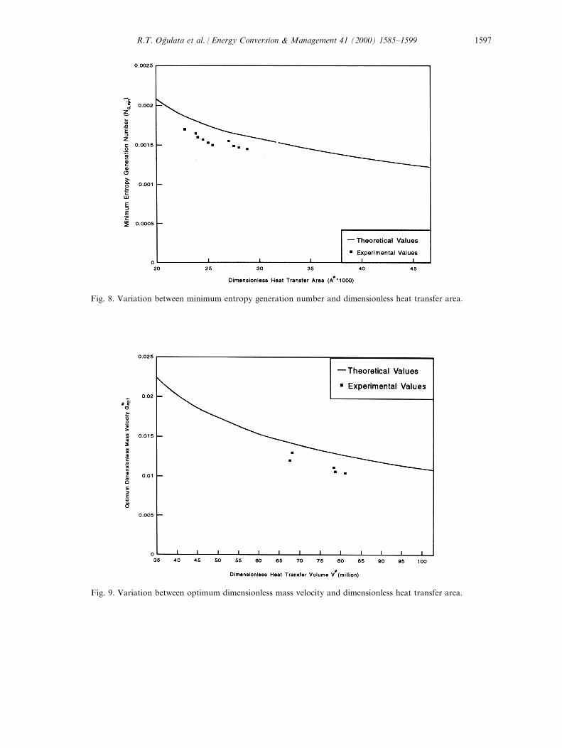
Fig. 8. Variation between minimum entropy generation number and dimensionless heat transfer area.
Fig. 9. Variation between optimum dimensionless mass velocity and dimensionless heat transfer area.
R.T. OgÆulata et al. / Energy Conversion & Management 41 (2000) 1585±1599 1597
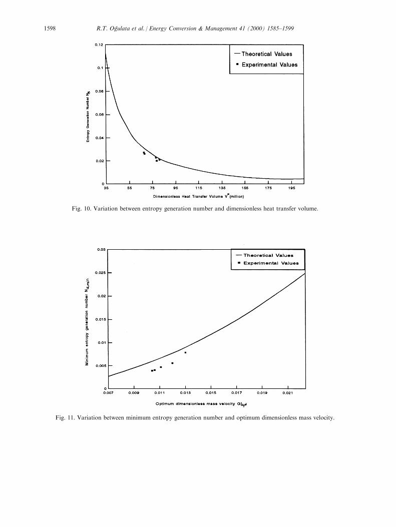
Fig. 10. Variation between entropy generation number and dimensionless heat transfer volume.
Fig. 11. Variation between minimum entropy generation number and optimum dimensionless mass velocity.
R.T. OgÆulata et al. / Energy Conversion & Management 41 (2000) 1585±15991598
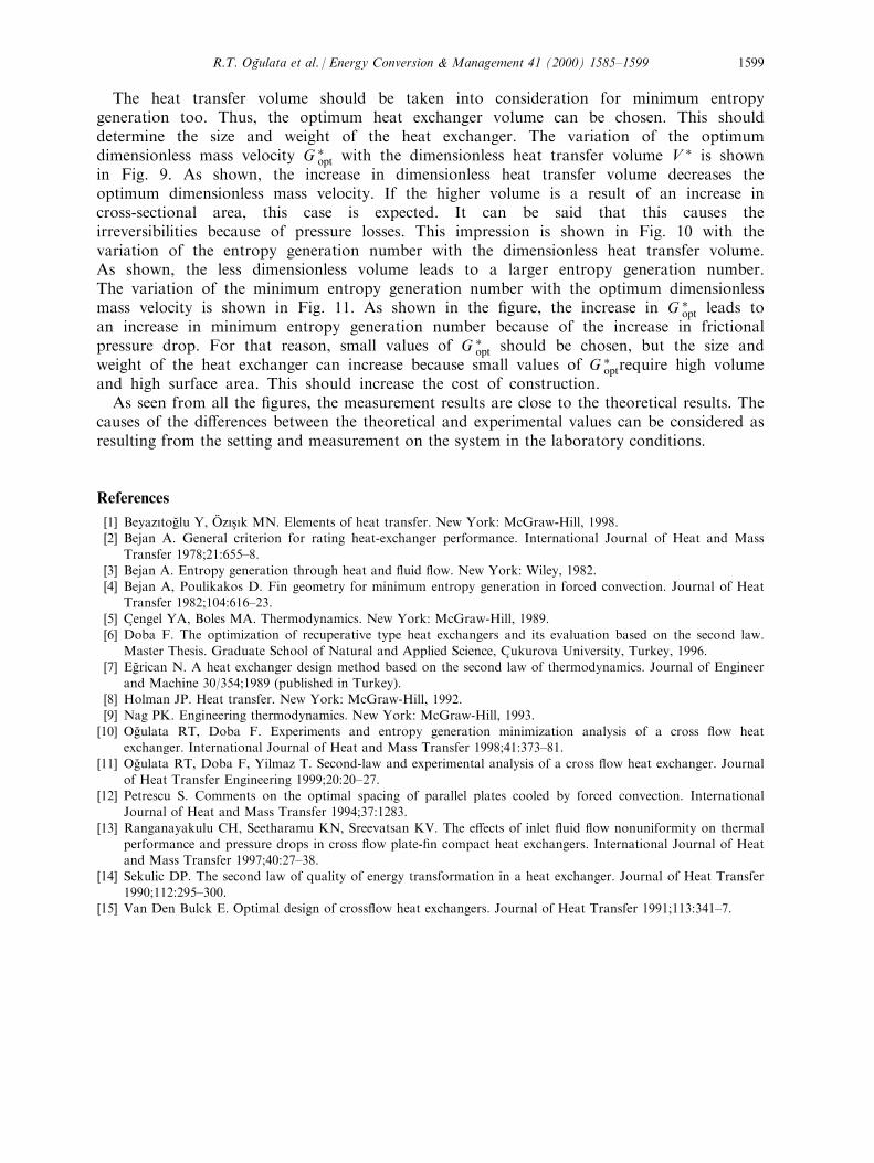
The heat transfer volume should be taken into consideration for minimum entropygeneration too. Thus, the optimum heat exchanger volume can be chosen. This shoulddetermine the size and weight of the heat exchanger. The variation of the optimumdimensionless mass velocity G �opt with the dimensionless heat transfer volume V � is shownin Fig. 9. As shown, the increase in dimensionless heat transfer volume decreases theoptimum dimensionless mass velocity. If the higher volume is a result of an increase incross-sectional area, this case is expected. It can be said that this causes theirreversibilities because of pressure losses. This impression is shown in Fig. 10 with thevariation of the entropy generation number with the dimensionless heat transfer volume.As shown, the less dimensionless volume leads to a larger entropy generation number.The variation of the minimum entropy generation number with the optimum dimensionlessmass velocity is shown in Fig. 11. As shown in the ®gure, the increase in G �opt leads toan increase in minimum entropy generation number because of the increase in frictionalpressure drop. For that reason, small values of G �opt should be chosen, but the size andweight of the heat exchanger can increase because small values of G �optrequire high volumeand high surface area. This should increase the cost of construction.As seen from all the ®gures, the measurement results are close to the theoretical results. The
causes of the di�erences between the theoretical and experimental values can be considered asresulting from the setting and measurement on the system in the laboratory conditions.
References
[1] BeyazõtogÆ lu Y, OÈ zõs° õk MN. Elements of heat transfer. New York: McGraw-Hill, 1998.[2] Bejan A. General criterion for rating heat-exchanger performance. International Journal of Heat and Mass
Transfer 1978;21:655±8.[3] Bejan A. Entropy generation through heat and ¯uid ¯ow. New York: Wiley, 1982.[4] Bejan A, Poulikakos D. Fin geometry for minimum entropy generation in forced convection. Journal of Heat
Transfer 1982;104:616±23.
[5] C° engel YA, Boles MA. Thermodynamics. New York: McGraw-Hill, 1989.[6] Doba F. The optimization of recuperative type heat exchangers and its evaluation based on the second law.
Master Thesis. Graduate School of Natural and Applied Science, C° ukurova University, Turkey, 1996.
[7] EgÆ rican N. A heat exchanger design method based on the second law of thermodynamics. Journal of Engineerand Machine 30/354;1989 (published in Turkey).
[8] Holman JP. Heat transfer. New York: McGraw-Hill, 1992.
[9] Nag PK. Engineering thermodynamics. New York: McGraw-Hill, 1993.[10] OgÆ ulata RT, Doba F. Experiments and entropy generation minimization analysis of a cross ¯ow heat
exchanger. International Journal of Heat and Mass Transfer 1998;41:373±81.
[11] OgÆ ulata RT, Doba F, Yilmaz T. Second-law and experimental analysis of a cross ¯ow heat exchanger. Journalof Heat Transfer Engineering 1999;20:20±27.
[12] Petrescu S. Comments on the optimal spacing of parallel plates cooled by forced convection. InternationalJournal of Heat and Mass Transfer 1994;37:1283.
[13] Ranganayakulu CH, Seetharamu KN, Sreevatsan KV. The e�ects of inlet ¯uid ¯ow nonuniformity on thermalperformance and pressure drops in cross ¯ow plate-®n compact heat exchangers. International Journal of Heatand Mass Transfer 1997;40:27±38.
[14] Sekulic DP. The second law of quality of energy transformation in a heat exchanger. Journal of Heat Transfer1990;112:295±300.
[15] Van Den Bulck E. Optimal design of cross¯ow heat exchangers. Journal of Heat Transfer 1991;113:341±7.
R.T. OgÆulata et al. / Energy Conversion & Management 41 (2000) 1585±1599 1599
Related Documents