INSTALLATION MANUAL FLUSH MOUNT INSTALLATION MANUAL

Welcome message from author
This document is posted to help you gain knowledge. Please leave a comment to let me know what you think about it! Share it to your friends and learn new things together.
Transcript
INSTALLATION MANUAL
FLUSH MOUNT
INSTALLATION MANUAL
CONTeNTS
FLUSH MOUNT INSTALLATION MANUAL - 1© 2019 IRONRIDGE, INC. VERSION 2.1
DISCLAIMER 1RATINGS 2MARKINGS 2CHECKLIST 31. ATTACH BASES 42. PLACE RAILS 43. SECURE LUGS 54. SECURE MODULES 5CAMO 6EXPANSION JOINTS 7ELECTRICAL DIAGRAM 7FLASHFOOT2 8ALL TILE HOOK 8KNOCKOUT TILE 8FLAT ROOF ATTACHMENT 9END CAPS 9WIRE CLIPS 9FLUSH STANDOFFS 9MICROINVERTER KITS 10SYSTEMS USING ENPHASE MICROINVERTERS OR SUNPOWER AC MODULES 10SYSTEMS USING PHAZR MICROSTORAGE PRODUCTS 10FRAMELESS MODULE KITS 11MODULE COMPATIBILITY 12MODULE COMPATIBILITY 13MODULE COMPATIBILITY 14
DISCLAIMeR
This manual describes proper installation procedures and provides necessary standards required for product reliability. Warranty details are available on website. All installers must thoroughly read this manual and have a clear understanding of the installation procedures prior to installation. Failure to follow these guidelines may result in property damage, bodily injury or even death.
IT IS THe INSTALLeR’S ReSPONSIBILITY TO:
• Ensure safe installation of all electrical aspects of the array. All electrical installation and procedures should be conducted by a licensed and bonded electrician or solar contractor. Routine maintenance of a module or panel shall not involve breaking or disturbing the bonding path of the system. All work must comply with national, state and local installation procedures, product and safety standards.
• Comply with all applicable local or national building and fire codes, including any that may supersede this manual.• Ensure all products are appropriate for the installation, environment, and array under the site’s loading conditions.• Use only IronRidge parts or parts recommended by IronRidge; substituting parts may void any applicable warranty.• Review the Design Assistant and Certification Letters to confirm design specifications.• Ensure provided information is accurate. Issues resulting from inaccurate information are the installer’s responsibility.• Ensure bare copper grounding wire does not contact aluminum and zinc-plated steel components, to prevent risk of
galvanic corrosion.• If loose components or loose fasteners are found during periodic inspection, re-tighten immediately. If corrosion is
found, replace affected components immediately.• Provide an appropriate method of direct-to-earth grounding according to the latest edition of the National Electrical
Code, including NEC 250: Grounding and Bonding, and NEC 690: Solar Photovoltaic Systems.• Disconnect AC power before servicing or removing modules, AC modules, microinverters and power optimizers.• Review module manufacturer’s documentation for compatibility and compliance with warranty terms and conditions.
FLUSH MOUNT INSTALLATION MANUAL - 2© 2019 IRONRIDGE, INC. VERSION 2.1
RATINGS
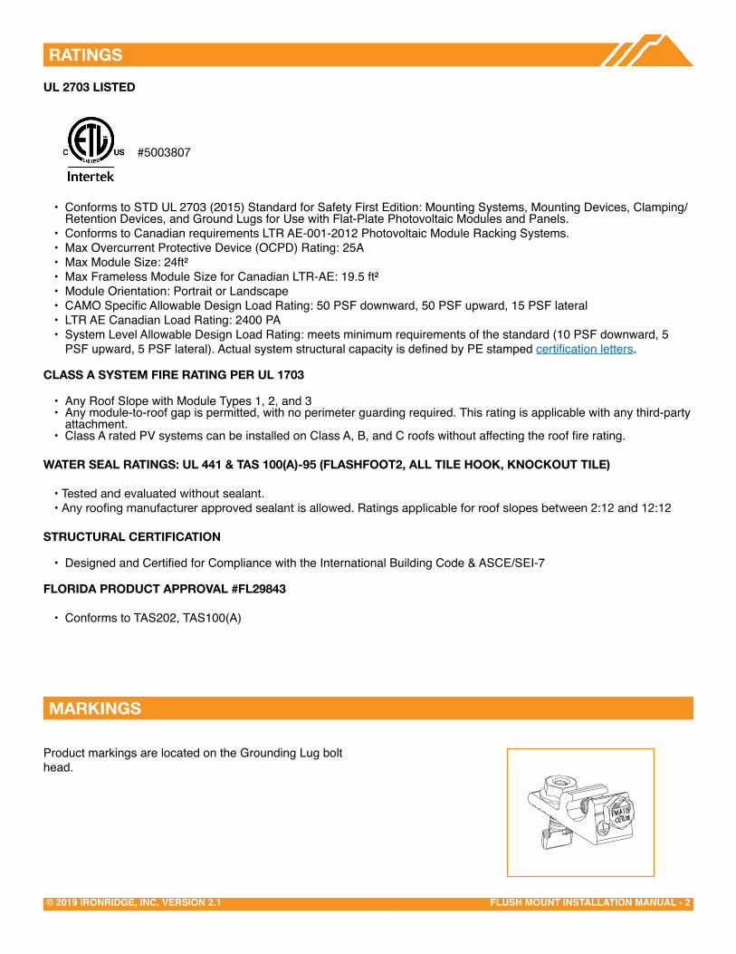
Product markings are located on the Grounding Lug bolt head.
MARKINGS
UL 2703 LISTeD
• Conforms to STD UL 2703 (2015) Standard for Safety First Edition: Mounting Systems, Mounting Devices, Clamping/Retention Devices, and Ground Lugs for Use with Flat-Plate Photovoltaic Modules and Panels.
• Conforms to Canadian requirements LTR AE-001-2012 Photovoltaic Module Racking Systems.• Max Overcurrent Protective Device (OCPD) Rating: 25A• Max Module Size: 24ft²• Max Frameless Module Size for Canadian LTR-AE: 19.5 ft²• Module Orientation: Portrait or Landscape• CAMO Specific Allowable Design Load Rating: 50 PSF downward, 50 PSF upward, 15 PSF lateral• LTR AE Canadian Load Rating: 2400 PA• System Level Allowable Design Load Rating: meets minimum requirements of the standard (10 PSF downward, 5
PSF upward, 5 PSF lateral). Actual system structural capacity is defined by PE stamped certification letters.
CLASS A SYSTeM FIRe RATING PeR UL 1703
• Any Roof Slope with Module Types 1, 2, and 3• Any module-to-roof gap is permitted, with no perimeter guarding required. This rating is applicable with any third-party
attachment.• Class A rated PV systems can be installed on Class A, B, and C roofs without affecting the roof fire rating.
WATeR SeAL RATINGS: UL 441 & TAS 100(A)-95 (FLASHFOOT2, ALL TILe HOOK, KNOCKOUT TILe)
• Tested and evaluated without sealant.• Any roofing manufacturer approved sealant is allowed. Ratings applicable for roof slopes between 2:12 and 12:12
STRUCTURAL CeRTIFICATION
• Designed and Certified for Compliance with the International Building Code & ASCE/SEI-7
FLORIDA PRODUCT APPROVAL #FL29843
• Conforms to TAS202, TAS100(A)
#5003807

FLUSH MOUNT INSTALLATION MANUAL - 3© 2019 IRONRIDGE, INC. VERSION 2.1
CHeCKLIST
PRe-INSTALLATION
☐ Verify module compatibility. See Page 10 for info.
TOOLS ReQUIReD
☐ Cordless Drill (non-impact)
☐ Impact Driver (for lag bolts)
☐ Torque Wrench (0-250 in-lbs)
☐ 5/16” Socket
☐ 7/16” Socket
☐ 1/2" Socket
☐ String Line
TORQUe VALUeS
☐ FlashFoot2 Lag Bolts (7/16" Socket): Fully Seat
☐ Bonded Splice Screws (5/16" Socket): 20 in-lbs
☐ Grounding Lug Nuts (7/16" Socket): 80 in-lbs
☐ Grounding Lug Terminal Screws (7/16" Socket): 20 in-lbs
☐ Universal Fastening Object (7/16" Socket): 80 in-lbs
☐ Expansion Joint Nuts (7/16" Socket): 80 in-lbs
☐ Flush Standoffs (1/2" Socket): 132 in-lbs
☐ Microinverter Kit Nuts (7/16" Socket): 80 in-lbs
☐ Frameless Module Kit Nuts (7/16" Socket): 80 in-lbs
☐ 3/8" Bonding Hardware Nuts (7/16" Socket): 250 in-lbs
☐ All Tile Hook Lags (7/16" Socket): Fully Seat
☐ All Tile Hook Carriage Bolts (7/16" Socket): 132 in-lbs
☐ Knockout Tile Lags (1/2" Socket): Fully Seat
☐ Knockout Tile Nuts (1/2" Socket): 132 in-lbs
☐ Flat Roof Attachment Nuts (9/16” Socket): 250 in-lbs
Þ If using previous version of: FlashFoot, Integrated Grounding Mid Clamps, Grounding Lug, End Clamps, and Expansion Joints please refer to Alternate Components Addendum (Version 1.20).
IRONRIDGe COMPONeNTS
Bonded SpliceXR Rail L-Foot
FlashFoot2 UFO and Stopper Sleeve CAMO
Grounding Lug8" Bonding Jumper Expansion Joint
Wire ClipEnd Cap Flush Standoff
3/8" BondingHardwareMicroinverter Kit Frameless
Module Kit
A A
B B
C C
D D
E E
F F
8
8
7
7
6
6
5
5
4
4
3
3
2
2
1
1
Frameless End/Mid Clamp
All Tile Hook Flashing
A A
B B
C C
D D
E E
F F
8
8
7
7
6
6
5
5
4
4
3
3
2
2
1
1
Knockout TileA A
B B
C C
D D
E E
F F
8
8
7
7
6
6
5
5
4
4
3
3
2
2
1
1
Membrane Flashing
All Tile Hook
Flat Roof Attachment
FLUSH MOUNT INSTALLATION MANUAL - 4© 2019 IRONRIDGE, INC. VERSION 2.1
1. ATTACH BASeS
A. CONNeCT SPLICeS
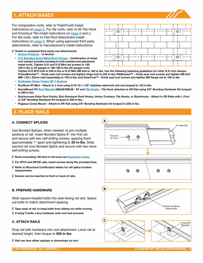
Use Bonded Splices, when needed, to join multiple sections of rail. Insert Bonded Splice 6" into first rail and secure with two self-drilling screws, spacing them approximately 1” apart and tightening to 20 in-lbs. Slide second rail over Bonded Splice and secure with two more self-drilling screws.
Þ Rows exceeding 100 feet of rail must use expansion Joints.
Þ For XR10 and XR100 rails, insert screws along the provided lines.
Þ Refer to Structural Certification letters for rail splice location requirements.
Þ Screws can be inserted on front or back of rails.
B. PRePARe HARDWARe
Slide square-headed bolts into side-facing rail slot. Space out bolts to match attachment spacing.
Þ Tape ends of rail, to keep bolts from sliding out while moving. Þ If using T-bolts, carry hardware onto roof and proceed.
C. ATTACH RAILS
Drop rail with hardware into roof attachment. Level rail at desired height, then torque to 250 in-lbs.
Þ Rail can face either upslope or downslope on roof.
2. PLACe RAILS
CTorque to250 in-lbs
B
Preload and Space Square Bolts
A
Torque to20 in-lbs
6" Inside Rail
1"
Þ Tested or evaluated third-party roof attachments:• Anchor Products - U-Anchor• S-5! Standing Seam Metal Roof Clamps - Certification of metal
roof clamps includes bonding to both painted and galvalume metal roofs. Tighten S-5! and S-5! Mini set screws to 130-150 in-lbs (≥ 24 gauge) or 160-180 in-lbs (22 gauge) roofs. Tighten S-5! M10 bolt to 240 in-lbs or S-5! Mini M8 bolt to 160 in-lbs. Use the following fastening guidelines for other S-5! roof clamps: ProteaBracket™ - firmly seat roof screws and tighten hinge bolt to 225 in-lbs; RibBracket™ - firmly seat roof screws and tighten M8 bolt (M8-1.25 x 22mm sold separately) to 160 in-lbs; and SolarFoot™ - firmly seat roof screws and tighten M8 flange nut to 160 in-lbs.
• ecoFasten Green Fasten GF-1 Anchors• Rooftech RT-Mini - Attach to L-foot using 5/16-18 x 1.25" stainless steel bolt and nut torqued to 132 in-lbs. • QuickMount PV Roof Mounts QMLM/QMLM - ST and Tile Hooks - Tile Hook attaches to XR Rail using 3/8" Bonding Hardware Kit torqued
to 250 in-lbs.• Quickscrews Solar Roof Hooks, ejot Aluminum Roof Hooks, Unirac Creotecc Tile Hooks, or Solarhooks - Attach to XR Rails with L-Foot
or 3/8” Bonding Hardware Kit torqued to 250 in-lbs.• Pegasus Comp Mount - Attach to XR Rail using 3/8" Bonding Hardware kit torqued to 250 in-lbs.
For composition roofs, refer to FlashFoot2 install instructions on page 8. For tile roofs, refer to All Tile Hook and Knockout Tile install instructions on page 8 and 9. For flat roofs, refer to Flat Roof Attachment install instructions on page 9. When using approved third party attachments, refer to manufacturer's install instructions.
FLUSH MOUNT INSTALLATION MANUAL - 5© 2019 IRONRIDGE, INC. VERSION 2.1
3. SeCURe LUGS
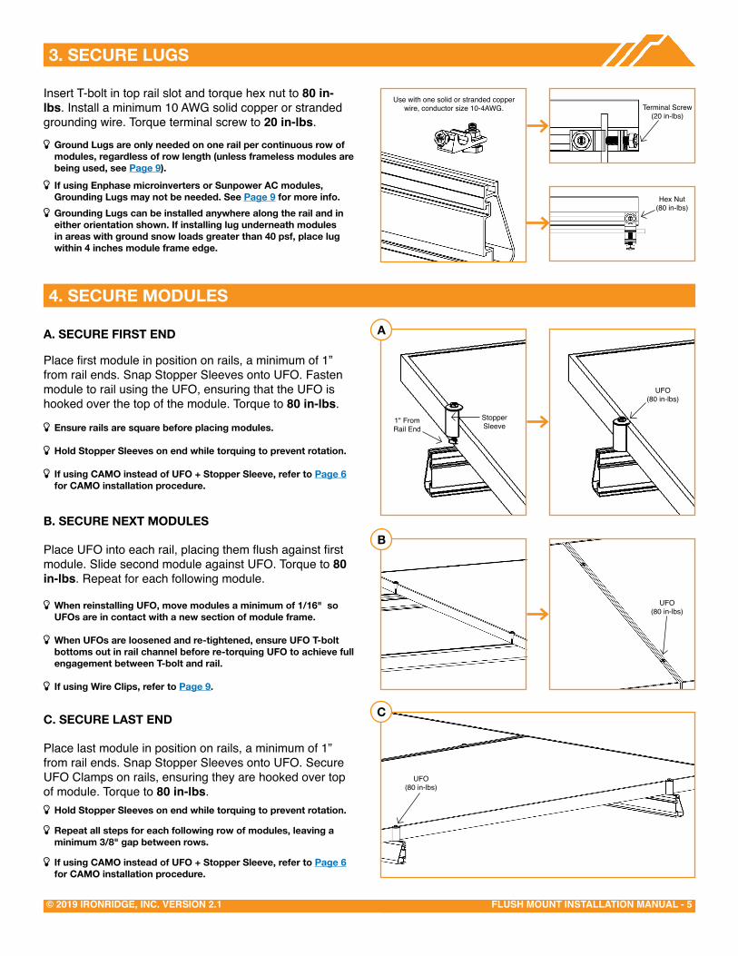
Insert T-bolt in top rail slot and torque hex nut to 80 in-lbs. Install a minimum 10 AWG solid copper or stranded grounding wire. Torque terminal screw to 20 in-lbs.
Þ Ground Lugs are only needed on one rail per continuous row of modules, regardless of row length (unless frameless modules are being used, see Page 9).
Þ If using enphase microinverters or Sunpower AC modules, Grounding Lugs may not be needed. See Page 9 for more info.
Þ Grounding Lugs can be installed anywhere along the rail and in either orientation shown. If installing lug underneath modules in areas with ground snow loads greater than 40 psf, place lug within 4 inches module frame edge.
4. SeCURe MODULeS
A. SeCURe FIRST eND
Place first module in position on rails, a minimum of 1” from rail ends. Snap Stopper Sleeves onto UFO. Fasten module to rail using the UFO, ensuring that the UFO is hooked over the top of the module. Torque to 80 in-lbs.
Þ ensure rails are square before placing modules.
Þ Hold Stopper Sleeves on end while torquing to prevent rotation.
Þ If using CAMO instead of UFO + Stopper Sleeve, refer to Page 6 for CAMO installation procedure.
B. SeCURe NeXT MODULeS
Place UFO into each rail, placing them flush against first module. Slide second module against UFO. Torque to 80 in-lbs. Repeat for each following module.
Þ When reinstalling UFO, move modules a minimum of 1/16" so UFOs are in contact with a new section of module frame.
Þ When UFOs are loosened and re-tightened, ensure UFO T-bolt bottoms out in rail channel before re-torquing UFO to achieve full engagement between T-bolt and rail.
Þ If using Wire Clips, refer to Page 9.
C. SeCURe LAST eND
Place last module in position on rails, a minimum of 1” from rail ends. Snap Stopper Sleeves onto UFO. Secure UFO Clamps on rails, ensuring they are hooked over top of module. Torque to 80 in-lbs.
Þ Hold Stopper Sleeves on end while torquing to prevent rotation.
Þ Repeat all steps for each following row of modules, leaving a minimum 3/8" gap between rows.
Þ If using CAMO instead of UFO + Stopper Sleeve, refer to Page 6 for CAMO installation procedure.
A
B
Hex Nut(84 in-lbs)
Terminal Screw(20 in-lbs)
C
Hex Nut(80 in-lbs)
1" From Rail End
UFO(80 in-lbs)
StopperSleeve
UFO(80 in-lbs)
UFO(80 in-lbs)
Use with one solid or stranded copper wire, conductor size 10-4AWG.
FLUSH MOUNT INSTALLATION MANUAL - 6© 2019 IRONRIDGE, INC. VERSION 2.1
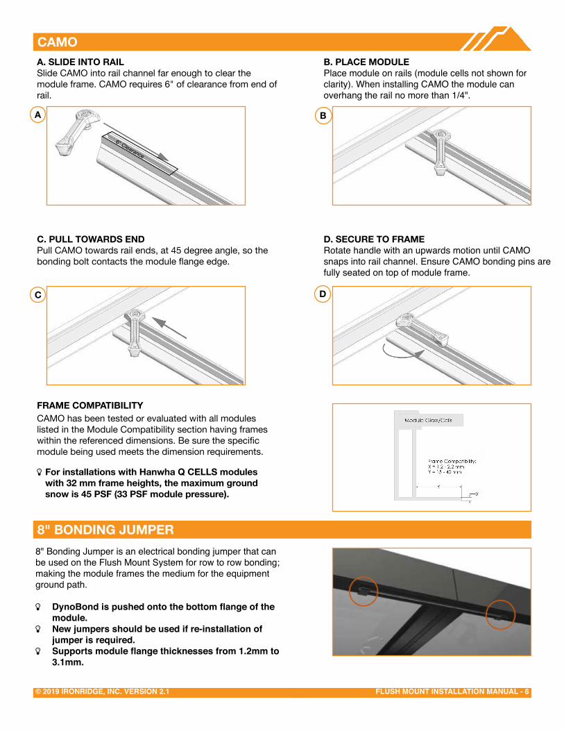
B. PLACe MODULePlace module on rails (module cells not shown for clarity). When installing CAMO the module can overhang the rail no more than 1/4".
D. SeCURe TO FRAMeRotate handle with an upwards motion until CAMO snaps into rail channel. Ensure CAMO bonding pins are fully seated on top of module frame.
CAMOA. SLIDe INTO RAILSlide CAMO into rail channel far enough to clear the module frame. CAMO requires 6" of clearance from end of rail.
C. PULL TOWARDS eNDPull CAMO towards rail ends, at 45 degree angle, so the bonding bolt contacts the module flange edge.
FRAMe COMPATIBILITYCAMO has been tested or evaluated with all modules listed in the Module Compatibility section having frames within the referenced dimensions. Be sure the specific module being used meets the dimension requirements.
Þ For installations with Hanwha Q CeLLS modules with 32 mm frame heights, the maximum ground snow is 45 PSF (33 PSF module pressure).
B
C D
A
6" Clearance
8" BONDING JUMPER8" Bonding Jumper is an electrical bonding jumper that can be used on the Flush Mount System for row to row bonding; making the module frames the medium for the equipment ground path.
Þ DynoBond is pushed onto the bottom flange of the module.
Þ New jumpers should be used if re-installation of jumper is required.
Þ Supports module flange thicknesses from 1.2mm to 3.1mm.
FLUSH MOUNT INSTALLATION MANUAL - 7© 2019 IRONRIDGE, INC. VERSION 2.1
eXPANSION JOINTS
eLeCTRICAL DIAGRAM
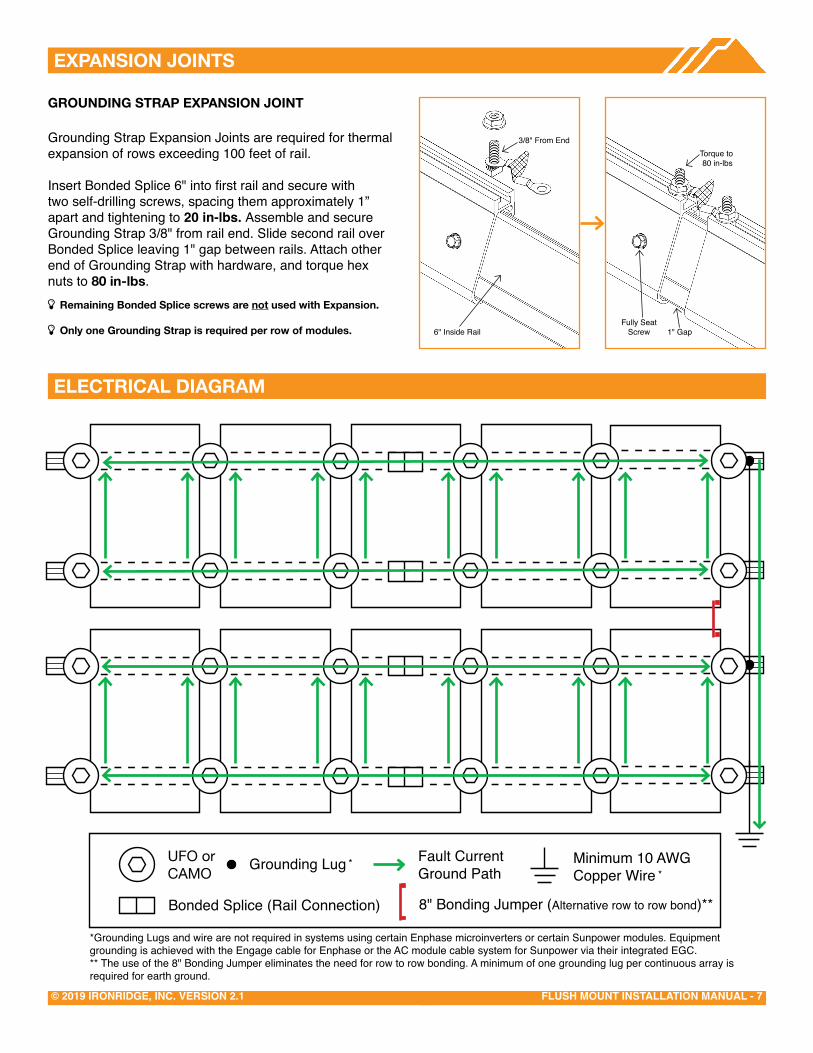
GROUNDING STRAP eXPANSION JOINT
Grounding Strap Expansion Joints are required for thermal expansion of rows exceeding 100 feet of rail.
Insert Bonded Splice 6" into first rail and secure with two self-drilling screws, spacing them approximately 1” apart and tightening to 20 in-lbs. Assemble and secure Grounding Strap 3/8" from rail end. Slide second rail over Bonded Splice leaving 1" gap between rails. Attach other end of Grounding Strap with hardware, and torque hex nuts to 80 in-lbs.
Þ Remaining Bonded Splice screws are not used with expansion.
Þ Only one Grounding Strap is required per row of modules.Fully Seat
Screw 1" Gap6" Inside Rail
3/8" From EndTorque to 80 in-lbs
UFO Grounding Lug Minimum 10 AWGCopper Wire
Fault Current Ground Path
Bonded Splice (Rail Connection)
**
*Grounding Lugs and wire are not required in systems using certain Enphase microinverters or certain Sunpower modules. Equipment grounding is achieved with the Engage cable for Enphase or the AC module cable system for Sunpower via their integrated EGC.** The use of the 8" Bonding Jumper eliminates the need for row to row bonding. A minimum of one grounding lug per continuous array is required for earth ground.
CAMO orUFO or
CAMO
8" Bonding Jumper (Alternative row to row bond)**

FLUSH MOUNT INSTALLATION MANUAL - 8© 2019 IRONRIDGE, INC. VERSION 2.1
FLASHFOOT2
Locate roof rafters and mark locations on roof. Drill 1/4” pilot holes and backfill with approved sealant. Slide flashing between 1st and 2nd course of shingles, ensuring flashing doesn't overhang the downhill shingle. Line up with pilot hole and insert supplied lag bolt with washer through flashing. Fully seat lag bolt. Place Cap onto flashing in desired orientation for E/W or N/S rails and rotate 180 degrees until it locks into place.
Þ Rail can be installed on either side of FlashFoot2 Cap.
Þ Standalone FlashFoot2 manual available on website.
Remove tile and mark rafter. Position base over rafter, adjust arm if necessary and torque hardware to 132 in-lbs (11 ft-lbs). Use base as guide to drill 1/4" pilot holes, back fill with roofing manufacturer’s approved sealant, then insert lag bolts and tighten until fully seated. Replace tiles and notch as necessary to ensure proper fit. Attach rails to either side of slot using bonding hardware and torque to 250 in-lbs (21-ft-lbs).
Þ Position arm near the center of valley for curved tiles.
Þ Position arm away from seam of joining flat tiles.
Þ ensure top of hook does not extend above rail.
Þ IronRidge offers an optional aluminum deck flashing. Refer to All Tile Hook Flashing Installation Manual. Other approved flashing methods include user supplied adhesive backed flexible flashing.
Þ Standalone All Tile Hook manual available on website.
ALL TILe HOOK
KNOCKOUT TILe
Remove tile and mark rafter. Use base as guide to drill 1/4” pilot hole and fill with roofing manufacturer’s approved sealant. Insert lag bolt with bonded washer through base and drive until fully seated. Insert Tile Replacement Flashing, lower onto base and apply pressure over the threaded post until it dimples the flashing. Place L-Foot over dimple and tap with hammer to punch threaded post through the flashing. Ensure punched pieces of flashing are cleared away. Form flashing as needed to sit flush with surrounding tiles, position L-Foot in desired orientation and torque hardware to 132 in-lbs (11 ft-lbs). Attach rail to either side of L-Foot with bonding hardware and torque to 250 in-lbs (21 ft-lbs).
Þ Base can be installed parallel or perpendicular to rafter. Þ L-foot can be installed facing any direction. Þ ensure L-Foot does not extend above rail. Þ If deck level flashing is required, approved flashing methods include user supplied adhesive backed flexible flashing.
Þ Standalone Knockout Tile manual available on website.
Rafter
Torque to 132 in-lbs
Torque to 250 in-lbs
Rafter
Tight UntilFully Seated
Dimple
Tap WithHammer
Torque to 132 in-lbs
Torque to 250 in-lbs
Tighten Until Fully Seated
FLUSH MOUNT INSTALLATION MANUAL - 9© 2019 IRONRIDGE, INC. VERSION 2.1
FLAT ROOF ATTACHMeNT
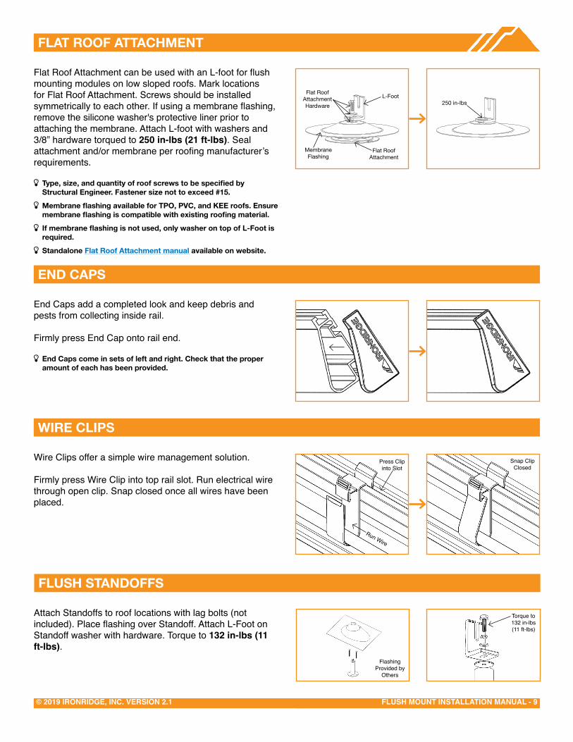
End Caps add a completed look and keep debris and pests from collecting inside rail.
Firmly press End Cap onto rail end.
Þ end Caps come in sets of left and right. Check that the proper amount of each has been provided.
WIRe CLIPS
Wire Clips offer a simple wire management solution.
Firmly press Wire Clip into top rail slot. Run electrical wire through open clip. Snap closed once all wires have been placed.
Press Clip into Slot
Run Wire
Snap Clip Closed
Attach Standoffs to roof locations with lag bolts (not included). Place flashing over Standoff. Attach L-Foot on Standoff washer with hardware. Torque to 132 in-lbs (11 ft-lbs).
Torque to132 in-lbs (11 ft-lbs)
FLUSH STANDOFFS
Flashing Provided by
Others
eND CAPS
Flat Roof Attachment can be used with an L-foot for flush mounting modules on low sloped roofs. Mark locations for Flat Roof Attachment. Screws should be installed symmetrically to each other. If using a membrane flashing, remove the silicone washer's protective liner prior to attaching the membrane. Attach L-foot with washers and 3/8” hardware torqued to 250 in-lbs (21 ft-lbs). Seal attachment and/or membrane per roofing manufacturer’s requirements.
Þ Type, size, and quantity of roof screws to be specified by Structural engineer. Fastener size not to exceed #15.
Þ Membrane flashing available for TPO, PVC, and KEE roofs. Ensure membrane flashing is compatible with existing roofing material.
Þ If membrane flashing is not used, only washer on top of L-Foot is required.
Þ Standalone Flat Roof Attachment manual available on website.
250 in-lbs
Flat RoofAttachmentHardware
L-Foot
Flat RoofAttachment
MembraneFlashing

FLUSH MOUNT INSTALLATION MANUAL - 10© 2019 IRONRIDGE, INC. VERSION 2.1
MICROINVeRTeR KITS
Microinverter Kit(80 in-lbs)
SYSTeMS USING eNPHASe MICROINVeRTeRS OR SUNPOWeR AC MODULeS
IronRidge systems using approved Enphase products or SunPower modules eliminate the need for lay-in lugs and field installed equipment grounding conductors (EGC). This solution meets the requirements of UL 2703 for bonding and grounding and is included in this listing.
The following Sunpower modules are included in this listing: Modules with model identifier Ab-xxx-YY and InvisiMount (G5) 46mm frame; where "A" is either E, or X; “b” can be 17, 18, 19, 20, 21, or 22; and “YY” can be C-AC, D-AC, BLK-C-AC, or BLK-D-AC.
The following Enphase products are included in this listing: Microinverters M250-72, M250-60, M215-60, C250-72, and Engage cables ETXX-240, ETXX-208, ETXX-277. �
Þ A minimum of two inverters mounted to the same rail and connected to the same Engage cable are required.
Þ The microinverters or Sunpower AC modules must be used with a maximum 20 A branch rated overcurrent protection device (OCPD).
Þ If an AC module is removed from a circuit for maintenance, you must first disconnect AC power and then install a temporary EGC to bridge the gap by inserting an AC extension cable (or via other NEC-compliant means), in order to maintain effective ground continuity to subsequent modules.
Use IronRidge's Microinverter Kit to bond compatible microinverters and power optimizers to the racking system.
Insert Microinverter Kit T-bolt into top rail slot. Place compatible microinverter or power optimizer into position and tighten hex nut to 80 in-lbs.
Þ If installing in areas with ground snow loads greater than 40 psf, install MLPE devices directly next to module frame edge.
�COMPATIBLe PRODUCTSEnphaseM250-72, 250-60, M215-60, C250-72, S230, S280, IQ 6, IQ 6+, IQ 7, IQ 7+, IQ 7X, Q Aggregator
DarfonMIG240, MIG300, G320, G640
Solar EdgeP300, P320, P340, P370, P400, P405, P505, P600, P700, P730, P800p, P800s, P850, P860
SYSTeMS USING PHAZR MICROSTORAGe PRODUCTS
Bonding and grounding is achieved via the IronRidge system when using the Microinverter Kit. Running a separate equipment grounding conductor to the PHAZRs is not required.
Þ If installing in areas with ground snow loads greater than 40 psf and underneath a module, install PHAZR devices as close as possible to module frame edge.
Microinverter Kit(80 in-lbs)
FLUSH MOUNT INSTALLATION MANUAL - 11© 2019 IRONRIDGE, INC. VERSION 2.1
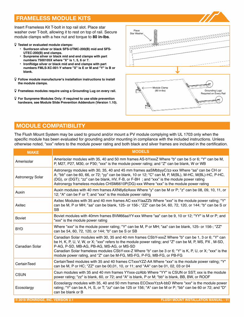
FRAMeLeSS MODULe KITSInsert Frameless Kit T-bolt in top rail slot. Place star washer over T-bolt, allowing it to rest on top of rail. Secure module clamps with a hex nut and torque to 80 in-lbs.
Þ Tested or evaluated module clamps: • Sunforson silver or black SFS-UTMC-200(B) mid and SFS-
UTEC-200(B) end clamps.• Sunpreme silver or black mid and end clamps with part
numbers 7500105X where "X" is 1, 5, 6 or 7.• IronRidge silver or black mid and end clamps with part
numbers FMLS-XC-001-Y where "X" is E or M and "Y" is B or blank.
Þ Follow module manufacturer's installation instructions to installthe module clamps.
Þ Frameless modules require using a Grounding Lug on every rail.
Þ For Sunpreme Modules Only: If required to use slide prevention hardware, see Module Slide Prevention Addendum (Version 1.10).
Place Star Washer
Module Clamp(80 in-lbs) Grounding Lugs
Required on Every Rail
MODULe COMPATIBILITYThe Flush Mount System may be used to ground and/or mount a PV module complying with UL 1703 only when the specific module has been evaluated for grounding and/or mounting in compliance with the included instructions. Unless otherwise noted, “xxx” refers to the module power rating and both black and silver frames are included in the certification.
MAKe MODELS
Amerisolar Amerisolar modules with 35, 40 and 50 mm frames AS-bYxxxZ Where "b" can be 5 or 6; "Y" can be M, P, M27, P27, M30, or P30; "xxx" is the module power rating; and "Z" can be blank, W or WB
Astronergy Solar
Astronergy modules with 30, 35, 40 and 45 mm frames aaSMbbyyC/zz-xxx Where “aa” can be CH or A; "bb" can be 60, 66, or 72; “yy” can be blank, 10 or 12; "C" can M, P, M(BL), M-HC, M(BL)-HC, P-HC, (DG), or (DGT); “zz” can be blank, HV, F-B, or F-BH ; and “xxx” is the module power rating Astronergy frameless modules CHSM6610P(DG)-xxx Where “xxx” is the module power rating
Auxin Auxin modules with 40 mm frames AXN6y6zAxxx Where "y" can be M or P; "z" can be 08, 09, 10, 11, or 12; "A" can be F or T; and "xxx" is the module power rating
AxitecAxitec Modules with 35 and 40 mm frames AC-xxxY/aaZZb Where "xxx" is the module power rating; "Y" can be M, P or MH; "aa" can be blank, 125- or 156-; "ZZ" can be 54, 60, 72, 120, or 144; "b" can be S or SB
Boviet Boviet modules with 40mm frames BVM66aaYY-xxx Where "aa" can be 9, 10 or 12; "YY" is M or P; and "xxx" is the module power rating
BYD Where "xxx" is the module power rating; "Y" can be M, P or MH; "aa" can be blank, 125- or 156-; "ZZ" can be 54, 60, 72, 120, or 144; "b" can be S or SB
Canadian Solar
Canadian Solar modules with 30, 35 and 40 mm frames CSbY-xxxZ Where "b" can be 1, 3 or 6; "Y" can be H, K, P, U, V, W, or X; "xxx" refers to the module power rating; and "Z" can be M, P, MS, PX , M-SD, P-AG, P-SD, MB-AG, PB-AG, MS-AG, or MS-SD Canadian Solar frameless modules CSbY-xxx-Z Where "b" can be 3 or 6; "Y" is K, P, U, or X; "xxx" is the module power rating, and "Z" can be M-FG, MS-FG, P-FG, MB-FG, or PB-FG
CertainTeed CertainTeed modules with 35 and 40 frames CTxxxYZZ-AA Where "xxx" is the module power rating; "Y" can be M, P or HC; "ZZ" can be 00,01, 10, or 11; and "AA" can be 01, 02, 03 or 04
CSUN Csun modules with 35 and 40 mm frames YYxxx-zzAbb Where "YY" is CSUN or SST; xxx is the module power rating; "zz" is blank, 60, or 72; and "A" is blank, P or M; "bb" is blank, BB, BW, or ROOF
EcosolargyEcosolargy modules with 35, 40 and 50 mm frames ECOxxxYzzA-bbD Where "xxx" is the module power rating; "Y" can be A, H, S, or T; "zz" can be 125 or 156; "A" can be M or P; "bb" can be 60 or 72; and "D" can be blank or B

FLUSH MOUNT INSTALLATION MANUAL - 12© 2019 IRONRIDGE, INC. VERSION 2.1
MODULe COMPATIBILITY
ET SolarET Solar modules with 35, 40 and 50 mm frames ET-Y6ZZxxxAA Where “Y” can be P, L, or M; “ZZ” can be 60 or 72; “xxx” refers to the module power rating; and “AA” can be WB, WW, BB, WBG, WWG, WBAC, WBCO, WWCO, WWBCO or BBAC
FlexFlex modules with 35, 40 and 50 mm frames and model identifier FXS-xxxYY-ZZ; where "xxx" is the module power rating; "YY" can be BB or BC; and "ZZ" can be MAA1B, MAA1W, MAB1W, SAA1B, SAA1W, SAC1B, SAC1W, SAD1W, SBA1B, SBA1W, SBC1B, or SBC1W
GCL GCL modules with 35 mm and 40 mm frames GCL-a6/YY xxx Where "a" can be M or P; "YY" can be 60, 72, or 72H; and xxx is the module power rating
GigaWatt Solar Gigawatt modules with 40 mm frames GWxxxYY Where “xxx” refers to the module power rating; and “YY” can be either PB or MB
Hansol Hansol modules with 35 and 40 frames HSxxxYY-zz Where "xxx" is the module power rating; "YY" can be PB, PD, PE, TB, TD, UB, UD, or UE; and "zz" can be AN1, AN3, AN4, HV1, or JH2
Hanwha Solar Hanwha Solar modules with 40, 45 and 50 mm frames HSLaaP6-YY-1-xxxZ Where "aa" can be either 60 or 72; "YY" can be PA or PB; "xxx" refers to the module power rating; and "Z" can be blank or B
Hanwha Q CELLS
Hanwha Q CELLS Modules with 32, 35, 40 and 42mm frames and model identifier aaYY-ZZ-xxx where "aa" can be Q. or B.; "YY" can be PLUS, PRO, PEAK, LINE PRO, LINE PLUS, or PEAK DUO; and "ZZ" can be G3, G3.1, G4, G4.1, L-G2, L-G2.3, L-G3, L-G3.1, L-G3y, L-G4, L-G4.2, L-G4y, LG4.2/TAA, BFR-G3, BLK-G3, BFR-G3.1, BLK-G3.1, BFR-G4, BFR-G4.1, BFR G4.3, BLK-G4.1, G4/SC, G4.1/SC, G4.1/TAA, G4.1/MAX, BFR G4.1/TAA, BFR G4.1/MAX, BLK G4.1/TAA, BLK G4.1/SC, EC-G4.4, G5, BLK-G5, L-G5, L-G5.1, L-G5.2, L-G5.2/H, L-G5.3, G6, G6+, BLK-G6, L-G6, L-G6.1, L-G6.2, L-G6.3, G7, BLK-G6+, BLK-G7, G7.2, G8, BLK-G8, G8+, BLK-G8+ L-G7, L-G7.1, L-G7.2, L-G7.3, L-G8, L-G8.1, L-G8.2, or L-G8.3; and "xxx" is the module power rating
Heliene Heliene modules with 40 mm frames YYZZxxx Where "YY" can be 36, 60, 72, or 96; "ZZ" can be M, P, or MBLK; and "xxx" is the module power rating
HT-SAAE HT-SAAE modules with 40 mm frames HT72-156Z-xxx Where "Z" can be M, P, M-C, P-C, M(S), M(VS), M(V), P(V), M(V)-C, P(V)-C; and "xxx" is the module power rating
HyundaiHyundai modules with 33, 35, 40 and 50 mm frames HiY-SxxxZZ Where "Y" can be A, M or S; "xxx" refers to the module power rating; and "ZZ" can be HG, HI, KI, MI, MF, MG, RI, RG(BF), RG(BK), SG, TI, or TG
Itek Itek Modules with 40 and 50 mm frames IT-xxx-YY Where "xxx" is the module power rating; and "YY" can be blank, HE, or SE, or SE72
JA Solar
JA Solar modules with 35, 40 and 45 mm frames JAyyzz-bbww-xxx/aa Where “yy” can be M, P, M6 or P6; “zz” can be blank, (K), (L), (R), (V), (BK), (FA), (TG), (FA)(R), (L)(BK), (L)(TG), (R)(BK), (R)(TG), (V)(BK), (BK)(TG), or (L)(BK)(TG); “bb” can be 48, 60, or 72; "ww" can be S01, S02, S03, S09, or S10; “xxx” is the module power rating; and “aa” can be MP, SI, SC, PR, 3BB, 4BB, 4BB/RE, 5BB
Jinko
Jinko modules with 35 and 40 mm frames JKMYxxxZZ-aa Where "Y" can either be blank or S; "xxx" is the module power rating; "ZZ" can be P, PP, M; and "aa" can be blank, 60, 60B, 60H, 60L, 60BL, 60HL, 60HBL, 60-J4, 60B-J4, 60B-EP, 60(Plus), 60-V, 60-MX, 72, 72-V, 72H-V, 72L-V, 72HL-V or 72-MX Jinko frameless modules JKMxxxPP-DV Where "xxx" is the module power rating
KyoceraKyocera Modules with 46mm frames KYxxxZZ-AA Where "Y" can be D or U; "xxx" is the module power rating; "ZZ" can be blank, GX, or SX; and "AA" can be LPU, LFU, UPU, LPS, LPB, LFB, LFBS, LFB2, LPB2, 3AC, 3BC, 3FC, 4AC, 4BC, 4FC, 4UC, 5AC, 5BC, 5FC, 5UC, 6BC, 6FC, 8BC, 6MCA, or 6MPA
LGLG modules with 35, 40 and 46 mm frames LGxxxYaZ-bb Where "xxx" is the module power rating; "Y" can be A, E, N, Q, S; "a" can be 1 or 2; "Z" can be C, K, T, or W; and "bb" can be A3, A5, B3, G3, G4, K4, or V5
LongiLongi modules with 30, 35 and 40 mm frames LRa-YYZZ-xxxM Where "a" can be 4 or 6; "YY" can be blank, 60 or 72; "ZZ" can be blank, BK, BP, HV, PB, PE, PH, HBD, HPB, or HPH; "xxx" is the module power rating
Mission SolarMission Solar modules with 40 mm frames MSEbbxxxZZaa Where "bb" can be blank or 60A; "xxx" is the module power rating; "ZZ" can be blank, MM, SE, SO or SQ, and "aa" can be blank, 1J, 4J, 4S, 5K, 5T, 6J, 6S, 6W, 8K, 8T, or 9S
Mitsubishi Mitsubishi modules with 46 mm frames PV-MYYxxxZZ Where "YY" can be LE or JE; xxx is the module power rating; and "ZZ" can be either HD, HD2, or FB

FLUSH MOUNT INSTALLATION MANUAL - 13© 2019 IRONRIDGE, INC. VERSION 2.1
MODULe COMPATIBILITY
Motech IM and XS series modules with 40, 45 and 50 mm frames
Neo Solar PowerNeo Solar Power modules with 35 mm frames D6YxxxZZaa Where "Y" can be M or P; xxx is the module power rating; "ZZ" can be B3A, B4A, E3A, E4A, H3A, H4A; and "aa" can be blank, (TF), ME or ME (TF)
PanasonicPanasonic modules with 35 and 40 mm frames BHNxxxYYzzA Where "xxx" refers to the module power rating; "YY" can be either KA, SA or ZA; "zz" can be either 01, 02, 03, 04, 06, 06B, 11, 11B, 15, 15B, 16, 16B, 17, or 18; and "A" can be blank, E or G
Peimar Peimar modules with 40 mm frames SGxxxYzz Where “xxx” is the module power rating; “Y” can be M or P; and “zz” can be blank, (BF), or (FB)
Phono Solar Phono Solar modules with 35, 40 and 45 mm frames PSxxxY-ZZ/A Where xxx refers to the module power rating; "Y" can be M or P; "ZZ" can be 20 or 24; and "A" can be F, T or U
Prism Solar Prism Solar frameless modules BiYY-xxxBSTC Where "YY" can be 48, 60, 60S, 72 or 72S; and "xxx" is the module power rating
REC SolarREC modules with 30, 38 and 45 mm frames RECxxxYYZZ Where “xxx” is the module power rating; “YY” can be AA, M, NP, PE, PE72, TP, TP2, TP2M, TP2SM, or TP2S; and “ZZ” can be blank, Black, BLK, BLK2, SLV, or 72
RenesolaReneSola modules with 35, 40 and 50 mm frames JCxxxY-ZZ Where "xxx" refers to the module power rating; "Y" can be F, M or S; and "ZZ" can be Ab, Ab-b, Abh, Abh-b, Abv, Abv-b, Bb, Bb-b, Bbh, Bbh-b, Bbv, Bbv-b, Db, or Db-b
Renogy Renogy Modules with 40 and 50 mm frames RNG-xxxY Where "xxx" is the module power rating; and "Y" can be D or P
Risen
Risen Modules with 35 and 40 mm frames RSMyy-6-xxxZZ Where "yy" can be 60 or 72; "xxx" is the module power rating; and "ZZ" can be M or P Frameless modules RSMyy-6-xxxZZ Where "yy" can be 60 or 72; "xxx" is the module power rating; and "ZZ" can be MDG or PDG
S-Energy S-Energy modules with 40 frames SNxxxY-ZZ Where "xxx" is the module power rating; "Y" can be M or P; and "ZZ" can be 10, or 15
Seraphim Energy Group Seraphim modules with 35 and 40 mm frames SEG-6YY-xxxZZ Where "YY" can be MA, MB, PA, or PB; "xxx" is the module power rating; and "ZZ" can be BB, BW, WB or WW
Seraphim USA Seraphim modules with 40 and 50 mm frames SRP-xxx-6YY Where "xxx" is the module power rating; and "YY" can be MA, MB, PA, PB, QA-XX-XX, and QB-XX-XX
Sharp Sharp modules with 35 and 40 mm frames NUYYxxx Where “YY” can be SA or SC; and "xxx" is the module power rating
Silfab Silfab Modules with 38 mm frames SYY-Z-xxx Where "YY" can be SA or LA; SG or LG; "Z" can be M, P, or X; and "xxx" is the module power rating
Solaria Solaria modules with 40 mm frames PowerXT xxxY-ZZ Where "xxx" is the module power rating; "Y" can be R or C; and "ZZ" can be AC, BD, BX, BY, PD, PX, PZ, WX or WZ
Solarcity Solarcity modules with 40 mm frames SCxxxYY Where "xxx" is the module power rating; and "YY" can be blank, B1 or B2
SolarTech SolarTech modules with 42 mm frames STU-xxxYY Where "xxx" is the module power rating; and "YY" can be PERC or HJT
SolarWorld AG / Industries GmbH
SolarWorld Sunmodule Plus, Protect, Bisun, XL, Bisun XL, may be followed by mono, poly, duo, black, bk, or clear; modules with 31, 33 or 46 mm frames SW-xxx Where "xxx" is the module power rating
SolarWorld Americas Inc. SolarWorld Sunmodule Plus, Protect, Bisun, XL, Bisun XL, may be followed by mono, poly, duo, black, bk, or clear; modules with 33 mm frames SWA-xxx Where "xxx" is the module power rating
Stion Stion Thin film modules with 35 mm frames STO-xxx or STO-xxxA Thin film frameless modules STL-xxx or STL-xxxA Where "xxx" is the module power rating
SunEdisonSunEdison Modules with 35, 40 and 50 mm frames SE-YxxxZABCDE Where "Y" can be B, F, H, P, R, or Z; "xxx" refers to the module power rating; "Z" can be 0 or 4; "A" can be B,C,D,E,H,I,J,K,L,M, or N ; "B" can be B or W; "C" can be A or C; "D" can be 3, 7, 8, or 9; and "E" can be 0, 1 or 2
MODULe COMPATIBILITY
FLUSH MOUNT INSTALLATION MANUAL - 14© 2019 IRONRIDGE, INC. VERSION 2.1
Suniva Suniva modules with 35, 38, 40, 46 and 50 mm frames OPTxxx-AA-B-YYY-Z MVXxxx-AA-B-YYY-Z Where "xxx" is the module power rating; "AA" is either 60 or 72; "B" is either 4 or 5; "YYY" is either 100,101,700,1B0, or 1B1; and "Z" is blank or B
SunpowerSunpower standard (G3 or G4) or InvisiMount (G5) 40 and 46 mm frames SPR-Zb-xxx-YY Where "Z" is either A, E, P or X; “b” can be blank, 17, 18, 19, 20, 21, or 22; “xxx” is the module power rating and “YY” can be blank, BLK, COM, C-AC, D-AC, E-AC, G-AC, BLK-C-AC, or BLK-D-AC
Sunpreme Sunpreme frameless modules GXB-xxxYY Where "xxx" is the module power rating; and "YY" can be blank or SL
Sunspark Sunspark modules with 40 mm frames SYY-xxZ Where “YY” can be MX or ST; “xxx” is the module power rating; and “Z” can be P or W
Suntech Vd, Vem, Wdb, Wde, and Wd series modules with 35, 40 and 50 mm frames
Talesun Talesun modules with 35 and 40 frames TP6yyZxxx-A Where "yy" can be 60, 72, H60 or H72; "Z" can be M, or P; "xxx" is the module power rating; and "A" can be blank, B, or T
Trina
Trina Modules with 30, 35, 40 and 46mm frames TSM-xxxYYZZ Where "xxx" is the module power rating; "YY" can be DD05, DD06, DE14, DE15, DEG15, PA05, PC05, PD05, PD06, PA14, PC14, PD14, PE14, or PE15 ; and "ZZ" can be blank, .05, .08, .10, .18, .08D, .18D, 0.82, .002, .00S, 05S, 08S, A, A.05, A.08, A.10, A.18, A(II), A.05(II), A.08(II), A.082(II), A.10(II), A.18(II), H, H(II), H.05(II), H.08(II), HC.20(II), HC.20(II), or M Frameless modules TSM-xxxYY Where "YY" can be either DEG5(II), DEG5.07(II), DEG5.40(II), DEG5.47(II), DEG14(II), DEG14C(II), DEG14C.07(II), DEG14.40(II), PEG5, PEG5.07, PEG5.40, PEG5.47, PEG14, or PEG14.40
VikramVikram solar modules with 40 mm frames Syy.ZZ.AAA.bb Where "yy" can be M, P, MBB, MH, MS, MHBB, or PBB; "ZZ" can be 60 or 72; "AAA" is the module power rating; and "bb" can be 03.04 or 05
Winaico Winaico modules with 35 and 40 mm frames Wsy-xxxz6 Where "y" can be either P or T; "xxx" is the module power rating; and "z" can be either M or P
Yingli Panda, YGE and YGE-U series modules with 35, 40 and 50 mm frames
Related Documents