IRIX ® Device Driver Programmer’s Guide Document Number 007-0911-110

Welcome message from author
This document is posted to help you gain knowledge. Please leave a comment to let me know what you think about it! Share it to your friends and learn new things together.
Transcript
IRIX® Device DriverProgrammer’s Guide
Document Number 007-0911-110

IRIX® Device Driver Programmer’s GuideDocument Number 007-0911-110
CONTRIBUTORS
Written by David Cortesi, John RaithelIllustrated by Dany GalganiSignificant engineering contributions by (in alphabetical order): Rich Altmaier,
Radek Aster, Peter Baran, Vijay Chander, Brad Eacker, Ben Fathi, SteveHaehnichen, Jeremy Higdon, Bruce Johnson, Tom Lawrence, Casey Leedom, GregLimes, Ben Mahjoor, Charles Marker, Dave Olson, Bhanu Prakash, James Putnam,Sarah Rosedahl, Brett Rudley, Deepinder Setia, Adam Sweeney, Michael Wang,Chris Wagner, Len Widra, Daniel Yau, Feng Zhou.
St Peter’s Basilica image courtesy of ENEL SpA and InfoByte SpA. Disk Throwerimage courtesy of Xavier Berenguer, Animatica.
© 1996-1998, Silicon Graphics, Inc.— All Rights ReservedThe contents of this document may not be copied or duplicated in any form, in wholeor in part, without the prior written permission of Silicon Graphics, Inc.
RESTRICTED RIGHTS LEGENDUse, duplication, or disclosure of the technical data contained in this document bythe Government is subject to restrictions as set forth in subdivision (c) (1) (ii) of theRights in Technical Data and Computer Software clause at DFARS 52.227-7013and/or in similar or successor clauses in the FAR, or in the DOD or NASA FARSupplement. Unpublished rights reserved under the Copyright Laws of the UnitedStates. Contractor/manufacturer is Silicon Graphics, Inc., 2011 N. Shoreline Blvd.,Mountain View, CA 94043-1389.
Silicon Graphics, the Silicon Graphics logo, CHALLENGE, Indigo, Indy, IRIX, andOnyx are registered trademarks and Indigo2, Indigo2 Maximum Impact, IRIS InSight,O2, Origin200, Origin2000, POWER CHALLENGE, POWER Channel, POWERIndigo2, and POWER Onyx are trademarks of Silicon Graphics, Inc.
MIPS, R4000, R8000 are registered trademarks and R10000 is a trademark of MIPSTechnologies, Inc.
Sun and SunOS are trademarks of Sun Microsystems, Inc. MC6800, MC68000, andVERSAbus are trademarks of Motorola Corporation. IBM is a trademark ofInternational Business Machines. Intel is a trademark of Intel Corporation. XWindow System is a trademark of Massachusetts Institute of Technology. UNIX is aregistered trademark in the United States and other countries, licensed exclusivelythrough X/Open Company Ltd.
iii
Contents
List of Examples xxiii
List of Figures xxvii
List of Tables xxix
About This Guide xxxvWhat You Need to Know to Write Device Drivers xxxviUpdating Device Drivers From Previous Releases to IRIX 6.5 xxxvi
Updating a Device Driver From IRIX 6.2 xxxviUpdating a Device Driver From IRIX 6.3 xxxviiUpdating a Device Driver From IRIX 6.4 xxxviii
What This Guide Contains xxxviiiOther Sources of Information xxxix
Developer Program xxxixInternet Resources xlStandards Documents xlImportant Reference Pages xliAdditional Reading xli
Conventions Used in This Guide xliii
iv
Contents
VOLUME I
PART I IRIX Device Integration
1. Physical and Virtual Memory 3CPU Access to Memory and Devices 4
CPU Modules 4CPU Access to Memory 5Processor Operating Modes 7Virtual Address Mapping 7Address Space Creation 8Address Exceptions 8CPU Access to Device Registers 9Direct Memory Access 10PIO Addresses and DMA Addresses 11Cache Use and Cache Coherency 13
The 32-Bit Address Space 15Segments of the 32-bit Address Space 15Virtual Address Mapping 17User Process Space—kuseg 17Kernel Virtual Space—kseg2 18Cached Physical Memory—kseg0 18Uncached Physical Memory—kseg1 18
The 64-Bit Address Space 19Segments of the 64-Bit Address Space 19Compatibility of 32-Bit and 64-Bit Spaces 21Virtual Address Mapping 21User Process Space—xkuseg 22Supervisor Mode Space—xksseg 22Kernel Virtual Space—xkseg 23Cache-Controlled Physical Memory—xkphys 23
Contents
v
Address Space Usage in Origin2000 Systems 25User Process Space and Kernel Virtual Space 25Uncached and Special Address Spaces 25Cached Access to Physical Memory 26Uncached Access to Memory 28Synchronization Access to Memory 28
Device Driver Use of Memory 30Allowing for 64-Bit Mode 30Memory Use in User-Level Drivers 31Memory Use in Kernel-Level Drivers 32
2. Device Configuration 35Device Special Files 36
Devices as Files 36Block and Character Device Access 36Multiple Device Names 37Major Device Number 38Minor Device Number 39Creating Conventional Device Names 40
Hardware Graph 42UNIX Hardware Assumptions, Old and New 42Hardware Graph Features 43/hw Filesystem 46Driver Interface to Hwgraph 47
Hardware Inventory 48Using the Hardware Inventory 48Creating an Inventory Entry 51Using ioconfig for Global Controller Numbers 51
Configuration Files 55Master Configuration Database 55Kernel Configuration Files 56System Tuning Parameters 58X Display Manager Configuration 58
vi
Contents
3. Device Control Software 59User-Level Device Control 59
PCI Mapping Support 60EISA Mapping Support 60VME Mapping Support 61User-Level DMA From the VME Bus 61User-Level Control of SCSI Devices 61Managing External Interrupts 62
Kernel-Level Device Control 62Kinds of Kernel-Level Drivers 62Typical Driver Operations 63Upper and Lower Halves 70Layered Drivers 72Combined Block and Character Drivers 72Drivers for Multiprocessors 73Loadable Drivers 74
PART II Device Control From Process Space
4. User-Level Access to Devices 77PCI Programmed I/O 78
Mapping a PCI Device Into Process Address Space 78PCI Device Special Files 78Using mmap() With PCI Devices 80PCI Bus Hardware Errors 81PCI PIO Example 81
EISA Programmed I/O 83Mapping an EISA Device Into Memory 83EISA PIO Bandwidth 85
VME Programmed I/O 86Mapping a VME Device Into Process Address Space 86VME PIO Access 90
VME User-Level DMA 91Using the DMA Library Functions 91
Contents
vii
5. User-Level Access to SCSI Devices 93Overview of the dsreq Driver 94Generic SCSI Device Special Files 94
Major and Minor Device Numbers in /dev/scsi 95Form of Filenames in /dev/scsi 95Creating Additional Names in /dev/scsi 96Relationship to Other Device Special Files 97
The dsreq Structure 97Values for ds_flags 99Data Transfer Options 100Return Codes and Status Values 101
Testing the Driver Configuration 104Using the Special DS_RESET and DS_ABORT Calls 105
Using DS_ABORT 105Using DS_RESET 105
Using dslib Functions 105dslib Functions 106Using dsopen() and dsclose() 107Issuing a Request With doscsireq() 108SCSI Utility Functions 108Using Command-Building Functions 111
Example dslib Program 118
6. Control of External Interrupts 127External Interrupts in Challenge and Onyx Systems 128
Generating Outgoing Signals 128Responding to Incoming External Interrupts 129
External Interrupts In Origin2000 and Origin200 133Generating Outgoing Signals 134Responding to Incoming External Interrupts 136
viii
Contents
PART III Kernel-Level Drivers
7. Structure of a Kernel-Level Driver 141Summary of Driver Structure 143
Entry Point Naming and lboot 143Entry Point Summary 145
Driver Flag Constant 148Flag D_MP 149Flag D_MT 149Flag D_WBACK 149Flag D_OLD Not Supported 150
Initialization Entry Points 150When Initialization Is Performed 150Entry Point init() 151Entry Point edtinit() 151Entry Point start() 152Entry Point reg() 153
Attach and Detach Entry Points 153Entry Point attach() 153Entry Point detach() 156
Open and Close Entry Points 157Entry Point open() 157Entry Point close() 160
Control Entry Point 161Choosing the Command Numbers 162Supporting 32-Bit and 64-Bit Callers 162User Return Value 162
Data Transfer Entry Points 163Entry Points read() and write() 163Entry Point strategy() 165
Contents
ix
Poll Entry Point 166Use and Operation of poll(2) 166Entry Point poll() 167
Memory Map Entry Points 169Concepts and Use of mmap() 169Entry Point map() 170Entry Point mmap() 173Entry Point unmap() 174
Interrupt Entry Point and Handler 175Associating Interrupt to Driver 175Interrupt Handler Operation 176Interrupts as Threads 177Mutual Exclusion 178Interrupt Performance and Latency 179
Support Entry Points 180Entry Point unreg() 180Entry Point unload() 180Entry Point halt() 181Entry Point size() 181Entry Point print() 182
Handling 32-Bit and 64-Bit Execution Models 182Designing for Multiprocessor Use 184
The Multiprocessor Environment 184Synchronizing Within Upper-Half Functions 186Coordinating Upper-Half and Interrupt Entry Points 187Converting a Uniprocessor Driver 188Example Conversion Problem 189
x
Contents
8. Device Driver/Kernel Interface 191Important Data Types 192
Hardware Graph Types 192Address Types 193Address/Length Lists 193Structure uio_t 195Structure buf_t 196Lock and Semaphore Types 198Device Number Types 199
Important Header Files 201Kernel Memory Allocation 203
General-Purpose Allocation 203Allocating Memory in Specific Nodes of a Origin2000 System 204Allocating Objects of Specific Kinds 205
Transferring Data 207General Data Transfer 207Transferring Data Through a uio_t Object 209
Managing Virtual and Physical Addresses 210Managing Mapped Memory 210Working With Page and Sector Units 211Using Address/Length Lists 213Setting Up a DMA Transfer 216Testing Device Physical Addresses 220
Hardware Graph Management 221Interrogating the hwgraph 221Extending the hwgraph 222Attaching Information to Vertexes 229
User Process Administration 232Sending a Process Signal 232
Contents
xi
Waiting and Mutual Exclusion 233Mutual Exclusion Compared to Waiting 233Basic Locks 235Long-Term Locks 237Reader/Writer Locks 240Priority Level Functions 242Waiting for Time to Pass 242Waiting for Memory to Become Available 245Waiting for Block I/O to Complete 245Waiting for a General Event 247Semaphores 251
9. Building and Installing a Driver 253Defining Device Numbers 253
Selecting a Major Number 254Selecting Minor Numbers 254
Defining Device Special Files 255Static Definition of Device Special Files 255Dynamic Definition of Device Special Files 255
Compiling and Linking 256Platform Support 256Using /var/sysgen/Makefile.kernio 256Compiler Variables 257Compiler Options 258
Configuring a Nonloadable Driver 259How Names Are Used in Configuration 259Placing the Object File in /var/sysgen/boot 260Describing the Driver in /var/sysgen/master.d 260Configuring a Kernel 263Generating a Kernel 264

xii
Contents
Configuring a Loadable Driver 264Public Global Variables 265Compile Options for Loadable Drivers 265Master File for Loadable Drivers 265Loading 266Registration 267Unloading 268
10. Testing and Debugging a Driver 269Preparing the System for Debugging 269
Placing symmon in the Volume Header 269Enabling Debugging in irix.sm 271Generating a Debugging Kernel 273Specifying a Separate System Console 273Verifying the Debugging Tools 274
Producing Diagnostic Displays 274Using cmn_err 274Using printf() 276Using ASSERT 277
Using symmon 277How symmon Is Entered 278Commands of symmon 279Syntax of Command Elements 280Commands for Symbol Conversion and Lookup 281Commands to Control Execution Flow 282Commands to Manage Virtual Memory 284Commands to Display Memory 284Commands to Display the hwgraph 285Utility Commands 286
Contents
xiii
Using idbg 287Loading and Invoking idbg 287Commands of idbg 289Commands to Display Memory and Symbols 290Commands to Display Process Information 290Commands to Display Locks and Semaphores 291Commands to Display I/O Status 292Commands to Display buf_t Objects 293Commands to Display STREAMS Structures 293Commands to Display Network-Related Structures 294
Using icrash 294
11. Driver Example 295Installing the Example Driver 295
Obtaining the Source Files 296Compiling the Example Driver 296Configuring the Example Driver 296Creating Device Special Files 297Verifying Driver Operation 298
Example Driver Source Files 299Descriptive File 299System File 300Header File 300Driver Source 304User Program Source 321
xiv
Contents
VOLUME II
PART IV VME Device Drivers
12. VME Device Attachment on Origin 2000/Onyx2 327Overview of the VME Bus 328
VME History 328VME Features 328
About VME Bus Attachment 330The VME Bus Controller 331VME PIO Operations 332VME DMA Operations 333Operation of the DMA Engine 334
About VME Bus Addresses and System Addresses 334User-Level and Kernel-Level Addressing 335PIO Addressing and DMA Addressing 335
About VME in the Origin2000 337About the VME Controller 339Universe II Controller Chip 340
Configuring VME Devices 342VME Bus and Interrupt Naming 342Directing VME Interrupts 343VME Device Naming 344Defining VME Devices with the VECTOR Statement 344
13. Services for VME Drivers on Origin 2000/Onyx 2 349About VME Drivers 350
About VME Support Functions 350Initializing the Driver 352Initializing a VME Device 352
Information in the edt_t Structure 353Setting Up the Hardware Graph 355Dealing with Initialization Errors 357
Contents
xv
Creating and Using PIO Maps 357Allocating and Freeing PIO Maps 358Using a PIO Map for PIO 361Using a PIO Map for Block Copy 362
Creating and Using DMA Maps 362Allocating a DMA Map 363Using a DMA Map for One Buffer 364Using a DMA Map with Address/Length Lists 365
Handling VME Interrupts 365Connecting the Interrupt Handler 366
Porting From IRIX 6.2 369Sample VME Device Driver 370
14. VME Device Attachment on Challenge/Onyx 445Overview of the VME Bus 446
VME History 446VME Features 446
VME Bus in Challenge and Onyx Systems 448The VME Bus Controller 449VME PIO Operations 450VME PIO Bandwidth 450VME DMA Operations 451Operation of the DMA Engine 452DMA Engine Bandwidth 452
VME Bus Addresses and System Addresses 454User-Level and Kernel-Level Addressing 454PIO Addressing and DMA Addressing 455PIO Addressing in Challenge and Onyx Systems 456DMA Addressing 460Mapping DMA Addresses 460
xvi
Contents
Configuring VME Devices 463Configuring Device Addresses 463Configuring the System Files 464Allocating an Interrupt Vector Dynamically 466
VME Hardware in Challenge and Onyx Systems 468VME Hardware Architecture 468Maximum Latency 470VME Bus Numbering 470VMEbus Channel Adapter Module (VCAM) Board 471VME Interface Features and Restrictions 474VME Hardware Features and Restrictions 477
15. Services for VME Drivers on Challenge/Onyx 481Kernel Services for VME 481
Mapping PIO Addresses 481Mapping DMA Addresses 486Allocating an Interrupt Vector Dynamically 488Supporting Early IO4 Cache Problems 490
Sample VME Device Driver 490
PART V SCSI Device Drivers
16. SCSI Device Drivers 507SCSI Support in Silicon Graphics Systems 508
SCSI Hardware Support 508IRIX Kernel SCSI Support 509SCSI Devices in the hwgraph 510Hardware Administration 514
Contents
xvii
Host Adapter Facilities 515Purpose of the Host Adapter Driver 515Host Adapter Concepts 515Overview of Host Adapter Functions 517How the Host Adapter Functions Are Found 518Using scsi_info() 521Using scsi_alloc() 521Using scsi_free() 522Using scsi_command() 523Using scsi_abort() 529
Designing a SCSI Driver 530Configuring a SCSI Driver 531About Registration 531About Attaching a Device 533Opening a SCSI Device 534Accessing a SCSI Device 535About Detaching a Device 535About Unloading a SCSI Driver 535Creating Device Aliases 536
SCSI Reference Data 537SCSI Error Messages 537SCSI Error Message Tables 538
A Note on FibreChannel Drivers 544
PART VI Network Drivers
17. Network Device Drivers 547Overview of Network Drivers 548
Application Interfaces 549Protocol Stack Interfaces 549Device Driver Interfaces 550
xviii
Contents
Network Driver Interfaces 550Kernel Facilities 551Principal ifnet Header Files 551Debugging Facilities 552Information Sources 552Network Inventory Entries 554
Multiprocessor Considerations 554Ineffective spl() Functions 555Multiprocessor Locking Macros 555Compiler Flags for MP TCP/IP 555Mutual Exclusion Macros 556
Example ifnet Driver 558
PART VII EISA Drivers
18. EISA Device Drivers 589The EISA Bus in Silicon Graphics Systems 590
EISA Bus Overview 590EISA Request Arbitration 591EISA Interrupts 592EISA Data Transfers 592EISA Address Spaces 592EISA Locked Cycles 593EISA Byte Ordering 593EISA Product Identifier 593
EISA Support in Indigo2 and Challenge M Series 596Available Card Slots 596EISA Address Mapping 596Interrupt Priority Scheduling 596
EISA Configuration 597Configuring the Hardware 597Configuring IRIX 597
Contents
xix
Kernel Functions for EISA Support 600Mapping PIO Addresses 600Allocating IRQs and Channels 603Programming Bus-Master DMA 605Programming Slave DMA 607
Sample EISA Driver Code 608Initialization Sketch 608Complete EISA Character Driver 610
PART VIII GIO Drivers
19. GIO Device Drivers 673GIO Bus Overview 674
GIO Bus Address Spaces 674Configuring a GIO Device 675
GIO VECTOR Line 675Writing a GIO Driver 676
GIO-Specific Kernel Functions 676splgio0, splgio1, splgio2 678GIO Driver edtinit() Entry Point 678GIO Driver Interrupt Handler 680Using PIO 680Using DMA 682
Memory Parity Workarounds 686Example GIO Driver 689
PART IX PCI Drivers
20. PCI Device Attachment 703PCI Bus in Silicon Graphics Workstations 704
PCI Bus and System Bus 704Buses, Slots, Cards, and Devices 706Architectural Implications 706Byte Order Considerations 707
xx
Contents
PCI Implementation in O2 Workstations 710Unsupported PCI Signals 710Configuration Register Initialization 711Address Spaces Supported 711Slot Priority and Bus Arbitration 712Interrupt Signal Distribution 713
PCI Implementation in Origin Servers 714Latency and Operation Order 714Unsupported PCI Signals 714Configuration Register Initialization 715Address Spaces Supported 715Bus Arbitration 717Interrupt Signal Distribution 717
21. Services for PCI Drivers 719IRIX 6.5 PCI Drivers 720About PCI Drivers 720
About Registration 721About Attaching a Device 722About Unloading 723
Using PIO Maps 723PIO Mapping Functions 724Allocating PIO Maps 725Performing PIO With a PIO Map 728Using One-Step PIO Translation 729Accessing the Device Configuration 730Interrogating PIO Maps 732PCI Drivers for the O2 (IP32) Platform 732
Using DMA Maps 735Allocating DMA Maps 737Using a DMA Map 738Interrogating DMA Maps 740
Contents
xxi
Registering an Interrupt Handler 740Creating an Interrupt Object 741Connecting the Handler 742Disconnecting the Handler 744Interrogating an Interrupt Handler 744
Registering an Error Handler 744Interrogating a PCI Device 746Example PCI Driver 747
PART X STREAMS Drivers
22. STREAMS Drivers 763Driver Exported Names 764
Streamtab Structure 764Driver Flag Constant 764Initialization Entry Points 765Entry Point open() 765Entry Point close() 766Put Functions wput() and rput() 766Service Functions rsrv() and wsrv() 767
Building and Debugging 768Special Considerations for Multiprocessing 769Expanded Termio Interface 771Special Considerations for IRIX 771
Extension of Poll and Select 772Support for Pipes 772Service Scheduling 772Supplied STREAMS Modules 772No #idefs 773Different I/O Hardware Model 773Different Network Model 773Support for CLONE Drivers 774
Summary of Standard STREAMS Functions 776

STREAMS Modules for X Input Devices 779The X Input Subsystem 779Shared Memory Input Queue 780IDEV Interface 780Input Device Naming 781Opening Input Devices 781Device Controls 783
A. Silicon Graphics Driver/Kernel API 785Driver Exported Names 786Kernel Data Structures and Declarations 787Kernel Functions 789
B. Challenge DMA with Multiple IO4 Boards 807The IO4 Problem 807
Software Fix 808Software Not Affected 808
Fixing the IO4 Problem 809
Glossary 811
Index 825
xxiii
List of Examples
Example 2-1 Testing the Hardware Inventory in a Shell Script 49Example 2-2 Function Returning Type Code for CPU Module 50Example 4-1 PCI Configuration Space Dump 81Example 5-1 Testing the Generic SCSI Configuration 104Example 5-2 Code of the testunitread00() Function 117Example 5-3 Program That Uses dslib Functions 118Example 6-1 Challenge Function to Test and Set External Interrupt Pulse Width 131Example 7-1 Compiling Driver Prefix as a Macro 144Example 7-2 Entry Point Name Macros 144Example 7-3 Hypothetical pfxread() entry in a Character/Block Driver 164Example 7-4 pfxpoll() Code for Hypothetical Driver 168Example 7-5 Edited Fragment of flash_map() 172Example 7-6 Hypothetical Call to pollwakeup() 177Example 7-7 Entry Point pfxprint() 182Example 7-8 Conditional Choice of Mutual Exclusion Lock Type 188Example 7-9 Uniprocessor Upper-Half Wait Logic 189Example 7-10 Uniprocessor Interrupt Logic 189Example 8-1 Typical Code to Get Device Info 222Example 8-2 Hypothetical Code for a Single Vertex 224Example 8-3 Hypothetical Code for Multiple Vertexes 227Example 8-4 LIFO Queue Using Basic Locks 236Example 8-5 Skeleton Code for Use of SV_WAIT 250Example 9-1 Defining Variables in Master Descriptive File 263Example 10-1 Verifying Presence of symmon 270Example 10-2 Setting Kernel putbuf Size 276
xxiv
List of Examples
Example 10-3 Debugging Macros Using cmn_err() 276Example 10-4 Invoking idbg Interactively 287Example 10-5 Invoking idbg with a Log File 288Example 10-6 Invoking idbg for a Single Command 288Example 11-1 Startup Messages from snoop Driver 297Example 11-2 Driver Administration Statement in snoop.sm 297Example 11-3 Typical Output of snoop Driver Unit Test 298Example 12-1 Hypothetical VME Configuration File 346Example 13-1 Adding a Vertex to the Hardware Graph 355Example 13-2 Sample VME Driver 370Example 14-1 Comparing pio_badaddr() to pio_badaddr_val() 458Example 15-1 Comparing pio_badaddr() to pio_badaddr_val() 483Example 15-2 Example VME Character Driver 491Example 17-1 Skeleton ifnet Driver 558Example 18-1 Sketch of EISA Initialization 608Example 18-2 Master File /var/sysgen/rap for RAP-10 Driver 611Example 18-3 Configuration File /var/sysgen/rap.sm for RAP-10 Driver 611Example 18-4 Installation Script for RAP-10 Driver 611Example 18-5 Program to Test RAP-10 Driver 612Example 18-6 Complete EISA Character Driver for RAP-10 614Example 19-1 GIO Driver edtinit() Entry Point 679Example 19-2 Hypothetical PIO Routine for GIO 681Example 19-3 Strategy Code for Hypothetical Scatter/Gather GIO Device 682Example 19-4 Strategy() Code for GIO Device Without Scatter/Gather 685Example 19-5 Disabling SysAD Parity Checking During PIO 688Example 19-6 Complete Driver for Hypothetical GIO Device 689Example 20-1 Declaration of Memory Copy of Configuration Space 709Example 21-1 Driver Registration 721Example 21-2 Allocation of PCI PIO Map 725Example 21-3 Function to Read Using a Map 728
List of Examples
xxv
Example 21-4 Configuration Access Macros 730Example 21-5 Reading PCI Configuration Space 731Example 21-6 Non-O2 PCI PIO Code Example 733Example 21-7 O2 PCI PIO Code Example 734Example 21-8 Setting Up a PCI Interrupt Handler 743Example 22-1 Testing Pipe Configuration 772

xxvii
List of Figures
Figure 1-1 CPU Access to Memory 6Figure 1-2 CPU Access to Device Registers (Programmed I/O) 9Figure 1-3 Device Access to Memory 10Figure 1-4 Device Access Through a Bus Adapter 11Figure 1-5 The 32-Bit Address Space 16Figure 1-6 MIPS 32-Bit Virtual Address Format 17Figure 1-7 Main Parts of the 64-Bit Address Space 20Figure 1-8 MIPS 64-Bit Virtual Address Format 22Figure 1-9 Address Decoding for Physical Memory Access 23Figure 1-10 Origin2000 Physical Address Decoding 27Figure 1-11 Origin2000 Fetch-and-Op Address Decoding 29Figure 2-1 Part of a Typical Hwgraph 44Figure 3-1 Overview of Device Open 64Figure 3-2 Overview of Device Control 65Figure 3-3 Overview of Programmed Kernel I/O 66Figure 3-4 Overview of Memory Mapping 67Figure 3-5 Overview of DMA I/O 69Figure 5-1 Bit Assignments in SCSI Device Minor Numbers 95Figure 8-1 Address/Length List Concepts 194Figure 12-1 Relationship of VME Bus to System Bus 331Figure 12-2 VME Bus Enclosure and Cable to an Origin2000 Deskside 338Figure 12-3 VME Bus Connection to System Bus 339Figure 14-1 Relationship of VME Bus to System Bus 449Figure 14-2 VMECC, the VMEbus Adapter 471Figure 14-3 I/O Address to System Address Mapping 476Figure 14-4 VMECC Contribution to VME Handshake Cycle Time 478
xxviii
List of Figures
Figure 16-1 SCSI Vertexes and Data Structures 519Figure 17-1 Overview of Network Architecture 548Figure 18-1 High-Level Overview of EISA Bus in Indigo2 591Figure 18-2 Encoding of the EISA Manufacturer ID 595Figure 19-1 The SysAD Bus in Relation to GIO 687Figure 20-1 PCI Bus In Relation to System Bus 705
xxix
List of Tables
Table 1-1 CPU Modules and System Names 4Table 1-2 Number of TLB Entries by Processor Type 8Table 1-3 Cache Algorithm Selection 24Table 1-4 Special Address Spaces in Origin2000 26Table 1-5 Origin2000 Fetch-and-Op Operations 29Table 4-1 PCI Device Special File Names for User Access 79Table 4-2 EISA Bus PIO Bandwidth (32-Bit Slave, 33-MHz GIO Clock) 86Table 4-3 EISA Bus PIO Bandwidth (16-Bit Slave, 33-MHz GIO Clock) 86Table 4-4 Data Width Names in VME Special Device Names 88Table 5-1 Fields of the dsreq Structure 97Table 5-2 Flag Values for ds_flags 99Table 5-3 Return Codes From SCSI Operations 101Table 5-4 SCSI Status Codes 102Table 5-5 SCSI Message Byte Values 103Table 5-6 Fields of the dsconf Structure 104Table 5-7 dslib Function Summary 106Table 5-8 Lookup Tables in dslib 110Table 6-1 Functions for Outgoing External Signals in Challenge 128Table 6-2 Functions for Incoming External Interrupts 129Table 6-3 Functions for Fixed External Levels in Origin2000 134Table 6-4 Functions for Pulses and Pulse Trains in Origin2000 135Table 6-5 Functions for Outgoing External Signals in Origin2000 135Table 6-6 Functions for Incoming External Interrupts in Challenge 136Table 7-1 Entry Points in Alphabetic Order 146Table 8-1 Accessible Fields of buf_t Objects 197Table 8-2 Functions to Manipulate Device Numbers 200Table 8-3 Header Files Often Used in Device Drivers 201
xxx
List of Tables
Table 8-4 Functions for Kernel Virtual Memory 203Table 8-5 Functions for Kernel Memory In Specific Nodes 205Table 8-6 Functions for Allocating pollhead Structures 205Table 8-7 Functions for Allocating buf_t Objects and Buffers 206Table 8-8 Functions for General Data Transfer 207Table 8-9 Functions Moving Data Using uio_t 209Table 8-10 Functions to Manipulate a vhandl_t Object 210Table 8-11 Constants and Macros for Page and Sector values 211Table 8-12 Functions to Convert Bytes to Sectors or Pages 212Table 8-13 Functions to Explicitly Manage Alenlists 213Table 8-14 Functions to Populate Alenlists 214Table 8-15 Functions to Manage Alenlist Cursors 215Table 8-16 Functions to Use an Alenlist Based on a Cursor 215Table 8-17 Functions to Map Buffer Pages 218Table 8-18 Functions Related to Cache Coherency 219Table 8-19 Functions to Test Physical Addresses 220Table 8-20 Functions to Query the Hardware Graph 221Table 8-21 Functions to Construct Edges and Vertexes 223Table 8-22 Functions to Manage Attributes 230Table 8-23 Functions for User Process Management 232Table 8-24 Functions for Basic Locks 235Table 8-25 Functions for Mutex Locks 237Table 8-26 Functions for Sleep Locks 239Table 8-27 Functions for Reader/Writer Locks 240Table 8-28 Functions to Set Interrupt Levels 242Table 8-29 Functions for Timed Delays 242Table 8-30 Functions for Synchronizing Block I/O 245Table 8-31 Functions for Synchronization: sleep/wakeup 247Table 8-32 Functions for Synchronization: Synchronization Variables 248Table 8-33 Functions for Semaphores 251Table 9-1 Compiler Variables Tested by System Header Files 257Table 9-2 Compiler Options Kernel Modules 258Table 9-3 Fields of Descriptive Line in Master File 261
List of Tables
xxxi
Table 9-4 Flag Values for Nonloadable Drivers 261Table 9-5 Flag Values for Loadable Drivers 265Table 10-1 Commands for Symbol Conversion and Lookup 281Table 10-2 Commands to Control Execution 282Table 10-3 Commands to Manage Virtual Memory 284Table 10-4 Commands to Display Memory 284Table 10-5 Utility Commands 285Table 10-6 Utility Commands 286Table 10-7 Commands to Display Memory and Symbols 290Table 10-8 Commands to Display Process Information 290Table 10-9 Commands to Display Locks and Semaphores 292Table 10-10 Commands to Display I/O Status 292Table 10-11 Commands to Display buf_t Objects 293Table 10-12 Commands to Display STREAMS Structures 293Table 10-13 Commands to Display Network-Related Structures 294Table 12-1 Accessible VME PIO Addresses on Any Bus 337Table 12-2 Universe II Register Settings 341Table 13-1 Functions of the VME I/O Infrastructure 351Table 13-2 VME Driver Contents of edt_t Structure 353Table 13-3 VME Driver Contents of iospace_t Structures 354Table 13-4 Functions to Create and Use PIO Maps 357Table 13-5 Address Space and Modifiers Available for PIO 359Table 13-6 Functions That Operate on DMA Maps 362Table 13-7 Address Space and Modifiers Available for DMA 364Table 13-8 Functions for Interrupt Control 366Table 13-9 VME Kernel Function Compatibility Summary 369Table 14-1 VME Bus PIO Bandwidth 450Table 14-2 VME Bus Bandwidth, DMA Engine, D32 Transfer 452Table 14-3 Functions to Create and Use PIO Maps 456Table 14-4 Functions That Operate on DMA Maps 461Table 14-5 Accessible VME Addresses in Challenge and Onyx Systems 463Table 14-6 Functions to Manage Interrupt Vector Values 466Table 15-1 Functions to Create and Use PIO Maps 482
xxxii
List of Tables
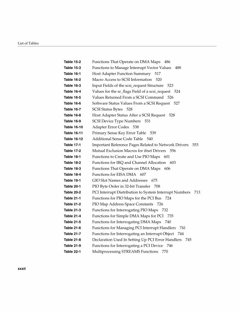
Table 15-2 Functions That Operate on DMA Maps 486Table 15-3 Functions to Manage Interrupt Vector Values 488Table 16-1 Host Adapter Function Summary 517Table 16-2 Macro Access to SCSI Information 520Table 16-3 Input Fields of the scsi_request Structure 523Table 16-4 Values for the sr_flags Field of a scsi_request 524Table 16-5 Values Returned From a SCSI Command 526Table 16-6 Software Status Values From a SCSI Request 527Table 16-7 SCSI Status Bytes 528Table 16-8 Host Adapter Status After a SCSI Request 528Table 16-9 SCSI Device Type Numbers 531Table 16-10 Adapter Error Codes 538Table 16-11 Primary Sense Key Error Table 539Table 16-12 Additional Sense Code Table 540Table 17-1 Important Reference Pages Related to Network Drivers 553Table 17-2 Mutual Exclusion Macros for ifnet Drivers 556Table 18-1 Functions to Create and Use PIO Maps 601Table 18-2 Functions for IRQ and Channel Allocation 603Table 18-3 Functions That Operate on DMA Maps 606Table 18-4 Functions for EISA DMA 607Table 19-1 GIO Slot Names and Addresses 675Table 20-1 PIO Byte Order in 32-bit Transfer 708Table 20-2 PCI Interrupt Distribution to System Interrupt Numbers 713Table 21-1 Functions for PIO Maps for the PCI Bus 724Table 21-2 PIO Map Address Space Constants 726Table 21-3 Functions for Interrogating PIO Maps 732Table 21-4 Functions for Simple DMA Maps for PCI 735Table 21-5 Functions for Interrogating DMA Maps 740Table 21-6 Functions for Managing PCI Interrupt Handlers 741Table 21-7 Functions for Interrogating an Interrupt Object 744Table 21-8 Declaration Used In Setting Up PCI Error Handlers 745Table 21-9 Functions for Interrogating a PCI Device 746Table 22-1 Multiprocessing STREAMS Functions 770
List of Tables
xxxiii
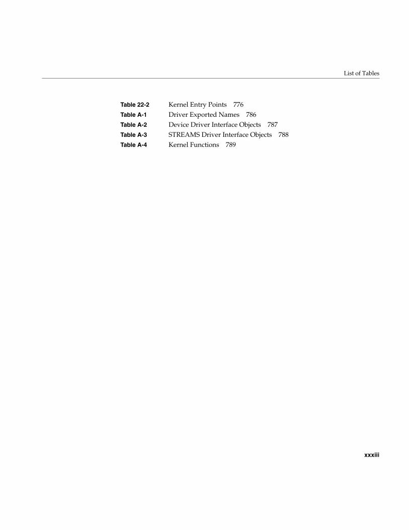
Table 22-2 Kernel Entry Points 776Table A-1 Driver Exported Names 786Table A-2 Device Driver Interface Objects 787Table A-3 STREAMS Driver Interface Objects 788Table A-4 Kernel Functions 789

xxxv
About This Guide
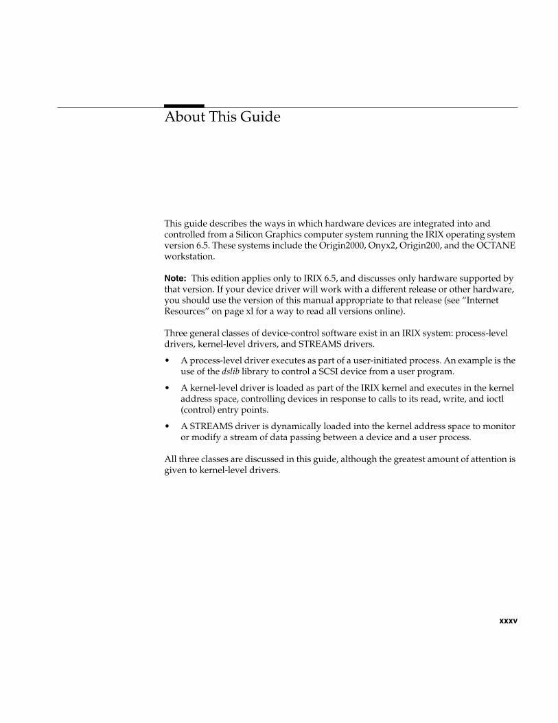
This guide describes the ways in which hardware devices are integrated into andcontrolled from a Silicon Graphics computer system running the IRIX operating systemversion 6.5. These systems include the Origin2000, Onyx2, Origin200, and the OCTANEworkstation.
Note: This edition applies only to IRIX 6.5, and discusses only hardware supported bythat version. If your device driver will work with a different release or other hardware,you should use the version of this manual appropriate to that release (see “InternetResources” on page xl for a way to read all versions online).
Three general classes of device-control software exist in an IRIX system: process-leveldrivers, kernel-level drivers, and STREAMS drivers.
• A process-level driver executes as part of a user-initiated process. An example is theuse of the dslib library to control a SCSI device from a user program.
• A kernel-level driver is loaded as part of the IRIX kernel and executes in the kerneladdress space, controlling devices in response to calls to its read, write, and ioctl(control) entry points.
• A STREAMS driver is dynamically loaded into the kernel address space to monitoror modify a stream of data passing between a device and a user process.
All three classes are discussed in this guide, although the greatest amount of attention isgiven to kernel-level drivers.
xxxvi
About This Guide
What You Need to Know to Write Device Drivers
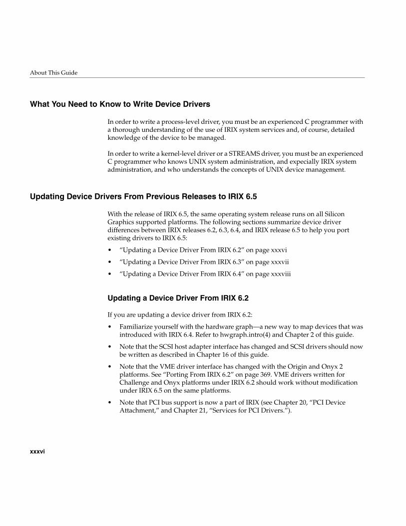
In order to write a process-level driver, you must be an experienced C programmer witha thorough understanding of the use of IRIX system services and, of course, detailedknowledge of the device to be managed.
In order to write a kernel-level driver or a STREAMS driver, you must be an experiencedC programmer who knows UNIX system administration, and expecially IRIX systemadministration, and who understands the concepts of UNIX device management.
Updating Device Drivers From Previous Releases to IRIX 6.5
With the release of IRIX 6.5, the same operating system release runs on all SiliconGraphics supported platforms. The following sections summarize device driverdifferences between IRIX releases 6.2, 6.3, 6.4, and IRIX release 6.5 to help you portexisting drivers to IRIX 6.5:
• “Updating a Device Driver From IRIX 6.2” on page xxxvi
• “Updating a Device Driver From IRIX 6.3” on page xxxvii
• “Updating a Device Driver From IRIX 6.4” on page xxxviii
Updating a Device Driver From IRIX 6.2
If you are updating a device driver from IRIX 6.2:
• Familiarize yourself with the hardware graph—a new way to map devices that wasintroduced with IRIX 6.4. Refer to hwgraph.intro(4) and Chapter 2 of this guide.
• Note that the SCSI host adapter interface has changed and SCSI drivers should nowbe written as described in Chapter 16 of this guide.
• Note that the VME driver interface has changed with the Origin and Onyx 2platforms. See “Porting From IRIX 6.2” on page 369. VME drivers written forChallenge and Onyx platforms under IRIX 6.2 should work without modificationunder IRIX 6.5 on the same platforms.
• Note that PCI bus support is now a part of IRIX (see Chapter 20, “PCI DeviceAttachment,” and Chapter 21, “Services for PCI Drivers.”).
About This Guide
xxxvii
• If you are using poll(), refer to “Entry Point poll()” on page 167 and the poll(D2)reference manual page for the discussion of the genp argument.
• Beginning with IRIX 6.4, there is no restriction on which kernel services you can callfrom driver lower-half code. Refer to “Upper and Lower Halves” on page 70.
• Beginning with IRIX 6.4, there is no special provision for uniprocessor drivers inmultiprocessor systems. You can write a uniprocessor-only driver and use it on auniprocessor workstation but you cannot use the same driver design on amultiprocessor system.
• Mapped driver routines (for example, v_mapphys) are now located in ksys/ddmap.h(not /sys/region.h), which also contains some new routines (see ksys/ddmap.h).
Updating a Device Driver From IRIX 6.3
If you are updating a device driver from IRIX 6.3:
• Familiarize yourself with the hardware graph—a new way to map devices that wasintroduced with IRIX 6.4. Refer to hwgraph.intro(4) and Chapter 2 of this guide.
• Note that the SCSI host adapter interface has changed and SCSI drivers should nowbe written as described in Chapter 16 of this guide.
• Note that PCI drivers will have to be modified to work with the PCI interface asdocumented in Chapter 20, “PCI Device Attachment,” and Chapter 21, “Services forPCI Drivers” of this guide.
• If you are using poll(), refer to “Entry Point poll()” on page 167 and the poll(D2)man page for the discussion of the genp argument.
• Beginning with IRIX 6.4, there is no restriction on which kernel services you can callfrom driver lower-half code. Refer to “Upper and Lower Halves” on page 70.
• Beginning with IRIX 6.4, there is no special provision for uniprocessor drivers inmultiprocessor systems. You can write a uniprocessor-only driver and use it on auniprocessor workstation, but you cannot use the same driver design on amultiprocessor system.
• Mapped driver routines (for example, v_mapphys) are now located in ksys/ddmap.h(not /sys/region.h) which also contains some new routines (see ksys/ddmap.h).
xxxviii
About This Guide
Updating a Device Driver From IRIX 6.4
If you are updating a device driver from IRIX 6.4:
• Note that IRIX 6.5 covers all supported platforms. If you want your driver tosupport multiple platforms, refer to “Platform Support” on page 256.
• Note that the third-party SCSI drivers are supported as documented in Chapter 16.
• Note that PCI drivers for the O2 platform should be written as described in “PCIDrivers for the O2 (IP32) Platform” on page 732, and user-level PCI drivers shouldbe updated to support the pciba interface instead of usrpci (see “PCI ProgrammedI/O” on page 78 of this guide.
• Mapped driver routines (for example, v_mapphys) are now located in ksys/ddmap.h(not /sys/region.h), which also contains some new routines (see ksys/ddmap.h).
• If you are using poll(), refer to “Entry Point poll()” on page 167 and the poll(D2)reference manual page for the discussion of the genp argument.
• VME drivers support either the Origin and Onyx2 platforms (refer to Chapter 12and Chapter 13), or the Challenge and Onyx platforms (refer to Chapter 14 andChapter 15).
What This Guide Contains
This guide is divided into the following major parts.
Part I, “IRIX Device Integration” How devices are attached to Silicon Graphicscomputers, configured to IRIX, and initialized atboot time.
Part II, “Device Control FromProcess Space”
Details of user-level handling of PCI devices andSCSI control using dslib.
Part III, “Kernel-Level Drivers” How kernel-level drivers are designed, compiled,loaded, and tested. Survey of kernel services fordrivers.
Part IV, “VME Device Drivers” Kernel-level drivers for the VME bus.
Part V, “SCSI Device Drivers” Kernel-level drivers for the SCSI bus.
Part VI, “Network Drivers” Kernel-level drivers for network interfaces.
About This Guide
xxxix
In the printed book, you can locate these parts using the part-tabs printed in the margins.Using IRIS InSight, each part is a top-level division in the clickable table of contents, oryou can jump to any part by clicking the blue cross-references in the list above.
Other Sources of Information
Developer Program
Information and support are available through the Silicon Graphics Developer Program.The Developer Toolbox CDROM contains numerous code examples. To join the program,contact the Developer Response Center at (800) 770-3033 or send e-mail [email protected].
Part VII, “EISA Drivers” Kernel-level drivers for the EISA bus in Indigo2workstations.
Part VIII, “GIO Drivers” Kernel-level drivers for the GIO bus in Indigo2workstations.
Part IX, “PCI Drivers” Kernel-level drivers for the PCI bus.
Part X, “STREAMS Drivers” Design of STREAMS drivers.
Appendix A, “Silicon GraphicsDriver/Kernel API”
Summary of kernel functions with compatibilitynotes.
Appendix B, “Challenge DMAwith Multiple IO4 Boards”
VME I/O considerations for Challenge and Onyxsystems.
xl
About This Guide
Internet Resources
A great deal of useful material can be found on the Internet. Some starting points are inthe following list.
Standards Documents
The following documents are the official standard descriptions of buses:
• PCI Local Bus Specification, Version 2.1, available from the PCI Special Interest Group,P.O. Box 14070, Portland, OR 97214 (fax: 503-234-6762).
• ANSI/IEEE standard 1014-1987 (VME Bus), available from IEEE Customer Service,445 Hoes Lane, PO Box 1331, Piscataway, NJ 08855-1331 (but see also “InternetResources” on page xl).
Earlier versions of this book as well as allother Silicon Graphics technical manuals toread or download.
http://techpubs.sgi.com/library/
Silicon Graphics patches, examples, and othermaterial.
ftp://ftp.sgi.com
Network of pages of information aboutSilicon Graphics and MIPS® products
http://www.sgi.com
Text of all Internet RFC documents. ftp://ds.internic.net/rfc/
Computer graphics pointers at the UCSCPerceptual Science Labororatory.
http://mambo.ucsc.edu/psl/cg.html
Pointers to binaries and sources at TheNational Research Council of Canada’sInstitute For Biodiagnostics.
http://zeno.ibd.nrc.ca:80/~sgi/
A Silicon Graphics “meta page” at the GeorgiaInstitute of Technology College of Computing.
http://www.cc.gatech.edu/services/sgimeta.html
Complete SCSI-2 standard in HTML. http://scitexdv.com:8080/SCSI2/
IEEE Catalog and worldwide orderinginformation.
http://standards.ieee.org/index.html
MIPS processor manuals in HTML form. http://www.mips.com/
Home page of the PCI bus standardizationorganization
http://www.pcisig.com
About This Guide
xli
Important Reference Pages
The following reference pages contain important details about software tools andpractices that you need.
Additional Reading
The following books, obtainable from Silicon Graphics, can be helpful when designingor testing a device driver:
• MIPSpro Compiling and Performance Tuning Guide, document number 007-2360-nnn,tells how to use the C compiler and related tools.
• MIPSpro Assembly Language Programmer’s Guide, document number 007-2418-nnn,tells how to compile assembly-language modules.
• MIPSpro 64-Bit Porting and Transition Guide, document number 007-2391-nnn,documents the implications of the 64-bit execution mode for user programs.
• MIPSpro N32 ABI Handbook, document number 007-2816-nnn, gives details of thecode generated when the -n32 compiler option is used.
alenlist(d4x) Overview of address/length list functions
getinvent(3) The interface to the inventory database
hinv(1) The use of the inventory display command
hwgraph.intro(d4x) Overview of the hardware graph and kernel functions for it
intro(7) The conventions used for special device filenames
ioconfig(1M) The startup program that creates device special files
master(4) Syntax of files in /var/sysgen/master.d
system(4) Syntax of files in /var/sysgen/system/*.sm
prom(1) Commands of the “miniroot” and other features of the bootPROM, which you use to bring up the system when testing anew device driver
udmalib(3) Functions for performing user-level DMA from VME.
uli(3) Functions for registering and using a user-level interrupthandler (installs with the REACT/Pro product)
usrvme(7) Naming conventions for mappable VME device special files
xlii
About This Guide
• Topics in IRIX Programming, document number 008-2478-nnn, documents some ofthe sophisticated services offered by the IRIX kernel to user-level programs.
• MIPS R4000 User’s Manual (2nd ed.) by Joe Heinrich, document number007-2489-001, gives detailed information on the MIPS instruction set and hardwareregisters for the processor used in many Silicon Graphics computer systems (alsoavailable as HTML on http://www.mips.com/).
• MIPS R10000 User’s Manual by Joe Heinrich gives detailed information on the MIPSinstruction set and hardware registers for the processor used in certain high-endsystems. Available only in HTML form from http://www.mips.com/.
• IRIX Admin: System Configuration and Operation, document number 007-2859-nnn,describes the basic adminstrative tools for configuring, operating, and tuning IRIX.
• IRIX Admin: Disks and File Systems, document number 007-2825-nnn, describes theconfiguration of new disk subsystems and the management of logical volumes andfile systems.
• IRIX Admin: Peripheral Devices, document number 007-2861-nnn, describes theadminstration of tapes, printers, and other devices.
The following books, obtainable from bookstores or libraries, can also be helpful.
• Lenoski, Daniel E. and Wolf-Dietrich Weber. Scalable Shared-Memory Multiprocessing.Morgan Kaufmann Publishers, San Francisco, 1995. ISBN 1-55860-315-8.
• Egan, Janet I., and Thomas J. Teixeira. Writing a UNIX Device Driver. John Wiley &Sons, 1992.
• Leffler, Samuel J., et alia. The Design and Implementation of the 4.3BSD UNIXOperating System. Palo Alto, California: Addison-Wesley Publishing Company, 1989.
• A. Silberschatz, J. Peterson, and P. Galvin. Operating System Concepts, Third Edition.Addison Wesley Publishing Company, 1991.
• Heath, Steve. VMEbus User’s Handbook. CRC Press, Inc, 1989. ISBN 0-8493-7130-9.
• Device Driver Reference, UNIX SVR4.2, UNIX Press 1992.
• UNIX System V Release 4 Programmer’s Guide, UNIX SVR4.2. UNIX Press, 1992.
• STREAMS Modules and Drivers, UNIX SVR4.2, UNIX Press 1992. ISBN 0-13-066879.
About This Guide
xliii
Conventions Used in This Guide
Special terms and special kinds of words are indicated with the following typographicalconventions:
Data structures, variables, functionarguments, and macros.
The dsiovec structure has members iov_base andiov_len. Use the IOVLEN macro to access them.
Kernel and library functions andfunctions in examples.
When successful, v_mapphys() returns 0.
Driver entry point names that must becompleted with a unique prefix string.
The munmap() system function calls thepfxunmap() entry point.
Files and directories. Device special files are in /dev, and are createdusing the /dev/MAKEDEV script.
First use of terms defined in theglossary (see “Glossary”).
The inode of a device special file contains themajor device number.
Literal quotes of code examples. The SCSI driver’s prefix is scsi_.

PART ONE
IRIX Device Integration I
Chapter 1, “Physical and Virtual Memory”An overview of physical memory, virtual address space management, anddevice addressing in Silicon Graphics/MIPS systems.
Chapter 2, “Device Configuration”How IRIX locates devices, and how devices are represented in software.
Chapter 3, “Device Control Software”A survey of the ways in which you can control devices under IRIX, fromuser-level processes and from kernel-level drivers of different kinds.

3
Chapter 1
1. Physical and Virtual Memory
This chapter gives an overview of the management of physical and virtual memory inSilicon Graphics systems based on the MIPS R5000 and R10000 processors. The purposeis to give you the background to understand terms used in device driver header files andreference pages, and to understand the limitations and special conventions used by somekernel functions.
This information is only of academic interest if you intend to control a device from auser-level process. ( See Chapter 3, “Device Control Software,” for the difference betweenuser-level and kernel-level drivers.) For a deeper level of detail on Origin2000 memoryhardware, see the hardware manuals listed under “Additional Reading” on page xli.
The following main topics are covered in this chapter.
• “CPU Access to Memory and Devices” on page 4 summarizes the hardwarearchitecture by which the CPU accesses memory.
• “The 32-Bit Address Space” on page 15 describes the parts of the physical addressspace when 32-bit addressing is used.
• “The 64-Bit Address Space” on page 19 describes the 64-bit physical address space.
• “Address Space Usage in Origin2000 Systems” on page 25 gives an overview ofhow physical memory is addressed in the complex architecture of the Origin2000.
4
Chapter 1: Physical and Virtual Memory
CPU Access to Memory and Devices
Each Silicon Graphics computer system has one or more CPU modules. A CPU readsdata from memory or a device by placing an address on a system bus, and receiving databack from the addressed memory or device. An address can be translated more than onceas it passes through multiple layers of bus adapters. Access to memory can pass throughmultiple levels of cache.
CPU Modules
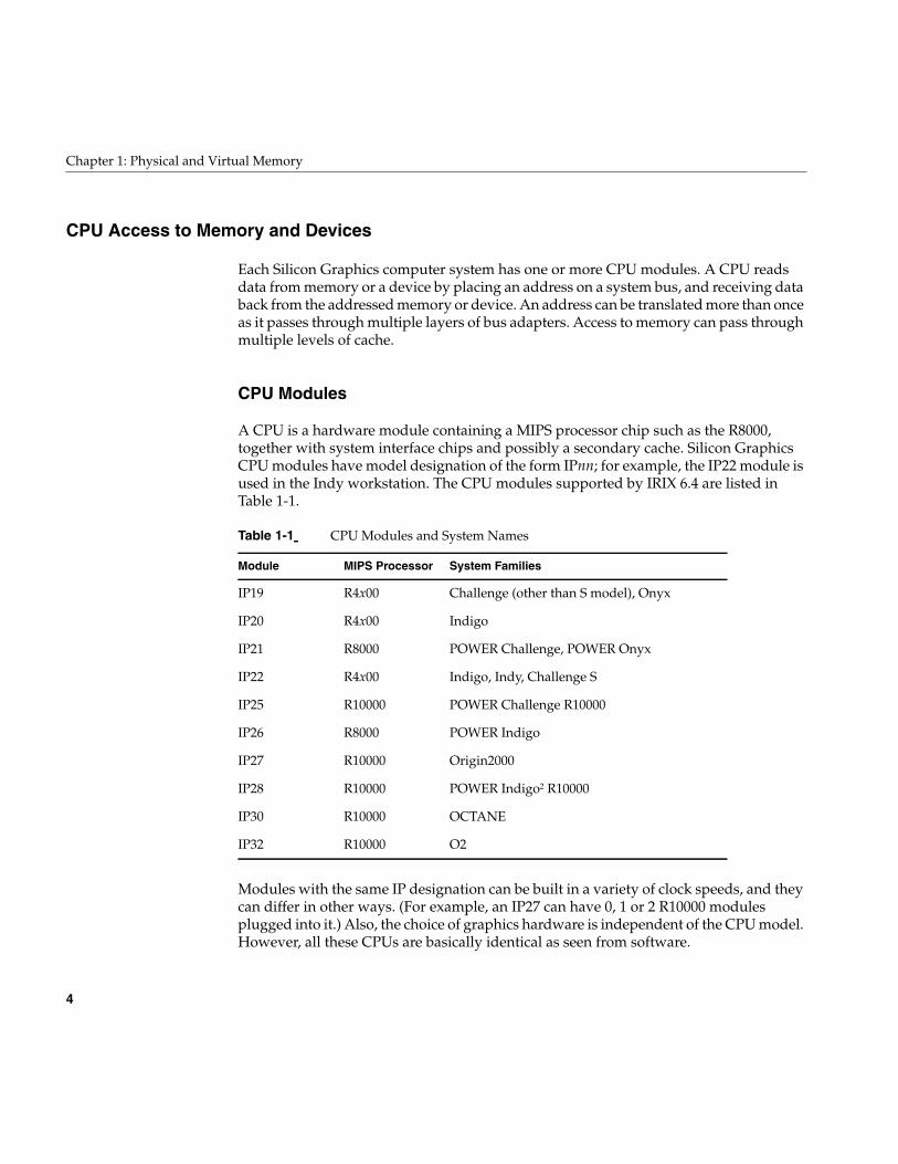
A CPU is a hardware module containing a MIPS processor chip such as the R8000,together with system interface chips and possibly a secondary cache. Silicon GraphicsCPU modules have model designation of the form IPnn; for example, the IP22 module isused in the Indy workstation. The CPU modules supported by IRIX 6.4 are listed inTable 1-1.
Modules with the same IP designation can be built in a variety of clock speeds, and theycan differ in other ways. (For example, an IP27 can have 0, 1 or 2 R10000 modulesplugged into it.) Also, the choice of graphics hardware is independent of the CPU model.However, all these CPUs are basically identical as seen from software.
Table 1-1 CPU Modules and System Names
Module MIPS Processor System Families
IP19 R4x00 Challenge (other than S model), Onyx
IP20 R4x00 Indigo
IP21 R8000 POWER Challenge, POWER Onyx
IP22 R4x00 Indigo, Indy, Challenge S
IP25 R10000 POWER Challenge R10000
IP26 R8000 POWER Indigo
IP27 R10000 Origin2000
IP28 R10000 POWER Indigo2 R10000
IP30 R10000 OCTANE
IP32 R10000 O2
CPU Access to Memory and Devices
5
Interrogating the CPU Type
At the interactive command line, you can determine which CPU module a system useswith the command
hinv -c processor
Within a shell script, it is more convenient to process the terse output of
uname -m
(See the uname(1) and hinv(1) reference pages.)
Within a program, you can get the CPU model using the getinvent() function. For anexample, see “Testing the Inventory In Software” on page 49.
CPU Access to Memory
The CPU generates the address of data that it needs—the address of an instruction tofetch, or the address of an operand of an instruction. It requests the data through amechanism that is depicted in simplified form in Figure 1-1.
6
Chapter 1: Physical and Virtual Memory
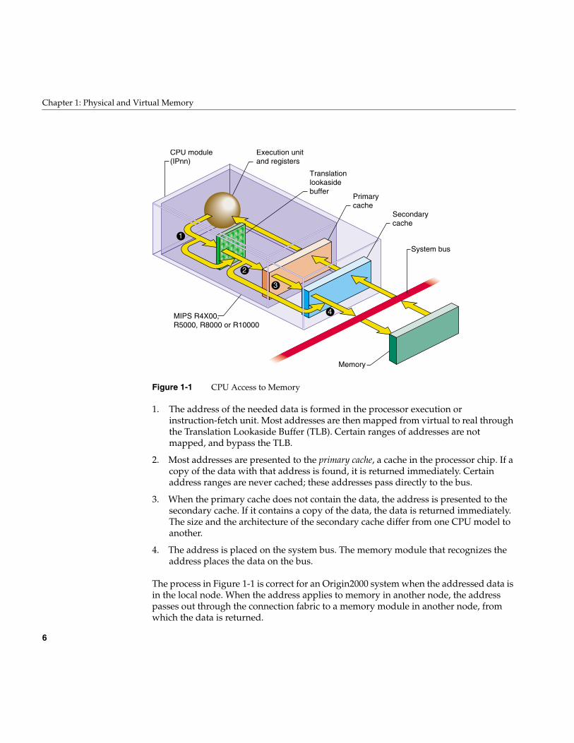
Figure 1-1 CPU Access to Memory
1. The address of the needed data is formed in the processor execution orinstruction-fetch unit. Most addresses are then mapped from virtual to real throughthe Translation Lookaside Buffer (TLB). Certain ranges of addresses are notmapped, and bypass the TLB.
2. Most addresses are presented to the primary cache, a cache in the processor chip. If acopy of the data with that address is found, it is returned immediately. Certainaddress ranges are never cached; these addresses pass directly to the bus.
3. When the primary cache does not contain the data, the address is presented to thesecondary cache. If it contains a copy of the data, the data is returned immediately.The size and the architecture of the secondary cache differ from one CPU model toanother.
4. The address is placed on the system bus. The memory module that recognizes theaddress places the data on the bus.
The process in Figure 1-1 is correct for an Origin2000 system when the addressed data isin the local node. When the address applies to memory in another node, the addresspasses out through the connection fabric to a memory module in another node, fromwhich the data is returned.
1
2
3
4
Execution unitand registers
Translation lookasidebuffer
Primarycache
Secondarycache
System bus
Memory
CPU module(IPnn)
MIPS R4X00,R5000, R8000 or R10000
CPU Access to Memory and Devices
7
Processor Operating Modes
The MIPS processor under IRIX operates in one of two modes: kernel and user. Theprocessor enters the more privileged kernel mode when an interrupt, a systeminstruction, or an exception occurs. It returns to user mode only with a “Return fromException” instruction.
Certain instructions cannot be executed in user mode. Certain segments of memory canbe accessed only in kernel mode, and other segments only in user mode.
Virtual Address Mapping
The MIPS processor contains an array of Translation Lookaside Buffer (TLB) entries thatmap, or translate, virtual addresses to physical ones. Most memory accesses are firstmapped by reference to the TLB. This permits the IRIX kernel to to relocate parts of thekernel’s memory and to implement virtual memory for user processes. The translationscheme is summarized in the following sections and covered in detail in the hardwaremanuals listed under “Additional Reading” on page xli.
TLB Misses and TLB Sizes
Each TLB entry describes a segment of memory containing two adjacent pages. When theinput address falls in a page described by a TLB entry, the TLB supplies the physicalmemory address for that page. The translated address, now physical instead of virtual,is passed on to the cache, as shown in Figure 1-1 on page 6.
When the input address is not covered by any active TLB entry, the MIPS processorgenerates a “TLB miss” interrupt, which is handled by an IRIX kernel routine. The kernelroutine inspects the address. When the address has a valid translation to some page inthe address space, the kernel loads a TLB entry to describe that page, and restarts theinstruction.
8
Chapter 1: Physical and Virtual Memory
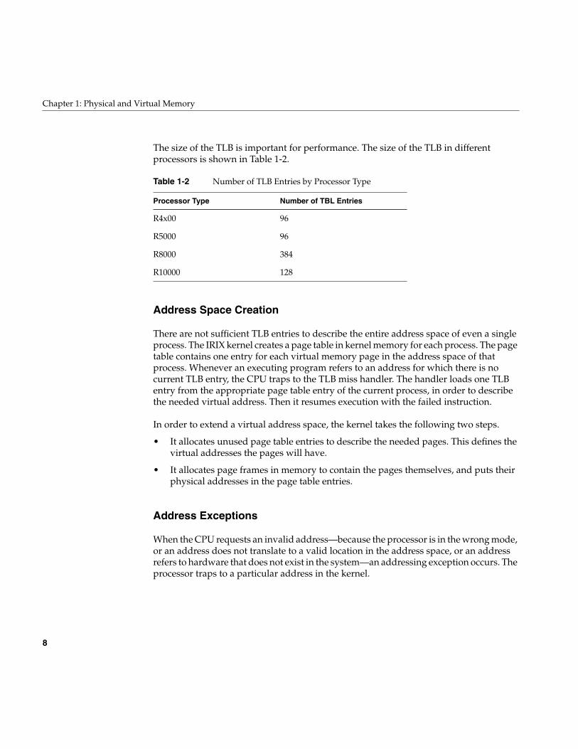
The size of the TLB is important for performance. The size of the TLB in differentprocessors is shown in Table 1-2.
Address Space Creation
There are not sufficient TLB entries to describe the entire address space of even a singleprocess. The IRIX kernel creates a page table in kernel memory for each process. The pagetable contains one entry for each virtual memory page in the address space of thatprocess. Whenever an executing program refers to an address for which there is nocurrent TLB entry, the CPU traps to the TLB miss handler. The handler loads one TLBentry from the appropriate page table entry of the current process, in order to describethe needed virtual address. Then it resumes execution with the failed instruction.
In order to extend a virtual address space, the kernel takes the following two steps.
• It allocates unused page table entries to describe the needed pages. This defines thevirtual addresses the pages will have.
• It allocates page frames in memory to contain the pages themselves, and puts theirphysical addresses in the page table entries.
Address Exceptions
When the CPU requests an invalid address—because the processor is in the wrong mode,or an address does not translate to a valid location in the address space, or an addressrefers to hardware that does not exist in the system—an addressing exception occurs. Theprocessor traps to a particular address in the kernel.
Table 1-2 Number of TLB Entries by Processor Type
Processor Type Number of TBL Entries
R4x00 96
R5000 96
R8000 384
R10000 128
CPU Access to Memory and Devices
9
An addressing exception can also be detected in the course of handling a TLB miss. Ifthere is no page table entry assigned for the desired address, that address is not part ofthe address space of the processs.
When a user-mode process caused the addressing exception, the kernel sends the processa SIGSEGV (see the signal(5) reference page), usually causing a segmentation fault.When kernel-level code such as a device driver causes the exception, the kernel executesa “panic,” taking a crash dump and shutting down the system.
CPU Access to Device Registers
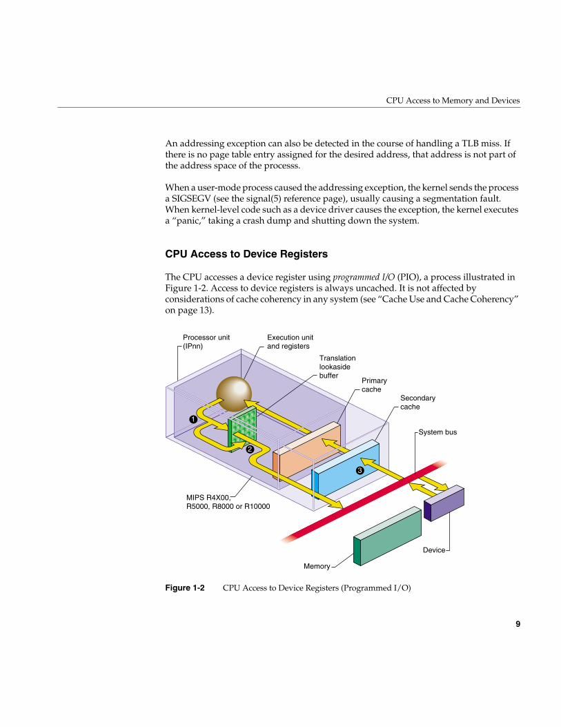
The CPU accesses a device register using programmed I/O (PIO), a process illustrated inFigure 1-2. Access to device registers is always uncached. It is not affected byconsiderations of cache coherency in any system (see “Cache Use and Cache Coherency”on page 13).
Figure 1-2 CPU Access to Device Registers (Programmed I/O)
1
2
3
Execution unitand registers
Translation lookasidebuffer
Primarycache
Secondarycache
System bus
Memory
Processor unit(IPnn)
Device
MIPS R4X00,R5000, R8000 or R10000
10
Chapter 1: Physical and Virtual Memory
1. The address of the device is formed in the Execution unit. It may or may not be anaddress that is mapped by the TLB.
2. A device address, after mapping if necessary, always falls in one of the ranges that isnot cached, so it passes directly to the system bus.
3. The device or bus attachment recognizes its physical address and responds withdata.
The PIO process shown in Figure 1-2 is correct for an Origin2000 system when theaddressed device is attached to the same node. When the device is attached to a differentnode, the address passes through the connection fabric to that node, and the data returnsthe same way.
Direct Memory Access
Some devices can perform direct memory access (DMA), in which the device itself, not theCPU, reads or writes data into memory. A device that can perform DMA is called a busmaster because it independently generates a sequence of bus accesses without help fromthe CPU.
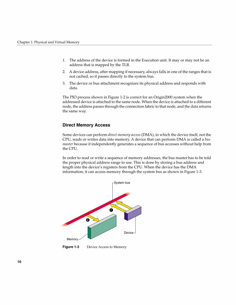
In order to read or write a sequence of memory addresses, the bus master has to be toldthe proper physical address range to use. This is done by storing a bus address andlength into the device’s registers from the CPU. When the device has the DMAinformation, it can access memory through the system bus as shown in Figure 1-3.
Figure 1-3 Device Access to Memory
1
2
System bus
Memory
Device
CPU Access to Memory and Devices
11
1. The device places the next physical address, and data, on the system bus.
2. The memory module stores the data.
In a Origin2000 system, the device and the memory module can be in different nodes,with address and data passing through the connection fabric between nodes.
When a device is programmed with an invalid physical address, the result is a bus errorinterrupt. The interrupt is taken by some CPU that is enabled for bus error interrupts.These interrupts are not simple to process for two reasons. First, the CPU that receivesthe interrupt is not necessarily the CPU from which the DMA operation wasprogrammed. Second, the bus error can occur a long time after the operation wasinitiated.
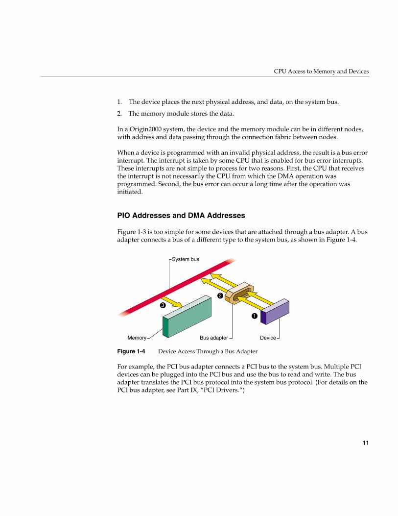
PIO Addresses and DMA Addresses
Figure 1-3 is too simple for some devices that are attached through a bus adapter. A busadapter connects a bus of a different type to the system bus, as shown in Figure 1-4.
Figure 1-4 Device Access Through a Bus Adapter
For example, the PCI bus adapter connects a PCI bus to the system bus. Multiple PCIdevices can be plugged into the PCI bus and use the bus to read and write. The busadapter translates the PCI bus protocol into the system bus protocol. (For details on thePCI bus adapter, see Part IX, “PCI Drivers.”)
2
3
System bus
Memory Bus adapter
1
Device
12
Chapter 1: Physical and Virtual Memory
Each bus has address lines that carry the address values used by devices on the bus.These bus addresses are not related to the physical addresses used on the system bus. Theissue of bus addressing is made complicated by three facts:
• Bus-master devices independently generate memory-read and memory-writecommands that are intended to access system memory.
• The bus adapter can translate addresses between addresses on the bus it manages,and different addresses on the system bus it uses.
• The translation done by the bus adapter can be programmed dynamically, and canchange from one I/O operation to another.
This subject can be simplified by dividing it into two distinct subjects: PIO addressing,used by the CPU to access a device, and DMA addressing, used by a bus master to accessmemory. These addressing modes need to be treated differently.
PIO Addressing
Programmed I/O (PIO) is the term for a load or store instruction executed by the CPUthat names an I/O device as its operand. The CPU places a physical address on thesystem bus. The bus adapter repeats the read or write command on its bus, but notnecessarily using the same address bits as the CPU put on the system bus.
One task of a bus adapter is to translate between the physical addresses used on thesystem bus and the addressing scheme used within the proprietary bus. The addressplaced on the target bus is not necessarily the same as the address generated by the CPU.The translation is done differently with different bus adapters and in different systemmodels.
In some older Silicon Graphics systems, the translation was hard-wired. For a simpleexample, the address translation from the Indigo2 system bus to the EISA bus washardwired, so that, for example, CPU access to a physical address of 0x0000 4010 wasalways translated to location 0x0010 in the I/O address space of EISA slot 4.
With the more sophisticated PCI and VME buses, the translation is dynamic. Both ofthese buses support bus address spaces that are as large or larger than the physicaladdress space of the system bus. It is impossible to hard-wire a translation of the entirebus address space.
In order to use a dynamic PIO address, a device driver creates a software object called aPIO map that represents that portion of bus address space that contains the device
CPU Access to Memory and Devices
13
registers the driver uses. When the driver wants to use the PIO map, the kerneldynamically sets up a translation from an unused part of physical address space to theneeded part of the bus address space. The driver extracts an address from the PIO mapand uses it as the base for accessing the device registers. PIO maps are discussed inChapter 13, “Services for VME Drivers on Origin 2000/Onyx 2,” and in Chapter 20, “PCIDevice Attachment.”
DMA Addressing
A bus-master device on the PCI or VME bus can be programmed to perform transfers toor from memory independently and asynchronously. A bus master is programmed usingPIO with a starting bus address and a length. The bus master generates a series ofmemory-read or memory-write operations to successive addresses. But what busaddresses should it use in order to store into the proper memory addresses?
The bus adapter translates the addresses used on the proprietary bus to correspondingaddresses on the system bus. Considering Figure 1-4, the operation of a DMA device isas follows:
1. The device places a bus address and data on the PCI or VME bus.
2. The bus adapter translates the address to a meaningful physical address, and placesthat address and the data on the system bus.
3. The memory modules stores the data.
The translation of bus virtual to physical addresses is done by the bus adapter andprogrammed by the kernel. A device driver requests the kernel to set up a dynamicmapping from a designated memory buffer to bus addresses. The map is represented bya software object called a DMA map.
The driver calls kernel functions to establishe the range of memory addresses that the busmaster device will need to access—typically the address of an I/O buffer. When thedriver activates the DMA map, the kernel sets up the bus adapter hardware to translatebetween some range of bus addresses and the desired range of memory space. The driverextracts from the DMA map the starting bus address, and (using PIO) programs that busaddress into the bus master device.
Cache Use and Cache Coherency
The primary and secondary caches shown in Figure 1-1 on page 6 are essential to CPUperformance. There is an order of magnitude difference in the speed of access between
14
Chapter 1: Physical and Virtual Memory
cache memory and main memory. Execution speed remains high only as long as a veryhigh proportion of memory accesses are satisfied from the primary or secondary cache.
The use of caches means that there are often multiple copies of data: a copy in mainmemory, a copy in the secondary cache (when one is used) and a copy in the primarycache. Moreover, a multiprocessor system has multiple CPU modules like the oneshown, and there can be copies of the same data in the cache of each CPU.
The problem of cache coherency is to ensure that all cache copies of data are true reflectionsof the data in main memory. Different Silicon Graphics systems use different hardwaredesigns to achieve cache coherency.
In most cases, cache coherence is achieved by the hardware, without any effect onsoftware. In a few cases, specialized software, such as a kernel-level device driver, musttake specific steps to maintain cache coherency.
Cache Coherency in Multiprocessors
Multiprocessor systems have more complex cache coherency protection because it ispossible to have data in multiple caches. In a multiprocessor system, the hardwareensures that cache coherency is maintained under all conditions, including DMA inputand output, without action by the software. However, in some systems the cachecoherency hardware works correctly only when a DMA buffer is aligned on acache-line-sized boundary. You ensure this by using the KM_CACHEALIGN flag whenallocating buffer space with kmem_alloc() (see “Kernel Memory Allocation” on page 203and the kmem_alloc(D3) reference page).
Cache Coherency in Uniprocessors
In some uniprocessor systems, it is possible for the CPU cache to have newer informationthan appears in memory. This is a problem only when a bus master device is going toperform DMA. If the bus master reads memory, it can get old data. If it writes memory,the input data can be destroyed when the CPU writes the modified cache line back tomemory.
In systems where this is possible, a device driver calls a kernel function to ensure that allcached data has been written to memory prior to DMA output (the dki_dcache_wb(D3)reference page). The device driver calls a kernel function to ensure that the CPU receivesthe latest data following a DMA input (see the dki_dcache_inval(D3) reference page). Ina multiprocessor these functions do nothing, but it is always safe to call them.

The 32-Bit Address Space
15
The 32-Bit Address Space
The MIPS processors can operate in one of two address modes: 32-bit and 64-bit. Thechoice of address mode is independent of other features of the instruction set architecturesuch as the number of available registers and the precision of integer arithmetic. Forexample, programs compiled to the n32 binary interface use 32-bit addresses but 64-bitintegers. The implications for user programs are documented in manuals listed under“Additional Reading” on page xli.
The addressing mode can be switched dynamically; for example, the IRIX kernel canoperate with 64-bit addresses, but the kernel can switch to 32-bit address when itdispatches a user program that was compiled for that mode. The 32-bit address space isthe range of all addresses that can be used when in 32-bit mode. This space is discussedfirst because it is simpler and more familiar than the 64-bit space.
Segments of the 32-bit Address Space
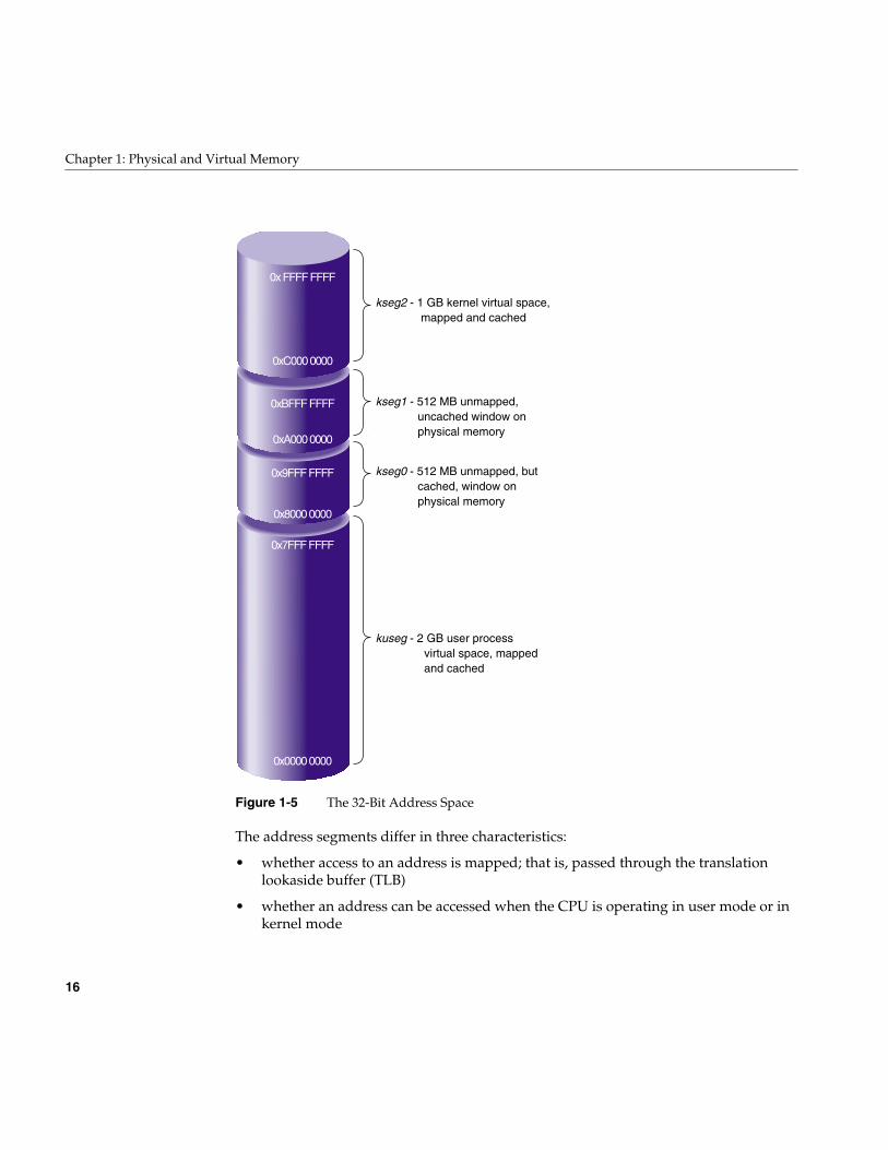
When operating in 32-bit mode, the MIPS architecture uses addresses that are 32-bitunsigned integers from 0x0000 0000 to 0xFFFF FFFF. However, this address space is notuniform. The MIPS hardware divides it into segments, and treats each segmentdifferently. The ranges are shown graphically in Figure 1-5.
16
Chapter 1: Physical and Virtual Memory
Figure 1-5 The 32-Bit Address Space
The address segments differ in three characteristics:
• whether access to an address is mapped; that is, passed through the translationlookaside buffer (TLB)
• whether an address can be accessed when the CPU is operating in user mode or inkernel mode
0xBFFF FFFF
0x9FFF FFFF
0x7FFF FFFF
0xA000 0000
0x8000 0000
0x0000 0000
0x FFFF FFFF
0xC000 0000
kseg2 - 1 GB kernel virtual space, mapped and cached
kseg1 - 512 MB unmapped, uncached window on physical memory
kseg0 - 512 MB unmapped, but cached, window on physical memory
kuseg - 2 GB user process virtual space, mapped and cached
The 32-Bit Address Space
17
• whether access to an address is cached; that is, looked up in the primary andsecondary caches before it is sent to main memory
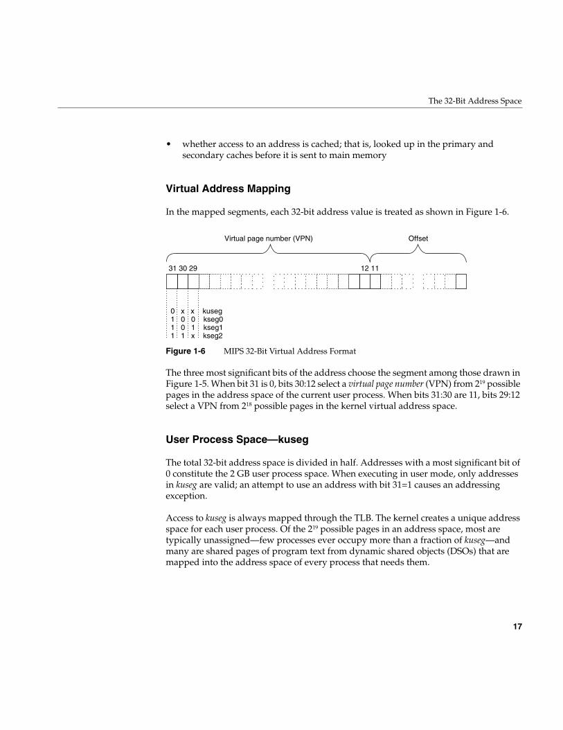
Virtual Address Mapping
In the mapped segments, each 32-bit address value is treated as shown in Figure 1-6.
Figure 1-6 MIPS 32-Bit Virtual Address Format
The three most significant bits of the address choose the segment among those drawn inFigure 1-5. When bit 31 is 0, bits 30:12 select a virtual page number (VPN) from 219 possiblepages in the address space of the current user process. When bits 31:30 are 11, bits 29:12select a VPN from 218 possible pages in the kernel virtual address space.
User Process Space—kuseg
The total 32-bit address space is divided in half. Addresses with a most significant bit of0 constitute the 2 GB user process space. When executing in user mode, only addressesin kuseg are valid; an attempt to use an address with bit 31=1 causes an addressingexception.
Access to kuseg is always mapped through the TLB. The kernel creates a unique addressspace for each user process. Of the 219 possible pages in an address space, most aretypically unassigned—few processes ever occupy more than a fraction of kuseg—andmany are shared pages of program text from dynamic shared objects (DSOs) that aremapped into the address space of every process that needs them.
31 30 29
0 x x kuseg 1 0 0 kseg0 1 0 1 kseg1 1 1 x kseg2
12 11
OffsetVirtual page number (VPN)
18
Chapter 1: Physical and Virtual Memory
Kernel Virtual Space—kseg2
When bits 31:30 are 11, access is to kernel virtual memory. Only code that is part of thekernel can access this space. References to this space are translated through the TLB. Thekernel uses the TLB to map kernel pages in memory as required, possibly innoncontiguous locations. Although pages in kernel space are mapped, they are alwaysassociated with real memory. Kernel memory is never paged to secondary storage.
This is the space in which the IRIX kernel allocates such objects as stacks, user pagetables, and per-process data that must be accessible on context switches. This areacontains automatic variables declared by loadable device drivers. It is the space in whichkernel-level device drivers allocate memory. Since kernel space is mapped, addresses inkseg2 that are apparently contiguous need not be contiguous in physical memory.However, a device driver can can allocate space that is both logically and physicallycontiguous, when that is required (see for example the kmem_alloc(D3) reference page).
Cached Physical Memory—kseg0
When address bits 31:29 contain 100, access is directed to physical memory through thecache. If the addressed location is not in the cache, bits 28:0 are placed on the system busas a physical memory address, and the data presented by memory or a device is returned.Kseg0 contains the exception address to which the MIPS processor branches it when itdetects an exception such as an addressing exception or TLB miss.
Since only 29 bits are available for mapping physical memory, only 512 MB of physicalmemory space can be accessed through this segment in 32-bit mode. Some of this spacemust be reserved for device addressing. It is possible to gain cached access to widerphysical addresses by mapping through the TLB into kseg2, but systems that need accessto more physical memory typically run in 64-bit mode (see “Cache-Controlled PhysicalMemory—xkphys” on page 23).
Uncached Physical Memory—kseg1
When address bits 31:29 contain 101, access is directly to physical memory, bypassing thecache. Bits 28:0 are placed on the system bus for memory or device transfer.
The kernel refers to kseg1 when performing PIO to devices because loads or stores fromdevice registers should not pass through cache memory. The kernel also uses kseg1 whenoperating on certain data structures that might be volatile. Kernel-level device drivers
The 64-Bit Address Space
19
sometimes need to write to uncached memory, and must take special precautions whendoing so (see “Uncached Memory Access in the IP26 and IP28” on page 33).
Portions of kseg0 or kseg1 can be mapped into kuseg by the mmap() function. This iscovered at more length under “Memory Use in User-Level Drivers” on page 31.
The 64-Bit Address Space
The 64-bit mode is an upward extension of 32-bit mode. All MIPS processors from theR4000 on support 64-bit mode. However, this mode was not used in Silicon Graphicssoftware until IRIX 6.0 was released.
Segments of the 64-Bit Address Space
When operating in 64-bit mode, the MIPS architecture uses addresses that are 64-bitunsigned integers from 0x0000 0000 0000 0000 to 0xFFFF FFFF FFFF FFFF. This is animmense span of numbers—if it were drawn to a scale of 1 millimeter per terabyte, thedrawing would be 16.8 kilometers long (just over 10 miles).
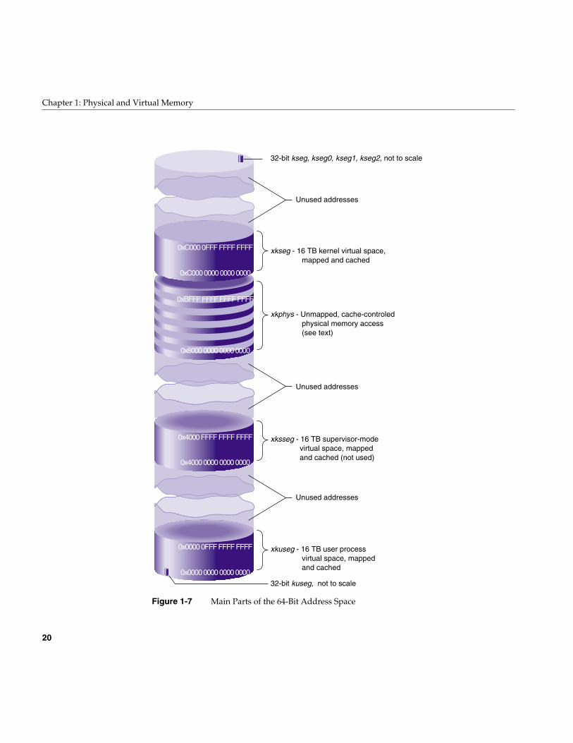
The MIPS hardware divides the address space into segments based on the mostsignificant bits, and treats each segment differently. The ranges are shown graphically inFigure 1-7. These major segments define only a fraction of the 64-bit space. Most of thepossible addresses are undefined and cause an addressing exception (segmentationfault) if used.
20
Chapter 1: Physical and Virtual Memory
Figure 1-7 Main Parts of the 64-Bit Address Space
0xBFFF FFFF FFFF FFFF
0x4000 FFFF FFFF FFFF
0x0000 0FFF FFFF FFFF
0x8000 0000 0000 0000
0x4000 0000 0000 0000
0x0000 0000 0000 0000
0xC000 0FFF FFFF FFFF
0xC000 0000 0000 0000
xkseg - 16 TB kernel virtual space, mapped and cached
32-bit kseg, kseg0, kseg1, kseg2, not to scale
32-bit kuseg, not to scale
xkphys - Unmapped, cache-controled physical memory access (see text)
xksseg - 16 TB supervisor-mode virtual space, mapped and cached (not used)
xkuseg - 16 TB user process virtual space, mapped and cached
Unused addresses
Unused addresses
Unused addresses
The 64-Bit Address Space
21
As in the 32-bit space, these major segments differ in three characteristics:
• whether access to an address is mapped; that is, passed through the translationlookaside buffer (TLB)
• whether an address can be accessed when the CPU is operating in user mode or inkernel mode.
• whether access to an address is cached; that is, looked up in the primary andsecondary caches before it is sent to main memory
Compatibility of 32-Bit and 64-Bit Spaces
The MIPS-3 instruction set (which is in use when the processor is in 64-bit mode) isdesigned so that when a 32-bit instruction is used to generate or to load an address, the32-bit operand is automatically sign-extended to fill the high-order 32 bits.
As a result, any 32-bit address that falls in the user segment kuseg, and which must havea sign bit of 0, is extended to a 64-bit integer with 32 high-order 0 bits. This automaticallyplaces the 32-bit kuseg in the bottom of the 64-bit xkuseg, as shown in Figure 1-7.
A 32-bit kernel address, which must have a sign bit of 1, is automatically extended to a64-bit integer with 32 high-order 1 bits. This places all kernel segments shown inFigure 1-5 at the extreme top of the 64-bit address space. However, these 32-bit kernelspaces are not used by a kernel operating in 64-bit mode.
Virtual Address Mapping
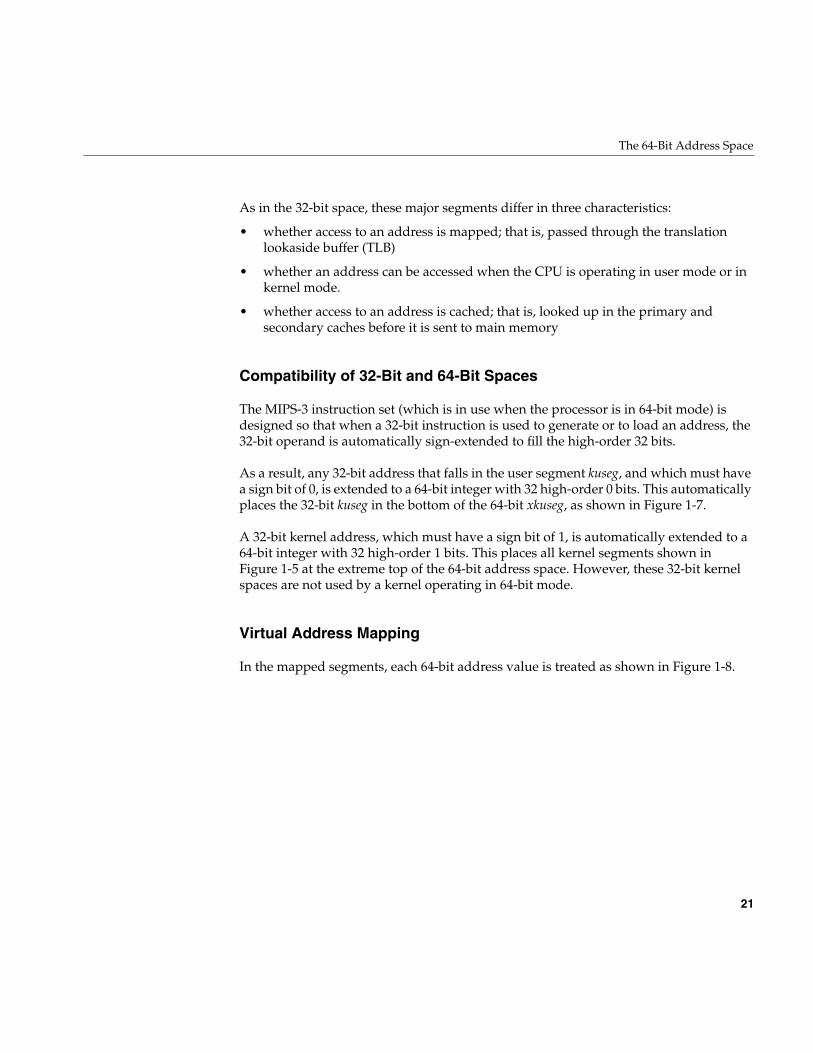
In the mapped segments, each 64-bit address value is treated as shown in Figure 1-8.
22
Chapter 1: Physical and Virtual Memory
Figure 1-8 MIPS 64-Bit Virtual Address Format
The two most significant bits select the major segment (compare these to the addressboundaries in Figure 1-7). Bits 61:40 must all be 0. (In principle, references to 32-bit kernelsegments would have bits 61:40 all 1, but these segments are not used in 64-bit mode.)
The size of a page of virtual memory can vary from system to system and release torelease, so always determine it dynamically. In a user-level program, call thegetpagesize() function (see the getpagesize(2) reference page). In a kernel-level driver,use the ptob() kernel function (see the ptob(D3) reference page) or the constant NBPPdeclared in sys/immu.h.)
When the page size is 16 KB, bits 13:0 of the address represent the offset within the page,and bits 39:14 select a VPN from the 226, or 64 M, pages in the virtual segment..
User Process Space—xkuseg
The first 16 TB of the address space are devoted to user process space. Access to xkuseg isalways mapped through the TLB. The kernel creates a unique address space for each userprocess. Of the 226 possible pages in a process’s address space, most are typicallyunassigned, and many are shared pages of program text from dynamic shared objects(DSOs) that are mapped into the address space of every process that needs them.
Supervisor Mode Space—xksseg
The MIPS architecture permits three modes of operation: user, kernel, and supervisor.When operating in kernel or supervisor mode, the 2 TB space beginning at0x4000 0000 0000 0000 is accessible. IRIX does not employ the supervisor mode, and doesnot use xksseg. If xksseg were used, it would be mapped and cached.
63 62 40 39
0 0 xkuseg 1 1 xksseg 1 0 xkphys 1 1 xkseg
14 13
OffsetAll-0 or all-1 Virtual page number (VPN)
The 64-Bit Address Space
23
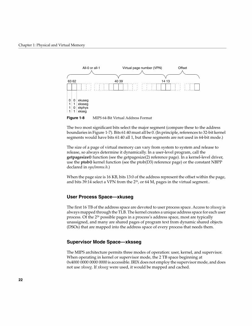
Kernel Virtual Space—xkseg
When bits 63:62 are 11, access is to kernel virtual memory. Only code that is part of thekernel can access this space, a 2 TB segment starting at 0xC000 0000 0000 0000.References to this space are translated through the TLB, and cached. The kernel uses theTLB to map kernel pages in memory as required, possibly in noncontiguous locations.Although pages in kernel space are mapped, they are always associated with realmemory. Kernel pages are never paged to secondary storage.
This is the space in which the IRIX kernel allocates such objects as stacks, per-processdata that must be accessible on context switches, and user page tables. This area containsautomatic variables declared by loadable device drivers. It is the space in whichkernel-level device drivers allocate memory. Since kernel space is mapped, addresses inkseg2 that are apparently contiguous need not be contiguous in physical memory.However, a device driver can can allocate space that is both logically and physicallycontiguous, when that is required (see for example the kmem_alloc(D3) reference page).
Cache-Controlled Physical Memory—xkphys
One-quarter of the 64-bit address space—all addresses with bits 63:62 containing 10—aredevoted to special access to one or more 1 TB physical address spaces. Any reference tothe other spaces (xkuseg and xkseg) is transformed by the TLB into a reference to xkphys.Addresses in this space are interpreted as shown in Figure 1-9.
Figure 1-9 Address Decoding for Physical Memory Access
63 62 57 40 39
Must be 0 Physical address
1 0
a a a x x
Cachealgorithm
Physicalpage
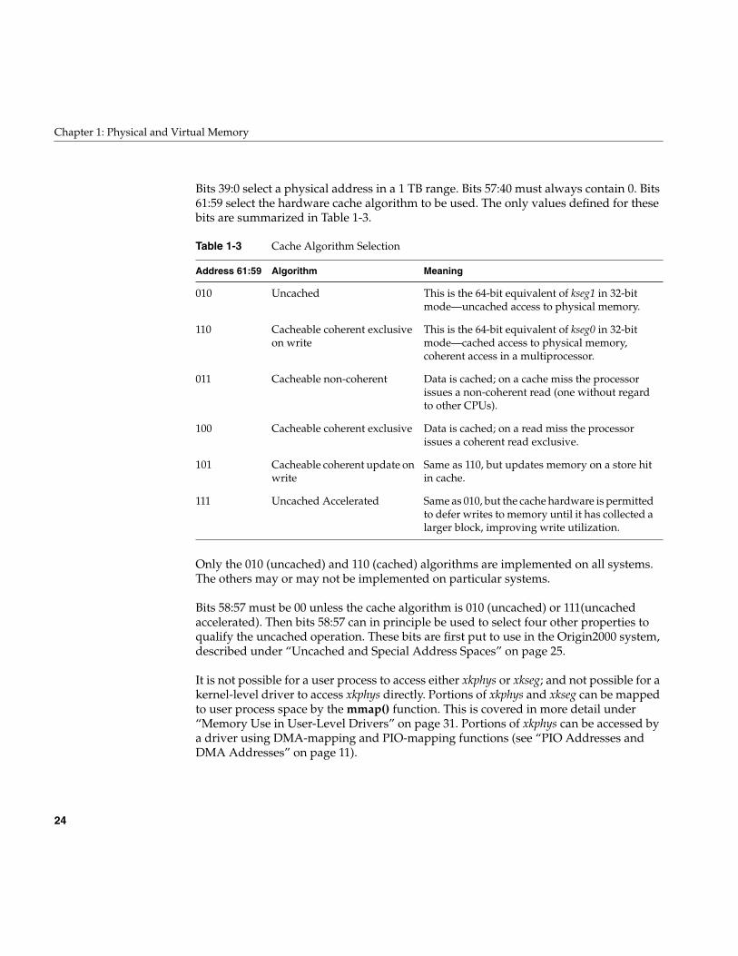
24
Chapter 1: Physical and Virtual Memory
Bits 39:0 select a physical address in a 1 TB range. Bits 57:40 must always contain 0. Bits61:59 select the hardware cache algorithm to be used. The only values defined for thesebits are summarized in Table 1-3.
Only the 010 (uncached) and 110 (cached) algorithms are implemented on all systems.The others may or may not be implemented on particular systems.
Bits 58:57 must be 00 unless the cache algorithm is 010 (uncached) or 111(uncachedaccelerated). Then bits 58:57 can in principle be used to select four other properties toqualify the uncached operation. These bits are first put to use in the Origin2000 system,described under “Uncached and Special Address Spaces” on page 25.
It is not possible for a user process to access either xkphys or xkseg; and not possible for akernel-level driver to access xkphys directly. Portions of xkphys and xkseg can be mappedto user process space by the mmap() function. This is covered in more detail under“Memory Use in User-Level Drivers” on page 31. Portions of xkphys can be accessed bya driver using DMA-mapping and PIO-mapping functions (see “PIO Addresses andDMA Addresses” on page 11).
Table 1-3 Cache Algorithm Selection
Address 61:59 Algorithm Meaning
010 Uncached This is the 64-bit equivalent of kseg1 in 32-bitmode—uncached access to physical memory.
110 Cacheable coherent exclusiveon write
This is the 64-bit equivalent of kseg0 in 32-bitmode—cached access to physical memory,coherent access in a multiprocessor.
011 Cacheable non-coherent Data is cached; on a cache miss the processorissues a non-coherent read (one without regardto other CPUs).
100 Cacheable coherent exclusive Data is cached; on a read miss the processorissues a coherent read exclusive.
101 Cacheable coherent update onwrite
Same as 110, but updates memory on a store hitin cache.
111 Uncached Accelerated Same as 010, but the cache hardware is permittedto defer writes to memory until it has collected alarger block, improving write utilization.
Address Space Usage in Origin2000 Systems
25
Address Space Usage in Origin2000 Systems
An Origin2000 system contains one or more nodes. Each node can contain one or twoCPUs as well as up to 2 GB of memory. There is a single, flat, address space that containsall memory in all nodes. All memory can be accessed from any CPU. However, a CPUcan access memory in its own node in less time than it can access memory in a differentnode.
The node hardware provides a variety of special-purpose access modes to make kernelprogramming simpler. These special modes are described here at a high level. For detailsrefer to the hardware manuals listed in “Additional Reading” on page xli. These specialaddressing modes are a feature of the Origin2000 node hardware, not of the R10000 CPUchip. As such they are available only in the Origin2000 and Origin200 systems.
User Process Space and Kernel Virtual Space
Virtual addresses with bits 63:62 containing 00 are references to the usr process addressspace. The kernel creates a virtual address space for each user process as described before(see “Virtual Address Mapping” on page 7). The Origin2000 architecture adds thecomplication that the location of a page, relative to the location where the processexecutes, has an effect on the performance of the process. The kernel uses a variety ofstrategies to locate pages of memory in the same node as the CPU that is running theprocess.
Kernel virtual addresses (in which bits 63:62 contain 11) are mapped as already described(see “Kernel Virtual Space—xkseg” on page 23). Certain important data structures maybe replicated into each node for faster access.
The stack and data areas used by device drivers are in xkseg. A driver has the ability torequest memory allocation in a particular node, in order to make sure that data about adevice is stored in the same node where the device is attached and where deviceinterrupts are taken (see “Kernel Memory Allocation” on page 203).
Uncached and Special Address Spaces
A physical address in xkphys (bits 63:62 contain 10) has different meanings depending onthe settings of bits 61:57 (see Figure 1-9 and Table 1-3). In the Origin2000 architecture,these bits are interpreted by the memory control circuits of the node, external to the CPU.
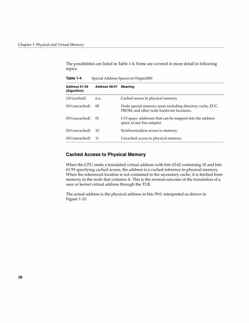
26
Chapter 1: Physical and Virtual Memory
The possibilities are listed in Table 1-4. Some are covered in more detail in followingtopics.
Cached Access to Physical Memory
When the CPU emits a translated virtual address with bits 63:62 containing 10 and bits61:59 specifying cached access, the address is a cached reference to physical memory.When the referenced location is not contained in the secondary cache, it is fetched frommemory in the node that contains it. This is the normal outcome of the translation of auser or kernel virtual address through the TLB.
The actual address is the physical address in bits 39:0, interpreted as shown inFigure 1-10.
Table 1-4 Special Address Spaces in Origin2000
Address 61:59(Algorithm)
Address 58:57 Meaning
110 (cached) n.a. Cached access to physical memory
010 (uncached) 00 Node special memory areas including directory cache, ECC,PROM, and other node hardware locations..
010 (uncached) 01 I/O space: addresses that can be mapped into the addressspace of any bus adapter.
010 (uncached) 10 Synchronization access to memory.
010 (uncached) 11 Uncached access to physical memory.
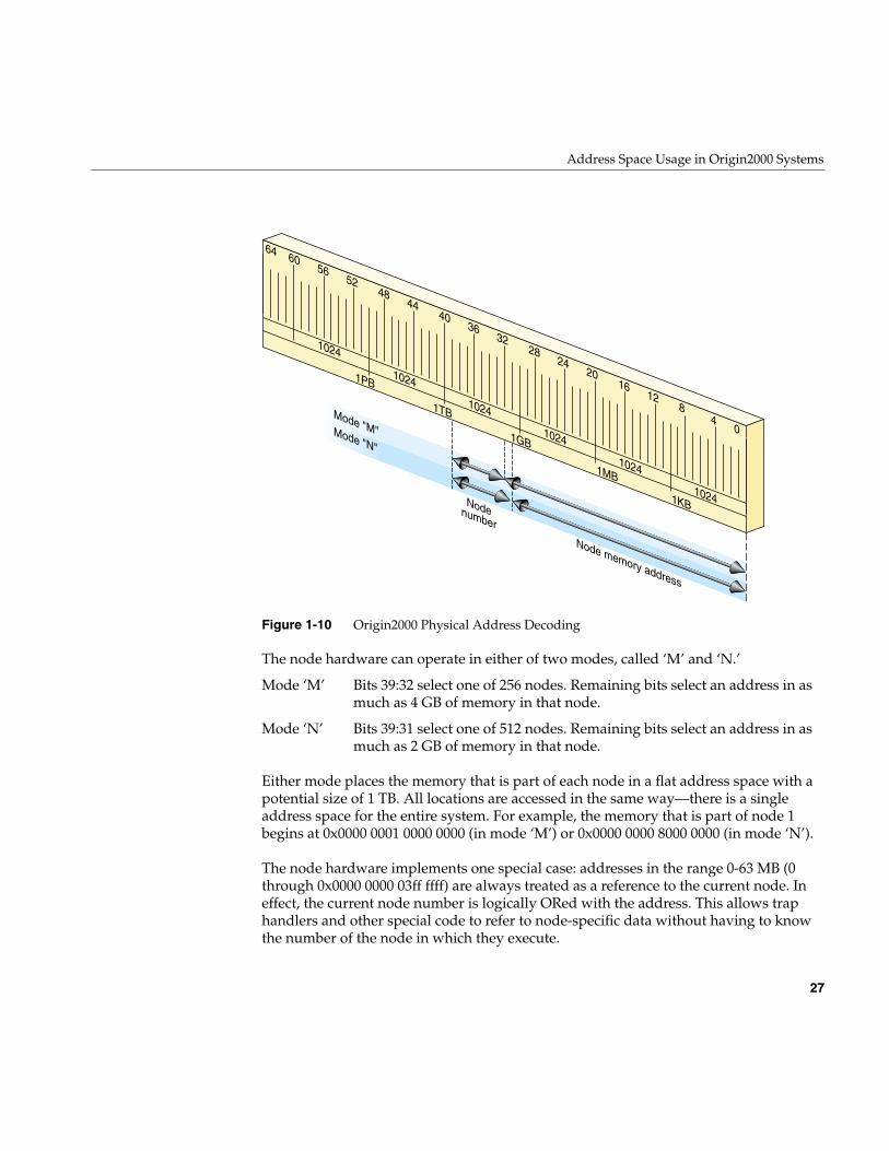
Address Space Usage in Origin2000 Systems
27
Figure 1-10 Origin2000 Physical Address Decoding
The node hardware can operate in either of two modes, called ‘M’ and ‘N.’
Either mode places the memory that is part of each node in a flat address space with apotential size of 1 TB. All locations are accessed in the same way—there is a singleaddress space for the entire system. For example, the memory that is part of node 1begins at 0x0000 0001 0000 0000 (in mode ‘M’) or 0x0000 0000 8000 0000 (in mode ‘N’).
The node hardware implements one special case: addresses in the range 0-63 MB (0through 0x0000 0000 03ff ffff) are always treated as a reference to the current node. Ineffect, the current node number is logically ORed with the address. This allows traphandlers and other special code to refer to node-specific data without having to knowthe number of the node in which they execute.
Mode ‘M’ Bits 39:32 select one of 256 nodes. Remaining bits select an address in asmuch as 4 GB of memory in that node.
Mode ‘N’ Bits 39:31 select one of 512 nodes. Remaining bits select an address in asmuch as 2 GB of memory in that node.
64 60 56 52 48 44 40 36 32 28 24 20 16 12 8 4 0
1PB 1TB
1GB
1MB 1KB
Node memory address
Mode "M"Mode "N"
Nodenumber
1024
1024
1024
1024
1024
1024
28
Chapter 1: Physical and Virtual Memory
Uncached Access to Memory
A physical address in xkphys (bits 63:62 contain 10) that has the uncached algorithm (bits61:59 contain 010) always bypasses the secondary cache. An address of this form canaccess physical memory in either of two ways.
When bits 58:57 contain 11, the address bits 39:0 are decoded as shown in Figure 1-10. Inthis mode there is no aliasing of addresses in the range 0-63 MB to the current node; thenode number must be given explicitly.
However, when bits 58:57 contain 00, an address in the range 0-768 MB is interpreted asuncached access to the memory in the current node. In effect, the node number is ORedinto the address. Also in this mode, access to the lowest 64 KB is swapped between thetwo CPUs in a node. CPU 0 access to addresses 0x0 0000 through 0x1 ffff is directed tothose addresses. But CPU 1 access to 0x0 0000 goes to 0x1 0000, and access to 0x1 0000goes to 0x0 0000—reversing the use of the first two 64 KB blocks. This helps trap handlersthat need quick access to a 64 KB space that is unique to the CPU.
Synchronization Access to Memory
An uncached physical address with bits 58:57 containing 10 is an atomicfetch-and-modify access. Bits 39:6 select a memory unit of 64 bytes (half a cache line) andbits 5:3 select an operation, as shown in Figure 1-11.
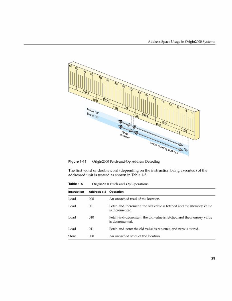
Address Space Usage in Origin2000 Systems
29
Figure 1-11 Origin2000 Fetch-and-Op Address Decoding
The first word or doubleword (depending on the instruction being executed) of theaddressed unit is treated as shown in Table 1-5.
Table 1-5 Origin2000 Fetch-and-Op Operations
Instruction Address 5:3 Operation
Load 000 An uncached read of the location.
Load 001 Fetch-and-increment: the old value is fetched and the memory valueis incremented.
Load 010 Fetch-and-decrement: the old value is fetched and the memory valueis decremented.
Load 011 Fetch-and-zero: the old value is returned and zero is stored.
Store 000 An uncached store of the location.
64 60 56 52 48 44 40 36 32 28 24 20 16 12 8 4 0
1PB 1TB
1GB
1MB 1KB
1024
1024
Node memory address
Mode "M"Mode "N"
Nodenumber
1024
1024
1024
1024
Op
30
Chapter 1: Physical and Virtual Memory
These are atomic operations; that is, no other CPU can perform an interleaved operationto the same 64-byte unit. The kernel can use this addressing mode to implement locksand other synchronization operations. A user-level library is also available so thatnormal programs can use these facilities when they are available; see the fetchop(3)reference page.
Device Driver Use of Memory
Memory use by device drivers is simpler than the details in this chapter suggest. Theprimary complication for the designer is the use of 64-bit addresses, which may beunfamiliar.
Allowing for 64-Bit Mode
You must take account of a number of considerations when porting an existing Cprogram to an environment where 64-bit mode is used, or might be used. This can be anissue for all types of drivers, kernel-level and user-level alike. For detailed discussion, seethe MIPSpro 64-Bit Porting and Transition Guide listed on page xli.
The most common problems arise because the size of a pointer and of a long int changesbetween a program compiled with the -64 option and one compiled -32. When you usepointers, longs, or types derived from longs, in structures, the field offsets differ betweenthe two modes.
When all programs in the system are compiled to the same mode, there is no problem.This is the case for a system in which the kernel is compiled to 32-bit mode: only 32-bituser programs are supported. However, a kernel compiled to 64-bit mode executes userprograms in 32-bit or 64-bit mode. A structure prepared by a 32-bit program—a structure
Store 001 Increment: the memory location is incrmented.
Store 010 Decrement: the memory location is decremented.
Store 011 AND: memory data is ANDed with the store data.
Store 100 OR: memory data is ORed with the store data.
Table 1-5 (continued) Origin2000 Fetch-and-Op Operations
Instruction Address 5:3 Operation
Device Driver Use of Memory
31
passed as an argument to ioctl(), for example—does not have fields at the offsetsexpected by a 64-bit kernel device driver. For more on this specific problem, see“Handling 32-Bit and 64-Bit Execution Models” on page 182.
The basic strategy to make your code portable between 32-bit and 64-bit kernels is to beextremely specific when declaring the types of data. You should almost never declare asimple “int” or “char.” Instead, use a data type that is explicit as to the precision and thesign of the variable. The header files sgidefs.h and sys/types.h define type names that youcan use to declare structures that always have the same size. The type __psint_t, forexample, is an integer the same size as a pointer; you can use it safely as alias for apointer. Similarly, the type __uint32_t is guranteed to be an unsigned, 32-bit, integer inall cases.
Memory Use in User-Level Drivers
When you control a device from a user process, your code executes entirely in userprocess space, and has no direct access to any of the other spaces described in thischapter.
Depending on the device and other considerations, you may use the mmap() function tomap device registers into the address space of your process (see the mmap(2) referencepage). When the kernel maps a device address into process space, it does it using the TLBmechanism. From mmap() you receive a valid address in process space. This address ismapped through a TLB entry to an address in segment that accesses uncached physicalmemory. When your program refers to this address, the reference is directed to thesystem bus and the device.
Portions of kernel virtual memory (kseg0 or xkseg) can be accessed from a user process.Access is based on the use of device special files (see the mem(7) reference page). Accessis done using two models, a device model and a memory map model.
Access Using a Device Model
The device special file /dev/mem represents physical memory. A process that can open thisdevice can use lseek() and read() to copy physical memory into process virtual memory.If the process can open the device for output, it can use write() to patch physical memory.
The device special file /dev/kmem represents kernel virtual memory (kseg0 or xkseg). It canbe opened, read and written similarly to /dev/mem. Clearly both of these devices shouldhave file permissions that restrict their use even for input.
32
Chapter 1: Physical and Virtual Memory
Access Using mmap()
The mmap() function allows a user process to map an open file into the process addressspace (see the mmap(2) reference page). When the file that is mapped is /dev/mem, theprocess can map a specified segment of physical memory. The effect of mmap() is to setup a page table entry and TLB entry so that access to a range of virtual addresses in userspace is redirected to the mapped physical addresses in cached physical memory (kseg0or the equivalent segment of xkphys).
The /dev/kmem device, representing kernel virtual memory, cannot be used with mmap().However, a third device special, /dev/mmem (note the double “m”), represents access toonly those addresses that are configured in the file /var/sysgen/master.d/mem. Asdistributed, this file is configured to allow access to the free-running timer device and, insome systems, to graphics hardware.
For an example of mapped access to physical memory, see the example code in thesyssgi(2) reference page related to the SGI_QUERY_CYCLECNTR option. In thisoperation, the address of the timer (a device register) is mapped into the process’saddress space using a TLB entry. When the user process accesses the mapped address,the TLB entry converts it to an address in kseg1/xkphys, which then bypasses the cache.
Mapped Access Provided by a Device Driver
A kernel-level device driver can provide mapped access to device registers or to memoryallocated in kernel virtual space. An example of such a driver is shown in Part III,“Kernel-Level Drivers.”
Memory Use in Kernel-Level Drivers
When you control a device from a kernel-level driver, your code executes in kernelvirtual space. The allocation of memory for program text, local (stack) variables, andstatic global variables is handled automatically by the kernel. Besides designing datastructures so they have a consistent size, you have to consider these special cases:
• dynamic memory allocation for data and for buffers
• transferring data between kernel space and user process space
• getting addresses of device registers to use for PIO
Device Driver Use of Memory
33
The kernel supplies utility functions to help you deal with each of these issues, all ofwhich are discussed in Chapter 8, “Device Driver/Kernel Interface.”
Uncached Memory Access in Origin2000 and in Challenge and Onyx Series
Access to uncached memory is not supported in these systems, in which cache coherencyis maintained by the hardware, even under access from CPUs and concurrent DMA.There is never a need (and no approved way) to access uncached memory in thesesystems.
Uncached Memory Access in the IP26 and IP28
The IP26 CPU module is used in the Silicon Graphics Power Indigo2 workstation and thePower Challenge M workstation. Both are deskside workstations using the R8000processor chip. These remarks also apply to the IP28 CPU used in the Power Indigo2R10000 workstation. In these machines, extra care must be taken in cache management.
Cache Invalidation and Writeback
When an I/O device is going to perform DMA input to memory, the device driver mustinvalidate any cached copies of the buffer that will receive the data. If this is not done,the CPU could go on using the “stale” data in the cache, ignoring the input data placedin memory by the device. This is done by calling the dki_dcache_inval() function toinvalidate the range of addresses where DMA input is planned.
In the IP28 CPU, the delayed and speculative execution features of the R10000 processormake it necessary for the driver to invalidate the cache twice: once before initiating theDMA input, and once again immediately after DMA ends.
Before initiating DMA output, the driver must force all cached data to memory by callingdki_dcache_wb(). This ensures that recent data in the cache is also present in memorybefore the device begins to access memory. The use of both these functions is discussedfurther under “Managing Memory for Cache Coherency” on page 219.
Cache invalidation is handled automatically when you use the userdma() and undma()functions to lock memory for DMA (see “Setting Up a DMA Transfer” on page 216).
34
Chapter 1: Physical and Virtual Memory
Program Access to Uncached Memory
The Indigo2 systems use ECC memory (error-correcting code memory, which can correctfor single-bit errors on the fly). ECC memory is also used in large multiprocessor systemsfrom Silicon Graphics, where it has no effect on performance.
In the IP26 and IP28, although ECC memory has no impact on the performance ofnormal, cached memory access, uncached access can be permitted only when the CPU isplaced in a special, “slow” access mode.
A device driver may occasionally need to write directly to uncached memory (althoughit is better to write to cached memory and then use dki_dcache_wb()). Before doing so,the driver must put the CPU in “slow” mode by calling the functionip26_enable_ucmem(). As soon as the uncached store is complete, return the system to“fast” mode by calling ip26_return_ucmem(). (See the ip26_ucmem(D3) reference page.)While the CPU is in “slow” mode, several clock cycles are added to every memory access,so do not keep it in “slow” mode any longer than necessary.
These functions can be called in any system. They do nothing unless the CPU is an IP26or IP28.
35
Chapter 2
2. Device Configuration
This chapter discusses how IRIX represents devices to software, and how it establishesthe inventory of available hardware.
This information is essential when your work involves attaching a new device or a newclass of devices to IRIX. The information is helpful background material when youintend to control a device from a user-level process.
The following primary topics are covered in this chapter.
• “Device Special Files” on page 36 describes the traditional UNIX method ofrepresenting a device as a special kind of file, and defines such important terms asmajor and minor device number.
• “Hardware Graph” on page 42 describes the internal database of devices and itsexternal representation as the /hw filesystem.
• “Hardware Inventory” on page 48 describes the interface to the hardware inventorydatabase through the hinv command and getinvent() function.
• “Configuration Files” on page 55 summarizes the files used for system generationand kernel configuration.
In addition to the discussion here, you can find the system administrator’s perspectiveon these issues in the books IRIX Admin: Disks and Filesystems and IRIX Admin: SystemConfiguration and Tuning.
36
Chapter 2: Device Configuration
Device Special Files
A device is represented in a UNIX system is as a device special file in a certain directory(historically, the /dev directory). Beginning with IRIX 6.4 the implementation of devicespecial files has been changed and expanded, but the basic purpose—to treat a device asa special case of a file—is not changed.
Devices as Files
A device special file consists of a filename and access permissions, but no associated diskdata. The access permissions, owner ID, and group ID of the file control whether the filecan be opened. A device special file can be used like a regular file in most IRIXcommands; for example, a device file can be the target of a symbolic link, the destinationof redirected input or output, authorized by chmod, and so on. A process opens a deviceby passing the pathname of the device special file to the open() function (see the open(2)reference page).
Historically, a device special file contained three items of information about a device:
The device numbers are no longer relevant, but the distinction between block andcharacter access still exists. To display the details of all block and character devices in asystem using the /hw filesystem (described under “Hardware Graph” on page 42) use acommand such as the following:
find /hw \( -type c -o -type b \) -exec ls -l {} \; | more
Block and Character Device Access
IRIX supports two classes of device. A block device such as a disk drive transfers data infixed size blocks between the device and memory, and usually has some ability toreposition the medium so as to read or write the same data again. The driver for a blockdevice typically has to manage buffering, and it is free to schedule I/O operations in adifferent sequence than they are requested.
Block or Character A flag showing which of two types of access, block orcharacter, applies to this device.
Major device number A numeric code for the device driver that controls this device.
Minor device number A number passed to the device driver to distinguish thisdevice from others of the same type.
Device Special Files
37
A character device such as a printer accepts or returns data as a stream of bytes, andusually acts as a sink or source of data—the medium cannot be repositioned and readagain. The driver for a character device typically transfers data as soon as it is requestedand completes one operation before accepting another request. Character devices arealso called raw devices, because their input is not buffered.
The two kinds of devices are supported by two different kinds of kernel-level devicedrivers, block and character drivers. The two kinds of drivers are expected to offerdifferent kinds of service. For example, a block device driver is expected to provide a“strategy” entry point where it schedules asynchronous, buffered, transfers of data inunits of 512 bytes. A character device driver is expected to provide read and write entrypoints that synchronously transfer any quantity of data from 1 byte upward.
Some device drivers offer both kinds of access. In particular, the disk device driverssupport block-type access to data partitions of the disk, and character-type read/writeaccess to the disk volume header.
Multiple Device Names
When a single device is accessed in different modes, the device is described by multipledevice special files. Each device special file represents one way of accessing the device.Some reasons for using multiple names are as follows:
• By convention, UNIX system supply certain default device names, and this is doneby creating extra symbolic links. For example, the default device /dev/tapens is a linkto the first device file in /dev/rmt/*.
• When a device supports both block and character modes of access, there is aseparate device special file for each mode. For example, the following (edited)pathnames provide block and character access to one partition of a SCSI device:/hw/.../scsi_ctlr/0/target/1/lun/0/disk/partition/0/block/hw/.../scsi_ctlr/0/target/1/lun/0/disk/partition/0/char
• When a device can be treated as independent, logical partitions, each partition isgiven an independent device special file name, although the device is the same ineach case. The following (edited) pathnames provide block access to, respectively,an entire disk volume, partition 0 (root), partition 1 (swap), and the volume header(label) of the same disk:/hw/.../scsi_ctlr/0/target/1/lun/0/disk/volume/block/hw/.../scsi_ctlr/0/target/1/lun/0/disk/partition/0/block/hw/.../scsi_ctlr/0/target/1/lun/0/disk/partition/1/block/hw/.../scsi_ctlr/0/target/1/lun/0/disk/volume_header/block
38
Chapter 2: Device Configuration
• When a device needs different treatment at different times, it can have one devicespecial file for each kind of treatment. The following pathnames all provide accessto the identical tape drive. The user can open a different name for each combinationof byte-swapped and non-byte-swapped I/O with fixed or variable record lengths:/hw/tape/tps0d3stat/hw/tape/tps0d3s/hw/tape/tps0d3sc/hw/tape/tps0d3nrs/hw/tape/tps0d3nrsc/hw/tape/tps0d3ns/hw/tape/tps0d3nsc/hw/tape/tps0d3/hw/tape/tps0d3c/hw/tape/tps0d3nrns/hw/tape/tps0d3nrnsc/hw/tape/tps0d3nr/hw/tape/tps0d3nrc/hw/tape/tps0d3sv/hw/tape/tps0d3svc/hw/tape/tps0d3nrsv/hw/tape/tps0d3nrsvc/hw/tape/tps0d3nsv/hw/tape/tps0d3nsvc/hw/tape/tps0d3v/hw/tape/tps0d3vc/hw/tape/tps0d3nrnsv/hw/tape/tps0d3nrnsvc/hw/tape/tps0d3nrv/hw/tape/tps0d3nrvc
Major Device Number
The major device number was, in traditional UNIX architecture, a numeric key that relateda device special file to the device driver that managed it. When special file was opened,IRIX selected the driver to handle the device based on the major device number. In thenewer /hw filesystem, a different means is used. The major number is no longer relevant.
The major number in all device special files in /hw is always 0. The device special files in/hw are created dynamically, by the device drivers, as the devices are attached. Theidentity of the device driver is stored in the device special files at this time, but not as anumber. When a process opens a device special file in /hw (or a name in /dev that is asymbolic link to /hw), the kernel can tell directly which driver to call.
Device Special Files
39
Minor Device Number
In conventional UNIX, and in versions of IRIX previous to IRIX 6.4, a minor device numberwas encoded in the device special file and was passed to the device driver. The major andminor numbers were passed together in an integer called a dev_t. The driver could extractthe minor device number by passing the dev_t value to the geteminor() function.
Historical Use of Minor Number
Prior to IRIX 6.4, the minor device number served as an argument to help the devicedriver distinguish one device from another. Many devices can have the same majornumber and be serviced by the same driver. Using the minor number, the driver coulddistinguish the particular device being serviced.
Some device drivers treated the minor device number as a logical unit number, whileother drivers used it to contain multiple, encoded bit fields. For example:
• The IRIX tape device driver used the minor device number to encode the options forrewind or no-rewind, byte-swap or nonswap, and fixed or variable blocking, alongwith the logical unit number.
• The IRIX disk device drivers encoded the disk partition number into the minordevice number along with a disk unit number.
• Both disk and tape devices encoded the SCSI adapter number in the minor number.
With STREAMS drivers, the minor device number can be chosen arbitrarily during aCLONE open—see “Support for CLONE Drivers” on page 774.
Present Use of Minor Numbers
Beginning with IRIX 6.4, the minor device number has little importance because thedriver has a direct way to distinguish each device and its special needs, through thehardware graph (see “Hardware Graph” on page 42.)
The minor number in device special files in /hw is an arbitrary integer with no relation tothe device itself. The device special files in /hw are created dynamically, by the devicedrivers, as the devices are attached. The device driver stores any information it needs todistinguish one device from another, directly in the device special file itself. When aprocess opens a device special file in /hw (or a name in /dev that is a symbolic link to /hw),the driver can retrieve the information directly, without needing to decode the minornumber.
40
Chapter 2: Device Configuration
Creating Conventional Device Names
Starting with IRIX 6.4, there is a complete filesystem, /hw, that is devoted to device specialfiles. However, the use of /hw is both new and unique to IRIX. For the sake ofcompatibility, the conventional device special files in the /dev filesystem that are used inUNIX systems generally and in previous release of IRIX are retained. This topic describesthese conventional names. See also “/hw Filesystem” on page 46.
Many device special files are created automatically at boot time by execution of the script/dev/MAKEDEV. Additional device special files can be created with administratorcommands.
IRIX Conventional Device Names
Conventions for the format of device special filenames are spelled out in the followingreference pages: intro(7), dks(7), dsreq(7), and tps(7). For example, the components of adisk device name in /dev/dsk include
Programs throughout the system rely on the conventions for these device names. Inaddition, by convention the associated major and minor numbers agree with the names.For example, the logical unit and partition numbers that appear in a disk name are alsoencoded into the minor number.
Beginning with IRIX 6.4, these highly-compressed conventional names are unpackedinto longer pathnames in the /hw filesystem. However, the older, encoded names in /devare retained for compatibility and portability.
dksc Constant prefix “dks” followed by bus adapter number c.
du Constant letter “d” followed by disk SCSI ID number u.
ln Optionally, letter “l” (ell) and logical unit number n (usedonly when disk u controls multiple drives).
sp or vh or vol Constant letter “s” and partition number p, or else “vh” forvolume header, or “vol” for (entire) volume.
Device Special Files
41
The Script MAKEDEV
The conventions for all the IRIX device special names are written into the script/dev/MAKEDEV. This is a make file, but unlike most make files, it is not used to compileexecutable programs. It contains the logic to prepare device special names and theirassociated major and minor numbers and file permissions.
The MAKEDEV script is executed during IRIX startup from a script in /etc/rc2.d. It isexecuted after all device drivers have been initialized, so it can use the output of the hinvcommand to construct device names to suit the actual configuration.
The system administrator can invoke MAKEDEV to construct device special files.Administrator use of MAKEDEV is described in IRIX Admin: System Configuration andOperation.
Making Conventional Device Files
You or a system administrator can create device special files explicitly using thecommands mknod or install. Either command can be used in a make file such as you mightcreate as part of the installation script for a product.
For details of these commands, see the install(1) and mknod(1M) reference pages, andIRIX Admin: System Configuration and Operation. The following is a hypothetical exampleof install:
# install -m 644 -u root -g sys -root /dev -chr 62,0
The -chr option specifies a character device, and 62,0 are the major and minor devicenumbers, respectively.
Tip: The mknod command is portable, being used in most UNIX systems. The installcommand is unique to IRIX, and has a number of features and uses beyond those ofmknod. Examples of both can be found by reading /dev/MAKEDEV.
42
Chapter 2: Device Configuration
Hardware Graph
Conventional UNIX software is designed based on the assumption that the computer hasonly a small, fixed set of peripheral devices under undemanding reliability constraints.IRIX 6.5 is designed to handle a system with a large complement of devices that changesdynamically, under high demands for reliable uptime. To meet the new requirements,IRIX introduces the hwgraph (hardware graph) to represent devices, and the /hwfilesystem as the externally visible form of the hwgraph.
UNIX Hardware Assumptions, Old and New
Historically, UNIX was designed to support small computer systems that wereadministered by the same group of people that used them. When there are only a few, ora few dozen, peripheral devices, it is acceptable to:
• Represent all devices as brief names in the /dev filesystem
• Use a limited range of major device numbers to specify all possible device drivers
• Use an 18-bit integer (the minor device number) as the sole parameter to represent adevice’s identify and access mode
• Leave the details of device addressing to be specified in configuration files or byhard-coding in the source of device drivers.
When devices are only rarely added to or removed from the system, it is acceptable torequire that the administrator shut the system down, modify a configuration file, andreboot, in order to remove or add a device. When the system has a small number oftolerant users, it is acceptable to shut the system down and restart it to make smallchanges in the I/O configuration.
All of these assumptions are challenged by the kinds of large-scale systems that can bebuilt using the Silicon Graphics Origin2000 architecture.
• It is possible to build very large Origin2000 systems with many independent nodes,each with a number of attached devices.
• Because of the rich possibilities for interconnecting Origin2000 nodes, the topologyof a Origin2000 system can be complex, with devices addressed by lengthy paths,and sometimes with multiple possible paths from a CPU to a device.
Hardware Graph
43
• The hardware configuration of a Origin2000 system can change dynamically whilethe system runs, by adding and removing entire nodes, or single buses, or singlecards on a PCI bus.
• Origin2000 is designed to be the basis of systems that are available a very highpercentage of the time, on which frequent or casual reboots are not allowed.
In this environment it is no longer acceptable to require downtime on any change, nor torequire the administrator to issue detailed commands or to edit configuration files tomake simple changes. Previous release of IRIX addressed some of these points throughthe MAKEDEV script (see “The Script MAKEDEV” on page 41), which creates devicespecial files automatically for many types of hardware.
IRIX 6.4 moves away from the conventional UNIX model by creating the hwgraph, andby requiring all kernel-level device drivers to maintain the hwgraph as devices areattached and detached.
Hardware Graph Features
The hwgraph is an in-memory, graph-structured database that describes all hardwareunits that are addressable by the system. For a very concise overview of the hwgraph, seethe hwgraph(4) reference page.
Hwgraph Nomenclature
“In-memory” means that the hwgraph is contained in kernel memory. It is reconstructeddynamically in memory each time the system boots up, and is kept current in memoryas the hardware configuration changes.
“Graph-structured” means that the hwgraph is topologically a directed graph, consistingof a set of “vertexes” (points) that represent devices, and “edges” (lines) that connect thevertexes. Each edge is a one-way linkage from a source vertex to a target vertex (this isthe definition of a directed graph). Each edge has a label, a character string that namesthe edge. A small part of a typical hwgraph is depicted in Figure 2-1.
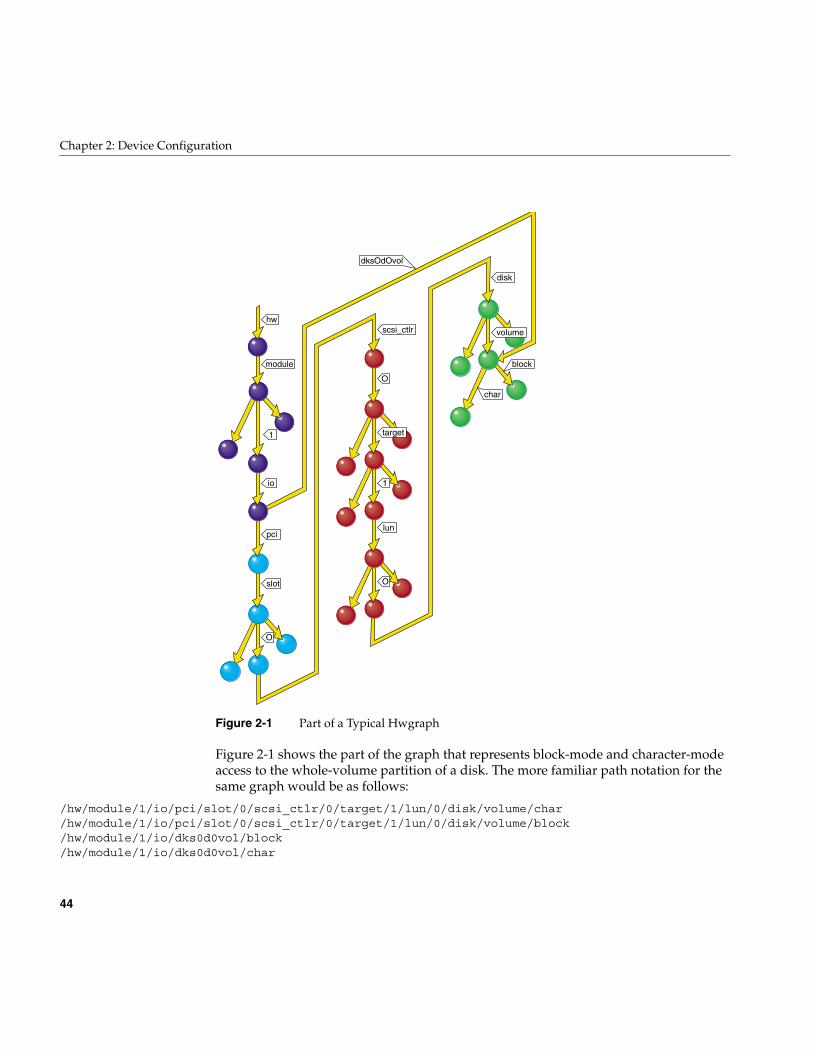
44
Chapter 2: Device Configuration
Figure 2-1 Part of a Typical Hwgraph
Figure 2-1 shows the part of the graph that represents block-mode and character-modeaccess to the whole-volume partition of a disk. The more familiar path notation for thesame graph would be as follows:
/hw/module/1/io/pci/slot/0/scsi_ctlr/0/target/1/lun/0/disk/volume/char/hw/module/1/io/pci/slot/0/scsi_ctlr/0/target/1/lun/0/disk/volume/block/hw/module/1/io/dks0d0vol/block/hw/module/1/io/dks0d0vol/char
block
char
volume
disk
dksOdOvol
lun
O
1
scsi_ctlr
O
target
pci
slot
module
hw
1
io
O
Hardware Graph
45
Figure 2-1 is color-coded to show when the parts of graph are built:
• The parts of the hwgraph that are built by the kernel during bootup are shown inblack.
• The parts shown in red are built by the PCI bus adapter as it probes the bus.
• The parts in magenta are built by the host adapter driver for the SCSI controller, toreflect the addressable units on the SCSI bus.
• The parts shown in green are built by the disk device driver as it attaches the disk—including a shorthand link from /hw/module/1/io to the volume vertex.
Properties of Edges and Vertexes
An edge in the hwgraph originates in one vertex (the source vertex) and points to anothervertex (the target vertex). The only property of an edge is its label.
A vertex in the hwgraph stores information about an addressable unit of hardware in thesystem. A vertex can contain the following kinds of information:
• A pointer to an information structure supplied by the device driver.
• One or more inventory_t objects, representing information to be reported out by thehinv command (see the hinv(1) reference page).
• One or more labelled attributes, containing information that can be reported out bythe attr command (see the attr(1) reference page).
• One or more labelled attributes that are not exported for availability by attr.
• The edges leading out of this vertex.
Not all vertexes have all this information.
Additional Edges
The basic hwgraph—as constructed by the kernel and by built-in drivers such as the PCIbus adapter—is highly detailed and explicit, and is generally tree-structured. However,kernel-level drivers are free to add edges between any two vertexes. A driver can addextra edges in order to provide short-circuit paths for convenient access to vertexes deepin the hwgraph.
46
Chapter 2: Device Configuration
Many device drivers distributed with IRIX create convenience vertexes and edges; anddevice drivers provided by OEMs are welcome to do so as well. One problem is that oftena driver needs to label a convenience edge with a unique number—a controller number,a port number, or a line number of some kind. At the time a driver is initializing andcreating vertexes, the total hardware complement is not known and it is impossible todecide which number of this kind to use. This problem is alleviated by a program likeioconfig; see “Using ioconfig for Global Controller Numbers” on page 51.
Implicit Edges
Every vertex has one implicit edge with the label “..” which leads back to a parent vertex.Every vertex has one implicit edge with the label “.” which leads to the vertex itself. Thisis deliberately the same convention used in a filesystem, where every directory contains“..” and “.” entries. No other edges are required.
A vertex that has only the implicit edges is a leaf vertex. A leaf vertex can stand for adevice, so that a user process can name a leaf vertex in an open() call in order to open thedevice. A user process cannot open a non-leaf vertex, just as a process cannot open adirectory as a file.
/hw Filesystem
The /hw filesystem is a visible reflection of the hwgraph. The /hw filesystem is afilesystem, on a par with an EFS or XFS filesystem, but of a different type. It is builtdynamically (it has no disk contents) and changes to reflect changes in the hwgraph. (Youcan compare the /hw filesystem to another artificial, dynamic filesystem, /proc, which isan externally visible representation of the currently executing user processes.)
Any user can navigate the /hw filesystem using commands such as cd, ls, find, and file.Users can browse the /hw filesystem to discover the hardware configuration. Names inthe /hw filesystem have access permissions that are applied in the same way as in otherfilesystems. Pathnames beginning /hw can be used wherever other filesystem pathnamesare used, and in particular,
• A process can use a /hw pathname with the open() function to open a device.
• An /hw pathname can be used to construct a symbolic link.
Hardware Graph
47
The use of symbolic links to /hw paths is important. All the device special filenames thatare conventionally expected to exist in /dev are implemented by creating symbolic linksfrom /dev to /hw. Here is a typical link:
lrwxr-xr-x 1 root sys 13 Aug 6 11:23 /dev/root ->/hw/disk/root
However, a symbolic link is not a perfect alias. Links are given special treatment bycommands such as ls, tar, and chmod; and by the system function stat() on which thecommands are based (see the stat(2) reference page). What is needed is a way to make afunctional alias for a device special file under a different name. That is supplied bymknod.
Driver Interface to Hwgraph
A kernel-level device driver can make use of a variety of kernel functions for examiningand modifying the hwgraph. These functions are covered in detail in “Hardware GraphManagement” on page 221The kernel offers functions by which a driver can:
• Traverse the hwgraph, following edges by name from vertex to vertex.
• Create new vertexes.
• Create new edges from existing vertexes to new vertexes.
• Set, change, or retrieve the address of driver-defined data from a vertex.
• Addhardware inventory data to a vertex.
• Set, change, retrieve or remove labelled attributes, and specify whether theattributes should be accessible to the attr command or not.
• Remove edges and destroy vertexes.
Some device drivers do not have to perform these functions, but most kernel-leveldrivers do need to create at least a few edges and vertexes to provide access to devices.Vertexes are typically created when the driver is called at its pfxattach() entry point(driver entry points are covered in detail in Chapter 7, “Structure of a Kernel-LevelDriver.”) Vertexes are typically destroyed when the driver is called at its pfxdetach()entry point.
48
Chapter 2: Device Configuration
Hardware Inventory
In IRIX previous to IRIX 6.4, during bootstrap, each device driver probed the hardwareattachments for which it was responsible, and added information to a hardwareinventory table. The kernel maintained a hardware inventory table in kernel virtualmemory. The table could be queried by users and by programs.
Beginning with IRIX 6.4, what was once a simple table of devices has expanded into thehwgraph (“Hardware Graph” on page 42). Device drivers create the hardware inventoryby adding vertexes to the hwgraph. However, existing programs continue to query thehardware inventory using the old programming interface, as well as new ones.
Using the Hardware Inventory
The hardware inventory is used by users, administrators, and programmers.
Contents of the Inventory
Using database terminology, the hardware inventory consists of a single table with thefollowing columns:
Of these values,
• The Class and Type are arbitrary codes that are defined in /usr/include/invent.h. Onlythe defined codes can be interpreted by the hinv command.
• The Controller and Unit are small integers. The hinv command formats them basedthe Class code. For example, when Class is INV_DISK, hinv might report “Diskdrive: unit 4 on SCSI controller 56.” When Class is INV_NETWORK and Type isINV_NET_ETHER, hinv might report “Integral Ethernet controller: et2, Ebusslot 11.”
Class A code for the class of device; for example, audio, disk, processor, ornetwork.
Type A code for the type of device within its class; for example, FPU and CPUtypes within the processor class.
Controller When applicable, the number of the controller, board, or attachment.
Unit When applicable, the logical unit or device within a Controller number.
State A descriptive number, such as the CPU model number.
Hardware Inventory
49
• The Controller number is used to distinguish between identical controllers. Thedevice driver can assign a controller number when it attaches inventory data to adevice vertex; or the controller numbers can be assigned dynamically at boot time,as discussed under “Using ioconfig for Global Controller Numbers” on page 51.
Displaying the Inventory with hinv
The hinv command formats all or selected rows of the inventory table for display (see thehinv(1) reference page), translating the numbers to readable form. The user or systemadministrator can use command options to select a class of entries or certain specificdevice types by name. The class or type can be qualified with a unit number and acontroller number. For example,
hinv -c disk -b 1 -u 4
displays information about disk 4 on controller 1.
You can use hinv to check the result of installing new hardware. The new hardwareshould show up in the report after the system is booted following installation, providedthat the associated device driver was called and was written correctly.
A full inventory report (hinv -mv) is almost mandatory documentation for a softwareproblem report, either submitted by your user to you, or by you to Silicon Graphics.
Testing the Inventory In Software
Within a shell script, you can test the output of hinv most conveniently in the commandexit status. The command sets exit status of 0 when it finds or reports any items. It setsstatus of 1 when it finds no items. The code in Example 2-1 could be used in a shell scriptto test the existence of a disk controller.
Example 2-1 Testing the Hardware Inventory in a Shell Script
if hinv -s -c disk -b 1;then ;else echo No second disk controller;
fi ;
50
Chapter 2: Device Configuration
You can access the inventory table in a C program using the functions documented in thegetinvent(3) reference page. The only access method supported is a sequential scan overthe table, viewing all entries. Three functions permit access:
These functions use static variables and should only be used by a single process withinan address space. Reentrant forms of the same functions, which can safely be used in amultithreaded process, are also available (see getinvent(3)). Example 2-2 demonstratesthe use of these functions.
The format of one inventory table row is declared as type inventory_t in the sys/invent.hheader file. This header file also supplies symbolic names for all the class and typenumbers that can appear in the table, as well as containing commentary explaining themeanings of some of the numbers.
Example 2-2 Function Returning Type Code for CPU Module
#include <stddef.h> /* for NULL */#include <invent.h> /* includes sys/invent.h */int getIPtypeCode(){
inv_state_t * pstate = NULL;inventory_t * work;int ret = 0;setinvent_r(&pstate);do {
work = getinvent_r(pstate);if ( (INV_PROCESSOR == work->inv_class)&& (INV_CPUBOARD == work->inv_type) )
ret = work->inv_state;} while (!ret)endinvent_r(pstate); /* releases pstate-> */return ret;
}
setinvent() initializes or reinitializes the scan to the first row
getinvent() returns the next table row in sequence
endinvent() releases storage allocated by setinvent()
Hardware Inventory
51
Creating an Inventory Entry
Device drivers supplied by Silicon Graphics add information to the hardware inventoryby adding vertexes to the hwgraph (see “Driver Interface to Hwgraph” on page 47) andthen by attaching inventory_t structures to the vertexes using the functionhwgraph_inventory_add() (this and other hwgraph functions are discussed under“Hardware Graph Management” on page 221).
The inventory_t structure is declared in the header file sys/invent.h, along with theinventory type and class numbers that are valid.
Drivers written for releases prior to IRIX 6.4 called the kernel functionadd_to_inventory() in order to add a row to the inventory table. This function issupported in IRIX 6.5 in a limited way. When called, it attaches the inventory informationto the root of the hwgraph (to the /hw directory itself). As a result, the hinv command doessee and report the added inventory information, but the information is not physicallyassociated with the hwgraph vertex to which it applies.
Note: The only valid inventory types and classes are those declared in sys/invent.h. Onlythose numbers can be decoded and displayed by the hinv command, which prints anerror message if it finds an unknown device class, and which prints nothing at all for anunknown device type within a known class. There is no provision for adding newdevice-class or device-type values for third-party devices.
However, it is possible now for a driver to add any arbitrary descriptive string desired toany vertex. These labelled attributes can be retrieved by the attr command and insoftware by the attr_get() function (see attr(1) and attr_get(2)).
Using ioconfig for Global Controller Numbers
An Origin2000 system can be reconfigured dynamically, so the complement of devicescan change from day to day or even minute to minute—a primary motive for creating thehwgraph. However, the dynamic nature of the hardware complement makes it difficultto define a stable, predictable numbering scheme for hardware devices. This need is metby the ioconfig command (see reference page ioconfig(1M)).
52
Chapter 2: Device Configuration
Need for Stable Numbering
As discussed under “IRIX Conventional Device Names” on page 40, a conventionalname for a disk device in the /dev/dsk directory is dksCdulnsp. The number C is the“controller” number, which in previous systems represented a fixed, well-knownnumbering of SCSI bus adapters. No such fixed numbering is inherent in the Origin2000architecture. Controller cards can be added to and removed from modules, and entiremodules can be added to and removed from the system.
Users of network interface cards, serial ports, bus adapters, and other devices need apredictable, static naming scheme for devices. The name /dev/ttyf2 should represent thesame serial port tomorrow that it does today. A related problem is that some devicedrivers want to place extra, short-circuit vertexes under /hw to allow simpler access totheir devices (see “Additional Edges” on page 45). Typically such short-circuit namesought to be distinguished by a predictable number.
However, it is impossible to assign stable, repeatable controller numbers dynamically atboot time, while the system is discovering the I/O complement. All the CPUs in thesystem boot at the same time. Bus controllers and device drivers are initialized in parallelon the nodes to which the hardware is connected. The sequence in which this happens isunpredictable; and in any case the hardware connections can change from boot to boot.A driver cannot know, when it is called to attach a device, what controller number itought to specify in the hardware inventory.
Design of ioconfig
In order to solve these problems, the ioconfig command is invoked automatically, afterdevice drivers have been initialized and the hwgraph has been initialized, but beforeuser processes are started.
Operating in parallel for speed, ioconfig traverses the entire hwgraph, inspecting thehardware inventory data at each vertex. At a vertex where the hardware inventory Classvalue indicates a controller that should be numbered, ioconfig assigns a number, andupdates the hardware inventory Controller value to reflect the assigned number. Thenthe program opens the device and optionally causes an ioctl function. This results in anentry to the open() entry point, and optionally the ioctl() entry point., of the device driver(for an overview of this interaction, see “Overview of Device Open” on page 63 and“Overview of Device Control” on page 65).
In these entry points, the device driver can recognize that its device now has an assignedController number. The driver can use this information to create extra hwgraph vertexesand edges if it wishes. (For an overview of how the distributed SCSI drivers use thisfacility, see “SCSI Devices in the hwgraph” on page 510.)
Hardware Inventory
53
Configuration Control File
The ioconfig program uses three disk files. The first, /etc/ioconfig.conf, in which it recordsthe controller numbers it has assigned and the related /hw pathnames. When it needs toassign a number, ioconfig first looks up the current hwgraph path in /etc/ioconfig.conf. Ifthe path appears, ioconfig assigns the same controller number that it used last time. If thepath does not appear, ioconfig assigns the lowest number that has never been assigned inthis device Class, and adds the path and its number to /etc/ioconfig.conf.
This procedure ensures that a given device always receives the same controller number,even if the device is removed and later replaced. Users can inspect /etc/ioconfig.conf at anytime to discover the numbering, and so can infer the relationship of a controller numberin /dev/dsk (for example) to a vertex in the hwgraph. Alternatively, the systemadministrator can cause all numbers to be reassigned simply by removing the file/etc/ioconfig.conf.
Permissions Control File
The ioconfig command also can be used to set ownership and permissions on the devicespecial files. This enables the administrator to specify ownership and permissions fordevice names that are created dynamically, each time the system boots.
Assignment of permissions is driven by the file /etc/ioperms. Its format (as described inioconfig(1M)) has four fields:
There is no requirement that /etc/ioperms describe only existing devices; it can describedevices that are not currently in the system. Also it can describe devices defined by thirdparties other than SGI.
device_name A path in /hw or /dev. The path can include wildcards so it appliesto many devices.
permissions The device file permissions, as an octal number, as described inchmod(1) or chmod(2).
owner_name A valid userid to own the device, usually root.
group_name A valid group name to own the device, usually sys.
54
Chapter 2: Device Configuration
Device Management File
The ioconfig command has built-in knowledge of SGI network and disk controllers andother devices. However, you can cause ioconfig to assign a controller number to an OEMdevice, and to call your driver when it does so. You do this by placing a file in thedirectory /var/sysgen/ioconfig.
All files in that directory are processed by ioconfig. A noncomment line in any of thesefiles has the following seven fields (not 8 fields, as some editions of the ioconfig(1M)reference page show):
By placing a file in /var/sysgen/ioconfig, you can cause ioconfig to assign a controllernumber to devices that you support, and to open each device and optionally execute anioctl call against each device, so the device driver can take note of the assigned number.
class The inventory Class value that is found in a vertex of this kind, as aninteger number.
type The inventory Type value that is found in a vertex of this kind, as aninteger number. Use -1 for “any.”
state The inventory State value that is found in a vertex of this kind, as aninteger number. Use -1 for “any.”
suffix A suffix to be added to the hwgraph path name when opening the device.Use the two characters -1 to mean “none.”
pattern A hwgraph path prefix that defines the set of controller numbers for thisClass, Type, and State of device. Use the characters -1 to mean “use thehwgraph base path string.”
start_num The lowest (first) controller number to be assigned to devices of thisClass, Type, and State; the first number assigned under pattern.
ioctl_num The ioctl command number to pass in an ioctl call after opening thedevice, as decimal or hexadecimal integer. Use -1 to say “no ioctl.”
Configuration Files
55
Configuration Files
IRIX uses a number of configuration files to supplement its knowledge of devices anddevice drivers. This is a summary of the files. The use of each file for device driverpurposes is described in more detail in other chapters. (The uses of these files for othersystem administration tasks is covered in IRIX Admin: System Configuration andOperation.)
Most configuration files used by the IRIX kernel are located in the directory /var/sysgen.Files used by the X11 display system are generally in /usr/lib/X11. With regard to devicedrivers, the important files are:
Master Configuration Database
Every configurable module of the kernel (this includes kernel-level device drivers andother optional kernel modules) is represented by a single file in the directory/var/sysgen/master.d.
A file in master.d describes the attributes of a module of the kernel which is to be loadedat boot time (or loaded later). The general syntax of the file is documented in detail in themaster(4) reference page. Only a subset of the syntax is used to describe a device drivermodule. In general, the master.d file specifies device driver attributes such as:
• the driver’s prefix, a name that qualifies all its entry points
• whether it is a block, character, or STREAMS driver
• the major number serviced by the driver
• whether the driver can be loaded dynamically as needed
• whether the driver is multiprocessor-aware
• which of the possible driver entry points the driver supplies
/var/sysgen/master.d/* Descriptions of the attributes of kernel modules
/var/sysgen/boot/* Kernel object modules
/var/sysgen/system/*.sm Kernel configuration directions
/var/sysgen/mtune/* Values and limits of tunable parameters
/var/sysgen/stune New values for tunable parameters
/var/sysgen/ioconfig/* Directives to iconfig program
/usr/lib/X11/input/config/* Initialization commands for Xdm input modules
56
Chapter 2: Device Configuration
For each module described in a master.d file there should be a corresponding objectmodule in /var/sysgen/boot. The creation of device driver modules and the syntax ofmaster.d files is covered in detail in Chapter 9, “Building and Installing a Driver.”
Kernel Configuration Files
The files /var/sysgen/system/*.sm direct the lboot command in loading the modules of thekernel at boot time. Although there are normally several files with the names ofsubsystems, all the files in this directory are treated as one single file. The exact syntax ofthese files is documented in the system(4) reference page.
Use of Configuration Files by lboot
The contents of the files direct lboot in loading components that are described by files in/var/sysgen/master.d, and in probing for devices to see if they exist. (For details of theoperation of lboot, see the lboot(1M) and autoconfig(1M) reference pages.)
The VECTOR statement in a kernel configuration file directs lboot to probe for theexistence of hardware at a stated address, and to include a device driver only when thehardware existed. Starting with IRIX 6.3, the kernel automatically probes the PCI bus andother attachments in which the hardware devices can identify themselves dynamically.The VECTOR statement is used only for VME and EISA devices (in systems that supportthem) because these cannot identify themselves automatically.
Storing Device and Driver Attributes
The system administrator can place statements in any file in /var/sysgen/system. Thesestatements cause labelled attributes to be placed in the hardware graph, where devicedrivers can retrieve them (see “Driver Interface to Hwgraph” on page 47 and thesystem(4) reference page).
The DEVICE_ADMIN statement is used to attach an attribute giving information abouta particular device. The attribute is attached to a specific device special file in thehwgraph. Its syntax is as follows:
DEVICE_ADMIN : /hw/path label = value [, label = value]...
Configuration Files
57
The colon (:) is required; don’t overlook it. The values you supply are:
The path is terminated by white space. The label is terminated by the “=” or by whitespace. The value is terminated by a comma or by the end of the line, so the value cancontain white space and special characters other than the comma. As one example of theuse of DEVICE_ADMIN, you can find the following in /var/sysgen/system/irix.sm:
DEVICE_ADMIN: /hw/module/1/slot/io1/baseio/pci/0/scsi_ctlr/0ql_request_queue_depth=1024
The path specifies a particular SCSI controller. The label is “ql_request_queue_depth,”and the value is 1024.
The DRIVER_ADMIN statement is used to pass a value directly to a device driver. Itssyntax is as follows:
DRIVER_ADMIN : prefix label = value [, label = value]...
The values you supply are:
The prefix is terminated by white space. The label is terminated by the “=” or by whitespace. The value is terminated by a comma or by the end of the line, so the value cancontain white space and special characters other than the comma.
These two statements can be placed in any file in /var/sysgen/system, but typically appearin the irix.sm file. The device driver must expect to receive labelled values, and mustrequest them using the interface described under “Retrieving Administrator Attributes”on page 231.
path Completion of a path to a device special file in the /hw filesystem.
label The label for which the device driver will ask.
value The value, a character string, the driver will retrieve.
prefix The prefix string that identifies a driver (see “Driver Name Prefix” onpage 143).
label The label for which the device driver will ask.
value The value, a character string, the driver will retrieve.
58
Chapter 2: Device Configuration
Setting Interrupt Targets and Levels
The DEVICE_ADMIN statement is used to perform general administration of deviceinterrupts. These uses are documented with examples in /var/sysgen/system/irix.sm:
• DEVICE_ADMIN: CPU-path NOINTR=1 blocks all interrupts from that CPU.
• DEVICE_ADMIN: device-path INTR_TARGET=CPU-path directs all interrupts froma device to a CPU.
• DEVICE_ADMIN: device-path INTR_SWLEVEL=n sets the dispatching priority forthe thread that executes the interrupt handler for a device. The default is 230 andnormally should not be changed.
System Tuning Parameters
The IRIX kernel supports a variety of tunable parameters, some of which can beinterrogated by device drivers. The current values of the parameters are recorded in filesin /var/sysgen/mtune/* (one file per major subsystem).
You or the system administrator can view the current settings using the systunecommand (see the systune(1M) reference page). The system administrator can usesystune to request changes in parameters. Some changes take effect at once; others arerecorded in a modified kernel that is loaded the next time the system boots.
To retrieve certain tuning parameters from within a kernel-level device driver, includethe header file sys/var.h.
The use of systune and its related files is covered in IRIX Admin: System Configuration andOperation.
X Display Manager Configuration
Most files related to the configuration of the X Display Manager Xdm are held in /var/X11.These files are documented in reference pages such as xdm(1) and in the programmingmanuals related to the X Windows System.
One set of files, in /usr/lib/X11/input/config, controls the initialization of nonstandardinput devices. These devices use STREAMS modules, and their configuration is coveredin Chapter 22, “STREAMS Drivers.”
59
Chapter 3
3. Device Control Software
IRIX provides for two general methods of controlling devices, at the user level and at thekernel level. This chapter describes the architecture of these two software levels andpoints out the different abilities of each. This is important background material forunderstanding all types of device control. The chapter covers the following main topics:
• “User-Level Device Control” summarizes five methods of device control foruser-initiated processes.
• “Kernel-Level Device Control” on page 62 sets the concepts needed to understandkernel-level drivers.
User-Level Device Control
In IRIX terminology, a user-level process is one that is initiated by a user (possibly thesuperuser). A user-level process runs in an address space of its own. Except for explicitmemory-sharing agreements, a user-level process has no access to the address space ofany other process or to the kernel’s address space.
In particular, a user-level process has no access to physical memory (which includesaccess to device registers) unless the kernel allows the process to share part of the kernel’saddress space. (For more on physical memory, see Chapter 1, “Physical and VirtualMemory.”)
There are several ways in which a user-level process can control devices, which aresummarized in the following topics:
• “PCI Mapping Support” on page 60 summarizes PIO access to the PCI bus.
• “EISA Mapping Support” on page 60 summarizes PIO access to the EISA bus.
• “VME Mapping Support” on page 61 summarizes PIO access to the VME bus.
60
Chapter 3: Device Control Software
• “User-Level DMA From the VME Bus” on page 61 summarizes DMA I/O managedfrom a user-level process.
• “User-Level Control of SCSI Devices” on page 61 summarizes DMA and commandaccess to the SCSI bus.
• “Managing External Interrupts” on page 62 summarizes access to the externalinterrupt ports on Challenge and Onyx systems.
PCI Mapping Support
In systems that support the PCI bus, IRIX contains a kernel-level device driver whichsupports general-purpose mapping of PCI bus addresses into the address space of a userprocess (see “Overview of Memory Mapping” on page 67). The kernel-level drivers forspecific devices can also provide support for mapping the registers of the devices theycontrol into user process space.
You can write a program that maps a portion of the VME bus address space into theprogram address space. Then you can load and store from device registers directly.
For more details of PIO to the PCI bus, see Chapter 4, “User-Level Access to Devices.”
EISA Mapping Support
In the Silicon Graphics Indigo2 workstation line (including the Indigo2 Maximum Impact,Power Indigo2, and Indigo2 R10000), IRIX contains a kernel-level device driver thatallows a user-level process to map EISA bus addresses into the address space of the userprocess (see “Overview of Memory Mapping” on page 67).
This means that you can write a program that maps a portion of the EISA bus addressspace into the program address space. Then you can load and store from device registersdirectly.
For more details of PIO to the EISA bus, see Chapter 4, “User-Level Access to Devices.”
User-Level Device Control
61
VME Mapping Support
In systems that support the VME bus, IRIX contains a kernel-level device driver thatsupports general-purpose mapping of VME bus addresses into the address space of auser process (see “Overview of Memory Mapping” on page 67). The kernel-level driversfor specific devices can also provide support for mapping the registers of the devices theycontrol into user process space.
You can write a program that maps a portion of the VME bus address space into theprogram address space. Then you can load and store from device registers directly.
For more details of PIO to the VME bus, see Chapter 4, “User-Level Access to Devices.”
User-Level DMA From the VME Bus
The Challenge L, Challenge XL, and Onyx systems and their Power versions contain aDMA engine that manages DMA transfers from VME devices, including VME slavedevices that normally cannot do DMA.
The DMA engine in these systems can be programmed directly from code in a user-levelprocess. Software support for this facility is contained in the udmalib package.
For more details of user DMA, see Chapter 4, “User-Level Access to Devices” and theudmalib(3) reference page.
User-Level Control of SCSI Devices
IRIX contains a special kernel-level device driver whose purpose is to give user-levelprocesses the ability to issue commands and read and write data on the SCSI bus. Byusing ioctl() calls to this driver, a user-level process can interrogate and program devices,and can initiate DMA transfers between buffers in user process memory and devices.
The low-level programming used with the dsreq device driver is eased by the use of alibrary of utility functions documented in the dslib(3) reference page. The source code ofthe dslib library is distributed with IRIX.
For more details on user-level SCSI access, see Chapter 5, “User-Level Access to SCSIDevices.”
62
Chapter 3: Device Control Software
Managing External Interrupts
The Challenge L, Challenge XL, and Onyx systems and their Power versions have fourexternal-interrupt output jacks and four external-interrupt input jacks on their backpanels. Origin2000 systems also support one or more external interrupt inputs andoutputs.
In all these systems, the device special file /dev/ei represents a device driver that managesaccess to external interrupt ports.
Using ioctl() calls to this device (see “Overview of Device Control” on page 65), yourprogram can
• enable and disable the detection of incoming external interrupts
• set the strobe length of outgoing signals
• strobe, or set a fixed level, on any of the four output ports
In addition, library calls are provided that allow very low-latency detection of anincoming signal.
For more information on external interrupt management, see Chapter 6, “Control ofExternal Interrupts” and the ei(7) reference page.
Kernel-Level Device Control
IRIX supports the conventional UNIX architecture in which a user process uses a kernelservice to request a data transfer, and the kernel calls on a device driver to perform thetransfer.
Kinds of Kernel-Level Drivers
There are three distinct kinds of kernel-level drivers:
• A character device driver transfers data as a stream of bytes of arbitrary length. Acharacter device driver is invoked when a user process issuing a system functioncall such as read() or ioctl().
Kernel-Level Device Control
63
• A block device driver transfers data in blocks of fixed size. Often a block driver is notcalled directly to support a user process. User reads and writes are directed to files,and the filesystem code calls the block driver to read or write whole disk blocks.Block drivers are also called for paging operations.
• A STREAMS driver is not a device driver, but rather can be dynamically installed tooperate on the flow of data to and from any character device driver.
Overviews of the operation of STREAMS drivers are found in Chapter 22, “STREAMSDrivers.” The rest of this discussion is on character and block device drivers.
Typical Driver Operations
There are five different kinds of operations that a device driver can support:
• The open interaction is supported by all drivers; it initializes the connectionbetween a process and a device.
• The control operation is supported by character drivers; it allows the user process tomodify the connection to the device or to control the device.
• A character driver transfers data directly between the device and a buffer in theuser process address space.
• Memory mapping enables the user process to perform PIO data transfers for itself.
• A block driver transfers one or more fixed-size blocks of data between the deviceand a buffer owned by a filesystem or the memory paging system.
The following topics present a conceptual overview of the relationship between the userprocess, the kernel, and the kernel-level device driver. The software architecture thatsupports these interactions is documented in detail in Part III, “Kernel-Level Drivers,”especially Chapter 7, “Structure of a Kernel-Level Driver.”
Overview of Device Open
Before a user process can use a kernel-controlled device, the process must open thedevice as a file. A high-level overview of this process, as it applies to a character devicedriver, is shown in Figure 3-1.
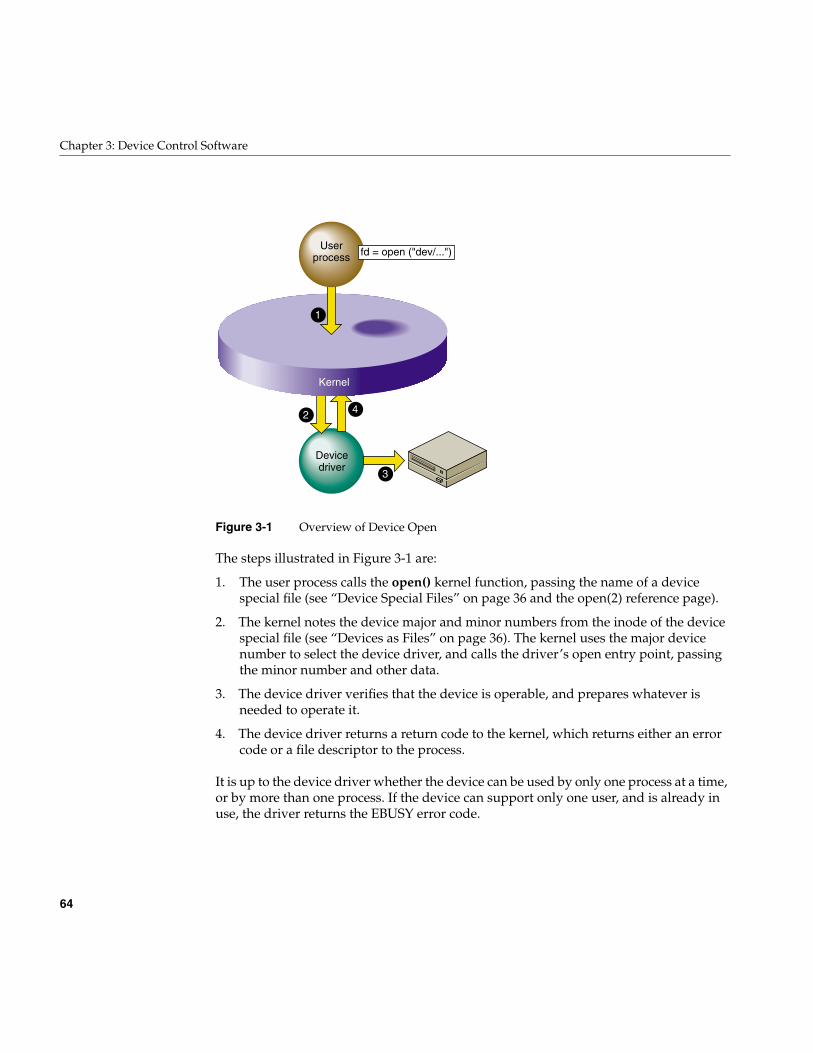
64
Chapter 3: Device Control Software
Figure 3-1 Overview of Device Open
The steps illustrated in Figure 3-1 are:
1. The user process calls the open() kernel function, passing the name of a devicespecial file (see “Device Special Files” on page 36 and the open(2) reference page).
2. The kernel notes the device major and minor numbers from the inode of the devicespecial file (see “Devices as Files” on page 36). The kernel uses the major devicenumber to select the device driver, and calls the driver’s open entry point, passingthe minor number and other data.
3. The device driver verifies that the device is operable, and prepares whatever isneeded to operate it.
4. The device driver returns a return code to the kernel, which returns either an errorcode or a file descriptor to the process.
It is up to the device driver whether the device can be used by only one process at a time,or by more than one process. If the device can support only one user, and is already inuse, the driver returns the EBUSY error code.
Kernel
1
2
3
4
Userprocess
Devicedriver
fd = open ("dev/...")
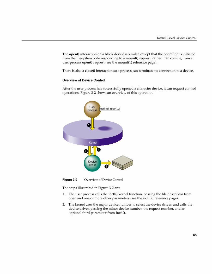
Kernel-Level Device Control
65
The open() interaction on a block device is similar, except that the operation is initiatedfrom the filesystem code responding to a mount() request, rather than coming from auser process open() request (see the mount(1) reference page).
There is also a close() interaction so a process can terminate its connection to a device.
Overview of Device Control
After the user process has successfully opened a character device, it can request controloperations. Figure 3-2 shows an overview of this operation.
Figure 3-2 Overview of Device Control
The steps illustrated in Figure 3-2 are:
1. The user process calls the ioctl() kernel function, passing the file descriptor fromopen and one or more other parameters (see the ioctl(2) reference page).
2. The kernel uses the major device number to select the device driver, and calls thedevice driver, passing the minor device number, the request number, and anoptional third parameter from ioctl().
Kernel
1
2
3
4
Userprocess
Devicedriver
ioctl (fd, req#,...)
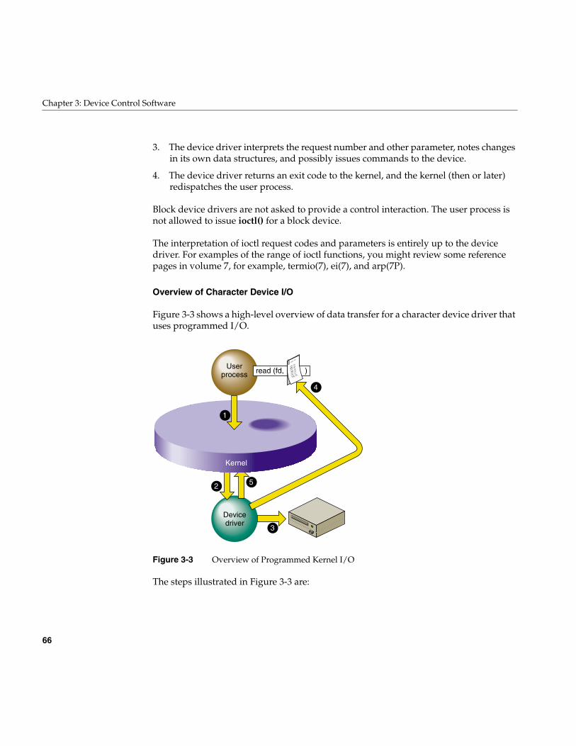
66
Chapter 3: Device Control Software
3. The device driver interprets the request number and other parameter, notes changesin its own data structures, and possibly issues commands to the device.
4. The device driver returns an exit code to the kernel, and the kernel (then or later)redispatches the user process.
Block device drivers are not asked to provide a control interaction. The user process isnot allowed to issue ioctl() for a block device.
The interpretation of ioctl request codes and parameters is entirely up to the devicedriver. For examples of the range of ioctl functions, you might review some referencepages in volume 7, for example, termio(7), ei(7), and arp(7P).
Overview of Character Device I/O
Figure 3-3 shows a high-level overview of data transfer for a character device driver thatuses programmed I/O.
Figure 3-3 Overview of Programmed Kernel I/O
The steps illustrated in Figure 3-3 are:
Kernel
1
2
3
5
4
Userprocess
Devicedriver
read (fd, )
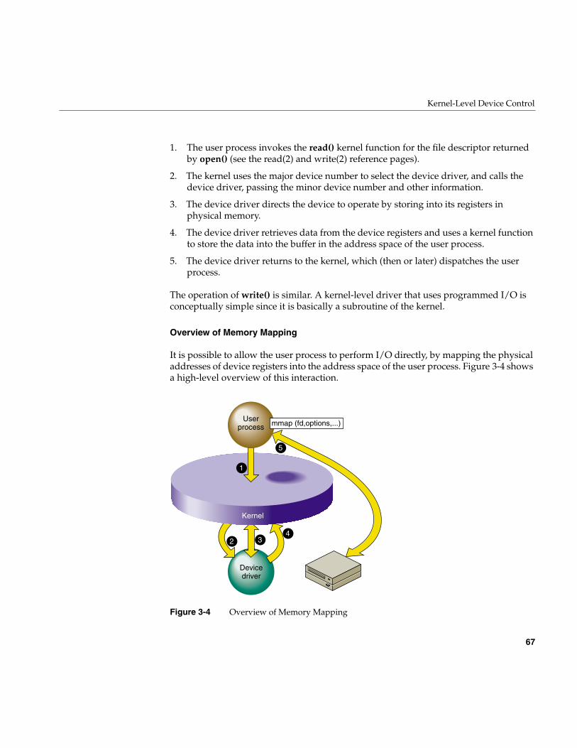
Kernel-Level Device Control
67
1. The user process invokes the read() kernel function for the file descriptor returnedby open() (see the read(2) and write(2) reference pages).
2. The kernel uses the major device number to select the device driver, and calls thedevice driver, passing the minor device number and other information.
3. The device driver directs the device to operate by storing into its registers inphysical memory.
4. The device driver retrieves data from the device registers and uses a kernel functionto store the data into the buffer in the address space of the user process.
5. The device driver returns to the kernel, which (then or later) dispatches the userprocess.
The operation of write() is similar. A kernel-level driver that uses programmed I/O isconceptually simple since it is basically a subroutine of the kernel.
Overview of Memory Mapping
It is possible to allow the user process to perform I/O directly, by mapping the physicaladdresses of device registers into the address space of the user process. Figure 3-4 showsa high-level overview of this interaction.
Figure 3-4 Overview of Memory Mapping
Kernel
1
2 34
5
Userprocess
Devicedriver
mmap (fd,options,...)
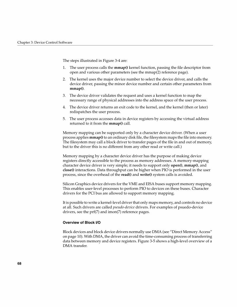
68
Chapter 3: Device Control Software
The steps illustrated in Figure 3-4 are:
1. The user process calls the mmap() kernel function, passing the file descriptor fromopen and various other parameters (see the mmap(2) reference page).
2. The kernel uses the major device number to select the device driver, and calls thedevice driver, passing the minor device number and certain other parameters frommmap().
3. The device driver validates the request and uses a kernel function to map thenecessary range of physical addresses into the address space of the user process.
4. The device driver returns an exit code to the kernel, and the kernel (then or later)redispatches the user process.
5. The user process accesses data in device registers by accessing the virtual addressreturned to it from the mmap() call.
Memory mapping can be supported only by a character device driver. (When a userprocess applies mmap() to an ordinary disk file, the filesystem maps the file into memory.The filesystem may call a block driver to transfer pages of the file in and out of memory,but to the driver this is no different from any other read or write call.)
Memory mapping by a character device driver has the purpose of making deviceregisters directly accessible to the process as memory addresses. A memory-mappingcharacter device driver is very simple; it needs to support only open(), mmap(), andclose() interactions. Data throughput can be higher when PIO is performed in the userprocess, since the overhead of the read() and write() system calls is avoided.
Silicon Graphics device drivers for the VME and EISA buses support memory mapping.This enables user-level processes to perform PIO to devices on these buses. Characterdrivers for the PCI bus are allowed to support memory mapping.
It is possible to write a kernel-level driver that only maps memory, and controls no deviceat all. Such drivers are called pseudo-device drivers. For examples of psuedo-devicedrivers, see the prf(7) and imon(7) reference pages.
Overview of Block I/O
Block devices and block device drivers normally use DMA (see “Direct Memory Access”on page 10). With DMA, the driver can avoid the time-consuming process of transferringdata between memory and device registers. Figure 3-5 shows a high-level overview of aDMA transfer.
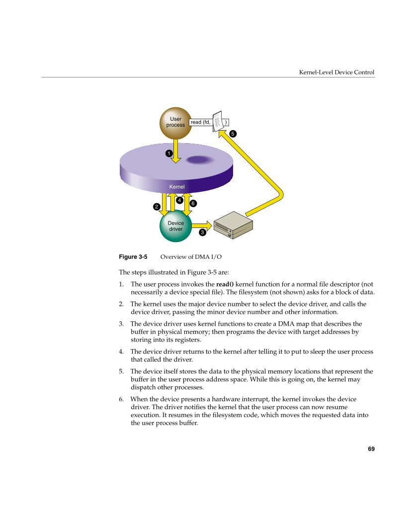
Kernel-Level Device Control
69
Figure 3-5 Overview of DMA I/O
The steps illustrated in Figure 3-5 are:
1. The user process invokes the read() kernel function for a normal file descriptor (notnecessarily a device special file). The filesystem (not shown) asks for a block of data.
2. The kernel uses the major device number to select the device driver, and calls thedevice driver, passing the minor device number and other information.
3. The device driver uses kernel functions to create a DMA map that describes thebuffer in physical memory; then programs the device with target addresses bystoring into its registers.
4. The device driver returns to the kernel after telling it to put to sleep the user processthat called the driver.
5. The device itself stores the data to the physical memory locations that represent thebuffer in the user process address space. While this is going on, the kernel maydispatch other processes.
6. When the device presents a hardware interrupt, the kernel invokes the devicedriver. The driver notifies the kernel that the user process can now resumeexecution. It resumes in the filesystem code, which moves the requested data intothe user process buffer.
Kernel
1
2
3
46
5
Userprocess
Devicedriver
read (fd, )
70
Chapter 3: Device Control Software
DMA is fundamentally asynchronous. There is no necessary timing relation between theoperation of the device performing its operation and the operation of the various userprocesses. A DMA device driver has a more complex structure because it must deal withsuch issues as
• making a DMA map and programming a device to store into a buffer in physicalmemory
• blocking a user process, and waking it up when the operation is complete
• handling interrupts from the device
• the possibility that requests from other processes can occur while the device isoperating
• the possibility that a device interrupt can occur while the driver is handling arequest
The reward for the extra complexity of DMA is the possibility of much higherperformance. The device can store or read data from memory at its maximum ratedspeed, while other processes can execute in parallel.
A DMA driver must be able to cope with the possibility that it can receive severalrequests from different processes while the device is busy handling one operation. Thisimplies that the driver must implement some method of queuing requests until they canbe serviced in turn.
The mapping between physical memory and process address space can be complicated.For example, the buffer can span multiple pages, and the pages need not be in contiguouslocations in physical memory. If the device does not support scatter/gather operations, thedevice driver has to program a separate DMA operation for each page or part of a page—or else has to obtain a contiguous buffer in the kernel address space, do the I/O from thatbuffer, and copy the data from that buffer to the process buffer. When the device supportsscatter/gather, it can be programmed with the starting addresses and lengths of eachpage in the buffer, and read and write into them in turn before presenting a singleinterrupt.
Upper and Lower Halves
When a device can produce hardware interrupts, its kernel-level device driver has twodistinct logical parts, called the “upper half” and the “lower half” (although the upper“half” is usually much more than half the code).
Kernel-Level Device Control
71
Driver Upper Half
The upper half of a driver comprises all the parts that are invoked as a result of userprocess calls: the driver entry points that execute in response to open(), close(), ioctl(),mmap(), read() and write().
These parts of the driver are always called on behalf of a specific process. This is referredto as “having user context,” which means that the entry point is executed under theidentity of a specific process. In effect, the driver code is a subroutine of the user process.
Upper half code can request kernel services that can be delayed, or “sleep.” For example,code in the upper half of a driver can call kmem_alloc() to request memory in kernelspace, and can specify that if memory is not available, the driver can sleep until memoryis available. Also, code in the upper half can wait on a semaphore until some eventoccurs, or can seize a lock knowing that it may have to sleep until the lock is released.
In each case, the entire kernel does not “sleep.” The kernel marks the user process asblocked, and dispatches other processes to run. When the blocking condition isremoved—when memory is available, the semaphore is posted, or the lock is released—the driver is scheduled for execution and resumes.
Driver Lower Half
The lower half of a driver comprises the code that is called to respond to a hardwareinterrupt. An interrupt can occur at almost any time, including large parts of the timewhen the kernel is executing other services, including driver upper and lower halves.
The kernel is not in a known state when executing a driver lower half, and there is noprocess context. In conventional UNIX systems and in previous versions of IRIX, the lackof user context meant that the lower-half code could not use any kernel service that couldsleep. Because of this restriction, you will find that the reference pages for driver kernelservices always state whether the service can sleep or not—a service that might sleepcould never be called from an interrupt handler.
Starting with IRIX 6.4, the IRIX kernel is threaded; that is, all kernel code executes undera thread identity. When it is time to handle an interrupt, a kernel thread calls the driver’sinterrupt handler code. In general this makes very little difference to the design of adevice driver, but it does mean that the driver lower half has an identity that can sleep.In other words, starting with IRIX 6.4, there is no restriction on what kernel services youcan call from driver lower-half code.
72
Chapter 3: Device Control Software
In all systems, an interrupt handler should do as little as possible and do it as quickly aspossible. An interrupt handler will typically get the device status; store it where thetop-half code expects it; possibly post a semaphore to release a blocked user process; andpossibly start the next I/O operation if one is waiting.
Relationship Between Halves
Each half has its proper kind of work. In general terms, the upper half performs allvalidation and preparation, including allocating and deallocating memory and copyingdata between address spaces. It initiates the first device operation of a series and queuesother operations. Then it waits on a semaphore.
The lower half verifies the correct completion of an operation. If another operation isqueued, it initiates that operation. Then it posts the semaphore to awaken the upper half,and exits.
Layered Drivers
IRIX allows for “layered” device drivers, in which one driver operates the actualhardware and the driver at the higher layer presents the programming interface. Thisapproach is implemented for SCSI devices: actual management of the SCSI bus isdelegated to a set of Host Adapter drivers. Drivers for particular kinds of SCSI devicescall the Host Adapter driver through an indirect table to execute SCSI commands. SCSIdrivers and Host Adapter drivers are discussed in detail in Chapter 16, “SCSI DeviceDrivers.”
Combined Block and Character Drivers
A block device driver is called indirectly, from the filesystem, and it is not allowed tosupport the ioctl() entry point. In some cases, block devices can also be thought of ascharacter devices. For example, a block device might return a string of diagnosticinformation, or it might be sensitive to dynamic control settings.
It is possible to support both block and character access to a device: block access tosupport filesystem operations, and character access in order to allow a user process(typically one started by a system administrator) to read, write, or control the devicedirectly.
Kernel-Level Device Control
73
For example, the Silicon Graphics disk device drivers support both block and characteraccess to disk devices. This is why you can find every disk device represented as a blockdevice in the /dev/dsk directory and again as a character device in /dev/rdsk (“r” for “raw,”meaning character devices).
Drivers for Multiprocessors
All but a few Silicon Graphics computers have multiple CPUs that execute concurrently.The CPUs share access to the single main memory, including a single copy of the kerneladdress space. In principle, all CPUs can execute in the kernel code simultaneously. Inprinciple, the upper half of a device driver could be entered simultaneously by as manydifferent processes are there are CPUs in the system (up to 36 in a Challenge or Onyxsystem).
A device driver written for a uniprocessor system cannot tolerate concurrent executionby multiple CPUs. For example, a uniprocessor driver has scalar variables whose valueswould be destroyed if two or more processes updated them concurrently.
In versions previous to IRIX 6.4, IRIX made special provision to support uniprocessorcharacter drivers in multiprocessors. It forced a uniprocessor driver to use only CPU 0 toexecute calls to upper-half code. This ensured that at most one process executed in anyupper half at one time. And it forced interrupts for these drivers to execute on CPU 0.These policies had a detrimental effect on driver and system performance, but theyallowed the drivers to work.
Beginning with IRIX 6.4, there is no special provision for uniprocessor drivers inmultiprocessor systems. You can write a uniprocessor-only driver and use it on auniprocessor workstation but you cannot use the same driver design on amultiprocessor.
It is not difficult to design a kernel-level driver to execute safely in any CPU of amultiprocessor. Each critical data object must be protected by a lock or semaphore, andparticular techniques must be used to coordinate between the upper and lower halves.These techniques are discussed in “Designing for Multiprocessor Use” on page 184.
When you have made a driver multiprocessor-safe, you compile it with a particular flagvalue that IRIX recognizes. Multiprocessor-safe drivers work properly on uniprocessorsystems with very little, if any, extra overhead.
74
Chapter 3: Device Control Software
Loadable Drivers
Some drivers are needed whenever the system is running, but others are needed onlyoccasionally. IRIX allows you to create a kernel-level device driver or STREAMS driverthat is not loaded at boot time, but only later when it is needed.
A loadable driver has the same purposes as a nonloadable one, and uses the sameinterfaces to do its work. A loadable driver can be configured for automatic loadingwhen its device is opened. Alternatively it can be loaded on command using the mlprogram (see the ml(1) and mload(4) reference pages).
A loadable driver remains in memory until its device is no longer in use, or until theadministrator uses ml to unload it. A loadable driver remains in memory indefinitely,and cannot be unloaded, unless it provides a pfxunload() entry point (see “Entry Pointunload()” on page 180).
There are some small differences in the way a loadable driver is compiled and configured(see “Configuring a Loadable Driver” on page 264).
One operational difference is that a loadable driver is not available in the miniroot, thestandalone system administration environment used for emergency maintenance. If adriver might be required in the miniroot, it can be made nonloadable, or it can beconfigured for “autoregistration” (see “Registration” on page 267).
PART TWO
Device Control From Process Space II
Chapter 4, “User-Level Access to Devices”How a user-level process can access and control devices on the VME and EISAbuses.
Chapter 5, “User-Level Access to SCSI Devices”How a user-level process can execute commands and transfer data to a SCSIdevice.
Chapter 6, “Control of External Interrupts”How a user-level process creates or responds to external interrupt signals in theChallenge and Power Challenge systems.

77
Chapter 4
4. User-Level Access to Devices
Programmed I/O (PIO) refers to loading and storing data between program variablesand device registers. This is done by setting up a memory mapping of a device into theprocess address space, so that the program can treat device registers as if they werevolatile memory locations. This chapter discusses the methods of setting up thismapping, and the performance that can be obtained. The main topics are as follows:
• “PCI Programmed I/O” on page 78 discusses PIO mapping of PCI devices.
• “EISA Programmed I/O” on page 83 discusses PIO mapping of EISA bus devices inthe Indigo2 workstation line.
• “VME Programmed I/O” on page 86 discusses PIO mapping of VME devices.
• “VME User-Level DMA” on page 91 discusses the use of the VME DMA engine.
Normally, PIO programs are designed in synchronous fashion; that is, the process issuescommands to the device and then polls the device to find out when the action iscomplete. (However, it is possible for a user process to receive interrupts from somemapped devices if you have purchased the optional REACT software.)
A user-level process can perform DMA transfers from a VME bus master or (in theChallenge or Onyx series) a VME bus slave, directly into the process address space. Theuse of these features is covered under “VME User-Level DMA” on page 91.
78
Chapter 4: User-Level Access to Devices
PCI Programmed I/O
Note: For an overview of the PCI bus and its hardware implementation in SiliconGraphics systems, see Chapter 20, “PCI Device Attachment.” For syntax details of theuser interface to PCI, see the reference page usrpci(7).This section still discusses the useof usrpci instead of the pciba user-level PCI bus adapter interface and should be updatedin the near future. We recommend that you switch over to pciba from usrpci. For moreinformation, refer to the reference page pciba(7M).
Mapping a PCI Device Into Process Address Space
As discussed in “CPU Access to Device Registers” on page 9, an I/O device isrepresented as an address, or range of addresses, in the address space of its bus. Akernel-level device driver has the ability to set up a mapping between an address on anI/O bus and an arbitrary location in the address space of a user-level process. When thishas been done, the bus location appears to be a variable in memory. The program canassign values to it, or refer to it in expressions.
The PCI bus addresses managed by a device are not wired or jumpered into the board;they are established dynamically at the time the system attaches the device. The assignedbus addresses can vary from one day to the next, as devices are added to or removedfrom that PCI bus adapter. For this reason, you cannot program the bus addresses of aPCI device into software or into a configuration file.
In order to map bus addresses for a particular device, you must open the device specialfile that represents that device. You pass the file descriptor for the opened device to themmap() function. If the device driver for the device supports memory mapping—mapping is an optional feature of a PCI device driver—the mapping is set up.
The PCI bus defines three address spaces: configuration space, I/O space, and memoryspace. It is up to the device driver which of the spaces it allows you to map. Some devicedrivers may set up a convention allowing you to map in different spaces.
PCI Device Special Files
Device special files for PCI devices are established in the /hw filesystem by the PCI devicedriver when the device is attached (see “Hardware Graph” on page 42). Thesepathnames are dynamic. Typically, the system administrator also creates stable,
PCI Programmed I/O
79
predictable device special files in the /dev filesystem. The paths to a specific device isdetermined by the device driver for that device.
The PCI bus adapter also creates a set of generic PCI device names for each PCI slot inthe system. The names of these special device files can be discovered by the followingcommand:
find /hw -name usrpci -print -exec ls -l {} \;/hw/module/1/slot/io1/xwidget/pci/0/usrpcitotal 0crw------- 0 root sys 0, 78 Aug 12 15:27 configcrw------- 0 root sys 0, 79 Aug 12 15:27 defaultcrw------- 0 root sys 0, 77 Aug 12 15:27 iocrw------- 0 root sys 0, 75 Aug 12 15:27 mem32crw------- 0 root sys 0, 76 Aug 12 15:27 mem64/hw/module/1/slot/io1/xwidget/pci/1/usrpcitotal 0crw------- 0 root sys 0, 85 Aug 12 15:27 configcrw------- 0 root sys 0, 86 Aug 12 15:27 defaultcrw------- 0 root sys 0, 84 Aug 12 15:27 iocrw------- 0 root sys 0, 82 Aug 12 15:27 mem32crw------- 0 root sys 0, 83 Aug 12 15:27 mem64
The names usrpci are not leaf vertexes and cannot be opened. However, the names config,io, mem32, mem64, and default are character special devices that can be opened from aprocess with the correct privilege. The names represent the following bus addresses:
Table 4-1 PCI Device Special File Names for User Access
Name PCI Bus Address Space Offset in mmap() Call
config Configuration space or spaces on the card in this slot. Offset in config space.
default PCI bus memory space defined by the first base addressregister (BAR) on the card.
Added to BAR.
io PCI bus I/O space defined by this card. Offset in I/O space.
mem32 PCI bus 32-bit memory address space allocated to thiscard when it was attached.
Offset in total allocatedmemory space.
mem64 PCI bus 64-bit memory address space allocated to thiscard when it was attached.
Offset in total allocatedmemory space.
80
Chapter 4: User-Level Access to Devices
Opening a Device Special File
Either kind of pathname is passed to the open() system function, along with flagsrepresenting the type of access (see the open(2) reference page). You can use the returnedfile descriptor for any operation supported by the device driver. The usrpci device driversupports only the mmap() and unmap() functions. A driver for a specific PCI device mayor may not support mmap(), read() and write(), or ioctl() operations.
Using mmap() With PCI Devices
When you have successfully opened a usrpci device special file, you use the filedescriptor as the primary input parameter in a call to the mmap() system function.
This function is documented for all its many uses in the mmap(2) reference page. Forpurposes of mapping a PCI device into memory, the parameters should be as follows(using the names from the reference page):
The meaning of the off value depends on the PCI bus address space represented by thedevice special file, as indicated in Table 4-1.
The value returned by mmap() is the virtual address that corresponds to the starting PCIbus address. When the process accesses that address, the access is implemented by PIOdata transfer to or from the PCI bus.
addr Should be NULL to permit the kernel to choose an address in user processspace.
len The length of the span of PCI addresses to map.
prot PROT_READ for input, PROT_WRITE for output, or the logical sum ofthose names when the device will be used for both input and output.
flags MAP_SHARED. Add MAP_PRIVATE if this mapping is not to be visible tochild processes created with the sproc() function (see the sproc(2) referencepage).
fd The file descriptor returned from opening the device special file.
off The offset into the device address space.
PCI Programmed I/O
81
Map Size Limits
There are limits to the amount and location of PCI bus address space that can be mappedfor PIO. The system architecture can restrict the span of mappable addresses, and kernelresource constraints can impose limits. In order to create the map, the PCI device driverhas to create a software object called a PIO map. In some systems, only a limited numberof PIO maps can be active at one time.
PCI Bus Hardware Errors
When the PCI bus adapter reports an addressing or access error, the error is reflectedback to the device driver. This can take place long after the instruction that initiated theerror transaction. For example, a PIO store to a memory-mapped PCI device can (incertain hardware architectures) pass through several layers of translation. An error couldbe detected several microseconds after the CPU store that initiated the write. By thattime, the CPU could have executed hundreds more instructions.
When the usrpci device driver is notified of a PCI Bus error, it looks up the identities ofall user processes that had mapped the part of PCI address space where the erroroccurred. The driver then sends a SIGBUS signal to each such process. As a result of thispolicy, your process could receive a SIGBUS for an error it did not cause; and when yourprocess did cause the error, the signal could arrive a long time after the erroneoustransaction was initiated.
PCI PIO Example
The code in X demonstrates how to dump the standard configuration space registers ofa device in PCI slot 1 on an Origin200 (PCI slot 1 is XIO bus slot 5 on this system).
Example 4-1 PCI Configuration Space Dump
#include <sys/types.h>#include <sys/mman.h>#include <sys/prctl.h>#include <sys/fcntl.h>#include <sys/prctl.h>#include <unistd.h>#include <stdio.h>#define CFGPATH "/hw/module/1/slot/MotherBoard/node/xtalk/8/pci/5/usrpci/config"#define CFGSIZE (4*1024)
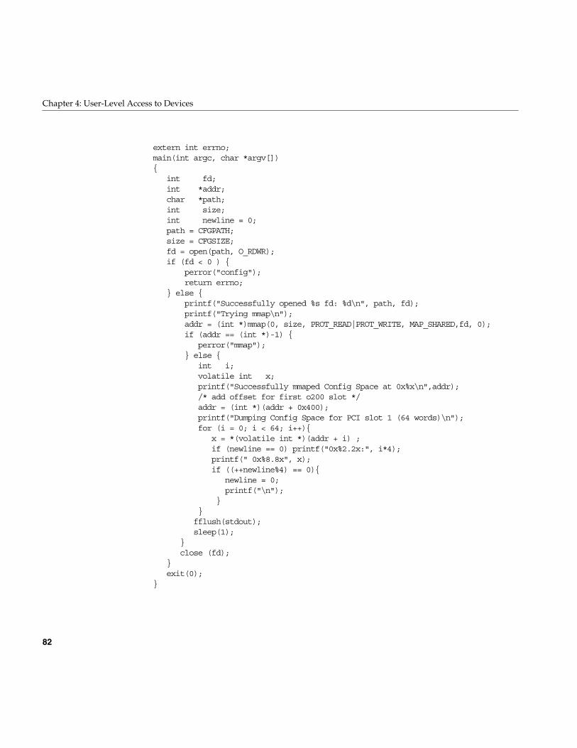
82
Chapter 4: User-Level Access to Devices
extern int errno;main(int argc, char *argv[]){
int fd;int *addr;char *path;int size;int newline = 0;path = CFGPATH;size = CFGSIZE;fd = open(path, O_RDWR);if (fd < 0 ) {
perror("config");return errno;
} else {printf("Successfully opened %s fd: %d\n", path, fd);printf("Trying mmap\n");addr = (int *)mmap(0, size, PROT_READ|PROT_WRITE, MAP_SHARED,fd, 0);if (addr == (int *)-1) {
perror("mmap");} else {
int i;volatile int x;printf("Successfully mmaped Config Space at 0x%x\n",addr);/* add offset for first o200 slot */addr = (int *)(addr + 0x400);printf("Dumping Config Space for PCI slot 1 (64 words)\n");for (i = 0; i < 64; i++){
x = *(volatile int *)(addr + i) ;if (newline == 0) printf("0x%2.2x:", i*4);printf(" 0x%8.8x", x);if ((++newline%4) == 0){
newline = 0;printf("\n");
}}fflush(stdout);sleep(1);
}close (fd);
}exit(0);
}
EISA Programmed I/O
83
EISA Programmed I/O
The EISA bus is supported in Silicon Graphics Indigo2 workstations only. For anoverview of the EISA bus and its implementation in Silicon Graphics systems, seeChapter 18, “EISA Device Drivers.”
Mapping an EISA Device Into Memory
As discussed in “CPU Access to Device Registers” on page 9, an I/O device isrepresented as an address or range of addresses in the address space of its bus. Akernel-level device driver has the ability to set up a mapping between the bus address ofa device register and an arbitrary location in the address space of a user-level process.When this has been done, the device register appears to be a variable in memory—theprogram can assign values to it, or refer to it in expressions.
Learning EISA Device Addresses
In order to map an EISA device for PIO, you must know the following points:
• which EISA bus adapter the device is on
In all Silicon Graphics systems that support it, there is only one EISA bus adapter,and its number is 0.
• whether you need access to the EISA bus memory or I/O address space
• the address and length of the desired registers within the address space
You can find all these values by examining files in the /var/sysgen/system directory,especially the /var/sysgen/system/irix.sm file, in which each configured EISA device isspecified by a VECTOR line. When you examine a VECTOR line, note the followingparameter values:
bustype Specified as EISA for EISA devices. The VECTOR statement can beused for other types of buses as well.
adapter The number of the bus where the device is attached (0).
iospace,iospace2,iospace3
Each iospace group specifies the address space, starting bus address,and the size of a segment of bus address space used by this device.
84
Chapter 4: User-Level Access to Devices
Within each iospace parameter group you find keywords and numbers for the addressspace and addresses for a device. The following is an example of a VECTOR line (whichmust be a single physical line in the system file):
VECTOR: bustype=EISA module=if_ec3 ctlr=1iospace=(EISAIO,0x1000,0x1000)exprobe_space=(r,EISAIO, 0x1c80,4,0x6010d425,0xffffffff)
This example specifies a device that resides in the I/O space at offset 0x1000 (the slot-1I/O space) for the usual length of 0x1000 bytes. The exprobe_space parameter suggeststhat a key device register is at 0x1c80.
Opening a Device Special File
When you know the device addresses, you can open a device special file that representsthe correct range of addresses. The device special files for EISA mapping are found in/dev/eisa.
The naming convention for these files is as follows: Each file is named eisaBaM, where
The device special file for the device described by the example VECTOR line in thepreceding section would be /dev/vme/eisa0aio.
In order to map a device on a particular bus and address space, you must open thecorresponding file in /dev/eisa.
Using the mmap() Function
When you have successfully opened the device special file, you use the file descriptor asthe primary input parameter in a call to the mmap() system function.
This function is documented for all its many uses in the mmap(2) reference page. Forpurposes of mapping EISA devices, the parameters should be as follows (using thenames from the reference page):
B is a digit for the bus number (0)
M is the modifier, either io or mem
addr Should be NULL to permit the kernel to choose an address in user processspace.
EISA Programmed I/O
85
The value returned by mmap() is the virtual memory address that corresponds to thestarting bus address. When the process accesses that address, the access is implementedby data transfer to the EISA bus.
Note: When programming EISA PIO, you must always be aware that EISA devicesgenerally store 16-bit and 32-bit values in “small-endian” order, with the least-significantbyte at the lowest address. This is opposite to the order used by the MIPS CPU underIRIX. If you simply assign to a C unsigned integer from a 32-bit EISA register, the valuewill appear to be byte-inverted.
EISA PIO Bandwidth
The EISA bus adapter is a device on the GIO bus. The GIO bus runs at either 25 MHz or33 MHz, depending on the system model. Each EISA device access takes multiple GIOcycles, as follows:
• The base time to do a native GIO read (of up to 64 bits) is 1 microsecond.
• A 32-bit EISA slave read adds 15 GIO cycles to the base GIO read time; hence oneEISA access takes 19 GIO cycles, best case.
• A 4-byte access to a 16-bit EISA device requires 10 more GIO cycles to transfer thesecond 2-byte group; hence a 4-byte read to a 16-bit EISA slave requires 25 GIOcycles.
• Each wait state inserted by the EISA device adds four GIO cycles.
len The length of the span of bus addresses, as documented in the iospace groupin the VECTOR line.
prot PROT_READ, or PROT_WRITE, or the logical sum of those names whenthe device is used for both input and output.
flags MAP_SHARED, with the addition of MAP_PRIVATE if this mapping is notto be visible to child processes created with the sproc() function (see thesproc(2) reference page).
fd The file descriptor from opening the device special file in /dev/eisa.
off The starting bus address, as documented in the iospace group in theVECTOR line.
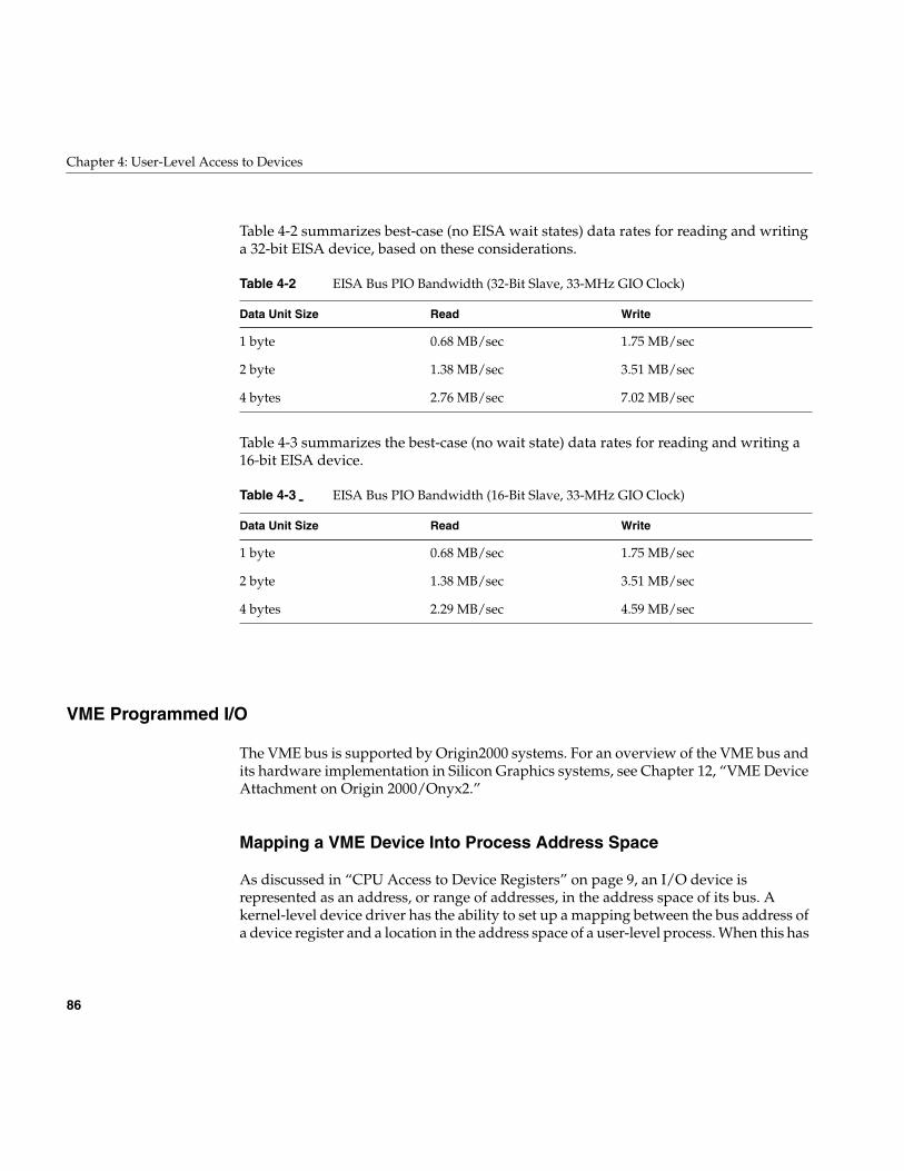
86
Chapter 4: User-Level Access to Devices
Table 4-2 summarizes best-case (no EISA wait states) data rates for reading and writinga 32-bit EISA device, based on these considerations.
Table 4-3 summarizes the best-case (no wait state) data rates for reading and writing a16-bit EISA device.
VME Programmed I/O
The VME bus is supported by Origin2000 systems. For an overview of the VME bus andits hardware implementation in Silicon Graphics systems, see Chapter 12, “VME DeviceAttachment on Origin 2000/Onyx2.”
Mapping a VME Device Into Process Address Space
As discussed in “CPU Access to Device Registers” on page 9, an I/O device isrepresented as an address, or range of addresses, in the address space of its bus. Akernel-level device driver has the ability to set up a mapping between the bus address ofa device register and a location in the address space of a user-level process. When this has
Table 4-2 EISA Bus PIO Bandwidth (32-Bit Slave, 33-MHz GIO Clock)
Data Unit Size Read Write
1 byte 0.68 MB/sec 1.75 MB/sec
2 byte 1.38 MB/sec 3.51 MB/sec
4 bytes 2.76 MB/sec 7.02 MB/sec
Table 4-3 EISA Bus PIO Bandwidth (16-Bit Slave, 33-MHz GIO Clock)
Data Unit Size Read Write
1 byte 0.68 MB/sec 1.75 MB/sec
2 byte 1.38 MB/sec 3.51 MB/sec
4 bytes 2.29 MB/sec 4.59 MB/sec
VME Programmed I/O
87
been done, the device register appears to be a variable in memory. The program canassign values to it, or refer to it in expressions.
Learning VME Device Addresses
In order to map a VME device for PIO, you must know the following points:
• The VME bus number on which the device resides. IRIX supports as many as fiveVME buses. On Challenge and Onyx systems the first VME bus is number 0; onOrigin and Onyx2 systems the first VME bus is number 1. Use the hinv command tosee the numbers of others (and see “About VME Bus Addresses and SystemAddresses” on page 334).
• The VME address space in which the device resides
This will be either A16, A24, or A32.
• The VME address space modifier the device uses—either supervisory (s) ornonprivileged (n)
• The VME bus addresses associated with the device
This must be a sequential range of VME bus addresses that spans all the deviceregisters you need to map.
This information is normally documented in VECTOR lines found in a file in the/var/sysgen/system/ directory (see “Defining VME Devices with the VECTOR Statement”on page 344).
Opening a Device Special File
When you know the device addresses, you can open a device special file that representsthe correct range of addresses. The device special files for VME mapping are found in thehardware graph at paths having the form:
/hw/module/mod/slot/ion/baseio/vme_xtown/pci/7/vmebus/usrvme/assm/width
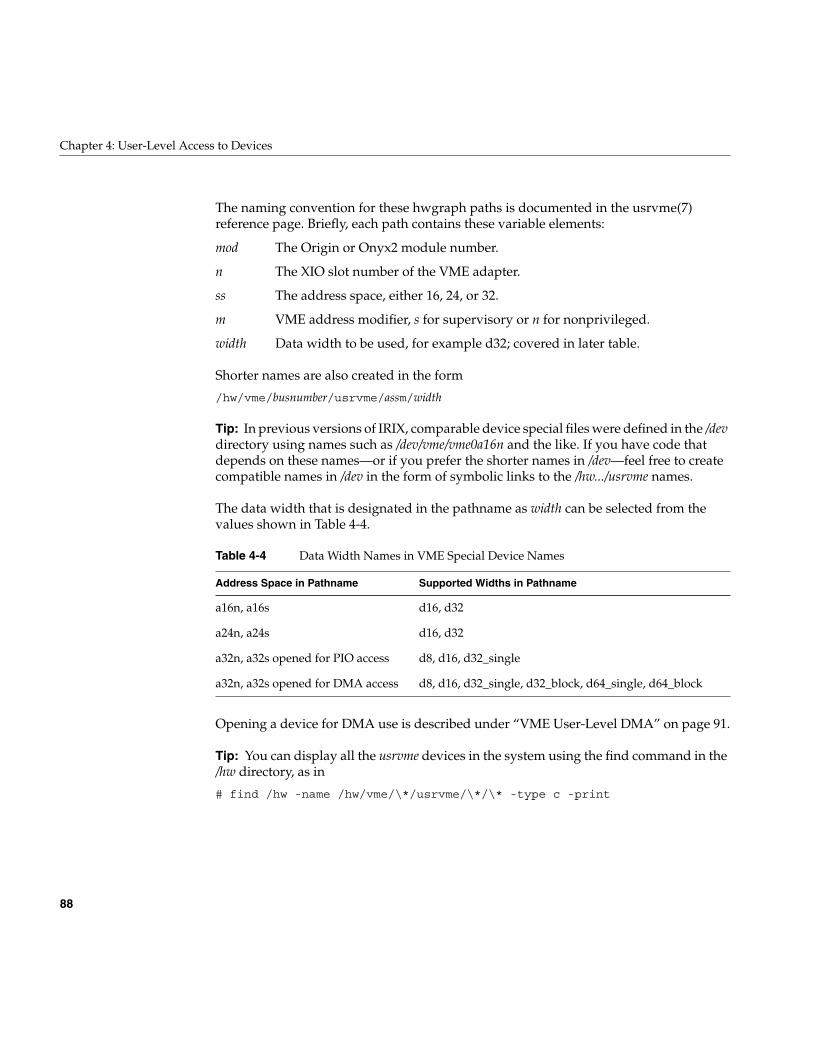
88
Chapter 4: User-Level Access to Devices
The naming convention for these hwgraph paths is documented in the usrvme(7)reference page. Briefly, each path contains these variable elements:
Shorter names are also created in the form
/hw/vme/busnumber/usrvme/assm/width
Tip: In previous versions of IRIX, comparable device special files were defined in the /devdirectory using names such as /dev/vme/vme0a16n and the like. If you have code thatdepends on these names—or if you prefer the shorter names in /dev—feel free to createcompatible names in /dev in the form of symbolic links to the /hw.../usrvme names.
The data width that is designated in the pathname as width can be selected from thevalues shown in Table 4-4.
Opening a device for DMA use is described under “VME User-Level DMA” on page 91.
Tip: You can display all the usrvme devices in the system using the find command in the/hw directory, as in
# find /hw -name /hw/vme/\*/usrvme/\*/\* -type c -print
mod The Origin or Onyx2 module number.
n The XIO slot number of the VME adapter.
ss The address space, either 16, 24, or 32.
m VME address modifier, s for supervisory or n for nonprivileged.
width Data width to be used, for example d32; covered in later table.
Table 4-4 Data Width Names in VME Special Device Names
Address Space in Pathname Supported Widths in Pathname
a16n, a16s d16, d32
a24n, a24s d16, d32
a32n, a32s opened for PIO access d8, d16, d32_single
a32n, a32s opened for DMA access d8, d16, d32_single, d32_block, d64_single, d64_block
VME Programmed I/O
89
Using the mmap() Function
When you have successfully opened the device special file, you use the file descriptor asthe primary input parameter in a call to the mmap() system function.
This function has many different uses, all of which are documented in the mmap(2)reference page. For purposes of mapping a VME device into memory, the parametersshould be as follows (using the names from the reference page):
The value returned by mmap() is the virtual address that corresponds to the startingVME bus address. When the process accesses that address, the access is implemented bydata transfer to the VME bus.
Limits on Maps
There are limits to the amount and location of VME bus address space that can bemapped for PIO. The system architecture can restrict the span of mappable addresses.Kernel resource constraints can impose limits on the number of VME maps that aresimultaneously active. You must always inspect the return code from the mmap() call.
addr Should be NULL to permit the kernel to choose the address in user processspace.
len The length of the span of VME addresses, as documented in the iospacegroup in the VECTOR line.
prot PROT_READ for input, PROT_WRITE for output, or the logical sum ofthose names when the device will be used for both.
flags MAP_SHARED. Add MAP_PRIVATE if this mapping is not to be visible tochild processes created with the sproc() function.
fd The file descriptor returned from opening the device special file.
off The starting VME bus address, as documented in the iospace group in theVECTOR line.
90
Chapter 4: User-Level Access to Devices
VME PIO Access
Once a VME device has been mapped into memory, your program reads from the deviceby referencing the mapped address, and writes to the device by storing into the mappedaddress.
Typically you organize the mapped space using a data structure that describes the layoutof registers. Two key points to note about the mapped space are:
• You should always declare register variables with the C keyword volatile. Thisforces the C compiler to generate a reference to memory whenever the registervalue is needed.
• The VME PIO hardware does not support 64-bit integer load or store operations.For this reason you must not:
– Declare a VME item as long long, because the C compiler generates 64-bit loadsand stores for such variables
– Apply library functions such as bcopy(), bzero(), or memmove() to the VMEmapped registers, because these optimized routines use 64-bit loads and storeswhenever possible.
On an Origin or Onyx2 system, a PIO read can take one or more microseconds tocomplete—a time in which the R10000 CPU can process many instructions from memory.The R10000 continues to execute instructions following the PIO load until it reaches aninstruction that requires the value from that load. Then it stalls until the PIO data arrivesfrom the device.
A PIO write is asynchronous at the hardware level. The CPU executes a register-storeinstruction that is complete as soon as the physical address and data have been placedon the system bus. The actual VME write operation on the VME bus can take 1 or moremicroseconds to complete. During that time the CPU can execute dozens or evenhundreds more instructions from cache memory.
VME User-Level DMA
91
VME User-Level DMA
A DMA engine is included as part of each VME bus adapter in an Silicon GraphicsOrigin2000 system. The DMA engine can perform efficient, block-mode, DMA transfersbetween system memory and VME bus slave cards—cards that would normally becapable of only PIO transfers.
You can use the udma functions to access a VME Bus Master device, if the device canrespond in slave mode. However, this would normally be less efficient than using theMaster device’s own DMA circuitry.
The DMA engine greatly increases the rate of data transfer compared to PIO, providedthat you transfer at least 32 contiguous bytes at a time. The DMA engine can perform D8,D16, D32, D32 Block, and D64 Block data transfers in the A16, A24, and A32 bus addressspaces.
Using the DMA Library Functions
All DMA engine transfers are initiated by a special device driver. However, you do notaccess this driver through open/read/write system calls. Instead, you program itthrough a library of functions. The functions are documented in the vme_dma_engine(3)reference page. They are used in the following sequence:
1. Call vme_dma_engine_alloc() to initialize DMA access to a particular VME busadapter, specified by device special file name (see “Opening a Device Special File”on page 87). You can create an engine for each available bus.
2. Call vme_dma_engine_buffer_alloc() to allocate storage to use for DMA buffers.This function pins the memory pages of the buffers to prevent swapping.
3. You can call vme_dma_engine_buffer_addr_get() to return the address of a bufferallocated by the preceding function.
4. Call vme_dma_engine_transfer_alloc() to create a descriptor for an operation,including the buffer, the length, and the direction of transfer as well as several otherattributes. The handle can be used repeatedly.
5. Call vme_dma_engine_schedule() to schedule one transfer (as described tovme_dma_engine_transfer_alloc()) for future execution. The transfer does notactually start at this time. This function can be called from multiple, parallelthreads.
92
Chapter 4: User-Level Access to Devices
6. Call vme_dma_engine_commit() to commence execution of all scheduled transfers.If you specify a synchronous transfer, the function does not return until the transferis complete.
7. If you specify an asynchronous transfer, call vme_dma_engine_rendezvous() afterstarting all transfers. This function does not return until all transfers are complete.
In prior releases, user-level DMA was provided through a comparable library offunctions with different names and calling sequences. That library of functions issupported in the current release (see a prior edition of this manual, and the udmalib(3)reference page if installed). The new library described here is recommended.
93
Chapter 5
5. User-Level Access to SCSI Devices
IRIX contains a programming library, called dslib, that allows you to control SCSI devicesfrom a user-level process. This chapter documents the functions in dslib, including thefollowing topics:
• “Overview of the dsreq Driver” on page 94 gives a summary of the features and useof the generic SCSI device driver.
• “Generic SCSI Device Special Files” on page 94 documents the format of the namesand major and minor numbers of generic SCSI files.
• “The dsreq Structure” on page 97 gives details of the request structure that is theprimary input to the generic SCSI driver.
• “Testing the Driver Configuration” on page 104 documents the use of theDS_CONF ioctl() operation.
• “Using the Special DS_RESET and DS_ABORT Calls” on page 105 describes twospecial functions of the generic SCSI driver.
• “Using dslib Functions” on page 105 describes the functions that make it simpler touse the generic SCSI driver.
• “Example dslib Program” on page 118 shows a simple example of use.
You must understand the SCSI interface in order to command a SCSI device. For severalSCSI information resources, see “Other Sources of Information” on page xxxix.
If you are specifically interested in using audio data from a CDROM or DAT drive, youshould use the special-purpose libraries for CDROM and DAT that are included in theIRIS Digital Media Development Environment. These libraries are built upon the genericSCSI driver, but provide convenient, audio-oriented functions. For more information onthese libraries, see the IRIS Digital Media Programming Guide, document number008-1799-040.
If your interest is in controlling SCSI devices at the kernel level, see Part V, “SCSI DeviceDrivers.”
94
Chapter 5: User-Level Access to SCSI Devices
Overview of the dsreq Driver
IRIX includes a generic SCSI device driver, the dsreq driver, through which a user-levelprogram can issue SCSI commands to SCSI devices. This is a character device driver thatsupports only open(), close() and ioctl() operations (see “Kinds of Kernel-Level Drivers”on page 62, and also the open(2), close(2) and ioctl(2) reference pages).
The formal documentation of the dsreq driver is found in the ds(7) reference page. Inorder to invoke its services, you prepare a dsreq data structure describing the operationand pass it to the device driver using an ioctl() call. The device driver issues the SCSIcommand you specify, and sleeps until it has completed. Then it returns the status in thedsreq structure.
You can request operations for input and output as well as issuing control and diagnosticcommands. The dsreq structure for input and output operations specifies a buffer inmemory for data transfer. The dsreq driver handles the task of locking the buffer intomemory (if necessary) and managing a DMA transfer of data.
The programming interface supported by the generic SCSI driver is quite primitive. Alibrary of higher-level functions makes it easier to use. This library is formallydocumented in the dslib(3) reference page, and is described under “Using dslibFunctions” on page 105.
Generic SCSI Device Special Files
The creation and use of device special files is discussed under “Device Special Files” onpage 36. A device special file represents a device, and is the mechanism for associating adevice with a kernel-level device driver.
The device special files in the /dev/scsi directory are all associated with the dsreq driver. Abasic set of these names is created automatically by the /dev/MAKEDEV script (see “TheScript MAKEDEV” on page 41). You have to create additional device special files if youneed to control logical units other than logical unit 0.
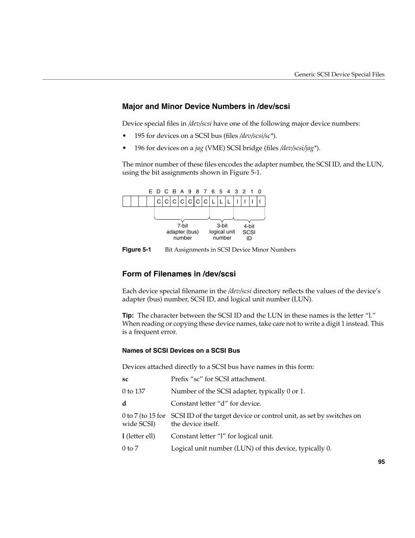
Generic SCSI Device Special Files
95
Major and Minor Device Numbers in /dev/scsi
Device special files in /dev/scsi have one of the following major device numbers:
• 195 for devices on a SCSI bus (files /dev/scsi/sc*).
• 196 for devices on a jag (VME) SCSI bridge (files /dev/scsi/jag*).
The minor number of these files encodes the adapter number, the SCSI ID, and the LUN,using the bit assignments shown in Figure 5-1.
Figure 5-1 Bit Assignments in SCSI Device Minor Numbers
Form of Filenames in /dev/scsi
Each device special filename in the /dev/scsi directory reflects the values of the device’sadapter (bus) number, SCSI ID, and logical unit number (LUN).
Tip: The character between the SCSI ID and the LUN in these names is the letter “l.”When reading or copying these device names, take care not to write a digit 1 instead. Thisis a frequent error.
Names of SCSI Devices on a SCSI Bus
Devices attached directly to a SCSI bus have names in this form:
sc Prefix “sc” for SCSI attachment.
0 to 137 Number of the SCSI adapter, typically 0 or 1.
d Constant letter “d” for device.
0 to 7 (to 15 forwide SCSI)
SCSI ID of the target device or control unit, as set by switches onthe device itself.
l (letter ell) Constant letter “l” for logical unit.
0 to 7 Logical unit number (LUN) of this device, typically 0.
E D C B A 9 8 7 6 5 4 3 2 1 0
7-bitadapter (bus)
number
3-bitlogical unit
number
4-bitSCSI
ID
C C C C C C C L L L I I I I
96
Chapter 5: User-Level Access to SCSI Devices
A typical device name would be /dev/scsi/sc1d3l0 meaning a SCSI device configured as ID3 on SCSI bus 1. Either this device has no logical units, or this is the first logical unit ondevice 3.
Names of SCSI Devices on the Jag (VME Bus) Controller
Machines in the Challenge and Onyx systems can optionally have SCSI devices attachedto the VME bus through a bridge using the jag device driver. These devices are alsorepresented in /dev/scsi with names of the following form:
A typical device name would be /dev/scsi/jag1d3l0 meaning a SCSI device configured asID 3 on VME bus 1. Either the device has no logical units, or this is the first logical uniton device 3.
Creating Additional Names in /dev/scsi
The script /dev/MAKEDEV, which runs each time the system boots, creates 16 files foreach existing SCSI or jag bus. These files represent the possible SCSI ID numbers 0-15 oneach bus, with a logical number of 0. If you want to control a device with LUN 0, thedevice special file exists.
In order to control a device with a LUN of 1-7, you must create an additional devicespecial file, using the mknode or install command (see the install(1) reference page). Forexample, before you can operate logical unit 2 of device 5 on SCSI bus 1, you must create/dev/scsi/sc1d5l2 using a command such as
install -F /dev/scsi -m 600 -u root -g sys \-chr 195,165 sc1d5l2
jag Prefix “jag” for VME/SCSI attachment.
0 to 4 Number of the VME adapter, typically 0 or 1.
d Constant letter “d” for device.
0 to 7 (to 15 forwide SCSI)
SCSI ID of the target device or control unit, as set by switches onthe device itself.
l (letter ell) Constant letter “l” for logical unit.
0 to 7 Logical unit number (LUN) of this device, typically 0.
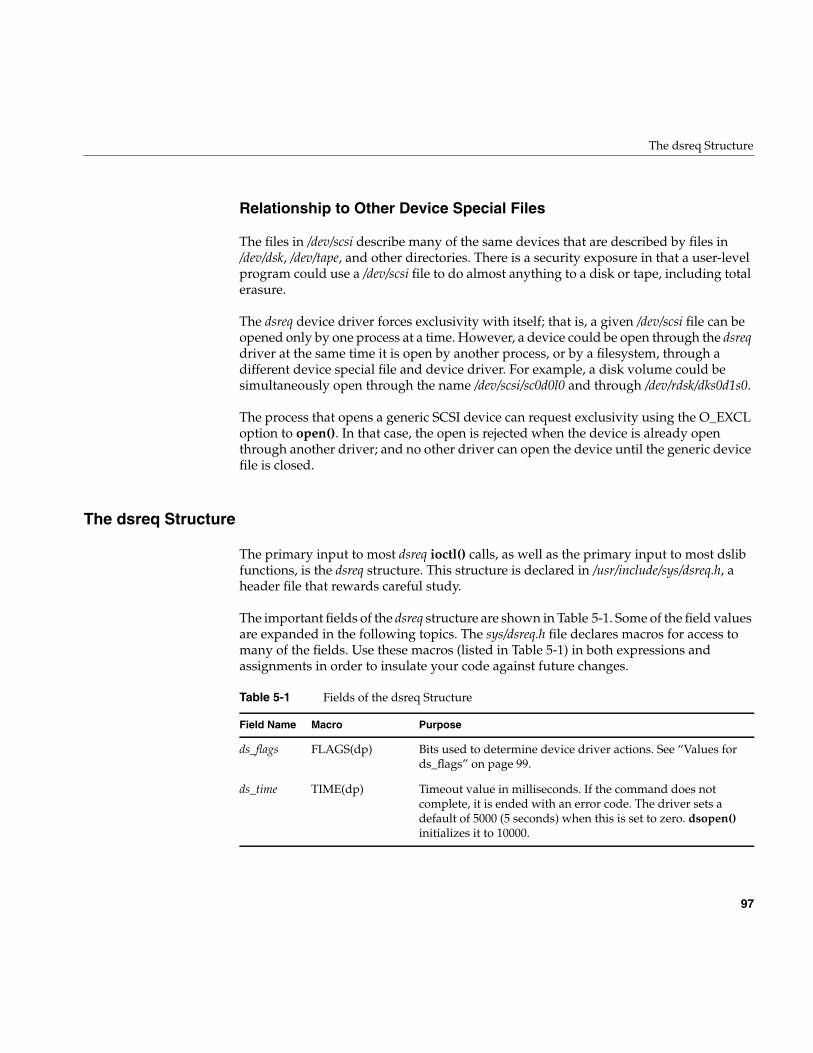
The dsreq Structure
97
Relationship to Other Device Special Files
The files in /dev/scsi describe many of the same devices that are described by files in/dev/dsk, /dev/tape, and other directories. There is a security exposure in that a user-levelprogram could use a /dev/scsi file to do almost anything to a disk or tape, including totalerasure.
The dsreq device driver forces exclusivity with itself; that is, a given /dev/scsi file can beopened only by one process at a time. However, a device could be open through the dsreqdriver at the same time it is open by another process, or by a filesystem, through adifferent device special file and device driver. For example, a disk volume could besimultaneously open through the name /dev/scsi/sc0d0l0 and through /dev/rdsk/dks0d1s0.
The process that opens a generic SCSI device can request exclusivity using the O_EXCLoption to open(). In that case, the open is rejected when the device is already openthrough another driver; and no other driver can open the device until the generic devicefile is closed.
The dsreq Structure
The primary input to most dsreq ioctl() calls, as well as the primary input to most dslibfunctions, is the dsreq structure. This structure is declared in /usr/include/sys/dsreq.h, aheader file that rewards careful study.
The important fields of the dsreq structure are shown in Table 5-1. Some of the field valuesare expanded in the following topics. The sys/dsreq.h file declares macros for access tomany of the fields. Use these macros (listed in Table 5-1) in both expressions andassignments in order to insulate your code against future changes.
Table 5-1 Fields of the dsreq Structure
Field Name Macro Purpose
ds_flags FLAGS(dp) Bits used to determine device driver actions. See “Values fords_flags” on page 99.
ds_time TIME(dp) Timeout value in milliseconds. If the command does notcomplete, it is ended with an error code. The driver sets adefault of 5000 (5 seconds) when this is set to zero. dsopen()initializes it to 10000.
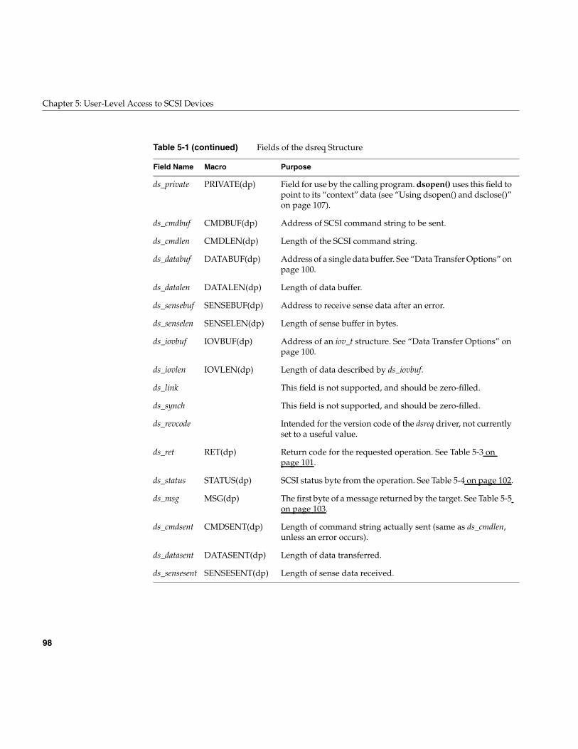
98
Chapter 5: User-Level Access to SCSI Devices
ds_private PRIVATE(dp) Field for use by the calling program. dsopen() uses this field topoint to its “context” data (see “Using dsopen() and dsclose()”on page 107).
ds_cmdbuf CMDBUF(dp) Address of SCSI command string to be sent.
ds_cmdlen CMDLEN(dp) Length of the SCSI command string.
ds_databuf DATABUF(dp) Address of a single data buffer. See “Data Transfer Options” onpage 100.
ds_datalen DATALEN(dp) Length of data buffer.
ds_sensebuf SENSEBUF(dp) Address to receive sense data after an error.
ds_senselen SENSELEN(dp) Length of sense buffer in bytes.
ds_iovbuf IOVBUF(dp) Address of an iov_t structure. See “Data Transfer Options” onpage 100.
ds_iovlen IOVLEN(dp) Length of data described by ds_iovbuf.
ds_link This field is not supported, and should be zero-filled.
ds_synch This field is not supported, and should be zero-filled.
ds_revcode Intended for the version code of the dsreq driver, not currentlyset to a useful value.
ds_ret RET(dp) Return code for the requested operation. See Table 5-3 onpage 101.
ds_status STATUS(dp) SCSI status byte from the operation. See Table 5-4 on page 102.
ds_msg MSG(dp) The first byte of a message returned by the target. See Table 5-5on page 103.
ds_cmdsent CMDSENT(dp) Length of command string actually sent (same as ds_cmdlen,unless an error occurs).
ds_datasent DATASENT(dp) Length of data transferred.
ds_sensesent SENSESENT(dp) Length of sense data received.
Table 5-1 (continued) Fields of the dsreq Structure
Field Name Macro Purpose
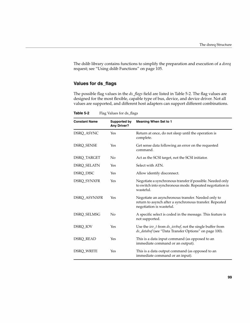
The dsreq Structure
99
The dslib library contains functions to simplify the preparation and execution of a dsreqrequest; see “Using dslib Functions” on page 105.
Values for ds_flags
The possible flag values in the ds_flags field are listed in Table 5-2. The flag values aredesigned for the most flexible, capable type of bus, device, and device driver. Not allvalues are supported, and different host adapters can support different combinations.
Table 5-2 Flag Values for ds_flags
Constant Name Supported byAny Driver?
Meaning When Set to 1
DSRQ_ASYNC Yes Return at once, do not sleep until the operation iscomplete.
DSRQ_SENSE Yes Get sense data following an error on the requestedcommand.
DSRQ_TARGET No Act as the SCSI target, not the SCSI initiator.
DSRQ_SELATN Yes Select with ATN.
DSRQ_DISC Yes Allow identify disconnect.
DSRQ_SYNXFR Yes Negotiate a synchronous transfer if possible. Needed onlyto switch into synchronous mode. Repeated negotiation iswasteful.
DSRQ_ASYNXFR Yes Negotiate an asynchronous transfer. Needed only toreturn to asynch after a synchronous transfer. Repeatednegotiation is wasteful.
DSRQ_SELMSG No A specific select is coded in the message. This feature isnot supported.
DSRQ_IOV Yes Use the iov_t from ds_iovbuf, not the single buffer fromds_databuf (see “Data Transfer Options” on page 100).
DSRQ_READ Yes This is a data input command (as opposed to animmediate command or an output).
DSRQ_WRITE Yes This is a data output command (as opposed to animmediate command or an input).
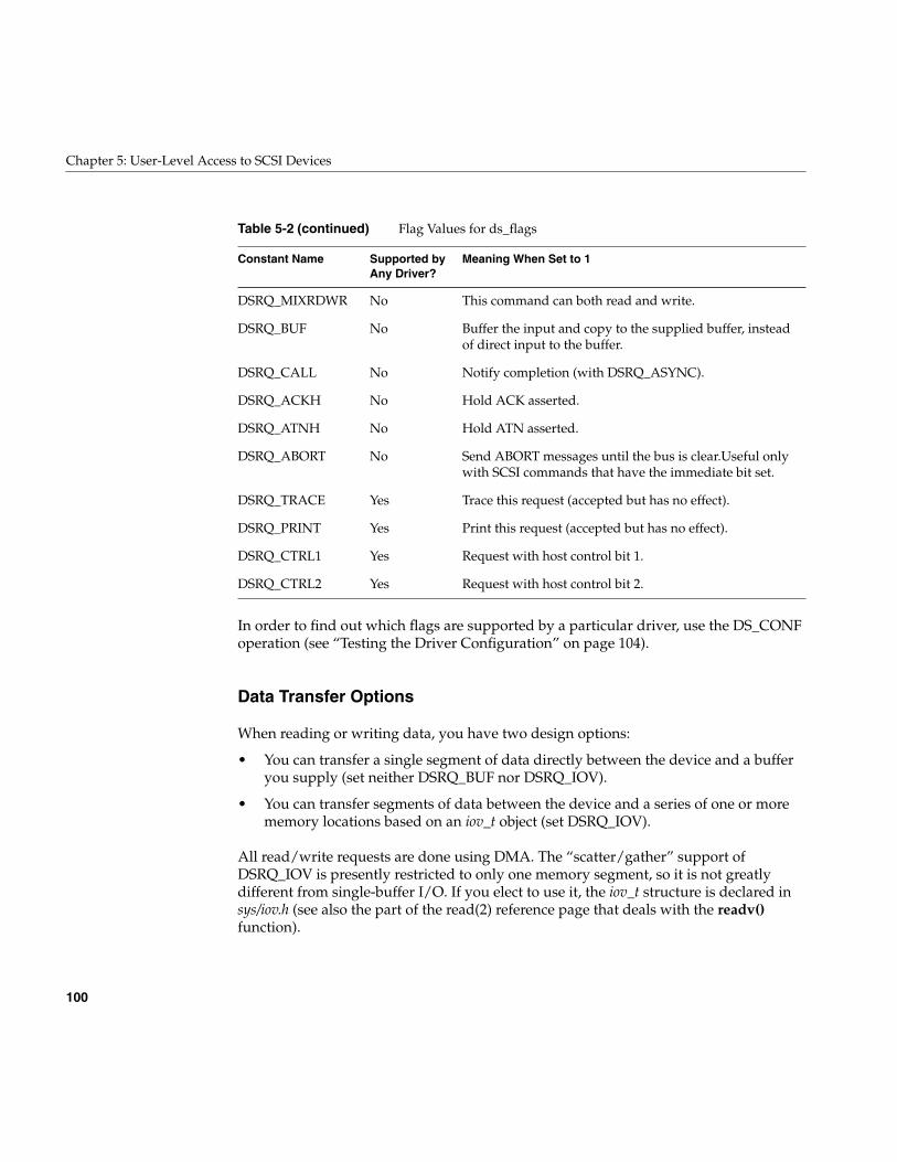
100
Chapter 5: User-Level Access to SCSI Devices
In order to find out which flags are supported by a particular driver, use the DS_CONFoperation (see “Testing the Driver Configuration” on page 104).
Data Transfer Options
When reading or writing data, you have two design options:
• You can transfer a single segment of data directly between the device and a bufferyou supply (set neither DSRQ_BUF nor DSRQ_IOV).
• You can transfer segments of data between the device and a series of one or morememory locations based on an iov_t object (set DSRQ_IOV).
All read/write requests are done using DMA. The “scatter/gather” support ofDSRQ_IOV is presently restricted to only one memory segment, so it is not greatlydifferent from single-buffer I/O. If you elect to use it, the iov_t structure is declared insys/iov.h (see also the part of the read(2) reference page that deals with the readv()function).
DSRQ_MIXRDWR No This command can both read and write.
DSRQ_BUF No Buffer the input and copy to the supplied buffer, insteadof direct input to the buffer.
DSRQ_CALL No Notify completion (with DSRQ_ASYNC).
DSRQ_ACKH No Hold ACK asserted.
DSRQ_ATNH No Hold ATN asserted.
DSRQ_ABORT No Send ABORT messages until the bus is clear.Useful onlywith SCSI commands that have the immediate bit set.
DSRQ_TRACE Yes Trace this request (accepted but has no effect).
DSRQ_PRINT Yes Print this request (accepted but has no effect).
DSRQ_CTRL1 Yes Request with host control bit 1.
DSRQ_CTRL2 Yes Request with host control bit 2.
Table 5-2 (continued) Flag Values for ds_flags
Constant Name Supported byAny Driver?
Meaning When Set to 1
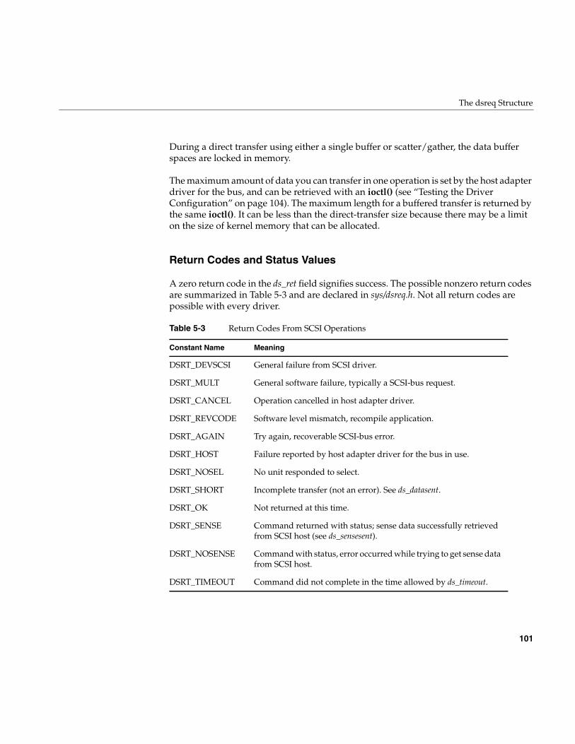
The dsreq Structure
101
During a direct transfer using either a single buffer or scatter/gather, the data bufferspaces are locked in memory.
The maximum amount of data you can transfer in one operation is set by the host adapterdriver for the bus, and can be retrieved with an ioctl() (see “Testing the DriverConfiguration” on page 104). The maximum length for a buffered transfer is returned bythe same ioctl(). It can be less than the direct-transfer size because there may be a limiton the size of kernel memory that can be allocated.
Return Codes and Status Values
A zero return code in the ds_ret field signifies success. The possible nonzero return codesare summarized in Table 5-3 and are declared in sys/dsreq.h. Not all return codes arepossible with every driver.
Table 5-3 Return Codes From SCSI Operations
Constant Name Meaning
DSRT_DEVSCSI General failure from SCSI driver.
DSRT_MULT General software failure, typically a SCSI-bus request.
DSRT_CANCEL Operation cancelled in host adapter driver.
DSRT_REVCODE Software level mismatch, recompile application.
DSRT_AGAIN Try again, recoverable SCSI-bus error.
DSRT_HOST Failure reported by host adapter driver for the bus in use.
DSRT_NOSEL No unit responded to select.
DSRT_SHORT Incomplete transfer (not an error). See ds_datasent.
DSRT_OK Not returned at this time.
DSRT_SENSE Command returned with status; sense data successfully retrievedfrom SCSI host (see ds_sensesent).
DSRT_NOSENSE Command with status, error occurred while trying to get sense datafrom SCSI host.
DSRT_TIMEOUT Command did not complete in the time allowed by ds_timeout.
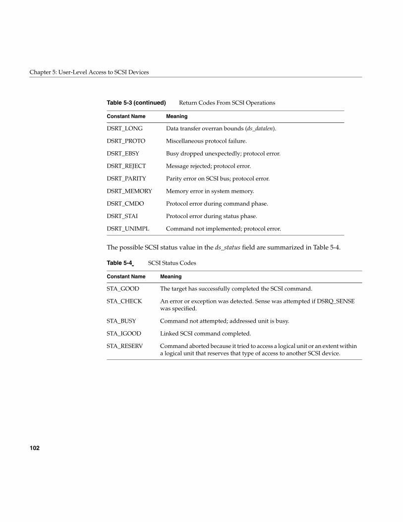
102
Chapter 5: User-Level Access to SCSI Devices
The possible SCSI status value in the ds_status field are summarized in Table 5-4.
DSRT_LONG Data transfer overran bounds (ds_datalen).
DSRT_PROTO Miscellaneous protocol failure.
DSRT_EBSY Busy dropped unexpectedly; protocol error.
DSRT_REJECT Message rejected; protocol error.
DSRT_PARITY Parity error on SCSI bus; protocol error.
DSRT_MEMORY Memory error in system memory.
DSRT_CMDO Protocol error during command phase.
DSRT_STAI Protocol error during status phase.
DSRT_UNIMPL Command not implemented; protocol error.
Table 5-4 SCSI Status Codes
Constant Name Meaning
STA_GOOD The target has successfully completed the SCSI command.
STA_CHECK An error or exception was detected. Sense was attempted if DSRQ_SENSEwas specified.
STA_BUSY Command not attempted; addressed unit is busy.
STA_IGOOD Linked SCSI command completed.
STA_RESERV Command aborted because it tried to access a logical unit or an extent withina logical unit that reserves that type of access to another SCSI device.
Table 5-3 (continued) Return Codes From SCSI Operations
Constant Name Meaning
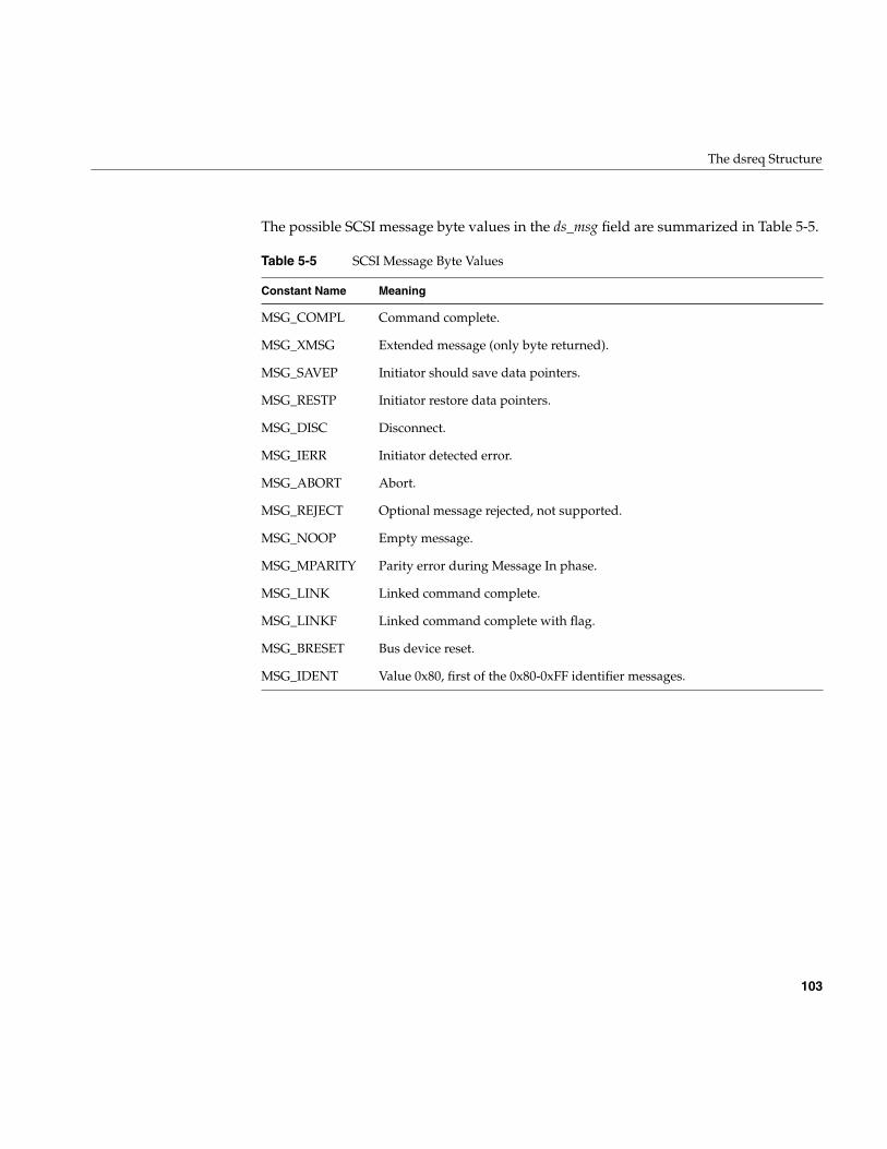
The dsreq Structure
103
The possible SCSI message byte values in the ds_msg field are summarized in Table 5-5.
Table 5-5 SCSI Message Byte Values
Constant Name Meaning
MSG_COMPL Command complete.
MSG_XMSG Extended message (only byte returned).
MSG_SAVEP Initiator should save data pointers.
MSG_RESTP Initiator restore data pointers.
MSG_DISC Disconnect.
MSG_IERR Initiator detected error.
MSG_ABORT Abort.
MSG_REJECT Optional message rejected, not supported.
MSG_NOOP Empty message.
MSG_MPARITY Parity error during Message In phase.
MSG_LINK Linked command complete.
MSG_LINKF Linked command complete with flag.
MSG_BRESET Bus device reset.
MSG_IDENT Value 0x80, first of the 0x80-0xFF identifier messages.
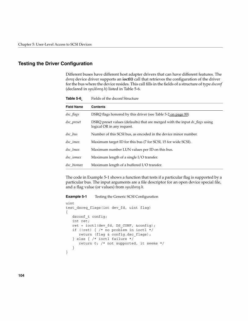
104
Chapter 5: User-Level Access to SCSI Devices
Testing the Driver Configuration
Different buses have different host adapter drivers that can have different features. Thedsreq device driver supports an ioctl() call that retrieves the configuration of the driverfor the bus where the device resides. This call fills in the fields of a structure of type dsconf(declared in sys/dsreq.h) listed in Table 5-6.
The code in Example 5-1 shows a function that tests if a particular flag is supported by aparticular bus. The input arguments are a file descriptor for an open device special file,and a flag value (or values) from sys/dsreq.h.
Example 5-1 Testing the Generic SCSI Configuration
uinttest_dsreq_flags(int dev_fd, uint flag){
dsconf_t config;int ret;ret = ioctl(dev_fd, DS_CONF, &config);if (!ret) { /* no problem in ioctl */
return (flag & config.dsc_flags);} else { /* ioctl failure */
return 0; /* not supported, it seems */}
}
Table 5-6 Fields of the dsconf Structure
Field Name Contents
dsc_flags DSRQ flags honored by this driver (see Table 5-2 on page 99)
dsc_preset DSRQ preset values (defaults) that are merged with the input ds_flags usinglogical OR in any request.
dsc_bus Number of this SCSI bus, as encoded in the device minor number.
dsc_imax Maximum target ID for this bus (7 for SCSI, 15 for wide SCSI).
dsc_lmax Maximum number LUN values per ID on this bus.
dsc_iomax Maximum length of a single I/O transfer.
dsc_biomax Maximum length of a buffered I/O transfer.
Using the Special DS_RESET and DS_ABORT Calls
105
A program could use the function in Example 5-1 to find out if a particular feature issupported. For example, a test of support for the DSRQ_SYNXFER feature could becoded as follows:
if (test_dsreq_flags(the_dev, DSRQ_SYNXFER)) {/* synchronous negotiation is supported */...
Using the Special DS_RESET and DS_ABORT Calls
Two special functions of the generic SCSI driver are available only as ioctl() calls, notthrough dslib functions.
Using DS_ABORT
The DS_ABORT ioctl() sends a SCSI ABORT message to the bus, target, and LUN definedby the file descriptor. The resulting status is returned in the dsreq that is also specified.The host adapter driver waits until no commands are pending on that bus, so there is nopoint in using this function to cancel anything but an immediate command such as arewind. And example of this call is as follows:
ioctl(dev_fd, DS_ABORT, &some_dsreq);
Using DS_RESET
The DS_RESET ioctl() function causes a reset of the SCSI bus specified by the filedescriptor. The resulting status is returned in the dsreq that is also specified. Thispowerful operation should be used with great care, because it terminates all pendingactivity on the bus.
Using dslib Functions
The functions in the dslib library are built upon calls to the dsreq device driver, andsimplify the process of allocating a dsreq structure, setting values in it, and executingcommands. The formal documentation of the library is found in dslib(3). The source codeis distributed with the system in the /usr/share/src/irix/examples/scsi directory so that youcan read and extend it. (This directory installs as part of the irix_dev softwarecomponent, and the examples directory does not install by default.)
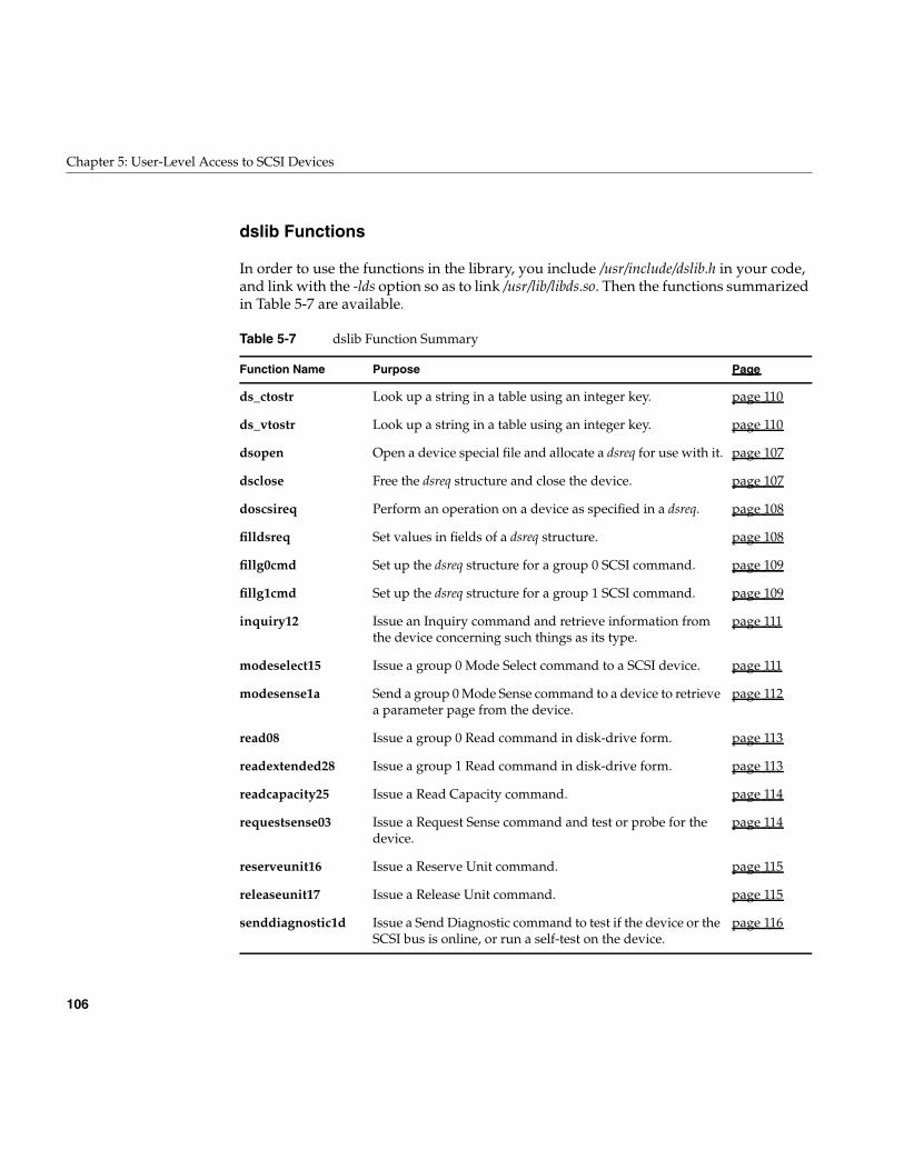
106
Chapter 5: User-Level Access to SCSI Devices
dslib Functions
In order to use the functions in the library, you include /usr/include/dslib.h in your code,and link with the -lds option so as to link /usr/lib/libds.so. Then the functions summarizedin Table 5-7 are available.
Table 5-7 dslib Function Summary
Function Name Purpose Page
ds_ctostr Look up a string in a table using an integer key. page 110
ds_vtostr Look up a string in a table using an integer key. page 110
dsopen Open a device special file and allocate a dsreq for use with it. page 107
dsclose Free the dsreq structure and close the device. page 107
doscsireq Perform an operation on a device as specified in a dsreq. page 108
filldsreq Set values in fields of a dsreq structure. page 108
fillg0cmd Set up the dsreq structure for a group 0 SCSI command. page 109
fillg1cmd Set up the dsreq structure for a group 1 SCSI command. page 109
inquiry12 Issue an Inquiry command and retrieve information fromthe device concerning such things as its type.
page 111
modeselect15 Issue a group 0 Mode Select command to a SCSI device. page 111
modesense1a Send a group 0 Mode Sense command to a device to retrievea parameter page from the device.
page 112
read08 Issue a group 0 Read command in disk-drive form. page 113
readextended28 Issue a group 1 Read command in disk-drive form. page 113
readcapacity25 Issue a Read Capacity command. page 114
requestsense03 Issue a Request Sense command and test or probe for thedevice.
page 114
reserveunit16 Issue a Reserve Unit command. page 115
releaseunit17 Issue a Release Unit command. page 115
senddiagnostic1d Issue a Send Diagnostic command to test if the device or theSCSI bus is online, or run a self-test on the device.
page 116
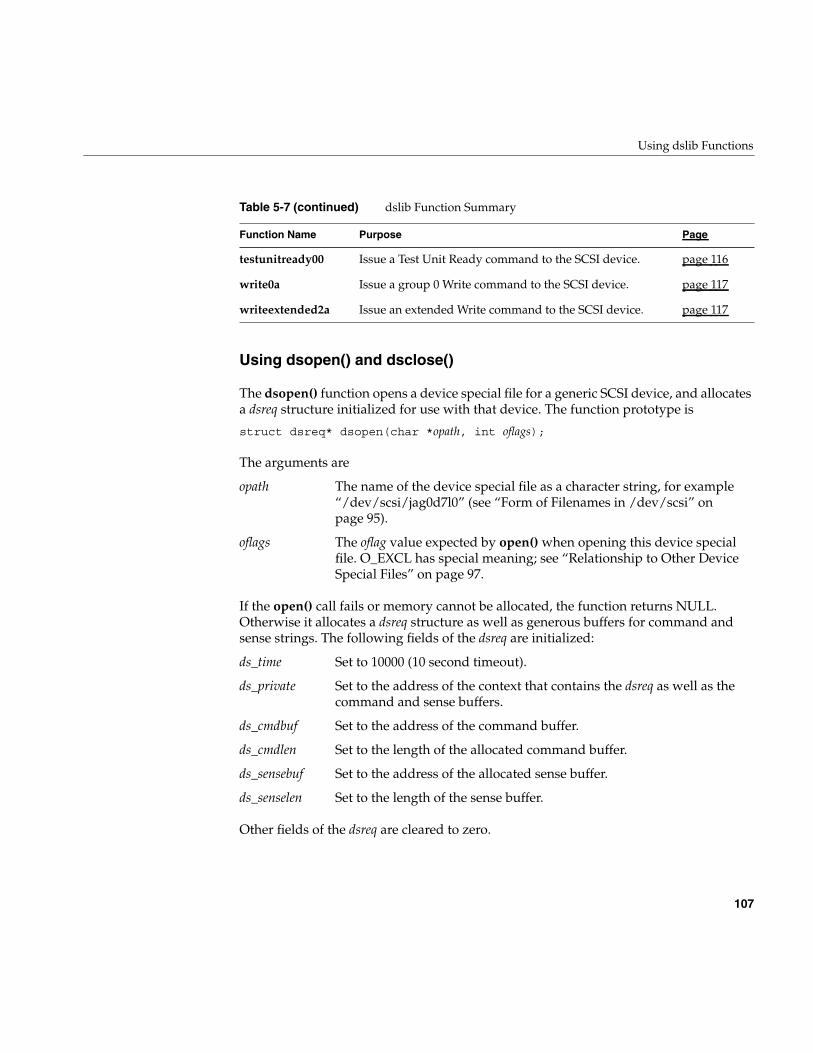
Using dslib Functions
107
Using dsopen() and dsclose()
The dsopen() function opens a device special file for a generic SCSI device, and allocatesa dsreq structure initialized for use with that device. The function prototype is
struct dsreq* dsopen(char *opath, int oflags);
The arguments are
If the open() call fails or memory cannot be allocated, the function returns NULL.Otherwise it allocates a dsreq structure as well as generous buffers for command andsense strings. The following fields of the dsreq are initialized:
Other fields of the dsreq are cleared to zero.
testunitready00 Issue a Test Unit Ready command to the SCSI device. page 116
write0a Issue a group 0 Write command to the SCSI device. page 117
writeextended2a Issue an extended Write command to the SCSI device. page 117
opath The name of the device special file as a character string, for example“/dev/scsi/jag0d7l0” (see “Form of Filenames in /dev/scsi” onpage 95).
oflags The oflag value expected by open() when opening this device specialfile. O_EXCL has special meaning; see “Relationship to Other DeviceSpecial Files” on page 97.
ds_time Set to 10000 (10 second timeout).
ds_private Set to the address of the context that contains the dsreq as well as thecommand and sense buffers.
ds_cmdbuf Set to the address of the command buffer.
ds_cmdlen Set to the length of the allocated command buffer.
ds_sensebuf Set to the address of the allocated sense buffer.
ds_senselen Set to the length of the sense buffer.
Table 5-7 (continued) dslib Function Summary
Function Name Purpose Page
108
Chapter 5: User-Level Access to SCSI Devices
Note: Other functions in dslib assume that a dsreq has been initialized by dsopen(). Inparticular they assume the ds_private value points to a context block. You should notattempt to use any dsreq structure with a dslib function except one returned by dsopen();and you should not use a dsreq opened for one file with another file.
The dsclose() function releases the dsreq structure and close the device. Its prototype is
void dsclose(struct dsreq *dsp);
The only argument is the dsreq created by dsopen().
Issuing a Request With doscsireq()
The doscsireq() function issues a SCSI request by passing a dsreq to the SCSI devicedriver using an ioctl() call. The dsreq must have been prepared completely beforehand.The function prototype is
int doscsireq(int fd, struct dsreq *dsp);
The arguments are as follows:
Normally the returned value is the SCSI status byte. When the requested operation endswith Busy or Reserve Conflict status, the function sleeps 2 seconds and tries theoperation up to four times. The returned value is -1 when the device driver rejects theioctl() or the third retry ends in failure.
SCSI Utility Functions
The functions filldsreq(), fillg0cmd(), fillg1cmd(), ds_vtostr(), and ds_ctostr() are notoriented toward particular SCSI operations, but are used to construct your owntask-oriented SCSI functions.
Using filldsreq()
The filldsreq() function is used to set the ds_flags, ds_databuf, and ds_datalen members ofa dsreq structure. Its prototype is
void filldsreq(struct dsreq *dsp, uchar_t *data,long datalen, long flags)
fd The file descriptor for the open device file.
dsp The address of the dsreq prepared by dsopen().
Using dslib Functions
109
The arguments are as follows:
The bits in flags are added to ds_flags with an OR; they do not replace the contents of thefield.
Note: Besides the specified values, the function also sets 10000 in ds_timeout and clearsds_link, ds_synch, and ds_ret to zero.
Using fillg0cmd() and fillg1cmd()
The fillg0cmd() function stores a group 0 (6-byte) SCSI command in a command buffer.The fillg1cmd() stores a group 1 (10-byte) SCSI command in the buffer. Both functions setthe ds_cmdbuf and ds_cmdlen fields of a dsreq. The function prototypes are:
void fillg0cmd(struct dsreq *dsp, uchar_t *cmdbuf, b0, ..., b5)void fillg1cmd(struct dsreq *dsp, uchar_t *cmdbuf, b0, ..., b9)
The arguments are as follows:
In typical use, the arguments are as follows:
A typical call resembles the following:
fillg0cmd(dsp, (uchar_t *)CMDBUF(dsp), G0_INQU, 1, inq_page, 0,B1(datalen),0);
dsp The address of a dsreq prepared by dsopen().
data The address of a buffer area.
datalen The length of the buffer area.
flags Flag values for ds_flags (see “Values for ds_flags” on page 99).
dsp The address of any dsreq.
cmdbuf The address of a buffer to receive the command string.
b0, b1,... Expressions for the successive bytes of a SCSI command.
dsp The address of a dsreq initialized by dsopen().
cmdbuf The command buffer allocated by dsopen(), whose address is stored inthe ds_cmdbuf field of the dsreq.
b0 A SCSI command verb expressed as one of the constants declared indslib.h, for example G0_INQU.
110
Chapter 5: User-Level Access to SCSI Devices
The macros B1(), B2(), and B4() defined in sys/dsreq.h are useful for expressing halfwordand word values as byte sequences.
Using ds_vtostr() and ds_ctostr()
The dslib library module contains six static tables that can be used to convert betweennumeric values and character strings for message display. The tables are summarized inTable 5-8. The table definitions are in the source file dstab.c.
The ds_vtostr() function searches any of the five vtab tables for the string matching aninteger key. The ds_ctostr() function searches a ctab (currently, only sensekeytab is a ctab)for the string matching a key. The function prototypes are
char * ds_vtostr(unsigned long v, struct vtab *table);char * ds_ctostr(unsigned long v, struct ctab *table);
Each function searches the specified table for a row containing the numeric value v, andreturns address of the corresponding string. If there is no such row, the functions returnthe address of a zero-length string.
Table 5-8 Lookup Tables in dslib
External Name Type Table Contents
cmdnametab vtab Names for SCSI command bytes, for example “Test Unit.”
cmdstatustab vtab Names for SCSI status byte codes, for example “BUSY.”
dsrqnametab vtab Descriptions of flag values from ds_flags, for example “select with(without) atn” for DSRQ_SELATN.
dsrtnametab vtab Descriptions of return values in ds_ret, for example “parity error onSCSI bus” for DSRT_PARITY.
msgnametab vtab Descriptions of SCSI message bytes, for example “Save Pointers.”
sensekeytab ctab Descriptions of SCSI sense byte values, for example “Illegal Request.”
Using dslib Functions
111
Using Command-Building Functions
The remaining functions in dslib each construct and execute a specific type of commonSCSI command. Each function follows this general pattern:
1. Use fillg0cmd() or fillg1cmd() to set up the command string, based on the function’sarguments.
2. Use filldsreq() to set up the remaining fields of the dsreq structure.
3. Execute the command using doscsireq().
4. Return the value returned by doscsireq().
You can construct similar, additional functions using the utility functions in this sameway. In particular you are likely to need to construct your own function to issue Readcommands.
inquiry12()—Issue an Inquiry Command
The inquiry12() function prepares and issues an Inquiry command to retrievedevice-specific information. The function prototype is
int inquiry12(struct dsreq *dsp, caddr_t data, long datalen, int vu);
The arguments are as follows:
modeselect15()—Issue a Group 0 Mode Select Command
The modeselect15() function prepares and issues a group 0 Mode Select command. Thiscommand is used to control a variety of standard and vendor-specific device parameters.Typically, modesense1A() is first used to retrieve the current parameters. The functionprototype is
int modeselect15(struct dsreq *dsp, caddr_t data, long datalen,int save, int vu);
dsp The address of a dsreq structure prepared by dsopen().
data The address of a buffer to receive the inquiry response.
datalen The length of the buffer, at least 36 and typically 64.
vu The least-significant two bits are used to set the vendor-specific bits inthe Control byte in the command.
112
Chapter 5: User-Level Access to SCSI Devices
The arguments are as follows:
modesense1a()—Send a Group 0 Mode Sense Command
The modesense1a() function prepares and issues a group 0 Mode Sense command to aSCSI device to retrieve a page of device-dependent information. The function prototype:
int modesense1a(struct dsreq *dsp, caddr_t data, long datalen,int pagectrl, int pagecode, int vu);
The arguments are as follows:
For reference, the PCF codes are as follows:
For reference, some page numbers are as follows:
dsp The address of a dsreq structure prepared by dsopen().
data The address of a mode data page to send.
datalen The length of the data.
save The least significant bit sets the SP bit in the command.
vu The least-significant two bits are used to set the vendor-specific bits inthe Control byte in the command.
dsp The address of a dsreq structure prepared by dsopen().
data The address of a buffer to receive the page of data.
datalen The length of the buffer.
pagectrl The least significant 2 bits are set as the PCF bits in the command.
pagecode The least significant 6 bits are set as the page number.
vu The least-significant two bits are used to set the vendor-specific bits inthe Control byte in the command.
0 Current values.
1 Changeable values.
2 Default values.
3 Saved values.
0 Vendor unique.
Using dslib Functions
113
read08() and readextended28()—Issue a Read Command
The read08() and readextended28() functions prepare and issue particular forms of SCSIRead commands. The Read and extended Read commands have so many variations thatit is unlikely that either of these functions will work with your device. However, you canuse them as models to build additional variations on Read. Do not preempt the functionnames.
The function prototypes are
intread08(struct dsreq *dsp, caddr_t data, long datalen,
long lba, int vu);intreadextended28(struct dsreq *dsp, caddr_t data, long datalen,
long lba, int vu);
The arguments are as follows:
1 Read/write error recovery.
2 Disconnect/reconnect.
3 Direct access device format; parallel interface; measurement units.
4 Rigid disk geometry; serial interface.
5 Flexible disk; printer options.
6 Optical memory.
7 Verification error.
8 Caching.
9 Peripheral device.
63 (0x3f) Return all pages supported.
dsp The address of a dsreq structure prepared by dsopen().
data The address of a buffer to receive the data.
datalen The length of the buffer (not exceeding 255 for read08)
lba The logical block address for the start of the read (not exceeding 16 bitsfor read08)
vu The least-significant two bits are used to set the vendor-specific bits inthe Control byte in the command.
114
Chapter 5: User-Level Access to SCSI Devices
The functions set the transfer length in the command to the number of bytes given bydatalen. This is often incorrect; many devices want a number of blocks of some size.Function read08() sets only 16 bits from lba as the logical block number, although theSCSI command format permits another 5 bits to be encoded in the command. For theseand other reasons you are likely to need to create customized Read functions of yourown.
readcapacity25()—Issue a Read Capacity Command
The readcapacity25() function prepares and issues a Read Capacity command to a SCSIdevice. The function prototype is
intreadcapacity25(struct dsreq *dsp, caddr_t data, long datalen,
long lba, int pmi, int vu);
The arguments are as follows:
When pmi is 0, lba should be given as 0 and the command returns the device capacity.When pmi is 1, the command returns the last block following block lba before which adelay (seek) will occur.
requestsense03()—Issue a Request Sense Command
The requestsense03() function prepares and issues a Request Sense command. If youinclude DSRQ_SENSE in the flag argument to doscsireq(), a Request Sense is sentautomatically after an error in a command. The function prototype is
intrequestsense03(struct dsreq *dsp, caddr_t data,
long datalen, int vu);
dsp The address of a dsreq structure prepared by dsopen().
data The address of a buffer to receive the capacity data.
datalen The length of the buffer, typically 8.
lba Last block address, 0 unless pmi is nonzero.
pmi The least-significant bit is used to set the partial medium indicator(PMI) bit of the command.
vu The least-significant two bits are used to set the vendor-specific bits inthe Control byte in the command.
Using dslib Functions
115
The arguments are:
reserveunit16() and releaseunit17()—Control Logical Units
The reserveunit16() function prepares and issues a Reserve Unit command to reserve alogical unit, causing it to return Reservation Conflict status to requests from otherinitiators. The releaseunit17() function prepares and issues a Release Unit command torelease a reserved unit. The function prototypes are
intreservunit16(struct dsreq *dsp, caddr_t data, long datalen,
int tpr, int tpdid, int extent, int res_id, int vu);intreleaseunit17(struct dsreq *dsp,
int tpr, int tpdid, int extent, int res_id, int vu);
The arguments are as follows:
dsp The address of a dsreq structure prepared by dsopen().
data The address of a buffer to receive the sense data.
datalen The length of the buffer.
vu The least-significant two bits are used to set the vendor-specific bits inthe Control byte in the command.
dsp The address of a dsreq structure prepared by dsopen().
data The address of data to send with the Reserve Unit. (This may be NULLfor reservunit16() which does not normally transfer data.)
datalen The length of the data (typically 0).
tpr The least-significant bit is used to set the Third-Party Reservation bit inthe command: 1 means the reservation is on behalf of another initiator.
tpdid The device ID for the device to hold the reservation: 0 unless tpr is 1.
extent The least-significant bit sets the least-significant bit of byte 1 of thecommand string.
res_id Passed as byte 2 of the command string.
vu The least-significant two bits are used to set the vendor-specific bits inthe Control byte in the command.
116
Chapter 5: User-Level Access to SCSI Devices
senddiagnostic1d()—Issue a Send Diagnostic Command
The senddiagnostic1d() function prepares and issues a Send Diagnostic command. Thefunction prototype is
intsenddiagnostic1d(struct dsreq *dsp, caddr_t data, long datalen,
int self, int dofl, int uofl, int vu);
The arguments are as follows:
When self is 1, the status reflects the success of the self-test. You should either set theDSRQ_SENSE flag in the dsreq so that if the self-test fails, a Sense command will beissued, or be prepared to call requestsense03(). When self is 0, you can use a ReadDiagnostic command to return detailed results of the test (however, dslib does notcontain a predefined function for Read Diagnostic).
testunitready00—Issue a Test Unit Ready Command
The testunitready00() function prepares and issues a Test Unit Ready command to a SCSIdevice. The function prototype is
inttestunitready00(struct dsreq *dsp);
This function is reproduced here in Example 5-2 as an example of how othercommand-oriented functions can be created.
dsp The address of a dsreq structure prepared by dsopen().
data The address of a page or pages of diagnostic parameter data to be sent.
datalen The length of the data (0 if none).
self The least-significant bit sets the Self Test (ST) bit in the command: 1means return status from the self-test; 0 means hold the results.
dofl The least-significant bit sets the Device Offline bit of the command: 1authorizes tests that can change the status of other logical units.
uofl The least-significant bit sets the Unit Offline bit of the command: 1authorizes tests that can change the status of the logical unit.
vu The least-significant two bits are used to set the vendor-specific bits inthe Control byte in the command.
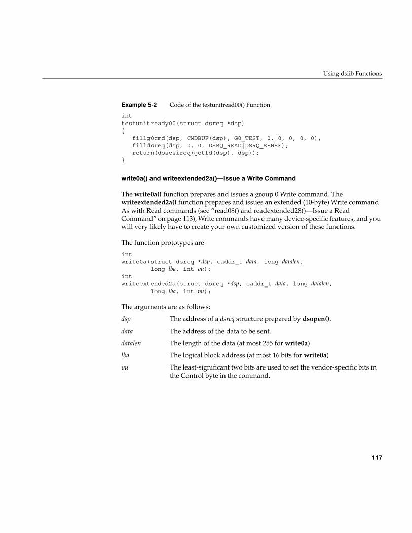
Using dslib Functions
117
Example 5-2 Code of the testunitread00() Function
inttestunitready00(struct dsreq *dsp){
fillg0cmd(dsp, CMDBUF(dsp), G0_TEST, 0, 0, 0, 0, 0);filldsreq(dsp, 0, 0, DSRQ_READ|DSRQ_SENSE);return(doscsireq(getfd(dsp), dsp));
}
write0a() and writeextended2a()—Issue a Write Command
The write0a() function prepares and issues a group 0 Write command. Thewriteextended2a() function prepares and issues an extended (10-byte) Write command.As with Read commands (see “read08() and readextended28()—Issue a ReadCommand” on page 113), Write commands have many device-specific features, and youwill very likely have to create your own customized version of these functions.
The function prototypes are
intwrite0a(struct dsreq *dsp, caddr_t data, long datalen,
long lba, int vu);intwriteextended2a(struct dsreq *dsp, caddr_t data, long datalen,
long lba, int vu);
The arguments are as follows:
dsp The address of a dsreq structure prepared by dsopen().
data The address of the data to be sent.
datalen The length of the data (at most 255 for write0a)
lba The logical block address (at most 16 bits for write0a)
vu The least-significant two bits are used to set the vendor-specific bits inthe Control byte in the command.
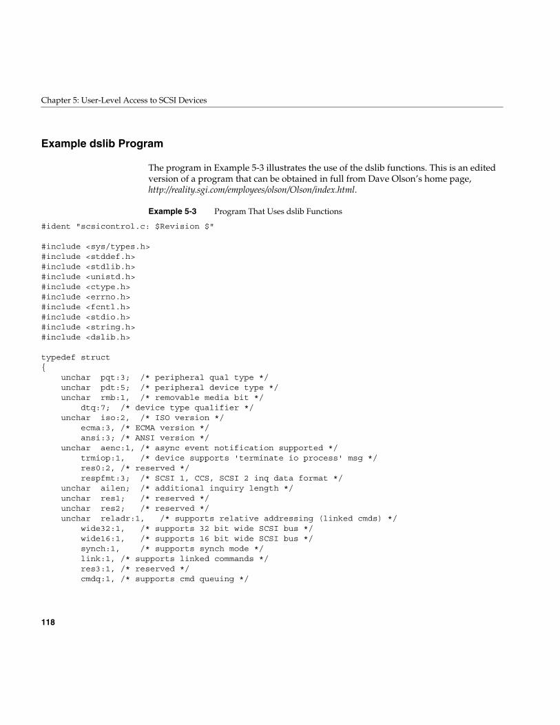
118
Chapter 5: User-Level Access to SCSI Devices
Example dslib Program
The program in Example 5-3 illustrates the use of the dslib functions. This is an editedversion of a program that can be obtained in full from Dave Olson’s home page,http://reality.sgi.com/employees/olson/Olson/index.html.
Example 5-3 Program That Uses dslib Functions
#ident "scsicontrol.c: $Revision $"
#include <sys/types.h>#include <stddef.h>#include <stdlib.h>#include <unistd.h>#include <ctype.h>#include <errno.h>#include <fcntl.h>#include <stdio.h>#include <string.h>#include <dslib.h>
typedef struct{
unchar pqt:3; /* peripheral qual type */unchar pdt:5; /* peripheral device type */unchar rmb:1, /* removable media bit */
dtq:7; /* device type qualifier */unchar iso:2, /* ISO version */
ecma:3, /* ECMA version */ansi:3; /* ANSI version */
unchar aenc:1, /* async event notification supported */trmiop:1, /* device supports 'terminate io process' msg */res0:2, /* reserved */respfmt:3; /* SCSI 1, CCS, SCSI 2 inq data format */
unchar ailen; /* additional inquiry length */unchar res1; /* reserved */unchar res2; /* reserved */unchar reladr:1, /* supports relative addressing (linked cmds) */
wide32:1, /* supports 32 bit wide SCSI bus */wide16:1, /* supports 16 bit wide SCSI bus */synch:1, /* supports synch mode */link:1, /* supports linked commands */res3:1, /* reserved */cmdq:1, /* supports cmd queuing */
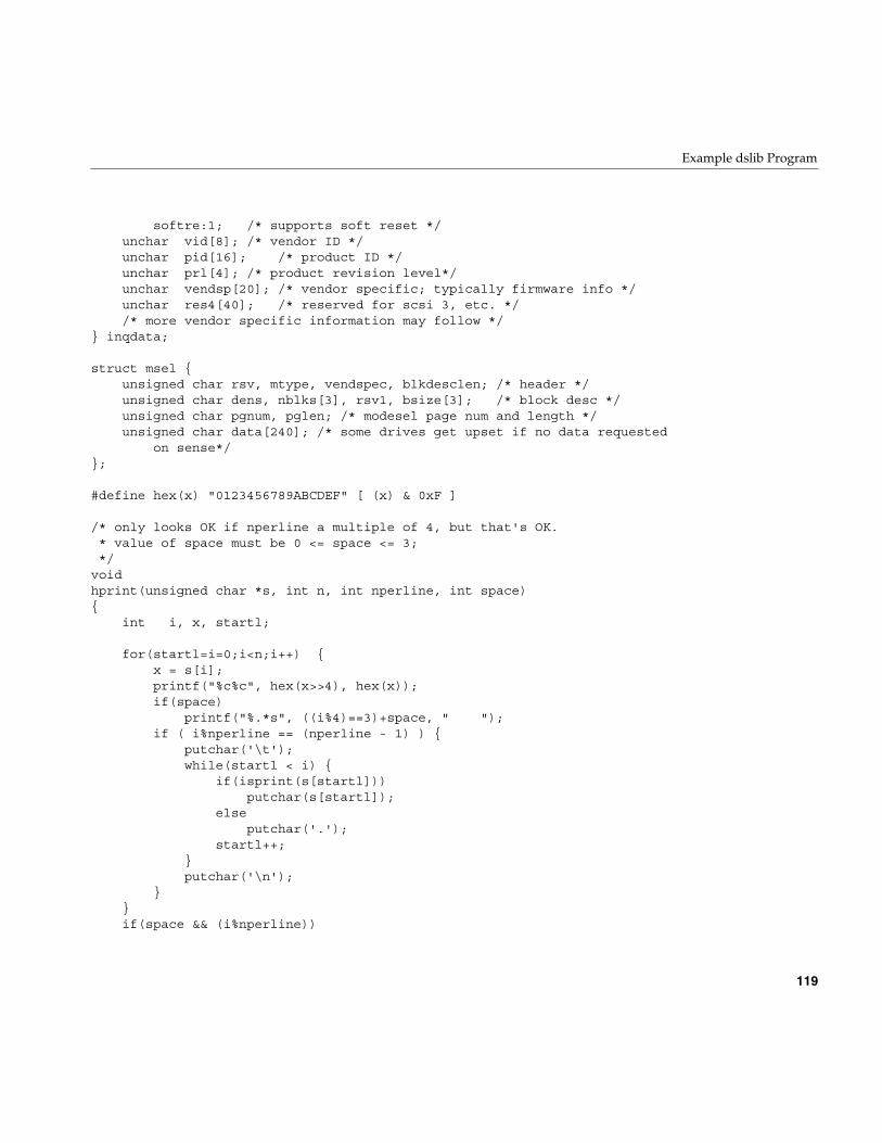
Example dslib Program
119
softre:1; /* supports soft reset */unchar vid[8]; /* vendor ID */unchar pid[16]; /* product ID */unchar prl[4]; /* product revision level*/unchar vendsp[20]; /* vendor specific; typically firmware info */unchar res4[40]; /* reserved for scsi 3, etc. *//* more vendor specific information may follow */
} inqdata;
struct msel {unsigned char rsv, mtype, vendspec, blkdesclen; /* header */unsigned char dens, nblks[3], rsv1, bsize[3]; /* block desc */unsigned char pgnum, pglen; /* modesel page num and length */unsigned char data[240]; /* some drives get upset if no data requested
on sense*/};
#define hex(x) "0123456789ABCDEF" [ (x) & 0xF ]
/* only looks OK if nperline a multiple of 4, but that's OK.* value of space must be 0 <= space <= 3;*/
voidhprint(unsigned char *s, int n, int nperline, int space){
int i, x, startl;
for(startl=i=0;i<n;i++) {x = s[i];printf("%c%c", hex(x>>4), hex(x));if(space)
printf("%.*s", ((i%4)==3)+space, " ");if ( i%nperline == (nperline - 1) ) {
putchar('\t');while(startl < i) {
if(isprint(s[startl]))putchar(s[startl]);
elseputchar('.');
startl++;}putchar('\n');
}}if(space && (i%nperline))
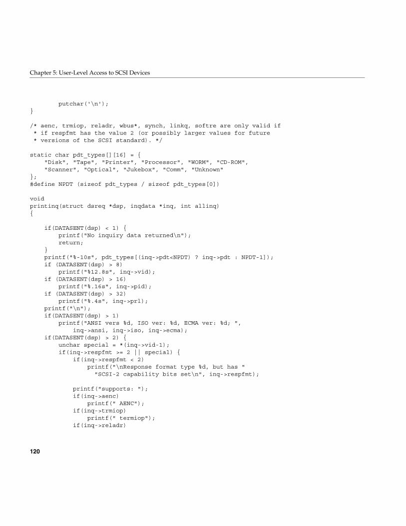
120
Chapter 5: User-Level Access to SCSI Devices
putchar('\n');}
/* aenc, trmiop, reladr, wbus*, synch, linkq, softre are only valid if* if respfmt has the value 2 (or possibly larger values for future* versions of the SCSI standard). */
static char pdt_types[][16] = {"Disk", "Tape", "Printer", "Processor", "WORM", "CD-ROM","Scanner", "Optical", "Jukebox", "Comm", "Unknown"
};#define NPDT (sizeof pdt_types / sizeof pdt_types[0])
voidprintinq(struct dsreq *dsp, inqdata *inq, int allinq){
if(DATASENT(dsp) < 1) {printf("No inquiry data returned\n");return;
}printf("%-10s", pdt_types[(inq->pdt<NPDT) ? inq->pdt : NPDT-1]);if (DATASENT(dsp) > 8)
printf("%12.8s", inq->vid);if (DATASENT(dsp) > 16)
printf("%.16s", inq->pid);if (DATASENT(dsp) > 32)
printf("%.4s", inq->prl);printf("\n");if(DATASENT(dsp) > 1)
printf("ANSI vers %d, ISO ver: %d, ECMA ver: %d; ",inq->ansi, inq->iso, inq->ecma);
if(DATASENT(dsp) > 2) {unchar special = *(inq->vid-1);if(inq->respfmt >= 2 || special) {
if(inq->respfmt < 2)printf("\nResponse format type %d, but has "
"SCSI-2 capability bits set\n", inq->respfmt);
printf("supports: ");if(inq->aenc)
printf(" AENC");if(inq->trmiop)
printf(" termiop");if(inq->reladr)
Example dslib Program
121
printf(" reladdr");if(inq->wide32)
printf(" 32bit");if(inq->wide16)
printf(" 16bit");if(inq->synch)
printf(" synch");if(inq->synch)
printf(" linkedcmds");if(inq->cmdq)
printf(" cmdqueing");if(inq->softre)
printf(" softreset");}if(inq->respfmt < 2) {
if(special)printf(". ");
printf("inquiry format is %s",inq->respfmt ? "SCSI 1" : "CCS");
}}putchar('\n');printf("Device is ");/* do test unit ready only if inquiry successful, since many
devices, such as tapes, return inquiry info, even ifnot ready (i.e., no tape in a tape drive). */
if(testunitready00(dsp) != 0)printf("%s\n",
(RET(dsp)==DSRT_NOSEL) ? "not responding" : "not ready");else
printf("ready");printf("\n");
}
/* inquiry cmd that does vital product data as spec'ed in SCSI2 */intvpinquiry12( struct dsreq *dsp, caddr_t data, long datalen, char vu,
int page){fillg0cmd(dsp, (uchar_t *)CMDBUF(dsp), G0_INQU, 1, page, 0, B1(datalen),
B1(vu<<6));filldsreq(dsp, (uchar_t *)data, datalen, DSRQ_READ|DSRQ_SENSE);return(doscsireq(getfd(dsp), dsp));
}
122
Chapter 5: User-Level Access to SCSI Devices
intstartunit1b(struct dsreq *dsp, int startstop, int vu){fillg0cmd(dsp,(uchar_t *)CMDBUF(dsp),0x1b,0,0,0,(uchar_t)startstop,B1(vu<<6));filldsreq(dsp, NULL, 0, DSRQ_READ|DSRQ_SENSE);dsp->ds_time = 1000 * 90; /* 90 seconds */return(doscsireq(getfd(dsp), dsp));
}
intmyinquiry12(struct dsreq *dsp, uchar_t *data, long datalen, int vu, int neg){fillg0cmd(dsp, (uchar_t *)CMDBUF(dsp), G0_INQU, 0,0,0, B1(datalen), B1(vu<<6));filldsreq(dsp, data, datalen, DSRQ_READ|DSRQ_SENSE|neg);dsp->ds_time = 1000 * 30; /* 90 seconds */return(doscsireq(getfd(dsp), dsp));
}
intdsreset(struct dsreq *dsp){return ioctl(getfd(dsp), DS_RESET, dsp);
}
voidusage(char *prog){
fprintf(stderr,"Usage: %s [-i (inquiry)] [-e (exclusive)] [-s (sync) | -a (async)]\n""\t[-l (long inq)] [-v (vital proddata)] [-r (reset)] [-D (diagselftest)]\n""\t[-H (halt/stop)] [-b blksize]\n""\t[-g (get host flags)] [-d (debug)] [-q (quiet)] scsidevice [...]\n",
prog);exit(1);
}
main(int argc, char **argv){
struct dsreq *dsp;char *fn;/* int because they must be word aligned. */int errs = 0, c;int vital=0, doreset=0, exclusive=0, dosync=0;int dostart = 0, dostop = 0, dosenddiag = 0;
Example dslib Program
123
int doinq = 0, printname = 1;unsigned bsize = 0;extern char *optarg;extern int optind, opterr;
opterr = 0; /* handle errors ourselves. */while ((c = getopt(argc, argv, "b:HDSaserdvlgCiq")) != -1)switch(c) {case 'i':
doinq = 1; /* do inquiry */break;
case 'D':dosenddiag = 1;break;
case 'r':doreset = 1; /* do a scsi bus reset */break;
case 'e':exclusive = O_EXCL;break;
case 'd':dsdebug++; /* enable debug info */break;
case 'q':printname = 0; /* print devicename only if error */break;
case 'v':vital = 1; /* set evpd bit for scsi 2 vital product data */break;
case 'H':dostop = 1; /* send a stop (Halt) command */break;
case 'S':dostart = 1; /* send a startunit/spinup command */break;
case 's':dosync = DSRQ_SYNXFR; /* attempt to negotiate sync scsi */break;
case 'a':dosync = DSRQ_ASYNXFR; /* attempt to negotiate async scsi */break;
default:usage(argv[0]);
}
124
Chapter 5: User-Level Access to SCSI Devices
if(optind >= argc || optind == 1) /* need at 1 arg and one option */usage(argv[0]);
while (optind < argc) { /* loop over each filename */fn = argv[optind++];if(printname) printf("%s: ", fn);if((dsp = dsopen(fn, O_RDONLY|exclusive)) == NULL) {
/* if open fails, try pre-pending /dev/scsi */char buf[256];strcpy(buf, "/dev/scsi/");if((strlen(buf) + strlen(fn)) < sizeof(buf)) {
strcat(buf, fn);dsp = dsopen(buf, O_RDONLY|exclusive);
}if(!dsp) {
if(!printname) printf("%s: ", fn);fflush(stdout);perror("cannot open");errs++;continue;
}}
/* try to order for reasonableness; reset first in case* hung, then inquiry, etc. */
if(doreset) {if(dsreset(dsp) != 0) {
if(!printname) printf("%s: ", fn);printf("reset failed: %s\n", strerror(errno));errs++;
}}
if(doinq) {int inqbuf[sizeof(inqdata)/sizeof(int)];if(myinquiry12(dsp, (uchar_t *)inqbuf, sizeof inqbuf, 0, dosync)) {
if(!printname) printf("%s: ", fn);printf("inquiry failure\n");errs++;
}else
printinq(dsp, (inqdata *)inqbuf, 0);}
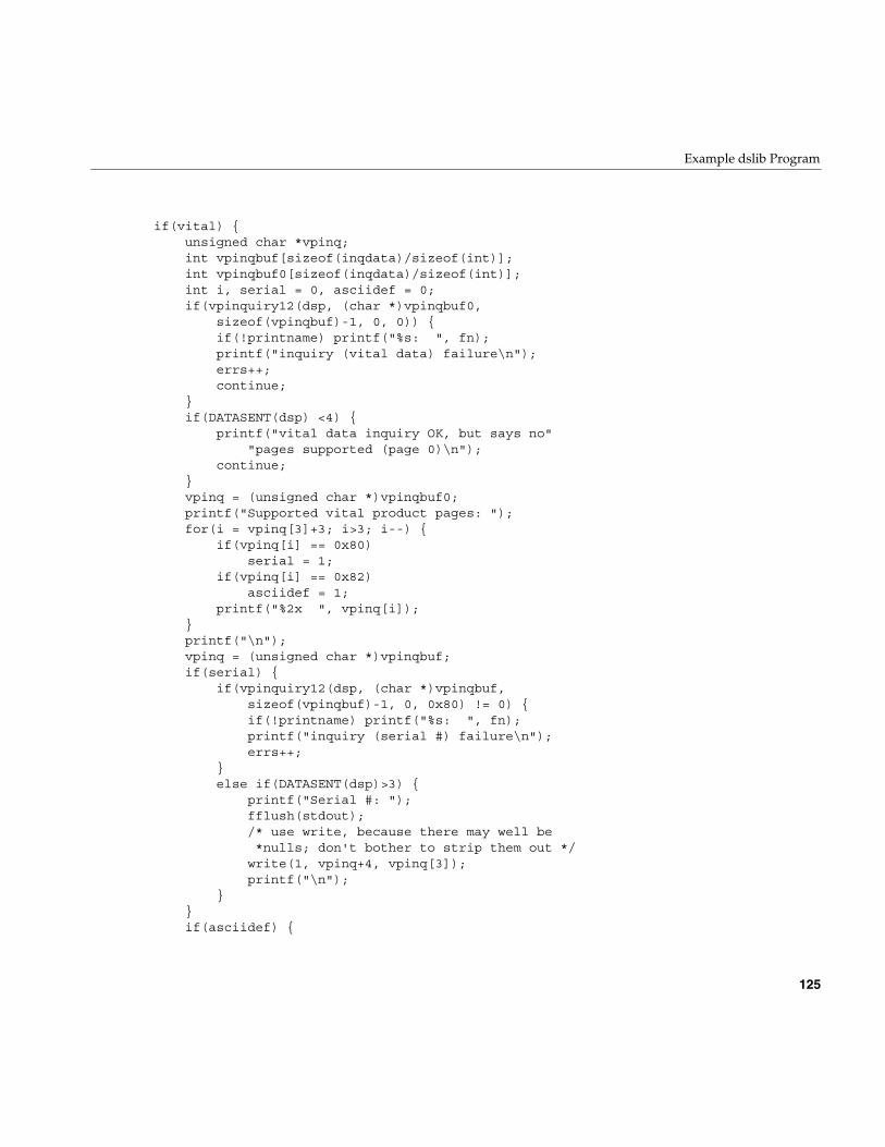
Example dslib Program
125
if(vital) {unsigned char *vpinq;int vpinqbuf[sizeof(inqdata)/sizeof(int)];int vpinqbuf0[sizeof(inqdata)/sizeof(int)];int i, serial = 0, asciidef = 0;if(vpinquiry12(dsp, (char *)vpinqbuf0,
sizeof(vpinqbuf)-1, 0, 0)) {if(!printname) printf("%s: ", fn);printf("inquiry (vital data) failure\n");errs++;continue;
}if(DATASENT(dsp) <4) {
printf("vital data inquiry OK, but says no""pages supported (page 0)\n");
continue;}vpinq = (unsigned char *)vpinqbuf0;printf("Supported vital product pages: ");for(i = vpinq[3]+3; i>3; i--) {
if(vpinq[i] == 0x80)serial = 1;
if(vpinq[i] == 0x82)asciidef = 1;
printf("%2x ", vpinq[i]);}printf("\n");vpinq = (unsigned char *)vpinqbuf;if(serial) {
if(vpinquiry12(dsp, (char *)vpinqbuf,sizeof(vpinqbuf)-1, 0, 0x80) != 0) {if(!printname) printf("%s: ", fn);printf("inquiry (serial #) failure\n");errs++;
}else if(DATASENT(dsp)>3) {
printf("Serial #: ");fflush(stdout);/* use write, because there may well be*nulls; don't bother to strip them out */write(1, vpinq+4, vpinq[3]);printf("\n");
}}if(asciidef) {
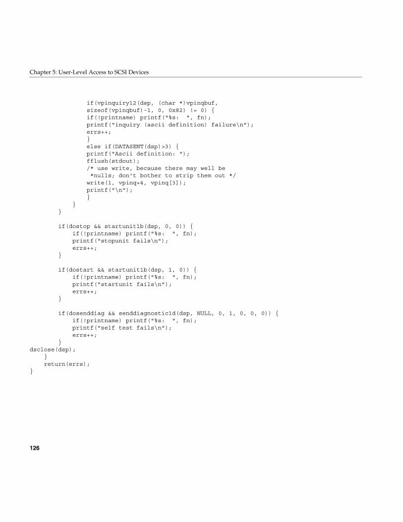
126
Chapter 5: User-Level Access to SCSI Devices
if(vpinquiry12(dsp, (char *)vpinqbuf,sizeof(vpinqbuf)-1, 0, 0x82) != 0) {if(!printname) printf("%s: ", fn);printf("inquiry (ascii definition) failure\n");errs++;}else if(DATASENT(dsp)>3) {printf("Ascii definition: ");fflush(stdout);/* use write, because there may well be*nulls; don't bother to strip them out */write(1, vpinq+4, vpinq[3]);printf("\n");}
}}
if(dostop && startunit1b(dsp, 0, 0)) {if(!printname) printf("%s: ", fn);printf("stopunit fails\n");errs++;
}
if(dostart && startunit1b(dsp, 1, 0)) {if(!printname) printf("%s: ", fn);printf("startunit fails\n");errs++;
}
if(dosenddiag && senddiagnostic1d(dsp, NULL, 0, 1, 0, 0, 0)) {if(!printname) printf("%s: ", fn);printf("self test fails\n");errs++;
}dsclose(dsp);
}return(errs);
}
127
Chapter 6
6. Control of External Interrupts
Some Silicon Graphics computer systems can generate and receive external interruptsignals. These are simple, two-state signal lines that cause an interrupt in the receivingsystem.
The external interrupt hardware is managed by a kernel-level device driver that isdistributed with IRIX and automatically configured when the system supports externalinterrupts. The driver provides two abilities to user-level processes:
• The ability to change the state of an outgoing interrupt line, so as to interrupt thesystem to which the line is connected.
• The ability to capture an incoming interrupt signal with low latency.
External interrupt support is closely tied to the hardware of the system. The featuresdescribed in this chapter are hardware-dependent and in many cases cannot be portedfrom one system type to another without making software changes. System architecturesare covered in separate sections:
• “External Interrupts in Challenge and Onyx Systems” on page 128 describesexternal interrupt support in that architectural family.
• “External Interrupts In Origin2000 and Origin200” on page 133 describes externalinterrupt support in systems that use the IOC3 board.
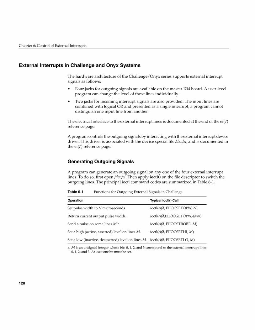
128
Chapter 6: Control of External Interrupts
External Interrupts in Challenge and Onyx Systems
The hardware architecture of the Challenge/Onyx series supports external interruptsignals as follows:
• Four jacks for outgoing signals are available on the master IO4 board. A user-levelprogram can change the level of these lines individually.
• Two jacks for incoming interrupt signals are also provided. The input lines arecombined with logical OR and presented as a single interrupt; a program cannotdistinguish one input line from another.
The electrical interface to the external interrupt lines is documented at the end of the ei(7)reference page.
A program controls the outgoing signals by interacting with the external interrupt devicedriver. This driver is associated with the device special file /dev/ei, and is documented inthe ei(7) reference page.
Generating Outgoing Signals
A program can generate an outgoing signal on any one of the four external interruptlines. To do so, first open /dev/ei. Then apply ioctl() on the file descriptor to switch theoutgoing lines. The principal ioctl command codes are summarized in Table 6-1.
a. M is an unsigned integer whose bits 0, 1, 2, and 3 correspond to the external interrupt lines0, 1, 2, and 3. At least one bit must be set.
Table 6-1 Functions for Outgoing External Signals in Challenge
Operation Typical ioctl() Call
Set pulse width to N microseconds. ioctl(eifd, EIIOCSETOPW, N)
Return current output pulse width. ioctl(eifd,EIIOCGETOPW,&var)
Send a pulse on some lines M.a ioctl(eifd, EIIOCSTROBE, M)
Set a high (active, asserted) level on lines M. ioctl(eifd, EIIOCSETHI, M)
Set a low (inactive, deasserted) level on lines M. ioctl(eifd, EIIOCSETLO, M)
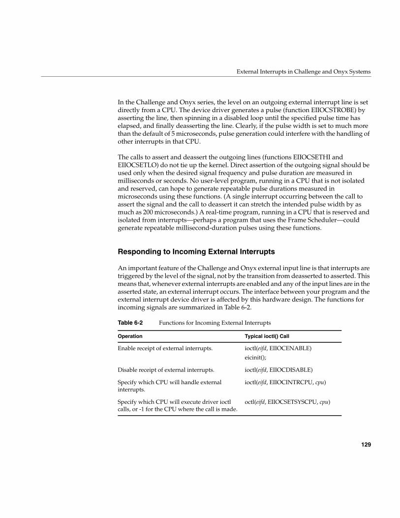
External Interrupts in Challenge and Onyx Systems
129
In the Challenge and Onyx series, the level on an outgoing external interrupt line is setdirectly from a CPU. The device driver generates a pulse (function EIIOCSTROBE) byasserting the line, then spinning in a disabled loop until the specified pulse time haselapsed, and finally deasserting the line. Clearly, if the pulse width is set to much morethan the default of 5 microseconds, pulse generation could interfere with the handling ofother interrupts in that CPU.
The calls to assert and deassert the outgoing lines (functions EIIOCSETHI andEIIOCSETLO) do not tie up the kernel. Direct assertion of the outgoing signal should beused only when the desired signal frequency and pulse duration are measured inmilliseconds or seconds. No user-level program, running in a CPU that is not isolatedand reserved, can hope to generate repeatable pulse durations measured inmicroseconds using these functions. (A single interrupt occurring between the call toassert the signal and the call to deassert it can stretch the intended pulse width by asmuch as 200 microseconds.) A real-time program, running in a CPU that is reserved andisolated from interrupts—perhaps a program that uses the Frame Scheduler—couldgenerate repeatable millisecond-duration pulses using these functions.
Responding to Incoming External Interrupts
An important feature of the Challenge and Onyx external input line is that interrupts aretriggered by the level of the signal, not by the transition from deasserted to asserted. Thismeans that, whenever external interrupts are enabled and any of the input lines are in theasserted state, an external interrupt occurs. The interface between your program and theexternal interrupt device driver is affected by this hardware design. The functions forincoming signals are summarized in Table 6-2.
Table 6-2 Functions for Incoming External Interrupts
Operation Typical ioctl() Call
Enable receipt of external interrupts. ioctl(eifd, EIIOCENABLE)
eicinit();
Disable receipt of external interrupts. ioctl(eifd, EIIOCDISABLE)
Specify which CPU will handle externalinterrupts.
ioctl(eifd, EIIOCINTRCPU, cpu)
Specify which CPU will execute driver ioctlcalls, or -1 for the CPU where the call is made.
octl(eifd, EIIOCSETSYSCPU, cpu)
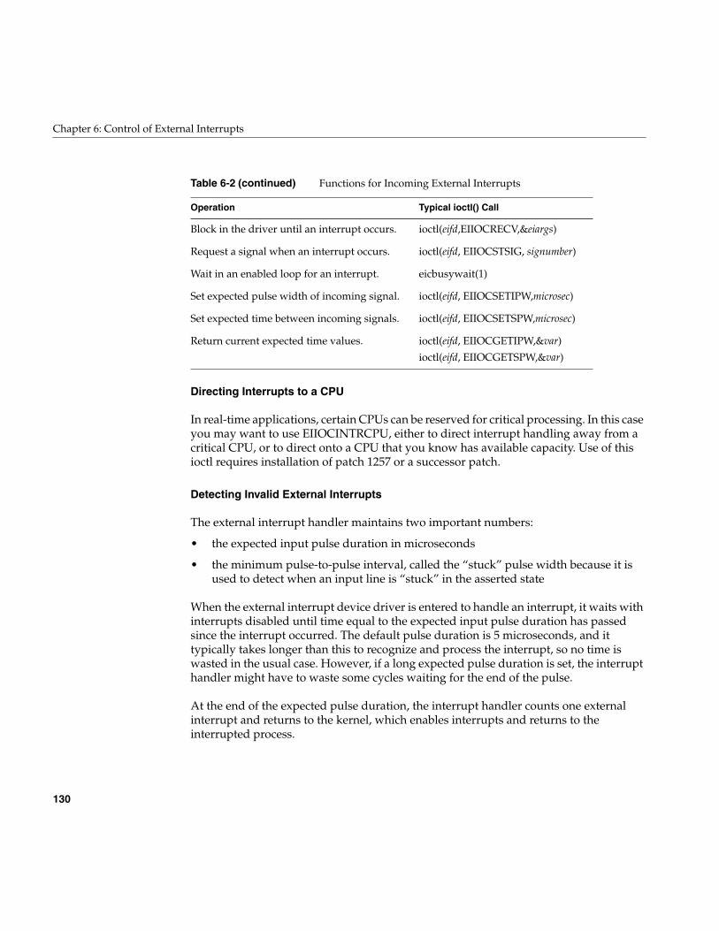
130
Chapter 6: Control of External Interrupts
Directing Interrupts to a CPU
In real-time applications, certain CPUs can be reserved for critical processing. In this caseyou may want to use EIIOCINTRCPU, either to direct interrupt handling away from acritical CPU, or to direct onto a CPU that you know has available capacity. Use of thisioctl requires installation of patch 1257 or a successor patch.
Detecting Invalid External Interrupts
The external interrupt handler maintains two important numbers:
• the expected input pulse duration in microseconds
• the minimum pulse-to-pulse interval, called the “stuck” pulse width because it isused to detect when an input line is “stuck” in the asserted state
When the external interrupt device driver is entered to handle an interrupt, it waits withinterrupts disabled until time equal to the expected input pulse duration has passedsince the interrupt occurred. The default pulse duration is 5 microseconds, and ittypically takes longer than this to recognize and process the interrupt, so no time iswasted in the usual case. However, if a long expected pulse duration is set, the interrupthandler might have to waste some cycles waiting for the end of the pulse.
At the end of the expected pulse duration, the interrupt handler counts one externalinterrupt and returns to the kernel, which enables interrupts and returns to theinterrupted process.
Block in the driver until an interrupt occurs. ioctl(eifd,EIIOCRECV,&eiargs)
Request a signal when an interrupt occurs. ioctl(eifd, EIIOCSTSIG, signumber)
Wait in an enabled loop for an interrupt. eicbusywait(1)
Set expected pulse width of incoming signal. ioctl(eifd, EIIOCSETIPW,microsec)
Set expected time between incoming signals. ioctl(eifd, EIIOCSETSPW,microsec)
Return current expected time values. ioctl(eifd, EIIOCGETIPW,&var)
ioctl(eifd, EIIOCGETSPW,&var)
Table 6-2 (continued) Functions for Incoming External Interrupts
Operation Typical ioctl() Call
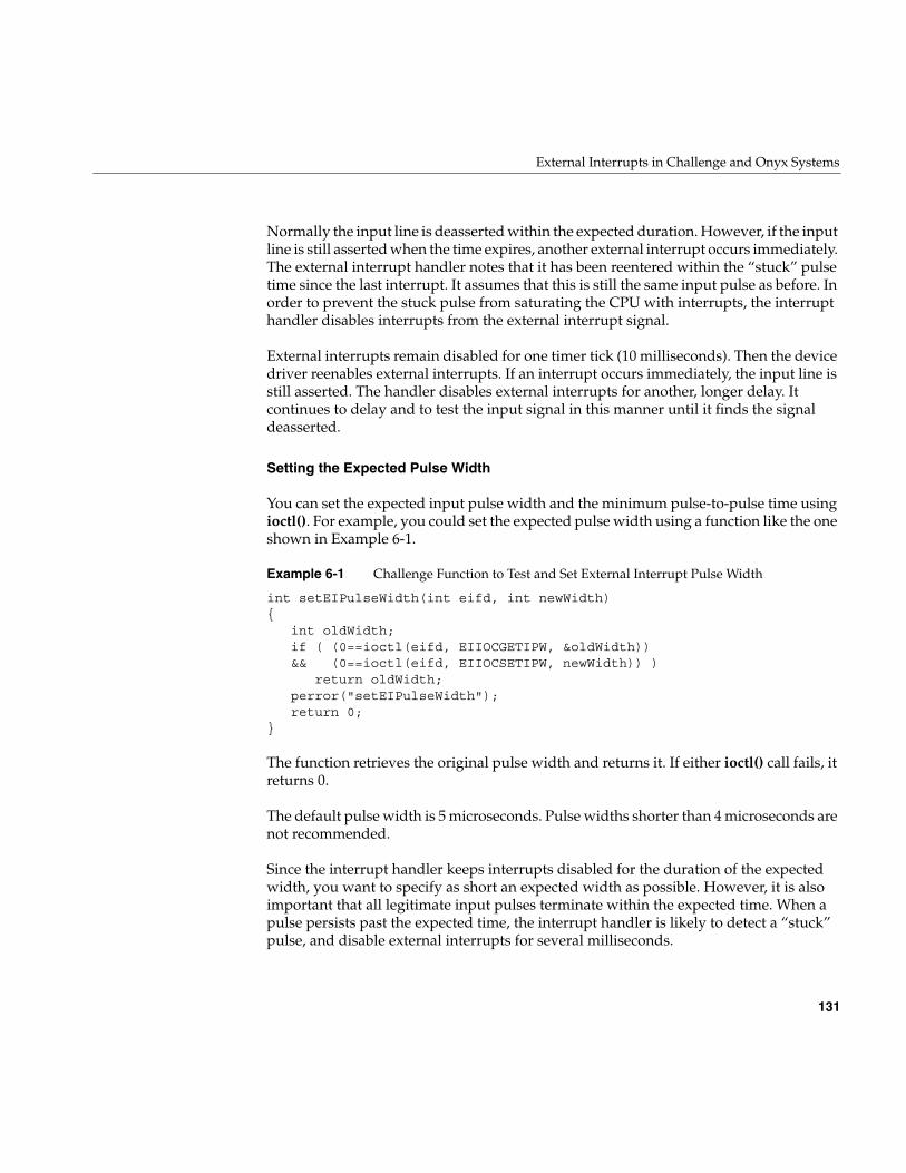
External Interrupts in Challenge and Onyx Systems
131
Normally the input line is deasserted within the expected duration. However, if the inputline is still asserted when the time expires, another external interrupt occurs immediately.The external interrupt handler notes that it has been reentered within the “stuck” pulsetime since the last interrupt. It assumes that this is still the same input pulse as before. Inorder to prevent the stuck pulse from saturating the CPU with interrupts, the interrupthandler disables interrupts from the external interrupt signal.
External interrupts remain disabled for one timer tick (10 milliseconds). Then the devicedriver reenables external interrupts. If an interrupt occurs immediately, the input line isstill asserted. The handler disables external interrupts for another, longer delay. Itcontinues to delay and to test the input signal in this manner until it finds the signaldeasserted.
Setting the Expected Pulse Width
You can set the expected input pulse width and the minimum pulse-to-pulse time usingioctl(). For example, you could set the expected pulse width using a function like the oneshown in Example 6-1.
Example 6-1 Challenge Function to Test and Set External Interrupt Pulse Width
int setEIPulseWidth(int eifd, int newWidth){
int oldWidth;if ( (0==ioctl(eifd, EIIOCGETIPW, &oldWidth))&& (0==ioctl(eifd, EIIOCSETIPW, newWidth)) )
return oldWidth;perror("setEIPulseWidth");return 0;
}
The function retrieves the original pulse width and returns it. If either ioctl() call fails, itreturns 0.
The default pulse width is 5 microseconds. Pulse widths shorter than 4 microseconds arenot recommended.
Since the interrupt handler keeps interrupts disabled for the duration of the expectedwidth, you want to specify as short an expected width as possible. However, it is alsoimportant that all legitimate input pulses terminate within the expected time. When apulse persists past the expected time, the interrupt handler is likely to detect a “stuck”pulse, and disable external interrupts for several milliseconds.
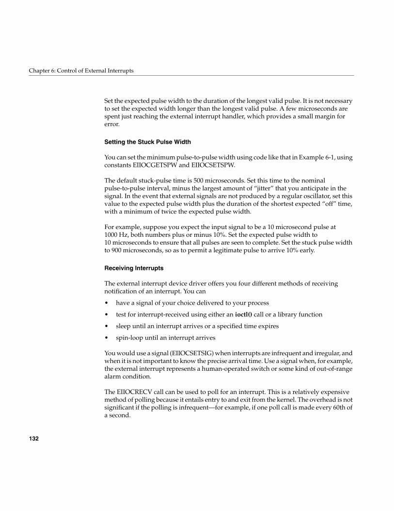
132
Chapter 6: Control of External Interrupts
Set the expected pulse width to the duration of the longest valid pulse. It is not necessaryto set the expected width longer than the longest valid pulse. A few microseconds arespent just reaching the external interrupt handler, which provides a small margin forerror.
Setting the Stuck Pulse Width
You can set the minimum pulse-to-pulse width using code like that in Example 6-1, usingconstants EIIOCGETSPW and EIIOCSETSPW.
The default stuck-pulse time is 500 microseconds. Set this time to the nominalpulse-to-pulse interval, minus the largest amount of “jitter” that you anticipate in thesignal. In the event that external signals are not produced by a regular oscillator, set thisvalue to the expected pulse width plus the duration of the shortest expected “off” time,with a minimum of twice the expected pulse width.
For example, suppose you expect the input signal to be a 10 microsecond pulse at1000 Hz, both numbers plus or minus 10%. Set the expected pulse width to10 microseconds to ensure that all pulses are seen to complete. Set the stuck pulse widthto 900 microseconds, so as to permit a legitimate pulse to arrive 10% early.
Receiving Interrupts
The external interrupt device driver offers you four different methods of receivingnotification of an interrupt. You can
• have a signal of your choice delivered to your process
• test for interrupt-received using either an ioctl() call or a library function
• sleep until an interrupt arrives or a specified time expires
• spin-loop until an interrupt arrives
You would use a signal (EIIOCSETSIG) when interrupts are infrequent and irregular, andwhen it is not important to know the precise arrival time. Use a signal when, for example,the external interrupt represents a human-operated switch or some kind of out-of-rangealarm condition.
The EIIOCRECV call can be used to poll for an interrupt. This is a relatively expensivemethod of polling because it entails entry to and exit from the kernel. The overhead is notsignificant if the polling is infrequent—for example, if one poll call is made every 60th ofa second.
External Interrupts In Origin2000 and Origin200
133
The EIIOCRECV call can be used to suspend the caller until an interrupt arrives or atimeout expires (see the ei(7) reference page for details). Use this method when interruptsarrive frequently enough that it is worthwhile devoting a process to handling them. Anunknown amount of time can pass between the moment when the interrupt handlerunblocks the process and the moment when the kernel dispatches the process. Thismakes it impossible to timestamp the interrupt at the microsecond level.
In order to poll for, or detect, an incoming interrupt with minimum overhead, use thelibrary function eicbusywait() (see the ei(7) reference page). You use the eicinit()function to open /dev/ei and prepare to use eicbusywait().
The eicbusywait() function does not switch into kernel mode, so it can perform alow-overhead poll for a received interrupt. If you ask it to wait until an interrupt occurs,it waits by spinning on a repeated test for an interrupt. This monopolizes the CPU, so thisform of waiting is normally used by a process running in an isolated CPU. The benefit isthat control returns to the calling process in negligible time after the interrupt handlerdetects the interrupt, so the interrupt can be handled quickly and timed precisely.
External Interrupts In Origin2000 and Origin200
The miscellaneous I/O attachment logic in the Origin2000 and Origin200™ architectureis provided by the IOC3 ASIC. Among many other I/O functions, this chip dedicates oneinput line and one output line for external interrupts.
There is one IOC3 chip on the motherboard in a Origin200 deskside unit. There is oneIOC3 chip on the IO6 board which provides the base I/O functions in each Origin2000module; hence in a Origin2000 system there can be as many unique external interruptsignal pairs as there are physical modules.
The electrical interface to the external interrupt line is documented at the end of the ei(7)reference page.
A program controls the outgoing signals by interacting with the external interrupt devicedriver. This driver is associated with device special files /hw/external_interrupt/n, where nis an integer. The name /hw/external_interrupt/1 designates the only external interruptdevice in a Origin200, or the external interrupt device on the system console module ofa Origin2000 system.
There is also a symbolic link /dev/ei that refers to /hw/external_interrupt/1.
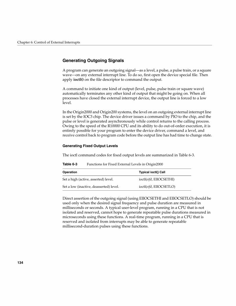
134
Chapter 6: Control of External Interrupts
Generating Outgoing Signals
A program can generate an outgoing signal—as a level, a pulse, a pulse train, or a squarewave—on any external interrupt line. To do so, first open the device special file. Thenapply ioctl() on the file descriptor to command the output.
A command to initiate one kind of output (level, pulse, pulse train or square wave)automatically terminates any other kind of output that might be going on. When allprocesses have closed the external interrupt device, the output line is forced to a lowlevel.
In the Origin2000 and Origin200 systems, the level on an outgoing external interrupt lineis set by the IOC3 chip. The device driver issues a command by PIO to the chip, and thepulse or level is generated asynchronously while control returns to the calling process.Owing to the speed of the R10000 CPU and its ability to do out-of-order execution, it isentirely possible for your program to enter the device driver, command a level, andreceive control back to program code before the output line has had time to change state.
Generating Fixed Output Levels
The ioctl command codes for fixed output levels are summarized in Table 6-3.
Direct assertion of the outgoing signal (using EIIOCSETHI and EIIOCSETLO) should beused only when the desired signal frequency and pulse duration are measured inmilliseconds or seconds. A typical user-level program, running in a CPU that is notisolated and reserved, cannot hope to generate repeatable pulse durations measured inmicroseconds using these functions. A real-time program, running in a CPU that isreserved and isolated from interrupts may be able to generate repeatablemillisecond-duration pulses using these functions.
Table 6-3 Functions for Fixed External Levels in Origin2000
Operation Typical ioctl() Call
Set a high (active, asserted) level. ioctl(eifd, EIIOCSETHI)
Set a low (inactive, deasserted) level. ioctl(eifd, EIIOCSETLO)
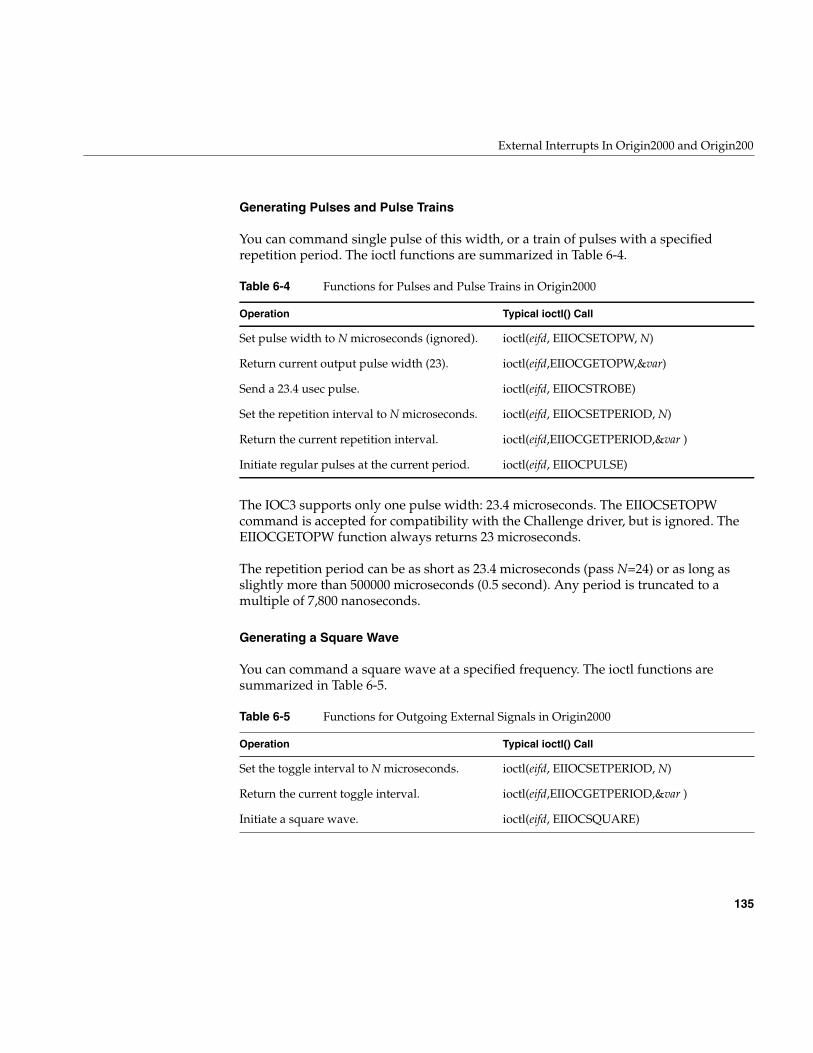
External Interrupts In Origin2000 and Origin200
135
Generating Pulses and Pulse Trains
You can command single pulse of this width, or a train of pulses with a specifiedrepetition period. The ioctl functions are summarized in Table 6-4.
The IOC3 supports only one pulse width: 23.4 microseconds. The EIIOCSETOPWcommand is accepted for compatibility with the Challenge driver, but is ignored. TheEIIOCGETOPW function always returns 23 microseconds.
The repetition period can be as short as 23.4 microseconds (pass N=24) or as long asslightly more than 500000 microseconds (0.5 second). Any period is truncated to amultiple of 7,800 nanoseconds.
Generating a Square Wave
You can command a square wave at a specified frequency. The ioctl functions aresummarized in Table 6-5.
Table 6-4 Functions for Pulses and Pulse Trains in Origin2000
Operation Typical ioctl() Call
Set pulse width to N microseconds (ignored). ioctl(eifd, EIIOCSETOPW, N)
Return current output pulse width (23). ioctl(eifd,EIIOCGETOPW,&var)
Send a 23.4 usec pulse. ioctl(eifd, EIIOCSTROBE)
Set the repetition interval to N microseconds. ioctl(eifd, EIIOCSETPERIOD, N)
Return the current repetition interval. ioctl(eifd,EIIOCGETPERIOD,&var )
Initiate regular pulses at the current period. ioctl(eifd, EIIOCPULSE)
Table 6-5 Functions for Outgoing External Signals in Origin2000
Operation Typical ioctl() Call
Set the toggle interval to N microseconds. ioctl(eifd, EIIOCSETPERIOD, N)
Return the current toggle interval. ioctl(eifd,EIIOCGETPERIOD,&var )
Initiate a square wave. ioctl(eifd, EIIOCSQUARE)
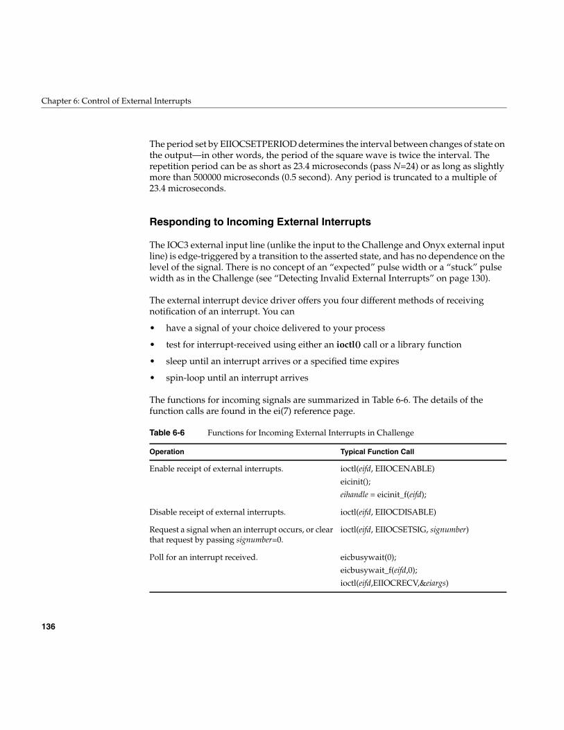
136
Chapter 6: Control of External Interrupts
The period set by EIIOCSETPERIOD determines the interval between changes of state onthe output—in other words, the period of the square wave is twice the interval. Therepetition period can be as short as 23.4 microseconds (pass N=24) or as long as slightlymore than 500000 microseconds (0.5 second). Any period is truncated to a multiple of23.4 microseconds.
Responding to Incoming External Interrupts
The IOC3 external input line (unlike the input to the Challenge and Onyx external inputline) is edge-triggered by a transition to the asserted state, and has no dependence on thelevel of the signal. There is no concept of an “expected” pulse width or a “stuck” pulsewidth as in the Challenge (see “Detecting Invalid External Interrupts” on page 130).
The external interrupt device driver offers you four different methods of receivingnotification of an interrupt. You can
• have a signal of your choice delivered to your process
• test for interrupt-received using either an ioctl() call or a library function
• sleep until an interrupt arrives or a specified time expires
• spin-loop until an interrupt arrives
The functions for incoming signals are summarized in Table 6-6. The details of thefunction calls are found in the ei(7) reference page.
Table 6-6 Functions for Incoming External Interrupts in Challenge
Operation Typical Function Call
Enable receipt of external interrupts. ioctl(eifd, EIIOCENABLE)
eicinit();
eihandle = eicinit_f(eifd);
Disable receipt of external interrupts. ioctl(eifd, EIIOCDISABLE)
Request a signal when an interrupt occurs, or clearthat request by passing signumber=0.
ioctl(eifd, EIIOCSETSIG, signumber)
Poll for an interrupt received. eicbusywait(0);
eicbusywait_f(eifd,0);
ioctl(eifd,EIIOCRECV,&eiargs)
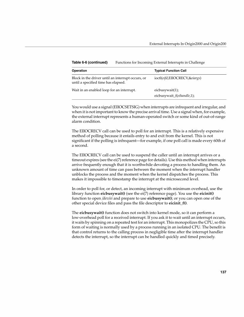
External Interrupts In Origin2000 and Origin200
137
You would use a signal (EIIOCSETSIG) when interrupts are infrequent and irregular, andwhen it is not important to know the precise arrival time. Use a signal when, for example,the external interrupt represents a human-operated switch or some kind of out-of-rangealarm condition.
The EIIOCRECV call can be used to poll for an interrupt. This is a relatively expensivemethod of polling because it entails entry to and exit from the kernel. This is notsignificant if the polling is infrequent—for example, if one poll call is made every 60th ofa second.
The EIIOCRECV call can be used to suspend the caller until an interrupt arrives or atimeout expires (see the ei(7) reference page for details). Use this method when interruptsarrive frequently enough that it is worthwhile devoting a process to handling them. Anunknown amount of time can pass between the moment when the interrupt handlerunblocks the process and the moment when the kernel dispatches the process. Thismakes it impossible to timestamp the interrupt at the microsecond level.
In order to poll for, or detect, an incoming interrupt with minimum overhead, use thelibrary function eicbusywait() (see the ei(7) reference page). You use the eicinit()function to open /dev/ei and prepare to use eicbusywait(); or you can open one of theother special device files and pass the file descriptor to eicinit_f().
The eicbusywait() function does not switch into kernel mode, so it can perform alow-overhead poll for a received interrupt. If you ask it to wait until an interrupt occurs,it waits by spinning on a repeated test for an interrupt. This monopolizes the CPU, so thisform of waiting is normally used by a process running in an isolated CPU. The benefit isthat control returns to the calling process in negligible time after the interrupt handlerdetects the interrupt, so the interrupt can be handled quickly and timed precisely.
Block in the driver until an interrupt occurs, oruntil a specified time has elapsed.
ioctl(eifd,EIIOCRECV,&eiargs)
Wait in an enabled loop for an interrupt. eicbusywait(1);
eicbusywait_f(eihandle,1);
Table 6-6 (continued) Functions for Incoming External Interrupts in Challenge
Operation Typical Function Call

PART THREE
Kernel-Level Drivers III
Chapter 7, “Structure of a Kernel-Level Driver”The software structure of a block or character device driver: the entry points itprovides for kernel use, and how it communicates with user-level processes
Chapter 8, “Device Driver/Kernel Interface”A topical survey of the facilities the IRIX kernel provides to device drivers.
Chapter 9, “Building and Installing a Driver”How a kernel-level driver is compiled, loaded, and linked with the IRIX kernel.
Chapter 10, “Testing and Debugging a Driver”How a kernel-level driver is tested and debugged using symmon and otherfacilities.
Chapter 11, “Driver Example”Annotated code of a simple device driver with no hardware dependencies.

141
Chapter 7
7.Structure of a Kernel-Level Driver
A kernel-level device driver consists of a module of subroutines that supply services tothe kernel. The subroutines are public entry points in the driver. When an event occurs,the kernel calls one of these entry points. The driver takes action and returns a resultcode.
This chapter discusses when the driver entry points are called, what parameters theyreceive, and what actions they are expected to take. For a conceptual overview of thekernel and drivers, see “Kernel-Level Device Control” on page 62. For details on how adriver is compiled, linked, and added to IRIX, see Chapter 9, “Building and Installing aDriver.”
Note: This chapter concentrates on device drivers. Entry points unique to STREAMSdrivers are covered in Chapter 22, “STREAMS Drivers.”

142
Chapter 7: Structure of a Kernel-Level Driver
The primary topics covered in this chapter are:
• “Summary of Driver Structure” on page 143 summarizes the entry points and howthey are made known to the kernel.
• “Driver Flag Constant” on page 148 describes the public constant that documentsthe driver type for lboot and mload.
• “Initialization Entry Points” on page 150 discusses the entry points at which adriver initializes its own data and its devices.
• “Attach and Detach Entry Points” on page 153 discusses the entry points thathandle dynamic attachment of PCI devices.
• “Open and Close Entry Points” on page 157 discusses the entry points called by theopen() and close() kernel functions.
• “Control Entry Point” on page 161 documents the entry point called by the ioctl()kernel function.
• “Data Transfer Entry Points” on page 163 documents the entry points called by theread() and write() kernel functions.
• “Poll Entry Point” on page 166 documents the entry point called by the poll() kernelfunction.
• “Memory Map Entry Points” on page 169 tells how a driver supports memorymapping of devices and buffers.
• “Interrupt Entry Point and Handler” on page 175 discusses the design andoperation of interrupt handlers.
• “Support Entry Points” on page 180 describes several entry points that supportkernel operations.
• “Handling 32-Bit and 64-Bit Execution Models” on page 182 covers the techniquesof supporting user processes that have different execution models.
• “Designing for Multiprocessor Use” on page 184 covers the techniques of making adriver work in a multiprocessor, multithreading environment.
Summary of Driver Structure
143
Summary of Driver Structure
A driver consists of a binary object module in ELF format stored in the /var/sysgen/bootdirectory. As a program, the driver consists of a set of functional entry points that supplyservices to the IRIX kernel. There is a large set of entry points to cover different situations.Some entry points are historical relics, while others were first defined in IRIX 6.4. Nosingle driver supports all possible entry points.
The entry points that a driver supports must be named according to a specifiedconvention. The lboot command uses entry point names to build tables used by thekernel.
Entry Point Naming and lboot
The device driver makes known which entry points it supports by giving them publicnames in its object module. The lboot command links together the object modules ofdrivers and other kernel modules to make a bootable kernel. lboot recognizes the entrypoints by the form of their names. (See the lboot(1M) and autoconfig(1M) referencepages.)
Driver Name Prefix
A device driver must be described by a file in the /var/sysgen/master.d directory (see“Master Configuration Database” on page 55). In that configuration file you specify thedriver prefix, a string of 1 to 14 characters that is unique to that driver. For example, theprefix of the SCSI driver is scsi_.
The prefix string is defined in the /var/sysgen/master.d file only. The string does not haveto appear as a constant in the driver, and the name of the driver object file does not haveto correspond to the prefix (although the object module typically has a related name).
The lboot command recognizes driver entry points by searching the driver object modulefor public names that begin with the prefix string. For example, the entry point for theopen() operation must have a name that consists of the prefix string followed by theletters “open.”
In this book, entry point names are written as follows: pfxopen(), where pfx stands for thedriver’s prefix string.
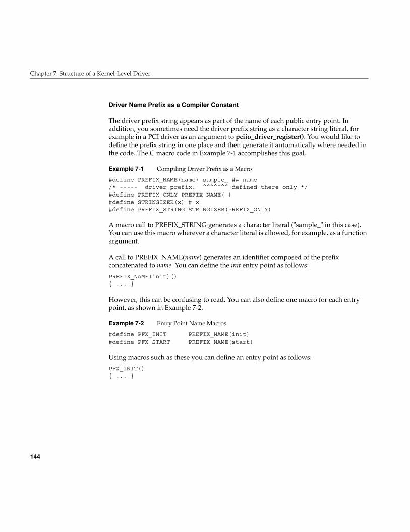
144
Chapter 7: Structure of a Kernel-Level Driver
Driver Name Prefix as a Compiler Constant
The driver prefix string appears as part of the name of each public entry point. Inaddition, you sometimes need the driver prefix string as a character string literal, forexample in a PCI driver as an argument to pciio_driver_register(). You would like todefine the prefix string in one place and then generate it automatically where needed inthe code. The C macro code in Example 7-1 accomplishes this goal.
Example 7-1 Compiling Driver Prefix as a Macro
#define PREFIX_NAME(name) sample_ ## name/* ----- driver prefix: ^^^^^^^ defined there only */#define PREFIX_ONLY PREFIX_NAME( )#define STRINGIZER(x) # x#define PREFIX_STRING STRINGIZER(PREFIX_ONLY)
A macro call to PREFIX_STRING generates a character literal ("sample_" in this case).You can use this macro wherever a character literal is allowed, for example, as a functionargument.
A call to PREFIX_NAME(name) generates an identifier composed of the prefixconcatenated to name. You can define the init entry point as follows:
PREFIX_NAME(init)(){ ... }
However, this can be confusing to read. You can also define one macro for each entrypoint, as shown in Example 7-2.
Example 7-2 Entry Point Name Macros
#define PFX_INIT PREFIX_NAME(init)#define PFX_START PREFIX_NAME(start)
Using macros such as these you can define an entry point as follows:
PFX_INIT(){ ... }
Summary of Driver Structure
145
Kernel Switch Tables
The IRIX kernel maintains tables that allow it to dispatch calls to device drivers quickly.These tables are built by lboot based on the names of the driver entry points. The tablesare named as follows:
Conceptually, the tables for block and character drivers have one row for each driver, andone column for each possible driver entry point. (Historically, the major device numberwas the driver’s row number in the switch table. This simple data structure is no longerused.)
As lboot loads a driver, it fills in that driver’s row of a switch table with the addresses ofthe driver’s entry points. Where an entry point is not defined in the driver object file, lbootleaves the address of a null routine that returns the ENODEV error code. Thus no driverneeds to define all entry points—only the ones it can support in a useful way.
The sizes of the switch tables are fixed at boot time in order to minimize kernel dataspace. The table sizes are tunable parameters that can be set with systune (see thesystune(1) reference page).
When a driver is loaded dynamically (see “Configuring a Loadable Driver” on page 264),the associated row of the switch table is not filled at link time but rather is filled when thedriver is loaded. When you add new, loadable drivers, you might need to specify a largerswitch table. The book IRIX Admin: System Configuration and Operation documents thesetunable parameters.
Entry Point Summary
The names of all possible driver entry points and their purposes are summarized inTable 7-1. The entry point names are in alphabetic order, not logical order. Device driverentry points are discussed in this chapter. Entry points to STREAMS drivers arediscussed in Chapter 22, “STREAMS Drivers.”.
bdevsw Table of block device drivers
cdevsw Table of character device drivers
fmodsw Table of STREAMS drivers
vfssw Table of filesystem modules (not related to device drivers)
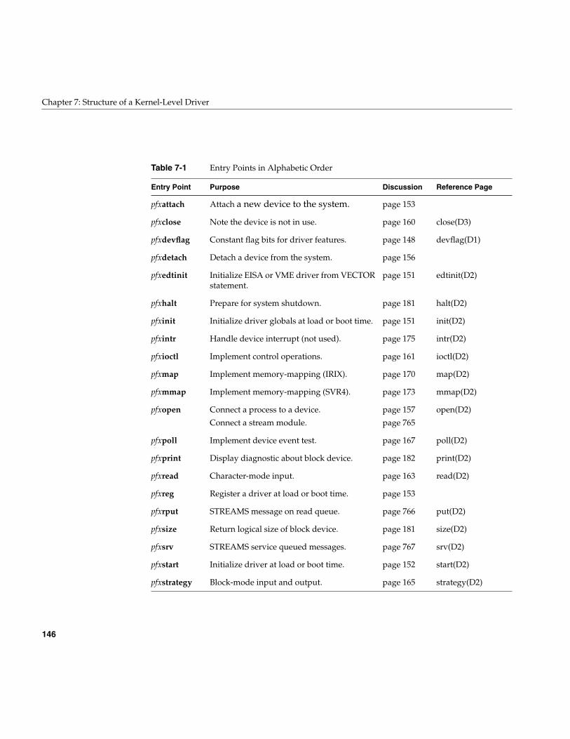
146
Chapter 7: Structure of a Kernel-Level Driver
Table 7-1 Entry Points in Alphabetic Order
Entry Point Purpose Discussion Reference Page
pfxattach Attach a new device to the system. page 153
pfxclose Note the device is not in use. page 160 close(D3)
pfxdevflag Constant flag bits for driver features. page 148 devflag(D1)
pfxdetach Detach a device from the system. page 156
pfxedtinit Initialize EISA or VME driver from VECTORstatement.
page 151 edtinit(D2)
pfxhalt Prepare for system shutdown. page 181 halt(D2)
pfxinit Initialize driver globals at load or boot time. page 151 init(D2)
pfxintr Handle device interrupt (not used). page 175 intr(D2)
pfxioctl Implement control operations. page 161 ioctl(D2)
pfxmap Implement memory-mapping (IRIX). page 170 map(D2)
pfxmmap Implement memory-mapping (SVR4). page 173 mmap(D2)
pfxopen Connect a process to a device.
Connect a stream module.
page 157
page 765
open(D2)
pfxpoll Implement device event test. page 167 poll(D2)
pfxprint Display diagnostic about block device. page 182 print(D2)
pfxread Character-mode input. page 163 read(D2)
pfxreg Register a driver at load or boot time. page 153
pfxrput STREAMS message on read queue. page 766 put(D2)
pfxsize Return logical size of block device. page 181 size(D2)
pfxsrv STREAMS service queued messages. page 767 srv(D2)
pfxstart Initialize driver at load or boot time. page 152 start(D2)
pfxstrategy Block-mode input and output. page 165 strategy(D2)
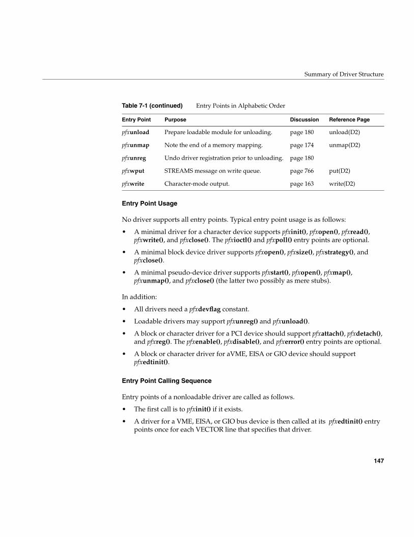
Summary of Driver Structure
147
Entry Point Usage
No driver supports all entry points. Typical entry point usage is as follows:
• A minimal driver for a character device supports pfxinit(), pfxopen(), pfxread(),pfxwrite(), and pfxclose(). The pfxioctl() and pfxpoll() entry points are optional.
• A minimal block device driver supports pfxopen(), pfxsize(), pfxstrategy(), andpfxclose().
• A minimal pseudo-device driver supports pfxstart(), pfxopen(), pfxmap(),pfxunmap(), and pfxclose() (the latter two possibly as mere stubs).
In addition:
• All drivers need a pfxdevflag constant.
• Loadable drivers may support pfxunreg() and pfxunload().
• A block or character driver for a PCI device should support pfxattach(), pfxdetach(),and pfxreg(). The pfxenable(), pfxdisable(), and pfxerror() entry points are optional.
• A block or character driver for aVME, EISA or GIO device should supportpfxedtinit().
Entry Point Calling Sequence
Entry points of a nonloadable driver are called as follows.
• The first call is to pfxinit() if it exists.
• A driver for a VME, EISA, or GIO bus device is then called at its pfxedtinit() entrypoints once for each VECTOR line that specifies that driver.
pfxunload Prepare loadable module for unloading. page 180 unload(D2)
pfxunmap Note the end of a memory mapping. page 174 unmap(D2)
pfxunreg Undo driver registration prior to unloading. page 180
pfxwput STREAMS message on write queue. page 766 put(D2)
pfxwrite Character-mode output. page 163 write(D2)
Table 7-1 (continued) Entry Points in Alphabetic Order
Entry Point Purpose Discussion Reference Page
148
Chapter 7: Structure of a Kernel-Level Driver
• The pfxstart() entry point is called, if it exists.
• The pfxregister() entry point is called, if it exists.
• A driver for a PCI device is called at its pfxattach() entry point once for each devicethat it supports, as the kernel discovers the devices.
• The pfxopen() entry point is called whenever any process opens a device controlledby this driver.
• The pfxread(), pfxwrite(), pfxstrategy(), pfxmap(), pfxpoll() and pfxioctl() calls areexercised as long as any device is open.
• The pfxunmap() entry point is called when all processes have unmapped a givensegment of memory.
• The pfxclose() entry point is called when the last process closes a device, so thedevice is known to be no longer in use.
• The pfxdetach() entry point can be called only when a device has been closed.
The sequence of entry points called for a loadable driver is similar, with additional callsthat are discussed under “Entry Point unreg()” on page 180 and “Entry Point unload()”on page 180.
Driver Flag Constant
Any device driver or STREAMS module must define a public name pfxdevflag as a staticinteger. This integer contains a bitmask with one or more of the following flags, whichare declared in sys/conf.h:
A typical definition would resemble the following:
int testdrive_devflag = D_MP+D_MT;
A STREAMS module should also provide this flag, but the only relevant bit value for aSTREAMS driver is D_MP (see “Driver Flag Constant” on page 764).
D_MP The driver is prepared for multiprocessor systems.
D_MT The driver is prepared for a multithreaded kernel.
D_WBACK The driver handles its own cache-writeback operations.
Driver Flag Constant
149
The flag value is saved in the kernel switch table with the driver’s entry points (see“Kernel Switch Tables” on page 145).
When a driver does not define a pfxdevflag, or defines one containing 0, lboot refuses toload it as part of the kernel.
Flag D_MP
You specify D_MP in pfxdevflag to tell lboot that your driver is designed to operate in amultiprocessor system. The top half of the driver is designed to cope with multipleconcurrent entries in multiple CPUs. The top and bottom halves synchronize through theuse of semaphores or locks and do not rely on interrupt masking for critical sections.These issues are discussed further under “Designing for Multiprocessor Use” onpage 184.
All drivers must be designed in this fashion and confirm it with D_MP, even driverswritten for uniprocessor workstations.
Flag D_MT
Driver interrupt routines execute as independent, preemptable threads of control withinthe kernel address space (see “Interrupts as Threads” on page 177). D_MT indicates thatthis driver understands that it can be run as one or more cooperating threads, and useskernel synchronization primitives to serialize access to driver common data structures.
In IRIX 6.4, D_MT does not commit a driver to anything beyond the meaning of D_MP.
Flag D_WBACK
You specify D_WBACK in pfxdevflag to tell lboot that a block driver performs anynecessary cache write-back operations through explicit calls to dki_dcache_wb() andrelated functions (see the dki_dcache_wb(D3) reference page).
When D_WBACK is not present in pfxdevflag, the physiock() function ensures that allcached data related to buf_t structures is written back to main memory before it entersthe driver’s strategy routine. (See the physiock(D3) reference page and “Entry Pointstrategy()” on page 165.)
150
Chapter 7: Structure of a Kernel-Level Driver
Flag D_OLD Not Supported
In versions prior to IRIX 6.4, a driver was allowed to have no pfxdevflag, or to have onecontaining only a flag named D_OLD. This flag, or the absence of a flag, requestedcompatibility handling for an obsolete driver interface. Support for this interface hasbeen withdrawn effective with IRIX 6.4.
Initialization Entry Points
The kernel calls a driver to initialize itself at four different entry points, as follows:
Historically, these calls were made at different times in the boot process and the driverhad different abilities at each time. Now they are all called at nearly the same time. Adriver may define any combination of these entry points. Typically a PCI driver willdefine pfxinit() and pfxreg(), while a VME or EISA device will define pfxinit() andpfxedtinit().
When Initialization Is Performed
The initialization entry points of ordinary (nonloadable) drivers are called during systemstartup, after interrupts have been enabled and before the message “The system iscoming up” is displayed on the console. In all cases, interrupts are enabled and basickernel services are available at this time. However, other loadable or optional kernelmodules might not have been initialized, depending on the sequence of statements in thefiles in /var/sysgen/system.
Whenever a driver is initialized, the entry points are called in the following sequence:
1. pfxinit() is called.
2. pfxedtinit() is called once for each VECTOR statement in reverse order of theVECTOR statements found in /var/sysgen/system files.
pfxinit Initialize self-defining hardware or a pseudo-device.
pfxedtinit Initialize a hardware device based on VECTOR data.
pfxstart General initialization.
pfxreg For a driver that supports the pfxattach() entry point, register thedriver as ready to attach devices.
Initialization Entry Points
151
3. pfxstart() is called.
4. pfxreg() is called.
Initialization of Loadable Drivers
A loadable driver (see “Loadable Drivers” on page 74) is initialized any time it is loaded.This can occur more than once, if the driver is loaded, unloaded, and reloaded. When aloadable driver is configured for autoregister, it is loaded with other drivers duringsystem startup. (For more information on autoregister, see “Configuring a LoadableDriver” on page 264.) Such a driver is initialized at system startup time along with thenonloadable drivers.
Entry Point init()
The pfxinit() entry point is called once during system startup or when a loadable driveris loaded. It receives no input arguments; its prototype is simply:
void pfxinit(void);
You can use this entry point for any of the following purposes:
• To intialize global data used by more than one entry point or with more than onedevice.
• To initialize a hardware device that is self-defining; that is, all the information thedriver needs is either coded into the driver, or can be gotten by probing the deviceitself.
• To initialize a pseudo-device driver; that is, a driver that does not have realhardware attached.
A driver that is brought into the system by a USE or INCLUDE line in a systemconfiguration file (see “Configuring a Kernel” on page 263) typically initializes in thepfxinit() entry point.
Entry Point edtinit()
The pfxedtinit() entry is designed to initialize devices that are configured using theVECTOR statement in the system configuration file (see “Kernel Configuration Files” onpage 56). This includes GIO, EISA, and VME devices. The entry point name is acontraction of “early device table initialization.”
152
Chapter 7: Structure of a Kernel-Level Driver
The VECTOR statement specifies hardware details about a device on the VME, GIO, orEISA bus, including such items as iospace addresses, interrupt level, bus number, and adriver-defined integer value referred to as the controller number. The VECTORstatement also specifies the driver that is to manage the device; and it can specify probeoperations that let the kernel test for the existence of the device.
When the kernel processes a VECTOR statement during bootstrap, it executes the probe,if one is specified. When the probe is successful (or no probe is given), the kernel makessure that the specified driver is loaded. Then it stores the hardware parameters from theVECTOR statement in a structure of type edt_t. (This structure is declared in sys/edt.h.)
Tthe kernel calls the specified driver’s pfxedtinit() entry one time for each VECTORstatement that named that driver and had a successful probe (or had no probe). VECTORstatements are processed in reverse sequence to the order in which they are coded in/var/sysgen/system files.
The prototype of the pfxedtinit() entry is
void pfxedtinit(edt_t *e);
The edt_t contains at least the following fields (see the system(4) reference page for thecorresponding VECTOR parameters):
The VME form of the VECTOR statement for IRIX 6.4 is discussed at length under“Defining VME Devices with the VECTOR Statement” on page 344. The operation of thepfxedtinit() entry for VME is discussed under “Initializing a VME Device” on page 352.
Entry Point start()
The pfxstart() entry point is called at system startup, and whenever a loadable driver isloaded. It is called after pfxedtinit() and pfxinit(), but before any other entry point suchas pfxopen(). The pfxstart() entry point receives no arguments; its prototype is simply
void pfxstart(void);
e_bus_type Integer specifying the bus type; constant values are declared insys/edt.h, for example ADAP_VME, ADAP_GIO, or ADAP_EISA.
e_adap For EISA or VME, an integer specifying the adapter (bus) number.
e_ctlr Value from the VECTOR ctlr= parameter; typically a device numberused to distinguish one device from another.
e_space Array of up to three I/O space structures of type iospace_t.
Attach and Detach Entry Points
153
The pfxstart() entry point is a suitable place to allocate a poll-head structure usingphalloc(), as discussed in “Use and Operation of poll(2)” on page 166.
Entry Point reg()
The pfxreg() entry point is specifically intended to allow a driver that supports thepfxattach() entry point (see “Entry Point attach()” on page 153) to register with the kernel.At present, the only buses that support device attachment and registration (accessible toOEMs) are the PCI and SCSI buses. The functions used to register as a PCI driver arediscussed in “Configuration Register Initialization” on page 711.
Attach and Detach Entry Points
First defined in IRIX 6.3, the pfxattach() entry point informs the driver that the kernel hasfound a device that matches the driver. This is the time at which the driver initializes datathat is unique to one instance of a device. The pfxdetach() entry point informs the driverthat the device has been removed from the system. The driver undoes whateverpfxattach() did for that device instance.
Entry Point attach()
The pfxattach() entry point is called to notify the driver that the PCI bus adapter haslocated a device that has a vendor and device ID for which the driver has registered (see“Entry Point reg()” on page 153).
This entry point is typically called during bootstrap, while the kernel is probing the PCIbus. However, it can occur at a later time, if the device is physically plugged in oractivated after the system has initialized. In an Origin2000 system, the entry point isexecuted in the hardware node closest to the device being attached. (See “AllocatingMemory in Specific Nodes of a Origin2000 System” on page 204.)
The purpose of the entry point is to make the device usable, including making it visiblein the hwgraph by creating vertexes and edges to represent it.
154
Chapter 7: Structure of a Kernel-Level Driver
Matching A Device to A Driver
When the system boots up, the kernel probes the PCI bus configuration space and takesa census of active devices. For each device it notes
• Vendor and device ID numbers
• Requested size of memory space
• Requested size of I/O space
The kernel assigns starting bus addresses for memory and I/O space and sets theseaddresses in the Base Address Registers (BARs) in the device. Then the kernel looks fora driver that has registered a matching set of vendor and device IDs usingpciio_driver_register() (for discussion, see “Configuration Register Initialization” onpage 711).
If no matching driver has registered, the device remains inactive. For example, the drivermight be a loadable driver that has not been loaded as yet. When the driver is loaded andregisters, the kernel will match it to any unattached devices.
When the kernel matches a device to its registered driver, the kernel calls the driver’spfxattach() entry point. It passes one argument, a handle to the hwgraph vertexrepresenting the hardware connection point for the device. This handle is used to:
• Request PIO and DMA maps on the device
• Register an interrupt handler for the device
Completing the hwgraph
The handle passed to pfxattach() addresses the hwgraph vertex that represents a slot ona bus. This is not informative to users, because a card can be plugged into any slot. Noris this a reliable target for a symbolic link from /dev. In any case, the driver cannot storeinformation in this vertex. At attach time the driver needs to create at least one additionalhwgraph vertex in order to:
• Create a device vertex for use by user programs.
• Provide a vertex to hold the device information.
• Establish a well-known, convenient names high up in the /hw filesystem.
• Provide extra device names that represent different aspects of the same device (forexample, different partitions), or different access modes to the device (a characterdevice and a block device), or different treatments of the device (for example,byte-swapped and nonswapped).
Attach and Detach Entry Points
155
• Establish predictable names that satisfy symbolic links that exist in /dev.
Each leaf vertex you create in the hwgraph is a device special file the user can open. Youcreate a leaf vertex by calling hwgraph_block_device_add() orhwgraph_char_device_add(). You can make each leaf vertex distinct by attachingdistinct information to it using device_info_set().
You create additional vertexes and edges using the functions discussed under“Hardware Graph Management” on page 221.
Allocating Storage for Device Information
A driver needs to save information about each device, usually in a structure. Fields in atypical structure might include:
• Locks or semaphores used for mutual exclusion among upper-half entry points andbetween them and the interrupt handler.
• Addresses of allocated PIO and DMA maps for this device (see “PIO AddressMapping” on page 716 and “DMA Address Mapping” on page 712).
• Address of an interrupt connection object for the device (see “Interrupt SignalDistribution” on page 713).
• In a block driver, anchors for a queue of buf_t objects being filled or emptied.
• Device status flags.
A problem is that at initialization time a driver does not know how many devices it willbe asked to manage. In the past this problem has been handled by allocating an array ofa fixed number of information structures, indexed by the device minor number.
In a PCI driver, you dynamically allocate memory for an information structure to holdinformation about the one device being attached. (See “General-Purpose Allocation” onpage 203.) You save the address of the structure in the leaf vertex you create, using thedevice_info_set() function, which associates an arbitrary pointer with a vertex_hdl_t (seehwgraph(d3x) and “Extending the hwgraph” on page 222).
The information structure can easily be recovered in any top-half routine; see“Interrogating the hwgraph” on page 221.
156
Chapter 7: Structure of a Kernel-Level Driver
Inserting Hardware Inventory Data
You attach the hardware inventory data for the attached device to the hwgraph vertexpassed to the pfxattach() entry point—see “Creating an Inventory Entry” on page 51.
Return Value from Attach
The return code from pfxattach() is tested by the kernel. The driver can reject anattachment. When your driver cannot allocate memory, or fails due to another problem,it should:
• Use cmn_err() to document the problem (see “Using cmn_err” on page 274)
• Release any objects such as PIO and DMA maps that were created.
• Release any space allocated to the device such as a device information structure.
• Return an informative return code which might be meaningful in future releases.
More than one driver can register to support the same vendor ID and device ID. Whenthe first driver fails to complete the attachment, the kernel continues on to test the next,until all have refused or one accepts. The pfxdetach() entry point can only be called if thepfxattach() entry point returns success (0).
Entry Point detach()
The pfxdetach() entry point is called when the kernel decides to detach a device. As ofIRIX 6.4 this is only done for PCI devices. The need to detach can be created by ahardware failure or by administrator action. If the entry point is not defined, the devicecannot be detached.
In general, the detach entry point must undo as much as possible of the work done bythe pfxattach() entry point (see “Entry Point attach()” on page 153). This includes suchactions as:
• Disconnect a registered interrupt handler.
• If any I/O operations are pending on the device, cancel them. If any top-half entrypoints are waiting on the completion of these operations, wake them up.
• Release all software objects allocated, such as PIO maps, DMA maps, and interruptobjects.
Open and Close Entry Points
157
• Release any allocated kernel memory used for buffers or for a device informationstructure.
• Detach and release any edges and vertexes in the hwgraph created at attach time.
The state of the device itself is not known. If the detach code attempts to reset the deviceor put it in a quiescent state, the code should be prepared for errors to occur.
Open and Close Entry Points
The pfxopen() and pfxclose() entries for block and character devices are called when adevice comes into use and when use of it is finished. For a conceptual overview of theopen() process, see “Overview of Device Open” on page 63.
Entry Point open()
The kernel calls a device driver’s pfxopen() entry when a process executes the open()system call on any device special file (see the open(2) reference page). It is also calledwhen a process executes the mount() system call on a block device (see the mount(2)reference page). ( For the pfxopen() entry point of a STREAMS driver, see “Entry Pointopen()” on page 765.)
The prototype of pfxopen() is as follows:
int pfxopen(dev_t *devp, int oflag, int otyp, cred_t *crp);
The argument values are
*devp Pointer to a dev_t value, actually a handle to a leaf vertex in the hwgraph.
otyp An integer flag specifying the source of the call: a user process opening acharacter device or block device, or another driver.
oflag Flag bits specifying user mode options on the open() call.
crp A cred_t object—an opaque structure for use in authentication. Standardaccess privileges to the special device file have already been verified.
158
Chapter 7: Structure of a Kernel-Level Driver
Note: In releases prior to IRIX 6.4, a driver’s pfxdevflag constant could contain D_OLD.In that case, the first argument to pfxopen() was a dev_t value, not a pointer to a dev_tvalue. However, this compatibility mode is no longer supported. The first argument topfxopen() is always a pointer to a dev_t.
The open(D2) reference page discusses the kind of work the pfxopen() entry point can do.In general, the driver is expected to verify that this user process is permitted access in theway specified in otyp (reading, writing, or both) for the device specified in *devp. If accessis not allowable, the driver returns a nonzero error code from sys/errno.h, for exampleENOMEM or EBUSY.
Use of the Device Handle
The dev_t value input to pfxopen() and all other top-half entry points is the key parameterthat specifies the device. You use the dev_t to locate the hwgraph vertex that is beingopened. From that vertex you extract the address of the device information structure thatwas stored when the device was attached (see “Allocating Storage for DeviceInformation” on page 155). In pfxopen() or any other top-half entry point, the driverretrieves the device information by applying device_info_get() to the dev_t value (see“Interrogating the hwgraph” on page 221).
Use of the Open Type
The otyp flag distinguishes between the following possible sources of this call topfxopen() (the constants are defined in sys/open.h).
• a call to open a character device (OTYP_CHR)
• a call to open a block device (OTYP_BLK)
• a call to a mount a block device as a filesystem (OTYP_MNT)
• a call to open a block device as swapping device (OTYP_SWP)
• a call direct from a device driver at a higher level (OTYP_LYR)
Typically a driver is written only to be a character driver or a block driver, and can becalled only through the switch table for that type of device. When this is the case, the otypvalue has little use.
Open and Close Entry Points
159
It is possible to have the same driver treated as both block and character, in which casethe driver needs to know whether the open() call addressed a block or character specialdevice. It is possible for a block device to support different partitions with different uses,in which case the driver might need to record the fact that a device has been mounted, oropened as a swap device.
With all open types except OTYP_LYR, pfxopen() is called for every open or mountoperation, but pfxclose() is called only when the last close or unmount occurs. TheOTYP_LYR feature is used almost exclusively by drivers distributed with IRIX, like thehost adapter SCSI driver (see “Host Adapter Concepts” on page 515). For each open ofthis type, there is one call to pfxclose().
Use of the Open Flag
The interpretation of the open mode flags is up to the designer of the driver. Four modescan be requested (declared in sys/file.h):
You decide which of the flags have meaning with respect to the abilities of this device.You can return an EINVAL error when an unsupported mode is requested.
A key decision is whether the device can be opened only by one process at a time, or bymultiple processes. If multiple opens are supported, a process can still request exclusiveaccess with the FEXCL mode.
When the device can be used by only one process, or when FEXCL access is supported,the driver must keep track of the fact that the device is open. When the device is busy, thedriver can test the FNDELAY and FNONBLOCK flags; if either is set, it can returnEBUSY. Otherwise, the driver should sleep until the device is free; this requirescoordination with the pfxclose() entry point.
FREAD Input access wanted.
FWRITE Output access wanted (both FREAD and FWRITE may be set,corresponding to O_RDWR mode).
FNDELAY orFNONBLOCK
Return at once, do not sleep if the open cannot be doneimmediately.
FEXCL Request exclusive use of the device.
160
Chapter 7: Structure of a Kernel-Level Driver
Use of the cred_t Object
The cred_t object passed to pfxopen(), pfxclose(), and pfxioctl() can be used with thedrv_priv() function to find out if the effective calling user ID is privileged or not (see thedrv_priv(D3) reference page). Do not examine the object in detail, since its contents aresubject to change from release to release.
Saving the Size of a Block Device
In a block device driver, the pfxsize() entry point will be called soon after pfxopen() (see“Entry Point size()” on page 181). It is typically best to calculate or read the devicecapacity at open time, and save it to be reported from pfxsize().
Completing the hwgraph
Some device drivers distributed with IRIX test, at open time, to see if this is the first opensince the attachment of the specified device. For these devices, the first open() call isguaranteed to come from the ioconfig program after it has assigned a stable controllernumber (see “Using ioconfig for Global Controller Numbers” on page 51). When thesedrivers detect the first open for a device, they retrieve the assigned controller numberfrom the device vertex using device_controller_num_get() (see hwgraph.inv(d3x), andpossibly add convenience vertexes to the hwgraph.
Entry Point close()
The kernel calls the pfxclose() entry when the last process calls close() or umount() forthe device special file. It is important to know that when the device can be opened bymultiple processes, pfxclose() is not called for every close() function, but only when thelast remaining process closes the device and no other processes have it open.
The function prototype and arguments of pfxclose() are
int pfxclose(dev_t dev, int flag, int otyp, cred_t *crp);
The arguments are the same as were passed to pfxopen(). However, the flag argument isnot necessarily the same as at any particular call to open().
Control Entry Point
161
It is up to you to design the meaning of “close” for this type of device. The close(D2)reference page discusses some of the actions the driver can do. Some considerations are:
• If the device is opened and closed frequently, you may decide to retain dynamicdata structures.
• If the device can perform an action such as “rewind” or “eject,” you decide whetherthat action should be done upon close. Possibly the choice of acting or not actingcan be set by an ioctl() call; or possibly the choice can be encoded into the deviceminor number—for example, the no-rewind-on-close option is encoded in certaintape minor device numbers.
• If the pfxopen() entry point supports exclusive access, and it can be waiting for thedevice to be free, pfxclose() must release the wait.
When a device can do DMA, the pfxclose() entry point is the appropriate place to makesure that all I/O has terminated. Since all processes have closed the device, there is noreason for it to continue transmitting data into memory; and if it does continue, it mightcorrupt memory.
The pfxclose() entry can detect an error and report it with a return code. However, the fileis closed or unmounted regardless.
Control Entry Point
The pfxioctl() entry point is called by the kernel when a user process executes the ioctl()system call (see the ioctl(2) reference page). This entry point is allowed in characterdrivers only. Block device drivers do not support it. STREAMS drivers pass controlinformation as messages.
For an overview of the relationship between the user process, kernel, and the controlentry point, see “Overview of Device Control” on page 65.
The prototype of the entry point is
int pfxioctl(dev_t dev, int cmd, void *arg,int mode, cred_t *crp, int *rvalp);
The argument values are
dev A dev_t value from which you can extract the major and minor devicenumbers, or the device information from the hwgraph vertex.
cmd The request value specified in the ioctl() call.
162
Chapter 7: Structure of a Kernel-Level Driver
It is up to the device driver to interpret the cmd and arg values in the light of the mode andother arguments. When the arg value is a pointer to data in the process address space, thedriver uses the copyin() kernel function to copy the data into kernel space, and thecopyout() function to return updated values. (See the copyin(D3) and copyout(D3)reference pages, and also “Transferring Data” on page 207.)
Choosing the Command Numbers
The command numbers supported by pfxioctl() are arbitrary; but the recommendedpractice is to make sure that they are different from those of any other driver. Onemethod to achieve this is suggested in the ioctl(D2) reference page.
Supporting 32-Bit and 64-Bit Callers
The ioctl() entry point may need to interpret a structure prepared in the user process. Ina 64-bit system, the user process can be either a 32-bit or a 64-bit program. For discussionof this issue, see “Handling 32-Bit and 64-Bit Execution Models” on page 182
User Return Value
The kernel returns 0 to the ioctl() system function unless the pfxioctl() function returnsan error code. In the event of an error, the kernel may also return the code the driverplaces in *rvalp, if any, or -1. To ensure that the user process sees a specific error code, itis a good idea to set the code in *rvalp, and return that value. If your device driver doesnot define a pfxdevflag or sets it to D_OLD, see “Driver Flag Constant” on page 148.
arg The optional argument value specified in the ioctl() call, or NULL if none wasspecified.
mode Flag bits specifying the open() mode, as associated with the file descriptorpassed to the ioctl() system function.
crp A cred_t object—an opaque structure for use in authentication, describing theprocess that is in-context. Standard access privileges to the special device filehave already been verified.
*rvalp The integer result to be returned to the user process.
Data Transfer Entry Points
163
Data Transfer Entry Points
The pfxread() and pfxwrite() entry points are supported by character device drivers andpseudo-device drivers that allow reading and writing. They are called by the kernelwhen the user process calls the read(), readv(), write(), or writev() system function.
The pfxstrategy() entry point is required of block device drivers. It is called by the kernelwhen either a filesystem or the paging subsystem needs to transfer a block of data.
Entry Points read() and write()
The pfxread() and pfxwrite() entry points are similar to each other—only the direction ofdata transfer differs. The prototypes of the functions are
int pfxread (dev_t dev, uio_t *uiop, cred_t *crp);int pfxwrite(dev_t dev, uio_t *uiop, cred_t *crp);
The arguments are
Data Transfer for a PIO Device
A character device driver using PIO transfers data in the following steps:
1. If there is a possibility of a timeout, start a timeout delay (see “Waiting for Time toPass” on page 242).
2. Initiate the device operation as required.
3. Transfer data between the device and the buffer represented by the uio_t (see“Transferring Data Through a uio_t Object” on page 209).
4. If it is necessary to wait for an interrupt, put the process to sleep (see “Waiting andMutual Exclusion” on page 233).
5. When data transfer is complete, or when an error occurs, clear any pending timeoutand return the final status of the operation. If the return code is 0, the final state ofthe uio_t determines the byte count returned by the read() or write() call.
dev A dev_t value from which you can extract the major and minor devicenumbers, or the device information from the hwgraph vertex.
*uiop A uio_t object—a structure that defines the user’s buffer memory areas.
crp A cred_t object—an opaque structure for use in authentication. Standardaccess privileges to the special device file have already been verified.
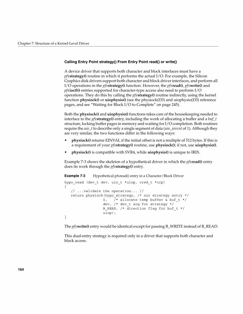
164
Chapter 7: Structure of a Kernel-Level Driver
Calling Entry Point strategy() From Entry Point read() or write()
A device driver that supports both character and block interfaces must have apfxstrategy() routine in which it performs the actual I/O. For example, the SiliconGraphics disk drivers support both character and block driver interfaces, and perform allI/O operations in the pfxstrategy() function. However, the pfxread(), pfxwrite() andpfxioctl() entries supported for character-type access also need to perform I/Ooperations. They do this by calling the pfxstrategy() routine indirectly, using the kernelfunction physiock() or uiophysio() (see the physiock(D3) and uiophysio(D3) referencepages, and see “Waiting for Block I/O to Complete” on page 245).
Both the physiock() and uiophysio() functions takes care of the housekeeping needed tointerface to the pfxstrategy() entry, including the work of allocating a buffer and a buf_tstructure, locking buffer pages in memory and waiting for I/O completion. Both routinesrequire the uio_t to describe only a single segment of data (uio_iovcnt of 1). Although theyare very similar, the two functions differ in the following ways:
• physiock() returne EINVAL if the initial offset is not a multiple of 512 bytes. If this isa requirement of your pfxstrategy() routine, use physiock(); if not, use uiophysio().
• physiock() is compatible with SVR4, while uiophysio() is unique to IRIX.
Example 7-3 shows the skeleton of a hypothetical driver in which the pfxread() entrydoes its work through the pfxstrategy() entry.
Example 7-3 Hypothetical pfxread() entry in a Character/Block Driver
hypo_read (dev_t dev, uio_t *uiop, cred_t *crp){
// ...validate the operation... //return physiock(hypo_strategy, /* our strategy entry */
0, /* allocate temp buffer & buf_t */dev, /* dev_t arg for strategy */B_READ, /* direction flag for buf_t */uiop);
}
The pfxwrite() entry would be identical except for passing B_WRITE instead of B_READ.
This dual-entry strategy is required only in a driver that supports both character andblock access.
Data Transfer Entry Points
165
Entry Point strategy()
A block device driver does not directly support system calls by user processes. Instead,it provides services to a filesystem such as XFS, or to the memory paging subsystem ofIRIX. These subsystems call the pfxstrategy() entry point to read data in whole blocks.
Calls to pfxstrategy() are not directly related in time to system functions called by a userprocess. For example, a filesystem may buffer many blocks of data in memory, so that theuser process may execute dozens or hundreds of write() calls without causing an entryto the device driver. When the user function closes the file or calls fsync()—or when forunrelated reasons the filesystem needs to free some buffers—the filesystem callspfxstrategy() to write numerous blocks of data.
In a driver that supports the character interface as well, the pfxstrategy() entry can becalled indirectly from the pfxread(), pfxwrite() and pfxioctl() entries, as described under“Calling Entry Point strategy() From Entry Point read() or write()” on page 164.
The prototype of the pfxstrategy() entry point is
int pfxstrategy(struct buf *bp);
The argument is the address of a buf_t structure, which gives the strategy routine theinformation it needs to perform the I/O:
• The dev_t, from which the driver can get major and minor device numbers or thedevice information from thehwgraph vertex
• The direction of the transfer (read or write)
• The location of the buffer in kernel memory
• The amount of data to transfer
• The starting block number on the device
For more on the contents of the buf_t structure, see “Structure buf_t” on page 196 and thebuf(D4) reference page.
The driver uses the information in the buf_t to validate the data transfer and programsthe device to start the transfer. Then it stores the address of the buf_t where the interrupthandler can find it (see “Interrupt Entry Point and Handler” on page 175) and callsbiowait() to wait for the operation to complete. For the next step, see “Completing BlockI/O” on page 176 (see also the biowait(D3) reference page).
166
Chapter 7: Structure of a Kernel-Level Driver
Poll Entry Point
The pfxpoll() entry point is called by the kernel when a user process calls the poll() orselect() system function asking for status on a character special device. To implement it,you need to understand the IRIX implementation of poll().
Use and Operation of poll(2)
The IRIX version of poll() allows a process to wait for events of different types to occuron any combination of devices, files, and STREAMS (see the poll(2) and select(2)reference pages). It is possible for multiple processes to be waiting for events on the samedevice.
It is up to you as the designer of a driver to decide which of the events that aredocumented in poll(2) are meaningful for your device. Other requested events simplynever happen to the device.
Much of the complexity of poll() is handled by the IRIX kernel, but the kernel requiresthe assistance of any device driver that supports poll(). The driver is expected to allocateand hold a pollhead structure (declared in sys/poll.h) for each minor device that it supports.Allocation is simple; the driver merely calls the phalloc() kernel function. (The pfxstart()entry point is a suitable place for this call; see “Entry Point start()” on page 152.)
There are two phases to the operation of poll(). When the system function is called, thekernel calls the pfxpoll() entry point to find out if any requested events are pending atthis time. If the kernel finds any event s pending (on this or any other polled object), thepoll() function returns to the user process. Nothing further is required.
However, when no requested event has happened, the user process expects the poll()function to block until an event has occured. The kernel must implement this delay. Itwould be too inefficient for the kernel to repeatedly test for events. The kernel must relyon device drivers to notify it when an event has occurred.
Use of pollwakeup()
A device driver that supports pfxpoll() is required to notify the kernel whenever an eventthat the driver supports has occurred. The driver does this by calling a kernel function,pollwakeup(), passing the pollhead structure for the affected device, and bit flags for theevents that have taken place. In the event that one or more user processes are blocked ina poll(), waiting for an event from this device, the call to pollwakeup() will release thesleeping processes. For an example, see “Calling pollwakeup()” on page 177.
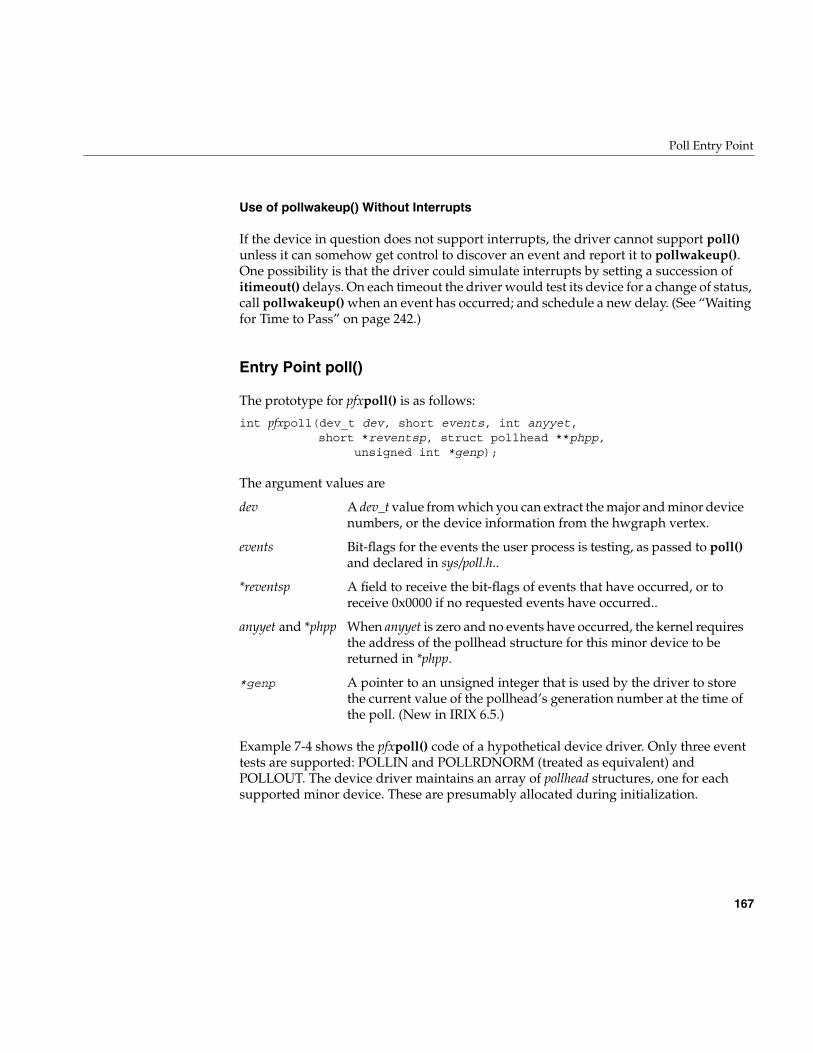
Poll Entry Point
167
Use of pollwakeup() Without Interrupts
If the device in question does not support interrupts, the driver cannot support poll()unless it can somehow get control to discover an event and report it to pollwakeup().One possibility is that the driver could simulate interrupts by setting a succession ofitimeout() delays. On each timeout the driver would test its device for a change of status,call pollwakeup() when an event has occurred; and schedule a new delay. (See “Waitingfor Time to Pass” on page 242.)
Entry Point poll()
The prototype for pfxpoll() is as follows:
int pfxpoll(dev_t dev, short events, int anyyet,short *reventsp, struct pollhead **phpp,
unsigned int *genp);
The argument values are
Example 7-4 shows the pfxpoll() code of a hypothetical device driver. Only three eventtests are supported: POLLIN and POLLRDNORM (treated as equivalent) andPOLLOUT. The device driver maintains an array of pollhead structures, one for eachsupported minor device. These are presumably allocated during initialization.
dev A dev_t value from which you can extract the major and minor devicenumbers, or the device information from the hwgraph vertex.
events Bit-flags for the events the user process is testing, as passed to poll()and declared in sys/poll.h..
*reventsp A field to receive the bit-flags of events that have occurred, or toreceive 0x0000 if no requested events have occurred..
anyyet and *phpp When anyyet is zero and no events have occurred, the kernel requiresthe address of the pollhead structure for this minor device to bereturned in *phpp.
*genp A pointer to an unsigned integer that is used by the driver to storethe current value of the pollhead’s generation number at the time ofthe poll. (New in IRIX 6.5.)
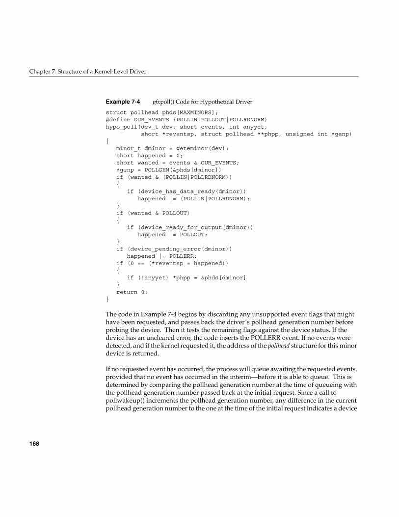
168
Chapter 7: Structure of a Kernel-Level Driver
Example 7-4 pfxpoll() Code for Hypothetical Driver
struct pollhead phds[MAXMINORS];#define OUR_EVENTS (POLLIN|POLLOUT|POLLRDNORM)hypo_poll(dev_t dev, short events, int anyyet,
short *reventsp, struct pollhead **phpp, unsigned int *genp){
minor_t dminor = geteminor(dev);short happened = 0;short wanted = events & OUR_EVENTS;
*genp = POLLGEN(&phds[dminor])if (wanted & (POLLIN|POLLRDNORM)){
if (device_has_data_ready(dminor))happened |= (POLLIN|POLLRDNORM);
}if (wanted & POLLOUT){
if (device_ready_for_output(dminor))happened |= POLLOUT;
}if (device_pending_error(dminor))
happened |= POLLERR;if (0 == (*reventsp = happened)){
if (!anyyet) *phpp = &phds[dminor]}return 0;
}
The code in Example 7-4 begins by discarding any unsupported event flags that mighthave been requested, and passes back the driver’s pollhead generation number beforeprobing the device. Then it tests the remaining flags against the device status. If thedevice has an uncleared error, the code inserts the POLLERR event. If no events weredetected, and if the kernel requested it, the address of the pollhead structure for this minordevice is returned.
If no requested event has occurred, the process will queue awaiting the requested events,provided that no event has occurred in the interim—before it is able to queue. This isdetermined by comparing the pollhead generation number at the time of queueing withthe pollhead generation number passed back at the initial request. Since a call topollwakeup() increments the pollhead generation number, any difference in the currentpollhead generation number to the one at the time of the initial request indicates a device
Memory Map Entry Points
169
event has occurred, and the device must be queried again to determine if it was arequested event. If the values of the previous and current pollhead generation numbersare equal, the process queues.
Memory Map Entry Points
A user process requests memory mapping by calling the system function mmap(). Whenthe mapped object is a character device special file, the kernel calls the pfxmmap() orpfxmap() entry to validate and complete the mapping. To understand these entry points,you must understand the mmap() system function.
Concepts and Use of mmap()
The purpose of the mmap() system function (see the mmap(2) reference page) is to makethe contents of a file directly accessible as part of the virtual address space of the userprocess. The results depend on the kind of file that is mapped:
• When the mapped object is a normal file, the process can load and store data fromthe file as if it were an array in memory.
• When the mapped object is a character device special file, the process can load andstore data from device registers as if they were memory variables.
• When the mapped object is a block of memory owned and prepared by apseudo-device driver, the process gains access to some special piece of memorydata that it would not normally be able to access.
In all cases, access is gained through normal load and store instructions, without theoverhead of calling system functions such as read(). Furthermore, the same mapping canbe executed by other processes, in which case the same memory, or file, or device isshared by multiple, concurrent processes. This is how shared memory segments areachieved.
170
Chapter 7: Structure of a Kernel-Level Driver
Use of mmap()
The mmap() system function takes four key parameters:
• the file descriptor for an open file, which can be either a normal disk file or a devicespecial file
• an offset within that file at which the mapped data is to start. For a normal file, thisis a file offset; for a device file, it represents an address in the address space of thedevice or the bus
• the length of data to be mapped
• protection flags, showing whether the mapped data is read-only or read-write
When the mapped object is a normal file, the filesystem implements the mapping. Thefilesystem does not call the block device driver for assistance in mapping a file. It doescall the block device driver pfxstrategy() entry to read and write blocks of file data asnecessary, but the mapping of pages of data into pages of memory is controlled in thefilesystem code.
When the mapped object is a device special file, the mmap() parameters are passed to thedevice driver at either its pfxmmap() or pfxmap() entry point. The device driver interpretsthe parameters in the context of the device, and uses a kernel function to create themapping.
Persistent Mappings
Once a device or kernel memory has been mapped into some user address space, themapping persists until the user process terminates or calls unmap() (see the unmap(2)reference page). In particular, the mapping does not end simply because the devicespecial file is closed. You cannot assume, in the pfxclose() or pfxunload() entry points,that all mappings to devices have ended.
Entry Point map()
The pfxmap() entry point can be defined in either a character or a block driver (it is theonly mapping entry point that a block driver can supply). The function prototype is
int pfxmap(dev_t dev, vhandl_t *vt,off_t off, int len, int prot);
Memory Map Entry Points
171
The argument values are
The first task of the driver is to verify that the access specified in prot is allowed. The nexttask is to validate the off and len values: do they fall in the valid address space of thedevice?
When the device driver approves of a mapping, it uses a kernel function, v_mapphys(),to establish the mapping. This function (documented in the v_mapphys(D3) referencepage) takes the vhandle_t, an address in kernel cached or uncached memory, and a length.It makes the specified region of kernel space a part of the address space of the userprocess.
For example, a pseudo-device driver that intends to share kernel virtual memory withuser processes would first allocate the memory:
caddr_t *kaddr = kmem_alloc (len , KM_CACHEALIGN);
It would then use the address of the allocated memory with the vhandle_t value it hadreceived to map the allocated memory into the user space:
v_mapphys (vt, kaddr, len)
Note: There are no special precautions to take when mapping cached memory into userspace, or when mapping device registers or bus addresses. However, you should almostnever map uncached memory into user space. The effects of uncached memory access arehardware dependent and differ between multiprocessors and uniprocessors. Amonguniprocessors, the IP26 and IP28 CPU modules have highly restrictive rules for the useof uncached memory (see “Uncached Memory Access in the IP26 and IP28” on page 33).In general, mapping uncached memory makes a driver nonportable and is likely to leadto subtle failures that are hard to resolve.
dev A dev_t value from which you can extract both the major and minordevice numbers.
vt The address of an opaque structure that describes the assigned addressin the user process address space. The structure contents are subject tochange.
off, len The offset and length arguments passed to mmap() by the user process.
prot Flags showing the access intentions of the user process.

172
Chapter 7: Structure of a Kernel-Level Driver
Example 7-5 contains an edited fragment of code from a Silicon Graphics device driver.This pseudo-device driver, whose prefix is flash_, provides access to “flash” PROM incertain computer models. It allows a user process to map the PROM into user space.
Example 7-5 Edited Fragment of flash_map()
int flash_map(dev_t dev, vhandl_t *vt, off_t off, long len){
long offset = (long) off; /*Actual offset in flash prom*//* Don’t allow requests which exceed the flash prom size */
if ((offset + len) > FLASHPROM_SIZE)return ENOSPC;
/* Don’t allow non page-aligned offsets */if ((offset % NBPC) != 0)
return EIO;/* Only allow mapping of entire pages */
if ((len % NBPC) != 0)return EIO;
return v_mapphys(vt, FLASHMAP_ADDR + offset, len);}
Note: Because there is no way for a driver to retract a successful call to v_mapphys(),your driver must return success to a pfxmap() call if v_mapphys() succeeds. In otherwords, you should make the call to v_mapphys() the last part of your pfxmap() routine,and only call it if you have determined that there have been no errors in any previouspart of this routine. If there have been errors, the routine should return an error and notcall v_mapphys(). If there have been no errors, then pfxmap() can return error or successbased on the call to v_mapphys().
When the driver allocates some memory resource associated with the mapping, andwhen more than one mapping can be active at a time, the driver needs to tag eachmemory resource so it can be located when the pfxunmap() entry point is called. Oneanswer is to use the v_gethandle() macro defined in ksys/ddmap.h. This macro takes apointer to a vhandle_t and returns a unique pointer-sized integer that can be used to tagallocations. No other information in ksys/ddmap.h is supported for driver use.
Memory Map Entry Points
173
Entry Point mmap()
The pfxmmap() (note: two letters “m”) entry can be used only in a character device driver.The prototype is
int pfxmmap(dev_t dev, off_t off, int prot);
The argument values are
The function is expected to return the page frame number (PFN) that corresponds to theoffset off in the device address space. A PFN is an address divided by the page size. (See“Working With Page and Sector Units” on page 211 for page unit conversion functions.)
This entry point is supported only for compatibility with SVR4. When the kernel needsto map a character device, it looks first for pfxmap(). It calls pfxmmap() only whenpfxmap() is not available. The differences between the two entry points are as follows:
• This entry point receives no vhandl_t argument, so it cannot use v_mapphys(). It hasto calculate a page frame number, which means that it has to be aware of the currentpage size (obtainable from the ptob() kernel function, see the ptob(D3) referencepage).
• This entry point does not receive a length argument, so it has to assume a defaultlength for every map (typically the page size).
• When a mapping is created using this entry point, the pfxunmap() entry is notcalled.
dev A dev_t value from which you can extract both the major and minor devicenumbers.
off The offset argument passed to mmap() by the user process.
prot Flags showing the access intentions of the user process.
174
Chapter 7: Structure of a Kernel-Level Driver
Entry Point unmap()
The kernel calls the pfxunmap() entry point after a mapping is created using the pfxmap()entry point. This entry should be supplied, even if it is an empty function, when thepfxmap() entry point is supplied. If it is not supplied, the munmap() system functionreturns the ENODEV error to the user process.
The pfxunmap() entry point is only called when the mapped region has been completelyunmapped by all processes. For example, suppose a parent process calls mmap() to mapa device. Then the parent creates one or more child processes using sproc(). Each childshares the address space, including the mapped segment. A process in the share groupcan terminate, or can explicitly unmap() the segment or part of the segment, but theseactions do not result in a call to pfxunmap(). Only when the last process with access tothe segment has fully unmapped the segment is pfxunmap() called.
On entry, the kernel has completed unmapping the object from the user process addressspace. This entry point does not need to do anything to affect the user address space; itonly needs to release any resources that were allocated to support the mapping.
The prototype is
int pfxunmap(dev_t dev, vhandl_t *vt);
The argument values are
If the driver allocated no resources to support a mapping, no action is needed here; theentry point can consist of a “return 0” statement.
When the driver does allocate memory or a PIO map to support a mapping, and supportsmultiple mappings, the driver needs to identify the resource associated with thisparticular mapping in order to release it. The vt_gethandle() function returns a uniquenumber based on the vt argument; this can be used to identify resources.
dev A dev_t value from which you can extract both the major and minor devicenumbers.
vt The address of an opaque structure that describes the assigned address inthe user process address space.
Interrupt Entry Point and Handler
175
Interrupt Entry Point and Handler
In traditional UNIX, when a hardware device presents an interrupt, the kernel locates thedevice driver for the device and calls the pfxintr() entry point (see the intr(D2) referencepage). In current practice, an entry point named pfxintr() is not given any specialtreatment—although driver writers often give this name to the interrupt-handlingfunction even so.
A device driver must register a specific interrupt handler for each device. The kernelfunctions for doing this are bus-specific, and are discussed in the bus-specific chapters.For example, the means of registering a VME interrupt handler is discussed inChapter 13, “Services for VME Drivers on Origin 2000/Onyx 2.” However, thediscussion of interrupts that follows is still relevant to any interrupt handler.
In principle an interrupt can happen at any time. Normally an interrupt occurs becauseat some previous time, the driver initiated a device operation. Some devices can interruptwithout a preceding command.
Associating Interrupt to Driver
The association between an interrupt and the driver is established in different waysdepending on the hardware.
• The VECTOR statement establishes the interrupt level and the associated driver fordevices on the EISA and VME busses.
• For some VME devices, the interrupt level is established dynamically usingvme_ivec_set() (see Chapter 13, “Services for VME Drivers on Origin 2000/Onyx2”).
• For devices on the SCSI bus, all interrupts are handled by a single, low-level driverwhich notifies a callback function (see Chapter 16, “SCSI Device Drivers”).
• For devices on the PCI bus, the driver registers an interrupt handler usingpci_intr_connect() at the time the device is attached (“Interrupt SignalDistribution” on page 713).
In all cases, the driver specifies the interrupt handler as the address of a function to becalled, with an argument to be passed to the function when it is called. This argumentvalue is typically the address of a data structure in which the driver has storedinformation about the device. Alternatively, it could be the dev_t that names the device—from which the interrupt handler can get device information, see “Allocating Storage forDevice Information” on page 155.
176
Chapter 7: Structure of a Kernel-Level Driver
Interrupt Handler Operation
In general, the interrupt handler implements the following tasks.
• When the driver supports multiple logical units, use its argument value to locatethe data structure for the interrupting unit.
• Determine the reason for the interrupt by interrogating the device. This is typicallydone with PIO loads and stores of device registers.
• When the interrupt is a response to an I/O operation, note the success or failure ofthe operation.
• When the driver top half is waiting for the interrupt, waken it.
• If the driver supports polling, and the interrupt represents a pollable event, callpollwakeup().
• If the device is not in an error state and another operation is waiting to be started,start it.
The details of each of these tasks depends on the hardware and on the design of the datastructures used by the driver top half. In general, you should design an interrupt handlerso that it does the least possible and exits as quickly as possible.
Completing Block I/O
In a block device driver, an I/O operation is represented by the buf_t structure. Thepfxstrategy() routine starts operations and waits for them to complete (see “Entry Pointstrategy()” on page 165).
The interrupt entry point sets the residual count in b_resid. It can post an error usingbioerror(). It posts the operation complete and wakens the pfxstrategy() routine bycalling biodone(). If the pfxstrategy() entry has set the address of a completion callbackfunction in the b_iodone field of the buf_t, biodone() invokes it. (For more discussion, see“Waiting for Block I/O to Complete” on page 245.)
Completing Character I/O
In a character device driver, the driver top half typically awaits an interrupt by sleepingon a semaphore or synchronizing variable, and the interrupt routine posts the semaphore(see “Waiting for a General Event” on page 247). Error information must be passed indriver variables according to some local convention.
Interrupt Entry Point and Handler
177
Calling pollwakeup()
When the interrupt represents an event that can be reported by the driver’s pfxpoll()entry point (see “Entry Point poll()” on page 167), the interrupt handler must report theevent to the kernel, in case some user process is waiting in a poll() call. Hypothetical codeto do this is shown in Example 7-6.
Example 7-6 Hypothetical Call to pollwakeup()
hypo_intr(int ivec){
struct hypo_dev_info *pinfo;if (! pinfo = find_dev_info(ivec))
return; /* not our device */...if (pinfo->have_data_flag)
pollwakeup (pinfo->phead, POLLIN, POLLRDNORM);if (pinfo->output_ok_flag)
pollwakeup (pinfo->phead, POLLOUT);...
Note: It’s important that the call to pollwakeup() occurs after any state has been updatedby the event interrupt routine.
Interrupts as Threads
In traditional UNIX design, and in versions of IRIX preceding IRIX 6.4, an interrupt ishandled as an asynchronous trap. The hardware trap handler calls the driver’s interruptfunction as a subroutine. In these systems, when the interrupt handler code is entered thesystem is in an unknown state. As a result, the interrupt handler can use only a restrictedset of kernel services, and no services that can sleep.
Starting with IRIX 6.4, the IRIX kernel does all its work under control of lightweightexecutable entities called “kernel threads.” When a device driver registers an interrupthandler, the kernel allocates a thread to execute that handler. The thread begins executionby waiting on an internal semaphore.
When a hardware interrupt occurs, the trap code merely posts the semaphore on whichthe handler’s thread is waiting. Soon thereafter, the interrupt thread is scheduled toexecute, and it calls the function registered by the driver.
178
Chapter 7: Structure of a Kernel-Level Driver
The differences from previous releases are small. It is still true that the interrupt handlercode is entered unpredictably, at a high priority; does little; and exits quickly. However,there are the following differences compared to earlier systems:
• The interrupt handler can be preempted by kernel threads running at higherpriorities.
Previously, an interrupt handler in a uniprocessor system could only be preemptedby an interrupt from a device with higher hardware priority. In IRIX 6.4, the handlercan be preempted by kernel threads running daemons and high-priority real-timetasks, in addition to other interrupt threads.
• There are no restrictions on the kernel services an interrupt handler may call.
In particular, the interrupt handler is permitted to call services that could sleep.However, this is still typically not a good idea. For example, an interrupt handlershould almost never allocate memory.
• Mutual exclusion between the interrupt handler the driver top half can be donewith mutex locks, instead of requiring the use of spinlocks.
• The handler can do more work, and more elaborate work, if that leads to a betterdesign for the driver.
In IRIX 6.4, the driver writer has no control over the selection of interrupt thread priority.The kernel assigns a high relative priority to threads that execute interrupt handlers.However, higher priorities exist, and an interrupt thread can be preempted.
Mutual Exclusion
In historical UNIX systems, which were uniprocessor systems, when the only CPU isexecuting the interrupt handler, nothing else is executing. The hardware architectureensured that top-half code could not preempt the interrupt handler; and the top halfcould use functions such as splhi() to block interrupts during critical sections (see“Priority Level Functions” on page 242). An interrupt handler could only be preemptedby an interrupt of higher priority—which would be an interrupt for a different driver,and so would have no conflicts with this driver over the use of data.
None of these comfortable assumptions are tenable any longer.
Interrupt Entry Point and Handler
179
Hardware Exclusion Is Ineffective
In a multiprocessor, an interrupt can be taken on any CPU, while other CPUs continue toexecute kernel or user code. This means that the top half code cannot block out interruptsusing a function such as splhi(), because the interrupt could be taken on another CPU.Nor can the interrupt handler assume that it is safe; another CPU could be executing atop-half entry point to the same driver, for the same device, as an interrupt handler.
With the threaded kernel of IRIX 6.4, it is even possible for a process with an extremelyhigh priority, in the same CPU (or in the only CPU of a uniprocessor), to enter the drivertop half, preempting the thread that is executing the interrupt handler.
It is theoretically possible in a threaded kernel for a device to interrupt; for the kernelthread to be scheduled and enter the interrupt handler; and for the device to interruptagain, resulting in multiple concurrent entries to the same interrupt handler. However,IRIX prevents this. The interrupt handler for a device is entered serially. If you registerthe same handler function for multiple devices, it can be entered concurrently whendifferent devices present interrupts at the same time.
Using Locking Between Top and Bottom Half
The only solution possible is that you must use a software lock of some kind to protectthe data objects that can be accessed concurrently by top-half code and the interrupthandler. Before using that shared data, a function must acquire the lock. Options for thetype of lock are discussed under “Designing for Multiprocessor Use” on page 184.
Interrupt Performance and Latency
Another interrupt cannot be handled from the same device until the interrupt handlerfunction returns. The interrupt thread runs at very nearly the highest priority, so all butthe most essential work is suspended in the interrupted CPU until the handler returns.
180
Chapter 7: Structure of a Kernel-Level Driver
Support Entry Points
Certain driver entry points are used to support the operations of the kernel or theadministration of the system.
Entry Point unreg()
The pfxunreg() entry point is called in a loadable driver, prior to the call to thepfxunload() entry point. This entry point is used by drivers that support the pfxattach()entry point (see “Attach and Detach Entry Points” on page 153). Such drivers have toregister with the kernel as supporting devices of certain types. Before unloading, a driverneeds to retract this registration, so the kernel will not call the driver to attach anotherdevice.
If pfxunreg() returns a nonzero error code, the driver is not unloaded.
Entry Point unload()
The pfxunload() entry point is called when the kernel is about to dynamically remove aloadable driver from the running system. A driver can be unloaded either because all itsdevices are closed and a timeout has elapsed, or because the operator has used the mlcommand (see the ml(1) reference page). The kernel calls pfxunload() only when nodevice special files managed by the driver are open. If any device had been opened, thepfxclose() entry has been called.
It is not easy to retain state information about the device over the time when the driveris not in memory. The entire text and data of a loadable driver, including static variables,are removed and reloaded. Global variables defined in the descriptive file (see“Describing the Driver in /var/sysgen/master.d” on page 260) remain in memory afterthe driver is unloaded, as do any allocated memory addressed from a hwgraph vertex(see “Attaching Information to Vertexes” on page 229). Be sure not to store any addressesof driver code or driver static variables in global variables or vertex structures, since thedriver addresses will be different when the driver is reloaded.
Other than data addressed from the hwgraph, allocated dynamic memory should bereleased. The driver should also release any process handles (see “Sending a ProcessSignal” on page 232).
Support Entry Points
181
The driver is not required to unload. If the driver should not be unloaded at this time, itreturns a nonzero return code to the call, and the kernel does not unload it. There areseveral reasons why a driver should not be unloaded.
A driver should never permit unloading when there is any kind of pointer to the driverheld in any kernel data structure. It is a frequent design error to unload when there is alive pointer to the driver. Unpredictable kernel panics often result.
One example of a live pointer to a driver is a pending callback function. Any pendingitimeout() or bufcall() timers should be cancelled before returning 0 from pfxunload().Another example is a registered interrupt handler. The driver must disconnect anyinterrupt handler before unloading; or else refuse to unload.
Entry Point halt()
The kernel calls the pfxhalt() entry point, if one exists, while performing an orderlysystem shutdown (see the halt(1) reference page). No other driver entry points are calledafter this one. The prototype is simply
void pfxhalt(void);
Since the system is shutting down, there is no point in returning allocated memory. Theonly purpose this entry point can serve is to leave the device in a safe and stablecondition. For example, this is the place at which a disk driver could command the headsof the drive to move to a safe zone for power off.
The driver cannot assume that interrupts are disabled or enabled. The driver cannotblock waiting for device actions, so whatever commands it issues to the device must takeeffect immediately.
Entry Point size()
The pfxsize() entry point is required of block device drivers. It reports the size of thedevice in “sector” units, where a “sector” size is declared as NBPSCTR in sys/param.h(currently 512). The prototype is
int pfxsize(dev_t dev);
182
Chapter 7: Structure of a Kernel-Level Driver
The device major and minor numbers can be extracted from the dev argument. The entrypoint is not called until pfxopen() has been called. Typically the driver will calculate thesize of the medium during pfxopen().
Since the int return value is 32 bits in all systems, the largest possible block device is 1,024gigabytes ((231*512)/1,0243).
Entry Point print()
The pfxprint() entry point is called from the kernel to display a diagnostic message whenan error is detected on a block device. The prototype and the complete logic of the entrypoint is shown in Example 7-7.
Example 7-7 Entry Point pfxprint()
#include <sys/cmn_err.h>#include <sys/ddi.h>int hypo_print(dev_t dev, char *str){
cmn_err(CE_NOTE,"Error on dev %d: %s\n",geteminor(dev),str);return 0;
}
Handling 32-Bit and 64-Bit Execution Models
The pfxioctl() entry point can be passed a data structure from the user process addressspace; that is, the arg value can be a pointer to a structure or an array of data. In order tointerpret such a structure, the driver has to know the execution model for which the userprocess was compiled.
The execution model is specified when code is compiled. The 32-bit model (compileroption -32 or -n32) uses 32-bit address values and a long int contains 32 bits. The 64-bitmodel (compiler option -64) uses 64-bit address values and a long int contains 64 bits.(The size of an unqualified int is 32 bits in both models.) The execution model issometimes casually called the “ABI” (Authorized Binary Interface), but this is animproper use of that term—an ABI comprises calling conventions, public names, andstructure definitions, as well as the execution model.
Handling 32-Bit and 64-Bit Execution Models
183
An IRIX kernel compiled to the 32-bit model contains 32-bit drivers and supports only32-bit user processes. A kernel compiled to the 64-bit model contains 64-bit drivers, butit supports user processes compiled to either 32-bit or 64-bit models. Therefore, in a 64-bitkernel, a driver can be asked to interpret data produced by a 32-bit program.
This is true only of the pfxioctl() entry point. Other driver entry points move data to andfrom user space as streams or blocks of bytes—not as a structure with fields to beinterpreted.
Since in other respects it is easy to make your driver portable between 64-bit and 32-bitsystems, you should design your driver so that it can handle the case of operating in a64-bit kernel, receiving ioctl() requests alternately from 32-bit and 64-bit programs.
The simplest way to do this is to define the arguments passed to the entry points in sucha way that they have the same precision in either system. However, this is not alwayspossible. To handle the general case, the driver must know to which model the userprocess was compiled.
In any top-half entry point (where there is a user process context), you find this out bycalling the userabi() function (for which there is no reference page available). Theprototype of userabi() (declared in sys/ddi.h) is
int userabi(__userabi_t *);
If there is no user process context, userabi() returns ESRCH. Otherwise it fills out a__userabi_t structure and returns 0. The structure of type __userabi_t (declared insys/types.h) contains the fields listed below:
Store the value of uabi_szptr when opening a device. Then you can use it to choosebetween 32-bit and 64-bit declarations of a structure passed to pfxioctl() or an addresspassed to pfxpoll().
In any part of the driver, including interrupt threads, you can get the current ABI bycalling the kernel function get_current_abi(). It takes no argument. It returns anunsigned character value that can be decoded using macros and constants that aredeclared in the header file sys/kabi.h.
uabi_szint Size of a user int (4).
uabi_szlong Size of a user long (4 or 8).
uabi_szptr Size of a user address (4 or 8).
uabi_szlonglong Size of a user long long (8).
184
Chapter 7: Structure of a Kernel-Level Driver
Designing for Multiprocessor Use
Multiprocessor computers are a central part of the Silicon Graphics product line and willbecome increasingly common in the future. A device driver that is notmultiprocessor-ready can be used in a multiprocessor, but it is likely to cause aperformance bottleneck. A multiprocessor-ready driver, on the other hand, works wellin a uniprocessor with no cost in performance.
The Multiprocessor Environment
A multiprocessor has two or more CPU modules, all of the same type. The CPUs executeindependently, but all share the same main memory. Any CPU can execute the code ofthe IRIX kernel, and it is common for two or more CPUs to be executing kernel code,including driver code, simultaneously.
Uniprocessor Assumptions
Traditional UNIX architecture assumes a uniprocessor hardware environment with ahierarchy of interrupt levels. Ordinary code could be preempted by an interrupt, but aninterrupt handler could only be preempted by an interrupt at a higher level.
This assumed hardware environment was reflected in the design of device drivers andkernel support functions.
• In a uniprocessor, an upper-half driver entry point such as pfxopen() cannot bepreempted except by an interrupt. It has exclusive access to driver variables exceptfor those changed by the interrupt handler.
• Once in an interrupt handler, no other code can possibly execute except an interruptof a higher hardware level. The interrupt handler has exclusive access to drivervariables.
• The interrupt handler can use kernel functions such as splhi() to set the hardwareinterrupt mask, blocking interrupts of all kinds, and thus getting exclusive access toall memory including kernel data structures.
Designing for Multiprocessor Use
185
All of these assumptions fail in a multiprocessor.
• Upper-half entry points can be entered concurrently on multiple CPUs. Forexample, one CPU can be executing pfxopen() while another CPU is in pfxstrategy().Exclusive use of driver variables cannot be assumed.
• An interrupt can be taken on one CPU while upper-half routines or a timeoutfunction execute concurrently on other CPUs. The interrupt routine cannot assumeexclusive use of driver variables.
• Interrupt-level functions such as splhi() are meaningless, since at best they set theinterrupt mask on the current CPU only. Other CPUs can accept interrupts at alllevels. The interrupt handler can never gain exclusive access to kernel data.
The process of making a driver multiprocessor-ready consists of changing all code whosecorrectness depends on uniprocessor assumptions.
Protecting Common Data
Whenever a common resource can be updated by two processes concurrently, theresource must be protected by a lock that represents the exclusive right to update theresource. Before changing the resource, the software acquires the lock, claiming exclusiveaccess. After changing the resource, the software releases the lock.
The IRIX kernel provides a set of functions for creating and using locks. It providesanother set of functions for creating and using semaphore objects, which are like locks butsometimes more flexible. Both sets of functions are discussed under “Waiting andMutual Exclusion” on page 233.
Sleeping and Waking
Sometimes the lock is not available—some other process executing in another CPU hasacquired the lock. When this happens, the requesting process is delayed in the lockfunction until the lock is free. To delay, or sleep, is allowed for upper-half entry points,because they execute (in effect) as subroutines of user processes.
Interrupt handlers and timeout functions are not permitted to sleep. They have noprocess identity and so there is no mechanism for saving and restoring their state. Aninterrupt handler can test a lock, and can claim the lock conditionally, but if a lock isalready held, the handler must have some alternate way of storing data.
186
Chapter 7: Structure of a Kernel-Level Driver
Synchronizing Within Upper-Half Functions
When designing an upper-half entry point, keep in mind that it could be executedconcurrently with any other upper-half entry point, and that the one entry point couldeven be executed concurrently by multiple CPUs. Only a few entry points are immune:
• The pfxinit(), pfxedtinit(), and pfxstart() entry points cannot be entered concurrentlywith each other or any other entry point (pfxstart() could be entered concurrentlywith the interrupt handler).
• The pfxunload() and pfxhalt() entry points cannot be entered concurrently with anyother entry point except for stray interrupts.
• Certain entry points have no cause to use shared data; for example, pfxsize() andpfxprint() normally do not need to take any precautions.
Other upper-half entry points, and all STREAMS entry points, can be enteredconcurrently by multiple CPUs, when the driver is multiprocessor-aware. In earlierversions of IRIX, you could place a flag in the pfxdevflag of a character driver that madethe kernel run the driver only on CPU 0. This effectively serialized all use of that driver.That feature is no longer supported. You must deal with concurrency.
Serializing on a Single Lock
You can create a single lock for upper-half serialization. Each upper-half function beginswith read-only operations such as extracting the device minor number, getting deviceinformation from the hwgraph vertex, and testing and validating arguments. You allowthese to execute concurrently on any CPU.
In each enry point, when the preliminaries are complete, you acquire the single lock, andrelease it just before returning. The result is that processes are serialized for I/O throughthe driver. If the driver supports only a single device, processes would be serialized inany case, waiting for the device to operate. Since the upper half can execute on any CPU,latency is more predictable.
Serializing on a Lock Per Device
When the driver supports multiple minor devices, you will normally have a datastructure per device. An upper-half routine is concerned only with one device. You candefine a lock in the data structure for each device instance, and acquire that lock as soonas the device information structure is known.
This method permits concurrent execution of upper-half requests for different minordevices, but it serializes access to any one device.
Designing for Multiprocessor Use
187
Coordinating Upper-Half and Interrupt Entry Points
Upper-half entry points prepare work for the device to do, and the interrupt handlerreports the completion of the device action (see “Interrupt Handler Operation” onpage 176). In a block device driver, this communication is relatively simple. In a characterdriver, you have more design options. The kernel functions mentioned in the followingtopics are covered under “Waiting and Mutual Exclusion” on page 233.
Coordinating Through the buf_t
In a block device driver, the pfxstrategy() routine initiates a read or a write based on abuf_t structure (see “Entry Point strategy()” on page 165), and leaves the address of thebuf_t where the interrupt routine can find it. Then pfxstrategy() calls the biowait() kernelfunction to wait for completion.
The pfxintr() entry point updates the buf_t (using pfxbioerror() if necessary) and thenuses biodone() to mark the buf_t as complete. This ends the wait for pfxstrategy().
Coordination in a Character Driver
In a character driver that supports interrupts, you design your own coordinationmechanism. The simplest (and not recommended) would be based on using the kernelfunction sleep() in the upper half, and wakeup() in the interrupt routine. It is better touse a semaphore and use psema() in the upper half and vsema() in the interrupt handler.
If you need to allow for timeouts in addition to interrupts, you have to deal with thecomplication that the timeout function can be called concurrently with an interrupt. Inthis case it is better to use synchronization variables (see “Using SynchronizationVariables” on page 248).
Choice of Lock Type
In versions before IRIX 6.4, interrupt handlers must not use kernel services that cansleep. This prevented you from using normal locks to provide mutual exclusion betweenthe upper half and the interrupt handler. The lock had to be a basic lock (see “BasicLocks” on page 235), a type that is implemented as a spinning lock in a multiprocessor.
Now that interrupt handlers execute as kernel threads, they have the ability to sleep ifnecessary. This means that you can now use mutex locks (see “Using Mutex Locks” onpage 237) between the upper half and interrupt handler. Although you do not want an
188
Chapter 7: Structure of a Kernel-Level Driver
interrupt handler to be delayed, it is much better for a kernel thread to sleep briefly whilewaiting for a lock, than for it to spin in a tight loop. In general, mutex locks are moreefficient than spinning locks.
In the event you must maintain a multiprocessor driver that operates in both IRIX 6.4 andan earlier, nonthreaded version, you can make the choice of lock type dynamically usingconditional compilation. Example 7-8 shows one technique.
Example 7-8 Conditional Choice of Mutual Exclusion Lock Type
#ifdef INTR_KTHREADS#define INT_LOCK_TYPE mutex_t#define INT_LOCK_INIT(p) MUTEX_INIT(p,MUTEX_DEFAULT,”DRIVER_NAME”)#define INT_LOCK_LOCK(p) MUTEX_LOCK(p,-1)#define INT_LOCK_FREE(p) MUTEX_UNLOCK(p)#else /* not a threaded kernel */#define INT_LOCK_TYPE struct{lock_t lk, int cookie}#define INT_LOCK_INIT(p)LOCK_INIT(&p->lk,(uchar_t)-1,plhi,(lkinfo_t)-1)#define INT_LOCK_LOCK(p) (p->cookie=LOCK(&p->lk,plhi))#define INT_LOCK_FREE(p) UNLOCK(&p->lk,p->cookie)#endif
Converting a Uniprocessor Driver
As a general approach, you can convert a uniprocessor driver to make itmultiprocessor-safe in the following steps:
1. If it currently uses the D_OLD flag, or has no pfxdevflag constant, convert it to usethe current interface, with a pfxdevflag of D_MP.
2. Make sure it works in the original uniprocessor at the current release of IRIX.
3. Begin adding semaphores, locks, and other exclusion and synchronization tools.Continue to test the driver on the uniprocessor. It will never wait for a lock, but thecoordination between upper half and interrupt handler should work.
4. Test on a multiprocessor.
In performing the conversion, you can look for calls to spl..() functions as marking pointsat which work is needed. These functions are used for mutual exclusion in auniprocessor, but they are all ineffective or unnecessary in a multiprocessor-safe driver.
Designing for Multiprocessor Use
189
Example Conversion Problem
The code in Example 7-9 shows typical logic in a uniprocessor character driver.
Example 7-9 Uniprocessor Upper-Half Wait Logic
s = splvme();flag |= WAITING;while (flag & WAITING) {
sleep(&flag, PZERO);}splx(s);
The upper half calls the splvme() function with the intention of blocking interrupts, andthus preventing execution of this driver’s interrupt handler while the flag variable isupdated. In a multiprocessor this is ineffective because at best it sets the interrupt levelon the current CPU. The interrupt handler can execute on another CPU and change thevariable.
The corresponding interrupt handler is sketched in Example 7-10.
Example 7-10 Uniprocessor Interrupt Logic
if (flag & WAITING) {wakeup(&flag);flag &= ~WAITING;
}
The interrupt handler could execute on another CPU, and test the flag after the upperhalf has called splvme() and before it has set WAITING in flag. The interrupt is effectivelylost. This would happen rarely and would be hard to repeat, but it would happen andwould be hard to trace.
A more reliable, and simpler, technique is to use a semaphore. The driver defines a globalsemaphore:
static sema_t sleeper;
A driver with multiple devices would have a semaphore per device, perhaps as an arrayof sema_t items indexed by device minor number.
190
Chapter 7: Structure of a Kernel-Level Driver
The semaphore (or array) would be initialized to a starting value of 1 in the pfxinit() orpfxstart() entry:
void hypo_start(){...
initnsema(&sleeper,1,"sleeper");}
After the upper half started a device operation, it would await the interrupt usingpsema():
psema(sleeper,PZERO);
The PZERO argument makes the wait immune to signals. If the driver should wake upwhen a signal is sent to the calling process (such as SIGINT or SIGTERM), the secondargument can be PCATCH. A return value of -1 indicates the semaphore was posted bya signal, not by a vsema() call. The interrupt handler would use vsema() to post thesemaphore.
191
Chapter 8
8. Device Driver/Kernel Interface
The programming interface between a device driver and the IRIX kernel is founded onthe AT&T System V Release 4 DDI/DKI, and it remains true that a working device driverfor an SVR4 system can be ported to IRIX with relatively little difficulty. However, as bothSilicon Graphics hardware and the IRIX kernel have evolved into far greater complexityand sophistication, the driver interface has been extended. A driver can now call uponnearly as many IRIX extended kernel functions as it can SVR4-compatible ones.
The function prototypes and detailed operation of all kernel functions are documentedin the reference pages in volume “D.” The aim of this chapter is to provide background,context, and an overview of the interface under the following headings:
• “Important Data Types” on page 192 describes the data types that are exchangedbetween the kernel and a driver.
• “Important Header Files” on page 201 summarizes the C header files that arefrequently included in a driver source file.
• “Kernel Memory Allocation” on page 203 discusses allocating kernel memory ingeneral and for objects of specific types.
• “Transferring Data” on page 207 discusses the problems of copying data betweenuser and kernel address spaces, and block-copy operations within the kernel.
• “Managing Virtual and Physical Addresses” on page 210 discusses functions fortesting and translating addresses in different spaces, for using address/length lists,and for setting up DMA transfers.
• “Hardware Graph Management” on page 221 discusses the kernel function used tocreate and modify hwgraph vertexes.
• “User Process Administration” on page 232 tells how to test the attributes of acalling process and how to send a signal.
• “Waiting and Mutual Exclusion” on page 233 details the kinds of locks andsemaphores available, and the methods of waiting for events to occur.
192
Chapter 8: Device Driver/Kernel Interface
Important Data Types
In order to understand the driver/kernel interface, you need first of all to understand thedata types with which it deals.
Hardware Graph Types
As discussed under “Hardware Graph Features” on page 43, the hwgraph is composedof vertexes connected by labelled edges. The functions for working with the hwgraph arediscussed under “Hardware Graph Management” on page 221.
Vertex Handle Type
There is no data type associated with the edge as such. The data type of a graph vertex isthe vertex_hdl_t, an opaque, 32-bit number. When you create a vertex, a vertex_hdl_t isreturned. When you store data in a vertex, or get data from one, you pass a vertex_hdl_tas the argument.
Vertex Handle and dev_t
The device number type, dev_t, is an important type in classical driver design (see“Device Number Types” on page 199). In IRIX 6.4, the dev_t and the vertex_hdl_t areidentical. That is, when a driver is called to open or operate a device that is representedas a vertex in the hardware graph, the value passed to identify the device is simply thehandle to the hwgraph vertex for that device.
When a driver is called to open a device that is only represented as a special file in /dev(as in IRIX 6.3 and earlier—there are no such devices supported by IRIX 6.4, but suchsupport is provided for third-party drivers in IRIX 6.5), the identifying value is ano_dev_t, containing major and minor numbers and identical to the traditional dev_t.
Graph Error Numbers
Most hwgraph functions have graph error codes as their explicit result type. Thegraph_error_t is an enumeration declared in sys/graph.h (included by sys/hwgraph.h)having these values:
GRAPH_SUCCESS Operation successful. This success value is 0, as isconventional in C programming.
Important Data Types
193
Address Types
Device drivers deal with addresses in different address spaces. When you storeindividual addresses, it is a good idea to use a data type specific to the address space. Thefollowing types are declared in sys/types.h to use for pointer variables:
It is a very good idea to always store a pointer in a variable with the correct type. It makesthe intentions of the program more understandable, and helps you think about thecomplexities of address translation.
Address/Length Lists
An address/length list, or alenlist, is a software object you use to store the address and sizeof each segment of a buffer. An alenlist is a list in which each list item is a pair composedof an address and a related length. All the addresses in the list refer to the same addressspace, whether that is a user virtual space, the kernel virtual space, physical memory
GRAPH_DUP Data to be added already exists.
GRAPH_NOT_FOUND Data requested does not exist.
GRAPH_BAD_PARAM Typically a null value where an address is required, orother unusable function parameter.
GRAPH_HIT_LIMIT Arbitrary limit on, for example, number of edges.
GRAPH_CANNOT_ALLOC Unable to allocate memory to expand vertex or otherdata structure, possibly because “no sleep” specified.
GRAPH_ILLEGAL_REQUEST Improper or impossible request.
GRAPH_IN_USE Cannot deallocate vertex because there are referencesto it.
caddr_t Any memory (“core”) address in user or kernel space.
daddr_t A disk offset or address (64 bits).
paddr_t A physical memory address.
iopaddr_t An address in some I/O bus address space.
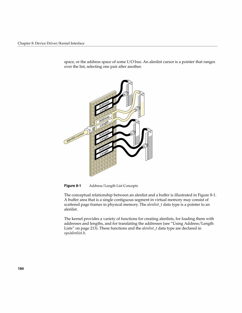
194
Chapter 8: Device Driver/Kernel Interface
space, or the address space of some I/O bus. An alenlist cursor is a pointer that rangesover the list, selecting one pair after another.
Figure 8-1 Address/Length List Concepts
The conceptual relationship between an alenlist and a buffer is illustrated in Figure 8-1.A buffer area that is a single contiguous segment in virtual memory may consist ofscattered page frames in physical memory. The alenlist_t data type is a pointer to analenlist.
The kernel provides a variety of functions for creating alenlists, for loading them withaddresses and lengths, and for translating the addresses (see “Using Address/LengthLists” on page 213). These functions and the alenlist_t data type are declared insys/alenlist.h.
Address
Length
Address
Length
Address
Length
Address
Length
alenlist-cursor
Important Data Types
195
Structure uio_t
The uio_t structure describes data transfer for a character device:
• The pfxread() and pfxwrite() entry points receive a uio_t that describes the buffer ofdata.
• Within an pfxioctl() entry point, you might construct a uio_t to represent datatransfer for control purposes.
• In a hybrid character/block driver, the physiock() function translates a uio_t into abuf_t for use by the pfxstrategy() entry point.
The fields and values in a uio_t are declared in sys/uio.h, which is included by sys/ddi.h.For a detailed discussion, see the uio(D4) reference page. Typically the contents of theuio_t reflect the buffer areas that were passed to a read(), readv(), write(), or writev() call(see the read(2) and write(2) reference pages).
Data Location and the iovec_t
One uio_t describes data transfer to or from a single address space, either the addressspace of a user process or the kernel address space. The address space is indicated by aflag value, either UIO_USERSPACE or UIO_SYSSPACE, in the uio_segflg field.
The total number of bytes remaining to be transferred is given in field uio_resid. Initiallythis is the total requested transfer size.
Although the transfer is to a single address space, it can be directed to multiple segmentsof data within the address space. Each segment of data is described by a structure of typeiovec_t. An iovec_t contains the virtual address and length of one segment of memory.
The number of segments is given in field uio_iovcnt. The field uio_iov points to the firstiovec_t in an array of iovec_t structures, each describing one segment. of data. The totalsize in uio_resid is the sum of the segment sizes.
For a simple data transfer, uio_iovcnt contains 1, and uio_iov points to a single iovec_tdescribing a buffer of 1 or more bytes. For a complicated transfer, the uio_t might describea number of scattered segments of data. Such transfers can arise in a network driverwhere multiple layers of message header data are added to a message at different levelsof the software.
196
Chapter 8: Device Driver/Kernel Interface
Use of the uio_t
In the pfxread() and pfxwrite() entry points, you can test uio_segflag to see if the data isdestined for user space or kernel space, and you can save the initial value of uio_resid asthe requested length of the transfer.
In a character driver, you fetch or store data using functions that both use and modify theuio_t. These functions are listed under “Transferring Data Through a uio_t Object” onpage 209. When data is not immediately available, you should test for the FNDELAY orFNONBLOCK flags in uio_fmode, and return when either is set rather than sleeping.
Structure buf_t
The buf_t structure describes a block data transfer. It is designed to represent the transfer(in or out) of a sequence of adjacent, fixed-size blocks from a random-access device to ablock of contiguous memory. The size of one device block is NBPSCTR, declared insys/param.h. For a detailed discussion of the buf_t, see the buf(D4) reference page.
The buf_t is used internally in IRIX by the paging I/O system to manage queues ofphysical pages, and by filesystems to manage queues of pages of file data. The pagingsystem and filesystems are the primary clients of the pfxstrategy() entry point to a blockdevice driver, so it is only natural that a buf_t pointer is the input argument topfxstrategy().
Tip: The idbg kernel debugging tool has several functions related to displaying thecontents of buf_t objects. See “Commands to Display buf_t Objects” on page 293.
Fields of buf_t
The fields of the buf_t are declared in sys/buf.h, which is included by sys/ddi.h. This headerfile also declares the names of many kernel functions that operate on buf_t objects. (Manyof those functions are not supported as part of the DDI/DKI. You should only use kernelfunctions that have reference pages.)

Important Data Types
197
Because buf_t is used by so many software components, it has many fields that are notrelevant to device driver needs, as well as some fields that have multiple uses. Therelevant fields are summarized in Table 8-1.
No other fields of the buf_t are designed for use by a driver. In Table 8-1, “read-only”access means that the driver should never change this field in a buf_t that is owned by thekernel. When the driver is working with a buf_t that the driver has allocated (see“Allocating buf_t Objects and Buffers” on page 206) the driver can do what it likes.
Using the Logical Block Number
The logical block number is the number of the 512-byte block in the device. The “device”is encoded by the minor device number that you can extract from b_edev. It might be acomplete device surface, or it might be a partition within a larger device (for example,the IRIX disk device drivers support different minor device numbers for different diskpartitions).
Table 8-1 Accessible Fields of buf_t Objects
Field Name Access Purpose and Contents
b_edev read-only dev_t giving device major and minor numbers.
b_flags read-only Operational flags; for a detailed list see buf(D4).
b_forw, b_back,av_forw, av_back
read-write Queuing pointers, available for driver use within thepfxstrategy() routine.
b_un.b_addr read-only Sometimes the kernel virtual address of the buffer, depending onthe b_flags setting BP_ISMAPPED.
b_bcount read-only Number of bytes to transfer.
b_blkno read-only Starting logical block number on device (for a disk, relative to thepartition that the device represents).
b_iodone read-write Address of a driver internal function to be called on I/Ocompletion.
b_resid read-write Number of bytes not transferred, set at completion to 0 unless anerror occurs.
b_error read-write Error code, set at completion of I/O.
198
Chapter 8: Device Driver/Kernel Interface
The pfxstrategy() routine may have to translate the logical block number based on thedriver’s information about device partitioning and device geometry (sector size, sectorsper track, tracks per cylinder).
Buffer Location and b_flags
The data buffer represented by a buf_t can be in one of two places, depending on bits inb_flags.
When the macro BP_ISMAPPED(buf_t-address) returns true, the buffer is in kernel virtualmemory and its virtual address is in b_un.b_addr.
When BP_ISMAPPED(buf_t-address) returns false, the buffer is described by a chain ofpfdat structures (declared in sys/pfdat.h, but containing no fields of any use to a devicedriver). In this case, b_un.b_addr contains only an offset into the first page frame of thechain. See “Managing Buffer Virtual Addresses” on page 218 for a method of mappingan unmapped buffer.
Lock and Semaphore Types
The header files sys/sema.h and sys/types.h declare the data types of locks of differenttypes, including the following:
These lock types should be treated as opaque objects because their contents can changefrom release to release (and in fact their contents are different in IRIX 6.2 from previousreleases).
The families of locking and synchronization functions contain functions for allocating,initializing, and freeing each type of lock. See “Waiting and Mutual Exclusion” onpage 233.
lock_t Basic lock, or spin-lock, used with LOCK() and related functions
mutex_t Sleeping lock, used for mutual exclusion between upper-half instances.
sema_t Semaphore object, used for general locking.
mrlock_t Reader-writer locks, used with RW_RDLOCK() and related functions.
sv_t Synchronization variable, used with SV_WAIT and related functions
Important Data Types
199
Device Number Types
In the /dev filesystem (but not in the /hw filesystem), two numbers are carried in the inodeof a device special file: a major device number of up to 9 bits, and a minor device number ofup to 18 bits. The numbers are assigned when the device special file is created, either bythe /dev/MAKEDEV script or by the system administrator. The contents and meaning ofdevice numbers is discussed under “Devices as Files” on page 36.
In traditional UNIX practice, the dev_t has been an unsigned integer containing thevalues of the major and minor numbers for the device that is to be used. When a deviceis represented in IRIX only as a device special file in /dev, this is still the case.
When a device is represented by a vertex of the hwgraph, visible as a name in the /hwfilesystem, the major number is always 0 and the minor number is arbitrary. When adevice is opened as a special file in /hw, the dev_t received by the driver is composed ofmajor 0 and an arbitrary minor number. In fact, the dev_t is a vertex_hdl_t, a handle to thehwgraph vertex that represents the device.
Historical Use of the Device Numbers
Historically, a driver used the major device number to learn which device driver has beencalled. This was important only when the driver supported multiple interfaces, forexample both character and block access to the same hardware.
Also historically, the driver used the minor device number to distinguish one hardwareunit from another. A typical scheme was to have an array of device-informationstructures indexed by the minor number. In addition, mode of use options were encodedin the minor number, as described under “Minor Device Number” on page 39.
You can still use major and minor numbers the same way, but only when the device isrepresented by a device special file that is created with the mknod command, so that itcontains meaningful major and minor numbers. The kernel functions related to dev_t useare summarized in Table 8-2.
200
Chapter 8: Device Driver/Kernel Interface
The most important of the functions in in Table 8-2 are
• getemajor(), which extracts the major number from a dev_t and returns it as amajor_t
• geteminor(), which extracts the minor number from a dev_t and returns it as aminor_t
The makedevice() function, which combines a major_t and a minor_t to form a traditionaldev_t, is useful only when creating a “clone” driver (see “Support for CLONE Drivers”on page 774).
Contemporary Device Number Use
When the device is represented as a hwgraph vertex, the driver does not receive usefulmajor and minor numbers. Instead, the driver uses the device-unique information thatthe driver itself has stored in the hwgraph vertex.
An historical driver makes only historical use of the dev_t, using the functions listed inthe preceding topic. Such a driver makes no use of the hwgraph, and can only managedevices that are opened as device special files in /dev.
A contemporary driver creates hwgraph vertexes to represent its devices (see “Extendingthe hwgraph” on page 222); makes no use of the major and minor device numbers; and
Table 8-2 Functions to Manipulate Device Numbers
Function Header Files Purpose
etoimajor(D3) ddi.h Convert external to internal major device number.
getemajor(D3) ddi.h Get external major device number.
geteminor(D3) ddi.h Get external minor device number.
getmajor(D3) ddi.h Get internal major device number.
getminor(D3) ddi.h Get internal minor device number.
itoemajor(D3) ddi.h Convert internal to external major device number.
makedevice(D3) ddi.h Make device number from major and minor numbers.
Important Header Files
201
uses the dev_t as a handle to a hwgraph vertex. Such a driver can only manage devicesthat are opened as device special files in /hw, or devices that are opened through symboliclinks in /dev that refer to /hw.
It might possibly be necessary to merge the two approaches. This can be done as follows.In each upper-half entry point, apply getemajor() to the dev_t. When the result isnonzero, the dev_t is conventional and geteminor() will return a useful minor number.Use it to locate the device-specific information.
When getemajor() returns 0, the dev_t is a vertex handle. Use device_info_get() toretrieve the address of device-specific information.
Important Header Files
The header files that are frequently needed in device driver source modules aresummarized in Table 8-3.
Table 8-3 Header Files Often Used in Device Drivers
Header File Reason for Including
sys/alenlist.h The address/length list type and related functions.
sys/buf.h The buf_t structure and related constants and functions (included by sys/ddi.h).
sys/cmn_err.h The cmn_err() function.
sys/conf.h The constants used in the pfxdevflags global.
sys/ddi.h Many kernel functions declared. Also includes sys/types.h, sys/uio.h, andsys/buf.h.
sys/debug.h Defines the ASSERT macro and others.
sys/dmamap.h Data types and kernel functions related to DMA mapping.
sys/edt.h Declares the edt_t type passed to pfxedtinit().
sys/eisa.h EISA-bus hardware constants and EISA kernel functions.
sys/errno.h Names for all system error codes.
sys/file.h Names for file mode flags passed to driver entry points.
sys/hwgraph.h Hardware graph objects and related functions.
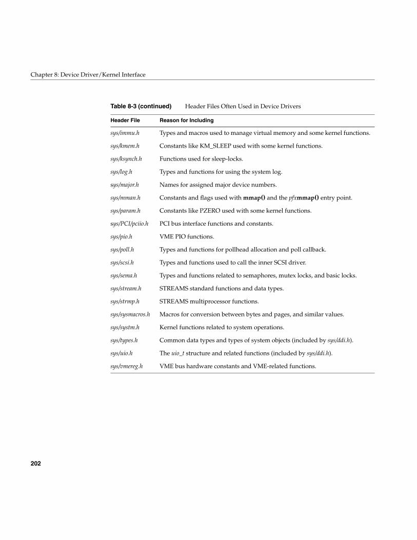
202
Chapter 8: Device Driver/Kernel Interface
sys/immu.h Types and macros used to manage virtual memory and some kernel functions.
sys/kmem.h Constants like KM_SLEEP used with some kernel functions.
sys/ksynch.h Functions used for sleep-locks.
sys/log.h Types and functions for using the system log.
sys/major.h Names for assigned major device numbers.
sys/mman.h Constants and flags used with mmap() and the pfxmmap() entry point.
sys/param.h Constants like PZERO used with some kernel functions.
sys/PCI/pciio.h PCI bus interface functions and constants.
sys/pio.h VME PIO functions.
sys/poll.h Types and functions for pollhead allocation and poll callback.
sys/scsi.h Types and functions used to call the inner SCSI driver.
sys/sema.h Types and functions related to semaphores, mutex locks, and basic locks.
sys/stream.h STREAMS standard functions and data types.
sys/strmp.h STREAMS multiprocessor functions.
sys/sysmacros.h Macros for conversion between bytes and pages, and similar values.
sys/systm.h Kernel functions related to system operations.
sys/types.h Common data types and types of system objects (included by sys/ddi.h).
sys/uio.h The uio_t structure and related functions (included by sys/ddi.h).
sys/vmereg.h VME bus hardware constants and VME-related functions.
Table 8-3 (continued) Header Files Often Used in Device Drivers
Header File Reason for Including
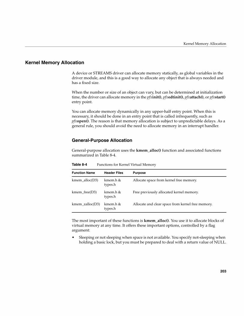
Kernel Memory Allocation
203
Kernel Memory Allocation
A device or STREAMS driver can allocate memory statically, as global variables in thedriver module, and this is a good way to allocate any object that is always needed andhas a fixed size.
When the number or size of an object can vary, but can be determined at initializationtime, the driver can allocate memory in the pfxinit(), pfxedtinit(), pfxattach(), or pfxstart()entry point.
You can allocate memory dynamically in any upper-half entry point. When this isnecessary, it should be done in an entry point that is called infrequently, such aspfxopen(). The reason is that memory allocation is subject to unpredictable delays. As ageneral rule, you should avoid the need to allocate memory in an interrupt handler.
General-Purpose Allocation
General-purpose allocation uses the kmem_alloc() function and associated functionssummarized in Table 8-4.
The most important of these functions is kmem_alloc(). You use it to allocate blocks ofvirtual memory at any time. It offers these important options, controlled by a flagargument:
• Sleeping or not sleeping when space is not available. You specify not-sleeping whenholding a basic lock, but you must be prepared to deal with a return value of NULL.
Table 8-4 Functions for Kernel Virtual Memory
Function Name Header Files Purpose
kmem_alloc(D3) kmem.h &types.h
Allocate space from kernel free memory.
kmem_free(D3) kmem.h &types.h
Free previously allocated kernel memory.
kmem_zalloc(D3) kmem.h &types.h
Allocate and clear space from kernel free memory.

204
Chapter 8: Device Driver/Kernel Interface
• Physically-contiguous memory. The memory allocated is virtual, and when it spansmultiple pages, the pages are not necessarily adjacent in physical memory. You needphysically contiguous pages when doing DMA with a device that cannot doscatter/gather. However, contiguous memory is harder to get as the system runs, soit is best to obtain it in an initialization routine.
• Cache-aligned memory. By requesting memory that is a multiple of a cache line insize, and aligned on a cache-line boundary, you ensure that DMA operations willaffect the fewest cache lines (see “Setting Up a DMA Transfer” on page 216).
The kmem_zalloc() function takes the same options, but offers the additional service ofzero-filling the allocated memory.
In porting an old driver you may find use of allocation calls beginning with “kern.” Callsto the “kern” group of functions should be upgraded as follows:
Allocating Memory in Specific Nodes of a Origin2000 System
In the nonuniform memory of a Origin2000 system, there is a time penalty for access tomemory that is physically located in a node different from the node where the code isexecuting. However, kmem_alloc() attempts to allocate memory in the same node wherethe caller is executing. The pfxedtinit() and pfxattach() entry points execute in the nodethat is closest to the hardware device. If you allocate per-device structures in these entrypoints using kmem_alloc(), the structures will normally be in memory on the same nodeas the device. This provides the best performance for the interrupt handler, which alsoexecutes in the closest node to the device.
Other upper-half entry points execute in the node used by the process that called theentry point. If you allocate memory in the open() entry point, for example, that memorywill be close to the user process.
When it is essential to allocate memory in a specific node and to fail if memory in thatnode is not available, you can use one of the functions summarized in Table 8-5.
kern_malloc(n) Change to kmem_alloc(n,KM_SLEEP).
kern_calloc(n,s) Change to kmem_zalloc(n*s,KM_SLEEP)
kern_free(p) Change to kmem_free(p)
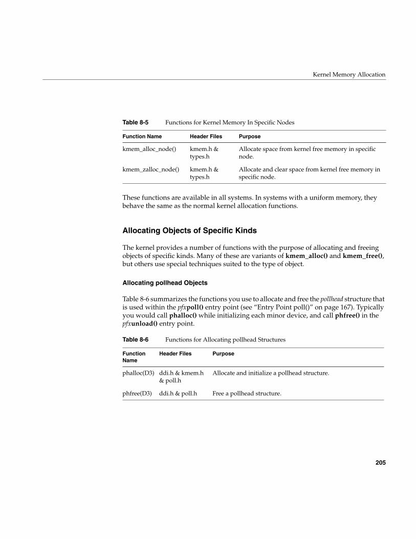
Kernel Memory Allocation
205
These functions are available in all systems. In systems with a uniform memory, theybehave the same as the normal kernel allocation functions.
Allocating Objects of Specific Kinds
The kernel provides a number of functions with the purpose of allocating and freeingobjects of specific kinds. Many of these are variants of kmem_alloc() and kmem_free(),but others use special techniques suited to the type of object.
Allocating pollhead Objects
Table 8-6 summarizes the functions you use to allocate and free the pollhead structure thatis used within the pfxpoll() entry point (see “Entry Point poll()” on page 167). Typicallyyou would call phalloc() while initializing each minor device, and call phfree() in thepfxunload() entry point.
Table 8-5 Functions for Kernel Memory In Specific Nodes
Function Name Header Files Purpose
kmem_alloc_node() kmem.h &types.h
Allocate space from kernel free memory in specificnode.
kmem_zalloc_node() kmem.h &types.h
Allocate and clear space from kernel free memory inspecific node.
Table 8-6 Functions for Allocating pollhead Structures
FunctionName
Header Files Purpose
phalloc(D3) ddi.h & kmem.h& poll.h
Allocate and initialize a pollhead structure.
phfree(D3) ddi.h & poll.h Free a pollhead structure.
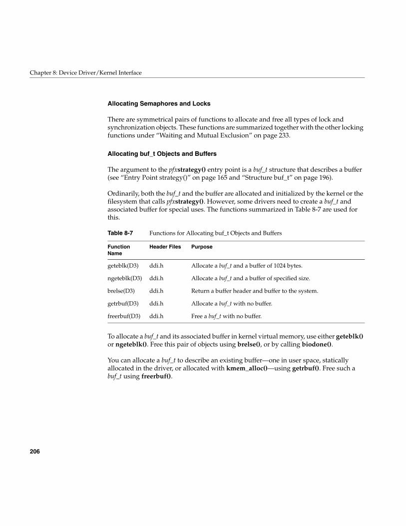
206
Chapter 8: Device Driver/Kernel Interface
Allocating Semaphores and Locks
There are symmetrical pairs of functions to allocate and free all types of lock andsynchronization objects. These functions are summarized together with the other lockingfunctions under “Waiting and Mutual Exclusion” on page 233.
Allocating buf_t Objects and Buffers
The argument to the pfxstrategy() entry point is a buf_t structure that describes a buffer(see “Entry Point strategy()” on page 165 and “Structure buf_t” on page 196).
Ordinarily, both the buf_t and the buffer are allocated and initialized by the kernel or thefilesystem that calls pfxstrategy(). However, some drivers need to create a buf_t andassociated buffer for special uses. The functions summarized in Table 8-7 are used forthis.
To allocate a buf_t and its associated buffer in kernel virtual memory, use either geteblk()or ngeteblk(). Free this pair of objects using brelse(), or by calling biodone().
You can allocate a buf_t to describe an existing buffer—one in user space, staticallyallocated in the driver, or allocated with kmem_alloc()—using getrbuf(). Free such abuf_t using freerbuf().
Table 8-7 Functions for Allocating buf_t Objects and Buffers
FunctionName
Header Files Purpose
geteblk(D3) ddi.h Allocate a buf_t and a buffer of 1024 bytes.
ngeteblk(D3) ddi.h Allocate a buf_t and a buffer of specified size.
brelse(D3) ddi.h Return a buffer header and buffer to the system.
getrbuf(D3) ddi.h Allocate a buf_t with no buffer.
freerbuf(D3) ddi.h Free a buf_t with no buffer.
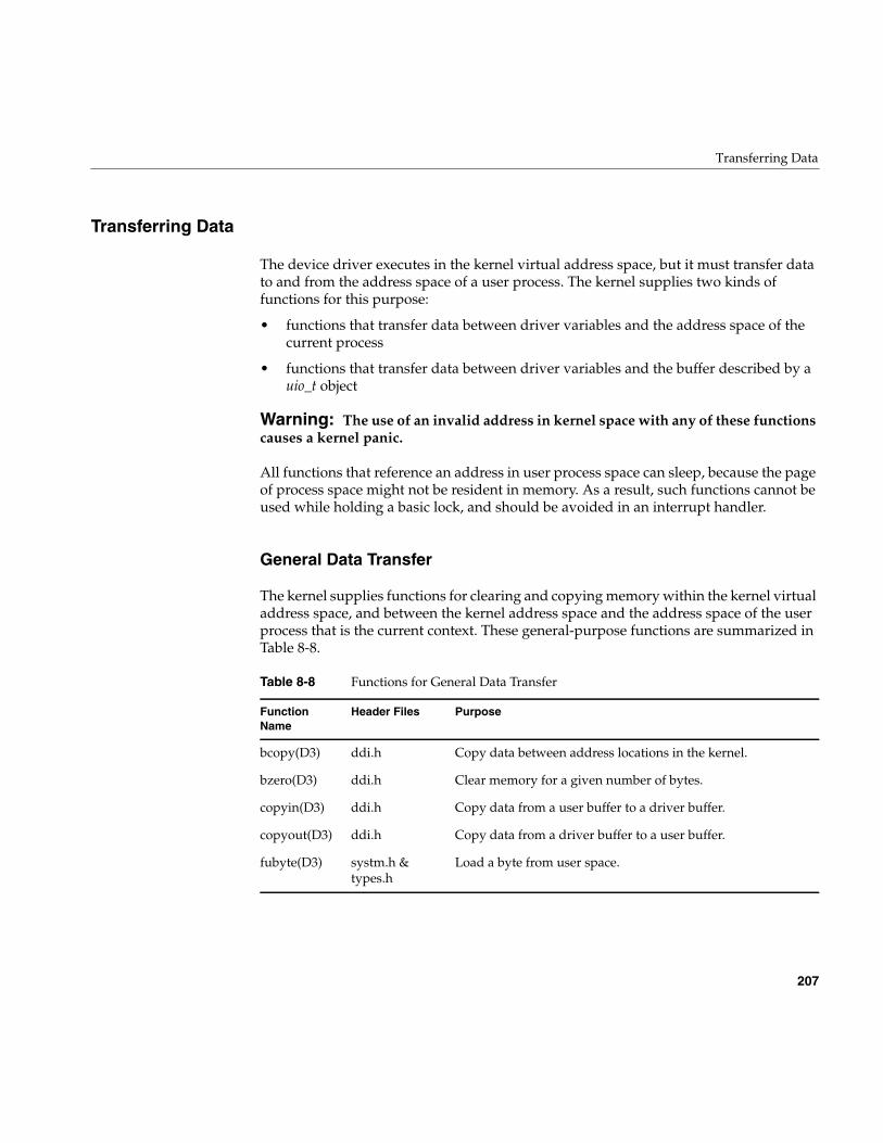
Transferring Data
207
Transferring Data
The device driver executes in the kernel virtual address space, but it must transfer datato and from the address space of a user process. The kernel supplies two kinds offunctions for this purpose:
• functions that transfer data between driver variables and the address space of thecurrent process
• functions that transfer data between driver variables and the buffer described by auio_t object
Warning: The use of an invalid address in kernel space with any of these functionscauses a kernel panic.
All functions that reference an address in user process space can sleep, because the pageof process space might not be resident in memory. As a result, such functions cannot beused while holding a basic lock, and should be avoided in an interrupt handler.
General Data Transfer
The kernel supplies functions for clearing and copying memory within the kernel virtualaddress space, and between the kernel address space and the address space of the userprocess that is the current context. These general-purpose functions are summarized inTable 8-8.
Table 8-8 Functions for General Data Transfer
FunctionName
Header Files Purpose
bcopy(D3) ddi.h Copy data between address locations in the kernel.
bzero(D3) ddi.h Clear memory for a given number of bytes.
copyin(D3) ddi.h Copy data from a user buffer to a driver buffer.
copyout(D3) ddi.h Copy data from a driver buffer to a user buffer.
fubyte(D3) systm.h &types.h
Load a byte from user space.
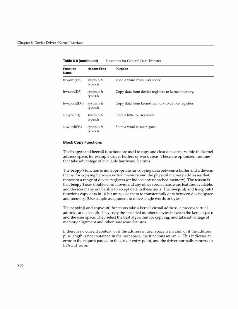
208
Chapter 8: Device Driver/Kernel Interface
Block Copy Functions
The bcopy() and bzero() functions are used to copy and clear data areas within the kerneladdress space, for example driver buffers or work areas. These are optimized routinesthat take advantage of available hardware features.
The bcopy() function is not appropriate for copying data between a buffer and a device;that is, for copying between virtual memory and the physical memory addresses thatrepresent a range of device registers (or indeed any uncached memory). The reason isthat bcopy() uses doubleword moves and any other special hardware features available,and devices many not be able to accept data in these units. The hwcpin() and hwcpout()functions copy data in 16-bit units; use them to transfer bulk data between device spaceand memory. (Use simple assignment to move single words or bytes.)
The copyin() and copyout() functions take a kernel virtual address, a process virtualaddress, and a length. They copy the specified number of bytes between the kernel spaceand the user space. They select the best algorithm for copying, and take advantage ofmemory alignment and other hardware features.
If there is no current context, or if the address in user space is invalid, or if the addressplus length is not contained in the user space, the functions return -1. This indicates anerror in the request passed to the driver entry point, and the driver normally returns anEFAULT error.
fuword(D3) systm.h &types.h
Load a word from user space.
hwcpin(D3) systm.h &types.h
Copy data from device registers to kernel memory.
hwcpout(D3) systm.h &types.h
Copy data from kernel memory to device registers.
subyte(D3) systm.h &types.h
Store a byte to user space.
suword(D3) systm.h &types.h
Store a word to user space.
Table 8-8 (continued) Functions for General Data Transfer
FunctionName
Header Files Purpose
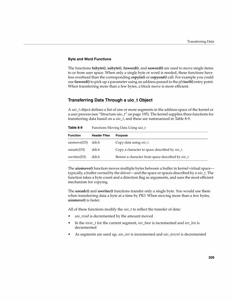
Transferring Data
209
Byte and Word Functions
The functions fubyte(), subyte(), fuword(), and suword() are used to move single itemsto or from user space. When only a single byte or word is needed, these functions haveless overhead than the corresponding copyin() or copyout() call. For example you coulduse fuword() to pick up a parameter using an address passed to the pfxioctl() entry point.When transferring more than a few bytes, a block move is more efficient.
Transferring Data Through a uio_t Object
A uio_t object defines a list of one or more segments in the address space of the kernel ora user process (see “Structure uio_t” on page 195). The kernel supplies three functions fortransferring data based on a uio_t, and these are summarized in Table 8-9.
The uiomove() function moves multiple bytes between a buffer in kernel virtual space—typically, a buffer owned by the driver—and the space or spaces described by a uio_t. Thefunction takes a byte count and a direction flag as arguments, and uses the most efficientmechanism for copying.
The ureadc() and uwritec() functions transfer only a single byte. You would use themwhen transferring data a byte at a time by PIO. When moving more than a few bytes,uiomove() is faster.
All of these functions modify the uio_t to reflect the transfer of data:
• uio_resid is decremented by the amount moved
• In the iovec_t for the current segment, iov_base is incremented and iov_len isdecremented
• As segments are used up, uio_iov is incremented and uio_iovcnt is decremented
Table 8-9 Functions Moving Data Using uio_t
Function Header Files Purpose
uiomove(D3) ddi.h Copy data using uio_t.
ureadc(D3) ddi.h Copy a character to space described by uio_t.
uwritec(D3) ddi.h Return a character from space described by uio_t.
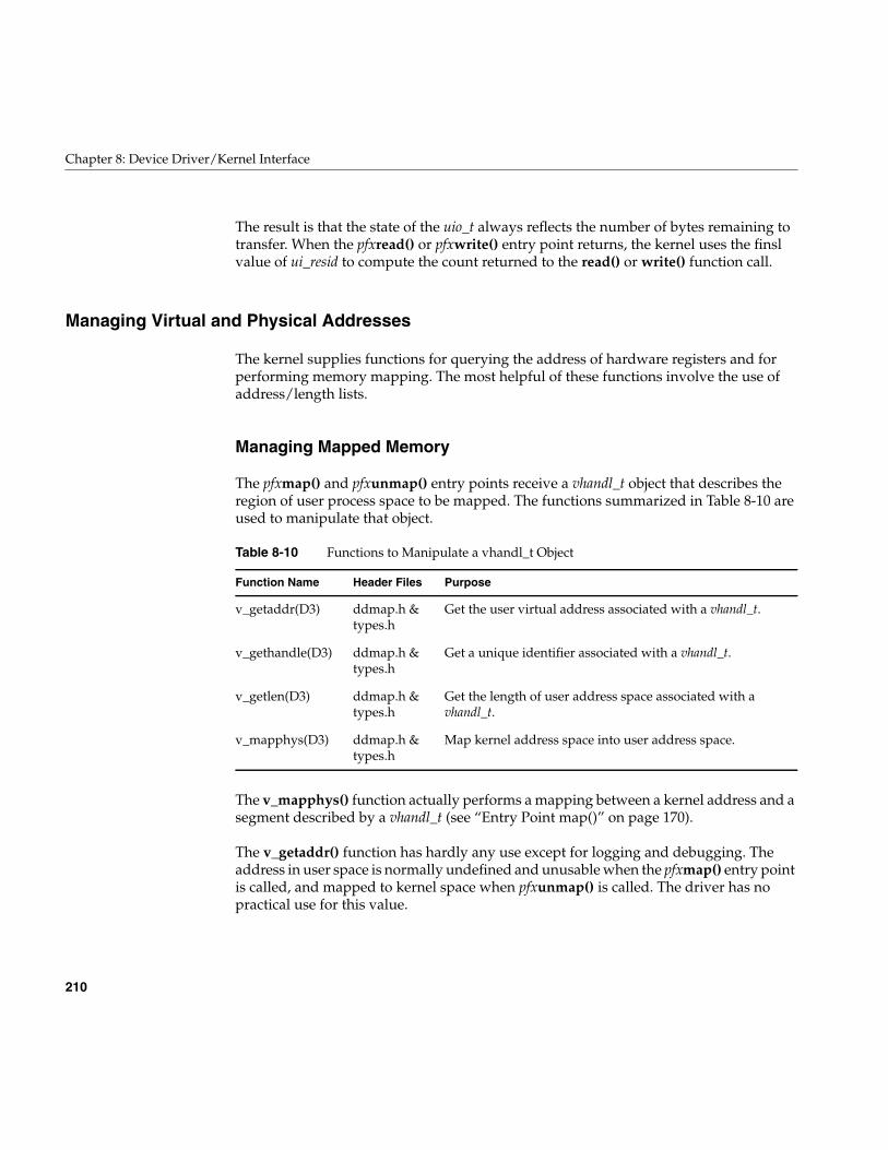
210
Chapter 8: Device Driver/Kernel Interface
The result is that the state of the uio_t always reflects the number of bytes remaining totransfer. When the pfxread() or pfxwrite() entry point returns, the kernel uses the finslvalue of ui_resid to compute the count returned to the read() or write() function call.
Managing Virtual and Physical Addresses
The kernel supplies functions for querying the address of hardware registers and forperforming memory mapping. The most helpful of these functions involve the use ofaddress/length lists.
Managing Mapped Memory
The pfxmap() and pfxunmap() entry points receive a vhandl_t object that describes theregion of user process space to be mapped. The functions summarized in Table 8-10 areused to manipulate that object.
The v_mapphys() function actually performs a mapping between a kernel address and asegment described by a vhandl_t (see “Entry Point map()” on page 170).
The v_getaddr() function has hardly any use except for logging and debugging. Theaddress in user space is normally undefined and unusable when the pfxmap() entry pointis called, and mapped to kernel space when pfxunmap() is called. The driver has nopractical use for this value.
Table 8-10 Functions to Manipulate a vhandl_t Object
Function Name Header Files Purpose
v_getaddr(D3) ddmap.h &types.h
Get the user virtual address associated with a vhandl_t.
v_gethandle(D3) ddmap.h &types.h
Get a unique identifier associated with a vhandl_t.
v_getlen(D3) ddmap.h &types.h
Get the length of user address space associated with avhandl_t.
v_mapphys(D3) ddmap.h &types.h
Map kernel address space into user address space.
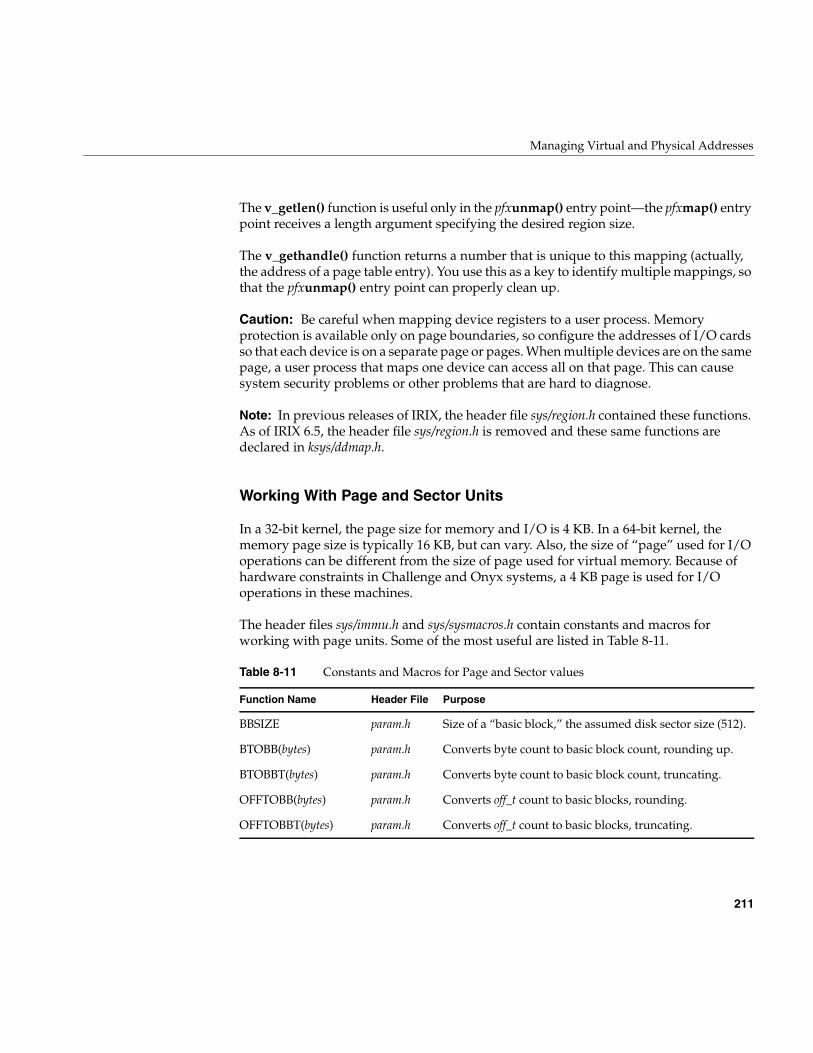
Managing Virtual and Physical Addresses
211
The v_getlen() function is useful only in the pfxunmap() entry point—the pfxmap() entrypoint receives a length argument specifying the desired region size.
The v_gethandle() function returns a number that is unique to this mapping (actually,the address of a page table entry). You use this as a key to identify multiple mappings, sothat the pfxunmap() entry point can properly clean up.
Caution: Be careful when mapping device registers to a user process. Memoryprotection is available only on page boundaries, so configure the addresses of I/O cardsso that each device is on a separate page or pages. When multiple devices are on the samepage, a user process that maps one device can access all on that page. This can causesystem security problems or other problems that are hard to diagnose.
Note: In previous releases of IRIX, the header file sys/region.h contained these functions.As of IRIX 6.5, the header file sys/region.h is removed and these same functions aredeclared in ksys/ddmap.h.
Working With Page and Sector Units
In a 32-bit kernel, the page size for memory and I/O is 4 KB. In a 64-bit kernel, thememory page size is typically 16 KB, but can vary. Also, the size of “page” used for I/Ooperations can be different from the size of page used for virtual memory. Because ofhardware constraints in Challenge and Onyx systems, a 4 KB page is used for I/Ooperations in these machines.
The header files sys/immu.h and sys/sysmacros.h contain constants and macros forworking with page units. Some of the most useful are listed in Table 8-11.
Table 8-11 Constants and Macros for Page and Sector values
Function Name Header File Purpose
BBSIZE param.h Size of a “basic block,” the assumed disk sector size (512).
BTOBB(bytes) param.h Converts byte count to basic block count, rounding up.
BTOBBT(bytes) param.h Converts byte count to basic block count, truncating.
OFFTOBB(bytes) param.h Converts off_t count to basic blocks, rounding.
OFFTOBBT(bytes) param.h Converts off_t count to basic blocks, truncating.
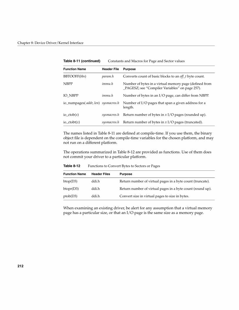
212
Chapter 8: Device Driver/Kernel Interface
The names listed in Table 8-11 are defined at compile-time. If you use them, the binaryobject file is dependent on the compile-time variables for the chosen platform, and maynot run on a different platform.
The operations summarized in Table 8-12 are provided as functions. Use of them doesnot commit your driver to a particular platform.
When examining an existing driver, be alert for any assumption that a virtual memorypage has a particular size, or that an I/O page is the same size as a memory page.
BBTOOFF(bbs) param.h Converts count of basic blocks to an off_t byte count.
NBPP immu.h Number of bytes in a virtual memory page (defined from_PAGESZ; see “Compiler Variables” on page 257).
IO_NBPP immu.h Number of bytes in an I/O page, can differ from NBPP.
io_numpages( addr, len) sysmacros.h Number of I/O pages that span a given address for alength.
io_ctob(x) sysmacros.h Return number of bytes in x I/O pages (rounded up).
io_ctobt(x) sysmacros.h Return number of bytes in x I/O pages (truncated).
Table 8-12 Functions to Convert Bytes to Sectors or Pages
Function Name Header Files Purpose
btop(D3) ddi.h Return number of virtual pages in a byte count (truncate).
btopr(D3) ddi.h Return number of virtual pages in a byte count (round up).
ptob(D3) ddi.h Convert size in virtual pages to size in bytes.
Table 8-11 (continued) Constants and Macros for Page and Sector values
Function Name Header File Purpose
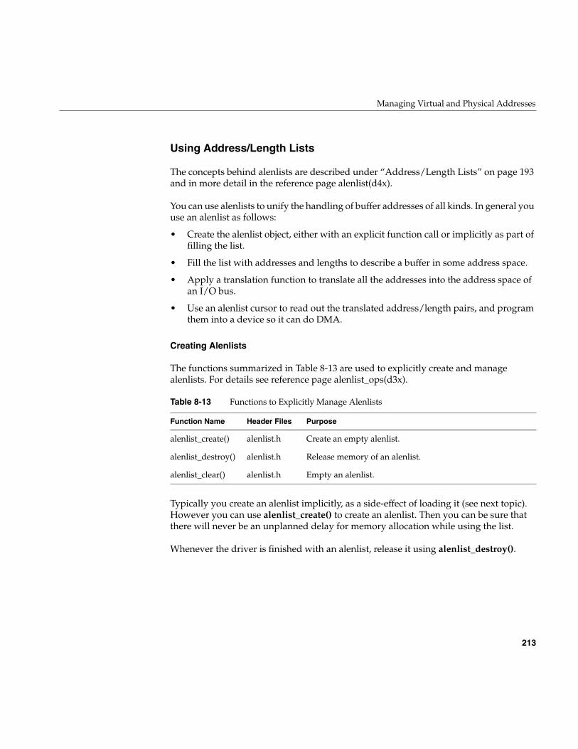
Managing Virtual and Physical Addresses
213
Using Address/Length Lists
The concepts behind alenlists are described under “Address/Length Lists” on page 193and in more detail in the reference page alenlist(d4x).
You can use alenlists to unify the handling of buffer addresses of all kinds. In general youuse an alenlist as follows:
• Create the alenlist object, either with an explicit function call or implicitly as part offilling the list.
• Fill the list with addresses and lengths to describe a buffer in some address space.
• Apply a translation function to translate all the addresses into the address space ofan I/O bus.
• Use an alenlist cursor to read out the translated address/length pairs, and programthem into a device so it can do DMA.
Creating Alenlists
The functions summarized in Table 8-13 are used to explicitly create and managealenlists. For details see reference page alenlist_ops(d3x).
Typically you create an alenlist implicitly, as a side-effect of loading it (see next topic).However you can use alenlist_create() to create an alenlist. Then you can be sure thatthere will never be an unplanned delay for memory allocation while using the list.
Whenever the driver is finished with an alenlist, release it using alenlist_destroy().
Table 8-13 Functions to Explicitly Manage Alenlists
Function Name Header Files Purpose
alenlist_create() alenlist.h Create an empty alenlist.
alenlist_destroy() alenlist.h Release memory of an alenlist.
alenlist_clear() alenlist.h Empty an alenlist.
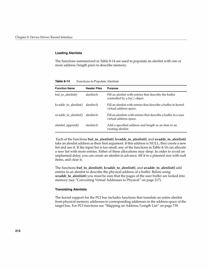
214
Chapter 8: Device Driver/Kernel Interface
Loading Alenlists
The functions summarized in Table 8-14 are used to populate an alenlist with one ormore address/length pairs to describe memory.
Each of the functions buf_to_alenlist(), kvaddr_to_alenlist(), and uvaddr_to_alenlist()take an alenlist address as their first argument. If this address is NULL, they create a newlist and use it. If the input list is too small, any of the functions in Table 8-14 can allocatea new list with more entries. Either of these allocations may sleep. In order to avoid anunplanned delay, you can create an alenlist in advance, fill it to a planned size with nullitems, and clear it.
The functions buf_to_alenlist(), kvaddr_to_alenlist(), and uvaddr_to_alenlist() addentries to an alenlist to describe the physical address of a buffer. Before usinguvaddr_to_alenlist() you must be sure that the pages of the user buffer are locked intomemory (see “Converting Virtual Addresses to Physical” on page 217).
Translating Alenlists
The kernel support for the PCI bus includes functions that translate an entire alenlistfrom physical memory addresses to corresponding addresses in the address space of thetarget bus. For PCI functions see “Mapping an Address/Length List” on page 739.
Table 8-14 Functions to Populate Alenlists
Function Name Header Files Purpose
buf_to_alenlist() alenlist.h Fill an alenlist with entries that describe the buffercontrolled by a buf_t object.
kvaddr_to_alenlist() alenlist.h Fill an alenlist with entries that describe a buffer in kernelvirtual address space.
uvaddr_to_alenlist() alenlist.h Fill an alenlists with entries that describe a buffer in a uservirtual address space.
alenlist_append() alenlist.h Add a specified address and length as an item to anexisting alenlist.
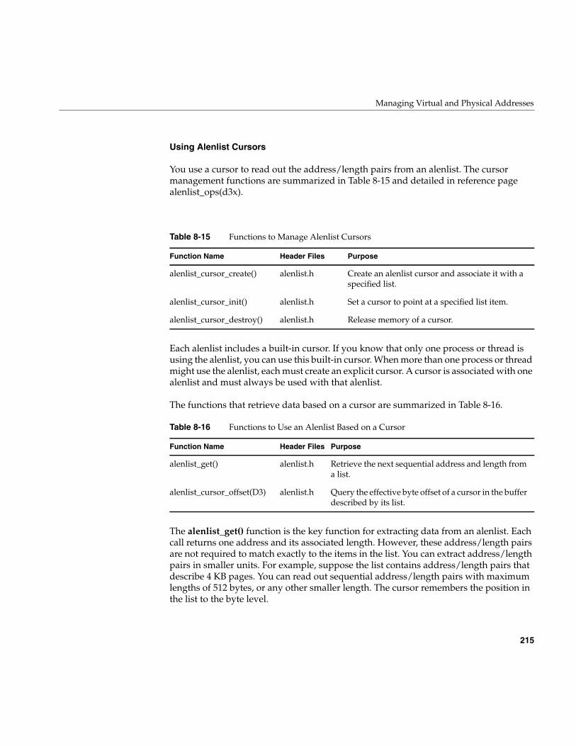
Managing Virtual and Physical Addresses
215
Using Alenlist Cursors
You use a cursor to read out the address/length pairs from an alenlist. The cursormanagement functions are summarized in Table 8-15 and detailed in reference pagealenlist_ops(d3x).
Each alenlist includes a built-in cursor. If you know that only one process or thread isusing the alenlist, you can use this built-in cursor. When more than one process or threadmight use the alenlist, each must create an explicit cursor. A cursor is associated with onealenlist and must always be used with that alenlist.
The functions that retrieve data based on a cursor are summarized in Table 8-16.
The alenlist_get() function is the key function for extracting data from an alenlist. Eachcall returns one address and its associated length. However, these address/length pairsare not required to match exactly to the items in the list. You can extract address/lengthpairs in smaller units. For example, suppose the list contains address/length pairs thatdescribe 4 KB pages. You can read out sequential address/length pairs with maximumlengths of 512 bytes, or any other smaller length. The cursor remembers the position inthe list to the byte level.
Table 8-15 Functions to Manage Alenlist Cursors
Function Name Header Files Purpose
alenlist_cursor_create() alenlist.h Create an alenlist cursor and associate it with aspecified list.
alenlist_cursor_init() alenlist.h Set a cursor to point at a specified list item.
alenlist_cursor_destroy() alenlist.h Release memory of a cursor.
Table 8-16 Functions to Use an Alenlist Based on a Cursor
Function Name Header Files Purpose
alenlist_get() alenlist.h Retrieve the next sequential address and length froma list.
alenlist_cursor_offset(D3) alenlist.h Query the effective byte offset of a cursor in the bufferdescribed by its list.
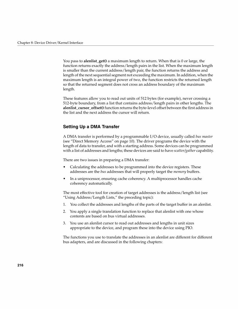
216
Chapter 8: Device Driver/Kernel Interface
You pass to alenlist_get() a maximum length to return. When that is 0 or large, thefunction returns exactly the address/length pairs in the list. When the maximum lengthis smaller than the current address/length pair, the function returns the address andlength of the next sequential segment not exceeding the maximum. In addition, when themaximum length is an integral power of two, the function restricts the returned lengthso that the returned segment does not cross an address boundary of the maximumlength.
These features allow you to read out units of 512 bytes (for example), never crossing a512-byte boundary, from a list that contains address/length pairs in other lengths. Thealenlist_cursor_offset() function returns the byte-level offset between the first address inthe list and the next address the cursor will return.
Setting Up a DMA Transfer
A DMA transfer is performed by a programmable I/O device, usually called bus master(see “Direct Memory Access” on page 10). The driver programs the device with thelength of data to transfer, and with a starting address. Some devices can be programmedwith a list of addresses and lengths; these devices are said to have scatter/gather capability.
There are two issues in preparing a DMA transfer:
• Calculating the addresses to be programmed into the device registers. Theseaddresses are the bus addresses that will properly target the memory buffers.
• In a uniprocessor, ensuring cache coherency. A multiprocessor handles cachecoherency automatically.
The most effective tool for creation of target addresses is the address/length list (see“Using Address/Length Lists,” the preceding topic):
1. You collect the addresses and lengths of the parts of the target buffer in an alenlist.
2. You apply a single translation function to replace that alenlist with one whosecontents are based on bus virtual addresses.
3. You use an alenlist cursor to read out addresses and lengths in unit sizesappropriate to the device, and program these into the device using PIO.
The functions you use to translate the addresses in an alenlist are different for differentbus adapters, and are discussed in the following chapters:
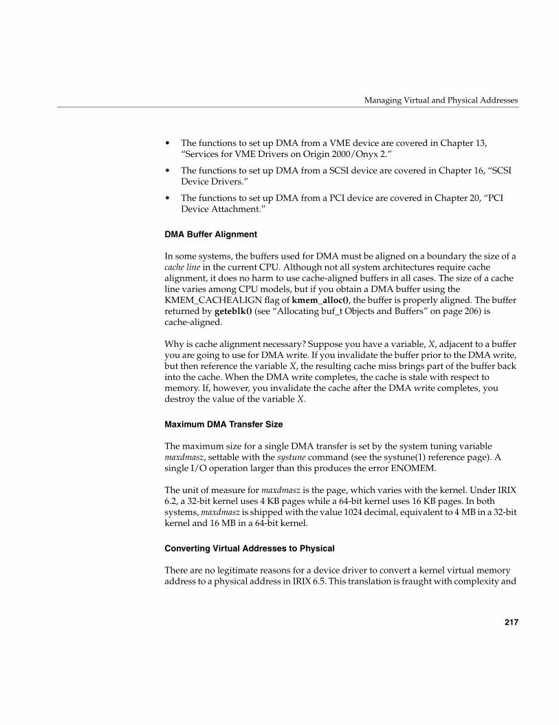
Managing Virtual and Physical Addresses
217
• The functions to set up DMA from a VME device are covered in Chapter 13,“Services for VME Drivers on Origin 2000/Onyx 2.”
• The functions to set up DMA from a SCSI device are covered in Chapter 16, “SCSIDevice Drivers.”
• The functions to set up DMA from a PCI device are covered in Chapter 20, “PCIDevice Attachment.”
DMA Buffer Alignment
In some systems, the buffers used for DMA must be aligned on a boundary the size of acache line in the current CPU. Although not all system architectures require cachealignment, it does no harm to use cache-aligned buffers in all cases. The size of a cacheline varies among CPU models, but if you obtain a DMA buffer using theKMEM_CACHEALIGN flag of kmem_alloc(), the buffer is properly aligned. The bufferreturned by geteblk() (see “Allocating buf_t Objects and Buffers” on page 206) iscache-aligned.
Why is cache alignment necessary? Suppose you have a variable, X, adjacent to a bufferyou are going to use for DMA write. If you invalidate the buffer prior to the DMA write,but then reference the variable X, the resulting cache miss brings part of the buffer backinto the cache. When the DMA write completes, the cache is stale with respect tomemory. If, however, you invalidate the cache after the DMA write completes, youdestroy the value of the variable X.
Maximum DMA Transfer Size
The maximum size for a single DMA transfer is set by the system tuning variablemaxdmasz, settable with the systune command (see the systune(1) reference page). Asingle I/O operation larger than this produces the error ENOMEM.
The unit of measure for maxdmasz is the page, which varies with the kernel. Under IRIX6.2, a 32-bit kernel uses 4 KB pages while a 64-bit kernel uses 16 KB pages. In bothsystems, maxdmasz is shipped with the value 1024 decimal, equivalent to 4 MB in a 32-bitkernel and 16 MB in a 64-bit kernel.
Converting Virtual Addresses to Physical
There are no legitimate reasons for a device driver to convert a kernel virtual memoryaddress to a physical address in IRIX 6.5. This translation is fraught with complexity and
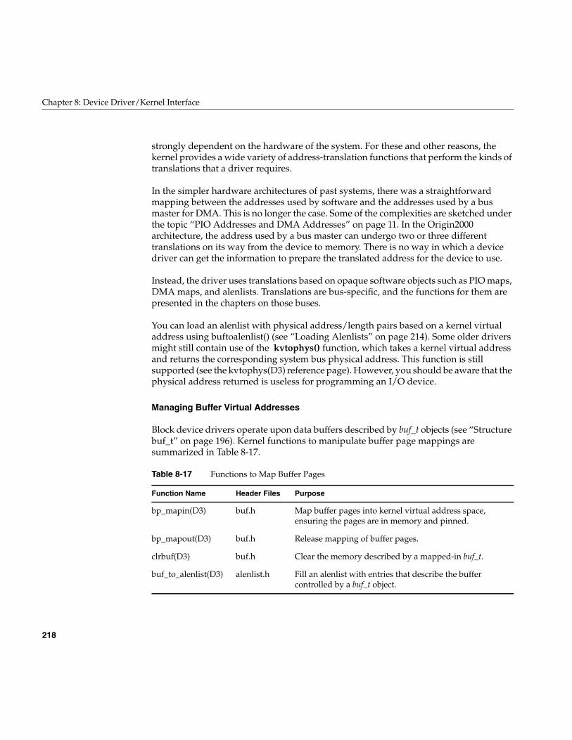
218
Chapter 8: Device Driver/Kernel Interface
strongly dependent on the hardware of the system. For these and other reasons, thekernel provides a wide variety of address-translation functions that perform the kinds oftranslations that a driver requires.
In the simpler hardware architectures of past systems, there was a straightforwardmapping between the addresses used by software and the addresses used by a busmaster for DMA. This is no longer the case. Some of the complexities are sketched underthe topic “PIO Addresses and DMA Addresses” on page 11. In the Origin2000architecture, the address used by a bus master can undergo two or three differenttranslations on its way from the device to memory. There is no way in which a devicedriver can get the information to prepare the translated address for the device to use.
Instead, the driver uses translations based on opaque software objects such as PIO maps,DMA maps, and alenlists. Translations are bus-specific, and the functions for them arepresented in the chapters on those buses.
You can load an alenlist with physical address/length pairs based on a kernel virtualaddress using buftoalenlist() (see “Loading Alenlists” on page 214). Some older driversmight still contain use of the kvtophys() function, which takes a kernel virtual addressand returns the corresponding system bus physical address. This function is stillsupported (see the kvtophys(D3) reference page). However, you should be aware that thephysical address returned is useless for programming an I/O device.
Managing Buffer Virtual Addresses
Block device drivers operate upon data buffers described by buf_t objects (see “Structurebuf_t” on page 196). Kernel functions to manipulate buffer page mappings aresummarized in Table 8-17.
Table 8-17 Functions to Map Buffer Pages
Function Name Header Files Purpose
bp_mapin(D3) buf.h Map buffer pages into kernel virtual address space,ensuring the pages are in memory and pinned.
bp_mapout(D3) buf.h Release mapping of buffer pages.
clrbuf(D3) buf.h Clear the memory described by a mapped-in buf_t.
buf_to_alenlist(D3) alenlist.h Fill an alenlist with entries that describe the buffercontrolled by a buf_t object.
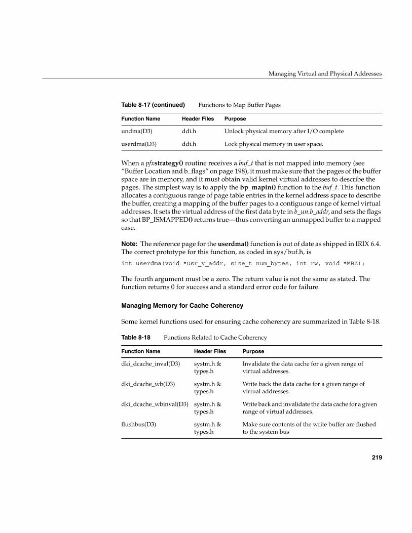
Managing Virtual and Physical Addresses
219
When a pfxstrategy() routine receives a buf_t that is not mapped into memory (see“Buffer Location and b_flags” on page 198), it must make sure that the pages of the bufferspace are in memory, and it must obtain valid kernel virtual addresses to describe thepages. The simplest way is to apply the bp_mapin() function to the buf_t. This functionallocates a contiguous range of page table entries in the kernel address space to describethe buffer, creating a mapping of the buffer pages to a contiguous range of kernel virtualaddresses. It sets the virtual address of the first data byte in b_un.b_addr, and sets the flagsso that BP_ISMAPPED() returns true—thus converting an unmapped buffer to a mappedcase.
Note: The reference page for the userdma() function is out of date as shipped in IRIX 6.4.The correct prototype for this function, as coded in sys/buf.h, is
int userdma(void *usr_v_addr, size_t num_bytes, int rw, void *MBZ);
The fourth argument must be a zero. The return value is not the same as stated. Thefunction returns 0 for success and a standard error code for failure.
Managing Memory for Cache Coherency
Some kernel functions used for ensuring cache coherency are summarized in Table 8-18.
undma(D3) ddi.h Unlock physical memory after I/O complete
userdma(D3) ddi.h Lock physical memory in user space.
Table 8-18 Functions Related to Cache Coherency
Function Name Header Files Purpose
dki_dcache_inval(D3) systm.h &types.h
Invalidate the data cache for a given range ofvirtual addresses.
dki_dcache_wb(D3) systm.h &types.h
Write back the data cache for a given range ofvirtual addresses.
dki_dcache_wbinval(D3) systm.h &types.h
Write back and invalidate the data cache for a givenrange of virtual addresses.
flushbus(D3) systm.h &types.h
Make sure contents of the write buffer are flushedto the system bus
Table 8-17 (continued) Functions to Map Buffer Pages
Function Name Header Files Purpose
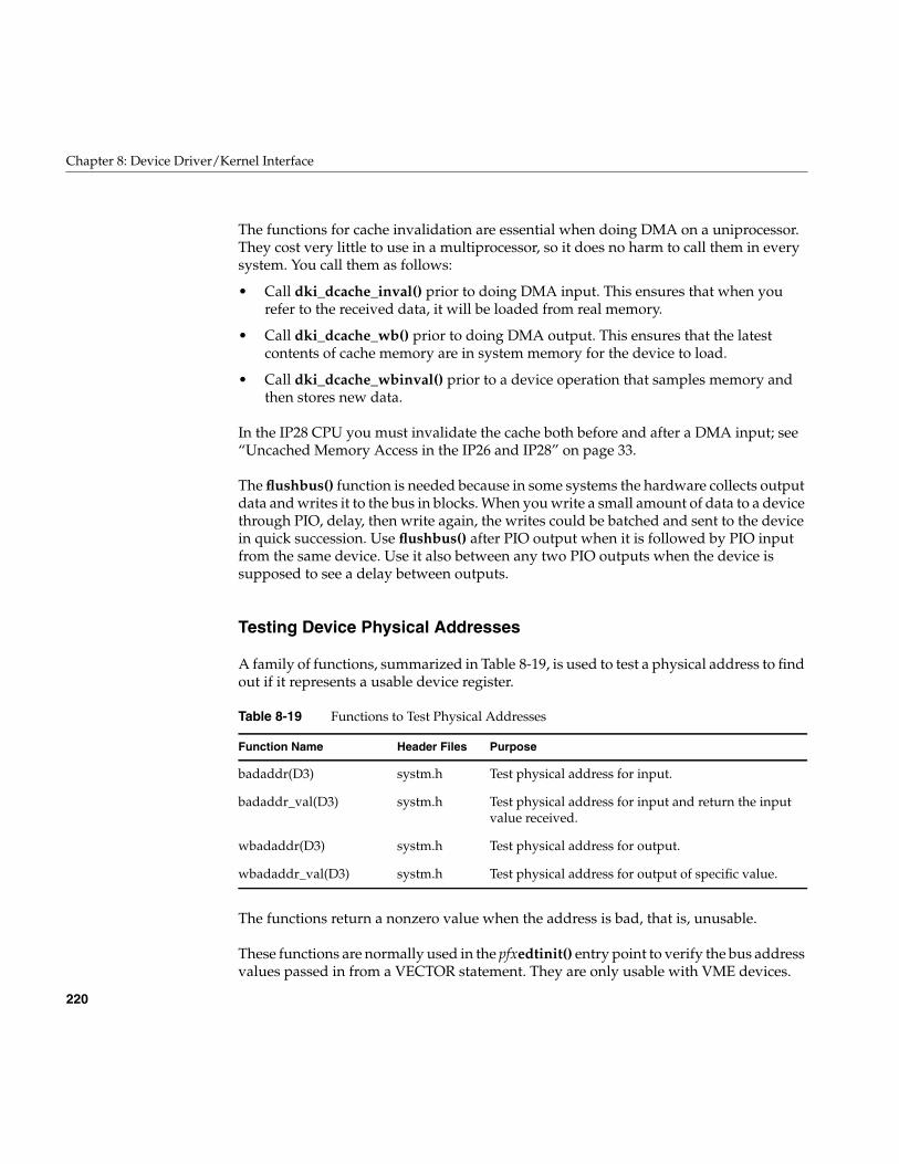
220
Chapter 8: Device Driver/Kernel Interface
The functions for cache invalidation are essential when doing DMA on a uniprocessor.They cost very little to use in a multiprocessor, so it does no harm to call them in everysystem. You call them as follows:
• Call dki_dcache_inval() prior to doing DMA input. This ensures that when yourefer to the received data, it will be loaded from real memory.
• Call dki_dcache_wb() prior to doing DMA output. This ensures that the latestcontents of cache memory are in system memory for the device to load.
• Call dki_dcache_wbinval() prior to a device operation that samples memory andthen stores new data.
In the IP28 CPU you must invalidate the cache both before and after a DMA input; see“Uncached Memory Access in the IP26 and IP28” on page 33.
The flushbus() function is needed because in some systems the hardware collects outputdata and writes it to the bus in blocks. When you write a small amount of data to a devicethrough PIO, delay, then write again, the writes could be batched and sent to the devicein quick succession. Use flushbus() after PIO output when it is followed by PIO inputfrom the same device. Use it also between any two PIO outputs when the device issupposed to see a delay between outputs.
Testing Device Physical Addresses
A family of functions, summarized in Table 8-19, is used to test a physical address to findout if it represents a usable device register.
The functions return a nonzero value when the address is bad, that is, unusable.
These functions are normally used in the pfxedtinit() entry point to verify the bus addressvalues passed in from a VECTOR statement. They are only usable with VME devices.
Table 8-19 Functions to Test Physical Addresses
Function Name Header Files Purpose
badaddr(D3) systm.h Test physical address for input.
badaddr_val(D3) systm.h Test physical address for input and return the inputvalue received.
wbadaddr(D3) systm.h Test physical address for output.
wbadaddr_val(D3) systm.h Test physical address for output of specific value.
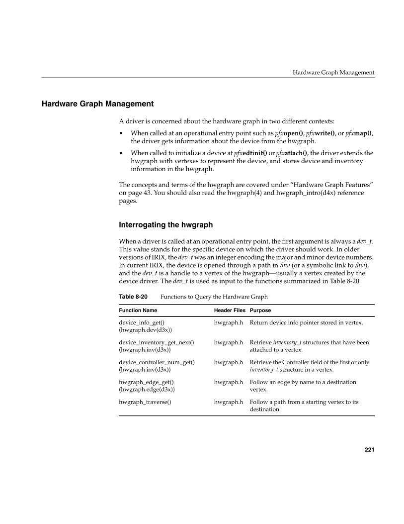
Hardware Graph Management
221
Hardware Graph Management
A driver is concerned about the hardware graph in two different contexts:
• When called at an operational entry point such as pfxopen(), pfxwrite(), or pfxmap(),the driver gets information about the device from the hwgraph.
• When called to initialize a device at pfxedtinit() or pfxattach(), the driver extends thehwgraph with vertexes to represent the device, and stores device and inventoryinformation in the hwgraph.
The concepts and terms of the hwgraph are covered under “Hardware Graph Features”on page 43. You should also read the hwgraph(4) and hwgraph_intro(d4x) referencepages.
Interrogating the hwgraph
When a driver is called at an operational entry point, the first argument is always a dev_t.This value stands for the specific device on which the driver should work. In olderversions of IRIX, the dev_t was an integer encoding the major and minor device numbers.In current IRIX, the device is opened through a path in /hw (or a symbolic link to /hw),and the dev_t is a handle to a vertex of the hwgraph—usually a vertex created by thedevice driver. The dev_t is used as input to the functions summarized in Table 8-20.
Table 8-20 Functions to Query the Hardware Graph
Function Name Header Files Purpose
device_info_get()(hwgraph.dev(d3x))
hwgraph.h Return device info pointer stored in vertex.
device_inventory_get_next()(hwgraph.inv(d3x))
hwgraph.h Retrieve inventory_t structures that have beenattached to a vertex.
device_controller_num_get()(hwgraph.inv(d3x))
hwgraph.h Retrieve the Controller field of the first or onlyinventory_t structure in a vertex.
hwgraph_edge_get()(hwgraph.edge(d3x))
hwgraph.h Follow an edge by name to a destinationvertex.
hwgraph_traverse() hwgraph.h Follow a path from a starting vertex to itsdestination.
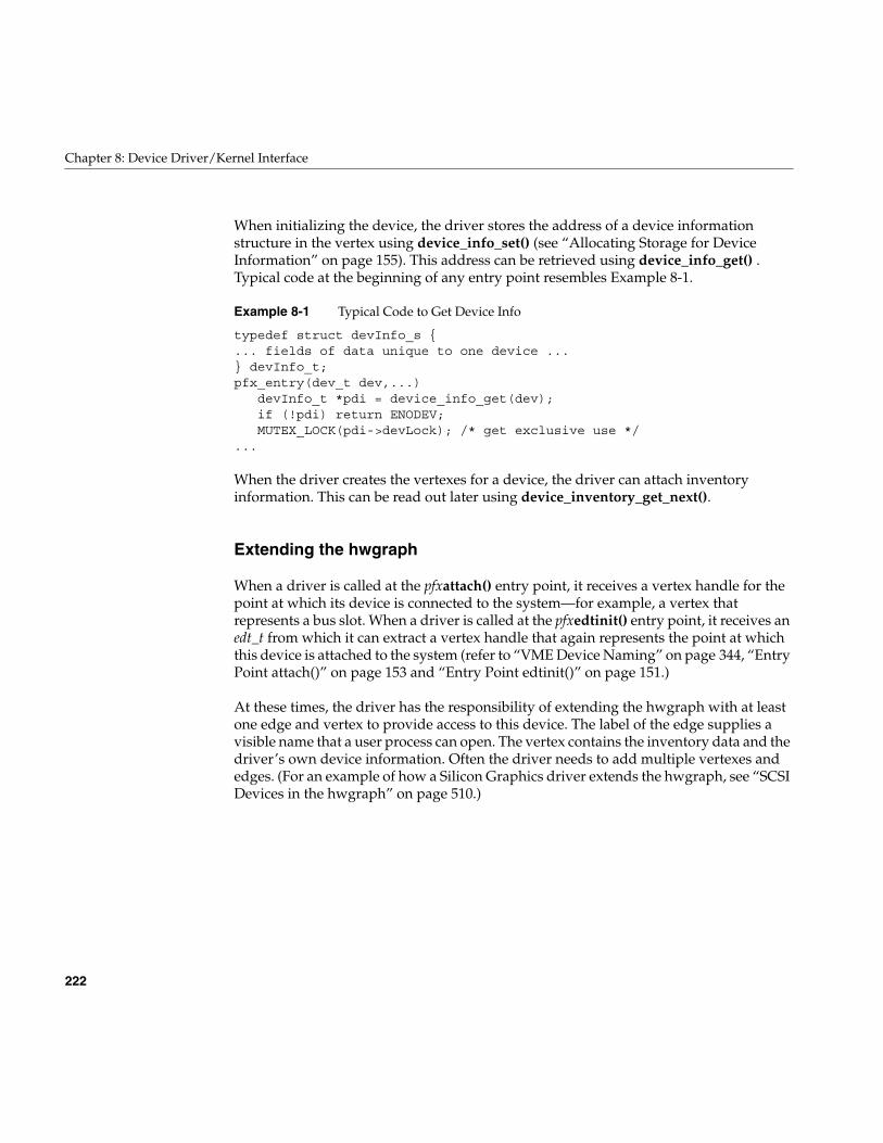
222
Chapter 8: Device Driver/Kernel Interface
When initializing the device, the driver stores the address of a device informationstructure in the vertex using device_info_set() (see “Allocating Storage for DeviceInformation” on page 155). This address can be retrieved using device_info_get() .Typical code at the beginning of any entry point resembles Example 8-1.
Example 8-1 Typical Code to Get Device Info
typedef struct devInfo_s {... fields of data unique to one device ...} devInfo_t;pfx_entry(dev_t dev,...)
devInfo_t *pdi = device_info_get(dev);if (!pdi) return ENODEV;MUTEX_LOCK(pdi->devLock); /* get exclusive use */
...
When the driver creates the vertexes for a device, the driver can attach inventoryinformation. This can be read out later using device_inventory_get_next().
Extending the hwgraph
When a driver is called at the pfxattach() entry point, it receives a vertex handle for thepoint at which its device is connected to the system—for example, a vertex thatrepresents a bus slot. When a driver is called at the pfxedtinit() entry point, it receives anedt_t from which it can extract a vertex handle that again represents the point at whichthis device is attached to the system (refer to “VME Device Naming” on page 344, “EntryPoint attach()” on page 153 and “Entry Point edtinit()” on page 151.)
At these times, the driver has the responsibility of extending the hwgraph with at leastone edge and vertex to provide access to this device. The label of the edge supplies avisible name that a user process can open. The vertex contains the inventory data and thedriver’s own device information. Often the driver needs to add multiple vertexes andedges. (For an example of how a Silicon Graphics driver extends the hwgraph, see “SCSIDevices in the hwgraph” on page 510.)
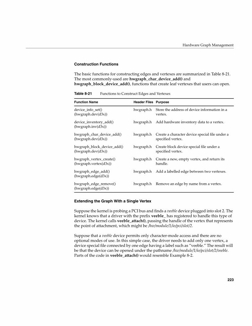
Hardware Graph Management
223
Construction Functions
The basic functions for constructing edges and vertexes are summarized in Table 8-21.The most commonly-used are hwgraph_char_device_add() andhwgraph_block_device_add(), functions that create leaf vertexes that users can open.
Extending the Graph With a Single Vertex
Suppose the kernel is probing a PCI bus and finds a veeble device plugged into slot 2. Thekernel knows that a driver with the prefix veeble_ has registered to handle this type ofdevice. The kernel calls veeble_attach(), passing the handle of the vertex that representsthe point of attachment, which might be /hw/module/1/io/pci/slot/2.
Suppose that a veeble device permits only character-mode access and there are nooptional modes of use. In this simple case, the driver needs to add only one vertex, adevice special file connected by one edge having a label such as “veeble.” The result willbe that the device can be opened under the pathname /hw/module/1/io/pci/slot/2/veeble.Parts of the code in veeble_attach() would resemble Example 8-2.
Table 8-21 Functions to Construct Edges and Vertexes
Function Name Header Files Purpose
device_info_set()(hwgraph.dev(d3x))
hwgraph.h Store the address of device information in avertex.
device_inventory_add()(hwgraph.inv(d3x))
hwgraph.h Add hardware inventory data to a vertex.
hwgraph_char_device_add()(hwgraph.dev(d3x))
hwgraph.h Create a character device special file under aspecified vertex.
hwgraph_block_device_add()(hwgraph.dev(d3x))
hwgraph.h Create block device special file under aspecified vertex.
hwgraph_vertex_create()(hwgraph.vertex(d3x))
hwgraph.h Create a new, empty vertex, and return itshandle.
hwgraph_edge_add()(hwgraph.edge(d3x))
hwgraph.h Add a labelled edge between two vertexes.
hwgraph_edge_remove()(hwgraph.edge(d3x))
hwgraph.h Remove an edge by name from a vertex.
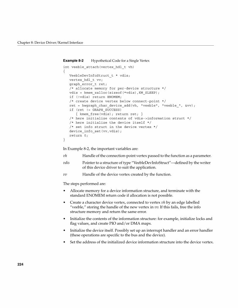
224
Chapter 8: Device Driver/Kernel Interface
Example 8-2 Hypothetical Code for a Single Vertex
int veeble_attach(vertex_hdl_t vh){
VeebleDevInfoStruct_t * vdis;vertex_hdl_t vv;graph_error_t ret;/* allocate memory for per-device structure */vdis = kmem_zalloc(sizeof(*vdis),KM_SLEEP);if (!vdis) return ENOMEM;/* create device vertex below connect-point */ret = hwgraph_char_device_add(vh, "veeble", "veeble_", &vv);if (ret != GRAPH_SUCCESS)
{ kmem_free(vdis); return ret; }/* here initialize contents of vdis->information struct *//* here initialize the device itself *//* set info struct in the device vertex */device_info_set(vv,vdis);return 0;
}
In Example 8-2, the important variables are:
The steps performed are:
• Allocate memory for a device information structure, and terminate with thestandard ENOMEM return code if allocation is not possible.
• Create a character device vertex, connected to vertex vh by an edge labelled“veeble,” storing the handle of the new vertex in vv. If this fails, free the infostructure memory and return the same error.
• Initialize the contents of the information structure: for example, initialize locks andflag values, and create PIO and/or DMA maps.
• Initialize the device itself. Possibly set up an interrupt handler and an error handler(these operations are specific to the bus and the device).
• Set the address of the initialized device information structure into the device vertex.
vh Handle of the connection-point vertex passed to the function as a parameter.
vdis Pointer to a structure of type “VeebleDevInfoStruct”—defined by the writerof this device driver to suit the application.
vv Handle of the device vertex created by the function.
Hardware Graph Management
225
An additional step not shown is the storing of hardware inventory information that canbe reported by hinv using device_inventory_add().
A point to note is that in a multiprocessor system, a user process could try to open thenew “veeble” vertex as soon as (or even before) hwgraph_char_device_add() returns.This would result in an entry to the veeble_open() entry point of the driver, concurrentwith the continued execution of the veeble_attach() entry point. However, note the twostatements in Example 8-1:
devInfo_t *pdi = device_info_get(dev);if (!pdi) return ENODEV;
At any time before veeble_attach() executes its call to device_info_set(), a call toveeble_open() for this vertex returns ENODEV. Needless to say, all the hwgraphfunctions are multiprocessor-aware and use locking as necessary to avoid raceconditions.
Extending the Graph With Multiple Vertexes
In a more complicated case, a vooble device permits access as a block device or as acharacter device. The device should be accessible under names vooble/char andvooble/block. In this case the driver proceeds as follows:
1. Create a vertex to be the primary representation of the device usinghwgraph_vertex_create().
2. Connect this primary vertex to the point of attachment with an edge named“vooble” using hwgraph_edge_add().
3. Add new vertexes, connected by edges “block” and “char” to the primary vertexusing hwgraph_block_device_add() and hwgraph_char_device_add().
The subordinate block and character vertexes are device special files that can be openedby user code. Handles to these vertexes will be passed in to other driver entry points.There are a variety of ways to store device information in the three vertexes:
• Store a pointer to a single information structure in both leaf vertexes.
• Create separate “block” and “char” information structures and store one in each leafvertex. Perhaps create a separate structure of information that is common to bothblock and character access, and point to it from both block and char structures.
226
Chapter 8: Device Driver/Kernel Interface
As you plan this arrangement of data structures, bear in mind that the pfxopen() entrypoint receives a flag telling it whether the open is for block or character access (see “EntryPoint open()” on page 157); and that other entry points are called only for block, or onlyfor character, devices.
Vertexes for Modes of Use
Possibly the device has multiple modes of use, as for example a tape device hasbyte-swapped and non-swapped access, fixed-block and variable-block access, and soon. Traditionally these modes of access were encoded in the device minor number as wellas in the device name (see “Creating Conventional Device Names” on page 40). Currentpractice is to create a separate vertex for each mode of use (see “Multiple Device Names”on page 37).
When using the hwgraph, you represent each mode of access as a separate name in the/hw filesystem. Suppose that a PCI device of type flipper supports two modes of use,“flipped” and “flopped.” It is the job of the flipper_attach() entry point to set uphwgraph vertexes so that one device can be opened under different pathnames such as/hw/module/1/io/pci/slot/2/flipper/flipped and /hw/module/1/io/pci/slot/2/flipper/flopped. Theproblem is very similar to creating separate block and character vertexes for one device,with the additional problem that the device information stored in each vertex shouldreflect the desired mode of use, flipped or flopped. The code might resemble in part thatshown in Example 8-3.
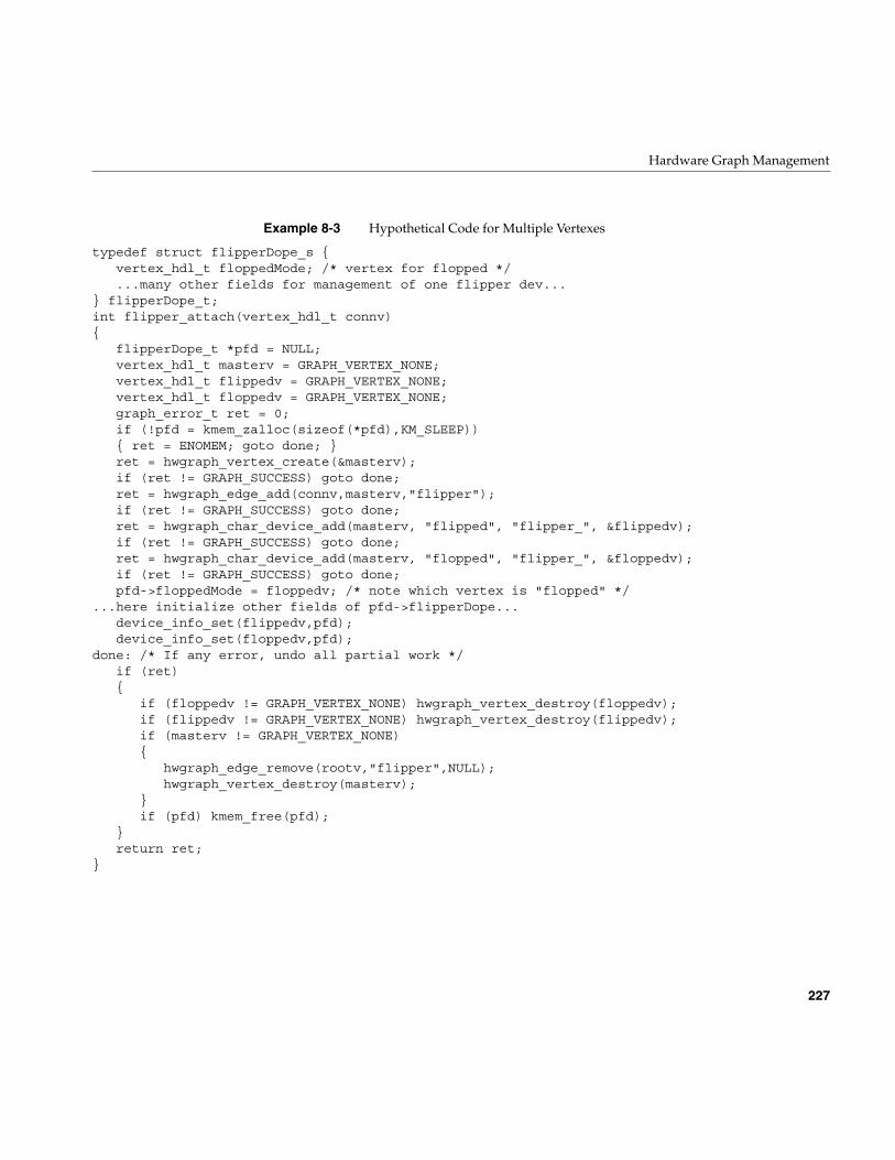
Hardware Graph Management
227
Example 8-3 Hypothetical Code for Multiple Vertexes
typedef struct flipperDope_s {vertex_hdl_t floppedMode; /* vertex for flopped */...many other fields for management of one flipper dev...
} flipperDope_t;int flipper_attach(vertex_hdl_t connv){
flipperDope_t *pfd = NULL;vertex_hdl_t masterv = GRAPH_VERTEX_NONE;vertex_hdl_t flippedv = GRAPH_VERTEX_NONE;vertex_hdl_t floppedv = GRAPH_VERTEX_NONE;graph_error_t ret = 0;if (!pfd = kmem_zalloc(sizeof(*pfd),KM_SLEEP)){ ret = ENOMEM; goto done; }ret = hwgraph_vertex_create(&masterv);if (ret != GRAPH_SUCCESS) goto done;ret = hwgraph_edge_add(connv,masterv,"flipper");if (ret != GRAPH_SUCCESS) goto done;ret = hwgraph_char_device_add(masterv, "flipped", "flipper_", &flippedv);if (ret != GRAPH_SUCCESS) goto done;ret = hwgraph_char_device_add(masterv, "flopped", "flipper_", &floppedv);if (ret != GRAPH_SUCCESS) goto done;pfd->floppedMode = floppedv; /* note which vertex is "flopped" */
...here initialize other fields of pfd->flipperDope...device_info_set(flippedv,pfd);device_info_set(floppedv,pfd);
done: /* If any error, undo all partial work */if (ret){
if (floppedv != GRAPH_VERTEX_NONE) hwgraph_vertex_destroy(floppedv);if (flippedv != GRAPH_VERTEX_NONE) hwgraph_vertex_destroy(flippedv);if (masterv != GRAPH_VERTEX_NONE){
hwgraph_edge_remove(rootv,"flipper",NULL);hwgraph_vertex_destroy(masterv);
}if (pfd) kmem_free(pfd);
}return ret;
}
228
Chapter 8: Device Driver/Kernel Interface
After successful completion of flipper_attach() there are two character special deviceswith paths /hw/.../flipper/flipped and /hw/.../flipper/flopped. A pointer to a single deviceinformation structure (a flipperDope_t object) is stored in both vertexes. However, thevertex handle of the flopped vertex is saved in the floppedMode field of the structure.Whenever the device driver is entered, it can retrieve the device information with astatement such as the following:
flipperDope_t *pfd = device_info_get(dev);
Whenever the driver needs to distinguish between “flipped” and “flopped” modes ofaccess, it can do so with code such as the following:
if (dev == pfd->floppedMode){ ...this is flopped-mode...}else{ ...this is flipped-mode...}
Vertexes for User Convenience
The driver is allowed to create vertexes and attach them anywhere in the hwgraph. Theconnection point of a device is often at the end of a long path that is hard for a human toread or type. The driver can use hwgraph_vertex_create() and hwgraph_edge_add() tocreate a shorter, more readable path to any of the leaf vertexes it creates. For example, thehypothetical veeble_ driver of Example 8-2 might like to make the devices it attachesavailable via paths like /hw/veebles/1 and /hw/veebles/2.
At the time a driver is called to attach a device, the driver has no way to tell how manyof these devices exist in the system. Also, recall that the pfxattach() entry point can becalled concurrently on multiple CPUs to attach devices in different slots on differentbuses. The attach code has no basis on which to assign ordinal numbers to devices; thatis, no way to know that a particular device is device 1, and another is device 2. Thesequestions cannot be answered until the entire hardware complement has been found andattached.
The purpose of the iconfig command is to call drivers one more time, before userprocesses start but after the hwgraph is complete, so they can create conveniencevertexes. This use of ioconfig is described under “Device Management File” on page 54.You direct ioconfig to assign controller numbers to your devices. After it does so, it openseach device (resulting in the first entry to pfxopen() for that device vertex), and optionallyissues an ioctl against the open device passing a command number you specify. Uponeither the first open of a device or in pfxioctl(), you can create convenience vertexes thatinclude the assigned controller number of the device to make the names unique.
Hardware Graph Management
229
The assigned controller numbers are stable from one boot time to the next, so you canalso create symbolic links in /dev naming them.
Attaching Information to Vertexes
The driver can attach several kinds of information to any vertex it creates:
• Device information defined by the driver itself.
• Hardware inventory information to be used by hinv.
• Labelled attribute values.
The driver can also retrieve information that was set in the hwgraph by theadministrator.
Attaching Device Information
The use of device_info_set() is discussed under two other topics: “Allocating Storage forDevice Information” on page 155 and “Extending the Graph With a Single Vertex” onpage 223. Every device needs such an information structure—if for no other reason thanto contain a lock used to ensure that each upper-half entry point has exclusive use of thedevice.
When the driver creates multiple vertexes for a particular device, the driver can store thesame address in every vertex (as shown in Example 8-2 on page 224 and Example 8-3 onpage 227). Yet another design option is to have each vertex contain the address of a smallstructure containing optional information unique to that view of the device, and apointer to a single common structure for the device.
Attaching Inventory Information
The device_inventory_add() function stores the fields of one inventory_t record in avertex. The driver can store multiple inventory_t records in a single vertex, but it iscustomary to store only one. There is no facility to delete an inventory record from avertex.
The device_inventory_get_next() function is used to read out each of the inventory_tstructures in turn. Normally the driver does not have any reason to inspect these.However, the function does not return a copy of the structure; it returns the address ofthe actual structure in the vertex. The fields of the structure can be modified by the driver.
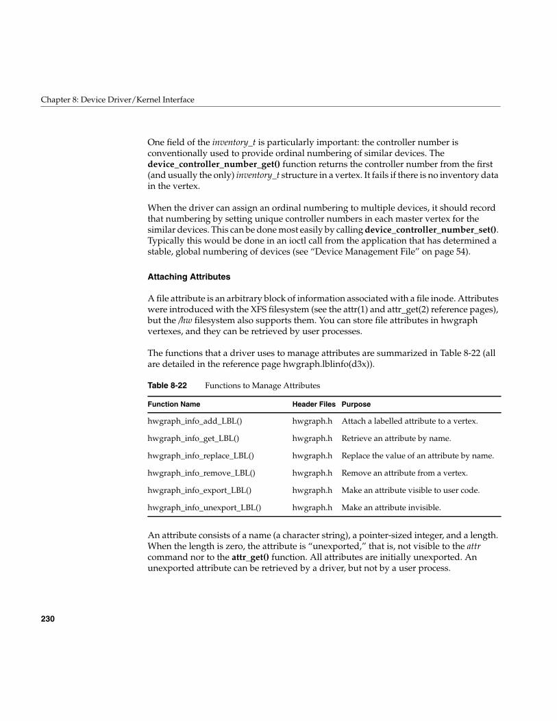
230
Chapter 8: Device Driver/Kernel Interface
One field of the inventory_t is particularly important: the controller number isconventionally used to provide ordinal numbering of similar devices. Thedevice_controller_number_get() function returns the controller number from the first(and usually the only) inventory_t structure in a vertex. It fails if there is no inventory datain the vertex.
When the driver can assign an ordinal numbering to multiple devices, it should recordthat numbering by setting unique controller numbers in each master vertex for thesimilar devices. This can be done most easily by calling device_controller_number_set().Typically this would be done in an ioctl call from the application that has determined astable, global numbering of devices (see “Device Management File” on page 54).
Attaching Attributes
A file attribute is an arbitrary block of information associated with a file inode. Attributeswere introduced with the XFS filesystem (see the attr(1) and attr_get(2) reference pages),but the /hw filesystem also supports them. You can store file attributes in hwgraphvertexes, and they can be retrieved by user processes.
The functions that a driver uses to manage attributes are summarized in Table 8-22 (allare detailed in the reference page hwgraph.lblinfo(d3x)).
An attribute consists of a name (a character string), a pointer-sized integer, and a length.When the length is zero, the attribute is “unexported,” that is, not visible to the attrcommand nor to the attr_get() function. All attributes are initially unexported. Anunexported attribute can be retrieved by a driver, but not by a user process.
Table 8-22 Functions to Manage Attributes
Function Name Header Files Purpose
hwgraph_info_add_LBL() hwgraph.h Attach a labelled attribute to a vertex.
hwgraph_info_get_LBL() hwgraph.h Retrieve an attribute by name.
hwgraph_info_replace_LBL() hwgraph.h Replace the value of an attribute by name.
hwgraph_info_remove_LBL() hwgraph.h Remove an attribute from a vertex.
hwgraph_info_export_LBL() hwgraph.h Make an attribute visible to user code.
hwgraph_info_unexport_LBL() hwgraph.h Make an attribute invisible.
Hardware Graph Management
231
The value of an attribute is just a pointer; it can be an integer, a vertex handle, or anaddress of any kind of information. You can use attributes to hold any kind ofinformation you want to associate with a vertex. (For one example, you could use anattribute to contain mode-bits that determine how a device should be treated.)
Attribute storage is not sophisticated. Attribute names are stored sequentially in a stringtable that is part of the vertex, and looked up in a sequential search. The attribute schemeis meant for convenient storage of a few attributes per vertex, each having a short name.
When you export an attribute, you assert that the value of the attribute is a valid addressin kernel virtual memory, and the export length is its correct length. The attr_get()function relies on these points. A user process can retrieve a copy of an attribute bycalling attr_get(). The attribute value is copied from the kernel address space to the useraddress space. This is a convenient route by which you can export driver internal data touser processes, without the complexity of memory mapping or ioctl calls.
Retrieving Administrator Attributes
The system administrator can use the DEVICE_ADMIN statement to attach a labelledattribute to any device special file in the hwgraph, and can use DRIVER_ADMIN to storea labelled attribute for the driver (see “Storing Device and Driver Attributes” onpage 56).
These statements are processed at boot time. At this time, the driver might not be loaded,and the device special file might not have been created in the hwgraph. However, theattributes are saved. When a driver creates a hwgraph vertex that is the target of aDEVICE_ADMIN statement, the labelled attributes are attached to the vertexautomatically.
Your driver can request an administrator attribute for a specific device usinghwgraph_info_get_LBL() directly, as described above under “Attaching Attributes” onpage 230. Or you can call device_admin_info_get() (see the reference pagehwgraph.admin(d3x)). The returned value is the address of a read-only copy of the valuestring.
Your driver can request an attribute that was addressed to the driver withDRIVER_ADMIN using device_driver_admin_info_get(). The returned value is theaddress of a read-only copy of the value string from the DRIVER_ADMIN statement.
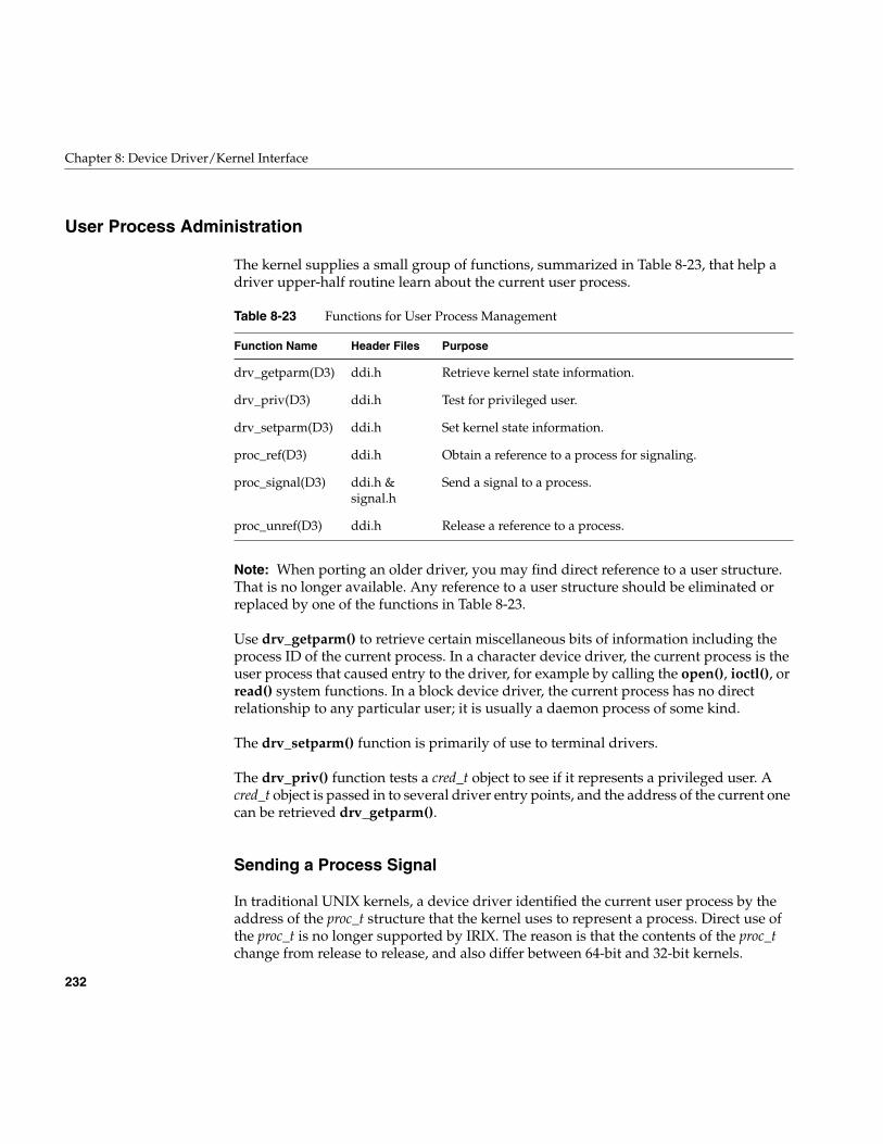
232
Chapter 8: Device Driver/Kernel Interface
User Process Administration
The kernel supplies a small group of functions, summarized in Table 8-23, that help adriver upper-half routine learn about the current user process.
Note: When porting an older driver, you may find direct reference to a user structure.That is no longer available. Any reference to a user structure should be eliminated orreplaced by one of the functions in Table 8-23.
Use drv_getparm() to retrieve certain miscellaneous bits of information including theprocess ID of the current process. In a character device driver, the current process is theuser process that caused entry to the driver, for example by calling the open(), ioctl(), orread() system functions. In a block device driver, the current process has no directrelationship to any particular user; it is usually a daemon process of some kind.
The drv_setparm() function is primarily of use to terminal drivers.
The drv_priv() function tests a cred_t object to see if it represents a privileged user. Acred_t object is passed in to several driver entry points, and the address of the current onecan be retrieved drv_getparm().
Sending a Process Signal
In traditional UNIX kernels, a device driver identified the current user process by theaddress of the proc_t structure that the kernel uses to represent a process. Direct use ofthe proc_t is no longer supported by IRIX. The reason is that the contents of the proc_tchange from release to release, and also differ between 64-bit and 32-bit kernels.
Table 8-23 Functions for User Process Management
Function Name Header Files Purpose
drv_getparm(D3) ddi.h Retrieve kernel state information.
drv_priv(D3) ddi.h Test for privileged user.
drv_setparm(D3) ddi.h Set kernel state information.
proc_ref(D3) ddi.h Obtain a reference to a process for signaling.
proc_signal(D3) ddi.h &signal.h
Send a signal to a process.
proc_unref(D3) ddi.h Release a reference to a process.
Waiting and Mutual Exclusion
233
The most common use of the proc_t by a driver was to send a signal to the process. Thiscapability is still supported. To do it, take three steps:
1. Call proc_ref() to get a process handle, a number unique to the current process. Thereturned value must be treated as an arbitrary number (in some releases of IRIX itwas the proc_t address, but this is not the defined behavior of the function.)
2. Use the process handle as an argument to proc_signal(), sending the signal to theprocess.
3. Release the process handle by calling proc_unref().
The third step is important. In order to keep the process handle valid, IRIX retainsinformation about the process to which it is related. However, that process couldterminate (possibly as a result of the signal the driver sends) but until the driverannounces that it is done with the handle, the kernel must try to retain processinformation.
It is especially important to release a process handles before unloading a loadable driver(see “Entry Point unload()” on page 180).
Waiting and Mutual Exclusion
The kernel supplies a rich variety of functions for waiting and for mutual exclusion. Inorder to use these features well, you must understand the different purposes for whichthey are designed. In particular, you must clearly understand the distinction betweenwaiting and mutual exclusion (or locking).
Mutual Exclusion Compared to Waiting
Mutual exclusion allows one entity to have exclusive use of a global resource, temporarilydenying use of the resource to other entities. Mutual exclusion normally does not requirewaiting when software is carefully designed—the resource is normally free when it isrequested. A driver that calls a mutual exclusion function expects to proceed withoutdelay—although there is a chance that the resource is in use, and the driver will have towait.
234
Chapter 8: Device Driver/Kernel Interface
The kernel offers an array of functions for mutual exclusion, and the choice among themcan be critical to performance. The functions are reviewed in the following topics:
• “Basic Locks” on page 235 covers basic locks, once required by device drivers, anduseful in multiprocessors.
• “Long-Term Locks” on page 237 covers sleep locks, which can be held for longerperiods.
• “Reader/Writer Locks” on page 240 covers a class of locks that allow multiple,concurrent, read-only access to resources that are infrequently changed.
• “Priority Level Functions” on page 242 discusses the traditional UNIX method ofmutual exclusion, now obsolete and dangerous.
Waiting allows a driver to coordinate its actions with a specific event or action that occursasynchronously. A driver can wait for a specified amount of time to pass, wait for an I/Oaction to complete, and so on. When a driver calls a waiting function, it expects to wait forsomething to happen—although there is a chance that the expected event has alreadyhappened, and the driver will be able to continue at once.
The kernel offers several functions that allow you to wait for specific events; and alsooffers functions for general synchronization. These are covered in the following topics:
• “Waiting for Time to Pass” on page 242 covers timer-related functions.
• “Waiting for Memory to Become Available” on page 245 covers memory allocationwaits.
• “Waiting for Block I/O to Complete” on page 245 covers waits used in thepfxstrategy() entry point.
• “Waiting for a General Event” on page 247 covers the general-purpose functionsthat you can adapt to any synchronization problem.
The most general facility, the semaphore, can be used for synchronization and forlocking. This topic is covered under “Semaphores” on page 251.
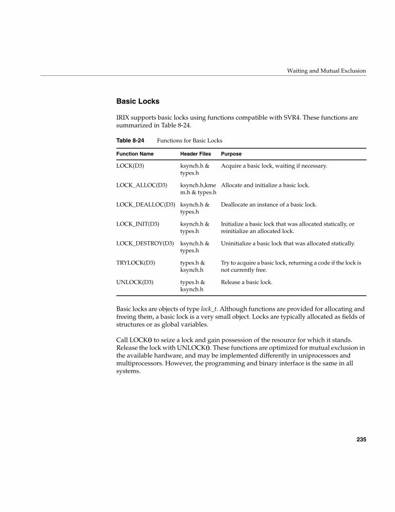
Waiting and Mutual Exclusion
235
Basic Locks
IRIX supports basic locks using functions compatible with SVR4. These functions aresummarized in Table 8-24.
Basic locks are objects of type lock_t. Although functions are provided for allocating andfreeing them, a basic lock is a very small object. Locks are typically allocated as fields ofstructures or as global variables.
Call LOCK() to seize a lock and gain possession of the resource for which it stands.Release the lock with UNLOCK(). These functions are optimized for mutual exclusion inthe available hardware, and may be implemented differently in uniprocessors andmultiprocessors. However, the programming and binary interface is the same in allsystems.
Table 8-24 Functions for Basic Locks
Function Name Header Files Purpose
LOCK(D3) ksynch.h &types.h
Acquire a basic lock, waiting if necessary.
LOCK_ALLOC(D3) ksynch.h,kmem.h & types.h
Allocate and initialize a basic lock.
LOCK_DEALLOC(D3) ksynch.h &types.h
Deallocate an instance of a basic lock.
LOCK_INIT(D3) ksynch.h &types.h
Initialize a basic lock that was allocated statically, orreinitialize an allocated lock.
LOCK_DESTROY(D3) ksynch.h &types.h
Uninitialize a basic lock that was allocated statically.
TRYLOCK(D3) types.h &ksynch.h
Try to acquire a basic lock, returning a code if the lock isnot currently free.
UNLOCK(D3) types.h &ksynch.h
Release a basic lock.
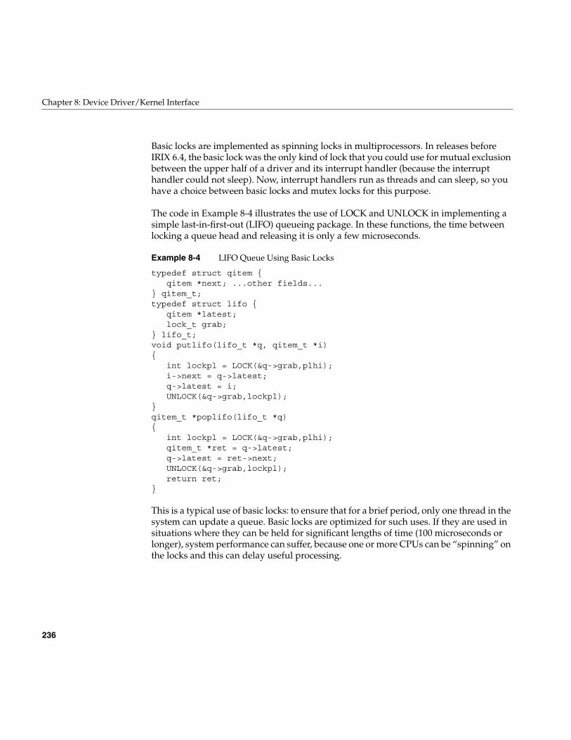
236
Chapter 8: Device Driver/Kernel Interface
Basic locks are implemented as spinning locks in multiprocessors. In releases beforeIRIX 6.4, the basic lock was the only kind of lock that you could use for mutual exclusionbetween the upper half of a driver and its interrupt handler (because the interrupthandler could not sleep). Now, interrupt handlers run as threads and can sleep, so youhave a choice between basic locks and mutex locks for this purpose.
The code in Example 8-4 illustrates the use of LOCK and UNLOCK in implementing asimple last-in-first-out (LIFO) queueing package. In these functions, the time betweenlocking a queue head and releasing it is only a few microseconds.
Example 8-4 LIFO Queue Using Basic Locks
typedef struct qitem {qitem *next; ...other fields...
} qitem_t;typedef struct lifo {
qitem *latest;lock_t grab;
} lifo_t;void putlifo(lifo_t *q, qitem_t *i){
int lockpl = LOCK(&q->grab,plhi);i->next = q->latest;q->latest = i;UNLOCK(&q->grab,lockpl);
}qitem_t *poplifo(lifo_t *q){
int lockpl = LOCK(&q->grab,plhi);qitem_t *ret = q->latest;q->latest = ret->next;UNLOCK(&q->grab,lockpl);return ret;
}
This is a typical use of basic locks: to ensure that for a brief period, only one thread in thesystem can update a queue. Basic locks are optimized for such uses. If they are used insituations where they can be held for significant lengths of time (100 microseconds orlonger), system performance can suffer, because one or more CPUs can be “spinning” onthe locks and this can delay useful processing.
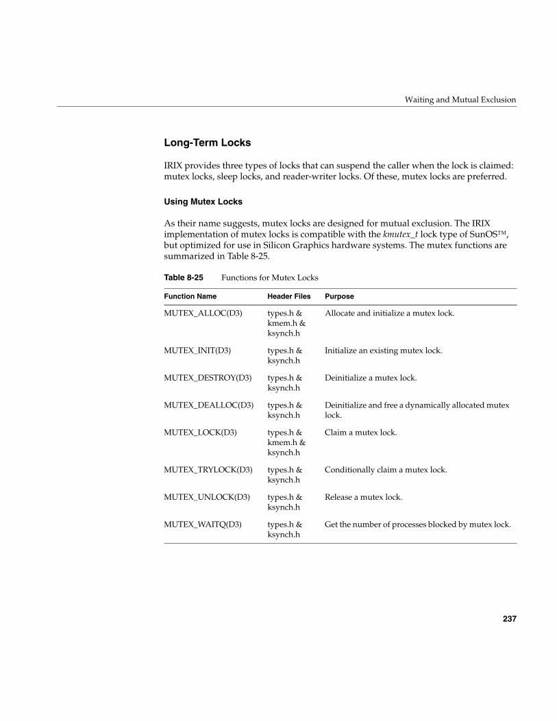
Waiting and Mutual Exclusion
237
Long-Term Locks
IRIX provides three types of locks that can suspend the caller when the lock is claimed:mutex locks, sleep locks, and reader-writer locks. Of these, mutex locks are preferred.
Using Mutex Locks
As their name suggests, mutex locks are designed for mutual exclusion. The IRIXimplementation of mutex locks is compatible with the kmutex_t lock type of SunOS™,but optimized for use in Silicon Graphics hardware systems. The mutex functions aresummarized in Table 8-25.
Table 8-25 Functions for Mutex Locks
Function Name Header Files Purpose
MUTEX_ALLOC(D3) types.h &kmem.h &ksynch.h
Allocate and initialize a mutex lock.
MUTEX_INIT(D3) types.h &ksynch.h
Initialize an existing mutex lock.
MUTEX_DESTROY(D3) types.h &ksynch.h
Deinitialize a mutex lock.
MUTEX_DEALLOC(D3) types.h &ksynch.h
Deinitialize and free a dynamically allocated mutexlock.
MUTEX_LOCK(D3) types.h &kmem.h &ksynch.h
Claim a mutex lock.
MUTEX_TRYLOCK(D3) types.h &ksynch.h
Conditionally claim a mutex lock.
MUTEX_UNLOCK(D3) types.h &ksynch.h
Release a mutex lock.
MUTEX_WAITQ(D3) types.h &ksynch.h
Get the number of processes blocked by mutex lock.
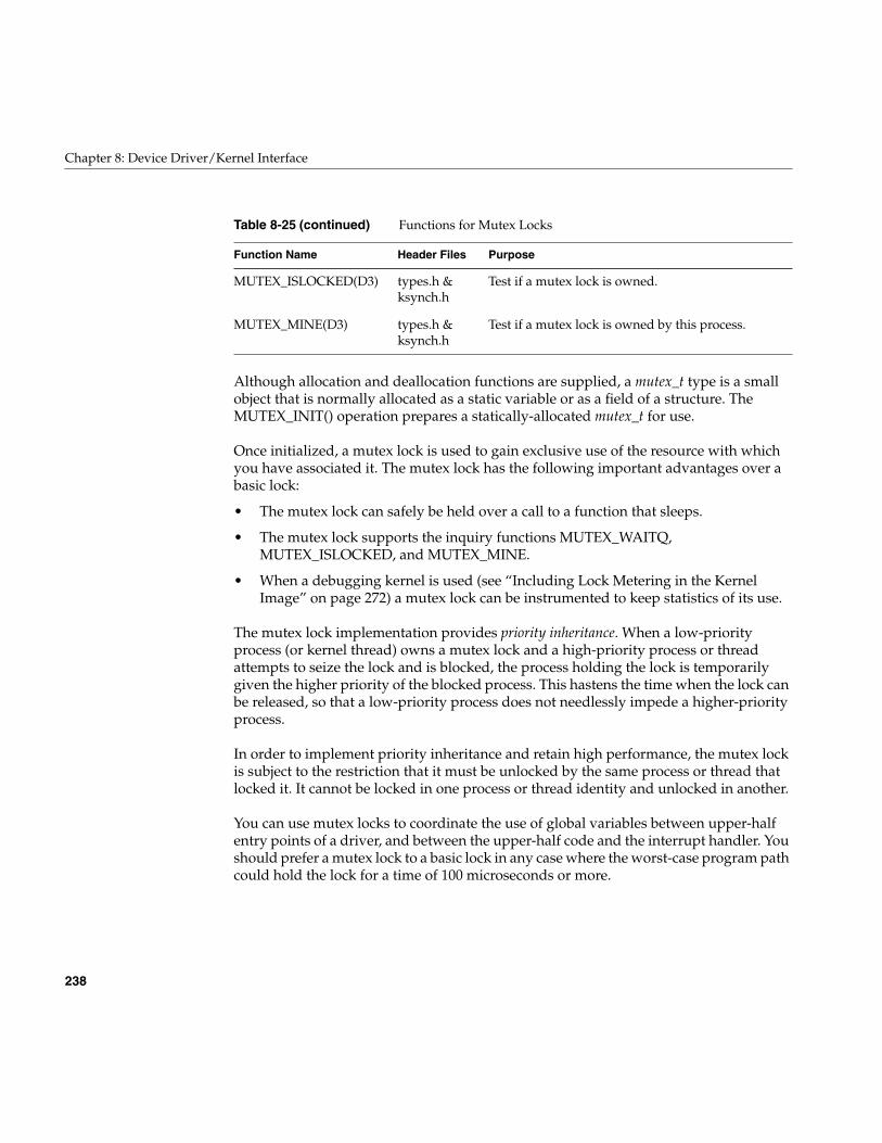
238
Chapter 8: Device Driver/Kernel Interface
Although allocation and deallocation functions are supplied, a mutex_t type is a smallobject that is normally allocated as a static variable or as a field of a structure. TheMUTEX_INIT() operation prepares a statically-allocated mutex_t for use.
Once initialized, a mutex lock is used to gain exclusive use of the resource with whichyou have associated it. The mutex lock has the following important advantages over abasic lock:
• The mutex lock can safely be held over a call to a function that sleeps.
• The mutex lock supports the inquiry functions MUTEX_WAITQ,MUTEX_ISLOCKED, and MUTEX_MINE.
• When a debugging kernel is used (see “Including Lock Metering in the KernelImage” on page 272) a mutex lock can be instrumented to keep statistics of its use.
The mutex lock implementation provides priority inheritance. When a low-priorityprocess (or kernel thread) owns a mutex lock and a high-priority process or threadattempts to seize the lock and is blocked, the process holding the lock is temporarilygiven the higher priority of the blocked process. This hastens the time when the lock canbe released, so that a low-priority process does not needlessly impede a higher-priorityprocess.
In order to implement priority inheritance and retain high performance, the mutex lockis subject to the restriction that it must be unlocked by the same process or thread thatlocked it. It cannot be locked in one process or thread identity and unlocked in another.
You can use mutex locks to coordinate the use of global variables between upper-halfentry points of a driver, and between the upper-half code and the interrupt handler. Youshould prefer a mutex lock to a basic lock in any case where the worst-case program pathcould hold the lock for a time of 100 microseconds or more.
MUTEX_ISLOCKED(D3) types.h &ksynch.h
Test if a mutex lock is owned.
MUTEX_MINE(D3) types.h &ksynch.h
Test if a mutex lock is owned by this process.
Table 8-25 (continued) Functions for Mutex Locks
Function Name Header Files Purpose
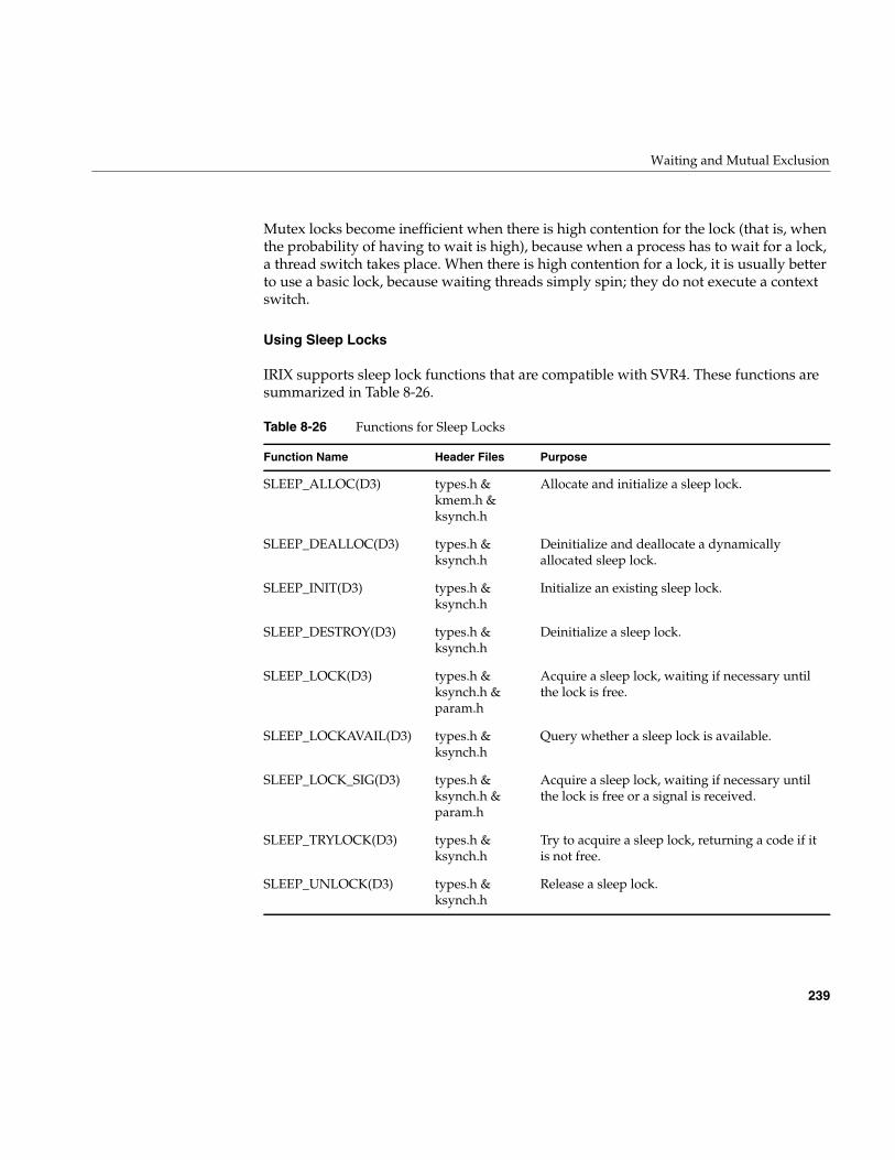
Waiting and Mutual Exclusion
239
Mutex locks become inefficient when there is high contention for the lock (that is, whenthe probability of having to wait is high), because when a process has to wait for a lock,a thread switch takes place. When there is high contention for a lock, it is usually betterto use a basic lock, because waiting threads simply spin; they do not execute a contextswitch.
Using Sleep Locks
IRIX supports sleep lock functions that are compatible with SVR4. These functions aresummarized in Table 8-26.
Table 8-26 Functions for Sleep Locks
Function Name Header Files Purpose
SLEEP_ALLOC(D3) types.h &kmem.h &ksynch.h
Allocate and initialize a sleep lock.
SLEEP_DEALLOC(D3) types.h &ksynch.h
Deinitialize and deallocate a dynamicallyallocated sleep lock.
SLEEP_INIT(D3) types.h &ksynch.h
Initialize an existing sleep lock.
SLEEP_DESTROY(D3) types.h &ksynch.h
Deinitialize a sleep lock.
SLEEP_LOCK(D3) types.h &ksynch.h ¶m.h
Acquire a sleep lock, waiting if necessary untilthe lock is free.
SLEEP_LOCKAVAIL(D3) types.h &ksynch.h
Query whether a sleep lock is available.
SLEEP_LOCK_SIG(D3) types.h &ksynch.h ¶m.h
Acquire a sleep lock, waiting if necessary untilthe lock is free or a signal is received.
SLEEP_TRYLOCK(D3) types.h &ksynch.h
Try to acquire a sleep lock, returning a code if itis not free.
SLEEP_UNLOCK(D3) types.h &ksynch.h
Release a sleep lock.
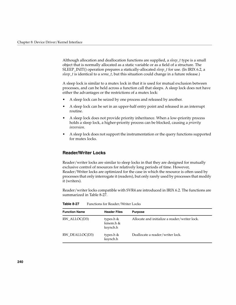
240
Chapter 8: Device Driver/Kernel Interface
Although allocation and deallocation functions are supplied, a sleep_t type is a smallobject that is normally allocated as a static variable or as a field of a structure. TheSLEEP_INIT() operation prepares a statically-allocated sleep_t for use. (In IRIX 6.2, asleep_t is identical to a sema_t, but this situation could change in a future release.)
A sleep lock is similar to a mutex lock in that it is used for mutual exclusion betweenprocesses, and can be held across a function call that sleeps. A sleep lock does not haveeither the advantages or the restrictions of a mutex lock:
• A sleep lock can be seized by one process and released by another.
• A sleep lock can be set in an upper-half entry point and released in an interruptroutine.
• A sleep lock does not provide priority inheritance. When a low-priority processholds a sleep lock, a higher-priority process can be blocked, causing a priorityinversion.
• A sleep lock does not support the instrumentation or the query functions supportedfor mutex locks.
Reader/Writer Locks
Reader/writer locks are similar to sleep locks in that they are designed for mutuallyexclusive control of resources for relatively long periods of time. However,Reader/Writer locks are optimized for the case in which the resource is often used byprocesses that only interrogate it (readers), but only rarely used by processes that modifyit (writers).
Reader/writer locks compatible with SVR4 are introduced in IRIX 6.2. The functions aresummarized in Table 8-27.
Table 8-27 Functions for Reader/Writer Locks
Function Name Header Files Purpose
RW_ALLOC(D3) types.h &kmem.h &ksynch.h
Allocate and initialize a reader/writer lock.
RW_DEALLOC(D3) types.h &ksynch.h
Deallocate a reader/writer lock.
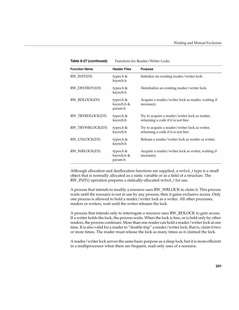
Waiting and Mutual Exclusion
241
Although allocation and deallocation functions are supplied, a mrlock_t type is a smallobject that is normally allocated as a static variable or as a field of a structure. TheRW_INIT() operation prepares a statically-allocated mrlock_t for use.
A process that intends to modify a resource uses RW_WRLOCK to claim it. This processwaits until the resource is not in use by any process, then it gains exclusive access. Onlyone process is allowed to hold a reader/writer lock as a writer. All other processes,readers or writers, wait until the writer releases the lock.
A process that intends only to interrogate a resource uses RW_RDLOCK to gain access.If a writer holds the lock, the process waits. When the lock is free, or is held only by otherreaders, the process continues. More than one reader can hold a reader/writer lock at onetime. It is also valid for a reader to “double-trip” a reader/writer lock; that is, claim it twoor more times. The reader must release the lock as many times as it claimed the lock.
A reader/writer lock serves the same basic purpose as a sleep lock, but it is more efficientin a multiprocessor when there are frequent, read-only uses of a resource.
RW_INIT(D3) types.h &ksynch.h
Initialize an existing reader/writer lock.
RW_DESTROY(D3) types.h &ksynch.h
Deinitialize an existing reader/writer lock.
RW_RDLOCK(D3) types.h &ksynch.h ¶m.h
Acquire a reader/writer lock as reader, waiting ifnecessary.
RW_TRYRDLOCK(D3) types.h &ksynch.h
Try to acquire a reader/writer lock as reader,returning a code if it is not free.
RW_TRYWRLOCK(D3) types.h &ksynch.h
Try to acquire a reader/writer lock as writer,returning a code if it is not free.
RW_UNLOCK(D3) types.h &ksynch.h
Release a reader/writer lock as reader or writer.
RW_WRLOCK(D3) types.h &ksynch.h ¶m.h
Acquire a reader/writer lock as writer, waiting ifnecessary.
Table 8-27 (continued) Functions for Reader/Writer Locks
Function Name Header Files Purpose
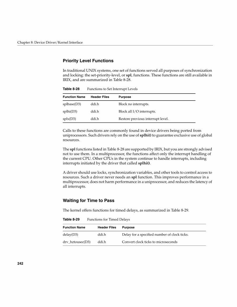
242
Chapter 8: Device Driver/Kernel Interface
Priority Level Functions
In traditional UNIX systems, one set of functions served all purposes of synchronizationand locking: the set-priority-level, or spl, functions. These functions are still available inIRIX, and are summarized in Table 8-28.
Calls to these functions are commonly found in device drivers being ported fromuniprocessors. Such drivers rely on the use of splhi() to guarantee exclusive use of globalresources.
The spl functions listed in Table 8-28 are supported by IRIX, but you are strongly advisednot to use them. In a multiprocessor, the functions affect only the interrupt handling ofthe current CPU. Other CPUs in the system continue to handle interrupts, includinginterrupts initiated by the driver that called splhi().
A driver should use locks, synchronization variables, and other tools to control access toresources. Such a driver never needs an spl function. This improves performance in amultiprocessor, does not harm performance in a uniprocessor, and reduces the latency ofall interrupts.
Waiting for Time to Pass
The kernel offers functions for timed delays, as summarized in Table 8-29.
Table 8-28 Functions to Set Interrupt Levels
Function Name Header Files Purpose
splbase(D3) ddi.h Block no interrupts.
splhi(D3) ddi.h Block all I/O interrupts.
splx(D3) ddi.h Restore previous interrupt level.
Table 8-29 Functions for Timed Delays
Function Name Header Files Purpose
delay(D3) ddi.h Delay for a specified number of clock ticks.
drv_hztousec(D3) ddi.h Convert clock ticks to microseconds
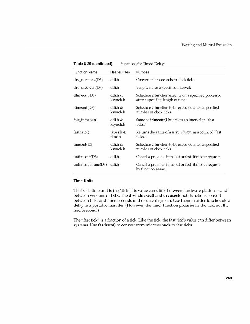
Waiting and Mutual Exclusion
243
Time Units
The basic time unit is the “tick.” Its value can differ between hardware platforms andbetween versions of IRIX. The drvhztousec() and drvusectohz() functions convertbetween ticks and microseconds in the current system. Use them in order to schedule adelay in a portable mannter. (However, the timer function precision is the tick, not themicrosecond.)
The “fast tick” is a fraction of a tick. Like the tick, the fast tick’s value can differ betweensystems. Use fasthzto() to convert from microseconds to fast ticks.
drv_usectohz(D3) ddi.h Convert microseconds to clock ticks.
drv_usecwait(D3) ddi.h Busy-wait for a specified interval.
dtimeout(D3) ddi.h &ksynch.h
Schedule a function execute on a specified processorafter a specified length of time.
itimeout(D3) ddi.h &ksynch.h
Schedule a function to be executed after a specifiednumber of clock ticks.
fast_itimeout() ddi.h &ksynch.h
Same as itimeout() but takes an interval in “fastticks.”
fasthzto() types.h &time.h
Returns the value of a struct timeval as a count of “fastticks.”
timeout(D3) ddi.h &ksynch.h
Schedule a function to be executed after a specifiednumber of clock ticks.
untimeout(D3) ddi.h Cancel a previous itimeout or fast_itimeout request.
untimeout_func(D3) ddi.h Cancel a previous itimeout or fast_itimeout requestby function name.
Table 8-29 (continued) Functions for Timed Delays
Function Name Header Files Purpose
244
Chapter 8: Device Driver/Kernel Interface
Timer Support
Timer support is based on the idea of a “callback” function. You specify the following todtimeout(), itimeout(), timeout() or fast_itimeout():
• an interval in clock ticks or fast ticks
• a function to be called at the expiration of the interval
• one or more arguments to be passed to the function
• a priority (interrupt) level at which the function should run
After a delay of at least the length requested, the function is called. The function isentered asynchronously. On a uniprocessor, it can interrupt execution of an upper-halfroutine. On a multiprocessor, it can execute concurrently with an upper-half routine orwith an interrupt handler or a different timeout function. (Use locks or mutexes formutual exclusion.)
The difference between itimeout() and timeout() is that the latter takes no argumentvalues to be passed to the function when it is called. In order to get a repeated series oftimer events, start a new timeout from the callback function.
The untimeout() and untimeout_func() functions cancel a pending timeout. In aloadable driver that has an pfxunload() entry point, cancel any pending timeouts beforeunloading.
The STREAMS_TIMOUT macro supplies similar timeout capability for a STREAMSdriver (see “Special Considerations for Multiprocessing” on page 769).
Short-Term Delay Support
In rare circumstances, a driver needs to pause briefly between two hardware operations.For example, the Silicon Graphics support for external interrupts in the Challenge andOnyx computers sometimes needs to set a high output level, wait for a brief, preciseinterval, then set a low output level.
The drv_usecwait() function supports this type of very short, precisely-timed delay. It“spins” for a specified number of microseconds, then returns to the caller. The CPU doesnothing else during this period, so clearly a delay of more than a few microseconds caninterfere with other work. Furthermore, if interrupts are disabled during the wait, theresponse to another interrupt is delayed also—the delay contributes directly to the“latency” of interrupt handling.
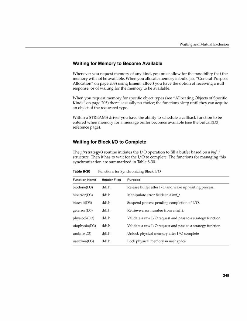
Waiting and Mutual Exclusion
245
Waiting for Memory to Become Available
Whenever you request memory of any kind, you must allow for the possibility that thememory will not be available. When you allocate memory in bulk (see “General-PurposeAllocation” on page 203) using kmem_alloc() you have the option of receiving a nullresponse, or of waiting for the memory to be available.
When you request memory for specific object types (see “Allocating Objects of SpecificKinds” on page 205) there is usually no choice; the functions sleep until they can acquirean object of the requested type.
Within a STREAMS driver you have the ability to schedule a callback function to beentered when memory for a message buffer becomes available (see the bufcall(D3)reference page).
Waiting for Block I/O to Complete
The pfxstrategy() routine initiates the I/O operation to fill a buffer based on a buf_tstructure. Then it has to wait for the I/O to complete. The functions for managing thissynchronization are summarized in Table 8-30.
Table 8-30 Functions for Synchronizing Block I/O
Function Name Header Files Purpose
biodone(D3) ddi.h Release buffer after I/O and wake up waiting process.
bioerror(D3) ddi.h Manipulate error fields in a buf_t.
biowait(D3) ddi.h Suspend process pending completion of I/O.
geterror(D3) ddi.h Retrieve error number from a buf_t.
physiock(D3) ddi.h Validate a raw I/O request and pass to a strategy function.
uiophysio(D3) ddi.h Validate a raw I/O request and pass to a strategy function.
undma(D3) ddi.h Unlock physical memory after I/O complete
userdma(D3) ddi.h Lock physical memory in user space.
246
Chapter 8: Device Driver/Kernel Interface
How the strategy() Entry Point Is Called
The pfxstrategy() entry point is called directly from the filesystem or virtual memorymanagement, or it can be called indirectly from a pfxread() or pfxwrite() entry point (see“Calling Entry Point strategy() From Entry Point read() or write()” on page 164).
Strategies of the strategy() Entry Point
Typically the pfxstrategy() routine must interact with its interrupt handler. Thepfxstrategy() routine can be designed in either of two ways, synchronous orasynchronous.
The synchronous pfxstrategy() routine initiates every I/O operation. Its interrupthandler is responsible only for detecting and signalling the completion of one I/O. Thepfxstrategy() routine proceeds as follows:
1. Lock the data buffer in memory using userdma().
2. Place the address of the buf_t where the pfxintr() entry point can find it.
3. Program the device (see “Setting Up a DMA Transfer” on page 216) and initiate theI/O activity.
4. Call biowait().
When the interrupt handler is entered, the handler uses bioerror() if necessary, andbiodone() to signal the completion of the I/O. Then it exits. The strategy code, which iswaiting in the call to biowait(), regains control following the call to biodone(), and canuse geterror() to check the results.
The asynchronous pfxstrategy() routine only initiates the first I/O operation of a series,and never waits. It proceeds as follows:
1. Lock the data buffer in memory using userdma().
2. Append the address of the buf_t to a queue shared with the interrupt handler.
3. If the queue was empty, no I/O is in progress. Call a subroutine that programs thedevice and initiates the I/O.
4. Return to the caller. The caller (a filesystem or paging system or uiophysio()) waitsusing biowait().
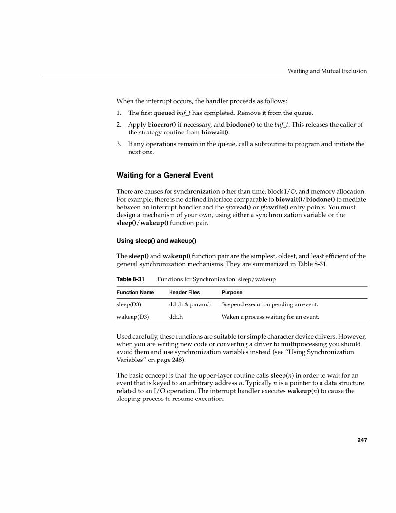
Waiting and Mutual Exclusion
247
When the interrupt occurs, the handler proceeds as follows:
1. The first queued buf_t has completed. Remove it from the queue.
2. Apply bioerror() if necessary, and biodone() to the buf_t. This releases the caller ofthe strategy routine from biowait().
3. If any operations remain in the queue, call a subroutine to program and initiate thenext one.
Waiting for a General Event
There are causes for synchronization other than time, block I/O, and memory allocation.For example, there is no defined interface comparable to biowait()/biodone() to mediatebetween an interrupt handler and the pfxread() or pfxwrite() entry points. You mustdesign a mechanism of your own, using either a synchronization variable or thesleep()/wakeup() function pair.
Using sleep() and wakeup()
The sleep() and wakeup() function pair are the simplest, oldest, and least efficient of thegeneral synchronization mechanisms. They are summarized in Table 8-31.
Used carefully, these functions are suitable for simple character device drivers. However,when you are writing new code or converting a driver to multiprocessing you shouldavoid them and use synchronization variables instead (see “Using SynchronizationVariables” on page 248).
The basic concept is that the upper-layer routine calls sleep(n) in order to wait for anevent that is keyed to an arbitrary address n. Typically n is a pointer to a data structurerelated to an I/O operation. The interrupt handler executes wakeup(n) to cause thesleeping process to resume execution.
Table 8-31 Functions for Synchronization: sleep/wakeup
Function Name Header Files Purpose
sleep(D3) ddi.h & param.h Suspend execution pending an event.
wakeup(D3) ddi.h Waken a process waiting for an event.
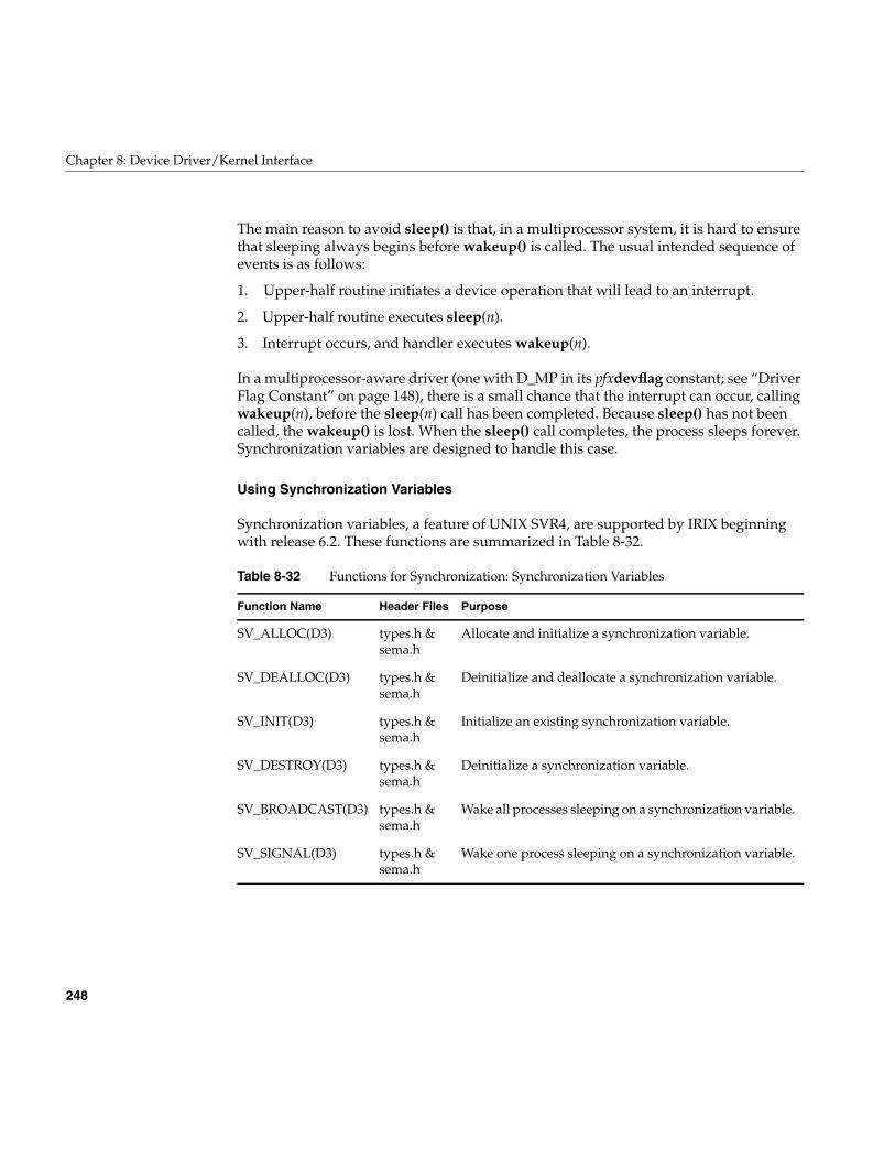
248
Chapter 8: Device Driver/Kernel Interface
The main reason to avoid sleep() is that, in a multiprocessor system, it is hard to ensurethat sleeping always begins before wakeup() is called. The usual intended sequence ofevents is as follows:
1. Upper-half routine initiates a device operation that will lead to an interrupt.
2. Upper-half routine executes sleep(n).
3. Interrupt occurs, and handler executes wakeup(n).
In a multiprocessor-aware driver (one with D_MP in its pfxdevflag constant; see “DriverFlag Constant” on page 148), there is a small chance that the interrupt can occur, callingwakeup(n), before the sleep(n) call has been completed. Because sleep() has not beencalled, the wakeup() is lost. When the sleep() call completes, the process sleeps forever.Synchronization variables are designed to handle this case.
Using Synchronization Variables
Synchronization variables, a feature of UNIX SVR4, are supported by IRIX beginningwith release 6.2. These functions are summarized in Table 8-32.
Table 8-32 Functions for Synchronization: Synchronization Variables
Function Name Header Files Purpose
SV_ALLOC(D3) types.h &sema.h
Allocate and initialize a synchronization variable.
SV_DEALLOC(D3) types.h &sema.h
Deinitialize and deallocate a synchronization variable.
SV_INIT(D3) types.h &sema.h
Initialize an existing synchronization variable.
SV_DESTROY(D3) types.h &sema.h
Deinitialize a synchronization variable.
SV_BROADCAST(D3) types.h &sema.h
Wake all processes sleeping on a synchronization variable.
SV_SIGNAL(D3) types.h &sema.h
Wake one process sleeping on a synchronization variable.
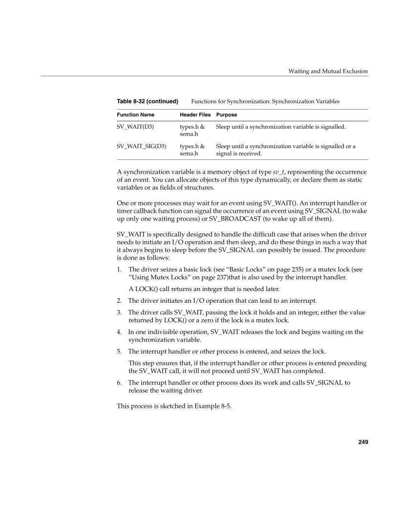
Waiting and Mutual Exclusion
249
A synchronization variable is a memory object of type sv_t, representing the occurrenceof an event. You can allocate objects of this type dynamically, or declare them as staticvariables or as fields of structures.
One or more processes may wait for an event using SV_WAIT(). An interrupt handler ortimer callback function can signal the occurrence of an event using SV_SIGNAL (to wakeup only one waiting process) or SV_BROADCAST (to wake up all of them).
SV_WAIT is specifically designed to handle the difficult case that arises when the driverneeds to initiate an I/O operation and then sleep, and do these things in such a way thatit always begins to sleep before the SV_SIGNAL can possibly be issued. The procedureis done as follows:
1. The driver seizes a basic lock (see “Basic Locks” on page 235) or a mutex lock (see“Using Mutex Locks” on page 237)that is also used by the interrupt handler.
A LOCK() call returns an integer that is needed later.
2. The driver initiates an I/O operation that can lead to an interrupt.
3. The driver calls SV_WAIT, passing the lock it holds and an integer, either the valuereturned by LOCK() or a zero if the lock is a mutex lock.
4. In one indivisible operation, SV_WAIT releases the lock and begins waiting on thesynchronization variable.
5. The interrupt handler or other process is entered, and seizes the lock.
This step ensures that, if the interrupt handler or other process is entered precedingthe SV_WAIT call, it will not proceed until SV_WAIT has completed.
6. The interrupt handler or other process does its work and calls SV_SIGNAL torelease the waiting driver.
This process is sketched in Example 8-5.
SV_WAIT(D3) types.h &sema.h
Sleep until a synchronization variable is signalled.
SV_WAIT_SIG(D3) types.h &sema.h
Sleep until a synchronization variable is signalled or asignal is received.
Table 8-32 (continued) Functions for Synchronization: Synchronization Variables
Function Name Header Files Purpose
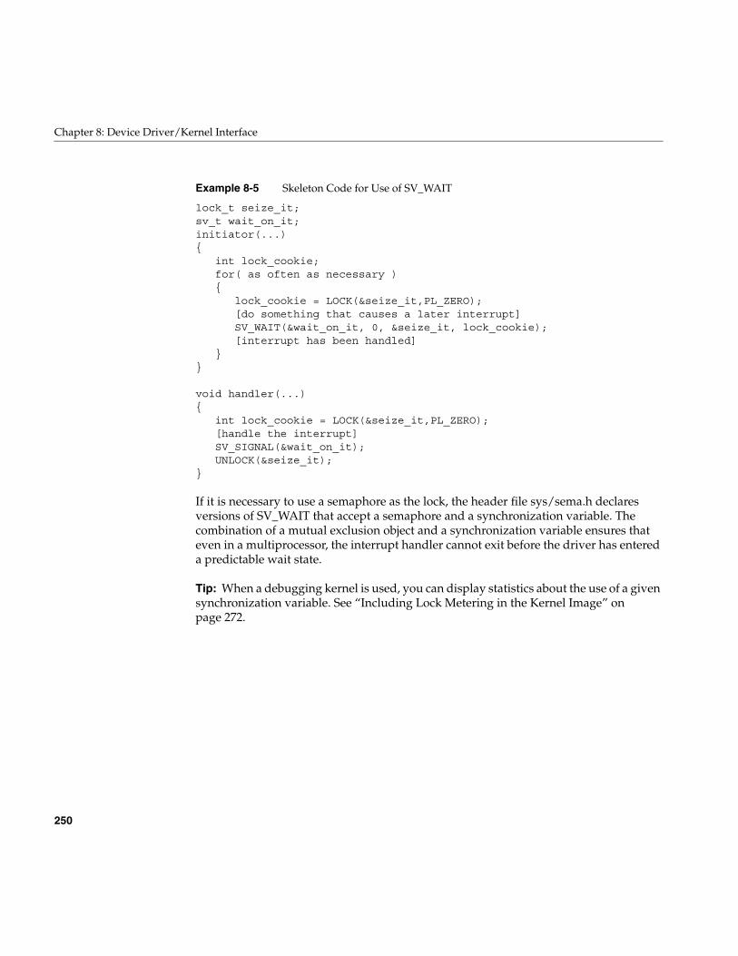
250
Chapter 8: Device Driver/Kernel Interface
Example 8-5 Skeleton Code for Use of SV_WAIT
lock_t seize_it;sv_t wait_on_it;initiator(...){
int lock_cookie;for( as often as necessary ){
lock_cookie = LOCK(&seize_it,PL_ZERO);[do something that causes a later interrupt]SV_WAIT(&wait_on_it, 0, &seize_it, lock_cookie);[interrupt has been handled]
}}
void handler(...){
int lock_cookie = LOCK(&seize_it,PL_ZERO);[handle the interrupt]SV_SIGNAL(&wait_on_it);UNLOCK(&seize_it);
}
If it is necessary to use a semaphore as the lock, the header file sys/sema.h declaresversions of SV_WAIT that accept a semaphore and a synchronization variable. Thecombination of a mutual exclusion object and a synchronization variable ensures thateven in a multiprocessor, the interrupt handler cannot exit before the driver has entereda predictable wait state.
Tip: When a debugging kernel is used, you can display statistics about the use of a givensynchronization variable. See “Including Lock Metering in the Kernel Image” onpage 272.
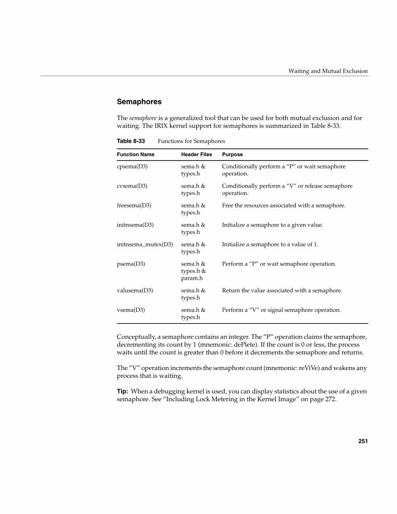
Waiting and Mutual Exclusion
251
Semaphores
The semaphore is a generalized tool that can be used for both mutual exclusion and forwaiting. The IRIX kernel support for semaphores is summarized in Table 8-33.
Conceptually, a semaphore contains an integer. The “P” operation claims the semaphore,decrementing its count by 1 (mnemonic: dePlete). If the count is 0 or less, the processwaits until the count is greater than 0 before it decrements the semaphore and returns.
The “V” operation increments the semaphore count (mnemonic: reViVe) and wakens anyprocess that is waiting.
Tip: When a debugging kernel is used, you can display statistics about the use of a givensemaphore. See “Including Lock Metering in the Kernel Image” on page 272.
Table 8-33 Functions for Semaphores
Function Name Header Files Purpose
cpsema(D3) sema.h &types.h
Conditionally perform a “P” or wait semaphoreoperation.
cvsema(D3) sema.h &types.h
Conditionally perform a “V” or release semaphoreoperation.
freesema(D3) sema.h &types.h
Free the resources associated with a semaphore.
initnsema(D3) sema.h &types.h
Initialize a semaphore to a given value.
initnsema_mutex(D3) sema.h &types.h
Initialize a semaphore to a value of 1.
psema(D3) sema.h &types.h ¶m.h
Perform a “P” or wait semaphore operation.
valusema(D3) sema.h &types.h
Return the value associated with a semaphore.
vsema(D3) sema.h &types.h
Perform a “V” or signal semaphore operation.
252
Chapter 8: Device Driver/Kernel Interface
Note: In releases before IRIX 6.2, initnsema_mutex() was used to initialize a semaphorein a special way that got the performance of a basic lock in a multiprocessor. Since IRIX6.2, this function is simply a macro that initializes the semaphore to a count of 1.
Using a Semaphore for Mutual Exclusion
To use a semaphore for locking, initialize it to 1. (This reflects the idea that a processcalling a locking function expects to continue.) When you require exclusive use of theassociated resource, call psema(). Typically this finds a semaphore count of 1, reduces itto 0, and returns.
When you are finished with the resource, call vsema() to increment the semaphore count,and release any process that is blocked in a psema() call for the same semaphore.
For locking, a semaphore is comparable to a sleep lock. In some systems, the performanceof semaphore operations may not be as good as the performance of a mutex lock. In othersystems, mutex locks may be implemented using semaphores.
Using a Semaphore for Waiting
To use a semaphore for waiting, initialize it to 0. Then call psema(). Because thesemaphore count is 0, the process waits. When the desired event occurs, typically in theinterrupt handler, call vsema() to release the waiting process.
This synchronization method is as reliable as a synchronization variable, but it hasslightly different behavior. When a synchronization variable is used correctly (see “UsingSynchronization Variables” on page 248), if the interrupt handler is entered before theSV_WAIT call completes, the interrupt handler waits on a LOCK call.
When a semaphore is used, if the interrupt handler is entered before the psema() callcompletes, the vsema() operation is done immediately and the interrupt handlercontinues without waiting. The fact that vsema() was called is stored as a count withinthe semaphore, where psema() will find it. Because the semaphore can contain this stateinformation, the interrupt handler does not have to be synchronized in time using a lock.
Note: In releases before IRIX 6.2, the vpsema() function was used in a way similar tosynchronization variables are used: to release one semaphore and wait on another in anatomic operation. This function is no longer supported; replace it with syncronizationvariable.
253
Chapter 9
9. Building and Installing a Driver
After a kernel-level driver has been designed and coded, it must be compiled, linked, andinstalled. The topics in this chapter describe the major steps of this process, as follows:
• “Defining Device Numbers” on page 253 covers the choice of major and minordevice numbers.
• “Defining Device Special Files” on page 255 describes options for creating the file orfiles controlled by the driver.
• “Compiling and Linking” on page 256 covers the compiler and linker options usedfor driver modules.
• “Configuring a Nonloadable Driver” on page 259 describes the configuration filesused to set up a driver loaded at boot time.
• “Configuring a Loadable Driver” on page 264 describes the additionalconfiguration needed for a loadable driver.
Defining Device Numbers
The topics “Major Device Number” on page 38 and “Minor Device Number” on page 39cover the purpose and use of the device numbers. Major and minor numbers were oncevery important in the device driver design because they were the primary input thatdistinguished a device to a device driver upper-half entry point. In current IRIX, this isonly the case for legacy drivers in older machines. Contemporary drivers take their inputfrom a vertex of the hwgraph (see “Hardware Graph” on page 42).
254
Chapter 9: Building and Installing a Driver
The historical use of device numbers can be summarized as follows:
• Both numbers are encoded in the inode of a device special file in /dev.
• The major number selects the device driver.
• The minor number specifies the logical unit, and can encode device features.
• Both numbers are passed as a parameter to driver entry points.
Part of creating and installing a device driver is the selection of device numbers and thedefinition of device special files.
Selecting a Major Number
If your driver does not use the hwgraph, you must select a major number to stand foryour driver. The numbers that already exist are listed in sys/major.h. However, the majornumber should not be coded into the driver. Typically the driver code does not need toknow its major number, and if it does, the driver should discover its major numberdynamically. A method of doing this is discussed under “Variables Section” on page 262.
A driver is associated with its major number in the master.d configuration file. When thedriver discovers this number dynamically, the system administrator is free to changemajor numbers in /var/sysgen/master.d files to correct conflicts between one product andanother.
Selecting Minor Numbers
When a driver is called to service a device special file defined only in /dev, it receives adevice minor number comprising 18 bits of information. You design the content of thesenumbers to give your driver the information it needs about each device special file.Typically you encode a unique device unit number so the driver can index deviceinformation from an array. (When the hwgraph is used, a pointer to the deviceinformation is stored in the hwgraph vertex instead.)
Examine the /dev/MAKEDEV script to see some techniques for assembling minornumbers dynamically based on the hardware inventory and other commands.
Defining Device Special Files
255
Defining Device Special Files
As described under “Device Special Files” on page 36, the association between a deviceand a driver is established when a process opens a device special file in the /hw or /devdirectory. Without at least one device special file, a device can never be opened.
Static Definition of Device Special Files
The system administrator can create device special files using mknod or install (see“Making Conventional Device Files” on page 41). This can be done manually, or throughan installation script, or as an exit operation of the software manager program. Thedevice special files can be created at any time—whether or not the device driver isinstalled, and whether or not the hardware exists. The special device files continue toexist until the administrator removes them.
Dynamic Definition of Device Special Files
A more sophisticated approach is to have the device special files created, or recreated,dynamically each time the system boots. This was the purpose for which /dev/MAKEDEV(see “The Script MAKEDEV” on page 41) was introduced—it removes and redefinesdevice special files based on information in the hardware inventory. In current IRIX, allentries in the /hw filesystem are created dynamically by device drivers as devices areattached.
Definition and Use of /hw Entries
The kernel creates the upper levels of the hardware graph to represent addressable unitsof hardware in the basic system—modules, buses, and slots. While probing buses, it findsdevices, and calls upon device drivers to attach them (see “Entry Point attach()” onpage 153 and “Entry Point edtinit()” on page 151). At these times, the driver has theresponsibility of extending the hwgraph with vertexes that provide access to the device(see “Extending the hwgraph” on page 222).
Because hwgraph entries are always created dynamically, and can be created anddestroyed while the system is running, the initial set of pathnames in /hw are not stableand should not be written into user scripts and source code. Your driver can createadditional vertexes in the hwgraph (see “Extending the hwgraph” on page 222), bothwhen attaching a device and later, when ioconfig runs (see “Using ioconfig for GlobalController Numbers” on page 51).
256
Chapter 9: Building and Installing a Driver
Compiling and Linking
You compile a kernel device driver to an ELF binary using shared libraries. The compileoptions differ between 32-bit and 64-bit modules.
Platform Support
If you are building a device driver that you wish to use on multiple platforms, youshould build a different driver for each CPU board type (for example, IP22) that youwant to run it on. You can use the hinv command to determine the host architecture (seehinv(1M)) and then specify the board type in the Makefile as described in the next section.
Using /var/sysgen/Makefile.kernio
The file /var/sysgen/Makefile.kernio is a sample Makefile for compiling kernel modules.You can include it from a Makefile of your own to set the definitions of compiler variablesand compiler options appropriately for different CPUs and module types.
The Makefile.kernio file tests the following environment variables, which you set:
The purpose of the rules in Makefile.kernio is to set numerous compiler variablesappropriately for the CPU type and execution model. It also sets compiler options into aMake variable CFLAGS. Owing to the number of compiler variables and the importanceof getting them right for each CPU type, Silicon Graphics strongly recommends that youinvoke Makefile.kernio from your own makefile.
Note: Makefile.kernio is designed for nonloadable drivers. In particular it sets thecompiler option -G8, which is valid for nonloadable drivers. A loadable driver must use-G0, but this can be set after invoking Makefile.kernio.
CPUBOARD Set to the type of CPU used in the target system, forexample IP19, IP22, IP27 (see the sys/cpu.h header file).
COMPILATION_MODEL Set to 64 for a 64-bit kernel module, or to 32 for a 32-bitkernel module.
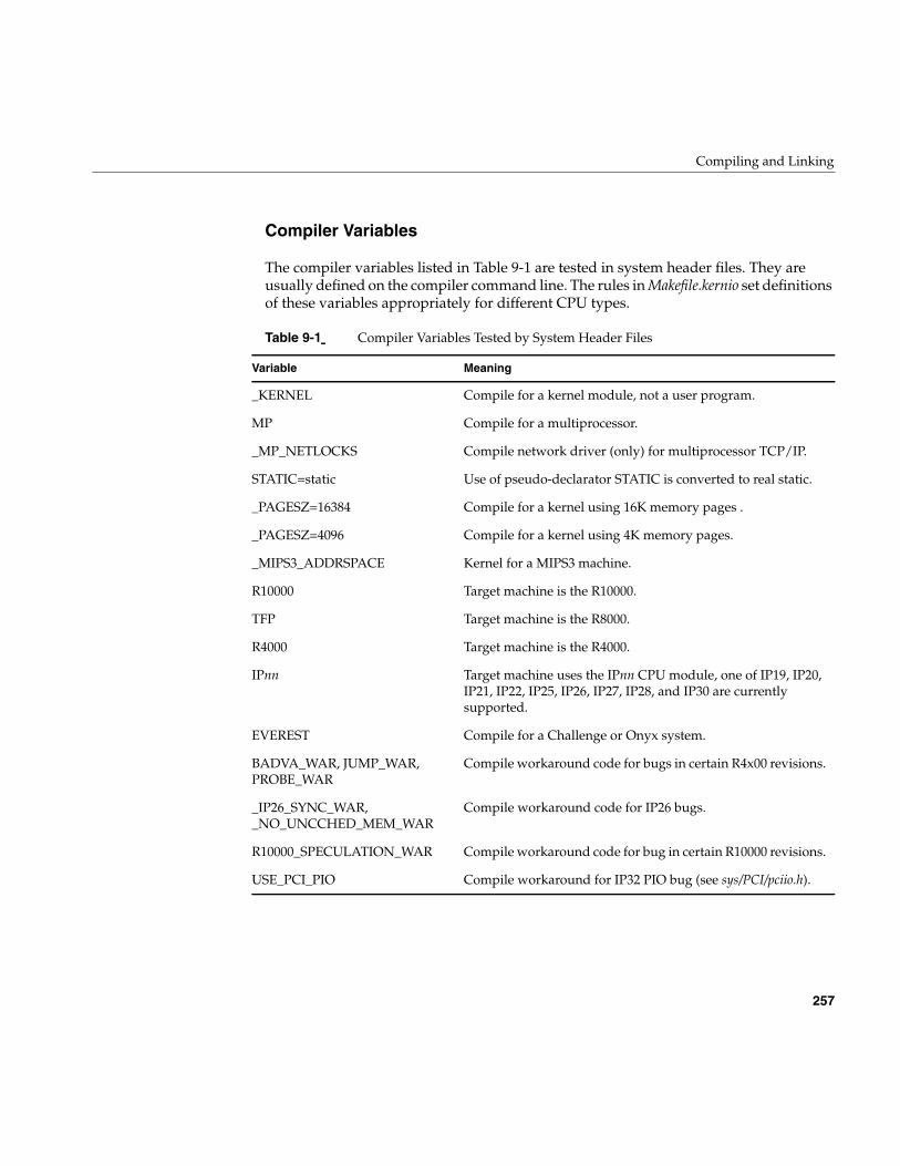
Compiling and Linking
257
Compiler Variables
The compiler variables listed in Table 9-1 are tested in system header files. They areusually defined on the compiler command line. The rules in Makefile.kernio set definitionsof these variables appropriately for different CPU types.
Table 9-1 Compiler Variables Tested by System Header Files
Variable Meaning
_KERNEL Compile for a kernel module, not a user program.
MP Compile for a multiprocessor.
_MP_NETLOCKS Compile network driver (only) for multiprocessor TCP/IP.
STATIC=static Use of pseudo-declarator STATIC is converted to real static.
_PAGESZ=16384 Compile for a kernel using 16K memory pages .
_PAGESZ=4096 Compile for a kernel using 4K memory pages.
_MIPS3_ADDRSPACE Kernel for a MIPS3 machine.
R10000 Target machine is the R10000.
TFP Target machine is the R8000.
R4000 Target machine is the R4000.
IPnn Target machine uses the IPnn CPU module, one of IP19, IP20,IP21, IP22, IP25, IP26, IP27, IP28, and IP30 are currentlysupported.
EVEREST Compile for a Challenge or Onyx system.
BADVA_WAR, JUMP_WAR,PROBE_WAR
Compile workaround code for bugs in certain R4x00 revisions.
_IP26_SYNC_WAR,_NO_UNCCHED_MEM_WAR
Compile workaround code for IP26 bugs.
R10000_SPECULATION_WAR Compile workaround code for bug in certain R10000 revisions.
USE_PCI_PIO Compile workaround for IP32 PIO bug (see sys/PCI/pciio.h).
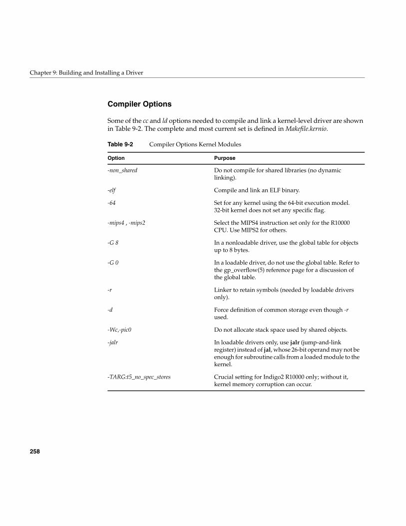
258
Chapter 9: Building and Installing a Driver
Compiler Options
Some of the cc and ld options needed to compile and link a kernel-level driver are shownin Table 9-2. The complete and most current set is defined in Makefile.kernio.
Table 9-2 Compiler Options Kernel Modules
Option Purpose
-non_shared Do not compile for shared libraries (no dynamiclinking).
-elf Compile and link an ELF binary.
-64 Set for any kernel using the 64-bit execution model.32-bit kernel does not set any specific flag.
-mips4 , -mips2 Select the MIPS4 instruction set only for the R10000CPU. Use MIPS2 for others.
-G 8 In a nonloadable driver, use the global table for objectsup to 8 bytes.
-G 0 In a loadable driver, do not use the global table. Refer tothe gp_overflow(5) reference page for a discussion ofthe global table.
-r Linker to retain symbols (needed by loadable driversonly).
-d Force definition of common storage even though -rused.
-Wc,-pic0 Do not allocate stack space used by shared objects.
-jalr In loadable drivers only, use jalr (jump-and-linkregister) instead of jal, whose 26-bit operand may not beenough for subroutine calls from a loaded module to thekernel.
-TARG:t5_no_spec_stores Crucial setting for Indigo2 R10000 only; without it,kernel memory corruption can occur.
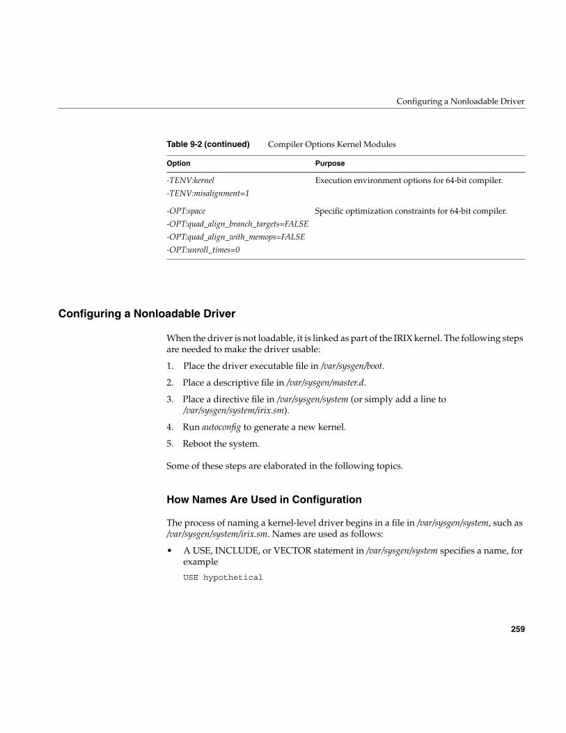
Configuring a Nonloadable Driver
259
Configuring a Nonloadable Driver
When the driver is not loadable, it is linked as part of the IRIX kernel. The following stepsare needed to make the driver usable:
1. Place the driver executable file in /var/sysgen/boot.
2. Place a descriptive file in /var/sysgen/master.d.
3. Place a directive file in /var/sysgen/system (or simply add a line to/var/sysgen/system/irix.sm).
4. Run autoconfig to generate a new kernel.
5. Reboot the system.
Some of these steps are elaborated in the following topics.
How Names Are Used in Configuration
The process of naming a kernel-level driver begins in a file in /var/sysgen/system, such as/var/sysgen/system/irix.sm. Names are used as follows:
• A USE, INCLUDE, or VECTOR statement in /var/sysgen/system specifies a name, forexample
USE hypothetical
-TENV:kernel
-TENV:misalignment=1
Execution environment options for 64-bit compiler.
-OPT:space
-OPT:quad_align_branch_targets=FALSE
-OPT:quad_align_with_memops=FALSE
-OPT:unroll_times=0
Specific optimization constraints for 64-bit compiler.
Table 9-2 (continued) Compiler Options Kernel Modules
Option Purpose
260
Chapter 9: Building and Installing a Driver
• This statement directs lboot to read a file of the same name in /var/sysgen/master.d. Inthis example, the file would be /var/sysgen/master.d/hypothetical.
• The file in /var/sysgen/master.d specifies the prefix for driver entry points, forexample hypo_.
• The same name with the suffix .o, is searched for in /var/sysgen/boot—in thisexample, /var/sysgen/boot/hypothetical.o. This object file is linked with the kernel.
• The public symbols in the object file are searched for names that start with theprefix, for example hypo_attach(). These are noted in the kernel switch table so thedriver can be called as needed.
Placing the Object File in /var/sysgen/boot
The /var/sysgen/boot directory, where the kernel object modules reside, is actually asymbolic link to one of the directories /usr/cpu/sysgen/IPnnboot, where nn is the numberof one of the CPU modules supported by the current release of IRIX (see “CPU Modules”on page 4). When you place the object file of a driver in /var/sysgen/boot, you actuallyplace it in the CPU directory for the system in use.
Describing the Driver in /var/sysgen/master.d
You describe your driver in a file with the name of the driver in /var/sysgen/master.d. Theformat of these files is described in two places: the master(4) reference page, and in/var/sysgen/master.d/README. In addition, you can examine the many examples in thedistributed system.
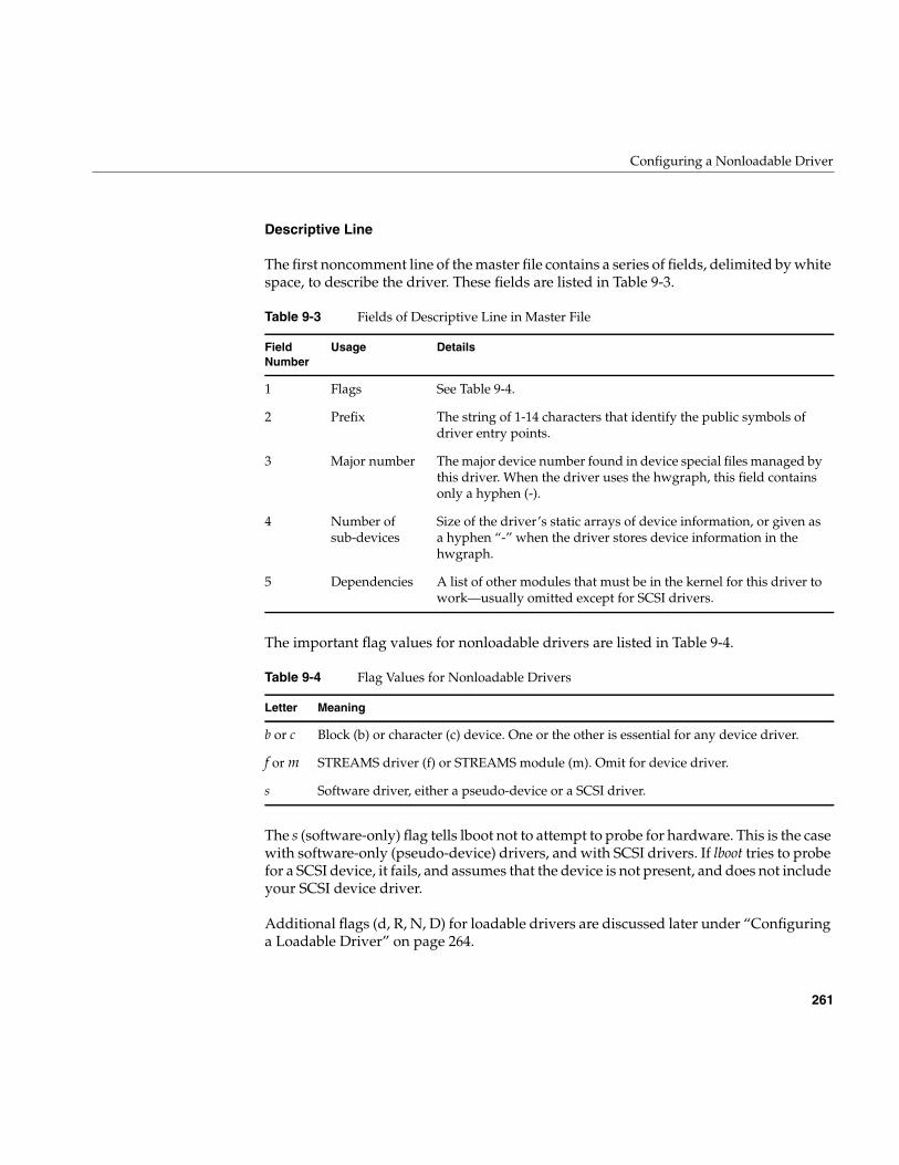
Configuring a Nonloadable Driver
261
Descriptive Line
The first noncomment line of the master file contains a series of fields, delimited by whitespace, to describe the driver. These fields are listed in Table 9-3.
The important flag values for nonloadable drivers are listed in Table 9-4.
The s (software-only) flag tells lboot not to attempt to probe for hardware. This is the casewith software-only (pseudo-device) drivers, and with SCSI drivers. If lboot tries to probefor a SCSI device, it fails, and assumes that the device is not present, and does not includeyour SCSI device driver.
Additional flags (d, R, N, D) for loadable drivers are discussed later under “Configuringa Loadable Driver” on page 264.
Table 9-3 Fields of Descriptive Line in Master File
FieldNumber
Usage Details
1 Flags See Table 9-4.
2 Prefix The string of 1-14 characters that identify the public symbols ofdriver entry points.
3 Major number The major device number found in device special files managed bythis driver. When the driver uses the hwgraph, this field containsonly a hyphen (-).
4 Number ofsub-devices
Size of the driver’s static arrays of device information, or given asa hyphen “-” when the driver stores device information in thehwgraph.
5 Dependencies A list of other modules that must be in the kernel for this driver towork—usually omitted except for SCSI drivers.
Table 9-4 Flag Values for Nonloadable Drivers
Letter Meaning
b or c Block (b) or character (c) device. One or the other is essential for any device driver.
f or m STREAMS driver (f) or STREAMS module (m). Omit for device driver.
s Software driver, either a pseudo-device or a SCSI driver.
262
Chapter 9: Building and Installing a Driver
Listing Dependencies
The descriptive line ends with a comma-separated list of other loadable kernel moduleson which this driver depends. The lboot command makes sure that it will not load thismodule if it fails to load a dependency.
In most cases, an OEM driver does not have any dependencies. However, a SCSI driver(see Chapter 16, “SCSI Device Drivers”) should list the name scsi, since it depends on theinner SCSI driver. A STREAMS driver might list the name of a STREAMS supportmodule such as clone (see “Support for CLONE Drivers” on page 774).
It is possible for you to design a driver in the form of multiple, loadable modules. In thatcase, you would name your support modules in this field.
Stubs Section
Noncomment lines that follow the descriptive line and precede a line beginning “$” areused by library modules—not by device drivers or STREAMS drivers. Each such linespecifies an entry point that this module provides, and which is used by the kernel orsome other loadable module. These lines instruct lboot in how to create a harmless “stub”function in the event that this driver is not included in the kernel—for example, becauseit is specified by an EXCLUDE line in the system file. The format is discussed in themaster(4) reference page.
Since a device or STREAMS driver provides only standard entry points that are accessedvia the switch tables rather than by linking, drivers do not need to define any stubs.
Variables Section
Following the descriptive line (and the stubs section, if any), you can place a line thatbegins with “$” and, following this, you can write definitions of global variables using Csyntax. This text is compiled into a module linked with the kernel. You refer to thesevariables as extern in the driver source code.
Configuring a Nonloadable Driver
263
The advantage of defining global variables in the master file is that the initializingexpressions for these variables can include values taken from the descriptive line. Thefollowing special symbols can be used:
You can use these symbols to compile run-time values for the major device number andthe number of supported sub-devices, as specified in the descriptive line of the file,without coding them as constants in the driver. In the source code you can write
extern major_t myMajNum;extern int myDevLimit;
In the master file you can implement the variables using the code in Example 9-1
Example 9-1 Defining Variables in Master Descriptive File
$$$major_t myMajNum = ##E;int myDevLimit = ##C;
(In a loadable driver this technique requires one additional step; see “Master File forLoadable Drivers” on page 265.)
Configuring a Kernel
Once you have placed the binary in /var/sysgen/boot and the master file in/var/sysgen/master.d, you can configure and generate a new kernel. This is done using theautoconfig command, which in turn calls lboot to actually create a new bootable file.
The lboot program only loads modules that are specified in a file in /var/sysgen/system. Onecommand is required to specify the new driver; the command is one of the following:
##E The integer coded as the major number in the descriptive line. The firstinteger, if a list of major numbers is given.
##C The number of controllers (bus adapters) of this type.
##D The number of sub-devices as coded in the fourth field of the descriptive line.
VECTOR To specify hardware details, to request a hardware probe at boot time, toload the driver and invoke pfxedtinit().
INCLUDE To load the driver and invoke pfxinit().
USE To load the driver and invoke pfxinit() only if the master file exists inmaster.d.
264
Chapter 9: Building and Installing a Driver
The form of these commands is detailed in the system(4) reference page. In addition, youshould examine the distributed files in /var/sysgen/system, especial irix.sm, which containsmany comments on the meaning and use of different entries. Specific uses of theVECTOR statement are discussed in the following topics: The form of VECTOR lines forVME devices is discussed under “Configuring VME Devices” on page 342.
You could place the VECTOR, USE, or INCLUDE line for your driver in irix.sm. However,since lboot treats all files in /var/sysgen/system as a single file, you can create a small fileunique to your driver. The name of this file is not significant, but a good name is thedriver name with the suffix .sm.
Generating a Kernel
The autoconfig script invokes lboot to read the system files, read the master files, and linkall the kernel executables. Provided there are no errors, the output is a new file/unix.install. At boot time this file is moved to the name /unix and used as the kernel.
During the testing period you may want to keep the original kernel file available as/unix.original. A simple way to retain this file is to create a link to it using the ln command.
Configuring a Loadable Driver
You compile and configure a loadable driver very much as you would a nonloadabledriver (so you should read “Configuring a Nonloadable Driver” on page 259 beforereading this section). The differences are as follows:
• You provide an additional global variable with the public name pfxmversion.
• You use a few different compile options.
• You decide when the driver should be loaded, and use appropriate flags in thedescriptive line in the master file.
For more background on loadable modules, see the mload(4) and ml(1) reference pages.
Configuring a Loadable Driver
265
Public Global Variables
To be loadable, a driver must specify a pfxdevflag entry point containing the D_MP orD_MT flag (see “Driver Flag Constant” on page 148).
Any loadable module must define a public name pfxmversion, declared as follows:
#include <sys/mload.h>char *pfxmversion = M_VERSION;
Note the exact spelling of the variable; it is easy to overlook the letter “m” after the prefix.If the variable does not exist or is incorrectly spelled, an attempt to load the driver willfail.
Compile Options for Loadable Drivers
Use the -G 0 option when compiling and linking a loadable driver, since the global optiontable is not available to a loadable driver. You must also use the -jalr option in a loadabledriver (see “Compiler Options” on page 258 and “Compiler Options” on page 258).
In a loadable driver, link using the -r and -d options to retain the symbol table yetgenerate a bss segment.
Master File for Loadable Drivers
The file in /var/sysgen/master.d for a loadable driver has different flags.
In the flags field of the descriptive line of the master file (see “Descriptive Line” onpage 261), you specify that the driver is loadable, and when it should be loaded. Thepossible flags are listed in Table 9-5.
Table 9-5 Flag Values for Loadable Drivers
Letter Meaning
b or c Block (b) or character (c) device. One or the other is essential for any device driver.
f or m STREAMS driver (f) or STREAMS module (m). Omit for device driver.
s Software driver, either a pseudo-device or a SCSI driver.
266
Chapter 9: Building and Installing a Driver
When the d flag is given for an included module, lboot parses the master file for the driver.Global variables defined in the variables section of the master file (see “VariablesSection” on page 262) are defined and included in the kernel. However, object code of thedriver is not included in the kernel, and the names of its entry points are not entered intothe kernel switch table.
Such a driver has to be manually loaded with the ml or lboot command before it can beused; and it cannot be used from the miniroot.
Loading
A loadable driver can be loaded by the lboot command at boot time, and by the mlcommand while the system is running. The following steps occur when a driver is loaded:
1. The object file header is read.
2. Memory is allocated for the driver’s text, data, and bss segments.
3. The driver’s text and data are read.
4. The text and data are relocated. References to kernel names and to global variablesnamed in the master file are resolved.
5. Entry points are noted in the appropriate kernel switch table.
6. The pfxinit() entry point is called if one is defined.
7. If the driver is named in a VECTOR statement and has a pfxedtinit() entry point,that entry point is called for each VECTOR statement that names the driver.
8. The pfxstart() entry point, if any, is called.
9. The pfxreg() entry point, if any, is called.
d Specifies that this is a loadable driver.
R Auto-register the module (discussed in text).
D Load, then unload, at boot time, in order to let the driver initialize the hardwareinventory.
N Prevent this module from being automatically unloaded even when it has a pfxunload()entry point.
Table 9-5 Flag Values for Loadable Drivers
Letter Meaning
Configuring a Loadable Driver
267
Space allocated for the module’s text, data, and bss is located in node 0 of an Origin2000system. Static buffers in loadable modules are not necessarily physically contiguous inmemory.
A variety of errors can occur when a module is loaded. See the mload(4) reference pagefor a list of possible causes.
Effect of ‘D’ Flag
Normally a loadable driver is not loaded at boot time. It must be loaded sometime afterboot using the ml command. When the D flag is included in the descriptive line in thedescriptive file, lboot loads the driver at boot time, and immediately after callingpfxstart(), unloads the driver. This permits the driver to test the hardware and set up thehwgraph and hardware inventory.
Registration
A loadable module is “registered” by loading it, then placing a stub entry in thepfxopen() and pfxattach() column of its row of the switch table, and unloading it again.The stub entry points are invoked when the driver is needed, and the code of the entrypoints initiates a load of the driver.
Registration of this kind can be done automatically during bootstrap, or later using theml command. Once it has been registered, a driver is loaded automatically the first timethe kernel needs to attach a device supported by this driver, or the first time a processattempts to open a device special file managed by this driver. You can also load aregistered driver in advance of any use with the ml command—loading impliesregistration.
Note: Try not to confuse this “registration” with a driver’s registration with the kernelto handle a particular type of device.
Registration is done automatically for each master descriptive file that contains the d(loadable) and R (register) flags. Autoregistration is done at bootstrap phase 2. It isinitiated by the script /etc/rc2/S23autoconfig. Registration can be intiated manually at anytime after bootstrap by using the ml or lboot command with the reg option (see the ml(1M)and lboot(1M) reference pages).
268
Chapter 9: Building and Installing a Driver
Reloading
When a registered driver is reloaded, the sequence of events listed under “Loading” onpage 266 occurs again. There is one exception: the pfxreg() entry point is not called whena registered driver is reloaded from a stub. (The complete sequence occurs when anunregistered driver is explicitly loaded by the ml command.)
Unloading
A module can be unloaded only when it provides an pfxunload() entry point (see “EntryPoint unload()” on page 180). The N flag can be specified in the master file to preventautomatic unloading in any case.
A loaded module is automatically unloaded following a delay after the last close of adevice it supports. The delay is configurable using systune, as the module_unld_delayvariable (see the systune(1) reference page). You can use ml to specify an unloading delayfor a particular module.
The lboot or ml command can be used to unload a module before the delay expires, or tomanually override the N flag.
The unload sequence is as follows:
1. The kernel verifies that all opens of the driver’s devices have been closed. Thedriver cannot be unloaded if it has open devices or active mmaps.
2. The pfxunreg() entry point is called, if one exists. This gives the driver a chance tounregister as a provider of service for a particular device type. If pfxunreg() returnsnonzero, the process stops.
3. The pfxunload() entry point is called. If it returns nonzero, the process stops.
4. The module is removed from memory. If it had been registered (R flag), stubs areagain placed in the pfxopen() and pfxattach() column of its row of the switch table.
Experience has shown that most of the problems with loadable drivers arise fromunloading and reloading. The precautions to take are described under “Entry Pointunload()” on page 180.
269
Chapter 10
10. Testing and Debugging a Driver
As a critical system component, a driver deserves careful testing, but because it is part ofthe kernel, the normal testing tools are not available. This chapter describes the availabletesting tools and methods, in the following major topics:
• “Preparing the System for Debugging” on page 269 describes how to set up thekernel for use of the debugging tools.
• “Producing Diagnostic Displays” on page 274 covers the kernel functions yourdriver can use to generate diagnostic output as it executes.
• “Using symmon” on page 277 describes the use of the standalone debugger.
• “Using idbg” on page 287 describes some uses of the kernel-display command.
Preparing the System for Debugging
The standalone debugger symmon is a key tool for driver programming. It must beinstalled in the volume header of the boot disk. In order for it to be useful you must boota “debugging” kernel, that is, one that retains symbols, and contains the displaymodules, that are used by debugging tools. Normally these modules and symbols areeliminated to save space. You modify the irix.sm file to enable debugging, and thengenerate a new kernel.
All these steps should be performed before you attempt to install your device driver.
Placing symmon in the Volume Header
The symmon standalone debugger resides in the volume header of a disk—not in anormal IRIX filesystem. The volume header is disk partition 8. It always contains a labelrecord (sgilabel). On a bootable disk, the volume header contains the standalone shellsash that manages the bootstrap operation. Some bootable disks may also contain the ideprogram, a PROM-level diagnostic program. If symmon is to be available, it, too, must beplaced in the volume header.
270
Chapter 10: Testing and Debugging a Driver
Normally you acquire symmon by installing the debugging kernel feature(eoe.sw.kdebug) in the IRIX Developer Option software distribution. You can verify thatthis feature has been installed by executing the command
versions eoe.sw.kdebug
The response should confirm the presence of this component (it does not show symmonby name). When you install the kernel debug feature, the symmon program file is copiedto the volume header of the current boot disk automatically.
You can verify the presence of symmon in the volume header through the use of dvhtool(described in the dvhtool(1) reference page). The results should be similar to the displayin Example 10-1. The response to the “l” (list) command shows that the volume headerof this disk contains sgilabel, ide, sash, and symmon.
Example 10-1 Verifying Presence of symmon
# dvhtool -v list /dev/rvhCurrent contents:
File name Length Block #sgilabel 512 2ide 281600 278sash 281600 828symmon 248320 1378
In the event you need to install symmon in the volume header of a disk without using thesoftware manager, you can copy the standalone program to the volume header usingdvhtool. However, you first need to get a copy of the program in the form of a UNIX file.
Starting from a volume that currently has a copy of symmon (verified as in Example 10-1),use dvhtool to extract a copy of symmon into a convenient spot.
dvhtool -v g symmon /var/tmp/symmon.IPxx
There is a unique version of symmon for each CPU module, so it is a good idea to qualifythe filename with the CPU module type. Once the program is available as a normal file,you can use dvhtool to install it in the volume header of some other disk.
In the event there is not enough room in partition 0 (the volume header) of the target disk,it is safe to use dvhtool to delete the ide program from the volume header. The ideapplication can be booted manually from a CDROM if it is ever required.
Preparing the System for Debugging
271
Enabling Debugging in irix.sm
In order to make debugging symbols available in the kernel, you must make twochanges, one required and one optional, in the file /var/sysgen/system/irix.sm. Assuperuser, make a hard link to the file /var/sysgen/system/irix.sm as irix.sm.nondebug. Thisenables you to return easily to a nondebugging kernel.
Including Symbols in the Kernel Image
Edit /var/sysgen/system/irix.sm. Near the end, note the lines that resemble the following:
* Compilation and load flags* To load a kernel that can be co-resident with symmon* (for breakpoint debugging) replace LDOPTS* with the following. You must also INCLUDE prf and idbg.**LDOPTS: -non_shared -N -e start -G 8 -elf -woff 84 -woff 47 -woff 17-mips2 -o32 -nostdlib -T 88069000
The active LDOPTS statement (the one without an initial asterisk) appears a few lineslater. Remove the asterisk from the front of the debugging LDOPTS to make it active.Insert an asterisk to convert the original LDOPTS into a comment.
Tip: Despite the residual comment in the irix.sm file, you need not include module prf ina debugging kernel. It is only used for kernel profiling.
Including idbg in the Kernel Image
The symbol-display routines used by the command-line kernel display tool, idbg, arecontained in optional kernel modules. (See “Using idbg” on page 287.) You can change/var/sysgen/system/irix.sm so that support for idbg is always present in the kernel.Alternatively, you can load these modules manually with ml before you use them (see theml(1) reference page).
If you are entering an extended debugging period, make the modules permanent. Lookfor the lines in /var/sysgen/system/irix.sm that resemble the following:
** Kernel debugging tools (see profiler(1M) and idbg(1M))*EXCLUDE: idbgEXCLUDE: dmiidbg, grioidbg, xfsidbg, xlvidbg, cachefsidbg, mloadidbg
272
Chapter 10: Testing and Debugging a Driver
Change these lines, if necessary, so that all modules ending in idbg is marked INCLUDE,not EXCLUDE. (INCLUDE is preferred to USE in order to get an error message if theyare not found.) Verify that the corresponding object files /var/sysgen/boot/*idbg.o exist.They are normally installed with the debugging kernel feature, although some of themmay be installed with specific products.
Parts of the idbg support that are unique to particular filesystems are in the other moduleslisted in this area of irix.sm. Modules such as xlvidbg are useful to Silicon Graphicsdevelopers but are not likely to be helpful to developers of third-party drivers. However,it does no harm to change those modules from EXCLUDE to USE also.
Including Lock Metering in the Kernel Image
In addition to the display support included by the idbg modules, you can includemodules that support lock metering. This causes the kernel to keep statistics on the useof each semaphore, basic lock, and reader/writer lock, so you can display the statisticsthrough idbg commands. To enable lock metering, find lines in /var/sysgen/system/irix.smthat resemble the following:
* Required kernel modules...* ksync - kernel synchronization routines (mutex_lock, sv_wait,psema...)* or* ksync_metered - metered kernel synchronization routines...*KERNEL: kernelINCLUDE: os, disp, mem, zeroINCLUDE: ksyncEXCLUDE: ksync_metered
Reverse the state of the two “ksync” lines so that ksync is excluded and ksync_meteredis included.
Then find a line that resembles
INCLUDE hardlocks
Change this line to a comment, and add a line that says
INCLUDE dhardlocks
(Inserting the initial letter “d” in the module name.) This is the module that implementsbasic locks as spinlocks, and dhardlocks is the metered version.
Preparing the System for Debugging
273
Generating a Debugging Kernel
Run the autoconfig command to generate a new kernel that will reflect the changes madein irix.sm. The result is a new kernel file, /unix.install, that will be renamed to /unix andused when the system is booted. This kernel can support idbg but is not yet ready forstandalong debugging with symmon.
The setsym command copies the symbol table from a kernel file and stores it as datawithin the kernel, so that symmon can find it. After autoconfig has created /unix.install,apply the setsym command to it, as follows:
#setsym /unix.install
If this command returns an error message about “symbol table overflow,” it means youhave neglected to activate the debugging LDOPTS statement in /var/sysgen/irix.sm.
Tip: You can use setsym with the -d option to generate a list of all symbols in the kernelbeing modified. The list is very long; direct it to a file for later reference.
At this time, you may wish to create a link to the current, nondebugging kernel so youcan retrieve it easily. You can also return to a nondebugging kernel by restoring theoriginal irix.sm file and running autoconfig again.
Specifying a Separate System Console
In order to use the standalone debugger, you must have an ASCII terminal as a separatesystem console device. Install a terminal next to the system or workstation and connectit to the first serial port (of a workstation) or the system console serial port (of a server).
You may have to modify the file /etc/inittab so that the line for the alternate console isactive (see the inittab(4) reference page). Alternatively, you can use the System Managerapplication from the 4D desktop. Select the icon for Port Setup. Select the port and clickConnect. You can then configure the port for baud rate and terminal type interactively.
Verify the terminal’s operation by logging in to the system. When you know the terminalworks, use the nvram command to change the nonvolatile RAM variable console from aletter “g” to a letter “d,” as follows:
# nvram consoleg# nvram console d# nvram consoled
274
Chapter 10: Testing and Debugging a Driver
The nvram command is used to report and change the contents of the nonvolatile RAMvariables used by the boot PROM and standalone shell (see the nvram(1) reference page).
Verifying the Debugging Tools
After performing the preceding steps, restart the system. Messages from sash appear onthe attached terminal, rather than on the graphics screen. If symmon is present, itannounces itself on the console terminal also.
To verify operation of idbg, issue the idbg command and display the process list:
# idbgidbg> plistactive process list:34:672:"xdm" pri(60) SLEEP flags: load uload siglck recalc sv0:0:"sched" ndpri(39) SLEEP flags: sys nwake load uload sv31:193:"inetd" pri(60) SLEEP flags: load uload siglck recalc sv...
To verify operation of symmon, press control-A at the console terminal. The prompt stringDBG: should appear. At this time the system is frozen and no longer responds to mouseor keyboard input. Type the letter c (for continue) and press return (in a multiprocessor,use c all). The system returns to life.
Producing Diagnostic Displays
Normally a device or STREAMS driver produces display output in only two cases:
• To advise the operator or administrator of a serious problem.
• To display debugging information during software development.
Both of these purposes are served by the cmn_err() function. It brings to a kernel-levelmodule the abilities that a user-level process gets from printf() and syslog().
Using cmn_err
The details of cmn_err() usage are in the cmn_err(D3) reference page. The functionprototype and the constant values it uses are declared in sys/cmnerr.h.
Producing Diagnostic Displays
275
In summary, cmn_err() takes two or more arguments:
• A severity code that specifies how the message should be treated when it is writtento the system log.
• A message string, which can have substitution points in the style of printf().
• As many numeric values as are needed to substitute into the message string.
The first character of the message string specifies the destination of the message, eitheran in-memory buffer or the system log, or both.
Displaying to the System Log
The message is sent to the the system log daemon whenever the first message character(after substitution) is not an exclamation mark (“!”). The message is written only to thesystem log when the first message character is a circumflex (“^”).
This is basically the same service that a user-level process receives from the syslog()function. (Compare the syslog(3) and cmn_err(D3) reference pages, and examine thesys/cmnerr.h header file; the relationship is clear.) The first argument to cmn_err() is aseverity code which corresponds to one of the severity codes supported by syslog():CE_WARN equals LOG_WARN, and so on.
Use cmn_err() to write log messages to record serious errors (with CE_ALERT severity)or to advise the administrator of conditions that should be changed (using CE_NOTE).
Displaying to the Circular Message Buffer
The message is stored in the next available position in a circular buffer in kernel memorywhenever the first message character (after substitution) is not a circumflex (“^”). Themessage is stored only in the memory buffer when the first message character is anexclamation mark (“!”).
The name of the circular buffer (as a symbol to idbg or symmon) is putbuf. The contents ofputbuf can be displayed with the pb command of either idbg or symmon (see“Usingsymmon” on page 277 and “Using idbg” on page 287), or in a post-mortem dump usingicrash (see “Using icrash” on page 294). Use cmn_err() to store debugging trace data inthe circular buffer, and extract it after a stop or breakpoint with symmon, or use idbg tolook at it while the system is running.
276
Chapter 10: Testing and Debugging a Driver
The size of the buffer can be configured by changing the kernel variable putbufsz, asshown in the dialog in Example 10-2.
Example 10-2 Setting Kernel putbuf Size
# systune -iUpdates will be made to running system and /unix.installsystune-> putbufsz putbufsz = 1024 (0x400)systune-> putbufsz 4096 putbufsz = 1024 (0x400) Do you really want to change putbufsz to 4096 (0x1000)? (y/n)yIn order for the change in parameter putbufsz to become effective,reboot the systemsystune-> quit
Using cmn_err() Through Macros
The inventive C programmer can think of many ways to invoke cmn_err() using macros.One method is illustrated in the example driver displayed in Chapter 11, “DriverExample.” It contains the code shown in Example 10-3.
Example 10-3 Debugging Macros Using cmn_err()
#ifdef DEBUG#define DBGMSG0(s) cmn_err(CE_DEBUG,s)#define DBGMSG1(s,x) cmn_err(CE_DEBUG,s,x)#define DBGMSG2(s,x,y) cmn_err(CE_DEBUG,s,x,y)#define DBGMSG3(s,x,y,z) cmn_err(CE_DEBUG,s,x,y,z)#else#define DBGMSG0(s)#define DBGMSG1(s,x)#define DBGMSG2(s,x,y)#define DBGMSG3(s,x,y,z)#endif
Using printf()
You can call the printf() function from a kernel module. The kernel version of printf() isbasically a call to cmn_err() with severity CE_CONT. In general it is better to usecmn_err() explicitly.
Using symmon
277
Using ASSERT
The assert() macro is familiar to many C programmers; it terminates a program with amessage if its argument evaluates to false (see the assert(3X) reference page). This normalassert() macro does not work in a kernel module because the normal C library is notavailable. However, a similar function is available as the ASSERT() macro in the headerfile sys/debug.h.
The ASSERT() macro compiles to null code unless the compiler variable DEBUG is notonly defined, but defined as YES. When it compiles to executable code, ASSERT() testsits argument. If the argument evaluates to false, a kernel panic is forced.
Clearly ASSERT() must be used with care, testing conditions that are truly essential to theintegrity of the system. When reporting conditions that are merely operational errors, usea call to cmn_err() with the CE_WARN option.
Using symmon
The symmon program is a standalone debug monitor that can display and modifymemory, and stop, start, and trace execution, without using any kernel facilities. Usingsymmon you can set breakpoints in your driver, single-step its execution, and display thecontents of driver and kernel variables.
The facilities of symmon are unsophisticated compared to the high-level debuggers youmight use to debug a user-level application. For example, symmon does not understandC syntax, so it cannot display data structures as structures. Execution tracing is done atthe level of machine instructions, not at the level of C statements.
However, you can use symmon to examine the operations of a kernel module in a runningsystem, and resume execution of the system. This is an invaluable facility whendebugging a new driver.
278
Chapter 10: Testing and Debugging a Driver
How symmon Is Entered
When the system boots a debugging kernel with symmon installed, control can pass intothe debug monitor under several different circumstances:
• Early in the bootstrap process, if certain environment variables are set in thestand-alone shell (see “Entering symmon at Boot Time” on page 279).
• Whenever a control-A character is typed at the system console terminal.
• Whenever a breakpoint is reached or a watchpoint is tripped (see “Commands toControl Execution Flow” on page 282).
• Whenever a kernel module calls the kernel function debug(uchar_t *msg).
• When a non-maskable interrupt (NMI) is detected.
• When a kernel panic is detected or forced with cmn_err().
When symmon gains control, it displays its “DBG:” prompt at the console terminal andwaits for a command.
To resume execution at the point of interruption, enter the c (continue) command.
Using symmon in a Uniprocessor Workstation
In a single-processor workstation, no IRIX execution takes place while symmon isrunning. The mouse and keyboard are unresponsive. (One keystroke may be stored inthe keyboard hardware to be processed when the system resumes execution.) As a result,time-dependent processes can fail; for example, the system clock is not updated.Network interrupts are not taken, so if the workstation is acting as an NFS server, it willappear to be dead to other systems.
Using symmon in a Multiprocessor Workstation
In a multiprocessor, the CPU that was interrupted runs symmon and nothing else. Forexample, the CPU that executes the breakpoint, or the CPU that handles the interruptthat returns the control-A character, or the CPU in which debug() was called, comesunder the control of symmon. Other CPUs continue to execute normally. However, if thesymmon CPU holds a lock, other CPUs may come to a halt waiting for the lock to bereleased.
Using symmon
279
The symmon breakpoint table is shared by all CPUs. A breakpoint set from one CPU canbe taken by another CPU, or by multiple other CPUs. It is possible to run multipleinstances of symmon concurrently. The output from all instances of symmon ismultiplexed onto the system console terminal. However, only one CPU at a time issuesthe DBG: prompt. Use the cpu command with no argument to find out which CPU isprompting. Use the cpu command with a cpu number to switch to a different CPU. (See“Commands to Control Execution Flow” on page 282.)
Entering symmon at Boot Time
You can cause the kernel to stop during initialization and enter symmon during thebootstrap process. In order to do this, you must use the miniroot to set environmentvariables.
1. Restart the system, for example by giving the commands sync and halt. Eventually,the 5-item PROM menu is displayed at the console terminal.
2. Select item 5, “Enter the Command Monitor.”
3. Set one or both of the environment variables dbgstop and symstop to 1, usingcommands such as the following:
>> setenv symstop 1
4. Return to the PROM menu by entering the command exit.
5. Select menu item 1, “Start System.”
In either case, symmon seizes the system and displays its DBG: prompt at the systemconsole during bootstrap. When the dbgstop variable is set, symmon takes control of thesystem very early in the bootstrap process. Symbolic names are not initialized at thispoint. However, breakpoints can be set and memory can be displayed using explicitaddresses.
When the symstop variable is set, symmon takes control after symbols are defined, butbefore driver initialization is begun. At this stop, you can display memory and setbreakpoints based on entry point names of your driver.
Commands of symmon
The exact set of commands supported by symmon changes from release to release andfrom CPU model to CPU model. Many symmon commands are useful only to SiliconGraphics engineers who are debugging hardware and kernel problems. For a complete
280
Chapter 10: Testing and Debugging a Driver
list of commands, see the symmon(1M) reference page, or enter symmon and give the helpcommand. You can use control-S and control-Q on the console terminal to pause thescrolling display.
The commands described in this section are generally useful and are available on all CPUmodels under IRIX 6.2. These commands can be grouped into the following categories:
• Conversion between symbols and memory addresses.
• Execution control, including commands for stopping, starting, and settingbreakpoints.
• Display and modification of memory, including the display of machine registersand of system data structures such as the buf_t and proc_t objects.
• Management of the virtual memory system and the TLB.
Syntax of Command Elements
The symmon commands all have the same form: a keyword, usually followed by one ormore arguments separated by spaces.
Many commands take an address value. An address argument value can have one of thefollowing forms:
Decimal number A number starting with 1-9 is decimal, for example 4095.
Octal number A number starting with 0 and a digit is octal, for example 033.
Hex number A number starting 0x is hexadecimal, for example 0xffff8000.
Binary number A number starting 0b is binary, for example 0b0100.
Symbol A word starting with a non-digit is looked up in the kernelsymbol table, and its address is the value; for example dk_open.
Register A word starting with “$” is taken as a register name, Its value isthe contents of the register at the last interrupt; for example $a2.
Value and offset A value plus or minus a number is a value, for example$a2-0x100 or dk_open+128.
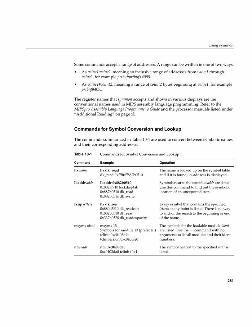
Using symmon
281
Some commands accept a range of addresses. A range can be written in one of two ways:
• As value1:value2, meaning an inclusive range of addresses from value1 throughvalue2, for example prtbuf:prtbuf+4095.
• As value1#count2, meaning a range of count2 bytes beginning at value1, for exampleprtbuf#4095.
The register names that symmon accepts and shows in various displays are theconventional names used in MIPS assembly language programming. Refer to theMIPSpro Assembly Language Programmer’s Guide and the processor manuals listed under“Additional Reading” on page xli.
Commands for Symbol Conversion and Lookup
The commands summarized in Table 10-1 are used to convert between symbolic namesand their corresponding addresses.
Table 10-1 Commands for Symbol Conversion and Lookup
Command Example Operation
hx name hx dk_readdk_read 0xffffffff882b0510
The name is looked up on the symbol tableand if it is found, its address is displayed.
lkaddr addr lkaddr 0x882b05100x882af910 lockdisptab0x882b0510 dk_read0x882b051c dk_write
Symbols near to the specified addr are listed.Use this command to find out the symboliclocation of an unexpected stop.
lkup letters hx dk_rea0x880d5f10 dk_readcap0x882b0510 dk_read0x332b0528 dk_readcapacity
Every symbol that contains the specifiedletters at any point is listed. There is no wayto anchor the search to the beginning or endof the name.
msyms ident msyms 13Symbols for module 13 (prefix tcl)tclinit 0xc0403d9ctclmversion 0xc0405fe0
The symbols for the loadable module identare listed. Use the ml command with noarguments to list all modules and their identnumbers.
nm addr nm 0xc0403da00xc0403da0 tclinit+0x4
The symbol nearest to the specified addr islisted.
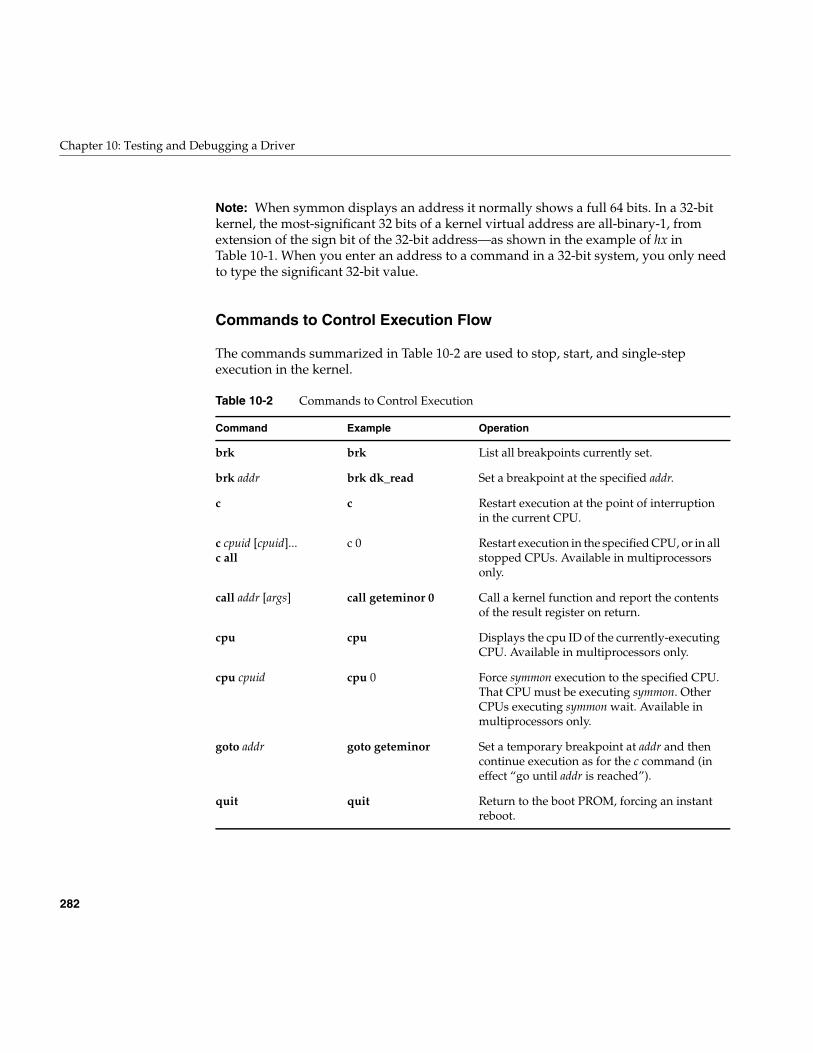
282
Chapter 10: Testing and Debugging a Driver
Note: When symmon displays an address it normally shows a full 64 bits. In a 32-bitkernel, the most-significant 32 bits of a kernel virtual address are all-binary-1, fromextension of the sign bit of the 32-bit address—as shown in the example of hx inTable 10-1. When you enter an address to a command in a 32-bit system, you only needto type the significant 32-bit value.
Commands to Control Execution Flow
The commands summarized in Table 10-2 are used to stop, start, and single-stepexecution in the kernel.
Table 10-2 Commands to Control Execution
Command Example Operation
brk brk List all breakpoints currently set.
brk addr brk dk_read Set a breakpoint at the specified addr.
c c Restart execution at the point of interruptionin the current CPU.
c cpuid [cpuid]...c all
c 0 Restart execution in the specified CPU, or in allstopped CPUs. Available in multiprocessorsonly.
call addr [args] call geteminor 0 Call a kernel function and report the contentsof the result register on return.
cpu cpu Displays the cpu ID of the currently-executingCPU. Available in multiprocessors only.
cpu cpuid cpu 0 Force symmon execution to the specified CPU.That CPU must be executing symmon. OtherCPUs executing symmon wait. Available inmultiprocessors only.
goto addr goto geteminor Set a temporary breakpoint at addr and thencontinue execution as for the c command (ineffect “go until addr is reached”).
quit quit Return to the boot PROM, forcing an instantreboot.
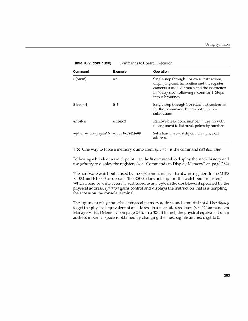
Using symmon
283
Tip: One way to force a memory dump from symmon is the command call dumpsys.
Following a break or a watchpoint, use the bt command to display the stack history anduse printreg to display the registers (see “Commands to Display Memory” on page 284).
The hardware watchpoint used by the wpt command uses hardware registers in the MIPSR4000 and R10000 processors (the R8000 does not support the watchpoint registers).When a read or write access is addressed to any byte in the doubleword specified by thephysical address, symmon gains control and displays the instruction that is attemptingthe access on the console terminal.
The argument of wpt must be a physical memory address and a multiple of 8. Use tlbvtopto get the physical equivalent of an address in a user address space (see “Commands toManage Virtual Memory” on page 284). In a 32-bit kernel, the physical equivalent of anaddress in kernel space is obtained by changing the most significant hex digit to 0.
s [count] s 8 Single-step through 1 or count instructions,displaying each instruction and the registercontents it uses. A branch and the instructionin “delay slot” following it count as 1. Stepsinto subroutines.
S [count] S 8 Single-step through 1 or count instructions asfor the s command, but do not step intosubroutines.
unbrk n unbrk 2 Remove break point number n. Use brk withno argument to list break points by number.
wpt {r|w|rw} physaddr wpt r 0x0841f608 Set a hardware watchpoint on a physicaladdress.
Table 10-2 (continued) Commands to Control Execution
Command Example Operation
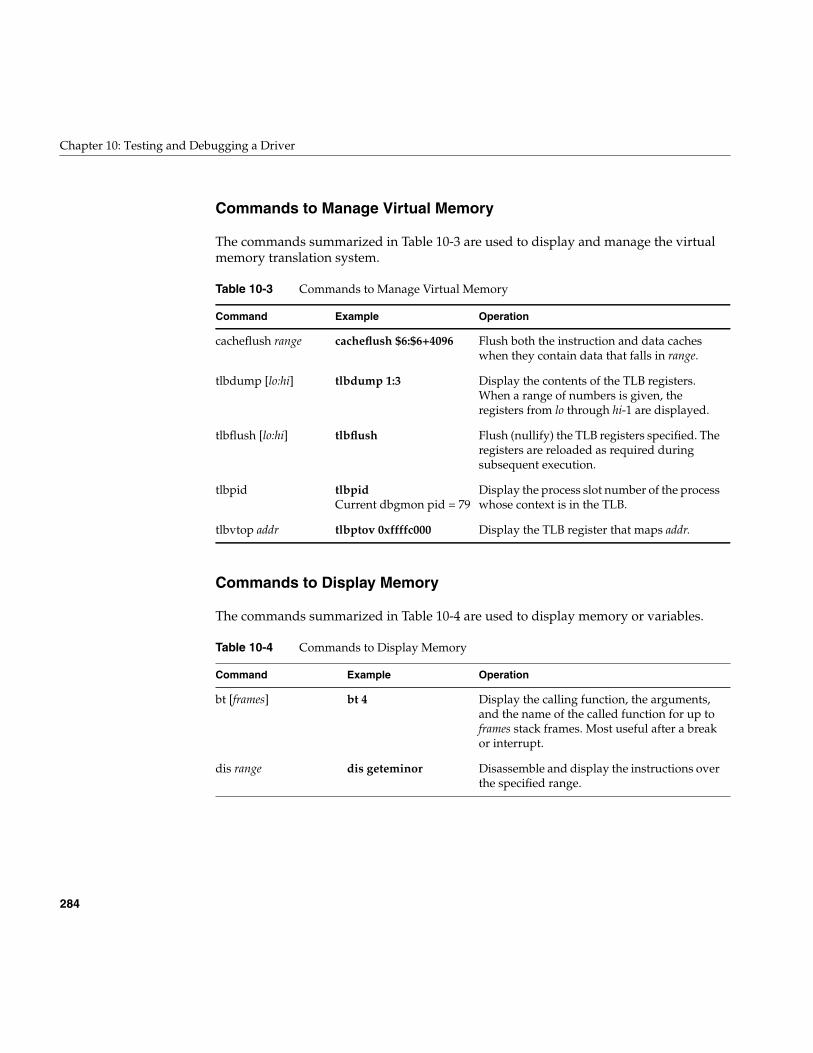
284
Chapter 10: Testing and Debugging a Driver
Commands to Manage Virtual Memory
The commands summarized in Table 10-3 are used to display and manage the virtualmemory translation system.
Commands to Display Memory
The commands summarized in Table 10-4 are used to display memory or variables.
Table 10-3 Commands to Manage Virtual Memory
Command Example Operation
cacheflush range cacheflush $6:$6+4096 Flush both the instruction and data cacheswhen they contain data that falls in range.
tlbdump [lo:hi] tlbdump 1:3 Display the contents of the TLB registers.When a range of numbers is given, theregisters from lo through hi-1 are displayed.
tlbflush [lo:hi] tlbflush Flush (nullify) the TLB registers specified. Theregisters are reloaded as required duringsubsequent execution.
tlbpid tlbpidCurrent dbgmon pid = 79
Display the process slot number of the processwhose context is in the TLB.
tlbvtop addr tlbptov 0xffffc000 Display the TLB register that maps addr.
Table 10-4 Commands to Display Memory
Command Example Operation
bt [frames] bt 4 Display the calling function, the arguments,and the name of the called function for up toframes stack frames. Most useful after a breakor interrupt.
dis range dis geteminor Disassemble and display the instructions overthe specified range.
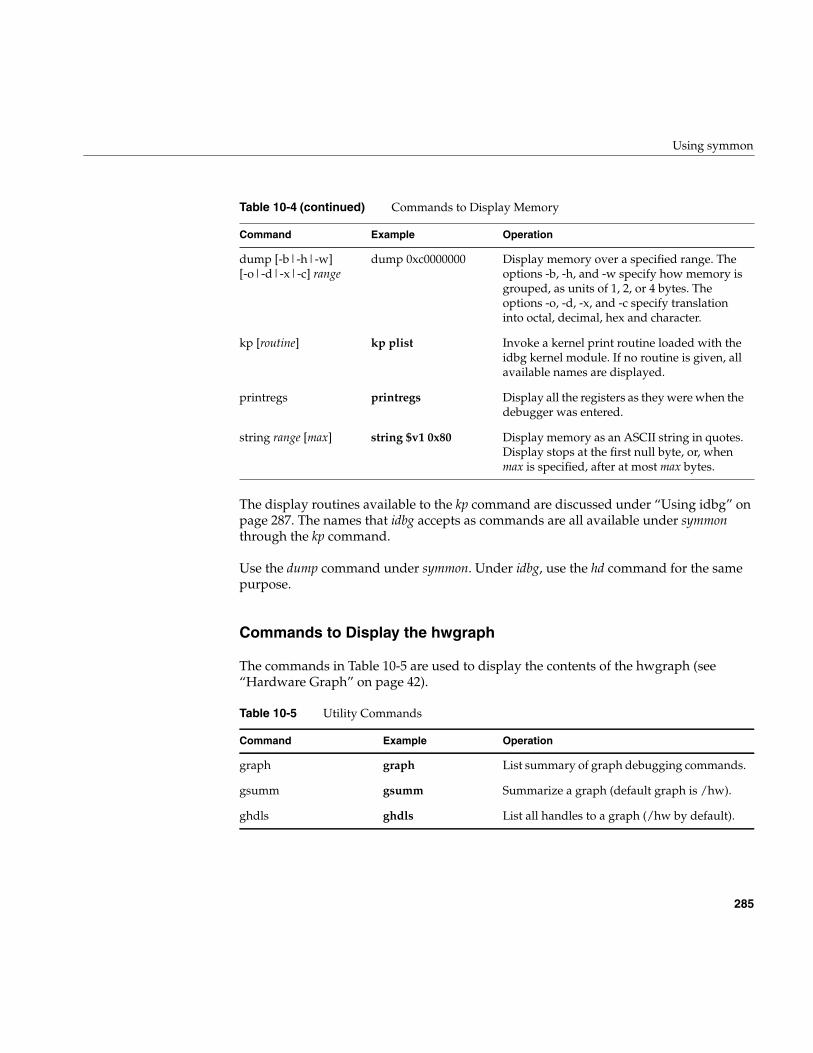
Using symmon
285
The display routines available to the kp command are discussed under “Using idbg” onpage 287. The names that idbg accepts as commands are all available under symmonthrough the kp command.
Use the dump command under symmon. Under idbg, use the hd command for the samepurpose.
Commands to Display the hwgraph
The commands in Table 10-5 are used to display the contents of the hwgraph (see“Hardware Graph” on page 42).
dump [-b|-h|-w][-o|-d|-x|-c] range
dump 0xc0000000 Display memory over a specified range. Theoptions -b, -h, and -w specify how memory isgrouped, as units of 1, 2, or 4 bytes. Theoptions -o, -d, -x, and -c specify translationinto octal, decimal, hex and character.
kp [routine] kp plist Invoke a kernel print routine loaded with theidbg kernel module. If no routine is given, allavailable names are displayed.
printregs printregs Display all the registers as they were when thedebugger was entered.
string range [max] string $v1 0x80 Display memory as an ASCII string in quotes.Display stops at the first null byte, or, whenmax is specified, after at most max bytes.
Table 10-5 Utility Commands
Command Example Operation
graph graph List summary of graph debugging commands.
gsumm gsumm Summarize a graph (default graph is /hw).
ghdls ghdls List all handles to a graph (/hw by default).
Table 10-4 (continued) Commands to Display Memory
Command Example Operation
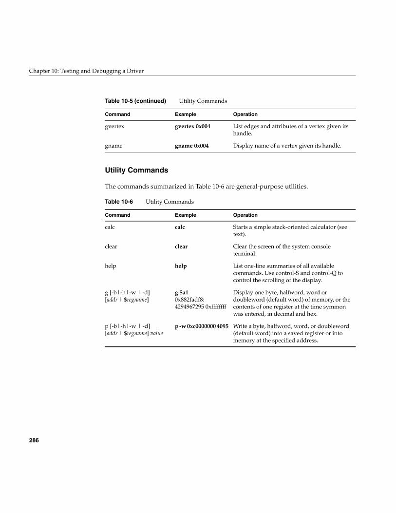
286
Chapter 10: Testing and Debugging a Driver
Utility Commands
The commands summarized in Table 10-6 are general-purpose utilities.
gvertex gvertex 0x004 List edges and attributes of a vertex given itshandle.
gname gname 0x004 Display name of a vertex given its handle.
Table 10-6 Utility Commands
Command Example Operation
calc calc Starts a simple stack-oriented calculator (seetext).
clear clear Clear the screen of the system consoleterminal.
help help List one-line summaries of all availablecommands. Use control-S and control-Q tocontrol the scrolling of the display.
g [-b|-h|-w | -d][addr | $regname]
g $a10x882fadf8:4294967295 0xffffffff
Display one byte, halfword, word ordoubleword (default word) of memory, or thecontents of one register at the time symmonwas entered, in decimal and hex.
p [-b|-h|-w | -d][addr | $regname] value
p -w 0xc0000000 4095 Write a byte, halfword, word, or doubleword(default word) into a saved register or intomemory at the specified address.
Table 10-5 (continued) Utility Commands
Command Example Operation
Using idbg
287
Using idbg
The idbg command is a utility that provides much of the display capability of symmon butfrom the command line of a user process, without stopping the system. Many details ofidbg use are covered in the idbg(1M) reference page. Keep in mind that all idbgcommands are available under the standalone debugger through the kp command (see“Commands to Display Memory” on page 284).
Loading and Invoking idbg
Superuser privilege is required to invoke idbg, because it maps kernel memory. Thecommand is ineffective unless its support modules have been made part of the kernel.This can be done permanently by changing the irix.sm file (see “Including idbg in theKernel Image” on page 271). Alternatively, you can load the needed modulesdynamically using the ml command, as follows:
# ml ld -i /var/sysgen/boot/idbg.o
Dynamic loading is discussed at more length in the idbg(1M) and ml(1M) referencepages.
When the support modules are loaded, idbg can be invoked in three styles.
Invoking idbg for Interactive Use
Invoking the command with no arguments causes it to enter interactive mode,prompting for one command after another from standard input, as shown inExample 10-4.
Example 10-4 Invoking idbg Interactively
# idbgidbg> plist 187pid 187 is in proc slot 31idbg> quit#
The command terminates when quit is entered or when control-D (input end of file) istyped.
288
Chapter 10: Testing and Debugging a Driver
Invoking idbg with a Log File
Invoking the command with the -r option and a filename causes it to write all its outputto the specified file, as shown in Example 10-5.
Example 10-5 Invoking idbg with a Log File
# idbg -r /var/tmp/idbg.saveidbg> plist 187pid 187 is in proc slot 31idbg> proc 31proc: slot 31 addr 0x8832db30 pid 187 ppid 1 uid 0 abi IRIX5 SLEEP flags: load uload siglck recalc sv...idbg> ^D# cat /var/tmp/idbg.savepid 187 is in proc slot 31proc: slot 31 addr 0x8832db30 pid 187 ppid 1 uid 0 abi IRIX5 SLEEP flags: load uload siglck recalc sv...#
You can use this method to collect a series of displays in a single file as you test a driver.
Invoking idbg for a Single Command
You can invoke idbg with a command on the command line. The output of the singlecommand is written to standard output, where it can be captured or piped to anotherprogram. Example 10-6 shows one simple use of this feature.
Example 10-6 Invoking idbg for a Single Command
# idbg plist | fgrep -c tcsh3#
Since the displays of idbg are very rich, there are endless opportunities to use this modeto generate data within shell scripts, and to process it using tools such as awk and perl.Using perl you could write an intelligent display routine that showed the status of yourdriver’s private data structures using your own terminology and display format.
Using idbg
289
Commands of idbg
Almost all idbg commands are concerned with displaying kernel memory data indifferent ways. There are commands to display almost every type of kernel data.
The vocabulary of commands changes from release to release, and can change withinreleases by software patches. Also, the commands available depend on which supportmodules are loaded; for example lock and semaphore meters cannot be displayed unlessthe ksynch_meter module is loaded (see “Including Lock Metering in the Kernel Image”on page 272). Only a few commands are listed in the idbg(1M) reference page.
The commands summarized in this book are generally useful and available on allplatforms in the current release of IRIX. For a complete (but cursory) list, use thecommand itself.
# idbg help | lp
In general, commands take zero or one argument. Typically the argument is a number,which can be any of the following:
• A kernel symbol, optionally +offset
• A number in hexadecimal (starting with 0x)
• A number in octal (starting with 0)
• A number in decimal.
The number is interpreted in the context of the command: sometimes it represents aprocess ID (pid), sometimes a process “slot” number or a buffer number. Oftencommands treat positive numbers as slot numbers or table indexes, while negativenumbers are treated as addresses in kernel space.
290
Chapter 10: Testing and Debugging a Driver
Commands to Display Memory and Symbols
The commands summarized in Table 10-7 are used to display memory based on specificaddresses or symbols, and to display the addresses for kernel symbols.
When you display the circular buffer, there is no special indication to show which line isthe newest. You have to deduce the boundary between the newest and oldest lines fromthe content.
Commands to Display Process Information
The commands summarized in Table 10-8 are concerned with displaying the status ofprocesses. Processes are recorded in an array of “slots.” The plist command gives theprocess slot number for a given process ID. The other commands take slot numbers.
Table 10-7 Commands to Display Memory and Symbols
Command Operation
dsym addr [length] Dump memory by words, starting at addr. When a word of memorydata is reasonably close to the value of a kernel symbol, the symbolplus offset is displayed instead of the hex value.
hd addr [length] Dump memory in bytes, with ASCII translation, starting at addr.When length is given, it is a count of words (not bytes) to be displayed.
pb Display the strings in the circular putbuf (see “Displaying to theCircular Message Buffer” on page 275).
string addr [max] Display memory as an ASCII string. Display stops at the first nullbyte, or, when max is specified, after at most max bytes.
Table 10-8 Commands to Display Process Information
Command Operation
eframe [ addr | slot ] Diplay the contents of an exception frame. With no argument,displays the last exception taken for the current process. Elsedisplays the exception associated with the process specified either byaddress (negative number) or process table slot number (positivenumber)
pchain slot Display the slot numbers of sibling processes to the process in slot.
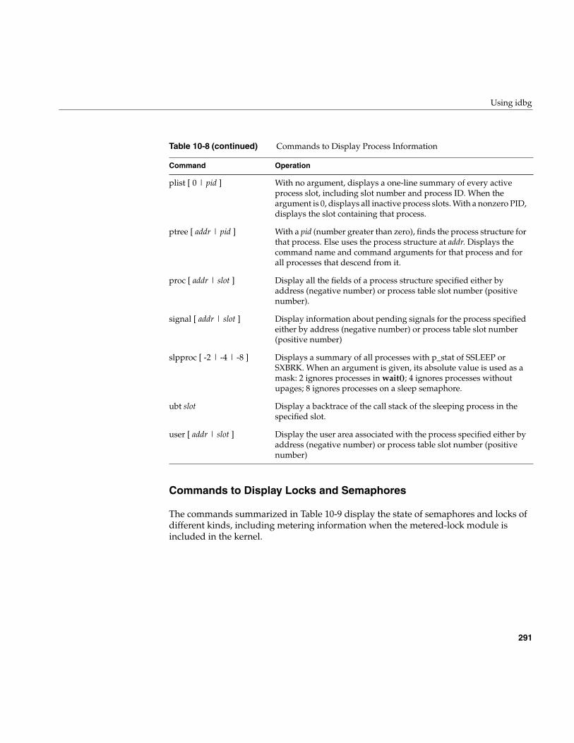
Using idbg
291
Commands to Display Locks and Semaphores
The commands summarized in Table 10-9 display the state of semaphores and locks ofdifferent kinds, including metering information when the metered-lock module isincluded in the kernel.
plist [ 0 | pid ] With no argument, displays a one-line summary of every activeprocess slot, including slot number and process ID. When theargument is 0, displays all inactive process slots. With a nonzero PID,displays the slot containing that process.
ptree [ addr | pid ] With a pid (number greater than zero), finds the process structure forthat process. Else uses the process structure at addr. Displays thecommand name and command arguments for that process and forall processes that descend from it.
proc [ addr | slot ] Display all the fields of a process structure specified either byaddress (negative number) or process table slot number (positivenumber).
signal [ addr | slot ] Display information about pending signals for the process specifiedeither by address (negative number) or process table slot number(positive number)
slpproc [ -2 | -4 | -8 ] Displays a summary of all processes with p_stat of SSLEEP orSXBRK. When an argument is given, its absolute value is used as amask: 2 ignores processes in wait(); 4 ignores processes withoutupages; 8 ignores processes on a sleep semaphore.
ubt slot Display a backtrace of the call stack of the sleeping process in thespecified slot.
user [ addr | slot ] Display the user area associated with the process specified either byaddress (negative number) or process table slot number (positivenumber)
Table 10-8 (continued) Commands to Display Process Information
Command Operation
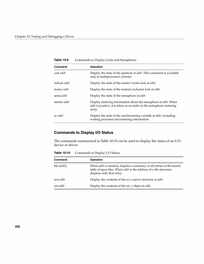
292
Chapter 10: Testing and Debugging a Driver
Commands to Display I/O Status
The commands summarized in Table 10-10 can be used to display the status of an I/Odevice or driver.
Table 10-9 Commands to Display Locks and Semaphores
Command Operation
;ock addr Display the state of the spinlock at addr. This command is availableonly in multiprocessor systems.
mrlock addr Display the state of the reader/writer lock at addr.
mutex addr Display the state of the mutual exclusion lock at addr.
sema addr Display the state of the semaphore at addr.
smeter addr Display metering information about the semaphore at addr. Whenaddr is positive, it is taken as an index to the semaphore meteringarray.
sv addr Display the state of the synchronizing variable at addr, includingwaiting processes and metering information.
Table 10-10 Commands to Display I/O Status
Command Operation
file [addr] When addr is omitted, displays a summary of all entries of the kerneltable of open files. When addr is the address of a file structure,displays only that entry.
scsi addr Display the contents of the scsi_request structure at addr.
uio addr Display the contents of the uio_t object at addr.
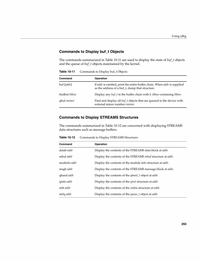
Using idbg
293
Commands to Display buf_t Objects
The commands summarized in Table 10-11 are used to display the state of buf_t objectsand the queue of buf_t objects maintained by the kernel.
Commands to Display STREAMS Structures
The commands summarized in Table 10-12 are concerned with displaying STREAMSdata structures such as message buffers.
Table 10-11 Commands to Display buf_t Objects
Command Operation
buf [addr] If addr is omitted, print the entire buffer chain. When addr is suppliedas the address of a buf_t, dump that structure.
findbuf blkno Display any buf_t in the buffer chain with b_blkno containing blkno.
qbuf eminor Find and display all buf_t objects that are queued to the device withexternal minor number eminor.
Table 10-12 Commands to Display STREAMS Structures
Command Operation
datab addr Display the contents of the STREAMS data block at addr.
mbuf addr Display the contents of the STREAMS mbuf structure at addr.
modinfo addr Display the contents of the module info structure at addr.
msgb addr Display the contents of the STREAMS message block at addr.
qband addr Display the contents of the qband_t object at addr.
qinfo addr Display the contents of the qinit structure at addr.
strh addr Display the contents of the stdata structure at addr.
strfq addr Display the contents of the queue_t object at addr.
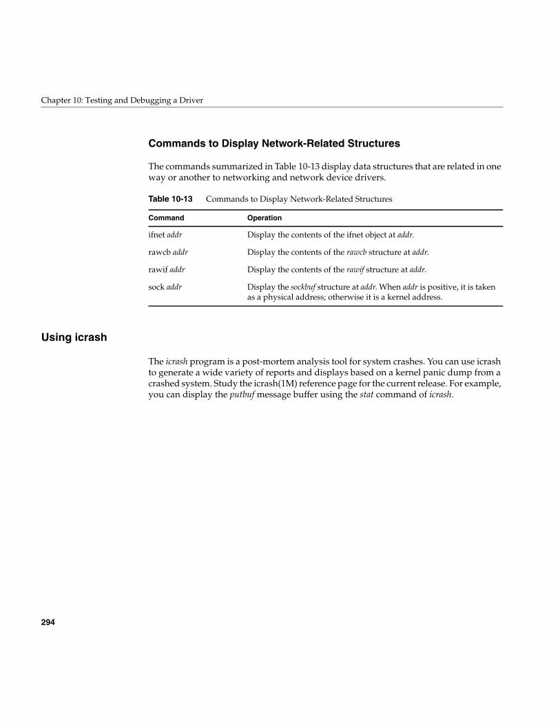
294
Chapter 10: Testing and Debugging a Driver
Commands to Display Network-Related Structures
The commands summarized in Table 10-13 display data structures that are related in oneway or another to networking and network device drivers.
Using icrash
The icrash program is a post-mortem analysis tool for system crashes. You can use icrashto generate a wide variety of reports and displays based on a kernel panic dump from acrashed system. Study the icrash(1M) reference page for the current release. For example,you can display the putbuf message buffer using the stat command of icrash.
Table 10-13 Commands to Display Network-Related Structures
Command Operation
ifnet addr Display the contents of the ifnet object at addr.
rawcb addr Display the contents of the rawcb structure at addr.
rawif addr Display the contents of the rawif structure at addr.
sock addr Display the sockbuf structure at addr. When addr is positive, it is takenas a physical address; otherwise it is a kernel address.

295
Chapter 11
11. Driver Example
This chapter displays the code of a complete device driver. The driver has no hardwaredependencies, so it can be used for experimentation in any IRIX 6.5 system.
Note: This driver is not intended to have a practical use, and it should not be installedin a production system.
The example driver has the following purposes:
• You can use it as an experimental animal with the symmon and idbg debugging tools.
• You can use it to experiment with loading and unloading a driver.
• You can modify the source code and use it to try out different kernel function calls,especially to the hwgraph package.
Installing the Example Driver
Use the following steps to install and test the example driver. Each step is expanded inthe following topics.
1. Obtain the source code files.
2. Compile the source to obtain an object file.
3. Set up the appropriate configuration files.
4. Reboot the system and verify driver operation using the supplied unit-test program.
296
Chapter 11: Driver Example
Obtaining the Source Files
The example driver consists of the following five source files:
These files (and other example code from this book) are available from the SiliconGraphics FTP server, ftp://ftp.sgi.com/sgi/
Alternatively, a patient person could recreate the files by copying and pasting from theonline manual.
Compiling the Example Driver
Compile using the techniques described under “Compiling and Linking” on page 256.
When the driver is compiled with the -DDEBUG option, all its informational displays areenabled. Without that option, it only displays messages related to unexpected errorreturns from kernel functions.
Configuring the Example Driver
Before you configure the example driver into the kernel, you should set the system witha debugging kernel, as described under “Preparing the System for Debugging” onpage 269.
Configure the example driver to IRIX by copying files as follows:
• Copy the object file, snoop.o, to /var/sysgen/boot.
• Edit the descriptive file, snoop.master, and make any desired changes—for example,making the driver nonloadable/
snoop.h Header file that declares ioctl command codes, data structures, andmacros used in the driver.
snoop.c Driver source module.
snoop.master Descriptive file for /var/sysgen/master.d.
snoop.sm A USE statement for /var/sysgen/system.
usnoop.c User-level program to exercise the driver.
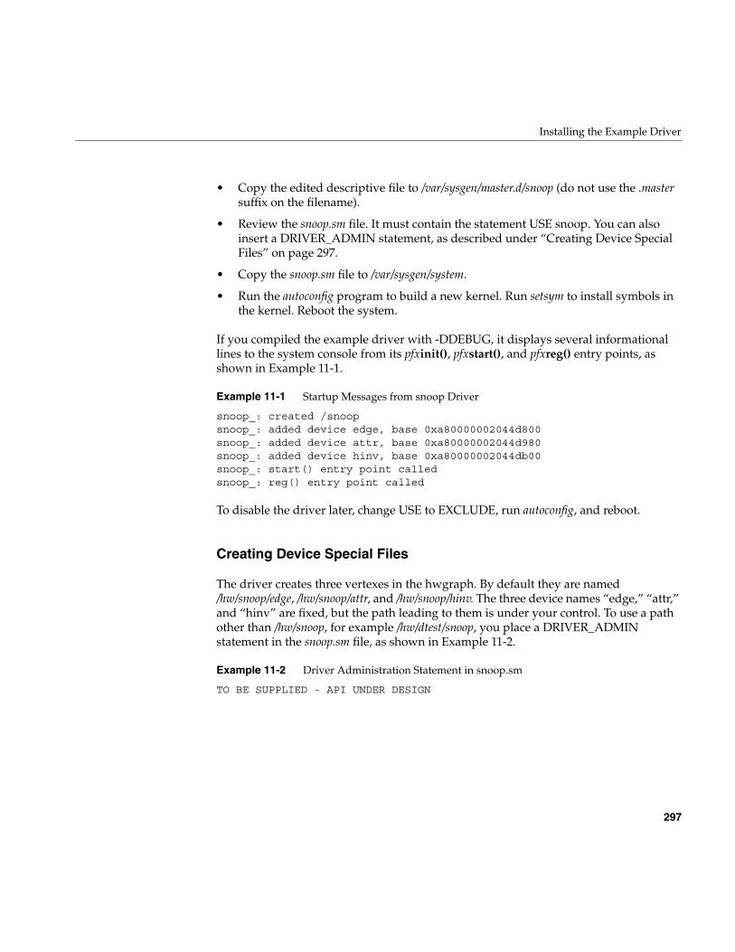
Installing the Example Driver
297
• Copy the edited descriptive file to /var/sysgen/master.d/snoop (do not use the .mastersuffix on the filename).
• Review the snoop.sm file. It must contain the statement USE snoop. You can alsoinsert a DRIVER_ADMIN statement, as described under “Creating Device SpecialFiles” on page 297.
• Copy the snoop.sm file to /var/sysgen/system.
• Run the autoconfig program to build a new kernel. Run setsym to install symbols inthe kernel. Reboot the system.
If you compiled the example driver with -DDEBUG, it displays several informationallines to the system console from its pfxinit(), pfxstart(), and pfxreg() entry points, asshown in Example 11-1.
Example 11-1 Startup Messages from snoop Driver
snoop_: created /snoopsnoop_: added device edge, base 0xa80000002044d800snoop_: added device attr, base 0xa80000002044d980snoop_: added device hinv, base 0xa80000002044db00snoop_: start() entry point calledsnoop_: reg() entry point called
To disable the driver later, change USE to EXCLUDE, run autoconfig, and reboot.
Creating Device Special Files
The driver creates three vertexes in the hwgraph. By default they are named/hw/snoop/edge, /hw/snoop/attr, and /hw/snoop/hinv. The three device names “edge,” “attr,”and “hinv” are fixed, but the path leading to them is under your control. To use a pathother than /hw/snoop, for example /hw/dtest/snoop, you place a DRIVER_ADMINstatement in the snoop.sm file, as shown in Example 11-2.
Example 11-2 Driver Administration Statement in snoop.sm
TO BE SUPPLIED - API UNDER DESIGN
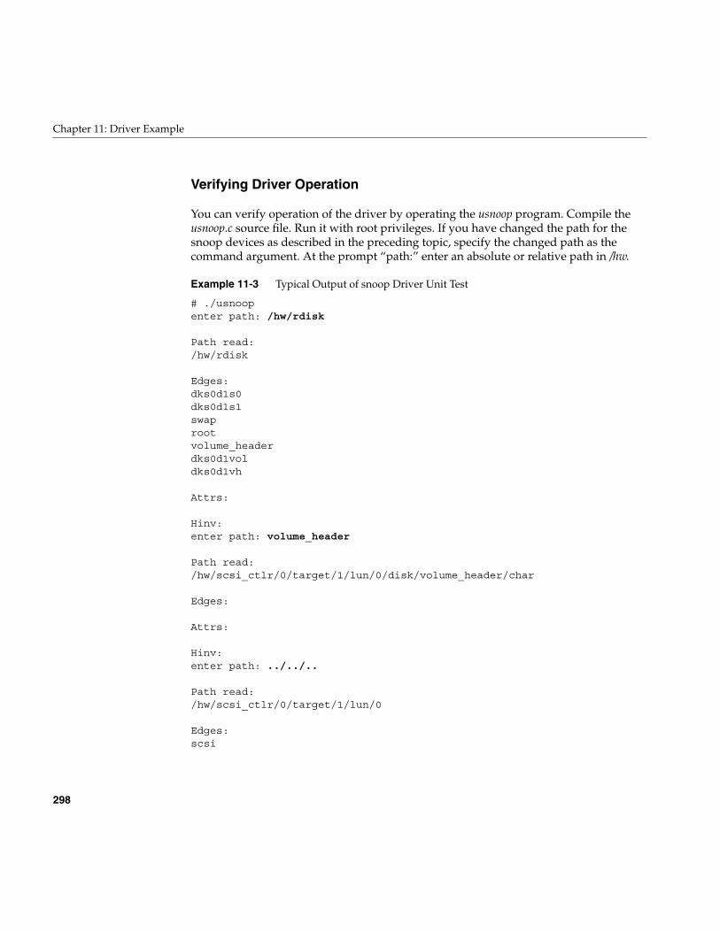
298
Chapter 11: Driver Example
Verifying Driver Operation
You can verify operation of the driver by operating the usnoop program. Compile theusnoop.c source file. Run it with root privileges. If you have changed the path for thesnoop devices as described in the preceding topic, specify the changed path as thecommand argument. At the prompt “path:” enter an absolute or relative path in /hw.
Example 11-3 Typical Output of snoop Driver Unit Test
# ./usnoopenter path: /hw/rdisk
Path read:/hw/rdisk
Edges:dks0d1s0dks0d1s1swaprootvolume_headerdks0d1voldks0d1vh
Attrs:
Hinv:enter path: volume_header
Path read:/hw/scsi_ctlr/0/target/1/lun/0/disk/volume_header/char
Edges:
Attrs:
Hinv:enter path: ../../..
Path read:/hw/scsi_ctlr/0/target/1/lun/0
Edges:scsi
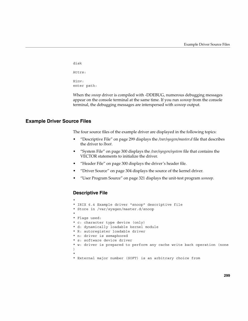
Example Driver Source Files
299
disk
Attrs:
Hinv:enter path:
When the snoop driver is compiled with -DDEBUG, numerous debugging messagesappear on the console terminal at the same time. If you run usnoop from the consoleterminal, the debugging messages are interspersed with usnoop output.
Example Driver Source Files
The four source files of the example driver are displayed in the following topics:
• “Descriptive File” on page 299 displays the /var/sysgen/master.d file that describesthe driver to lboot.
• “System File” on page 300 displays the /var/sysgen/system file that contains theVECTOR statements to initialize the driver.
• “Header File” on page 300 displays the driver’s header file.
• “Driver Source” on page 304 displays the source of the kernel driver.
• “User Program Source” on page 321 displays the unit-test program usnoop.
Descriptive File** IRIX 6.4 Example driver "snoop" descriptive file* Store in /var/sysgen/master.d/snoop** Flags used:* c: character type device (only)* d: dynamically loadable kernel module* R: autoregister loadable driver* n: driver is semaphored* s: software device driver* w: driver is prepared to perform any cache write back operation (none)** External major number (SOFT) is an arbitrary choice from
300
Chapter 11: Driver Example
* the range of numbers reserved for customer drivers.** #DEV is passed in to the driver and used to configure its info array.**FLAG PREFIX SOFT #DEV DEPENDENCIEScdnswR snoop_ 77 -b
$$$
System File** Lboot config file for IRIX 6.4 example driver "snoop"* Store as /var/sysgen/system/snoop.sm*USE: snoop
Header File/*************************************************************************** ** Copyright (C) 1993, Silicon Graphics, Inc. ** ** These coded instructions, statements, and computer programs contain ** unpublished proprietary information of Silicon Graphics, Inc., and ** are protected by Federal copyright law. They may not be disclosed ** to third parties or copied or duplicated in any form, in whole or ** in part, without the prior written consent of Silicon Graphics, Inc. ** ***************************************************************************/
#ifndef __SNOOP_H__#define __SNOOP_H__#ifdef __cplusplusextern "C" {#endif/**************************************************************************| The driver creates character special device nodes in the hwgraph, by| default at /hw/snoop/{edge,attr,hinv} However you can place a statement| in the /var/sysgen/system/irix.sm file to establish a different path,| for example:| DRIVER_ADMIN snoop_ hwpath = /hw/admin/snoopy/nodes| The driver prefix must be given exactly, as must the name "hwpath".| The argument must be a valid /hw path that does not exist when the
Example Driver Source Files
301
| driver initializes. The following constant gives the attr-name used:***************************************************************************/#define ADMIN_LABEL "hwpath"/**************************************************************************| The following definitions establish the ioctl() command numbers that| are recognized by this driver. See ioctl(D2) for comments. Ascii| uppercase letters, minus 64, fit in 5 bits, so the command #s are:| 0b0000 0000 0sss ssnn nnno oooo #### ####| These definitions are useful in client code as well as the driver.***************************************************************************/#define IOCTL_BASE ((('S'-64)<<18)|(('N'-64)<<13)|(('O'-64)<<8))#define IOCTL_MASTER_TEST (IOCTL_BASE + 1)#define IOCTL_MASTER_GO (IOCTL_BASE + 2)#define IOCTL_CLOSING (IOCTL_BASE + 6)#define IOCTL_PATH_READ (IOCTL_BASE + 9)#define IOCTL_VERTEX_GET (IOCTL_BASE + 15)#define IOCTL_VERTEX_SET (IOCTL_BASE + 16)
#ifdef _KERNEL /* remainder is only useful to the driver */#include <sys/types.h> /* all kinds of types inc. vertex_hdl_t */#include <sys/kmem.h> /* kmem_zalloc, kmem_free */#include <sys/ksynch.h> /* locks */#include <sys/ddi.h> /* many utility functions */#include <sys/invent.h> /* inventory_t */#include <sys/hwgraph.h> /* hwgraph functions */#include <sys/driver.h> /* driver_admin functions */#include <sys/cred.h> /* for cred_t used in open/read/write */#include <sys/cmn_err.h> /* for cmn_err and its constants */#include <sys/errno.h> /* error constants */#include <sys/mload.h> /* mload version string *//**************************************************************************| The purpose of the following macros are to make it possible to define| the driver prefix in exactly one place (the PREFIX_NAME macro) and then| to invoke that prefix anywhere else -| - as part of function names, e.g. <prefix>open(), <prefix>init().| - as a character literal, as in pciio_driver_register(..."prefix")| - automatically as part of other macros for example debug displays***************************************************************************/#define PREFIX_NAME(name) snoop_ ## name/* ----- driver prefix: ^^^^^^ defined here only *//* utility macros, not to be used directly */#define PREFIX_ONLY PREFIX_NAME( )#define STRINGIZER(x) # x#define EVALUEIZER(x) STRINGIZER(x)#define PREFIX_STRING EVALUEIZER(PREFIX_ONLY)
302
Chapter 11: Driver Example
/*| Define driver entry point macros in alpha order. This is your basic| character driver: open-read-write-ioctl-close.*/#define PFX_CLOSE PREFIX_NAME(close)#define PFX_DEVFLAG PREFIX_NAME(devflag)#define PFX_INIT PREFIX_NAME(init)#define PFX_IOCTL PREFIX_NAME(ioctl)#define PFX_MVERSION PREFIX_NAME(mversion)#define PFX_OPEN PREFIX_NAME(open)#define PFX_READ PREFIX_NAME(read)#define PFX_REG PREFIX_NAME(reg)#define PFX_START PREFIX_NAME(start)#define PFX_UNLOAD PREFIX_NAME(unload)#define PFX_WRITE PREFIX_NAME(write)/**************************************************************************| Debug display macros: one each for cmn_err calls with 0, 1, 2, 3 or 4| arguments. The macros generate the PREFIX_STRING, colon, space at the| front of the message and \n on the end. For example,| DBGMSG2("one %d two %x",a,b) is the same as| cmn_err(CE_DEBUG,"snoop_: one %d two %x\n",a,b)|**************************************************************************/#ifndef DEBUG#define DBGMSG0(s)#define DBGMSG1(s,x)#define DBGMSG2(s,x,y)#define DBGMSG3(s,x,y,z)#define DBGMSG4(s,x,y,z,w)#else#define DBGMSGX(s) cmn_err(CE_DEBUG,PREFIX_STRING ": " s "\n"#define DBGMSG0(s) DBGMSGX(s) )#define DBGMSG1(s,x) DBGMSGX(s) ,x)#define DBGMSG2(s,x,y) DBGMSGX(s) ,x,y)#define DBGMSG3(s,x,y,z) DBGMSGX(s) ,x,y,z)#define DBGMSG4(s,x,y,z,w) DBGMSGX(s) ,x,y,z,w)#endif/**************************************************************************| The ERRMSGn macros are the same as the DGBMSGn macros, except they are| always defined (not conditional on DEBUG) and use CE_WARN status.|**************************************************************************/#define ERRMSGX(s) cmn_err(CE_WARN,PREFIX_STRING ": " s "\n"#define ERRMSG0(s) ERRMSGX(s) )#define ERRMSG1(s,x) ERRMSGX(s) ,x)#define ERRMSG2(s,x,y) ERRMSGX(s) ,x,y)#define ERRMSG3(s,x,y,z) ERRMSGX(s) ,x,y,z)
Example Driver Source Files
303
#define ERRMSG4(s,x,y,z,w) ERRMSGX(s) ,x,y,z,w)/**************************************************************************| One instance of the following structure is created when any of our| devices is opened. The structure is by default allocated in| the node where the open() is executed. The structure is protected by a| lock because it is possible for multiple threads in a pgroup to attempt| concurrent read/write/ioctl calls to the same FD.| use_lock : ensure only one thread modifies structure at a time| read_ptr : address of data to return to read()| read_len : length of data remaining to read()| v_current : hwgraph vertex being snooped (initially /hw)| v_last_edge : vertex at end of last-scanned edge| edge_place : position in edge list, for /hw/snoop/edge| info_place : position in the info list, for /hw/snoop/attr| hinv_place : position in the hinv list, for /hw/snoop/hinv| scratch : buffer to hold maximal /hw path on write() call| Only one of the _place fields is used in any one structure, but the| memory saved by making a union of them is not worth the coding bother.|**************************************************************************/typedef struct snoop_user_s {
mutex_t use_lock;char * read_ptr;unsigned int read_len;vertex_hdl_t v_current;vertex_hdl_t v_last_edge;graph_edge_place_t edge_place;graph_info_place_t info_place;invplace_t hinv_place;char scratch[HWGRAPH_VPATH_LEN_MAX*LABEL_LENGTH_MAX];
} snoop_user_t;/**************************************************************************| One instance of the following structure is created for each char device| we create (3 in all), and its address is saved with device_info_set().| dev_lock : for controlled access to the device data| val_func : function to set up data for a read| nopen : number of opened/allocated users| user_list : vector of pointers to snoop_user structs| Use of this structure is controlled by a reader/writer lock. Only the| open & close entries modify the user list, and so claim the writer lock.| Other entries claim it as readers.|| The reason for making user_list a fixed array (as opposed to linking| the snoop_user structs in a chain) is because each snoop_user_t can be| in a different module, and we want to touch only the one for the caller.|**************************************************************************/
304
Chapter 11: Driver Example
#define MAX_PGID 20typedef void (*val_func)(snoop_user_t *puser);typedef struct snoop_base_s {
rwlock_t dev_lock;val_func vector;unsigned nopen;struct {
pid_t user; /* pgid at open() time */int generation; /* number of occupants of this slot */snoop_user_t *work; /* -> corresponding work area */
} user_list[MAX_PGID];} snoop_base_t;
#ifdef __cplusplus}#endif#endif /* _KERNEL */#endif /* __SNOOP_H__ */
Driver Source/**************************************************************************|| This is snoop.c, a pseudo-device driver for IRIX 6.4 and later.|| At snoop_init(), create three char device vertexes in the hwgraph,| /hw/snoop/{edge,attr,hinv}. Each device supports open, read, write,| close, and ioctl.|| At most one open() from any process group is accepted for any device.| Second attempts are rejected with EBUSY. However, multiple processes| and POSIX threads in a process group may use the open FD concurrently.|| The driver maintains a current status for each process group open of| each device. The two key status variables are:| a position on a current vertex in the hwgraph| a scan position for reading out edges, attributes, or inventory_t's|| Each read() of /hw/snoop/edge returns the next (first) edge from the| current vertex as a character string. If the read length is less than| the string length, the byte position is remembered and the rest of the| string is returned on the next read.|
Example Driver Source Files
305
| Each read() of /hw/snoop/attr returns the first/next attribute label| from the current vertex under the same rule as edges.|| Each read() of /hw/snoop/hinv returns the first/next invent_t ditto.| Note that an invent_t is binary data, not ascii.|| For any device, a call to write() must present an absolute or relative| path in the /hw filesystem. The device moves to the selected vertex| and initializes the input scan of edges, attrs, or hinvs. For example,| write(FD,"/hw/snoop") moves to that vertex.| write(FD,"..") moves back to /hw| write(FD,"snoop/edge") moves down to /hw/snoop/edge.|| The following IOCTL calls are supported (declared in snoop.h):|| IOCTL_MASTER_TEST returns 0 if a "master" vertex exists, or ENOENT|| IOCTL_MASTER_GO moves the current vertex to its master, if any|| IOCTL_PATH_READ sets to return the complete "/hw..." path of the| current vertex on the next read() call, in place| of the next edge/attr/hinv.|| IOCTL_CLOSING notifies the driver that this process group is| about to close the device. Subsequent attempts to| use that open file are rejected. Interesting| mutual-exclusion problems arise here.|| IOCTL_VERTEX_GET retrieve the current vertex handle. Argument is| an address in user memory to place the handle.|| IOCTL_VERTEX_SET set a new current vertex. Argument is an address| in user memory where a handle sits, presumably| one retrieved with IOCTL_VERTEX_GET.||**************************************************************************/#include "snoop.h" /* all #includes are inside this header */int PFX_DEVFLAG = D_MP;char * PFX_MVERSION = M_VERSION;/* Function Directory */static int
alloc_user(snoop_base_t *pbase); /* make & init snoop_user_t on open */static pid_t
get_pgroup(void); /* get PGID of client */static int
get_user_index(snoop_base_t *pbase, pid_t pgroup); /* get index of client */
306
Chapter 11: Driver Example
static snoop_user_t *get_user(snoop_base_t *pbase); /* locate snoop_user_t for client */
static intinit_dev(char *name, vertex_hdl_t v_snoop, val_func func);
static voidreset_scans(snoop_user_t *puser); /* reset input scans for client */
static voidval_attr(snoop_user_t *puser); /* scan next attr for read() */
static voidval_edge(snoop_user_t *puser); /* scan next edge for read() */
static voidval_hinv(snoop_user_t *puser); /* scan next inventory_t for read() */
intPFX_INIT(); /* init() entry point */
intPFX_OPEN(dev_t *devp, int oflag, int otyp, cred_t *crp);
intPFX_REG(); /* reg() entry point */
intPFX_START(); /* start() entry point */
intPFX_WRITE(dev_t dev, uio_t *uiop, cred_t *crp);
intPFX_IOCTL(dev_t dev, int cmd, void *arg, int mode, cred_t *crp, int *rvalp);/**************************************************************************| Get the process group ID for the client process. The pgid is used as| a key to search the user_list.|**************************************************************************/static pid_tget_pgroup(void){
ulong_t val = 0;(void)drv_getparm(PPGRP,&val);return (pid_t) val;
}/**************************************************************************| Get the index of the snoop_user_t for the client process in the| user_list. Return -1 if the specified pgid is not found. "Not Found"| is the expected result when this function is called from the| pfx_open() entry. It is a possible result in other entry points, but| only when the client calls ioctl(IOCTL_CLOSING) and then continues| to use the file descriptor.|**************************************************************************/
Example Driver Source Files
307
static intget_user_index(snoop_base_t *pbase, pid_t pgid){
int j;
for (j=0 ;j<MAX_PGID;++j) {if (pbase->user_list[j].user == pgid)
return j;}return -1;
}/**************************************************************************| Locate the snoop_user_t for the client process. The caller is assumed| to hold pbase->dev_lock as reader at least.|**************************************************************************/static snoop_user_t *get_user(snoop_base_t *pbase){
snoop_user_t *puser = NULL;int j;if (-1 != (j = get_user_index(pbase, get_pgroup())) )
puser = pbase->user_list[j].work;return puser;
}/**************************************************************************| Reset all three data scans for this user. Only one scan is actually in| use on a given device, but it's less trouble to have a single function.|**************************************************************************/static voidreset_scans(snoop_user_t *puser){
puser->read_len = 0;puser->v_last_edge = GRAPH_VERTEX_NONE;puser->edge_place = EDGE_PLACE_WANT_REAL_EDGES;puser->info_place = GRAPH_INFO_PLACE_NONE;puser->hinv_place = INVPLACE_NONE;
}/**************************************************************************| Allocate a snoop_user_t for the calling process and install it in the| user_list. The caller must hold dev_lock as a writer. Errors:| if the calling pgroup already has this device open, EBUSY| if there is no open slot in the user_list, EMFILE| if kmem_alloc fails, ENOMEM| Initialize the lock and all 3 data scans before setting the pointer.| Increment the generation count of the slot.|**************************************************************************/
308
Chapter 11: Driver Example
static intalloc_user(snoop_base_t *pbase){
snoop_user_t *puser;pid_t pgroup = get_pgroup();int j = get_user_index(pbase,pgroup);
if (j != -1) {DBGMSG0("rejecting open, pgid in list");return EBUSY;
}for(j=0 ;j<MAX_PGID;++j) { /* find empty user_list slot */
if (!(pbase->user_list[j].user)) break;}if (j>=MAX_PGID) {
DBGMSG0("user list full at open");return EMFILE;
}puser = kmem_alloc(sizeof(*puser),KM_SLEEP+KM_CACHEALIGN);if (!puser) {
ERRMSG0("unable to allocate user struct at open");return ENOMEM;
}MUTEX_INIT(&puser->use_lock,MUTEX_DEFAULT,PREFIX_STRING);puser->v_current = hwgraph_root; /* "/hw" vertex, see hwgraph.h */reset_scans(puser);pbase->user_list[j].user = pgroup;pbase->user_list[j].generation += 1;pbase->user_list[j].work = puser;DBGMSG3("user for pgid %d at 0x%x in slot %d",pgroup,puser,j);++ pbase->nopen;DBGMSG1(" now %d open",pbase->nopen);return 0;
}/**************************************************************************| Set up the next edge label from the current vertex as the read data.| If there is no next edge label, set up to return 0 bytes.| This function is used for read() to the device /hw/snoop/edge.| The caller, snoop_read(), has checked that puser->read == 0.|**************************************************************************/
Example Driver Source Files
309
static voidval_edge(snoop_user_t *puser){
graph_error_t err;if (puser->v_current != GRAPH_VERTEX_NONE) {
err = hwgraph_edge_get_next(puser->v_current, /* in source vertex */puser->scratch, /* out big buffer for string */&puser->v_last_edge, /* out save destination vertex */&puser->edge_place); /* inout scan position */
if (!err) { /* we got a string... */puser->read_ptr = puser->scratch; /* ..set up as read data */puser->read_len = 1+strlen(puser->scratch); /* incl. null */
}else { /* no edge string, leave len=0 */
if (err != GRAPH_NOT_FOUND) /* ..unexpected cause? */ERRMSG1("hwgraph_edge_get_next err %d", err);
}}
}/**************************************************************************| Set up the next attr label from the current vertex as the read data.| If there is no next attr label, set up to return 0 bytes.| This function is used for read() to the device /hw/snoop/attr.|**************************************************************************/static voidval_attr(snoop_user_t *puser){
graph_error_t err;arbitrary_info_t junk;
if (puser->v_current != GRAPH_VERTEX_NONE) {err = hwgraph_info_get_next_LBL(
puser->v_current, /* in source vertex */puser->scratch, /* out big buffer for string */&junk, /* don't want the info ptr */&puser->info_place); /* inout scan position */
if (!err) { /* we got a string... */puser->read_ptr = puser->scratch; /* ..set up as read data */puser->read_len = 1+strlen(puser->scratch); /* incl. null */
}else { /* no edge string, leave len=0 */
if (err != GRAPH_NOT_FOUND) /* ..unexpected cause? */ERRMSG1("hwgraph_info_get_next err %d\n", err);
}}
}
310
Chapter 11: Driver Example
/**************************************************************************| Set up the next inventory_t from the current vertex as the read data.| If there is no next data, set up to return 0 bytes.| This function is used for read() to the device /hw/snoop/hinv.|**************************************************************************/static voidval_hinv(snoop_user_t *puser){
graph_error_t err;inventory_t *invp;
if (puser->v_current != GRAPH_VERTEX_NONE) {err = hwgraph_inventory_get_next(
puser->v_current, /* in source vertex */&puser->hinv_place, /* inout scan position */&invp ); /* out ->inventory_t */
if (!err) {puser->read_ptr = (char*)invp;puser->read_len = sizeof(inventory_t);
}else { /* no inv data, leave len=0 */
if (err != GRAPH_NOT_FOUND) /* ..unexpected cause? */ERRMSG1("hwgraph_info_get_next err %d\n", err);
}}
}/**************************************************************************| At initialization time, create a char special device "/hw/snoop/<name>"| The <name> is "edge," "attr," or "hinv." v_snoop is the handle of the| master node, expected to be "/hw/snoop."|**************************************************************************/
Example Driver Source Files
311
static intinit_dev(char *name, vertex_hdl_t v_snoop, val_func func){
graph_error_t err;vertex_hdl_t v_dev = GRAPH_VERTEX_NONE;snoop_base_t *pbase = NULL;/*|| See if the device already exists.*/err = hwgraph_edge_get(v_snoop,name,&v_dev);if (err != GRAPH_SUCCESS) { /* it does not. create it. */
err = hwgraph_char_device_add(v_snoop, /* starting vertex */name, /* path, in this case just a name */PREFIX_STRING, /* our driver prefix */&v_dev); /* out: new vertex */
if (err) {ERRMSG2("char_device_add(%s) error %d",name,err);return err;
}DBGMSG2("created device %s, vhdl 0x%x",name,v_dev);
}else
DBGMSG2("found device %s, vhdl 0x%x",name,v_dev);/*|| The device vertex exists. See if it already contains a snoop_base_t|| from a previous load. If the vertex was only just created,|| this returns NULL and we need to aallocate a base struct.*/pbase = device_info_get(v_dev);if (!pbase) { /* no device info yet */
pbase = kmem_zalloc(sizeof(*pbase),KM_SLEEP);if (!pbase) {
ERRMSG0("failed to allocate base struct");return ENOMEM;
}RW_INIT(&pbase->dev_lock, PREFIX_STRING);
}DBGMSG1(" base struct at 0x%x",pbase);/*|| This is a key step: on a reload, we must refresh the address|| of the value function, which is different from when we last loaded.*/pbase->vector = func;device_info_set(v_dev,pbase);return 0;
}
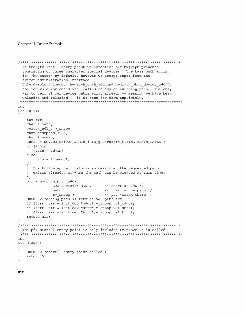
312
Chapter 11: Driver Example
/**************************************************************************| At the pfx_init() entry point we establish our hwgraph presence| consisting of three character special devices. The base path string| is "/hw/snoop" by default, however we accept input from the| driver-administration interface.| Unload/reload issues: hwgraph_path_add and hwgraph_char_device_add do| not return error codes when called to add an existing path! The only| way to tell if our device paths exist already -- meaning we have been| unloaded and reloaded -- is to test for them explicitly.|**************************************************************************/intPFX_INIT(){
int err;char * path;vertex_hdl_t v_snoop;char testpath[256];char * admin;admin = device_driver_admin_info_get(PREFIX_STRING,ADMIN_LABEL);if (admin)
path = admin;else
path = "/snoop";/*|| The following call returns success when the requested path|| exists already, or when the path can be created at this time.*/err = hwgraph_path_add(
GRAPH_VERTEX_NONE, /* start at /hw */path, /* this is the path */&v_snoop); /* put vertex there */
DBGMSG2("adding path %s returns %d",path,err);if (!err) err = init_dev("edge",v_snoop,val_edge);if (!err) err = init_dev("attr",v_snoop,val_attr);if (!err) err = init_dev("hinv",v_snoop,val_hinv);return err;
}/**************************************************************************| The pfx_start() entry point is only included to prove it is called.|**************************************************************************/intPFX_START(){
DBGMSG0("start() entry point called");return 0;
}
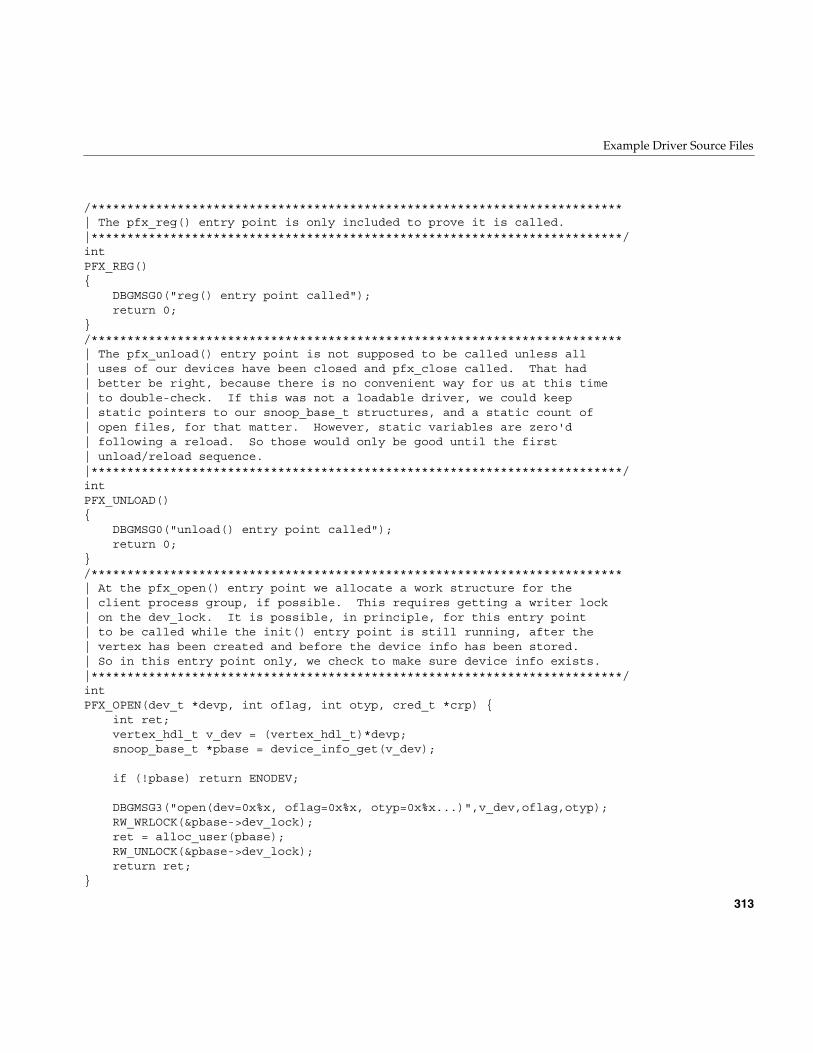
Example Driver Source Files
313
/**************************************************************************| The pfx_reg() entry point is only included to prove it is called.|**************************************************************************/intPFX_REG(){
DBGMSG0("reg() entry point called");return 0;
}/**************************************************************************| The pfx_unload() entry point is not supposed to be called unless all| uses of our devices have been closed and pfx_close called. That had| better be right, because there is no convenient way for us at this time| to double-check. If this was not a loadable driver, we could keep| static pointers to our snoop_base_t structures, and a static count of| open files, for that matter. However, static variables are zero'd| following a reload. So those would only be good until the first| unload/reload sequence.|**************************************************************************/intPFX_UNLOAD(){
DBGMSG0("unload() entry point called");return 0;
}/**************************************************************************| At the pfx_open() entry point we allocate a work structure for the| client process group, if possible. This requires getting a writer lock| on the dev_lock. It is possible, in principle, for this entry point| to be called while the init() entry point is still running, after the| vertex has been created and before the device info has been stored.| So in this entry point only, we check to make sure device info exists.|**************************************************************************/intPFX_OPEN(dev_t *devp, int oflag, int otyp, cred_t *crp) {
int ret;vertex_hdl_t v_dev = (vertex_hdl_t)*devp;snoop_base_t *pbase = device_info_get(v_dev);
if (!pbase) return ENODEV;
DBGMSG3("open(dev=0x%x, oflag=0x%x, otyp=0x%x...)",v_dev,oflag,otyp);RW_WRLOCK(&pbase->dev_lock);ret = alloc_user(pbase);RW_UNLOCK(&pbase->dev_lock);return ret;
}
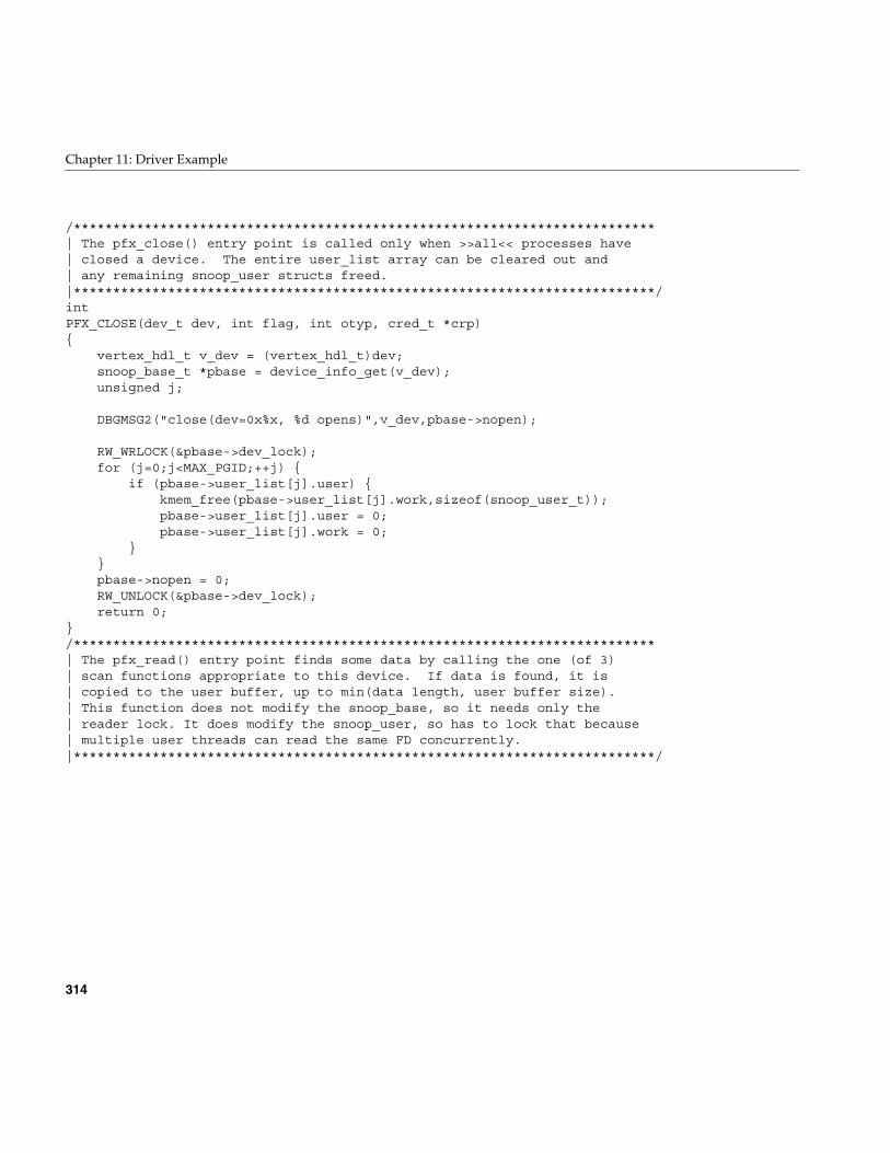
314
Chapter 11: Driver Example
/**************************************************************************| The pfx_close() entry point is called only when >>all<< processes have| closed a device. The entire user_list array can be cleared out and| any remaining snoop_user structs freed.|**************************************************************************/intPFX_CLOSE(dev_t dev, int flag, int otyp, cred_t *crp){
vertex_hdl_t v_dev = (vertex_hdl_t)dev;snoop_base_t *pbase = device_info_get(v_dev);unsigned j;
DBGMSG2("close(dev=0x%x, %d opens)",v_dev,pbase->nopen);
RW_WRLOCK(&pbase->dev_lock);for (j=0;j<MAX_PGID;++j) {
if (pbase->user_list[j].user) {kmem_free(pbase->user_list[j].work,sizeof(snoop_user_t));pbase->user_list[j].user = 0;pbase->user_list[j].work = 0;
}}pbase->nopen = 0;RW_UNLOCK(&pbase->dev_lock);return 0;
}/**************************************************************************| The pfx_read() entry point finds some data by calling the one (of 3)| scan functions appropriate to this device. If data is found, it is| copied to the user buffer, up to min(data length, user buffer size).| This function does not modify the snoop_base, so it needs only the| reader lock. It does modify the snoop_user, so has to lock that because| multiple user threads can read the same FD concurrently.|**************************************************************************/
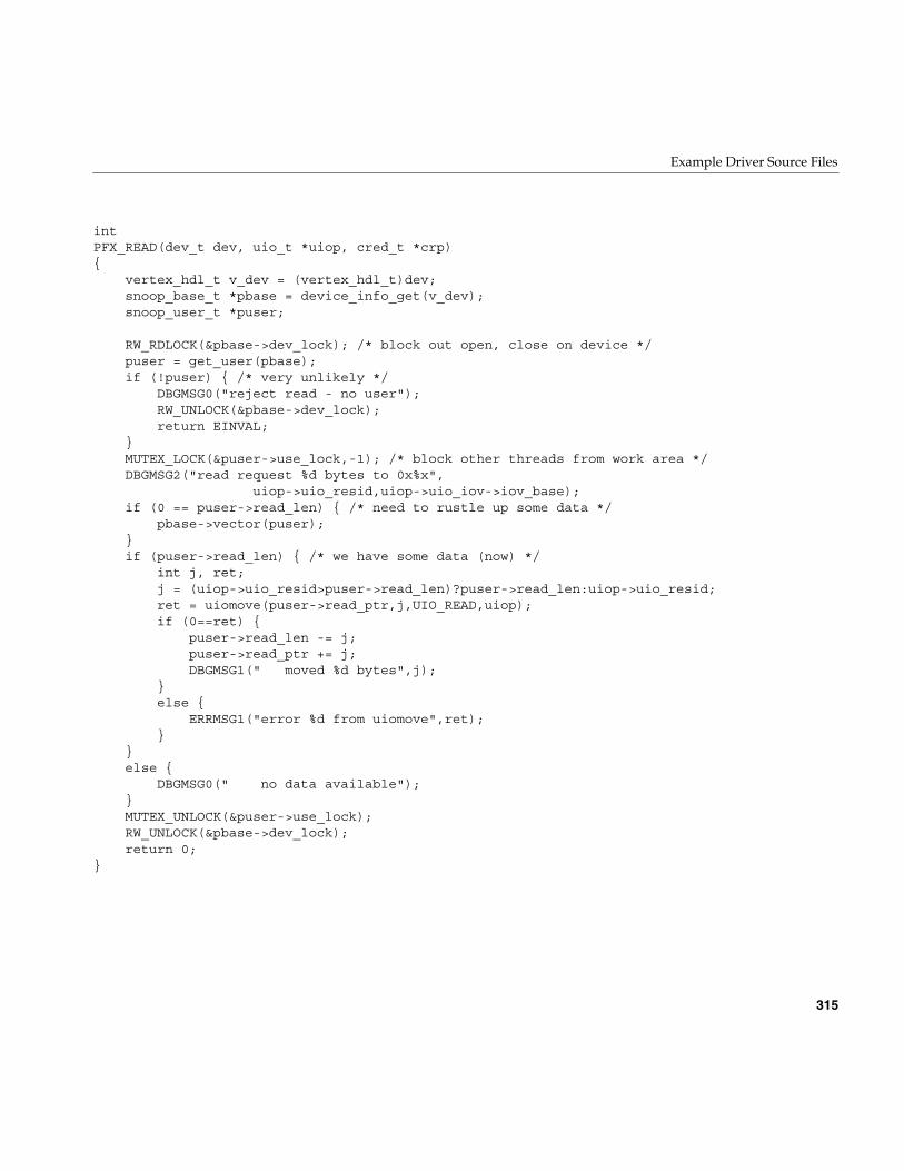
Example Driver Source Files
315
intPFX_READ(dev_t dev, uio_t *uiop, cred_t *crp){
vertex_hdl_t v_dev = (vertex_hdl_t)dev;snoop_base_t *pbase = device_info_get(v_dev);snoop_user_t *puser;
RW_RDLOCK(&pbase->dev_lock); /* block out open, close on device */puser = get_user(pbase);if (!puser) { /* very unlikely */
DBGMSG0("reject read - no user");RW_UNLOCK(&pbase->dev_lock);return EINVAL;
}MUTEX_LOCK(&puser->use_lock,-1); /* block other threads from work area */DBGMSG2("read request %d bytes to 0x%x",
uiop->uio_resid,uiop->uio_iov->iov_base);if (0 == puser->read_len) { /* need to rustle up some data */
pbase->vector(puser);}if (puser->read_len) { /* we have some data (now) */
int j, ret;j = (uiop->uio_resid>puser->read_len)?puser->read_len:uiop->uio_resid;ret = uiomove(puser->read_ptr,j,UIO_READ,uiop);if (0==ret) {
puser->read_len -= j;puser->read_ptr += j;DBGMSG1(" moved %d bytes",j);
}else {
ERRMSG1("error %d from uiomove",ret);}
}else {
DBGMSG0(" no data available");}MUTEX_UNLOCK(&puser->use_lock);RW_UNLOCK(&pbase->dev_lock);return 0;
}
316
Chapter 11: Driver Example
/**************************************************************************| The pfx_write() entry point accepts data into the scratch area. No matter| what happens, the input scan on this user is going to be reset, so if| there is residual data in the scratch area, it can be overwritten.| All the write data is moved to scratch and treated as a hwgraph path.| It can be absolute or relative to the current vertex. We traverse| to that vertex and if it is found, make it the current vertex.|**************************************************************************/intPFX_WRITE(dev_t dev, uio_t *uiop, cred_t *crp){
vertex_hdl_t v_dev = (vertex_hdl_t)dev;snoop_base_t *pbase = device_info_get(v_dev);snoop_user_t *puser;int ret = 0;int user_lock = 0;int len;
RW_RDLOCK(&pbase->dev_lock); /* block out open, close on device */puser = get_user(pbase);if (!puser) { /* very unlikely */
DBGMSG0("reject write - no user");ret = EINVAL;
}if (!ret) { /* user (pgroup) is valid */
len = uiop->uio_resid;DBGMSG2("write request %d bytes from 0x%x",
len, uiop->uio_iov->iov_base);if (len >= sizeof(puser->scratch)) {
ret = ENOSPC;DBGMSG0(" rejected, path too long");
}else if (!len) { /* write for 0 bytes? */
ret = EINVAL;DBGMSG0(" rejected, 0 length");
}
}if (!ret) { /* data length is acceptable */
MUTEX_LOCK(&puser->use_lock,-1); /* block others from work area */user_lock = 1; /* remember to unlock it */reset_scans(puser); /* now we lose scan positioning */ret = uiomove(puser->scratch,len,UIO_WRITE,uiop);if (0 == ret) {
puser->scratch[len] = '\0'; /* terminate string */}
Example Driver Source Files
317
else { /* couldn't move it? */ERRMSG1("error %d from uiomove",ret);
}}if (!ret) { /* path data has been copied */
vertex_hdl_t v_end;char * path = puser->scratch;if (*path == '/') { /* absolute path */
v_end = hwgraph_path_to_vertex(path);if (v_end == GRAPH_VERTEX_NONE)
ret = GRAPH_NOT_FOUND;}else { /* relative path to current vertex */
ret = hwgraph_traverse(puser->v_current,path,&v_end);}if (!ret) { /* v_end is a valid endpoint */
(void)hwgraph_vertex_unref(puser->v_current);puser->v_current = v_end;
}else {
DBGMSG2("lookup (%s) = %d",puser->scratch,ret);ret = ESPIPE; /* "illegal seek" */
}}if (user_lock)
MUTEX_UNLOCK(&puser->use_lock);RW_UNLOCK(&pbase->dev_lock);return ret;
}/**************************************************************************| the pfx_ioctl() entry point receives ioctl() calls. Cleverly, all the| supported ioctl calls are designed to use no "arg" parameters, thus| avoiding all questions of user ABI.***************************************************************************/intPFX_IOCTL(dev_t dev, int cmd, void *arg, int mode, cred_t *crp, int *rvalp){
vertex_hdl_t v_dev = (vertex_hdl_t)dev;snoop_base_t *pbase = device_info_get(v_dev);snoop_user_t *puser;vertex_hdl_t v_mast;int ret = 0;
RW_RDLOCK(&pbase->dev_lock); /* block out open, close on device */puser = get_user(pbase);if (!puser) { /* very unlikely */
318
Chapter 11: Driver Example
DBGMSG0("reject ioctl - no user");RW_UNLOCK(&pbase->dev_lock);return (*rvalp = EINVAL);
}MUTEX_LOCK(&puser->use_lock,-1); /* block out other threads on file */switch(cmd) {
case IOCTL_MASTER_TEST: {/*|| Request the master vertex and return either 0 or ENOENT.*/
v_mast = device_master_get(puser->v_current);if (v_mast == GRAPH_VERTEX_NONE)
ret = ENOENT;DBGMSG1("IOCTL_MASTER_TEST: %d",ret);break;
}case IOCTL_MASTER_GO: {/*|| Request the master vertex and if we get it, make it current.*/
v_mast = device_master_get(puser->v_current);if (v_mast != GRAPH_VERTEX_NONE) {
hwgraph_vertex_unref(puser->v_current);reset_scans(puser);puser->v_current = v_mast;
}else
ret = ENOENT;DBGMSG1("IOCTL_MASTER_GO: %d",ret);break;
}case IOCTL_VERTEX_GET: {/*|| <arg> is a pointer to user space where we store a vertex handle.*/
if (copyout(&puser->v_current,arg,sizeof(puser->v_current)))ret = EINVAL;
DBGMSG2("IOCTL_VERTEX_GET(0x%x): %d",arg,ret);break;
}case IOCTL_VERTEX_SET: {/*|| <arg> is a pointer to a vertex handle in user memory,|| hopefully one retrieved with IOCTL_VERTEX_GET.|| Use hwgraph_vertex_ref() for a quick validity check,|| and make it the current vertex.*/
Example Driver Source Files
319
vertex_hdl_t temp;if (copyin(arg,&temp,sizeof(temp)))
ret = EINVAL;if (!ret) { /* copy was ok */
ret = hwgraph_vertex_ref(temp);if (ret==GRAPH_SUCCESS) { /* it's a real vertex */
(void) hwgraph_vertex_unref(puser->v_current);puser->v_current = temp;ret = 0;
}else { /* bogus */
DBGMSG2("vertex_ref(%d) -> %d",temp,ret);ret = EINVAL;
}}DBGMSG2("IOCTL_VERTEX_SET(0x%x): %d",arg,ret);break;
}case IOCTL_PATH_READ: {/*|| Request the "canonical name" of the current vertex. There are|| cases in which that name cannot be formed, in which event we|| return EBADF (seems logical). Otherwise, we reset the input|| scan and set the new path as the input. The pfx_read() entry|| will return this data until it is consumed.|| This function has to reset the scans because it has to use|| the generous puser->scratch buffer. The alternative is to|| allocate an equally generous work area on the stack, and to|| copy the result to scratch only when hwgraph_vertex_name_get|| succeeds. However, one, it almost always succeeds, and two,|| that would use too much driver stack space.*/
reset_scans(puser); /* ensure no pending data in scratch */ret = hwgraph_vertex_name_get(
puser->v_current,puser->scratch,sizeof(puser->scratch));if (!ret) {
puser->read_ptr = puser->scratch;puser->read_len = 1+strlen(puser->scratch);
}else { /* cannot work out path for current */
DBGMSG1("hwgraph_vertex_name_get ret %d",ret);ret = EBADF;
}DBGMSG1("IOCTL_PATH_READ: %d",ret);break;
}case IOCTL_CLOSING: {
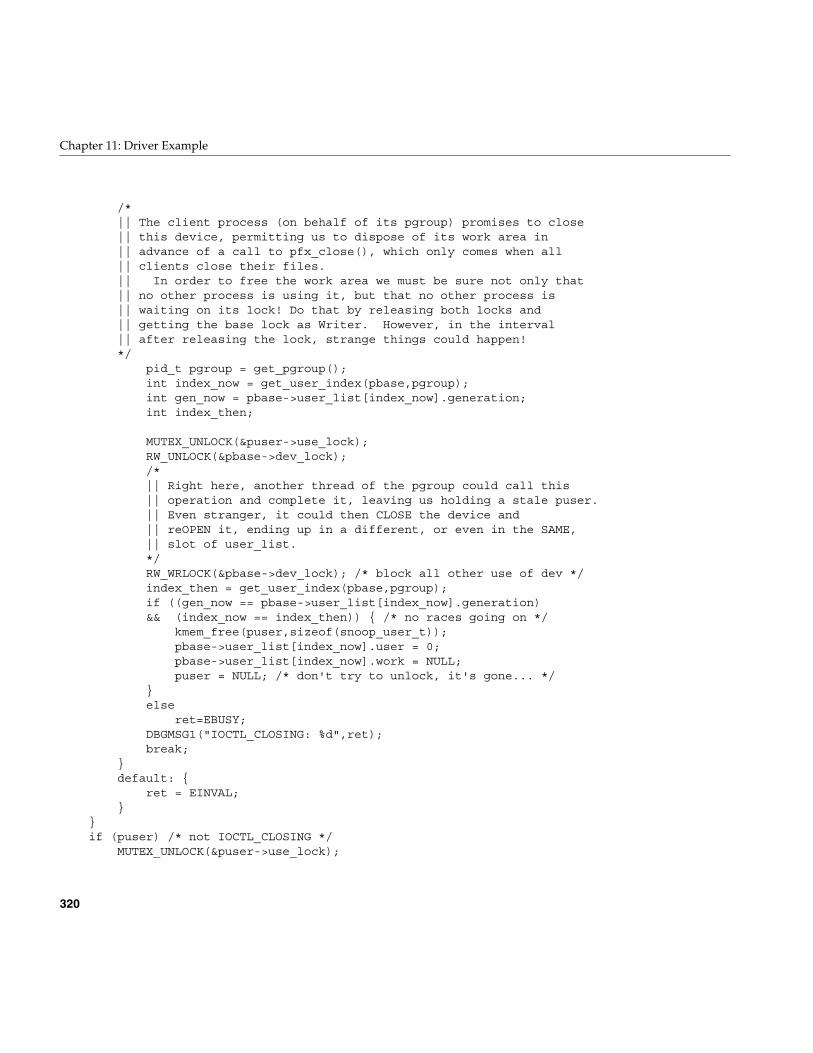
320
Chapter 11: Driver Example
/*|| The client process (on behalf of its pgroup) promises to close|| this device, permitting us to dispose of its work area in|| advance of a call to pfx_close(), which only comes when all|| clients close their files.|| In order to free the work area we must be sure not only that|| no other process is using it, but that no other process is|| waiting on its lock! Do that by releasing both locks and|| getting the base lock as Writer. However, in the interval|| after releasing the lock, strange things could happen!*/
pid_t pgroup = get_pgroup();int index_now = get_user_index(pbase,pgroup);int gen_now = pbase->user_list[index_now].generation;int index_then;
MUTEX_UNLOCK(&puser->use_lock);RW_UNLOCK(&pbase->dev_lock);/*|| Right here, another thread of the pgroup could call this|| operation and complete it, leaving us holding a stale puser.|| Even stranger, it could then CLOSE the device and|| reOPEN it, ending up in a different, or even in the SAME,|| slot of user_list.*/RW_WRLOCK(&pbase->dev_lock); /* block all other use of dev */index_then = get_user_index(pbase,pgroup);if ((gen_now == pbase->user_list[index_now].generation)&& (index_now == index_then)) { /* no races going on */
kmem_free(puser,sizeof(snoop_user_t));pbase->user_list[index_now].user = 0;pbase->user_list[index_now].work = NULL;puser = NULL; /* don't try to unlock, it's gone... */
}else
ret=EBUSY;DBGMSG1("IOCTL_CLOSING: %d",ret);break;
}default: {
ret = EINVAL;}
}if (puser) /* not IOCTL_CLOSING */
MUTEX_UNLOCK(&puser->use_lock);
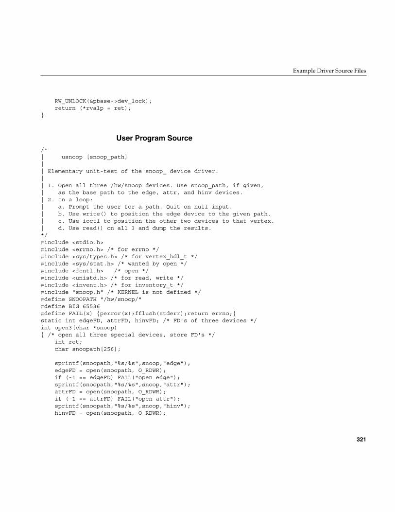
Example Driver Source Files
321
RW_UNLOCK(&pbase->dev_lock);return (*rvalp = ret);
}
User Program Source/*| usnoop [snoop_path]|| Elementary unit-test of the snoop_ device driver.|| 1. Open all three /hw/snoop devices. Use snoop_path, if given,| as the base path to the edge, attr, and hinv devices.| 2. In a loop:| a. Prompt the user for a path. Quit on null input.| b. Use write() to position the edge device to the given path.| c. Use ioctl to position the other two devices to that vertex.| d. Use read() on all 3 and dump the results.*/#include <stdio.h>#include <errno.h> /* for errno */#include <sys/types.h> /* for vertex_hdl_t */#include <sys/stat.h> /* wanted by open */#include <fcntl.h> /* open */#include <unistd.h> /* for read, write */#include <invent.h> /* for inventory_t */#include "snoop.h" /* KERNEL is not defined */#define SNOOPATH "/hw/snoop/"#define BIG 65536#define FAIL(x) {perror(x);fflush(stderr);return errno;}static int edgeFD, attrFD, hinvFD; /* FD's of three devices */int open3(char *snoop){ /* open all three special devices, store FD's */ int ret; char snoopath[256];
sprintf(snoopath,"%s/%s",snoop,"edge"); edgeFD = open(snoopath, O_RDWR); if (-1 == edgeFD) FAIL("open edge"); sprintf(snoopath,"%s/%s",snoop,"attr"); attrFD = open(snoopath, O_RDWR); if (-1 == attrFD) FAIL("open attr"); sprintf(snoopath,"%s/%s",snoop,"hinv"); hinvFD = open(snoopath, O_RDWR);
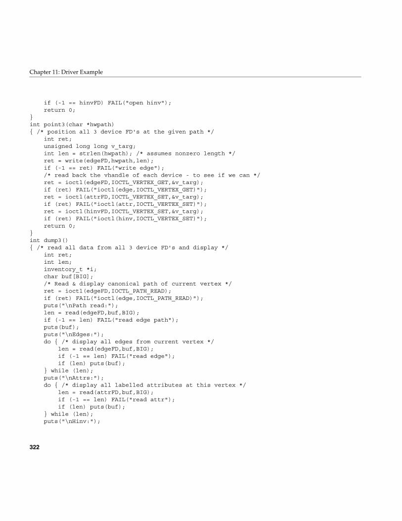
322
Chapter 11: Driver Example
if (-1 == hinvFD) FAIL("open hinv"); return 0;}int point3(char *hwpath){ /* position all 3 device FD's at the given path */ int ret; unsigned long long v_targ; int len = strlen(hwpath); /* assumes nonzero length */ ret = write(edgeFD,hwpath,len); if (-1 == ret) FAIL("write edge"); /* read back the vhandle of each device - to see if we can */ ret = ioctl(edgeFD,IOCTL_VERTEX_GET,&v_targ); if (ret) FAIL("ioctl(edge,IOCTL_VERTEX_GET)"); ret = ioctl(attrFD,IOCTL_VERTEX_SET,&v_targ); if (ret) FAIL("ioctl(attr,IOCTL_VERTEX_SET)"); ret = ioctl(hinvFD,IOCTL_VERTEX_SET,&v_targ); if (ret) FAIL("ioctl(hinv,IOCTL_VERTEX_SET)"); return 0;}int dump3(){ /* read all data from all 3 device FD's and display */ int ret; int len; inventory_t *i; char buf[BIG]; /* Read & display canonical path of current vertex */ ret = ioctl(edgeFD,IOCTL_PATH_READ); if (ret) FAIL("ioctl(edge,IOCTL_PATH_READ)"); puts("\nPath read:"); len = read(edgeFD,buf,BIG); if (-1 == len) FAIL("read edge path"); puts(buf); puts("\nEdges:"); do { /* display all edges from current vertex */ len = read(edgeFD,buf,BIG); if (-1 == len) FAIL("read edge"); if (len) puts(buf); } while (len); puts("\nAttrs:"); do { /* display all labelled attributes at this vertex */ len = read(attrFD,buf,BIG); if (-1 == len) FAIL("read attr"); if (len) puts(buf); } while (len); puts("\nHinv:");
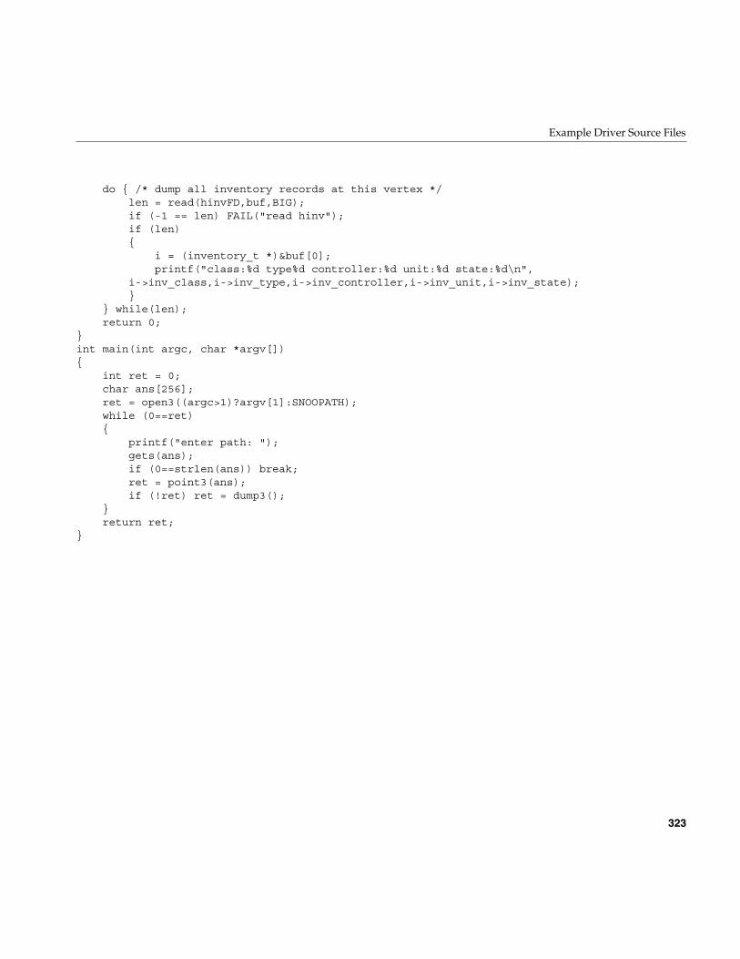
Example Driver Source Files
323
do { /* dump all inventory records at this vertex */ len = read(hinvFD,buf,BIG); if (-1 == len) FAIL("read hinv"); if (len) { i = (inventory_t *)&buf[0]; printf("class:%d type%d controller:%d unit:%d state:%d\n", i->inv_class,i->inv_type,i->inv_controller,i->inv_unit,i->inv_state); } } while(len); return 0;}int main(int argc, char *argv[]){ int ret = 0; char ans[256]; ret = open3((argc>1)?argv[1]:SNOOPATH); while (0==ret) { printf("enter path: "); gets(ans); if (0==strlen(ans)) break; ret = point3(ans); if (!ret) ret = dump3(); } return ret;}

PART FOUR
VME Device Drivers IV
Chapter 12, “VME Device Attachment on Origin 2000/Onyx2”How the VME bus is configured in different Silicon Graphics systems.
Chapter 13, “Services for VME Drivers on Origin 2000/Onyx 2”Kernel functions available specifically to VME device drivers.
Chapter 14, “VME Device Attachment on Challenge/Onyx.”How the VME bus is configured in different Silicon Graphics systems.
Chapter 15, “Services for VME Drivers on Challenge/Onyx”Kernel functions available specifically to VME device drivers.

327
Chapter 12
12. VME Device Attachment on Origin 2000/Onyx2
This chapter descibes IRIX 6.5 VME support for Origin2000 and Onyx2 systems. Forinformation on VME drivers on Challenge and ONYX systems, refer to This chaptergives a high-level overview of the VME bus, and describes how the VME bus is attachedto an Origin2000 or Onyx2 system and how it is configured.
Note: This chapter has no information about VME in Challenge and Onyx systems. Forthose systems, refer to Chapter 14, “VME Device Attachment on Challenge/Onyx,” andChapter 15, “Services for VME Drivers on Challenge/Onyx.”
This chapter contains important details on VME operation if you are writing akernel-level VME device driver. It contains useful background information if you plan tocontrol a VME device from a user-level program.
• “Overview of the VME Bus” on page 328 summarizes the history and features of theVME bus architecture.
• “About VME Bus Attachment” on page 330 gives a conceptual overview of howVME support is provided in all Silicon Graphics systems that have it.
• “About VME Bus Addresses and System Addresses” on page 334 describes theimportant relationship between addresses on the VME bus and addresses in thephysical address space of the system.
• “About VME in the Origin2000” on page 337 documents the hardware details of theVME implementation on Origin2000 and Origin200 systems.
• “Configuring VME Devices” on page 342 tells how to configure a device so thatIRIX 6.4 can recognize it and initialize its device driver.
More information about VME device control appears in these chapters:
• Chapter 4, “User-Level Access to Devices,” covers PIO and DMA access from theuser process.
• Chapter 13, “Services for VME Drivers on Origin 2000/Onyx 2,”discusses thekernel services used by a kernel-level VME device driver, and contains an example.
328
Chapter 12: VME Device Attachment on Origin 2000/Onyx2
Overview of the VME Bus
The VME bus was standardized in the early 1980s. It was designed as a flexibleinterconnection between multiple master and slave devices using a variety of addressand data precisions. While VME is not the fastest bus design available, its well-definedprotocols, comparitively low signaling speeds, and ample board dimensions make it aneasy bus to design for, whether to create intelligent I/O devices or special-purpose andone-off interfaces. As a result, VME has become a popular standard bus used in a varietyof general-purpose and embedded products.
In its original applications, the VME bus was used as the primary system bus, with a CPUcard as the principal (or only) bus master. In Silicon Graphics systems, however, the VMEbus is treated as an I/O device—it is never the main system bus.
VME History
The VME bus descends from the VERSAbus, a bus design published by Motorola, Inc.,in 1980 to support the needs of the MC68000 line of microprocessors. The bus timingrelationships and some signal names still reflect this heritage, although the VME bus isused by devices from many manufacturers today.
The original VERSAbus design specified a large form factor for pluggable cards. Becauseof this, it was not popular with European designers. A bus with a smaller form factor butsimilar functions and electrical specifications was designed for European use, andpromoted by Motorola, Phillips, Thompson, and other companies. This was theVersaModule European, or VME, bus. Beginning with rev B of 1982, the bus quicklybecame an accepted standard. (For ordering information on the standards documents,see “Standards Documents” on page xl.)
VME Features
A VME bus is a set of parallel conductors that interconnect multiple processing devices.The devices can exchange data in units of 8, 16, 32 or 64 bits during a bus cycle.
VME Address Spaces
Each VME device associates itself with a range of bus addresses. A bus address has either16, 24, 32, or 64 bits of precision. Each width of address forms a separate address space.

Overview of the VME Bus
329
That is, the same numeric value can refer to one device in the 24-bit address space, andto a different device in the 32-bit address space. Typically, a device operates in only oneaddress space, but some devices can be configured to respond to addresses in multiplespaces.
Each VME bus cycle contains the bits of an address. The address is qualified by sets ofaddress-modifier bits that specify the following:
• the address space (A16, A24, A32, or A64)
• whether the operation is single or a block transfer
• whether the access is to what, in the MC68000 architecture, would be data or code,in a supervisor or user area. Silicon Graphics systems support only data areatransactions, supervisor-data or user-data.
Master and Slave Devices
Each VME device acts as either a bus master or a bus slave. Typically a bus master is aprogrammable device with a microprocessor—for example, a disk controller. A slavedevice is typically a nonprogrammable device like a memory board or set of A/D inputs.
Each data transfer is initiated by a master device. The master
• asserts ownership of the bus
• specifies the address modifier bits for the transfer, including the address space,single/block mode, and supervisor/normal mode
• specifies the address for the transfer
• specifies the data unit size for the transfer (8, 16, 32 or 64 bits)
• specifies the direction of the transfer with respect to the master
The VME bus design permits multiple master devices to exist on the bus, and provides ahardware-based arbitration system so that they can share the bus in alternation.
A slave device responds to a master when the master specifies one of the slave’saddresses. The addressed slave accepts data, or provides data, as directed.
330
Chapter 12: VME Device Attachment on Origin 2000/Onyx2
VME Transactions
The VME design allows for four types of data transfer bus cycles:
• A read cycle returns data from the slave to the master.
• A write cycle sends data from the master to the slave.
• A read-modify-write cycle takes data from the slave, and on the following bus cyclesends it back to the same address, possibly altered.
• A block-transfer transaction sends multiple data units to adjacent addresses in aburst of consecutive bus cycles.
The VME design also allows for interrupts. A device can raise an interrupt on any ofseven interrupt levels. The interrupt is acknowledged by a bus master. The bus masterinterrogates the interrupting device in an interrupt-acknowledge bus cycle, and thedevice returns an interrupt vector number.
In Silicon Graphics systems, VME interrupts are received by the VME controller. If thecontroller has been configured by a VECTOR statement (see “Entry Point edtinit()” inChapter 7) to handle a given interrupt level, it acknowledges the interrupt and sends aninterrupt to one of the CPUs in the system.
If the controller has not been configured to acknowledge an interrupt level, the interruptlevel is ignored and can be handled by another device on the VME bus.
About VME Bus Attachment
The VME bus was designed as the system backplane for a workstation, supporting oneor more CPU modules along with the memory and I/O modules they used. However, noSilicon Graphics computer uses the VME bus as the system backplane. In all SiliconGraphics computers, the main system bus that connects CPUs to memory is a proprietarybus design. The VME bus is attached to the system as an I/O device.
This section provides a conceptual overview of the design of the VME bus in any SiliconGraphics system. It is sufficient background for most users of VME devices. A moredetailed look at the hardware follows in later topics
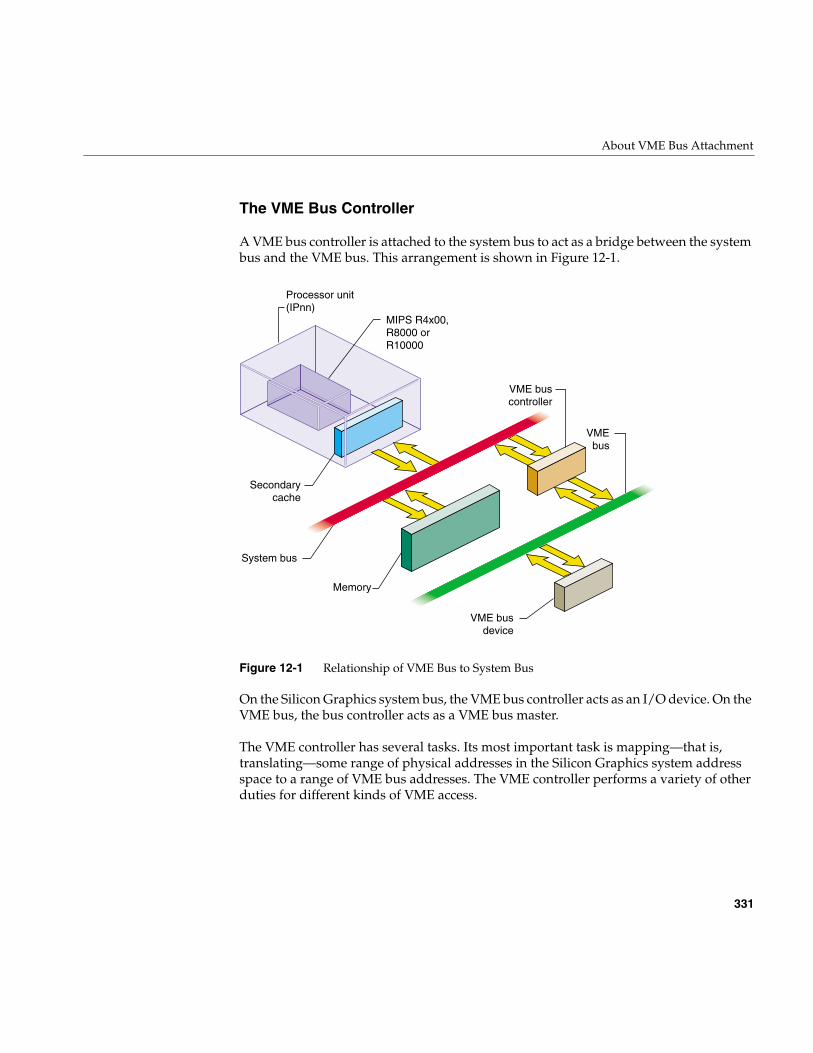
About VME Bus Attachment
331
The VME Bus Controller
A VME bus controller is attached to the system bus to act as a bridge between the systembus and the VME bus. This arrangement is shown in Figure 12-1.
Figure 12-1 Relationship of VME Bus to System Bus
On the Silicon Graphics system bus, the VME bus controller acts as an I/O device. On theVME bus, the bus controller acts as a VME bus master.
The VME controller has several tasks. Its most important task is mapping—that is,translating—some range of physical addresses in the Silicon Graphics system addressspace to a range of VME bus addresses. The VME controller performs a variety of otherduties for different kinds of VME access.
Secondarycache
System bus
Memory
Processor unit(IPnn)
MIPS R4x00,R8000 or R10000
VMEbus
VME buscontroller
VME busdevice
332
Chapter 12: VME Device Attachment on Origin 2000/Onyx2
VME PIO Operations
During programmed I/O (PIO) to the VME bus, software in the CPU loads or stores thecontents of CPU registers to a device on the VME bus. The operation of a CPU load froma VME device register is as follows:
1. The CPU executes a load from a system physical address.
2. The physical address is placed on a system bus.
3. The VME controller recognizes the address as one of those it has been programmedto map.
4. The VME controller translates the system address to an address in one of the VMEbus address spaces.
5. Acting as a VME bus master, the VME bus controller starts a read cycle on the VMEbus, using the translated address.
6. A device on the VME bus responds to the VME address and returns data.
7. The VME controller initiates a system bus cycle to return the data packet to the CPU,thus completing the load operation.
A store to a VME device is similar except that it performs a VME bus write, and no datais returned.
PIO Latency and R10000 Execution
PIO input and output are fundamentally different in the following way: PIO inputrequires two system bus cycles—one to request the data and one to return it—separatedby the cycle time of the VME bus. PIO output takes only one system bus cycle, and theVME bus write cycle run concurrently with the next system bus cycle. As a result, PIOinput always takes at least twice as much time as PIO output.
The MIPS R10000 CPU has the ability to execute instructions out of sequence, leaving amemory-load operation pending while executing the instructions that logically follow it,provided that those instructions do not depend on the loaded data. PIO input requires amicrosecond or more, a time during which an R10000 can execute 200 or moreinstructions. An R10000 can execute many instructions following a PIO load before theCPU has to stall and wait for the PIO data to arrive.
In a similar way, the R10000 CPU can execute hundreds of instructions after thebeginning of a PIO write, concurrently with the output operation.
About VME Bus Attachment
333
VME DMA Operations
A VME device that can act as a bus master can perform DMA into system memory. Thegeneral sequence of operations in this case is as follows:
1. The device driver allocates a DMA map object to represent the operation. When thekernel creates the DMA map, it programs the VME controller to map a certain rangeof VME bus addresses to a range of system memory locations.
2. The device driver uses PIO to program the device registers of the VME device,instructing it to perform DMA to the assigned range of VME bus address for aspecified length of data.
3. The VME bus master device initiates the first read, write, block-read, or block-writecycle on the VME bus.
4. The VME controller, recognizing a mapped address, responds as a slave device onthe VME bus.
5. If the bus master is writing, the VME controller accepts the data and initiates asystem bus cycle to write the data to system memory at the mapped address.
If the bus master is reading, the VME controller uses a system bus cycle to read datafrom system memory, and returns the data to the bus master.
6. The bus master device continues to use the VME controller as a slave device until ithas completed the DMA transfer.
During a DMA transaction, the VME bus controller operates independently of any CPU.CPUs in the system execute software concurrently with the data transfer. Since thesystem bus is faster than the VME bus, the data transfer typically takes place at themaximum data rate that the VME bus master can sustain.
334
Chapter 12: VME Device Attachment on Origin 2000/Onyx2
Operation of the DMA Engine
In the Origin2000 and Onyx2 systems (and in the Challenge and Onyx lines), the VMEcontroller contains an additional “DMA Engine” that can be programmed to performDMA-type transfers between memory and a VME device that is a slave, not a bus master.The general course of operations in a DMA engine transfer is as follows:
1. The VME bus controller is programmed to perform a DMA transfer to a certainphysical memory address for a specified amount of data from a specified deviceaddress in VME address space.
2. The VME bus controller, acting as the VME bus master, initiates a block read orblock write to the specified device.
3. As the slave device responds to successive VME bus cycles, the VME bus controllertransfers data to or from memory using the system bus.
The DMA engine transfers data independently of any CPU, and at the maximum rate theVME bus slave can sustain. In addition, the VME controller collects smaller data unitsinto blocks of the full system bus width, minimizing the number of system bus cyclesneeded to transfer data. For both these reasons, DMA engine transfers are faster than PIOtransfers for all but very short transfer lengths. (For details, see “DMA EngineBandwidth” on page 72.)
About VME Bus Addresses and System Addresses
Devices on the VME bus exist in one of the following address spaces:
• The 16-bit space (A16) permits addresses from 0x0000 to 0xffff.
• The 24-bit space (A24) permits addresses from 0x00 0000 to 0xff ffff.
• The 32-bit space (A32) permits addresses 0x0000 0000 to 0xffff ffff.
• The 64-bit space (A64), defined in the revision D specification, uses 64-bit addresses.
The Silicon Graphics system bus uses 64-bit numbers to address memory and other I/Odevices on the system bus (discussed in Chapter 1). Much of the physical address spaceis used to address system memory. Portions of physical address space are set asidedynamically to represent VME addresses. Parts of the VME address spaces are mapped,that is, translated, into these ranges of physical addresses.
About VME Bus Addresses and System Addresses
335
The translation is performed by the VME bus controller: It is programmed to recognizecertain ranges of addresses on the system bus and translate them into VME busaddresses; and it recognizes certain VME bus addresses and translates them into physicaladdresses on the system bus.
The entire A32 or A64 address space cannot be mapped into the physical address space.No Silicon Graphics system can provide access to all VME address spaces at one time.Only parts of the VME address spaces are available at any time. The limits on how manyaddresses can be mapped at any time are different in different architectures.
User-Level and Kernel-Level Addressing
In a user-level program you can perform PIO and certain types of DMA operations (seeChapter 4, “User-Level Access to Devices”). You call on the services of a kernel-leveldevice driver to map a portion of VME address space into the address space of yourprocess. The requested segment of VME space is mapped dynamically to a segment ofyour user-level address space—a segment that can differ from one run of the program tothe next.
In a kernel-level device driver, you request mappings for both PIO and DMA operationsusing maps—software objects that represent a mapping between kernel virtual memoryand a range of VME bus addresses.
Note: The remainder of this chapter has direct meaning only for kernel-level drivers.
PIO Addressing and DMA Addressing
The addressing needs of PIO access and DMA access are different.
PIO deals in small amounts of data, typically single words. PIO is directed to deviceregisters that are identified with specific VME bus addresses. The association between adevice register and its VME address is fixed, typically by setting jumpers or switches onthe VME card.
336
Chapter 12: VME Device Attachment on Origin 2000/Onyx2
DMA deals with extended segments of kilobytes or megabytes. The addresses used inDMA are not fixed in the device, but are programmed into it just before the data transferbegins. For example, a disk controller can be programmed to read a certain disk sectorand write the sector data to a range of 512 consecutive bytes in the VME bus addressspace. The programming of the disk controller is done by storing numbers into itsregisters using PIO. While the registers respond only to fixed addresses that areconfigured into the board, the address for sector data is just a number that isprogrammed into the controller before a transfer is to start.
These are the key differences between PIO addresses and addresses used for DMA:
• PIO addresses are relatively few in number and cover small spans of data, whileDMA addresses can span large ranges of data.
• PIO addresses are closely related to the hardware architecture of the device and areconfigured by hardware or firmware, while DMA addresses are simply parametersprogrammed into the device before each operation.
In systems supported by IRIX 6.4, all mappings from VME address spaces to systemphysical memory are dynamic, assigned as needed. Kernel functions are provided tocreate and use map objects that represent the translation between designated VMEaddresses and kernel addresses (described in detail in Chapter 13, “Services for VMEDrivers on Origin 2000/Onyx 2”).
An Origin2000 system can support a maximum of five VME bus adapters per module.Although a system can comprise numerous modules, there is also a limit of five VME busadapters, total, per system.
Available PIO Addresses
Normally a VME card can be programmed to use different VME addresses for PIO, basedon jumper or switch settings on the card. Each device plugged into a single VME busmust be configured to use unique addresses. Errors that are hard to diagnose can arisewhen multiple cards respond to the same bus address. Devices on different VME busescan of course use the same addresses.
About VME in the Origin2000
337
Not all parts of each address space are accessible. The accessible parts are summarizedin Table 12-1.
There are additional limits on the maximum size of any single PIO map and limits on theaggregate size of all maps per bus. These limits differ between the Origin2000 and theChallenge architectures; the details are given in the discussion of allocating maps.
In general, however, when configuring the devices on a bus, it is best if you can locate alldevice registers in a single, relatively compact, range of addresses. This economizes onkernel resources used for mapping.
Available DMA Addresses
When you program a bus master to perform DMA, you load it with a starting targetaddress in one of the VME address spaces, and a length. This address and length isdynamically mapped to a corresponding range of memory addresses. You can obtain amap to memory for a range of addresses in any of the A16, A24, or A32 data addressspaces.
The A64 address space is not available for either PIO or DMA on Origin2000 or Onyx2systems.
About VME in the Origin2000
In the Origin2000 (including Origin Deskside) and Onyx2 systems, external I/O isprovided through the XIO interface. The VME bus and adapter is an external I/O deviceinterfaced through one XIO slot. A typical installation is shown in Figure 12-2.
Table 12-1 Accessible VME PIO Addresses on Any Bus
AddressSpace
Origin2000 Systems Challenge and Onyx Systems
A16 All All
A24 0x80 0000–0xFE 0000 0x80 0000–0xFF FFFF
A32 0x0000 0000–0x7FFF FFFF 0x0000 0000–0x7FFF FFFF
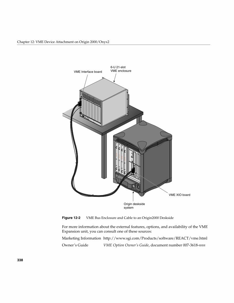
338
Chapter 12: VME Device Attachment on Origin 2000/Onyx2
Figure 12-2 VME Bus Enclosure and Cable to an Origin2000 Deskside
For more information about the external features, options, and availability of the VMEExpansion unit, you can consult one of these sources:
Marketing Information http://www.sgi.com/Products/software/REACT/vme.html
Owner’s Guide VME Option Owner’s Guide, document number 007-3618-nnn
6-U 21-slotVME enclosure
Origin desksidesystem
VME XIO board
VME Interface board
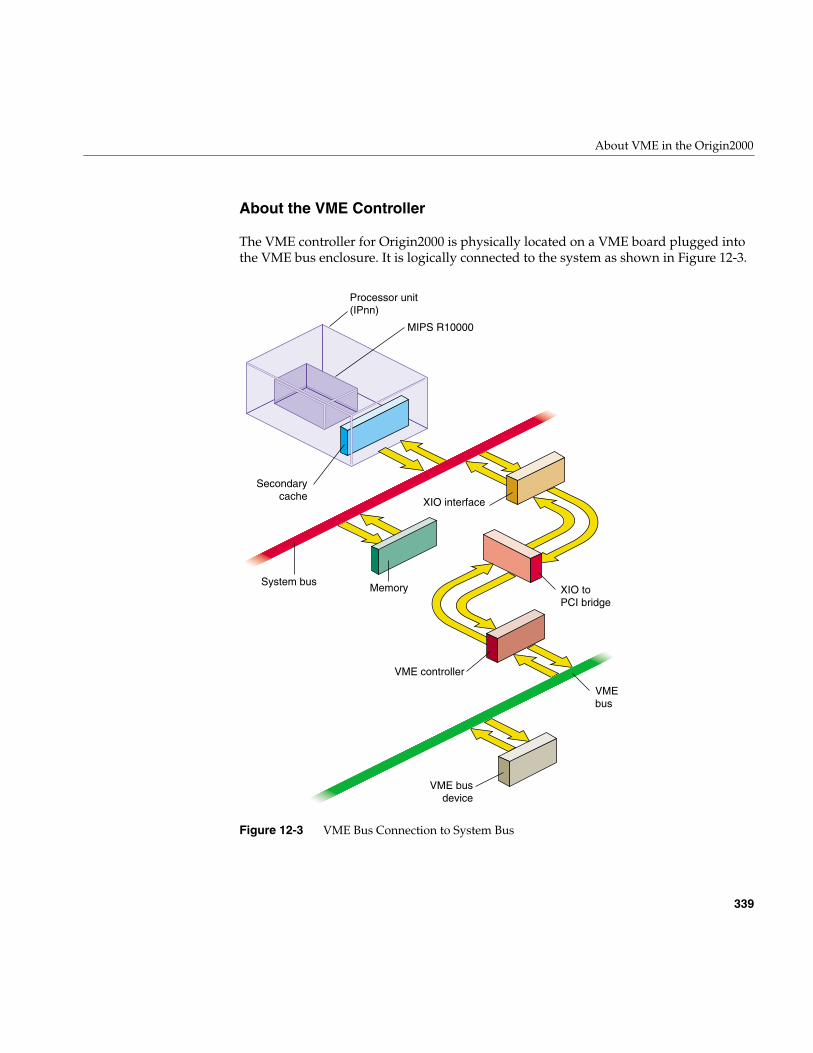
About VME in the Origin2000
339
About the VME Controller
The VME controller for Origin2000 is physically located on a VME board plugged intothe VME bus enclosure. It is logically connected to the system as shown in Figure 12-3.
Figure 12-3 VME Bus Connection to System Bus
Secondarycache
System bus Memory
Processor unit(IPnn)
MIPS R10000
VMEbus
VME controller
VME busdevice
XIO toPCI bridge
XIO interface
340
Chapter 12: VME Device Attachment on Origin 2000/Onyx2
As suggested by Figure 12-3, data to and from the VME bus passes through multiplelayers of bus protocols. For example, on a PIO write from the CPU to a VME device, thefollowing functional units are involved:
1. The CPU sends a word to a physical memory address. In the Origin2000architecture, physical addressing is managed by the Hub chip on the node board(not shown). The Hub chip directs the word to the XIO interface.
2. The XIO interface passes the word down the Craylink cable (see Figure 12-2) to theVME controller board, which is a VME 6U or 9U card mounted in the card cage.
3. On the VME controller board, an XIO-to-PCI converter called a Bridge chip. Thetransaction is converted to a PCI bus write.
4. The sole device on the PCI bus is the VME controller chip, a PCI-to-VME bridgechip.
5. The VME controller operates the signal and data lines of the VME enclosure toexecute a write the desired VME address
Universe II Controller Chip
The VME controller chip is a PCI-to-VME bridge named the Universe II, produced byTundra Semiconductor Corporation (http://www.tundra.com).
Universe II Features
The Universe II contains:
• FIFO buffers for asynchronous staging of data between the two buses.
• Mapping registers for translating VME bus addresses.
• A DMA engine comparable to the DMA engine in the Challenge systems, with theadded ability to handle linked lists of data (scatter/gather). This engine is accessibleonly to user-level processes through the udmalib interface.
• The ability to pack and unpack multiple D8, D16 and D32 data units from 64-bit PCIdata words.
It is important to note that although the data path spans three different bus protocols andmultiple bus controller chips, none of these controllers are directly accessible to a VMEdevice driver. The device driver calls on the kernel to create software objects called maps,either PIO maps or DMA maps. When the kernel creates a map, it sets up all the multiple
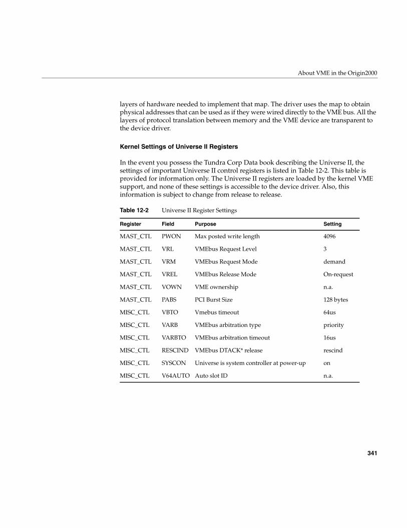
About VME in the Origin2000
341
layers of hardware needed to implement that map. The driver uses the map to obtainphysical addresses that can be used as if they were wired directly to the VME bus. All thelayers of protocol translation between memory and the VME device are transparent tothe device driver.
Kernel Settings of Universe II Registers
In the event you possess the Tundra Corp Data book describing the Universe II, thesettings of important Universe II control registers is listed in Table 12-2. This table isprovided for information only. The Universe II registers are loaded by the kernel VMEsupport, and none of these settings is accessible to the device driver. Also, thisinformation is subject to change from release to release.
Table 12-2 Universe II Register Settings
Register Field Purpose Setting
MAST_CTL PWON Max posted write length 4096
MAST_CTL VRL VMEbus Request Level 3
MAST_CTL VRM VMEbus Request Mode demand
MAST_CTL VREL VMEbus Release Mode On-request
MAST_CTL VOWN VME ownership n.a.
MAST_CTL PABS PCI Burst Size 128 bytes
MISC_CTL VBTO Vmebus timeout 64us
MISC_CTL VARB VMEbus arbitration type priority
MISC_CTL VARBTO VMEbus arbitration timeout 16us
MISC_CTL RESCIND VMEbus DTACK* release rescind
MISC_CTL SYSCON Universe is system controller at power-up on
MISC_CTL V64AUTO Auto slot ID n.a.
342
Chapter 12: VME Device Attachment on Origin 2000/Onyx2
Configuring VME Devices
You (or the system administrator) must configure a VME bus and device to the IRIXsystem in order to direct interrupts and to associate each VME device with its devicedriver. In order to configure the bus you need to know how VME devices are representedin the hardware graph (see “Hardware Graph” on page 42).
VME Bus and Interrupt Naming
Each VME bus is entered into the IRIX hardware graph during bootstrap, as a connectionpoint for devices and as a source of interrupts.
VME Bus Paths in the Hardware Graph
The actual hardware graph path to a VME bus has this form:
/hw/module/mod/slot/ion/baseio/vme_xtown/pci/7/vmebus/
The integer mod is the number of the Origin module to which the VME option is attached.Vertex ion designates the XIO slot to which the VME option is cabled.
The hwgraph vertex named vmebus represents the VME controller. Vertexes for deviceson the bus are found under that vertex.
A convenience path is also created for each bus in the form:
/hw/vme/b/
VME Bus Numbers Assigned by ioconfig
The bus number b is assigned by the ioconfig command (see “Using ioconfig for GlobalController Numbers” on page 51). The number b is arbitrarily assigned the first timeioconfig runs after a VME option is added to the system. The first VME bus must benumber 1 (not 0).
The bus numbers as assigned are recorded in the ioconfig database file /etc/ioconfig.config(see “Configuration Control File” on page 53). The administrator can edit that file tochange the numbering, for example to force a certain bus to be number 1.
Configuring VME Devices
343
VME Bus Interrupt Level Names
In order to direct VME bus interrupt levels to specified CPUs, you need to be able toname the interrupt levels of a bus. For this purpose, the kernel creates names of thefollowing form in the hwgraph:
/hw/module/mod/slot/ion/baseio/vme_xtown/pci/7/vmebus/ipl/i
Seven of these names appear under each vmebus vertex, with i ranging from 1 to 7. Eachvertex represents one VME bus interrupt priority level. The same vertexes are accessibleunder the convenience names
/hw/vme/b/ipl/i
You can use either of these pathnames in a DEVICE_ADMIN command to direct VMEinterrupts.
Directing VME Interrupts
VME interrupts are handled in two phases. The first phase, which executes at a highpriority and is extremely quick, involves acknowledging the interrupt and locating thedevice driver interrupt handler that should be notified. In the second phase, the devicedriver’s specified handler executes as an independent thread (see “Handling VMEInterrupts” on page 365).
The first phase of processing executes on the CPU to which the interrupt is directed byhardware. When nothing is done, all interrupts from a VME bus controller are directedto CPU 0 in the Origin module to which the VME bus is attached.
The system administrator can use the DEVICE_ADMIN statement to direct VMEinterrupts to a specific CPU. The DEVICE_ADMIN statement is placed in a file in the/var/sysgen/system directory, possibly (but not necessarily) /var/sysgen/system/irix.sm. Theform of the statement to direct interrupts is:
DEVICE_ADMIN: device_path INTR_TARGET=cpu_path
The device_path is the hwgraph path specifying one of the VME interrupt levels for a bus(see “VME Bus and Interrupt Naming” on page 342). The cpu_path is the hwgraph paththat specifies a CPU. For example, to send VME level-7 interrupts from the first VME busto CPU 12, you could write
DEVICE_ADMIN: /hw/vme/1/ipl/7 INTR_TARGET=/hw/cpunum/12
344
Chapter 12: VME Device Attachment on Origin 2000/Onyx2
Although there are seven VME interrupt levels, only six unique redirections of this typecan be supported for any VME bus. In other words, you can direct the seven levels to atmost six different CPUs. You must send at least two levels to the same CPU. (Typicallyyou direct all the levels to a single CPU.)
The DEVICE_ADMIN statement directs interrupt detection. The device driver itselfspecifies the CPU in which the interrupt handler code executes. By default this is thesame CPU where detection takes place.
VME Device Naming
VME devices are entered as vertexes in the hwgraph while the VECTOR statements areprocessed during system startup. The kernel creates a vertex for each device with thefollowing form:
/hw/module/mod/slot/ion/baseio/vme_xtown/pci/7/vmebus/assm/addr/
The vertex shown here as assm is the name of the VME address space, one of a16s, a16n,a24s, a24n, a32s, or a32n. The vertex addr is the primary address of the device, from itsVECTOR statement. The address is in hexadecimal digits with leading zeros suppressed.For example, a device located at 0x00108000 in the A32 non-supervisory space wouldappear in the hwgraph as
/hw/module/mod/slot/ion/baseio/vme_xtown/pci/7/vmebus/a32n/108000
The same vertex appears also under the convenience vertex for that bus:
/hw/vme/b/a32n/108000
This kernel-created vertex is the “connection point” that is passed to the device driverwhen the driver is called to initialize the device. The device driver is allowed(encouraged) to create additional vertexes with more meaningful names (theinitialization process is described under “Initializing a VME Device” on page 352).
Defining VME Devices with the VECTOR Statement
Devices on the VME bus do not identify themselves to the system automatically (asdevices on the PCI bus do). You must tell IRIX that a device exists, or should exist. Youdo this using the VECTOR statement. The VECTOR statement is placed in a file in thedirectory /var/sysgen/system (see “Kernel Configuration Files” on page 56). For VME, thesyntax of the VECTOR statement is as follows:
Configuring VME Devices
345
VECTOR: bustype=VME module=modname [ adapter=b [ ctlr=c ] ][ ipl=i ] [ vector=v ]iospace=(AnnM,addr,size)
[ iospace2=(AnnM,addr,size) ][ iospace3=(AnnM,addr,size) ][ exprobe=((cmd,paddr,width,value,mask) [,...] ]
The variable elements of this statement, in order of appearance, are as follows:
Numeric values (variables b, c, i, v, nn, addr, size, paddr, width, value and mask) can bewritten in decimal, or in hexadecimal with a prefix of “0x.”
Note: The VECTOR statement is written as a single physical line in a text file. In thisbook, VECTOR statements are broken across multiple lines for readability. Do not breaka VECTOR statement across multiple text lines in a configuration file.
modname Name of the configuration file for the device driver for this type of device (see“Master Configuration Database” on page 55).
b Number of the VME bus as assigned by ioconfig (see “VME Bus andInterrupt Naming” on page 342)
c Arbitrary number to distinguish this device to the driver.
i Interrupt priority level used by this device, if it produces interrupts.
v Interrupt vector value returned by this device, when that is known (somedevices are dynamically configured with vector numbers by the driver).
AnnM Name of the address space used by this device, one of A16S, A16NP, A24S,A24NP, A32S, A32NP
addr Lowest address in a range of addresses used by the device.
size Number of bytes in the range of addresses.
cmd Probe command, either w meaning write, r meaning read and test equal, orrn meaning read and test not-equal.
paddr Address to probe (in the address space given by iospace).
width The width of data to read or write in the probe: 1, 2, 4 or 8 bytes.
value A value to be written, or to be compared to the data returned by read.
mask A mask to be ANDed with the value before writing, or to be ANDed with thedata returned by a read before comparison.
346
Chapter 12: VME Device Attachment on Origin 2000/Onyx2
Example VME Configuration
As an example, imagine you have two VME boards on the bus numbered 1, with thesefeatures:
• Reside in the A32NP address space at a start address of 0x001008000 and0x00108020 respectively.
• Support 8, 4-byte registers.
• Writing a zero word into the first register resets a board; after which the leastsignificant bit of the eighth register should be zero.
• The driver for this type of board is configured in a file named/var/sysgen/master.d/vme_examp.
• Jumpered to generate interrupts on IPL 5 with vectors of 0x0e and 0x0f respectively.
To configure these boards you could prepare a file named /var/sysgen/system/twoboards.smwith these contents:
Example 12-1 Hypothetical VME Configuration File
* First board, "controller" 0, base 10 8000, vector 0eVECTOR: bustype=VME module=vme_examp adapter=1 ctlr=0
ipl=5 vector=0x0e iospace=(A32NP,0x00108000,32)exprobe=((w,0x001080000,4,0,0),(r,0x0010801c,4,0,1))
* Second board, "controller" 1, base 10 8020, vector 0fVECTOR: bustype=VME module=vme_examp adapter=1 ctlr=1
ipl=5 vector=0x0f iospace=(A32NP,0x00108020,32)exprobe=((w,0x001080020,4,0,0),(r,0x0010803c,4,0,1))
Using the exprobe Parameter
You use the exprobe= parameter to specify one or more PIO writes and reads to the bus.You can use the parameter to initialize multiple registers, and to test the values inmultiple registers before or after writing.
The primary purpose of the exprobe parameter is to make the call to a device driverconditional on the presence of the device. When the probe fails because a read did notreturn the expected value, the kernel assumes the device is not present (or is notoperating correctly, or is the wrong type of device), and the kernel does not call the devicedriver to initialize the device.
Configuring VME Devices
347
When you do not specify a probe sequence, the kernel assumes the device exists, andcalls the driver to initialize the device. In this case, the driver can be called when nodevice is present. You must write code into the driver to verify that a device of theexpected type is actually present on the bus. (See “Verifying Device Addresses” onpage 354).
Using the adapter=b Parameter
VECTOR statements are processed in two sets, depending on whether or not theadapter=b parameter is present. The presence or absence of this parameter has animportant effect on the scope and timing of device initialization.
When you omit adapter=b, the kernel applies the VECTOR statement to every VME busin the system. The exprobe, if one is given, is executed against every VME bus found, assoon as the bus is found. The device driver is called when a probe succeeds on a bus. Thedriver is called for every bus when no probe is given
When you specify adapter=b, the kernel does not execute the VECTOR statement untilafter all buses have been found, and ioconfig has run to apply numbering to the buses.Then the kernel executes these VECTOR statements, applying each one only to the busyou specify.
The differences are that, with adapter=b, the probe is executed and the driver called onlyfor the specified bus, and this occurs quite a bit later in the startup sequence. It is almostalways a better idea to code adapter=b than to omit it.
Initialization Process
Assuming that adapter=b is supplied, the following steps take place:
• The kernel discovers each VME bus and builds a hwgraph vertexes for it.
• The ioconfig program runs and numbers te buses.
• The kernel processes the VECTOR statements.
348
Chapter 12: VME Device Attachment on Origin 2000/Onyx2
• The kernel executes the specified probes; for example, assuming the first statementin Example 12-1, the kernel
– Writes a word of zero to A32NP address 0x0010080000.
– Reads a word from address 0x001008001c, ANDs the returned data with 1, andcompares the result to 0. If the comparison is equal, the device exists.
• When the probe succeeds, the kernel creates hwgraph vertices for the device; givenExample 12-1 it might build:
/hw/module/mod/slot/ion/baseio/vme_xtown/pci/7/vmebus/a32n/1008000/hw/vme/1/a32n/1008000
• The kernel loads the specified device driver (if necessary) and calls it to initialize thedevice, passing it much of the information from the VECTOR statement.
349
Chapter 13
13. Services for VME Drivers on Origin 2000/Onyx 2
This chapter provides an overview of the kernel services needed by a kernel-level VMEdevice driveron Origin 2000 and Onyx 2 systems. The following topics are covered:
• “About VME Drivers” on page 350 relates the structure of VME drivers to otherchapters in this book.
• “Initializing the Driver” on page 352 describes the process of initializing a driver.
• “Initializing a VME Device” on page 352 describes the steps of attaching a VMEdevice when the kernel finds one.
• “Creating and Using PIO Maps” on page 357 describes the use of PIO map objectsto access VME device registers.
• “Creating and Using DMA Maps” on page 362 describes how to set up and initiateDMA access to VME.
• “Handling VME Interrupts” on page 365 describes two ways to establish aninterrupt handler function.
• “Porting From IRIX 6.2” on page 369 documents the changes in VME supportbetween IRIX 6.5 and previous releases.
• “Sample VME Device Driver” on page 370 displays the source code of a VMEdevice driver for Origin2000.
Chapter 12, “VME Device Attachment on Origin 2000/Onyx2,” describes the hardwareimplementation for VME devices. Chapter 4, “User-Level Access to Devices,” coversoperation of VME devices from user-level processes.
Note: For information about VME in Challenge and Onyx systems, refer to Chapter 14,“VME Device Attachment on Challenge/Onyx,” and Chapter 15, “Services for VMEDrivers on Challenge/Onyx.”
350
Chapter 13: Services for VME Drivers on Origin 2000/Onyx 2
About VME Drivers
A kernel-level VME device driver is an executable module with the structure describedin Chapter 7, “Structure of a Kernel-Level Driver.” It uses the driver/kernel interfacedescribed in Chapter 8, “Device Driver/Kernel Interface.” In general it is configured intoIRIX as described in Chapter 9, “Building and Installing a Driver.”
The general sequence of operations of a VME driver is as follows:
1. In the pfxinit() entry point, the driver prepares any global variables.
2. When the kernel processes a VECTOR statement naming this driver (see “DefiningVME Devices with the VECTOR Statement” on page 344), it calls the pfxedtinit()entry point of the driver. Here the driver initializes its own per-device datastructures, sets up the hardware graph to represent the device, and initializes thedevice itself, if necessary.
3. The driver operates the device and transfers data in the normal upper-half entrypoints such as pfxopen(), pfxread(), pfxwrite(), and pfxstrategy().
These steps are covered in the following topics.
If you are porting a driver from an earlier version of IRIX, the driver will use otherfunctions than the ones described here. See “Porting From IRIX 6.2” on page 369 forfunction equivalents. Also, an older driver will not make use of the concept of thehwgraph (see “Hardware Graph” on page 42). It is almost essential to integrate a VMEdriver for Origin2000 systems with the hwgraph. This is done during deviceinitialization.
About VME Support Functions
Table 13-1 summarizes in alphabetic order the functions that are unique to the I/Oinfrastructure for VME. Their uses are mentioned in the following topics. Formaldocumentation of the functions can be found in the vmeio(D3) reference page.
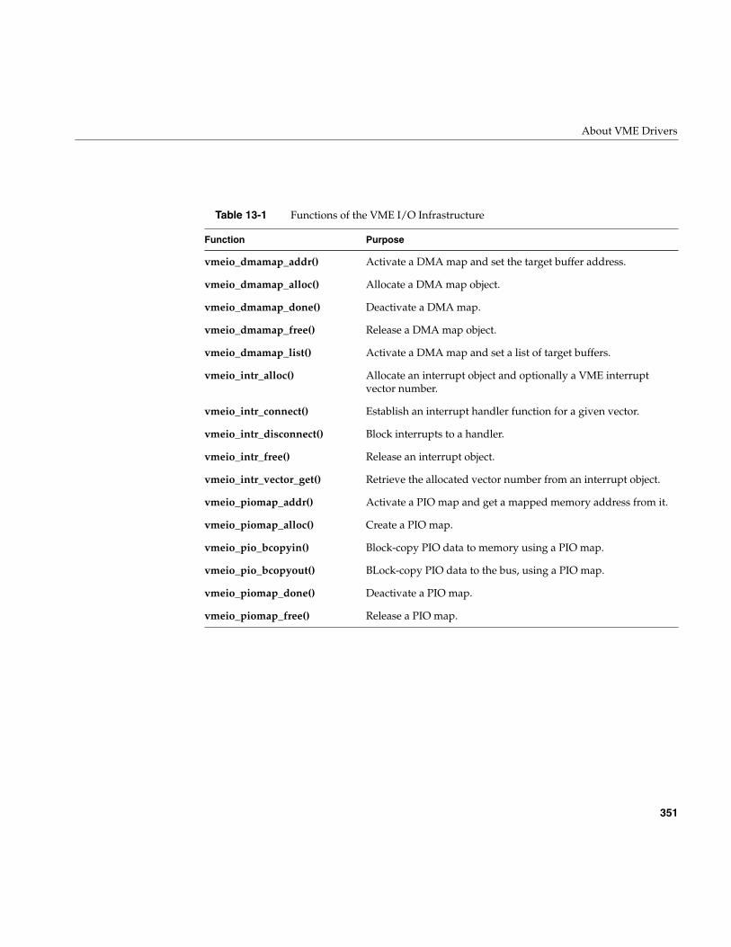
About VME Drivers
351
Table 13-1 Functions of the VME I/O Infrastructure
Function Purpose
vmeio_dmamap_addr() Activate a DMA map and set the target buffer address.
vmeio_dmamap_alloc() Allocate a DMA map object.
vmeio_dmamap_done() Deactivate a DMA map.
vmeio_dmamap_free() Release a DMA map object.
vmeio_dmamap_list() Activate a DMA map and set a list of target buffers.
vmeio_intr_alloc() Allocate an interrupt object and optionally a VME interruptvector number.
vmeio_intr_connect() Establish an interrupt handler function for a given vector.
vmeio_intr_disconnect() Block interrupts to a handler.
vmeio_intr_free() Release an interrupt object.
vmeio_intr_vector_get() Retrieve the allocated vector number from an interrupt object.
vmeio_piomap_addr() Activate a PIO map and get a mapped memory address from it.
vmeio_piomap_alloc() Create a PIO map.
vmeio_pio_bcopyin() Block-copy PIO data to memory using a PIO map.
vmeio_pio_bcopyout() BLock-copy PIO data to the bus, using a PIO map.
vmeio_piomap_done() Deactivate a PIO map.
vmeio_piomap_free() Release a PIO map.
352
Chapter 13: Services for VME Drivers on Origin 2000/Onyx 2
Initializing the Driver
When the driver has a pfxinit() entry point, that entry point is called during the bootprocess before any other driver entry point. The driver can initialize global variables atthis time. The driver cannot depend on the state of the hardware graph, however. TheVME bus attachments may or may not be defined in the hardware graph.
If the driver has a pfxstart() entry point, that entry point is called late in the initializationprocess, after all device initialization is complete.
For more discussion of these entry points, see “When Initialization Is Performed” onpage 150, “Entry Point init()” on page 151, and “Entry Point start()” on page 152.
Initializing a VME Device
The device driver does not know in advance how many devices it will be asked tomanage. There might be none configured, or only one, or many. The devices might all beon one VME bus, or they can be on different buses.
The kernel calls the driver’s pfxedtinit() entry point once for each VME VECTORstatement it finds (see “Defining VME Devices with the VECTOR Statement” on page 344for a discussion of the VECTOR statement).
For an overview of the duties and actions of the pfxedtinit() entry point, see “Entry Pointedtinit()” on page 151. An important part of initializing the device is setting up thehwgraph. For an overview of hwgraph facilities, see “Hardware Graph Management” onpage 221.
In summary, at device initialization time the driver
• Creates hwgraph vertexes to represent the device
• Allocates and initializes a data structure to hold per-device information
• Allocates PIO maps and (optionally) DMA maps to use in addressing the device
• If necessary, registers an interrupt handler
• Initializes the device itself
The allocation and use of PIO and DMA maps, and the registration of an interrupthandler, are covered separately in following topics.
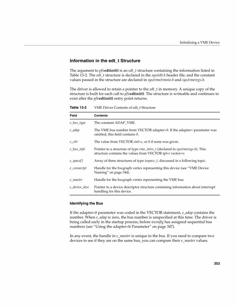
Initializing a VME Device
353
Information in the edt_t Structure
The argument to pfxedtinit() is an edt_t structure containing the information listed inTable 13-2. The edt_t structure is declared in the sys/edt.h header file; and the constantvalues passed in the structure are declared in sys/vme/vmeio.h and sys/vmeregs.h.
The driver is allowed to retain a pointer to the edt_t in memory. A unique copy of thestructure is built for each call to pfxedtinit(). The structure is writeable and continues toexist after the pfxedtinit() entry point returns.
Identifying the Bus
If the adapter=b parameter was coded in the VECTOR statement, e_adap contains thenumber. When e_adap is zero, the bus number is unspecified at this time. The driver isbeing called early in the startup process, before ioconfig has assigned sequential busnumbers (see “Using the adapter=b Parameter” on page 347).
In any event, the handle in e_master is unique to the bus. If you need to compare twodevices to see if they are on the same bus, you can compare their e_master values.
Table 13-2 VME Driver Contents of edt_t Structure
Field Contents
e_bus_type The constant ADAP_VME.
e_adap The VME bus number from VECTOR adapter=b. If the adapter= parameter wasomitted, this field contains 0.
e_ctlr The value from VECTOR ctrl=c, or 0 if none was given.
e_bus_info Pointer to a structure of type vme_intrs_t (declared in sys/vmeregs.h). Thisstructure contains the values from VECTOR ipl=i vector=v.
e_space[] Array of three structures of type iospace_t, discussed in a following topic.
e_connectpt Handle for the hwgraph vertex representing this device (see “VME DeviceNaming” on page 344).
e_master Handle for the hwgraph vertex representing the VME bus.
e_device_desc Pointer to a device descriptor structure containing information about interrupthandling for this device.
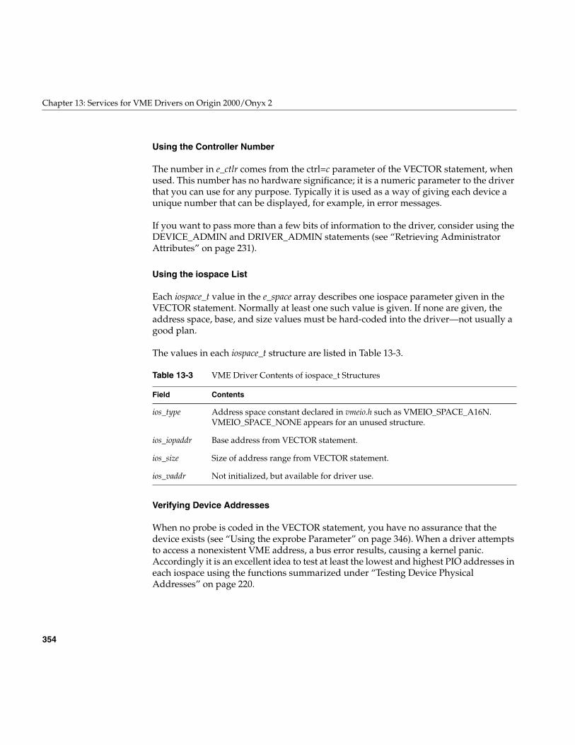
354
Chapter 13: Services for VME Drivers on Origin 2000/Onyx 2
Using the Controller Number
The number in e_ctlr comes from the ctrl=c parameter of the VECTOR statement, whenused. This number has no hardware significance; it is a numeric parameter to the driverthat you can use for any purpose. Typically it is used as a way of giving each device aunique number that can be displayed, for example, in error messages.
If you want to pass more than a few bits of information to the driver, consider using theDEVICE_ADMIN and DRIVER_ADMIN statements (see “Retrieving AdministratorAttributes” on page 231).
Using the iospace List
Each iospace_t value in the e_space array describes one iospace parameter given in theVECTOR statement. Normally at least one such value is given. If none are given, theaddress space, base, and size values must be hard-coded into the driver—not usually agood plan.
The values in each iospace_t structure are listed in Table 13-3.
Verifying Device Addresses
When no probe is coded in the VECTOR statement, you have no assurance that thedevice exists (see “Using the exprobe Parameter” on page 346). When a driver attemptsto access a nonexistent VME address, a bus error results, causing a kernel panic.Accordingly it is an excellent idea to test at least the lowest and highest PIO addresses ineach iospace using the functions summarized under “Testing Device PhysicalAddresses” on page 220.
Table 13-3 VME Driver Contents of iospace_t Structures
Field Contents
ios_type Address space constant declared in vmeio.h such as VMEIO_SPACE_A16N.VMEIO_SPACE_NONE appears for an unused structure.
ios_iopaddr Base address from VECTOR statement.
ios_size Size of address range from VECTOR statement.
ios_vaddr Not initialized, but available for driver use.
Initializing a VME Device
355
Setting Up the Hardware Graph
The handle in e_connectpt represents the hwgraph vertex built by the kernel for thisVECTOR statement. The driver needs to create another vertex attached to this one witha meaningful product-related name. That is the vertex that programs will open; it is alsothe vertex in which the driver can store its per-device information.
Note: Under IRIX 6.4 only, depending on the system patch level, it may be possible forthe pfxedtinit() entry point to be called when no device exists. The sign that this hashappened is that e_connectpt contains 0. For IRIX 6.4 only you may need to place testsuch as the following near the beginning of device initialization:
if (!(edt->e_connectpt)) return; /* invalid call */
For an overview of hardware graph modification see “Hardware Graph Management”on page 221, and in particular “Extending the Graph With a Single Vertex” on page 223.Using the example devices under “Example VME Configuration” on page 346, the kernelcreates the connection point
/hw/module/mod/slot/ion/baseio/vme_xtown/pci/7/vmebus/a32n/1008000
This same vertex is also visible to the user with the convenience path
/hw/vme/1/a32n/1008000
However, this vertex is not a device vertex and the user cannot open it. Your driver needsto create a device vertex for this purpose.
You know that the device is in fact a character device, a Frummage Corp model AD6. Youwant to add a single character device vertex named ad6. In that vertex you can store apointer to a device information structure you call ad6_stuff_t. This is the vertex that ispassed to entry points such as pfxread(), and the device information will be available atthose times.
The code in Example 13-1 is a hypothetical (i.e. untested) fragment that might appear inyour pfxedtinit() entry point, somewhere after the point at which you know the deviceexists.
Example 13-1 Adding a Vertex to the Hardware Graphad6_stuff_t * ad6;vertex_hdl_t vert;...
/* allocate memory for per-device structure */
356
Chapter 13: Services for VME Drivers on Origin 2000/Onyx 2
ad6 = kmem_zalloc(sizeof(*ad6),KM_SLEEP);if (!ad6) goto SayDie;/* create device vertex below connect-point */ret = hwgraph_char_device_add(edt->e_connectpt,
"ad6", "ad6_", &vert);if (ret != GRAPH_SUCCESS) goto SayDie;
.../* set info struct in the device vertex */device_info_set(vert,ad6); ...
SayDie:/* release all allocated objects and exit */
Following this step, the new vertex is visible in the hwgraph under the two paths:
/hw/module/mod/slot/ion/baseio/vme_xtown/pci/7/vmebus/a32n/1008000/ad6/hw/vme/1/a32n/1008000/ad6
Note that you did not have to worry about uniqueness, since there can be only one pathto this particular bus, address space, and base address. However, even the shorter ofthese paths is cumbersome. You would like to create an alias that is even shorter, forexample, /hw/Frummage/ad6. However, you cannot be sure that there is only this one AD6board in the system. There might be several, and if there are, you cannot predict the orderin which they are initialized. Initialization calls might even occur in parallel on differentCPUs.
What you need to create is a path /hw/Frummage/n/ad6, where n is certain to be uniqueamong all Frummage devices. The simplest way to create a unique numbering is throughthe ctlr=c parameter of the VECTOR statement.
The steps to create this convenience path would include:
• Use hwgraph_traverse() to test if /hw/Frummage has been created yet.
• If it has not, create a new vertex using hwgraph_vertex_create(), and connect it tothe root of the hwgraph by an edge “Frummage” using hwgraph_edge_add().
• Convert the controller number (or a unique integer from some other source) into acharacter string “n” for use as a unique edge.
• Connect an edge, named with the unique numeric string, between the/hw/Frummage vertex and the newly-created ad6 vertex, usinghwgraph_edge_add(). (If this fails, it is probably because the number is not uniqueafter all and the edge already exists.)
Creating and Using PIO Maps
357
Dealing with Initialization Errors
The initialization process can encounter many possible errors, for example:
• No iospace information in the edt_t.
• Unable to allocate a PIO map, a DMA map, or some other data structure.
• Unable to verify a device address (device does not exist).
• Unable to create a hwgraph vertex or edge.
You do not expect these errors to occur and usually they will not, but when oneinevitably does occur you want the driver to behave sensibly and to be informative. Planin advance for this; there are a variety of coding techniques you can use.
Creating and Using PIO Maps
A PIO map is a system object that represents a range of addresses in one VME addressspace. After creating a PIO map, a device driver can use it in the following ways:
• Obtain mapped addresses in kernel virtual address space that represent the device.These can be used to load or store data words between the CPU and the device, orthey can be mapped into user process space for loading or storing.
• Copy data between the device and memory, or perform compare-and-swap to thedevice, without learning the specific kernel addresses involved.
The kernel virtual address returned by PIO mapping is not a physical memory address,and it bears no relationship to the VME bus address. The kernel virtual address and theVME bus address need not have any bits in in common.
The functions used with PIO maps are summarized in Table 13-4.The syntax of thesefunctions is given in the vmeio(D3) reference page.
Table 13-4 Functions to Create and Use PIO Maps
Function Purpose
vmeio_piomap_addr() Get a mapped memory address for a device address.
vmeio_piomap_alloc() Create a PIO map.
vmeio_piomap_done() Deactivate a PIO map.
358
Chapter 13: Services for VME Drivers on Origin 2000/Onyx 2
The expected sequence of use is:
• During device initialization, allocate a PIO map for the device.
• To use a map (during initialization or at any other entry point), get the base addressof the device using vmeio_piomap_addr(). Use the returned address for PIO, orrequest block copy operations.
• When finished accessing device addresses at any one entry point, ensurecompletion of all PIO operations by calling vmeio_piomap_done().
• When shutting down the device or system, release the map withvmeio_piomap_free().
Allocating and Freeing PIO Maps
A driver creates a PIO map by calling vmeio_piomap_alloc(). This function performsmemory allocation and it associates the PIO map with a “VME slave image” in the VMEcontroller. Either of these operations can encounter a delay. You specify whether thefunction should return an error when a resource is not available, or should wait.
Typically your driver creates its PIO map in the pfxedtinit() entry point, where the driverfirst learns about the device addresses from the contents of the edt_t structure. At thistime a delay is usually acceptable. Unless the device registers are scattered widely in itsaddress space, one PIO map is usually sufficient.
The parameters to vmeio_piomap_alloc() are as follows:
vmeio_piomap_free() Release a PIO map.
vmeio_pio_bcopyin() Block-copy PIO data to memory using a PIO map.
vmeio_pio_bcopyout() Block-copy PIO data to the bus, using a PIO map.
vme_conn Hwgraph connection point of the device, as passed in the e_connpt fieldof the edt_t (see “Information in the edt_t Structure” on page 353).
dev_desc Current device descriptor for the device. This can be obtained from thee_device_desc field of the edt_t, or by calling device_desc_default_get()with the connection point.
Table 13-4 (continued) Functions to Create and Use PIO Maps
Function Purpose
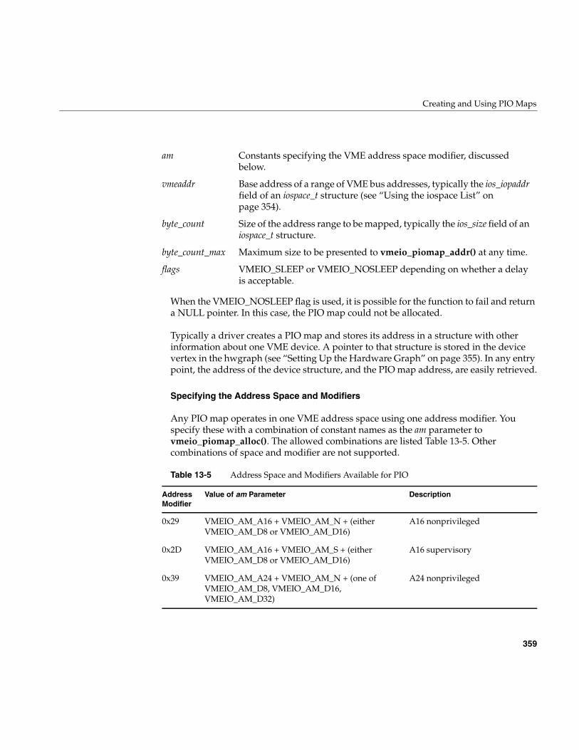
Creating and Using PIO Maps
359
When the VMEIO_NOSLEEP flag is used, it is possible for the function to fail and returna NULL pointer. In this case, the PIO map could not be allocated.
Typically a driver creates a PIO map and stores its address in a structure with otherinformation about one VME device. A pointer to that structure is stored in the devicevertex in the hwgraph (see “Setting Up the Hardware Graph” on page 355). In any entrypoint, the address of the device structure, and the PIO map address, are easily retrieved.
Specifying the Address Space and Modifiers
Any PIO map operates in one VME address space using one address modifier. Youspecify these with a combination of constant names as the am parameter tovmeio_piomap_alloc(). The allowed combinations are listed Table 13-5. Othercombinations of space and modifier are not supported.
am Constants specifying the VME address space modifier, discussedbelow.
vmeaddr Base address of a range of VME bus addresses, typically the ios_iopaddrfield of an iospace_t structure (see “Using the iospace List” onpage 354).
byte_count Size of the address range to be mapped, typically the ios_size field of aniospace_t structure.
byte_count_max Maximum size to be presented to vmeio_piomap_addr() at any time.
flags VMEIO_SLEEP or VMEIO_NOSLEEP depending on whether a delayis acceptable.
Table 13-5 Address Space and Modifiers Available for PIO
AddressModifier
Value of am Parameter Description
0x29 VMEIO_AM_A16 + VMEIO_AM_N + (eitherVMEIO_AM_D8 or VMEIO_AM_D16)
A16 nonprivileged
0x2D VMEIO_AM_A16 + VMEIO_AM_S + (eitherVMEIO_AM_D8 or VMEIO_AM_D16)
A16 supervisory
0x39 VMEIO_AM_A24 + VMEIO_AM_N + (one ofVMEIO_AM_D8, VMEIO_AM_D16,VMEIO_AM_D32)
A24 nonprivileged
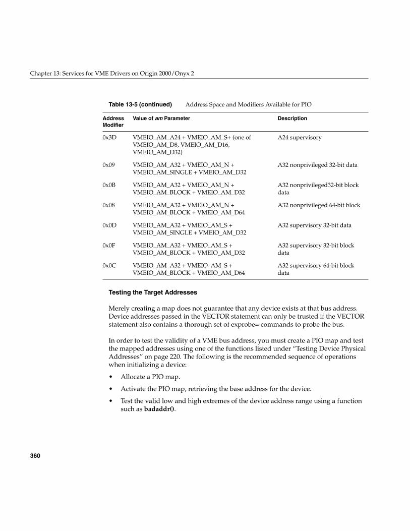
360
Chapter 13: Services for VME Drivers on Origin 2000/Onyx 2
Testing the Target Addresses
Merely creating a map does not guarantee that any device exists at that bus address.Device addresses passed in the VECTOR statement can only be trusted if the VECTORstatement also contains a thorough set of exprobe= commands to probe the bus.
In order to test the validity of a VME bus address, you must create a PIO map and testthe mapped addresses using one of the functions listed under “Testing Device PhysicalAddresses” on page 220. The following is the recommended sequence of operationswhen initializing a device:
• Allocate a PIO map.
• Activate the PIO map, retrieving the base address for the device.
• Test the valid low and high extremes of the device address range using a functionsuch as badaddr().
0x3D VMEIO_AM_A24 + VMEIO_AM_S+ (one ofVMEIO_AM_D8, VMEIO_AM_D16,VMEIO_AM_D32)
A24 supervisory
0x09 VMEIO_AM_A32 + VMEIO_AM_N +VMEIO_AM_SINGLE + VMEIO_AM_D32
A32 nonprivileged 32-bit data
0x0B VMEIO_AM_A32 + VMEIO_AM_N +VMEIO_AM_BLOCK + VMEIO_AM_D32
A32 nonprivileged32-bit blockdata
0x08 VMEIO_AM_A32 + VMEIO_AM_N +VMEIO_AM_BLOCK + VMEIO_AM_D64
A32 nonprivileged 64-bit block
0x0D VMEIO_AM_A32 + VMEIO_AM_S +VMEIO_AM_SINGLE + VMEIO_AM_D32
A32 supervisory 32-bit data
0x0F VMEIO_AM_A32 + VMEIO_AM_S +VMEIO_AM_BLOCK + VMEIO_AM_D32
A32 supervisory 32-bit blockdata
0x0C VMEIO_AM_A32 + VMEIO_AM_S +VMEIO_AM_BLOCK + VMEIO_AM_D64
A32 supervisory 64-bit blockdata
Table 13-5 (continued) Address Space and Modifiers Available for PIO
AddressModifier
Value of am Parameter Description
Creating and Using PIO Maps
361
• If an address is not valid the device does not exist or is not the type of device youexpected. In this case::
– Document the error with a message (“Producing Diagnostic Displays” onpage 274).
– Release the PIO map and any other objects that have been allocated.
– Terminate the initialization (see “Dealing with Initialization Errors” onpage 357).
• When the extreme addresses test valid, continue to initialize the device andcomplete initialization with a call to vmeio_piomap_done().
Freeing a PIO Map
As long as the PIO map object is safely anchored from the device vertex, there is no needto release the object. A loadable driver can unload and reload, the map is still available.If a PIO map is created on the fly, it can be released with a call to vmeio_piomap_free().
Using a PIO Map for PIO
You get a kernel virtual address from a map for use with PIO by applyingvmeio_piomap_addr(). In this function call you specify the lowest VME address ofinterest at this time, and the total range of VME addresses that you want to access at thistime. Typically these two numbers are the same as the vmeaddr and byte_count parametersto vmeio_piomap_alloc().
The value returned by vmeio_piomap_addr() is an address in kernel virtual space that isassociated with the requested base address on the VME bus. Stores and fetches to themapped address range are executed on the VME bus.
When the driver does not need further PIO for a period of time that might be long, thedriver should call vmeio_piomap_done(). This call does not return until all PIO outputhas reached the device. In some systems it may release temporary resources.
Mapping a PIO Map into a User Process
In the pfxmap() entry point (see “Concepts and Use of mmap()” on page 169), you canalso use a mapped PIO address with the v_mapphys() function to map the range ofdevice addresses into the address space of a user process. When you do this, the PIO mapremains in use for an indefinite time. You can release the PIO map in the pfxunmap()entry point (see “Entry Point unmap()” on page 174).
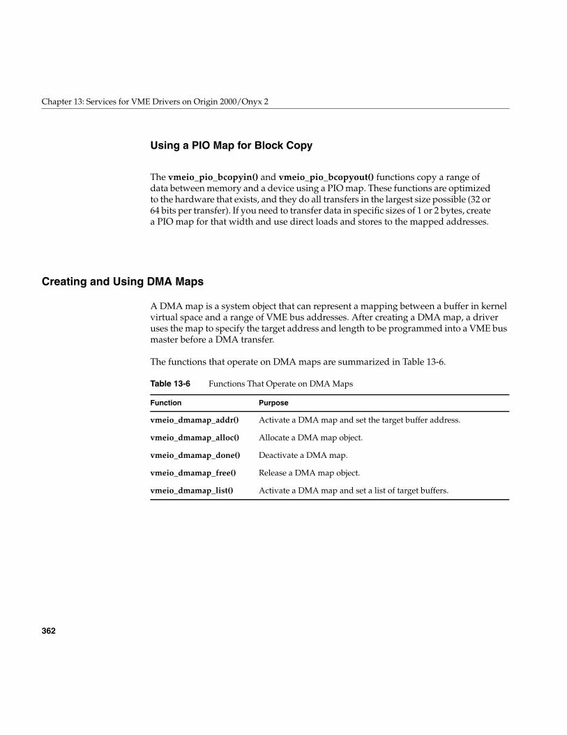
362
Chapter 13: Services for VME Drivers on Origin 2000/Onyx 2
Using a PIO Map for Block Copy
The vmeio_pio_bcopyin() and vmeio_pio_bcopyout() functions copy a range ofdata between memory and a device using a PIO map. These functions are optimizedto the hardware that exists, and they do all transfers in the largest size possible (32 or64 bits per transfer). If you need to transfer data in specific sizes of 1 or 2 bytes, createa PIO map for that width and use direct loads and stores to the mapped addresses.
Creating and Using DMA Maps
A DMA map is a system object that can represent a mapping between a buffer in kernelvirtual space and a range of VME bus addresses. After creating a DMA map, a driveruses the map to specify the target address and length to be programmed into a VME busmaster before a DMA transfer.
The functions that operate on DMA maps are summarized in Table 13-6.
Table 13-6 Functions That Operate on DMA Maps
Function Purpose
vmeio_dmamap_addr() Activate a DMA map and set the target buffer address.
vmeio_dmamap_alloc() Allocate a DMA map object.
vmeio_dmamap_done() Deactivate a DMA map.
vmeio_dmamap_free() Release a DMA map object.
vmeio_dmamap_list() Activate a DMA map and set a list of target buffers.
Creating and Using DMA Maps
363
Allocating a DMA Map
A device driver allocates a DMA map using vmeio_dmamap_alloc(). This is typicallydone in the pfxedtinit() entry point, provided that the maximum I/O size is known atthat time. The arguments to this function are as follows:
Specifying the Type of Access
The VME support code assumes that a DMA map is used for one of two kinds of access:
• Command-type access in which relatively small quantities of command or statusinformation are exchanged between the device and word-aligned buffers.
Command-type access is characterized by short, infrequent transfers that are notnecessarily aligned on a cache line boundary. For example, if the device can load itsown scatter/gather register set using DMA, or if the device uses DMA to store ablock of status information, this is command-type DMA access.
• Data-type access in which relatively large amounts of data are exchanged betweenthe device and buffers that are at least a cache-line in length and typically aligned tocache boundaries.
Data-type access is characterized by long, multiple-cache-line bursts of data.
You state the type of DMA access by specifying either VMEIO_DMA_CMD orVMEIO_DMA_DATA in the flags parameter when allocating the map. When the kernelschedules I/O through a data-type DMA map, it sets up the XIO and PCI interfaces forbest bandwidth under the assumption that multiple cache lines will be transferred.When the kernel schedules I.O through a command-type DMA map, it sets up theinterfaces for quickest coherent access to data.
vme_conn Hwgraph connection point of the device, as passed in the e_connpt fieldof the edt_t (see “Information in the edt_t Structure” on page 353).
dev_desc Current device descriptor for the device. This can be obtained from thee_device_desc field of the edt_t, or by calling device_desc_default_get()with the connection point.
space Constant specifying the address space, discussed below.
byte_count_max Largest range of addresses to be mapped at any time.
flags VMEIO_SLEEP or VMEIO_NOSLEEP, depending on whether a delayis acceptable. VMEIO_DMA_CMD or VMEIO_DMA_DATA todescribe the use of the map.
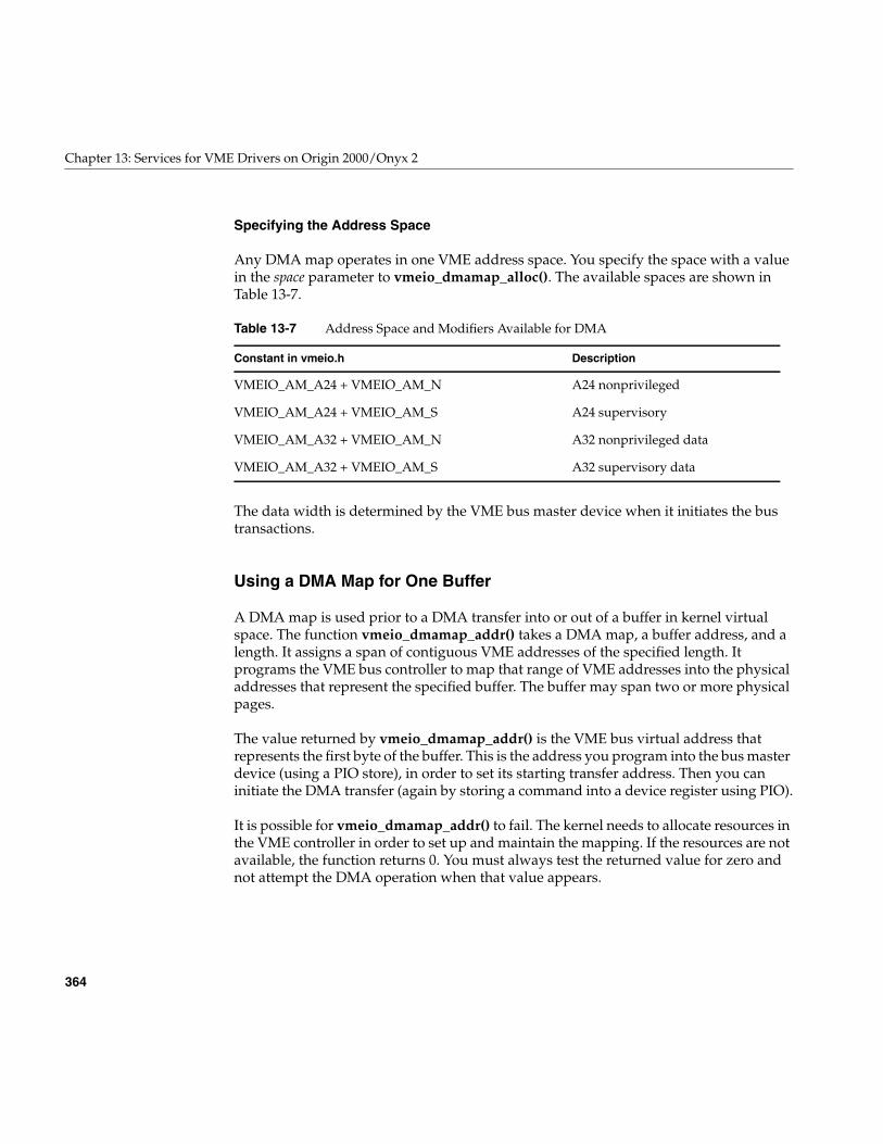
364
Chapter 13: Services for VME Drivers on Origin 2000/Onyx 2
Specifying the Address Space
Any DMA map operates in one VME address space. You specify the space with a valuein the space parameter to vmeio_dmamap_alloc(). The available spaces are shown inTable 13-7.
The data width is determined by the VME bus master device when it initiates the bustransactions.
Using a DMA Map for One Buffer
A DMA map is used prior to a DMA transfer into or out of a buffer in kernel virtualspace. The function vmeio_dmamap_addr() takes a DMA map, a buffer address, and alength. It assigns a span of contiguous VME addresses of the specified length. Itprograms the VME bus controller to map that range of VME addresses into the physicaladdresses that represent the specified buffer. The buffer may span two or more physicalpages.
The value returned by vmeio_dmamap_addr() is the VME bus virtual address thatrepresents the first byte of the buffer. This is the address you program into the bus masterdevice (using a PIO store), in order to set its starting transfer address. Then you caninitiate the DMA transfer (again by storing a command into a device register using PIO).
It is possible for vmeio_dmamap_addr() to fail. The kernel needs to allocate resources inthe VME controller in order to set up and maintain the mapping. If the resources are notavailable, the function returns 0. You must always test the returned value for zero andnot attempt the DMA operation when that value appears.
Table 13-7 Address Space and Modifiers Available for DMA
Constant in vmeio.h Description
VMEIO_AM_A24 + VMEIO_AM_N A24 nonprivileged
VMEIO_AM_A24 + VMEIO_AM_S A24 supervisory
VMEIO_AM_A32 + VMEIO_AM_N A32 nonprivileged data
VMEIO_AM_A32 + VMEIO_AM_S A32 supervisory data
Handling VME Interrupts
365
Using a DMA Map with Address/Length Lists
IRIX now supports the very convenient and useful address/length list (alenlist)functions described under “Using Address/Length Lists” on page 213. You can use analenlist to represent a series of one or more buffer areas separated in kernel virtualmemory. In particular, the buf_to_alenlist() function returns an alenlist to describe akernel memory buffer.
When your buffer is defined by an alenlist, you can map all components in the list in asingle operation by calling vmeio_dmamap_list(). This function creates an alenlist inwhich the same segments of memory are represented as a list of VME bus addresses.(Note that the new list can have more or fewer address/length pairs than the originallist.) The function returns the list containing translated addresses. This is a newlyallocated alenlist object unless you specify VMEIO_INPLACE in the flags argument.
You can read out VME bus address segments from the list one at a time and programthem into the device for DMA. If the device has multiple target registers(“scatter/gather” registers) you can program it with all the segments from the translatedlist. If the device can handle only one transfer at a time, you have to program each listelement as a separate operation.
Handling VME Interrupts
When a VME interrupt occurs, the VME bus controller directs the interrupt signal to oneof the CPUs in the Origin2000 system (see “Directing VME Interrupts” on page 343).
The kernel VME support in that CPU fetches the interrupt vector presented during theinterrupt acknowledge (IACK) cycle on the VME bus. Then the kernel looks to see if anyVME driver has asked to receive interrupts with that vector on that priority level. If adriver has registered a handler for this interrupt, the kernel schedules the driver’shandler to execute asynchronously as a kernel thread. This phase of acknowledgementand scheduling runs as a trap handler in the CPU that receives the hardware signal. Thedriver’s handler function can execute in that same CPU (by default) or in another one.
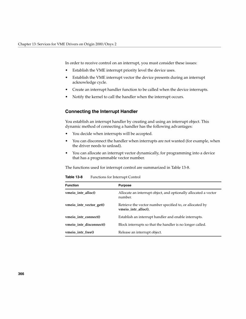
366
Chapter 13: Services for VME Drivers on Origin 2000/Onyx 2
In order to receive control on an interrupt, you must consider these issues:
• Establish the VME interrupt priority level the device uses.
• Establish the VME interrupt vector the device presents during an interruptacknowledge cycle.
• Create an interrupt handler function to be called when the device interrupts.
• Notify the kernel to call the handler when the interrupt occurs.
Connecting the Interrupt Handler
You establish an interrupt handler by creating and using an interrupt object. Thisdynamic method of connecting a handler has the following advantages:
• You decide when interrupts will be accepted.
• You can disconnect the handler when interrupts are not wanted (for example, whenthe driver needs to unload).
• You can allocate an interrupt vector dynamically, for programming into a devicethat has a programmable vector number.
The functions used for interrupt control are summarized in Table 13-8.
Table 13-8 Functions for Interrupt Control
Function Purpose
vmeio_intr_alloc() Allocate an interrupt object, and optionally allocated a vectornumber.
vmeio_intr_vector_get() Retrieve the vector number specified to, or allocated byvmeio_intr_alloc(),
vmeio_intr_connect() Establish an interrupt handler and enable interrupts.
vmeio_intr_disconnect() Block interrupts so that the handler is no longer called.
vmeio_intr_free() Release an interrupt object.
Handling VME Interrupts
367
Allocating an Interrupt Object
During initialization of the device in the edtinit() entry point, allocate an object torepresent the expected interrupt. This is the purpose of vmeio_intr_alloc(). Theparameters to this function are as follows:
The priority level and vector number can be passed in the VECTOR statement (see“Information in the edt_t Structure” on page 353), or they can be coded into the driver.When the device can be programmed with a vector number, you can request theassignment of an unused vector number by passing VMEIO_INTR_VECTOR_NONE.You can retrieve the assigned (or specified) vector number by callingvmeio_intr_vector_get(), then program it into the device by PIO.
Note: According to the VME standard, the interrupt vector can be a data item of 8, 16, or32 bits. However, Silicon Graphics systems accept only an 8-bit vector, and its value mustfall in the range 1-254 inclusive. (0x00 and 0xFF are excluded because they could begenerated by a hardware fault.)
Typically you should store the address of the interrupt object in the device informationstructure for future use.
vme_conn Hwgraph connection point of the device, as passed in the e_connpt fieldof the edt_t (see “Information in the edt_t Structure” on page 353).
dev_desc Current device descriptor for the device. This can be obtained from thee_device_desc field of the edt_t, or by calling device_desc_default_get()with the connection point.
vec Interrupt vector value, or VMEIO_INTR_VECTOR_NONE to requestallocation of an unused vector.
level Interupt priority level used by the device, typically passed indirectlythrough the e_bus_info field of the edt_t structure.
owner_dev Any hwgraph vertex that the system should display when reporting anerror in interrupt handling. Typically the device vertex created by thedriver.
flags VMEIO_SLEEP or VMEIO_NOSLEEP, depending on whether a memoryallocation delay is acceptable.
368
Chapter 13: Services for VME Drivers on Origin 2000/Onyx 2
Using the Device Descriptor
The use of the device_desc data type is desribed in two reference pages, device_desc(d4x)and device_desc_ops(d3x). Where a device descriptor is required, you can obtain adefault descriptor handle by calling device_desc_default_get(). However, you can alsoobtain a writeable copy of the device descriptor and modify it with a function such asdevice_desc_intr_target_set().
The device descriptor that you pass to vmeio_intr_alloc() determines the CPU on whichyour interrupt handler will execute. Normally the default interrupt CPU is appropriate.If you have a good reason to know that the handler should execute on a particular CPU,you can modify the device descriptor before calling vmeio_intr_alloc().
Connecting the Handler
Once you have created an interrupt object, you can enable calls to your handler functionby calling vmeio_intr_connect(). The important parameters to this function are:
• The interrupt object, which indirectly specifies the device, level, and vector.
• The address of the handler function, which can have any name you choose.
• An argument to be passed to the function, typically the handle of the deviceinformation structure you have prepared.
Although the function also takes a “thread” parameter, there is no current support foroperating the interrupt handler on a specific kernel thread. It is called at a high priority,but not necessarily the highest priority (see “Interrupts as Threads” on page 177).
Disconnecting the Handler
When you want to ensure that the interrupt handler will not be called, applyvmeio_intr_disconnect(). Following interrupts from the device are discarded until youonce again call vmeio_intr_connect().
You must disconnect interrupts in a loadable driver before unloading the driver
Porting From IRIX 6.2
369
Porting From IRIX 6.2
The kernel services for VME programming changed substantially for Origin and Onyx2systems. This section lists the Challenge and Onyx kernel functions and relates them tothe Origina nd Onyx2 interface as it is described in the preceding topics. Refer toChapter 14, “VME Device Attachment on Challenge/Onyx,” and Chapter 15, “Servicesfor VME Drivers on Challenge/Onyx” for information on writing VME device driversfor Challenge and Onyx systems.
Table 13-9 lists the kernel functions used under IRIX 5.3, IRIX 6.0, IRIX 6.1, and IRIX 6.2to program the VME interface on the Challenge and Onyx systems, in alphabeticalorder.After the name of the function is a brief summary of its purpose; in the thirdcolumn is a summary of the comparable facility introduced in IRIX 6.5.
When you begin porting a VME driver from IRIX 6.2 or earlier, look each function up inTable 13-9. Rewrite the driver to use the function or functions listed in the rightmostcolumn.
Table 13-9 VME Kernel Function Compatibility Summary
Old Function Purpose Replacement Facility
dma_map() Map a buffer for DMA. vmeio_dmamap_addr() andvmeio_dmamap_list()
dma_mapaddr() Get the VME bus address for amapped buffer.
vmeio_dmamap_addr() andvmeio_dmamap_list()
dma_mapalloc() Allocate a DMA map. vmeio_dmamap_alloc()
dma_mapbp() Map a system buffer for DMA. buf_to_alenlist(), thenvmeio_dmamap_list()
dma_mapfree() Release a DMA map. vmeio_dmamap_free()
pio_and[bhw]_rmw() Perform read-AND-writeback. No replacement
pio_bcopyin() Block-copy PIO data to memory. vmeio_pio_bcopyin()
pio_bcopyout() Block-copy PIO data to device. vmeio_pio_bcopyout()
pio_mapaddr() Position PIO map in VME addressspace.
vmeio_piomap_addr()
pio_mapalloc() Allocate a PIO map. vmeio_piomap_alloc()
370
Chapter 13: Services for VME Drivers on Origin 2000/Onyx 2
Sample VME Device Driver
In Example 13-2 you can read the code of a complete VME driver provided courtesy ofthe VME Microsystems International Corporation (VMIC). The code of this driver mayalso be installed as part of VME support in the directory /usr/src/vme. Sample driver codemay also be made available from Silicon Graphics Developer Support.
The sample driver has been set up for conditional compilation on either IRIX 6.2 orIRIX 6.4. The statements#if SN0 || IP30#define VMEIO 1#endif
set up the value of the VMEIO compiler variable. This variable is used to select code foreither the older IRIX 6.2 or the newer IRIX 6.4.
Example 13-2 Sample VME Driver
/** SGI would like to thank VME Microsystems International Corporation* (VMIC) for providing source code to the device driver for their* VMIVME-5588DMA Reflective Memory Card. Reflective memory is a* real-time network that supports low latency data transfers among* heterogenous systems via either PCI or VME. Data written to a* reflective memory board location is atomatically sent to all* reflective memory boards in the network. This is all done by the
pio_mapfree() Release a PIO map. vmeio_piomap_free()
pio_or[bhw]_rmw() Perform read-OR-writeback. No replacement
vme_adapter() Get number of VME bus for device. No replacement
vme_ivec_alloc() Reserve unused VME vectornumber.
vmeio_intr_alloc()
vme_ivec_free() Release VME vector number. vmeio_intr_free()
vme_ivec_set() Register interrupt handler forVME vector.
vmeio_intr_connect()
Table 13-9 (continued) VME Kernel Function Compatibility Summary
Old Function Purpose Replacement Facility
Sample VME Device Driver
371
* Reflective Memory hardware. No software messaging or CPU cycles are* required. For more information, contact VMIC at:** VME Microsystems Int’l Corp* 12090 South Memorial Parkway* Huntsville AL 35803 USA* (800) 322-3616* http://www.vmic.com*--------------------------------------------------------------------------* COPYRIGHT NOTICE** Copyright (C) 1996 VME Microsystems International Corporation* International copyright secured. All rights reserved.*--------------------------------------------------------------------------* VMIVME/SW-5550-ABC-205 Device Driver for IRIX-6.4*--------------------------------------------------------------------------* FYI: All non-static symbols must, must, *MUST*, begin with "rfm_".*--------------------------------------------------------------------------*/
#ifndef lintstatic char rfm_c_sccs_id[] = "@(#)rfm.c 1.60 96/07/23 VMIC";#endif /* lint */#include <sys/types.h>#include <sys/debug.h>#include <sys/param.h>#include <sys/immu.h>#include <ksys/ddmap.h>#include <sys/conf.h>#include <sys/edt.h>#include <sys/cmn_err.h>#include <sys/errno.h>#include <sys/open.h>#include <sys/cred.h>#include <sys/ksynch.h> /* For SV_ALLOC(D3DK), et. al. */#include <sys/sema.h>#include <sys/file.h>#include <sys/uio.h>#include <fcntl.h>#include <sys/mload.h>#include <sys/buf.h>#include <sys/dir.h>#include <sys/signal.h>#include <sys/mman.h>#include <sys/sg.h>#include <sys/kmem.h>
372
Chapter 13: Services for VME Drivers on Origin 2000/Onyx 2
#include <sys/ddi.h>#include <sys/vmereg.h>#include <stdarg.h>#if SN0 || IP30#define VMEIO 1#endif#if VMEIO#include <sys/ioerror.h>#include <sys/alenlist.h>#include <sys/vme/vmeio.h>#else /* Challenge */#include <sys/pio.h>#include <sys/dmamap.h>#include <sys/user.h> /* The header file is gone from 6.4 on */#endif#include <rfm_reg.h>#include <rfm_io.h>#include "spaces.h"#include "bflags.h"#if VMEIO#define RFM_PREFIX "rfm_"#define EDGE_LBL_RFM "rfm"#define NEW(ptr) (ptr = kmem_alloc(sizeof (*(ptr)), KM_SLEEP))#define DEL(ptr) (kmem_free(ptr, sizeof (*(ptr))))#endif#if VMEIOtypedef vmeio_piomap_t rfm_piomap_t;#elsetypedef piomap_t *rfm_piomap_t;#endif#if VMEIOtypedef vmeio_dmamap_t rfm_dmamap_t;#elsetypedef dmamap_t *rfm_dmamap_t;#endif#if VMEIO/* vmeio_dmamap_alloc returns "0" for errors */#define DMAMAP_FAILED ((rfm_dmamap_t) 0L)#else/* dmamap_alloc returns "-1" for errors */#define DMAMAP_FAILED ((rfm_dmamap_t) -1L)#endif/**========================================================================* Configuraion constants (you may change these, if needed)
Sample VME Device Driver
373
*========================================================================*/
/**------------------------------------------------------------------------* NRFM is the number of devices which we will support. Making this* too big uses only a little extra memory.
#if VMEIO* When usint VMEIO, NRFM is ignored.
#endif*------------------------------------------------------------------------*/
#ifndef NRFM#define NRFM 2 /* Support 2 boards */#endif /* NRFM *//**------------------------------------------------------------------------* EVENTPATIENCE is the default number of seconds to which an event* timeout is limited.*------------------------------------------------------------------------*/
#ifndef EVENTPATIENCE#define EVENTPATIENCE 20 /* Timeout limit (seconds) */#endif /* EVENTPATIENCE *//**------------------------------------------------------------------------* RFMSLEEP is the priority level at which the driver will sleep during* timeouts. If you don’t want a signal (such as happen when you type a ^C* on the keyboard) from interrupting the wait, then uncomment the* definition below *without* "PCATCH". However, if you don’t allow* signals to interrupt the wait and the event never happens, you’ll have* to reboot the system in order to kill your applications program.*------------------------------------------------------------------------*/
#if 1#define RFMSLEEP (PCATCH|(PZERO+1)) /* ^C interrupts wait */#else /* NOPE */#define RFMSLEEP (PZERO-1) /* Nothing interrupts */#endif /* NOPE *//**------------------------------------------------------------------------* The SMALLEST_DMA symbol gives the size (in bytes) of the smallest DMA* transfer we will perform. Any attempted read(2)’s or write(2)’s shorter* than this will be handled by programmed I/O (copying the data via the* CPU). The rationale is this: the DMA setup, interrupt processing, and* DMA teardown takes a certain amount of time. For shorter transfers this
374
Chapter 13: Services for VME Drivers on Origin 2000/Onyx 2
* overhead is greater than the time it would take to just move the data* using the CPU. You may want to experiment with this value to determine* the optimal limit for your system.** The SMALLEST_DMA_IREQ symbol gives the size (in bytes)of the smallest* DMA which will use a DMA complete interrupt; transfers smaller than* this will simply poll the DMA engine’s complete flag. You may want to* experiment with this value to determine the optimal limit for your* system. In view of the relatively large overhead incurred in processing* any interrupt, you may want this value to be fairly high so that you* reduce the transfer latency (although this might saturate the CPU).* Your mileage may vary :-)*------------------------------------------------------------------------*/
#define SMALLEST_DMA (1024) /* Smallest DMA we will do */#define SMALLEST_DMA_IREQ (2048) /* Smallest DMA using interrupt *//**------------------------------------------------------------------------* The following data structure defines the default DMA configuration* options used unless the application program uses an RFM_DMAINFO* ioctl(2) command to change them.*------------------------------------------------------------------------*/
static rfmdmainfo_t defaultDmaInfo = {1, /* U-seconds between DMA polls */64, /* DMA burst cycle length (0=64) */RDI_RELMODE_ROR, /* DMA release mode */0, /* Burst interleave (x250 nsec) */3, /* VMEbus request level */SMALLEST_DMA, /* Minimum size to use DMA */SMALLEST_DMA_IREQ /* Minimum DMA w/interrupt size */
};/**========================================================================* PLEASE DO NOT ALTER ANYTHING PAST THIS POINT*========================================================================*/
/* IRIX 6.2 has some missing prototypes */void MUTEX_LOCK(mutex_t *lockp, int priority);void SV_WAIT( sv_t *svp, void *lkp, int rv );int badaddr(volatile void *addr, int size);/* In "systm.h", can’t use it *//* Use our own min/max macros, not whatever happens to be lying around */#undef min#undef max#undef bounds
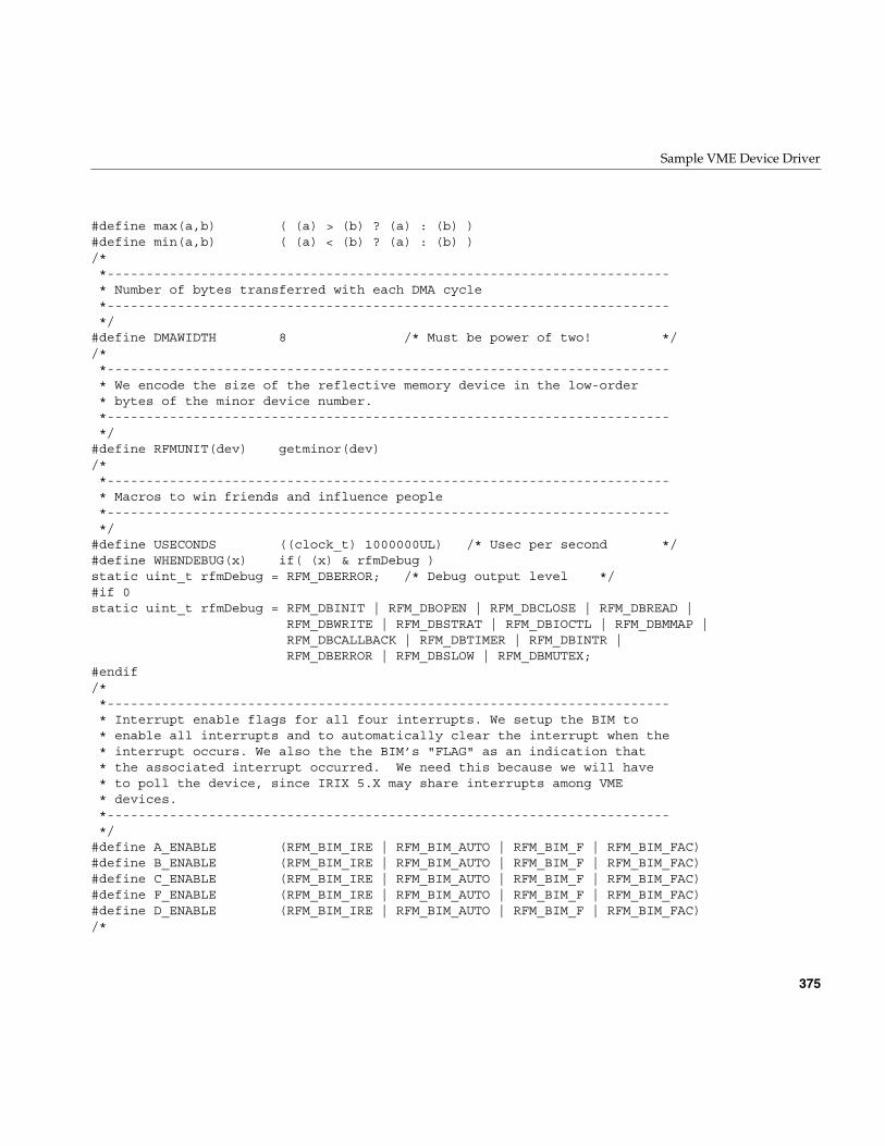
Sample VME Device Driver
375
#define max(a,b) ( (a) > (b) ? (a) : (b) )#define min(a,b) ( (a) < (b) ? (a) : (b) )/**------------------------------------------------------------------------* Number of bytes transferred with each DMA cycle*------------------------------------------------------------------------*/
#define DMAWIDTH 8 /* Must be power of two! *//**------------------------------------------------------------------------* We encode the size of the reflective memory device in the low-order* bytes of the minor device number.*------------------------------------------------------------------------*/
#define RFMUNIT(dev) getminor(dev)/**------------------------------------------------------------------------* Macros to win friends and influence people*------------------------------------------------------------------------*/
#define USECONDS ((clock_t) 1000000UL) /* Usec per second */#define WHENDEBUG(x) if( (x) & rfmDebug )static uint_t rfmDebug = RFM_DBERROR; /* Debug output level */#if 0static uint_t rfmDebug = RFM_DBINIT | RFM_DBOPEN | RFM_DBCLOSE | RFM_DBREAD |
RFM_DBWRITE | RFM_DBSTRAT | RFM_DBIOCTL | RFM_DBMMAP |RFM_DBCALLBACK | RFM_DBTIMER | RFM_DBINTR |RFM_DBERROR | RFM_DBSLOW | RFM_DBMUTEX;
#endif/**------------------------------------------------------------------------* Interrupt enable flags for all four interrupts. We setup the BIM to* enable all interrupts and to automatically clear the interrupt when the* interrupt occurs. We also the the BIM’s "FLAG" as an indication that* the associated interrupt occurred. We need this because we will have* to poll the device, since IRIX 5.X may share interrupts among VME* devices.*------------------------------------------------------------------------*/
#define A_ENABLE (RFM_BIM_IRE | RFM_BIM_AUTO | RFM_BIM_F | RFM_BIM_FAC)#define B_ENABLE (RFM_BIM_IRE | RFM_BIM_AUTO | RFM_BIM_F | RFM_BIM_FAC)#define C_ENABLE (RFM_BIM_IRE | RFM_BIM_AUTO | RFM_BIM_F | RFM_BIM_FAC)#define F_ENABLE (RFM_BIM_IRE | RFM_BIM_AUTO | RFM_BIM_F | RFM_BIM_FAC)#define D_ENABLE (RFM_BIM_IRE | RFM_BIM_AUTO | RFM_BIM_F | RFM_BIM_FAC)/*
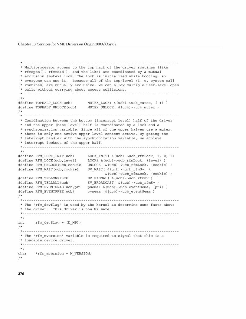
376
Chapter 13: Services for VME Drivers on Origin 2000/Onyx 2
*------------------------------------------------------------------------* Multiprocessor access to the top half of the driver routines (like* rfmopen(), rfmread(), and the like) are coordinated by a mutual* exclusion (mutex) lock. The lock is initialized while booting, so* everyone can use it. Because all of the top-level (i. e. system call* routines) are mutually exclusive, we can allow multiple user-level open* calls without worrying about access collisions.*------------------------------------------------------------------------*/
#define TOPHALF_LOCK(ucb) MUTEX_LOCK( &(ucb)->ucb_mutex, (-1) )#define TOPHALF_UNLOCK(ucb) MUTEX_UNLOCK( &(ucb)->ucb_mutex )/**------------------------------------------------------------------------* Coordination between the bottom (interrupt level) half of the driver* and the upper (base level) half is coordinated by a lock and a* synchronization variable. Since all of the upper halves use a mutex,* there is only one active upper level context active. By gating the* interrupt handler with the synchronization variable, we achieve* interrupt lockout of the upper half.*------------------------------------------------------------------------*/
#define RFM_LOCK_INIT(ucb) LOCK_INIT( &(ucb)->ucb_rfmLock, 0, 0, 0)#define RFM_LOCK(ucb,level) LOCK( &(ucb)->ucb_rfmLock, (level) )#define RFM_UNLOCK(ucb,cookie) UNLOCK( &(ucb)->ucb_rfmLock, (cookie) )#define RFM_WAIT(ucb,cookie) SV_WAIT( &(ucb)->ucb_rfmSv, \
&(ucb)->ucb_rfmLock, (cookie) )#define RFM_TELLONE(ucb) SV_SIGNAL( &(ucb)->ucb_rfmSv )#define RFM_TELLALL(ucb) SV_BROADCAST( &(ucb)->ucb_rfmSv )#define RFM_EVENTGRAB(ucb,pri) psema( &(ucb)->ucb_eventSema, (pri) )#define RFM_EVENTFREE(ucb) cvsema( &(ucb)->ucb_eventSema )/**------------------------------------------------------------------------* The ‘rfm_devflag’ is used by the kernel to determine some facts about* the driver. This driver is now MP safe.*------------------------------------------------------------------------*/
int rfm_devflag = (D_MP);/**------------------------------------------------------------------------* The ‘rfm_mversion’ variable is required to signal that this is a* loadable device driver.*------------------------------------------------------------------------*/
char *rfm_mversion = M_VERSION;/*
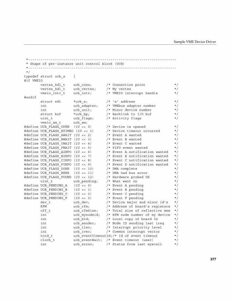
Sample VME Device Driver
377
*------------------------------------------------------------------------* Shape of per-instance unit control block (UCB)*------------------------------------------------------------------------*/
typedef struct ucb_s {#if VMEIO
vertex_hdl_t ucb_conn; /* Connection point */vertex_hdl_t ucb_vertex; /* My vertex */vmeio_intr_t ucb_intr; /* VMEIO interrupt handle */
#endifstruct edt *ucb_e; /* ‘e’ address */int ucb_adapter; /* VMEbus adapter number */int ucb_unit; /* Minor device number */struct buf *ucb_bp; /* Backlink to I/O buf */uint_t ucb_flags; /* Activity flags */vmeio_am_t ucb_am;
#define UCB_FLAGS_OPEN (1U << 0) /* Device is opened */#define UCB_FLAGS_ETIMEO (1U << 1) /* Device timeout occurred */#define UCB_FLAGS_AWAIT (1U << 2) /* Event A wanted */#define UCB_FLAGS_BWAIT (1U << 3) /* Event B wanted */#define UCB_FLAGS_CWAIT (1U << 4) /* Event C wanted */#define UCB_FLAGS_FWAIT (1U << 5) /* FIFO event wanted */#define UCB_FLAGS_AINFO (1U << 6) /* Event A notification wanted */#define UCB_FLAGS_BINFO (1U << 7) /* Event B notification wanted */#define UCB_FLAGS_CINFO (1U << 8) /* Event C notification wanted */#define UCB_FLAGS_FINFO (1U << 9) /* Event D notification wanted */#define UCB_FLAGS_DONE (1U << 10) /* DMA complete */#define UCB_FLAGS_BERR (1U << 11) /* DMA had bus error */#define UCB_FLAGS_FOUND (1U << 12) /* Hardware probed OK */
uint_t ucb_pending; /* What went on */#define UCB_PENDING_A (1U << 0) /* Event A pending */#define UCB_PENDING_B (1U << 1) /* Event B pending */#define UCB_PENDING_C (1U << 2) /* Event C pending */#define UCB_PENDING_F (1U << 3) /* Event F pending */
dev_t ucb_dev; /* Device major and minor id’s */RFM ucb_rfm; /* Address of board’s registers */off_t ucb_rfmSize; /* Total size of reflective mem */int ucb_mynodeid; /* RFM node number of my device */int ucb_bid; /* Local copy of board ID */int ucb_sender; /* Node ID sending last ireq */int ucb_ilev; /* Interrupt priority level */int ucb_ivec; /* Common interrupt vector */toid_t ucb_eventTimeoutId;/* Id of event timeout */clock_t ucb_eventWait; /* Event timeout (usec) */int ucb_errno; /* Status from last syscall */
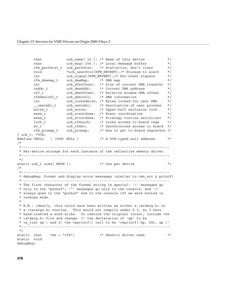
378
Chapter 13: Services for VME Drivers on Origin 2000/Onyx 2
char ucb_name[ 32 ]; /* Name of this device */char ucb_msg[ 256 ]; /* Local message buffer */rfm_perfstat_t ucb_perfstat; /* Statistics; don’t clear */void *ucb_userProc[RFM_NEVENT];/* Process to alert */int ucb_signal[RFM_NEVENT];/* Per-event signals */rfm_dmamap_t ucb_dmaMap; /* DMA map */int ucb_xferCount; /* Size of current DMA transfer */caddr_t ucb_dmaAddr; /* Current DMA address */off_t ucb_dmaOffset; /* Relative window DMA offset */rfmdmainfo_t ucb_dmaInfo; /* DMA information */int ucb_lockedSize; /* Bytes locked for user DMA */__userabi_t ucb_userabi; /* Description of user process */mutex_t ucb_mutex; /* Upper-half exclusion lock */sema_t ucb_eventSema; /* Event coordination */sema_t ucb_stratSema; /* Strategy routine serializer */lock_t ucb_rfmLock; /* Locks access to board regs */sv_t ucb_rfmSv; /* Synchronizes access to board */rfm_piomap_t ucb_piomap; /* How to get to board registers */
} ucb_t, *UCB;#define UNULL ( (UCB) NULL ) /* A UCB-typed null address *//**------------------------------------------------------------------------* Per-device storage for each instance of the reflective memory driver*------------------------------------------------------------------------*/
static ucb_t ucbs[ NRFM ]; /* One per device *//**------------------------------------------------------------------------* debugMsg: format and display error messages (similar to cmn_err & printf)*------------------------------------------------------------------------* The first character of the format string is special: ‘!’ messages go* only to the "putbuf"; ‘^’ messages go only to the console; and ‘?’* always goes to the "putbuf" and to the console iff we were booted in* verbose mode.** N.B.: ideally, this could have been written as either a <stdarg.h> or* a <varargs.h> routine. This would not compile under 5.3, so I have* hand-crafted a work-alike. To restore the original intent, include the* <stdarg.h> file and change: 1) the declaration of ‘ap’ to be* va_list ap’; and 2) the vsprintf() call to be ‘vsprintf( bp, fmt, ap )’*------------------------------------------------------------------------*/
static char *me = "rfm"; /* Generic driver name */static voiddebugMsg(
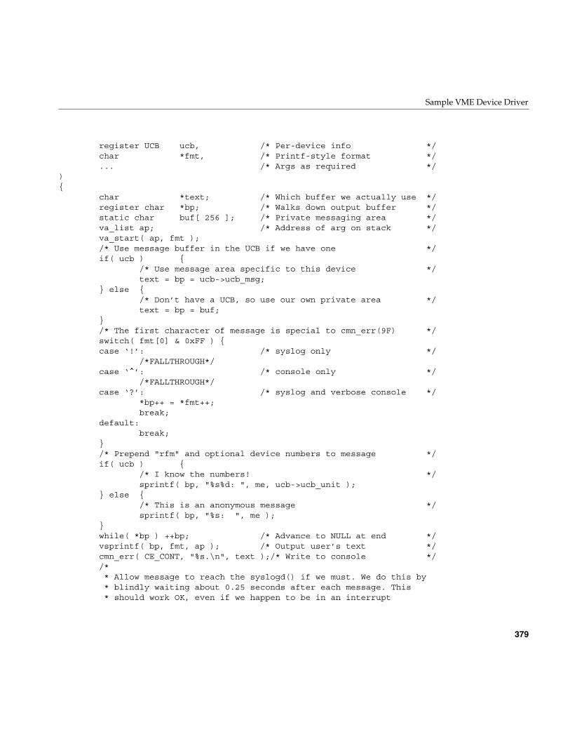
Sample VME Device Driver
379
register UCB ucb, /* Per-device info */char *fmt, /* Printf-style format */... /* Args as required */
){
char *text; /* Which buffer we actually use */register char *bp; /* Walks down output buffer */static char buf[ 256 ]; /* Private messaging area */va_list ap; /* Address of arg on stack */va_start( ap, fmt );/* Use message buffer in the UCB if we have one */if( ucb ) {
/* Use message area specific to this device */text = bp = ucb->ucb_msg;
} else {/* Don’t have a UCB, so use our own private area */text = bp = buf;
}/* The first character of message is special to cmn_err(9F) */switch( fmt[0] & 0xFF ) {case ‘!’: /* syslog only */
/*FALLTHROUGH*/case ‘^’: /* console only */
/*FALLTHROUGH*/case ‘?’: /* syslog and verbose console */
*bp++ = *fmt++;break;
default:break;
}/* Prepend "rfm" and optional device numbers to message */if( ucb ) {
/* I know the numbers! */sprintf( bp, "%s%d: ", me, ucb->ucb_unit );
} else {/* This is an anonymous message */sprintf( bp, "%s: ", me );
}while( *bp ) ++bp; /* Advance to NULL at end */vsprintf( bp, fmt, ap ); /* Output user’s text */cmn_err( CE_CONT, "%s.\n", text );/* Write to console *//** Allow message to reach the syslogd() if we must. We do this by* blindly waiting about 0.25 seconds after each message. This* should work OK, even if we happen to be in an interrupt
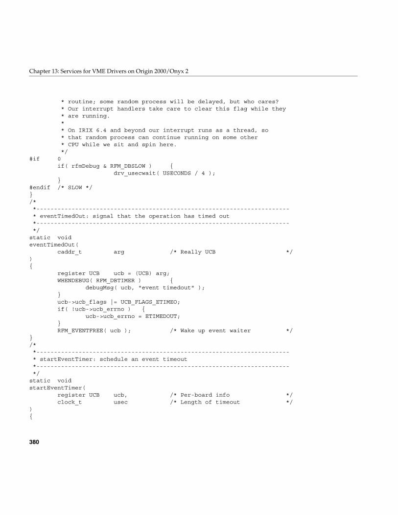
380
Chapter 13: Services for VME Drivers on Origin 2000/Onyx 2
* routine; some random process will be delayed, but who cares?* Our interrupt handlers take care to clear this flag while they* are running.** On IRIX 6.4 and beyond our interrupt runs as a thread, so* that random process can continue running on some other* CPU while we sit and spin here.*/
#if 0if( rfmDebug & RFM_DBSLOW ) {
drv_usecwait( USECONDS / 4 );}
#endif /* SLOW */}/**------------------------------------------------------------------------* eventTimedOut: signal that the operation has timed out*------------------------------------------------------------------------*/
static voideventTimedOut(
caddr_t arg /* Really UCB */){
register UCB ucb = (UCB) arg;WHENDEBUG( RFM_DBTIMER ) {
debugMsg( ucb, "event timedout" );}ucb->ucb_flags |= UCB_FLAGS_ETIMEO;if( !ucb->ucb_errno ) {
ucb->ucb_errno = ETIMEDOUT;}RFM_EVENTFREE( ucb ); /* Wake up event waiter */
}/**------------------------------------------------------------------------* startEventTimer: schedule an event timeout*------------------------------------------------------------------------*/
static voidstartEventTimer(
register UCB ucb, /* Per-board info */clock_t usec /* Length of timeout */
){
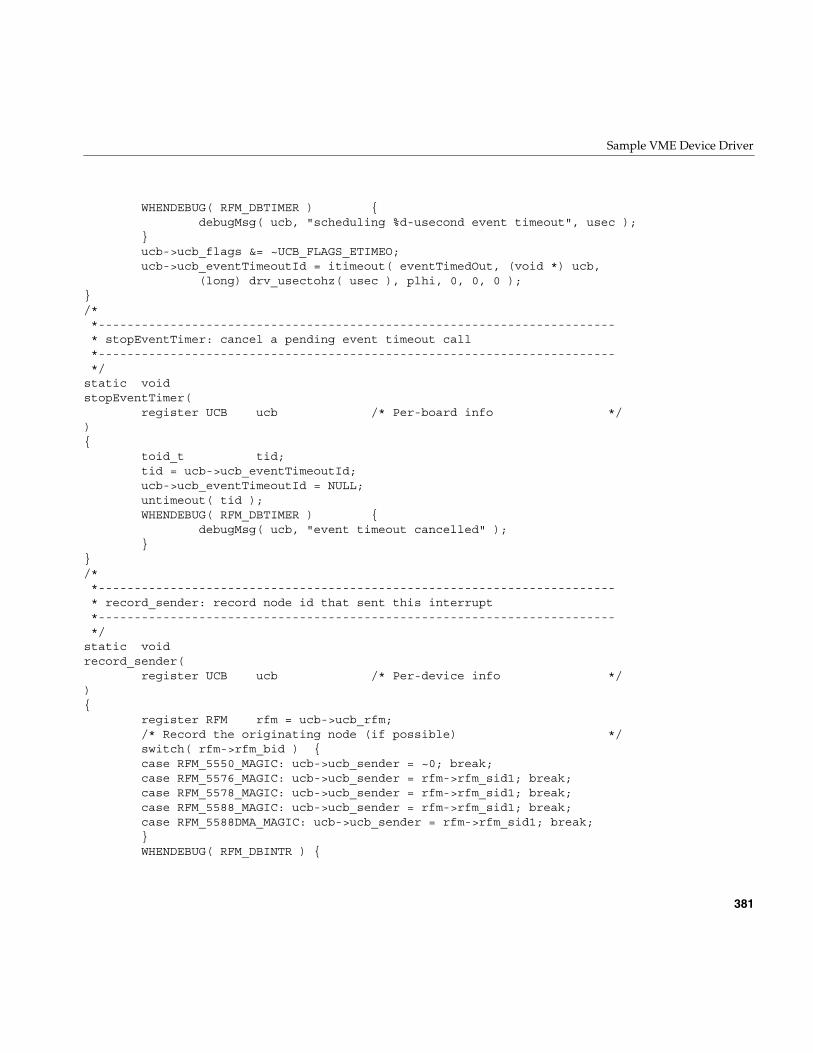
Sample VME Device Driver
381
WHENDEBUG( RFM_DBTIMER ) {debugMsg( ucb, "scheduling %d-usecond event timeout", usec );
}ucb->ucb_flags &= ~UCB_FLAGS_ETIMEO;ucb->ucb_eventTimeoutId = itimeout( eventTimedOut, (void *) ucb,
(long) drv_usectohz( usec ), plhi, 0, 0, 0 );}/**------------------------------------------------------------------------* stopEventTimer: cancel a pending event timeout call*------------------------------------------------------------------------*/
static voidstopEventTimer(
register UCB ucb /* Per-board info */){
toid_t tid;tid = ucb->ucb_eventTimeoutId;ucb->ucb_eventTimeoutId = NULL;untimeout( tid );WHENDEBUG( RFM_DBTIMER ) {
debugMsg( ucb, "event timeout cancelled" );}
}/**------------------------------------------------------------------------* record_sender: record node id that sent this interrupt*------------------------------------------------------------------------*/
static voidrecord_sender(
register UCB ucb /* Per-device info */){
register RFM rfm = ucb->ucb_rfm;/* Record the originating node (if possible) */switch( rfm->rfm_bid ) {case RFM_5550_MAGIC: ucb->ucb_sender = ~0; break;case RFM_5576_MAGIC: ucb->ucb_sender = rfm->rfm_sid1; break;case RFM_5578_MAGIC: ucb->ucb_sender = rfm->rfm_sid1; break;case RFM_5588_MAGIC: ucb->ucb_sender = rfm->rfm_sid1; break;case RFM_5588DMA_MAGIC: ucb->ucb_sender = rfm->rfm_sid1; break;}WHENDEBUG( RFM_DBINTR ) {
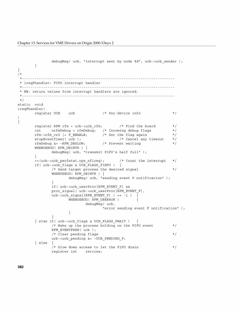
382
Chapter 13: Services for VME Drivers on Origin 2000/Onyx 2
debugMsg( ucb, "interrupt sent by node %d", ucb->ucb_sender );}
}/**------------------------------------------------------------------------* ireqFhandler: FIFO interrupt handler*------------------------------------------------------------------------* NB: return values from interrupt handlers are ignored.*------------------------------------------------------------------------*/
static voidireqFhandler(
register UCB ucb /* Per-device info */){
register RFM rfm = ucb->ucb_rfm; /* Find the board */int orfmDebug = rfmDebug; /* Incoming debug flags */rfm->rfm_cr0 |= F_ENABLE; /* Set the flag again */stopEventTimer( ucb ); /* Cancel any timeout */rfmDebug &= ~RFM_DBSLOW; /* Prevent waiting */WHENDEBUG( RFM_DBINTR ) {
debugMsg( ucb, "transmit FIFO’s half full" );}++(ucb->ucb_perfstat.rps_nfireq); /* Count the interrupt */if( ucb->ucb_flags & UCB_FLAGS_FINFO ) {
/* Send target process the desired signal */WHENDEBUG( RFM_DBINTR ) {
debugMsg( ucb, "sending event F notification" );}if( ucb->ucb_userProc[RFM_EVENT_F] &&proc_signal( ucb->ucb_userProc[RFM_EVENT_F],ucb->ucb_signal[RFM_EVENT_F] ) == -1 ) {
WHENDEBUG( RFM_DBERROR ) {debugMsg( ucb,
"error sending event F notification" );}
}} else if( ucb->ucb_flags & UCB_FLAGS_FWAIT ) {
/* Wake up the process holding on the FIFO event */RFM_EVENTFREE( ucb );/* Clear pending flags */ucb->ucb_pending &= ~UCB_PENDING_F;
} else {/* Slow down access to let the FIFO drain */register int retries;
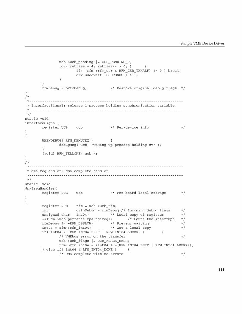
Sample VME Device Driver
383
ucb->ucb_pending |= UCB_PENDING_F;for( retries = 4; retries-- > 0; ) {
if( (rfm->rfm_csr & RFM_CSR_TXHALF) != 0 ) break;drv_usecwait( USECONDS / 4 );
}}rfmDebug = orfmDebug; /* Restore original debug flags */
}/**------------------------------------------------------------------------* interfaceSignal: release 1 process holding synchronization variable*------------------------------------------------------------------------*/
static voidinterfaceSignal(
register UCB ucb /* Per-device info */){
WHENDEBUG( RFM_DBMUTEX ) {debugMsg( ucb, "waking up process holding sv" );
}(void) RFM_TELLONE( ucb );
}/**------------------------------------------------------------------------* dmaIreqHandler: dma complete handler*------------------------------------------------------------------------*/
static voiddmaIreqHandler(
register UCB ucb /* Per-board local storage */){
register RFM rfm = ucb->ucb_rfm;int orfmDebug = rfmDebug;/* Incoming debug flags */unsigned char int04; /* Local copy of register */++(ucb->ucb_perfstat.rps_ndireq); /* Count the interrupt */rfmDebug &= ~RFM_DBSLOW; /* Prevent waiting */int04 = rfm->rfm_int04; /* Get a local copy */if( int04 & (RFM_INT04_BERR | RFM_INT04_LBERR) ) {
/* VMEbus error on the transfer */ucb->ucb_flags |= UCB_FLAGS_BERR;rfm->rfm_int04 = (int04 & ~(RFM_INT04_BERR | RFM_INT04_LBERR));
} else if( int04 & RFM_INT04_DONE ) {/* DMA complete with no errors */
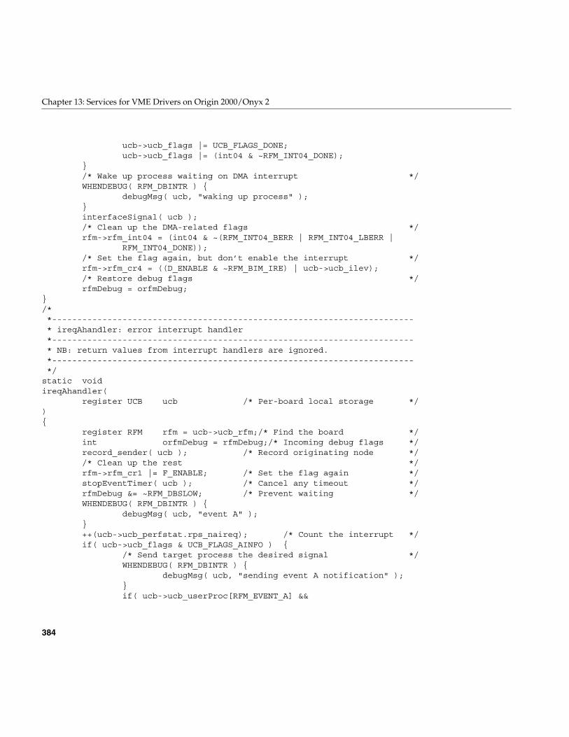
384
Chapter 13: Services for VME Drivers on Origin 2000/Onyx 2
ucb->ucb_flags |= UCB_FLAGS_DONE;ucb->ucb_flags |= (int04 & ~RFM_INT04_DONE);
}/* Wake up process waiting on DMA interrupt */WHENDEBUG( RFM_DBINTR ) {
debugMsg( ucb, "waking up process" );}interfaceSignal( ucb );/* Clean up the DMA-related flags */rfm->rfm_int04 = (int04 & ~(RFM_INT04_BERR | RFM_INT04_LBERR |
RFM_INT04_DONE));/* Set the flag again, but don’t enable the interrupt */rfm->rfm_cr4 = ((D_ENABLE & ~RFM_BIM_IRE) | ucb->ucb_ilev);/* Restore debug flags */rfmDebug = orfmDebug;
}/**------------------------------------------------------------------------* ireqAhandler: error interrupt handler*------------------------------------------------------------------------* NB: return values from interrupt handlers are ignored.*------------------------------------------------------------------------*/
static voidireqAhandler(
register UCB ucb /* Per-board local storage */){
register RFM rfm = ucb->ucb_rfm;/* Find the board */int orfmDebug = rfmDebug;/* Incoming debug flags */record_sender( ucb ); /* Record originating node *//* Clean up the rest */rfm->rfm_cr1 |= F_ENABLE; /* Set the flag again */stopEventTimer( ucb ); /* Cancel any timeout */rfmDebug &= ~RFM_DBSLOW; /* Prevent waiting */WHENDEBUG( RFM_DBINTR ) {
debugMsg( ucb, "event A" );}++(ucb->ucb_perfstat.rps_naireq); /* Count the interrupt */if( ucb->ucb_flags & UCB_FLAGS_AINFO ) {
/* Send target process the desired signal */WHENDEBUG( RFM_DBINTR ) {
debugMsg( ucb, "sending event A notification" );}if( ucb->ucb_userProc[RFM_EVENT_A] &&
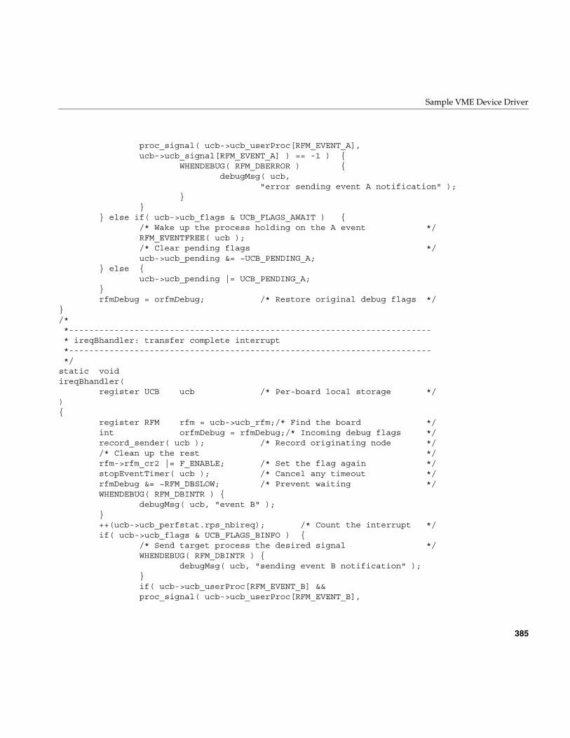
Sample VME Device Driver
385
proc_signal( ucb->ucb_userProc[RFM_EVENT_A],ucb->ucb_signal[RFM_EVENT_A] ) == -1 ) {
WHENDEBUG( RFM_DBERROR ) {debugMsg( ucb,
"error sending event A notification" );}
}} else if( ucb->ucb_flags & UCB_FLAGS_AWAIT ) {
/* Wake up the process holding on the A event */RFM_EVENTFREE( ucb );/* Clear pending flags */ucb->ucb_pending &= ~UCB_PENDING_A;
} else {ucb->ucb_pending |= UCB_PENDING_A;
}rfmDebug = orfmDebug; /* Restore original debug flags */
}/**------------------------------------------------------------------------* ireqBhandler: transfer complete interrupt*------------------------------------------------------------------------*/
static voidireqBhandler(
register UCB ucb /* Per-board local storage */){
register RFM rfm = ucb->ucb_rfm;/* Find the board */int orfmDebug = rfmDebug;/* Incoming debug flags */record_sender( ucb ); /* Record originating node *//* Clean up the rest */rfm->rfm_cr2 |= F_ENABLE; /* Set the flag again */stopEventTimer( ucb ); /* Cancel any timeout */rfmDebug &= ~RFM_DBSLOW; /* Prevent waiting */WHENDEBUG( RFM_DBINTR ) {
debugMsg( ucb, "event B" );}++(ucb->ucb_perfstat.rps_nbireq); /* Count the interrupt */if( ucb->ucb_flags & UCB_FLAGS_BINFO ) {
/* Send target process the desired signal */WHENDEBUG( RFM_DBINTR ) {
debugMsg( ucb, "sending event B notification" );}if( ucb->ucb_userProc[RFM_EVENT_B] &&proc_signal( ucb->ucb_userProc[RFM_EVENT_B],
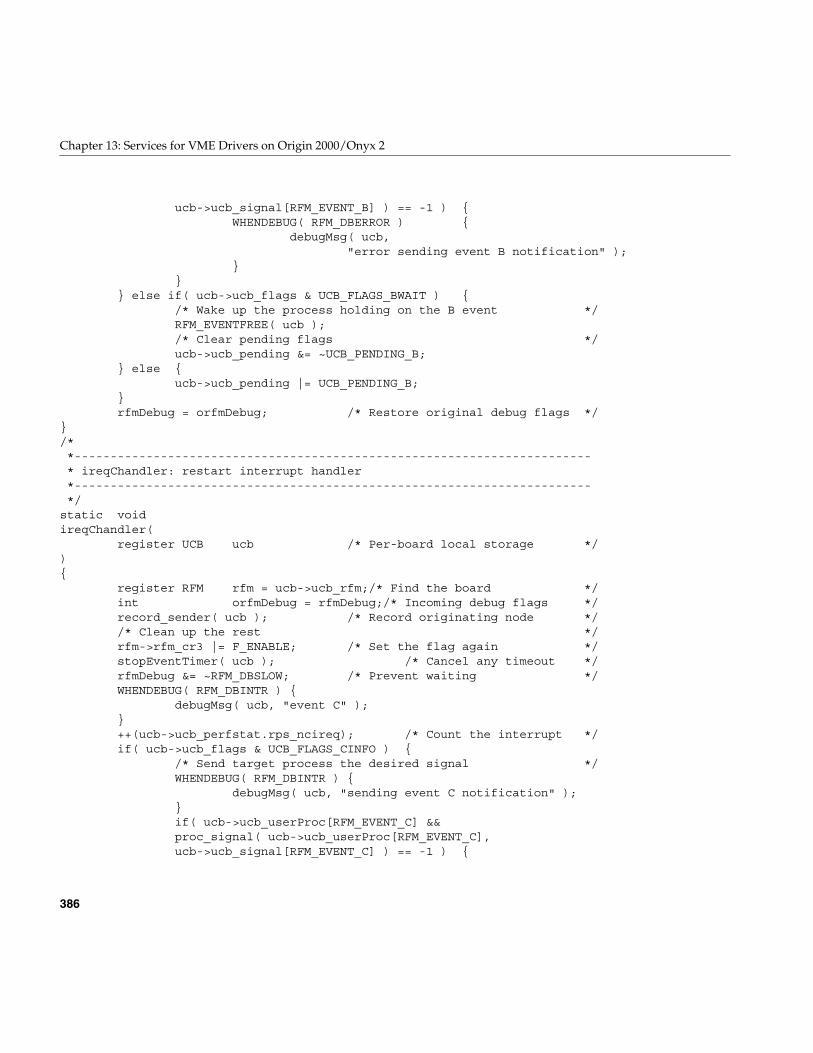
386
Chapter 13: Services for VME Drivers on Origin 2000/Onyx 2
ucb->ucb_signal[RFM_EVENT_B] ) == -1 ) {WHENDEBUG( RFM_DBERROR ) {
debugMsg( ucb,"error sending event B notification" );
}}
} else if( ucb->ucb_flags & UCB_FLAGS_BWAIT ) {/* Wake up the process holding on the B event */RFM_EVENTFREE( ucb );/* Clear pending flags */ucb->ucb_pending &= ~UCB_PENDING_B;
} else {ucb->ucb_pending |= UCB_PENDING_B;
}rfmDebug = orfmDebug; /* Restore original debug flags */
}/**------------------------------------------------------------------------* ireqChandler: restart interrupt handler*------------------------------------------------------------------------*/
static voidireqChandler(
register UCB ucb /* Per-board local storage */){
register RFM rfm = ucb->ucb_rfm;/* Find the board */int orfmDebug = rfmDebug;/* Incoming debug flags */record_sender( ucb ); /* Record originating node *//* Clean up the rest */rfm->rfm_cr3 |= F_ENABLE; /* Set the flag again */stopEventTimer( ucb ); /* Cancel any timeout */rfmDebug &= ~RFM_DBSLOW; /* Prevent waiting */WHENDEBUG( RFM_DBINTR ) {
debugMsg( ucb, "event C" );}++(ucb->ucb_perfstat.rps_ncireq); /* Count the interrupt */if( ucb->ucb_flags & UCB_FLAGS_CINFO ) {
/* Send target process the desired signal */WHENDEBUG( RFM_DBINTR ) {
debugMsg( ucb, "sending event C notification" );}if( ucb->ucb_userProc[RFM_EVENT_C] &&proc_signal( ucb->ucb_userProc[RFM_EVENT_C],ucb->ucb_signal[RFM_EVENT_C] ) == -1 ) {
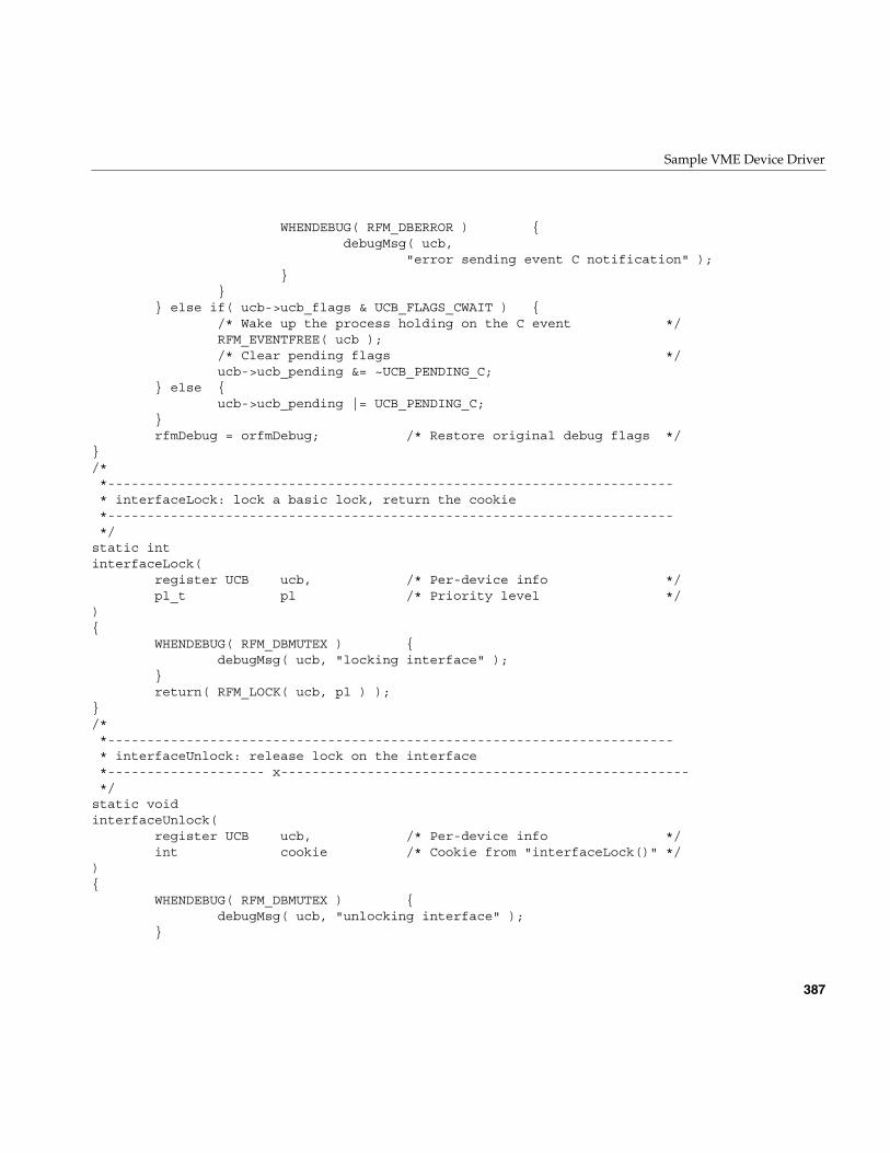
Sample VME Device Driver
387
WHENDEBUG( RFM_DBERROR ) {debugMsg( ucb,
"error sending event C notification" );}
}} else if( ucb->ucb_flags & UCB_FLAGS_CWAIT ) {
/* Wake up the process holding on the C event */RFM_EVENTFREE( ucb );/* Clear pending flags */ucb->ucb_pending &= ~UCB_PENDING_C;
} else {ucb->ucb_pending |= UCB_PENDING_C;
}rfmDebug = orfmDebug; /* Restore original debug flags */
}/**------------------------------------------------------------------------* interfaceLock: lock a basic lock, return the cookie*------------------------------------------------------------------------*/
static intinterfaceLock(
register UCB ucb, /* Per-device info */pl_t pl /* Priority level */
){
WHENDEBUG( RFM_DBMUTEX ) {debugMsg( ucb, "locking interface" );
}return( RFM_LOCK( ucb, pl ) );
}/**------------------------------------------------------------------------* interfaceUnlock: release lock on the interface*-------------------- x----------------------------------------------------*/
static voidinterfaceUnlock(
register UCB ucb, /* Per-device info */int cookie /* Cookie from "interfaceLock()" */
){
WHENDEBUG( RFM_DBMUTEX ) {debugMsg( ucb, "unlocking interface" );
}
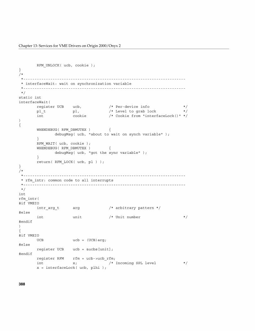
388
Chapter 13: Services for VME Drivers on Origin 2000/Onyx 2
RFM_UNLOCK( ucb, cookie );}/**------------------------------------------------------------------------* interfaceWait: wait on synchronization variable*------------------------------------------------------------------------*/
static intinterfaceWait(
register UCB ucb, /* Per-device info */pl_t pl, /* Level to grab lock */int cookie /* Cookie from "interfaceLock()" */
){
WHENDEBUG( RFM_DBMUTEX ) {debugMsg( ucb, "about to wait on synch variable" );
}RFM_WAIT( ucb, cookie );WHENDEBUG( RFM_DBMUTEX ) {
debugMsg( ucb, "got the sync variable" );}return( RFM_LOCK( ucb, pl ) );
}/**------------------------------------------------------------------------* rfm_intr: common code to all interrupts*------------------------------------------------------------------------*/
intrfm_intr(#if VMEIO
intr_arg_t arg /* arbitrary pattern */#else
int unit /* Unit number */#endif){#if VMEIO
UCB ucb = (UCB)arg;#else
register UCB ucb = &ucbs[unit];#endif
register RFM rfm = ucb->ucb_rfm;int x; /* Incoming SPL level */x = interfaceLock( ucb, plhi );
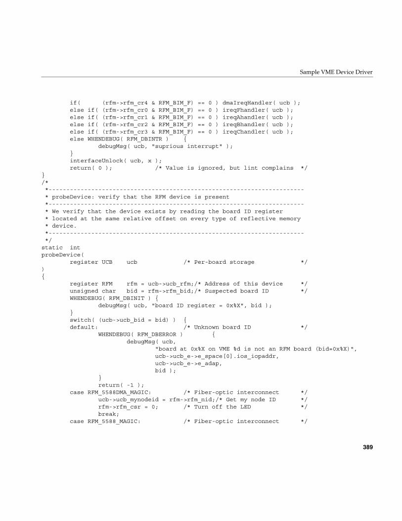
Sample VME Device Driver
389
if( (rfm->rfm_cr4 & RFM_BIM_F) == 0 ) dmaIreqHandler( ucb );else if( (rfm->rfm_cr0 & RFM_BIM_F) == 0 ) ireqFhandler( ucb );else if( (rfm->rfm_cr1 & RFM_BIM_F) == 0 ) ireqAhandler( ucb );else if( (rfm->rfm_cr2 & RFM_BIM_F) == 0 ) ireqBhandler( ucb );else if( (rfm->rfm_cr3 & RFM_BIM_F) == 0 ) ireqChandler( ucb );else WHENDEBUG( RFM_DBINTR ) {
debugMsg( ucb, "suprious interrupt" );}interfaceUnlock( ucb, x );return( 0 ); /* Value is ignored, but lint complains */
}/**------------------------------------------------------------------------* probeDevice: verify that the RFM device is present*------------------------------------------------------------------------* We verify that the device exists by reading the board ID register* located at the same relative offset on every type of reflective memory* device.*------------------------------------------------------------------------*/
static intprobeDevice(
register UCB ucb /* Per-board storage */){
register RFM rfm = ucb->ucb_rfm;/* Address of this device */unsigned char bid = rfm->rfm_bid;/* Suspected board ID */WHENDEBUG( RFM_DBINIT ) {
debugMsg( ucb, "board ID register = 0x%X", bid );}switch( (ucb->ucb_bid = bid) ) {default: /* Unknown board ID */
WHENDEBUG( RFM_DBERROR ) {debugMsg( ucb,
"board at 0x%X on VME %d is not an RFM board (bid=0x%X)",ucb->ucb_e->e_space[0].ios_iopaddr,ucb->ucb_e->e_adap,bid );
}return( -1 );
case RFM_5588DMA_MAGIC: /* Fiber-optic interconnect */ucb->ucb_mynodeid = rfm->rfm_nid;/* Get my node ID */rfm->rfm_csr = 0; /* Turn off the LED */break;
case RFM_5588_MAGIC: /* Fiber-optic interconnect */
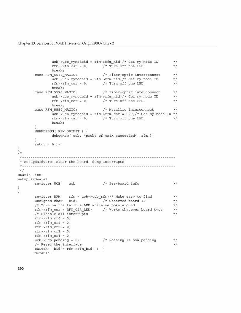
390
Chapter 13: Services for VME Drivers on Origin 2000/Onyx 2
ucb->ucb_mynodeid = rfm->rfm_nid;/* Get my node ID */rfm->rfm_csr = 0; /* Turn off the LED */break;
case RFM_5578_MAGIC: /* Fiber-optic interconnect */ucb->ucb_mynodeid = rfm->rfm_nid;/* Get my node ID */rfm->rfm_csr = 0; /* Turn off the LED */break;
case RFM_5576_MAGIC: /* Fiber-optic interconnect */ucb->ucb_mynodeid = rfm->rfm_nid;/* Get my node ID */rfm->rfm_csr = 0; /* Turn off the LED */break;
case RFM_5550_MAGIC: /* Metallic interconnect */ucb->ucb_mynodeid = rfm->rfm_csr & 0xF;/* Get my node ID */rfm->rfm_csr = 0; /* Turn off the LED */break;
}WHENDEBUG( RFM_DBINIT ) {
debugMsg( ucb, "probe of 0x%X succeeded", rfm );}return( 0 );
}/**------------------------------------------------------------------------* setupHardware: clear the board, dump interrupts*------------------------------------------------------------------------*/
static intsetupHardware(
register UCB ucb /* Per-board info */){
register RFM rfm = ucb->ucb_rfm;/* Make easy to find */unsigned char bid; /* Observed board ID *//* Turn on the failure LED while we poke around */rfm->rfm_csr = RFM_CSR_LED; /* Works whatever board type *//* Disable all interrupts */rfm->rfm_cr0 = 0;rfm->rfm_cr1 = 0;rfm->rfm_cr2 = 0;rfm->rfm_cr3 = 0;rfm->rfm_cr4 = 0;ucb->ucb_pending = 0; /* Nothing is now pending *//* Reset the interface */switch( (bid = rfm->rfm_bid) ) {default:
Sample VME Device Driver
391
{WHENDEBUG( RFM_DBERROR ) {
debugMsg( ucb, "unknown board id (0x%X)",bid );
}return( (ucb->ucb_errno = EINVAL) );
}/*NOTREACHED*/
case RFM_5550_MAGIC: /* Metallic 5550 */{
strcpy( ucb->ucb_name, "VMIVME-5550" );}break;
case RFM_5576_MAGIC: /* Fiber-optic 5576 */{
strcpy( ucb->ucb_name, "VMIVME-5576" );/** Drop anything that may be in the board’s* receive FIFO’s. Do this by first clearing the* CSR’s flags and then doing a benign write to* the board (we’ll use the board ID register, but* any location in the first RFM_REGSIZ bytes* would work, but writing the board ID register* won’t really change anything on tbe board). Any* write to the board (even to the registers) is* propagated around the fiber optic ring. We poke* the board and then check that we saw our write* come back around.*/rfm->rfm_csr = 0; /* Clear all flags */rfm->rfm_bid = RFM_5576_MAGIC;rfm->rfm_bid = RFM_5576_MAGIC;rfm->rfm_bid = RFM_5576_MAGIC;drv_usecwait( 1 + (USECONDS / 100) );if( rfm->rfm_csr & RFM_OCSR_OWNDAT ) {
/* Flush the interrupt FIFO’s */rfm->rfm_sid1 = 0;rfm->rfm_sid2 = 0;rfm->rfm_sid3 = 0;
} else WHENDEBUG( RFM_DBERROR ) {debugMsg( ucb, "fiber-optic ring not intact" );
}}break;
case RFM_5578_MAGIC: /* Fiber-optic 5578 */
392
Chapter 13: Services for VME Drivers on Origin 2000/Onyx 2
{strcpy( ucb->ucb_name, "VMIVME-5578" );/* Clear the violation bit if needed */if( rfm->rfm_irs & RFM_IRS_VIOLAT ) {
/* Strobe RFM_IRS_RPL to resync PLL */rfm->rfm_irs = (RFM_IRS_RPL|RFM_IRS_LVIOLAT);rfm->rfm_irs;rfm->rfm_irs = (RFM_IRS_LVIOLAT);rfm->rfm_irs;
}/** Drop anything that may be in the board’s* receive FIFO’s. Do this by first clearing the* CSR’s flags and then doing a benign write to* the board (we’ll use the node ID register, but* any location in the first RFM_REGSIZ bytes* would work, but writing the node ID register* won’t really change anything on tbe board). Any* write to the board (even to the registers) is* propagated around the fiber optic ring. We poke* the board and then check that we saw our write* come back around.*/rfm->rfm_csr = 0; /* Clear all flags */rfm->rfm_nid = 0;rfm->rfm_nid = 0;rfm->rfm_nid = 0;drv_usecwait( 1 + (USECONDS / 100) );if( rfm->rfm_csr & RFM_OCSR_OWNDAT ) {
/* Flush the interrupt FIFO’s */rfm->rfm_sid1 = 0;rfm->rfm_sid2 = 0;rfm->rfm_sid3 = 0;
} else WHENDEBUG( RFM_DBERROR ) {debugMsg( ucb, "fiber-optic ring not intact" );
}}break;
case RFM_5588DMA_MAGIC: /* Fiber-optic 5588 w/DMA *//*FALLTHROUGH*/
case RFM_5588_MAGIC: /* Fiber-optic 5588 */{
strcpy( ucb->ucb_name,((bid == RFM_5588DMA_MAGIC) ?
"VMIVME-5588DMA" : "VMIVME-5588") );
Sample VME Device Driver
393
/* Clear the violation bit if needed */if( rfm->rfm_irs & RFM_IRS_VIOLAT ) {
/* Strobe RFM_IRS_RPL to resync PLL */rfm->rfm_irs = (RFM_IRS_RPL|RFM_IRS_LVIOLAT);rfm->rfm_irs;rfm->rfm_irs = (RFM_IRS_LVIOLAT);rfm->rfm_irs;
}/** Drop anything that may be in the board’s* receive FIFO’s. Do this by first clearing the* CSR’s flags and then doing a benign write to* the board (we’ll use the node ID register, but* any location in the first RFM_REGSIZ bytes* would work, but writing the node ID register* won’t really change anything on tbe board). Any* write to the board (even to the registers) is* propagated around the fiber optic ring. We poke* the board and then check that we saw our write* come back around.*/rfm->rfm_csr = 0; /* Clear all flags */rfm->rfm_nid = 0;rfm->rfm_nid = 0;rfm->rfm_nid = 0;drv_usecwait( 1 + (USECONDS / 100) );if( rfm->rfm_csr & RFM_OCSR_OWNDAT ) {
/* Flush the interrupt FIFO’s */rfm->rfm_sid1 = 0;rfm->rfm_sid2 = 0;rfm->rfm_sid3 = 0;
} else WHENDEBUG( RFM_DBERROR ) {debugMsg( ucb, "fiber-optic ring not intact" );
}}break;
}/* Get the interrupt vector and set as common vector */rfm->rfm_vr0 = ucb->ucb_ivec;rfm->rfm_vr1 = ucb->ucb_ivec;rfm->rfm_vr2 = ucb->ucb_ivec;rfm->rfm_vr3 = ucb->ucb_ivec;rfm->rfm_vr4 = ucb->ucb_ivec;/* Get the interrupt csr values and set them on board */rfm->rfm_cr0 = F_ENABLE | ucb->ucb_ilev;
394
Chapter 13: Services for VME Drivers on Origin 2000/Onyx 2
rfm->rfm_cr1 = A_ENABLE | ucb->ucb_ilev;rfm->rfm_cr2 = B_ENABLE | ucb->ucb_ilev;rfm->rfm_cr3 = C_ENABLE | ucb->ucb_ilev;rfm->rfm_cr4 = C_ENABLE | ucb->ucb_ilev;rfm->rfm_csr = 0; /* Turn off the failure LED */return( 0 );
}/**------------------------------------------------------------------------* loadDmaInfo: setup DMA control registers*------------------------------------------------------------------------*/
static voidloadDmaInfo(
register UCB ucb /* Per-board info */){
register RFM rfm = ucb->ucb_rfm;int bid; /* Observed board ID */switch( (bid = rfm->rfm_bid) ) {default:
{WHENDEBUG( RFM_DBERROR ) {
debugMsg( ucb,"loadDmaInfo() didn’t recognize board ID of 0x%X",
bid );}
}break;
case RFM_5588DMA_MAGIC:{
unsigned char dmac0;/* Local copy */unsigned char dmac1;/* Local copy *//* Construct DMAC0 */dmac0 = ucb->ucb_dmaInfo.rdi_burst & RFM_DMAC0_BMASK;/* Construct DMAC1 */dmac1 = 0;switch( ucb->ucb_dmaInfo.rdi_relmode ) {default:
{WHENDEBUG( RFM_DBERROR ) {
debugMsg( ucb,"unknown rdi_relmode of %d",ucb->ucb_dmaInfo.rdi_relmode );
}
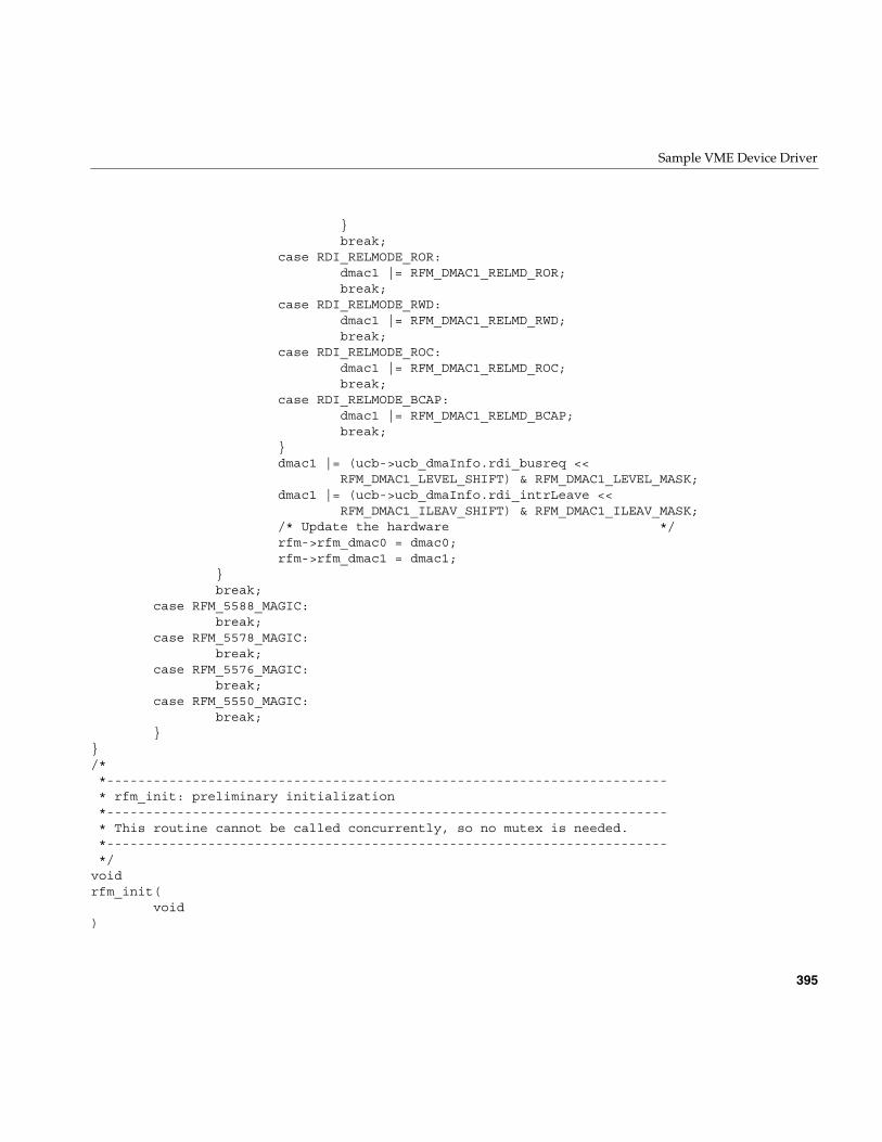
Sample VME Device Driver
395
}break;
case RDI_RELMODE_ROR:dmac1 |= RFM_DMAC1_RELMD_ROR;break;
case RDI_RELMODE_RWD:dmac1 |= RFM_DMAC1_RELMD_RWD;break;
case RDI_RELMODE_ROC:dmac1 |= RFM_DMAC1_RELMD_ROC;break;
case RDI_RELMODE_BCAP:dmac1 |= RFM_DMAC1_RELMD_BCAP;break;
}dmac1 |= (ucb->ucb_dmaInfo.rdi_busreq <<
RFM_DMAC1_LEVEL_SHIFT) & RFM_DMAC1_LEVEL_MASK;dmac1 |= (ucb->ucb_dmaInfo.rdi_intrLeave <<
RFM_DMAC1_ILEAV_SHIFT) & RFM_DMAC1_ILEAV_MASK;/* Update the hardware */rfm->rfm_dmac0 = dmac0;rfm->rfm_dmac1 = dmac1;
}break;
case RFM_5588_MAGIC:break;
case RFM_5578_MAGIC:break;
case RFM_5576_MAGIC:break;
case RFM_5550_MAGIC:break;
}}/**------------------------------------------------------------------------* rfm_init: preliminary initialization*------------------------------------------------------------------------* This routine cannot be called concurrently, so no mutex is needed.*------------------------------------------------------------------------*/
voidrfm_init(
void)
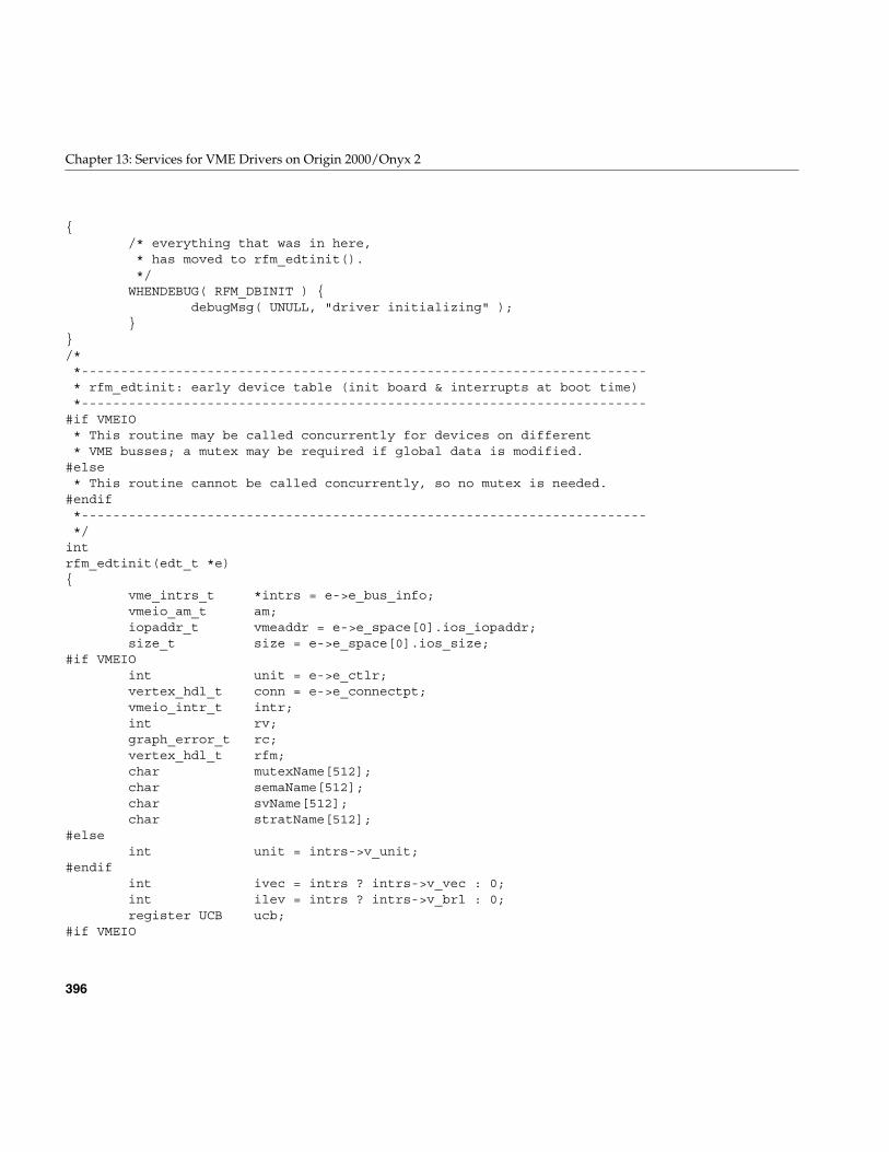
396
Chapter 13: Services for VME Drivers on Origin 2000/Onyx 2
{/* everything that was in here,* has moved to rfm_edtinit().*/
WHENDEBUG( RFM_DBINIT ) {debugMsg( UNULL, "driver initializing" );
}}/**------------------------------------------------------------------------* rfm_edtinit: early device table (init board & interrupts at boot time)*------------------------------------------------------------------------
#if VMEIO* This routine may be called concurrently for devices on different* VME busses; a mutex may be required if global data is modified.
#else* This routine cannot be called concurrently, so no mutex is needed.
#endif*------------------------------------------------------------------------*/
intrfm_edtinit(edt_t *e){
vme_intrs_t *intrs = e->e_bus_info;vmeio_am_t am;iopaddr_t vmeaddr = e->e_space[0].ios_iopaddr;size_t size = e->e_space[0].ios_size;
#if VMEIOint unit = e->e_ctlr;vertex_hdl_t conn = e->e_connectpt;vmeio_intr_t intr;int rv;graph_error_t rc;vertex_hdl_t rfm;char mutexName[512];char semaName[512];char svName[512];char stratName[512];
#elseint unit = intrs->v_unit;
#endifint ivec = intrs ? intrs->v_vec : 0;int ilev = intrs ? intrs->v_brl : 0;register UCB ucb;
#if VMEIO
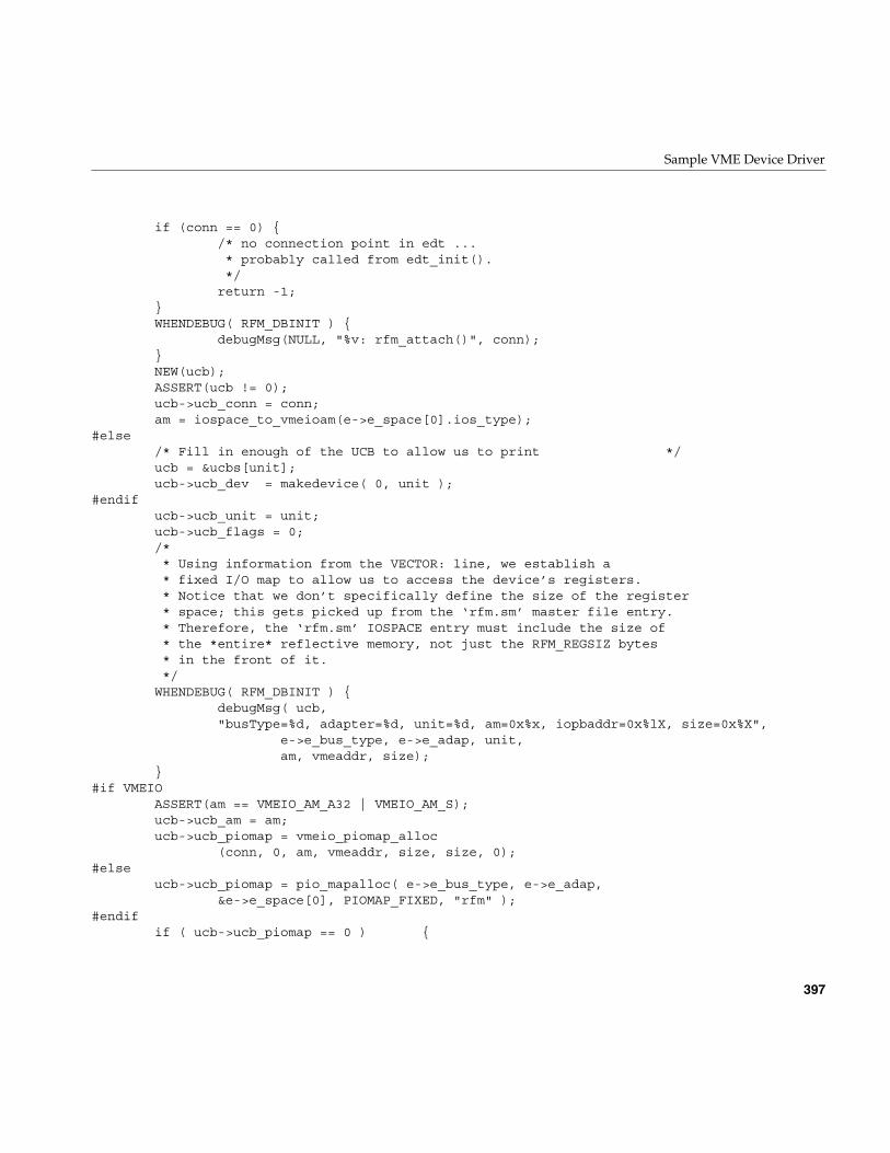
Sample VME Device Driver
397
if (conn == 0) {/* no connection point in edt ...* probably called from edt_init().*/return -1;
}WHENDEBUG( RFM_DBINIT ) {
debugMsg(NULL, "%v: rfm_attach()", conn);}NEW(ucb);ASSERT(ucb != 0);ucb->ucb_conn = conn;am = iospace_to_vmeioam(e->e_space[0].ios_type);
#else/* Fill in enough of the UCB to allow us to print */ucb = &ucbs[unit];ucb->ucb_dev = makedevice( 0, unit );
#endifucb->ucb_unit = unit;ucb->ucb_flags = 0;/** Using information from the VECTOR: line, we establish a* fixed I/O map to allow us to access the device’s registers.* Notice that we don’t specifically define the size of the register* space; this gets picked up from the ‘rfm.sm’ master file entry.* Therefore, the ‘rfm.sm’ IOSPACE entry must include the size of* the *entire* reflective memory, not just the RFM_REGSIZ bytes* in the front of it.*/
WHENDEBUG( RFM_DBINIT ) {debugMsg( ucb,"busType=%d, adapter=%d, unit=%d, am=0x%x, iopbaddr=0x%lX, size=0x%X",
e->e_bus_type, e->e_adap, unit,am, vmeaddr, size);
}#if VMEIO
ASSERT(am == VMEIO_AM_A32 | VMEIO_AM_S);ucb->ucb_am = am;ucb->ucb_piomap = vmeio_piomap_alloc
(conn, 0, am, vmeaddr, size, size, 0);#else
ucb->ucb_piomap = pio_mapalloc( e->e_bus_type, e->e_adap,&e->e_space[0], PIOMAP_FIXED, "rfm" );
#endifif ( ucb->ucb_piomap == 0 ) {
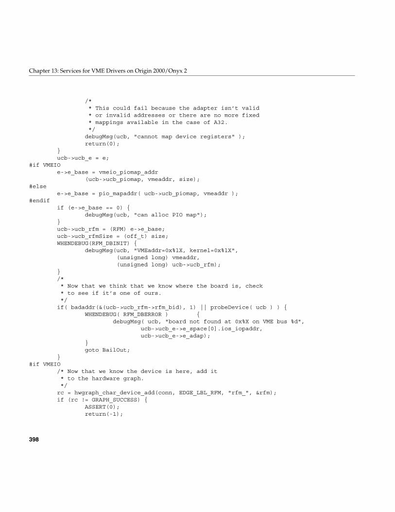
398
Chapter 13: Services for VME Drivers on Origin 2000/Onyx 2
/** This could fail because the adapter isn’t valid* or invalid addresses or there are no more fixed* mappings available in the case of A32.*/debugMsg(ucb, "cannot map device registers" );return(0);
}ucb->ucb_e = e;
#if VMEIOe->e_base = vmeio_piomap_addr
(ucb->ucb_piomap, vmeaddr, size);#else
e->e_base = pio_mapaddr( ucb->ucb_piomap, vmeaddr );#endif
if (e->e_base == 0) {debugMsg(ucb, "can alloc PIO map");
}ucb->ucb_rfm = (RFM) e->e_base;ucb->ucb_rfmSize = (off_t) size;WHENDEBUG(RFM_DBINIT) {
debugMsg(ucb, "VMEaddr=0x%lX, kernel=0x%lX",(unsigned long) vmeaddr,(unsigned long) ucb->ucb_rfm);
}/** Now that we think that we know where the board is, check* to see if it’s one of ours.*/
if( badaddr(&(ucb->ucb_rfm->rfm_bid), 1) || probeDevice( ucb ) ) {WHENDEBUG( RFM_DBERROR ) {
debugMsg( ucb, "board not found at 0x%X on VME bus %d",ucb->ucb_e->e_space[0].ios_iopaddr,ucb->ucb_e->e_adap);
}goto BailOut;
}#if VMEIO
/* Now that we know the device is here, add it* to the hardware graph.*/
rc = hwgraph_char_device_add(conn, EDGE_LBL_RFM, "rfm_", &rfm);if (rc != GRAPH_SUCCESS) {
ASSERT(0);return(-1);
Sample VME Device Driver
399
}ucb->ucb_vertex = rfm;device_info_set(rfm, ucb);/* [try to] create the convenience link.*/
{vertex_hdl_t cvhdl;char name[32];cvhdl = GRAPH_VERTEX_NONE;hwgraph_path_add(hwgraph_root, EDGE_LBL_RFM, &cvhdl);sprintf(name, "%d", unit);if (cvhdl != GRAPH_VERTEX_NONE)
hwgraph_edge_add(cvhdl, rfm, name);}
#endifucb->ucb_adapter = e->e_adap;
#if VMEIO/* VMEIO can use levels and vectors that we* assign, or it can assign them if we tell* it to do so.*/
intr = vmeio_intr_alloc(conn, 0, ivec, ilev, rfm, 0);
if (intr == 0) {WHENDEBUG( RFM_DBERROR ) {
debugMsg( ucb, "cannot allocate interrupt resource" );}goto BailOut;
}ucb->ucb_intr = intr;/* Find out the vector vmeio has assigned us;* complain if the result is not appropriate.*/
if (ivec == VMEIO_INTR_VECTOR_ANY)ivec = vmeio_intr_vector_get(intr);
else if (ivec != vmeio_intr_vector_get(intr))cmn_err(CE_WARN, "rfm%d intr alloc error:\n"
"\twanted interrupt vector %d\n""\tgot interrupt vector %d\n",unit, ivec, vmeio_intr_vector_get(intr));
#if 0/* vmeio_intr_level_get doesn’t exist. (yet?) */if (ilev == VMEIO_INTR_LEVEL_NONE)
ilev = vmeio_intr_level_get(intr);else if (ilev != vmeio_intr_level_get(intr))
400
Chapter 13: Services for VME Drivers on Origin 2000/Onyx 2
cmn_err(CE_WARN, "rfm%d intr alloc error:\n""\twanted interrupt level %d\n""\tgot interrupt level %d\n",unit, ilev, vmeio_intr_level_get(intr));
#endif#else
ivec = vme_ivec_alloc( ucb->ucb_adapter );if ( ucb->ucb_ivec == -1 ) {
WHENDEBUG( RFM_DBERROR ) {debugMsg( ucb, "cannot allocate interrupt vector" );
}goto BailOut;
}#endif
ucb->ucb_ilev = ilev;ucb->ucb_ivec = ivec;WHENDEBUG( RFM_DBINIT ) {
debugMsg(ucb, "vector=0x%X, level=%d", ivec, ilev);}
#if VMEIOrv = vmeio_intr_connect
(intr, (intr_func_t) rfm_intr, (intr_arg_t)ucb, 0);if (rv == -1) {
debugMsg(ucb, "cannot connection interrupt handler");goto BailOut;
}#else
vme_ivec_set( ucb->ucb_adapter, ucb->ucb_ivec,(int (*)(int)) rfm_intr, unit );
#endif/* Initialize the software state and the board */ucb->ucb_flags = UCB_FLAGS_FOUND;/* Setup for the DMA */ucb->ucb_dmaMap = DMAMAP_FAILED;
if( setupHardware(ucb) ) {WHENDEBUG( RFM_DBERROR ) {
debugMsg( ucb, "unknown board type; not installed" );}goto BailOut;
}/* Load the random board registers */ucb->ucb_rfm->rfm_dmac2 = RFM_DMAC2_DWID_D64
#if VMEIO| VMEbus_AMR_A32SMBLT
Sample VME Device Driver
401
#else| addrSpaces[unit].vs_vmeAmr
#endif;
/* Ok */WHENDEBUG( RFM_DBOPEN ) {
debugMsg( ucb, "device is a %ld-Kbyte %s",ucb->ucb_rfmSize / 1024L,ucb->ucb_name );
}WHENDEBUG( RFM_DBINIT ) {
debugMsg( ucb, "creating mutex’s and sema’s" );}sprintf( mutexName, "rfm%d", ucb->ucb_unit);MUTEX_INIT( &ucb->ucb_mutex, MUTEX_DEFAULT, mutexName );/* more per-UCB date initialization *//* The "EVENT" semaphore is initially not available */sprintf( semaName, "rfm%d", ucb->ucb_unit);initnsema( &ucb->ucb_eventSema, 0, semaName );/* The "STRAT" semaphone is initially available */sprintf( stratName, "rfm%d", ucb->ucb_unit);initnsema( &ucb->ucb_stratSema, 1, stratName );/* The "SV" is used for DMA locking */sprintf( svName, "rfm%d", ucb->ucb_unit);SV_INIT( &ucb->ucb_rfmSv, SV_DEFAULT, svName );RFM_LOCK_INIT(ucb);WHENDEBUG( RFM_DBINIT ) {
debugMsg(ucb, "rfm_edtinit() finished");}return (RFM_REGSIZ);/**================================================================* Some error is preventing us from installing ourselves so we* need to clean up as well as we can.*================================================================*/
BailOut:WHENDEBUG( RFM_DBINIT ) {
debugMsg( ucb, "edtinit failed" );}if( ucb->ucb_flags & UCB_FLAGS_FOUND ) {
WHENDEBUG( RFM_DBINIT ) {debugMsg( ucb, "freeing adapter %d vector %d",
ucb->ucb_adapter, ucb->ucb_ivec );}
402
Chapter 13: Services for VME Drivers on Origin 2000/Onyx 2
#if VMEIOif (ucb->ucb_intr)
vmeio_intr_free(ucb->ucb_intr);#else
vme_ivec_free (ucb->ucb_adapter, ucb->ucb_ivec );#endif
}WHENDEBUG( RFM_DBINIT ) {
debugMsg( ucb, "unmapping device registers" );}
#if VMEIOif (ucb->ucb_piomap)
vmeio_piomap_free(ucb->ucb_piomap); /* Unmap the device registers */#else
pio_mapfree( ucb->ucb_piomap );#endif
ucb->ucb_rfm = 0; /* Forget where device is */ucb->ucb_piomap = 0; /* Forget the map, also */
#if VMEIODEL(ucb);
#endifreturn( 0 );
}/**------------------------------------------------------------------------* rfm_start: called after rfminit() and rfmedtinit()
#if VMEIO* In the VMEIO world, rfm_start() is rather useless* since it gets called before we find any dynamically* located VME busses (like the XIO-VME adapter).
#endif*------------------------------------------------------------------------* This routine cannot be called concurrently, although interrupts are* alive at this point.*------------------------------------------------------------------------*/
voidrfm_start(void){
WHENDEBUG( RFM_DBINIT ) {debugMsg( UNULL, "started" );
}}/**------------------------------------------------------------------------
Sample VME Device Driver
403
* topHalfLock: set mutual exclusion of top-half of system call handlers*------------------------------------------------------------------------*/
static voidtopHalfLock(register UCB ucb) /* Per-device info */{
WHENDEBUG( RFM_DBMUTEX ) {debugMsg( ucb, "locking top half" );
}TOPHALF_LOCK( ucb );
}/**------------------------------------------------------------------------* topHalfUnlock: unlock top half of system call handlers*------------------------------------------------------------------------*/
static voidtopHalfUnlock(
register UCB ucb /* Per-device info */){
WHENDEBUG( RFM_DBMUTEX ) {debugMsg( ucb, "unlocking top half" );
}TOPHALF_UNLOCK( ucb );
}/**------------------------------------------------------------------------* rfm_open: called in response to the open(2) system call*------------------------------------------------------------------------* Only the ‘dev’ argument is really used. The others are all ignored,* except for ‘otyp’ -- we look at that to catch layered opens. Multiple* user-level open’s are OK.*------------------------------------------------------------------------*/
intrfm_open(
dev_t *devp, /* Complex device number addr */int oflag, /* Open(2) flags (not used) */int otyp, /* Open(2) type */cred_t *crp /* Credentials (not used) */
){
dev_t dev = *devp;#if VMEIO
404
Chapter 13: Services for VME Drivers on Origin 2000/Onyx 2
vertex_hdl_t vhdl = dev_to_vhdl(dev);UCB ucb = device_info_get(vhdl);int unit = ucb->ucb_unit; /* for printing */vertex_hdl_t conn = ucb->ucb_conn; /* for vmeio */
#elseint unit = RFMUNIT(dev); /* Extract unit number */UCB ucb = &ucbs[unit];
#endif#if !VMEIO
if( unit > NRFM ) {WHENDEBUG( RFM_DBOPEN ) {
debugMsg( NULL, "no such unit (%d)", unit );}return( ENODEV );
}#endif
topHalfLock(ucb);if( ucb->ucb_rfm == (RFM) NULL ) {
WHENDEBUG( RFM_DBERROR ) {debugMsg(ucb, "attempt to open missing unit %d", unit);
}topHalfUnlock(ucb);return( ENODEV );
}if( otyp == OTYP_BLK ) {
WHENDEBUG( RFM_DBOPEN ) {debugMsg( ucb, "illegal open type (%d)", otyp );
}topHalfUnlock(ucb);return( EINVAL );
}if( (ucb->ucb_flags & UCB_FLAGS_OPEN) == 0 ) {
/* Not opened before */int eventId; /* Loops across notifications *//* Make sure that there are no notifications left over */ucb->ucb_pending = 0;for( eventId = 0; eventId < RFM_NEVENT; ++eventId ) {
ucb->ucb_userProc[eventId] = 0;}/* Set the default event wait time */ucb->ucb_eventWait = EVENTPATIENCE * USECONDS;/* Set the default DMA wait time */ucb->ucb_dmaInfo = defaultDmaInfo;ucb->ucb_dev = dev;if( userabi(&ucb->ucb_userabi)) {
Sample VME Device Driver
405
/* Somehow we got called without a user context! */WHENDEBUG( RFM_DBOPEN ) {
debugMsg( ucb, "no userabi context" );}topHalfUnlock(ucb);return( ESRCH );
}WHENDEBUG( RFM_DBOPEN ) {
debugMsg( ucb,"userabi(int=%d,long=%d,ptr=%d,longlong=%d)",ucb->ucb_userabi.uabi_szint,ucb->ucb_userabi.uabi_szlong,ucb->ucb_userabi.uabi_szptr,ucb->ucb_userabi.uabi_szlonglong );
}loadDmaInfo( ucb );if( setupHardware( ucb ) != 0 ) {
int errno = ucb->ucb_errno;topHalfUnlock(ucb);return( errno );
}/* Create the DMA mapping window if board supports DMA */if( ucb->ucb_rfm->rfm_bid == RFM_5588DMA_MAGIC ) {
WHENDEBUG( RFM_DBOPEN ) {debugMsg( ucb, "allocating DMA map" );
}#if VMEIO
ucb->ucb_dmaMap = vmeio_dmamap_alloc(conn, 0, ucb->ucb_am, ucb->ucb_rfmSize, 0);
#elseucb->ucb_dmaMap = dma_mapalloc(
addrSpaces[ unit ].vs_type,ucb->ucb_adapter,(int) btopr( ucb->ucb_rfmSize ), 0 );
#endifif (ucb->ucb_dmaMap == DMAMAP_FAILED) {
WHENDEBUG( RFM_DBERROR ) {debugMsg( ucb,
"cannot create %d-page dma map",btopr( ucb->ucb_rfmSize ) );
}topHalfUnlock(ucb);return( ENOMEM );
}} else {
406
Chapter 13: Services for VME Drivers on Origin 2000/Onyx 2
/* Does not support DMA, so don’t need a DMA map */ucb->ucb_dmaMap = DMAMAP_FAILED;
}ucb->ucb_flags |= UCB_FLAGS_OPEN;
}topHalfUnlock(ucb);return( 0 );
}/**------------------------------------------------------------------------* disableRfmInterrupts: disable all interrupts on the reflective memory*------------------------------------------------------------------------*/
static voiddisableRfmInterrupts(
register UCB ucb /* Per-board info address */){
register RFM rfm = ucb->ucb_rfm;/** It is not too difficult to disable interrupts, just zero* the interrupt enables in each BIM control register. Just* to be thorough, we will also clean up the UCB, but this* really isn’t necessary since interrupts are being disabled* only because the device is being closed.*/
rfm->rfm_cr0 = 0;rfm->rfm_cr1 = 0;rfm->rfm_cr2 = 0;rfm->rfm_cr3 = 0;rfm->rfm_cr4 = 0;ucb->ucb_pending = 0;
}/**------------------------------------------------------------------------* notificationControl: turn notification on or off*------------------------------------------------------------------------*/
static intnotificationControl(
register UCB ucb, /* Per-device local storage */RFM_EVENT evp /* Event control pointer */
){
int flag; /* Event flag bit */
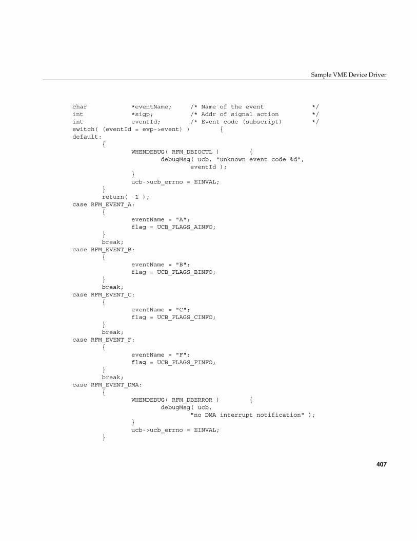
Sample VME Device Driver
407
char *eventName; /* Name of the event */int *sigp; /* Addr of signal action */int eventId; /* Event code (subscript) */switch( (eventId = evp->event) ) {default:
{WHENDEBUG( RFM_DBIOCTL ) {
debugMsg( ucb, "unknown event code %d",eventId );
}ucb->ucb_errno = EINVAL;
}return( -1 );
case RFM_EVENT_A:{
eventName = "A";flag = UCB_FLAGS_AINFO;
}break;
case RFM_EVENT_B:{
eventName = "B";flag = UCB_FLAGS_BINFO;
}break;
case RFM_EVENT_C:{
eventName = "C";flag = UCB_FLAGS_CINFO;
}break;
case RFM_EVENT_F:{
eventName = "F";flag = UCB_FLAGS_FINFO;
}break;
case RFM_EVENT_DMA:{
WHENDEBUG( RFM_DBERROR ) {debugMsg( ucb,
"no DMA interrupt notification" );}ucb->ucb_errno = EINVAL;
}
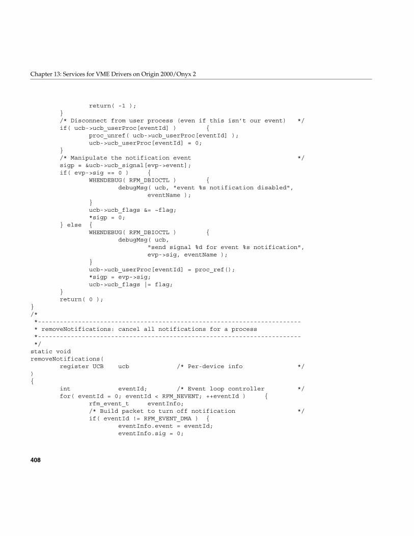
408
Chapter 13: Services for VME Drivers on Origin 2000/Onyx 2
return( -1 );}/* Disconnect from user process (even if this isn’t our event) */if( ucb->ucb_userProc[eventId] ) {
proc_unref( ucb->ucb_userProc[eventId] );ucb->ucb_userProc[eventId] = 0;
}/* Manipulate the notification event */sigp = &ucb->ucb_signal[evp->event];if( evp->sig == 0 ) {
WHENDEBUG( RFM_DBIOCTL ) {debugMsg( ucb, "event %s notification disabled",
eventName );}ucb->ucb_flags &= ~flag;*sigp = 0;
} else {WHENDEBUG( RFM_DBIOCTL ) {
debugMsg( ucb,"send signal %d for event %s notification",evp->sig, eventName );
}ucb->ucb_userProc[eventId] = proc_ref();*sigp = evp->sig;ucb->ucb_flags |= flag;
}return( 0 );
}/**------------------------------------------------------------------------* removeNotifications: cancel all notifications for a process*------------------------------------------------------------------------*/
static voidremoveNotifications(
register UCB ucb /* Per-device info */){
int eventId; /* Event loop controller */for( eventId = 0; eventId < RFM_NEVENT; ++eventId ) {
rfm_event_t eventInfo;/* Build packet to turn off notification */if( eventId != RFM_EVENT_DMA ) {
eventInfo.event = eventId;eventInfo.sig = 0;
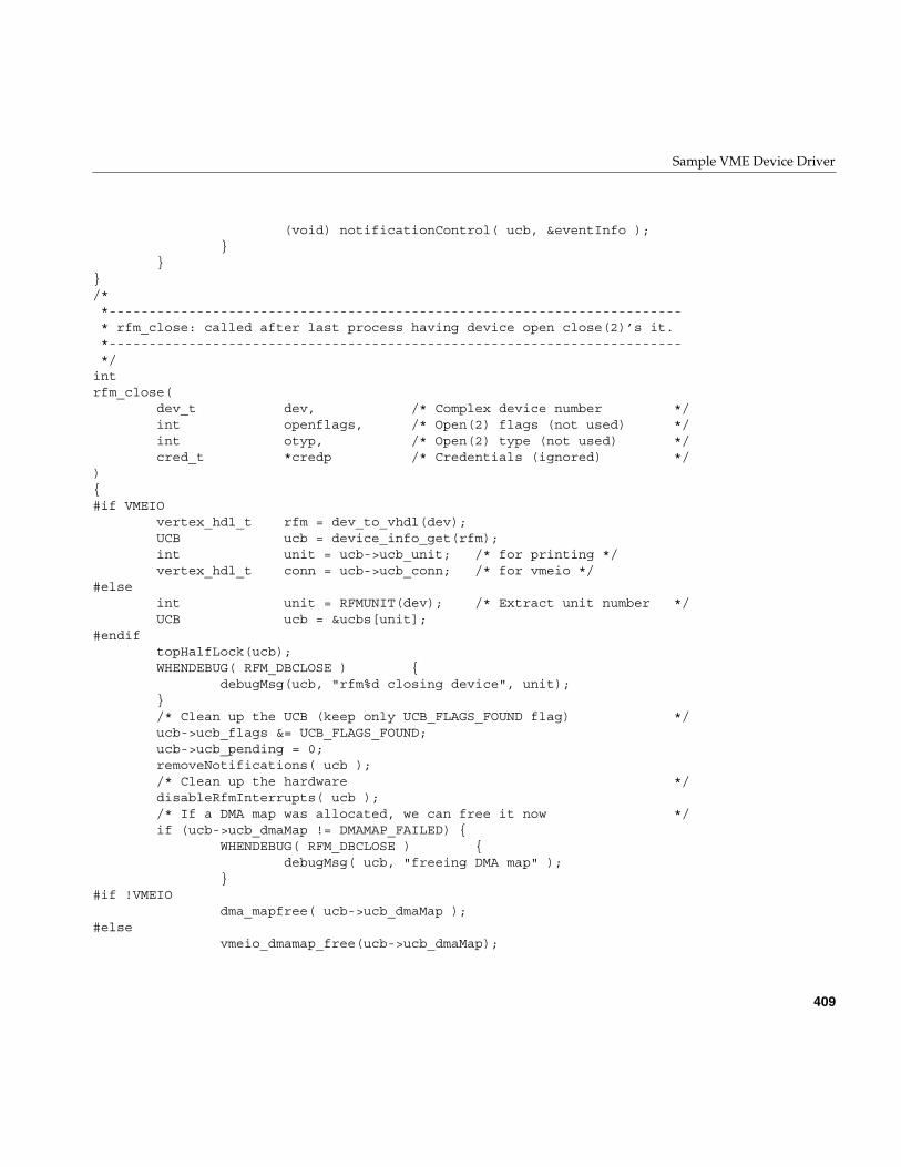
Sample VME Device Driver
409
(void) notificationControl( ucb, &eventInfo );}
}}/**------------------------------------------------------------------------* rfm_close: called after last process having device open close(2)’s it.*------------------------------------------------------------------------*/
intrfm_close(
dev_t dev, /* Complex device number */int openflags, /* Open(2) flags (not used) */int otyp, /* Open(2) type (not used) */cred_t *credp /* Credentials (ignored) */
){#if VMEIO
vertex_hdl_t rfm = dev_to_vhdl(dev);UCB ucb = device_info_get(rfm);int unit = ucb->ucb_unit; /* for printing */vertex_hdl_t conn = ucb->ucb_conn; /* for vmeio */
#elseint unit = RFMUNIT(dev); /* Extract unit number */UCB ucb = &ucbs[unit];
#endiftopHalfLock(ucb);WHENDEBUG( RFM_DBCLOSE ) {
debugMsg(ucb, "rfm%d closing device", unit);}/* Clean up the UCB (keep only UCB_FLAGS_FOUND flag) */ucb->ucb_flags &= UCB_FLAGS_FOUND;ucb->ucb_pending = 0;removeNotifications( ucb );/* Clean up the hardware */disableRfmInterrupts( ucb );/* If a DMA map was allocated, we can free it now */if (ucb->ucb_dmaMap != DMAMAP_FAILED) {
WHENDEBUG( RFM_DBCLOSE ) {debugMsg( ucb, "freeing DMA map" );
}#if !VMEIO
dma_mapfree( ucb->ucb_dmaMap );#else
vmeio_dmamap_free(ucb->ucb_dmaMap);
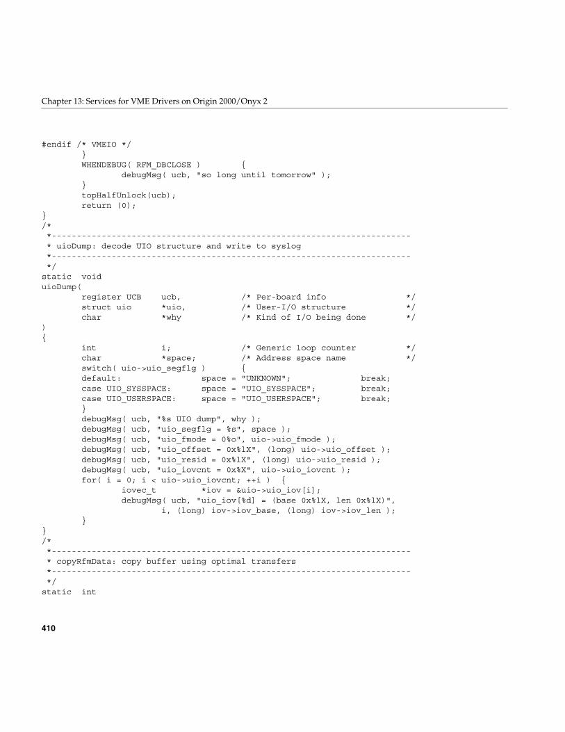
410
Chapter 13: Services for VME Drivers on Origin 2000/Onyx 2
#endif /* VMEIO */}WHENDEBUG( RFM_DBCLOSE ) {
debugMsg( ucb, "so long until tomorrow" );}topHalfUnlock(ucb);return (0);
}/**------------------------------------------------------------------------* uioDump: decode UIO structure and write to syslog*------------------------------------------------------------------------*/
static voiduioDump(
register UCB ucb, /* Per-board info */struct uio *uio, /* User-I/O structure */char *why /* Kind of I/O being done */
){
int i; /* Generic loop counter */char *space; /* Address space name */switch( uio->uio_segflg ) {default: space = "UNKNOWN"; break;case UIO_SYSSPACE: space = "UIO_SYSSPACE"; break;case UIO_USERSPACE: space = "UIO_USERSPACE"; break;}debugMsg( ucb, "%s UIO dump", why );debugMsg( ucb, "uio_segflg = %s", space );debugMsg( ucb, "uio_fmode = 0%o", uio->uio_fmode );debugMsg( ucb, "uio_offset = 0x%lX", (long) uio->uio_offset );debugMsg( ucb, "uio_resid = 0x%lX", (long) uio->uio_resid );debugMsg( ucb, "uio_iovcnt = 0x%X", uio->uio_iovcnt );for( i = 0; i < uio->uio_iovcnt; ++i ) {
iovec_t *iov = &uio->uio_iov[i];debugMsg( ucb, "uio_iov[%d] = (base 0x%lX, len 0x%lX)",
i, (long) iov->iov_base, (long) iov->iov_len );}
}/**------------------------------------------------------------------------* copyRfmData: copy buffer using optimal transfers*------------------------------------------------------------------------*/
static int
Sample VME Device Driver
411
copyRfmData(UCB ucb, /* Per-board info */register caddr_t src, /* Source buffer KVA */register caddr_t dst, /* Destination buffer KVA */register long len /* Number of bytes */
){
register RFM rfm = ucb->ucb_rfm;register int retries;/* Make sure transmit FIFO’s are not too full */
DrainFIFO:retries = 0;while( (rfm->rfm_csr & RFM_CSR_TXHALF) == 0 ) {
WHENDEBUG( RFM_DBSTRAT ) {debugMsg( ucb, "txhalf" );
}if( retries-- <= 0 ) {
WHENDEBUG( RFM_DBSTRAT ) {debugMsg( ucb, "rfm clogged" );
}return( EIO );
}drv_usecwait( 25 );
}/* Try to advance to next ‘32-bit’ boundary */while( (len > 0) && ((((long)src) % sizeof(int32_t)) != 0) ) {
WHENDEBUG( RFM_DBSTRAT ) {debugMsg( ucb,"a-copy (src=0x%X, dst=0x%X, len=0x%X)",
src, dst, len );}*dst++ = *src++;--len;
}/* Try 32-bit transfers if possible */if( (rfm->rfm_csr & RFM_CSR_TXHALF) == 0 ) {
goto DrainFIFO;}if( (len >= sizeof(int32_t)) &&((((long)src)|((long)dst)) % sizeof(int32_t)) == 0 ) {
register int32_t *isrc;register int32_t *idst;WHENDEBUG( RFM_DBSTRAT ) {
debugMsg( ucb, "32-copy (src=0x%X, dst=0x%X, len=0x%X)",src, dst, len );
412
Chapter 13: Services for VME Drivers on Origin 2000/Onyx 2
}/* Aligned to an ‘int’ boundary */isrc = (int32_t *) src;idst = (int32_t *) dst;while( len >= sizeof(int32_t) ) {
*idst++ = *isrc++;len -= sizeof(int32_t);
}src = (caddr_t) isrc;dst = (caddr_t) idst;
}/* Try 16-bit transfers if possible */if( (rfm->rfm_csr & RFM_CSR_TXHALF) == 0 ) {
goto DrainFIFO;}if( (len >= sizeof(int16_t)) &&((((long)src)|((long)dst)) % sizeof(int16_t)) == 0 ) {
register int16_t *isrc;register int16_t *idst;WHENDEBUG( RFM_DBSTRAT ) {
debugMsg( ucb,"16-copy (src=0x%X, dst=0x%X, len=0x%X)",src, dst, len );
}/* Aligned to a ‘int16_t’ boundary */isrc = (int16_t *) src;idst = (int16_t *) dst;while( len >= sizeof(int16_t) ) {
*idst++ = *isrc++;len -= sizeof(int16_t);
}src = (caddr_t) isrc;dst = (caddr_t) idst;
}/* Copy any remaining bytes */if( len > 0 ) {
WHENDEBUG( RFM_DBSTRAT ) {debugMsg( ucb, "8-copy (src=0x%X, dst=0x%X, len=0x%X)",
src, dst, len );}if( (rfm->rfm_csr & RFM_CSR_TXHALF) == 0 ) {
goto DrainFIFO;}while( len-- > 0 ) {
*dst++ = *src++;
Sample VME Device Driver
413
}}return( 0 );
}/**------------------------------------------------------------------------* generalStrategy: perform physical I/O based on buffer descriptor*------------------------------------------------------------------------*/
static intgeneralStrategy(
register struct buf *bp /* Buffer descriptor address */){
dev_t dev = bp->b_edev;#if VMEIO
vertex_hdl_t vhdl = dev_to_vhdl(dev);UCB ucb = device_info_get(vhdl);int unit = ucb->ucb_unit; /* for printing */
#elseint unit = RFMUNIT(dev); /* Extract unit number */UCB ucb = &ucbs[unit];
#endifregister RFM rfm = ucb->ucb_rfm;int err; /* I/O results */int x; /* Previous CPU interrupt level */int hasDma; /* True if RFM has DMA engine */int Pass;caddr_t userBuffer; /* Walks down the user area *//* Since there is only one DMA resource, serialize this routine */psema( &ucb->ucb_stratSema, PZERO+1 );/* Decode the buffer structure if we are asked */WHENDEBUG( RFM_DBSTRAT ) {
char msg[ 512 ];char *mp = msg;int flags;BFLAGS bfp;BFLAGS lbfp;int leadin;flags = bp->b_flags;leadin = ‘\0’;for( bfp = bflags, lbfp = bflags + Nbflags;bfp < lbfp; ++bfp ) {
if( flags & bfp->bf_value ) {char *tp = bfp->bf_name;
414
Chapter 13: Services for VME Drivers on Origin 2000/Onyx 2
if( leadin ) {*mp++ = leadin;
}while( (*mp++ = *tp++) ) continue;--mp;flags &= ~(bfp->bf_value);leadin = ‘,’;
}}if( flags ) {
sprintf( mp, "[leftover=0x%X]", flags );while( *mp ) ++mp;
}*mp = ‘\0’;debugMsg( ucb, "bp->b_flags = 0x%X (%s)", bp->b_flags, msg );
}/* Decide if we can DMA at all */hasDma = (rfm->rfm_bid == RFM_5588DMA_MAGIC);WHENDEBUG( RFM_DBSTRAT ) {
debugMsg( ucb, "rfm board %s do DMA",(hasDma ? "can" : "cannot") );
}/* Whole buffer remains to be transferred */bp->b_resid = bp->b_bcount;/* NB. The SGI "how to write a driver" documents say that thedriver can change the "bp->b_dmaaddr" field. Well, you can’t ifyou’re using the "uiophysio" interface like we are! */userBuffer = bp->b_dmaaddr;/* Disable interrupts */x = interfaceLock( ucb, plhi );if( hasDma ) {
if( bp->b_flags & B_READ ) {/* Map region as DMA readable */rfm->rfm_dmac0 &= ~RFM_DMAC0_H2RFM;
} else {/* Map region as DMA writable */rfm->rfm_dmac0 |= RFM_DMAC0_H2RFM;
}}/* Do until all tranfers are done or until an error */Pass = 1;for( err = 0; (err == 0) && (bp->b_resid > 0); ) {
long quadAlignment; /* Byte alignment within 64-bits */long nbytes; /* Byte count of data to move */int useDma; /* True if use DMA engine */
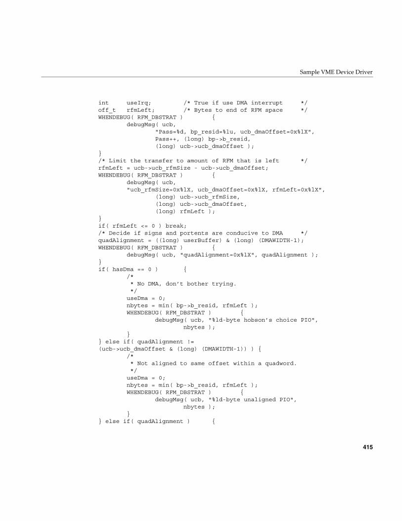
Sample VME Device Driver
415
int useIrq; /* True if use DMA interrupt */off_t rfmLeft; /* Bytes to end of RFM space */WHENDEBUG( RFM_DBSTRAT ) {
debugMsg( ucb,"Pass=%d, bp_resid=%lu, ucb_dmaOffset=0x%lX",Pass++, (long) bp->b_resid,(long) ucb->ucb_dmaOffset );
}/* Limit the transfer to amount of RFM that is left */rfmLeft = ucb->ucb_rfmSize - ucb->ucb_dmaOffset;WHENDEBUG( RFM_DBSTRAT ) {
debugMsg( ucb,"ucb_rfmSize=0x%lX, ucb_dmaOffset=0x%lX, rfmLeft=0x%lX",
(long) ucb->ucb_rfmSize,(long) ucb->ucb_dmaOffset,(long) rfmLeft );
}if( rfmLeft <= 0 ) break;/* Decide if signs and portents are conducive to DMA */quadAlignment = ((long) userBuffer) & (long) (DMAWIDTH-1);WHENDEBUG( RFM_DBSTRAT ) {
debugMsg( ucb, "quadAlignment=0x%lX", quadAlignment );}if( hasDma == 0 ) {
/** No DMA, don’t bother trying.*/useDma = 0;nbytes = min( bp->b_resid, rfmLeft );WHENDEBUG( RFM_DBSTRAT ) {
debugMsg( ucb, "%ld-byte hobson’s choice PIO",nbytes );
}} else if( quadAlignment !=(ucb->ucb_dmaOffset & (long) (DMAWIDTH-1)) ) {
/** Not aligned to same offset within a quadword.*/useDma = 0;nbytes = min( bp->b_resid, rfmLeft );WHENDEBUG( RFM_DBSTRAT ) {
debugMsg( ucb, "%ld-byte unaligned PIO",nbytes );
}} else if( quadAlignment ) {
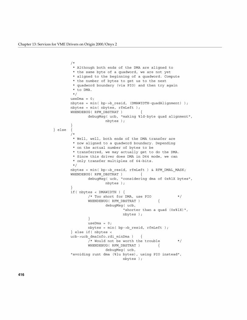
416
Chapter 13: Services for VME Drivers on Origin 2000/Onyx 2
/** Although both ends of the DMA are aligned to* the same byte of a quadword, we are not yet* aligned to the beginning of a quadword. Compute* the number of bytes to get us to the next* quadword boundary (via PIO) and then try again* to DMA.*/useDma = 0;nbytes = min( bp->b_resid, (DMAWIDTH-quadAlignment) );nbytes = min( nbytes, rfmLeft );WHENDEBUG( RFM_DBSTRAT ) {
debugMsg( ucb, "making %ld-byte quad alignment",nbytes );
}} else {
/** Well, well, both ends of the DMA transfer are* now aligned to a quadword boundary. Depending* on the actual number of bytes to be* transferred, we may actually get to do the DMA.* Since this driver does DMA in D64 mode, we can* only transfer multiples of 64-bits.*/nbytes = min( bp->b_resid, rfmLeft ) & RFM_DMAL_MASK;WHENDEBUG( RFM_DBSTRAT ) {
debugMsg( ucb, "considering dma of 0x%lX bytes",nbytes );
}if( nbytes < DMAWIDTH ) {
/* Too short for DMA, use PIO */WHENDEBUG( RFM_DBSTRAT ) {
debugMsg( ucb,"shorter than a quad (0x%lX)",nbytes );
}useDma = 0;nbytes = min( bp->b_resid, rfmLeft );
} else if( nbytes <ucb->ucb_dmaInfo.rdi_minDma ) {
/* Would not be worth the trouble */WHENDEBUG( RFM_DBSTRAT ) {
debugMsg( ucb,"avoiding runt dma (%lu bytes), using PIO instead",
nbytes );
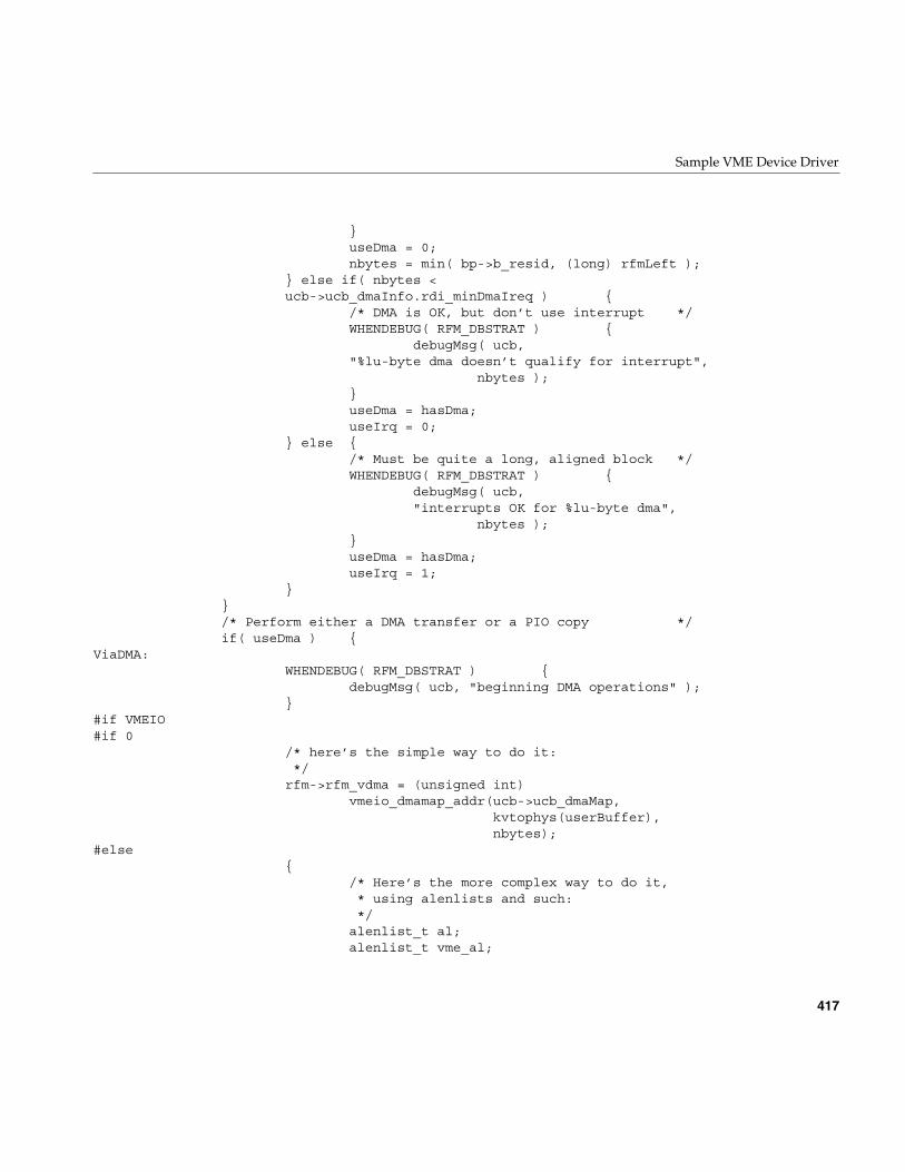
Sample VME Device Driver
417
}useDma = 0;nbytes = min( bp->b_resid, (long) rfmLeft );
} else if( nbytes <ucb->ucb_dmaInfo.rdi_minDmaIreq ) {
/* DMA is OK, but don’t use interrupt */WHENDEBUG( RFM_DBSTRAT ) {
debugMsg( ucb,"%lu-byte dma doesn’t qualify for interrupt",
nbytes );}useDma = hasDma;useIrq = 0;
} else {/* Must be quite a long, aligned block */WHENDEBUG( RFM_DBSTRAT ) {
debugMsg( ucb,"interrupts OK for %lu-byte dma",
nbytes );}useDma = hasDma;useIrq = 1;
}}/* Perform either a DMA transfer or a PIO copy */if( useDma ) {
ViaDMA:WHENDEBUG( RFM_DBSTRAT ) {
debugMsg( ucb, "beginning DMA operations" );}
#if VMEIO#if 0
/* here’s the simple way to do it:*/rfm->rfm_vdma = (unsigned int)
vmeio_dmamap_addr(ucb->ucb_dmaMap,kvtophys(userBuffer),nbytes);
#else{
/* Here’s the more complex way to do it,* using alenlists and such:*/alenlist_t al;alenlist_t vme_al;
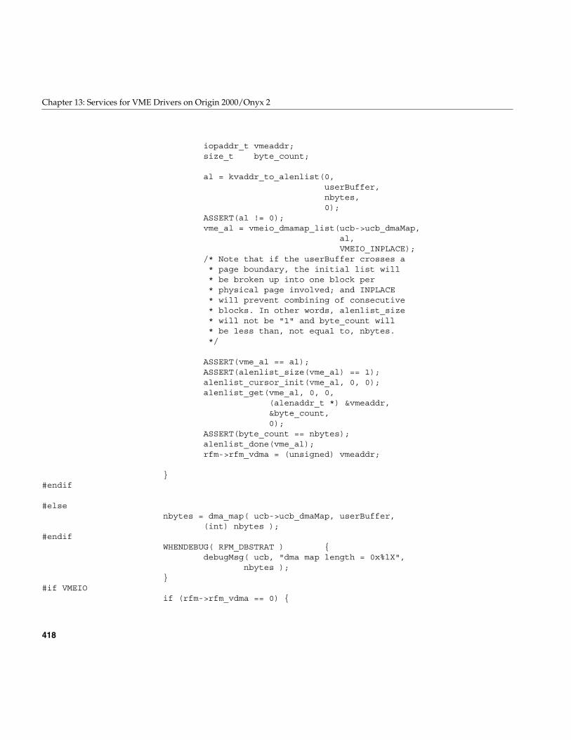
418
Chapter 13: Services for VME Drivers on Origin 2000/Onyx 2
iopaddr_t vmeaddr;size_t byte_count;
al = kvaddr_to_alenlist(0,userBuffer,nbytes,0);
ASSERT(al != 0);vme_al = vmeio_dmamap_list(ucb->ucb_dmaMap,
al,VMEIO_INPLACE);
/* Note that if the userBuffer crosses a* page boundary, the initial list will* be broken up into one block per* physical page involved; and INPLACE* will prevent combining of consecutive* blocks. In other words, alenlist_size* will not be "1" and byte_count will* be less than, not equal to, nbytes.*/
ASSERT(vme_al == al);ASSERT(alenlist_size(vme_al) == 1);alenlist_cursor_init(vme_al, 0, 0);alenlist_get(vme_al, 0, 0,
(alenaddr_t *) &vmeaddr,&byte_count,0);
ASSERT(byte_count == nbytes);alenlist_done(vme_al);rfm->rfm_vdma = (unsigned) vmeaddr;
}#endif
#elsenbytes = dma_map( ucb->ucb_dmaMap, userBuffer,
(int) nbytes );#endif
WHENDEBUG( RFM_DBSTRAT ) {debugMsg( ucb, "dma map length = 0x%lX",
nbytes );}
#if VMEIOif (rfm->rfm_vdma == 0) {
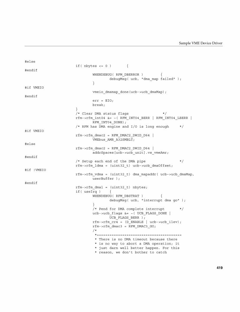
Sample VME Device Driver
419
#elseif( nbytes <= 0 ) {
#endifWHENDEBUG( RFM_DBERROR ) {
debugMsg( ucb, "dma_map failed" );}
#if VMEIOvmeio_dmamap_done(ucb->ucb_dmaMap);
#endiferr = EIO;break;
}/* Clear DMA status flags */rfm->rfm_int04 &= ~( RFM_INT04_BERR | RFM_INT04_LBERR |
RFM_INT04_DONE);/* RFM has DMA engine and I/O is long enough */
#if VMEIOrfm->rfm_dmac2 = RFM_DMAC2_DWID_D64 |
VMEbus_AMR_A32SMBLT;#else
rfm->rfm_dmac2 = RFM_DMAC2_DWID_D64 |addrSpaces[ucb->ucb_unit].vs_vmeAmr;
#endif/* Setup each end of the DMA pipe */rfm->rfm_ldma = (uint32_t) ucb->ucb_dmaOffset;
#if !VMEIOrfm->rfm_vdma = (uint32_t) dma_mapaddr( ucb->ucb_dmaMap,
userBuffer );#endif
rfm->rfm_dmal = (uint32_t) nbytes;if( useIrq ) {
WHENDEBUG( RFM_DBSTRAT ) {debugMsg( ucb, "interrupt dma go" );
}/* Pend for DMA complete interrupt */ucb->ucb_flags &= ~( UCB_FLAGS_DONE |
UCB_FLAGS_BERR );rfm->rfm_cr4 = (D_ENABLE | ucb->ucb_ilev);rfm->rfm_dmac3 = RFM_DMAC3_GO;/**========================================* There is no DMA timeout because there* is no way to abort a DMA operation; it* just darn well better happen. For this* reason, we don’t bother to catch
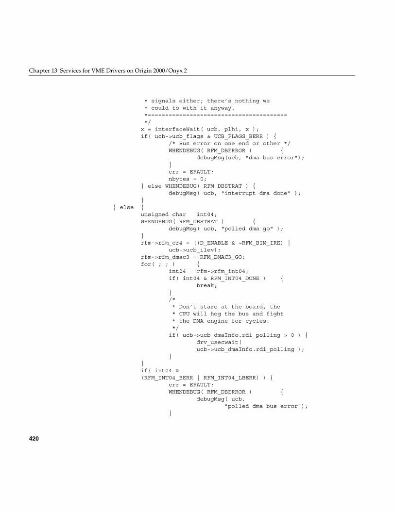
420
Chapter 13: Services for VME Drivers on Origin 2000/Onyx 2
* signals either; there’s nothing we* could to with it anyway.*========================================*/x = interfaceWait( ucb, plhi, x );if( ucb->ucb_flags & UCB_FLAGS_BERR ) {
/* Bus error on one end or other */WHENDEBUG( RFM_DBERROR ) {
debugMsg(ucb, "dma bus error");}err = EFAULT;nbytes = 0;
} else WHENDEBUG( RFM_DBSTRAT ) {debugMsg( ucb, "interrupt dma done" );
}} else {
unsigned char int04;WHENDEBUG( RFM_DBSTRAT ) {
debugMsg( ucb, "polled dma go" );}rfm->rfm_cr4 = ((D_ENABLE & ~RFM_BIM_IRE) |
ucb->ucb_ilev);rfm->rfm_dmac3 = RFM_DMAC3_GO;for( ; ; ) {
int04 = rfm->rfm_int04;if( int04 & RFM_INT04_DONE ) {
break;}/** Don’t stare at the board, the* CPU will hog the bus and fight* the DMA engine for cycles.*/if( ucb->ucb_dmaInfo.rdi_polling > 0 ) {
drv_usecwait(ucb->ucb_dmaInfo.rdi_polling );
}}if( int04 &(RFM_INT04_BERR | RFM_INT04_LBERR) ) {
err = EFAULT;WHENDEBUG( RFM_DBERROR ) {
debugMsg( ucb,"polled dma bus error");
}
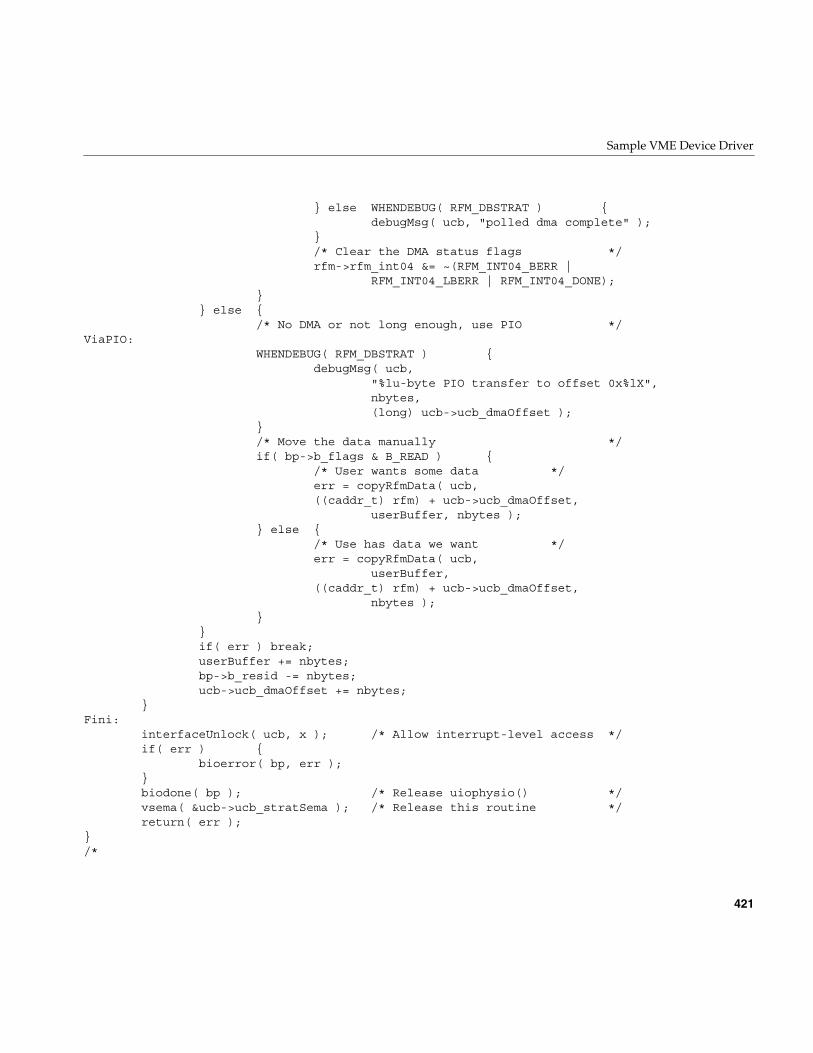
Sample VME Device Driver
421
} else WHENDEBUG( RFM_DBSTRAT ) {debugMsg( ucb, "polled dma complete" );
}/* Clear the DMA status flags */rfm->rfm_int04 &= ~(RFM_INT04_BERR |
RFM_INT04_LBERR | RFM_INT04_DONE);}
} else {/* No DMA or not long enough, use PIO */
ViaPIO:WHENDEBUG( RFM_DBSTRAT ) {
debugMsg( ucb,"%lu-byte PIO transfer to offset 0x%lX",nbytes,(long) ucb->ucb_dmaOffset );
}/* Move the data manually */if( bp->b_flags & B_READ ) {
/* User wants some data */err = copyRfmData( ucb,((caddr_t) rfm) + ucb->ucb_dmaOffset,
userBuffer, nbytes );} else {
/* Use has data we want */err = copyRfmData( ucb,
userBuffer,((caddr_t) rfm) + ucb->ucb_dmaOffset,
nbytes );}
}if( err ) break;userBuffer += nbytes;bp->b_resid -= nbytes;ucb->ucb_dmaOffset += nbytes;
}Fini:
interfaceUnlock( ucb, x ); /* Allow interrupt-level access */if( err ) {
bioerror( bp, err );}biodone( bp ); /* Release uiophysio() */vsema( &ucb->ucb_stratSema ); /* Release this routine */return( err );
}/*
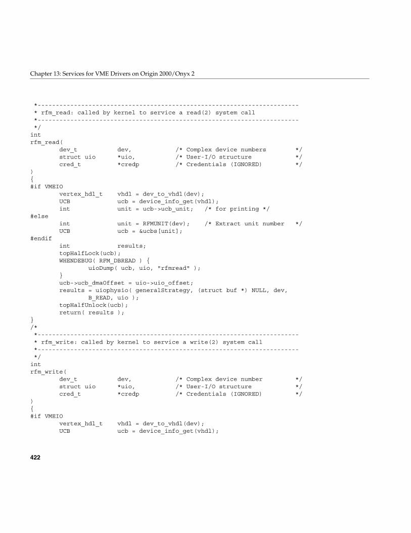
422
Chapter 13: Services for VME Drivers on Origin 2000/Onyx 2
*------------------------------------------------------------------------* rfm_read: called by kernel to service a read(2) system call*------------------------------------------------------------------------*/
intrfm_read(
dev_t dev, /* Complex device numbers */struct uio *uio, /* User-I/O structure */cred_t *credp /* Credentials (IGNORED) */
){#if VMEIO
vertex_hdl_t vhdl = dev_to_vhdl(dev);UCB ucb = device_info_get(vhdl);int unit = ucb->ucb_unit; /* for printing */
#elseint unit = RFMUNIT(dev); /* Extract unit number */UCB ucb = &ucbs[unit];
#endifint results;topHalfLock(ucb);WHENDEBUG( RFM_DBREAD ) {
uioDump( ucb, uio, "rfmread" );}ucb->ucb_dmaOffset = uio->uio_offset;results = uiophysio( generalStrategy, (struct buf *) NULL, dev,
B_READ, uio );topHalfUnlock(ucb);return( results );
}/**------------------------------------------------------------------------* rfm_write: called by kernel to service a write(2) system call*------------------------------------------------------------------------*/
intrfm_write(
dev_t dev, /* Complex device number */struct uio *uio, /* User-I/O structure */cred_t *credp /* Credentials (IGNORED) */
){#if VMEIO
vertex_hdl_t vhdl = dev_to_vhdl(dev);UCB ucb = device_info_get(vhdl);
Sample VME Device Driver
423
int unit = ucb->ucb_unit; /* for printing */#else
int unit = RFMUNIT(dev); /* Extract unit number */UCB ucb = &ucbs[unit];
#endifint results;topHalfLock(ucb);WHENDEBUG( RFM_DBWRITE ) {
uioDump( ucb, uio, "rfmwrite" );}ucb->ucb_dmaOffset = uio->uio_offset;results = uiophysio( generalStrategy, (struct buf *) NULL, dev,
B_WRITE, uio );topHalfUnlock(ucb);return( results );
}/**------------------------------------------------------------------------* awaitSpecificEvent: pend waiting for specific event to happen*------------------------------------------------------------------------*/
static voidawaitSpecificEvent(
register UCB ucb, /* Per-board local storage */register uint_t pending, /* Event indication pending */register uint_t wants, /* Event indication wanted */char *spelling /* Name of event (for debug) */
){
if( ucb->ucb_pending & pending ) {/* At least one event of this type is outstanding */ucb->ucb_pending &= ~pending;WHENDEBUG( RFM_DBIOCTL ) {
debugMsg( ucb, "using stored event %s indication",spelling );
}} else {
/** No event of that type just yet, so flag that we want* it, schedule a timeout (if a period is defined), and* then wait for the event to happen*/ucb->ucb_flags |= wants;startEventTimer( ucb, ucb->ucb_eventWait );if( psema( (sema_t *) &ucb->ucb_eventSema, RFMSLEEP ) ) {
424
Chapter 13: Services for VME Drivers on Origin 2000/Onyx 2
/* Got a signal before we saw the event */stopEventTimer( ucb );WHENDEBUG( RFM_DBTIMER ) {
debugMsg( ucb,"event %s wait interrupted by signal",spelling );
}ucb->ucb_errno = EINTR;ucb->ucb_flags |= UCB_FLAGS_ETIMEO;
}/** If we have a timeout flag, then we didn’t get the event* because of a timeout or a signal.*/if( (ucb->ucb_flags & UCB_FLAGS_ETIMEO) &&(ucb->ucb_errno == 0) ) {
ucb->ucb_errno = ETIMEDOUT;}
}ucb->ucb_flags &= ~wants; /* Don’t want it anymore */
}/**------------------------------------------------------------------------* dumpdmaInfo: print a decoded version of DMA info for debug purposes*------------------------------------------------------------------------*/
static voiddumpDmaInfo(
register UCB ucb, /* Per-board info */volatile rfmdmainfo_t *rdi /* RFM dma information */
){
char *spelling; /* Generic name pointer */debugMsg( ucb, "dma polling interval is %d usec", rdi->rdi_polling );debugMsg( ucb, "dma burst length is %d cycles", rdi->rdi_polling );switch( rdi->rdi_relmode ) {default: spelling = "UNKNOWN"; break;case RDI_RELMODE_ROR: spelling = "ROR"; break;case RDI_RELMODE_RWD: spelling = "RWD"; break;case RDI_RELMODE_ROC: spelling = "ROC"; break;case RDI_RELMODE_BCAP: spelling = "BCAP"; break;}debugMsg( ucb, "%s bus release mode (%d)", spelling, rdi->rdi_relmode );debugMsg( ucb, "burst interleave is %d (%d nsec)", rdi->rdi_intrLeave,
rdi->rdi_intrLeave * 250);
Sample VME Device Driver
425
debugMsg( ucb, "bus request level is %d", rdi->rdi_busreq );debugMsg( ucb, "minimum DMA transfer is %d bytes", rdi->rdi_minDma );debugMsg( ucb, "minimum DMA transfer w/interrupt is %d bytes",
rdi->rdi_minDmaIreq );}/**------------------------------------------------------------------------* rfm_ioctl: called by kernel to service an ioctl(2) system call*------------------------------------------------------------------------*/
intrfm_ioctl(
dev_t dev, /* Complex device number */int cmd, /* Command code */void *arg, /* Argument to command */int mode, /* Open(2) flags (IGNORED) */cred_t *crp, /* Credentials (IGNORED) */int *rvalp /* Return value pointer (UNUSED) */
){#if VMEIO
vertex_hdl_t vhdl = dev_to_vhdl(dev);UCB ucb = device_info_get(vhdl);int unit = ucb->ucb_unit; /* for printing */
#elseint unit = RFMUNIT(dev); /* Extract unit number */UCB ucb = &ucbs[unit];
#endifregister RFM rfm = ucb->ucb_rfm;char *spelling = "UNKNOWN";/* Name of ioctl command */int retval; /* Results of system call */topHalfLock(ucb);WHENDEBUG( RFM_DBIOCTL ) {
debugMsg( ucb, "ioctl arg = 0x%X", (caddr_t) arg );}ucb->ucb_errno = 0;/* Dispatch based on the command code */switch( cmd ) {default:
{WHENDEBUG( RFM_DBIOCTL ) {
debugMsg( ucb,"unknown ioctl(2) command = 0x%X",cmd );
}
426
Chapter 13: Services for VME Drivers on Origin 2000/Onyx 2
if( !ucb->ucb_errno ) ucb->ucb_errno = ENOTTY;}break;
case RFM_RESET: /* Reset the interrupt stuff */{
spelling = "RFM_RESET";WHENDEBUG( RFM_DBIOCTL ) {
debugMsg( ucb, "%s: board reset", spelling );}setupHardware( ucb );
}break;
case RFM_ENABL_DIAG_MSG: /* Turn on all debug messages */{
spelling = "RFM_ENABL_DIAG_MSG";WHENDEBUG( RFM_DBIOCTL ) {
debugMsg( ucb, "%s: enable messages",spelling );
}rfmDebug = ~0;
}break;
case RFM_DISABL_DIAG_MSG: /* Turn off all debug messages */{
spelling = "RFM_DISABL_DIAG_MSG";WHENDEBUG( RFM_DBIOCTL ) {
debugMsg( ucb, "%s: disable messages",spelling );
}rfmDebug = 0;
}break;
case RFM_DEBUG: /* Set new debug flags */{
uint_t debug;spelling = "RFM_DEBUG";if( copyin( (caddr_t) arg, (caddr_t) &debug,sizeof(debug) ) )
goto BadCopy;WHENDEBUG( RFM_DBIOCTL ) {
debugMsg( ucb, "%s: new debug level = 0x%X",spelling, debug );
}rfmDebug = debug;
}
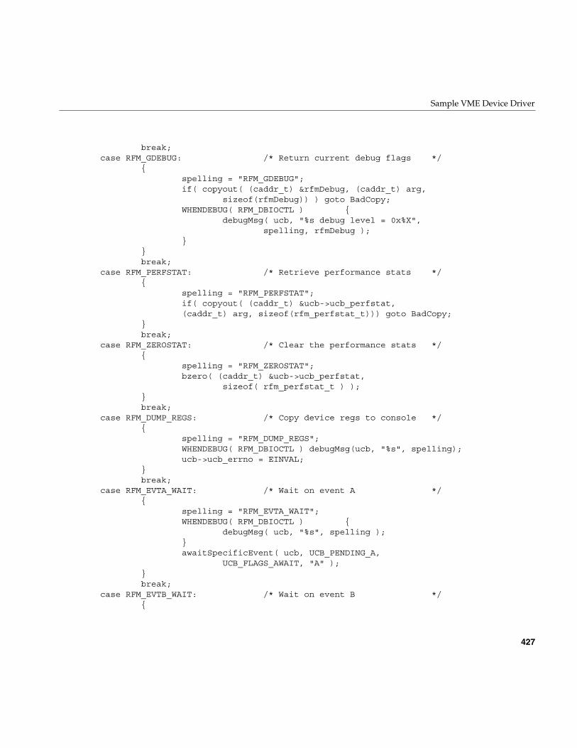
Sample VME Device Driver
427
break;case RFM_GDEBUG: /* Return current debug flags */
{spelling = "RFM_GDEBUG";if( copyout( (caddr_t) &rfmDebug, (caddr_t) arg,
sizeof(rfmDebug)) ) goto BadCopy;WHENDEBUG( RFM_DBIOCTL ) {
debugMsg( ucb, "%s debug level = 0x%X",spelling, rfmDebug );
}}break;
case RFM_PERFSTAT: /* Retrieve performance stats */{
spelling = "RFM_PERFSTAT";if( copyout( (caddr_t) &ucb->ucb_perfstat,(caddr_t) arg, sizeof(rfm_perfstat_t))) goto BadCopy;
}break;
case RFM_ZEROSTAT: /* Clear the performance stats */{
spelling = "RFM_ZEROSTAT";bzero( (caddr_t) &ucb->ucb_perfstat,
sizeof( rfm_perfstat_t ) );}break;
case RFM_DUMP_REGS: /* Copy device regs to console */{
spelling = "RFM_DUMP_REGS";WHENDEBUG( RFM_DBIOCTL ) debugMsg(ucb, "%s", spelling);ucb->ucb_errno = EINVAL;
}break;
case RFM_EVTA_WAIT: /* Wait on event A */{
spelling = "RFM_EVTA_WAIT";WHENDEBUG( RFM_DBIOCTL ) {
debugMsg( ucb, "%s", spelling );}awaitSpecificEvent( ucb, UCB_PENDING_A,
UCB_FLAGS_AWAIT, "A" );}break;
case RFM_EVTB_WAIT: /* Wait on event B */{
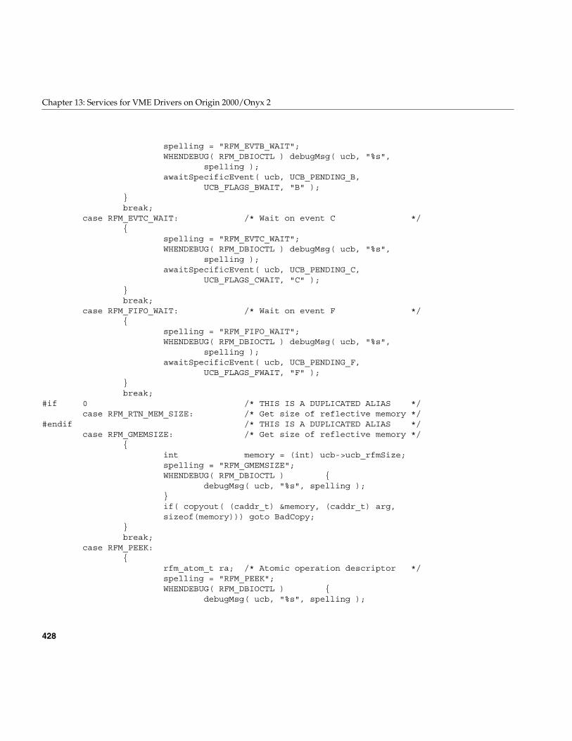
428
Chapter 13: Services for VME Drivers on Origin 2000/Onyx 2
spelling = "RFM_EVTB_WAIT";WHENDEBUG( RFM_DBIOCTL ) debugMsg( ucb, "%s",
spelling );awaitSpecificEvent( ucb, UCB_PENDING_B,
UCB_FLAGS_BWAIT, "B" );}break;
case RFM_EVTC_WAIT: /* Wait on event C */{
spelling = "RFM_EVTC_WAIT";WHENDEBUG( RFM_DBIOCTL ) debugMsg( ucb, "%s",
spelling );awaitSpecificEvent( ucb, UCB_PENDING_C,
UCB_FLAGS_CWAIT, "C" );}break;
case RFM_FIFO_WAIT: /* Wait on event F */{
spelling = "RFM_FIFO_WAIT";WHENDEBUG( RFM_DBIOCTL ) debugMsg( ucb, "%s",
spelling );awaitSpecificEvent( ucb, UCB_PENDING_F,
UCB_FLAGS_FWAIT, "F" );}break;
#if 0 /* THIS IS A DUPLICATED ALIAS */case RFM_RTN_MEM_SIZE: /* Get size of reflective memory */
#endif /* THIS IS A DUPLICATED ALIAS */case RFM_GMEMSIZE: /* Get size of reflective memory */
{int memory = (int) ucb->ucb_rfmSize;spelling = "RFM_GMEMSIZE";WHENDEBUG( RFM_DBIOCTL ) {
debugMsg( ucb, "%s", spelling );}if( copyout( (caddr_t) &memory, (caddr_t) arg,sizeof(memory))) goto BadCopy;
}break;
case RFM_PEEK:{
rfm_atom_t ra; /* Atomic operation descriptor */spelling = "RFM_PEEK";WHENDEBUG( RFM_DBIOCTL ) {
debugMsg( ucb, "%s", spelling );
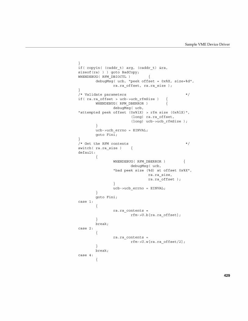
Sample VME Device Driver
429
}if( copyin( (caddr_t) arg, (caddr_t) &ra,sizeof(ra) ) ) goto BadCopy;WHENDEBUG( RFM_DBIOCTL ) {
debugMsg( ucb, "peek offset = 0x%X, size=%d",ra.ra_offset, ra.ra_size );
}/* Validate parameters */if( ra.ra_offset > ucb->ucb_rfmSize ) {
WHENDEBUG( RFM_DBERROR ) {debugMsg( ucb,
"attempted peek offset (0x%lX) > rfm size (0x%lX)",(long) ra.ra_offset,(long) ucb->ucb_rfmSize );
}ucb->ucb_errno = EINVAL;goto Fini;
}/* Get the RFM contents */switch( ra.ra_size ) {default:
{WHENDEBUG( RFM_DBERROR ) {
debugMsg( ucb,"bad peek size (%d) at offset 0x%X",
ra.ra_size,ra.ra_offset );
}ucb->ucb_errno = EINVAL;
}goto Fini;
case 1:{
ra.ra_contents =rfm->U.b[ra.ra_offset];
}break;
case 2:{
ra.ra_contents =rfm->U.w[ra.ra_offset/2];
}break;
case 4:{
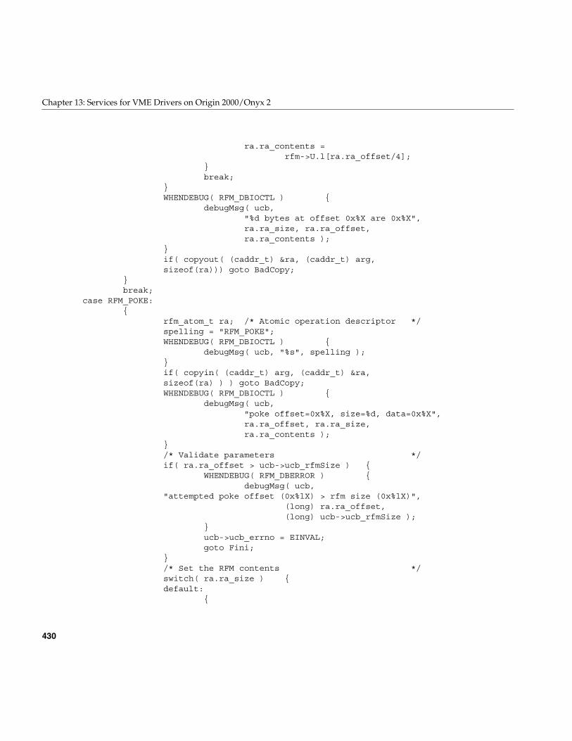
430
Chapter 13: Services for VME Drivers on Origin 2000/Onyx 2
ra.ra_contents =rfm->U.l[ra.ra_offset/4];
}break;
}WHENDEBUG( RFM_DBIOCTL ) {
debugMsg( ucb,"%d bytes at offset 0x%X are 0x%X",ra.ra_size, ra.ra_offset,ra.ra_contents );
}if( copyout( (caddr_t) &ra, (caddr_t) arg,sizeof(ra))) goto BadCopy;
}break;
case RFM_POKE:{
rfm_atom_t ra; /* Atomic operation descriptor */spelling = "RFM_POKE";WHENDEBUG( RFM_DBIOCTL ) {
debugMsg( ucb, "%s", spelling );}if( copyin( (caddr_t) arg, (caddr_t) &ra,sizeof(ra) ) ) goto BadCopy;WHENDEBUG( RFM_DBIOCTL ) {
debugMsg( ucb,"poke offset=0x%X, size=%d, data=0x%X",ra.ra_offset, ra.ra_size,ra.ra_contents );
}/* Validate parameters */if( ra.ra_offset > ucb->ucb_rfmSize ) {
WHENDEBUG( RFM_DBERROR ) {debugMsg( ucb,
"attempted poke offset (0x%lX) > rfm size (0x%lX)",(long) ra.ra_offset,(long) ucb->ucb_rfmSize );
}ucb->ucb_errno = EINVAL;goto Fini;
}/* Set the RFM contents */switch( ra.ra_size ) {default:
{
Sample VME Device Driver
431
WHENDEBUG( RFM_DBERROR ) {debugMsg( ucb,
"bad poke size (%d) at offset 0x%X",ra.ra_size,ra.ra_offset );
}ucb->ucb_errno = EINVAL;
}goto Fini;
case 1:{
rfm->U.b[ra.ra_offset] =ra.ra_contents;
}break;
case 2:{
rfm->U.w[ra.ra_offset/2] =ra.ra_contents;
}break;
case 4:{
rfm->U.l[ra.ra_offset/4] =ra.ra_contents;
}break;
}}break;
case RFM_SET_TIMEOUT: /* Set timeout period (seconds) */{
uint_t secs; /* Timeout value in seconds */clock_t usec; /* Timeout value in microseconds */spelling = "RFM_SET_TIMEOUT";WHENDEBUG( RFM_DBIOCTL ) {
debugMsg( ucb, "%s", spelling );}if( copyin( (caddr_t) arg, (caddr_t) &secs,sizeof(secs) ) ) goto BadCopy;usec = secs * USECONDS;WHENDEBUG( RFM_DBIOCTL ) {
debugMsg( ucb,"event timeout is now %d seconds (%lu usec)",
secs, usec );
432
Chapter 13: Services for VME Drivers on Origin 2000/Onyx 2
}ucb->ucb_eventWait = usec;
}break;
case RFM_GET_TIMEOUT: /* Get timeout period (seconds) */{
uint_t secs;uint_t usec;spelling = "RFM_GET_TIMEOUT";WHENDEBUG( RFM_DBIOCTL ) {
debugMsg( ucb, "%s", spelling );}secs = ucb->ucb_eventWait / USECONDS;usec = ucb->ucb_eventWait % USECONDS;WHENDEBUG( RFM_DBIOCTL ) {
debugMsg( ucb,"event timeout is now %d.06d seconds",secs, usec );
}if( copyout( (caddr_t) &secs, (caddr_t) arg,sizeof(secs))) {
goto BadCopy;}
}break;
case RFM_TIMEOUT: /* Set timeout period (usec) */{
clock_t usec; /* Timeout value in microseconds */spelling = "RFM_TIMEOUT";WHENDEBUG( RFM_DBIOCTL ) {
debugMsg( ucb, "%s", spelling );}if( copyin( (caddr_t) arg, (caddr_t) &usec,sizeof(usec) ) ) goto BadCopy;WHENDEBUG( RFM_DBIOCTL ) {
debugMsg( ucb,"event timeout is now %d usec", usec );
}ucb->ucb_eventWait = usec;
}break;
case RFM_GTIMEOUT: /* Get timeout period (usec) */{
spelling = "RFM_GTIMEOUT";WHENDEBUG( RFM_DBIOCTL ) {
Sample VME Device Driver
433
debugMsg( ucb, "%s", spelling );}WHENDEBUG( RFM_DBIOCTL ) {
debugMsg( ucb, "event timeout is now %lu usec",ucb->ucb_eventWait );
}if( copyout( (caddr_t) &ucb->ucb_eventWait,(caddr_t) arg, sizeof(ucb->ucb_eventWait))) {
goto BadCopy;}
}break;
case RFM_DMAINFO:{
rfmdmainfo_t rdi;int bad;spelling = "RFM_DMAINFO";WHENDEBUG( RFM_DBIOCTL ) {
debugMsg( ucb, "%s", spelling );}if( copyin( (caddr_t) arg, (caddr_t) &rdi,sizeof(rdi) ) ) goto BadCopy;/* Validate the user’s information */bad = 0;if( rdi.rdi_burst > 64 ) {
WHENDEBUG( RFM_DBERROR ) {debugMsg( ucb,
"dma burst length limited to 64, not %d",rdi.rdi_burst );
}++bad;
}switch( rdi.rdi_relmode ) {default:
{WHENDEBUG( RFM_DBERROR ) {
debugMsg( ucb,"unknown bus release mode %d",
rdi.rdi_relmode );}++bad;
}break;
case RDI_RELMODE_ROR:case RDI_RELMODE_RWD:
434
Chapter 13: Services for VME Drivers on Origin 2000/Onyx 2
case RDI_RELMODE_ROC:case RDI_RELMODE_BCAP:
break;}if( rdi.rdi_intrLeave > 15 ) {
WHENDEBUG( RFM_DBERROR ) {debugMsg( ucb,
"dma interleave range is (0..15), not %d",rdi.rdi_intrLeave );
}++bad;
}if( rdi.rdi_busreq > 3 ) {
WHENDEBUG( RFM_DBERROR ) {debugMsg( ucb,"VMEbus request level (%d) not 0..3",
rdi.rdi_busreq );}++bad;
}if( !bad ) {
ucb->ucb_dmaInfo = rdi;WHENDEBUG( RFM_DBIOCTL ) {
dumpDmaInfo( ucb, &ucb->ucb_dmaInfo );}loadDmaInfo( ucb );
}}break;
case RFM_GDMAINFO:{
spelling = "RFM_GDMAINFO";WHENDEBUG( RFM_DBIOCTL ) {
debugMsg( ucb, "%s", spelling );}WHENDEBUG( RFM_DBIOCTL ) {
dumpDmaInfo( ucb, &ucb->ucb_dmaInfo );}if( copyout( (caddr_t) &ucb->ucb_dmaInfo,(caddr_t) arg, sizeof(ucb->ucb_dmaInfo))) {
goto BadCopy;}
}break;
case RFM_CMD_INT: /* Send interrupt to chassis */
Sample VME Device Driver
435
{char cmd_data[2];spelling = "RFM_CMD_INT";WHENDEBUG( RFM_DBIOCTL ) {
debugMsg( ucb, "%s", spelling );}if( copyin( (caddr_t) arg, (caddr_t) &cmd_data,sizeof(cmd_data) ) ) goto BadCopy;switch( rfm->rfm_bid ) {default:
WHENDEBUG( RFM_DBERROR ) {debugMsg( ucb, "unknown board ID=0x%X",
rfm->rfm_bid );}ucb->ucb_errno = EINVAL;break;
case RFM_5588_MAGIC:/*FALLTHRU*/
case RFM_5578_MAGIC:/*FALLTHRU*/
case RFM_5576_MAGIC:rfm->rfm_cmn = cmd_data[1];/*FALLTHRU*/
case RFM_5550_MAGIC:rfm->rfm_cmd = cmd_data[0];break;
}}break;
case RFM_INTERRUPT: /* Send interrupt to node(s) */{
rfm_dnode_t rdn; /* Holds node info */if( copyin( (caddr_t) arg, (caddr_t) &rdn,sizeof(rdn) ) ) {
goto BadCopy;}WHENDEBUG( RFM_DBIOCTL ) {
debugMsg( ucb, "sending event %d to node %d",rdn.rdn_channel, rdn.rdn_node );
}/* Cannot send an interrupt to ourselves */if( rdn.rdn_node == ucb->ucb_mynodeid ) {
WHENDEBUG( RFM_DBERROR ) {debugMsg( ucb,"node %d cannot interrupt node %d",
436
Chapter 13: Services for VME Drivers on Origin 2000/Onyx 2
ucb->ucb_mynodeid,rdn.rdn_node );
}ucb->ucb_errno = EINVAL;goto Fini;
}/* Validate the channel */switch( rdn.rdn_channel ) {default:
WHENDEBUG( RFM_DBIOCTL ) {debugMsg( ucb, "invalid channel %d",
rdn.rdn_channel );}ucb->ucb_errno = EINVAL;goto Fini;
case RFM_CHANNEL_A: break;case RFM_CHANNEL_B: break;case RFM_CHANNEL_C: break;}if( rdn.rdn_node == RFM_BROADCAST ) {
rdn.rdn_channel |= (1 << 6);rdn.rdn_node = 0;
}switch( ucb->ucb_bid ) {default:
if(rdn.rdn_node < 0 || rdn.rdn_node > 15) {WHENDEBUG( RFM_DBIOCTL ) {
debugMsg( ucb,"invalid channel %d",rdn.rdn_channel );
}ucb->ucb_errno = EINVAL;goto Fini;
}rfm->rfm_cmd = ((rdn.rdn_node << 2) |
rdn.rdn_channel);break;
case RFM_5576_MAGIC:/* VMIVME-5576 *//* FALLTHRU */
case RFM_5578_MAGIC:/* VMIVME-5578 *//* FALLTHRU */
case RFM_5588_MAGIC:/* VMIVME-5588 */if(rdn.rdn_node < 0 || rdn.rdn_node > 255) {
WHENDEBUG( RFM_DBIOCTL ) {debugMsg( ucb,
Sample VME Device Driver
437
"invalid channel %d",rdn.rdn_channel );
}ucb->ucb_errno = EINVAL;goto Fini;
}rfm->rfm_cmn = rdn.rdn_node;rfm->rfm_cmd = rdn.rdn_channel;break;
}}break;
case RFM_INTR_INIT: /* Purge interrupts */{
spelling = "RFM_INTR_INIT";WHENDEBUG( RFM_DBIOCTL ) {
debugMsg( ucb, "%s", spelling );}setupHardware( ucb );
}break;
case RFM_INT_SENDER: /* Return last interrupt sender */{
spelling = "RFM_INT_SENDER";WHENDEBUG( RFM_DBIOCTL ) {
debugMsg( ucb, "%s", spelling );}if( copyout( (caddr_t) &ucb->ucb_sender, (caddr_t) arg,sizeof(ucb->ucb_sender))) {
goto BadCopy;}
}break;
case RFM_NOTIFY: /* Reset the interrupt stuff */{
rfm_event_t eventInfo;/* Info to use */spelling = "RFM_NOTIFY";if( copyin( (caddr_t) arg, (caddr_t) &eventInfo,sizeof(eventInfo) ) ) {
goto BadCopy;}if( notificationControl( ucb, &eventInfo ) ) {
goto Fini;}
}
438
Chapter 13: Services for VME Drivers on Origin 2000/Onyx 2
break;case RFM_GNOTIFY: /* Return notification status */
{int flag;char *eventName;char *state;rfm_event_t eventInfo;/* Info to use */spelling = "RFM_GNOTIFY";if( copyin( (caddr_t) arg, (caddr_t) &eventInfo,sizeof(eventInfo) ) ) {
goto BadCopy;}switch( eventInfo.event ) {default:
{WHENDEBUG( RFM_DBIOCTL ) {
debugMsg( ucb,"unknown event code %d",eventInfo.event );
}ucb->ucb_errno = EINVAL;
}goto Fini;
case RFM_EVENT_A:{
eventName = "A";flag = UCB_FLAGS_AINFO;
}break;
case RFM_EVENT_B:{
eventName = "B";flag = UCB_FLAGS_BINFO;
}break;
case RFM_EVENT_C:{
eventName = "C";flag = UCB_FLAGS_CINFO;
}break;
case RFM_EVENT_F:{
eventName = "F";flag = UCB_FLAGS_FINFO;
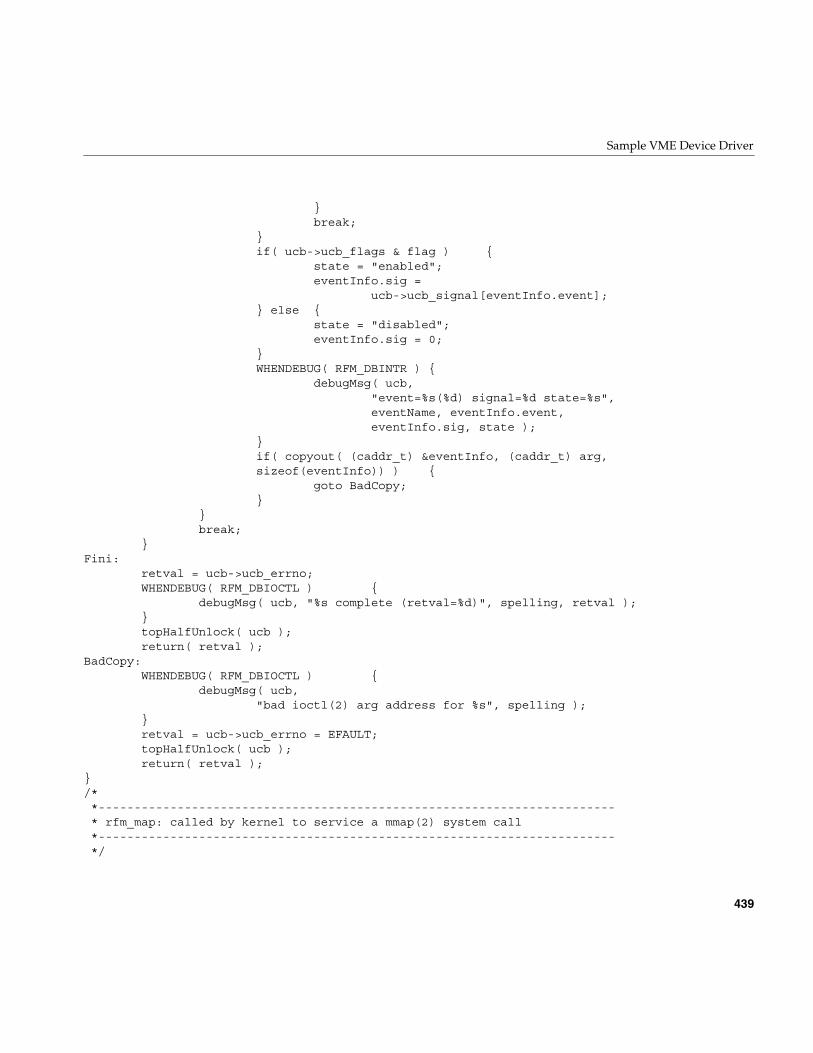
Sample VME Device Driver
439
}break;
}if( ucb->ucb_flags & flag ) {
state = "enabled";eventInfo.sig =
ucb->ucb_signal[eventInfo.event];} else {
state = "disabled";eventInfo.sig = 0;
}WHENDEBUG( RFM_DBINTR ) {
debugMsg( ucb,"event=%s(%d) signal=%d state=%s",eventName, eventInfo.event,eventInfo.sig, state );
}if( copyout( (caddr_t) &eventInfo, (caddr_t) arg,sizeof(eventInfo)) ) {
goto BadCopy;}
}break;
}Fini:
retval = ucb->ucb_errno;WHENDEBUG( RFM_DBIOCTL ) {
debugMsg( ucb, "%s complete (retval=%d)", spelling, retval );}topHalfUnlock( ucb );return( retval );
BadCopy:WHENDEBUG( RFM_DBIOCTL ) {
debugMsg( ucb,"bad ioctl(2) arg address for %s", spelling );
}retval = ucb->ucb_errno = EFAULT;topHalfUnlock( ucb );return( retval );
}/**------------------------------------------------------------------------* rfm_map: called by kernel to service a mmap(2) system call*------------------------------------------------------------------------*/
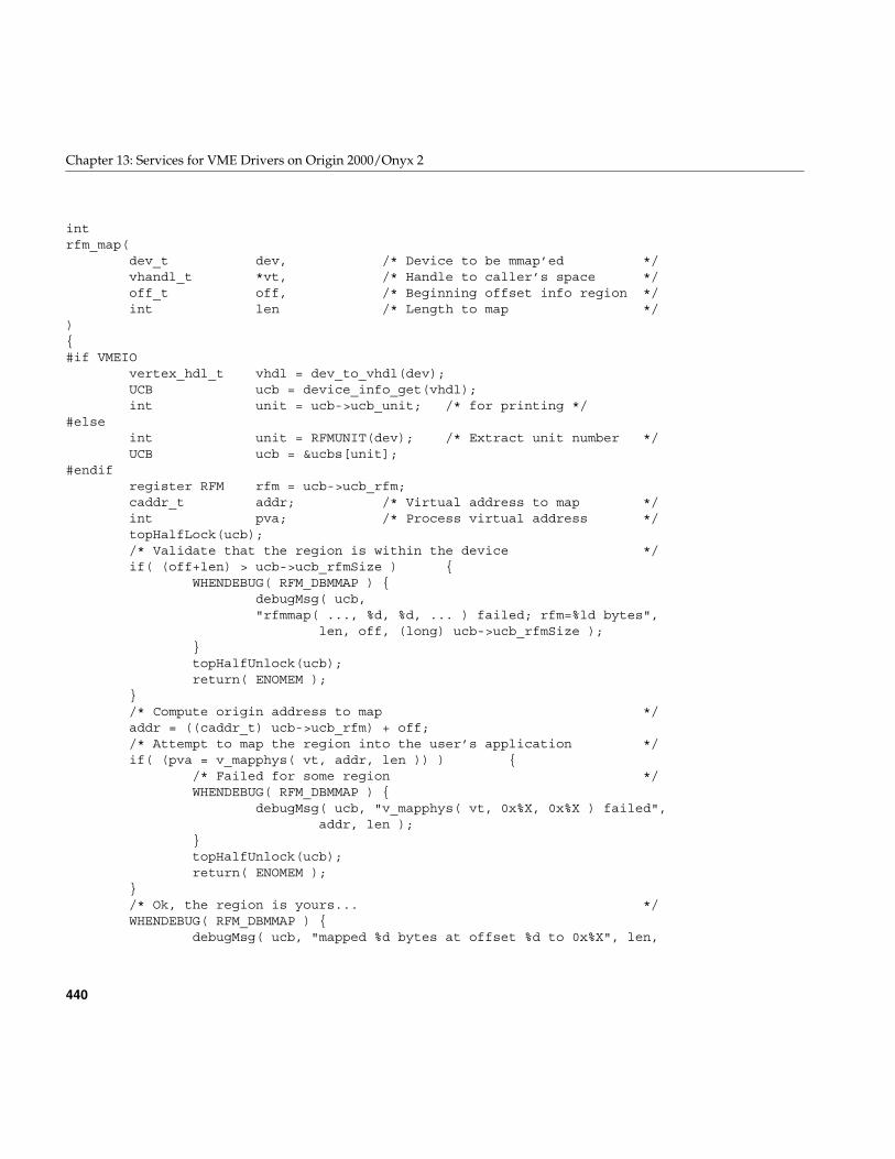
440
Chapter 13: Services for VME Drivers on Origin 2000/Onyx 2
intrfm_map(
dev_t dev, /* Device to be mmap’ed */vhandl_t *vt, /* Handle to caller’s space */off_t off, /* Beginning offset info region */int len /* Length to map */
){#if VMEIO
vertex_hdl_t vhdl = dev_to_vhdl(dev);UCB ucb = device_info_get(vhdl);int unit = ucb->ucb_unit; /* for printing */
#elseint unit = RFMUNIT(dev); /* Extract unit number */UCB ucb = &ucbs[unit];
#endifregister RFM rfm = ucb->ucb_rfm;caddr_t addr; /* Virtual address to map */int pva; /* Process virtual address */topHalfLock(ucb);/* Validate that the region is within the device */if( (off+len) > ucb->ucb_rfmSize ) {
WHENDEBUG( RFM_DBMMAP ) {debugMsg( ucb,"rfmmap( ..., %d, %d, ... ) failed; rfm=%ld bytes",
len, off, (long) ucb->ucb_rfmSize );}topHalfUnlock(ucb);return( ENOMEM );
}/* Compute origin address to map */addr = ((caddr_t) ucb->ucb_rfm) + off;/* Attempt to map the region into the user’s application */if( (pva = v_mapphys( vt, addr, len )) ) {
/* Failed for some region */WHENDEBUG( RFM_DBMMAP ) {
debugMsg( ucb, "v_mapphys( vt, 0x%X, 0x%X ) failed",addr, len );
}topHalfUnlock(ucb);return( ENOMEM );
}/* Ok, the region is yours... */WHENDEBUG( RFM_DBMMAP ) {
debugMsg( ucb, "mapped %d bytes at offset %d to 0x%X", len,
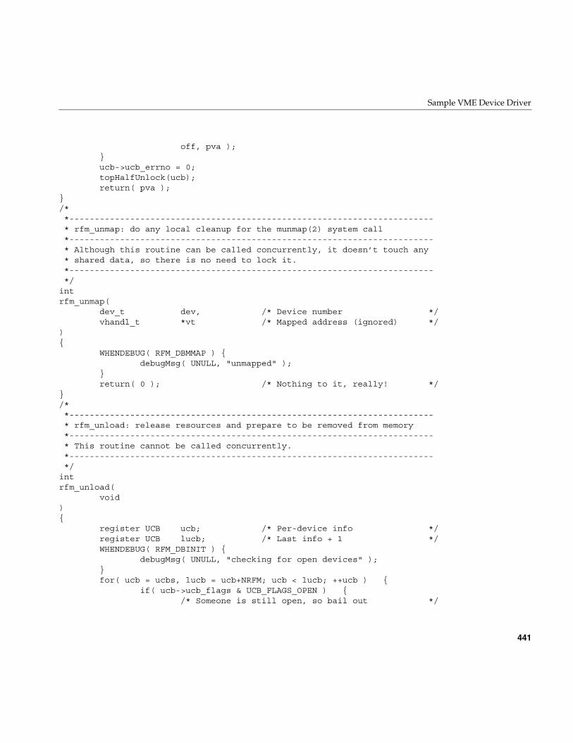
Sample VME Device Driver
441
off, pva );}ucb->ucb_errno = 0;topHalfUnlock(ucb);return( pva );
}/**------------------------------------------------------------------------* rfm_unmap: do any local cleanup for the munmap(2) system call*------------------------------------------------------------------------* Although this routine can be called concurrently, it doesn’t touch any* shared data, so there is no need to lock it.*------------------------------------------------------------------------*/
intrfm_unmap(
dev_t dev, /* Device number */vhandl_t *vt /* Mapped address (ignored) */
){
WHENDEBUG( RFM_DBMMAP ) {debugMsg( UNULL, "unmapped" );
}return( 0 ); /* Nothing to it, really! */
}/**------------------------------------------------------------------------* rfm_unload: release resources and prepare to be removed from memory*------------------------------------------------------------------------* This routine cannot be called concurrently.*------------------------------------------------------------------------*/
intrfm_unload(
void){
register UCB ucb; /* Per-device info */register UCB lucb; /* Last info + 1 */WHENDEBUG( RFM_DBINIT ) {
debugMsg( UNULL, "checking for open devices" );}for( ucb = ucbs, lucb = ucb+NRFM; ucb < lucb; ++ucb ) {
if( ucb->ucb_flags & UCB_FLAGS_OPEN ) {/* Someone is still open, so bail out */
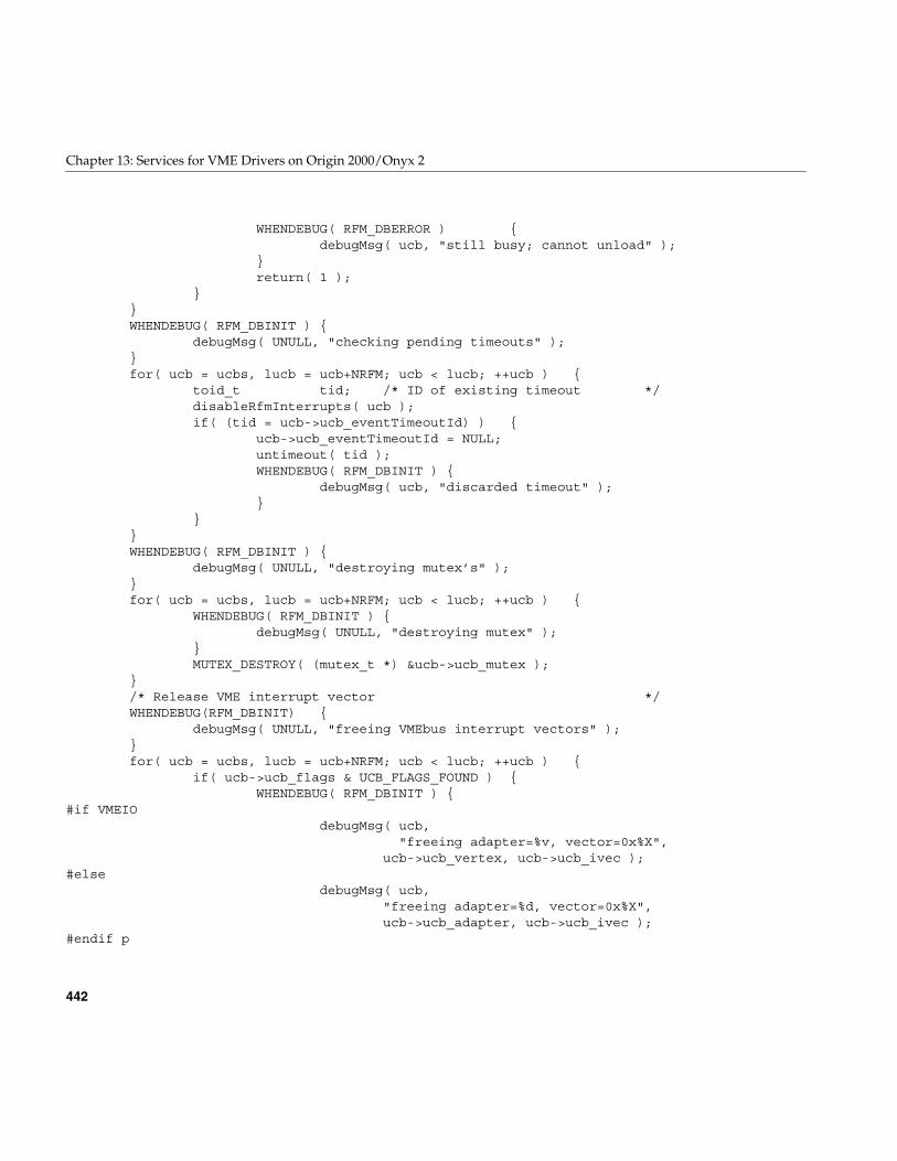
442
Chapter 13: Services for VME Drivers on Origin 2000/Onyx 2
WHENDEBUG( RFM_DBERROR ) {debugMsg( ucb, "still busy; cannot unload" );
}return( 1 );
}}WHENDEBUG( RFM_DBINIT ) {
debugMsg( UNULL, "checking pending timeouts" );}for( ucb = ucbs, lucb = ucb+NRFM; ucb < lucb; ++ucb ) {
toid_t tid; /* ID of existing timeout */disableRfmInterrupts( ucb );if( (tid = ucb->ucb_eventTimeoutId) ) {
ucb->ucb_eventTimeoutId = NULL;untimeout( tid );WHENDEBUG( RFM_DBINIT ) {
debugMsg( ucb, "discarded timeout" );}
}}WHENDEBUG( RFM_DBINIT ) {
debugMsg( UNULL, "destroying mutex’s" );}for( ucb = ucbs, lucb = ucb+NRFM; ucb < lucb; ++ucb ) {
WHENDEBUG( RFM_DBINIT ) {debugMsg( UNULL, "destroying mutex" );
}MUTEX_DESTROY( (mutex_t *) &ucb->ucb_mutex );
}/* Release VME interrupt vector */WHENDEBUG(RFM_DBINIT) {
debugMsg( UNULL, "freeing VMEbus interrupt vectors" );}for( ucb = ucbs, lucb = ucb+NRFM; ucb < lucb; ++ucb ) {
if( ucb->ucb_flags & UCB_FLAGS_FOUND ) {WHENDEBUG( RFM_DBINIT ) {
#if VMEIOdebugMsg( ucb,
"freeing adapter=%v, vector=0x%X",ucb->ucb_vertex, ucb->ucb_ivec );
#elsedebugMsg( ucb,
"freeing adapter=%d, vector=0x%X",ucb->ucb_adapter, ucb->ucb_ivec );
#endif p
Sample VME Device Driver
443
}#if VMEIO
vmeio_intr_free(ucb->ucb_intr);#else
vme_ivec_free (ucb->ucb_adapter, ucb->ucb_ivec );#endif
ucb->ucb_flags &= ~UCB_FLAGS_FOUND;}
}/* Unmap device registers */WHENDEBUG( RFM_DBINIT ) {
debugMsg( UNULL, "unmapping registers" );}for( ucb = ucbs, lucb = ucb+NRFM; ucb < lucb; ++ucb ) {
if( ucb->ucb_piomap ) {WHENDEBUG( RFM_DBINIT ) {
debugMsg( ucb, "freeing register map" );}
#if VMEIOvmeio_piomap_free(ucb->ucb_piomap);
#elsepio_mapfree( ucb->ucb_piomap );
#endifucb->ucb_rfm = 0;ucb->ucb_piomap = 0;
}}return( 0 );
}/**------------------------------------------------------------------------* rfm_halt: system is about to halt*------------------------------------------------------------------------* This routine cannot be called concurrently.*------------------------------------------------------------------------*/
voidrfm_halt(
void){
WHENDEBUG( RFM_DBINIT ) {debugMsg( UNULL, "halted" );
}}

445
Chapter 14
14.VME Device Attachment on Challenge/Onyx
This chapter gives a high-level overview of the VME bus, and describes how the VMEbus is attached to, and operated by Challenge and Onyx systems.
Note: For information on hardware device issues on the Origin2000 and Onyx2platforms, refer to Chapter 12, “VME Device Attachment on Origin 2000/Onyx2,” andChapter 13, “Services for VME Drivers on Origin 2000/Onyx 2.”.
This chapter contains useful background information if you plan to control a VME devicefrom a user-level program. It contains important details on VME addressing if you arewriting a kernel-level VME device driver.
• “Overview of the VME Bus” on page 446 summarizes the history and features of theVME bus architecture.
• “VME Bus in Challenge and Onyx Systems” on page 448 gives an overview of howthe VME bus is integrated into Challenge and Onyx computer systems.
• “VME Bus Addresses and System Addresses” on page 454 discusses therelationship between addresses on the VME bus and addresses in the physicaladdress space of the system.
• “Configuring VME Devices” on page 463 tells how to configure a device so thatIRIX can recognize it and initialize its device driver.
• “VME Hardware in Challenge and Onyx Systems” on page 468 documents thehardware details of the VME implementation on those systems.
More information about VME device control appears in these chapters:
• Chapter 4, “User-Level Access to Devices,” covers PIO and DMA access from theuser process.
• Chapter 15, “Services for VME Drivers on Challenge/Onyx,”discusses the kernelservices used by a kernel-level VME device driver, and contains an example.
446
Chapter 14: VME Device Attachment on Challenge/Onyx
Overview of the VME Bus
The VME bus dates to the early 1980s. It was designed as a flexible interconnectionbetween multiple master and slave devices using a variety of address and dataprecisions, and has become a popular standard bus used in a variety of products. (Forordering information on the standards documents, see “Standards Documents” onpage xl.)
In Silicon Graphics systems, the VME bus is treated as an I/O device, not as the mainsystem bus.
VME History
The VME bus descends from the VERSAbus, a bus design published by Motorola, Inc.,in 1980 to support the needs of the MC68000 line of microprocessors. The bus timingrelationships and some signal names still reflect this heritage, although the VME bus isused by devices from many manufacturers today.
The original VERSAbus design specified a large form factor for pluggable cards. Becauseof this, it was not popular with European designers. A bus with a smaller form factor butsimilar functions and electrical specifications was designed for European use, andpromoted by Motorola, Phillips, Thompson, and other companies. This was theVersaModule European, or VME, bus. Beginning with rev B of 1982, the bus quicklybecame an accepted standard.
VME Features
A VME bus is a set of parallel conductors that interconnect multiple processing devices.The devices can exchange data in units of 8, 16, 32 or 64 bits during a bus cycle.
Overview of the VME Bus
447
VME Address Spaces
Each VME device identifies itself with a range of bus addresses. A bus address has either16, 24, or 32 bits of precision. Each address width forms a separate address space. That is,the same numeric value can refer to one device in the 24-bit address space but a differentdevice in the 32-bit address space. Typically, a device operates in only one address space,but some devices can be configured to respond to addresses in multiple spaces.
Each VME bus cycle contains the bits of an address. The address is qualified by sets ofaddress-modifier bits that specify the following:
• the address space (A16, A24, or A32)
• whether the operation is single or a block transfer
• whether the access is to what, in the MC68000 architecture, would be data or code,in a supervisor or user area (Silicon Graphics systems support only supervisor-dataand user-data requests)
Master and Slave Devices
Each VME device acts as either a bus master or a bus slave. Typically a bus master is adevice with some level of programmability, usually a microprocessor. A disk controlleris an example of a master device. A slave device is typically a nonprogrammable devicelike a memory board.
Each data transfer is initiated by a master device. The master
• asserts ownership of the bus
• specifies the address modifier bits for the transfer, including the address space,single/block mode, and supervisor/normal mode
• specifies the address for the transfer
• specifies the data unit size for the transfer (8, 16, 32 or 64 bits)
• specifies the direction of the transfer with respect to the master
The VME bus design permits multiple master devices to use the bus, and provides ahardware-based arbitration system so that they can use the bus in alternation.
A slave device responds to a master when the master specifies the slave’s address. Theaddressed slave accepts data, or provides data, as directed.
448
Chapter 14: VME Device Attachment on Challenge/Onyx
VME Transactions
The VME design allows for four types of data transfer bus cycles:
• A read cycle returns data from the slave to the master.
• A write cycle sends data from the master to the slave.
• A read-modify-write cycle takes data from the slave, and on the following bus cyclesends it back to the same address, possibly altered.
• A block-transfer transaction sends multiple data units to adjacent addresses in aburst of consecutive bus cycles.
The VME design also allows for interrupts. A device can raise an interrupt on any ofseven interrupt levels. The interrupt is acknowledged by a bus master. The bus masterinterrogates the interrupting device in an interrupt-acknowledge bus cycle, and thedevice returns an interrupt vector number.
In Silicon Graphics systems, it is always the Silicon Graphics VME controller thatacknowledges interrupts. It passes the interrupt to one of the CPUs in the system.
VME Bus in Challenge and Onyx Systems
The VME bus was designed as the system backplane for a workstation, supporting oneor more CPU modules along with the memory and I/O modules they used. However, noSilicon Graphics computer uses the VME bus as the system backplane. In all Challengeand Onyx computers, the main system bus that connects CPUs to memory is aproprietary bus design, with higher speed and sometimes wider data units than the VMEbus provides. The VME bus is attached to the system as an I/O device.
This section provides an overview of the design of the VME bus in any Challenge andOnyx system. It is sufficient background for most users of VME devices. For a moredetailed look at the Challenge and Onyx implementation of VME, see “VME Hardwarein Challenge and Onyx Systems” on page 468.
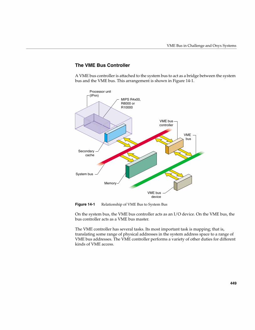
VME Bus in Challenge and Onyx Systems
449
The VME Bus Controller
A VME bus controller is attached to the system bus to act as a bridge between the systembus and the VME bus. This arrangement is shown in Figure 14-1.
Figure 14-1 Relationship of VME Bus to System Bus
On the system bus, the VME bus controller acts as an I/O device. On the VME bus, thebus controller acts as a VME bus master.
The VME controller has several tasks. Its most important task is mapping; that is,translating some range of physical addresses in the system address space to a range ofVME bus addresses. The VME controller performs a variety of other duties for differentkinds of VME access.
Secondarycache
System bus
Memory
Processor unit(IPnn)
MIPS R4x00,R8000 or R10000
VMEbus
VME buscontroller
VME busdevice
450
Chapter 14: VME Device Attachment on Challenge/Onyx
VME PIO Operations
During programmed I/O (PIO) to the VME bus, software in the CPU loads or stores thecontents of CPU registers to a device on the VME bus. The operation of a CPU load froma VME device register is as follows:
1. The CPU executes a load from a system physical address.
2. The system recognizes the physical address as one of its own.
3. The system translates the physical address into a VME bus address.
4. Acting as a VME bus master, the system starts a read cycle on the VME bus.
5. A slave device on the VME bus responds to the VME address and returns data.
6. The VME controller initiates a system bus cycle to return the data packet to the CPU,thus completing the load operation.
A store to a VME device is similar except that it performs a VME bus write, and no datais returned.
PIO input requires two system bus cycles—one to request the data and one to return it—separated by the cycle time of the VME bus. PIO output takes only one system bus cycle,and the VME bus write cycle run concurrently with the next system bus cycle. As a result,PIO input always takes at least twice as much time as PIO output.
VME PIO Bandwidth
VME bus:PIO to:bandwidthOn a Challenge L or Onyx system, the maximum rate of PIOoutput is approximately 750K writes per second. The maximum rate of PIO input isapproximately 250K reads per second. The corresponding data rate depends on thenumber of bytes transferred on each operation, as summarized in Table 14-1.
Table 14-1 VME Bus PIO Bandwidth
Data Unit Size Read Write
D8 0.25 MB/second 0.75 MB/second
D16 0.5 MB/second 1.5 MB/second
D32 1 MB/second 3 MB/second
VME Bus in Challenge and Onyx Systems
451
Note: The numbers in Table 14-1 were obtained by doing continuous reads, orcontinuous writes, to a device in the Challenge chassis. When reads and writes alternate,add approximately 1 microsecond for each change of direction. The use of a repeater toextend to an external card cage would add 200 nanoseconds or more to each transfer.
VME DMA Operations
A VME device that can act as a bus master can perform DMA into memory. The generalsequence of operations in this case is as follows:
1. Kernel software uses PIO to program the device registers of the VME device,instructing it to perform DMA to a certain VME bus address for a specified length ofdata.
2. The VME bus master initiates the first read, write, block-read, or block-write cycleon the VME bus.
3. The VME controller, responding as a slave device on the VME bus, recognizes theVME bus address as one that corresponds to a physical memory address in thesystem.
4. If the bus master is writing, the VME controller accepts the data and initiates asystem bus cycle to write the data to system memory.
If the bus master is reading, the VME controller uses a system bus cycle to read datafrom system memory, and returns the data to the bus master.
5. The bus master device continues to use the VME controller as a slave device until ithas completed the DMA transfer.
During a DMA transaction, the VME bus controller operates independently of any CPU.CPUs in the system execute software concurrently with the data transfer. Since thesystem bus is faster than the VME bus, the data transfer takes place at the maximum datarate that the VME bus master can sustain.
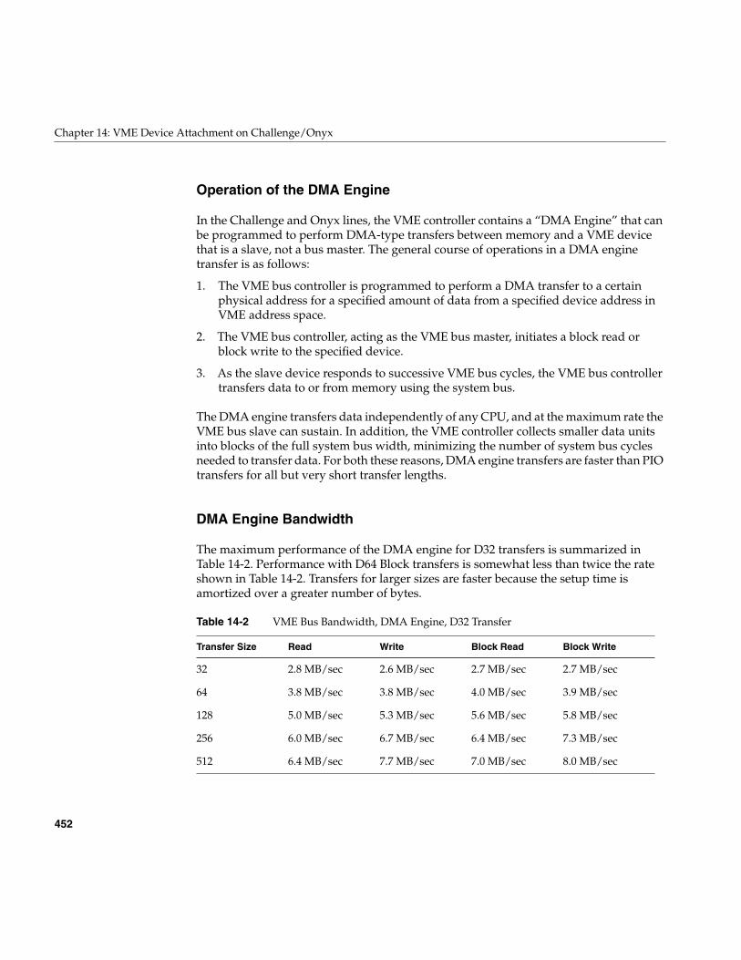
452
Chapter 14: VME Device Attachment on Challenge/Onyx
Operation of the DMA Engine
In the Challenge and Onyx lines, the VME controller contains a “DMA Engine” that canbe programmed to perform DMA-type transfers between memory and a VME devicethat is a slave, not a bus master. The general course of operations in a DMA enginetransfer is as follows:
1. The VME bus controller is programmed to perform a DMA transfer to a certainphysical address for a specified amount of data from a specified device address inVME address space.
2. The VME bus controller, acting as the VME bus master, initiates a block read orblock write to the specified device.
3. As the slave device responds to successive VME bus cycles, the VME bus controllertransfers data to or from memory using the system bus.
The DMA engine transfers data independently of any CPU, and at the maximum rate theVME bus slave can sustain. In addition, the VME controller collects smaller data unitsinto blocks of the full system bus width, minimizing the number of system bus cyclesneeded to transfer data. For both these reasons, DMA engine transfers are faster than PIOtransfers for all but very short transfer lengths.
DMA Engine Bandwidth
The maximum performance of the DMA engine for D32 transfers is summarized inTable 14-2. Performance with D64 Block transfers is somewhat less than twice the rateshown in Table 14-2. Transfers for larger sizes are faster because the setup time isamortized over a greater number of bytes.
Table 14-2 VME Bus Bandwidth, DMA Engine, D32 Transfer
Transfer Size Read Write Block Read Block Write
32 2.8 MB/sec 2.6 MB/sec 2.7 MB/sec 2.7 MB/sec
64 3.8 MB/sec 3.8 MB/sec 4.0 MB/sec 3.9 MB/sec
128 5.0 MB/sec 5.3 MB/sec 5.6 MB/sec 5.8 MB/sec
256 6.0 MB/sec 6.7 MB/sec 6.4 MB/sec 7.3 MB/sec
512 6.4 MB/sec 7.7 MB/sec 7.0 MB/sec 8.0 MB/sec
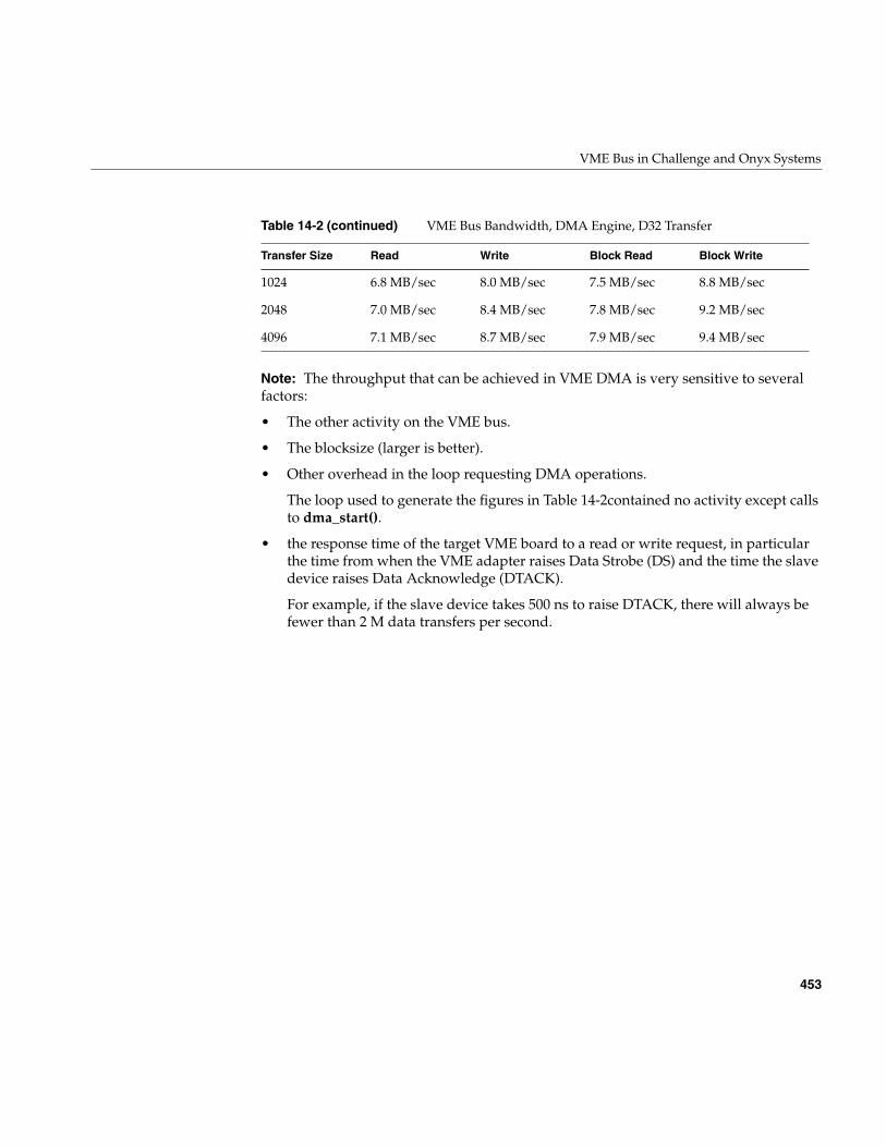
VME Bus in Challenge and Onyx Systems
453
Note: The throughput that can be achieved in VME DMA is very sensitive to severalfactors:
• The other activity on the VME bus.
• The blocksize (larger is better).
• Other overhead in the loop requesting DMA operations.
The loop used to generate the figures in Table 14-2contained no activity except callsto dma_start().
• the response time of the target VME board to a read or write request, in particularthe time from when the VME adapter raises Data Strobe (DS) and the time the slavedevice raises Data Acknowledge (DTACK).
For example, if the slave device takes 500 ns to raise DTACK, there will always befewer than 2 M data transfers per second.
1024 6.8 MB/sec 8.0 MB/sec 7.5 MB/sec 8.8 MB/sec
2048 7.0 MB/sec 8.4 MB/sec 7.8 MB/sec 9.2 MB/sec
4096 7.1 MB/sec 8.7 MB/sec 7.9 MB/sec 9.4 MB/sec
Table 14-2 (continued) VME Bus Bandwidth, DMA Engine, D32 Transfer
Transfer Size Read Write Block Read Block Write
454
Chapter 14: VME Device Attachment on Challenge/Onyx
VME Bus Addresses and System Addresses
Devices on the VME bus exist in one of the following address spaces:
• The 16-bit space (A16) contains numbers from 0x0000 to 0xffff.
• The 24-bit space (A24) contains numbers from 0x00 0000 to 0xff ffff.
• The 32-bit space (A32) uses numbers from 0x0000 0000 to 0xffff ffff.
• The 64-bit space (A64), defined in the revision D specification, uses 64-bit addresses.
The system bus also uses 32-bit or 64-bit numbers to address memory and other I/Odevices on the system bus. In order to avoid conflicts between the meanings of addressnumbers, certain portions of the physical address space are reserved for VME use. TheVME address spaces are mapped, that is, translated, into these ranges of physicaladdresses.
The translation is performed by the VME bus controller: It recognizes certain physicaladdresses on the system bus and translates them into VME bus addresses; and itrecognizes certain VME bus addresses and translates them into physical addresses on thesystem bus.
Even with mapping, the entire A32 or A64 address space cannot be mapped into thephysical address space. As a result, the system does not provide access to all of the VMEaddress spaces. Only parts of the VME address spaces are available at any time.
User-Level and Kernel-Level Addressing
In a user-level program you can perform PIO and certain types of DMA operations (seeChapter 4, “User-Level Access to Devices”), but you do not program these in terms of thephysical addresses mapped to the VME bus. Instead, you call on the services of akernel-level device driver to map a portion of VME address space into the address spaceof your process. The requested segment of VME space is mapped dynamically to asegment of your user-level address space—a segment that can differ from one run of theprogram to the next.
VME Bus Addresses and System Addresses
455
In a kernel-level device driver, you program PIO and DMA operations in terms ofspecific addresses in kernel space—memory addresses that are mapped to specifiedaddresses in the VME bus address space. The mapping is either permanent, establishedby the system hardware, or dynamic, set up temporarily by a kernel function.
Note: The remainder of this chapter has direct meaning only for kernel-level drivers,which must deal with physical mappings of VME space.
PIO Addressing and DMA Addressing
The addressing needs of PIO access and DMA access are different.
PIO deals in small amounts of data, typically single bytes or words. PIO is directed todevice registers that are identified with specific VME bus addresses. The associationbetween a device register and its bus address is fixed, typically by setting jumpers orswitches on the VME card.
DMA deals with extended segments of kilobytes or megabytes. The addresses used inDMA are not fixed in the device, but are programmed into it just before the data transferbegins. For example, a disk controller device can be programmed to read a certain sectorand to write the sector data to a range of 512 consecutive bytes in the VME bus addressspace. The programming of the disk controller is done by storing numbers into itsregisters using PIO. While the registers respond only to fixed addresses that areconfigured into the board, the address to which the disk controller writes its sector datais just a number that is programmed into it each time a transfer is to start.
The key differences between addresses used by PIO and addresses used for DMA arethese:
• PIO addresses are relatively few in number and cover small spans of data, whileDMA addresses can span large ranges of data.
• PIO addresses are closely related to the hardware architecture of the device and areconfigured by hardware or firmware, while DMA addresses are simply parametersprogrammed into the device before each operation.
In Challenge and Onyx systems, all VME mappings are dynamic, assigned as needed.Kernel functions are provided to create and release mappings between designated VMEaddresses and kernel addresses.
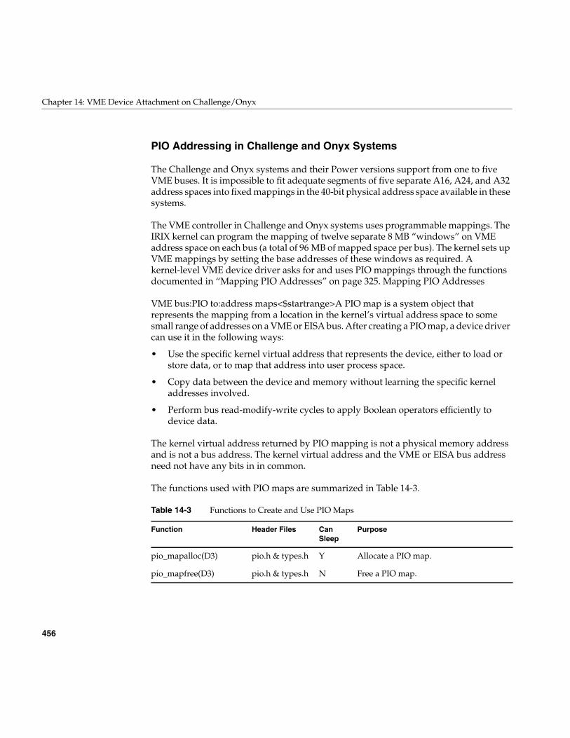
456
Chapter 14: VME Device Attachment on Challenge/Onyx
PIO Addressing in Challenge and Onyx Systems
The Challenge and Onyx systems and their Power versions support from one to fiveVME buses. It is impossible to fit adequate segments of five separate A16, A24, and A32address spaces into fixed mappings in the 40-bit physical address space available in thesesystems.
The VME controller in Challenge and Onyx systems uses programmable mappings. TheIRIX kernel can program the mapping of twelve separate 8 MB “windows” on VMEaddress space on each bus (a total of 96 MB of mapped space per bus). The kernel sets upVME mappings by setting the base addresses of these windows as required. Akernel-level VME device driver asks for and uses PIO mappings through the functionsdocumented in “Mapping PIO Addresses” on page 325. Mapping PIO Addresses
VME bus:PIO to:address maps<$startrange>A PIO map is a system object thatrepresents the mapping from a location in the kernel’s virtual address space to somesmall range of addresses on a VME or EISA bus. After creating a PIO map, a device drivercan use it in the following ways:
• Use the specific kernel virtual address that represents the device, either to load orstore data, or to map that address into user process space.
• Copy data between the device and memory without learning the specific kerneladdresses involved.
• Perform bus read-modify-write cycles to apply Boolean operators efficiently todevice data.
The kernel virtual address returned by PIO mapping is not a physical memory addressand is not a bus address. The kernel virtual address and the VME or EISA bus addressneed not have any bits in in common.
The functions used with PIO maps are summarized in Table 14-3.
Table 14-3 Functions to Create and Use PIO Maps
Function Header Files CanSleep
Purpose
pio_mapalloc(D3) pio.h & types.h Y Allocate a PIO map.
pio_mapfree(D3) pio.h & types.h N Free a PIO map.
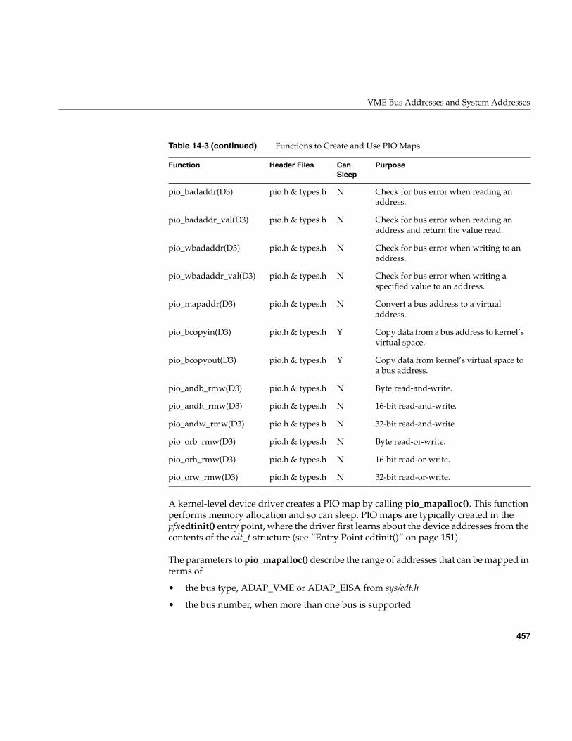
VME Bus Addresses and System Addresses
457
A kernel-level device driver creates a PIO map by calling pio_mapalloc(). This functionperforms memory allocation and so can sleep. PIO maps are typically created in thepfxedtinit() entry point, where the driver first learns about the device addresses from thecontents of the edt_t structure (see “Entry Point edtinit()” on page 151).
The parameters to pio_mapalloc() describe the range of addresses that can be mapped interms of
• the bus type, ADAP_VME or ADAP_EISA from sys/edt.h
• the bus number, when more than one bus is supported
pio_badaddr(D3) pio.h & types.h N Check for bus error when reading anaddress.
pio_badaddr_val(D3) pio.h & types.h N Check for bus error when reading anaddress and return the value read.
pio_wbadaddr(D3) pio.h & types.h N Check for bus error when writing to anaddress.
pio_wbadaddr_val(D3) pio.h & types.h N Check for bus error when writing aspecified value to an address.
pio_mapaddr(D3) pio.h & types.h N Convert a bus address to a virtualaddress.
pio_bcopyin(D3) pio.h & types.h Y Copy data from a bus address to kernel’svirtual space.
pio_bcopyout(D3) pio.h & types.h Y Copy data from kernel’s virtual space toa bus address.
pio_andb_rmw(D3) pio.h & types.h N Byte read-and-write.
pio_andh_rmw(D3) pio.h & types.h N 16-bit read-and-write.
pio_andw_rmw(D3) pio.h & types.h N 32-bit read-and-write.
pio_orb_rmw(D3) pio.h & types.h N Byte read-or-write.
pio_orh_rmw(D3) pio.h & types.h N 16-bit read-or-write.
pio_orw_rmw(D3) pio.h & types.h N 32-bit read-or-write.
Table 14-3 (continued) Functions to Create and Use PIO Maps
Function Header Files CanSleep
Purpose
458
Chapter 14: VME Device Attachment on Challenge/Onyx
• the address space, using constants such as PIOMAP_A24N or PIOMAP_EISA_IOfrom sys/pio.h
• the starting bus address and a length
This call also specifies a “fixed” or “unfixed” map. The usual type is “fixed.” For thedifferences, see “Fixed PIO Maps” on page 459 and “Unfixed PIO Maps” on page 460.
A call to pio_mapfree() releases a PIO map. PIO maps created by a loadable driver mustbe released in the pfxunload() entry point (see “Entry Point unload()” on page 180 and“Unloading” on page 268).
Testing the PIO Map
The PIO map is created from the parameters that are passed. These are not validated bypio_mapalloc(). If there is any possibility that the mapped device is not installed, notactive, or improperly configured, you should test the mapped address.
The pio_badaddr() and pio_badaddr_val() functions test the mapped address to see if itis usable for input. Both functions perform the same operation: operating through a PIOmap, they test a specified bus address for validity by reading 1, 2, 4, or 8 bytes from it.The pio_badaddr_val() function returns the value that it reads while making the test.This can simplify coding, as shown in Example 14-1.
Example 14-1 Comparing pio_badaddr() to pio_badaddr_val()
unsigned int gotvalue;piomap_t *themap;/* Using only pio_badaddr() */
if (!pio_badaddr(themap,CTLREG,4){
(void) pio_bcopyin(themap,CTLREG,&gotvalue,4,4,0);...use "gotvalue"
/* Using pio_badaddr_val() */if (!pio_badaddr_val(themap,CTLREG,4,&gotvalue)){
...use "gotvalue"
The pio_wbadaddr() function tests a mapped device address for writeability. Thepio_wbadaddr_val() not only tests the address but takes a specific value to write to thataddress in the course of testing it.
VME Bus Addresses and System Addresses
459
Using the Mapped Address
From a fixed PIO map you can recover a kernel virtual address that corresponds to thefirst bus address in the map. The pio_mapaddr() function is used for this.
You can use this address to load or store data into device registers. In the pfxmap() entrypoint (see “Concepts and Use of mmap()” on page 169), you can use this address with thev_mapphys() function to map the range of device addresses into the address space of auser process.
You cannot extract a kernel address from an unfixed PIO map, as explained under“Unfixed PIO Maps” on page 460.
Using the PIO Map in Functions
You can apply a variety of kernel functions to any PIO map, fixed or unfixed. Thepio_bcopyin() and pio_bcopyout() functions copy a range of data between memory anda fixed or unfixed PIO map. These functions are optimized to the hardware that exists,and they do all transfers in the largest size possible (32 or 64 bits per transfer). If you needto transfer data in specific sizes of 1 or 2 bytes, use direct loads and stores to the mappedaddresses.
The series of functions pio_andb_rmw() and pio_orb_rmw() perform aread-modify-write cycle on the VME bus. You can use them to set or clear bits in deviceregisters. A read-modify-write cycle is faster than a load followed by a store since it usesfewer system bus cycles.
Fixed PIO Maps
fOn a Challenge or Onyx system, a PIO map can be either “fixed” or “unfixed.” Thisattribute is specified when the map is created.
The Challenge and Onyx architecture provides for a total of 15 separate, 8 MB windowson VME address space for each VME bus. Two of these are permanently reserved to thekernel, and one window is reserved for use with unfixed mappings. The remaining 12windows are available to implement fixed PIO maps.
When the kernel creates a fixed PIO map, the map is associated with one of the 12available VME mapping windows. The kernel tries to be clever, so that whenever a PIOmap falls within an 8 MB window that already exists, the PIO map uses that window. If
460
Chapter 14: VME Device Attachment on Challenge/Onyx
the desired VME address is not covered by an open window, one of the twelve windowsfor that bus is opened to expose a mapping for that address.
It is possible in principle to configure thirteen devices that are scattered so widely in theA32 address space that twelve, 8 MB windows cannot cover all of them. In that unlikelycase, the attempt to create the thirteenth fixed PIO map will fail for lack of a mappingwindow.
In order to prevent this, simply configure your PIO addresses into a span of at most96 MB per bus (see “Configuring Device Addresses” on page 463).
Unfixed PIO Maps
When you create an unfixed PIO map, the map is not associated with any of the twelvemapping windows. As a result, the map cannot be queried for a kernel address thatmight be saved, or mapped into user space.
You can use an unfixed map with kernel functions that copy data or performread-modify-write cycles. These functions use the one mapping window that is reservedfor unfixed maps, repositioning it in VME space if necessary.
The lboot command uses an unfixed map to perform the probe and exprobe sequences fromVECTOR statements (see “Configuring the System Files” on page 464). As a result, theseprobes do not tie up mapping windows.
DMA Addressing
DMA is supported only for the A24 and A32 address spaces. DMA addresses are alwaysassigned dynamically in the Challenge and Onyx systems.
Mapping DMA Addresses
A DMA map is a system object that represents a mapping between a buffer in kernelvirtual space and a range of VME bus addresses. After creating a DMA map, a driveruses the map to specify the target address and length to be programmed into a VME busmaster before a DMA transfer.
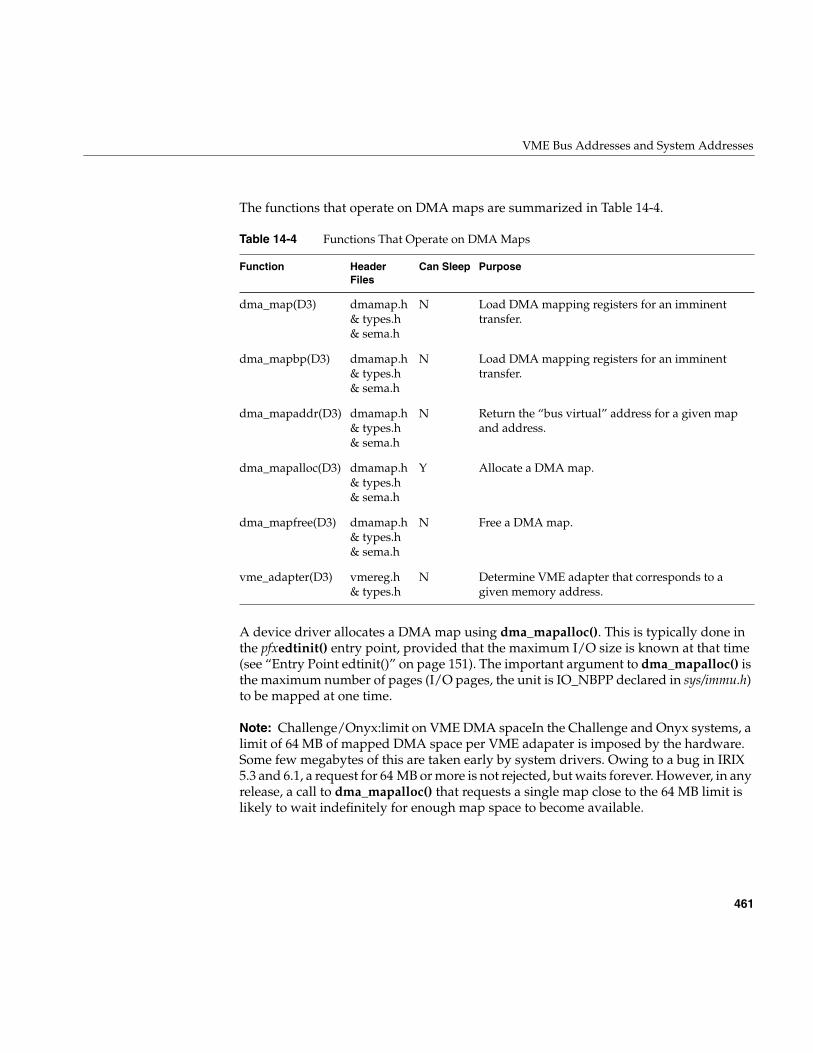
VME Bus Addresses and System Addresses
461
The functions that operate on DMA maps are summarized in Table 14-4.
A device driver allocates a DMA map using dma_mapalloc(). This is typically done inthe pfxedtinit() entry point, provided that the maximum I/O size is known at that time(see “Entry Point edtinit()” on page 151). The important argument to dma_mapalloc() isthe maximum number of pages (I/O pages, the unit is IO_NBPP declared in sys/immu.h)to be mapped at one time.
Note: Challenge/Onyx:limit on VME DMA spaceIn the Challenge and Onyx systems, alimit of 64 MB of mapped DMA space per VME adapater is imposed by the hardware.Some few megabytes of this are taken early by system drivers. Owing to a bug in IRIX5.3 and 6.1, a request for 64 MB or more is not rejected, but waits forever. However, in anyrelease, a call to dma_mapalloc() that requests a single map close to the 64 MB limit islikely to wait indefinitely for enough map space to become available.
Table 14-4 Functions That Operate on DMA Maps
Function HeaderFiles
Can Sleep Purpose
dma_map(D3) dmamap.h& types.h& sema.h
N Load DMA mapping registers for an imminenttransfer.
dma_mapbp(D3) dmamap.h& types.h& sema.h
N Load DMA mapping registers for an imminenttransfer.
dma_mapaddr(D3) dmamap.h& types.h& sema.h
N Return the “bus virtual” address for a given mapand address.
dma_mapalloc(D3) dmamap.h& types.h& sema.h
Y Allocate a DMA map.
dma_mapfree(D3) dmamap.h& types.h& sema.h
N Free a DMA map.
vme_adapter(D3) vmereg.h& types.h
N Determine VME adapter that corresponds to agiven memory address.
462
Chapter 14: VME Device Attachment on Challenge/Onyx
DMA maps created by a loadable driver should be released in the pfxunload() entrypoint (see “Entry Point unload()” on page 180 and “Unloading” on page 268).
Using a DMA Map
A DMA map is used prior to a DMA transfer into or out of a buffer in kernel virtualspace. The function dma_map() takes a DMA map, a buffer address, and a length. Itassigns a span of contiguous VME addresses of the specified length, and sets up amapping between that range of VME addresses and the physical addresses that representthe specified buffer.
When the buffer spans two or more physical pages (IO_NBPP units), dma_map() sets upa scatter/gather operation, so that the VME bus controller will place the data in theappropriate page frames.
It is possible that dma_map() cannot map the entire size of the buffer. This can occur onlywhen the buffer spans two or more pages, and is caused by a shortage of mappingregisters in the bus adapter. The function maps as much of the buffer as it can, andreturns the length of the mapped data.
You must always anticipate that dma_map() might map less than the requested numberof bytes, so that the DMA transfer has to be done in two or more operations.
Following the call to dma_map(), you call dma_mapaddr() to get the bus virtual addressthat represents the first byte of the buffer. This is the address you program into the busmaster device (using a PIO store), in order to set its starting transfer address. Then youinitiate the DMA transfer (again by storing a command into a device register using PIO).
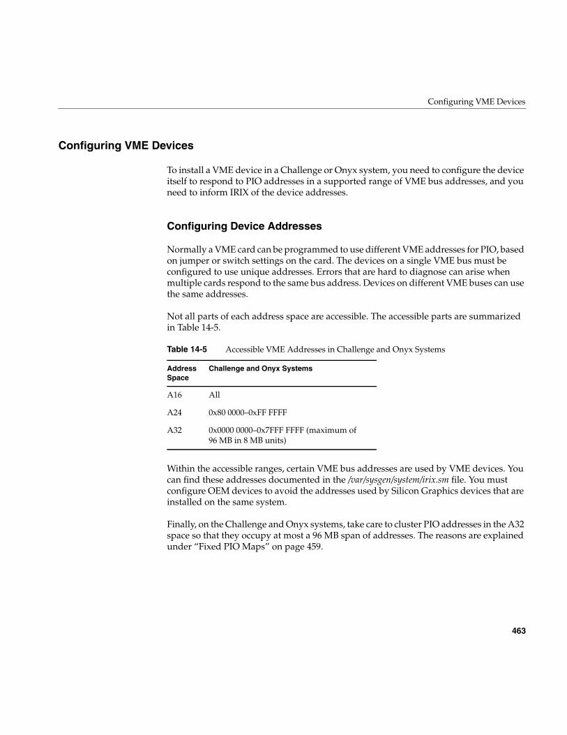
Configuring VME Devices
463
Configuring VME Devices
To install a VME device in a Challenge or Onyx system, you need to configure the deviceitself to respond to PIO addresses in a supported range of VME bus addresses, and youneed to inform IRIX of the device addresses.
Configuring Device Addresses
Normally a VME card can be programmed to use different VME addresses for PIO, basedon jumper or switch settings on the card. The devices on a single VME bus must beconfigured to use unique addresses. Errors that are hard to diagnose can arise whenmultiple cards respond to the same bus address. Devices on different VME buses can usethe same addresses.
Not all parts of each address space are accessible. The accessible parts are summarizedin Table 14-5.
Within the accessible ranges, certain VME bus addresses are used by VME devices. Youcan find these addresses documented in the /var/sysgen/system/irix.sm file. You mustconfigure OEM devices to avoid the addresses used by Silicon Graphics devices that areinstalled on the same system.
Finally, on the Challenge and Onyx systems, take care to cluster PIO addresses in the A32space so that they occupy at most a 96 MB span of addresses. The reasons are explainedunder “Fixed PIO Maps” on page 459.
Table 14-5 Accessible VME Addresses in Challenge and Onyx Systems
AddressSpace
Challenge and Onyx Systems
A16 All
A24 0x80 0000–0xFF FFFF
A32 0x0000 0000–0x7FFF FFFF (maximum of96 MB in 8 MB units)
464
Chapter 14: VME Device Attachment on Challenge/Onyx
Configuring the System Files
Inform IRIX and the device driver of the existence of a VME device by adding a VECTORstatement to a file in the directory /var/sysgen/system (see “Kernel Configuration Files” onpage 56). The syntax of a VECTOR statement is documented in two places:
• The /var/sysgen/system/irix.sm file itself contains descriptive comments on the syntaxand meaning of the statement, as well as numerous examples.
• The system(4) reference page gives a more formal definition of the syntax.
In addition to the VECTOR statement, you may need to code an IPL statement.
Coding the VECTOR Statement
The important elements in a VECTOR line are as follows:
bustype Specified as VME for VME devices. The VECTOR statement can beused for other types of buses as well.
module The base name of the device driver for this device, as used in the/var/sysgen/master.d database (see “Master Configuration Database”on page 55 and “How Names Are Used in Configuration” onpage 259).
adapter The number of the VME bus where the device is attached—the busnumber in a Challenge or Onyx machine.
ipl The interrupt level at which the device causes interrupts, from 0 to 7.
vector An 8-bit value between 1 and 254 that the device returns during aninterrupt acknowledge cycle.
ctlr The “controller” number is simply an integer parameter that ispassed to the device driver at boot time. It can be used for exampleto specify a logical unit number.
iospace, iospace2,iospace3
Each iospace group specifies the VME address space, the starting busaddress, and the size of a segment of VME address space used by thisdevice.
probe or exprobe Specify a hardware test that can be applied at boot time to find out ifthe device exists.
Configuring VME Devices
465
Use the probe or exprobe parameter to program a test for the existence of the device at boottime. If the device does not respond (because it is offline or because it has been removedfrom the system), the lboot command will not invoke the device driver for this device.
The device driver specified by the module parameter is invoked at its pfxedtinit() entrypoint, where it receives most of the other information specified in the VECTOR statement(see “Entry Point edtinit()” on page 151).
Omit the vector parameter in either of two cases: when the device does not causeinterrupts, or when it supports a programmable interrupt vector (see “Allocating anInterrupt Vector Dynamically” on page 466).
Use the iospace parameters to pass in the exact VME bus addresses that correspond to thisdevice, as configured in the device. Up to three address space ranges can be passed to thedriver. This does not restrict the device—it can use other ranges of addresses, but thedevice driver has to deduce their addresses from other information. The device drivertypically uses this data to set up PIO maps (see “PIO Addressing in Challenge and OnyxSystems” on page 456)
Using the IPL Statement
In a Challenge or Onyx system, you can direct VME interrupts to specific CPUs. This isdone with the IPL statement, also written into a file in /var/sysgen/system. The IPLstatement, which like the VECTOR statement is documented in both the system(4)reference page and the /var/sysgen/system/irix.sm file itself, has only two parameters:
The purpose of the IPL statement is to send interrupts from specific devices to a specificCPU. There are two contradictory reasons for doing this:
• That CPU is dedicated to handling those interrupts with minimum latency
• Those interrupts would disrupt high-priority work being done on other CPUs ifthey were allowed to reach the other CPUs.
The IPL statement cannot direct interrupts from a specific device; it directs all interruptsthat occur at the specified level.
level The VME interrupt level to be directed, 0 to 7 (the same value that iscoded as ipl= in the VECTOR statement.
cpu The number of the CPU that should handle all VME interrupts at thislevel.
466
Chapter 14: VME Device Attachment on Challenge/Onyx
Allocating an Interrupt Vector Dynamically
When a VME device generates an interrupt, the Silicon Graphics VME controller initiatesan interrupt acknowledge (IACK) cycle on the VME bus. During this cycle, theinterrupting device presents a data value that characterizes the interrupt. This is theinterrupt vector, in VME terminology.
According to the VME standard, the interrupt vector can be a data item of 8, 16, or 32 bits.However, Challenge and Onyx systems accept only an 8-bit vector, and its value must fallin the range 1-254 inclusive. (0x00 and 0xFF are excluded because they could begenerated by a hardware fault.)
The interrupt vector returned by some VME devices is hard-wired or configured into theboard with switches or jumpers. When this is the case, the vector number should bewritten as the vector parameter in the VECTOR statement that describes the device (see“Configuring the System Files” on page 464).
Some VME devices are programmed with a vector number at runtime. For these devices,you omit the vector parameter, or give its value as an asterisk. In the device driver, youuse the functions in Table 14-6 to choose a vector number.
Table 14-6 Functions to Manage Interrupt Vector Values
Function HeaderFiles
Can Sleep Purpose
vme_ivec_alloc(D3) vmereg.h& types.h
N Allocate a VME bus interrupt vector.
vme_ivec_free(D3) vmereg.h& types.h
N Free a VME bus interrupt vector.
vme_ivec_set(D3) vmereg.h& types.h
N Register a VME bus interrupt vector.

Configuring VME Devices
467
Allocating a Vector
In the pfxedtinit() entry point, the device driver selects a vector number for the device touse. The best way to select a number is to call vme_ivec_alloc(), which returns a numberthat has not been registered for that bus, either dynamically or in a VECTOR line.
The driver then uses vme_ivec_set() to register the chosen vector number. This functiontakes parameters that specify
• The vector number
• The bus number to which it applies
• The address of the interrupt handler for this vector—typically but not necessarilythe name of the pfxintr() entry point of the same driver
• An integer value to be passed to the interrupt entry point—typically but notnecessarily the vector number
The vme_ivec_set() function simply registers the number in the kernel, with thefollowing two effects:
• The vme_ivec_alloc() function does not return the same number to another calluntil the number is released.
• The specified handler is called when any device presents this vector number on aninterrupt.
Multiple devices can present the identical vector, provided that the interrupt handler hassome way of distinguishing one device from another.
Note: If you are working with both the VME and EISA interfaces, it is worth noting thatthe number and types of arguments of vme_ivec_set() differ from the similar EISAsupport function eisa_ivec_set().
468
Chapter 14: VME Device Attachment on Challenge/Onyx
Releasing a Vector
There is a limit of 254 vector numbers per bus, so it is a good idea for a loadable driver,in its pfxunload() entry point, to release a vector by calling vme_ivec_free() (see “EntryPoint unload()” on page 180 and “Unloading” on page 268).
Vector Errors
A common problem with programmable vectors in the Challenge or Onyx systems is theappearance of the following warning in the SYSLOG file:
Warning: Stray VME interrupt: vector =0xff
One possible cause of this error is that the board is emitting the wrong interrupt vector;another is that the board is emitting the correct vector but with the wrong timing, so thatthe VME bus adapter samples all-binary-1 instead. Both these conditions can be verifiedwith a VME bus analyzer. In the Challenge or Onyx hardware design, the most likelycause is the presence of empty slots in the VME card cage. All empty slots must beproperly jumpered in order to pass interrupts correctly.
VME Hardware in Challenge and Onyx Systems
The overview topic, “VME Bus in Challenge and Onyx Systems” on page 448, providessufficient orientation for most users of VME devices. However, if you are designinghardware or a high-performance device driver specifically for the Challenge and Onyxsystems, the details in this topic are important.
Note: For information on physical cabinets, panels, slot numbering, cables and jumpers,and data about dimensions and airflow, refer to the Owner’s Guide manual for yourmachine. For example, see the POWER CHALLENGE AND CHALLENGE XL RackmountOwner’s Guide (007-1735) for the physical layout and cabling of VME busses in the largeChallenge systems.
VME Hardware Architecture
The VME bus interface circuitry for Challenge and Onyx systems resides on a mezzanineboard called the VMEbus Channel Adapter Module (VCAM) board. One VCAM boardis standard in every system and mounts directly on top of the IO4 board in the systemcard cage.
VME Hardware in Challenge and Onyx Systems
469
The IO4 board is the heart of the I/O subsystem. The IO4 board supplies the system witha basic set of I/O controllers and system boot and configuration devices such as serialand parallel ports, and Ethernet.
In addition, the IO4 board provides these interfaces:
• two Flat Cable Interconnects (FCIs) for connection to Card Cage 3 (CC3)
• two SCSI-2 cable connections
• two Ibus connections
A Challenge or Onyx system can contain multiple IO4 boards, which can operate inparallel. (Early versions of the IO4 have a possible hardware problem that is described inAppendix B, “Challenge DMA with Multiple IO4 Boards”.)
Main System Bus
The main set of buses in the Challenge and Onyx system architecture is the Everestaddress and data buses, Ebus for short. The Ebus provides a 256-bit data bus and a 40-bitaddress bus that can sustain a bandwidth of 1.2 GB per second.
The 256-bit data bus provides the data transfer capability to support a large number ofhigh-performance RISC CPUs. The 40-bit address bus is also wide enough to support16 GB of contiguous memory in addition to an 8 GB I/O address space.
Ibus
The 64-bit Ibus (also known as the HIO bus) is the main internal bus of the I/Osubsystem and interfaces to the high-power Ebus through a group of bus adapters.TheIbus has a bandwidth of 320 MB per second that can sufficiently support a graphicssubsystem, a VME64 bus, and as many as eight SCSI channels operating simultaneously.
Bus Interfacing
Communication with the VME and SCSI buses, the installed set or sets of graphicsboards, and Ethernet takes place through the 64-bit Ibus. The Ibus interfaces to the mainsystem bus, the 256-bit Ebus, through a set of interface control devices, an I address (IA)and four I data (ID). The ID ASICs latch the data, and the IA ASIC clocks the data fromeach ID to the Flat Cable Interface (FCI) through the F controller (or F chip).
470
Chapter 14: VME Device Attachment on Challenge/Onyx
Two FCI controllers (or F controllers) help handle the data transfers to and from aninternal graphics board set (if present) and any VMEbus boards in optional CC3applications. The SCSI-2 (S1) controller serves as an interface to the various SCSI-2 buses.The Everest peripheral controller (EPC) device manages the data movement to and fromthe Ethernet, a parallel port, and various types of on-board PROMs and RAM.
Maximum Latency
The worst-case delay for the start of a VME access, if all of the devices on the IO4simulataneously request the IO channel for a 128 byte write and the VME adapterreceives the grant last, the VME access start could be delayed for a total of about2 microseconds. Only a VME read would suffer this delay; a VME write would not.
There is a another potential delay from an independent cause, which depends on thenumber of bus master (IO4 and CPU) boards on the system bus. If all the E-bus mastersin a fairly large configuration hit the bus at once, a VME read or write could be held upby as much as 1 microsecond in a large system.
VME Bus Numbering
The Challenge and Onyx systems support up to five independent VME buses in a singlesystem. The numbering of these buses is not sequential.
There is always a VME bus number 0. This is the bus connected to the system midplane.It is always connected by the primary IO4 board (the IO4 board attached to the highestslot on the system bus).
Bus numbers for other VME buses depend on the Ebus slot number where their IO4 isattached, and on the I/O adapter number of the VCAM card on the IO4. Each IO4 boardsupports adapter numbers from 1 to 7, but a VME bus can only be attached to adapternumber 2, 3, 5, or 6. These four adapters are given VME index numbers of 0, 1, 2, and 3respectively.
The bus number of a VME bus is given by E*4+A, where E is the Ebus slot of the IO4 card,and A is the index of the adapter on the IO4. A VME bus attached through adapter 3 onthe IO4 in Ebus slot 13 is bus number 53, from the sum of adapter index 1 and 4 times theslot number.
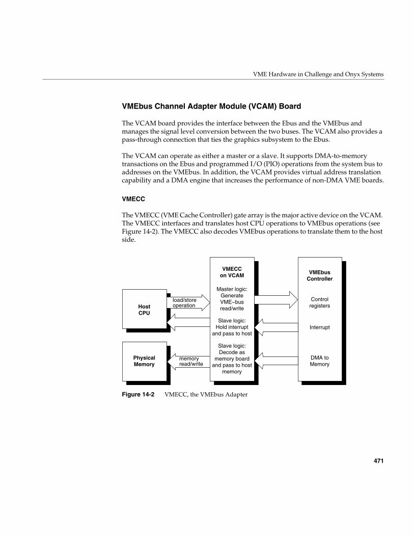
VME Hardware in Challenge and Onyx Systems
471
VMEbus Channel Adapter Module (VCAM) Board
The VCAM board provides the interface between the Ebus and the VMEbus andmanages the signal level conversion between the two buses. The VCAM also provides apass-through connection that ties the graphics subsystem to the Ebus.
The VCAM can operate as either a master or a slave. It supports DMA-to-memorytransactions on the Ebus and programmed I/O (PIO) operations from the system bus toaddresses on the VMEbus. In addition, the VCAM provides virtual address translationcapability and a DMA engine that increases the performance of non-DMA VME boards.
VMECC
The VMECC (VME Cache Controller) gate array is the major active device on the VCAM.The VMECC interfaces and translates host CPU operations to VMEbus operations (seeFigure 14-2). The VMECC also decodes VMEbus operations to translate them to the hostside.
Figure 14-2 VMECC, the VMEbus Adapter
HostCPU
VMECCon VCAM
Master logic:GenerateVME−busread/write
Slave logic:Hold interrupt
and pass to host
Slave logic:Decode as
memory boardand pass to host
memory
Controlregisters
Interrupt
DMA toMemory
VMEbusController
PhysicalMemory
load/storeoperation
memoryread/write
472
Chapter 14: VME Device Attachment on Challenge/Onyx
The VMECC provides the following features:
• an internal DMA engine to speed copies between physical memory and VME space(see “Operation of the DMA Engine” on page 452)
• a 16-entry deep PIO FIFO to smooth writing to the VME bus from the host CPUs
• a built-in VME interrupt handler and built-in VME bus arbiter
• an explicit internal delay register to aid in spacing PIOs for VME controller boardsthat cannot accept back-to-back operations
• support for issuing A16, A24, A32, and A64 addressing modes as a bus masterduring PIO
• support for single-item transfers (D8, D16, D32, and D64) as a bus master duringPIO
• support for response as a slave to A24, A32, and A64 addressing modes to provideDMA access to the Ebus
• support for single-item transfers (D8, D16, and D32) as a slave during DMA accessto the Ebus
• support for block item transfers (D8, D16, D32, and D64) as a slave during DMAaccess to the Ebus
The VMECC also provides four levels of VMEbus request grants, 0-3 (3 has the highestpriority), for DMA arbitration. Do not confuse these bus request levels with the interruptpriority levels 1-7. Bus requests prioritize the use of the physical lines representing thebus and are normally set by means of jumpers on the interface board.
F Controller ASIC
Data transfers between VME controller boards and the host CPU(s) takes place throughthe VMECC on the VCAM board, then through a flat cable interface (FCI), and onto theF controller ASIC.
The F controller acts as an interface between the Ibus and the Flat Cable Interfaces (FCIs).This device is primarily composed of FIFO registers and synchronizers that provideprotocol conversion and buffer transactions in both directions and translate 34-bit I/Oaddresses into 40-bit system addresses.
VME Hardware in Challenge and Onyx Systems
473
Two configurations of the F controller are used on the IO4 board; the difference betweenthem is the instruction set they contain. One version is programmed with a set ofinstructions designed to communicate with the GFXCC (for graphics); the other versionhas instructions designed for the VMECC. All communication with the GFXCC orVMECC ICs is done over the FCI, where the F controller is always the slave.
Both versions of the F controller ASICs have I/O error-detection and handlingcapabilities. Data errors that occur on either the Ibus or the FCI are recorded by the Fcontroller and sent to the VMECC or GFXCC.
ICs must report the error to the appropriate CPU and log any specific information aboutthe operation in progress. FCI errors are recorded in the error status register. This registerprovides the status of the first error that occurred, as well as the cause of the most recentFCI reset.
VMEbus Interrupt Generation
The VME bus supports seven levels of prioritized interrupts, 1 through 7 (where 7 hasthe highest priority). The VMECC has a register associated with each level. When thesystem responds to the VMEbus interrupt, it services all devices identified in theinterrupt vector register in order of their VMEbus priority (highest number first). Thefollowing list outlines how a VMEbus interrupt is generated:
1. A VME controller board asserts a VME interrupt on one of the IRQ levels.
2. The built-in interrupt handler in the VMECC chip checks if the interrupt level ispresently enabled by an internal interrupt mask.
3. The interrupt handler in the VMECC issues a bussed IACK (interrupt acknowledge)response and acquires the vector from the device. The 3-bit response identifies oneof the seven VME levels.
4. If multiple VME boards are present, the bussed IACK signal is sent to the first VMEcontroller as an IACKIN. When the first controller is not the requesting master, itpasses the IACKIN signal to the next board (in the daisy-chain) as IACKOUT.
5. The requesting board responds to IACKIN by issuing a DTACK* (data acknowledgesignal), blocking the IACKOUT signal to the next board, and placing an 8-bitinterrupt vector number on the data bus.
6. The VMECC latches the interrupt vector, and an interrupt signal is sent over the FCIinterface to the F-chip and is queued awaiting completion of other F-chip tasks.
7. The F controller ASIC requests the I-bus and sends the interrupt to the IA chip.
474
Chapter 14: VME Device Attachment on Challenge/Onyx
8. The IA chip requests the Ebus and sends the interrupt over the Ebus to the CC chipon the IP19/IP21 board.
9. The CC chip interrupts the R4400/R8000, provided that the interrupt level is notmasked.
The time for this to complete is normally less than 3 microseconds, but will be queued toawait completion of other VME activities.
VME Interface Features and Restrictions
The Challenge and Onyx VME interface supports all protocols defined in Revision C ofthe VME specification plus the A64 and D64 modes defined in Revision D. The D64 modeallows DMA bandwidths of up to 60 MB. This bus also supports the following features:
• seven levels of prioritized processor interrupts
• 16-bit, 24-bit, and 32-bit data addresses and 64-bit memory addresses
• 16-bit and 32-bit accesses (and 64-bit accesses in MIPS III mode)
• 8-bit, 16-bit, 32-bit, and 64-bit data transfer
• DMA to and from main memory
DMA Multiple Address Mapping
In the Challenge and Onyx series, a DMA address from a VME controller goes througha two-level translation to generate an acceptable physical address. This requires twolevels of mapping. The first level of mapping is done through the map RAM on the IO4board. The second level is done through the map tables in system memory. This mappingis shown in Figure 14-3.
Note: The second level mapping requires system memory to be reserved for themapping tables. The current limit on the number of pages that is allocated for map tablesis 16 pages and the maximum memory allotted for the map tables is 64 KB. The R4400provides a 4 KB page size for 16 pages (4 KB * 16 pages= 64 KB). The R8000 provides a16 KB page size for 4pages (16 KB * 4 pages = 64 KB).
VME Hardware in Challenge and Onyx Systems
475
Each second-leel map table entry corresponds to 4 KB of physical memory. In addition,each second-level map table entry is 4 bytes. With 64 KB of mapping table, there are atotal of 16 K entries translating a maximum of 64 MB of DMA mapping, setting a limit of64 MB that can be mapped at any time for each VME bus. This does not set any limit onthe amount of DMA that can be done by a board during its operation.
Referring to the top of Figure 14-3, bits 32 and 33 from the IBus address come from theVMECC. These two bits determine a unique VMEbus number for systems with multipleVME buses. Of the remaining 32 bits (31 to 0), 12 are reserved for an offset in physicalmemory, and the other 20 bits are used to select up to 220 or 1 million pages into the mainmemory table. However, as stated earlier only 64 KB is allocated for map tables.
As shown in Figure 14-3, thirteen bits go to the static RAM table. Recall that two of thethirteen bits are from the VMECC to identify the VMEbus number. The static RAM tablethen generates a 29-bit identifier into the main memory table. These 29 bits select a tablein the main memory table. An additional nine bits select an entry or element within thetable. A 00 (two zeros) are appended to form a 40-bit address into the main memory table.
The main memory table then generates 28-bit address which is then appended to the12-bit offset of the IBus to form the final 40-bit physical address.
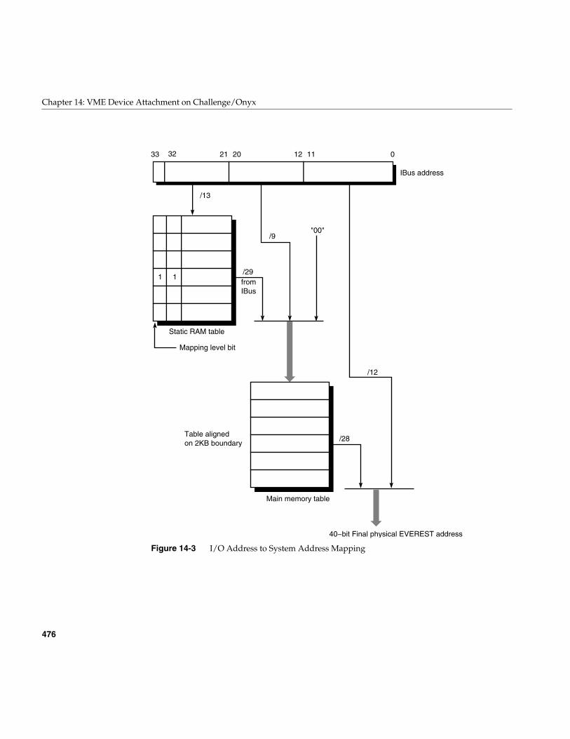
476
Chapter 14: VME Device Attachment on Challenge/Onyx
Figure 14-3 I/O Address to System Address Mapping
Static RAM table
Mapping level bit
"00"/9
/29
/13
fromIBus
Main memory table
/12
/28
01112202133
Table alignedon 2KB boundary
IBus address
40−bit Final physical EVEREST address
1 1
32
VME Hardware in Challenge and Onyx Systems
477
VME Interrupt Priority
Interrupts within the Challenge/Onyx architecture are managed by a set of interruptvectors. An interrupt generated by an I/O device like a VME controller in turn generatesan interrupt to the CPU on one of the previously assigned levels.
Each IRQ on each VME bus is assigned an internal interrupt level, and by default all theselevels are at the same priority. If multiple interrupts arrive simultaneously within a singlebus, for example IRQ 3 and IRQ 4 at once, priority is given to the higher-numbered IRQ.
All VME interrupts are made to go to CPU 0 (unless configured differently with IPLstatements). This prevents one interrupt level from preempting the driver handling adifferent VME interrupt level.
VME Hardware Features and Restrictions
When designing an OEM hardware board to interface to the Challenge or Onyx VMEbus, observe the following restrictions:
• Devices should require 8-bit interrupt vectors only. This is the only interrupt vectorsize that is supported by the VMECC or recognized by the IRIX kernel.
• Devices must not require UAT (unaligned transfer or tri-byte) access.
• Devices in slave mode must not require address modifiers other thanSupervisory/Nonprivileged data access.
• While in master mode, a device must use only nonprivileged data access ornonprivileged block transfers.
• The Challenge or Onyx VME bus does not support VSBbus boards. In addition,there are no pins on the back of the VME backplane. This area is inaccessible forcables or boards.
• Metal face plates or front panels on VME boards may prevent the I/O door fromproperly closing and can possibly damage I/O bulkhead. (In some VME enclosures,a face plate supplies required EMI shielding. However, the Challenge chassisalready provides sufficient shielding, so these plates are not necessary.)
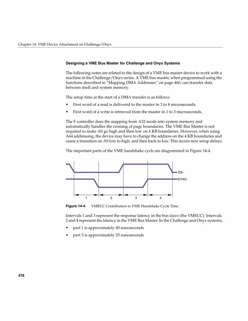
478
Chapter 14: VME Device Attachment on Challenge/Onyx
Designing a VME Bus Master for Challenge and Onyx Systems
The following notes are related to the design of a VME bus master device to work with amachine in the Challenge/Onyx series. A VME bus master, when programmed using thefunctions described in “Mapping DMA Addresses” on page 460, can transfer databetween itself and system memory.
The setup time at the start of a DMA transfer is as follows:
• First word of a read is delivered to the master in 3 to 8 microseconds.
• First word of a write is retrieved from the master in 1 to 3 microseconds.
The F controller does the mapping from A32 mode into system memory andautomatically handles the crossing of page boundaries. The VME Bus Master is notrequired to make AS go high and then low on 4 KB boundaries. However, when usingA64 addressing, the device may have to change the address on the 4 KB boundaries andcause a transition on AS low to high, and then back to low. This incurs new setup delays.
The important parts of the VME handshake cycle are diagrammed in Figure 14-4.
Figure 14-4 VMECC Contribution to VME Handshake Cycle Time
Intervals 1 and 3 represent the response latency in the bus slave (the VMECC). Intervals2 and 4 represent the latency in the VME Bus Master. In the Challenge and Onyx systems,
• part 1 is approximately 40 nanoseconds
• part 3 is approximately 25 nanoseconds
1 2 3 4
DS-
DTAC-
VME Hardware in Challenge and Onyx Systems
479
The total contribution by the VMECC is approximately 65 nanoseconds. If the total of thefour intervals can be held to 125 nanoseconds, the absolute peak transfer rate (in D64mode) is 64 MB per second.
Note: Startup and latency numbers are averages and may occasionally be longer. Thesystem design does not have any guaranteed latency.
The VME specification provides for a burst length of 265 bytes in D8, D16, and D32modes, or 2 KB in D64. The burst length is counted in bytes, not transfer cycles.
Operating at this burst length, the duration of a single burst of 2 KB would be 256transfers at 125 nanoseconds each, plus a startup of roughly 5 microseconds, giving atotal of 37 microseconds per burst. Continuous, back-to-back bursts could achieve atmost 55 MB per second.
However, the Challenge and Onyx VMECC uses a 20-bit burst counter allowing up to2 MB in a burst of any data size. Suppose the bus master transfers 64 KB per burst,transferring 4-byte data words. The duration of a single burst would be 8,192 times 125nanoseconds, plus 5 microseconds startup, or 1,029 microseconds per burst. Continuousbursts of this size achieve a data rate of 63.7 MB per second.
The use of long bursts violates the VME standard, and a bus master that depends on longbursts is likely not to work in other computers. If you decide to exceed the VME busspecifications, you should condition this feature with a field in a control register on theVME board, so that it can be disabled for use on other VME systems.

481
Chapter 15
15.Services for VME Drivers on Challenge/Onyx
This chapter provides an overview of the kernel services needed by a kernel-level VMEdevice driver on Challenge and Onyx systems. It contains a complete example driver.
Note: For information on writing VME device drivers for Origina and Onyx2 systems,refer to Chapter 13. For information on porting IRIX 6.2 drivers to IRIX 6.5, refer to“Porting From IRIX 6.2” on page 369.
Kernel Services for VME
The kernel provides services for mapping the VME bus into the kernel virtual addressspace for PIO or DMA, and for transferring data using maps. It also provides services forallocating interrupt vector numbers.
Mapping PIO Addresses
A PIO map is a system object that represents the mapping from a location in the kernel’svirtual address space to some small range of addresses on a VME or EISA bus. Aftercreating a PIO map, a device driver can use it in the following ways:
• Use the specific kernel virtual address that represents the device, either to load orstore data, or to map that address into user process space.
• Copy data between the device and memory without learning the specific kerneladdresses involved.
• Perform bus read-modify-write cycles to apply Boolean operators efficiently todevice data.
The kernel virtual address returned by PIO mapping is not a physical memory addressand is not a bus address. The kernel virtual address and the VME or EISA bus addressneed not have any bits in in common.
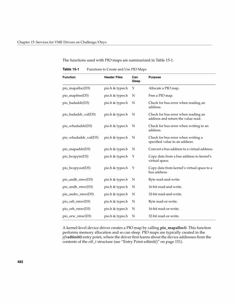
482
Chapter 15: Services for VME Drivers on Challenge/Onyx
The functions used with PIO maps are summarized in Table 15-1.
A kernel-level device driver creates a PIO map by calling pio_mapalloc(). This functionperforms memory allocation and so can sleep. PIO maps are typically created in thepfxedtinit() entry point, where the driver first learns about the device addresses from thecontents of the edt_t structure (see “Entry Point edtinit()” on page 151).
Table 15-1 Functions to Create and Use PIO Maps
Function Header Files CanSleep
Purpose
pio_mapalloc(D3) pio.h & types.h Y Allocate a PIO map.
pio_mapfree(D3) pio.h & types.h N Free a PIO map.
pio_badaddr(D3) pio.h & types.h N Check for bus error when reading anaddress.
pio_badaddr_val(D3) pio.h & types.h N Check for bus error when reading anaddress and return the value read.
pio_wbadaddr(D3) pio.h & types.h N Check for bus error when writing to anaddress.
pio_wbadaddr_val(D3) pio.h & types.h N Check for bus error when writing aspecified value to an address.
pio_mapaddr(D3) pio.h & types.h N Convert a bus address to a virtual address.
pio_bcopyin(D3) pio.h & types.h Y Copy data from a bus address to kernel’svirtual space.
pio_bcopyout(D3) pio.h & types.h Y Copy data from kernel’s virtual space to abus address.
pio_andb_rmw(D3) pio.h & types.h N Byte read-and-write.
pio_andh_rmw(D3) pio.h & types.h N 16-bit read-and-write.
pio_andw_rmw(D3) pio.h & types.h N 32-bit read-and-write.
pio_orb_rmw(D3) pio.h & types.h N Byte read-or-write.
pio_orh_rmw(D3) pio.h & types.h N 16-bit read-or-write.
pio_orw_rmw(D3) pio.h & types.h N 32-bit read-or-write.
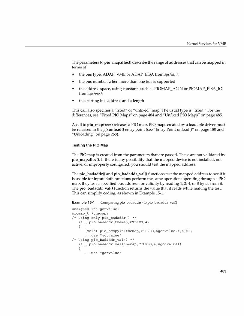
Kernel Services for VME
483
The parameters to pio_mapalloc() describe the range of addresses that can be mapped interms of
• the bus type, ADAP_VME or ADAP_EISA from sys/edt.h
• the bus number, when more than one bus is supported
• the address space, using constants such as PIOMAP_A24N or PIOMAP_EISA_IOfrom sys/pio.h
• the starting bus address and a length
This call also specifies a “fixed” or “unfixed” map. The usual type is “fixed.” For thedifferences, see “Fixed PIO Maps” on page 484 and “Unfixed PIO Maps” on page 485.
A call to pio_mapfree() releases a PIO map. PIO maps created by a loadable driver mustbe released in the pfxunload() entry point (see “Entry Point unload()” on page 180 and“Unloading” on page 268).
Testing the PIO Map
The PIO map is created from the parameters that are passed. These are not validated bypio_mapalloc(). If there is any possibility that the mapped device is not installed, notactive, or improperly configured, you should test the mapped address.
The pio_badaddr() and pio_badaddr_val() functions test the mapped address to see if itis usable for input. Both functions perform the same operation: operating through a PIOmap, they test a specified bus address for validity by reading 1, 2, 4, or 8 bytes from it.The pio_badaddr_val() function returns the value that it reads while making the test.This can simplify coding, as shown in Example 15-1.
Example 15-1 Comparing pio_badaddr() to pio_badaddr_val()
unsigned int gotvalue;piomap_t *themap;/* Using only pio_badaddr() */
if (!pio_badaddr(themap,CTLREG,4){
(void) pio_bcopyin(themap,CTLREG,&gotvalue,4,4,0);...use "gotvalue"
/* Using pio_badaddr_val() */if (!pio_badaddr_val(themap,CTLREG,4,&gotvalue)){
...use "gotvalue"
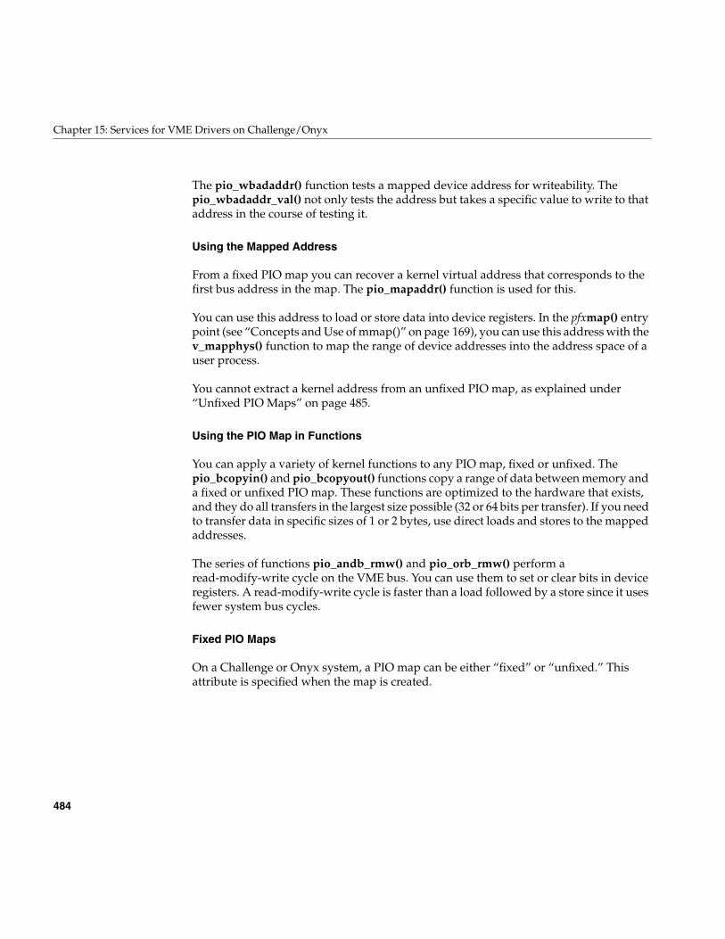
484
Chapter 15: Services for VME Drivers on Challenge/Onyx
The pio_wbadaddr() function tests a mapped device address for writeability. Thepio_wbadaddr_val() not only tests the address but takes a specific value to write to thataddress in the course of testing it.
Using the Mapped Address
From a fixed PIO map you can recover a kernel virtual address that corresponds to thefirst bus address in the map. The pio_mapaddr() function is used for this.
You can use this address to load or store data into device registers. In the pfxmap() entrypoint (see “Concepts and Use of mmap()” on page 169), you can use this address with thev_mapphys() function to map the range of device addresses into the address space of auser process.
You cannot extract a kernel address from an unfixed PIO map, as explained under“Unfixed PIO Maps” on page 485.
Using the PIO Map in Functions
You can apply a variety of kernel functions to any PIO map, fixed or unfixed. Thepio_bcopyin() and pio_bcopyout() functions copy a range of data between memory anda fixed or unfixed PIO map. These functions are optimized to the hardware that exists,and they do all transfers in the largest size possible (32 or 64 bits per transfer). If you needto transfer data in specific sizes of 1 or 2 bytes, use direct loads and stores to the mappedaddresses.
The series of functions pio_andb_rmw() and pio_orb_rmw() perform aread-modify-write cycle on the VME bus. You can use them to set or clear bits in deviceregisters. A read-modify-write cycle is faster than a load followed by a store since it usesfewer system bus cycles.
Fixed PIO Maps
On a Challenge or Onyx system, a PIO map can be either “fixed” or “unfixed.” Thisattribute is specified when the map is created.
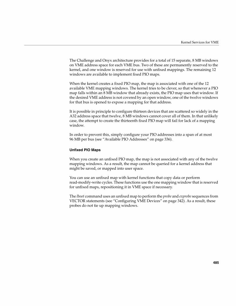
Kernel Services for VME
485
The Challenge and Onyx architecture provides for a total of 15 separate, 8 MB windowson VME address space for each VME bus. Two of these are permanently reserved to thekernel, and one window is reserved for use with unfixed mappings. The remaining 12windows are available to implement fixed PIO maps.
When the kernel creates a fixed PIO map, the map is associated with one of the 12available VME mapping windows. The kernel tries to be clever, so that whenever a PIOmap falls within an 8 MB window that already exists, the PIO map uses that window. Ifthe desired VME address is not covered by an open window, one of the twelve windowsfor that bus is opened to expose a mapping for that address.
It is possible in principle to configure thirteen devices that are scattered so widely in theA32 address space that twelve, 8 MB windows cannot cover all of them. In that unlikelycase, the attempt to create the thirteenth fixed PIO map will fail for lack of a mappingwindow.
In order to prevent this, simply configure your PIO addresses into a span of at most96 MB per bus (see “Available PIO Addresses” on page 336).
Unfixed PIO Maps
When you create an unfixed PIO map, the map is not associated with any of the twelvemapping windows. As a result, the map cannot be queried for a kernel address thatmight be saved, or mapped into user space.
You can use an unfixed map with kernel functions that copy data or performread-modify-write cycles. These functions use the one mapping window that is reservedfor unfixed maps, repositioning it in VME space if necessary.
The lboot command uses an unfixed map to perform the probe and exprobe sequences fromVECTOR statements (see “Configuring VME Devices” on page 342). As a result, theseprobes do not tie up mapping windows.
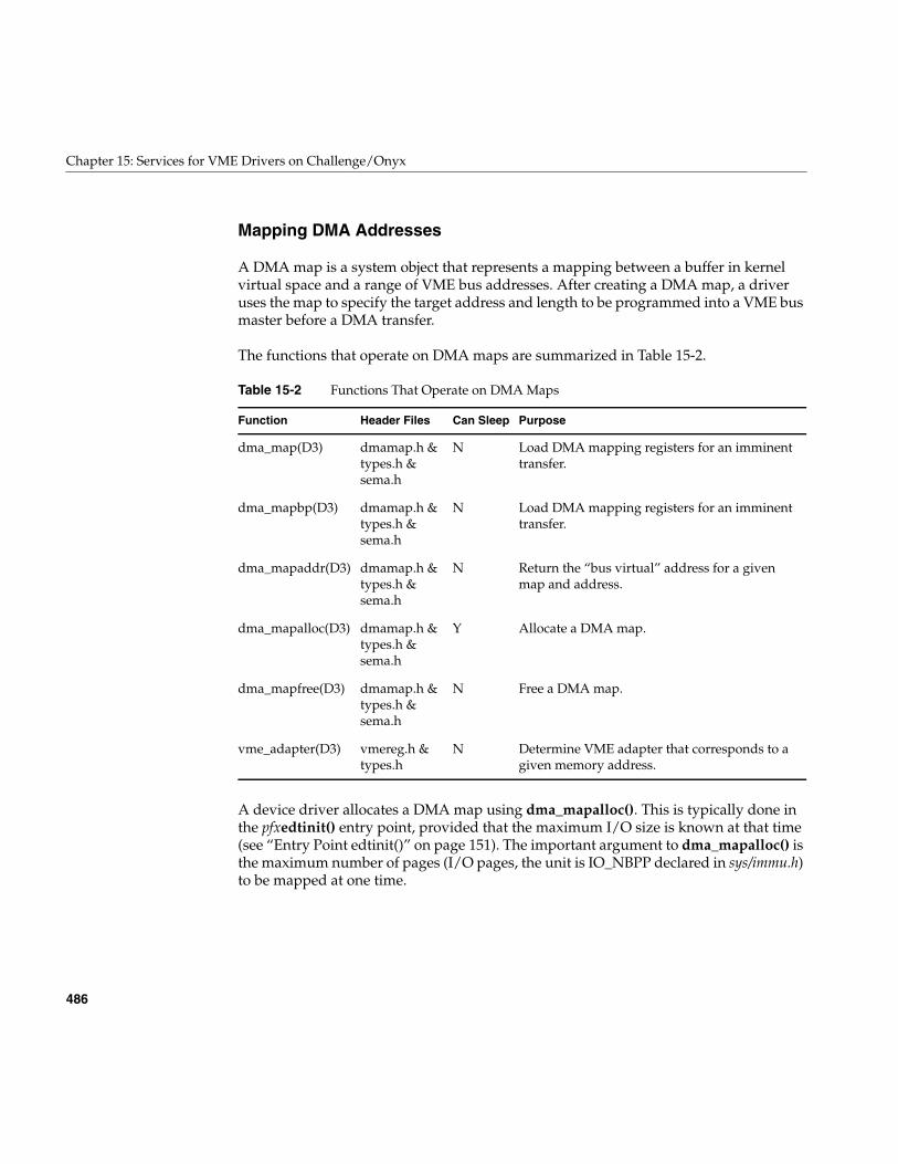
486
Chapter 15: Services for VME Drivers on Challenge/Onyx
Mapping DMA Addresses
A DMA map is a system object that represents a mapping between a buffer in kernelvirtual space and a range of VME bus addresses. After creating a DMA map, a driveruses the map to specify the target address and length to be programmed into a VME busmaster before a DMA transfer.
The functions that operate on DMA maps are summarized in Table 15-2.
A device driver allocates a DMA map using dma_mapalloc(). This is typically done inthe pfxedtinit() entry point, provided that the maximum I/O size is known at that time(see “Entry Point edtinit()” on page 151). The important argument to dma_mapalloc() isthe maximum number of pages (I/O pages, the unit is IO_NBPP declared in sys/immu.h)to be mapped at one time.
Table 15-2 Functions That Operate on DMA Maps
Function Header Files Can Sleep Purpose
dma_map(D3) dmamap.h &types.h &sema.h
N Load DMA mapping registers for an imminenttransfer.
dma_mapbp(D3) dmamap.h &types.h &sema.h
N Load DMA mapping registers for an imminenttransfer.
dma_mapaddr(D3) dmamap.h &types.h &sema.h
N Return the “bus virtual” address for a givenmap and address.
dma_mapalloc(D3) dmamap.h &types.h &sema.h
Y Allocate a DMA map.
dma_mapfree(D3) dmamap.h &types.h &sema.h
N Free a DMA map.
vme_adapter(D3) vmereg.h &types.h
N Determine VME adapter that corresponds to agiven memory address.
Kernel Services for VME
487
Note: In the Challenge and Onyx systems, a limit of 64 MB of mapped DMA space perVME adapater is imposed by the hardware. Some few megabytes of this are taken earlyby system drivers. Owing to a bug in IRIX 5.3 and 6.1, a request for 64 MB or more is notrejected, but waits forever. However, in any release, a call to dma_mapalloc() thatrequests a single map close to the 64 MB limit is likely to wait indefinitely for enoughmap space to become available.
DMA maps created by a loadable driver should be released in the pfxunload() entrypoint (see “Entry Point unload()” on page 180 and “Unloading” on page 268).
Using a DMA Map
A DMA map is used prior to a DMA transfer into or out of a buffer in kernel virtualspace. The function dma_map() takes a DMA map, a buffer address, and a length. Itassigns a span of contiguous VME addresses of the specified length, and sets up amapping between that range of VME addresses and the physical addresses that representthe specified buffer.
When the buffer spans two or more physical pages (IO_NBPP units), dma_map() sets upa scatter/gather operation, so that the VME bus controller will place the data in theappropriate page frames.
It is possible that dma_map() cannot map the entire size of the buffer. This can occur onlywhen the buffer spans two or more pages, and is caused by a shortage of mappingregisters in the bus adapter. The function maps as much of the buffer as it can, andreturns the length of the mapped data.
You must always anticipate that dma_map() might map less than the requested numberof bytes, so that the DMA transfer has to be done in two or more operations.
Following the call to dma_map(), you call dma_mapaddr() to get the bus virtual addressthat represents the first byte of the buffer. This is the address you program into the busmaster device (using a PIO store), in order to set its starting transfer address. Then youinitiate the DMA transfer (again by storing a command into a device register using PIO).
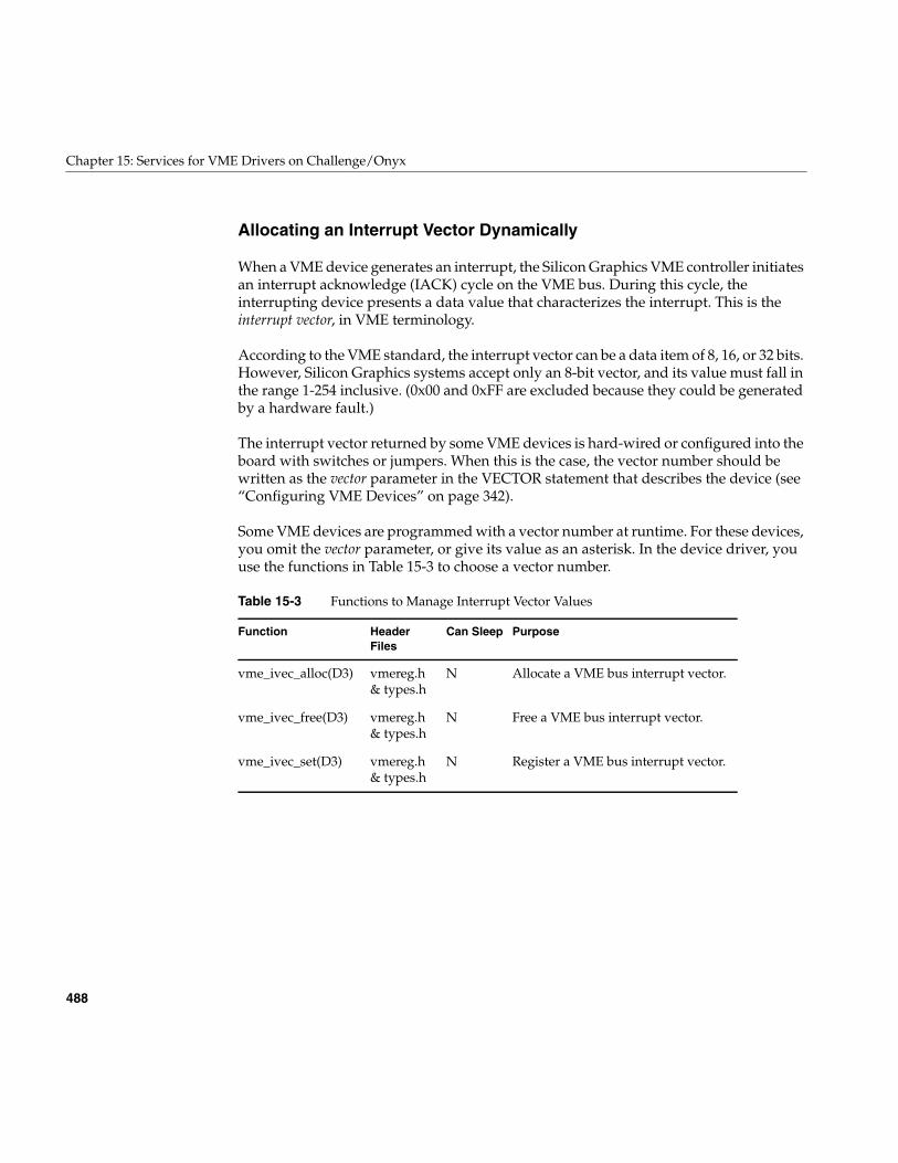
488
Chapter 15: Services for VME Drivers on Challenge/Onyx
Allocating an Interrupt Vector Dynamically
When a VME device generates an interrupt, the Silicon Graphics VME controller initiatesan interrupt acknowledge (IACK) cycle on the VME bus. During this cycle, theinterrupting device presents a data value that characterizes the interrupt. This is theinterrupt vector, in VME terminology.
According to the VME standard, the interrupt vector can be a data item of 8, 16, or 32 bits.However, Silicon Graphics systems accept only an 8-bit vector, and its value must fall inthe range 1-254 inclusive. (0x00 and 0xFF are excluded because they could be generatedby a hardware fault.)
The interrupt vector returned by some VME devices is hard-wired or configured into theboard with switches or jumpers. When this is the case, the vector number should bewritten as the vector parameter in the VECTOR statement that describes the device (see“Configuring VME Devices” on page 342).
Some VME devices are programmed with a vector number at runtime. For these devices,you omit the vector parameter, or give its value as an asterisk. In the device driver, youuse the functions in Table 15-3 to choose a vector number.
Table 15-3 Functions to Manage Interrupt Vector Values
Function HeaderFiles
Can Sleep Purpose
vme_ivec_alloc(D3) vmereg.h& types.h
N Allocate a VME bus interrupt vector.
vme_ivec_free(D3) vmereg.h& types.h
N Free a VME bus interrupt vector.
vme_ivec_set(D3) vmereg.h& types.h
N Register a VME bus interrupt vector.
Kernel Services for VME
489
Allocating a Vector
In the pfxedtinit() entry point, the device driver selects a vector number for the device touse. The best way to select a number is to call vme_ivec_alloc(), which returns a numberthat has not been registered for that bus, either dynamically or in a VECTOR line.
The driver then uses vme_ivec_set() to register the chosen vector number. This functiontakes parameters that specify
• The vector number
• The bus number to which it applies
• The address of the interrupt handler for this vector—typically but not necessarilythe name of the pfxintr() entry point of the same driver
• An integer value to be passed to the interrupt entry point—typically but notnecessarily the vector number
The vme_ivec_set() function simply registers the number in the kernel, with thefollowing two effects:
• The vme_ivec_alloc() function does not return the same number to another calluntil the number is released.
• The specified handler is called when any device presents this vector number on aninterrupt.
Multiple devices can present the identical vector, provided that the interrupt handler hassome way of distinguishing one device from another.
Note: If you are working with both the VME and EISA interfaces, it is worth noting thatthe number and types of arguments of vme_ivec_set() differ from the similar EISAsupport function eisa_ivec_set().
490
Chapter 15: Services for VME Drivers on Challenge/Onyx
Releasing a Vector
There is a limit of 254 vector numbers per bus, so it is a good idea for a loadable driver,in its pfxunload() entry point, to release a vector by calling vme_ivec_free() (see “EntryPoint unload()” on page 180 and “Unloading” on page 268).
Vector Errors
A common problem with programmable vectors in the Challenge or Onyx systems is theappearance of the following warning in the SYSLOG file:
Warning: Stray VME interrupt: vector =0xff
One possible cause of this error is that the board is emitting the wrong interrupt vector;another is that the board is emitting the correct vector but with the wrong timing, so thatthe VME bus adapter samples all-binary-1 instead. Both these conditions can be verifiedwith a VME bus analyzer. In the Challenge or Onyx hardware design, the most likelycause is the presence of empty slots in the VME card cage. All empty slots must beproperly jumpered in order to pass interrupts correctly.
Supporting Early IO4 Cache Problems
VME drivers that support DMA to buffers that are not cache-aligned multiples of acache-line need to take special precautions in a Challenge system; see Appendix B,“Challenge DMA with Multiple IO4 Boards”.
Sample VME Device Driver
The source module displayed in Table 15-2 contains a complete character device driverfor a hypothetical VME device. Although it is a character driver, it contains a strategyroutine (the cdev_strategy() function). Both the pfxread() and pfxwrite() entry points callthe strategy routine to perform the actual I/O. As a result, this driver could be installedas either a block device driver or a character driver, or as both.
The driver is multiprocessor-aware, so its pfxdevflag global contains D_MP. It uses twolocks. A basic lock (board.cd_lock) is used for short-term mutual exclusion, to block apotential race between the strategy routine and the interrupt routine. A semaphore(board.cd_rwsema) is used for long-term mutual exclusion to make sure that only oneprocess uses the device for reading or writing at any time.
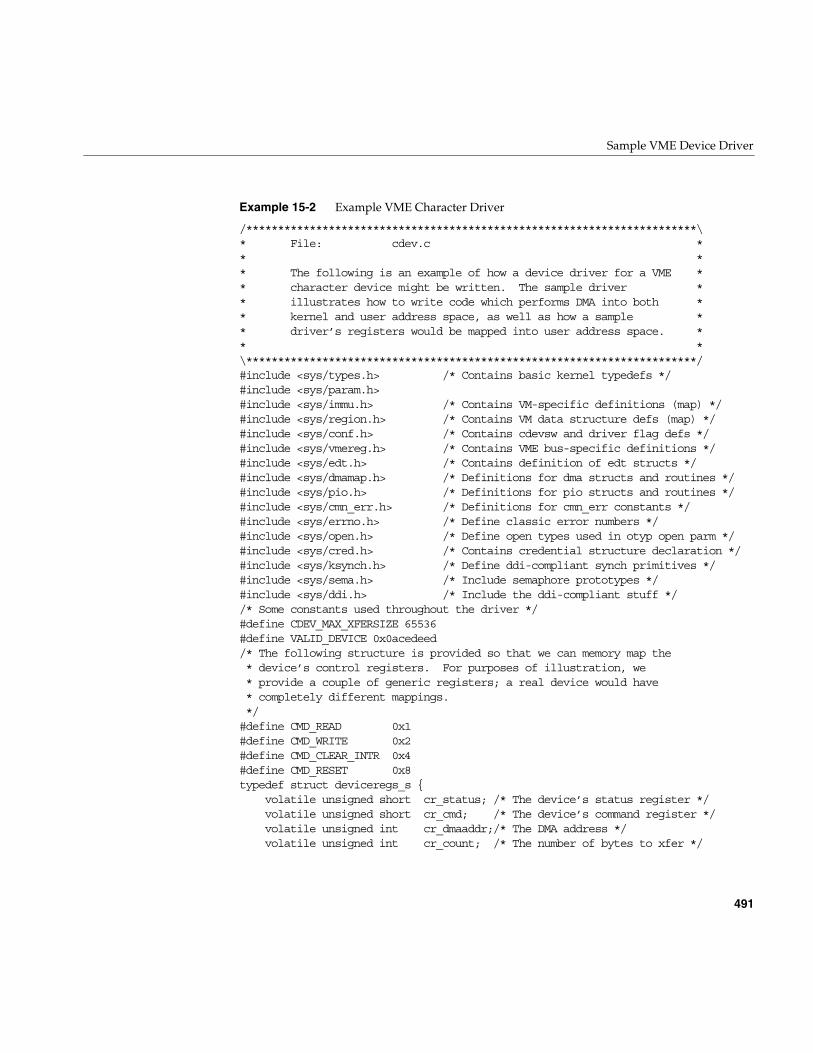
Sample VME Device Driver
491
Example 15-2 Example VME Character Driver
/***********************************************************************\* File: cdev.c ** ** The following is an example of how a device driver for a VME ** character device might be written. The sample driver ** illustrates how to write code which performs DMA into both ** kernel and user address space, as well as how a sample ** driver’s registers would be mapped into user address space. ** *\***********************************************************************/#include <sys/types.h> /* Contains basic kernel typedefs */#include <sys/param.h>#include <sys/immu.h> /* Contains VM-specific definitions (map) */#include <sys/region.h> /* Contains VM data structure defs (map) */#include <sys/conf.h> /* Contains cdevsw and driver flag defs */#include <sys/vmereg.h> /* Contains VME bus-specific definitions */#include <sys/edt.h> /* Contains definition of edt structs */#include <sys/dmamap.h> /* Definitions for dma structs and routines */#include <sys/pio.h> /* Definitions for pio structs and routines */#include <sys/cmn_err.h> /* Definitions for cmn_err constants */#include <sys/errno.h> /* Define classic error numbers */#include <sys/open.h> /* Define open types used in otyp open parm */#include <sys/cred.h> /* Contains credential structure declaration */#include <sys/ksynch.h> /* Define ddi-compliant synch primitives */#include <sys/sema.h> /* Include semaphore prototypes */#include <sys/ddi.h> /* Include the ddi-compliant stuff *//* Some constants used throughout the driver */#define CDEV_MAX_XFERSIZE 65536#define VALID_DEVICE 0x0acedeed/* The following structure is provided so that we can memory map the* device’s control registers. For purposes of illustration, we* provide a couple of generic registers; a real device would have* completely different mappings.*/#define CMD_READ 0x1#define CMD_WRITE 0x2#define CMD_CLEAR_INTR 0x4#define CMD_RESET 0x8typedef struct deviceregs_s {
volatile unsigned short cr_status; /* The device’s status register */volatile unsigned short cr_cmd; /* The device’s command register */volatile unsigned int cr_dmaaddr;/* The DMA address */volatile unsigned int cr_count; /* The number of bytes to xfer */
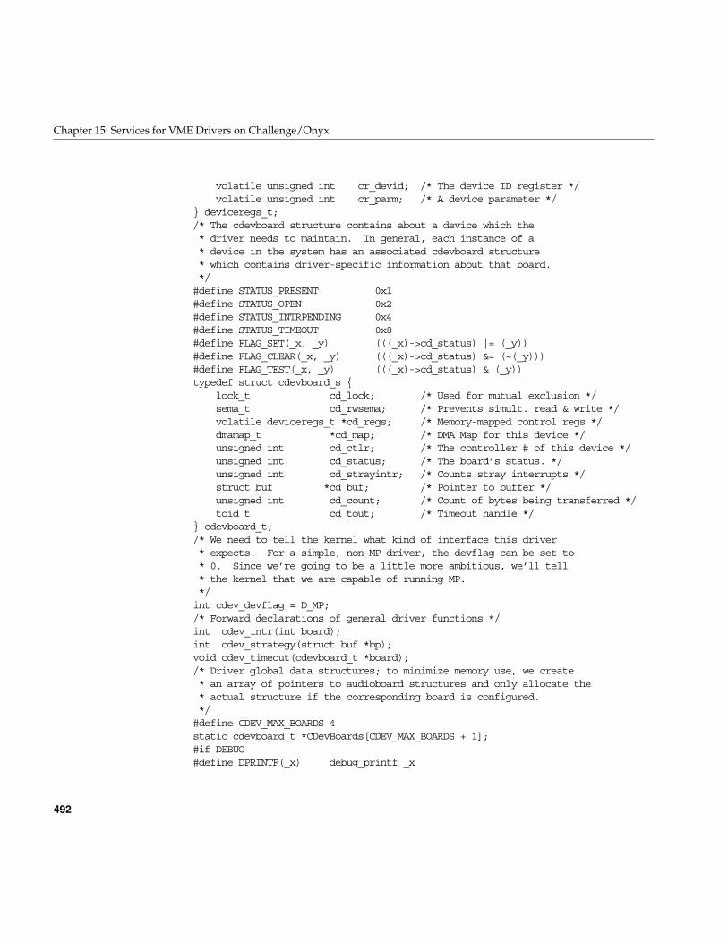
492
Chapter 15: Services for VME Drivers on Challenge/Onyx
volatile unsigned int cr_devid; /* The device ID register */volatile unsigned int cr_parm; /* A device parameter */
} deviceregs_t;/* The cdevboard structure contains about a device which the* driver needs to maintain. In general, each instance of a* device in the system has an associated cdevboard structure* which contains driver-specific information about that board.*/#define STATUS_PRESENT 0x1#define STATUS_OPEN 0x2#define STATUS_INTRPENDING 0x4#define STATUS_TIMEOUT 0x8#define FLAG_SET(_x, _y) (((_x)->cd_status) |= (_y))#define FLAG_CLEAR(_x, _y) (((_x)->cd_status) &= (~(_y)))#define FLAG_TEST(_x, _y) (((_x)->cd_status) & (_y))typedef struct cdevboard_s {
lock_t cd_lock; /* Used for mutual exclusion */sema_t cd_rwsema; /* Prevents simult. read & write */volatile deviceregs_t *cd_regs; /* Memory-mapped control regs */dmamap_t *cd_map; /* DMA Map for this device */unsigned int cd_ctlr; /* The controller # of this device */unsigned int cd_status; /* The board’s status. */unsigned int cd_strayintr; /* Counts stray interrupts */struct buf *cd_buf; /* Pointer to buffer */unsigned int cd_count; /* Count of bytes being transferred */toid_t cd_tout; /* Timeout handle */
} cdevboard_t;/* We need to tell the kernel what kind of interface this driver* expects. For a simple, non-MP driver, the devflag can be set to* 0. Since we’re going to be a little more ambitious, we’ll tell* the kernel that we are capable of running MP.*/int cdev_devflag = D_MP;/* Forward declarations of general driver functions */int cdev_intr(int board);int cdev_strategy(struct buf *bp);void cdev_timeout(cdevboard_t *board);/* Driver global data structures; to minimize memory use, we create* an array of pointers to audioboard structures and only allocate the* actual structure if the corresponding board is configured.*/#define CDEV_MAX_BOARDS 4static cdevboard_t *CDevBoards[CDEV_MAX_BOARDS + 1];#if DEBUG#define DPRINTF(_x) debug_printf _x
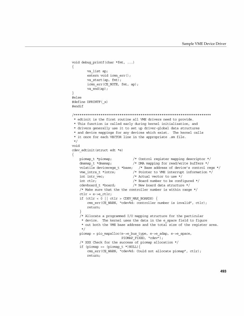
Sample VME Device Driver
493
void debug_printf(char *fmt, ...){
va_list ap;extern void icmn_err();va_start(ap, fmt);icmn_err(CE_NOTE, fmt, ap);va_end(ap);
}#else#define DPRINTF(_x)#endif
/************************************************************************* edtinit is the first routine all VME drivers need to provide.* This function is called early during kernel initialization, and* drivers generally use it to set up driver-global data structures* and device mappings for any devices which exist. The kernel calls* it once for each VECTOR line in the appropriate .sm file.*/voidcdev_edtinit(struct edt *e){
piomap_t *piomap; /* Control register mapping descriptor */dmamap_t *dmamap; /* DMA mapping for read/write buffers */volatile deviceregs_t *base; /* Base address of device’s control regs */vme_intrs_t *intrs; /* Pointer to VME interrupt information */int intr_vec; /* Actual vector to use */int ctlr; /* Board number to be configured */cdevboard_t *board; /* New board data structure *//* Make sure that the the controller number is within range */ctlr = e->e_ctlr;if (ctlr < 0 || ctlr > CDEV_MAX_BOARDS) {
cmn_err(CE_WARN, “cdev%d: controller number is invalid”, ctlr);return;
}/* Allocate a programmed I/O mapping structure for the particular* device. The kernel uses the data in the e_space field to figure* out both the VME base address and the total size of the register area.*/piomap = pio_mapalloc(e->e_bus_type, e->e_adap, e->e_space,
PIOMAP_FIXED, “cdev”);/* XXX Check for the success of piomap allocation */if (piomap == (piomap_t *)NULL){
cmn_err(CE_WARN, “cdev%d: Could not allocate piomap”, ctlr);return;
494
Chapter 15: Services for VME Drivers on Challenge/Onyx
}/* Now that the map is allocated, we position it so that it overlays* the device’s hardware registers. Since this is a fixed map, we* just pass in the base address of the control register range.* iobase comes from the VECTOR line in the .sm file.*/base = (volatile deviceregs_t*) pio_mapaddr(piomap, e->e_iobase);/* We’re going to need to DMA map the user’s buffer during read and* write requests, so we preallocate a fixed number of dma mapping* entries based on the constant CDEV_MAX_XFERSIZE. If we allowed* multiple users to perform reads and writes simultaneously we’d* probably want to allocate one map for reads and one for writes.* Since we only allow one operation to occur at any given time,* though, we can get away with only one.** IMPORTANT NOTE: There are only a limited number of dma mapping* registers available in a system; you should be somewhat conservative* in your use of them. It is reasonable to consume up to 100 per* device (you can use more if you expect that only a couple devices* will be attached for each driver. If, for example, this driver* will never control more than two devices, you could probably use* up to 512 mapping registers for each device. If however, you’d expect* to see hundreds of devices, you’d need to be more conservative.*/dmamap = dma_mapalloc(DMA_A24VME, e->e_adap,
io_btoc(CDEV_MAX_XFERSIZE) + 1, 0);if (dmamap == (dmamap_t*) NULL) {
cmn_err(CE_WARN, “cdev%d: Could not allocate dmamaps”, ctlr);pio_mapfree(piomap);return;
}/* The next step would be to probe the device to determine whether* it is actually present. To do this, we attempt to read some* registers which behave in a manner unique to this particular* hardware. We need to protect ourselves in the event that the* device isn’t actually present, however, so we use the badaddr* and wbadaddr routines. For our example, we assume that the* device is present if it’s device*/if ((badaddr(&(base->cr_devid), 4) == 0) &&
(base->cr_devid == VALID_DEVICE)) {DPRINTF((“cdev%d: found valid device”, ctlr));
} else {/* It doesn’t look like the device is there. */cmn_err(CE_WARN, “cdev%d: cannot find actual device”, ctlr);
Sample VME Device Driver
495
pio_mapfree(piomap);dma_mapfree(dmamap);return;
}/* Now we set up the interrupt for this device.* It is possible to specify a vector and priority level on the* VECTOR line in the .sm file, so we check to see if such was the case.*/intrs = (vme_intrs_t*) e->e_bus_info;intr_vec = intrs->v_vec;/* If intr_vec is non-zero, user specified specific vec in .sm file.* If the interrupt was specified on the VECTOR line, the kernel has* already established a vector for us, so we don’t need to do it* ourselves.*/if (intr_vec == 0) {
intr_vec = vme_ivec_alloc(e->e_adap);/* Make sure that we got a good interrupt vector */if (intr_vec == -1) {
cmn_err(CE_WARN, “cdev%d: could not allocate intr vector\n”, ctlr);pio_mapfree(piomap);dma_mapfree(dmamap);return;
}/* Associate this driver’s interrupt routine with the acquired vec */vme_ivec_set(e->e_adap, intr_vec, cdev_intr, 0);
}/* Initialize the board structure for this board */board = (cdevboard_t*) kmem_alloc(sizeof(cdevboard_t));if (board == (void*) 0) {
cmn_err(CE_WARN, “cdev%d: kmem_alloc failed”, ctlr);pio_mapfree(piomap);dma_mapfree(dmamap);/* XXX Need to check whether it is allocated?? */vme_ivec_free(e->e_adap, intr_vec);return;
}board = CDevBoards[ctlr];board->cd_regs = base;board->cd_ctlr = ctlr;board->cd_status = STATUS_PRESENT;board->cd_strayintr = 0;board->cd_map = dmamap;initnsema(&board->cd_rwsema, 1, “CDevRWM”);/* Finally, call any one-time-only device initialization routines;
496
Chapter 15: Services for VME Drivers on Challenge/Onyx
* this particular device doesn’t have any.*/return;
}/************************************************************************* cdev_open -- When opening a device, we need to check for mutual* exclusion (if desired) and then set up an additional data structures* if this is the first time the device has been opened. Remember that* the OS usually doesn’t call close until all users close the device,* so you can’t count on being able to set up unique data for each user* of the device unless you either disallow multiple opens at the same time* or mark the device as being a layered (otype = O_LYR) device.*/intcdev_open(dev_t *dev, int flag, int otyp, cred_t *cred){
minor_t ctlr; /* Controller # of cdev being opened */cdevboard_t *board; /* per-board data for opened cdev*/int s; /* Opaque lock value *//* We assume that the minor number encodes the ctlr number, so* we just go ahead and use it to index the CDevBoards array once* we’ve validated it.*/ctlr = geteminor(*dev);if (ctlr > CDEV_MAX_BOARDS) {
DPRINTF((“cdev%d: open: minor number out of range”, ctlr));return ENXIO;
}board = CDevBoards[ctlr];if (FLAG_TEST(board, STATUS_PRESENT) || (board->cd_ctlr != ctlr)) {
DPRINTF((“cdev%d: open: device not found”, ctlr));return ENXIO;
}/* If exclusiveness is desired, we now need to atomically insure that* we are the owners of the device.*/s = LOCK(&board->cd_lock, splhi);if (FLAG_TEST(board, STATUS_OPEN)) {
UNLOCK(&board->cd_lock, s);return EBUSY;
} else {ASSERT(board->cd_status == STATUS_PRESENT);FLAG_SET(board, STATUS_OPEN);
}UNLOCK(&board->cd_lock, s);
Sample VME Device Driver
497
return 0;}
/************************************************************************* cdev_close -- Called when the open reference count drops to zero.* Cleans up any leftover data structure and marks the device as* available.*/intcdev_close(dev_t dev, int flag, int otyp, cred_t *cred){
int ctlr; /* Controller # of dev being closed */cdevboard_t *board; /* per-board data structure */ctlr = geteminor(dev);ASSERT(ctlr <= CDEV_MAX_BOARDS);board = CDevBoards[ctlr];ASSERT(board && FLAG_TEST(board, STATUS_OPEN|STATUS_PRESENT));/* Do any cleanup required here *//* Reset the board’s status flags (to clear the OPEN flag) */FLAG_CLEAR(board, STATUS_OPEN);return 0;
}/************************************************************************* cdev_intr -- Called when an interrupt occurs. We check to see if* a process was waiting for an I/O operation to complete and* re-activate that process if such is the case.*/#ifdef EVEREST /* IO4 fix for Challenge */extern int io4_flush_cache(caddr_t piomap);#endifintcdev_intr(int ctlr){
cdevboard_t *board; /* per-board data structure pointer */int s; /* lock return value */
/* Make sure that the controller value is legitimate */ASSERT(ctlr <= CDEV_MAX_BOARDS);board = CDevBoards[ctlr];ASSERT(board && FLAG_TEST(board, STATUS_PRESENT));
#ifdef EVEREST /* flush IO4 cache */(void)io4_flush_cache((caddr_t)board->cd_regs);
#endif/** Get exclusive use of the board. This ensures that the strategy* routine is completely finished setting STATUS_INTRPENDING before
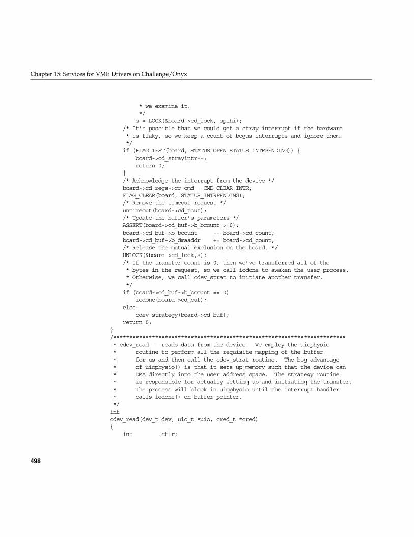
498
Chapter 15: Services for VME Drivers on Challenge/Onyx
* we examine it.*/s = LOCK(&board->cd_lock, splhi);
/* It’s possible that we could get a stray interrupt if the hardware* is flaky, so we keep a count of bogus interrupts and ignore them.*/if (FLAG_TEST(board, STATUS_OPEN|STATUS_INTRPENDING)) {
board->cd_strayintr++;return 0;
}/* Acknowledge the interrupt from the device */board->cd_regs->cr_cmd = CMD_CLEAR_INTR;FLAG_CLEAR(board, STATUS_INTRPENDING);/* Remove the timeout request */untimeout(board->cd_tout);/* Update the buffer’s parameters */ASSERT(board->cd_buf->b_bcount > 0);board->cd_buf->b_bcount -= board->cd_count;board->cd_buf->b_dmaaddr += board->cd_count;/* Release the mutual exclusion on the board. */UNLOCK(&board->cd_lock,s);/* If the transfer count is 0, then we’ve transferred all of the* bytes in the request, so we call iodone to awaken the user process.* Otherwise, we call cdev_strat to initiate another transfer.*/if (board->cd_buf->b_bcount == 0)
iodone(board->cd_buf);else
cdev_strategy(board->cd_buf);return 0;
}/************************************************************************* cdev_read -- reads data from the device. We employ the uiophysio* routine to perform all the requisite mapping of the buffer* for us and then call the cdev_strat routine. The big advantage* of uiophysio() is that it sets up memory such that the device can* DMA directly into the user address space. The strategy routine* is responsible for actually setting up and initiating the transfer.* The process will block in uiophysio until the interrupt handler* calls iodone() on buffer pointer.*/intcdev_read(dev_t dev, uio_t *uio, cred_t *cred){
int ctlr;
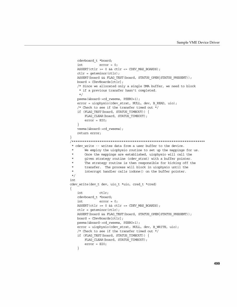
Sample VME Device Driver
499
cdevboard_t *board;int error = 0;ASSERT(ctlr >= 0 && ctlr <= CDEV_MAX_BOARDS);ctlr = geteminor(ctlr);ASSERT(board && FLAG_TEST(board, STATUS_OPEN|STATUS_PRESENT));board = CDevBoards[ctlr];/* Since we allocated only a single DMA buffer, we need to block* if a previous transfer hasn’t completed.*/psema(&board->cd_rwsema, PZERO+1);error = uiophysio(cdev_strat, NULL, dev, B_READ, uio);/* Check to see if the transfer timed out */if (FLAG_TEST(board, STATUS_TIMEOUT)) {
FLAG_CLEAR(board, STATUS_TIMEOUT);error = EIO;
}vsema(&board->cd_rwsema);return error;
}/************************************************************************* cdev_write -- writes data from a user buffer to the device.* We employ the uiophysio routine to set up the mappings for us.* Once the mappings are established, uiophysio will call the* given strategy routine (cdev_strat) with a buffer pointer.* The strategy routine is then responsible for kicking off the* transfer. The process will block in uiophysio until the* interrupt handler calls iodone() on the buffer pointer.*/intcdev_write(dev_t dev, uio_t *uio, cred_t *cred){
int ctlr;cdevboard_t *board;int error = 0;ASSERT(ctlr >= 0 && ctlr <= CDEV_MAX_BOARDS);ctlr = geteminor(ctlr);ASSERT(board && FLAG_TEST(board, STATUS_OPEN|STATUS_PRESENT));board = CDevBoards[ctlr];psema(&board->cd_rwsema, PZERO+1);error = uiophysio(cdev_strat, NULL, dev, B_WRITE, uio);/* Check to see if the transfer timed out */if (FLAG_TEST(board, STATUS_TIMEOUT)) {
FLAG_CLEAR(board, STATUS_TIMEOUT);error = EIO;
}
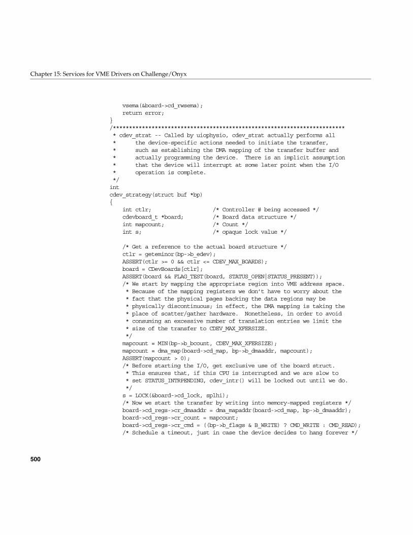
500
Chapter 15: Services for VME Drivers on Challenge/Onyx
vsema(&board->cd_rwsema);return error;
}/************************************************************************* cdev_strat -- Called by uiophysio, cdev_strat actually performs all* the device-specific actions needed to initiate the transfer,* such as establishing the DMA mapping of the transfer buffer and* actually programming the device. There is an implicit assumption* that the device will interrupt at some later point when the I/O* operation is complete.*/intcdev_strategy(struct buf *bp){
int ctlr; /* Controller # being accessed */cdevboard_t *board; /* Board data structure */int mapcount; /* Count */int s; /* opaque lock value */
/* Get a reference to the actual board structure */ctlr = geteminor(bp->b_edev);ASSERT(ctlr >= 0 && ctlr <= CDEV_MAX_BOARDS);board = CDevBoards[ctlr];ASSERT(board && FLAG_TEST(board, STATUS_OPEN|STATUS_PRESENT));/* We start by mapping the appropriate region into VME address space.* Because of the mapping registers we don’t have to worry about the* fact that the physical pages backing the data regions may be* physically discontinuous; in effect, the DMA mapping is taking the* place of scatter/gather hardware. Nonetheless, in order to avoid* consuming an excessive number of translation entries we limit the* size of the transfer to CDEV_MAX_XFERSIZE.*/mapcount = MIN(bp->b_bcount, CDEV_MAX_XFERSIZE);mapcount = dma_map(board->cd_map, bp->b_dmaaddr, mapcount);ASSERT(mapcount > 0);/* Before starting the I/O, get exclusive use of the board struct.* This ensures that, if this CPU is interrupted and we are slow to* set STATUS_INTRPENDING, cdev_intr() will be locked out until we do.*/s = LOCK(&board->cd_lock, splhi);/* Now we start the transfer by writing into memory-mapped registers */board->cd_regs->cr_dmaaddr = dma_mapaddr(board->cd_map, bp->b_dmaaddr);board->cd_regs->cr_count = mapcount;board->cd_regs->cr_cmd = ((bp->b_flags & B_WRITE) ? CMD_WRITE : CMD_READ);/* Schedule a timeout, just in case the device decides to hang forever */
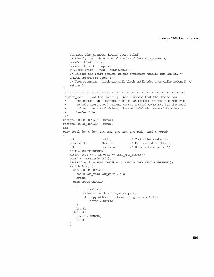
Sample VME Device Driver
501
itimeout(cdev_timeout, board, 2000, splhi);/* Finally, we update some of the board data structures */board->cd_buf = bp;board->cd_count = mapcount;FLAG_SET(board, STATUS_INTRPENDING);/* Release the board struct, so the interrupt handler can use it. */UNLOCK(&board->cd_lock, s);/* Upon returning, uiophysio will block until cdev_intr calls iodone() */return 0;
}/************************************************************************* cdev_ioctl -- Not too exciting. We’ll assume that the device has* one controllable parameter which can be both written and received.* To help users avoid errors, we use unusual constants for the ioctl* values. In a real driver, the CDIOC definitions would go into a* header file.*/#define CDIOC_SETPARM 0xcd01#define CDIOC_GETPARM 0xcd02intcdev_ioctl(dev_t dev, int cmd, int arg, int mode, cred_t *cred){
int ctlr; /* Controller number */cdevboard_t *board; /* Per-controller data */int error = 0; /* Error return value */ctlr = geteminor(dev);ASSERT(ctlr >= 0 && ctlr <= CDEV_MAX_BOARDS);board = CDevBoards[ctlr];ASSERT(board && FLAG_TEST(board, STATUS_OPEN|STATUS_PRESENT));switch (cmd) {case CDIOC_SETPARM:board->cd_regs->cr_parm = arg;break;
case CDIOC_GETPARM:{
int value;value = board->cd_regs->cr_parm;if (copyout(&value, (void*) arg, sizeof(int)))
error = EFAULT;}break;
default:error = EINVAL;break;
}
502
Chapter 15: Services for VME Drivers on Challenge/Onyx
return error;}/************************************************************************* cdev_timeout -- If an I/O request takes a really long time to complete* for some reason (if, for example, someone takes the device offline),* it is better to warn the user than to simply hang. This timeout* routine will cancel any pending I/O requests and display a message.* A more sophisticated routine might try resetting the device and* re-executing the operation.*/voidcdev_timeout(cdevboard_t *board){
/* Clear the pending request from the device. This operation* is extremely dependent on the actual device. This driver* pretends that we simply can use the reset command.*/board->cd_regs->cr_cmd = CMD_RESET;/* Make a note that the operation timed out */FLAG_SET(board, STATUS_TIMEOUT);/* Display a warning */cmn_err(CE_WARN, “cdev%d: device timed out”, board->cd_ctlr);/* Notify the user process that the operation has “finished”. */iodone(board->cd_buf);
}/************************************************************************* cdev_map -- For illustrative purposes, we show how one would go about* mapping the device’s control registers.*/intcdev_map(dev_t dev, vhandl_t *vt, off_t off, int len, int prot){
int ctlr; /* Controller number */cdevboard_t *board; /* Per-controller data */ctlr = geteminor(dev);ASSERT(ctlr >= 0 && ctlr <= CDEV_MAX_BOARDS);board = CDevBoards[ctlr];ASSERT(board && FLAGS_TEST(board, STATUS_OPEN|STATUS_PRESENT));if (v_mapphys(vt, (void*) board->cd_regs, len))
return ENOMEM;else
return 0;}
Sample VME Device Driver
503
/************************************************************************* cdev_unmap -- Called when a region is unmapped. We don’t actually* need to do anything.*/intcdev_unmap(dev_t dev, vhandl_t *vt){
/* No need to do anything here; unmapping is handled by upper levels* of the kernel.*/return 0;
}


PART FIVE
SCSI Device Drivers V
Chapter 16, “SCSI Device Drivers”Actual control of the SCSI bus is managed by one or more Host Adapter drivers.This chapter tells how SCSI device drivers use these facilities.

507
Chapter 16
16. SCSI Device Drivers
All Silicon Graphics systems support the small computer systems interface (SCSI) bus forthe attachment of disks, tapes, and other devices. This chapter details the kernel-levelsupport for SCSI device drivers.
If your aim is to control a SCSI device from a user-level process, this chapter containssome useful background information to supplement Chapter 5, “User-Level Access toSCSI Devices.” If you are designing a kernel-level SCSI driver, this chapter containsessential information on kernel support. The major topics in this chapter are as follows:
• “SCSI Support in Silicon Graphics Systems” on page 508 gives an overview of thehardware and software support for SCSI.
• “Host Adapter Facilities” on page 515 documents the use of the host adapter driverto access a SCSI device.
• “Designing a SCSI Driver” on page 530 provides information on how to design athird party SCSI device drivers.
• “SCSI Reference Data” on page 537 tabulates SCSI codes and messages forreference.
• “A Note on FibreChannel Drivers” on page 544 correlates writing SCSI deviceDrivers with writing FibreChannel device drivers.
508
Chapter 16: SCSI Device Drivers
In addition, you may want to review the following additional sources:
SCSI Support in Silicon Graphics Systems
All current Silicon Graphics systems rely on the SCSI bus as the primary attachment fordisks and tapes. The IRIX kernel also provides support for OEM drivers for SCSI devices.
As used here, the term “adapter” means a SCSI controller such as the Western DigitalW93 chip, which attaches a unique chain of SCSI devices. In this sense, a SCSI adapterand a SCSI bus are the same. “Adapter number” is used instead of “bus number.”
SCSI Hardware Support
The Silicon Graphics computer systems supported by IRIX 6.5 can attach multiple SCSIadapters, as follows:
• The Origin2000 and Onyx2 systems have two SCSI controllers on each Base I/Omodule. Several additional SCSI controllers can be added to each module.
• The Origin200 system has two SCSI controllers per chassis and the possibility ofoptional SCSI controllers using PCI and MSCSI interfaces.
• The OCTANE workstation has two SCSI controllers, one for the internal disks andone for the external chain. In addition, PCI and MSCSI controllers can be added.
• The Indy workstation has at least one SCSI adapter on its motherboard, and canhave up to two additional adapters on a GIO option board.
intro(7) reference page Documents the naming conventions for diskand tape device special files.
dksc(7) reference page Documents the Silicon Graphics disk volumepartition layout and the ioctl support in thebase-level SCSI drivers.
ANSI X3.131-1986 and X3T9.2/85-52Rev 4B.
SCSI standards documents.
http://scitexdv.com:8080/SCSI2/ Web page containing the complete SCSI-2standard in HTML form.
master.d/scsi Driver registration tables used for registeringthird party drivers.
SCSI Support in Silicon Graphics Systems
509
• The Indigo2 series supports two SCSI adapters on the motherboard.
• The Challenge S system has two SCSI adapters on the motherboard, and can haveone or two additional on each of one or two additional GIO option boards, for amaximum of sixadapters.
• The Challenge M system supports one SCSI adapter on the CPU board and canhave up to two additional adapters on a GIO option board.
• The Power Channel-2 (IO4) boards used in the Challenge and Onyx series supporttwo SCSI adapters, plus many as six additional SCSI adapters on mezzanine cards,for a maximum of eight adapters per IO4.
In all systems, DMA mapping hardware allows a SCSI adapter to treat discontiguousmemory locations as if they were a contiguous buffer, providing scatter and gathersupport.
IRIX Kernel SCSI Support
The IRIX kernel contains two levels of SCSI support. An inner SCSI driver, the host adapterdriver, manages all communication with a SCSI hardware adapter. The kernel-level SCSIdevice driver for a particular device prepares SCSI commands and calls on the hostadapter driver to execute them. This design centralizes the management of SCSIadapters. Centralization is necessary because the use of the SCSI bus is shared by manydevices, while recovery and error-handling are handled at the adapter level. In addition,use of the host adapter driver makes it simpler to write a SCSI device driver.
Host Adapter Drivers
Different host adapter drivers are loaded, depending on the hardware in the system.Some examples of host adapter drivers are wd93 and ql.
The host adapter drivers support all levels of the SCSI standard: SCSI-1, the CommonCommand Set (CCS, superceded by SCSI-2), and SCSI-2. Not all optional features of thestandard are supported. Different systems support different feature combinations (suchas synchronous, fast, and wide SCSI), depending on the available hardware.
The host adapter drivers handle the low-level communication over the SCSI interface,such as programming the SCSI interface chip or board, negotiating synchronous or widemode, and handling disconnect and reconnect.
510
Chapter 16: SCSI Device Drivers
A host adapter driver is not, strictly speaking, a proper device driver because it does notsupport all the entry points documented in Chapter 7, “Structure of a Kernel-LevelDriver.” You can think of it as a specialized library module for SCSI-bus management oras a device driver, whichever you prefer. The software interface to the host adapter driveris documented under “Host Adapter Facilities” on page 515.
SCSI Devices in the hwgraph
When planning a SCSI device driver, it is informative to spend some time exploring therather complex network of hwgraph vertexes that is set up by the existing SCSI drivers.Your tools for this are the find and grep commands. For example:
find /hw -print | grep scsi | grep -v disk
The result is voluminous even on a relatively small system and reveals that there aremany vertexes created for each logical unit (LUN) on each controller. Here is a samplewith repetitions edited out:
houston 30% find /hw -print | grep scsi | grep -v disk/hw/module/1/slot/io1/baseio/pci/0/scsi_ctlr/hw/module/1/slot/io1/baseio/pci/0/scsi_ctlr/0/hw/module/1/slot/io1/baseio/pci/0/scsi_ctlr/0/bus/hw/module/1/slot/io1/baseio/pci/0/scsi_ctlr/0/target/hw/module/1/slot/io1/baseio/pci/0/scsi_ctlr/0/target/1/hw/module/1/slot/io1/baseio/pci/0/scsi_ctlr/0/target/1/lun/hw/module/1/slot/io1/baseio/pci/0/scsi_ctlr/0/target/1/lun/0/hw/module/1/slot/io1/baseio/pci/0/scsi_ctlr/0/target/1/lun/0/scsi/hw/module/1/slot/io1/baseio/pci/0/scsi_ctlr/0/target/1/lun/1.../hw/module/1/slot/io1/baseio/pci/0/scsi_ctlr/0/target/2.../hw/module/1/slot/io1/baseio/pci/1/scsi_ctlr.../hw/scsi_ctlr/hw/scsi_ctlr/0/hw/scsi_ctlr/1/hw/scsi/hw/scsi/sc0d1l0/hw/scsi/sc0d2l0
SCSI Support in Silicon Graphics Systems
511
Controller Vertexes
Paths of the form /hw/.../scsi_ctlr/... are hwgraph vertexes that represent SCSI hostadapters (controllers) discovered during boot time. Each of these is presented to a hostadapter at its pfxattach() entry point (see “Entry Point attach()” on page 153). All theother hwgraph paths that contain the word scsi were created by the host adapter driveror by SCSI device drivers (see “Extending the hwgraph” on page 222).
Target Vertexes and LUN Vertexes
Paths that contain scsi_ctlr/N/target/N were created by the host adapter driver torepresent each target that it discovered while probing its bus at attach time. Attached tothese are paths containing lun/N, for example:
/hw/module/1/slot/io1/baseio/pci/0/scsi_ctlr/0/target/1/lun/0/scsi
Whenever a target is found to have logical units, a vertex is created for each, and whenthe LUN responds, a character device vertex is created for it.
ls -l /hw/module/1/slot/io1/baseio/pci/0/scsi_ctlr/0/target/1/lun/0total 0drwxr-xr-x 2 root sys 0 Mar 12 14:30 diskcrw------- 1 root sys 0,116 Mar 12 14:30 scsi
The character device scsi represents the addressable LUN. The vertex disk was installedby the disk device driver. It is the attachment vertex for a number of device vertexes thatrepresent the parts of a disk volume, such as disk/partition/1/block and disk/partition/1/char,character and block access to a disk (see “Block and Character Device Access” onpage 36).
Convenience Vertexes
In addition to the lengthy pathnames, there are shortcut names:
% ls -l /hw/scsitotal 0crw------- 1 root sys 0,116 Mar 12 14:41 sc0d1l0crw------- 1 root sys 0,133 Mar 12 14:41 sc0d2l0crw------- 1 root sys 0,150 Mar 12 14:41 sc0d3l0crw------- 1 root sys 0,167 Mar 12 14:41 sc0d4l0crw------- 1 root sys 0,184 Mar 12 14:41 sc0d5l0
512
Chapter 16: SCSI Device Drivers
These were created by the SCSI driver as shortcut links to the lun/N/scsi vertexes, as youcan verify with the -S option of ls:
% ls -S /hw/scsi/sc0d1l0/hw/scsi/sc0d1l0 ->/hw/module/1/slot/io1/baseio/pci/0/scsi_ctlr/0/target/1/lun/0/scsi
In the system used to create this example, a second SCSI controller exists but has noLUNs. If it had LUNs, there would be shortcut names sc1d1l0 and so forth in /hw/scsi, aswell.
At boot time, the host adapter driver creates a vertex and adds an edge labelled “scsi”from the root vertex to the new vertex. The ioconfig command (see “Using ioconfig forGlobal Controller Numbers” on page 51) then adds edges from it labelled “sc0d1l0,”“sc0d2l0,” and so forth, each ending at one of the lun/N/scsi vertexes.
Although it is created dynamically, the shortcut name /hw/scsi is the target of a symboliclink in /dev. Thus all convenience links such as /hw/scsi/sc0d1l0 can also be addressed as/dev/scsi/sc0d1l0 and so on.
ls -l /dev/scsilrwxr-xr-x 1 root sys 8 Jan 10 15:33 /dev/scsi->/hw/scsi% ls -l /dev/scsi/sc0d1l0crw------- 1 root sys 0,116 Mar 12 15:21 /dev/scsi/sc0d1l0
Additional convenience vertexes are created to point to the controllers themselves. Thesecan be used by scsiha to pass requests to the scsi host adapter drivers to perform activitiesthat aren’t related to the SCSI commands (see scsiha(7M) and scsiha(1M).
% ls -l /hw/scsi_ctlrtotal 0lrw------- 1 root sys 47 Mar 12 14:42 0 ->/hw/module/1/slot/io1/baseio/pci/0/scsi_ctlr/0lrw------- 1 root sys 47 Mar 12 14:42 1 ->/hw/module/1/slot/io1/baseio/pci/1/scsi_ctlr/0
These were also created by ioconfig for each of the controller vertexes (controller 0 in PCIslot 0, later controller 0 in PCI slot 1). When they were created, the driver:
1. Created a vertex.
2. Added an edge from the root vertex with the label “scsi_ctlr,” ending at the newvertex.
3. Added an edge labelled “0” from that vertex ending at the controller vertex.
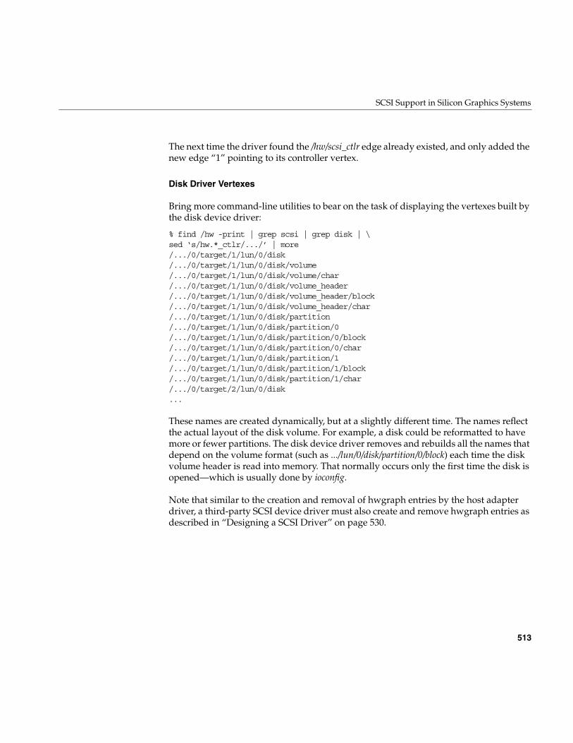
SCSI Support in Silicon Graphics Systems
513
The next time the driver found the /hw/scsi_ctlr edge already existed, and only added thenew edge “1” pointing to its controller vertex.
Disk Driver Vertexes
Bring more command-line utilities to bear on the task of displaying the vertexes built bythe disk device driver:
% find /hw -print | grep scsi | grep disk | \sed ‘s/hw.*_ctlr/.../’ | more/.../0/target/1/lun/0/disk/.../0/target/1/lun/0/disk/volume/.../0/target/1/lun/0/disk/volume/char/.../0/target/1/lun/0/disk/volume_header/.../0/target/1/lun/0/disk/volume_header/block/.../0/target/1/lun/0/disk/volume_header/char/.../0/target/1/lun/0/disk/partition/.../0/target/1/lun/0/disk/partition/0/.../0/target/1/lun/0/disk/partition/0/block/.../0/target/1/lun/0/disk/partition/0/char/.../0/target/1/lun/0/disk/partition/1/.../0/target/1/lun/0/disk/partition/1/block/.../0/target/1/lun/0/disk/partition/1/char/.../0/target/2/lun/0/disk...
These names are created dynamically, but at a slightly different time. The names reflectthe actual layout of the disk volume. For example, a disk could be reformatted to havemore or fewer partitions. The disk device driver removes and rebuilds all the names thatdepend on the volume format (such as .../lun/0/disk/partition/0/block) each time the diskvolume header is read into memory. That normally occurs only the first time the disk isopened—which is usually done by ioconfig.
Note that similar to the creation and removal of hwgraph entries by the host adapterdriver, a third-party SCSI device driver must also create and remove hwgraph entries asdescribed in “Designing a SCSI Driver” on page 530.
514
Chapter 16: SCSI Device Drivers
Hardware Administration
Some bus protocol features such as connect and disconnect are controlled byconfiguration files that are used by the host adapter drivers. For example, the wd93 driverhas a number of configurable options coded in the descriptive file /var/sysgen/master.d (forthe format of descriptive files, see “Describing the Driver in /var/sysgen/master.d” onpage 260).
The QLogic driver ql takes its options by the more modern route of the DEVICE_ADMINstatement (see “Storing Device and Driver Attributes” on page 56 and “RetrievingAdministrator Attributes” on page 231). You can peruse /var/sysgen/system/irix.sm to seeDEVICE_ADMIN statements addressed to “ql_” and associated comments.
Note: The connect/disconnect strategy is enabled on any SCSI bus by default (the optionis controlled by a constant defined in the host adapter driver descriptive file in/var/sysgen/master.d). When disconnect is enabled on a bus, and a device on that busrefuses to disconnect, it can cause timeouts on other devices.
Host Adapter Facilities
515
Host Adapter Facilities
The principal difference between a SCSI driver and other kernel-level drivers is that,while other kinds of drivers are expected to control devices directly using PIO and DMA,a SCSI driver operates its devices indirectly, by making function calls to the host adapterdriver. This section documents the functional interface to the host adapter driver.
Purpose of the Host Adapter Driver
IRIX uses host adapter drivers because the SCSI bus is shared among multiple devices ofdifferent types, each type controlled by a different driver. A disk, a tape, a CDROM, anda scanner could all be cabled from the same SCSI adapter. Each device has a differentdriver, but each driver needs to use the adapter, a single chip-set, to communicate withits device.
If IRIX allowed multiple drivers to operate the host adapter, there would be confusionand errors from the conflicting uses. IRIX puts the management of each host adapterunder the control of a host adapter driver, whose job is to issue commands on its bus andreport the results. The host adapter driver is tailored to the hardware of the particularhost adapter and to the architecture of the host system.
The interface to the host adapter driver is the same no matter what type of hardware theadapter uses. This insulates the individual device drivers from details of the adapterhardware.
The driver for each type of device is responsible for preparing the SCSI command bytesfor its device, for passing the command requests to the correct host adapter driver, andfor interpreting sense and status data as it comes back.
Host Adapter Concepts
The host adapter driver is the driver that is called by the kernel to attach the SCSIcontroller at boot time while the kernel is exploring the hardware and building thehwgraph (see “Entry Point attach()” on page 153).
The host adapter driver places information in the hwgraph vertex that represents thecontroller, and extends the hwgraph with subordinate vertexes that represent targets andLUNs (see “SCSI Devices in the hwgraph” on page 510).
516
Chapter 16: SCSI Device Drivers
A SCSI driver is called to manage one or more SCSI target devices. Each target isphysically connected to a SCSI adapter. The hwgraph echoes this connectivity: the SCSItarget vertex is connected to the SCSI adapter vertex. Thus when the SCSI driver knowsits target device vertex, it can access the corresponding host adapter vertex, and throughthis vertex, can invoke the host adapter driver.
Target Numbers
The purpose of a host adapter driver is to carry communications between a SCSI driverand a target. A target is a device on the SCSI chain that responds to SCSI commands. Atarget can be a single device, or it can be a controller that in turn manages other devices.
A target is identified by a number between 0 and 15. Normally this number is configuredinto the device with switches or jumpers. The SCSI controller itself has a target number(usually number 0), but it cannot be used as a target.
The SCSI device driver needs to know the number of its target in order to format arequest structure. The target number is accessible from the target vertex, as shown under“Using the Function Vector Macros” on page 520.
Logical Unit Numbers (LUNs)
When the target is a controller, it manages one or more subdevices, each one a logical unitof that target. The logical unit being addressed is identified by a logical unit number(LUN). When the target is a single device, its LUN is 0.
A SCSI device driver needs the unit number of a device when it formats a requeststructure. The unit number is accessible from the vertex for the LUN, as shown under“Using the Function Vector Macros” on page 520.
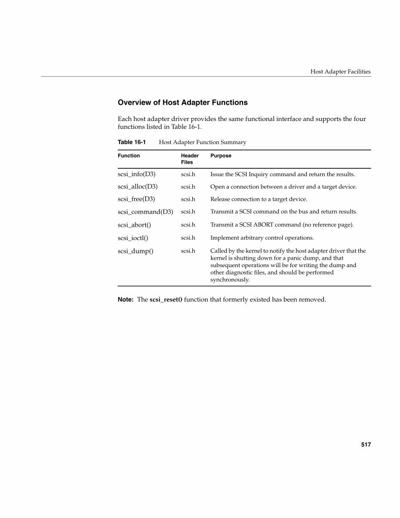
Host Adapter Facilities
517
Overview of Host Adapter Functions
Each host adapter driver provides the same functional interface and supports the fourfunctions listed in Table 16-1.
Note: The scsi_reset() function that formerly existed has been removed.
Table 16-1 Host Adapter Function Summary
Function HeaderFiles
Purpose
scsi_info(D3) scsi.h Issue the SCSI Inquiry command and return the results.
scsi_alloc(D3) scsi.h Open a connection between a driver and a target device.
scsi_free(D3) scsi.h Release connection to a target device.
scsi_command(D3) scsi.h Transmit a SCSI command on the bus and return results.
scsi_abort() scsi.h Transmit a SCSI ABORT command (no reference page).
scsi_ioctl() scsi.h Implement arbitrary control operations.
scsi_dump() scsi.h Called by the kernel to notify the host adapter driver that thekernel is shutting down for a panic dump, and thatsubsequent operations will be for writing the dump andother diagnostic files, and should be performedsynchronously.
518
Chapter 16: SCSI Device Drivers
How the Host Adapter Functions Are Found
A SCSI device driver can be asked to manage devices on different adapters. Differentadapters may use the same or different hardware, and be managed by the same ordifferent host adapter drivers. How does the driver locate the correct host adapterfunction for a given device?
The answer is that each host adapter driver places a set of vectors to its functions in thehwgraph vertex for the controller. Using macros defined in sys/scsi.h, the driver invokesthe function it needs indirectly, by way of pointers stored in the controller vertex.
Vertex Information Structures
The host adapter driver constructs the arrangement of hwgraph vertexes and datastructures illustrated in Figure 16-1.
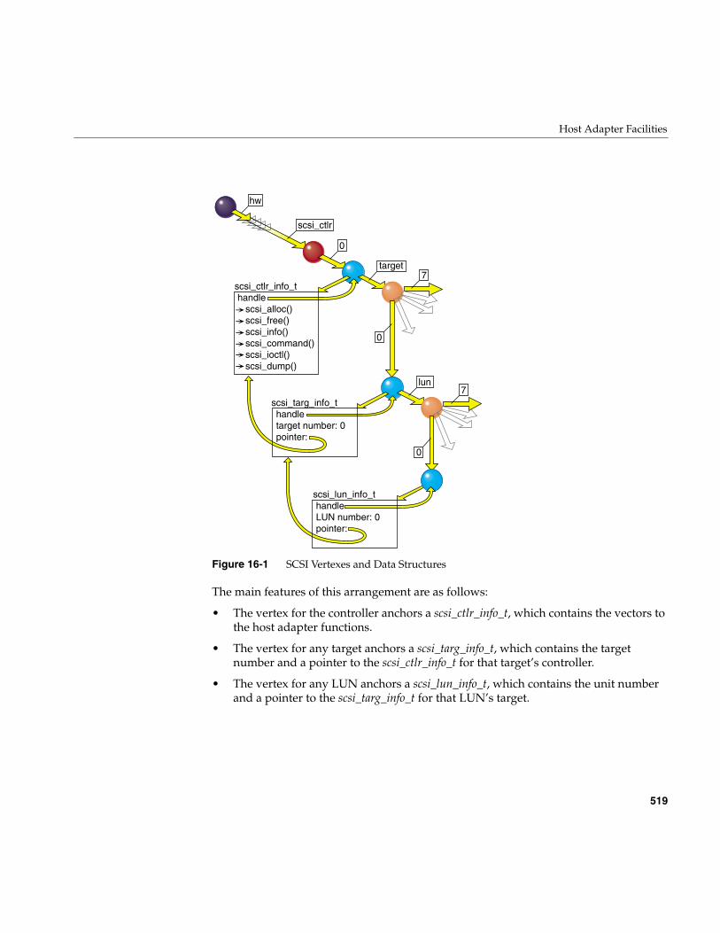
Host Adapter Facilities
519
Figure 16-1 SCSI Vertexes and Data Structures
The main features of this arrangement are as follows:
• The vertex for the controller anchors a scsi_ctlr_info_t, which contains the vectors tothe host adapter functions.
• The vertex for any target anchors a scsi_targ_info_t, which contains the targetnumber and a pointer to the scsi_ctlr_info_t for that target’s controller.
• The vertex for any LUN anchors a scsi_lun_info_t, which contains the unit numberand a pointer to the scsi_targ_info_t for that LUN’s target.
lun
0
target
hw
scsi_ctlr
7
0
7
0
scsi_lun_info_thandleLUN number: 0pointer:
scsi_ctlr_info_thandle scsi_alloc() scsi_free() scsi_info() scsi_command() scsi_ioctl() scsi_dump()
scsi_targ_info_thandletarget number: 0pointer:
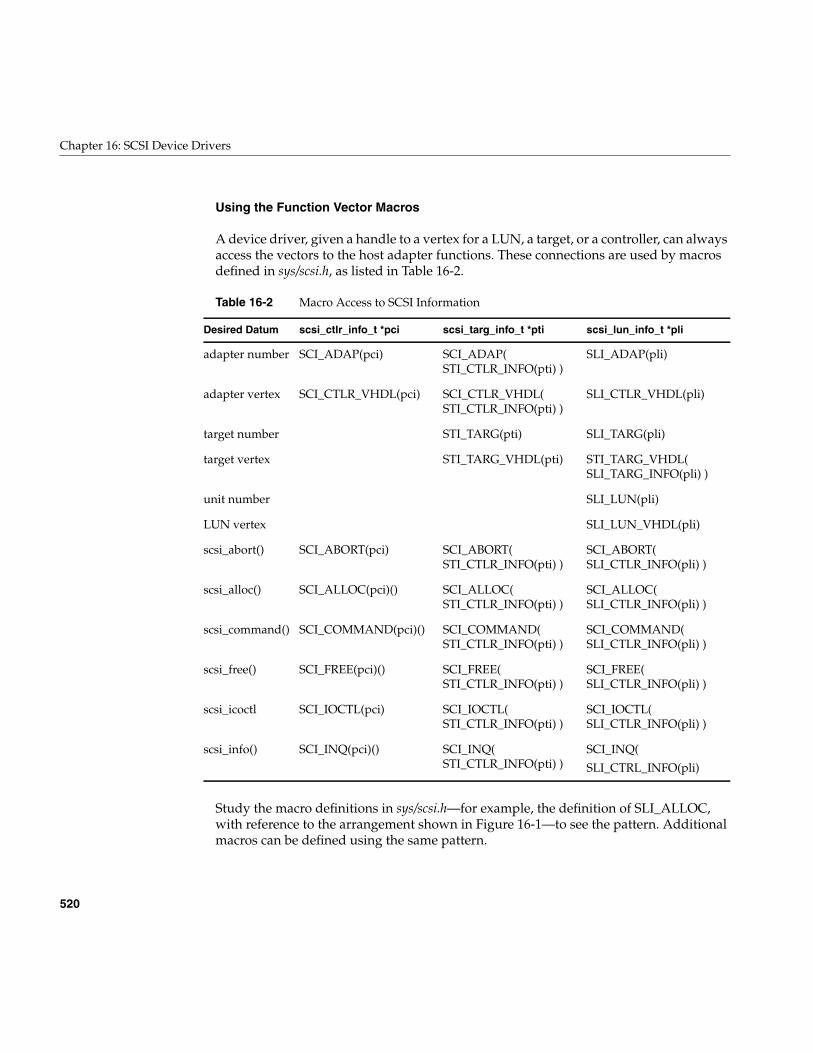
520
Chapter 16: SCSI Device Drivers
Using the Function Vector Macros
A device driver, given a handle to a vertex for a LUN, a target, or a controller, can alwaysaccess the vectors to the host adapter functions. These connections are used by macrosdefined in sys/scsi.h, as listed in Table 16-2.
Study the macro definitions in sys/scsi.h—for example, the definition of SLI_ALLOC,with reference to the arrangement shown in Figure 16-1—to see the pattern. Additionalmacros can be defined using the same pattern.
Table 16-2 Macro Access to SCSI Information
Desired Datum scsi_ctlr_info_t *pci scsi_targ_info_t *pti scsi_lun_info_t *pli
adapter number SCI_ADAP(pci) SCI_ADAP(STI_CTLR_INFO(pti) )
SLI_ADAP(pli)
adapter vertex SCI_CTLR_VHDL(pci) SCI_CTLR_VHDL(STI_CTLR_INFO(pti) )
SLI_CTLR_VHDL(pli)
target number STI_TARG(pti) SLI_TARG(pli)
target vertex STI_TARG_VHDL(pti) STI_TARG_VHDL(SLI_TARG_INFO(pli) )
unit number SLI_LUN(pli)
LUN vertex SLI_LUN_VHDL(pli)
scsi_abort() SCI_ABORT(pci) SCI_ABORT(STI_CTLR_INFO(pti) )
SCI_ABORT(SLI_CTLR_INFO(pli) )
scsi_alloc() SCI_ALLOC(pci)() SCI_ALLOC(STI_CTLR_INFO(pti) )
SCI_ALLOC(SLI_CTLR_INFO(pli) )
scsi_command() SCI_COMMAND(pci)() SCI_COMMAND(STI_CTLR_INFO(pti) )
SCI_COMMAND(SLI_CTLR_INFO(pli) )
scsi_free() SCI_FREE(pci)() SCI_FREE(STI_CTLR_INFO(pti) )
SCI_FREE(SLI_CTLR_INFO(pli) )
scsi_icoctl SCI_IOCTL(pci) SCI_IOCTL(STI_CTLR_INFO(pti) )
SCI_IOCTL(SLI_CTLR_INFO(pli) )
scsi_info() SCI_INQ(pci)() SCI_INQ(STI_CTLR_INFO(pti) )
SCI_INQ(
SLI_CTRL_INFO(pli)
Host Adapter Facilities
521
Using scsi_info()
Before a SCSI driver tries to access a device, it must call the host adapter scsi_info()function, passing the vertex handle for the LUN. This function issues an Inquirycommand to the adapter, target, and logical unit. If the Inquiry is not successful—or if theadapter, target, or LUN are not valid—the return value is NULL. Otherwise, the returnvalue is a pointer to a scsi_target_info structure.
The SCSI driver can learn the following things from a call to scsi_info():
• If the return is NULL, there is a serious problem with the device or the informationabout it. Write a descriptive log message with cmn_err() and return ENODEV.
• The si_inq field points to the Inquiry bytes returned by the device. Examine them fordevice-dependent information.
• The value in si_maxq is the default limit on pending SCSI commands that can bequeued to this host adapter driver. (You can specify a higher limit to scsi_alloc().)
• Test the bits in si_ha_status for information about the capabilities and error status ofthe host adapter itself. The possible bits are declared in sys/scsi.h. For example,SRH_NOADAPSYNC indicates that the specified target, or possibly the hostadapter itself, does not support synchronous transfer. Not all bits are supported byall host adapter drivers.
You can also call scsi_info() at other times; some of the returned information can beuseful in error recovery. However, be aware that scsi_info() for some host adapters isslow, and can use serialized access to hardware. (See also reference page scsi_info(d3x).)
Using scsi_alloc()
Depending on its particular design, the host adapter driver may need to allocate memoryfor data structures, DMA maps, or buffers for sense and inquiry data, before it is readyto execute commands to a particular target. The call to scsi_alloc() gives the host adapterdriver the opportunity to prepare in these ways. (See also reference page scsi_alloc(d3x).)
Because the host adapter driver may allocate virtual memory, it may sleep. Some hostadapter drivers allocate all the resources they need on the first call to scsi_alloc() and dolittle or nothing on subsequent calls.
522
Chapter 16: SCSI Device Drivers
A call to scsi_alloc() specifies these parameters:
The option parameter may include the SCSIALLOC_EXCLUSIVE flag to requestexclusive use of the target. If another driver has allocated a path to the same device,scsi_alloc() returns EBUSY. For example, a tape device driver might require exclusiveaccess, while a disk device driver would not.
The option parameter may include SCSIALLOC_NOSYNC to specify that this deviceshould not, or cannot, use synchronous transfer mode. That setting can be overridden forsingle commands by a flag to scsi_command() (see Table 16-4).
The option parameter can also include a small integer value indicating the maximumqueue depth (the number of SCSI commands the driver would like to start before anyhave completed). The call to scsi_info() returns the default queue depth that will be usedif you do not pass a nonzero value here (typically the default is 1).
The callback function address can be specified as NULL. The specified callback functionis called only when sense data is gotten from the allocated device (regardless of whichdriver initiated the command that resulted in sense data). Only one driver that allocatesa path to a device can specify a callback function. If the path is not held exclusively, anyother drivers must specify a null address for their callback functions.
Using scsi_free()
A SCSI driver typically calls scsi_free() from the pfxclose() entry point. That is the timewhen the driver knows that no processes have the device open, so the host adaptershould be allowed to release any resources it is holding just for this device.
In addition, scsi_free() releases the device for use by other drivers, if the driver hadallocated it for exclusive use.
lun_vhdl Vertex handle of the LUN, from which the target andcontroller can be identified.
option An integer comprising two parameters, a flag, and a count.
callback Address of a function to be called whenever sense data isgotten from the device.
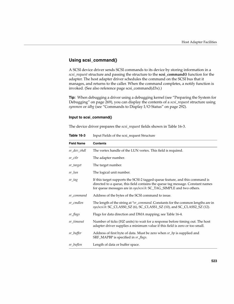
Host Adapter Facilities
523
Using scsi_command()
A SCSI device driver sends SCSI commands to its device by storing information in ascsi_request structure and passing the structure to the scsi_command() function for theadapter. The host adapter driver schedules the command on the SCSI bus that itmanages, and returns to the caller. When the command completes, a notify function isinvoked. (See also reference page scsi_command(d3x).)
Tip: When debugging a driver using a debugging kernel (see “Preparing the System forDebugging” on page 269), you can display the contents of a scsi_request structure usingsymmon or idbg (see “Commands to Display I/O Status” on page 292).
Input to scsi_command()
The device driver prepares the scsi_request fields shown in Table 16-3.
Table 16-3 Input Fields of the scsi_request Structure
Field Name Contents
sr_dev_vhdl The vertex handle of the LUN vertex. This field is required.
sr_ctlr The adapter number.
sr_target The target number.
sr_lun The logical unit number.
sr_tag If this target supports the SCSI-2 tagged-queue feature, and this command isdirected to a queue, this field contains the queue tag message. Constant namesfor queue messages are in sys/scsi.h: SC_TAG_SIMPLE and two others.
sr_command Address of the bytes of the SCSI command to issue.
sr_cmdlen The length of the string at *sr_command. Constants for the common lengths are insys/scsi.h: SC_CLASS0_SZ (6), SC_CLASS1_SZ (10), and SC_CLASS2_SZ (12).
sr_flags Flags for data direction and DMA mapping; see Table 16-4.
sr_timeout Number of ticks (HZ units) to wait for a response before timing out. The hostadapter driver supplies a minimum value if this field is zero or too small.
sr_buffer Address of first byte of data. Must be zero when sr_bp is supplied andSRF_MAPBP is specified in sr_flags.
sr_buflen Length of data or buffer space.
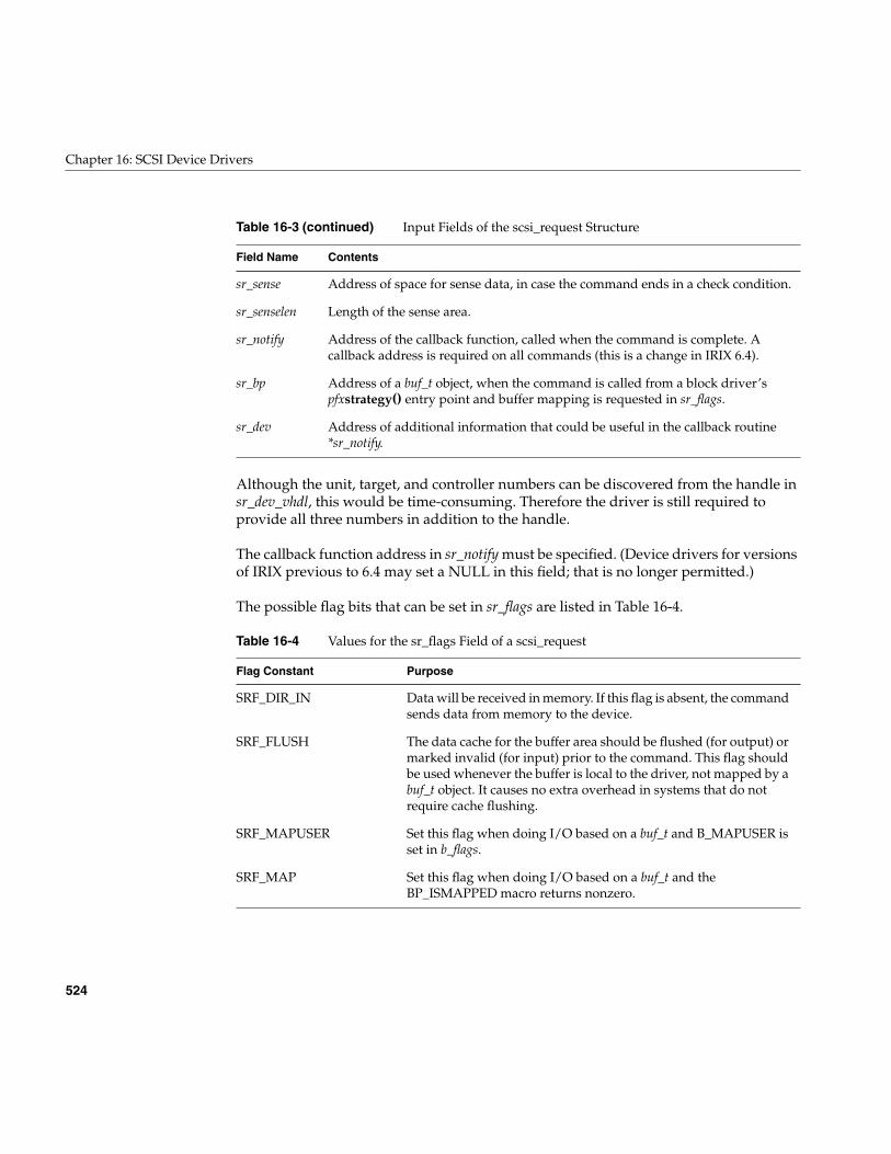
524
Chapter 16: SCSI Device Drivers
Although the unit, target, and controller numbers can be discovered from the handle insr_dev_vhdl, this would be time-consuming. Therefore the driver is still required toprovide all three numbers in addition to the handle.
The callback function address in sr_notify must be specified. (Device drivers for versionsof IRIX previous to 6.4 may set a NULL in this field; that is no longer permitted.)
The possible flag bits that can be set in sr_flags are listed in Table 16-4.
sr_sense Address of space for sense data, in case the command ends in a check condition.
sr_senselen Length of the sense area.
sr_notify Address of the callback function, called when the command is complete. Acallback address is required on all commands (this is a change in IRIX 6.4).
sr_bp Address of a buf_t object, when the command is called from a block driver’spfxstrategy() entry point and buffer mapping is requested in sr_flags.
sr_dev Address of additional information that could be useful in the callback routine*sr_notify.
Table 16-4 Values for the sr_flags Field of a scsi_request
Flag Constant Purpose
SRF_DIR_IN Data will be received in memory. If this flag is absent, the commandsends data from memory to the device.
SRF_FLUSH The data cache for the buffer area should be flushed (for output) ormarked invalid (for input) prior to the command. This flag shouldbe used whenever the buffer is local to the driver, not mapped by abuf_t object. It causes no extra overhead in systems that do notrequire cache flushing.
SRF_MAPUSER Set this flag when doing I/O based on a buf_t and B_MAPUSER isset in b_flags.
SRF_MAP Set this flag when doing I/O based on a buf_t and theBP_ISMAPPED macro returns nonzero.
Table 16-3 (continued) Input Fields of the scsi_request Structure
Field Name Contents
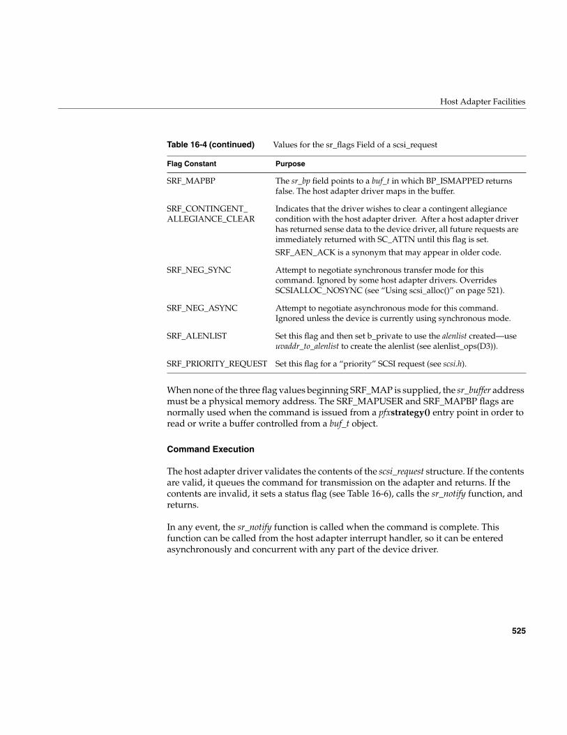
Host Adapter Facilities
525
When none of the three flag values beginning SRF_MAP is supplied, the sr_buffer addressmust be a physical memory address. The SRF_MAPUSER and SRF_MAPBP flags arenormally used when the command is issued from a pfxstrategy() entry point in order toread or write a buffer controlled from a buf_t object.
Command Execution
The host adapter driver validates the contents of the scsi_request structure. If the contentsare valid, it queues the command for transmission on the adapter and returns. If thecontents are invalid, it sets a status flag (see Table 16-6), calls the sr_notify function, andreturns.
In any event, the sr_notify function is called when the command is complete. Thisfunction can be called from the host adapter interrupt handler, so it can be enteredasynchronously and concurrent with any part of the device driver.
SRF_MAPBP The sr_bp field points to a buf_t in which BP_ISMAPPED returnsfalse. The host adapter driver maps in the buffer.
SRF_CONTINGENT_ALLEGIANCE_CLEAR
Indicates that the driver wishes to clear a contingent allegiancecondition with the host adapter driver. After a host adapter driverhas returned sense data to the device driver, all future requests areimmediately returned with SC_ATTN until this flag is set.
SRF_AEN_ACK is a synonym that may appear in older code.
SRF_NEG_SYNC Attempt to negotiate synchronous transfer mode for thiscommand. Ignored by some host adapter drivers. OverridesSCSIALLOC_NOSYNC (see “Using scsi_alloc()” on page 521).
SRF_NEG_ASYNC Attempt to negotiate asynchronous mode for this command.Ignored unless the device is currently using synchronous mode.
SRF_ALENLIST Set this flag and then set b_private to use the alenlist created—useuvaddr_to_alenlist to create the alenlist (see alenlist_ops(D3)).
SRF_PRIORITY_REQUEST Set this flag for a “priority” SCSI request (see scsi.h).
Table 16-4 (continued) Values for the sr_flags Field of a scsi_request
Flag Constant Purpose
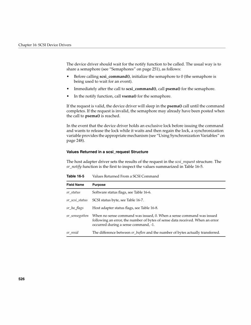
526
Chapter 16: SCSI Device Drivers
The device driver should wait for the notify function to be called. The usual way is toshare a semaphore (see “Semaphores” on page 251), as follows:
• Before calling scsi_command(), initialize the semaphore to 0 (the semaphore isbeing used to wait for an event).
• Immediately after the call to scsi_command(), call psema() for the semaphore.
• In the notify function, call vsema() for the semaphore.
If the request is valid, the device driver will sleep in the psema() call until the commandcompletes. If the request is invalid, the semaphore may already have been posted whenthe call to psema() is reached.
In the event that the device driver holds an exclusive lock before issuing the commandand wants to release the lock while it waits and then regain the lock, a synchronizationvariable provides the appropriate mechanism (see “Using Synchronization Variables” onpage 248).
Values Returned in a scsi_request Structure
The host adapter driver sets the results of the request in the scsi_request structure. Thesr_notify function is the first to inspect the values summarized in Table 16-5.
Table 16-5 Values Returned From a SCSI Command
Field Name Purpose
sr_status Software status flags, see Table 16-6.
sr_scsi_status SCSI status byte, see Table 16-7.
sr_ha_flags Host adapter status flags, see Table 16-8.
sr_sensegotten When no sense command was issued, 0. When a sense command was issuedfollowing an error, the number of bytes of sense data received. When an erroroccurred during a sense command, -1.
sr_resid The difference between sr_buflen and the number of bytes actually transferred.
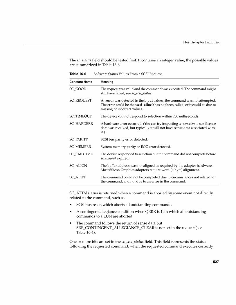
Host Adapter Facilities
527
The sr_status field should be tested first. It contains an integer value; the possible valuesare summarized in Table 16-6.
SC_ATTN status is returned when a command is aborted by some event not directlyrelated to the command, such as:
• SCSI bus reset, which aborts all outstanding commands.
• A contingent allegiance condition when QERR is 1, in which all outstandingcommands to a LUN are aborted
• The command follows the return of sense data butSRF_CONTINGENT_ALLEGIANCE_CLEAR is not set in the request (seeTable 16-4).
One or more bits are set in the sc_scsi_status field. This field represents the statusfollowing the requested command, when the requested command executes correctly.
Table 16-6 Software Status Values From a SCSI Request
Constant Name Meaning
SC_GOOD The request was valid and the command was executed. The command mightstill have failed; see sr_scsi_status.
SC_REQUEST An error was detected in the input values; the command was not attempted.The error could be that scsi_alloc() has not been called, or it could be due tomissing or incorrect values.
SC_TIMEOUT The device did not respond to selection within 250 milliseconds.
SC_HARDERR A hardware error occurred. (You can try inspecting sr_senselen to see if sensedata was received, but typically it will not have sense data associated withit.)
SC_PARITY SCSI bus parity error detected.
SC_MEMERR System memory parity or ECC error detected.
SC_CMDTIME The device responded to selection but the command did not complete beforesr_timeout expired.
SC_ALIGN The buffer address was not aligned as required by the adapter hardware.Most Silicon Graphics adapters require word (4-byte) alignment.
SC_ATTN The command could not be completed due to circumstances not related tothe command, and not due to an error in the command.
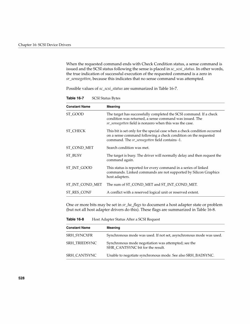
528
Chapter 16: SCSI Device Drivers
When the requested command ends with Check Condition status, a sense command isissued and the SCSI status following the sense is placed in sc_scsi_status. In other words,the true indication of successful execution of the requested command is a zero insr_sensegotten, because this indicates that no sense command was attempted.
Possible values of sc_scsi_status are summarized in Table 16-7.
One or more bits may be set in sr_ha_flags to document a host adapter state or problem(but not all host adapter drivers do this). These flags are summarized in Table 16-8.
Table 16-7 SCSI Status Bytes
Constant Name Meaning
ST_GOOD The target has successfully completed the SCSI command. If a checkcondition was returned, a sense command was issued. Thesr_sensegotten field is nonzero when this was the case.
ST_CHECK This bit is set only for the special case when a check condition occurredon a sense command following a check condition on the requestedcommand. The sr_sensegotten field contains -1.
ST_COND_MET Search condition was met.
ST_BUSY The target is busy. The driver will normally delay and then request thecommand again.
ST_INT_GOOD This status is reported for every command in a series of linkedcommands. Linked commands are not supported by Silicon Graphicshost adapters.
ST_INT_COND_MET The sum of ST_COND_MET and ST_INT_COND_MET.
ST_RES_CONF A conflict with a reserved logical unit or reserved extent.
Table 16-8 Host Adapter Status After a SCSI Request
Constant Name Meaning
SRH_SYNCXFR Synchronous mode was used. If not set, asynchronous mode was used.
SRH_TRIEDSYNC Synchronous mode negotiation was attempted; see theSHR_CANTSYNC bit for the result.
SRH_CANTSYNC Unable to negotiate synchronous mode. See also SRH_BADSYNC.
Host Adapter Facilities
529
Using scsi_abort()
The purpose of the scsi_abort() function is to abort all pending or executing commandson a device. The prototype of the function is:
SCI_ABORT(SLI_CTLR_INFO(scsi_lun_info_get(lun_vhdl))(struct scsi_request *req);
The only fields of the scsi_request that are input to this function are those that identifythe device: sr_dev_vhdl (always!), sr_ctlr, sr_target, and sr_lun. The ABORT command isissued on the bus as soon as possible but there could be a delay if the bus is busy. Statusis returned in sr_status. The function returns a nonzero value when the ABORT commandis issued successfully, and a zero when the ABORT command fails (which probablyindicates a serious bus problem).
Note: Not all devices and not all host adapters support this operation. Error recovery ofqueued commands is up to the driver.
SRH_BADSYNC When SRH_CANTSYNC is set, indicates that the negotiation failedbecause the device cannot negotiate.
SRH_NOADAPSYNC When SRH_CANTSYNC is set, this bit indicates that the host adapterdoes not support synchronous negotiation, or that the system has beenconfigured not to use synchronous mode for this device.
SRH_WIDE This adapter supports Wide mode.
SRH_DISC This adapter supports Disconnect mode and is configured to use it.
SRH_TAGQ This adapter supports tagged queueing and is configured to use it.
SRH_MAPUSER This host adapter driver can map user addresses.
SRH_QERR0,SRH_QERR1
This host adapter supports one or the other of the queuing errorrecovery policies. The device reports its QERR bit on the Control modepage. If the device policy differs from the host adapter policy, the devicedriver should avoid the use of queued commands.
Table 16-8 (continued) Host Adapter Status After a SCSI Request
Constant Name Meaning
530
Chapter 16: SCSI Device Drivers
Designing a SCSI Driver
As of IRIX 6.5, support is provided for you to write your own kernel-level SCSI devicedriver using the software interfaces and hardware devices supported by SiliconGraphics. A SCSI driver can be loadable or it can be linked with the kernel. In general itis configured into IRIX as described in Chapter 9, “Building and Installing a Driver.”However, a SCSI driver uses additional services, including those of the host adapterdriver, and its configuration is slightly different from other drivers.
IRIX support for the SCSI bus is designed to allow support for dynamic reconfiguration.A SCSI driver can be designed to allow devices to be attached and detached at any time.The general sequence of operations related to a functioning SCSI driver is as follows:
1. The driver is placed for kernel inclusion (or to be loaded later) and all appropriatesystem support files are properly configured (see Chapter 9, “Building andInstalling a Driver”).
2. The (optional) pfxinit() entry point is called early in the boot sequence so the drivercan perform initialization procedures.
3. In the (required) pfxreg() entry point, the driver registers itself as a SCSI driver,specifying the SCSI device type it supports and the driver prefix. See “AboutRegistration” on page 531.
4. The host adapter driver discovers attached SCSI devices that return a device typeand vendor and product identification strings. The kernel searches a table list foreach discovered device for matching vendor ID and product ID strings for thatdevice type. If it discovers a matching entry, it calls the (required) pfxattach() entrypoint of the registered driver, supplying the hwgraph vertex handle. See “AboutAttaching a Device” on page 533.
5. The driver uses the supplied vertex handle to construct the proper hwgraph spacefor its device(s). See “Building hwgraph Entries” on page 534. The driver may alsocreate convenient aliases for hwgraph entries (see “Creating Device Aliases” onpage 536).
6. The driver interacts with the device(s) using the SCSI host adapter interface asdescribed under “Host Adapter Facilities” on page 515.
7. If the kernel learns that the device is being detached, the kernel calls the driver’spfxdetach() entry point. The driver then undoes the work done in pfxattach().
Designing a SCSI Driver
531
These steps are described in more detail in the following sections:
• “Configuring a SCSI Driver” on page 531
• “About Registration” on page 531
• “About Attaching a Device” on page 533
• “Opening a SCSI Device” on page 534
• “About Detaching a Device” on page 535
• “About Unloading a SCSI Driver” on page 535
• “Creating Device Aliases” on page 536
Configuring a SCSI Driver
A SCSI driver can be either a block or a character driver, or it can support both interfaces.When preparing the descriptive file for /var/sysgen/master.d, you must use the s flag,specifying a software-only driver, and list scsi as a dependency in the description line. See“Describing the Driver in /var/sysgen/master.d” on page 260.
About Registration
Registration is a step that tells the kernel how to associate a device with a driver. Thedriver must register with the kernel or it will not be able to access a device.
At boot time, the host adapter driver discovers the complement of devices by probing thebus. A SCSI device is identified by its device type, a number defined as shown inTable 16-9.
Table 16-9 SCSI Device Type Numbers
Number Type
0 Direct-access device (for example, magnetic disk)
1 Sequential-access device (for example, magnetic tape)
2 Printer device
3 Processor device
4 Write-once device (for example, some optical disks)
5 CD-ROM device
532
Chapter 16: SCSI Device Drivers
In addition to the device type, SCSI devices supply vendor ID and product ID strings.When the kernel finds a device, it needs to associate it with a driver. For SCSI devices, thekernel looks through a list of drivers that have registered as supporting SCSI devices ofthe particular type. If a driver of that type has registered, and the kernel finds an entryfor a driver of that type with vendor ID and product ID strings that match the ones foundat device discovery, it calls pfxattach() (see “About Attaching a Device” on page 533).
Registration tables for driver types are defined in master.d/scsi.h. The entries inscsi_drivers[] list the device types supported (by default, only the type 1 table is defined,but you may define other types):
scsi_type_reg_s scsi_drivers[] = {{ 0, NULL }, /* Type 0 driver reg table */{ 0, scsi_drivers_type1 }, /* Type 1 driver reg table */{ 0, NULL }, /* Type 2 driver reg table */{ 0, NULL }, /* Type 3 driver reg table */{ 0, NULL }, /* Type 4 driver reg table */{ 0, NULL }, /* Type 5 driver reg table */{ 0, NULL }, /* Type 6 driver reg table */{ 0, NULL }, /* Type 7 driver reg table */{ 0, NULL }, /* Type 8 driver reg table */{ 1, NULL }, /* Terminator - don’t remove */};
A driver is associated with a device type in the master.d/scsi file with a four part entry forthe specific table type. The four fields are strings that contain the SCSI vendor ID, theSCSI product ID, the driver prefix, and a hwgraph pathname component.
For example, consider the following entry for a type 1 (tape) driver:
scsi_driver_reg_s scsi_drivers_type1[] = { // Type 1 - sequential access devices, tapes // { “Fujitsu”, “Diana-1”, “fuj”, “fujitsu-tape” }, { NULL, NULL, NULL, NULL }};
6 Scanner device
7 Optical memory device (for example, some optical disks)
8 Medium changer device (for example, jukeboxes)
Table 16-9 SCSI Device Type Numbers
Number Type
Designing a SCSI Driver
533
The vendor ID is Fujitsu, the product ID is Diana-1, the prefix is fuj, and the hwgraphpathname component is fujitsu-tape. So, if a SCSI Inquiry on the device at devicediscovery time returns a type 1, and the vendor and product ID returned are Fujitsuand Diana-1, the kernel will address the driver entry points with the prefix fuj, passingthe hwgraph pathname suffix fujitsu-tape.
Your driver registers by calling the scsi_driver_register() function (see master.d/scsi):
int scsi_driver_register(int unit_type, char *driver_prefix)
This call specifies the SCSI device type int (see Table 16-9) and the driver’s prefixcharacter string that you define. The prefix string is configured in the driver’s descriptivefile (see “Describing the Driver in /var/sysgen/master.d” on page 260). The kernel usesthis string to find the addresses of driver entry points. Note that you may call thisfunction multiple times if your driver supports more than one SCSI device type.
You should call scsi_driver_register() from the pfxreg() entry point. Be aware that, ifthere is an available device of the specified type, pfxattach() can be called immediately,before the scsi_driver_register() function returns.
The order in which drivers are called to attach a device is not defined.
About Attaching a Device
At device discovery during the boot sequence, the kernel identifies SCSI devices bydevice type and by the vendor ID and product ID strings. It then searches the device typetable for matching strings (see “About Registration” on page 531). When it finds a match,it uses the associated prefix string in the table entry to call pfxattach() and passes thehwgraph vertex handle, which represents the “connection point” of the device—typically the LUN vertex handle (for example .../scsi_ctlr/0/target/0/lun/0). The driveradds more vertexes connected to this one to represent the logical devices. The handle ofthe connection point is needed in several kernel functions, so you should save it as partof the device information.
Device and Inventory Information
You should allocate and initialize a device information structure for each device . Youshould also put inventory information on one created vertex, forexample,/hw/.../xyz/disk/volume/char. Refer to “Attaching Information to Vertexes” onpage 229. Note that you should create the devices representing your actual hardware
534
Chapter 16: SCSI Device Drivers
configuration, and not all possible devices as used to be the case with the old /dev filescheme populated by MKNOD. In this way, the /hw structure represents the actualsystem configuration. (Consequently, when detaching, you should remove any creatednodes as described in “About Detaching a Device” on page 535.)
Building hwgraph Entries
Use hwgraph_char_device_add or hwgraph_block_device_add (possibly both,depending on your device), to add vertexes to the hardware graph. You pass the vertexhandle received at pfxattach along with the additional edges or path to describe eachlogical device. For example, if the vertex handle received was /hw/.../xyz, an entry youcreate with hwgraph_block_device_add might be /hw/.../xyz/partition/0/block. Refer to“SCSI Devices in the hwgraph” on page 510 for information on how the SCSI hostadapter performs these same functions.
Returning from pfxattach
The return code from pfxattach() is tested by the kernel. The driver can reject anattachment. When your driver fails due to some problem, it should:
• Use cmn_err() to document the problem (see “Using cmn_err” on page 274)
• Release any space allocated to the device such as a device information structure
• Return an informative return code
The pfxdetach() entry point can be called only if the pfxattach() entry point returnssuccess (0).
Whenever the new vertex is opened, pfxopen is called.
Opening a SCSI Device
When the pfxopen() entry point is called, the SCSI driver uses the appropriate scsi_info()function to verify the device and get hardware dependent Inquiry data from it. If thedevice is not operational, the driver can return ENODEV. If the device is operational, thedriver calls scsi_alloc() to open a communications path to it.
Designing a SCSI Driver
535
The pfxopen entry point is passed the edge vertex, which you can use withdevice_info_get to access the device info pointer (see “Hardware Graph Management”on page 221).
Refer to “Host Adapter Facilities” on page 515 for information on how your driver caninteract with the device.
Accessing a SCSI Device
In general, it is simplest to put all access to a device within a pfxstrategy() entry point,even in a character device driver. When the pfxread(), pfxwrite(), or pfxioctl() entry pointneeds to read or write data, it can prepare a uio_t to describe the data, and calluiophysio() to direct the operation through the single pfxstrategy() entry point (see“Calling Entry Point strategy() From Entry Point read() or write()” on page 164).
The notify routine passed in the sr_notify field plays the same role as the pfxintr() entrypoint in other device drivers. It is called asynchronously, when the SCSI commandcompletes. It may not call a kernel function that can sleep. However, it does not have tobe named pfxintr(), and a SCSI driver does not have to provide a pfxintr() entry point.
About Detaching a Device
Your pfxdetach entry point is where you remove hwgraph vertexes added with pfxattach.Note that if you create aliases with an ioctl (see “Creating Device Aliases” on page 536),you should remove them in your pfxdetach routine as well. As a result of this practice,the hwgraph will represent the actual available devices.
About Unloading a SCSI Driver
When a loadable SCSI driver is called at its pfxunload() entry point, indicating that thekernel would like to unload it, the driver must take pains not to leave any danglingpointers (as discussed under “Entry Point unload()” on page 180). A driver should notunload when it has any registered interrupt or error handlers.
A driver does not have to unregister itself as a SCSI driver before unloading. Nor does ithave to detach any devices it has attached. However, if any devices are open or memorymapped, the driver should not unload.
536
Chapter 16: SCSI Device Drivers
If the driver has been autoregistered (see “Registration” on page 267), stub functions areplaced in the switch tables for the attach and open functions. When the kernel discoversa new device and wants this driver to attach it, or when a process attempts to open adevice for which this driver created the vertex, the kernel reloads the driver.
Creating Device Aliases
A device alias is a convenient shorthand path which refers to the same device as the fullhwgraph entry. If you want your driver to create aliases for hwgraph entries, create a filein /var/sysgen/ioconfig, for example, /var/sysgen/ioconfig/xyz. This file allows you to choosea stable controller number for your device alias, and to specify an ioctl number used byioconfig and your driver to create the alias. (See /var/sysgen/ioconfig/README andioconfig(1M) for details of of the file syntax.)
Create a pfxioctl entry point that is responsible for creating device aliases, for example, apath under /hw/disk and /hw/rdisk corresponding to the actual hwgraph entry. The pfxioctlentry point might be called with XYZ_ALIAS, for example, which is a numerical valuespecified in the last entry in /var/sysgen/ioconfig/xyz.
Use device_controller_num_get(dev) (see sys/invent.h), where dev is the hwgraph vertexon which your driver added inventory information, to get the controller number that hasbeen assigned by ioconfig. The controller number supplied will be the starting oneclaimed in /var/sysgen/ioconfig, so your aliases will remain associated with the actualhwgraph entries.
For example, if you have specified that controller numbers should start at 10, you can beassured that you will always use 10 as your first controller number and, by picking arelatively high number, your driver should have no effect on ioconfig’s default controllernumber assignments for other controllers of the class.
Refer to “Convenience Vertexes” on page 511 for information on how the SCSI hostadapter driver creates the hwgraph aliases.
SCSI Reference Data
537
SCSI Reference Data
This section contains reference material in the following categories:
• “SCSI Error Messages” on page 537 describes the general form of messages writtenby host adapter drivers into the system log.
• “Adapter Error Codes (Table scsi_adaperrs_tab)” on page 538 lists the possibleadapter error codes and their message strings.
• “SCSI Sense Codes (Table scsi_key_msgtab)” on page 539 lists the primary sensecodes and the corresponding message strings.
• “Additional Sense Codes (Table scsi_addit_msgtab)” on page 540 lists the possibleadditional sense codes (ASCs) and their message strings.
SCSI Error Messages
The host adapter drivers send error messages to the system log using the cmn_err()function (see “Producing Diagnostic Displays” on page 274).
These messages almost always contain the adapter number (sometimes called the busnumber or controller number). They sometimes contain the number of the target device,and sometimes add the number of the logical unit that was addressed.
Messages from the wd93 driver specify the adapter number as Bus=n. The target deviceis shown as ID=n and the logical unit as LUN=n.
Messages from the wd95 and jag drivers contain one, two, or three or more decimalnumbers. In all cases, the first number is the adapter number, the second is the target ID,and the third (when present) is the logical unit number.
When error messages list a sense code, refer to “SCSI Sense Codes (Tablescsi_key_msgtab)” on page 539 and to “Additional Sense Codes (Tablescsi_addit_msgtab)” on page 540.
When the error message reports an error from the adapter itself, refer to “Adapter ErrorCodes (Table scsi_adaperrs_tab)” on page 538.
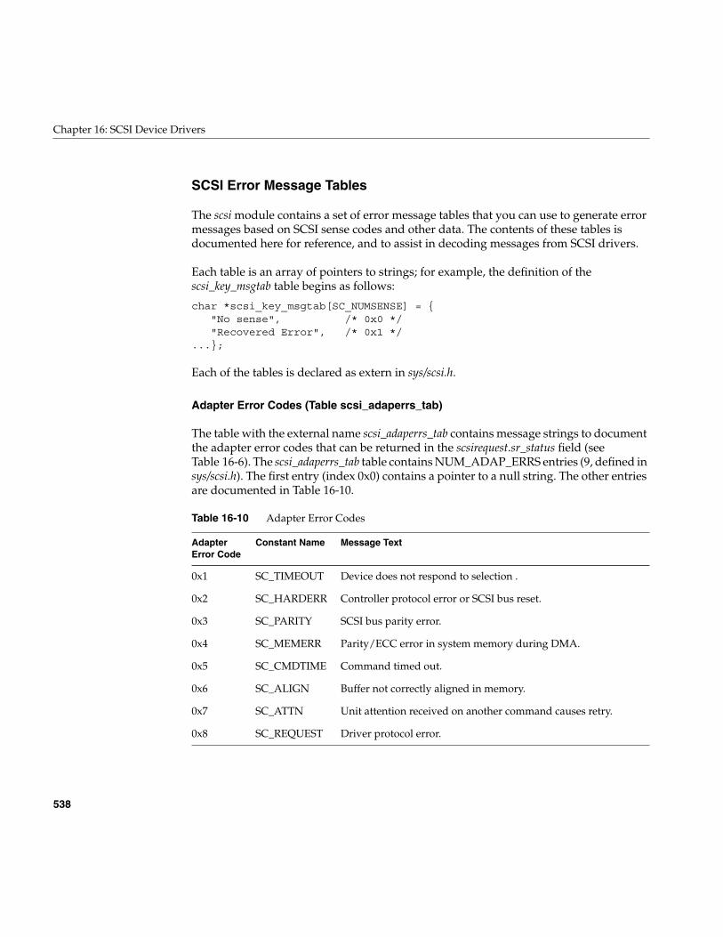
538
Chapter 16: SCSI Device Drivers
SCSI Error Message Tables
The scsi module contains a set of error message tables that you can use to generate errormessages based on SCSI sense codes and other data. The contents of these tables isdocumented here for reference, and to assist in decoding messages from SCSI drivers.
Each table is an array of pointers to strings; for example, the definition of thescsi_key_msgtab table begins as follows:
char *scsi_key_msgtab[SC_NUMSENSE] = {"No sense", /* 0x0 */"Recovered Error", /* 0x1 */
...};
Each of the tables is declared as extern in sys/scsi.h.
Adapter Error Codes (Table scsi_adaperrs_tab)
The table with the external name scsi_adaperrs_tab contains message strings to documentthe adapter error codes that can be returned in the scsirequest.sr_status field (seeTable 16-6). The scsi_adaperrs_tab table contains NUM_ADAP_ERRS entries (9, defined insys/scsi.h). The first entry (index 0x0) contains a pointer to a null string. The other entriesare documented in Table 16-10.
Table 16-10 Adapter Error Codes
AdapterError Code
Constant Name Message Text
0x1 SC_TIMEOUT Device does not respond to selection .
0x2 SC_HARDERR Controller protocol error or SCSI bus reset.
0x3 SC_PARITY SCSI bus parity error.
0x4 SC_MEMERR Parity/ECC error in system memory during DMA.
0x5 SC_CMDTIME Command timed out.
0x6 SC_ALIGN Buffer not correctly aligned in memory.
0x7 SC_ATTN Unit attention received on another command causes retry.
0x8 SC_REQUEST Driver protocol error.
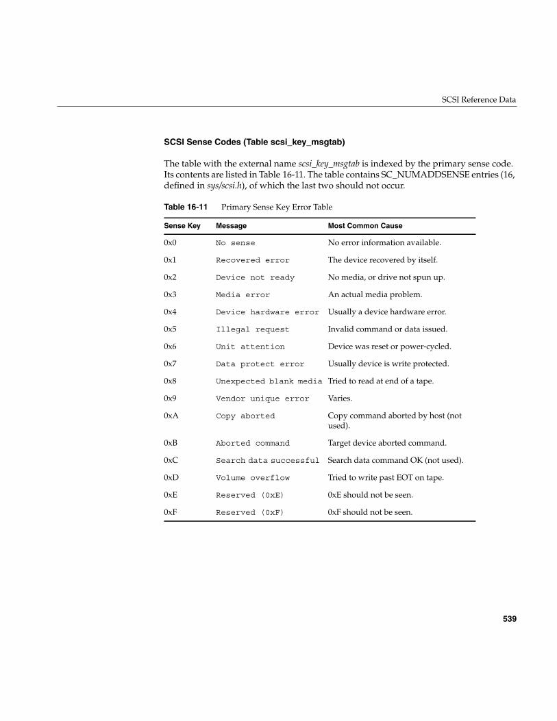
SCSI Reference Data
539
SCSI Sense Codes (Table scsi_key_msgtab)
The table with the external name scsi_key_msgtab is indexed by the primary sense code.Its contents are listed in Table 16-11. The table contains SC_NUMADDSENSE entries (16,defined in sys/scsi.h), of which the last two should not occur.
Table 16-11 Primary Sense Key Error Table
Sense Key Message Most Common Cause
0x0 No sense No error information available.
0x1 Recovered error The device recovered by itself.
0x2 Device not ready No media, or drive not spun up.
0x3 Media error An actual media problem.
0x4 Device hardware error Usually a device hardware error.
0x5 Illegal request Invalid command or data issued.
0x6 Unit attention Device was reset or power-cycled.
0x7 Data protect error Usually device is write protected.
0x8 Unexpected blank media Tried to read at end of a tape.
0x9 Vendor unique error Varies.
0xA Copy aborted Copy command aborted by host (notused).
0xB Aborted command Target device aborted command.
0xC Search data successful Search data command OK (not used).
0xD Volume overflow Tried to write past EOT on tape.
0xE Reserved (0xE) 0xE should not be seen.
0xF Reserved (0xF) 0xF should not be seen.
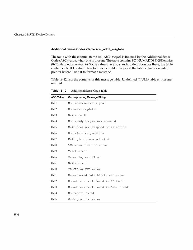
540
Chapter 16: SCSI Device Drivers
Additional Sense Codes (Table scsi_addit_msgtab)
The table with the external name scsi_addit_msgtab is indexed by the Additional SenseCode (ASC) value, when one is present. The table contains SC_NUMADDSENSE entries(0x71, defined in sys/scsi.h). Some values have no standard definition; for these, the tablecontains a NULL value. Therefore you should always test the table value for a validpointer before using it to format a message.
Table 16-12 lists the contents of this message table. Undefined (NULL) table entries areomitted.
Table 16-12 Additional Sense Code Table
ASC Value Corresponding Message String
0x01 No index/sector signal
0x02 No seek complete
0x03 Write fault
0x04 Not ready to perform command
0x05 Unit does not respond to selection
0x06 No reference position
0x07 Multiple drives selected
0x08 LUN communication error
0x09 Track error
0x0a Error log overflow
0x0c Write error
0x10 ID CRC or ECC error
0x11 Unrecovered data block read error
0x12 No address mark found in ID field
0x13 No address mark found in Data field
0x14 No record found
0x15 Seek position error
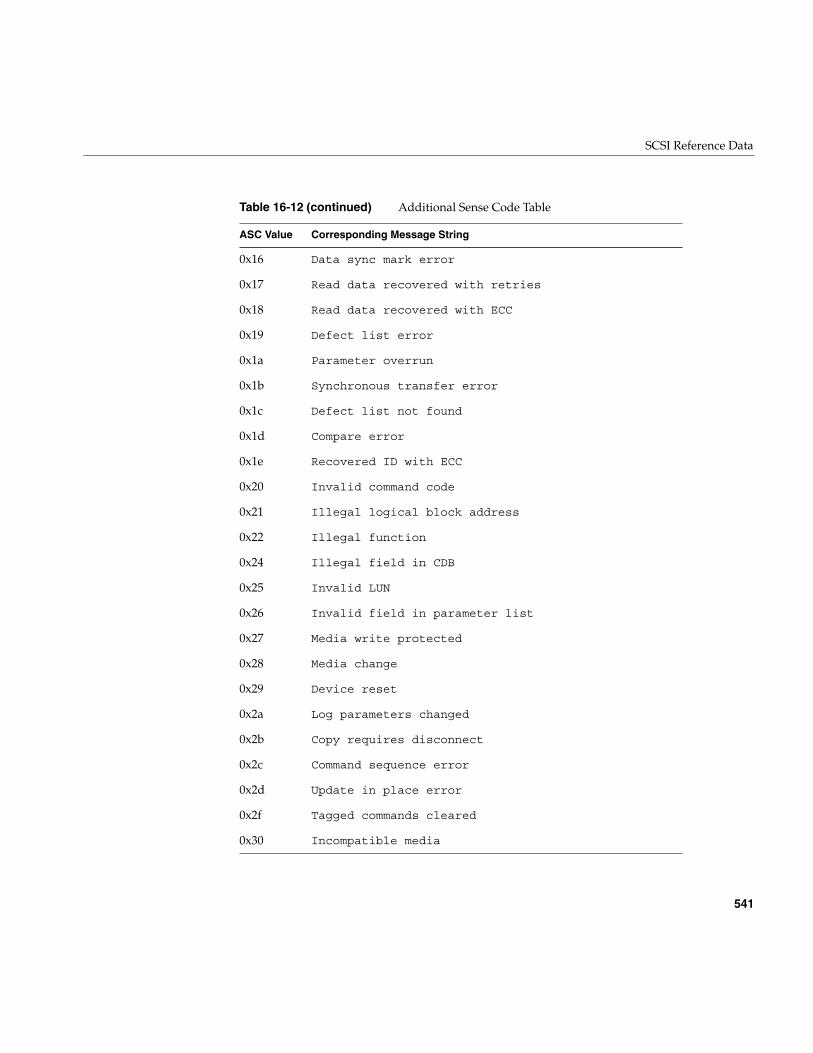
SCSI Reference Data
541
0x16 Data sync mark error
0x17 Read data recovered with retries
0x18 Read data recovered with ECC
0x19 Defect list error
0x1a Parameter overrun
0x1b Synchronous transfer error
0x1c Defect list not found
0x1d Compare error
0x1e Recovered ID with ECC
0x20 Invalid command code
0x21 Illegal logical block address
0x22 Illegal function
0x24 Illegal field in CDB
0x25 Invalid LUN
0x26 Invalid field in parameter list
0x27 Media write protected
0x28 Media change
0x29 Device reset
0x2a Log parameters changed
0x2b Copy requires disconnect
0x2c Command sequence error
0x2d Update in place error
0x2f Tagged commands cleared
0x30 Incompatible media
Table 16-12 (continued) Additional Sense Code Table
ASC Value Corresponding Message String
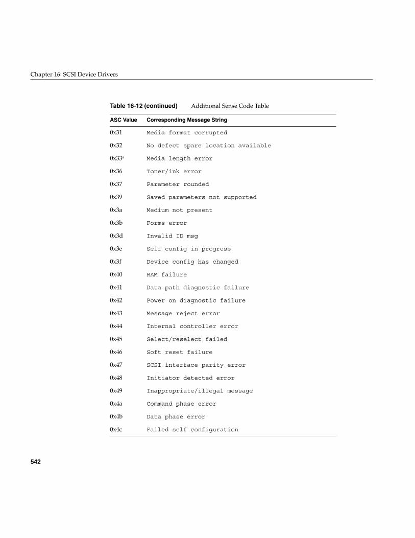
542
Chapter 16: SCSI Device Drivers
0x31 Media format corrupted
0x32 No defect spare location available
0x33a Media length error
0x36 Toner/ink error
0x37 Parameter rounded
0x39 Saved parameters not supported
0x3a Medium not present
0x3b Forms error
0x3d Invalid ID msg
0x3e Self config in progress
0x3f Device config has changed
0x40 RAM failure
0x41 Data path diagnostic failure
0x42 Power on diagnostic failure
0x43 Message reject error
0x44 Internal controller error
0x45 Select/reselect failed
0x46 Soft reset failure
0x47 SCSI interface parity error
0x48 Initiator detected error
0x49 Inappropriate/illegal message
0x4a Command phase error
0x4b Data phase error
0x4c Failed self configuration
Table 16-12 (continued) Additional Sense Code Table
ASC Value Corresponding Message String
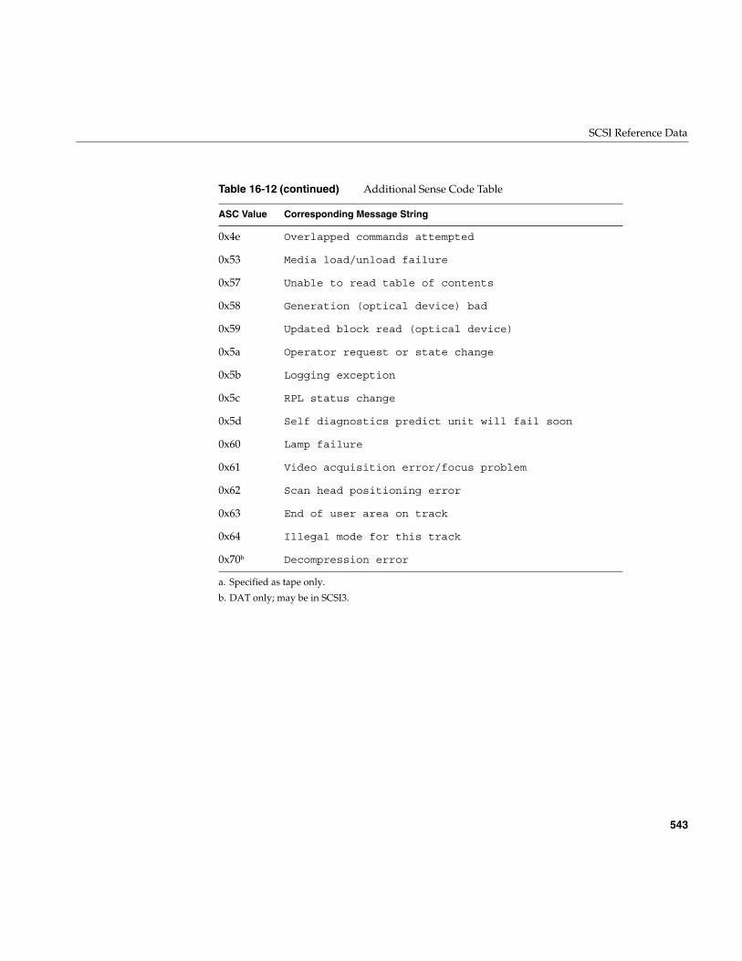
SCSI Reference Data
543
a. Specified as tape only.
b. DAT only; may be in SCSI3.
0x4e Overlapped commands attempted
0x53 Media load/unload failure
0x57 Unable to read table of contents
0x58 Generation (optical device) bad
0x59 Updated block read (optical device)
0x5a Operator request or state change
0x5b Logging exception
0x5c RPL status change
0x5d Self diagnostics predict unit will fail soon
0x60 Lamp failure
0x61 Video acquisition error/focus problem
0x62 Scan head positioning error
0x63 End of user area on track
0x64 Illegal mode for this track
0x70b Decompression error
Table 16-12 (continued) Additional Sense Code Table
ASC Value Corresponding Message String
544
Chapter 16: SCSI Device Drivers
A Note on FibreChannel Drivers
The FibreChannel adapter is accessed just like a SCSI adapter. It is a peer to drivers suchas ql, adp78, and wd95.
Note that there is one difference in that all commands are tagged, whether or not thesr_tag member of the scsi_request structure is set.
PART SIX
Network Drivers VI
Chapter 17, “Network Device Drivers”Network device drivers are special in that they interface a device to the ifnetinterface of the TCP/IP protocol stack.

547
Chapter 17
17. Network Device Drivers
A network device driver is a kernel-level driver that connects a communications deviceto the IRIX TCP/IP protocol stack using the ifnet interface established by BSD UNIX. Thischapter contains these major topics:
• “Overview of Network Drivers” on page 548 gives an overview of the IRIXnetworking subsystem and the role of an ifnet driver in it.
• “Network Driver Interfaces” on page 550 summarizes the unique interfaces used byan ifnet driver.
• “Multiprocessor Considerations” on page 554 discusses writing device drivers in asymmetric multiprocessing environment.
• “Example ifnet Driver” on page 558 displays the code of a network driver, omittingall device-specific features.
Note: If your interest is in creating a network application based on sockets, TLI, orstreams, this chapter offers little but background information. Refer to the IRIX NetworkProgramming Guide, document Number 007-0810-050, for a complete review of allapplication-level services.
Even if your interest is in creating a kernel-level network driver, you should be familiarwith the facilities documented in the IRIX Network Programming Guide. This chapterassumes that your are familiar with them.
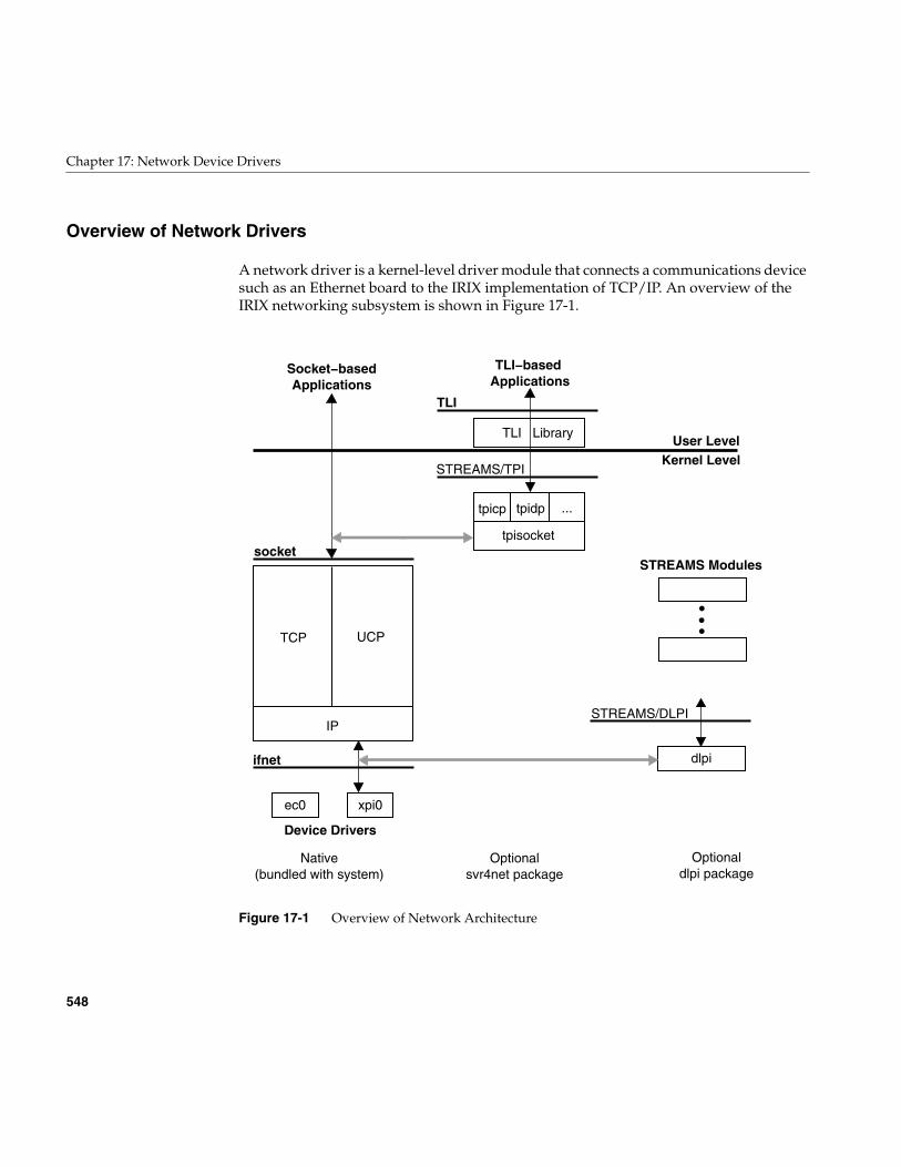
548
Chapter 17: Network Device Drivers
Overview of Network Drivers
A network driver is a kernel-level driver module that connects a communications devicesuch as an Ethernet board to the IRIX implementation of TCP/IP. An overview of theIRIX networking subsystem is shown in Figure 17-1.
Figure 17-1 Overview of Network Architecture
IP
Native(bundled with system)
Optionaldlpi package
Optionalsvr4net package
UCPTCP
tpisocket
...tpidptpicp
TLI Library
STREAMS/TPI
TLI
socket
ifnet
Kernel LevelUser Level
TLI−based Applications
Socket−basedApplications
STREAMS Modules
xpi0ec0
dlpi
STREAMS/DLPI
Device Drivers
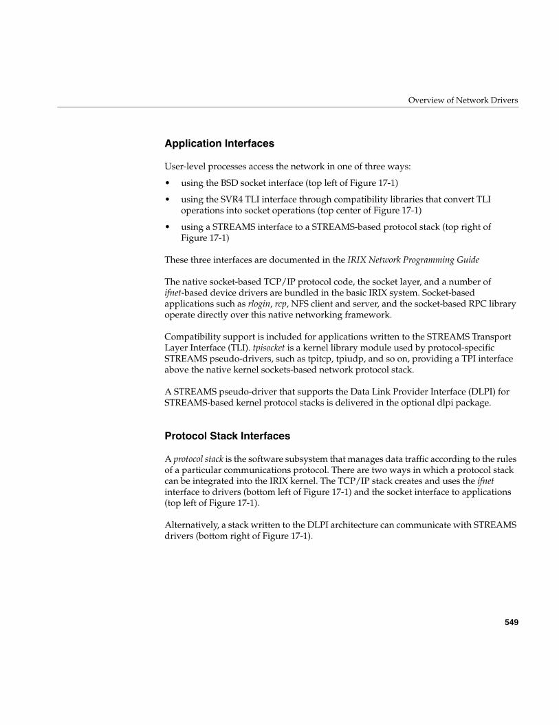
Overview of Network Drivers
549
Application Interfaces
User-level processes access the network in one of three ways:
• using the BSD socket interface (top left of Figure 17-1)
• using the SVR4 TLI interface through compatibility libraries that convert TLIoperations into socket operations (top center of Figure 17-1)
• using a STREAMS interface to a STREAMS-based protocol stack (top right ofFigure 17-1)
These three interfaces are documented in the IRIX Network Programming Guide
The native socket-based TCP/IP protocol code, the socket layer, and a number ofifnet-based device drivers are bundled in the basic IRIX system. Socket-basedapplications such as rlogin, rcp, NFS client and server, and the socket-based RPC libraryoperate directly over this native networking framework.
Compatibility support is included for applications written to the STREAMS TransportLayer Interface (TLI). tpisocket is a kernel library module used by protocol-specificSTREAMS pseudo-drivers, such as tpitcp, tpiudp, and so on, providing a TPI interfaceabove the native kernel sockets-based network protocol stack.
A STREAMS pseudo-driver that supports the Data Link Provider Interface (DLPI) forSTREAMS-based kernel protocol stacks is delivered in the optional dlpi package.
Protocol Stack Interfaces
A protocol stack is the software subsystem that manages data traffic according to the rulesof a particular communications protocol. There are two ways in which a protocol stackcan be integrated into the IRIX kernel. The TCP/IP stack creates and uses the ifnetinterface to drivers (bottom left of Figure 17-1) and the socket interface to applications(top left of Figure 17-1).
Alternatively, a stack written to the DLPI architecture can communicate with STREAMSdrivers (bottom right of Figure 17-1).
550
Chapter 17: Network Device Drivers
Device Driver Interfaces
A network driver uses the methods and facilities of other kernel-level device drivers, asdescribed in Part III, “Kernel-Level Drivers” of this book. A network driver is compiledand linked like other drivers, configured using the same configuration files, and loadedinto the kernel by lboot like other drivers.
However, other device drivers support the UNIX filesystem, transferring data inresponse to calls to their pfxread(), pfxwrite(), or pfxstrategy() entry points. This is not thecase with a network driver; it supports protocol stacks, and it transfers data in responseto calls from the ifnet interface.
Network Driver Interfaces
The IRIX kernel networking design is based on the kernel networking framework in4.3BSD. If you are familiar with the 4.3BSD kernel networking design, then you arealready familiar with the IRIX kernel networking design because they are basically thesame.
The IRIX networking design is based on the socket interface: mbuf objects are used toexchange messages within the kernel, and device drivers support the TCP/IP internetprotocol suite by supporting the ifnet interface.
Since the BSD-based networking framework and the implementation of the TCP/IPprotocol suite have changed little from previous releases of IRIX, porting your ifnetdevice driver to this release of IRIX should be straightforward.
Note: Although the general kernel facilities documented in Chapter 8, “DeviceDriver/Kernel Interface,” are standardized and stable, this is not the case with networkinterfaces. The ifnet and other interfaces summarized in this topic are subject to change withoutnotice.
Network Driver Interfaces
551
Kernel Facilities
A network driver is structured like any kernel-level device driver, much as described inChapter 7, “Structure of a Kernel-Level Driver,” but with the following similarities anddifferences:
• A network driver is loaded by lboot in response to either a USE or VECTOR line in afile in /var/sysgen/system (see “Configuring a Nonloadable Driver” on page 259).
• A network driver is initialized by a call to either its pfxinit() or pfxedtinit() entrypoint when it is loaded.
• A network driver does not need to provide any other entry points (see “Entry PointSummary” on page 145).
• A network driver does not need to provide a driver flag constant pfxdevflag becausea network driver is always assumed to be multiprocessor-aware (see “Driver FlagConstant” on page 148).
• Although a network driver can use the kernel functions for synchronization andlocking (see “Waiting and Mutual Exclusion” on page 233), it normally does notbecause the ifnet interface includes special-purpose locking facilities that are moreconvenient (see “Multiprocessor Considerations” on page 554).
Principal ifnet Header Files
The software interface to network facilities is declared in the following important headerfiles:
net/if.h Basic ifnet facilities and data structures, including the ifnetstructure, the basic driver interface object.
net/if_types.h Constants for interface types, used in decoding address headers.
sys/mbuf.h The mbuf structure with related constants and macros, anddeclarations of functions to allocate, manipulate, and free mbufobjects.
net/netisr.h Declarations related to software interrupts, includingschednetisr() to schedule an interrupt, and the IP input queueipintrq.
net/multi.h Routines defining a generic filter for use by drivers whose devicescannot perfectly filter multicast packets.
552
Chapter 17: Network Device Drivers
Debugging Facilities
When your driver is operating under a debugging kernel, you can use the facilities ofsymmon and idbg to display a variety of network-related data structures. See “Preparingthe System for Debugging” on page 269 , and see “Commands to DisplayNetwork-Related Structures” on page 294.
Information Sources
Aside from comments in header files, the complete ifnet interface and related interfaceshave never been documented. In prior years, most people working on ifnet drivers havehad access to the Berkeley UNIX source distribution and have been able to answerquestions by referring to the code.
Referring to the code is an even more common option today, thanks to the release of4.4BSD-Lite, a software distribution of BSD UNIX that does not require a source license,now widely available at a reasonable price. To obtain a copy, order the following:
• 4.4BSD-Lite Berkely Software Distribution CD-ROM Companion, published by USENIXand O’Reilly & Associates; ISBN 1-56592-081-3 (US domestic) or ISBN 1-56592-092-9(non-US).
The ifnet source code in this software is functionally compatible with IRIX ifnet, althoughsome protocols (for example, snoop and drain) are not implemented in BSD-Lite.
net/soioctl.h Socket ioctl() function numbers, some of which reach a driver foraction.
net/raw.h The interface to the raw protocol family members snoop and drain.
net/if_arp.h Generic ARP declarations.
netinet/if_ether.h Essential declarations for Ethernet drivers, including ARP protocolfor Ethernet.
sys/dlsap_register.h DLPI interface declarations.
Network Driver Interfaces
553
Finally, the IRIX reference pages contain a wealth of detail regarding network interfaces.Some reference pages that are related to the interests of driver designers are listed inTable 17-1.
Table 17-1 Important Reference Pages Related to Network Drivers
Reference Page Contents
arp(7) Operation of the ARP protocol, with details of ioctl() functions.
drain(7) Operation of the drain driver, which receives unwanted packets, with detailsof its ioctl() functions.
ethernet(7) Overview of the IRIX Ethernet drivers, including error messages and the useof VECTOR lines to configure them.
fddi(7) Cursory overview of IRIX FDDI drivers, with naming conventions.
ifconfig(1) Management program used to enable and disable network interfaces (drivers)and change their runtime parameters.
netintro(7) Overview of network facilities; mentions the role of the network interface(driver); has extensive detail on routing ioctl() calls.
network(1) Documents the network initialization script that runs when the system isbooted up.
raw(7) Overview of the Raw protocol family whose members are snoop and drain.
routed(1) Documents operation of the routing daemon, including ioctl() use.
snoop(7) Operation of the snoop driver, which allows inspection of packets, with detailsof its ioctl() features.
ticlts(7) Operation and use of the ticlts, ticots, and ticotsord loopback drivers.
tokenring(7) Overview of the IRIX token-ring drivers, including packet formats.
554
Chapter 17: Network Device Drivers
Network Inventory Entries
The driver must call device_inventory_add() from its attach() entry point to label thedevice hardware vertex with the appropriate inventory information. The deviceconfiguration program ioconfig requires this information in order to assign a uniquecontroller number and communicate this to the device driver by opening the device (see“Using ioconfig for Global Controller Numbers” on page 51). The driver can use thefollowing parameters when calling device_inventory_add() (see sys/invent.h and“Attaching Device Information” on page 229):
Multiprocessor Considerations
Prior to IRIX 5.3, the kernel BSD framework code and TCP/IP protocol stack executedunder a single kernel lock, creating a single-threaded implementation. Beginning withIRIX 5.3, the BSD framework and TCP/IP protocol suite have been multi-threaded tosupport symmetric multiprocessing. The code uses different kernel locks to protectdifferent critical sections.
IRIX now supports multiple, concurrent threads of execution within the TCP/UDP/IPprotocol suite, and the kernel socket layer. In addition, network device drivers run onany available CPU, concurrently with the network software, applications, and otherdrivers.
This means that any ifnet-based network driver must be prepared to run asynchronouslyand concurrently with other drivers and with the protocol stack.
vhdl The vertex handle of the attached device.
class INV_NETWORK
type The packet type, for example INV_NET_ETHER. See sys/invent.h forthe possible “types for class network” list.
controller The kind of network controller from the “controllers for networktypes” list in sys/invent.h.
unit Any distinguishing number for this device. The hinv command doesnot decode this field.
state Any characteristic number for this device. The hinv command does notdecode this field.
Multiprocessor Considerations
555
Ineffective spl() Functions
The spl*() functions were the traditional UNIX method of gaining exclusive use of data.In single-threaded ifnet drivers, the splimp() or splnet() functions were used to getexclusive use of the ifnet structure.
In a multiprocessor, spl*() functions like splimp() or splnet() do block interrupts on thelocal CPU, but they do not prevent interrupts from occurring on other processors in thesystem, nor do they prevent other processes on other CPUs from executing code thatrefers to the same data.
If you are porting a driver from a uniprocessor environment, search for any use of anspl*() function and plan to replace it with effective mutual exclusion locking macros.
Multiprocessor Locking Macros
Under BSD networking, drivers interface with the protocol stacks by queueing incomingpackets on a per-protocol input queue. In a multiprocessor, each protocol input queuemust be protected by the locking macros defined in the file net/if.h.
All the locking macros that protect the input queue are assumed to be called at the properprocessor interrupt masking level, splimp. All input queue locking macros also take aninput parameter ifq, which is a pointer to the protocol input queue that must be definedas a struct ifqueue.
Compiler Flags for MP TCP/IP
The _MP_NETLOCKS and MP compiler variables must be defined in order to enable themacros necessary to run under multi-threaded TCP/IP (see “Compiler Variables” onpage 257).
556
Chapter 17: Network Device Drivers
Mutual Exclusion Macros
The macros for mutual exclusion defined in net/if.h are listed in Table 17-2.
The variables used in Table 17-2 are as follows:
Table 17-2 Mutual Exclusion Macros for ifnet Drivers
Macro Prototype Purpose
IFNET_LOCK(ifp, s) Get exclusive use of the structure *ifp. splimp() is called toraise the interrupt level if necessary, and the returned valueis saved in s.
IFNET_UNLOCK(ifp,s) Release use of *ifp, and return to interrupt level s.
IFNET_LOCKNOSPL(ifp) Get exclusive use of the structure *ifp, but do not callsplimp() (the driver knows it is already at the appropriatelevel.)
IFNET_UNLOCKNOSPL(ifp) Release use of *ifp after use of IFNET_LOCKNOSPL.
IFNET_ISLOCKED(ifp) Test whether *ifp is locked.
IFQ_LOCK(ifq) Get exclusive use of an input queue *ifq.
IFQ_UNLOCK(ifq) Release use of *ifq.
IF_ENQUEUE(ifq, mp) Lock the queue *ifq; post the mbuf *mp; release the queue.
IF_ENQUEUE_NOLOCK(ifq,mp) Post the mbuf *mp without locking.
ifp Address of a struct ifnet to be used exclusively.
s Integer variable to store the current interrupt mask level.
ifq Address of a struct ifqueue to be posted.
mp Address of a struct mbuf to be posted.
Multiprocessor Considerations
557
Macro Use
The TCP/IP protocol stack automatically acquires the ifnet structure before calling anetwork driver routine through that structure. Thus the driver’s init(), stop(), start(),output(), and ioctl() functions do not need to use IFNET_LOCK or IFNET_UNLOCK.Look for expressions
ASSERT(IFNET_ISLOCKED(ifp));
in the example driver (“Example ifnet Driver” on page 558) to see places where this is thecase. Explicit use of IFNET_LOCK is needed in the interrupt handler.
558
Chapter 17: Network Device Drivers
Example ifnet Driver
The code in Example 17-1 represents the skeleton of an ifnet driver, showing its entrypoints, data structures, required ioctl() functions, address format conventions, and itsuse of kernel utility routines and locking primitives.
A comment beginning “MISSING:” represents a point at which a complete driver wouldcontain code related to the device or bus it manages.
Example 17-1 Skeleton ifnet Driver/** if_sk - skeleton IRIX 6.4 ifnet device driver** This is a skeleton ifnet driver for IRIX 6.4* meant to demonstrate ifnet driver entry points,* data structures, required ioctls, address format* conventions, kernel utility routines, and locking* primitives. These kernel data structures and* routines are SUBJECT TO CHANGE w/o notice.** Refer to the IRIX 6.4 Device Driver Programming Guide* and Device Driver Reference Pages for complete* information on writing PCI, GIO, VME, and EISA bus* device drivers for SGI systems.** "MISSING" is used to designate places where device/bus/driver-* specific code sections are required.** Locking strategy:* IFNET_LOCK() and IFNET_UNLOCK() acquire/release the* lock on a given ifnet structure. IFQ_LOCK() and* IFQ_UNLOCK() acquire/release the lock on a given ifqueue* structure. The ifnet or ifqueue lock must be held while* modifying any fields within the associated data* structure. The ifnet lock is also held to singlethread* portions of the device driver. The driver xxinit,* xxreset, xxoutput, xxwatchdog, and xxioctl entry points* are called with IFNET_LOCK() already acquired thus only* a single thread of execution is allowed in these* portions of the driver for each interface. It is the* driver's responsibility to call IFNET_LOCK() within its* xxintr() and other private routines to singlethread any* other critical sections. It is also the driver's* responsibility to acquire the ifq lock by calling
Example ifnet Driver
559
* IFQ_LOCK() before attempting to enqueue onto the IP* input queue "ipintrq".** Notes:* - don't forget appropriate machine-specific cache flushing operations* (refer to IRIX Device Driver Programming guide)* - declare pointers to device registers as "volatile"** Caveat Emptor:* No guarantees are made wrt correctness nor completeness* of this source.** Copyright 1996 Silicon Graphics, Inc. All rights reserved.*/
#ident "$Revision: 2.0$"
#include <sys/types.h>#include <sys/param.h>#include <sys/systm.h>#include <sys/sysmacros.h>#include <sys/cmn_err.h>#include <sys/debug.h>#include <sys/hwgraph.h>#include <sys/iograph.h>#include <sys/errno.h>#include <sys/PCI/pciio.h>#include <sys/idbgentry.h>#include <sys/tcp-param.h>#include <sys/mbuf.h>#include <sys/immu.h>#include <sys/sbd.h>#include <sys/ddi.h>#include <sys/kmem.h>#include <sys/cpu.h>#include <sys/invent.h>#include <net/if.h>#include <net/if_types.h>#include <net/netisr.h>#include <netinet/if_ether.h>#include <net/raw.h>#include <net/multi.h>#include <netinet/in_var.h>#include <net/soioctl.h>#include <sys/dlsap_register.h>
560
Chapter 17: Network Device Drivers
/* MISSING: driver-specific header includes go here */
/** driver-specific and device-specific data structure* declarations and definitions might go here.*/
#define SK_MAX_UNITS 8#define SK_MTU 4096#define SK_DOG (2*IFNET_SLOWHZ) /* watchdog duration in seconds */#define SK_IFT (IFT_FDDI) /* refer to <net/if_types.h> */#define SK_INV (INV_NET_FDDI) /* refer to <sys/invent.h> */
#define INV_FDDI_SK (23) /* refer to <sys/invent.h> */
#define IFF_ALIVE (IFF_UP|IFF_RUNNING)#define iff_alive(flags) (((flags) & IFF_ALIVE) == IFF_ALIVE)#define iff_dead(flags) (((flags) & IFF_ALIVE) != IFF_ALIVE)
#define SK_ISBROAD(addr) (!bcmp((addr), &skbroadcastaddr, SKADDRLEN))#define SK_ISGROUP(addr) ((addr)[0] & 01)
/** MISSING media-specific definitions of address size and header format.*/
#define SKADDRLEN (6)#define SKHEADERLEN (sizeof (struct skheader))
/** Our fictional media has an IEEE 802-looking header..*/
struct skaddr {u_int8_t sk_vec[SKADDRLEN];
};struct skheader {
struct skaddr sh_dhost;struct skaddr sh_shost;u_int16_t sh_type;
};struct skaddr skbroadcastaddr = {
0xff, 0xff, 0xff, 0xff, 0xff, 0xff};
/*
Example ifnet Driver
561
* Each interface is represented by a private* network interface data structure that maintains* the device hardware resource addresses, pointers* to device registers, allocated dma_alloc maps,* lists of mbufs pending transmit or reception, etc, etc.* We use ARP and have an 802 address.*/
struct sk_info {struct arpcom si_ac; /* common ifnet and arp */struct skaddr si_ouraddr; /* our individual media address */struct mfilter si_filter; /* AF_RAW sw snoop filter */struct rawif si_rawif; /* raw snoop interface */int si_flags;caddr_t si_regs; /* pointer to device registers */vertex_hdl_t si_our_vhdl; /* our vertex */vertex_hdl_t si_conn_vhdl; /* our parent vertex */pciio_intr_t si_intr; /* interrupt handle *//* MISSING additional driver-specific data structures */
};
#define si_if si_ac.ac_if
#define sktoifp(si) (&(si)->si_ac.ac_if)#define ifptosk(ifp)((struct sk_info *)ifp)
#define ALIGNED(addr, alignment) (((u_long)(addr) & (alignment-1)) == 0)
#define sk_info_set(v,i) hwgraph_fastinfo_set((v),(arbitrary_info_t)(i))#define sk_info_get(v) ((struct sk_info *)hwgraph_fastinfo_get((v)))
/** The start of an mbuf containing an input frame*/
struct sk_ibuf {struct ifheader sib_ifh;struct snoopheader sib_snoop;struct skheader sib_skh;
};#define SK_IBUFSZ (sizeof (struct sk_ibuf))
/** Multicast filter request for SIOCADDMULTI/SIOCDELMULTI .*/
struct mfreq {union mkey *mfr_key; /* pointer to socket ioctl arg */
562
Chapter 17: Network Device Drivers
mval_t mfr_value; /* associated value */};
void sk_init(void);static int sk_ifinit(struct ifnet *ifp);int sk_attach(vertex_hdl_t conn_vhdl);static void sk_reset(struct sk_info *si);static void sk_intr(struct sk_info *si);static int sk_output(struct ifnet *ifp, struct mbuf *m, struct sockaddr *dst);static void sk_input(struct sk_info *si, struct mbuf *m, int totlen);static int sk_ioctl(struct ifnet *ifp, int cmd, void *data);static void sk_watchdog(struct ifnet *ifp);static void sk_stop(struct sk_info *si);static int sk_start(struct sk_info *si, int flags);static int sk_add_da(struct sk_info *si, union mkey *key, int ismulti);static int sk_del_da(struct sk_info *si, union mkey *key, int ismulti);static int sk_dahash(char *addr);static int sk_dlp(struct sk_info *si, int port, int encap, struct mbuf *m, int len);static void sk_dump(int unit);/* MISSING additional driver-specific routine prototypes */
extern struct ifqueue ipintrq; /* ip input queue */extern struct ifnet loif; /* loopback driver if */
extern void bitswapcopy(void *, void *, int);
int sk_devflag = D_MP;
/** xxinit() routine called early during boot.*/
voidsk_init(void){
/* register ourselves with the pci i/o infrastructure */pciio_driver_register(0x10A9, 0x0003, "sk_", 0);
/** register a handy debugging routine so we can call it* from idbg(1) and the kernel debugger.*/
idbg_addfunc("sk_dump", (void (*)())sk_dump);}
Example ifnet Driver
563
/** xxattach() routine is called by the i/o infrastructure* when a hardware device matches our pci vendor and device ids.*/
intsk_attach(vertex_hdl_t conn_vhdl){
graph_error_t rc;vertex_hdl_t our_vhdl;struct sk_info *si;struct ifnet *ifp;device_desc_t sk_dev_desc;
/* add a char device vertex to the hardware graph tree ("/hw") */if ((rc = hwgraph_char_device_add(conn_vhdl, "sk", "sk_",
&our_vhdl)) != GRAPH_SUCCESS) {cmn_err(CE_ALERT, "skattach: hwgraph_char_device_add error %d", rc);return (EIO);
}
/* fix up device descriptor */sk_dev_desc = device_desc_dup(our_vhdl);device_desc_intr_name_set(sk_dev_desc, "sk device");device_desc_default_set(our_vhdl, sk_dev_desc);
if ((si = (struct sk_info*) kmem_zalloc(sizeof (struct sk_info), KM_SLEEP)) == NULL){
cmn_err(CE_ALERT, "skattach: kmem_alloc failed\n");return (ENOMEM);
}
/* save our vertex and our parent's vertex for later */si->si_our_vhdl = our_vhdl;si->si_conn_vhdl = conn_vhdl;
/* save a pointer to our sk_info structure in our vertex */sk_info_set(our_vhdl, si);
/** MISSING* Driver-specific actions that might go here:** - call sk_reset to disable the device* - pciio_pio map in the device registers* - allocate a new sk_info structure
564
Chapter 17: Network Device Drivers
* - allocate device host memory buffers and descriptors* and create any static dma mappings (pciio_dmamap_xx )* ...*/
/* register our interrupt handler */si->si_intr = pciio_intr_alloc(conn_vhdl, sk_dev_desc,
PCIIO_INTR_LINE_A, our_vhdl);pciio_intr_connect(si->si_intr, (intr_func_t) sk_intr, (intr_arg_t) si, (void *)0);
/** MISSING your address translation protocol goes here.* Save a copy of our MAC address in the arpcom structure.*/
bcopy((caddr_t)&si->si_ouraddr, (caddr_t)si->si_ac.ac_enaddr,SKADDRLEN);
/** Initialize ifnet structure with our name, type, mtu size,* supported flags, pointers to our entry points,* and attach to the available ifnet drivers list.*/
ifp = sktoifp(si);ifp->if_name = "sk";ifp->if_unit = -1;ifp->if_type = SK_IFT;ifp->if_mtu = SK_MTU;ifp->if_flags = IFF_BROADCAST | IFF_MULTICAST | IFF_NOTRAILERS;ifp->if_output = sk_output;ifp->if_ioctl = (int (*)(struct ifnet*, int, void*))sk_ioctl;ifp->if_watchdog = sk_watchdog;
/** A note about unit numbering and when to call if_attach:** IRIX 6.4 includes a new boot-time command ioconfig(1M)* which walks the hardware device tree ("/hw") and allocates* and assigns a controller number (unit number) to each* device vertex it finds which has an inventory record.** So we do everything but the if_attach() call now,* since we don't yet have our unit number, and call* if_attach() from our xxopen() routine when it is* called by the ioconfig(1M) command during booting.*/
Example ifnet Driver
565
/** Allocate a multicast filter table with an initial* size of 10. See <net/multi.h> for a description* of the support for generic sw multicast filtering.* Use of these mf routines is purely optional -* if you're not supporting multicast addresses or* your device does perfect filtering or you think* you can roll your own better, feel free.*/
if (!mfnew(&si->si_filter, 10))cmn_err(CE_PANIC, "sk_edtinit: no memory for frame filter\n");
/** You must create an inventory record for this vertex now* or ioconfig(1M) will not call our xxopen() routine to* pass in an allocated unit number later.*/
device_inventory_add(our_vhdl, INV_NETWORK, INV_NET_FDDI, 100, -1, 0);
return (0);}
/** Driver xxopen() routine exists only to take unit# which* has now been assigned to the vertex by ioconfig(1M)* and if_attach() the device.*/
/* ARGSUSED */intsk_open(dev_t *devp, int flag, int otyp, struct cred *crp){
vertex_hdl_t our_vhdl;struct sk_info *si;int unit;
our_vhdl = dev_to_vhdl(*devp);
if ((si = sk_info_get(our_vhdl)) == NULL)return (EIO);
/* if already if_attached, just return */if (si->si_if.if_unit != -1)
return (0);
566
Chapter 17: Network Device Drivers
/* get our unit number from the vertex label */if ((unit = device_controller_num_get(our_vhdl)) < 0) {
cmn_err(CE_ALERT, "sk_open: vertex missing ctlr number");return (EIO);
}
si->si_if.if_unit = unit;
/** Install this device in the list of IRIX ifnet structures.*/
if_attach(&si->si_if);
/** Initialize the raw socket interface. See <net/raw.h>* and the man pages for descriptions of the SNOOP* and DRAIN raw protocols.*/
rawif_attach(&si->si_rawif, &si->si_if,(caddr_t) &si->si_ouraddr,(caddr_t) &skbroadcastaddr,SKADDRLEN,SKHEADERLEN,structoff(skheader, sh_shost),structoff(skheader, sh_dhost));
return (0);}
static intsk_ifinit(struct ifnet *ifp){
struct sk_info *si;
si = ifptosk(ifp);
ASSERT(IFNET_ISLOCKED(ifp));
/** Reset the device first, ask questions later..*/
sk_reset(si);
/** - free or reuse any pending xmit/recv mbufs
Example ifnet Driver
567
* - initialize device configuration registers, etc.* - allocate and post receive buffers** Refer to Device Driver Programming guide for* descriptions on use of kvtophys() (GIO) or* dma_map/dma_mapaddr() (VME) routines for* obtaining DMA addresses and system-specific* issues like flushing caches or write buffers.*/
/** MISSING* enable if_flags device behavior (IFF_DEBUG on/off, etc.)*/
ifp->if_timer = SK_DOG; /* turn on watchdog */
/* MISSING: turn device "on" now */
return 0;}
/** Reset the interface.*/
static voidsk_reset(struct sk_info *si){
struct ifnet *ifp = sktoifp(si);
ifp->if_timer = 0; /* turn off watchdog */
/** MISSING* - reset device* - reset device receive descriptor ring* - free any enqueued transmit mbufs* - create device xmit descriptor ring*/
}
static voidsk_intr(struct sk_info *si){
struct ifnet *ifp;
568
Chapter 17: Network Device Drivers
struct mbuf *m;int totlen;
#ifndef INTR_KTHREADSint s;
#endif
ifp = &si->si_if;
/** Ignore early interrupts.*/
if (iff_dead(ifp->if_flags)) {sk_stop(si);return;
}
IFNET_LOCK(ifp, s); /* acquire interface lock */
/** MISSING: read and clear the device interrupt status register.*/
/** process any received packets.*/
while (0/* MISSING: received packets available */) {
/** MISSING* Do device-specific receive processing here.* Allocate and post a replacement receive buffer.*/
sk_input(si, m, totlen);}
while (0/* MISSING mbufs completed transmission */) {
/** MISSING* Reclaim any completed device transmit resources* freeing completed mbufs, checking for errors,* and maintaining if_opackets, if_oerrors,* if_collisions, etc.*/
Example ifnet Driver
569
}
/* MISSING: process any other interrupt conditions */
IFNET_UNLOCK(ifp, s);}
/** Transmit packet. If the destination is this system or* broadcast, send the packet to the loop-back device if* we cannot hear ourself transmit. Return 0 or errno.*/
static intsk_output(
struct ifnet *ifp,struct mbuf *m0,struct sockaddr *dst)
{struct sk_info *si = ifptosk(ifp);struct skheader *sh;struct mbuf *m, *m1;struct mbuf *mloop;struct sockaddr_sdl *sdl;int error;
ASSERT(IFNET_ISLOCKED(ifp));
mloop = NULL;
if (iff_dead(ifp->if_flags)) {error = EHOSTDOWN;goto bad;
}
/** If snd queue full, try reclaiming some completed* mbufs. If it's still full, then just drop the* packet and return ENOBUFS.*/
if (IF_QFULL(&si->si_if.if_snd)) {while (0/* MISSING xmits done */) {
/** MISSING: Reclaim completed xmit descriptors.*/
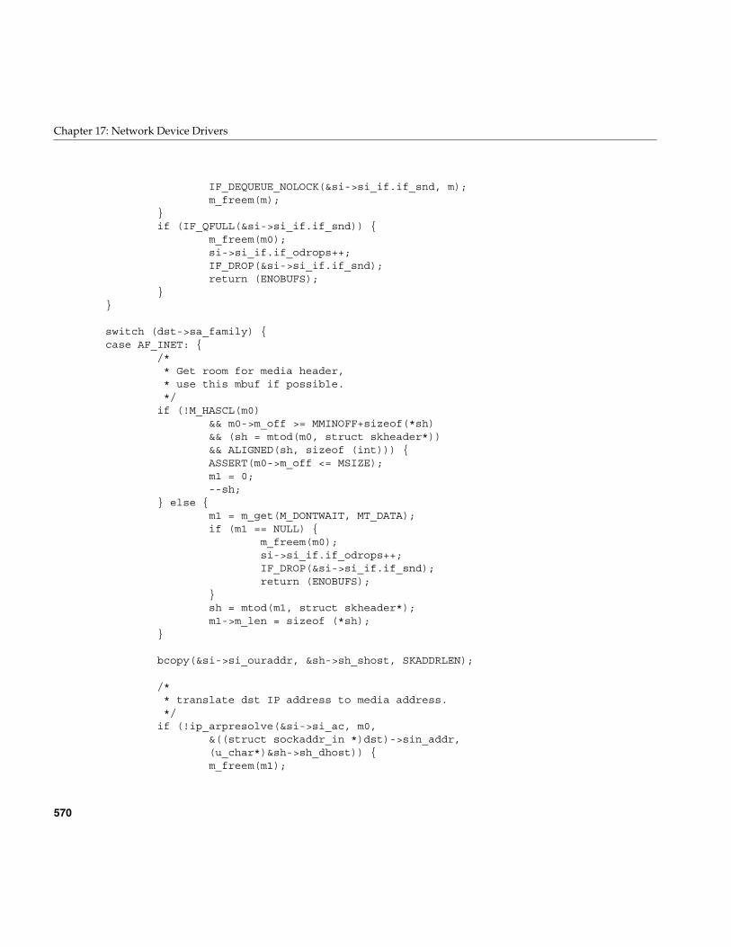
570
Chapter 17: Network Device Drivers
IF_DEQUEUE_NOLOCK(&si->si_if.if_snd, m);m_freem(m);
}if (IF_QFULL(&si->si_if.if_snd)) {
m_freem(m0);si->si_if.if_odrops++;IF_DROP(&si->si_if.if_snd);return (ENOBUFS);
}}
switch (dst->sa_family) {case AF_INET: {
/** Get room for media header,* use this mbuf if possible.*/if (!M_HASCL(m0)
&& m0->m_off >= MMINOFF+sizeof(*sh)&& (sh = mtod(m0, struct skheader*))&& ALIGNED(sh, sizeof (int))) {ASSERT(m0->m_off <= MSIZE);m1 = 0;--sh;
} else {m1 = m_get(M_DONTWAIT, MT_DATA);if (m1 == NULL) {
m_freem(m0);si->si_if.if_odrops++;IF_DROP(&si->si_if.if_snd);return (ENOBUFS);
}sh = mtod(m1, struct skheader*);m1->m_len = sizeof (*sh);
}
bcopy(&si->si_ouraddr, &sh->sh_shost, SKADDRLEN);
/** translate dst IP address to media address.*/if (!ip_arpresolve(&si->si_ac, m0,
&((struct sockaddr_in *)dst)->sin_addr,(u_char*)&sh->sh_dhost)) {m_freem(m1);
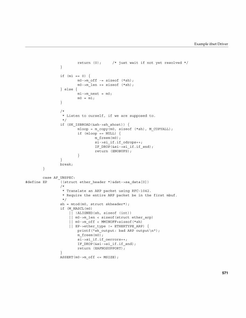
Example ifnet Driver
571
return (0); /* just wait if not yet resolved */}
if (m1 == 0) {m0->m_off -= sizeof (*sh);m0->m_len += sizeof (*sh);
} else {m1->m_next = m0;m0 = m1;
}
/** Listen to ourself, if we are supposed to.*/if (SK_ISBROAD(&sh->sh_shost)) {
mloop = m_copy(m0, sizeof (*sh), M_COPYALL);if (mloop == NULL) {
m_freem(m0);si->si_if.if_odrops++;IF_DROP(&si->si_if.if_snd);return (ENOBUFS);
}}break;
}
case AF_UNSPEC:#define EP ((struct ether_header *)&dst->sa_data[0])
/** Translate an ARP packet using RFC-1042.* Require the entire ARP packet be in the first mbuf.*/sh = mtod(m0, struct skheader*);if (M_HASCL(m0)
|| !ALIGNED(sh, sizeof (int))|| m0->m_len < sizeof(struct ether_arp)|| m0->m_off < MMINOFF+sizeof(*sh)|| EP->ether_type != ETHERTYPE_ARP) {
printf("sk_output: bad ARP output\n");m_freem(m0);si->si_if.if_oerrors++;IF_DROP(&si->si_if.if_snd);return (EAFNOSUPPORT);
}ASSERT(m0->m_off <= MSIZE);
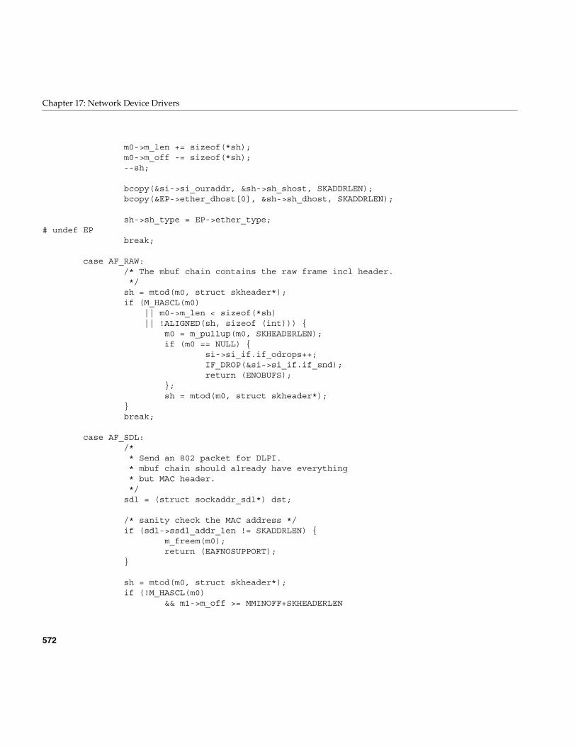
572
Chapter 17: Network Device Drivers
m0->m_len += sizeof(*sh);m0->m_off -= sizeof(*sh);--sh;
bcopy(&si->si_ouraddr, &sh->sh_shost, SKADDRLEN);bcopy(&EP->ether_dhost[0], &sh->sh_dhost, SKADDRLEN);
sh->sh_type = EP->ether_type;# undef EP
break;
case AF_RAW:/* The mbuf chain contains the raw frame incl header.*/sh = mtod(m0, struct skheader*);if (M_HASCL(m0)
|| m0->m_len < sizeof(*sh)|| !ALIGNED(sh, sizeof (int))) {
m0 = m_pullup(m0, SKHEADERLEN);if (m0 == NULL) {
si->si_if.if_odrops++;IF_DROP(&si->si_if.if_snd);return (ENOBUFS);
};sh = mtod(m0, struct skheader*);
}break;
case AF_SDL:/** Send an 802 packet for DLPI.* mbuf chain should already have everything* but MAC header.*/sdl = (struct sockaddr_sdl*) dst;
/* sanity check the MAC address */if (sdl->ssdl_addr_len != SKADDRLEN) {
m_freem(m0);return (EAFNOSUPPORT);
}
sh = mtod(m0, struct skheader*);if (!M_HASCL(m0)
&& m1->m_off >= MMINOFF+SKHEADERLEN
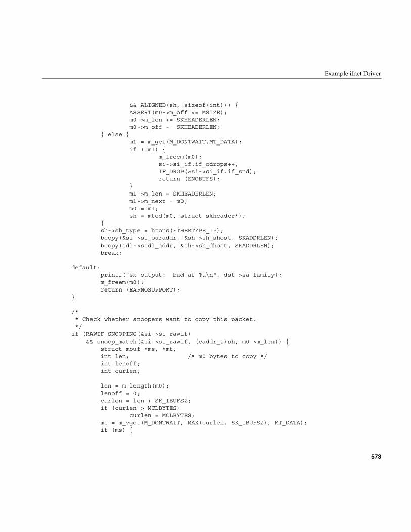
Example ifnet Driver
573
&& ALIGNED(sh, sizeof(int))) {ASSERT(m0->m_off <= MSIZE);m0->m_len += SKHEADERLEN;m0->m_off -= SKHEADERLEN;
} else {m1 = m_get(M_DONTWAIT,MT_DATA);if (!m1) {
m_freem(m0);si->si_if.if_odrops++;IF_DROP(&si->si_if.if_snd);return (ENOBUFS);
}m1->m_len = SKHEADERLEN;m1->m_next = m0;m0 = m1;sh = mtod(m0, struct skheader*);
}sh->sh_type = htons(ETHERTYPE_IP);bcopy(&si->si_ouraddr, &sh->sh_shost, SKADDRLEN);bcopy(sdl->ssdl_addr, &sh->sh_dhost, SKADDRLEN);break;
default:printf("sk_output: bad af %u\n", dst->sa_family);m_freem(m0);return (EAFNOSUPPORT);
}
/** Check whether snoopers want to copy this packet.*/
if (RAWIF_SNOOPING(&si->si_rawif)&& snoop_match(&si->si_rawif, (caddr_t)sh, m0->m_len)) {
struct mbuf *ms, *mt;int len; /* m0 bytes to copy */int lenoff;int curlen;
len = m_length(m0);lenoff = 0;curlen = len + SK_IBUFSZ;if (curlen > MCLBYTES)
curlen = MCLBYTES;ms = m_vget(M_DONTWAIT, MAX(curlen, SK_IBUFSZ), MT_DATA);if (ms) {
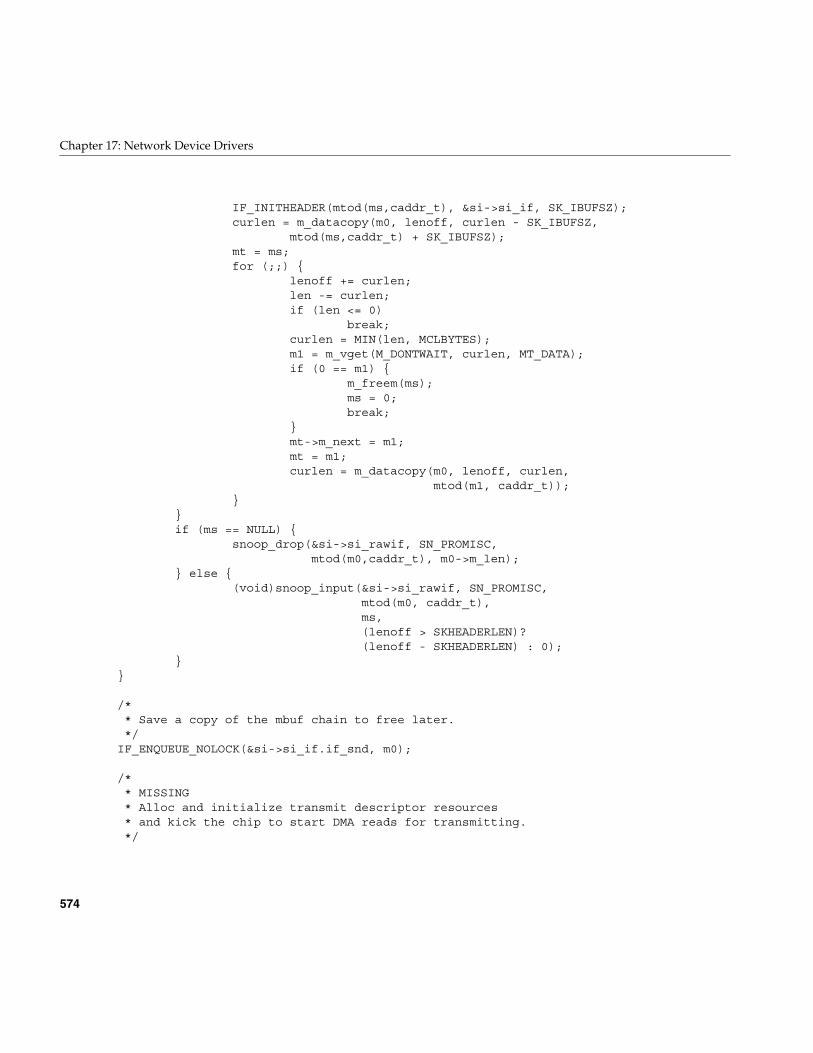
574
Chapter 17: Network Device Drivers
IF_INITHEADER(mtod(ms,caddr_t), &si->si_if, SK_IBUFSZ);curlen = m_datacopy(m0, lenoff, curlen - SK_IBUFSZ,
mtod(ms,caddr_t) + SK_IBUFSZ);mt = ms;for (;;) {
lenoff += curlen;len -= curlen;if (len <= 0)
break;curlen = MIN(len, MCLBYTES);m1 = m_vget(M_DONTWAIT, curlen, MT_DATA);if (0 == m1) {
m_freem(ms);ms = 0;break;
}mt->m_next = m1;mt = m1;curlen = m_datacopy(m0, lenoff, curlen,
mtod(m1, caddr_t));}
}if (ms == NULL) {
snoop_drop(&si->si_rawif, SN_PROMISC,mtod(m0,caddr_t), m0->m_len);
} else {(void)snoop_input(&si->si_rawif, SN_PROMISC,
mtod(m0, caddr_t),ms,(lenoff > SKHEADERLEN)?(lenoff - SKHEADERLEN) : 0);
}}
/** Save a copy of the mbuf chain to free later.*/
IF_ENQUEUE_NOLOCK(&si->si_if.if_snd, m0);
/** MISSING* Alloc and initialize transmit descriptor resources* and kick the chip to start DMA reads for transmitting.*/
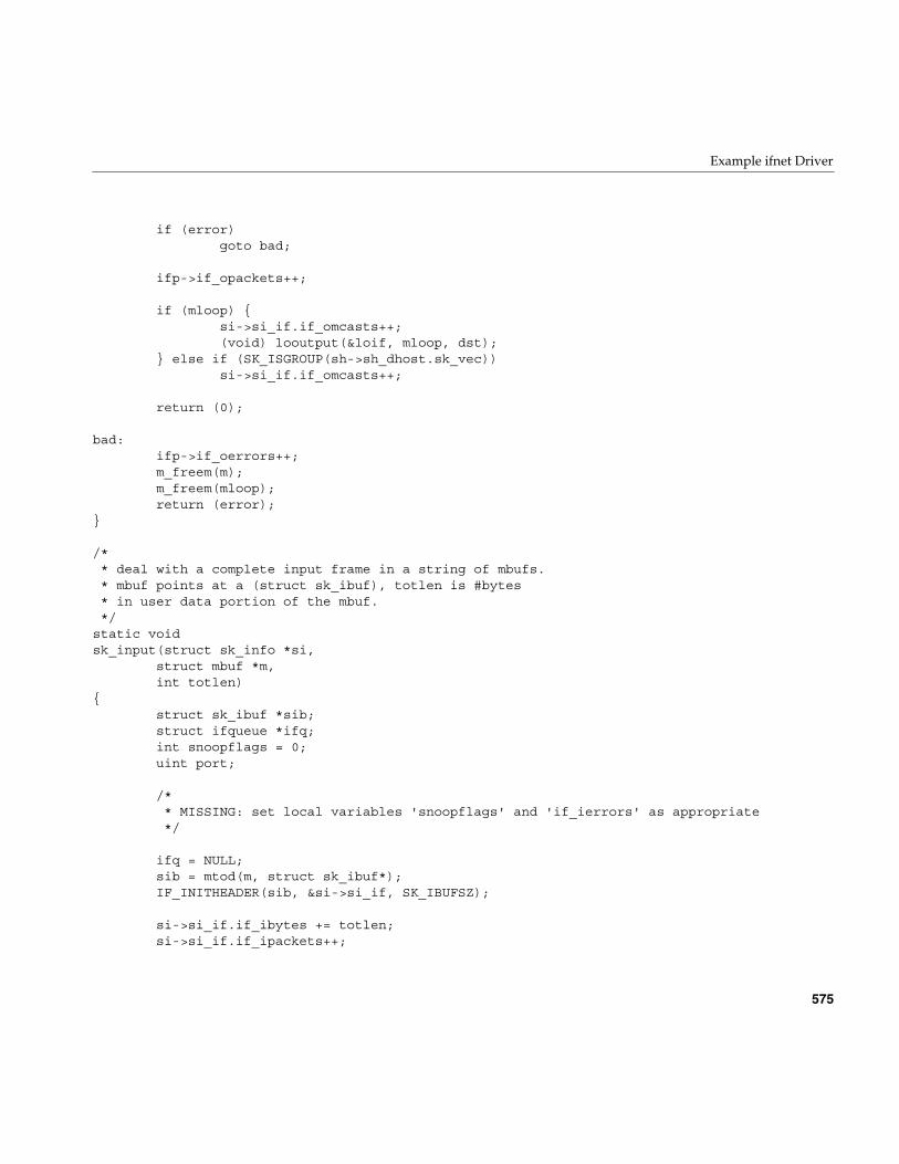
Example ifnet Driver
575
if (error)goto bad;
ifp->if_opackets++;
if (mloop) {si->si_if.if_omcasts++;(void) looutput(&loif, mloop, dst);
} else if (SK_ISGROUP(sh->sh_dhost.sk_vec))si->si_if.if_omcasts++;
return (0);
bad:ifp->if_oerrors++;m_freem(m);m_freem(mloop);return (error);
}
/** deal with a complete input frame in a string of mbufs.* mbuf points at a (struct sk_ibuf), totlen is #bytes* in user data portion of the mbuf.*/
static voidsk_input(struct sk_info *si,
struct mbuf *m,int totlen)
{struct sk_ibuf *sib;struct ifqueue *ifq;int snoopflags = 0;uint port;
/** MISSING: set local variables 'snoopflags' and 'if_ierrors' as appropriate*/
ifq = NULL;sib = mtod(m, struct sk_ibuf*);IF_INITHEADER(sib, &si->si_if, SK_IBUFSZ);
si->si_if.if_ibytes += totlen;si->si_if.if_ipackets++;
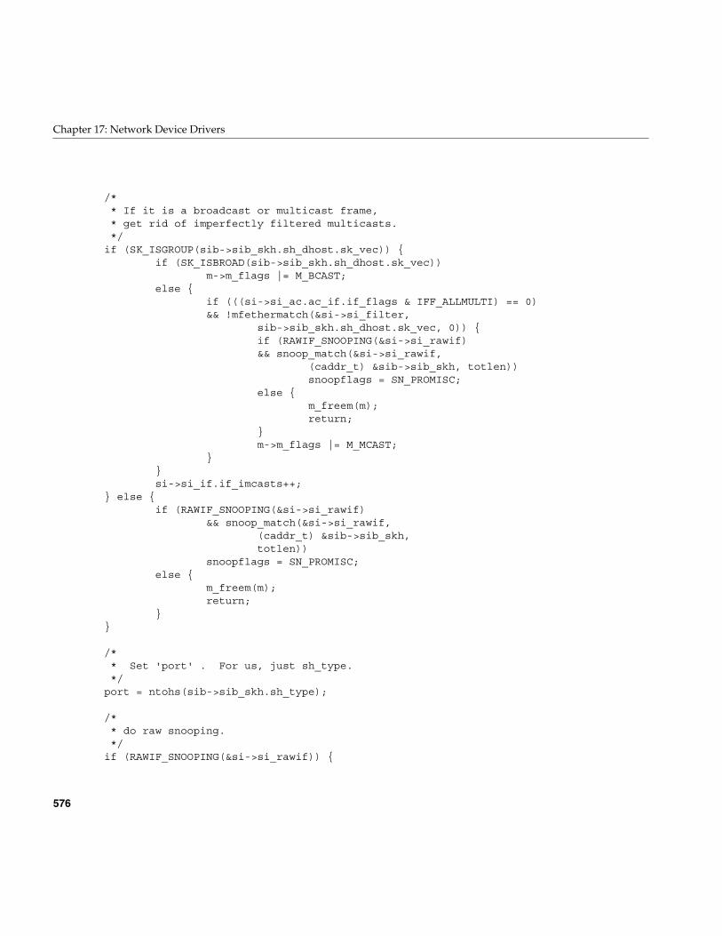
576
Chapter 17: Network Device Drivers
/** If it is a broadcast or multicast frame,* get rid of imperfectly filtered multicasts.*/
if (SK_ISGROUP(sib->sib_skh.sh_dhost.sk_vec)) {if (SK_ISBROAD(sib->sib_skh.sh_dhost.sk_vec))
m->m_flags |= M_BCAST;else {
if (((si->si_ac.ac_if.if_flags & IFF_ALLMULTI) == 0)&& !mfethermatch(&si->si_filter,
sib->sib_skh.sh_dhost.sk_vec, 0)) {if (RAWIF_SNOOPING(&si->si_rawif)&& snoop_match(&si->si_rawif,
(caddr_t) &sib->sib_skh, totlen))snoopflags = SN_PROMISC;
else {m_freem(m);return;
}m->m_flags |= M_MCAST;
}}si->si_if.if_imcasts++;
} else {if (RAWIF_SNOOPING(&si->si_rawif)
&& snoop_match(&si->si_rawif,(caddr_t) &sib->sib_skh,totlen))
snoopflags = SN_PROMISC;else {
m_freem(m);return;
}}
/** Set 'port' . For us, just sh_type.*/
port = ntohs(sib->sib_skh.sh_type);
/** do raw snooping.*/
if (RAWIF_SNOOPING(&si->si_rawif)) {
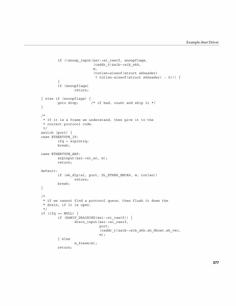
Example ifnet Driver
577
if (!snoop_input(&si->si_rawif, snoopflags,(caddr_t)&sib->sib_skh,m,(totlen>sizeof(struct skheader)? totlen-sizeof(struct skheader) : 0))) {
}if (snoopflags)
return;
} else if (snoopflags) {goto drop; /* if bad, count and skip it */
}
/** If it is a frame we understand, then give it to the* correct protocol code.*/
switch (port) {case ETHERTYPE_IP:
ifq = &ipintrq;break;
case ETHERTYPE_ARP:arpinput(&si->si_ac, m);return;
default:if (sk_dlp(si, port, DL_ETHER_ENCAP, m, totlen))
return;break;
}
/** if we cannot find a protocol queue, then flush it down the* drain, if it is open.*/
if (ifq == NULL) {if (RAWIF_DRAINING(&si->si_rawif)) {
drain_input(&si->si_rawif,port,(caddr_t)&sib->sib_skh.sh_dhost.sk_vec,m);
} elsem_freem(m);
return;
578
Chapter 17: Network Device Drivers
}
/** Put it on the IP protocol queue.*/
if (IF_QFULL(ifq)) {si->si_if.if_iqdrops++;si->si_if.if_ierrors++;IF_DROP(ifq);goto drop;
}IF_ENQUEUE(ifq, m);schednetisr(NETISR_IP);return;
drop:m_freem(m);if (RAWIF_SNOOPING(&si->si_rawif))
snoop_drop(&si->si_rawif, snoopflags,(caddr_t)&sib->sib_skh, totlen);
if (RAWIF_DRAINING(&si->si_rawif))drain_drop(&si->si_rawif, port);
}
/** See if a DLPI function wants a frame.*/
static intsk_dlp(struct sk_info *si,
int port,int encap,struct mbuf *m,int len)
{dlsap_family_t *dlp;struct mbuf *m2;struct sk_ibuf *sib;
if ((dlp = dlsap_find(port, encap)) == NULL)return (0);
/** The DLPI code wants the entire MAC and LLC headers.* It needs the total length of the mbuf chain to reflect
Example ifnet Driver
579
* the actual data length, not to be extended to contain* a fake, zeroed LLC header which keeps the snoop code from* crashing.*/
if ((m2 = m_copy(m, 0, len+sizeof(struct skheader))) == NULL)return (0);
if (M_HASCL(m2)) {m2 = m_pullup(m2, SK_IBUFSZ);if (m2 == NULL)
return (0);}sib = mtod(m2, struct sk_ibuf*);
/** MISSING: The DLPI code wants the MAC address in canonical bit order.* Convert here if necessary.*/
/** MISSING:* The DLPI code wants the LLC header, if present,* not to be hidden with the MAC header. Decrement* LLC header size from ifh_hdrlen if necessary.*/
if ((*dlp->dl_infunc)(dlp, &si->si_if, m2, &sib->sib_skh)) {m_freem(m);return (1);
}m_freem(m2);return (0);
}
/** Process an ioctl request.* Return 0 or errno.*/
static intsk_ioctl(
struct ifnet *ifp,int cmd,void *data)
{struct sk_info *si;
580
Chapter 17: Network Device Drivers
int error = 0;int flags;
ASSERT(IFNET_ISLOCKED(ifp));
si = ifptosk(ifp);
switch (cmd) {case SIOCSIFADDR:{
struct ifaddr *ifa = (struct ifaddr *)data;
switch (ifa->ifa_addr->sa_family) {case AF_INET:
sk_stop(si);si->si_ac.ac_ipaddr = IA_SIN(ifa)->sin_addr;sk_start(si, ifp->if_flags);break;
case AF_RAW:/** Not safe to change addr while the* board is alive.*/if (!iff_dead(ifp->if_flags))
error = EINVAL;else {
bcopy(ifa->ifa_addr->sa_data,si->si_ac.ac_enaddr, SKADDRLEN);
error = sk_start(si, ifp->if_flags);}break;
default:error = EINVAL;break;
}break;
}
case SIOCSIFFLAGS:{
flags = ((struct ifreq *)data)->ifr_flags;
if (((struct ifreq*)data)->ifr_flags & IFF_UP)
Example ifnet Driver
581
error = sk_start(si, flags);else
sk_stop(si);break;
}
case SIOCADDMULTI:case SIOCDELMULTI:{
#define MKEY ((union mkey*)data)int allmulti;
/** Convert an internet multicast socket address* into an 802-type address.*/error = ether_cvtmulti((struct sockaddr *)data, &allmulti);if (0 == error) {
if (allmulti) {if (SIOCADDMULTI == cmd)
si->si_if.if_flags |= IFF_ALLMULTI;else
si->si_if.if_flags &= ~IFF_ALLMULTI;/* MISSING enable hw all multicast addrs */
} else {bitswapcopy(MKEY->mk_dhost, MKEY->mk_dhost,
sizeof (MKEY->mk_dhost));if (SIOCADDMULTI == cmd)
error = sk_add_da(si, MKEY, 1);else
error = sk_del_da(si, MKEY, 1);}
}break;
#undef MKEY}
case SIOCADDSNOOP:case SIOCDELSNOOP:{
#define SF(nm) ((struct skheader*)&(((struct snoopfilter *)data)->nm))/** raw protocol snoop filter. See <net/raw.h>* and <net/multi.h> and the snoop(7P) man page.*/
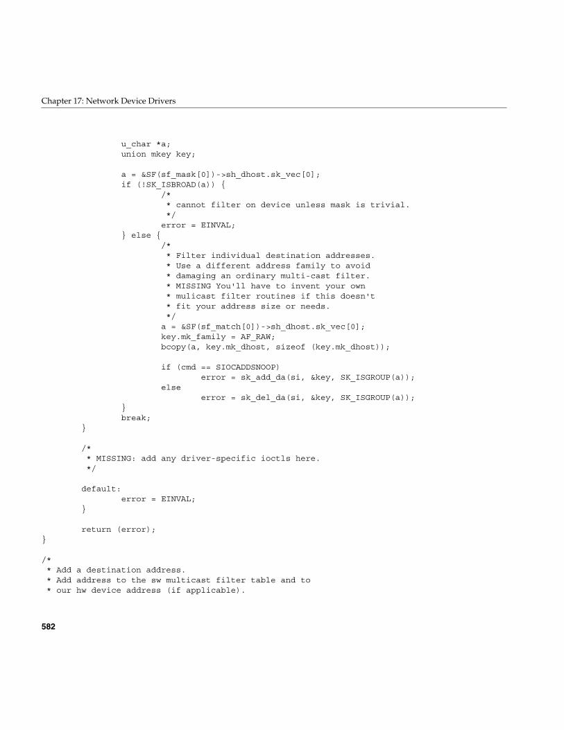
582
Chapter 17: Network Device Drivers
u_char *a;union mkey key;
a = &SF(sf_mask[0])->sh_dhost.sk_vec[0];if (!SK_ISBROAD(a)) {
/** cannot filter on device unless mask is trivial.*/error = EINVAL;
} else {/** Filter individual destination addresses.* Use a different address family to avoid* damaging an ordinary multi-cast filter.* MISSING You'll have to invent your own* mulicast filter routines if this doesn't* fit your address size or needs.*/a = &SF(sf_match[0])->sh_dhost.sk_vec[0];key.mk_family = AF_RAW;bcopy(a, key.mk_dhost, sizeof (key.mk_dhost));
if (cmd == SIOCADDSNOOP)error = sk_add_da(si, &key, SK_ISGROUP(a));
elseerror = sk_del_da(si, &key, SK_ISGROUP(a));
}break;
}
/** MISSING: add any driver-specific ioctls here.*/
default:error = EINVAL;
}
return (error);}
/** Add a destination address.* Add address to the sw multicast filter table and to* our hw device address (if applicable).
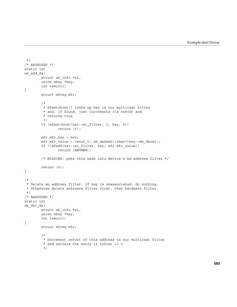
Example ifnet Driver
583
*//* ARGSUSED */static intsk_add_da(
struct sk_info *si,union mkey *key,int ismulti)
{struct mfreq mfr;
/** mfmatchcnt() looks up key in our multicast filter* and, if found, just increments its refcnt and* returns true.*/
if (mfmatchcnt(&si->si_filter, 1, key, 0))return (0);
mfr.mfr_key = key;mfr.mfr_value = (mval_t) sk_dahash((char*)key->mk_dhost);if (!mfadd(&si->si_filter, key, mfr.mfr_value))
return (ENOMEM);
/* MISSING: poke this hash into device's hw address filter */
return (0);}
/** Delete an address filter. If key is unassociated, do nothing.* Otherwise delete software filter first, then hardware filter.*/
/* ARGSUSED */static intsk_del_da(
struct sk_info *si,union mkey *key,int ismulti)
{struct mfreq mfr;
/** Decrement refcnt of this address in our multicast filter* and reclaim the entry if refcnt == 0.*/
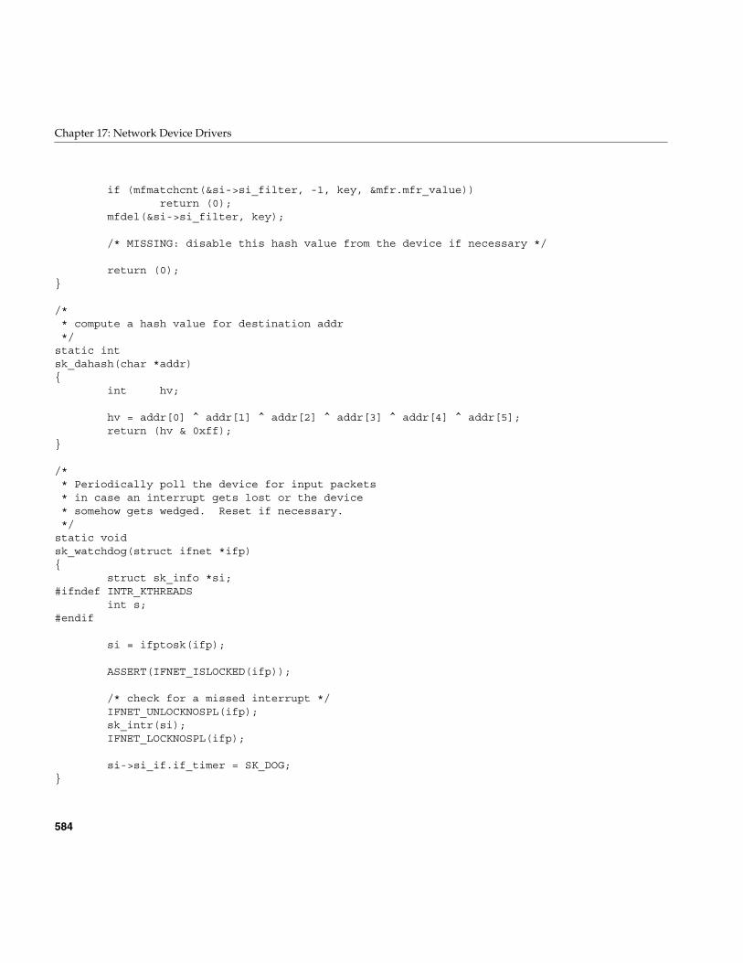
584
Chapter 17: Network Device Drivers
if (mfmatchcnt(&si->si_filter, -1, key, &mfr.mfr_value))return (0);
mfdel(&si->si_filter, key);
/* MISSING: disable this hash value from the device if necessary */
return (0);}
/** compute a hash value for destination addr*/
static intsk_dahash(char *addr){
int hv;
hv = addr[0] ^ addr[1] ^ addr[2] ^ addr[3] ^ addr[4] ^ addr[5];return (hv & 0xff);
}
/** Periodically poll the device for input packets* in case an interrupt gets lost or the device* somehow gets wedged. Reset if necessary.*/
static voidsk_watchdog(struct ifnet *ifp){
struct sk_info *si;#ifndef INTR_KTHREADS
int s;#endif
si = ifptosk(ifp);
ASSERT(IFNET_ISLOCKED(ifp));
/* check for a missed interrupt */IFNET_UNLOCKNOSPL(ifp);sk_intr(si);IFNET_LOCKNOSPL(ifp);
si->si_if.if_timer = SK_DOG;}
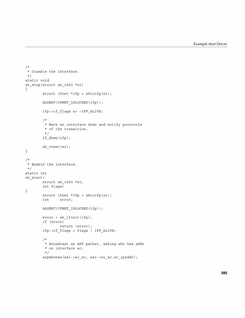
Example ifnet Driver
585
/** Disable the interface.*/
static voidsk_stop(struct sk_info *si){
struct ifnet *ifp = sktoifp(si);
ASSERT(IFNET_ISLOCKED(ifp));
ifp->if_flags &= ~IFF_ALIVE;
/** Mark an interface down and notify protocols* of the transition.*/
if_down(ifp);
sk_reset(si);}
/** Enable the interface.*/
static intsk_start(
struct sk_info *si,int flags)
{struct ifnet *ifp = sktoifp(si);int error;
ASSERT(IFNET_ISLOCKED(ifp));
error = sk_ifinit(ifp);if (error)
return (error);ifp->if_flags = flags | IFF_ALIVE;
/** Broadcast an ARP packet, asking who has addr* on interface ac.*/
arpwhohas(&si->si_ac, &si->si_ac.ac_ipaddr);
586
Chapter 17: Network Device Drivers
return (0);}
/** private debugging routine.*/
static voidsk_dump(int unit){
struct sk_info *si;struct ifnet *ifp;char name[128];
if (unit == -1)unit = 0;
sprintf(name, "sk%d", unit);
if ((ifp = ifunit(name)) == NULL) {qprintf("sk_dump: %s not found in ifnet list\n", name);return;
}
si = ifptosk(ifp);qprintf("si 0x%x\n", si);/* MISSING: qprintf() whatever you want here */
}
PART SEVEN
EISA Drivers VII
Chapter 18, “EISA Device Drivers”Overview of the architecture of the EISA bus attachment and the services offeredby the kernel to EISA device drivers.

589
Chapter 18
18. EISA Device Drivers
The EISA (Extended Industry Standard Architecture) bus is supported by the SiliconGraphics Indigo2, POWER Indigo2, and Indigo2 Maximum IMPACT systems. Thischapter contains the following topics related to support for the EISA bus:
• “The EISA Bus in Silicon Graphics Systems” on page 590 gives an overview of theEISA bus features and implementation.
• “Kernel Functions for EISA Support” on page 600 discusses the kernel functionsthat are specifically used by EISA device drivers.
• “Sample EISA Driver Code” on page 608 displays a complete character driver for anEISA device.
Note: Often it is most practical to control an EISA device through programmed I/O froma user-level process. For information on PIO, turn to “EISA Programmed I/O” onpage 83 after reading “The EISA Bus in Silicon Graphics Systems” on page 590.
For information on the general architecture of a kernel-level device driver, see Part III,“Kernel-Level Drivers.”
590
Chapter 18: EISA Device Drivers
The EISA Bus in Silicon Graphics Systems
The EISA (Extended Industry Standard Architecture) bus is an enhancement of the ISA(Industry Standard Architecture) bus standard originally developed by IBM.
EISA Bus Overview
EISA is backward compatible with ISA, but expands the ISA data bus from 16 bits to32 bits, and provides 23 more address lines and 16 more indicator and control lines.
The EISA bus supports the following features:
• all ISA transfers
• bus master devices
• burst-mode DMA transfers
• 32-bit data and address paths
• peer-to-peer card communication
For detailed information on EISA-bus protocols, electrical specifications, and operation,see the standards documents (“Standards Documents” on page xl). Figure 18-1 showsthe high-level design of the EISA attachment in the Indigo2 architecture.
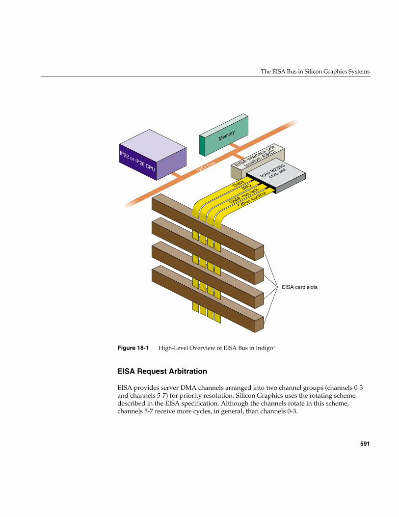
The EISA Bus in Silicon Graphics Systems
591
Figure 18-1 High-Level Overview of EISA Bus in Indigo2
EISA Request Arbitration
EISA provides server DMA channels arranged into two channel groups (channels 0-3and channels 5-7) for priority resolution. Silicon Graphics uses the rotating schemedescribed in the EISA specification. Although the channels rotate in this scheme,channels 5-7 receive more cycles, in general, than channels 0-3.
IP22 or IP26 CPU
Memory
EISA interface unit
(custom ASIC)
Intel 82350
chip set
Data
GIO bus
IRQ
DMA req /ack
Other control
EISA card slots
592
Chapter 18: EISA Device Drivers
EISA Interrupts
The EISA bus supports 11 edge-triggerable or level-triggerable interrupts. IRQ0–IRQ2,IRQ8, and IRQ13 are reserved for internal functions and are not available to EISA cards.The remaining 11 interrupt lines (IRQ3–IRQ7, IRQ9–IRQ12, IRQ14, IRQ15) can begenerated by EISA cards. Multiple cards can use one IRQ level, so long as they use thesame triggering method.
All EISA-generated interrupts are transmitted to a single interrupt level on the SiliconGraphics CPU (see “Interrupt Priority Scheduling” on page 596.)
EISA Data Transfers
The EISA bus supports 8-bit, 16-bit, and 32-bit data transfers through direct CPU access(PIO) as well as DMA initiated by a bus-master card or the on-board DMA hardware.
EISA Address Spaces
The EISA-bus address space is divided into I/O address space and memory addressspace. On the EISA bus, accesses to memory and to I/O are distinguished by havingdifferent bus cycle protocols. The MIPS architecture has only one type of memory access,so in the Silicon Graphics systems, EISA I/O space and memory space are assignedseparate ranges of physical addresses. The EISA Interface Unit (see Figure 18-1) decodesthe address ranges and causes the Intel 82350 bus control to issue the appropriate buscycle type, I/O or memory.
The I/O address space comprises a sequence of 4 KB page, one for each bus slot. The firstpage, slot 0, corresponds to the registers of the Intel 82350 chip set. The pages for slots 1-4correspond to the four accessible slots in the Indigo2 and Challenge M chassis (see“Available Card Slots” on page 596).
The EISA Bus in Silicon Graphics Systems
593
EISA Locked Cycles
The EISA bus architecture provides a signal, LOCK*, which allows a card (or theprocessor, in an Intel architecture system) to lock bus access so as to perform one or moreatomic updates.
The Silicon Graphics hardware implementation of the EISA bus is bridged onto the GIObus, which does not support a locked cycle. The general form of locked bus cycles is notsupported in the Silicon Graphics implementation of EISA. An EISA card cannot lock thebus nor can software in the IRIX kernel lock the EISA bus.
A device driver in the IRIX kernel can perform a software-controlled read-modify-writecycle, as on a VME bus, using the pio_*_rmw() kernel functions. See (“Using the PIOMap in Functions” on page 603). This function ensures that no other software accessesthe EISA bus during the read-modify-write operation.
EISA Byte Ordering
An important implementation detail of the EISA bus is that it uses the Intel conventionof “little-endian” byte ordering, in which the least significant byte of a halfword or wordis in the lowest address. The Silicon Graphics CPU uses “big-endian” ordering, with themost significant byte first. Hence data exchanged with the EISA bus often needs to bereordered before use.
EISA Product Identifier
EISA expansion boards, embedded devices, and system boards have a four-byte productidentifier (ID) that can be read from I/O port addresses 0xsC80 through 0xsC83 in thecard’s I/O address space, where s is the offset of the card slot. For example, the slot 1product ID can be read as a 4-byte value from I/O port addresses 0x1C80. This value canbe tested in an exprobe parameter of the VECTOR line during system boot (see“Configuring IRIX” on page 597).
594
Chapter 18: EISA Device Drivers
The first two bytes (0xsC80 and 0xsC81) contain a compressed representation of themanufacturer code. The manufacturer code is a three-character code (uppercase ASCIIcharacters in the range of A to Z) chosen by the manufacturer and registered with thestandard (see “Standards Documents” on page xl). The manufacturer code “ISA” is usedto indicate a generic ISA adapter.
The three-character manufacturer code is compressed into three 5-bit values so that it canbe incorporated into the two I/O bytes at 0xsC80 and 0xsC81. The compressionprocedure is as follows:
1. Find the hexadecimal ASCII value for each letter:
ASCII for “A”-“Z” : “A” = 0x41, “Z” = 0x5a
2. Subtract 0x40 from each ASCII value:
Compressed “A” = 0x41-0x40 = 0x01 = 0000 0001Compressed “Z” = 0x5a-0x40 = 0x1A = 0001 1010
3. Discard leading 0-bits, retaining the five least significant bits of each letter:
Compressed “A” = 00001. Compressed “Z” = 11010
4. Compressed code = concatenate “0” and the three 5-bit values:
“AZA” = 0 00001 11010 00001
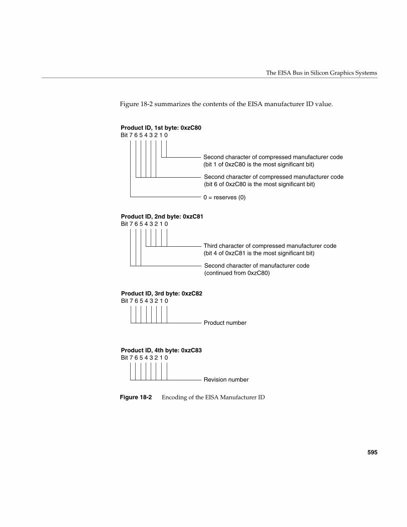
The EISA Bus in Silicon Graphics Systems
595
Figure 18-2 summarizes the contents of the EISA manufacturer ID value.
Figure 18-2 Encoding of the EISA Manufacturer ID
Product ID, 1st byte: 0xzC80Bit 7 6 5 4 3 2 1 0
Second character of compressed manufacturer code (bit 1 of 0xzC80 is the most significant bit)
0 = reserves (0)
Second character of compressed manufacturer code (bit 6 of 0xzC80 is the most significant bit)
Product ID, 2nd byte: 0xzC81Bit 7 6 5 4 3 2 1 0
Third character of compressed manufacturer code (bit 4 of 0xzC81 is the most significant bit)
Second character of manufacturer code (continued from 0xzC80)
Product ID, 3rd byte: 0xzC82Bit 7 6 5 4 3 2 1 0
Product number
Product ID, 4th byte: 0xzC83Bit 7 6 5 4 3 2 1 0
Revision number
596
Chapter 18: EISA Device Drivers
EISA Support in Indigo2 and Challenge M Series
One or more EISA cards can be plugged into an Indigo2 series workstation, or into aChallenge M system (which uses the identical chassis). Any EISA-conforming card canbe plugged into an available slot. EISA devices can be used as block devices or characterdevices, but they cannot be used as boot devices.
Available Card Slots
The Indigo2 series has four peripheral card slots that accept graphics adapters, EISAcards, or GIO cards in any combination. Graphics cards are available that use one, two,or three slots, resulting in the following combinations:
• With Extreme graphics installed, one slot is available for use by an EISA card.
• With XZ graphics installed, two slots are used by the graphics, and two areavailable for EISA cards.
• The XL graphics uses only one slot, so up to three EISA cards can beaccommodated.
The Challenge M system, having no graphics adapter, has four available slots.
EISA Address Mapping
The pages of EISA I/O address space are mapped to physical addresses 0x0001 0000 (slot1) through 0x0004 0000 (slot 4). The 112 MB of EISA memory address space is mapped tophysical addresses between 0x000A 0000 and 0x06FF FFFF.
Addresses in these ranges can be mapped into the kernel address space for PIO or forDMA (see “Kernel Functions for EISA Support” on page 600).
Interrupt Priority Scheduling
The EISA architecture associates interrupt priority with the IRQ level, from IRQ0 toIRQ15. In Silicon Graphics systems, all EISA interrupts are channeled into one CPUinterrupt level. The priority of this CPU interrupt is below that of the clock and at thesame level as on-board devices. When multiple EISA interrupts arrive, they are servicedin their EISA-bus priority order.
EISA Configuration
597
When the CPU receives an EISA-bus interrupt, it responds to each interrupt level in IRQpriority order (lower number first). For each interrupt level, the IRIX kernel calls one ormore interrupt service functions that have been established by device drivers (see“Allocating IRQs and Channels” on page 603).
EISA Configuration
In order to integrate an EISA device into a Silicon Graphics system you must configurethe EISA card itself, and then configure the system to recognize the card.
Configuring the Hardware
The I/O address space on an EISA card plugged into a card slot responds to the range ofbus addresses for that slot. All EISA cards are identified by a manufacturer-specificdevice ID that the operating system uses to register the existence of each card. ISA cards,in contrast, are jumpered to respond to a specific address range that corresponds to thedevice’s I/O registers.
Normally a kernel-level driver accesses registers in the I/O space using a PIO map (see“Mapping PIO Addresses” on page 600). For a card’s memory space to be accessible, thecard must be configured or jumpered to respond to the appropriate address range. Thespecified address range must be selected to avoid conflicts with other EISA/ISA devices.
Configuring IRIX
In the PC/DOS hardware and software environment, where the EISA bus is commonlyfound, device configuration is handled in part by use of a standalone ROM BIOSinitialization program that stores device information in the nonvolatile RAM of the PC;and in part by saving device initialization information in configuration files that are readat boot time.
Neither of these facilities is available in the same way under IRIX. Each EISA device isconfigured to IRIX using a VECTOR line in a file stored in the directory /var/sysgen/system(see “Kernel Configuration Files” on page 56).
598
Chapter 18: EISA Device Drivers
The syntax of a VECTOR line is documented in two places:
• The /var/sysgen/system/irix.sm file itself contains descriptive comments on the syntaxand meaning of the statement, as well as numerous examples.
• The system(4) reference page gives a more formal definition of the syntax.
In a Silicon Graphics system equipped with an EISA bus, the file/var/sysgen/system/irix.sm contains a number of VECTOR lines describing the EISAdevices supported by distributed code.
The important elements in a VECTOR line for EISA are as follows:
The following is a typical VECTOR line for an EISA device (it must be a single physicalline in the file):
VECTOR: bustype=EISA module=if_ec3 ctlr=1iospace=(EISAIO,0x1000,0x1000)exprobe_space=(r,EISAIO, 0x1c80,4,0x6010d425,0xffffffff)
Using the iospace Parameters
The iospace, iospace2, and iospace3 parameters are used to pass ranges of device addressesto the device driver. Each parameter contains the following three items:
bustype Specified as EISA for EISA devices. The VECTOR statement can beused for other types of buses as well.
module The base name of a kernel-level device driver for this device, as usedin the /var/sysgen/master.d database (see “Master ConfigurationDatabase” on page 55 and “How Names Are Used in Configuration”on page 259).
adapter The number of the EISA bus where the device is attached—always 0,or omitted, in current systems.
ctlr The “controller” number is simply an integer parameter that ispassed to the device driver at boot time. It can be used for exampleto specify a slot number.
iospace, iospace2,iospace3
Each iospace group specifies the address space, the starting address,and the size of a segment of address space used by this device.
probe or exprobe Specifies a hardware test that can be applied at boot time to find outif the device exists.
EISA Configuration
599
• A keyword for the address space, either EISAIO or EISAMEM.
• The starting address, which depends on the address space and the card itself, asfollows:
– For the I/O space of an EISA card, the starting address of I/O registers is0x1000 multiplied by the slot number of the card (from 1 to 4), and extends for alength of 0x1000 (4096). For example, the manufacturer ID of the card in slot 2 isat address 0x1C80.
– The I/O space of an ISA card is hard-wired or jumpered on the card, and falls inthe range 0x0100 to 0x0400.
– The EISAMEM space is card-dependent and falls in the range 0x000A 0000through 0x06FF FFFF.
• The length of this bus address range.
The values in these parameters are passed to the device driver at its pfxedtinit() entrypoint, provided that the probe shows the device is active.
Using the probe and exprobe Parameters
You use the probe or exprobe parameter to program a test for the existence of the device atboot time. When no test is specified, lboot assumes the device exists. Then it is up to thedevice driver to determine if the device is active and usable. When the device does notrespond to a probe (because it is off-line or because it has been removed from the system),the lboot command will not invoke the device driver for this device.
An example exprobe parameter is as follows:
exprobe_space=(r,EISAIO, 0x1c80,4,0x6010d425,0xffffffff)
The exprobe parameter lists groups of six subparameters, as follows:
Sequence One or more of w for write, r for read, or rn for read-negate.
Space EISAIO or EISAMEM.
Address The address of the byte, halfword, or word to test.
Length The number of bytes to test: 1, 2, or 4.
Value The value to write, or the test value for a read.
Mask A number to be ANDed with the Value operand before a write or after aread. Specify 0xffffffff to nullify the AND operation.
600
Chapter 18: EISA Device Drivers
You can use the w operation to prime a device. You can use the r operation to test for aspecific value, and the rn operation to test that a specific value (or a specific bit, aftermasking) is not returned.
Typically, a simple r operation is used on an EISA card to test for the manufacturer’sproduct identifier.
To test the existence of an ISA card, use a wr sequence to write a value to a register andread it back unchanged. Or read a value and verify that it does not come backall-binary-1, the value returned by a nonexistent device.
Using the module Parameter
The device driver specified by the module parameter is invoked at its pfxedtinit() entrypoint, where it receives ctlr and iospace information specified in the VECTOR line (see“Entry Point edtinit()” on page 151). The device driver initializes the device at this time.
You use the iospace parameters to pass in the exact bus addresses that correspond to thisdevice. Up to three address space ranges can be passed to the driver. This does not restrictthe device—it can use other ranges of addresses, but the device driver has to deduce theiraddresses from other information. The device driver typically uses this data to set up PIOmaps (see “Mapping PIO Addresses” on page 600).
Kernel Functions for EISA Support
The kernel provides services for mapping the EISA bus into the kernel virtual addressspace for PIO or DMA, and for transferring data using these maps. Two types of DMAare supported, Bus-master DMA and Slave DMA.
Mapping PIO Addresses
A PIO map is a system object that represents the mapping of a location in kernel virtualmemory to some range of addresses on a VME or EISA bus. After creating a PIO map, adevice driver can use it in the following ways:
• Extract a specific kernel virtual address that represents the device. This address canbe used to load or store data, or it can be mapped that into user process space.
Kernel Functions for EISA Support
601
• Copy data between the device and memory without learning the specific kerneladdresses involved.
• Perform bus read-modify-write cycles to apply Boolean operators to device data.
The functions used with PIO maps are summarized in Table 18-1.
A kernel-level device driver creates a PIO map by calling pio_mapalloc(). This functionperforms memory allocation and so can sleep. PIO maps are typically created in thepfxedtinit() entry point, where the driver first learns about the device addresses from thecontents of the edt_t structure (see “Entry Point edtinit()” on page 151).
Table 18-1 Functions to Create and Use PIO Maps
Function Header Files CanSleep
Purpose
pio_mapalloc(D3) pio.h & types.h Y Allocate a PIO map.
pio_mapfree(D3) pio.h & types.h N Free a PIO map.
pio_badaddr(D3) pio.h & types.h N Check for bus error when reading anaddress.
pio_wbadaddr(D3) pio.h & types.h N Check for bus error when writing to anaddress.
pio_mapaddr(D3) pio.h & types.h N Convert a bus address to a virtual address.
pio_bcopyin(D3) pio.h & types.h Y Copy data from a bus address to kernel’svirtual space.
pio_bcopyout(D3) pio.h & types.h Y Copy data from kernel’s virtual space to abus address.
pio_andb_rmw(D3) pio.h & types.h N Byte read-AND-write cycle.
pio_andh_rmw(D3) pio.h & types.h N 16-bit read-AND-write cycle.
pio_andw_rmw(D3) pio.h & types.h N 32-bit read-AND-write cycle.
pio_orb_rmw(D3) pio.h & types.h N Byte read-OR-write cycle.
pio_orh_rmw(D3) pio.h & types.h N 16-bit read-OR-write cycle.
pio_orw_rmw(D3) pio.h & types.h N 32-bit read-OR-write cycle.
602
Chapter 18: EISA Device Drivers
The parameters to pio_mapalloc() describe the range of addresses that can be mapped interms of
• the bus type, in this case ADAP_EISA from sys/edt.h
• the bus number, when more than one bus is supported
• the address space, using constants such as PIOMAP_EISA_IO from sys/pio.h
• the starting bus address and a length
This call also specifies a “fixed” or “unfixed” map. This distinction applies only to VMEmaps. An EISA map is always a fixed map.
A call to pio_mapfree() releases a PIO map. PIO maps created by a loadable driver mustbe released in the pfxunload() entry point (see “Entry Point unload()” on page 180 and“Unloading” on page 268).
Testing the PIO Map
The PIO map is created from the parameters that are passed. These are not validated bypio_mapalloc(). If there is any possibility that the mapped device is not installed, notactive, or improperly configured, you should test the mapped address.
The pio_baddr() and pio_wbaddr() functions test the mapped address to see if it isusable.
Using the Mapped Address
From a fixed PIO map you can recover a kernel virtual address that corresponds to thefirst bus address in the map. The pio_mapaddr() function is used for this.
You can use this address to load or store data into device registers. In the pfxmap() entrypoint (see “Concepts and Use of mmap()” on page 169), you can use this address with thev_mapphys() function to map the range of device addresses into the address space of auser process.
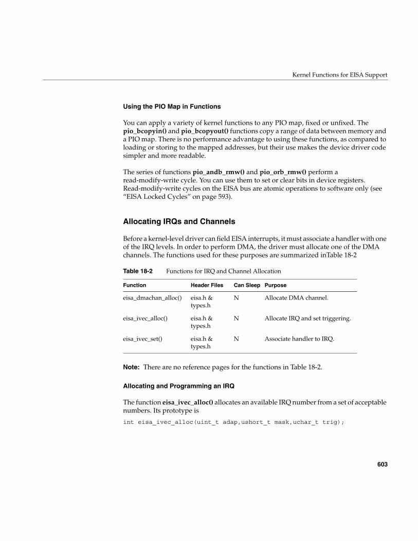
Kernel Functions for EISA Support
603
Using the PIO Map in Functions
You can apply a variety of kernel functions to any PIO map, fixed or unfixed. Thepio_bcopyin() and pio_bcopyout() functions copy a range of data between memory anda PIO map. There is no performance advantage to using these functions, as compared toloading or storing to the mapped addresses, but their use makes the device driver codesimpler and more readable.
The series of functions pio_andb_rmw() and pio_orb_rmw() perform aread-modify-write cycle. You can use them to set or clear bits in device registers.Read-modify-write cycles on the EISA bus are atomic operations to software only (see“EISA Locked Cycles” on page 593).
Allocating IRQs and Channels
Before a kernel-level driver can field EISA interrupts, it must associate a handler with oneof the IRQ levels. In order to perform DMA, the driver must allocate one of the DMAchannels. The functions used for these purposes are summarized inTable 18-2
Note: There are no reference pages for the functions in Table 18-2.
Allocating and Programming an IRQ
The function eisa_ivec_alloc() allocates an available IRQ number from a set of acceptablenumbers. Its prototype is
int eisa_ivec_alloc(uint_t adap,ushort_t mask,uchar_t trig);
Table 18-2 Functions for IRQ and Channel Allocation
Function Header Files Can Sleep Purpose
eisa_dmachan_alloc() eisa.h &types.h
N Allocate DMA channel.
eisa_ivec_alloc() eisa.h &types.h
N Allocate IRQ and set triggering.
eisa_ivec_set() eisa.h &types.h
N Associate handler to IRQ.
604
Chapter 18: EISA Device Drivers
The arguments are as follows:
ISA cards are usually hard-wired or jumpered to a particular IRQ, so that the maskargument contains a single bit. Some EISA cards can be programmed dynamically to usea selected IRQ; in that case mask contains a 1-bit for each IRQ the card can beprogrammed to use.
The function attempts to allocate an IRQ from the mask set that is not in use by any card.If all acceptable levels are in use, it allocates an IRQ that is already in use with therequested kind of triggering. In either case, it returns the number of the IRQ to be used.
In the event that all the IRQs requested are already in use with a conflicting type oftriggering, the function returns -1.
After allocating an IRQ, the device driver programs the card (using PIO) to interrupt onthat line.
The function eisa_ivec_set() associates a function in the device driver with an IRQnumber. Its prototype is
int eisa_ivec_set(uint_t adap, int irq,void (*e_intr)(long), long e_arg)
The parameters are as follows:
When more than one device is allocated the same IRQ, the kernel calls all the interruptfunctions associated with that IRQ. This means that an interrupt function must alwaysverify, by testing device registers, that the interrupt was caused by its device.
adap The adapter number, always 0 in current systems.
mask A 16-bit mask containing a 1-bit for each IRQ level that is acceptable forthis device. (For available IRQ levels, see “EISA Interrupts” onpage 592.)
trig The triggering method used by the card, either EISA_EDGE_IRQ orEISA_LEVEL_IRQ from sys/eisa.h.
adap The adapter number, always 0 in current systems.
irq The IRQ level to be monitored.
e_intr The address of the interrupt handling function to call.
e_arg An argument to pass to the function when called.
Kernel Functions for EISA Support
605
The first call to eisa_ivec_set() for a given IRQ enables interrupts from that IRQ. Prior tothe call, interrupts from that IRQ are ignored.
Note: If you are working with both the VME and EISA interfaces, it is worth noting thatthe number and type of arguments of eisa_ivec_set() differ from those of vme_ivec_set().
Note: There is no way to retract the association of an interrupt function with an IRQ. Thismeans that if an EISA driver handles interrupts and is loadable, it must not support thepfxunload() entry point. An interrupt arriving after the driver had been unloaded wouldpanic the system.
Allocating a DMA Channel
The function eisa_dmachan_alloc() allocates one of the seven available DMA channels(channel 4 is reserved by the hardware) from a set of acceptable channels. The function’sprototype is
int eisa_dmachan_alloc(uint_t adap, uchar_t dma_mask)
The arguments are as follows:
The function allocates the channel in the requested set that is in use by the fewest devices.It is possible for a single channel to be requested by multiple devices. However, if thedevice can use any of several channels, it is likely that the device will be the only oneusing the channel whose number is returned. After allocating a channel number, thedevice driver programs the device to use that channel, if necessary.
Programming Bus-Master DMA
Bus-master DMA is performed by an EISA card that has bus-master logic. The cardgenerates the DMA bus cycles, and provides the target memory address to store orretrieve data.
The device driver sets up Bus-master DMA by programming the card with a targetphysical address and length of data. Some cards support scatter/gather operations, inwhich the card is programmed with a list of memory pages and their lengths, and the
adap The adapter number, always 0 in current systems.
dma_mask An 8-bit mask containing 1-bits for the DMA channels thatcan be used by this device.
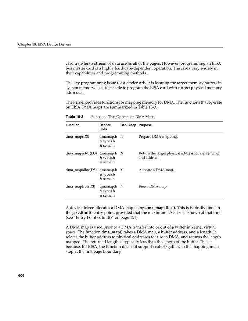
606
Chapter 18: EISA Device Drivers
card transfers a stream of data across all of the pages. However, programming an EISAbus master card is a highly hardware-dependent operation. The cards vary widely intheir capabilities and programming methods.
The key programming issue for a device driver is locating the target memory buffers insystem memory, so as to be able to program the EISA card with correct physical memoryaddresses.
The kernel provides functions for mapping memory for DMA. The functions that operateon EISA DMA maps are summarized in Table 18-3.
A device driver allocates a DMA map using dma_mapalloc(). This is typically done inthe pfxedtinit() entry point, provided that the maximum I/O size is known at that time(see “Entry Point edtinit()” on page 151).
A DMA map is used prior to a DMA transfer into or out of a buffer in kernel virtualspace. The function dma_map() takes a DMA map, a buffer address, and a length. Itrelates the buffer address to physical addresses for use in DMA, and returns the lengthmapped. The returned length is typically less than the length of the buffer. This isbecause, for EISA, the function does not support scatter/gather, so the mapping muststop at the first page boundary.
Table 18-3 Functions That Operate on DMA Maps
Function HeaderFiles
Can Sleep Purpose
dma_map(D3) dmamap.h& types.h& sema.h
N Prepare DMA mapping.
dma_mapaddr(D3) dmamap.h& types.h& sema.h
N Return the target physical address for a given mapand address.
dma_mapalloc(D3) dmamap.h& types.h& sema.h
Y Allocate a DMA map.
dma_mapfree(D3) dmamap.h& types.h& sema.h
N Free a DMA map.
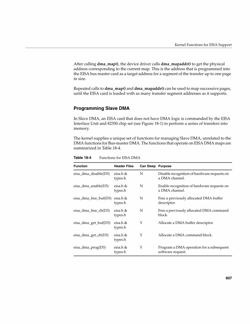
Kernel Functions for EISA Support
607
After calling dma_map(), the device driver calls dma_mapaddr() to get the physicaladdress corresponding to the current map. This is the address that is programmed intothe EISA bus master card as a target address for a segment of the transfer up to one pagein size.
Repeated calls to dma_map() and dma_mapaddr() can be used to map successive pages,until the EISA card is loaded with as many transfer segment addresses as it supports.
Programming Slave DMA
In Slave DMA, an EISA card that does not have DMA logic is commanded by the EISAInterface Unit and 82350 chip set (see Figure 18-1) to perform a series of transfers intomemory.
The kernel supplies a unique set of functions for managing Slave DMA, unrelated to theDMA functions for Bus-master DMA. The functions that operate on EISA DMA maps aresummarized in Table 18-4.
Table 18-4 Functions for EISA DMA
Function Header Files Can Sleep Purpose
eisa_dma_disable(D3) eisa.h &types.h
N Disable recognition of hardware requests ona DMA channel.
eisa_dma_enable(D3) eisa.h &types.h
N Enable recognition of hardware requests ona DMA channel.
eisa_dma_free_buf(D3) eisa.h &types.h
N Free a previously allocated DMA bufferdescriptor.
eisa_dma_free_cb(D3) eisa.h &types.h
N Free a previously allocated DMA commandblock.
eisa_dma_get_buf(D3) eisa.h &types.h
Y Allocate a DMA buffer descriptor.
eisa_dma_get_cb(D3) eisa.h &types.h
Y Allocate a DMA command block.
eisa_dma_prog(D3) eisa.h &types.h
Y Program a DMA operation for a subsequentsoftware request.
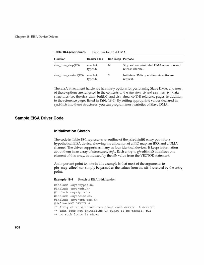
608
Chapter 18: EISA Device Drivers
The EISA attachment hardware has many options for performing Slave DMA, and mostof these options are reflected in the contents of the eisa_dma_cb and eisa_dma_buf datastructures (see the eisa_dma_buf(D4) and eisa_dma_cb(D4) reference pages, in additionto the reference pages listed in Table 18-4). By setting appropriate values declared insys/eisa.h into these structures, you can program most varieties of Slave DMA.
Sample EISA Driver Code
Initialization Sketch
The code in Table 18-1 represents an outline of the pfxedtinit() entry point for ahypothetical EISA device, showing the allocation of a PIO map, an IRQ, and a DMAchannel. The driver supports as many as four identical devices. It keeps informationabout them in an array of structures, einfo. Each entry to pfxedtinit() initializes oneelement of this array, as indexed by the ctlr value from the VECTOR statement.
An important point to note in this example is that most of the arguments topio_map_alloc() can simply be passed as the values from the edt_t received by the entrypoint.
Example 18-1 Sketch of EISA Initialization
#include <sys/types.h>#include <sys/edt.h>#include <sys/pio.h>#include <sys/eisa.h>#include <sys/cmn_err.h>#define MAX_DEVICE 4/* Array of info structures about each device. A device** that does not initialize OK ought to be marked, but** no such logic is shown.
eisa_dma_stop(D3) eisa.h &types.h
N Stop software-initiated DMA operation andrelease channel.
eisa_dma_swstart(D3) eisa.h &types.h
Y Initiate a DMA operation via softwarerequest.
Table 18-4 (continued) Functions for EISA DMA
Function Header Files Can Sleep Purpose
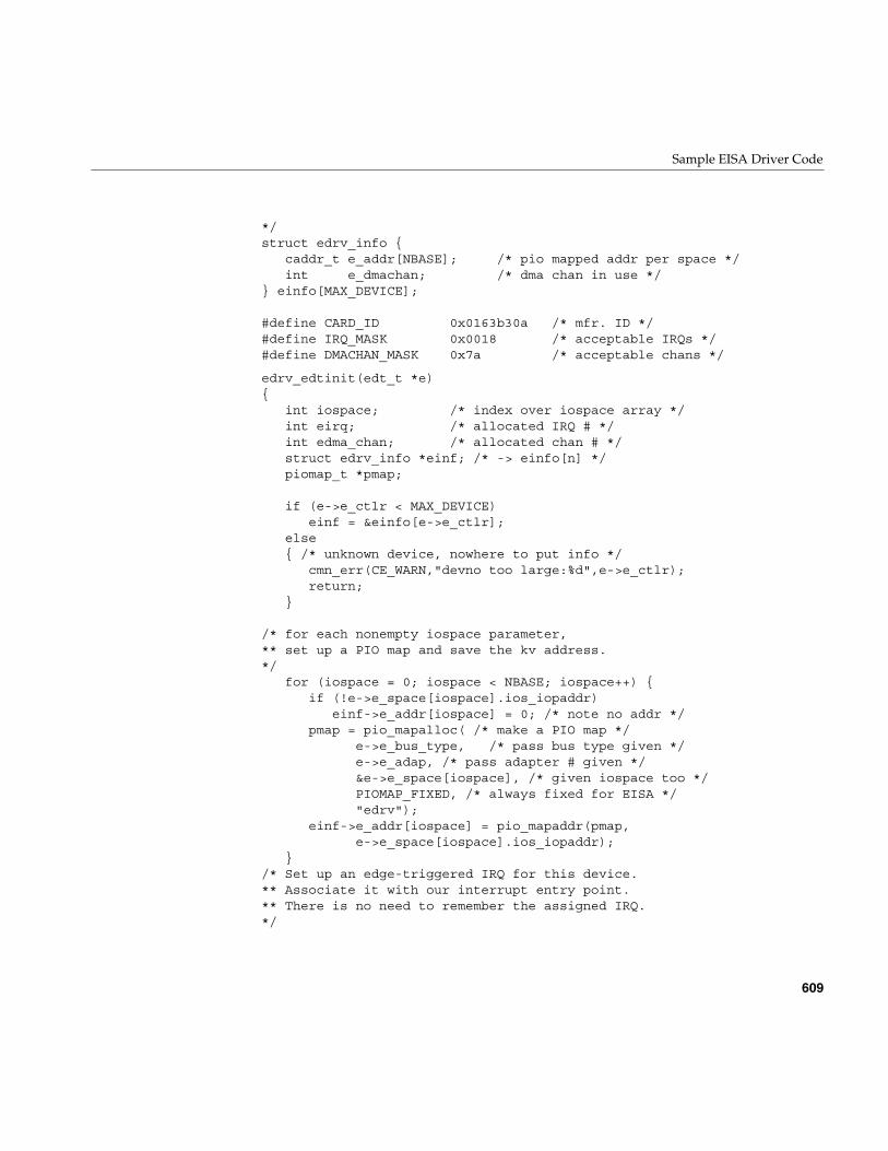
Sample EISA Driver Code
609
*/struct edrv_info {
caddr_t e_addr[NBASE]; /* pio mapped addr per space */int e_dmachan; /* dma chan in use */
} einfo[MAX_DEVICE];
#define CARD_ID 0x0163b30a /* mfr. ID */#define IRQ_MASK 0x0018 /* acceptable IRQs */#define DMACHAN_MASK 0x7a /* acceptable chans */
edrv_edtinit(edt_t *e){
int iospace; /* index over iospace array */int eirq; /* allocated IRQ # */int edma_chan; /* allocated chan # */struct edrv_info *einf; /* -> einfo[n] */piomap_t *pmap;
if (e->e_ctlr < MAX_DEVICE)einf = &einfo[e->e_ctlr];
else{ /* unknown device, nowhere to put info */
cmn_err(CE_WARN,"devno too large:%d",e->e_ctlr);return;
}
/* for each nonempty iospace parameter,** set up a PIO map and save the kv address.*/
for (iospace = 0; iospace < NBASE; iospace++) {if (!e->e_space[iospace].ios_iopaddr)
einf->e_addr[iospace] = 0; /* note no addr */pmap = pio_mapalloc( /* make a PIO map */
e->e_bus_type, /* pass bus type given */e->e_adap, /* pass adapter # given */&e->e_space[iospace], /* given iospace too */PIOMAP_FIXED, /* always fixed for EISA */"edrv");
einf->e_addr[iospace] = pio_mapaddr(pmap,e->e_space[iospace].ios_iopaddr);
}/* Set up an edge-triggered IRQ for this device.** Associate it with our interrupt entry point.** There is no need to remember the assigned IRQ.*/
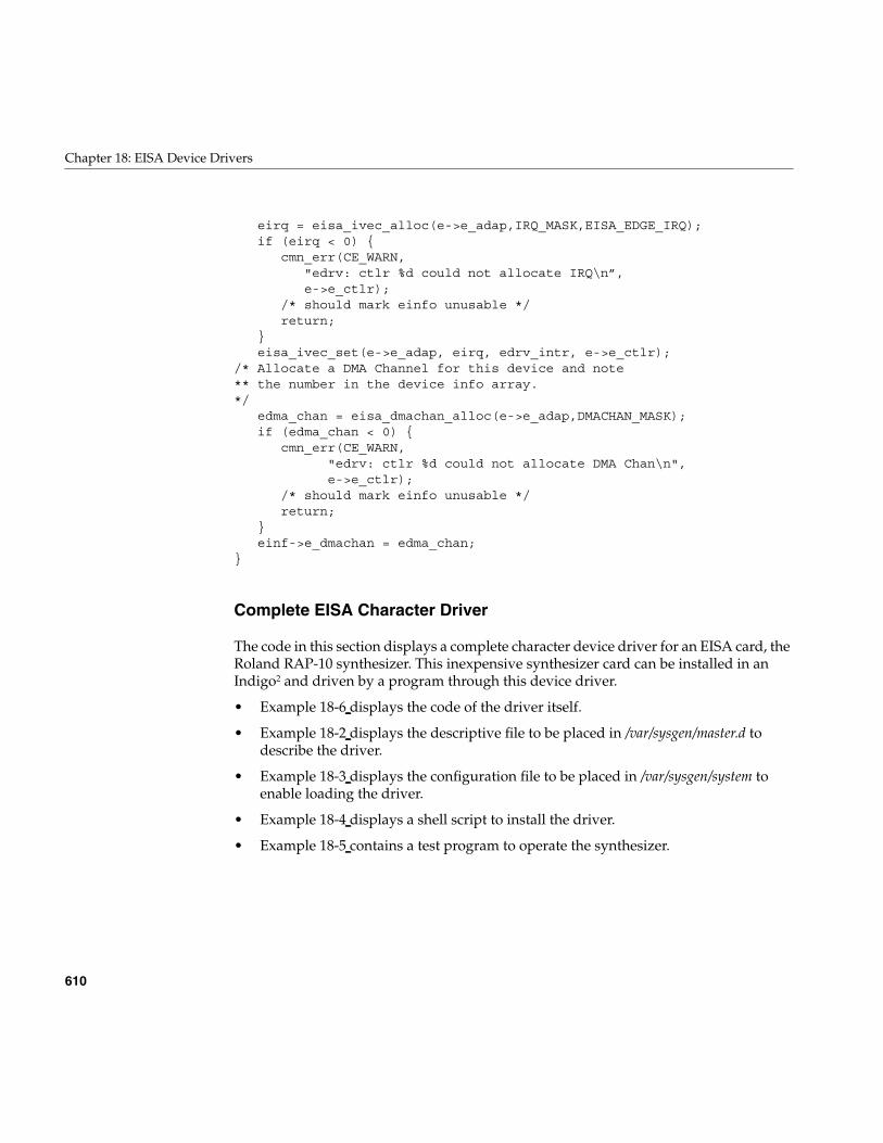
610
Chapter 18: EISA Device Drivers
eirq = eisa_ivec_alloc(e->e_adap,IRQ_MASK,EISA_EDGE_IRQ);if (eirq < 0) {
cmn_err(CE_WARN,"edrv: ctlr %d could not allocate IRQ\n”,e->e_ctlr);
/* should mark einfo unusable */return;
}eisa_ivec_set(e->e_adap, eirq, edrv_intr, e->e_ctlr);
/* Allocate a DMA Channel for this device and note** the number in the device info array.*/
edma_chan = eisa_dmachan_alloc(e->e_adap,DMACHAN_MASK);if (edma_chan < 0) {
cmn_err(CE_WARN,"edrv: ctlr %d could not allocate DMA Chan\n",e->e_ctlr);
/* should mark einfo unusable */return;
}einf->e_dmachan = edma_chan;
}
Complete EISA Character Driver
The code in this section displays a complete character device driver for an EISA card, theRoland RAP-10 synthesizer. This inexpensive synthesizer card can be installed in anIndigo2 and driven by a program through this device driver.
• Example 18-6 displays the code of the driver itself.
• Example 18-2 displays the descriptive file to be placed in /var/sysgen/master.d todescribe the driver.
• Example 18-3 displays the configuration file to be placed in /var/sysgen/system toenable loading the driver.
• Example 18-4 displays a shell script to install the driver.
• Example 18-5 contains a test program to operate the synthesizer.
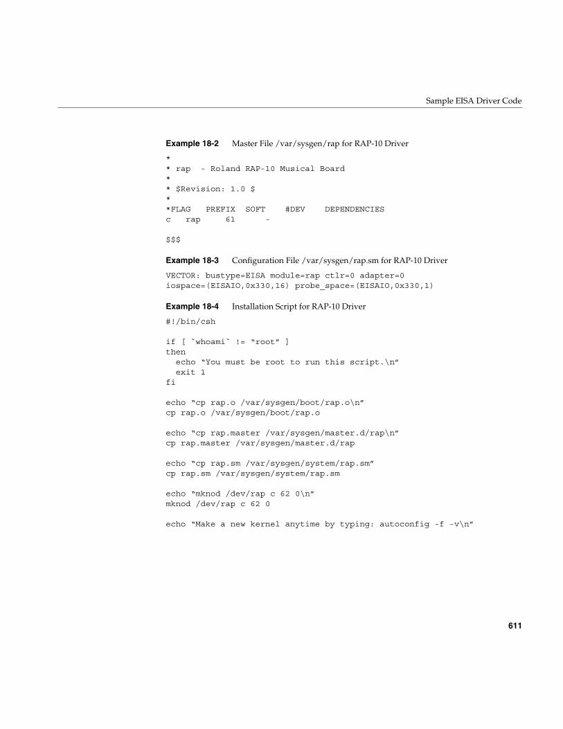
Sample EISA Driver Code
611
Example 18-2 Master File /var/sysgen/rap for RAP-10 Driver
** rap - Roland RAP-10 Musical Board** $Revision: 1.0 $**FLAG PREFIX SOFT #DEV DEPENDENCIESc rap 61 -
$$$
Example 18-3 Configuration File /var/sysgen/rap.sm for RAP-10 Driver
VECTOR: bustype=EISA module=rap ctlr=0 adapter=0iospace=(EISAIO,0x330,16) probe_space=(EISAIO,0x330,1)
Example 18-4 Installation Script for RAP-10 Driver
#!/bin/csh
if [ `whoami` != “root” ]then echo “You must be root to run this script.\n” exit 1fi
echo “cp rap.o /var/sysgen/boot/rap.o\n”cp rap.o /var/sysgen/boot/rap.o
echo “cp rap.master /var/sysgen/master.d/rap\n”cp rap.master /var/sysgen/master.d/rap
echo “cp rap.sm /var/sysgen/system/rap.sm”cp rap.sm /var/sysgen/system/rap.sm
echo “mknod /dev/rap c 62 0\n”mknod /dev/rap c 62 0
echo “Make a new kernel anytime by typing: autoconfig -f -v\n”
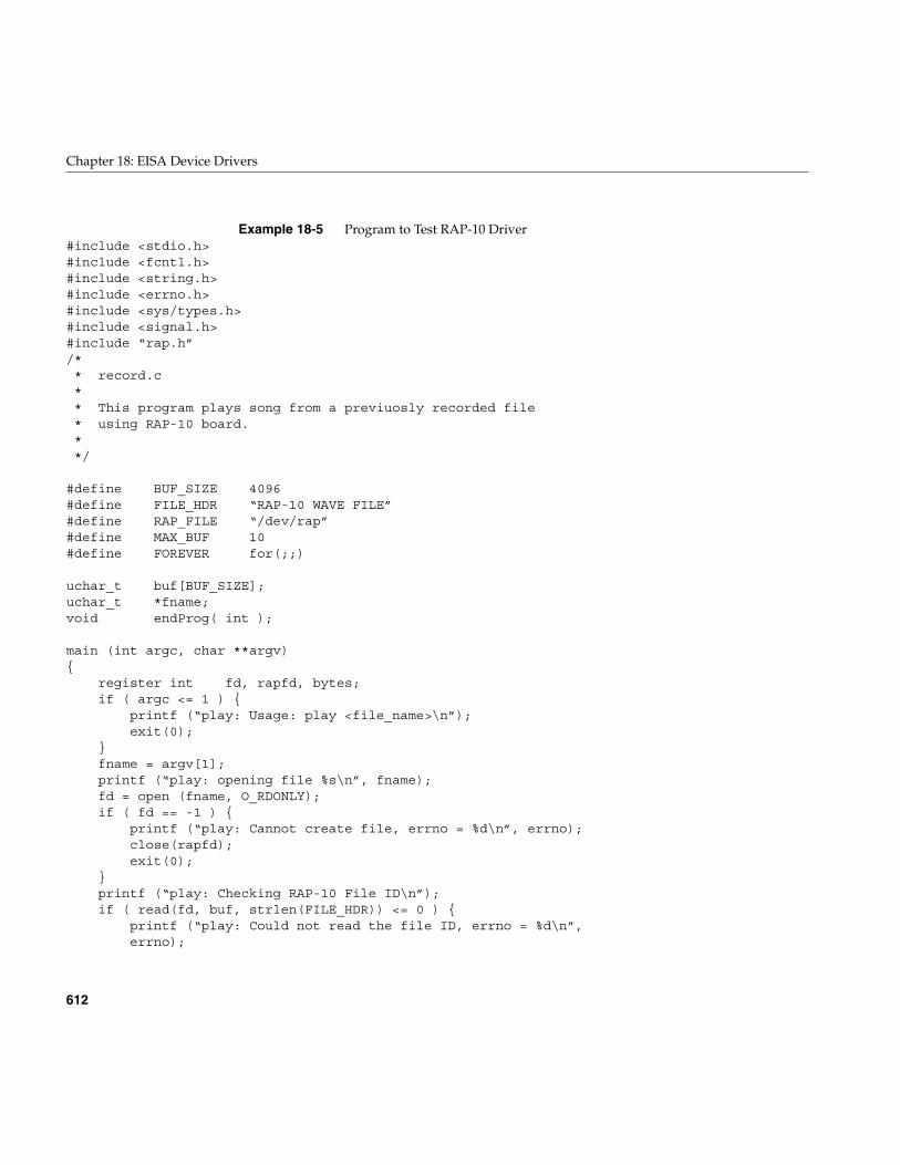
612
Chapter 18: EISA Device Drivers
Example 18-5 Program to Test RAP-10 Driver#include <stdio.h>#include <fcntl.h>#include <string.h>#include <errno.h>#include <sys/types.h>#include <signal.h>#include “rap.h”/** record.c** This program plays song from a previuosly recorded file* using RAP-10 board.**/
#define BUF_SIZE 4096#define FILE_HDR “RAP-10 WAVE FILE”#define RAP_FILE “/dev/rap”#define MAX_BUF 10#define FOREVER for(;;)
uchar_t buf[BUF_SIZE];uchar_t *fname;void endProg( int );
main (int argc, char **argv){
register int fd, rapfd, bytes;if ( argc <= 1 ) {
printf (“play: Usage: play <file_name>\n”);exit(0);
}fname = argv[1];printf (“play: opening file %s\n”, fname);fd = open (fname, O_RDONLY);if ( fd == -1 ) {
printf (“play: Cannot create file, errno = %d\n”, errno);close(rapfd);exit(0);
}printf (“play: Checking RAP-10 File ID\n”);if ( read(fd, buf, strlen(FILE_HDR)) <= 0 ) {
printf (“play: Could not read the file ID, errno = %d\n”,errno);
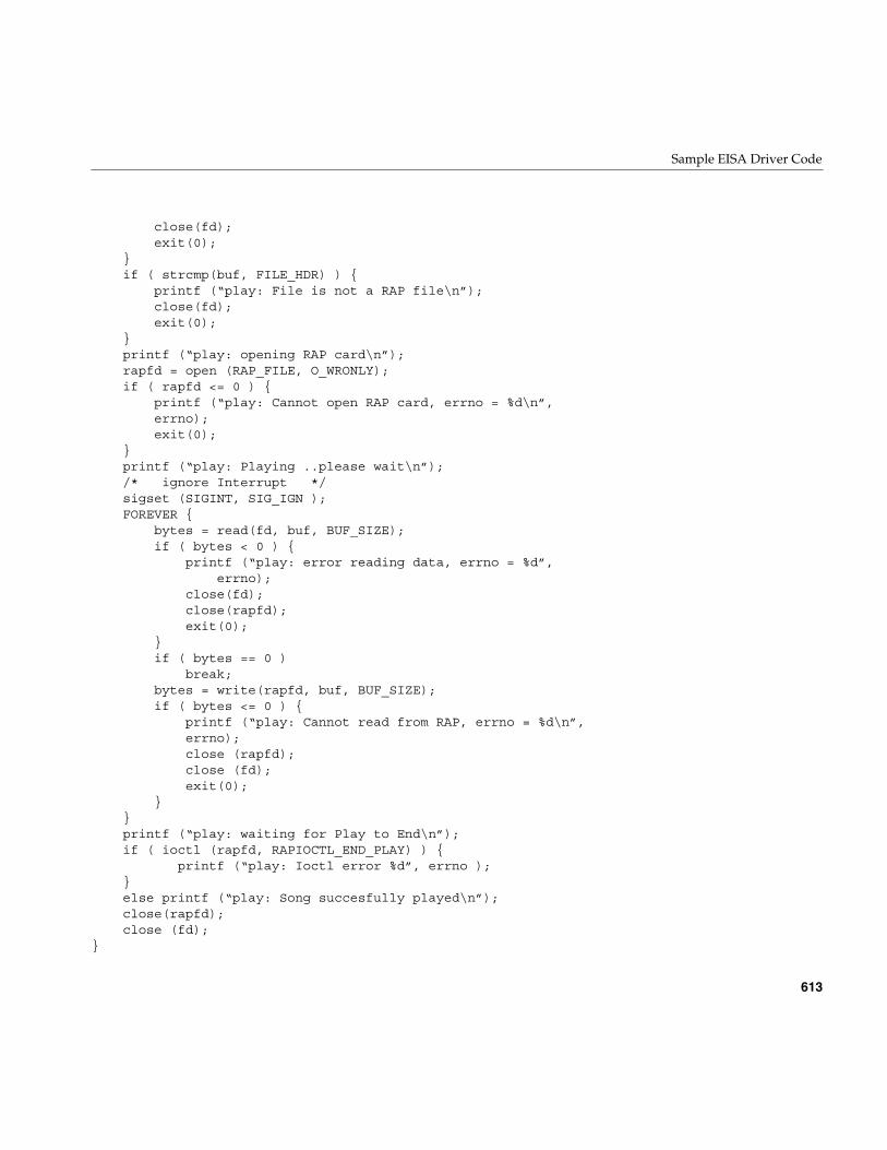
Sample EISA Driver Code
613
close(fd);exit(0);
}if ( strcmp(buf, FILE_HDR) ) {
printf (“play: File is not a RAP file\n”);close(fd);exit(0);
}printf (“play: opening RAP card\n”);rapfd = open (RAP_FILE, O_WRONLY);if ( rapfd <= 0 ) {
printf (“play: Cannot open RAP card, errno = %d\n”,errno);exit(0);
}printf (“play: Playing ..please wait\n”);/* ignore Interrupt */sigset (SIGINT, SIG_IGN );FOREVER {
bytes = read(fd, buf, BUF_SIZE);if ( bytes < 0 ) {
printf (“play: error reading data, errno = %d”,errno);
close(fd);close(rapfd);exit(0);
}if ( bytes == 0 )
break;bytes = write(rapfd, buf, BUF_SIZE);if ( bytes <= 0 ) {
printf (“play: Cannot read from RAP, errno = %d\n”,errno);close (rapfd);close (fd);exit(0);
}}printf (“play: waiting for Play to End\n”);if ( ioctl (rapfd, RAPIOCTL_END_PLAY) ) {
printf (“play: Ioctl error %d”, errno );}else printf (“play: Song succesfully played\n”);close(rapfd);close (fd);
}
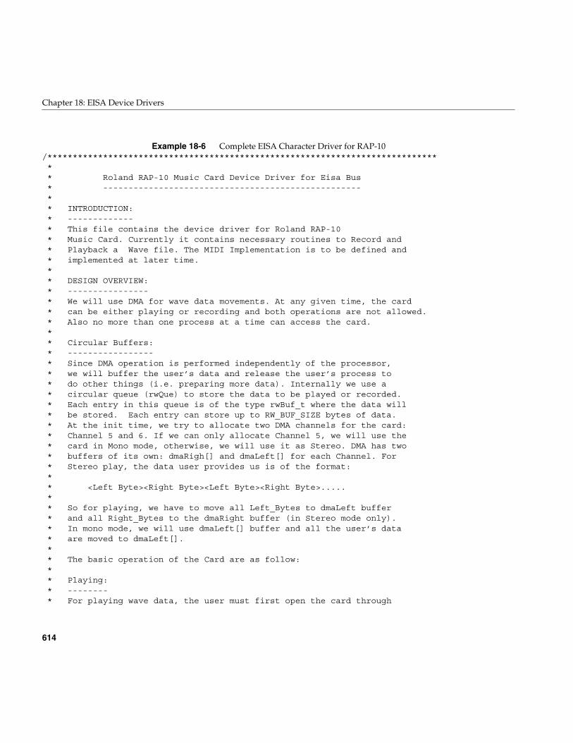
614
Chapter 18: EISA Device Drivers
Example 18-6 Complete EISA Character Driver for RAP-10/******************************************************************************* Roland RAP-10 Music Card Device Driver for Eisa Bus* ---------------------------------------------------** INTRODUCTION:* -------------* This file contains the device driver for Roland RAP-10* Music Card. Currently it contains necessary routines to Record and* Playback a Wave file. The MIDI Implementation is to be defined and* implemented at later time.** DESIGN OVERVIEW:* ----------------* We will use DMA for wave data movements. At any given time, the card* can be either playing or recording and both operations are not allowed.* Also no more than one process at a time can access the card.** Circular Buffers:* -----------------* Since DMA operation is performed independently of the processor,* we will buffer the user’s data and release the user’s process to* do other things (i.e. preparing more data). Internally we use a* circular queue (rwQue) to store the data to be played or recorded.* Each entry in this queue is of the type rwBuf_t where the data will* be stored. Each entry can store up to RW_BUF_SIZE bytes of data.* At the init time, we try to allocate two DMA channels for the card:* Channel 5 and 6. If we can only allocate Channel 5, we will use the* card in Mono mode, otherwise, we will use it as Stereo. DMA has two* buffers of its own: dmaRigh[] and dmaLeft[] for each Channel. For* Stereo play, the data user provides us is of the format:** <Left Byte><Right Byte><Left Byte><Right Byte>.....** So for playing, we have to move all Left_Bytes to dmaLeft buffer* and all Right_Bytes to the dmaRight buffer (in Stereo mode only).* In mono mode, we will use dmaLeft[] buffer and all the user’s data* are moved to dmaLeft[].** The basic operation of the Card are as follow:** Playing:* --------* For playing wave data, the user must first open the card through
Sample EISA Driver Code
615
* open() system call.The call comes to us as rapopen(). This* routine resets all global values, states and counters, prepares* necessary DMA structures for each channel, disables RAP-10* interrupts and establishes this process as the owner of the card.** The user provides us with the wave data by issuing write()* system calls. This call comes to us as rapwrite(). We will* move the data from user’s address space into an empty rwQue[]* entry and will retrun so that the user can issue another call.* If there is no DMA going, we will start one and the data will* start to be moved to the Card to be played.* The user can issue as many write() as necessary. The playing* operation will be done by either closing the card or issuing* an Ioctl call. Issuing Ioctl, will leave this process as owner* still while closing the card will release the card.** Recording:* ----------* Assuming that the user has opened the card and is the current* owner, user will issue read() system call. The call comes to* us as rapread(). If no DMA Record is going on, we will start* one. We will move data from rwQue[] entries (as they are filled)* to user’s address space. The recording is done either by a* close() or ioctl() call.** DMA Starting:* -------------* For Playing, we will start DMA when we have a full circular buffer.* This is done so that we have enough data available for a fast DMA* operation to be busy with. For recording, we will start DMA* immediatly.** Interrupts:* -----------* For each DMA transfer, we will receive two interrupts: One when 1st* half the buffer is transfered, one when 2nd half of the buffer is* transfered. We must fill the half that has just been transfered with* fresh data. Note that in Stereo mode, there are two DMA operation* going. So when we receive Interrupt for one DMA, we must wait for the* exact interrupt from the other DMA and service both DMA’s half buffers.** Card Address and IRQ* --------------------* We will use the default bus address of 0x330 and IRQ 5. Change in* bus address should also be reflected in /var/sysgen/system/rap.sm
616
Chapter 18: EISA Device Drivers
* file. Changes in IRQ should be reflected in the source code and* the program must be recomplied.** ISSUES:* -------* 1. The DMA processing and transfer of data from/to user’s buffer* are independent of each other. When we are servicing the* one half of the dma buffer that just been transfered, there is* no guarantee that we can fill that half of the buffer BEFORE* dma is done with the other half. In this case, dma plays the* fist half of buffer WHILE we are writing into it.** 2. Currently eisa_dma_disable() routine does not actually* releases the Dma channels. This is the reason why we access* the Dma channel table (e_ch[]) ourselves and release the* channel.** 3. Somehow because of number 2, the Play program cannot be* stopped with a Ctrl-C. In Play program this signal is* explicitly ignored. Trapping a Ctrl-C causes a kernel panic.* Once we have a workable eisa_dma_disable(), this problem will* be resolved.** TECHNICAL REFERENCES:* ---------------------* Roland RAP-10 Technical Reference and Programmer’s Guide, Ver. 1.1* IRIX Device Driver Programming Guide* IRIX Device Driver Reference Pages.* Intel 82357 Preliminary Reference, Section: 3.7.8 Mode Register (pp: 223)********************************************************************************** ****** Copyright 1994, Silicon Graphics Inc., Mountain View, CA. ****** **********************************************************************************/
#include “sys/types.h”#include “sys/file.h”#include “sys/errno.h”#include “sys/open.h”#include “sys/conf.h”#include “sys/cmn_err.h”#include “sys/debug.h”#include “sys/param.h”#include “sys/edt.h”
Sample EISA Driver Code
617
#include “sys/pio.h”#include “sys/uio.h”#include “sys/proc.h”#include “sys/user.h”#include “sys/eisa.h”#include “sys/sema.h”#include “sys/buf.h”#include “sys/cred.h”#include “sys/kmem.h”#include “sys/ddi.h”#include “./rap.h”/** Macros to Read/Write 8 and 16-bit values from an address*/
#define OUTB(addr, b) ( *(volatile uchar_t *)(addr) = (b) )#define INPB(addr) ( *(volatile uchar_t *)(addr) )#define OUTW(addr, w) ( *(volatile ushort_t *)(addr) = (w) )#define INPW(addr) ( *(volatile ushort_t *)(addr) )/** Raising and lowering CPU interrupt*/
#define LOCK() spl5()#define UNLOCK(s) splx(s)#define FROM_INTR 1#define FROM_USR 0#define User_pid u.u_procp->p_pid/** IRQ and DMA channels we need.**/
#define IRQ_MASK 0x0020#define DMAC_CH5 0x20 /* DMA Channel 5 */#define DMAC_CH6 0x40 /* DMA Channel 6 *//*=======================================** MIDI and RAP Registers **=======================================*** The following is a description of RAP-10 registers. The same* names used throughout this program. Some of these registers are* 8-bit and some are 16-bit long.** mdrd: MIDI Receive Data* mdtd: MIDI Transmit Data* mdst: MIDI Status* mdcm: MIDI Command
618
Chapter 18: EISA Device Drivers
* pwmd: Pulse Width Modulation Data* timm: Timer MSB data* gpcm: GPCC Command* dtci: DMA Transfer Count Buffer Interrupt Status* adcm: GPCC Analog to Digital Command* dacm: D/A Command and DMA Transfer Configuration* gpis: GPCC Interrupt Status* gpdi: GPCC DMA/Interrupt Enable* gpst: GPCC Status* dad0: Digital to Analog Data Channel 0* addt: A/D Data Transfer* dad1: Digital to Analog Data Channel 1* timd: Timer Data* cmp0: Compare Register Channel 0* dtcd: DMA Transfer Count Data* cmp1: Compare Register Channel 1** These defines indicate the offsets of the above registers* from the Drive’s base address:*/
#define MDRD 0x0#define MDTD 0x0#define MDST 0x1#define MDCM 0x1#define PWMD 0x2#define TIMM 0x3#define GPCM 0x3#define DTCI 0x4#define ADCM 0x4#define DACM 0x5#define GPIS 0x6#define GPDI 0x6#define GPST 0x8#define DAD0 0x8#define ADDT 0xa#define DAD1 0xa#define TIMD 0xc#define CMP0 0xc#define DTCD 0xe#define CMP1 0xe
typedef struct rapReg {uchar_t mdrd;uchar_t mdtd;uchar_t mdst;
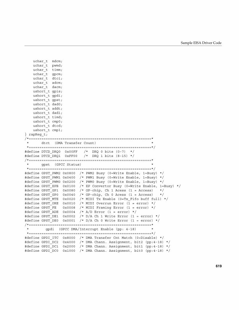
Sample EISA Driver Code
619
uchar_t mdcm;uchar_t pwmd;uchar_t timm;uchar_t gpcm;uchar_t dtci;uchar_t adcm;uchar_t dacm;ushort_t gpis;ushort_t gpdi;ushort_t gpst;ushort_t dad0;ushort_t addt;ushort_t dad1;ushort_t timd;ushort_t cmp0;ushort_t dtcd;ushort_t cmp1;
} rapReg_t;/*==========================================================** dtct (DMA Transfer Count) **==========================================================*/
#define DTCD_DRQ0 0x00FF /* DRQ 0 bits (0-7) */#define DTCD_DRQ1 0xFF00 /* DRQ 1 bits (8-15) *//*==========================================================** gpst (GPCC Status) **==========================================================*/
#define GPST_PWM2 0x0800 /* PWM2 Busy (0=Write Enable, 1=Busy) */#define GPST_PWM1 0x0400 /* PWM1 Busy (0=Write Enable, 1=Busy) */#define GPST_PWM0 0x0200 /* PWM0 Busy (0=Write Enable, 1=Busy) */#define GPST_EPB 0x0100 /* EP Convertor Busy (0=Write Enable, 1=Busy) */#define GPST_GP1 0x0080 /* GP-chip, Ch 1 Acess (1 = Access) */#define GPST_GP0 0x0040 /* GP-chip, Ch 0 Acess (1 = Access) */#define GPST_MTE 0x0020 /* MIDI Tx Enable (0=Tx_Fifo buff full) */#define GPST_ORE 0x0010 /* MIDI Overrun Error (1 = error) */#define GPST_FE 0x0008 /* MIDI Framing Error (1 = error) */#define GPST_ADE 0x0004 /* A/D Error (1 = error) */#define GPST_DE1 0x0002 /* D/A Ch 1 Write Error (1 = error) */#define GPST_DE0 0x0001 /* D/A Ch 0 Write Error (1 = error) *//*==========================================================** gpdi (GPCC DMA/Interrupt Enable (pp: 4-18) **==========================================================*/
#define GPDI_ITC 0x8000 /* DMA Transfer Cnt Match (0=Disable) */#define GPDI_DC2 0x4000 /* DMA Chann. Assignment, bit2 (pp:4-18) */#define GPDI_DC1 0x2000 /* DMA Chann. Assignment, bit1 (pp:4-18) */#define GPDI_DC0 0x1000 /* DMA Chann. Assignment, bit0 (pp:4-18) */

620
Chapter 18: EISA Device Drivers
#define GPDI_DT1 0x0800 /* DMA Trans. Mode, bit:1 (pp: 4-18) */#define GPDI_DT0 0x0400 /* DMA Trans. Mode, bit:0 (pp: 4-18) */#define GPDI_OVF 0x0200 /* Free Run.Cntr (FCR) Ov.Flow (0=Disable)*/#define GPDI_TC1 0x0100 /* Timer 1 Compare Match (0=Disable) */#define GPDI_TC0 0x0080 /* Timer 0 Compare Match (0=Disable) */#define GPDI_RXD 0x0040 /* MIDI Data Read Request (0=Disable) */#define GPDI_TXD 0x0020 /* MIDI Tx_fifo Buf Empty (0=Disable) */#define GPDI_ADD 0x0010 /* A/D Data Ready (0=Disable) */#define GPDI_DN1 0x0008 /* D/A Ch1 Note ON Ready (0=Disable) */#define GPDI_DN0 0x0004 /* D/A Ch0 Note ON Ready (0=Disable) */#define GPDI_DQ1 0x0002 /* D/A Ch1 Data Request (0=Disable) */#define GPDI_DQ0 0x0001 /* D/A Ch0 Data Request (0=Disable) *//*==========================================================** gpis (GPCC Interrupt Status .. pp: 4-16) **==========================================================*/
#define GPIS_ITC 0x8000 /* DMA Transfer Count Match */#define GPIS_JSD 0x0400 /* Joystick Data Ready */#define GPIS_OVF 0x0200 /* Free Running Countr Overflow */#define GPIS_TC1 0x0100 /* Timer1 Compare Match */#define GPIS_TC0 0x0080 /* Timer0 Compare Match */#define GPIS_RXD 0x0040 /* MIDI Data Read Request */#define GPIS_TXD 0x0020 /* MIDI Tx_fifo Buf. Empty */#define GPIS_ADD 0x0010 /* A/D Data Ready */#define GPIS_DN1 0x0008 /* D/A Ch1 Note ON Ready */#define GPIS_DN0 0x0004 /* D/A Ch0 Note ON Ready */#define GPIS_DQ1 0x0002 /* D/A Ch1 Data Request */#define GPIS_DQ0 0x0001 /* D/A Ch0 Data Request *//*===================================================================** dacm (Digital To Analogue Cmd and DMA Transfer Config) **===================================================================*/
#define DACM_SCC 0x80 /* DMA Size Cmp. Cnt (0=in Sample, 1=in Bytes)*/#define DACM_TS2 0x40 /* DMA Trnsfr Size, bit 2 (pp: 4-14) */#define DACM_TS1 0x20 /* DMA Trnsfr Size, bit 1 (pp: 4-14) */#define DACM_TS0 0x10 /* DMA Trnsfr Size, bit 0 (pp: 4-14) */#define DACM_DL1 0x08 /* Ch1 DA Data Len (0=8 bit, 1=17 bit) */#define DACM_DL0 0x04 /* Ch0 DA Data Len (0=8 bit, 1=17 bit) */#define DACM_DS1 0x02 /* Ch1 DA Convrsion (0=Stop, 1=Start) */#define DACM_DS0 0x01 /* Ch0 DA Convrsion (0=Stop, 1=Start) *//*=====================================================** adcm ( GPCC AD Command ) **=====================================================*/
#define ADCM_MON 0x40 /* Monitor MIC (0=Monitor Off) */#define ADCM_GIN 0x20 /* Gain Input (0=Line, 1=Mic) */#define ADCM_AF1 0x10 /* Analog Freq Selection bit 1 (pp: 4-13) */#define ADCM_AF0 0x08 /* Analog Freq Selection bit 0 (pp: 4-13) */
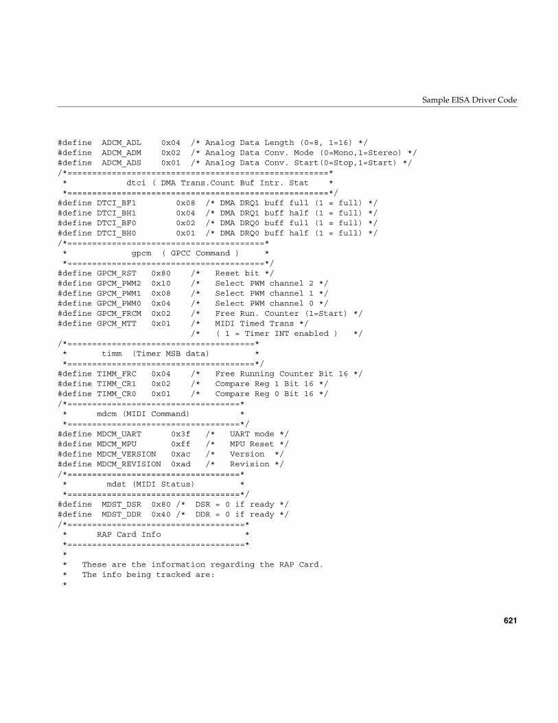
Sample EISA Driver Code
621
#define ADCM_ADL 0x04 /* Analog Data Length (0=8, 1=16) */#define ADCM_ADM 0x02 /* Analog Data Conv. Mode (0=Mono,1=Stereo) */#define ADCM_ADS 0x01 /* Analog Data Conv. Start(0=Stop,1=Start) *//*=====================================================** dtci ( DMA Trans.Count Buf Intr. Stat **=====================================================*/
#define DTCI_BF1 0x08 /* DMA DRQ1 buff full (1 = full) */#define DTCI_BH1 0x04 /* DMA DRQ1 buff half (1 = full) */#define DTCI_BF0 0x02 /* DMA DRQ0 buff full (1 = full) */#define DTCI_BH0 0x01 /* DMA DRQ0 buff half (1 = full) *//*========================================** gpcm ( GPCC Command ) **========================================*/
#define GPCM_RST 0x80 /* Reset bit */#define GPCM_PWM2 0x10 /* Select PWM channel 2 */#define GPCM_PWM1 0x08 /* Select PWM channel 1 */#define GPCM_PWM0 0x04 /* Select PWM channel 0 */#define GPCM_FRCM 0x02 /* Free Run. Counter (1=Start) */#define GPCM_MTT 0x01 /* MIDI Timed Trans */
/* ( 1 = Timer INT enabled ) *//*======================================** timm (Timer MSB data) **======================================*/
#define TIMM_FRC 0x04 /* Free Running Counter Bit 16 */#define TIMM_CR1 0x02 /* Compare Reg 1 Bit 16 */#define TIMM_CR0 0x01 /* Compare Reg 0 Bit 16 *//*===================================** mdcm (MIDI Command) **===================================*/
#define MDCM_UART 0x3f /* UART mode */#define MDCM_MPU 0xff /* MPU Reset */#define MDCM_VERSION 0xac /* Version */#define MDCM_REVISION 0xad /* Revision *//*===================================** mdst (MIDI Status) **===================================*/
#define MDST_DSR 0x80 /* DSR = 0 if ready */#define MDST_DDR 0x40 /* DDR = 0 if ready *//*====================================** RAP Card Info **====================================*** These are the information regarding the RAP Card.* The info being tracked are:*
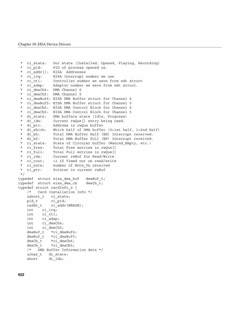
622
Chapter 18: EISA Device Drivers
* ci_state: Our state (Installed, Opened, Playing, Recording)* ci_pid: PID of process opened us.* ci_addr[]: EISA Addresses* ci_irq: EISA Interrupt number we use* ci_ctl: Controller number we save from edt struct* ci_adap: Adaptor number we save from edt struct.* ci_dmaCh6: DMA Channel 6* ci_dmaCh5: DMA Channel 5* ci_dmaBuf6: EISA DMA Buffer struct for Channel 6* ci_dmaBuf5: EISA DMA Buffer struct for Channel 5* ci_dmaCb6: EISA DMA Control Block for Channel 6* ci_dmaCb5: EISA DMA Control Block for Channel 5* di_state: DMA buffers state (Idle, Progress)* di_idx: Current rwQue[] entry being used.* di_ptr: Address in rwQue buffer* di_which: Which half of DMA buffer (0=1st half, 1=2nd Half)* di_bh: Total DMA Buffer Half (BH) Interrupt received.* di_bf: Total DMA Buffer Full (BF) Interrupt received.* ri_state: State of Circular buffer (Wanted_Empty, etc.)* ri_free: Total Free entries in rwQue[]* ri_full: Total Full entries in rwQue[]* ri_idx: Current rwBuf for Read/Write* ri_tout; =1 if Timed out on read/write* ri_note; number of Note_On received* ri_ptr: Pointer in current rwBuf*/
typedef struct eisa_dma_buf dmaBuf_t;typedef struct eisa_dma_cb dmaCb_t;typedef struct cardInfo_s {
/* Card Installation Info */ushort_t ci_state;pid_t ci_pid;caddr_t ci_addr[NBASE];int ci_irq;int ci_ctl;int ci_adap;int ci_dmaCh6;int ci_dmaCh5;dmaBuf_t *ci_dmaBuf6;dmaBuf_t *ci_dmaBuf5;dmaCb_t *ci_dmaCb6;dmaCb_t *ci_dmaCb5;/* DMA Buffer Information data */uchar_t di_state;short di_idx;
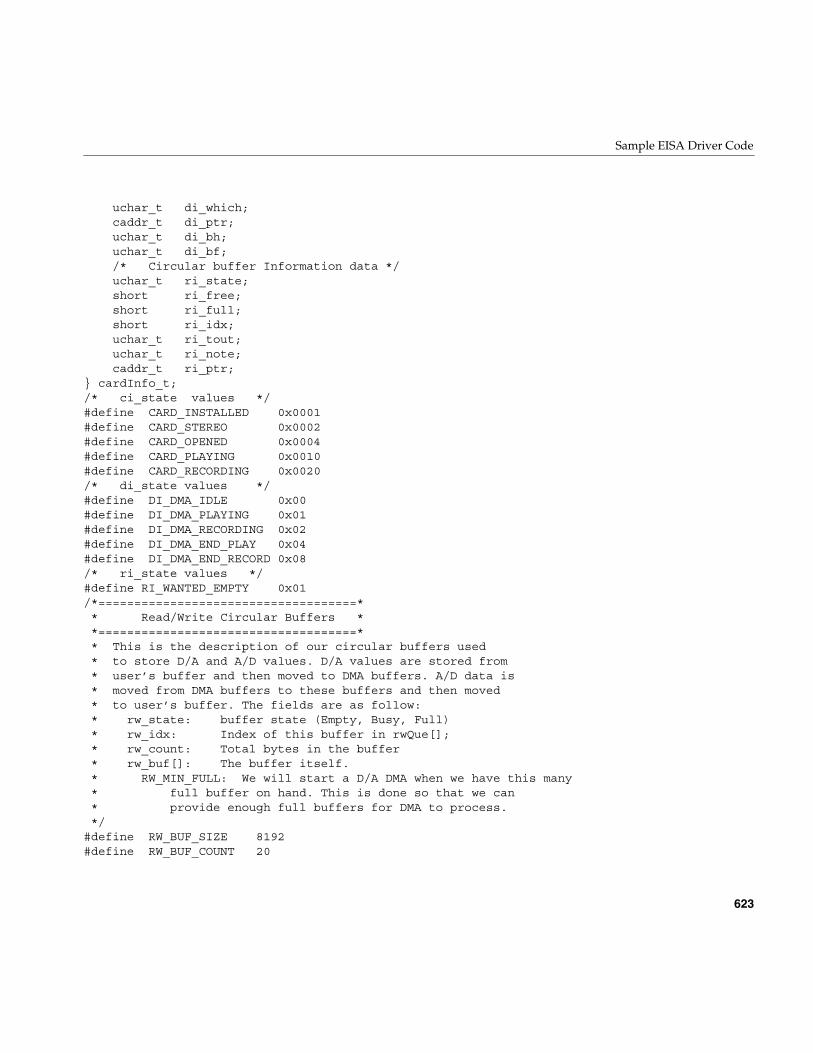
Sample EISA Driver Code
623
uchar_t di_which;caddr_t di_ptr;uchar_t di_bh;uchar_t di_bf;/* Circular buffer Information data */uchar_t ri_state;short ri_free;short ri_full;short ri_idx;uchar_t ri_tout;uchar_t ri_note;caddr_t ri_ptr;
} cardInfo_t;/* ci_state values */#define CARD_INSTALLED 0x0001#define CARD_STEREO 0x0002#define CARD_OPENED 0x0004#define CARD_PLAYING 0x0010#define CARD_RECORDING 0x0020/* di_state values */#define DI_DMA_IDLE 0x00#define DI_DMA_PLAYING 0x01#define DI_DMA_RECORDING 0x02#define DI_DMA_END_PLAY 0x04#define DI_DMA_END_RECORD 0x08/* ri_state values */#define RI_WANTED_EMPTY 0x01/*====================================** Read/Write Circular Buffers **====================================** This is the description of our circular buffers used* to store D/A and A/D values. D/A values are stored from* user’s buffer and then moved to DMA buffers. A/D data is* moved from DMA buffers to these buffers and then moved* to user’s buffer. The fields are as follow:* rw_state: buffer state (Empty, Busy, Full)* rw_idx: Index of this buffer in rwQue[];* rw_count: Total bytes in the buffer* rw_buf[]: The buffer itself.* RW_MIN_FULL: We will start a D/A DMA when we have this many* full buffer on hand. This is done so that we can* provide enough full buffers for DMA to process.*/
#define RW_BUF_SIZE 8192#define RW_BUF_COUNT 20
624
Chapter 18: EISA Device Drivers
#define RW_MIN_FULL 1#define RW_TIMEOUT 1600typedef struct rwBuf_s {
uchar_t rw_state;short rw_idx;int rw_count;uchar_t rw_buf[RW_BUF_SIZE];
} rwBuf_t;/* rw_state values */#define RW_EMPTY 0x00 /* used as parameter only */#define RW_FULL 0x01#define RW_WANTED_FULL 0x02#define RW_WANTED_EMPTY 0x04/*==================================** Global values **==================================*/
#define DMA_BUF_SIZE 8192#define DMA_HALF_SIZE 4096int rapdevflag = 0;static cardInfo_t cardInfo;static caddr_t dmaRight;static caddr_t dmaLeft;static paddr_t dmaRightPhys;static paddr_t dmaLeftPhys;static rwBuf_t rwQue[RW_BUF_COUNT];static caddr_t eisa_addr;/** Eisam Dma Channel semaphores..shoule be removed when* proper way of releasing channels found*/
extern struct eisa_ch_state {sema_t chan_sem; /* inuse semaphore for each channel */sema_t dma_sem; /* dma completion semaphore */struct eisa_dma_buf *cur_buf; /* current eisa_dma_buf being dma’ed */struct eisa_dma_cb *cur_cb; /* ptr to current command block */int count;
} e_ch[];/*=========================================** Driver Entry routines Data **=========================================*/
int rapopen ( dev_t *, int, int, cred_t * );int rapread ( dev_t, uio_t *, cred_t * );int rapwrite ( dev_t, uio_t *, cred_t * );int rapclose ( dev_t, int, int, cred_t * );void rapedtinit ( struct edt * );
Sample EISA Driver Code
625
void rapintr ( int );int rapioctl (dev_t, int, void *, int, cred_t *, int *);/*=======================================** Misc and Internal routines **=======================================*/
static void rapDisInt (cardInfo_t *);static int rapGetDma( dmaBuf_t **, dmaCb_t **, int );static int rapClose(uchar_t);static short rapGetNextEmpty (short, uchar_t);static short rapGetNextFull (short, uchar_t);static void rapPrepEisa( dmaBuf_t *, dmaCb_t *, uchar_t, paddr_t);static int rapStart(uchar_t);static void rapStop(uchar_t);static void rapStartDA();static void rapStartAD();static void rapBufToDma( int );static void rapDmaToBuf( int );static void rapMarkBuf(rwBuf_t *, cardInfo_t *, uchar_t);static int rapKernMem(uchar_t);static void rapSetAutoInit(cardInfo_t *, uchar_t);static void rapTimeOut( void *);static void rapNoteOn(cardInfo_t *, ushort_t );static void rapNoteOff(cardInfo_t *);static void rapZeroDma(cardInfo_t *, int);static void rapReleaseDma (cardInfo_t *);/************************************************************************** r a p e d t i n i t************************************************************************** Name: rapedtint* Purpose: Initializes the driver. Called once for each controller.* Called only once.* Returns: None.*************************************************************************/
voidrapedtinit ( struct edt *e ){
int ctl, iospace, dmac, eirq;cardInfo_t *ci;piomap_t *pmap;iospace_t eisa_io;
ci = &cardInfo;cmn_err (CE_NOTE, “rapedtinit: Installing RAP board.”);bzero ((void *)ci, sizeof(cardInfo_t) );dmaRight = dmaLeft = (caddr_t)NULL;
626
Chapter 18: EISA Device Drivers
ci->ci_ctl = e->e_ctlr;ci->ci_adap = e->e_adap;/** Get the base address of Eisa bus (for rapSetAutoInit)*/
bzero (&eisa_io, sizeof(iospace_t));eisa_io.ios_iopaddr = 0;eisa_io.ios_size = 1000;pmap = pio_mapalloc (e->e_bus_type, 0, &eisa_io, PIOMAP_FIXED, “eisa”);if ( pmap == (piomap_t *)NULL ) {
cmn_err (CE_WARN, “rapedtinit: Cannot get Eisa bus address”);return;
}eisa_addr = pio_mapaddr (pmap, eisa_io.ios_iopaddr);#ifdef DEBUGcmn_err (CE_NOTE, “rapedtinit: Eisa base address = %x”, eisa_addr);#endif/*===================================================** map EISA IO/Memory addresses for RAP-10 card **===================================================*/
for ( iospace = 0; iospace < NBASE; iospace++ ) {/* any address to map ? */if ( !e->e_space[iospace].ios_iopaddr )
continue;pmap = pio_mapalloc ( e->e_bus_type, e->e_adap,
&e->e_space[iospace],PIOMAP_FIXED, “rap10” );
ci->ci_addr[iospace] = pio_mapaddr ( pmap,e->e_space[iospace].ios_iopaddr );
}/* is Card still there ? */if ( badaddr(ci->ci_addr[0], 1) ) {
cmn_err (CE_WARN, “rapedtinit: RAP board not installed.”);return;
}#ifdef DEBUGcmn_err (CE_NOTE, “rapedtinit: First Load..allocating IRQ”);#endifeirq = eisa_ivec_alloc( e->e_adap, IRQ_MASK, EISA_EDGE_IRQ );if ( eirq < 0 ) {
cmn_err (CE_WARN,“rapedtinit: Could not allocate IRQ for RAP card.”);return;
}/* set Interrupt handler */
Sample EISA Driver Code
627
#ifdef DEBUGcmn_err (CE_NOTE, “rapedtinit: Setting Interrupt Handler for IRQ %d”,
eirq);#endifif ( eisa_ivec_set(e->e_adap, eirq, rapintr, e->e_ctlr) == -1 ) {
cmn_err (CE_NOTE,“rapedtinit: Could not set Interrupt handler for Irq %d”, eirq);ci->ci_state = 0;return;
}ci->ci_irq = eirq;/*======================================** DMA Channels Allocation **======================================*/
/* DMA channel 5 */dmac = eisa_dmachan_alloc ( e->e_adap, DMAC_CH5 );if ( dmac < 0 ) {
cmn_err (CE_WARN,“rapedtinit: Could not allocate DMA Channel 5.”);
return;}ci->ci_dmaCh5 = dmac;/* DMA channel 6 */dmac = eisa_dmachan_alloc ( e->e_adap, DMAC_CH6 );if ( dmac < 0 ) {
cmn_err (CE_WARN,“rapedtinit: Could not allocate DMA Chann 6.”);
cmn_err (CE_WARN,“rapedtinit: RAP is initialized as Mono.”);
}else {
ci->ci_dmaCh6 = dmac;ci->ci_state |= CARD_STEREO;
}/*==============================** DMA Buffer allocation **==============================*/
if ( rapKernMem (1) ) {cmn_err (CE_WARN, “rapedtinit: Did not install RAP-10.”);return;
}ci->ci_state |= CARD_INSTALLED;
#ifdef DEBUGcmn_err (CE_NOTE, “rapedtinit: RAP installed, Addr: %x, Irq: %d.”,
ci->ci_addr[0], ci->ci_irq );
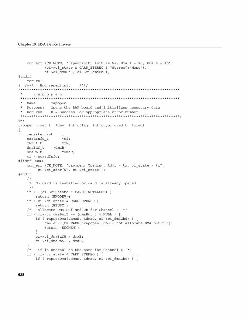
628
Chapter 18: EISA Device Drivers
cmn_err (CE_NOTE, “rapedtinit: Init as %s, Dma 1 = %d, Dma 0 = %d”,(ci->ci_state & CARD_STEREO ? “Stereo”:”Mono”),ci->ci_dmaCh5, ci->ci_dmaCh6);
#endifreturn;
} /*** End rapedtinit ***//************************************************************************** r a p o p e n************************************************************************** Name: rapopen* Purpose: Opens the RAP board and initializes necessary data* Returns: 0 = Success, or appropriate error number.*************************************************************************/
intrapopen ( dev_t *dev, int oflag, int otyp, cred_t *cred){
register int i;cardInfo_t *ci;rwBuf_t *rw;dmaBuf_t *dmaB;dmaCb_t *dmaC;ci = &cardInfo;
#ifdef DEBUGcmn_err (CE_NOTE, “rapopen: Opening, Addr = %x, ci_state = %x”,
ci->ci_addr[0], ci->ci_state );#endif
/** No card is installed or card is already opened*/
if ( !(ci->ci_state & CARD_INSTALLED) )return (ENODEV);
if ( ci->ci_state & CARD_OPENED )return (EBUSY);
/* Allocate DMA Buf and Cb for Channel 5 */if ( ci->ci_dmaBuf5 == (dmaBuf_t *)NULL ) {
if ( rapGetDma(&dmaB, &dmaC, ci->ci_dmaCh5) ) {cmn_err (CE_WARN,”rapopen: Could not allocate DMA Buf 5.”);return (ENOMEM);
}ci->ci_dmaBuf5 = dmaB;ci->ci_dmaCb5 = dmaC;
}/* if in stereo, do the same for Channel 6 */if ( ci->ci_state & CARD_STEREO ) {
if ( rapGetDma(&dmaB, &dmaC, ci->ci_dmaCh6) ) {
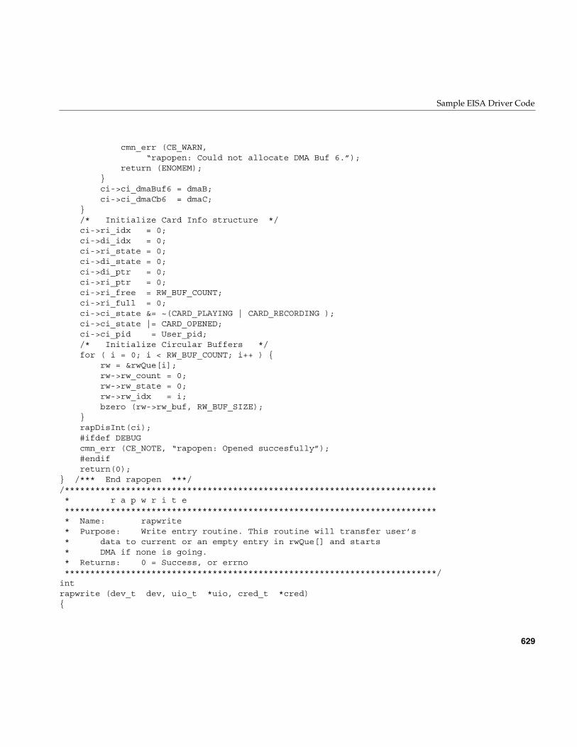
Sample EISA Driver Code
629
cmn_err (CE_WARN,“rapopen: Could not allocate DMA Buf 6.”);
return (ENOMEM);}ci->ci_dmaBuf6 = dmaB;ci->ci_dmaCb6 = dmaC;
}/* Initialize Card Info structure */ci->ri_idx = 0;ci->di_idx = 0;ci->ri_state = 0;ci->di_state = 0;ci->di_ptr = 0;ci->ri_ptr = 0;ci->ri_free = RW_BUF_COUNT;ci->ri_full = 0;ci->ci_state &= ~(CARD_PLAYING | CARD_RECORDING );ci->ci_state |= CARD_OPENED;ci->ci_pid = User_pid;/* Initialize Circular Buffers */for ( i = 0; i < RW_BUF_COUNT; i++ ) {
rw = &rwQue[i];rw->rw_count = 0;rw->rw_state = 0;rw->rw_idx = i;bzero (rw->rw_buf, RW_BUF_SIZE);
}rapDisInt(ci);#ifdef DEBUGcmn_err (CE_NOTE, “rapopen: Opened succesfully”);#endifreturn(0);
} /*** End rapopen ***//************************************************************************** r a p w r i t e************************************************************************** Name: rapwrite* Purpose: Write entry routine. This routine will transfer user’s* data to current or an empty entry in rwQue[] and starts* DMA if none is going.* Returns: 0 = Success, or errno*************************************************************************/
intrapwrite (dev_t dev, uio_t *uio, cred_t *cred){
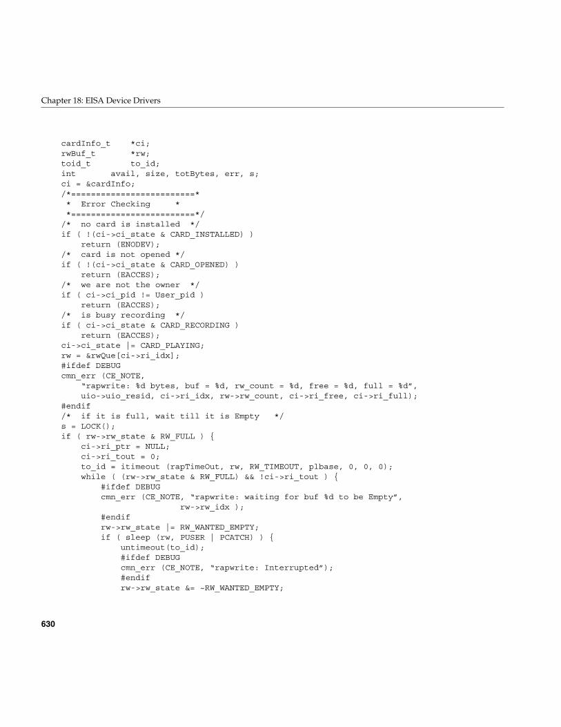
630
Chapter 18: EISA Device Drivers
cardInfo_t *ci;rwBuf_t *rw;toid_t to_id;int avail, size, totBytes, err, s;ci = &cardInfo;/*=========================** Error Checking **=========================*/
/* no card is installed */if ( !(ci->ci_state & CARD_INSTALLED) )
return (ENODEV);/* card is not opened */if ( !(ci->ci_state & CARD_OPENED) )
return (EACCES);/* we are not the owner */if ( ci->ci_pid != User_pid )
return (EACCES);/* is busy recording */if ( ci->ci_state & CARD_RECORDING )
return (EACCES);ci->ci_state |= CARD_PLAYING;rw = &rwQue[ci->ri_idx];#ifdef DEBUGcmn_err (CE_NOTE,
“rapwrite: %d bytes, buf = %d, rw_count = %d, free = %d, full = %d”,uio->uio_resid, ci->ri_idx, rw->rw_count, ci->ri_free, ci->ri_full);
#endif/* if it is full, wait till it is Empty */s = LOCK();if ( rw->rw_state & RW_FULL ) {
ci->ri_ptr = NULL;ci->ri_tout = 0;to_id = itimeout (rapTimeOut, rw, RW_TIMEOUT, plbase, 0, 0, 0);while ( (rw->rw_state & RW_FULL) && !ci->ri_tout ) {
#ifdef DEBUGcmn_err (CE_NOTE, “rapwrite: waiting for buf %d to be Empty”,
rw->rw_idx );#endifrw->rw_state |= RW_WANTED_EMPTY;if ( sleep (rw, PUSER | PCATCH) ) {
untimeout(to_id);#ifdef DEBUGcmn_err (CE_NOTE, “rapwrite: Interrupted”);#endifrw->rw_state &= ~RW_WANTED_EMPTY;
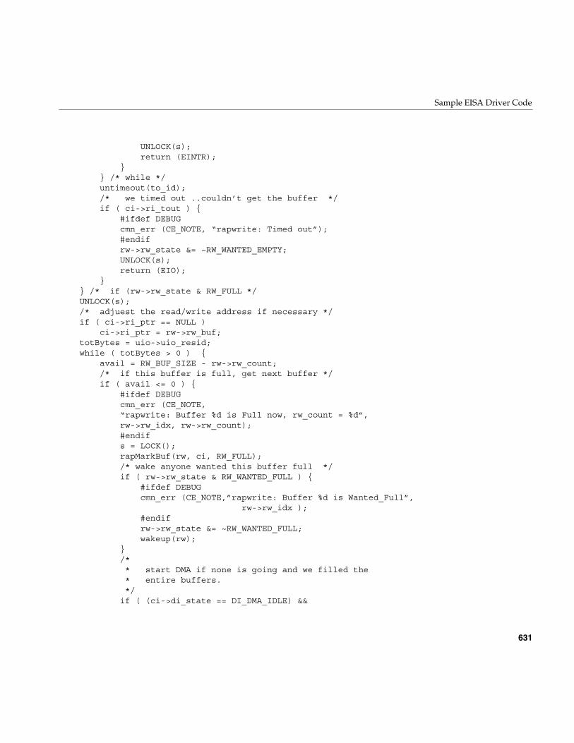
Sample EISA Driver Code
631
UNLOCK(s);return (EINTR);
}} /* while */untimeout(to_id);/* we timed out ..couldn’t get the buffer */if ( ci->ri_tout ) {
#ifdef DEBUGcmn_err (CE_NOTE, “rapwrite: Timed out”);#endifrw->rw_state &= ~RW_WANTED_EMPTY;UNLOCK(s);return (EIO);
}} /* if (rw->rw_state & RW_FULL */UNLOCK(s);/* adjuest the read/write address if necessary */if ( ci->ri_ptr == NULL )
ci->ri_ptr = rw->rw_buf;totBytes = uio->uio_resid;while ( totBytes > 0 ) {
avail = RW_BUF_SIZE - rw->rw_count;/* if this buffer is full, get next buffer */if ( avail <= 0 ) {
#ifdef DEBUGcmn_err (CE_NOTE,“rapwrite: Buffer %d is Full now, rw_count = %d”,rw->rw_idx, rw->rw_count);#endifs = LOCK();rapMarkBuf(rw, ci, RW_FULL);/* wake anyone wanted this buffer full */if ( rw->rw_state & RW_WANTED_FULL ) {
#ifdef DEBUGcmn_err (CE_NOTE,”rapwrite: Buffer %d is Wanted_Full”,
rw->rw_idx );#endifrw->rw_state &= ~RW_WANTED_FULL;wakeup(rw);
}/** start DMA if none is going and we filled the* entire buffers.*/
if ( (ci->di_state == DI_DMA_IDLE) &&
632
Chapter 18: EISA Device Drivers
(rw->rw_idx >= RW_MIN_FULL ) ) {#ifdef DEBUGcmn_err (CE_NOTE,”rapwrite: Starting Play Dma”);#endiferr = rapStart(DI_DMA_PLAYING);if ( err ) {
cmn_err (CE_WARN,“rapwrite: Could not start playing error %d”,err );
UNLOCK(s);return(err);
}}/* get next empty buffer */ci->ri_idx = rapGetNextEmpty(ci->ri_idx, FROM_USR);rw = &rwQue[ci->ri_idx];ci->ri_ptr = rw->rw_buf;UNLOCK(s);continue;
}/* start filling this buffer */size = (totBytes > avail ? avail: totBytes);err = uiomove (ci->ri_ptr, size, UIO_WRITE, uio);if ( err ) {
cmn_err (CE_NOTE, “rapwrite: uiomov error %d”, err);return(err);
}rw->rw_count += size;ci->ri_ptr += size;totBytes = uio->uio_resid;#ifdef DEBUGcmn_err (CE_NOTE,
“rapwrite: Wrote %d to Buffer %d, Left = %d, rw_count = %d”,size, rw->rw_idx, totBytes, rw->rw_count );
#endif}return (0);
} /*** end rapwrite ***//************************************************************************** r a p r e a d*************************************************************************** Name: rapread** Purpose: Reads data from rwQue[] into user’s buffer.* This routine waits for current DMA operation to end
Sample EISA Driver Code
633
* and then starts a A/D Dma (recording). If A/D is already* going then it simply moves data from current Full buffer* into user’s buffer. If buffer is not full, it waits for* it to get full.** Returns: 0 = Success, or errno.**************************************************************************/
intrapread (dev_t dev, uio_t *uio, cred_t *cred){
cardInfo_t *ci;rwBuf_t *rw;toid_t to_id;int avail, size, totBytes, err, s;ci = &cardInfo;/*===============================** Error Checking **===============================*/
/* card is not installed */if ( !(ci->ci_state & CARD_INSTALLED) )
return (ENODEV);/* card is not opened */if ( !(ci->ci_state & CARD_OPENED) )
return (EACCES);/* we do not own the card */if ( ci->ci_pid != User_pid )
return (EACCES);/* card is in middle of a Play operation */if ( ci->ci_state & CARD_PLAYING )
return (EIO);ci->ci_state |= CARD_RECORDING;/* start a A/D Dma if none is going on */if ( ci->di_state == DI_DMA_IDLE ) {
#ifdef DEBUGcmn_err (CE_NOTE, “rapread: Idle DMA. Starting one”);#endifif ( rapStart(DI_DMA_RECORDING) ) {
#ifdef DEBUGcmn_err (CE_NOTE, “rapread: Could not start A/D”);#endifci->ci_state &= ~CARD_RECORDING;UNLOCK(s);return (EIO);
}
634
Chapter 18: EISA Device Drivers
}/** get the buffer we should be using and* wait for it to become Full*/
rw = &rwQue[ci->ri_idx];#ifdef DEBUGcmn_err (CE_NOTE,
“rapread: %d bytes, buf = %d, rw_count = %d, free = %d, full = %d”,uio->uio_resid, ci->ri_idx, rw->rw_count, ci->ri_free, ci->ri_full);
#endifs = LOCK();if ( !(rw->rw_state & RW_FULL) ) {
ci->ri_ptr = NULL;ci->ri_tout = 0;to_id = itimeout (rapTimeOut, rw, RW_TIMEOUT, plbase, 0, 0, 0);while ( !(rw->rw_state & RW_FULL) && !ci->ri_tout ) {
#ifdef DEBUGcmn_err (CE_NOTE, “rapread: wating for buf %d to become Full”,rw->rw_idx );#endifrw->rw_state |= RW_WANTED_FULL;if ( sleep (rw, PUSER | PCATCH) ) {
untimeout (to_id);#ifdef DEBUGcmn_err (CE_NOTE, “rapread: Interrupted”);#endifrw->rw_state &= ~RW_WANTED_FULL;UNLOCK(s);return(EINTR);
}} /* while */untimeout (to_id);if ( ci->ri_tout ) {
#ifdef DEBUGcmn_err (CE_NOTE, “rapread: Timed out”);#endifrw->rw_state &= ~RW_WANTED_FULL;UNLOCK(s);return (EIO);
}} /* if !rw->rw_state & RW_FULL */UNLOCK(s);/* adjust read/write pointer if necessary */if ( ci->ri_ptr == NULL )
Sample EISA Driver Code
635
ci->ri_ptr = rw->rw_buf;/*===================================** Actual Read (Data movement) **===================================*/
totBytes = uio->uio_resid;while ( totBytes > 0 ) {
avail = rw->rw_count;/* if this buffer is Empty, get next Full buffer */if ( avail <= 0 ) {
#ifdef DEBUGcmn_err (CE_NOTE,
“rapread: Buffer %d is Empty now, rw_count = %d”,rw->rw_idx, rw->rw_count );
#endifs = LOCK();rapMarkBuf(rw, ci, RW_EMPTY);/* wake anyone wanted this buffer Empty */if ( rw->rw_state & RW_WANTED_EMPTY ) {
#ifdef DEBUGcmn_err (CE_NOTE,”rapread: Buffer %d is Wanted_Empty”,
rw->rw_idx );#endifrw->rw_state &= ~RW_WANTED_FULL;wakeup(rw);
}/* get next Full buffer */ci->ri_idx = rapGetNextFull(ci->ri_idx, FROM_USR);rw = &rwQue[ci->ri_idx];ci->ri_ptr = rw->rw_buf;UNLOCK(s);continue;
}/* start filling this buffer */size = (totBytes > avail ? avail: totBytes);err = uiomove (ci->ri_ptr, size, UIO_READ, uio);if ( err ) {
cmn_err (CE_PANIC, “rapread: uiomov error %d”, err);return(err);
}rw->rw_count -= size;ci->ri_ptr += size;totBytes = uio->uio_resid;#ifdef DEBUGcmn_err (CE_NOTE,
“rapread: Read %d, Buffer %d, Left = %d, rw_count = %d”,
636
Chapter 18: EISA Device Drivers
size, rw->rw_idx, totBytes, rw->rw_count );#endif
}return (0);
} /*** End rapread ***//************************************************************************** r a p c l o s e************************************************************************** Name: rapclose* Purpose: closes connection to the card and makes it available* for next process to open it.* Returns: 0 = Success, or errno*************************************************************************/
intrapclose (dev_t dev, int flag, int otyp, cred_t *cred){
cardInfo_t *ci;ci = &cardInfo;#ifdef DEBUGcmn_err (CE_NOTE,“rapclose: ci_state = %x, di_state = %x, full = %d, empty = %d”,
ci->ci_state, ci->di_state, ci->ri_full, ci->ri_free );#endif/*=========================** Error Checking **=========================*/
/* card is not installed */if ( !(ci->ci_state & CARD_INSTALLED) )
return (ENODEV);/* card is not opened */if ( !(ci->ci_state & CARD_OPENED) )
return (EACCES);/* we do not own the card */if ( ci->ci_pid != User_pid )
return (EACCES);return ( rapClose(1) );
}/************************************************************************** r a p i n t r************************************************************************** Name: rapintr* Purpose: Interrupt handling routine* Returns: None.*************************************************************************/
void
Sample EISA Driver Code
637
rapintr ( int ctl ){
ushort_t gpis;uchar_t dtci;uchar_t stereo;uchar_t totreq;uchar_t playing;uchar_t moveData;cardInfo_t *ci;caddr_t addr;ci = &cardInfo;addr = ci->ci_addr[0];/** moveData: 0 = we should move data between Buf/DMA to DMA/Buf.* totreq: In stereo, we have to wait for 2 BF or BH interrupt* but in Mono we have to wait for only one.* playing: 1 = Playing, 0= Recording.*/
moveData = 0;totreq = (ci->ci_state & CARD_STEREO? 2:1); /* No. of Ints. we need */playing = ci->ci_state & CARD_PLAYING;gpis = INPW(addr+GPIS);/** First, check for stray interrupts and ignore them*/
if ( !(ci->ci_state & (CARD_PLAYING | CARD_RECORDING)) ) {#ifdef DEBUGcmn_err (CE_NOTE,
“rapintr: Stray interupt, gpis = %x, ci_state = %x”,ci->ci_state );
#endifreturn;
}#ifdef DEBUGcmn_err (CE_NOTE, “rapintr: New ..Gpis = %x”, gpis );#endif/*********************************** DMA Buffers Half/Full ***********************************/
while ( gpis & GPIS_ITC ) {/* see which buffer is half/full */dtci = INPB(addr+DTCI);#ifdef DEBUGcmn_err (CE_NOTE,
“rapintr: Dma buffer status..Gpis = %x, Dtci = %x”, gpis, dtci);
638
Chapter 18: EISA Device Drivers
#endifif ( dtci & DTCI_BF0 )
ci->di_bf++;if ( dtci & DTCI_BF1 )
ci->di_bf++;if (dtci & DTCI_BH0 )
ci->di_bh++;if (dtci & DTCI_BH1 )
ci->di_bh++;#ifdef DEBUGcmn_err (CE_NOTE, “rapintr: di_bf = %d, di_bh = %d”,
ci->di_bf, ci->di_bh );#endif/* 1st half of dma needs service */if ( ci->di_bh == totreq ) {
#ifdef DEBUGcmn_err (CE_NOTE,
“rapintr: DMA First_Half needs service”);#endifci->di_bh = 0;ci->di_which = 0; /* 1st half of DMA buffer */moveData = 1;
}/* 2nd half of dma needs service */else if ( ci->di_bf == totreq ) {
#ifdef DEBUGcmn_err (CE_NOTE,“rapintr: DMA Second_Half needs service”);#endifci->di_bf = 0;ci->di_which = 1; /* 2nd half of DMA buffer */moveData = 1;
}/** Move data if needed*/
if ( moveData ) {/* move data for Play if only data available */if ( playing ) {
/* No more data..end of play */if ( ci->ri_full <= 0 ) {
if (ci->di_state & DI_DMA_END_PLAY ) {#ifdef DEBUGcmn_err (CE_NOTE,”rapintr: End of Play Reached”);#endif
Sample EISA Driver Code
639
if ( ci->ri_state & RI_WANTED_EMPTY ) {#ifdef DEBUGcmn_err (CE_NOTE,“rapintr: Cir.Buff is Wanted Empty”);#endifci->ri_state &= ~RI_WANTED_EMPTY;wakeup (ci);
}else rapStop(DI_DMA_PLAYING);
return;} else {
#ifdef DEBUGcmn_err (CE_NOTE,
“rapintr: Playing but no Full buffers”);#endifreturn;
}}/* Data is available to play */#ifdef DEBUGcmn_err (CE_NOTE,“rapintr: Playing..which = %d, idx = %d, full = %d, Empty = %d”,ci->di_which, ci->di_idx, ci->ri_full, ci->ri_free);#endifrapBufToDma(DMA_HALF_SIZE);
} /* if playing */else { /* recording */
#ifdef DEBUGcmn_err (CE_NOTE,
“rapintr: Recording..which = %d, full = %d, Empty = %d”,ci->di_which, ci->ri_full, ci->ri_free);
#endifrapDmaToBuf(DMA_HALF_SIZE);
}} /* if move data */else { /* no need to move data */
#ifdef DEBUGcmn_err (CE_NOTE,
“rapintr: Waiting for next interrupt, bf = %d, bh = %d”,ci->di_bf, ci->di_bh);
#endif}gpis = INPW(addr+GPIS);#ifdef DEBUGcmn_err (CE_NOTE, “rapintr: next Gpis = %x”, gpis);
640
Chapter 18: EISA Device Drivers
#endif} /* while ( gpis & .. */#ifdef DEBUGcmn_err (CE_NOTE, “rapintr: finished ...”);#endif
} /*** End rapintr ***//************************************************************************** r a p i o c t l************************************************************************** Name: rapioctl* Purpose: handles IOCTL calls for RAP-10.* Returns: 0 = Success, or errno*************************************************************************/
intrapioctl (dev_t dev, int cmd, void *arg, int mode, cred_t *cred, int *ret){
cardInfo_t *ci;ci = &cardInfo;#ifdef DEBUGcmn_err (CE_NOTE, “rapioctl: Cmd = %d, full = %d, Empty = %d”,
cmd, ci->ri_full, ci->ri_free );#endif/** No card is installed or card is already opened*/
if ( !(ci->ci_state & CARD_INSTALLED) )return (ENODEV);
if ( !(ci->ci_state & CARD_OPENED) )return (EACCES);
if ( ci->ci_pid != User_pid )return (EACCES);
*ret = 0;switch ( cmd ) {
case RAPIOCTL_END_PLAY:/*=======================** End PLAY **=======================*/
if ( !(ci->ci_state & CARD_PLAYING) ) {#ifdef DEBUGcmn_err (CE_NOTE,
“rapioctl: End_PLay command in wrong state”);#endifreturn (EACCES);
}return (rapClose (0) );
Sample EISA Driver Code
641
case RAPIOCTL_END_RECORD:/*=======================** End RECORD **=======================*/
if ( !(ci->ci_state & CARD_RECORDING) ) {#ifdef DEBUGcmn_err (CE_NOTE,
“rapioctl: End_Recrd command in wrong state”);#endifreturn (EACCES);
}return (rapClose (0) );
} /* switch */return (0);
} /** End rapioctl **//********************************************************************************** I n t e r n a l R o u t i n e s ***********************************************************************************/
/************************************************************************** r a p C l o s e************************************************************************** Name: rapClose* Purpose: Routine to actually ends current operation and releases* the card. It is written as a separate routine here so* it can be shared by rapclose() and rapioctl() routines.* One frees up the card, one does not. Also if we are called* from ioctl, we will wait till all buffers are played (if* in Playback mode).* Returns: 0 = Success, or errno*************************************************************************/
intrapClose( uchar_t relCard ){
cardInfo_t *ci;rwBuf_t *rw;int s, totLeft;ci = &cardInfo;s = LOCK();rw = &rwQue[ci->ri_idx];#ifdef DEBUGcmn_err (CE_NOTE,
“rapClose: relCard = %d, ci_state = %x, di_state = %x”,relCard, ci->ci_state, ci->di_state );
#endif/*
642
Chapter 18: EISA Device Drivers
* if we are not recording and are not playing* then simply mark the card as not opened and return*/
if ( !(ci->ci_state & (CARD_RECORDING | CARD_PLAYING)) ) {#ifdef DEBUGcmn_err (CE_NOTE, “rapClose: Idle card ..closing”);#endifif ( relCard ) {
ci->ci_state &= ~CARD_OPENED;ci->ci_pid = 0;
}UNLOCK(s);return(0);
}/** Recording ? end it.*/
if ( ci->ci_state & CARD_RECORDING ) {#ifdef DEBUGcmn_err (CE_NOTE,”rapClose: Ending Record (A/D)”);#endifrapStop(DI_DMA_RECORDING);if ( relCard ) {
ci->ci_state &= ~CARD_OPENED;ci->ci_pid = 0;
}UNLOCK(s);return(0);
}/** playback and called from close() routine ?* End the playback*/
if ( relCard ) {#ifdef DEBUGcmn_err (CE_NOTE,“rapClose: Ending Playback (D/A”);#endifrapStop(DI_DMA_PLAYING);ci->ci_state &= ~CARD_OPENED;ci->ci_pid = 0;UNLOCK(s);return(0);
}/*
Sample EISA Driver Code
643
* Called from Ioctl.* Closing in middle of play is different based on we* have been called from close() routine or not.* If called from Ioctl (relCard = 0), we will wait till* all buffers are played back.*/
if ( !(rw->rw_state & RW_FULL) && (rw->rw_count > 0) ) {totLeft = RW_BUF_SIZE - rw->rw_count;#ifdef DEBUGcmn_err (CE_NOTE,
“rapClose: Current Buf %d has %d data. Filled with %d zeros”,rw->rw_idx, rw->rw_count, totLeft );
#endifif ( totLeft > 0 ) {
bzero (ci->ri_ptr, totLeft);ci->ri_ptr += totLeft;
}rapMarkBuf(rw, ci, RW_FULL);
}/* some buffers to play */if ( ci->ri_full > 0 ) {
/* Playback has not started yet */if ( ci->di_state == DI_DMA_IDLE ) {
#ifdef DEBUGcmn_err (CE_NOTE,“rapClose: Starting playback, full = %d, empty = %d”,ci->ri_full, ci->ri_free);#endifrapStart(DI_DMA_PLAYING);
}ci->di_state = DI_DMA_IDLE;ci->di_state |= DI_DMA_END_PLAY;/* wait till buffers are all played back */while ( ci->ri_full > 0 ) {
#ifdef DEBUGcmn_err (CE_NOTE,
“rapClose: waiting for Play to end..full = %d, empty = %d, ri_idx = %d, di_idx = %d”,
ci->ri_full, ci->ri_free, ci->ri_idx, ci->di_idx);#endifci->ri_state |= RI_WANTED_EMPTY;if ( sleep (ci, PUSER | PCATCH) ) {
#ifdef DEBUGcmn_err (CE_NOTE, “rapClose: Interrupted”);#endif
644
Chapter 18: EISA Device Drivers
rapStop(DI_DMA_PLAYING);ci->ci_state &= ~CARD_OPENED;ci->ci_pid = 0;UNLOCK(s);return (EINTR);
}}rapStop(DI_DMA_PLAYING);
}else {
#ifdef DEBUGcmn_err (CE_NOTE, “rapClose: Circular buffer empty..closing”);#endifrapStop(DI_DMA_PLAYING);
}UNLOCK(s);return(0);
} /*** End rapClose ***//************************************************************************** r a p S t o p************************************************************************** Name: rapStop* Purpose: Stops D/A and A/D conversion.* Returns: None.*************************************************************************/
static voidrapStop( uchar_t what ){
cardInfo_t *ci;rwBuf_t *rw;caddr_t addr;uchar_t dacm, adcm;ushort_t gpdi;int s, i;s = LOCK();ci = &cardInfo;addr = ci->ci_addr[0];gpdi = adcm = dacm = 0;#ifdef DEBUGcmn_err (CE_NOTE,
“rapStop: Stoping %s, full = %d, Empty = %d”,(what == DI_DMA_PLAYING ? “Playback(D/A)”:”Record(A/D)”),ci->ri_full, ci->ri_free);
#endifswitch ( what ) {
Sample EISA Driver Code
645
/* stop D/A Conversion (Playing) */case DI_DMA_PLAYING:
ci->di_which = 0;rapZeroDma(ci, DMA_BUF_SIZE);OUTB(addr+DACM, dacm);rapNoteOff (ci);break;
/* stop A/D Conversion (recording) */case DI_DMA_RECORDING:
OUTB(addr+ADCM, adcm);OUTB(addr+DACM, dacm);break;
}OUTW(addr+GPDI, gpdi);rapReleaseDma(ci);/* Initialize Card Info structure */ci->ci_state &= ~(CARD_PLAYING | CARD_RECORDING);ci->ri_idx = 0;ci->di_idx = 0;ci->ri_state = 0;ci->di_state = 0;ci->di_ptr = rwQue[0].rw_buf;ci->ri_ptr = rwQue[0].rw_buf;ci->ri_free = RW_BUF_COUNT;ci->ri_full = 0;/* Initialize Circular Buffers */for ( i = 0; i < RW_BUF_COUNT; i++ ) {
rw = &rwQue[i];rw->rw_count = 0;rw->rw_state = 0;rw->rw_idx = i;bzero (rw->rw_buf, RW_BUF_SIZE);
}
/* clear out any hanging GPIS and DACM */gpdi = INPW(addr+GPIS);UNLOCK(s);
} /** End rapStop **//************************************************************************** r a p S t a r t************************************************************************** Name: rapStart* Purpose: Prepares Eisa DMA buffers/Control block for Playing/Recording* This function is called when DMA is Idle.* Returns: 0 = Success or Error number.
646
Chapter 18: EISA Device Drivers
*************************************************************************/static intrapStart (uchar_t what){
cardInfo_t *ci;dmaBuf_t *dmaB;dmaCb_t *dmaC;uchar_t stereo;int err;ci = &cardInfo;stereo = (ci->ci_state & CARD_STEREO);#ifdef DEBUGcmn_err (CE_NOTE,
“rapStart: Starting %s, full = %d, empty = %d”,(what == DI_DMA_PLAYING ? “Playback(D/A)”:”Record(A/D)”),ci->ri_full, ci->ri_free );
#endif/* clear Dma buffers */ci->di_which = 0;rapZeroDma(ci, DMA_BUF_SIZE);/* check for Dma buffer addresses */if ( (ci->ci_dmaBuf5 == (dmaBuf_t *)0) ||
(ci->ci_dmaCb5 == (dmaCb_t *)0) ) {cmn_err (CE_WARN,
“rapStart: Chan 5 dmaBuf/dmaCb is NULL, what = %d”, what);return(EIO);
}if ( (ci->ci_dmaBuf6 == (dmaBuf_t *)0) ||
(ci->ci_dmaCb6 == (dmaCb_t *)0) ) {cmn_err (CE_WARN,
“rapStart: Chan 6 dmaBuf/dmaCb is NULL, what = %d”, what);return(EIO);
}/** Prepare Eisa Buf and Cb for Channel 5. If in* stereo mode, do the same for Channel 6.*/
dmaB = ci->ci_dmaBuf5;dmaC = ci->ci_dmaCb5;rapPrepEisa (dmaB, dmaC, what, dmaLeftPhys );if ( stereo ) {
dmaB = ci->ci_dmaBuf6;dmaC = ci->ci_dmaCb6;rapPrepEisa (dmaB, dmaC, what, dmaRightPhys );
}
Sample EISA Driver Code
647
/** Program Eisa DMA Channels*/
err = eisa_dma_prog (ci->ci_adap, ci->ci_dmaCb5, ci->ci_dmaCh5,EISA_DMA_NOSLEEP);
if ( err == 0 ) {cmn_err (CE_WARN, “rapStart: DMA Channel %d is busy”,
ci->ci_dmaCh5 );return (EBUSY);
}if ( stereo ) {
err = eisa_dma_prog (ci->ci_adap, ci->ci_dmaCb6, ci->ci_dmaCh6,EISA_DMA_NOSLEEP);
if ( err == 0 ) {cmn_err (CE_WARN,
“rapStart: DMA Channel %d is busy”,ci->ci_dmaCh6 );
return (EBUSY);}
}/* enable hardware recognition on Eisa Dma Channels */eisa_dma_enable (ci->ci_adap, ci->ci_dmaCb5, ci->ci_dmaCh5,
EISA_DMA_NOSLEEP);if ( stereo ) {
eisa_dma_enable (ci->ci_adap, ci->ci_dmaCb6, ci->ci_dmaCh6,EISA_DMA_NOSLEEP);
}/* set Eisa DMA register for Autoinit mode */rapSetAutoInit(ci, what);ci->di_state |= what;/* let’s do it ! */if ( what == DI_DMA_PLAYING ) {
#ifdef DEBUGcmn_err (CE_NOTE, “rapStart: Starting DMA for D/A Play”);#endifrapStartDA();
}else {
#ifdef DEBUGcmn_err (CE_NOTE, “rapStart: Starting DMA for A/D Record”);#endifrapStartAD();
}return(0);
} /** End rapStart **/
648
Chapter 18: EISA Device Drivers
/************************************************************************* r a p P r e p E i s a************************************************************************** Name: rapPrepEisa* Purpose: prepares EISA Buf and Cb structures.* Returns: None.*************************************************************************/
static voidrapPrepEisa( dmaBuf_t *dmaB, dmaCb_t *dmaC, uchar_t what, paddr_t addr){
#ifdef DEBUGcmn_err (CE_NOTE,
“rapPrepEisa: Preparing Eisa DMA buffers for %s”,(what == DI_DMA_PLAYING ? “Playback(D/A)” : “Record(A/D)” ) );
#endif/* prepare Eisa DMA Buf struct */bzero (dmaB, sizeof(dmaBuf_t) );dmaB->count = DMA_BUF_SIZE;dmaB->address = addr;/* prepare Eisa DMA Control Block */bzero (dmaC, sizeof(dmaCb_t) );dmaC->reqrbufs = dmaB;dmaC->reqr_path = EISA_DMA_PATH_16;dmaC->trans_type = EISA_DMA_TRANS_DMND;dmaC->targ_step = EISA_DMA_STEP_INC;dmaC->bufprocess = EISA_DMA_BUF_SNGL;if ( what == DI_DMA_PLAYING )
dmaC->cb_cmd = EISA_DMA_CMD_READ; /* mem -> rap10 */else
dmaC->cb_cmd = EISA_DMA_CMD_WRITE; /* rap10 -> mem */} /*** End rapPrepEisa ***//************************************************************************** r a p S t a r t D A************************************************************************** Name: rapStartDA* Purpose: Enables appropriate RAP interrupts and starts D/A Dma.* Returns: None*************************************************************************/
static voidrapStartDA(){
cardInfo_t *ci;caddr_t addr;ushort_t gpdi, gpis, gpst, dtcd, mask;uchar_t gpcm, pwmd, adcm, dacm;
Sample EISA Driver Code
649
uchar_t stereo;int s;ci = &cardInfo;
addr = ci->ci_addr[0];stereo = ci->ci_state & CARD_STEREO;#ifdef DEBUGcmn_err (CE_NOTE,
“rapStartDA: Starting D/A Dma, full = %d, empty = %d”,ci->ri_full, ci->ri_free );
#endif/** Prepare the board for Record (A/D)* Here is what we will do (in exact order):** GPDI: Stereo = 0xA800, Mono = 0x9800* itc = 1, dma transfer match count* Stereo: Drq1->Dma5, Drq0->Dma6* Mono: Drq1->Dma5* Dt1, Dt0 = 10, Chan 1 ->Drq1, Chan 0 ->Drq0* Left Chan->Drq1, Right Chan->Drq0** DACM: Stereo: BF, Mono: BE* scc = 1, Dma size in byte* ts1 = ts2 = 1, transfer size of 4096 bytes* dl1 = dl0 = 1; Data length of 16 bits for both Channels.* Stereo ? ds1 = ds0 = 1 Start D/A on both Channels.* Mono ? ds1 = 1 Start D/A on Channel 1** GPCM: Select Mike level = 0x04* Aux level = 0x08* PWMD: 0xFF (Max level)*/
gpdi = (stereo ? 0xA800: 0x9800);dacm = (stereo ? 0xBF:0xBE);gpcm = 0x04;pwmd = 0xFF;mask = (stereo ? (GPIS_DN1|GPIS_DN0): GPIS_DN1);#ifdef DEBUGcmn_err (CE_NOTE,
“rapStartDA: gpdi = %x, dacm = %x”, gpdi, dacm);#endif/* Set Rap-10 card */OUTB(addr+GPCM, gpcm);OUTB(addr+PWMD, pwmd);OUTW(addr+GPDI, gpdi);
650
Chapter 18: EISA Device Drivers
OUTB(addr+DACM, dacm);/** Busy-wait for both Note_On interrupts* The interrupt version is commenetd out for now.*/
gpis = INPW(addr+GPIS);#ifdef DEBUGcmn_err (CE_NOTE,
“rapStartDA: Waiting for Note_On, gpis = %x, mask = %x”,gpis, mask);
#endifwhile ( !(gpis & mask) ) {
gpis = INPW(addr+GPIS);#ifdef DEBUGcmn_err (CE_NOTE, “rapStartDA: Waiting ..new gpis = %x”, gpis);#endif
}#ifdef DEBUGcmn_err (CE_NOTE, “rapStartDA: Note_On Interrupt Received, gpis = %x”,gpis );#endifrapNoteOn(ci, gpis);
} /*** End rapStartDA ***//************************************************************************** r a p S t a r t A D************************************************************************** Name: rapStartAD* Purpose: Enables appropriate RAP interrupts and starts A/D Dma.* Returns: None*************************************************************************/
static voidrapStartAD(){
cardInfo_t *ci;caddr_t addr;ushort_t gpdi;uchar_t gpcm, pwmd, adcm, dacm;uchar_t stereo, mic;ci = &cardInfo;addr = ci->ci_addr[0];stereo = ci->ci_state & CARD_STEREO;
#ifdef DEBUGcmn_err (CE_NOTE,
“rapStartAD: Starting A/D Dma in %s, full = %d, empty = %d”,(stereo ? “Stereo”:”Mono”), ci->ri_full, ci->ri_free );
Sample EISA Driver Code
651
#endif/** Prepare the board for Record (A/D)* Here is what we will do (in exact order):** GPDI: Stereo = 0xA400, Mono = 0x9400* itc = 1, dma transfer match count* Stereo: Drq1->Dma5, Drq0->Dma6* Mono: Drq1->Dma5* Dt1, Dt0 = 01, Left Chan->Drq1, Right Chan->Drq0** DACM: 0xB0* scc = 1, Dma size in byte* ts1 = ts2 = 1, transfer size of 4096 bytes** GPCM: Select Mic level = 0x04* Aux level = 0x08* PWMD: 0xFF (Max level)** ADCM: Stereo: Mic 0x6F, line 0x4F,* Mono: Mic 0x6D, line 0x4D* Mon = 1, Monitor ON* Gin = 1, Head Amp Gain to Mic.* Af1, Af0 = 01, 22.05 KHz* Adl = 1, 16 bit data length* Stereo, Adm = 1, else = 0* Ads = 1, Start A/D*/
gpdi = (stereo ? 0xA400: 0x9400);gpcm = 0x08;adcm = (stereo ? 0x6F:0x6D);dacm = 0xB0;gpcm = 0x04;pwmd = 0xFF;#ifdef DEBUGcmn_err (CE_NOTE,“rapStartAD: Rap init as: gpdi = %x, dacm = %x, gpcm = %x, adcm = %x”,gpdi, dacm, gpcm, adcm);#endifOUTW(addr+GPDI, gpdi);OUTB(addr+DACM, dacm);OUTB(addr+GPCM, gpcm);OUTB(addr+PWMD, pwmd);OUTB(addr+ADCM, adcm);
} /*** End rapStartAD ***/
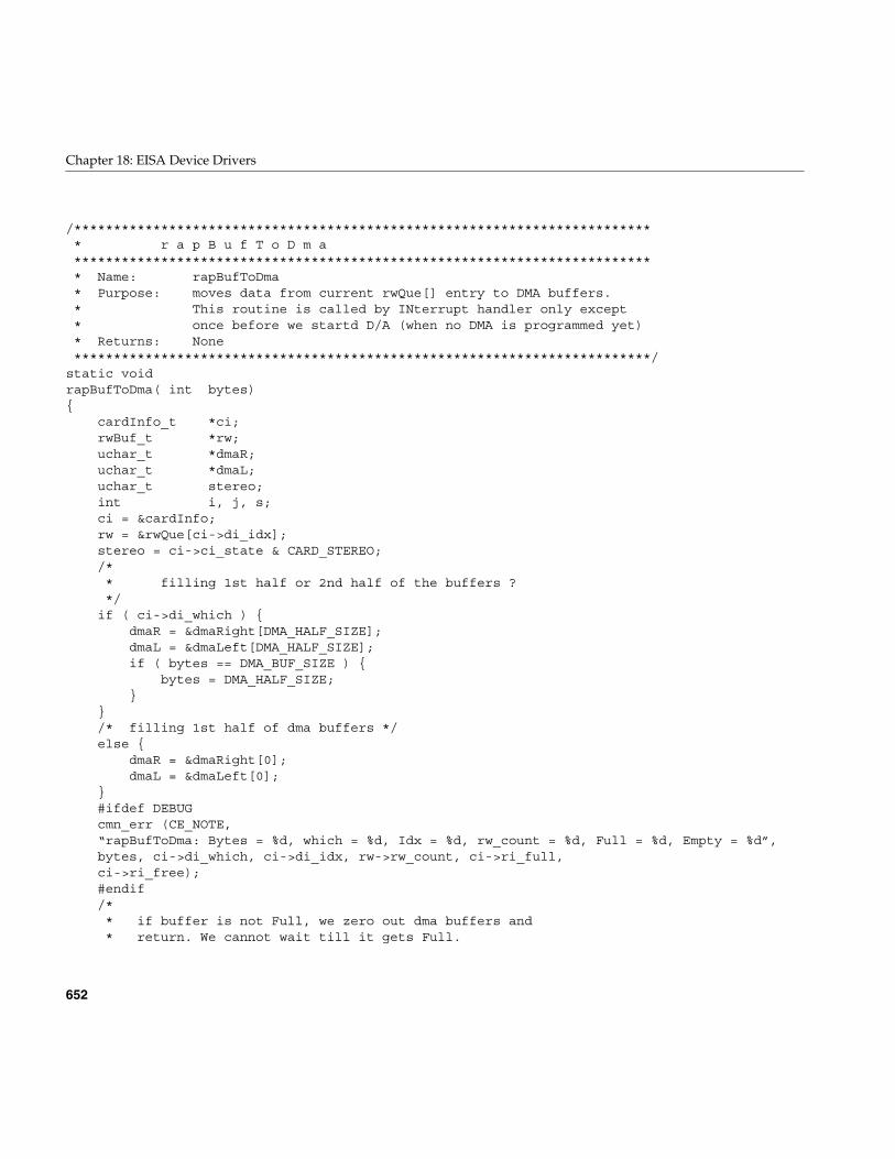
652
Chapter 18: EISA Device Drivers
/************************************************************************** r a p B u f T o D m a************************************************************************** Name: rapBufToDma* Purpose: moves data from current rwQue[] entry to DMA buffers.* This routine is called by INterrupt handler only except* once before we startd D/A (when no DMA is programmed yet)* Returns: None*************************************************************************/
static voidrapBufToDma( int bytes){
cardInfo_t *ci;rwBuf_t *rw;uchar_t *dmaR;uchar_t *dmaL;uchar_t stereo;int i, j, s;ci = &cardInfo;rw = &rwQue[ci->di_idx];stereo = ci->ci_state & CARD_STEREO;/** filling 1st half or 2nd half of the buffers ?*/
if ( ci->di_which ) {dmaR = &dmaRight[DMA_HALF_SIZE];dmaL = &dmaLeft[DMA_HALF_SIZE];if ( bytes == DMA_BUF_SIZE ) {
bytes = DMA_HALF_SIZE;}
}/* filling 1st half of dma buffers */else {
dmaR = &dmaRight[0];dmaL = &dmaLeft[0];
}#ifdef DEBUGcmn_err (CE_NOTE,“rapBufToDma: Bytes = %d, which = %d, Idx = %d, rw_count = %d, Full = %d, Empty = %d”,bytes, ci->di_which, ci->di_idx, rw->rw_count, ci->ri_full,ci->ri_free);#endif/** if buffer is not Full, we zero out dma buffers and* return. We cannot wait till it gets Full.
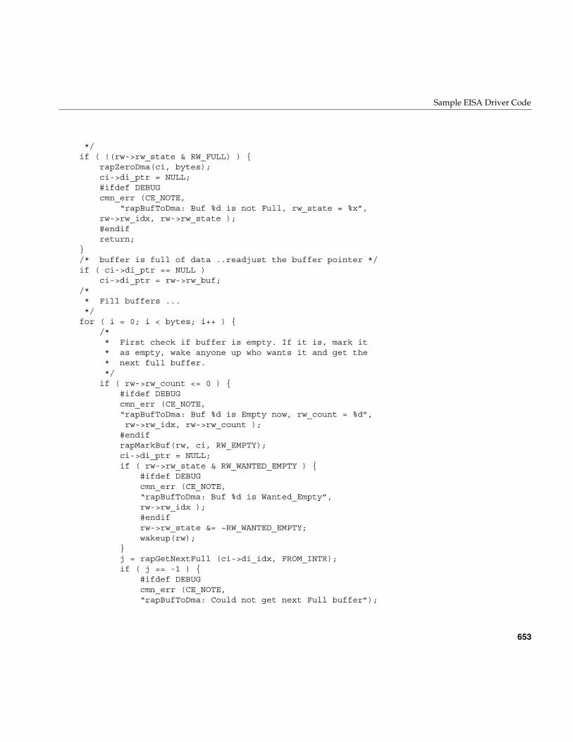
Sample EISA Driver Code
653
*/if ( !(rw->rw_state & RW_FULL) ) {
rapZeroDma(ci, bytes);ci->di_ptr = NULL;#ifdef DEBUGcmn_err (CE_NOTE,
“rapBufToDma: Buf %d is not Full, rw_state = %x”,rw->rw_idx, rw->rw_state );#endifreturn;
}/* buffer is full of data ..readjust the buffer pointer */if ( ci->di_ptr == NULL )
ci->di_ptr = rw->rw_buf;/** Fill buffers ...*/
for ( i = 0; i < bytes; i++ ) {/** First check if buffer is empty. If it is, mark it* as empty, wake anyone up who wants it and get the* next full buffer.*/
if ( rw->rw_count <= 0 ) {#ifdef DEBUGcmn_err (CE_NOTE,“rapBufToDma: Buf %d is Empty now, rw_count = %d”,rw->rw_idx, rw->rw_count );
#endifrapMarkBuf(rw, ci, RW_EMPTY);ci->di_ptr = NULL;if ( rw->rw_state & RW_WANTED_EMPTY ) {
#ifdef DEBUGcmn_err (CE_NOTE,“rapBufToDma: Buf %d is Wanted_Empty”,rw->rw_idx );#endifrw->rw_state &= ~RW_WANTED_EMPTY;wakeup(rw);
}j = rapGetNextFull (ci->di_idx, FROM_INTR);if ( j == -1 ) {
#ifdef DEBUGcmn_err (CE_NOTE,“rapBufToDma: Could not get next Full buffer”);
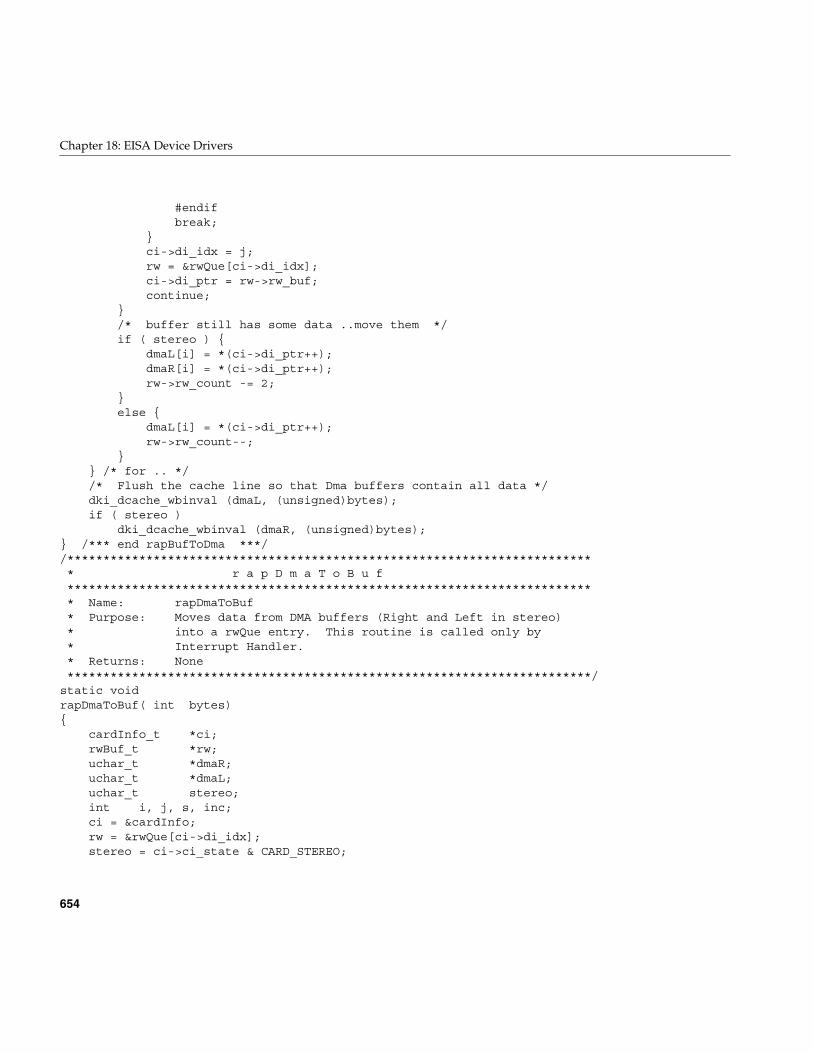
654
Chapter 18: EISA Device Drivers
#endifbreak;
}ci->di_idx = j;rw = &rwQue[ci->di_idx];ci->di_ptr = rw->rw_buf;continue;
}/* buffer still has some data ..move them */if ( stereo ) {
dmaL[i] = *(ci->di_ptr++);dmaR[i] = *(ci->di_ptr++);rw->rw_count -= 2;
}else {
dmaL[i] = *(ci->di_ptr++);rw->rw_count--;
}} /* for .. *//* Flush the cache line so that Dma buffers contain all data */dki_dcache_wbinval (dmaL, (unsigned)bytes);if ( stereo )
dki_dcache_wbinval (dmaR, (unsigned)bytes);} /*** end rapBufToDma ***//************************************************************************** r a p D m a T o B u f************************************************************************** Name: rapDmaToBuf* Purpose: Moves data from DMA buffers (Right and Left in stereo)* into a rwQue entry. This routine is called only by* Interrupt Handler.* Returns: None*************************************************************************/
static voidrapDmaToBuf( int bytes){
cardInfo_t *ci;rwBuf_t *rw;uchar_t *dmaR;uchar_t *dmaL;uchar_t stereo;int i, j, s, inc;ci = &cardInfo;rw = &rwQue[ci->di_idx];stereo = ci->ci_state & CARD_STEREO;
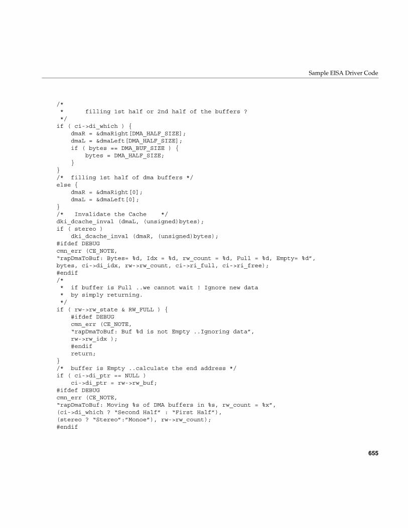
Sample EISA Driver Code
655
/** filling 1st half or 2nd half of the buffers ?*/
if ( ci->di_which ) {dmaR = &dmaRight[DMA_HALF_SIZE];dmaL = &dmaLeft[DMA_HALF_SIZE];if ( bytes == DMA_BUF_SIZE ) {
bytes = DMA_HALF_SIZE;}
}/* filling 1st half of dma buffers */else {
dmaR = &dmaRight[0];dmaL = &dmaLeft[0];
}/* Invalidate the Cache */dki_dcache_inval (dmaL, (unsigned)bytes);if ( stereo )
dki_dcache_inval (dmaR, (unsigned)bytes);#ifdef DEBUGcmn_err (CE_NOTE,“rapDmaToBuf: Bytes= %d, Idx = %d, rw_count = %d, Full = %d, Empty= %d”,bytes, ci->di_idx, rw->rw_count, ci->ri_full, ci->ri_free);#endif/** if buffer is Full ..we cannot wait ! Ignore new data* by simply returning.*/
if ( rw->rw_state & RW_FULL ) {#ifdef DEBUGcmn_err (CE_NOTE,“rapDmaToBuf: Buf %d is not Empty ..Ignoring data”,rw->rw_idx );#endifreturn;
}/* buffer is Empty ..calculate the end address */if ( ci->di_ptr == NULL )
ci->di_ptr = rw->rw_buf;#ifdef DEBUGcmn_err (CE_NOTE,“rapDmaToBuf: Moving %s of DMA buffers in %s, rw_count = %x”,(ci->di_which ? “Second Half” : “First Half”),(stereo ? “Stereo”:”Monoe”), rw->rw_count);#endif
656
Chapter 18: EISA Device Drivers
/** Fill buffers ...in stereo bytes are Left:Right:Left:Right...*/
for ( i = 0; i < bytes; i++ ) {/** First check if this buffer is Full or not.* If it is, mark it as Full and wake anyone up who is* waiting for it. Then get the next Empty buffer.*/
if ( rw->rw_count >= RW_BUF_SIZE ) {#ifdef DEBUGcmn_err (CE_NOTE,“rapDmaToBuf: Buf %d is Full now, rw_count = %d”,rw->rw_idx, rw->rw_count );#endifrapMarkBuf(rw, ci, RW_FULL);if ( rw->rw_state & RW_WANTED_FULL ) {
#ifdef DEBUGcmn_err (CE_NOTE,“rapDmaToBuf: Buf %d is Wanted_Full”,rw->rw_idx );#endifrw->rw_state &= ~RW_WANTED_FULL;wakeup(rw);
}j = rapGetNextEmpty(ci->di_idx, FROM_INTR);if ( j == -1 ) {
cmn_err (CE_NOTE,“rapDmaToBuf: Could not get next empty”);
return;}ci->di_idx = j;rw = &rwQue[ci->di_idx];ci->di_ptr = rw->rw_buf;continue;
}/* buffer still has room ...move data */if ( stereo ) {
*(ci->di_ptr++) = dmaL[i];*(ci->di_ptr++) = dmaR[i];rw->rw_count += 2;
}else {
*(ci->di_ptr++) = dmaL[i];rw->rw_count++;
Sample EISA Driver Code
657
}} /* while bytes ... */
} /*** end rapDmaToBuf ***//************************************************************************** r a p G e t N e x t F u l l************************************************************************** Name: rapGetNextFull* Purpose: returns the index of next Full entry in rwQue[],* starting from a given index. Sleeps if the entry* is not Full.* Returns: the index of the empty entry.*************************************************************************/
static shortrapGetNextFull (short idx, uchar_t fromIntr){
cardInfo_t *ci;int s;toid_t to_id;rwBuf_t *rw;ci = &cardInfo;#ifdef DEBUGcmn_err (CE_NOTE,“rapGetNextFull: Getting Next Full Buffer..idx = %d, fromIntr: %d”,idx, fromIntr );#endif/* go to beginning if at the end of the queu */idx++;if ( idx >= RW_BUF_COUNT )
idx = 0;rw = &rwQue[idx];/** if buffer is not available and we were called from Intrupt* handler, simply ignore the request and return error*/
s = LOCK();if ( !(rw->rw_state & RW_FULL) && (fromIntr) ) {
#ifdef DEBUGcmn_err (CE_NOTE,“rapGetNextFull: Buffer %d is not Full. ..Cannot Wait”,rw->rw_idx);#endifUNLOCK(s);return(-1);
}/* wait for the buffer to become Full */
658
Chapter 18: EISA Device Drivers
if ( !(rw->rw_state & RW_FULL) ) {ci->ri_tout = 0;to_id = itimeout (rapTimeOut, rw, RW_TIMEOUT, plbase, 0, 0, 0);while ( !(rw->rw_state & RW_FULL) && !ci->ri_tout ) {
#ifdef DEBUGcmn_err (CE_NOTE,“rapGetNextFull: Waiting for Buf %d to become Full”,rw->rw_idx );#endifrw->rw_state |= RW_WANTED_FULL;if ( sleep(rw, PUSER | PCATCH) ) {
untimeout(to_id);#ifdef DEBUGcmn_err (CE_NOTE, “rapGetNextFull: Interrupted”);#endifrw->rw_state &= ~RW_WANTED_FULL;UNLOCK(s);return(-1);
}}untimeout (to_id);if ( ci->ri_tout ) {
#ifdef DEBUGcmn_err (CE_NOTE, “raGetNextFull: Timed out”);#endifrw->rw_state &= ~RW_WANTED_FULL;UNLOCK(s);return (-1);
}} /* if !(rw->rw_state & RW_FULL) */UNLOCK(s);#ifdef DEBUGcmn_err (CE_NOTE, “rapGetNextFull: next Full Buffer is %d”, idx);#endifreturn(idx);
} /*** End rapGetNextFull ***//************************************************************************** r a p G e t N e x t E m p t y************************************************************************** Name: rapGetNextEmpty** Purpose: returns the index of next empty entry in rwQue[],* starting from a given index. Sleeps if the entry* is not empty.* Returns: the index of the empty entry.
Sample EISA Driver Code
659
*************************************************************************/static shortrapGetNextEmpty (short idx, uchar_t fromIntr){
cardInfo_t *ci;int s;toid_t to_id;rwBuf_t *rw;ci = &cardInfo;#ifdef DEBUGcmn_err (CE_NOTE,
“rapGetNextEmpty: Getting Next Empty Buffer..idx = %d, fromIntr: %d”,idx, fromIntr );
#endif
/* go to beginning if at the end of the queu */idx++;if ( idx >= RW_BUF_COUNT )
idx = 0;rw = &rwQue[idx];s = LOCK();/** if buffer is nit available and we were called from Intrupt* handler, simply ignore the request and return error*/
if ( (rw->rw_state & RW_FULL) && (fromIntr) ) {#ifdef DEBUGcmn_err (CE_NOTE,“rapGetNextEmpty: Buffer %d is not Empty ..Cannot Wait”,rw->rw_idx);#endifUNLOCK(s);return(-1);
}/* wait for the buffer to become Empty */if ( rw->rw_state & RW_FULL ) {
ci->ri_tout = 0;to_id = itimeout (rapTimeOut, rw, RW_TIMEOUT, plbase, 0, 0, 0);while ( (rw->rw_state & RW_FULL) && !ci->ri_tout ) {
#ifdef DEBUGcmn_err (CE_NOTE,“rapGetNextEmpty: Waiting for Buf %d to become Empty”,rw->rw_idx );#endifrw->rw_state |= RW_WANTED_EMPTY;
660
Chapter 18: EISA Device Drivers
if ( sleep(rw, PUSER | PCATCH) ) {untimeout(to_id);#ifdef DEBUGcmn_err (CE_NOTE, “rapGetNextEmpty: Interrupted”);#endifrw->rw_state &= ~RW_WANTED_EMPTY;UNLOCK(s);return(-1);
}} /* while .. */untimeout (to_id);if ( ci->ri_tout ) {
#ifdef DEBUGcmn_err (CE_NOTE, “raGetNextEmpty: Timed out”);#endifrw->rw_state &= ~RW_WANTED_EMPTY;UNLOCK(s);return (-1);
}} /* if (rw->rw_state & RW_FULL) */UNLOCK(s);#ifdef DEBUGcmn_err (CE_NOTE, “rapGetNextEmpty: next Empty Buffer is %d”, idx);#endifreturn(idx);
} /*** End rapGetNextEmpty ***//************************************************************************** r a p D i s I n t************************************************************************** Name: rapDisInt* Purpose: Disables RAP-10 interrupts.* Returns: None.*************************************************************************/
static voidrapDisInt( cardInfo_t *ci){
caddr_t addr;ushort_t s;uchar_t c;#ifdef DEBUGcmn_err (CE_NOTE, “rapDisInt: full = %d, empty = %d, di_state = %d”,ci->ri_full, ci->ri_free, ci->di_state );#endifaddr = ci->ci_addr[0];/* disable all Interrupts */
Sample EISA Driver Code
661
s = 0;OUTW(addr+GPDI, s);OUTB(addr+DACM, 0x00);OUTB(addr+ADCM, 0x00);#ifdef DEBUGcmn_err (CE_NOTE, “rapDisInt: Rap is set”);#endif
} /*** End rapDisInt ***//*************************************************************************** r a p G e t D m a **************************************************************************** Name: rapGetDma* Purpose: allocates dma Buf and Cb structures* Returns: 0 = Success, 1 = Error**************************************************************************/
static intrapGetDma ( dmaBuf_t **dmaB, dmaCb_t **dmaC, int ch ){
#ifdef DEBUGcmn_err (CE_NOTE,“rapGetDma: Getting Eisa Dma Buf and Cb for Channel %d”, ch);#endif*dmaB = eisa_dma_get_buf (EISA_DMA_SLEEP);if ( *dmaB == NULL )
return (1);*dmaC = eisa_dma_get_cb ( EISA_DMA_SLEEP );if ( *dmaC == NULL )
return (1);return (0);
} /*** End rapGetDma ***//************************************************************************** r a p M a r k B u f************************************************************************** Name: rapMarkBuf* Purpose: Marks a buffer (Empty, Busy, Full) and increments/decrements* appropriate counters. Buffers status changed as:* Empty -> Busy -> Full -> Empty -> Busy ..* Returns: None.*************************************************************************/
static voidrapMarkBuf (rwBuf_t *rw, cardInfo_t *ci, uchar_t m){
int s;s = LOCK();switch ( m ) {
662
Chapter 18: EISA Device Drivers
case RW_EMPTY:rw->rw_state &= ~RW_FULL;if ( ci->ri_full )
ci->ri_full--;ci->ri_free++;rw->rw_count = 0;#ifdef DEBUGcmn_err (CE_NOTE,“rapMarkBuf: Buf %d set EMPTY. Full = %d, Emp = %d”,rw->rw_idx, ci->ri_full, ci->ri_free );#endifbreak;
case RW_FULL:rw->rw_state |= RW_FULL;ci->ri_full++;if ( ci->ri_free )
ci->ri_free--;rw->rw_count = RW_BUF_SIZE;#ifdef DEBUGcmn_err (CE_NOTE,
“rapMarkBuf: Buf %d set FULL. Full = %d, Emp = %d”,rw->rw_idx, ci->ri_full, ci->ri_free );
#endifbreak;
}UNLOCK(s);
} /*** End rapMarkBuf ***//************************************************************************** r a p K e r n M e m************************************************************************** Name: rapKernMem* Purpose: Allocates/Disallocates Kernel memory for Right and* Left DMA channels.* Returns: 0 = Success, 1 = Failure.*************************************************************************/
static intrapKernMem ( uchar_t what){
#ifdef DEBUGcmn_err (CE_NOTE, “rapKernMem: %s Kernel Contigious Memory”,
(what == 1 ? “Allocating” : “Deallocating”) );#endifswitch ( what ) {
/*=======================================** Allocate Right/Left DMA Channels *
Sample EISA Driver Code
663
*=======================================*/case 1:
dmaRight = kmem_alloc (DMA_BUF_SIZE,KM_NOSLEEP | KM_PHYSCONTIG | KM_CACHEALIGN );
if ( dmaRight == (caddr_t)NULL ) {cmn_err (CE_WARN,“rapKernMem: Cannot allocate DMA memory for R_chann”);return(1);
}dmaLeft = kmem_alloc (DMA_BUF_SIZE,
KM_NOSLEEP | KM_PHYSCONTIG | KM_CACHEALIGN );if ( dmaLeft == (caddr_t)NULL ) {
cmn_err (CE_WARN,“rapKernMem: Cannot allocate DMA memory for L_chann”);
kmem_free (dmaRight, DMA_BUF_SIZE);return(1);
}/* get the physicall address */dmaRightPhys = kvtophys(dmaRight);dmaLeftPhys = kvtophys(dmaLeft);return(0);
/*=======================================** Deallocate Right/Left DMA Channels **=======================================*/
case 2:if ( dmaRight != NULL ) {
kmem_free (dmaRight, DMA_BUF_SIZE);dmaRight = (caddr_t)NULL;
}if ( dmaLeft != NULL ) {
kmem_free (dmaLeft, DMA_BUF_SIZE);dmaLeft = (caddr_t)NULL;
}return(0);
} /* switch */} /*** End rapKernMem ***//************************************************************************** r a p T i m e O u t************************************************************************** Name: rapTimeOut* Purpose: is called when Read/Write waiting for buffers time out.* Returns:*************************************************************************/
static voidrapTimeOut( void *addr )
664
Chapter 18: EISA Device Drivers
{cardInfo_t *ci;ci = &cardInfo;/* indicate a timeout */ci->ri_tout = 1;wakeup (addr);
}/************************************************************************** r a p N o t e O n************************************************************************** Name: rapNoteOn* Purpose: Sends a MIDI Note_On message.* This code is taken from RAP-10 manual.* Returns: None.*************************************************************************/
static voidrapNoteOn ( cardInfo_t *ci, ushort_t orig_gpis){
int s, stereo;uchar_t c, pan, rank, chksum, sum;caddr_t addr;ushort_t gpis;addr = ci->ci_addr[0];stereo = ci->ci_state & CARD_STEREO;pan = 0x40;rank = 0x01; /* for 22050 Hz */gpis = orig_gpis;/** Busy wait till Txd Fifo is empty* The interrupt version is commenetd out below*/
#ifdef DEBUGcmn_err (CE_NOTE, “rapNoteOn: Waiting for Txd Fifo Empty, gpis = %x”,
gpis);#endifwhile ( !(gpis & GPIS_TXD) ) {
gpis = INPW(addr+GPIS);#ifdef DEBUGcmn_err (CE_NOTE, “rapNoteOn: Waiting ..new gpis = %x”, gpis);#endif
}#ifdef DEBUGcmn_err (CE_NOTE, “rapNoteOn: Issuing a Note_On SysEx Cmd”);#endif/* send Note_On */
Sample EISA Driver Code
665
c = 0xf0; OUTB(addr+MDTD, c);c = 0x41; OUTB(addr+MDTD, c);c = 0x10; OUTB(addr+MDTD, c);c = 0x56; OUTB(addr+MDTD, c);c = 0x12; OUTB(addr+MDTD, c);if ( stereo ) {
c = 0x03; OUTB(addr+MDTD, c);c = 0x00; OUTB(addr+MDTD, c);c = 0x01; OUTB(addr+MDTD, c);sum = 0x03 + 0x01;
}else {
c = 0x02; OUTB(addr+MDTD, c);c = 0x00; OUTB(addr+MDTD, c);c = 0x0A+0x01; OUTB(addr+MDTD, c);sum = 0x02+0x0A+0x01;
}c = 0x01; OUTB(addr+MDTD, c);c = 0x7F; OUTB(addr+MDTD, c);c = 0x7F; OUTB(addr+MDTD, c);
OUTB(addr+MDTD, rank);sum += (0x01+0x7F+0x7F+rank);c = 0x40; OUTB(addr+MDTD, c);c = 0x00; OUTB(addr+MDTD, c);c = 0x40; OUTB(addr+MDTD, c);
OUTB(addr+MDTD, pan);sum += (0x40+0x40+pan);/* calculate the checksum */chksum = (0x80 - (sum % 0x80)) & 0x7F;OUTB(addr+MDTD, chksum);c = 0xF7; OUTB(addr+MDTD, c);#ifdef DEBUGcmn_err (CE_NOTE, “rapNoteOn: Note_On Issued, chksum = %x”, chksum);#endif
} /* end rapNoteOn */
/************************************************************************** r a p N o t e O f f************************************************************************** Name: rapNoteOff* Purpose: Sends a MIDI Note_Off message.* This code is taken from RAP-10 manual.* Returns: None.*************************************************************************/
static void
666
Chapter 18: EISA Device Drivers
rapNoteOff ( cardInfo_t *ci){
int s, stereo;uchar_t pan, b, rank, sum, chksum;caddr_t addr;ushort_t gpis;addr = ci->ci_addr[0];stereo = ci->ci_state & CARD_STEREO;pan = 0x40;rank = 0x01; /* for 22050 Hz */#ifdef DEBUGcmn_err (CE_NOTE, “rapNoteOff: Waiting for Txd Empty”);#endif/* wait till Txd is Empty */gpis = INPW(addr+GPIS);while ( !(gpis & GPIS_TXD) ) {
us_delay(10);gpis = INPW(addr+GPIS);#ifdef DEBUGcmn_err (CE_NOTE, “rapNoteOff: Waiting ..new gpis = %x”, gpis);#endif
}#ifdef DEBUGcmn_err (CE_NOTE, “rapNoteOff: Issuing Note_Off”);#endif/* send Note_On */OUTB(addr+MDTD, 0xF0);OUTB(addr+MDTD, 0x41);OUTB(addr+MDTD, 0x10);OUTB(addr+MDTD, 0x56);OUTB(addr+MDTD, 0x12);if ( stereo ) {
OUTB(addr+MDTD, 0x03);OUTB(addr+MDTD, 0x00);OUTB(addr+MDTD, 0x01);sum = 0x03 + 0x01;
}else {
OUTB(addr+MDTD, 0x02);OUTB(addr+MDTD, 0x00);OUTB(addr+MDTD, 0x0A+0x01);sum = 0x02 + 0x0A + 0x01;
}OUTB(addr+MDTD, 0x00);OUTB(addr+MDTD, 0x7F);
Sample EISA Driver Code
667
OUTB(addr+MDTD, 0x7F);OUTB(addr+MDTD, 0x00);sum += 0x7F + 0x7F;OUTB(addr+MDTD, 0x40);OUTB(addr+MDTD, 0x00);OUTB(addr+MDTD, 0x40);OUTB(addr+MDTD, pan);sum += 0x40 + 0x40 + pan;/* calculate checksum */chksum = (0x80 - (sum % 0x80)) & 0x7F;OUTB(addr+MDTD, chksum);OUTB(addr+MDTD, 0x7F);#ifdef DEBUGcmn_err (CE_NOTE, “rapNoteOff: Note_On Issued, chksum = %x”, chksum);#endif
} /* end rapNoteOff *//************************************************************************** r a p Z e r o D m a************************************************************************** Name: rapZeroDma* Purpose: Zero outs DMA buffers.* Returns: None.*************************************************************************/
static voidrapZeroDma (cardInfo_t *ci, int bytes){
caddr_t dmaL, dmaR;int stereo, s;s = LOCK();stereo = ci->ci_state & CARD_STEREO;/** Zero out which half ?*/
if ( ci->di_which ) {dmaR = &dmaRight[DMA_HALF_SIZE];dmaL = &dmaLeft[DMA_HALF_SIZE];if ( bytes == DMA_BUF_SIZE ) {
bytes = DMA_HALF_SIZE;}
}/* Zer out 1st half of dma buffers */else {
dmaR = &dmaRight[0];dmaL = &dmaLeft[0];
}
668
Chapter 18: EISA Device Drivers
#ifdef DEBUGcmn_err (CE_NOTE,
“rapZeroDma: Zeroing out %s of Dma buffers in %s for %d bytes”,(ci->di_which ? “2nd half”:”1st half”),(stereo ? “Stereo”:”Mono”),bytes);
#endifbzero (dmaL, bytes);dki_dcache_wbinval (dmaL, (unsigned)bytes);if ( stereo ) {
bzero (dmaR, bytes);dki_dcache_wbinval (dmaR, (unsigned)bytes);
}UNLOCK(s);
} /*** end rapZeroDma ***//************************************************************************** r a p R e l e a s e D m a************************************************************************** Name: rapReleaseDma* Purpose: Releases Dma channel(s).* Note that we access kernel’s Dma structure and later on* a routine will be provided for us to avoid this.* Returns: None.*************************************************************************/
static voidrapReleaseDma (cardInfo_t *ci){
/* disable Eisa Dma */#ifdef DEBUGcmn_err (CE_NOTE, “rapReleaseDma: Releasing Eisa Dma Chann %d”,
ci->ci_dmaCh5);#endifeisa_dma_disable(0, ci->ci_dmaCh5);if ( ci->ci_state & CARD_STEREO ) {
#ifdef DEBUGcmn_err (CE_NOTE, “rapReleaseDma: Releasing Eisa Dma Chann %d”,
ci->ci_dmaCh6);#endifeisa_dma_disable(0, ci->ci_dmaCh6);
}} /*** end rapReleaseDma ***//************************************************************************** r a p S e t A u t o I n i t************************************************************************** Name: rapSetAutoInit
Sample EISA Driver Code
669
* Purpose: sets Eisa DMA register for Autoinit. In Autoinit, DMA* starts over from the beginning of the buffer again once it* has transfered all bytes in the buffer.* Returns: None.*************************************************************************/
#define EISA_MODE_REG 0xd6#define EISA_CH5 0x01#define EISA_CH6 0x02#define EISA_WRITE 0x04#define EISA_READ 0x08#define EISA_AUTO 0x10static voidrapSetAutoInit( cardInfo_t *ci, uchar_t what){
uchar_t b;#ifdef DEBUGcmn_err (CE_NOTE,
“rapSetAutoInit: setting Autoinit DMA for %s, Eisa Addr = %x”,( what == DI_DMA_PLAYING ? “Playback(D/A)” : “Record(A/D)” ),eisa_addr );
#endifb = 0;if ( what == DI_DMA_PLAYING )
b |= EISA_READ; /* Memory -> Device */else
b |= EISA_WRITE; /* Device -> Memory *//* Autoinit for Channel 5 - Demand Mode select is default */b |= (EISA_AUTO | EISA_CH5);OUTB(eisa_addr+EISA_MODE_REG, b);/* Autoinit for Channel 6 (if in stereo mode) */if ( ci->ci_state & CARD_STEREO ) {
b &= ~EISA_CH5;b |= EISA_CH6;OUTB(eisa_addr+EISA_MODE_REG, b);
}} /*** End rapSetAutoInit ***/

PART EIGHT
GIO Drivers VIII
Chapter 19, “GIO Device Drivers”Overview of the architecture of the GIO bus and the special services offered bythe kernel to GIO drivers.

673
Chapter 19
19. GIO Device Drivers
The GIO bus is a synchronous, multiplexed address-data bus connecting high-speeddevices to main memory and CPU for Silicon Graphics workstations. This chapter givesan overview of the GIO architecture, and describes the special kernel functions used tomanage a device on the GIO bus. The main topics are as follows:
• “GIO Bus Overview” on page 674 describes the hardware implementation of theGIO bus.
• “Configuring a GIO Device” on page 675 discusses the use of the VECTOR line todescribe a GIO device to IRIX.
• “Writing a GIO Driver” on page 676 discusses the work done in each entry point ofa GIO device driver.
• “Memory Parity Workarounds” on page 686 covers an important hardwareproblem.
• “Example GIO Driver” on page 689 displays major parts of a driver for ahypothetical GIO device.
674
Chapter 19: GIO Device Drivers
GIO Bus Overview
The GIO bus is a family of buses with different electrical requirements and form factors.However, the only systems that use GIO and are supported by IRIX 6.5 are the Indigo2,POWER Indigo2™, and Indigo2 Maximum IMPACT™ workstations. These systemssupport the GIO64 bus, a 64-bit, synchronous, multiplexed address-data bus that can runat speeds up to 33 MHz. It supports both 32- and 64-bit devices. GIO64 has two slightlydifferent varieties: non-pipelined for internal system memory, and pipelined for graphicsand pipelined GIO64 slot devices.
Older systems (Indigo, Indy) used a 32-bit version of the GIO bus.
The Indigo2 has three physical sockets, but the lower two are paired as a single logicalslot—the double socket provides extra electrical and mechanical support for heavy cards.The Indigo2 Maximum Impact has four physical sockets, with each pair ganged as onelogical slot. Thus all systems have two GIO slots, electrically speaking.
The form factor depends on the specific platform in which the device is installed. GIO64boards are the size of an EISA board. Slots in Indigo2 systems can accept either an EISAboard or a GIO64 board. These two types of boards share common board dimensions buthave different connectors for attaching to their respective buses. GIO devices can beeither single or double-wide (that is, taking one or two sockets).
GIO Bus Address Spaces
Each GIO device has a range of bus addresses to which it responds. These addressescorrespond to device registers or on-board memory, depending on the GIO device.
The address range for a GIO bus device is determined in part by the slot number of thedevice. The hardware must be designed to determine which slot the device is in andmake the appropriate adjustments to respond to that slot’s address range.
Indigo2 systems support three GIO address spaces, referred to as gfx, exp0, and exp1. Thegfx address space is used by the graphics card.
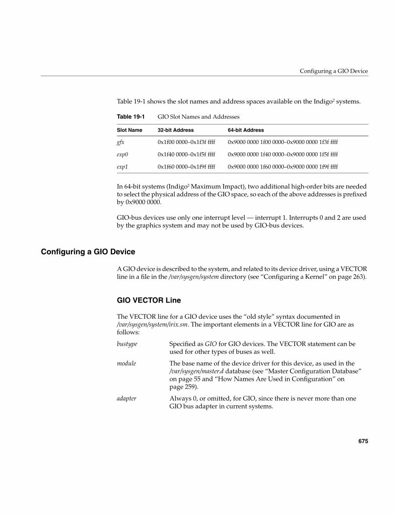
Configuring a GIO Device
675
Table 19-1 shows the slot names and address spaces available on the Indigo2 systems.
In 64-bit systems (Indigo2 Maximum Impact), two additional high-order bits are neededto select the physical address of the GIO space, so each of the above addresses is prefixedby 0x9000 0000.
GIO-bus devices use only one interrupt level — interrupt 1. Interrupts 0 and 2 are usedby the graphics system and may not be used by GIO-bus devices.
Configuring a GIO Device
A GIO device is described to the system, and related to its device driver, using a VECTORline in a file in the /var/sysgen/system directory (see “Configuring a Kernel” on page 263).
GIO VECTOR Line
The VECTOR line for a GIO device uses the “old style” syntax documented in/var/sysgen/system/irix.sm. The important elements in a VECTOR line for GIO are asfollows:
Table 19-1 GIO Slot Names and Addresses
Slot Name 32-bit Address 64-bit Address
gfx 0x1f00 0000–0x1f3f ffff 0x9000 0000 1f00 0000–0x9000 0000 1f3f ffff
exp0 0x1f40 0000–0x1f5f ffff 0x9000 0000 1f40 0000–0x9000 0000 1f5f ffff
exp1 0x1f60 0000–0x1f9f ffff 0x9000 0000 1f60 0000–0x9000 0000 1f9f ffff
bustype Specified as GIO for GIO devices. The VECTOR statement can beused for other types of buses as well.
module The base name of the device driver for this device, as used in the/var/sysgen/master.d database (see “Master Configuration Database”on page 55 and “How Names Are Used in Configuration” onpage 259).
adapter Always 0, or omitted, for GIO, since there is never more than oneGIO bus adapter in current systems.
676
Chapter 19: GIO Device Drivers
You use the probe or exprobe parameter to program a test for the existence of the device atboot time. If the device does not respond (because it is offline or because it has beenremoved from the system), the lboot command will not invoke the device driver for thisdevice. This facility is used in distributed /var/sysgen/system/irix.sm files in order tochoose between the graphics board in slot gfx or in slot exp0.
Writing a GIO Driver
GIO bus devices are controlled only from kernel-level drivers; there is no provision formemory-mapping GIO devices into user-level address spaces.
A GIO device driver is a kernel-level driver compiled, linked, and loaded into the kernelas described in Chapter 9, “Building and Installing a Driver.” A GIO driver can call onthe kernel functions described in Chapter 7, “Structure of a Kernel-Level Driver.”However, a GIO driver has to use some special features in its pfxedtinit() and pfxintr()entry points.
GIO-Specific Kernel Functions
Three GIO-specific functions are used in setting up a GIO device. They are onlydocumented here; there are no reference pages for them. The functions are declared asexternal in the CPU-specific include files sys/IP20.h and sys/IP22.h. (When compiling fora POWER Indigo2, which uses an IP26 CPU, you include sys/IP22.h as well as sys/IP26.h.)
Registering an Interrupt Handler
The setgiovector() function registers an interrupt service function for a GIO deviceinterrupt with the kernel’s interrupt dispatcher, or unregisters one. The functionprototype is
ctlr The “controller” number is simply an integer parameter that ispassed to the device driver at boot time. It can be used, for example,to specify a logical unit number.
base Device base address, as shown in Table 19-1.
probe or exprobe Specify a hardware test that can be applied at boot time to find out ifthe device exists.
Writing a GIO Driver
677
voidsetgiovector(int level, int slot,
void (*func)(__psint_t, struct eframe_s *),__psint_t arg);
The arguments are as follows:
Note: If either the level or slot number is out of range, setgiovector() issues an errormessage with the CE_PANIC level, causing a kernel panic.
When func is not NULL, the specified function is registered to receive interrupts at thegiven level from the given slot. When an interrupt occurs, the function is called with twoarguments. The first is the value specified as arg, a “pointer-sized integer,” typically theaddress of device-specific information. The second is the interrupt registers. Thestructure eframe_s is declared in sys/reg.h. However, this structure is of no interest.
This function can be used with a NULL for the func argument to unregister an interruptroutine that was previously registered. You must unregister an interrupt handler in aloadable device driver prior to unloading, when called at the pfxunload() entry point (see“Entry Point unload()” on page 180).
Configuring a Slot
The function setgioconfig() configures the GIO slot for a particular use. The functionprototype is
voidsetgioconfig(int slot, int flags);
The arguments are as follows:
level The interrupt level; must be GIO_INTERRUPT_1 for all devices except thegraphics board.
slot The slot number, 0 or 1.
func The address of the interrupt handling function (typically the pfxintr() entrypoint of the device driver), or else NULL to unregister.
arg A “pointer-sized integer” value to be passed as the first argument of theinterrupt handler when it is invoked.
slot The slot number, 0 or 1.
flags A set of bit-flags from the constants GIO_ARB_* declared in sys/mc.h.
678
Chapter 19: GIO Device Drivers
Note: If the slot number is out of range, setgioconfig() either issues an error message withthe CE_PANIC level or suffers an assertion failure, causing a kernel panic.
The flags that can be combined to make the flags argument are
splgio0, splgio1, splgio2
Three functions can be used to set the processor interrupt mask to block GIO-businterrupts. As of IRIX 6.2, the only systems that support the GIO bus are uniprocessorsystems, in which spl()-type functions are effective. When writing a device driver thatmight be ported to a multiprocessor, you should avoid functions of this type, and useother means of getting mutual exclusion (see “Priority Level Functions” on page 242).
The prototypes of the GIO spl() functions are
long splgio0();long splgio1();long splgio2();
Devices other than graphics drivers would typically only have a reason to use splgio1(),because 1 is the interrupt level of non-graphics GIO devices.
GIO Driver edtinit() Entry Point
The device driver specified by the module parameter is invoked at its pfxedtinit() entrypoint, where it receives most of the other information specified in the VECTOR statement(see “Entry Point edtinit()” on page 151).
The pfxedtinit() entry point is called only in response to a VECTOR line. However, aVECTOR line need not contain a probe or exprobe test of the hardware.
GIO64_ARB_EXP0_SIZE_64 Configure for 64-bit transfers; otherwise transfers willbe 32-bit.
GIO64_ARB_EXP0_RT Configure as a real-time device; otherwise it will be along burst device.
GIO64_ARB_EXP0_MST Configure as a bus master; otherwise it will be a slave.
GIO64_ARB_EXP0_PIPED Configure slot as a pipelined device, otherwise it will bea non-pipelined device. For Indigo2 systems, this mustbe set.
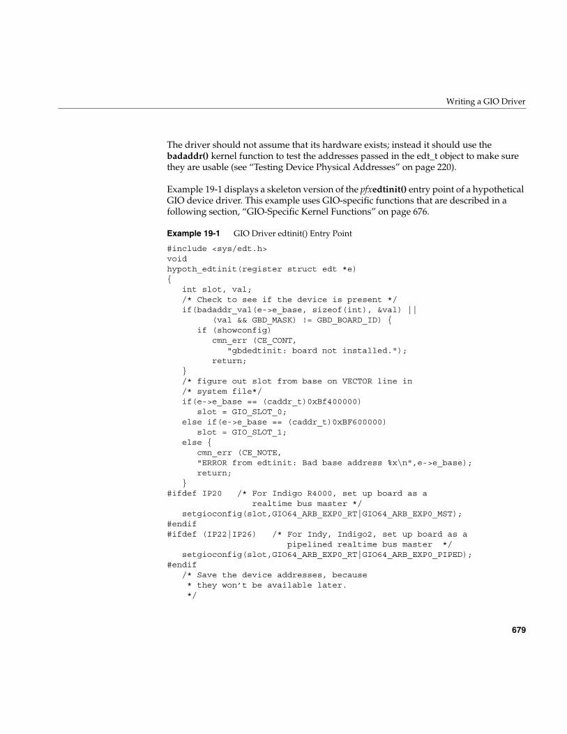
Writing a GIO Driver
679
The driver should not assume that its hardware exists; instead it should use thebadaddr() kernel function to test the addresses passed in the edt_t object to make surethey are usable (see “Testing Device Physical Addresses” on page 220).
Example 19-1 displays a skeleton version of the pfxedtinit() entry point of a hypotheticalGIO device driver. This example uses GIO-specific functions that are described in afollowing section, “GIO-Specific Kernel Functions” on page 676.
Example 19-1 GIO Driver edtinit() Entry Point
#include <sys/edt.h>voidhypoth_edtinit(register struct edt *e){
int slot, val;/* Check to see if the device is present */if(badaddr_val(e->e_base, sizeof(int), &val) ||
(val && GBD_MASK) != GBD_BOARD_ID) {if (showconfig)
cmn_err (CE_CONT,"gbdedtinit: board not installed.");
return;}/* figure out slot from base on VECTOR line in/* system file*/if(e->e_base == (caddr_t)0xBf400000)
slot = GIO_SLOT_0;else if(e->e_base == (caddr_t)0xBF600000)
slot = GIO_SLOT_1;else {
cmn_err (CE_NOTE,"ERROR from edtinit: Bad base address %x\n",e->e_base);return;
}#ifdef IP20 /* For Indigo R4000, set up board as a
realtime bus master */setgioconfig(slot,GIO64_ARB_EXP0_RT|GIO64_ARB_EXP0_MST);
#endif#ifdef (IP22|IP26) /* For Indy, Indigo2, set up board as a
pipelined realtime bus master */setgioconfig(slot,GIO64_ARB_EXP0_RT|GIO64_ARB_EXP0_PIPED);
#endif/* Save the device addresses, because * they won’t be available later. */
680
Chapter 19: GIO Device Drivers
gbd_device[slot == GIO_SLOT_0 ? 0 : 1] =(struct gbd_device *)e->e_base;
gbd_memory[slot == GIO_SLOT_0 ? 0 : 1] =(char *)e->e_base2; /* Where "unit_#" is any parameter passed to /* the interrupt handler (gbdintr) */
setgiovector(GIO_INTERRUPT_1,slot,gbdintr,unit_#);}
GIO Driver Interrupt Handler
A GIO driver must contain an interrupt entry point. It does not have to be namedpfxintr() because it is registered using the giosetvector() function.
When the device generates an interrupt, the general GIO interrupt handler calls yourdriver’s registered interrupt routine and passes it the argument that was specified tosetgiovector() as the argument. This is typically a unit number, or the address of adevice-specific information structure.
Within the interrupt routine, the driver must wake up the sleeping upper-half process, ifone is waiting on the transfer to complete. In a block device driver, the interrupt routinecalls iodone() to indicate that a block type I/O transfer for the buffer is complete (see“Waiting for Block I/O to Complete” on page 245).
Using PIO
Programmed I/O (PIO) is used to transfer small amounts of data between memory anddevice registers. PIO is typically used for control functions and to set up device registersprior to DMA (see “Using DMA” on page 682).
PIO can be as simple as storing a variable into a bus address (as passed to the pfxedtinit()entry point). Example 19-2 displays fragmentary code of a hypothetical character devicedriver for a GIO device that controls a printer. This pfxwrite() entry point copies datafrom the user address space to device memory using the uiomove() function (see“Transferring Data Through a uio_t Object” on page 209). Then it stores an explicitcommand in the device to start it, and sleeps until the device interrupts.
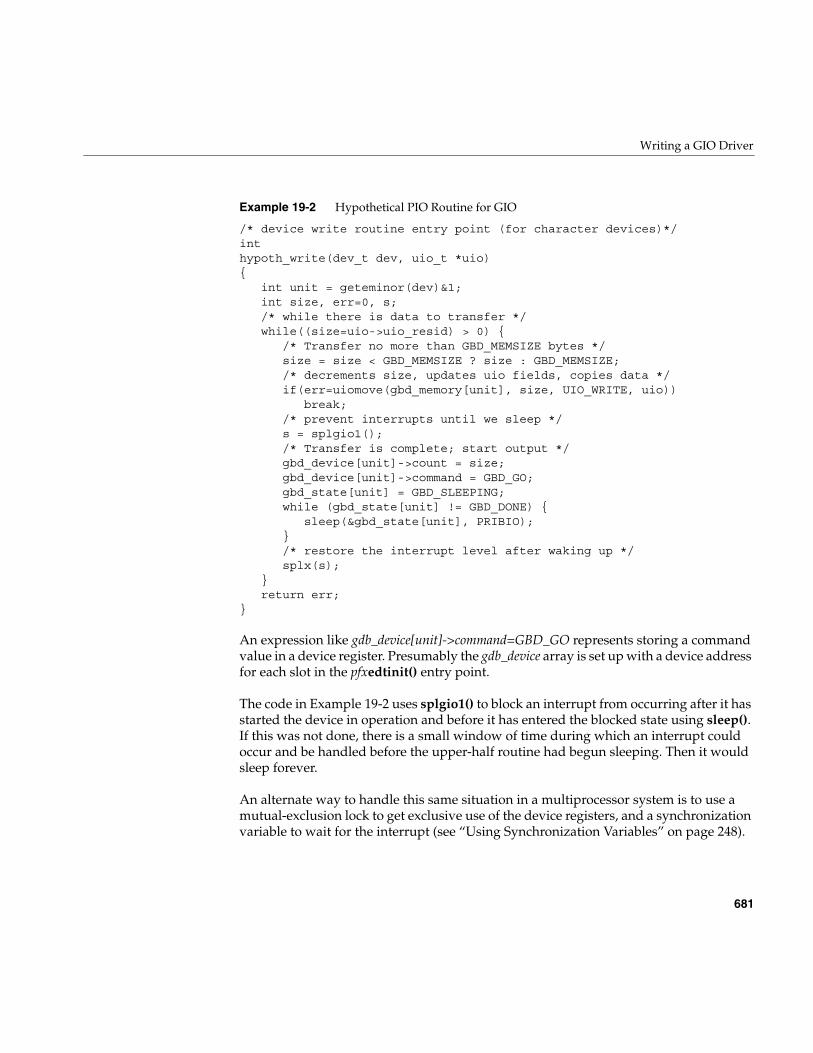
Writing a GIO Driver
681
Example 19-2 Hypothetical PIO Routine for GIO
/* device write routine entry point (for character devices)*/inthypoth_write(dev_t dev, uio_t *uio){
int unit = geteminor(dev)&1;int size, err=0, s;/* while there is data to transfer */while((size=uio->uio_resid) > 0) {
/* Transfer no more than GBD_MEMSIZE bytes */size = size < GBD_MEMSIZE ? size : GBD_MEMSIZE;/* decrements size, updates uio fields, copies data */if(err=uiomove(gbd_memory[unit], size, UIO_WRITE, uio))
break;/* prevent interrupts until we sleep */s = splgio1();/* Transfer is complete; start output */gbd_device[unit]->count = size;gbd_device[unit]->command = GBD_GO;gbd_state[unit] = GBD_SLEEPING;while (gbd_state[unit] != GBD_DONE) {
sleep(&gbd_state[unit], PRIBIO);}/* restore the interrupt level after waking up */splx(s);
}return err;
}
An expression like gdb_device[unit]->command=GBD_GO represents storing a commandvalue in a device register. Presumably the gdb_device array is set up with a device addressfor each slot in the pfxedtinit() entry point.
The code in Example 19-2 uses splgio1() to block an interrupt from occurring after it hasstarted the device in operation and before it has entered the blocked state using sleep().If this was not done, there is a small window of time during which an interrupt couldoccur and be handled before the upper-half routine had begun sleeping. Then it wouldsleep forever.
An alternate way to handle this same situation in a multiprocessor system is to use amutual-exclusion lock to get exclusive use of the device registers, and a synchronizationvariable to wait for the interrupt (see “Using Synchronization Variables” on page 248).
682
Chapter 19: GIO Device Drivers
Using DMA
DMA access achieves higher throughput than PIO when the device transfers more thana few words of data at a time. DMA is typically set up by programming device registerswith the target address and length, and leaving the device to generate a series of storesor loads from memory. The details of device control are hardware-dependent.
The direction of a DMA transfer is measured with respect to the device, which operatesindependently. A DMA operation is either a DMA read (of memory data out to thedevice) or a DMA write (by the device, of data into memory).
DMA buffers should be cache-aligned in memory (see “Setting Up a DMA Transfer” onpage 216). Prior to a DMA read, the driver should make sure that cached data has beenwritten to memory using dki_cache_wb(). Prior to a DMA write, the driver should makesure the CPU knows that cached data is invalid (or is about to become invalid) usingdki_cache_inval() (see “Managing Memory for Cache Coherency” on page 219).
DMA To Multiple Pages
Some devices can perform DMA only in a single transfer of data to a range of contiguousaddresses. Such a device must be programmed separately for each individual page ofdata. Other devices are capable of transferring a series of page units to differentaddresses; that is, they support “scatter/gather” capability. These devices can beprogrammed once to transfer an entire buffer of data, regardless of whether the bufferspans multiple pages.
In either case, the pfxstrategy() entry point of a block device driver must calculate thephysical addresses of a series of one or more pages, and program them into the device.When the device does not support scatter/gather, it is set up and started on each page ofdata individually, with an interrupt after each page. When the device supportsscatter/gather, it is programmed with a list of page addresses all at once.
DMA With Scatter/Gather Capability
Example 19-3 shows the skeleton of a pfxstrategy() entry point for a block device driverfor a hypothetical GIO device that supports scatter/gather capability.
Example 19-3 Strategy Code for Hypothetical Scatter/Gather GIO Device
/* Actual device setup for DMA, etc., if your board has * hardware scatter/gather DMA support.
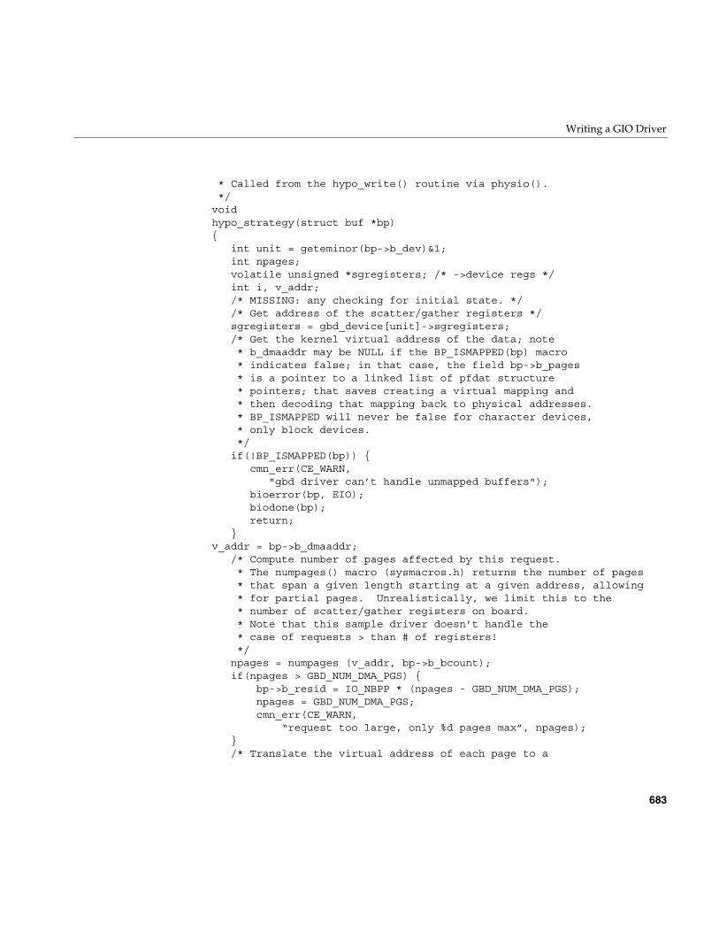
Writing a GIO Driver
683
* Called from the hypo_write() routine via physio(). */voidhypo_strategy(struct buf *bp){
int unit = geteminor(bp->b_dev)&1;int npages;volatile unsigned *sgregisters; /* ->device regs */int i, v_addr;/* MISSING: any checking for initial state. *//* Get address of the scatter/gather registers */sgregisters = gbd_device[unit]->sgregisters;/* Get the kernel virtual address of the data; note * b_dmaaddr may be NULL if the BP_ISMAPPED(bp) macro * indicates false; in that case, the field bp->b_pages * is a pointer to a linked list of pfdat structure * pointers; that saves creating a virtual mapping and * then decoding that mapping back to physical addresses. * BP_ISMAPPED will never be false for character devices, * only block devices. */if(!BP_ISMAPPED(bp)) {
cmn_err(CE_WARN,"gbd driver can’t handle unmapped buffers");
bioerror(bp, EIO);biodone(bp);return;
}v_addr = bp->b_dmaaddr;
/* Compute number of pages affected by this request.* The numpages() macro (sysmacros.h) returns the number of pages* that span a given length starting at a given address, allowing* for partial pages. Unrealistically, we limit this to the* number of scatter/gather registers on board.* Note that this sample driver doesn’t handle the* case of requests > than # of registers!*/npages = numpages (v_addr, bp->b_bcount);if(npages > GBD_NUM_DMA_PGS) {
bp->b_resid = IO_NBPP * (npages - GBD_NUM_DMA_PGS);npages = GBD_NUM_DMA_PGS;cmn_err(CE_WARN,
“request too large, only %d pages max”, npages);}/* Translate the virtual address of each page to a
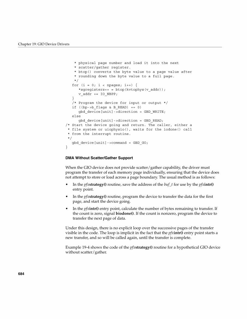
684
Chapter 19: GIO Device Drivers
* physical page number and load it into the next * scatter/gather register. * btop() converts the byte value to a page value after * rounding down the byte value to a full page. */for (i = 0; i < npages; i++) {
*sgregisters++ = btop(kvtophys(v_addr));v_addr += IO_NBPP;
}/* Program the device for input or output */if ((bp->b_flags & B_READ) == 0)
gbd_device[unit]->direction = GBD_WRITE;else
gbd_device[unit]->direction = GBD_READ;/* Start the device going and return. The caller, either a* file system or uiophysio(), waits for the iodone() call* from the interrupt routine.*/
gbd_device[unit]->command = GBD_GO;}
DMA Without Scatter/Gather Support
When the GIO device does not provide scatter/gather capability, the driver mustprogram the transfer of each memory page individually, ensuring that the device doesnot attempt to store or load across a page boundary. The usual method is as follows:
• In the pfxstrategy() routine, save the address of the buf_t for use by the pfxintr()entry point.
• In the pfxstrategy() routine, program the device to transfer the data for the firstpage, and start the device going.
• In the pfxintr() entry point, calculate the number of bytes remaining to transfer. Ifthe count is zero, signal biodone(). If the count is nonzero, program the device totransfer the next page of data.
Under this design, there is no explicit loop over the successive pages of the transfervisible in the code. The loop is implicit in the fact that the pfxintr() entry point starts anew transfer, and so will be called again, until the transfer is complete.
Example 19-4 shows the code of the pfxstrategy() routine for a hypothetical GIO devicewithout scatter/gather.
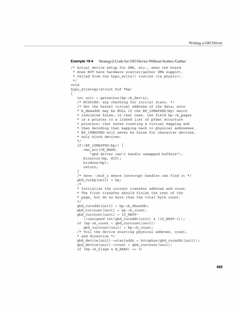
Writing a GIO Driver
685
Example 19-4 Strategy() Code for GIO Device Without Scatter/Gather
/* Actual device setup for DMA, etc., when the board* does NOT have hardware scatter/gather DMA support.* Called from the hypo_write() routine via physio().*/voidhypo_strategy(struct buf *bp){
int unit = geteminor(bp->b_dev)&1;/* MISSING: any checking for initial state. *//* Get the kernel virtual address of the data; note* b_dmaaddr may be NULL if the BP_ISMAPPED(bp) macro* indicates false; in that case, the field bp->b_pages* is a pointer to a linked list of pfdat structure* pointers; that saves creating a virtual mapping and* then decoding that mapping back to physical addresses.* BP_ISMAPPED will never be false for character devices,* only block devices.*/if(!BP_ISMAPPED(bp)) {
cmn_err(CE_WARN,"gbd driver can’t handle unmapped buffers");
bioerror(bp, EIO);biodone(bp);return;
}/* Save ->buf_t where interrupt handler can find it */gbd_curbp[unit] = bp;/** Initialize the current transfer address and count.* The first transfer should finish the rest of the* page, but do no more than the total byte count.*/gbd_curaddr[unit] = bp->b_dmaaddr;gbd_totcount[unit] = bp->b_count;gbd_curcount[unit] = IO_NBPP-
((unsigned int)gbd_curaddr[unit] & (IO_NBPP-1));if (bp->b_count < gbd_curcount[unit])
gbd_curcount[unit] = bp->b_count;/* Tell the device starting physical address, count,* and direction */gbd_device[unit]->startaddr = kvtophys(gbd_curaddr[unit]);gbd_device[unit]->count = gbd_curcount[unit];if (bp->b_flags & B_READ) == 0)
686
Chapter 19: GIO Device Drivers
gbd_device[unit]->direction = GBD_WRITE;else
gbd_device[unit]->direction = GBD_READ;gbd_device[unit]->command = GBD_GO; /* start DMA *//* and return; upper layers of kernel wait for iodone(bp) */
}
An alternate design might seem conceptually simpler: to put an explicit loop in thepfxstrategy() routine, starting each page transfer and waiting on a semaphore until thepfxintr() routine is called. Such a design keeps the complexity in the pfxstrategy() routine,making the pfxintr() routine as simple as possible. However, it has a high cost inperformance because the pfxstrategy routine must wake up and be dispatched for everypage.
Scatter/gather programming can be simplified by the use of the sgset() function, whichcalculates the physical addresses and lengths for each page in the transfer (see thesgset(D3) reference page). The sgset() function is limited to use with hardware that usesa fixed mapping of bus addresses to memory addresses, which is the case in theworkstations supporting GIO. For example, sgset() cannot be used in the Challenge orOnyx line; it always returns -1 in those systems.
Memory Parity Workarounds
Beginning with IRIX 5.3, parity checking is enabled on the SysAD bus, which connectsthe CPU to memory in workstations that use the GIO bus (see Figure 19-1).Unfortunately, with certain GIO cards, errors can occur if memory reads complete beforethe Memory Controller (MC) finishes calculating parity.
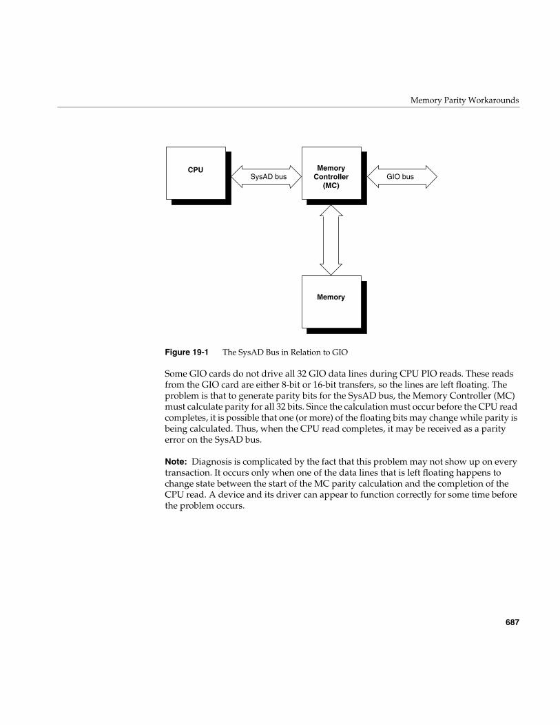
Memory Parity Workarounds
687
Figure 19-1 The SysAD Bus in Relation to GIO
Some GIO cards do not drive all 32 GIO data lines during CPU PIO reads. These readsfrom the GIO card are either 8-bit or 16-bit transfers, so the lines are left floating. Theproblem is that to generate parity bits for the SysAD bus, the Memory Controller (MC)must calculate parity for all 32 bits. Since the calculation must occur before the CPU readcompletes, it is possible that one (or more) of the floating bits may change while parity isbeing calculated. Thus, when the CPU read completes, it may be received as a parityerror on the SysAD bus.
Note: Diagnosis is complicated by the fact that this problem may not show up on everytransaction. It occurs only when one of the data lines that is left floating happens tochange state between the start of the MC parity calculation and the completion of theCPU read. A device and its driver can appear to function correctly for some time beforethe problem occurs.
CPU MemoryController
(MC)
Memory
SysAD bus GIO bus
688
Chapter 19: GIO Device Drivers
When writing a driver for a GIO card that does not drive all 32 data lines, you must eitherdisable SysAD parity checking completely, or disable it during the time your driver isperforming PIO transfers. Three kernel functions are supplied for these purposes; noneof them take arguments.
• is_sysad_parity_enabled() returns a nonzero value if SysAD parity checking isenabled.
• disable_sysad_parity() turns off parity checking on the SysAD bus.
• enable_sysad_parity() returns SysAD parity checking to normal.
To completely disable SysAD parity checking removes the system’s ability to recoverfrom a parity error in main memory. As a short-term fix, a driver could simply calldisable_sysad_parity() in the pfxinit() or pfxedtinit() entry point.
It is much better to disable parity checking only during the time the device is being used.The advantage here is that the software recovery procedures for memory parity errorsare almost always in effect.
To selectively disable parity checking, put wrappers around your driver’s PIOtransactions to disable SysAD parity checking before a transfer, and to re-enable it afterthe PIO completes. Example 19-5 shows a skeleton of such a wrapper.
Example 19-5 Disabling SysAD Parity Checking During PIO
voiddo_PIO_without_parity(){
int was_enabled = is_sysad_parity_enabled();if (was_enabled) disable_sysad_parity();
/* do driver PIO transfers */if (was_enabled) enable_sysad_parity();}
The reason that the function in Example 19-5 saves the current state of parity, and onlyre-enables parity when it was enabled on entry, is that parity checking could have beenturned off in some higher-level routine. For example, an interrupt handler could beentered during execution of a device driver function that disables parity checking. If theinterrupt handler turned parity checking back on regardless of its former state, errorswould occur.
Example GIO Driver
689
Example GIO Driver
The code in Example 19-6 displays a complete device driver for a hypothetical device.The driver prefix is gbd (for “GIO board”).
Example 19-6 Complete Driver for Hypothetical GIO Device
/* Source for a hypothetical GIO board device; it can be compiled for* devices that support DMA (with or without scatter gather support),* or for PIO mode only. This version is designed for IRIX 6.2 or later.* Dave Olson, 5/93. 6.2 port by Dave Cortesi 9/95.
*/
/* Compilation: Define the environment variable CPUBOARD as IP20, IP22,* or IP26 (the only GIO platforms). Then include the build rules from* /var/sysgen/Makefile.kernio to set $CFLAGS including:
# _K32U32 kernel in 32 bit mode running only 32 bit binaries# _K64U64 kernel in 64 bit mode running 32/64 bit binaries (IP26)# -DR4000 R4000 machine (IP20, IP22)# -DTFP R8000 machine (IP26)# -G 8 global pointer set to 8 (GIO drivers cannot be loadable)# -elf produce an elf executable*/
/* the following definitions choose between PIO vs DMA supporting* boards, and if DMA is supported, whether hardware scatter/gather* is supported. */
#define GBD_NODMA 0 /* non-zero for PIO version of driver */#define GBD_NUM_DMA_PGS 8 /* 0 for no hardware scatter/gather
* support, else number of pages of* scatter/gather per request */
#include <sys/param.h>#include <sys/systm.h>#include <sys/cpu.h>#include <sys/buf.h>#include <sys/cred.h>#include <sys/uio.h>#include <sys/ddi.h>#include <sys/errno.h>#include <sys/cmn_err.h>#include <sys/edt.h>#include <sys/conf.h> /* for flags D_MP */
/* gbd (for Gio BoarD) is the driver prefix, specified in the* file /var/sysgen/master.d/gbd and in VECTOR module=gbd lines.
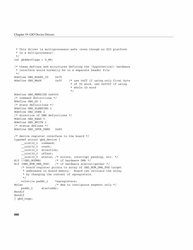
690
Chapter 19: GIO Device Drivers
* This driver is multiprocessor-safe (even though no GIO platform* is a multiprocessor).*/
int gbddevflags = D_MP;
/* these defines and structures defining the (hypothetical) hardware* interface would normally be in a separate header file*/
#define GBD_BOARD_ID 0x75#define GBD_MASK 0xff /* use 0xff if using only first byte
* of ID word, use 0xffff if using* whole ID word*/
#define GBD_MEMSIZE 0x8000/* command definitions */#define GBD_GO 1/* state definitions */#define GBD_SLEEPING 1#define GBD_DONE 2/* direction of DMA definitions */#define GBD_READ 0#define GBD_WRITE 1/* status defines */#define GBD_INTR_PEND 0x80
/* device register interface to the board */typedef struct gbd_device {
__uint32_t command;__uint32_t count;__uint32_t direction;__uint32_t offset;__uint32_t status; /* errors, interrupt pending, etc. */
#if (!GBD_NODMA) /* if hardware DMA */#if (GBD_NUM_DMA_PGS) /* if hardware scatter/gather */
/* board register points to array of GBD_NUM_DMA_PGS target* addresses in board memory. Board can relocate the array* by changing the content of sgregisters.*/
volatile paddr_t *sgregisters;#else /* dma to contiguous segment only */
paddr_t startaddr;#endif#endif} gbd_regs;
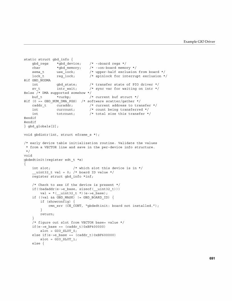
Example GIO Driver
691
static struct gbd_info {gbd_regs *gbd_device; /* ->board regs */char *gbd_memory; /* ->on-board memory */sema_t use_lock; /* upper-half exclusion from board */lock_t reg_lock; /* spinlock for interrupt exclusion */
#if GBD_NODMAint gbd_state; /* transfer state of PIO driver */sv_t intr_wait; /* sync var for waiting on intr */
#else /* DMA supported somehow */buf_t *curbp; /* current buf struct */
#if (0 == GBD_NUM_DMA_PGS) /* software scatter/gather */caddr_t curaddr; /* current address to transfer */int curcount; /* count being transferred */int totcount; /* total size this transfer */
#endif#endif} gbd_globals[2];
void gbdintr(int, struct eframe_s *);
/* early device table initialization routine. Validate the values* from a VECTOR line and save in the per-device info structure.*/
voidgbdedtinit(register edt_t *e){
int slot; /* which slot this device is in */__uint32_t val = 0; /* board ID value */register struct gbd_info *inf;
/* Check to see if the device is present */if(!badaddr(e->e_base, sizeof(__uint32_t)))
val = *(__uint32_t *)(e->e_base);if ((val && GBD_MASK) != GBD_BOARD_ID) {
if (showconfig) {cmn_err (CE_CONT, “gbdedtinit: board not installed.”);
}return;
}/* figure out slot from VECTOR base= value */if(e->e_base == (caddr_t)0xBF400000)
slot = GIO_SLOT_0;else if(e->e_base == (caddr_t)0xBF600000)
slot = GIO_SLOT_1;else {
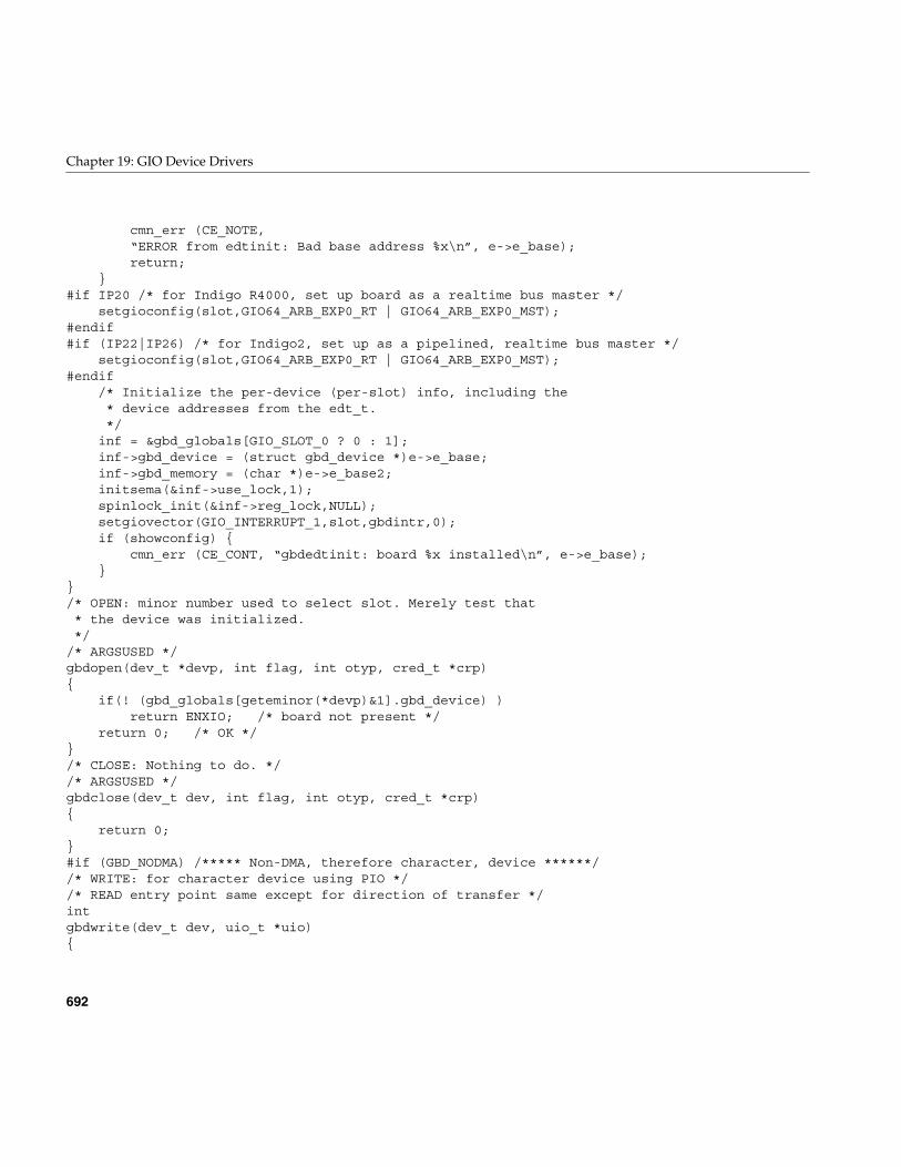
692
Chapter 19: GIO Device Drivers
cmn_err (CE_NOTE,“ERROR from edtinit: Bad base address %x\n”, e->e_base);return;
}#if IP20 /* for Indigo R4000, set up board as a realtime bus master */
setgioconfig(slot,GIO64_ARB_EXP0_RT | GIO64_ARB_EXP0_MST);#endif#if (IP22|IP26) /* for Indigo2, set up as a pipelined, realtime bus master */
setgioconfig(slot,GIO64_ARB_EXP0_RT | GIO64_ARB_EXP0_MST);#endif
/* Initialize the per-device (per-slot) info, including the* device addresses from the edt_t.*/
inf = &gbd_globals[GIO_SLOT_0 ? 0 : 1];inf->gbd_device = (struct gbd_device *)e->e_base;inf->gbd_memory = (char *)e->e_base2;initsema(&inf->use_lock,1);spinlock_init(&inf->reg_lock,NULL);setgiovector(GIO_INTERRUPT_1,slot,gbdintr,0);if (showconfig) {
cmn_err (CE_CONT, “gbdedtinit: board %x installed\n”, e->e_base);}
}/* OPEN: minor number used to select slot. Merely test that* the device was initialized.*/
/* ARGSUSED */gbdopen(dev_t *devp, int flag, int otyp, cred_t *crp){
if(! (gbd_globals[geteminor(*devp)&1].gbd_device) )return ENXIO; /* board not present */
return 0; /* OK */}/* CLOSE: Nothing to do. *//* ARGSUSED */gbdclose(dev_t dev, int flag, int otyp, cred_t *crp){
return 0;}#if (GBD_NODMA) /***** Non-DMA, therefore character, device ******//* WRITE: for character device using PIO *//* READ entry point same except for direction of transfer */intgbdwrite(dev_t dev, uio_t *uio){
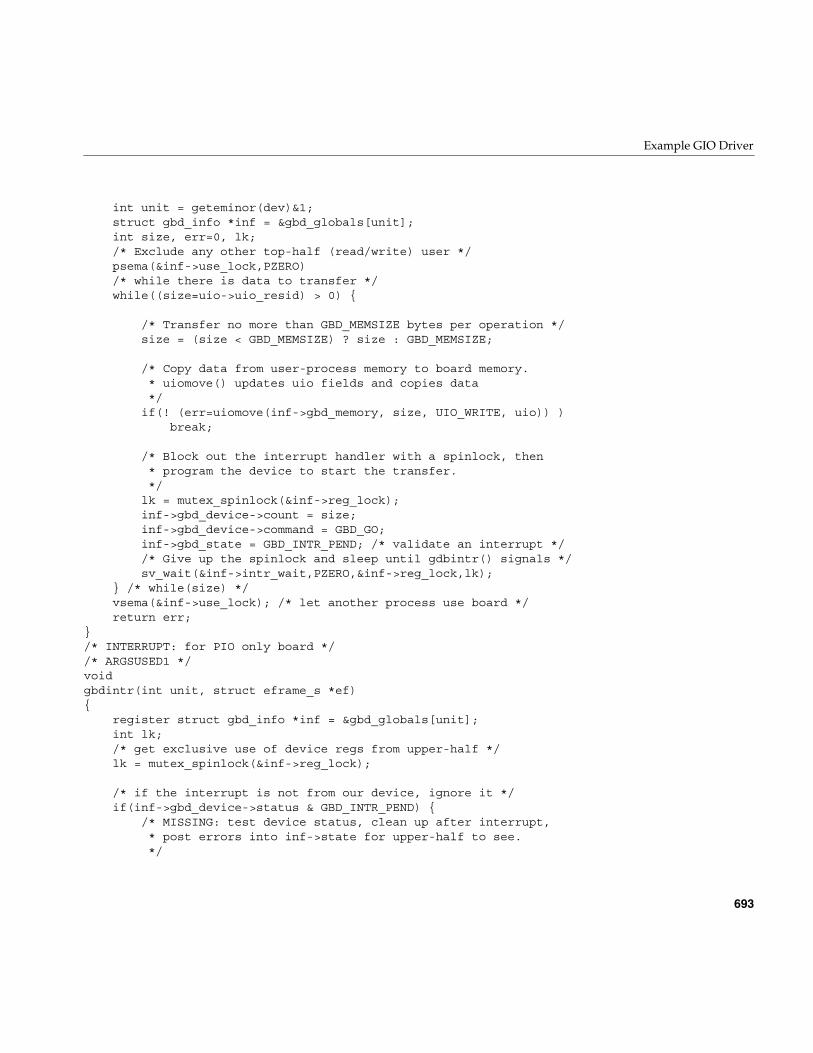
Example GIO Driver
693
int unit = geteminor(dev)&1;struct gbd_info *inf = &gbd_globals[unit];int size, err=0, lk;/* Exclude any other top-half (read/write) user */psema(&inf->use_lock,PZERO)/* while there is data to transfer */while((size=uio->uio_resid) > 0) {
/* Transfer no more than GBD_MEMSIZE bytes per operation */size = (size < GBD_MEMSIZE) ? size : GBD_MEMSIZE;
/* Copy data from user-process memory to board memory.* uiomove() updates uio fields and copies data*/
if(! (err=uiomove(inf->gbd_memory, size, UIO_WRITE, uio)) )break;
/* Block out the interrupt handler with a spinlock, then* program the device to start the transfer.*/
lk = mutex_spinlock(&inf->reg_lock);inf->gbd_device->count = size;inf->gbd_device->command = GBD_GO;inf->gbd_state = GBD_INTR_PEND; /* validate an interrupt *//* Give up the spinlock and sleep until gdbintr() signals */sv_wait(&inf->intr_wait,PZERO,&inf->reg_lock,lk);
} /* while(size) */vsema(&inf->use_lock); /* let another process use board */return err;
}/* INTERRUPT: for PIO only board *//* ARGSUSED1 */voidgbdintr(int unit, struct eframe_s *ef){
register struct gbd_info *inf = &gbd_globals[unit];int lk;/* get exclusive use of device regs from upper-half */lk = mutex_spinlock(&inf->reg_lock);
/* if the interrupt is not from our device, ignore it */if(inf->gbd_device->status & GBD_INTR_PEND) {
/* MISSING: test device status, clean up after interrupt,* post errors into inf->state for upper-half to see.*/
694
Chapter 19: GIO Device Drivers
/* Provided the upper-half expected this, wake it up */if (inf->gbd_state & GBD_INTR_PEND)
sv_signal(&inf->intr_wait);}mutex_spinunlock(&inf->reg_lock,lk);
}
#else /******** DMA version of driver ************/
void gbd_strategy(struct buf *);
/* WRITE entry point (for character driver of DMA board).* Call uiophysio() to set up and call gbd_strategy routine,* where the transfer is actually done.
*/intgbdwrite(dev_t dev, uio_t *uiop){
return uiophysio((int (*)())gbd_strategy, 0, dev, B_WRITE, uiop);}/* READ entry point same except for direction of transfer */#if GBD_NUM_DMA_PGS > 0
/* STRATEGY for hardware scatter/gather DMA support.* Called from gbdwrite()/gbdread() via physio().* Called from file-system/paging code directly.*/
voidgbd_strategy(register struct buf *bp){
int unit = geteminor(bp->b_edev)&1;register struct gbd_info *inf = &gbd_globals[unit];register gbd_regs *regs = inf->gbd_device;volatile paddr_t *sgregisters;int npages;int i, lk;caddr_t v_addr;
/* Get the kernel virtual address of the data. Note that* b_dmaaddr is NULL when the BP_ISMAPPED(bp) macro* indicates false; in that case, the field bp->b_pages* is a pointer to a linked list of pfdat structure* pointers; that saves creating a virtual mapping and* then decoding that mapping back to physical addresses.* BP_ISMAPPED will never be false for character devices,
Example GIO Driver
695
* only block devices.*/if(!BP_ISMAPPED(bp)) {
cmn_err(CE_WARN, “gbd driver can’t handle unmapped buffers”);bp->b_flags |= B_ERROR;iodone(bp);return;
}v_addr = bp->b_dmaaddr;
/* Compute number of pages affected by this request.* The numpages() macro (sysmacros.h) returns the number of pages* that span a given length starting at a given address, allowing* for partial pages. Unrealistically, we limit this to the* number of scatter/gather registers on board.* Note that this sample driver doesn’t handle the* case of requests > than # of registers!*/
npages = numpages (v_addr, bp->b_bcount);if(npages > GBD_NUM_DMA_PGS) {
bp->b_resid = IO_NBPP * (npages - GBD_NUM_DMA_PGS);npages = GBD_NUM_DMA_PGS;cmn_err(CE_WARN,
“request too large, only %d pages max”, npages);}
/* Get exclusive upper-half use of device. The sema is released* wherever iodone() is called, here or in the int handler.*/
psema(&inf->use_lock,PZERO)inf->curbp = bp;
/* Get exclusive use of the device regs, blocking the int handler */lk = mutex_spinlock(&inf->reg_lock);
/* MISSING: set up board to transfer npages discreet segments. *//* Get address of the scatter-gather registers */sgregisters = regs->sgregisters;
/* Provide the beginning byte offset and count to the device. */regs->offset = io_poff(bp->b_dmaaddr); /* in immu.h */regs->count = (IO_NBPP - inf->gbd_device->offset)
+ (npages-1)*IO_NBPP;
/* Translate the virtual address of each page to a
696
Chapter 19: GIO Device Drivers
* physical page number and load it into the next* scatter-gather register. The btoct(K) macro* converts the byte value to a page value after* rounding down the byte value to a full page.*/for (i = 0; i < npages; i++) {
*sgregisters++ = btoct(kvtophys(v_addr));v_addr += IO_NBPP;
}
if ((bp->b_flags & B_READ) == 0)regs->direction = GBD_WRITE;
elseregs->direction = GBD_READ;
regs->command = GBD_GO; /* start DMA */
/* release use of the device regs to the interrupt handler */mutex_spinunlock(inf->reg_lock,lk);
/* and return; upper layers of kernel wait for iodone(bp) */}
/* INTERRUPT: for hardware DMA support. This is over-simplified* because the above strategy routine never accepts a transfer* larger than the device can handle in a single operation.*/
/* ARGSUSED1 */voidgbdintr(int unit, struct eframe_s *ef){
register struct gbd_info *inf = &gbd_globals[unit];register gbd_regs *regs = inf->gbd_device;int error = 0;int lk;
/* get exclusive use if device regs from upper-half */lk = mutex_spinlock(&inf->reg_lock);
/* If interrupt was not from this device, exit quick */if (! (regs->status & GBD_INTR_PEND) ) {
mutex_spinunlock(&inf->reg_lock,lk);return;
}
/* MISSING: read board registers, clear interrupt,
Example GIO Driver
697
* and note any errors in the “error” variable. */if(error)
inf->curbp->b_flags |= B_ERROR;
/* release lock on exclusive use of device regs */mutex_spinunlock(&inf->reg_lock,lk);
/* wake up any kernel/file-system waiting for this I/O */iodone(inf->curbp);
/* unlock use of device to other upper-half driver code */vsema(&inf->use_lock);
}
#else /****** GBD_NUM_DMA_PGS == 0; no hardware scatter/gather ******/
/* STRATEGY: for software-controlled scatter/gather.* Called from the gbdwrite() routine via uiophysio().*/
voidgbd_strategy(struct buf *bp){
int unit = geteminor(bp->b_edev)&1;register struct gbd_info *inf = &gbd_globals[unit];register gbd_regs *regs = inf->gbd_device;int lk;
/* Get the kernel virtual address of the data; note* b_dmaaddr may be NULL if the BP_ISMAPPED(bp) macro* indicates false; in that case, the field bp->b_pages* is a pointer to a linked list of pfdat structure* pointers; that saves creating a virtual mapping and* then decoding that mapping back to physical addresses.* BP_ISMAPPED will never be false for character devices,* only block devices.*/if(!BP_ISMAPPED(bp)) {
cmn_err(CE_WARN, “gbd driver can’t handle unmapped buffers”);bp->b_flags |= B_ERROR;iodone(bp);return;
}
/* Get exclusive upper-half use of device. The sema is released* wherever iodone() is called, here or in the int handler.
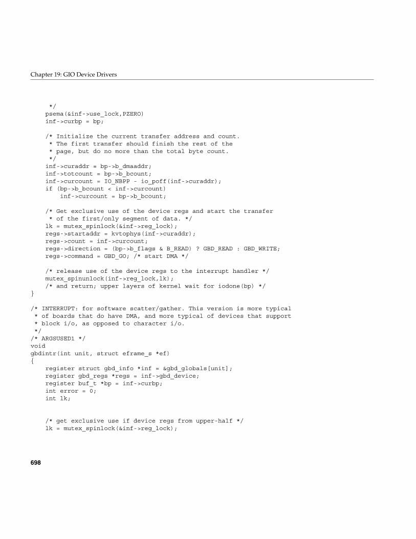
698
Chapter 19: GIO Device Drivers
*/psema(&inf->use_lock,PZERO)inf->curbp = bp;
/* Initialize the current transfer address and count.* The first transfer should finish the rest of the* page, but do no more than the total byte count.*/
inf->curaddr = bp->b_dmaaddr;inf->totcount = bp->b_bcount;inf->curcount = IO_NBPP - io_poff(inf->curaddr);if (bp->b_bcount < inf->curcount)
inf->curcount = bp->b_bcount;
/* Get exclusive use of the device regs and start the transfer* of the first/only segment of data. */
lk = mutex_spinlock(&inf->reg_lock);regs->startaddr = kvtophys(inf->curaddr);regs->count = inf->curcount;regs->direction = (bp->b_flags & B_READ) ? GBD_READ : GBD_WRITE;regs->command = GBD_GO; /* start DMA */
/* release use of the device regs to the interrupt handler */mutex_spinunlock(inf->reg_lock,lk);/* and return; upper layers of kernel wait for iodone(bp) */
}
/* INTERRUPT: for software scatter/gather. This version is more typical* of boards that do have DMA, and more typical of devices that support* block i/o, as opposed to character i/o.*/
/* ARGSUSED1 */voidgbdintr(int unit, struct eframe_s *ef){
register struct gbd_info *inf = &gbd_globals[unit];register gbd_regs *regs = inf->gbd_device;register buf_t *bp = inf->curbp;int error = 0;int lk;
/* get exclusive use if device regs from upper-half */lk = mutex_spinlock(&inf->reg_lock);
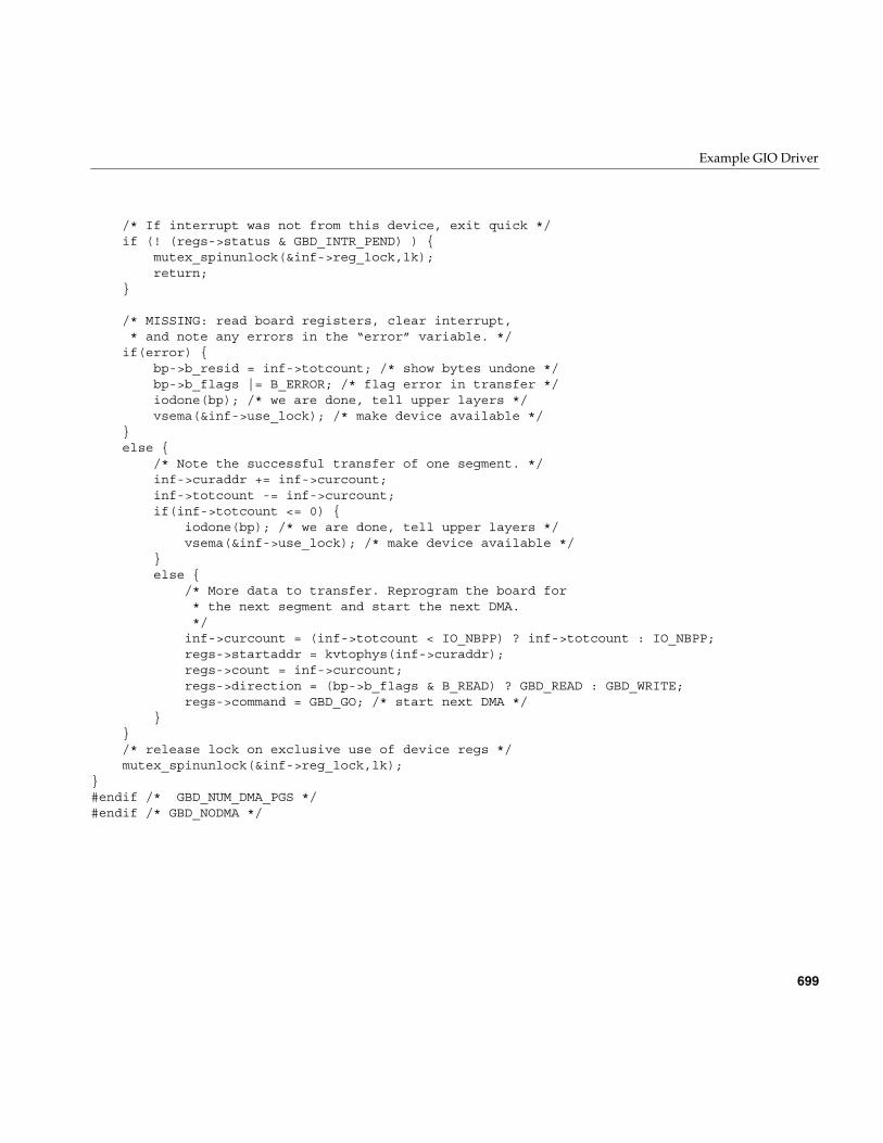
Example GIO Driver
699
/* If interrupt was not from this device, exit quick */if (! (regs->status & GBD_INTR_PEND) ) {
mutex_spinunlock(&inf->reg_lock,lk);return;
}
/* MISSING: read board registers, clear interrupt,* and note any errors in the “error” variable. */
if(error) {bp->b_resid = inf->totcount; /* show bytes undone */bp->b_flags |= B_ERROR; /* flag error in transfer */iodone(bp); /* we are done, tell upper layers */vsema(&inf->use_lock); /* make device available */
}else {
/* Note the successful transfer of one segment. */inf->curaddr += inf->curcount;inf->totcount -= inf->curcount;if(inf->totcount <= 0) {
iodone(bp); /* we are done, tell upper layers */vsema(&inf->use_lock); /* make device available */
}else {
/* More data to transfer. Reprogram the board for* the next segment and start the next DMA.*/
inf->curcount = (inf->totcount < IO_NBPP) ? inf->totcount : IO_NBPP;regs->startaddr = kvtophys(inf->curaddr);regs->count = inf->curcount;regs->direction = (bp->b_flags & B_READ) ? GBD_READ : GBD_WRITE;regs->command = GBD_GO; /* start next DMA */
}}/* release lock on exclusive use of device regs */mutex_spinunlock(&inf->reg_lock,lk);
}#endif /* GBD_NUM_DMA_PGS */#endif /* GBD_NODMA */

PART NINE
PCI Drivers IX
Chapter 20, “PCI Device Attachment”Overview of the architecture of the PCI bus attachment in different SiliconGraphics systems.
Chapter 21, “Services for PCI Drivers”Discusses the services offered by the kernel to PCI device drivers.

703
Chapter 20
20. PCI Device Attachment
The Peripheral Component Interconnect (PCI) bus, initially designed at Intel Corp, isstandardized by the PCI Bus Interest Group, a nonprofit consortium of vendors (see“Standards Documents” on page xl and “Internet Resources” on page xl).
The PCI bus is designed as a high-performance local bus to connect peripherals tomemory and a microprocessor. In many personal computers based on Intel and Motorolaprocessors, the PCI bus is the primary system bus. A wide range of vendors make devicesthat plug into the PCI bus.
The PCI bus is supported by the O2 and OCTANE workstations, by the Origin2000architecture, and by the Origin200 deskside systems. This chapter contains the followingtopics related to support for the PCI bus:
• “PCI Bus in Silicon Graphics Workstations” on page 704 gives an overview of PCIbus features and implementation.
• “PCI Implementation in O2 Workstations” on page 710 describes the hardwarefeatures and restrictions of the PCI bus in low-end workstations.
• “PCI Implementation in Origin Servers” on page 714 describes the features of thePCI implementation in larger architectures.
More information about PCI device control appears in these chapters:
• Chapter 4, “User-Level Access to Devices,” covers PIO and DMA access from theuser process.
• Chapter 21, “Services for PCI Drivers,”discusses the kernel services used by akernel-level VME device driver, and contains an example.
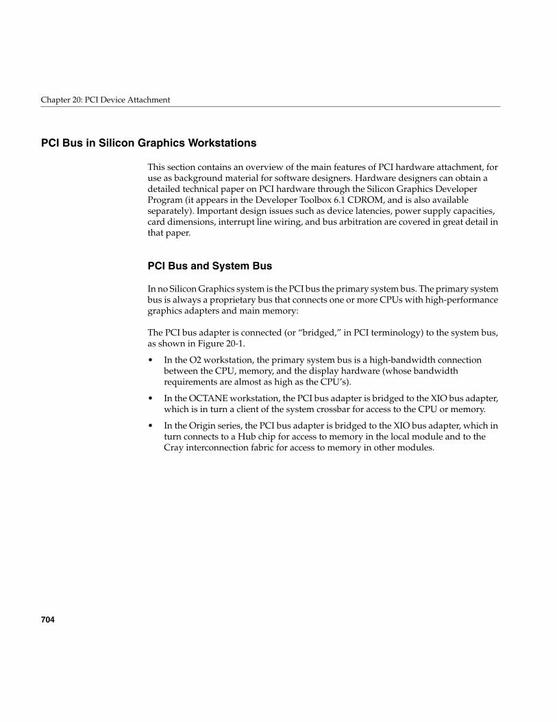
704
Chapter 20: PCI Device Attachment
PCI Bus in Silicon Graphics Workstations
This section contains an overview of the main features of PCI hardware attachment, foruse as background material for software designers. Hardware designers can obtain adetailed technical paper on PCI hardware through the Silicon Graphics DeveloperProgram (it appears in the Developer Toolbox 6.1 CDROM, and is also availableseparately). Important design issues such as device latencies, power supply capacities,card dimensions, interrupt line wiring, and bus arbitration are covered in great detail inthat paper.
PCI Bus and System Bus
In no Silicon Graphics system is the PCI bus the primary system bus. The primary systembus is always a proprietary bus that connects one or more CPUs with high-performancegraphics adapters and main memory:
The PCI bus adapter is connected (or “bridged,” in PCI terminology) to the system bus,as shown in Figure 20-1.
• In the O2 workstation, the primary system bus is a high-bandwidth connectionbetween the CPU, memory, and the display hardware (whose bandwidthrequirements are almost as high as the CPU’s).
• In the OCTANE workstation, the PCI bus adapter is bridged to the XIO bus adapter,which is in turn a client of the system crossbar for access to the CPU or memory.
• In the Origin series, the PCI bus adapter is bridged to the XIO bus adapter, which inturn connects to a Hub chip for access to memory in the local module and to theCray interconnection fabric for access to memory in other modules.
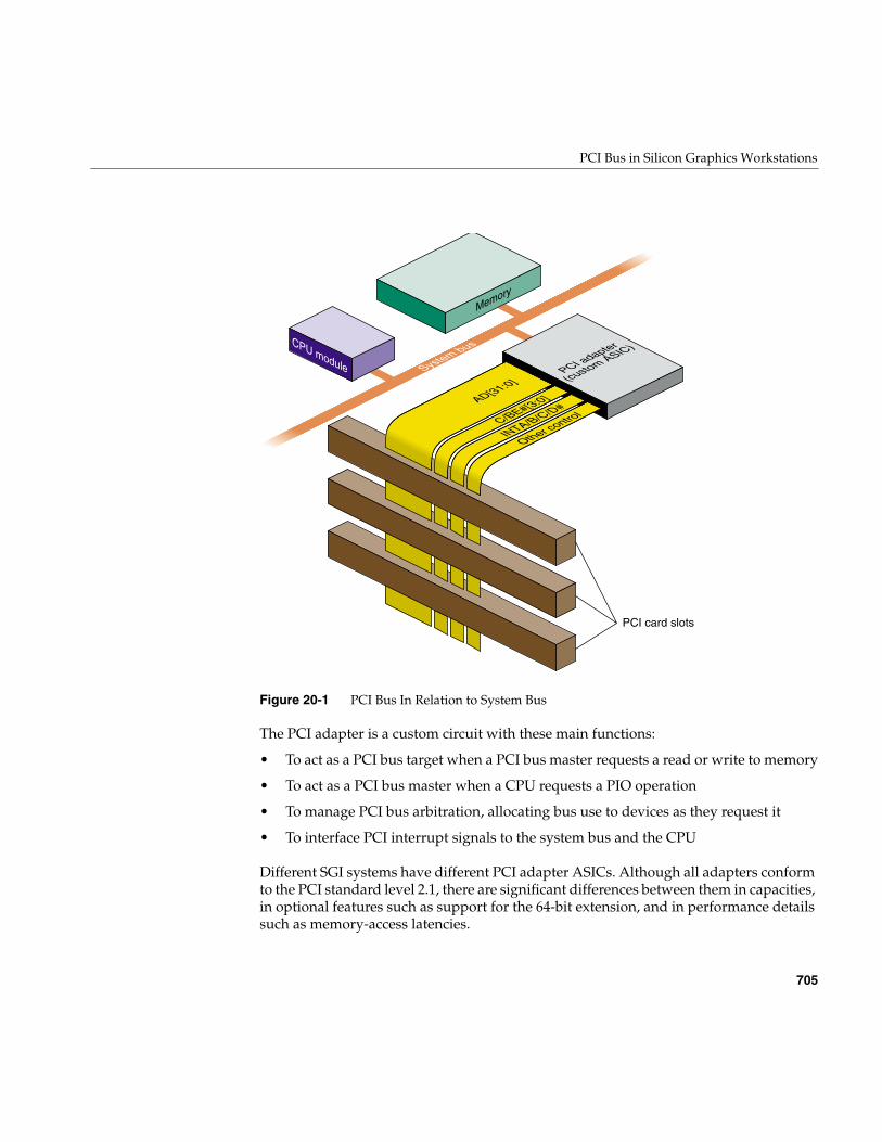
PCI Bus in Silicon Graphics Workstations
705
Figure 20-1 PCI Bus In Relation to System Bus
The PCI adapter is a custom circuit with these main functions:
• To act as a PCI bus target when a PCI bus master requests a read or write to memory
• To act as a PCI bus master when a CPU requests a PIO operation
• To manage PCI bus arbitration, allocating bus use to devices as they request it
• To interface PCI interrupt signals to the system bus and the CPU
Different SGI systems have different PCI adapter ASICs. Although all adapters conformto the PCI standard level 2.1, there are significant differences between them in capacities,in optional features such as support for the 64-bit extension, and in performance detailssuch as memory-access latencies.
CPU module
Memory
PCI adapter
(custom ASIC)
AD[31:0]System bus
C/BE#[3:0]
INTA/B/C/D#
Other control
PCI card slots
706
Chapter 20: PCI Device Attachment
Buses, Slots, Cards, and Devices
A system may contain one or more PCI bus adapters. Each bus connects one or morephysical packages. The PCI standard allows up to 32 physical packages on a bus. A“package” may consist of a card plugged into a slot on the bus. However, a “package”can also consist of an internal chipset mounted directly on the system board, using thePCI bus and occupying one or more virtual slots on the bus. For example, the SCSIadapter in the O2 workstation occupies the first two virtual slots of the PCI bus in thatsystem.
Each physical package can implement from one to eight functions. A PCI function is anindependent device with its own configuration registers in PCI configuration space, andits own address decoders.
In Silicon Graphics systems, each PCI function is integrated into IRIX as a device. A PCIdevice driver manages one or more devices in this sense. A driver does not manage aparticular package, or card, or bus slot; it manages one or more logical devices.
Note: IRIX 6.3 for the O2 workstation supports multifunction cards. However, IRIX 6.4for Origin, Onyx2, and OCTANE does not support multifunction cards. Support formultifunction cards returns for all hardware platforms with IRIX 6.5.
Architectural Implications
All Silicon Graphics PCI implementations permit peer-to-peer transactions, in which twoPCI devices exchange data without the involvement of the bus adapter except asarbitrator. However, most PCI transactions take place between a PCI device and systemmemory, by way of the bus adapter.
Two important facts about PCI-to-memory transaction are, first, that memory is notlocated on the PCI bus and in fact, the PCI bus competes for the use of memory with theCPU and other devices on the system bus; and second, that memory in SGI systems isorganized around cache lines of 128 bytes. When a PCI device initiates a read to memory,the bus adapter requests a cache line from memory, and returns the addressed word fromthat line. When a PCI device initiates a write to memory, the bus adapter fetches theaddressed line; stores successive words into it until the operation ends or another line isaddressed; and writes the line back to memory.
PCI Bus in Silicon Graphics Workstations
707
Some important implications follow:
• The latency of access to the first byte or word in a cache line can be long—in therange of multiple microseconds, if the system bus is heavily used.
• Access to subsequent words in the same cache line can go at maximum bus speed.
A PCI bus master that attempts to read small fields scattered in memory will beconstrained to run at the rate at which the PCI adapter can fetch entire cache lines frommemory. A PCI bus master that attempts to write small fields scattered in memory willbe constrained even further, to the rate at which the PCI adapter can performread-modify-write cycles of entire cache lines.
A device that performs streaming access to consecutive locations can operate at goodspeed, once the initial latency period is past. However, a streaming device must haveenough on-card buffer capacity to hold data during the maximum latency.
These issues of latency are discussed in much greater detail in a document available fromthe Silicon Graphics developer support organization.
Byte Order Considerations
The order of bytes in a word, also called “endianness,” is in conflict between PCI devicesand MIPS-based software. MIPS-based software is “big-endian,” placing the mostsignificant byte (MSB) of a 32-bit word at the lowest (“leftmost”) address. Devices madefor the PCI bus typically use “little-endian,” or Intel, byte ordering, in which the MSB isat the highest address. Whether the bus hardware should perform byte-swapping tocompensate is a difficult question with no universal answer. The question is complicatedby the facts that in some systems, PCI data passes through more than one bus adapterbetween the device and memory, and the default settings of the byte-swapping hardwareis different between different SGI platforms.
When considering byte order, you must consider the intended use of the data (user dataor driver command/status), and the method (PIO or DMA, which use differenthardware).
Byte Order in Data Transfers
When considering only a stream of bytes being transferred between memory and somekind of storage medium—for example, a block of data being read or written from atape—the byte order of the device is not significant. The system writes the stream; later
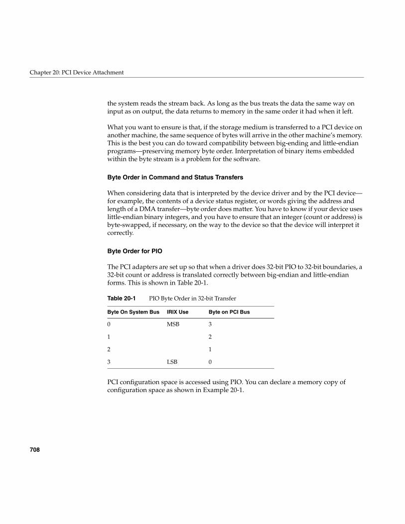
708
Chapter 20: PCI Device Attachment
the system reads the stream back. As long as the bus treats the data the same way oninput as on output, the data returns to memory in the same order it had when it left.
What you want to ensure is that, if the storage medium is transferred to a PCI device onanother machine, the same sequence of bytes will arrive in the other machine’s memory.This is the best you can do toward compatibility between big-ending and little-endianprograms—preserving memory byte order. Interpretation of binary items embeddedwithin the byte stream is a problem for the software.
Byte Order in Command and Status Transfers
When considering data that is interpreted by the device driver and by the PCI device—for example, the contents of a device status register, or words giving the address andlength of a DMA transfer—byte order does matter. You have to know if your device useslittle-endian binary integers, and you have to ensure that an integer (count or address) isbyte-swapped, if necessary, on the way to the device so that the device will interpret itcorrectly.
Byte Order for PIO
The PCI adapters are set up so that when a driver does 32-bit PIO to 32-bit boundaries, a32-bit count or address is translated correctly between big-endian and little-endianforms. This is shown in Table 20-1.
PCI configuration space is accessed using PIO. You can declare a memory copy ofconfiguration space as shown in Example 20-1.
Table 20-1 PIO Byte Order in 32-bit Transfer
Byte On System Bus IRIX Use Byte on PCI Bus
0 MSB 3
1 2
2 1
3 LSB 0
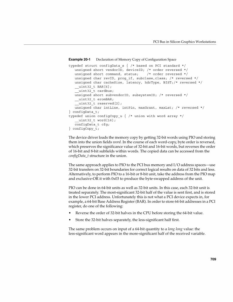
PCI Bus in Silicon Graphics Workstations
709
Example 20-1 Declaration of Memory Copy of Configuration Space
typedef struct configData_s { /* based on PCI standard */unsigned short vendorID, deviceID; /* order reversed */unsigned short command, status; /* order reversed */unsigned char revID, prog_if, subclase,class; /* reversed */unsigned char cacheSize, latency, hdrType, BIST;/* reversed */__uint32_t BAR[6];__uint32_t cardbus;unsigned short subvendorID, subsystemID; /* reversed */__uint32_t eromBAR;__uint32_t reserved[2];unsigned char intLine, intPin, maxGrant, maxLat; /* reversed */
} configData_t;typedef union configCopy_u { /* union with word array */
__uint32_t word[16];configData_t cfg;
} configCopy_t;
The device driver loads the memory copy by getting 32-bit words using PIO and storingthem into the union fields word. In the course of each word-copy, byte order is reversed,which preserves the significance value of 32-bit and 16-bit words, but reverses the orderof 16-bit and 8-bit subfields within words. The copied data can be accessed from theconfigData_t structure in the union.
The same approach applies to PIO to the PCI bus memory and I/O address spaces—use32-bit transfers on 32-bit boundaries for correct logical results on data of 32 bits and less.Alternatively, to perform PIO to a 16-bit or 8-bit unit, take the address from the PIO mapand exclusive-OR it with 0x03 to produce the byte-swapped address of the unit.
PIO can be done in 64-bit units as well as 32-bit units. In this case, each 32-bit unit istreated separately. The most-significant 32-bit half of the value is sent first, and is storedin the lower PCI address. Unfortunately this is not what a PCI device expects in, forexample, a 64-bit Base Address Register (BAR). In order to store 64-bit addresses in a PCIregister, do one of the following:
• Reverse the order of 32-bit halves in the CPU before storing the 64-bit value.
• Store the 32-bit halves separately, the less-significant half first.
The same problem occurs on input of a 64-bit quantity to a long long value: theless-significant word appears in the more-significant half of the received variable.
710
Chapter 20: PCI Device Attachment
Byte Order for DMA
A driver prepares for DMA access by creating a DMA map (see “Using DMA Maps” onpage 735). When a map is allocated, you specify one of two flags: PCI_BYTE_STREAMor PCI_WORD_VALUES. All transfers through the map are appropriate for either a datastream or a command stream, as requested.
PCI Implementation in O2 Workstations
In the O2 workstation, a proprietary system bus connects the CPU, multimedia devices(audio, video, and graphics) and main memory. Multimedia use is a central focus of thisworkstation’s design, and audio and video devices have highest priority, after the CPU,for bandwidth on the system bus.
The PCI bus adapter interfaces one PCI bus to this system bus. The PCI bus adapter is aunit on the system bus, on a par with other devices. The PCI bus adapter competes withthe CPU and with multimedia I/O for the use of main memory.
The built-in SCSI adapter, which is located on the main system board, is logicallyconnected to the PCI bus and takes the place of the first two “slots” on the PCI bus, sothat the first actual slot is number 2.
Unsupported PCI Signals
In the O2, the PCI adapter implements a standard, 32-bit PCI bus operating at 33 MHZ.The following optional signal lines are not supported.
• The LOCK# signal is ignored; atomic access to memory is not supported.
• The cache-snoop signals SBO# and SDONE are ignored. Cache coherency must beensured by the driver.
• The JTAG signals are not supported.
PCI Implementation in O2 Workstations
711
Configuration Register Initialization
When the IRIX kernel probes the PCI bus and finds an active device, it initializes thedevice configuration registers as follows:
The device driver is free to set any other configuration parameters when attaching thedevice.
Caution: If the driver changes the contents of a Base Address Register, the results areunpredictable. Don’t do this.
Address Spaces Supported
The relationship between the PCI bus address space and the system memory physicaladdress space differs from one system type to another.
64-bit Address and Data Support
The O2 PCI adapter supports 64-bit data transfers, but not 64-bit addressing. All busaddresses are 32 bits, that is, all PCI bus virtual addresses are in the 4 GB range. The DualAddress Cycle (DAC) command is not supported (or needed).
The 64-bit extension signals AD[63:32], C/BE#[7:4], REQ64# and ACK64# are pulled upas required by the PCI standard.
When the PCI bus adapter operates as a bus master (as it does when implementing a PIOload or store for the CPU), the PCI adapter generates 32-bit data cycles.
CommandRegister
The enabling bits for I/O Access, Memory Access, and Master areset to 1. Other bits, such as Memory Write and Invalidate and FastBack-to-Back are left at 0.
Cache Line Size 0x20 (32, 32-bit words, or 128 bytes).
Latency Timer 0x30 (48 clocks, 1.45 microseconds).
Base Addressregisters
Each register that requests memory or I/O address space isprogrammed with a starting address. In the O2 system, memoryaddresses are always greater than 0x8000 0000.
712
Chapter 20: PCI Device Attachment
When the PCI bus adapter operates as a bus target (as it does when a PCI bus mastertransfers data using DMA), the PCI adapter does not respond to REQ64#, and hence64-bit data transfers are accomplished in two, 32-bit, data phases as described in the PCIspecification.
PIO Address Mapping
For PIO purposes (CPU load and store access to a device), memory space defined by eachPCI device in its configuration registers is allocated in the upper two gigabytes of the PCIaddress space, above 0x8000 0000. These addresses are allocated dynamically, based onthe contents of the configuration registers of active devices. The I/O address spacerequested by each PCI device in its configuration registers is also allocated dynamicallyas the system comes up. Device drivers get a virtual address to use for PIO to any addressspace by creating a PIO map (see “Using PIO Maps” on page 723).
It is possible for a PCI device to request (in the initial state of its Base Address Registers)that its address space be allocated in the first 1 MB of the PCI bus. This request cannot behonored in the O2 workstation. Devices that cannot decode bus addresses above0x8000 0000 are not supported.
PIO access to configuration space is supported. However, drivers must not only create aPIO map, but must use kernel functions instead of simply loading and storing to atranslated address.
DMA Address Mapping
The O2 workstation supports a 1 GB physical memory address space (30 bits of physicaladdress used). Any part of physical address space can be mapped into PCI bus addressspace for purposes of DMA access from a PCI bus master device. The device driverensures correct mapping through the use of a DMA map object (see “Using DMA Maps”on page 735).
Slot Priority and Bus Arbitration
Two devices that are built into the workstation take the positions of PCI bus slots 0 and1. Actual bus slots begin with slot 2 and go up to a maximum of slot 4 (the built-in devicesand a design maximum of three physical slots).
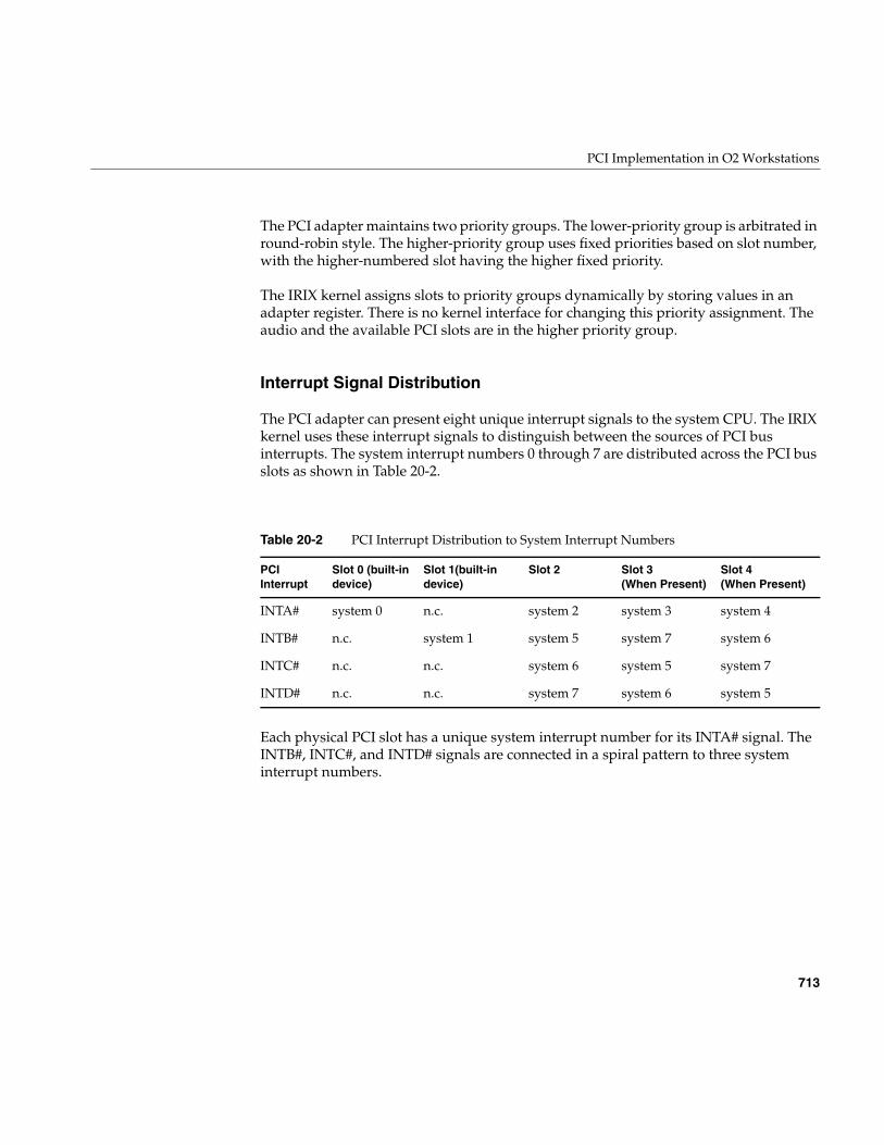
PCI Implementation in O2 Workstations
713
The PCI adapter maintains two priority groups. The lower-priority group is arbitrated inround-robin style. The higher-priority group uses fixed priorities based on slot number,with the higher-numbered slot having the higher fixed priority.
The IRIX kernel assigns slots to priority groups dynamically by storing values in anadapter register. There is no kernel interface for changing this priority assignment. Theaudio and the available PCI slots are in the higher priority group.
Interrupt Signal Distribution
The PCI adapter can present eight unique interrupt signals to the system CPU. The IRIXkernel uses these interrupt signals to distinguish between the sources of PCI businterrupts. The system interrupt numbers 0 through 7 are distributed across the PCI busslots as shown in Table 20-2.
Each physical PCI slot has a unique system interrupt number for its INTA# signal. TheINTB#, INTC#, and INTD# signals are connected in a spiral pattern to three systeminterrupt numbers.
Table 20-2 PCI Interrupt Distribution to System Interrupt Numbers
PCIInterrupt
Slot 0 (built-indevice)
Slot 1(built-indevice)
Slot 2 Slot 3(When Present)
Slot 4(When Present)
INTA# system 0 n.c. system 2 system 3 system 4
INTB# n.c. system 1 system 5 system 7 system 6
INTC# n.c. n.c. system 6 system 5 system 7
INTD# n.c. n.c. system 7 system 6 system 5
714
Chapter 20: PCI Device Attachment
PCI Implementation in Origin Servers
In the Origin2000, Onyx2, and Origin200 systems, the PCI adapter bridges to the XIObus, a high-speed I/O bus. This joins the PCI bus into the connection fabric, so any PCIbus can be addressed from any module, and any PCI bus can access memory that isphysically located in any module. In the OCTANE workstation, the same PCI adapterASIC is used to bridge the PCI bus to a proprietary system bus.
Latency and Operation Order
In these systems the multimedia features have substantial local resources, so thatcontention with multimedia for the use of main memory is lower than in the O2workstation. However, these systems also have multiple CPUs and multiple layers ofaddress translation, and these factors can introduce latencies in PCI transactions.
It is important to understand that there is no guaranteed order of execution betweenseparate PCI transactions in these systems. There can be multiple hardware layersbetween the CPU, memory, and the device. One or more data transactions can be “inflight” for durations that are significant. For example, suppose that a PCI bus masterdevice completes the last transfer of a DMA write of data to memory, and then executesa DMA write to update a status flag elsewhere in memory. Under circumstances that areunusual but not impossible, the status in memory can be updated, and acted upon bysoftware, while the data transaction is still “in flight” and has not completely arrived inmemory. The same can be true of a PIO read that polls the device—it can return“complete” status from the device while data sent by DMA has yet to reach memory.
Ordering is guaranteed when interrupts are used. An interrupt handler is not executeduntil all writes initiated by the interrupting device have completed.
Unsupported PCI Signals
In these larger systems, the PCI adapter implements a standard, 64-bit PCI bus operatingat 33 MHZ. The following optional signal lines are not supported.
• The LOCK# signal is ignored; atomic access to memory is not supported.
• The cache-snoop signals SBO# and SDONE are ignored. Cache coherency is ensuredby the PCI adapter and the memory architecture, with assistance by the driver.
PCI Implementation in Origin Servers
715
Configuration Register Initialization
When the IRIX 6.5 kernel probes the PCI bus and finds an active device, it initializes thedevice configuration registers as follows:
The device driver is free to set any other configuration parameters when attaching thedevice.
Caution: If the driver changes the contents of a Base Address Register, the results areunpredictable. Don’t do this.
Address Spaces Supported
In these systems, addresses are translated not once but at least twice and sometimes moreoften between the CPU and the device, or between the device and memory. Also, someof the logic for features such as prefetching and byte-swapping is controlled by the useof high-order address bits. There is no simple function on a physical memory addressthat yields a PCI bus address (nor vice-versa). It is essential that device driver use PIOand DMA maps (see Chapter 21, “Services for PCI Drivers”).
64-bit Address and Data Support
These systems support 64-bit data transactions. Use of 64-bit data transactions results inbest performance.
The PCI adapter accepts 64-bit addresses produced by a bus master device. The PCIadapter does not generate 64-bit addresses itself (because the PCI adapter generatesaddresses only to implement PIO transactions, and PIO targets are always located in32-bit addresses).
CommandRegister
The enabling bits for I/O Access, Memory Access, and Master areset to 1. Other bits, such as Memory Write and Invalidate and FastBack-to-Back are left at 0.
Cache Line Size 0x20 (32, 32-bit words, or 128 bytes).
Latency Timer 0x30 (48 clocks, or 1.45 us).
Base Addressregisters
Each register that requests memory or I/O address space isprogrammed with a starting address. Under IRIX 6.5, memoryspace addresses are below 0x4000 0000.
716
Chapter 20: PCI Device Attachment
PIO Address Mapping
For PIO purposes, memory space defined by each PCI device in its configurationregisters is allocated in the lowest gigabyte of PCI address space, below 0x400 0000.These addresses are allocated dynamically, based on the contents of the configurationregisters of active devices. The I/O address space requested by each PCI device in itsconfiguration registers is also allocated dynamically as the system comes up. A drivercan request additional PCI I/O or Memory space when the device uses space beyond thatdescribed by its configuration registers.
Device drivers get a virtual address to use for PIO in any address space by creating a PIOmap (see “Using PIO Maps” on page 723).
It is possible for a PCI device to request (in the initial state of its Base Address Registers)that its address space be allocated in the first 1 MB of the PCI bus. This request is honoredin larger systems (it cannot be honored in the O2 workstation, as noted under “PCIImplementation in O2 Workstations” on page 710).
PIO access to configuration space is supported. However, drivers use kernel functionsinstead of simply loading and storing to a translated address.
DMA Address Mapping
Any part of physical address space can be mapped into PCI bus address space forpurposes of DMA access from a PCI bus master device. As described under “AddressSpace Usage in Origin2000 Systems” on page 25, the Origin2000 architecture uses a 40-bitphysical address, of which some bits designate a node board. The PCI adapter sets up atranslation between an address in PCI memory space and a physical address, which canrefer to a different node from the one to which the PCI bus is attached.
The device driver ensures correct mapping through the use of a DMA map object (see“Using DMA Maps” on page 735).
If the PCI device supports only 32-bit addresses, DMA addresses can be established in32-bit PCI space. When this requested, extra mapping hardware is used to map awindow of 32-bit space into the 40-bit memory space. These mapping registers arelimited in number, so it is possible that a request for DMA translation could fail. For thisreason it is preferable to use 64-bit DMA mapping when the device supports it.
PCI Implementation in Origin Servers
717
When the device supports 64-bit PCI bus addresses for DMA, the PCI adapter can use asimpler mapping method from a 64-bit address into the target 40-bit address, and thereis less chance of contention for mapping hardware. The device driver must request a64-bit DMA map, and must program the device with 64-bit values.
Bus Arbitration
The PCI adapter maintains two priority groups, the real-time group and the low-prioritygroup. Both groups are arbitrated in round-robin style. Devices in the real-time groupalways have priority for use of the bus. There is no kernel interface for changing thepriority of a device.
Interrupt Signal Distribution
There are two unique interrupt signals on each PCI bus. The INTA# and INTC# signalsare wired together, and the INTB# and INTD# signals are wired together. A PCI devicethat uses two distinct signals must use INTA and INTB, or INTC and INTD. A device thatneeds more than two signals can use the additional signal lines, but such a device mustalso provide a register from which the device driver can learn the cause of the interrupt.

719
Chapter 21
21. Services for PCI Drivers
The IRIX 6.5 kernel provides a uniform interface for managing a PCI device. Thefunctions in this interface are covered in this chapter under the following headings:
• “IRIX 6.5 PCI Drivers” on page 720 summarizes important information comparingprevious versions IRIX device drivers with those for IRIX 6.5.
• “About PCI Drivers” on page 720 summarizes the entry points and main activitiesof a PCI driver.
• “Using PIO Maps” on page 723 discusses the kernel functions to allocate and usePIO maps.
• “Using DMA Maps” on page 735 discusses the kernel functions to allocate and usePIO maps.
• “Registering an Interrupt Handler” on page 740 discusses the kernel functions usedto register and unregister an interrupt handler for a PCI device.
• “Registering an Error Handler” on page 744 summarizes the method of associatingan error handler function with a device.
• “Interrogating a PCI Device” on page 746 lists the functions you can use to querydevice status.
• “Example PCI Driver” on page 747 displays a simple, skeletal PCI driver.
720
Chapter 21: Services for PCI Drivers
IRIX 6.5 PCI Drivers
This section discusses changes made to PCI driver support for IRIX 6.5 and refers to theappropriate sections of the manual for more information.
• If your driver is to be compiled for the IP32 (O2) platform, refer to “PCI Drivers forthe O2 (IP32) Platform” on page 732
• Values of flags PCIIO_DMA_CMD and PCIIO_DMA_DATA have changed. See“Setting Flag Values” on page 737 for details.
• PCIIO_PIOMAP_* defines are being replaced by PCIIO_SPACE_* defines. Refer to“Selecting the Address Space” on page 726 for details.
• pciio_config_{get.set} interfaces are defined as described in “Changes InConfiguration Interface” on page 730.
• pciio_pio_mapsz now returns a ulong. See “Interrogating PIO Maps” on page 732
About PCI Drivers
A PCI device driver is a kernel-level device driver that has the general structuredescribed in Chapter 7, “Structure of a Kernel-Level Driver.” It uses the driver/kernelinterface described in Chapter 8, “Device Driver/Kernel Interface.” A PCI driver can beloadable or it can be linked with the kernel. In general it is configured into IRIX asdescribed in Chapter 9, “Building and Installing a Driver.”
PCI hardware configuration is more dynamic than the configuration of the VME or EISAbuses. With other types of bus, the administrator describes the device configurationusing VECTOR statements and the configuration is static. IRIX support for the PCI busis designed to allow support for dynamic reconfiguration. A PCI driver can be designedto allow devices to be attached and detached at any time.
The general sequence of operations of a PCI driver is as follows:
1. In the pfxinit() entry point, the driver prepares any global variables.
2. In the pfxreg() entry point, the driver calls a kernel function to register itself as a PCIdriver, specifying the kind of device it supports.
3. When the kernel discovers a device of this type, it calls the pfxattach() entry point ofthe driver.
4. In the normal upper-half entry points such as pfxopen(), pfxread(), and pfxstrategy(),the driver operates the device and transfers data.
About PCI Drivers
721
5. If the kernel learns that the device is being detached, the kernel calls the driver’spfxdetach() entry point. The driver undoes the work done in by pfxattach().
A PCI driver uses a number of PCI-related kernel functions that are all declared in theheader file sys/PCI/pciio.h.
About Registration
Registration is a step that lets the kernel know how to associate a device to a driver.
A PCI device identifies itself on the bus by its vendor ID and device ID numbers. Thekernel discovers the complement of devices by probing the bus. When it finds a device,the kernel needs to associate it with a driver. With other types of bus, the associationbetween a device and a driver is entered by the system administrator in a staticconfiguration file. For PCI devices, the kernel looks through a list of drivers that haveregistered as supporting PCI devices of particular types.
Your driver registers by calling the pciio_driver_register() function (see reference pagepciio(d3)).This call specifies the PCI vendor ID and device ID numbers as they appear inthe PCI configuration space of any device that this driver can support. The thirdargument is the driver’s prefix string as configured in its descriptive file (see “Describingthe Driver in /var/sysgen/master.d” on page 260). The kernel uses this string to find theaddresses of the driver’s pfxattach() and pfxdetach() entry points.
Example 21-1 shows a hypothetical example of driver registration. This fragmentaryexample also shows how a driver can register multiple times to handle multiplecombinations of vendor ID and device ID.
Example 21-1 Driver Registration
int hypo_reg(){
ret = pciio_driver_register(HYPO_VENID,HYPO_DEVID1,"hypo_",0);if (!ret){
cmn_err(CE_WARN,"error %d registering devid %d",ret,HYPO_DEVID1);return ret;
}ret = pciio_driver_register(HYPO_VENID,HYPO_DEVID2,"hypo_",0);if (!ret)...
}
722
Chapter 21: Services for PCI Drivers
In a loadable driver, you must call pciio_driver_register() from the pfxreg() entry point.In a nonloadable driver, you can make the call from pfxinit() if you prefer, but the drivermight not then work if someone later tries to make it loadable.
Wherever you call the function, be aware that, if there is an available device of thespecified type, pfxattach() can be called immediately, before the pci_driver_register()function returns. In a multiprocessor, pfxattach() can be called concurrently with thereturn of pci_driver_register() and following code.
About Attaching a Device
The duties and actions of the pfxattach() entry point are discussed in detail in “EntryPoint attach()” on page 153 and under “Hardware Graph Management” on page 221. Insummary, at this time the driver
• Creates hwgraph vertexes to represent the device
• Allocates and initializes a data structure to hold per-device information
• Allocates PIO maps and (optionally) DMA maps to use in addressing the device
• If necessary, registers an interrupt handler
• If necessary, registers an error handler
• Initializes the device itself
The allocation and use of PIO and DMA maps, and the registration of an interrupthandler, are covered in detail in following topics.
The argument to pfxattach() is a hwgraph vertex handle that represents the “connectionpoint” of the device—usually the bus slot. The driver builds more vertexes connected tothis one to represent the logical device. However, the handle of the connection point isneeded in several kernel functions, and it should be saved as part of the deviceinformation.
The return code from pfxattach() is tested by the kernel. The driver can reject anattachment. When your driver cannot allocate memory, or fails due to another problem,it should:
• Use cmn_err() to document the problem (see “Using cmn_err” on page 274)
• Release any objects such as PIO and DMA maps that were created
Using PIO Maps
723
• Release any space allocated to the device such as a device information structure
• Return an informative return code
The pfxdetach() entry point can only be called if the pfxattach() entry point returnssuccess (0).
More than one driver can register to support the same vendor ID and device ID. Theorder in which drivers are called to attach a device is not defined. When the first-calleddriver fails to complete the attachment, the kernel continues on to test the next, until allhave refused or one accepts.
About Unloading
When a loadable PCI driver is called at its pfxunload() entry point, indicating that thekernel would like to unload it, the driver must take pains not to leave any danglingpointers (as discussed under “Entry Point unload()” on page 180). A driver should notunload when it has any registered interrupt or error handlers.
A driver does not have to unregister itself as a PCI driver before unloading. Nor does ithave to detach any devices it has attached. However, if any devices are open or memorymapped, the driver should not unload.
If the driver has been autoregistered (see “Registration” on page 267), stub functions areplaced in the switch tables for the attach and open functions. When the kernel discoversa new device and wants this driver to attach it, or when a process attempts to open adevice for which this driver created the vertex, the kernel reloads the driver.
Using PIO Maps
You use a PIO map to establish a mapping between a kernel virtual address and someportion of PCI bus memory space, configuration space, or I/O space so that the CPU canload and store into the PCI bus. Depending on the machine architecture, the mappingmay be a simple, linear translation, or it may require the kernel to program hardwareregisters in one or more bus adapters. The software interface is the same in all cases.
724
Chapter 21: Services for PCI Drivers
You cannot program a PCI device without at least one PIO map and you might allocateseveral. Typically you store the handles of the allocated maps in the device informationstructure; and you store the address of the device information structure in turn in thehwgraph vertex for the device.
In summary, a PIO map is used as follows:
1. Allocate it with pciio_piomap_alloc().
2. Activate the map and extract a translated address using pciio_piomap_addr(). Usethe translated address to fetch or store.
3. Deactivate the map using pciio_piomap_done(), when the map will be kept but willnot be used for some time.
4. Release the map with pciio_piomap_free().
PIO Mapping Functions
The functions that are used to create and apply PIO maps are summarized in Table 21-1.For syntax details see the reference page pciio_pio(d3).
Table 21-1 Functions for PIO Maps for the PCI Bus
Function HeaderFiles
Purpose and Operation
pciio_piomap_alloc() ddi.h,pciio.h
Create a PIO map object, specifying the bus address space,base offset, and length it needs to cover.
pciio_piomap_addr() ddi.h,pciio.h
Get a kernel virtual address from a PIO map for a specificoffset and length.
pciio_piomap_done() ddi.h,pciio.h
Make a PIO map inactive until it is next needed (mayrelease hardware resources asslociated to the map).
pciio_piomap_free() ddi.h,pciio.h
Release a PIO map object.
pciio_piotrans_addr() ddi.h,pciio.h
Request immediate translation of a bus address to a kernelvirtual address without use of a PIO map. Returns NULLunless this system supports fixed PIO addressing.
pciio_pio_addr() ddi.h,pciio.h
Attempt immediate translation, but allocate a PIO map ifnecessary.
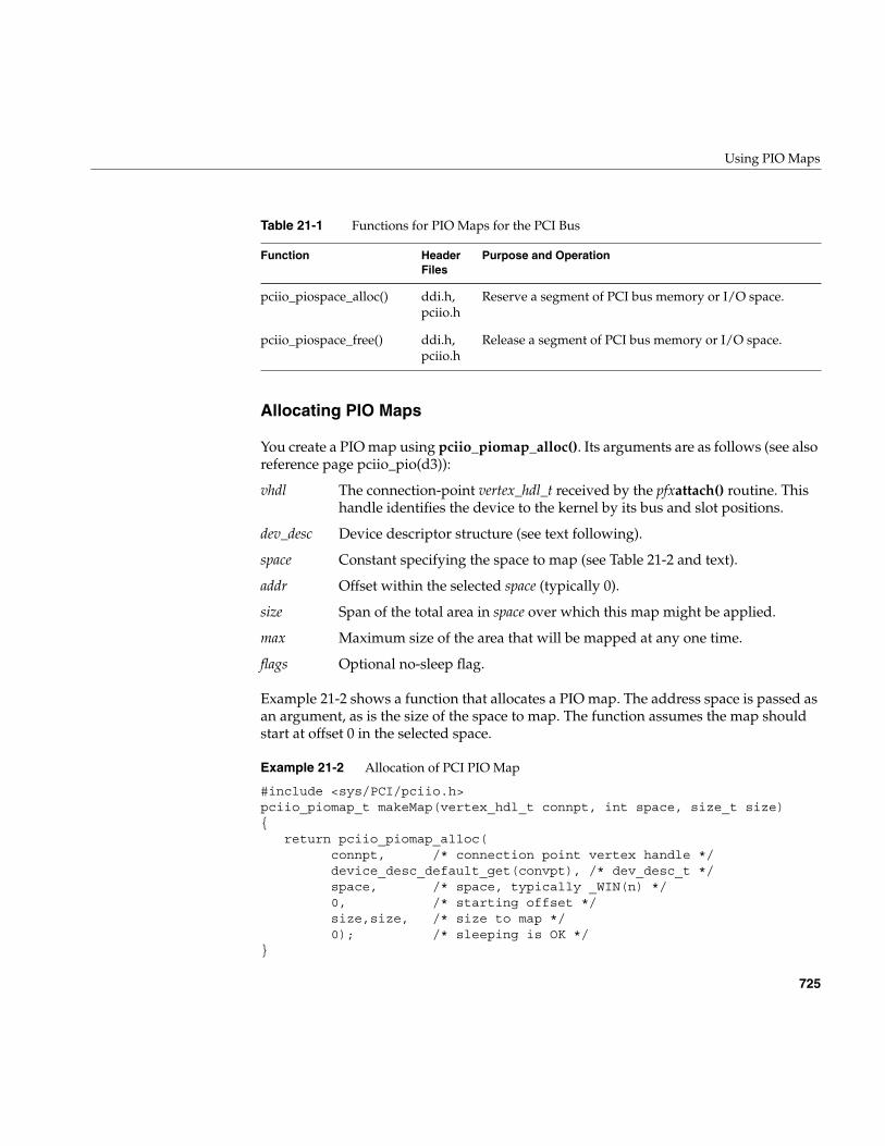
Using PIO Maps
725
Allocating PIO Maps
You create a PIO map using pciio_piomap_alloc(). Its arguments are as follows (see alsoreference page pciio_pio(d3)):
Example 21-2 shows a function that allocates a PIO map. The address space is passed asan argument, as is the size of the space to map. The function assumes the map shouldstart at offset 0 in the selected space.
Example 21-2 Allocation of PCI PIO Map
#include <sys/PCI/pciio.h>pciio_piomap_t makeMap(vertex_hdl_t connpt, int space, size_t size){
return pciio_piomap_alloc(connpt, /* connection point vertex handle */device_desc_default_get(convpt), /* dev_desc_t */space, /* space, typically _WIN(n) */0, /* starting offset */size,size, /* size to map */0); /* sleeping is OK */
}
pciio_piospace_alloc() ddi.h,pciio.h
Reserve a segment of PCI bus memory or I/O space.
pciio_piospace_free() ddi.h,pciio.h
Release a segment of PCI bus memory or I/O space.
vhdl The connection-point vertex_hdl_t received by the pfxattach() routine. Thishandle identifies the device to the kernel by its bus and slot positions.
dev_desc Device descriptor structure (see text following).
space Constant specifying the space to map (see Table 21-2 and text).
addr Offset within the selected space (typically 0).
size Span of the total area in space over which this map might be applied.
max Maximum size of the area that will be mapped at any one time.
flags Optional no-sleep flag.
Table 21-1 Functions for PIO Maps for the PCI Bus
Function HeaderFiles
Purpose and Operation
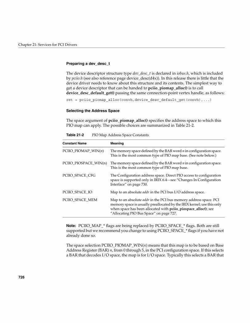
726
Chapter 21: Services for PCI Drivers
Preparing a dev_desc_t
The device descriptor structure type dev_desc_t is declared in iobus.h, which is includedby pciio.h (see also reference page device_desc(d4x)). In this release there is little that thedevice driver needs to know about this structure and its contents. The simplest way toget a device descriptor that can be handed to pciio_piomap_alloc() is to calldevice_desc_default_get() passing the same connection-point vertex handle, as follows:
ret = pciio_piomap_alloc(convh,device_desc_default_get(convh),...)
Selecting the Address Space
The space argument of pciio_piomap_alloc() specifies the address space to which thisPIO map can apply. The possible choices are summarized in Table 21-2.
Note: PCIIO_MAP_* flags are being replaced by PCIIO_SPACE_* flags. Both are stillsupported but we recommend you change to using PCIIO_SPACE_* flags if you have notalready done so.
The space selection PCIIO_PIOMAP_WIN(n) means that this map is to be based on BaseAddress Register (BAR) n, from 0 through 5, in the PCI configuration space. If this selectsa BAR that decodes I/O space, the map is for I/O space. Typically this selects a BAR that
Table 21-2 PIO Map Address Space Constants
Constant Name Meaning
PCIIO_PIOMAP_WIN(n) The memory space defined by the BAR word n in configuration space.This is the most common type of PIO map base. (See note below.)
PCIIO_PIOSPACE_WIN(n) The memory space defined by the BAR word n in configuration space.This is the most common type of PIO map base.
PCIIO_SPACE_CFG The Configuration address space. Direct PIO access to configurationspace is supported only in IRIX 6.4—see “Changes In ConfigurationInterface” on page 730.
PCIIO_SPACE_IO Map to an absolute addr in the PCI bus I/O address space.
PCIIO_SPACE_MEM Map to an absolute addr in the PCI bus memory address space. PCImemory space is usually preallocated by the IRIX kernel; use this onlywhen space has been allocated with pciio_piospace_alloc(); see“Allocating PIO Bus Space” on page 727.
Using PIO Maps
727
decodes memory space. When the space is defined by a 64-bit base address register, usethe lower number that indexes the word that contains the configuration bits.
Note: The PCI infrastructure verifies that a segment of size max, starting at addr, can bemapped in the specified space, based on the device configuration. If this is not possible,the map is not allocated and NULL is returned.
Sizing the Space
The max argument sets a limit on the total span of addresses, from lowest to highest, forwhich this map can ever be used. When the map is always used for the same area, sizeand max are the same. When the map can be used for smaller segments within a largerarea, size is the limit of any single segment and max the size of the total extent. The sizeto be mapped at any one time is specified when you apply pciio_piomap_addr() to theallocated map.
Specifying the No-Sleep Flag
The pciio_piomap_alloc() function may need to allocate memory. Normally it does sowith a function that can sleep if memory is temporarily unavailable. If it is important thatthe function never sleep, pass PCIIO_NOSLEEP in the flags argument. When you do this,you must check for a NULL return, indicating that memory was not available.
Allocating PIO Bus Space
When the kernel locates a PCI device on the bus, it allocates the amount of PCI busMemory and I/O address space that the device requests in its standard configurationregisters. You get a PIO map into this preallocated space by allocating a map for spacePCIIO_SPACE_WIN(n), specifying the configuration register for that space.
In some cases, a PCI device needs additional memory or I/O space based ondevice-specific configuration data that is not known to the kernel. You usepciio_piospace_alloc() to allocate additional ranges of memory or I/O space to be usedby a device. It is up to your driver to program the device to use the allocated space.
When you need to perform PIO to allocated space that is not decoded by the standardBARs, you create a PIO map for space PCIIO_SPACE_MEM or PCIIO_SPACE_IO, andspecify the exact base address that was allocated.
728
Chapter 21: Services for PCI Drivers
Performing PIO With a PIO Map
After a map has been allocated, it is inactive. The function pciio_piomap_addr()activates a map if it is not active, and uses the map to translate an offset within themapped space to a kernel virtual address.
In some systems, “activating a map” can be a null operation. In other systems, an activePIO map may represent a commitment of limited hardware resources—for example, amapping register in a bus adapter. The function arguments are as follows (see alsoreference page pciio_pio(d3):
If any argument is invalid, or if the map cannot be activated, the returned address is 0.The returned address, when it is not 0, can be used to fetch and store from the PCI bus asif it were memory. An attempt to access beyond the specified size might cause a kernelpanic or might simply return bad data.
Accessing Memory and I/O Space
PIO access to memory or I/O space follows the same pattern: extract a translated addressusing pciio_piomap_addr(), then use the address as a memory pointer. The function inExample 21-3 encapsulates the process of reading a word based on a map.
Example 21-3 Function to Read Using a Map
__uint_32_t mapRefer(pciio_piomap_t map, iopaddr_t offset){
volatile __uint32_t *xaddr; /* word in PCI space */xaddr = pciio_piomap_addr(map,offset,sizeof(*xaddr));if (xaddr)
return *xaddr;cmn_err(CE_WARN,"Unable to map PCI PIO address");return 0xffffffff; /* imitate hardware fault */
}
Access to quantities smaller than 32 bits needs special handling. When you access a 16-bitor 8-bit value, the least-significant address bits must reflect the PCI byte-lane enable bits.What this means in practice is that the target address of a 16-bit value must be
map The allocated map to use. The map specifies the address space.
addr The offset in the mapped space.
size The number of bytes to be mapped.
Using PIO Maps
729
exclusive-ored with 0x02, and the target address of an 8-bit value must be exclusive-oredwith 0x03. You can do this explicitly, by modifying the word address returned frompciio_piomap_addr(). Alternatively you can use the PIO address to base a structure, andin the structure you can invert the positions of bytes and halfwords within words, so thatthe sum of base and offset has the correct PIO address.
Deactivating an Address and Map
After you extract an address using pciio_piomap_addr(), the map is active, supportingthe translated address over the span of bytes you specified. The address remains validonly as long as the map supports it.
The address becomes inactive when you call pciio_piomap_addr() for a differentaddress or size based on the same map. If you attempt to use an address after the maphas changed, a kernel panic can occur.
The map itself remains active until you call either pciio_piomap_done() orpciio_piomap_free(). In some systems, it costs nothing to keep a PIO map active. In othersystems, an active PIO map may tie up global hardware resources. It is is a good idea tocall pciio_piomap_done() when the current address will not be used for some time.
Using One-Step PIO Translation
Some systems also support a one-step translation function, pciio_piotrans_addr(). Thisfunction takes a combination of the arguments of pciio_piomap_alloc() andpciio_piomap_addr(), and returns a translated address. In effect, it combines creating amap, using the map, and freeing the map, into a single step (see reference pagepciio_pio(d3)).
This function can fail in systems that do not use hard-wired bus maps. If you use it, youmust test the returned address. If it is 0, the one-step translation failed. The address isinvalid, and you must create a PIO map instead.
The two-step process of allocating a map and then interrogating it is more general andworks in all systems.
730
Chapter 21: Services for PCI Drivers
Accessing the Device Configuration
Typically a PCI driver needs to read the device configuration registers and possibly writeto them. These are PIO operations, but the interface for performing them has variedbetween releases.
Changes In Configuration Interface
The hardware to generate PCI configuration cycles differs from one system to another. Inall systems, access to configuration space is limited to 32-bit words on 32-bit boundaries.For these and other reasons, configuration access methods have varied from release torelease.
• In IRIX 6.3, configuration access was done by obtaining a PIO map address forconfiguration space and passing it to kernel functions pciio_config_get() andpciio_config_set(). This is because, in the O2 workstation, configuration cycles arenot generated by normal PIO operations. The functions operate the specialhardware.
• In IRIX 6.4, you performed configuration access using PIO through a PIO map. Thisis because, in the hardware supported by IRIX 6.4 (Origin, Onyx2, and Octane),normal PIO access through a map can generate PCI configuration cycles, althoughonly for 32-bit transfers.
• As of this release, IRIX 6.5, you are required to use functions pciio_config_get() andpciio_config_set() for configuration access. This is because that release supports theO2 as well as other platforms. However, the interface to these functions is extendedto support 8-byte registers, transfers of 1, 2, and 3 bytes, and access to nonstandard(device-defined) configuration registers.
In order to bring a degree of uniformity to this picture, the macros in Example 21-4 arepresented.
Example 21-4 Configuration Access Macros
/* PCI Config Space Access Macros for source compatibility in drivers** that use the same source for IRIX 6.3, IRIX 6.4, and IRIX 6.5** Usage:** PCI_CFG_BASE(conn)** PCI_CFG_GET(conn,base,offset,type)** PCI_CFG_SET(conn,base,offset,type,value)**** Use caddr_t cfg_base = PCI_CFG_BASE(c) once during attach to get the** PIO base address for the specific device needed by 6.3 and 6.4.
Using PIO Maps
731
** Later, use PCI_CFG_GET() to read and PCI_CFG_SET() to write config registers.**** NOTE: IRIX 6.4 supports only 32-bit access. IRIX 6.3 determines the size of** register (1-4 bytes) based on the offset and the standard layout of a Type 00** PCI Configuration Space Header. If you specify a nonstandard size or offset,** you get different results in different releases.*/#if IRIX6_3#define PCI_CFG_BASE(c) pciio_piotrans_addr(c,0,PCIIO_SPACE_CFG,0,256,0)#define PCI_CFG_GET(c,b,o,t) pciio_config_get(b,o)#define PCI_CFG_SET(c,b,o,t,v) pciio_config_set(b,o,v)#elif IRIX6_4#define PCI_CFG_BASE(c) pciio_piotrans_addr(c,0,PCIIO_SPACE_CFG,0,256,0)#define PCI_CFG_GET(c,b,o,t) ((*(t *)((char *)(b)+(o))))#define PCI_CFG_SET(c,b,o,t,v) ((*(t *)((char *)(b)+(o))) = v)#else /* IRIX 6.5 and onward */#define PCI_CFG_BASE(c) NULL#define PCI_CFG_GET(c,b,o,t) pciio_config_get(c,o,sizeof(t))#define PCI_CFG_SET(c,b,o,t,v) pciio_config_set(c,o,sizeof(t),v)#endif
The skeletal code in Example 21-5 illustrates access to 32-bit words in configurationspace using the macros.
Example 21-5 Reading PCI Configuration Space
int hypo_attach(vertex_hdl_t connpt){...
pDevInfo->conn_vh = connpt;...
pDevInfo->cfg_base = PCI_CFG_BASE(connpt);...}__uint32_t get_config_word(DevInfo *pDefInfo, int offset){
return PCI_CFG_GET(pDevInfo->conn_vh,pDevInfo->cfg_base,offset, sizeof(__uint32_t));
}void set_config_word(DevInfo *pDefInfo, int offset, __uint32_t val){
PCI_CFG_SET(pDevInfo->conn_vh,pDevInfo->cfg_base,offset,sizeof(val),val);
}
732
Chapter 21: Services for PCI Drivers
Interrogating PIO Maps
The following functions can be used to interrogate a PIO map object (see pciio_get(d3)):
Most of these functions return values that were supplied to pciio_piomap_alloc().However, pciio_pio_slot_get() provides a way to learn the bus slot number of a device.You can also obtain the slot number from a general query function; see “Interrogating aPCI Device” on page 746.
PCI Drivers for the O2 (IP32) Platform
For IRIX 6.5 drivers on the O2 (IP32) platform, new function prototypes are provided forPIO access. These are defined in sys/PCI/pciio.h as follows:
extern uint8_t pciio_pio_read8(volatile uint8_t *addr);extern uint16_t pciio_pio_read16(volatile uint16_t *addr);extern uint32_t pciio_pio_read32(volatile uint32_t *addr);extern uint64_t pciio_pio_read64(volatile uint64_t *addr);extern void pciio_pio_write8(uint8_t val, volatile uint8_t *addr);extern void pciio_pio_write16(uint16_t val, volatile uint16_t *addr);extern void pciio_pio_write32(uint32_t val, volatile uint32_t *addr);extern void pciio_pio_write64(uint64_t val, volatile uint64_t *addr);
Table 21-3 Functions for Interrogating PIO Maps
Function HeaderFiles
Purpose and Operation
pciio_pio_dev_get() ddi.h,pciio.h
Return the connection point handle from a map.
pciio_pio_mapsz_get() ddi.h,pciio.h
Return the maximum size of a map. (Note that this returnsa ulong as of IRIX 6.5.)
pciio_pio_pciaddr_get() ddi.h,pciio.h
Return the bus base address for a map.
pciio_pio_space_get() ddi.h,pciio.h
Return the specified bus address space of a map.
pciio_pio_slot_get() ddi.h,pciio.h
Return the bus slot number of the mapped device.
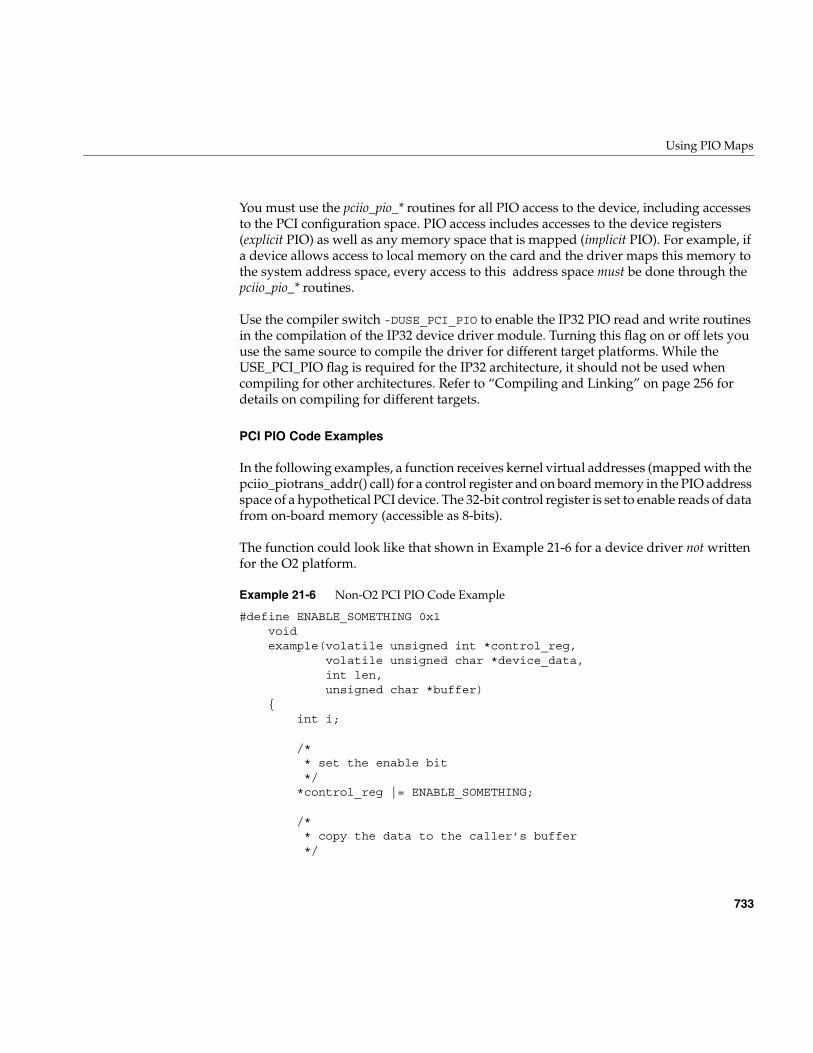
Using PIO Maps
733
You must use the pciio_pio_* routines for all PIO access to the device, including accessesto the PCI configuration space. PIO access includes accesses to the device registers(explicit PIO) as well as any memory space that is mapped (implicit PIO). For example, ifa device allows access to local memory on the card and the driver maps this memory tothe system address space, every access to this address space must be done through thepciio_pio_* routines.
Use the compiler switch -DUSE_PCI_PIO to enable the IP32 PIO read and write routinesin the compilation of the IP32 device driver module. Turning this flag on or off lets youuse the same source to compile the driver for different target platforms. While theUSE_PCI_PIO flag is required for the IP32 architecture, it should not be used whencompiling for other architectures. Refer to “Compiling and Linking” on page 256 fordetails on compiling for different targets.
PCI PIO Code Examples
In the following examples, a function receives kernel virtual addresses (mapped with thepciio_piotrans_addr() call) for a control register and on board memory in the PIO addressspace of a hypothetical PCI device. The 32-bit control register is set to enable reads of datafrom on-board memory (accessible as 8-bits).
The function could look like that shown in Example 21-6 for a device driver not writtenfor the O2 platform.
Example 21-6 Non-O2 PCI PIO Code Example
#define ENABLE_SOMETHING 0x1 void example(volatile unsigned int *control_reg, volatile unsigned char *device_data, int len, unsigned char *buffer) { int i;
/* * set the enable bit */ *control_reg |= ENABLE_SOMETHING;
/* * copy the data to the caller’s buffer */
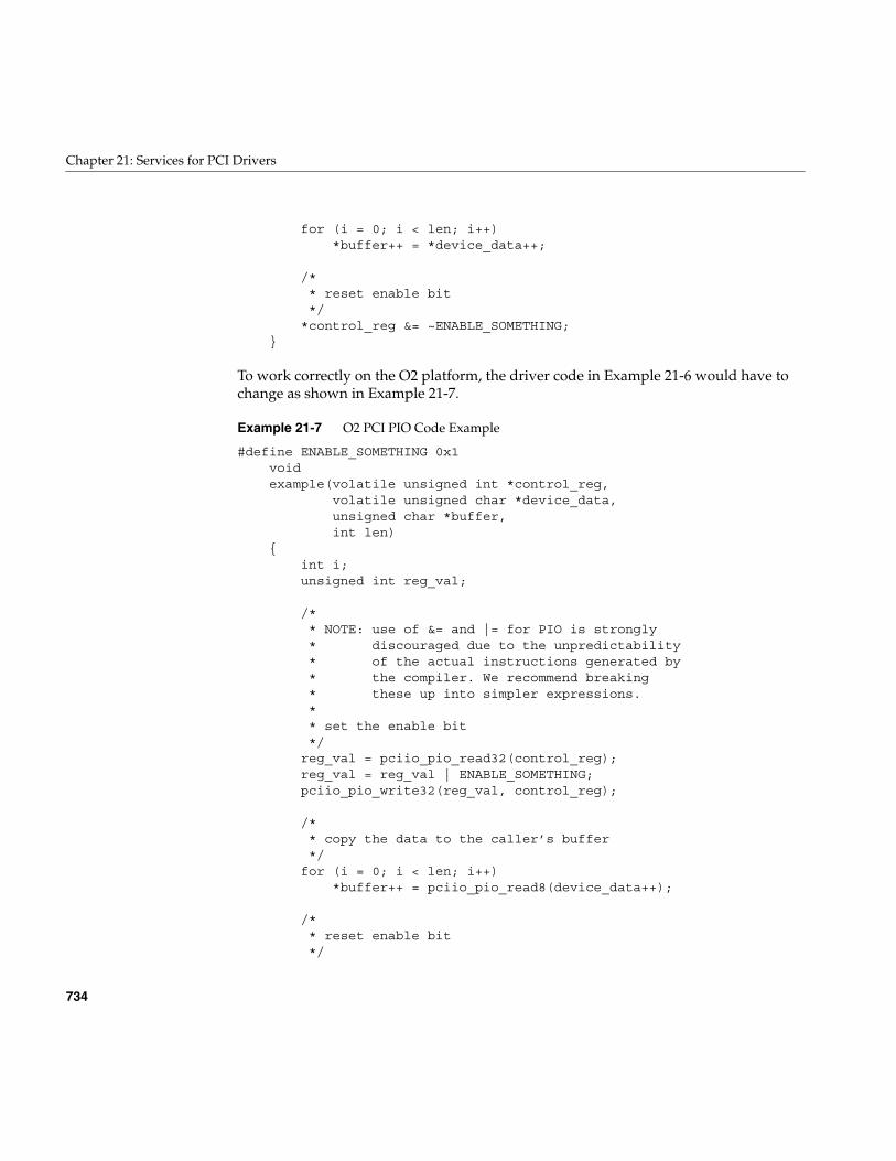
734
Chapter 21: Services for PCI Drivers
for (i = 0; i < len; i++) *buffer++ = *device_data++;
/* * reset enable bit */ *control_reg &= ~ENABLE_SOMETHING; }
To work correctly on the O2 platform, the driver code in Example 21-6 would have tochange as shown in Example 21-7.
Example 21-7 O2 PCI PIO Code Example
#define ENABLE_SOMETHING 0x1 void example(volatile unsigned int *control_reg, volatile unsigned char *device_data, unsigned char *buffer, int len) { int i; unsigned int reg_val;
/* * NOTE: use of &= and |= for PIO is strongly * discouraged due to the unpredictability * of the actual instructions generated by * the compiler. We recommend breaking * these up into simpler expressions. * * set the enable bit */ reg_val = pciio_pio_read32(control_reg); reg_val = reg_val | ENABLE_SOMETHING; pciio_pio_write32(reg_val, control_reg);
/* * copy the data to the caller’s buffer */ for (i = 0; i < len; i++) *buffer++ = pciio_pio_read8(device_data++);
/* * reset enable bit */
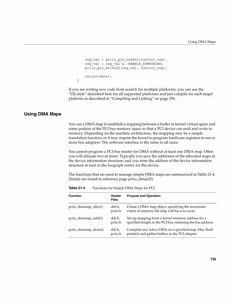
Using DMA Maps
735
reg_val = pciio_pio_read32(control_reg); reg_val = reg_val & ~ENABLE_SOMETHING; pciio_pio_write32(reg_val, control_reg);
return(data); }
If you are writing new code from scratch for multiple platforms, you can use the“O2-style” described here for all supported platforms and just compile for each targetplatform as described in “Compiling and Linking” on page 256.
Using DMA Maps
You use a DMA map to establish a mapping between a buffer in kernel virtual space andsome portion of the PCI bus memory space so that a PCI device can read and write tomemory. Depending on the machine architecture, the mapping may be a simpletranslation function, or it may require the kernel to program hardware registers in one ormore bus adapters. The software interface is the same in all cases.
You cannot program a PCI bus master for DMA without at least one DMA map. Oftenyou will allocate two or more. Typically you save the addresses of the allocated maps inthe device information structure; and you store the address of the device informationstructure in turn in the hwgraph vertex for the device.
The functions that are used to manage simple DMA maps are summarized in Table 21-4.Details are found in reference page pciio_dma(d3).
Table 21-4 Functions for Simple DMA Maps for PCI
Function HeaderFiles
Purpose and Operation
pciio_dmamap_alloc() ddi.h,pciio.h
Create a DMA map object, specifying the maximumextent of memory the map will have to cover.
pciio_dmamap_addr() ddi.h,pciio.h
Set up mapping from a kernel memory address for aspecified length, to the PCI bus, returning the bus address.
pciio_dmamap_drain() ddi.h,pciio.h
Complete any active DMA on a specified map. May flushprefetch and gather buffers in the PCI adapter.
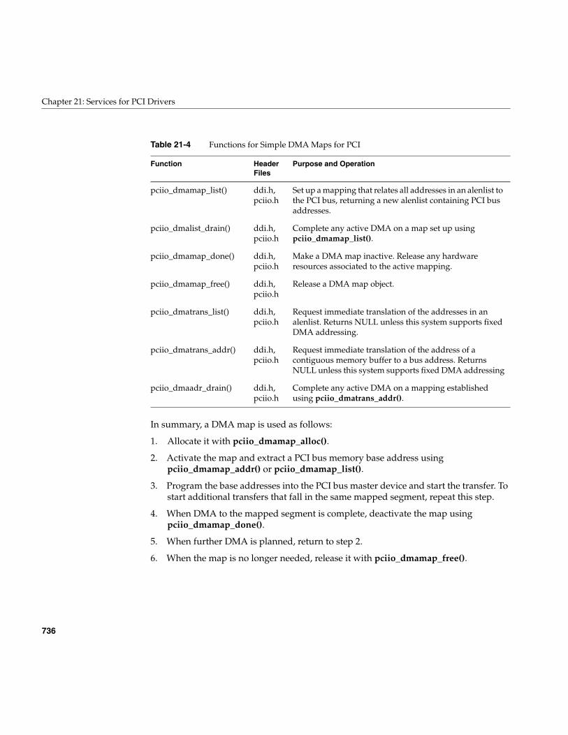
736
Chapter 21: Services for PCI Drivers
In summary, a DMA map is used as follows:
1. Allocate it with pciio_dmamap_alloc().
2. Activate the map and extract a PCI bus memory base address usingpciio_dmamap_addr() or pciio_dmamap_list().
3. Program the base addresses into the PCI bus master device and start the transfer. Tostart additional transfers that fall in the same mapped segment, repeat this step.
4. When DMA to the mapped segment is complete, deactivate the map usingpciio_dmamap_done().
5. When further DMA is planned, return to step 2.
6. When the map is no longer needed, release it with pciio_dmamap_free().
pciio_dmamap_list() ddi.h,pciio.h
Set up a mapping that relates all addresses in an alenlist tothe PCI bus, returning a new alenlist containing PCI busaddresses.
pciio_dmalist_drain() ddi.h,pciio.h
Complete any active DMA on a map set up usingpciio_dmamap_list().
pciio_dmamap_done() ddi.h,pciio.h
Make a DMA map inactive. Release any hardwareresources associated to the active mapping.
pciio_dmamap_free() ddi.h,pciio.h
Release a DMA map object.
pciio_dmatrans_list() ddi.h,pciio.h
Request immediate translation of the addresses in analenlist. Returns NULL unless this system supports fixedDMA addressing.
pciio_dmatrans_addr() ddi.h,pciio.h
Request immediate translation of the address of acontiguous memory buffer to a bus address. ReturnsNULL unless this system supports fixed DMA addressing
pciio_dmaadr_drain() ddi.h,pciio.h
Complete any active DMA on a mapping establishedusing pciio_dmatrans_addr().
Table 21-4 Functions for Simple DMA Maps for PCI
Function HeaderFiles
Purpose and Operation
Using DMA Maps
737
Allocating DMA Maps
A DMA map is created by pciio_dmamap_alloc(), which takes arguments are as follows:
Preparing a dev_desc_t
The device descriptor structure type dev_desc_t is declared in iobus.h, which is includedby pciio.h (see also reference page device_desc(d4x)). In this release there is little that thedevice driver needs to know about this structure and its contents. The simplest way toget a device descriptor that can be handed to pciio_dmamap_alloc() is to calldevice_desc_default_get() passing the same connection-point vertex handle, as follows:
ret = pciio_dmamap_alloc(convh,device_desc_default_get(convh),...)
Setting Flag Values
The following flag values control data transfer:
vhdl Connection-point vertex_hdl_t received by pfxattach(). This handleidentifies the device to the kernel by its bus and slot positions.
dev_desc Device descriptor structure (see text following).
byte_count_max Maximum size of the area that will be mapped at any one time.
flags Usage flags and optional no-sleep flag.
PCIIO_DMA_CMD Configure as a generic “command” stream. Generally thismeans turn off prefetchers and write gatherers, andwhatever else might be necessary to make command ringDMAs work as expected.
PCIIO_DMA_DATA Configure as a generic “data” stream. Generally, thismeans turning on prefetchers and write gatherers, andanything else that might increase DMA throughput (shortof using “high priority” or “real time” resources that maylower overall system performance).
PCIIO_PREFETCHPCIIO_NOPREFETCH
Control the use of prefetch hardware, overriding the CMDor DATA selection.
PCIIO_WRITE_GATHERPCIIO_NOWRITE_GATHER
Control the use of write-gather hardware, overriding theCMD or DATA selection.
738
Chapter 21: Services for PCI Drivers
(Note that the values for the PCIIO_DMA* flags has changed for IRIX 6.5.) All systemshave the ability to gather as much as one cache line of device data before starting a writeto memory, but some systems have better write-gather support. All systems have acertain amount of “prefetch” ability in that they load a full cache line from memory whenthe device issues a read. However, some systems can prefetch the next cache line whilethe device is still accepting the first one. The PCI infrastructure notes in the DMA mapwhether you want these features maximized for the given hardware, or minimized,depending on the flag settings.
The following flag values control the use of the PCI bus adapter:
You should specify either PCIIO_BYTE_STREAM or PCIIO_WORD_VALUES; there isno default. (More correctly, the default is “whatever the hardware of this system does,”and different systems do different things.) When you specify PCIIO_BYTE_STREAM, ablock of bytes transferred from the device to memory has the same sequence of bytes inboth locations. When you specify PCIIO_WORD_VALUES, the numerical significance ofthe bytes in each 32-bit word are preserved between the big-endian memory andlittle-endian device.
The following flag values control kernel operations:
Using a DMA Map
After a map has been allocated, it is inactive. When you apply a function to a map to geta translated address, the function activates the map if it is not active, and uses the mapto set up a correspondence between PCI bus memory addresses and one or moresegments of kernel virtual address space.
In some systems, “activating a map” can be a null operation. In other systems, an activeDMA map may represent a commitment of limited hardware resources—for example,mapping registers in a bus adapter.
PCIIO_DMA_A64 Device and driver are prepared to use 64-bit addressing.
PCIIO_BYTE_STREAM Retain the order of a stream of bytes between device andmemory.
PCIIO_WORD_VALUES Byte-swap 32-bit words during transfer as required toproduce big-endian data order in memory.
PCIIO_NOSLEEP Do not sleep on memory allocation.
PCIIO_INPLACE Translate alenlists in place instead of copying them.
Using DMA Maps
739
You can use a DMA map to map a specified memory segment, or you can use it totranslate all entries in an address/length list (see “Address/Length Lists” on page 193)in a single operation.
Mapping an Address/Length List
You map an alenlist using pciio_dmamap_list(). This function takes an alenlist thatrepresents a memory buffer, and in one operation produces a new list containing PCI busaddresses and lengths. You read out the translated addresses from the list and programthem into the bus master device (see “Using Address/Length Lists” on page 213).
Mapping a Specific Buffer
You obtain a DMA map for a single, contiguous span of kernel virtual memory by callingpciio_dmamap_addr(). If the mapping cannot be set up, 0 is returned. (You must checkfor this possibility, because if you start a DMA transfer to location 0, a bus error results.)Otherwise the value returned is a PCI bus address that you can program into a busmaster device. When the device accesses that address, it accesses the specified memorylocation.
Completing DMA Transfers
If it is necessary to establish that a DMA transfer is fully complete—all input data storedin physical memory, all output data copied from memory—use the “drain” function thatcorresponds to the way the map was activated. For example, if the map was activatedusing pciio_dmamap_list(), you call pciio_dmalist_drain() to ensure that current DMAis complete. When the bus adapter uses prefetch buffers or write-gather buffers, they areflushed.
Deactivating Addresses and Maps
Once you have created a mapping, the map is active. It remains active until you use thesame DMA map object to map a different buffer, or until you call eitherpciio_dmamap_done() or pciio_dmamap_free().
In some systems, it costs nothing to keep a DMA map active. In other systems, an activemap may tie up global hardware resources. It is is a good idea to callpciio_dmamap_done() when the I/O operation is complete.
740
Chapter 21: Services for PCI Drivers
Caution: Never call pciio_dmamap_done() before the device has stopped sending data.Memory corruption could result.
Using One-Step DMA Translation
Some systems also support one-step mapping functions pciio_dmatrans_addr() andpciio_dmatrans_list(). In effect, these functions combine creating a map, using the map,and freeing the map into a single step. They can fail (returning 0) in systems that do notuse simple bus maps. If you use them, you must test the returned address. If it is 0, theone-step translation failed and the address is invalid.
The two-step process of allocating a map and then interrogating it is more general andworks in all systems.
Interrogating DMA Maps
The following functions can be used to interrogate a DMA map object (see pciio_get(d3)):
Registering an Interrupt Handler
When a device can interrupt, you must register an interrupt handler for it. This is donein a two-step process. First you create an interrupt connection object; then you use thatobject to specify the interrupt handling function. Prior to unloading the driver ordetaching the device, you must unregister the handler (but you can retain the interruptconnection object).
Table 21-5 Functions for Interrogating DMA Maps
Function HeaderFiles
Purpose and Operation
pciio_dma_dev_get() ddi.h,pciio.h
Return the connection point handle from a map.
pciio_dma_slot_get() ddi.h,pciio.h
Return the bus slot number of the mapped device.
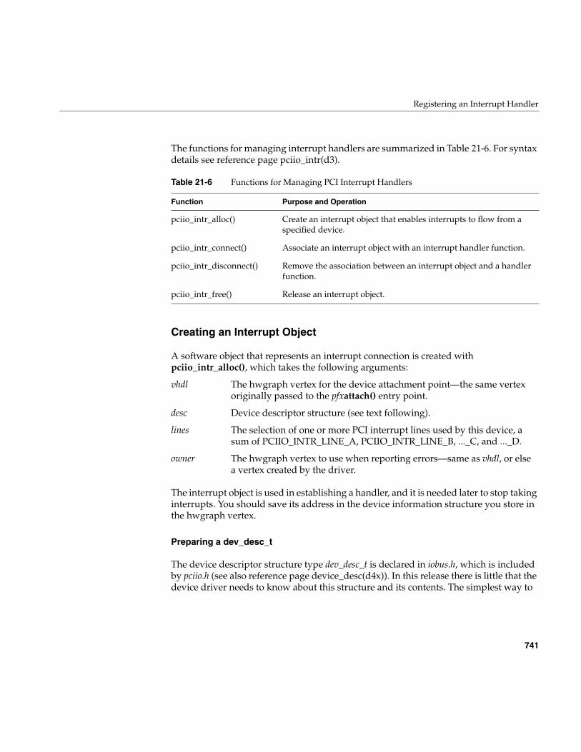
Registering an Interrupt Handler
741
The functions for managing interrupt handlers are summarized in Table 21-6. For syntaxdetails see reference page pciio_intr(d3).
Creating an Interrupt Object
A software object that represents an interrupt connection is created withpciio_intr_alloc(), which takes the following arguments:
The interrupt object is used in establishing a handler, and it is needed later to stop takinginterrupts. You should save its address in the device information structure you store inthe hwgraph vertex.
Preparing a dev_desc_t
The device descriptor structure type dev_desc_t is declared in iobus.h, which is includedby pciio.h (see also reference page device_desc(d4x)). In this release there is little that thedevice driver needs to know about this structure and its contents. The simplest way to
Table 21-6 Functions for Managing PCI Interrupt Handlers
Function Purpose and Operation
pciio_intr_alloc() Create an interrupt object that enables interrupts to flow from aspecified device.
pciio_intr_connect() Associate an interrupt object with an interrupt handler function.
pciio_intr_disconnect() Remove the association between an interrupt object and a handlerfunction.
pciio_intr_free() Release an interrupt object.
vhdl The hwgraph vertex for the device attachment point—the same vertexoriginally passed to the pfxattach() entry point.
desc Device descriptor structure (see text following).
lines The selection of one or more PCI interrupt lines used by this device, asum of PCIIO_INTR_LINE_A, PCIIO_INTR_LINE_B, ..._C, and ..._D.
owner The hwgraph vertex to use when reporting errors—same as vhdl, or elsea vertex created by the driver.
742
Chapter 21: Services for PCI Drivers
get a device descriptor that can be handed to pciio_intr_alloc() is to calldevice_desc_default_get() passing the same connection-point vertex handle, as follows:
ret = pciio_intr_alloc(convh,device_desc_default_get(convh),...)
Connecting the Handler
After creating the interrupt object, you establish a handler using pciio_intr_connect(). Itsprincipal arguments are the interrupt object, a handler address, and a value to be passedto the handler when it is called:
Connecting the Handler
The function prototype for the interrupt handler is named intr_func_t and is declared insys/iobus.h (which is included by sys/PCI/pciio.h). The function prototype is
typedef void *intr_arg_t;typedef void intr_func_f(intr_arg_t);typedef intr_func_f *intr_func_t;
Caution: This function prototype differs from the same prototype as it was declared inIRIX 6.3. The interrupt handler in 6.3 is declared to receive one additional argument thatis not supported in the later releases.
If a device will interrupt on line C, interrupt setup could resemble Example 21-8.
intr The value returned by pciio_intr_alloc().
func Address of the function to be called when an interrupt occurs; seefollowing text for the prototype.
arg A pointer-sized value to be passed as the argument to func each time it iscalled. Typically the address of the device information structure, or thehandle of the device vertex.
thread Passed as NULL.
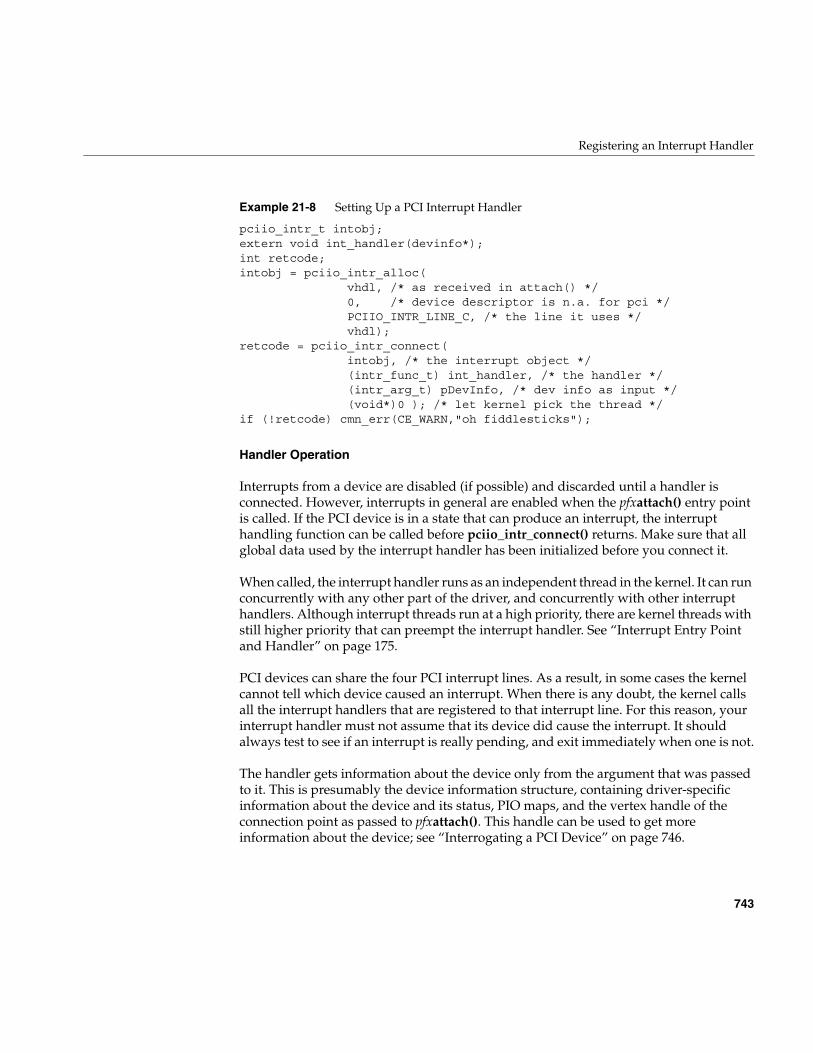
Registering an Interrupt Handler
743
Example 21-8 Setting Up a PCI Interrupt Handler
pciio_intr_t intobj;extern void int_handler(devinfo*);int retcode;intobj = pciio_intr_alloc(
vhdl, /* as received in attach() */0, /* device descriptor is n.a. for pci */PCIIO_INTR_LINE_C, /* the line it uses */vhdl);
retcode = pciio_intr_connect(intobj, /* the interrupt object */(intr_func_t) int_handler, /* the handler */(intr_arg_t) pDevInfo, /* dev info as input */(void*)0 ); /* let kernel pick the thread */
if (!retcode) cmn_err(CE_WARN,"oh fiddlesticks");
Handler Operation
Interrupts from a device are disabled (if possible) and discarded until a handler isconnected. However, interrupts in general are enabled when the pfxattach() entry pointis called. If the PCI device is in a state that can produce an interrupt, the interrupthandling function can be called before pciio_intr_connect() returns. Make sure that allglobal data used by the interrupt handler has been initialized before you connect it.
When called, the interrupt handler runs as an independent thread in the kernel. It can runconcurrently with any other part of the driver, and concurrently with other interrupthandlers. Although interrupt threads run at a high priority, there are kernel threads withstill higher priority that can preempt the interrupt handler. See “Interrupt Entry Pointand Handler” on page 175.
PCI devices can share the four PCI interrupt lines. As a result, in some cases the kernelcannot tell which device caused an interrupt. When there is any doubt, the kernel callsall the interrupt handlers that are registered to that interrupt line. For this reason, yourinterrupt handler must not assume that its device did cause the interrupt. It shouldalways test to see if an interrupt is really pending, and exit immediately when one is not.
The handler gets information about the device only from the argument that was passedto it. This is presumably the device information structure, containing driver-specificinformation about the device and its status, PIO maps, and the vertex handle of theconnection point as passed to pfxattach(). This handle can be used to get moreinformation about the device; see “Interrogating a PCI Device” on page 746.
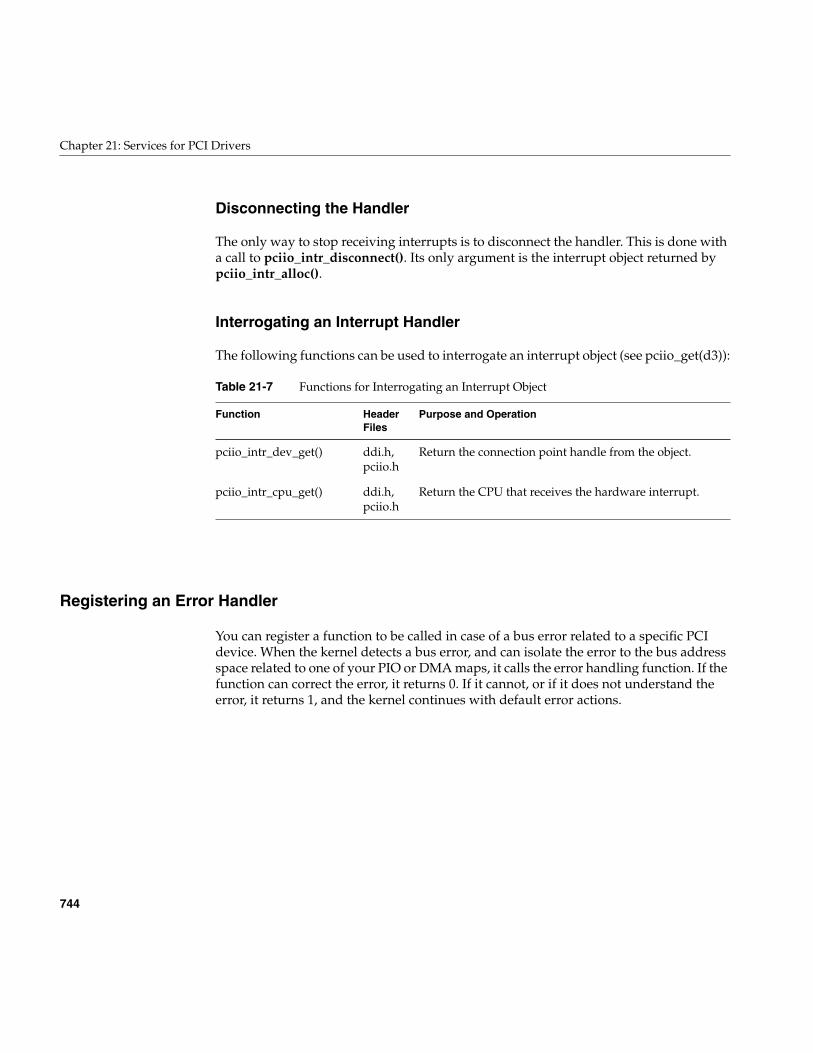
744
Chapter 21: Services for PCI Drivers
Disconnecting the Handler
The only way to stop receiving interrupts is to disconnect the handler. This is done witha call to pciio_intr_disconnect(). Its only argument is the interrupt object returned bypciio_intr_alloc().
Interrogating an Interrupt Handler
The following functions can be used to interrogate an interrupt object (see pciio_get(d3)):
Registering an Error Handler
You can register a function to be called in case of a bus error related to a specific PCIdevice. When the kernel detects a bus error, and can isolate the error to the bus addressspace related to one of your PIO or DMA maps, it calls the error handling function. If thefunction can correct the error, it returns 0. If it cannot, or if it does not understand theerror, it returns 1, and the kernel continues with default error actions.
Table 21-7 Functions for Interrogating an Interrupt Object
Function HeaderFiles
Purpose and Operation
pciio_intr_dev_get() ddi.h,pciio.h
Return the connection point handle from the object.
pciio_intr_cpu_get() ddi.h,pciio.h
Return the CPU that receives the hardware interrupt.
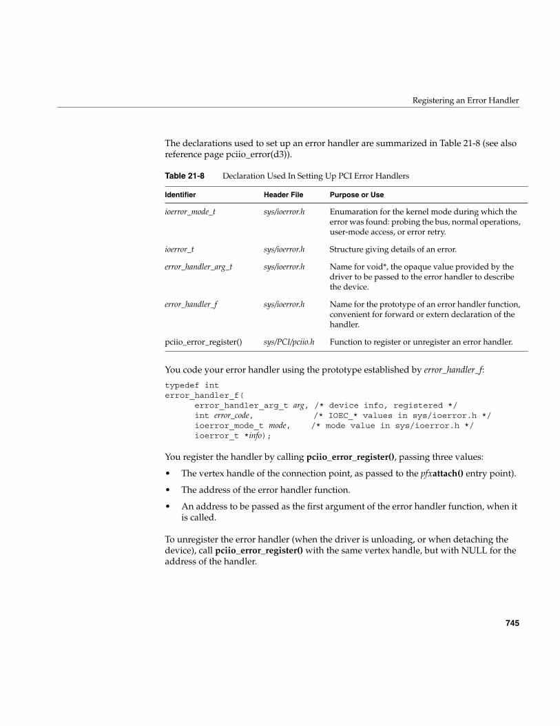
Registering an Error Handler
745
The declarations used to set up an error handler are summarized in Table 21-8 (see alsoreference page pciio_error(d3)).
You code your error handler using the prototype established by error_handler_f:
typedef interror_handler_f(
error_handler_arg_t arg, /* device info, registered */int error_code, /* IOEC_* values in sys/ioerror.h */ioerror_mode_t mode, /* mode value in sys/ioerror.h */ioerror_t *info);
You register the handler by calling pciio_error_register(), passing three values:
• The vertex handle of the connection point, as passed to the pfxattach() entry point).
• The address of the error handler function.
• An address to be passed as the first argument of the error handler function, when itis called.
To unregister the error handler (when the driver is unloading, or when detaching thedevice), call pciio_error_register() with the same vertex handle, but with NULL for theaddress of the handler.
Table 21-8 Declaration Used In Setting Up PCI Error Handlers
Identifier Header File Purpose or Use
ioerror_mode_t sys/ioerror.h Enumaration for the kernel mode during which theerror was found: probing the bus, normal operations,user-mode access, or error retry.
ioerror_t sys/ioerror.h Structure giving details of an error.
error_handler_arg_t sys/ioerror.h Name for void*, the opaque value provided by thedriver to be passed to the error handler to describethe device.
error_handler_f sys/ioerror.h Name for the prototype of an error handler function,convenient for forward or extern declaration of thehandler.
pciio_error_register() sys/PCI/pciio.h Function to register or unregister an error handler.
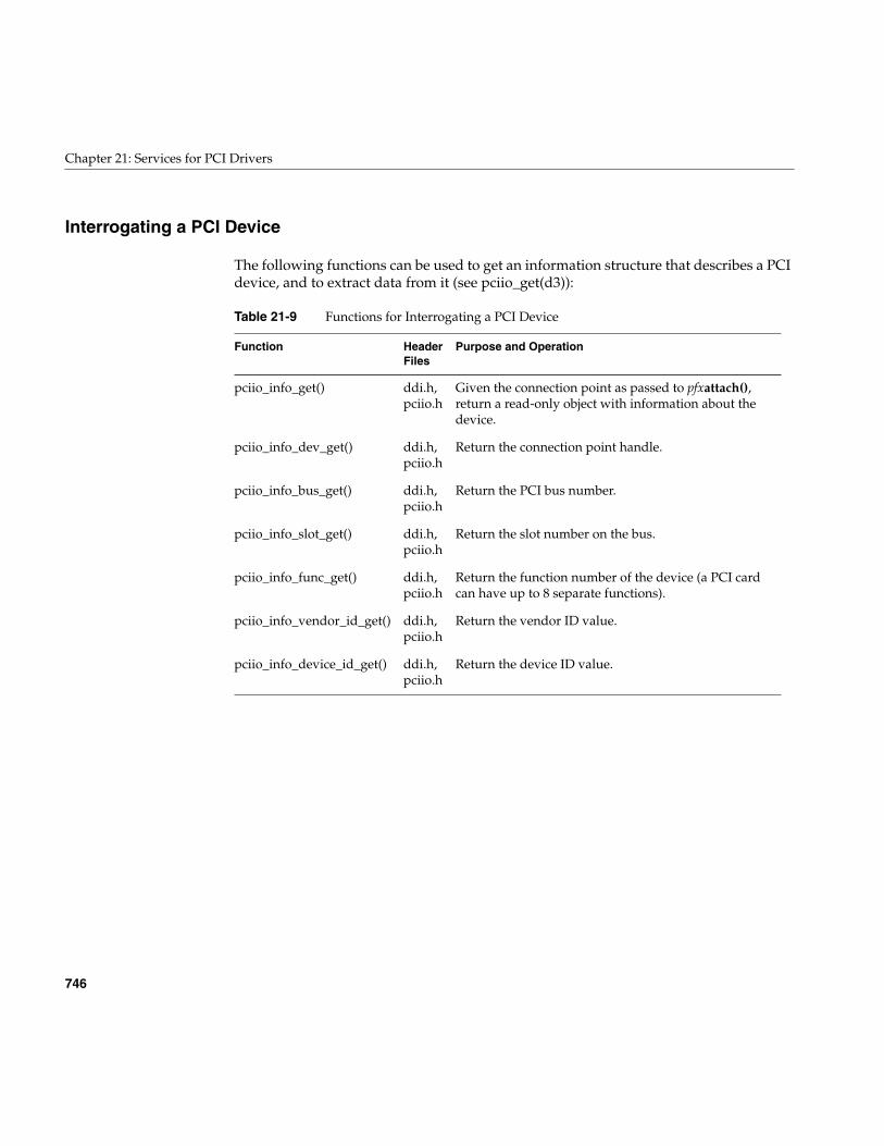
746
Chapter 21: Services for PCI Drivers
Interrogating a PCI Device
The following functions can be used to get an information structure that describes a PCIdevice, and to extract data from it (see pciio_get(d3)):
Table 21-9 Functions for Interrogating a PCI Device
Function HeaderFiles
Purpose and Operation
pciio_info_get() ddi.h,pciio.h
Given the connection point as passed to pfxattach(),return a read-only object with information about thedevice.
pciio_info_dev_get() ddi.h,pciio.h
Return the connection point handle.
pciio_info_bus_get() ddi.h,pciio.h
Return the PCI bus number.
pciio_info_slot_get() ddi.h,pciio.h
Return the slot number on the bus.
pciio_info_func_get() ddi.h,pciio.h
Return the function number of the device (a PCI cardcan have up to 8 separate functions).
pciio_info_vendor_id_get() ddi.h,pciio.h
Return the vendor ID value.
pciio_info_device_id_get() ddi.h,pciio.h
Return the device ID value.
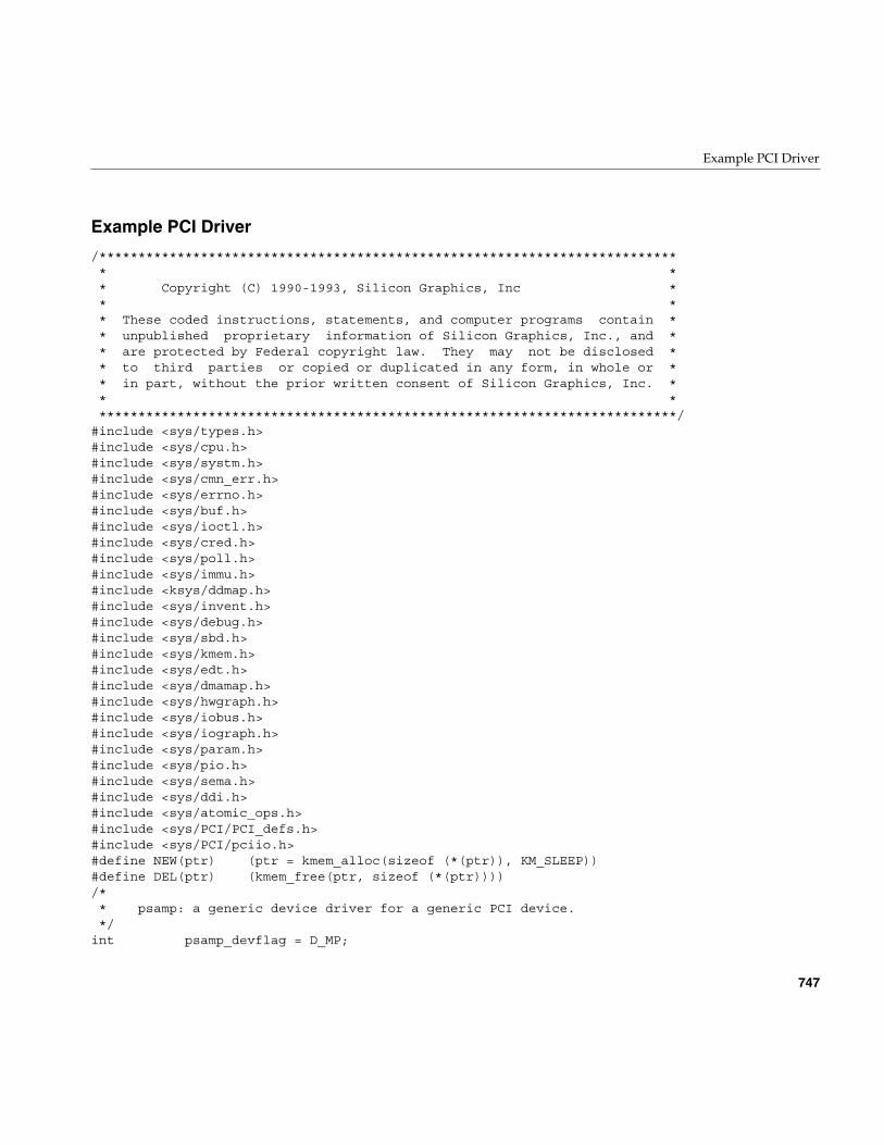
Example PCI Driver
747
Example PCI Driver
/************************************************************************** * * * Copyright (C) 1990-1993, Silicon Graphics, Inc * * * * These coded instructions, statements, and computer programs contain * * unpublished proprietary information of Silicon Graphics, Inc., and * * are protected by Federal copyright law. They may not be disclosed * * to third parties or copied or duplicated in any form, in whole or * * in part, without the prior written consent of Silicon Graphics, Inc. * * * **************************************************************************/#include <sys/types.h>#include <sys/cpu.h>#include <sys/systm.h>#include <sys/cmn_err.h>#include <sys/errno.h>#include <sys/buf.h>#include <sys/ioctl.h>#include <sys/cred.h>#include <sys/poll.h>#include <sys/immu.h>#include <ksys/ddmap.h>#include <sys/invent.h>#include <sys/debug.h>#include <sys/sbd.h>#include <sys/kmem.h>#include <sys/edt.h>#include <sys/dmamap.h>#include <sys/hwgraph.h>#include <sys/iobus.h>#include <sys/iograph.h>#include <sys/param.h>#include <sys/pio.h>#include <sys/sema.h>#include <sys/ddi.h>#include <sys/atomic_ops.h>#include <sys/PCI/PCI_defs.h>#include <sys/PCI/pciio.h>#define NEW(ptr) (ptr = kmem_alloc(sizeof (*(ptr)), KM_SLEEP))#define DEL(ptr) (kmem_free(ptr, sizeof (*(ptr))))/* * psamp: a generic device driver for a generic PCI device. */int psamp_devflag = D_MP;
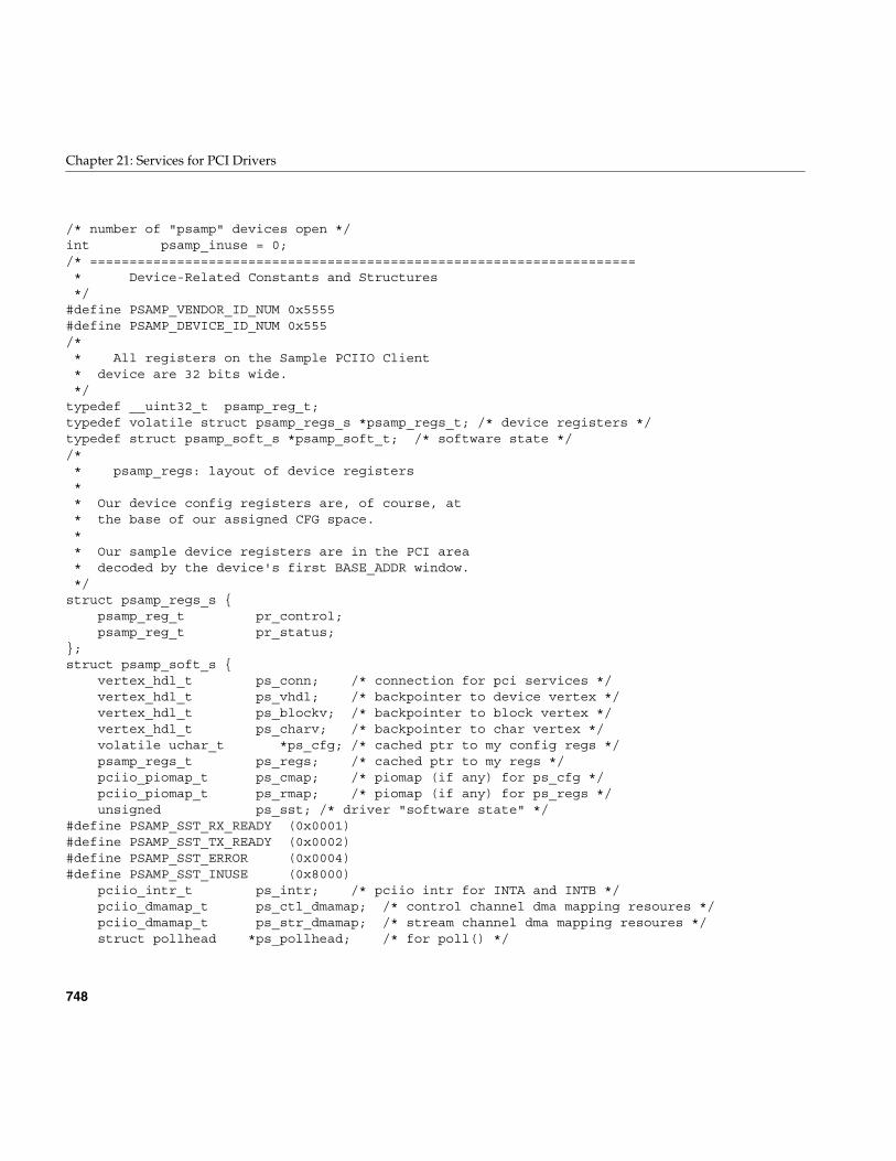
748
Chapter 21: Services for PCI Drivers
/* number of "psamp" devices open */int psamp_inuse = 0;/* ===================================================================== * Device-Related Constants and Structures */#define PSAMP_VENDOR_ID_NUM 0x5555#define PSAMP_DEVICE_ID_NUM 0x555/* * All registers on the Sample PCIIO Client * device are 32 bits wide. */typedef __uint32_t psamp_reg_t;typedef volatile struct psamp_regs_s *psamp_regs_t; /* device registers */typedef struct psamp_soft_s *psamp_soft_t; /* software state *//* * psamp_regs: layout of device registers * * Our device config registers are, of course, at * the base of our assigned CFG space. * * Our sample device registers are in the PCI area * decoded by the device's first BASE_ADDR window. */struct psamp_regs_s { psamp_reg_t pr_control; psamp_reg_t pr_status;};struct psamp_soft_s { vertex_hdl_t ps_conn; /* connection for pci services */ vertex_hdl_t ps_vhdl; /* backpointer to device vertex */ vertex_hdl_t ps_blockv; /* backpointer to block vertex */ vertex_hdl_t ps_charv; /* backpointer to char vertex */ volatile uchar_t *ps_cfg; /* cached ptr to my config regs */ psamp_regs_t ps_regs; /* cached ptr to my regs */ pciio_piomap_t ps_cmap; /* piomap (if any) for ps_cfg */ pciio_piomap_t ps_rmap; /* piomap (if any) for ps_regs */ unsigned ps_sst; /* driver "software state" */#define PSAMP_SST_RX_READY (0x0001)#define PSAMP_SST_TX_READY (0x0002)#define PSAMP_SST_ERROR (0x0004)#define PSAMP_SST_INUSE (0x8000) pciio_intr_t ps_intr; /* pciio intr for INTA and INTB */ pciio_dmamap_t ps_ctl_dmamap; /* control channel dma mapping resoures */ pciio_dmamap_t ps_str_dmamap; /* stream channel dma mapping resoures */ struct pollhead *ps_pollhead; /* for poll() */
Example PCI Driver
749
int ps_blocks; /* block device size in NBPSCTR blocks */};#define psamp_soft_set(v,i) device_info_set((v),(void *)(i))#define psamp_soft_get(v) ((psamp_soft_t)device_info_get((v)))/* ===================================================================== * FUNCTION TABLE OF CONTENTS */void psamp_init(void);int psamp_unload(void);int psamp_reg(void);int psamp_unreg(void);int psamp_attach(vertex_hdl_t conn);int psamp_detach(vertex_hdl_t conn);static pciio_iter_f psamp_reloadme;static pciio_iter_f psamp_unloadme;int psamp_open(dev_t *devp, int oflag, int otyp, cred_t *crp);int psamp_close(dev_t dev, int oflag, int otyp, cred_t *crp);int psamp_ioctl(dev_t dev, int cmd, void *arg, int mode, cred_t *crp, int *rvalp);int psamp_read(dev_t dev, uio_t * uiop, cred_t *crp);int psamp_write(dev_t dev, uio_t * uiop, cred_t *crp);int psamp_strategy(struct buf *bp);int psamp_poll(dev_t dev, short events, int anyyet, short *reventsp, struct pollhead **phpp);int psamp_map(dev_t dev, vhandl_t *vt, off_t off, size_t len, uint_t prot);int psamp_unmap(dev_t dev, vhandl_t *vt);void psamp_dma_intr(intr_arg_t arg);static error_handler_f psamp_error_handler;void psamp_halt(void);int psamp_size(dev_t dev);int psamp_print(dev_t dev, char *str);/* ===================================================================== * Driver Initialization *//* * psamp_init: called once during system startup or * when a loadable driver is loaded. */voidpsamp_init(void){ printf("psamp_init()\n"); /* * if we are already registered, note * that this is a "reload" and reconnect * all the places we attached.
750
Chapter 21: Services for PCI Drivers
*/ pciio_iterate("psamp_", psamp_reloadme);}/* * psamp_unload: if no "psamp" is open, put us to bed * and let the driver text get unloaded. */intpsamp_unload(void){ if (psamp_inuse) return EBUSY; pciio_iterate("psamp_", psamp_unloadme); return 0;}/* * psamp_reg: called once during system startup or * when a loadable driver is loaded. * * NOTE: a bus provider register routine should always be * called from _reg, rather than from _init. In the case * of a loadable module, the devsw is not hooked up * when the _init routines are called. * */intpsamp_reg(void){ printf("psamp_reg()\n"); pciio_driver_register(PSAMP_VENDOR_ID_NUM, PSAMP_DEVICE_ID_NUM, "psamp_", 0); return 0;}/* * psamp_unreg: called when a loadable driver is unloaded. */intpsamp_unreg(void){ pciio_driver_unregister("psamp_"); return 0;}/*
Example PCI Driver
751
* psamp_attach: called by the pciio infrastructure * once for each vertex representing a crosstalk * widget. * * In large configurations, it is possible for a * huge number of CPUs to enter this routine all at * nearly the same time, for different specific * instances of the device. Attempting to give your * devices sequence numbers based on the order they * are found in the system is not only futile but * may be dangerous as the order may differ from * run to run. */intpsamp_attach(vertex_hdl_t conn){ vertex_hdl_t vhdl, blockv, charv; volatile uchar_t *cfg; psamp_regs_t regs; psamp_soft_t soft; pciio_piomap_t cmap; pciio_piomap_t rmap; printf("psamp_attach()\n"); hwgraph_device_add(conn, "psamp", "psamp_", &vhdl, &blockv, &charv); /* * Allocate a place to put per-device * information for this vertex. Then * associate it with the vertex in the * most efficient manner. */ NEW(soft); ASSERT(soft != NULL); psamp_soft_set(vhdl, soft); psamp_soft_set(blockv, soft); psamp_soft_set(charv, soft); soft->ps_conn = conn; soft->ps_vhdl = vhdl; soft->ps_blockv = blockv; soft->ps_charv = charv; /* * Find our PCI CONFIG registers. */ cfg = (volatile uchar_t *) pciio_pio_addr (conn, 0, /* device and (override) dev_info */ PCIIO_SPACE_CFG, /* select configuration address space */ 0, /* from the start of space, */
752
Chapter 21: Services for PCI Drivers
PCI_CFG_VEND_SPECIFIC, /* ... up to the vendor specific stuff. */ &cmap, /* in case we needed a piomap */ 0); /* flag word */ soft->ps_cfg = cfg; /* save for later */ soft->ps_cmap = cmap; printf("psamp_attach: I can see my CFG regs at 0x%x\n", cfg); /* * Get a pointer to our DEVICE registers */ regs = (psamp_regs_t) pciio_pio_addr (conn, 0, /* device and (override) dev_info */ PCIIO_SPACE_WIN(0), /* in my primary decode window, */ 0, sizeof(*regs), /* base and size */ &rmap, /* in case we needed a piomap */ 0); /* flag word */ soft->ps_regs = regs; /* save for later */ soft->ps_rmap = cmap; printf("psamp_attach: I can see my device regs at 0x%x\n", regs); /* * Set up our interrupt. * We might interrupt on INTA or INTB, * but route 'em both to the same function. */ soft->ps_intr = pciio_intr_alloc (conn, 0, PCIIO_INTR_LINE_A | PCIIO_INTR_LINE_B, vhdl); pciio_intr_connect(soft->ps_intr, psamp_dma_intr, soft, (void *) 0); /* * set up our error handler. */ pciio_error_register(conn, psamp_error_handler, soft); /* * For pciio clients, *now* is the time to * allocate pollhead structures. */ soft->ps_pollhead = phalloc(0); return 0; /* attach successsful */}/* * psamp_detach: called by the pciio infrastructure * once for each vertex representing a crosstalk
Example PCI Driver
753
* widget when unregistering the driver. * * In large configurations, it is possible for a * huge number of CPUs to enter this routine all at * nearly the same time, for different specific * instances of the device. Attempting to give your * devices sequence numbers based on the order they * are found in the system is not only futile but * may be dangerous as the order may differ from * run to run. */intpsamp_detach(vertex_hdl_t conn){ vertex_hdl_t vhdl, blockv, charv; psamp_soft_t soft; printf("psamp_detach()\n"); if (GRAPH_SUCCESS != hwgraph_traverse(conn, "psamp", &vhdl)) return -1; soft = psamp_soft_get(vhdl); pciio_error_register(conn, 0, 0); pciio_intr_disconnect(soft->ps_intr); pciio_intr_free(soft->ps_intr); phfree(soft->ps_pollhead); if (soft->ps_ctl_dmamap) pciio_dmamap_free(soft->ps_ctl_dmamap); if (soft->ps_str_dmamap) pciio_dmamap_free(soft->ps_str_dmamap); if (soft->ps_cmap) pciio_piomap_free(soft->ps_cmap); if (soft->ps_rmap) pciio_piomap_free(soft->ps_rmap); hwgraph_edge_remove(conn, "psamp", &vhdl); /* we really need "hwgraph_dev_remove" ... */ if (GRAPH_SUCCESS == hwgraph_edge_remove(vhdl, EDGE_LBL_BLOCK, &blockv)) { psamp_soft_set(blockv, 0); hwgraph_vertex_destroy(blockv); } if (GRAPH_SUCCESS == hwgraph_edge_remove(vhdl, EDGE_LBL_CHAR, &charv)) { psamp_soft_set(charv, 0); hwgraph_vertex_destroy(charv); } psamp_soft_set(vhdl, 0);
754
Chapter 21: Services for PCI Drivers
hwgraph_vertex_destroy(vhdl); DEL(soft); return 0;}/* * psamp_reloadme: utility function used indirectly * by psamp_init, via pciio_iterate, to "reconnect" * each connection point when the driver has been * reloaded. */static voidpsamp_reloadme(vertex_hdl_t conn){ vertex_hdl_t vhdl; psamp_soft_t soft; if (GRAPH_SUCCESS != hwgraph_traverse(conn, "psamp", &vhdl)) return; soft = psamp_soft_get(vhdl); /* * Reconnect our error and interrupt handlers */ pciio_error_register(conn, psamp_error_handler, soft); pciio_intr_connect(soft->ps_intr, psamp_dma_intr, soft, 0);}/* * psamp_reloadme: utility function used indirectly * by psamp_unload, via pciio_iterate, to "disconnect" * each connection point before the driver becomes * unloaded. */static voidpsamp_unloadme(vertex_hdl_t pconn){ vertex_hdl_t vhdl; psamp_soft_t soft; if (GRAPH_SUCCESS != hwgraph_traverse(pconn, "psamp", &vhdl)) return; soft = psamp_soft_get(vhdl); /* * Disconnect our error and interrupt handlers */ pciio_error_register(pconn, 0, 0); pciio_intr_disconnect(soft->ps_intr);
Example PCI Driver
755
}/* ===================================================================== * DRIVER OPEN/CLOSE *//* * psamp_open: called when a device special file is * opened or when a block device is mounted. *//* ARGSUSED */intpsamp_open(dev_t *devp, int oflag, int otyp, cred_t *crp){ vertex_hdl_t vhdl = dev_to_vhdl(*devp); psamp_soft_t soft = psamp_soft_get(vhdl); psamp_regs_t regs = soft->ps_regs; printf("psamp_open() regs=%x\n", regs); /* * BLOCK DEVICES: now would be a good time to * calculate the size of the device and stash it * away for use by psamp_size. */ /* * USER ABI (64-bit): chances are, you are being * compiled for use in a 64-bit IRIX kernel; if * you use the _ioctl or _poll entry points, now * would be a good time to test and save the * user process' model so you know how to * interpret the user ioctl and poll requests. */ if (!(PSAMP_SST_INUSE & atomicSetUint(&soft->ps_sst, PSAMP_SST_INUSE))) atomicAddInt(&psamp_inuse, 1); return 0;}/* * psamp_close: called when a device special file * is closed by a process and no other processes * still have it open ("last close"). *//* ARGSUSED */intpsamp_close(dev_t dev, int oflag, int otyp, cred_t *crp){ vertex_hdl_t vhdl = dev_to_vhdl(dev); psamp_soft_t soft = psamp_soft_get(vhdl); psamp_regs_t regs = soft->ps_regs; printf("psamp_close() regs=%x\n", regs);
756
Chapter 21: Services for PCI Drivers
atomicClearUint(&soft->ps_sst, PSAMP_SST_INUSE); atomicAddInt(&psamp_inuse, -1); return 0;}/* ===================================================================== * CONTROL ENTRY POINT *//* * psamp_ioctl: a user has made an ioctl request * for an open character device. * * cmd and arg are as specified by the user; arg is * probably a pointer to something in the user's * address space, so you need to use copyin() to * read through it and copyout() to write through it. *//* ARGSUSED */intpsamp_ioctl(dev_t dev, int cmd, void *arg, int mode, cred_t *crp, int *rvalp){ vertex_hdl_t vhdl = dev_to_vhdl(dev); psamp_soft_t soft = psamp_soft_get(vhdl); psamp_regs_t regs = soft->ps_regs; printf("psamp_ioctl() regs=%x\n", regs); *rvalp = -1; return ENOTTY; /* TeleType® is a registered trademark. */}/* ===================================================================== * DATA TRANSFER ENTRY POINTS * * Since I'm trying to provide an example for both * character and block devices, I'm routing read * and write back through strategy as described in * the IRIX Device Driver Programming Guide. * * This limits our character driver to reading and * writing in multiples of the standard sector * length. *//* ARGSUSED */intpsamp_read(dev_t dev, uio_t * uiop, cred_t *crp){ return physiock(psamp_strategy,
Example PCI Driver
757
0, /* alocate temp buffer & buf_t */ dev, /* dev_t arg for strategy */ B_READ, /* direction flag for buf_t */ psamp_size(dev), uiop);}/* ARGSUSED */intpsamp_write(dev_t dev, uio_t * uiop, cred_t *crp){ return physiock(psamp_strategy, 0, /* alocate temp buffer & buf_t */ dev, /* dev_t arg for strategy */ B_WRITE, /* direction flag for buf_t */ psamp_size(dev), uiop);}/* ARGSUSED */intpsamp_strategy(struct buf *bp){ /* * I think Len has some code that I can * modify and drop into here. */ return 0;}/* ===================================================================== * POLL ENTRY POINT */intpsamp_poll(dev_t dev, short events, int anyyet, short *reventsp, struct pollhead **phpp){ vertex_hdl_t vhdl = dev_to_vhdl(dev); psamp_soft_t soft = psamp_soft_get(vhdl); psamp_regs_t regs = soft->ps_regs; short happened = 0; printf("psamp_poll() regs=%x\n", regs); if (events & (POLLIN | POLLRDNORM)) if (soft->ps_sst & PSAMP_SST_RX_READY) happened |= POLLIN | POLLRDNORM; if (events & POLLOUT) if (soft->ps_sst & PSAMP_SST_TX_READY) happened |= POLLOUT;
758
Chapter 21: Services for PCI Drivers
if (soft->ps_sst & PSAMP_SST_ERROR) happened |= POLLERR; *reventsp = happened; if (!happened && anyyet) *phpp = soft->ps_pollhead; return 0;}/* ===================================================================== * MEMORY MAP ENTRY POINTS *//* ARGSUSED */intpsamp_map(dev_t dev, vhandl_t *vt, off_t off, size_t len, uint_t prot){ vertex_hdl_t vhdl = dev_to_vhdl(dev); psamp_soft_t soft = psamp_soft_get(vhdl); vertex_hdl_t conn = soft->ps_conn; psamp_regs_t regs = soft->ps_regs; pciio_piomap_t amap; caddr_t kaddr; printf("psamp_map() regs=%x\n", regs); /* * The stuff we want users to mmap * is in our second BASE_ADDR window, * just for fun. */ kaddr = (caddr_t) pciio_pio_addr (conn, 0, PCIIO_SPACE_WIN(1), off, len, &amap, 0); if (kaddr == NULL) return EINVAL; /* XXX- must stash amap somewhere * so we can pciio_piomap_free it * when the mapping goes away. */ v_mapphys(vt, kaddr, len); return 0;}/* ARGSUSED2 */intpsamp_unmap(dev_t dev, vhandl_t *vt){ /* XXX- need to find "amap" that we
Example PCI Driver
759
* used in psamp_map() above, and * if (amap) pciio_piomap_free(amap); */ return (0);}/* ===================================================================== * INTERRUPT ENTRY POINTS * * We avoid using the standard name, since our * prototype has changed. */voidpsamp_dma_intr(intr_arg_t arg){ psamp_soft_t soft = (psamp_soft_t) arg; vertex_hdl_t vhdl = soft->ps_vhdl; psamp_regs_t regs = soft->ps_regs; cmn_err(CE_CONT, "psamp %v: dma done, regs at 0x%X\n", vhdl, regs); /* * for each buf our hardware has processed, * set buf->b_resid, * call pciio_dmamap_done, * call bioerror() or biodone(). * * XXX- would it be better for buf->b_iodone * to be used to get to pciio_dmamap_done? */ /* * may want to call pollwakeup. */}/* ===================================================================== * ERROR HANDLING ENTRY POINTS */static intpsamp_error_handler(void *einfo, int error_code, ioerror_mode_t mode, ioerror_t *ioerror){ psamp_soft_t soft = (psamp_soft_t) einfo; vertex_hdl_t vhdl = soft->ps_vhdl;#if DEBUG && ERROR_DEBUG cmn_err(CE_CONT, "%v: psamp_error_handler\n", vhdl);#else
760
Chapter 21: Services for PCI Drivers
vhdl = vhdl;#endif /* * XXX- there is probably a lot more to do * to recover from an error on a real device; * experts on this are encouraged to add common * things that need to be done into this function. */ ioerror_dump("sample_pciio", error_code, mode, ioerror); return IOERROR_HANDLED;}/* ===================================================================== * SUPPORT ENTRY POINTS *//* * psamp_halt: called during orderly system * shutdown; no other device driver call will be * made after this one. */voidpsamp_halt(void){ printf("psamp_halt()\n");}/* * psamp_size: return the size of the device in * "sector" units (multiples of NBPSCTR). */intpsamp_size(dev_t dev){ vertex_hdl_t vhdl = dev_to_vhdl(dev); psamp_soft_t soft = psamp_soft_get(vhdl); return soft->ps_blocks;}/* * psamp_print: used by the kernel to report an * error detected on a block device. */intpsamp_print(dev_t dev, char *str){ cmn_err(CE_NOTE, "%V: %s\n", dev, str); return 0;}

PART TEN
STREAMS Drivers X
Chapter 22, “STREAMS Drivers”How STREAMS drivers are integrated into the IRIX system.

763
Chapter 22
22. STREAMS Drivers
The IRIX implementation of STREAMS drivers is intended to be compatible with themultiprocessor implementation of STREAMS in UNIX version SVR4.2.
STREAMS programming in SVR4.2 is documented in STREAMS Modules and Drivers,UNIX SVR4.2. That book contains detailed discussion and many examples of STREAMSprogramming.
References in this chapter to STREAMS Modules and Drivers are to the edition copyright1992 by UNIX System Laborartories, published by UNIX Press/Prentice-Hall, andbearing ISBN 0-13-066879. If you are using an earlier edition, you should upgrade it. Ifyou have a later edition, you may have to interpret references carefully.
This chapter contains the following major sections:
• “Driver Exported Names” on page 764 summarizes the public names and functionsthat a STREAMS driver must export.
• “Building and Debugging” on page 768 describes the ways that building aSTREAMS driver are like and unlike other kernel-level drivers.
• “Special Considerations for Multiprocessing” on page 769 describes the methodsyou must use to work with the multi-threaded STREAMS monitor.
• “Special Considerations for IRIX” on page 771 details the points at which IRIXdiffers from the SVR4 STREAMS environment.
• “Summary of Standard STREAMS Functions” on page 776 lists the available kernelfunctions used by STREAMS drivers.
• “STREAMS Modules for X Input Devices” on page 779 describes the use ofconfiguration files for special input devices used by the X display manager.
764
Chapter 22: STREAMS Drivers
Driver Exported Names
A STREAMS driver or module must define certain public names for use by lboot, asdescribed in “Summary of Driver Structure” on page 143. Only one of these names, theinfo structure, is unique to a STREAMS driver or module; all the others are also definedby kernel-level device drivers.
The public names all begin with a prefix (see “Driver Name Prefix” on page 143); thesame prefix is specified in the configuration file (see “Describing the Driver in/var/sysgen/master.d” on page 260).
Streamtab Structure
A STREAMS driver or module must provide a global streamtab structure containingpointers to the qinit structures for its read and write queues. These structures in turnpoint to required module_info structures. The name of the streamtab is pfxinfo.
Driver Flag Constant
A STREAMS driver or module should provide a driver flag constant containing either 0or the flag D_MP. (See “Driver Flag Constant” on page 148 and “Flag D_MP” onpage 149). The name of the constant is pfxdevflag.
Note: A driver or module that does not export pfxdevflag is assumed to use SVR3 callingconventions at its pfxopen() and pfxclose() entry points. However, this support will bewithdrawn in a release of IRIX in the very near term. If you are porting a STREAMSdriver or module to IRIX you are urged to make sure it uses SVR4 conventions andexports a pfxdevflag containing at least 0.
Driver Exported Names
765
Initialization Entry Points
A STREAMS driver or module can define an entry point pfxinit(), or an entry pointpfxstart(), or both. These entry points will be called during boot if the driver or moduleis included in the kernel, or when the driver or module is loaded if it is loadable. Theoperation of these entry points is the same as for device drivers (see “Initialization EntryPoints” on page 150).
Many STREAMS drivers perform all initialization at open time, and have no pfxinit() orpfxstart() entry points. Many STREAMS modules perform initialization when theyreceive the I_PUSH ioctl message.
Entry Point open()
A STREAMS driver (but not module) must export a pfxopen() entry point. The argumentlist for a STREAMS driver’s open differs from that of a device driver. The prototype fora STREAMS pfxopen() entry point is:
intpfxopen(queue_t *q, dev_t *devp, int oflag, int sflag, cred_t *crp);
The argument values are
The pfxopen() entry point is a public name. In addition a pointer to it must be defined inthe qinit structure for the read queue.
*q Pointer to the queue structure being opened.
*devp Pointer to a dev_t value from which you can extract both the major andminor device numbers.
oflag Flag bits specifying user mode options on the open() call.
sflag Flag bits specifying the type of STREAM open: driver, module or clone.
*crp Pointer to a cred_t object—an opaque structure for use in authentication.
766
Chapter 22: STREAMS Drivers
Entry Point close()
A STREAMS driver (but not module) must export a pfxclose() entry point. The argumentlist for a STREAMS driver’s close differs from that of a device driver. The prototype fora STREAMS pfxclose() entry point is:
intpfxclose(queue_t *q, int oflag, cred_t *crp);
The argument values are the same as passed to pfxopen(). The pfxclose() entry point is apublic name. In addition a pointer to it must be defined in the qinit structure for the readqueue.
Put Functions wput() and rput()
Every STREAMS driver and module must define a put() function to handle messages asthey are delivered to a queue.
The prototype of a put() function is as follows:
intname(queue_t *q, mblk_t *mp);
Because the put() function for a given queue is addressed from the associated qinitstructure, there is no requirement that the put() function be a public name, and norequirement that it begin with the prefix string. The put() function for the write queue,which handles messages moving “downstream” from the user process toward the driver,is conventionally called the wput() function. All write queues need a wput() function.
The put() function for the read queue, which handles messages moving “upstream” fromthe driver toward the user process, is conventionally called the rput() function. In somecases the rput() function is not required, for example in a driver where all upstreammessages are generated by an interrupt handler.
Driver Exported Names
767
Typically, a put() function decides what to do by switching on the message type valuefrom mp->b_datap->db_type. A put routine must do at least one of the following:
• Process the message, if immediate processing is required, consuming the messageor transforming it.
• Pass the original or processed message to the next component in the stream bycalling the putnext() function (see the putnext(D3) reference page).
• Queue the message for deferred processing by the service routine with the putq()function (see the putq(D3) reference page).
When all processing is deferred to the service function, the address of the kernel functionputq() can be given as a queue’s put() function.
In a multiprocessor, a put() function can be called concurrently with user-level code, andconcurrently with another put() function for the same or a different queue. A servicefunction for the same or different queue can also be executing concurrently.
Service Functions rsrv() and wsrv()
When a STREAMS driver defers message processing by setting the kernel functionputq() address as the driver’s put() function, the queue must also define a servicefunction srv().
Because the srv() function for a given queue is addressed from the associated qinitstructure, there is no requirement that the srv() function be a public name, and norequirement that it begin with the prefix string.
The prototype of a svr() function is as follows:
intname(queue_t *q);
The srv() function for the write queue, which handles messages moving “downstream”from the user process toward the driver, is conventionally called the wsrv() function. Thesrv() function for the read queue, which handles messages moving “upstream” from thedriver toward the user process, is conventionally called the rsrv() function.
An srv() function is called by the STREAMS monitor to deal with queued messages. It iscalled at a time chosen by the monitor, not necessarily related to any call to the put()function for the same queue. In a multiprocessor, only one instance of srv() is called per
768
Chapter 22: STREAMS Drivers
queue at any time. However, one or more instances of the put() function could executeconcurrently with the srv() function—so any data that is used in common by put() andsrv() must be protected with a lock (see “Waiting and Mutual Exclusion” on page 233).User-level code can also execute concurrently with a service function.
The service function is expected to dispose of all queued messages through one of thefollowing actions:
• Consuming and freeing the message.
• Passing the message on to the following queue using putnext() (see the putnext(D3)reference page).
• Replacing the message on the same queue using putbq() for processing later (seethe putbq(D3) reference page).
The service function implements flow control (which the put() function cannot do).Before applying putnext(), the service function calls a flow control function such ascanputnext() to find out if the following queue can accept a message. If the followingqueue cannot accept a message, the service function replaces the message with putbq()and exits.
A STREAMS module or driver that is not multiprocessor-aware (lacks D_MP in itspfxdevflags) uses one set of functions for flow control (see the canput(D3) andbcanputnext(D3) reference pages), while one that is multiprocessor-aware uses adifferent set (see canputnext(D3) and bcanputnext(D3) ).
Building and Debugging
A STREAMS driver or module is a kernel module and is compiled using the samecompiler options as any driver (see “Compiling and Linking” on page 256).
You configure each STREAMS driver or module as part of the IRIX kernel by:
• Placing the executable module in /var/sysgen/boot
• Writing a descriptive file and placing it in /var/sysgen/master.d (see “Describing theDriver in /var/sysgen/master.d” on page 260)
• Placing a USE or INCLUDE line in /var/sysgen/system (see “Configuring a Kernel”on page 263)
Special Considerations for Multiprocessing
769
When a STREAMS driver or module is loadable, you specify the appropriate options inthe descriptive file (see “Master File for Loadable Drivers” on page 265). You canconfigure a STREAMS driver or module to be autoregisterd and loaded automatically(see “Registration” on page 267). Alternatively, you can require a STREAMS driver ormodule to be loaded manually using the ml command (see “Loading” on page 266).
When you have configured a debugging kernel (see “Preparing the System forDebugging” on page 269), the symbols of a STREAMS driver or module are available fordisplay. You can set breakpoints using symmon (see “Using symmon” on page 277). Youcan display symbols using symmon or idbg (see “Using idbg” on page 287). In particular,idbg has built-in support for displaying the contents of structures used by a STREAMSmodule or driver (see “Commands to Display STREAMS Structures” on page 293).
Special Considerations for Multiprocessing
In IRIX releases prior to 6.2, the STREAMS monitor was single-threaded, so that only oneput() or srv() function in the entire system could execute at any time. That one put() orsrv() function might execute concurrently with user-level code, but no two STREAMSfunctions could execute concurrently.
Beginning with IRIX 6.2, the STREAMS monitor is multi-threaded. Depending on theversion of IRIX and on the number of CPUs in the system, the following functions canrun concurrently in any combination: one srv() function for each queue; any number ofput() functions for each queue; and one or more user processes. For general discussionof the consequences, see “Designing for Multiprocessor Use” on page 184.
In the multithreaded monitor, when a module or driver calls putq() or qenable(), theservice function for the enabled queue can begin to execute at any time. It can beginexecution before the putq() or qenable() call has returned, and can run concurrently withthe module or driver that enabled the queue.
The STREAMS monitor runs concurrently with interrupt handling. For this reason, theinterrupt handler of a STREAMS driver must take an extra step before it performs anySTREAMS-related processing such as allocb(), putq(), or qenable(). The IRIX-uniquefunctions provided for this purpose are summarized in Table 22-1.
770
Chapter 22: STREAMS Drivers
Suppose that the interrupt handler of a STREAMS driver needs to add a message to theread queue with putq(). It cannot simply call that function, since the STREAMS monitormight be using the queue at the same time in another CPU. The driver must define afunction in which the putq() call is written. The name of this function and the pointer tothe queue are passed to streams_interrupt(). As soon as possible, streams_interrupt()gets control of the queue and executes the passed function.
A callback function scheduled using itimeout() and similar functions (see “Waiting forTime to Pass” on page 242) must also be synchronized with the STREAMS monitor.
Suppose that a STREAMS driver or module needs to schedule a function to execute at alater time. (In a nonSTREAMS driver the function would be scheduled with itimeout().)In the time-delayed function is a call to qenable(). That call cannot be executed freelywhenever the interval expires, because the state of the STREAMS monitor is not knownat that time.
The STREAMS_TIMEOUT macros provide a solution. Like itimeout(), it schedules afunction to be executed at a later time. However, it defers calling the function until thefunction is synchronized with the STREAMS monitor, so that it can execute calls such asqenable().
Table 22-1 Multiprocessing STREAMS Functions
Name Can Sleep? Summary
streams_interrupt(D3) N Synchronize interrupt-level function with STREAMSmechanism.
STREAMS_TIMEOUT(D3) N Synchronize timeout with STREAMS mechanism.
Expanded Termio Interface
771
Expanded Termio Interface
Beginning in IRIX 6.3, the termio and termios structures (defined in the header filestermio.h and termios.h) are expanded with two additional fields. These data structures aredocumented in the termio(7) reference page.
In order to ensure forward compatibility for user programs, the original structures arestill supported at the level of the user process. The termio(7) reference page contains adiscussion of how to ensure continued compilation of the old structure, under theheading “Mixing old and new interfaces.”
Some STREAMS drivers may use the termios structure as an argument of an ioctlmessage. The STREAMS head, when processing an ioctl message that is known to take atermio structure, always converts the old (pre-6.3) structure to the new format. As a result,STREAMS drivers that process standard ioctl messages must be prepared to use the newstructure. This is largely a matter of recompiling, because the names and types of thefields in the old structure are unchanged in the new structure.
STREAMS drivers that define and implement their own unique ioctl messages, andwhich take a termios structure as an argument of the ioctl, must be prepared to receiveeither the old termios format or the new one, depending on whether or not the userprogram has been recompiled on the current system.
The prinicipal difference between the old and new structures, and the reason for thechange, is that input and output baud rates are no longer encoded in a few bits, but arerepresented as integer fields. This permits specification of a much wider range of rates.
Special Considerations for IRIX
While IRIX is largely compatible with UNIX SVR4.2, there are points of difference in theimplementation of IRIX that have to be reflected in the design of a STREAMS driver ormodule. This topic lists points at which the contents of STREAMS Modules and Drivers,UNIX SVR4.2 is not a correct description of IRIX and STREAMS use within IRIX.
772
Chapter 22: STREAMS Drivers
Extension of Poll and Select
Under IRIX, the poll() system function is not limited to testing STREAMS, but can beapplied to file descriptors of all types (see the poll(2) and select(2) reference pages). Inaddition the select() function can be applied to STREAMS file descriptors. You may wantto note this under the heading “STREAMS System Calls” in Chapter 2 of STREAMSModules and Drivers, UNIX SVR4.2.
Support for Pipes
IRIX supports two kinds of pipes with different semantics, as described in the pipe(2)reference page. The default type of pipe is compatible with UNIX SVR3, and does notconform to the description in Chapter 2 of STREAMS Modules and Drivers, UNIX SVR4.2under the heading “Creating a STREAMS-based Pipe.”
The SVR4 pipe semantics are enabled on a system-wide basis by using the systunecommand to set the tuning parameter svr3pipe to 0. First test the configuration as shownin Example 22-1.
Example 22-1 Testing Pipe Configuration
# systune | grep svr3pipesvr3pipe = 1 (0x1)
Service Scheduling
At two points in STREAMS Modules and Drivers, UNIX SVR4.2 (Under “ServiceProcedure” in Chapter 4 and under “Message Processing” in Chapter 5), the bookexplicitly says that in a uniprocessor, enabled service functions are always executedbefore returning to user-level processing. This promise is not supported by IRIX. In bothuniprocessors and multiprocessors, user-level processes can potentially execute after aservice function is enabled and before it executes.
Supplied STREAMS Modules
STREAMS Modules and Drivers, UNIX SVR4.2, Chapter 4, refers to some exampleSTREAMS drivers named CHARPROC, CANONPROC, and ASCEBC. These examplesare not supplied with IRIX.
Special Considerations for IRIX
773
The following STREAMS-based modules are supplied with IRIX. You can read theirreference pages in volume 7:
No #idefs
Chapter 4 of STREAMS Modules and Drivers, UNIX SVR4.2 refers in a note to the use ofthe #idef and a transition period for SVR3-compatible drivers. None of this material isrelevant to IRIX. IRIX is SVR4-compatible, with no special provision for SVR3 drivers.
Different I/O Hardware Model
Chapter 5 of STREAMS Modules and Drivers, UNIX SVR4.2 discusses the use ofmemory-mapped hardware and of Dual-Access RAM (DARAM). None of theseconsiderations are relevant in a MIPS processor. The MIPS I/O model is discussed inChapter 1, “Physical and Virtual Memory.”
Different Network Model
Chapter 10 of STREAMS Modules and Drivers, UNIX SVR4.2 describes the TPI interfacemodel. This model is supported in IRIX. When an application uses the TLI libraryfunctions such as t_open(), the library uses IRIX-provided TPI STREAMS moduleswhich implement the protocol described in chapter 10.
alp(7) Algorithm pool management module.
clone(7) Clone-open driver; see “Support for CLONE Drivers” on page 774.
connld(7) Line discipline for unique stream connections.
kbd(7) Generalized string translation module.
log(7) Interface to STREAMS error logging and event tracing.
sad(7) STREAMS Administrative Driver.
streamio(7) STREAMS ioctl commands.
timod(7) Transport Interface cooperating STREAMS module.
tirdwr(7) Transport Interface read/write interface STREAMS module.
tsd(7) TELNET server protocol STREAMS device.
774
Chapter 22: STREAMS Drivers
Chapter 11 of STREAMS Modules and Drivers, UNIX SVR4.2 describes the Data LinkProvider Interface (DLPI) as implemented using STREAMS facilities.
The IRIX networking support is not STREAMS-based, but rather is based on BSD ifnetarchitecture. This is discussed in Chapter 17, “Network Device Drivers.” The IRIXnetwork support includes DLPI support as an add-on feature to the ifnet driver interface.If you are porting a network device driver to IRIX, it is better to convert it to the ifnetinterface. You can install a DLPI-based network device driver, but only other STREAMSmodules could use it—there would be no connection to the rest of the IRIX networkingsystem.
Support for CLONE Drivers
STREAMS Modules and Drivers, UNIX SVR4.2 discusses CLONE drivers; that is,STREAMS drivers that generate a new minor device number for each open. Refer toChapter 3, “The CLONE Driver,” and to Chapter 8, “Cloning.” Clone opens and the clonedriver are implemented under IRIX. This section clarifies the discussion in the SVR4manual.
The essence of cloned access to a STREAMS driver is that the user process is indifferentto the minor device number, and simply wants to open a stream from this driver. Acloned stream is created using the following steps:
1. Recognize that the process calling open() is indifferent to the minor device numberand simply wants cloned access.
2. Choose an unused minor device number from the set of minor numbers the driversupports.
3. Construct a new device number dev_t value based on the chosen minor number, andassign it to the argument passed to pfxopen().
Using the CLONE Driver
The IRIX-supplied clone driver automates some of these steps for your driver. In orderto use it, prepare a device special file with these characteristics:
• A device name that is related to the actual device name
• The major device number (10 decimal) that specifies the clone driver
• A minor device number equal to the major number of the actual driver
Special Considerations for IRIX
775
You can view the descriptive file for the clone driver in /var/sysgen/master.d/clone. This filesets its major number (10) and states that it is not loadable. Although the clone driver isnot specifically configured in the /var/sysgen/system/irix.sm file, it is included in anykernel because it is listed as a dependency in the descriptive file of several other drivers(use fgrep clone /var/sysgen/master.d/* to see which drivers depend on it; and see “ListingDependencies” on page 262). You can specify it as a dependency in the same way, if yourdriver depends on it.
When a user process opens a device special file with the major number of the clonedriver, the kernel naturally calls the clone driver’s open entry point. The clone driververifies that the minor number passed is the major number of an existing, STREAMSdriver. (If it is not, the clone driver returns ENXIO).
The clone driver sets up the qinit structure appropriately for the target driver’s queueand calls that driver’s pfxopen() entry point, passing the CLONEOPEN flag in the sflagargument (see “Entry Point open()” on page 765).
Recognizing a Clone Request Independently
It is not essential to use the clone driver. You can instead designate a particular minordevice number to stand for “clone open.” You prepare a device special file with thesecharacteristics:
• A device name related to the actual device name
• The major number of your driver
• Some minor number you define to mean “clone open”
When a user process opens this device special file, the kernel calls the pfxopen() entrypoint of your driver. It does not pass the CLONEOPEN flag in sflag, but your driver canrecognize a request for a clone open based on the minor device number.
Responding to a Clone Request
In response to a clone request coming from either of the two methods described, yourpfxopen() entry point must select an unused minor device number. (If no minor numberis available, return EBUSY.)
Text in Chapter 3 of STREAMS Modules and Drivers, UNIX SVR4.2 seems to suggest thatyour driver should scan through the kernel’s cdevsw table to find an unused minornumber (see “Kernel Switch Tables” on page 145). Under IRIX, the cdevsw table is not
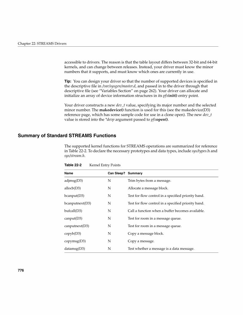
776
Chapter 22: STREAMS Drivers
accessible to drivers. The reason is that the table layout differs between 32-bit and 64-bitkernels, and can change between releases. Instead, your driver must know the minornumbers that it supports, and must know which ones are currently in use.
Tip: You can design your driver so that the number of supported devices is specified inthe descriptive file in /var/sysgen/master.d, and passed in to the driver through thatdescriptive file (see “Variables Section” on page 262). Your driver can allocate andinitialize an array of device information structures in its pfxinit() entry point.
Your driver constructs a new dev_t value, specifying its major number and the selectedminor number. The makedevice() function is used for this (see the makedevice(D3)reference page, which has some sample code for use in a clone open). The new dev_tvalue is stored into the *devp argument passed to pfxopen().
Summary of Standard STREAMS Functions
The supported kernel functions for STREAMS operations are summarized for referencein Table 22-2. To declare the necessary prototypes and data types, include sys/types.h andsys/stream.h.
Table 22-2 Kernel Entry Points
Name Can Sleep? Summary
adjmsg(D3) N Trim bytes from a message.
allocb(D3) N Allocate a message block.
bcanput(D3) N Test for flow control in a specified priority band.
bcanputnext(D3) N Test for flow control in a specified priority band.
bufcall(D3) N Call a function when a buffer becomes available.
canput(D3) N Test for room in a message queue.
canputnext(D3) N Test for room in a message queue.
copyb(D3) N Copy a message block.
copymsg(D3) N Copy a message.
datamsg(D3) N Test whether a message is a data message.
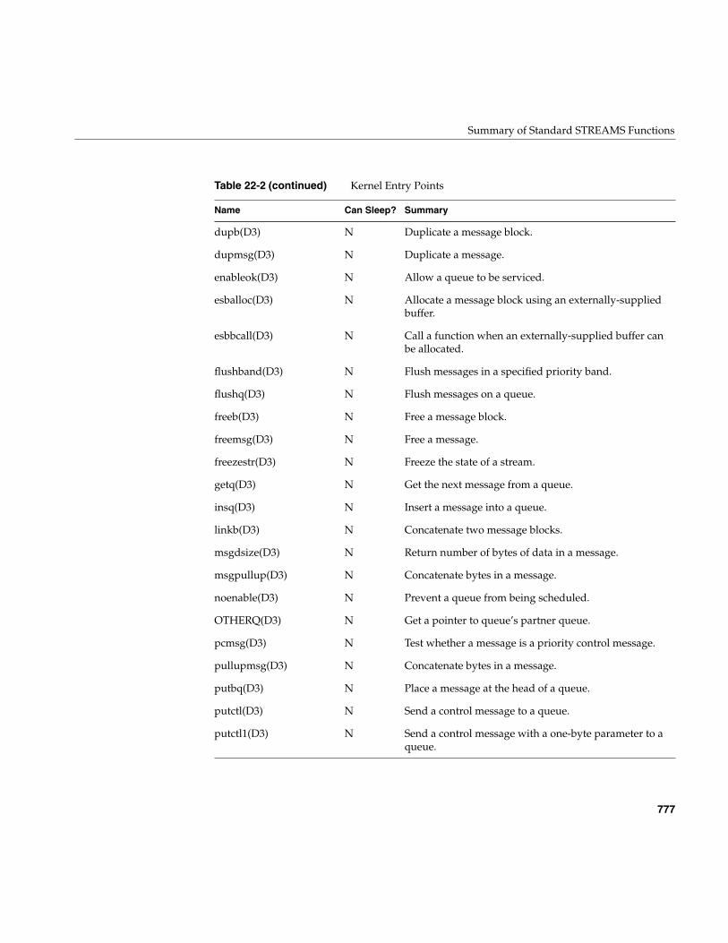
Summary of Standard STREAMS Functions
777
dupb(D3) N Duplicate a message block.
dupmsg(D3) N Duplicate a message.
enableok(D3) N Allow a queue to be serviced.
esballoc(D3) N Allocate a message block using an externally-suppliedbuffer.
esbbcall(D3) N Call a function when an externally-supplied buffer canbe allocated.
flushband(D3) N Flush messages in a specified priority band.
flushq(D3) N Flush messages on a queue.
freeb(D3) N Free a message block.
freemsg(D3) N Free a message.
freezestr(D3) N Freeze the state of a stream.
getq(D3) N Get the next message from a queue.
insq(D3) N Insert a message into a queue.
linkb(D3) N Concatenate two message blocks.
msgdsize(D3) N Return number of bytes of data in a message.
msgpullup(D3) N Concatenate bytes in a message.
noenable(D3) N Prevent a queue from being scheduled.
OTHERQ(D3) N Get a pointer to queue’s partner queue.
pcmsg(D3) N Test whether a message is a priority control message.
pullupmsg(D3) N Concatenate bytes in a message.
putbq(D3) N Place a message at the head of a queue.
putctl(D3) N Send a control message to a queue.
putctl1(D3) N Send a control message with a one-byte parameter to aqueue.
Table 22-2 (continued) Kernel Entry Points
Name Can Sleep? Summary
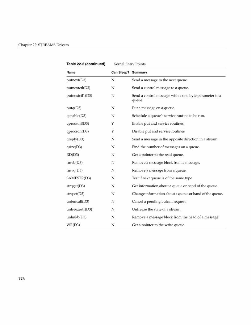
778
Chapter 22: STREAMS Drivers
putnext(D3) N Send a message to the next queue.
putnextctl(D3) N Send a control message to a queue.
putnextctl1(D3) N Send a control message with a one-byte parameter to aqueue.
putq(D3) N Put a message on a queue.
qenable(D3) N Schedule a queue’s service routine to be run.
qprocsoff(D3) Y Enable put and service routines.
qprocson(D3) Y Disable put and service routines
qreply(D3) N Send a message in the opposite direction in a stream.
qsize(D3) N Find the number of messages on a queue.
RD(D3) N Get a pointer to the read queue.
rmvb(D3) N Remove a message block from a message.
rmvq(D3) N Remove a message from a queue.
SAMESTR(D3) N Test if next queue is of the same type.
strqget(D3) N Get information about a queue or band of the queue.
strqset(D3) N Change information about a queue or band of the queue.
unbufcall(D3) N Cancel a pending bufcall request.
unfreezestr(D3) N Unfreeze the state of a stream.
unlinkb(D3) N Remove a message block from the head of a message.
WR(D3) N Get a pointer to the write queue.
Table 22-2 (continued) Kernel Entry Points
Name Can Sleep? Summary
STREAMS Modules for X Input Devices
779
STREAMS Modules for X Input Devices
The Silicon Graphics, Inc. implementation of the X display manager, Xsgi, is acustomized version of the MIT X11 Sample Server. Besides other enhancements such asintegration with Silicon Graphics proprietary graphics subsystems, Xsgi implements ageneralized input subsystem so that unusual input devices can easily be integrated intothe X window system. The input system is based on STREAMS modules.
The X Input Subsystem
While X mandates that every X server support a keyboard and mouse, there is nostandard system interface for accessing such devices on UNIX systems. This means eachvendor has its own input subsystem for its X server. SGI’s input subsystem not onlymeets the basic requirement to support a keyboard and mouse but also has the followingfeatures:
• A shared memory input queue is supported for high performance
• A wide variety of input devices is supported, including 3D devices such as theSpaceball
• Input devices are supported abstractly; knowledge of specific input devices isisolated to modular kernel-level device drivers
• Hardware cursor tracking is supported in the kernel
These features provide a more functional, responsive input subsystem than thatavailable in the MIT Sample Server.
The programming interface to the input subsystem from the X client API is covered inthe X11 Input Extension Library Specification, an online book that is distributed with theIRIX Developer’s Option.
Note: Numerous code examples demonstrating the X input system are available in theX developer component (x_dev component) of the IRIX Developer Option. Source forSTREAMS modules to integrate a Spaceball, a dial-and-button box, and other devices canbe found in subdirectories of /usr/share/src/X.
780
Chapter 22: STREAMS Drivers
Shared Memory Input Queue
A shared memory input queue (called a shmiq in Silicon Graphics code comments, andpronounced “shmick”) is a fast way of receiving input device events by eliminating thefilesystem overhead to receive data from input devices. Instead of the X server readingthe input devices through file descriptors, a kernel-level driver deposits input eventsdirectly into a region of the X server’s address space, organized as a ring buffer.
The IRIX shmiq device driver is implemented as a STREAMS multiplexor. This allows anarbitrary number of input sources (in the form of STREAMS modules) to be linked to itso all input sources are funneled through the shmiq.
In addition to processing input events from input device modules, the schmiq driver alsoprocesses events from the graphics subsystem, and updates the screen cursor position.This allows smooth cursor movement since cursor positioning is done in kernel code,without Xsgi involvement.
IDEV Interface
X input devices are integrated into the shmiq driver by implementing STREAMSmodules that translate raw device input into abstract events which are sent to the shmiqdriver (and on to the server). For example, an input device that connects to a serial portcan be integrated in the form of a STREAMS module that is pushed onto the stream fromthat serial device, and translates incoming bytes into event messages.
The shmiq driver expects messages from all input devices to be in the form of IDEVevents, as documented in the /usr/include/sys/idev.h header file; hence this is called theIDEV interface. IDEV device events appear as valuator, button, and pointer statechanges.
The IDEV interface defines two-way communications between the input device and Xsgi.Besides the uniform set of IDEV input events, the interface defines a standard set ofabstract commands that Xsgi can send down (using IOCTL messages) to initialize andcontrol input devices. This allows the server to see input devices as abstract input sourcesand does not require special server code to be written every time a new input device issupported. Instead, device specific knowledge of each devices is encapsulated in anIDEV-based STREAMS module linked into the kernel.
STREAMS Modules for X Input Devices
781
Input Device Naming
Xsgi recognizes as input devices, any device special files named in the /dev/inputdirectory. On a machine with graphics, this includes /dev/input/keyboard and/dev/input/mouse. (A server-type machine without graphics typically has no names in/dev/input.) Other input devices that are to be integrated into the IDEV interface must alsoappear as symbolic links in /dev/input.
Typically an X input device is defined as a link from /dev/input to some other devicespecial file, typically a serial port in the /hw/ttys/tty* group. The filename in /dev/inputdetermines the name of the STREAMS module that is used to interface that device to theIDEV input system. For example, if the file is /dev/input/calcomp, the calcomp STREAMSmodule is loaded and pushed onto the stream from the device.
When a single STREAMS module is used to support two or more devices, you can use ahyphen-digit suffix on the filename. For example, the calcomp STREAMS module wouldbe used for both /dev/input/calcomp-1 and /dev/input/calcomp-2.
When a device is initialized (as described in the next section), the STREAMS module isasked to return the X name of the input device. This name can be the same as the nameof the device and the module, or it can be different. Typically the device and modulenames will reflect the hardware type (for example calcomp), while the X name reflects thekind of device (for example tablet).
Opening Input Devices
An input device is opened at one of two times: when the X server starts up, and when anX client requests an open.
Starting Up the Server
When Xsgi starts up, it opens each device name in /dev/input and for each one it:
• Loads a STREAMS module that has the same name as the name of the devicespecial file, and pushes it onto the stream from the device, below the shmiqmultiplexor.
The STREAMS module may be loadable, and most IDEV modules are loadable.
• Looks for a file in /usr/lib/X11/input/config having the same name as the module. Thedevice controls in that file are sent down the stream as IOCTL messages.
782
Chapter 22: STREAMS Drivers
The format of device controls is discussed under “Device Controls” on page 783.
• Asks the device to describe itself. This is done by sending down an IOCTL messageof the type IDEVDESC. The module must return the IOCTL message withdescriptive data.
The IDEV IOCTL structures are declared in /usr/include/sys/idev.h. A key element ofthe device description is the X name of the input device.
• Looks for a file in /usr/lib/X11/input/config having the X name of the device asreturned in the device description. The X init controls in this file are processed bythe X server.
The format of X init controls is discussed under “Device Controls” on page 783.
• Unless autostart was specified for this device, the device is closed.
Opening from a Client
An X application can use the XListInputDevices() function to get a list of available inputdevices. Then it can call XOpenDevice() to open a selected device, so that input eventsfrom that device will be processed by the X server (see the XListInputDevices(3X) andXOpenDevice(3X) reference pages).
When XOpenDevice() is called for an input device that is not already open, it repeats theprocess done at startup time:
• Loads the STREAMS module and pushes it on the device stream, feeding the shmiqmultiplexor.
• Sends device controls from a file in /usr/lib/X11/input/config having the same name asthe module.
• Asks the device (module) to describe itself, including the X name of the device.
• Processes X init controls from a file in /usr/lib/X11/input/config having the X name ofthe device.
STREAMS Modules for X Input Devices
783
Device Controls
Device controls are string values that are passed via an IOCTL message to the STREAMSmodule for an input device at the time the device is opened. You can use device controlsas a way of configuring the device module at runtime. Device controls are interpretedonly by the module.
X init controls have the same syntax as device controls, but are processed by the X serverafter the device has been initialized.
Where Controls Are Stored
You can issue X server device controls on the fly by calling XSGIDeviceControl fromwithin a program, or by storing them in configuration files in the /usr/lib/X11/input/configdirectory. Specific documentation on controls can be found in/usr/lib/X11/input/config/README.
There are (potentially) two configuration files per device. As noted under “OpeningInput Devices” on page 781, the X server looks for device controls in a file with the samename as the STREAMS module that implements the device. After the module returns theX name of the device, the X server looks for X init controls in a file with the X name of thedevice.
Some devices use the same name for the STREAMS module and for the X device (tablet,mouse), but some use different names for the two. For example, the STREAMS modulefor the Spaceball device is sball, while the X name is spaceball.
The X server intercepts about a dozen x_init controls. For a list of the x_init controls andsome of the more common device_init controls, see the file
Control Syntax
When the X server opens a file to look for device controls, it searches the file for a singleset of controls with the following format:
device_init {name "value"...
}
784
Chapter 22: STREAMS Drivers
Each name may have at most 15 characters. Each value may have at most 23 characters.Each pair of name and value are put in an IOCTL message of idevOtherControl type andsent down to the device module for interpretation.
When the X server opens a file to look for X init controls, it searches the file for a singleset of controls with the following format:
x_init {name "value"...
}
The syntax is the same, except for the use of x_init instead of device_init.
The specific name and value strings that the X server supports are documented in the file/usr/lib/X11/input/config/README. Any name strings that are not recognized by the Xserver are sent down to the device module, just as if they were device controls.
785
Appendix A
A. Silicon Graphics Driver/Kernel API
This appendix summarizes the Silicon Graphics Driver/Kernel AuthorizedProgramming Interface in tabular form. The data structures, entry points, and kernelfunctions are listed alphabetically with cross-references to the pages where they arediscussed. The tables also show which functions and structures are compatible withSVR4 and which are unique to IRIX.
The tables in this appendix are based on the reference pages in volume D. The referencepages in volume D constitute the formal, engineering definition of the Driver/KernelAPI. When discussion in this book disagrees with the contents of a reference page, thereference page takes precedence (however, any such disagreement should be reported byemail to [email protected]).
• “Driver Exported Names” on page 786 tabulates the names of data and functionsthat a driver must export.
• “Kernel Data Structures and Declarations” on page 787 tabulates the objects used inthe interface.
• “Kernel Functions” on page 789 tabulates the IRIX kernel services used by drivers.
Each table in this appendix has a column headed “Versions.” The codes in this columnhave the following meanings:
SV Syntactically and semantically portable from SVR4 UNIX, as documentedin the UNIX SVR4.2 Device Driver Reference.
SV* Syntactically portable from UNIX SVR4, but semantics may differ. Readthe discussion and reference page carefully when porting.
5.3 Portable from IRIX version 5.3.
5.3* Portable from IRIX 5.3, but interface has changed in some detail or newability has been added.
6.2 Portable from IRIX version 6.2.
6.4 Introduced in IRIX 6.4.
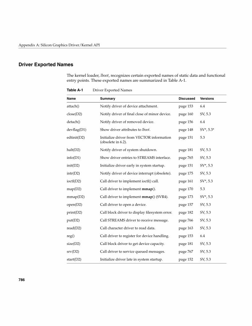
786
Appendix A: Silicon Graphics Driver/Kernel API
Driver Exported Names
The kernel loader, lboot, recognizes certain exported names of static data and functionalentry points. These exported names are summarized in Table A-1.
Table A-1 Driver Exported Names
Name Summary Discussed Versions
attach() Notify driver of device attachment. page 153 6.4
close(D2) Notify driver of final close of minor device. page 160 SV, 5.3
detach() Notify driver of removed device. page 156 6.4
devflag(D1) Show driver attributes to lboot. page 148 SV*, 5.3*
edtinit(D2) Initialize driver from VECTOR information(obsolete in 6.2).
page 151 5.3
halt(D2) Notify driver of system shutdown. page 181 SV, 5.3
info(D1) Show driver entries to STREAMS interface. page 765 SV, 5.3
init(D2) Initialize driver early in system startup. page 151 SV*, 5.3
intr(D2) Notify driver of device interrupt (obsolete). page 175 SV, 5.3
ioctl(D2) Call driver to implement ioctl() call. page 161 SV*, 5.3
map(D2) Call driver to implement mmap(). page 170 5.3
mmap(D2) Call driver to implement mmap() (SVR4). page 173 SV*, 5.3
open(D2) Call driver to open a device. page 157 SV, 5.3
print(D2) Call block driver to display filesystem error. page 182 SV, 5.3
put(D2) Call STREAMS driver to receive message. page 766 SV, 5.3
read(D2) Call character driver to read data. page 163 SV, 5.3
reg() Call driver to register for device handling. page 153 6.4
size(D2) Call block driver to get device capacity. page 181 SV, 5.3
srv(D2) Call driver to service queued messages. page 767 SV, 5.3
start(D2) Initialize driver late in system startup. page 152 SV, 5.3
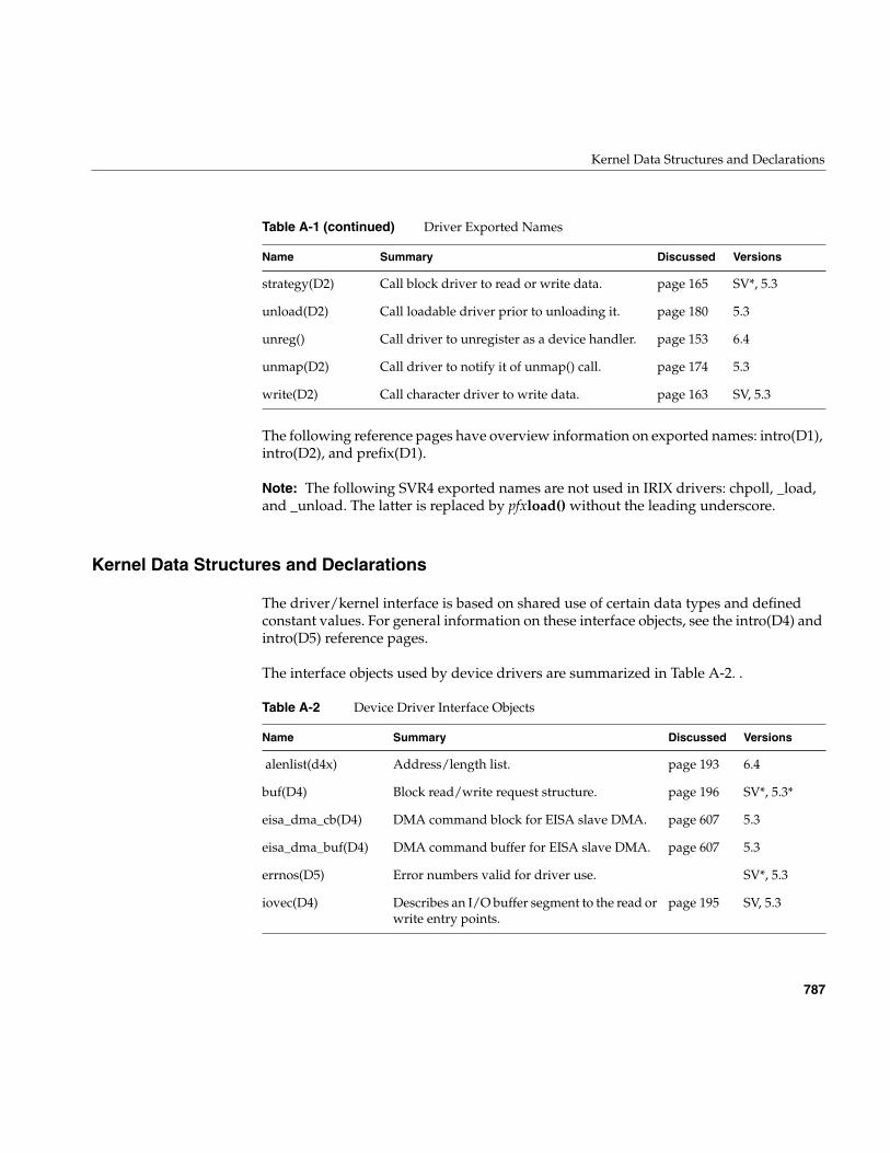
Kernel Data Structures and Declarations
787
The following reference pages have overview information on exported names: intro(D1),intro(D2), and prefix(D1).
Note: The following SVR4 exported names are not used in IRIX drivers: chpoll, _load,and _unload. The latter is replaced by pfxload() without the leading underscore.
Kernel Data Structures and Declarations
The driver/kernel interface is based on shared use of certain data types and definedconstant values. For general information on these interface objects, see the intro(D4) andintro(D5) reference pages.
The interface objects used by device drivers are summarized in Table A-2. .
strategy(D2) Call block driver to read or write data. page 165 SV*, 5.3
unload(D2) Call loadable driver prior to unloading it. page 180 5.3
unreg() Call driver to unregister as a device handler. page 153 6.4
unmap(D2) Call driver to notify it of unmap() call. page 174 5.3
write(D2) Call character driver to write data. page 163 SV, 5.3
Table A-2 Device Driver Interface Objects
Name Summary Discussed Versions
alenlist(d4x) Address/length list. page 193 6.4
buf(D4) Block read/write request structure. page 196 SV*, 5.3*
eisa_dma_cb(D4) DMA command block for EISA slave DMA. page 607 5.3
eisa_dma_buf(D4) DMA command buffer for EISA slave DMA. page 607 5.3
errnos(D5) Error numbers valid for driver use. SV*, 5.3
iovec(D4) Describes an I/O buffer segment to the read orwrite entry points.
page 195 SV, 5.3
Table A-1 (continued) Driver Exported Names
Name Summary Discussed Versions
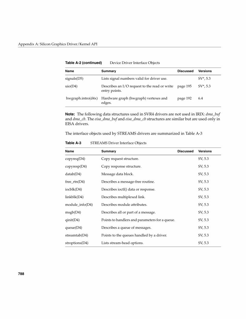
788
Appendix A: Silicon Graphics Driver/Kernel API
Note: The following data structures used in SVR4 drivers are not used in IRIX: dma_bufand dma_cb. The eisa_dma_buf and eisa_dma_cb structures are similar but are used only inEISA drivers.
The interface objects used by STREAMS drivers are summarized in Table A-3
signals(D5) Lists signal numbers valid for driver use. SV*, 5.3
uio(D4) Describes an I/O request to the read or writeentry points.
page 195 SV*, 5.3
hwgraph.intro(d4x) Hardware graph (hwgraph) vertexes andedges.
page 192 6.4
Table A-3 STREAMS Driver Interface Objects
Name Summary Discussed Versions
copyreq(D4) Copy request structure. SV, 5.3
copyresp(D4) Copy response structure. SV, 5.3
datab(D4) Message data block. SV, 5.3
free_rtn(D4) Describes a message-free routine. SV, 5.3
iocblk(D4) Describes ioctl() data or response. SV, 5.3
linkblk(D4) Describes multiplexed link. SV, 5.3
module_info(D4) Describes module attributes. SV, 5.3
msgb(D4) Describes all or part of a message. SV, 5.3
qinit(D4) Points to handlers and parameters for a queue. SV, 5.3
queue(D4) Describes a queue of messages. SV, 5.3
streamtab(D4) Points to the queues handled by a driver. SV, 5.3
stroptions(D4) Lists stream-head options. SV, 5.3
Table A-2 (continued) Device Driver Interface Objects
Name Summary Discussed Versions
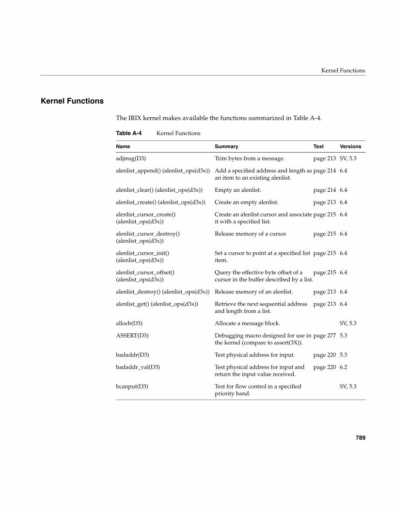
Kernel Functions
789
Kernel Functions
The IRIX kernel makes available the functions summarized in Table A-4.
Table A-4 Kernel Functions
Name Summary Text Versions
adjmsg(D3) Trim bytes from a message. page 213 SV, 5.3
alenlist_append() (alenlist_ops(d3x)) Add a specified address and length asan item to an existing alenlist.
page 214 6.4
alenlist_clear() (alenlist_ops(d3x)) Empty an alenlist. page 214 6.4
alenlist_create() (alenlist_ops(d3x)) Create an empty alenlist. page 213 6.4
alenlist_cursor_create()(alenlist_ops(d3x))
Create an alenlist cursor and associateit with a specified list.
page 215 6.4
alenlist_cursor_destroy()(alenlist_ops(d3x))
Release memory of a cursor. page 215 6.4
alenlist_cursor_init()(alenlist_ops(d3x))
Set a cursor to point at a specified listitem.
page 215 6.4
alenlist_cursor_offset()(alenlist_ops(d3x))
Query the effective byte offset of acursor in the buffer described by a list.
page 215 6.4
alenlist_destroy() (alenlist_ops(d3x)) Release memory of an alenlist. page 213 6.4
alenlist_get() (alenlist_ops(d3x)) Retrieve the next sequential addressand length from a list.
page 213 6.4
allocb(D3) Allocate a message block. SV, 5.3
ASSERT(D3) Debugging macro designed for use inthe kernel (compare to assert(3X)).
page 277 5.3
badaddr(D3) Test physical address for input. page 220 5.3
badaddr_val(D3) Test physical address for input andreturn the input value received.
page 220 6.2
bcanput(D3) Test for flow control in a specifiedpriority band.
SV, 5.3
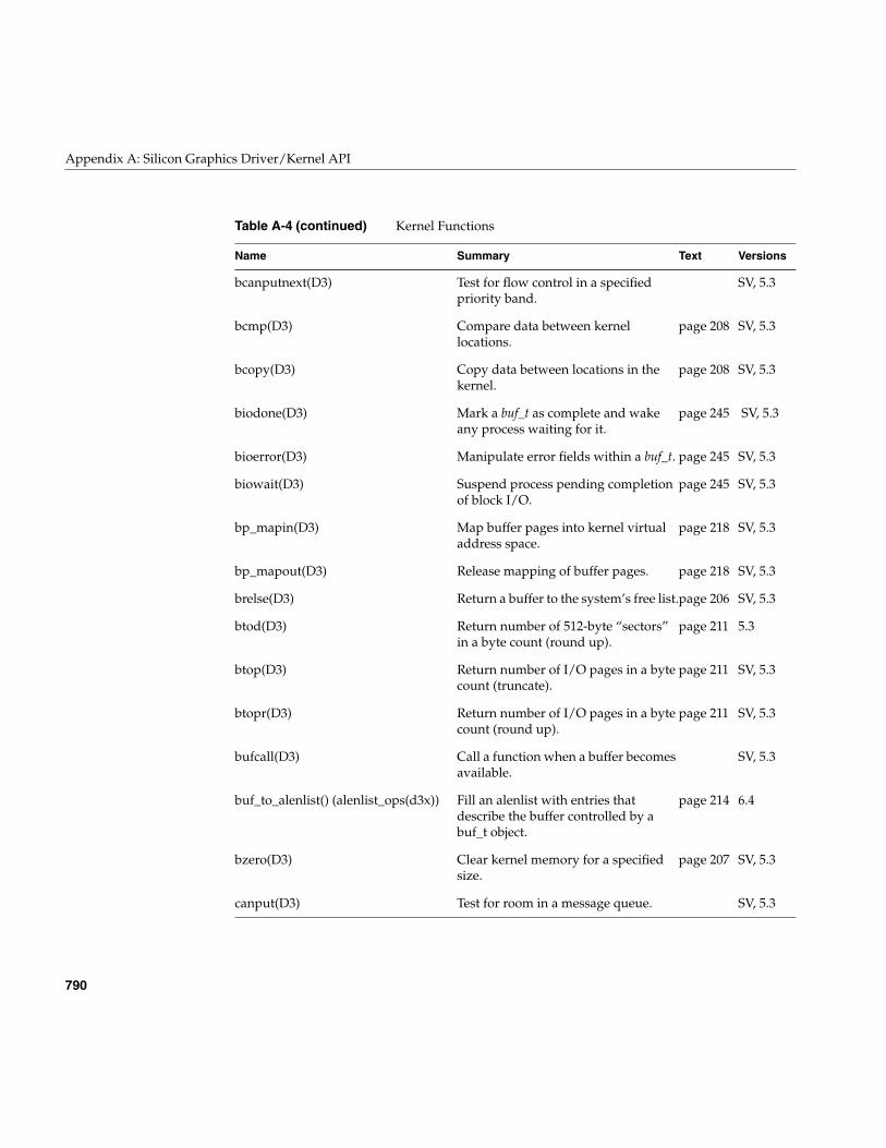
790
Appendix A: Silicon Graphics Driver/Kernel API
bcanputnext(D3) Test for flow control in a specifiedpriority band.
SV, 5.3
bcmp(D3) Compare data between kernellocations.
page 208 SV, 5.3
bcopy(D3) Copy data between locations in thekernel.
page 208 SV, 5.3
biodone(D3) Mark a buf_t as complete and wakeany process waiting for it.
page 245 SV, 5.3
bioerror(D3) Manipulate error fields within a buf_t. page 245 SV, 5.3
biowait(D3) Suspend process pending completionof block I/O.
page 245 SV, 5.3
bp_mapin(D3) Map buffer pages into kernel virtualaddress space.
page 218 SV, 5.3
bp_mapout(D3) Release mapping of buffer pages. page 218 SV, 5.3
brelse(D3) Return a buffer to the system’s free list.page 206 SV, 5.3
btod(D3) Return number of 512-byte “sectors”in a byte count (round up).
page 211 5.3
btop(D3) Return number of I/O pages in a bytecount (truncate).
page 211 SV, 5.3
btopr(D3) Return number of I/O pages in a bytecount (round up).
page 211 SV, 5.3
bufcall(D3) Call a function when a buffer becomesavailable.
SV, 5.3
buf_to_alenlist() (alenlist_ops(d3x)) Fill an alenlist with entries thatdescribe the buffer controlled by abuf_t object.
page 214 6.4
bzero(D3) Clear kernel memory for a specifiedsize.
page 207 SV, 5.3
canput(D3) Test for room in a message queue. SV, 5.3
Table A-4 (continued) Kernel Functions
Name Summary Text Versions
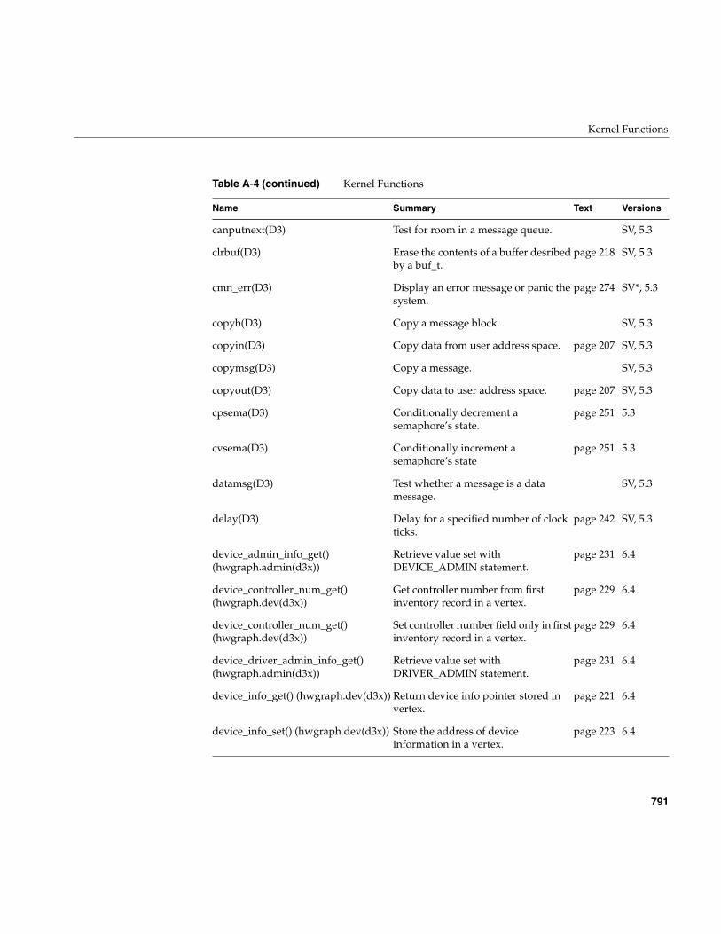
Kernel Functions
791
canputnext(D3) Test for room in a message queue. SV, 5.3
clrbuf(D3) Erase the contents of a buffer desribedby a buf_t.
page 218 SV, 5.3
cmn_err(D3) Display an error message or panic thesystem.
page 274 SV*, 5.3
copyb(D3) Copy a message block. SV, 5.3
copyin(D3) Copy data from user address space. page 207 SV, 5.3
copymsg(D3) Copy a message. SV, 5.3
copyout(D3) Copy data to user address space. page 207 SV, 5.3
cpsema(D3) Conditionally decrement asemaphore’s state.
page 251 5.3
cvsema(D3) Conditionally increment asemaphore’s state
page 251 5.3
datamsg(D3) Test whether a message is a datamessage.
SV, 5.3
delay(D3) Delay for a specified number of clockticks.
page 242 SV, 5.3
device_admin_info_get()(hwgraph.admin(d3x))
Retrieve value set withDEVICE_ADMIN statement.
page 231 6.4
device_controller_num_get()(hwgraph.dev(d3x))
Get controller number from firstinventory record in a vertex.
page 229 6.4
device_controller_num_get()(hwgraph.dev(d3x))
Set controller number field only in firstinventory record in a vertex.
page 229 6.4
device_driver_admin_info_get()(hwgraph.admin(d3x))
Retrieve value set withDRIVER_ADMIN statement.
page 231 6.4
device_info_get() (hwgraph.dev(d3x)) Return device info pointer stored invertex.
page 221 6.4
device_info_set() (hwgraph.dev(d3x)) Store the address of deviceinformation in a vertex.
page 223 6.4
Table A-4 (continued) Kernel Functions
Name Summary Text Versions
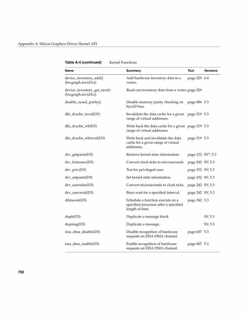
792
Appendix A: Silicon Graphics Driver/Kernel API
device_inventory_add()(hwgraph.inv(d3x))
Add hardware inventory data to avertex.
page 229 6.4
device_inventory_get_next()(hwgraph.inv(d3x))
Read out inventory data from a vertex.page 229
disable_sysad_parity() Disable memory parity checking onSysAD bus.
page 686 5.3
dki_dcache_inval(D3) Invalidate the data cache for a givenrange of virtual addresses.
page 219 5.3
dki_dcache_wb(D3) Write back the data cache for a givenrange of virtual addresses.
page 219 5.3
dki_dcache_wbinval(D3) Write back and invalidate the datacache for a given range of virtualaddresses.
page 219 5.3
drv_getparm(D3) Retrieve kernel state information. page 232 SV*, 5.3
drv_hztousec(D3) Convert clock ticks to microseconds page 242 SV, 5.3
drv_priv(D3) Test for privileged user. page 232 SV, 5.3
drv_setparm(D3) Set kernel state information. page 232 SV, 5.3
drv_usectohz(D3) Convert microseconds to clock ticks. page 242 SV, 5.3
drv_usecwait(D3) Busy-wait for a specified interval. page 242 SV, 5.3
dtimeout(D3) Schedule a function execute on aspecified processor after a specifiedlength of time.
page 242 5.3
dupb(D3) Duplicate a message block. SV, 5.3
dupmsg(D3) Duplicate a message. SV, 5.3
eisa_dma_disable(D3) Disable recognition of hardwarerequests on EISA DMA channel.
page 607 5.3
eisa_dma_enable(D3) Enable recognition of hardwarerequests on EISA DMA channel.
page 607 5.3
Table A-4 (continued) Kernel Functions
Name Summary Text Versions
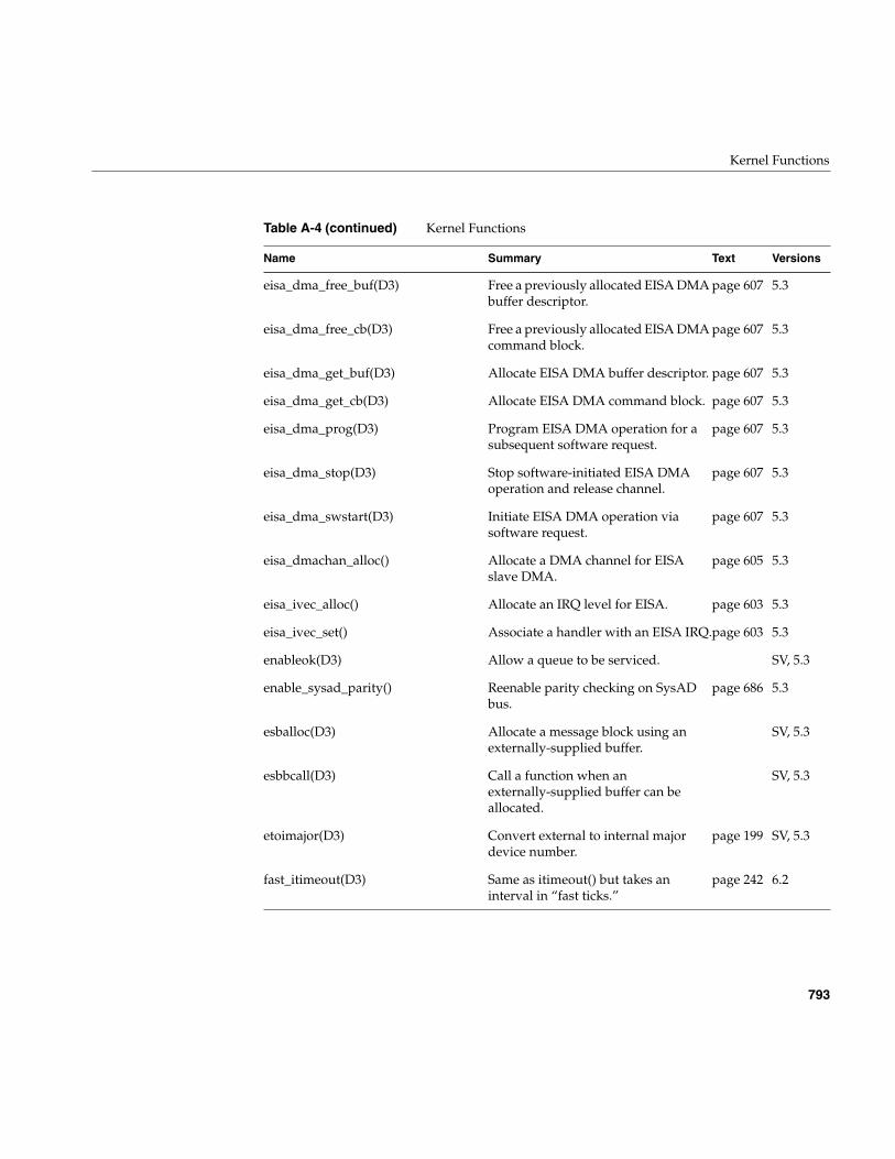
Kernel Functions
793
eisa_dma_free_buf(D3) Free a previously allocated EISA DMAbuffer descriptor.
page 607 5.3
eisa_dma_free_cb(D3) Free a previously allocated EISA DMAcommand block.
page 607 5.3
eisa_dma_get_buf(D3) Allocate EISA DMA buffer descriptor. page 607 5.3
eisa_dma_get_cb(D3) Allocate EISA DMA command block. page 607 5.3
eisa_dma_prog(D3) Program EISA DMA operation for asubsequent software request.
page 607 5.3
eisa_dma_stop(D3) Stop software-initiated EISA DMAoperation and release channel.
page 607 5.3
eisa_dma_swstart(D3) Initiate EISA DMA operation viasoftware request.
page 607 5.3
eisa_dmachan_alloc() Allocate a DMA channel for EISAslave DMA.
page 605 5.3
eisa_ivec_alloc() Allocate an IRQ level for EISA. page 603 5.3
eisa_ivec_set() Associate a handler with an EISA IRQ.page 603 5.3
enableok(D3) Allow a queue to be serviced. SV, 5.3
enable_sysad_parity() Reenable parity checking on SysADbus.
page 686 5.3
esballoc(D3) Allocate a message block using anexternally-supplied buffer.
SV, 5.3
esbbcall(D3) Call a function when anexternally-supplied buffer can beallocated.
SV, 5.3
etoimajor(D3) Convert external to internal majordevice number.
page 199 SV, 5.3
fast_itimeout(D3) Same as itimeout() but takes aninterval in “fast ticks.”
page 242 6.2
Table A-4 (continued) Kernel Functions
Name Summary Text Versions
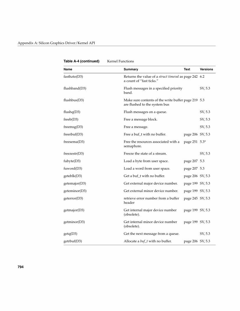
794
Appendix A: Silicon Graphics Driver/Kernel API
fasthzto(D3) Returns the value of a struct timeval asa count of “fast ticks.”
page 242 6.2
flushband(D3) Flush messages in a specified priorityband.
SV, 5.3
flushbus(D3) Make sure contents of the write bufferare flushed to the system bus
page 219 5.3
flushq(D3) Flush messages on a queue. SV, 5.3
freeb(D3) Free a message block. SV, 5.3
freemsg(D3) Free a message. SV, 5.3
freerbuf(D3) Free a buf_t with no buffer. page 206 SV, 5.3
freesema(D3) Free the resources associated with asemaphore.
page 251 5.3*
freezestr(D3) Freeze the state of a stream. SV, 5.3
fubyte(D3) Load a byte from user space. page 207 5.3
fuword(D3) Load a word from user space. page 207 5.3
geteblk(D3) Get a buf_t with no buffer. page 206 SV, 5.3
getemajor(D3) Get external major device number. page 199 SV, 5.3
geteminor(D3) Get external minor device number. page 199 SV, 5.3
geterror(D3) retrieve error number from a bufferheader
page 245 SV, 5.3
getmajor(D3) Get internal major device number(obsolete).
page 199 SV, 5.3
getminor(D3) Get internal minor device number(obsolete).
page 199 SV, 5.3
getq(D3) Get the next message from a queue. SV, 5.3
getrbuf(D3) Allocate a buf_t with no buffer. page 206 SV, 5.3
Table A-4 (continued) Kernel Functions
Name Summary Text Versions
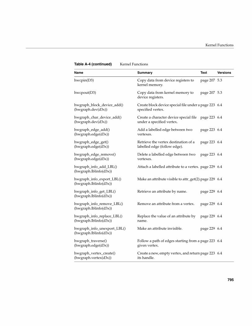
Kernel Functions
795
hwcpin(D3) Copy data from device registers tokernel memory.
page 207 5.3
hwcpout(D3) Copy data from kernel memory todevice registers.
page 207 5.3
hwgraph_block_device_add()(hwgraph.dev(d3x))
Create block device special file under aspecified vertex.
page 223 6.4
hwgraph_char_device_add()(hwgraph.dev(d3x))
Create a character device special fileunder a specified vertex.
page 223 6.4
hwgraph_edge_add()(hwgraph.edge(d3x))
Add a labelled edge between twovertexes.
page 223 6.4
hwgraph_edge_get()(hwgraph.edge(d3x))
Retrieve the vertex destination of alabelled edge (follow edge).
page 223 6.4
hwgraph_edge_remove()(hwgraph.edge(d3x))
Delete a labelled edge between twovertexes.
page 223 6.4
hwgraph_info_add_LBL()(hwgraph.lblinfo(d3x))
Attach a labelled attribute to a vertex. page 229 6.4
hwgraph_info_export_LBL()(hwgraph.lblinfo(d3x))
Make an attribute visible to attr_get(2).page 229 6.4
hwgraph_info_get_LBL()(hwgraph.lblinfo(d3x))
Retrieve an attribute by name. page 229 6.4
hwgraph_info_remove_LBL()(hwgraph.lblinfo(d3x))
Remove an attribute from a vertex. page 229 6.4
hwgraph_info_replace_LBL()(hwgraph.lblinfo(d3x))
Replace the value of an attribute byname.
page 229 6.4
hwgraph_info_unexport_LBL()(hwgraph.lblinfo(d3x))
Make an attribute invisible. page 229 6.4
hwgraph_traverse()(hwgraph.edge(d3x))
Follow a path of edges starting from agiven vertex.
page 223 6.4
hwgraph_vertex_create()(hwgraph.vertex(d3x))
Create a new, empty vertex, and returnits handle.
page 223 6.4
Table A-4 (continued) Kernel Functions
Name Summary Text Versions
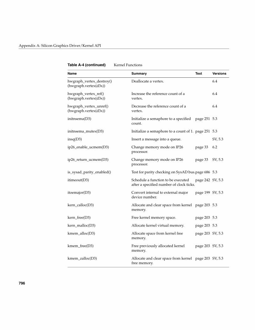
796
Appendix A: Silicon Graphics Driver/Kernel API
hwgraph_vertex_destroy()(hwgraph.vertex(d3x))
Deallocate a vertex. 6.4
hwgraph_vertex_ref()(hwgraph.vertex(d3x))
Increase the reference count of avertex.
6.4
hwgraph_vertex_unref()(hwgraph.vertex(d3x))
Decrease the reference count of avertex.
6.4
initnsema(D3) Initialize a semaphore to a specifiedcount.
page 251 5.3
initnsema_mutex(D3) Initialize a semaphore to a count of 1. page 251 5.3
insq(D3) Insert a message into a queue. SV, 5.3
ip26_enable_ucmem(D3) Change memory mode on IP26processor.
page 33 6.2
ip26_return_ucmem(D3) Change memory mode on IP26processor.
page 33 SV, 5.3
is_sysad_parity_enabled() Test for parity checking on SysAD bus.page 686 5.3
itimeout(D3) Schedule a function to be executedafter a specified number of clock ticks.
page 242 SV, 5.3
itoemajor(D3) Convert internal to external majordevice number.
page 199 SV, 5.3
kern_calloc(D3) Allocate and clear space from kernelmemory.
page 203 5.3
kern_free(D3) Free kernel memory space. page 203 5.3
kern_malloc(D3) Allocate kernel virtual memory. page 203 5.3
kmem_alloc(D3) Allocate space from kernel freememory.
page 203 SV, 5.3
kmem_free(D3) Free previously allocated kernelmemory.
page 203 SV, 5.3
kmem_zalloc(D3) Allocate and clear space from kernelfree memory.
page 203 SV, 5.3
Table A-4 (continued) Kernel Functions
Name Summary Text Versions
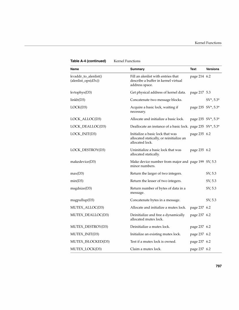
Kernel Functions
797
kvaddr_to_alenlist()(alenlist_ops(d3x))
Fill an alenlist with entries thatdescribe a buffer in kernel virtualaddress space.
page 214 6.2
kvtophys(D3) Get physical address of kernel data. page 217 5.3
linkb(D3) Concatenate two message blocks. SV*, 5.3*
LOCK(D3) Acquire a basic lock, waiting ifnecessary.
page 235 SV*, 5.3*
LOCK_ALLOC(D3) Allocate and initialize a basic lock. page 235 SV*, 5.3*
LOCK_DEALLOC(D3) Deallocate an instance of a basic lock. page 235 SV*, 5.3*
LOCK_INIT(D3) Initialize a basic lock that wasallocated statically, or reinitialize anallocated lock.
page 235 6.2
LOCK_DESTROY(D3) Uninitialize a basic lock that wasallocated statically.
page 235 6.2
makedevice(D3) Make device number from major andminor numbers.
page 199 SV, 5.3
max(D3) Return the larger of two integers. SV, 5.3
min(D3) Return the lesser of two integers. SV, 5.3
msgdsize(D3) Return number of bytes of data in amessage.
SV, 5.3
msgpullup(D3) Concatenate bytes in a message. SV, 5.3
MUTEX_ALLOC(D3) Allocate and initialize a mutex lock. page 237 6.2
MUTEX_DEALLOC(D3) Deinitialize and free a dynamicallyallocated mutex lock.
page 237 6.2
MUTEX_DESTROY(D3) Deinitialize a mutex lock. page 237 6.2
MUTEX_INIT(D3) Initialize an existing mutex lock. page 237 6.2
MUTEX_ISLOCKED(D3) Test if a mutex lock is owned. page 237 6.2
MUTEX_LOCK(D3) Claim a mutex lock. page 237 6.2
Table A-4 (continued) Kernel Functions
Name Summary Text Versions
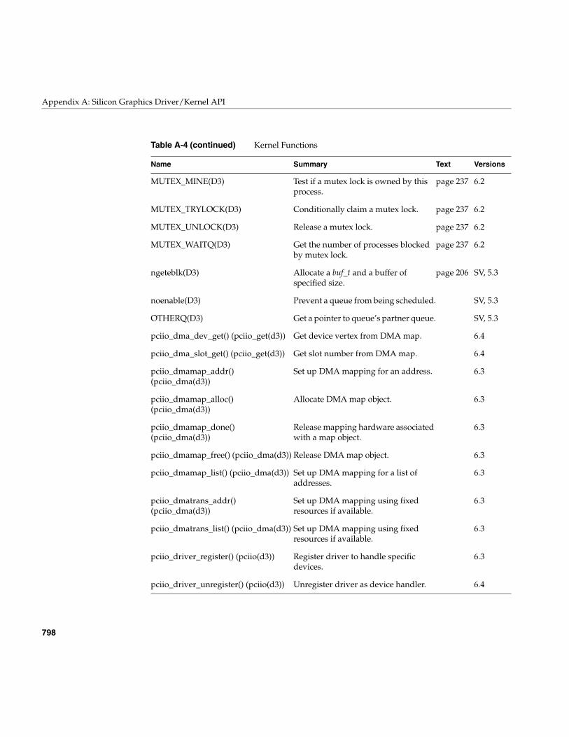
798
Appendix A: Silicon Graphics Driver/Kernel API
MUTEX_MINE(D3) Test if a mutex lock is owned by thisprocess.
page 237 6.2
MUTEX_TRYLOCK(D3) Conditionally claim a mutex lock. page 237 6.2
MUTEX_UNLOCK(D3) Release a mutex lock. page 237 6.2
MUTEX_WAITQ(D3) Get the number of processes blockedby mutex lock.
page 237 6.2
ngeteblk(D3) Allocate a buf_t and a buffer ofspecified size.
page 206 SV, 5.3
noenable(D3) Prevent a queue from being scheduled. SV, 5.3
OTHERQ(D3) Get a pointer to queue’s partner queue. SV, 5.3
pciio_dma_dev_get() (pciio_get(d3)) Get device vertex from DMA map. 6.4
pciio_dma_slot_get() (pciio_get(d3)) Get slot number from DMA map. 6.4
pciio_dmamap_addr()(pciio_dma(d3))
Set up DMA mapping for an address. 6.3
pciio_dmamap_alloc()(pciio_dma(d3))
Allocate DMA map object. 6.3
pciio_dmamap_done()(pciio_dma(d3))
Release mapping hardware associatedwith a map object.
6.3
pciio_dmamap_free() (pciio_dma(d3)) Release DMA map object. 6.3
pciio_dmamap_list() (pciio_dma(d3)) Set up DMA mapping for a list ofaddresses.
6.3
pciio_dmatrans_addr()(pciio_dma(d3))
Set up DMA mapping using fixedresources if available.
6.3
pciio_dmatrans_list() (pciio_dma(d3)) Set up DMA mapping using fixedresources if available.
6.3
pciio_driver_register() (pciio(d3)) Register driver to handle specificdevices.
6.3
pciio_driver_unregister() (pciio(d3)) Unregister driver as device handler. 6.4
Table A-4 (continued) Kernel Functions
Name Summary Text Versions
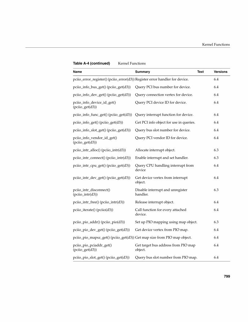
Kernel Functions
799
pciio_error_register() (pciio_error(d3)) Register error handler for device. 6.4
pciio_info_bus_get() (pciio_get(d3)) Query PCI bus number for device. 6.4
pciio_info_dev_get() (pciio_get(d3)) Query connection vertex for device. 6.4
pciio_info_device_id_get()(pciio_get(d3))
Query PCI device ID for device. 6.4
pciio_info_func_get() (pciio_get(d3)) Query interrupt function for device. 6.4
pciio_info_get() (pciio_get(d3)) Get PCI info object for use in queries. 6.4
pciio_info_slot_get() (pciio_get(d3)) Query bus slot number for device. 6.4
pciio_info_vendor_id_get()(pciio_get(d3))
Query PCI vendor ID for device. 6.4
pciio_intr_alloc() (pciio_intr(d3)) Allocate interrupt object. 6.3
pciio_intr_connect() (pciio_intr(d3)) Enable interrupt and set handler. 6.3
pciio_intr_cpu_get() (pciio_get(d3)) Query CPU handling interrupt fromdevice
6.4
pciio_intr_dev_get() (pciio_get(d3)) Get device vertex from interruptobject.
6.4
pciio_intr_disconnect()(pciio_intr(d3))
Disable interrupt and unregisterhandler.
6.3
pciio_intr_free() (pciio_intr(d3)) Release interrupt object. 6.4
pciio_iterate() (pciio(d3)) Call function for every attacheddevice.
6.4
pciio_pio_addr() (pciio_pio(d3)) Set up PIO mapping using map object. 6.3
pciio_pio_dev_get() (pciio_get(d3)) Get device vertex from PIO map. 6.4
pciio_pio_mapsz_get() (pciio_get(d3)) Get map size from PIO map object. 6.4
pciio_pio_pciaddr_get()(pciio_get(d3))
Get target bus address from PIO mapobject.
6.4
pciio_pio_slot_get() (pciio_get(d3)) Query bus slot number from PIO map. 6.4
Table A-4 (continued) Kernel Functions
Name Summary Text Versions
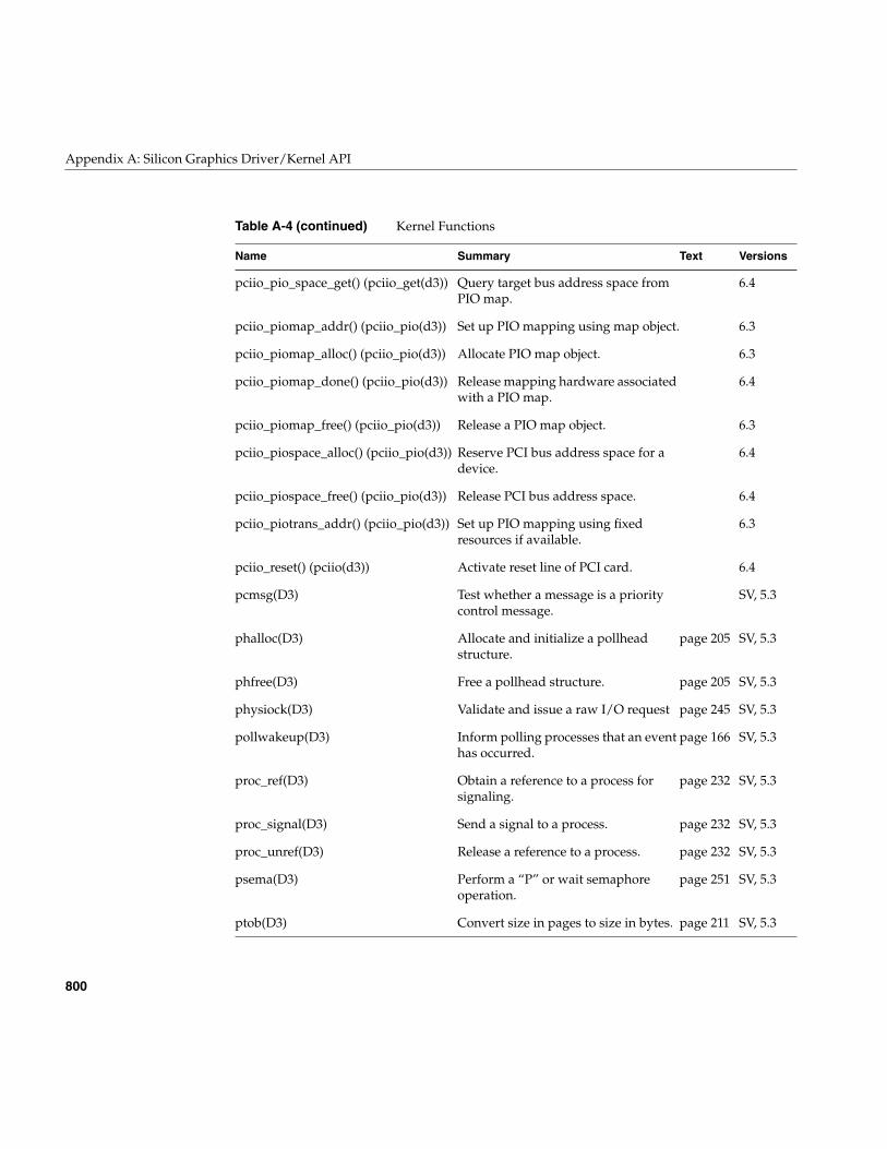
800
Appendix A: Silicon Graphics Driver/Kernel API
pciio_pio_space_get() (pciio_get(d3)) Query target bus address space fromPIO map.
6.4
pciio_piomap_addr() (pciio_pio(d3)) Set up PIO mapping using map object. 6.3
pciio_piomap_alloc() (pciio_pio(d3)) Allocate PIO map object. 6.3
pciio_piomap_done() (pciio_pio(d3)) Release mapping hardware associatedwith a PIO map.
6.4
pciio_piomap_free() (pciio_pio(d3)) Release a PIO map object. 6.3
pciio_piospace_alloc() (pciio_pio(d3)) Reserve PCI bus address space for adevice.
6.4
pciio_piospace_free() (pciio_pio(d3)) Release PCI bus address space. 6.4
pciio_piotrans_addr() (pciio_pio(d3)) Set up PIO mapping using fixedresources if available.
6.3
pciio_reset() (pciio(d3)) Activate reset line of PCI card. 6.4
pcmsg(D3) Test whether a message is a prioritycontrol message.
SV, 5.3
phalloc(D3) Allocate and initialize a pollheadstructure.
page 205 SV, 5.3
phfree(D3) Free a pollhead structure. page 205 SV, 5.3
physiock(D3) Validate and issue a raw I/O request page 245 SV, 5.3
pollwakeup(D3) Inform polling processes that an eventhas occurred.
page 166 SV, 5.3
proc_ref(D3) Obtain a reference to a process forsignaling.
page 232 SV, 5.3
proc_signal(D3) Send a signal to a process. page 232 SV, 5.3
proc_unref(D3) Release a reference to a process. page 232 SV, 5.3
psema(D3) Perform a “P” or wait semaphoreoperation.
page 251 SV, 5.3
ptob(D3) Convert size in pages to size in bytes. page 211 SV, 5.3
Table A-4 (continued) Kernel Functions
Name Summary Text Versions
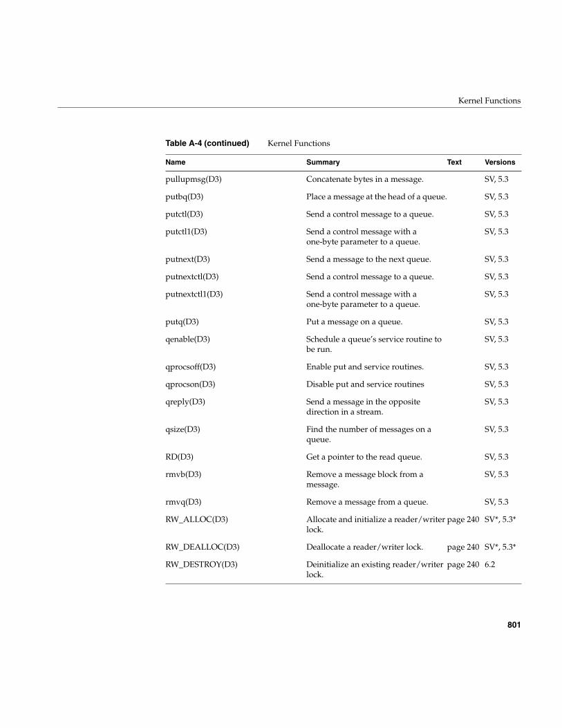
Kernel Functions
801
pullupmsg(D3) Concatenate bytes in a message. SV, 5.3
putbq(D3) Place a message at the head of a queue. SV, 5.3
putctl(D3) Send a control message to a queue. SV, 5.3
putctl1(D3) Send a control message with aone-byte parameter to a queue.
SV, 5.3
putnext(D3) Send a message to the next queue. SV, 5.3
putnextctl(D3) Send a control message to a queue. SV, 5.3
putnextctl1(D3) Send a control message with aone-byte parameter to a queue.
SV, 5.3
putq(D3) Put a message on a queue. SV, 5.3
qenable(D3) Schedule a queue’s service routine tobe run.
SV, 5.3
qprocsoff(D3) Enable put and service routines. SV, 5.3
qprocson(D3) Disable put and service routines SV, 5.3
qreply(D3) Send a message in the oppositedirection in a stream.
SV, 5.3
qsize(D3) Find the number of messages on aqueue.
SV, 5.3
RD(D3) Get a pointer to the read queue. SV, 5.3
rmvb(D3) Remove a message block from amessage.
SV, 5.3
rmvq(D3) Remove a message from a queue. SV, 5.3
RW_ALLOC(D3) Allocate and initialize a reader/writerlock.
page 240 SV*, 5.3*
RW_DEALLOC(D3) Deallocate a reader/writer lock. page 240 SV*, 5.3*
RW_DESTROY(D3) Deinitialize an existing reader/writerlock.
page 240 6.2
Table A-4 (continued) Kernel Functions
Name Summary Text Versions
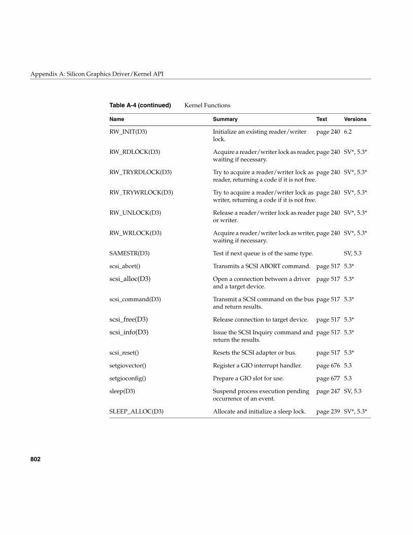
802
Appendix A: Silicon Graphics Driver/Kernel API
RW_INIT(D3) Initialize an existing reader/writerlock.
page 240 6.2
RW_RDLOCK(D3) Acquire a reader/writer lock as reader,waiting if necessary.
page 240 SV*, 5.3*
RW_TRYRDLOCK(D3) Try to acquire a reader/writer lock asreader, returning a code if it is not free.
page 240 SV*, 5.3*
RW_TRYWRLOCK(D3) Try to acquire a reader/writer lock aswriter, returning a code if it is not free.
page 240 SV*, 5.3*
RW_UNLOCK(D3) Release a reader/writer lock as readeror writer.
page 240 SV*, 5.3*
RW_WRLOCK(D3) Acquire a reader/writer lock as writer,waiting if necessary.
page 240 SV*, 5.3*
SAMESTR(D3) Test if next queue is of the same type. SV, 5.3
scsi_abort() Transmits a SCSI ABORT command. page 517 5.3*
scsi_alloc(D3) Open a connection between a driverand a target device.
page 517 5.3*
scsi_command(D3) Transmit a SCSI command on the busand return results.
page 517 5.3*
scsi_free(D3) Release connection to target device. page 517 5.3*
scsi_info(D3) Issue the SCSI Inquiry command andreturn the results.
page 517 5.3*
scsi_reset() Resets the SCSI adapter or bus. page 517 5.3*
setgiovector() Register a GIO interrupt handler. page 676 5.3
setgioconfig() Prepare a GIO slot for use. page 677 5.3
sleep(D3) Suspend process execution pendingoccurrence of an event.
page 247 SV, 5.3
SLEEP_ALLOC(D3) Allocate and initialize a sleep lock. page 239 SV*, 5.3*
Table A-4 (continued) Kernel Functions
Name Summary Text Versions
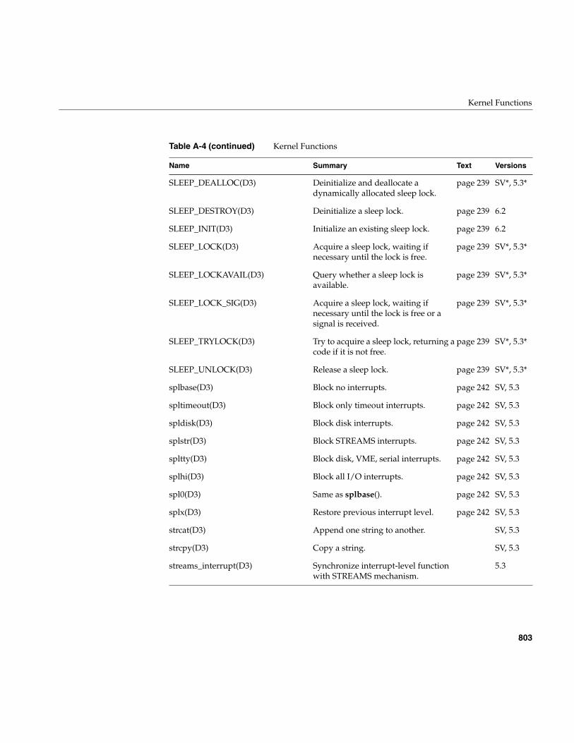
Kernel Functions
803
SLEEP_DEALLOC(D3) Deinitialize and deallocate adynamically allocated sleep lock.
page 239 SV*, 5.3*
SLEEP_DESTROY(D3) Deinitialize a sleep lock. page 239 6.2
SLEEP_INIT(D3) Initialize an existing sleep lock. page 239 6.2
SLEEP_LOCK(D3) Acquire a sleep lock, waiting ifnecessary until the lock is free.
page 239 SV*, 5.3*
SLEEP_LOCKAVAIL(D3) Query whether a sleep lock isavailable.
page 239 SV*, 5.3*
SLEEP_LOCK_SIG(D3) Acquire a sleep lock, waiting ifnecessary until the lock is free or asignal is received.
page 239 SV*, 5.3*
SLEEP_TRYLOCK(D3) Try to acquire a sleep lock, returning acode if it is not free.
page 239 SV*, 5.3*
SLEEP_UNLOCK(D3) Release a sleep lock. page 239 SV*, 5.3*
splbase(D3) Block no interrupts. page 242 SV, 5.3
spltimeout(D3) Block only timeout interrupts. page 242 SV, 5.3
spldisk(D3) Block disk interrupts. page 242 SV, 5.3
splstr(D3) Block STREAMS interrupts. page 242 SV, 5.3
spltty(D3) Block disk, VME, serial interrupts. page 242 SV, 5.3
splhi(D3) Block all I/O interrupts. page 242 SV, 5.3
spl0(D3) Same as splbase(). page 242 SV, 5.3
splx(D3) Restore previous interrupt level. page 242 SV, 5.3
strcat(D3) Append one string to another. SV, 5.3
strcpy(D3) Copy a string. SV, 5.3
streams_interrupt(D3) Synchronize interrupt-level functionwith STREAMS mechanism.
5.3
Table A-4 (continued) Kernel Functions
Name Summary Text Versions
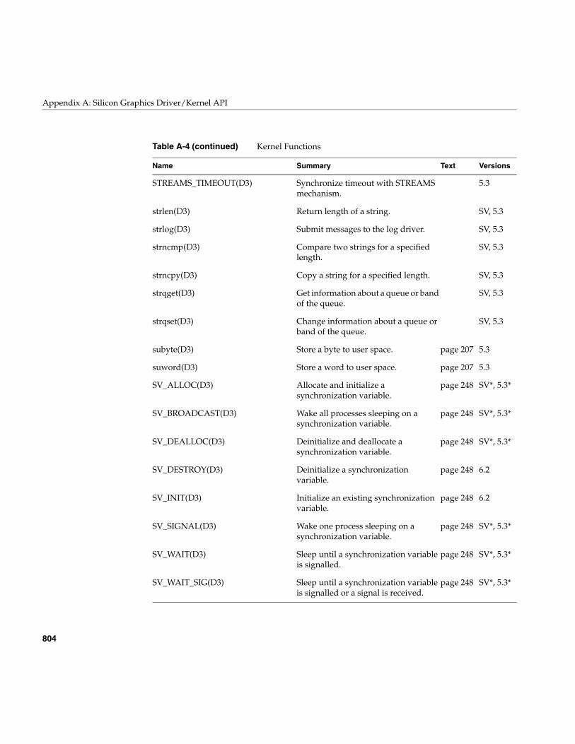
804
Appendix A: Silicon Graphics Driver/Kernel API
STREAMS_TIMEOUT(D3) Synchronize timeout with STREAMSmechanism.
5.3
strlen(D3) Return length of a string. SV, 5.3
strlog(D3) Submit messages to the log driver. SV, 5.3
strncmp(D3) Compare two strings for a specifiedlength.
SV, 5.3
strncpy(D3) Copy a string for a specified length. SV, 5.3
strqget(D3) Get information about a queue or bandof the queue.
SV, 5.3
strqset(D3) Change information about a queue orband of the queue.
SV, 5.3
subyte(D3) Store a byte to user space. page 207 5.3
suword(D3) Store a word to user space. page 207 5.3
SV_ALLOC(D3) Allocate and initialize asynchronization variable.
page 248 SV*, 5.3*
SV_BROADCAST(D3) Wake all processes sleeping on asynchronization variable.
page 248 SV*, 5.3*
SV_DEALLOC(D3) Deinitialize and deallocate asynchronization variable.
page 248 SV*, 5.3*
SV_DESTROY(D3) Deinitialize a synchronizationvariable.
page 248 6.2
SV_INIT(D3) Initialize an existing synchronizationvariable.
page 248 6.2
SV_SIGNAL(D3) Wake one process sleeping on asynchronization variable.
page 248 SV*, 5.3*
SV_WAIT(D3) Sleep until a synchronization variableis signalled.
page 248 SV*, 5.3*
SV_WAIT_SIG(D3) Sleep until a synchronization variableis signalled or a signal is received.
page 248 SV*, 5.3*
Table A-4 (continued) Kernel Functions
Name Summary Text Versions
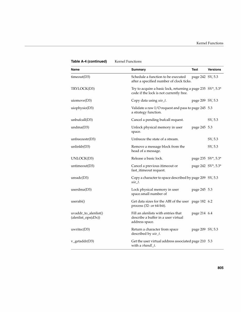
Kernel Functions
805
timeout(D3) Schedule a function to be executedafter a specified number of clock ticks.
page 242 SV, 5.3
TRYLOCK(D3) Try to acquire a basic lock, returning acode if the lock is not currently free.
page 235 SV*, 5.3*
uiomove(D3) Copy data using uio_t. page 209 SV, 5.3
uiophysio(D3) Validate a raw I/O request and pass toa strategy function.
page 245 5.3
unbufcall(D3) Cancel a pending bufcall request. SV, 5.3
undma(D3) Unlock physical memory in userspace.
page 245 5.3
unfreezestr(D3) Unfreeze the state of a stream. SV, 5.3
unlinkb(D3) Remove a message block from thehead of a message.
SV, 5.3
UNLOCK(D3) Release a basic lock. page 235 SV*, 5.3*
untimeout(D3) Cancel a previous itimeout orfast_itimeout request.
page 242 SV*, 5.3*
ureadc(D3) Copy a character to space described byuio_t.
page 209 SV, 5.3
userdma(D3) Lock physical memory in userspace.small number of
page 245 5.3
userabi() Get data sizes for the ABI of the userprocess (32- or 64-bit).
page 182 6.2
uvaddr_to_alenlist()(alenlist_ops(d3x))
Fill an alenlists with entries thatdescribe a buffer in a user virtualaddress space.
page 214 6.4
uwritec(D3) Return a character from spacedescribed by uio_t.
page 209 SV, 5.3
v_getaddr(D3) Get the user virtual address associatedwith a vhandl_t.
page 210 5.3
Table A-4 (continued) Kernel Functions
Name Summary Text Versions
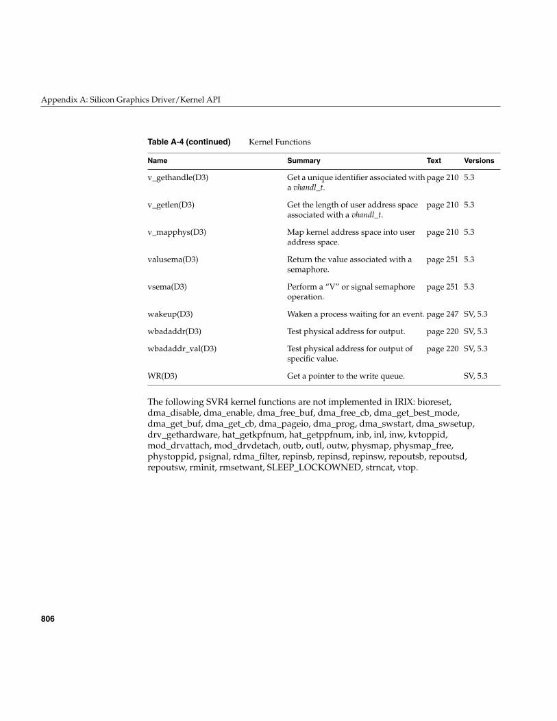
806
Appendix A: Silicon Graphics Driver/Kernel API
The following SVR4 kernel functions are not implemented in IRIX: bioreset,dma_disable, dma_enable, dma_free_buf, dma_free_cb, dma_get_best_mode,dma_get_buf, dma_get_cb, dma_pageio, dma_prog, dma_swstart, dma_swsetup,drv_gethardware, hat_getkpfnum, hat_getppfnum, inb, inl, inw, kvtoppid,mod_drvattach, mod_drvdetach, outb, outl, outw, physmap, physmap_free,phystoppid, psignal, rdma_filter, repinsb, repinsd, repinsw, repoutsb, repoutsd,repoutsw, rminit, rmsetwant, SLEEP_LOCKOWNED, strncat, vtop.
v_gethandle(D3) Get a unique identifier associated witha vhandl_t.
page 210 5.3
v_getlen(D3) Get the length of user address spaceassociated with a vhandl_t.
page 210 5.3
v_mapphys(D3) Map kernel address space into useraddress space.
page 210 5.3
valusema(D3) Return the value associated with asemaphore.
page 251 5.3
vsema(D3) Perform a “V” or signal semaphoreoperation.
page 251 5.3
wakeup(D3) Waken a process waiting for an event. page 247 SV, 5.3
wbadaddr(D3) Test physical address for output. page 220 SV, 5.3
wbadaddr_val(D3) Test physical address for output ofspecific value.
page 220 SV, 5.3
WR(D3) Get a pointer to the write queue. SV, 5.3
Table A-4 (continued) Kernel Functions
Name Summary Text Versions
807
Appendix B
B. Challenge DMA with Multiple IO4 Boards
In late 1995 a subtle hardware problem was identified in the IO4 board that is the primaryI/O interface subsystem to systems using the Challenge/Onyx architecture. Theproblem can be prevented with a software fix. The software fix is included in all devicedrivers distributed with IRIX 6.2 and a software patch is available for IRIX 5.3. However,some third-party device drivers also need to incorporate the sofware fix. This appendixexplains the IO4 problem as it affects device drivers produced outside Silicon Graphics.
The issue in a nutshell: if you are responsible for a kernel-level device driver for a DMAdevice for the Challenge/Onyx architecture, you probably need to insert a function callin the driver interrupt handler.
The IO4 Problem
The IO4 hardware problem involves a subtle interaction between two IO4 boards whenthey perform DMA to the identical cache line of memory. If one IO4 performs a partialupdate of a 128-byte cache line, and another IO4 accesses the same cache line for DMAbetween partial updates, the second IO4 can suffer a change to a different, unrelatedcache line in its on-board cache. That modified cache line may not be used again, but if itis used, invalid data can be transferred.
It is important to note that the IO4 problem is specific to interactions between multipleIO4 boards. It does not affect memory interactions between CPUs, or between CPUs andIO4s. Cache coherency is properly maintained in these cases.
An unusual coincidence is required to trigger the modification of the IO4 cache memory;then the modified cache line must be used for output before the error has any effect. Theright combinations are sufficiently rare that many systems with multiple IO4 boardshave never enountered it. For example, the problem has occurred on a system that actedas a network gateway between ATM and FDDI network, with ATM and FDDI adapterson different IO4 boards; and it has been seen when “raw” (not filesystem) disk input wascopied to a tape on a different IO4.
808
Appendix B: Challenge DMA with Multiple IO4 Boards
Software Fix
The software solution involves a number of behind-the-scenes changes to kernelfunctions that manage I/O mapping. However, for third-party device drivers, the fix tothe IO4 problem consists of ensuring that any IO4 doing DMA input (when a device usesDMA to write to memory) flushes its cache on any interrupt. This change has been madein IRIX 6.2 to all device drivers supplied by Silicon Graphics.
A patch containing all necessary fixes is available for IRIX 5.3. Contact the SiliconGraphics technical support line for the current patch number for a particular system.
Software Not Affected
As a result of hardware design and software fixes, none of the following kinds ofsoftware are affected by the problem:
• Code using PIO to manage a device.
The IO4 problem cannot be triggered by PIO, either at the user or kernel level.
• User-level code using the udmalib library or the dslib SCSI library.
These libraries for user-level DMA contain the fix, or use kernel functions that arefixed.
• User-level code based on user-level interrupts (ULI) or external interrupts.
These facilities are not relevant to the IO4 problem.
Among kernel-level drivers, only drivers that directly program DMA can be affected.STREAMS drivers are not affected; nor are pseudo-device drivers; nor are drivers thatuse only PIO and memory mapping. Drivers that are not used on Challenge-architecturemachines are not affected; for example an EISA-bus driver cannot be affected.
SCSI drivers that use the host adapter interface (see “Host Adapter Facilities” onpage 515) are also not affected. Silicon Graphics host adapter drivers contain the fix. Hostadapter drivers from third parties may need to be fixed, but this does not affect driversthat rely on the host adapter interface.
Drivers that do only block-mode I/O for the filesystem, and do not implement acharacter I/O interface (or do not support the character I/O interface using DMA) arenot affected. This is because the filesystem always requests I/O in cache-line-sizedmultiples to buffers that are cache-aligned.
Fixing the IO4 Problem
809
Fixing the IO4 Problem
A kernel-level device driver for a device that uses DMA in a Challenge-architecturesystem probably needs to make one change to guard against the IO4 problem.
In order to preclude any chance of data corruption, drivers that are affected must ensurethat the IO4 flushes its cache following any DMA write to memory (input from a device).This is done by calling a new kernel function, io4_flush_cache(), in the interrupt routineimmediately following completion of any DMA.
The prototype of io4_flush_cache() is
int io4_flush_cache(caddr_t any_PIO_mapaddr);
The argument to the function is any value returned by pio_mapaddr() that is related tothe device doing the DMA. The kernel uses this address to locate the IO4 involved. Thereturned value is 0 when the operation is successful (or was not needed). It is 1 when theargument is not a valid address returned by pio_mapaddr().
The function should be called immediately after the completion of a DMA input tomemory. Typically the device produces an interrupt at the end of a DMA, and thefunction can be called from the interrupt hander. However, some devices can completemore than one DMA transaction per interrupt, and io4_flush_cache() should be calledwhen each DMA completes. Put another way, if it is possible that a data transfercompleted after an interrupt, then the driver should call io4_flush_cache() beforemarking the transaction as complete.
The io4_flush_cache() function does nothing and returns immediately in a machine thathas only one IO4 board, and in a machine in which all IO4 boards have the hardware fix.
The kernel’s VME interrupt handler calls io4_flush_cache() once on each VME interrupt.Thus a VME device driver only needs to call io4_flush_cache() in the event that ithandles the completion of more than DMA transaction per interrupt. For example, aVME-based network driver that handles multiple packets per interrupt should callio4_flush_cache() once for each packet that completes.
Since this problem only affects Challenge/Onyx systems (including POWER Challenge,POWER Onyx, and POWER Challenge R10000), the software fix can and should beconditionally compiled on the compiler variable EVEREST, which is set by/var/sysgen/Makefile.kernio for the affected machines (see “Using/var/sysgen/Makefile.kernio” on page 256).
810
Appendix B: Challenge DMA with Multiple IO4 Boards
The following is a skeletal example of fix code for a hypothetical driver:
#ifdef EVERESTextern void io4_flush_cache(void* anyPIOMapAddr);#endifcaddr_t some_PIO_map_addr;hypothetical_edtinit(...){...
some_PIO_map_addr = pio_mapaddr(my_piomap, some_dev_addr)...}hypothetical_intr(...){...#ifdef EVEREST
io4_flush_cache(some_PIO_map_addr);#endif...}
For another example, see the code of the example VME device driver under “SampleVME Device Driver” on page 370.
811
Glossary
ABI
Application Binary Interface, a defined interface that includes an API, but adds thefurther promise that a compiled object file will be portable; no recompilation will berequired to move to any supported platform.
address/length list
A software object used to store and translate buffer addresses. Also called an alenlist, anaddress/length list is a list in which each item is a pair consisting of an address and alength. The kernel provides numerous functions to create and fill alenlists and totranslate them from one address space to another.
API
Application Programming Interface, a defined interface through which services can beobtained. A typical API is implemented as a set of callable functions and header files thatdefine the data structures and specific values that the functions accept or return. Thepromise behind an API is that a program that compiles and works correctly will continueto compile and work correctly in any supported environment (however, recompilationmay be required when porting or changing versions). See ABI.
big-endian
The hardware design in which the most significant bits of a multi-byte integer are storedin the byte with the lowest address. Big-endian is the default storage order in MIPSprocessors. Opposed to little-endian.
block
As a verb, to suspend execution of a process. See sleep.
block device
A device such as magnetic tape or a disk drive, that naturally transfers data in blocks offixed size. Opposed to character device.
812
Glossary
block device driver
Driver for a block device. A block device’s driver is not allowed to support the ioctl(),read() or write() entry points, but does have a strategy() entry point. See character devicedriver.
bus master
An I/O device that is capable of generating a sequence of bus operations—usually aseries of memory reads or writes—independently, once programmed by software. Seedirect memory access.
bus-watching cache
A cache memory that is aware of bus activity and, when the I/O system performs a DMAwrite into physical memory or another CPU in a multiprocessor system modifies virtualmemory, automatically invalidates any copy of the same data then in the cache. Thishardware function eliminates the need for explicit data cache write back or invalidationby software.
cache coherency
The problem of ensuring that all cached copies of data are true reflections of the data inmemory. The usual solution is to ensure that, when one copy is changed, all other copiesare automatically marked as invalid so that they will not be used.
cache line
The unit of data when data is loaded into a cache memory. Typically 128 bytes in currentCPU models.
cache memory
High-speed memory closely attached to a CPU, containing a copy of the most recentlyused memory data. When the CPU’s request for instructions or data can be satisfied fromthe cache, the CPU can run at full rated speed. In a multiprocessor or when DMA isallowed, a bus-watching cache is needed.
character device
A device such as a terminal or printer that transfers data as a stream of bytes, or a devicethat can be treated in this way under some circumstances. For example, a disk (normallya block device) can be treated as a character device for purposes of reading diagnosticinformation.
Glossary
813
character device driver
The kernel-level device driver for a character device transfers data in bytes between thedevice and the user program. A STREAMS driver works with a character driver. Note thata block device such as magnetic tape or disk drives can also support character accessthrough a character driver. Each disk device, for example, is represented as two differentdevice special files, one managed by a block device driver and one by a character devicedriver.
close
Relinquish access to a resource. The user process invokes the close() system call when itis finished with a device, but the system does not necessarily execute your drvclose()entry point for that device.
data structure
Contiguous memory used to hold an ordered collection of fields of different types. AnyAPI usually defines several data structures. The most common data structure in theDDI/DKI is the buf_t.
DDI/DKI
Device Driver Interface/Device Kernel Interface; the formal API that defines the servicesprovided to a device driver by the kernel, and the rules for using those services.DDI/DKI is the term used in the UNIX System V documentation. The IRIX version of theDDI/DKI is close to, but not perfectly compatible with, the System V interface.
deadlock
The condition in which two or more processes are blocked, each waiting for a lock heldby the other. Deadlock is prevented by the rule that a driver upper-half entry point is notallowed to hold a lock while sleeping.
devflag
A public global flag word that characterizes the abilities of a device driver, including theflags D_MP, D_WBACK and D_OLD.
device driver
A software module that manages access to a hardware device, taking the device in andout of service, setting hardware parameters, transmitting data between memory and thedevice, sometimes scheduling multiple uses of the device on behalf of multipleprocesses, and handling I/O errors.
814
Glossary
device number
Each device special file is identified by a pair of numbers: the major device number identifiesthe device driver that manages the device, and the minor device number identifies thedevice to the driver.
device special file
A filename in the /hw filesystem that represents a hardware device. A device special filedoes not specify data on disk, but rather identifies a particular hardware unit and thedevice driver that handles it. The inode of the file contains the device number as well aspermissions and ownership data.
direct memory access
When a device reads or writes in memory, asynchronously and without specificintervention by a CPU. In order to perform DMA, the device or its attachment must havesome means of storing a memory address and incrementing it, usually through mappingregisters. The device writes to physical memory and in so doing can invalidate cachememory; a bus-watching cache compensates.
downstream
The direction of STREAMS messages flowing through a write queue from the userprocess to the driver.
EISA bus
Enhanced Industry Standard Architecture, a bus interface supported by certain SiliconGraphics systems.
EISA Product Identifier (ID)
The four-byte product identifier returned by an EISA expansion board.
external interrupt
A hardware signal on a specified input or output line that causes an interrupt in thereceiving computer. The Silicon Graphics Challenge, OCTANE, and Origin2000architectures support external interrupt signals.
file handle
An integer returned by the open() kernel function to represent the state of an open file.When the file handle is passed in subsequent kernel services, the kernel can retrieveinformation about the file, for example, when the file is a device special file, the file handlecan be associated with the major and minor device number.
Glossary
815
gigabyte
See kilobyte.
GIO bus
Graphics I/O bus, a bus interface used on Indigo, Indigo2, and Indy workstations.
hwgraph
The hardware graph is a graph-structured database of device connections, maintained inkernel memory by the kernel and by kernel-level device drivers. You can display thestructure of the hwgraph by listing the contents of the /hw filesystem.
I/O operations
Services that provide access to shared input/output devices and to the global datastructures that describe their status. I/O operations open and close files and devices, readdata from and write data to devices, set the state of devices, and read and write systemdata structures.
inode
The UNIX and IRIX disk object that represents the existence of a file. The inode recordsthe owner and group IDs and permissions. For regular disk files, the inode distinguishesfiles from directories and has other data that can be set with chmod. For device special files,the inode contains the major and minor device numbers and distinguishes block fromcharacter files.
inter-process communication
System calls that allow a process to send information to another process. There areseveral ways of sending information to another process: signals, pipes, shared memory,message queues, semaphores, streams, or sockets.
interrupt
A hardware signal that causes a CPU to set aside normal processing and begin executionof an interrupt handler. An interrupt is parameterized by the type of bus and the interruptlevel, and possibly with an interrupt vector number. The kernel uses this information toselect the interrupt handler for that device.
interrupt level
A number that characterizes the source of an interrupt. The VME bus provides for seveninterrupt levels. Other buses have different schemes.
816
Glossary
interrupt priority level
The relative priority at which a bus or device requests that the CPU call an interruptprocess. Interrupts at a higher level are taken first. The interrupt handler for an interruptcan only be preempted on its CPU by an interrupt handler for an interrupt of higherlevel.
interrupt vector
A number that characterizes the specific device that caused an interrupt. Most VME busdevices have a specific vector number set by hardware, but some can have their vectorset by software.
ioctl
Control a character device. Character device drivers may include a "special function"entry point, pfxioct().
IRQ
Interrupt Request Input, a hardware signal that initiates an interrupt.
k0
Virtual address range within the kernel address space that is cached but not mapped bytranslation look-aside buffers. Also referred to as kseg0.
k1
Virtual address range within the kernel address space that is neither cached nor mapped.Also called kseg1.
k2
Virtual address range within the kernel address space that can be both cached andmapped by translation look-aside buffers. Also called kseg2.
kernel level
The level of privilege at which code in the IRIX kernel runs. The kernel has a privateaddress space, not acceptable to processes at user-level, and has sole access to physicalmemory.
kilobyte (KB)
1,024 bytes, a unit chosen because it is both an integer power of 2 (210) and close to 1,000,the basic scale multiple of engineering quantities. Thus 1,024 KB, 220, is 1 megabyte (MB)and close to 1e6; 1,024 MB, 230, is 1 gigabyte (GB) and close to 1e9; 1,024 GB, 240, is
Glossary
817
1 terabyte (TB) and close to 1e12. In the MIPS architecture using 32-bit addressing, theuser segment spans 2 GB. Using 64-bit addressing, both the user segment and the rangeof physical addresses span 1 TB.
ksegn
See k0, k1, k2.
little-endian
The hardware design in which the least significant bits of a multi-byte integer are storedin the byte with the lowest address. Little-endian order is the normal order in Intelprocessors, and optional in MIPS processors. Opposed to big-endian. (These terms arefrom Swift’s Gulliver’s Travels, in which the citizens of Lilliput and Blefescu are dividedby the burning question of whether one’s breakfast egg should be opened at the little orthe big end.)
lock
A data object that represents the exclusive right to use a resource. A lock can beimplemented as a semaphore (q.v.) with a count of 1, but because of the frequency of useof locks, they have been given distinct software support (see LOCK(D3)).
major device number
A number that specifies which device driver manages the device represented by a devicespecial file. In IRIX 6.2, a major number has at most 9 bits of precision (0-511). Numbers60-79 are used for OEM drivers. See also minor device number.
map
In general, to translate from one set of symbols to another. Particularly, translate onerange of memory addresses to the addresses for the corresponding space in anothersystem. The virtual memory hardware maps the process address space onto pages ofphysical memory. The mapping registers in a DMA device map bus addresses to physicalmemory corresponding to a buffer. The mmap(2) system call maps part of processaddress space onto the contents of a file.
mapping registers
Registers in a DMA device or its bus attachment that store the address translation dataso that the device can access a buffer in physical memory.
megabyte
See kilobyte.
818
Glossary
minor device number
A number that, encoded in a device special file, identifies a single hardware unit among theunits managed by one device driver. Sometimes used to encode device managementoptions as well. In IRIX 6.2, a minor number may have up to 18 bits of precision. See alsomajor device number.
mmapped device driver
A driver that supports mapping hardware registers into process address space,permitting a user process to access device data as if it were in memory.
module
A STREAMS module consists of two related queue structures, one for upstreammessages and one for downstream messages. One or more modules may be pushed ontoa stream between the stream head and the driver, usually to implement and isolate acommunication protocol or a line discipline.
open
Gain access to a device. The kernel calls the pfxopen() entry when the user process issuesan open() system call.
page
A block of virtual or physical memory, of a size set by the operating system and residingon a page-size address boundary. The page size is 4,096 (212) bytes when in 32-bit mode;the page size in 64-bit mode can range from 212 to 220 at the operating system’s choice (seethe getpagesize(2) reference page).
programmed I/O
Programmed I/O (PIO), meaning access to a device by mapping device registers intoprocess address space, and transferring data by storing and loading single bytes orwords.
poll
Poll entry point for a non-stream character driver. A character device driver may includea drvpoll() entry point so that users can use select(2) or poll(2) to poll the file descriptorsopened on such devices.
prefix
Driver prefix. The name of the driver must be the first characters of its standard entrypoint names; the combined names are used to dynamically link the driver into the kernel.Specified in the master.d file for the driver. Throughout this manual, the prefix pfxrepresents the name of the device driver, as in pfxopen(), pfxioctl().
Glossary
819
primary cache
The cache memory most closely attached to the CPU execution unit, usually in theprocessor chip.
primitives
Fundamental operations from which more complex operations can be constructed.
priority inheritance
An implementation technique that prevents priority inversion when a process of lowerpriority holds a mutual exclusion lock and a process of higher priority is blocked waitingfor the lock. The process holding the lock “inherits” or acquires the priority of thehighest-priority waiting process in order to expedite its release of the lock. IRIX supportspriority inheritance for mutual exclusion locks only.
priority inversion
The effect that occurs when a low-priority process holds a lock that a process of higherpriority needs. The lower priority process runs and the higher priority process waits,inverting the intended priorities. See priority inheritance.
process control
System calls that allow a process to control its own execution. A process can allocatememory, lock itself in memory, set its scheduling priorities, wait for events, execute anew program, or create a new process.
protocol stack
A software subsystem that manages the flow of data on a communications channelaccording to the rules of a particular protocol, for example the TCP/IP protocol. Calleda “stack” because it is typically designed as a hierarchy of layers, each supporting the oneabove and using the one below.
pseudo-device
Software that uses the facilites of the DDI/DKI to provide specialized access to data,without using any actual hardware device. Pseudo-devices can provide access to systemdata structures that are unavailable at the user-level. For example, the fsctl driver givessuperuser access to filesystem data (see fsctl(7)) and the inode monitor pseudo-deviceallows access to file activity (see imon(7)).
read
Read data from a device. The kernel executes the pfxread() entry point whenever a userprocess calls the read() system call.
820
Glossary
scatter/gather
An I/O operation in which what to the device is a contiguous range of data is distributedacross multiple pages that may not be contiguous in physical memory. On input tomemory, the device scatters the data into the different pages; on output, the devicegathers data from the pages.
SCSI
Small Computer System Interface, the bus architecture commonly used to attach diskdrives and other block devices.
SCSI driver interface
A collection of machine-independent input/output controls, functions, and datastructures, that provides a standard interface for writing a SCSI driver.
semaphore
A data object that represents the right to use a limited resource, used for synchronizationand communication between asynchronous processes. A semaphore contains a countthat represents the quantity of available resource (typically 1). The P operation(mnemonic: dePlete) decrements the count and, if the count goes negative, causes thecaller to wait (see psema(D3X), cpsema(D3X)). The V operation (mnemonic: reVive)increments the count and releases any waiting process (see vsema(D3X), cvsema(D3X)).See also lock.
signals
Software interrupts used to communicate between processes. Specific signal numberscan be handled or blocked. Device drivers sometimes use signals to report events to userprocesses. Device drivers that can wait have to be sensitive to the possibility that a signalcould arrive.
sleep
Suspend process execution pending occurrence of an event. The term “block” is alsoused.
socket
A software structure that represents one endpoint in a two-way communications link.Created by socket(2).
Glossary
821
spl
Set priority level, a function that was formerly part of the DDI/DKI, and used to lock orallow interrupts on a processor. It is not possible to use spl effectively in a multiprocessorsystem, so it has been superceded by more sophisticated means of synchronization suchas the lock and semaphore.
strategy
In general, the plan or policy for arbitrating between multiple, concurrent requests forthe use of a device. Specifically in disk device drivers, the policy for scheduling multiple,concurrent disk block-read and block-write requests.
STREAM
A linked list of kernel data structures that provide a full-duplex data path between a userprocess and a device. Streams are supported by the STREAMS facilities in UNIX SystemV Release 3 and later.
STREAM head
The stream head, which is inserted by the STREAMS subsystem, processesSTREAMS-related system calls and performs data transfers between user space andkernel space. It is the component of a stream closest to the user process. Every stream hasa stream head.
STREAMS
A kernel subsystem used to build a stream, which is a modular, full-duplex data pathbetween a device and a user process. In IRIX 5.x and later, the TCP/IP stack sits on topof the STREAMS stack. The Transport Layer Interface (TLI) is fully supported.
STREAMS driver
A software module that implements one stage of a STREAM. A STREAMS driver can be“pushed on” or “popped off” any STREAM.
TCP/IP
Transmission Control Protocol/Internet Protocol.
terabyte
See kilobyte (KB).
822
Glossary
TFP
The internal code name for the MIPS R8000 processor, used in some Silicon Graphicspublications.
TLI
Transport Interface Layer.
user-level
The privilege level of the system at which user-initiated programs run. A user-levelprocess can access the contents of one address space, and can access files and devicesonly by calling kernel functions. Contrast to kernel level.
unmap
Disconnect a memory-mapped device from user process space, breaking the associationset by mapping it.
VME bus
VERSA Module Eurocard bus, a bus architecture supported by the Silicon GraphicsChallenge and Onyx systems.
VME-bus adapter
A hardware conduit that translates host CPU operations to VME-bus operations anddecodes some VME-bus operations to translate them to the host side.
virtual memory
Memory contents that appear to be in contiguous addresses, but are actually mapped todifferent physical memory locations by hardware action of the translation lookasidebuffer (TLB) and page tables managed by the IRIX kernel. The kernel can exploit virtualmemory to give each process its own address space, and to load many more processesthan physical memory can support.
virtual page number
The most significant bits of a virtual address, which select a page of memory. Theprocessor hardware looks for the VPN in the TLB; if the VPN is found, it is translated toa physical page address. If it is not found, the processor traps to an exception routine.
Glossary
823
volatile
Subject to change. The volatile keyword informs the compiler that a variable couldchange value at any time (because it is mapped to a hardware register, or because it isshared with other, concurrent processes) and so should always be loaded before use.
wakeup
Resume suspended process execution.
write
Write data to a device. The kernel executes the pfxread() or pfxwrite() entry pointswhenever a user process calls the read() or write() system calls.

825
Numbers
32-bit address spaceSee address space, 32-bit
64-bit address spaceSee address space, 64-bit
64-bit mode, 30
A
address exception, 8addressing, 3-34address/length list, 193, 213-216
cursor use, 215address space
32-bit, 15-19embedding in 64-bit, 21kseg0, 18kseg1, 18kseg2, 18kuseg, 17segments of, 15virtual mapping, 17
64-bit, 19-24cache-controlled, 23segments of, 19-24sign extension, 21virtual mapping, 21xkseg, 23xksseg, 22xkuseg, 22
bus virtual, 11data transfer between, 207kernel, 18, 23
map to user, 31physical, 217supervisor, 22user process, 17, 22See also execution model
alternate console, 273ASSERT macro, 277audio not covered, 93authorized binary interface (ABI), 182
B
bdevswtable, 145block device, 63
combined with character, 72, 159versus character, 36
buffer (buf_t)See data types, buf_t
bus adaptertranslates addresses, 12
bus virtual address, 11
C
cache, 13-14, 80764-bit access, 23alignment of buffers, 217
Index
826
Index
coherency, 14control functions, 219device access always uncached, 9primary, 6secondary, 6
cache algorithm, 24cdevsw table, 145Challenge/Onyx
directing interrupts, 465DMA engine in, 334, 452IO4 board, 469, 807-810limit on VME DMA space, 461, 487no uncached memory, 33VME address windows, 459, 485VME bus address mapping in, 456VME bus numbers, 470VME design constraints, 477VME hardware, 468-479
character device, 62combined with block, 72, 159versus block, 37
COFF file format not supported, 256command
See IRIX commandscompiler options, 258
for loadable driver, 265for network driver, 555
compiler variables, 257configuration files, 55-58
/dev/MAKEDEV, 255/etc/inittab, 273/etc/ioconfig.config, 53, 342/etc/ioperms, 53/etc/rc2.d, 41/etc/rc2/S23autoconfig, 267/usr/cpu/sysgen/IPnnboot, 260/usr/lib/X11/input/config, 58/var/sysgen/boot, 56, 259, 260/var/sysgen/irix.sm, 343, 344
/var/sysgen/Makefile.kernio, 256/var/sysgen/master.d, 55, 254, 259, 260, 260-263
dependencies, 262example, 299format, 261, 265stubs, 262variables, 262
/var/sysgen/master.d/mem, 32/var/sysgen/mtune/*, 58/var/sysgen/system, 56, 259
example, 299/var/sysgen/system/irix.sm, 83
for debugging, 271/var/sysgen/system/irix.smVME devices, 464
configuration flags, 261configuring a driver
loadable, 264-268nonloadable, 259-264
Controller number, assigned in hwgraph, 51CPU, 4-14
device access, 9IP26, 33memory access by, 5model number from inventory, 50processors in, 4type numbers, 4watchpoint registers, 283
D
D_MP flag, 149D_MT flag, 149D_OLD flag, 150, 158D_WBACK flag, 149Data Link Provider Interface (DLPI), 549data transfer, 207-210data types
summary table, 787
827
Index
alenlist_t, 193, 213buf_t, 165, 196-198
BP_ISMAPPED, 198displaying, 293for syncronization, 187functions, 218interrupt handling, 176management, 246
caddr_t, 193cred_t, 160, 232dev_desc_t, 726, 737, 741dev_t, 39, 158, 199
same as vertex_hdl_t, 192struct dsconf, 104struct dsreq
ds_flags, 99ds_msg, 103ds_ret, 101ds_status, 102
edt_t, 152graph_error_t, 192iopaddr_t, 193iovec_t, 195lock_t, 198, 235mrlock_t, 198, 241mutex_t, 198, 238paddr_t, 193struct pollhead, 166proc_t (not available), 232scsi_request, 523-528struct scsi_target_info, 521sema_t, 198sleep_t, 240struct dsreq, 97-103sv_t, 198, 249uio_t, 163, 195, 209__userabi_t, 183vertex_hdl_t, 192vhandl_t, 170, 210
debugging kernel, 269-274device access, 9
device numberSee major device number, minor device number
device special file, 36-41as normal file, 36defining, 255/dev/dsk, 40/dev/ei, 128, 133/dev/kmem, 31/dev/mem, 31, 32/dev/mmem, 32/dev/scsi/*, 94-97EISA mapping, 84/hw/external_interrupt, 133multiple names for, 37name format, 40, 95PCI mapping, 78VME mapping, 87
device special file/dev/kmem, 32digital media not covered, 93DIrect Memory Access (DMA)
cache control, 807Direct Memory Access (DMA), 10, 68-70
buffer alignment for, 217cache control, 219DMA engine for VME bus, 334, 452EISA bus-master, 605EISA bus slave, 607GIO bus, 682IO4 hardware problem, 807mapping, 362-365, 735-740maximum size, 217setting up, 216-220user-level, 91-92user-level SCSI, 100VME bus, 333, 336, 451, 455
disk volume header, 269driver
compiling, 257-259, 555configuring, 259-268debugging, 269-294

828
Index
examplesEISA, 608-669GIO bus, 689-699network, 558-586SCSI bus, 536-537VME, 370-444, 490-503
flag constant, 148-150, 265, 764initialization, 150-153lower half, 70, 71prefix, 143, 260
in master.d, 55process context, 232types
GIO bus, 673-699types of, xxxv, 59-74
block, 63character, 62EISA bus, 589-669kernel-level, xxxv, 32, 62-74layered, 72loadable, 74network, 547-586process-level, xxxvpseudo-device, 68SCSI bus, 535STREAMS, xxxv, 63
updating, xxxviupper half, 70
in multiprocessor, 185, 186user-level, 31, 59See also entry pointsSee also loadable driver
driver debuggingalternate console, 273breakpoints, 282circular buffer output, 275lock metering, 272memory display, 284multiprocessor, 278setsym use, 273stopping during bootstrap, 279
symbol lookup, 281symbols, 271symmon use, 277system log output, 275
driver operations, 63-70DMA, 68ioctl, 65mmap, 67open, 63read, 66write, 66
dslib library, 105-118function summary, 106data transfer options, 100doscsireq(), 108ds_ctostr(), 110ds_vtostr(), 110dsclose(), 107dsopen(), 107filldsreq(), 108fillg0cmd(), 109fillg1cmd(), 109inquiry12(), 111modeselect15(), 111modesense1a(), 112read08(), 113readcapacity25(), 114readextended28(), 113releaseunit17(), 115requestsense03(), 114reserveunit16(), 115senddiagnostic1d(), 116testunitready00(), 116write0a(), 117writeextended2a(), 117
dsreq driver, 94data transfer options, 100DS_ABORT, 105DS_CONF, 104DS_RESET, 105
829
Index
exclusive open, 97flags, 99return codes, 101scatter/gather, 100struct dsconf, 104struct dsreq, 97-103
ds_flags, 99ds_msg, 103ds_ret, 101ds_status, 102
E
EISA bus, 589-669address mapping, 596address spaces, 592allocate DMA channel, 605allocate IRQ, 603-605byte order, 593card slots, 596configuring, 597-600DMA to bus master, 605-607example driver, 608interrupts, 592, 596kernel services, 600-608locked cycles, 593mapping into user process, 60overview, 590-595PIO bandwidth, 85PIO mapping, 600-603product identifier, 593-595request arbitration, 591user-level PIO, 83-86
ELF object format, 256entry points
summary table, 145, 786attach, 153, 533, 722close, 160-161, 170, 766detach, 156devflag, 148-150, 265
edtinit, 151, 266, 352, 678halt, 181info, 764init, 151, 266, 765interrupt, 175-179, 680ioctl, 161-162, 182map, 170-172mmap, 173mversion, 264, 265open, 157-160, 765
mode flag, 159type flag, 158
poll, 166-169and interrupts, 177
print, 182read, 163-164reg, 153, 266, 530, 720size, 160, 181start, 152, 266, 765strategy, 165
and interrupts, 176called from read or write, 164design models, 245
unload, 170, 180-181, 268, 535, 723unmap, 174unreg, 180when called, 147write, 163-164
example driver, 295, 370, 490, 536, 558, 608, 689execution model, 182-183external interrupt, 62, 127-137
Challenge architecture, 128-133generate, 128, 134input is level-triggered, 129, 136Origin2000 architecture, 133-137pulse widths, 130set pulse widths, 131
830
Index
F
FibreChannel, 544fixed PIO map, 459, 484fmodsw table, 145function
See IRIX functions, kernel functions
G
GIO bus, 673-699address space mapping, 674configuring, 675-676edtinit entry point, 678example driver, 689-699interrupt handler, 680kernel services, 676-678memory parity checking with, 686
H
hardware graphSee hwgraph
hardware inventory, 48-54adding entries to, 51contents, 48hinv displays, 49network driver use, 554software interface to, 50
header filessummary table, 201dslib.h, 106for network drivers, 551sgidefs.h, 31sys/cmnerr.h, 274sys/debug.h, 277sys/file.h, 159sys/immu.h, 211
sys/invent.h, 50, 51sys/open.h, 158sys/param.h, 196sys/PCI/pciio.h, 532, 721sys/poll.h, 166sys/region.h, 172sys/sema.h, 198sys/sysmacros.h, 211sys/types.h, 31sys/uio.h, 195sys/var.h, 58
/hw filesystemSee hwgraph
hwgraph, 42-47and attach entry point, 154, 722and top-half entry point, 158and VME, 342-344controller numbers assigned, 51data types in, 192-193definition, 43display by symmon, 285edge, 43
implicit, 46hardware inventory in, 51/hw filesystem reflects, 46implicit edge, 46justification for, 42nomenclature, 43relation to driver, 255use by SCSI driver, 510-513vertex, 43
properties, 45
I
idbg debugger, 271-272, 287-294command line use, 288command syntax, 289-294configuring in kernel, 271display I/O status, 292
831
Index
display process data, 290interactive mode, 287invoking, 287loading, 287lock meter display, 291log file output, 288memory display, 290
ide PROM monitor, 269include file
See header filesINCLUDE statement, 151, 263, 266initialization, 150-153inode, 64interrupt, 71
and strategy entry point, 176associating to a driver, 175concurrent with processing, 185enabled during initialization, 150handler runs as thread, 177latency, 179mutual exclusion with, 178on multiprocessor, 178preemption of, 179
inventorySee hardware inventory
IO4 board, 469multiple DMA problem, 807-810
IP26 CPU, 33IPL statement, 465IRIX 6.5 and PCI drivers, 720IRIX 6.5 device drivers, xxxviIRIX commands
autoconfig, 259, 263, 273dvhtool, 270hinv, 49
and MAKEDEV, 41for CPU type, 5
install, 41, 255ioconfig
with VME, 342ioconfig, 51-54lboot, 56
builds switch tables, 145driver prefix with, 143
mknod, 41, 255ml, 74mount, 65, 157nvram, 273setsym, 273systune, 58, 268, 276
max DMA size, 217switch table size, 145
umount, 160uname, 5versions, 270
IRIX functionsclose(), 160endinvent(), 50getinvent(), 50getpagesize(), 22ioctl(), 61, 62, 65kmem_alloc(), 71mmap()
EISA PIO, 84PCI PIO, 80VME PIO, 89
mmap(), 32, 67, 169-170munmap(), 174open()
with dsreq driver, 97open(), 63, 157pio_badaddr(), 458, 483poll(), 166-167read(), 66, 68setinvent(), 50syslog(), 275write(), 66, 68
832
Index
J
jag (SCSI-toVME) adapter, 96
K
kernel address spacedriver runs in, 32mapping to user space, 31
kernel execution model, 183kernel functions
summary table, 789add_to_inventory(), 51alenlist_create(), 213alenlist_cursor_offset(), 216alenlist_destroy(), 213alenlist_get(), 215badaddr(), 220bcopy(), 208biodone(), 176, 246bioerror(), 176biowait(), 246bp_mapin(), 219brelse(), 206buf_to_alenlist(), 214bzero(), 208cmn_err(), 274-276
buffer output, 275system log output, 275
copyin(), 162, 208copyout(), 162, 208device_admin_info_get(), 231device_controller_number_get(), 230device_controller_number_set(), 230device_driver_admin_info_get(), 231device_info_get(), 222device_info_set(), 224, 356device_inventory_add(), 225, 229device_inventory_get_next(), 222dki_dcache_inval(), 220
dki_dcache_wb(), 220dma_map(), 462, 487, 606dma_mapaddr(), 462, 487, 607dma_mapalloc(), 461, 486, 606drv_getparm(), 232drv_priv(), 160, 232drvhztousec(), 243drvusectohz(), 243eisa_dmachan_alloc(), 605eisa_ivec_alloc(), 603fasthzto(), 243flushbus(), 220fubyte(), 209get_current_abi(), 183geteblk(), 206getemajor(), 200geteminor(), 200getinvent(), 5getrbuf(), 206hwgraph_block_device_add(), 225hwgraph_char_device_add(), 224, 356hwgraph_char_device_add(), 225, 227hwgraph_edge_add(), 225, 227hwgraph_edge_remove(), 227hwgraph_info_add_LBL(), 230hwgraph_info_export_LBL(), 230hwgraph_info_get_LBL(), 230, 231hwgraph_info_remove_LBL(), 230hwgraph_info_replace_LBL(), 230hwgraph_info_unexport_LBL(), 230hwgraph_inventory_get_next(), 229hwgraph_vertex_create(), 225, 227hwgraph_vertex_destroy(), 227initnsema(), 190initnsema_mutex() (not supported), 252ip26_enable_ucmem(), 34ip26_return_ucmem(), 34itimeout(), 167, 244kmem_alloc(), 18, 203kmem_free(), 224, 227, 356kmem_zalloc(), 204, 224, 227, 356
833
Index
kvaddr_to_alenlist(), 214kvtophys(), 218makedevice(), 200pciio_dmamap_addr(), 739pciio_dmamap_alloc(), 737pciio_dmamap_done(), 739pciio_dmamap_list(), 739pciio_dmatrans_addr(), 740pciio_dmatrans_list(), 740pciio_driver_register(), 533, 721pciio_error_register(), 745pciio_intr_alloc(), 741pciio_intr_connect(), 742pciio_intr_disconnect(), 744pciio_piomap_addr(), 728pciio_piomap_alloc(), 725, 732pciio_piomap_done(), 729pciio_piotrans_addr(), 729phalloc(), 166, 205phfree(), 205physiock(), 149, 164pio_baddr(), 602pio_bcopyin(), 459, 484, 603pio_bcopyout(), 459, 484, 603pio_map_alloc(), 608pio_mapaddr(), 459, 484pio_mapalloc(), 457, 482, 601pio_wbadaddr(), 458, 484pollwakeup(), 166, 177printf(), 276psema(), 190, 252ptob(), 22setgioconfig(), 677setgiovector(), 676sleep(), 247splhi()
denigrated, 242meaningless, 185
splnet()ineffective, 555
splvme()useless, 189
subyte(), 209timeout(), 244uiomove(), 209uiophysio(), 164untimeout(), 244userabi(), 183uvaddr_to_alenlist(), 214v_getaddr(), 210v_gethandle(), 211v_mapphys(), 171, 210vme_ivec_alloc(), 467, 489vme_ivec_free(), 468, 490vme_ivec_set(), 467, 489vsema(), 190, 252vt_gethandle(), 172, 174wakeup(), 247
kernel-level driver, xxxv, 62-74, 141-190structure of, 143
kernel mode of processor, 7kernel panic
address exception, 8moving data, 207
kernel switch tables, 145
L
layered driver, 72lboot
See IRIX commandsloadable driver, 74
and switch table, 145autoregister, 151compiler options, 265configuring, 264initialization, 151loading, 266master.d, 265
834
Index
mversion entry, 265not in miniroot, 74registration, 267unloading, 268
loading a driver, 266locking
See mutual exclusionlock metering support, 272, 291lower half of driver, 71
M
major device number, 38, 199for STREAMS clone, 774, 775in /dev/scsi, 95in inode, 36in master.d, 55, 261input to open, 64in variables in master.d, 263selecting, 254
/dev/MAKEDEV, 40-41, 94, 199, 255adding to /dev/scsi, 96
master.d configuration filesSee configuration files,/var/sysgen/master.d
memory, 3-34memory address
cached, 18physical, 283, 596uncached, 18
memory allocation, 203-206memory display, 284memory mapping, 31-32, 169-174migrating drivers from previous releases, xxxviminiroot
no loadable drivers, 74minor device number, 39, 199
encoding, 39for STREAMS clone driver, 774, 775
in /dev/scsi, 95in inode, 36input to open, 64, 158selecting, 254
multiprocessorconverting to, 188driver design for, 184-190, 769driver flag D_MP, 149drivers for, 73interrupt handling on, 178network drivers in, 554-557splhi() useless in, 185synchronizing upper-half code, 186uniprocessor assumptions invalid, 184uniprocessor drivers use CPU 0, 73using symmon in, 278
mutex locks, 237mutual exclusion, 233, 235-242
basic locks, 235-236in multiprocessor drivers, 185in network driver, 556-557mutex locks, 237priority inheritance, 238reader/writer locks, 240semaphore, 252sleep locks, 239
N
names of devices, 40, 95network, 547
based on 4.3BSD, 550driver interfaces, 550-554example driver, 558header files, 551multiprocessor considerations, 554overview, 548STREAMS protocol stack, 549
835
Index
network driverdebugging, 294
Network File System (NFS), 549
O
O2 PCI driver, 732
P
page sizeI/O, 211macros, 211memory, 22, 211
parity check with GIO, 686pciba, usrpci, 78PCI bus
arbitration, 712, 717base address register, 711, 715byte order, 707-710cache line size, 711, 715configuration
initialized, 711, 715configuration space, 708, 730-732device ID, 721, 723driver structure, 530-536, 720-723endianness, 707error handler, 744-745implementation, 703-717interrupt handler, 740-744interrupt lines, 713, 717kernel services, 719-747latency of, 706latency timer, 711, 715register driver, 721slot versus device, 706user-level PIO, 78-82vendor ID, 533, 721, 723versus system bus, 704
PCI drivers and IRIX 6.5, 720PCI drivers for O2, 732pciio_pio_* routines, 732pipe semantics, 772prefix, 55, 143, 260primary cache, 6priority inheritance, 238priority level functions, 242privilege checking, 232process, 232-233
display data about, 290handle of, 233sending signal to, 233table of in kernel, 290
process-level driver, xxxvprocessor
kernel mode, 7types, 4user mode, 7
Programmed I/O (PIO), 9, 77, 450address maps for, 357-362, 456-460, 481-485,
723-729EISA bus, 83-86, 600GIO bus, 680PCI bus, 78-82VME bus, 86-90, 332, 335, 450, 450-451, 455
pseudo-device driver, 68putbuf circular buffer, 275, 290
R
raw deviceSee character device
reader/writer locks, 240register a driver
loadable driver for callback, 267PCI driver, 531, 721reg entry point, 153
836
Index
S
sash standalone shell, 269SCSI bus, 507-544
adapter error codes, 538adapter number, 95command
Inquiry, 111, 521Mode Select, 111Mode Sense, 112Read, 113Read Capacity, 114Request Sense, 114Reserve Unit, 115Send Diagnostic, 116Test Unit Ready, 116Write, 117
display request structure, 292driver, 535error messages, 537-544example driver, 536-537hardware support overview, 508host adapter, 509
functions of, 517purpose, 515scsi_abort(), 529scsi_alloc(), 521scsi_command(), 523scsi_free(), 522scsi_info(), 521vectors to, 518
kernel overview, 509LUN, 95, 516message string tables, 538sense codes, 539target ID, 95target number, 516user-level access, 61, 93-118See also dsreq driver
secondary cache, 6
sector unit macros, 211semaphore, 251-252
for mutual exclusion, 252for waiting, 252
signal, 232sign extension of 32-bit addresses, 21SIGSEGV, 8Silicon Graphics
developer program, xxxixFTP server, xlVME bus hardware, 330, 448WWW server, xl
64-bit address spaceSee address space, 64-bit
64-bit entriesSee Numbers
sleep locks, 239socket interface, 549stray VME interrupt, 468, 490STREAMS, 763-784
function summary, 776clone driver, 774-776close entry point, 766debugging, 293display data structures, 293driver, xxxvextended poll support, 772module_info structure, 764multiprocessor design, 769multithreaded monitor, 769open entry point, 765put functions, 766service scheduling, 772srv functions, 767streamtab structure, 764supplied drivers, 773
STREAMS protocol stack, 549structure of driver, 143switch table, 145
837
Index
symmon debugger, 269-270, 277-286breakpoints, 282command syntax, 279-281how invoked, 278hwgraph display, 285in multiprocessor, 278in uniprocessor, 278invoking at bootstrap, 279memory display, 284prompt, 278symbol lookup, 281virtual memory commands, 284watchpoint register use, 283
synchronization variable, 248SysAD bus parity checks, 686sysgen files
See configuration filessystem console
alternate, 273system log display, 275systune
See IRIX commands
T
terminal as console, 273The, 29432-bit entries see Numbersthread
interrupt runs on, 177tick, 243time unit functions, 243TLI interface, 549Translate Lookaside Buffer (TLB), 6Translation Lookaside Buffer (TLB), 7
maps kernel space, 23maps kuseg, 17number of entries in, 8
U
udmalib, 91-92uncached memory access
32-bit, 1864-bit, 23do not map, 171IP26, 33none in Challenge, 33
uniprocessorconverting driver, 188using symmon, 278
unloading a driver, 268updating drivers, xxxviupper half of driver, 70upper half of of driver, 185, 186user-level DMA, 91-92user-level driver, 59user-level process, 59user mode of processor, 7USE statement, 151, 263usrpci, pciba, 78
V
variables in master.d, 262VECTOR statement, 175, 263, 266
edtinit entry point, 151EISA kernel driver, 597EISA PIO, 83GIO bus, 675use of probe=, 599VME devices, 464
vfssw table, 145virtual memory, 6, 7-9
32-bit mapping, 1764-bit mapping, 21
838
Index
debug display of, 284page size, 22
virtual page number (VPN)32-bit, 17
VME bus, 327-444, 445-503adapter number, 96address modifier, 329bus address spaces, 328, 334-337, 447, 454-462
mapping, 335, 454bus cycles, 330, 448configuring, 463DMA engine, 334, 452DMA to
addresses, 460address maps, 362-365, 460-462, 486-487
example driver, 370, 490hardware
Challenge, 468-479design constraints, 477DMA cycle, 333, 451interrupt priority, 477overview, 330-334, 448PIO cycle, 332, 450relation to system bus, 331, 449
history, 328, 446hwgraph use, 342-344interrupt levels, 330, 448interrupt vector, 365, 466, 488jag adapter, 96kernel services, 349-369, 481-503mapping into user process, 61master device, 329, 447overview, 328-337PIO to
addresses, 335, 455addressing in, 336addressing in Challenge, 456address maps, 357-362, 456-460, 481-485bandwidth, 450fixed, unfixed maps, 459, 484
slave device, 329, 447stray interrupt cause, 468, 490user-level DMA, 61, 91-92user-level DMA bandwidth, 452user-level PIO, 86-90, 450-451
VME bus, configuration, 342-348VME bus, hardware, 327-348VMEbus Channel Adapter Module (VCAM) board,
468, 471VME Cache Controller (VMECC), 471-472volume header, 269
W
waiting, 234, 242-250for a general event, 247for an interrupt, 245for memory, 245semaphore, 252synchronization variables, 248timed events, 243time units, 243
Related Documents