DENSITÉ series IRD-3111 SD MPEG Receiver/Decoder with ASI and RF Inputs Guide to Installation and Operation M907-9600-100 18 Jan 2011 Miranda Technologies Inc. 3499 Douglas-B.-Floreani St-Laurent, Québec, Canada H4S 2C6 Tel. 514-333-1772 Fax. 514-333-9828 www.miranda.com © 2011 Miranda Technologies Inc.

Welcome message from author
This document is posted to help you gain knowledge. Please leave a comment to let me know what you think about it! Share it to your friends and learn new things together.
Transcript
DENSITÉ series
IRD-3111 SD MPEG Receiver/Decoder
with ASI and RF Inputs Guide to Installation and Operation M907-9600-100
18 Jan 2011
Miranda Technologies Inc. 3499 Douglas-B.-Floreani St-Laurent, Québec, Canada H4S 2C6 Tel. 514-333-1772 Fax. 514-333-9828 www.miranda.com © 2011 Miranda Technologies Inc.

GUIDE TO INSTALLATION AND OPERATION
IRD-3111
Electromagnetic Compatibility
This equipment has been tested for verification of compliance with FCC Part 15, Subpart B requirements for Class A digital devices.
NOTE: This equipment has been tested and found to comply with the limits for a Class A digital device, pursuant to part 15 of the FCC Rules. These limits are designed to provide reasonable protection against harmful interference when the equipment is operated in a commercial environment. This equipment generates, uses, and can radiate radio frequency energy and, if not installed and used in accordance with the instruction manual, may cause harmful interference to radio communications. Operation of this equipment in a residential area is likely to cause harmful interference in which case the user will be required to correct the interference at his own expense.
This equipment has been tested and found to comply with the requirements of the EMC directive 2004/108/CE:
• EN 55022 Class A radiated and conducted emissions • EN 61000-3-2 Harmonic current injection • EN 61000-3-3 Limitation of voltage changes, voltage fluctuations and flicker • EN 61000-4-2 Electrostatic discharge immunity • EN 61000-4-3 Radiated electromagnetic field immunity – radio frequencies
How to contact us: For technical assistance, please contact the Miranda Technical support centre nearest you: Americas Telephone: +1-800-224-7882 e-mail: [email protected]
Asia Telephone: +852-2539-6987 e-mail: [email protected]
Europe, Middle East, Africa, UK Telephone: +44 (0) 1491 820222 e-mail: [email protected]
China Telephone: +86-10-5873-1814 e-mail: [email protected]
France (only)Telephone: +33 (0) 1 55 86 87 88 e-mail: [email protected]
Visit our web site at www.miranda.com
GUIDE TO INSTALLATION AND OPERATION
IRD-3111
Table of Contents 1 IRD-3111 SD MPEG Decoder with ASI and RF inputs ............................................................ 1
1.1 Using this Manual ............................................................................................................................... 1 1.2 Introduction ......................................................................................................................................... 1 1.3 Features .............................................................................................................................................. 1 1.4 Applications ......................................................................................................................................... 3 1.5 Block Diagrams ................................................................................................................................... 4 1.6 Front Card-edge Interface ................................................................................................................... 5 1.7 Physical Layout – IRD-3111 with Tuner and CAM modules ............................................................... 5
2 Installation .................................................................................................................................. 6 2.1 Installation in the Densité frame .......................................................................................................... 6 2.2 Rear Panels ........................................................................................................................................ 6 2.3 Connections ........................................................................................................................................ 6 2.4 Installation of the Conditional Access Module (CAM) ......................................................................... 7
3 Operation .................................................................................................................................... 8 3.1 Control options .................................................................................................................................... 8 3.2 Card-Edge Status LED ....................................................................................................................... 8 3.3 Local control using the Densité frame control panel ........................................................................... 9
3.3.1 Overview ................................................................................................................................ 9 3.3.2 Menu for local control ............................................................................................................. 9
3.4 Remote control using iControl ........................................................................................................... 10 3.4.1 The iControl graphic interface window ................................................................................. 10 3.4.2 The Input panel .................................................................................................................... 14 3.4.3 Tuner panels ........................................................................................................................ 15 3.4.4 The Conditional Access panel ............................................................................................. 17 3.4.5 The ASI Output panel .......................................................................................................... 18 3.4.6 The Decoder panel .............................................................................................................. 19 3.4.7 The Video Output panel ....................................................................................................... 19 3.4.8 The Video Processing panel ................................................................................................ 23 3.4.9 The Audio Config panel ....................................................................................................... 24 3.4.10 The Audio Processing panel ................................................................................................ 25 3.4.11 The Reference panel ........................................................................................................... 26 3.4.12 The Probing panel ................................................................................................................ 27 3.4.13 The Test panel ..................................................................................................................... 29 3.4.14 The Network Settings panel ................................................................................................. 30 3.4.15 The Factory/Presets panel ................................................................................................... 32 3.4.16 The Options panel ................................................................................................................ 34 3.4.17 The Alarm Config panel ....................................................................................................... 37 3.4.18 The Info panel ...................................................................................................................... 40
4 User Reference Guide ............................................................................................................. 43 4.1 Decoding MPEG Transport Streams ................................................................................................ 43 4.2 Decoding Audio ................................................................................................................................. 43 4.3 MPEG AV Synchronization ............................................................................................................... 44 4.4 About V-CHIP & Rating Information ................................................................................................. 44 4.5 Using the Up Conversion Option ...................................................................................................... 45

GUIDE TO INSTALLATION AND OPERATION
IRD-3111
4.6 About AFD processing ....................................................................................................................... 45 4.7 Using the TS Probing Option ............................................................................................................. 49
5 Specifications .......................................................................................................................... 50
ANNEX 1 – Local Control Panel User Interface .......................................................................... 52
ANNEX 2 – Dolby Metadata Profiles ............................................................................................ 56
GUIDE TO INSTALLATION AND OPERATION
IRD-3111 | 1
1 IRD-3111 SD MPEG Decoder with ASI and RF inputs 1.1 Using this Manual The IRD-3111 comes in three versions: IRD-3111-VQ ATSC Tuner IRD-3111-DVB-S2 DVB-S2 Tuner IRD-3111-DVB-S2-CI DVB-S2 Tuner with Conditional Access Module All three are described in this manual. For convenience, any description that applies to all three variants will use the term IRD-3111. Descriptions that apply exclusively to specific versions will use the more detailed version name as given above. THIS MANUAL DESCRIBES FEATURES ASSOCIATED WITH IRD-3111 FIRMWARE VERSION 3.25 1.2 Introduction The IRD-3111 combines RF demodulation, MPEG-2 and H.264 decoding of ASI transport streams to SD. It also offers processing of key video and audio parameters, and signal probing functions for feed aggregation, distribution, and monitoring applications by broadcasters and TV service providers. DVB-ASI, ATSC off-air or DVBS/S2 satellite signals fed to the IRD-3111 can be demodulated and decoded to provide SD video with embedded multi-channel audio, in all leading formats, as well as composite video and stereo analog audio for monitoring. The IRD is also available with a DVB-CI slot, supporting leading Conditional Access Systems, and allowing descrambling of multiple encrypted services. With its optional Gigabit Ethernet port, the IRD-3111 can also act as a gateway, by performing IP encapsulation of the input transport stream in either RTP or UDP mode. The IRD also provides optional video signal processing with frame synchronization and selectable delay as well as proc-amp, up conversion and aspect ratio conversion. The IRD can decode an extensive range of Metadata, such as CEA-608 compliant Closed captioning, Teletext, AFD, V-chip and DVITC Time Code, which can be embedded in the decoded SDI signal. Transport Stream Metadata, such as PSIP can also be analyzed. The audio processing capabilities of the IRD-3111 are also extensive, with dual audio decoding and selectable stereo downmix modes of decoded MPEG-1 and Dolby Digital (AC-3) 2.0 audio. Optionally, the IRD-3111 also performs embedding of decoded of Dolby Digital (AC-3) 5.1 audio, with discrete 8-channel output. In addition, the IRD-3111 performs a wide range of signal quality probing, with user-defined alarm settings on an extensive range of transport stream parameters, including TR 101290 alarms, transport stream structure analysis and individual program statistics. 1.3 Features
Input/Output Versatility • Single ATSC 8VSB or DVB-S/S2 RF input • Single ASI transport stream input • Single ASI transport stream output for signal monitoring or retransmission • Optional IP transport stream output: an ASI signal can be re-transmitted as IP • IRD acts as IP video gateway with forward error correction (FEC) for improved quality • Dual HD/SD SDI outputs • Composite video and stereo analog audio monitoring outputs
GUIDE TO INSTALLATION AND OPERATION
2 | IRD-3111
Conditional Access • DVB-CI common interface slot allow insertion of CAM card • Allow descrambling of multiple programs encrypted by leading DVB Conditional Access Systems • Supports BISS-1
RF Input Monitoring
• Automatic detection of RF loss • Convenient auto-scan mode for detection of valid signals • Monitoring of input signal strength, bit error rate (BER) and carrier to noise ratio (CNR)
Easy Input and Program Selection • Manual or automatic input selection mode • Automatic mode allows switching to backup input upon loss of signal on active input, with adjustable duration • Program selection using local control or iControl • Extensive transport stream structure is displayed allowing easy identification of individual programs in an MPTS • MPTS automatic program selection mode and recovery
Optional Video Up-Conversion
• The IRD-3111 can decode and output SD signals. With the up conversion option activated, HD output formats are available and include: o 1920x1080i 59.94 o 1920x1080i 50 o 1280x720p 59.94 o 1280x720p 50 o 720x486i 59.94 o 720x576i 50
Comprehensive Audio Decoding
• Decoding of MPEG-1 Layer 2 stereo audio • Support of Dolby Digital (AC-3) 2.0 audio • Optional decoding and embedding of Dolby Digital (AC-3) 5.1 audio to SDI with support of main and associated
audio services for up to discrete 8-channel output • Selectable passthrough of Dolby Digital stream to SDI • Decoding of AAC Audio for 2/0 and 1/0 coding modes
Frame Synchronizer/Delay and Reference Input
• Supports timing, full phasing and freeze modes • Reference can be external via BNC connection, internal using Densité REF-1801 module or directly from the
decoded signal with selectable genlock modes • Video proc amp functions including, brightness, saturation, hue and contrast
Decoded Video Format Identification
• Convenient identification of key video parameters o Aspect ratio identification: 16:9 or 4:3 o Video resolution
Audio Processing and Format Identification
• Provides down mix of 5.1 channel to Lt/Rt or Lo/Ro modes • Extensive Dolby Digital Status reporting, including:
o Service and Source Channel ID o Low Frequency Effect (LFE) presence detection
GUIDE TO INSTALLATION AND OPERATION
IRD-3111 | 3
o Sample rate detection o Bit rate reporting
• Support for Secondary Audio Program (SAP) • Configurable Dolby Digital dynamic range and compression • Dolby Metadata embedding on SDI
Metadata Extraction, Display and Embedding
The following can be extracted from the TS and embedded in the HD/SD-SDI signal: o EIA-608 and EIA-708 closed captioning o WST teletext o SMPTE 12M Time code
SMPTE 2016 AFD flag Extensive PSIP data extraction, including:
o Time and date and other STT data o Channel number and other VCT parameters o Event description and EIT Event Information Table o Rating and other RRT data o Dolby metadata o TSID
Transport Stream Probing and Alarming
• Transport Stream (TS) monitoring, alarming and settings: o TR 101 290 Priority 1 and Priority 2 alarming on key parameters o TS Bit rate o TS ID and number of programs as identified in PAT o Network ID and name as identified in NIT o Logging of alarms using iControl
• Detailed TS structure reporting using graphical and hierarchical views • Individual program data statistics, including individual program bit rate, content and PMT data
1.4 Applications
• Decoding of MPEG-2 and H.264 multi-program or single-program ASI transport streams • IP encapsulation of ASI transport streams • Program aggregation in TV service-provider headends
GUIDE TO INSTALLATION AND OPERATION
4 | IRD-3111
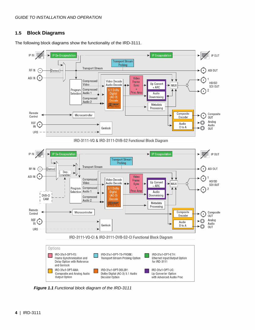
1.5 Block Diagrams The following block diagrams show the functionality of the IRD-3111.
Figure 1.1 Functional block diagram of the IRD-3111
GUIDE TO INSTALLATION AND OPERATION
IRD-3111 | 5
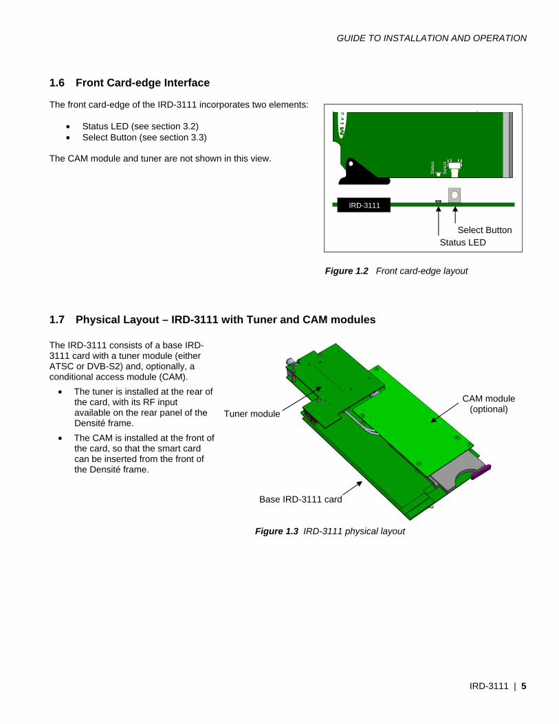
1.6 Front Card-edge Interface The front card-edge of the IRD-3111 incorporates two elements:
• Status LED (see section 3.2) • Select Button (see section 3.3)
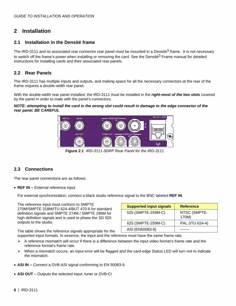
The CAM module and tuner are not shown in this view. Figure 1.2 Front card-edge layout 1.7 Physical Layout – IRD-3111 with Tuner and CAM modules The IRD-3111 consists of a base IRD-3111 card with a tuner module (either ATSC or DVB-S2) and, optionally, a conditional access module (CAM).
• The tuner is installed at the rear of the card, with its RF input available on the rear panel of the Densité frame.
• The CAM is installed at the front of the card, so that the smart card can be inserted from the front of the Densité frame.
Figure 1.3 IRD-3111 physical layout
Select Button
IRD-3111
Status LED
Sta
tus
Sel
ect
CAM module (optional)
Base IRD-3111 card
Tuner module
GUIDE TO INSTALLATION AND OPERATION
6 | IRD-3111
2 Installation 2.1 Installation in the Densité frame The IRD-3111 and its associated rear connector rear panel must be mounted in a Densité3 frame. It is not necessary to switch off the frame’s power when installing or removing the card. See the Densité3 Frame manual for detailed instructions for installing cards and their associated rear panels.
2.2 Rear Panels The IRD-3111 has multiple inputs and outputs, and making space for all the necessary connectors at the rear of the frame requires a double-width rear panel. With the double-width rear panel installed, the IRD-3111 must be installed in the right-most of the two slots covered by the panel in order to mate with the panel’s connectors.
NOTE: attempting to install the card in the wrong slot could result in damage to the edge connector of the rear panel. BE CAREFUL
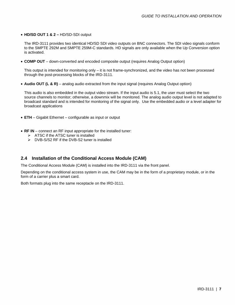
Figure 2.1 IRD-3111-3DRP Rear Panel for the IRD-3111 2.3 Connections The rear panel connections are as follows: • REF IN – External reference input
For external synchronization, connect a black studio reference signal to the BNC labeled REF IN. The reference input must conform to SMPTE 170M/SMPTE 318M/ITU 624-4/BUT 470-6 for standard definition signals and SMPTE 274M / SMPTE 296M for high definition signals and is used to phase the SD SDI outputs to the studio. The table shows the reference signals appropriate for the supported input formats. In essence, the input and the reference must have the same frame rate.
A reference mismatch will occur if there is a difference between the input video format’s frame rate and the reference format’s frame rate.
When a mismatch occurs, an input error will be flagged and the card-edge Status LED will turn red to indicate the mismatch.
• ASI IN – Connect a DVB-ASI signal conforming to EN 50083-9. • ASI OUT – Outputs the selected input, tuner or DVB-CI
Supported input signals Reference 525 (SMPTE-259M-C) NTSC (SMPTE-
170M) 625 (SMPTE-259M-C) PAL (ITU 624-4) ASI (EN50083-9) -------
GUIDE TO INSTALLATION AND OPERATION
IRD-3111 | 7
• HD/SD OUT 1 & 2 – HD/SD-SDI output
The IRD-3111 provides two identical HD/SD SDI video outputs on BNC connectors. The SDI video signals conform to the SMPTE 292M and SMPTE 259M-C standards. HD signals are only available when the Up Conversion option is activated.
• COMP OUT – down-converted and encoded composite output (requires Analog Output option)
This output is intended for monitoring only – it is not frame-synchronized, and the video has not been processed through the post-processing blocks of the IRD-3111.
• Audio OUT (L & R) – analog audio extracted from the input signal (requires Analog Output option)
This audio is also embedded in the output video stream. If the input audio is 5.1, the user must select the two source channels to monitor; otherwise, a downmix will be monitored. The analog audio output level is not adapted to broadcast standard and is intended for monitoring of the signal only. Use the embedded audio or a level adapter for broadcast applications
• ETH – Gigabit Ethernet – configurable as input or output • RF IN – connect an RF input appropriate for the installed tuner:
ATSC if the ATSC tuner is installed DVB-S/S2 RF if the DVB-S2 tuner is installed
2.4 Installation of the Conditional Access Module (CAM) The Conditional Access Module (CAM) is installed into the IRD-3111 via the front panel.
Depending on the conditional access system in use, the CAM may be in the form of a proprietary module, or in the form of a carrier plus a smart card.
Both formats plug into the same receptacle on the IRD-3111.
GUIDE TO INSTALLATION AND OPERATION
8 | IRD-3111
3 Operation 3.1 Control options The IRD-3111 can be controlled in two different ways:
• The local control panel and its push-buttons can be used to move through a menu of parameters and to adjust parameter values (see section 3.3).
• Miranda’s iControl system can be used to access the card’s operating parameters from a remote computer, using a convenient graphical user interface (GUI). (see section 3.4)
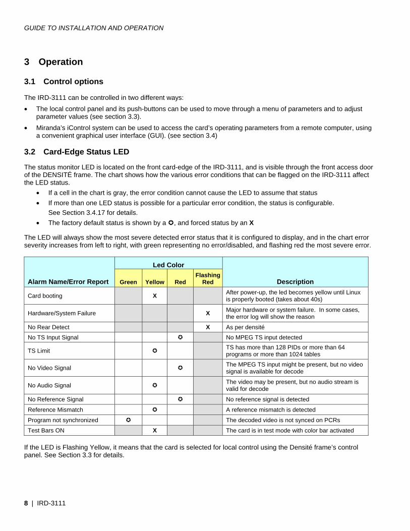
3.2 Card-Edge Status LED The status monitor LED is located on the front card-edge of the IRD-3111, and is visible through the front access door of the DENSITÉ frame. The chart shows how the various error conditions that can be flagged on the IRD-3111 affect the LED status.
• If a cell in the chart is gray, the error condition cannot cause the LED to assume that status • If more than one LED status is possible for a particular error condition, the status is configurable. See Section 3.4.17 for details. • The factory default status is shown by a , and forced status by an X
The LED will always show the most severe detected error status that it is configured to display, and in the chart error severity increases from left to right, with green representing no error/disabled, and flashing red the most severe error.
Alarm Name/Error Report
Led Color
Description Green Yellow Red Flashing
Red
Card booting X After power-up, the led becomes yellow until Linux is properly booted (takes about 40s)
Hardware/System Failure X Major hardware or system failure. In some cases, the error log will show the reason
No Rear Detect X As per densité
No TS Input Signal No MPEG TS input detected
TS Limit TS has more than 128 PIDs or more than 64 programs or more than 1024 tables
No Video Signal The MPEG TS input might be present, but no video signal is available for decode
No Audio Signal The video may be present, but no audio stream is valid for decode
No Reference Signal No reference signal is detected
Reference Mismatch A reference mismatch is detected
Program not synchronized The decoded video is not synced on PCRs
Test Bars ON X The card is in test mode with color bar activated
If the LED is Flashing Yellow, it means that the card is selected for local control using the Densité frame’s control panel. See Section 3.3 for details.
GUIDE TO INSTALLATION AND OPERATION
IRD-3111 | 9
3.3 Local control using the Densité frame control panel
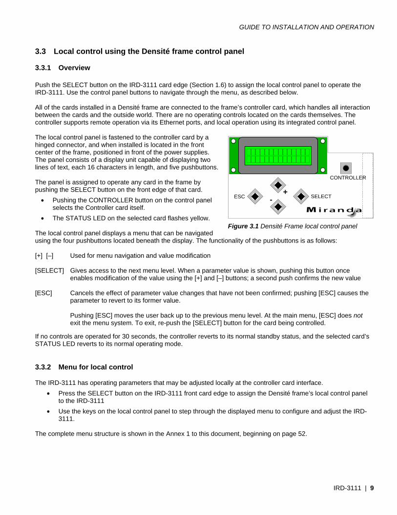
3.3.1 Overview Push the SELECT button on the IRD-3111 card edge (Section 1.6) to assign the local control panel to operate the IRD-3111. Use the control panel buttons to navigate through the menu, as described below. All of the cards installed in a Densité frame are connected to the frame’s controller card, which handles all interaction between the cards and the outside world. There are no operating controls located on the cards themselves. The controller supports remote operation via its Ethernet ports, and local operation using its integrated control panel. The local control panel is fastened to the controller card by a hinged connector, and when installed is located in the front center of the frame, positioned in front of the power supplies. The panel consists of a display unit capable of displaying two lines of text, each 16 characters in length, and five pushbuttons. The panel is assigned to operate any card in the frame by pushing the SELECT button on the front edge of that card.
• Pushing the CONTROLLER button on the control panel selects the Controller card itself.
• The STATUS LED on the selected card flashes yellow. The local control panel displays a menu that can be navigated using the four pushbuttons located beneath the display. The functionality of the pushbuttons is as follows: [+] [–] Used for menu navigation and value modification [SELECT] Gives access to the next menu level. When a parameter value is shown, pushing this button once
enables modification of the value using the [+] and [–] buttons; a second push confirms the new value [ESC] Cancels the effect of parameter value changes that have not been confirmed; pushing [ESC] causes the
parameter to revert to its former value. Pushing [ESC] moves the user back up to the previous menu level. At the main menu, [ESC] does not
exit the menu system. To exit, re-push the [SELECT] button for the card being controlled. If no controls are operated for 30 seconds, the controller reverts to its normal standby status, and the selected card’s STATUS LED reverts to its normal operating mode.
3.3.2 Menu for local control The IRD-3111 has operating parameters that may be adjusted locally at the controller card interface.
• Press the SELECT button on the IRD-3111 front card edge to assign the Densité frame’s local control panel to the IRD-3111
• Use the keys on the local control panel to step through the displayed menu to configure and adjust the IRD-3111.
The complete menu structure is shown in the Annex 1 to this document, beginning on page 52.
Figure 3.1 Densité Frame local control panel
SELECTESC+
-
CONTROLLER
GUIDE TO INSTALLATION AND OPERATION
10 | IRD-3111
3.4 Remote control using iControl The operation of the IRD-3111 may be controlled using Miranda’s iControl system.
• This manual describes the control panels associated with the IRD-3111 and their use. • Please consult the iControl User’s Guide for information about setting up and operating iControl.
In iControl Navigator or iControl Websites, double-click on the IRD-3111 icon to open the control panel.
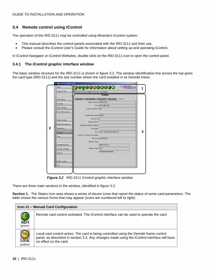
3.4.1 The iControl graphic interface window The basic window structure for the IRD-3111 is shown in figure 3.2. The window identification line across the top gives the card type (IRD-3111) and the slot number where the card installed in its Densité frame. There are three main sections in the window, identified in figure 3.2: Section 1. The Status Icon area shows a series of eleven icons that report the status of some card parameters. The table shows the various forms that may appear (icons are numbered left to right):
Icon #1 – Manual Card Configuration
(green)
Remote card control activated. The iControl interface can be used to operate the card
(yellow)
Local card control active, The card is being controlled using the Densité frame control panel, as described in section 3.3. Any changes made using the iControl interface will have no effect on the card.
Figure 3.2 IRD-3111 iControl graphic interface window
1
2 3
GUIDE TO INSTALLATION AND OPERATION
IRD-3111 | 11
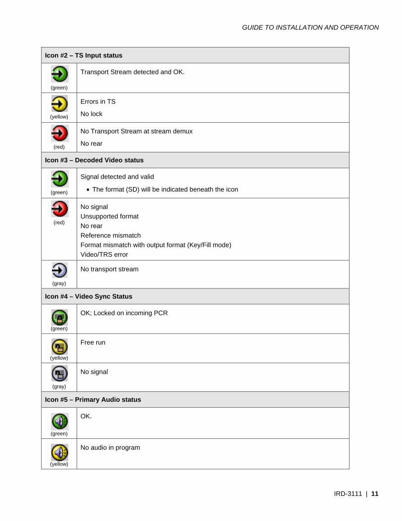
Icon #2 – TS Input status
(green)
Transport Stream detected and OK.
(yellow)
Errors in TS
No lock
(red)
No Transport Stream at stream demux
No rear
Icon #3 – Decoded Video status
(green)
Signal detected and valid
• The format (SD) will be indicated beneath the icon
(red)
No signal Unsupported format No rear Reference mismatch Format mismatch with output format (Key/Fill mode) Video/TRS error
(gray)
No transport stream
Icon #4 – Video Sync Status
(green)
OK; Locked on incoming PCR
(yellow)
Free run
(gray)
No signal
Icon #5 – Primary Audio status
(green)
OK.
(yellow)
No audio in program
GUIDE TO INSTALLATION AND OPERATION
12 | IRD-3111
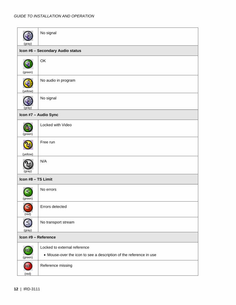
(gray)
No signal
Icon #6 – Secondary Audio status
(green)
OK
(yellow)
No audio in program
(gray)
No signal
Icon #7 – Audio Sync
(green)
Locked with Video
(yellow)
Free run
(gray)
N/A
Icon #8 – TS Limit
(green)
No errors
(red)
Errors detected
(gray)
No transport stream
Icon #9 – Reference
(green)
Locked to external reference
• Mouse-over the icon to see a description of the reference in use
(red)
Reference missing
GUIDE TO INSTALLATION AND OPERATION
IRD-3111 | 13
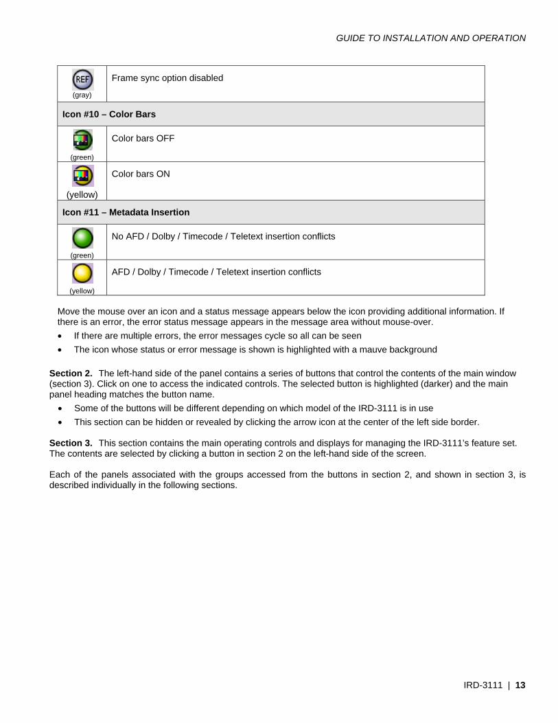
(gray)
Frame sync option disabled
Icon #10 – Color Bars
(green)
Color bars OFF
(yellow)
Color bars ON
Icon #11 – Metadata Insertion
(green)
No AFD / Dolby / Timecode / Teletext insertion conflicts
(yellow)
AFD / Dolby / Timecode / Teletext insertion conflicts
Move the mouse over an icon and a status message appears below the icon providing additional information. If there is an error, the error status message appears in the message area without mouse-over. • If there are multiple errors, the error messages cycle so all can be seen • The icon whose status or error message is shown is highlighted with a mauve background
Section 2. The left-hand side of the panel contains a series of buttons that control the contents of the main window (section 3). Click on one to access the indicated controls. The selected button is highlighted (darker) and the main panel heading matches the button name.
• Some of the buttons will be different depending on which model of the IRD-3111 is in use • This section can be hidden or revealed by clicking the arrow icon at the center of the left side border.
Section 3. This section contains the main operating controls and displays for managing the IRD-3111’s feature set. The contents are selected by clicking a button in section 2 on the left-hand side of the screen. Each of the panels associated with the groups accessed from the buttons in section 2, and shown in section 3, is described individually in the following sections.
GUIDE TO INSTALLATION AND OPERATION
14 | IRD-3111
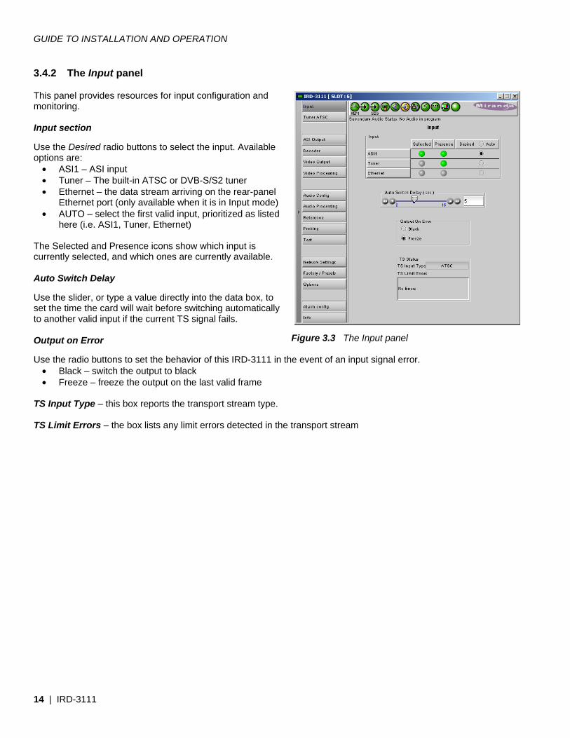
3.4.2 The Input panel This panel provides resources for input configuration and monitoring. Input section Use the Desired radio buttons to select the input. Available options are:
• ASI1 – ASI input • Tuner – The built-in ATSC or DVB-S/S2 tuner • Ethernet – the data stream arriving on the rear-panel
Ethernet port (only available when it is in Input mode) • AUTO – select the first valid input, prioritized as listed
here (i.e. ASI1, Tuner, Ethernet) The Selected and Presence icons show which input is currently selected, and which ones are currently available. Auto Switch Delay Use the slider, or type a value directly into the data box, to set the time the card will wait before switching automatically to another valid input if the current TS signal fails. Output on Error Use the radio buttons to set the behavior of this IRD-3111 in the event of an input signal error.
• Black – switch the output to black • Freeze – freeze the output on the last valid frame
TS Input Type – this box reports the transport stream type. TS Limit Errors – the box lists any limit errors detected in the transport stream
Figure 3.3 The Input panel
GUIDE TO INSTALLATION AND OPERATION
IRD-3111 | 15
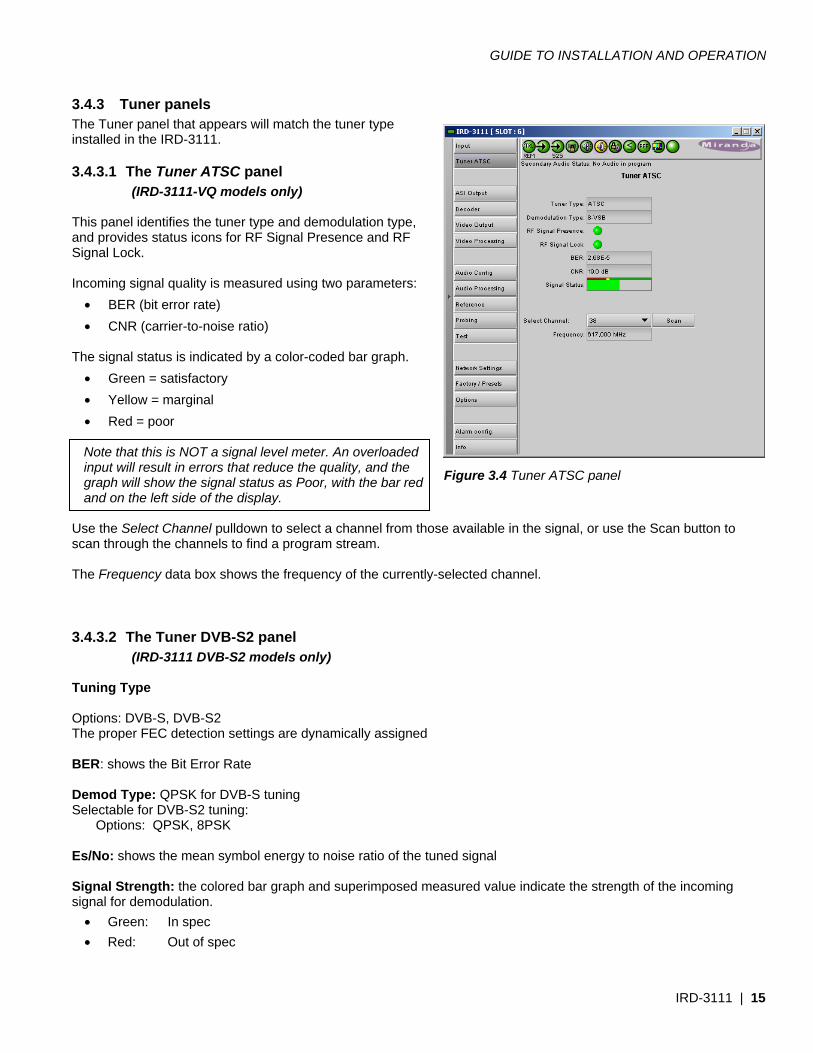
3.4.3 Tuner panels The Tuner panel that appears will match the tuner type installed in the IRD-3111.
3.4.3.1 The Tuner ATSC panel (IRD-3111-VQ models only)
This panel identifies the tuner type and demodulation type, and provides status icons for RF Signal Presence and RF Signal Lock. Incoming signal quality is measured using two parameters:
• BER (bit error rate) • CNR (carrier-to-noise ratio)
The signal status is indicated by a color-coded bar graph.
• Green = satisfactory • Yellow = marginal • Red = poor
Note that this is NOT a signal level meter. An overloaded input will result in errors that reduce the quality, and the graph will show the signal status as Poor, with the bar red and on the left side of the display.
Use the Select Channel pulldown to select a channel from those available in the signal, or use the Scan button to scan through the channels to find a program stream. The Frequency data box shows the frequency of the currently-selected channel.
3.4.3.2 The Tuner DVB-S2 panel (IRD-3111 DVB-S2 models only)
Tuning Type Options: DVB-S, DVB-S2 The proper FEC detection settings are dynamically assigned BER: shows the Bit Error Rate Demod Type: QPSK for DVB-S tuning Selectable for DVB-S2 tuning:
Options: QPSK, 8PSK Es/No: shows the mean symbol energy to noise ratio of the tuned signal Signal Strength: the colored bar graph and superimposed measured value indicate the strength of the incoming signal for demodulation.
• Green: In spec • Red: Out of spec
Figure 3.4 Tuner ATSC panel
GUIDE TO INSTALLATION AND OPERATION
16 | IRD-3111
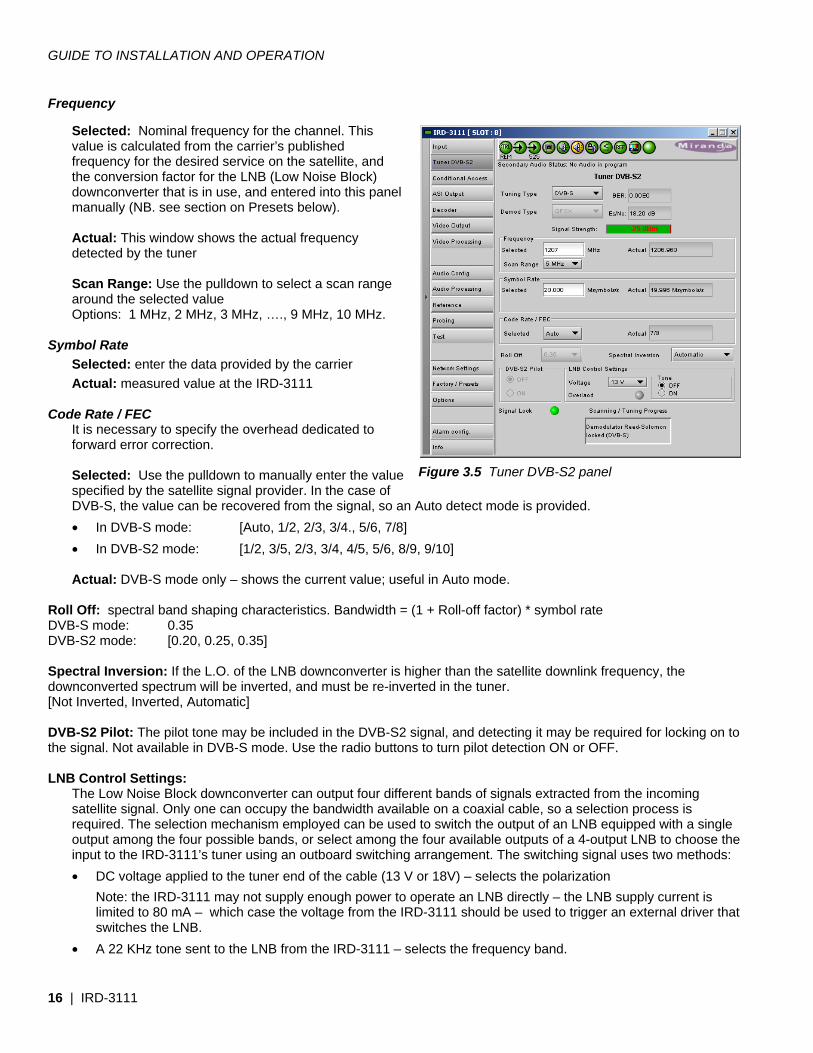
Frequency Selected: Nominal frequency for the channel. This value is calculated from the carrier’s published frequency for the desired service on the satellite, and the conversion factor for the LNB (Low Noise Block) downconverter that is in use, and entered into this panel manually (NB. see section on Presets below). Actual: This window shows the actual frequency detected by the tuner Scan Range: Use the pulldown to select a scan range around the selected value Options: 1 MHz, 2 MHz, 3 MHz, …., 9 MHz, 10 MHz.
Symbol Rate
Selected: enter the data provided by the carrier Actual: measured value at the IRD-3111
Code Rate / FEC It is necessary to specify the overhead dedicated to forward error correction.
Selected: Use the pulldown to manually enter the value specified by the satellite signal provider. In the case of DVB-S, the value can be recovered from the signal, so an Auto detect mode is provided. • In DVB-S mode: [Auto, 1/2, 2/3, 3/4., 5/6, 7/8] • In DVB-S2 mode: [1/2, 3/5, 2/3, 3/4, 4/5, 5/6, 8/9, 9/10] Actual: DVB-S mode only – shows the current value; useful in Auto mode.
Roll Off: spectral band shaping characteristics. Bandwidth = (1 + Roll-off factor) * symbol rate DVB-S mode: 0.35 DVB-S2 mode: [0.20, 0.25, 0.35] Spectral Inversion: If the L.O. of the LNB downconverter is higher than the satellite downlink frequency, the downconverted spectrum will be inverted, and must be re-inverted in the tuner. [Not Inverted, Inverted, Automatic] DVB-S2 Pilot: The pilot tone may be included in the DVB-S2 signal, and detecting it may be required for locking on to the signal. Not available in DVB-S mode. Use the radio buttons to turn pilot detection ON or OFF. LNB Control Settings:
The Low Noise Block downconverter can output four different bands of signals extracted from the incoming satellite signal. Only one can occupy the bandwidth available on a coaxial cable, so a selection process is required. The selection mechanism employed can be used to switch the output of an LNB equipped with a single output among the four possible bands, or select among the four available outputs of a 4-output LNB to choose the input to the IRD-3111’s tuner using an outboard switching arrangement. The switching signal uses two methods: • DC voltage applied to the tuner end of the cable (13 V or 18V) – selects the polarization
Note: the IRD-3111 may not supply enough power to operate an LNB directly – the LNB supply current is limited to 80 mA – which case the voltage from the IRD-3111 should be used to trigger an external driver that switches the LNB.
• A 22 KHz tone sent to the LNB from the IRD-3111 – selects the frequency band.
Figure 3.5 Tuner DVB-S2 panel
GUIDE TO INSTALLATION AND OPERATION
IRD-3111 | 17
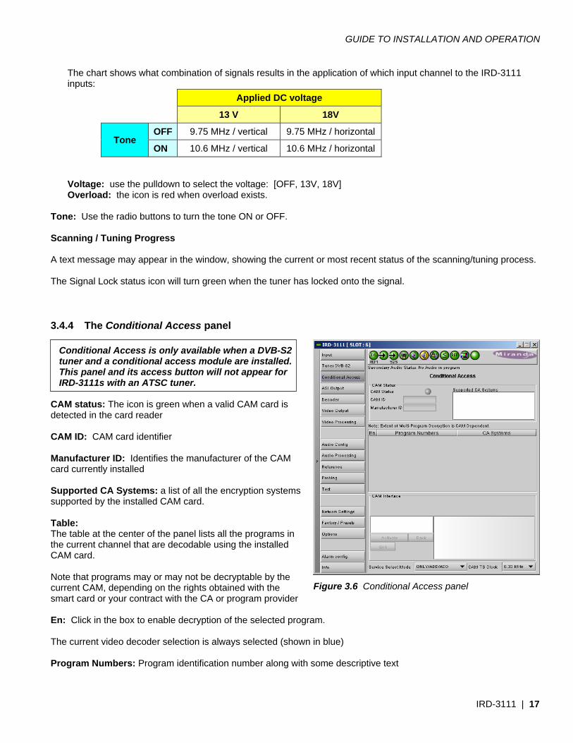
The chart shows what combination of signals results in the application of which input channel to the IRD-3111 inputs:
Applied DC voltage
13 V 18V
Tone OFF 9.75 MHz / vertical 9.75 MHz / horizontal
ON 10.6 MHz / vertical 10.6 MHz / horizontal
Voltage: use the pulldown to select the voltage: [OFF, 13V, 18V] Overload: the icon is red when overload exists.
Tone: Use the radio buttons to turn the tone ON or OFF. Scanning / Tuning Progress A text message may appear in the window, showing the current or most recent status of the scanning/tuning process. The Signal Lock status icon will turn green when the tuner has locked onto the signal.
3.4.4 The Conditional Access panel
Conditional Access is only available when a DVB-S2 tuner and a conditional access module are installed. This panel and its access button will not appear for IRD-3111s with an ATSC tuner.
CAM status: The icon is green when a valid CAM card is detected in the card reader CAM ID: CAM card identifier Manufacturer ID: Identifies the manufacturer of the CAM card currently installed Supported CA Systems: a list of all the encryption systems supported by the installed CAM card. Table: The table at the center of the panel lists all the programs in the current channel that are decodable using the installed CAM card. Note that programs may or may not be decryptable by the current CAM, depending on the rights obtained with the smart card or your contract with the CA or program provider En: Click in the box to enable decryption of the selected program. The current video decoder selection is always selected (shown in blue) Program Numbers: Program identification number along with some descriptive text
Figure 3.6 Conditional Access panel
GUIDE TO INSTALLATION AND OPERATION
18 | IRD-3111
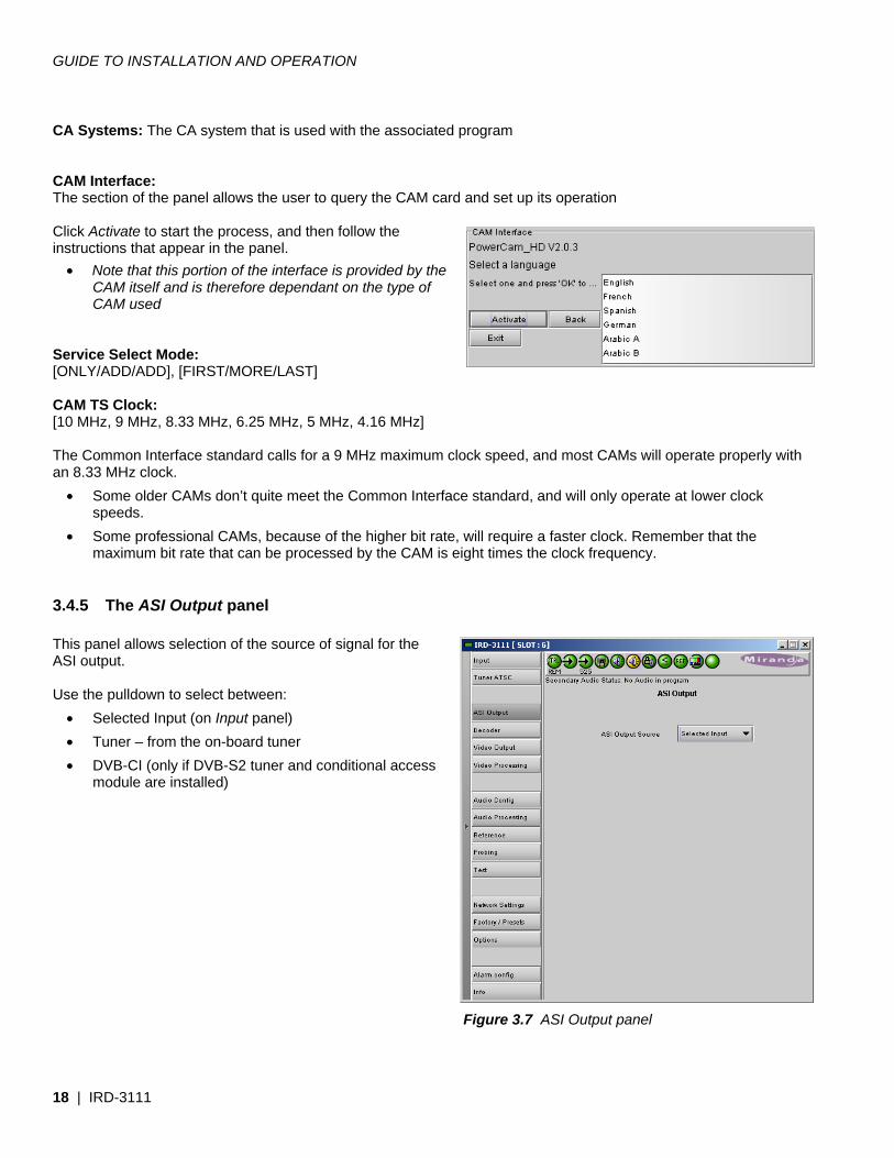
CA Systems: The CA system that is used with the associated program CAM Interface: The section of the panel allows the user to query the CAM card and set up its operation Click Activate to start the process, and then follow the instructions that appear in the panel.
• Note that this portion of the interface is provided by the CAM itself and is therefore dependant on the type of CAM used
Service Select Mode: [ONLY/ADD/ADD], [FIRST/MORE/LAST] CAM TS Clock: [10 MHz, 9 MHz, 8.33 MHz, 6.25 MHz, 5 MHz, 4.16 MHz] The Common Interface standard calls for a 9 MHz maximum clock speed, and most CAMs will operate properly with an 8.33 MHz clock.
• Some older CAMs don’t quite meet the Common Interface standard, and will only operate at lower clock speeds.
• Some professional CAMs, because of the higher bit rate, will require a faster clock. Remember that the maximum bit rate that can be processed by the CAM is eight times the clock frequency.
3.4.5 The ASI Output panel This panel allows selection of the source of signal for the ASI output. Use the pulldown to select between:
• Selected Input (on Input panel) • Tuner – from the on-board tuner • DVB-CI (only if DVB-S2 tuner and conditional access
module are installed)
Figure 3.7 ASI Output panel
GUIDE TO INSTALLATION AND OPERATION
IRD-3111 | 19
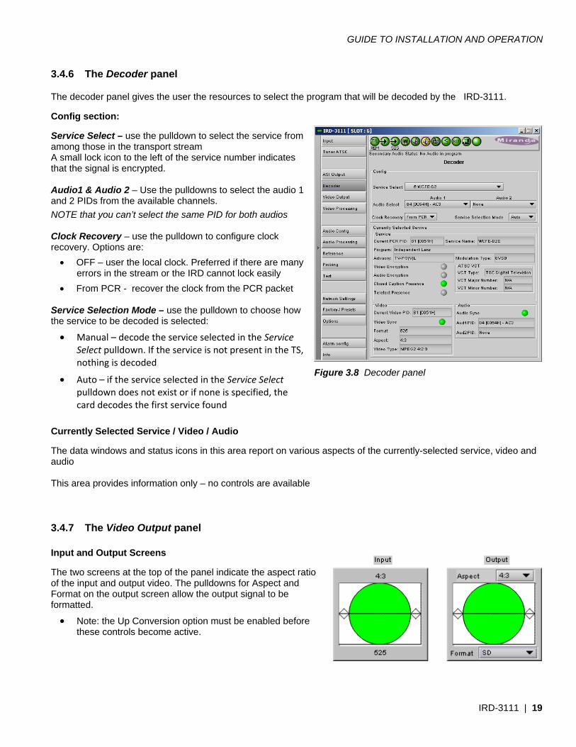
3.4.6 The Decoder panel The decoder panel gives the user the resources to select the program that will be decoded by the IRD-3111. Config section: Service Select – use the pulldown to select the service from among those in the transport stream A small lock icon to the left of the service number indicates that the signal is encrypted. Audio1 & Audio 2 – Use the pulldowns to select the audio 1 and 2 PIDs from the available channels. NOTE that you can’t select the same PID for both audios Clock Recovery – use the pulldown to configure clock recovery. Options are:
• OFF – user the local clock. Preferred if there are many errors in the stream or the IRD cannot lock easily
• From PCR - recover the clock from the PCR packet Service Selection Mode – use the pulldown to choose how the service to be decoded is selected:
• Manual – decode the service selected in the Service Select pulldown. If the service is not present in the TS, nothing is decoded
• Auto – if the service selected in the Service Select pulldown does not exist or if none is specified, the card decodes the first service found
Currently Selected Service / Video / Audio The data windows and status icons in this area report on various aspects of the currently-selected service, video and audio This area provides information only – no controls are available
3.4.7 The Video Output panel Input and Output Screens The two screens at the top of the panel indicate the aspect ratio of the input and output video. The pulldowns for Aspect and Format on the output screen allow the output signal to be formatted.
• Note: the Up Conversion option must be enabled before these controls become active.
Figure 3.8 Decoder panel
GUIDE TO INSTALLATION AND OPERATION
20 | IRD-3111
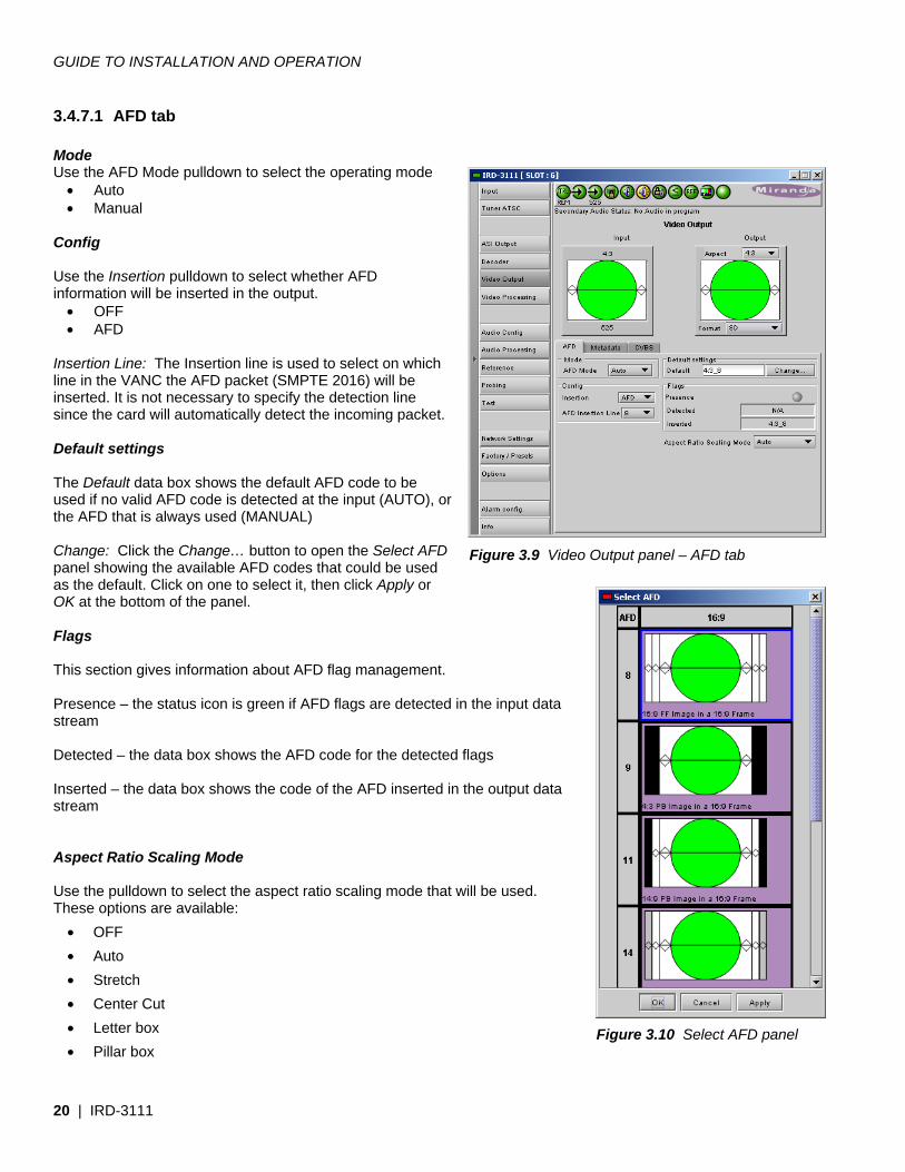
3.4.7.1 AFD tab Mode Use the AFD Mode pulldown to select the operating mode
• Auto • Manual
Config Use the Insertion pulldown to select whether AFD information will be inserted in the output.
• OFF • AFD
Insertion Line: The Insertion line is used to select on which line in the VANC the AFD packet (SMPTE 2016) will be inserted. It is not necessary to specify the detection line since the card will automatically detect the incoming packet. Default settings The Default data box shows the default AFD code to be used if no valid AFD code is detected at the input (AUTO), or the AFD that is always used (MANUAL)
Change: Click the Change… button to open the Select AFD panel showing the available AFD codes that could be used as the default. Click on one to select it, then click Apply or OK at the bottom of the panel. Flags This section gives information about AFD flag management. Presence – the status icon is green if AFD flags are detected in the input data stream Detected – the data box shows the AFD code for the detected flags Inserted – the data box shows the code of the AFD inserted in the output data stream Aspect Ratio Scaling Mode Use the pulldown to select the aspect ratio scaling mode that will be used. These options are available:
• OFF • Auto • Stretch • Center Cut • Letter box • Pillar box
Figure 3.10 Select AFD panel
Figure 3.9 Video Output panel – AFD tab
GUIDE TO INSTALLATION AND OPERATION
IRD-3111 | 21
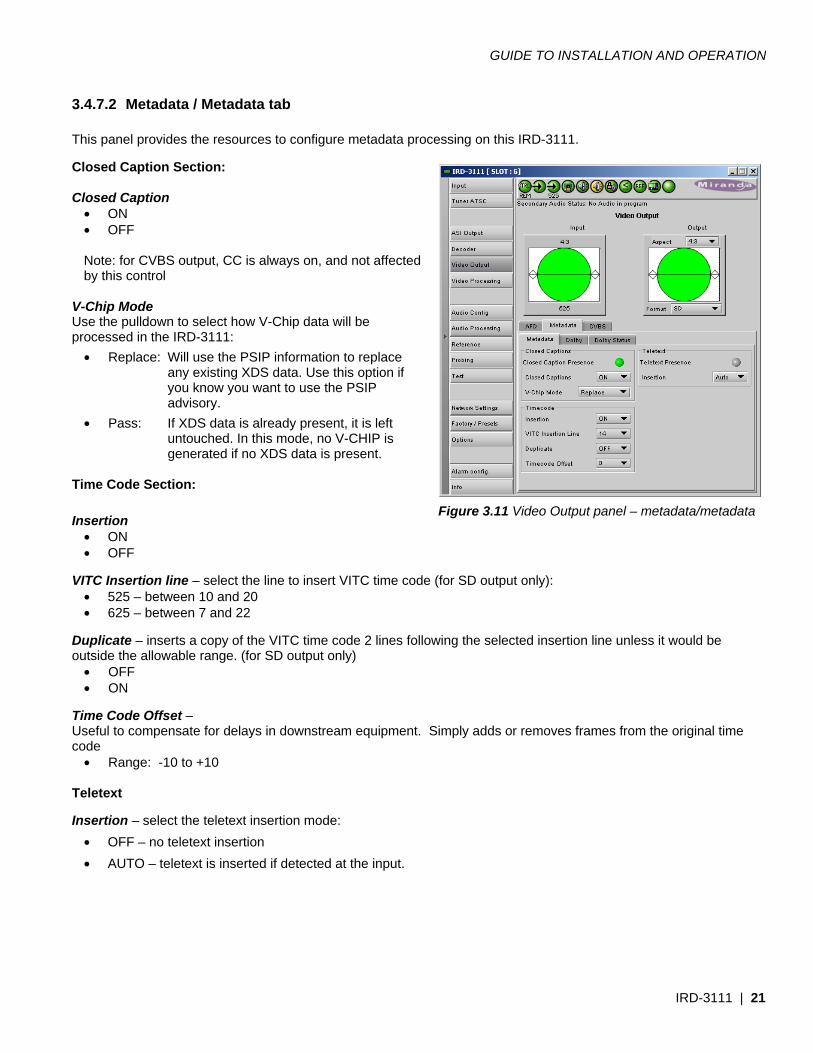
3.4.7.2 Metadata / Metadata tab This panel provides the resources to configure metadata processing on this IRD-3111. Closed Caption Section: Closed Caption
• ON • OFF Note: for CVBS output, CC is always on, and not affected by this control
V-Chip Mode Use the pulldown to select how V-Chip data will be processed in the IRD-3111:
• Replace: Will use the PSIP information to replace any existing XDS data. Use this option if you know you want to use the PSIP advisory.
• Pass: If XDS data is already present, it is left untouched. In this mode, no V-CHIP is generated if no XDS data is present.
Time Code Section: Insertion
• ON • OFF
VITC Insertion line – select the line to insert VITC time code (for SD output only):
• 525 – between 10 and 20 • 625 – between 7 and 22
Duplicate – inserts a copy of the VITC time code 2 lines following the selected insertion line unless it would be outside the allowable range. (for SD output only)
• OFF • ON
Time Code Offset – Useful to compensate for delays in downstream equipment. Simply adds or removes frames from the original time code
• Range: -10 to +10 Teletext Insertion – select the teletext insertion mode:
• OFF – no teletext insertion • AUTO – teletext is inserted if detected at the input.
Figure 3.11 Video Output panel – metadata/metadata
GUIDE TO INSTALLATION AND OPERATION
22 | IRD-3111
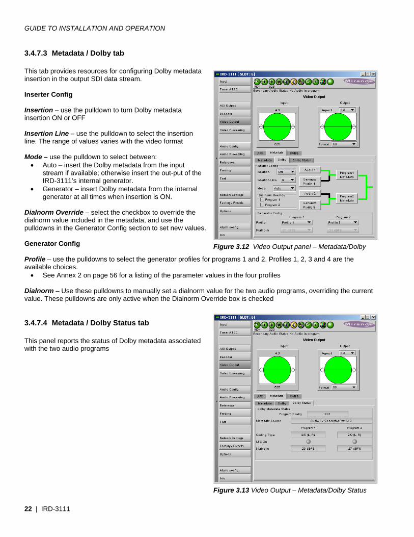
3.4.7.3 Metadata / Dolby tab This tab provides resources for configuring Dolby metadata insertion in the output SDI data stream. Inserter Config Insertion – use the pulldown to turn Dolby metadata insertion ON or OFF Insertion Line – use the pulldown to select the insertion line. The range of values varies with the video format Mode – use the pulldown to select between:
• Auto – insert the Dolby metadata from the input stream if available; otherwise insert the out-put of the IRD-3111’s internal generator.
• Generator – insert Dolby metadata from the internal generator at all times when insertion is ON.
Dialnorm Override – select the checkbox to override the dialnorm value included in the metadata, and use the pulldowns in the Generator Config section to set new values. Generator Config Profile – use the pulldowns to select the generator profiles for programs 1 and 2. Profiles 1, 2, 3 and 4 are the available choices.
• See Annex 2 on page 56 for a listing of the parameter values in the four profiles Dialnorm – Use these pulldowns to manually set a dialnorm value for the two audio programs, overriding the current value. These pulldowns are only active when the Dialnorm Override box is checked
3.4.7.4 Metadata / Dolby Status tab This panel reports the status of Dolby metadata associated with the two audio programs
Figure 3.12 Video Output panel – Metadata/Dolby
Figure 3.13 Video Output – Metadata/Dolby Status
GUIDE TO INSTALLATION AND OPERATION
IRD-3111 | 23
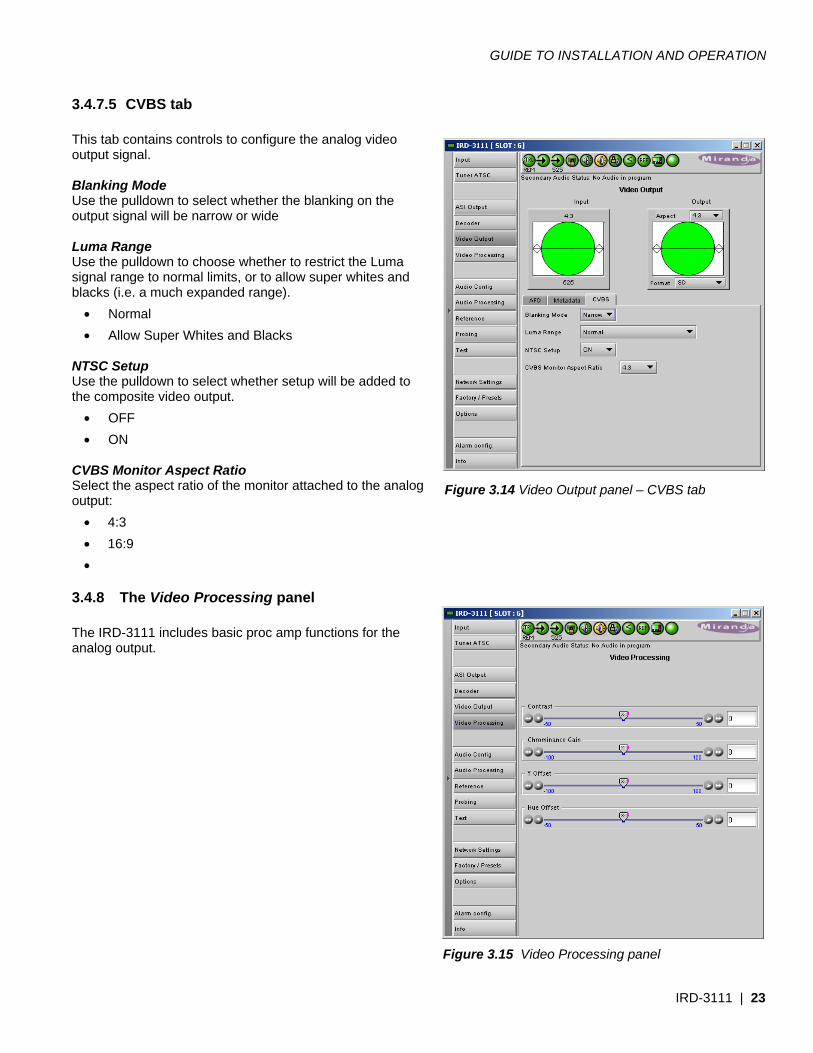
3.4.7.5 CVBS tab This tab contains controls to configure the analog video output signal. Blanking Mode Use the pulldown to select whether the blanking on the output signal will be narrow or wide Luma Range Use the pulldown to choose whether to restrict the Luma signal range to normal limits, or to allow super whites and blacks (i.e. a much expanded range).
• Normal • Allow Super Whites and Blacks
NTSC Setup Use the pulldown to select whether setup will be added to the composite video output.
• OFF • ON
CVBS Monitor Aspect Ratio Select the aspect ratio of the monitor attached to the analog output:
• 4:3 • 16:9 •
3.4.8 The Video Processing panel The IRD-3111 includes basic proc amp functions for the analog output.
Figure 3.14 Video Output panel – CVBS tab
Figure 3.15 Video Processing panel
GUIDE TO INSTALLATION AND OPERATION
24 | IRD-3111
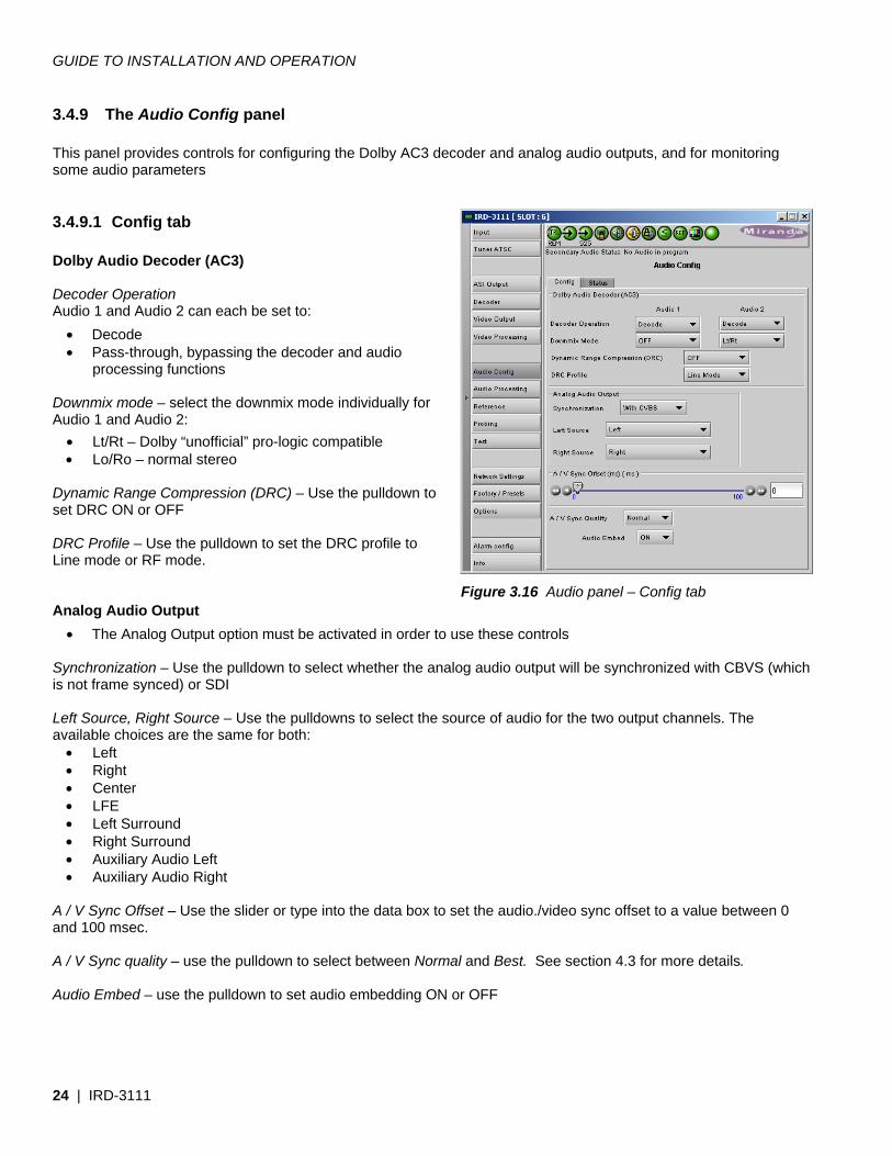
3.4.9 The Audio Config panel This panel provides controls for configuring the Dolby AC3 decoder and analog audio outputs, and for monitoring some audio parameters
3.4.9.1 Config tab Dolby Audio Decoder (AC3) Decoder Operation Audio 1 and Audio 2 can each be set to:
• Decode • Pass-through, bypassing the decoder and audio
processing functions Downmix mode – select the downmix mode individually for Audio 1 and Audio 2:
• Lt/Rt – Dolby “unofficial” pro-logic compatible • Lo/Ro – normal stereo
Dynamic Range Compression (DRC) – Use the pulldown to set DRC ON or OFF DRC Profile – Use the pulldown to set the DRC profile to Line mode or RF mode. Analog Audio Output
• The Analog Output option must be activated in order to use these controls Synchronization – Use the pulldown to select whether the analog audio output will be synchronized with CBVS (which is not frame synced) or SDI Left Source, Right Source – Use the pulldowns to select the source of audio for the two output channels. The available choices are the same for both:
• Left • Right • Center • LFE • Left Surround • Right Surround • Auxiliary Audio Left • Auxiliary Audio Right
A / V Sync Offset – Use the slider or type into the data box to set the audio./video sync offset to a value between 0 and 100 msec. A / V Sync quality – use the pulldown to select between Normal and Best. See section 4.3 for more details. Audio Embed – use the pulldown to set audio embedding ON or OFF
Figure 3.16 Audio panel – Config tab
GUIDE TO INSTALLATION AND OPERATION
IRD-3111 | 25
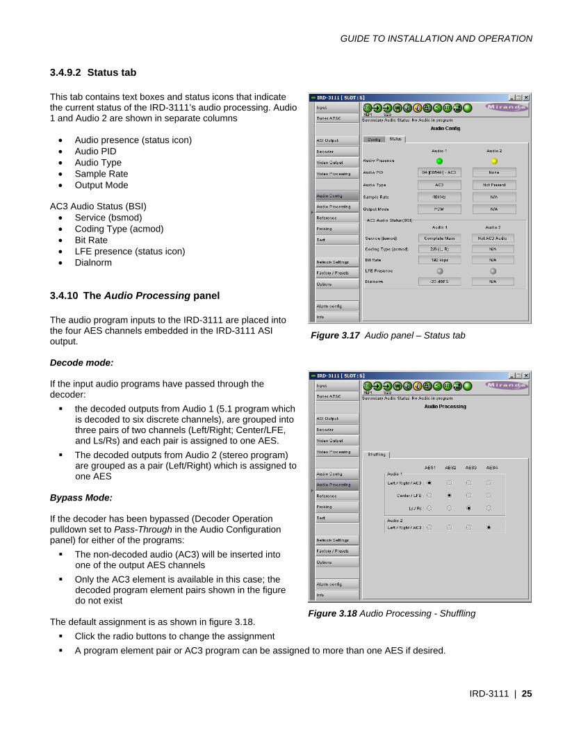
3.4.9.2 Status tab This tab contains text boxes and status icons that indicate the current status of the IRD-3111’s audio processing. Audio 1 and Audio 2 are shown in separate columns
• Audio presence (status icon) • Audio PID • Audio Type • Sample Rate • Output Mode
AC3 Audio Status (BSI)
• Service (bsmod) • Coding Type (acmod) • Bit Rate • LFE presence (status icon) • Dialnorm
3.4.10 The Audio Processing panel The audio program inputs to the IRD-3111 are placed into the four AES channels embedded in the IRD-3111 ASI output. Decode mode: If the input audio programs have passed through the decoder:
the decoded outputs from Audio 1 (5.1 program which is decoded to six discrete channels), are grouped into three pairs of two channels (Left/Right; Center/LFE, and Ls/Rs) and each pair is assigned to one AES.
The decoded outputs from Audio 2 (stereo program) are grouped as a pair (Left/Right) which is assigned to one AES
Bypass Mode: If the decoder has been bypassed (Decoder Operation pulldown set to Pass-Through in the Audio Configuration panel) for either of the programs:
The non-decoded audio (AC3) will be inserted into one of the output AES channels
Only the AC3 element is available in this case; the decoded program element pairs shown in the figure do not exist
The default assignment is as shown in figure 3.18.
Click the radio buttons to change the assignment A program element pair or AC3 program can be assigned to more than one AES if desired.
Figure 3.17 Audio panel – Status tab
Figure 3.18 Audio Processing - Shuffling
GUIDE TO INSTALLATION AND OPERATION
26 | IRD-3111
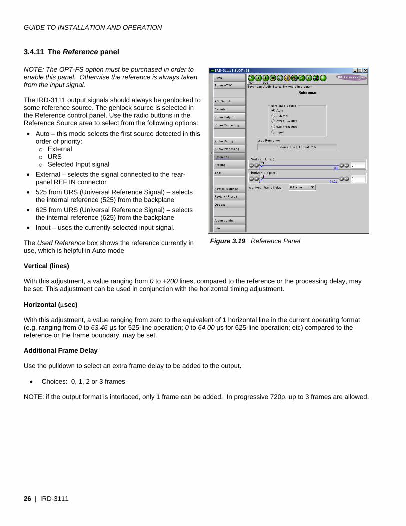
3.4.11 The Reference panel NOTE: The OPT-FS option must be purchased in order to enable this panel. Otherwise the reference is always taken from the input signal. The IRD-3111 output signals should always be genlocked to some reference source. The genlock source is selected in the Reference control panel. Use the radio buttons in the Reference Source area to select from the following options: • Auto – this mode selects the first source detected in this
order of priority: o External o URS o Selected Input signal
• External – selects the signal connected to the rear-panel REF IN connector
• 525 from URS (Universal Reference Signal) – selects the internal reference (525) from the backplane
• 625 from URS (Universal Reference Signal) – selects the internal reference (625) from the backplane
• Input – uses the currently-selected input signal. The Used Reference box shows the reference currently in use, which is helpful in Auto mode Vertical (lines) With this adjustment, a value ranging from 0 to +200 lines, compared to the reference or the processing delay, may be set. This adjustment can be used in conjunction with the horizontal timing adjustment. Horizontal (μsec) With this adjustment, a value ranging from zero to the equivalent of 1 horizontal line in the current operating format (e.g. ranging from 0 to 63.46 µs for 525-line operation; 0 to 64.00 µs for 625-line operation; etc) compared to the reference or the frame boundary, may be set. Additional Frame Delay Use the pulldown to select an extra frame delay to be added to the output.
• Choices: 0, 1, 2 or 3 frames NOTE: if the output format is interlaced, only 1 frame can be added. In progressive 720p, up to 3 frames are allowed.
Figure 3.19 Reference Panel
GUIDE TO INSTALLATION AND OPERATION
IRD-3111 | 27
3.4.12 The Probing panel
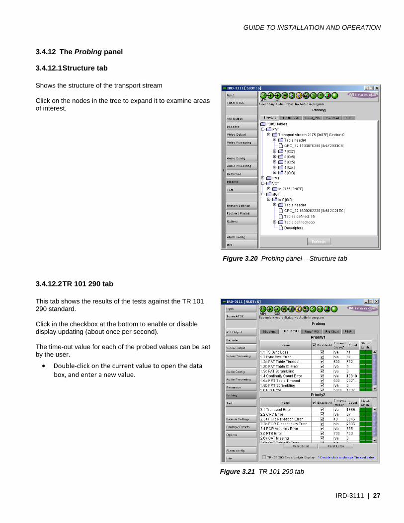
3.4.12.1 Structure tab Shows the structure of the transport stream Click on the nodes in the tree to expand it to examine areas of interest,
3.4.12.2 TR 101 290 tab This tab shows the results of the tests against the TR 101 290 standard. Click in the checkbox at the bottom to enable or disable display updating (about once per second). The time-out value for each of the probed values can be set by the user.
• Double-click on the current value to open the data box, and enter a new value.
Figure 3.21 TR 101 290 tab
Figure 3.20 Probing panel – Structure tab
GUIDE TO INSTALLATION AND OPERATION
28 | IRD-3111
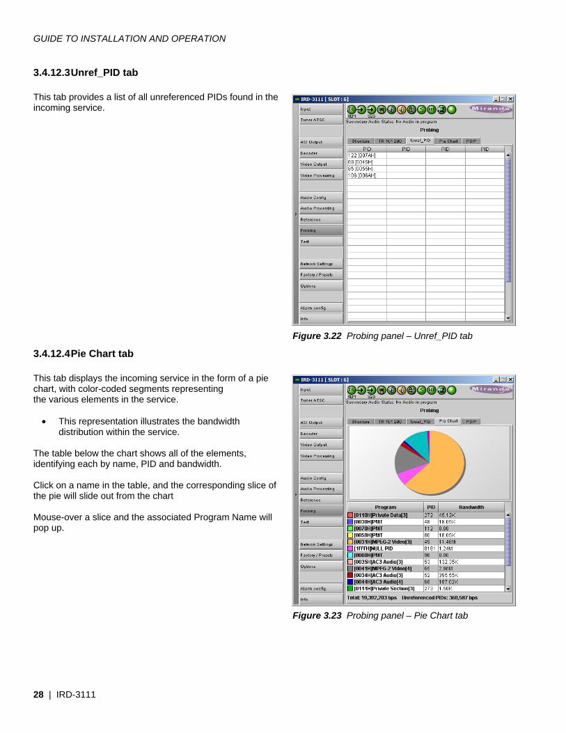
3.4.12.3 Unref_PID tab This tab provides a list of all unreferenced PIDs found in the incoming service.
3.4.12.4 Pie Chart tab This tab displays the incoming service in the form of a pie chart, with color-coded segments representing the various elements in the service.
• This representation illustrates the bandwidth distribution within the service.
The table below the chart shows all of the elements, identifying each by name, PID and bandwidth. Click on a name in the table, and the corresponding slice of the pie will slide out from the chart Mouse-over a slice and the associated Program Name will pop up.
Figure 3.22 Probing panel – Unref_PID tab
Figure 3.23 Probing panel – Pie Chart tab
GUIDE TO INSTALLATION AND OPERATION
IRD-3111 | 29
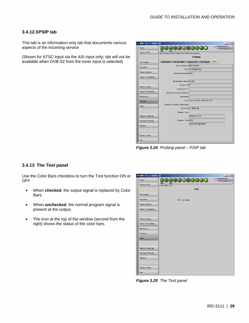
3.4.12.5 PSIP tab This tab is an information-only tab that documents various aspects of the incoming service (Shown for ATSC input via the ASI input only; tab will not be available when DVB-S2 from the tuner input is selected)
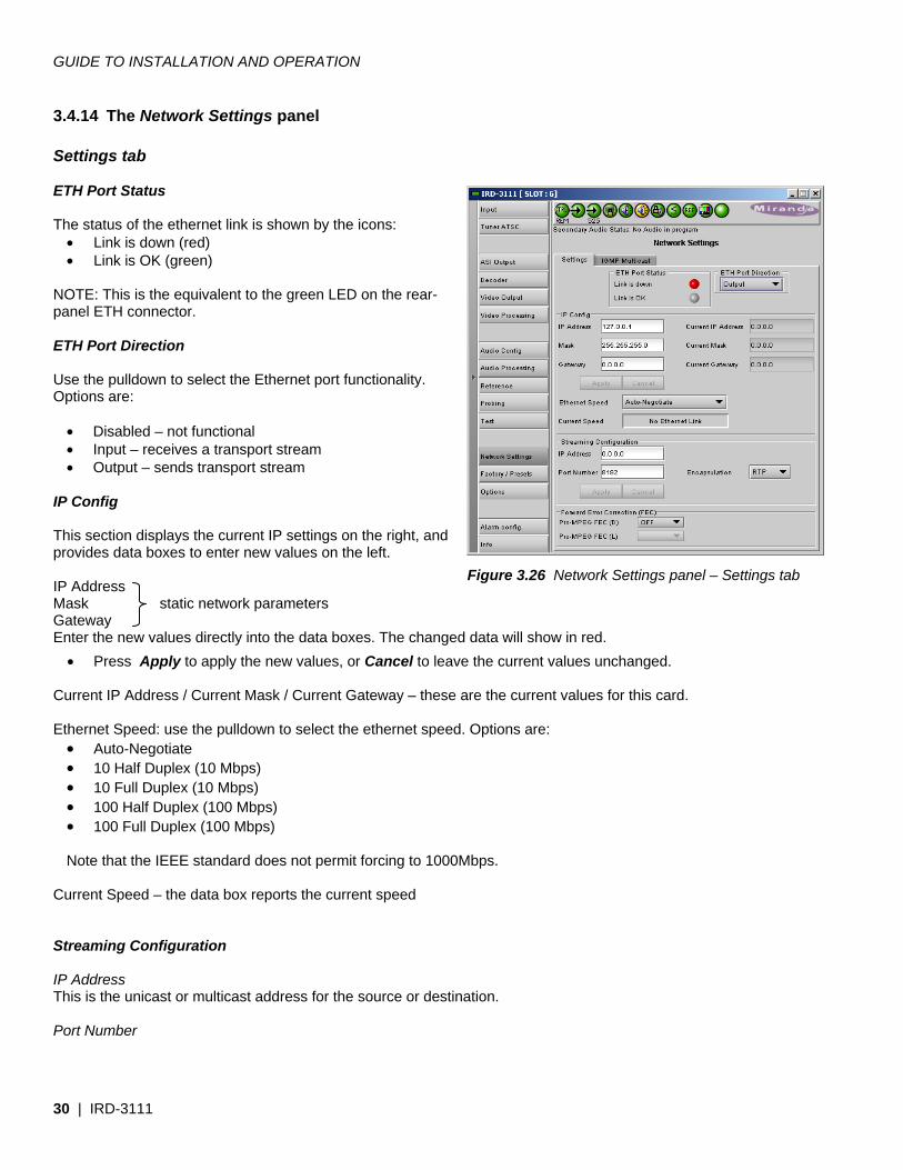
3.4.13 The Test panel Use the Color Bars checkbox to turn the Test function ON or OFF
• When checked, the output signal is replaced by Color Bars.
• When unchecked, the normal program signal is
present at the output.
• The icon at the top of the window (second from the right) shows the status of the color bars.
Figure 3.24 Probing panel – PSIP tab
Figure 3.25 The Test panel
GUIDE TO INSTALLATION AND OPERATION
30 | IRD-3111
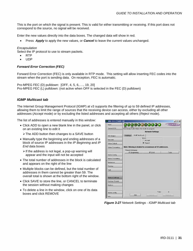
3.4.14 The Network Settings panel Settings tab ETH Port Status The status of the ethernet link is shown by the icons:
• Link is down (red) • Link is OK (green)
NOTE: This is the equivalent to the green LED on the rear-panel ETH connector. ETH Port Direction Use the pulldown to select the Ethernet port functionality. Options are:
• Disabled – not functional • Input – receives a transport stream • Output – sends transport stream
IP Config This section displays the current IP settings on the right, and provides data boxes to enter new values on the left. IP Address Mask static network parameters Gateway Enter the new values directly into the data boxes. The changed data will show in red.
• Press Apply to apply the new values, or Cancel to leave the current values unchanged. Current IP Address / Current Mask / Current Gateway – these are the current values for this card. Ethernet Speed: use the pulldown to select the ethernet speed. Options are:
• Auto-Negotiate • 10 Half Duplex (10 Mbps) • 10 Full Duplex (10 Mbps) • 100 Half Duplex (100 Mbps) • 100 Full Duplex (100 Mbps)
Note that the IEEE standard does not permit forcing to 1000Mbps.
Current Speed – the data box reports the current speed Streaming Configuration IP Address This is the unicast or multicast address for the source or destination. Port Number
Figure 3.26 Network Settings panel – Settings tab
GUIDE TO INSTALLATION AND OPERATION
IRD-3111 | 31
This is the port on which the signal is present. This is valid for either transmitting or receiving. If this port does not correspond to the source, no signal will be received. Enter the new values directly into the data boxes. The changed data will show in red.
• Press Apply to apply the new values, or Cancel to leave the current values unchanged. Encapsulation Select the IP protocol to use to stream packets.
• RTP • UDP
Forward Error Correction (FEC) Forward Error Correction (FEC) is only available in RTP mode. This setting will allow inserting FEC codes into the stream when the port is sending data. On reception, FEC is automatic. Pro-MPEG FEC (D) pulldown: [OFF, 4, 5, 6,…., 19, 20] Pro-MPEG FEC (L) pulldown: (not active when OFF is selected in the FEC (D) pulldown) IGMP Multicast tab The Internet Group Management Protocol (IGMP) at v3 supports the filtering of up to 59 defined IP addresses, allowing them to limit the range of sources that the receiving device can access, either by excluding all other addresses (Accept mode) or by excluding the listed addresses and accepting all others (Reject mode). The list of addresses is entered manually in this window:
• Click ADD to open a new blank line in the panel, or click on an existing line to edit it
The ADD button then changes to a SAVE button • Manually type the beginning and ending addresses of a
block of source IP addresses in the IP Beginning and IP End data boxes
If the address is not legal, a pop-up warning will appear and the input will not be accepted
• The total number of addresses in the block is calculated and appears on the right of the line
• Multiple blocks can be defined, but the total number of addresses in them cannot be greater than 59. The overall total is shown at the bottom right of the window.
• Click SAVE to store the line, or CANCEL to terminate the session without making changes
• To delete a line in the window, click on one of its data boxes and click REMOVE
Figure 3-27 Network Settings - IGMP Multicast tab
GUIDE TO INSTALLATION AND OPERATION
32 | IRD-3111
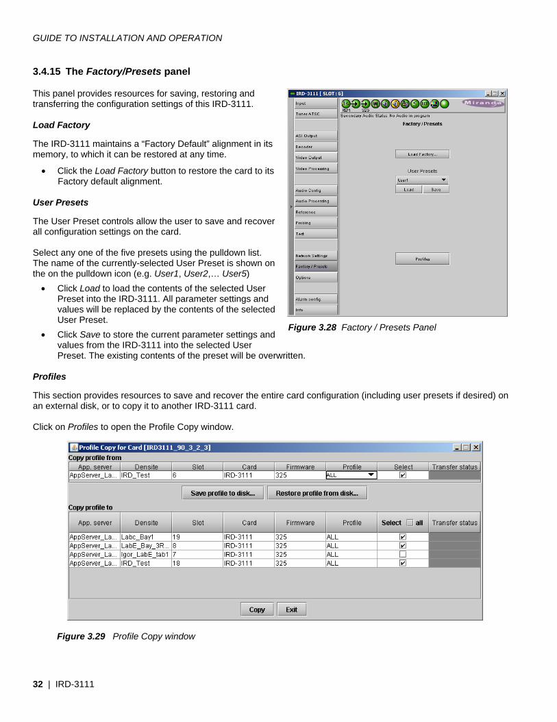
3.4.15 The Factory/Presets panel This panel provides resources for saving, restoring and transferring the configuration settings of this IRD-3111. Load Factory The IRD-3111 maintains a “Factory Default” alignment in its memory, to which it can be restored at any time.
• Click the Load Factory button to restore the card to its Factory default alignment.
User Presets The User Preset controls allow the user to save and recover all configuration settings on the card. Select any one of the five presets using the pulldown list. The name of the currently-selected User Preset is shown on the on the pulldown icon (e.g. User1, User2,… User5)
• Click Load to load the contents of the selected User Preset into the IRD-3111. All parameter settings and values will be replaced by the contents of the selected User Preset.
• Click Save to store the current parameter settings and values from the IRD-3111 into the selected User Preset. The existing contents of the preset will be overwritten.
Profiles This section provides resources to save and recover the entire card configuration (including user presets if desired) on an external disk, or to copy it to another IRD-3111 card. Click on Profiles to open the Profile Copy window.
Figure 3.28 Factory / Presets Panel
Figure 3.29 Profile Copy window
GUIDE TO INSTALLATION AND OPERATION
IRD-3111 | 33
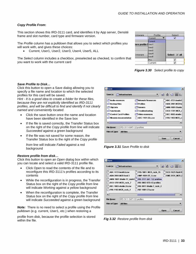
Copy Profile From: This section shows this IRD-3111 card, and identifies it by App server, Densité frame and slot number, card type and firmware version. The Profile column has a pulldown that allows you to select which profiles you will work with, and gives these choices:
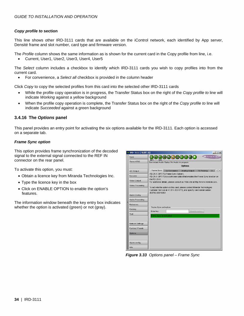
• Current, User1, User2, User3, User4, User5, ALL The Select column includes a checkbox, preselected as checked, to confirm that you want to work with the current card Save Profile to Disk… Click this button to open a Save dialog allowing you to specify a file name and location to which the selected profiles for this card will be saved. Hint - It is a good idea to create a folder for these files, because they are not explicitly identified as IRD-3111 profiles, and will be difficult to find and identify if not clearly named and conveniently located.
• Click the save button once the name and location have been identified in the Save box
• If the file is saved correctly, the Transfer Status box on the right of the Copy profile from line will indicate Succeeded against a green background
• If the file was not saved for some reason, the Transfer Status box to the right of the Copy profile
from line will indicate Failed against a red background
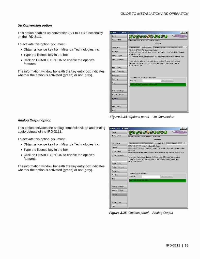
Restore profile from disk… Click this button to open an Open dialog box within which you can locate and select a valid IRD-3111 profile file.
• Click Open to read the contents of the file and to reconfigure this IRD-3111’s profiles according to its contents
• While the reconfiguration is in progress, the Transfer Status box on the right of the Copy profile from line will indicate Working against a yellow background
• When the reconfiguration is complete, the Transfer Status box on the right of the Copy profile from line will indicate Succeeded against a green background
Note: There is no need to select a profile using the Profile pulldown (e.g. current, User1, etc.) when restoring a
profile from disk, because the profile selection is stored within the file.
Figure 3.31 Save Profile to disk
Fig 3.32 Restore profile from disk
Figure 3.30 Select profile to copy
GUIDE TO INSTALLATION AND OPERATION
34 | IRD-3111
Copy profile to section This line shows other IRD-3111 cards that are available on the iControl network, each identified by App server, Densité frame and slot number, card type and firmware version. The Profile column shows the same information as is shown for the current card in the Copy profile from line, i.e.
• Current, User1, User2, User3, User4, User5 The Select column includes a checkbox to identify which IRD-3111 cards you wish to copy profiles into from the current card.
• For convenience, a Select all checkbox is provided in the column header
Click Copy to copy the selected profiles from this card into the selected other IRD-3111 cards • While the profile copy operation is in progress, the Transfer Status box on the right of the Copy profile to line will
indicate Working against a yellow background • When the profile copy operation is complete, the Transfer Status box on the right of the Copy profile to line will
indicate Succeeded against a green background
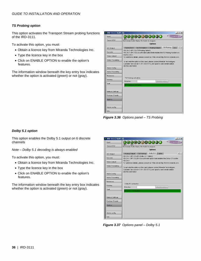
3.4.16 The Options panel This panel provides an entry point for activating the six options available for the IRD-3111. Each option is accessed on a separate tab. Frame Sync option This option provides frame synchronization of the decoded signal to the external signal connected to the REF IN connector on the rear panel. To activate this option, you must:
• Obtain a licence key from Miranda Technologies Inc. • Type the licence key in the box • Click on ENABLE OPTION to enable the option’s
features. The information window beneath the key entry box indicates whether the option is activated (green) or not (gray).
Figure 3.33 Options panel – Frame Sync
GUIDE TO INSTALLATION AND OPERATION
IRD-3111 | 35
Up Conversion option This option enables up-conversion (SD-to-HD) functionality on the IRD-3111. To activate this option, you must:
• Obtain a licence key from Miranda Technologies Inc. • Type the licence key in the box • Click on ENABLE OPTION to enable the option’s
features. The information window beneath the key entry box indicates whether the option is activated (green) or not (gray). Analog Output option This option activates the analog composite video and analog audio outputs of the IRD-3111. To activate this option, you must:
• Obtain a licence key from Miranda Technologies Inc. • Type the licence key in the box • Click on ENABLE OPTION to enable the option’s
features. The information window beneath the key entry box indicates whether the option is activated (green) or not (gray).
Figure 3.34 Options panel – Up Conversion
Figure 3.35 Options panel – Analog Output
GUIDE TO INSTALLATION AND OPERATION
36 | IRD-3111
TS Probing option This option activates the Transport Stream probing functions of the IRD-3111. To activate this option, you must:
• Obtain a licence key from Miranda Technologies Inc. • Type the licence key in the box • Click on ENABLE OPTION to enable the option’s
features. The information window beneath the key entry box indicates whether the option is activated (green) or not (gray).
Dolby 5.1 option This option enables the Dolby 5.1 output on 6 discrete channels Note – Dolby 5.1 decoding is always enabled To activate this option, you must:
• Obtain a licence key from Miranda Technologies Inc. • Type the licence key in the box • Click on ENABLE OPTION to enable the option’s
features. The information window beneath the key entry box indicates whether the option is activated (green) or not (gray).
Figure 3.37 Options panel – Dolby 5.1
Figure 3.36 Options panel – TS Probing
GUIDE TO INSTALLATION AND OPERATION
IRD-3111 | 37
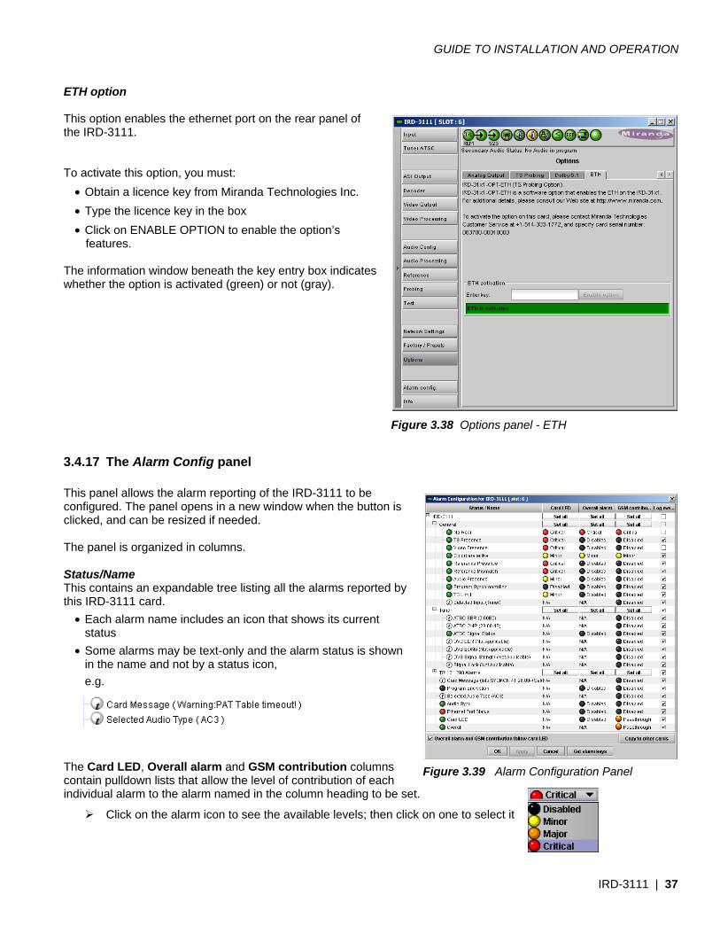
ETH option This option enables the ethernet port on the rear panel of the IRD-3111. To activate this option, you must:
• Obtain a licence key from Miranda Technologies Inc. • Type the licence key in the box • Click on ENABLE OPTION to enable the option’s
features. The information window beneath the key entry box indicates whether the option is activated (green) or not (gray).
3.4.17 The Alarm Config panel This panel allows the alarm reporting of the IRD-3111 to be configured. The panel opens in a new window when the button is clicked, and can be resized if needed. The panel is organized in columns. Status/Name This contains an expandable tree listing all the alarms reported by this IRD-3111 card.
• Each alarm name includes an icon that shows its current status
• Some alarms may be text-only and the alarm status is shown in the name and not by a status icon, e.g.
The Card LED, Overall alarm and GSM contribution columns contain pulldown lists that allow the level of contribution of each individual alarm to the alarm named in the column heading to be set.
Click on the alarm icon to see the available levels; then click on one to select it
Figure 3.38 Options panel - ETH
Figure 3.39 Alarm Configuration Panel
GUIDE TO INSTALLATION AND OPERATION
38 | IRD-3111
Levels associated with these alarms:
The pulldown lists may contain some or all of the following options:
The alarm makes no contribution (black icon)
The alarm is of minor importance (yellow icon)
The alarm is of major importance (orange icon)
The alarm is of critical importance (red icon)
The alarm exists but has no effect (used for text and composite alarms)
Shortcut: if you click in one of the Set All boxes beside a section heading, you will open a pulldown that lets you assign a level to all alarms in that section of the column simultaneously.
• Card LED
This column allows configuration of the contribution of each individual alarm to the state of the Status LED located on the front panel this card.
• Overall Alarm This column allows configuration of the contribution of each individual alarm to the Overall Alarm associated with this card. The Overall Alarm is shown in the upper left corner of the iControl panel, and also appears at the bottom of the Status/Name column.
• GSM Contribution
This column allows configuration of the contribution of each individual alarm to the GSM Alarm Status associated with this card. GSM is a dynamic register of all iControl system alarms, and is also an alarm provider for external applications. The possible values for this contribution are related to the Overall alarm contribution:
• If the Overall alarm contribution is selected as Disabled, the GSM alarm contribution can be set to any available value
• If the Overall alarm contribution is selected as any level other than disabled, the GSM contribution is forced to follow the Overall Alarm.
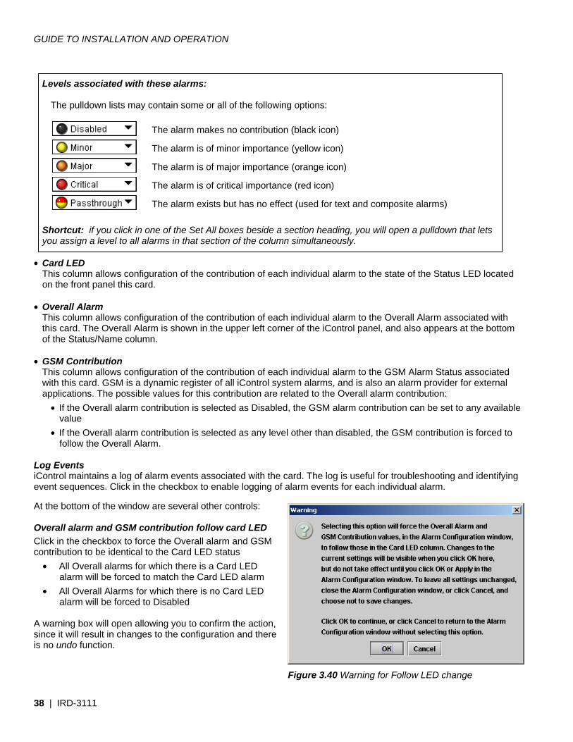
Log Events iControl maintains a log of alarm events associated with the card. The log is useful for troubleshooting and identifying event sequences. Click in the checkbox to enable logging of alarm events for each individual alarm. At the bottom of the window are several other controls: Overall alarm and GSM contribution follow card LED Click in the checkbox to force the Overall alarm and GSM contribution to be identical to the Card LED status
• All Overall alarms for which there is a Card LED alarm will be forced to match the Card LED alarm
• All Overall Alarms for which there is no Card LED alarm will be forced to Disabled
A warning box will open allowing you to confirm the action, since it will result in changes to the configuration and there is no undo function.
Figure 3.40 Warning for Follow LED change
GUIDE TO INSTALLATION AND OPERATION
IRD-3111 | 39
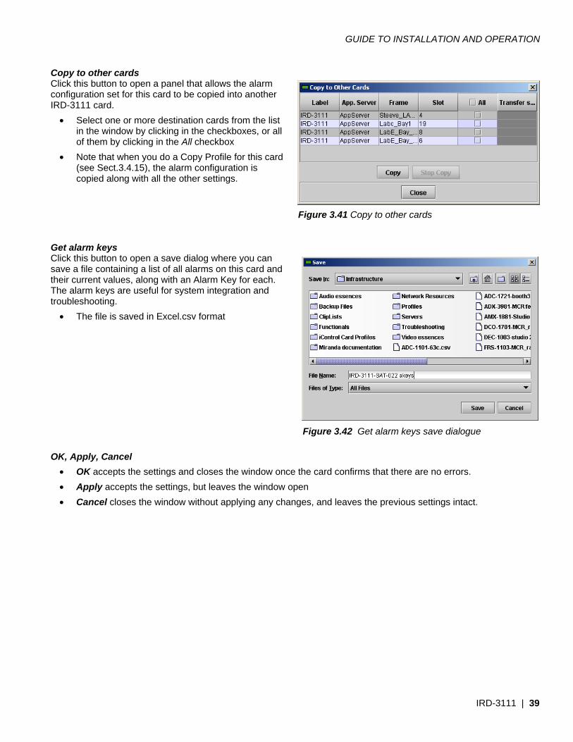
Copy to other cards Click this button to open a panel that allows the alarm configuration set for this card to be copied into another IRD-3111 card.
• Select one or more destination cards from the list in the window by clicking in the checkboxes, or all of them by clicking in the All checkbox
• Note that when you do a Copy Profile for this card (see Sect.3.4.15), the alarm configuration is copied along with all the other settings.
Get alarm keys Click this button to open a save dialog where you can save a file containing a list of all alarms on this card and their current values, along with an Alarm Key for each. The alarm keys are useful for system integration and troubleshooting.
• The file is saved in Excel.csv format OK, Apply, Cancel
• OK accepts the settings and closes the window once the card confirms that there are no errors. • Apply accepts the settings, but leaves the window open • Cancel closes the window without applying any changes, and leaves the previous settings intact.
Figure 3.41 Copy to other cards
Figure 3.42 Get alarm keys save dialogue
GUIDE TO INSTALLATION AND OPERATION
40 | IRD-3111
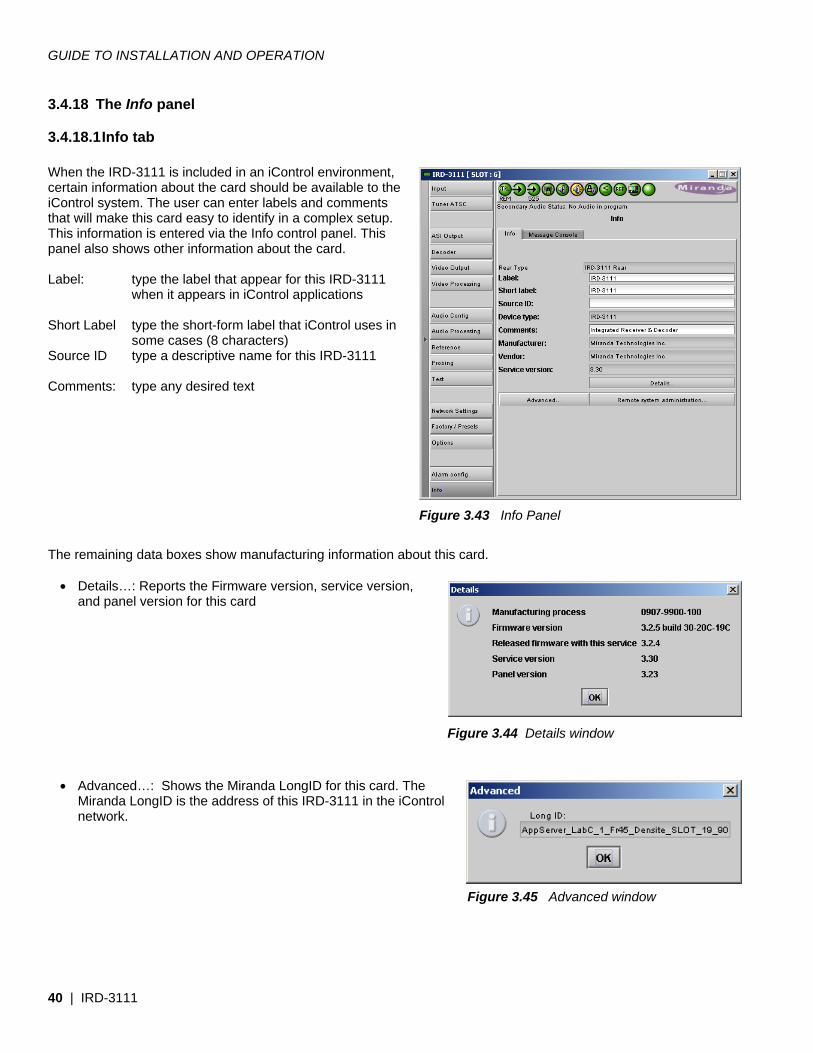
3.4.18 The Info panel
3.4.18.1 Info tab When the IRD-3111 is included in an iControl environment, certain information about the card should be available to the iControl system. The user can enter labels and comments that will make this card easy to identify in a complex setup. This information is entered via the Info control panel. This panel also shows other information about the card. Label: type the label that appear for this IRD-3111
when it appears in iControl applications Short Label type the short-form label that iControl uses in
some cases (8 characters) Source ID type a descriptive name for this IRD-3111 Comments: type any desired text The remaining data boxes show manufacturing information about this card.
• Details…: Reports the Firmware version, service version, and panel version for this card
• Advanced…: Shows the Miranda LongID for this card. The
Miranda LongID is the address of this IRD-3111 in the iControl network.
Figure 3.45 Advanced window
Figure 3.44 Details window
Figure 3.43 Info Panel
GUIDE TO INSTALLATION AND OPERATION
IRD-3111 | 41
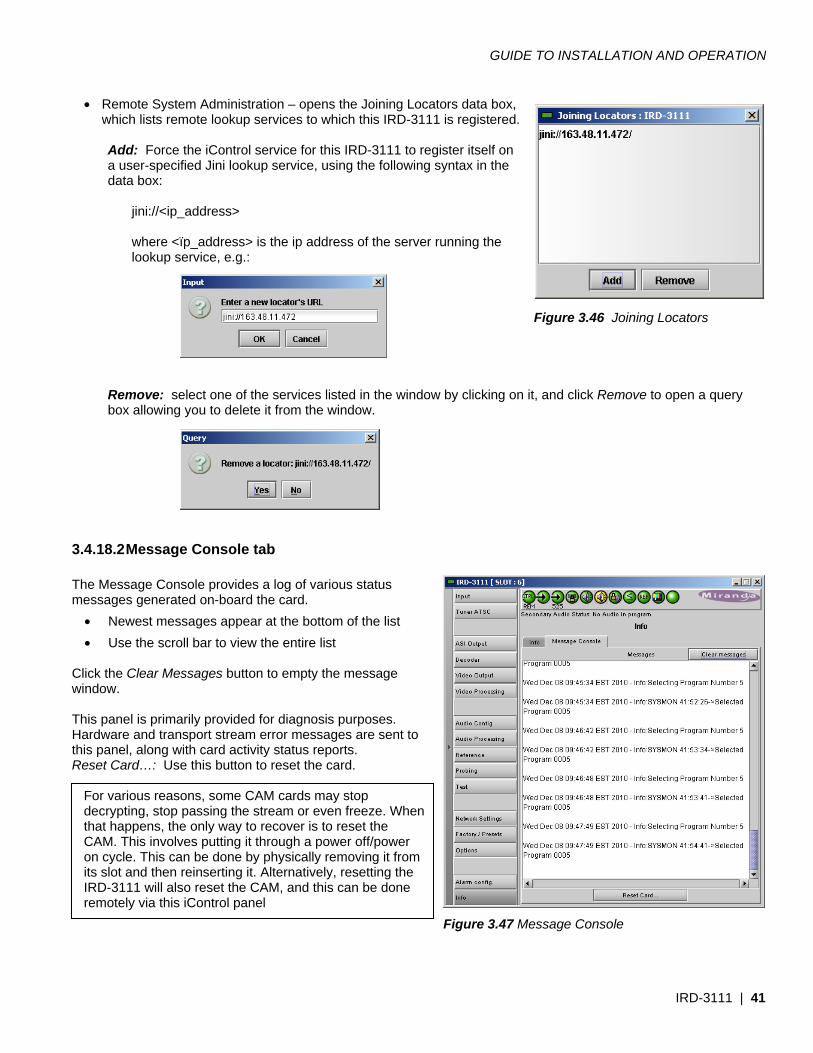
• Remote System Administration – opens the Joining Locators data box, which lists remote lookup services to which this IRD-3111 is registered.
Add: Force the iControl service for this IRD-3111 to register itself on a user-specified Jini lookup service, using the following syntax in the data box:
jini://<ip_address>
where <ïp_address> is the ip address of the server running the lookup service, e.g.:
Remove: select one of the services listed in the window by clicking on it, and click Remove to open a query box allowing you to delete it from the window.
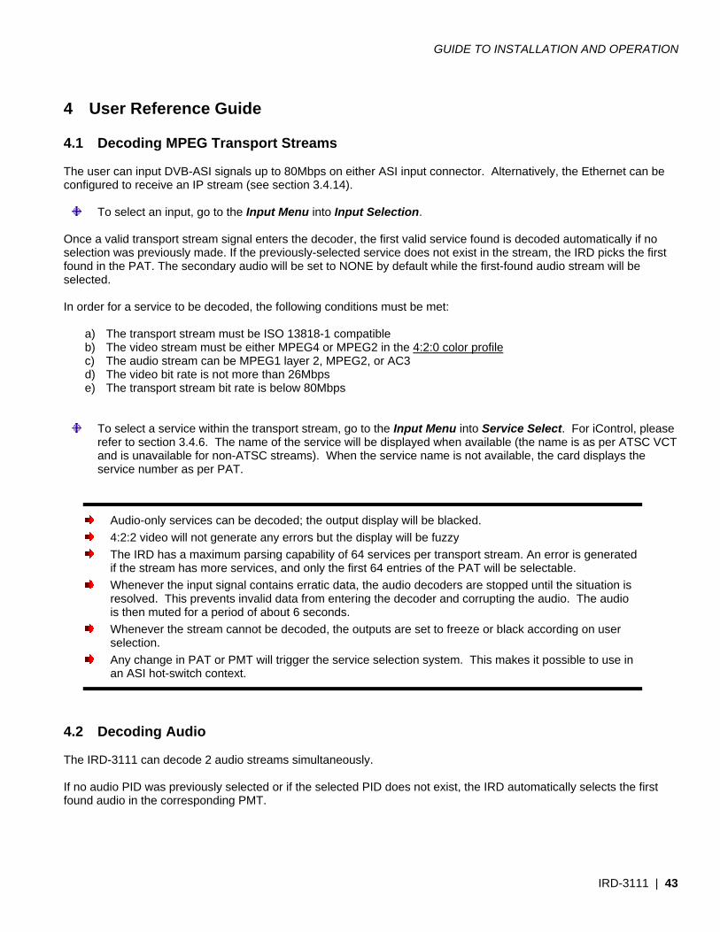
3.4.18.2 Message Console tab The Message Console provides a log of various status messages generated on-board the card.
• Newest messages appear at the bottom of the list • Use the scroll bar to view the entire list
Click the Clear Messages button to empty the message window. This panel is primarily provided for diagnosis purposes. Hardware and transport stream error messages are sent to this panel, along with card activity status reports. Reset Card…: Use this button to reset the card.
For various reasons, some CAM cards may stop decrypting, stop passing the stream or even freeze. When that happens, the only way to recover is to reset the CAM. This involves putting it through a power off/power on cycle. This can be done by physically removing it from its slot and then reinserting it. Alternatively, resetting the IRD-3111 will also reset the CAM, and this can be done remotely via this iControl panel
Figure 3.46 Joining Locators
Figure 3.47 Message Console

GUIDE TO INSTALLATION AND OPERATION
42 | IRD-3111
When you click the button, you will be presented with a dialog allowing you to confirm your decision to reset, or to cancel the reset.
GUIDE TO INSTALLATION AND OPERATION
IRD-3111 | 43
4 User Reference Guide 4.1 Decoding MPEG Transport Streams The user can input DVB-ASI signals up to 80Mbps on either ASI input connector. Alternatively, the Ethernet can be configured to receive an IP stream (see section 3.4.14).
To select an input, go to the Input Menu into Input Selection. Once a valid transport stream signal enters the decoder, the first valid service found is decoded automatically if no selection was previously made. If the previously-selected service does not exist in the stream, the IRD picks the first found in the PAT. The secondary audio will be set to NONE by default while the first-found audio stream will be selected. In order for a service to be decoded, the following conditions must be met:
a) The transport stream must be ISO 13818-1 compatible b) The video stream must be either MPEG4 or MPEG2 in the 4:2:0 color profile c) The audio stream can be MPEG1 layer 2, MPEG2, or AC3 d) The video bit rate is not more than 26Mbps e) The transport stream bit rate is below 80Mbps
To select a service within the transport stream, go to the Input Menu into Service Select. For iControl, please refer to section 3.4.6. The name of the service will be displayed when available (the name is as per ATSC VCT and is unavailable for non-ATSC streams). When the service name is not available, the card displays the service number as per PAT.
Audio-only services can be decoded; the output display will be blacked. 4:2:2 video will not generate any errors but the display will be fuzzy The IRD has a maximum parsing capability of 64 services per transport stream. An error is generated
if the stream has more services, and only the first 64 entries of the PAT will be selectable. Whenever the input signal contains erratic data, the audio decoders are stopped until the situation is
resolved. This prevents invalid data from entering the decoder and corrupting the audio. The audio is then muted for a period of about 6 seconds.
Whenever the stream cannot be decoded, the outputs are set to freeze or black according on user selection.
Any change in PAT or PMT will trigger the service selection system. This makes it possible to use in an ASI hot-switch context.
4.2 Decoding Audio The IRD-3111 can decode 2 audio streams simultaneously. If no audio PID was previously selected or if the selected PID does not exist, the IRD automatically selects the first found audio in the corresponding PMT.
GUIDE TO INSTALLATION AND OPERATION
44 | IRD-3111
The following audio coding formats are currently supported:
• AC3 audio up to 5.1 channels • MPEG1 Layer II • MPEG2 Audio • AAC audio (2 CH only)
The first audio can be embedded as 5.1 discrete channels (the Dolby option is required to get discreet channels; otherwise you get 2 down-mixed channels) while the second audio is always output as 2 channels. Downmix mode can be selected between Lt/Rt or Lo/Ro modes independently for both audios. The secondary audio can be set in pass-through mode for AC3 data stream. This allows embedding raw AC3 streams on channel 7 and 8 of the SDI signal.
Audio only services can be decoded Audio PIDs not belonging to the current service cannot be selected Only supported audio streams will be available to the user for selection Audio 1 is embedded on AES channels 1 to 6, Audio 2 is on channels 7-8 The Dolby option must be activated to get 6 discrete AC3 channels on the SDI
4.3 MPEG AV Synchronization MPEG transport streams normally contain information about the encoder clock system in order to genlock the decoder to the incoming signal and avoid buffer underrun or overflows. Moreover, the audio and video streams contain time stamps (PTS) in order to re-synchronize the stream at the output. Should synchronization be a problem (PCR jitter, bad PTS), the MPEG clock recover system can be manually forced to OFF. In such case, the system decoder clock is free run and frames are repeated or dropped to cope with buffer overflows or underflows (frame buffer mode). Setting the clock recovery in the OFF mode is particularly useful when network jitter is important and the video sync or audio sync status of the IRD keeps blinking.
To change the clock recovery mode, go to the card menu into Input Menu, CLOCK RECOVERY Refer to section 3.4.6 for iControl.
The audio video synchronization can be further improved with firmware revision 301 and up. A new setting called AV sync quality allow the user to achieve better AV sync when set to BEST. The BEST setting will deliver AV sync within 1ms but requires the input TS to be completely free of errors. If errors are present in the TS, the video and audio may become out of sync. The synchro system will then restart the audio decoder to reach sync and this will cause a mute in the audio. This feature must be used only in error free environments. 4.4 About V-CHIP & Rating Information The IRD can translate ATSC PSIP Advisories from the EPG to standard V-CHIP inserted in the XDS of compliant IEA-608 closed captioning data. Because the video stream may already contain XDS advisory data, the IRD provides two modes of operation:
GUIDE TO INSTALLATION AND OPERATION
IRD-3111 | 45
Replace: Will use the PSIP information to replace any existing XDS data. Use this option if you know you want to use the PSIP advisory.
Pass: If XDS data is already present, it is left untouched. In this mode, no V-CHIP is generated if no
XDS data is present.
Note that the PSIP RTT tables are not extracted. The rating information comes from the standard MPAA and other North American rating systems.
Closed captioning data must be present in the MPEG video stream or XDS data will not be inserted at the output
4.5 Using the Up Conversion Option The Up Conversion Option allows the user to upscale the input signal from 525 or 625 to 720 or 1080i keeping same frame rate. In addition to resolution conversion, the option allows aspect ratio conversion to occur. The user can either manually select the desired conversion method or use the AFD from the source to automatically resize the picture. In manual mode, the following scaling options are available:
• NONE: No aspect ratio conversion done. • AUTO: The scaling method is selected automatically. In this mode, the AFD flag is used along
with the aspect ratio of the output to select the best method. If no AFD is present, the default AFD flag is used.
• STRETCH: Use this mode to stretch the picture vertically. This mode is useful when the input picture has the wrong aspect ratio.
• CENTER CUT: When converting from 16:9 to 4:3, use this to crop both sides of the picture and fill the entire screen while keeping the aspect ratio.
• LETTER BOX: Adds black curtains to the 16:9 picture for 4:3 monitors • PILLAR BOX: Adds black bars to the 16:9 picture to properly display 4:3 images on 16:9 monitors.
Some modes may not apply depending on the input signal and desired output format. If the selected mode is not possible the result will be the same as if NONE was selected.
The AUTO mode will use the input AFD to automatically choose the best rescaling method. The decisions follow the CEA-CEB16 recommendation for receivers/decoders. 4.6 About AFD processing According to ATSC A/53 part 4, AFD and BAR data can be carried in MPEG signals. The AFD information and BAR data are extracted from the MPEG signal if present. The user can configure the IRD to trigger on the AFD flags to automatically rescale the picture so that it is optimally displayed. Alternatively, the user can set the scaling mode to OFF and simply carry the AFD flags to the outputs for further processing. A card like the XVP-38xx from Miranda could then use the flag to rescale the picture properly.
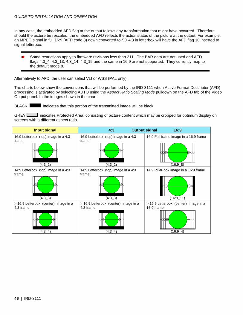
GUIDE TO INSTALLATION AND OPERATION
46 | IRD-3111
In any case, the embedded AFD flag at the output follows any transformation that might have occurred. Therefore should the picture be rescaled, the embedded AFD reflects the actual status of the picture at the output. For example, an MPEG signal in full 16:9 (AFD code 8) down converted to SD 4:3 in letterbox will have the AFD flag 10 inserted to signal letterbox.
Some restrictions apply to firmware revisions less than 211. The BAR data are not used and AFD flags 4:3_4, 4:3_13, 4:3_14, 4:3_15 and the same in 16:9 are not supported. They currently map to the default mode 8.
Alternatively to AFD, the user can select VLI or WSS (PAL only). The charts below show the conversions that will be performed by the IRD-3111 when Active Format Descriptor (AFD) processing is activated by selecting AUTO using the Aspect Ratio Scaling Mode pulldown on the AFD tab of the Video Output panel. In the images shown in the chart: BLACK Indicates that this portion of the transmitted image will be black GREY indicates Protected Area, consisting of picture content which may be cropped for optimum display on screens with a different aspect ratio.
Input signal 4:3 Output signal 16:9 16:9 Letterbox (top) image in a 4:3 frame
(4:3_2)
16:9 Letterbox (top) image in a 4:3 frame
(4:3_2)
16:9 Full frame image in a 16:9 frame
(16:9_8)
14:9 Letterbox (top) image in a 4:3 frame
(4:3_3)
14:9 Letterbox (top) image in a 4:3 frame
(4:3_3)
14:9 Pillar-box image in a 16:9 frame
(16:9_11)
> 16:9 Letterbox (center) image in a 4:3 frame
(4:3_4)
> 16:9 Letterbox (center) image in a 4:3 frame
(4:3_4)
> 16:9 Letterbox (center) image in a 16:9 frame
(16:9_4)
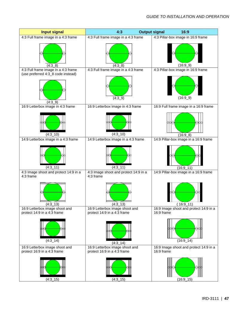
4
4(
1
1
44
1p
1p
Inp4:3 Full frame im
4:3 Full frame imuse preferred 4
16:9 Letterbox
14:9 Letterbox
4:3 Image shoo4:3 frame
16:9 Letterbox protect 14:9 in a
16:9 Letterbox protect 16:9 in a
put signal mage in a 4:3 f
(4:3_8)
mage in a 4:3 f4:3_8 code ins
(4:3_9)
image in 4:3 fra
(4:3_10) image in a 4:3
(4:3_11)
ot and protect 1
(4:3_13) image shoot ana 4:3 frame
(4:3_14)
image shoot ana 4:3 frame
(4:3_15)
frame 4:3
frame tead)
4:3
ame 16
frame 14
14:9 in a 4:34:3
nd 16pr
nd 16pr
3 Full frame im
(3 Full frame im
(
6:9 Letterbox im
(44:9 Letterbox im
(43 Image shoot 3 frame
(46:9 Letterbox imotect 14:9 in a
(46:9 Letterbox imotect 16:9 in a
(4
4:3mage in a 4:3 fra
(4:3_8)
mage in a 4:3 fra
(4:3_9)
mage in 4:3 fra
4:3_10) mage in a 4:3 fr
4:3_11) and protect 14
4:3_13) mage shoot and4:3 frame
4:3_14) mage shoot and4:3 frame
4:3_15)
GUIDE
Output signame 4:3
ame 4:3
me 16:9
rame 14:9
4:9 in a 14:9
d 16:916:9
d 16:916:9
E TO INSTALL
nal 1Pillar-box imag
(16Pillar-box imag
(16
9 Full frame im
(169 Pillar-box ima
(169 Pillar-box ima
( 169 Image shoot 9 frame
(16
9 Image shoot 9 frame
(16
LATION AND
IR
16:9 ge in 16:9 fram
6:9_9) ge in 16:9 fram
6:9_9)
mage in a 16:9 f
6:9_8) age in a 16:9 fr
6:9_11) age in a 16:9 fr
6:9_11) and protect 14
6:9_14)
and protect 14
6:9_15)
OPERATION
RD-3111 | 47
me
me
frame
rame
rame
4:9 in a
4:9 in a
N
7
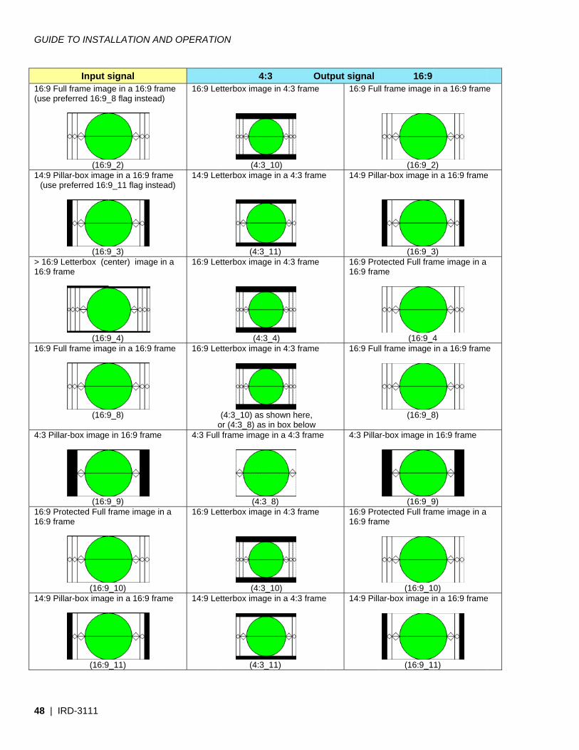
GUID
48 |
16:9 F(use p
14:9 P(use
> 16:916:9 f
16:9 F
4:3 P
16:9 P16:9 f
14:9 P
DE TO INSTA
IRD-3111
Input sFull frame imagpreferred 16:9_
(16:9Pillar-box image preferred 16:9
(16:99 Letterbox (ceframe
(16:9Full frame imag
(16:9
illar-box image
(16:9Protected Full fframe
(16:9Pillar-box imag
(16:9
ALLATION AN
signal ge in a 16:9 fra_8 flag instead
9_2) ge in a 16:9 fram9_11 flag inste
9_3) enter) image i
9_4) ge in a 16:9 fra
9_8)
e in 16:9 frame
9_9) frame image in
9_10) ge in a 16:9 fram
9_11)
ND OPERATI
ame )
16:9 Le
me ead)
14:9 Le
n a 16:9 Le
ame 16:9 Le
4:3 Ful
n a 16:9 Le
me 14:9 Le
ION
4:3etterbox image
(4:3_etterbox image
(4:3_1etterbox image
(4:3_etterbox image
(4:3_10) as sor (4:3_8) as inll frame image
(4:3_etterbox image
(4:3_etterbox image
(4:3_1
3 Oue in 4:3 frame
10)
e in a 4:3 frame
11) e in 4:3 frame
_4) e in 4:3 frame
hown here, n box below in a 4:3 frame
_8) e in 4:3 frame
10)
e in a 4:3 frame
11)
utput signal16:9 Ful
e 14:9 Pill
16:9 Pro16:9 fram
16:9 Ful
4:3 Pilla
16:9 Pro16:9 fram
e 14:9 Pill
16:9 ll frame image
(16:9_2ar-box image i
(16:9_3otected Full frame
(16:9_4ll frame image
(16:9_8
r-box image in
(16:9_9otected Full frame
(16:9_1ar-box image i
(16:9_1
in a 16:9 frame
2) n a 16:9 frame
3) me image in a
4 in a 16:9 frame
8)
16:9 frame
9) me image in a
0) n a 16:9 frame
1)
e
e
e
e
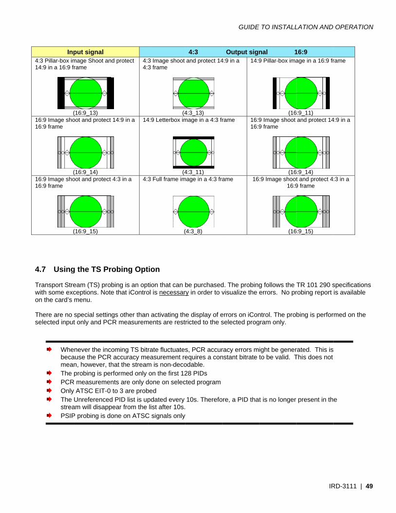
41
11
11
4 Two Ts
Inp4:3 Pillar-box im14:9 in a 16:9 fr
(16:9 Image sho16:9 frame
(16:9 Image sho16:9 frame
(
4.7 Using
Transport Strewith some excon the card’s
There are no selected input
Whebecamean
The p PCR Only The
strea PSIP
put signal mage Shoot anrame
(16:9_13) oot and protect
(16:9_14) oot and protect
(16:9_15)
g the TS Pr
eam (TS) proceptions. Notemenu.
special settint only and PC
never the incause the PCRn, however, thprobing is pe
R measuremenATSC EIT-0
Unreferencedam will disappP probing is do
d protect
4:34:3
14:9 in a
14
4:3 in a
4:3
robing Opt
bing is an opte that iContro
gs other thanCR measurem
oming TS bitrR accuracy mehat the streamrformed only nts are only dto 3 are prob
d PID list is uppear from the one on ATSC
3 Image shoot 3 frame
(44:9 Letterbox im
(43 Full frame im
(
ion
tion that can bol is necessar
n activating thments are rest
rate fluctuateseasurement rem is non-decoon the first 12
done on selecbed pdated every list after 10s.
C signals only
4:3and protect 14
4:3_13) mage in a 4:3 fr
4:3_11)
mage in a 4:3 fra
(4:3_8)
be purchasedry in order to v
e display of ericted to the s
s, PCR accurequires a conodable. 28 PIDs cted program
10s. Therefo
GUIDE
Output sign4:9 in a 14:9
rame 16:916:9
ame 16
d. The probingvisualize the e
errors on iConselected prog
racy errors mnstant bitrate t
ore, a PID that
E TO INSTALL
nal 19 Pillar-box ima
(169 Image shoot 9 frame
(16:9 Image shoot
16:9
(16
g follows the errors. No pr
ntrol. The program only.
ight be generto be valid. T
t is no longer
LATION AND
IR
16:9 age in a 16:9 fr
6:9_11)
and protect 14
6:9_14) t and protect 49 frame
6:9_15)
TR 101 290 srobing report
bing is perfor
rated. This isThis does not
present in th
OPERATION
RD-3111 | 49
rame
4:9 in a
:3 in a
specificationsis available
rmed on the
e
N
9
s
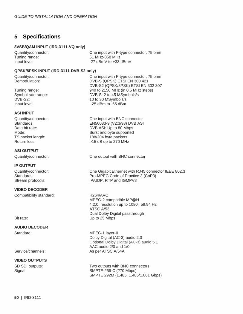
GUIDE TO INSTALLATION AND OPERATION
50 | IRD-3111
5 Specifications
8VSB/QAM INPUT (IRD-3111-VQ only) Quantity/connector: One input with F-type connector, 75 ohm Tuning range: 51 MHz-858 MHz Input level: -27 dBmV to +33 dBmV QPSK/8PSK INPUT (IRD-3111-DVB-S2 only) Quantity/connector: One input with F-type connector, 75 ohm Demodulation: DVB-S (QPSK) ETSI EN 300 421 DVB-S2 (QPSK/8PSK) ETSI EN 302 307 Tuning range: 940 to 2150 MHz (in 0.5 MHz steps) Symbol rate range: DVB-S: 2 to 45 MSymbols/s DVB-S2: 10 to 30 MSymbols/s Input level: -25 dBm to -65 dBm ASI INPUT Quantity/connector: One input with BNC connector Standards: EN50083-9 (V2:3/98) DVB ASI Data bit rate: DVB ASI: Up to 80 Mbps Mode: Burst and byte supported TS packet length: 188/204 byte packets Return loss: >15 dB up to 270 MHz ASI OUTPUT Quantity/connector: One output with BNC connector IP OUTPUT Quantity/connector: One Gigabit Ethernet with RJ45 connector IEEE 802.3 Standards: Pro-MPEG Code of Practice 3 (CoP3) Stream protocols: IP/UDP, RTP and IGMPV3 VIDEO DECODER Compatibility standard: H264/AVC MPEG-2 compatible MP@H 4:2:0, resolution up to 1080i, 59.94 Hz ATSC A/53 Dual Dolby Digital passthrough Bit rate: Up to 25 Mbps AUDIO DECODER Standard: MPEG-1 layer-II Dolby Digital (AC-3) audio 2.0 Optional Dolby Digital (AC-3) audio 5.1 AAC audio 2/0 and 1/0 Service/channels: As per ATSC A/54A VIDEO OUTPUTS SD SDI outputs: Two outputs with BNC connectors Signal: SMPTE-259-C (270 Mbps) SMPTE 292M (1.485, 1.485/1.001 Gbps)
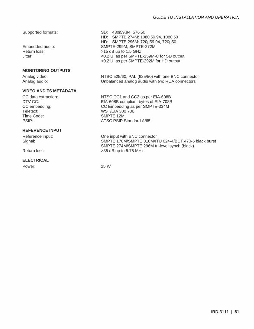
GUIDE TO INSTALLATION AND OPERATION
IRD-3111 | 51
Supported formats: SD: 480i59.94, 576i50 HD: SMPTE 274M: 1080i59.94, 1080i50 HD: SMPTE 296M: 720p59.94, 720p50 Embedded audio: SMPTE-299M, SMPTE-272M Return loss: >15 dB up to 1.5 GHz Jitter: <0.2 UI as per SMPTE-259M-C for SD output <0.2 UI as per SMPTE-292M for HD output MONITORING OUTPUTS Analog video: NTSC 525/60, PAL (625/50) with one BNC connector Analog audio: Unbalanced analog audio with two RCA connectors VIDEO AND TS METADATA CC data extraction: NTSC CC1 and CC2 as per EIA-608B DTV CC: EIA-608B compliant bytes of EIA-708B CC embedding: CC Embedding as per SMPTE-334M Teletext: WST/EIA 300 706 Time Code: SMPTE 12M PSIP: ATSC PSIP Standard A/65 REFERENCE INPUT Reference input: One input with BNC connector Signal: SMPTE 170M/SMPTE 318M/ITU 624-4/BUT 470-6 black burst SMPTE 274M/SMPTE 296M tri-level synch (black) Return loss: >35 dB up to 5.75 MHz ELECTRICAL Power: 25 W
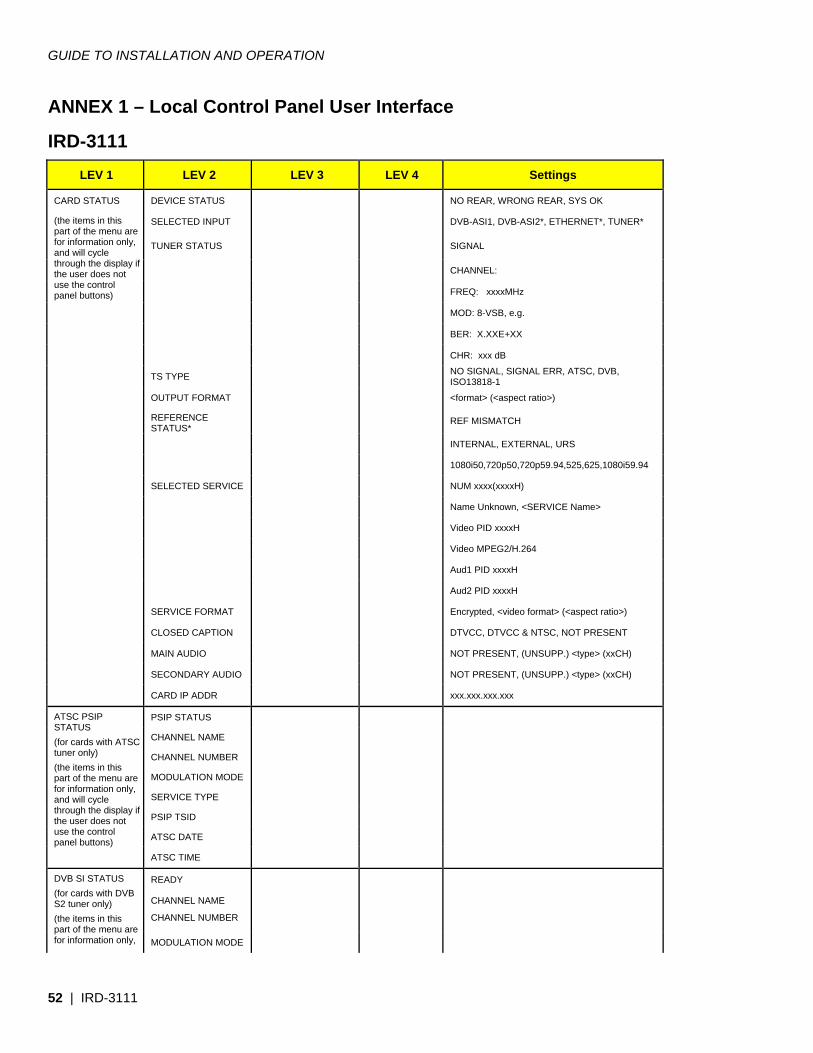
GUIDE TO INSTALLATION AND OPERATION
52 | IRD-3111
ANNEX 1 – Local Control Panel User Interface
IRD-3111 LEV 1 LEV 2 LEV 3 LEV 4 Settings
CARD STATUS DEVICE STATUS NO REAR, WRONG REAR, SYS OK
(the items in this part of the menu are for information only, and will cycle through the display if the user does not use the control panel buttons)
SELECTED INPUT DVB-ASI1, DVB-ASI2*, ETHERNET*, TUNER*
TUNER STATUS
SIGNAL
CHANNEL:
FREQ: xxxxMHz
MOD: 8-VSB, e.g.
BER: X.XXE+XX
CHR: xxx dB
TS TYPE NO SIGNAL, SIGNAL ERR, ATSC, DVB, ISO13818-1
OUTPUT FORMAT <format> (<aspect ratio>)
REFERENCE STATUS*
REF MISMATCH
INTERNAL, EXTERNAL, URS
1080i50,720p50,720p59.94,525,625,1080i59.94
SELECTED SERVICE NUM xxxx(xxxxH)
Name Unknown, <SERVICE Name>
Video PID xxxxH
Video MPEG2/H.264
Aud1 PID xxxxH
Aud2 PID xxxxH
SERVICE FORMAT Encrypted, <video format> (<aspect ratio>)
CLOSED CAPTION DTVCC, DTVCC & NTSC, NOT PRESENT
MAIN AUDIO NOT PRESENT, (UNSUPP.) <type> (xxCH)
SECONDARY AUDIO NOT PRESENT, (UNSUPP.) <type> (xxCH)
CARD IP ADDR xxx.xxx.xxx.xxx
ATSC PSIP STATUS (for cards with ATSC tuner only) (the items in this part of the menu are for information only, and will cycle through the display if the user does not use the control panel buttons)
PSIP STATUS
CHANNEL NAME
CHANNEL NUMBER
MODULATION MODE
SERVICE TYPE
PSIP TSID
ATSC DATE
ATSC TIME
DVB SI STATUS (for cards with DVB S2 tuner only) (the items in this part of the menu are for information only,
READY
CHANNEL NAME
CHANNEL NUMBER
MODULATION MODE
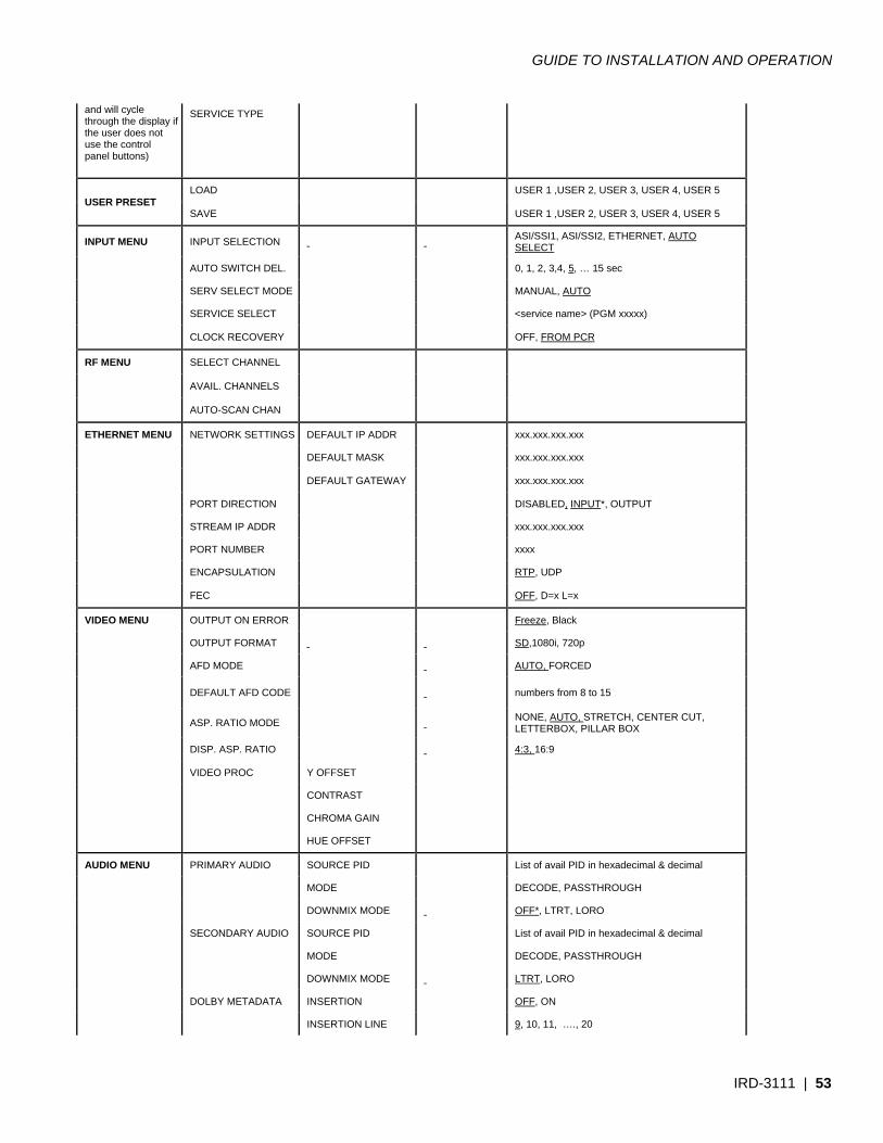
GUIDE TO INSTALLATION AND OPERATION
IRD-3111 | 53
and will cycle through the display if the user does not use the control panel buttons)
SERVICE TYPE
USER PRESET LOAD USER 1 ,USER 2, USER 3, USER 4, USER 5
SAVE USER 1 ,USER 2, USER 3, USER 4, USER 5
INPUT MENU INPUT SELECTION ASI/SSI1, ASI/SSI2, ETHERNET, AUTO SELECT
AUTO SWITCH DEL. 0, 1, 2, 3,4, 5, … 15 sec
SERV SELECT MODE MANUAL, AUTO
SERVICE SELECT <service name> (PGM xxxxx)
CLOCK RECOVERY OFF, FROM PCR
RF MENU SELECT CHANNEL
AVAIL. CHANNELS
AUTO-SCAN CHAN
ETHERNET MENU NETWORK SETTINGS DEFAULT IP ADDR xxx.xxx.xxx.xxx
DEFAULT MASK xxx.xxx.xxx.xxx
DEFAULT GATEWAY xxx.xxx.xxx.xxx
PORT DIRECTION DISABLED, INPUT*, OUTPUT
STREAM IP ADDR xxx.xxx.xxx.xxx
PORT NUMBER xxxx
ENCAPSULATION RTP, UDP
FEC OFF, D=x L=x
VIDEO MENU OUTPUT ON ERROR Freeze, Black
OUTPUT FORMAT SD,1080i, 720p
AFD MODE AUTO, FORCED
DEFAULT AFD CODE numbers from 8 to 15
ASP. RATIO MODE NONE, AUTO, STRETCH, CENTER CUT, LETTERBOX, PILLAR BOX
DISP. ASP. RATIO 4:3, 16:9
VIDEO PROC Y OFFSET
CONTRAST
CHROMA GAIN
HUE OFFSET
AUDIO MENU PRIMARY AUDIO SOURCE PID List of avail PID in hexadecimal & decimal
MODE DECODE, PASSTHROUGH
DOWNMIX MODE OFF*, LTRT, LORO
SECONDARY AUDIO SOURCE PID List of avail PID in hexadecimal & decimal
MODE DECODE, PASSTHROUGH
DOWNMIX MODE LTRT, LORO
DOLBY METADATA INSERTION OFF, ON
INSERTION LINE 9, 10, 11, …., 20
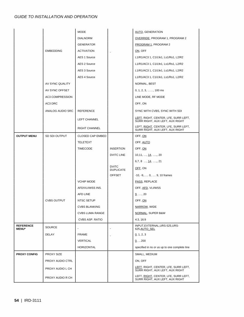
GUIDE TO INSTALLATION AND OPERATION
54 | IRD-3111
MODE AUTO, GENERATION
DIALNORM OVERRIDE, PROGRAM 1, PROGRAM 2
GENERATOR PROGRAM 1, PROGRAM 2
EMBEDDING ACTIVATION ON, OFF
AES 1 Source L1/R1/AC3 1, C1/Lfe1, Ls1/Rs1, L2/R2
AES 2 Source L1/R1/AC3 1, C1/Lfe1, Ls1/Rs1, L2/R2
AES 3 Source L1/R1/AC3 1, C1/Lfe1, Ls1/Rs1, L2/R2
AES 4 Source L1/R1/AC3 1, C1/Lfe1, Ls1/Rs1, L2/R2
AV SYNC QUALITY NORMAL, BEST
AV SYNC OFFSET 0, 1, 2, 3, ……, 100 ms
AC3 COMPRESSION LINE MODE, RF MODE
AC3 DRC OFF, ON
ANALOG AUDIO SRC REFERENCE SYNC WITH CVBS, SYNC WITH SDI
LEFT CHANNEL LEFT, RIGHT, CENTER, LFE, SURR LEFT, SURR RIGHT, AUX LEFT, AUX RIGHT
RIGHT CHANNEL LEFT, RIGHT, CENTER, LFE, SURR LEFT, SURR RIGHT, AUX LEFT, AUX RIGHT
OUTPUT MENU SD SDI OUTPUT CLOSED CAP EMBED OFF, ON
TELETEXT OFF, AUTO
TIMECODE INSERTION OFF, ON
DVITC LINE 10,11, …, 14, ….,, 20
6,7, 8 …, 14, ….,, 21
DVITC DUPLICATE OFF, ON
OFFSET -10, -9,….. 0, …. 9, 10 frames
VCHIP MODE PASS, REPLACE
AFD/VLI/WSS INS. OFF, AFD, VLI/WSS
AFD LINE 9, …., 20
CVBS OUTPUT NTSC SETUP OFF, ON
CVBS BLANKING NARROW, WIDE
CVBS LUMA RANGE NORMAL, SUPER B&W
CVBS ASP. RATIO 4:3, 16:9
REFERENCE MENU* SOURCE INPUT,EXTERNAL,URS-525,URS-
625,AUTO_SEL
DELAY FRAME 0, 1, 2, 3
VERTICAL 0, …200
HORIZONTAL specified in ns or us up to one complete line
PROXY CONFIG PROXY SIZE SMALL, MEDIUM
PROXY AUDIO CTRL ON, OFF
PROXY AUDIO L CH LEFT, RIGHT, CENTER, LFE, SURR LEFT, SURR RIGHT, AUX LEFT, AUX RIGHT
PROXY AUDIO R CH LEFT, RIGHT, CENTER, LFE, SURR LEFT, SURR RIGHT, AUX LEFT, AUX RIGHT
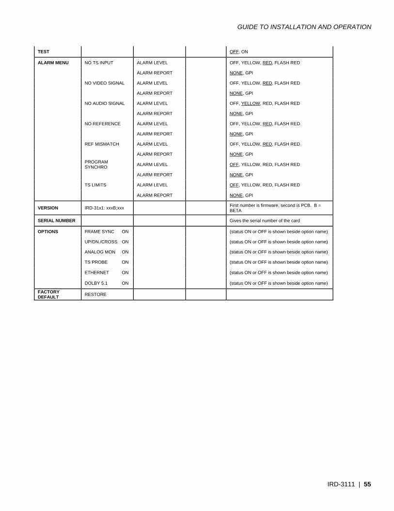
GUIDE TO INSTALLATION AND OPERATION
IRD-3111 | 55
TEST OFF, ON
ALARM MENU NO TS INPUT ALARM LEVEL OFF, YELLOW, RED, FLASH RED
ALARM REPORT NONE, GPI
NO VIDEO SIGNAL ALARM LEVEL OFF, YELLOW, RED, FLASH RED
ALARM REPORT NONE, GPI
NO AUDIO SIGNAL ALARM LEVEL OFF, YELLOW, RED, FLASH RED
ALARM REPORT NONE, GPI
NO REFERENCE ALARM LEVEL OFF, YELLOW, RED, FLASH RED
ALARM REPORT NONE, GPI
REF MISMATCH ALARM LEVEL OFF, YELLOW, RED, FLASH RED
ALARM REPORT NONE, GPI
PROGRAM SYNCHRO ALARM LEVEL OFF, YELLOW, RED, FLASH RED
ALARM REPORT NONE, GPI
TS LIMITS ALARM LEVEL OFF, YELLOW, RED, FLASH RED
ALARM REPORT NONE, GPI
VERSION IRD-31x1: xxxB;xxx First number is firmware, second is PCB. B = BETA
SERIAL NUMBER Gives the serial number of the card
OPTIONS FRAME SYNC ON (status ON or OFF is shown beside option name)
UP/DN./CROSS ON (status ON or OFF is shown beside option name)
ANALOG MON ON (status ON or OFF is shown beside option name)
TS PROBE ON (status ON or OFF is shown beside option name)
ETHERNET ON (status ON or OFF is shown beside option name)
DOLBY 5.1 ON (status ON or OFF is shown beside option name)
FACTORY DEFAULT RESTORE
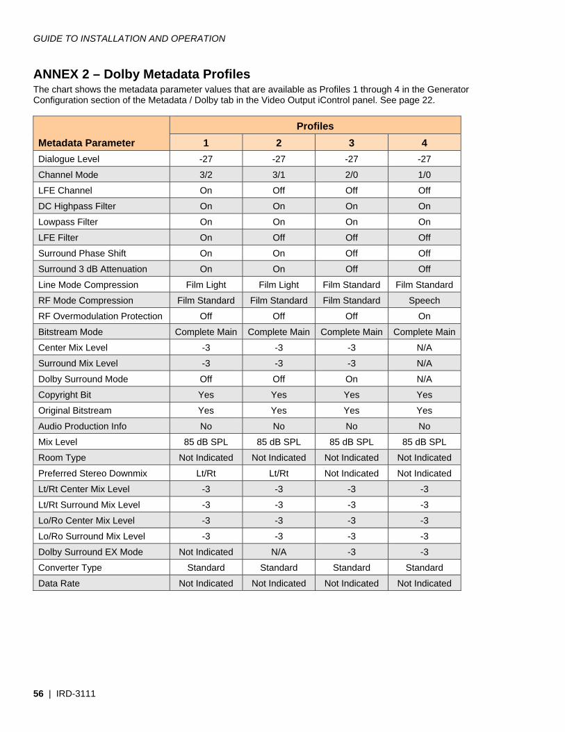
GUIDE TO INSTALLATION AND OPERATION
56 | IRD-3111
ANNEX 2 – Dolby Metadata Profiles The chart shows the metadata parameter values that are available as Profiles 1 through 4 in the Generator Configuration section of the Metadata / Dolby tab in the Video Output iControl panel. See page 22.
Metadata Parameter Profiles
1 2 3 4 Dialogue Level -27 -27 -27 -27
Channel Mode 3/2 3/1 2/0 1/0
LFE Channel On Off Off Off
DC Highpass Filter On On On On
Lowpass Filter On On On On
LFE Filter On Off Off Off
Surround Phase Shift On On Off Off
Surround 3 dB Attenuation On On Off Off
Line Mode Compression Film Light Film Light Film Standard Film Standard
RF Mode Compression Film Standard Film Standard Film Standard Speech
RF Overmodulation Protection Off Off Off On
Bitstream Mode Complete Main Complete Main Complete Main Complete Main
Center Mix Level -3 -3 -3 N/A
Surround Mix Level -3 -3 -3 N/A
Dolby Surround Mode Off Off On N/A
Copyright Bit Yes Yes Yes Yes
Original Bitstream Yes Yes Yes Yes
Audio Production Info No No No No
Mix Level 85 dB SPL 85 dB SPL 85 dB SPL 85 dB SPL
Room Type Not Indicated Not Indicated Not Indicated Not Indicated
Preferred Stereo Downmix Lt/Rt Lt/Rt Not Indicated Not Indicated
Lt/Rt Center Mix Level -3 -3 -3 -3
Lt/Rt Surround Mix Level -3 -3 -3 -3
Lo/Ro Center Mix Level -3 -3 -3 -3
Lo/Ro Surround Mix Level -3 -3 -3 -3
Dolby Surround EX Mode Not Indicated N/A -3 -3
Converter Type Standard Standard Standard Standard
Data Rate Not Indicated Not Indicated Not Indicated Not Indicated
Related Documents