NASA CONTRACTOR REPORT NASA CR-964 i_r> STRUCTURAL DESIGN SYNTHESIS APPROACH TO FILAMENTARY COMPOSITES by George Gerard and C. Lakshmikantham Prepared by ALLIED RESEARCH ASSOCIATES, INC. Concord, Mass. for NATIONAL AERONAUTICS AND SPACE ADMINISTRATION . WASHINGTON, D. C. IßgpAWfMENT OF DEFENSE PLASTICS TECHNICAL EVALUATION CÖffER PICATINNY ARSENAL. DOVER, N. M NOVEMBER 1

Welcome message from author
This document is posted to help you gain knowledge. Please leave a comment to let me know what you think about it! Share it to your friends and learn new things together.
Transcript
NASA CONTRACTOR
REPORT
NASA CR-964
i_r>
STRUCTURAL DESIGN SYNTHESIS APPROACH TO FILAMENTARY COMPOSITES
by George Gerard and C. Lakshmikantham
Prepared by
ALLIED RESEARCH ASSOCIATES, INC.
Concord, Mass.
for
NATIONAL AERONAUTICS AND SPACE ADMINISTRATION . WASHINGTON, D. C.
IßgpAWfMENT OF DEFENSE PLASTICS TECHNICAL EVALUATION CÖffER
PICATINNY ARSENAL. DOVER, N. M
NOVEMBER 1
NASA CR-964
STRUCTURAL DESIGN SYNTHESIS APPROACH
TO FILAMENTARY COMPOSITES
By George Gerard and C. Lakshmikantham
Distribution of this report is provided in the interest of information exchange. Responsibility for the contents resides in the author or organization that prepared it.
Issued by Originator as Technical Report No. ARA 327-6
Prepared under Contract No. NASw-1378 by ALLIED RESEARCH ASSOCIATES, INC.
Concord, Mass.
for
NATIONAL AERONAUTICS AND SPACE ADMINISTRATION
QüÄI.T'PT T?TR7?EnfrF''H 1
Summary
The first part of this paper is in the nature of a progress report on recent
developments of analysis methods for filamentary composites. Theoretical pre-
dictions of the stiffness and strength properties of a unidirectional composite based
on a knowledge of the constituent properties are correlated with experiments for
both tensile and compressive loadings. The analysis of multilayer or laminated
composites based upon the unidirectional composite properties then requires the
rather straight forward use of classical anisotropic shell theory.
Some structural aspects of filamentary composites designed for biaxial loads
are considered in the second part. In particular, certain design restrictions inherent
in the use of such composites become evident when compared to the more familiar
isotropic sheet. Some of these restrictions can be overcome by a close matching
of filament orientations and stress field. These factors serve to emphasize the
overwhelming importance of creative structural concepts in the design of successful
filamentary composites.
ill
Symbols
Af cross sectional area of filament
C contiguity factor
E elastic modulus
G shear modulus
n number of filaments per unit width
Nj , N2 loading per unit width referred to total composite thickness
Nf loading per unit width in filamentary direction referred to thickness
of unidirectional composite
tf equivalent filamentary sheet thickness
T shear strength of composite
V volume fraction
W weight fraction
X, Y, Z uniaxial composite strengths in filamentary, transverse and thickness
directions, respectively
ß angle between loading and filamentary axes
v Poisson's ratio
cr stress component
cr, tensile strength of filaments
cr microbuckling strength er °
T shear stress
Subscripts :
f filamentary
m matrix
x, y coordinates
1, 2 principal directions
— denotes composite properties
STRUCTURAL DESIGN SYNTHESIS APPROACH
TO FILAMENTARY COMPOSITES
Introduction
In Ref. 1, the essential roles of, and research opportunities for the constituent
elements of the composite (matrix, reinforcement and interface) were presented in
considerable depth. These areas essentially encompass the materials aspects of
composites. When we consider the composite under various loading conditions,
then we necessarily shift from a materials to a structural viewpoint. In this regard,
it was noted in Ref. 1 that since a composite is a combination of materials selected
to obtain specified design objectives, a structural mechanics approach is essential
to the successful design of composites tailored for specific applications.
The treatment of the structural aspects of the composite presented in Ref. 1
consisted of an identification of fundamental problem areas and an assessment of
the state of knowledge in those areas as of 1963. Considerable progress in the
development of methods of analysis of filamentary composites and their experimental
confirmation has been achieved since that time as a result of an expanding research
effort. One of the objectives here is to highlight some significant developments in
this area and this information is contained in Section 2.
A second, and perhaps more important objective, is to present some recent
information on structural design aspects of filamentary composites particularly
from a minimum weight viewpoint. Here, starting with the mechanics of a uni-
directional filamentary sheet, the strength/weight characteristics of laminates
composed of variously oriented filamentary sheets are considered for various
loading conditions. The unidirectional filamentary sheet is considered to be the
composite material which becomes the fundamental building block of the structural
composite or laminate.
As compared to the familiar isotropic metallic sheet in a biaxial stress field,
certain restrictions are inherent in the design of filamentary sheet laminates with
regard to the magnitude and orientation of the stress components. This aspect
constitutes a major difference in the structural applications of composites when
compared to familiar metallic sheets. These and other design considerations for
filamentary composites are presented in Section 3.
Z. Structural Analysis Methods for Filamentary
Composites Under Uniaxial Loads
Elementary Considerations
The only significant load that a single continuous filament is capable of sus-
taining is one that is collinear with the filament axis and tensile in character. The
following quantities are associated with the filament: filament strength (crf), fila-
ment modulus (E ), cross sectional area (A ).
The fundamental filamentary composite sheet consists of a series of parallel
filaments (unidirectional) of the same material properties (homogeneous) uniformly
stressed (isotensoid) in a suitable matrix. For a large volume fraction of filaments,
their role is primarily that of load transmission. Functionally, the matrix positions
the filaments, provides the desired geometric contours and acts as a sealant. For
tensile loading, it also provides a shear path around fractured filaments. For com-
pressive loading, the matrix provides an effective foundation modulus against buck-
ling of the filamentary columns.
As indicated in Fig. 1, the filamentary composite sheet has an equivalent
filamentary thickness, tf = nA where n is the number of filaments per inch width.
Based on the filament stress, we can define the loading, Nf = crftf. Similarly, we
can define an effective composite thickness T based on the composite stress o"c
such that
Nr = cr t" = <r,tf (!) f c c f f
The properties based on the filamentary characteristics neglect the matrix whereas
the composite properties include the volume fraction of the matrix.
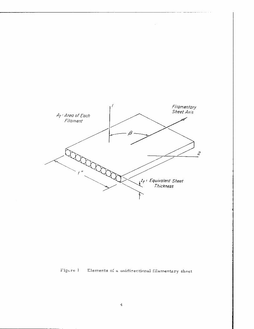
Af ■ Area of Each Filament
Filamentary Sheet Axis
f • Equivalent Sheet Thickness
Figure 1 Elements of a unidirectional filamentary sheet
Elastic Properties of Filamentary Sheets
The elastic stiffness properties of composites are of fundamental importance
in the design of structures subject to buckling as well as those subject to deflection
limitations. Tsai has surveyed various methods of analysis for predicting the
elastic constants of unidirectional filamentary composites from the constituent
properties (filament: E v ; matrix: E , v ). Particularly noteworthy are the
test results that he has obtained and the correlation obtained with theory.
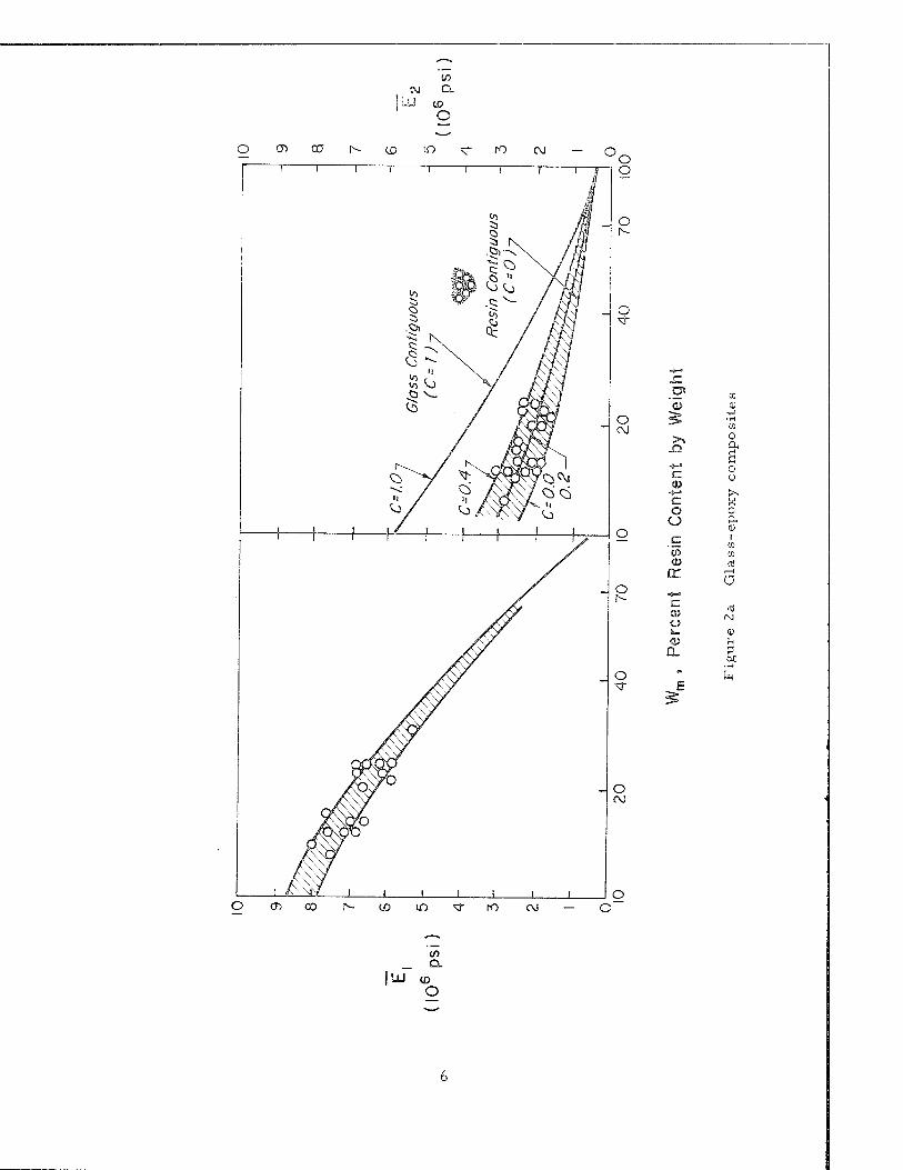
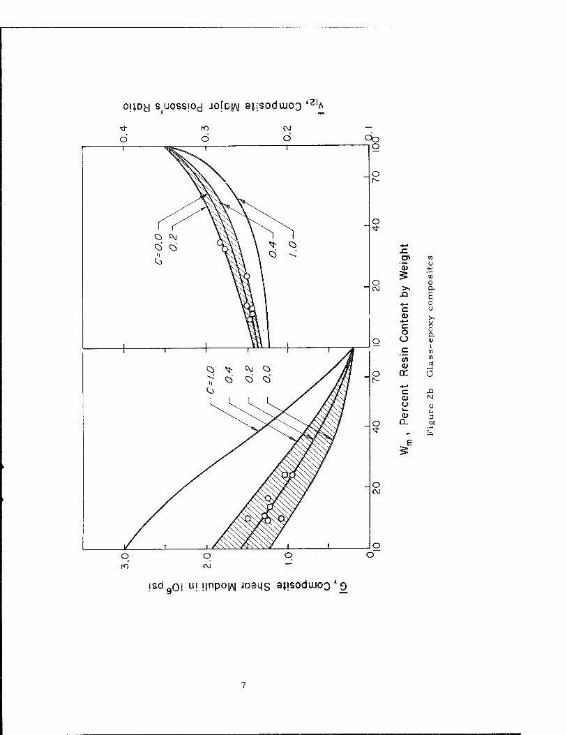
To summarize his results and conclusions, a unidirectional filamentary com-
posite can be represented as an anisotropic sheet and characterized in terms of
four composite elastic constants: Ej , E2 , v12, and G. Test results and theory
for the four constants as a function of matrix weight fraction are shown in Fig. Z.
It was observed that Ej depends primarily upon Ef and that filament unalignment
caused the scatter in the data of Fig. Z. On the other hand, E2, and G are strongly
influenced bv E as well as the degree of filament contiguity, a factor not readily ' m
predictable although C = 0. Z represents the test data of Fig. Z. The major Poisson's
ratio, v12 is somewhat influenced by the contiguity factor and is well predicted by
the theory.
Once the properties of a unidirectional filamentary sheet have been estab-
lished, classical theories of anisotropic layered plates can be used to predict the
elastic constants of laminated filamentary composites. By a series of experiments,
Azzi and Tsai3 have demonstrated the successful application of such theory to
cross-ply and angle-ply filamentary composite laminates. Further experimental
work by NASA4 on filament wound cylinders confirm the use of existing theories
for the elastic properties.
Tensile Strength of Filamentary Sheets
Tensile strength data constitute basic material property data in the aerospace
field. Thus, we return again to the unidirectional filamentary composite for the
purpose of establishing the strength properties that are required to characterize
to OJ Q.
LU «3 o
o o
o
o
o» 0)
a> <1J
o $ •r-i
C\J >> 0
c 0 o
0» «s>~« >. C x o 0 o a
o 4) c CO en <D ni cr r 1
n o
o la» 0 <P U
Q_ 3 00
o
o CM
h
O o
(7> 00 N- CO in ro CM o
to _ CL
| LU (D o
OjJDy S UOSSjOd JOfDJAl BJISOdtUOQ 4<5IA
d CM
d o
Q> sj- CVJ Q
ii Q> O Q> <o
o
o <fr
o> 0) .*» o a> +J
£ • rH 01
c > 0 <\l >s ft
.O a ■8-* 0 c u 0) >,
o
c o O
0
c M
«) en 0) nJ
o <r a N-
•*-» c ji o> ro o 0) 1_ u Q> 0
O Q. Ö0
Sf fr,
!sdQ0I ui i|npoi/\j iDOLis sjjsoduuoo'o
the behavior of such a composite under tensile loads at various angles to its fila-
mentary axis.
Azzi and Tsai have examined this problem for the unidirectional filamentary
sheet and by assuming plane stress conditions have taken the thickness stress
components to be zero. Under this condition, Hill ^«generalized anisotropic
strength law becomes
1 + 2£i Y2 Z2 x y
2£! Y2
r2
y 2Ü T2
-2 xy
Here, the filamentary axis is in the x-direction, y is transverse and z is the
thickness direction. The axial strength properties in the filamentary, transverse
and thickness directions are X, Y, and Z, respectively, and T is the shear strength.
By assuming that the unidirectional filamentary composite is transversely
Isotropie, Y = Z, Eq. (2) reduces to
X 2
'x'WlYJ ^HTJ Txy = X2 X
(3)
.5 Thus, Azzi and Tsai have used three experimentally determined composite strength
values to characterize the unidirectional filamentary sheet: the tensile strength in
the filamentary direction (X), the tensile strength transverse to the filamentary
direction (Y), and the shear strength on a plane of anisotropic symmetry (T). The
latter can be obtained on a torsion tube using a specimen with only circumferential
windings, or in a pure shear loading frame.
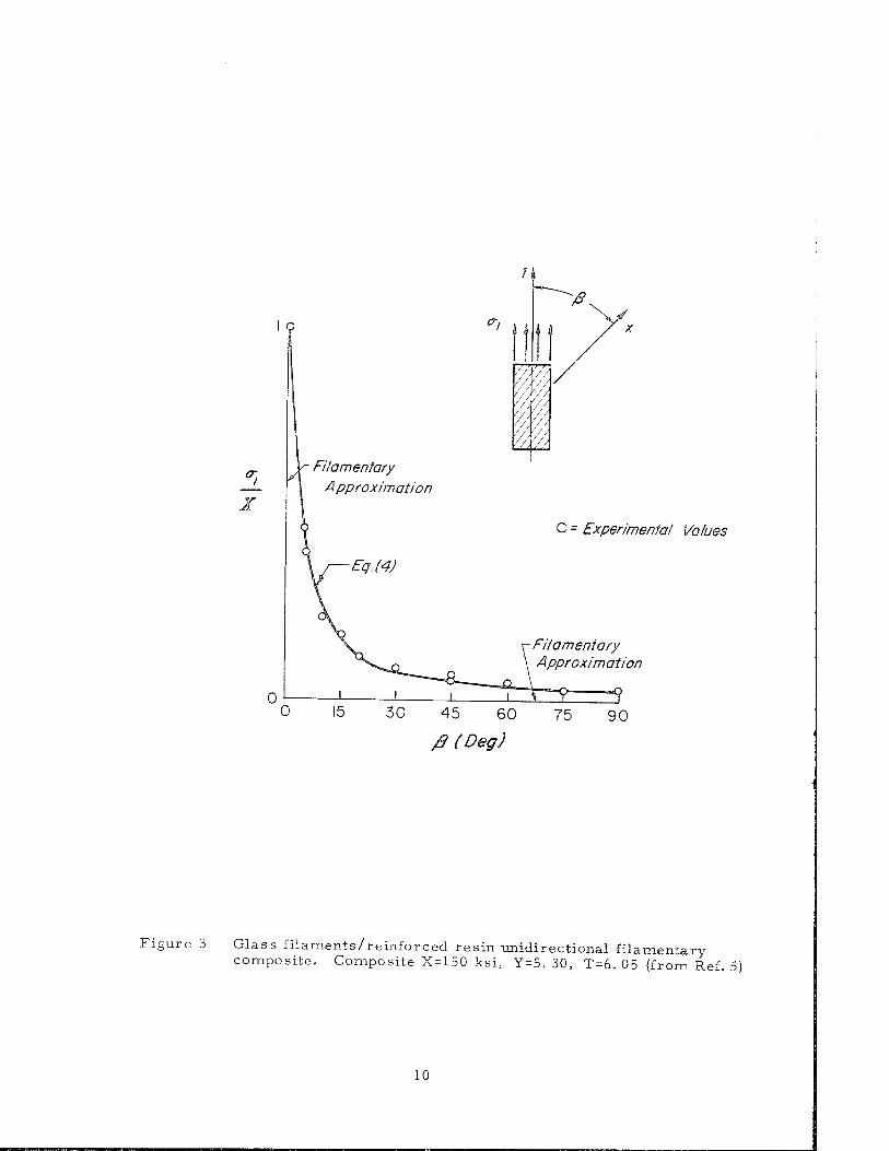
In cases where the tensile loading axis (1) may be at an angle ß with the fila-
mentary axis (x), the well known coordinate transformation equations must be
employed. For the uniaxial tension case the following relation is obtained5
«Hill, R. , The Mathematical Theory of Plasticity, Oxford University P
London, 1950, pp. 318-320.
ress,
o-j/X I) sin4ß+{(|) - \)- sin2 ßcos2 •1/2
(4)
Experimental confirmation of the validity of Eq. (4) for a glass filament-reinforced
resin unidirectional composite is shown in Fig. 3.
From a practical standpoint, Fig. 3 demonstrates conclusively the intolerance
of a unidirectional composite to load misalignment. It also demonstrates that a
convenient "filamentary approximation" for low strength matrices is the following:
o-j/X = 1 for p = 0; cr^X = 0 for ß > 0 (5)
While the foregoing serves to identify three experimentally determined com-
posite strength properties for characterizing unidirectional composites, it is
apparent that there has been a great interest in predicting the composite tensile
strength (X) directly from a knowledge of the constituent properties. The effort
in this area has proceeded for quite some time since the most simple and direct
measure of composite efficiency is the tensile test. Thus, knowledge in this area
is perhaps most widespread of all composite properties. The work of Kelly and
Tyson, Cratchley, and Weeton on metal filament/metal matrix composites is well
known. Some representative recent work on glass filament/organic matrix com-
posites, in which various statistical distributions of glass filaments strength have
been used to predict composite tensile strength, includes that of Rosen and Ekvall.
The latter has also treated matrix materials exhibiting a variable strength law by
utilizing the Mohr strength envelope.
Tsai and Azzi8 have generalized the unidirectional results for laminates
subjected to combined external loads as well as the thermomechanical stresses
O - Experimental Values
30 45 60
/B (Deg) 75 90
Figure 3 Glass filaments/reinforced resin unidirectional filamentary composite. Composite X=150 ksi, Y = 5. 30, T = 6. 05 {from Ref. 5)
10
induced by the lamination process. Test data on cross-ply and angle-ply composites
under uniaxial tensile loads correlate quite well with theory.
Compressive Strength of Filamentary Sheets
The design of structures subject to compressive loads is generally governed
by either of the following limitations: buckling in a general"instability mode in which
the elastic stiffness properties are of basic importance or compressive strength
which for a filamentary composite depends upon a filamentary microbuckling phen-
omenon.
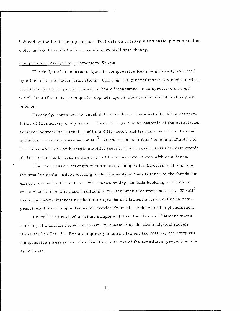
Presently, there are not much data available on the elastic buckling charact-
istics of filamentary composites. However, Fig. 4 is an example of the correlation
achieved between orthotropic shell stability theory and test data on filament wound
cylinders under compressive loads. As additional test data become available and
are correlated with orthotropic stability theory, it will permit available orthotropic
shell solutions to be applied directly to filamentary structures with confidence.
The compressive strength of filamentary composites involves buckling on a
far smaller scale: microbuckling of the filaments in the presence of the foundation
effect provided by the matrix. Well known analogs include buckling of a column 7
on an elastic foundation and wrinkling of the sandwich face upon the core. Ekvall
has shown some interesting photomicrographs of filament microbuckling in com-
pressively failed composites which provide dramatic evidence of the phenomenon.
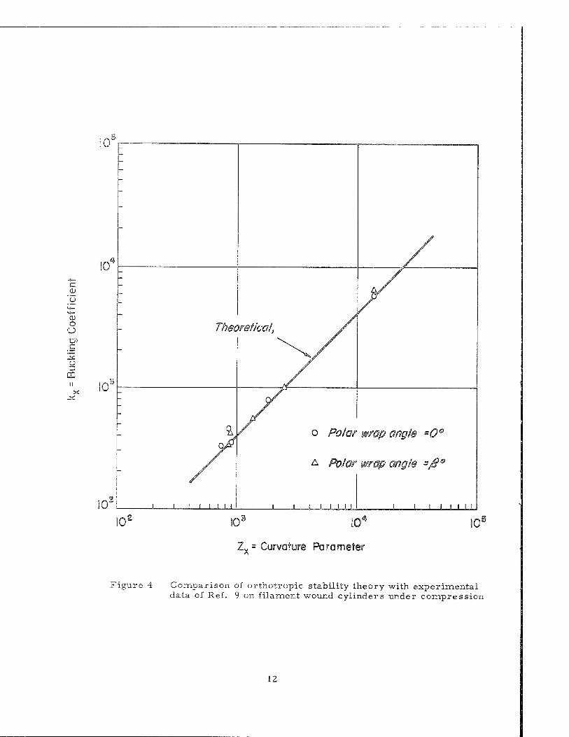
Rosen has provided a rather simple and direct analysis of filament micro-
buckling of a unidirectional composite by considering the two analytical models
illustrated in Fig. 5. For a completely elastic filament and matrix, the composite
compressive stresses for microbuckling in terms of the constituent properties are
as follows:
11
c o
o o c
o
CD
Zv = Curvature Parameter A
Figure 4 Comparison of orthotropic stability theory with experimental data of Ref. 9 on filament wound cylinders under compression
12
10 r / i Elastic
o lb
O1
c. a>
CO
a> -*— '(/> o CL
E o
CJ
a> c
35 o
-O O &— O
<u 0.5 >
0) Q. E o o
0.1
5/7<?ar Mode AntiSymmetric
Extension Mode Symmetric
E - Glass/Epoxy Matrix
Plastic Correction
0 0.2 0.4 0.6 0.8 .0
Volume Fraction VF
Figure 5 Micro-buckling strength of E-glass/epoxy composite
13
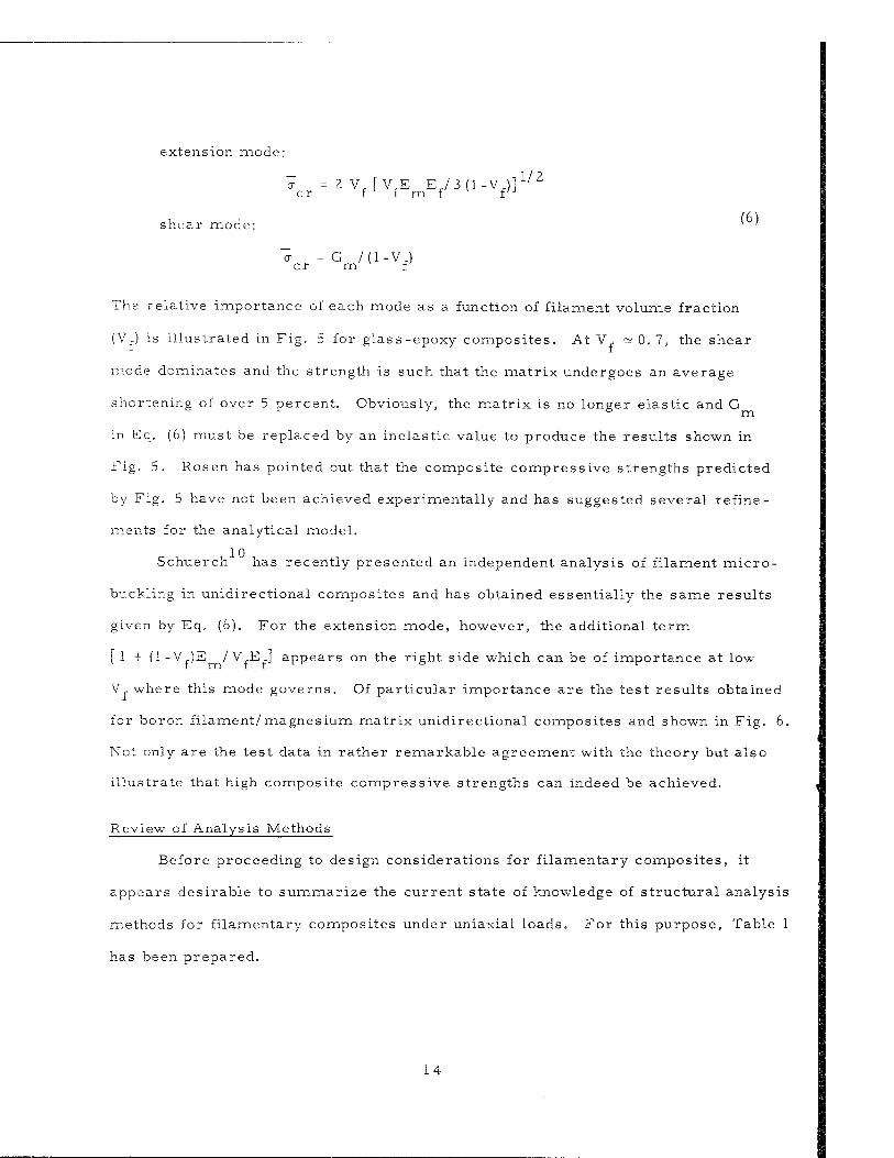
extension mode:
1/2
shear mode:
o- =2V, [ V,E E,/3(1-V.)j cr f f m f f
a = G /(1-V.) er m f
(6)
The relative importance of each mode as a function of filament volume fraction
(Vf) is illustrated in Fig. 5 for glass-epoxy composites. At V. =* 0. 7, the shear
mode dominates and the strength is such that the matrix undergoes an average
shortening of over 5 percent. Obviously, the matrix is no longer elastic and G ° m
in Eq. (6) must be replaced by an inelastic value to produce the results shown in
Fig. 5. Rosen has pointed out that the composite compressive strengths predicted
by Fig. 5 have not been achieved experimentally and has suggested several refine-
ments for the analytical model.
Schuerch has recently presented an independent analysis of filament micro-
buckling in unidirectional composites and has obtained essentially the same results
given by Eq. (6). For the extension mode, however, the additional term
[ 1 + (1 -V,)E / VjE,] appears on the right side which can be of importance at low
V, where this mode governs. Of particular importance are the test results obtained
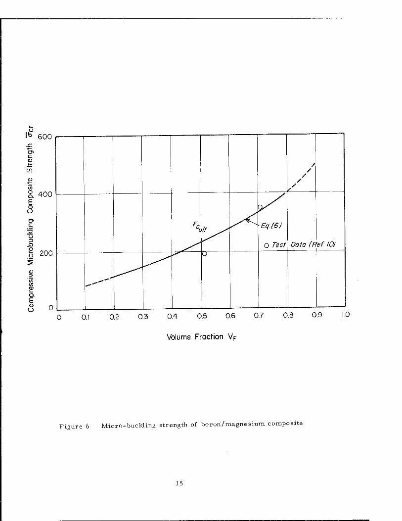
for boron filament/magnesium matrix unidirectional composites and shown in Fig. 6.
Not only are the test data in rather remarkable agreement with the theory but also
illustrate that high composite compressive strengths can indeed be achieved.
Review of Analysis Methods
Before proceeding to design considerations for filamentary composites, it
appears desirable to summarize the current state of knowledge of structural analysis
methods for filamentary composites under uniaxial loads. For this purpose, Table 1
has been prepared.
14
o lb
c CD
c/j a> y5 O Q. E o o
o> c 15 ü D
.O O i_
0> > 07 0> ••_ Q. e O o
600
400
200
0
/ /
/
Fcult ^ Eq.(6)
O Tes/1 Data (Ref. 10)
^"^
Ü
0 0. 0.2 0.3 0.4 0.5 0.6 0.7 0.8 0.9 1.0
Volume Fraction Vp
Figure 6 Micro-buckling strength of bor on/magnesium composite
15
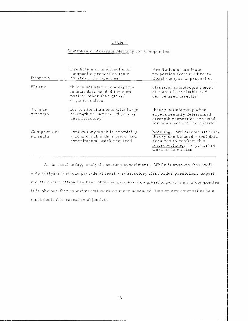
Table 1
Summary of Analysis Methods for Composites
P rope rty
Prediction of unidir ectional composite properties from constituent properties
Prediction of laminate properties from unidirect- tional composite properties
Elastic
1 ensile s trength
theory satisfactory - experi- mental data needed for com- posites other than glass/ organic matrix
for brittle filaments with large strength variations, theory is unsatisfactory
Compressive exploratory work is promising strength - considerable theoretical and
experimental work required
classical anisotropic theory of plates is available and can be used directly
theory satisfactory when experimentally determined strength properties are used for unidirectional composite
buckling: orthotropic stability theory can be used - test data required to confirm this microbuckling: no published work on laminates
As is usual today, analysis outruns experiment. While it appears that avail-
able analysis methods provide at least a satisfactory first order prediction, experi-
mental confirmation has been obtained primarily on glass/ organic matrix composites.
It is obvious that experimental work on more advanced filamentary composites is a
most desirable research objective.-
16
3. Design of Filamentary Composites Under Biaxial Loads
The methods of analysis reviewed in Section 2 for unidirectional filamentary
sheets and laminates composed of unidirectional composites were basically con-
cerned with uniaxial load applications. It is understandable that the early emphasis
would be on uniaxial loads in order to build up our level of knowledge of the behavior
of composites. However, the major successful applications of filamentary com-
posites have been in pressure vessels where biaxial loads govern. Other applications
will likewise require consideration of biaxial loads and consequently it is important
for us to turn our attention now to the design of filamentary composites under biaxial
loads.
Since it is rather important to understand some of the design possib-
ilities and restrictions of filamentary composites, we will employ for this purpose
a particularly simple method of analysis. We will assume a matrix of zero strength
thus permitting us to use the filamentary approximation given by Eq. (5). In this
manner, rather simple and direct design results can be obtained with the recognition
that the influence of the matrix has been neglected. It is believed, however, that
inclusion of matrix effects will not substantially alter any of the principal conclusions
derived herein.
Mechanics of a Bilayer Composite Sheet
In order to design composite laminates for biaxial loads it is convenient to
base the design upon the properties of the unidirectional filamentary sheets com-
prising the laminate and characterized by a filamentary strength cr,, thickness
t, and filament density as indicated in Fig. 1. The fundamental laminate is assumed
to be the bilayer shown in Fig. 7 consisting of two identical unidirectional filamen-
tary sheets oriented symmetrically at an angle +_ ß with respect to the reference
axis. For convenience, we refer to a unidirectional composite stress resultant
17
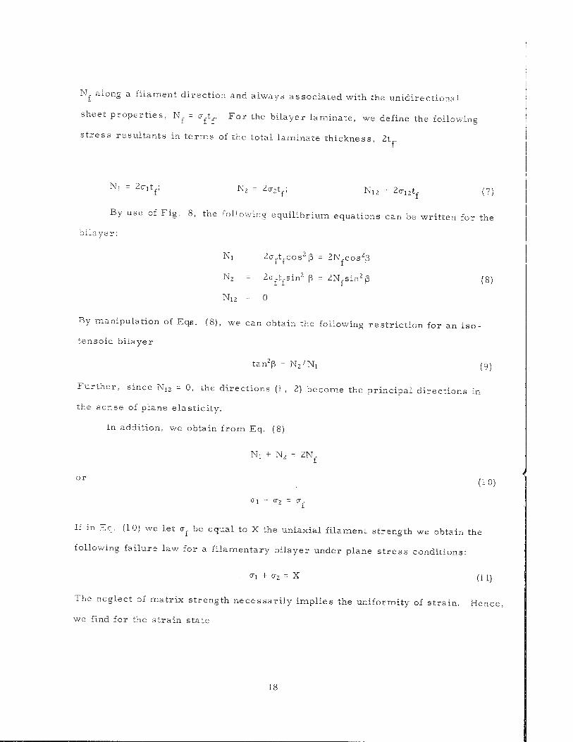
Nf along a filament direction and always associated with the unidirectional
sheet properties, Nf = o-ftf. For the bilayer laminate, we define the following
stress resultants in terms of the total laminate thickness, 2t f
Nl = Z(7lV N2 = Z^r N12 = 2tr12tf (7)
By use of Fig. 8, the following equilibrium equations can be written for the
bilayer:
Ni = 2crft cos2ß = 2N cos2ß
rftfsin2 ß = ZN; Nz = 2crft sin2 ß = 2N sin2ß (8)
Ni2 = 0
By manipulation of Eqs. (8), we can obtain the following restriction for an iso-
tensoid bilayer
tan2ß = N2/N! (9)
Further, since N12 = 0, the directions (1, 2) become the principal directions in
the sense of plane elasticity.
In addition, we obtain from Eq. (8)
Nj + N2 = 2N
°r (10)
If in Eq. (10) we let <xf be equal to X the uniaxial filament strength we obtain the
following failure law for a filamentary bilayer under plane stress conditions:
■ °"1 + °"2 = X (11)
The neglect of matrix strength necessarily implies the uniformity of strain. Hence,
we find for the strain state
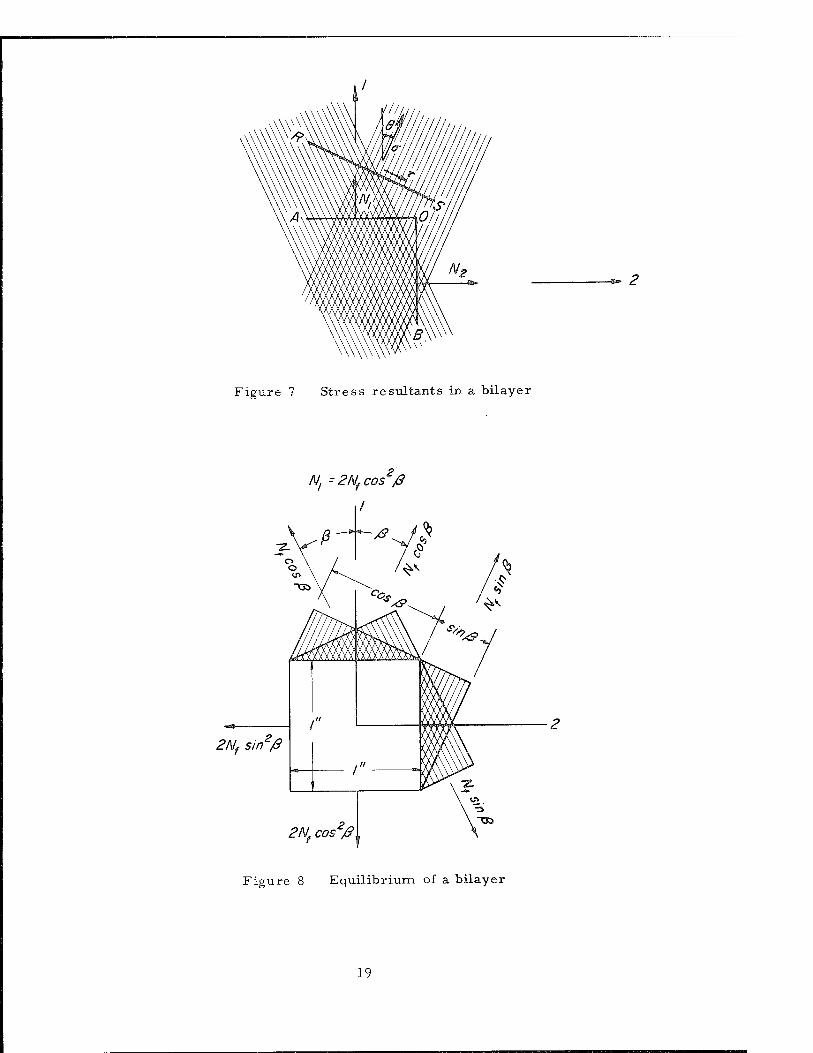
Figure 7 Stress resultants in a bilayer
2Nf sin2/3
2Nfcos'/&„
Figure 8 Equilibrium of a bilayer
19
ei = ^2 = ef = £ (12) f
Utilizing Eq. (12) in Eq. (11) and writing El = crj^, E2 = o-2/e2we find
Ei + E2 = Ef (13)
Eqs (11) and (13) constitute the failure and rigidity laws for filamentary bilayers.
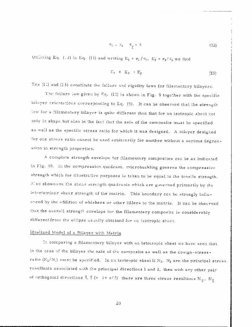
The failure law given by Eq. (11) is shown in Fig. 9 together with the specific
bilayer orientations corresponding to Eq. (9). It can be observed that the strength
law for a filamentary bilayer is quite different than that for an isotropic sheet not
only in shape but also in the fact that the axis of the composite must be specified
as well as the specific stress ratio for which it was designed. A bilayer designed
for one stress ratio cannot be used arbitrarily for another without a serious degrad-
ation in strength properties.
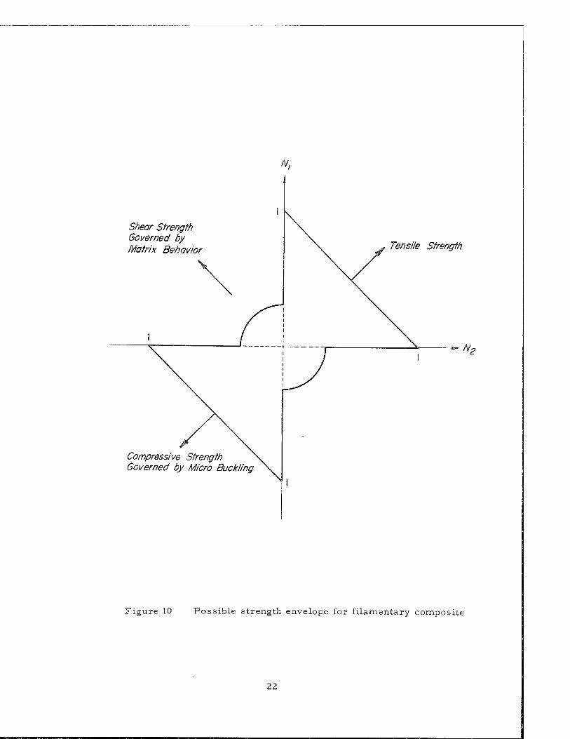
A complete strength envelope for filamentary composites can be as indicated
m Fig. 10. In the compression quadrant, microbuckling governs the compressive
strength which for illustrative purposes is taken to be equal to the tensile strength.
Also shown are the shear strength quadrants which are governed primarily by the
interlaminar shear strength of the matrix. This boundary can be strongly influ-
enced by the addition of whiskers or other fillers to the matrix. It can be observed
that the overall strength envelope for the filamentary composite is considerably
differentfrom the ellipse usually obtained for an isotropic sheet.
Idealized Model of a Bilayer with Matrix
In comparing a filamentary bilayer with an istotropic sheet we have seen that
in the case of the bilayer the axis of the composite as well as the design-stress -
ratio (Nz/Nj) must be specified. In an isotropic sheet if Nj, N2 are the principal stress
resultants associated with the principal directions 1 and 2, then with any other pair
of orthogonal directions Ö c (= Q+ ■„/?.) there are three stress resultants NQ, N=,
20
ß = 0
tXficr
/? = A er
| ) /9>#cr
Isotropie Metallic Behavior
ß =90c
Figure 9 Strength surfaces for filamentary and isotropic sheets
21
N,
Shear Strength Governed by Matrix Behavior Tensile Strength
Compressive Strength Governed by Micro Buckling
Figure 10 Possible strength envelope for filamentary composite
22
and N t associated with the orthogonal axes, 8, £. Hence, in an isotropic system
one could prescribe either N,, N2 as the design loads or NQ, N^, N^ along any two
orthogonal directions. However, in a bilayer such equivalent loading is inconsistent
with the omission of the shear resistance of the matrix.
In order to take into account the presence of shearing components, and yet
idealize the picture so that matrix strength can be neglected, we construct the
following model. We consider the bilayer to be imbedded in a frame and the loading
applied externally to the frame. The frame itself may carry shear resultants such
as N t, while the filaments develop only axial stresses. The matrix, as a load
carrying agent, is then visualized as the frame. It carries the shearing components
while the filaments develop the axial stresses.
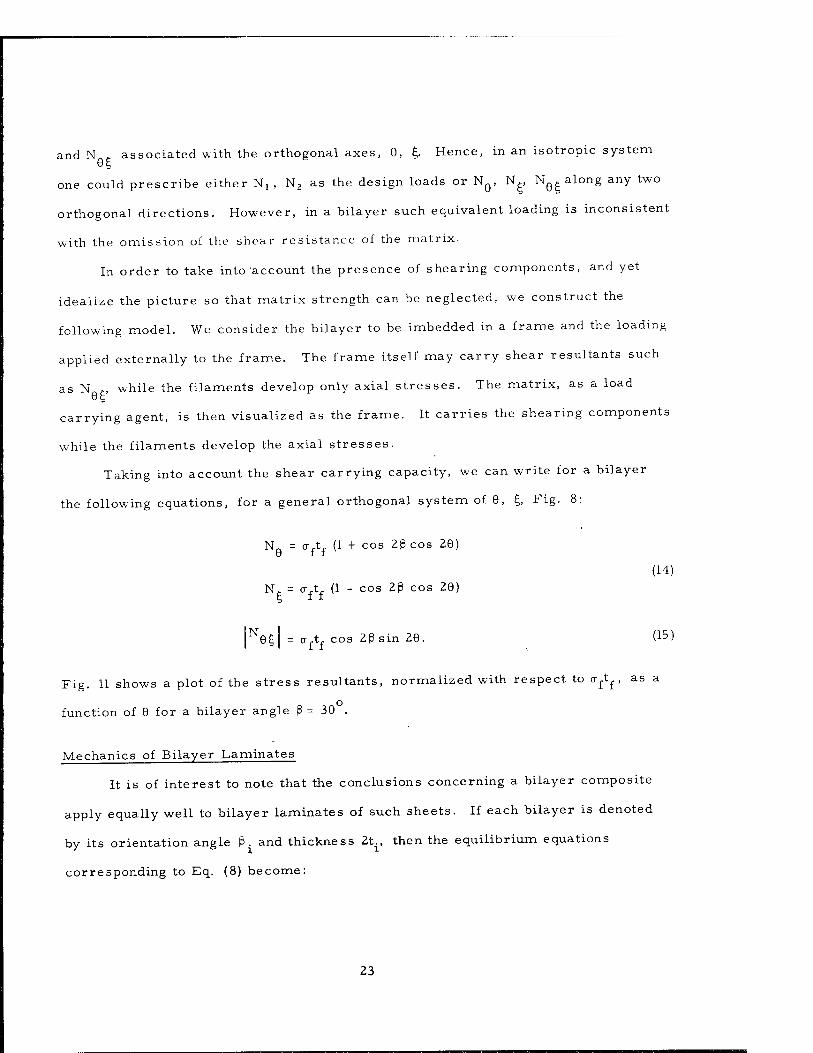
Taking into account the shear carrying capacity, we can write for a bilayer
the following equations, for a general orthogonal system of 6, £, Fig. 8:
N. = cr,t, (1 + cos 2ßcos 29) U It
N. = o-ft (1 - cos 2ß cos 29) (14)
|N6^| = crftf cos 2ßsin 29. (15)
Fig. 11 shows a plot of the stress resultants, normalized with respect to crftf , as a
function of 9 for a bilayer angle ß = 30 .
Mechanics of Bilayer Laminates
It is of interest to note that the conclusions concerning a bilayer composite
apply equally well to bilayer laminates of such sheets. If each bilayer is denoted
by its orientation angle ß. and thickness 2t., then the equilibrium equations
corresponding to Eq. (8) become:
23
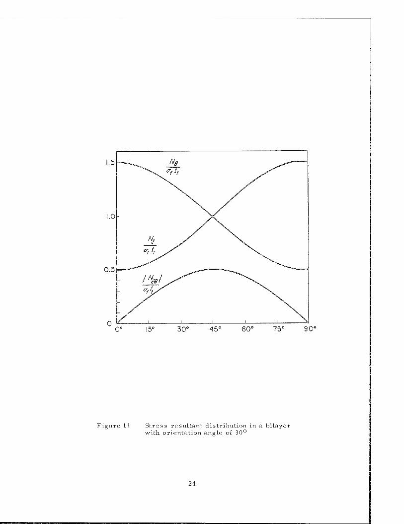
1.5 —^ Ng ^—j X^^ ^f lf y^
1.0 y\ "f X \v
°? ff y^ \
0.5 ^—^^ ^^_-^^ ^>"""-—
/V/^^ ^^\ - j^/-^ \^^
r\ // \
0° 15° 30° 45c 60° 75° 90c
Figure 11 Stress resultant distribution in a bilayer with orientation angle of 30°
24
N, = S 2o-rtr cos2 ß. 1 ..ff. l
(16)
n ,^2
i=l x "i N2 = S 2o-fyf sin' . i
By suitably combining Eqs. (16), the same failure law Eq. (11) is obtained.
However, Eq. (9) is replaced by the condition
n n cos2 ß. (17) N,/N, = £ sin2 ß./S
i=l i=l
In a given design problem where it is assumed that Nj and N2 are given,
Eq. (17) implies that the bilayer angles ßt , ß2 . . . ßn_1 may be arbitrarily chosen
while ß can be adjusted to satisfy Eq. (17). In a general filamentary system of n
bilayers designed for a given Nt and N2 , there are (n-1) degrees of freedom in
selecting the ß. angles of individual bilayers. This is an important consideration
which permits some design freedom to overcome the restrictions inherent in a
single bilayer composite sheet.
Weight Efficiency of Filamentary Bilayer Laminates
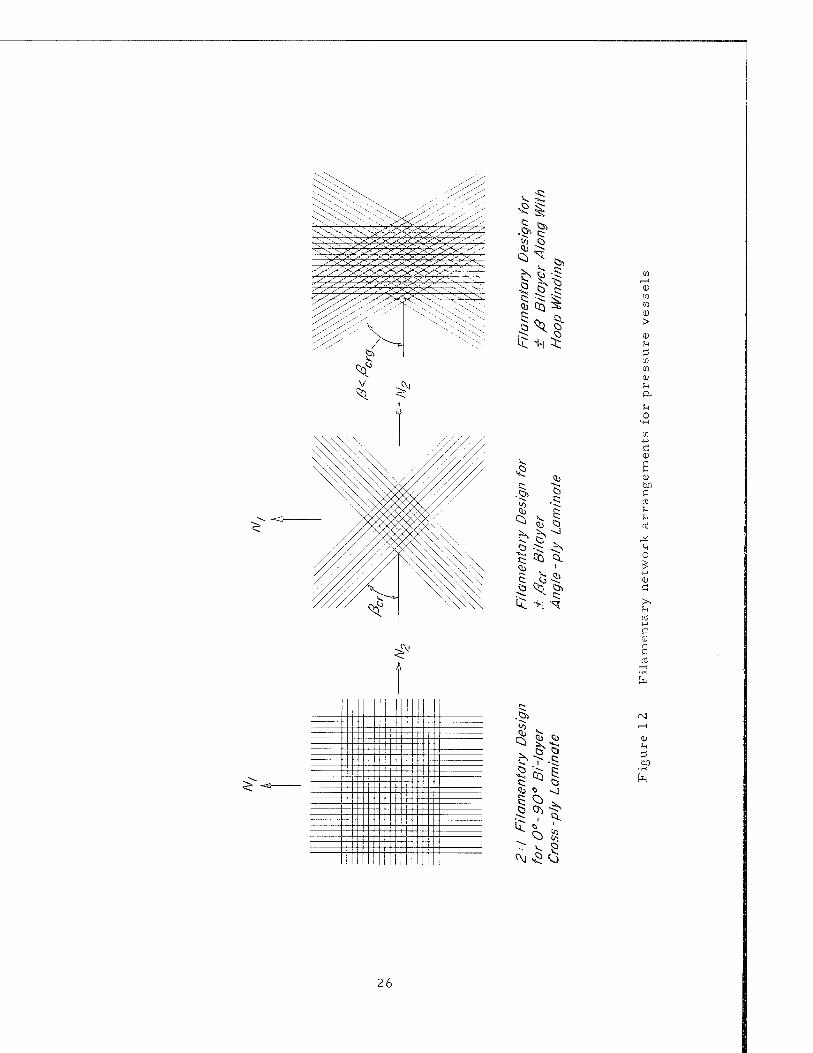
In the cylindrical pressure vessel design, manufacturing techniques have
produced three filamentary network patterns for the associated 2:1 biaxial stress
field; as shown in Fig. 12. We shall compare the weight/ strength efficiencies of
these arrangements, given the design loads Ni and N2.
Let the laminate be part of a shell whose thickness h is made
up of several bilayers each of thickness 2t.. Hence,
n h = E 2t.
i=l X
The weight of a shell element of length, width and thickness 1 , b, and h respectively,
and density p~, (which may be either the matrix density or the filament density
25
Öl .c;
III £+1 5;
.c:
i< +i ^
-^N
>
u
en <p u a u o
a; no a n) U u
f-i O
u
0)
&4
.öl
Q
-j
u
26
or a linear combination of these) is given by
n W= plbh= 2p lb Zt. (18)
i = lX
If ß . is the orientation of each bilayer, utilizing Eq. (18) we have
W = p"lb (Ni + N2)/tr (19)
T!i,.s, Eq. (19) shows that the weight of a uniform element of a bilayer laminate
with arbitrary individual bilayer orientation is independent of the orientation
and 13 dependent only upon the external loading invariant (Nj + N2) and the filament
strength. Hence, all the three designs of Fig.11 have the same theoretical
weight/ strength efficiency.
A further interesting feature of the weight efficiency study concerns the
strength weight efficiency of an "isotropic" filamentary laminate. By an "isotropic"
filamentary laminate we mean a multiple bilayer system with the orientations
ßi, ß2 . . . arranged in such a manner that there is planar symmetry of stress.
That is, the stress resultant along any direction 9 from axis 1 is the same,, i. e. ,
Ni - NE = N - N. This is achieved either by taking ß i = (3 2 . . . u'4 or by 6
considering the generalizations of Eqs. (14) for the multiple bilayer systems and
letting ßi, ß2 . . be the appropriate combinations. For instance, if the laminate
consists of even (2n) bilayers, then ß i + ß 2 = ß2 + ß3 =ß3 + ß 4 • • • - ß ? l + ß? =TT/2
is a suitable arrangement.
Having thus defined an isotropic laminate, we may compare the strength/
weight efficiency of an isotropic filamentary laminate with that of
a monolayer system, where all the filaments are lined along the direction of the
loading, under the same loading N.
Let an elementary parallelepiped of the filamentary sheet of length 1, width
b and thickness h be considered. If it is composed of 2n bilayers, each of thickness
27
2t , where t is the bilayer thickness, then the thickness of element h = 4nt . If the
orientations are ß i . . . ß -, , then from the equilibrium of multilayer systems
we have,
N = Ni = Zo-T (cos2 p i + cos2p 2 4-, . . . cos2ß )
(20)
= o-f "2^- (cos2ß! + cos2ß2 + . . . cos2ß2n)
But from the requirement of planar isotropy ßi + ß2 = ß2+ß3 =■ • • ß -> +ß? = TT/ 2
N = a {h'Zn) (1/2) 2n = crfh / 2 .
Since the weight of the parallelepiped W, is given by W = p lbh where p is the density
of material of the filament, we find from Eq. (21)
TN/(W/b)] .so = (1/2) (trf/pl) (22)
Now if the laminate were a monolayer of the same material and the same
dimensions, then evidently
fN/{W/b)] = (<r,/pl) (23) mono f r
Hence, the strength/weight efficiency of an "isotropic" filamentary laminate
is half that of a monolayer laminate.
Some Design Possibilities With Filamentary Bilayer Laminates
Now that it is evident that certain degrees of freedom can be attained by use
of multiple bilayer composites, it is of interest to examine how this can be exploited.
One obvious case is the manufacturing freedom offered by the third design of Fig. 12.
Another example is that a laminate can be designed to carry alternative loads in
addition to the basic biaxial loads (Nj and N2) for which it was primarily designed.
Thus we can pose the design question: given a filamentary bilayer laminate
designed for the principal stress resultants Nj and N2, what are other possible
load combinations that the laminate can carry?
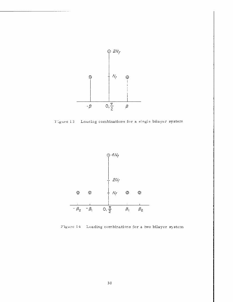
Starting first with a single bilayer, we see that it is de signed primarily for the
biaxial loads which according to Eq. (10) are Nj + N2 = 2Nf where Nf is the filamentary
strength of a unidirectional composite referred to its thickness. In this discussion
it is convenient to use N. as a reference value. As indicated in Fig. 13, the following
ad'! 'Honal load combinations are possible:
a. combined loads N, applied along +ß
b. single loads Nf applied along j_ß .
A similar situation is obtained for the bilayer laminate shown in Fig. 14.
Note that there are two additional degrees of freedom here although the strength/
weight ratio of a unidirectional composite is obviously degraded relative to the
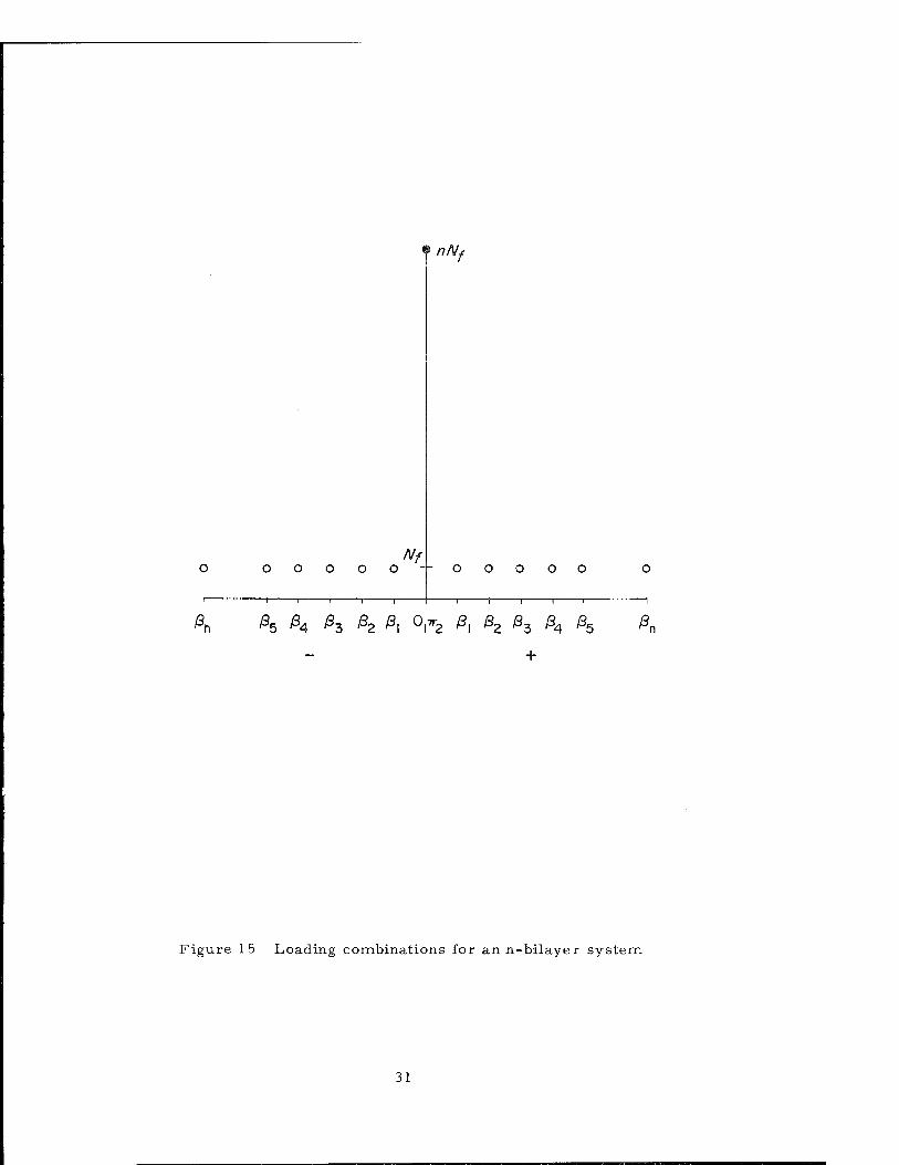
complete laminate. Finally, we turn to the n-bilayer laminate and obtain the results
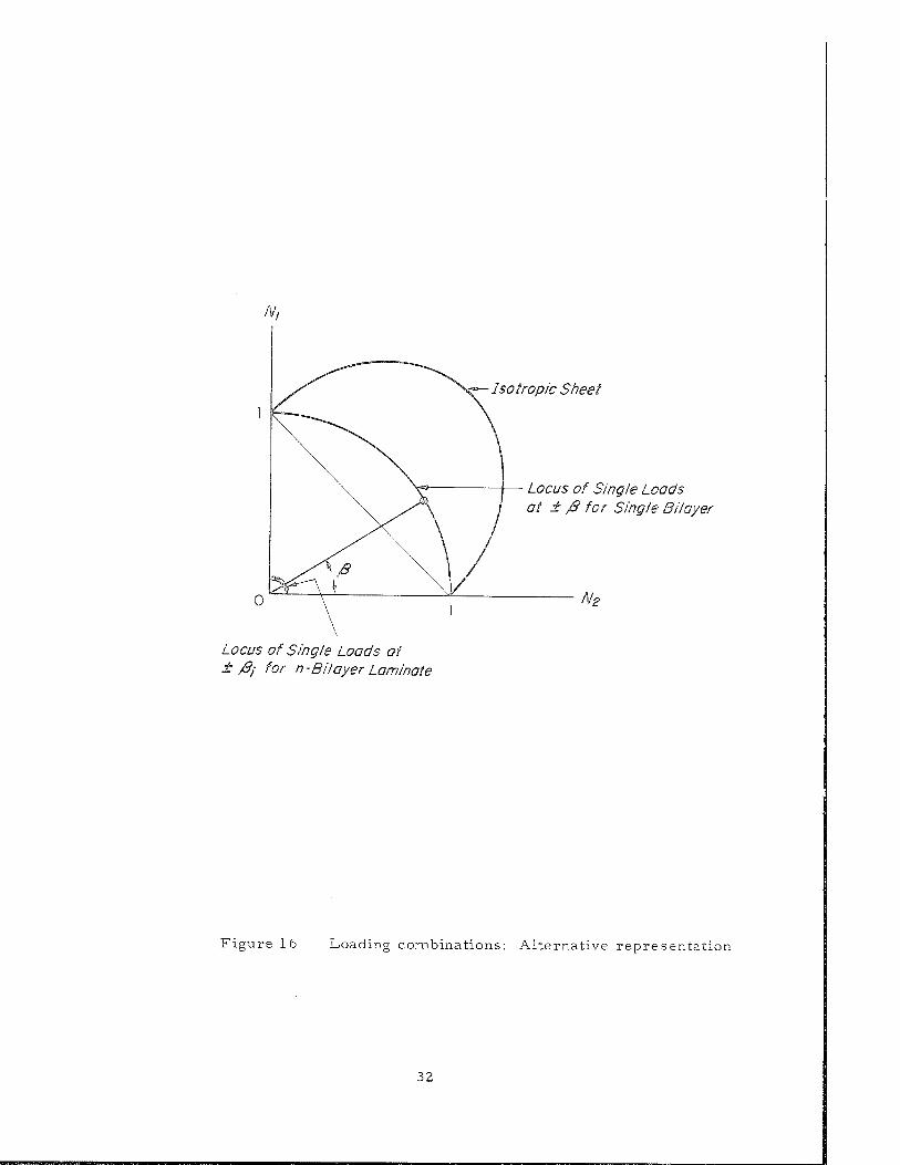
shown in Fig. 15. Also shown in an alternative form in Fig. 16-is a representation
of the biaxial loads as well as single load combinations possible with an n-bilayer
laminate and for an isotropic sheet of the same uniaxial strength. Again the differ-
ence in behavior of the filamentary sheet and isotropic sheet is considerable.
29
©
0 2Nf
- ^ ©
■/S 0, T
Figure I 3 Loading combinations for a single bilayer system
% •■) <t/Vf
■ ■ 2Nf
©
1
®
1
■ Nf © ©
i
■ß\ 0,f /S, j82
Figure 14 Loading combinations for a two bilayer system
30
Nf 00000--00000
nNs
ß„ 1 1 1 1 r
/3R ßA ß, ßo ßx 0|7r? ß. ß9 ß, ßA ß 2 MZ HA H5
+
Figure 15 Loading combinations for an n-bilayer system
31
Isotropie Sheet
Locus of Single Loads at ± /$/ for n-Bilayer Laminate
Locus of Single Loads at ± j8 for Single Bilayer
N2
Figure 16 Loading combinations: Alternative representation
32
4. Concluding Remarks
An underlying objective of Section 3 has been to demonstrate the folly of
"substitution", the favorite device of the designer in which he substitutes a panel
of new material for one which has been tested by time in the design environment.
Filamentary materials require an accurate matching of filament orientation and
stress field in order to achieve superior strength/weight properties. The import-
ant and creative job required of the structural designer is to arrange the unidirec-
tional filamentary composite material into an efficient filamentary structural
laminate.
While the preceding discussion has been concerned primarily with strength
limited structures, it is important to recognize that many types of aerospace
structures are stability limited. Such structures are governed by elastic buckling
considerations because of their geometry in combination with the relatively low
magnitude of the applied loads. In such cases, filament orientation and stress
field matching is required to achieve maximum stiffness/weight. As is well known,
cross-sectional shaping by the use of stiffening and sandwich concepts provides a
very effective means of achieving high structural efficiency for isotropic sheet
materials. Creative ideas on cross-sectional shaping that can utilize the unique
features of filamentary composites will be required to exploit this concept for
filamentary structures.
Finally, some words on the selection of materials for composites in terms
of filament, matrix and volume fraction. It is obvious that the selection of con-
stituent materials for unidirectional composites and their volume fraction will
depend upon whether the structural application is strength or stability as
well as the role of the matrix under the applied loads. For example, it is well
known that glass filaments are fine for strength limited applications, although
33
they are relatively poor in stability limited applications. On the other hand,
beryllium and boron filaments exhibit very superior stiffness properties although
their strength properties represent little, if any, improvement over glass fila-
ments .
Thus, we can expe.ct that the same situation will prevail with filamentary
composites as exists with sheet metallics. Specific criteria should be developed to
define the materials efficiency aspects of the composite, its constituents and volume
fraction for designs governed by strength or stability limitations. Approximate
analyses based on criteria derived from isotropic sheet materials can already
provide an effective screening tool for composites.
34
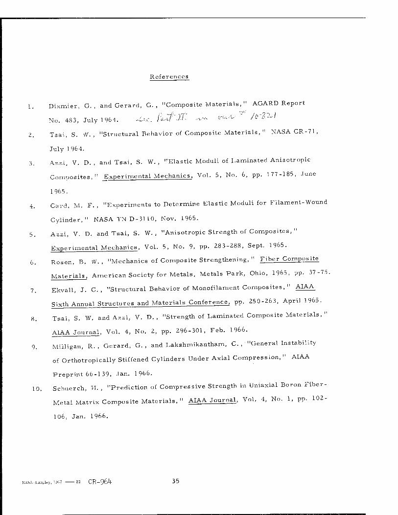
References
1. Dixmier, G. , and Gerard, G. , "Composite Materials, " AGARD Report
No. 483, July 1964. M^ /i-CPJl -v- «ru-^ /&'? — '
2. Tsai, S. W. , "Structural Behavior of Composite Materials," NASA CR-71,
July 1964.
3. Azzi, V. D. , and Tsai, S. W. , "Elastic Moduli of Laminated Anisotropie
Composites," Experimental Mechanics, Vol. 5, No. 6, pp. 177-185, June
1965.
4. Card, M. F. , "Experiments to Determine Elastic Moduli for Filament-Wound
Cylinder," NASA TN D-3110, Nov. 1965.
5. Azzi, V. D. and Tsai, S. W. , "Anisotropie Strength of Composites, "
Experimental Mechanics, Vol. 5, No. 9, pp. 283-288, Sept. 1965.
6. Rosen, B. W. , "Mechanics of Composite Strengthening, " Fiber Composite
Materials, American Society for Metals, Metals Park, Ohio, 1965, pp. 37-75.
7. Ekvall, J. C. , "Structural Behavior of Monofilament Composites, " AIAA
Sixth Annual Structures and Materials Conference, pp. 250-263, April 1965.
8. Tsai, S. W. and Azzi, V. D. , "Strength of Laminated Composite Materials, "
AIAA Journal, Vol. 4, No. 2, pp. 296-301, Feb. 1966.
9. Milligan, R. , Gerard, G. , and Lakshmikantham, C. , "General Instability
of Orthotropically Stiffened Cylinders Under Axial Compression, " AIAA
Preprint 66-1 39, Jan. 1966.
10. Schuerch, H. , "Prediction of Compressive Strength in Uniaxial Boron Fiber-
Metal Matrix Composite Materials, " AIAA Journal, Vol. 4, No. 1, pp. 102-
106, Jan. 1966.
NASA-Langley, 1967 32 CR-964 35
"The aeronautical and space activities of the United States shall be conducted so as to contribute . . . to the expansion of human knowl- edge of phenomena in the atmosphere and space. The Administration shall provide for the widest practicable and appropriate dissemination of information concerning its activities and the results thereof."
—NATIONAL AERONAUTICS AND SPACE ACT OF 1958
NASA SCIENTIFIC AND TECHNICAL PUBLICATIONS
TECHNICAL REPORTS: Scientific and technical information considered important, complete, and a lasting contribution to existing knowledge.
TECHNICAL NOTES: Information less broad in scope but nevertheless of importance as a contribution to existing knowledge.
TECHNICAL MEMORANDUMS: Information receiving limited distribu- tion because of preliminary data, security classification, or other reasons.
CONTRACTOR REPORTS: Scientific and technical information generated under a NASA contract or grant and considered an important contribution to existing knowledge.
TECHNICAL TRANSLATIONS: Information published in a foreign language considered to merit NASA distribution in English.
SPECIAL PUBLICATIONS: Information derived from or of value to NASA activities. Publications include conference proceedings, monographs, data compilations, handbooks, sourcebooks, and special bibliographies.
TECHNOLOGY UTILIZATION PUBLICATIONS: Information on tech- nology used by NASA that may be of particular interest in commercial and other non-aerospace applications. Publications include Tech JJriefs, Technology Utilization Reports and Notes, and Technology Surveys. ■:
Details on the availability of these publications may be obtained from:
SCIENTIFIC AND TECHNICAL INFORMATION DIVISION
NATIONAL AERONAUTICS AND SPACE ADMINISTRATION
Woshinsfon, D.C 20546
Related Documents