Safe Use and Installation Manual Keeping the World Flowing Remote Hand Station IQ Range

Welcome message from author
This document is posted to help you gain knowledge. Please leave a comment to let me know what you think about it! Share it to your friends and learn new things together.
Transcript

Safe Use and Installation Manual
A4 US
US
A4
US
A4
A4 US
Keeping the World Flowing
Remote Hand Station
IQ Range
A4US
US
A4
US A4
US
A4
2
Contents
Section Page
1 - Introduction 3
2 - Health and Safety 4
3 - Remote Hand Station Mounting 5
4 - Electrical Connections 6
5 - Enabling the Remote Handstation 8 Mode on the IQ3
6 - Remote Hand Station Settings 9
7 - Operating the Remote Hand Station 10
8 - Approvals 11
9 - Environmental 13
A4 US
US
A4
US
A4
A4 US
Keeping the World Flowing 3
1 - Introduction
Actuators used in many industries sometimes have to be mounted in places where it is hazardous, inconvenient or just unpleasant for a human to operate. In these cases it is useful to be able to see the status and locally operate an actuator from a safe distance.
Typically in this situation you would be faced with a simplistic interface for basic operation and indication, however Rotork’s enhanced solution allows the user to have an exact replication of the actuator interface.
Using the same display and controls interface from Rotorks 3rd generation of IQ actuators, users can remotely operate, interrogate and configure a Rotork actuator from up to 100 m distance. Due to the familiar, feature rich interface, set up couldn’t be simpler using the Rotork Bluetooth® Setting Tool Pro supplied with the actuator.
Retaining the full functionality of the IQ, dataloggers can be viewed and downloaded locally at the Remote Hand Station (RHS) instead of gaining access to the actuator. Power for the RHS is supplied by the actuator, removing the need for supplementary power supplies.
The following instructions must be followed and integrated with your safety program when installing and using Rotork Controls products:
• Read and save all instructions prior to installing, operating and servicing this product.
• If you don’t understand any of the instructions, contact Rotork Controls for clarification.
• Follow all warnings, cautions and instructions marked on, and supplied with, the product.
• Inform and educate personnel in the proper installation, operation and maintenance of the product.
• Install equipment as specified in Rotork Controls installation instructions and per applicable local and national codes. Connect all products to the proper electrical sources.
• To ensure proper performance, use qualified personnel to install, operate, update and maintain the unit.
• When replacement parts are required, ensure that the qualified service technician uses replacement parts specified by Rotork Controls. Substitutions may result in fire, electrical shock, other hazards, or improper equipment operation.
• Keep all product protective covers in place (except when installing, or when maintenance is being performed by qualified personnel), to prevent electrical shock, personal injury or damage to the product.
• Operation of product in an inappropriate fashion may cause harm or damage to unit or other equipment surroundings.

A4US
US
A4
US A4
US
A4
4
2 - Health and Safety
This manual has been produced to enable a competent user to install, operate, adjust and inspect the Remote Hand Station (RHS).
The electrical installation, maintenance and use of the RHS should be carried out in accordance with the National Legislation and Statutory Provisions relating to the safe use of this equipment applicable to the site of installation.
For the UK: Electricity at Work Regulations 1989 and the guidance given in the applicable edition of the ‘IEE Wiring Regulations’ should be applied. Also the user should be fully aware of their duties under the Health and Safety at Work Act 1974.
For the USA: NFPA70, National Electrical Code® is applicable. The mechanical installation should be carried out as outlined in this manual and also in accordance with any relevant national standard codes of practice. If the RHS nameplate indicates that it is suitable for use in Potentially Explosive Atmospheres (Hazardous Areas) then the RHS is suitable for use in Zone 1 and Zone 2 (or Div 1 and Div 2) hazardous area classifications, as defined by the RHS's nameplate marking.
For Canada: CEC, Canadian Electrical Code is applicable.
Any equipment connected to the RHS should be of an equivalent (or better) hazardous area certification. The installation, maintenance and use of the RHS installed in a hazardous area must be carried out by a competent person and in accordance with all relevant codes of practice for the particular Hazardous Area certification.
Any inspection or repair of a Hazardous Area approved RHS should not be undertaken unless it conforms to National Legislation and Statutory Provisions relating to the specific Hazardous Area.
Only Rotork approved replacement parts should be used. Under no circumstances should any modification or alteration be carried out on the unit, as this could invalidate the conditions under which its certification was granted.
Access to live electrical conductors is forbidden in a Hazardous Area unless it is done under a special permit to work, otherwise all power should be isolated and the RHS moved to a non-hazardous area for repair or attention.
Only persons competent by virtue of their training or experience should be allowed to install, maintain and repair Rotork equipment. Work undertaken must be carried out in accordance with instructions in the manual. The user and those persons working on this equipment should be familiar with their responsibilities under any statutory provisions relating to the Health and Safety of their workplace.
WARNING: Enclosure Materials
The RHS is manufactured from aluminium alloy with stainless steel fasteners and terminal enclosure fasteners using 12.9 grade high tensile carbon steel.
The cover window is toughened glass which is retained with a 2-part silicone cement.
The user must ensure that the operating environment and any materials surrounding the RHS cannot lead to a reduction in the safe use of, or the protection afforded by, the RHS. Where appropriate the user must ensure the RHS is suitably protected against its operating environment.
A4 US
US
A4
US
A4
A4 US
5Keeping the World Flowing
3 - Remote Hand Station Mounting
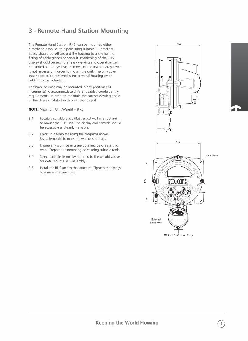
The Remote Hand Station (RHS) can be mounted either directly on a wall or to a pole using suitable ‘C’ brackets. Space should be left around the housing to allow for the fitting of cable glands or conduit. Positioning of the RHS display should be such that easy viewing and operation can be carried out at eye level. Removal of the main display cover is not necessary in order to mount the unit. The only cover that needs to be removed is the terminal housing when cabling to the actuator.
The back housing may be mounted in any position (90o increments) to accommodate different cable / conduit entry requirements. In order to maintain the correct viewing angle of the display, rotate the display cover to suit.
NOTE: Maximum Unit Weight = 9 kg
3.1 Locate a suitable place (flat vertical wall or structure) to mount the RHS unit. The display and controls should be accessible and easily viewable.
3.2 Mark up a template using the diagrams above. Use a template to mark the wall or structure.
3.3 Ensure any work permits are obtained before starting work. Prepare the mounting holes using suitable tools.
3.4 Select suitable fixings by referring to the weight above for details of the RHS assembly.
3.5 Install the RHS unit to the structure. Tighten the fixings to ensure a secure hold.
230
ExternalEarth Point
M25 x 1.5p Conduit Entry
326
19717
2
200
4 x 8.5 mm
230
ExternalEarth Point
M25 x 1.5p Conduit Entry
326197
172
200
4 x 8.5 mm
A4US
US
A4
US A4
US
A4
6
4 - Electrical Connections
The RHS unit is powered by via a CAN Bus system installed within Rotork actuators as an option actuator so does not require any supplementary power supply or protection device. The single cable entry is located at the bottom of the terminal housing and is supplied M25 as standard. A thread adaptor can be supplied for other thread sizes including imperial threads.
The interconnecting cable is not supplied. Below is a table of the minimum cable specification for remote mounting up to 50 m and up to 100 m.
No. PARAMETERBELDEN CABLE 3084A T5U500 (OR EQUIVALENT) UP TO 100M
MINIMUM SPECIFICATION FOR UP TO 50 M
1 Type of Cable Twisted pair shielded Twisted pair shielded
2 No. of Cores 4 (Data pair + Power pair) 4 (Data pair + Power pair)
3 Conductor Material Tinned Copper Tinned Copper
4Core Insulation Material
PVC (power)FPE (data)
PVC
5 Shield Type Foil + Braid Braid
6 Shield CoverageBraid ≥65%
Braid ≥65%Foil = 100%
7 Outer Sheath PVC PVC
8Data Pair Capacitance
≤40 pF/m ≤70 pF/m
9Conductor Resistance
≤175 Ohm/km (Power) ≤280 Ohm/km (Data)
≤175 Ohm/km ≤280 Ohm/km (Data)
10 Current Rating ≥1 A ≥1 A
Note: For installation in hazardous areas suitable equivalent cables must be used in accordance with local regulations.
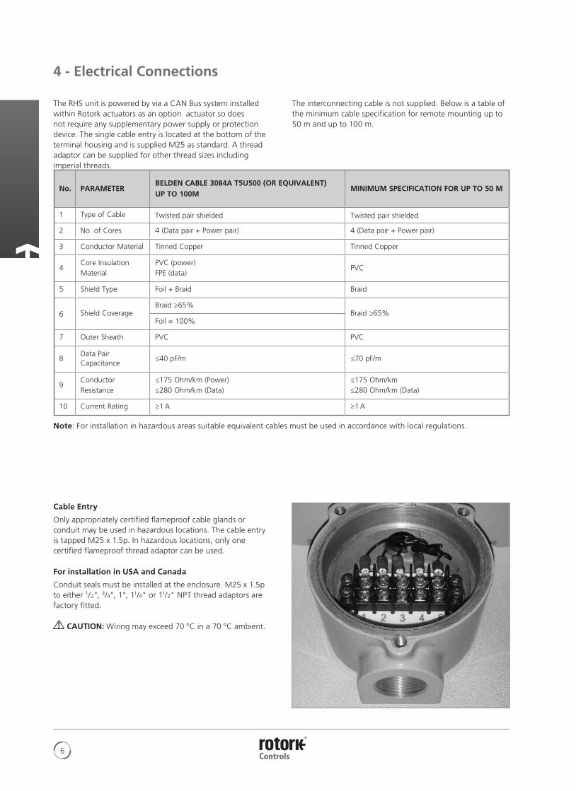
Cable Entry
Only appropriately certified flameproof cable glands or conduit may be used in hazardous locations. The cable entry is tapped M25 x 1.5p. In hazardous locations, only one certified flameproof thread adaptor can be used.
For installation in USA and Canada
Conduit seals must be installed at the enclosure. M25 x 1.5p to either 1/2", 3/4", 1", 11/4" or 11/2" NPT thread adaptors are factory fitted.
CAUTION: Wiring may exceed 70 ºC in a 70 ºC ambient.
A4 US
US
A4
US
A4
A4 US
7Keeping the World Flowing
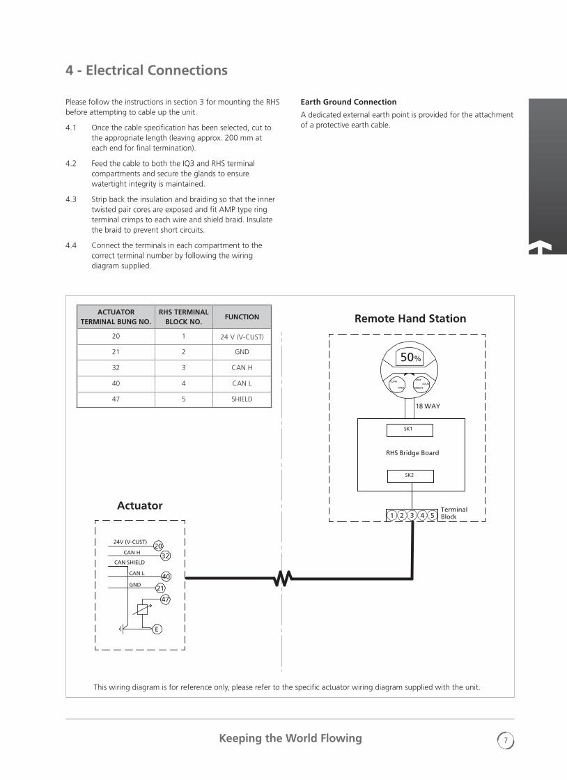
Please follow the instructions in section 3 for mounting the RHS before attempting to cable up the unit.
4.1 Once the cable specification has been selected, cut to the appropriate length (leaving approx. 200 mm at each end for final termination).
4.2 Feed the cable to both the IQ3 and RHS terminal compartments and secure the glands to ensure watertight integrity is maintained.
4.3 Strip back the insulation and braiding so that the inner twisted pair cores are exposed and fit AMP type ring terminal crimps to each wire and shield braid. Insulate the braid to prevent short circuits.
4.4 Connect the terminals in each compartment to the correct terminal number by following the wiring diagram supplied.
4 - Electrical Connections
2032
24V (V-CUST)
CAN H
40
CAN SHIELD
CAN L
21GND
TerminalBlock
SK2
RHS Bridge Board
SK1
18 WAY
50%
CLOSE
OPEN
STOP
REMOTE
LOCAL
1 2 3 4 5
47
E
Actuator
Remote Hand StationACTUATOR
TERMINAL BUNG NO.RHS TERMINAL
BLOCK NO.FUNCTION
20 1 24 V (V-CUST)
21 2 GND
32 3 CAN H
40 4 CAN L
47 5 SHIELD
Earth Ground Connection
A dedicated external earth point is provided for the attachment of a protective earth cable.
This wiring diagram is for reference only, please refer to the specific actuator wiring diagram supplied with the unit.
A4US
US
A4
US A4
US
A4
8
5 - Enabling the Remote Hand Station Mode on the IQ3
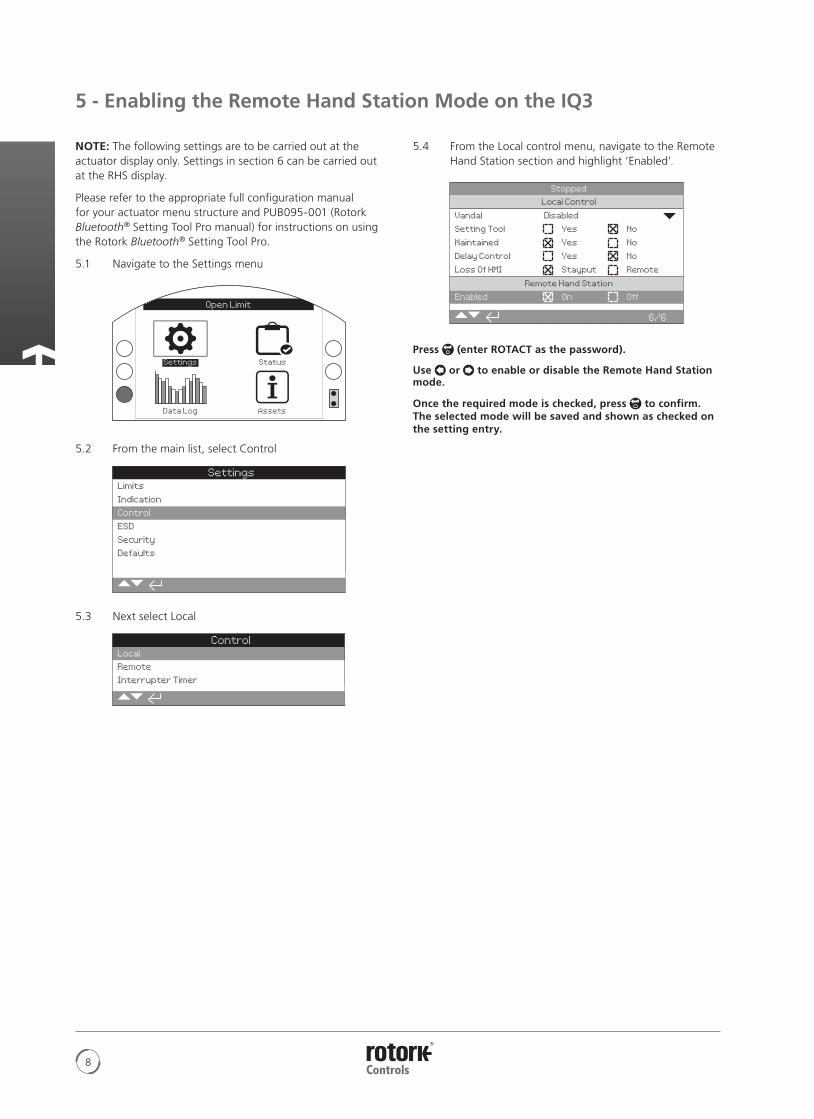
NOTE: The following settings are to be carried out at the actuator display only. Settings in section 6 can be carried out at the RHS display.
Please refer to the appropriate full configuration manual for your actuator menu structure and PUB095-001 (Rotork Bluetooth® Setting Tool Pro manual) for instructions on using the Rotork Bluetooth® Setting Tool Pro.
5.1 Navigate to the Settings menu
Open Limit
5.2 From the main list, select Control
SettingsLimits
Indication
Control
ESD
Security
Defaults
5.3 Next select Local
ControlLocal
Remote
Interrupter Timer
5.4 From the Local control menu, navigate to the Remote Hand Station section and highlight ‘Enabled’.
Stopped
Local Control
Vandal Disabled
Setting Tool Yes No
Maintained Yes No
Delay Control Yes No
Loss Of HMI Stayput Remote
Remote Hand Station
Enabled On Off
6/6
Press (enter ROTACT as the password).
Use or to enable or disable the Remote Hand Station mode.
Once the required mode is checked, press to confirm. The selected mode will be saved and shown as checked on the setting entry.

A4 US
US
A4
US
A4
A4 US
9Keeping the World Flowing
6 - Remote Hand Station Settings
NOTE: The following settings can be carried out either at the actuator or at the RHS display.
Setting the Bluetooth Security - The RHS and actuator Bluetooth security can be configured independently.
6.1 Navigate to SETTINGS > SECURITY and under the Bluetooth section, choose the level of Bluetooth access required for the actuator.
Press (enter ROTACT as the password).
Use or to select the actuator Bluetooth mode.
Once the required mode is highlighted, press to confirm. The selected mode will be saved and shown as checked on the setting entry.
Open Limit
Bluetooth
Low: Discover Always
Password
Change Default
Lost Code L81L18
Re-Enter
Remote Hand Station
Low: Discover Always
5/5
6.2 Navigate to SETTINGS > SECURITY and under the Remote Hand Station section, choose the level of Bluetooth access required for the RHS.
Press (enter the password if applicable).
Use or to select the Remote Hand Station Bluetooth mode.
Once the required mode is highlighted, press to confirm. The selected mode will be saved and shown as checked on the setting entry.
Setting the Action on Loss of RHS control - The actuator action can be configured to a particular mode if the RHS were to fail or lose communication with the actuator.
6.3 Navigate to SETTINGS > CONTROL > REMOTE HAND STATION and under the Remote Hand Station section select the mode on Loss of HMI.
Press (enter the password if applicable).
Use or to select the Loss of HMI mode.
Once the required mode is highlighted, press to confirm. The selected mode will be saved and shown as checked on the setting entry.
Open Limit
Remote Hand Station
Loss of HMI Stayput
Local On Off
1/2
Setting the Local Mode - The Remote Hand Station is intended to work when the actuator is set to Remote Control only, however you can configure the RHS to work when the actuator is set to Local Control. In this case both the RHS and actuator will allow local control, with the last issued command taking preference.
6.4 Navigate to SETTINGS > CONTROL > REMOTE HAND STATION and under the Remote Hand Station section select the Local mode.
Press (enter the password if applicable).
Use or to select the Local mode on or off.
Once the required mode is checked, press to confirm. The selected mode will be saved and shown as checked on the setting entry.
Setting the Home Screen Display - The RHS and actuator home screens can be independently configured to show different information.
NOTE: The following setting has to be carried out at the device you are configuring, e.g. at the actuator for the actuator home screen and at the RHS for the RHS home screen.
6.5 Navigate to SETTINGS > INDICATION > LOCAL DISPLAY and under the LCD section select the Home Screen mode from the following 4 options:
Position only
Torque (analogue) + Position
Torque (digital) + Position
Positioner
Press (enter the password if applicable).
Use or to select the Local mode on or off.
Once the required mode is highlighted, press to confirm. The selected mode will be saved and shown as checked on the setting entry.
Open Limit
LCD
Home Screen Position
Power Save Torque (A) + POS
Torque (D) + POS
Close LED Positioner
Mid Travel LED On
Alarm LED Disabled
LCD / LED Test
1/7
A4US
US
A4
US A4
US
A4
10
The Remote Hand Station provides a remote mountable display which allows the operator to monitor and control an actuator mounted in an inaccessible location. All operations which could be performed at the actuator will be duplicated at the Remote Hand Station, including configuration setup, data log download and local control operation.
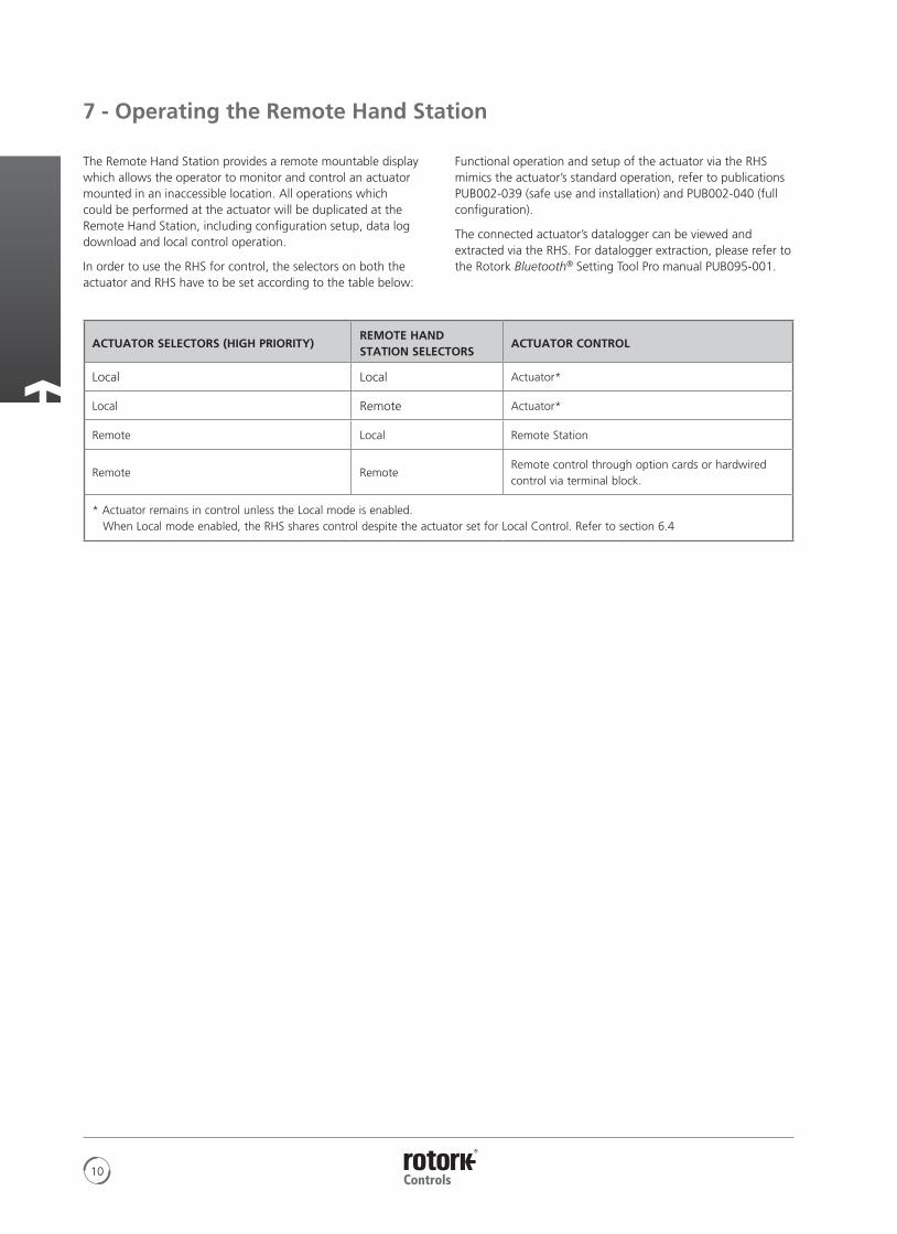
In order to use the RHS for control, the selectors on both the actuator and RHS have to be set according to the table below:
7 - Operating the Remote Hand Station
ACTUATOR SELECTORS (HIGH PRIORITY)REMOTE HAND STATION SELECTORS
ACTUATOR CONTROL
Local Local Actuator*
Local Remote Actuator*
Remote Local Remote Station
Remote RemoteRemote control through option cards or hardwired control via terminal block.
* Actuator remains in control unless the Local mode is enabled. When Local mode enabled, the RHS shares control despite the actuator set for Local Control. Refer to section 6.4
Functional operation and setup of the actuator via the RHS mimics the actuator’s standard operation, refer to publications PUB002-039 (safe use and installation) and PUB002-040 (full configuration).
The connected actuator’s datalogger can be viewed and extracted via the RHS. For datalogger extraction, please refer to the Rotork Bluetooth® Setting Tool Pro manual PUB095-001.

A4 US
US
A4
US
A4
A4 US
11Keeping the World Flowing
Refer to RHS nameplate for unit specific approval details.
European – Hazardous Area
ATEX (2014/34/EU) II 2 GDEx db IIB T4 GbEx tb IIIC T120 °C Db T4, IP66 & IP68
Temperature -20 °C to +70 °C (-4 °F to +158 °F)
*Option -30 °C to +70 °C (-22 °F to +158 °F)
*Option -40 °C to +70 °C (-40 °F to +158 °F)
*Option -50 °C to +40 °C (-58 °F to +104 °F)
Ex db IIC T4 Gb T4Ex tb IIIC T120 °C Db T4, IP66 & IP68
Temperature -20 °C to +70 °C (-4 °F to +158 °F)
*Option -30 °C to +70 °C (-22 °F to +158 °F)
*Option -40 °C to +70 °C (-40 °F to +158 °F)
*Option -50 °C to +40 °C (-58 °F to +104 °F)
International – Hazardous Area
IECEx. IEC60079-0 & IEC600679-1Ex db IIB T4 GbEx tb IIIC T120 °C Db T4, IP66 & IP68
Temperature -20 °C to +70 °C (-4 °F to +158 °F)
*Option -30 °C to +70 °C (-22 °F to +158 °F)
*Option -40 °C to +70 °C (-40 °F to +158 °F)
*Option -50 °C to +40 °C (- 58 °F to +104 °F)
Ex db IIC T4 Gb T4Ex tb IIIC T120 °C Db T4, IP66 & IP68
Temperature -20 °C to +70 °C (-4 °F to +158 °F)
*Option -30 °C to +70 °C (-22 °F to +158 °F)
*Option -40 °C to +70 °C (-40 °F to +158 °F)
*Option -50 °C to +70 °C (-58 °F to +158 °F)
USA – Hazardous Area
CSAUS - Explosionproof to NEC Article 500 (FM3615 & FM3616)Class I, Division 1, Groups C & DClass II, Division 1, Groups E, F & G
FM Explosionproof to NEC Article 500 FM3600, FM3615 & FM3616
Temperature -30 °C to +70 °C (-22 °F to +158 °F)
*Option -40 °C to +70 °C (-40 °F to +158 °F)
*Option -50 °C to +40 °C (-58 °F to +104 °F)
Class I, Division 1, Groups B, C & DClass II, Division 1, Groups E, F & G
Temperature -30 °C to +70 °C (-22 °F to +158 °F)
*Option -40 °C to +70 °C (-40 °F to +158 °F)
*Option -50 °C to +40 °C (-58 °F to +104 °F)
Canada – Hazardous Area
CSA Explosionproof to C22.2 No. 30CSA Dust explosionproof to C22.2 No. 25Class I, Division 1, Groups C & DClass II, Division 1, Groups E, F & G
Temperature -30 °C to +70 °C (-22 °F to +158 °F)
*Option -40 °C to +70 °C (-40 °F to +158 °F)
*Option -50 °C to +40 °C (-58 °F to +104 °F)
Class I, Division 1, Groups B, C & D
Class II, Division 1, Groups E, F & G
Temperature -30 °C to +70 °C (-22 °F to +158 °F)
*Option -40 °C to +70 °C (-40 °F to +158 °F)
*Option -50 °C to +40 °C (-58 °F to +104 °F)
International Non Hazardous
Watertight, BS EN60529IP66 & IP68, (7 metres for 72 hours)Temperature -30 °C to +70 °C (-22 °F to +158 °F)
*Option -40 °C to +70 °C (-40 °F to +158 °F)
*Option -50 °C to +40 °C (-58 °F to +104 °F)
US – Non Hazardous
UL50 Enclosure Type 4x & 6
Temperature -30 °C to +70 °C (-22 °F to +158 °F)
*Option -40 °C to +70 °C (-40 °F to +158 °F)
*Option -50 °C to +40 °C (-58 °F to +104 °F)
Canada – Non Hazardous
Enclosure Type 4x & 6 CSA C22.2 No. 94
Temperature -30 °C to +70 °C (-22 °F to +158 °F)
*Option -40 °C to +70 °C (-40 °F to +158 °F)
*Option -50 °C to +40 °C (-58 °F to +104 °F)
Rotork can supply RHS product to national standards not listed above. For details please contact Rotork.
8 - Approvals
A4US
US
A4
US A4
US
A4
12
8 - Approvals
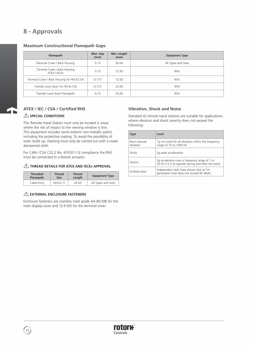
Maximum Constructional Flamepath Gaps
FlamepathMax. Gap
(mm)Min. Length
(mm)Equipment Type
Electrical Cover / Back Housing 0.15 26.00 All Types and Sizes
Terminal Cover / Back Housing ATEX / IECEx
0.15 12.50 RHS
Terminal Cover / Back Housing for FM & CSA 0.115 12.50 RHS
Transfer Loom Bush for FM & CSA 0.115 25.00 RHS
Transfer Loom Bush Flamepath 0.15 25.00 RHS
Vibration, Shock and Noise
Standard IQ remote hand stations are suitable for applications where vibration and shock severity does not exceed the following:
Type Level
Plant induced vibration
1g rms total for all vibration within the frequency range of 10 to 1000 Hz
Shock 5g peak acceleration
Seismic2g acceleration over a frequency range of 1 to 50 Hz if it is to operate during and after the event
Emitted noiseIndependent tests have shown that at 1m generated noise does not exceed 65 db(A)
ATEX / IEC / CSA / Certified RHS
SPECIAL CONDITIONS
This Remote Hand Station must only be located in areas where the risk of impact to the viewing window is low. This equipment includes some exterior non-metallic paints including the protective coating. To avoid the possibility of static build up, cleaning must only be carried out with a water dampened cloth.
For CAN / CSA C22.2 No. 61010-1-12 compliance the RHS must be connected to a Rotork actuator.
THREAD DETAILS FOR ATEX AND IECEx APPROVAL
Threaded Flamepath
Thread Size
Thread Length
Equipment Type
Cable Entry M25x1.5 20.00 All Types and Sizes
EXTERNAL ENCLOSURE FASTENERS
Enclosure fasteners are stainless steel grade A4-80 M8 for the main display cover and 12.9 M5 for the terminal cover.
A4 US
US
A4
US
A4
A4 US
13Keeping the World Flowing
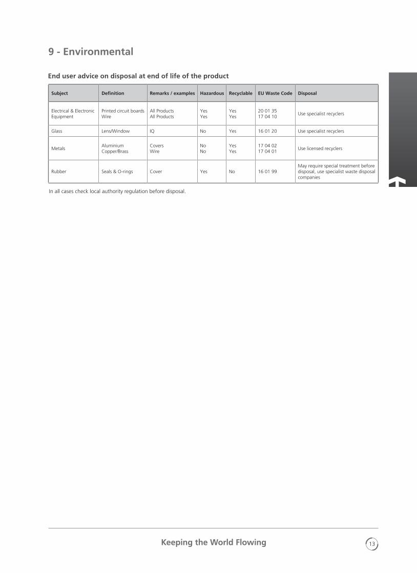
End user advice on disposal at end of life of the product
Subject Definition Remarks / examples Hazardous Recyclable EU Waste Code Disposal
Electrical & Electronic Equipment
Printed circuit boards Wire
All Products All Products
Yes Yes
Yes Yes
20 01 35 17 04 10
Use specialist recyclers
Glass Lens/Window IQ No Yes 16 01 20 Use specialist recyclers
MetalsAluminium Copper/Brass
Covers Wire
No No
Yes Yes
17 04 02 17 04 01
Use licensed recyclers
Rubber Seals & O-rings Cover Yes No 16 01 99May require special treatment before disposal, use specialist waste disposal companies
In all cases check local authority regulation before disposal.
9 - Environmental
Maximum Constructional Flamepath Gaps
FlamepathMax. Gap
(mm)Min. Length
(mm)Equipment Type
Electrical Cover / Back Housing 0.15 26.00 All Types and Sizes
Terminal Cover / Back Housing ATEX / IECEx
0.15 12.50 RHS
Terminal Cover / Back Housing for FM & CSA 0.115 12.50 RHS
Transfer Loom Bush for FM & CSA 0.115 25.00 RHS
Transfer Loom Bush Flamepath 0.15 25.00 RHS

A4US
US
A4
US A4
US
A4
14
Notes
A4 US
US
A4
US
A4
A4 US
15Keeping the World Flowing
Notes

Rotork plcBrassmill Lane, Bath, UK
tel +44 (0)1225 733200fax +44 (0)1225 333467email [email protected]
Keeping the World Flowing
PUB002-059-00Issue 07/17
www.rotork.com
A full listing of our worldwide sales and service network is available on our website.
As part of a process of on-going product development, Rotork reserves the right to amend and change specifications without prior notice. Published data may be subject to change. For the very latest version release, visit our website at www.rotork.com
The name Rotork is a registered trademark. Rotork recognises all registered trademarks. The Bluetooth® word mark and logos are registered trademarks owned by Bluetooth SIG, Inc. and any use of such marks by Rotork is under license. Published and produced in the UK by Rotork Controls Limited. POWTG0717
Rotork is a corporate member of the Institute of Asset Management
Related Documents