References 0 Dynamic Host Configuration Protocol for IPv6 (DHCPv6) – RFC 3315 Neighbor Discovery (ND) for IP Version 6 (IPv6) – RFC 2461 Internet Control Message Protocol for IP Version 6 (ICMPv6) – RFC 2463 IPv6 Stateless Address Auto-configuration – RFC 2462 IPv6 Addressing Architecture – RFC 3513 IPv6 Specification – RFC 2460 DOCSIS MULPI spec. BSR_64000_IPv6_Phase-1_Requirements_Specification.doc IPv6 Essentials, Silvia Hagen Special Thanks to Rob Faulds and Vasu Jothilingam Copyright © 2008 Motorola Inc. 111 Locke Drive Marlborough, MA 01752 All Rights Reserved

Welcome message from author
This document is posted to help you gain knowledge. Please leave a comment to let me know what you think about it! Share it to your friends and learn new things together.
Transcript

References
0
Dynamic Host Configuration Protocol for IPv6 (DHCPv6) – RFC 3315
Neighbor Discovery (ND) for IP Version 6 (IPv6) – RFC 2461
Internet Control Message Protocol for IP Version 6 (ICMPv6) – RFC 2463
IPv6 Stateless Address Auto-configuration – RFC 2462
IPv6 Addressing Architecture – RFC 3513
IPv6 Specification – RFC 2460
DOCSIS MULPI spec.
BSR_64000_IPv6_Phase-1_Requirements_Specification.doc
IPv6 Essentials, Silvia Hagen
Special Thanks to Rob Faulds and Vasu Jothilingam
Copyright © 2008Motorola Inc.
111 Locke DriveMarlborough, MA 01752
All Rights Reserved

The IPv6 Datagram Format :
1
Traffic Class: replaces TOS/Difserv byte. Uses all 8 bits (details to follow)
Total length of the IPv4 is removed. IP performs fragmentation indicated in IPv6
Fragmentation Header.
TTL in IPv4 is changed to Hop Limit in IPv6:
Protocol field in IPv4 is handled in IPv6 Next Header (extension headers e.g. router header,
fragmentation header, etc.)
A new capability is added to enable the labeling of packets belonging to particular traffic
"flows" for which the sender requests special handling, such as non-default quality of service
or "real-time" service.
Source IP Address: 128 bit address of the sending device.
Destination IP Address: 128 bit address of the final destination.
No header checksum as in v4 because it was thought to be redundant. Layer 2 does a
checksum that includes all of IP.

To be used by routers to give preferential treatment to IPv6 packets in the same way as TOS and DIFSERV. Six bits of the DS field are used as a codepoint
2
way as TOS and DIFSERV. Six bits of the DS field are used as a codepoint (DSCP) to select the PHB a packet experiences at each node. A two-bit currently unused (CU) field is reserved
Classifiers 22/23/60.12.1
From RFC3168:
The definitions for the IPv4 TOS octet [RFC791] and the IPv6 Traffic Class octet have been superseded by the six-bit DS (Differentiated Services) Field [RFC2474, RFC2780]. Bits 6 and 7 are listed in [RFC2474] as Currently Unused, and are specified in RFC 2780 as approved for experimental use for ECN. Section 22gives a brief history of the TOS octet.

Header extensions allow special handling.
Next Header: 8-bit selector. Identifies the type of header immediately following the
3
Next Header: 8-bit selector. Identifies the type of header immediately following the IPv6 header. Uses the same values as the IPv4 Protocol field. In IPv6, optional internet-layer information is encoded in separate headers that may be placed between the IPv6 header and the upper- layer header in a packet.
Extension Headers: Hop-by-Hop Options, Routing (Type 0), Fragment Destination Options, Authentication, Encapsulating Security Payload.
Flow Label: The 20-bit Flow Label field in the IPv6 header may be used by a source to label sequences of packets for which it requests special handling by the IPv6 routers, such as non-default quality of service or "real-time" service. Similar to an MPLS label. Can be used to identify flows for classification.
Next Hop: 8-bit unsigned integer. Decremented by 1 by each node that forwards the packet. The packet is discarded if Hop Limit is decremented to zero. Analogous to TTL in v4.
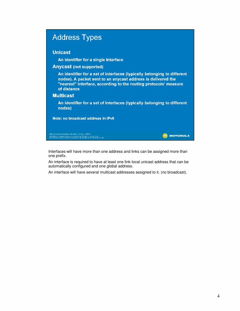
Interfaces will have more than one address and links can be assigned more than one prefix.
4
one prefix.
An interface is required to have at least one link-local unicast address that can be automatically configured and one global address.
An interface will have several multicast addresses assigned to it. (no broadcast).

The IPv6 address is composed of 128 bits divided into 8 sections of 16 bits (one hex word or two bytes), or 16 bytes total. Like IPv4 there are bits that identify the
5
hex word or two bytes), or 16 bytes total. Like IPv4 there are bits that identify the network and bits that identify the interface (more later). There are rules for the use of shorthand notation:
Leading zeros can be omitted. Trailing zeroes must remain, of course. Fields of successive zeros or successive fields of zeros may be represented by a :: . The "::" can only appear once in an address.
Be careful when using shorthand notation. It is very useful since this address is so long but can lead to problems if not observed carefully. (see RFC3513 for some good examples).
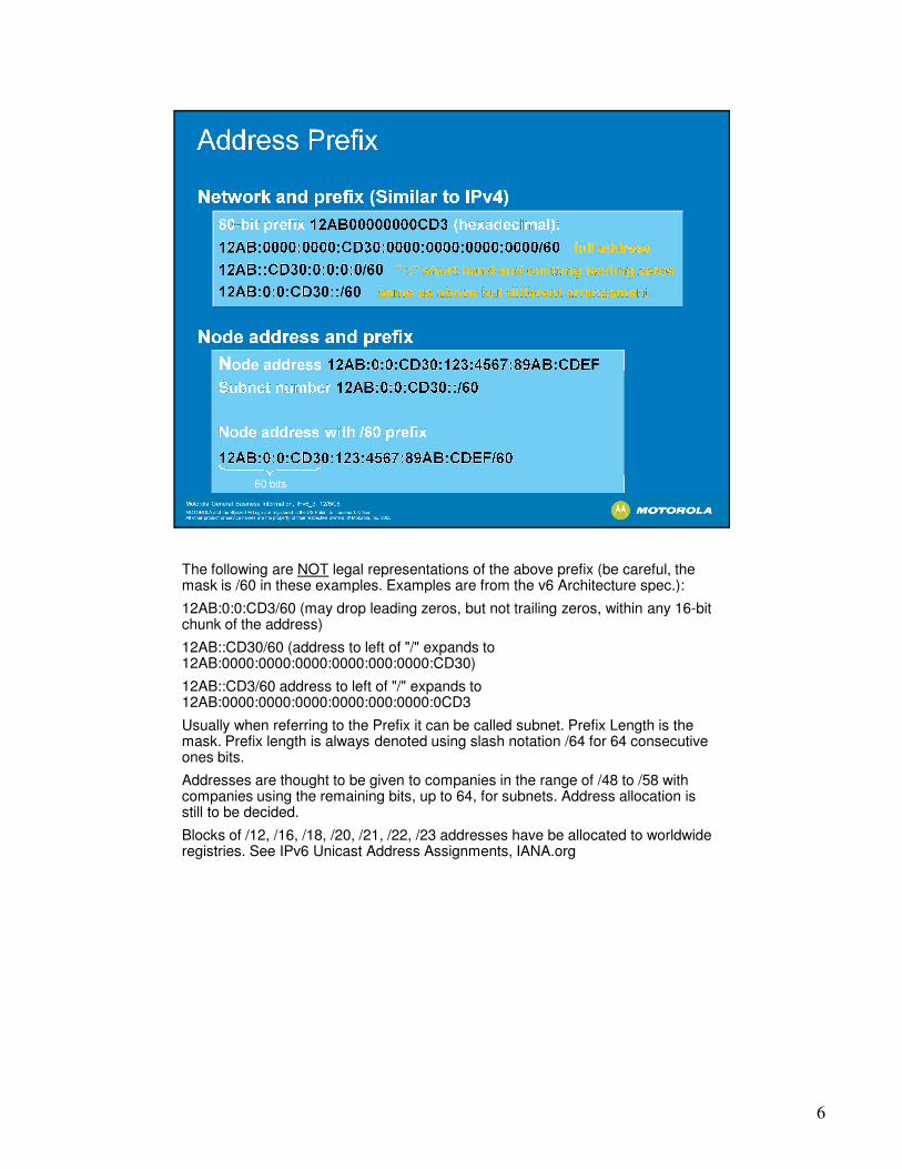
The following are NOT legal representations of the above prefix (be careful, the mask is /60 in these examples. Examples are from the v6 Architecture spec.):
6
mask is /60 in these examples. Examples are from the v6 Architecture spec.):
12AB:0:0:CD3/60 (may drop leading zeros, but not trailing zeros, within any 16-bit chunk of the address)
12AB::CD30/60 (address to left of "/" expands to 12AB:0000:0000:0000:0000:000:0000:CD30)
12AB::CD3/60 address to left of "/" expands to 12AB:0000:0000:0000:0000:000:0000:0CD3
Usually when referring to the Prefix it can be called subnet. Prefix Length is the mask. Prefix length is always denoted using slash notation /64 for 64 consecutive ones bits.
Addresses are thought to be given to companies in the range of /48 to /58 with companies using the remaining bits, up to 64, for subnets. Address allocation is still to be decided.
Blocks of /12, /16, /18, /20, /21, /22, /23 addresses have be allocated to worldwide registries. See IPv6 Unicast Address Assignments, IANA.org

The address 0:0:0:0:0:0:0:0 is called the unspecified address. It must never be assigned to any node. It indicates the absence of an address. One example of its
7
assigned to any node. It indicates the absence of an address. One example of its use is in the Source Address field of any IPv6 packets sent by an initializing host before it has learned its own address.
The unicast address 0:0:0:0:0:0:0:1 is called the loopback address. It may be used by a node to send an IPv6 packet to itself. It may never be assigned to any physical interface. It is treated as having link-local scope, and may be thought of as the link-local unicast address of a virtual interface (typically called "the loopback interface") to an imaginary link that goes nowhere.
Site local was in early specs. but is now deprecated.
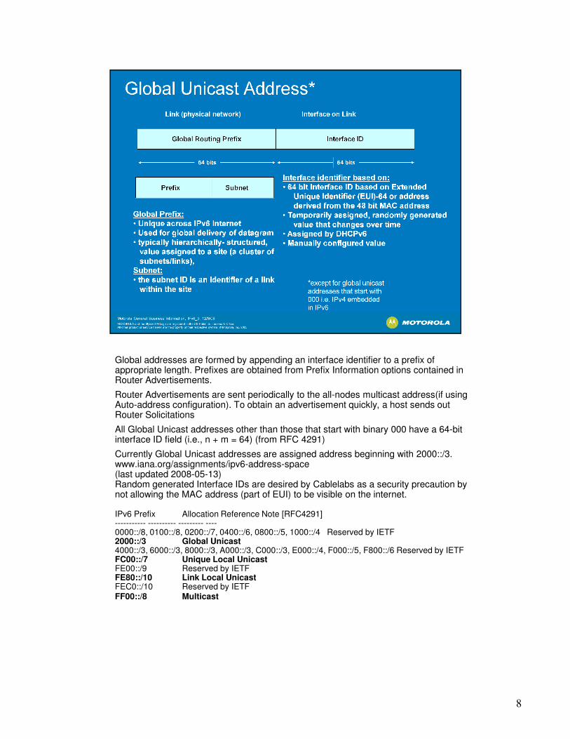
Global addresses are formed by appending an interface identifier to a prefix of appropriate length. Prefixes are obtained from Prefix Information options contained in
8
appropriate length. Prefixes are obtained from Prefix Information options contained in Router Advertisements.
Router Advertisements are sent periodically to the all-nodes multicast address(if using Auto-address configuration). To obtain an advertisement quickly, a host sends out Router Solicitations
All Global Unicast addresses other than those that start with binary 000 have a 64-bit interface ID field (i.e., n + m = 64) (from RFC 4291)
Currently Global Unicast addresses are assigned address beginning with 2000::/3.www.iana.org/assignments/ipv6-address-space(last updated 2008-05-13)Random generated Interface IDs are desired by Cablelabs as a security precaution by not allowing the MAC address (part of EUI) to be visible on the internet.
IPv6 Prefix Allocation Reference Note [RFC4291] ----------- ---------- --------- ----0000::/8, 0100::/8, 0200::/7, 0400::/6, 0800::/5, 1000::/4 Reserved by IETF 2000::/3 Global Unicast4000::/3, 6000::/3, 8000::/3, A000::/3, C000::/3, E000::/4, F000::/5, F800::/6 Reserved by IETF FC00::/7 Unique Local UnicastFE00::/9 Reserved by IETF FE80::/10 Link Local Unicast FEC0::/10 Reserved by IETF FF00::/8 Multicast

Link Local Prefix FE80::/10
FEC0::/10 was previously defined as a Site-Local scoped address prefix. This
9
FEC0::/10 was previously defined as a Site-Local scoped address prefix. This definition has been deprecated as of September 2004 [RFC3879].

Interface-local scope spans only a single interface on a node, and is useful only for loopback transmission of multicast.
10
for loopback transmission of multicast.
Link-local and site-local multicast scopes span the same topological regions as the corresponding unicast scopes.
Admin-local scope is the smallest scope that must be administratively configured, i.e., not automatically derived from physical connectivity or other, non- multicast-related configuration.
Organization-local scope is intended to span multiple sites belonging to a single organization.
FF01:0:0:0:0:0:0:101 means all NTP servers on the same interface (i.e., the same node) as the sender.
FF02:0:0:0:0:0:0:101 means all NTP servers on the same link as the sender. FF05:0:0:0:0:0:0:101 means all NTP servers in the same site as the sender. FF0E:0:0:0:0:0:0:101 means all NTP servers in the internet.

Link Local is autoconfigured with the link-local prefix and the EUI of the interface.
The Global address is sent to the interface by DHCPv6 or it is manually
11
The Global address is sent to the interface by DHCPv6 or it is manually configured. In the BSR the Global addresses will be manually configured, and that generally applies to all router interfaces . Whereas host address will come from DHCPv6.
The following multicast addresses are automatically generated by the BSR for router interfaces:
The All-Nodes multicast address
The All-Routers multicast address
The Solicited-Node multicast address (note: there is a solicited node multicast address for each and every unicast address on the interface)
The last three bytes of the Solicited-Node multicast address will be the last three bytes of the unicast Intrerface ID.
For Example: the CM will send a DHCP Solicit message on the HFC network to the FF02::1:2 multicast address, which is a link-scoped address. The BSR will receive that message and forward it to the DHCP server specified in the cable ipv6 helper address configured in the Loopback (Cable Bundle) interface.
The site-scoped 'all dhcp servers' multicast address is used by the relay agent to send messages to all dhcp servers within the site or because it does not know the unicast address of the dhcp servers. Usually the BSR knows the unicast address of the dhcp server.

The IEEE defined 64-bit extended unique identifier (EUI-64) is a concatenation of the 24-bit /_or 36-bit_ /company_id value by the IEEE Registration Authority and a
12
the 24-bit /_or 36-bit_ /company_id value by the IEEE Registration Authority and a _/the/_ extension identifier assigned by the organization with that company_idassignment _/resulting in a 64 bit unique identifier/_. /_The extension identifiers shall be 40 bits for the 24-bit company_id (OUI-24) and 28 bit for the 36 bit company_id (OUI-36).
The first byte of the 64 bit EUI has a bit that identifies whether the EUI address is unique globally or not. The bit is automatically set by the interface driver when it autoconfigures the link-local address. In the example above the bit is set so the first byte of the EUI shows 0x02.

0000::/96 was previously defined as the "IPv4-compatible IPv6 address" prefix. This definition has been deprecated by [RFC4291].
13
This definition has been deprecated by [RFC4291].
Global Address are reserved by:
IANA: Internet Assigned Numbers Authority
The Réseaux IP Européens Network Coordination Centre (RIPE NCC) is the Regional Internet Registry (RIR) for Europe, the Middle East and parts of Central ...APNIC: Regional Internet Registry that allocates IP and AS numbers in the Asia Pacific region
AfrNIC: Regional Internet Registry that will allocates IP and AS numbers in the African region
LACNIC: Latin American and Caribbean Internet Addresses Registry
14

ND is sort of a combination of IPv4 ARP and Router Discovery.
ND is a protocol that uses ICMP messages for Duplicate Address Detection,
15
ND is a protocol that uses ICMP messages for Duplicate Address Detection, Router Discovery, address Resolution, Neighbor Unreachability Detection
CM uses Neighbor Solicitation (NS) message from Neighbor Discovery (ND) protocol [RFC2461], for Router Discovery and DAD. The CMTS will not do Router Discovery but will do Router Advertisements.
A Neighbor Solicitation is used for link-layer address resolution (like ARP in IPv4) or Neighbor Unreachability Detection. When doing a packet capture you would see many NS. The way to determine what kind they are is by looking at the destination address: If the destination address in the NS is a multicast address (usually the solicited node multicast address), the source is resolving a link-layer address. If the destination address is unicast address the source is verifying neighbor reachability.
Source Address Destination Address ND Message Tpye
all-zero (::0) all-routers multicast Stateless autoconfig
all-zero (::0) Solicited node multicast DAD
Unicast Solicited node multicast Link Layer Addr Resolution
Unicast Unicast Unreachability Detection
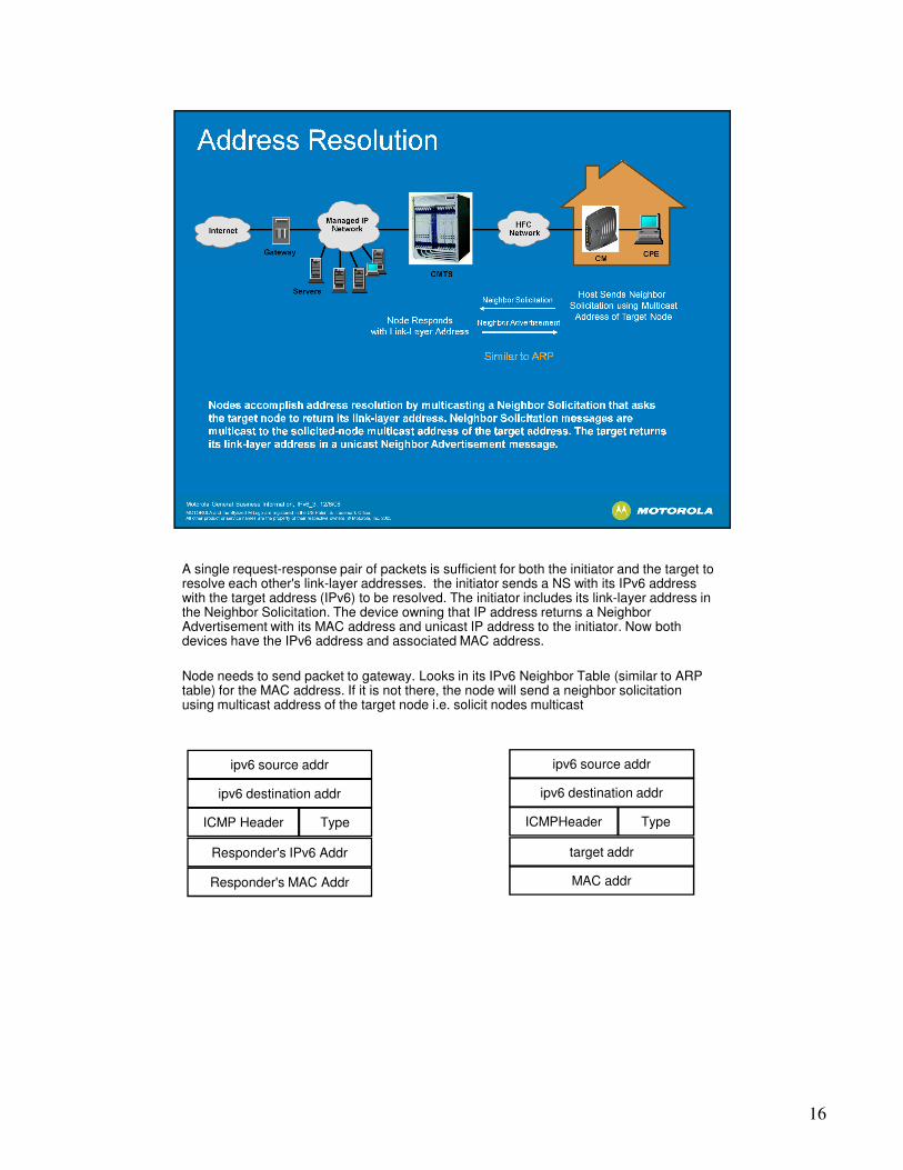
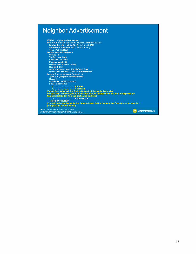
A single request-response pair of packets is sufficient for both the initiator and the target to resolve each other's link-layer addresses. the initiator sends a NS with its IPv6 address
16
resolve each other's link-layer addresses. the initiator sends a NS with its IPv6 address with the target address (IPv6) to be resolved. The initiator includes its link-layer address in the Neighbor Solicitation. The device owning that IP address returns a Neighbor Advertisement with its MAC address and unicast IP address to the initiator. Now both devices have the IPv6 address and associated MAC address.
Node needs to send packet to gateway. Looks in its IPv6 Neighbor Table (similar to ARP table) for the MAC address. If it is not there, the node will send a neighbor solicitation using multicast address of the target node i.e. solicit nodes multicast
ipv6 source addr
ipv6 destination addr
ICMP Header
Responder's IPv6 Addr
Responder's MAC Addr
ipv6 source addr
ipv6 destination addr
target addr
MAC addr
Type ICMPHeader Type

A router sends periodic Router Advertisements containing list of IPv6 prefixes assigned to a link (to be used for stateless autoconfiguration), availability of the
17
assigned to a link (to be used for stateless autoconfiguration), availability of the router as default router.
CM can send a Router Solicitation to trigger a transmission of RA.
The BSR will send RAs on the cable side to advertise itself as the default router i.e. the Lifetime byte will be non-zero.
In Release 5.1 the BSR will send the Router Advertisement with the M bit flag set to 1. This indicates to the CMs that it is to use Stateful address configuration i.e. go to the DHCPv6 server for its address. (if the M bit is set to 0, the host would perform Stateless autoconfiguration).
Unsolicited Router Advertisements are not strictly periodic: the interval between subsequent transmissions is randomized to reduce the probability of synchronization with the advertisements from other routers on the same link. Each advertising interface has its own timer.

Duplicate Address Detection (DAD): CM sends a NS message with query about CM's link-local address, if no response, address is ok, otherwise a response
18
CM's link-local address, if no response, address is ok, otherwise a response means that there is another device on the local link with the same Link Local address. Will do the same for its global IP address.

19

To facilitate the transition, DOCSIS 3.0 and to support legacy product, DOCSIS 3.0 allows for both IPv4 and IPv6.
20
3.0 allows for both IPv4 and IPv6.
"In Dual-stack Provisioning Mode (DPM), the CM attempts to acquire both IPv6 and IPv4 addresses and parameters through DHCPv6 and DHCPv4 almost simultaneously.” from MULPI spec.
When provisioning in Alternate Provisioning Mode, the CM tries to provision using IPv6 first. If IPv6 provisioning is unsuccessful, either because IPv6 Address acquisition or the TFTP configuration file download fails, the CM abandons IPv6 provisioning and attempts provisioning using IPv4.
CM acts as a bridge linking CPEs to IPv6 services through the CMTS. To begin it is anticipated that the CPE traffic will use IPv4 and that DHCP servers will support both (or there will be two servers, one for each.)
DHCP extended to support IPv6 scopes and new IPv6 options are defined.

21
IP provisioning mode for the cable modems is configured in each cable interface using the "cable ip prov-mode" command. The options are IPv4(default), IPv6 only, Alternate Provisioning Mode, and Dual Stack provisioning mode.
The MDD communicates to the CMs:
DS Ambiguity Resolution List and DS Channel Info for DS Channel Bonding (rel 5.0)
IP initialization parameters (IPv4/v6) (rel 5.1).
Note: the TI modem must see a DS Channel list in the MDD (i.e. a fiber node must be configured in the BSR) to come up in v6.
Other TLVs for DOCSIS 3.0 that are not support yet, that are in the MDD:
Early Authentication and Encryption (EAE) TLV
Upstream Active Channel List TLV
Upstream Ambiguity Resolution Channel List
Upstream Frequency Range (standard 5-42 or extended 5-85)
Symbol Clock Locking Indicator
CM-Status Event Control TLV
Upstream Transmit Power Reporting TLV
DSG DA-DSIS Association Entry
Registration Response Timeout Override
No Dynamic Bonding-group Change in this release. All CMs will de-register when the bonding group is changed.
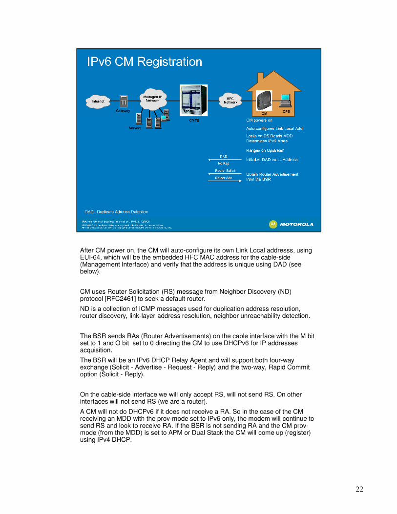
After CM power on, the CM will auto-configure its own Link Local addresss, using EUI-64, which will be the embedded HFC MAC address for the cable-side
22
EUI-64, which will be the embedded HFC MAC address for the cable-side (Management Interface) and verify that the address is unique using DAD (see below).
CM uses Router Solicitation (RS) message from Neighbor Discovery (ND) protocol [RFC2461] to seek a default router.
ND is a collection of ICMP messages used for duplication address resolution, router discovery, link-layer address resolution, neighbor unreachability detection.
The BSR sends RAs (Router Advertisements) on the cable interface with the M bit set to 1 and O bit set to 0 directing the CM to use DHCPv6 for IP addresses acquisition.
The BSR will be an IPv6 DHCP Relay Agent and will support both four-way exchange (Solicit - Advertise - Request - Reply) and the two-way, Rapid Commit option (Solicit - Reply).
On the cable-side interface we will only accept RS, will not send RS. On other interfaces will not send RS (we are a router).
A CM will not do DHCPv6 if it does not receive a RA. So in the case of the CM receiving an MDD with the prov-mode set to IPv6 only, the modem will continue to send RS and look to receive RA. If the BSR is not sending RA and the CM prov-mode (from the MDD) is set to APM or Dual Stack the CM will come up (register) using IPv4 DHCP.

BSR inserts the following DHCPv6 options in upstream DHCPv6 messages (SOLICIT, REQUEST etc.) while relaying the CM’s DHCPv6 messages in a
23
(SOLICIT, REQUEST etc.) while relaying the CM’s DHCPv6 messages in a Relay-Forward message to DHCP server.
DHCPv6 Interface-ID option (Option Code-18) : containing the IP address
of cable interface on which DHCPv6 message is received
DOCSIS Relay Agent CM MAC Address Option (Option Code-39):
containing the MAC address of cable modem from which DHCPv6
message is received.
CMTS DOCSIS Version Number (encoded in DHCPv6 Relay Agent
CMTS Capabilities Option-Option Code-38): containing the major ad
Minor DOCSIS version of CMTS.
BSR relays the DHCPv6 messages to the CM including:
Vendor Specific Options (Option Type – 17)
Enterprise Number: 4491 (CableLabs)
TFTP Server Addresses option (Option code - 32)
Configuration File Name option (Option code - 33)
Syslog Server Addresses option (Option code - 34)
TLV5 encoding (Option code - 35)
DOCSIS Device Identifier option (Option code - 36)
CableLabs client configuration (Option code - 37)
Option Request option (Option Code - 1)

The DHCP server supplies the CM with a globally unique address in IPv6 format.
The CM management interface MUST join the all-nodes multicast address and
24
The CM management interface MUST join the all-nodes multicast address and the solicited-node multicast address of the IPv6 address acquired through DHCPv6.
The CM will perform DAD on the new addresses.
If the CM gets an the IPv6 addresses it must use it for communication with the TODv6 and TFTPv6 servers.
The TFTPv6 server responds with a CM configuration file with some IPv6 parameters (see classifiers below).
If any step in the process fails the CM will reset its MAC and try again.

In Dual-stack Provisioning Mode (DPM), the CM attempts to acquire both IPv6 and IPv4 addresses and parameters through DHCPv6 and DHCPv4 almost
25
and IPv4 addresses and parameters through DHCPv6 and DHCPv4 almost simultaneously. For the acquisition of time-of-day and the download of a configuration file the CM prioritizes the use of the IPv6 address over the IPv4 address. If the CM cannot obtain an IPv6 address, or if it cannot download a configuration file using IPv6, it tries downloading it using IPv4. In this mode, the CM makes both the IPv4 and the IPv6 addresses, if successfully acquired, available for management. (from DOCIS MULPI Spec).

When provisioning in Alternate Provisioning Mode, the CM tries to provision using IPv6 first. If IPv6 provisioning is unsuccessful, either because IPv6 Address
26
IPv6 first. If IPv6 provisioning is unsuccessful, either because IPv6 Address acquisition or the TFTPv6 configuration file download fails, the CM abandons IPv6 provisioning and attempts provisioning using IPv4. (from DOCIS MULPI Spec)

Configuration file parameters new to DOCSIS 3.0 that deal with IPv6 (excluding multicast).
27
multicast).
See Table G–1 - Summary of Configuration File Parameters for a complete listing of all TFTP file parameters for DOCSIS 3.0.

28
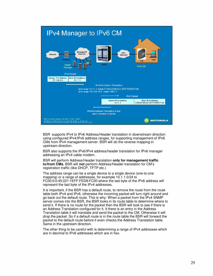
BSR supports IPv4 to IPv6 Address/Header translation in downstream direction using configured IPv4/IPv6 address ranges, for supporting management of IPv6
29
using configured IPv4/IPv6 address ranges, for supporting management of IPv6 CMs from IPv4 management server. BSR will do the reverse mapping in upstream direction.
BSR also supports the IPv6/IPv4 address/header translation for IPv6 manager addressing an IPv4 cable modem.
BSR will perform Address/Header translation only for management traffic to/from CMs. BSR will not perform Address/Header translation for CM’s registration traffic (like DHCP, TFTP etc.)
The address range can be a single device to a single device (one-to-one mapping) or a range of addresses, for example 10.1.1.0/24 to FC00:0:0:45:221:1EFF:FED8:FC00 where the last byte of the IPv6 address will represent the last byte of the IPv4 addresses.
It is important, if the BSR has a default route, to remove the route from the route table both IPv4 and IPv6, otherwise the incoming packet will turn right around and go back out the default route. This is why: When a packet from the IPv4 SNMP server comes into the BSR, the BSR looks in its route table to determine where to send it. If there is no route for the packet then the BSR will look to see if there is an Address Translation configured for it. It there is an entry in the Address Translation table it will translate and send the packet to the CM. Otherwise it will drop the packet. So if a default route is in the route table the BSR will forward the packet to the default route before it even checks the Address Translation table. Same in the upstream direction.
The other thing to be careful with is determining a range of IPv4 addresses which are in decimal to IPv6 addresses which are in hex.

30

No support for IPv6 from the CPE such traffic will be dropped by the BSR (in Release 5.1)
31
Release 5.1)
Dynamic IPv6 Routing Protocols (some examples): RIPng (next gen.), OSPFv3, IS-IS6, BGPv6. (none are currently supported in the BSR)
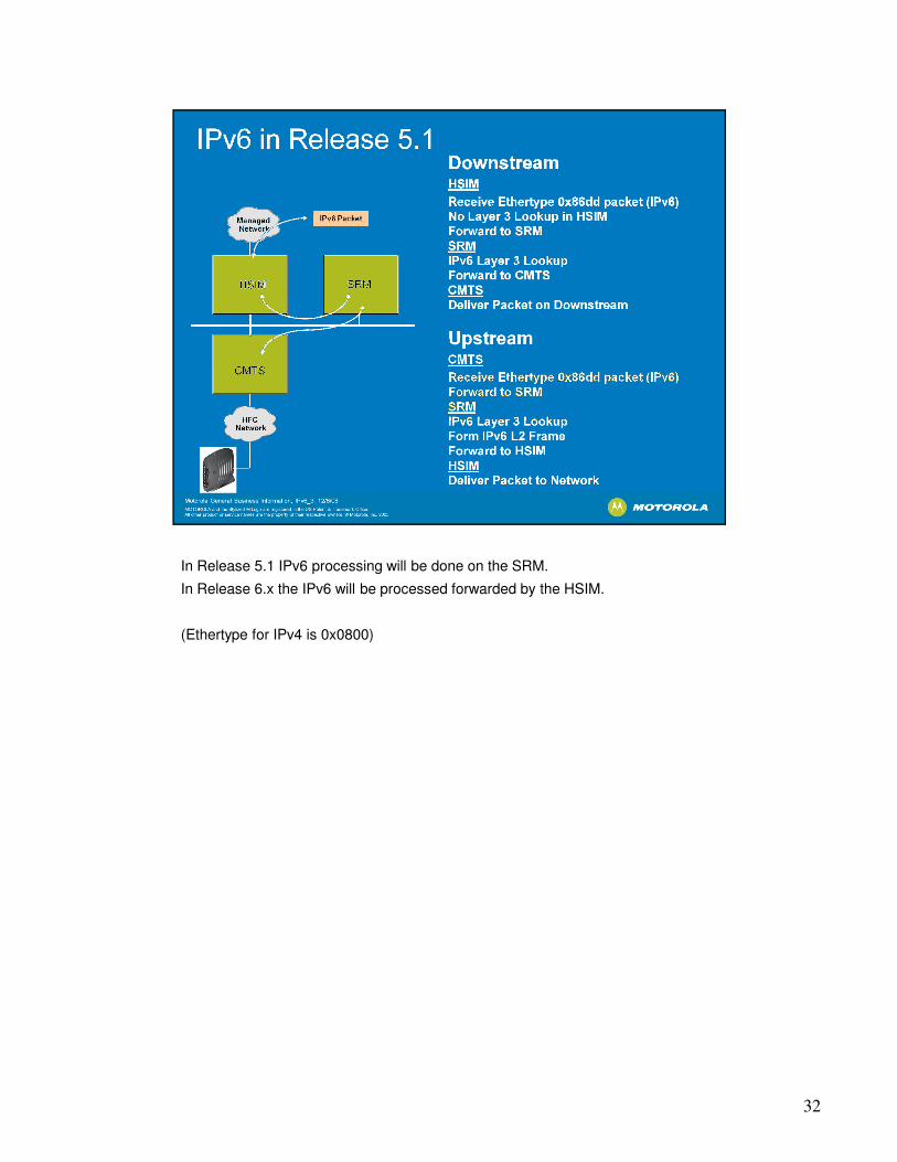
In Release 5.1 IPv6 processing will be done on the SRM.
In Release 6.x the IPv6 will be processed forwarded by the HSIM.
32
In Release 6.x the IPv6 will be processed forwarded by the HSIM.
(Ethertype for IPv4 is 0x0800)
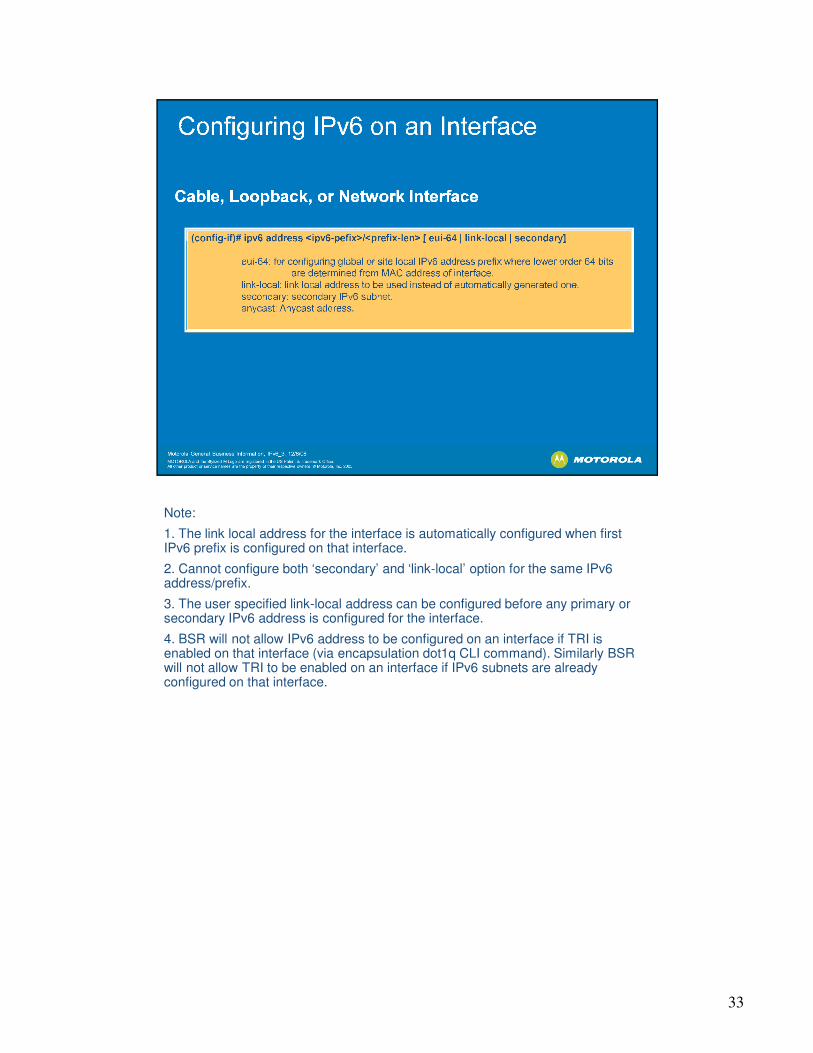
Note:
1. The link local address for the interface is automatically configured when first
33
1. The link local address for the interface is automatically configured when first IPv6 prefix is configured on that interface.
2. Cannot configure both ‘secondary’ and ‘link-local’ option for the same IPv6 address/prefix.
3. The user specified link-local address can be configured before any primary or secondary IPv6 address is configured for the interface.
4. BSR will not allow IPv6 address to be configured on an interface if TRI is enabled on that interface (via encapsulation dot1q CLI command). Similarly BSR will not allow TRI to be enabled on an interface if IPv6 subnets are already configured on that interface.

When configuring the interface IPv6 address you have the option to configure the Interface ID manually and show in the second option or to use the EUI-64 address
34
Interface ID manually and show in the second option or to use the EUI-64 address which has the interface MAC address automatically embedded in the IPv6 address, shown as the first example.

This command shows the Link-Local and Global IPv6 addresses for each interface and the state of the interface.
35
interface and the state of the interface.

Primary IPv4 address for the CMs because the provisioning mode is APM or Dual Stack but also because of the legacy 1.x/2.0 IPv4 Cable Modems i.e. the non-
36
Stack but also because of the legacy 1.x/2.0 IPv4 Cable Modems i.e. the non-DOCSIS 3.0 modems.

For multicast addresses see earlier slide.
1 and 2 Not used. 0 setting means this parameter not used
37
1 and 2 Not used. 0 setting means this parameter not used
3 BSR will send a Neighbor Solicit on the cable interface once every 1 second, if we get no response from a previous NS.
4 BSR will send a router advertisement every 200 seconds. Remember that a host, in this case a cable modem, will send a Router Solicit when it initializes its interface. We respond to the RS immediately with an RA.
5 BSR will send a parameter, this lifetime, in its router advertisement.

In the DHCP debug shown above we see the two message Rapid Commit DHCP option.
38
option.

Used to add static routes to the IPv6 route table.
Where optional parameter “distance” specifies the cost of the route; range <1-
39
Where optional parameter “distance” specifies the cost of the route; range <1-255>; If not specified cost of zero is assumed.

Dynamic protocols that support IPv6 (not currently supported by the BSR)
OSPFv3
40
OSPFv3
IS-IS v6 Extended
RIPnG (next generation)
Connected networks are added to the route table when the interface is configured for IPv6
Local Networks signify host routes to the BSR. Currently these addresses are not displayed in the v6 route table.
Static networks are added to the route table when an ipv6 static route is configured.
41

INCOMPLETE Address resolution is in progress and the link-layer address of the neighbor has not yet been determined.
42
address of the neighbor has not yet been determined.
REACHABLE Roughly speaking, the neighbor is known to have been reachable recently (within tens of seconds ago).
STALE The neighbor is no longer known to be reachable but until traffic is sent to the neighbor, no attempt should be made to verify its reachability.
DELAY The neighbor is no longer known to be reachable, and traffic has recently been sent to the neighbor.Rather than probe the neighbor immediately, however, delay sending probes for a short while in order to give upper layer protocols a chance to provide reachability confirmation.
PROBE The neighbor is no longer known to be reachable, and unicast Neighbor Solicitation probes are being sent to verify reachability.
(from the ND rfc)

IPv6 Traffic statistics
IPv6 DHCP statistics
43
IPv6 DHCP statistics
Show cable modem will now display the IPv6 address.
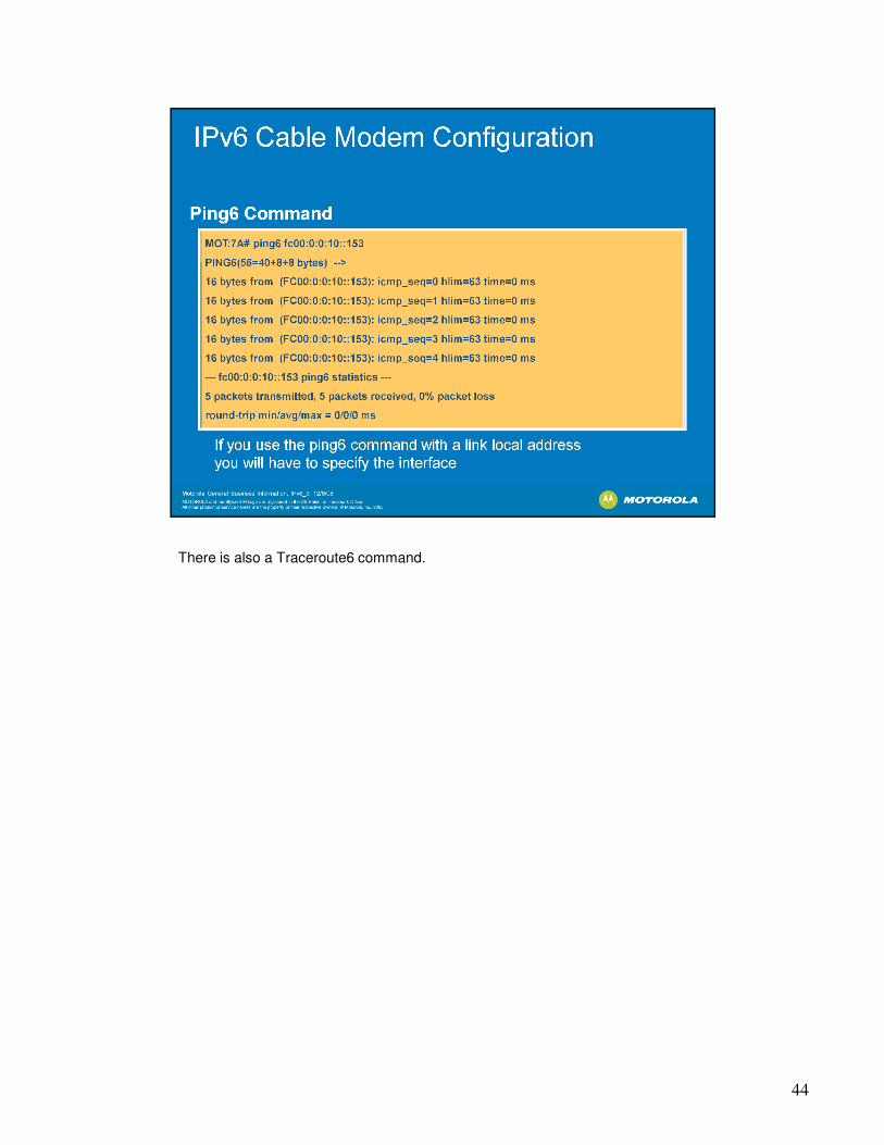
There is also a Traceroute6 command.
44

45

46

47
48
Related Documents