IPSG Administration Guide, StarOS Release 21.23 First Published: 2021-03-31 Americas Headquarters Cisco Systems, Inc. 170 West Tasman Drive San Jose, CA 95134-1706 USA http://www.cisco.com Tel: 408 526-4000 800 553-NETS (6387) Fax: 408 527-0883

Welcome message from author
This document is posted to help you gain knowledge. Please leave a comment to let me know what you think about it! Share it to your friends and learn new things together.
Transcript
IPSG Administration Guide, StarOS Release 21.23First Published: 2021-03-31
Americas HeadquartersCisco Systems, Inc.170 West Tasman DriveSan Jose, CA 95134-1706USAhttp://www.cisco.comTel: 408 526-4000
800 553-NETS (6387)Fax: 408 527-0883

THE SPECIFICATIONS AND INFORMATION REGARDING THE PRODUCTS IN THIS MANUAL ARE SUBJECT TO CHANGE WITHOUT NOTICE. ALL STATEMENTS,INFORMATION, AND RECOMMENDATIONS IN THIS MANUAL ARE BELIEVED TO BE ACCURATE BUT ARE PRESENTED WITHOUT WARRANTY OF ANY KIND,EXPRESS OR IMPLIED. USERS MUST TAKE FULL RESPONSIBILITY FOR THEIR APPLICATION OF ANY PRODUCTS.
THE SOFTWARE LICENSE AND LIMITED WARRANTY FOR THE ACCOMPANYING PRODUCT ARE SET FORTH IN THE INFORMATION PACKET THAT SHIPPED WITHTHE PRODUCT AND ARE INCORPORATED HEREIN BY THIS REFERENCE. IF YOU ARE UNABLE TO LOCATE THE SOFTWARE LICENSE OR LIMITED WARRANTY,CONTACT YOUR CISCO REPRESENTATIVE FOR A COPY.
The Cisco implementation of TCP header compression is an adaptation of a program developed by the University of California, Berkeley (UCB) as part of UCB's public domain version ofthe UNIX operating system. All rights reserved. Copyright © 1981, Regents of the University of California.
NOTWITHSTANDING ANY OTHERWARRANTY HEREIN, ALL DOCUMENT FILES AND SOFTWARE OF THESE SUPPLIERS ARE PROVIDED “AS IS" WITH ALL FAULTS.CISCO AND THE ABOVE-NAMED SUPPLIERS DISCLAIM ALL WARRANTIES, EXPRESSED OR IMPLIED, INCLUDING, WITHOUT LIMITATION, THOSE OFMERCHANTABILITY, FITNESS FOR A PARTICULAR PURPOSE AND NONINFRINGEMENT OR ARISING FROM A COURSE OF DEALING, USAGE, OR TRADE PRACTICE.
IN NO EVENT SHALL CISCO OR ITS SUPPLIERS BE LIABLE FOR ANY INDIRECT, SPECIAL, CONSEQUENTIAL, OR INCIDENTAL DAMAGES, INCLUDING, WITHOUTLIMITATION, LOST PROFITS OR LOSS OR DAMAGE TO DATA ARISING OUT OF THE USE OR INABILITY TO USE THIS MANUAL, EVEN IF CISCO OR ITS SUPPLIERSHAVE BEEN ADVISED OF THE POSSIBILITY OF SUCH DAMAGES.
Any Internet Protocol (IP) addresses and phone numbers used in this document are not intended to be actual addresses and phone numbers. Any examples, command display output, networktopology diagrams, and other figures included in the document are shown for illustrative purposes only. Any use of actual IP addresses or phone numbers in illustrative content is unintentionaland coincidental.
All printed copies and duplicate soft copies of this document are considered uncontrolled. See the current online version for the latest version.
Cisco has more than 200 offices worldwide. Addresses and phone numbers are listed on the Cisco website at www.cisco.com/go/offices.
Cisco and the Cisco logo are trademarks or registered trademarks of Cisco and/or its affiliates in the U.S. and other countries. To view a list of Cisco trademarks, go to this URL:https://www.cisco.com/c/en/us/about/legal/trademarks.html. Third-party trademarks mentioned are the property of their respective owners. The use of the word partner does not imply apartnership relationship between Cisco and any other company. (1721R)
© 2021 Cisco Systems, Inc. All rights reserved.
C O N T E N T S
About this Guide xiiiP R E F A C E
Conventions Used xiii
Supported Documents and Resources xv
Related Common Documentation xv
Related Product Documentation xv
Obtaining Documentation xv
Contacting Customer Support xvi
IP Services Gateway Overview 1C H A P T E R 1
Introduction 1
Qualified Platforms 1
License Requirements 2
How it Works 2
RADIUS Server Mode 2
RADIUS Proxy 2
RADIUS Snoop Mode 3
In-line Services 4
Application Detection and Control 4
Content Filtering 4
Enhanced Charging Service 4
Enhanced Feature Support 4
Accounting-On and Accounting-Off Messages 4
IPSG Server Mode 5
IPSG Proxy Mode 5
Cisco Ultra Traffic Optimization 5
Content Service Steering 5
IPSG Administration Guide, StarOS Release 21.23iii
Dynamic RADIUS Extensions (Change of Authorization) 6
Gx Interface Support 6
Gy Interface Support 7
Lawful Intercept 7
Multiple IPSG Services 8
Overlapping IP Support over VLAN 8
Call Flows for Overlapping IP Support over VLAN 8
Dictionary Requirements 10
Radius Client IP Validation 11
Session Recovery 12
IP Services Gateway Configuration 13C H A P T E R 2
Configuration Requirements for the IPSG 13
Required Configuration File Components 14
Required Component Information 15
Configuring the IPSG 16
IPSG Context and Service Configuration 17
Option 1: RADIUS Server Mode Configuration 17
Option 2: RADIUS Server with Proxy Mode Configuration 17
Option 3: RADIUS Snoop Mode Configuration 18
ISP Context Configuration 19
Creating the ISP Context 19
Enhanced and Optional Configurations 19
Virtual APN Support Configuration 20
Gx Interface Configuration 20
Gy Interface Configuration 20
Overlapping IP Support over VPN Configuration 20
Radius Client IP Validation 21
Responding to Accounting-Stop Messages for Non-Existing Sessions 21
IPSG 4G Support 23C H A P T E R 3
Feature Summary and Revision History 23
Feature Description 24
How It Works 24
IPSG Administration Guide, StarOS Release 21.23iv
Contents
Limitations and Restrictions 25
Cisco Ultra Traffic Optimization 27C H A P T E R 4
Feature Summary and Revision History 27
Overview 28
How Cisco Ultra Traffic Optimization Works 28
Architecture 28
Handling of Traffic Optimization Data Record 29
List of Attributes and File Format 29
Licensing 31
Limitations and Restrictions 32
Configuring Cisco Ultra Traffic Optimization 32
Loading Traffic Optimization 32
Enabling Cisco Ultra Traffic Optimization Configuration Profile 32
Configuring the Operating Mode 33
Configuring Threshold Value 33
Enabling Cisco Ultra Traffic Optimization Configuration Profile Using Service-scheme Framework34
Session Setup Trigger 34
Bearer Creation Trigger 35
Flow Creation Trigger 35
Generating TODR 37
Configuring Rulebase to Allow UDP Traffic Optimization 37
Multi-Policy Support for Traffic Optimization 38
How Multi-Policy Support Works 39
Configuring Multi-Policy Support 39
Configuring a Traffic Optimization Profile 39
Configuring a Traffic Optimization Policy 40
Associating a Trigger Action to a Traffic Optimization Policy 47
Enabling TCP and UDP 48
Service-Scheme Configuration for Multi-Policy Support 48
Monitoring and Troubleshooting 48
Cisco Ultra Traffic Optimization Show Commands and/or Outputs 48
show active-charging rulebase name <rulebase_name> 48
IPSG Administration Guide, StarOS Release 21.23v
Contents
show active-charging traffic-optimization counters 49
show active-charging traffic-optimization info 52
show active-charging traffic-optimization policy 52
IP Services Gateway AAA AVP Support 55A P P E N D I X A
IP Services Gateway Engineering Rules 61A P P E N D I X B
IPSG Context and Service Rules 61
IPSG RADIUS Messaging Rules 61
CoA, RADIUS DM, and Session Redirection (Hotlining) 63A P P E N D I X C
RADIUS Change of Authorization and Disconnect Message 63
CoA Overview 63
DM Overview 64
License Requirements 64
Enabling CoA and DM 64
Enabling CoA and DM 64
CoA and DM Attributes 65
CoA and DM Error-Cause Attribute 66
Viewing CoA and DM Statistics 67
Session Redirection (Hotlining) 68
Overview 68
License Requirements 68
Operation 68
ACL Rule 68
Redirecting Subscriber Sessions 69
Session Limits On Redirection 69
Stopping Redirection 69
Handling IP Fragments 69
Recovery 69
AAA Accounting 70
Viewing the Redirected Session Entries for a Subscriber 70
Gx Interface Support 73A P P E N D I X D
IPSG Administration Guide, StarOS Release 21.23vi
Contents
Rel. 7 Gx Interface 73
Introduction 74
Supported Networks and Platforms 76
License Requirements 76
Supported Standards 76
Terminology and Definitions 76
Policy Control 77
Charging Control 81
Policy and Charging Control (PCC) Rules 82
PCC Procedures over Gx Reference Point 84
Volume Reporting Over Gx 86
How Rel. 7 Gx Works 91
Configuring Rel. 7 Gx Interface 95
Configuring IMS Authorization Service at Context Level 96
Applying IMS Authorization Service to an APN 98
Configuring Volume Reporting over Gx 99
Gathering Statistics 100
Rel. 8 Gx Interface 100
HA/PDSN Rel. 8 Gx Interface Support 101
Introduction 101
Terminology and Definitions 103
How it Works 111
Configuring HA/PDSN Rel. 8 Gx Interface Support 114
Gathering Statistics 117
P-GW Rel. 8 Gx Interface Support 118
Introduction 118
Terminology and Definitions 118
Rel. 9 Gx Interface 123
P-GW Rel. 9 Gx Interface Support 123
Introduction 123
Terminology and Definitions 124
3GPP Rel.9 Compliance for IPFilterRule 129
Rel. 10 Gx Interface 131
P-GW Rel. 10 Gx Interface Support 132
IPSG Administration Guide, StarOS Release 21.23vii
Contents
Introduction 132
Terminology and Definitions 132
Supported Gx Features 140
Assume Positive for Gx 140
Default Policy on CCR-I Failure 141
Gx Back off Functionality 142
Support for Volume Reporting in Local Policy 142
Support for Session Recovery and Session Synchronization 143
Configuring Gx Assume Positive Feature 143
Time Reporting Over Gx 145
License Requirements 145
Feature Overview 145
Usage Monitoring 146
Usage Reporting 147
Configuring Time Reporting over Gx 148
Support for Multiple Active and Standby Gx Interfaces to PCRF 149
Configuring Diameter Peer Selection at Diabase in Failure Scenarios 149
Support for Multiple CCR-Us over Gx Interface 150
Configuring Gateway Node to Support Back-to-Back CCR-Us 151
Support for RAN/NAS Cause IE on Gx Interface 151
Configuring Supported Feature Netloc-RAN-NAS-Cause 151
Support ADC Rules over Gx Interface 152
Limitations 153
Configuring ADC Rules over Gx 153
GoR Name Support in TDF-Application-Identifier 153
ADC Mute Customization 154
Support for TAI and ECGI Change Reporting 157
Feature Description 157
How it Works 158
Monitoring and Troubleshooting the TAI and ECGI Change Reporting Feature 159
Location Based Local-Policy Rule Enforcement 160
Feature Description 160
How it Works 161
Configuring Location Based Local Policy Rule Enforcement Feature 162
IPSG Administration Guide, StarOS Release 21.23viii
Contents
Monitoring and Troubleshooting the Location Based LP Rule Enforcement Feature 164
Gx Support for GTP based S2a/S2b 165
Gx-based Virtual APN Selection 165
Feature Description 165
Configuring Gx based Virtual APN Selection Feature 166
Monitoring and Troubleshooting the Gx based Virtual APN Selection 166
Graceful Handling of RAR from Different Peers 167
NetLoc Feature Enhancement 168
Feature Description 168
Command Changes 172
Performance Indicator Changes 173
RAN-NAS Cause Code Feature Enhancement 173
Feature Description 173
Command Changes 177
Session Disconnect During Diamproxy-Session ID Mismatch 177
Feature Description 177
Configuring System to Delete Diamproxy-Session ID Mismatched Sessions 178
Monitoring and Troubleshooting the Mismatched Session Deletion Feature 179
Support for Negotiating Mission Critical QCIs 179
Feature Description 180
Configuring DPCA for Negotiating Mission Critical QCIs 180
Monitoring and Troubleshooting the Mission Critical QCI 181
HSS and PCRF-based P-CSCF Restoration Support for WLAN 181
Feature Description 182
Configuring the HSS/PCRF-based P-CSCF Restoration 183
Monitoring and Troubleshooting the HSS/PCRF-based P-CSCF Restoration 184
Loop Prevention for Dynamic Rules 186
Feature Information 186
Feature Description 187
How It Works 187
Configuring Loop Prevention for Dynamic Rules 187
Monitoring and Troubleshooting 188
Separation of Accounting Interim Interval Timer for RADIUS and Diameter Rf 189
Feature Information 189
IPSG Administration Guide, StarOS Release 21.23ix
Contents
Feature Description 189
How It Works 190
Configuring Diameter Accounting Interim Interval 191
Monitoring and Troubleshooting 191
Enhancement to OCS Failure Reporting for Gy 192
Feature Information 192
Feature Description 193
Support Added for RAN/NAS Cause Code for S5/S8 and S2b Interfaces 193
Feature Information 193
Feature Changes 194
Command Changes 198
Gy Interface Support 199A P P E N D I X E
Introduction 199
License Requirements 200
Supported Standards 201
Features and Terminology 201
Charging Scenarios 201
Session Charging with Reservation 201
Basic Operations 202
Re-authorization 202
Threshold based Re-authorization Triggers 203
Termination Action 203
Diameter Base Protocol 203
Diameter Credit Control Application 204
Quota Behavior 204
Supported AVPs 216
Unsupported AVPs 220
PLMN and Time Zone Reporting 225
Interworking between Session-based Gy and Event-based Gy 226
OCS Unreachable Failure Handling Feature 226
Enhancement to OCS Failure Reporting for Gy 228
Feature Description 228
Backpressure Handling 228
IPSG Administration Guide, StarOS Release 21.23x
Contents
Gy Backpressure Enhancement 229
Gy Support for GTP based S2a/S2b 229
Generating OOC/ROC with Changing Association between Rule and RG 230
Static Rulebase for CCR 230
CC based Selective Gy Session Control 230
Feature Description 230
Configuring CC based Selective Gy Session Control 232
Monitoring and Troubleshooting the Selective Gy Session Control Feature 232
Credit-Control Group in Rulebase Configuration 233
Feature Description 233
Configuring Credit-Control Group in Rulebase 234
Monitoring and Troubleshooting the CC-Group Selection in Rulebase 235
Combined CCR-U Triggering for QoS Change Scenarios 235
Re-activating Offline Gy Session after Failure 235
Feature Description 236
Configuring Offline Gy Session after Failure 237
Monitoring and Troubleshooting the Offline Gy Session after Failure 237
Suppress AVPs 238
Feature Description 238
Command Changes 238
Performance Indicator Changes 239
Configuring Gy Interface Support 239
Configuring GGSN / P-GW / IPSG Gy Interface Support 239
Configuring HA / PDSN Gy Interface Support 240
Configuring PLMN and Time Zone Reporting 241
Configuring Server Unreachable Feature 242
Configuring Static Rulebase for CCR 243
Configuring Gy for GTP based S2a/S2b 244
Gathering Statistics 244
ICAP Interface Support 247A P P E N D I X F
ICAP Interface Support Overview 247
Supported Networks and Platforms 249
License Requirements 249
IPSG Administration Guide, StarOS Release 21.23xi
Contents
Failure Action on Retransmitted Packets 249
ICAP Client Communication with RFC 3507 compliance 250
Configuring ICAP Interface Support 252
Creating ICAP Server Group and Address Binding 253
Configuring ICAP Server and Other Parameters 253
Configuring ECS Rulebase for ICAP Server Group 254
Configuring Charging Action for ICAP Server Group 254
Verifying the ICAP Server Group Configuration 255
IPSG Administration Guide, StarOS Release 21.23xii
Contents
About this Guide
The documentation set for this product strives to use bias-free language. For purposes of this documentationset, bias-free is defined as language that does not imply discrimination based on age, disability, gender, racialidentity, ethnic identity, sexual orientation, socioeconomic status, and intersectionality. Exceptions may bepresent in the documentation due to language that is hardcoded in the user interfaces of the product software,language used based on RFP documentation, or language that is used by a referenced third-party product.
Note
The HA, HSGW, PDSN, and SecGW products have reached end of life and are not supported in this release.Any references to these products (specific or implied) their components or functions including CLI commandsand parameters in this document are coincidental and are not supported. Full details on the end of life for theseproducts are available athttps://www.cisco.com/c/en/us/products/collateral/wireless/asr-5000-series/eos-eol-notice-c51-740422.html.
Note
This preface describes the IPSG Administration Guide, how it is organized, and its document conventions.
The IP Services Gateway (IPSG) is a StarOS™ application that runs on Cisco® ASR 5500 and virtualizedplatforms.
• Conventions Used, on page xiii• Supported Documents and Resources, on page xv
Conventions UsedThe following tables describe the conventions used throughout this documentation.
DescriptionNotice Type
Provides information about important features orinstructions.
Information Note
Alerts you of potential damage to a program, device,or system.
Caution
IPSG Administration Guide, StarOS Release 21.23xiii
DescriptionNotice Type
Alerts you of potential personal injury or fatality. Mayalso alert you of potential electrical hazards.
Warning
DescriptionTypeface Conventions
This typeface represents displays that appear on yourterminal screen, for example:
Login:
Text represented as a screen display
This typeface represents commands that you enter,for example:
show ip access-list
This document always gives the full form of acommand in lowercase letters. Commands are notcase sensitive.
Text represented as commands
This typeface represents a variable that is part of acommand, for example:
show card slot_number
slot_number is a variable representing the desiredchassis slot number.
Text represented as a command variable
This typeface represents menus and sub-menus thatyou access within a software application, for example:
Click the File menu, then click New
Text represented as menu or sub-menu names
DescriptionCommand Syntax Conventions
Required keyword options and variables are thosecomponents that are required to be entered as part ofthe command syntax.
Required keyword options and variables aresurrounded by grouped braces { }. For example:
sctp-max-data-chunks { limit max_chunks
| mtu-limit }
If a keyword or variable is not enclosed in braces orbrackets, it is mandatory. For example:
snmp trap link-status
{ keyword or variable }
Optional keywords or variables, or those that a usermay or may not choose to use, are surrounded bybrackets.
[ keyword or variable ]
IPSG Administration Guide, StarOS Release 21.23xiv
About this GuideAbout this Guide
DescriptionCommand Syntax Conventions
Some commands support multiple options. These aredocumented within braces or brackets by separatingeach option with a vertical bar.
These options can be used in conjunction withrequired or optional keywords or variables. Forexample:
action activate-flow-detection {intitiation | termination }
or
ip address [ count number_of_packets |size number_of_bytes ]
|
Supported Documents and Resources
Related Common DocumentationThe most up-to-date information for this product is available in the product Release Notes provided with eachproduct release.
The following common documents are available:
• AAA Interface Administration and Reference• Command Line Interface Reference• GTPP Interface Administration and Reference• Installation Guide (hardware dependent)• VPC-SI System Administration Guide• Release Change Reference• SNMP MIB Reference• Statistics and Counters Reference• System Administration Guide (hardware dependent)• Thresholding Configuration Guide
Related Product DocumentationThe following product documents are also available and work in conjunction with IPSG:
• ADC Administration Guide• ECS Administration Guide• GGSN Administration Guide• P-GW Administration Guide
Obtaining DocumentationThe most current Cisco documentation is available on the following website:
IPSG Administration Guide, StarOS Release 21.23xv
About this GuideSupported Documents and Resources
http://www.cisco.com/cisco/web/psa/default.html
Use the following path selections to access the IPSG documentation:
Products > Wireless > Mobile Internet> Network Functions > Cisco IPSG IP Services
Contacting Customer SupportUse the information in this section to contact customer support.
Refer to the support area of http://www.cisco.com for up-to-date product documentation or to submit a servicerequest. A valid username and password are required to access this site. Please contact your Cisco sales orservice representative for additional information.
IPSG Administration Guide, StarOS Release 21.23xvi
About this GuideContacting Customer Support
C H A P T E R 1IP Services Gateway Overview
This chapter provides an overview of the IP Services Gateway (IPSG) product.
This chapter covers the following topics:
• Introduction, on page 1• How it Works, on page 2• In-line Services, on page 4• Enhanced Feature Support, on page 4
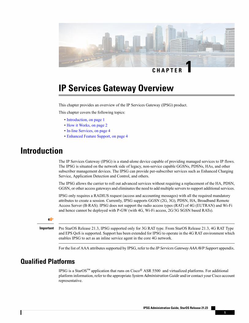
IntroductionThe IP Services Gateway (IPSG) is a stand-alone device capable of providing managed services to IP flows.The IPSG is situated on the network side of legacy, non-service capable GGSNs, PDSNs, HAs, and othersubscriber management devices. The IPSG can provide per-subscriber services such as Enhanced ChargingService, Application Detection and Control, and others.
The IPSG allows the carrier to roll out advanced services without requiring a replacement of the HA, PDSN,GGSN, or other access gateways and eliminates the need to add multiple servers to support additional services.
IPSG only requires a RADIUS request (access and accounting messages) with all the required mandatoryattributes to create a session. Currently, IPSG supports GGSN (2G, 3G), PDSN, HA, Broadband RemoteAccess Server (B-RAS). IPSG does not support the radio access types (RAT) of 4G (EUTRAN) and Wi-Fiand hence cannot be deployed with P-GW (with 4G, Wi-Fi access, 2G/3G SGSN based RATs).
Pre StarOS Release 21.3, IPSG supported only for 3G RAT type. From StarOS Release 21.3, 4G RAT Typeand EPS QoS is supported. Support has been extended for IPSG to operate in the 4G RAT environment whichenables IPSG to act as an inline service agent in the core 4G network.
Important
For the list of AAA attributes supported by IPSG, refer to the IP Services Gateway AAA AVP Support appendix.
Qualified PlatformsIPSG is a StarOS™ application that runs on Cisco® ASR 5500 and virtualized platforms. For additionalplatform information, refer to the appropriate System Administration Guide and/or contact your Cisco accountrepresentative.
IPSG Administration Guide, StarOS Release 21.231
License RequirementsThe IP Services Gateway is a licensed Cisco product. Separate session and feature licenses may be required.Contact your Cisco account representative for detailed information on licensing requirements.
For information on installing and verifying licenses, refer to theManaging License Keys section of the SoftwareManagement Operations chapter in the System Administration Guide.
How it WorksThe IPSG supports the following service modes:
• RADIUS Server Mode, on page 2• RADIUS Snoop Mode, on page 3
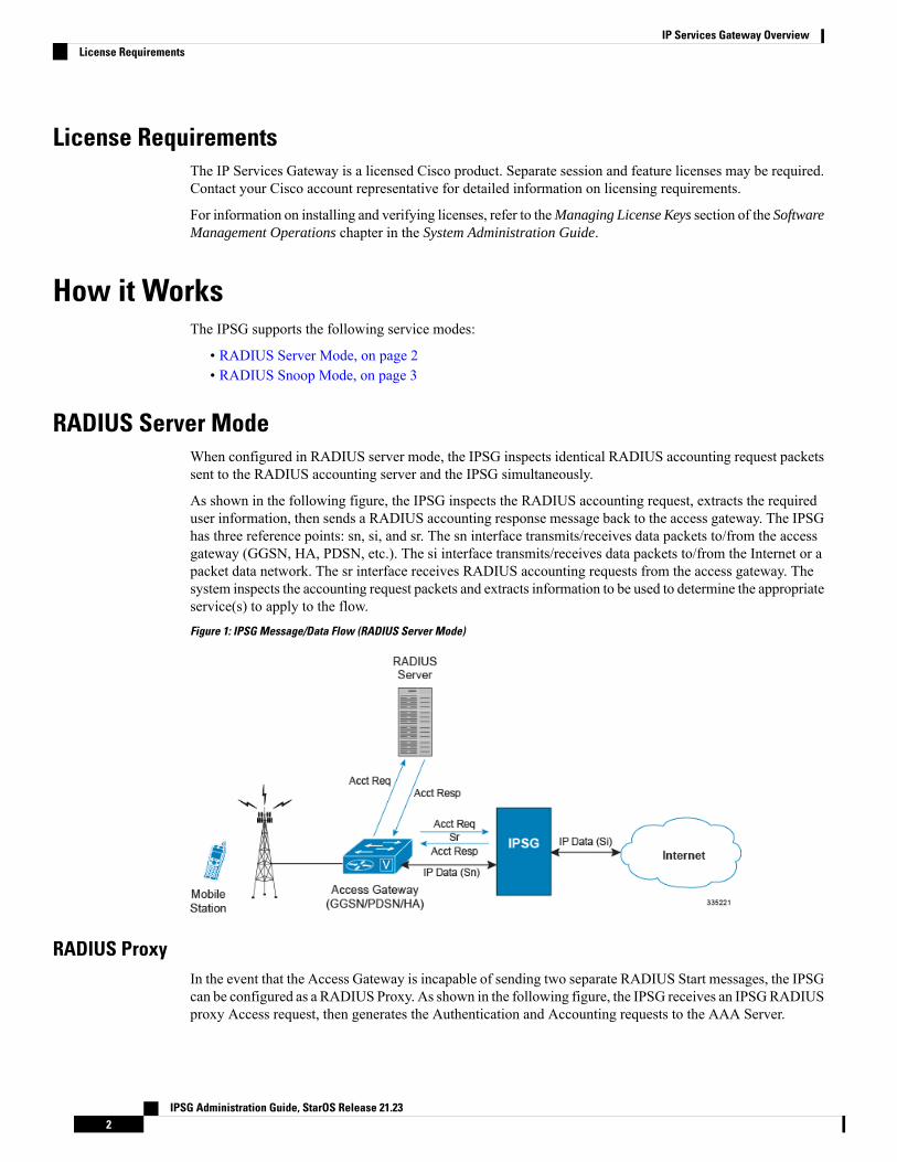
RADIUS Server ModeWhen configured in RADIUS server mode, the IPSG inspects identical RADIUS accounting request packetssent to the RADIUS accounting server and the IPSG simultaneously.
As shown in the following figure, the IPSG inspects the RADIUS accounting request, extracts the requireduser information, then sends a RADIUS accounting response message back to the access gateway. The IPSGhas three reference points: sn, si, and sr. The sn interface transmits/receives data packets to/from the accessgateway (GGSN, HA, PDSN, etc.). The si interface transmits/receives data packets to/from the Internet or apacket data network. The sr interface receives RADIUS accounting requests from the access gateway. Thesystem inspects the accounting request packets and extracts information to be used to determine the appropriateservice(s) to apply to the flow.
Figure 1: IPSG Message/Data Flow (RADIUS Server Mode)
RADIUS ProxyIn the event that the Access Gateway is incapable of sending two separate RADIUS Start messages, the IPSGcan be configured as a RADIUS Proxy. As shown in the following figure, the IPSG receives an IPSGRADIUSproxy Access request, then generates the Authentication and Accounting requests to the AAA Server.
IPSG Administration Guide, StarOS Release 21.232
IP Services Gateway OverviewLicense Requirements
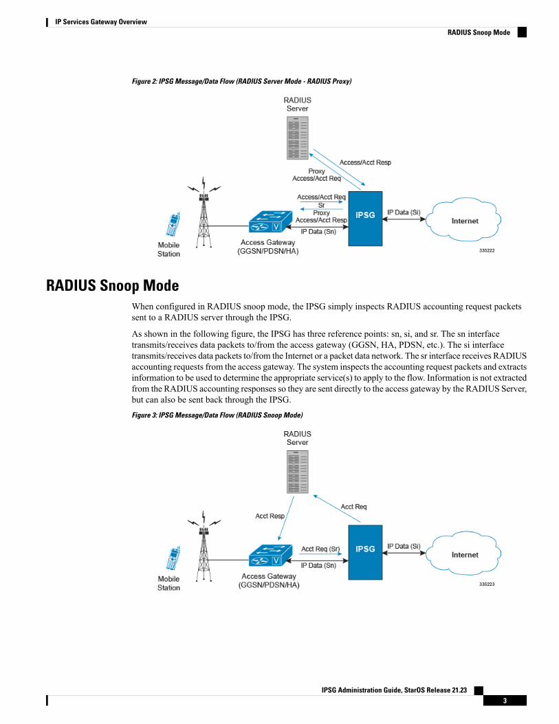
Figure 2: IPSG Message/Data Flow (RADIUS Server Mode - RADIUS Proxy)
RADIUS Snoop ModeWhen configured in RADIUS snoop mode, the IPSG simply inspects RADIUS accounting request packetssent to a RADIUS server through the IPSG.
As shown in the following figure, the IPSG has three reference points: sn, si, and sr. The sn interfacetransmits/receives data packets to/from the access gateway (GGSN, HA, PDSN, etc.). The si interfacetransmits/receives data packets to/from the Internet or a packet data network. The sr interface receives RADIUSaccounting requests from the access gateway. The system inspects the accounting request packets and extractsinformation to be used to determine the appropriate service(s) to apply to the flow. Information is not extractedfrom the RADIUS accounting responses so they are sent directly to the access gateway by the RADIUS Server,but can also be sent back through the IPSG.
Figure 3: IPSG Message/Data Flow (RADIUS Snoop Mode)
IPSG Administration Guide, StarOS Release 21.233
IP Services Gateway OverviewRADIUS Snoop Mode
In-line ServicesAs described previously, the IPSG provides a method of inspecting RADIUS packets to discover user identityfor the purpose of applying enhanced services to the subsequent data flow. Internal applications such as theEnhanced Charging Service, Content Filtering, and Application Detection and Control are primary featuresthat take advantage of the IPSG service.
Application Detection and ControlApplication Detection and Control (ADC) is an in-line service feature that detects peer-to-peer protocols inreal time and applies actions such as permitting, blocking, charging, bandwidth control, and TOS marking.
For more information, refer to the Application Detection and Control Administration Guide.
Content FilteringContent Filtering is an in-line service feature that filters HTTP and WAP requests from mobile subscribersbased on the URLs in the requests. This enables operators to filter and control the content that an individualsubscriber can access, so that subscribers are inadvertently not exposed to universally unacceptable contentand/or content inappropriate as per the subscribers' preferences.
For more information, refer to the Content Filtering Services Administration Guide.
Enhanced Charging ServiceEnhanced Charging Service (ECS)/Active Charging Service (ACS) is the primary vehicle performing packetinspection and applying rules to the session which includes the delivery of enhanced services.
For more information, refer to the Enhanced Charging Service Administration Guide.
Enhanced Feature SupportThis section describes the enhanced features supported by IPSG.
Accounting-On and Accounting-Off MessagesThis feature introduces IPSG support for Accounting-On andAccounting-Off RADIUS accountingmessages,in addition to the existing start, interim-update, and stop messages. The Accounting-On message sent by thepeer RADIUS client indicates that the RADIUS client has restarted and is ready to accept calls.
An Accounting-Off message indicates that the peer RADIUS client is shutting down.
IPSG clears the existing subscriber sessions on receiving the Accounting-On/Off messages, and proxies themessage to the RADIUS server (Proxy mode). The existing sessions are cleared based on the NAS-IP addressof the subscriber that was assigned when the Acct-start message was created . If there is no NAS-IP-Addressavailable, the peer IP address is considered as the NAS-IP-Address for the session. IPSG clears calls basedon the NAS-IP address AVP in the Accounting-On/Off message irrespective of the origin of the message.
IPSG Administration Guide, StarOS Release 21.234
IP Services Gateway OverviewIn-line Services
IPSG Server ModeIn the server mode, IPSG acts like the RADIUS server and on receiving an Accounting-On message, IPSGclears the existing sessions based on the NAS-IP address and sends a response to the RADIUS client.
When an Accounting-Off message is received, IPSG clears the existing sessions mapped to that NAS-IPaddress and sends a response to the client.
Only the first Accounting-On/Off message from the RADIUS client is addressed and the sessions are notcleared for retries. However, a response is sent to the RADIUS client for the retries.
IPSG Proxy ModeIn the proxy mode, when IPSG receives the Accounting-On/Off message from the RADIUS client, IPSGclears the subscriber sessions based on the NAS-IP address and proxies the message to the RADIUS server.IPSG then proxies the response from the RADIUS server back to the RADIUS client. Only the firstAccounting-On/Off message from the RADIUS client is addressed. The corresponding messages are proxieddirectly to the RADIUS server and the response proxied back to the RADIUS client.
Cisco Ultra Traffic OptimizationIn a high-bandwidth bulk data flow scenario, user experience is impacted due to various wireless networkconditions and policies like shaping, throttling, and other bottlenecks that induce congestion, especially in theRAN. This results in TCP applying its saw-tooth algorithm for congestion control and impacts user experience,and overall system capacity is not fully utilized.
The Cisco Ultra Traffic Optimization solution provides clientless optimization of TCP and HTTP traffic. Thissolution is integrated with Cisco IPSG and has the following benefits:
• Increases the capacity of existing cell sites and therefore, enables more traffic transmission.
• Improves Quality of Experience (QoE) of users by providing more bits per second.
• Provides instantaneous stabilizing andmaximizing per subscriber throughput, particularly during networkcongestion.
For detailed information on Cisco Ultra Traffic Optimization solution, refer to the Cisco Ultra TrafficOptimization chapter in the IPSG Administration Guide.
Content Service SteeringContent Service Steering (CSS), defines how traffic is handled by the system based on the content of the datapresented by a mobile subscriber. CSS can be used to direct traffic to in-line services that are internal to thesystem. CSS controls how subscriber data is forwarded to a particular in-line service, but does not control thecontent.
IPSG supports steering subscriber sessions to Content Filtering Service based on their policy setting. If asubscriber does not have a policy setting (ACL name) requiring Content Filtering, their session will bypassthe Content Filtering Service and will be routed on to the destination address.
If subscriber policy entitlements indicate that filtering is required for a subscriber, CSS is used to steersubscriber sessions to the Content Filtering in-line service.
If a subscriber is using a mobile application with protocol type not supported, their session will bypass theContent Filtering Service and will be efficiently routed on to destination address.
IPSG Administration Guide, StarOS Release 21.235
IP Services Gateway OverviewIPSG Server Mode
For more information regarding CSS, refer to theContent Service Steering chapter in the System AdministrationGuide.
Dynamic RADIUS Extensions (Change of Authorization)Dynamic RADIUS extension support provides operators with greater control over subscriber PDP contextsby providing the ability to dynamically redirect data traffic, and or disconnect the PDP context.
This functionality is based on the RFC 3576, Dynamic Authorization Extensions to Remote AuthenticationDial In User Service (RADIUS), July 2003 standard.
The system supports the configuration and use of the following dynamic RADIUS extensions:
• Change of Authorization: The system supports CoAmessages from the AAA server to change data filtersassociated with a subscriber session. The CoA request message from the AAA server must containattributes to identify NAS and the subscriber session and a data filter ID for the data filter to apply to thesubscriber session.
• Disconnect Message: The DM message is used to disconnect subscriber sessions in the system from aRADIUS server. The DM request message should contain necessary attributes to identify the subscribersession.
The above extensions can be used to dynamically re-direct subscriber PDP contexts to an alternate addressfor performing functions such as provisioning and/or account set up. This functionality is referred to as SessionRedirection, or Hotlining.
Session redirection provides a means to redirect subscriber traffic to an external server by applying ACL rulesto the traffic of an existing or a new subscriber session. The destination address and optionally the destinationport of TCP/IP or UDP/IP packets from the subscriber are rewritten so the packet is forwarded to the designatedredirected address.
Return traffic to the subscriber has the source address and port rewritten to the original values. The redirectACL may be applied dynamically by means of the RADIUS Change of Authorization (CoA) extension.
Formore information on dynamic RADIUS extensions support, refer theCoA, RADIUS, and Session Redirection(Hotlining) appendix of this guide.
Important
Gx Interface SupportTo support roaming IMS subscribers in a GPRS/UMTS network, the IPSG must be able to charge only forthe amount of resources consumed by the particular IMS application and bandwidth used. The IPSG mustalso allow for the provisioning and control of the resources used by the IMS subscriber. To facilitate this, theIPSG supports the R7 Gx interface to a Policy Control and Charging Rule Function (PCRF).
For detailed information on Gx Interface support, refer to theGx Interface Support appendix in the IP ServicesGateway Administration Guide.
Note the following for IPSG:
• Only single bearer/session concept is supported. Multiple bearer concept is not applicable.
• Only PCRF binding is applicable. PCEF binding is not applicable.
IPSG Administration Guide, StarOS Release 21.236
IP Services Gateway OverviewDynamic RADIUS Extensions (Change of Authorization)
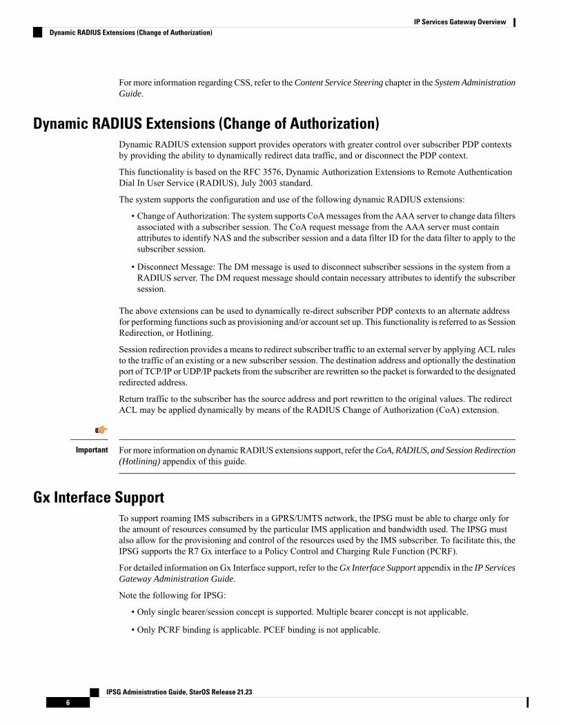
The following figure shows the interface and basic message flow of the Gx interface.
Figure 4: IPSG Message/Data Flow (RADIUS Server Mode - IMS Auth Service)
IPSG also supports IMS Authorization Service Session Recovery with the following limitations:
• Active calls only
• The number of rules recovered is limited to the following:
• 3 flow-descriptions per charging-rule-definition
• 3 Charging-rule-definitions per PDP context
• The above are combined limits for opened/closed gates and for uplink and downlink rules. IMSA sessionswith rules more than the above are not recoverable.
Gy Interface SupportThis is a Diameter protocol-based interface over which the IPSG communicates with a Charging TriggerFunction (CTF) server that provides online charging data. Gy interface support provides an online charginginterface that works with the ECS deep packet inspection feature. With Gy, customer traffic can be gated andbilled in an "online" or "prepaid" style. Both time- and volume-based charging models are supported. In allof these models, differentiated rates can be applied to different services based on shallow or deep packetinspection.
For more information on Gy interface support, refer to the Gy Interface Support appendix in the IP ServicesGateway Administration Guide.
Lawful InterceptThe Cisco Lawful Intercept feature is supported on the IPSG. Lawful Intercept is a license-enabled,standards-based feature that provides telecommunications service providers with a mechanism to assist lawenforcement agencies in monitoring suspicious individuals for potential illegal activity. For additionalinformation and documentation on the Lawful Intercept feature, contact your Cisco account representative.
IPSG Administration Guide, StarOS Release 21.237
IP Services Gateway OverviewGy Interface Support
Multiple IPSG ServicesMultiple IPSG services, can be configured on the system using different contexts. Each such IPSG servicefunctions independently as an IPSG. Both source and destination contexts must be different for each IPSGservice.
Overlapping IP Support over VLANSupport for overlapping IP addresses for subscribers serviced by access networks on IPSG using VLANs isnow possible through this feature. Overlapping IP addresses can be set up by defining multiple interfaces onthe Sn interface (access side) and binding them to separate VLANs, while a single interface is setup to separatetraffic using VPNv4 on the Si side (network side). When IPSG receives a packet, the appropriate session isidentified based on the combination of IP address and VLAN. Currently, a maximum of 500 VLANs can beconfigured.
IPSG running on Cisco ASR 5500 acts as a BGPv4 peer (BGP proxy) per VLAN on the Sn interface, andMP-BGP peer on the Si interface. There can be 500 BGPv4 peers on the access side. IPSG can support amaximum of 64 BGP sessions per context, and hence 8 contexts are required to address 500 BGP sessions.On the Si interface, one VPNv4 per context is used, with a maximum of 8 VPNv4 contexts (if 8 contexts areused). The Sn and Si interfaces must be in the same context.
The session creation and deletion on IPSG is triggered on receiving the enriched AAA Accounting Start/Stoprequests from the Cisco Account Register (CAR) AAA. The VLAN information is forwarded using theSN1-Assigned-VLAN-ID AVP.
This feature can be enabled using the CLI in the IPSG RADIUS Server Configuration Mode. Refer the IPServices Gateway Configuration chapter for configuration information.
Call Flows for Overlapping IP Support over VLANThe following call flow illustration and descriptions explain how a session is created:
IPSG Administration Guide, StarOS Release 21.238
IP Services Gateway OverviewMultiple IPSG Services
Figure 5: Session Creation Call Flow
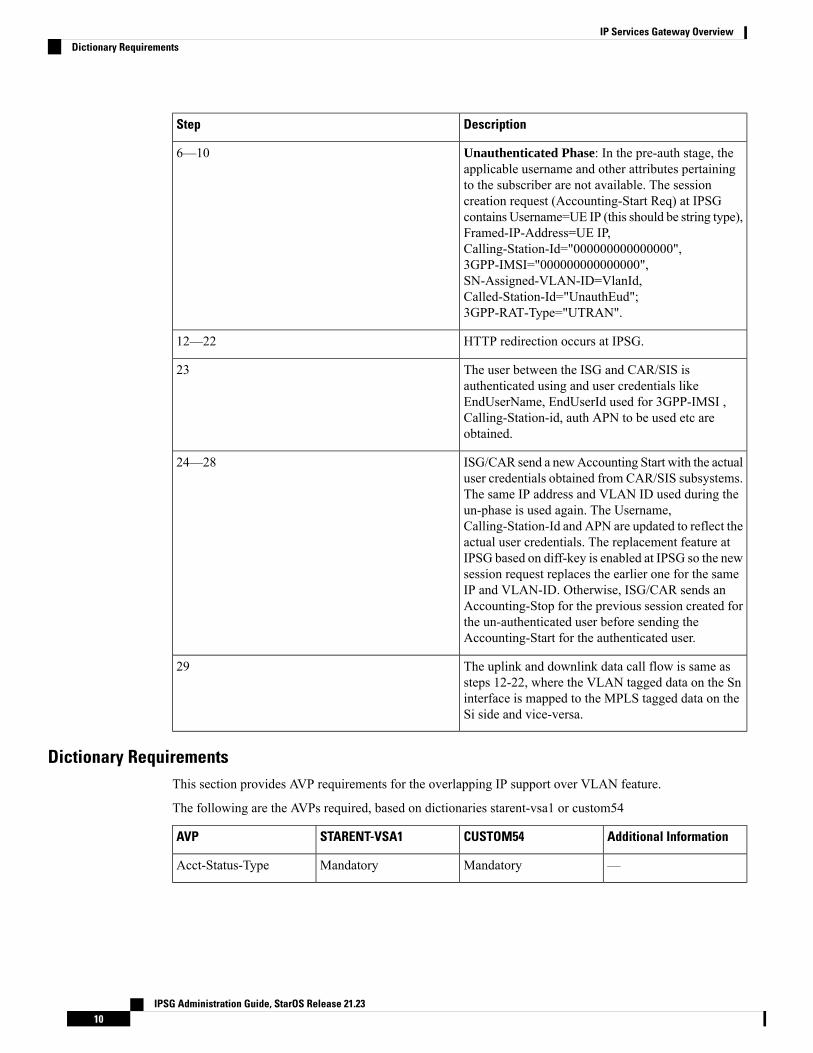
Table 1: Session Creation Call Flow Descriptions
DescriptionStep
BGP peering is established and routes exchangebetween ISG, BGPv4 routers, IPSG and MP-BGProuter.
1—3
IPSG Administration Guide, StarOS Release 21.239
IP Services Gateway OverviewCall Flows for Overlapping IP Support over VLAN
DescriptionStep
Unauthenticated Phase: In the pre-auth stage, theapplicable username and other attributes pertainingto the subscriber are not available. The sessioncreation request (Accounting-Start Req) at IPSGcontains Username=UE IP (this should be string type),Framed-IP-Address=UE IP,Calling-Station-Id="000000000000000",3GPP-IMSI="000000000000000",SN-Assigned-VLAN-ID=VlanId,Called-Station-Id="UnauthEud";3GPP-RAT-Type="UTRAN".
6—10
HTTP redirection occurs at IPSG.12—22
The user between the ISG and CAR/SIS isauthenticated using and user credentials likeEndUserName, EndUserId used for 3GPP-IMSI ,Calling-Station-id, auth APN to be used etc areobtained.
23
ISG/CAR send a newAccounting Start with the actualuser credentials obtained from CAR/SIS subsystems.The same IP address and VLAN ID used during theun-phase is used again. The Username,Calling-Station-Id and APN are updated to reflect theactual user credentials. The replacement feature atIPSG based on diff-key is enabled at IPSG so the newsession request replaces the earlier one for the sameIP and VLAN-ID. Otherwise, ISG/CAR sends anAccounting-Stop for the previous session created forthe un-authenticated user before sending theAccounting-Start for the authenticated user.
24—28
The uplink and downlink data call flow is same assteps 12-22, where the VLAN tagged data on the Sninterface is mapped to the MPLS tagged data on theSi side and vice-versa.
29
Dictionary RequirementsThis section provides AVP requirements for the overlapping IP support over VLAN feature.
The following are the AVPs required, based on dictionaries starent-vsa1 or custom54
Additional InformationCUSTOM54STARENT-VSA1AVP
—MandatoryMandatoryAcct-Status-Type
IPSG Administration Guide, StarOS Release 21.2310
IP Services Gateway OverviewDictionary Requirements
Additional InformationCUSTOM54STARENT-VSA1AVP
For custom54, if present,this AVP is used.Otherwise, a default value"void" is used as theusername in ipsgmgr.
OptionalMandatoryUser-Name
For starent-vsa1, this AVPwill be set to null andprocessed in ipsgmgr.
MandatoryOptionalCalling-Station-Id
Optional if an IPv6 prefixexists.
Optional for RadioAccessrequests.
MandatoryMandatoryFramed-Ip-Address
Optional for RadioAccessrequests.
MandatoryMandatoryAcct-Session-Id
Optional for Subscriberprofile and Radio Accessrequests.
MandatoryMandatoryCalled-Station-Id
This AVP is used toforward the VLAN ID.
MandatoryMandatorySN-Assigned-VLAN-ID
—OptionalOptionalSN-Transparent-Data
This AVP is used toforward the VPN name(destination context).
MandatoryMandatorySN-Vpn-Name
Radius Client IP ValidationThis feature enables IPSG to validate RADIUS accounting messages from different configured RADIUSclient IP addresses, and forward requests to the session manager.
In an architecture where multiple sites of IPSG and Radius Proxies exist, GGSN forwards RADIUS accountingmessages to IPSG through its Radius Proxy. In an event where the Radius Proxy is unreachable, GGSNforwards subsequent messages using the RADIUS Proxy belonging to another site. IPSG updates the RADIUSclient IP in the subscriber session, and forwards all control messages from the session manager to the alternateclient.
This feature can be enabled using the validate-client-ip keyword in the radius accounting command underthe IPSG RADIUS Server Configuration Mode. By default, the RADIUS client IPs are validated, and can bedisabled using the disable radius accounting validate-client-ip command.
IPSG Administration Guide, StarOS Release 21.2311
IP Services Gateway OverviewRadius Client IP Validation
Session RecoveryThe Session Recovery feature provides seamless failover and reconstruction of subscriber session informationin the event of a hardware or software fault within the system preventing a fully connected user session frombeing disconnected.
Session recovery is performed by mirroring key software processes (for example, Session Manager and AAAManager) within the system. These mirrored processes remain in an idle state (in standby-mode), whereinthey perform no processing, until they may be needed in the case of a software failure (for example, a SessionManager task aborts). The system spawns new instances of "standby mode" session and AAA Managers foreach active Control Processor (CP) being used.
Additionally, other key system-level software tasks, such as VPN Manager, are performed on a physicallyseparate packet processing card to ensure that a double software fault (for example, Session Manager andVPN Manager fails at same time on same card) cannot occur. The packet processing card used to host theVPNManager process is in active mode and is reserved by the operating system for this sole use when sessionrecovery is enabled.
For more information on Session Recovery, refer to the Session Recovery chapter in the System AdministrationGuide.
Note that the Inter-Chassis Session Recovery feature is not supported in this release.
IPSG Administration Guide, StarOS Release 21.2312
IP Services Gateway OverviewSession Recovery
C H A P T E R 2IP Services Gateway Configuration
This chapter describes how to configure the IPSG.
This chapter covers the following topics:
• Configuration Requirements for the IPSG, on page 13• Configuring the IPSG, on page 16
Configuration Requirements for the IPSGThis section provides a high-level description of the configuration requirements of the IPSG.
The Snoop and Server methods use the same configuration components and differ only in how the IPSGservice is configured.
The IPSG can be configured in various ways such as by creating a single context with interfaces for theRADIUSmessages and both inbound and outbound data traffic. The following figure presents another methodin which the IPSG context manages communication with the access gateway for both RADIUS messagingand inbound data traffic. The ISP context is responsible for all outbound data traffic.
The following figure also shows other important components such as IP access control lists (ACLs) in bothcontexts as well as an Enhanced Charging Service (ECS) configuration.
IPSG Administration Guide, StarOS Release 21.2313
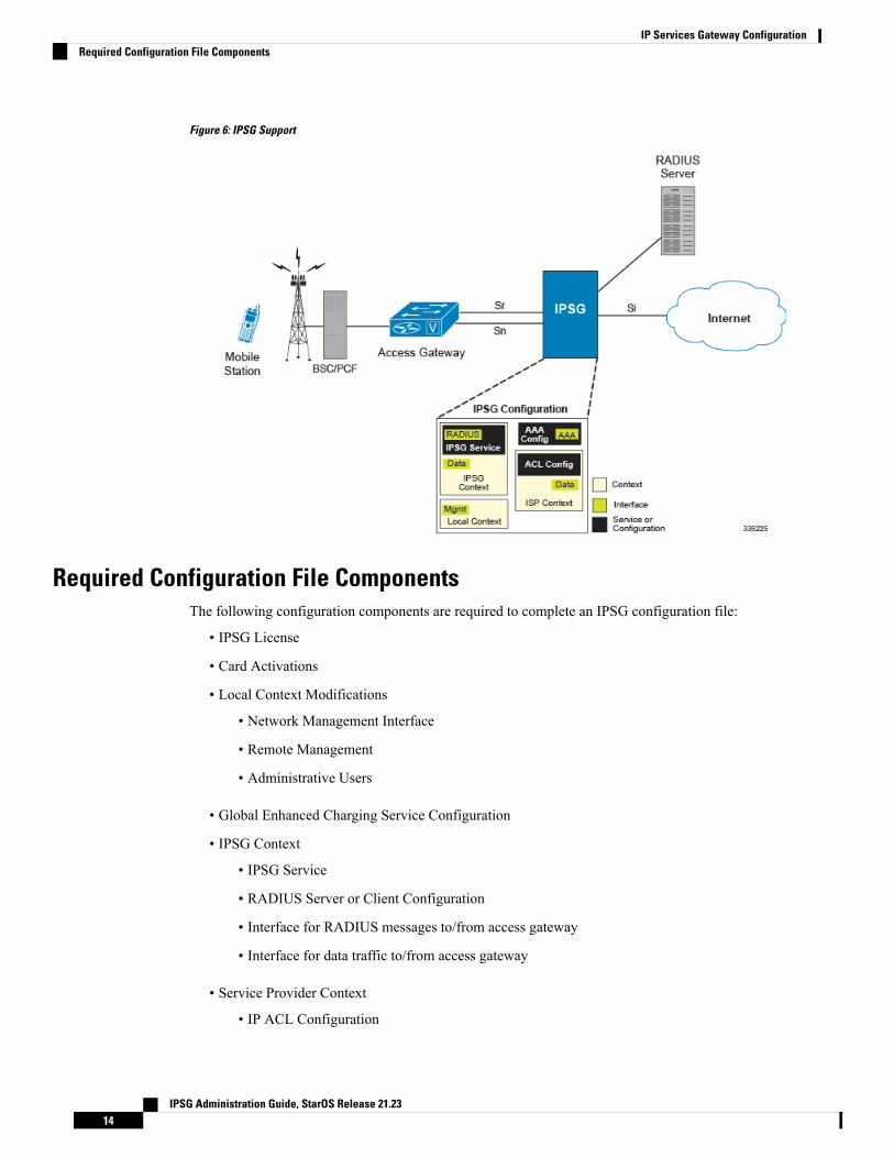
Figure 6: IPSG Support
Required Configuration File ComponentsThe following configuration components are required to complete an IPSG configuration file:
• IPSG License
• Card Activations
• Local Context Modifications
• Network Management Interface
• Remote Management
• Administrative Users
• Global Enhanced Charging Service Configuration
• IPSG Context
• IPSG Service
• RADIUS Server or Client Configuration
• Interface for RADIUS messages to/from access gateway
• Interface for data traffic to/from access gateway
• Service Provider Context
• IP ACL Configuration
IPSG Administration Guide, StarOS Release 21.2314
IP Services Gateway ConfigurationRequired Configuration File Components
• Interface for data traffic to/from access gateway
• Port Configuration (bindings)
Required Component InformationPrior to configuring the system, determine the following information:
• Context names
• Service names
• Enhanced Charging Service
• Rule definitions
• Rulebase name
• IMS Auth Service
• RADIUS accounting client IP address, dictionary type, and shared secret (RADIUS Server Mode)
• RADIUS accounting server IP address and dictionary type (RADIUS Snoop Mode)
• All Interfaces and ports
• Interface IP addresses
• Interface names
• Port names
• Port numbers
For a complete understanding of the required information for all configuration mode commands, refer to theCommand Line Interface Reference.
IPSG RADIUS Dictionaries
The following table provides information on the different IPSG RADIUS dictionaries and the correspondingusage:
Table 2: IPSG RADIUS Dictionaries
Session IdentityMandatory AttributesDictionary
User-Name
Framed-IP-Address
User-Name
Acct-Status-Type
Acct-Sess-Id
Called-Station-Id
Framed-IP-Address
starent-vsa1
IPSG Administration Guide, StarOS Release 21.2315
IP Services Gateway ConfigurationRequired Component Information
Session IdentityMandatory AttributesDictionary
Calling-station-Id
Framed-IP-Address
Acct-Status-Type
Acct-Sess-Id
Called-Station-Id
Framed-IP-Address
Calling-Station-Id
custom28
Calling-station-id
Framed-IP-Address
Acct-Status-Type
Acct-Sess-Id
Called-Station-Id
Framed-IP-Address
Calling-Station-Id
custom54
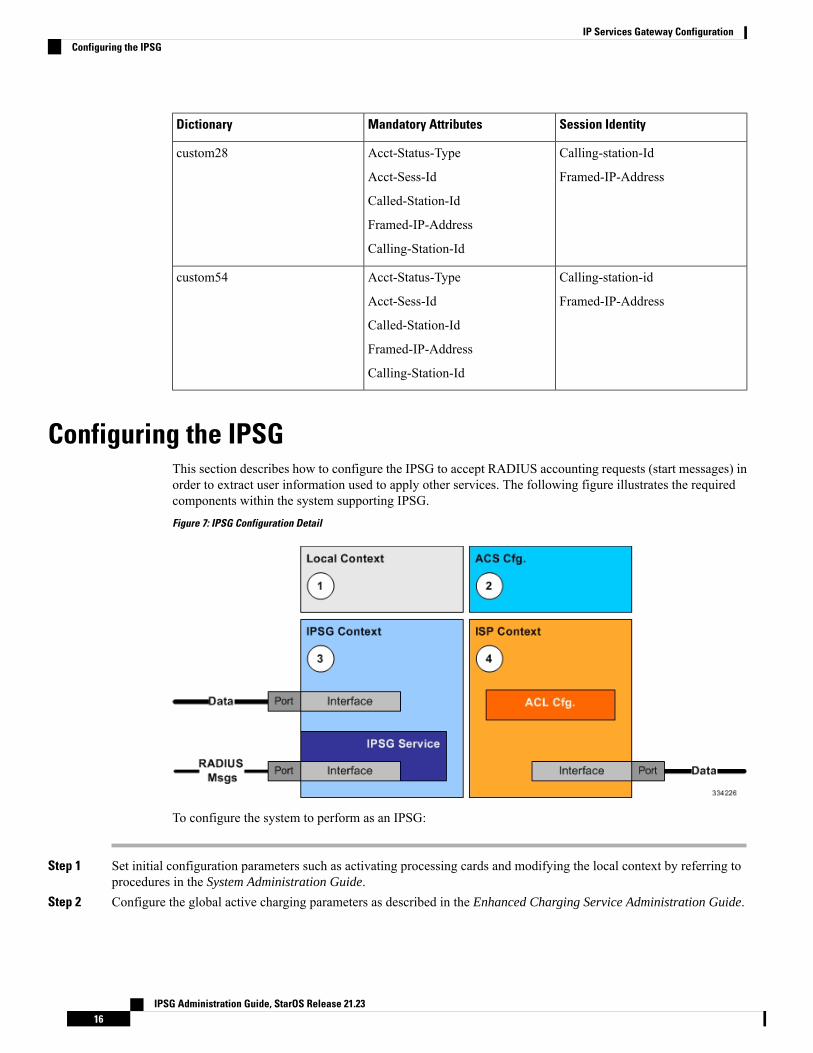
Configuring the IPSGThis section describes how to configure the IPSG to accept RADIUS accounting requests (start messages) inorder to extract user information used to apply other services. The following figure illustrates the requiredcomponents within the system supporting IPSG.
Figure 7: IPSG Configuration Detail
To configure the system to perform as an IPSG:
Step 1 Set initial configuration parameters such as activating processing cards and modifying the local context by referring toprocedures in the System Administration Guide.
Step 2 Configure the global active charging parameters as described in the Enhanced Charging Service Administration Guide.
IPSG Administration Guide, StarOS Release 21.2316
IP Services Gateway ConfigurationConfiguring the IPSG
Step 3 Configure the system to perform as an IPSG by applying the example configurations presented in IPSG Context andService Configuration, on page 17.
Step 4 Configure the Service Provider context by applying the example configuration presented in ISP Context Configuration,on page 19.
Step 5 Bind interfaces to ports as described in the System Administration Guide.Step 6 Save your configuration to flash memory, an external memory device, and/or a network location using the Exec mode
command save configuration. For additional information on how to verify and save configuration files, refer to theSystem Administration Guide and the Command Line Interface Reference.
Commands used in the configuration examples in this section provide base functionality to the extent that themost common or likely commands and/or keyword options are presented. In many cases, other optionalcommands and/or keyword options are available. Refer to the Command Line Interface Reference for completeinformation regarding all commands.
Important
IPSG Context and Service ConfigurationTo configure IPSG context and service:
Step 1 Create an IPSG context and the IPSG service by applying the example configuration in one of the following sections asrequired:
• Option 1: RADIUS Server Mode Configuration, on page 17• Option 2: RADIUS Server with Proxy Mode Configuration, on page 17• Option 3: RADIUS Snoop Mode Configuration, on page 18
Step 2 Create two interfaces within the IPSG context for communication with the access gateway by referring to the Creatingand Configuring Ethernet Interfaces and Ports procedure in the System Administration Guide.
Option 1: RADIUS Server Mode ConfigurationTo create an IPSG context and IPSG service in RADIUS Server Mode, use the following configuration:
configurecontext ipsg_context_name
ipsg-service ipsg_service_name mode radius-serverbind address ipv4/ipv6_address
radius dictionary dictionary_name
radius accounting client ipv4/ipv6_address [ encrypted ] keykey [ dictionary dictionary_name ] [ disconnect-message [ dest-port port_number
] ]end
Option 2: RADIUS Server with Proxy Mode ConfigurationTo create an IPSG context and IPSG service in RADIUS ServerMode with IPSG authentication and accountingproxy configuration, use the following configuration:
IPSG Administration Guide, StarOS Release 21.2317
IP Services Gateway ConfigurationIPSG Context and Service Configuration
configurecontext ipsg_context_name
ipsg-service ipsg_service_name mode radius-serverbind address ipv4/ipv6_address
radius dictionary dictionary_name
radius accounting client ipv4/ipv6_address [ encrypted ] keykey [ dictionary dictionary_name ] [ disconnect-message [ dest-port port_number
] ]# IPSG Authentication Proxy Configuration:
bind authentication-proxy address ipv4/ipv6_address
connection authorization [ encrypted ] password password
radius dictionary dictionary_name
radius accounting client ipv4/ipv6_address [ encrypted ] keykey [ dictionary dictionary_name ] [ disconnect-message [ dest-port port_number
] ]exit
aaa group defaultradius attribute nas-ip-address address ipv4/ipv6_address
radius dictionary dictionary_name
radius server ipv4/ipv6_address [ encrypted ] key key portport_number
radius accounting server ipv4/ipv6_address [ encrypted ] keykey port port_number
exit# IPSG Accounting Proxy Configuration:
ipsg-service ipsg_service_name mode radius-serverbind accounting-proxy address ipv4/ipv6_address port port_number
radius dictionary dictionary_name
radius accounting client ipv4/ipv6_address [ encrypted ] keysecret_key [ dictionary dictionary_name ] [ disconnect-message [ dest-portport_number ] ]
exitaaa group default
radius attribute nas-ip-address address ipv4/ipv6_address
radius dictionary dictionary_name
radius accounting server ipv4/ipv6_address [ encrypted ] keykey port port_number
end
Notes:
• If both IPSG Service and client/server dictionaries are configured, the client/server dictionary takesprecedence over the IPSG Service dictionary.
• If both RADIUS server and client dictionaries are configured, the client dictionary takes precedence overthe server dictionary.
• For basic AAA configurations please refer to the AAA and GTP Interface Administration and Reference.
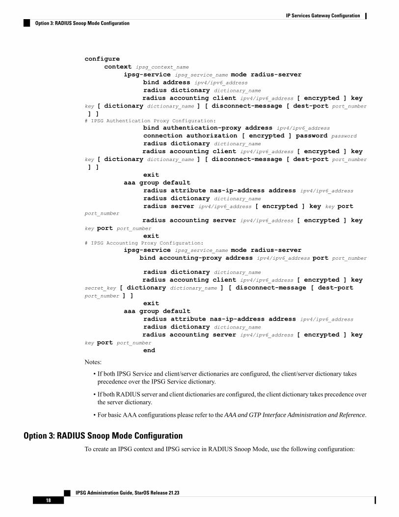
Option 3: RADIUS Snoop Mode ConfigurationTo create an IPSG context and IPSG service in RADIUS Snoop Mode, use the following configuration:
IPSG Administration Guide, StarOS Release 21.2318
IP Services Gateway ConfigurationOption 3: RADIUS Snoop Mode Configuration
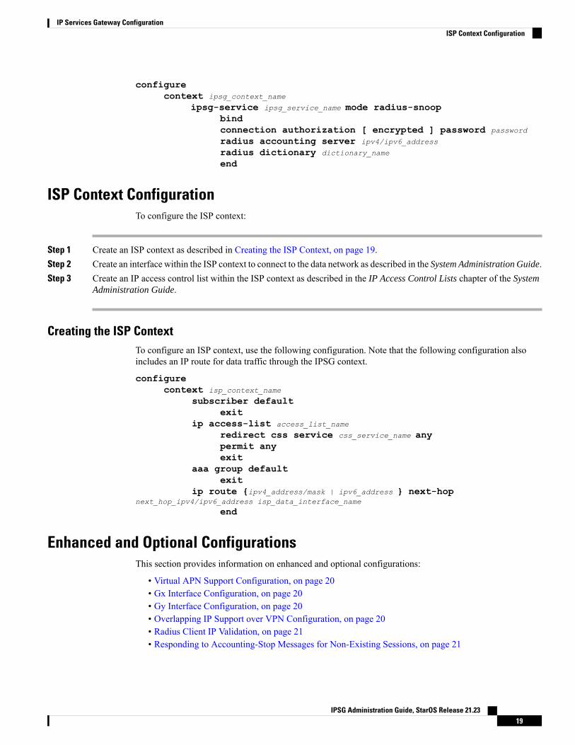
configurecontext ipsg_context_name
ipsg-service ipsg_service_name mode radius-snoopbindconnection authorization [ encrypted ] password password
radius accounting server ipv4/ipv6_address
radius dictionary dictionary_name
end
ISP Context ConfigurationTo configure the ISP context:
Step 1 Create an ISP context as described in Creating the ISP Context, on page 19.Step 2 Create an interface within the ISP context to connect to the data network as described in the System Administration Guide.Step 3 Create an IP access control list within the ISP context as described in the IP Access Control Lists chapter of the System
Administration Guide.
Creating the ISP ContextTo configure an ISP context, use the following configuration. Note that the following configuration alsoincludes an IP route for data traffic through the IPSG context.
configurecontext isp_context_name
subscriber defaultexit
ip access-list access_list_name
redirect css service css_service_name anypermit anyexit
aaa group defaultexit
ip route {ipv4_address/mask | ipv6_address } next-hopnext_hop_ipv4/ipv6_address isp_data_interface_name
end
Enhanced and Optional ConfigurationsThis section provides information on enhanced and optional configurations:
• Virtual APN Support Configuration, on page 20• Gx Interface Configuration, on page 20• Gy Interface Configuration, on page 20• Overlapping IP Support over VPN Configuration, on page 20• Radius Client IP Validation, on page 21• Responding to Accounting-Stop Messages for Non-Existing Sessions, on page 21
IPSG Administration Guide, StarOS Release 21.2319
IP Services Gateway ConfigurationISP Context Configuration
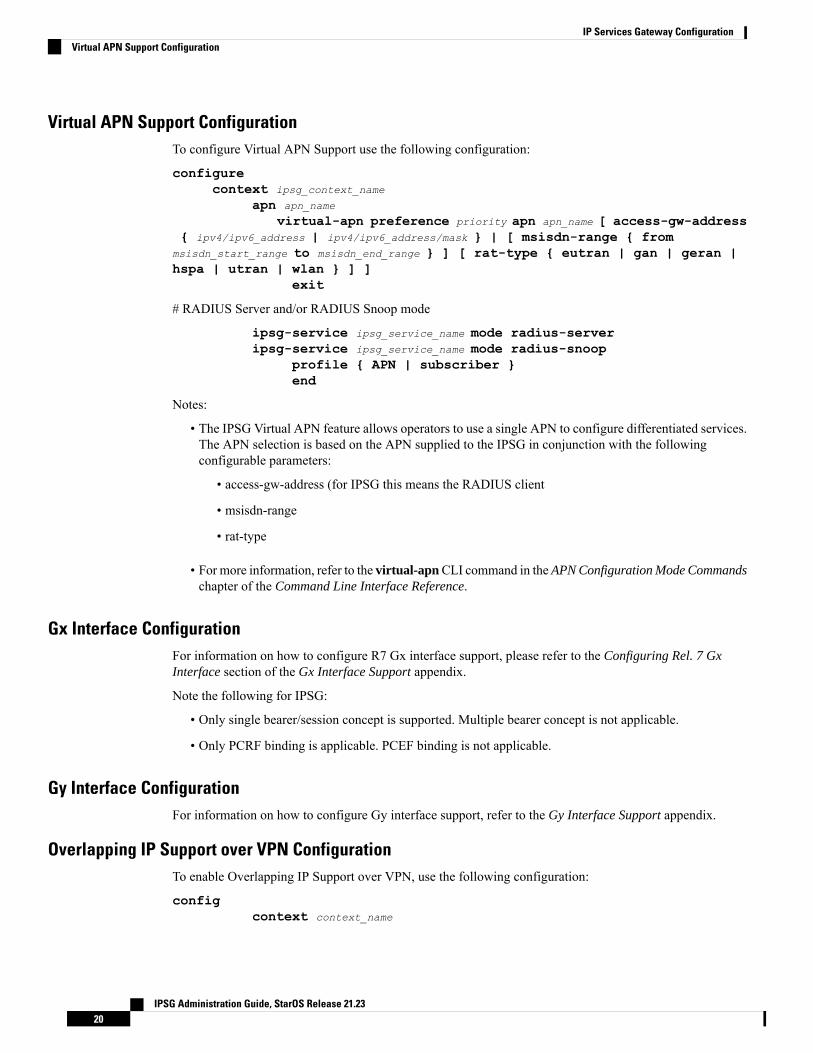
Virtual APN Support ConfigurationTo configure Virtual APN Support use the following configuration:
configurecontext ipsg_context_name
apn apn_name
virtual-apn preference priority apn apn_name [ access-gw-address{ ipv4/ipv6_address | ipv4/ipv6_address/mask } | [ msisdn-range { from
msisdn_start_range to msisdn_end_range } ] [ rat-type { eutran | gan | geran |hspa | utran | wlan } ] ]
exit
# RADIUS Server and/or RADIUS Snoop mode
ipsg-service ipsg_service_name mode radius-serveripsg-service ipsg_service_name mode radius-snoop
profile { APN | subscriber }end
Notes:
• The IPSG Virtual APN feature allows operators to use a single APN to configure differentiated services.The APN selection is based on the APN supplied to the IPSG in conjunction with the followingconfigurable parameters:
• access-gw-address (for IPSG this means the RADIUS client
• msisdn-range
• rat-type
• For more information, refer to the virtual-apnCLI command in the APN Configuration Mode Commandschapter of the Command Line Interface Reference.
Gx Interface ConfigurationFor information on how to configure R7 Gx interface support, please refer to the Configuring Rel. 7 GxInterface section of the Gx Interface Support appendix.
Note the following for IPSG:
• Only single bearer/session concept is supported. Multiple bearer concept is not applicable.
• Only PCRF binding is applicable. PCEF binding is not applicable.
Gy Interface ConfigurationFor information on how to configure Gy interface support, refer to the Gy Interface Support appendix.
Overlapping IP Support over VPN ConfigurationTo enable Overlapping IP Support over VPN, use the following configuration:
configcontext context_name
IPSG Administration Guide, StarOS Release 21.2320
IP Services Gateway ConfigurationVirtual APN Support Configuration
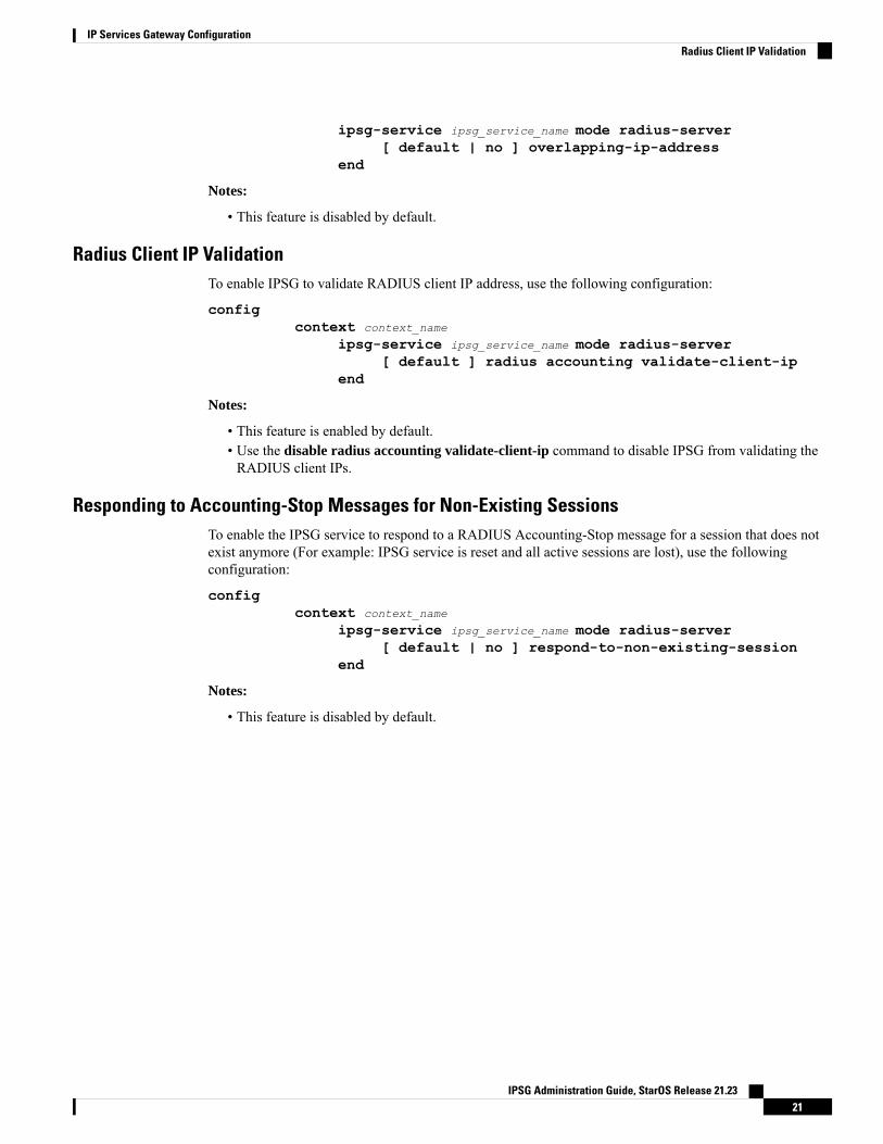
ipsg-service ipsg_service_name mode radius-server[ default | no ] overlapping-ip-address
end
Notes:
• This feature is disabled by default.
Radius Client IP ValidationTo enable IPSG to validate RADIUS client IP address, use the following configuration:
configcontext context_name
ipsg-service ipsg_service_name mode radius-server[ default ] radius accounting validate-client-ip
end
Notes:
• This feature is enabled by default.• Use the disable radius accounting validate-client-ip command to disable IPSG from validating theRADIUS client IPs.
Responding to Accounting-Stop Messages for Non-Existing SessionsTo enable the IPSG service to respond to a RADIUS Accounting-Stop message for a session that does notexist anymore (For example: IPSG service is reset and all active sessions are lost), use the followingconfiguration:
configcontext context_name
ipsg-service ipsg_service_name mode radius-server[ default | no ] respond-to-non-existing-session
end
Notes:
• This feature is disabled by default.
IPSG Administration Guide, StarOS Release 21.2321
IP Services Gateway ConfigurationRadius Client IP Validation

IPSG Administration Guide, StarOS Release 21.2322
IP Services Gateway ConfigurationResponding to Accounting-Stop Messages for Non-Existing Sessions
C H A P T E R 3IPSG 4G Support
• Feature Summary and Revision History, on page 23• Feature Description, on page 24• How It Works, on page 24• Limitations and Restrictions, on page 25
Feature Summary and Revision HistorySummary Data
IPSGApplicable Product(s) or FunctionalArea
AllApplicable Platform(s)
Enabled - Always-on (IPSG Licence Required)Feature Default
Not ApplicableRelated Changes in This Release
IPSG Administration GuideRelated Documentation
Revision History
Revision history details are not provided for features introduced before releases 21.2 and N5.5.Important
ReleaseRevision Details
21.3IPSG now supports operating in the 4GRAT environment, which enables IPSGto act as an inline service agent in thecore 4G network.
Pre 21.2First introduced.
IPSG Administration Guide, StarOS Release 21.2323
Feature DescriptionPre StarOS Release 21.3, IPSG supported only for 3G RAT type. From StarOS Release 21.3, 4G RAT Typeand EPS QoS is supported. Support has been extended for IPSG to operate in the 4G RAT environment whichenables IPSG to act as an inline service agent in the core 4G network.
Previous Behavior: Earlier, IPSG supported only 3G RAT type and not 4G RAT type.
New Behavior: With StarOS Release 21.3, IPSG supports 4G RAT type. IPSG also supports ULI withTAI+ECGI and TAI, EPS QoS Profile, and generates P-GW CDRs with 4G RAT type.
Customer Impact: 4G calls on IPSG are supported.
EPS QoS Profile Handling
EPS QoS profile handling is done in the following way:
• The QoS profile received from PCRF is given priority as compared to the QoS profile received from theP-GW.
• AMBRs received from PCRF are given priority when there is bandwidth limitation.
• If the Rule Level AMBRs are present, then first, the rule level bandwidth limiting is enforced and then,the APN level AMBR is enforced only for the non-GBR QCI values.
• In the accounting start message, if the QoS profile is received with GBR QCI, then the call is droppedon the IPSG. It is assumed that the QoS profile that is being received on IPSG is of default-bearer on theP-GW.
• If IPSG receives an interim update for a subscriber with a GBRQCI value, then the QCI profile is ignoredand no CCR-U is sent to the PCRF.
• If the CLI command radius accounting interim create-new-call is configured under the IPSG serviceand a QoS profile is received with GBR QCI as part of the interim RADIUS update message, then thecall is dropped on the IPSG. It is assumed that the QoS profile that is being received on IPSG is of thedefault bearer on the P-GW.
• To see the QoS profile and QCI information in the CCR-U, you must enable the trigger for the QoSchange and default bearer QoS change.
As the RAT type is EUTRAN, you must pick the correct P-GW specific dictionary in order to generate theP-GW records.
Important
How It WorksThis section lists the working of IPSG:
• Support for the EUTRAN RAT type on IPSG creates an EPS bearer.
• The ULI information includes TAI+ECGI, TAI, and ECGI.
IPSG Administration Guide, StarOS Release 21.2324
IPSG 4G SupportFeature Description
• This ULI information is populated to the eGCDRs and the CDRs.
• The EPS QoS information received as part of the RADIUS message is also parsed.
• The bearer type (EPS), RAT Type (eUTRAN, ULI (TAI + ECGI + TAI), and EPS QoS Information thatis received as part of RADIUS message is conveyed to the Gx.
• When an interim update is received from the P-GW, IPSG handles this interim update. If the PCRF isregistered as ULI change or QoS change, CCR-U is sent to the PCRF with the received information.
Limitations and RestrictionsFollowing are the limitations of this feature:
• Handoff scenarios are not supported.
• Gy interface is only supported for 4G.
• CoA and disconnect messages handling is not supported.
• IPSG session replacement with EUTRAN is not supported.
• Tethering detection on IPSG is not supported.
IPSG Administration Guide, StarOS Release 21.2325
IPSG 4G SupportLimitations and Restrictions

IPSG Administration Guide, StarOS Release 21.2326
IPSG 4G SupportLimitations and Restrictions
C H A P T E R 4Cisco Ultra Traffic Optimization
This chapter describes the following topics:
• Feature Summary and Revision History, on page 27• Overview, on page 28• How Cisco Ultra Traffic Optimization Works, on page 28• Configuring Cisco Ultra Traffic Optimization, on page 32• Multi-Policy Support for Traffic Optimization, on page 38• Monitoring and Troubleshooting, on page 48
Feature Summary and Revision HistorySummary Data
Applicable Product(s) or Functional Area • IPSG
• P-GW
Applicable Platform(s) • ASR 5500
• Ultra Gateway Platform
Disabled - License RequiredFeature Default
Not ApplicableRelated Changes in This Release
Related Documentation • Command Line Interface Reference
• IPSG Administration Guide
Revision History
ReleaseRevision Details
21.8With this release, Cisco Ultra Traffic Optimization is qualified on IPSG.
IPSG Administration Guide, StarOS Release 21.2327
OverviewIn a high-bandwidth bulk data flow scenario, user experience is impacted due to various wireless networkconditions and policies like shaping, throttling, and other bottlenecks that induce congestion, especially in theRAN. This results in TCP applying its saw-tooth algorithm for congestion control and impacts user experience,and overall system capacity is not fully utilized.
The Cisco Ultra Traffic Optimization solution provides clientless optimization of TCP and HTTP traffic. Thissolution is integrated with Cisco P-GW and has the following benefits:
• Increases the capacity of existing cell sites and therefore, enables more traffic transmission.
• Improves Quality of Experience (QoE) of users by providing more bits per second.
• Provides instantaneous stabilizing andmaximizing per subscriber throughput, particularly during networkcongestion.
How Cisco Ultra Traffic Optimization WorksThe Cisco Ultra Traffic Optimization achieves its gains by shaping video traffic during times of high networkload/congestion. It monitors and profiles each individual video flow that passes through the gateway and usesits machine learning algorithms to determine whether that flow is traversing a congested channel. Cisco UltraTraffic Optimization then flow-controls video to varying levels and time, depending on the degree of detectedcongestion, and efficiently aligns delivery of the video traffic to less-congested moments while still providingadequate bandwidth to videos to maintain their quality. The result is less network latency and higher userthroughputs while maintaining HD video. Cisco Ultra Traffic Optimization does not drop packets or modifydata payloads in any way.
The Cisco Ultra Traffic Optimization integrates with standard Cisco P-GW functions such as ApplicationDetection and Control (ADC), allowing mobile operators to define optimization policies that are based on thetraffic application type as well as APN, QCI, and other common traffic delineations. Cisco Ultra TrafficOptimization is fully radio network aware, allowing management on a per eNodeB cell basis.
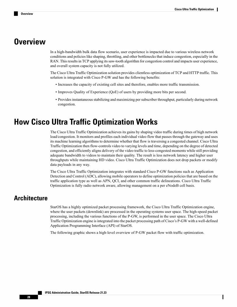
ArchitectureStarOS has a highly optimized packet processing framework, the Cisco Ultra Traffic Optimization engine,where the user packets (downlink) are processed in the operating systems user space. The high-speed packetprocessing, including the various functions of the P-GW, is performed in the user space. The Cisco UltraTraffic Optimization engine is integrated into the packet processing path of Cisco’s P-GWwith a well-definedApplication Programming Interface (API) of StarOS.
The following graphic shows a high-level overview of P-GW packet flow with traffic optimization.
IPSG Administration Guide, StarOS Release 21.2328
Cisco Ultra Traffic OptimizationOverview
Handling of Traffic Optimization Data RecordThe Traffic Optimization Data Record (TODR) is generated only on the expiry of idle-timeout of the CiscoUltra Traffic Optimization engine. No statistics related to session or flow from P-GW is included in thisTODR. The data records are a separate file for the Traffic Optimization statistics, and available to externalanalytics platform.
List of Attributes and File FormatAll TODR attributes of traffic optimization is enabled by a single CLI command. The output is always commaseparated, and in a rigid format.
Standard TODR
The following is the format of a Standard TODR:instance_id,flow_type,srcIP,dstIP,policy_id, proto_type, dscp,flow_first_pkt_rx_time_ms,flow_last_pkt_rx_time_ms,flow_cumulative_rx_bytes
Example:
1,0,173.39.13.38,192.168.3.106,0,1,0,1489131332693,1489131335924,342292
Where:
• instance_id: Instance ID.
• flow_type: Standard flow (0)
• srcIP: Indicates the source IP address.
IPSG Administration Guide, StarOS Release 21.2329
Cisco Ultra Traffic OptimizationHandling of Traffic Optimization Data Record
• dstIP: Indicates the destination IP address.
• policy_id: Indicates the traffic optimization policy ID.
• proto_type: Indicates the IP protocol being used. The IP protocols are: TCP and UDP.
• dscp: Indicates the DSCP code for upstream packets.
• flow_first_pkt_rx_time_ms: Indicates the timestamp when the first packet was detected during trafficoptimization.
• flow_last_pkt_rx_time_ms: Indicates the timestamp when the last packet was detected during trafficoptimization.
• flow_cumulative_rx_bytes: Indicates the number of bytes transferred by this flow.
Large TODR
The following is a sample output of a Large TODR.
19,1,404005123456789,22.22.0.1,1.1.1.8,custom1,2,0,1588858362158,1588858952986,16420806,1588858364162,419,351,7000,0,0,1,19:2:15,2,0,0,2,1,1,16:0x12546300012345,1588858364162,80396,1472,0,0,0,2,1,16:0x12546300012345,1588858366171,146942,1937,7000,0,0,2
Where:
• instance_id: Instance ID.
• flow_type: Large flow (1)
• imsi_id: Indicates the International Mobile Subscriber Identity.
• srcIP: Indicates the source IP address.
• dstIP: Indicates the destination IP address.
• policy_name: Identifies the name of the configured traffic optimization policy.
• policy_id: Indicates the traffic optimization policy ID.
• proto_type: Indicates the IP protocol being used. The IP protocols are: TCP and UDP.
• dscp: Indicates the DSCP code for upstream packets.
• flow_first_pkt_rx_time_ms: Indicates the timestamp when the first packet was detected during trafficoptimization.
• flow_last_pkt_rx_time_ms: Indicates the timestamp when the last packet was detected during trafficoptimization.
• flow_cumulative_rx_bytes: Indicates the number of bytes transferred by this flow.
• large_detection_time_ms: Indicates the timestamp when the flow was detected as Large.
• avg_burst_rate_kbps: Indicates the average rate in Kbps of all the measured bursts.
• avg_eff_rate_kbps: Indicates the average effective rate in Kbps.
• final_link_peak_kbps: Indicates the highest detected link peak over the life of the Large flow.
• recovered_capacity_bytes: Indicates the recovered capacity in Kbps for this Large flow.
IPSG Administration Guide, StarOS Release 21.2330
Cisco Ultra Traffic OptimizationList of Attributes and File Format
• recovered_capacity_ms: Indicates the timestamp of recovered capacity for this Large flow.
• acs_flow_id_count: Indicates the number of ACS Flow IDs present in this TODR. A maximum of 20ACS Flow IDs is present.
• acs_flow_id_list: Indicates the list of individual ACS Flow IDs. For example, acs_flow_id1, acs_flow_id2,and so on.
• phase_count: Indicates the Large flow phase count.
• min_gbr_kbps: Indicates the Minimum Guaranteed Bit Rate (GBR) in Kbps.
• max_gbr_kbps: Indicates the Maximum Guaranteed Bit Rate (MBR) in Kbps.
• phase_count_record: Indicates the number of phases present in this record.
• end_of_phases: 0 (not end of phases) or 1 (end of phases).
• Large flow phase attributes:
• phase_type: Indicates the type of the phase. This field represents that the flow was in one of thefollowing three possible states where each state is represented by a numeric value:
• 0 - Ramp-up Phase (if the Flow was previously idle)
• 1 - Measurement Phase (required)
• 2 - Flow Control Phase (if congestion detected during Measurement Phase)
• uli_type: Indicates the type of ULI.
• phase_start_time_ms: Indicates the timestamp for the start time of the phase.
• burst_bytes: Indicates the burst size in bytes.
• burst_duration_ms: Indicates the burst duration in milliseconds.
• link_peak_kbps: Indicates the peak rate for the flow during its life.
• flow_control_rate_kbps: Indicates the rate at which flow control was attempted (or 0 if non-flowcontrol phase). This field is valid only when flow is in ‘Flow Control Phase’.
• max_num_queued_packets: Identifies the maximum number of packets queued.
• policy_id: Identifies the traffic optimization policy ID.
LicensingThe Cisco Ultra Traffic Optimization is a licensed Cisco solution. Contact your Cisco account representativefor detailed information on specific licensing requirements. For information on installing and verifying licenses,refer to the Managing License Keys section of the Software Management Operations chapter in the SystemAdministration Guide.
IPSG Administration Guide, StarOS Release 21.2331
Cisco Ultra Traffic OptimizationLicensing
Limitations and RestrictionsThe values which the P-GW chooses to send to the Cisco Ultra Traffic Optimization engine are the valuesassociated from the bearer GBR and bearer MBR. In the current implementation, only downlink GBR andMBR are sent to the engine for traffic optimization.
The IPSG supports only certain triggers for which the information is available with the IPSG service.
Configuring Cisco Ultra Traffic OptimizationThis section provides information on enabling support for the Cisco Ultra Traffic Optimization solution.
Loading Traffic OptimizationUse the following configuration under the Global Configuration Mode to load the Cisco Ultra TrafficOptimization as a solution:
configurerequire active-charging traffic-optimizationend
After you configure this command, you must save the configuration and then reload the chassis for thecommand to take effect. For information on saving the configuration file and reloading the chassis, refer tothe System Administration Guide for your deployment.
Important
Enabling or disabling the traffic optimization can be done through the Service-scheme framework.Important
After you configure the require active-charging traffic-optimization CLI command, you must save theconfiguration and then reload the chassis for the command to take effect. For information on saving theconfiguration file and reloading the chassis, refer to the System Administration Guide for your deployment.
Important
In 21.3, and 21.5 and later releases, the dependency on the chassis reboot is not valid anymore. The CiscoUltra Traffic Optimization engine is loaded by default. The Cisco Ultra Traffic Optimization configurationCLIs are available when the license is enabled. As such, the traffic-optimization keyword has been deprecated.
Important
Enabling Cisco Ultra Traffic Optimization Configuration ProfileUse the following configuration under ACSConfigurationMode to enable the Cisco Ultra Traffic Optimizationprofile:
IPSG Administration Guide, StarOS Release 21.2332
Cisco Ultra Traffic OptimizationLimitations and Restrictions
configureactive-charging service service_name
traffic-optimization-profileend
NOTES:
• The above CLI command enables the Traffic Optimization Profile Configuration, a new configurationmode.
Configuring the Operating ModeUse the following CLI commands to configure the operating mode under Traffic Optimization ProfileConfiguration Mode for the Cisco Ultra Traffic Optimization engine:
configureactive-charging service service_name
traffic-optimization-profilemode [ active | passive ]end
Notes:
• mode: Sets the mode of operation for traffic optimization.
• active: Active mode where both traffic optimization and flow monitoring is done on the packet.
• passive: Passive mode where no flow-control is performed but monitoring is done on the packet.
Configuring Threshold ValueUse the following CLI commands to configure the threshold value for the TCP flow to be considered for thetraffic optimization:
configureactive-charging service service_name
traffic-optimization-profileheavy-session detection-threshold bytes
end
Notes:
• detection-threshold bytes: Specifies the Detection Threshold (in bytes), beyond which it is consideredas heavy session.
bytes must be an integer from 1 to 4294967295.
For optimum traffic optimization benefits, it is recommended to set the threshold above 3 MB.
IPSG Administration Guide, StarOS Release 21.2333
Cisco Ultra Traffic OptimizationConfiguring the Operating Mode
Enabling Cisco Ultra Traffic Optimization Configuration Profile UsingService-scheme Framework
The service-scheme framework is used to enable traffic optimization at APN, rule base, QCI, and Rule level.There are two main constructs for the service-scheme framework:
• Subscriber-base – This helps in associating subscribers with service-scheme based on the subs-classconfiguration.
• subs-class – The conditions defined under subs-class enables in classifying the subscribers basedon rule base, APN, v-APN name. The conditions can also be defined in combination, and both ORas well as AND operators are supported while evaluating them.
• Service-scheme – This helps in associating actions based on trigger conditions which can be triggeredeither at call-setup time, Bearer-creation time, or flow-creation time.
• trigger-condition – For any trigger, the trigger-action application is based on conditions definedunder the trigger-condition.
• trigger-actions – Defines the actions to be taken on the classified flow. These actions can be trafficoptimization, throttle-suppress, and so on.
Session Setup TriggerThe any-match = TRUE, a wildcard configuration, is the only supported condition for this trigger and sothis is applicable to all the flows of the subscriber.
Use the following configuration to setup a Session Trigger:
configureactive-charging service service_name
trigger-action trigger_action_name
traffic-optimizationexit
trigger-condition trigger_condition_name1
any-match = TRUEexit
service-scheme service_scheme_name
trigger sess-setuppriority priority_value trigger-condition trigger_condition_name1
trigger-action trigger_action_name
exitsubs-class sub_class_name
apn = apn_name
exitsubscriber-base subscriber_base_name
priority priority_value subs-class sub_class_name bind service-schemeservice_scheme_name
end
Sample Configuration
Following is a sample configuration for Session Setup Trigger:
IPSG Administration Guide, StarOS Release 21.2334
Cisco Ultra Traffic OptimizationEnabling Cisco Ultra Traffic Optimization Configuration Profile Using Service-scheme Framework
service-scheme SS1trigger sess-setuppriority 1 trigger-condition sess-setup trigger-action sess-setup
#exittrigger-condition sess-setupany-match = TRUE
#exittrigger-action sess-setuptraffic-optimization policy sess-setup
#exit
Bearer Creation TriggerThe trigger conditions related to QCI can be used for this trigger, and so this is applicable to all the flows ofspecific bearers.
The following is a sample configuration:
configureactive-charging service service_name
trigger-action trigger_action_name
traffic-optimizationexit
trigger-condition trigger_condition_name1
any-match = TRUEexit
trigger-condition trigger_condition_name2
qci = qci_value
exitservice-scheme service_scheme_name
trigger bearer-creationpriority priority_value trigger-condition trigger_condition_name2
trigger-action trigger_action_name
exitexit
subs-class sub_class_name
apn = apn_name
exitsubscriber-base subscriber_base_name
priority priority_value subs-class sub_class_name bind service-schemeservice_scheme_name
end
Flow Creation TriggerThe trigger conditions related to rule-name and QCI can be used here, and so this is related to specific flow.
The following is a sample configuration:
configureactive-charging service service_name
trigger-action trigger_action_name
traffic-optimizationexit
trigger-condition trigger_condition_name1
any-match = TRUE
IPSG Administration Guide, StarOS Release 21.2335
Cisco Ultra Traffic OptimizationBearer Creation Trigger
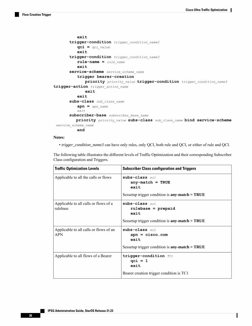
exittrigger-condition trigger_condition_name2
qci = qci_value
exittrigger-condition trigger_condition_name3
rule-name = rule_name
exitservice-scheme service_scheme_name
trigger bearer-creationpriority priority_value trigger-condition trigger_condition_name3
trigger-action trigger_action_name
exitexit
subs-class sub_class_name
apn = apn_nameexit
subscriber-base subscriber_base_name
priority priority_value subs-class sub_class_name bind service-schemeservice_scheme_name
end
Notes:
• trigger_condition_name3 can have only rules, only QCI, both rule and QCI, or either of rule and QCI.
The following table illustrates the different levels of Traffic Optimization and their corresponding SubscriberClass configuration and Triggers.
Subscriber Class configuration and TriggersTraffic Optimization Levels
subs-class sc1
any-match = TRUEexit
Sessetup trigger condition is any-match = TRUE
Applicable to all the calls or flows
subs-class sc1
rulebase = prepaidexit
Sessetup trigger condition is any-match = TRUE
Applicable to all calls or flows of arulebase
subs-class sc1
apn = cisco.comexit
Sessetup trigger condition is any-match = TRUE
Applicable to all calls or flows of anAPN
trigger-condition TC1
qci = 1exit
Bearer creation trigger condition is TC1
Applicable to all flows of a Bearer
IPSG Administration Guide, StarOS Release 21.2336
Cisco Ultra Traffic OptimizationFlow Creation Trigger
Subscriber Class configuration and TriggersTraffic Optimization Levels
trigger-condition TC1
qci = 1rule-name = tcpmulti-line-or all-linesexit
Flow creation trigger condition is TC1
Applicable to a particular flow
In case of LTE to eHRPD handover, since QCI is not valid for eHRPD, it is recommended to configurerule-name as the trigger-condition under service-scheme.
Important
Generating TODRUse the following CLI commands under ACSConfigurationMode to enable Traffic Optimization Data Record(TODR) generation:
configureactive-charging service service_name
traffic-optimization-profiledata-recordend
NOTES:
• If previously configured, use the no data-record command to disable generating TODR.
Configuring Rulebase to Allow UDP Traffic Optimization
From Release 21.8 onwards, it is recommended to enable TCP and UDP protocol for Traffic Optimizationby using the CLI commands mentioned in the Enabling TCP and UDP section of this chapter.
Important
Use the following configuration in ACSRulebase ConfigurationMode to turn ON/OFF the traffic optimizationfor UDP traffic.
Enabling/Disabling the Cisco Ultra Traffic Optimization solution is controlled by Service-scheme Framework.Important
configureactive-charging service service_name
rulebase rulebase_name
[ no ] traffic-optimization udpend
NOTES:
IPSG Administration Guide, StarOS Release 21.2337
Cisco Ultra Traffic OptimizationGenerating TODR
• udp: Specifies traffic optimization for UDP traffic.
• By default, UDP traffic optimization is disabled.
• If previously configured, use the no traffic-optimization udpCLI command to disable traffic optimizationfor UDP traffic.
Multi-Policy Support for Traffic OptimizationCisco Ultra Traffic Optimization engine supports Traffic Optimization for multiple policies and providesTraffic Optimization for a desired location. It supports a maximum of 32 policies that include two pre-configuredpolicies, by default. Operators can configure several parameters under each Traffic Optimization policy.
This feature includes the following functionalities:
• By default, Traffic Optimization is enabled for TCP and UDP data for a particular Subscriber, Bearer,or Flow that use the Service-Schema.
PORT 443 supports UDP or QUIC-based Traffic Optimization.Important
• Selection of a policy depends on the priority configured. A trigger-condition is used to prioritize a trafficoptimization policy. The priority is configurable regardless of a specific location where the trafficoptimization policy is applied. Based on the configured priorities, a traffic optimization policy can beoverridden by another policy.
• A configuration to associate a traffic optimization policy with a Trigger Action, under the Service-Schema.
• A configuration to select a Traffic Optimization policy for a Location Trigger. Currently, only ECGIChange Detection is supported under the Local Policy Service Configuration mode.
Location Change Trigger is not supported with IPSG.Important
Policy ID for a flow is not recovered after a Session Recovery (SR) or Inter-Chassis Session Recovery (ICSR).Important
The Multi-Policy Support feature requires the same Cisco Ultra Traffic Optimization license key be installed.Contact your Cisco account representative for detailed information on specific licensing requirements.
Important
IPSG Administration Guide, StarOS Release 21.2338
Cisco Ultra Traffic OptimizationMulti-Policy Support for Traffic Optimization
How Multi-Policy Support Works
Policy Selection
Cisco’s Ultra Traffic Optimization engine provides two default policies – Managed and Unmanaged. WhenUnmanaged policy is selected, traffic optimization is not performed.
WhenManaged policy is selected, traffic optimization is performed using default parameters.Managed policyis applied when a policy is not specified in a Trigger Action where traffic optimization is enabled withoutspecifying a policy.
WhenManaged policy is selected, traffic optimization is performed using default parameters.Managed policyis applied when a policy is not specified in a Trigger Action where traffic optimization is enabled withoutspecifying a policy.
• Session Setup Trigger – If a Trigger Action is applied only for a Session Setup in a Service-Schema,then the trigger action is only applied to new sessions only.
• Bearer Setup Trigger – If a trigger action is applied only for a Bearer Setup, changes in the trigger actionwill be applicable to newly created bearers and its flows.
• Flow Creation Trigger – Under a trigger condition corresponding to a flow create, conditions can beadded based on a rule-name, local-policy-rule or an IP protocol in addition to the trigger condition:any-match.
When traffic optimization on existing flows is disabled because of a trigger condition, then the trafficoptimization engine will apply the default Unmanaged policy on them.
Deleting a Policy
Before deleting a Policy profile, all association to a traffic optimization policy should be removed.
For more information on deletion of a policy, refer to the Traffic Optimization Policy Configuration section.
Configuring Multi-Policy SupportThe following sections describes the required configurations to support the Multi-Policy Support.
Configuring a Traffic Optimization ProfileUse the following CLI commands to configure a Traffic Optimization Profile.
configurerequire active-chargingactive-charging service service_name
traffic-optimization-profile profile_name
data-record[ large-flows-only | managed-large-flows-only ]no data record[ no ] efd-flow-cleanup-interval cleanup_interval
[ no ] stats-interval stats_interval
[ no ] stats-options { flow-analyst [ flow-trace ] | flow-trace [flow-analyst ] }
end
IPSG Administration Guide, StarOS Release 21.2339
Cisco Ultra Traffic OptimizationHow Multi-Policy Support Works
NOTES:
• require active-charging: Enables the configuration requirement for an Active Charging service.
After you configure this command, you must save the configuration and thenreload the chassis for the command to take effect. For information on saving theconfiguration file and reloading the chassis, refer to the System AdministrationGuide for your deployment.
Important
• data-record: Enables the generation of traffic optimization data record.
large-flows-only: Enables the traffic optimization data record generation for large flows.
managed-large-flows-only: Enables the traffic optimization data record generation for managed largeflows.
The keywords - large-flows-only andmanaged-large-flows-onlywhen configured alongwithdata-recordenables the CUTO library to stream the respective statistics as part of the stats-options command, to theexternal server. The operator can configure a combination of the stats-options keywords flow-trace andflow-analyst and the data-record command to notify the CUTO library accordingly.
One of the above the two keywords can be configured as part of the data-record,which enables the CUTO library to stream the respective statistics.
Note
The default behavior of the data-record command is not affected with the above implementation . Ifconfigured without any of the options, then TODRs are generated for all standard and large flows, whichis the existing behavior.
• efd-flow-cleanup-interval: Configures the EFD flow cleanup interval. The interval value is an integerthat ranges 10–5000 milliseconds.
• stats-interval: Configures the flow statistics collection and reporting interval in seconds. The intervalvalue is an integer that ranges 1–60 seconds.
• stats-options: Configures options to collect the flow statistics. It only specifies whether the stream mustbe a Flow Trace or a Flow Analyst or both, to an external server.
From Release 21.6 onwards, the heavy-session command is deprecated.Note
Configuring a Traffic Optimization PolicyUse the following CLI commands to configure a Traffic Optimization Policy.
configurerequire active-chargingactive-charging service service_name[extended]
[ no ] traffic-optimization-policy policy_name[extended]bandwidth-mgmt { backoff-profile [ managed | unmanaged ] [
IPSG Administration Guide, StarOS Release 21.2340
Cisco Ultra Traffic OptimizationConfiguring a Traffic Optimization Policy
min-effective-rate effective_rate [ min-flow-control-rate flow_rate ] |min-flow-control-rate flow_rate [ min-effective-rate effective_rate ] ] |min-effective-rate effective_rate [ backoff-profile [ managed | unmanaged ][ min-flow-control-rate flow_rate ] | min-flow-control-rate control_rate [backoff-profile [ managed | unmanaged ] ] | min-flow-control-rate [ [backoff-profile [ managed | unmanaged ] [ min-effective-rate effective_rate
] | [ min-effective-rate effective_rate ] [ backoff-profile [ managed |unmanaged ] ] }
extended-bandwidth-mgmt { backoff-profile [ managed | unmanaged ][ min-effective-rate effective_rate [ min-flow-control-rate flow_rate ] |min-flow-control-rate flow_rate [ min-effective-rate effective_rate ] ] |min-effective-rate effective_rate [ backoff-profile [ managed | unmanaged ][ min-flow-control-rate flow_rate ] | min-flow-control-rate control_rate [backoff-profile [ managed | unmanaged ] ] | min-flow-control-rate [ [backoff-profile [ managed | unmanaged ] [ min-effective-rate effective_rate
] | [ min-effective-rate effective_rate ] [ backoff-profile [ managed |unmanaged ] ] }
[ no ] bandwidth-mgmt[ no ] extended-bandwidth-mgmtcurbing-control { max-phases max_phase_value [ rate curbing_control_rate
[ threshold-rate threshold_rate [ time curbing_control_duration ] ] ] | ratecurbing_control_rate [ max-phases [ threshold-rate threshold_rate [ timecurbing_control_duration ] ] ] | threshold-rate [ max-phases max_phase_value [rate curbing_control_rate [ time curbing_control_duration ] ] ] | time [ max-phasesmax_phase_value [ rate curbing_control_rate [ threshold-rate threshold_rate] ] ]}
extended-curbing-control { max-phases max_phase_value [ ratecurbing_control_rate [ threshold-rate threshold_rate [ time curbing_control_duration
] ] ] | rate curbing_control_rate [ max-phases [ threshold-rate threshold_rate
[ time curbing_control_duration ] ] ] | threshold-rate [ max-phasesmax_phase_value [ rate curbing_control_rate [ time curbing_control_duration ] ] ] |time [ max-phases max_phase_value [ rate curbing_control_rate [ threshold-ratethreshold_rate] ] ] }
[ no ] curbing-control[ no ] extended-curbing-controlheavy-session { standard-flow-timeout [ threshold threshold_value |
threshold threshold_value [ standard-flow-timeout timeout_value ] }extended-heavy-session { standard-flow-timeout [ threshold
threshold_value | threshold threshold_value [ standard-flow-timeout timeout_value
] }[ no ] heavy-session[ no ] extended-heavy-sessionlink-profile { initial-rate initial_seed_value [ max-rate
max_peak_rate_value [ peak-lock ] ] | max-rate [ initial-rate initial_seed_value
[ peak-lock ] ] | peak-lock [ initial-rate initial_seed_value [ max-ratemax_peak_rate_value ] ] }
extended-link-profile { initial-rate initial_seed_value [ max-ratemax_peak_rate_value [ peak-lock ] ] | max-rate [ initial-rate initial_seed_value
[ peak-lock ] ] | peak-lock [ initial-rate initial_seed_value [ max-ratemax_peak_rate_value ] ] }
[ no ] link-profile
IPSG Administration Guide, StarOS Release 21.2341
Cisco Ultra Traffic OptimizationConfiguring a Traffic Optimization Policy
[ no ] extended-link-profilesession-params { tcp-ramp-up tcp_rampup_duration [ udp-ramp-up
udp_rampup_duration ] | udp-ramp-up udp_rampup_duration [ tcp-ramp-uptcp_rampup_duration ] }
extended-session-params { tcp-ramp-up tcp_rampup_duration [ udp-ramp-upudp_rampup_duration ] | udp-ramp-up udp_rampup_duration [ tcp-ramp-up
tcp_rampup_duration ] }[ no ] session-params[ no ] extended-session-paramsend
NOTES:
• Only when extended keyword is used after the policy name, you will be able to see the ‘extended-*’parameters, for example extended-bandwidth-mgmt.
• no: Overwrites the configured parameters with default values. The operator must remove all associatedpolicies in a policy profile before deleting a policy profile. Otherwise, the following error message isdisplayed:Failure: traffic-optimization policy in use, cannot be deleted.
• bandwidth-mgmt: Configures Base bandwidth management parameters.
• backoff-profile: Determines the overall aggressiveness of the back off rates.
• managed: Enables both traffic monitoring and traffic optimization.
• unmanaged: Only enables traffic monitoring.
• min-effective-rate: Configures minimum effective shaping rate in Kbps.
• min-flow-control-rate: Configures the minimum rate that is allowed in Kbps to control the flowof heavy-session-flows during congestion.
• extended-bandwidth-mgmt: Configures Extended bandwidth management parameters.
• backoff-profile: Determines the overall aggressiveness of the back off rates.
• managed: Enables both traffic monitoring and traffic optimization.
• unmanaged: Only enables traffic monitoring.
• min-effective-rate: Configures minimum effective shaping rate in Kbps.
• min-flow-control-rate: Configures the minimum rate that is allowed in Kbps to control the flowof heavy-session-flows during congestion.
• curbing-control: Configures Base curbing flow control related parameters.
• max-phases: Configures consecutive phases where the target shaping rate is below threshold-rateto trigger curbing flow control. .
• rate: Configures the curbing flow-control at a fixed rate in Kbps instead of a dynamic rate.
• threshold-rate: Configures the minimum target shaping rate in kbps to trigger curbing..
• time: Configures the duration of a flow control phase in milliseconds.
IPSG Administration Guide, StarOS Release 21.2342
Cisco Ultra Traffic OptimizationConfiguring a Traffic Optimization Policy
• extended-curbing-control: Configures Extended curbing flow control related parameters.
• max-phases: Configures consecutive phases where the target shaping rate is below threshold-rateto trigger curbing flow control. The maximum phase value is an integer ranging 2–10 for extendedparameter. The default value inherits base.
• rate: Configures the curbing flow-control at a fixed rate in Kbps instead of a dynamic rate. Thecontrol rate value is an integer ranging 0-100000 kbps for extended parameter. The default valueinherits base.
• threshold-rate: Configures the minimum target shaping rate in kbps to trigger curbing.The thresholdrate is an integer ranging 100-100000 kbps for extended parameter. The default value inherits base.
• time: Configures the duration of a flow control phase in milliseconds.
The flow control duration value is an integer ranging 0–600000 for extended parameter. The defaultvalue inherits base.
• heavy-session: Configures parameters for Base heavy-session detection.
• standard-flow-timeout: Configures the idle timeout in milliseconds, for expiration of standardflows.
• threshold: Configures heavy-session detection threshold in bytes. On reaching the threshold, theflow is monitored and potentially managed..
• extended-heavy-session: Configures parameters for Extended heavy-session detection.
• standard-flow-timeout: Configures the idle timeout in milliseconds, for expiration of standardflows. .
• threshold: Configures heavy-session detection threshold in bytes. On reaching the threshold, theflow is monitored and potentially managed.
• link-profile: Configures Base link profile parameters.
• initial-rate: Configures the initial seed value of the acquired peak rate in Kbps for a traffic session.
• max-rate: Configures the maximum learned peak rate that is allowed in Kbps for a traffic session.
• peak-lock: Confirms with the link peak rate available at the initial link peak rate setting.
• extended-link-profile: Configures Extended link profile parameters.
• initial-rate: Configures the initial seed value of the acquired peak rate in Kbps for a traffic session.
• max-rate: Configures the maximum learned peak rate that is allowed in Kbps for a traffic session.
• peak-lock: Confirms with the link peak rate available at the initial link peak rate setting.
• session-params: Configures Base session parameters.
• tcp-ramp-up: Configures the ramp-up-phase duration in milliseconds, for TCP traffic.
• udp-ramp-up: Configures the ramp-up-phase duration in milliseconds, for the UDP traffic..
• extended-session-params: Configures Extended session parameters.
IPSG Administration Guide, StarOS Release 21.2343
Cisco Ultra Traffic OptimizationConfiguring a Traffic Optimization Policy
• tcp-ramp-up: Configures the ramp-up-phase duration in milliseconds, for TCP traffic.
• udp-ramp-up: Configures the ramp-up-phase duration in milliseconds, for the UDP traffic..
After you configure require active-charging command, you must save the configuration and then reload thechassis for the command to take effect. For information on saving the configuration file and reloading thechassis, refer to the System Administration Guide for your deployment.
Important
The following table shows the parameter ranges for both Base and Extended set parameters, the default valuesof those parameters and, the validated Range/value for configuring the parameters for Cisco Ultra TrafficOptimization library.
Comment
Range/valuecheck
Extendeddefaultvalue
ExtendedParameterRange
Basedefaultvalue
Base ParameterRange
ParameterParametercategory(Base/Extended)
If youenter avaluedifferentfromBase,thevaluefromBaseparameterand anappropriatemessagewill bedisplayed.
requirematchbase
Inheritsbase
managed/unmanaged
managedmanaged/unmanaged
backoff-profile
bandwidth-mgmt/extended-bandwidth-mgmt
allow fullrange
45000100-500000kbps
600100-100000kbps
min-effective-rate
allow fullrange
1000100- 500000kbps
250100-100000kbps
min-flow-control-rate
IPSG Administration Guide, StarOS Release 21.2344
Cisco Ultra Traffic OptimizationConfiguring a Traffic Optimization Policy
Comment
Range/valuecheck
Extendeddefaultvalue
ExtendedParameterRange
Basedefaultvalue
Base ParameterRange
ParameterParametercategory(Base/Extended)
allow fullrange
Inheritsbase
2-1022-10max-phasescurbing-control /extended-curbing-control
allow fullrange
Inheritsbase
0-100000 kbps00-100000 kbpsrate
allow fullrange
Inheritsbase
100-100000kbps
600100-100000kbps
threshold- rate
allow fullrange
Inheritsbase
0-600000 ms00-600000 mstime
allow fullrange
Inheritsbase
100-10000 ms500100-10000 msstandard-flow-time out
heavy-session /extended- heavy-session
allow fullrange
Inheritsbase
100000–100000000bytes
3000000100000–100000000bytes
threshold
IPSG Administration Guide, StarOS Release 21.2345
Cisco Ultra Traffic OptimizationConfiguring a Traffic Optimization Policy
Comment
Range/valuecheck
Extendeddefaultvalue
ExtendedParameterRange
Basedefaultvalue
Base ParameterRange
ParameterParametercategory(Base/Extended)
If youenter avaluedifferentfromBase,thevaluefromBaseparameterand anappropriatemessagewill bedisplayed.
requiregreaterthan orequal tobasemax-rate
50000100-500000kbps
7000100-100000kbps
initial-ratelink-profile /extended-link-profile
If youenter avaluedifferentfromBase,thevaluefromBaseparameterand anappropriatemessagewill bedisplayed.
requiregreaterthan orequal tobasemax-rate
100000100-500000kbps
15000100-100000kbps
max- rate
alloweither
disabledenabled/disableddisabledenabled/disabledpeak-lock
IPSG Administration Guide, StarOS Release 21.2346
Cisco Ultra Traffic OptimizationConfiguring a Traffic Optimization Policy
Comment
Range/valuecheck
Extendeddefaultvalue
ExtendedParameterRange
Basedefaultvalue
Base ParameterRange
ParameterParametercategory(Base/Extended)
allow fullrange
20000-10000 ms20000-10000 mstcp-ramp-up
session-params /extended- session-params allow full
range20000-10000 ms20000-10000 msudp-
ramp-up
Traffic Optimization Policy - Default Values
Bandwidth-Mgmt:
Backoff-Profile : ManagedMin-Effective-Rate : 600 (kbps)Min-Flow-Control-Rate : 250 (kbps)
Curbing-Control:
Time : 0 (ms)Rate : 0 (kbps)Max-Phases : 2Threshold-Rate : 600 (kbps)
Heavy-Session:
Threshold : 3000000(bytes)Standard-Flow-Timeout : 500 (ms)
Link-Profile:
Initial-Rate : 7000 (kbps)Max-Rate : 15000 (kbps)Peak-Lock : Disabled
Session-Params:
Tcp-Ramp-Up : 2000 (ms)Udp-Ramp-Up : 2000 (ms)
Associating a Trigger Action to a Traffic Optimization PolicyUse the following CLI commands to associate a Trigger Action to a Traffic Optimization Policy.
configurerequire active-chargingactive-charging service service_name
trigger-action trigger_action_name
traffic-optimization policy policy_name
[ no ] traffic-optimizationend
NOTES:
• traffic-optimization policy: Configures a traffic optimization policy.
• no: Removes the configured traffic optimization policy.
IPSG Administration Guide, StarOS Release 21.2347
Cisco Ultra Traffic OptimizationAssociating a Trigger Action to a Traffic Optimization Policy
Enabling TCP and UDPUse the following CLI commands to enable TCP and UDP protocol for Traffic Optimization:
configurerequire active-chargingactive-charging service service_name
trigger-condition trigger_condition_name
[ no ] ip protocol = [ tcp | udp ]end
NOTES:
• no: Deletes the Active Charging Service related configuration.
• ip: Establishes an IP configuration.
• protocol: Indicates the protocol being transported by the IP packet.
• tcp: Indicates the TCP protocol to be transported by the IP packet.
• udp: Indicates the UDP protocol to be transported by the IP packet.
After you configure this command, you must save the configuration and then reload the chassis for thecommand to take effect. For information on saving the configuration file and reloading the chassis, refer tothe System Administration Guide for your deployment.
Important
Service-Scheme Configuration for Multi-Policy SupportThe service-schema framework enables traffic optimization at APN, rule base, QCI, and Rule level. With theMulti-Policy Support feature, traffic optimization in a service-scheme framework allows the operator toconfigure multiple policies and to configure traffic optimization based on a desirable location.
The service-scheme framework helps in associating actions based on trigger conditions, which can be triggeredeither at call-setup time, Bearer-creation time, or flow-creation time.
Monitoring and TroubleshootingThis section provides information regarding commands available to monitor and troubleshoot the Cisco UltraTraffic Optimization solution on the P-GW.
Cisco Ultra Traffic Optimization Show Commands and/or OutputsThis section provides information about show commands and the fields that are introduced in support of CiscoUltra Traffic Optimization solution.
show active-charging rulebase name <rulebase_name>The output of this show command has been enhanced to display if the UDP traffic optimization is Enabledor Disabled. Following are the fields that has been introduced:
IPSG Administration Guide, StarOS Release 21.2348
Cisco Ultra Traffic OptimizationEnabling TCP and UDP
• Traffic Optimization:
• UDP: Enabled/Disabled
show active-charging traffic-optimization countersThe show active-charging traffic-optimization counters sessmgr { all | instance number } CLI commandis introduced where:
• counters – Displays aggregate flow counters/statistics from Cisco Ultra Traffic Optimization engine.
This CLI command is license dependent and visible only if the license is loaded.Important
Following are the new field/counters:
• Traffic Optimization Flows:
• Active Normal Flow Count
• Active Large Flow Count
• Active Managed Large Flow Count
• Active Unmanaged Large Flow Count
• Base Policy:
• Active Large Flow Count
• Active Managed Large Flow Count
• Active Unmanaged Large Flow Count
• Extended Policy:
• Active Large Flow Count
• Active Managed Large Flow Count
• Active Unmanaged Large Flow Count
• Total Normal Flow Count
• Total Large Flow Count
• Total Managed Large Flow Count
• Total Unmanaged Large Flow Count
• Base Policy:
• Total Large Flow Count
• Total Managed Large Flow Count
• Total Unmanaged Large Flow Count
IPSG Administration Guide, StarOS Release 21.2349
Cisco Ultra Traffic Optimizationshow active-charging traffic-optimization counters
• Extended Policy:
• Total Large Flow Count
• Total Managed Large Flow Count
• Total Unmanaged Large Flow Count
• Total IO Bytes
• Total Large Flow Bytes
• Total Recovered Capacity Bytes
• Total Recovered Capacity ms
On executing the above command, the following new fields are displayed for theMulti-Policy Support feature:
This CLI command is license dependent and visible only if the license is loaded.Important
• TCP Traffic Optimization Flows:
• Active Normal Flow Count
• Active Large Flow Count
• Active Managed Large Flow Count
• Active Unmanaged Large Flow Count
• Base Policy:
• Active Large Flow Count
• Active Managed Large Flow Count
• Active Unmanaged Large Flow Count
• Extended Policy:
• Active Large Flow Count
• Active Managed Large Flow Count
• Active Unmanaged Large Flow Count
• Total Normal Flow Count
• Total Large Flow Count
• Total Managed Large Flow Count
• Total Unmanaged Large Flow Count
• Base Policy:
• Total Large Flow Count
IPSG Administration Guide, StarOS Release 21.2350
Cisco Ultra Traffic Optimizationshow active-charging traffic-optimization counters
• Total Managed Large Flow Count
• Total Unmanaged Large Flow Count
• Extended Policy:
• Total Large Flow Count
• Total Managed Large Flow Count
• Total Unmanaged Large Flow Count
• Total IO Bytes
• Total Large Flow Bytes
• Total Recovered Capacity Bytes
• Total Recovered Capacity ms
• UDP Traffic Optimization Flows:
• Active Normal Flow Count
• Active Large Flow Count
• Active Managed Large Flow Count
• Active Unmanaged Large Flow Count
• Base Policy:
• Active Large Flow Count
• Active Managed Large Flow Count
• Active Unmanaged Large Flow Count
• Extended Policy:
• Active Large Flow Count
• Active Managed Large Flow Count
• Active Unmanaged Large Flow Count
• Total Normal Flow Count•
• Total Large Flow Count
• Total Managed Large Flow Count
• Total Unmanaged Large Flow Count
• Base Policy:
• Total Large Flow Count
• Total Managed Large Flow Count
IPSG Administration Guide, StarOS Release 21.2351
Cisco Ultra Traffic Optimizationshow active-charging traffic-optimization counters
• Total Unmanaged Large Flow Count
• Extended Policy:
• Total Large Flow Count
• Total Managed Large Flow Count
• Total Unmanaged Large Flow Count
• Total IO Bytes:
• Total Large Flow Bytes
• Total Recovered Capacity Bytes
• Total Recovered Capacity ms
show active-charging traffic-optimization infoThis show command has been introduced in Exec Mode, where:
• traffic-optimization – Displays all traffic optimization options.
• info – Displays Cisco Ultra Traffic Optimization engine information.
The output of this CLI command displays the version, mode, and configuration values.
Following are the new fields/counters:
• Version:
• Mode:
• Configuration:
• Data Records (TODR)
• Statistics Options
• EFD Flow Cleanup Interval
• Statistics Interval
show active-charging traffic-optimization policyOn executing the above command, the following new fields are displayed for theMulti-Policy Support feature:
• Policy Name
• Policy-Id
• Bandwidth-Mgmt
• Backoff-Profile
• Min-Effective-Rate
IPSG Administration Guide, StarOS Release 21.2352
Cisco Ultra Traffic Optimizationshow active-charging traffic-optimization info
• Min-Flow-Control-Rate
• Extended-Bandwidth-Mgmt
• Backoff-Profile
• Min-Effective-Rate
• Min-Flow-Control-Rate
• Curbing-Control
• Time
• Rate
• Max-phases
• Threshold-Rate
• Extended-Curbing-Control
• Time
• Rate
• Max-phases
• Threshold-Rate
• Heavy-Session
• Threshold
• Standard-Flow-Timeout
• Extended-Heavy-Session
• Threshold
• Standard-Flow-Timeout
• Link-Profile
• Initial-Rate
• Max-Rate
• Peak-Lock
• Extended-Link-Profile
• Initial-Rate
• Max-Rate
• Peak-Lock
• Session-Params
IPSG Administration Guide, StarOS Release 21.2353
Cisco Ultra Traffic Optimizationshow active-charging traffic-optimization policy
• Tcp-Ramp-Up
• Udp-Ramp-Up
• Extended-Session-Params
• Tcp-Ramp-Up
• Udp-Ramp-Up
IPSG Administration Guide, StarOS Release 21.2354
Cisco Ultra Traffic Optimizationshow active-charging traffic-optimization policy
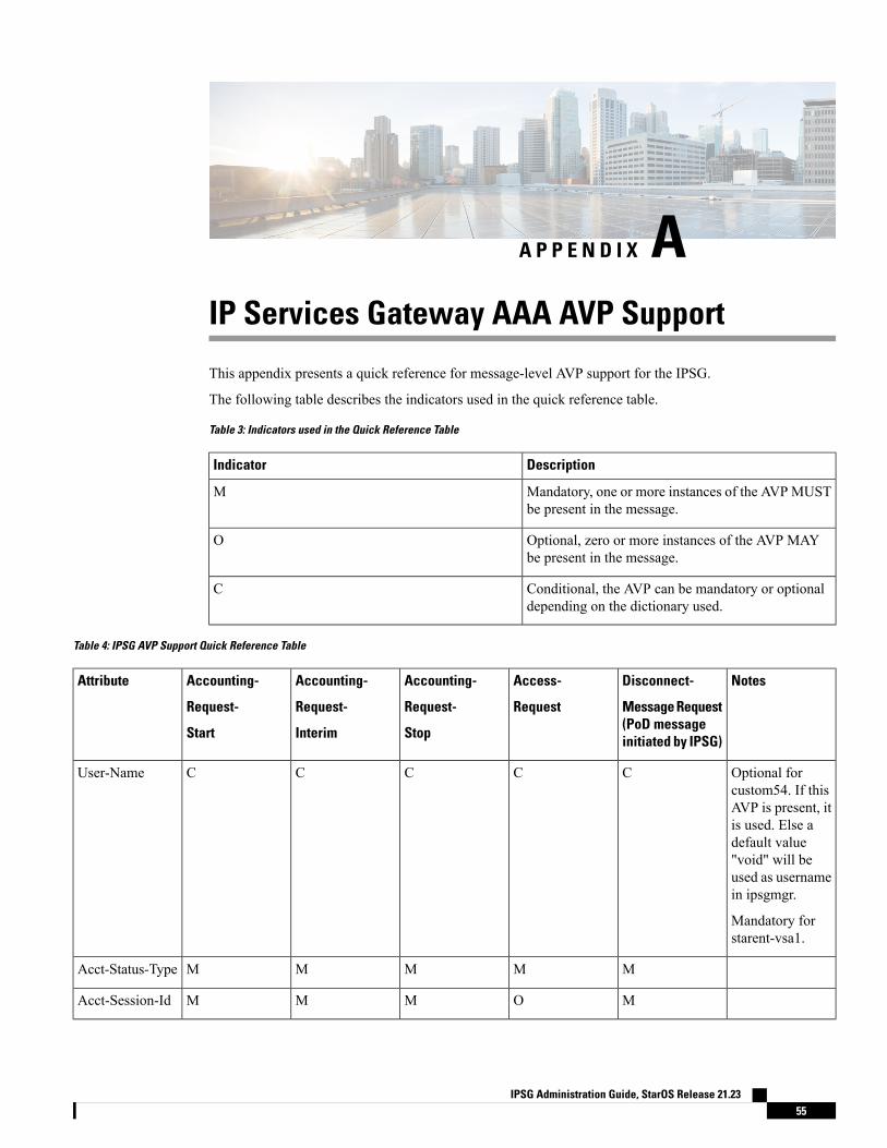
A P P E N D I X AIP Services Gateway AAA AVP Support
This appendix presents a quick reference for message-level AVP support for the IPSG.
The following table describes the indicators used in the quick reference table.
Table 3: Indicators used in the Quick Reference Table
DescriptionIndicator
Mandatory, one or more instances of the AVPMUSTbe present in the message.
M
Optional, zero or more instances of the AVP MAYbe present in the message.
O
Conditional, the AVP can be mandatory or optionaldepending on the dictionary used.
C
Table 4: IPSG AVP Support Quick Reference Table
NotesDisconnect-
Message Request(PoD messageinitiated by IPSG)
Access-
Request
Accounting-
Request-
Stop
Accounting-
Request-
Interim
Accounting-
Request-
Start
Attribute
Optional forcustom54. If thisAVP is present, itis used. Else adefault value"void" will beused as usernamein ipsgmgr.
Mandatory forstarent-vsa1.
CCCCCUser-Name
MMMMMAcct-Status-Type
MOMMMAcct-Session-Id
IPSG Administration Guide, StarOS Release 21.2355
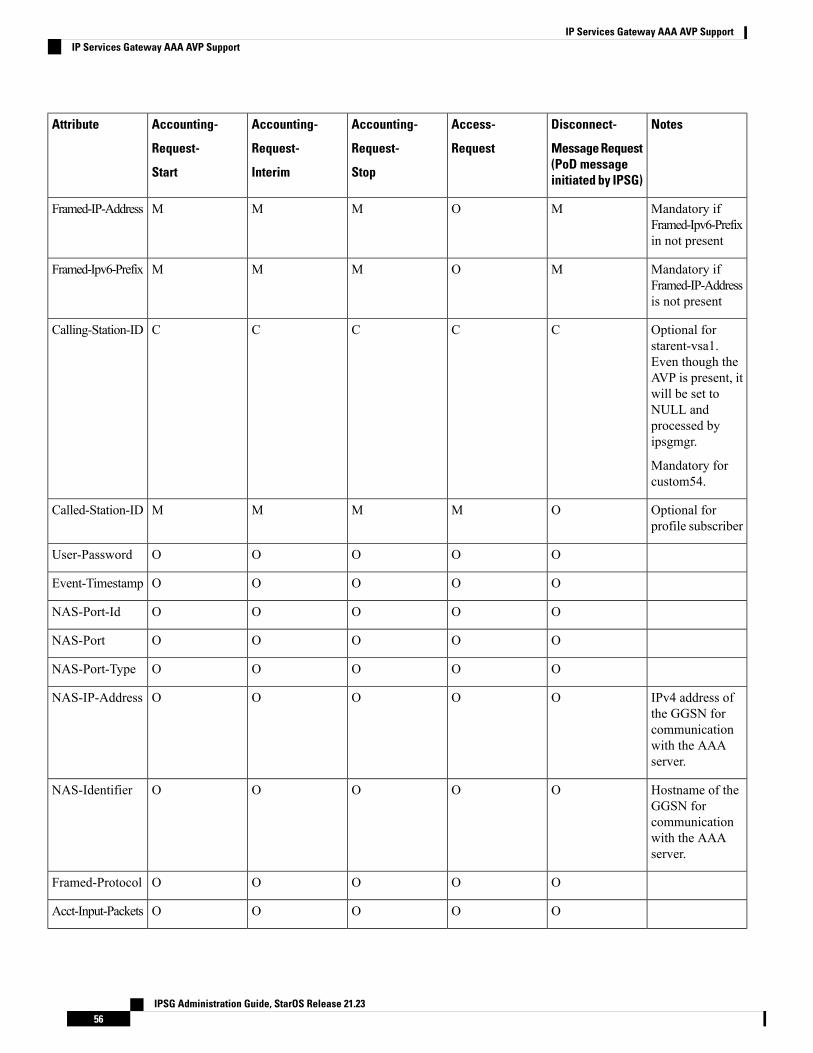
NotesDisconnect-
Message Request(PoD messageinitiated by IPSG)
Access-
Request
Accounting-
Request-
Stop
Accounting-
Request-
Interim
Accounting-
Request-
Start
Attribute
Mandatory ifFramed-Ipv6-Prefixin not present
MOMMMFramed-IP-Address
Mandatory ifFramed-IP-Addressis not present
MOMMMFramed-Ipv6-Prefix
Optional forstarent-vsa1.Even though theAVP is present, itwill be set toNULL andprocessed byipsgmgr.
Mandatory forcustom54.
CCCCCCalling-Station-ID
Optional forprofile subscriber
OMMMMCalled-Station-ID
OOOOOUser-Password
OOOOOEvent-Timestamp
OOOOONAS-Port-Id
OOOOONAS-Port
OOOOONAS-Port-Type
IPv4 address ofthe GGSN forcommunicationwith the AAAserver.
OOOOONAS-IP-Address
Hostname of theGGSN forcommunicationwith the AAAserver.
OOOOONAS-Identifier
OOOOOFramed-Protocol
OOOOOAcct-Input-Packets
IPSG Administration Guide, StarOS Release 21.2356
IP Services Gateway AAA AVP SupportIP Services Gateway AAA AVP Support
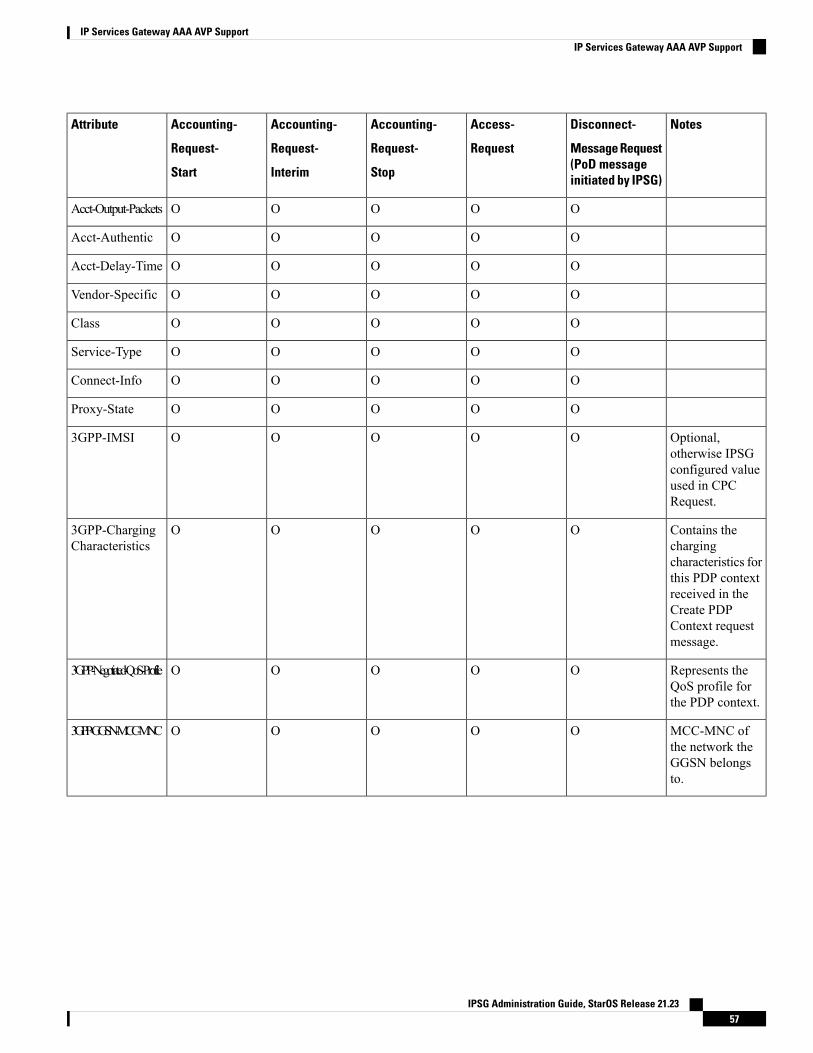
NotesDisconnect-
Message Request(PoD messageinitiated by IPSG)
Access-
Request
Accounting-
Request-
Stop
Accounting-
Request-
Interim
Accounting-
Request-
Start
Attribute
OOOOOAcct-Output-Packets
OOOOOAcct-Authentic
OOOOOAcct-Delay-Time
OOOOOVendor-Specific
OOOOOClass
OOOOOService-Type
OOOOOConnect-Info
OOOOOProxy-State
Optional,otherwise IPSGconfigured valueused in CPCRequest.
OOOOO3GPP-IMSI
Contains thechargingcharacteristics forthis PDP contextreceived in theCreate PDPContext requestmessage.
OOOOO3GPP-ChargingCharacteristics
Represents theQoS profile forthe PDP context.
OOOOO3GPP-Negotiated-QoS-Profile
MCC-MNC ofthe network theGGSN belongsto.
OOOOO3GPP-GGSN-MCC-MNC
IPSG Administration Guide, StarOS Release 21.2357
IP Services Gateway AAA AVP SupportIP Services Gateway AAA AVP Support
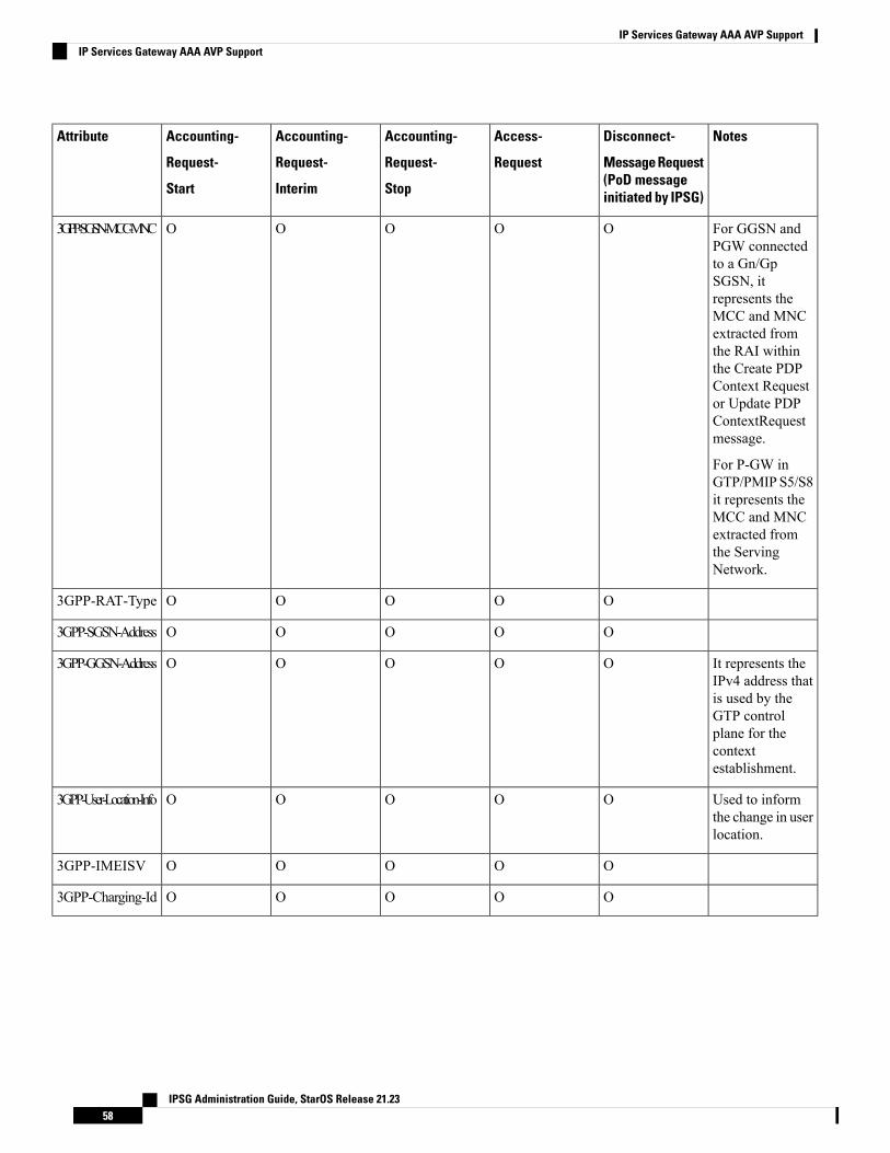
NotesDisconnect-
Message Request(PoD messageinitiated by IPSG)
Access-
Request
Accounting-
Request-
Stop
Accounting-
Request-
Interim
Accounting-
Request-
Start
Attribute
For GGSN andPGW connectedto a Gn/GpSGSN, itrepresents theMCC and MNCextracted fromthe RAI withinthe Create PDPContext Requestor Update PDPContextRequestmessage.
For P-GW inGTP/PMIPS5/S8it represents theMCC and MNCextracted fromthe ServingNetwork.
OOOOO3GPP-SGSN-MCC-MNC
OOOOO3GPP-RAT-Type
OOOOO3GPP-SGSN-Address
It represents theIPv4 address thatis used by theGTP controlplane for thecontextestablishment.
OOOOO3GPP-GGSN-Address
Used to informthe change in userlocation.
OOOOO3GPP-User-Location-Info
OOOOO3GPP-IMEISV
OOOOO3GPP-Charging-Id
IPSG Administration Guide, StarOS Release 21.2358
IP Services Gateway AAA AVP SupportIP Services Gateway AAA AVP Support
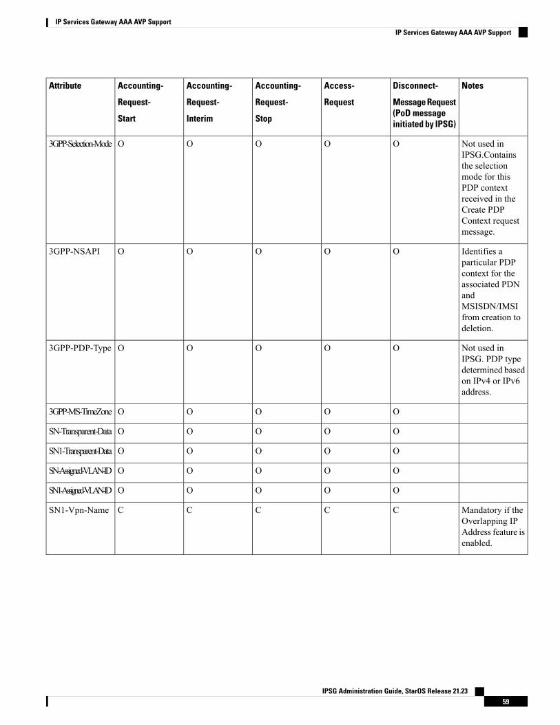
NotesDisconnect-
Message Request(PoD messageinitiated by IPSG)
Access-
Request
Accounting-
Request-
Stop
Accounting-
Request-
Interim
Accounting-
Request-
Start
Attribute
Not used inIPSG.Containsthe selectionmode for thisPDP contextreceived in theCreate PDPContext requestmessage.
OOOOO3GPP-Selection-Mode
Identifies aparticular PDPcontext for theassociated PDNandMSISDN/IMSIfrom creation todeletion.
OOOOO3GPP-NSAPI
Not used inIPSG. PDP typedetermined basedon IPv4 or IPv6address.
OOOOO3GPP-PDP-Type
OOOOO3GPP-MS-TimeZone
OOOOOSN-Transparent-Data
OOOOOSN1-Transparent-Data
OOOOOSN-Assigned-VLAN-ID
OOOOOSN1-Assigned-VLAN-ID
Mandatory if theOverlapping IPAddress feature isenabled.
CCCCCSN1-Vpn-Name
IPSG Administration Guide, StarOS Release 21.2359
IP Services Gateway AAA AVP SupportIP Services Gateway AAA AVP Support

IPSG Administration Guide, StarOS Release 21.2360
IP Services Gateway AAA AVP SupportIP Services Gateway AAA AVP Support
A P P E N D I X BIP Services Gateway Engineering Rules
This appendix lists IPSG-specific engineering rules that must be considered prior to configuring the systemfor your network deployment. General and network-specific rules are available in the appendix of the SystemAdministration Guide for the specific network type.
The following rules are covered in this appendix:
• IPSG Context and Service Rules, on page 61• IPSG RADIUS Messaging Rules, on page 61
IPSG Context and Service Rules• Only one IPSG service can be configured within a context.
• Single context configurations must have the ingress port identified using the ingress-mode command inthe Ethernet Port Configuration Mode.
• In single context configurations, if data packets are received before a session is initiated, the packetscould be routed to their destination without being processed. Use separate ingress and egress contextsto prevent this issue.
• Regardless of number of contexts in the configuration, ingress-mode CLI command must be configuredfor ASR5500 and VPC-SI or VPC-DI platforms. This is done to give precedence to the two matchingflows. For example, cases when IPv4SA or IPv4DA both are matched for the ingress packet, then if theincoming interface is designated as ingress, the lookup will be performed in the order of IPv4SA firstand then IPv4DA. But if the ingress mode is not set, priority is given to the IPv4DA flow. This is trueonly for ASR5500 and later platforms such as VPC-SI and VPC-DI.
IPSG RADIUS Messaging Rules• The sending of RADIUS accounting start messages to the RADIUS server is delayed by the IPSG untila session is successfully started.
IPSG Administration Guide, StarOS Release 21.2361

IPSG Administration Guide, StarOS Release 21.2362
IP Services Gateway Engineering RulesIPSG RADIUS Messaging Rules
A P P E N D I X CCoA, RADIUS DM, and Session Redirection(Hotlining)
This chapter describes Change of Authorization (CoA), Disconnect Message (DM), and Session Redirect(Hotlining) support in the system. RADIUS attributes, Access Control Lists (ACLs) and filters that are usedto implement these features are discussed. The product administration guides provide examples and proceduresfor configuration of basic services on the system. It is recommended that you select the configuration examplethat best meets your service model, and configure the required elements for that model, as described in thisAdministration Guide, before using the procedures in this chapter.
Not all functions, commands, and keywords/variables are available or supported for all network function orservices. This depends on the platform type and the installed license(s).
Important
• RADIUS Change of Authorization and Disconnect Message, on page 63• Session Redirection (Hotlining), on page 68
RADIUS Change of Authorization and Disconnect MessageThis section describes how the system implements CoA and DM RADIUS messages and how to configurethe system to use and respond to CoA and DM messages.
CoA OverviewThe system supports CoA messages from the AAA server to change data filters associated with a subscribersession. The CoA request message from the AAA server must contain attributes to identify NAS and thesubscriber session and a data filter ID for the data filter to apply to the subscriber session. The filter-id attribute(attribute ID 11) contains the name of an Access Control List (ACL). For detailed information on configuringACLs, refer to the IP Access Control Lists chapter in the System Administration Guide.
If the system successfully executes a CoA request, a CoA-ACK message is sent back to the RADIUS serverand the data filter is applied to the subscriber session. Otherwise, a CoA-NAK message is sent with anerror-cause attribute without making any changes to the subscriber session.
IPSG Administration Guide, StarOS Release 21.2363
Changing ACL and rulebase together in a single CoA is not supported. For this, two separate CoA requestscan be sent through AAA server requesting for one attribute change per request.
Important
DM OverviewThe DM message is used to disconnect subscriber sessions in the system from a RADIUS server. The DMrequest message should contain necessary attributes to identify the subscriber session. If the system successfullydisconnects the subscriber session, a DM-ACK message is sent back to the RADIUS server, otherwise, aDM-NAK message is sent with proper error reasons.
License RequirementsThe RADIUS Change of Authorization (CoA) and Disconnect Message (DM) are licensed Cisco features. Aseparate feature license may be required. Contact your Cisco account representative for detailed informationon specific licensing requirements. For information on installing and verifying licenses, refer to theManagingLicense Keys section of the Software Management Operations chapter in the System Administration Guide.
Enabling CoA and DMTo enable RADIUS Change of Authorization and Disconnect Message:
Step 1 Enable the system to listen for and respond to CoA and DMmessages from the RADIUS server as described in EnablingCoA and DM, on page 64.
Step 2 Save your configuration to flash memory, an external memory device, and/or a network location using the Exec modecommand save configuration. For additional information on how to verify and save configuration files, refer to theSystem Administration Guide and the Command Line Interface Reference.
Step 3 View CoA and DM message statistics as described in Viewing CoA and DM Statistics, on page 67.
Commands used in the configuration examples in this section provide base functionality to the extent that themost common or likely commands and/or keyword options are presented. In many cases, other optionalcommands and/or keyword options are available. Refer to the Command Line Interface Reference for completeinformation regarding all commands. Not all commands and keywords/variables are available or supported.This depends on the platform type and the installed license(s).
Important
Enabling CoA and DMUse the following example to enable the system to listen for and respond to CoA and DM messages from theRADIUS server:
configurecontext <context_name>
radius change-authorize-nas-ip <ipv4/ipv6_address>
end
IPSG Administration Guide, StarOS Release 21.2364
CoA, RADIUS DM, and Session Redirection (Hotlining)DM Overview
Notes:
• <context_name> must be the name of the AAA context where you want to enable CoA and DM.
For more information on configuring the AAA context, if you are using StarOS 12.3 or an earlier release,refer to the Configuring Context-Level AAA Functionality section of the AAA and GTPP InterfaceAdministration and Reference. If you are using StarOS 14.0 or a later release, refer to the AAA InterfaceAdministration and Reference.
• A number of optional keywords and variables are available for the radius change-authorize-nas-ipcommand. For more information regarding this command please refer to the Command Line InterfaceReference.
CoA and DM AttributesFor CoA and DM messages to be accepted and acted upon, the system and subscriber session to be affectedmust be identified correctly.
To identify the system, use any one of the following attributes:
• NAS-IP-Address: NAS IP address if present in the CoA/DM request should match with the NAS IPaddress.
• NAS-Identifier: If this attribute is present, its value should match to the nas-identifier generated for thesubscriber session
To identify the subscriber session, use any one of the following attributes.
• If 3GPP2 service is configured the following attribute is used for correlation identifier:
• 3GPP2-Correlation-ID: The values should exactly match the 3GPP2-correlation-id of the subscribersession. This is one of the preferred methods of subscriber session identification.
• If 3GPP service is configured the following attributes are used for different identifiers:
• 3GPP-IMSI: International Mobile Subscriber Identification (IMSI) number should be validated andmatched with the specified IMSI for specific PDP context.
• 3GPP-NSAPI: Network Service Access Point Identifier (NSAPI) should match to the NSAPIspecified for specific PDP context.
• User-Name: The value should exactly match the subscriber name of the session. This is one of thepreferred methods of subscriber session identification.
• Framed-IP-Address: The values should exactly match the framed IP address of the session.
• Calling-station-id: The value should match the Mobile Station ID.
To specify the ACL to apply to the subscriber session, use the following attribute:
• Filter-ID: CoA only. This must be the name of an existing Access Control List. If this is present in aCoA request, the specified ACL is immediately applied to the specified subscriber session. The ContextConfiguration mode command, radius attribute filter-id direction, controls in which direction filtersare applied.
The following attributes are also supported:
IPSG Administration Guide, StarOS Release 21.2365
CoA, RADIUS DM, and Session Redirection (Hotlining)CoA and DM Attributes
• Event-Timestamp: This attribute is a timestamp of when the event being logged occurred.
• If 3GPP2 service is configured following additional attributes are supported:
• 3GPP2-Disconnect-Reason: This attribute indicates the reason for disconnecting the user. Thisattribute may be present in the RADIUS Disconnect-request Message from the Home Radius serverto the PDSN.
• 3GPP2-Session-Termination-Capability: When CoA and DM are enabled by issuing the radiuschange-authorize-nas-ip command, this attribute is included in a RADIUS Access-request messageto the Home RADIUS server and contains the value 3 to indicate that the system supports bothDynamic authorization with RADIUS and Registration Revocation for Mobile IPv4. The attributeis also included in the RADIUS Access-Accept message and contains the preferred resourcemanagement mechanism by the home network, which is used for the session andmay include values1 through 3.
CoA and DM Error-Cause AttributeThe Error-Cause attribute is used to convey the results of requests to the system. This attribute is present whena CoA or DM NAK or ACK message is sent back to the RADIUS server.
The value classes of error causes are as follows:
• 0-199, 300-399 reserved
• 200-299 - successful completion
• 400-499 - errors in RADIUS server
• 500-599 - errors in NAS/Proxy
The following error cause is sent in ACK messages upon successful completion of a CoA or DM request:
• 201- Residual Session Context Removed
The following error causes are sent in NAK messages when a CoA or DM request fails:
• 401 - Unsupported Attribute
• 402 - Missing Attribute
• 403 - NAS Identification Mismatch
• 404 - Invalid Request
• 405 - Unsupported Service
• 406 - Unsupported Extension
• 501 - Administratively Prohibited
• 503 - Session Context Not Found
• 504 - Session Context Not Removable
• 506 - Resources Unavailable
IPSG Administration Guide, StarOS Release 21.2366
CoA, RADIUS DM, and Session Redirection (Hotlining)CoA and DM Error-Cause Attribute
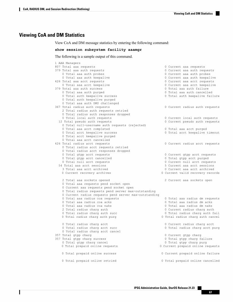
Viewing CoA and DM StatisticsView CoA and DM message statistics by entering the following command:
show session subsystem facility aaamgr
The following is a sample output of this command.1 AAA Managers807 Total aaa requests 0 Current aaa requests379 Total aaa auth requests 0 Current aaa auth requests
0 Total aaa auth probes 0 Current aaa auth probes0 Total aaa auth keepalive 0 Current aaa auth keepalive
426 Total aaa acct requests 0 Current aaa acct requests0 Total aaa acct keepalive 0 Current aaa acct keepalive
379 Total aaa auth success 0 Total aaa auth failure0 Total aaa auth purged 0 Total aaa auth cancelled0 Total auth keepalive success 0 Total auth keepalive failure0 Total auth keepalive purged0 Total aaa auth DMU challenged
367 Total radius auth requests 0 Current radius auth requests2 Total radius auth requests retried0 Total radius auth responses dropped0 Total local auth requests 0 Current local auth requests
12 Total pseudo auth requests 0 Current pseudo auth requests0 Total null-username auth requests (rejected)0 Total aaa acct completed 0 Total aaa acct purged0 Total acct keepalive success 0 Total acct keepalive timeout0 Total acct keepalive purged0 Total aaa acct cancelled
426 Total radius acct requests 0 Current radius acct requests0 Total radius acct requests retried0 Total radius acct responses dropped0 Total gtpp acct requests 0 Current gtpp acct requests0 Total gtpp acct cancelled 0 Total gtpp acct purged0 Total null acct requests 0 Current null acct requests
54 Total aaa acct sessions 5 Current aaa acct sessions3 Total aaa acct archived 0 Current aaa acct archived0 Current recovery archives 0 Current valid recovery records
2 Total aaa sockets opened 2 Current aaa sockets open0 Total aaa requests pend socket open0 Current aaa requests pend socket open0 Total radius requests pend server max-outstanding0 Current radius requests pend server max-outstanding0 Total aaa radius coa requests 0 Total aaa radius dm requests0 Total aaa radius coa acks 0 Total aaa radius dm acks0 Total aaa radius coa naks 0 Total aaa radius dm naks2 Total radius charg auth 0 Current radius charg auth0 Total radius charg auth succ 0 Total radius charg auth fail0 Total radius charg auth purg 0 Total radius charg auth cancel
0 Total radius charg acct 0 Current radius charg acct0 Total radius charg acct succ 0 Total radius charg acct purg0 Total radius charg acct cancel
357 Total gtpp charg 0 Current gtpp charg357 Total gtpp charg success 0 Total gtpp charg failure
0 Total gtpp charg cancel 0 Total gtpp charg purg0 Total prepaid online requests 0 Current prepaid online requests
0 Total prepaid online success 0 Current prepaid online failure
0 Total prepaid online retried 0 Total prepaid online cancelled
IPSG Administration Guide, StarOS Release 21.2367
CoA, RADIUS DM, and Session Redirection (Hotlining)Viewing CoA and DM Statistics
0 Current prepaid online purged0 Total aaamgr purged requests0 SGSN: Total db records0 SGSN: Total sub db records0 SGSN: Total mm records0 SGSN: Total pdp records0 SGSN: Total auth records
Session Redirection (Hotlining)
Functionality described for this feature in this segment is not applicable for HNB-GW sessions.Important
OverviewSession redirection provides a means to redirect subscriber traffic to an external server by applying ACL rulesto the traffic of an existing or a new subscriber session. The destination address and optionally the destinationport of TCP/IP or UDP/IP packets from the subscriber are rewritten so the packet is forwarded to the designatedredirected address. Return traffic to the subscriber has the source address and port rewritten to the originalvalues. The redirect ACL may be applied dynamically by means of the RADIUS Change of Authorization(CoA) feature.
Note that the session redirection feature is only intended to redirect a very small subset of subscribers at anygiven time. The data structures allocated for this feature are kept to the minimum to avoid large memoryoverhead in the session managers.
License RequirementsThe Session Redirection (Hotlining) is a licensed Cisco feature. A separate feature license may be required.Contact your Cisco account representative for detailed information on specific licensing requirements. Forinformation on installing and verifying licenses, refer to the Managing License Keys section of the SoftwareManagement Operations chapter in the System Administration Guide.
Operation
ACL RuleAn ACL rule named readdress server supports redirection of subscriber sessions. The ACL containing thisrule must be configured in the destination context of the user. Only TCP and UDP protocol packets aresupported. The ACL rule allows specifying the redirected address and an optional port. The source anddestination address and ports (with respect to the traffic originating from the subscriber) may be wildcarded.If the redirected port is not specified, the traffic will be redirected to the same port as the original destinationport in the datagrams. For detailed information on configuring ACLs, refer to the IP Access Control Listschapter in the System Administration Guide. For more information on readdress server, refer to the ACLConfiguration Mode Commands chapter of the Command Line Interface Reference.
IPSG Administration Guide, StarOS Release 21.2368
CoA, RADIUS DM, and Session Redirection (Hotlining)Session Redirection (Hotlining)
Redirecting Subscriber SessionsAn ACL with the readdress server rule is applied to an existing subscriber session through CoA messagesfrom the RADIUS server. The CoAmessage contains the 3GPP2-Correlation-ID, User-Name, Acct-Session-ID,or Framed-IP-Address attributes to identify the subscriber session. The CoAmessage also contains the Filter-Idattribute which specifies the name of the ACL with the readdress server rule. This enables applying the ACLdynamically to existing subscriber sessions. By default, the ACL is applied as both the input and output filterfor the matching subscriber unless the Filter-Id in the CoA message bears the prefix in: or out:.
For information on CoA messages and how they are implemented in the system, refer to RADIUS Changeof Authorization and Disconnect Message, on page 63.
Changing ACL and rulebase together in a single CoA is not supported. For this, two separate CoA requestscan be sent through AAA server requesting for one attribute change per request.
Important
Session Limits On RedirectionTo limit the amount of memory consumed by a session manager a limit of 2000 redirected session entries persession manager is allocated. This limit is equally shared by the set of subscribers who are currently beingredirected.Whenever a redirected session entry is subject to revocation from a subscriber due to an insufficientnumber of available session entries, the least recently used entry is revoked.
Stopping RedirectionThe redirected session entries for a subscriber remain active until a CoA message issued from the RADIUSserver specifies a filter that does not contain the readdress server ACL rule. When this happens, the redirectedsession entries for the subscriber are deleted.
All redirected session entries are also deleted when the subscriber disconnects.
Handling IP FragmentsSince TCP/UDP port numbers are part of the redirection mechanism, fragmented IP datagrams must bereassembled before being redirected. Reassembly is particularly necessary when fragments are sent out oforder. The session manager performs reassembly of datagrams and reassembly is attempted only when adatagram matches the redirect server ACL rule. To limit memory usage, only up to 10 different datagramsmay be concurrently reassembled for a subscriber. Any additional requests cause the oldest datagram beingreassembled to be discarded. The reassembly timeout is set to 2 seconds. In addition, the limit on the totalnumber of fragments being reassembled by a session manager is set to 1000. If this limit is reached, the oldestdatagram being reassembled in the session manager and its fragment list are discarded. These limits are notconfigurable.
RecoveryWhen a session manager dies, the ACL rules are recovered. The session redirect entries have to be re-createdwhen the MN initiates new traffic for the session. Therefore when a crash occurs, traffic from the Internetside is not redirected to the MN.
IPSG Administration Guide, StarOS Release 21.2369
CoA, RADIUS DM, and Session Redirection (Hotlining)Redirecting Subscriber Sessions
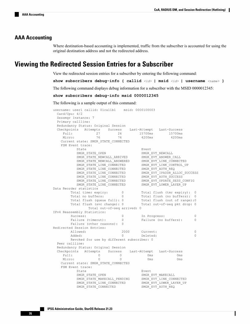
AAA AccountingWhere destination-based accounting is implemented, traffic from the subscriber is accounted for using theoriginal destination address and not the redirected address.
Viewing the Redirected Session Entries for a SubscriberView the redirected session entries for a subscriber by entering the following command:
show subscribers debug-info { callid <id> | msid <id> | username <name> }
The following command displays debug information for a subscriber with the MSID 0000012345:
show subscribers debug-info msid 0000012345
The following is a sample output of this command:username: user1 callid: 01ca11b1 msid: 0000100003Card/Cpu: 4/2Sessmgr Instance: 7Primary callline:Redundancy Status: Original SessionCheckpoints Attempts Success Last-Attempt Last-Success
Full: 27 26 15700ms 15700msMicro: 76 76 4200ms 4200msCurrent state: SMGR_STATE_CONNECTEDFSM Event trace:
State EventSMGR_STATE_OPEN SMGR_EVT_NEWCALLSMGR_STATE_NEWCALL_ARRIVED SMGR_EVT_ANSWER_CALLSMGR_STATE_NEWCALL_ANSWERED SMGR_EVT_LINE_CONNECTEDSMGR_STATE_LINE_CONNECTED SMGR_EVT_LINK_CONTROL_UPSMGR_STATE_LINE_CONNECTED SMGR_EVT_AUTH_REQSMGR_STATE_LINE_CONNECTED SMGR_EVT_IPADDR_ALLOC_SUCCESSSMGR_STATE_LINE_CONNECTED SMGR_EVT_AUTH_SUCCESSSMGR_STATE_LINE_CONNECTED SMGR_EVT_UPDATE_SESS_CONFIGSMGR_STATE_LINE_CONNECTED SMGR_EVT_LOWER_LAYER_UP
Data Reorder statisticsTotal timer expiry: 0 Total flush (tmr expiry): 0Total no buffers: 0 Total flush (no buffers): 0Total flush (queue full): 0 Total flush (out of range):0Total flush (svc change): 0 Total out-of-seq pkt drop: 0
Total out-of-seq arrived: 0IPv4 Reassembly Statistics:
Success: 0 In Progress: 0Failure (timeout): 0 Failure (no buffers): 0Failure (other reasons): 0
Redirected Session Entries:Allowed: 2000 Current: 0Added: 0 Deleted: 0Revoked for use by different subscriber: 0
Peer callline:Redundancy Status: Original SessionCheckpoints Attempts Success Last-Attempt Last-Success
Full: 0 0 0ms 0msMicro: 0 0 0ms 0msCurrent state: SMGR_STATE_CONNECTEDFSM Event trace:
State EventSMGR_STATE_OPEN SMGR_EVT_MAKECALLSMGR_STATE_MAKECALL_PENDING SMGR_EVT_LINE_CONNECTEDSMGR_STATE_LINE_CONNECTED SMGR_EVT_LOWER_LAYER_UPSMGR_STATE_CONNECTED SMGR_EVT_AUTH_REQ
IPSG Administration Guide, StarOS Release 21.2370
CoA, RADIUS DM, and Session Redirection (Hotlining)AAA Accounting
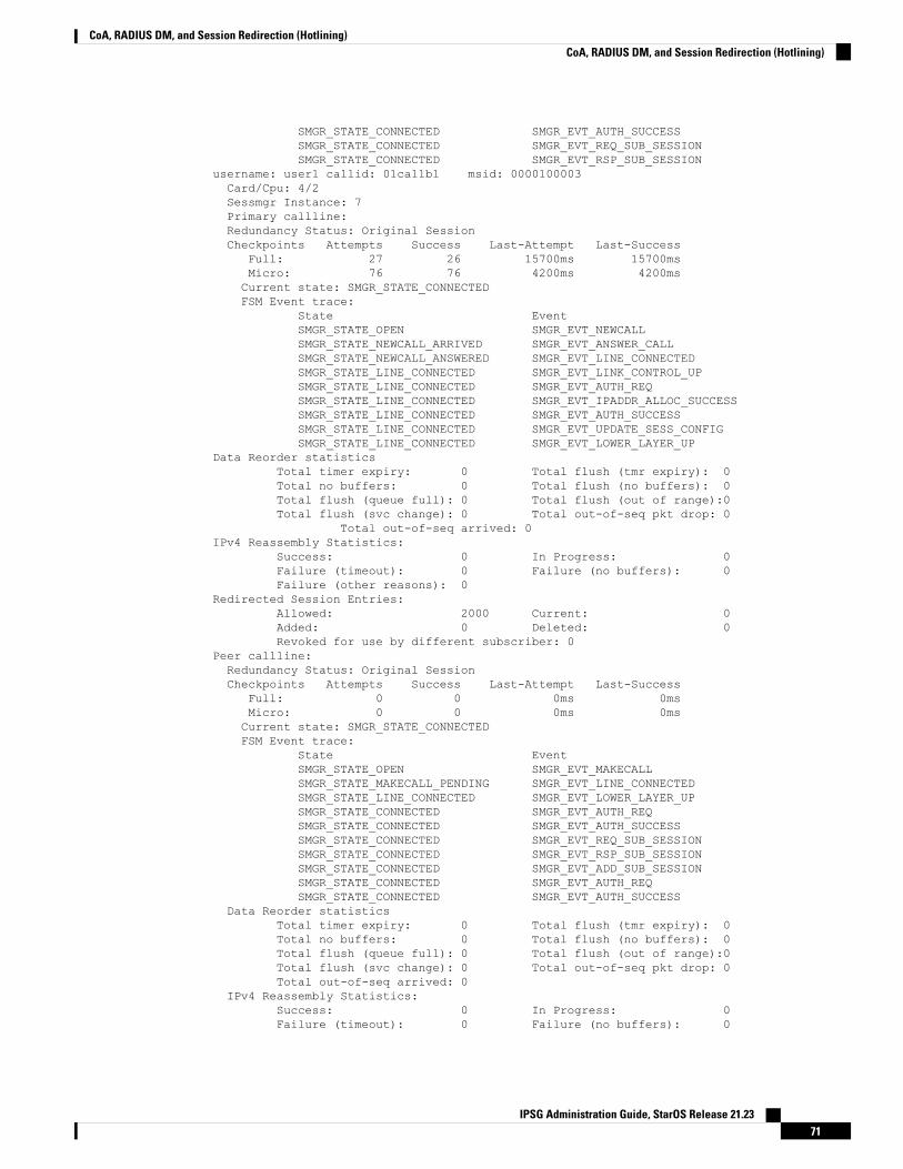
SMGR_STATE_CONNECTED SMGR_EVT_AUTH_SUCCESSSMGR_STATE_CONNECTED SMGR_EVT_REQ_SUB_SESSIONSMGR_STATE_CONNECTED SMGR_EVT_RSP_SUB_SESSION
username: user1 callid: 01ca11b1 msid: 0000100003Card/Cpu: 4/2Sessmgr Instance: 7Primary callline:Redundancy Status: Original SessionCheckpoints Attempts Success Last-Attempt Last-Success
Full: 27 26 15700ms 15700msMicro: 76 76 4200ms 4200msCurrent state: SMGR_STATE_CONNECTEDFSM Event trace:
State EventSMGR_STATE_OPEN SMGR_EVT_NEWCALLSMGR_STATE_NEWCALL_ARRIVED SMGR_EVT_ANSWER_CALLSMGR_STATE_NEWCALL_ANSWERED SMGR_EVT_LINE_CONNECTEDSMGR_STATE_LINE_CONNECTED SMGR_EVT_LINK_CONTROL_UPSMGR_STATE_LINE_CONNECTED SMGR_EVT_AUTH_REQSMGR_STATE_LINE_CONNECTED SMGR_EVT_IPADDR_ALLOC_SUCCESSSMGR_STATE_LINE_CONNECTED SMGR_EVT_AUTH_SUCCESSSMGR_STATE_LINE_CONNECTED SMGR_EVT_UPDATE_SESS_CONFIGSMGR_STATE_LINE_CONNECTED SMGR_EVT_LOWER_LAYER_UP
Data Reorder statisticsTotal timer expiry: 0 Total flush (tmr expiry): 0Total no buffers: 0 Total flush (no buffers): 0Total flush (queue full): 0 Total flush (out of range):0Total flush (svc change): 0 Total out-of-seq pkt drop: 0
Total out-of-seq arrived: 0IPv4 Reassembly Statistics:
Success: 0 In Progress: 0Failure (timeout): 0 Failure (no buffers): 0Failure (other reasons): 0
Redirected Session Entries:Allowed: 2000 Current: 0Added: 0 Deleted: 0Revoked for use by different subscriber: 0
Peer callline:Redundancy Status: Original SessionCheckpoints Attempts Success Last-Attempt Last-Success
Full: 0 0 0ms 0msMicro: 0 0 0ms 0msCurrent state: SMGR_STATE_CONNECTEDFSM Event trace:
State EventSMGR_STATE_OPEN SMGR_EVT_MAKECALLSMGR_STATE_MAKECALL_PENDING SMGR_EVT_LINE_CONNECTEDSMGR_STATE_LINE_CONNECTED SMGR_EVT_LOWER_LAYER_UPSMGR_STATE_CONNECTED SMGR_EVT_AUTH_REQSMGR_STATE_CONNECTED SMGR_EVT_AUTH_SUCCESSSMGR_STATE_CONNECTED SMGR_EVT_REQ_SUB_SESSIONSMGR_STATE_CONNECTED SMGR_EVT_RSP_SUB_SESSIONSMGR_STATE_CONNECTED SMGR_EVT_ADD_SUB_SESSIONSMGR_STATE_CONNECTED SMGR_EVT_AUTH_REQSMGR_STATE_CONNECTED SMGR_EVT_AUTH_SUCCESS
Data Reorder statisticsTotal timer expiry: 0 Total flush (tmr expiry): 0Total no buffers: 0 Total flush (no buffers): 0Total flush (queue full): 0 Total flush (out of range):0Total flush (svc change): 0 Total out-of-seq pkt drop: 0Total out-of-seq arrived: 0
IPv4 Reassembly Statistics:Success: 0 In Progress: 0Failure (timeout): 0 Failure (no buffers): 0
IPSG Administration Guide, StarOS Release 21.2371
CoA, RADIUS DM, and Session Redirection (Hotlining)CoA, RADIUS DM, and Session Redirection (Hotlining)
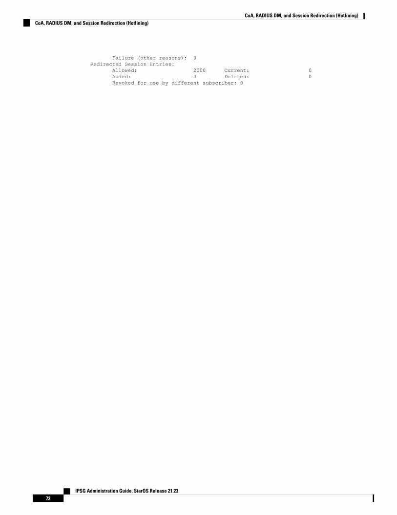
Failure (other reasons): 0Redirected Session Entries:
Allowed: 2000 Current: 0Added: 0 Deleted: 0Revoked for use by different subscriber: 0
IPSG Administration Guide, StarOS Release 21.2372
CoA, RADIUS DM, and Session Redirection (Hotlining)CoA, RADIUS DM, and Session Redirection (Hotlining)
A P P E N D I X DGx Interface Support
This chapter provides information on configuring Gx interface to support policy and charging control forsubscribers.
The IMS service provides application support for transport of voice, video, and data independent of accesssupport. Roaming IMS subscribers require apart from other functionality sufficient, uninterrupted, consistent,and seamless user experience during an application session. It is also important that a subscriber gets chargedonly for the resources consumed by the particular IMS application used.
It is recommended that before using the procedures in this chapter you select the configuration example thatbest meets your service model, and configure the required elements for that model as described in thisAdministration Guide.
The following topics are covered in this chapter:
• Rel. 7 Gx Interface, on page 73• Rel. 8 Gx Interface, on page 100• Rel. 9 Gx Interface, on page 123• Rel. 10 Gx Interface, on page 131• Supported Gx Features, on page 140
Rel. 7 Gx InterfaceRel. 7 Gx interface support is available on the Cisco ASR chassis running StarOS 8.1 or StarOS 9.0 and laterreleases for the following products:
• GGSN
• IPSG
This section describes the following topics:
• Introduction, on page 74• Terminology and Definitions, on page 76• How Rel. 7 Gx Works, on page 91• Configuring Rel. 7 Gx Interface, on page 95• Gathering Statistics, on page 100
IPSG Administration Guide, StarOS Release 21.2373
IntroductionFor IMS deployment in GPRS/UMTS networks the system uses Rel. 7 Gx interface for policy-based admissioncontrol support and flow-based charging. The Rel. 7 Gx interface supports enforcing policy control featureslike gating, bandwidth limiting, and so on, and also supports flow-based charging. This is accomplished viadynamically provisioned Policy Control and Charging (PCC) rules. These PCC rules are used to identifyService Data Flows (SDF) and do charging. Other parameters associated with the rules are used to enforcepolicy control.
The PCC architecture allows operators to perform service-based QoS policy, and flow-based charging control.In the PCC architecture, this is accomplished mainly by the Policy and Charging Enforcement Function(PCEF)/Cisco Systems GGSN and the Policy and Charging Rules Function (PCRF).
In GPRS/UMTS networks, the client functionality lies with the GGSN, therefore in the IMS authorizationscenario it is also called the Gateway. In the following figure, Gateway is the Cisco Systems GGSN, and thePCEF function is provided by Enhanced Charging Service (ECS). The Rel 7. Gx interface is implemented asa Diameter connection. The Gx messages mostly involve installing/modifying/removing dynamic rules andactivating/deactivating predefined rules.
The Rel. 7 Gx reference point is located between the Gateway and the PCRF. This reference point is used forprovisioning and removal of PCC rules from the PCRF to the Gateway, and the transmission of traffic planeevents from the Gateway to the PCRF. The Gx reference point can be used for charging control, policy control,or both by applying AVPs relevant to the application. The following figure shows the reference points betweenvarious elements involved in the policy and charging architecture.
IPSG Administration Guide, StarOS Release 21.2374
Gx Interface SupportIntroduction
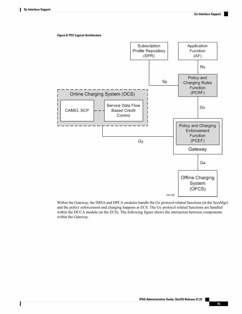
Figure 8: PCC Logical Architecture
Within the Gateway, the IMSA and DPCAmodules handle the Gx protocol related functions (at the SessMgr)and the policy enforcement and charging happens at ECS. The Gy protocol related functions are handledwithin the DCCA module (at the ECS). The following figure shows the interaction between componentswithin the Gateway.
IPSG Administration Guide, StarOS Release 21.2375
Gx Interface SupportGx Interface Support
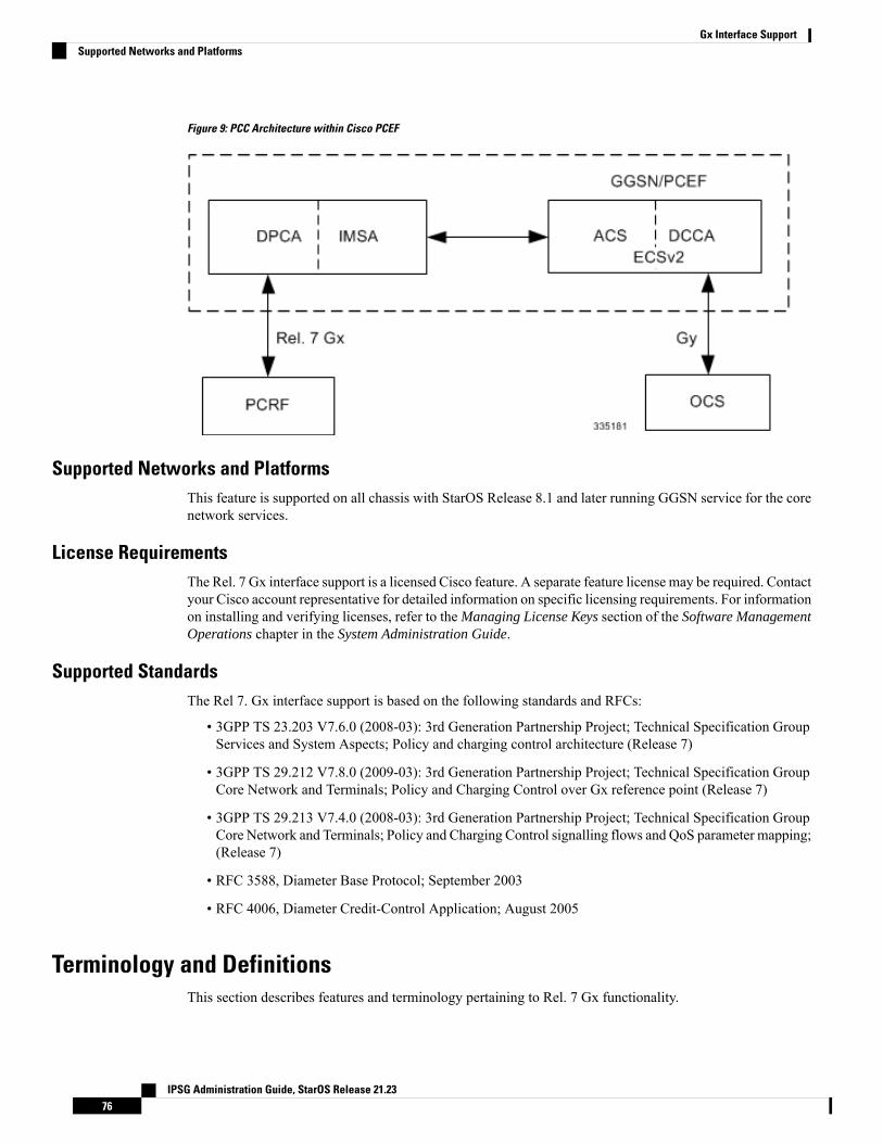
Figure 9: PCC Architecture within Cisco PCEF
Supported Networks and PlatformsThis feature is supported on all chassis with StarOS Release 8.1 and later running GGSN service for the corenetwork services.
License RequirementsThe Rel. 7 Gx interface support is a licensed Cisco feature. A separate feature license may be required. Contactyour Cisco account representative for detailed information on specific licensing requirements. For informationon installing and verifying licenses, refer to the Managing License Keys section of the Software ManagementOperations chapter in the System Administration Guide.
Supported StandardsThe Rel 7. Gx interface support is based on the following standards and RFCs:
• 3GPP TS 23.203 V7.6.0 (2008-03): 3rd Generation Partnership Project; Technical Specification GroupServices and System Aspects; Policy and charging control architecture (Release 7)
• 3GPP TS 29.212 V7.8.0 (2009-03): 3rd Generation Partnership Project; Technical Specification GroupCore Network and Terminals; Policy and Charging Control over Gx reference point (Release 7)
• 3GPP TS 29.213 V7.4.0 (2008-03): 3rd Generation Partnership Project; Technical Specification GroupCore Network and Terminals; Policy and Charging Control signalling flows and QoS parameter mapping;(Release 7)
• RFC 3588, Diameter Base Protocol; September 2003
• RFC 4006, Diameter Credit-Control Application; August 2005
Terminology and DefinitionsThis section describes features and terminology pertaining to Rel. 7 Gx functionality.
IPSG Administration Guide, StarOS Release 21.2376
Gx Interface SupportSupported Networks and Platforms
Policy ControlThe process whereby the PCRF indicates to the PCEF how to control the IP-CAN bearer.
Policy control comprises the following functions:
• Binding: Binding is the generation of an association between a Service Data Flow (SDF) and the IPCAN bearer (for GPRS a PDP context) transporting that SDF.
The QoS demand in the PCC rule, as well as the SDF template are input for the bearer binding. Theselected bearer will have the same QoS Class as the one indicated by the PCC rule.
Depending on the type of IP-CAN and bearer control mode, bearer binding can be executed either bythe PCRF, or both PCRF and PCEF.
• For UE-only IP-CAN bearer establishment mode, the PCRF performs bearer binding. When thePCRF performs bearer binding, it indicates the bearer (PDP context) by means of Bearer ID. TheBearer ID uniquely identifies the bearer within the PDP session.
• For UE/NW IP-CAN bearer establishment mode, the PCRF performs the binding of the PCC rulesfor user controlled services, while the PCEF performs the binding of the PCC rules for thenetwork-controlled services.
Prior to Release 16.0, the rule binding was getting rejected. In 16.0 and later releases, the binding ofPCEF rules will be successful when BCM mode is set to UE-only for EPS IP-CAN bearer without"bearer-ID" in the PCRF messages such as RAR or CCA-U.
In the 3G to 4G handover scenario, rule binding and rule removal will be successful in UE-only modeand any filter (and related info) changes because of this modification/installation/removal will not benotified to UE as updates in UE only mode cannot be sent to UE. These rules are only considered forcharging and the expectation is that the same rules are again modified in 4G (if handover is done) so thatthe filters (and related info) can be notified to UE.
In releases prior to 18, P-GW/GGSN does not send CCR-U with Charging Rule report for rule bindingfailure occurred during 4G to 3G HO in a collision case where create/update bearer response in 3G/4Gis pending and update bearer of 3G HO is received. In 18 and later releases, CCR-U is generated andsent to PCRF for reporting rule failure when the collision happens during GnGp HO scenario.
This additional Gx message (CCR-U) triggered will require multiple CCR-Us to be configured whenRAT_TYPE trigger is enabled. Otherwise, the subscriber call will be dropped whenever the collisionhappens during HO.
• Gating Control: Gating control is the blocking or allowing of packets, belonging to an SDF, to passthrough to the desired endpoint. A gate is described within a PCC rule and gating control is applied ona per SDF basis. The commands to open or close the gate leads to the enabling or disabling of the passagefor corresponding IP packets. If the gate is closed, all packets of the related IP flows are dropped. If thegate is opened, the packets of the related IP flows are allowed to be forwarded.
• Event Reporting: Event reporting is the notification of and reaction to application events to trigger newbehavior in the user plane as well as the reporting of events related to the resources in the Gateway(PCEF).
• Event triggers may be used to determine which IP-CAN session modification or specific eventcauses the PCEF to re-request PCC rules. Although event trigger reporting from PCEF to PCRFcan apply for an IP CAN session or bearer depending on the particular event, provisioning of eventtriggers will be done at session level.
IPSG Administration Guide, StarOS Release 21.2377
Gx Interface SupportPolicy Control
Note that in 11.0 and later releases, RAR with unknown event triggers are silently ignored andresponded with DIAMETER_SUCCESS. In earlier releases, when unknown event triggers werereceived in the RAR command from PCRF, invalid AVP result code was set in the RAA command.
• The Event Reporting Function (ERF) receives event triggers from PCRF during the Provision ofPCC Rules procedure and performs event trigger detection. When an event matching the receivedevent trigger occurs, the ERF reports the occurred event to the PCRF. If the provided event triggersare associated with certain parameter values then the ERF includes those values in the responseback to the PCRF. The Event Reporting Function is located in the PCEF.
In StarOS releases prior to 14.0, SUCCESSFUL_RESOURCE_ALLOCATION ( 22 ) event triggerwas sent for rules irrespective of successful installation. In 14.0 and later releases,SUCCESSFUL_RESOURCE_ALLOCATION ( 22 ) event trigger will be sent under the followingconditions:
• When a rule is installed successfully (and the event trigger is armed by PCRF andresource-allocation-notification is enabled).
• On partial failure, i.e., when two or more rules are installed and at least one of the rules weresuccessfully installed. (and the event trigger is armed by PCRF andresource-allocation-notification is enabled).
On complete failure, i.e., none of the rules were installed, the event-triggerSUCCESSFUL_RESOURCE_ALLOCATION ( 22 ) will not be sent.
In this release, event triggers "IP-CAN_CHANGE" and"MAX_NR_BEARERS_REACHED" are not supported.
Important
• QoS Control: QoS control is the authorization and enforcement of the maximum QoS that is authorizedfor a SDF or an IP-CAN bearer or a QoS Class Identifier (QCI). In case of an aggregation of multipleSDFs (for GPRS a PDP context), the combination of the authorized QoS information of the individualSDFs is provided as the authorized QoS for this aggregate.
• QoS control per SDF allows the PCC architecture to provide the PCEF with the authorized QoS tobe enforced for each specific SDF.
• The enforcement of the authorized QoS of the IP-CAN bearer may lead to a downgrading orupgrading of the requested bearer QoS by the Gateway (PCEF) as part of a UE-initiated IP-CANbearer establishment or modification. Alternatively, the enforcement of the authorized QoS may,depending on operator policy and network capabilities, lead to network-initiated IP-CAN bearerestablishment or modification. If the PCRF provides authorized QoS for both, the IP-CAN bearerand PCC rule(s), the enforcement of authorized QoS of the individual PCC rules takes place first.
• QoS authorization informationmay be dynamically provisioned by the PCRF, or it can be a predefinedPCC rule in the PCEF. In case the PCRF provides PCC rules dynamically, authorized QoSinformation for the IP-CAN bearer (combined QoS) may be provided. For a predefined PCC rulewithin the PCEF, the authorized QoS information takes affect when the PCC rule is activated. ThePCEF combines the different sets of authorized QoS information, that is the information receivedfrom the PCRF and the information corresponding to the predefined PCC rules. The PCRF knowsthe authorized QoS information of the predefined PCC rules and takes this information into accountwhen activating them. This ensures that the combined authorized QoS of a set of PCC rules that are
IPSG Administration Guide, StarOS Release 21.2378
Gx Interface SupportGx Interface Support
activated by the PCRF is within the limitations given by the subscription and operator policiesregardless of whether these PCC rules are dynamically provided, predefined, or both.
In this release, QoS Resource Reservation is not supported.Important
Supported Features:
• Provisioning and Policy Enforcement of Authorized QoS: The PCRF may provide authorized QoS tothe PCEF. The authorized QoS provides appropriate values for resources to be enforced.
• Provisioning of "Authorized QoS" Per IP CAN Bearer: The authorized QoS per IP-CAN bearer is usedif the bearer binding is performed by the PCRF.
• Policy Enforcement for "Authorized QoS" per IP CAN Bearer: The PCEF is responsible for enforcingthe policy-based authorization, that is to ensure that the requested QoS is in-line with the "AuthorizedQoS" per IP CAN Bearer.
• Policy Provisioning for Authorized QoS Per SDF: The provisioning of authorized QoS per SDF is a partof PCC rule provisioning procedure.
• Policy Enforcement for Authorized QoS Per SDF: If an authorized QoS is defined for a PCC rule,the PCEF limits the data rate of the SDF corresponding to that PCC rule not to exceed the maximumauthorized bandwidth for the PCC rule by discarding packets exceeding the limit.
• Upon deactivation or removal of a PCC rule, the PCEF frees the resources reserved for that PCCrule. If the PCRF provides authorized QoS for both the IP-CAN bearer and PCC rule(s), theenforcement of authorized QoS of the individual PCC rules takes place first.
In this release, coordination of authorized QoS scopes in mixed mode (BCM = UE_NW) is not supported.Important
• Provisioning of Authorized QoS Per QCI: If the PCEF performs the bearer binding, the PCRF mayprovision an authorized QoS per QCI for non-GBR bearer QCI values. If the PCRF performs the
•
bearer binding the PCRF does not provision an authorized QoS per QCI. The PCRF does notprovision an authorized QoS per QCI for GBR bearer QCI values.
Only standards-based QCI values of 1 through 9 are supported. QCI values 1through 9 are defined in 3GPP Specification TS 23.203 "Policy and chargingcontrol architecture".
Important
• Policy Enforcement for Authorized QoS per QCI: The PCEF can receive an authorized QoS perQCI for non GBR-bearer QCI values.
• Other Features:
• Bearer Control Mode Selection: The PCEF may indicate, via the Gx reference point, a request forBearer Control Mode (BCM) selection at IP-CAN session establishment or IP-CAN session
IPSG Administration Guide, StarOS Release 21.2379
Gx Interface SupportGx Interface Support
modification (as a consequence of an SGSN change). It will be done using the "PCC Rule Request"procedure.
If the Bearer-Control-Mode AVP is not received from PCRF, the IP-CAN session is not terminated.The value negotiated between UE/SGSN/GGSN is considered as the BCM. The following valuesare considered for each of the service types:
• GGSN: The negotiated value between UE/SGSN/GGSN is considered.
In the following scenarios UE_ONLY is chosen as the BCM:
Scenario 1:
• UE-> UE_ONLY
• SGSN-> UE_ONLY
• GGSN-> UE_ONLY
• PCRF-> NO BCM
Scenario 2:
• UE-> UE_ONLY
• SGSN-> UE_ONLY
• GGSN-> Mixed
• PCRF-> NO BCM
• GTP-PGW: BCM of UE_NW is considered.
• IPSG: BCM of UE_ONLY is considered.
• HSGW/SGW/PDIF/FA/PDSN/HA/MIPV6HA: BCM of NONE is considered.
• PCC Rule Error Handling: If the installation/activation of one or more PCC rules fails, the PCEFincludes one or more Charging-Rule-Report AVP(s) in either a CCR or an RAA command for theaffected PCC rules. Within each Charging-Rule-Report AVP, the PCEF identifies the failed PCCrule(s) by including the Charging-Rule-Name AVP(s) or Charging-Rule-Base-Name AVP(s),identifies the failed reason code by including a Rule-Failure-Code AVP, and includes thePCC-Rule-Status AVP.
If the installation/activation of one or more new PCC rules (that is, rules that were not previouslysuccessfully installed) fails, the PCEF sets the PCC-Rule-Status to INACTIVE for both the PUSHand the PULL modes.
If a PCC rule was successfully installed/activated, but can no longer be enforced by the PCEF, thePCEF sends the PCRF a new CCR command and include a Charging-Rule-Report AVP. The PCEFincludes the Rule-Failure-Code AVP within the Charging-Rule-Report AVP and sets thePCC-Rule-Status to INACTIVE.
In releases prior to 18, P-GW/GGSN does not send CCR-U with Charging Rule report for rulebinding failure occurred during 4G to 3GHO in a collision case where create/update bearer responsein 3G/4G is pending and update bearer of 3G HO is received. In 18 and later releases, CCR-U isgenerated and sent to PCRF for reporting rule failure when the collision happens during GnGp HOscenario.
IPSG Administration Guide, StarOS Release 21.2380
Gx Interface SupportGx Interface Support
This additional Gx message (CCR-U) triggered will require multiple CCR-Us to be configuredwhen RAT_TYPE trigger is enabled. Otherwise, the subscriber call will be dropped whenever thecollision happens during HO.
• Time of the Day Procedures: PCEF performs PCC rule request as instructed by the PCRF.Revalidation-Time when set by the PCRF, causes the PCEF to trigger a PCRF interaction to requestPCC rules from the PCRF for an established IP CAN session. The PCEF stops the timer once thePCEF triggers a REVALIDATION_TIMEOUT event.
In 11.0 and later releases, Rule-Activation-Time / Rule-Deactivation-Time / Revalidation-Time AVP issuccessfully parsed only if its value corresponds to current time or a later time than the current IPSG time,else the AVP and entire message is rejected. In earlier releases the AVP is successfully parsed only if its valuecorresponds to a later time than the current IPSG time, else the AVP and entire message is rejected.
Important
In releases prior to 17.0, if "Rule-Deactivation-Time" AVP for a predefined rule was omitted in a CCA-U orRAR message, then any previous value for this AVP was continued to be used in the chassis. In 17.0 and laterreleases, if Rule-Deactivation-Time AVP is omitted in CCA/RAR, then any previous value for this AVP isno longer valid. The new behavior is compliant to the 3GPP specification for Gx, version 12.1.0.
If PCRF enables the same predefined rule again in RAR/CCA-U without Rule-Deactivation-Time AVP, thenthe deactivation-time for this rule, if any, will be removed.
For switching to the old behavior, PCRF should re-send the same value of Rule-Deactivation-Time AVPalong with predef-rule name in the PCRF message (RAR, CCA-U).
This behavior change is applicable only to predefined rules.Important
Support for Firewall Policy on Gx: The Diameter AVP "SN-Firewall-Policy" has been added to the Diameterdynamic dictionary to support Firewall policy on Gx interface. This AVP can be encoded in CCA-I messageto apply/overwrite the fw-and-nat policy that has either been statically assigned to the PDP context via APNconfiguration or dynamically assigned via RADIUS in Access-Accept. This AVP can also parsed in anyCCA-U or RAR message to modify the fw-and-nat policy that is currently assigned to the PDP context.
Charging ControlCharging Control is the process of associating packets belonging to a SDF to a charging key, and applyingonline charging and/or offline charging, as appropriate. Flow-based charging handles differentiated chargingof the bearer usage based on real time analysis of the SDFs. In order to allow for charging control, theinformation in the PCC rule identifies the SDF and specifies the parameters for charging control. The PCCrule information may depend on subscription data.
In the case of online charging, it is possible to apply an online charging action upon PCEF events (for example,re-authorization upon QoS change).
It is possible to indicate to the PCEF that interactions with the charging systems are not required for a PCCrule, that is to perform neither accounting nor credit control for this SDF, and then no offline charginginformation is generated.
Supported Features:
IPSG Administration Guide, StarOS Release 21.2381
Gx Interface SupportCharging Control
• Provisioning of Charging-related Information for the IP-CAN Session.
• Provisioning of ChargingAddresses: Primary or secondary event charging function name (Online ChargingServer (OCS) addresses or the peer names).
In this release, provisioning of primary or secondary charging collection functionname (Offline Charging Server (OFCS) addresses) over Gx is not supported.
Important
• Provisioning of Default Charging Method: In this release, the default charging method is sent in CCR-Imessage. For this, new AVPs Online/Offline are sent in CCR-I message based on the configuration. TheOnline/Offline AVP received at command level applies only to dynamic rules if they are not configuredat PCC rule level.
Charging Correlation
For the purpose of charging correlation between SDF level and application level (for example, IMS) as wellas on-line charging support at the application level, applicable charging identifiers and IP-CAN type identifiersare passed from the PCRF to the AF, if such identifiers are available.
For IMS bearer charging, the IP Multimedia Core Network (IM CN) subsystem and the Packet Switched (PS)domain entities are required to generate correlated charging data.
In order to achieve this, the Gateway provides the GGSNCharging Identifier (GCID) associated with the PDPcontext along with its address to the PCRF. The PCRF in turn sends the IMS Charging Identifier (ICID),which is provided by the P-CSCF, to the Gateway. The Gateway generates the charging records including theGCID as well as the ICID if received from PCRF, so that the correlation of charging data can be done withthe billing system.
PCRF also provides the flow identifier, which uniquely identifies an IP flow in an IMS session.
Policy and Charging Control (PCC) RulesA PCC rule enables the detection of an SDF and provides parameters for policy control and/or chargingcontrol. The purpose of the PCC rule is to:
• Detect a packet belonging to an SDF.
• Select downlink IP CAN bearers based on SDF filters in the PCC rule.
• Enforce uplink IP flows are transported in the correct IP CAN bearer using the SDF filters withinthe PCC rule.
• Identify the service that the SDF contributes to.
• Provide applicable charging parameters for an SDF.
• Provide policy control for an SDF.
The PCEF selects a PCC rule for each packet received by evaluating received packets against SDF filters ofPCC rules in the order of precedence of the PCC rules. When a packet matches a SDF filter, the packetmatching process for that packet is completed, and the PCC rule for that filter is applied.
There are two types of PCC rules:
IPSG Administration Guide, StarOS Release 21.2382
Gx Interface SupportCharging Correlation
• Dynamic PCC Rules: Rules dynamically provisioned by the PCRF to the PCEF via the Gx interface.These PCC rules may be either predefined or dynamically generated in the PCRF. Dynamic PCC rulescan be installed, modified, and removed at any time.
• Predefined PCC Rule: Rules preconfigured in the PCEF by the operators. Predefined PCC rules can beactivated or deactivated by the PCRF at any time. Predefined PCC rules within the PCEFmay be groupedallowing the PCRF to dynamically activate a set of PCC rules over the Gx reference point.
A third type of rule, the static PCC rule can be preconfigured in the chassis by the operators. Static PCC rulesare not explicitly known in the PCRF, and are not under control of the PCRF. Static PCC rules are bound togeneral purpose bearer with no Gx control.
Important
A PCC rule consists of:
• Rule Name: The rule name is used to reference a PCC rule in the communication between the PCEF andPCRF.
• Service Identifier: The service identifier is used to identify the service or the service component the SDFrelates to.
• Service Data Flow Filter(s): The service flow filter(s) is used to select the traffic for which the ruleapplies.
• Precedence: For different PCC rules with overlapping SDF filter, the precedence of the rule determineswhich of these rules is applicable. When a dynamic PCC rule and a predefined PCC rule have the samepriority, the dynamic PCC rule takes precedence.
• Gate Status: The gate status indicates whether the SDF, detected by the SDF filter(s), may pass (gate isopen) or will be discarded (gate is closed) in uplink and/or in downlink direction.
• QoS Parameters: The QoS information includes the QoS class identifier (authorized QoS class for theSDF), the Allocation and Retention Priority (ARP), and authorized bitrates for uplink and downlink.
In earlier releases, ECS used only the Priority-Level part of ARP byte for bearerbinding, (along with QCI). Now the entire ARP byte is used for bearer binding(along with QCI). Since the capability and vulnerability bits are optional in adynamic rule, if a dynamic rule is received without these flags, it is assumed thatthe capability bit is set to 1 (disabled) and vulnerability bit is set to 0 (enabled).For predefined rules, currently configuring these two flags is not supported, soas of now all predefined rules are assumed to have capability bit set to 1 (disabled)and vulnerability bit set to 0 (enabled).
Important
• Charging key (rating group)
• Other charging parameters: The charging parameters define whether online and offline charging interfacesare used, what is to be metered in offline charging, on what level the PCEF will report the usage relatedto the rule, and so on.
IPSG Administration Guide, StarOS Release 21.2383
Gx Interface SupportGx Interface Support
In this release, configuring theMeteringMethod and Reporting Level for dynamic PCC rules is not supported.Important
PCC rules also include Application Function (AF) record information for enabling charging correlationbetween the application and bearer layer if the AF has provided this information via the Rx interface. ForIMS, this includes the IMS Charging Identifier (ICID) and flow identifiers.
ASR 5500 supports only eight flow information including the flow description per dynamic charging rule ina Gx message.
Important
In releases prior to 14.0, there were only 10 PCC rules that were recovered per bearer in the event of a sessionmanager crash. In 14.0 and later releases, this limit has been increased to 24. That is, up to 24 PCC rules canbe recovered post ICSR.
With the increase in the limit of PCC rules that can be recovered, the rules are not lost and hence the chargingapplied to the end users are not impacted.
In releases prior to 17.0, when P-GW received PCC rules from PCRF and it results in Create Bearer or UpdateBearer to be triggered towards MME/S-GW, the PCC rules were kept in a pending-active state. Anymodification request that was received for these pending-active rules were not currently honored by the P-GW.In 17.0 and later releases, when modification for the PCC rules in pending-active state is received, the modifiedparameters will be buffered at P-GW. After the response for the pending request is received from the accessnetwork, P-GW will process the modification of the buffered parameters and if required generate anotherupdate towards network.
PCC Procedures over Gx Reference Point
Request for PCC Rules
The PCEF, via the Gx reference point, requests for PCC rules in the following instances:
• At IP-CAN session establishment
• At IP-CAN session modification
PCC rules can also be requested as a consequence of a failure in the PCC rule installation/activation orenforcement without requiring an event trigger.
Provisioning of PCC Rules
The PCRF indicates, via the Rel. 8 Gx reference point, the PCC rules to be applied at the PCEF. This may beusing one of the following procedures:
• PULL (provisioning solicited by the PCEF): In response to a request for PCC rules being made by thePCEF, the PCRF provisions PCC rules in the CC-Answer.
• PUSH (unsolicited provisioning): The PCRF may decide to provision PCC rules without obtaining arequest from the PCEF. For example, in response to information provided to the PCRF via the Rx referencepoint, or in response to an internal trigger within the PCRF. To provision PCC rules without a requestfrom the PCEF, the PCRF includes these PCC rules in an RA-Request message. No CCR/CCAmessagesare triggered by this RA-Request.
IPSG Administration Guide, StarOS Release 21.2384
Gx Interface SupportPCC Procedures over Gx Reference Point
For each request from the PCEF or upon unsolicited provisioning, the PCRF provisions zero or more PCCrules. The PCRF may perform an operation on a single PCC rule by one of the following means:
• To activate or deactivate a PCC rule that is predefined at the PCEF, the PCRF provisions a reference tothis PCC rule within a Charging-Rule-Name AVP and indicates the required action by choosing eitherthe Charging-Rule-Install AVP or the Charging-Rule-Remove AVP.
• To install or modify a PCRF-provisioned PCC rule, the PCRF provisions a correspondingCharging-Rule-Definition AVP within a Charging-Rule-Install AVP.
• To remove a PCC rule which has previously been provisioned by the PCRF, the PCRF provisions thename of this rule as value of a Charging-Rule-Name AVP within a Charging-Rule-Remove AVP.
In 11.0 and later releases, the maximum valid length for a charging rule name is 63 bytes. When the lengthof the charging rule name is greater than 63 bytes, a charging rule report with RESOURCES_LIMITATIONas Rule-Failure-Code is sent. This charging rule report is sent only when the length of the rule name is lesserthan 128 characters.When the charging rule name length is greater than or equal to 128 characters no chargingrule report will be sent. In earlier releases, the length of the charging rule name constructed by PCRF waslimited to 32 bytes.
Important
Releases prior to 14.0, when PCRF has subscribed to Out of Credit trigger, on session connect when one rulevalidation fails and also when an Out of Credit was received from OCS for another rule, P-GW was trying toreport these failures in different CCR-U to PCRF. However, the second CCR-U of Out of credit was gettingdropped internally.
In 14.0 and later releases, on session connect, P-GW combines the rule failure and out of credit in the sameCCR-U and sends to PCRF.
Selecting a PCC Rule for Uplink IP Packets
If PCC is enabled, the PCEF selects the applicable PCC rule for each received uplink IP packet within an IPCAN bearer by evaluating the packet against uplink SDF filters of PCRF-provided or predefined active PCCrules of this IP CAN bearer in the order of the precedence of the PCC rules.
When a PCRF-provided PCC rule and a predefined PCC rule have the same precedence, the uplink SDF filtersof the PCRF-provided PCC rule is applied first.
Important
In 11.0 and later releases, IMSA and ECS allow the PCRF to install two (or more) dynamic rules with thesame precedence value. In earlier releases, for two distinct dynamic rules having the same precedence thesecond rule used to be rejected.
Important
When a packet matches an SDF filter, the packet matching process for that packet is completed, and the PCCrule for that filter is applied. Uplink IP packets which do not match any PCC rule of the corresponding IPCAN bearer are discarded.
IPSG Administration Guide, StarOS Release 21.2385
Gx Interface SupportSelecting a PCC Rule for Uplink IP Packets
Selecting a PCC Rule and IP CAN Bearer for Downlink IP Packets
If PCC is enabled, the PCEF selects a PCC rule for each received downlink IP packet within an IP CANsession by evaluating the packet against downlink SDF filters of PCRF-provided or predefined active PCCrules of all IP CAN bearers of the IP CAN session in the order of the precedence of the PCC rules.
When a PCRF-provided PCC rule and a predefined PCC rule have the same precedence, the downlink SDFfilters of the PCRF-provided PCC rule are applied first.
Important
When a packet matches a SDF filter, the packet matching process for that packet is completed, and the PCCrule for that filter is applied. The Downlink IP Packet is transported within the IP CAN bearer where theselected PCC rule is mapped. Downlink IP packets that do not match any PCC rule of the IP CAN sessionare discarded.
The following procedures are also supported:
• Indication of IP-CAN Bearer Termination Implications
• Indication of IP-CAN Session Termination: When the IP-CAN session is being terminated (for example,for GPRS when the last PDP Context within the IP-CAN session is being terminated) the PCEF contactsthe PCRF.
• Request of IP-CAN Bearer Termination: If the termination of the last IP CAN bearer within an IP CANsession is requested, the PCRF and PCEF apply the "Request of IP-CAN Session Termination" procedure.
• Request of IP-CAN Session Termination: If the PCRF decides to terminate an IP CAN session due toan internal trigger or trigger from the SPR, the PCRF informs the PCEF. The PCEF acknowledges to thePCRF and instantly removes/deactivates all the PCC rules that have been previously installed or activatedon that IP-CAN session.
The PCEF applies IP CAN specific procedures to terminate the IP CAN session. For GPRS, the GGSN senda PDP context deactivation request with the teardown indicator set to indicate that the termination of the entireIP-CAN session is requested. Furthermore, the PCEF applies the "Indication of IP CAN Session Termination"procedure.
In 12.0 and later releases, volume or rule information obtained from PCRF is discarded if the subscriber isgoing down.
Volume Reporting Over GxThis section describes the 3GPP Rel. 9 Volume Reporting over Gx feature, which is supported by all productssupporting Rel. 7 Gx interface.
License Requirements
The Volume Reporting over Gx is a licensed Cisco feature. A separate feature license may be required. Contactyour Cisco account representative for detailed information on specific licensing requirements. For informationon installing and verifying licenses, refer to the Managing License Keys section of the Software ManagementOperations chapter in the System Administration Guide.
In 12.0 and later releases, no separate license is required for Charging over Gx / Volume Reporting over Gxfeature. This feature can be enabled as part of "Policy Interface" license.
Important
IPSG Administration Guide, StarOS Release 21.2386
Gx Interface SupportSelecting a PCC Rule and IP CAN Bearer for Downlink IP Packets
Supported Standards
The Volume Reporting over Gx feature is based on the following standard:
3GPP TS 29.212 V9.5.0 (2010-06): 3rd Generation Partnership Project; Technical Specification Group CoreNetwork and Terminals; Policy and Charging Control over Gx reference point (Release 9).
Feature Overview
The Volume Reporting over Gx feature provides PCRF the capability to make real-time decisions based onthe data usage by subscribers.
Volume Reporting over Gx is applicable only for volume quota.
In release 10.0, only total data usage reporting is supported, uplink/downlink level reporting is not supported.In 10.2 and later releases, it is supported.
The PCEF only reports the accumulated usage since the last report for usage monitoring and not from thebeginning.
If the usage threshold is set to zero (infinite threshold), no further threshold events will be generated by PCEF,but monitoring of usage will continue and be reported at the end of the session.
In 12.2 and later releases, usage reporting on bearer termination is supported.
Important
The following steps explain how Volume Reporting over Gx works:
1. PCEF after receiving the message from PCRF parses the usage monitoring related AVPs, and sends theinformation to IMSA.
2. IMSA updates the information to ECS.
3. Once the ECS is updated with the usage monitoring information from PCRF, the PCEF (ECS) startstracking the data usage.
4. For session-level monitoring, the ECS maintains the amount of data usage.
5. For PCC rule monitoring, usage is monitored with the monitoring key as the unique identifier. Each nodemaintains the usage information per monitoring key. When the data traffic is passed, the usage is checkedagainst the usage threshold values and reported as described in the Usage Reporting section.
6. The PCEF continues to track data usage after the threshold is reached and before a new threshold isprovided by the PCRF. If a new usage threshold is not provided by the PCRF in the acknowledgement ofan IP-CAN Session modification where its usage was reported, then usage monitoring does not continuein the PCEF for that IP CAN session.
Usage Monitoring
• Usage Monitoring at Session Level: PCRF subscribes to the session-level volume reporting over Gx bysending the Usage-Monitoring-InformationAVPwith the usage threshold level set in Granted-Service-UnitAVP and Usage-Monitoring-Level AVP set to SESSION_LEVEL(0). After the AVPs are parsed byDPCA, IMSA updates the information to ECS. Once ECS is updated usage monitoring is started andconstantly checked with the usage threshold whenever the data traffic is present. In 11.0 and later releases,Monitoring Key at session level is supported.
IPSG Administration Guide, StarOS Release 21.2387
Gx Interface SupportSupported Standards
In 12.0 and later releases, enabling and disabling session usage in a single message from PCRF issupported. This is supported only if the monitoring key is associated at session level.
In 12.0 and later releases, monitoring of usage based on input/output octet threshold levels is supported.Usage is reported based on the enabled threshold level. If multiple levels are enabled, usage will bereported on all the enabled levels even if only one of the levels is breached. Monitoring will be stoppedon the missing threshold levels in the response for the usage report from PCRF (expected to provide thecomplete set again if PCRF wants to continue monitoring on the multiple levels enabled earlier).
Total threshold level along with UL/DL threshold level in the GSU AVP is treated as an error and onlytotal threshold level is accepted.
In releases prior to 17.0, extra CCR-U was generated for a monitoring key when the following requestsare received in the response to the CCR-U which reported the usage for the same monitoring key.
• immediate reporting request with monitoring key at rule level• immediate reporting request with or without monitoring key at session level• explicit disable request at rule level• explicit disable request at session level
In 17.0 and later releases, extra CCR-U is not generated for a monitoring key when all the abovementionedrequests are received in the response to the CCR-U which reported the usage for the same monitoringkey. Also, extra CCR-U is not generated when immediate reporting request without monitoring key atrule level is received in the response to the CCR-U which reported the usage for all the active monitoringkeys.
• UsageMonitoring at Flow Level: PCRF subscribes to the flow-level volume reporting over Gx by sendingthe Usage-Monitoring-Information AVP with the usage threshold level set in Granted-Service-Unit AVPand Usage-Monitoring-Level AVP set to PCC_RULE_LEVEL(1). Monitoring Key is mandatory in caseof a flow-level monitoring since the rules are associated with the monitoring key and enabling/disablingof usage monitoring at flow level can be controlled by PCRF using it. After the AVPs are parsed byDPCA, IMSA updates the information to ECS. Once ECS is updated usage monitoring is started andconstantly checked with the usage threshold whenever the data traffic is present.
Usage monitoring is supported for static, predefined rules, and dynamic rule definitions.
• UsageMonitoring for Static Rules: In the case of static rules, the usage reporting on last rule removalassociated with the monitoring key is not applicable. In this case only the usage monitoringinformation is received from the PCRF.
• Usage Monitoring for Predefined Rules: If the usage monitoring needs to be enabled for thepredefined rules, PCRF sends the rule and the usagemonitoring information containing themonitoringkey and the usage threshold. The Monitoring key should be the same as the one pre-configured inPCEF for that predefined rule. There can be multiple rules associated with the same monitoringkey. Hence enabling a particular monitoring key would result in the data being tracked for multiplerules having the same monitoring key. After DPCA parses the AVPs IMSA updates the informationto ECS. Once ECS is updated usage monitoring is started and constantly checked with the usagethreshold whenever the data traffic is present.
• Usage Monitoring for Dynamic Rules: If the usage monitoring needs to be enabled for dynamicruledefs, PCRF provides the monitoring key along with a charging rule definition and the usagemonitoring information containing the monitoring key and the usage threshold. This would resultin the usage monitoring being done for all the rules associated with that monitoring key. After DPCAparses the AVPs, IMSA updates the information to ECS. Once ECS is updated, the usage monitoringis started and constantly checked with the usage threshold whenever the data traffic is present.
IPSG Administration Guide, StarOS Release 21.2388
Gx Interface SupportGx Interface Support
Monitoring key for dynamic ruledef is dynamically assigned by PCRF which is the only differencewith predefined rules in case of usage monitoring.
In releases prior to 15.0, when threshold breach happens for multiple monitoring keys at the same time, onlyone of the monitoring keys' usage is reported and the rest of the monitoring keys' usage is reported in CCR-T(threshold set to infinity). On Tx expiry/TCP link error, unreported usage is stored at ECS and reported onlyon session termination.
In 15.0 and later releases, only one of the monitoring keys' usage is reported first. Upon receiving successfulresponse from PCRF, the rest of the monitoring keys' usage is reported to PCRF. On Tx expiry/TCP link error,unreported usage is stored at ECS. Any future successful interaction with PCRF for the session will sendunreported UMI to PCRF.
Usage Reporting
Usage at subscriber/flow level is reported to PCRF under the following conditions:
• Usage Threshold Reached: PCEF records the subscriber data usage and checks if the usage thresholdprovided by PCRF is reached. This is done for both session and rule level reporting.
For session-level reporting, the actual usage volume is compared with the usage volume threshold.
For rule-level reporting the rule that hits the data traffic is used to find out if the monitoring key isassociated with it, and based on the monitoring key the data usage is checked. Once the condition is met,it reports the usage information to IMSA and continues monitoring. IMSA then triggers the CCR-U if"USAGE_REPORT" trigger is enabled by the PCRF. The Usage-Monitoring-Information AVP is sentin this CCR with the "Used-Service-Unit" set to the amount of data usage by subscriber.
If PCRF does not provide a new usage threshold in the usage monitoring information as a result of CCRfrom PCEF when the usage threshold is reached, the usage monitoring is stopped at PCEF and no usagestatus is reported.
In the non-standard Volume Reporting over Gx implementation, usage monitoring will be stopped oncethe threshold is breached, else the monitoring will continue. There will be no further usage reportinguntil the CCA is received.
• Usage Monitoring Disabled: If the PCRF explicitly disables the usage monitoring withUsage-Monitoring-Support AVP set toUSAGE_MONITORING_DISABLED, the PCEF stopsmonitoringand reports the usage information (when the monitoring was enabled) to PCRF if the usage monitoringis disabled by PCRF as a result of CCR from PCEF which is not related to reporting usage, other externaltriggers, or a PCRF internal trigger. If the PCRF does not provide a new usage threshold as a result ofCCR from PCEF when the usage threshold is reached, the usage monitoring is stopped at PCEF and nofurther usage status is reported.
• IP CAN Session Termination:When the IP CAN session is terminated, the accumulated subscriber usageinformation is reported to PCRF in the CCR-T from PCEF. If PCC usage level information is enabledby PCRF, the PCC usage will also be reported.
PCRF uses RAR message and includes Session-Release-Cause AVP in it to initiate IP CAN SessionTermination. However, there are some scenarios where PCRFmaywant to terminate the IP CAN Sessionin CCA messages. In order to avoid an unnecessary additional message, PCRF can inform P-GW toterminate the subscriber in CCA-U message itself. Hence, in 17.0 and later releases, the Session ReleaseCause has been added in CCA messages for all Gx dictionaries.
• PCC Rule Removal: When the PCRF deactivates the last PCC rule associated with a usage monitoringkey, the PCEF sends a CCR with the data usage for that monitoring key. If the PCEF reports the last
IPSG Administration Guide, StarOS Release 21.2389
Gx Interface SupportUsage Reporting
PCC rule associated with a usage monitoring key is inactive, the PCEF reports the accumulated usagefor that monitoring key within the same CCR command if the Charging-Rule-Report AVP was includedin a CCR command; otherwise, if the Charging-Rule-Report AVP was included in an RAA command,the PCEF sends a new CCR command to report accumulated usage for the usage monitoring key. In 12.0and later releases, usage reporting on last rule deactivation using rule deactivation time set by PCRF issupported.
Releases prior to 14.0, when PCC rule was tried to be removed while waiting for access side updatebearer response, the charging rules were not removed. In 14.0 and later releases, on receiving messagefrom PCRF, the rule that is meant for removal is marked and then after the access side procedure iscomplete the rule is removed.
• PCRF Requested Usage Report: In 10.2 and later releases, the accumulated usage since the last reportis sent even in case of immediate reporting, the usage is reset after immediate reporting and usagemonitoring continued so that the subsequent usage report will have the usage since the current report. Inearlier releases the behavior was to accumulate the so far usage in the next report.
• Release 12.2 onwards, usage reporting on bearer termination can be added. When a bearer is deleted dueto some reason, the rules associated with the bearer will also be removed. So, the usage will be reportedon the monitoring key(s) whose associated rule is the last one that is removed because of bearertermination.
• Revalidation Timeout: In the non-standard implementation, if usage monitoring and reporting is enabledand a revalidation timeout occurs, the PCEF sends a CCR to request PCC rules and reports all accumulatedusage for all enabled monitoring keys since the last report (or since usage reporting was enabled if theusage was not yet reported) with the accumulated usage at IP-CAN session level (if enabled) and atservice data flow level (if enabled) This is the default behavior.
In the case of standard implementation, this must be enabled by CLI configuration.
The Usage Reporting on Revalidation Timeout feature is available by default in non-standard implementationof Volume Reporting over Gx. In 10.2 and later releases, this is configurable in the standard implementation.This is not supported in 10.0 release for standard based volume reporting.
Important
Once the usage is reported, the usage counter is reset to zero. The PCEF continues to track data usage fromthe zero value after the threshold is reached and before a new threshold is provided by the PCRF. If a newusage threshold is not provided by the PCRF in the acknowledgement of an IP-CAN Session modificationwhere its usage was reported, then usage monitoring does not continue in the PCEF for that IP CAN sessionand and the usage accumulated between the CCR-CCA will be discarded.
In releases prior to 17.0, CCR-U triggered on server retries does not take server granted quota into accountfor reporting USU. In 17.0 and later releases, CCR-U triggered on server retries takes server granted quotainto account for reporting USU. For newly created MSCC, interim quota configuration is taken as referencefor reporting USU.
For information on how to configure the Volume Reporting over Gx feature, see Configuring Volume Reportingover Gx, on page 99.
ICSR Support for Volume Reporting over Gx (VoRoGx)
In releases prior to 15.0, post the ICSR switchover, any existing session for which the PCRF has enabledvolume reporting used to continue indefinitely until the session is terminated or until CCR-U is sent for agiven trigger, without having the volume counted via Gx.
IPSG Administration Guide, StarOS Release 21.2390
Gx Interface SupportICSR Support for Volume Reporting over Gx (VoRoGx)
To summarize, after an ICSR switchover, volume reporting over Gx is no longer done for existing sessions.Also, volume usage is not synced to standby chassis.
In 15.0 and later releases, volume threshold and volume usage are synced to standby chassis to support volumereporting over Gx for existing sessions post switchover.
Without this support it cannot cause a subscriber to use higher speeds than what s/he is supposed to get, ifvolume reporting is for example used to enforce fair usage; the operator may already consider this a revenueloss. It will also severely impact roaming subscribers who are supposed to get a notification and beblocked/redirected once the limits set by the EU roaming regulation are reached. If a session continues nowwithout being blocked, the operator is not allowed to charge for data beyond the limit and will have a significantand real revenue loss (roaming partner may still charge for the data used on their SGSNs).
How Rel. 7 Gx WorksThis section describes how dynamic policy and charging control for subscribers works with Rel. 7 Gx interfacesupport in GPRS/UMTS networks.
The following figure and table explain the IMSA process between a system and IMS components that isinitiated by the UE.
In this example, the Diameter Policy Control Application (DPCA) is the Gx interface to the PCRF. Theinterface between IMSAwith PCRF is the Gx interface, and the interface between SessionManager (SessMgr)and Online Charging Service (OCS) is the Gy interface. Note that the IMSA service and DPCA are part ofSessMgr on the system and separated in the figure for illustration purpose only.
In 14.0 and later releases, the DPCA and the IMSA will be acting as one module within the Policy Serverinterface application.
Important
IPSG Administration Guide, StarOS Release 21.2391
Gx Interface SupportHow Rel. 7 Gx Works
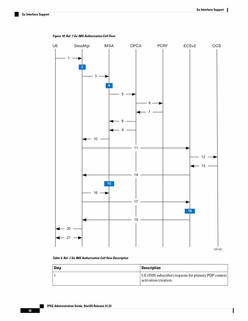
Figure 10: Rel. 7 Gx IMS Authorization Call Flow
Table 5: Rel. 7 Gx IMS Authorization Call flow Description
DescriptionStep
UE (IMS subscriber) requests for primary PDP contextactivation/creation.
1
IPSG Administration Guide, StarOS Release 21.2392
Gx Interface SupportGx Interface Support
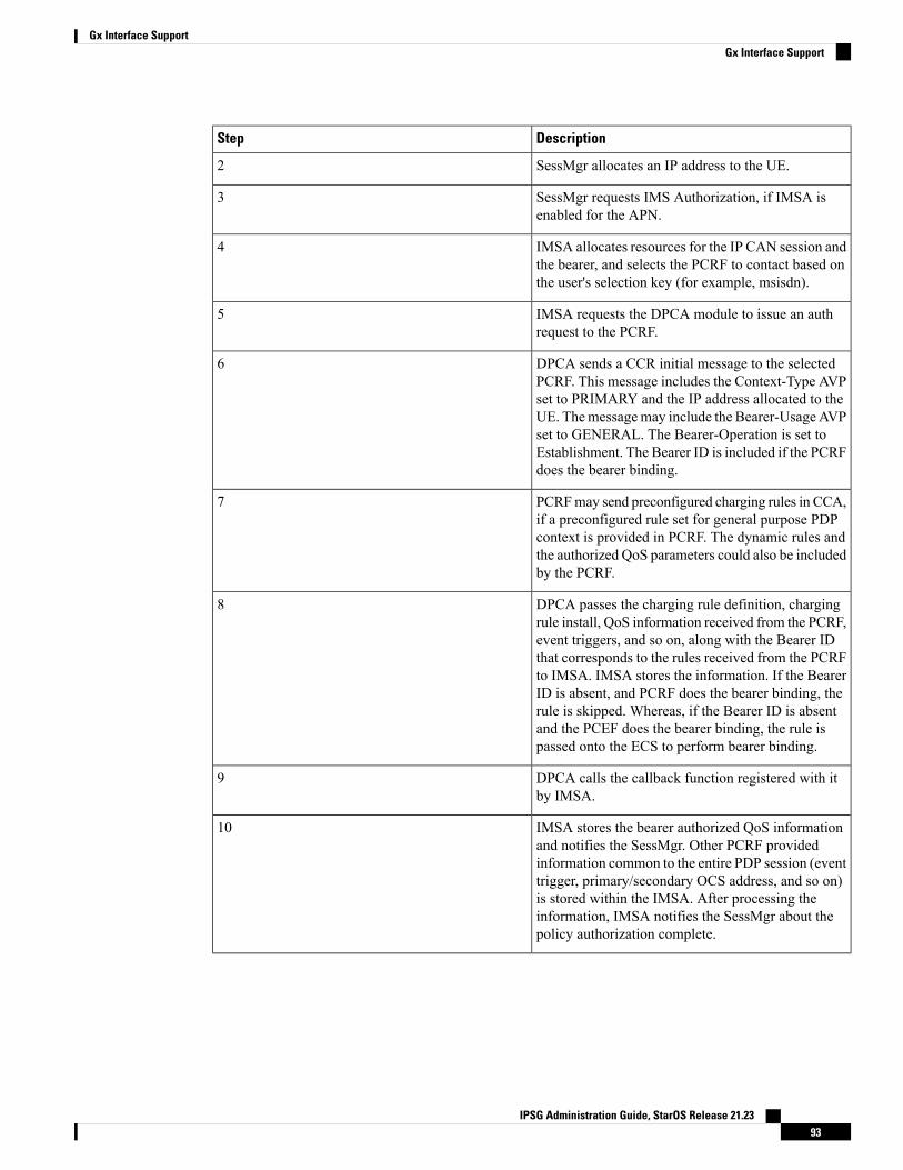
DescriptionStep
SessMgr allocates an IP address to the UE.2
SessMgr requests IMS Authorization, if IMSA isenabled for the APN.
3
IMSA allocates resources for the IP CAN session andthe bearer, and selects the PCRF to contact based onthe user's selection key (for example, msisdn).
4
IMSA requests the DPCA module to issue an authrequest to the PCRF.
5
DPCA sends a CCR initial message to the selectedPCRF. This message includes the Context-Type AVPset to PRIMARY and the IP address allocated to theUE. Themessagemay include the Bearer-UsageAVPset to GENERAL. The Bearer-Operation is set toEstablishment. The Bearer ID is included if the PCRFdoes the bearer binding.
6
PCRFmay send preconfigured charging rules in CCA,if a preconfigured rule set for general purpose PDPcontext is provided in PCRF. The dynamic rules andthe authorized QoS parameters could also be includedby the PCRF.
7
DPCA passes the charging rule definition, chargingrule install, QoS information received from the PCRF,event triggers, and so on, along with the Bearer IDthat corresponds to the rules received from the PCRFto IMSA. IMSA stores the information. If the BearerID is absent, and PCRF does the bearer binding, therule is skipped. Whereas, if the Bearer ID is absentand the PCEF does the bearer binding, the rule ispassed onto the ECS to perform bearer binding.
8
DPCA calls the callback function registered with itby IMSA.
9
IMSA stores the bearer authorized QoS informationand notifies the SessMgr. Other PCRF providedinformation common to the entire PDP session (eventtrigger, primary/secondary OCS address, and so on)is stored within the IMSA. After processing theinformation, IMSA notifies the SessMgr about thepolicy authorization complete.
10
IPSG Administration Guide, StarOS Release 21.2393
Gx Interface SupportGx Interface Support
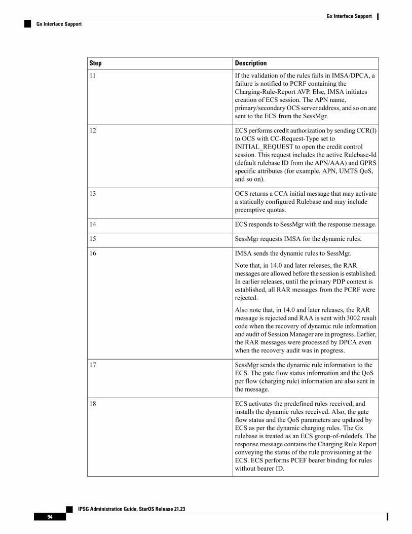
DescriptionStep
If the validation of the rules fails in IMSA/DPCA, afailure is notified to PCRF containing theCharging-Rule-Report AVP. Else, IMSA initiatescreation of ECS session. The APN name,primary/secondary OCS server address, and so on aresent to the ECS from the SessMgr.
11
ECS performs credit authorization by sending CCR(I)to OCS with CC-Request-Type set toINITIAL_REQUEST to open the credit controlsession. This request includes the active Rulebase-Id(default rulebase ID from the APN/AAA) and GPRSspecific attributes (for example, APN, UMTS QoS,and so on).
12
OCS returns a CCA initial message that may activatea statically configured Rulebase and may includepreemptive quotas.
13
ECS responds to SessMgr with the response message.14
SessMgr requests IMSA for the dynamic rules.15
IMSA sends the dynamic rules to SessMgr.
Note that, in 14.0 and later releases, the RARmessages are allowed before the session is established.In earlier releases, until the primary PDP context isestablished, all RAR messages from the PCRF wererejected.
Also note that, in 14.0 and later releases, the RARmessage is rejected and RAA is sent with 3002 resultcode when the recovery of dynamic rule informationand audit of SessionManager are in progress. Earlier,the RAR messages were processed by DPCA evenwhen the recovery audit was in progress.
16
SessMgr sends the dynamic rule information to theECS. The gate flow status information and the QoSper flow (charging rule) information are also sent inthe message.
17
ECS activates the predefined rules received, andinstalls the dynamic rules received. Also, the gateflow status and the QoS parameters are updated byECS as per the dynamic charging rules. The Gxrulebase is treated as an ECS group-of-ruledefs. Theresponse message contains the Charging Rule Reportconveying the status of the rule provisioning at theECS. ECS performs PCEF bearer binding for ruleswithout bearer ID.
18
IPSG Administration Guide, StarOS Release 21.2394
Gx Interface SupportGx Interface Support
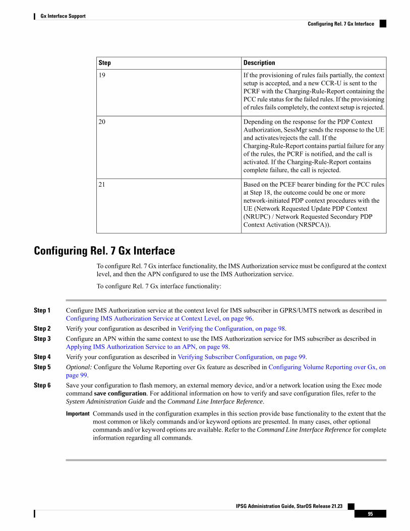
DescriptionStep
If the provisioning of rules fails partially, the contextsetup is accepted, and a new CCR-U is sent to thePCRF with the Charging-Rule-Report containing thePCC rule status for the failed rules. If the provisioningof rules fails completely, the context setup is rejected.
19
Depending on the response for the PDP ContextAuthorization, SessMgr sends the response to the UEand activates/rejects the call. If theCharging-Rule-Report contains partial failure for anyof the rules, the PCRF is notified, and the call isactivated. If the Charging-Rule-Report containscomplete failure, the call is rejected.
20
Based on the PCEF bearer binding for the PCC rulesat Step 18, the outcome could be one or morenetwork-initiated PDP context procedures with theUE (Network Requested Update PDP Context(NRUPC) / Network Requested Secondary PDPContext Activation (NRSPCA)).
21
Configuring Rel. 7 Gx InterfaceTo configure Rel. 7 Gx interface functionality, the IMSAuthorization service must be configured at the contextlevel, and then the APN configured to use the IMS Authorization service.
To configure Rel. 7 Gx interface functionality:
Step 1 Configure IMS Authorization service at the context level for IMS subscriber in GPRS/UMTS network as described inConfiguring IMS Authorization Service at Context Level, on page 96.
Step 2 Verify your configuration as described in Verifying the Configuration, on page 98.Step 3 Configure an APN within the same context to use the IMS Authorization service for IMS subscriber as described in
Applying IMS Authorization Service to an APN, on page 98.Step 4 Verify your configuration as described in Verifying Subscriber Configuration, on page 99.Step 5 Optional: Configure the Volume Reporting over Gx feature as described in Configuring Volume Reporting over Gx, on
page 99.Step 6 Save your configuration to flash memory, an external memory device, and/or a network location using the Exec mode
command save configuration. For additional information on how to verify and save configuration files, refer to theSystem Administration Guide and the Command Line Interface Reference.
Commands used in the configuration examples in this section provide base functionality to the extent that themost common or likely commands and/or keyword options are presented. In many cases, other optionalcommands and/or keyword options are available. Refer to the Command Line Interface Reference for completeinformation regarding all commands.
Important
IPSG Administration Guide, StarOS Release 21.2395
Gx Interface SupportConfiguring Rel. 7 Gx Interface
Configuring IMS Authorization Service at Context LevelUse the following example to configure IMS Authorization service at context level for IMS subscribers inGPRS/UMTS networks:
configurecontext <context_name>
ims-auth-service <imsa_service_name>
p-cscf discovery table { 1 | 2 } algorithm {ip-address-modulus | msisdn-modulus | round-robin }
p-cscf table { 1 | 2 } row-precedence <precedence_value> {address <ip_address> | ipv6-address <ipv6_address> } [ secondary { address<ip_address> | ipv6-address <ipv6_address> } ]
policy-controldiameter origin endpoint <endpoint_name>
diameter dictionary <dictionary>
diameter request-timeout <timeout_duration>
diameter host-select table { { { 1 | 2 } algorithm {ip-address-modulus | msisdn-modulus | round-robin } } | prefix-table {1 | 2 } }
diameter host-select row-precedence <precedence_value>
table { { { 1 | 2 } host <host_name> [ realm <realm_id> ] [ secondary host<host_name> [ realm <realm_id> ] ] } | { prefix-table { 1 | 2 }msisdn-prefix-from <msisdn_prefix_from> msisdn-prefix-to <msisdn_prefix_to> host<host_name> [ realm <realm_id> ] [ secondary host <sec_host_name> [ realm
<sec_realm_id> ] algorithm { active-standby | round-robin } ] } } [ -noconfirm]
diameter host-select reselect subscriber-limit<subscriber_limit> time-interval <duration>
failure-handling cc-request-type { any-request |initial-request | terminate-request | update-request } {diameter-result-code { any-error | <result_code> [ to <end_result_code> ] } }{ continue | retry-and-terminate | terminate }
end
Notes:
• <context_name> must be the name of the context where you want to enable IMS Authorization service.
• <imsa_service_name> must be the name of the IMS Authorization service to be configured for Rel. 7Gx interface authentication.
• In releases prior to 18, a maximum of 16 authorization services can be configured globally in the system.There is also a system limit for the maximum number of total configured services. In 18 and later releases,up to a maximum of 30 IMS authorization service profiles can be configured within the system.
• Secondary P-CSCF IP address can be configured in the P-CSCF table. Refer to the Command LineInterface Reference for more information on the p-cscf table command.
In 18 and later releases, the syntax for p-cscf table configuration command is:
p-cscf table { 1 | 2 } row-precedence precedence_value { ipv4-addressipv4_address [ ipv6-address ipv6_address ] | ipv6-address ipv6_address [ipv4-address ipv4_address ] } [ secondary { ipv4-address ipv4_address [
IPSG Administration Guide, StarOS Release 21.2396
Gx Interface SupportConfiguring IMS Authorization Service at Context Level
ipv6-address ipv6_address ] | ipv6-address ipv6_address [ ipv4-addressipv4_address ] } [ weight value ]
• To enable Rel. 7 Gx interface support, pertinent Diameter dictionarymust be configured. For informationon the specific Diameter dictionary to use, contact your Cisco account representative.
• When configuring the MSISDN prefix range based PCRF selection mechanism:
To enable the Gx interface to connect to a specific PCRF for a range of subscribers configuremsisdn-prefix-from <msisdn_prefix_from> andmsisdn-prefix-to <msisdn_prefix_to>with the startingand ending MSISDNs respectively.
To enable the Gx interface to connect to a specific PCRF for a specific subscriber, configure bothmsisdn-prefix-from <msisdn_prefix_from> and msisdn-prefix-to <msisdn_prefix_to> with the sameMSISDN.
In StarOS 8.1 and later releases, per MSISDN prefix range table a maximum of 128 rows can be added.In StarOS 8.0 and earlier releases, a maximum of 100 rows can be added.
The MSISDN ranges must not overlap between rows.
• The Round Robin algorithm for PCRF selection is effective only over a large number of PCRF selections,and not at a granular level.
• Optional: To configure the Quality of Service (QoS) update timeout for a subscriber, in the IMSAuthorization Service Configuration Mode, enter the following command:
qos-update-timeout <timeout_duration>
This command is obsolete in release 11.0 and later releases.Important
• Optional: To configure signalling restrictions, in the IMS Authorization Service Configuration Mode,enter the following commands:
signaling-flag { deny | permit }
signaling-flow permit server-address <ip_address> [ server-port { <port_number> | range<start_number> to <end_number> } ] [ description <string> ]
• Optional: To configure action on packets that do not match any policy gates in the general purpose PDPcontext, in the IMS Authorization Service Configuration Mode, enter the following command:
traffic-policy general-pdp-context no-matching-gates direction { downlink | uplink } { forward |discard }
• To configure the PCRF host destinations configured in the GGSN/PCEF, use the diameter host-selectCLI commands.
• To configure the GGSN/PCEF to use a pre-defined rule when the Gx fails, set the failure-handlingcc-request-type CLI to continue. Policies available/in use will continue to be used and there will be nofurther interaction with the PCRF.
• For provisioning of default charging method, use the following configurations. For this, the AVPs Onlineand Offline will be sent in CCR-I message based on the configuration. The Online/Offline AVP receivedat command level applies only to dynamic rules if they are not configured at PCC rule level.
• To send Enable Online:
IPSG Administration Guide, StarOS Release 21.2397
Gx Interface SupportGx Interface Support
configure
active-charging service <ecs_service_name>
charging-action <charging_action_name>
cca charging credit
exit
• To send Enable Offline:
configure
active-charging service <ecs_service_name>
rulebase <rulebase_name>
billing-records rf
exit
Verifying the Configuration
To verify the IMS Authorization service configuration:
Step 1 Change to the context where you enabled IMS Authorization service by entering the following command:
context <context_name>
Step 2 Verify the IMS Authorization service's configurations by entering the following command:
show ims-authorization service name <imsa_service_name>
Applying IMS Authorization Service to an APNAfter configuring IMS Authorization service at the context-level, an APN must be configured to use the IMSAuthorization service for an IMS subscriber.
Use the following example to apply IMS Authorization service functionality to a previously configured APNwithin the context configured as described in Configuring Rel. 7 Gx Interface, on page 95.
configurecontext <context_name>
apn <apn_name>
ims-auth-service <imsa_service_name>
active-charging rulebase <rulebase_name>
end
Notes:
• <context_name>must be the name of the context in which the IMSAuthorization service was configured.
• <imsa_service_name> must be the name of the IMS Authorization service configured for IMSauthentication in the context.
• For Rel. 7 Gx, the ECS rulebase must be configured in the APN.
IPSG Administration Guide, StarOS Release 21.2398
Gx Interface SupportVerifying the Configuration
• ECS allows change of rulebase via Gx for PCEF binding scenarios. When the old rulebase goes away,all the rules that were installed from that rulebase are removed. This may lead to termination of a fewbearers (PDP contexts) if they are left without any rules. If there is a Gxmessage that changes the rulebase,and also activates some predefined rules, the rulebase change is made first, and the rules are activatedfrom the new rulebase. Also, the rulebase applies to the entire call. All PDP contexts (bearers) in onecall use the same ECS rulebase.
• For predefined rules configured in the ECS, MBR/GBR of a dynamic/predefined rule is checked beforeit is used for PCEF binding. All rules (dynamic as well as predefined) have to have an MBR associatedwith them and all rules with GBR QCI should have GBR also configured. So for predefined rules, oneneeds to configure appropriate peak-data-rate, committed-data-rate as per the QCI being GBR QCI ornon-GBR QCI. For more information, in the ACS Charging Action Configuration Mode, see the flowlimit-for-bandwidth CLI command.
• For interpretation of the Gx rulebase (Charging-Rule-Base-Name AVP) from PCRF as ECSgroup-of-ruledefs, configure the following command in the Active Charging Service ConfigurationMode:
policy-control charging-rule-base-name active-charging-group-of-ruledefs
Verifying Subscriber Configuration
Verify the IMS Authorization service configuration for subscriber(s) by entering the following command:
show subscribers ims-auth-service <imsa_service_name>
<imsa_service_name>must be the name of the IMSAuthorization service configured for IMS authentication.
Configuring Volume Reporting over GxThis section describes the configuration required to enable Volume Reporting over Gx.
To enable Volume Reporting over Gx, use the following configuration:
configureactive-charging service <ecs_service_name>
rulebase <rulebase_name>
action priority <priority> dynamic-only ruledef <ruledef_name>
charging-action <charging_action_name> monitoring-key <monitoring_key>
exitexit
context <context_name>
ims-auth-service <imsa_service_name>
policy-controlevent-update send-usage-report [ reset-usage ]end
Notes:
• The maximum accepted monitoring key value by the PCEF is 4294967295. If the PCEF sends a greatervalue, the value is converted to an Unsigned Integer value.
• The event-update CLI which enables volume usage report to be sent in event updates is available onlyin 10.2 and later releases. The optional keyword reset-usage enables to support delta reporting whereinthe usage is reported and reset at PCEF. If this option is not configured, the behavior is to send the usageinformation as part of event update but not reset at PCEF.
IPSG Administration Guide, StarOS Release 21.2399
Gx Interface SupportVerifying Subscriber Configuration
Gathering StatisticsThis section explains how to gather Rel. 7 Gx statistics and configuration information.
In the following table, the first column lists what statistics to gather, and the second column lists the actionto perform.
Table 6: Gathering Rel. 7 Gx Statistics and Information
Action to performStatistics/Information
show ims-authorization policy-control statisticsInformation and statistics specific to policy controlin IMS Authorization service.
show ims-authorization servers ims-auth-serviceInformation and statistics specific to the authorizationservers used for IMS Authorization service.
show ims-authorization service allInformation of all IMS Authorization service.
show ims-authorization service statisticsStatistics of IMS Authorization service.
show ims-authorization sessions allInformation, configuration, and statistics of sessionsactive in IMS Authorization service.
show ims-authorization sessions fullComplete information, configuration, and statisticsof sessions active in IMS Authorization service.
show ims-authorization sessions summarySummarized information of sessions active in IMSAuthorization service.
show active-charging sessions fullComplete statistics for active charging servicesessions.
show active-charging ruledef allInformation for all rule definitions configured in theservice.
show active-charging rulebase allInformation for all rulebases configured in the system.
show active-charging group-of-ruledefs allInformation on all group of ruledefs configured in thesystem.
show ims-authorization policy-gate { counters |status }
This command is no longer an option in StarOSrelease 11.0 and beyond.
Information on policy gate counters and status.
Rel. 8 Gx InterfaceRel. 8 Gx interface support is available on the Cisco ASR chassis running StarOS 10.0 or StarOS 11.0 andlater releases.
This section describes the following topics:
IPSG Administration Guide, StarOS Release 21.23100
Gx Interface SupportGathering Statistics
• HA/PDSN Rel. 8 Gx Interface Support, on page 101• P-GW Rel. 8 Gx Interface Support, on page 118
HA/PDSN Rel. 8 Gx Interface SupportThis section provides information on configuring Rel. 8 Gx interface for HA and PDSN to support policy andcharging control for subscribers in CDMA networks.
The IMS service provides application support for transport of voice, video, and data independent of accesssupport. Roaming IMS subscribers in CDMA networks require apart from other functionality sufficient,uninterrupted, consistent, and seamless user experience during an application session. It is also important thata subscriber gets charged only for the resources consumed by the particular IMS application used.
It is recommended that before using the procedures in this section you select the configuration example thatbest meets your service model, and configure the required elements for that model as described in thisAdministration Guide.
This section describes the following topics:
• Introduction, on page 101
• Terminology and Definitions, on page 103
• How it Works, on page 111
• Configuring HA/PDSN Rel. 8 Gx Interface Support, on page 114
• Gathering Statistics, on page 117
IntroductionFor IMS deployment in CDMA networks the system uses Rel. 8 Gx interface for policy-based admissioncontrol support and flow-based charging (FBC). The Rel. 8 Gx interface supports enforcing policy controlfeatures like gating, bandwidth limiting, and so on, and also supports FBC. This is accomplished via dynamicallyprovisioned Policy Control and Charging (PCC) rules. These PCC rules are used to identify Service DataFlows (SDF) and to do charging. Other parameters associated with the rules are used to enforce policy control.
The PCC architecture allows operators to perform service-based QoS policy and FBC control. In the PCCarchitecture, this is accomplishedmainly by the Policy and Charging Enforcement Function (PCEF)/HA/PDSNand the Policy and Charging Rules Function (PCRF). The client functionality lies with the HA/PDSN, thereforein the IMS Authorization (IMSA) scenario it is also called the Gateway. The PCEF function is provided bythe Enhanced Charging Service (ECS). The Gx interface is implemented as a Diameter connection. The Gxmessagingmostly involves installing/modifying/removing dynamic rules and activating/deactivating predefinedrules.
The Gx reference point is located between the Gateway/PCEF and the PCRF. This reference point is used forprovisioning and removal of PCC rules from the PCRF to the Gateway/PCEF, and the transmission of trafficplane events from the Gateway/PCEF to the PCRF. The Gx reference point can be used for charging control,policy control, or both by applying AVPs relevant to the application.
The following figure shows the reference points between elements involved in the policy and chargingarchitecture.
IPSG Administration Guide, StarOS Release 21.23101
Gx Interface SupportHA/PDSN Rel. 8 Gx Interface Support
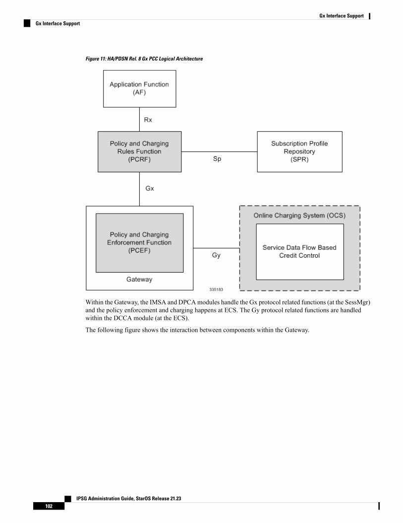
Figure 11: HA/PDSN Rel. 8 Gx PCC Logical Architecture
Within the Gateway, the IMSA and DPCAmodules handle the Gx protocol related functions (at the SessMgr)and the policy enforcement and charging happens at ECS. The Gy protocol related functions are handledwithin the DCCA module (at the ECS).
The following figure shows the interaction between components within the Gateway.
IPSG Administration Guide, StarOS Release 21.23102
Gx Interface SupportGx Interface Support
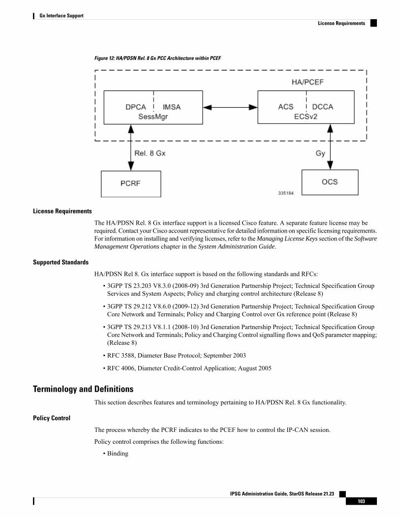
Figure 12: HA/PDSN Rel. 8 Gx PCC Architecture within PCEF
License Requirements
The HA/PDSN Rel. 8 Gx interface support is a licensed Cisco feature. A separate feature license may berequired. Contact your Cisco account representative for detailed information on specific licensing requirements.For information on installing and verifying licenses, refer to theManaging License Keys section of the SoftwareManagement Operations chapter in the System Administration Guide.
Supported Standards
HA/PDSN Rel 8. Gx interface support is based on the following standards and RFCs:
• 3GPP TS 23.203 V8.3.0 (2008-09) 3rd Generation Partnership Project; Technical Specification GroupServices and System Aspects; Policy and charging control architecture (Release 8)
• 3GPP TS 29.212 V8.6.0 (2009-12) 3rd Generation Partnership Project; Technical Specification GroupCore Network and Terminals; Policy and Charging Control over Gx reference point (Release 8)
• 3GPP TS 29.213 V8.1.1 (2008-10) 3rd Generation Partnership Project; Technical Specification GroupCore Network and Terminals; Policy and Charging Control signalling flows and QoS parameter mapping;(Release 8)
• RFC 3588, Diameter Base Protocol; September 2003
• RFC 4006, Diameter Credit-Control Application; August 2005
Terminology and DefinitionsThis section describes features and terminology pertaining to HA/PDSN Rel. 8 Gx functionality.
Policy Control
The process whereby the PCRF indicates to the PCEF how to control the IP-CAN session.
Policy control comprises the following functions:
• Binding
IPSG Administration Guide, StarOS Release 21.23103
Gx Interface SupportLicense Requirements
• Gating Control
• Event Reporting
• QoS Control
• Other Features
Binding
In the HA/PDSN Rel. 8 Gx implementation, since there are no bearers within a MIP session the IP-CANBearer concept does not apply. Only authorized IP-CAN session is applicable.
Gating Control
Gating control is the blocking or allowing of packets belonging to an SDF, to pass through to the desiredendpoint. A gate is described within a PCC rule and gating control is applied on a per SDF basis. The commandsto open or close the gate leads to the enabling or disabling of the passage for corresponding IP packets. If thegate is closed, all packets of the related IP flows are dropped. If the gate is open, the packets of the related IPflows are allowed to be forwarded.
Event Reporting
Unconditional reporting of event triggers from PCRF to PCEF when PCEF has not requested for is notsupported.
Important
In the HA/PDSN Rel. 8 Gx implementation, only the AN_GW_CHANGE (21) event trigger is supported.Important
Event reporting is the notification of and reaction to application events to trigger new behavior in the userplane as well as the reporting of events related to the resources in the Gateway (PCEF). Event triggers maybe used to determine which IP-CAN session modification or specific event causes the PCEF to re-requestPCC rules. Event trigger reporting from PCEF to PCRF, and provisioning of event triggers happens at IP-CANsession level.
The Event Reporting Function (ERF) located in the PCEF, receives event triggers from PCRF during theProvision of PCCRules procedure and performs event trigger detection.When an event matching the receivedevent trigger occurs, the ERF reports the occurred event to the PCRF. If the provided event triggers areassociated with certain parameter values then the ERF includes those values in the response to the PCRF.
QoS Control
In the HA/PDSN Rel. 8 Gx implementation, only authorized IP-CAN Session is supported. Provisioning ofauthorized QoS per IP-CAN bearer, policy enforcement for authorized QoS per QCI, and coordination ofauthorized QoS scopes in mixed mode are not applicable.
Important
QoS control is the authorization and enforcement of the maximum QoS that is authorized for an SDF. In caseof an aggregation of multiple SDFs, the combination of the authorized QoS information of the individual
IPSG Administration Guide, StarOS Release 21.23104
Gx Interface SupportBinding
SDFs is provided as the authorized QoS for this aggregate. QoS control per SDF allows the PCC architectureto provide the PCEF with the authorized QoS to be enforced for each specific SDF.
QoS authorization information may be dynamically provisioned by the PCRF, or it can be a predefined PCCrule in the PCEF. For a predefined PCC rule within the PCEF, the authorized QoS information takes affectwhen the PCC rule is activated. The PCEF combines the different sets of authorized QoS information, that isthe information received from the PCRF and the information corresponding to the predefined PCC rules. ThePCRF knows the authorized QoS information of the predefined PCC rules and takes this information intoaccount when activating them. This ensures that the combined authorized QoS of a set of PCC rules that areactivated by the PCRF is within the limitations given by the subscription and operator policies regardless ofwhether these PCC rules are dynamically provided, predefined, or both.
Supported features include:
• Provisioning and Policy Enforcement of Authorized QoS: The PCRF may provide authorized QoS tothe PCEF. The authorized QoS provides appropriate values for resources to be enforced.
• Policy Provisioning for Authorized QoS Per SDF: The provisioning of authorized QoS per SDF is a partof PCC rule provisioning procedure.
• Policy Enforcement for Authorized QoS Per SDF: If an authorized QoS is defined for a PCC rule, thePCEF limits the data rate of the SDF corresponding to that PCC rule not to exceed themaximum authorizedbandwidth for the PCC rule by discarding packets exceeding the limit.
• Upon deactivation or removal of a PCC rule, the PCEF frees the resources reserved for that PCC rule.
Other Features
This section describes some of the other features.
PCC Rule Error Handling
If the installation/activation of one or more PCC rules fails, the PCEF communicates the failure to the PCRFby including one or more Charging-Rule-Report AVP(s) in either a CCR or an RAA command for the affectedPCC rules. Within each Charging-Rule-Report AVP, the PCEF identifies the failed PCC rule(s) by includingthe Charging-Rule-Name AVP(s) or Charging-Rule-Base-Name AVP(s), identifies the failed reason code byincluding a Rule-Failure-Code AVP, and includes the PCC-Rule-Status AVP.
If the installation/activation of one or more new PCC rules (that is, rules that were not previously successfullyinstalled) fail, the PCEF sets the PCC-Rule-Status to INACTIVE for both the PUSH and the PULL modes.
If a PCC rule was successfully installed/activated, but can no longer be enforced by the PCEF, the PCEFsends the PCRF a new CCR command and includes the Charging-Rule-Report AVP. The PCEF includes theRule-Failure-Code AVP within the Charging-Rule-Report AVP and sets the PCC-Rule-Status to INACTIVE.
In releases prior to 18, P-GW/GGSN does not send CCR-U with Charging Rule report for rule binding failureoccurred during 4G to 3G HO in a collision case where create/update bearer response in 3G/4G is pendingand update bearer of 3G HO is received. In 18 and later releases, CCR-U is generated and sent to PCRF forreporting rule failure when the collision happens during GnGp HO scenario.
This additional Gx message (CCR-U) triggered will require multiple CCR-Us to be configured whenRAT_TYPE trigger is enabled. Otherwise, the subscriber call will be dropped whenever the collision happensduring HO.
In the HA/PDSN Gx implementation, the following rule failure codes are supported:
• RATING_GROUP_ERROR (2)
IPSG Administration Guide, StarOS Release 21.23105
Gx Interface SupportOther Features
• SERVICE_IDENTIFIER_ERROR (3)
• GW/PCEF_MALFUNCTION (4)
• RESOURCES_LIMITATION (5)
If the installation/activation of one or more PCC rules fails during RAR procedure, the RAA command is sentwith the Experimental-Result-Code AVP set to DIAMETER_PCC_RULE_EVENT (5142).
Time of the Day Procedures
PCEF performs PCC rule request as instructed by the PCRF. Revalidation-Time when set by the PCRF, causesthe PCEF to trigger a PCRF interaction to request PCC rules from the PCRF for an established IP-CANsession. The PCEF stops the timer once the PCEF triggers a REVALIDATION_TIMEOUT event.
When installed, the PCC rule is inactive. If Rule-Activation-Time / Rule-Deactivation-Time is specified, thenthe PCEF sets the rule active / inactive after that time.
In releases prior to 17.0, if "Rule-Deactivation-Time" AVP for a predefined rule was omitted in a CCA-U orRAR message, then any previous value for this AVP was continued to be used in the chassis. In 17.0 and laterreleases, if Rule-Deactivation-Time AVP is omitted in CCA/RAR, then any previous value for this AVP isno longer valid. The new behavior is compliant to the 3GPP specification for Gx, version 12.1.0.
If PCRF enables the same predefined rule again in RAR/CCA-U without Rule-Deactivation-Time AVP, thenthe deactivation-time for this rule, if any, will be removed.
For switching to the old behavior, PCRF should re-send the same value of Rule-Deactivation-Time AVPalong with predef-rule name in the PCRF message (RAR, CCA-U).
This behavior change is applicable only to predefined rules.Note
Support for Firewall Policy on Gx
The Diameter AVP "SN-Firewall-Policy" has been added to the Diameter dynamic dictionary to supportFirewall policy on Gx interface. This AVP can be encoded in CCA-I message to apply/overwrite the fw-and-natpolicy that has either been statically assigned to the PDP context via APN configuration or dynamicallyassigned via RADIUS in Access-Accept. This AVP can also parsed in any CCA-U or RARmessage to modifythe fw-and-nat policy that is currently assigned to the PDP context.
Charging Control
In the HA/PDSN Rel. 8 Gx implementation, offline charging is not supported.Important
Charging Control is the process of associating packets belonging to an SDF to a charging key, and applyingonline charging as appropriate. FBC handles differentiated charging of the bearer usage based on real-timeanalysis of the SDFs. In order to allow for charging control, the information in the PCC rule identifies theSDF and specifies the parameters for charging control. The PCC rule information may depend on subscriptiondata.
Online charging is supported via the Gy interface. In the case of online charging, it is possible to apply anonline charging action upon PCEF events (for example, re-authorization upon QoS change).
IPSG Administration Guide, StarOS Release 21.23106
Gx Interface SupportTime of the Day Procedures
It is possible to indicate to the PCEF that interactions with the charging systems are not required for a PCCrule, that is to perform neither accounting nor credit control for this SDF, then neither online nor offlinecharging is performed.
Supported Features:
• Provisioning of charging-related information for the IP-CAN Session
• Provisioning of charging addresses: Primary or secondary event charging function name (Online ChargingServer (OCS) addresses)
In the HA/PDSNRel. 8 Gx implementation, provisioning of primary or secondarycharging collection function name (Offline Charging Server (OFCS) addresses)over Gx is not supported.
Important
• Provisioning of Default Charging Method: In this release, the default charging method is sent in CCR-Imessage. For this, new AVPs Online/Offline are sent in CCR-I message based on the configuration. TheOnline/Offline AVP received at command level applies only to dynamic rules if they are not configuredat PCC rule level.
Charging Correlation
In the HA/PDSN Rel. 8 Gx implementation, Charging Correlation is not supported. PCRF provides the flowidentifier, which uniquely identifies an IP flow in an IMS session.
Policy and Charging Control (PCC) Rules
A PCC rule enables the detection of an SDF and provides parameters for policy control and/or chargingcontrol. The purpose of the PCC rule is to:
• Detect a packet belonging to an SDF in case of both uplink and downlink IP flows based on SDF filtersin the PCC rule (packet rule matching).
If no PCC rule matches the packet, the packet is dropped.
• Identify the service that the SDF contributes to.
• Provide applicable charging parameters for an SDF.
• Provide policy control for an SDF.
The PCEF selects a PCC rule for each packet received by evaluating received packets against SDF filters ofPCC rules in the order of precedence of the PCC rules. When a packet matches an SDF filter, the packetmatching process for that packet is completed, and the PCC rule for that filter is applied.
There are two types of PCC rules:
• Dynamic PCC Rules: Rules dynamically provisioned by the PCRF to the PCEF via the Gx interface.These PCC rules may be either predefined or dynamically generated in the PCRF. Dynamic PCC rulescan be activated, modified, and deactivated at any time.
• Predefined PCC Rule: Rules preconfigured in the PCEF by the operators. Predefined PCC rules can beactivated or deactivated by the PCRF at any time. Predefined PCC rules within the PCEFmay be groupedallowing the PCRF to dynamically activate a set of PCC rules over the Gx reference point.
IPSG Administration Guide, StarOS Release 21.23107
Gx Interface SupportCharging Correlation
A third kind of rule, the static PCC rule can be preconfigured in the chassis by the operators. Static PCC rulesare not explicitly known in the PCRF, and are not under control of the PCRF. Static PCC rules are bound togeneral purpose bearer with no Gx control.
Important
A PCC rule consists of:
• Rule Name: The rule name is used to reference a PCC rule in the communication between the PCEF andPCRF.
• Service Identifier: The service identifier is used to identify the service or the service component the SDFrelates to.
• Service Data Flow Filter(s): The service flow filter(s) is used to select the traffic for which the ruleapplies.
• Precedence: For different PCC rules with overlapping SDF filter, the precedence of the rule determineswhich of these rules is applicable. When a dynamic PCC rule and a predefined PCC rule have the samepriority, the dynamic PCC rule takes precedence.
• Gate Status: The gate status indicates whether the SDF, detected by the SDF filter(s), may pass (gate isopen) or will be discarded (gate is closed) in uplink and/or in downlink direction.
• QoS Parameters: The QoS information includes the QoS class identifier (authorized QoS class for theSDF), and authorized bitrates for uplink and downlink.
• Charging Key (rating group)
• Other charging parameters: The charging parameters define whether online charging interfaces are used,on what level the PCEF will report the usage related to the rule, etc.
Configuring the Metering Method and Reporting Level for dynamic PCC rules is not supported.Important
PCC rules also include Application Function (AF) record information for enabling charging correlationbetween the application and bearer layer if the AF has provided this information via the Rx interface. ForIMS, this includes the IMS Charging Identifier (ICID) and flow identifiers.
ASR 5500 supports only eight flow information including the flow description per dynamic charging rule ina Gx message.
Important
In releases prior to 14.0, there were only 10 PCC rules that were recovered per bearer in the event of a sessionmanager crash. In 14.0 and later releases, this limit has been increased to 24. That is, up to 24 PCC rules canbe recovered post ICSR.
With the increase in the limit of PCC rules that can be recovered, the rules are not lost and hence the chargingapplied to the end users are not impacted.
In releases prior to 17.0, when P-GW received PCC rules from PCRF and it results in Create Bearer or UpdateBearer to be triggered towards MME/S-GW, the PCC rules were kept in a pending-active state. Anymodification request that was received for these pending-active rules were not currently honored by the P-GW.
IPSG Administration Guide, StarOS Release 21.23108
Gx Interface SupportGx Interface Support
In 17.0 and later releases, when modification for the PCC rules in pending-active state is received, the modifiedparameters will be buffered at P-GW. After the response for the pending request is received from the accessnetwork, P-GW will process the modification of the buffered parameters and if required generate anotherupdate towards network.
PCC Procedures over Gx Reference Point
Request for PCC Rules
The PCEF, via the Gx reference point, requests for PCC rules in the following instances:
• At IP-CAN session establishment
• At IP-CAN session modification
PCC rules can also be requested as a consequence of a failure in the PCC rule installation/activation orenforcement without requiring an event trigger.
Provisioning of PCC Rules
The PCRF indicates, via the Rel. 8 Gx reference point, the PCC rules to be applied at the PCEF. This may beusing one of the following procedures:
• PULL (provisioning solicited by the PCEF): In response to a request for PCC rules being made by thePCEF, the PCRF provisions PCC rules in the CC-Answer.
• PUSH (unsolicited provisioning): The PCRF may decide to provision PCC rules without obtaining arequest from the PCEF. For example, in response to information provided to the PCRF via the Rx referencepoint, or in response to an internal trigger within the PCRF. To provision PCC rules without a requestfrom the PCEF, the PCRF includes these PCC rules in an RA-Request message. No CCR/CCAmessagesare triggered by this RA-Request.
For each request from the PCEF or upon unsolicited provisioning, the PCRF provisions zero or more PCCrules. The PCRF may perform an operation on a single PCC rule by one of the following means:
• To activate or deactivate a PCC rule that is predefined at the PCEF, the PCRF provisions a reference tothis PCC rule within a Charging-Rule-Name AVP and indicates the required action by choosing eitherthe Charging-Rule-Install AVP or the Charging-Rule-Remove AVP.
• To install or modify a PCRF-provisioned PCC rule, the PCRF provisions a correspondingCharging-Rule-Definition AVP within a Charging-Rule-Install AVP.
• To remove a PCC rule which has previously been provisioned by the PCRF, the PCRF provisions thename of this rule as value of a Charging-Rule-Name AVP within a Charging-Rule-Remove AVP.
In 11.0 and later releases, the maximum valid length for a charging rule name is 63 bytes. When the lengthof the charging rule name is greater than 63 bytes, a charging rule report with RESOURCES_LIMITATIONas Rule-Failure-Code is sent. This charging rule report is sent only when the length of the rule name is lesserthan 128 characters.When the charging rule name length is greater than or equal to 128 characters no chargingrule report will be sent. In earlier releases, the length of the charging rule name constructed by PCRF waslimited to 32 bytes.
Important
IPSG Administration Guide, StarOS Release 21.23109
Gx Interface SupportPCC Procedures over Gx Reference Point
Releases prior to 14.0, when PCRF has subscribed to Out of Credit trigger, on session connect when one rulevalidation fails and also when an Out of Credit was received from OCS for another rule, P-GW was trying toreport these failures in different CCR-U to PCRF. However, the second CCR-U of Out of credit was gettingdropped internally.
In 14.0 and later releases, on session connect, P-GW combines the rule failure and out of credit in the sameCCR-U and sends to PCRF.
Selecting a PCC Rule for Uplink IP Packets
If PCC is enabled, the PCEF selects the applicable PCC rule for each received uplink IP packet within anIP-CAN session by evaluating the packet against uplink SDF filters of PCRF-provided or predefined activePCC rules of this IP-CAN session in the order of the precedence of the PCC rules.
When a PCRF-provided PCC rule and a predefined PCC rule have the same precedence, the uplink SDF filtersof the PCRF-provided PCC rule is applied first.
Important
When a packet matches an SDF filter, the packet matching process for that packet is completed, and the PCCrule for that filter is applied. Uplink IP packets which do not match any PCC rule of the corresponding IP-CANsession are discarded.
Selecting a PCC Rule for Downlink IP Packets
If PCC is enabled, the PCEF selects a PCC rule for each received downlink IP packet within an IP-CANsession by evaluating the packet against downlink SDF filters of PCRF-provided or predefined active PCCrules of the IP-CAN session in the order of precedence of the PCC rules.
When a PCRF-provided PCC rule and a predefined PCC rule have the same precedence, the downlink SDFfilters of the PCRF-provided PCC rule are applied first.
Important
When a packet matches an SDF filter, the packet matching process for that packet is completed, and the PCCrule for that filter is applied. Downlink IP packets that do not match any PCC rule of the IP-CAN session arediscarded.
The following procedures are also supported:
• Indication of IP-CAN Session Termination: When the IP-CAN session is being terminated the PCEFcontacts the PCRF.
• Request of IP-CAN Session Termination: If the PCRF decides to terminate an IP-CAN session due toan internal trigger or trigger from the SPR, the PCRF informs the PCEF. The PCEF acknowledges to thePCRF and instantly removes/deactivates all the PCC rules that have been previously installed or activatedon that IP-CAN session.
The PCEF applies IP-CAN specific procedures to terminate the IP-CAN session. The HA/PDSN sendsa MIP Revocation Request with the teardown indicator set to indicate that the termination of the entireIP-CAN session is requested. Furthermore, the PCEF applies the "Indication of IP-CAN SessionTermination" procedure.
• Use of the Supported-Features AVP during session establishment to inform the destination host aboutthe required and optional features that the origin host supports.
IPSG Administration Guide, StarOS Release 21.23110
Gx Interface SupportSelecting a PCC Rule for Uplink IP Packets
How it WorksThis section describes how HA/PDSN Rel. 8 Gx Interface support works.
The following figure and table explain the IMSAuthorization process between a system and IMS componentsthat is initiated by the UE.
In this example, the Diameter Policy Control Application (DPCA) is the Gx interface to the PCRF. Theinterface between IMSAwith PCRF is the Gx interface, and the interface between SessionManager (SessMgr)and Online Charging Service (OCS) is the Gy interface. Note that the IMSA service and DPCA are part ofSessMgr on the system and separated in the figure for illustration purpose only.
In 14.0 and later releases, the DPCA and the IMSA will be acting as one module within the Policy Serverinterface application.
Important
IPSG Administration Guide, StarOS Release 21.23111
Gx Interface SupportHow it Works
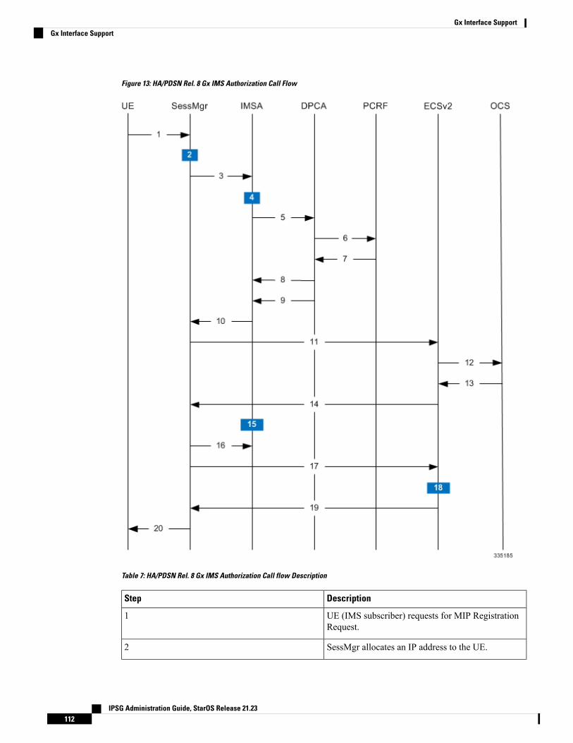
Figure 13: HA/PDSN Rel. 8 Gx IMS Authorization Call Flow
Table 7: HA/PDSN Rel. 8 Gx IMS Authorization Call flow Description
DescriptionStep
UE (IMS subscriber) requests for MIP RegistrationRequest.
1
SessMgr allocates an IP address to the UE.2
IPSG Administration Guide, StarOS Release 21.23112
Gx Interface SupportGx Interface Support
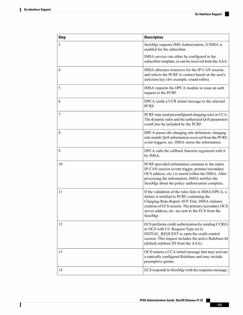
DescriptionStep
SessMgr requests IMS Authorization, if IMSA isenabled for the subscriber.
IMSA service can either be configured in thesubscriber template, or can be received from the AAA.
3
IMSA allocates resources for the IP-CAN session,and selects the PCRF to contact based on the user'sselection key (for example, round-robin).
4
IMSA requests the DPCA module to issue an authrequest to the PCRF.
5
DPCA sends a CCR initial message to the selectedPCRF.
6
PCRFmay send preconfigured charging rules in CCA.The dynamic rules and the authorized QoS parameterscould also be included by the PCRF.
7
DPCA passes the charging rule definition, chargingrule install, QoS information received from the PCRF,event triggers, etc. IMSA stores the information.
8
DPCA calls the callback function registered with itby IMSA.
9
PCRF-provided information common to the entireIP-CAN session (event trigger, primary/secondaryOCS address, etc.) is stored within the IMSA. Afterprocessing the information, IMSA notifies theSessMgr about the policy authorization complete.
10
If the validation of the rules fails in IMSA/DPCA, afailure is notified to PCRF containing theCharging-Rule-Report AVP. Else, IMSA initiatescreation of ECS session. The primary/secondary OCSserver address, etc. are sent to the ECS from theSessMgr.
11
ECS performs credit authorization by sending CCR(I)to OCS with CC-Request-Type set toINITIAL_REQUEST to open the credit controlsession. This request includes the active Rulebase-Id(default rulebase ID from the AAA).
12
OCS returns a CCA initial message that may activatea statically configured Rulebase and may includepreemptive quotas.
13
ECS responds to SessMgr with the response message.14
IPSG Administration Guide, StarOS Release 21.23113
Gx Interface SupportGx Interface Support
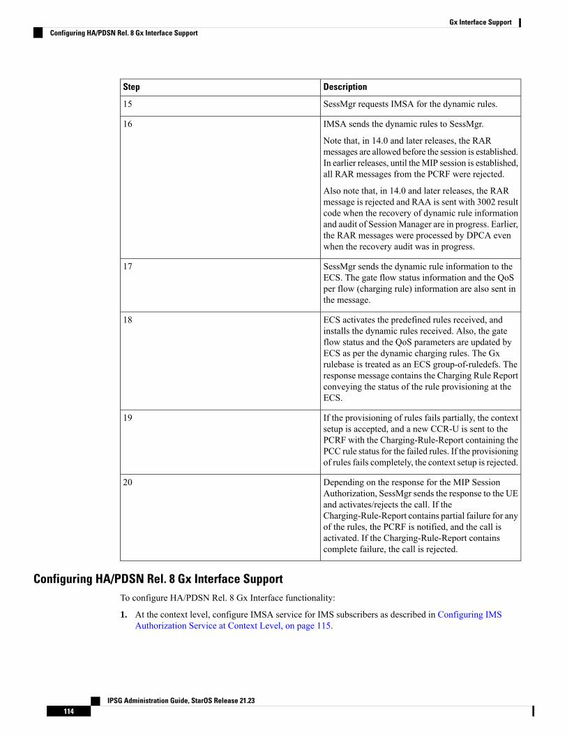
DescriptionStep
SessMgr requests IMSA for the dynamic rules.15
IMSA sends the dynamic rules to SessMgr.
Note that, in 14.0 and later releases, the RARmessages are allowed before the session is established.In earlier releases, until theMIP session is established,all RAR messages from the PCRF were rejected.
Also note that, in 14.0 and later releases, the RARmessage is rejected and RAA is sent with 3002 resultcode when the recovery of dynamic rule informationand audit of SessionManager are in progress. Earlier,the RAR messages were processed by DPCA evenwhen the recovery audit was in progress.
16
SessMgr sends the dynamic rule information to theECS. The gate flow status information and the QoSper flow (charging rule) information are also sent inthe message.
17
ECS activates the predefined rules received, andinstalls the dynamic rules received. Also, the gateflow status and the QoS parameters are updated byECS as per the dynamic charging rules. The Gxrulebase is treated as an ECS group-of-ruledefs. Theresponse message contains the Charging Rule Reportconveying the status of the rule provisioning at theECS.
18
If the provisioning of rules fails partially, the contextsetup is accepted, and a new CCR-U is sent to thePCRF with the Charging-Rule-Report containing thePCC rule status for the failed rules. If the provisioningof rules fails completely, the context setup is rejected.
19
Depending on the response for the MIP SessionAuthorization, SessMgr sends the response to the UEand activates/rejects the call. If theCharging-Rule-Report contains partial failure for anyof the rules, the PCRF is notified, and the call isactivated. If the Charging-Rule-Report containscomplete failure, the call is rejected.
20
Configuring HA/PDSN Rel. 8 Gx Interface SupportTo configure HA/PDSN Rel. 8 Gx Interface functionality:
1. At the context level, configure IMSA service for IMS subscribers as described in Configuring IMSAuthorization Service at Context Level, on page 115.
IPSG Administration Guide, StarOS Release 21.23114
Gx Interface SupportConfiguring HA/PDSN Rel. 8 Gx Interface Support
2. Within the same context, configure the subscriber template to use the IMSA service as described inApplying IMS Authorization Service to Subscriber Template, on page 116.
3. Save your configuration to flash memory, an external memory device, and/or a network location usingthe Exec mode command save configuration. For additional information on how to verify and saveconfiguration files, refer to the System Administration Guide and the Command Line Interface Reference.
Commands used in the configuration examples in this section provide base functionality to the extent that themost common or likely commands and/or keyword options are presented. In many cases, other optionalcommands and/or keyword options are available. Refer to theCommand Line Interface Reference for completeinformation regarding all commands.
Important
Configuring IMS Authorization Service at Context Level
Use the following example to configure IMSA service at context level for IMS subscribers:
configurecontext <context_name>
ims-auth-service <imsa_service_name>
policy-controldiameter origin endpoint <endpoint_name>
diameter dictionary <dictionary>
diameter request-timeout <timeout_duration>
diameter host-select table { 1 | 2 } algorithmround-robin
diameter host-select row-precedence <precedence_value>
table { 1 | 2 } host <primary_host_name> [ realm <primary_realm_id> ] [ secondaryhost <secondary_host_name> [ realm <secondary_realm_id> ] ] [ -noconfirm ]
failure-handling cc-request-type { any-request |initial-request | terminate-request | update-request } {diameter-result-code { any-error | <result_code> [ to <end_result_code> ] } }{ continue | retry-and-terminate | terminate }
exitexit
diameter endpoint <endpoint_name> [ -noconfirm ]origin realm <realm_name>
use-proxyorigin host <host_name> address <ip_address>
no watchdog-timeoutresponse-timeout <timeout_duration>
connection timeout <timeout_duration>
connection retry-timeout <timeout_duration>
peer <primary_peer_name> [ realm <primary_realm_name> ] address<ip_address> [ port <port_number> ]
peer <secondary_peer_name> [ realm <secondary_realm_name> ] address<ip_address> [ port <port_number> ]
end
Notes:
• <context_name> must be the name of the context where you want to enable IMSA service.
IPSG Administration Guide, StarOS Release 21.23115
Gx Interface SupportConfiguring IMS Authorization Service at Context Level
• <imsa_service_name> must be the name of the IMSA service to be configured for Rel. 8 Gx interfaceauthentication.
• In releases prior to 18, a maximum of 16 authorization services can be configured globally in the system.There is also a system limit for the maximum number of total configured services. In 18 and later releases,up to a maximum of 30 IMS authorization service profiles can be configured within the system.
• To enable Rel. 8 Gx interface support, pertinent Diameter dictionarymust be configured. For informationon the specific Diameter dictionary to use, contact your Cisco account representative.
• The Round Robin algorithm for PCRF selection is effective only over a large number of PCRF selections,and not at a granular level.
• To configure the PCRF host destinations configured in the PCEF, use the diameter host-select CLIcommand.
• To configure the PCEF to use a pre-defined rule when the Gx fails, set the failure-handlingcc-request-type CLI to continue. Policies available/in use will continue to be used and there will be nofurther interaction with the PCRF.
Verifying the IMSA Service Configuration
To verify the IMSA service configuration:
1. Change to the context where you enabled IMSA service by entering the following command:
context <context_name>
2. Verify the IMSA service configuration by entering the following command:
show ims-authorization service name <imsa_service_name>
Applying IMS Authorization Service to Subscriber Template
After configuring IMSA service at the context-level, within the same context subscriber template must beconfigured to use the IMSA service for IMS subscribers.
Use the following example to apply IMSA service functionality to subscriber template within the contextconfigured as described in Configuring IMS Authorization Service at Context Level, on page 115.
configurecontext <context_name>
subscriber defaultencrypted password <encrypted_password>
ims-auth-service <imsa_service_name>
ip access-group <access_group_name> inip access-group <access_group_name> outip context-name <context_name>
mobile-ip home-agent <ip_address>
active-charging rulebase <rulebase_name>
end
Notes:
• <context_name> must be the name of the context in which the IMSA service was configured.
IPSG Administration Guide, StarOS Release 21.23116
Gx Interface SupportVerifying the IMSA Service Configuration
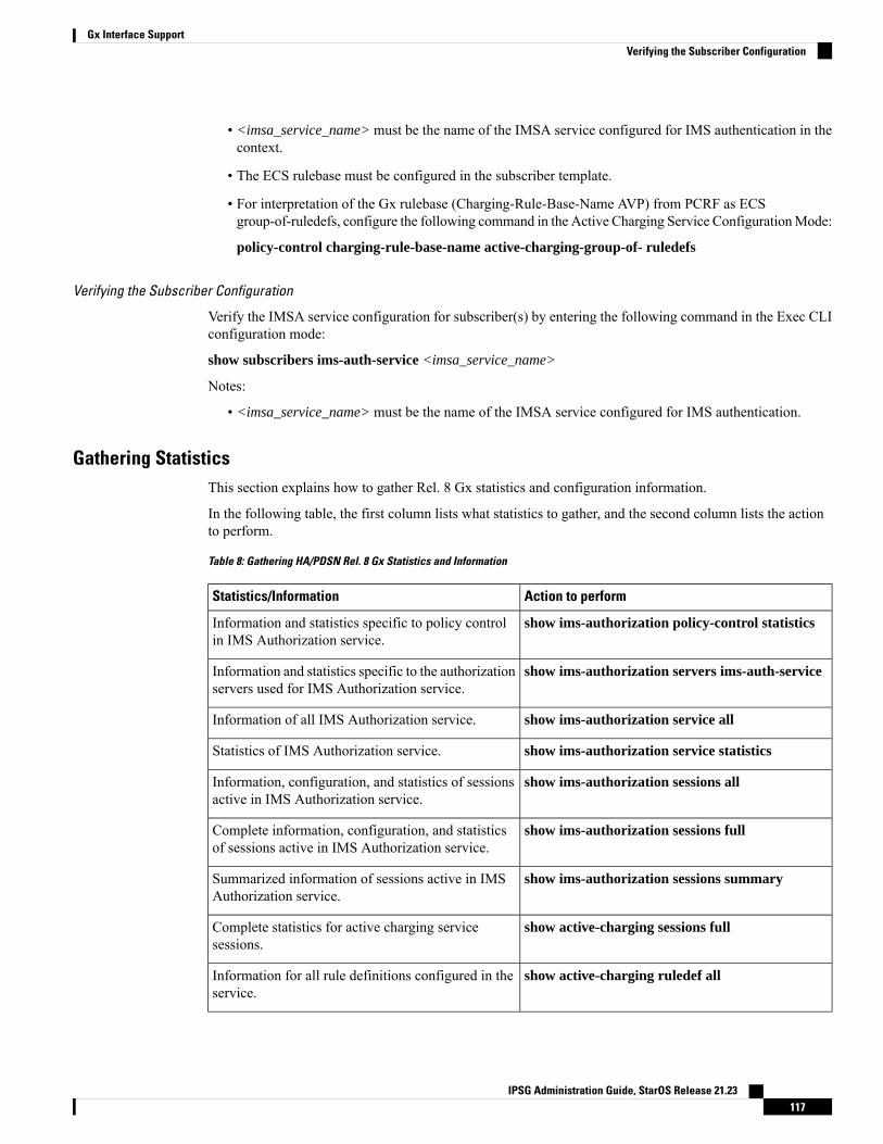
• <imsa_service_name> must be the name of the IMSA service configured for IMS authentication in thecontext.
• The ECS rulebase must be configured in the subscriber template.
• For interpretation of the Gx rulebase (Charging-Rule-Base-Name AVP) from PCRF as ECSgroup-of-ruledefs, configure the following command in the Active Charging Service ConfigurationMode:
policy-control charging-rule-base-name active-charging-group-of- ruledefs
Verifying the Subscriber Configuration
Verify the IMSA service configuration for subscriber(s) by entering the following command in the Exec CLIconfiguration mode:
show subscribers ims-auth-service <imsa_service_name>
Notes:
• <imsa_service_name> must be the name of the IMSA service configured for IMS authentication.
Gathering StatisticsThis section explains how to gather Rel. 8 Gx statistics and configuration information.
In the following table, the first column lists what statistics to gather, and the second column lists the actionto perform.
Table 8: Gathering HA/PDSN Rel. 8 Gx Statistics and Information
Action to performStatistics/Information
show ims-authorization policy-control statisticsInformation and statistics specific to policy controlin IMS Authorization service.
show ims-authorization servers ims-auth-serviceInformation and statistics specific to the authorizationservers used for IMS Authorization service.
show ims-authorization service allInformation of all IMS Authorization service.
show ims-authorization service statisticsStatistics of IMS Authorization service.
show ims-authorization sessions allInformation, configuration, and statistics of sessionsactive in IMS Authorization service.
show ims-authorization sessions fullComplete information, configuration, and statisticsof sessions active in IMS Authorization service.
show ims-authorization sessions summarySummarized information of sessions active in IMSAuthorization service.
show active-charging sessions fullComplete statistics for active charging servicesessions.
show active-charging ruledef allInformation for all rule definitions configured in theservice.
IPSG Administration Guide, StarOS Release 21.23117
Gx Interface SupportVerifying the Subscriber Configuration
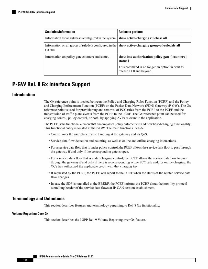
Action to performStatistics/Information
show active-charging rulebase allInformation for all rulebases configured in the system.
show active-charging group-of-ruledefs allInformation on all group of ruledefs configured in thesystem.
show ims-authorization policy-gate { counters |status }
This command is no longer an option in StarOSrelease 11.0 and beyond.
Information on policy gate counters and status.
P-GW Rel. 8 Gx Interface Support
IntroductionThe Gx reference point is located between the Policy and Charging Rules Function (PCRF) and the Policyand Charging Enforcement Function (PCEF) on the Packet Data Network (PDN) Gateway (P-GW). The Gxreference point is used for provisioning and removal of PCC rules from the PCRF to the PCEF and thetransmission of traffic plane events from the PCEF to the PCRF. The Gx reference point can be used forcharging control, policy control, or both, by applying AVPs relevant to the application.
The PCEF is the functional element that encompasses policy enforcement and flow based charging functionality.This functional entity is located at the P-GW. The main functions include:
• Control over the user plane traffic handling at the gateway and its QoS.
• Service data flow detection and counting, as well as online and offline charging interactions.
• For a service data flow that is under policy control, the PCEF allows the service data flow to pass throughthe gateway if and only if the corresponding gate is open.
• For a service data flow that is under charging control, the PCEF allows the service data flow to passthrough the gateway if and only if there is a corresponding active PCC rule and, for online charging, theOCS has authorized the applicable credit with that charging key.
• If requested by the PCRF, the PCEF will report to the PCRF when the status of the related service dataflow changes.
• In case the SDF is tunnelled at the BBERF, the PCEF informs the PCRF about the mobility protocoltunnelling header of the service data flows at IP-CAN session establishment.
Terminology and DefinitionsThis section describes features and terminology pertaining to Rel. 8 Gx functionality.
Volume Reporting Over Gx
This section describes the 3GPP Rel. 9 Volume Reporting over Gx feature.
IPSG Administration Guide, StarOS Release 21.23118
Gx Interface SupportP-GW Rel. 8 Gx Interface Support
License Requirements
The Volume Reporting over Gx is a licensed Cisco feature. A separate feature license may be required. Contactyour Cisco account representative for detailed information on specific licensing requirements. For informationon installing and verifying licenses, refer to the Managing License Keys section of the Software ManagementOperations chapter in the System Administration Guide.
In 12.0 and later releases, no separate license is required for Charging over Gx / Volume Reporting over Gxfeature. This feature can be enabled as part of "Policy Interface" license.
Important
Supported Standards
The Volume Reporting over Gx feature is based on the following standard:
3GPP TS 29.212 V9.5.0 (2010-06): 3rd Generation Partnership Project; Technical Specification Group CoreNetwork and Terminals; Policy and Charging Control over Gx reference point (Release 9).
Feature Overview
The Volume Reporting over Gx feature provides PCRF the capability to make real-time decisions based onthe data usage by subscribers.
Volume Reporting over Gx is applicable only for volume quota.
In release 10.0, only total data usage reporting is supported, uplink/downlink level reporting is not supported.In 10.2 and later releases, it is supported.
The PCEF only reports the accumulated usage since the last report for usage monitoring and not from thebeginning.
If the usage threshold is set to zero (infinite threshold), no further threshold events will be generated by PCEF,but monitoring of usage will continue and be reported at the end of the session.
In 12.2 and later releases, usage reporting on bearer termination is supported.
Important
The following steps explain how Volume Reporting over Gx works:
1. PCEF after receiving the message from PCRF parses the usage monitoring related AVPs, and sends theinformation to IMSA.
2. IMSA updates the information to ECS.
3. Once the ECS is updated with the usage monitoring information from PCRF, the PCEF (ECS) startstracking the data usage.
4. For session-level monitoring, the ECS maintains the amount of data usage.
5. For PCC rule monitoring, usage is monitored with the monitoring key as the unique identifier. Each nodemaintains the usage information per monitoring key. When the data traffic is passed, the usage is checkedagainst the usage threshold values and reported as described in the Usage Reporting section.
6. The PCEF continues to track data usage after the threshold is reached and before a new threshold isprovided by the PCRF. If a new usage threshold is not provided by the PCRF in the acknowledgement of
IPSG Administration Guide, StarOS Release 21.23119
Gx Interface SupportLicense Requirements
an IP-CAN Session modification where its usage was reported, then usage monitoring does not continuein the PCEF for that IP CAN session.
Usage Monitoring
• Usage Monitoring at Session Level: PCRF subscribes to the session-level volume reporting over Gx bysending the Usage-Monitoring-InformationAVPwith the usage threshold level set in Granted-Service-UnitAVP and Usage-Monitoring-Level AVP set to SESSION_LEVEL(0). After the AVPs are parsed byDPCA, IMSA updates the information to ECS. Once ECS is updated usage monitoring is started andconstantly checked with the usage threshold whenever the data traffic is present. In 11.0 and later releases,Monitoring Key at session level is supported.
In 12.0 and later releases, enabling and disabling session usage in a single message from PCRF issupported. This is supported only if the monitoring key is associated at session level.
In 12.0 and later releases, monitoring of usage based on input/output octet threshold levels is supported.Usage is reported based on the enabled threshold level. If multiple levels are enabled, usage will bereported on all the enabled levels even if only one of the levels is breached. Monitoring will be stoppedon the missing threshold levels in the response for the usage report from PCRF (expected to provide thecomplete set again if PCRF wants to continue monitoring on the multiple levels enabled earlier).
Total threshold level along with UL/DL threshold level in the GSU AVP is treated as an error and onlytotal threshold level is accepted.
In releases prior to 17.0, extra CCR-U was generated for a monitoring key when the following requestsare received in the response to the CCR-U which reported the usage for the same monitoring key.
• immediate reporting request with monitoring key at rule level• immediate reporting request with or without monitoring key at session level• explicit disable request at rule level• explicit disable request at session level
In 17.0 and later releases, extra CCR-U is not generated for a monitoring key when all the abovementionedrequests are received in the response to the CCR-U which reported the usage for the same monitoringkey. Also, extra CCR-U is not generated when immediate reporting request without monitoring key atrule level is received in the response to the CCR-U which reported the usage for all the active monitoringkeys.
• UsageMonitoring at Flow Level: PCRF subscribes to the flow-level volume reporting over Gx by sendingthe Usage-Monitoring-Information AVP with the usage threshold level set in Granted-Service-Unit AVPand Usage-Monitoring-Level AVP set to PCC_RULE_LEVEL(1). Monitoring Key is mandatory in caseof a flow-level monitoring since the rules are associated with the monitoring key and enabling/disablingof usage monitoring at flow level can be controlled by PCRF using it. After the AVPs are parsed byDPCA, IMSA updates the information to ECS. Once ECS is updated usage monitoring is started andconstantly checked with the usage threshold whenever the data traffic is present.
Usage monitoring is supported for static, predefined rules, and dynamic rule definitions.
• UsageMonitoring for Static Rules: In the case of static rules, the usage reporting on last rule removalassociated with the monitoring key is not applicable. In this case only the usage monitoringinformation is received from the PCRF.
• Usage Monitoring for Predefined Rules: If the usage monitoring needs to be enabled for thepredefined rules, PCRF sends the rule and the usagemonitoring information containing themonitoringkey and the usage threshold. TheMonitoring key should be same as the one pre-configured in PCEFfor that predefined rule. There can bemultiple rules associated with the samemonitoring key. Hence
IPSG Administration Guide, StarOS Release 21.23120
Gx Interface SupportUsage Monitoring
enabling a particular monitoring key would result in the data being tracked for multiple rules havingthe same monitoring key. After DPCA parses the AVPs IMSA updates the information to ECS.Once ECS is updated usage monitoring is started and constantly checked with the usage thresholdwhenever the data traffic is present.
• Usage Monitoring for Dynamic Rules: If the usage monitoring needs to be enabled for dynamicruledefs, PCRF provides the monitoring key along with a charging rule definition and the usagemonitoring information containing the monitoring key and the usage threshold. This would resultin the usage monitoring being done for all the rules associated with that monitoring key. After DPCAparses the AVPs, IMSA updates the information to ECS. Once ECS is updated, the usage monitoringis started and constantly checked with the usage threshold whenever the data traffic is present.Monitoring key for dynamic ruledef is dynamically assigned by PCRF which is the only differencewith predefined rules in case of usage monitoring.
In releases prior to 15.0, when threshold breach happens for multiple monitoring keys at the same time, onlyone of the monitoring keys' usage is reported and the rest of the monitoring keys' usage is reported in CCR-T(threshold set to infinity). On Tx expiry/TCP link error, unreported usage is stored at ECS and reported onlyon session termination.
In 15.0 and later releases, only one of the monitoring keys' usage is reported first. Upon receiving successfulresponse from PCRF, the rest of the monitoring keys' usage is reported to PCRF. On Tx expiry/TCP link error,unreported usage is stored at ECS. Any future successful interaction with PCRF for the session will sendunreported UMI to PCRF.
Usage Reporting
Usage at subscriber/flow level is reported to PCRF under the following conditions:
• Usage Threshold Reached: PCEF records the subscriber data usage and checks if the usage thresholdprovided by PCRF is reached. This is done for both session and rule level reporting.
For session-level reporting, the actual usage volume is compared with the usage volume threshold.
For rule-level reporting the rule that hits the data traffic is used to find out if the monitoring key isassociated with it, and based on the monitoring key the data usage is checked. Once the condition is met,it reports the usage information to IMSA and continues monitoring. IMSA then triggers the CCR-U if"USAGE_REPORT" trigger is enabled by the PCRF. The Usage-Monitoring-Information AVP is sentin this CCR with the "Used-Service-Unit" set to the amount of data usage by subscriber.
If PCRF does not provide a new usage threshold in the usage monitoring information as a result of CCRfrom PCEF when the usage threshold is reached, the usage monitoring is stopped at PCEF and no usagestatus is reported.
In the non-standard Volume Reporting over Gx implementation, usage monitoring will be stopped oncethe threshold is breached, else the monitoring will continue. There will be no further usage reportinguntil the CCA is received.
• Usage Monitoring Disabled: If the PCRF explicitly disables the usage monitoring withUsage-Monitoring-Support AVP set toUSAGE_MONITORING_DISABLED, the PCEF stopsmonitoringand reports the usage information (when the monitoring was enabled) to PCRF if the usage monitoringis disabled by PCRF as a result of CCR from PCEF which is not related to reporting usage, other externaltriggers, or a PCRF internal trigger. If the PCRF does not provide a new usage threshold as a result ofCCR from PCEF when the usage threshold is reached, the usage monitoring is stopped at PCEF and nofurther usage status is reported.
IPSG Administration Guide, StarOS Release 21.23121
Gx Interface SupportUsage Reporting
• IP CAN Session Termination:When the IP CAN session is terminated, the accumulated subscriber usageinformation is reported to PCRF in the CCR-T from PCEF. If PCC usage level information is enabledby PCRF, the PCC usage will also be reported.
PCRF uses RAR message and includes Session-Release-Cause AVP in it to initiate IP CAN SessionTermination. However, there are some scenarios where PCRFmaywant to terminate the IP CAN Sessionin CCA messages. In order to avoid an unnecessary additional message, PCRF can inform P-GW toterminate the subscriber in CCA-U message itself. Hence, in 17.0 and later releases, the Session ReleaseCause has been added in CCA messages for all Gx dictionaries.
• PCC Rule Removal: When the PCRF deactivates the last PCC rule associated with a usage monitoringkey, the PCEF sends a CCR with the data usage for that monitoring key. If the PCEF reports the lastPCC rule associated with a usage monitoring key is inactive, the PCEF reports the accumulated usagefor that monitoring key within the same CCR command if the Charging-Rule-Report AVP was includedin a CCR command; otherwise, if the Charging-Rule-Report AVP was included in an RAA command,the PCEF sends a new CCR command to report accumulated usage for the usage monitoring key. In 12.0and later releases, usage reporting on last rule deactivation using rule deactivation time set by PCRF issupported.
Releases prior to 14.0, when PCC rule was tried to be removed while waiting for access side updatebearer response, the charging rules were not removed. In 14.0 and later releases, on receiving messagefrom PCRF, the rule that is meant for removal is marked and then after the access side procedure iscomplete the rule is removed.
• PCRF Requested Usage Report: In 10.2 and later releases, the accumulated usage since the last reportis sent even in case of immediate reporting, the usage is reset after immediate reporting and usagemonitoring continued so that the subsequent usage report will have the usage since the current report. Inearlier releases the behavior was to accumulate the so far usage in the next report.
• Release 12.2 onwards, usage reporting on bearer termination can be added. When a bearer is deleted dueto some reason, the rules associated with the bearer will also be removed. So, the usage will be reportedon the monitoring key(s) whose associated rule is the last one that is removed because of bearertermination.
• Revalidation Timeout: In the non-standard implementation, if usage monitoring and reporting is enabledand a revalidation timeout occurs, the PCEF sends a CCR to request PCC rules and reports all accumulatedusage for all enabled monitoring keys since the last report (or since usage reporting was enabled if theusage was not yet reported) with the accumulated usage at IP-CAN session level (if enabled) and atservice data flow level (if enabled) This is the default behavior.
In the case of standard implementation, this must be enabled by CLI configuration.
The Usage Reporting on Revalidation Timeout feature is available by default in non-standard implementationof Volume Reporting over Gx. In 10.2 and later releases, this is configurable in the standard implementation.This is not supported in 10.0 release for standard based volume reporting.
Important
Once the usage is reported, the usage counter is reset to zero. The PCEF continues to track data usage fromthe zero value after the threshold is reached and before a new threshold is provided by the PCRF. If a newusage threshold is not provided by the PCRF in the acknowledgement of an IP-CAN Session modificationwhere its usage was reported, then usage monitoring does not continue in the PCEF for that IP CAN sessionand and the usage accumulated between the CCR-CCA will be discarded.
IPSG Administration Guide, StarOS Release 21.23122
Gx Interface SupportGx Interface Support
In releases prior to 17.0, CCR-U triggered on server retries does not take server granted quota into accountfor reporting USU. In 17.0 and later releases, CCR-U triggered on server retries takes server granted quotainto account for reporting USU. For newly created MSCC, interim quota configuration is taken as referencefor reporting USU.
For information on how to configure the Volume Reporting over Gx feature, refer to Configuring VolumeReporting over Gx, on page 99.
ICSR Support for Volume Reporting over Gx (VoRoGx)
In releases prior to 15.0, post the ICSR switchover, any existing session for which the PCRF has enabledvolume reporting used to continue indefinitely until the session is terminated or until CCR-U is sent for agiven trigger, without having the volume counted via Gx.
To summarize, after an ICSR switchover, volume reporting over Gx is no longer done for existing sessions.Also, volume usage is not synced to standby chassis.
In 15.0 and later releases, volume threshold and volume usage are synced to standby chassis to support volumereporting over Gx for existing sessions post switchover.
Without this support it cannot cause a subscriber to use higher speeds than what s/he is supposed to get, ifvolume reporting is for example used to enforce fair usage; the operator may already consider this a revenueloss. It will also severely impact roaming subscribers who are supposed to get a notification and beblocked/redirected once the limits set by the EU roaming regulation are reached. If a session continues nowwithout being blocked, the operator is not allowed to charge for data beyond the limit and will have a significantand real revenue loss (roaming partner may still charge for the data used on their SGSNs).
Rel. 9 Gx InterfaceRel. 9 Gx interface support is available on the Cisco ASR chassis running StarOS 12.2 and later releases.
P-GW Rel. 9 Gx Interface Support
IntroductionThe Gx reference point is located between the Policy and Charging Rules Function (PCRF) and the Policyand Charging Enforcement Function (PCEF) on the Packet Data Network (PDN) Gateway (P-GW). The Gxreference point is used for provisioning and removal of PCC rules from the PCRF to the PCEF and thetransmission of traffic plane events from the PCEF to the PCRF. The Gx reference point can be used forcharging control, policy control, or both, by applying AVPs relevant to the application.
The PCEF is the functional element that encompasses policy enforcement and flow based charging functionality.This functional entity is located at the P-GW. The main functions include:
• Control over the user plane traffic handling at the gateway and its QoS.
• Service data flow detection and counting, as well as online and offline charging interactions.
• For a service data flow that is under policy control, the PCEF allows the service data flow to pass throughthe gateway if and only if the corresponding gate is open.
• For a service data flow that is under charging control, the PCEF allows the service data flow to passthrough the gateway if and only if there is a corresponding active PCC rule and, for online charging, theOCS has authorized the applicable credit with that charging key.
IPSG Administration Guide, StarOS Release 21.23123
Gx Interface SupportICSR Support for Volume Reporting over Gx (VoRoGx)
• If requested by the PCRF, the PCEF reports to the PCRF when the status of the related service data flowchanges.
• In case the SDF is tunnelled at the BBERF, the PCEF informs the PCRF about the mobility protocoltunnelling header of the service data flows at IP-CAN session establishment.
ASR 5500 supports only eight flow information including the flow description per dynamic charging rule ina Gx message.
Important
Terminology and DefinitionsThis section describes features and terminology pertaining to Rel. 9 Gx functionality.
Volume Reporting Over Gx
This section describes the 3GPP Rel. 9 Volume Reporting over Gx feature.
License Requirements
The Volume Reporting over Gx is a licensed Cisco feature. A separate feature license may be required. Contactyour Cisco account representative for detailed information on specific licensing requirements. For informationon installing and verifying licenses, refer to the Managing License Keys section of the Software ManagementOperations chapter in the System Administration Guide.
In 12.0 and later releases, no separate license is required for Charging over Gx / Volume Reporting over Gxfeature. This feature can be enabled as part of "Policy Interface" license.
Important
Supported Standards
The Volume Reporting over Gx feature is based on the following standard:
3GPP TS 29.212 V9.5.0 (2011-01): 3rd Generation Partnership Project; Technical Specification Group CoreNetwork and Terminals; Policy and Charging Control over Gx reference point (Release 9).
Feature Overview
The Volume Reporting over Gx feature provides PCRF the capability to make real-time decisions based onthe data usage by subscribers.
IPSG Administration Guide, StarOS Release 21.23124
Gx Interface SupportTerminology and Definitions
Volume Reporting over Gx is applicable only for volume quota.
In release 10.0, only total data usage reporting is supported, uplink/downlink level reporting is not supported.In 10.2 and later releases, it is supported.
In release 10.0, only total data usage reporting is supported, uplink/downlink level reporting is not supported.In 10.2 and later releases, it is supported.
The PCEF only reports the accumulated usage since the last report for usage monitoring and not from thebeginning.
If the usage threshold is set to zero (infinite threshold), no further threshold events will be generated by PCEF,but monitoring of usage will continue and be reported at the end of the session.
In 12.2 and later releases, usage reporting on bearer termination is supported.
Important
The following steps explain how Volume Reporting over Gx works:
1. PCEF after receiving the message from PCRF parses the usage monitoring related AVPs, and sends theinformation to IMSA.
2. IMSA updates the information to ECS.
3. Once the ECS is updated with the usage monitoring information from PCRF, the PCEF (ECS) startstracking the data usage.
4. For session-level monitoring, the ECS maintains the amount of data usage.
5. For PCC rule monitoring, usage is monitored with the monitoring key as the unique identifier. Each nodemaintains the usage information per monitoring key. When the data traffic is passed, the usage is checkedagainst the usage threshold values and reported as described in the Usage Reporting section.
6. The PCEF continues to track data usage after the threshold is reached and before a new threshold isprovided by the PCRF. If a new usage threshold is not provided by the PCRF in the acknowledgement ofan IP-CAN Session modification where its usage was reported, then usage monitoring does not continuein the PCEF for that IP CAN session.
Usage Monitoring
• Usage Monitoring at Session Level: PCRF subscribes to the session-level volume reporting over Gx bysending the Usage-Monitoring-InformationAVPwith the usage threshold level set in Granted-Service-UnitAVP and Usage-Monitoring-Level AVP set to SESSION_LEVEL(0). After the AVPs are parsed byDPCA, IMSA updates the information to ECS. Once ECS is updated usage monitoring is started andconstantly checked with the usage threshold whenever the data traffic is present. In 11.0 and later releases,Monitoring Key at session level is supported.
In 12.0 and later releases, enabling and disabling session usage in a single message from PCRF issupported. This is supported only if the monitoring key is associated at session level.
In 12.0 and later releases, monitoring of usage based on input/output octet threshold levels is supported.Usage is reported based on the enabled threshold level. If multiple levels are enabled, usage will bereported on all the enabled levels even if only one of the levels is breached. Monitoring will be stoppedon the missing threshold levels in the response for the usage report from PCRF (expected to provide thecomplete set again if PCRF wants to continue monitoring on the multiple levels enabled earlier).
IPSG Administration Guide, StarOS Release 21.23125
Gx Interface SupportUsage Monitoring
Total threshold level along with UL/DL threshold level in the GSU AVP is treated as an error and onlytotal threshold level is accepted.
In releases prior to 17.0, extra CCR-U was generated for a monitoring key when the following requestsare received in the response to the CCR-U which reported the usage for the same monitoring key.
• immediate reporting request with monitoring key at rule level• immediate reporting request with or without monitoring key at session level• explicit disable request at rule level• explicit disable request at session level
In 17.0 and later releases, extra CCR-U is not generated for a monitoring key when all the abovementionedrequests are received in the response to the CCR-U which reported the usage for the same monitoringkey. Also, extra CCR-U is not generated when immediate reporting request without monitoring key atrule level is received in the response to the CCR-U which reported the usage for all the active monitoringkeys.
• UsageMonitoring at Flow Level: PCRF subscribes to the flow-level volume reporting over Gx by sendingthe Usage-Monitoring-Information AVP with the usage threshold level set in Granted-Service-Unit AVPand Usage-Monitoring-Level AVP set to PCC_RULE_LEVEL(1). Monitoring Key is mandatory in caseof a flow-level monitoring since the rules are associated with the monitoring key and enabling/disablingof usage monitoring at flow level can be controlled by PCRF using it. After the AVPs are parsed byDPCA, IMSA updates the information to ECS. Once ECS is updated usage monitoring is started andconstantly checked with the usage threshold whenever the data traffic is present.
Usage monitoring is supported for static, predefined rules, and dynamic rule definitions.
• UsageMonitoring for Static Rules: In the case of static rules, the usage reporting on last rule removalassociated with the monitoring key is not applicable. In this case only the usage monitoringinformation is received from the PCRF.
• Usage Monitoring for Predefined Rules: If the usage monitoring needs to be enabled for thepredefined rules, PCRF sends the rule and the usagemonitoring information containing themonitoringkey and the usage threshold. TheMonitoring key should be same as the one pre-configured in PCEFfor that predefined rule. There can bemultiple rules associated with the samemonitoring key. Henceenabling a particular monitoring key would result in the data being tracked for multiple rules havingthe same monitoring key. After DPCA parses the AVPs IMSA updates the information to ECS.Once ECS is updated usage monitoring is started and constantly checked with the usage thresholdwhenever the data traffic is present.
• Usage Monitoring for Dynamic Rules: If the usage monitoring needs to be enabled for dynamicruledefs, PCRF provides the monitoring key along with a charging rule definition and the usagemonitoring information containing the monitoring key and the usage threshold. This would resultin the usage monitoring being done for all the rules associated with that monitoring key. After DPCAparses the AVPs, IMSA updates the information to ECS. Once ECS is updated, the usage monitoringis started and constantly checked with the usage threshold whenever the data traffic is present.Monitoring key for dynamic ruledef is dynamically assigned by PCRF which is the only differencewith predefined rules in case of usage monitoring.
In releases prior to 15.0, when threshold breach happens for multiple monitoring keys at the same time, onlyone of the monitoring keys' usage is reported and the rest of the monitoring keys' usage is reported in CCR-T(threshold set to infinity). On Tx expiry/TCP link error, unreported usage is stored at ECS and reported onlyon session termination.
IPSG Administration Guide, StarOS Release 21.23126
Gx Interface SupportGx Interface Support
In 15.0 and later releases, only one of the monitoring keys' usage is reported first. Upon receiving successfulresponse from PCRF, the rest of the monitoring keys' usage is reported to PCRF. On Tx expiry/TCP link error,unreported usage is stored at ECS. Any future successful interaction with PCRF for the session will sendunreported UMI to PCRF.
Usage Reporting
Usage at subscriber/flow level is reported to PCRF under the following conditions:
• Usage Threshold Reached: PCEF records the subscriber data usage and checks if the usage thresholdprovided by PCRF is reached. This is done for both session and rule level reporting.
For session-level reporting, the actual usage volume is compared with the usage volume threshold.
For rule-level reporting the rule that hits the data traffic is used to find out if the monitoring key isassociated with it, and based on the monitoring key the data usage is checked. Once the condition is met,it reports the usage information to IMSA and continues monitoring. IMSA then triggers the CCR-U if"USAGE_REPORT" trigger is enabled by the PCRF. The Usage-Monitoring-Information AVP is sentin this CCR with the "Used-Service-Unit" set to the amount of data usage by subscriber.
If PCRF does not provide a new usage threshold in the usage monitoring information as a result of CCRfrom PCEF when the usage threshold is reached, the usage monitoring is stopped at PCEF and no usagestatus is reported.
In the non-standard Volume Reporting over Gx implementation, usage monitoring will be stopped oncethe threshold is breached, else the monitoring will continue. There will be no further usage reportinguntil the CCA is received.
• Usage Monitoring Disabled: If the PCRF explicitly disables the usage monitoring withUsage-Monitoring-Support AVP set toUSAGE_MONITORING_DISABLED, the PCEF stopsmonitoringand reports the usage information (when the monitoring was enabled) to PCRF if the usage monitoringis disabled by PCRF as a result of CCR from PCEF which is not related to reporting usage, other externaltriggers, or a PCRF internal trigger. If the PCRF does not provide a new usage threshold as a result ofCCR from PCEF when the usage threshold is reached, the usage monitoring is stopped at PCEF and nofurther usage status is reported.
• IP CAN Session Termination:When the IP CAN session is terminated, the accumulated subscriber usageinformation is reported to PCRF in the CCR-T from PCEF. If PCC usage level information is enabledby PCRF, the PCC usage will also be reported.
PCRF uses RAR message and includes Session-Release-Cause AVP in it to initiate IP CAN SessionTermination. However, there are some scenarios where PCRFmaywant to terminate the IP CAN Sessionin CCA messages. In order to avoid an unnecessary additional message, PCRF can inform P-GW toterminate the subscriber in CCA-U message itself. Hence, in 17.0 and later releases, the Session ReleaseCause has been added in CCA messages for all Gx dictionaries.
• PCC Rule Removal: When the PCRF deactivates the last PCC rule associated with a usage monitoringkey, the PCEF sends a CCR with the data usage for that monitoring key. If the PCEF reports the lastPCC rule associated with a usage monitoring key is inactive, the PCEF reports the accumulated usagefor that monitoring key within the same CCR command if the Charging-Rule-Report AVP was includedin a CCR command; otherwise, if the Charging-Rule-Report AVP was included in an RAA command,the PCEF sends a new CCR command to report accumulated usage for the usage monitoring key. In 12.0and later releases, usage reporting on last rule deactivation using rule deactivation time set by PCRF issupported.
IPSG Administration Guide, StarOS Release 21.23127
Gx Interface SupportUsage Reporting
Releases prior to 14.0, when PCC rule was tried to be removed while waiting for access side updatebearer response, the charging rules were not removed. In 14.0 and later releases, on receiving messagefrom PCRF, the rule that is meant for removal is marked and then after the access side procedure iscomplete the rule is removed.
• PCRF Requested Usage Report: In 10.2 and later releases, the accumulated usage since the last reportis sent even in case of immediate reporting, the usage is reset after immediate reporting and usagemonitoring continued so that the subsequent usage report will have the usage since the current report. Inearlier releases the behavior was to accumulate the so far usage in the next report.
• Release 12.2 onwards, usage reporting on bearer termination can be added. When a bearer is deleted dueto some reason, the rules associated with the bearer will also be removed. So, the usage will be reportedon the monitoring key(s) whose associated rule is the last one that is removed because of bearertermination.
• Revalidation Timeout: In the non-standard implementation, if usage monitoring and reporting is enabledand a revalidation timeout occurs, the PCEF sends a CCR to request PCC rules and reports all accumulatedusage for all enabled monitoring keys since the last report (or since usage reporting was enabled if theusage was not yet reported) with the accumulated usage at IP-CAN session level (if enabled) and atservice data flow level (if enabled) This is the default behavior.
In the case of standard implementation, this must be enabled by CLI configuration.
The Usage Reporting on Revalidation Timeout feature is available by default in non-standard implementationof Volume Reporting over Gx. In 10.2 and later releases, this is configurable in the standard implementation.This is not supported in 10.0 release for standard based volume reporting.
Important
Once the usage is reported, the usage counter is reset to zero. The PCEF continues to track data usage fromthe zero value after the threshold is reached and before a new threshold is provided by the PCRF. If a newusage threshold is not provided by the PCRF in the acknowledgement of an IP-CAN Session modificationwhere its usage was reported, then usage monitoring does not continue in the PCEF for that IP CAN sessionand and the usage accumulated between the CCR-CCA will be discarded.
In releases prior to 17.0, CCR-U triggered on server retries does not take server granted quota into accountfor reporting USU. In 17.0 and later releases, CCR-U triggered on server retries takes server granted quotainto account for reporting USU. For newly created MSCC, interim quota configuration is taken as referencefor reporting USU.
For information on how to configure the Volume Reporting over Gx feature, see the Configuring VolumeReporting over Gx, on page 99 section.
ICSR Support for Volume Reporting over Gx (VoRoGx)
In releases prior to 15.0, post the ICSR switchover, any existing session for which the PCRF has enabledvolume reporting used to continue indefinitely until the session is terminated or until CCR-U is sent for agiven trigger, without having the volume counted via Gx.
To summarize, after an ICSR switchover, volume reporting over Gx is no longer done for existing sessions.Also, volume usage is not synced to standby chassis.
In 15.0 and later releases, volume threshold and volume usage are synced to standby chassis to support volumereporting over Gx for existing sessions post switchover.
IPSG Administration Guide, StarOS Release 21.23128
Gx Interface SupportICSR Support for Volume Reporting over Gx (VoRoGx)
Without this support it cannot cause a subscriber to use higher speeds than what s/he is supposed to get, ifvolume reporting is for example used to enforce fair usage; the operator may already consider this a revenueloss. It will also severely impact roaming subscribers who are supposed to get a notification and beblocked/redirected once the limits set by the EU roaming regulation are reached. If a session continues nowwithout being blocked, the operator is not allowed to charge for data beyond the limit and will have a significantand real revenue loss (roaming partner may still charge for the data used on their SGSNs).
3GPP Rel.9 Compliance for IPFilterRuleThis section describes the overview and implementation of 3GPP Rel.9 Compliance for IPFilterRule feature.
This section discusses the following topics for this feature:
• Feature Description, on page 129
• Configuring Rel.9 Compliant AVPs, on page 130
• Monitoring and Troubleshooting the 3GPP Rel.9 Compliance for IPFilterRule, on page 131
Feature Description
Currently, PCEF is 3GPP Rel. 8 compliant for IPFilterRule in Flow-Description AVP, TFT-Filter, andPacket-Filter-Content AVPs. When PCRF sends the CCA-U or RAR with Flow-Description AVP in Rel. 9format during a network initiated dedicated bearer creation or modification, PCEF was misinterpreting thesource and destination IP address, resulting in sending a wrong TFT to UE.
When the PCRF is upgraded to 3GPP Rel. 9, PCEF still sends CCR-U with Flow-Description, TFT-Filter andPacket-Filter-Content AVPs in Rel. 8 format during UE initiated secondary bearer creation or modification.
To make the PCEF 3GPP Rel. 9 compliant for Flow-Description AVP, TFT-Filter, and Packet-Filter-ContentAVPs, the following changes are implemented:
• Interpretation of the source and destination IP address in IPFilterRule in Flow-Description AVP is changedto maintain 3GPP Rel.9 compliancy. That is, when a Rel. 9 Flow-Description for UPLINK is receivedduring a network-initiated bearer creation or modification, the source IP address is interpreted as remoteand the destination as local IP address.
• Traffic flow direction is interpreted from a newDiameter AVP "Flow-Direction". This newAVP indicatesthe direction or directions that a filter is applicable, downlink only, uplink only or both downlink anduplink (bi-directional).
• IMSAmodule is modified to encode TFT-Packet-Filter-Information and Packet-Filter-Information AVPsin Rel. 9 format if the negotiated supported feature is Rel. 9 and above.
• Configuration support is provided to enable Rel.9 changes for Flow-Description, TFT-Filter, andPacket-Filter-Content AVPs sent by PCEF in CCR-U. The diameter 3gpp-r9-flow-direction CLIcommand is used to enable Rel. 9 changes. When this CLI command is configured and negotiatedsupported feature is Rel. 9 or above (both gateway and PCRF are Rel. 9+ compliant), P-GW sendsFlow-Description, TFT-Filter, and Packet-Filter-Content AVPs in Rel. 9 format.
Backward compatibility is maintained, i.e. both Rel. 8 (permit in/out) and Rel. 9 (permit out with flow-direction)formats are accepted by PCEF.
Per the 3GPP Rel. 8 standards, the IPFilterRule in Flow-Description, TFT-Filter, and Packet-Filter-ContentAVPs is sent as "permit in" for UPLINK and "permit out" for DOWNLINK direction. From 3GPP Rel. 9onwards, the Flow-Description AVP within the Flow-Information AVP will have only "permit out" and the
IPSG Administration Guide, StarOS Release 21.23129
Gx Interface Support3GPP Rel.9 Compliance for IPFilterRule
traffic flow direction is indicated through Flow-Direction AVP. In 3GPP Rel. 9 format, both UPLINK andDOWNLINK are always sent as "permit out" and hence the usage of "permit in" is deprecated.
This feature is applicable for 3GPP Rel. 9 compliant PCEF and PCRF only when the supported featurenegotiated in CCA-I is Rel. 9 or above through the diameter update-dictionary-avps { 3gpp-r9 | 3gpp-r10} CLI command.
Important
Relationships to Other Features
This feature works only when the diameter update-dictionary-avps CLI command is configured as 3gpp-r9or 3gpp-r10. That is, PCEF will send Flow-Description, TFT-Filter, and Packet-Filter-Content AVPs in 3GPPRel. 9 format only when diameter 3gpp-r9-flow-directionCLI command is enabled and negotiated supportedfeature is Rel. 9 or above. The diameter 3gpp-r9-flow-direction CLI command for activating this featuremust be used only after the PCRF is upgraded to Rel. 9.
Configuring Rel.9 Compliant AVPs
The following section provides the configuration commands to enable Rel.9 changes for Flow-Description,TFT-Filter, and Packet-Filter-Content AVPs.
Encoding AVPs for 3GPP Compliance
Use the following configuration commands to control PCEF from sending Flow-Description, TFT-Filter, andPacket-Filter-Content AVPs in Rel. 9 format.
configurecontext context_name
ims-auth-service service_name
policy-controldiameter 3gpp-r9-flow-direction
end
• 3gpp-r9-flow-direction: Encodes Flow-Direction, Flow-Description, TFT-Filter, and Packet-Filter-ContentAVPs based on 3GPP Rel. 9 specification. By default, this feature is disabled.
• This CLI configuration is applicable only for TFT-Filter, Packet-Filter-Content, and Flow-DescriptionAVPs sent by PCEF in CCR-U.
• This CLI command must be used only after the PCRF is upgraded to Rel. 9.
• This CLI command works in conjunction with diameter update-dictionary-avps { 3gpp-r9 | 3gpp-r10}. When diameter 3gpp-r9-flow-direction is configured and negotiated supported feature is 3gpp-r9 orabove, PCEF will send Flow-Description, TFT-Filter, and Packet-Filter-Content AVPs in 3GPP Rel. 9format.
Verifying the Configuration for AVP Compliance
Use the following command to verify the configuration status of this feature.
show ims-authorization service name service_name
service_name must be the name of the IMS Authorization service configured for IMS authentication.
IPSG Administration Guide, StarOS Release 21.23130
Gx Interface SupportConfiguring Rel.9 Compliant AVPs
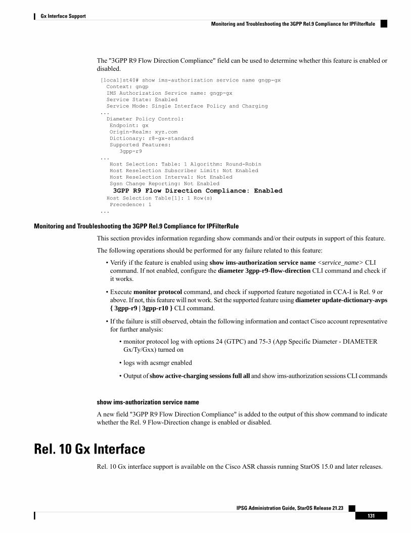
The "3GPP R9 Flow Direction Compliance" field can be used to determine whether this feature is enabled ordisabled.[local]st40# show ims-authorization service name gngp-gxContext: gngpIMS Authorization Service name: gngp-gxService State: EnabledService Mode: Single Interface Policy and Charging
...Diameter Policy Control:Endpoint: gxOrigin-Realm: xyz.comDictionary: r8-gx-standardSupported Features:
3gpp-r9...
Host Selection: Table: 1 Algorithm: Round-RobinHost Reselection Subscriber Limit: Not EnabledHost Reselection Interval: Not EnabledSgsn Change Reporting: Not Enabled3GPP R9 Flow Direction Compliance: Enabled
Host Selection Table[1]: 1 Row(s)Precedence: 1
...
Monitoring and Troubleshooting the 3GPP Rel.9 Compliance for IPFilterRule
This section provides information regarding show commands and/or their outputs in support of this feature.
The following operations should be performed for any failure related to this feature:
• Verify if the feature is enabled using show ims-authorization service name <service_name> CLIcommand. If not enabled, configure the diameter 3gpp-r9-flow-direction CLI command and check ifit works.
• Execute monitor protocol command, and check if supported feature negotiated in CCA-I is Rel. 9 orabove. If not, this feature will not work. Set the supported feature using diameter update-dictionary-avps{ 3gpp-r9 | 3gpp-r10 } CLI command.
• If the failure is still observed, obtain the following information and contact Cisco account representativefor further analysis:
• monitor protocol log with options 24 (GTPC) and 75-3 (App Specific Diameter - DIAMETERGx/Ty/Gxx) turned on
• logs with acsmgr enabled
• Output of show active-charging sessions full all and show ims-authorization sessions CLI commands
show ims-authorization service name
A new field "3GPP R9 Flow Direction Compliance" is added to the output of this show command to indicatewhether the Rel. 9 Flow-Direction change is enabled or disabled.
Rel. 10 Gx InterfaceRel. 10 Gx interface support is available on the Cisco ASR chassis running StarOS 15.0 and later releases.
IPSG Administration Guide, StarOS Release 21.23131
Gx Interface SupportMonitoring and Troubleshooting the 3GPP Rel.9 Compliance for IPFilterRule
This section describes the following topic:
• P-GW Rel. 10 Gx Interface Support, on page 132
P-GW Rel. 10 Gx Interface Support
IntroductionThe Gx reference point is located between the Policy and Charging Rules Function (PCRF) and the Policyand Charging Enforcement Function (PCEF) on the Packet Data Network (PDN) Gateway (P-GW). The Gxreference point is used for provisioning and removal of PCC rules from the PCRF to the PCEF and thetransmission of traffic plane events from the PCEF to the PCRF. The Gx reference point can be used forcharging control, policy control, or both, by applying AVPs relevant to the application.
The PCEF is the functional element that encompasses policy enforcement and flow based charging functionality.This functional entity is located at the P-GW. The main functions include:
• Control over the user plane traffic handling at the gateway and its QoS.
• Service data flow detection and counting, as well as online and offline charging interactions.
• For a service data flow that is under policy control, the PCEF allows the service data flow to pass throughthe gateway if and only if the corresponding gate is open.
• For a service data flow that is under charging control, the PCEF allows the service data flow to passthrough the gateway if and only if there is a corresponding active PCC rule and, for online charging, theOCS has authorized the applicable credit with that charging key.
• If requested by the PCRF, the PCEF will report to the PCRF when the status of the related service dataflow changes.
• In case the SDF is tunnelled at the BBERF, the PCEF informs the PCRF about the mobility protocoltunnelling header of the service data flows at IP-CAN session establishment.
ASR 5500 supports only eight flow information including the flow description per dynamic charging rule ina Gx message.
Important
Terminology and DefinitionsThis section describes features and terminology pertaining to Rel. 10 Gx functionality.
Volume Reporting Over Gx
This section describes the 3GPP Rel. 10 Volume Reporting over Gx feature.
License Requirements
The Volume Reporting over Gx is a licensed Cisco feature. A separate feature license may be required. Contactyour Cisco account representative for detailed information on specific licensing requirements. For informationon installing and verifying licenses, refer to the Managing License Keys section of the Software ManagementOperations chapter in the System Administration Guide.
IPSG Administration Guide, StarOS Release 21.23132
Gx Interface SupportP-GW Rel. 10 Gx Interface Support
In 12.0 and later releases, no separate license is required for Charging over Gx / Volume Reporting over Gxfeature. This feature can be enabled as part of "Policy Interface" license.
Important
Supported Standards
The Volume Reporting over Gx feature is based on the following standard:
3GPP TS 29.212 V10.5.0 (2012-01): 3rd Generation Partnership Project; Technical Specification Group CoreNetwork and Terminals; Policy and Charging Control over Gx reference point (Release 10).
Feature Overview
The Volume Reporting over Gx feature provides PCRF the capability to make real-time decisions based onthe data usage by subscribers.
Volume Reporting over Gx is applicable only for volume quota.
In release 10.0, only total data usage reporting is supported, uplink/downlink level reporting is not supported.In 10.2 and later releases, it is supported.
The PCEF only reports the accumulated usage since the last report for usage monitoring and not from thebeginning.
If the usage threshold is set to zero (infinite threshold), no further threshold events will be generated by PCEF,but monitoring of usage will continue and be reported at the end of the session.
In 12.2 and later releases, usage reporting on bearer termination is supported.
Important
The following steps explain how Volume Reporting over Gx works:
1. PCEF after receiving the message from PCRF parses the usage monitoring related AVPs, and sends theinformation to IMSA.
2. IMSA updates the information to ECS.
3. Once the ECS is updated with the usage monitoring information from PCRF, the PCEF (ECS) startstracking the data usage.
4. For session-level monitoring, the ECS maintains the amount of data usage.
5. For PCC rule monitoring, usage is monitored with the monitoring key as the unique identifier. Each nodemaintains the usage information per monitoring key. When the data traffic is passed, the usage is checkedagainst the usage threshold values and reported as described in the Usage Reporting section.
6. The PCEF continues to track data usage after the threshold is reached and before a new threshold isprovided by the PCRF. If a new usage threshold is not provided by the PCRF in the acknowledgement ofan IP-CAN Session modification where its usage was reported, then usage monitoring does not continuein the PCEF for that IP CAN session.
Usage Monitoring
• Usage Monitoring at Session Level: PCRF subscribes to the session-level volume reporting over Gx bysending the Usage-Monitoring-InformationAVPwith the usage threshold level set in Granted-Service-Unit
IPSG Administration Guide, StarOS Release 21.23133
Gx Interface SupportSupported Standards
AVP and Usage-Monitoring-Level AVP set to SESSION_LEVEL(0). After the AVPs are parsed byDPCA, IMSA updates the information to ECS. Once ECS is updated usage monitoring is started andconstantly checked with the usage threshold whenever the data traffic is present. In 11.0 and later releases,Monitoring Key at session level is supported.
In 12.0 and later releases, enabling and disabling session usage in a single message from PCRF issupported. This is supported only if the monitoring key is associated at session level.
In 12.0 and later releases, monitoring of usage based on input/output octet threshold levels is supported.Usage is reported based on the enabled threshold level. If multiple levels are enabled, usage will bereported on all the enabled levels even if only one of the levels is breached. Monitoring will be stoppedon the missing threshold levels in the response for the usage report from PCRF (expected to provide thecomplete set again if PCRF wants to continue monitoring on the multiple levels enabled earlier).
Total threshold level along with UL/DL threshold level in the GSU AVP is treated as an error and onlytotal threshold level is accepted.
In releases prior to 17.0, extra CCR-U was generated for a monitoring key when the following requestsare received in the response to the CCR-U which reported the usage for the same monitoring key.
• immediate reporting request with monitoring key at rule level• immediate reporting request with or without monitoring key at session level• explicit disable request at rule level• explicit disable request at session level
In 17.0 and later releases, extra CCR-U is not generated for a monitoring key when all the abovementionedrequests are received in the response to the CCR-U which reported the usage for the same monitoringkey. Also, extra CCR-U is not generated when immediate reporting request without monitoring key atrule level is received in the response to the CCR-U which reported the usage for all the active monitoringkeys.
• UsageMonitoring at Flow Level: PCRF subscribes to the flow-level volume reporting over Gx by sendingthe Usage-Monitoring-Information AVP with the usage threshold level set in Granted-Service-Unit AVPand Usage-Monitoring-Level AVP set to PCC_RULE_LEVEL(1). Monitoring Key is mandatory in caseof a flow-level monitoring since the rules are associated with the monitoring key and enabling/disablingof usage monitoring at flow level can be controlled by PCRF using it. After the AVPs are parsed byDPCA, IMSA updates the information to ECS. Once ECS is updated usage monitoring is started andconstantly checked with the usage threshold whenever the data traffic is present.
Usage monitoring is supported for static, predefined rules, and dynamic rule definitions.
• UsageMonitoring for Static Rules: In the case of static rules, the usage reporting on last rule removalassociated with the monitoring key is not applicable. In this case only the usage monitoringinformation is received from the PCRF.
• Usage Monitoring for Predefined Rules: If the usage monitoring needs to be enabled for thepredefined rules, PCRF sends the rule and the usagemonitoring information containing themonitoringkey and the usage threshold. TheMonitoring key should be same as the one pre-configured in PCEFfor that predefined rule. There can bemultiple rules associated with the samemonitoring key. Henceenabling a particular monitoring key would result in the data being tracked for multiple rules havingthe same monitoring key. After DPCA parses the AVPs IMSA updates the information to ECS.Once ECS is updated usage monitoring is started and constantly checked with the usage thresholdwhenever the data traffic is present.
• Usage Monitoring for Dynamic Rules: If the usage monitoring needs to be enabled for dynamicruledefs, PCRF provides the monitoring key along with a charging rule definition and the usage
IPSG Administration Guide, StarOS Release 21.23134
Gx Interface SupportGx Interface Support
monitoring information containing the monitoring key and the usage threshold. This would resultin the usage monitoring being done for all the rules associated with that monitoring key. After DPCAparses the AVPs, IMSA updates the information to ECS. Once ECS is updated, the usage monitoringis started and constantly checked with the usage threshold whenever the data traffic is present.Monitoring key for dynamic ruledef is dynamically assigned by PCRF which is the only differencewith predefined rules in case of usage monitoring.
In releases prior to 15.0, when threshold breach happens for multiple monitoring keys at the same time, onlyone of the monitoring keys' usage is reported and the rest of the monitoring keys' usage is reported in CCR-T(threshold set to infinity). On Tx expiry/TCP link error, unreported usage is stored at ECS and reported onlyon session termination.
In 15.0 and later releases, only one of the monitoring keys' usage is reported first. Upon receiving successfulresponse from PCRF, the rest of the monitoring keys' usage is reported to PCRF. On Tx expiry/TCP link error,unreported usage is stored at ECS. Any future successful interaction with PCRF for the session will sendunreported UMI to PCRF.
Usage Reporting
Usage at subscriber/flow level is reported to PCRF under the following conditions:
• Usage Threshold Reached: PCEF records the subscriber data usage and checks if the usage thresholdprovided by PCRF is reached. This is done for both session and rule level reporting.
For session-level reporting, the actual usage volume is compared with the usage volume threshold.
For rule-level reporting the rule that hits the data traffic is used to find out if the monitoring key isassociated with it, and based on the monitoring key the data usage is checked. Once the condition is met,it reports the usage information to IMSA and continues monitoring. IMSA then triggers the CCR-U if"USAGE_REPORT" trigger is enabled by the PCRF. The Usage-Monitoring-Information AVP is sentin this CCR with the "Used-Service-Unit" set to the amount of data usage by subscriber.
If PCRF does not provide a new usage threshold in the usage monitoring information as a result of CCRfrom PCEF when the usage threshold is reached, the usage monitoring is stopped at PCEF and no usagestatus is reported.
In the non-standard Volume Reporting over Gx implementation, usage monitoring will be stopped oncethe threshold is breached, else the monitoring will continue. There will be no further usage reportinguntil the CCA is received.
• Usage Monitoring Disabled: If the PCRF explicitly disables the usage monitoring withUsage-Monitoring-Support AVP set toUSAGE_MONITORING_DISABLED, the PCEF stopsmonitoringand reports the usage information (when the monitoring was enabled) to PCRF if the usage monitoringis disabled by PCRF as a result of CCR from PCEF which is not related to reporting usage, other externaltriggers, or a PCRF internal trigger. If the PCRF does not provide a new usage threshold as a result ofCCR from PCEF when the usage threshold is reached, the usage monitoring is stopped at PCEF and nofurther usage status is reported.
• IP CAN Session Termination:When the IP CAN session is terminated, the accumulated subscriber usageinformation is reported to PCRF in the CCR-T from PCEF. If PCC usage level information is enabledby PCRF, the PCC usage will also be reported.
PCRF uses RAR message and includes Session-Release-Cause AVP in it to initiate IP CAN SessionTermination. However, there are some scenarios where PCRFmaywant to terminate the IP CAN Sessionin CCA messages. In order to avoid an unnecessary additional message, PCRF can inform P-GW to
IPSG Administration Guide, StarOS Release 21.23135
Gx Interface SupportUsage Reporting
terminate the subscriber in CCA-U message itself. Hence, in 17.0 and later releases, the Session ReleaseCause has been added in CCA messages for all Gx dictionaries.
• PCC Rule Removal: When the PCRF deactivates the last PCC rule associated with a usage monitoringkey, the PCEF sends a CCR with the data usage for that monitoring key. If the PCEF reports the lastPCC rule associated with a usage monitoring key is inactive, the PCEF reports the accumulated usagefor that monitoring key within the same CCR command if the Charging-Rule-Report AVP was includedin a CCR command; otherwise, if the Charging-Rule-Report AVP was included in an RAA command,the PCEF sends a new CCR command to report accumulated usage for the usage monitoring key. In 12.0and later releases, usage reporting on last rule deactivation using rule deactivation time set by PCRF issupported.
Releases prior to 14.0, when PCC rule was tried to be removed while waiting for access side updatebearer response, the charging rules were not removed. In 14.0 and later releases, on receiving messagefrom PCRF, the rule that is meant for removal is marked and then after the access side procedure iscomplete the rule is removed.
• PCRF Requested Usage Report: In 10.2 and later releases, the accumulated usage since the last reportis sent even in case of immediate reporting, the usage is reset after immediate reporting and usagemonitoring continued so that the subsequent usage report will have the usage since the current report. Inearlier releases the behavior was to accumulate the so far usage in the next report.
• Release 12.2 onwards, usage reporting on bearer termination can be added. When a bearer is deleted dueto some reason, the rules associated with the bearer will also be removed. So, the usage will be reportedon the monitoring key(s) whose associated rule is the last one that is removed because of bearertermination.
• Revalidation Timeout: In the non-standard implementation, if usage monitoring and reporting is enabledand a revalidation timeout occurs, the PCEF sends a CCR to request PCC rules and reports all accumulatedusage for all enabled monitoring keys since the last report (or since usage reporting was enabled if theusage was not yet reported) with the accumulated usage at IP-CAN session level (if enabled) and atservice data flow level (if enabled) This is the default behavior.
In the case of standard implementation, this must be enabled by CLI configuration.
The Usage Reporting on Revalidation Timeout feature is available by default in non-standard implementationof Volume Reporting over Gx. In 10.2 and later releases, this is configurable in the standard implementation.This is not supported in 10.0 release for standard based volume reporting.
Important
Once the usage is reported, the usage counter is reset to zero. The PCEF continues to track data usage fromthe zero value after the threshold is reached and before a new threshold is provided by the PCRF. If a newusage threshold is not provided by the PCRF in the acknowledgement of an IP-CAN Session modificationwhere its usage was reported, then usage monitoring does not continue in the PCEF for that IP CAN sessionand and the usage accumulated between the CCR-CCA will be discarded.
In releases prior to 17.0, CCR-U triggered on server retries does not take server granted quota into accountfor reporting USU. In 17.0 and later releases, CCR-U triggered on server retries takes server granted quotainto account for reporting USU. For newly created MSCC, interim quota configuration is taken as referencefor reporting USU.
For information on how to configure the Volume Reporting over Gx feature, refer to Configuring VolumeReporting over Gx, on page 99.
IPSG Administration Guide, StarOS Release 21.23136
Gx Interface SupportGx Interface Support
ICSR Support for Volume Reporting over Gx (VoRoGx)
In releases prior to 15.0, post the ICSR switchover, any existing session for which the PCRF has enabledvolume reporting used to continue indefinitely until the session is terminated or until CCR-U is sent for agiven trigger, without having the volume counted via Gx.
To summarize, after an ICSR switchover, volume reporting over Gx is no longer done for existing sessions.Also, volume usage is not synced to standby chassis.
In 15.0 and later releases, volume threshold and volume usage are synced to standby chassis to support volumereporting over Gx for existing sessions post switchover.
Without this support it cannot cause a subscriber to use higher speeds than what s/he is supposed to get, ifvolume reporting is for example used to enforce fair usage; the operator may already consider this a revenueloss. It will also severely impact roaming subscribers who are supposed to get a notification and beblocked/redirected once the limits set by the EU roaming regulation are reached. If a session continues nowwithout being blocked, the operator is not allowed to charge for data beyond the limit and will have a significantand real revenue loss (roaming partner may still charge for the data used on their SGSNs).
Use of the Supported-Features AVP on the Gx Interface
The Supported-Features AVP is used during session establishment to inform the destination host about therequired and optional features that the origin host supports. The client will, in the first request in a Diametersession indicate the set of features required for the successul processing of the session. If there are featuressupported by the client that are not advertised as part of the required set of features, the client will provide inthe same request this set of optional features that are optional for the successful processing of the session. Theserver will, in the first answer within the Diameter session indicate the set of features that it has in commonwith the client and that the server will support within the same Diameter session. Any further commandmessages will always be compliant with the list of supported features indicated in the Supported-FeaturesAVPs and features that are not indicated in the Supported-Features AVPs during session establishment.Features that are not advertised as supported will not be used to construct the command messages for thatDiameter session. Unless otherwise stated, the use of the Supported-Features AVP on the Gx reference pointwill be compliant with the requirements for dynamic discovery of supported features and associated errorhandling.
The base functionality for the Gx reference point is the 3GPP Rel. 7 standard and a feature is an extension tothat functionality. If the origin host does not support any features beyond the base functionality, theSupported-Features AVP may be absent from the Gx commands. As defined in 3GPP TS 29.229, whenextending the application by adding new AVPs for a feature, the new AVPs will have the M bit cleared andthe AVP will not be defined mandatory in the command ABNF.
The Supported-Features AVP is of type grouped and contains the Vendor-Id, Feature-List-ID and Feature-ListAVPs. On the Gx reference point, the Supported-Features AVP is used to identify features that have beendefined by 3GPP and hence, the Vendor-Id AVP will contain the vendor ID of 3GPP (10415). If there aremultiple feature lists defined for the Gx reference point, the Feature-List-ID AVP will differentiate those listsfrom one another.
IPSG Administration Guide, StarOS Release 21.23137
Gx Interface SupportICSR Support for Volume Reporting over Gx (VoRoGx)
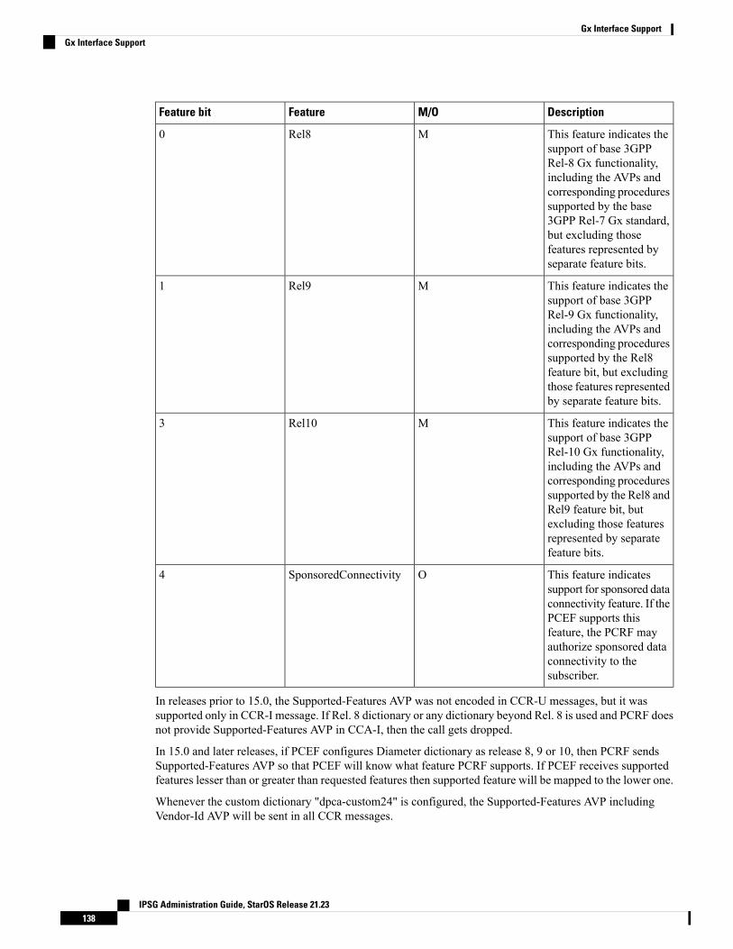
DescriptionM/OFeatureFeature bit
This feature indicates thesupport of base 3GPPRel-8 Gx functionality,including the AVPs andcorresponding proceduressupported by the base3GPP Rel-7 Gx standard,but excluding thosefeatures represented byseparate feature bits.
MRel80
This feature indicates thesupport of base 3GPPRel-9 Gx functionality,including the AVPs andcorresponding proceduressupported by the Rel8feature bit, but excludingthose features representedby separate feature bits.
MRel91
This feature indicates thesupport of base 3GPPRel-10 Gx functionality,including the AVPs andcorresponding proceduressupported by the Rel8 andRel9 feature bit, butexcluding those featuresrepresented by separatefeature bits.
MRel103
This feature indicatessupport for sponsored dataconnectivity feature. If thePCEF supports thisfeature, the PCRF mayauthorize sponsored dataconnectivity to thesubscriber.
OSponsoredConnectivity4
In releases prior to 15.0, the Supported-Features AVP was not encoded in CCR-U messages, but it wassupported only in CCR-I message. If Rel. 8 dictionary or any dictionary beyond Rel. 8 is used and PCRF doesnot provide Supported-Features AVP in CCA-I, then the call gets dropped.
In 15.0 and later releases, if PCEF configures Diameter dictionary as release 8, 9 or 10, then PCRF sendsSupported-Features AVP so that PCEF will know what feature PCRF supports. If PCEF receives supportedfeatures lesser than or greater than requested features then supported feature will be mapped to the lower one.
Whenever the custom dictionary "dpca-custom24" is configured, the Supported-Features AVP includingVendor-Id AVP will be sent in all CCR messages.
IPSG Administration Guide, StarOS Release 21.23138
Gx Interface SupportGx Interface Support

Rule-Failure-Code AVP
The Rule-Failure-Code AVP indicates the reason that the QoS/PCC rules cannot be successfullyinstalled/activated or enforced. The Rule-Failure-Code AVP is of type Enumerated. It is sent by the PCEF tothe PCRF within a Charging-Rule-Report AVP to identify the reason a PCC Rule is being reported.
In releases prior to 15.0, only 11 rule failure codes were defined as the values for this AVP. In 15.0 and laterreleases, two new rule failure codes INCORRECT_FLOW_INFORMATION (12) andNO_BEARER_BOUND(15) are added. The name of the existing rule failure code 9 is changed toMISSING_FLOW_INFORMATION.For 3GPP Rel. 10, rule failure code 9 maps to GW/PCEF_MALFUNCTION.
Sponsored Data Connectivity
With Sponsored Data Connectivity, the sponsor has a business relationship with the operator and the sponsorreimburses the operator for the user's data connectivity in order to allow the user access to an associatedApplication Service Provider's (ASP) services. Alternatively, the user pays for the connectivity with a transactionwhich is separate from the subscriber's charging. It is assumed the user already has a subscription with theoperator.
Sponsored Data Connectivity feature is introduced in Rel. 10 of 3GPP TS 29.212 specification. If SponsoredData Connectivity is supported, the sponsor identity for a PCC rule identifies the 3rd party organization (thesponsor) who is willing to pay for the operator's charge for connectivity required to deliver a service to theend user.
The purpose of this feature is to identify the data consumption for a certain set of flows differently and chargeit to sponsor. To support this, a new reporting level "SPONSORED_CONNECTIVITY_LEVEL" is addedfor reporting at Sponsor Connection level and two new AVPs "Sponsor-Identity" and"Application-Service-Provider-Identity" have been introduced at the rule level.
Sponsored Data Connectivity will be performed for service data flows associated with one or more PCC rulesif the information about the sponsor, the application service provider and optionally the threshold values areprovided by the Application Function (AF).
The provisioning of sponsored data connectivity per PCC rule will be performed using the PCC rule provisioningprocedure. The sponsor identity will be set using the Sponsor-Identity AVPwithin the Charging-Rule-DefinitionAVP of the PCC rule. The application service provider identity will be set using theApplication-Service-Provider-Identity AVP within the Charging-Rule-Definition AVP of the PCC rule.Sponsor-Identity AVP and Application-Service-Provider-Identity AVPwill be included if the Reporting-LevelAVP is set to the value SPONSORED_CONNECTIVITY_LEVEL.
When receiving the flow based usage thresholds from the AF, the PCRF will use the sponsor identity togenerate a monitoring key. The PCRF may also request usage monitoring control, in this case, only the flowbased usage is applied for the sponsored data connectivity. If requested, the PCEF may also report the usageto the PCRF.
A newCLI command "diameter encode-supported-features" has been added in Policy Control Configurationmode to send supported features with Sponsor Identity. For more information on the command, see theCommand Line Interface Reference.
Sponsored connectivity feature will be supported only when both P-GW and PCRF support 3GPP Rel. 10.P-GW advertises release as a part of supported features in CCR-I to PCRF. If P-GW supports Release 10 andalso sponsored connectivity but PCRF does not support it (as a part of supported features in CCA-I), thisfeature will be turned off.
This feature implementation impacts only the Gx dictionary "dpca-custom15". Also note that this feature issupported only for the dynamic rules.
IPSG Administration Guide, StarOS Release 21.23139
Gx Interface SupportRule-Failure-Code AVP
Volume Reporting
For Volume Reporting over Gx, PCRF generates a unique monitoring key based on sponsor identity. Sinceflows with different monitoring keys are treated differently, flows with sponsor ID are charged differently.
Supported Gx Features
Assume Positive for GxIn a scenario where both the primary and secondary PCRF servers are overloaded, the PCRF returns an errorto P-GW and HSGW. Current behavior for the P-GW and HSGW is to terminate the session if both primaryand secondary return a failure or timeout.
This feature is developed to enhance this behavior by applying local policy on the GW to ensure that thesubscriber session continues. P-GW / HSGW should implement Assume Positive feature to handle errors andbased on the event type implement specific rules.
Use of Gx Assume Positive requires that a valid license key be installed. Contact your Cisco accountrepresentative for information on how to obtain a license.
Important
The failure handling behavior is enhanced to ensure that the subscriber service is maintained in case of PCRFunavailability. It is also required that the GW reduces the traffic towards the PCRFwhen receiving a DiameterToo Busy (3004) by stopping the transmission and reception of Diameter messages (CCRs and RARs) to andfrom the PCRF for a configurable amount of time.
In case of any of the following failures with PCRF, the GW chooses to apply failure handling which resultsin subscriber termination or to allow browsing without any more policy enforcement.
• TCP link failure• Application Timer (Tx) expiry• Result code based failures
In 14.1 and later releases, the PCRF is allowed to fall back to Local Policy for all connection level failures,result code/experimental result code failures. Local Policy may choose to allow the subscriber for a configuredamount of time. During this time any subscriber/internal event on the call would be handled from Local Policy.After the expiry of the timer, the subscriber session can be either terminated or else PCRF can be retried. Notethat the retry attempt to PCRF happens only when the timer-expiry event is configured as reconnect-to-server.
The fallback support is added to the failure handling template and the local policy service needs to be associatedto IMS Authorization service.
Once the local policy is applied, all PCRF enabled event triggers will be disabled.When the subscriber sessionis with the local-policy, the GW skips sending of CCR-T and cleans up the session locally.
For a session that was created with active Gx session, the GW sends the CCR-T to primary and on failuresends the CCR-T to the secondary PCRF. If the CCR-T returns a failure from both primary and secondary ortimes out, the GW cleans up the session locally.
Fallback to Local Policy is done in the following scenarios:
• Tx timer expiry• Diabase Error
IPSG Administration Guide, StarOS Release 21.23140
Gx Interface SupportVolume Reporting
• Result Code Error (Permanent/Transient)• Experimental Result Code• Response Timeout
The following points are applicable only in the scenario where reconnect to PCRF is attempted.
• If the subscriber falls back to local-policy because of CCR-I failure, CCR-I will be sent to the PCRFafter the timer expiry. On successful CCA-I call will be continued with PCRF or else the call will becontinued with local-policy and retry-count will be incremented.
• If the subscriber falls back to local-policy because of the CCR-U failure, IMS Authorization applicationwaits for some event change to happen or to receive an RAR from PCRF.
• In case of event change after the timer expiry, CCR-U will be sent to PCRF. On successful CCA-Umessage, call will be continued with PCRF or else call will be with local-policy and retry-count will beincremented.
• If RAR is received after the timer-expiry the call will be continued with the PCRF. On expiry of maximumof retries to connect to PCRF, call will be disconnected.
Default Policy on CCR-I FailureThe following parameters are supported for local configuration on P-GW. The configuration parameters areconfigurable per APN and per RAT Type.
The following fields for a Default Bearer Charging Rule are configurable per APN and per RAT Type:
• Rule Name• Rating Group• Service ID• Online Charging• Offline Charging• QCI• ARP
• Priority Level• QCI• QVI
• Max-Requested-Bandwidth
• UL• DL
Flow Description and Flow Status are not configurable but the default value will be set to Any to Any andFlow Status will be set to Enabled.
The following command level fields are configurable per APN and per RAT Type:
• AMBR
• UL• DL
• QCI• ARP
IPSG Administration Guide, StarOS Release 21.23141
Gx Interface SupportDefault Policy on CCR-I Failure
Priority Level•• QCI• QVI
Gx Back off FunctionalityThis scenario is applicable when Primary PCRF cluster is unavailable but the secondary PCRF is availableto handle new CCR-I messages.
When the chassis receives 3004 result-code then back-off timer will be started for the peer and when the timeris running no messages will be sent to that peer.
The timer will be started only when the value is being configured under endpoint configuration.
Releases prior to 15.0, when the IP CAN session falls back to local policy it remained with local policy untilthe termination timer expires or the subscriber disconnects. Also, the RAR message received when thelocal-policy timer was running got rejected with the cause "Unknown Session ID".
In 15.0 and later releases, P-GW/GGSN provides a fair chance for the subscriber to reconnect with PCRF inthe event of CCR failure. To support this feature, configurable validity and peer backoff timers are introducedin the Local Policy Service and Diameter endpoint configuration commands. Also, the RAR received whenthe local-policy timer is running will be rejected with the cause "DIAMETER_UNABLE_TO_DELIVER".
In releases prior to 17.0, rule report was not sent in the CCR messages when PCRF is retried after the expiryof validity timer. In 17.0 and later releases, rule report will be sent to the PCRF during reconnect when theCLI command diameter encodeevent-avps local-fallback is configured under Policy Control Configurationmode.
Support for Volume Reporting in Local PolicyThis feature provides support for time based reconnect to PCRF instead of the event based for CCR-U failurescenarios.
In releases prior to 17.0, the following behaviors were observed with respect to the Volume Reporting forLocal Policy:
• In the event of CCR-U failure, CCR-U was triggered to PCRF only on receiving subscriber event.• When a CCR-U failure happened and a call continued without Gx, unreported volume is lost as thethreshold is set to infinity. In next CCR-U triggered to PCRF, the cumulative volume was sent to PCRF.
• RARwas rejected with result-code diameter_unable_to_comply (3002) when the validity timer is running.
In 17.0 and later releases, with the timer-based implementation, this feature introduces the following changesto the existing behavior:
• When send-usage-report is configured, the CCR-U with usage report will be sent immediately after thelocal-policy timer-expiry.
• The unreported usage will not be returned to ECS. Thus, usage since last tried CCR-U will be sent toPCRF.
• RAR will be accepted and the rules received on RAR will be installed even when the timer is running.
Session can be connected to PCRF immediately instead of waiting for subscriber event, and the updated usagereport can be sent.
IPSG Administration Guide, StarOS Release 21.23142
Gx Interface SupportGx Back off Functionality
Support for Session Recovery and Session SynchronizationCurrently PCRF and ASR 5500 gateway node are in sync during normal scenarios and when Gx assumepositive is not applied. However, there are potential scenarios where the PCRFmight have been locally deletedor lost the Gx session information and it is also possible that due to the loss of message, gateway node andPCRF can be out of sync on the session state.
While these are rare conditions in the network, the desired behavior is to have PCRF recover the Gx sessionwhen it is lost and also to have PCRF and gateway sync the rule and session information. This feature providesfunctionality to ensure PCRF and gateway can sync on session information and recover any lost Gx sessions.Configuration support has been provided to enable session recovery and session sync features.
In releases prior to 17.0, the implementation is as follows:
• If the PCRF deletes or loses session information during a Gx session update (CCR-U) initiated by thegateway, PCRF will respond back with DIAMETER_UNKNOWN_SESSION_ID resulting in sessiontermination even in the case of CCR-U.
• If the PCRF deletes or loses session information and an Rx message is received, PCRF will not be ableto implement corresponding rules and will result in failure of subscriber voice or video calls.
• For subscriber's existing Rx sessions and active voice/video calls, PCRF will not be able to initiatecleanup of the sessions towards the gateway and can result in wastage of the resources in the network(dedicated bearers not removed) or can result in subscriber not able to place calls on hold or conferenceor remove calls from hold.
• For out of sync scenarios, PCRF and gateway could be implementing different policies and can result inwastage of resources or in poor subscriber experience. Existing behavior does not provide for a way tosync the entire session information.
In 17.0 and later releases, the gateway (GW) node and PCRF now supports the ability to exchange sessioninformation and the GW provides the complete subscriber session information to enable PCRF to build thesession state. This will prevent the occurrence of the above mentioned scenarios and ensure that GW andPCRF are always in sync. The keywords session-recovery and session-sync are used with the diameterencode-supported-features CLI command in Policy Control Configuration mode to support GxSynchronization.
Configuring Gx Assume Positive FeatureTo configure Gx Assume Positive functionality:
Step 1 At the global configuration level, configure Local Policy service for subscribers as described in the Configuring LocalPolicy Service at Global Configuration Level, on page 144.
Step 2 At the global configuration level, configure the failure handling template to use the Local Policy service as described inthe Configuring Failure Handling Template at Global Configuration Level, on page 145.
Step 3 Within the IMS Authorization service, associate local policy service and failure handling template as described in theAssociating Local Policy Service and Failure Handling Template, on page 145.
Step 4 Verify your configuration as described in the Verifying Local Policy Service Configuration, on page 145.Step 5 Save your configuration to flash memory, an external memory device, and/or a network location using the Exec mode
command save configuration. For additional information on how to verify and save configuration files, refer to theSystem Administration Guide and the Command Line Interface Reference.
IPSG Administration Guide, StarOS Release 21.23143
Gx Interface SupportSupport for Session Recovery and Session Synchronization
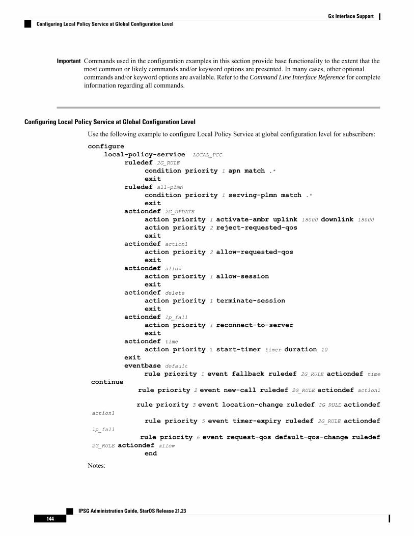
Commands used in the configuration examples in this section provide base functionality to the extent that themost common or likely commands and/or keyword options are presented. In many cases, other optionalcommands and/or keyword options are available. Refer to the Command Line Interface Reference for completeinformation regarding all commands.
Important
Configuring Local Policy Service at Global Configuration Level
Use the following example to configure Local Policy Service at global configuration level for subscribers:
configurelocal-policy-service LOCAL_PCC
ruledef 2G_RULE
condition priority 1 apn match .*
exitruledef all-plmn
condition priority 1 serving-plmn match .*
exitactiondef 2G_UPDATE
action priority 1 activate-ambr uplink 18000 downlink 18000
action priority 2 reject-requested-qosexit
actiondef action1
action priority 2 allow-requested-qosexit
actiondef allow
action priority 1 allow-sessionexit
actiondef delete
action priority 1 terminate-sessionexit
actiondef lp_fall
action priority 1 reconnect-to-serverexit
actiondef time
action priority 1 start-timer timer duration 10
exiteventbase default
rule priority 1 event fallback ruledef 2G_RULE actiondef time
continuerule priority 2 event new-call ruledef 2G_RULE actiondef action1
rule priority 3 event location-change ruledef 2G_RULE actiondefaction1
rule priority 5 event timer-expiry ruledef 2G_RULE actiondeflp_fall
rule priority 6 event request-qos default-qos-change ruledef2G_RULE actiondef allow
end
Notes:
IPSG Administration Guide, StarOS Release 21.23144
Gx Interface SupportConfiguring Local Policy Service at Global Configuration Level
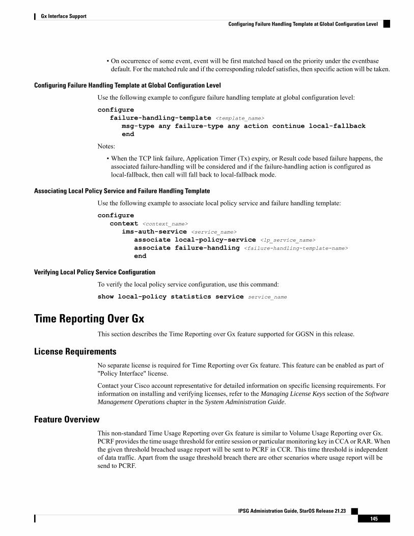
• On occurrence of some event, event will be first matched based on the priority under the eventbasedefault. For the matched rule and if the corresponding ruledef satisfies, then specific action will be taken.
Configuring Failure Handling Template at Global Configuration Level
Use the following example to configure failure handling template at global configuration level:
configurefailure-handling-template <template_name>
msg-type any failure-type any action continue local-fallbackend
Notes:
• When the TCP link failure, Application Timer (Tx) expiry, or Result code based failure happens, theassociated failure-handling will be considered and if the failure-handling action is configured aslocal-fallback, then call will fall back to local-fallback mode.
Associating Local Policy Service and Failure Handling Template
Use the following example to associate local policy service and failure handling template:
configurecontext <context_name>
ims-auth-service <service_name>
associate local-policy-service <lp_service_name>
associate failure-handling <failure-handling-template-name>
end
Verifying Local Policy Service Configuration
To verify the local policy service configuration, use this command:
show local-policy statistics service service_name
Time Reporting Over GxThis section describes the Time Reporting over Gx feature supported for GGSN in this release.
License RequirementsNo separate license is required for Time Reporting over Gx feature. This feature can be enabled as part of"Policy Interface" license.
Contact your Cisco account representative for detailed information on specific licensing requirements. Forinformation on installing and verifying licenses, refer to the Managing License Keys section of the SoftwareManagement Operations chapter in the System Administration Guide.
Feature OverviewThis non-standard Time Usage Reporting over Gx feature is similar to Volume Usage Reporting over Gx.PCRF provides the time usage threshold for entire session or particular monitoring key in CCA or RAR.Whenthe given threshold breached usage report will be sent to PCRF in CCR. This time threshold is independentof data traffic. Apart from the usage threshold breach there are other scenarios where usage report will besend to PCRF.
IPSG Administration Guide, StarOS Release 21.23145
Gx Interface SupportConfiguring Failure Handling Template at Global Configuration Level
Time reporting over Gx is applicable only for time quota.
The PCEF only reports the accumulated time usage since the last report for time monitoring and not from thebeginning.
If the time usage threshold is set to zero (infinite threshold), no further threshold events will be generated byPCEF, but monitoring of usage will continue and be reported at the end of the session.
Time usage reporting on bearer termination is supported. When a bearer is deleted due to some reason, therules associated with the bearer will also be removed. So, the usage will be reported on the monitoring key(s)whose associated rule is the last one that is removed because of bearer termination.
Important
The following steps explain how Time Reporting over Gx works:
1. PCEF after receiving the message from PCRF parses the time monitoring related AVPs, and sends theinformation to IMSA.
2. IMSA updates the information to ECS.
3. Once the ECS is updated with the timemonitoring information from PCRF, the PCEF (ECS) starts trackingthe time usage.
4. For session-level monitoring, the ECS maintains the amount of time usage.
5. For PCC rule monitoring, usage is monitored with the monitoring key as the unique identifier. Each nodemaintains the time usage information per monitoring key.
6. The PCEF continues to track time usage after the threshold is reached and before a new threshold isprovided by the PCRF. If a new usage threshold is not provided by the PCRF in the acknowledgement ofan IP-CAN Session modification where its usage was reported, then time monitoring does not continuein the PCEF for that IP CAN session.
Limitations
This section lists the limitations for Time Reporting over Gx in this release.
• Only integer monitoring key will be supported like Volume Reporting over Gx• If the same monitoring key is used for both time and data volume monitoring then disabling monitoringkey will disable both time and data usage monitoring.
• If the same monitoring key is used for both time and data usage monitoring and if an immediate reportrequest is received, then both time and volume report of that monitoring key will be sent.
Usage MonitoringTwo levels of time usage reporting are supported:
• Usage Monitoring at Session Level• Usage Monitoring at Flow Level
Usage Monitoring at Session Level
PCRF subscribes to the session level time reporting over Gx by sending the Usage-Monitoring-InformationAVP with the usage threshold level set in Granted-Service-Unit AVP and Usage-Monitoring-Level AVP setto SESSION_LEVEL (0).
IPSG Administration Guide, StarOS Release 21.23146
Gx Interface SupportLimitations
Usage Monitoring at Flow Level
PCRF subscribes to the flow level time reporting over Gx by sending the Usage-Monitoring-Information AVPwith the usage threshold level set in Granted-Service-Unit AVP and Usage-Monitoring-Level AVP set toPCC_RULE_LEVEL(1). Monitoring Key is mandatory in case of a flow level monitoring since the rules areassociated with themonitoring key and enabling or disabling of usagemonitoring at flow level can be controlledby PCRF using it. Usage monitoring is supported for both predefined rules and dynamic rule definition.
Usage Monitoring for Predefined and Static Rules
If the usage monitoring needs to be enabled for the predefined rules, PCRF sends the rule and the usagemonitoring information containing the monitoring key and the usage threshold. The monitoring key shouldbe same as the one pre-configured in PCEF for that predefined rule. There can be multiple rules associatedwith the same monitoring key. Hence enabling a particular monitoring key would result in the time beingtracked for multiple rules having the same monitoring key. Similarly, usage monitoring information is sentfrom PCRF for the static rules also.
Usage Monitoring for Dynamic Ruledefs
If the usage monitoring needs to be enabled for dynamic ruledefs, PCRF provides the monitoring key alongwith a charging rule definition and the usage monitoring information containing the monitoring key and theusage threshold. This results in the usagemonitoring being done for all the rules associated with that monitoringkey.
Usage ReportingTime usage at subscriber/flow level is reported to PCRF under the following conditions:
• Usage Threshold Reached: PCEF records the subscriber usage and checks if the usage threshold providedby PCRF is reached. Once the condition is met, it reports the usage information to IMSA and continuesmonitoring. IMSA then triggers the CCR-U if "USAGE_REPORT" trigger is enabled by PCRF. TheUsage-Monitoring-Information AVP is sent in this CCR with the "CC-Time" in "Used-Service-Unit" setto track the time usage of the subscriber.
• Usage Monitoring Disabled: If PCRF explicitly disables the usage monitoring withUsage-Monitoring-Support AVP set to USAGE_MONITORING_DISABLED, PCEF stops monitoringand reports the usage information (when the monitoring was enabled) to PCRF if the usage monitoringis disabled by PCRF as a result of CCR from PCEF which is not related to reporting usage, other externaltriggers, or a PCRF internal trigger.
• IP CAN Session Termination:When the IP CAN session is terminated, the accumulated subscriber usageinformation is reported to PCRF in the CCR-T from PCEF.
PCRF uses RAR message and includes Session-Release-Cause AVP in it to initiate IP CAN SessionTermination. However, there are some scenarios where PCRFmaywant to terminate the IP CAN Sessionin CCA messages. In order to avoid an unnecessary additional message, PCRF can inform P-GW toterminate the subscriber in CCA-U message itself. Hence, in 17.0 and later releases, the Session ReleaseCause has been added in CCA messages for all Gx dictionaries.
• PCC Rule Removal: When the PCRF deactivates the last PCC rule associated with a usage monitoringkey, PCEF sends a CCR with the usage time for that monitoring key. If the PCEF reports the last PCCrule associated with a usage monitoring key is inactive, the PCEF reports the accumulated usage for thatmonitoring key within the same CCR command if the Charging-Rule-Report AVP was included in aCCR command; otherwise, if the Charging-Rule-Report AVP was included in an RAA command, thePCEF sends a new CCR command to report accumulated usage for the usage monitoring key.
IPSG Administration Guide, StarOS Release 21.23147
Gx Interface SupportUsage Monitoring at Flow Level
• PCRF Requested Usage Report: When PCRF provides the Usage-Monitoring-Information with theUsage-Monitoring-Report set to USAGE_MONITORING_REPORT_REQUIRED, PCEF sends the timeusage information. If the monitoring key is provided by PCRF, time usage for that monitoring key isnotified to PCRF regardless of usage threshold. If the monitoring key is not provided by PCRF, timeusage for all enabled monitoring keys is notified to PCRF.
• Event Based Reporting: The event based reporting can be enabled through the CLI command event-updatesend-usage-report events. When an event like sgsn change, qos change or revalidation-timeout isconfigured under this CLI, time usage report is generated whenever that event happens.
Once the usage is reported, the usage counter is reset to zero. The PCEF continues to track time usage fromthe zero value after the threshold is reached and before a new threshold is provided by the PCRF. If a newusage threshold is not provided by the PCRF in the acknowledgement of an IP-CAN Session modificationwhere its usage was reported, then time usage monitoring does not continue in the PCEF for that IP CANsession.
For information on how to configure the Time Reporting over Gx feature, see the Configuring Time Reportingover Gx, on page 148.
Configuring Time Reporting over GxThis section describes the configuration required to enable Time Reporting over Gx.
To enable Time Reporting over Gx, use the following configuration:
configureactive-charging service <ecs_service_name>
rulebase <rulebase_name>
action priority <priority> dynamic-only ruledef <ruledef_name>
charging-action <charging_action_name> monitoring-key <monitoring_key>
exitexit
context <context_name>
ims-auth-service <imsa_service_name>
policy-controlevent-update send-usage-report [ reset-usage ]end
Notes:
• The configuration for enabling Time Reporting over Gx is same as the Volume Reporting over Gxconfiguration. If a time threshold is received from PCRF then Time monitoring is done, and if a volumethreshold is received then Volume monitoring will be done.
• The maximum accepted monitoring key value by the PCEF is 4294967295. If the PCEF sends a greatervalue, the value is converted to an Unsigned Integer value.
• The event-update CLI enables time usage report to be sent in event updates. The optional keywordreset-usage enables to support delta reporting wherein the usage is reported and reset at PCEF. If thisoption is not configured, the behavior is to send the time usage information as part of event update butnot reset at PCEF.
IPSG Administration Guide, StarOS Release 21.23148
Gx Interface SupportConfiguring Time Reporting over Gx
Support for Multiple Active and Standby Gx Interfaces to PCRFIn the earlier Gx implementation, Diameter Policy Control Application has the limitation to mandatorilyconfigure hosts as part of IMS Authorization service or associate a host template and select the hosts to becommunicated for each subscriber session. Since the peer selection can happen at diabase and applicationneed not select any hosts, this feature is developed to remove the restrictions imposed in the application andallow diabase to pick the peers in a round robin fashion. In addition, this feature will take care of peer selectionat diabase even when the hosts picked by application are not active. This change in behavior is controlledthrough the CLI command "endpoint-peer-select" as the default behavior is to drop the call if the serverdiscovery fails at application.
When the call is established, IMSAmodule checks the host selection table/prefix table/host template associatedin IMSA service to pick the primary and secondary peers to be contacted. If no host table/prefix table/hosttemplate is configured or none of the rows in prefix table are matching or the hosts selected by IMSA areinactive, then based on the CLI configuration the control is given to diabase module which will select thepeers in a round robin fashion or terminate the call based on the CLI configuration.
When the CCR message results in a diabase error/Tx expiry/response timeout, then IMSA will let diabaseselect an alternate route by excluding the peer which resulted in the failure and switch to the peer if the lookupis successful.
When CCR/CCAmessage is exchangedwith the directly connected host selected by diabase and RARmessageis received from new host, then IMSA will skip host configuration check and let further communication tohappen with the new host. If the directly connected host is selected by application during call establishment,then IMSA will check if the new host is the secondary server per application. When the CCR/CCA messageis exchanged with indirectly connected host through DRA which is picked by diabase and RAR message isreceived from same host through another DRA, then IMSA will skip host configuration check and let furthercommunication to happen with the same host through the new DRA. If the DRA is selected by applicationduring call establishment, then IMSAwill check if the newDRA is the secondary server per application. Evenif RAR message is received from different host though another DRA, IMSA will skip host configurationcheck and let further communication to happen with the new host through the new DRA.
Configuring Diameter Peer Selection at Diabase in Failure ScenariosThe following configuration enables diabase to select the Diameter peers when IMSA fails.
configurecontext context_name
ims-auth-service service_name
policy-controlendpoint-peer-select [ on-host-select-failure |
on-inactive-host ]{ default | no } endpoint-peer-selectend
Notes:
• This command is used to perform server selection at diabase when the hosts could not be selected byIMSAuthorization application or when the hosts selected by the IMSAuthorization application is inactive.For example, host table is not configured in IMSA service, host table is configured but not activated,none of the rows in prefix table match the subscriber, host template is not associated with IMSA service,host template could not select the hosts.
• on-host-select-failure: Specifies to perform server selection at Diabase when the hosts could not beselected by IMS Authorization application.
IPSG Administration Guide, StarOS Release 21.23149
Gx Interface SupportSupport for Multiple Active and Standby Gx Interfaces to PCRF
• on-inactive-host: Specifies to perform server selection at diabase when the hosts selected by applicationare inactive.
• This CLI command is added in policy control configuration mode to maintain backward compatibilitywith the old behavior of terminating the call when server selection fails at IMSAuthorization application.
Support for Multiple CCR-Us over Gx InterfaceASR 5500 node earlier supported only one pending CCR-U message per session over Gx interface. Anyrequest to trigger CCR-U (for access side updates/internal updates) were ignored/dropped, when there wasalready an outstanding message pending at the node. PCEF and PCRF were out of synch if CCR-U for criticalupdate was dropped (like RAT change/ULI change).
In 17.0 and later releases, ASR 5500 supports multiple CCR-U messages at a time per session through theuse of a configurable CLI command "max-outstanding-ccr-u" under IMSAuthorization Service configurationmode. That is, this CLI will allow the user to configure a value of up to 12 as the maximum number of CCR-Umessages per session.
The CLI-based implementation allows sending request messages as and when they are triggered and processingthe response when they are received. The gateway does re-ordering if the response messages are received outof sequence.
To support multiple outstanding messages towards PCRF, the following items should be supported:
• Allowing IMSA to send multiple CCR-U messages – This can be achieved through the use ofmax-outstanding-ccr-u command in the IMS Authorization Service configuration mode.
• Queuing of response message for ordering – DPCA should parse the received message irrespective oforder in which they are received. IMSA will check whether to forward the response to session manageror queue it locally.
• Peer switch – When multiple CCR-Us are triggered, IMSA will start Tx timer for each request sent out.On first Tx expiry, IMSA/DPCAwill do peer switch. That is, IMSAwill stop all other requests' Tx timersand switch to secondary peer (if available) or take appropriate failure handling action.
• Failure handling – On peer switch failure due to Tx expiry, DPCAwill take failure handling action basedon the configuration present under ims-auth-service.
• Handling back pressure – In case of multiple CCR-Us triggered to Primary PCRF and due to Tx timeoutall the messages are switched to Secondary PCRF. If Secondary server is already in backpressure state,then IMSA will put first message in the backpressure queue and once after message is processed nextpending request will be put into BP queue.
• Volume reporting – In case of multiple CCR-Us for usage report is triggered (for different monitoringkeys) and failure handling is configured as "continue send-ccrt-on-call-termination", on first Tx timeoutor response timeout, usage report present in all the CCR-Us will be sent to ECS. All the unreported usagewill be sent in CCR-T message when the subscriber goes down. If "event-update send-usage-report"CLI is present, then there are chances of reporting usage for same monitoring key in multiple CCR-Us.
Though the max-outstanding-ccr-u CLI command supports configuring more than one CCR-U, only oneoutstanding CCR-U for access side update is sent out at a time and multiple CCR-Us for internal updates aresent.
These are the access side updates for which CCR-U might be triggered:
• Bearer Resource Command• Modify Bearer Request (S-GW change, RAT change, ULI change)• Modify Bearer Command
These are the following internal updates for which CCR-U is triggered:
IPSG Administration Guide, StarOS Release 21.23150
Gx Interface SupportSupport for Multiple CCR-Us over Gx Interface
• S-GW restoration• Bearer going down (GGSN, BCM UE_Only)• ULI/Timezone notification• Default EPS bearer QoS failure• APN AMBR failure• Charging-Rule-Report• Out of credit / reallocation of credit• Usage reporting• Tethering flow detection• Access network charging identifier
Configuring Gateway Node to Support Back-to-Back CCR-UsThe following configuration enables or disables the gateway to send multiple back-to-back CCR-Us to PCRF.
configurecontext context_name
ims-auth-service service_name
policy-control[ default ] max-outstanding-ccr-u value
end
Notes:
• value must be an integer value from 1 through 12. The default value is 1.
Support for RAN/NAS Cause IE on Gx InterfaceNew supported feature "Netloc-RAN-NAS-Cause" has been introduced to be in compliance with the Release12 specification of 3GPP TS 29.212. This feature is used to send detailed RAN and/or NAS release causecode information from the access network to PCRF. It requires that the NetLoc feature is also supported.
This feature can be enabled only when the NetLoc feature license is installed.Important
A new Diameter AVP "RAN-NAS-Release-Cause" will be included in the Charging-Rule-Report AVP andin CCR-T for bearer and session deletion events respectively, when the NetLoc-RAN-NAS-Cause supportedfeature is enabled. This AVP will indicate the cause code for the subscriber/bearer termination.
Configuring Supported Feature Netloc-RAN-NAS-CauseThe following configuration enables the supported feature "Netloc-RAN-NAS-Cause".
configurecontext context_name
ims-auth-service service_name
policy-controldiameter encode-supported-features netloc-ran-nas-cause
end
Notes:
IPSG Administration Guide, StarOS Release 21.23151
Gx Interface SupportConfiguring Gateway Node to Support Back-to-Back CCR-Us
• netloc-ran-nas-cause: Enables the Netloc-RAN-NAS-Cause feature. By default, this supported featurewill be disabled.
• If the supported features "netloc-ran-nas-code" and "netloc" are enabled, then netloc-ran-nas-cause codewill be sent to PCRF.
To disable this supported feature, use the following command:
[ default | no ] diameter encode-supported-features
Support ADC Rules over Gx InterfaceIn this release, P-GW will use Application Detection and Control (ADC) functionality over Gx as defined inthe Release 11 specification of 3GPP standard.
ADC extension over Gx provides the functionality to notify PCRF about the start and stop of a specific protocolor a group of protocols, and provide the possibility to PCRF that with the knowledge of this information,change the QoS of the user when the usage of application is started and until it is finished.
The provision of ADC information is done through the ADC rule, the action initiated by PCRF is done throughthe PCC rule.
ADC rules are certain extensions to dynamic and predefined PCC rules in order to support specification,detection and reporting of an application flow. These rules are installed (modified/removed) by PCRF viaCCA-I/CCA-U/RAR events. ADC rules can be either dynamic PCC or predefined PCC rules, and the existingattributes of dynamic and predefined rules will be applicable.
Dynamic PCC rule contains either traffic flow filters or Application ID. When Application ID is present, therule is treated as ADC rule. Application ID is the name of the ruledef which is pre-defined in the boxerconfiguration. This ruledef contains application filters that define the application supported by P2P protocols.
PCEF will process and install ADC rules that are received from PCRF interface, and will detect the specifiedapplications and report detection of application traffic to the PCRF. PCRF in turn controls the reporting ofapplication traffic.
PCEF monitors the specified applications that are enabled by PCRF and generates Start/Stop events alongwith the Application ID. Such application detection is performed independent of the bearer on which the ADCPCC rule is bound to. For instance, if ADC rule is installed on a dedicated bearer whereas the ADC traffic isreceived on default bearer, application detection unit still reports the start event to PCRF.
ADC Rule support is a licensed-controlled feature. Contact your Cisco account representative for detailedinformation on specific licensing requirements.
Important
In support of this feature, the following Diameter AVPs are newly added to the Charging-Rule-DefinitionAVP, which PCEF will receive from PCRF.
• TDF-Application-Identifier: It references the application detection filter which the PCC rule for applicationdetection and control in the PCEF applies. The TDF-Application-Identifier AVP references also theapplication in the reporting to the PCRF.
• Redirect-Information: This indicates whether the detected application traffic should be redirected toanother controlled address.
• Mute-Notification: This AVP is used to mute the notification to the PCRF of the detected application'sstart/stop for the specific ADC/PCC rule from the PCEF.
IPSG Administration Guide, StarOS Release 21.23152
Gx Interface SupportSupport ADC Rules over Gx Interface
• Application Detection Information: If Mute-Notification AVP is not enclosed with charging rule reportand APPLICATION_START/APPLICATION_STOP event trigger is enabled then PCEF will sendApplication-Detection-Information to PCRF corresponding TDF-Application-Identifier.
In addition, these two new event triggers "APPLICATION_START" and "APPLICATION_STOP" aregenerated for reporting purpose.
LimitationsThe limitations for the ADC over Gx feature are:
• ADC does not support group of ruledefs.• Registration of the duplicate application IDs are not supported.• Readdress/Redirection for P2P flows will not be supported.• Redirection happens only on transactions of GET/Response.• Port based, IP Protocol based, and URL based applications are not supported.• Pre-configured options (precedence, redirect-server-ip) for dynamic ADC rules are not supported.• Simultaneous instances of an application for the same subscriber are not distinguished.• Flow recovery is not supported for application flows.
Configuring ADC Rules over GxThe following configuration enables ADC rules over Gx interface.
configurecontext context_name
ims-auth-service service_name
policy-controldiameter encode-supported-features adc-rulesend
Notes:
• The keyword "adc-rules" will be available only when the feature-specific license is configured.• For ADC 6th bit of supported feature will be set.
To disable the support for ADC Rules over Gx, use the following command:
[ default | no ] diameter encode-supported-features
GoR Name Support in TDF-Application-IdentifierASR 5500 supports dynamic rules to be installed with GoR name as TDF-Application-Identifier. When ADCrule is installed as a dynamic rule from PCRF, the TDF-Application-Identifier can include the GoR namepre-configured in the P-GW.
If the ADC feature is enabled, PCRF can send TDF-Application-Identifier as the name of GoR predefined inthe P-GW configuration.
• When dynamic charging-rules with the Charging-Rule-Definition AVP are activated from PCRF, thePCRF can specify the GoR name configured in ECS as TDF-Application-Identifier.
• When dynamic charging-rules with the Charging-Rule-Definition AVP are activated, the PCRF canremove or modify the rule through the Charging-Rule-Definition using RAR. During rule activation ormodification, the PCRF can add, modify or remove the charging-rule attributes of the rule.
IPSG Administration Guide, StarOS Release 21.23153
Gx Interface SupportLimitations
The configuration changes for TDF-Application-Identifier from PCRF are listed below:
• A non-ADC dynamic rule can be changed to ADC dynamic rule by sending TDF-Application-IdentifierAVP with relevant ruledef or GoR name.
ADC dynamic rule cannot be changed to non-ADC dynamic rule.
• The following AVPs will be modified and applied when received from PCRF:
• Precedence
• Rating-Group/Service-Identifier/Sponsor-Identity (mandatory depending on the Reporting-Level)
• Metering-Method
• Online/Offline
• QoS-Information
• Monitoring-Key
• Redirect-Information
• Dynamic route will be updated for all protocols of rules that are part of TDF-Application-Identifier GoR.
• Any change in dynamic rule priority or TDF-Application-Identifier value will lead to sending ofAPP-START and APP-STOP event notifications as new rule match. If an APP-START notification wassent already before rule modification, the corresponding APP-STOP notification will not be sent.
• Runtime deletion of associated GoR will take immediate effect and APP-STOP notification will not besent if an APP-START was already sent. Addition of GoR at service level will need to have rules to bere-installed for the new addition to take effect for both dynamic and predefined ADC rules.
ADC Mute CustomizationEarlier, 3GPP ADC over Gx did not support application MUTE status change. Once the application wasmuted, it was not possible to unmute it. From release 21.1, this feature introduces custom MUTE/UNMUTEfunctionality. ASR 5500 PCEF now supports customization to control reporting of the Application DetectionInformation CCRUs. For this, an AVP has been introduced with two possible values - custom MUTE andcustom UNMUTE.
• A Gx message might contain both Standards based MUTE and the custom MUTE.• Standards based MUTE is given preference over the custom MUTE/UNMUTE.• A dynamic ADC rule can be installed and modified with a custom MUTE.• Custom-Mute-Notification AVP can be sent by the PCRF in CCA-I and RAR.• A dynamic ADC rule can be modified with a custom UNMUTE.• On a custom MUTE for a given dynamic ADC rule, PCEF sends a single APPLICATION_START/APPLICATION_STOP response for the entire application traffic rather the per flowAPPLICATION_START /APPLICATION_STOP response.
• On a custom MUTE for a given dynamic ADC rule, if no APPLICATION_START has been sent priorto the custom MUTE then a single APPLICATION_START is sent on the next flow packet that hits thedynamic rule.
• On a custom MUTE for a given dynamic rule, the APPLICATION_START response is sent with theflow's 5-tuple information.
IPSG Administration Guide, StarOS Release 21.23154
Gx Interface SupportADC Mute Customization
• On a custom MUTE for a given dynamic rule, the APPLICATION_START response is sent withTDF-Application-Instance-Identifier = 0.
• On a customMUTE for a given dynamic rule, a single APPLICATION_STOP is sent when the last flowassociated with the given dynamic rule is terminated. Such an APPLICATION_STOP will not contain5-tuple information of the last flow and is sent with TDF-Application-Instance-Identifier = 0.
• On a custom UNMUTE for a given dynamic rule, APPLICATION STARTs response is matched withthe given dynamic rule and then sent to all the forthcoming flows.
• There is no change in behavior for a custom UNMUTE, which has not been customMUTED or standardMUTED before UNMUTING. APPLICATION_STARTs and APPLICATION_STOPs is continued tobe sent per flow as before.
• On a custom UNMUTE, PCEF sends an APPLICATION_STOP each for all flows that terminate thenonwards.
• A given dynamic rule is recovered in both SR and ICSR including the CustomMUTE/UNMUTE status.The APPLICATION_START status for a given dynamic rule is check-pointed and recovered. Thisensures that an extra APPLICATION_START is not sent to the PCRF post recoveries.
Enhancement to the ADC Custom Mute/Unmute Functionality
Feature Information
Summary Data
Modified FunctionalityStatus
21.1Introduced-In Release
21.2Modified-In Release(s)
SAEGWApplicable Product(s)
ASR 5500Applicable Platform(s)
DisabledDefault Setting
CSCvd00699Related CDETS ID(s)
Not ApplicableRelated Changes in This Release
Command Line Interface Reference
SAEGW Administration Guide
Related Documentation
Revision History
Revision history details are not provided for features introduced before release 21.2.Important
Release DateReleaseRevision Details
April 27, 201721.2Modified in this release.
IPSG Administration Guide, StarOS Release 21.23155
Gx Interface SupportEnhancement to the ADC Custom Mute/Unmute Functionality
Feature Changes
The "ADCmute customization" feature introduced customMUTE/UNMUTE functionality to control reportingof the Application Detection Information CCRUs. With the custom MUTE PCRF AVP, the PCRF informedP-GW when to disable/enable the ADC application notifications.
This feature enhances the "ADC mute customization" feature further and report the flow activities betweencustommute and unmute events. P-GW learns the flow activities between custommute events and then reportsthem to PCRF after the custom unmute event has occurred on the ADC rule. It minimizes the ADC applicationstart and stop mechanism in standard ADC mute and unmute case.
A newCLI command has been implemented at the rulebase, which when configured, reports ADC applicationstart and stop notifications only once per rule. This helps in reducing messaging flows towards the PCRF.
Limitations
Following are the limitations of this feature:
• P-GW stores maximum of 12 learned flows per ADC rule. Once the limit 12 has been reached, P-GWforgets the oldest flow and learns about the latest flow. Once P-GW receives the custom unmute event,it notifies the PCRF about the learned notifications. P-GW sends application stop notification, if theapplication start notification for the flow is sent.
• Flow information stored for sending the application start notifications to the PCRF after the event of thecustom unmute is not recovered.
• On LTE to WiFi handover, the values received from the PCRF for custom mute or custom unmute perADC dynamic rule gets applied in the new RAT. If there is no value received in the handover context,the previous values before the RAT change are retained for all the ADC dynamic rules which are present.
• If the CLI command adc notify is enabled, then the single ADC application start and stop notificationis notified to the PCRF. If there are multiple flows which match the same ADC dynamic rule, only oneapplication start and stop notification is sent to the PCRF.
• This feature is implemented only for the dynamic rules.
How it Works
Following is the sequence of events that occur when P-GW receives packet and ADC rule event occurs fromPCRF:
1. Packet reaches the ECS rule matching engine.
2. The rule matching engine checks if the ADC dynamic rule is matched. It also checks if the custom muteis applied through the PCRF or rulebase level CLI. A single application start notification is sent, if notsent earlier.
3. For all the subsequent flows matching the same ADC rule, application start notification is stored. Thesenotifications are sent in the CCRU after the custom unmute event is received.
Following are some important points:
• The values received from the PCRF has the highest priority. Hence, standard mute has the highest prioritythan custom-mute/custom-unmute. The CLI adc notify once has the least priority.
• If the CLI adc notify once is configured at the rulebase, the converse no adc notify does not have anyimpact. To converse the CLI impact, do either of the following tasks:
IPSG Administration Guide, StarOS Release 21.23156
Gx Interface SupportFeature Changes
Switch the rulebase in which the CLI adc notify once is not configured.•
• Send the "custom unmute" for that particular dynamic rule.
Configuring the ADC Notifications
The new CLI command, adc notify, has been added to the active charging service mode.
When this CLI is configured, a single application start or application stop notification for the ADC flowmatching per rule is sent to the PCRF. If this CLI is configured and the PCRF sends the custom mutenotification, then the PCRF notification takes precedence over the standard behavior for reporting thenotification.
The default value of this keyword is false. If this CLI is not configured, then no action is taken on sendingthe ADC notifications.
To enable or disable the feature, enter the following commands:
configureactive-charging service <service_name>
rulebase <rulebase_name>
[no] adc notify [once]end
For configuring single notification use the following command:
adc notify once
Notes:
• no: Disables the ADC notifications and ADC notifications are sent as per default behavior.• adc: Configures the ADC notifications.
• notify: Configures the application notification. If this keyword is not configured, ADC notifications aresent as per default behavior.
• once: Configures the application notification only once. PCRF takes the priority.
Support for TAI and ECGI Change ReportingThis section describes the overview and implementation of TAI and ECGI Change Reporting feature.
This section discusses the following topics for this feature:
• Feature Description, on page 157
• How it Works, on page 158
• Monitoring and Troubleshooting the TAI and ECGI Change Reporting Feature, on page 159
Feature DescriptionFor activating User Location Reporting for a UE over Gx, PCRF sends RAR/CCA with the"USER_LOCATION_CHANGE (13)" event trigger. On receiving this event trigger, P-GW typically sends
IPSG Administration Guide, StarOS Release 21.23157
Gx Interface SupportConfiguring the ADC Notifications
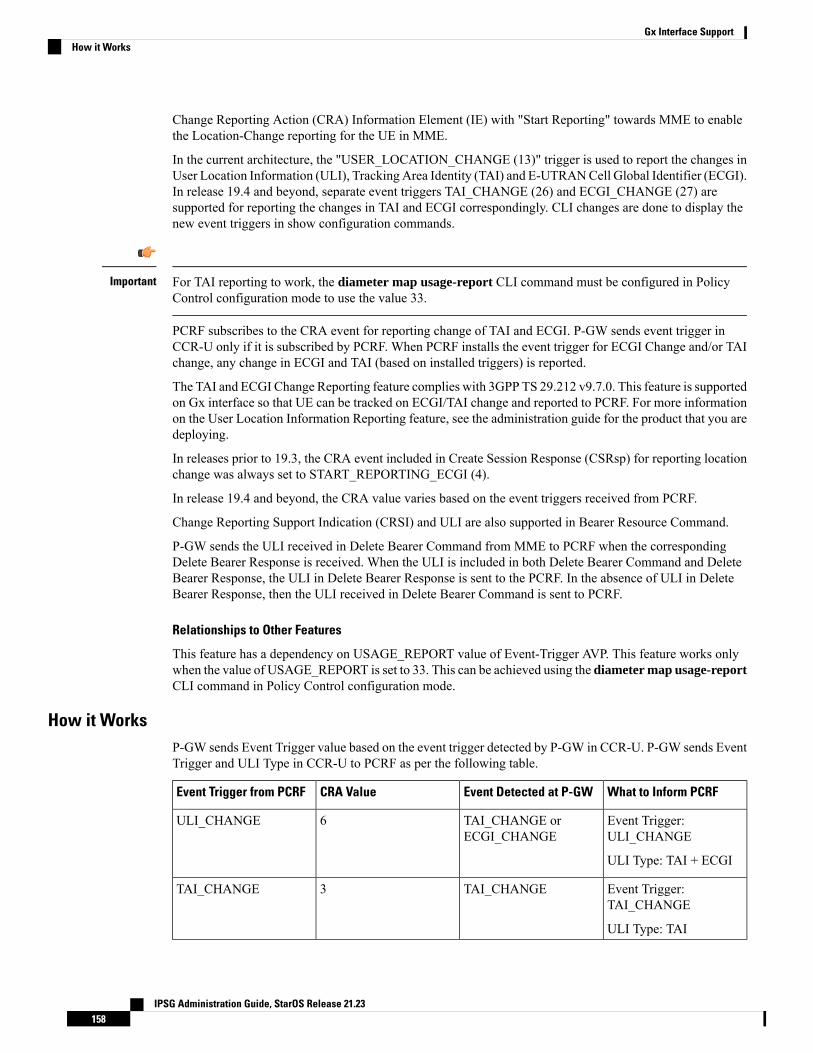
Change Reporting Action (CRA) Information Element (IE) with "Start Reporting" towards MME to enablethe Location-Change reporting for the UE in MME.
In the current architecture, the "USER_LOCATION_CHANGE (13)" trigger is used to report the changes inUser Location Information (ULI), Tracking Area Identity (TAI) and E-UTRANCell Global Identifier (ECGI).In release 19.4 and beyond, separate event triggers TAI_CHANGE (26) and ECGI_CHANGE (27) aresupported for reporting the changes in TAI and ECGI correspondingly. CLI changes are done to display thenew event triggers in show configuration commands.
For TAI reporting to work, the diameter map usage-report CLI command must be configured in PolicyControl configuration mode to use the value 33.
Important
PCRF subscribes to the CRA event for reporting change of TAI and ECGI. P-GW sends event trigger inCCR-U only if it is subscribed by PCRF. When PCRF installs the event trigger for ECGI Change and/or TAIchange, any change in ECGI and TAI (based on installed triggers) is reported.
The TAI and ECGI Change Reporting feature complies with 3GPP TS 29.212 v9.7.0. This feature is supportedon Gx interface so that UE can be tracked on ECGI/TAI change and reported to PCRF. For more informationon the User Location Information Reporting feature, see the administration guide for the product that you aredeploying.
In releases prior to 19.3, the CRA event included in Create Session Response (CSRsp) for reporting locationchange was always set to START_REPORTING_ECGI (4).
In release 19.4 and beyond, the CRA value varies based on the event triggers received from PCRF.
Change Reporting Support Indication (CRSI) and ULI are also supported in Bearer Resource Command.
P-GW sends the ULI received in Delete Bearer Command from MME to PCRF when the correspondingDelete Bearer Response is received. When the ULI is included in both Delete Bearer Command and DeleteBearer Response, the ULI in Delete Bearer Response is sent to the PCRF. In the absence of ULI in DeleteBearer Response, then the ULI received in Delete Bearer Command is sent to PCRF.
Relationships to Other Features
This feature has a dependency on USAGE_REPORT value of Event-Trigger AVP. This feature works onlywhen the value of USAGE_REPORT is set to 33. This can be achieved using the diameter map usage-reportCLI command in Policy Control configuration mode.
How it WorksP-GW sends Event Trigger value based on the event trigger detected by P-GW in CCR-U. P-GW sends EventTrigger and ULI Type in CCR-U to PCRF as per the following table.
What to Inform PCRFEvent Detected at P-GWCRA ValueEvent Trigger from PCRF
Event Trigger:ULI_CHANGE
ULI Type: TAI + ECGI
TAI_CHANGE orECGI_CHANGE
6ULI_CHANGE
Event Trigger:TAI_CHANGE
ULI Type: TAI
TAI_CHANGE3TAI_CHANGE
IPSG Administration Guide, StarOS Release 21.23158
Gx Interface SupportHow it Works
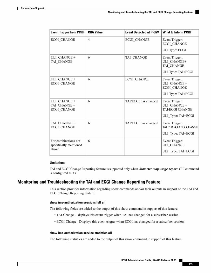
What to Inform PCRFEvent Detected at P-GWCRA ValueEvent Trigger from PCRF
Event Trigger:ECGI_CHANGE
ULI Type: ECGI
ECGI_CHANGE4ECGI_CHANGE
Event Trigger:ULI_CHANGE+TAI_CHANGE
ULI Type: TAI+ECGI
TAI_CHANGE6ULI_CHANGE +TAI_CHANGE
Event Trigger:ULI_CHANGE +ECGI_CHANGE
ULI Type: TAI+ECGI
ECGI_CHANGE6ULI_CHANGE +ECGI_CHANGE
Event Trigger:ULI_CHANGE +TAI/ECGI CHANGE
ULI_Type: TAI+ECGI
TAI/ECGI has changed6ULI_CHANGE +TAI_CHANGE +ECGI_CHANGE
Event Trigger:TAI_CHANGE/ECGI_CHANGE
ULI_Type: TAI+ECGI
TAI/ECGI has changed6TAI_CHANGE +ECGI_CHANGE
Event Trigger:ULI_CHANGE
ULI_Type: TAI+ECGI
6For combinations notspecifically mentionedabove
Limitations
TAI and ECGI Change Reporting feature is supported only when diameter map usage-report CLI commandis configured as 33.
Monitoring and Troubleshooting the TAI and ECGI Change Reporting FeatureThis section provides information regarding show commands and/or their outputs in support of the TAI andECGI Change Reporting feature.
show ims-authorization sessions full all
The following fields are added to the output of this show command in support of this feature:
• TAI-Change - Displays this event trigger when TAI has changed for a subscriber session.
• ECGI-Change - Displays this event trigger when ECGI has changed for a subscriber session.
show ims-authorization service statistics all
The following statistics are added to the output of this show command in support of this feature:
IPSG Administration Guide, StarOS Release 21.23159
Gx Interface SupportMonitoring and Troubleshooting the TAI and ECGI Change Reporting Feature
• TAI Change - Displays the total number of times P-GW has reported TAI_CHANGE (26) event triggerto PCRF.
• ECGI Change - Displays the total number of times P-GW has reported ECGI_CHANGE (27) eventtrigger to PCRF.
Location Based Local-Policy Rule EnforcementThis section describes the overview and implementation of Location-based Local-Policy (LP) Rule Enforcementfeature.
This section discusses the following topics for this feature:
• Feature Description, on page 160
• How it Works, on page 161
• Configuring Location Based Local Policy Rule Enforcement Feature, on page 162
• Monitoring and Troubleshooting the Location Based LP Rule Enforcement Feature, on page 164
Feature DescriptionThis feature is introduced to activate different predefined rules for different E-UTRANCell Global Identifiers(ECGIs) when the subscriber is connected to a corporate APN. The subscriber has to explicitly bring downthe connection with the corporate APN and re-establish session with Internet APN when out of the companyarea. It is assumed that corporate APN does not use PCRF and use only Local-Policy. In this case, all callsmatching the APN is directed to the Local-Policy.
For this feature to work, the license to activate Local-Policy must be configured. For more information onthe licensing requirements, contact your local Cisco account representative.
Important
To activate different predefined rules for ECGI, Local-Policy configurations are enhanced to support:
• Configuration and validation of a set of ECGIs
• Installation of ECGI_CHANGE event trigger through Change Reporting Action (CRA) event
• Detection of ECGI_CHANGE event
This feature supports the following actions to be applied based on the ECGI match with Local-Policy ruledefcondition:
• Enable a redirect rule on ECGI_CHANGE event notification when the ECGI belongs to a certain group
• Enable a wild card rule for any other ECGIs
Relationships to Other Features
This feature has a dependency on TAI and ECGI Change Reporting feature, which provides a framework toreport ECGI-Change from session manager module to IMSA/Local-Policy module.
IPSG Administration Guide, StarOS Release 21.23160
Gx Interface SupportLocation Based Local-Policy Rule Enforcement
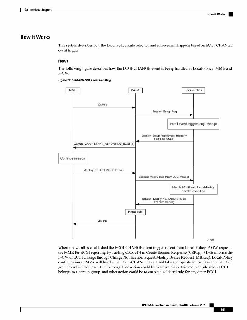
How it WorksThis section describes how the Local Policy Rule selection and enforcement happens based on ECGI-CHANGEevent trigger.
Flows
The following figure describes how the ECGI-CHANGE event is being handled in Local-Policy, MME andP-GW.
Figure 14: ECGI-CHANGE Event Handling
When a new call is established the ECGI-CHANGE event trigger is sent from Local-Policy. P-GW requeststhe MME for ECGI reporting by sending CRA of 4 in Create Session Response (CSRsp). MME informs theP-GW of ECGI Change through Change Notification request/Modify Bearer Request (MBReq). Local-Policyconfiguration at P-GWwill handle the ECGI-CHANGE event and take appropriate action based on the ECGIgroup to which the new ECGI belongs. One action could be to activate a certain redirect rule when ECGIbelongs to a certain group, and other action could be to enable a wildcard rule for any other ECGI.
IPSG Administration Guide, StarOS Release 21.23161
Gx Interface SupportHow it Works
Limitations
This section identifies the known limitations of this feature.
• ECGI Change detection and triggering is a pre-requisite for this feature.
• This feature is supported for Local-Policy-only (lp-only) mode wherein, all requests and responses withina particular APN directly go to Local-Policy without contacting PCRF. That is, this feature does notwork in Local-Policy fallback mode and dual mode wherein both PCRF and Local-Policy co-exist.
Configuring Location Based Local Policy Rule Enforcement FeatureThis section provides the configuration of parameters within Local-Policy to enable rule enforcement basedon ECGI-Change event notification.
Configuring ECGI Change Trigger
Use the following configuration to install ECGI-Change trigger from local-policy.
configurelocal-policy-service service_name
actiondef actiondef_name
action priority priority event-triggers ecgi-changeexit
eventbase default
rule priority priority event new-call ruledef ruledef_name actiondefactiondef_name [ continue ]
end
Notes:
• priority priority: Specifies a priority for the specified action. priority must be unique and an integerfrom 1 to 2048.
• ecgi-change: This keyword specifies to install ECGI-CHANGE event trigger. If enabled, ECGI-CHANGEevent trigger is sent from local-policy.
• This CLI command is configured in local-policy if operator wants to enable ECGI-Change notificationin MME by sending a CRA value.
Applying Rules for ECGI-Change Event
Use the following configuration to enable ECGI Change detection and take specific action for ECGI-CHANGEevent reported by MME.
configurelocal-policy-service service_name
eventbase eventbase_name
rule priority priority event ecgi-change ruledef ruledef_name
actiondef actiondef_name [ continue ]end
Notes:
• priority priority: Specifies a priority for the specified rule. priority must be unique and an integer from1 to 2048.
IPSG Administration Guide, StarOS Release 21.23162
Gx Interface SupportConfiguring Location Based Local Policy Rule Enforcement Feature
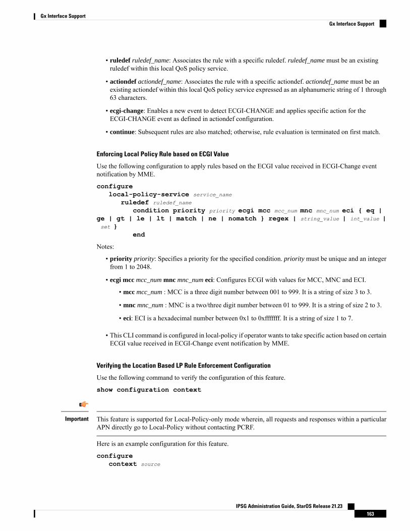
• ruledef ruledef_name: Associates the rule with a specific ruledef. ruledef_name must be an existingruledef within this local QoS policy service.
• actiondef actiondef_name: Associates the rule with a specific actiondef. actiondef_name must be anexisting actiondef within this local QoS policy service expressed as an alphanumeric string of 1 through63 characters.
• ecgi-change: Enables a new event to detect ECGI-CHANGE and applies specific action for theECGI-CHANGE event as defined in actiondef configuration.
• continue: Subsequent rules are also matched; otherwise, rule evaluation is terminated on first match.
Enforcing Local Policy Rule based on ECGI Value
Use the following configuration to apply rules based on the ECGI value received in ECGI-Change eventnotification by MME.
configurelocal-policy-service service_name
ruledef ruledef_name
condition priority priority ecgi mcc mcc_num mnc mnc_num eci { eq |ge | gt | le | lt | match | ne | nomatch } regex | string_value | int_value |set }
end
Notes:
• priority priority: Specifies a priority for the specified condition. priority must be unique and an integerfrom 1 to 2048.
• ecgi mcc mcc_num mnc mnc_num eci: Configures ECGI with values for MCC, MNC and ECI.
• mcc mcc_num : MCC is a three digit number between 001 to 999. It is a string of size 3 to 3.
• mnc mnc_num : MNC is a two/three digit number between 01 to 999. It is a string of size 2 to 3.
• eci: ECI is a hexadecimal number between 0x1 to 0xfffffff. It is a string of size 1 to 7.
• This CLI command is configured in local-policy if operator wants to take specific action based on certainECGI value received in ECGI-Change event notification by MME.
Verifying the Location Based LP Rule Enforcement Configuration
Use the following command to verify the configuration of this feature.
show configuration context
This feature is supported for Local-Policy-only mode wherein, all requests and responses within a particularAPN directly go to Local-Policy without contacting PCRF.
Important
Here is an example configuration for this feature.
configurecontext source
IPSG Administration Guide, StarOS Release 21.23163
Gx Interface SupportGx Interface Support
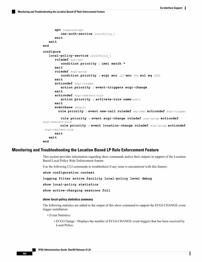
apn corporate-apn
ims-auth-service LocalPolicy_1
exitexit
end
configurelocal-policy-service LocalPolicy_1
ruledef any-imsi
condition priority 1 imsi match *exitruledef ecgi-group
condition priority 1 ecgi mcc 123 mnc 456 eci eq ffff
exitactiondef ecgi-trigger
action priority 1 event-triggers ecgi-changeexitactiondef ecgi-redirect-rule
action priority 1 activate-rule namerule-1exiteventbase default
rule priority 1 event new-call ruledef any-imsi actiondef ecgi-trigger
rule priority 2 event ecgi-change ruledef ecgi-group actiondefecgi-redirect-rule
rule priority 3 event location-change ruledef ecgi-group actiondefecgi-redirect-rule
exitexit
end
Monitoring and Troubleshooting the Location Based LP Rule Enforcement FeatureThis section provides information regarding show commands and/or their outputs in support of the LocationBased Local Policy Rule Enforcement feature.
Use the following CLI commands to troubleshoot if any issue is encountered with this feature.
show configuration context
logging filter active facility local-policy level debug
show local-policy statistics
show active-charging sessions full
show local-policy statistics summary
The following statistics are added to the output of this show command to support the ECGI-CHANGE eventtrigger installation:
• Event Statistics:
• ECGI Change - Displays the number of ECGI-CHANGE event triggers that has been received byLocal-Policy.
IPSG Administration Guide, StarOS Release 21.23164
Gx Interface SupportMonitoring and Troubleshooting the Location Based LP Rule Enforcement Feature
• Variable Matching Statistics
• ECGI - Displays the number of times the ECGI is matched and the specific action is applied basedon the event.
Gx Support for GTP based S2a/S2bIn releases prior to 18, forWiFi integration in P-GW, Gx support was already available for GTP based S2a/S2,but the implementation was specific to a particular customer.
In 18 and later releases, the Gx support for GTP based S2a/S2 interface is extended to all customers. Thisimplementation is in compliance with standard Rel.8 Non-3GPP specification part of 29.212, along withC3-101419 C3-110338 C3-110225 C3-120852 C3-130321 C3-131222 CRs from Rel.10/Rel.11.
As part of this enhancement, the following changes are introduced:
• AVP support for TWAN ID is provided• TWAN-ID is added to r8-gx-standard dictionary
Gx-based Virtual APN SelectionThis section describes the overview and implementation of Gx based Vitrual APN Selection feature.
This section discusses the following topics for this feature:
• Feature Description, on page 165
• Configuring Gx based Virtual APN Selection Feature , on page 166
• Monitoring and Troubleshooting the Gx based Virtual APN Selection, on page 166
Feature Description
Overview
The current implementation supports Virtual APN (VAPN) Selection through RADIUS or local configuration.In Release 19, ASR 5500 uses PCRF and Gx interface for Virtual APN selection to achieve signaling reduction.
A new supported feature "virtual-apn" with feature bit set to 4 is added to the IMSA configuration. Thisconfiguration enables Gx based Virtual APN Selection feature for a given IMS authorization service. Whenthis configuration is enabled at P-GW/GGSN, then P-GW/GGSN advertises this feature to PCRF through theSupported-Features AVP in CCR-I. When the VAPN is selected, then the PCRF rejects the CCR-I messagewith the Experimental-Result-Code AVP set to 5999 (DIAMETER_GX_APN_CHANGE), and sends a newAPN through the Called-Station-Id AVP in CCA-I message. The existing call is then disconnected andreestablished with the new virtual APN. Note that the Experimental Result Code 5999 will have the CiscoVendor ID.
Enabling this feature might have CPU impact (depending on the number of calls using this feature).Important
IPSG Administration Guide, StarOS Release 21.23165
Gx Interface SupportGx Support for GTP based S2a/S2b
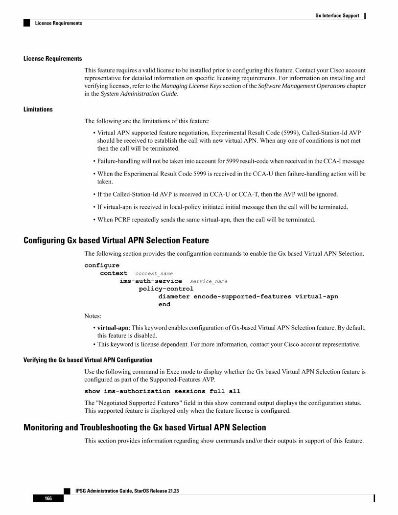
License Requirements
This feature requires a valid license to be installed prior to configuring this feature. Contact your Cisco accountrepresentative for detailed information on specific licensing requirements. For information on installing andverifying licenses, refer to theManaging License Keys section of the Software Management Operations chapterin the System Administration Guide.
Limitations
The following are the limitations of this feature:
• Virtual APN supported feature negotiation, Experimental Result Code (5999), Called-Station-Id AVPshould be received to establish the call with new virtual APN. When any one of conditions is not metthen the call will be terminated.
• Failure-handling will not be taken into account for 5999 result-code when received in the CCA-I message.
• When the Experimental Result Code 5999 is received in the CCA-U then failure-handling action will betaken.
• If the Called-Station-Id AVP is received in CCA-U or CCA-T, then the AVP will be ignored.
• If virtual-apn is received in local-policy initiated initial message then the call will be terminated.
• When PCRF repeatedly sends the same virtual-apn, then the call will be terminated.
Configuring Gx based Virtual APN Selection FeatureThe following section provides the configuration commands to enable the Gx based Virtual APN Selection.
configurecontext context_name
ims-auth-service service_name
policy-controldiameter encode-supported-features virtual-apnend
Notes:
• virtual-apn: This keyword enables configuration of Gx-based Virtual APN Selection feature. By default,this feature is disabled.
• This keyword is license dependent. For more information, contact your Cisco account representative.
Verifying the Gx based Virtual APN Configuration
Use the following command in Exec mode to display whether the Gx based Virtual APN Selection feature isconfigured as part of the Supported-Features AVP.
show ims-authorization sessions full all
The "Negotiated Supported Features" field in this show command output displays the configuration status.This supported feature is displayed only when the feature license is configured.
Monitoring and Troubleshooting the Gx based Virtual APN SelectionThis section provides information regarding show commands and/or their outputs in support of this feature.
IPSG Administration Guide, StarOS Release 21.23166
Gx Interface SupportLicense Requirements
show ims-authorization policy-control statistics
The following field has been added to the output of this show command to track the number of times thePCRF sends the Diameter Experimental Result Code (5999) when a new virtual APN is selected.
• Gx APN Change
For descriptions of this statistics, see the Statistics and Counters Reference guide.
Debugging Statistics
Use the following command to debug the Gx based Virtual APN calls.
show session subsystem facility sessmgr debug-info
This command displays the detailed statistics associated with the Gx-based VAPN feature. For example,number of Gx VAPN received, number of AAAMGR/SGX/DHCP messages after enabling Gx VAPN, andGx VAPN calls setup time.
Bulk Statistics for Gx based Virtual APN Selection Feature
IMSA Schema
The following new bulk statistic variable is added to the IMSA schema to track the number of times the PCRFsends the Diameter Experimental Result Code (5999) when a new virtual APN is selected.
• dpca-expres-gx-apn-change
For descriptions of this variable, see the Statistics and Counters Reference guide.
System Schema
The following new disconnect reason is added to the System schema to track the number of times aP-GW/GGSN/SAEGW session was disconnected due to validation failure of virtual APN received fromPCRF.
• gx-vapn-selection-failed (618)
For descriptions of this variable, see the Statistics and Counters Reference guide.
Graceful Handling of RAR from Different PeersIn StarOS Gx architecture, every Diameter session is associated with a Primary and a Secondary peer whenhost select is configured at the IMSA service. The behavior for processing RAR prior to release 20 is asfollows:
• If the RAR is received from the Primary peer for the session, the RAR is responded using the Primarypeer connection.
• If the RAR is received from a Secondary peer for the session, host-switch takes effect. This results inthe RAA (and any further session signaling) happening via the Secondary peer.
• If the RAR is received via a third peer which is neither the Primary nor the Secondary peer for the session,the RAR is dropped.
IPSG Administration Guide, StarOS Release 21.23167
Gx Interface Supportshow ims-authorization policy-control statistics
In certain networks where PCRF and PCEF are connected through multiple DRAs the PCRF may select theDRA in a round-robin fashion and the RAR for a session may come from a peer which is neither Primary norSecondary. In order to handle such a scenario, the ability to respond to the RAR received from a non-primaryand non-secondary peer was added. In this case, the RAR is answered via the peer from which RAR wasreceived. However any future signaling for the session will still occur via the previously communicating peer.If the RAR is received via the secondary peer, the host-switch occurs and the behavior remains unchanged.In order to be able to process the RAR from a third peer, that peer must be configured in the Diameter endpointconfiguration. Further, this issue is seen only when host select is configured at IMSA service. When the hostselection happens at endpoint level, this issue is not seen.
Assume there are three DRAs and they are configured as shown in the sample configuration below:
configurecontext test
diameter endpoint Gx...peer DRA1 realm realmName address 192.168.23.3peer DRA2 realm realmName address 192.168.23.3 port 3869peer DRA3 realm realmName address 192.168.23.3 port 3870exit
ims-auth-service imsa-Gxpolicy-control
diameter host-select row-precedence 1 table 1 host DRA1secondary host DRA2end
Without the feature, when RAR is received from DRA3, it is rejected. With the feature enabled, RAR fromDRA3 is responded via DRA3 only and Peer switch will not occur in this case and subsequent messaging willbe sent through DRA1 or DRA2 if any prior peer switch had happened.
Limitations
This section identifies the limitations for this feature.
• RAR will be rejected when received from different origin host.
• RAR will be rejected when received from a DRA not configured in Diameter endpoint.
NetLoc Feature EnhancementThis feature adds compliance with 3GPP standard R13 version to the existing NetLoc feature functionality.
Feature Description
This is a license controlled feature. Netloc feature license key is required to be enabled. Contact your Ciscoaccount representative for information on how to obtain a license.
Important
This feature adds compliance with 3GPP standard R13 version to the existing NetLoc feature functionality.Using this NetLoc feature, the IMS network can retrieve location information of the UE from the access orLTE network. This enhances the location related functionality and charging based on the location information.
IPSG Administration Guide, StarOS Release 21.23168
Gx Interface SupportNetLoc Feature Enhancement
This feature introduces the following behavior changes:
• Assuming that NetLoc feature is enabled on chassis and Access Network Information (ANI-45) Eventtrigger is installed, following behavior changes have been introduced:
Table 9: Gx Interface Behavior Change Towards PCRF
ULI & MS TZ BehaviorChange(StandardGx-R8/Custom15 (AT&T))
ULI & MS TZ BehaviorBefore 21.1Release(StandardGx-R8/Custom15 (AT&T))
Access Side InteractionPCRF Gx InterfaceInteraction
No change in thebehavior.
Create Bearer Responseis received with onlyNew ULI parameter.
Create Bearer Responseis received with onlyNew ULI parameter.
RAI AVP with '0 - ULI'is received in thecharging rule installrequest.
PLMN-id in3GPP-SGSN-MCC-MNCAVP is sent towards thePCRF.
Old ULI parameter issent towards the PCRFin the CCR-U message.
Create Bearer Responseis received with No ULIparameter.
RAI AVP with '0 - ULI'is received in thecharging rule installrequest.
No change in thebehavior.
New ULI parameter issent towards the PCRFin the CCR-U message.
Update Bearer Responseis received with onlyNew ULI parameter.
RAI AVP with '0 - ULI'is received in thecharging rule modifyrequest.
PLMN-id in3GPP-SGSN-MCC-MNCAVP is sent towards thePCRF.
Old ULI parameter issent towards the PCRFin the CCR-U message.
Update Bearer Responseis received with No ULIparameter.
RAI AVP with '0 - ULI'is received in thecharging rule Modifyrequest.
Only New ULI is senttowards the PCRF in theCCR-U message.
New ULI and old MSTZ parameters are senttowards the PCRF in theCCR-U message.
Delete Bearer Responseis received with onlyNew ULI parameter andNo MS TZ parameter.
RAI AVP with '0 - ULI'is received in thecharging rule modifyrequest.
PLMN-id in the3GPP-SGSN-MCC-MNCAVP is sent towards thePCRF.
Old ULI and old MS TZparameters are senttowards the PCRF in theCCR-U message.
Delete Bearer Responseis received with No ULIparameter and No MSTZ parameter.
RAI AVP with '0 - ULI'is received in thecharging rule Modifyrequest.
No change in thebehavior.
New MS TZ parameteris sent towards the PCRFin the CCR-U message.
Create Bearer Responseis received with onlynew MS TZ parameter.
RAI AVP with '1-MSTZ' is received inthe charging rule installrequest.
No change in thebehavior.
Old MS TZ parameter issent towards the PCRFin the CCR-U message.
Create Bearer Responseis received with No MSTZ parameter.
RAI AVP with '1 -MSTZ' is received in thecharging rule installrequest.
IPSG Administration Guide, StarOS Release 21.23169
Gx Interface SupportGx Interface Support
ULI & MS TZ BehaviorChange(StandardGx-R8/Custom15 (AT&T))
ULI & MS TZ BehaviorBefore 21.1Release(StandardGx-R8/Custom15 (AT&T))
Access Side InteractionPCRF Gx InterfaceInteraction
No change in thebehavior.
New MS TZ parameteris sent towards the PCRFin the CCR-U message.
Update Bearer Responseis received with onlyNew MS TZ parameter.
RAI AVP with '1-MSTZ' is received inthe charging rule modifyrequest.
No change in thebehavior.
Old MS TZ parameter issent towards the PCRFin the CCR-U message.
Update Bearer Responseis received with No MSTZ parameter.
RAI AVP with '1-MSTZ' is received inthe charging ruleModifyrequest.
OnlyNewMSTZ is senttowards the PCRF in theCCR-U message.
Old ULI and New MSTZ parameters are senttowards the PCRF in theCCR-U message.
Delete Bearer Responseis received with onlyNew MS TZ parameter.
RAI AVP with '1-MSTZ' is received inthe charging rule modifyrequest.
Only old MS TZ is senttowards the PCRF.
New ULI and old MSTZ parameters are senttowards the PCRF in theCCR-U message.
Delete Bearer Responseis received with No MSTZ parameter.
RAI AVP with '1-MSTZ' is received inthe charging ruleModifyrequest.
No change in thebehavior.
New ULI and New MSTZ parameters are senttowards the PCRF in theCCR-T message.
Delete Session Requestis received with NewULI and New MS TZparameters.
Nothing is received.
No change in thebehavior.
New ULI and Old MSTZ parameters are senttowards the PCRF in theCCR-T message.
Delete Session Requestis received with NewULI and No MS TZparameter.
Nothing is received.
No change in thebehavior.
Old ULI andOldMSTZparameters are senttowards the PCRF in theCCR-T message.
Delete Session Requestis received with No ULIand No MS TZparameter.
Nothing is received.
ULI and ULI timestamp is considered as paired. If the ULI timestamp isforwarded, it is forwarded and received with the ULI. If the ULI is received andthe ULI timestamp is not received, then that P-GW does not forward the oldtimestamp.
Important
• Inclusion of AVP support of NETLOC-ACCESS-NOT-SUPPORTED on Gx interface. This inclusionof AVP is based on the below conditions:
• RAT type is other than E-UTRAN, UTRAN, WCDMA, GPRS, GERAN, and W-LAN• IP CAN type is other than 3GPP EPS, GPRS, and non 3GPP EPS
IPSG Administration Guide, StarOS Release 21.23170
Gx Interface SupportGx Interface Support
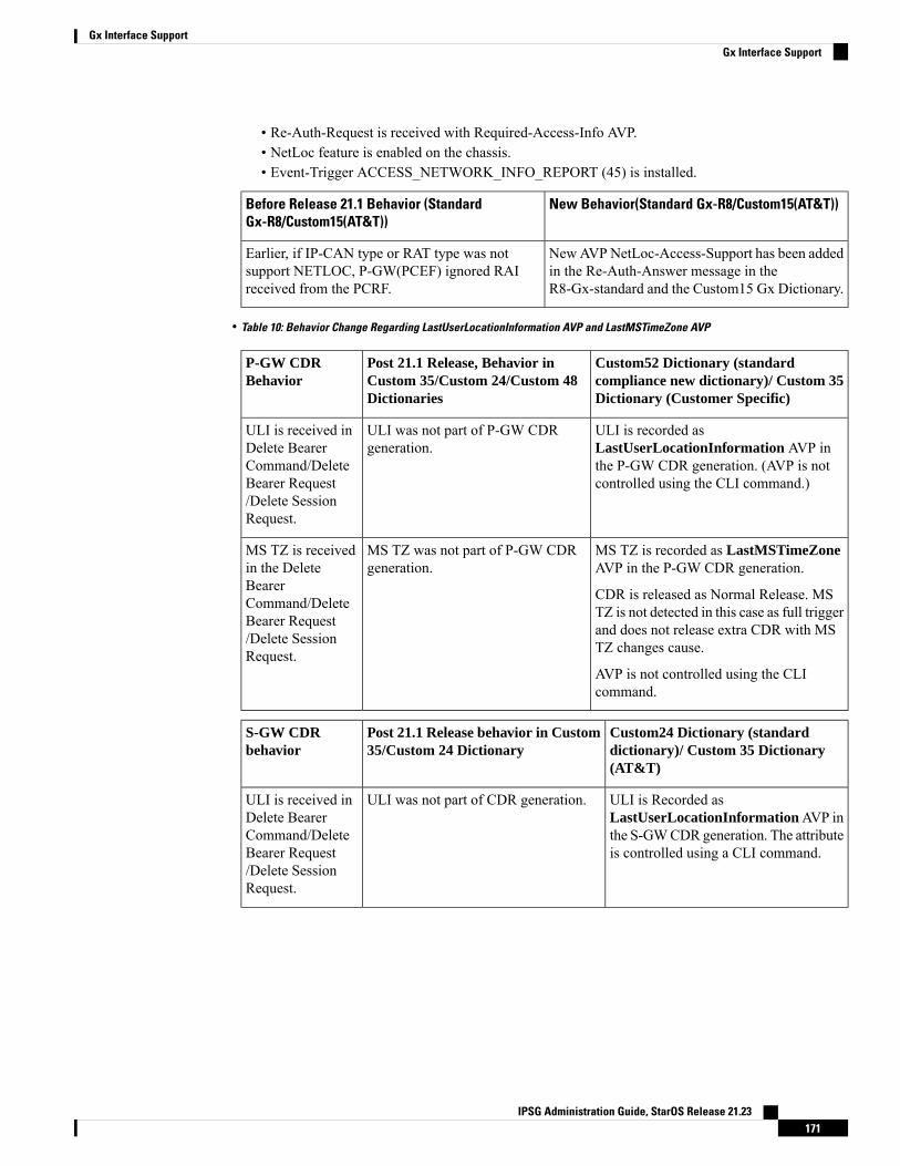
• Re-Auth-Request is received with Required-Access-Info AVP.• NetLoc feature is enabled on the chassis.• Event-Trigger ACCESS_NETWORK_INFO_REPORT (45) is installed.
New Behavior(Standard Gx-R8/Custom15(AT&T))Before Release 21.1 Behavior (StandardGx-R8/Custom15(AT&T))
NewAVPNetLoc-Access-Support has been addedin the Re-Auth-Answer message in theR8-Gx-standard and the Custom15 Gx Dictionary.
Earlier, if IP-CAN type or RAT type was notsupport NETLOC, P-GW(PCEF) ignored RAIreceived from the PCRF.
• Table 10: Behavior Change Regarding LastUserLocationInformation AVP and LastMSTimeZone AVP
Custom52 Dictionary (standardcompliance new dictionary)/ Custom 35Dictionary (Customer Specific)
Post 21.1 Release, Behavior inCustom 35/Custom 24/Custom 48Dictionaries
P-GW CDRBehavior
ULI is recorded asLastUserLocationInformation AVP inthe P-GW CDR generation. (AVP is notcontrolled using the CLI command.)
ULI was not part of P-GW CDRgeneration.
ULI is received inDelete BearerCommand/DeleteBearer Request/Delete SessionRequest.
MS TZ is recorded as LastMSTimeZoneAVP in the P-GW CDR generation.
CDR is released as Normal Release. MSTZ is not detected in this case as full triggerand does not release extra CDR with MSTZ changes cause.
AVP is not controlled using the CLIcommand.
MS TZ was not part of P-GW CDRgeneration.
MS TZ is receivedin the DeleteBearerCommand/DeleteBearer Request/Delete SessionRequest.
Custom24 Dictionary (standarddictionary)/ Custom 35 Dictionary(AT&T)
Post 21.1 Release behavior in Custom35/Custom 24 Dictionary
S-GW CDRbehavior
ULI is Recorded asLastUserLocationInformationAVP inthe S-GWCDR generation. The attributeis controlled using a CLI command.
ULI was not part of CDR generation.ULI is received inDelete BearerCommand/DeleteBearer Request/Delete SessionRequest.
IPSG Administration Guide, StarOS Release 21.23171
Gx Interface SupportGx Interface Support
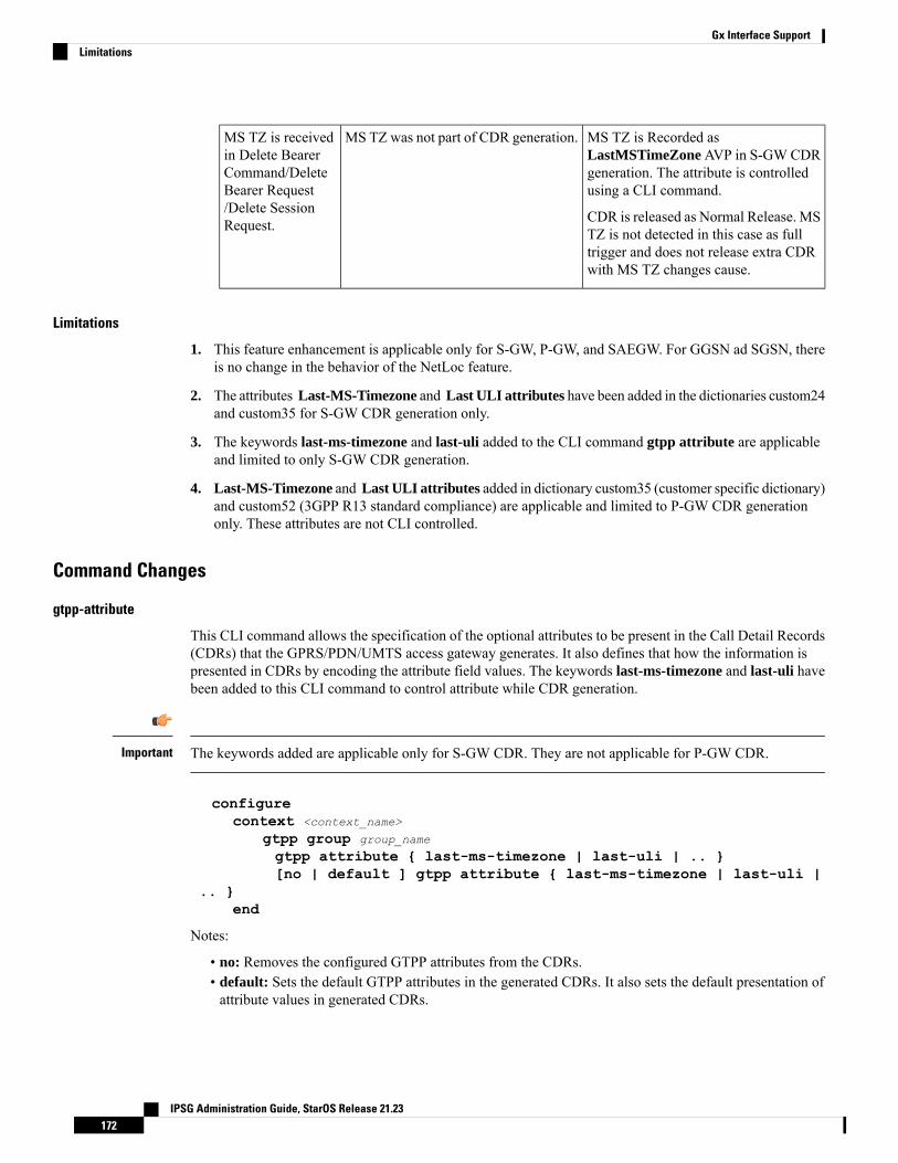
MS TZ is Recorded asLastMSTimeZone AVP in S-GW CDRgeneration. The attribute is controlledusing a CLI command.
CDR is released as Normal Release. MSTZ is not detected in this case as fulltrigger and does not release extra CDRwith MS TZ changes cause.
MS TZ was not part of CDR generation.MS TZ is receivedin Delete BearerCommand/DeleteBearer Request/Delete SessionRequest.
Limitations
1. This feature enhancement is applicable only for S-GW, P-GW, and SAEGW. For GGSN ad SGSN, thereis no change in the behavior of the NetLoc feature.
2. The attributes Last-MS-Timezone and Last ULI attributes have been added in the dictionaries custom24and custom35 for S-GW CDR generation only.
3. The keywords last-ms-timezone and last-uli added to the CLI command gtpp attribute are applicableand limited to only S-GW CDR generation.
4. Last-MS-Timezone and Last ULI attributes added in dictionary custom35 (customer specific dictionary)and custom52 (3GPP R13 standard compliance) are applicable and limited to P-GW CDR generationonly. These attributes are not CLI controlled.
Command Changes
gtpp-attribute
This CLI command allows the specification of the optional attributes to be present in the Call Detail Records(CDRs) that the GPRS/PDN/UMTS access gateway generates. It also defines that how the information ispresented in CDRs by encoding the attribute field values. The keywords last-ms-timezone and last-uli havebeen added to this CLI command to control attribute while CDR generation.
The keywords added are applicable only for S-GW CDR. They are not applicable for P-GW CDR.Important
configurecontext <context_name>
gtpp group group_name
gtpp attribute { last-ms-timezone | last-uli | .. }[no | default ] gtpp attribute { last-ms-timezone | last-uli |
.. }end
Notes:
• no: Removes the configured GTPP attributes from the CDRs.• default: Sets the default GTPP attributes in the generated CDRs. It also sets the default presentation ofattribute values in generated CDRs.
IPSG Administration Guide, StarOS Release 21.23172
Gx Interface SupportLimitations
• last-ms-timezone: Sets the "Last MS-Timezone" in the CDR field. This option would be disabled whenthe default option is used.
• last-uli: Sets the "Last ULI" in the CDR field. This option would be disabled when the default optionis used.
Performance Indicator Changes
show configuration
This command has been modified to display the following output:
• Last-MS-Timezone present
• Last-User Location Information present
show gtpp group name group_name
This command has been modified to display the following output:
Last-MS-Timezone present: yesLast-User Location Information present:
yes
RAN-NAS Cause Code Feature EnhancementThis chapter describes the RAN-NAS Cause Code Feature Enhancement.
Feature Description
This is a license controlled feature. You must enable the existing license of NPLI. Contact your Cisco accountrepresentative for information on how to obtain a license.
Important
This feature introduces support for 3GPP RAN/NAS cause code IE for "Failed Create Bearer Response","Failed Updated Bearer Response", and "Delete Bearer Response" at the Gx interface, the P-GW, and S-GWCDRs. This will enable the operator to get detailed RAN/NAS release cause code information from the accessnetwork. RAN/NAS cause can be received from the access side in either of the following messages:
• Failed Create Bearer Response
• Failed Update Bearer Response
• Delete Session Request
• Delete Bearer Response
• Delete Bearer Command
This support of 3GPP Release 12 RAN/NAS cause IE on the S4, S11, S5, and S8 interfaces exists for "DeleteSession Request" and "Delete Bearer" command through private extension as well as Standard IE for customerspecific dictionaries Gx- dpca-custom15 and Gz-Custom35.
IPSG Administration Guide, StarOS Release 21.23173
Gx Interface SupportPerformance Indicator Changes
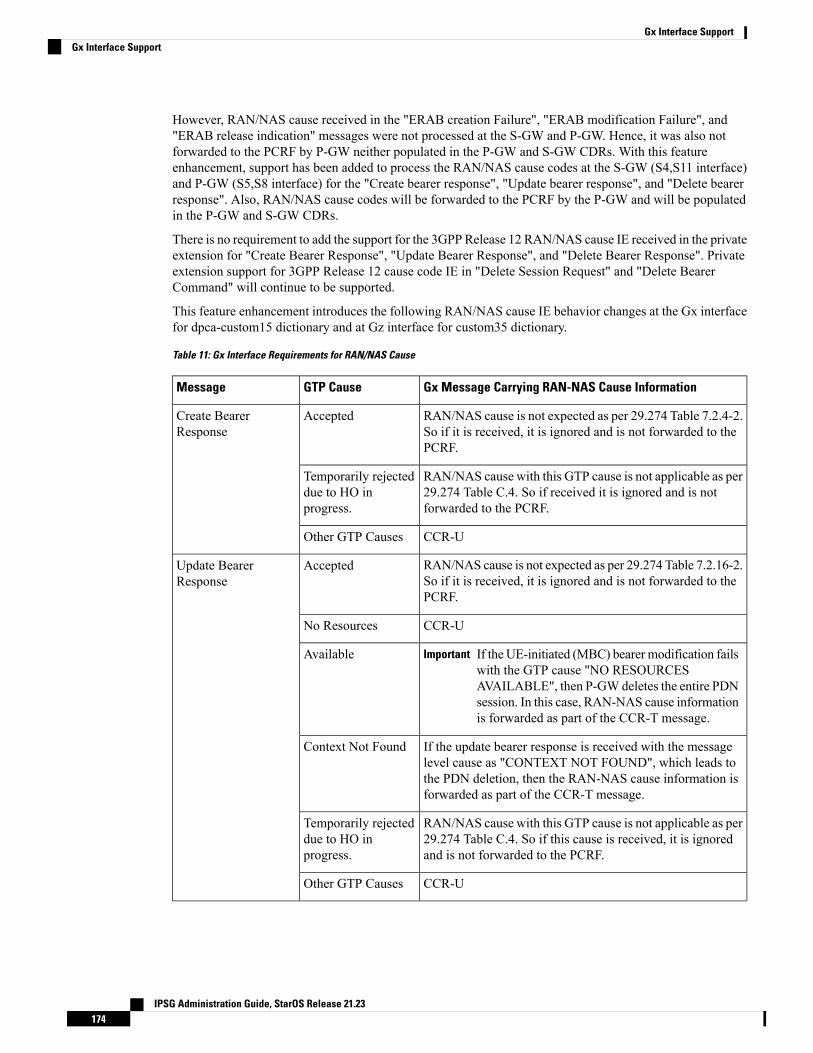
However, RAN/NAS cause received in the "ERAB creation Failure", "ERAB modification Failure", and"ERAB release indication" messages were not processed at the S-GW and P-GW. Hence, it was also notforwarded to the PCRF by P-GW neither populated in the P-GW and S-GW CDRs. With this featureenhancement, support has been added to process the RAN/NAS cause codes at the S-GW (S4,S11 interface)and P-GW (S5,S8 interface) for the "Create bearer response", "Update bearer response", and "Delete bearerresponse". Also, RAN/NAS cause codes will be forwarded to the PCRF by the P-GW and will be populatedin the P-GW and S-GW CDRs.
There is no requirement to add the support for the 3GPP Release 12 RAN/NAS cause IE received in the privateextension for "Create Bearer Response", "Update Bearer Response", and "Delete Bearer Response". Privateextension support for 3GPP Release 12 cause code IE in "Delete Session Request" and "Delete BearerCommand" will continue to be supported.
This feature enhancement introduces the following RAN/NAS cause IE behavior changes at the Gx interfacefor dpca-custom15 dictionary and at Gz interface for custom35 dictionary.
Table 11: Gx Interface Requirements for RAN/NAS Cause
Gx Message Carrying RAN-NAS Cause InformationGTP CauseMessage
RAN/NAS cause is not expected as per 29.274 Table 7.2.4-2.So if it is received, it is ignored and is not forwarded to thePCRF.
AcceptedCreate BearerResponse
RAN/NAS cause with this GTP cause is not applicable as per29.274 Table C.4. So if received it is ignored and is notforwarded to the PCRF.
Temporarily rejecteddue to HO inprogress.
CCR-UOther GTP Causes
RAN/NAS cause is not expected as per 29.274 Table 7.2.16-2.So if it is received, it is ignored and is not forwarded to thePCRF.
AcceptedUpdate BearerResponse
CCR-UNo Resources
If the UE-initiated (MBC) bearer modification failswith the GTP cause "NO RESOURCESAVAILABLE", then P-GWdeletes the entire PDNsession. In this case, RAN-NAS cause informationis forwarded as part of the CCR-T message.
ImportantAvailable
If the update bearer response is received with the messagelevel cause as "CONTEXT NOT FOUND", which leads tothe PDN deletion, then the RAN-NAS cause information isforwarded as part of the CCR-T message.
Context Not Found
RAN/NAS cause with this GTP cause is not applicable as per29.274 Table C.4. So if this cause is received, it is ignoredand is not forwarded to the PCRF.
Temporarily rejecteddue to HO inprogress.
CCR-UOther GTP Causes
IPSG Administration Guide, StarOS Release 21.23174
Gx Interface SupportGx Interface Support
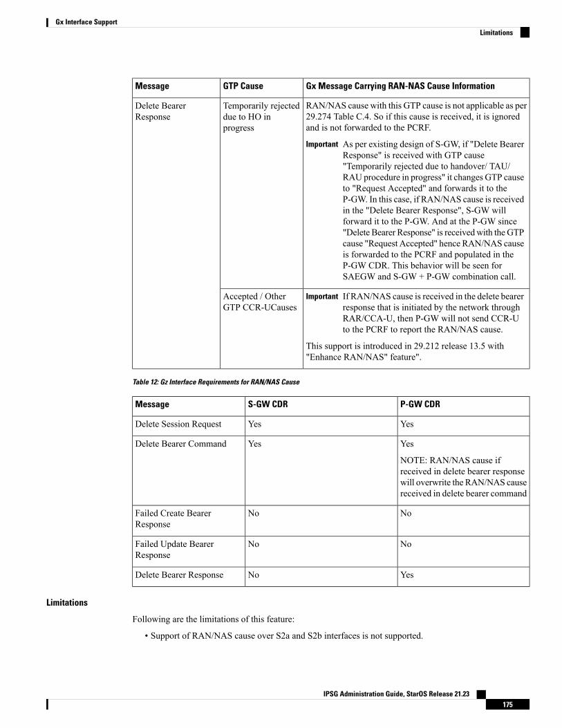
Gx Message Carrying RAN-NAS Cause InformationGTP CauseMessage
RAN/NAS cause with this GTP cause is not applicable as per29.274 Table C.4. So if this cause is received, it is ignoredand is not forwarded to the PCRF.
As per existing design of S-GW, if "Delete BearerResponse" is received with GTP cause"Temporarily rejected due to handover/ TAU/RAU procedure in progress" it changes GTP causeto "Request Accepted" and forwards it to theP-GW. In this case, if RAN/NAS cause is receivedin the "Delete Bearer Response", S-GW willforward it to the P-GW. And at the P-GW since"Delete Bearer Response" is receivedwith the GTPcause "Request Accepted" hence RAN/NAS causeis forwarded to the PCRF and populated in theP-GW CDR. This behavior will be seen forSAEGW and S-GW + P-GW combination call.
Important
Temporarily rejecteddue to HO inprogress
Delete BearerResponse
If RAN/NAS cause is received in the delete bearerresponse that is initiated by the network throughRAR/CCA-U, then P-GW will not send CCR-Uto the PCRF to report the RAN/NAS cause.
Important
This support is introduced in 29.212 release 13.5 with"Enhance RAN/NAS" feature".
Accepted / OtherGTP CCR-UCauses
Table 12: Gz Interface Requirements for RAN/NAS Cause
P-GW CDRS-GW CDRMessage
YesYesDelete Session Request
Yes
NOTE: RAN/NAS cause ifreceived in delete bearer responsewill overwrite the RAN/NAS causereceived in delete bearer command
YesDelete Bearer Command
NoNoFailed Create BearerResponse
NoNoFailed Update BearerResponse
YesNoDelete Bearer Response
Limitations
Following are the limitations of this feature:
• Support of RAN/NAS cause over S2a and S2b interfaces is not supported.
IPSG Administration Guide, StarOS Release 21.23175
Gx Interface SupportLimitations
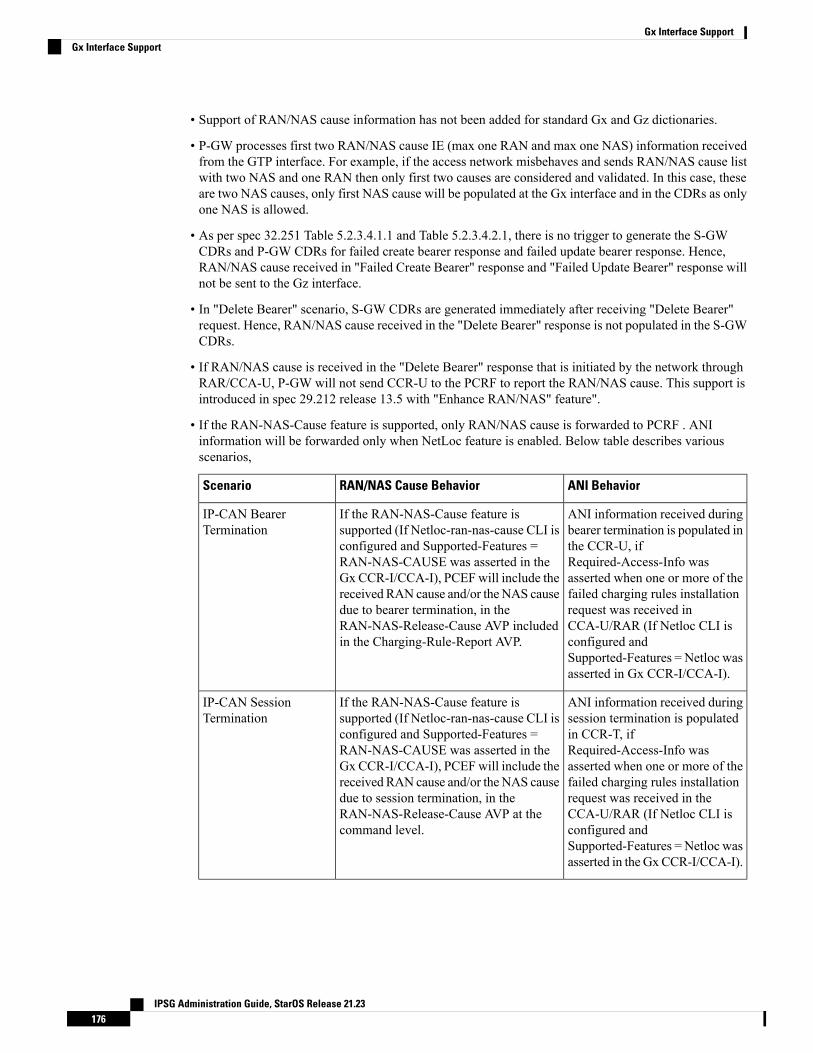
• Support of RAN/NAS cause information has not been added for standard Gx and Gz dictionaries.
• P-GW processes first two RAN/NAS cause IE (max one RAN and max one NAS) information receivedfrom the GTP interface. For example, if the access network misbehaves and sends RAN/NAS cause listwith two NAS and one RAN then only first two causes are considered and validated. In this case, theseare two NAS causes, only first NAS cause will be populated at the Gx interface and in the CDRs as onlyone NAS is allowed.
• As per spec 32.251 Table 5.2.3.4.1.1 and Table 5.2.3.4.2.1, there is no trigger to generate the S-GWCDRs and P-GW CDRs for failed create bearer response and failed update bearer response. Hence,RAN/NAS cause received in "Failed Create Bearer" response and "Failed Update Bearer" response willnot be sent to the Gz interface.
• In "Delete Bearer" scenario, S-GW CDRs are generated immediately after receiving "Delete Bearer"request. Hence, RAN/NAS cause received in the "Delete Bearer" response is not populated in the S-GWCDRs.
• If RAN/NAS cause is received in the "Delete Bearer" response that is initiated by the network throughRAR/CCA-U, P-GW will not send CCR-U to the PCRF to report the RAN/NAS cause. This support isintroduced in spec 29.212 release 13.5 with "Enhance RAN/NAS" feature".
• If the RAN-NAS-Cause feature is supported, only RAN/NAS cause is forwarded to PCRF . ANIinformation will be forwarded only when NetLoc feature is enabled. Below table describes variousscenarios,
ANI BehaviorRAN/NAS Cause BehaviorScenario
ANI information received duringbearer termination is populated inthe CCR-U, ifRequired-Access-Info wasasserted when one or more of thefailed charging rules installationrequest was received inCCA-U/RAR (If Netloc CLI isconfigured andSupported-Features = Netloc wasasserted in Gx CCR-I/CCA-I).
If the RAN-NAS-Cause feature issupported (If Netloc-ran-nas-cause CLI isconfigured and Supported-Features =RAN-NAS-CAUSE was asserted in theGx CCR-I/CCA-I), PCEFwill include thereceived RAN cause and/or the NAS causedue to bearer termination, in theRAN-NAS-Release-Cause AVP includedin the Charging-Rule-Report AVP.
IP-CAN BearerTermination
ANI information received duringsession termination is populatedin CCR-T, ifRequired-Access-Info wasasserted when one or more of thefailed charging rules installationrequest was received in theCCA-U/RAR (If Netloc CLI isconfigured andSupported-Features = Netloc wasasserted in the GxCCR-I/CCA-I).
If the RAN-NAS-Cause feature issupported (If Netloc-ran-nas-cause CLI isconfigured and Supported-Features =RAN-NAS-CAUSE was asserted in theGx CCR-I/CCA-I), PCEFwill include thereceived RAN cause and/or the NAS causedue to session termination, in theRAN-NAS-Release-Cause AVP at thecommand level.
IP-CAN SessionTermination
IPSG Administration Guide, StarOS Release 21.23176
Gx Interface SupportGx Interface Support
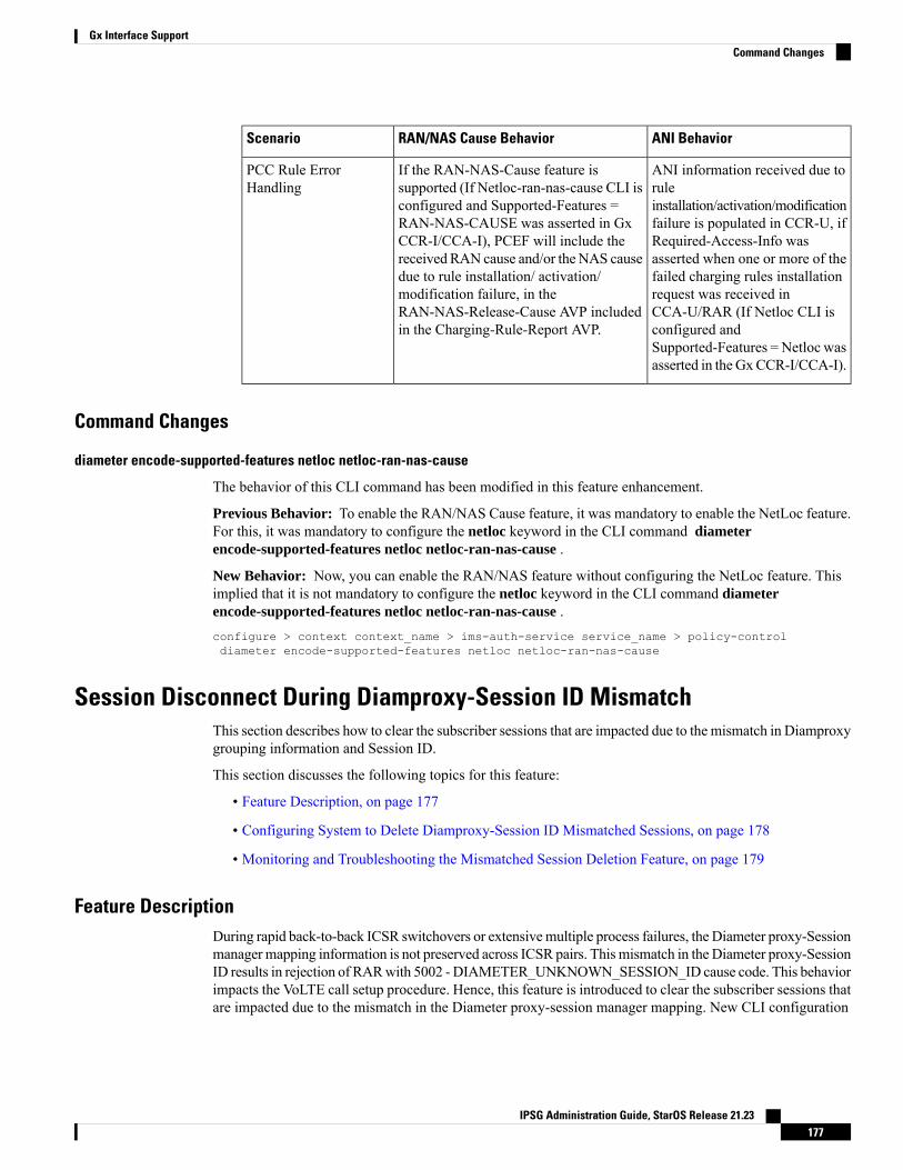
ANI BehaviorRAN/NAS Cause BehaviorScenario
ANI information received due toruleinstallation/activation/modificationfailure is populated in CCR-U, ifRequired-Access-Info wasasserted when one or more of thefailed charging rules installationrequest was received inCCA-U/RAR (If Netloc CLI isconfigured andSupported-Features = Netloc wasasserted in the GxCCR-I/CCA-I).
If the RAN-NAS-Cause feature issupported (If Netloc-ran-nas-cause CLI isconfigured and Supported-Features =RAN-NAS-CAUSE was asserted in GxCCR-I/CCA-I), PCEF will include thereceived RAN cause and/or the NAS causedue to rule installation/ activation/modification failure, in theRAN-NAS-Release-Cause AVP includedin the Charging-Rule-Report AVP.
PCC Rule ErrorHandling
Command Changes
diameter encode-supported-features netloc netloc-ran-nas-cause
The behavior of this CLI command has been modified in this feature enhancement.
Previous Behavior: To enable the RAN/NAS Cause feature, it was mandatory to enable the NetLoc feature.For this, it was mandatory to configure the netloc keyword in the CLI command diameterencode-supported-features netloc netloc-ran-nas-cause .
New Behavior: Now, you can enable the RAN/NAS feature without configuring the NetLoc feature. Thisimplied that it is not mandatory to configure the netloc keyword in the CLI command diameterencode-supported-features netloc netloc-ran-nas-cause .configure > context context_name > ims-auth-service service_name > policy-controldiameter encode-supported-features netloc netloc-ran-nas-cause
Session Disconnect During Diamproxy-Session ID MismatchThis section describes how to clear the subscriber sessions that are impacted due to the mismatch in Diamproxygrouping information and Session ID.
This section discusses the following topics for this feature:
• Feature Description, on page 177
• Configuring System to Delete Diamproxy-Session ID Mismatched Sessions, on page 178
• Monitoring and Troubleshooting the Mismatched Session Deletion Feature, on page 179
Feature DescriptionDuring rapid back-to-back ICSR switchovers or extensivemultiple process failures, the Diameter proxy-Sessionmanagermapping information is not preserved across ICSR pairs. This mismatch in the Diameter proxy-SessionID results in rejection of RARwith 5002 - DIAMETER_UNKNOWN_SESSION_ID cause code. This behaviorimpacts the VoLTE call setup procedure. Hence, this feature is introduced to clear the subscriber sessions thatare impacted due to the mismatch in the Diameter proxy-session manager mapping. New CLI configuration
IPSG Administration Guide, StarOS Release 21.23177
Gx Interface SupportCommand Changes
is provided to control the behavior and new bulk statistic counter is supported to report the Diamproxy-SessionID mismatch.
The bulk statistic counter will be incremented only when session is cleared upon receiving RAR messagewith 5002 result code and detecting session-ID Diamproxy mapping mismatch. A Delete Bearer Request issent to S-GW with a Reactivation Requested as the cause code while suppressing the CCR-T from being sentto PCRF. So, the subscriber reattaches immediately without impacting the subsequent VoLTE calls,encountering only one failure instead of manual intervention.
This enhancement is applicable only to IMS PDN so that there is a limit of one failure when encounteringthis situation instead of manual intervention. This is applicable to only the Gx RARs.
Important
Configuring System to Delete Diamproxy-Session ID Mismatched SessionsThe following section provides the configuration commands to enable the system to clear the subscribersessions that are impacted due to the mismatch in Diamproxy grouping information and Session ID.
Clearing Mismatched Subscriber Sessions
Use the following configuration commands to configure the system to disconnect the subscriber sessionsbased on signaling trigger when session ID and Diamproxy mismatch is identified.
configurecontext context_name
ims-auth-service service_name
policy-controldiameter clear-session sessid-mismatch
end
• sessid-mismatch: Clears the session with mismatched session ID. This CLI configuration is optional.
• The default configuration is no diameter clear-session. By default, the sessions will not be cleared.
Verifying the Configuration to Delete Mismatched Sessions
Use the following command to verify the configuration status of this feature.
show ims-authorization service name service_name
service_name must be the name of the IMS Authorization service configured for IMS authentication.
This command displays all the configurations that are enabled within the specified IMS authorization service.The "Session-Id Mismatch Clear Session" field can be used to determine whether this feature is enabled ordisabled.[local]st40# show ims-authorization service name service1Context: testIMS Authorization Service name: service1Service State: EnabledService Mode: Single Interface Policy and Charging
...Diameter Policy Control:Endpoint: gxOrigin-Realm: xyz.comDictionary: standard
IPSG Administration Guide, StarOS Release 21.23178
Gx Interface SupportConfiguring System to Delete Diamproxy-Session ID Mismatched Sessions
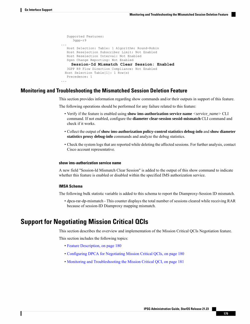
Supported Features:3gpp-r9
...Host Selection: Table: 1 Algorithm: Round-RobinHost Reselection Subscriber Limit: Not EnabledHost Reselection Interval: Not EnabledSgsn Change Reporting: Not EnabledSession-Id Mismatch Clear Session: Enabled
3GPP R9 Flow Direction Compliance: Not EnabledHost Selection Table[1]: 1 Row(s)Precedence: 1
...
Monitoring and Troubleshooting the Mismatched Session Deletion FeatureThis section provides information regarding show commands and/or their outputs in support of this feature.
The following operations should be performed for any failure related to this feature:
• Verify if the feature is enabled using show ims-authorization service name <service_name> CLIcommand. If not enabled, configure the diameter clear-session sessid-mismatch CLI command andcheck if it works.
• Collect the output of show ims-authorization policy-control statistics debug-info and show diameterstatistics proxy debug-info commands and analyze the debug statistics.
• Check the system logs that are reported while deleting the affected sessions. For further analysis, contactCisco account representative.
show ims-authorization service name
A new field "Session-Id Mismatch Clear Session" is added to the output of this show command to indicatewhether this feature is enabled or disabled within the specified IMS authorization service.
IMSA Schema
The following bulk statistic variable is added to this schema to report the Diamproxy-Session ID mismatch.
• dpca-rar-dp-mismatch - This counter displays the total number of sessions cleared while receiving RARbecause of session-ID Diamproxy mapping mismatch.
Support for Negotiating Mission Critical QCIsThis section describes the overview and implementation of the Mission Critical QCIs Negotiation feature.
This section includes the following topics:
• Feature Description, on page 180
• Configuring DPCA for Negotiating Mission Critical QCIs, on page 180
• Monitoring and Troubleshooting the Mission Critical QCI, on page 181
IPSG Administration Guide, StarOS Release 21.23179
Gx Interface SupportMonitoring and Troubleshooting the Mismatched Session Deletion Feature
Feature DescriptionTo support Mission Critical (MC) Push to Talk (PTT) services, a new set of standardized QoS Class Identifiers(QCIs) (65, 66, 69, 70) have been introduced. These are 65-66 (GBR) and 69-70 (non-GBR) network-initiatedQCIs defined in 3GPP TS 23.203 v13.6.0 and 3GPP TS 23.401 v13.5.0 specifications. These QCIs are usedfor Premium Mobile Broadband (PMB)/Public Safety solutions.
The MC-PTT QCI feature requires Wireless Priority Service (WPS) license to be configured. For moreinformation, contact Cisco account representative.
Important
Previous Behavior: The gateway accepted only standard QCIs (1-9) and operator defined QCIs (128-254).If the PCRF sends QCIs with values between 10 and 127, then the gateway rejects the request. MC QCIsupport was not negotiated with PCRF.
New Behavior: PCRF accepts the new standardized QCI values 69 and 70 for default bearer creation and 65,66, 69 and 70 for dedicated bearer creation.
For this functionality to work, a new configurable attribute, mission-critical-qcis, is introduced under thediameter encode-supported-features CLI command. When this CLI option is enabled, the gateway allowsconfiguringMCQCIs as a supported feature and then negotiates theMC-PTTQCI feature with PCRF throughSupported-Features AVP.
The gateway rejects the session create request with MC-PTT QCIs when the WPS license is not enabled andDiameter is not configured to negotiate MC-PTT QCI feature, which is part of Supported Feature bit.
For more information on this feature and associated configurations, refer to P-GW Enhancements for 21.0section in the Release Change Reference guide.
Configuring DPCA for Negotiating Mission Critical QCIsThe following section provides the configuration commands to enable support for MC-PTT QCI feature.
Enabling Mission Critical QCI Feature
Use the following configuration commands to enable MC-PTT QCI feature.
configurecontext context_name
ims-auth-service service_name
policy-controldiameter encode-supported-features mission-critical-qcisend
Notes:
• mission-critical-qcis: This keyword enables MC-PTT QCI feature. By default, this feature will not beenabled.
• This keyword can be enabled only if the WPS license is configured. For more information, contact yourCisco account representative.
• To disable the negotiation of this feature, the existing no diameter encode-supported-features commandneeds to be configured. On executing this command, none of the configured supported features will benegotiated with PCRF.
IPSG Administration Guide, StarOS Release 21.23180
Gx Interface SupportFeature Description
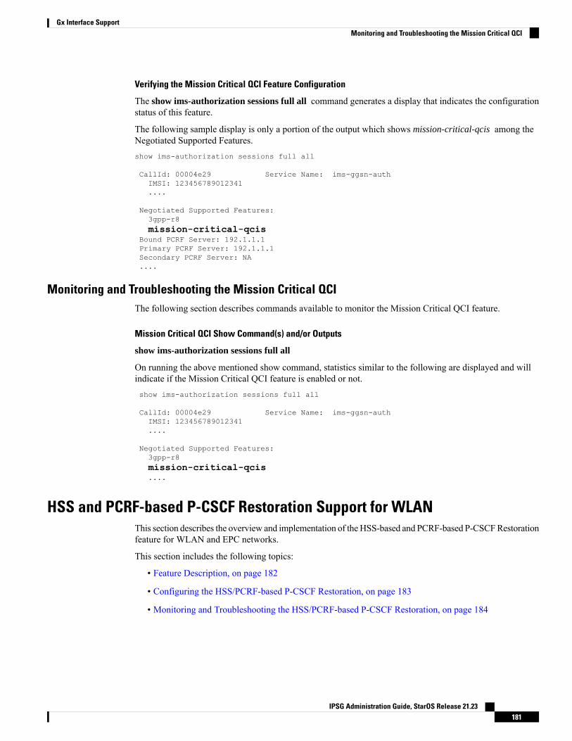
Verifying the Mission Critical QCI Feature Configuration
The show ims-authorization sessions full all command generates a display that indicates the configurationstatus of this feature.
The following sample display is only a portion of the output which shows mission-critical-qcis among theNegotiated Supported Features.show ims-authorization sessions full all
CallId: 00004e29 Service Name: ims-ggsn-authIMSI: 123456789012341....
Negotiated Supported Features:3gpp-r8mission-critical-qcis
Bound PCRF Server: 192.1.1.1Primary PCRF Server: 192.1.1.1Secondary PCRF Server: NA....
Monitoring and Troubleshooting the Mission Critical QCIThe following section describes commands available to monitor the Mission Critical QCI feature.
Mission Critical QCI Show Command(s) and/or Outputs
show ims-authorization sessions full all
On running the above mentioned show command, statistics similar to the following are displayed and willindicate if the Mission Critical QCI feature is enabled or not.show ims-authorization sessions full all
CallId: 00004e29 Service Name: ims-ggsn-authIMSI: 123456789012341....
Negotiated Supported Features:3gpp-r8mission-critical-qcis....
HSS and PCRF-based P-CSCF Restoration Support for WLANThis section describes the overview and implementation of theHSS-based and PCRF-based P-CSCFRestorationfeature for WLAN and EPC networks.
This section includes the following topics:
• Feature Description, on page 182
• Configuring the HSS/PCRF-based P-CSCF Restoration, on page 183
• Monitoring and Troubleshooting the HSS/PCRF-based P-CSCF Restoration, on page 184
IPSG Administration Guide, StarOS Release 21.23181
Gx Interface SupportMonitoring and Troubleshooting the Mission Critical QCI
Feature DescriptionThe P-CSCF restoration procedures were standardized to minimize the time a UE is unreachable for terminatingcalls after a P-CSCF failure. In compliance with 3GPP standard Release 13, this feature is developed to includethe following P-CSCF restoration mechanisms:
• HSS-based P-CSCF Restoration for Trusted/Untrusted WLAN Access (S2a/S2b)
• PCRF-based P-CSCF Restoration for LTE (S5/S8) and Trusted/Untrusted WLAN Access (S2a/S2b)
HSS-based P-CSCF Restoration was supported at P-GW for LTE (S5/S8) priorto StarOS release 21.0.
Important
This feature provides support for both basic and extended P-CSCF Restoration procedures.
The P-CSCF Restoration is a license-controlled feature. A valid feature license must be installed prior toconfiguring this feature. Contact your Cisco account representative for more information.
Important
• HSS-based P-CSCF Restoration for WLAN:
If the P-CSCF restoration mechanism is supported, gateway indicates the restoration support to AAAserver through Feature-List AVP in the Authorization Authentication Request (AAR) message sent overS6b interface. The Feature-List AVP is part of the Supported-Features grouped AVP. The Bit 0 of theFeature-List AVP is used to indicate P-CSCF Restoration support for WLAN.
During the P-CSCF Restoration, 3GPP AAA server, after having checked that the PGW supports theHSS-based P-CSCF restoration for WLAN, sends a P-CSCF restoration indication to the P-GW overS6b in a Re-authorization Request (RAR) command. A new Diameter AVP “RAR-Flags” is encodedin the RAR message with the Bit 1 set, would indicate to the gateway that the AAA server requests theexecution of HSS-based P-CSCF restoration procedures for WLAN.
The existing CLI command diameter authentication under AAA Group configuration is extended toencode P-CSCF Restoration feature as part of Supported-Features AVP in the AAR message.
Supported-Features will be sent in every AAR message for RAT type WLAN.Feature negotiation is required in every AAR. ReAuth AAR will also do thefeature renegotiation.
Important
• PCRF-based P-CSCF Restoration:
PCEF supporting P-CSCF restoration mechanism indicates the restoration support in CCR-I messagethrough the Supported-Features AVP. The 24th Bit of the Supported-Feature-List AVP indicates whetherthis mechanism is supported or not.
The existing CLI command diameter encode-supported-features in Policy Control configuration isextended to allow the negotiation of P-CSCF Restoration feature support with PCRF. A new DiameterAVP “PCSCF-Restoration-Indication” is introduced to indicate to PCEF that a P-CSCF Restorationis requested. This is achieved by setting AVP value to 0.
IPSG Administration Guide, StarOS Release 21.23182
Gx Interface SupportFeature Description
Supported-Features AVP is negotiated in CCR-I of all access types (eHRPD, P-GW, GGSN); however,Restoration trigger, if received, is ignored in eHRPD and GGSN.
Limitations
• As per the 3GPP standard specification, if S6b re-authorization request is used for P-CSCF Restorationfor WLAN, then for extended P-CSCF Restoration the gateway may send authorization request withonly mandatory AVPs. However, in the current implementation, ReAuth used for extended P-CSCFRestoration is a common authorization request of normal ReAuth. It will contain all the AVP ofReAuthorization AAR.
For more information on this feature and associated configurations, refer to P-GW Enhancements for 21.0and SAEGW Enhancements for 21.0 section in the Release Change Reference guide.
Configuring the HSS/PCRF-based P-CSCF RestorationThe following section provides the configuration commands to enable support for HSS-based and PCRF-basedP-CSCF Restoration feature.
Enabling P-CSCF Restoration Indication on S6b AAA interface
Use the following configuration commands for encoding Supported-Features AVP in the AAR message sentto AAA server via S6b interface.
configurecontext context_name
aaa group group_name
diameter authentication encode-supported-featurespcscf-restoration-indication
end
Notes:
• encode-supported-features: Encodes Supported-Features AVP.
• pcscf-restoration-indication: Enables the P-CSCF Restoration Indication feature.
• default encode-supported-features: Configures the default setting, that is not to send theSupported-Features AVP in AAR message.
• no encode-supported-features: Disables the CLI command to not send the Supported-Features AVP.
• The pcscf-restoration-indication keyword is license dependent. For more information, contact yourCisco account representative.
Enabling P-CSCF Restoration Indication on Gx interface
Use the following configuration to enable P-CSCF Restoration Indication feature on Gx interface.
configurecontext context_name
ims-auth-service service_name
policy-controldiameter encode-supported-features pcscf-restoration-indend
IPSG Administration Guide, StarOS Release 21.23183
Gx Interface SupportConfiguring the HSS/PCRF-based P-CSCF Restoration
Notes:
• pcscf-restoration-ind: Enables the P-CSCF Restoration Indication feature. This keyword is licensedependent. For more information, contact your Cisco account representative. By default, this feature isdisabled.
• default encode-supported-features: The default configuration is to remove/reset the supported features.
• no encode-supported-features: Removes the previously configured supported features.
Verifying the HSS/PCRF-based P-CSCF Restoration
show ims-authorization sessions full all
This command generates a display that indicates the negotiation status of this feature.
The following sample display is only a portion of the output which shows pcscf-restoration-ind among theNegotiated Supported Features.show ims-authorization sessions full all
CallId: 00004e22 Service Name: imsa-GxIMSI: 123456789012341....
Negotiated Supported Features:3gpp-r8pcscf-restoration-ind
....
show aaa group all
This show command displays pcscf-restoration-ind as part of Supported-Features, if this feature is configuredunder AAA group.show aaa group allGroup name: defaultContext: local
Diameter config:Authentication:
....Supported-Features: pcscf-restoration-ind....
Monitoring and Troubleshooting the HSS/PCRF-based P-CSCF RestorationThis section provides information regarding show commands and/or their outputs in support of this feature.
The following operations can be performed for troubleshooting any failure related to this feature:
• Verify if the feature is enabled using show ims-authorization sessions full all and show aaa group allCLI commands. If not enabled, configure the required CLI commands both under Policy Control andAAA group configuration and check if it works.
• Executemonitor protocol command and check if the support for P-CSCFRestoration feature is negotiatedin CCR-I and AAR messages. If not, enable the respective CLI commands for this feature to work.
• If the failure is still observed, obtain the following information and contact Cisco account representativefor further analysis:
IPSG Administration Guide, StarOS Release 21.23184
Gx Interface SupportMonitoring and Troubleshooting the HSS/PCRF-based P-CSCF Restoration
Monitor protocol log with options 74 (EGTPC) and 75 (App Specific Diameter –Gx/S6b) turnedon
•
• Logs with sessmgr, imsa, and diameter-auth enabled
• Output of show session disconnect reason CLI command and the relevant statistics at service level
Show Commands and/or Outputs
show ims-authorization sessions full all
TheNegotiated Supported Features field in this show command output displays whether or not the P-CSCFRestoration feature is negotiated with PCRF.
This supported feature is displayed only when the feature license is configured.
show aaa group all
The Supported Features field in this show command output displays whether or not the P-CSCF Restorationfeature is configured as part of the Supported-Features AVP.
This supported feature is displayed only when the feature license is configured.
show license information
If the license to enable the P-CSCF Restoration feature is configured, then the show license informationcommand displays the associated license information.
Monitoring Logs
This section provides information on how tomonitor the logs that are generated relating to the HSS/PCRF-basedP-CSCF Restoration feature.
S6b Diameter Protocol Logs
The Supported-Features field is available in AAR/AAA section. The log output generated will appear similarto the following:<<<<OUTBOUND 15:37:23:561 Eventid:92870(5)....[V] [M] Supported-Features:[M] Vendor-Id: 10415[V] Feature-List-ID: 1[V] Feature-List: 1
....
INBOUND>>>>> 15:37:23:562 Eventid:92871(5)....[V] [M] Supported-Features:[M] Vendor-Id: 10415[V] Feature-List-ID: 1[V] Feature-List: 1
....
TheRAR-Flags field is available in RAR section. The log output generated will appear similar to the following:INBOUND>>>>> 15:37:43:562 Eventid:92871(5)....[M] Re-Auth-Request-Type: AUTHORIZE_ONLY (0)[V] RAR-Flags: 2....
IPSG Administration Guide, StarOS Release 21.23185
Gx Interface SupportGx Interface Support
Gx Diameter Protocol Logs
Under Supported-Features, the P-CSCF Restoration Feature-List is available in CCR-I/CCA-I section. Theoutput generated will appear similar to the following:<<<<OUTBOUND 13:52:06:117 Eventid:92820(5)....[V] [M] Supported-Features:[M] Vendor-Id: 10415[V] Feature-List-ID: 1[V] Feature-List: 16777217
....
INBOUND>>>>> 13:52:06:118 Eventid:92821(5)....[V] [M] Supported-Features:[M] Vendor-Id: 10415[V] Feature-List-ID: 1[V] Feature-List: 16777216
....
The PCSCF-Restoration-Indication AVP is available in RAR. The output generated will appear similar tothe following:INBOUND>>>>> 13:52:26:119 Eventid:92821(5)....[M] Re-Auth-Request-Type: AUTHORIZE_ONLY (0)[V] PCSCF-Restoration-Indication: 0....
Loop Prevention for Dynamic Rules
Feature Information
Summary Data
New FunctionalityStatus
21.2Introduced-In Release
Not ApplicableModified-In Release(s)
P-GWApplicable Product(s)
ASR 5500Applicable Platform(s)
DisabledDefault Setting
CSCvc97345, CSCvd02249Related CDETS ID(s)
Not ApplicableRelated Changes in This Release
P-GW Administration Guide
Command Line Interface Reference
Related Documentation
IPSG Administration Guide, StarOS Release 21.23186
Gx Interface SupportLoop Prevention for Dynamic Rules
Revision History
Revision history details are not provided for features introduced before release 21.2.Important
Release DateReleaseRevision Details
April 27, 201721.2New in this release.
Feature DescriptionWhen a PCC (Dynamic or Predefined) rule installation fails, the PCEF initiates a CCR-U toward the PCRFto report the failed rule. In case the PCRF responds back with same rule definition, then the rule failure CCR-Uis initiated again. This results in a loop of rule failure.
With this feature, gateways have the ability to prevent the loop by reporting the rule install failure to PCRFonly once until it is successfully installed.
How It WorksThis feature is configurable through a CLI command with which, once a failure is being reported for asubscriber, failure for the same rule is suppressed for that subscriber until it is installed successfully. Therulenames are preserved for a subscriber for which the failures are reported. However, when the condition ofthe rule failure is rectified for an error (for example, rule definition is added to the configuration and the ruleis successfully installed), then the gateway removes the rulename from the failed rules list. So, if the failurefor that particular rule occurs again, it is reported to the PCRF.
The failed rulename is not checkpointed and so, if a recovery event like session recovery or an ICSR occursthen the failure of these rules are reported once again.
Configuring Loop Prevention for Dynamic RulesThis section explains the configuration procedures required to enable the feature.
Enabling ACS Policy to Control Loop Prevention
Use the following commands under ACS Configuration Mode to enable or disable the feature which preventsthe rule failure loop between PCRF and PCEF:
configureactive-charging service<service_name>
policy-control report-rule-failure-onceend
Notes:
• When configured, CCR-U will be sent only once for the same rule failure.
• By default, the feature is disabled.
• If previously configured, use the no policy-control report-rule-failure-once to disable the feature.
IPSG Administration Guide, StarOS Release 21.23187
Gx Interface SupportFeature Description
Monitoring and TroubleshootingThe following sections describe commands available to monitor the feature.
Show Commands and Outputs
This section provides information regarding show commands and their outputs for the Loop Prevention forDynamic Rules feature.
show active-charging service all
The output of the above command has been enhanced to display the status (Enabled/Disabled) of the feature.For example:
show active-charging service all...Report Rule Failure Once: Enabled
show active-charging subscribers full all
The output of the above command has been enhanced to display the new parameter which shows the totalnumber of rule failures not reported. For example:
Callid: 4e21 ACSMgr Card/Cpu: 15/0Active Charging Service name: acsActive charging service scheme:ACSMgr Instance: 1 Number of Sub sessions: 1Data Sessions Active: 0 Dynamic Routes created: 0Uplink Bytes: 0 Downlink Bytes: 0Uplink Packets: 0 Downlink Packets: 0Accel Packets: 0FastPath Packets: 0Total NRSPCA Requests: 0 NRSPCA Req. Succeeded: 0NRSPCA Req. Failed: 0Total NRUPC Requests: 0 NRUPC Req. Succeeded: 0NRUPC Req. Failed: 0Pending NRSPCA Requests: 0 Pending NRUPC Requests: 0Total Bound Dynamic Rules: 0 Total Bound Predef. Rules: 0Data Sessions moved: 0Bearers Terminated for no rules: 0Failed Rulebase Install (unknown bearer-id): 0Failed Rule Install (unknown bearer-id): 0Total number of rule failures not reported: 1
show active-charging subsystem all
The output of the above command has been enhanced to display the new parameter which shows the totalnumber of rule failures not reported. For example:
Total ACS Managers: 2Session Creation Succ: 1 Session Creation Fail: 0...Total Number of Unsolicited Downlink packets received : 0Total Number of ICMP-HU packets sent : 0
IPSG Administration Guide, StarOS Release 21.23188
Gx Interface SupportMonitoring and Troubleshooting
RADIUS Prepaid Statistics:Total prepaid sess: 0 Current prepaid sess: 0Total prepaid auth req: 0 Total prepaid auth success: 0Total prepaid auth fail: 0 Total prepaid errors: 0Total number of rule failures not reported : 4
Content Filtering URL Cache Statistics:Total cached entries: 0Total hits: 0 Total misses: 0...
Separation of Accounting Interim Interval Timer for RADIUS and Diameter Rf
Feature Information
Summary Data
New FunctionalityStatus
21.2Introduced-In Release
Not ApplicableModified-In Release(s)
eHRPD, GGSN, P-GWApplicable Product(s)
ASR 5500Applicable Platform(s)
DisabledDefault Setting
CSCvc97616Related CDETS ID(s)
Not ApplicableRelated Changes in This Release
AAA Interface Administration and Reference
Command Line Interface Reference
Related Documentation
Revision History
Revision history details are not provided for features introduced before release 21.2.Important
Release DateReleaseRevision Details
April 27, 201721.2New in this release.
Feature DescriptionPrior to Release 21.2, the Cisco StarOS platform had a single configuration parameter for sending accountinginterim records to RADIUS and Diameter Rf servers. Consequently, it was not possible to send accounting
IPSG Administration Guide, StarOS Release 21.23189
Gx Interface SupportSeparation of Accounting Interim Interval Timer for RADIUS and Diameter Rf
interim records to RADIUS and Diameter Rf servers with different intervals using the available CLI options.This feature provides a CLI controlled mechanism to have different interim intervals for Diameter Rf andRADIUS accounting applications. Having a separate configurable CLI and interim interval timer values forRADIUS and Diameter Rf servers provides enhanced usability.
How It WorksCurrently, the Diameter accounting uses the value configured for RADIUS accounting interim interval. Withthis feature, configurable through a CLI command, provides an option to separately configure Diameteraccounting interim interval for Rf interface. Until Diameter interim CLI is configured with either “no” optionor any specific timer value, as a measure for compatibility, RADIUS interim interval value is used for Diameterinterim interval. Once Diameter configuration takes effect, any change to RADIUS configuration will notaffect Diameter configuration and vice versa. The following table shows the Diameter interim interval valuesused for different scenarios.
Diameter Interim BehaviorDiameter ConfigurationRadius Configuration
Interim Interval: Y
Note: X may or may not be same as Y
Interim Interval: YNo configuration
OR
Interim Interval: X
OR
Interim disabled
Interim disabledInterim disabled using“No” option
No configuration
OR
Interim Interval: X
OR
Interim disabled
Fallback to RADIUS configurationNo configurationNo configuration
OR
Interim Interval: X
OR
Interim disabled
• Recovery/ICSR behavior: Interim interval configuration used at the time of PDN creation is applicablefor entire lifetime of PDN. Recovery/ICSR will not have any impact of existing PDN behavior withregard to Diameter interim interval.
• ICSR Upgrade/Downgrade behavior:
• Existing session will be recovered based on RADIUS configuration present in old chassis.
• New session behavior is as per configuration available on newly active chassis.
IPSG Administration Guide, StarOS Release 21.23190
Gx Interface SupportHow It Works
Limitations
Following are the known limitations of this feature:
1. In case Diameter interim interval CLI is not configured, the P-GW retains the older behavior whereDiameter accounting uses the same interim interval value configured for RADIUS accounting.
2. Once diameter accounting configuration is done, it’s not possible to go back to the older behavior.
Configuring Diameter Accounting Interim IntervalUse the following commands under AAAServer Group ConfigurationMode to configure Diameter accountinginterim interval independently from RADIUS accounting interim interval:
configurecontext context_name
aaa group group_name
diameter accounting interim interval interval_in_seconds
end
Notes:
• interval_in_seconds: Specifies the interim interval, and must be in the range of 50 through 40000000.
• If previously configured, use the no diameter accounting interim interval to disable the interimaccounting messages on Rf interface.
• There is no default Diameter interim interval value.
• In case Diameter interim interval CLI is not configured, the P-GW retains the older behavior whereDiameter accounting uses RADIUS interim interval configuration available in AAA server groupconfiguration block.
Monitoring and TroubleshootingThe following sections describe commands available to monitor the feature.
Show Commands and Outputs
This section provides information regarding show commands and their outputs in support of the feature.
show aaa group { name <group_name> | all }
The output of the above command is modified to display the following new field to show the currentconfiguration for interim interval used for upcoming Diameter Rf accounting sessions:
• Interim-timeout: <50-40000000> or <None>
Following is a sample output where Diameter interim interval is not configured:
show aaa group name defaultGroup name: defaultContext: pgw
Diameter config:Accounting:
IPSG Administration Guide, StarOS Release 21.23191
Gx Interface SupportLimitations
Request-timeout: 20Interim-timeout: None
Following is a sample output where Diameter interim interval is configured with the value 900:
show aaa group name defaultGroup name: defaultContext: pgw
Diameter config:Accounting:Request-timeout: 20Interim-timeout: 900
show configuration [ verbose ]
The output of the above command is modified to display the following new field to show the interval ofinterim messages in seconds:
• diameter accounting interim interval <value_in_seconds>
Following is a sample output where Diameter interim interval is configured with the value 60:
show configuration context isp verboseconfig
context ispaaa group default
diameter accounting interim interval 60
Enhancement to OCS Failure Reporting for Gy
Feature Information
Summary Data
Modified FunctionalityStatus
21.1Introduced-In Release
21.2Modified-In Release(s)
P-GW, SAEGWApplicable Product(s)
ASR 5500Applicable Platform(s)
EnabledDefault Setting
CSCvc93904Related CDETS ID(s)
Not ApplicableRelated Changes in This Release
AAA Interface Administration and Reference
P-GW Administration Guide
SAEGW Administration Guide
Related Documentation
IPSG Administration Guide, StarOS Release 21.23192
Gx Interface Supportshow configuration [ verbose ]
Revision History
Revision history details are not provided for features introduced before release 21.2.Important
Release DateReleaseRevision Details
April 27, 201721.2New in this release.
Feature DescriptionWhen Cisco-Event-Trigger-Type AVP is installed by PCRF in CCA-I, CCA-U or in RAR messages withvalue CREDIT_CONTROL_FAILURE (5), then the Cisco-Event grouped AVP is sent by the P-GW to PCRFin CCR-U message with the exact value of OCS failure code. This trigger is sent only when Gy failure occursand based on the configuration (Credit-Control-Failure-Handling), the ‘Continue’ action is taken and Gysession moves to Offline state.
In releases prior to the implementation of this enhancement, if a failure code was received from OCS in therange of 3000-3999, then Cisco-CC-Failure-Type was sent with the value 3XXX. Similarly, for error codesin the range of 4000-4999 or 5000-5999, Cisco-CC-Failure-Type was reported as 4XXX or 5XXX respectively.With this enhancement, the exact failure code is reported to the PCRF instead of the range. For example, whenthe Cisco-Event-Trigger-Type is CREDIT_CONTROL_FAILURE (5) and OCS failure code is 3002 inCCA-U, then in CCR-U towards PCRF Cisco-CC-Failure-Type (as part of grouped AVP Cisco-Event) is sentwith a value of 3002.
Support Added for RAN/NAS Cause Code for S5/S8 and S2b Interfaces
Feature Information
Summary Data
Modified FunctionalityStatus
21.1Introduced-In Release
21.2Modified-In Release(s)
P-GW, S-GW, SAEGWApplicable Product(s)
ASR 5500Applicable Platform(s)
DisabledDefault Setting
CSCuy93748/CSCvc97356Related CDETS ID(s)
Not ApplicableRelated Changes in This Release
IPSG Administration Guide, StarOS Release 21.23193
Gx Interface SupportFeature Description
P-GW Administration Guide
S-GW Administration Guide
SAEGW Administration Guide
Command Line Interface Reference
Related Documentation
Revision History
Revision history details are not provided for features introduced before Release 21.2.Important
Release DateReleaseRevision Details
April 27, 201721.2New in this release.
Feature Changes
This is a license controlled feature. There are separate licenses for this feature. You must enable the existinglicense of NPLI or contact your Cisco account representative for information on how to obtain the customlicense.
Important
For billing co-ordination at IMS domain and VoWiFi deployments, an operator may require access to theRAN or NAS (or both) release cause code information available at P-CSCF. The P-GW provides detailedRAN/NAS cause information with ANI information received from the access network to the P-GW and furtherdown to the PCRF based on the following events:
• Bearer deactivation (Delete Bearer Response/Delete Bearer Command)
• Session deactivation (Delete Session Request)
• Bearer creation/modification failures (Create/Update Bearer Response with cause as FAILURE)
The IMS network can retrieve detailed RAN and/or NAS release cause codes information from the accessnetwork that is used for call performance analysis, user QoE analysis, and proper billing reconciliation. Thisfeature is supported on the S5, S8, Gx, and S2b interfaces.
This feature includes support RAN/NAS cause IE in Create Bearer Response, Update Bearer Response, DeleteBearer Response, Delete Bearer Command, and Delete Session Request. The following table shows thesupported protocol type for RAN/NAS cause IE.
Table 13: Protocol Type for RAN/NAS IE
Supported Protocol Type for RAN/NAS IEInterface
S1AP Cause (1)/EMM Cause (2)/ESM Cause (3)S5/S8
Diameter Cause (4)/IKEv2 Cause (5)S2b
IPSG Administration Guide, StarOS Release 21.23194
Gx Interface SupportFeature Changes
Any protocol type value that is received apart from the supported protocol type values listed in the table areignored and not forwarded to the PCRF.
Note
GTP interface Requirements for RAN/NAS Cause
For S5/S8 interface, RAN/NAS cause is supported for the followingmessages for the dpca-custom8 dictionary.
• Failed Create Bearer Response
• Failed Update Bearer Response
• Delete Session Request
• Delete Bearer Response
• Delete Bearer Command
For S2b interface, RAN/NAS cause is supported for the following messages for the custom dpca-custom8dictionary:
• Failed Create Bearer Response
• Failed Update Bearer Response
• Delete Session Request
Gx interface Requirements for RAN/NAS Cause
The RAN/NAS cause is added for the custom dpca-custom8 dictionary to ensure that the RAN/NAS cause ispopulated. The Gx interface behavior to handle RAN/NAS cause is as follows:
Table 14: Gx Interface Requirements for RAN/NAS Cause
Gx Message Carrying RAN-NAS Cause InformationGTP CauseMessage
RAN/NAS cause is not expected as per 29.274 Table 7.2.4-2.Therefore, if it is received, it is ignored and not forwarded tothe PCRF.
AcceptedCreate BearerResponse
RAN/NAS cause with this GTP cause is not applicable as per29.274 Table C.4. Therefore, if it is received, it is ignoredand not forwarded to the PCRF.
Temporarily rejecteddue to HO inprogress.
CCR-UOther GTP Causes
IPSG Administration Guide, StarOS Release 21.23195
Gx Interface SupportGx Interface Support
Gx Message Carrying RAN-NAS Cause InformationGTP CauseMessage
RAN/NAS cause is not expected as per 29.274 Table 7.2.16-2.Therefore, if it is received, it is ignored and not forwarded tothe PCRF.
AcceptedUpdate BearerResponse
CCR-U
If UE-initiated (MBC) bearer modification failswith GTP cause “NO RESOURCESAVAILABLE”, P-GW deletes the entire PDNsession. In this case, RAN-NAS cause informationis forwarded as part of CCR-T message.
Note
No ResourcesAvailable
CCR-U
If the Update Bearer Response is received with themessage level cause as "CONTEXT NOTFOUND", which leads to the PDN deletion, thenthe RAN-NAS cause information is forwarded aspart of the CCR-T message.
Note
Context Not Found
RAN/NAS cause with this GTP cause is not applicable as per29.274 Table C.4. Therefore, if it is received, it is ignoredand not forwarded to the PCRF.
Temporarily rejecteddue to HO inprogress.
CCR-UOther GTP Causes
IPSG Administration Guide, StarOS Release 21.23196
Gx Interface SupportGx Interface Support
Gx Message Carrying RAN-NAS Cause InformationGTP CauseMessage
RAN/NAS cause with this GTP cause is not applicable as per29.274 Table C.4. Therefore, if it is received, it is ignoredand not forwarded to the PCRF.
Note • If RAN/NAS cause is received in the DeleteBearer Response, which is triggered as a partof the Delete Bearer command and cause as“Request Accepted”, P-GW forwards theRAN/NAS cause (received in Delete BearerResponse) to the PCRF.
• If RAN/NAS cause is received in the DeleteBearer command andDelete Bearer Responsewith HO in progress, the RAN/NAS Causereceived in the Delete Bearer command isforwarded to the PCRF.
• If RAN/NAS Cause is received in the DeleteBearer command andDelete Bearer Responsewith Accepted/Other Cause and newRAN/NAS Cause, the new RAN/NAS causeis forwarded to the PCRF.
Temporarily rejecteddue to HO inprogress
Delete BearerResponse
CCR-U
If RAN/NAS cause is received in the delete bearerresponse that is initiated through RAR/CCA-U,then P-GW doesl not send CCR-U to the PCRF toreport the RAN/NAS cause.
Note
This support is introduced in 29.212 release 13.5 with"Enhance RAN/NAS" feature".
Accepted / OtherGTP CCR-UCauses
CCR-TAcceptedDelete SessionRequest
ANI Behavior Towards PCRF
Section 4.5.6, 4.5.7, 4.5.12 of 3GPP 29.212 v13.4.0 mentions that if the RAN-NAS-Cause feature is supported,the PCEF should provide the available access network information within the 3GPP-User-Location-Info AVP(if available), TWAN-Identifier (if available and Trusted-WLAN feature is supported), User-Location-Info-TimeAVP (if available), and 3GPP-MS-TimeZone AVP (if available).
In the earlier releases, the dpca-custom8 dictionary did not support USER-LOCATION-INFO-TIME AVP.
In this release, the USER-LOCATION-INFO-TIME AVP is added to the dpca-custom8 dictionary, which issent to the PCRF (if available) as a part of ANI. Also, new PROTOCOL-TYPE, 1 to 5 are supported forRAN/NAS. This AVP can be seen in the CCR-U and CCR-T (whenever applicable). Also the newPROTOCOL-TYPE (S1AP Cause, EMM Cause, ESM Cause, IKEv2, DIAMETER) is visible on the Gxinterface (if the same is received over the S5/S8/S2b interface).
ANI Behavior for S5/S8 Interface
IPSG Administration Guide, StarOS Release 21.23197
Gx Interface SupportGx Interface Support
Along with RAN/NAS cause, P-GW also sends following information to the PCRF, if available, for thedpca-custom8 dictionary:
Table 15: Mapping of GTP IE to ANI AVPs on Gx Interface
Gx AVPGTP IE
3GPP-MS-TimeZoneUE Time Zone
User-Location-Info-TimeULI Timestamp
3GPP-User-Location-InfoUser Location Information
ANI information is sent to the PCRF irrespective of the event triggers configured when the RAN/NAS featureis enabled.
ANI Behavior for S2b Interface
ANI information is not sent towards PCRF for the dpca-custom8 dictionary. Also, the TWAN-Identifier isnot supported as part of ANI for the dpca-custom8 dictionary.
Limitations
Following are the limitations of this feature:
• Support of RAN/NAS cause information is added only for the dpca-custom8 dictionary.
• PGW processes first two RAN/NAS cause IE (max one RAN and max one NAS) information receivedfrom the GTP interface. For example, if the access network misbehaves and sends RAN/NAS cause listwith two NAS and one RAN then only first two causes are considered and validated. In this case, thereare two NAS causes, only first NAS cause is populated at the Gx interface.
• RAN/NAS information is populated only on the Gx interface, no other interface is impacted.
Command Changes
diameter encode-supported-features netloc-ran-nas-cause
Use the existing CLI command, diameter encode-supported-features netloc-ran-nas-cause to enable theRAN/NAS cause on each of the S5/S8 and S2b interfaces.
This feature is disabled by default.
To enable this feature, enter the following commands:
configurecontext ISP1
ims-auth-service IMSGxpolicy-controldiameter encode-supported-features netloc-ran-nas-causeend
IPSG Administration Guide, StarOS Release 21.23198
Gx Interface SupportLimitations
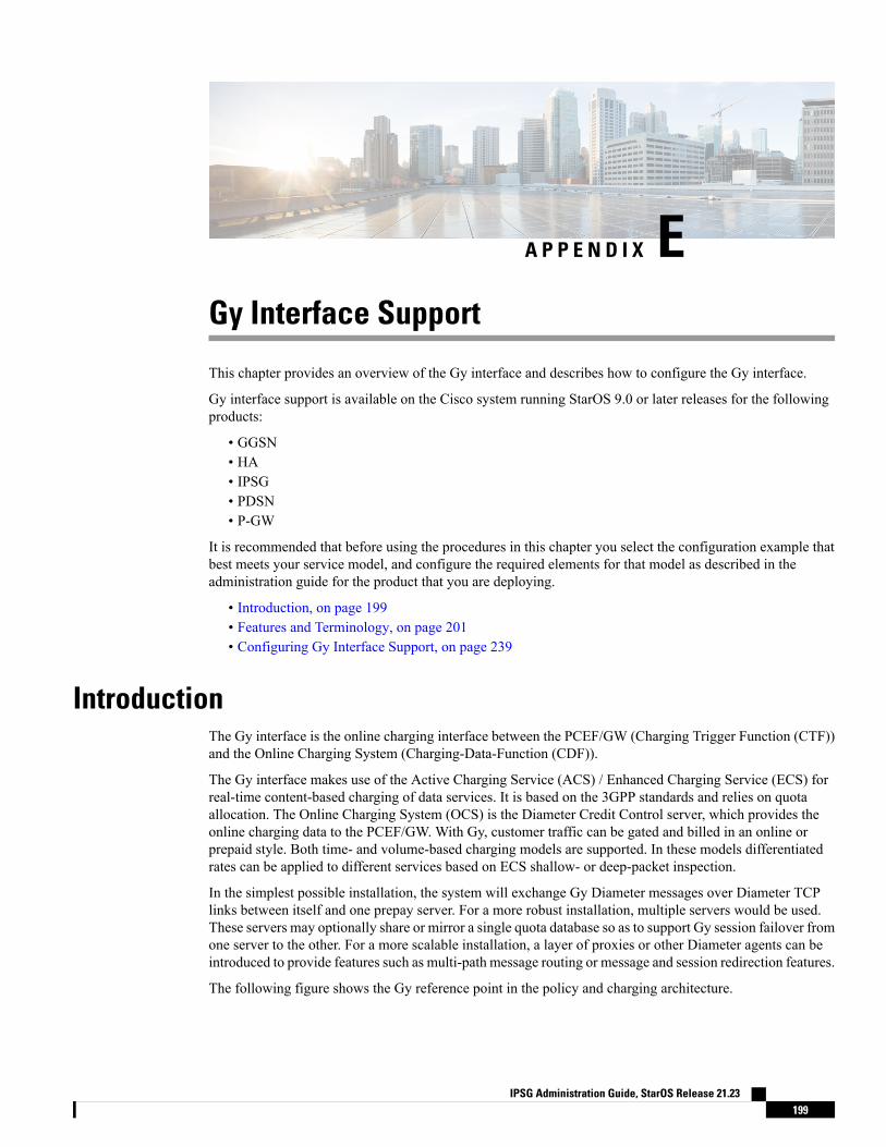
A P P E N D I X EGy Interface Support
This chapter provides an overview of the Gy interface and describes how to configure the Gy interface.
Gy interface support is available on the Cisco system running StarOS 9.0 or later releases for the followingproducts:
• GGSN• HA• IPSG• PDSN• P-GW
It is recommended that before using the procedures in this chapter you select the configuration example thatbest meets your service model, and configure the required elements for that model as described in theadministration guide for the product that you are deploying.
• Introduction, on page 199• Features and Terminology, on page 201• Configuring Gy Interface Support, on page 239
IntroductionThe Gy interface is the online charging interface between the PCEF/GW (Charging Trigger Function (CTF))and the Online Charging System (Charging-Data-Function (CDF)).
The Gy interface makes use of the Active Charging Service (ACS) / Enhanced Charging Service (ECS) forreal-time content-based charging of data services. It is based on the 3GPP standards and relies on quotaallocation. The Online Charging System (OCS) is the Diameter Credit Control server, which provides theonline charging data to the PCEF/GW. With Gy, customer traffic can be gated and billed in an online orprepaid style. Both time- and volume-based charging models are supported. In these models differentiatedrates can be applied to different services based on ECS shallow- or deep-packet inspection.
In the simplest possible installation, the system will exchange Gy Diameter messages over Diameter TCPlinks between itself and one prepay server. For a more robust installation, multiple servers would be used.These servers may optionally share or mirror a single quota database so as to support Gy session failover fromone server to the other. For a more scalable installation, a layer of proxies or other Diameter agents can beintroduced to provide features such as multi-path message routing or message and session redirection features.
The following figure shows the Gy reference point in the policy and charging architecture.
IPSG Administration Guide, StarOS Release 21.23199
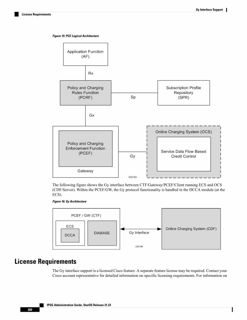
Figure 15: PCC Logical Architecture
The following figure shows the Gy interface between CTF/Gateway/PCEF/Client running ECS and OCS(CDF/Server). Within the PCEF/GW, the Gy protocol functionality is handled in the DCCA module (at theECS).
Figure 16: Gy Architecture
License RequirementsThe Gy interface support is a licensed Cisco feature. A separate feature license may be required. Contact yourCisco account representative for detailed information on specific licensing requirements. For information on
IPSG Administration Guide, StarOS Release 21.23200
Gy Interface SupportLicense Requirements
installing and verifying licenses, refer to the Managing License Keys section of the Software ManagementOperations chapter in the System Administration Guide.
Supported StandardsGy interface support is based on the following standards:
• IETF RFC 4006: Diameter Credit Control Application; August 2005
• 3GPP TS 32.299 V9.6.0 (2010-12) 3rd Generation Partnership Project; Technical Specification GroupServices and System Aspects; Telecommunication management; Charging management; Diametercharging applications (Release 9)
Features and TerminologyThis section describes features and terminology pertaining to Gy functionality.
Charging Scenarios
Online charging for events ("Immediate Event Charging" and "Event Charging with Reservation") is notsupported. Only "Session Charging with Reservation" is supported.
Important
Session Charging with ReservationSession Charging with Unit Reservation is used for credit control of sessions.
Decentralized Unit Determination and Centralized Rating
In this scenario, the CTF requests the reservation of units prior to session supervision. An account debitoperation is carried out following the conclusion of session termination.
Centralized Unit Determination and Centralized Rating
In this scenario, the CTF requests the OCS to reserve units based on the session identifiers specified by theCTF. An account debit operation is carried out following the conclusion of session.
Decentralized Unit Determination and Decentralized Rating
Decentralized Rating is not supported in this release. Decentralized Unit determination is done using CLIconfiguration.
Important
In this scenario, the CTF requests the OCS to assure the reservation of an amount of the specified number ofmonetary units from the subscriber's account. An account debit operation that triggers the deduction of theamount from the subscriber's account is carried out following the conclusion of session establishment.
IPSG Administration Guide, StarOS Release 21.23201
Gy Interface SupportSupported Standards
Basic Operations
Immediate Event Charging is not supported in this release. "Reserve Units Request" and "Reserve UnitsResponse" are done for Session Charging and not for Event Charging.
Important
Online credit control uses the basic logical operations "Debit Units" and "Reserve Units".
• Debit Units Request; sent from CTF to OCS: After receiving a service request from the subscriber, theCTF sends a Debit Units Request to the OCS. The CTFmay either specify a service identifier (centralisedunit determination) or the number of units requested (decentralised unit determination). For refundpurpose, the CTF sends a Debit Units Request to the OCS as well.
• Debit Units Response; sent from OCS to CTF: The OCS replies with a Debit Units Response, whichinforms the CTF of the number of units granted as a result of the Debit Units Request. This includes thecase where the number of units granted indicates the permission to render the requested service. Forrefund purpose, the OCS replies with a Debit Units Response.
• Reserve Units Request; sent from CTF to OCS: Request to reserve a number of units for the service tobe provided by an CTF. In case of centralised unit determination, the CTF specifies a service identifierin the Reserve Unit Request, and the OCS determines the number of units requested. In case ofdecentralised unit determination, the number of units requested is specified by the CTF.
• Reserve Units Response; sent from OCS to CTF: Response from the OCS which informs the CTF of thenumber of units that were reserved as a result of the "Reserve Units Request".
Session Charging with Unit Reservation (SCUR) use both the "Debit Units" and "Reserve Units" operations.SCUR uses the Session Based Credit Control procedure specified in RFC 4006. In session charging with unitreservation, when the "Debit Units" and "Reserve Units" operations are both needed, they are combined inone message.
Cost-Information, Remaining-Balance, and Low-Balance-Indication AVPs are not supported.Important
The consumed units are deducted from the subscriber's account after service delivery. Thus, the reserved andconsumed units are not necessarily the same. Using this operation, it is also possible for the CTF to modifythe current reservation, including the return of previously reserved units.
Re-authorizationThe server may specify an idle timeout associated with a granted quota. Alternatively, the client may have aconfigurable default value. The expiry of that timer triggers a re-authorization request.
Mid-session service events (re-authorisation triggers) may affect the rating of the current service usage. Theserver may instruct the credit control client to re-authorize the quota upon a number of different session relatedtriggers that can affect the rating conditions.
When a re-authorization is trigger, the client reports quota usage. The reason for the quota being reported isnotified to the server.
IPSG Administration Guide, StarOS Release 21.23202
Gy Interface SupportBasic Operations
Threshold based Re-authorization TriggersThe server may optionally include an indication to the client of the remaining quota threshold that triggers aquota re-authorization.
Termination ActionThe server may specify to the client the behavior on consumption of the final granted units; this is known astermination action.
Diameter Base ProtocolTheDiameter Base Protocol maintains the underlying connection between the Diameter Client and the DiameterServer. The connection between the client and server is TCP based. There are a series of message exchangesto check the status of the connection and the capabilities.
• Capabilities Exchange Messages: Capabilities Exchange Messages are exchanged between the diameterpeers to know the capabilities of each other and identity of each other.
• Capabilities Exchange Request (CER): This message is sent from the client to the server to knowthe capabilities of the server.
• Capabilities Exchange Answer (CEA): This message is sent from the server to the client in responseto the CER message.
Acct-Application-Id is not parsed and if sent will be ignored by the PCEF/GW.In case the Result-Code is not DIAMETER_SUCCESS, the connection to thepeer is closed.
Important
• Device Watchdog Request (DWR): After the CER/CEA messages are exchanged, if there is no moretraffic between peers for a while, to monitor the health of the connection, DWR message is sent fromthe client. The Device Watchdog timer (Tw) is configurable in PCEF/GW and can vary from 6 through30 seconds. A very low value will result in duplication of messages. The default value is 30 seconds. Ontwo consecutive expiries of Tw without a DWA, the peer is taken to be down.
DWR is sent only after Tw expiry after the last message that came from the server.Say if there is continuous exchange of messages between the peers, DWR mightnot be sent if (Current Time - Last message received time from server) is lessthan Tw.
Important
• Device Watchdog Answer (DWA): This is the response to the DWR message from the server. This isused to monitor the connection state.
• Disconnect Peer Request (DPR): This message is sent to the peer to inform to shutdown the connection.PCEF/GWonly receives this message. There is no capability currently to send the message to the diameterserver.
IPSG Administration Guide, StarOS Release 21.23203
Gy Interface SupportThreshold based Re-authorization Triggers
• Disconnect Peer Answer (DPA): This message is the response to the DPR request from the peer. Onreceiving the DPR, the peer sends DPA and puts the connection state to "DO NOT WANT TO TALKTO YOU" state and there is no way to get the connection back except for reconfiguring the peer again.
A timeout value for retrying the disconnected peer must be provided.
• Tw Timer Expiry Behavior: The connection between the client and the server is taken care by theDIABASE application. When two consecutive Tw timers are expired, the peer state is set to idle and theconnection is retried to be established. All the active sessions on the connection are then transferred tothe secondary connection if one is configured. All new session activations are also tried on the secondaryconnection.
There is a connection timeout interval, which is also equivalent to Tw timer, wherein after a CER hasbeen sent to the server, if there is no response received while trying to reestablish connection, theconnection is closed and the state set to idle.
Diameter Credit Control ApplicationThe Diameter Credit Control Application (DCCA) is a part of the ECS subsystem. For every prepaid customerwith Diameter Credit Control enabled, whenever a session comes up, the Diameter server is contacted andquota for the subscriber is fetched.
Quota BehaviorVarious forms of quotas are present that can be used to charge the subscriber in an efficient way. Variousquota mechanisms provide the end user with a variety of options to choose from and better handling of quotasfor the service provider.
Time Quotas
The Credit-Control server can send the CC-Time quota for the subscriber during any of the interrogation ofclient with it. There are also various mechanisms as discussed below which can be used in conjunction withtime quota to derive variety of methods for customer satisfaction.
• Quota Consumption Time: The server can optionally indicate to the client that the quota consumptionmust be stopped after a period equal to the "Quota Consumption Time" in which no packets are receivedor at session termination, whichever is sooner. The idle period equal to the Quota Consumption Time isincluded in the reported usage. The quota is consumed normally during gaps in traffic of duration lessthan or equal to the Quota-Consumption-Time. Quota consumption resumes on receipt of a further packetbelonging to the service data flow.
If packets are allowed to flow during a CCR (Update)/CCA exchange, and the Quota-Consumption-TimeAVP value in the provided quota is the same as in the previously provided quota, then theQuota-Consumption-Time runs normally through this procedure. For example, if 5 seconds of a 10 secondQCT timer have passed when a CCR(U) is triggered, and the CCA(U) returns 2 seconds later, then theQCT timer will expire 3 seconds after the receipt of the CCA and the remaining unaccounted 5 secondsof usage will be recorded against the new quota even though no packets were transmitted with the newquota.
A locally configurable default value in the client can be used if the server does not send the QCT in theCCA.
• Combinational Quota: Discrete-Time-Period (DTP) and Continuous-Time-Period (CTP) definesmechanisms that extends and generalize the Quota-Consumption-Time for consuming time-quota.
IPSG Administration Guide, StarOS Release 21.23204
Gy Interface SupportDiameter Credit Control Application
• Both DTP and CTP uses a "base-time-interval" that is used to create time-envelopes of quota used.
• Instead of consuming the quota linearly, DTP and CTP consumes the granted quota discretely inchunks of base-time-interval at the start of the each base-time-interval.
• Selection of one of this algorithm is based on the "Time-Quota-Mechanism" AVP sent by the serverin CCA.
• Reporting usage can also be controlled by Envelope-Reporting AVP sent by the server in CCAduring the quota grant. Based on the value of this AVP, the usage can be reported either as the usageper envelope or as usual cumulative usage for that grant.
• Discrete-Time-Period: The base-time-interval defines the length of the Discrete-Time-Period. So eachtime-envelope corresponds to exactly one Discrete-Time-Period. So when a traffic is detected, an envelopeof size equal to Base-Time-Interval is created. The traffic is allowed to pass through the time-envelope.Once the traffic exceeds the base-time-interval another new envelope equal to the base-time-interval iscreated. This continues till the quota used exceeds the quota grant or reaches the threshold limit for thatquota.
• Continuous-Time-Period: Continuous time periodmechanism constructs time envelope out of consecutivebase-time intervals in which the traffic occurred up to and including a base time interval which containsno traffic. Therefore the quota consumption continues within the time envelope, if there was traffic inthe previous base time interval. After an envelope has closed, then the quota consumption resumes onlyon the first traffic following the closure of the envelope. The envelope for CTP includes the last basetime interval which contains no traffic.
The size of the envelope is not constant as it was in Parking meter. The end of the envelope can only bedetermined retrospectively.
• Quota Hold Time: The server can specify an idle timeout associated with a granted quota using theQuota-Holding-Time AVP. If no traffic associated with the quota is observed for this time, the clientunderstands that the traffic has stopped and the quota is returned to the server. The client starts the quotaholding timer when quota consumption ceases. This is always when traffic ceases, i.e. the timer isre-started at the end of each packet. It applies equally to the granted time quota and to the granted volumequota. The timer is stopped on sending a CCR and re-initialized on receiving a CCA with the previousused value or a new value of Quota-Holding-Time if received.
Alternatively, if this AVP is not present, a locally configurable default value in the client is used. AQuota-Holding-Time value of zero indicates that this mechanism is not used.
• Quota Validity Time: The server can optionally send the validity time for the quota during the interrogationwith the client. The Validity-Time AVP is present at the MSCC level and applies equally to the entirequota that is present in that category. The quota gets invalidated at the end of the validity time and aCCR-Update is sent to the server with the Used-Service-Units AVP and the reporting reason asVALIDITY_TIME. The entire quota present in that category will be invalidated uponQuota-Validity-Timeexpiry and traffic in that category will be passed or dropped depending on the configuration, till aCCA-Update is received with quota for that category.
Validity-Time of zero is invalid. Validity-Time is relative and not absolute.
In releases prior to 17.0, the AVP "SN-Remaining-Service-Unit" was not sent in the CCR-T and CCR-Umessages with reporting Reason FINAL when the FUI action was received as Redirect and the grantedunits was zero in CCA. In 17.0 and later releases, for the Final-Reporting, the AVP"SN-Remaining-Service-Unit" will be encoded.
IPSG Administration Guide, StarOS Release 21.23205
Gy Interface SupportGy Interface Support
The "SN-Remaining-Service-Unit" AVP behavior is inherited from "Used-Service-Unit" AVP. ThisFinal-Reporting is missing for the Remaining-Service-Unit AVP, which is now incorporated.
Volume Quota
The server sends the CC-Total-Octets AVP to provide volume quota to the subscriber. DCCA currentlysupports only CC-Total-Octets AVP, which applies equally to uplink and downlink packets. If the total ofuplink and downlink packets exceeds the CC-Total-Octets granted, the quota is assumed to be exhausted.
If CC-Input-Octets and/or CC-Output-Octets is provided, the quota is counted against CC-Input-Octets and/orCC-Output-Octets respectively.
Restricting usages based on CC-Input-Octets and CC-Output-Octets is not supported in this release.Important
Units Quota
The server can also send a CC-Service-Specific-Units quota which is used to have packets counted as units.The number of units per packet is a configurable option.
Granting Quota
Gy implementation assumes that whenever the CC-Total-Octets AVP is present, volume quota has beengranted for both uplink and downlink.
If the Granted-Service-Unit contains no data, Gy treats it as an invalid CCA.
If the values are zero, it is assumed that no quota was granted.
If the AVP contains the sub AVPs without any data, it is assumed to be infinite quota.
Additional parameters relating to a category like QHT, QCT is set for the category after receiving a validvolume or time grant.
If a default quota is configured for the subscriber, and subscriber traffic is received it is counted against thedefault quota. The default quota is applicable only to the initial request and is not regranted during the courseof the session. If subscriber disconnects and reconnects, the default quota will be applied again for the initialrequest.
Requesting Quota
Quotas for a particular category type can be requested using the Requested-Service-Unit AVP in the CCR.The MSCC is filled with the Rating-Group AVP which corresponds to the category of the traffic andRequested-Service-Unit (RSU) AVP without any data.
The Requested-Service-Unit can contain the CCAVPs used for requesting specific quantity of time or volumegrant. Gy CLI can be used to request quota for a category type.
Alternatively quota can also be requested from the server preemptively for a particular category in CCR- I.When the server grants preemptive quota through the Credit control answer response, the quota will be usedonly when traffic is hit for that category. Quota can be preemptively requested from the Credit Control serverfrom the CLI.
In 12.3 and earlier releases, when no pre-emptive quota request is present in CCR-I, on hitting serverunreachable state for initial request, MSCC AVP with RSU is present in the CCR-I on server retries. Release
IPSG Administration Guide, StarOS Release 21.23206
Gy Interface SupportVolume Quota
14.0 onwards, the MSCC AVP is skipped in the CCR-I on server retries. Corresponding quota usage will bereported in the next CCR-U (MSCC AVP with USU and RSU).
Reporting Quota
Quotas are reported to the server for number of reasons including:
• Threshold• QHT Expiry• Quota Exhaustion• Rating Condition Change• Forced Reauthorization• Validity Time Expiry• Final during Termination of Category Instance from Server
For the above cases except for QHT and Final, the Requested-Service-Unit AVP is present in the CCR.
Reporting Reason is present in CCR to let the server know the reason for the reporting of Quota. TheReporting-Reason AVP can be present either in MSCC level or at Used Service Unit (USU) level dependingon whether the reason applies to all quotas or to single quota.
When one of these conditions is met, a CCR Update is sent to the server containing aMultiple-Services-Credit-Control AVP(s) indicating the reason for reporting usage in the Reporting-Reasonand the appropriate value(s) for Trigger, where appropriate. Where a threshold was reached, the DCCA stillhas the amount of quota available to it defined by the threshold.
For all other reporting reasons the client discards any remaining quota and either discards future user trafficmatching this category or allows user traffic to pass, or buffers traffic according to configuration.
For Reporting-Reason of Rating Condition Change, Gy requires the Trigger Type AVP to be present as partof the CCR to indicate which trigger event caused the reporting and re-authorization request.
For Reporting-Reason of end user service denied, this happens when a category is blacklisted by the creditcontrol server, in this case a CCR-U is sent with used service unit even if the values as zero. When more quotais received from the server for that particular category, the blacklisting is removed.
If a default quota has been set for the subscriber then the usage from the default quota is deducted from theinitial GSU received for the subscriber for the Rating Group or Rating Group and Service ID combination.
Default Quota Handling
• If default quota is set to 0, no data is passed/reported.
• If default quota is configured and default quota is not exhausted before OCS responds with quota, trafficis passed. Initial default quota used is counted against initial quota allocated. If quota allocated is lessthan the actual usage then actual usage is reported and additional quota is requested. If no additionalquota is available then traffic is denied.
• If default quota is not exhausted before OCS responds with denial of quota, gateway blocks traffic afterOCS response. Gateway will report usage on default quota even in this case in CCR-U (FINAL) orCCR-T.
• If default quota is consumed before OCS responds, if OCS is not declared dead (see definition in usecase 1 above) then traffic is blocked until OCS responds.
IPSG Administration Guide, StarOS Release 21.23207
Gy Interface SupportReporting Quota
Thresholds
The Gy client supports the following threshold types:
• Volume-Quota-Threshold• Time-Quota-Threshold• Units-Quota-Threshold
A threshold is always associated with a particular quota and a particular quota type. in theMultiple-Services-Credit-Control AVP, the Time-Quota-Threshold, Volume-Quota-Threshold, andUnit-Quota-Threshold are optional AVPs.
They are expressed as unsigned numbers and the units are seconds for time quota, octets for volume quotaand units for service specific quota. Once the quota has reached its threshold, a request for more quotas istriggered toward the server. User traffic is still allowed to flow. There is no disruption of traffic as the userstill has valid quota.
The Gy sends a CCR-U with a Multiple-Services-Credit-Control AVP containing usage reported in one ormore User-Service-Unit AVPs, the Reporting-Reason set to THRESHOLD and the Requested-Service-UnitAVP without data.
When quota of more than one type has been assigned to a category, each with its own threshold, then thethreshold is considered to be reached once one of the unit types has reached its threshold even if the otherunit type has not been consumed.
When reporting volume quota, the DCCA always reports uplink and downlink separately using theCC-Input-Octets AVP and the CC-Output-Octets AVP, respectively.
On receipt of more quotas in the CCA the Gy discard any quota not yet consumed since sending the CCR.Thus the amount of quota now available for consumption is the new amount received less any quota that mayhave been consumed since last sending the CCR.
Conditions for Reauthorization of Quota
Quota is re-authorized/requested from the server in case of the following scenarios:
• Threshold is hit
• Quota is exhausted
• Validity time expiry
• Rating condition change:
• Cellid change: Applicable only to GGSN and P-GW implementations.
• LAC change: Applicable only to GGSN and P-GW implementations.
• QoS change
• RAT change
• SGSN/Serving-Node change: Applicable only to GGSN and P-GW implementations.
Discarding or Allowing or Buffering Traffic to Flow
Whenever Gy is waiting for CCA from the server, there is a possibility of traffic for that particular traffic typeto be encountered in the Gy. The behavior of what needs to be done to the packet is determined by the
IPSG Administration Guide, StarOS Release 21.23208
Gy Interface SupportThresholds
configuration. Based on the configuration, the traffic is either allowed to pass or discarded or buffered whilewaiting for CCA from the server.
This behavior applies to all interrogation of client with server in the following cases:
• No quota present for that particular category
• Validity timer expiry for that category
• Quota exhausted for that category
• Forced Reauthorization from the server
In addition to allowing or discarding user traffic, there is an option available in case of quota exhausted or noquota circumstances to buffer the traffic. This typically happens when the server has been requested for morequota, but a valid quota response has not been received from the server, in this case the user traffic is bufferedand on reception of valid quota response from the server the buffered traffic is allowed to pass through.
Procedures for Consumption of Time Quota
• QCT is zero: When QCT is deactivated, the consumption is on a wall-clock basis. The consumption iscontinuous even if there is no packet flow.
• QCT is active: When QCT is present in the CCA or locally configured for the session, then theconsumption of quota is started only at the time of first packet arrival. The quota is consumed normallytill last packet arrival plus QCT time and is passed till the next packet arrival.
If the QCT value is changed during intermediate interrogations, then the new QCT comes into effectfrom the time the CCA is received. For instance, if the QCT is deactivated in the CCA, then quotaconsumptions resume normally evenwithout any packet flow. Or if the QCT is activated from deactivation,then the quota consumption resume only after receiving the first packet after CCA.
• QHT is zero: When QHT is deactivated, the user holds the quota indefinitely in case there is no furtherusage (for volume quota and with QCT for time quota). QHT is active between the CCA and the nextCCR.
• QHT is non-zero: When QHT is present in CCA or locally configured for the session, then after a idletime of QHT, the quota is returned to the server by sending a CCR-Update and reporting usage of thequota. On receipt of CCR-U, the server does not grant quota. QHT timer is stopped on sending the CCRand is restarted only if QHT is present in the CCA.
QHT timer is reset every time a packet arrives.
Envelope Reporting
The server may determine the need for additional detailed reports identifying start time and end times ofspecific activity in addition to the standard quota management. The server controls this by sending a CCAwith Envelope-Reporting AVP with the appropriate values. The DCCA client, on receiving the command,will monitor for traffic for a period of time controlled by the Quota-Consumption-Time AVP and report eachperiod as a single envelope for each Quota-Consumption-Time expiry where there was traffic. The servermay request envelope reports for just time or time and volume. Reporting the quota back to the server, iscontrolled by Envelope AVPwith Envelope-Start-Time and Envelope-End-Time along with usage information.
IPSG Administration Guide, StarOS Release 21.23209
Gy Interface SupportProcedures for Consumption of Time Quota
Credit Control Request
Credit Control Request (CCR) is the message that is sent from the client to the server to request quota andauthorization. CCR is sent before the establishment of MIP session, and at the termination of the MIP session.It can be sent during service delivery to request more quotas.
• Credit Control Request - Initial (CCR-I)
• Credit Control Request - Update (CCR-U)
• Credit Control Request - Terminate (CCR-T)
• Credit Control Answer (CCA)
• Credit Control Answer - Initial (CCA-I)
• Credit Control Answer - Update (CCA-U)
If the MSCC AVP is missing in CCA-U it is treated as invalid CCA and the session is terminated.
• Credit Control Answer - Terminate (CCA-T)
In releases prior to 16.0, CCR-T was immediately sent without waiting for CCA-U if the call was cleared andthere was a pending CCA-U. In 16.0 and later releases, if call is cleared when there is a pending update, thegateway will wait for CCA-U to arrive or timeout to happen (whichever happens first).
In releases prior to 20, CCR-Ts were not reported over Gy interface when the calls were terminated due toaudit failure during ICSR switchover. In 20 and later releases, DCCA allows generation of CCR-Ts in thisscenario.
The following figure depicts the call flow for a simple call request in the GGSN/P-GW/IPSG Gyimplementation.
IPSG Administration Guide, StarOS Release 21.23210
Gy Interface SupportCredit Control Request
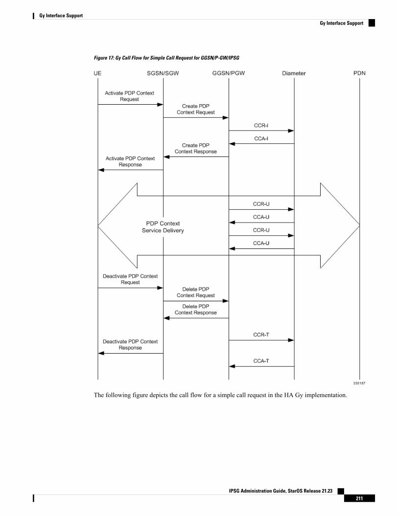
Figure 17: Gy Call Flow for Simple Call Request for GGSN/P-GW/IPSG
The following figure depicts the call flow for a simple call request in the HA Gy implementation.
IPSG Administration Guide, StarOS Release 21.23211
Gy Interface SupportGy Interface Support
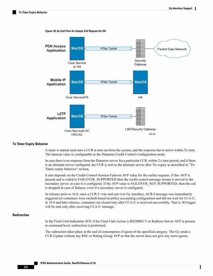
Figure 18: Gy Call Flow for Simple Call Request for HA
Tx Timer Expiry Behavior
A timer is started each time a CCR is sent out from the system, and the response has to arrive within Tx time.The timeout value is configurable in the Diameter Credit Control Configuration mode.
In case there is no response from the Diameter server for a particular CCR, within Tx time period, and if thereis an alternate server configured, the CCR is sent to the alternate server after Tw expiry as described in "TwTimer expiry behavior" section.
It also depends on the Credit-Control-Session-Failover AVP value for the earlier requests. If this AVP ispresent and is coded to FAILOVER_SUPPORTED then the credit-control message stream is moved to thesecondary server, in case it is configured. If the AVP value is FAILOVER_NOT SUPPORTED, then the callis dropped in case of failures, even if a secondary server is configured.
In releases prior to 16.0, once a CCR-U was sent out over Gy interface, ACR-I message was immediatelytriggered (or containers were cached) based on policy accounting configuration and did not wait for CCA-U.In 16.0 and later releases, containers are closed only after CCA-U is received successfully. That is, Rf triggerwill be sent only after receiving CCA-U message.
Redirection
In the Final-Unit-Indication AVP, if the Final-Unit-Action is REDIRECT or Redirect-Server AVP is presentat command level, redirection is performed.
The redirection takes place at the end of consumption of quota of the specified category. The Gy sends aCCR-Update without any RSU or Rating-Group AVP so that the server does not give any more quotas.
IPSG Administration Guide, StarOS Release 21.23212
Gy Interface SupportTx Timer Expiry Behavior
If the Final-Unit-Action AVP is RESTRICT_ACCESS, then according to the settings in Restriction-Filter-RuleAVP or Filter-Id AVP. Gy sends CCR-Update to the server with used quota.
Triggers
The Diameter server can provide with the triggers for which the client should reauthorize a particular category.The triggers can be configured locally as well but whatever trigger is present in the CCA from the server willhave precedence.
In this release, Gy triggers are not supported for HA.Important
The trigger types that are supported are:
• SGSN/Serving-Node Change
• QoS Change - Any
• RAT Change
• LAC Change
• CellID Change
On any event as described in the Trigger type happens, the client reauthorizes quota with the server. Thereporting reason is set as RATING_CONDITION_CHANGE.
Tariff Time Change
The tariff change mechanism applies to each category instance active at the time of the tariff change wheneverthe server indicated it should apply for this category.
The concept of dual coupon is supported. Here the server grants two quotas, which is accompanied by aTariff-Time-Change, in this case the first granted service unit is used until the tariff change time, once thetariff change time is reached the usage is reported up to the point and any additional usage is not accumulated,and then the second granted service unit is used.
If the server expects a tariff change to occur within the validity time of the quota it is granting, then it includesthe Tariff-Time-Change AVP in the CCA. The DCCA report usage, which straddles the change time bysending two instances of the Used-Service-Unit AVP, one with Tariff-Change-Usage set toUNIT_BEFORE_TARIFF_CHANGE, and one with Tariff-Change-Usage set toUNIT_AFTER_TARIFF_CHANGE, and this independently of the type of units used by application. BothVolume and Time quota are reported in this way.
The Tariff time change functionality can as well be done using Validity-Time AVP, where in the Validity-Timeis set to Tariff Time change and the client will reauthorize and get quota at Validity-Time expiry. This willtrigger a lot of reauthorize request to the server at a particular time and hence is not advised.
Tariff-Time-Usage AVP along with the Tariff-Time-Change AVP in the answer message to the client indicatesthat the quotas defined in Multiple-Services-Credit-Control are to be used before or after the Tariff Timechange. Two separate quotas are allocated one for before Tariff-Time-Change and one for afterTariff-Time-Change. This gives the flexibility to the operators to allocate different quotas to the users fordifferent periods of time. In this case, the DCCA should not send the Before-Usage and After-Usage countsin the update messages to the server. When Tariff-Time-Change AVP is present without Tariff-Time-UsageAVP in the answer message, then the quota is used as in single quota mechanism and the client has to sendbefore usage and after usage quotas in the updates to the server.
IPSG Administration Guide, StarOS Release 21.23213
Gy Interface SupportTriggers
In this release, Gy does not support UNIT_INDETERMINATE value.Important
Final Unit Indication
The Final-Unit-Indication AVP can be present in the CCA from the server to indicate that the given quota isthe final quota from the server and the corresponding action as specified in the AVP needs to be taken.
Final Unit Indication at Command Level
Gy currently does not support FUI AVP at command level. If this AVP is present at command level it isignored. If the FUI AVP is present at command level and the Final-Unit-Action AVP set to TERMINATE,Gy sends a CCR-Terminate at the expiry of the quota, with all quotas in the USU AVP.
FUI AVP at command level is only supported for Terminate action.Important
Final Unit Indication at MSCC Level
If the Final-Unit-Indication AVP is present at MSCC level, and if the Final-Unit-Action AVP is set toTERMINATE, a CCR-Update is sent at the expiry of the allotted quota and report the usage of the categorythat is terminated.
For information on redirection cases refer to the Redirection, on page 212.
Credit Control Failure Handling
CCFH AVP defines what needs to be done in case of failure of any type between the client and the server.The CCFH functionality can be defined in configuration but if the CCFH AVP is present in the CCA, it takesprecedence. CCFH AVP gives flexibility to have different failure handling.
Gy supports the following Failure Handling options:
• TERMINATE• CONTINUE• RETRY AND TERMINATE
CCFH with Failover Supported
In case there is a secondary server is configured and if the CC-Session-Failover AVP is set toFAILOVER_SUPPORTED, the following behavior takes place:
• Terminate: On any Tx expiry for the CCR-I the message is discarded and the session is torn down. Incase of CCR-Updates and Terminates the message is sent to the secondary server after response timeoutand the session is proceeded with the secondary server. In case there is a failure with the secondary servertoo, the session is torn down.
• Continue: On any Tx expiry, the message is sent to the secondary server after response timeout and thesession is proceeded with the secondary server. In case there is a failure with the secondary server too,the session is still established, but without quota management.
• Retry and Terminate: On any Tx expiry, the message is sent to the secondary server after the responsetimeout. In case there is a failure with secondary server too, the session is taken down.
IPSG Administration Guide, StarOS Release 21.23214
Gy Interface SupportFinal Unit Indication
CCFH with Failover Not Supported
In case there is a secondary server configured and if the CC-Session-Failover AVP is set toFAILOVER_NOT_SUPPORTED, the following behavior takes place as listed below. Same is the case ifthere is no secondary server configured on the system.
• Terminate: On any Tx expiry, the session is taken down.
• Continue: On any Tx expiry, the session is still established, but without quota management.
• Retry and Terminate: On any Tx expiry, the session is taken down.
Failover Support
The CC-Session-Failover AVP and the Credit-Control-Failure-Handling (CCFH) AVP may be returned bythe CC server in the CCA-I, and are used by the DCCA to manage the failover procedure. If they are presentin the CCA they override the default values that are locally configured in the system.
If the CC-Session-Failover is set to FAILOVER_NOT_SUPPORTED, a CC session will never be moved toan alternative Diameter Server.
If the value of CC-Session-Failover is set to FAILOVER_SUPPORTED, then the Gy attempts to move theCC session to the alternative server when it considers a request to have failed, i.e:
• On receipt of result code "DIAMETER_UNABLE_TO_DELIVER", "DIAMETER_TOO_BUSY", or"DIAMETER_LOOP_DETECTED".
• On expiry of the request timeout.
• On expiry of Tw without receipt of DWA, if the server is connected directly to the client.
The CCFH determines the behavior of the client in fault situations. If the Tx timer expires then based on theCCFH value the following actions are taken:
• CONTINUE: Allow the MIP session and user traffic for the relevant category or categories to continue,regardless of the interruption (delayed answer). Note that quota management of other categories is notaffected.
• TERMINATE: Terminate the MIP session, which affects all categories.
• RETRY_AND_TERMINATE: Allow the MIP session and user traffic for the relevant category orcategories to continue, regardless of the interruption (delayed answer). The client retries to send the CCRwhen it determines a failure-to-send condition and if this also fails, the MIP session is then terminated.
After the failover action has been attempted, and if there is still a failure to send or temporary error, dependingon the CCFH action, the following action is taken:
• CONTINUE: Allow the MIP session to continue.
• TERMINATE: Terminate the MIP session.
• RETRY_AND_TERMINATE: Terminate the MIP session.
Recovery Mechanisms
DCCA supports a recovery mechanism that is used to recover sessions without much loss of data in case ofSession Manager failures. There is a constant check pointing of Gy data at regular intervals and at importantevents like update, etc.
IPSG Administration Guide, StarOS Release 21.23215
Gy Interface SupportCCFH with Failover Not Supported
TheDCCA supports maximum of three bearers (including default) for the ICSRCheckpointing and Recovery.When more than three bearers are configured in the DCCA, checkpointing occurs from Active to Standby forall the bearers. However, during recovery, only the first three bearers are recovered and the rest remain in thememory consuming resources.
Important
For more information on recovery mechanisms, please refer to the System Administration Guide.
Error Mechanisms
Following are supported Error Mechanisms.
Unsupported AVPs
All unsupported AVPs from the server with "M" bit set are ignored.
Invalid Answer from Server
If there is an invalid answer from the server, Gy action is dependent on the CCFH setting:
• In case of continue, the MIP session context is continued without further control from Gy.
• In case of terminate and retry-and-terminate, the MIP session is terminated and a CCR-T is sent to thediameter server.
Result Code Behavior
• DIAMETER_RATING_FAILED: On reception of this code, Gy discards all traffic for that category anddoes not request any more quota from the server. This is supported at the MSCC level and not at thecommand level.
• DIAMETER_END_USER_SERVICE_DENIED: On reception of this code, Gy temporarily blackliststhe category and further traffic results in requesting new quota from the server. This is supported at theMSCC level and not at the command level.
• DIAMETER_CREDIT_LIMIT_REACHED: On reception of this code, Gy discards all traffic for thatcategory and waits for a configured time, after which if there is traffic for the same category requestsquota from the server. This is supported at the MSCC level and not at the command level.
• DIAMETER_CREDIT_CONTROL_NOT_APPLICABLE: On reception of this code, Gy allows thesession to establish, but without quota management. This is supported only at the command level andnot at the MSCC level.
• DIAMETER_USER_UNKNOWN: On reception of this code, DCCA does not allow the credit controlsession to get established, the session is terminated. This result code is supported only at the commandlevel and not at the MSCC level.
For all other permanent/transient failures, Gy action is dependent on the CCFH setting.
Supported AVPsThe Gy functionality supports the following AVPs:
• Supported Diameter Credit Control AVPs specified in RFC 4006:
IPSG Administration Guide, StarOS Release 21.23216
Gy Interface SupportError Mechanisms
• CC-Input-Octets (AVP Code: 412):
Gy supports this AVP only in USU.
• CC-Output-Octets (AVP Code: 414):
Gy supports this AVP only in USU.
• CC-Request-Number (AVP Code: 415)
• CC-Request-Type (AVP Code: 416):
Gy currently does not support EVENT_REQUEST value.
• CC-Service-Specific-Units (AVP Code: 417)
• CC-Session-Failover (AVP Code: 418)
• CC-Time (AVP Code: 420):
Gy does not support this AVP in RSU.
• CC-Total-Octets (AVP Code: 421):
Gy does not support this AVP in RSU.
• Credit-Control-Failure-Handling (AVP Code: 427)
• Final-Unit-Action (AVP Code: 449):
Supported at Multiple-Services-Credit-Control grouped AVP level and not at command level.
• Final-Unit-Indication (AVP Code: 430):
Fully supported at Multiple-Services-Credit-Control grouped AVP level and partially supported(TERMINATE) at command level.
• Granted-Service-Unit (AVP Code: 431)
• Multiple-Services-Credit-Control (AVP Code: 456)
• Multiple-Services-Indicator (AVP Code: 455)
• Rating-Group (AVP Code: 432)
• Redirect-Address-Type (AVP Code: 433):
Gy currently supports only URL (2) value.
• Redirect-Server (AVP Code: 434)
• Redirect-Server-Address (AVP Code: 435)
• Requested-Service-Unit (AVP Code: 437)
• Result-Code (AVP Code: 268)
• Service-Context-Id (AVP Code: 461)
• Service-Identifier (AVP Code: 439)
• Subscription-Id (AVP Code: 443)
• Subscription-Id-Data (AVP Code: 444)
IPSG Administration Guide, StarOS Release 21.23217
Gy Interface SupportGy Interface Support
• Subscription-Id-Type (AVP Code: 450)
• Tariff-Change-Usage (AVP Code: 452):
Gy does NOT support UNIT_INDETERMINATE (2) value.
• Tariff-Time-Change (AVP Code: 451)
• Used-Service-Unit (AVP Code: 446):
Gy sends only incremental counts for all the AVPs from the last CCA-U.
• User-Equipment-Info (AVP Code: 458)
• User-Equipment-Info-Type (AVP Code: 459):
Gy currently supports only IMEISV value.
Cisco GGSN and P-GW support IMEISV by default.
• User-Equipment-Info-Value (AVP Code: 460)
• Validity-Time (AVP Code: 448)
• Supported 3GPP specific AVPs specified in 3GPP TS 32.299:
• 3GPP-Charging-Characteristics (AVP Code: 13)
• 3GPP-Charging-Id (AVP Code: 2)
• 3GPP-GGSN-MCC-MNC (AVP Code: 9)
• 3GPP-GPRS-QoS-Negotiated-Profile (AVP Code: 5)
• 3GPP-IMSI-MCC-MNC (AVP Code: 8)
• 3GPP-NSAPI (AVP Code: 10)
• 3GPP-PDP-Type (AVP Code: 3)
• 3GPP-RAT-Type (AVP Code: 21)
• 3GPP-Selection-Mode (AVP Code: 12)
• 3GPP-Session-Stop-Indicator (AVP Code: 11)
• 3GPP-SGSN-MCC-MNC (AVP Code: 18)
• 3GPP-User-Location-Info (AVP Code: 22)
• Base-Time-Interval (AVP Code: 1265)
• Charging-Rule-Base-Name (AVP Code: 1004)
• Envelope (AVP Code: 1266)
• Envelope-End-Time (AVP Code: 1267)
• Envelope-Reporting (AVP Code: 1268)
• Envelope-Start-Time (AVP Code: 1269)
• GGSN-Address (AVP Code: 847)
IPSG Administration Guide, StarOS Release 21.23218
Gy Interface SupportGy Interface Support
• Offline-Charging (AVP Code: 1278)
• PDP-Address (AVP Code: 1227)
• PDP-Context-Type (AVP Code: 1247)
This AVP is present only in CCR-I.
• PS-Information (AVP Code: 874)
• Quota-Consumption-Time (AVP Code: 881):
This optional AVP is present only in CCA.
• Quota-Holding-Time (AVP Code: 871):
This optional AVP is present only in the CCA command. It is contained in theMultiple-Services-Credit-Control AVP. It applies equally to the granted time quota and to the grantedvolume quota.
• Reporting-Reason (AVP Code: 872):
Gy currently does not support the POOL_EXHAUSTED (8) value. It is used in case of credit-poolingwhich is currently not supported.
• Service-Information (AVP Code: 873):
Only PS-Information is supported.
• SGSN-Address (AVP Code: 1228)
• Time-Quota-Mechanism (AVP Code: 1270):
The Gy server may include this AVP in an Multiple-Services-Credit-Control AVP when grantingtime quota.
• Time-Quota-Threshold (AVP Code: 868)
• Time-Quota-Type (AVP Code: 1271)
• Trigger (AVP Code: 1264)
• Trigger-Type (AVP Code: 870)
• Unit-Quota-Threshold (AVP Code: 1226)
• Volume-Quota-Threshold (AVP Code: 869)
• Supported Diameter AVPs specified in 3GPP TS 32.299 V8.1.0:
• Auth-Application-Id (AVP Code: 258)
• Destination-Host (AVP Code: 293)
• Destination-Realm (AVP Code: 283)
• Disconnect-Cause (AVP Code: 273)
• Error-Message (AVP Code: 281)
• Event-Timestamp (AVP Code: 55)
• Failed-AVP (AVP Code: 279)
IPSG Administration Guide, StarOS Release 21.23219
Gy Interface SupportGy Interface Support
• Multiple-Services-Credit-Control (AVP Code: 456)
• Origin-Host (AVP Code: 264)
• Origin-Realm (AVP Code: 296)
• Origin-State-Id (AVP Code: 278)
• Redirect-Host (AVP Code: 292)
• Redirect-Host-Usage (AVP Code: 261)
• Redirect-Max-Cache-Time (AVP Code: 262)
• Rating-Group (AVP Code: 432)
• Result-Code (AVP Code: 268)
• Route-Record (AVP Code: 282)
• Session-Id (AVP Code: 263)
• Service-Context-Id (AVP Code: 461)
• Service-Identifier (AVP Code: 439)
• Supported-Vendor-Id (AVP Code: 265)
• Termination-Cause (AVP Code: 295)
• Used-Service-Unit (AVP Code: 446)
• User-Name (AVP Code: 1)
Unsupported AVPsThis section lists the AVPs that are NOT supported.
• NOT Supported Credit Control AVPs specified in RFC 4006:
• CC-Correlation-Id
• CC-Money
• CC-Sub-Session-Id
• CC-Unit-Type (AVP Code: 454)
• Check-Balance-Result
• Cost-Information (AVP Code: 423)
• Cost-Unit (AVP Code: 445)
• Credit-Control
• Currency-Code (AVP Code: 425)
• Direct-Debiting-Failure-Handling (AVP Code: 428)
• Exponent (AVP Code: 429)
IPSG Administration Guide, StarOS Release 21.23220
Gy Interface SupportUnsupported AVPs
• G-S-U-Pool-Identifier (AVP Code: 453)
• G-S-U-Pool-Reference (AVP Code: 457)
• Requested-Action (AVP Code: 436)
• Service-Parameter-Info (AVP Code: 440)
• Service-Parameter-Type (AVP Code: 441)
• Service-Parameter-Value (AVP Code: 442)
• Unit-Value (AVP Code: 424)
• Value-Digits (AVP Code: 447)
• NOT supported Diameter AVPs specified in 3GPP TS 32.299 V8.1.0:
• Acct-Application-Id (AVP Code: 259)
• Error-Reporting-Host (AVP Code: 294)
• Experimental-Result (AVP Code: 297)
• Experimental-Result-Code (AVP Code: 298)
• Proxy-Host
• Proxy-Info
• Proxy-State
• NOT supported 3GPP-specific AVPs specified in 3GPP TS 32.299 V8.1.0:
• 3GPP-CAMEL-Charging-Info (AVP Code: 24)• 3GPP-MS-TimeZone (AVP Code: 23)• 3GPP-PDSN-MCC-MNC• Authorised-QoS• Access-Network-Information• Adaptations• Additional-Content-Information• Additional-Type-Information• Address-Data• Address-Domain• Addressee-Type• Address-Type• AF-Correlation-Information• Alternate-Charged-Party-Address• Application-provided-Called-Party-Address• Application-Server• Application-Server-Information• Applic-ID• Associated-URI• Aux-Applic-Info
IPSG Administration Guide, StarOS Release 21.23221
Gy Interface SupportGy Interface Support
• Bearer-Service• Called-Asserted-Identity• Called-Party-Address• Calling-Party-Address• Cause-Code• Charged-Party• Class-Identifier• Content-Class• Content-Disposition• Content-Length• Content-Size• Content-Type• Data-Coding-Scheme• Deferred-Location-Event-Type• Delivery-Report-Requested• Destination-Interface• Domain-Name• DRM-Content• Early-Media-Description• Event• Event-Type• Expires• File-Repair-Supported• IM-Information• IMS-Charging-Identifier (ICID)• IMS-Communication-Service-Identifier• IMS-Information• Incoming-Trunk-Group-ID• Interface-Id• Interface-Port• Interface-Text• Interface-Type• Inter-Operator-Identifier• LCS-APN• LCS-Client-Dialed-By-MS• LCS-Client-External-ID• LCS-Client-ID• LCS-Client-Name• LCS-Client-Type• LCS-Data-Coding-Scheme• LCS-Format-Indicator• LCS-Information• LCS-Name-String• LCS-Requestor-ID• LCS-Requestor-ID-String• Location-Estimate
IPSG Administration Guide, StarOS Release 21.23222
Gy Interface SupportGy Interface Support
• Location-Estimate-Type• Location-Type• Low-Balance-Indication• MBMS-Information• MBMS-User-Service-Type• Media-Initiator-Flag• Media-Initiator-Party• Message-Body• Message-Class• Message-ID• Message-Size• Message-Type• MMBox-Storage-Requested• MM-Content-Type• MMS-Information• Node-Functionality• Number-Of-Participants• Number-Of-Received-Talk-Bursts• Number-Of-Talk-Bursts• Originating-IOI• Originator• Originator-Address• Originator-Interface• Originator-SCCP-Address• Outgoing-Trunk-Group-ID• Participant-Access-Priority• Participants-Group• Participants-Involved• PDG-Address• PDG-Charging-Id• PoC-Change-Condition• PoC-Change-Time• PoC-Controlling-Address• PoC-Group-Name• PoC-Information• PoC-Server-Role• PoC-Session-Id• PoC-Session-Initialtion-Type• PoC-Session-Type• PoC-User-Role• PoC-User-Role-IDs• PoC-User-Role-info-Units• Positioning-Data• Priority• PS-Append-Free-Format-Data (AVP Code: 867):
IPSG Administration Guide, StarOS Release 21.23223
Gy Interface SupportGy Interface Support
The PCEF/GW ignores this AVP if no PS free format data is stored for the online charging session.
• PS-Free-Format-Data (AVP Code: 866)
• PS-Furnish-Charging-Information (AVP Code: 865)
• RAI (AVP Code: 909)
• Read-Reply-Report-Requested• Received-Talk-Burst-Time• Received-Talk-Burst-Volume• Recipient-Address• Recipient-SCCP-Address• Refund-Information• Remaining-Balance• Reply-Applic-ID• Reply-Path-Requested• Requested-Party-Address• Role-of-node• SDP-Answer-Timestamp• SDP-Media-Component• SDP-Media-Description• SDP-Media-Name• SDP-Offer-Timestamp• SDP-Session-Description• SDP-TimeStamp• Served-Party-IP-Address• Service-Generic-Information• Service-ID• Service-Specific-Data• Service-Specific-Info• Service-Specific-Type• SIP-Method• SIP-Request-Timestamp• SIP-Response-Timestamp• SM-Discharge-Time• SM-Message-Type• SM-Protocol-Id• SMSC-Address• SMS-Information• SMS-Node• SM-Status• SM-User-Data-Header• Submission-Time• Talk-Burst-Exchange• Talk-Burst-Time• Talk-Burst-Volume• Terminating-IOI
IPSG Administration Guide, StarOS Release 21.23224
Gy Interface SupportGy Interface Support
• Time-Stamps• Token-Text• Trunk-Group-ID• Type-Number• User-Participating-Type• User-Session-ID• WAG-Address• WAG-PLMN-Id• WLAN-Information• WLAN-Radio-Container• WLAN-Session-Id• WLAN-Technology• WLAN-UE-Local-IPAddress
PLMN and Time Zone ReportingFor some implementations of online charging, the OCS requires the PCEF to reporting location-specificsubscriber information. For certain subscriber types, subscriber information such as PLMN, Time Zone, andULI can be sent over the Gy interface as the subscriber changes location, time zone, and serving networks toprovide accurate online charging services. Such information can be reported independently from time andvolume-based reporting.
PLMN and Time Zone Reporting feature is enabled to support location event reporting based on triggers fromGx, when the following conditions are met:
• Session-based Gy is not initiated due to the absence of charging-actions in rulebase with Credit-Controlenabled or due to delayed Gy session initiation.
• PLMN and Time Zone Reporting feature is either enabled in the credit control group or through the useof triggers received from Gx.
If session-basedGy initiation fails or the session goes offline due to configuration or network issues, event-basedGy session will not be initiated.
Note that the failure-handling will not be supported for event-based Gy.Important
Though, in event-based Gy, multiple events can be reported independently and simultaneously this is presentlynot supported. If an event occurs when the CCA-Event (CCA-E) of the previously reported event is awaited,then the new event is queued and reported only when a CCA-E is received or the message is timed out.
To enable the PLMN and Time Zone Reporting feature, the PCRF shall send the Trigger AVP (Trigger Type1, Trigger Type 2) at the command level in a CCA.
The Event-based Gy session will be terminated in the following scenarios:
• On termination of the bearer/subscriber (subscriber level Gy).• Initiation of session-based Gy session (delayed session initiation).• Once the CCR-E transaction is complete and there are no further events to report.
For information on how to configure this feature, refer to theGy Interface Support chapter in the administrationguide for the product that uses the Gy interface functionality.
IPSG Administration Guide, StarOS Release 21.23225
Gy Interface SupportPLMN and Time Zone Reporting
Interworking between Session-based Gy and Event-based GyIf both session-based Gy and event-based Gy mode are activated, then session-based Gy will take precedencei.e. all the events will be reported through CCR-U if the corresponding triggers are enabled. Event-based Gymode will be active only when session-based Gy has been disabled and has never been activated previouslyfor this session during its lifetime.
OCS Unreachable Failure Handling FeatureThe OCS Unreachable Failure Handling feature is required to handle when OCS goes down or unavailable.This feature is otherwise noted as Assume Positive for Gy.
The OCS is considered unavailable/unreachable in the following scenarios:
• PCEF transmits a CCR-U or CCR-I message but no response is received before the specified timeout• DiameterWatchdog request times out to the current RDR, causing the TCP connection state to be markeddown
• Diameter command-level error codes received in a CCA• If the PCEF is unable to successfully verify transmission of a CCR-T, the PCEF will not assign interimquota, because the user has disconnected.
In 15.0 and later releases, the error result codes can be configured using the CLI command servers-unreachablebehavior-triggers initial-request { result-code { any-error | result-code [ to end-result-code ] } } to triggerthe server unreachable mode. The same is applicable for the update request also. For more information on theCLI command, see theCredit Control Configuration Mode Commands chapter of theCommand Line InterfaceReference. However, if the CLI command no servers-unreachable behavior-triggers { initial-request |update-request } result-code { any-error | result-code [ to end-result-code ] } is configured, then the defaultset of hard-coded error codes are applicable.
The default set is:
• UNABLE_TO_DELIVER 3002
• UNABLE_TOO_BUSY 3004
• LOOP_DETECTED 3005
• ELECTION_LOST 4003
• Permanent failures 5001-5999 except 5002, 5003 and 5031.
In 12.2 and later releases, existing failure handling mechanism is enhanced such that the subscriber can beallowed to browse for a pre-configured amount of interim-volume and/or interim-time if OCS becomesunreachable due to transport connection failure or gives an impression that OCS is unreachable owing to slowresponse for Diameter request messages.
The purpose of this feature is to support Gy based data sessions in the event of an OCS outage. Diameterclient allows the user's data session to continue for some fixed quota and then retries the OCS server to restorenormal functionality. This feature adds more granularity to the existing failure handling mechanism.
With the implementation of this feature, Gy reporting during outages is supported. A temporary time and/orvolume quota is assigned to the user in the event of an OCS outage which will be used during the outageperiod.
When the OCS returns to service, the GW reports all used quota back to OCS and continues with normal Gyreporting.
IPSG Administration Guide, StarOS Release 21.23226
Gy Interface SupportInterworking between Session-based Gy and Event-based Gy
For each DCCA-service, CLI control is available for the following options:
• Interim quota volume (in bytes) and quota time (seconds). Both values will apply simultaneously, ifconfigured together and if either quota time or quota volume is exhausted, the Diameter client retries theOCS.
• Option to limit the number of times a session can be assigned a temporary quota. If the user exceeds thisamount, the session will be terminated/converted to postpaid.
The quota value is part of the dcca-service configuration, and will apply to all subscribers using thatdcca-service. The temporary quota will be specified in volume (bytes) and/or time (seconds) to allowenforcement of both quota tracking mechanisms individually or simultaneously.
When a user consumes the interim total quota or time configured for use during failure handling scenarios,the GW retries the OCS server to determine if functionality has been restored. In the event that services havebeen restored, quota assignment and tracking will proceed as per standard usage reporting procedures. Dataused during the outage will be reported to the OCS.
In the event that the OCS services have not been restored, the GW re-allocates the configured amount of quotaand/or time to the user. The GW reports all accumulated used data back to OCS when OCS is back online. Ifmultiple retries and interim allocations occur, the GW reports quota used during all allocation intervals. Thiscycle will continue until OCS services have been successfully restored, or the maximum number of quotaassignments has been exhausted.
Support for OCS unreachable CLI commands is added under Diameter Credit Control Configuration mode.
For the P-GW/XGW/GGSN, this behavior will apply to all APNs and subscribers that have online chargingenabled by the PCRF. In the HA, this behavior will apply to all users that have online charging enabled bythe AAA. Settings will be applied to the dcca-service.
In Release 15.0, the following enhancements are implemented as part of the Assume Positive Gy feature:
• Configurable per error code treatment to enter assume positive mode• Graceful session restart upon receipt of a 5002 error
Note that the Graceful session restart feature is customer specific. For more information contact your Ciscoaccount representative.
Important
Configurable per Error Code Treatment
This feature allows the customers to configure error result codes using the CLI command "servers-unreachablebehavior-triggers" that will trigger entering assume positive mode on the fly for CCR-Initial and CCR-Updatemessages. CCR-Terminate message is currently not supported.
Any error result codes from the range 3xxx to 5xxx can be specified using the CLI commands. This featurehas been implemented to provide more flexibility and granularity in the way assume positive mode is triggeredfor error result codes.
Graceful Session Restart
Graceful session restart upon receipt of a 5002 error code is supported for server retried CCR-U messagesduring assume positive state. Also, any unreported usage from the time, server retried CCR-U sent till CCA-Iis received, will be reported immediately by triggering CCR-U with usages for the same.
IPSG Administration Guide, StarOS Release 21.23227
Gy Interface SupportGy Interface Support
Note that the Graceful session restart feature is customer specific. For more information contact your Ciscoaccount representative.
Important
Any pending updates are aborted once CCA-Uwith 5002 is received from the server. Also CCR-U is triggeredimmediately following session restart only if there are any unreported usages pending.
When the server responds with 5002 error result code, it does not include any granted service units for therequested rating groups.
Important
For more information on the commands introduced in support of this feature, see the Credit ControlConfiguration Mode Command chapter in the Command Line Interface Reference.
Enhancement to OCS Failure Reporting for Gy
Feature DescriptionWhen Cisco-Event-Trigger-Type AVP is installed by PCRF in CCA-I, CCA-U or in RAR messages withvalue CREDIT_CONTROL_FAILURE (5), then the Cisco-Event grouped AVP is sent by the P-GW to PCRFin CCR-U message with the exact value of OCS failure code. This trigger is sent only when Gy failure occursand based on the configuration (Credit-Control-Failure-Handling), the ‘Continue’ action is taken and Gysession moves to Offline state.
In releases prior to the implementation of this enhancement, if a failure code was received from OCS in therange of 3000-3999, then Cisco-CC-Failure-Type was sent with the value 3XXX. Similarly, for error codesin the range of 4000-4999 or 5000-5999, Cisco-CC-Failure-Type was reported as 4XXX or 5XXX respectively.With this enhancement, the exact failure code is reported to the PCRF instead of the range. For example, whenthe Cisco-Event-Trigger-Type is CREDIT_CONTROL_FAILURE (5) and OCS failure code is 3002 inCCA-U, then in CCR-U towards PCRF Cisco-CC-Failure-Type (as part of grouped AVP Cisco-Event) is sentwith a value of 3002.
Backpressure HandlingDiameter base (Diabase) maintains an outbound stream. When an application wants to write a message intoa socket, the message handle of those messages are stored in the outbound stream. Only on receiving theresponse to the corresponding request, the stored message handle is removed from the outbound stream. Inorder to rate-limit the message transactions based on the responses received from the server, ASR 5500maintains a limit on the number of messages stored in the outbound stream. This is done using "max-outstanding<>" CLI (default value is 256). If the number of messages created by the application exceeds themax-outstanding limit, diabase sends a 'Backpressure' indication to the application to wait till it receives adecongestion indication from diabase to try again.
On receiving a response from the server, the corresponding request message handle will be removed from theoutbound stream, creating a slot for another message to be written by the application. In order to intimate thisslot availability, decongestion notification is sent to the registered application. The application in turn loopsthrough all sessions and processes the pending trigger to be sent.
IPSG Administration Guide, StarOS Release 21.23228
Gy Interface SupportEnhancement to OCS Failure Reporting for Gy
When the application loops through the sessions in the system, it traverse the sessions in a sorted order andchecks each session whether it has to send a pending CCR-Initial or CCR-Terminate or CCR-Update. Whenthe first session gets the slot to fill the outbound stream, it writes the message into the stream. Now the slotgets back into filled state, reaching the max-outstanding limit again. So the rest of the sessions will stillcontinue to be in backpressured state.
Backpressured request like Credit-Control-Initial and Credit-Control-Terminate are given higher priority overCredit-Control-Update as they are concerned with the creation or termination of a session. So on top of thedecongestion notification, DCCA has some internal timers which periodically try to send the message out.So in case of heavy backpressure condition, the probability of CCR-I or CCR-T being sent out is more thanCCR-U.
Gy Backpressure EnhancementThis feature facilitates maintaining a list of DCCA sessions that hit backpressure while creating a messagei.e., backpressured list, eliminating the current polling procedure. This will maintain a single queue for alltypes of messages (CCR-I, CCR-U, CCR-T, CCR-E) that are backpressured. The messages will be sent inFIFO order from the queue.
After processing a session from the backpressure queue DCCA will check for the congestion status of thepeer and continue only if the peer has empty slots in the outstanding message queue to accommodate furtherCCRs.
Releases prior to 16.0, the gateway has a max-outstanding configuration to manage a number of messagesthat are waiting for response from OCS. When the max-outstanding is configured to a low value, then thefrequency to be in congested state is very high.
CPU utilization is very high if the max-outstanding count is low and network is congested.
In 16.0 and later releases, all DCCA sessions associated with the CCR messages that are triggeredBACKPRESSURE (when max-outstanding has been reached) will be queued in backpressure list which ismaintained per ACS manager instance (credit-control) level.
This list will not have any specific configurable limits on the number of sessions that will be queued in it.This is because there is an inherent limit that is already present which is dependent on the number ofsubscriber/DCCA sessions.
With this new separate backpressured list, CPU utilization will come down under high backpressure case.
Gy Support for GTP based S2a/S2bFor WiFi integration in P-GW, Gy support is provided for GTP based S2a/S2b in Release 18.0. Thisimplementation is in compliance with standard Rel-11 non-3GPP access spec of 32.399: S5-120748 S5-131017S5-143090.
As part of this enhancement, the following AVP changes are introduced:
• Added TWAN as a new enum value for Serving-Node-Type AVP• Added a new Diameter AVP "TWAN-User-Location-Info". This is a grouped AVP and it contains theUE location in a Trusted WLAN Access Network (TWAN): BSSID and SSID of the access point.
The TWANAVPs will be effective only for 3GPP release 11 and it is added only to the standard Gy dictionary.That is, the TWAN AVP will be included in CCR-I/CCR-U/CCR-T messages only when the CLI command"diameter update-dictionary-avps 3gpp-rel11" is configured.
IPSG Administration Guide, StarOS Release 21.23229
Gy Interface SupportGy Backpressure Enhancement
Generating OOC/ROC with Changing Association between Rule and RGThe existing Gy implementation prevents duplicate Out-of-Credit (OOC) / Reallocation of Credit (ROC)report for the same rule to the PCRF. Subscriber throttling with the same rule with different Rating-Groupacross OOC event does not work. To overcome this, the following implementation is considered:
When a Rating-Group runs out of credit, OOC is sent to all rules that are currently associated with thatRating-Group. This is done irrespective of whether that rule was already OOC'd or not. Similarly, when aRating-Group gets quota after being in OOC state, a ROC is sent to all rules that are currently associated withthat Rating-Group. This is done irrespective of whether that rule was already ROC'd or not.
In releases prior to 18, MSCC's state was previously being maintained at MSCC and rule-level to suppressOOC/ROC events. So if MSCC triggered an OOC/ROC the same was suppressed by the status maintained atthe rule-level if the previous event on the rule was the same.
In 18 and later releases, the rule level status bits are no longer used to avoid similar back-to-back OOC/ROCevents. Now, the triggering of OOC/ROC events will solely be dependent on the MSCC state and triggers.
Customers might see an increase in OOC/ROC events on Gx if they change the association of the rule andRG or if they use the Override feature.
Static Rulebase for CCRAn APN/subscriber can have a single rulebase applied to it, but allowing a static rulebase configuration toalways pass a different or same rulebase to the OCS through CCR messages.
A new CLI command "charging-rulebase-name rulebase_name" has been introduced under Credit Control(CC) group to override/change the rulebase name present in APN/subscriber template, in the CCR AVP"Charging-Rule-Base-Name". The rulebase value configured in CC group will be sent to OCS via CCR. Ifthis CLI command is not configured, then the rulebase obtained from APN/subscriber template will be sentto OCS.
The configured value of rulebase under CC group is sent in all CCR (I/U/T) messages. This implies that anychange in rulebase value in CC group during mid-session gets reflected in the next CCR message.
This feature, when activated with the CLI command, reduces the complication involved in configuration ofservices like adding and removing services per enterprise on the OCS system.
CC based Selective Gy Session ControlThis section describes the overview and implementation of the Selective Gy Session Control feature basedon Charging Characteristics (CC) profile of the subscriber.
This section discusses the following topics for this feature:
• Feature Description, on page 230• Configuring CC based Selective Gy Session Control, on page 232• Monitoring and Troubleshooting the Selective Gy Session Control Feature, on page 232
Feature DescriptionThe functionality that allows users to configure certain Charging Characteristics (CC) values as prepaid/postpaidis available for GGSN service. In Release 17, this functionality is extended to P-GW service.
IPSG Administration Guide, StarOS Release 21.23230
Gy Interface SupportGenerating OOC/ROC with Changing Association between Rule and RG
To enable/disable Gy session based on the CC value received, the APN configuration is extended so thatadditional credit-control-groups/prepaid prohibited value can be configured for each of the CC values.
The cc profile cc-profile-index prepaid prohibited CLI command is used to configure the CC values todisable Credit-Control based charging. The P-GW/GGSN/SAEGW service subscriber sessions using thisAPN, can use this configuration to stop the triggering of Gy messages towards the OCS.
The UE provides the charging characteristics value and the active subscriber is connected through an APN.The CC index mapping is done for a corresponding CC group/prepaid prohibited value configured under theAPN. Depending on the match, the Gy session is enabled or disabled towards the OCS.
The Session controller stores/updates the APN configuration in the AAA manager. During the session setup,the session manager fills the CC value received in session authenticate request, and sends it to AAAmanager.The AAA manager matches this against the locally stored APN configuration, and selects the desiredcredit-control-group/prepaid-prohibited configuration for the session. Then the session manager passes thiscredit-control-group/prepaid-prohibited information received from the AAA manager to ACS manager.
When the local authentication (session setup request) is done, the credit-control group with the matchingcharging characteristic is selected and used. If there is no matching charging characteristic configuration foundfor the credit-control group selection, then the default credit-control group for the APN is selected.
When a particular CC is configured as postpaid, any session with this CC does not trigger Gy connection.Any change in the CC during the lifetime of session is ignored.
The CC based Gy Session Controlling feature is applicable only for the CC value received viaGTP-Auth-Request, and during the session establishment. The CC value updated via AAA/PCRF after thesession setup will not cause any change in already selected credit-control group. Once the credit-control groupis selected after session setup, this feature is not applicable.
Diamter Error Code and Counters
SaMOG supports Diameter error code counters for all transactions and diameter interfaces on SaMOG(Web-auth) services through P-GW LBO module on various StarOS platforms ASR5500/ASR5700.
The following set of result code specific counters are available for the responses received from the OCS(Online Charging System), on Gy interface. DCCA (Diameter Credit Control Application) is the protocolused on the Gy interface.
Table 16: Result Code Specific Counters
Result Code ValueResult CodeError Category
4010DIAMETER_END_USER_SERVICE_DENIEDTransient Failures [4XXX]
4012DIAMETER_CREDIT_LIMIT_REACHED
5031DIAMETER_RATING_FAILEDPermanent Failures [5XXX]
Relationships to Other Features
This feature can also be used when the CC profile configuration is enabled through the GGSN service. Whenthe CC profile is configured under APN service and GGSN service, the prepaid prohibited configuration forthe matching CC profile is applied irrespective of the services.
IPSG Administration Guide, StarOS Release 21.23231
Gy Interface SupportRelationships to Other Features
Limitations
The following are the limitations of this feature:
• One charging characteristic value can be mapped to only one credit-control-group/prepaid-prohibitedconfiguration within one APN.
• The charging-characteristic based OCS selection is possible only during the session-setup. Once thecredit-control-group is selected (after session setup), this feature is not applicable.
Configuring CC based Selective Gy Session ControlThe following sections provide the configuration commands to configure the Gy Session Control featurebased on the CC profile of the subscriber.
Configuring CC Value
The following commands are used to configure Charging Characteristic values as postpaid/prepaid todisable/enable Gy session towards the OCS.
configurecontext context_name
apn apn_name
cc-profile { cc_profile_index | any } { prepaid-prohibited |credit-control-group cc_group_name }
end
Notes:
• cc_profile_index: Specifies the CC profile index. cc_profile_index must be an integer from 0 through15.
• any: This keyword is applicable for any non-overridden cc-profile index. This keyword has the leastpriority over specific configuration for a CC profile value. So, configuring any keyword will not overrideother specific configurations under APN.
• prepaid-prohibited: Disables prepaid Gy session for the configured profile index.• cc_group_name: Specifies name of the credit control group as an alphanumeric string of 1 through 63characters.
• no cc-profile cc_profile_index: This command falls back to "any" cc-profile behavior irrespective of theCC profile index value configured.
Verifying the Selective Gy Session Control Configuration
Use the following command in Exec mode to display/verify the configuration of Selective Gy Session Controlfeature.
show configuration
Monitoring and Troubleshooting the Selective Gy Session Control FeatureThis section provides information regarding show commands and/or their outputs in support of the SelectiveGy Session Control feature.
IPSG Administration Guide, StarOS Release 21.23232
Gy Interface SupportLimitations
show active-charging sessions
The "Credit-Control" field that appears as part of the show active-charging sessions [ callid | imsi | msisdn] command output enables the user to determine the credit control state as "On" for online charging enabledsession or "Off" for prepaid prohibited session and monitor the subscriber session.
Credit-Control Group in Rulebase ConfigurationThis section describes the overview and implementation of the Credit-Control (CC) Group Selection basedon the rulebase of the subscriber.
This section discusses the following topics for this feature:
• Feature Description, on page 233
• Configuring Credit-Control Group in Rulebase, on page 234
• Monitoring and Troubleshooting the CC-Group Selection in Rulebase, on page 235
Feature DescriptionThis feature is introduced to customize the behavior for different types of subscribers in the Assume Positivescenario. This customization is made by enabling the users to specify a desired Credit-Control (CC) groupbased on the rulebase dynamically selected by PCRF.
Typically, the behavior for Assume Positive is configured within the CC group. In releases prior to 20, therewere options to choose the CC group through APN/subscriber-profiles, IMSA, or AAA configurations. Inthis release, the CC group selection functionality is extended to rulebase configuration.
This feature is explicitly required in scenarios where IMSA was not used, AAA server could not send CCgroup during authentication, and only a single APN/subscriber-profile was used for all the subscribers. Insuch situations, this feature targets to provide a premiumCC group within rulebase to enable premium treatmentto subscribers based on their types.
This feature introduces a new configurable option inside the rulebase configuration, so that the users canspecify the desired CC group whenever the rulebase is selected during the subscriber session setup. Thisconfigured CC group overrides or has a higher priority than the CC group configured within the subscriberprofile/APN. If the AAA or PCRF server sends the CC-Group AVP, the CC group value defined through theAVP overrides the rulebase configured CC group.
When this feature is enabled, the configuration allows specifying an association between the rulebase nameand the CC group so that when a premium subscriber connects, a premium rulebase and a premium CC groupare selected.
Mid-session configuration change will not impact the existing subscribers in the system. This configurationchange will be effected only to the new sessions.
Important
Implementing this new configuration option enables different types of Assume-Positive behavior for subscribersbased on the available quota. This results in achieving preferential treatment for premium customers.
The precedence order for selection of the CC group is defined as:
• PCRF provided CC group
IPSG Administration Guide, StarOS Release 21.23233
Gy Interface Supportshow active-charging sessions
• AAA provided CC group
• Rulebase configured CC group
• Subscriber Profile/APN selected CC group
• Default Credit-Control group
This feature should not be used when there is an option for AAA server to send the CC group duringauthentication process. If during the authentication, AAA server sends a CC group, and the rulebase selectedhas a CC group defined within, then the rulebase defined CC group is selected for the session.
Important
Limitations
There are no limitations or restrictions with this feature. However, it is important to keep in mind the precedenceorder for CC group selection.
Configuring Credit-Control Group in RulebaseThe following sections provide the configuration commands to configure the Credit-Control Group based onthe rulebase of the subscriber.
Defining Credit-Control Group
The following commands are used to configure a desired Credit-Control group name when using the rulebaseselected by PCRF.
configurerequire active-chargingactive-charging service service_name
rulebase rulebase_name
credit-control-group cc_group_name
end
• cc_group_name: Specifies name of the credit control group as an alphanumeric string of 1 through 63characters.
• no credit-control-group: Removes the previously configured CC group from the rulebase configuration.This is the default setting.
• This CLI configuration is applicable only during the session setup. Mid-session change in the CC groupis not allowed.
• This is an optional CLI configuration, and used only when customized Assume Positive behavior isrequired for subscribers.
• If this CLI command is configured, the selection of the CC group will be based on the precedence order.That is, the rulebase defined CC group has higher precedence over the CC group value specified in theSubscriber/APN profile.
• If the CC group configuration is not present in the rulebase, the default subscriber/APN profileconfiguration is applied.
IPSG Administration Guide, StarOS Release 21.23234
Gy Interface SupportConfiguring Credit-Control Group in Rulebase
Verifying the Credit-Control Group Configuration
Use the following command in Exec mode to display/verify the configuration of CC group in rulebase.
show configuration verbose
Monitoring and Troubleshooting the CC-Group Selection in RulebaseThis section provides information regarding show commands and/or their outputs in support of this feature.
show active-charging sessions full
The output of this show CLI command displays the selected credit-control-group for the session. The outputdetails are useful in verifying and troubleshooting the issues with this feature.
show configuration errors
This show CLI will list an error if the credit-control group that is configured inside the rulebase is not defined.
show configuration verbose
This command will show the "credit-control-group" option specified for the rulebase. For troubleshootingpurpose, capture the output of show configuration verbose and show subscribers full along with themonitor-protocol output containing "Radius Access-Accept".
Combined CCR-U Triggering for QoS Change ScenariosIn release 20, the number of CCR-Us sent to the OCS is controlled for QoS change scenarios in P-GW call.This new behavior is introduced in the system to easily handle the issues with Transactions Per Second (TPS)on OCS.
In releases prior to 20, for a change in the default EPS bearer QoS and APN AMBR received from PCRF forLTE or S2b WiFi calls, P-GW used to send two separate CCR-Us to OCS through Gy interface, one each forQoS change and AMBR change. In 20 and later releases, when default EPS bearer QoS and APN AMBRvalues are changed, P-GW sends update request to access side to change default bearer and APN AMBR ina single message. P-GW will apply APN AMBR and default bearer QoS accordingly and will send only oneCCR-U on Gy for this change condition.
This behavior change is applicable only to P-GW calls. This change has no impact to the Rf/CDR records,and GGSN/P-GW eHRPD calls.
Important
Also, note that this behavior is not applicable for split TFT case (QoS +APNAMBR + TFT) wherein multipleUpdate Bearer Requests are sent towards the access side.
Re-activating Offline Gy Session after FailureThis section describes the feature to re-enable Offline Gy session on detecting failure at Diameter CreditControl Application.
This section includes the following topics:
IPSG Administration Guide, StarOS Release 21.23235
Gy Interface SupportMonitoring and Troubleshooting the CC-Group Selection in Rulebase
Feature DescriptionWith this feature, a mechanism to re-enable the Offline Gy session back to Online charging, based on indicationfrom PCRF is introduced in this release. Upon receiving the Online AVP from PCRF, the gateway will establishthe Gy session.
In previous releases, there was no provision to activate Gy once the session wasmarked as Offline. On detectingfailure at Diameter Credit Control Application, the configured Credit Control Failure Handling (CCFH) actionwould be taken. Once the Gy session has taken the CCFH Continue action, the subscriber session could notbe retried/re-enabled.
The Online AVP in the Charging-Rule-Definition is considered as the trigger/indication from PCRF to enablethe Offline Gy session, after the CCFH Continue action been taken. The Online AVP at the command levelfrom PCRF will not be considered as a trigger to enable the Offline Gy session. As per 3GPP 29.212 (release12.12.0), the Online AVP (1009) is an optional AVP inside the Charging-Rule-Definition grouped AVP(1003).
Limitations and Restrictions
This section lists the limitations and configuration restrictions with this feature:
• This feature is limited only to Volume Quota mechanism. Special handling is not done forQuota-Validity-Time (QVT) and Quota-Hold-Time (QHT) timers. When the Gy session goes offlineand comes back again, these timers are not started. The timers will be started only when the next CCA-Uprovides the information from OCS.
• When the Gy session is marked Online, CDR closure is not required and this is handled by the billingsystem.
• This feature is not extended to the event-based credit-control sessions.
• When the CCFH action is taken due to MSCC level failure, the existing behavior is retained and thefollowing behavior is observed:
• CCFH Continue – Continue the category (MSCC) without charging at Gy and this is applicable tothe MSCC (not to the entire session). The MSCC state in the output of the show active-chargingsessions full command will display "No Charge".
• CCFH Terminate/Retry-and-Terminate – The bearer gets terminated.
• When the Result-Code 4011 (DIAMETER_CREDIT_CONTROL_NOT_APPLICABLE) is received atMSCC level, the category is marked Free-of-Charge and no further accounting for this category is done.When this result code is received at command level, the Gy session is made Offline. The Offline Gysession can be made Online again using the Online AVP from PCRF and the accounting will resumenormally (CCR-U will be seen at OCS for this session).
• When CCFH Continue is configured and CCR-I failure occurs, the following behavior is observed:
• Diabase Error – When diabase error (TCP connection down) occurs, the Gy session is markedOffline and the session-state is maintained (session-ID created). When re-enabling the Gy session,a new CCR-I is sent immediately (without waiting for data).
• Response Timeout – When the response timeout happens, if the CCR-I is sent at session-setup andthe session-setup timeout happens before response-timeout, then the bearer itself will be terminated.The diameter send-crri traffic-start configuration can be used optionally so that the CCR-I timeoutdoes not affect the bearer creation.
IPSG Administration Guide, StarOS Release 21.23236
Gy Interface SupportFeature Description
• When the Gy session goes Offline due to CCR-I response timeout and the Gy session is markedOnline, the same Session-ID will be used.
• If the Gy session went offline due to CCR-I error response, the session-information is deleted (nextsession-ID used will be different).
• In case of rule-movement across bearers (LTE to WiFi or vice-versa) where the Online rule ismoved/associated to an existing bearer, the status of the Gy session is not changed.
• The trigger for marking the Offline Gy Session to Online is only based on the Online AVP received fromthe PCRF in the Charging-Rule-Definition.
Configuring Offline Gy Session after FailureThe following section provides the configuration commands to re-enable the offline Gy session.
Re-enabling Offline Gy Session
Use the following configuration to re-enable offline Gy session after failure.
configureactive-charging service service_name
credit-control[ no ] offline-session re-enableend
Notes:
• When offline-session re-enable is configured and the PCRF installs/modifies a rule with "Online" AVPvalue set to 1, then the Offline DCCA will be marked Online.
• The default configuration is no offline-session re-enable. This feature is disabled by default and whendisabled only the show configuration verbose command will display this configuration.
Verifying the Configuration
Use the following command to verify the offline/online state transition timestamp:
show active-charging sessions full
Monitoring and Troubleshooting the Offline Gy Session after FailureThis section provides information regarding show commands and/or their outputs in support of this feature.
The following operations should be performed to troubleshoot any failure related to this feature:
• The CLI output of the show active-charging sessions full command can be verified. The "Last StateChange Time" field indicates the timestamps at which a session went Offline and came back Online.
• The messages frommonitor subscriber next-call command can be enabled with "verbosity 3" to analyzethe message exchanges happening for the subscriber.
• The "acsmgr" and "debug" level logs can be enabled for further debugging.
IPSG Administration Guide, StarOS Release 21.23237
Gy Interface SupportConfiguring Offline Gy Session after Failure
show active-charging sessions full
The following new fields are added to the output of this command to display the state transition timestamp:
• Last State Change Time:
• Offline/Online – The Offline timestamp is updated when the Gy session goes Offline. The Onlinetimestamp is updated when the session is back Online.
Suppress AVPsThis feature adds enhancement to the Support MVNO Information in Gx, Gy and CDRs feature.
Feature DescriptionThis feature adds enhancement to the Support MVNO Information in Gx, Gy and CDRs feature. SAEGWsends MVNO-Reseller-ID and MVNO-Subclass-ID AVPs in the Gy messages towards the OCS and CDR,whenever these AVPs are received by SAEGW from the PCRF.
With this enhancement, this behavior is now CLI controlled and a new CLI command has been introduced tosuppress the AVPs being sent in the Gy interface.
Old Behavior: Reseller-id and subclass-id AVPs were send in Gy when the same were received from PCRFfor the ATT dictionary.
New Behavior: New CLI command suppress_avphas been added which allows to suppress the Reseller-idand subclass-id AVPs.
Command Changes
suppress_avp
New CLI command has been added to the Credit Control Group configuration mode to suppress the AVPs.Configuring this CLI command would suppress the MVNO-subclass-id and MVNO-Reseller-Id AVPs.
configureactive-charging service <acs_service_name>
credit-control group <group_name>
diameter suppress-avp reseller-id subclass-id[ no | default ] diameter suppress-avp reseller-id subclass-id
end
Notes:
• no: Disables AVP suppression. Whenever PCRF sends the MVNO-subclassid and MVNO-Reseller-idAVPs in the Gx interface, the same is sent in the Gy message.
• default: Sets the default configuration. AVPs are not suppressed by default. Whenever PCRF sends theMVNO-subclassid andMVNO-Reseller-id AVPs in the Gx interface, the same is sent in the Gymessage.
• suppress-avp: Suppresses both MVNO-subclassid and MVNO-Reseller-id AVPs.• reseller-id: Supresses the MVNO-Reseller-Id AVP.• subclass-id: Supresses the MVNO-Sub-Class-Id AVP.
IPSG Administration Guide, StarOS Release 21.23238
Gy Interface SupportSuppress AVPs
Performance Indicator Changes
show configuration
This command has been modified to display the following output:
credit-control group defaultdiameter origin endpoint sundardiameter peer-select peer minid1 secondary-peer minid2diameter session failoverdiameter dictionary dcca-custom32failure-handling initial-request continuefailure-handling update-request continuediameter dynamic-rules request-quota on-traffic-matchdiameter suppress-avp reseller-id subclass-id
Configuring Gy Interface SupportTo configure Gy interface support:
Step 1 Configure the core network service as described in this Administration Guide.Step 2 Configure Gy interface support as described in the sections Configuring GGSN / P-GW / IPSG Gy Interface Support, on
page 239 and Configuring HA / PDSN Gy Interface Support, on page 240.Step 3 Configure Event-based Gy support as described in Configuring PLMN and Time Zone Reporting, on page 241.Step 4 Optional. Configure OCS Unreachable Failure Handling Feature or Assume Positive for Gy Feature as described in
Configuring Server Unreachable Feature, on page 242.Step 5 Optional. Configure Static Rulebase for CCR as described in Configuring Static Rulebase for CCR, on page 243.Step 6 Optional. Configure Gy for GTP based S2a/S2b as described in Configuring Gy for GTP based S2a/S2b, on page 244.Step 7 Save your configuration to flash memory, an external memory device, and/or a network location using the Exec mode
command save configuration. For additional information on how to verify and save configuration files, refer to theSystem Administration Guide and the Command Line Interface Reference.
Commands used in the configuration examples in this section provide base functionality to the extent that themost common or likely commands and/or keyword options are presented. In many cases, other optionalcommands and/or keyword options are available. Refer to the Command Line Interface Reference for completeinformation regarding all commands.
Important
Configuring GGSN / P-GW / IPSG Gy Interface SupportTo configure the standard Gy interface support for GGSN/P-GW/IPSG, use the following configuration:
configurecontext <context_name>
diameter endpoint <endpoint_name>
origin realm <realm>
origin host <diameter_host> address <ip_address>
peer <peer> realm <realm> address <ip_address>
IPSG Administration Guide, StarOS Release 21.23239
Gy Interface SupportPerformance Indicator Changes
exitexit
active-charging service <ecs_service_name>
credit-control [ group <cc_group_name> ]diameter origin endpoint <endpoint_name>
diameter peer-select peer <peer> realm <realm>
diameter pending-timeout <timeout_period>
diameter session failoverdiameter dictionary <dictionary>
failure-handling initial-request continuefailure-handling update-request continuefailure-handling terminate-request continueexit
exitcontext <context_name>
apn <apn_name>
selection-mode sent-by-msims-auth-service <service>
ip access-group <access_list_name> inip access-group <access_list_name> outip context-name <context_name>
active-charging rulebase <rulebase_name>
credit-control-group <cc_group_name>
end
Notes:
• For information on configuring IP access lists, refer to the Access Control Lists chapter in the SystemAdministration Guide.
• For more information on configuring ECS ruledefs, refer to the ACS Ruledef Configuration ModeCommands chapter in the Command Line Interface Reference.
• For more information on configuring ECS charging actions, refer to the ACS Charging ActionConfiguration Mode Commands chapter in the Command Line Interface Reference.
• For more information on configuring ECS rulebases, refer to the ACS Rulebase Configuration ModeCommands chapter in the Command Line Interface Reference.
Configuring HA / PDSN Gy Interface SupportTo configure HA / PDSN Gy interface support, use the following configuration:
configurecontext <context_name>
diameter endpoint <endpoint_name>
origin realm <realm>
origin host <diameter_host> address <ip_address>
peer <peer> realm <realm> address <ip_address>
exitexit
active-charging service <ecs_service_name>
ruledef <ruledef_name>
IPSG Administration Guide, StarOS Release 21.23240
Gy Interface SupportConfiguring HA / PDSN Gy Interface Support
ip any-match = TRUEexit
charging-action <charging_action_name>
content-id <content_id>
cca charging credit rating-group <rating_group>
exitrulebase <rulebase_name>
action priority <action_priority> ruledef <ruledef_name>
charging-action <charging_action_name>
exitcredit-control [ group <cc_group_name> ]
diameter origin endpoint <endpoint_name>
diameter peer-select peer <peer> realm <realm>
diameter pending-timeout <timeout>
diameter session failoverdiameter dictionary <dictionary>
failure-handling initial-request continuefailure-handling update-request continuefailure-handling terminate-request continuepending-traffic-treatment noquota bufferpending-traffic-treatment quota-exhausted bufferexit
exitcontext <context_name>
subscriber defaultip access-group <acl_name> inip access-group <acl_name> outip context-name <context_name>
active-charging rulebase <rulebase_name>
credit-control-group <cc_group_name>
end
Notes:
• For information on configuring IP access lists, refer to the Access Control Lists chapter in the SystemAdministration Guide.
• For more information on configuring ECS ruledefs, refer to the ACS Ruledef Configuration ModeCommands chapter in the Command Line Interface Reference.
• For more information on configuring ECS charging actions, refer to the ACS Charging ActionConfiguration Mode Commands chapter in the Command Line Interface Reference.
• For more information on configuring ECS rulebases, refer to the ACS Rulebase Configuration ModeCommands chapter in the Command Line Interface Reference.
Configuring PLMN and Time Zone ReportingPLMN and Time Zone Reporting feature requires a credit-control group to be defined in the APN or subscriberconfiguration or there must be a default credit-control group configured. The following CLI commands areavailable to enable/disable PLMN and Time Zone Reporting feature.
IPSG Administration Guide, StarOS Release 21.23241
Gy Interface SupportConfiguring PLMN and Time Zone Reporting
To enable PLMN and Time Zone Reporting through subscriber-template, use the following configuration:
configurecontext <context_name>
subscriber name <subscriber_name>
dns primary <primary_ipaddress>
dns secondary <secondary_ipaddress>
ip access-group test inip access-group test outip context-name <context_name>
credit-control-client event-based-chargingactive-charging rulebase <rulebase_name>
exitend
Notes:
• The credit-control-client event-based-charging command should be used to enable PLMN and TimeZone Reporting.
For more information on configuring PLMN and Time Zone Reporting feature, refer to the CommandLine Interface Reference.
To enable PLMN and Time Zone Reporting through APN template, use the following configuration:
configurecontext <context_name>
apn <apn_name>
selection-mode sent-by-msaccounting-mode noneip access-group test inip access-group test outip context-name <context_name>
ip address pool name<pool_name>credit-control-client event-based-chargingactive-charging rulebase <rulebase_name>
exitend
Rest of the parameters needed for Event-based Gy such as dictionary, endpoint will be picked from thecredit-control group.
In a scenario where the triggers are configured through the CLI command and another set of triggers are alsoreceived from Gx, then the triggers from Gx will have a higher priority.
Configuring Server Unreachable FeatureThe Server Unreachable feature requires a failure handling behavior to be defined in the Diameter CreditControl configuration. The following CLI commands are available to enable/disable OCSUnreachable FailureHandling feature.
To enable OCS Unreachable Failure Handling feature, use the following configuration:
configurerequire active-charging
IPSG Administration Guide, StarOS Release 21.23242
Gy Interface SupportConfiguring Server Unreachable Feature
active-charging service <service_name>
credit-controlservers-unreachable { initial-request | update-request
} { continue | terminate } [ { after-interim-volume <bytes> |after-interim-time <seconds> } + server-retries <retry_count> ]
servers-unreachable behavior-triggers { initial-request| update-request } transport-failure [ response-timeout | tx-expiry ]
servers-unreachable behavior-triggers initial-request{ result-code { any-error | result-code [ to end-result-code ] } }
servers-unreachable behavior-triggers update-request{ result-code { any-error | result-code [ to end-result-code ] } }
end
After you configure configure, require active-charging , active-charging service <service_name>, andcredit-control CLI commands, you must save the configuration and then reload the chassis for the commandto take effect. For information on saving the configuration file and reloading the chassis, refer to the SystemAdministration Guide for your deployment.
Important
Notes:
• This CLI command "servers-unreachable { initial-request | update-request } { continue | terminate} [ { after-interim-volume ..." allows configuring interim-volume and interim-time in the followingways:
• after-interim-volume <bytes> alone followed by server-retries.• after-interim-time <secs> alone followed by server-retries.• after-interim-volume <bytes> after-interim-time <secs> followed by server-retries.
• This CLI command "servers-unreachable behavior-triggers" is used to trigger the servers-unreachablefailure handling at either Tx expiry or Response timeout (This CLI is similar to retry-after-tx-expiry in"failure-handling update-request continue retry-after-tx-expiry" command.).
• This CLI command "servers-unreachable behavior-triggers initial-request { result-code { any-error| result-code [ to end-result-code ] } }" is used to trigger the servers-unreachable failure handling basedon the configured Diameter error result codes.
For more information on configuring this feature, refer to the Command Line Interface Reference.
Configuring Static Rulebase for CCRTo allow static configuration of rulebase name to be passed to OCS via CCR message, use the followingconfiguration:
configurerequire active-chargingactive-charging service service_name
credit-control group ccgroup_name
charging-rulebase-name rulebase_name
no charging-rulebase-nameend
IPSG Administration Guide, StarOS Release 21.23243
Gy Interface SupportConfiguring Static Rulebase for CCR
After you configure configure, require active-charging, active-charging service service_name, andcredit-control group ccgroup_name CLI commands, you must save the configuration and then reload thechassis for the command to take effect. For information on saving the configuration file and reloading thechassis, refer to the System Administration Guide for your deployment.
Important
Notes:
• By default, the rulebase obtained from APN/subscriber template will be sent to OCS through the CCRmessage.
For more information on configuring this feature, refer to the Command Line Interface Reference.
Configuring Gy for GTP based S2a/S2bTo provide Gy Support forWiFi integration in P-GW for GTP based S2a/S2b, use the following configuration:
configurerequire active-chargingactive-charging service service_name
credit-control group ccgroup_name
diameter update-dictionary-avps 3gpp-rel11[ default | no ] diameter update-dictionary-avpsend
Notes:
• 3gpp-rel11: Provides support for 3GPP Rel.11 specific AVPs in the standard Gy dictionary.
Gathering StatisticsThis section explains how to gather Gy related statistics and configuration information.
In the following table, the first column lists what statistics to gather, and the second column lists the actionto perform.
Action to performStatistics/Information
show active-charging sessions fullComplete statistics for ECS sessions.
show active-charging service allDetailed information for the Active Charging Service(ACS)
show active-charging ruledef allInformation on all rule definitions configured in theservice.
show active-charging charging-action allInformation on all charging actions configured in theservice.
show active-charging rulebase allInformation on all rulebases configured in the service.
show active-charging credit-control statisticsStatistics of the Credit Control application, DCCA.
IPSG Administration Guide, StarOS Release 21.23244
Gy Interface SupportConfiguring Gy for GTP based S2a/S2b
Action to performStatistics/Information
show active-charging credit-control session-states[ rulebase <rulebase_name> ] [ content-id<content_id> ]
States of the Credit Control application's sessions,DCCA.
IPSG Administration Guide, StarOS Release 21.23245
Gy Interface SupportGy Interface Support

IPSG Administration Guide, StarOS Release 21.23246
Gy Interface SupportGy Interface Support
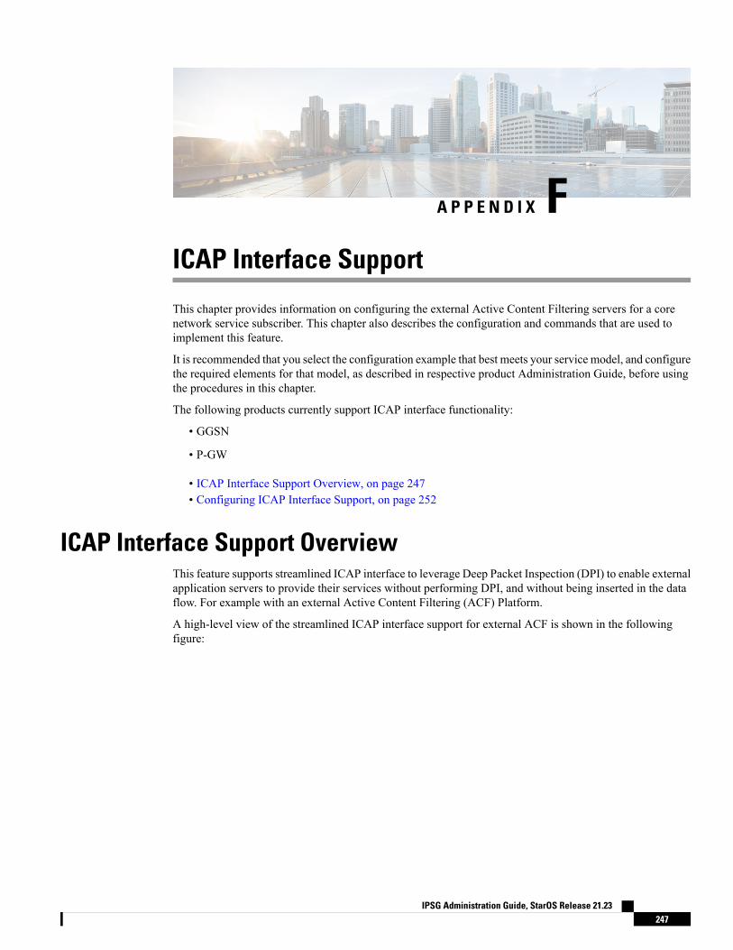
A P P E N D I X FICAP Interface Support
This chapter provides information on configuring the external Active Content Filtering servers for a corenetwork service subscriber. This chapter also describes the configuration and commands that are used toimplement this feature.
It is recommended that you select the configuration example that best meets your service model, and configurethe required elements for that model, as described in respective product Administration Guide, before usingthe procedures in this chapter.
The following products currently support ICAP interface functionality:
• GGSN
• P-GW
• ICAP Interface Support Overview, on page 247• Configuring ICAP Interface Support, on page 252
ICAP Interface Support OverviewThis feature supports streamlined ICAP interface to leverage Deep Packet Inspection (DPI) to enable externalapplication servers to provide their services without performing DPI, and without being inserted in the dataflow. For example with an external Active Content Filtering (ACF) Platform.
A high-level view of the streamlined ICAP interface support for external ACF is shown in the followingfigure:
IPSG Administration Guide, StarOS Release 21.23247
Figure 19: High-Level View of Streamlined ICAP Interface with external ACF
The system with ECS is configured to support DPI and the system uses this capability for content chargingas well. WAP and HTTP traffic is content filtered over the ICAP interface. RTSP traffic that contains adultcontent can also be content filtered on the ICAP interface. Only the RTSP Request packets will be consideredfor content filtering over the ICAP interface.
If a subscriber initiates a WAP (WAP1.x or WAP2.0) or Web session, the subsequent GET/POST request isdetected by the DPI function. The URL of the GET/POST request is extracted and passed, along with subscriberidentification information and the subscriber request, in an ICAP message to the application server. Theapplication server checks the URL on the basis of its category and other classifications like, type, access level,content category and decides if the request should be authorized, blocked, or redirected by answering to theGET/POST with:
• A 200 OK message if the request is accepted.
• A 302 Redirect message in case of redirection. This redirect message includes the URL to which thesubscriber must be redirected.
• Deny-response code 200 for RTSP requests is not supported. Only 403 "Forbidden" deny-response codewill be supported.
Depending on the response received, the system with ECS will either pass the request unmodified, or discardthe message and respond to the subscriber with the appropriate redirection or block message.
Content charging is performed by the Active Charging Service (ACS) only after the request has been controlledby the application server. This guarantees the appropriate interworking between the external application andcontent-based billing. In particular, this guarantees that charging will be applied to the appropriate request incase of redirection, and that potential charging-based redirections (i.e. Advice of Charge, Top Up page, etc.)will not interfere with the decisions taken by the application server.
Functions of the ACF include:
• Retrieval of subscriber policies based on the subscriber identity passed in the ICAP message
• Determining the appropriate action (permit, deny, redirect) to take for the type of content based onsubscriber profile
• Communication of the action (permit, deny, or redirect) decision for the URL back to the ACS module
IPSG Administration Guide, StarOS Release 21.23248
ICAP Interface SupportICAP Interface Support
Supported Networks and PlatformsThis feature supports the Cisco ASR 5500 platform for the core network services configured on the system.
For additional platform information, refer to the appropriate System Administration Guide and/or contact yourCisco account representative.
License RequirementsExternal Content Filtering Server support through Internet Content Adaptation Protocol (ICAP) interface isa licensed Cisco feature. A separate feature license may be required. Contact your Cisco account representativefor detailed information on specific licensing requirements.
For information on installing and verifying licenses, refer to theManaging License Keys section of the SoftwareManagement Operations chapter in the System Administration Guide.
Failure Action on Retransmitted PacketsICAP rating is enabled for retransmitted packet when default ICAP failure action was taken on an ICAPrequest for that flow. ICAP default failure action is taken on the pending ICAP request for a connection whenthe connection needs to be reset and there is no other redundant connection available. For example, in theICAP request timeout and ICAP connection timeout scenarios. In these cases the retransmitted packet in theuplink direction is sent for ICAP rating again.
In case of WAP CO, uplink retransmitted packet for the WAP transactions for which ICAP failure action wastaken will be sent for ICAP rating. WSP header of the retransmitted packet is not parsed by theWSP analyzer.The URL received in the previous packet for that transaction is used for ICAP rating. If failure action wastaken on multiple WTP transactions for the same flow (case: WTP concatenated GET request) then uplinkretransmitted packet for each of the transaction is sent for rating again.
In case of HTTP, uplink retransmitted packets for the HTTP flow on which ICAP failure action is taken issent for ICAP rating. The URL present in the current secondary session (last uplink request) is used for ICAPrating. However, if there were multiple outstanding ICAP request for the same flow (pipelined request) thenfor the retransmitted packet the URL that will be sent for rating will be that of the last GET request.
Retransmission in various cases of failure-action taken on re-transmitted packets when the ICAP response isnot received for the original request and the retransmitted request comes in:
• WSP CO:
• Permit: The uplink packet is sent for ICAP rating and depending on the ICAP response the WTPtransaction is allowed/blocked. It is possible that the WAP gateway sends the response for thepermitted GET request. Hence, there is a race condition and the subscriber may be able to view theweb page even thought the rating was redirect or content insert.
• Content Insert: The retransmitted packet is not sent for ICAP rating.
• Redirect: The retransmitted packet is not sent for ICAP rating.
• Discard: The uplink packet is sent for ICAP rating and depending on the ICAP response the WTPtransaction is allowed/blocked.
• Terminate flow: The uplink packet is sent for ICAP rating and depending on the ICAP response theWTP transaction is allowed or blocked. The WAP gateway may send an Abort transaction for this
IPSG Administration Guide, StarOS Release 21.23249
ICAP Interface SupportSupported Networks and Platforms
GET request if the WSP disconnect packet sent while terminating the flow is received by the WAPgateway.
• HTTP:
• Permit: The uplink packet is sent for ICAP rating and depending on the ICAP response the lastHTTP GET request. It is possible that the HTTP server sends the response for the permitted GETrequest. Hence there is a race condition and the subscriber may be able to view the web page eventhought the rating was redirect or content insert.
• Content Insert: Retransmitted packets are dropped and not charged.
• Redirect: Retransmitted packets are dropped and not charged.
• Discard: The uplink packet is sent for ICAP rating and depending on the ICAP response the WTPtransaction allowed/blocked.
• Terminate flow: Retransmitted packets are dropped and not charged.
• RTSP:
The following scenarios describe the failure actions where an RTSP request is received from the client.If ICAP is enabled, then the request goes to the ICAP server for content filtering.
• Allow: If the failure action configured is "allow", the RTSP request packet is sent out after applyingthe appropriate disposition action. Here, the flow remains the same as in the case if the ICAP responsereceived is 200 OK.
• Content Insert: If the failure action configured is "content-insertion <string of size 1 to 128>", thenthis failure action for RTSP request will not be supported. Instead the failure action "Discard" forsuch an RTSP request will be supported.
• Redirect-URL: If the failure action configured is "redirect-url <string of size 1 to 128>", then a TCPFIN_ACK packet with an RTSP "302 Moved Temporarily" response header is inserted towards theclient containing the said URL for redirection. A TCP RST packet is inserted towards the server.The underlying TCP connection is thus closed. If the RTSP client wants to retry to the redirectedURL, the opening of a new TCP connection must be initiated.
• Discard: If the failure action configured is "discard", then the RTSP request packet received fromthe client is quietly discarded and no notification is sent to the client.
• Terminate flow: If the failure action configured is "terminate-flow", then the TCP connection istorn down by injecting a TCP FIN-ACK towards the client and a RST packet towards the server.However, no notification will be sent to the RTSP client and the server regarding this flowtermination.
ICAP Client Communication with RFC 3507 complianceThe ICAP Content Filtering solution is extended to support ICAP client communication with ICAP server onCiscoASR 5500 P-GWandHA in compliancewith RFC 3507 - Internet Content Adaptation Protocol (ICAP).Only HTTP Request modification and partial enhancement of error codes per RFC 3507 is addressed in thisrelease. The ICAP client running on P-GW/HA communicates with external ICAP server over ICAP protocol.If content filtering is enabled for a subscriber, all HTTP GET requests from that subscriber are validated by
IPSG Administration Guide, StarOS Release 21.23250
ICAP Interface SupportICAP Client Communication with RFC 3507 compliance
the content filtering server (ICAP server), and is allowed, denied or redirected depending on the contentcategorization request.
Content-Filtering can be enabled for subscribers either through Override Control (OC) feature for predefinedand static rules, or L7 Dynamic Rule Activation feature. A configurable option is added in the Content FilteringServer Group ConfigurationMode to configure ICAP header that includes two parameters - Subscriber numberinformation and CIPA (Children's Internet Protection Act) category.
Override Control and L7 Dynamic Rule Activation are license-controlled features. A valid feature licensemust be installed prior to configuring these features. Contact your Cisco account representative for moreinformation.
Important
• Subscriber Number: The "Subscription ID" AVP is sent from gateway to PCRF in CCR message. TheAVP values are received to the gateway from HSS. The gateway does not receive this AVP in CCI-Amessage.
• CIPA category: The category string will be provided by PCRF and is included as an extension header inICAP request modification message. The AVP will be received from PCRF in CCA-I or RAR.
Dictionary and AVP Support
A new Content Filtering (CF) dictionary "custom4" is introduced and the following new AVPs are added tor8-gx-standard and custom4 dictionaries.
• Override-Content-Filtering-State: This attribute carries information about Content Filtering status (CFstate) of rules or charging-action. This AVP is used for overriding the content-filtering status of staticand predefined rules. This attribute is included in the Override-Control grouped AVP.
• CIPA: This attribute contains the Children's Internet Protection Act (CIPA) category string value that istreated as an ICAP plan identifier. This identifier helps ICAP server in locating the correct ContentFiltering plan i.e. CIPA category based on which the packet is processed.
This attribute value is received from PCRF over Gx interface and is included in ICAP header whilesending ICAP request.
• L7-Content-Filtering-State: This attribute carries information about Content Filtering status (CF state)of L7 rules. This attribute indicates whether or not the ICAP functionality is enabled or disabled for L7charging rule definition received for installation from PCRF. Based on this attribute value, the trafficmatching to the dynamic rule is sent to ICAP server.
This attribute is included in the L7-Application-Description grouped AVP for L7 rule processing. Thisis applicable only for HTTP protocol.
CIPA and flags for controlling content filtering via OC and L7 Dynamic Rules features is applicable only forr8-gx-standard dictionary.
Important
In addition to the newAVP support, L7-Field AVP in the L7-Application-Description grouped AVP is encodedto additionally accept ANY-MATCH as the input. The current framework does not support the existing field"vlan-id" in Override-Control, which is present in charging action. Hence, the Override-Content-Filtering-StateAVP replaces Override-VLAN-ID to support OC.
IPSG Administration Guide, StarOS Release 21.23251
ICAP Interface SupportICAP Interface Support
When subscriber initiates create session request, P-GW/HA sends CCR-I message to PCRF to obtain subscriberprofile. PCRF responds with CCA-I message that contains CIPA and OC information if ICAP functionalityis enabled for this subscriber.
In the case of L7 dynamic rules, the Content-Filtering capability is enabled by sendingL7-Content-Filtering-State AVP in L7-Application-Description grouped AVP. At least one L7 filter shouldbe present when L7-Content-Filtering-State is received for the dynamic rule. If L7-Content-Filtering-stateAVP is sent along with L7 filter information AVP, then the Content-Filtering state will not be considered.Hence, the filter received with L7-Content-Filtering-State will not be processed and the L7 rule will bediscarded.
In the case of Override Control, when content filtering is enabled for subscriber, PCRF sends ICAP flagthrough Override-Control AVP. This AVP overwrites charging action to enable ICAP feature for that subscriber.
Refer to the AAA Interface Administration and Reference for more information on the supported AVPs.
Limitations
The limitations for this feature are listed below:
• Only IPv4 addressing scheme is supported.
• ICAP content filtering is applicable only for HTTP traffic. HTTPS traffic is not supported by ICAPclient.
• Accelerated path will not be supported for this feature.
Configuring ICAP Interface SupportThis section describes how to configure the Content Filtering Server Group (CFSG) through Internet ContentAdaptation Protocol (ICAP) interface between ICAP client and ACF server (ICAP server).
This section provides the minimum instruction set for configuring external content filtering servers on ICAPinterface on the system. For more information on commands that configure additional parameters and options,refer to CFSG Configuration Mode Commands chapter in Command Line Interface Reference.
Important
To configure the system to provide ICAP interface support for external content filtering servers:
Step 1 Create the Content Filtering Server Group and create ICAP interface with origin (local) IP address of chassis by applyingthe example configuration in Creating ICAP Server Group and Address Binding, on page 253.
Step 2 Specify the active content filtering server (ICAP server) IP addresses and configure other parameters for ICAP servergroup by applying the example configuration in Configuring ICAP Server and Other Parameters, on page 253.
Step 3 Configure the content filtering mode to external content filtering server group mode in ECS rule base by applying theexample configuration in Configuring ECS Rulebase for ICAP Server Group, on page 254.
Step 4 Configure the charging action to forward HTTP/RTSP/WAP GET request to external content filtering servers on ICAPinterface in Active Charging Configuration mode by applying the example configuration in Configuring Charging Actionfor ICAP Server Group, on page 254.
Step 5 Verify your ICAP interface and external content filtering server group configuration by following the steps in Verifyingthe ICAP Server Group Configuration, on page 255.
IPSG Administration Guide, StarOS Release 21.23252
ICAP Interface SupportConfiguring ICAP Interface Support
Step 6 Save your configuration to flash memory, an external memory device, and/or a network location using the Exec modecommand save configuration. For additional information on how to verify and save configuration files, refer to theSystem Administration Guide and the Command Line Interface Reference.
Creating ICAP Server Group and Address BindingUse the following example to create the ICAP server group and bind the IP addresses:
configurecontext <icap_ctxt_name> [ -noconfirm ]
content-filtering server-group <icap_svr_grp_name> [ -noconfirm ]origin address <ip_address>
end
Notes:
• <ip_address> is local IP address of the CFSG endpoint.
Configuring ICAP Server and Other ParametersUse the following example to configure the active content filtering (ICAP server) and other related parameters:
configurecontext <icap_context_name>
content-filtering server-group <icap_server_grp_name>
icap server <ip_address> [ port <port_number> ] [ max <max_msgs>] [priority <priority> ] [ standby ]
connection retry-timeout <retry_timeout>
deny-message <msg_string>
dictionary { custom1 | custom2 | custom3 | custom4 | standard }failure-action { allow | content-insertion <content_string> | discard
| redirect-url <url> | terminate-flow }header extension options { cipa-category cipa_category_name |
subscriber-number subscriber_num_name } +response-timeout <timeout>
end
Notes:
• In 8.1 and later releases, a maximum of five ICAP servers can be configured per Content Filtering ServerGroup. In release 8.0, only one ICAP Server can be configured per Content Filtering Server Group.
• The standby keyword can be used to configure the ICAP server as standby. A maximum of ten activeand standby ICAP servers per Content Filtering Server Group can be configured. The active and standbyservers under the same server group can be configured to work in active-standby mode.
• Themaximum outstanding request per ICAP connection configured using the optionalmax <max_msgs>keyword is limited to one. Therefore, any other value configured using themax keyword will be ignored.
• Optional. To configure the ICAP URL extraction behavior, in the Content Filtering Server Groupconfiguration mode, enter the following command:
url-extraction { after-parsing | raw }
IPSG Administration Guide, StarOS Release 21.23253
ICAP Interface SupportCreating ICAP Server Group and Address Binding
By default, percent-encoded hex characters in URLs sent from the ACF client to the ICAP server willbe converted to corresponding ASCII characters and sent.
• The custom4 dictionary is a custom-defined dictionary that specifies user-defined information in theICAP request message. The ICAP request message includes subscriber number and CIPA category values.
When custom4 dictionary is configured, ICAP requests are formed as part of ICAP RFC 3507 requestmode request. If any other dictionary is configured, the earlier implementation of ICAP client will notbe partial RFC compliant.
• The header extension options command configures ICAP header parameters - subscriber number andCIPA category.
Configuring ECS Rulebase for ICAP Server GroupUse the following example to configure the content filtering mode to ICAP server mode in the ECS rulebasefor content filtering:
configurerequire active-charging [ optimized-mode ]active-charging service <acs_svc_name> [ -noconfirm ]
rulebase <rulebase_name> [ -noconfirm ]content-filtering mode server-group <cf_server_group>
end
Notes:
• In release 8.1, the optimized-mode keyword enables ACS in the Optimized mode, wherein ACSfunctionality is managed by SessMgrs. In release 8.1, ACS must be enabled in the Optimized mode.
• In release 8.3, the optimized-mode keyword is obsolete. With or without this keyword ACS is alwaysenabled in Optimized mode.
• In release 8.0 and release 9.0 and later, the optimized-mode keyword is not available.
After you configure configure, require active-charging [ optimized-mode ], active-charging service<acs_svc_name> [ -noconfirm ], and rulebase CLI commands, you must save the configuration and thenreload the chassis for the command to take effect. For information on saving the configuration file and reloadingthe chassis, refer to the System Administration Guide for your deployment.
Important
Configuring Charging Action for ICAP Server GroupUse the following example to configure the charging action to forward HTTP/WAP GET request to ICAPserver for content processing.
configureactive-charging service <acs_svc_name>
charging-action <charging_action_name> [ -noconfirm ][ no ] content-filtering processing server-groupend
IPSG Administration Guide, StarOS Release 21.23254
ICAP Interface SupportConfiguring ECS Rulebase for ICAP Server Group
Notes:
• If the content-filtering flag supplied by charging action is required to configure the Override Controlfeature, then the no content-filtering processing commandmust be configured. This will ensure overridingcontent-filtering processing to be enabled or disabled through the Override Control feature.
Verifying the ICAP Server Group ConfigurationThis section explains how to display and review the configurations after saving them in a .cfg file and also toretrieve errors and warnings within an active configuration for a service.
All commands listed here are under Exec mode. Not all commands are available on all platforms.Important
These instructions are used to verify the configuration for this feature.
Step 1 Verify your ICAP Content Filtering Server Group configuration by entering the following command in Exec Mode:
show content-filtering server-group
The following is a sample output. In this example, an ICAP Content Filtering server group named icap_cfsg1 wasconfigured.Content Filtering Group: icap_cfsg1
Context: icap1Origin Address: 1.2.3.4ICAP Address(Port): 1.2.3.4(1344)Max Outstanding: 256Priority: 1Response Timeout: 30(secs) Connection Retry Timeout: 30(secs)Dictionary: standardTimeout Action: terminate-flowDeny Message: "Service Not Subscribed"URL-extraction: after-parsingHeader Extension Options: subscriber-number i-subContent Filtering Group Connections: NONE
Total content filtering groups matching specified criteria: 1
Step 2 Verify any configuration error in your configuration by entering the following command in Exec Mode:
show configuration errors
IPSG Administration Guide, StarOS Release 21.23255
ICAP Interface SupportVerifying the ICAP Server Group Configuration

IPSG Administration Guide, StarOS Release 21.23256
ICAP Interface SupportVerifying the ICAP Server Group Configuration
Related Documents