IPS-4 Dual Bench (UV / IR) Analyzer Zone 1 / Division 2 User Manual PN 903-8804, Rev. L Canada A DIVISION OF AMETEK PROCESS & ANALYTICAL INSTRUMENTS

Welcome message from author
This document is posted to help you gain knowledge. Please leave a comment to let me know what you think about it! Share it to your friends and learn new things together.
Transcript
IPS-4 Dual Bench (UV / IR) Analyzer Zone 1 / Division 2
User Manual
PN 903-8804, Rev. LCanada
A DIVISION OF AMETEK PROCESS & ANALYTICAL INSTRUMENTS
© 2010–2019 AMETEK Canada LP, A Division of AMETEK Process & Analytical Instruments Printed in CanadaThis manual is a guide for the use of the IPS-4 (Integrated Process Spectrophometer) Analyzer with Dual Bench Option. Data herein has been verified and validated and is believed adequate for the intended use of this instrument. If the instrument or procedures are used for purposes over and above the capabilities specified herein, confirmation of their validity and suitability should be obtained; otherwise, AMETEK does not guarantee results and assumes no obligation or liability. This publication is not a license to operate under, or a recommendation to infringe upon, any process patents.
Offices
For other offices not listed here, visit us at www.ametekpi.com.
USA – HEADQUARTERS150 Freeport RoadPittsburgh, PA 15238, USATel: 412-828-9040Toll Free: 800-537-6044Fax: 412-826-0399USA – Delaware455 Corporate BoulevardNewark, DE 19702, USATel: 302-456-4400 (Main) 800-537-6044 (Service) 800-222-6789 (Ordering)Fax: 302-456-4444USA – Texas4903 West Sam Houston Parkway NorthSuite A-400Houston, TX 77041, USATel: 713-466-4900Toll Free: 1-800-634-8990Fax: 713-849-1924CANADAAMETEK Canada LP2876 Sunridge Way N.E.Calgary, AB, T1Y 7H9, CanadaTel: 403-235-8400 Toll Free: 800-661-9198Fax: 403-248-3550INDIAAMETEK Instruments India Pvt. Ltd.1st Floor, Prestige Featherlite Tech ParkPlot 148, EPIP Phase IIWhitefield, Bengaluru – 560066, Karnataka, IndiaTel: 91-80-6782-3200Fax: 91-80-6782-3232GERMANYAMETEK GmbHRudolf-Diesel Strasse 16D-40670 Meerbusch, GermanyTel: 49-2159-9136-0Fax: 49-2159-9136-39
FRANCEAMETEK – APIFRond point de l’epine des champsBuroplus Bat D78990 Elancourt, FranceTel: 33-1-30-68-89-20Fax: 33-1-30-68-89-29CHINAAMETEK Commercial Enterprise (Shanghai) Co. Ltd.Part A First Floor, 460 NorthFute RoadWaigaoqiao Free Trade ZoneShanghai, 200131, ChinaTel: 86-21-5868-5111Fax: 86-28-5866-0969Beijing BranchTel: 86-10-8526-2111Fax: 86-10-8526-2141Chengdu BranchTel: 86-28-8675-8111Fax: 86-28-8675-8141Guangzhou BranchTel: 86-20-8363-4768Fax: 86-20-8363-3701MIDDLE EAST – DubaiP.O. Box 17067Jebel Ali Free ZoneDubai, UAETel: 971-4-881-2052Fax: 971-4-881-2053SINGAPOREAMETEK Singapore Pte. Ltd.No. 43, Changi SouthAvenue 2, #04-01486164 SingaporeTel: 65-6486-2388Fax: 65-6481-6588BRAZILAMETEK Process BrazilRodovia Eng Ermênio de Oliveira PenteadoSP 75 - Km 55 - Bairro TombadouroIndaiatuba - SP – Brasil13347-600Tel: 55-19-2107-4100
ii | IPS-4 Dual Bench (UV / IR) Analyzer
ContentsOffices .................................................................................................................................. iiSafety Notes ....................................................................................................................... ixElectrical Safety .................................................................................................................. ixGrounding .......................................................................................................................... ixPersonnel and Equipment Safety Information .............................................................. x
Warnings ....................................................................................................................... xCautions ...................................................................................................................... xii
Warning Labels ................................................................................................................ xiiiEnvironmental Information (WEEE) ........................................................................... xiiiUV Source Lamps Disposal ........................................................................................... xiiiElectromagnetic Compatibility (EMC) ......................................................................... xivSpecial Warnings and Information ................................................................................ xv
Equipment Used in Class I, Division 1 and Zone 1 Hazardous Locations ....... xvEU Declaration of Conformity ...................................................................................... xviWarranty and Claims ....................................................................................................xviii
CHAPTER 1 OVERVIEW ....................................................................................................... 1-1Optical Bench Configurations ....................................................................................... 1-1
Basic Analytical Theory (Optical Bench) .............................................................. 1-1Flow Diagram ............................................................................................................ 1-1Calculation Flow ....................................................................................................... 1-2
Dispersive Ultraviolet/Visible (DUVV) Spectrometer ............................................... 1-4Basic Analytical Theory ........................................................................................... 1-4Optical Bench Design .............................................................................................. 1-4UV Specifications ...................................................................................................... 1-5
Wavelength Ranges ............................................................................................. 1-5Wavelength Accuracy .......................................................................................... 1-5Wavelength Resolution ........................................................................................ 1-53 nm ..................................................................................................................... 1-5Analyzer Range ................................................................................................... 1-5Photometric Range .............................................................................................. 1-5Photometric Noise ............................................................................................... 1-5
Non-Dispersive Infrared (NDIR) Photometer ............................................................ 1-6Basic Analytical Theory ........................................................................................... 1-6Optical Bench Design .............................................................................................. 1-6NDIR Specifications ................................................................................................. 1-7
Wavelength Ranges ............................................................................................. 1-7Photometric Range .............................................................................................. 1-7Photometric Noise ............................................................................................... 1-7
Sample System ................................................................................................................. 1-7Electronics ........................................................................................................................ 1-8Classified, Hazardous Area Protection Components and Functions ..................... 1-9Supplemental Information – Where Can I Find It? ................................................. 1-12
Contents | iii
CHAPTER 2 SPECIFICATIONS ........................................................................................... 2-1Analyzer Specifications .................................................................................................. 2-1
Analytes ...................................................................................................................... 2-1Response Linearity ................................................................................................... 2-1Measurement Accuracy ........................................................................................... 2-1Repeatability .............................................................................................................. 2-1Linearity ..................................................................................................................... 2-1Stability ....................................................................................................................... 2-124-Hour Zero Drift ................................................................................................... 2-2Inputs .......................................................................................................................... 2-2Outputs ...................................................................................................................... 2-2Sample System Limits .............................................................................................. 2-3
Sample Pressure .................................................................................................. 2-3Oven/Sample System Enclosure Temperature ..................................................... 2-3
Sample Transport ...................................................................................................... 2-3Instrument Air Requirements ................................................................................. 2-3Sample Fluid Flow Rate ........................................................................................... 2-3Electrical Requirements ........................................................................................... 2-4
Power Consumption ............................................................................................ 2-4Heated Sample Line ............................................................................................ 2-4Supply Voltage ..................................................................................................... 2-4
Cell Construction ...................................................................................................... 2-4Pressure Input Signals ............................................................................................. 2-4On-Board Temperature Sensor ............................................................................... 2-4Environmental .......................................................................................................... 2-5
Ambient Temperature .......................................................................................... 2-5Humidity ............................................................................................................. 2-5Pollution Degree .................................................................................................. 2-5Maximum Altitude.............................................................................................. 2-5Installation Category ........................................................................................... 2-5Enclosure Material .............................................................................................. 2-5Ingress Protection ................................................................................................ 2-5
Physical Dimensions ................................................................................................ 2-5Approvals and Certifications ......................................................................................... 2-6
Special Condition of Use ......................................................................................... 2-7ATEX and IECEx Certificates and Analyzer Markings ....................................... 2-8
IPS-4 Dual Bench Analyzer ATEX Certificate ................................................... 2-8IPS-4 Dual Bench Analyzer Marking ............................................................... 2-11IPS-4 Dual Bench Analyzer IECEx Certificate ................................................. 2-12
CHAPTER 3 INSTALLATION AND START-UP ................................................................... 3-1Safety Considerations ..................................................................................................... 3-2Pre-Installation Requirements....................................................................................... 3-2
Storage Prior to Installation .................................................................................... 3-2Uncrating and Inspecting the Analyzer ................................................................ 3-3General Installation Information ........................................................................... 3-3Tools, Equipment, and Supplies Required ........................................................... 3-4
iv | IPS-4 Dual Bench (UV / IR) Analyzer
Installing the Mechanical Components ....................................................................... 3-6Mounting the Analyzer ........................................................................................... 3-6
Location and Environment .................................................................................. 3-6Installing the Optical Bench-UV Assembly ........................................................ 3-10Installing the Optical Bench IR Assembly .......................................................... 3-11Installing the Sample System................................................................................ 3-13
Installing the Sample Probe/Sample Tap ........................................................... 3-14Installing and Connecting the Sample and Vent Lines ..................................... 3-14Installing and Connecting the Instrument Air/Zero Fluid Line ....................... 3-15Installing and Connecting the Purge Fluid Line ............................................. 3-17Installing the Calibration (Span) Fluid Line (Optional) ................................... 3-19
Connecting I/O Signals, Alarm Relay Contacts, and AC Power ............................ 3-20Electrical Connections ............................................................................................ 3-20Permanent Ethernet Cable Connections (Optional) ......................................... 3-21
Start-Up and Verification ............................................................................................. 3-23Purged Analyzers ................................................................................................... 3-23Powering Up the Analyzer .................................................................................... 3-26Start-Up Diagnostic Checklist .............................................................................. 3-35Sample System Leak Check .................................................................................. 3-37Manually Zeroing the Analyzer Sample System ............................................... 3-39Adjusting the Zero/Span Fluid Flow Rate .......................................................... 3-40Adjusting the Sample Flow Rate .......................................................................... 3-41Setting Sample Response Time ............................................................................ 3-42
Normal Operation ......................................................................................................... 3-43Recording Initial Readings .................................................................................... 3-43Recording Initial Sample Response Time ........................................................... 3-43
Analyzer Configuration ............................................................................................... 3-44
CHAPTER 4 CONTROLLER / USER INTERFACE ............................................................. 4-1Introduction to the User Interface Panel ..................................................................... 4-2
User Interface Panel Components ......................................................................... 4-2Special Software Characters .................................................................................... 4-4Working From the User Interface Panel – Conditions and Messages .............. 4-5Summary of Analyzer Operation .......................................................................... 4-6
Working in the Main Menus ......................................................................................... 4-7HOME Menu Screen ................................................................................................ 4-7
System Status Messages (HOME Screen) .......................................................... 4-9Alarm and Warning Notification (HOME Screen) .......................................... 4-10
ALARMS and WARNINGS Menu Screen ........................................................... 4-11Viewing Current Alarms and Warnings ........................................................... 4-11Viewing Logged Alarms and Warnings ............................................................ 4-12
STATUS Menu Screen ............................................................................................ 4-13SETUP Menu Screen .............................................................................................. 4-15
Calibration Control Screen ................................................................................ 4-16Calibration Settings Screen .........................................................................4-16Flush Times ..................................................................................................4-19
Contents | v
Calibration Valves .............................................................................................. 4-20Calibration Actions Screen ................................................................................ 4-21
Manually Starting a Zero Calibration .........................................................4-22Manually Starting a Span Calibration ........................................................4-23Manually Starting a Neutral Density Filter Verification ............................4-24Neutral Density Filter Verification Diagnostic Chart .................................4-25
Relay Setup Screens ............................................................................................... 4-26Current Output Setup Screens ......................................................................... 4-29Setpoints ............................................................................................................ 4-31Diagnostics Screen ............................................................................................ 4-33System Settings Screen ..................................................................................... 4-34The System Settings screen (Figure 4-31) allows the user to view and/or setup analyzer system parameters. ....................................................... 4-34Login/Set Passwords Screen .............................................................................. 4-35
Changing the Password ................................................................................4-37Locking the Password ...................................................................................4-37Removing the Password ...............................................................................4-37
Backup/Restore Settings Screen ........................................................................ 4-38Backing Up Analyzer Configuration Settings .............................................4-39Restoring Analyzer Configuration Settings ................................................4-39
Ethernet Network Screen .................................................................................. 4-41Customization Screen ........................................................................................ 4-44Modbus Screen .................................................................................................. 4-46
CHAPTER 5 MAINTENANCE AND TROUBLESHOOTING............................................... 5-1Safety Considerations ..................................................................................................... 5-1Maintenance ..................................................................................................................... 5-3
Preventive Maintenance .......................................................................................... 5-3Analyzer Preventive Maintenance Schedule ....................................................... 5-4Expo Technologies MiniPurge® System With eTimer (Optional) Preventive Maintenance Schedule ......................................................................................... 5-6Locating a Plug in the Sample System ................................................................ 5-7Detecting a Plug in the Sample System .............................................................. 5-7
Changing Out Replaceable Parts ........................................................................... 5-8Tools, Equipment, and Supplies Required for Maintenance ............................... 5-9Measuring Cell Preventive Maintenance .......................................................... 5-11
Replacing the Xenon (UV) Flash Lamp Assembly ............................................ 5-19Replacing the Infrared (IR) Source Assembly .................................................... 5-23
Troubleshooting and Diagnostics ............................................................................... 5-26Alarm Conditions and Corrective Action ........................................................... 5-27Analyzer Reset ........................................................................................................ 5-31
vi | IPS-4 Dual Bench (UV / IR) Analyzer
CHAPTER 6 SERVICE AND PARTS .................................................................................... 6-1Technical Support ............................................................................................................ 6-1Returning Equipment ..................................................................................................... 6-2AMETEK Service and Aftermarket Sales Support ..................................................... 6-3Recommended Spare Parts ............................................................................................ 6-4
Measuring Cell Assembly Spare Parts ................................................................... 6-4Optical Bench Assembly Spare Parts ..................................................................... 6-4Spare Analyzer Fuses ............................................................................................... 6-5Expo Technologies MiniPurge® System With eTimer Spare Parts .................... 6-5
CHAPTER 7 USER WEB INTERFACE ................................................................................ 7-1Introduction to the Web Interface ................................................................................ 7-2
Web Interface Components .................................................................................... 7-3Working From the Web Interface – Conditions and Messages ......................... 7-3HOME Menu Screen ................................................................................................ 7-4ALARMS Menu Screen ............................................................................................ 7-5
Current Alarms and Warnings ........................................................................... 7-5Logged Alarms and Warnings ............................................................................ 7-6Alarm and Warning Notification ........................................................................ 7-6
TRENDS Menu Screen ............................................................................................ 7-7Parameters ........................................................................................................... 7-8Intervals............................................................................................................... 7-8
SPECTRA Menu Screen ........................................................................................... 7-9Viewing Spectral Data ......................................................................................... 7-9
SETTINGS Menu Screen ....................................................................................... 7-10Calibration Settings Screen ............................................................................... 7-11Actions Screen ................................................................................................... 7-12Current Output Screen ..................................................................................... 7-13Relay Setup Screens .......................................................................................... 7-14Network and Modbus Screen ............................................................................ 7-15System and Customization Screen .................................................................... 7-16Analytes Screen ................................................................................................. 7-17
Limits Screen .......................................................................................................... 7-18Diagnostics Screen ............................................................................................ 7-19Save/Restore Files Screen .................................................................................. 7-20
CHAPTER 8 MODBUS COMMUNICATION INTERFACE .................................................. 8-1Hardware: .................................................................................................................. 8-1Configuration: ........................................................................................................... 8-2
Analyzer Modbus Interface Parameters ...................................................................... 8-3Modbus Address ....................................................................................................... 8-3Modbus Functions .................................................................................................... 8-3
Holding Registers ............................................................................................................ 8-4
Contents | vii
APPENDIX A – DRAWINGS ...................................................................................................A-1Analyzer Light Path, UV Optical Bench Schematic .................................................. A-2Analyzer Light Path, NDIR Optical Bench Schematic ............................................. A-3Analyzer Overall Component Layout, Zone 1, Example ........................................ A-4Analyzer Overall Component Layout, Division 2, Example................................... A-5Detector Board (100-2046) ............................................................................................. A-6Display Interface Board (100-2049) .............................................................................. A-7Customer Connection Board (100-1971) ..................................................................... A-8AC Disconnection Board (100-2077) ............................................................................ A-9Signal Disconnection Board (100-2076) .................................................................... A-10Relay Board (100-2050) ................................................................................................ A-11Analog Board (100-2047) ............................................................................................. A-12MCU Board (100-2045) ................................................................................................ A-13Xenon Lamp Power Supply Board (100-2061), UV Optical Bench ....................... A-14Infrared Source Assembly Interface Board (100-2838), IR Optical Bench ........... A-15Electronics Enclosure Wiring Diagram, Sheet 1 of 5 .............................................. A-16Electronics Enclosure Wiring Diagram, Sheet 2 of 5 .............................................. A-17Electronics Enclosure Wiring Diagram, Sheet 3 of 5 .............................................. A-18Disconnect Enclosure Wiring Diagram, Sheet 4 of 5 .............................................. A-19Disconnect Enclosure Wiring Diagram, Sheet 5 of 5 .............................................. A-20
SUPPLEMENTAL INFORMATION ........................................................................................S-1
viii | IPS-4 Dual Bench (UV / IR) Analyzer
Safety Notes
WARNINGS, CAUTIONS, and NOTES contained in this manual emphasize critical instructions as follows:
An operating procedure which, if not strictly observed, may result in personal injury or envi-ronmental contamination.
An operating procedure which, if not strictly observed, may result in damage to the equipment.
Important information that should not be overlooked.
Electrical Safety
High voltages are present in the analyzer housings. Always shut down power source(s) before perform-ing maintenance or troubleshooting. Only a qualified electrician should make electrical connections and ground checks.
Any use of the equipment in a manner not specified by the manufacturer may impair the safety protection originally provided by the equipment.
Grounding
Instrument grounding is mandatory. Performance specifications and safety protection are void if instru-ment is operated from an improperly grounded power source.
Verify ground continuity of all equipment before applying power.
!CAUTION
NOTE
!CAUTION
!WARNING
Contents | ix
Personnel and Equipment Safety Information
This section describes important safety information to avoid personal injury and damage to the equipment while installing, operating, maintaining, or servicing the equipment. All safety regulations, standards, and procedures at the analyzer location must be followed.
All personnel involved with the installation, start-up, operation, maintenance, service, or troubleshooting of the IPS-4 Analyzer must review and follow these Warnings and Cautions.
Warnings
Review and follow these Warnings to avoid personal injury or environmental contamination.
Always disconnect main AC power and/or external power sources to the analyzer before opening any covers or doors on the analyzer to check or perform maintenance on any compo-nents within the enclosures. If it is necessary to open the analyzer’s covers or doors while the circuits are live, test the area for flammable gases (and proceed only when the area is safe). Purged Analyzer (Hazardous Location) Applications To work on the analyzer with it powered up and its Electronics Enclosure door open, the Purge Bypass Switch must be in the “BYPASS” position. When the Electronics Enclosure door is open, take appropriate precautions to avoid electrical shock. Hazardous voltages are present inside.
All electrical connections, adjustments, or servicing of the analyzer should be performed only by properly trained and qualified personnel. All electrical connections, materials, and methods (plus all safety policies and procedures) must be made in compliance with local wiring regulations and electrical code for the hazard-ous area.
Follow appropriate regulatory and/or company procedures to lock out the analyzer while working on the analyzer electronics.
Before working on the sample system, confirm that the system has been purged with Zero fluid and is isolated (blocked in) from the process.
!WARNING
!WARNING
!WARNING
!WARNING
x | IPS-4 Dual Bench (UV / IR) Analyzer
Because ultraviolet radiation can harm your eyes, never look directly into the operating lamp. If the Xenon Flash Lamp must be viewed while energized, wear safety glasses that block ultraviolet radiation.
If the Oven/Sample System Enclosure is heated, the components within it will be hot; take precautions to avoid burning yourself.
The glass Xenon Flash Lamp is under high internal pressure which could result in flying glass fragments if ruptured. Handle the tube with care to avoid dropping it, subjecting it to impacts, applying excessive force to it, or scratching it. While handling a flash lamp, always wear protective devices (face mask, clothing) to prevent possible injury, especially to hand and face areas.
!WARNING
!WARNING
!WARNING
Contents | xi
Cautions
Review and follow these Cautions to avoid damaging the equipment.
The electronic circuit boards and other static-sensitive components should be stored and transported in static-shielding carriers or packages.
For electrical-shock protection, the analyzer must be operated from a grounded power source that has a securely connected protective-ground contact.
If it becomes necessary to handle any of the electronic circuit boards, do not subject the boards to static discharge. The ideal solution is a static-safe work area. Since such areas typically are not available at analyzer installation sites, the use of a wrist strap connected directly to a ground is recommended. If a wrist strap is not available, you should at the very least touch the metal chassis (to ground yourself) before handling or touching the boards.
When handling the Xenon Flash Lamp, it is very important not to touch the lamp windows because residual oils from the fingers will absorb ultraviolet light. The window is the flat sur-face at the end of the narrow glass tube. The lamp assembly is fragile and should be handled with care.
!CAUTION
!CAUTION
!CAUTION
!CAUTION
xii | IPS-4 Dual Bench (UV / IR) Analyzer
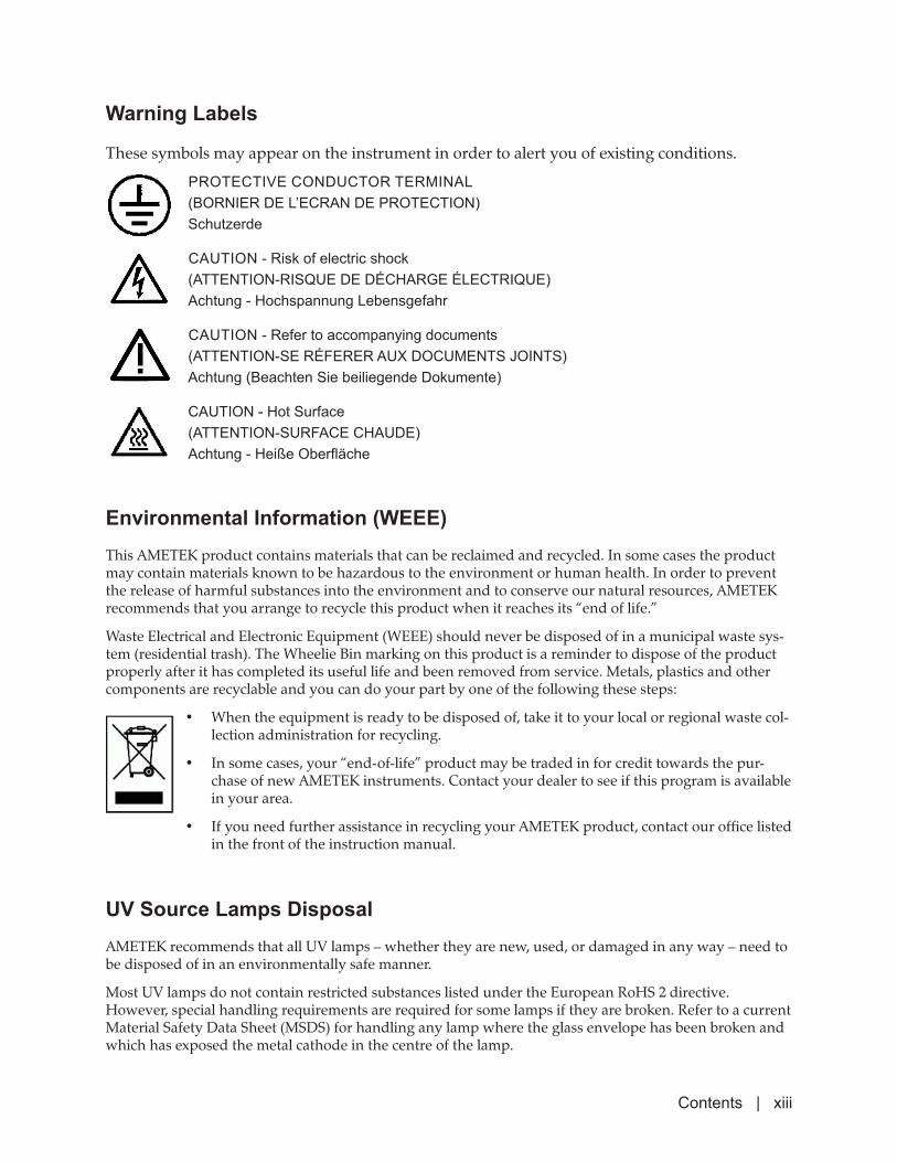
Environmental Information (WEEE)This AMETEK product contains materials that can be reclaimed and recycled. In some cases the product may contain materials known to be hazardous to the environment or human health. In order to prevent the release of harmful substances into the environment and to conserve our natural resources, AMETEK recommends that you arrange to recycle this product when it reaches its “end of life.”
Waste Electrical and Electronic Equipment (WEEE) should never be disposed of in a municipal waste sys-tem (residential trash). The Wheelie Bin marking on this product is a reminder to dispose of the product properly after it has completed its useful life and been removed from service. Metals, plastics and other components are recyclable and you can do your part by one of the following these steps:
• When the equipment is ready to be disposed of, take it to your local or regional waste col-lection administration for recycling.
• In some cases, your “end-of-life” product may be traded in for credit towards the pur-chase of new AMETEK instruments. Contact your dealer to see if this program is available in your area.
• If you need further assistance in recycling your AMETEK product, contact our office listed in the front of the instruction manual.
PROTECTIVE CONDUCTOR TERMINAL(BORNIER DE L’ECRAN DE PROTECTION)Schutzerde
CAUTION - Risk of electric shock(ATTENTION-RISQUE DE DÉCHARGE ÉLECTRIQUE)Achtung - Hochspannung Lebensgefahr
CAUTION - Refer to accompanying documents(ATTENTION-SE RÉFERER AUX DOCUMENTS JOINTS)Achtung (Beachten Sie beiliegende Dokumente)
CAUTION - Hot Surface(ATTENTION-SURFACE CHAUDE)Achtung - Heiße Oberfläche
Warning Labels
These symbols may appear on the instrument in order to alert you of existing conditions.
UV Source Lamps DisposalAMETEK recommends that all UV lamps – whether they are new, used, or damaged in any way – need to be disposed of in an environmentally safe manner.
Most UV lamps do not contain restricted substances listed under the European RoHS 2 directive. However, special handling requirements are required for some lamps if they are broken. Refer to a current Material Safety Data Sheet (MSDS) for handling any lamp where the glass envelope has been broken and which has exposed the metal cathode in the centre of the lamp.
Contents | xiii
Electromagnetic Compatibility (EMC)
Read and follow the recommendations in this section to avoid performance variations or damage to the internal circuits of this equipment when installed in harsh electrical environments.
The various configurations of the IPS-4 Analyzer should not produce, or fall victim to, electromagnetic disturbances as specified in the European Union’s EMC Directive (if applicable to your application). Strict compliance to the EMC Directive requires that certain installation techniques and wiring practices are used to prevent or minimize erratic behavior of the Analyzer or its electronic neighbors. Below are examples of the techniques and wiring practices to be followed.
In meeting the EMC requirements, the various analyzer configurations described in this manual rely heav-ily on the use of metallic shielded cables used to connect to the customer’s equipment and power. Foil and braid shielded I/O and DC power cables are recommended for use in otherwise unprotected situations. In addition, hard conduit, flexible conduit, and armor around non-shielded wiring also provides excellent control of radio frequency disturbances. However, use of these shielding techniques is effective only when the shielding element is connected to the equipment chassis/earth ground at both ends of the cable run. This may cause ground loop problems in some cases. These should be treated on a case-by-case basis. Disconnecting one shield ground may not provide sufficient protection depending on the electronic en-vironment. Connecting one shield ground via a 0.1 microfarad ceramic capacitor is a technique allowing high frequency shield bonding while avoiding the AC-ground metal connection. In the case of shielded cables the drain wire or braid connection must be kept short. A minimal connection distance between the shield’s end and the nearest grounded chassis point, ground bar or terminal is highly recommended. An even greater degree of shield performance can be achieved by using metallic glands for shielded cable entry into metal enclosures. Expose enough of the braid/foil/drain where it passes through the gland so that the shield materials can be wrapped backwards onto the cable jacket and captured inside the gland, and tightened up against the metal interior.
Inductive loads connected to the low voltage “Alarm Contacts” are not recommended. However, if this becomes a necessity, adhere to proper techniques and wiring practices. Install an appropriate transient voltage suppression device (low voltage MOV, “Transzorb,” or R/C) as close as possible to the inductive device to reduce the generation of transients. Do not run this type of signal wiring along with other I/O or DC in the same shielded cable. Inductive load wiring must be separated from other circuits in conduit by using an additional cable shield on the offending cable.
In general, for optimum protection against high frequency transients and other disturbances, do not allow installation of this Analyzer where its unshielded I/O and DC circuits are physically mixed with AC mains or any other circuit that could induce transients into the Analyzer or the overall system. Examples of elec-trical events and devices known for the generation of harmful electromagnetic disturbances include mo-tors, capacitor bank switching, storm related transients, RF welding equipment, static, and walkie-talkies.
!CAUTION
xiv | IPS-4 Dual Bench (UV / IR) Analyzer
SPECIAL WARNINGS AND INFORMATION
Equipment Used in Class I, Division 1 and Zone 1 Hazardous Locations
Refer to Chapter 2 – Specifications for details about the suitability of this equipment in hazard-ous areas.
Explosion Hazard – Substitution of Components May Impair Suitability for hazardous loca-tions. Risque d’explosion – La substitution de composants peut rendre ce materiel inacceptable pour les emplacements est designé dangereux.
Explosion Hazard – Do Not Disconnect Equipment Unless Power Has Been Switched Off or the Area is Known to be Non-Hazardous. Risque d’explosion – Avant de déconnecter l’équipement, coupez le courant où vous assurez que l’emplacement est designé non dangereux.
For installations using North American wiring practice, all input and output wiring must be in accordance with Class I, Division 1 and Zone 1 wiring methods (NEC Sec 501.10(a) and 505.15(b) or (CEC-18 106 or IEC 60079-14) and in accordance with the authority having jurisdiction.
!
!
WARNING
!Avertissement
WARNING
!Avertissement
Contents | xv

EU Declaration of Conformity
PN 903-8805 Rev C
EU Declaration of ConformityManufacturer’s Name: AMETEK Canada A Division of AMETEK Process & Analytical Instruments (ISO 9001:2008 Registered)
Manufacturer’s Address: 2876 Sunridge Way N.E. Calgary, Alberta, Canada T1Y 7H9 Phone: (403) 235-8400 / Fax: (403) 248-3550
EU Representative Address: AMETEK Precision Instruments Europe GmbH Rudolf-Diesel-Str. 16 D-40670 Meerbusch, Germany Phone 49-2159 91 36 0 / Fax: 49-2159 91 36 80
Declare under our sole responsibility that the product: Product Name: Model IPS-4 Analyzer Model Name/Number: Full Spectrum Option Markings: II 2 G Ex db pxb IIC T3 Gb IP65, -20 °C ≤ Ta ≤ +50 °C
Conforms to the following EU Standards and Directives:
Electromagnetic Compatibility Directive 2014/30/EU using the following standards:
EN 61000-6-4 Emission standard for industrial environments. EN 55011 Industrial, Scientific and Medical equipment – Class A. Radiated Electromagnetic Emissions, Class A 30 MHz to 1 GHz. EN 55011 Conducted Electromagnetic Emissions, Class A. EN 61000-6-2 Immunity for industrial environments. EN 61000-4-2 Testing and measurement techniques – Electrostatic discharge immunity test. EN 61000-4-3 Testing and measurement techniques – Radiated, radio-frequency, electromagnetic field
immunity test. EN 61000-4-4 Testing and measurement techniques – Electrical fast transient/burst immunity test. EN 61000-4-5 Testing and measurement techniques – Surge immunity test. EN 61000-4-6 Testing and measurement techniques – Conducted RF immunity (Immunity to conducted
disturbances, induced by radio-frequency fields). EN 61000-4-11 Testing and measurement techniques – Power line voltage dips/interrupts (Voltage dips,
short interruptions and voltage variations immunity tests). EN 61326-1 Electrical equipment for measurement, control, and laboratory use – EMC requirements –
(Part 1: General requirements).
Restriction of Hazardous Substances Directive 2011/65/EU (RoHS 2): EN 50581:2012 Technical documentation for the assessment of electrical and electronic products with
respect to the restriction of hazardous substances.
Low Voltage Directive 2014/35/EU using the following standards: EN 61010-1:2001 Safety Requirements for Electrical Equipment for Measurement, Control, and
Laboratory Use – Part 1. General requirements.
Page 1 of 2
CanadaA DIVISION OF AMETEK PROCESS & ANALYTICAL INSTRUMENTS
xvi | IPS-4 Dual Bench (UV / IR) Analyzer

EU Declaration of Conformity
The object of the declaration described [herein] is in conformity with the relevant Union harmonization legislation (Directive 2014/34/EU): EN 60079-0:2012+A11:2013 General requirements EN 60079-1:2014 Equipment protection by flameproof enclosures ‘d’ EN 60079-2:2014 Purged/Pressurization ‘p’ Equipment protection by pressurized enclosures ‘p’ Certificate Number: Presafe 15 ATEX 7029X Notified Body: DEKRA Certification B.V. 0344 Meander 1051, 6825 MJ Arnhem
The Netherlands
____________________________
Randy MeadsQuality Assurance ManagerCalgary, Alberta, CanadaJuly 12, 2019
Page 2 of 2
CanadaA DIVISION OF AMETEK PROCESS & ANALYTICAL INSTRUMENTS
Contents | xvii

WARRANTY AND CLAIMSWe warrant that any equipment of our own manufacture or manufactured for us pursuant to our specifications which shall not be, at the time of shipment thereof by or for us, free from defects in material or workmanship under normal use and service will be repaired or replaced (at our option) by us free of charge, provided that written notice of such defect is received by us within twelve (12) months from date of shipment of portable analyzers or within eighteen (18) months from date of shipment or twelve (12) months from date of installation of permanent equipment, whichever period is shorter. All equipment requiring repair or replacement under the warranty shall be returned to us at our factory, or at such other location as we may designate, transportation prepaid. Such returned equipment shall be examined by us and if it is found to be defective as a result of defective materials or workmanship, it shall be repaired or replaced as aforesaid. Our obligation does not include the cost of furnishing any labor in connection with the installation of such repaired or replaced equipment or parts thereof, nor does it include the responsibility or cost of transportation. In addition, instead of repairing or replacing the equipment returned to us as aforesaid, we may, at our option, take back the defective equipment, and refund in full settlement the purchase price thereof paid by Buyer.
Process photometric analyzers, process moisture analyzers, and sample systems are warranted to perform the intended measurement, only in the event that the customer has supplied, and AMETEK has accepted, valid sample stream com-position data, process conditions, and electrical area classification prior to order acknowledgment. The photometric light sources are warranted for ninety (90) days from date of shipment. Resale items warranty is limited to the transferable portion of the original equipment manufacturer’s warranty to AMETEK. If you are returning equipment from outside the North America, a statement should appear on the documentation accompanying the equipment being returned declaring that the goods being returned for repair are North American goods, the name of the firm who purchased the goods, and the shipment date.
The warranty shall not apply to any equipment (or part thereof) which has been tampered with or altered after leaving our control or which has been replaced by anyone except us, or which has been subject to misuse, neglect, abuse or im-proper use. Misuse or abuse of the equipment, or any part thereof, shall be construed to include, but shall not be limited to, damage by negligence, accident, fire or force of the elements. Improper use or misapplications shall be construed to include improper or inadequate protection against shock, vibration, high or low temperature, overpressure, excess voltage and the like, or operating the equipment with or in a corrosive, explosive or combustible medium, unless the equipment is specifically designed for such service, or exposure to any other service or environment of greater severity than that for which the equipment was designed.
The warranty does not apply to used or secondhand equipment nor extend to anyone other than the original purchaser from us. Should the Buyer’s technical staff require the on-site assistance of AMETEK’s agents or employees for service calls covered by this warranty clause, the Buyer shall pay travel time plus actual travel and living expenses.
THIS WARRANTY IS GIVEN AND ACCEPTED IN LIEU OF ALL OTHER WARRANTIES, WHETHER EXPRESS OR IMPLIED, INCLUDING WITHOUT LIMITATION AND WARRANTIES OF FITNESS OR OF MERCHANTABILITY OTHER THAN AS EXPRESSLY SET FORTH HEREIN, AND OF ALL OTHER OBLIGATIONS OR LIABILITIES ON OUR PART. IN NO EVENT SHALL WE BE LIABLE UNDER THIS WARRANTY OR ANY OTHER PROVISION OF THIS AGREEMENT FOR ANY ANTICIPATED OR LOST PROFITS, INCIDENTAL DAMAGES, CONSEQUENTIAL DAMAGES, TIME CHANGES OR ANY OTHER LOSSES INCURRED BY THE ORIGINAL PURCHASER OR ANY THIRD PARTY IN CONNECTION WITH THE PURCHASE, INSTALLATION, REPAIR OR OPERATION OF EQUIPMENT, OR ANY PART THEREOF COVERED BY THIS WARRANTY OR OTHERWISE. WE MAKE NO WARRANTY, EXPRESS OR IMPLIED, INCLUDING WITHOUT LIMITATION ANY WARRANTIES OF FITNESS OR OF MERCHANTABILITY, AS TO ANY OTHER MANUFACTURER’S EQUIPMENT, WHETHER SOLD SEPARATELY OR IN CONJUNCTION WITH EQUIPMENT OF OUR MANUFACTURE. WE DO NOT AUTHORIZE ANY REPRESENTATIVE OR OTHER PERSON TO ASSUME FOR US ANY LIABILITY IN CONNECTION WITH EQUIPMENT, OR ANY PART THEREOF, COVERED BY THIS WARRANTY.
xviii | IPS-4 Dual Bench (UV / IR) Analyzer
Overview | 1-1
OVERVIEW
This chapter discusses the features of the IPS-4 Analyzer and a summary of how the entire system operates. This chapter also provides an overview of the AMETEK electronics, Dual Bench options, sample systems, and the various sub-systems that make up the entire analyzer system.
Optical Bench Configurations
The Dual Bench option of the IPS-4 incorporates both a dispersive ul-traviolet/visible (DUVV) spectrometer and a non-dispersive infrared (NDIR) photometer. This section describes how the IPS-4 integrates the information obtained from both optical systems. Specific information for the DUVV and NDIR optical systems, including theory, hardware and software descriptions, and installation instructions are provided, under sections DUVV OPTICAL BENCH and NDIR OPTICAL BENCH.
Basic Analytical Theory (Optical Bench)
For this analyzer, the analytical measurement is transmittance, T( )λl
, over
one or more bands of wavelength ( )λl
. Transmittance is the ratio of the
transmitted power (originating from the source), ( )λl
to the incident
power, ( )λ0Ι
for each wavelength (see Equation 1.1).
( ) ( ) ( )λ/λλ 0λλ=Τ Equation 1.1
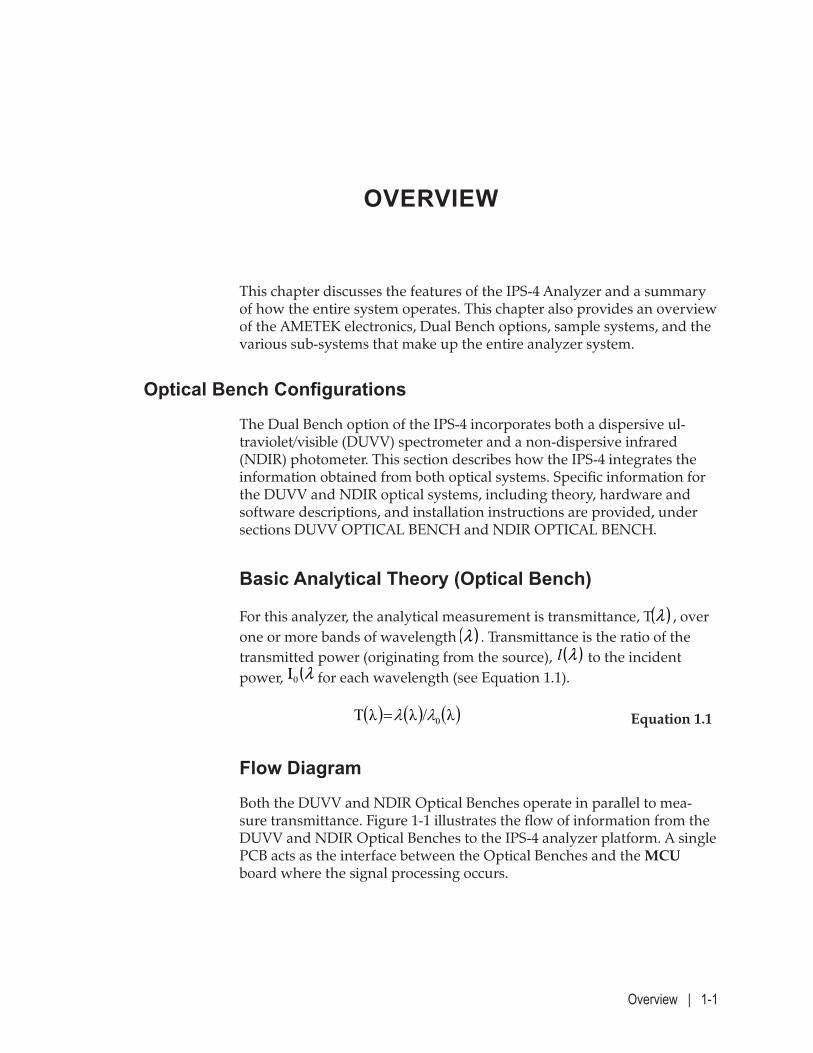
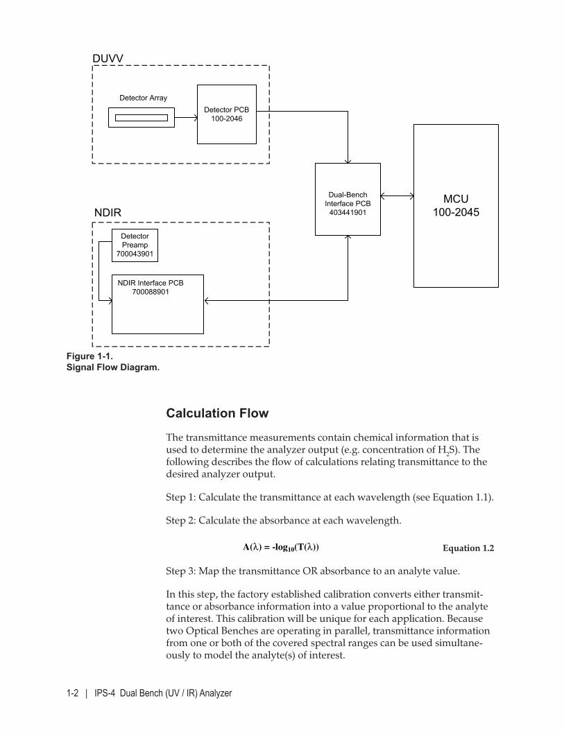
Flow Diagram
Both the DUVV and NDIR Optical Benches operate in parallel to mea-sure transmittance. Figure 1-1 illustrates the flow of information from the DUVV and NDIR Optical Benches to the IPS-4 analyzer platform. A single PCB acts as the interface between the Optical Benches and the MCU board where the signal processing occurs.
1-2 | IPS-4 Dual Bench (UV / IR) Analyzer
Calculation Flow
The transmittance measurements contain chemical information that is used to determine the analyzer output (e.g. concentration of H2S). The following describes the flow of calculations relating transmittance to the desired analyzer output.
Step 1: Calculate the transmittance at each wavelength (see Equation 1.1).
Step 2: Calculate the absorbance at each wavelength.
A(λ) = -log10(T(λ)) Equation 1.2
Step 3: Map the transmittance OR absorbance to an analyte value.
In this step, the factory established calibration converts either transmit-tance or absorbance information into a value proportional to the analyte of interest. This calibration will be unique for each application. Because two Optical Benches are operating in parallel, transmittance information from one or both of the covered spectral ranges can be used simultane-ously to model the analyte(s) of interest.
Figure 1-1. Signal Flow Diagram.
Detector ArrayDetector PCB
100-2046
DUVV
Dual-Bench Interface PCB
403441901MCU
100-2045
Detector Preamp
700043901
NDIR Interface PCB700088901
NDIR
Overview | 1-3
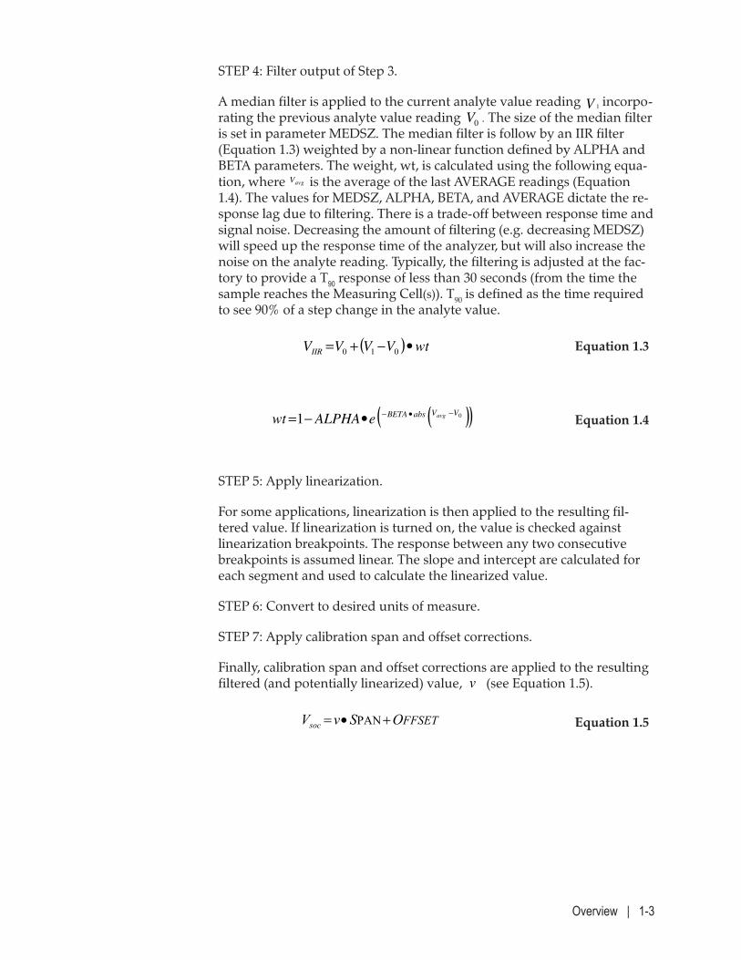
STEP 4: Filter output of Step 3.
A median filter is applied to the current analyte value reading 1V incorpo-rating the previous analyte value reading 0V
. The size of the median filter
is set in parameter MEDSZ. The median filter is follow by an IIR filter (Equation 1.3) weighted by a non-linear function defined by ALPHA and BETA parameters. The weight, wt, is calculated using the following equa-tion, where avgV is the average of the last AVERAGE readings (Equation 1.4). The values for MEDSZ, ALPHA, BETA, and AVERAGE dictate the re-sponse lag due to filtering. There is a trade-off between response time and signal noise. Decreasing the amount of filtering (e.g. decreasing MEDSZ) will speed up the response time of the analyzer, but will also increase the noise on the analyte reading. Typically, the filtering is adjusted at the fac-tory to provide a T90 response of less than 30 seconds (from the time the sample reaches the Measuring Cell(s)). T90 is defined as the time required to see 90% of a step change in the analyte value.
( ) wtVVVVIIR
•−+= 010 Equation 1.3
( )( )01 VVabsBETA avg
eALPHAwt−•−•−= Equation 1.4
STEP 5: Apply linearization.
For some applications, linearization is then applied to the resulting fil-tered value. If linearization is turned on, the value is checked against linearization breakpoints. The response between any two consecutive breakpoints is assumed linear. The slope and intercept are calculated for each segment and used to calculate the linearized value.
STEP 6: Convert to desired units of measure.
STEP 7: Apply calibration span and offset corrections.
Finally, calibration span and offset corrections are applied to the resulting filtered (and potentially linearized) value, v
(see Equation 1.5).
FFSETOSvVsoc +•= PAN Equation 1.5
1-4 | IPS-4 Dual Bench (UV / IR) Analyzer
Dispersive Ultraviolet/Visible (DUVV) Spectrometer
Basic Analytical Theory
The DUVV Optical Bench measures transmittance, T( )λl
, over one or
more bands of wavelength, ( )λl
. Transmittance is the ratio of the transmitted
power (originating from the source), I( )λl
, to the incident power, I0 ( )λl
for each wavelength (see Equation 1.1)
The DUVV Optical Bench operates in the near ultraviolet (200 to 400 nm) and visible (400 to 800 nm) wavelength ranges of the electromagnetic spectrum.
Optical Bench Design
An Optical Bench is composed of four main components:
• A source EM radiation (or “light”) in the wavelength region of interest.
• Measuring Cell with windows capable of transmitting light in the region of interest and compatible with the sample composition.
• A wavelength selection device to isolate wavelengths of interest for a specific application.
• A detector (or sensor) that is sensitive to the wavelength region.
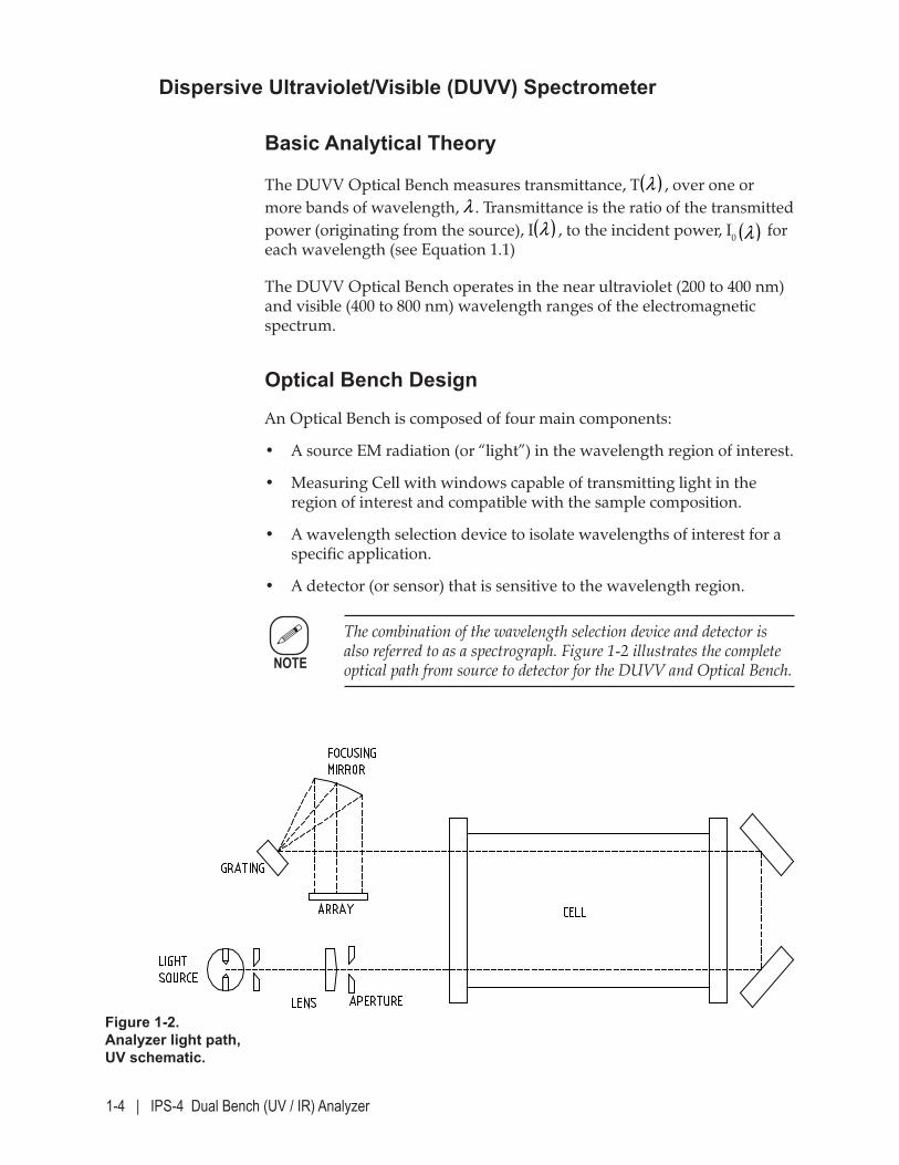
The combination of the wavelength selection device and detector is also referred to as a spectrograph. Figure 1-2 illustrates the complete optical path from source to detector for the DUVV and Optical Bench.
Figure 1-2. Analyzer light path, UV schematic.
NOTE
Overview | 1-5
A Xenon flash lamp is utilized as the source for the ultraviolet and visible regions. The collimated beam from the Xenon lamp travels through the Measuring Cell. There are several types of Measuring Cells for the IPS-4 (see Figure 5-2). When an application requires sensitivity at shorter wave-lengths, UV-grade fused silica windows are used. For streams containing components that are incompatible with fused silica (e.g. hydrofluoric acid, HF) or that require higher maintain pressures, Sapphire windows are also available. Front-surface aluminum mirrors are used in the Measuring Cell. After the beam passes through the Measuring Cell, a diffraction grating disperses the light over a range of wavelengths. Next, a concave mirror focuses the beam onto a 512 or 1024 element photodiode detector array.
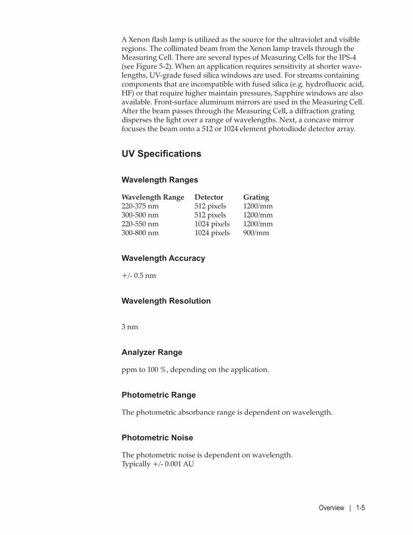
UV Specifications
Wavelength Ranges
Wavelength Range Detector Grating 220-375 nm 512 pixels 1200/mm 300-500 nm 512 pixels 1200/mm 220-550 nm 1024 pixels 1200/mm 300-800 nm 1024 pixels 900/mm
Wavelength Accuracy
+/- 0.5 nm
Wavelength Resolution
3 nm
Analyzer Range
ppm to 100 %, depending on the application.
Photometric Range
The photometric absorbance range is dependent on wavelength.
Photometric Noise
The photometric noise is dependent on wavelength. Typically +/- 0.001 AU
1-6 | IPS-4 Dual Bench (UV / IR) Analyzer
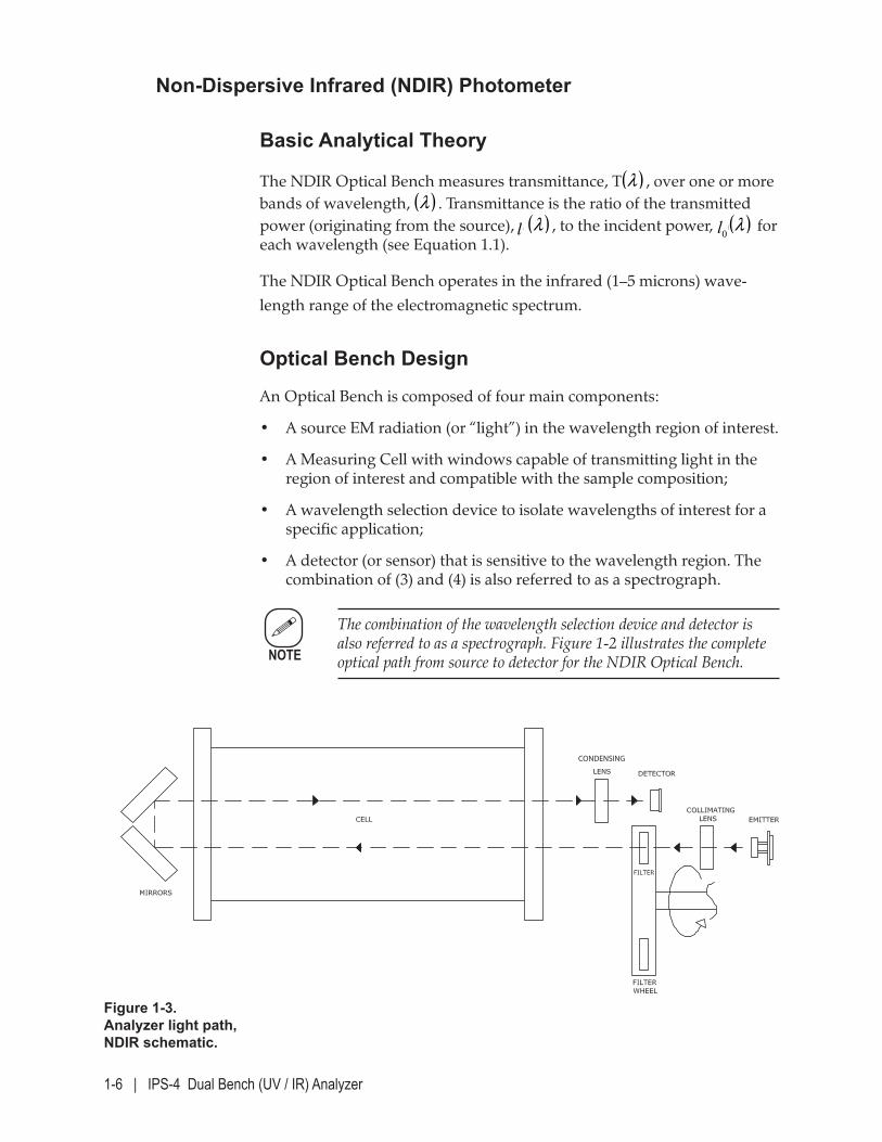
Non-Dispersive Infrared (NDIR) Photometer
Basic Analytical Theory
The NDIR Optical Bench measures transmittance, T( )λl
, over one or more
bands of wavelength, ( )λl
. Transmittance is the ratio of the transmitted
power (originating from the source), ( )λl
( )λl
, to the incident power, ( )λ0l ( )λl
for
each wavelength (see Equation 1.1).
The NDIR Optical Bench operates in the infrared (1–5 microns) wave-length range of the electromagnetic spectrum.
Optical Bench Design
An Optical Bench is composed of four main components:
• A source EM radiation (or “light”) in the wavelength region of interest.
• A Measuring Cell with windows capable of transmitting light in the region of interest and compatible with the sample composition;
• A wavelength selection device to isolate wavelengths of interest for a specific application;
• A detector (or sensor) that is sensitive to the wavelength region. The combination of (3) and (4) is also referred to as a spectrograph.
The combination of the wavelength selection device and detector is also referred to as a spectrograph. Figure 1-2 illustrates the complete optical path from source to detector for the NDIR Optical Bench.
CONDENSING
Figure 1-3. Analyzer light path, NDIR schematic.
NOTE
Overview | 1-7
A coiled filament, blackbody radiation steady-state emitter is utilized as the source for the infrared spectral region. The near-collimated beam from the emitter assembly (containing a parabolic reflector and CaF2 lens) trav-els through the optical bandpass filter (up to six filters located in the filter wheel assembly) and then through the Measuring Cell. There are several types of Measuring Cells for the IPS-4 (see Figure 5-2). Typically, Sapphire windows and gold mirrors are used in the Measuring Cell. Next, a con-densing lens focuses the beam onto a two-stage thermoelectrically cooled lead selenide (PbSe) detector.
NDIR Specifications
Wavelength Ranges
1-5 microns
Photometric Range
The photometric absorbance range is dependent on wavelength.
Photometric Noise
The photometric noise is dependent on wavelength. Typically +/- 0.001 AU
Sample System
The sample system is contained within an attached but separate, insulated enclosure (Oven/Sample System Enclosure). If this enclosure is heated, components within this enclosure are specified to operate at temperatures of up to 150 °C.
The system components are configurable for both gas and liquid applica-tions. A typical configuration for the sample system contains the connec-tions for the inlet and outlet sample lines, the Measuring Cell, an aspirator (gas applications only) to drive the sample fluid through the system, a Zero Fluid inlet, and a Span Fluid inlet. The system may also contain pres-sure sensors/indicators, a filter, and other application-dependent compo-nents. Information about specific (or optional) components that make up your sample system – if applicable – are included in a separate Manual Supplement document, located in the “Supplemental Information” section of this manual or the Documentation Package shipped with the analyzer.
1-8 | IPS-4 Dual Bench (UV / IR) Analyzer
Electronics
The 512 or 1024 element channel detector is mounted on a board which performs some signal conditioning. The signal passes to the MCU board which contains the main analyzer processor. The analyzer internal and external analog and digital inputs/outputs, along with relays, etc., are handled by the Analog and Relay boards.
The main user interface consists of a keypad/display, also known as the User Interface Panel. Other boards include the Customer Connection board, a Display Interface board to run the display, and a Xenon Lamp board. Smaller processors on some of the ancillary boards – all tied into the main MCU – handle local tasks.
The main functions of the processors are to:
• Control the lamp and detector settings.
• Monitor and control temperatures in the Oven/Sample System Enclo-sure (if required) and Optical Bench.
• Monitor sample system pressure.
• Monitor and control temperatures in the sample line.
• Monitor and control temperatures in the probe.
• Monitor alarm relays and other system health.
• Control the sample system including valves, etc.
• Calculate the fluid absorbances and concentrations.
For external communication, RS-232, RS-485, and Ethernet ports are avail-able. Analog signals are also available to the customer through configu-rable 0–20 mA or 4–20 mA outputs.
Overview | 1-9
Classified, Hazardous Area Protection Components and Functions
The Division 1 and Zone 1 versions of the IPS-4 are designed to be, and comply with requirements for, electrical equipment in Division 1 and Zone 1 classified hazardous areas respectively. The methods of protection used include type “p” (pressurized), and type “d” (Flameproof enclosure).
The purge system, redundant heater control, disconnect assembly and en-closure designs assure that the system will not ignite surrounding gases. For this reason, any repairs must not bypass these safety considerations and must use only recommended components.
The purge system consists of the Electronics Enclosure, a purge control-ler, an overpressure vent, a bypass switch and power/signal disconnect assembly. It maintains a positive pressure in the Electronics Enclosure that prevents flammable and corrosive gases from contacting electrical components. The oven enclosure and the seals between the enclosures are designed to assure that the required 5x factor of safety to assure that the sample containment system will not interfere with proper operation of the purge system.
The disconnect assembly receives a pneumatic signal from the purge controller when the enclosure has been adequately purged and the over-pressure is maintained. Until these conditions are met, the relays in the disconnect assembly break all power and signal connections between the field and the analyzer. When the Electronics Enclosure is opened or the pressurization gas supply is lost, the system will shut the analyzer down and transfer a set of contacts that may be used to provide an alarm.
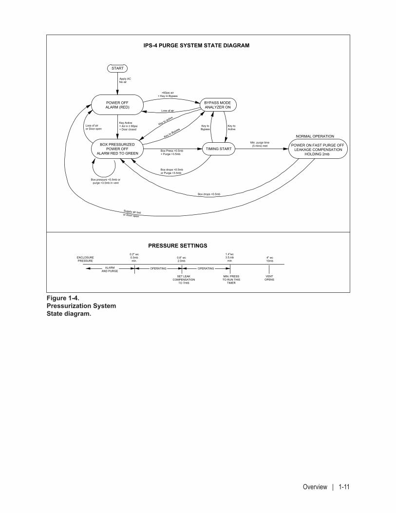
The bypass switch enables operation of the analyzer by applying air pres-sure to the disconnect assembly – bypassing the purge controller. This feature must only be used when the area is known to be safe and is being continuously monitored (See Combustible Gas Detection protection tech-niques in NFPA70 article 500 and 505). Figure 1-4 is a state diagram show-ing the operation of the pressurization system and the pressure settings.
1-10 | IPS-4 Dual Bench (UV / IR) Analyzer
The analyzer must be installed and operated in accordance with this instruction manual. Instrument air or nitrogen may be used as the purge gas.
Once the analyzer has been located in an area contaminated with flammable gases or vapors the IPS-4 purge system must be activated to keep these gases out of the enclosure. For this reason, AC power and an instrument air supply must be connected to the IPS-4. See “Sys-tem Start-Up” for instructions on how to initialize the purge system. If it is not required that the IPS-4 be powered on at this time, switch-ing the power off at the power source will shut down the analyzer while maintaining the protective internal pressure. Switching the power on again will re-activate the IPS-4 if the purge controller is still in the normal pressurization mode.
For the protection system to operate properly, the cover on the dis-connect enclosure must be properly installed and the electronics and oven enclosure doors must be securely shut. All door latches must be properly tightened with the key.
!CAUTION
!CAUTION
Overview | 1-11
Figure 1-4. Pressurization System State diagram.
BOX PRESSURIZEDPOWER OFF
ALARM RED TO GREEN
POWER OFFALARM (RED)
START
BYPASS MODEANALYZER ON
TIMING STARTPOWER ON FAST PURGE OFF
LEAKAGE COMPENSATIONHOLDING 2mb
NORMAL OPERATION
IPS-4 PURGE SYSTEM STATE DIAGRAM
PRESSURE SETTINGS
ENCLOSUREPRESSURE
ALARMAND PURGE
OPERATING OPERATING
SET LEAKCOMPENSATION
TO THIS
MIN. PRESSTO RUN THIS
TIMER
VENTOPENS
0.2" wc0.5mbmin.
0.8" wc2.0mb
1.4"wc3.5.mb
min4" wc10mb
Supply air lostor Door open
Box pressure <0.5mb orpurge <3.5mb in vent
Loss of airor Door open
Key Active+ Air in ≥ 60psi+ Door closed
Apply ACNo air
>60psi air+ Key in Bypass
Loss of air
Key to active
Key to Bypass
Box Press >0.5mb+ Purge >3.5mb
Box drops <0.5mbor Purge <3.5mb
Box drops <0.5mb
Min. purge time(5 mins) met
Key toActive
Key toBypass
IPS-4 PURGE SYSTEM STATE DIAGRAM
1-12 | IPS-4 Dual Bench (UV / IR) Analyzer
Supplemental Information – Where Can I Find It?
Some analyzers are configured with optional equipment that may require supplementary information. The analyzer manual and this additional information (not part of the main manual) – collectively known as the Documentation Package – is included with the manual.
The Documentation Package shipped with each analyzer includes the fol-lowing:
• Manual Supplements that describe and illustrate installation, operation, layout, and maintenance procedures for non-standard Measuring Cells* or optional equipment*, non-standard (derivative) analyzer models, or information that is intended to replace similar information in the Operator’s Guide. (*These documents can also include a non-standard Spare Parts List or a separate Custom Spare Parts List.)
• Analyzer Configuration Parameters sheet, which lists the critical analyzer operating parameters.
• Optical Bench Calibration Summary Report (Pixel to Wavelength) Sheet, which is a summary report.
• Signed Final QC (Quality Control) Document, which includes AMETEK Testing Quality Control information for the analyzer.
• Final "As-Built" drawings which are customer-specific drawings for the analyzer system.
• Other customer-specific information may also be included (if appli-cable), such as Product Data Sheets, a Custom Spare Parts list, or analyzer Certificates.
Specifications | 2-1
SPECIFICATIONS
Analyzer Specifications
Analytes
Up to eight analytes, depending on the application.
Response Linearity
+/- 1% of full scale range
Measurement Accuracy
+/- 1% or +/- 2% of full scale (typical – application specific). Accuracy is determined by comparing analyzer response to a known standard sample after a calibration has been performed.
Repeatability
< 1.0 % of full-scale range (application specific)
Linearity
< 1.0 % of full-scale range
Stability
+/- 1% of full scale range
2-2 | IPS-4 Dual Bench (UV / IR) Analyzer
24-Hour Zero Drift
< 1.0 % of full-scale range over 24 hours
Inputs
Two (2) non-isolated analog inputs, configurable as 0–20 mA, 4–20 mA, or 0–5 V.
Two (2) optically isolated discrete DC inputs (minimum voltage: 11.5 V; maximum voltage: 24.5 V)
22-key piezoelectric numeric keypad.
Outputs
256 x 64 pixel vacuum-fluorescent display with multilingual capability.
Four (4) isolated analog outputs, configurable as 0–20 mA or 4–20 mA (eight optional).
Up to eight (8) relays (NO, contact rating 100 VA, 240 V maximum), which indicate the operational status of the analyzer. Each relay provides one SPST (Form A) dry (potential free) contact.
Two form C loss of purge alarm contacts rated 240 Vac 5 A max.
RS-485 serial port, isolated.
RS-232 serial port, non-isolated.
Fast Ethernet (IEE802.3).
Modbus TCP (Supports single Modbus Client ).
Specifications | 2-3
Sample System Limits
Sample Pressure
Up to 10,000 kPag (1,450 psig / 100 barg) can be accommodated, depend-ing on the application. See product markings or the Final “As-Built” draw-ings in the analyzer Documentation Package.
Oven/Sample System Enclosure Temperature
For applications with a heated sample system, the Oven will operate at temperatures up to 150 °C (302 °F).
Sample Transport
Gas Applications: By aspiration, using Instrument Air or N2 as the drive gas.
Liquid Applications: Using sample stream pressure. Minimum 5 psi differential pressure inlet to outlet.
Instrument Air Requirements
The aspirator medium must be transported in 316 stainless steel.
Minimum pressure: 490–700 kPag (70–100 psig / 4.8–6.9 barg)
Air Quality: As per ANSI/ISA-S7.0.01 (1996) Quality Standard for Instrument Air.
Nitrogen Requirements: If using N2, use only ultra high purity (UHP) Nitrogen.
For “application specific” N2 requirements, refer to the Final “As-Built” drawings in the analyzer Documentation Package.
Sample Fluid Flow Rate
Application specific.
2-4 | IPS-4 Dual Bench (UV / IR) Analyzer
Electrical Requirements
Power Consumption
Without Oven Heater < 500 W maximum start-up (from a cold start) with continuous average, depending on ambient temperature.
With Oven Heater < 900 W maximum start-up (from a cold start) with continuous average, depending on ambient temperature.
Heated Sample Line
Depending on voltage and length (see customer wiring diagram). Max rating 240 Vac 20 A.
Supply Voltage
120 VAC (105–132 VAC), 47–63 Hz OR 240 VAC (209–264 VAC), 47–63 Hz
Cell Construction
Gas and Liquid Cells available, in a variety of materials (body can be 316 stainless steel, Hastelloy C-276, or Monel with Sapphire or UV-grade Quartz windows), to suit a variety of applications.
Pressure Input Signals
Two pressure input signals.Manifold Block: 0–100 psigMeasuring Cell: (0–30 psia, 0–100 psia, or 0–500 psia)
On-Board Temperature Sensor
The electronics temperature is measured by a solid-state temperature sen-sor located on the MCU board.
Specifications | 2-5
Environmental
Ambient Temperature
-20 °C to +50 °C (-4 °F to +122 °F), without external heating or cooling. * When liquids are used, ambient temperature is greater than the freezing point.
Humidity
0–90 % Relative Humidity
Pollution Degree
Pollution Degree 2
Maximum Altitude
2000 metres
Installation Category
Installation Category II
Enclosure Material
Stainless Steel main enclosures. Aluminum disconnect enclosure.
Ingress Protection
IP65 (Zone 1) and NEMA Type 4 (Div 1)
Physical Dimensions
Height: 660 mm (26"), analyzer only Width: 947 mm (37.3"), analyzer onlyDepth: 254 mm (10"), analyzer onlyWeight: 86 kg (188 lb), without Backpan
(may vary, depending on system) Approximately 129 kg (285 lb), with Backpan
2-6 | IPS-4 Dual Bench (UV / IR) Analyzer
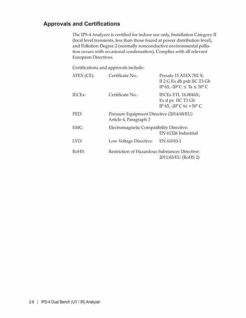
Approvals and Certifications
The IPS-4 Analyzer is certified for indoor use only, Installation Category II (local level transients, less than those found at power distribution level), and Pollution Degree 2 (normally nonconductive environmental pollu-tion occurs with occasional condensation). Complies with all relevant European Directives.
Certifications and approvals include:
ATEX (CE): Certificate No.: Presafe 15 ATEX 702 X; II 2 G Ex db pxb IIC T3 Gb IP 65, -20° C ≤ Ta ≤ 50° C
IECEx: Certificate No.: IECEx ETL 16.0044X; Ex d px IIC T3 Gb IP 65, -20° C to +50° C
PED: Pressure Equipment Directive (2014/68/EU) Article 4, Paragraph 3
EMC: Electromagnetic Compatibility Directive: EN 61326 Industrial
LVD: Low Voltage Directive: EN 61010-1
RoHS: Restriction of Hazardous Substances Directive: 2011/65/EU (RoHS 2)
Specifications | 2-7
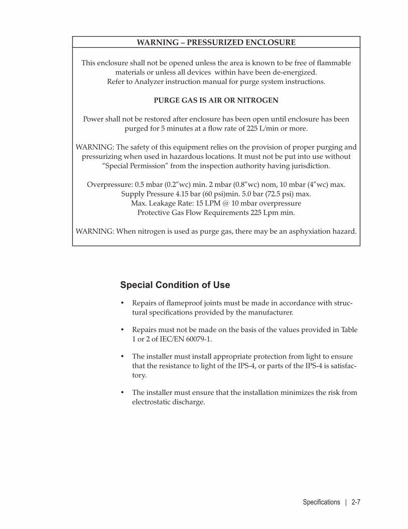
WARNING – PRESSURIZED ENCLOSURE
This enclosure shall not be opened unless the area is known to be free of flammable materials or unless all devices within have been de-energized.
Refer to Analyzer instruction manual for purge system instructions.
PURGE GAS IS AIR OR NITROGEN
Power shall not be restored after enclosure has been open until enclosure has been purged for 5 minutes at a flow rate of 225 L/min or more.
WARNING: The safety of this equipment relies on the provision of proper purging and pressurizing when used in hazardous locations. It must not be put into use without
“Special Permission” from the inspection authority having jurisdiction.
Overpressure: 0.5 mbar (0.2”wc) min. 2 mbar (0.8”wc) nom, 10 mbar (4”wc) max. Supply Pressure 4.15 bar (60 psi)min. 5.0 bar (72.5 psi) max.
Max. Leakage Rate: 15 LPM @ 10 mbar overpressure Protective Gas Flow Requirements 225 Lpm min.
WARNING: When nitrogen is used as purge gas, there may be an asphyxiation hazard.
Special Condition of Use
• Repairs of flameproof joints must be made in accordance with struc-tural specifications provided by the manufacturer.
• Repairs must not be made on the basis of the values provided in Table 1 or 2 of IEC/EN 60079-1.
• The installer must install appropriate protection from light to ensure that the resistance to light of the IPS-4, or parts of the IPS-4 is satisfac-tory.
• The installer must ensure that the installation minimizes the risk from electrostatic discharge.
2-8 | IPS-4 Dual Bench (UV / IR) Analyzer
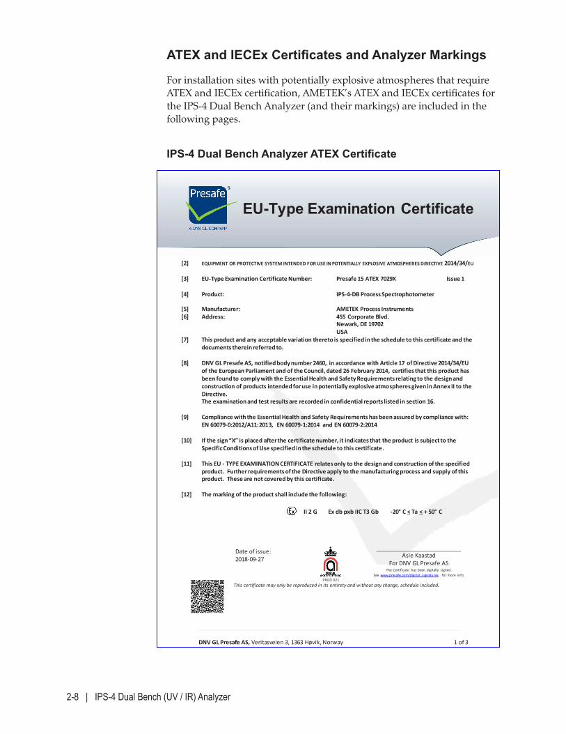
DNV GL Presafe AS, Veritasveien 3, 1363 Høvik, Norway 1 of 3
EU-Type Examination Certificate
[2] EQUIPMENT OR PROTECTIVE SYSTEM INTENDED FOR USE IN POTENTIALLY EXPLOSIVE ATMOSPHERES DIRECTIVE 2014/34/EU
[3] EU-Type Examination Certificate Number:
Presafe 15 ATEX 7029X Issue 1
[4] Product: IPS-4-DB Process Spectrophotometer
[5] Manufacturer: AMETEK Process Instruments [6] Address: 455 Corporate Blvd.
Newark, DE 19702 USA
[7] This product and any acceptable variation thereto is specified in the schedule to this certificate and the documents therein referred to.
[8] DNV GL Presafe AS, notified body number 2460, in accordance with Article 17 of Directive 2014/34/EU of the European Parliament and of the Council, dated 26 February 2014, certifies that this product has been found to comply with the Essential Health and Safety Requirements relating to the design and construction of products intended for use in potentially explosive atmospheres given in Annex II to the Directive.
The examination and test results are recorded in confidential reports listed in section 16.
[9] Compliance with the Essential Health and Safety Requirements has been assured by compliance with: EN 60079-0:2012/A11:2013, EN 60079-1:2014 and EN 60079-2:2014
[10] If the sign “X” is placed after the certificate number, it indicates that the product is subject to the Specific Conditions of Use specified in the schedule to this certificate.
[11] This EU - TYPE EXAMINATION CERTIFICATE relates only to the design and construction of the specified product. Further requirements of the Directive apply to the manufacturing process and supply of this product. These are not covered by this certificate.
[12] The marking of the product shall include the following:
II 2 G Ex db pxb IIC T3 Gb -20° C < Ta < + 50° C
Date of issue: 2018-09-27
PROD 021
____________________________
Asle Kaastad For DNV GL Presafe AS
The Certificate has been digitally signed. See www.presafe.com/digi tal_signatu res for more info
This certificate may only be reproduced in its entirety and without any change, schedule included.
ATEX and IECEx Certificates and Analyzer Markings
For installation sites with potentially explosive atmospheres that require ATEX and IECEx certification, AMETEK’s ATEX and IECEx certificates for the IPS-4 Dual Bench Analyzer (and their markings) are included in the following pages.
IPS-4 Dual Bench Analyzer ATEX Certificate
Specifications | 2-9
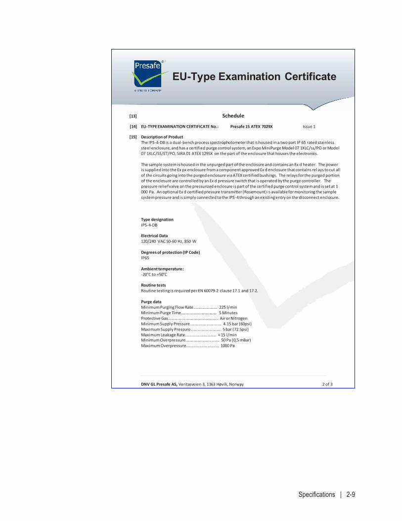
DNV GL Presafe AS, Veritasveien 3, 1363 Høvik, Norway 2 of 3
EU-Type Examination Certificate
[13] Schedule
[14] EU-TYPE EXAMINATION CERTIFICATE No.: Presafe 15 ATEX 7029X Issue 1
[15] Description of Product The IPS-4-DB is a dual-bench process spectrophotometer that is housed in a two part IP 65 rated stainless
steel enclosure, and has a certified purge control system, an Expo MiniPurge Model 07 1XLC/ss/PO or Model 07 1XLC/SS/ET/PO, SIRA 01 ATEX 1295X on the part of the enclosure that houses the electronics.
The sample system is housed in the unpurged part of the enclosure and contains an Ex d heater. The power
is supplied into the Ex px enclosure from a component approved Ex d enclosure that contains rel ays to cut all of the circuits going into the purged enclosure via ATEX certified bushings. The relays for the purged portion of the enclosure are controlled by an Ex d pressure switch that is operated by the purge controller. The pressure relief valve on the pressurized enclosure is part of the certified purge control system and is set at 1 000 Pa. An optional Ex d certified pressure transmitter (Rosemount) is available for monitoring the sample system pressure and is simply connected to the IPS-4 through an existing entry on the disconnect enclosure.
Type designation IPS-4-DB Electrical Data
120/240 VAC 50-60 Hz, 850 W Degrees of protection (IP Code)
IP65 Ambient temperature: -20°C to +50°C Routine tests Routine testing is required per EN 60079-2 clause 17.1 and 17.2. Purge data Minimum Purging Flow Rate..................... 225 l/min Minimum Purge Time............................... 5 Minutes Protective Gas............................................ Air or Nitrogen Minimum Supply Pressure............................ 4.15 bar (60psi) Maximum Supply Pressure........................... 5 bar (72.5psi) Maximum Leakage Rate........................... < 15 l/min Minimum Overpressure.............................. 50 Pa (0,5 mBar) Maximum Overpressure............................. 1000 Pa
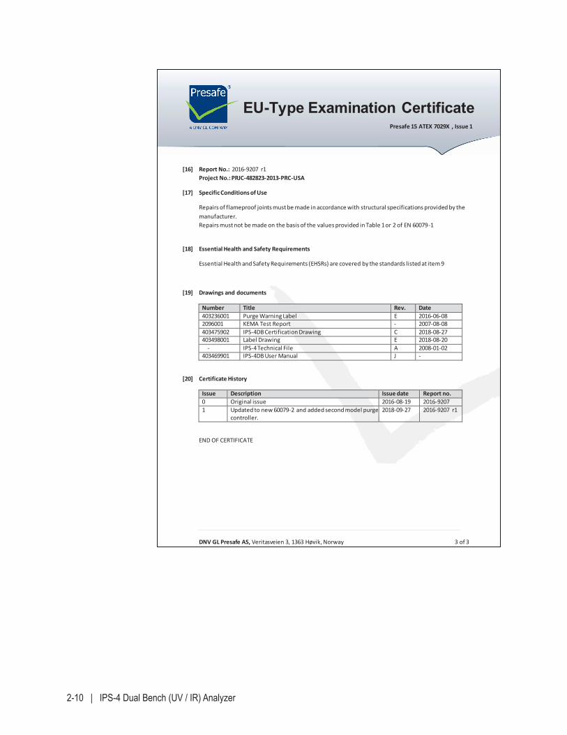
2-10 | IPS-4 Dual Bench (UV / IR) Analyzer
DNV GL Presafe AS, Veritasveien 3, 1363 Høvik, Norway 3 of 3
EU-Type Examination Certificate
Presafe 15 ATEX 7029X , Issue 1
[16] Report No.: 2016-9207 r1
Project No.: PRJC-482823-2013-PRC-USA
[17] Specific Conditions of Use
Repairs of flameproof joints must be made in accordance with structural specifications provided by the manufacturer. Repairs must not be made on the basis of the values provided in Table 1 or 2 of EN 60079-1
[18] Essential Health and Safety Requirements
Essential Health and Safety Requirements (EHSRs) are covered by the standards listed at item 9
[19] Drawings and documents
Number Title Rev. Date 403236001 Purge Warning Label E 2016-06-08 2096001 KEMA Test Report - 2007-08-08 403475902 IPS-4DB Certification Drawing C 2018-08-27 403498001 Label Drawing E 2018-08-20 - IPS-4 Technical File A 2008-01-02 403469901 IPS-4DB User Manual J -
[20] Certificate History
Issue Description Issue date Report no. 0 Original issue 2016-08-19 2016-9207 1 Updated to new 60079-2 and added second model purge
controller. 2018-09-27 2016-9207 r1
END OF CERTIFICATE
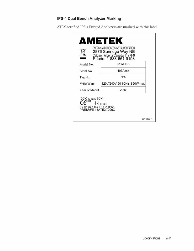
Specifications | 2-11
IPS-4 Dual Bench Analyzer Marking
ATEX-certified IPS-4 Purged Analyzers are marked with this label.
AMETEKENERGY AND PROCESS INSTRUMENTATION2876 Sunridge Way NECalgary, Alberta Canada T1Y7H9Phone: 1-888-661-9198
Model No.
Serial No.
Tag No.
V/Hz/Watts
301-5320-F
3x
IPS-4 DB
403Axxx
N/A
120V/240V 50-60Hz 850Wmax
-20°C ≤ Ta ≤ 50°C
II 2GEx db pxb IIC T3 Gb IP65PRESAFE 15ATEX7029X
Year of Manuf. 20xx
LABEL, IPS-4 DUAL BENCHATEX ZONE 1, IIC
FREV 24-OCT-2019301-5320
0344
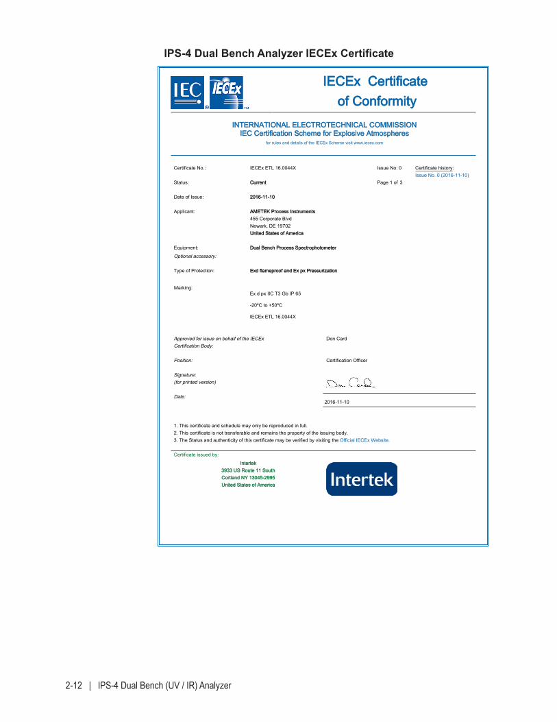
2-12 | IPS-4 Dual Bench (UV / IR) Analyzer
IIEECCEExx CCeerrttiiffiiccaattee ooff CCoonnffoorrmmiittyy
IINNTTEERRNNAATTIIOONNAALL EELLEECCTTRROOTTEECCHHNNIICCAALL CCOOMMMMIISSSSIIOONNIIEECC CCeerrttiiffiiccaattiioonn SScchheemmee ffoorr EExxpplloossiivvee AAttmmoosspphheerreess
for rules and details of the IECEx Scheme visit www.iecex.com
Certificate No.: IECEx ETL 16.0044X Issue No: 0 Certificate history:Issue No. 0 (2016-11-10)
Status: CCuurrrreenntt
Date of Issue: 22001166--1111--1100
Applicant: AAMMEETTEEKK PPrroocceessss IInnssttrruummeennttss455 Corporate BlvdNewark, DE 19702UUnniitteedd SSttaatteess ooff AAmmeerriiccaa
Equipment: DDuuaall BBeenncchh PPrroocceessss SSppeeccttrroopphhoottoommeetteerr
Optional accessory:
Type of Protection: EExxdd ffllaammeepprrooooff aanndd EExx ppxx PPrreessssuurriizzaattiioonn
Marking:Ex d px IIC T3 Gb IP 65
-20ºC to +50ºC
IECEx ETL 16.0044X
Approved for issue on behalf of the IECExCertification Body:
Don Card
Position: Certification Officer
Signature:(for printed version)
Date:
1. This certificate and schedule may only be reproduced in full.2. This certificate is not transferable and remains the property of the issuing body.3. The Status and authenticity of this certificate may be verified by visiting the Official IECEx Website.
Certificate issued by:
IInntteerrtteekk33993333 UUSS RRoouuttee 1111 SSoouutthhCCoorrttllaanndd NNYY 1133004455--22999955UUnniitteedd SSttaatteess ooff AAmmeerriiccaa
Page 1 of 3
2016-11-10
IPS-4 Dual Bench Analyzer IECEx Certificate
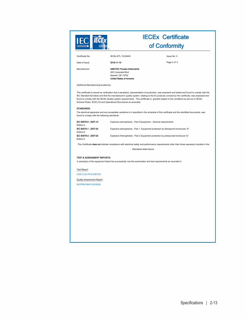
Specifications | 2-13
IIEECCEExx CCeerrttiiffiiccaattee ooff CCoonnffoorrmmiittyy
Certificate No: IECEx ETL 16.0044X Issue No: 0
Date of Issue: 22001166--1111--1100
Manufacturer: AAMMEETTEEKK PPrroocceessss IInnssttrruummeennttss455 Corporate BlvdNewark, DE 19702UUnniitteedd SSttaatteess ooff AAmmeerriiccaa
Additional Manufacturing location(s):
This certificate is issued as verification that a sample(s), representative of production, was assessed and tested and found to comply with theIEC Standard list below and that the manufacturer's quality system, relating to the Ex products covered by this certificate, was assessed andfound to comply with the IECEx Quality system requirements. This certificate is granted subject to the conditions as set out in IECExScheme Rules, IECEx 02 and Operational Documents as amended.
SSTTAANNDDAARRDDSS::
The electrical apparatus and any acceptable variations to it specified in the schedule of this certificate and the identified documents, wasfound to comply with the following standards:
IIEECC 6600007799--00 :: 22000077--1100Edition:5
Explosive atmospheres - Part 0:Equipment - General requirements
IIEECC 6600007799--11 :: 22000077--0044Edition:6
Explosive atmospheres - Part 1: Equipment protection by flameproof enclosures "d"
IIEECC 6600007799--22 :: 22000077--0022Edition:5
Explosive Atmospheres - Part 2 Equipment protection by pressurized enclosure "p"
This Certificate ddooeess nnoott indicate compliance with electrical safety and performance requirements other than those expressly included in the
Standards listed above.
TTEESSTT && AASSSSEESSSSMMEENNTT RREEPPOORRTTSS::
A sample(s) of the equipment listed has successfully met the examination and test requirements as recorded in
Test Report:
US/ETL/ExTR16.0067/00
Quality Assessment Report:
NO/PRE/QAR15.0035/00
Page 2 of 3
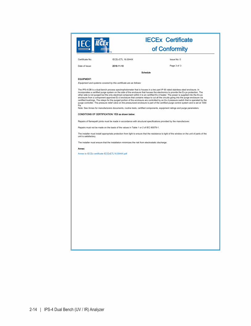
2-14 | IPS-4 Dual Bench (UV / IR) Analyzer
IIEECCEExx CCeerrttiiffiiccaattee ooff CCoonnffoorrmmiittyy
Certificate No: IECEx ETL 16.0044X Issue No: 0
Date of Issue: 22001166--1111--1100
SScchheedduullee
EEQQUUIIPPMMEENNTT::
Equipment and systems covered by this certificate are as follows:
The IPS-4-DB is a dual-bench process spectrophotometer that is houses in a two part IP 65 rated stainless steel enclosure. Inincorporates a certified purge system on the side of the enclosure that houses the electronics to provide the Ex px protection. Theother side is not purged but the only electrical component within it is an certified Ex d heater. The power is supplied into the Ex pxenclosure from a component approved Ex d enclosure that contains relays to cut all the circuits going into the purge enclosure viacertified bushings. The relays for the purged portion of the enclosure are controlled by an Ex d pressure switch that is operated by thepurge controller. The pressure relief valve on the pressurized enclosure is part of the certified purge control system and is set at 1000Pa.Note: See Annex for manufacturers documents, routine tests, certified components, equipment ratings and purge parameters.
CCOONNDDIITTIIOONNSS OOFF CCEERRTTIIFFIICCAATTIIOONN:: YYEESS aass sshhoowwnn bbeellooww::
Repairs of flamepath joints must be made in accordance with structural specifications provided by the manufacturer.
Repairs must not be made on the basis of the values in Table 1 or 2 of IEC 60079-1.
The installer must install appropriate protection from light to ensure that the resistance to light of the window on the unit of parts of theunit is satisfactory.
The installer must ensure that the installation minimizes the risk from electrostatic discharge.
AAnnnneexx::
Annex to IECEx certificate IECExETL16.0044X.pdf
Page 3 of 3
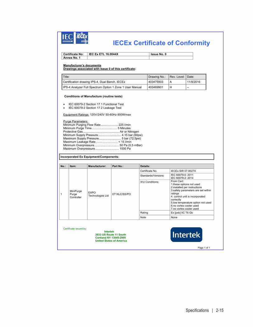
Specifications | 2-15
IECEx Certificate of ConformityCertificate No: IEC Ex ETL 16.0044X Issue No. 0Annex No. 1
Certificate issued by: Intertek 3933 US Route 11 South Cortland NY 13045-2995 United States of America
Page 1 of 1
Manufacturer’s documents Drawings associated with Issue 0 of this certificate:
Title: Drawing No.: Rev. Level: Date:
Certification drawing IPS-4, Dual Bench, IECEx 403475903 A 11/9/2016
IPS-4 Analyzer Full Spectrum Option 1 Zone 1 User Manual 403469901 H --
Conditions of Manufacture (routine tests)
• IEC 60079-2 Section 17.1 Functional Test • IEC 60079-2 Section 17.2 Leakage Test
Equipment Ratings: 120V/240V 50-60Hz 850Wmax
Purge Parameters: Minimum Purging Flow Rate..................... 225 l/min Minimum Purge Time............................... 5 Minutes Protective Gas............................................ Air or Nitrogen Minimum Supply Pressure............................ 4.15 bar (60psi) Maximum Supply Pressure........................... 5 bar (72.5psi) Maximum Leakage Rate........................... < 15 l/min Minimum Overpressure.............................. 50 Pa (0,5 mBar) Maximum Overpressure............................. 1000 Pa
Incorporated Ex Equipment/Components:
No.: Item: Manufacturer: Part No.: Details:
1 MiniPurge Purge Controller
EXPO Technologies Ltd 071XLC/SS/PO
Certificate No. IECEx SIR 07.0027X
Standards/Versions: IEC 60079-0: 2011 IEC 60079-2: 2014
X/U Conditions: From Cert: 1.these options not used 2.installed per instructions 3.safety parameters are set within ratings 4. control unit is incorporated correctly 5.low temperature option not used 6.no vortex cooler used 7.no vortex cooler used
Rating Ex [pxb] IIC T6 Gb
Note None
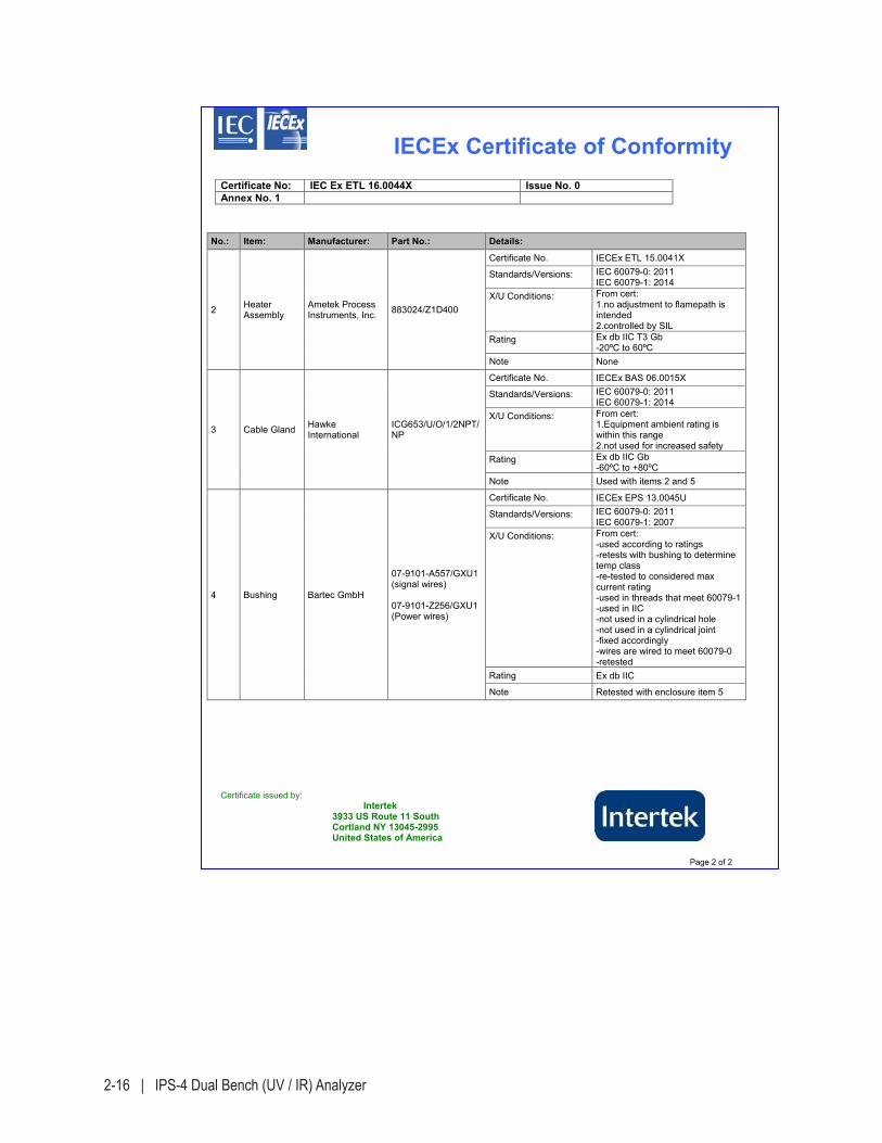
2-16 | IPS-4 Dual Bench (UV / IR) Analyzer
IECEx Certificate of ConformityCertificate No: IEC Ex ETL 16.0044X Issue No. 0Annex No. 1
Certificate issued by: Intertek 3933 US Route 11 South Cortland NY 13045-2995 United States of America
Page 2 of 2
No.: Item: Manufacturer: Part No.: Details:
2 Heater Assembly
Ametek Process Instruments, Inc. 883024/Z1D400
Certificate No. IECEx ETL 15.0041X
Standards/Versions: IEC 60079-0: 2011 IEC 60079-1: 2014
X/U Conditions: From cert: 1.no adjustment to flamepath is intended 2.controlled by SIL
Rating Ex db IIC T3 Gb -20ºC to 60ºC
Note None
3 Cable Gland Hawke International
ICG653/U/O/1/2NPT/NP
Certificate No. IECEx BAS 06.0015X
Standards/Versions: IEC 60079-0: 2011 IEC 60079-1: 2014
X/U Conditions: From cert: 1.Equipment ambient rating is within this range 2.not used for increased safety
Rating Ex db IIC Gb -60ºC to +80ºC
Note Used with items 2 and 5
4 Bushing Bartec GmbH
07-9101-A557/GXU1 (signal wires)
07-9101-Z256/GXU1 (Power wires)
Certificate No. IECEx EPS 13.0045U
Standards/Versions: IEC 60079-0: 2011 IEC 60079-1: 2007
X/U Conditions: From cert: -used according to ratings -retests with bushing to determine temp class -re-tested to considered max current rating -used in threads that meet 60079-1-used in IIC -not used in a cylindrical hole -not used in a cylindrical joint -fixed accordingly -wires are wired to meet 60079-0 -retested
Rating Ex db IIC
Note Retested with enclosure item 5
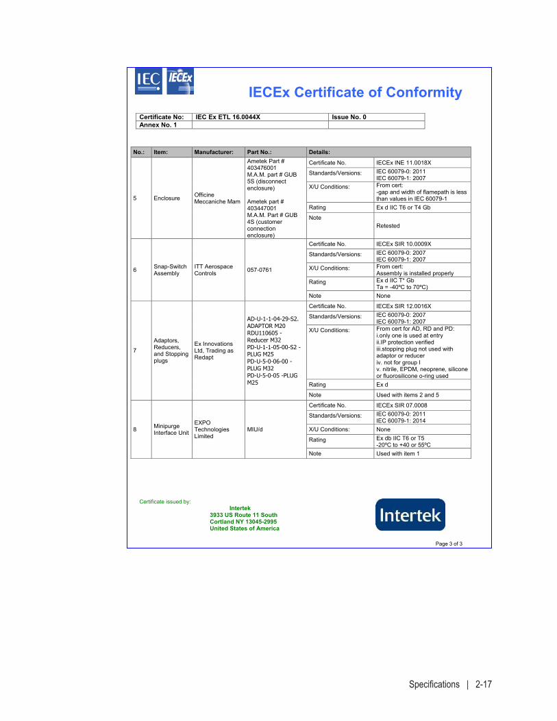
Specifications | 2-17
IECEx Certificate of ConformityCertificate No: IEC Ex ETL 16.0044X Issue No. 0Annex No. 1
Certificate issued by: Intertek 3933 US Route 11 South Cortland NY 13045-2995 United States of America
Page 3 of 3
No.: Item: Manufacturer: Part No.: Details:
5 Enclosure Officine Meccaniche Mam
Ametek Part # 403476001 M.A.M. part # GUB 5S (disconnect enclosure)
Ametek part # 403447001 M.A.M. Part # GUB 4S (customer connection enclosure)
Certificate No. IECEx INE 11.0018X
Standards/Versions: IEC 60079-0: 2011 IEC 60079-1: 2007
X/U Conditions: From cert: -gap and width of flamepath is less than values in IEC 60079-1
Rating Ex d IIC T6 or T4 Gb
Note Retested
6 Snap-Switch Assembly
ITT Aerospace Controls 057-0761
Certificate No. IECEx SIR 10.0009X
Standards/Versions: IEC 60079-0: 2007 IEC 60079-1: 2007
X/U Conditions: From cert: Assembly is installed properly
Rating Ex d IIC T* Gb Ta = -40ºC to 70ºC)
Note None
7
Adaptors, Reducers, and Stopping plugs
Ex Innovations Ltd, Trading as Redapt
AD-U-1-1-04-29-S2. ADAPTOR M20 RDU110605 - Reducer M32 PD-U-1-1-05-00-S2 - PLUG M25 PD-U-5-0-06-00 -PLUG M32 PD-U-5-0-05 -PLUG M25
Certificate No. IECEx SIR 12.0016X
Standards/Versions: IEC 60079-0: 2007 IEC 60079-1: 2007
X/U Conditions: From cert for AD, RD and PD: i.only one is used at entry ii.IP protection verified iii.stopping plug not used with adaptor or reducer iv. not for group I v. nitrile, EPDM, neoprene, silicone or fluorosilicone o-ring used
Rating Ex d
Note Used with items 2 and 5
8 Minipurge Interface Unit
EXPO Technologies Limited
MIU/d
Certificate No. IECEx SIR 07.0008
Standards/Versions: IEC 60079-0: 2011 IEC 60079-1: 2014
X/U Conditions: None
Rating Ex db IIC T6 or T5 -20ºC to +40 or 55ºC
Note Used with item 1

2-18 | IPS-4 Dual Bench (UV / IR) Analyzer
This page intentionally left blank.
Installation and Start-Up | 3-1
INSTALLATION and START-UP
The Installation and Start-Up chapter contains information about the fol-lowing topics:
• Where to find safety information in this guide before working with the analyzer.
• How to store the analyzer before installation.
• How to uncrate and inspect the analyzer for damage before installing it.
• Tools, equipment, and supplies required for installation.
• How to install the mechanical components and sample lines, and per-form a leak check on all of the fittings and connections before power-ing up the analyzer.
• How to make all of the required electrical connections.
• How to apply power to the analyzer and configure it for operation.
• What to expect during normal operation.
The installation of the analyzer must be in accordance with all of the customer (end user) and local regulatory standards and procedures. There are no operator-serviceable components inside the analyzer. Refer service requirements to qualified personnel.
!WARNING
3-2 | IPS-4 Dual Bench (UV / IR) Analyzer
Safety Considerations
Before beginning the installation of the analyzer and before powering it up, review and follow all safety requirements under “Important Safety Notes, Warnings, and Cautions” following the Table of Contents near the beginning of this manual. This information de-scribes procedures to follow to avoid personal injury and/or damage to the equipment. All regulatory agency and personnel safety proce-dures for your jurisdiction must be followed.
The IPS-4 Analyzer is certified with regard to electrical safety for Pollution Degree 2 (normally nonconductive environmental pollution occurs with occasional condensation) and Installation Category II (lo-cal level transients, less than those found at power distribution level). Mains supply voltage fluctuations are not to exceed 10 percent of the nominal supply voltage.
Pre-Installation Requirements
Storage Prior to Installation
If the analyzer and its Optical Bench Assembly are stored for any period of time prior to installation, store the equipment in an environment where it is not subject to dripping or splashing liquids, corrosive gases, high humidity, or excessive heat or cold. Recommended storage conditions include:
Temperature: 0 °C to 50 °C (32 °F to 122 °F)Relative Humidity: < 70 %
Failure to comply with these storage conditions will void your warranty.
NOTE
! WARNING
Installation and Start-Up | 3-3
Uncrating and Inspecting the Analyzer
The analyzer, along with its associated sample system, is shipped pre-mounted on unistruts (or on a backpan) either alone in a crate or in a crated weatherproof shelter. The Optical Bench Assemblies are shipped in a separate box within the Analyzer crate.
Upon receiving the analyzer system, remove the shipping crate and check the exterior of the shelter and/or analyzer for damage. Remove the Optical Bench Assembly from its box and check it for any physical dam-age. Replace the Optical Bench Assembly in its box until it is ready to be installed.
Open the shelter and/or analyzer and check to ensure that all of the com-ponents within are secure and that there is no physical damage. Check that all of the components and wiring within the Electronics Enclosure and Oven/Sample System Enclosure are secure and that there is no physi-cal damage.
After the inspection, close and secure all doors with at least one latch. This will keep the electronics equipment secure and will prevent dam-age to the doors and electronic components during installation.
For non-shelter systems, avoid damaging the analyzer piping or instrumentation by lifting it out of its shipping crate using only its unistruts or backpan, or metal enclosure. DO NOT use any external instrument or tubing connectors as a handle for lifting.
The analyzer (on unistruts) weighs approximately 164 kg (360 lb)depending on the system. Use caution when lifting it from its crate.
General Installation Information
Figure 3-1 illustrates an example of the layout of components within the IPS-4 Analyzer. The components in the Electronics Enclosure generally do not change. However, many of the sample system components in the Oven/Sample System Enclosure in this example illustration are optional and are configured specifically for the application.
Final “As-Built” drawings for your analyzer are located in the Documentation Package shipped with the analyzer and in the “Supplemental Information” section of this manual.
!CAUTION
!CAUTION
! WARNING
3-4 | IPS-4 Dual Bench (UV / IR) Analyzer
Tools, Equipment, and Supplies Required
While installing the analyzer, the following tools, equipment, and supplies are required:
• Door latchkeys (two keys are supplied with the analyzer), attached to the exterior of the analyzer.
• Set of open-end wrenches for fittings and set of metric ball drivers.
• Wire Cutters, strippers, and crimpers.
• Flat blade instrument screwdriver.
• Soft, non-abrasive cloth.
• Wrist Strap (for grounding).
• Detergent-based leak detector (Snoop® or another suitable leak detec-tion agent is permissible).
• Ethernet cable (supplied by customer), for systems using a permanent Ethernet connection. Length will vary, depending on application. Minimum requirements: CAT 5e (maximum 100 m). Special requirements may be necessary for outdoor analyzer installations, hazardous locations, and/or lengths greater than 100 m. Systems using Ethernet also require a ferrite core (supplied by AMETEK).
For systems using a temporary Ethernet connection, a crossover cable must be used.
• One power-disconnect explosion-proof switch (breaker), rated for at least 250 VAC, 20 A and certified for the hazardous location (to satisfy local electrical codes, the switch must be certified by the local author-ity for the appropriate hazardous location). The power-disconnect switch (breaker) must be connected to and mounted near the ana-lyzer, in an easily accessible area. The switch (breaker) must be clearly labeled (e.g., “AMETEK IPS-4 Analyzer Main AC Power Disconnect Switch”). For safety reasons during maintenance, this switch allows the main AC power to be disconnected from the analyzer prior to performing service on the analyzer. This switch (breaker) is to be sup-plied by the customer/end user.
• Tubing for the Instrument Air (or N2) and Span fluid lines. Length will vary, depending on the distance between the analyzer and the supply source. Supplied by the customer.
• Supply tubing and pressure regulator(s) for the purge system. This line should be sized to assure that the pressure at the purge control-ler inlet will not drop below 60 psi (4 barg) with a flow of up to 350 L/min. Installation of one or two regulators is required to assure that the inlet pressure does not exceed the rated inlet pressure (60-115 psi) and should allow for possible failure of one regulator to avoid hazards of excessive air pressure on the enclosure.
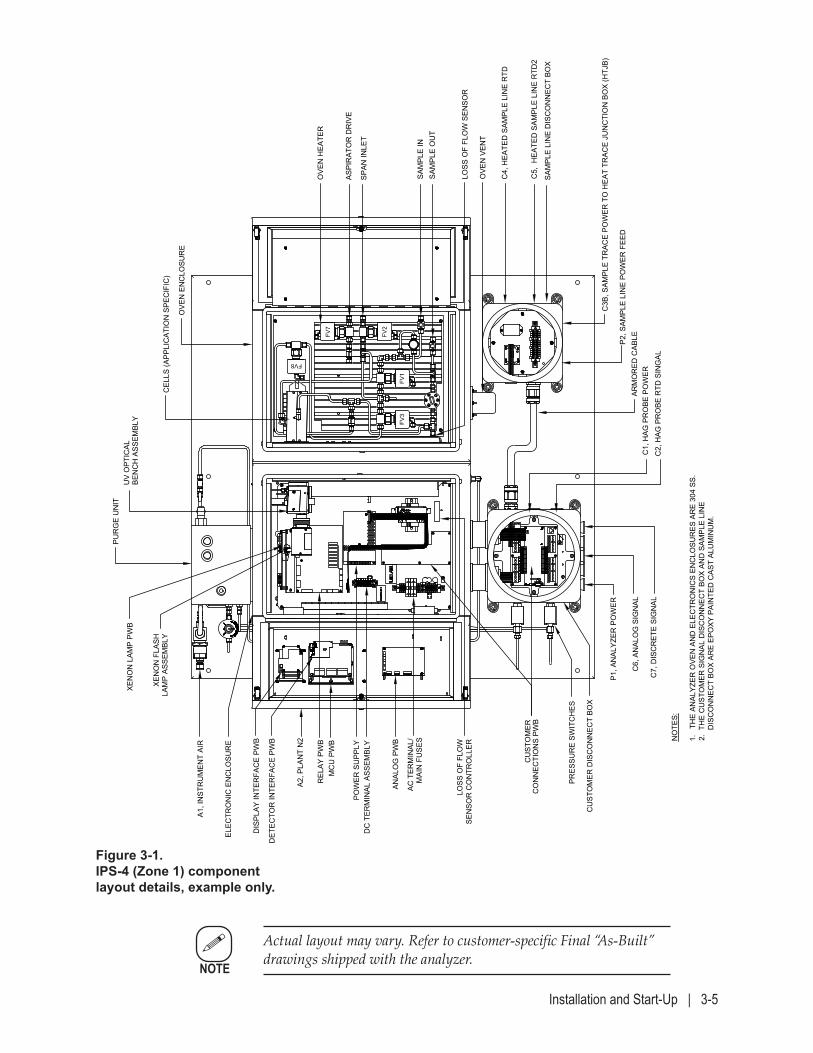
Installation and Start-Up | 3-5
Actual layout may vary. Refer to customer-specific Final “As-Built” drawings shipped with the analyzer.
NOTE
Figure 3-1. IPS-4 (Zone 1) component layout details, example only.
MOD
CON
SYST
EMS/
SOCA
R HA
OR -
AZER
BAIJA
NMO
DEL I
PS-4
ANA
LYZE
R / F
IELD
UNI
T AR
RANG
EMEN
T BREV
.
WX-
1106
2-3-
3B
SAM
PLE
LIN
E D
ISC
ON
NEC
T BO
X
OVE
N H
EATE
R
SAM
PLE
OU
TSA
MPL
E IN
OVE
N E
NC
LOSU
RE
CEL
LS (A
PPLI
CAT
ION
SPE
CIF
IC)
BEN
CH
ASS
EMBL
Y
PUR
GE
UN
IT
XEN
ON
LAM
P PW
B
XEN
ON
FLA
SHLA
MP
ASSE
MBL
Y
ELEC
TRO
NIC
EN
CLO
SUR
E
DC
TER
MIN
AL A
SSEM
BLY
CU
STO
MER
CO
NN
ECTI
ON
S PW
B
POW
ER S
UPP
LY
DET
ECTO
R IN
TER
FAC
E PW
B
DIS
PLAY
INTE
RFA
CE
PWB
MC
U P
WB
REL
AY P
WB
ANAL
OG
PW
B
AC T
ERM
INAL
/M
AIN
FU
SES
PRES
SUR
E SW
ITC
HES
A1, I
NST
RU
MEN
T AI
R
C4,
HEA
TED
SAM
PLE
LIN
E R
TD
C5,
HEA
TED
SAM
PLE
LIN
E R
TD2
C3B
, SAM
PLE
TRAC
E PO
WER
TO
HEA
T TR
ACE
JUN
CTI
ON
BO
X (H
TJB)
P2, S
AMPL
E LI
NE
POW
ER F
EED
OVE
N V
ENT
UV
OPT
ICAL
CU
STO
MER
DIS
CO
NN
ECT
BOX
ARM
OR
ED C
ABLE
C7,
DIS
CR
ETE
SIG
NAL
C6,
AN
ALO
G S
IGN
AL
C2,
HAG
PR
OBE
RTD
SIN
GAL
C1,
HAG
PR
OBE
PO
WER
P1, A
NAL
YZER
PO
WER
A2, P
LAN
T N
2
ASPI
RAT
OR
DR
IVE
NO
TES:
1.
THE
ANAL
YZER
OVE
N A
ND
ELE
CTR
ON
ICS
ENC
LOSU
RES
AR
E 30
4 SS
.2.
TH
E C
UST
OM
ER S
IGN
AL D
ISC
ON
NEC
T BO
X AN
D S
AMPL
E LI
NE
D
ISC
ON
NEC
T BO
X AR
E EP
OXY
PAI
NTE
D C
AST
ALU
MIN
UM
.
SPAN
INLE
T
LOSS
OF
FLO
WSE
NSO
R C
ON
TRO
LLER
LOSS
OF
FLO
W S
ENSO
R
FV7
FV2
FV1
FV3
FV8
2019
/11/
07
3-6 | IPS-4 Dual Bench (UV / IR) Analyzer
Installing the Mechanical Components
Do not mount the Optical Bench Assembly in the Electronics Enclosure until after the analyzer has been mounted in its designated location.
Mounting the Analyzer
The analyzer system comes mounted on a backpan.
Figure 3-2 illustrates the mounting hole locations and dimensions, plus necessary clearances on all sides.
While installing the mechanical components, refer to the Final “As-Built” drawings in the analyzer Documentation Package.
Location and Environment
The IPS-4 Analyzer is designed for operation in environments classified “Pollution Degree 2” per IEC 61010, so it must be shielded from conduc-tive pollution and subject to only temporary condensation.
The entire analyzer system can be mounted directly on a wall, in a spe-cially designed cabinet, or in a custom-built shelter. With its IP65 / NEMA 4 rating, the analyzer system is also suitable for installation in outdoor locations.
Regardless of which installation method is used, be sure to install the analyzer in a vibration-free location, and as close as possible to the sample extraction point to minimize the amount of sample lag time.
The minimum allowable clearances are (if possible, provide extra room to allow sufficient access for servicing the analyzer). See Figure 3-2a:
Below: 610 mm (24”) Front: 762 mm (30”) – door swing clearance Oven/Sample System side: 762 mm (30”) – door swing clearance Electronics Enclosure side: 762 mm (30”) – door swing clearance
NOTE
NOTE
Installation and Start-Up | 3-7
The surrounding ambient temperature of the analyzer should be main-tained between -20 °C to +50 °C (-4 °F to +122 °F). If the analyzer system is mounted within an AMETEK-designed shelter, these conditions are taken into consideration in the design of shelter.
To mount the analyzer:
Figure 3-2a and 2b is an example of an analyzer layout. Mounting configuration and layout for your analyzer system may vary. Refer to the Final “As-Built” drawings in the analyzer Documentation Package.
Non-Shelter Installations: In a suitable, accessible location, mount the analyzer on a vibration-free wall or instrument rack.
Shelter Installations: In a suitable, accessible location, install the analyzer in a vibration-free location.
Refer to customer-specific Final “As-Built” shelter drawings in the analyzer Documentation Package.
Outdoor Installations: In most cases, the analyzer must be shielded from harsh environmental elements such as wind, rain, and sun. In these cases a rain shelter or sun shade is required.
Also, proper water drainage must be considered in the mounting location to allow for suitable and safe working conditions for service personnel.
NOTE
NOTE
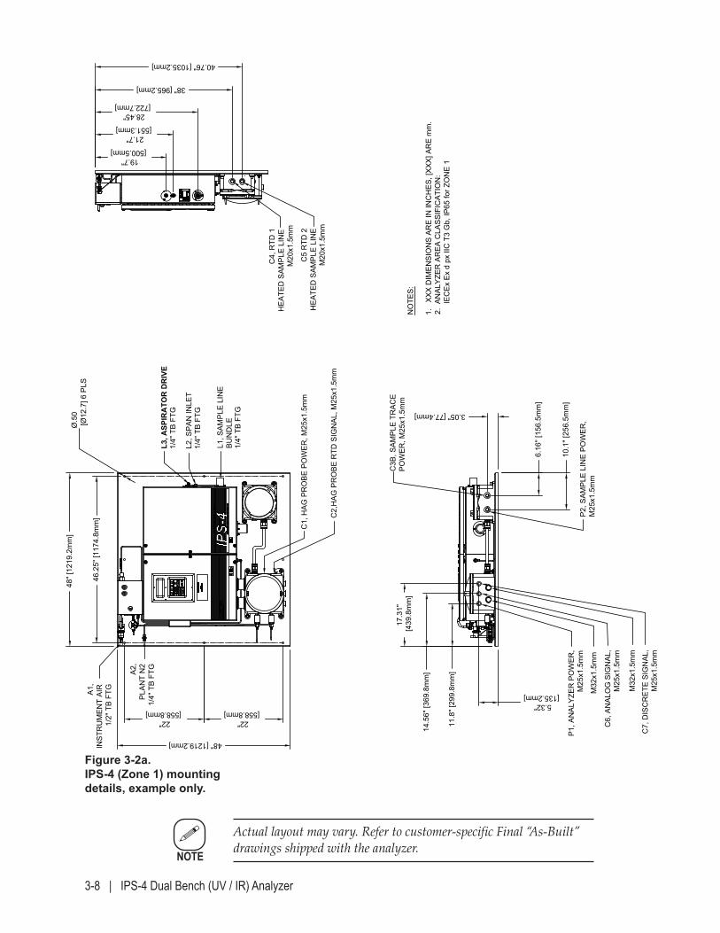
3-8 | IPS-4 Dual Bench (UV / IR) Analyzer
Figure 3-2a. IPS-4 (Zone 1) mounting details, example only.
Actual layout may vary. Refer to customer-specific Final “As-Built” drawings shipped with the analyzer.
NOTE
MOD
CON
SYST
EMS/
SOCA
R HA
OR -
AZER
BAIJA
NMO
DEL I
PS-4
ANA
LYZE
R / F
IELD
UNI
T IN
STAL
LATI
ON AREV
.
WX-
1106
2-3-
320
19/0
5/01
C6,
AN
ALO
G S
IGN
AL,
M25
x1.5
mm
P1, A
NAL
YZER
PO
WER
,M
25x1
.5m
m
C7,
DIS
CR
ETE
SIG
NAL
,M
25x1
.5m
m
C3B
, SAM
PLE
TRAC
EPO
WER
, M25
x1.5
mm
10.1
" [25
6.5m
m]
6.16
" [15
6.5m
m]
3.05" [77.4mm]
17.3
1" [4
39.8
mm
]
14.5
6" [3
69.8
mm
]
11.8
" [29
9.8m
m]
5.32" [135.2mm]
40.76" [1035.2mm]
38" [965.2mm]
28.45" [722.7mm]
21.7" [551.3mm]
19.7" [500.5mm]
Ø.5
0 [Ø
12.7
] 6 P
LS
22" [558.8mm]
22" [558.8mm]
48" [1219.2mm]
46.2
5" [1
174.
8mm
]
48" [
1219
.2m
m]
C5
RTD
2H
EATE
D S
AMPL
E LI
NE
C4,
RTD
1H
EATE
D S
AMPL
E LI
NE
M20
x1.5
mm
C1,
HAG
PR
OBE
PO
WER
, M25
x1.5
mm
C2,
HAG
PR
OBE
RTD
SIG
NAL
, M25
x1.5
mm
P2, S
AMPL
E LI
NE
POW
ER,
M25
x1.5
mm
L3, A
SPIR
ATO
R D
RIV
E1/
4" T
B FT
G
L2, S
PAN
INLE
T1/
4" T
B FT
G
A1,
INST
RU
MEN
T AI
R1/
2" T
B FT
G
NO
TES:
1.
XXX
DIM
ENSI
ON
S AR
E IN
INC
HES
, [XX
X] A
RE
mm
.2.
AN
ALYZ
ER A
REA
CLA
SSIF
ICAT
ION
:
IEC
Ex E
x d
px II
C T
3 G
b, IP
65 fo
r ZO
NE
1
L1, S
AMPL
E LI
NE
BUN
DLE
1/4"
TB
FTG
A2,
PLAN
T N
21/
4" T
B FT
G
M20
x1.5
mm
M32
x1.5
mm
M32
x1.5
mm
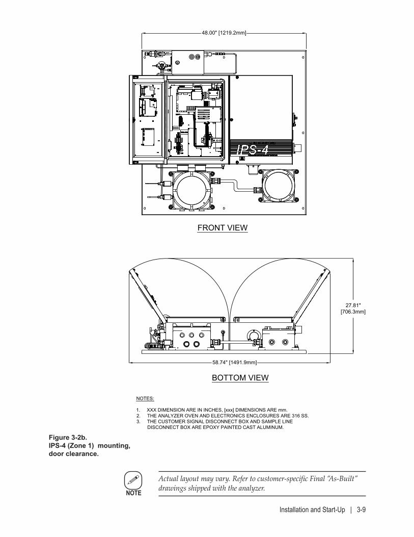
Installation and Start-Up | 3-9
Figure 3-2b. IPS-4 (Zone 1) mounting, door clearance.
Actual layout may vary. Refer to customer-specific Final “As-Built” drawings shipped with the analyzer.
NOTE
MODCON SYSTEMS/SOCAR HAOR - AZERBAIJANMODEL IPS-4 ANALYZER / FIELD UNIT INSTALLATION
AREV.
WX-11062-3-3A 2019/05/01
FRONT VIEW
BOTTOM VIEW
58.74" [1491.9mm]
27.81"[706.3mm]
NOTES:
1. XXX DIMENSION ARE IN INCHES, [xxx] DIMENSIONS ARE mm.2. THE ANALYZER OVEN AND ELECTRONICS ENCLOSURES ARE 316 SS.3. THE CUSTOMER SIGNAL DISCONNECT BOX AND SAMPLE LINE DISCONNECT BOX ARE EPOXY PAINTED CAST ALUMINUM.
48.00" [1219.2mm]
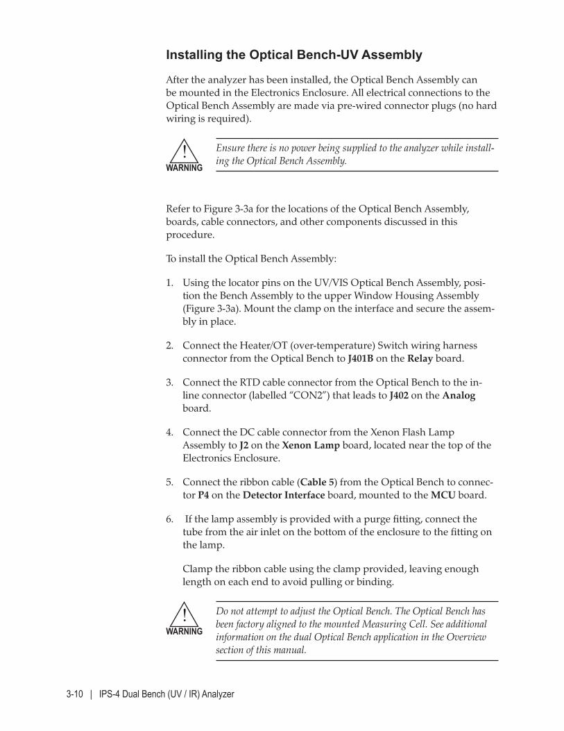
3-10 | IPS-4 Dual Bench (UV / IR) Analyzer
Installing the Optical Bench-UV Assembly
After the analyzer has been installed, the Optical Bench Assembly can be mounted in the Electronics Enclosure. All electrical connections to the Optical Bench Assembly are made via pre-wired connector plugs (no hard wiring is required).
Ensure there is no power being supplied to the analyzer while install-ing the Optical Bench Assembly.
Refer to Figure 3-3a for the locations of the Optical Bench Assembly, boards, cable connectors, and other components discussed in this procedure.
To install the Optical Bench Assembly:
1. Using the locator pins on the UV/VIS Optical Bench Assembly, posi-tion the Bench Assembly to the upper Window Housing Assembly (Figure 3-3a). Mount the clamp on the interface and secure the assem-bly in place.
2. Connect the Heater/OT (over-temperature) Switch wiring harness connector from the Optical Bench to J401B on the Relay board.
3. Connect the RTD cable connector from the Optical Bench to the in-line connector (labelled “CON2”) that leads to J402 on the Analog board.
4. Connect the DC cable connector from the Xenon Flash Lamp Assembly to J2 on the Xenon Lamp board, located near the top of the Electronics Enclosure.
5. Connect the ribbon cable (Cable 5) from the Optical Bench to connec-tor P4 on the Detector Interface board, mounted to the MCU board.
6. If the lamp assembly is provided with a purge fitting, connect the tube from the air inlet on the bottom of the enclosure to the fitting on the lamp.
Clamp the ribbon cable using the clamp provided, leaving enough length on each end to avoid pulling or binding.
Do not attempt to adjust the Optical Bench. The Optical Bench has been factory aligned to the mounted Measuring Cell. See additional information on the dual Optical Bench application in the Overview section of this manual.
!WARNING
!WARNING
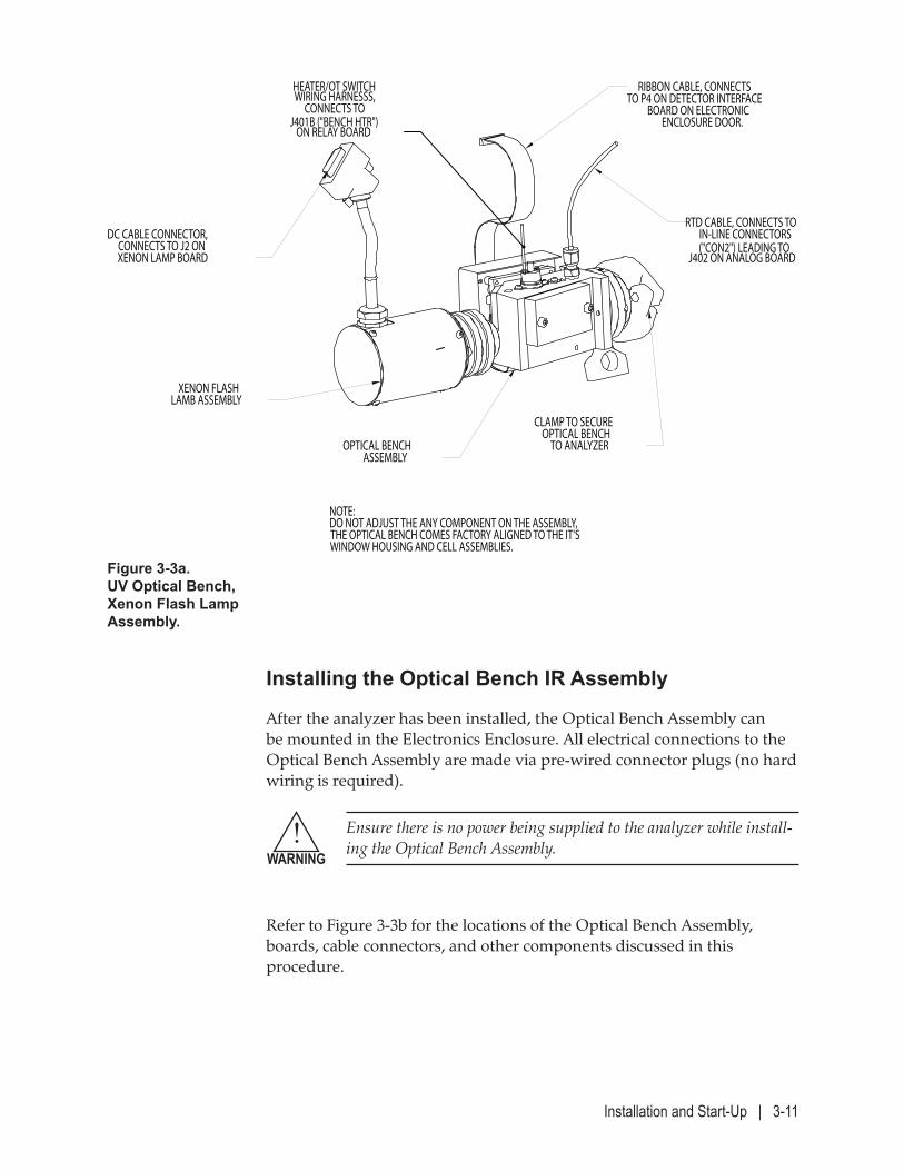
Installation and Start-Up | 3-11
Installing the Optical Bench IR Assembly
After the analyzer has been installed, the Optical Bench Assembly can be mounted in the Electronics Enclosure. All electrical connections to the Optical Bench Assembly are made via pre-wired connector plugs (no hard wiring is required).
Ensure there is no power being supplied to the analyzer while install-ing the Optical Bench Assembly.
Refer to Figure 3-3b for the locations of the Optical Bench Assembly, boards, cable connectors, and other components discussed in this procedure.
!WARNING
Figure 3-3a. UV Optical Bench, Xenon Flash Lamp Assembly.
NOTE:DO NOT ADJUST THE ANY COMPONENT ON THE ASSEMBLY, THE OPTICAL BENCH COMES FACTORY ALIGNED TO THE IT'SWINDOW HOUSING AND CELL ASSEMBLIES.
CLAMP TO SECUREOPTICAL BENCH
TO ANALYZEROPTICAL BENCH ASSEMBLY
XENON FLASHLAMB ASSEMBLY
HEATER/OT SWITCHWIRING HARNESSS,
CONNECTS TO J401B ("BENCH HTR")
ON RELAY BOARD
RIBBON CABLE, CONNECTS TO P4 ON DETECTOR INTERFACE
BOARD ON ELECTRONICENCLOSURE DOOR.
RTD CABLE, CONNECTS TO IN-LINE CONNECTORS ("CON2") LEADING TO
J402 ON ANALOG BOARD
DC CABLE CONNECTOR,CONNECTS TO J2 ONXENON LAMP BOARD
3-12 | IPS-4 Dual Bench (UV / IR) Analyzer
To install the Optical Bench Assembly:
1. Using the locator pins on the NDIR Optical Bench Assembly, position the Bench Assembly to the lower Window Housing Assembly (Figure 3-3b). Mount the clamp on the interface and secure the assembly in place.
2. Connect the three pin DC cable connector from DC supply to the mat-ing connector on the underside of the Optical Bench Assembly.
3. Connect the ribbon cable from the Optical Bench to connector P2 on the Detector Interface board, mounted to the MCU board.
4. Clamp the ribbon cable using the clamp provided, leaving enough length on each end to avoid pulling or binding.
5. Connect the purge supply tubing to the purge fitting on the Optical Bench Assembly.
Figure 3-3b. IR Optical Bench, Infrared Source Assembly.
CLAMP, TO SECUREOPTICAL BENCH
TO ANALYZER
PURGE FITTING
3-PIN FEMALE POWER CONNECTOR, CONNECTS TO POWER CABLE FROM DC TERMINAL ASSEMBLY
RIBBON CABLECONNECTS TO P2
OF DETECTOR INTERFACEBOARD
Installation and Start-Up | 3-13
Installing the Sample System
Sample systems will vary for each application, depending on the hazard-ous location, whether the application is gas or liquid, heated or non-heat-ed, etc. Sample system components can include, but are not limited to:
• Sample probe (or process tap)
• Sample/vent lines
• Filters
• Sample transport method
• Visual flow indicators (or meters)
• Span, Zero, Sample valves
If your application uses any of these or other special-requirement sample system components, the Final “As-Built” drawings and Manual Supplements – that describe and illustrate installation, operation (if applicable), and maintenance (if applicable) – are included in the “Supplemental Information” section of this manual and the Documentation Package shipped with the analyzer.
All regulatory agency, personnel safety procedures, and installation/removal procedures must be followed during the installation/removal of the sample system components. A breathing apparatus must be worn when installing/removing equipment from the extraction point. The sample stream may be under positive pressure, and injury or death from inhaling toxic gases/liquids in the stream could result from attempting to install/remove equipment without the use of a breathing apparatus.
!WARNING
3-14 | IPS-4 Dual Bench (UV / IR) Analyzer
Installing the Sample Probe/Sample Tap
If the Sample Probe is supplied by AMETEK, refer to the Final “As-Built” drawings in the analyzer Documentation Package for installation informa-tion. If the Sample Probe/Sample Tap is not supplied by AMETEK, refer to the information and drawings shipped with the probe.
Installing and Connecting the Sample and Vent Lines
If an aspirator is used to drive the sample fluid (typical in gas ap-plications), the Sample and Vent Lines must be minimum 3/8" O.D. to avoid back pressure. This is of particular importance for the Vent Lines. For Vent Lines longer than 15 metres (50 feet), 1/2" O.D. tubing is recommended.
This procedure applies to both unheated and heated Sample and Vent Lines. Refer to Sample/Vent Line drawings (if lines supplied by AMETEK) for additional information (see Final “As-Built” drawings in the analyzer Documentation Package).
To avoid damaging the Sample or Vent Lines, use two wrenches to ensure that the fitting body does not turn on the line.
Heated Lines only:• Refer to Final “As-Built” Heated Sample/Vent Line Details drawings.
• When laying out the lines, ensure the ends with the electrical leads are at the location of the external power supply.
• Install heat shrink around the Sample and Vent Line wiring and termi-nate the Sample and Vent Line wiring to the external power source.
Refer to power termination instructions supplied with the Sample and Vent Lines for details.
Ensure there is no power being supplied to the Sample and Vent Line temperature-control zone circuits or external power source. Do not apply power until the entire system has been installed, leak checked, and the analyzer is ready for power-up.
!CAUTION
!WARNING
NOTE
Installation and Start-Up | 3-15
To install the Sample and Vent Lines:
1. Lay out the Sample and Vent Lines.
Route the Sample Line from the analyzer to the sample probe (or process tap) and the Vent Line from the analyzer to the return/vent location.
Ensure there are no loops, sags, or other traps in the Sample and Vent Lines. Provide support where needed.
2. Make the connections at the analyzer. Refer to Figure 3-2.
3. Connect the Sample Line to the sample probe or process tap.
4. Connect the Vent Line from the analyzer to the return/vent location.
Pressure at the analyzer inlet connector must not exceed the ratings marked on the inlet and on the Final “As-Built” drawings in the ana-lyzer Documentation Package.
Installing and Connecting the Instrument Air/Zero Fluid Line
Instrument Air or Nitrogen can be used as the aspirator/pneumatic valve drive fluid and to zero the analyzer. This procedure assumes Instrument Air is being used for these functions. The procedure is the same, regard-less of which medium is being used.
The customer supplies the Instrument Air/Zero fluid line. The tubing must be 1/4" O.D. 316 stainless steel tubing with appropriate 1/4" tube connectors.
If using Instrument Air:
• The Instrument Air must meet the ANSI/ISA-7.0.01 (1996) specifica-tions at all times. If the Instrument Air cannot meet these require-ments, an inlet filter system must be installed.
• The air must be supplied to the analyzer pressure regulator at a pres-sure of 490–700 kPag (70–100 psig / 4.8–6.9 barg). Pressure require-ments may vary, depending on the application; refer to Final “As-Built” drawings in the analyzer Documentation Package.
If using N2:
• Use only ultrahigh purity (UHP) Nitrogen.
!CAUTION
3-16 | IPS-4 Dual Bench (UV / IR) Analyzer
To install the Instrument Air (or Zero fluid) line:
1. Route the line from the Instrument Air/Zero fluid supply to the analyzer.
2. Before connecting it to the analyzer, blow down (purge) the line to remove any liquids or particulate that may be present in it.
3. Connect the line to the Instrument Air/N2 supply and to the analyzer. The plumbing for purge systems and the Instrument Air/N2 feed through the analyzer manifold is already made by AMETEK.

Installation and Start-Up | 3-17
Installing and Connecting the Purge Fluid Line
Instrument Air or Nitrogen can be used to operate the purge system. This procedure assumes that Instrument Air is being used and is the same for Nitrogen. If using instrument air, the air must meet the ANSI/ISA-7.0.01 (1996) specification. If using nitrogen, use only ultrahigh purity (UHP) nitrogen.
The purge gas must be supplied via a pressure regulator and maintained at 60 to 115 psig (4 to 8 barg) and must be able to provide a flow of at least 350 L/min (after the initial purge, the flow is very low – just enough to compensate for leaks from the enclosure).
1. Provide a source of either Instrument Air or UHP grade Nitrogen.
2. Before connecting the purge inlet, purge the air line to clear any water or particulates.
3. Connect the air supply to the 1/2" purge supply connection fitting on the top of the analyzer (see Figure 3-4).
4. Ensure that the Purge Bypass Switch is in the “ACTIVE” position and that all enclosure doors are closed and latched.
5. Open the purge inlet valve and set the regulator to 60 to 65 PSI (4 barg). The left indicator should change from RED to GREEN and the right from BLACK to YELLOW.
6. After approximately 5 minutes, the right indicator should change from YELLOW to BLACK indicating a successful purge.
7. Open the Electronics Enclosure. The indicators on the purge controller should go back to RED and YELLOW.
8. Close the inlet valve and open the door and proceed with the analyzer installation.
The purge system should only be placed into BYPASS if the area is known to be clear of flammable gases.
!WARNING
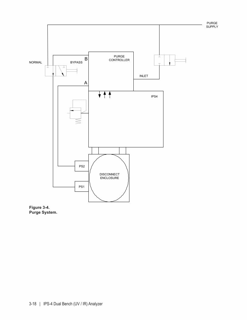
3-18 | IPS-4 Dual Bench (UV / IR) Analyzer
Figure 3-4. Purge System.
BYPASS
PS2
PS1
DISCONNECTENCLOSURE
PURGECONTROLLER
IPS4
B
AINLET
PURGESUPPLY
NORMAL
Installation and Start-Up | 3-19
Installing the Calibration (Span) Fluid Line (Optional)
For applications that require spanning, the Span fluid line is supplied by the customer. Refer to the Flow Diagram (part of the analyzer Final “As-Built” drawings package) shipped with the analyzer.
To install the Span fluid line:
1. Route the line from the calibration fluid supply to the analyzer.
2. Before connecting it to the analyzer, blow down (purge) the line to remove any liquids or particulate that may be present in it.
3. Connect the line to the calibration fluid supply and to the analyzer. The plumbing for the calibration fluid feed through the analyzer manifold is already made by AMETEK.
3-20 | IPS-4 Dual Bench (UV / IR) Analyzer
Connecting I/O Signals, Alarm Relay Contacts, and AC Power
The analog input/output signals, alarm relay contacts, and AC power requirements are specific to each analyzer installation.
For AC electrical supply cable and conduit requirements, refer to – and comply with – local wiring regulations and electrical codes for the area.
Refer to the “Electromagnetic Compatibility (EMC)” page in the con-tents section of this manual for information that discusses the EMC Directive regarding techniques and wiring practices to be followed.
Electrical Connections
Termination points for power and all signals are located in the Disconnect and Sample Line Junction box enclosures. Five metric M32 straight thread conduit entries are provided on the bottom of the Disconnect enclosure. Three additional entries on the right side of the disconnect enclosure are used for heated sample line and HAG probe option connections, but may be used for I/O wiring if these options are not installed.
Five metric M25 straight thread conduit entries are provided on the Sample Line enclosure. (Two on the right, two on the bottom and one on the left side of the enclosure. The conduit entries are for power, sample line heater and RTD wiring. Note that unused holes must be plugged with M25 or M32 hole plugs applicable to the enclosure. Do not use NPT hole plugs with thread adapters. Only properly certified conduit connec-tors must be used.
WIRING SEALS MUST BE LOCATED AT THE WALL OF THE DISCONNECT ASSEMBLY ENCLOSURE. NO ADDITIONAL ENTRIES CAN BE ADDED TO THE DISCONNECT ENCLOSURE WITHOUT VOIDING THE CERTIFICATION.
Figure 3-5 illustrates the general locations of all customer termination points, while the Interconnect Wiring drawing (part of the analyzer Final “As-Built” drawings package) specifically details the signal, relay contact, and AC power connection points. The Final “As-Built” drawings are located in the analyzer Documentation Package.
!WARNING
!WARNING
NOTE
NOTE
Installation and Start-Up | 3-21
To make the signal, relay contact, and AC power connections:
1. Open the Disconnect Enclosure or Sample Line Disconnect Box.
If a power-disconnect switch (breaker) was installed, open (turn off) the breaker before making the AC power connections. AC Power and relay connections are made at the AC Disconnect board.
2. Route the analog input/output signal wiring and alarm relay contact conductors through one of the Signal cable entry ports and into the Disconnect Enclosure.
Terminate the signal and alarm relay contact wires as detailed in the Interconnect Wiring drawing (part of the analyzer Final “As-Built” drawings package).
3. Route the AC power conductors through the Power cable entry port and into the Disconnect Enclosure.
Terminate the AC power wires as detailed in the Interconnect Wiring drawing.
Do not apply power to the system until after all of the wiring has been installed, connected, and verified, and only if the purging system (if used) is ready for operation.
4. Plug all unused cable entry ports with certified plugs.
Permanent Ethernet Cable Connections (Optional)
When using the Ethernet interface on the analyzer, the minimum re-quirements for the Ethernet cable is a CAT 5e (maximum 100 m) cable to connect the analyzer to the network, up to a maximum of 100 m from the hub. For outdoor analyzer installations, hazardous locations, and/or lengths greater than 100 m, special requirements may be necessary. Contact your network administrator for information.
For details about setting up Ethernet parameters, refer to “Ethernet Network Screen” in Chapter 4.
To install the customer Ethernet cable:
1. Route the Ethernet cable through one of the Signal cable entry ports and into the Disconnect Enclosure.
2. Connect the cable to J6.
3. Route the cable to the network connection in the plant and connect it.
NOTE
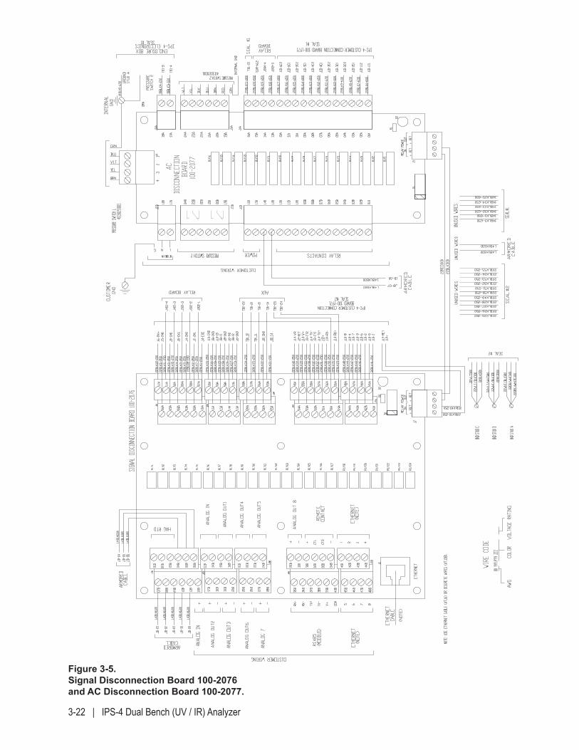
3-22 | IPS-4 Dual Bench (UV / IR) Analyzer
Figure 3-5. Signal Disconnection Board 100-2076 and AC Disconnection Board 100-2077.
Installation and Start-Up | 3-23
Start-Up and Verification
This section describes equipment and controls on the analyzer system that require adjustments and settings before, during, and after power-up.
Figure 3-1 illustrates the locations of analyzer equipment and controls that require adjustments for a typical Zone 1 analyzer layout. Refer to Final “As Built” drawings for settings specific to your analyzer system.
Purged Analyzers
The Electronics Enclosure and its Optical Bench and Measuring Cell Extension are continuously purged with Instrument Air to adequately dilute any flammable gases that may have been released into these areas. This function effectively prevents an internal explosion when the ana-lyzer is powered up and operating under normal sampling conditions. AMETEK analyzers that require purged enclosures in hazardous locations use an Expo Technologies MiniPurge® System With eTimer to perform this function.
The purge air supply is normally obtained from the Instrument Air supply connected directly to the Expo MiniPurge® System. The required purge air supply pressure for your analyzer is indicated on Final “As-Built” draw-ings in the analyzer Documentation Package.
After the Instrument Air supply has been connected to the MiniPurge® system, the ALARM/PRESSURIZED indicator on the MiniPurge® system (Figure 3-1) turns from RED (Alarm condition) to GREEN (Pressurized). Next, the system’s eTimer begins its purge timing cycle, and the four PURGE TIMING indicator LEDs will flash (YELLOW) sequentially, each for 25 % of the total purge time (minimum 15 minutes). During this stage, the MiniPurge® system will purge any flammable gases that may have entered the Electronics Enclosure while its door was open, and then pres-surize the enclosure. After the timing sequence is completed (LEDs off), the pneumatic switch will send a signal to the analyzer and the analyzer will power up (if the Purge Bypass Switch is in the “ACTIVE” position, if all fuses have been engaged, and if the external explosion-proof power-disconnect switch has been closed).
NOTE
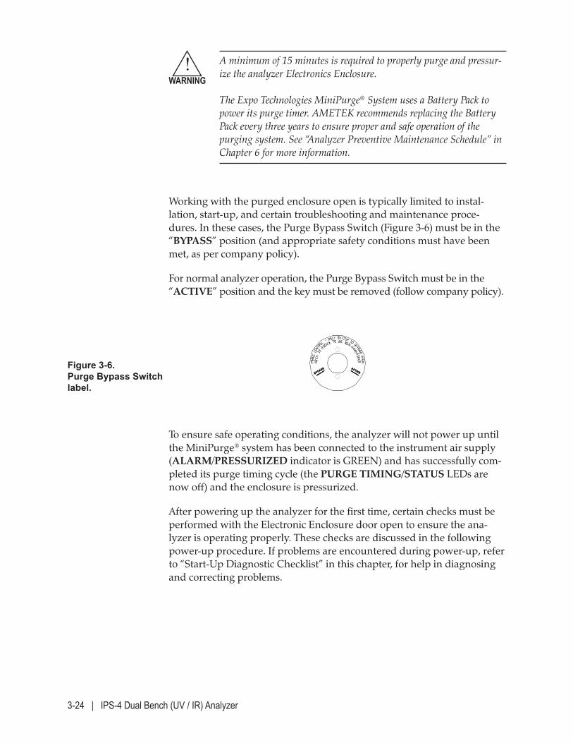
3-24 | IPS-4 Dual Bench (UV / IR) Analyzer
A minimum of 15 minutes is required to properly purge and pressur-ize the analyzer Electronics Enclosure. The Expo Technologies MiniPurge® System uses a Battery Pack to power its purge timer. AMETEK recommends replacing the Battery Pack every three years to ensure proper and safe operation of the purging system. See “Analyzer Preventive Maintenance Schedule” in Chapter 6 for more information.
Working with the purged enclosure open is typically limited to instal-lation, start-up, and certain troubleshooting and maintenance proce-dures. In these cases, the Purge Bypass Switch (Figure 3-6) must be in the “BYPASS” position (and appropriate safety conditions must have been met, as per company policy).
For normal analyzer operation, the Purge Bypass Switch must be in the “ACTIVE” position and the key must be removed (follow company policy).
BB YYPPAASSSS AA CC TTIIVVEE
Figure 3-6. Purge Bypass Switch label.
!WARNING
To ensure safe operating conditions, the analyzer will not power up until the MiniPurge® system has been connected to the instrument air supply (ALARM/PRESSURIZED indicator is GREEN) and has successfully com-pleted its purge timing cycle (the PURGE TIMING/STATUS LEDs are now off) and the enclosure is pressurized.
After powering up the analyzer for the first time, certain checks must be performed with the Electronic Enclosure door open to ensure the ana-lyzer is operating properly. These checks are discussed in the following power-up procedure. If problems are encountered during power-up, refer to “Start-Up Diagnostic Checklist” in this chapter, for help in diagnosing and correcting problems.
Installation and Start-Up | 3-25
Always disconnect main AC power and/or external power sources to the analyzer before opening any covers or doors on the analyzer to check or perform maintenance on any components within the enclo-sures. If it is necessary to open the analyzer’s covers or doors while the circuits are live, test the area for flammable gases (and proceed only when the area is safe). Purged Analyzer (Hazardous Location) Applications To work on the analyzer with it powered up and its Electronics Enclosure door open, the Purge Bypass Switch must be in the “BYPASS” position. When the Electronics Enclosure door is open, take appropriate precau-tions to avoid electrical shock. Hazardous voltages are present inside.
Do not apply power to the analyzer if any of its flamepaths appear to be scratched, dented, or worn. Applying power to an analyzer with a damaged flamepath is dangerous and could result in serious injury or death, and/or serious damage to equipment. Replace parts immediately if damage or wear is apparent. Contact AMETEK if there is any doubt about the integrity of any flamepath.
!WARNING
!WARNING
3-26 | IPS-4 Dual Bench (UV / IR) Analyzer
Powering Up the Analyzer
Before operating the analyzer for the first time, following a power-up or reset, or after maintenance, manually backflush the analyzer sample sys-tem and adjust the sample flow rate. Following initial power-up, a series of system checks should be performed to ensure the analyzer is operat-ing properly, prior to commissioning the analyzer into service. If start-up problems occur refer to page 3-24 in this chapter, to power up the analyzer and verify it is operating properly.
Hazardous Locations Applications: For verification and troubleshooting purposes during power up, it will be necessary to work with the analyzer doors open. Before powering up the analyzer, test the area for flammable gases. If a flammable gas atmosphere is present, do not apply power to the analyzer or any alternate power sources that supply power to the analyzer components. Proceed only when the area is found to be safe. DO NOT LEAVE POWER CONNECTED TO THE ANALYZER IF THE DOORS ARE OPEN UNLESS YOU ARE CONTINUOUSLY SAMPLING THE AREA FOR FLAMMABLE GASES AND ATTENDING TO THE ANALYZER. When the analyzer doors are open, take appropriate precautions to avoid electrical shock. Hazardous voltages are present inside. For normal operation, the disconnect cover must be installed, the analyzer doors must be closed and latched, and the purge system must be operating normally (bypass key on the “ACTIVE” position and the purge controller indicators GREEN (left) and BLACK (right).
Do not apply main AC power to the analyzer if the Xenon Flash Lamp Assembly electrical connections have not been made.
!WARNING
!CAUTION
Installation and Start-Up | 3-27
The analyzer is shipped from the factory without a password (security is disabled). Upon powering up the analyzer for the first time, all con-figurable parameters can be changed until a password is entered in the Change Password function (Login/Set Password screen, SYSTEM SETTINGS menu). Setting up security for the analyzer is necessary to ensure analyzer settings are not inadvertently changed while working from the User Interface Panel. If changing the password, be sure to record and store the password in a safe place for reference.
To power up the analyzer and verify it is operating properly:
1. Apply air pressure to the purge system. Switch the Purge Bypass switch from “ACTIVE” to “BYPASS” (switch is located to the left of the purge controller unit ).
2. With the Electronics Enclosure open:
Open the Bench Heater and Oven Heater fuses. Refer to the Fuse Legend (at the back of the Electronics Enclosure) for the location of these fuses. If a power-disconnect switch (breaker) was not installed, main AC power will be applied to the analyzer.
Do not power up the temperature-control zone circuitry (Bench Heater fuse and Oven Heater fuse, if Oven/Sample System Enclosure is heated) until after the sample system leak check has been performed and verified, as described later in this procedure.
If a power-disconnect switch was installed, close it to apply main AC power to the analyzer.
3. After applying AC main power to the analyzer, the message “System Starting” is displayed momentarily on the top line of the User Interface Panel. Following this, the AMETEK Process Instruments start-up screen will appear. This screen also displays the software version.
!WARNING
NOTE
3-28 | IPS-4 Dual Bench (UV / IR) Analyzer
After the start-up screen, the system defaults to the HOME screen which allows you to view the current status of up to nine factory-con-figured parameters. These parameters are displayed on the left side of this screen. The right side of this screen displays the current op-erational status of the analyzer. Descriptions of these parameters and states are described under “HOME Menu Screen” and “System Status Messages (HOME Screen),” in Chapter 4.
If these screens do not appear, check the AC wiring to ensure it is properly connected.
To check the AC wiring, take all necessary safety precautions to power down the analyzer and open the Main AC Power and DC Power fuses.
After powering down the analyzer, wait 5 minutes to allow the high-voltage capacitors to discharge.
Review the Interconnect Wiring drawing (part of the analyzer Final “As-Built” drawings package) and check the wiring terminations from the main AC power supply source to the analyzer.
Take all necessary safety precautions and reapply power to the ana-lyzer by closing the Main AC Power and DC Power fuses. Check the User Interface Panel again to see if these screens appear. If so, continue with the next step.
4. Perform a leak (pressure) check to ensure there are no leaks in the sys-tem, then return to this procedure and complete the remaining start-up and verification tests.
To perform the leak check, follow the procedure under “Sample System Leak Check,” later in this chapter.
!WARNING
!WARNING
Installation and Start-Up | 3-29
5. After the leak check has been performed and has passed, close the Bench Heater fuse and Oven Heater fuse (if Oven/Sample System Enclosure is heated) to apply power to the Measuring Cell and Oven Heater temperature-control zone circuitry. Ensure that the sample system door has been closed and latched.
Watch the purge controller until the indicators turn GREEN (left) and BLACK (right). Install the key in the bypass valve and place it in the “ACTIVE” position. Remove the bypass and enclosure keys and keep them in a safe place.
No alarms will be displayed on the HOME screen or entered into the Alarm Log until AFTER the system has left the Not Ready state for the first time after power-up, which occurs after the entire sample system has stabilized (2–3 hours) and reached normal operating temperature.
6. While performing the remaining start-up tests, close the analyzer doors to allow the sample system to warm up to normal operating temperature (necessary only if Oven/Sample System Enclosure is heated).
The Oven and the rest of the sample system will reach normal oper-ating temperature in approximately 2 hours, however (application-specific) analyzers may take up to another hour to stabilize. To minimize the time it takes for the entire sample system to warm up to normal operating temperature, be sure to close the doors after performing the checks that require them to be open.
NOTE
NOTE
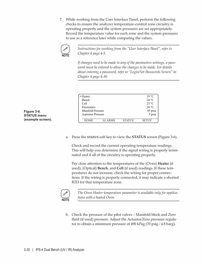
3-30 | IPS-4 Dual Bench (UV / IR) Analyzer
7. While working from the User Interface Panel, perform the following checks to ensure the analyzer temperature-control zone circuitry is operating properly and the system pressures are set appropriately. Record the temperature value for each zone and the system pressures to use as a reference later while comparing the values.
Instructions for working from the “User Interface Panel”, refer to Chapter 4 page 4-5. If changes need to be made to any of the parameters settings, a pass-word must be entered to allow the changes to be made. For details about entering a password, refer to “Login/Set Passwords Screen” in Chapter 4 page 4-30.
Figure 3-6. STATUS menu (example screen).
> Heater 19 °C Bench 24 °C Cell 23 °C Electronics 24 °C Manifold Pressure 85 psia Aspirator Pressure 3 psia
HOME ALARMS STATUS SETUP
a. Press the STATUS soft key to view the STATUS screen (Figure 3-6).
Check and record the current operating temperature readings. This will help you determine if the signal wiring is properly termi-nated and if all of the circuitry is operating properly.
Pay close attention to the temperatures of the (Oven) Heater (if used), (Optical) Bench, and Cell (if used) readings. If these tem-peratures do not increase, check the wiring for proper connec-tions. If the wiring is properly connected, it may indicate a shorted RTD for that temperature zone.
The Oven Heater temperature parameter is available only for applica-tions with a heated Oven.
b. Check the pressure of the pilot valves – Manifold block and Zero fluid (if used) pressure. Adjust the Actuator/Zero pressure regula-tor to obtain a minimum pressure of 490 kPag (70 psig / 4.8 barg).
NOTE
NOTE
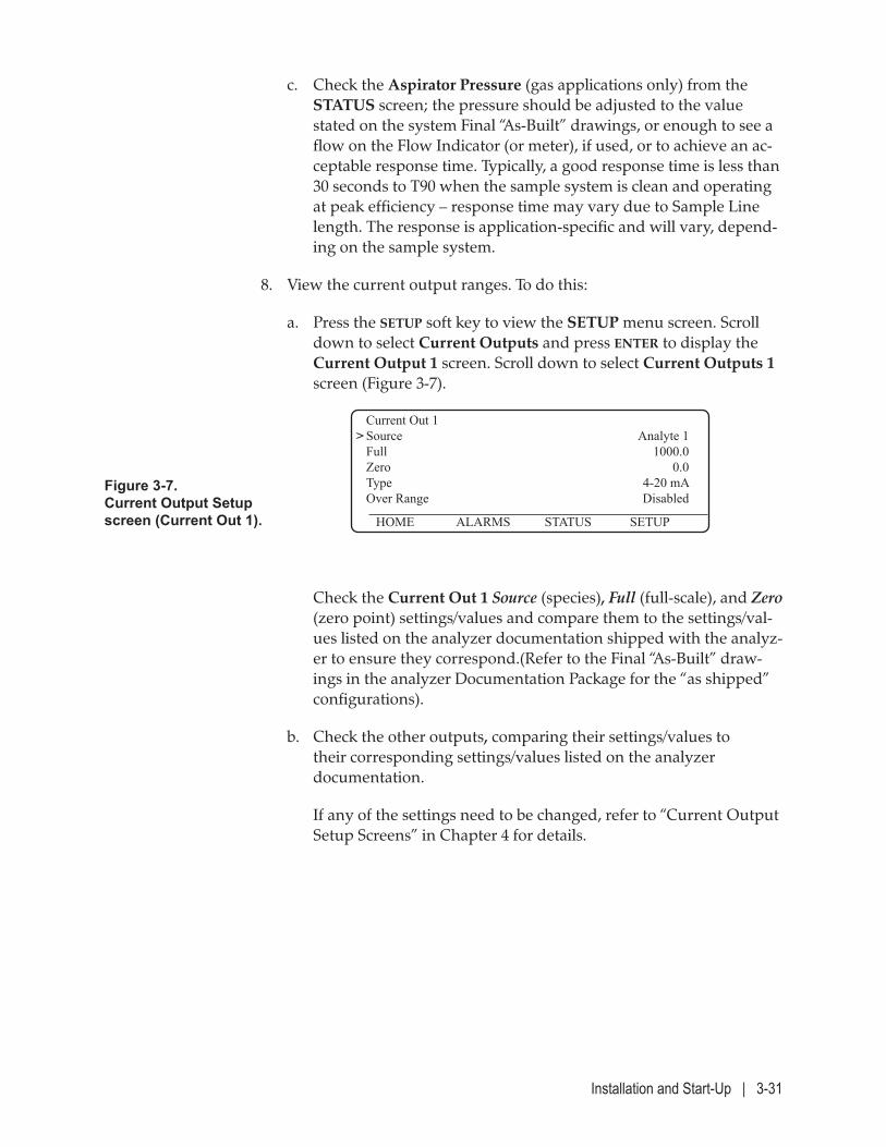
Installation and Start-Up | 3-31
c. Check the Aspirator Pressure (gas applications only) from the STATUS screen; the pressure should be adjusted to the value stated on the system Final “As-Built” drawings, or enough to see a flow on the Flow Indicator (or meter), if used, or to achieve an ac-ceptable response time. Typically, a good response time is less than 30 seconds to T90 when the sample system is clean and operating at peak efficiency – response time may vary due to Sample Line length. The response is application-specific and will vary, depend-ing on the sample system.
8. View the current output ranges. To do this:
a. Press the SETUP soft key to view the SETUP menu screen. Scroll down to select Current Outputs and press ENTER to display the Current Output 1 screen. Scroll down to select Current Outputs 1 screen (Figure 3-7).
Figure 3-7. Current Output Setup screen (Current Out 1).
Current Out 1 > Source Analyte 1 Full 1000.0 Zero 0.0 Type 4-20 mA Over Range Disabled
HOME ALARMS STATUS SETUP
Check the Current Out 1 Source (species), Full (full-scale), and Zero (zero point) settings/values and compare them to the settings/val-ues listed on the analyzer documentation shipped with the analyz-er to ensure they correspond.(Refer to the Final “As-Built” draw-ings in the analyzer Documentation Package for the “as shipped” configurations).
b. Check the other outputs, comparing their settings/values to their corresponding settings/values listed on the analyzer documentation.
If any of the settings need to be changed, refer to “Current Output Setup Screens” in Chapter 4 for details.
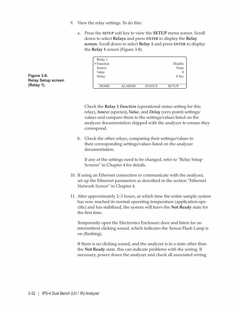
3-32 | IPS-4 Dual Bench (UV / IR) Analyzer
Figure 3-8. Relay Setup screen (Relay 1).
Relay 1 > Function Disable Source None Value 0 Delay 0 Sec
HOME ALARMS STATUS SETUP
9. View the relay settings. To do this:
a. Press the SETUP soft key to view the SETUP menu screen. Scroll down to select Relays and press ENTER to display the Relay screen. Scroll down to select Relay 1 and press ENTER to display the Relay 1 screen (Figure 3-8).
Check the Relay 1 Function (operational status setting for this relay), Source (species), Value, and Delay (zero point) settings/values and compare them to the settings/values listed on the analyzer documentation shipped with the analyzer to ensure they correspond.
b. Check the other relays, comparing their settings/values to their corresponding settings/values listed on the analyzer documentation.
If any of the settings need to be changed, refer to “Relay Setup Screens” in Chapter 4 for details.
10. If using an Ethernet connection to communicate with the analyzer, set up the Ethernet parameters as described in the section “Ethernet Network Screen” in Chapter 4.
11. After approximately 2–3 hours, at which time the entire sample system has now reached its normal operating temperature (application-spe-cific) and has stabilized, the system will leave the Not Ready state for the first time.
Temporarily open the Electronics Enclosure door and listen for an intermittent clicking sound, which indicates the Xenon Flash Lamp is on (flashing).
If there is no clicking sound, and the analyzer is in a state other than the Not Ready state, this can indicate problems with the wiring. If necessary, power down the analyzer and check all associated wiring.
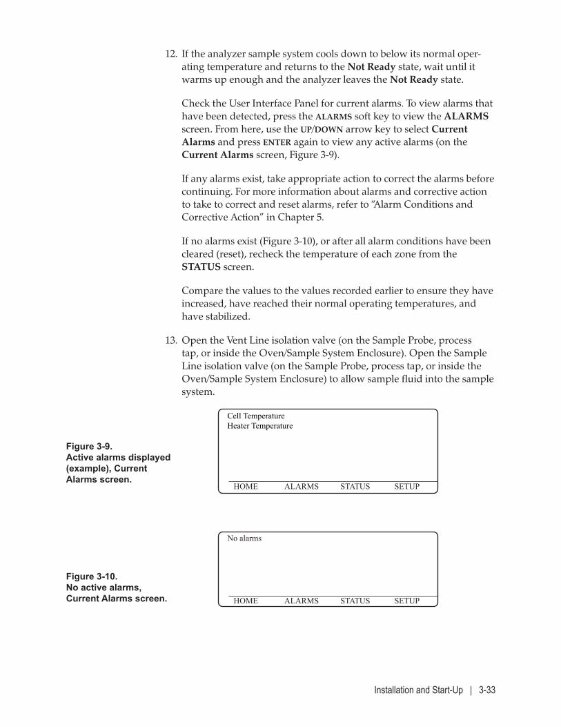
Installation and Start-Up | 3-33
12. If the analyzer sample system cools down to below its normal oper-ating temperature and returns to the Not Ready state, wait until it warms up enough and the analyzer leaves the Not Ready state.
Check the User Interface Panel for current alarms. To view alarms that have been detected, press the ALARMS soft key to view the ALARMS screen. From here, use the UP/DOWN arrow key to select Current Alarms and press ENTER again to view any active alarms (on the Current Alarms screen, Figure 3-9).
If any alarms exist, take appropriate action to correct the alarms before continuing. For more information about alarms and corrective action to take to correct and reset alarms, refer to “Alarm Conditions and Corrective Action” in Chapter 5.
If no alarms exist (Figure 3-10), or after all alarm conditions have been cleared (reset), recheck the temperature of each zone from the STATUS screen.
Compare the values to the values recorded earlier to ensure they have increased, have reached their normal operating temperatures, and have stabilized.
13. Open the Vent Line isolation valve (on the Sample Probe, process tap, or inside the Oven/Sample System Enclosure). Open the Sample Line isolation valve (on the Sample Probe, process tap, or inside the Oven/Sample System Enclosure) to allow sample fluid into the sample system.
Figure 3-9. Active alarms displayed (example), Current Alarms screen.
Cell Temperature Heater Temperature
HOME ALARMS STATUS SETUP
Figure 3-10. No active alarms, Current Alarms screen.
No alarms
HOME ALARMS STATUS SETUP
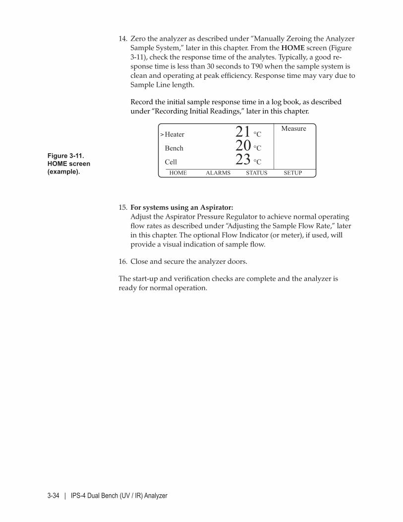
3-34 | IPS-4 Dual Bench (UV / IR) Analyzer
Figure 3-11. HOME screen (example).
Measure> Heater 21 °C
Bench 20 °C
Cell 23 °C HOME ALARMS STATUS SETUP
14. Zero the analyzer as described under “Manually Zeroing the Analyzer Sample System,” later in this chapter. From the HOME screen (Figure 3-11), check the response time of the analytes. Typically, a good re-sponse time is less than 30 seconds to T90 when the sample system is clean and operating at peak efficiency. Response time may vary due to Sample Line length.
Record the initial sample response time in a log book, as described under “Recording Initial Readings,” later in this chapter.
15. For systems using an Aspirator: Adjust the Aspirator Pressure Regulator to achieve normal operating flow rates as described under “Adjusting the Sample Flow Rate,” later in this chapter. The optional Flow Indicator (or meter), if used, will provide a visual indication of sample flow.
16. Close and secure the analyzer doors.
The start-up and verification checks are complete and the analyzer is ready for normal operation.
Installation and Start-Up | 3-35
Start-Up Diagnostic Checklist
This checklist describes problems that can be encountered while powering up the analyzer and/or preparing it for normal operation. If the analyzer experiences problems during power-up, review this checklist and perform the corresponding corrective action to fix any problems.
Problem Encountered Status/error code conditions for current alarms are displayed on the User Interface Panel.
Corrective Action To view current alarms, press the ALARMS soft key to view the ALARMs screen. For information about viewing current alarms, refer to “Alarm Notification (HOME Screen)” and “ALARMS Menu Screen” in Chapter 4. For detailed information about these alarms, refer to the alarm conditions and corrective action in the “Maintenance and Troubleshooting” chapter of this manual.
Problem Encountered The Xenon Flash Lamp is not operating (intermittent clicking sound is not heard).
Corrective Action Check the system state on the right side of the HOME screen. Note that the Xenon Flash Lamp will not operate when the system is in the Not Ready state. If the system is in a state other than Not Ready, take appropriate safety precautions and check for proper wiring connections.
Problem Encountered The LEDs on the Relay, Customer Connection, or MCU boards are not on.
Corrective Action Take appropriate safety precautions and check for proper I/O wiring connections.
3-36 | IPS-4 Dual Bench (UV / IR) Analyzer
Problem Encountered Temperature zone values do not increase.
Corrective Action The over-temperature circuits may have been tripped; press the Reset Switch (S501) on the Relay board or the Reset Switch on the Optical Bench. (Refer to Figure 3-3 of this manual. If the temperature zone values still do not increase, check the fuses (Bench Heater and Oven Heater, if used) for proper connections and blown fuses (located at TB1 in Electronics Enclosure). If the temperature zone values still do not increase, take appropriate safety precautions and check the proper connections for the appropri-ate temperature zone wiring.
Installation and Start-Up | 3-37
Sample System Leak Check
The analyzer sample system has been pressure-checked for leaks at the factory as part of AMETEK’s quality assurance procedures.
However, fittings can loosen during transport. Also, the Sample, Vent, Instrument Air (or N2), and Calibration (Span, if used) Fluid lines are in-stalled on-site. Therefore, it is important that a leak check is performed on the entire sample system prior to commissioning the analyzer for opera-tion for the first time, or following the replacement of any lines/fittings or Measuring Cell parts.
If the analyzer is configured for a heated sample system, perform the sample system leak check prior to applying power to the Oven/Sample System Enclosure circuitry (must not be hot).
Preventing leaks in the sample handling system is critical to ensure proper analyzer operation. If sample fluid migrates into the Optical Bench Assembly or Reflector Block due to a leak in the Measuring Cell Assembly, the optics will become damaged and will likely require replacement. Most leaks are preventable with the regular replacement of the Measuring Cell o-rings.
Do not use a leak detection fluid on hot fittings. If the analyzer system is at operating temperature, the temperature-control zone circuitry fuses must be opened to allow the temperature-control zones to cool before using a leak detection fluid on the fittings.
After all piping and electrical connections have been made:
Refer to the system Analyzer flow diagram, part of the Final “As-Built” drawings in the analyzer Documentation Package
Identify the portions of the system to be tested.
Identify the location of the pressure sources that can be applied for leak testing.
When pressurizing the system, do not exceed the rated pressure for that branch of the sample system.
!CAUTION
!CAUTION
!CAUTION

3-38 | IPS-4 Dual Bench (UV / IR) Analyzer
If a portion of the system includes a pressure sensor, first, pressurize the system and then block it off and monitor for a drop over time.
If a pressure sensor and isolation valves are not available, pressurize the system and bubble-test all joints with a soap solution. (e.g., Snoop or the fluid specific to the Analyzer.)
Installation and Start-Up | 3-39
Manually Zeroing the Analyzer Sample System
The Zero function forces the analyzer to purge the sample system with a Zero fluid to remove any residual contaminants in the sample system.
For heated systems, all temperature zones must be at their operating set points before performing a Zero. If necessary, view the temperature zones to verify this.
Pressing CANCEL at any time during this procedure will abort the procedure and return the software to the HOME screen.
To manually zero the analyzer:
1. Ensure that the Zero fluid cylinder source is connected and turned on.
2. Press the SETUP soft key to display the SETUP menu. Select the Calibration Control sub-menu and press enter. Scroll down to the Calibration sub-menu and press enter to display the Calibration screen.
3. Use the DOWN arrow key to select Start zero calibration and press ENTER to purge the sample system with Zero fluid. The message “Please wait ...” will appear while the analyzer performs the calibra-tion function.
Run the zero for 10 minutes.
Typically, the IPS-4 Analyzer controls the zero flow rate; no adjust-ments are required. If the customer provides the sample system zero, run the manual zero at a flow rate of 2.5 L/minute (0.08 scfm).
4. From the Calibration screen, select Start measure and press ENTER to return the analyzer to Measure mode.
5. Press the HOME soft key to return to the HOME screen.
6. Turn off the Zero fluid.
The zero is complete and the analyzer is now on-line.
NOTE
NOTE
3-40 | IPS-4 Dual Bench (UV / IR) Analyzer
Adjusting the Zero/Span Fluid Flow Rate
When the zero or span (if used) flow solenoid is in an energized state, Instrument Air (or Nitrogen or distilled water) flows into the sample path via a solenoid manifold block and a flow meter. The flow rate of Zero/Span (if used) fluid must be high enough to adequately flush the Measuring Cell of sample fluid to obtain a “good zero.”
Typically, the IPS-4 Analyzer controls the zero (and span, if used) flow rate; no adjustments are required. If the customer provides the sample system zero, run the manual zero at a flow rate of 2.5 L/minute (0.08 scfm). Since excess air flow into the analyzer sample system will cool the Measuring Cell and Oven/Sample System Enclosure, the optimum Zero fluid flow rate is the lowest consistent with a good zero.
A good zero can be defined as a state where the concentration outputs are stable and further increases in Zero fluid flow rate do not reduce the concentrations observed on the analyzer User Interface Panel. A mid-scale flow indicator (or meter) should be sufficient for this purpose.
While the sample system is warming up, or when the analyzer is in standby mode (Not Ready state), zero flow may be desired. During these conditions, it is important that the sample system is kept free of contami-nation by the sample fluid.
For additional information, refer to the Sample System Manual Supplement in the “Supplemental Information” section of this manual or in the Documentation Package shipped with the analyzer.
NOTE
Installation and Start-Up | 3-41
Adjusting the Sample Flow Rate
Applications With an Aspirator: The Aspirator Pressure Regulator is used to control the sample flow through the system. A typical sample flow rate is in the range of 3.0–5.0 L/minute (0.1–0.2 scfm) and can be achieved by adjusting the Aspirator Pressure higher than 70 kPa (10 psi) above the sample stream pressure. View the flow indicator (or meter), if used.
To avoid damaging the pressure transducer, do not set the pressure higher than 105 kPag (15 psig).
The analyzer pressure – measured by the pressure transducer – can also be used to set the sample flow rate. This is accomplished by first measur-ing the sample stream pressure with no aspiration (Drive Air Isolation Valve closed) and then adjusting the Aspirator Pressure Regulator with the Drive Air Isolation Valve open to obtain a pressure of 5–10 mmHg (0.20–0.39 inHg or 0.10–0.20 psi) less than the value obtained with the valve closed. View the Measuring Cell pressure (Cell Pressure) from the STATUS screen.
Applications Without an Aspirator: If an Aspirator is not used, a Metering Valve or Ball Valve may be used to adjust and control the sample flow through the system. Refer to the Final “As-Built” drawings in the analyzer Documentation Package for required settings for your application. View the flow indicator, when used in spe-cific applications.
!CAUTION
3-42 | IPS-4 Dual Bench (UV / IR) Analyzer
Setting Sample Response Time
Sample response time can also be used as a parameter for setting the Aspirator Pressure. Response time is determined by switching the analyz-er from Zero Gas Flush mode to Measure mode and recording the time it takes the analyzer to display the first reading after the switch.
To check the sample response time:
1. Observe the output concentration from the HOME screen.
2. Press the SETUP soft key to display the SETUP menu and then press the DOWN arrow key until the Calibration sub-menu item is displayed and selected.
3. Manually zero the analyzer. To do this, press ENTER to display the Calibration screen. Use the DOWN arrow key to select Start zero calibration and press ENTER. The message “Please wait ...” will appear while the analyzer initializes and performs the calibration function.
Run the manual zero for 10 minutes. For more information about set-ting the Zero fluid flow rate, refer to “Adjusting the Zero/Span Fluid Flow Rate” in this chapter.
4. From the Calibration screen, select Start measure and press ENTER to return the analyzer to Measure mode.
5. Press the HOME soft key to return to the HOME screen and observe the analyte output concentration(s) again.
If the sample response time is adequate (first response after a Zero is less than 30 seconds to T90), no further adjustment is necessary.
The sample response time may vary, depending on Sample Line length.
NOTE
Installation and Start-Up | 3-43
Normal Operation
After the analyzer is set up and started, the analyzer User Interface Panel defaults to the HOME screen. During normal operation, the top three lines of the User Interface Panel display the output names with their corresponding values displayed to the right. The User Interface Panel is updated once per second.
Recording Initial Readings
Before operating the analyzer, it is important to observe the analyzer to understand what normal operating conditions are, and how to use this information later to help you determine problems with the analyzer.
AMETEK recommends that you observe and record this information every month to obtain a history. From these recordings, you will be able to determine if there are problems with the analyzer, such as increasing sample response. These problems typically indicate that maintenance is required.
Keep the log book in a safe location until you need to review it for pat-terns of a longer sample response time.
Recording Initial Sample Response Time
The analyzer sample response time can be used for two functions. One function is to help you set the sample fluid flow rate, as discussed earlier in this chapter, under “Setting Sample Response Time.” The other func-tion is to help you determine if the typical response time is increasing, which can indicate a plug in the sample system which, in turn, can indi-cate maintenance is required.
To check and record the initial sample response time:
1. Manually zero the analyzer.
2. After the zero is complete, view the HOME screen and observe the analyte output concentration changes. Observe and record the time it takes the analyzer to display the first reading after the analyzer System State switches from “Zero” to “Measure”.
It is important to record the response time only after performing a manual Zero function to simulate the same conditions during the original recordings.
NOTE
3-44 | IPS-4 Dual Bench (UV / IR) Analyzer
3. If the sample response time is adequate (first reading after a Zero function and after the analyzer System State switches from “Zero” to “Measure” is less than 30 seconds to T90), no further adjustment is necessary.
The sample response time may vary, depending on Sample Line length.
4. Record these signals in a log book every month.
Analyzer Configuration
The Parameter List (Factory Settings) file is shipped with each analyzer. These configuration sheets list all of the settings applicable to the factory analyzer (to meet customer requirements). The files are provided on a CD and located in the “Supplemental Information” section of this manual and in the Documentation Package shipped with the analyzer.
If any changes are made to the original configuration, be sure to record the changes for later reference. If the MCU board is ever replaced, this data must be re-entered in order to override the factory defaults.
If necessary, refer to the Parameter List (Factory Settings) to revert the analyzer back to its original settings.
NOTE
Controller / User Interface | 4-1
CONTROLLER / USER INTERFACE
The Controller / User Interface chapter contains information about the following topics:
• An introduction to the User Interface Panel, and how to enter com-mands to view various screens. Information about passwords and how to change them is also discussed in this chapter.
• What the various keys that makes up the keypad do, and how to use them to work from the analyzer User Interface Panel.
• Analyzer operating temperatures, alarm set points, and default pa-rameter settings.
Before working from the User Interface Panel, read the section titled “Introduction to the User Interface Panel,” in the following pages. This section discusses the functions that can be performed by pressing the keypad keys. This section also discusses how to enter Edit mode, and how to quickly return to the HOME screen from anywhere in the software.
Pressing ENTER after making any changes will save the configuration data in non-volatile memory – the old values will be overwritten.
NOTE
NOTE
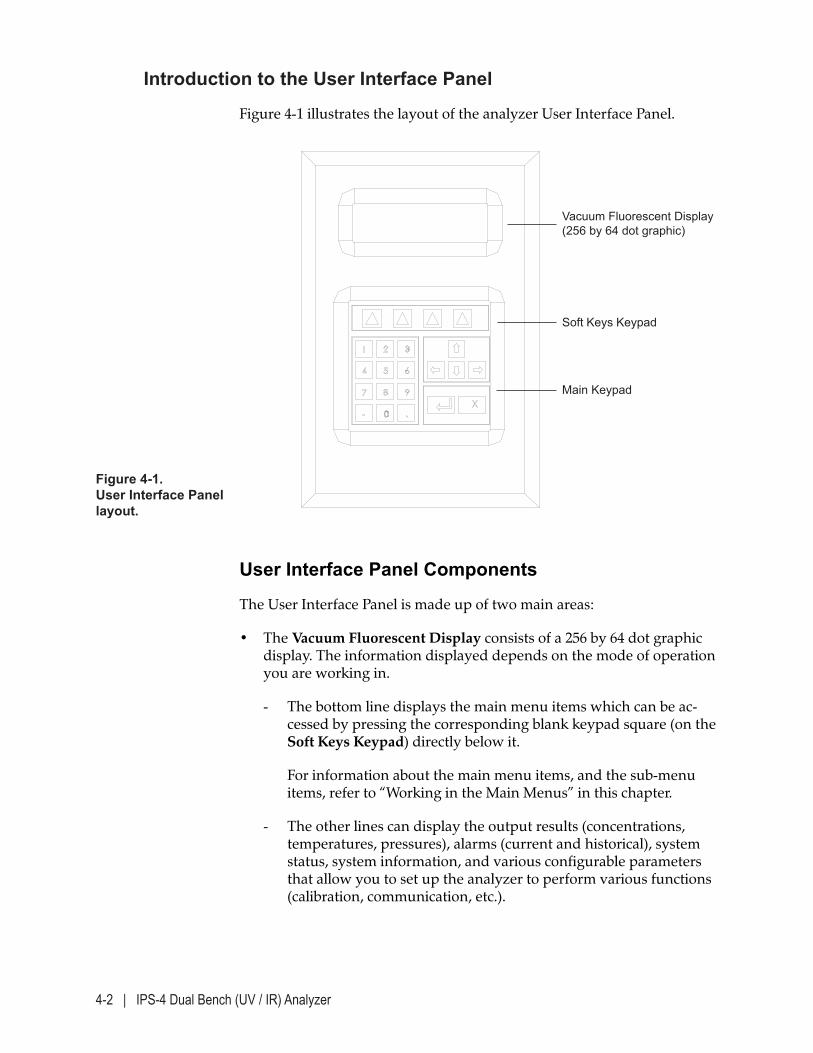
4-2 | IPS-4 Dual Bench (UV / IR) Analyzer
Introduction to the User Interface Panel
Figure 4-1 illustrates the layout of the analyzer User Interface Panel.
User Interface Panel Components
The User Interface Panel is made up of two main areas:
• The Vacuum Fluorescent Display consists of a 256 by 64 dot graphic display. The information displayed depends on the mode of operation you are working in.
- The bottom line displays the main menu items which can be ac-cessed by pressing the corresponding blank keypad square (on the Soft Keys Keypad) directly below it.
For information about the main menu items, and the sub-menu items, refer to “Working in the Main Menus” in this chapter.
- The other lines can display the output results (concentrations, temperatures, pressures), alarms (current and historical), system status, system information, and various configurable parameters that allow you to set up the analyzer to perform various functions (calibration, communication, etc.).
Vacuum Fluorescent Display (256 by 64 dot graphic)
Soft Keys Keypad
Main Keypad
Figure 4-1. User Interface Panel layout.
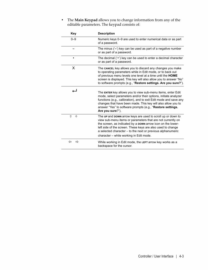
Controller / User Interface | 4-3
• The Main Keypad allows you to change information from any of the editable parameters. The keypad consists of:
Key Description
0–9 Numeric keys 0–9 are used to enter numerical data or as part of a password.
– The minus (‘–’) key can be used as part of a negative number or as part of a password.
• The decimal (‘•’) key can be used to enter a decimal character or as part of a password.
X The CANCEL key allows you to discard any changes you make to operating parameters while in Edit mode, or to back out of previous menu levels one level at a time until the HOME screen is displayed. This key will also allow you to answer “No” to software prompts (e.g., “Restore settings. Are you sure?”).
The ENTER key allows you to view sub-menu items, enter Edit mode, select parameters and/or their options, initiate analyzer functions (e.g., calibration), and to exit Edit mode and save any changes that have been made. This key will also allow you to answer “Yes” to software prompts (e.g., “Restore settings. Are you sure?”).
The UP and DOWN arrow keys are used to scroll up or down to view sub-menu items or parameters that are not currently on the screen, as indicated by a DOWN arrow icon on the lower-left side of the screen. These keys are also used to change a selected character – to the next or previous alphanumeric character – while working in Edit mode.
While working in Edit mode, the LEFT arrow key works as a backspace for the cursor.
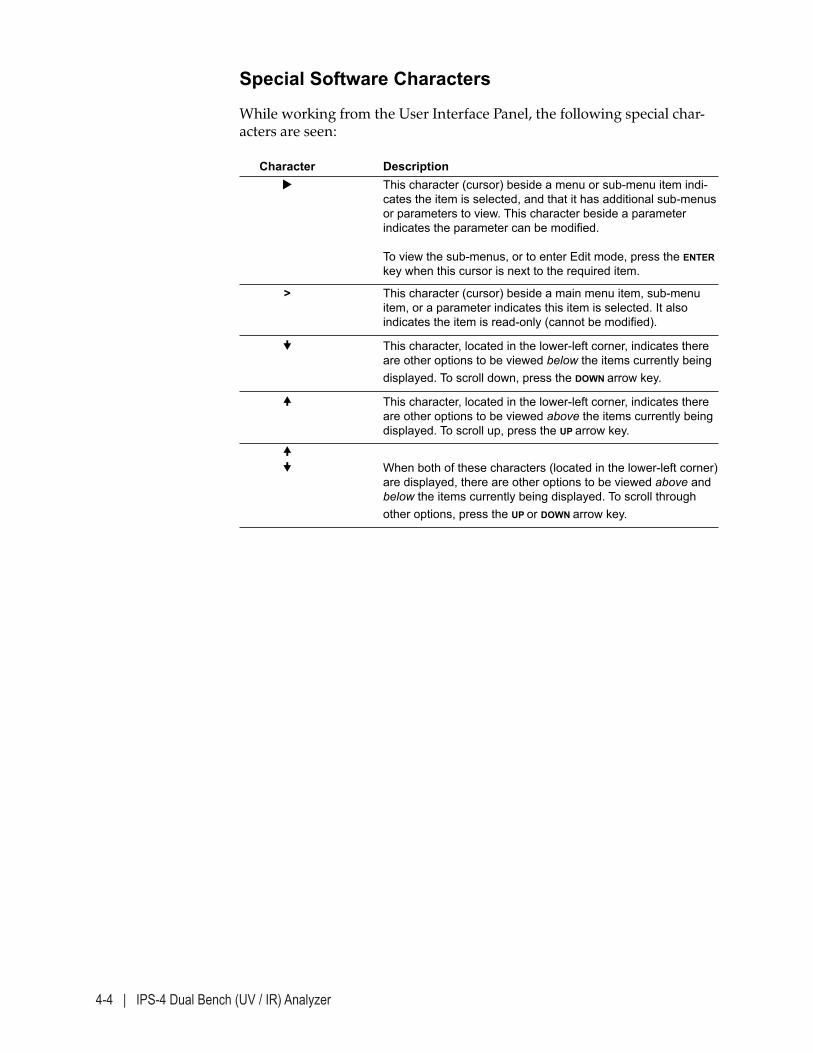
4-4 | IPS-4 Dual Bench (UV / IR) Analyzer
Special Software Characters
While working from the User Interface Panel, the following special char-acters are seen:
Character Description This character (cursor) beside a menu or sub-menu item indi-
cates the item is selected, and that it has additional sub-menus or parameters to view. This character beside a parameter indicates the parameter can be modified. To view the sub-menus, or to enter Edit mode, press the ENTER key when this cursor is next to the required item.
> This character (cursor) beside a main menu item, sub-menu item, or a parameter indicates this item is selected. It also indicates the item is read-only (cannot be modified).
This character, located in the lower-left corner, indicates there are other options to be viewed below the items currently being displayed. To scroll down, press the DOWN arrow key.
This character, located in the lower-left corner, indicates there are other options to be viewed above the items currently being displayed. To scroll up, press the UP arrow key.
When both of these characters (located in the lower-left corner)
are displayed, there are other options to be viewed above and below the items currently being displayed. To scroll through other options, press the UP or DOWN arrow key.
Controller / User Interface | 4-5
Working From the User Interface Panel – Conditions and Messages
While working from the User Interface Panel, the following conditions apply:
The analyzer is shipped from the factory without a password (security is disabled). Upon powering up the analyzer for the first time, all con-figurable parameters can be changed until a password is entered in the Change Password function (Login/Set Password screen, SYSTEM SETTINGS menu). Setting up security for the analyzer is necessary to ensure analyzer settings are not inadvertently changed while working from the User Interface Panel. If changing the password, be sure to record and store the password in a safe place for reference.
• If security is enabled (if a password has been entered in the Change Password function – Login/Set Password screen, SYSTEM SETTINGS menu), the software will revert to Operator (read-only) mode after 5 minutes of no keypad activity.
• If security is enabled but you are not logged in, the message “Pass-word required” is displayed when you press ENTER to initiate ana-lyzer functions (such as calibration functions) or go into Edit mode to change the configuration settings.
• A maximum of nine characters can be used to enter a password.
• On all screens, a cursor (‘>’ or ‘’ ) is displayed beside the current item; to view other related items that are not currently displayed (if available), press the UP or DOWN arrow keys.
The cursor ‘>’ indicates the item is read-only. The ‘’ cursor indicates the item is editable.
• When the ‘’ cursor is next to a sub-menu item press ENTER to view parameters under that item.
• When in Edit mode (for numeric entries only) the cursor ( ‘ _’ ) is dis-played on or to the right of the selected character.
• You can view all menus and sub-menus – and the current settings or values of all parameters or functions on each screen – without a pass-word.
• The display will revert to the HOME screen if no keys are pressed within 60 seconds.
NOTE
4-6 | IPS-4 Dual Bench (UV / IR) Analyzer
• Active alarm names will flash on the HOME screen only. To stop the flashing, press any key once. The alarm will begin flashing again after 20 seconds of no keypad activity, unless the alarm is reset.
• To return to the HOME screen from any other screen (except when in Edit mode), press the HOME soft key.
Summary of Analyzer Operation
The analyzer’s EEPROM contains a number of files that define its configu-ration for the intended application. The configuration variables are con-tained in a file named “params.xml.” This file consists of approximately 500 parameters and their default settings. A CD with the Parameter List (Factory Settings) file is shipped with each analyzer.
This list includes variables to set up Communications, Units of Measures, Language, Timers for analyzer operations, Inputs, Outputs, Relays and Solenoids, Alarm Limits, Lamp Control, Heater Setpoints and Control, Filtering, and various other parameters. It is also continuously updated by the main processor with (read-only) variables such as Relay/Solenoid/Valve Status, Current Outputs, and other parameters.
A subset of these parameters may be changed from the User Interface Panel. The sequence of analyzer operations is defined by a file called “statemachine.xml.” The processor continuously communicates with the “statemachine.xml” and “params.xml” files to define what function the analyzer should be performing at any given time. These files also control the setting of valves and other devices.
Examples of “states” include Zero, Span, and Measure. These and other states are described in detail under “System Status Messages (HOME Screen),” later in this chapter.
Generally, the analyzer will sequence through a series of factory-set, pre-defined states. However, through settings that can be changed from the User Interface Panel, you can vary the interval between analyzer states, manually change the analyzer to another state, or enable or disable certain states.
The analyzer will leave its normal sequence of states if there is an alarm condition, such as a temperature or pressure out of range, and will return to the first state in the sequence once the offending condition has been cleared (reset).
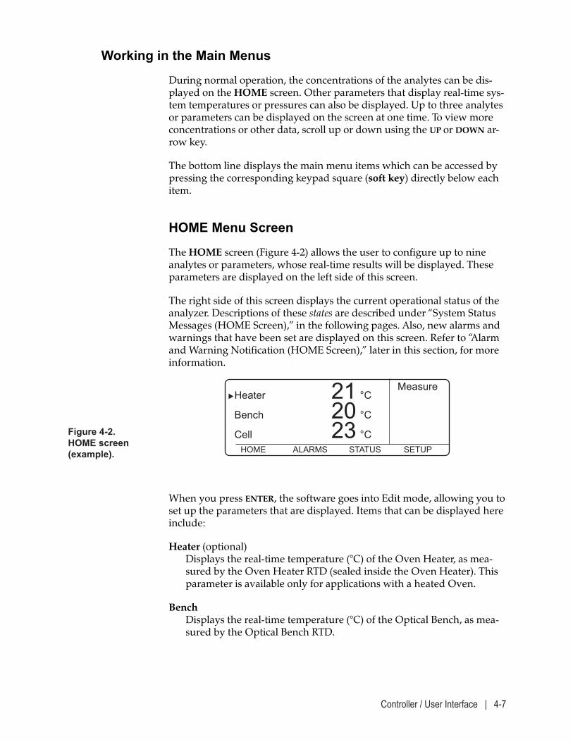
Controller / User Interface | 4-7
Working in the Main Menus
During normal operation, the concentrations of the analytes can be dis-played on the HOME screen. Other parameters that display real-time sys-tem temperatures or pressures can also be displayed. Up to three analytes or parameters can be displayed on the screen at one time. To view more concentrations or other data, scroll up or down using the UP or DOWN ar-row key.
The bottom line displays the main menu items which can be accessed by pressing the corresponding keypad square (soft key) directly below each item.
HOME Menu Screen
The HOME screen (Figure 4-2) allows the user to configure up to nine analytes or parameters, whose real-time results will be displayed. These parameters are displayed on the left side of this screen.
The right side of this screen displays the current operational status of the analyzer. Descriptions of these states are described under “System Status Messages (HOME Screen),” in the following pages. Also, new alarms and warnings that have been set are displayed on this screen. Refer to “Alarm and Warning Notification (HOME Screen),” later in this section, for more information.
When you press ENTER, the software goes into Edit mode, allowing you to set up the parameters that are displayed. Items that can be displayed here include:
Heater (optional) Displays the real-time temperature (°C) of the Oven Heater, as mea-sured by the Oven Heater RTD (sealed inside the Oven Heater). This parameter is available only for applications with a heated Oven.
Bench Displays the real-time temperature (°C) of the Optical Bench, as mea-sured by the Optical Bench RTD.
Figure 4-2. HOME screen (example).
Measure Heater 21 °C Bench 20 °C Cell 23 °C HOME ALARMS STATUS SETUP
4-8 | IPS-4 Dual Bench (UV / IR) Analyzer
Cell (heated Cell is optional) Displays the real-time temperature (°C) of the Measuring Cell, as mea-sured by the Cell RTD (mounted on the Cell, inside the Oven/Sample System Enclosure). This parameter is available only for applications with a heated Oven.
Manifold Pressure Displays the real-time pressure (psia, or other unit) measured at the Manifold Block. The manifold pressure is used for valve actuation and for zero flush (if applicable).
Aspirator Pressure Displays the real-time pressure (psia, or other unit) being used to drive the Aspirator system (gas applications only).
Cell Pressure Displays the real-time pressure (psia, or other unit) being measured in the Measuring Cell.
Tec Temperature Displays the temperature of the NDIR sensor.
Probe Temperature Displays temperature at the sample probe.
Sample/Vent line Temperature Displays temperature of sample/vent bundle.
Controller / User Interface | 4-9
System Status Messages (HOME Screen)
While working from the HOME screen, messages that are displayed on the right side of this screen indicate the current operating status (mode) of the analyzer, also known as System Status or System State. Please refer to supplemental material/documentation for any modes not described below. Messages that can be displayed here include:
Not Ready During this state, the analyzer is not measuring sample fluid due to alarm conditions that must be resolved before it will resume normal sampling operation.
Sample Flush Indicates the analyzer is allowing sample fluid into the sample system. There will be a short delay before it reaches the Measuring Cell, where the analyzer begins measuring the sample.
Measure Indicates the analyzer is measuring analyte values.
Span Fluid Flush Indicates the sample system is being flushed with Span fluid (span fluid valve is open). The valve will close when the system state chang-es to Measure mode.
Span This occurs following the Span Fluid Flush and indicates the analyzer is being spanned. When complete, the span fluid valve is closed.
Zero Fluid Flush Indicates the sample system is being flushed with Zero fluid (zero fluid valve is open). The valve has to be closed by changing the system state to Measure or Span mode.
Zero Indicates the analyzer is being zeroed. During this function, the zero fluid valve remains open until the Zero is complete. The Zero consists of an average reading of a factory-set number of readings (usually 10 to 90; default = 60). The valve has to be closed by changing the system state to Measure or Span mode.
Span Hold Indicates the analyzer is measuring concentration with the span fluid valve open. To leave this state, the analyzer must be manually changed to another state from the Calibration screen.
Zero Hold Indicates the analyzer is measuring concentration with the zero fluid valve open. To leave this state, the analyzer must be manually changed to another state from the Calibration screen.
4-10 | IPS-4 Dual Bench (UV / IR) Analyzer
Alarm and Warning Notification (HOME Screen)
When an alarm or warning is set by the analyzer, the message will flash on the HOME screen only. The information on the HOME screen will be replaced by a reverse (white) screen with the alarm name in black text. It will then switch to a black screen with white text and will continue to flash until the alarm conditions that triggered the alarm(s) are reset.
For more information about active and historical alarms and warnings, refer to “Viewing Current Alarms and Warnings” and “Viewing Logged Alarms or Warnings” in the following pages.
Alarms and warnings that have been reset (no longer active) are stored in the Alarm Log and Warning Log, accessed from the ALARMS AND WARNINGS screen. Logged (or historical) alarms and warnings – which occupy two lines – include the time and date each alarm was set and reset. The alarm or warning at the top of the list is most recent; the alarm or warning at the bottom is the oldest.
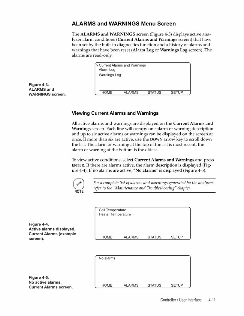
Controller / User Interface | 4-11
ALARMS and WARNINGS Menu Screen
The ALARMS and WARNINGS screen (Figure 4-3) displays active ana-lyzer alarm conditions (Current Alarms and Warnings screen) that have been set by the built-in diagnostics function and a history of alarms and warnings that have been reset (Alarm Log or Warnings Log screen). The alarms are read-only.
Figure 4-4. Active alarms displayed, Current Alarms (example screen).
Cell Temperature Heater Temperature
HOME ALARMS STATUS SETUP
Figure 4-5. No active alarms, Current Alarms screen.
No alarms
HOME ALARMS STATUS SETUP
Viewing Current Alarms and Warnings
All active alarms and warnings are displayed on the Current Alarms and Warnings screen. Each line will occupy one alarm or warning description and up to six active alarms or warnings can be displayed on the screen at once. If more than six are active, use the DOWN arrow key to scroll down the list. The alarm or warning at the top of the list is most recent; the alarm or warning at the bottom is the oldest.
To view active conditions, select Current Alarms and Warnings and press ENTER. If there are alarms active, the alarm description is displayed (Fig-ure 4-4). If no alarms are active, “No alarms” is displayed (Figure 4-5).
For a complete list of alarms and warnings generated by the analyzer, refer to the “Maintenance and Troubleshooting” chapter.
> Current Alarms and Warnings Alarm Log Warnings Log HOME ALARMS STATUS SETUP
Figure 4-3. ALARMS and WARNINGS screen.
NOTE
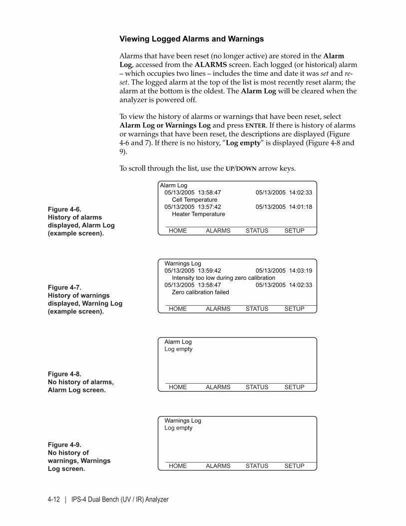
4-12 | IPS-4 Dual Bench (UV / IR) Analyzer
Viewing Logged Alarms and Warnings
Alarms that have been reset (no longer active) are stored in the Alarm Log, accessed from the ALARMS screen. Each logged (or historical) alarm – which occupies two lines – includes the time and date it was set and re-set. The logged alarm at the top of the list is most recently reset alarm; the alarm at the bottom is the oldest. The Alarm Log will be cleared when the analyzer is powered off.
To view the history of alarms or warnings that have been reset, select Alarm Log or Warnings Log and press ENTER. If there is history of alarms or warnings that have been reset, the descriptions are displayed (Figure 4-6 and 7). If there is no history, “Log empty” is displayed (Figure 4-8 and 9).
To scroll through the list, use the UP/DOWN arrow keys.
Figure 4-8. No history of alarms, Alarm Log screen.
Alarm Log Log empty
HOME ALARMS STATUS SETUP
Figure 4-7. History of warnings displayed, Warning Log (example screen).
Warnings Log 05/13/2005 13:59:42 05/13/2005 14:03:19 Intensity too low during zero calibration 05/13/2005 13:58:47 05/13/2005 14:02:33 Zero calibration failed HOME ALARMS STATUS SETUP
Figure 4-9. No history of warnings, Warnings Log screen.
Warnings Log Log empty
HOME ALARMS STATUS SETUP
Figure 4-6. History of alarms displayed, Alarm Log (example screen).
Alarm Log 05/13/2005 13:58:47 05/13/2005 14:02:33 Cell Temperature 05/13/2005 13:57:42 05/13/2005 14:01:18 Heater Temperature HOME ALARMS STATUS SETUP
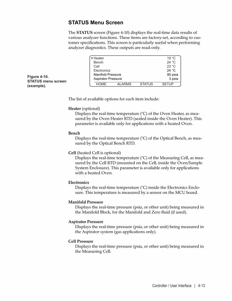
Controller / User Interface | 4-13
STATUS Menu Screen
The STATUS screen (Figure 4-10) displays the real-time data results of various analyzer functions. These items are factory-set, according to cus-tomer specifications. This screen is particularly useful when performing analyzer diagnostics. These outputs are read-only.
The list of available options for each item include:
Heater (optional) Displays the real-time temperature (°C) of the Oven Heater, as mea-sured by the Oven Heater RTD (sealed inside the Oven Heater). This parameter is available only for applications with a heated Oven.
Bench Displays the real-time temperature (°C) of the Optical Bench, as mea-sured by the Optical Bench RTD.
Cell (heated Cell is optional) Displays the real-time temperature (°C) of the Measuring Cell, as mea-sured by the Cell RTD (mounted on the Cell, inside the Oven/Sample System Enclosure). This parameter is available only for applications with a heated Oven.
Electronics Displays the real-time temperature (°C) inside the Electronics Enclo-sure. This temperature is measured by a sensor on the MCU board.
Manifold Pressure Displays the real-time pressure (psia, or other unit) being measured in the Manifold Block, for the Manifold and Zero fluid (if used).
Aspirator Pressure Displays the real-time pressure (psia, or other unit) being measured in the Aspirator system (gas applications only).
Cell Pressure Displays the real-time pressure (psia, or other unit) being measured in the Measuring Cell.
Figure 4-10. STATUS menu screen (example).
> Heater 19 °C Bench 24 °C Cell 23 °C Electronics 24 °C Manifold Pressure 85 psia Aspirator Pressure 3 psia HOME ALARMS STATUS SETUP
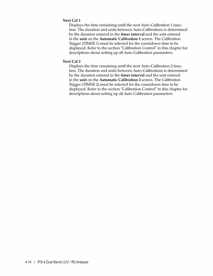
4-14 | IPS-4 Dual Bench (UV / IR) Analyzer
Next Cal 1 Displays the time remaining until the next Auto-Calibration 1 func-tion. The duration and units between Auto-Calibrations is determined by the duration entered in the timer interval and the unit entered in the unit on the Automatic Calibration 1 screen. The Calibration Trigger (TIMER 1) must be selected for the countdown time to be displayed. Refer to the section “Calibration Control” in this chapter for descriptions about setting up all Auto-Calibration parameters.
Next Cal 2 Displays the time remaining until the next Auto-Calibration 2 func-tion. The duration and units between Auto-Calibrations is determined by the duration entered in the timer interval and the unit entered in the unit on the Automatic Calibration 2 screen. The Calibration Trigger (TIMER 2) must be selected for the countdown time to be displayed. Refer to the section “Calibration Control” in this chapter for descriptions about setting up all Auto-Calibration parameters.
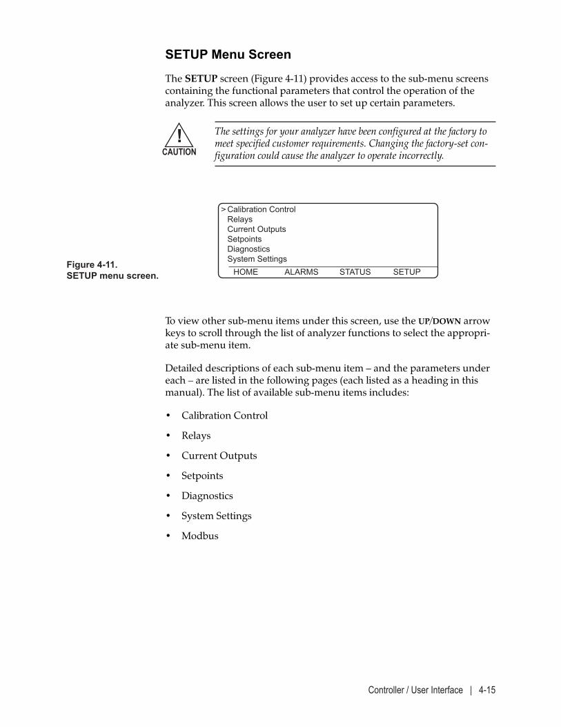
Controller / User Interface | 4-15
To view other sub-menu items under this screen, use the UP/DOWN arrow keys to scroll through the list of analyzer functions to select the appropri-ate sub-menu item.
Detailed descriptions of each sub-menu item – and the parameters under each – are listed in the following pages (each listed as a heading in this manual). The list of available sub-menu items includes:
• Calibration Control
• Relays
• Current Outputs
• Setpoints
• Diagnostics
• System Settings
• Modbus
Figure 4-11. SETUP menu screen.
> Calibration Control Relays Current Outputs Setpoints Diagnostics System Settings HOME ALARMS STATUS SETUP
SETUP Menu Screen
The SETUP screen (Figure 4-11) provides access to the sub-menu screens containing the functional parameters that control the operation of the analyzer. This screen allows the user to set up certain parameters.
The settings for your analyzer have been configured at the factory to meet specified customer requirements. Changing the factory-set con-figuration could cause the analyzer to operate incorrectly.
!CAUTION
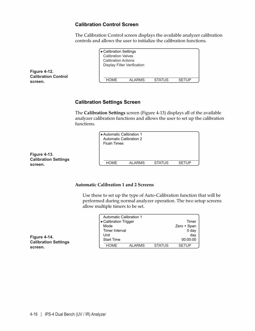
4-16 | IPS-4 Dual Bench (UV / IR) Analyzer
Calibration Control Screen
The Calibration Control screen displays the available analyzer calibration controls and allows the user to initialize the calibration functions.
Calibration Settings Screen
The Calibration Settings screen (Figure 4-13) displays all of the available analyzer calibration functions and allows the user to set up the calibration functions.
Figure 4-12. Calibration Control screen.
►Calibration Settings Calibration Valves Calibration Actions Display Filter Verification
HOME ALARMS STATUS SETUP
Automatic Calibration 1 and 2 Screens
Use these to set up the type of Auto-Calibration function that will be performed during normal analyzer operation. The two setup screens allow multiple timers to be set.
Figure 4-13. Calibration Settings screen.
►Automatic Calibration 1 Automatic Calibration 2 Flush Times
HOME ALARMS STATUS SETUP
Figure 4-14. Calibration Settings screen.
Automatic Calibration 1 ►Calibration Trigger Timer Mode Zero + Span Timer Interval 0 day Unit day Start Time 00:00:00 HOME ALARMS STATUS SETUP
Controller / User Interface | 4-17
Calibration Trigger Use this to select how auto-calibration is triggered.
Calibration Trigger options include:• Timer Enables the Auto-Calibration timer. The system will automatically
Zero and/or Span the analyzer.
• Input1 and Input2 Auto-Calibration will be initiated by a user-supplied contact clo-
sure.
• Off Disables Auto-Calibration. The system will not automatically Zero
or Span the analyzer regardless of what the automatic calibration mode function is set to. The analyzer can still be manually calibrat-ed using the Start zero calibration, Start span calibration or Start zero+span calibration functions on the Calibration screen.
Mode Use this to set up the type of Auto-Calibration function that will be performed during normal analyzer operation. Mode options include:• Zero + Span
For its regular sequence of operation, the analyzer will perform a Zero, followed by a Span, and then return to Measure mode.
• Span only For its regular sequence of operation, the analyzer will perform a Span and then return to Measure mode.
• Zero only For its regular sequence of operation, the analyzer will perform a Zero and then return to Measure mode.
This function is not available for applications with multi-species span capability (i.e., when “Select span fluid” function is available on the Calibration screen). In this case, Auto cal – if enabled (ON) – will perform a zero calibration only. Span calibration must be done manu-ally as described under “Manually Starting a Span Function” on page 4-21.
NOTE
4-18 | IPS-4 Dual Bench (UV / IR) Analyzer
Timer interval Defines the time between each Auto-Calibration cycle. The unit is determined by the Unit setting.
Unit Use this to set the time units that will be used to determine the fre-quency of each Auto-Calibration function. The unit can be set to hours or days. This function works in conjunction with the Timer interval.
Start Time Use this to set the start Auto-Calibration in military time.
To set up calibration functions:
1. Select the parameter you wish to change and press ENTER.
2. Use the UP/DOWN arrow keys to view the options available for each parameter.
3. Change the timer durations (Auto cal timer interval, Zero flush time, Span flush time):
• Use the UP/DOWN arrow key to increase/decrease the duration in increments of one (1.00). When using this method, the value counts up/down from the current setting. This works best for mi-nor changes.
• If a value exists, use the LEFT arrow key as a backspace to remove (erase) the characters to the left of the cursor ( ‘_’ ) if applicable, then use the numeric keys to enter the new value. This works best for drastic changes.
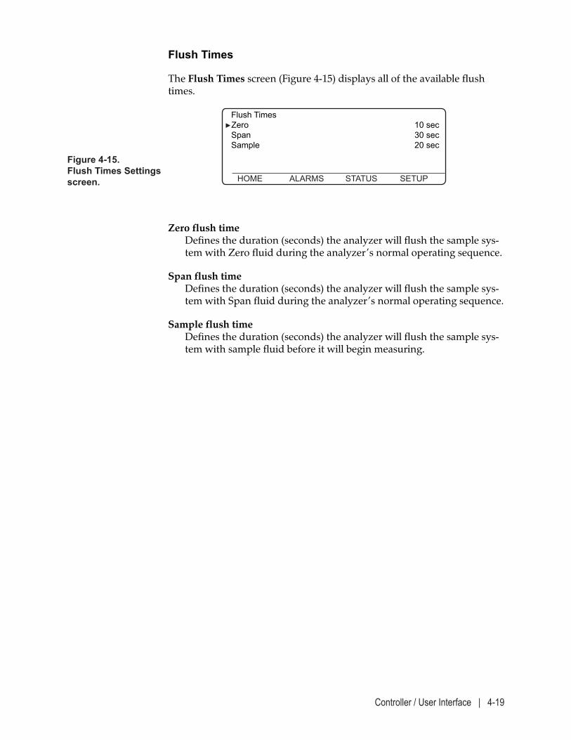
Controller / User Interface | 4-19
Figure 4-15. Flush Times Settings screen.
Flush Times ►Zero 10 sec Span 30 sec Sample 20 sec
HOME ALARMS STATUS SETUP
Flush Times
The Flush Times screen (Figure 4-15) displays all of the available flush times.
Zero flush time Defines the duration (seconds) the analyzer will flush the sample sys-tem with Zero fluid during the analyzer’s normal operating sequence.
Span flush time Defines the duration (seconds) the analyzer will flush the sample sys-tem with Span fluid during the analyzer’s normal operating sequence.
Sample flush time Defines the duration (seconds) the analyzer will flush the sample sys-tem with sample fluid before it will begin measuring.
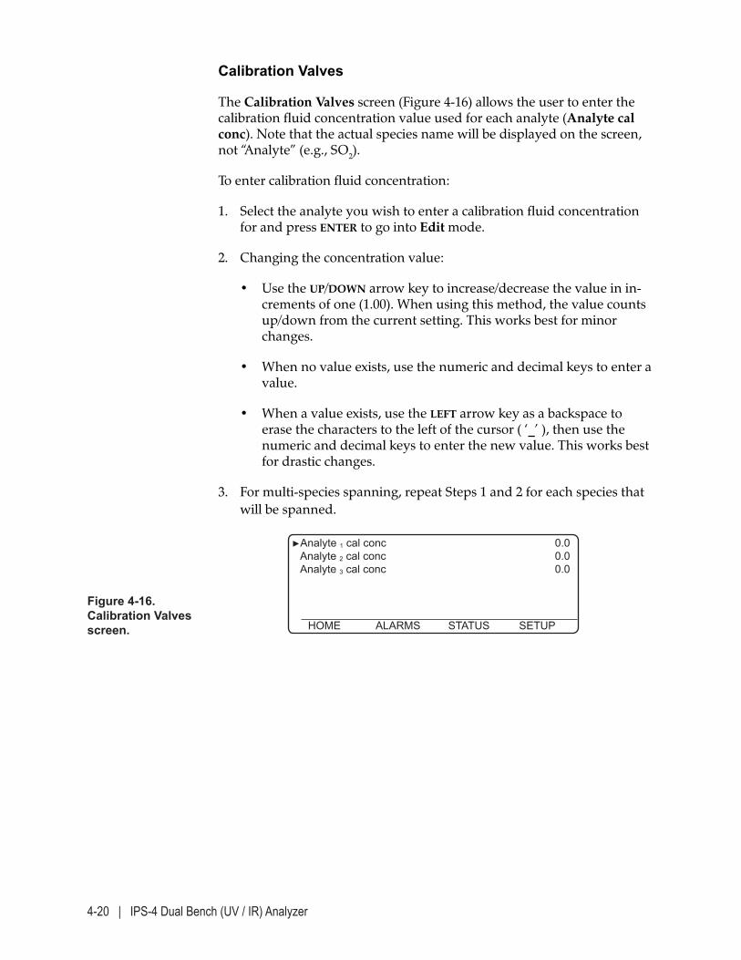
4-20 | IPS-4 Dual Bench (UV / IR) Analyzer
Calibration Valves
The Calibration Valves screen (Figure 4-16) allows the user to enter the calibration fluid concentration value used for each analyte (Analyte cal conc). Note that the actual species name will be displayed on the screen, not “Analyte” (e.g., SO2).
To enter calibration fluid concentration:
1. Select the analyte you wish to enter a calibration fluid concentration for and press ENTER to go into Edit mode.
2. Changing the concentration value:
• Use the UP/DOWN arrow key to increase/decrease the value in in-crements of one (1.00). When using this method, the value counts up/down from the current setting. This works best for minor changes.
• When no value exists, use the numeric and decimal keys to enter a value.
• When a value exists, use the LEFT arrow key as a backspace to erase the characters to the left of the cursor ( ‘_’ ), then use the numeric and decimal keys to enter the new value. This works best for drastic changes.
3. For multi-species spanning, repeat Steps 1 and 2 for each species that will be spanned.
Figure 4-16. Calibration Valves screen.
►Analyte 1 cal conc 0.0 Analyte 2 cal conc 0.0 Analyte 3 cal conc 0.0 HOME ALARMS STATUS SETUP
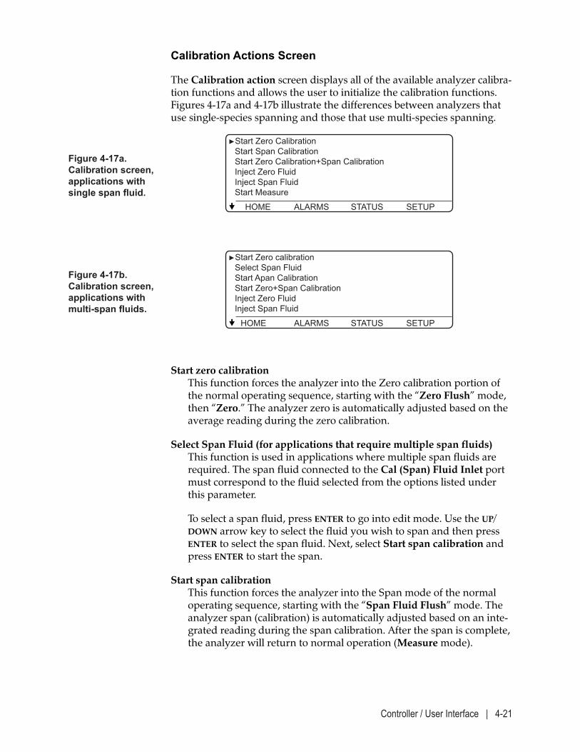
Controller / User Interface | 4-21
Calibration Actions Screen
The Calibration action screen displays all of the available analyzer calibra-tion functions and allows the user to initialize the calibration functions. Figures 4-17a and 4-17b illustrate the differences between analyzers that use single-species spanning and those that use multi-species spanning.
Start zero calibration This function forces the analyzer into the Zero calibration portion of the normal operating sequence, starting with the “Zero Flush” mode, then “Zero.” The analyzer zero is automatically adjusted based on the average reading during the zero calibration.
Select Span Fluid (for applications that require multiple span fluids) This function is used in applications where multiple span fluids are required. The span fluid connected to the Cal (Span) Fluid Inlet port must correspond to the fluid selected from the options listed under this parameter.
To select a span fluid, press ENTER to go into edit mode. Use the UP/DOWN arrow key to select the fluid you wish to span and then press ENTER to select the span fluid. Next, select Start span calibration and press ENTER to start the span.
Start span calibration This function forces the analyzer into the Span mode of the normal operating sequence, starting with the “Span Fluid Flush” mode. The analyzer span (calibration) is automatically adjusted based on an inte-grated reading during the span calibration. After the span is complete, the analyzer will return to normal operation (Measure mode).
Figure 4-17a. Calibration screen, applications with single span fluid.
►Start Zero Calibration Start Span Calibration Start Zero Calibration+Span Calibration Inject Zero Fluid Inject Span Fluid Start Measure
HOME ALARMS STATUS SETUP
Figure 4-17b. Calibration screen, applications with multi-span fluids.
►Start Zero calibration Select Span Fluid Start Apan Calibration Start Zero+Span Calibration Inject Zero Fluid Inject Span Fluid
HOME ALARMS STATUS SETUP
4-22 | IPS-4 Dual Bench (UV / IR) Analyzer
Inject Zero fluid This function injects Zero fluid into the sample system to flush the Measuring Cell of light-absorbing compounds. During this operation, the zero solenoid is open and “Zero Hold” is displayed in the Status area of the HOME screen. Note that this mode does not actually Zero the analyzer.
Inject Span fluid This function injects Span fluid into the sample system, which can be used to observe the analyzer’s response to species of known concentration(s). During this operation, the span solenoid is open and “Span Hold” is displayed in the Status area of the HOME screen. Note that this mode does not actually Span the analyzer.
Start measure This function returns the analyzer to normal Measure mode from any of the Inject Zero fluid, Inject Span fluid, Zero Gas Flush, or Span Gas Flush functions. To return the analyzer to Measure mode, select this function and press ENTER. The message “Please wait ...” appears while the analyzer performs a Sample Flush before switching back to Measure mode.
Manually Starting a Zero Calibration
Refer to “Manually Zeroing the Analyzer Sample System” in Chapter 3 for information about how to perform a manual zero on the analyzer.
Controller / User Interface | 4-23
Manually Starting a Span Calibration
This section applies only to systems with multi-species spanning capabil-ity.
Pressing CANCEL at any time during this procedure will abort the procedure and return the software to the HOME screen.
To introduce Span fluid:
1. Zero the analyzer, as described in Chapter 3 of this manual.
2. Ensure the Span fluid cylinder is connected to the Span Fluid Inlet on the right side of the analyzer and is turned on.
For applications using multiple span fluids: It is important to connect the appropriate Span fluid cylinder for the corresponding fluid being spanned.
3. From the SETUP menu, select the Calibration Control sub-menu and press enter. Scroll down to the Calibration Fluid Concentration sub-menu and press enter to display the Calibration Fluid Concentration screen (Figure 4-16).
Ensure that the concentration value for the Analyte being spanned corresponds with the concentration of the span fluid. If not, edit the value as described under “Calibration Fluids Screen,” later in this sec-tion.
4. For applications using multiple span fluids: From the Calibration screen (Figure 4-17b), choose Select Span Fluid and press ENTER to go into Edit mode. Use the UP/DOWN arrow key to select the fluid you wish to span and then press ENTER to select the span fluid.
5. From the Calibration screen, select Start span calibration and press ENTER to start the span. The analyzer will span the selected fluid and then return to normal operation (Measure mode).
6. Turn off the Span fluid.
The span process is complete and the analyzer is now on-line.
7. For applications using multiple span fluids: Repeat Steps 2 through 6 for each span fluid.
8. Press the HOME soft key to return to the HOME screen.
NOTE
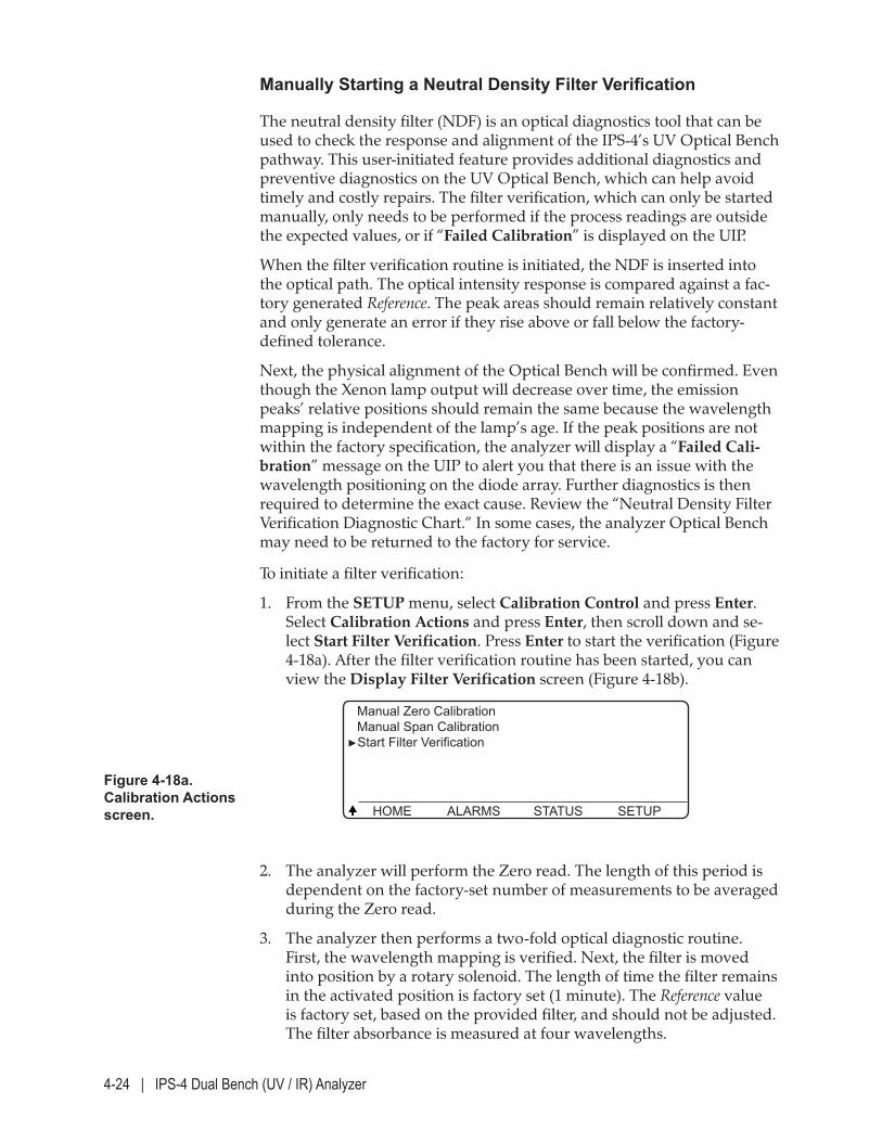
4-24 | IPS-4 Dual Bench (UV / IR) Analyzer
Manually Starting a Neutral Density Filter Verification
The neutral density filter (NDF) is an optical diagnostics tool that can be used to check the response and alignment of the IPS-4’s UV Optical Bench pathway. This user-initiated feature provides additional diagnostics and preventive diagnostics on the UV Optical Bench, which can help avoid timely and costly repairs. The filter verification, which can only be started manually, only needs to be performed if the process readings are outside the expected values, or if “Failed Calibration” is displayed on the UIP.
When the filter verification routine is initiated, the NDF is inserted into the optical path. The optical intensity response is compared against a fac-tory generated Reference. The peak areas should remain relatively constant and only generate an error if they rise above or fall below the factory-defined tolerance.
Next, the physical alignment of the Optical Bench will be confirmed. Even though the Xenon lamp output will decrease over time, the emission peaks’ relative positions should remain the same because the wavelength mapping is independent of the lamp’s age. If the peak positions are not within the factory specification, the analyzer will display a “Failed Cali-bration” message on the UIP to alert you that there is an issue with the wavelength positioning on the diode array. Further diagnostics is then required to determine the exact cause. Review the “Neutral Density Filter Verification Diagnostic Chart.“ In some cases, the analyzer Optical Bench may need to be returned to the factory for service.
To initiate a filter verification:
1. From the SETUP menu, select Calibration Control and press Enter. Select Calibration Actions and press Enter, then scroll down and se-lect Start Filter Verification. Press Enter to start the verification (Figure 4-18a). After the filter verification routine has been started, you can view the Display Filter Verification screen (Figure 4-18b).
2. The analyzer will perform the Zero read. The length of this period is dependent on the factory-set number of measurements to be averaged during the Zero read.
3. The analyzer then performs a two-fold optical diagnostic routine. First, the wavelength mapping is verified. Next, the filter is moved into position by a rotary solenoid. The length of time the filter remains in the activated position is factory set (1 minute). The Reference value is factory set, based on the provided filter, and should not be adjusted. The filter absorbance is measured at four wavelengths.
Figure 4-18a. Calibration Actions screen.
Manual Zero Calibration Manual Span Calibration►Start Filter Verification
HOME ALARMS STATUS SETUP
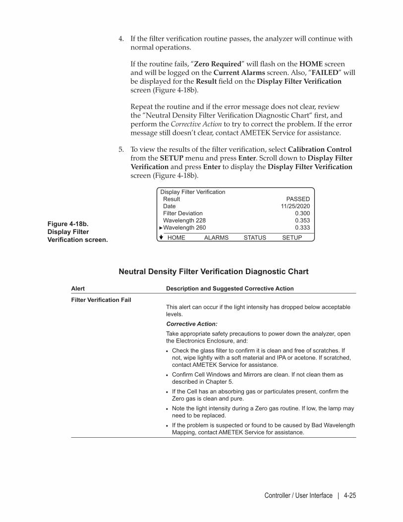
Controller / User Interface | 4-25
4. If the filter verification routine passes, the analyzer will continue with normal operations.
If the routine fails, “Zero Required” will flash on the HOME screen and will be logged on the Current Alarms screen. Also, “FAILED” will be displayed for the Result field on the Display Filter Verification screen (Figure 4-18b).
Repeat the routine and if the error message does not clear, review the “Neutral Density Filter Verification Diagnostic Chart“ first, and perform the Corrective Action to try to correct the problem. If the error message still doesn’t clear, contact AMETEK Service for assistance.
5. To view the results of the filter verification, select Calibration Control from the SETUP menu and press Enter. Scroll down to Display Filter Verification and press Enter to display the Display Filter Verification screen (Figure 4-18b).
Figure 4-18b. Display Filter Verification screen.
Display Filter Verification Result PASSED Date 11/25/2020 Filter Deviation 0.300 Wavelength 228 0.353►Wavelength 260 0.333
HOME ALARMS STATUS SETUP
Neutral Density Filter Verification Diagnostic Chart
Alert Description and Suggested Corrective Action
Filter Verification Fail This alert can occur if the light intensity has dropped below acceptable levels.
Corrective Action: Take appropriate safety precautions to power down the analyzer, open
the Electronics Enclosure, and: • Check the glass filter to confirm it is clean and free of scratches. If
not, wipe lightly with a soft material and IPA or acetone. If scratched, contact AMETEK Service for assistance.
• Confirm Cell Windows and Mirrors are clean. If not clean them as described in Chapter 5.
• If the Cell has an absorbing gas or particulates present, confirm the Zero gas is clean and pure.
• Note the light intensity during a Zero gas routine. If low, the lamp may need to be replaced.
• If the problem is suspected or found to be caused by Bad Wavelength Mapping, contact AMETEK Service for assistance.
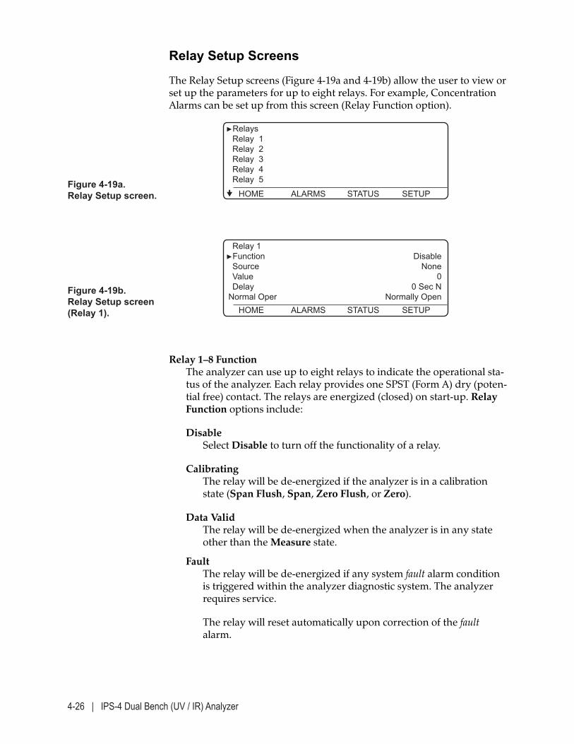
4-26 | IPS-4 Dual Bench (UV / IR) Analyzer
Relay Setup Screens
The Relay Setup screens (Figure 4-19a and 4-19b) allow the user to view or set up the parameters for up to eight relays. For example, Concentration Alarms can be set up from this screen (Relay Function option).
Figure 4-19a. Relay Setup screen.
►Relays Relay 1 Relay 2 Relay 3 Relay 4 Relay 5
HOME ALARMS STATUS SETUP
Figure 4-19b. Relay Setup screen (Relay 1).
Relay 1 ►Function Disable Source None Value 0 Delay 0 Sec N Normal Oper Normally Open HOME ALARMS STATUS SETUP
Relay 1–8 Function The analyzer can use up to eight relays to indicate the operational sta-tus of the analyzer. Each relay provides one SPST (Form A) dry (poten-tial free) contact. The relays are energized (closed) on start-up. Relay Function options include:
Disable Select Disable to turn off the functionality of a relay.
Calibrating The relay will be de-energized if the analyzer is in a calibration state (Span Flush, Span, Zero Flush, or Zero).
Data Valid The relay will be de-energized when the analyzer is in any state other than the Measure state.
Fault The relay will be de-energized if any system fault alarm condition is triggered within the analyzer diagnostic system. The analyzer requires service.
The relay will reset automatically upon correction of the fault alarm.
Controller / User Interface | 4-27
Low Limit Select this to enable an analyte concentration Low Limit Alarm.
High Limit Select this to enable an analyte concentration High Limit Alarm.
Heartbeat Relay periodically will turn on and off to indicate that the Ana-lyzer is “ON”.
Check Request Relay will be “ON” if any warnings are active.
User Relay action controlled by analyzer internal task.
Relay 1–8 Source Defines the assignment for each of the eight relay outputs, which are displayed on the right side of the screen. This parameter only applies if Relay Function is set to Low Limit or High Limit. Options include:
NONE Select NONE if you do not wish to assign a relay to an output channel.
Analyte 1–8 Defines the analyte (species) of interest for the relay output. You can assign a different relay for each channel. To assign a relay to a channel, select an analyte and press ENTER. Note that the actual species name (e.g., SO2) will be displayed on the screen, not “Analyte.”
Relay 1–8 Value Defines the Low or High Alarm Limit threshold for each relay (user input required). This parameter only applies if Relay Function is set to Low Limit or High Limit.
Relay 1–8 Delay Defines the delay time to de-energize the relay after the analyte con-centration goes outside the limit set with Relay Value.
For example, if Relay Delay is set to 5 seconds, the analyte concentra-tion can exceed the High Limit for up to 5 seconds at a time without de-energizing the relay. If the concentration stays high for more than 5 seconds, the relay will be de-energized. The range is 0–3600 seconds. This parameter only applies if Relay Function is set to Low Limit or High Limit.
4-28 | IPS-4 Dual Bench (UV / IR) Analyzer
To change the settings for a relay:
1. Enter a password to allow changes to be made to the relay settings.
2. Select one of the Relay (1–8) sub-menus. Press ENTER to view the pa-rameters for that relay.
3. Select the required parameter (Relay Function, Source, Value, or Delay), change the settings, and press ENTER.
Repeat this step for each parameter and each relay.
When entering a value for the Relay Value and Delay parameters:
• Use the UP/DOWN arrow key to increase/decrease the value in increments of one (1.00). This works best for minor changes. The relay value is displayed on the right side of the screen.
• If a value exists, use the LEFT arrow key as a backspace to erase the characters to the left of the cursor ( ‘_’ ) if applicable, then use the numeric keys to enter the new value. This works best for drastic changes.
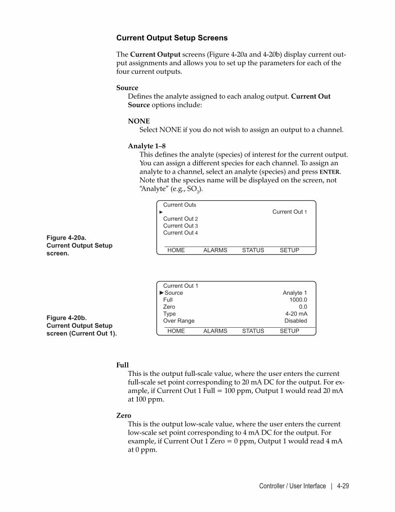
Controller / User Interface | 4-29
Current Output Setup Screens
The Current Output screens (Figure 4-20a and 4-20b) display current out-put assignments and allows you to set up the parameters for each of the four current outputs.
Source Defines the analyte assigned to each analog output. Current Out Source options include:
NONE Select NONE if you do not wish to assign an output to a channel.
Analyte 1–8 This defines the analyte (species) of interest for the current output. You can assign a different species for each channel. To assign an analyte to a channel, select an analyte (species) and press ENTER. Note that the species name will be displayed on the screen, not “Analyte” (e.g., SO2).
Figure 4-20a. Current Output Setup screen.
Current Outs► Current Out 1 Current Out 2 Current Out 3 Current Out 4
HOME ALARMS STATUS SETUP
Figure 4-20b. Current Output Setup screen (Current Out 1).
Current Out 1 ►Source Analyte 1 Full 1000.0 Zero 0.0 Type 4-20 mA Over Range Disabled
HOME ALARMS STATUS SETUP
Full This is the output full-scale value, where the user enters the current full-scale set point corresponding to 20 mA DC for the output. For ex-ample, if Current Out 1 Full = 100 ppm, Output 1 would read 20 mA at 100 ppm.
Zero This is the output low-scale value, where the user enters the current low-scale set point corresponding to 4 mA DC for the output. For example, if Current Out 1 Zero = 0 ppm, Output 1 would read 4 mA at 0 ppm.
4-30 | IPS-4 Dual Bench (UV / IR) Analyzer
Type This allows you to select the output value range, either 4–20 mA DC or 0–20 mA DC for the output. Select ‘0’ for 4–20 mA DC or ‘1’ for 0–20 mA DC.
Over Range When enabled, output readings of 3.8 and 20.5 mA will occur if the analyzer exceeds 4-20 mA.
To change the settings for a current output:
1. Enter a password to allow changes to be made to the current output settings.
2. Select one of the Current Output (1–8) sub-menus. Press ENTER to view the Current Output screen.
3. Select the required parameter ( Source, Full, Zero, Type, or Over Range), change the settings, and press ENTER.
Repeat this step for each parameter and each output.
When entering a value for the Full and Zero parameters:
• Use the UP/DOWN arrow key to increase/decrease the value in increments of one (1.00). This works best for minor changes. The range is 0–100. The current zero-scale set point is displayed on the right side of the screen.
• If a value exists, use the LEFT arrow key as a backspace to erase the characters to the left of the cursor ( ‘_’ ) if applicable, then use the numeric keys to enter the new value. This works best for drastic changes.
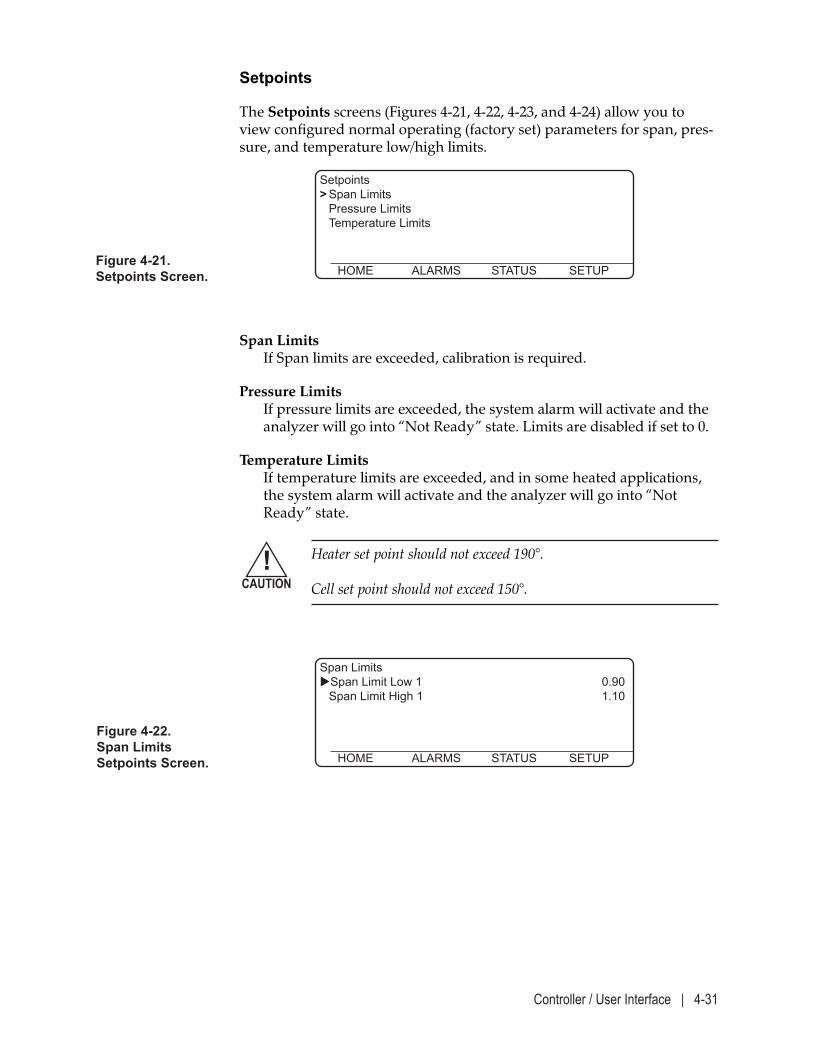
Controller / User Interface | 4-31
Figure 4-22. Span LimitsSetpoints Screen.
Span Limits Span Limit Low 1 0.90 Span Limit High 1 1.10
HOME ALARMS STATUS SETUP
Setpoints
The Setpoints screens (Figures 4-21, 4-22, 4-23, and 4-24) allow you to view configured normal operating (factory set) parameters for span, pres-sure, and temperature low/high limits.
Figure 4-21. Setpoints Screen.
Setpoints > Span Limits Pressure Limits Temperature Limits
HOME ALARMS STATUS SETUP
Span Limits If Span limits are exceeded, calibration is required.
Pressure Limits If pressure limits are exceeded, the system alarm will activate and the analyzer will go into “Not Ready” state. Limits are disabled if set to 0.
Temperature Limits If temperature limits are exceeded, and in some heated applications, the system alarm will activate and the analyzer will go into “Not Ready” state.
Heater set point should not exceed 190°. Cell set point should not exceed 150°.
!CAUTION
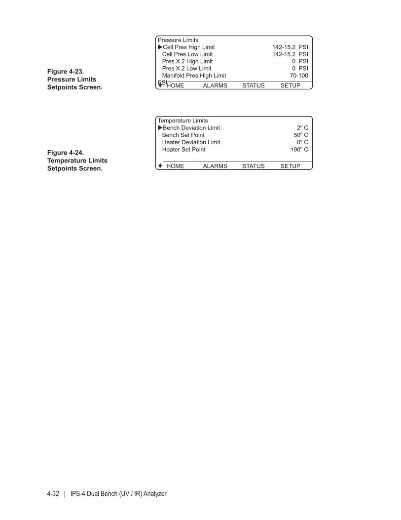
4-32 | IPS-4 Dual Bench (UV / IR) Analyzer
Figure 4-23. Pressure LimitsSetpoints Screen.
Pressure Limits Cell Pres High Limit 142-15.2 PSI Cell Pres Low Limit 142-15.2 PSI Pres X 2 High Limit 0 PSI Pres X 2 Low Limit 0 PSI Manifold Pres High Limit 70-100 PSI HOME ALARMS STATUS SETUP
Figure 4-24. Temperature LimitsSetpoints Screen.
Temperature Limits Bench Deviation Limit 2º C Bench Set Point 50º C Heater Deviation Limit 0º C Heater Set Point 190º C
HOME ALARMS STATUS SETUP
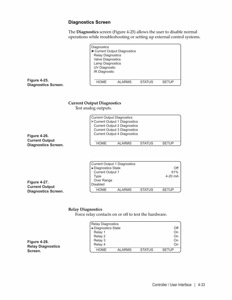
Controller / User Interface | 4-33
Diagnostics Screen
The Diagnostics screen (Figure 4-25) allows the user to disable normal operations while troubleshooting or setting up external control systems.
Figure 4-25. Diagnostics Screen.
Diagnostics►Current Output Diagnostics Relay Diagnostics Valve Diagnostics Lamp Diagnostics UV Diagnostic IR Diagnostic
HOME ALARMS STATUS SETUP
Figure 4-27. Current Output Diagnostics Screen.
Current Output 1 Diagnostics►Diagnostics State Off Current Output 1 61% Type 4-20 mA Over Range Disabled HOME ALARMS STATUS SETUP
Figure 4-26. Current Output Diagnostics Screen.
Current Output Diagnostics> Current Output 1 Diagnostics Current Output 2 Diagnostics Current Output 3 Diagnostics Current Output 4 Diagnostics
HOME ALARMS STATUS SETUP
Current Output Diagnostics Test analog outputs.
Relay Diagnostics Force relay contacts on or off to test the hardware.
Figure 4-28. Relay Diagnostics Screen.
Relay Diagnostics►Diagnostics State Off Relay 1 On Relay 2 On Relay 3 On Relay 4 On HOME ALARMS STATUS SETUP
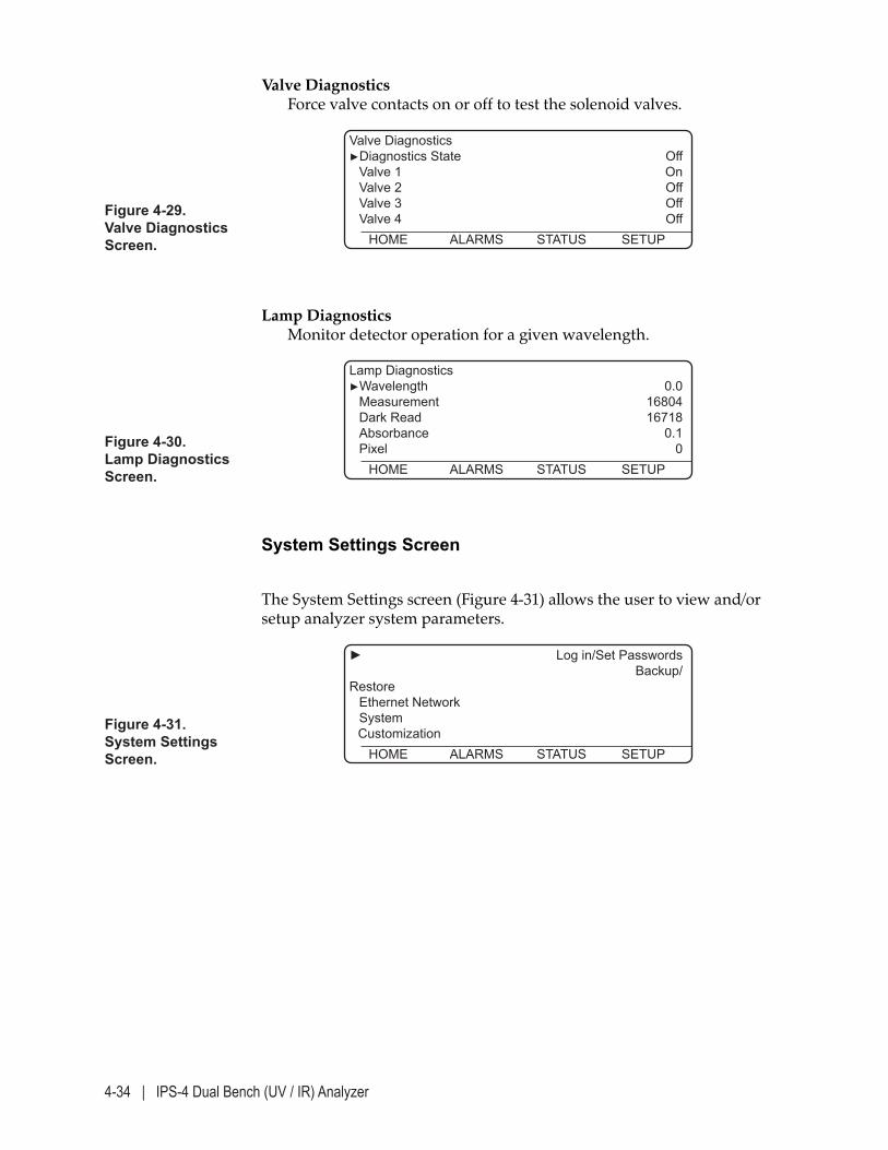
4-34 | IPS-4 Dual Bench (UV / IR) Analyzer
Figure 4-29. Valve Diagnostics Screen.
Valve Diagnostics►Diagnostics State Off Valve 1 On Valve 2 Off Valve 3 Off Valve 4 Off HOME ALARMS STATUS SETUP
Valve Diagnostics Force valve contacts on or off to test the solenoid valves.
Figure 4-30. Lamp Diagnostics Screen.
Lamp Diagnostics►Wavelength 0.0 Measurement 16804 Dark Read 16718 Absorbance 0.1 Pixel 0 HOME ALARMS STATUS SETUP
Lamp Diagnostics Monitor detector operation for a given wavelength.
System Settings Screen
The System Settings screen (Figure 4-31) allows the user to view and/or setup analyzer system parameters.
Figure 4-31. System Settings Screen.
► Log in/Set Passwords Backup/Restore Ethernet Network System Customization HOME ALARMS STATUS SETUP
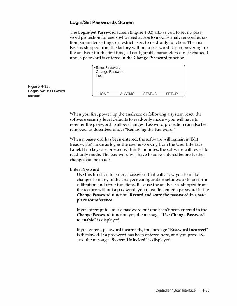
Controller / User Interface | 4-35
Login/Set Passwords Screen
The Login/Set Password screen (Figure 4-32) allows you to set up pass-word protection for users who need access to modify analyzer configura-tion parameter settings, or restrict users to read-only function. The ana-lyzer is shipped from the factory without a password. Upon powering up the analyzer for the first time, all configurable parameters can be changed until a password is entered in the Change Password function.
Figure 4-32. Login/Set Password screen.
Enter Password Change Password Lock
HOME ALARMS STATUS SETUP
When you first power up the analyzer, or following a system reset, the software security level defaults to read-only mode – you will have to re-enter the password to allow changes. Password protection can also be removed, as described under “Removing the Password.”
When a password has been entered, the software will remain in Edit (read-write) mode as log as the user is working from the User Interface Panel. If no keys are pressed within 10 minutes, the software will revert to read-only mode. The password will have to be re-entered before further changes can be made.
Enter Password Use this function to enter a password that will allow you to make changes to many of the analyzer configuration settings, or to perform calibration and other functions. Because the analyzer is shipped from the factory without a password, you must first enter a password in the Change Password function. Record and store the password in a safe place for reference.
If you attempt to enter a password but one hasn’t been entered in the Change Password function yet, the message “Use Change Password to enable” is displayed.
If you enter a password incorrectly, the message “Password incorrect” is displayed. If a password has been entered here, and you press EN-TER, the message “System Unlocked” is displayed.
4-36 | IPS-4 Dual Bench (UV / IR) Analyzer
Change Password Use this function to enter a password for the first time after installing the analyzer or whenever you are changing the password. The pass-word entered here is the password that must be entered in the Enter Password function that will allow you to change the analyzer configu-ration settings.
Because the analyzer is shipped from the factory without a password, you must enter a password in the Change Password function before you can change parameter settings. If you attempt to change the password without first entering the password, the message “System Locked” appears.
Keys that can be used to enter a password include any of the numeric keys (0–9), decimal key ( . ), and the minus ( – ) key. A maximum of nine characters can be used for the password.
Lock Use this functions to clear the password from memory and “lock” all parameters, settings, and functions as read-only. When you select Lock and press ENTER, the parameters are locked out and the message “System locked” is displayed. When the system is locked, a padlock icon ( ) appears in the top-right corner of the HOME screen.
Controller / User Interface | 4-37
Changing the Password
Occasionally, you should change the password that allows you to make changes to the analyzer configuration settings. If password protection al-ready exists, you must enter the existing password before you can change it.
To change the password:
1. Select Enter Password and press ENTER. Key in the password and press ENTER again. The software will now allow you to change the password.
2. Select Change Password and press ENTER. Key in the new password and press ENTER. Record and store the password in a safe place for reference.
Locking the Password
Use the Lock function to disable the password from the current session. This reverts all analyzer functions to read-only. Changes to the analyzer settings cannot be made until the password is entered again.
To lock out all users:
Select Lock and press ENTER. The message “System Locked” appears. A padlock icon appears on the top-right side of the HOME screen to indi-cate the system is currently locked from making any changes.
Removing the Password
To remove password protection:
1. Select Enter Password and press ENTER. Key in the password and press ENTER. The software will now allow you to remove the password.
2. Select Change Password and press ENTER. Leave the password blank and press ENTER again. The password is removed.
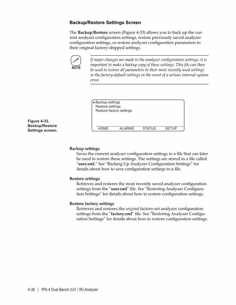
4-38 | IPS-4 Dual Bench (UV / IR) Analyzer
Backup/Restore Settings Screen
The Backup/Restore screen (Figure 4-33) allows you to back up the cur-rent analyzer configuration settings, restore previously saved analyzer configuration settings, or restore analyzer configuration parameters to their original factory-shipped settings.
If major changes are made to the analyzer configuration settings, it is important to make a backup copy of these settings. This file can then be used to restore all parameters to their most recently used settings or the factory-default settings in the event of a serious internal system error.
Figure 4-33. Backup/Restore Settings screen.
►Backup settings Restore settings Restore factory settings HOME ALARMS STATUS SETUP
NOTE
Backup settings Saves the current analyzer configuration settings to a file that can later be used to restore these settings. The settings are stored in a file called “user.xml.” See “Backing Up Analyzer Configuration Settings” for details about how to save configuration settings to a file.
Restore settings Retrieves and restores the most recently saved analyzer configuration settings from the “user.xml” file. See “Restoring Analyzer Configura-tion Settings” for details about how to restore configuration settings.
Restore factory settings Retrieves and restores the original factory-set analyzer configuration settings from the “factory.xml” file. See “Restoring Analyzer Configu-ration Settings” for details about how to restore configuration settings.
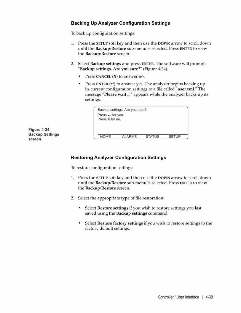
Controller / User Interface | 4-39
Backing Up Analyzer Configuration Settings
To back up configuration settings:
1. Press the SETUP soft key and then use the DOWN arrow to scroll down until the Backup/Restore sub-menu is selected. Press ENTER to view the Backup/Restore screen.
2. Select Backup settings and press ENTER. The software will prompt: “Backup settings. Are you sure?” (Figure 4-34).
• Press CANCEL (X) to answer no.
• Press ENTER ( ) to answer yes. The analyzer begins backing up its current configuration settings to a file called “user.xml.” The message “Please wait ...” appears while the analyzer backs up its settings.
Figure 4-34. Backup Settings screen.
Backup settings. Are you sure? Press for yes. Press X for no.
HOME ALARMS STATUS SETUP
Restoring Analyzer Configuration Settings
To restore configuration settings:
1. Press the SETUP soft key and then use the DOWN arrow to scroll down until the Backup/Restore sub-menu is selected. Press ENTER to view the Backup/Restore screen.
2. Select the appropriate type of file restoration:
• Select Restore settings if you wish to restore settings you last saved using the Backup settings command.
• Select Restore factory settings if you wish to restore settings to the factory default settings.
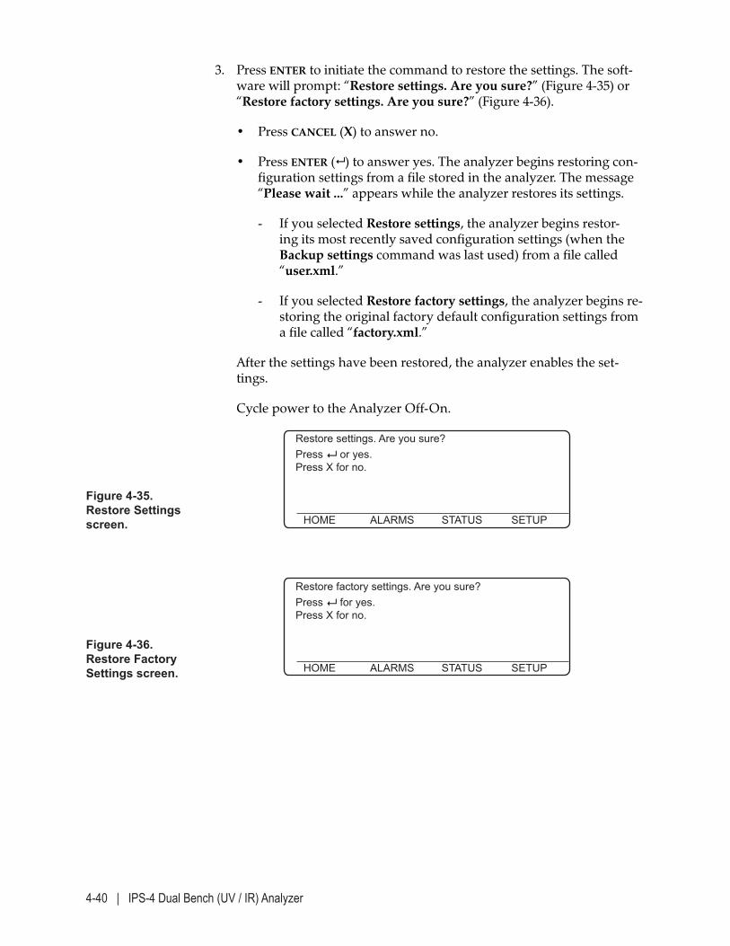
4-40 | IPS-4 Dual Bench (UV / IR) Analyzer
Figure 4-36. Restore Factory Settings screen.
Restore factory settings. Are you sure? Press for yes. Press X for no.
HOME ALARMS STATUS SETUP
Figure 4-35.Restore Settings screen.
Restore settings. Are you sure? Press or yes. Press X for no.
HOME ALARMS STATUS SETUP
3. Press ENTER to initiate the command to restore the settings. The soft-ware will prompt: “Restore settings. Are you sure?” (Figure 4-35) or “Restore factory settings. Are you sure?” (Figure 4-36).
• Press CANCEL (X) to answer no.
• Press ENTER ( ) to answer yes. The analyzer begins restoring con-figuration settings from a file stored in the analyzer. The message “Please wait ...” appears while the analyzer restores its settings.
- If you selected Restore settings, the analyzer begins restor-ing its most recently saved configuration settings (when the Backup settings command was last used) from a file called “user.xml.”
- If you selected Restore factory settings, the analyzer begins re-storing the original factory default configuration settings from a file called “factory.xml.”
After the settings have been restored, the analyzer enables the set-tings.
Cycle power to the Analyzer Off-On.
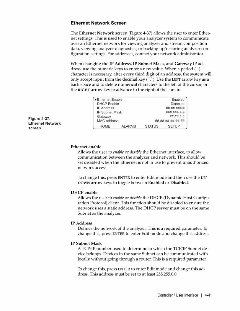
Controller / User Interface | 4-41
Figure 4-37. Ethernet Network screen.
►Ethernet Enable Enabled DHCP Enable Disabled IP Address ##.##.###.# IP Subnet Mask ###.###.#.# Gateway ##.##.#.# MAC address ##-##-##-##-##-## HOME ALARMS STATUS SETUP
Ethernet enable Allows the user to enable or disable the Ethernet interface, to allow communication between the analyzer and network. This should be set disabled when the Ethernet is not in use to prevent unauthorized network access.
To change this, press ENTER to enter Edit mode and then use the UP/DOWN arrow keys to toggle between Enabled or Disabled.
DHCP enable Allows the user to enable or disable the DHCP (Dynamic Host Configu-ration Protocol) client. This function should be disabled to ensure the network uses a static address. The DHCP server must be on the same Subnet as the analyzer.
IP Address Defines the network of the analyzer. This is a required parameter. To change this, press ENTER to enter Edit mode and change this address.
IP Subnet Mask A TCP/IP number used to determine to which the TCP/IP Subnet de-vice belongs. Devices in the same Subnet can be communicated with locally without going through a router. This is a required parameter.
To change this, press ENTER to enter Edit mode and change this ad-dress. This address must be set to at least 255.255.0.0.
Ethernet Network Screen
The Ethernet Network screen (Figure 4-37) allows the user to enter Ether-net settings. This is used to enable your analyzer system to communicate over an Ethernet network for viewing analyzer and stream composition data, viewing analyzer diagnostics, or backing up/restoring analyzer con-figuration settings. For addresses, contact your network administrator.
When changing the IP Address, IP Subnet Mask, and Gateway IP ad-dress, use the numeric keys to enter a new value. When a period ( . ) character is necessary, after every third digit of an address, the system will only accept input from the decimal key ( ‘.’ ). Use the LEFT arrow key as a back space and to delete numerical characters to the left of the cursor, or the RIGHT arrow key to advance to the right of the cursor.
4-42 | IPS-4 Dual Bench (UV / IR) Analyzer
Gateway (optional) A Gateway (or “Router”) is a device which is used to forward IP pack-ets to a remote destination. The definition of “remote,” in this case, is a device that is not directly attached to the same network segment as the sending device (e.g., the same Ethernet segment). This function defines the Gateway IP address for the network, which allows local network traffic to be sent to another network.
Setup of this parameter is required only if communicating from out-side the internal network. To change this, press ENTER to enter Edit mode and change this address.
MAC address Defines the MAC (Media Access Control) address (unique byte num-ber) of the analyzer (e.g., 00-0F-88-00-00-79). The MAC address is fac-tory-set. This address is read-only.
To set up Ethernet parameters:
For specific requirements for permanent Ethernet connections, refer to “Permanent Ethernet Cable Connections (Optional)” in Chapter 3.
1. Ensure the Ethernet cable is connected.
2. Enter a password to allow changes to be made to the analyzer con-figuration settings.
3. Press the SETUP soft key and then scroll down and select Ethernet Network. Press ENTER to view the Ethernet Network screen.
4. Enter the IP Address, IP Subnet Mask address, and Gateway IP ad-dress (if required), pressing ENTER after entering each address.
5. Ensure the DHCP server is on the same server as the analyzer.
6. Press CANCEL to back out of this sub-menu.
7. Reset the analyzer to allow the changes to take effect.
NOTE
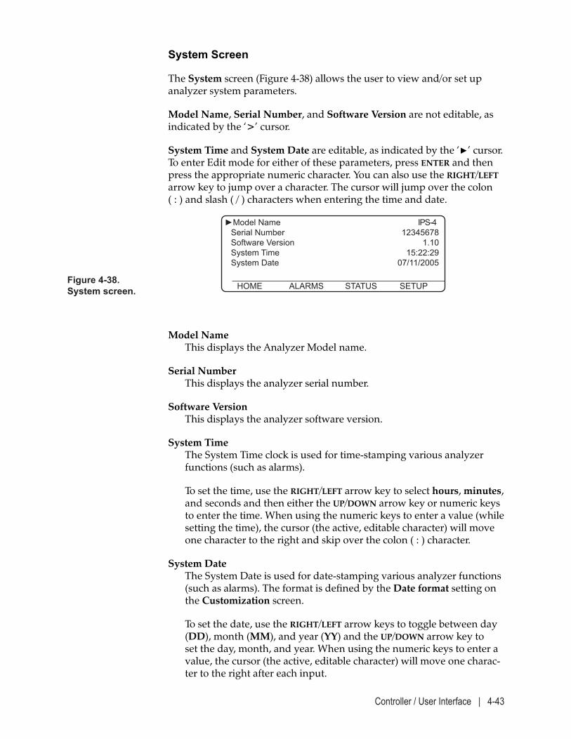
Controller / User Interface | 4-43
System Screen
The System screen (Figure 4-38) allows the user to view and/or set up analyzer system parameters.
Model Name, Serial Number, and Software Version are not editable, as indicated by the ‘>’ cursor.
System Time and System Date are editable, as indicated by the ‘►’ cursor. To enter Edit mode for either of these parameters, press ENTER and then press the appropriate numeric character. You can also use the RIGHT/LEFT arrow key to jump over a character. The cursor will jump over the colon ( : ) and slash ( / ) characters when entering the time and date.
Model Name This displays the Analyzer Model name.
Serial Number This displays the analyzer serial number.
Software Version This displays the analyzer software version.
System Time The System Time clock is used for time-stamping various analyzer functions (such as alarms).
To set the time, use the RIGHT/LEFT arrow key to select hours, minutes, and seconds and then either the UP/DOWN arrow key or numeric keys to enter the time. When using the numeric keys to enter a value (while setting the time), the cursor (the active, editable character) will move one character to the right and skip over the colon ( : ) character.
System Date The System Date is used for date-stamping various analyzer functions (such as alarms). The format is defined by the Date format setting on the Customization screen.
To set the date, use the RIGHT/LEFT arrow keys to toggle between day (DD), month (MM), and year (YY) and the UP/DOWN arrow key to set the day, month, and year. When using the numeric keys to enter a value, the cursor (the active, editable character) will move one charac-ter to the right after each input.
Figure 4-38. System screen.
►Model Name IPS-4 Serial Number 12345678 Software Version 1.10 System Time 15:22:29 System Date 07/11/2005
HOME ALARMS STATUS SETUP
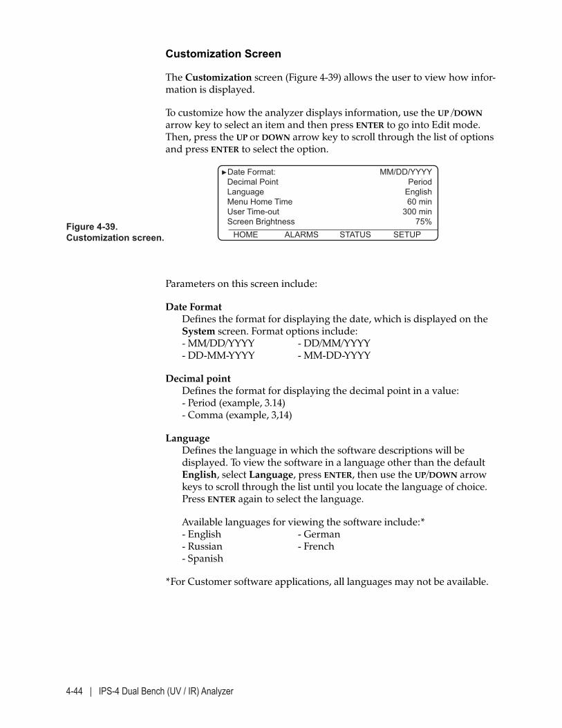
4-44 | IPS-4 Dual Bench (UV / IR) Analyzer
Customization Screen
The Customization screen (Figure 4-39) allows the user to view how infor-mation is displayed.
To customize how the analyzer displays information, use the UP /DOWN arrow key to select an item and then press ENTER to go into Edit mode. Then, press the UP or DOWN arrow key to scroll through the list of options and press ENTER to select the option.
Figure 4-39. Customization screen.
►Date Format: MM/DD/YYYY Decimal Point Period Language English Menu Home Time 60 min User Time-out 300 min Screen Brightness 75% HOME ALARMS STATUS SETUP
Parameters on this screen include:
Date Format Defines the format for displaying the date, which is displayed on the System screen. Format options include: - MM/DD/YYYY - DD/MM/YYYY - DD-MM-YYYY - MM-DD-YYYY
Decimal point Defines the format for displaying the decimal point in a value: - Period (example, 3.14) - Comma (example, 3,14)
Language Defines the language in which the software descriptions will be displayed. To view the software in a language other than the default English, select Language, press ENTER, then use the UP/DOWN arrow keys to scroll through the list until you locate the language of choice. Press ENTER again to select the language.
Available languages for viewing the software include:* - English - German - Russian - French - Spanish
*For Customer software applications, all languages may not be available.

Controller / User Interface | 4-45
Menu Home Time This displays and allows you to change the time an inactive menu will display before it returns to the home screen.
User Time-Out This displays and allows you to change the inactivity period a user is logged into to the system.
Screen Brightness This displays and allows you to change the screen brightness.
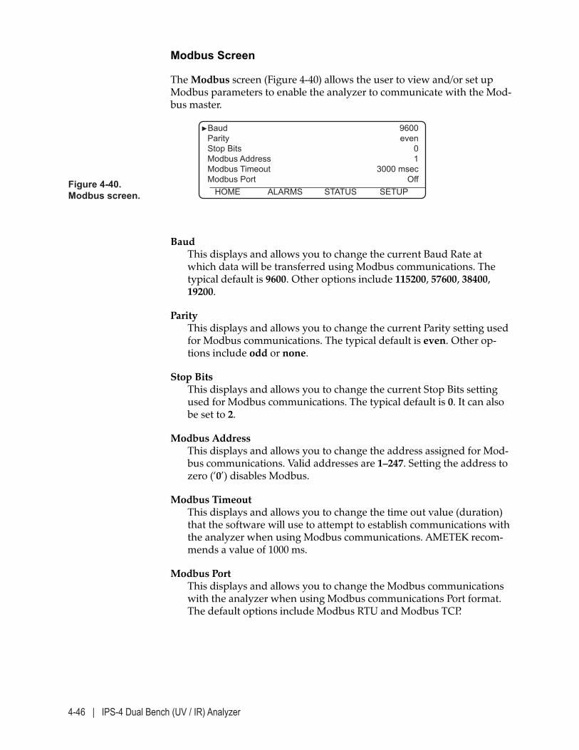
4-46 | IPS-4 Dual Bench (UV / IR) Analyzer
Modbus Screen
The Modbus screen (Figure 4-40) allows the user to view and/or set up Modbus parameters to enable the analyzer to communicate with the Mod-bus master.
Baud This displays and allows you to change the current Baud Rate at which data will be transferred using Modbus communications. The typical default is 9600. Other options include 115200, 57600, 38400, 19200.
Parity This displays and allows you to change the current Parity setting used for Modbus communications. The typical default is even. Other op-tions include odd or none.
Stop Bits This displays and allows you to change the current Stop Bits setting used for Modbus communications. The typical default is 0. It can also be set to 2.
Modbus Address This displays and allows you to change the address assigned for Mod-bus communications. Valid addresses are 1–247. Setting the address to zero (‘0’) disables Modbus.
Modbus Timeout This displays and allows you to change the time out value (duration) that the software will use to attempt to establish communications with the analyzer when using Modbus communications. AMETEK recom-mends a value of 1000 ms.
Modbus Port This displays and allows you to change the Modbus communications with the analyzer when using Modbus communications Port format. The default options include Modbus RTU and Modbus TCP.
Figure 4-40. Modbus screen.
►Baud 9600 Parity even Stop Bits 0 Modbus Address 1 Modbus Timeout 3000 msec Modbus Port Off HOME ALARMS STATUS SETUP
Controller / User Interface | 4-47
To change these parameters:
1. Select the parameter you wish to change and press ENTER to go into Edit mode.
2. For Baud, Parity, and Stop Bits, use the UP/DOWN arrow key to scroll through the available options. To select an option when it is displayed, press ENTER.
For Modbus Address and Modbus Timeout, enter a value using the numeric keys.
3. Reset the analyzer to allow the changes to take effect.

4-48 | IPS-4 Dual Bench (UV / IR) Analyzer
This page intentionally left blank.
Maintenance and Troubleshooting | 5-1
MAINTENANCE and TROUBLESHOOTING
The Maintenance and Troubleshooting chapter discusses preventive maintenance to keep the analyzer system operating at peak efficiency, how to check for plugging in the analyzer sample system, and how to replace internal parts. This chapter also discusses how to view alarm mes-sages to diagnose and troubleshoot problems with the analyzer.
Safety Considerations
Before working on the analyzer, read the entire procedure you will be performing to understand how to safely perform mainte-nance on and troubleshoot the analyzer.
Before performing any maintenance, service, or troubleshooting on the analyzer, review and follow all safety information in this chapter and under “Personnel and Equipment Safety Information” following the Table of Contents. This information describes procedures to follow to avoid personal injury and/or damage to the equipment. All regula-tory agency and personnel safety procedures for your jurisdic-tion must be followed. Personnel should be thoroughly familiar with the operation of the analyzer before performing the maintenance procedures described in this chapter.
To prevent an explosion, test the area around the analyzer for flamma-ble gases and proceed with maintenance only when the area is found to be safe (nonhazardous).
NOTE
!WARNING
!WARNING
5-2 | IPS-4 Dual Bench (UV / IR) Analyzer
Under normal operating conditions, lethal concentrations of H2S and other toxic gases/liquids from the sample stream may be present within the sample system. The sample system is defined as all compo-nents in the analyzer system through which sample gas passes. Before working on the sample system, manually Zero the analyzer (from the Calibration screen, select Start Zero Calibration and press ENTER), isolate it (block it in) from the sample stream, and disconnect the power. Follow this procedure prior to changing out any analyzer components or replacing any parts (as part of regular preventive maintenance), or when performing leak checks following the replacement of instrument air or other adjustments to any of the connection points in the analyzer’s sample system. If this is not pos-sible, a breathing apparatus must be worn while servicing the sample system.
If handling the circuit boards, do not subject them to static discharge. The ideal solution is a static-safe work area. Since such areas typically are not available at analyzer installation sites, the use of a wrist strap connected directly to a ground is recommended. If a wrist strap is not available, you should at the very least touch the metal chassis to ground yourself before handling the boards.
!WARNING
!CAUTION
Maintenance and Troubleshooting | 5-3
Maintenance
Generally, there is limited maintenance required to ensure the analyzer remains operating at peak efficiency, other than that described in the “An-alyzer Preventive Maintenance Schedule.” This section discusses preven-tive maintenance that must be followed to ensure continued and proper operation of the analyzer. This section also describes parts that require replacing and the frequency in which they should be replaced, according to this schedule.
Preventive Maintenance
To reduce the occurrence of problems with the analyzer, AMETEK recom-mends that you follow the “Analyzer Preventive Maintenance Schedule,” as outlined in the following pages. Since most analyzer problems originate within the sample handling system, the primary objective of the preven-tive maintenance schedule is proper care of the sample system.
For Gas Applications: Plugs in the sample system generally can be avoided by ensuring all components of the sample system operate at least 10 °C (18 °F) above the sample dew point temperature. The risk of developing a collection of liquids in low spots or plugging in the sample system is further reduced by sloping the Sample Line to the analyzer and the Vent Line back to the sample stream or other dispersal method.
Preventing leaks in the sample handling system is critical to proper analyzer operation. The analyzer sample system must be leak checked whenever it has been dismantled for maintenance or repair. Refer to “Sample System Leak Check” in Chapter 3 for details.
The “Analyzer Preventive Maintenance Schedule” suggests actions and their frequency when caring for the analyzer. Procedures and drawings that are intended to assist you when changing out parts can be found in appropriate sections in this chapter or in a Manual Supplement which is included in the “Supplemental Information”section of this manual and/or the analyzer Documentation Package.
!CAUTION
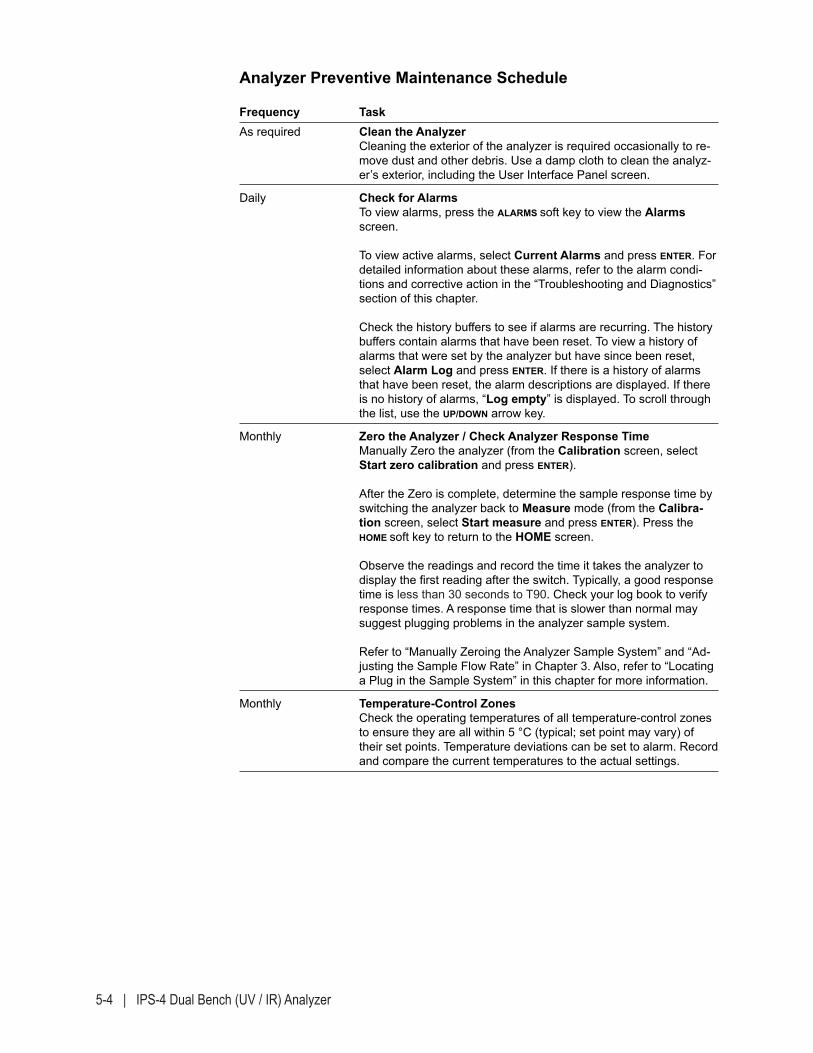
5-4 | IPS-4 Dual Bench (UV / IR) Analyzer
Analyzer Preventive Maintenance Schedule
Frequency TaskAs required Clean the Analyzer
Cleaning the exterior of the analyzer is required occasionally to re-move dust and other debris. Use a damp cloth to clean the analyz-er’s exterior, including the User Interface Panel screen.
Daily Check for Alarms To view alarms, press the ALARMS soft key to view the Alarms screen. To view active alarms, select Current Alarms and press ENTER. For detailed information about these alarms, refer to the alarm condi-tions and corrective action in the “Troubleshooting and Diagnostics” section of this chapter. Check the history buffers to see if alarms are recurring. The history buffers contain alarms that have been reset. To view a history of alarms that were set by the analyzer but have since been reset, select Alarm Log and press ENTER. If there is a history of alarms that have been reset, the alarm descriptions are displayed. If there is no history of alarms, “Log empty” is displayed. To scroll through the list, use the UP/DOWN arrow key.
Monthly Zero the Analyzer / Check Analyzer Response Time Manually Zero the analyzer (from the Calibration screen, select Start zero calibration and press ENTER). After the Zero is complete, determine the sample response time by switching the analyzer back to Measure mode (from the Calibra-tion screen, select Start measure and press ENTER). Press the HOME soft key to return to the HOME screen. Observe the readings and record the time it takes the analyzer to display the first reading after the switch. Typically, a good response time is less than 30 seconds to T90. Check your log book to verify response times. A response time that is slower than normal may suggest plugging problems in the analyzer sample system. Refer to “Manually Zeroing the Analyzer Sample System” and “Ad-justing the Sample Flow Rate” in Chapter 3. Also, refer to “Locating a Plug in the Sample System” in this chapter for more information.
Monthly Temperature-Control Zones Check the operating temperatures of all temperature-control zones to ensure they are all within 5 °C (typical; set point may vary) of their set points. Temperature deviations can be set to alarm. Record and compare the current temperatures to the actual settings.
Maintenance and Troubleshooting | 5-5
Frequency TaskMonthly Pressure Readings
Check the Aspirator, Pneumatic Valve/Zero, and Manifold pressure readings from the STATUS screen. Aspirator pressure should be set higher than 70 kPa (10 psi) above the sample stream pressure. Pneumatic Valve/Zero supply pressure should be set in the range of 420–560 kPa (60–80 psig), typically 560 kPa (80 psig) for high pressure applications. For the Zero supply, the pressure should be set to approximately 140 kPa (20 psig) above the sample stream pressure. Manifold pressure should be set approximately 560–700 kPa (80–100 psig). Refer to “Adjusting the Sample Flow Rate” in Chap-ter 3 for more details.
CAUTION: To avoid damaging the pressure transducer, do not set the pressure higher than the Cell pressure transducer rating. Refer to the Final “As-Built” drawings in the analyzer Documentation Package for maximum pressure ratings.
Every Three Months Outdoor Systems If your analyzer system is installed outdoors, check the condition of the seals on the doors. These seals are essential in the analyzer maintaining its IP65 and NEMA 4 rating. The secondary gaskets (with the wire mesh) on the door are used for electrical contact between each door and its enclosure. Ensure these gaskets are intact. If the seals are damaged, cracked, or show signs of wear, replace them immediately. Contact AMETEK for assistance.
Every Six Months Pressurization System Check Place any process control system that is using the analyzer
measurements in manual and alert any personnel who would be affected by alarms from the pressurization system. Refer to Figure 1-4 for proper operation of the purge system.
Open the purge controller and check that the filter is clean and that there is no accumulation of water or debris in the filter jar. Service if necessary.
Check that the area is free from flammable gases before proceed-ing. Place the Purge Bypass Switch in the “BYPASS” mode. Close the valve on the inlet side of the purge controller. The controller should quickly alarm and go into fast purge (indicators will be RED (left) and BLACK (right). Immediately open the air inlet valve fully.
The indicators should return to GREEN (left) and YELLOW (right). You should be able to hear the rush of air flowing through the en-closure. After five minutes, the right indicator on the purge control-ler should turn YELLOW and the controller will go into the leakage compensation mode.
Watch the system for an additional minute or two to make sure that the leakage compensation is set high enough to maintain the system in the leakage compensation mode (left indicator stays GREEN), and yet not too high that it causes the vent to open or the right indicator to turn YELLOW. At the end of the test, place the Purge Bypass Switch back to the “ACTIVE” position. *Allow Analyzer time to thoroughly equilibrate after the past purge and electronics tests.
5-6 | IPS-4 Dual Bench (UV / IR) Analyzer
Frequency TaskEvery Six Months Sheltered Systems
If your analyzer system is installed in a custom shelter, check the air filters for the shelter purge and air conditioning systems and replace them if necessary. Depending on the location of the site and its environmental conditions, it may be necessary to check and replace these filters more frequently.
Every Six Months Sample/Vent Lines Inspect the Sample Line and Vent Line for sags, sharp bends, or damage to the outer skin. If necessary, take appropriate safety pre-cautions and replace the lines. Perform a leak check on all associ-ated fittings after replacing any line(s).
Every Year Measuring Cell Clean the Measuring Cell and the rest of the analyzer sample sys-tem. This schedule is a minimum requirement. If other conditions are found to be present, as outlined in this chapter under “Measur-ing Cell Preventive Maintenance,” cleaning may be required more frequently. At the same time, replace the o-rings (always) and windows and/or window/mirror combinations (if chipped, cracked, or scratched).
3–5 Years Xenon Flash Lamp Assembly Replace the Xenon Flash Lamp Assembly. The assembly may need to be replaced sooner if information from the analyzer diagnostics indicates related alarms. Refer to “Replacing the Xenon (UV) Flash Lamp Assembly” in this chapter.
3–5 Years Infrared Source Assembly Replace the Infrared Source Assembly. The assembly may need to be replaced sooner if information from the analyzer diagnostics indi-cates related alarms. Refer to “Replacing the Infrared (IR) Source Assembly” in this chapter.
Expo Technologies MiniPurge® System With eTimer (Optional) Preventive Maintenance Schedule
Frequency Task
— If your analyzer uses an Expo Technologies MiniPurge® System With eTimer, refer to the system’s manual for maintenance frequen-cy and procedures. This manual is shipped with the analyzer.
— To test the pressure of the Electronics Enclosure, use the Cabinet Pressure Port on the Solenoid Block.
3 Years Battery Pack, Expo MiniPurge® System (if analyzer is equipped)
Replace the Battery Pack and perform the commissioning tests as de-scribed in the Expo MiniPurge® Type X / ET Size 1 Manual (ML 422).
See “Expo Technologies MiniPurge® System With eTimer Spare Parts” in Chapter 6 for spare parts ordering information.
Maintenance and Troubleshooting | 5-7
Locating a Plug in the Sample System
If analyzer problems occur, they are most likely related to improper sample system operation, such as plugs or leaks. Plugs in the sample sys-tem cause problems in analyzer response time, either to changing process conditions or to Zero fluid. Leaks are potentially dangerous and will even-tually lead to corrosion problems.
Detecting a Plug in the Sample System
This is best done by observing the analyzer measurement response time immediately following a Zero function. A typical response is less than 30 seconds to T90. Observe your analyzer and learn what a normal response time is. Use the recorded response time as a reference for detecting the formation of plugs in the sample system.
If the sample response time is longer than normal, it is most likely due to plugging somewhere in the sample system. The next step is to locate and remove the plug. The portion of the sample system with the high-est risk of plugging is the sample inlet and the portion of the sample inlet most prone to plugging is the valve on the sample probe or process tap. One way to confirm that a plug is in the sample inlet is to close the Vent Line Shut Off valve (in the Oven/Sample System Enclosure) and Zero the analyzer.
Observe the Cell Pressure reading from the STATUS screen, and if the reading approaches the Zero fluid supply pressure, a plug is present somewhere in the sample inlet.
To avoid damaging the pressure transducer, do not set the pressure higher than the sample system rating.
After confirming that the plug is somewhere in the sample inlet, take all appropriate safety precautions and dismantle the sample system, starting at the Sample Probe or process tap.
Plugs in the vent side of the sample system are rare. Plugs in the vent sys-tem cause the aspirator drive air to flow back into the Measuring Cell and, essentially, simulate a Zero condition.
!CAUTION
NOTE
5-8 | IPS-4 Dual Bench (UV / IR) Analyzer
Changing Out Replaceable Parts
This section discusses the parts that should be changed out and/or cleaned, according to the “Analyzer Preventive Maintenance Schedule.” These descriptions focus on the AMETEK sample system. When replacing parts in the analyzer refer to Figure 5-1 for the location of the main assem-bly. Drawings of the assembly are also included under each section.
Preventing leaks in the sample system is critical to ensure proper analyzer operation. If sample fluid migrates into the Optical Bench Assembly or Reflector Block due to a leak in the Measuring Cell Assembly, the optics will become damaged and most likely require replacement. Most leaks are preventable with regular cleaning and replacement of the Measuring Cell o-rings.
If the User Interface Panel displays alarm messages that indicate a faulty component requires replacement [as described under “Alarm Conditions and Corrective Action” later in this chapter], review this manual for replacement procedures. For complex maintenance procedures not discussed in this manual, such as replacing heaters, RTDs, or electronics boards, consult with your AMETEK distributor or representative.
!CAUTION
!CAUTION
Maintenance and Troubleshooting | 5-9
Tools, Equipment, and Supplies Required for Maintenance
While working on the Cell the following tools, equipment, and supplies are required (supplied by AMETEK only where indicated):
• Measuring Cell spare parts. Refer to either the Measuring Cell Manual Supplement or the Custom Spare Parts List (if applicable), located in the “Supplemental Information” section of this manual and the Documen-tation Package shipped with the analyzer.
• Set of open-end wrenches for fittings and set of metric ball drivers.
• O-ring removal tool.
• Flat blade instrument screwdriver.
• Soft, non-abrasive cloth to place Cell interior parts on.
• Kimwipes® EX-L or an equivalent extra low-lint tissue to clean the front and back sides of the Windows.
If the Windows require a more thorough cleaning, a high purity sol-vent such as Isopropanol (99 %) can be used (if suitable for use with removing contamination).
• Cotton swabs, to clean the interior of the Cell Body and other metal parts.
If the Cell requires a more thorough cleaning, use only non-abrasive cleaning materials that are suitable for use with the sample species and the Cell.
For example: If suitable for the species, an acceptable material is Chem-Thane – or a nonabrasive detergent and water solution. Reagent-grade acetone (if suitable), can then be used to rinse the Cell Body, followed by a rinse with pharmaceutical-grade distilled water.
• Pharmaceutical-grade distilled water, to rinse all Cell parts.
• Reagent-grade acetone as a secondary cleaner for the interior of the Cell Body and other metal parts (must be suitable for use with the sample species).
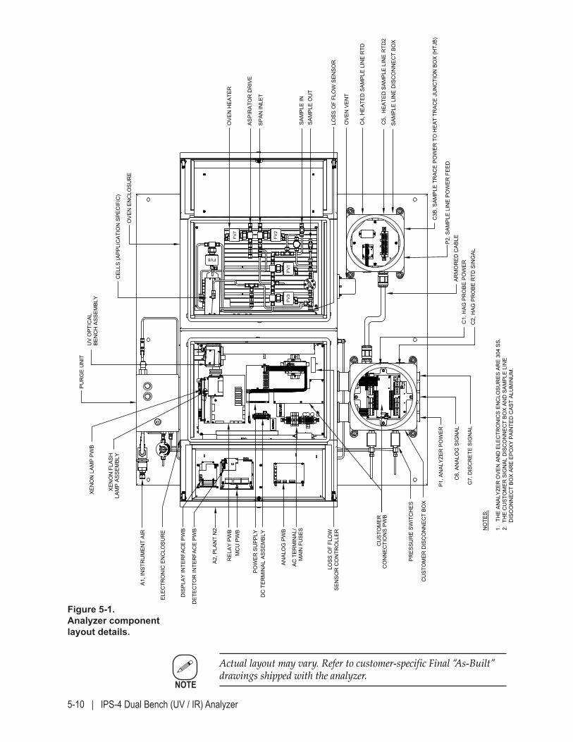
5-10 | IPS-4 Dual Bench (UV / IR) Analyzer
NOTE
Actual layout may vary. Refer to customer-specific Final “As-Built” drawings shipped with the analyzer.
Figure 5-1.Analyzer component layout details.
MOD
CON
SYST
EMS/
SOCA
R HA
OR -
AZER
BAIJA
NMO
DEL I
PS-4
ANA
LYZE
R / F
IELD
UNI
T AR
RANG
EMEN
T BREV
.
WX-
1106
2-3-
3B
SAM
PLE
LIN
E D
ISC
ON
NEC
T BO
X
OVE
N H
EATE
R
SAM
PLE
OU
TSA
MPL
E IN
OVE
N E
NC
LOSU
RE
CEL
LS (A
PPLI
CAT
ION
SPE
CIF
IC)
BEN
CH
ASS
EMBL
Y
PUR
GE
UN
IT
XEN
ON
LAM
P PW
B
XEN
ON
FLA
SHLA
MP
ASSE
MBL
Y
ELEC
TRO
NIC
EN
CLO
SUR
E
DC
TER
MIN
AL A
SSEM
BLY
CU
STO
MER
CO
NN
ECTI
ON
S PW
B
POW
ER S
UPP
LY
DET
ECTO
R IN
TER
FAC
E PW
B
DIS
PLAY
INTE
RFA
CE
PWB
MC
U P
WB
REL
AY P
WB
ANAL
OG
PW
B
AC T
ERM
INAL
/M
AIN
FU
SES
PRES
SUR
E SW
ITC
HES
A1, I
NST
RU
MEN
T AI
R
C4,
HEA
TED
SAM
PLE
LIN
E R
TD
C5,
HEA
TED
SAM
PLE
LIN
E R
TD2
C3B
, SAM
PLE
TRAC
E PO
WER
TO
HEA
T TR
ACE
JUN
CTI
ON
BO
X (H
TJB)
P2, S
AMPL
E LI
NE
POW
ER F
EED
OVE
N V
ENT
UV
OPT
ICAL
CU
STO
MER
DIS
CO
NN
ECT
BOX
ARM
OR
ED C
ABLE
C7,
DIS
CR
ETE
SIG
NAL
C6,
AN
ALO
G S
IGN
AL
C2,
HAG
PR
OBE
RTD
SIN
GAL
C1,
HAG
PR
OBE
PO
WER
P1, A
NAL
YZER
PO
WER
A2, P
LAN
T N
2
ASPI
RAT
OR
DR
IVE
NO
TES:
1.
THE
ANAL
YZER
OVE
N A
ND
ELE
CTR
ON
ICS
ENC
LOSU
RES
AR
E 30
4 SS
.2.
TH
E C
UST
OM
ER S
IGN
AL D
ISC
ON
NEC
T BO
X AN
D S
AMPL
E LI
NE
D
ISC
ON
NEC
T BO
X AR
E EP
OXY
PAI
NTE
D C
AST
ALU
MIN
UM
.
SPAN
INLE
T
LOSS
OF
FLO
WSE
NSO
R C
ON
TRO
LLER
LOSS
OF
FLO
W S
ENSO
R
FV7
FV2
FV1
FV3
FV8
2019
/11/
07
Maintenance and Troubleshooting | 5-11
Measuring Cell Preventive Maintenance
The o-rings in the Measuring Cell should be replaced every year to avoid a leak in the sample system. If the sample system operates above atmo-spheric pressure, sample fluid can leak from the Measuring Cell into the Oven/Sample System Enclosure. While the Measuring Cell is disassem-bled, clean its chambers and parts.
More frequent cleaning may be required if the sample fluid contains excessive contaminants.
Clean the Measuring Cell and its windows:
• If the analyzer responds slowly to zero when the sample system is free of restrictions, or
• If evidence of contamination is present in the Sample Line and/or Vent Line, or
• Every year as indicated in the “Analyzer Preventive Maintenance Schedule.”
Replace the o-rings/windows in the Measuring Cell:
• If, during an unscheduled cleaning (see cleaning requirements above), the Measuring Cell Windows are found to be damaged (scratched, cracked, or chipped).
Replace the o-rings in the Measuring Cell every time this assembly is apart.
• Every year as indicated in the “Analyzer Preventive Maintenance Schedule.”
This procedure is based on a 40 cm Measuring Cell. For other Cells, refer to the Measuring Cell Manual Supplement in the “Supplemen-tal Information” section of this manual and the Documentation Pack-age shipped with the analyzer. O-ring part numbers can vary, depending on the application. Verify all part numbers before ordering/replacing.
When cleaning the Cell and/or other sample system components, use only cleaning materials that are suitable for use with the sample species.
!WARNING
NOTE
NOTE
5-12 | IPS-4 Dual Bench (UV / IR) Analyzer
To clean the Measuring Cell and replace its o-rings:
Hazardous Locations Before proceeding, test the area around the analyzer for flammable gases. If an explosive gas atmosphere is present, do not power down the analyzer or any alternate power sources that supply power to the analyzer components. Proceed only when the area is found to be safe.
1. Manually Zero the analyzer for 10 minutes.
2. After the Zero is complete, close the Sample Line and then the Vent Line Shut Off valves (in the Oven/Sample System Enclosure) to isolate the analyzer from the sample stream.
3. Power down the analyzer:
General Purpose (GP) applications: Open the Electronics Enclosure door and disconnect AC power from the analyzer and its temperature-control zone circuitry by opening the Main AC Power, DC Power, Bench Heater, and Oven Heater (if used) fuses. Refer to the Fuse Legend at the back of the Electronics Enclo-sure for the locations of these fuses.
Purged Analyzers (Hazardous Locations): Open the explosion-proof power-disconnect switch to disconnect power from the analyzer and its temperature zone circuitry. If heated Sample and Vent Lines are used, disconnect power to them. Open the Electronics Enclosure.
Wait 5 minutes to allow the high-voltage capacitors in the source-lamp power supply to discharge.
4. If the Oven/Sample System Enclosure is heated: Wear insulated gloves and open the door to allow the Oven to cool down enough to ensure safe handling.
The Oven enclosure and components within the Oven are hot; take precautions to avoid burning yourself.
!WARNING
!WARNING
!WARNING
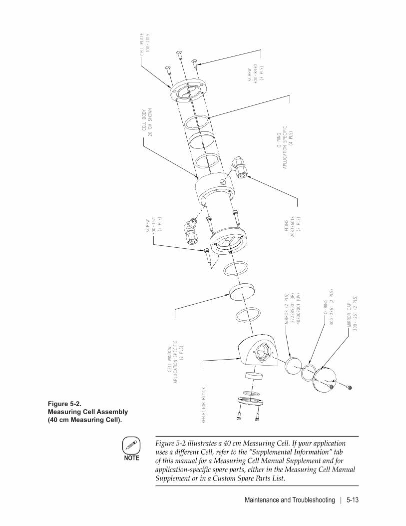
Maintenance and Troubleshooting | 5-13
Figure 5-2 illustrates a 40 cm Measuring Cell. If your application uses a different Cell, refer to the “Supplemental Information” tab of this manual for a Measuring Cell Manual Supplement and for application-specific spare parts, either in the Measuring Cell Manual Supplement or in a Custom Spare Parts List.
NOTE
Figure 5-2.Measuring Cell Assembly (40 cm Measuring Cell).
MIRR
OR C
AP30
0-1261 (2
PLS)
O-RING
300-
2361 (2
PLS)
MIRR
OR (2
PLS)
2722
8500
1 (IR
)40
3007
001 (UV)
REFLEC
TOR
BLOCK
O-RING
APLLICAT
ION
SPEC
IFIC
(4 P
LS)
CELL WIND
OWAP
LLICAT
ION
SPEC
IFIC
(2 P
LS)
CELL BOD
Y20
CM
SHOW
N
SCRE
W30
0-84
30(3 P
LS)
FITING
2033
36018
(2 P
LS)
SCRE
W30
0-1671
(2 P
LS)
CELL PLAT
E100-
2015
5-14 | IPS-4 Dual Bench (UV / IR) Analyzer
5. GP Analyzers Only: Turn off the Instrument Air supply to the analyzer and then close the Aspirator Air valve.
Purged Analyzers: The Instrument Air supply must always remain on for the Purge By-pass Switch to operate properly.
6. Removing/cleaning parts in the Measuring Cell:
The analyzer sample system will be under positive pressure.
Various lengths of screws are encountered while disassembling the Measuring Cell Assembly. Take note of where each length is used and be sure to replace the screws in their original locations when reassem-bling these parts later.
a. Disconnect the Sample Line and Vent Line tubes from the Cell.
Loosen and remove the Cell RTD (if used) from the RTD Clamp (not shown) on the Cell.
Disconnect all other sample system parts/tubing to allow removal of the Cell.
b. Note the position of the Cell and its Sample/Vent fittings and Re-flector Block.
Remove the three screws that secure the Cell to the Window Housing Assembly (not shown). Carefully pull the Cell straight out from the Window Housing and place it on a work bench or other suitable location to work on it.
If the Oven/Sample System Enclosure is heated, close its door to help maintain the temperature inside the enclosure while working on the Cell.
In the next steps use a soft, non-abrasive cloth to place the Cell parts on.
c. If the Measuring Cell has an Optical Bench/Cell Insulator, remove the three screws that secure it to the Cell and remove the Insulator.
NOTE
NOTE
!WARNING
Maintenance and Troubleshooting | 5-15
Use an o-ring removal tool to remove the outer o-ring from the Cell. Take care not to scratch or damage the o-ring groove.
Carefully remove the Cell Window from the Cell by grasping it by its outer edge and lifting it out of the Cell. Avoid touching the win-dow surfaces. Set the Window aside on a soft, non-abrasive cloth.
d. While holding the Cell vertically so that the Reflector Block end is up, remove the three M4 x 20 mm screws that secure the Reflector Block to the Cell. Remove the Reflector Block carefully to ensure the Cell Window behind it does not drop out.
e. With the Reflector Block end up, carefully remove the o-rings and Cell Window from the Cell.
Inspect the Windows for any chips, cracks, or scratches. If they are not damaged, they can be cleaned and reused; set them aside on a soft, nonabrasive cloth.
If the Windows are suitable for reuse, use Kimwipes® EX-L or an equivalent extra low-lint tissue to clean the front and back sides. A high purity solvent, such as Isopropanol (99 %), may also be used (if suitable for use with the sample species). Rinse with pharma-ceutical-grade distilled water.
Replace chipped, cracked, or scratched Windows when reassembling the Cell.
f. Systems with a Cell RTD: Note the position of the Cell RTD Clamp (see Cell RTD in Figure 5-1) and remove it from the Cell.
g. Inspect the interior of the Cell Body for foreign material. If neces-sary, use a cotton swab to clean the Cell Body.
If a more thorough cleaning is required, use only cleaning materi-als that are suitable for use with the sample species and the Cell.
Clean the fittings using the same method as the Cell Body.
For example: If suitable for the species, an acceptable material is Chem-Thane – or a nonabrasive detergent and water solution. The Cell Body can then be rinsed with reagent-grade acetone (if suitable), followed by a rinse with pharmaceutical-grade distilled water.
h. Allow all components to dry thoroughly before reassembling. Dry, oil-free instrument air can be used to remove any remaining mois-ture from the passages in the Cell Body and fittings.
!CAUTION
5-16 | IPS-4 Dual Bench (UV / IR) Analyzer
7. Replacing parts/reassembling the Measuring Cell:
a. Insert a new o-ring in the o-ring groove on the flat surface of the Reflector Block.
With the Cell held vertically so that the Reflector Block end of the Cell is up, install a new o-ring by using your thumbs to push it into the o-ring groove until it is completely seated in the groove.
While holding the edge of the Window, carefully place it in the Cell.
Orient the Reflector Block correctly, and place it on the Cell. Ensure the Cell Window does not slide out of position when the Reflector Block is placed against the Cell.
It is critical to reassemble the Reflector Block in the exact orientation as it was assembled at the factory.
Secure the Reflector Block to the Cell using three M4 x 20 mm screws. Tighten the screws evenly.
b. With the Cell held vertically so that the Reflector Block end is down, install a new o-ring by using your thumbs to push it into the o-ring groove until it is completely seated in the groove.
While holding the edge of the Window, carefully place it in the Cell, on top of the o-ring. Install a second, new o-ring on top of the Window.
If an Optical Bench/Cell Insulator is used, properly align it and secure it to the Cell using the three M4 x 12 mm screws.
c. Systems with a Cell RTD: Replace the RTD Clamp on the Cell but do not tighten it until the Cell is in place in the Oven/Sample System Enclosure.
8. Properly orient the Cell in the Oven/Sample System Enclosure and secure it to the Window Housing Assembly using the three M4 x 40 mm screws. Tighten the screws evenly.
9. Reconnect the Sample Line and Vent Line tubes to the Cell.
Reconnect all other sample system parts/tubing (use Teflon tape on fit-tings that originally were taped).
Systems with a Cell RTD: Replace the RTD in its clamp and hand-tighten it. Do not overtighten.
!CAUTION
Maintenance and Troubleshooting | 5-17
10. GP Analyzers Only: Turn on the Instrument Air supply to the analyzer and open the Aspi-rator Air valve.
11. Take all necessary precautions to safely power up the analyzer and prepare it for operation:
Before proceeding, test the area around the analyzer for flammable gases. If an explosive gas atmosphere is present, do not apply power to the analyzer or any alternate power sources that supply power to the analyzer components. Proceed only when the area is found to be safe. It is necessary to work with the Electronics Enclosure door open after replacing parts in the Measuring Cell. When the analyzer doors are open, take appropriate precautions to avoid electrical shock. Hazardous voltages are present inside.
For all applications: If heated Sample and Vent Lines are used, do not apply power to them until after the Leak Check has been performed. Do not close the Oven Heater fuse (if used) until after the Leak Check has been performed.
GP Analyzers: Apply power to the analyzer and its temperature-control zone circuit-ry by closing the Main AC Power, DC Power, and Bench Heater fuses.
Purged Analyzers: Insert the key into the Purge Bypass Switch and switch it to the “BYPASS” position (follow company policy). Follow any “Special Conditions for Safe Use” listed in accompanying certifications.
Hazardous Location Applications: Close the power-disconnect switch (breaker) to apply main AC Power to the analyzer.
12. Perform a leak check on all of the fittings that were reconnected. If necessary, follow the procedure under “Sample System Leak Check,” in Chapter 3.
After the leak check has been performed and has passed, return to this procedure and continue with the remaining steps.
!WARNING
!WARNING
5-18 | IPS-4 Dual Bench (UV / IR) Analyzer
13. For applications with heated Sample Systems: Apply power to the Sample and Vent Line circuitry.
Close the Oven Heater fuse to apply power to the Oven Heater temperature-control zone circuitry.
14. Open the Vent Line Shut Off valve (in the Oven/Sample System En-closure). Open the Sample Line Shut Off valve to allow sample fluid into the sample system.
15. Close and secure the Electronics Enclosure doors, and allow the ana-lyzer to warm up to operating temperature and stabilize. This could take up to 2 hours if the sample system has cooled completely.
16. Zero and Span (if applicable) the analyzer.
17. Change the analyzer back to Measure mode (from the Calibration screen, select Start measure and press ENTER). Press the HOME soft key to return to the HOME screen.
18. Adjust the Aspirator Pressure Regulator to achieve normal operating flow rates, as indicated on system Final “As-Built” drawings. The Flow Indicator (if used) should be in the centre of the meter for an optimal flow rate.
The procedure is complete.
Maintenance and Troubleshooting | 5-19
Replacing the Xenon (UV) Flash Lamp Assembly
The typical life expectancy of the Xenon Flash Lamp is 3–5 years of contin-uous operation. However, if the Xenon Flash Lamp begins to exhibit signs of degradation prior to the 3-year mark, replace the Xenon Flash Lamp Assembly (Figure 5-3.1). See Figure 5-1 for the location of this assembly in the Electronics Enclosure.
Refer to “Optical Bench Assembly Spare Parts” in Chapter 6 for reor-dering part numbers.
The glass Xenon Flash Lamp is under high internal pressure which could result in flying glass fragments if ruptured. Do not subject the lamp to drop impact, vibration, or shock. While handling a flash lamp, always wear protective devices (face mask, clothing) to prevent possible injury, especially to hand and face areas.
When handling the flash lamp, never touch the glass bulb of the lamp with bare hands. Dust or fingerprints on the glass bulb may greatly reduce transmittance in the ultraviolet range. If the glass bulb must be cleaned, wipe it using a soft, lint-free cloth moistened with high-quality alcohol.
To replace the Xenon Flash Lamp Assembly:
Hazardous Locations Before proceeding, test the area around the analyzer for flammable gases. If an explosive gas atmosphere is present, do not power down the analyzer or any alternate power sources that supply power to the analyzer components. Proceed only when the area is found to be safe.
1. Manually Zero the analyzer for 10 minutes.
2. After the Zero is complete, close the Sample Line and then the Vent Line Shut Off valves (in the Oven/Sample System Enclosure) to isolate the analyzer from the sample stream.
!WARNING
NOTE
!WARNING
!CAUTION
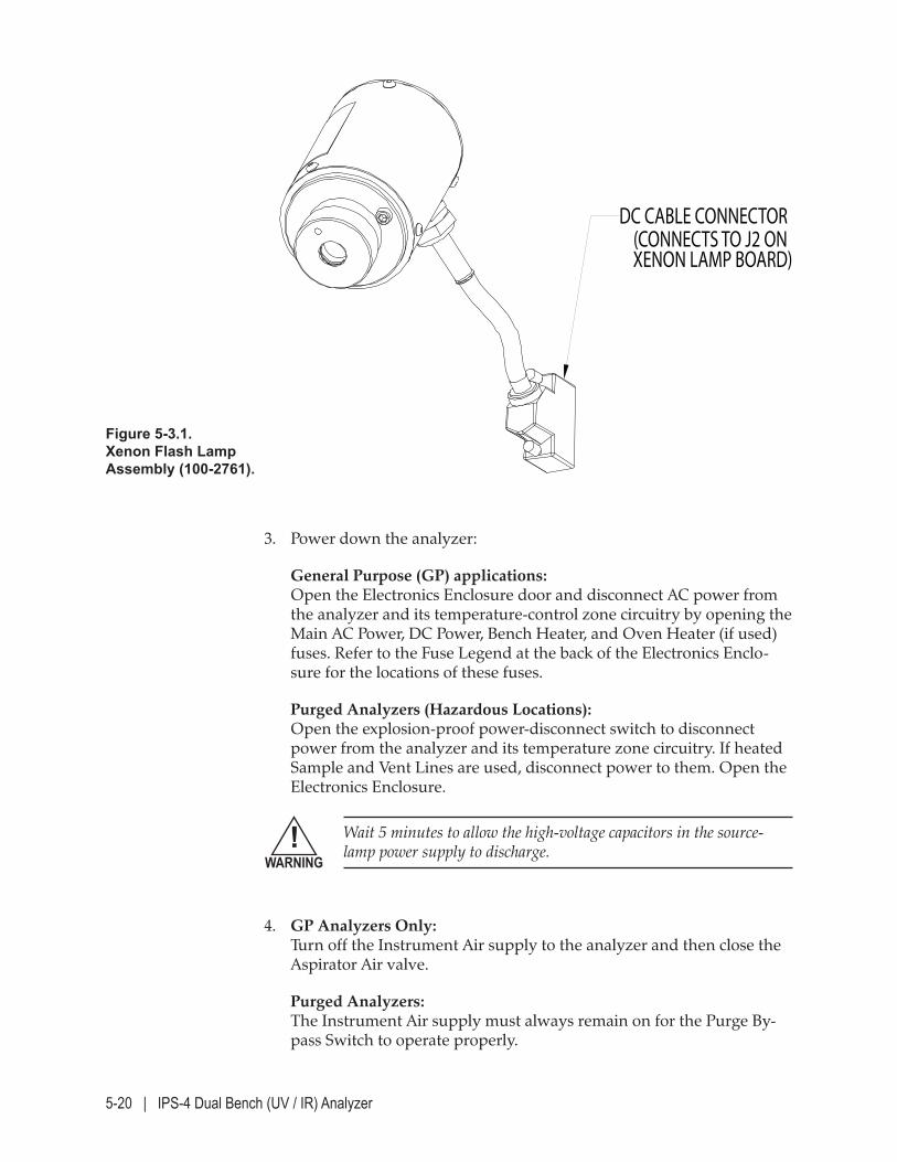
5-20 | IPS-4 Dual Bench (UV / IR) Analyzer
3. Power down the analyzer:
General Purpose (GP) applications: Open the Electronics Enclosure door and disconnect AC power from the analyzer and its temperature-control zone circuitry by opening the Main AC Power, DC Power, Bench Heater, and Oven Heater (if used) fuses. Refer to the Fuse Legend at the back of the Electronics Enclo-sure for the locations of these fuses.
Purged Analyzers (Hazardous Locations): Open the explosion-proof power-disconnect switch to disconnect power from the analyzer and its temperature zone circuitry. If heated Sample and Vent Lines are used, disconnect power to them. Open the Electronics Enclosure.
Wait 5 minutes to allow the high-voltage capacitors in the source-lamp power supply to discharge.
4. GP Analyzers Only: Turn off the Instrument Air supply to the analyzer and then close the Aspirator Air valve.
Purged Analyzers: The Instrument Air supply must always remain on for the Purge By-pass Switch to operate properly.
Figure 5-3.1.Xenon Flash Lamp Assembly (100-2761).
DC CABLE CONNECTOR (CONNECTS TO J2 ONXENON LAMP BOARD)
!WARNING

Maintenance and Troubleshooting | 5-21
5. Disconnect the DC Power Cable connector (from the Lamp Housing) at J2 on the Xenon Lamp board located near the top of the Electronics Enclosure (see Figure 5-1 for location).
6. While holding the Lamp Assembly with one hand, loosen (by hand) the blue knurled nut that secures it to the Optical Bench Assembly and remove the Lamp Assembly. Dispose of the Xenon Flash Lamp Assembly following company policy, or local regulations. Refer to “UV Source Lamps Disposal” in the contents section of this manual for more information on disposal recommendations.
Do not use any tool to loosen the blue nut on the Optical Bench when removing or replacing the Xenon Flash Lamp Assembly.
7. Take the new Xenon Flash Lamp Assembly (Part No. 100-2761) and, using the alignment pin on the Optical Bench Assembly as a guide, gently push the Lamp Assembly straight into place.
Tighten, by hand, the blue knurled nut to secure the Lamp Assembly to the Optical Bench Assembly.
8. Connect the DC Power Cable from the Lamp Housing to J2 on the Xenon Lamp board.
9. GP Analyzers Only: Turn on the Instrument Air supply to the analyzer and open the Aspi-rator Air valve.
10. Take all necessary precautions to safely power up the analyzer and prepare it for operation:
Do not apply main AC power to the analyzer if the Xenon Flash Lamp Assembly electrical connections have not been made.
Before proceeding, test the area around the analyzer for flammable gases. If an explosive gas atmosphere is present, do not apply power to the analyzer or any alternate power sources that supply power to the analyzer components. Proceed only when the area is found to be safe. When the analyzer doors are open, take appropriate precautions to avoid electrical shock. Hazardous voltages are present inside.
!CAUTION
!WARNING
!WARNING
5-22 | IPS-4 Dual Bench (UV / IR) Analyzer
Purged Analyzers:
If it is necessary to work with the Electronics Enclosure door open after replacing the Xenon Flash Lamp Assembly, take appropriate precautions to avoid electrical shock. Hazardous voltages are present inside.
Insert the key into the Purge Bypass Switch and switch it to the “BYPASS” position (follow company policy). Follow any “Special Conditions for Safe Use” listed in accompanying certifications.
Hazardous Location Applications: Close the power-disconnect switch (breaker) to apply main AC Power to the analyzer.
If heated Sample and Vent Lines are used, apply power to them.
11. Open the Vent Line Shut Off valve (in the Oven/Sample System En-closure). Open the Sample Line Shut Off valve to allow sample fluid into the sample system.
12. Close and secure the Electronics Enclosure doors, and allow the ana-lyzer to warm up to operating temperature and stabilize. This could take up to 2 hours if the sample system has cooled completely.
13. Zero and Span (if applicable) the analyzer.
14. Change the analyzer back to Measure mode (from the Calibration screen, select Start measure and press ENTER). Press the HOME soft key to return to the HOME screen.
15. Adjust the Aspirator Pressure Regulator to achieve normal operating flow rates, as indicated on system Final “As-Built” drawings. The Flow Indicator (if used) should be in the centre of the meter for an optimal flow rate.
The procedure is complete.
!WARNING
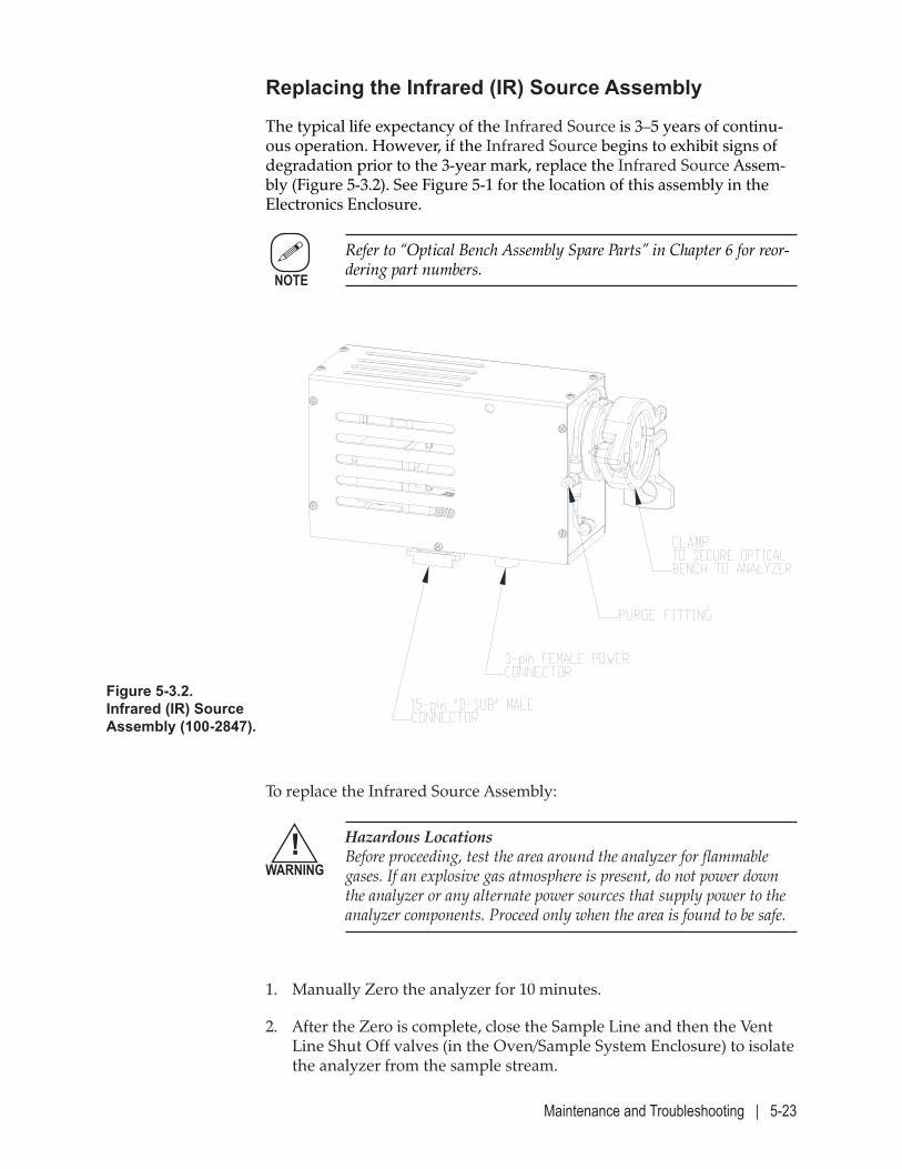
Maintenance and Troubleshooting | 5-23
Replacing the Infrared (IR) Source Assembly
The typical life expectancy of the Infrared Source is 3–5 years of continu-ous operation. However, if the Infrared Source begins to exhibit signs of degradation prior to the 3-year mark, replace the Infrared Source Assem-bly (Figure 5-3.2). See Figure 5-1 for the location of this assembly in the Electronics Enclosure.
Refer to “Optical Bench Assembly Spare Parts” in Chapter 6 for reor-dering part numbers.
NOTE
Figure 5-3.2.Infrared (IR) Source Assembly (100-2847).
To replace the Infrared Source Assembly:
Hazardous Locations Before proceeding, test the area around the analyzer for flammable gases. If an explosive gas atmosphere is present, do not power down the analyzer or any alternate power sources that supply power to the analyzer components. Proceed only when the area is found to be safe.
1. Manually Zero the analyzer for 10 minutes.
2. After the Zero is complete, close the Sample Line and then the Vent Line Shut Off valves (in the Oven/Sample System Enclosure) to isolate the analyzer from the sample stream.
!WARNING
5-24 | IPS-4 Dual Bench (UV / IR) Analyzer
3. Power down the analyzer:
General Purpose (GP) applications: Open the Electronics Enclosure door and disconnect AC power from the analyzer and its temperature-control zone circuitry by opening the Main AC Power, DC Power, Bench Heater, and Oven Heater (if used) fuses. Refer to the Fuse Legend at the back of the Electronics Enclo-sure for the locations of these fuses.
Purged Analyzers (Hazardous Locations): Open the explosion-proof power-disconnect switch to disconnect power from the analyzer and its temperature zone circuitry. If heated Sample and Vent Lines are used, disconnect power to them. Open the Electronics Enclosure.
The Infrared Source runs at an elevated temperature. Allow sufficient time for the Infrared Source Assembly to cool before handling.
4. GP Analyzers Only: Turn off the Instrument Air supply to the analyzer and then close the Aspirator Air valve.
Purged Analyzers: The Instrument Air supply must always remain on for the Purge By-pass Switch to operate properly.
5. Disconnect the DC Power Cable circular connector (from the Lamp Housing) and the 15-pin Ribbon Cable from the underside of the IR Source Assembly (see Figure 5-1 for location).
6. Loosen the locking clamp on the circular mount and carefully remove the IR Source Assembly. Remove the Optical Bench cover.
7. Disconnect the wires at TB1 located on the Interface board.
Remove the two screws holding the Infrared Source Assembly in place, and slide the assembly from the Optical Bench.
8. Insert the new assembly into the optical bench. Coat the three contact faces with a thin coat of heat-sink compound.
Insert the two screws removed earlier and attach the wires to TB1 Pins 3 (red) and 4 (black).
9. Replace the Optical Bench cover. Slide the Optical Bench back onto its mounting stud and tighten the locking clamp.
10. GP Analyzers Only: Turn on the Instrument Air supply to the analyzer and open the Aspi-rator Air valve.
!WARNING
Maintenance and Troubleshooting | 5-25
!WARNING
11. Take all necessary precautions to safely power up the analyzer and prepare it for operation:
Before proceeding, test the area around the analyzer for flammable gases. If an explosive gas atmosphere is present, do not apply power to the analyzer or any alternate power sources that supply power to the analyzer components. Proceed only when the area is found to be safe. When the analyzer doors are open, take appropriate precautions to avoid electrical shock. Hazardous voltages are present inside.
Purged Analyzers:
If it is necessary to work with the Electronics Enclosure door open after replacing the Infrared Source Assembly, take appropriate precau-tions to avoid electrical shock. Hazardous voltages are present inside.
Insert the key into the Purge Bypass Switch and switch it to the “BYPASS” position (follow company policy). Follow any “Special Conditions for Safe Use” listed in accompanying certifications.
Hazardous Location Applications: Close the power-disconnect switch (breaker) to apply main AC Power to the analyzer.
If heated Sample and Vent Lines are used, apply power to them.
12. Open the Vent Line Shut Off valve (in the Oven/Sample System En-closure). Open the Sample Line Shut Off valve to allow sample fluid into the sample system.
13. Close and secure the Electronics Enclosure doors, and allow the ana-lyzer to warm up to operating temperature and stabilize. This could take up to 2 hours if the sample system has cooled completely.
14. Zero and Span (if applicable) the analyzer.
15. Change the analyzer back to Measure mode (from the Calibration screen, select Start measure and press ENTER). Press the HOME soft key to return to the HOME screen.
16. Adjust the Aspirator Pressure Regulator to achieve normal operating flow rates, as indicated on system Final “As-Built” drawings. The Flow Indicator (if used) should be in the centre of the meter for an optimal flow rate.
The procedure is complete.
!WARNING
5-26 | IPS-4 Dual Bench (UV / IR) Analyzer
Troubleshooting and Diagnostics
This section describes how the analyzer detects and displays errors as-sociated with its operation, what the errors mean, and action to take to correct the errors. This section also discusses how to view the alarms from the User Interface Panel and how to reset the analyzer if a system reset is required.
Generally, most troubleshooting and diagnostics can be done by work-ing from the User Interface Panel on the front of the analyzer Electronics Enclosure. Typical diagnostic errors to watch for include pressure and temperature related alarms.
For more information about viewing diagnostics information from the User Interface Panel, refer to the descriptions in Chapter 4.
NOTE
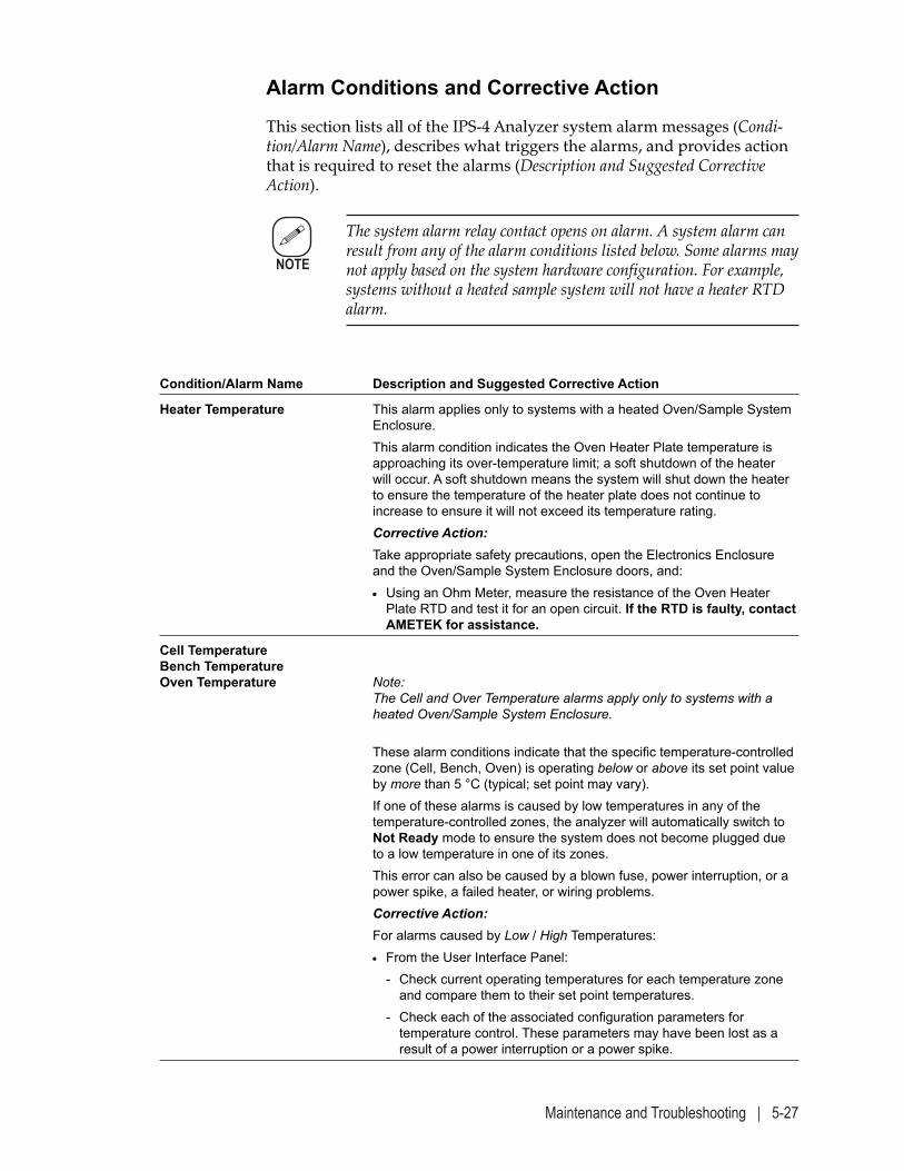
Maintenance and Troubleshooting | 5-27
Alarm Conditions and Corrective Action
This section lists all of the IPS-4 Analyzer system alarm messages (Condi-tion/Alarm Name), describes what triggers the alarms, and provides action that is required to reset the alarms (Description and Suggested Corrective Action).
The system alarm relay contact opens on alarm. A system alarm can result from any of the alarm conditions listed below. Some alarms may not apply based on the system hardware configuration. For example, systems without a heated sample system will not have a heater RTD alarm.
Condition/Alarm Name Description and Suggested Corrective Action
Heater Temperature This alarm applies only to systems with a heated Oven/Sample System Enclosure.
This alarm condition indicates the Oven Heater Plate temperature is approaching its over-temperature limit; a soft shutdown of the heater will occur. A soft shutdown means the system will shut down the heater to ensure the temperature of the heater plate does not continue to increase to ensure it will not exceed its temperature rating.
Corrective Action: Take appropriate safety precautions, open the Electronics Enclosure
and the Oven/Sample System Enclosure doors, and: • Using an Ohm Meter, measure the resistance of the Oven Heater
Plate RTD and test it for an open circuit. If the RTD is faulty, contact AMETEK for assistance.
Cell TemperatureBench TemperatureOven Temperature Note:
The Cell and Over Temperature alarms apply only to systems with a heated Oven/Sample System Enclosure.
These alarm conditions indicate that the specific temperature-controlled zone (Cell, Bench, Oven) is operating below or above its set point value by more than 5 °C (typical; set point may vary).
If one of these alarms is caused by low temperatures in any of the temperature-controlled zones, the analyzer will automatically switch to Not Ready mode to ensure the system does not become plugged due to a low temperature in one of its zones.
This error can also be caused by a blown fuse, power interruption, or a power spike, a failed heater, or wiring problems.
Corrective Action: For alarms caused by Low / High Temperatures: • From the User Interface Panel: - Check current operating temperatures for each temperature zone
and compare them to their set point temperatures. - Check each of the associated configuration parameters for
temperature control. These parameters may have been lost as a result of a power interruption or a power spike.
NOTE
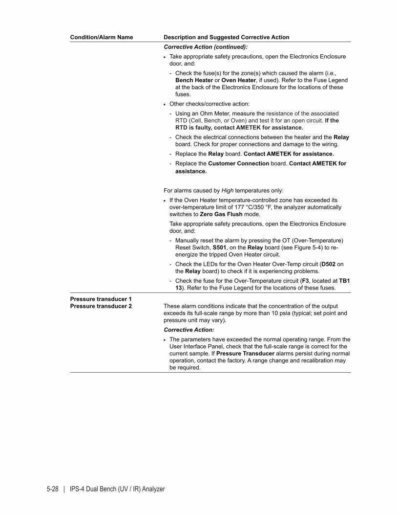
5-28 | IPS-4 Dual Bench (UV / IR) Analyzer
Condition/Alarm Name Description and Suggested Corrective Action Corrective Action (continued): • Take appropriate safety precautions, open the Electronics Enclosure
door, and: - Check the fuse(s) for the zone(s) which caused the alarm (i.e.,
Bench Heater or Oven Heater, if used). Refer to the Fuse Legend at the back of the Electronics Enclosure for the locations of these fuses.
• Other checks/corrective action: - Using an Ohm Meter, measure the resistance of the associated
RTD (Cell, Bench, or Oven) and test it for an open circuit. If the RTD is faulty, contact AMETEK for assistance.
- Check the electrical connections between the heater and the Relay board. Check for proper connections and damage to the wiring.
- Replace the Relay board. Contact AMETEK for assistance. - Replace the Customer Connection board. Contact AMETEK for
assistance.
For alarms caused by High temperatures only: • If the Oven Heater temperature-controlled zone has exceeded its
over-temperature limit of 177 °C/350 °F, the analyzer automatically switches to Zero Gas Flush mode.
Take appropriate safety precautions, open the Electronics Enclosure door, and:
- Manually reset the alarm by pressing the OT (Over-Temperature) Reset Switch, S501, on the Relay board (see Figure 5-4) to re-energize the tripped Oven Heater circuit.
- Check the LEDs for the Oven Heater Over-Temp circuit (D502 on the Relay board) to check if it is experiencing problems.
- Check the fuse for the Over-Temperature circuit (F3, located at TB1 13). Refer to the Fuse Legend for the locations of these fuses.
Pressure transducer 1Pressure transducer 2 These alarm conditions indicate that the concentration of the output
exceeds its full-scale range by more than 10 psia (typical; set point and pressure unit may vary).
Corrective Action: • The parameters have exceeded the normal operating range. From the
User Interface Panel, check that the full-scale range is correct for the current sample. If Pressure Transducer alarms persist during normal operation, contact the factory. A range change and recalibration may be required.
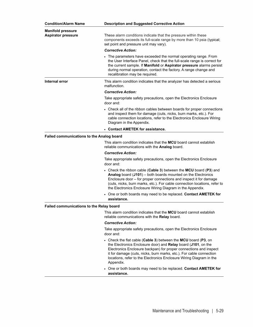
Maintenance and Troubleshooting | 5-29
Condition/Alarm Name Description and Suggested Corrective Action
Manifold pressureAspirator pressure These alarm conditions indicate that the pressure within these
components exceeds its full-scale range by more than 10 psia (typical; set point and pressure unit may vary).
Corrective Action: • The parameters have exceeded the normal operating range. From
the User Interface Panel, check that the full-scale range is correct for the current sample. If Manifold or Aspirator pressure alarms persist during normal operation, contact the factory. A range change and recalibration may be required.
Internal error This alarm condition indicates that the analyzer has detected a serious malfunction.
Corrective Action: Take appropriate safety precautions, open the Electronics Enclosure
door and: • Check all of the ribbon cables between boards for proper connections
and inspect them for damage (cuts, nicks, burn marks, etc.). For cable connection locations, refer to the Electronics Enclosure Wiring Diagram in the Appendix.
• Contact AMETEK for assistance.
Failed communications to the Analog board This alarm condition indicates that the MCU board cannot establish
reliable communications with the Analog board. Corrective Action: Take appropriate safety precautions, open the Electronics Enclosure
door and: • Check the ribbon cable (Cable 3) between the MCU board (P3) and
Analog board (J101) – both boards mounted on the Electronics Enclosure door – for proper connections and inspect it for damage (cuts, nicks, burn marks, etc.). For cable connection locations, refer to the Electronics Enclosure Wiring Diagram in the Appendix.
• One or both boards may need to be replaced. Contact AMETEK for assistance.
Failed communications to the Relay board This alarm condition indicates that the MCU board cannot establish
reliable communications with the Relay board. Corrective Action: Take appropriate safety precautions, open the Electronics Enclosure
door and: • Check the flat cable (Cable 3) between the MCU board (P3, on
the Electronics Enclosure door) and Relay board (J101, on the Electronics Enclosure backpan) for proper connections and inspect it for damage (cuts, nicks, burn marks, etc.). For cable connection locations, refer to the Electronics Enclosure Wiring Diagram in the Appendix.
• One or both boards may need to be replaced. Contact AMETEK for assistance.
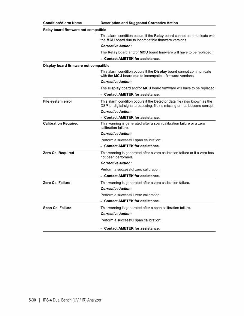
5-30 | IPS-4 Dual Bench (UV / IR) Analyzer
Condition/Alarm Name Description and Suggested Corrective Action
Relay board firmware not compatible This alarm condition occurs if the Relay board cannot communicate with
the MCU board due to incompatible firmware versions. Corrective Action:
The Relay board and/or MCU board firmware will have to be replaced:
• Contact AMETEK for assistance.
Display board firmware not compatible This alarm condition occurs if the Display board cannot communicate
with the MCU board due to incompatible firmware versions. Corrective Action:
The Display board and/or MCU board firmware will have to be replaced:
• Contact AMETEK for assistance.
File system error This alarm condition occurs if the Detector data file (also known as the DSP, or digital signal processing, file) is missing or has become corrupt.
Corrective Action: • Contact AMETEK for assistance.Calibration Required This warning is generated after a span calibration failure or a zero
calibration failure. Corrective Action:
Perform a successful span calibration: • Contact AMETEK for assistance.
Zero Cal Required This warning is generated after a zero calibration failure or if a zero has not been performed.
Corrective Action:
Perform a successful zero calibration:
• Contact AMETEK for assistance.
Zero Cal Failure This warning is generated after a zero calibration failure. Corrective Action:
Perform a successful zero calibration: • Contact AMETEK for assistance.
Span Cal Failure This warning is generated after a span calibration failure. Corrective Action:
Perform a successful span calibration:
• Contact AMETEK for assistance.
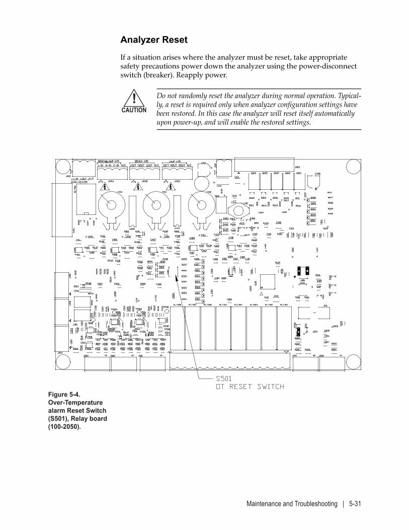
Maintenance and Troubleshooting | 5-31
Analyzer Reset
If a situation arises where the analyzer must be reset, take appropriate safety precautions power down the analyzer using the power-disconnect switch (breaker). Reapply power.
Do not randomly reset the analyzer during normal operation. Typical-ly, a reset is required only when analyzer configuration settings have been restored. In this case the analyzer will reset itself automatically upon power-up, and will enable the restored settings.
!CAUTION
Figure 5-4. Over-Temperature alarm Reset Switch (S501), Relay board (100-2050).

5-32 | IPS-4 Dual Bench (UV / IR) Analyzer
This page intentionally left blank.
Service and Parts | 6-1
SERVICE and PARTS
The Service and Parts chapter discusses what to do if you need techni-cal support from AMETEK, or if you are returning parts for service. This chapter also lists the recommended spare parts to have on hand to en-sure all consumable and replaceable parts are replaced according to the “Analyzer Preventive Maintenance Schedule” included in Chapter 5.
Technical Support
AMETEK Western Research is committed to providing you the best tech-nical support in the industry. If you need service or application assistance, contact your local or nearest AMETEK Service Centre or the AMETEK factory AMETEK at (403) 235-8400 or 1-800-661-9198), or contact your local AMETEK Western Research representative.
Before contacting AMETEK with questions regarding the installation, operation, or maintenance/troubleshooting of your analyzer system, carefully review the contents of this manual. If you are unable to find an explanation for your problem in this manual, please gather the following information prior to contacting AMETEK:
• Model number of the analyzer.
• Serial number of the analyzer experiencing problems.
• Purchase order number.
• AMETEK part number for the specific component you are enquiring about, if known.
• Information describing the problem.
• Billing address, shipping address, and telephone number.
6-2 | IPS-4 Dual Bench (UV / IR) Analyzer
Returning Equipment
If you need to return parts or equipment for repair, you will need a Return Material Authorization (RMA) number. This will ensure your equipment is serviced and returned to you in a prompt and efficient man-ner. To obtain an RMA number, contact your local or nearest AMETEK Service Center and have the following information available:
• Model number of the analyzer.
• Serial number of the analyzer.
• Purchase order number.
• Billing address, shipping address, and telephone number.

Service and Parts | 6-3
?? ANSWERS TO YOUR QUESTIONS ??
• ASAPAMETEK SERVICE ASSISTANCE PROGRAM. AM-ETEK’s exclusive ASAP program lets you select a service package from a menu of service options. ASAP options include 24 hour phone support, 24 hour on-site guarantee, rapid parts shipment, and many more service benefits. ASAP plans may be written to provide coverage for a single analyzer, or all of the AMETEK process analyzers at your facility.
• AFTERMARKET SALESOur Aftermarket Sales group will keep you supplied with the parts to maintain your analyzer to factory specifications. This is also the group that will keep your analyzer current with upgrades and retrofits.
• TECHNICAL SUPPORTJust call AMETEK and a factory trained Service Engineer will be there to answer your questions. With over 200 years of combined field service experience, our engi-neers are available to provide operational support or troubleshooting expertise.
• TRAININGWe will train your service technicians at our Technology Transfer Centres located in Calgary, Newark, or at your facility. Our TTCs have equipment similar to yours for hands-on training. A diploma will be presented upon completion of the course.
• PRE-lNSTALLATlON INSPECTIONSTo ensure you order the correct analyzer with the op-tions your operation requires, schedule a factory-trained Service Engineer to inspect the proposed analyzer loca-tion. The on-site charge for this visit can be deducted from the start-up charge if you select that option.
• START UPSYour decision to buy an AMETEK analyzer is greatly appreciated. After the time and money spent on your analyzer, wouldn’t you expect a fast and successful start up? We can ensure that will happen! Schedule us to be there before you power up the system. We will guarantee a satisfactory commissioning of your analyzer.
• WARRANTY VALIDATIONUpon start-up, we will validate your 1 year warranty. AMETEK’s warranty policy covers all parts and on-site time. Incurred costs will be the responsibility of the customer.
• WARRANTY EXTENSIONSAMETEK offers a 2 or 3 year warranty extension for your analyzers. The warranty is identical to the original policy supplied with the analyzer. Contact AMETEK Service for more details.
• SPARE PARTS KITSThese parts allow each customer to properly maintain their analyzers according to the recommended Preven-tive Maintenance Schedule (listed in the manual), to ensure optimal operations.
MINUTES OR HOURS,WE’RE THERE FOR YOU
The choice is yours...Whether by phone or in person, we can meet the needs required to keep your analyzer running at peak performance. Our factories are located in Calgary, Alberta and Newark, Delaware with a Sales & Service Centre in Houston, Texas. Depending on the programs you select, we will have a factory-trained representative talking to you within minutes – 24 hours a day, 365 days a year or on-site within 24 hours. We stock parts at all three locations.
ANYTIME / ANYWHERE
AMETEK SERVICE AND AFTERMARKET SALES SUPPORT
PROCESS INSTRUMENTSCanada: 1-800-661-9198 U.S.A.: 1-800-537-6044
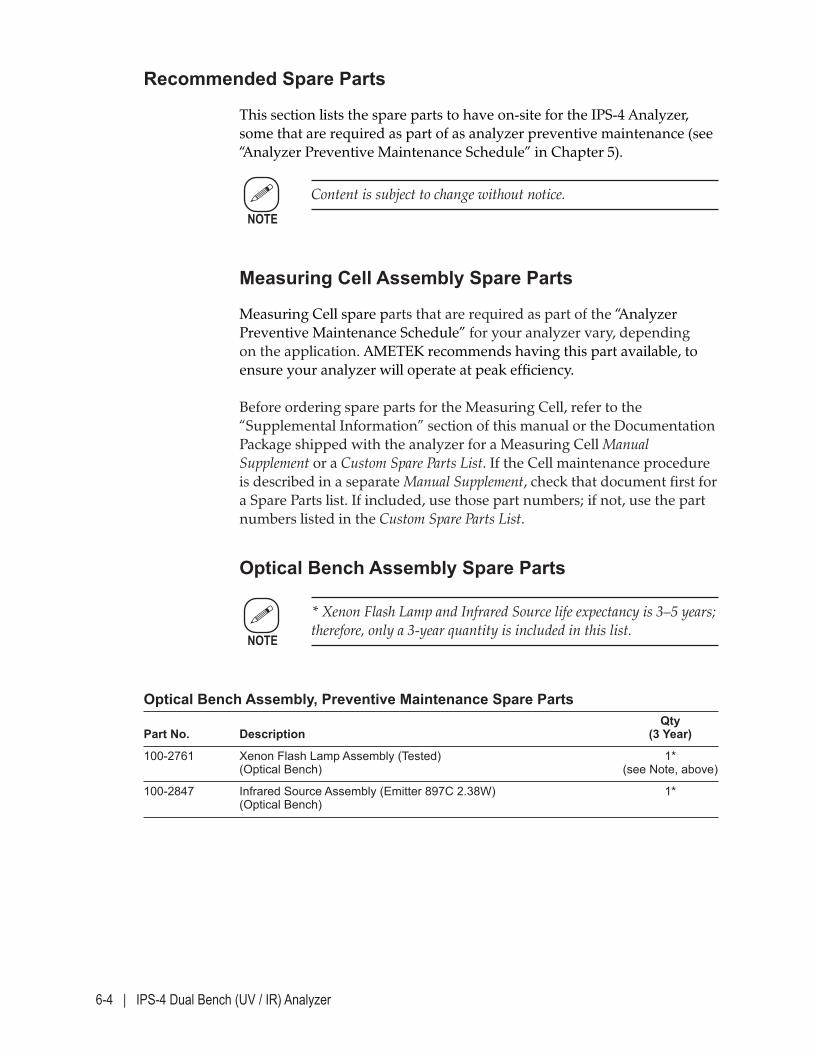
6-4 | IPS-4 Dual Bench (UV / IR) Analyzer
Recommended Spare Parts
This section lists the spare parts to have on-site for the IPS-4 Analyzer, some that are required as part of as analyzer preventive maintenance (see “Analyzer Preventive Maintenance Schedule” in Chapter 5).
Content is subject to change without notice.
Measuring Cell Assembly Spare Parts
Measuring Cell spare parts that are required as part of the “Analyzer Preventive Maintenance Schedule” for your analyzer vary, depending on the application. AMETEK recommends having this part available, to ensure your analyzer will operate at peak efficiency. Before ordering spare parts for the Measuring Cell, refer to the “Supplemental Information” section of this manual or the Documentation Package shipped with the analyzer for a Measuring Cell Manual Supplement or a Custom Spare Parts List. If the Cell maintenance procedure is described in a separate Manual Supplement, check that document first for a Spare Parts list. If included, use those part numbers; if not, use the part numbers listed in the Custom Spare Parts List.
Optical Bench Assembly Spare Parts
* Xenon Flash Lamp and Infrared Source life expectancy is 3–5 years; therefore, only a 3-year quantity is included in this list.
Optical Bench Assembly, Preventive Maintenance Spare Parts Qty Part No. Description (3 Year)
100-2761 Xenon Flash Lamp Assembly (Tested) 1* (Optical Bench) (see Note, above)
100-2847 Infrared Source Assembly (Emitter 897C 2.38W) 1* (Optical Bench)
NOTE
NOTE
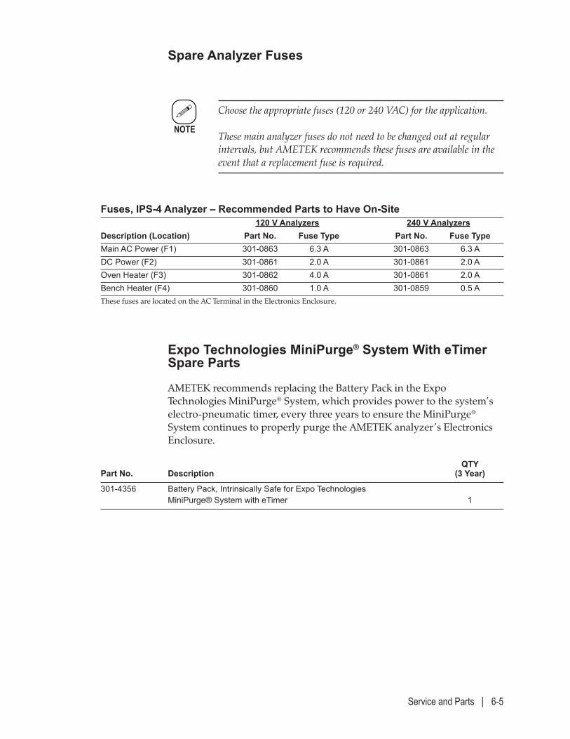
Service and Parts | 6-5
Spare Analyzer Fuses
Choose the appropriate fuses (120 or 240 VAC) for the application. These main analyzer fuses do not need to be changed out at regular intervals, but AMETEK recommends these fuses are available in the event that a replacement fuse is required.
Fuses, IPS-4 Analyzer – Recommended Parts to Have On-Site 120 V Analyzers 240 V AnalyzersDescription (Location) Part No. Fuse Type Part No. Fuse TypeMain AC Power (F1) 301-0863 6.3 A 301-0863 6.3 ADC Power (F2) 301-0861 2.0 A 301-0861 2.0 AOven Heater (F3) 301-0862 4.0 A 301-0861 2.0 ABench Heater (F4) 301-0860 1.0 A 301-0859 0.5 AThese fuses are located on the AC Terminal in the Electronics Enclosure.
Expo Technologies MiniPurge® System With eTimer Spare Parts
AMETEK recommends replacing the Battery Pack in the Expo Technologies MiniPurge® System, which provides power to the system’s electro-pneumatic timer, every three years to ensure the MiniPurge® System continues to properly purge the AMETEK analyzer’s Electronics Enclosure.
QTY Part No. Description (3 Year)
301-4356 Battery Pack, Intrinsically Safe for Expo Technologies MiniPurge® System with eTimer 1
NOTE

6-6 | IPS-4 Dual Bench (UV / IR) Analyzer
This page intentionally left blank.
User Web Interface | 7-1
USER WEB INTERFACE
The User Web Interface chapter contains information about the following topics:
• An introduction to the User Web Interface, and how to access, moni-tor, and control your analyzer through a web interface
• What the various screens that make up the interface do and how to use them to work from the analyzer User Web Interface.
Before working from the Web Interface, read the section titled “In-troduction to the Web Interface,” in the following pages. This section discusses the functions that can be performed.
NOTE
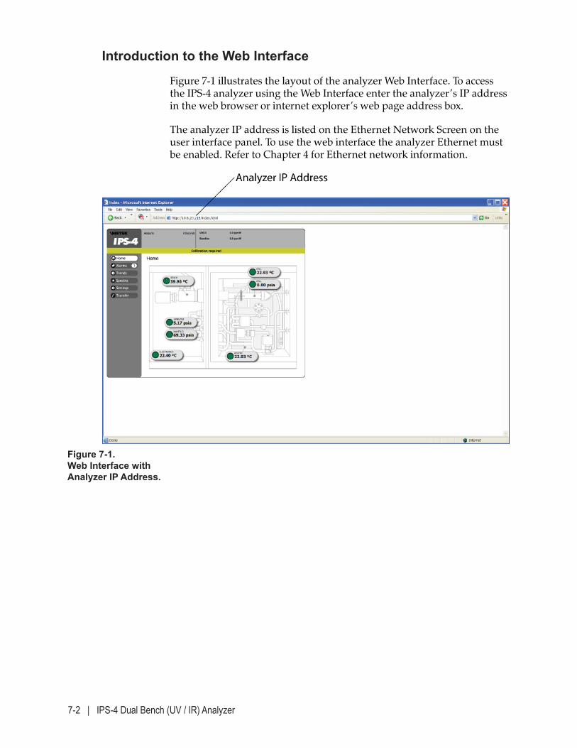
7-2 | IPS-4 Dual Bench (UV / IR) Analyzer
Figure 7-1. Web Interface with Analyzer IP Address.
Introduction to the Web Interface
Figure 7-1 illustrates the layout of the analyzer Web Interface. To access the IPS-4 analyzer using the Web Interface enter the analyzer’s IP address in the web browser or internet explorer’s web page address box.
The analyzer IP address is listed on the Ethernet Network Screen on the user interface panel. To use the web interface the analyzer Ethernet must be enabled. Refer to Chapter 4 for Ethernet network information.
User Web Interface | 7-3
Web Interface Components
The Web Interface is divided into six sections. Navigation buttons lo-cated on the left-hand side of the screen are used to view analyzer sta-tus, alarms, trends, and spectra; view and change analyzer settings; and transfer data.
The information displayed on the right-hand side varies depending on the selected section.
• The web interface header displays the “state” of the analyzer and the concentration of the analytes being measured. This section is read only.
- Examples of “states” include Zero, Span, and Measure. These and other states are described in detail under “System Status Messages (HOME Screen),” in Chapter 4.
- Analytes are factory set. Up to six analytes can be displayed.
• Alarm and warning notifications are displayed in the banner located below the header on every screen. The most current notification is displayed with 1 of x if there are multiple active notifications.
Working From the Web Interface – Conditions and Messages
While working from the Web Interface, the following condition applies:
The Web Interface is shipped from the factory without password pro-tection. All configurable parameters can be changed through the web interface. Trend and Spectral data are stored in temporary memory. For security reasons, temporary data can not be stored directly onto the computer hard drives. Any intentional or unintentional recycling of power will cause a loss of saved data. Data cannot be saved directly to your computer. To make a record of displayed information use your PC screen capture function and paste the image into another program.
NOTE
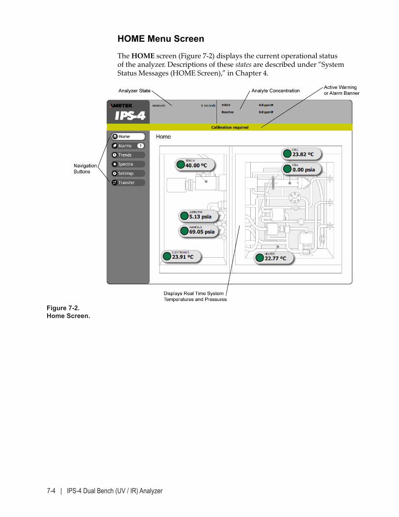
7-4 | IPS-4 Dual Bench (UV / IR) Analyzer
HOME Menu Screen
The HOME screen (Figure 7-2) displays the current operational status of the analyzer. Descriptions of these states are described under “System Status Messages (HOME Screen),” in Chapter 4.
Figure 7-2. Home Screen.
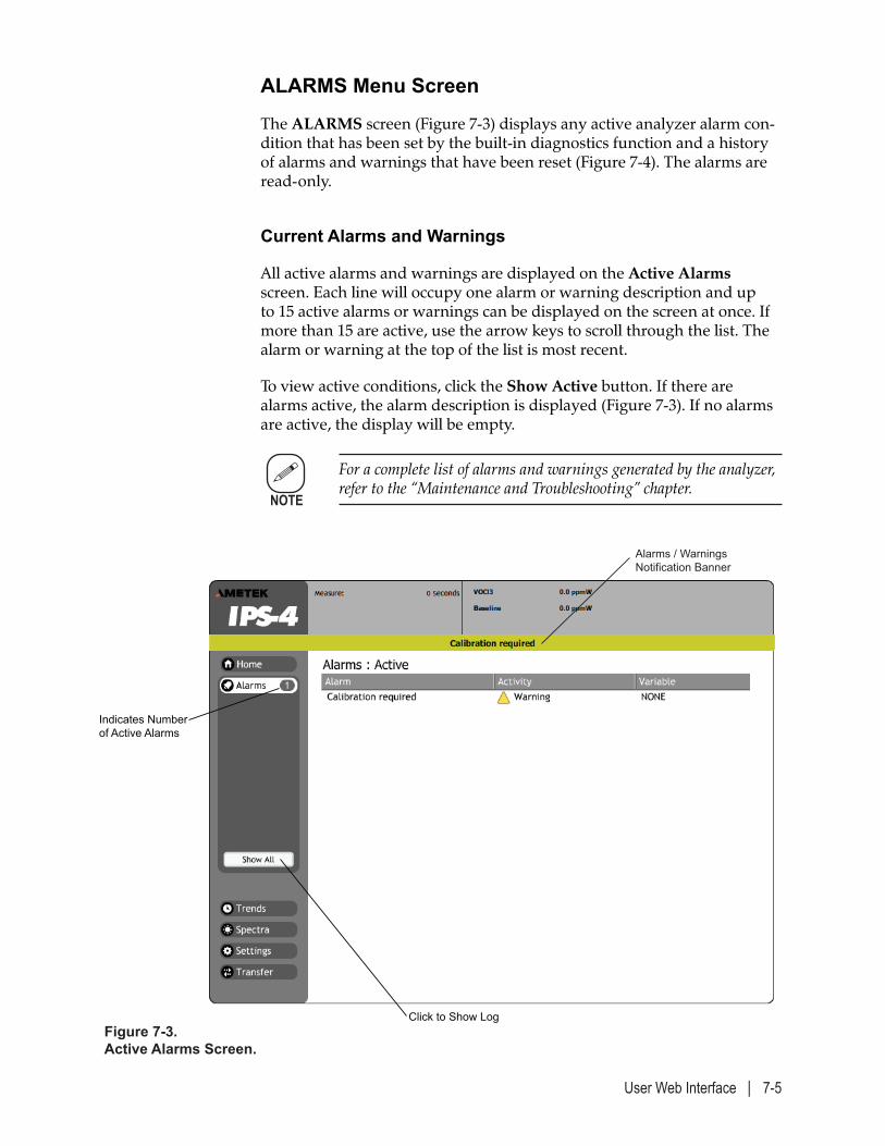
User Web Interface | 7-5
ALARMS Menu Screen
The ALARMS screen (Figure 7-3) displays any active analyzer alarm con-dition that has been set by the built-in diagnostics function and a history of alarms and warnings that have been reset (Figure 7-4). The alarms are read-only.
Current Alarms and Warnings
All active alarms and warnings are displayed on the Active Alarms screen. Each line will occupy one alarm or warning description and up to 15 active alarms or warnings can be displayed on the screen at once. If more than 15 are active, use the arrow keys to scroll through the list. The alarm or warning at the top of the list is most recent.
To view active conditions, click the Show Active button. If there are alarms active, the alarm description is displayed (Figure 7-3). If no alarms are active, the display will be empty.
For a complete list of alarms and warnings generated by the analyzer, refer to the “Maintenance and Troubleshooting” chapter.
Figure 7-3. Active Alarms Screen.
Indicates Number of Active Alarms
Click to Show Log
Alarms / WarningsNotification Banner
NOTE
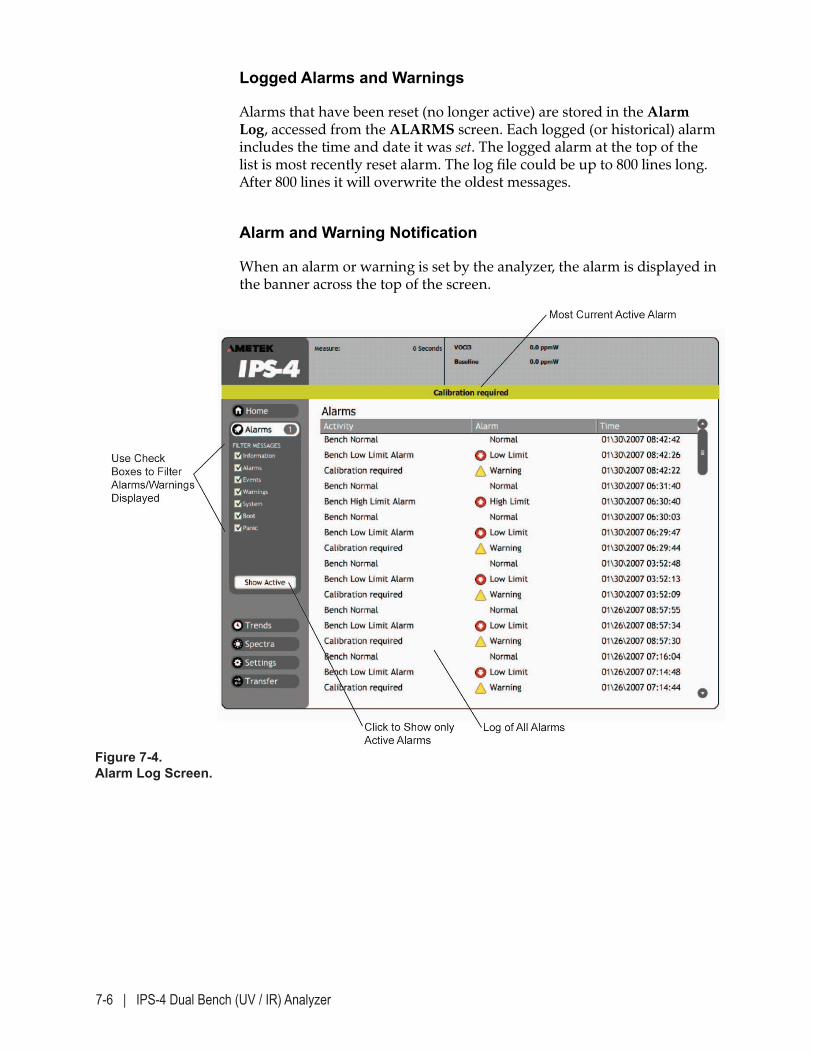
7-6 | IPS-4 Dual Bench (UV / IR) Analyzer
Figure 7-4. Alarm Log Screen.
Logged Alarms and Warnings
Alarms that have been reset (no longer active) are stored in the Alarm Log, accessed from the ALARMS screen. Each logged (or historical) alarm includes the time and date it was set. The logged alarm at the top of the list is most recently reset alarm. The log file could be up to 800 lines long. After 800 lines it will overwrite the oldest messages.
Alarm and Warning Notification
When an alarm or warning is set by the analyzer, the alarm is displayed in the banner across the top of the screen.
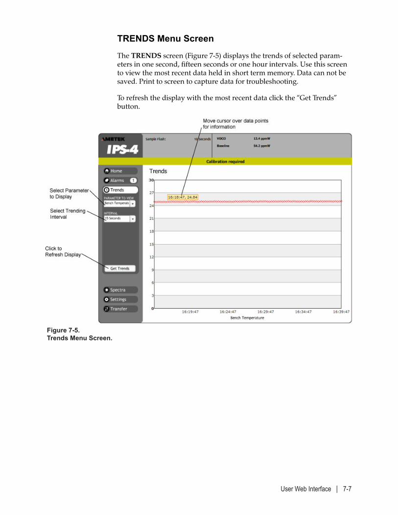
User Web Interface | 7-7
TRENDS Menu Screen
The TRENDS screen (Figure 7-5) displays the trends of selected param-eters in one second, fifteen seconds or one hour intervals. Use this screen to view the most recent data held in short term memory. Data can not be saved. Print to screen to capture data for troubleshooting.
To refresh the display with the most recent data click the “Get Trends” button.
Figure 7-5. Trends Menu Screen.
7-8 | IPS-4 Dual Bench (UV / IR) Analyzer
Parameters
Trends for the following system parameters are available for display:
• Bench Temperature
• Heater Temperature
• Lamp Temperature
• Cell Temperature
• Cell Pressure
• Manifold Pressure
• Aspirator Pressure
• Electronics Temperature
• Analytes Concentration
Intervals
Trend intervals for selected parameters are available in one second, fifteen seconds or one hour data points. The analyzer stores 3600 parameter data points in temporary memory prior to overwriting data.
• 1 second interval will contain 60 minutes before overwriting
• 15 second interval will contain 900 minutes or 15 hours before over-writing
• 1 hour interval will contain 3,600 hours or 150 days before overwrit-ing.
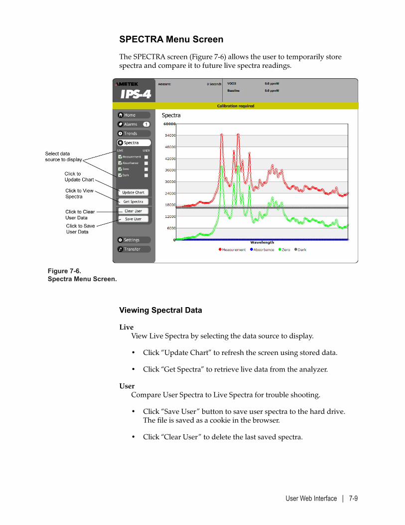
User Web Interface | 7-9
Viewing Spectral Data
Live View Live Spectra by selecting the data source to display.
• Click “Update Chart” to refresh the screen using stored data.
• Click “Get Spectra” to retrieve live data from the analyzer.
User Compare User Spectra to Live Spectra for trouble shooting.
• Click “Save User” button to save user spectra to the hard drive. The file is saved as a cookie in the browser.
• Click “Clear User” to delete the last saved spectra.
SPECTRA Menu Screen
The SPECTRA screen (Figure 7-6) allows the user to temporarily store spectra and compare it to future live spectra readings.
Figure 7-6. Spectra Menu Screen.
7-10 | IPS-4 Dual Bench (UV / IR) Analyzer
SETTINGS Menu Screen
The SETTINGS screen provides access to the sub-menu screens contain-ing the functional parameters that control the operation of the analyzer. This screen allows the user to set up certain parameters.
The settings for your analyzer have been configured at the factory to meet specified customer requirements. Changing the factory-set con-figuration could cause the analyzer to operate incorrectly.
Detailed descriptions of each menu item and parameters are described in Chapter 4. The list of available sub-menu items includes:
• Calibration Control
• Actions
• Current Outputs
• Relays
• Network and Modbus
• System and Custom
• Analytes
• Limits
• Diagnostics
NOTE
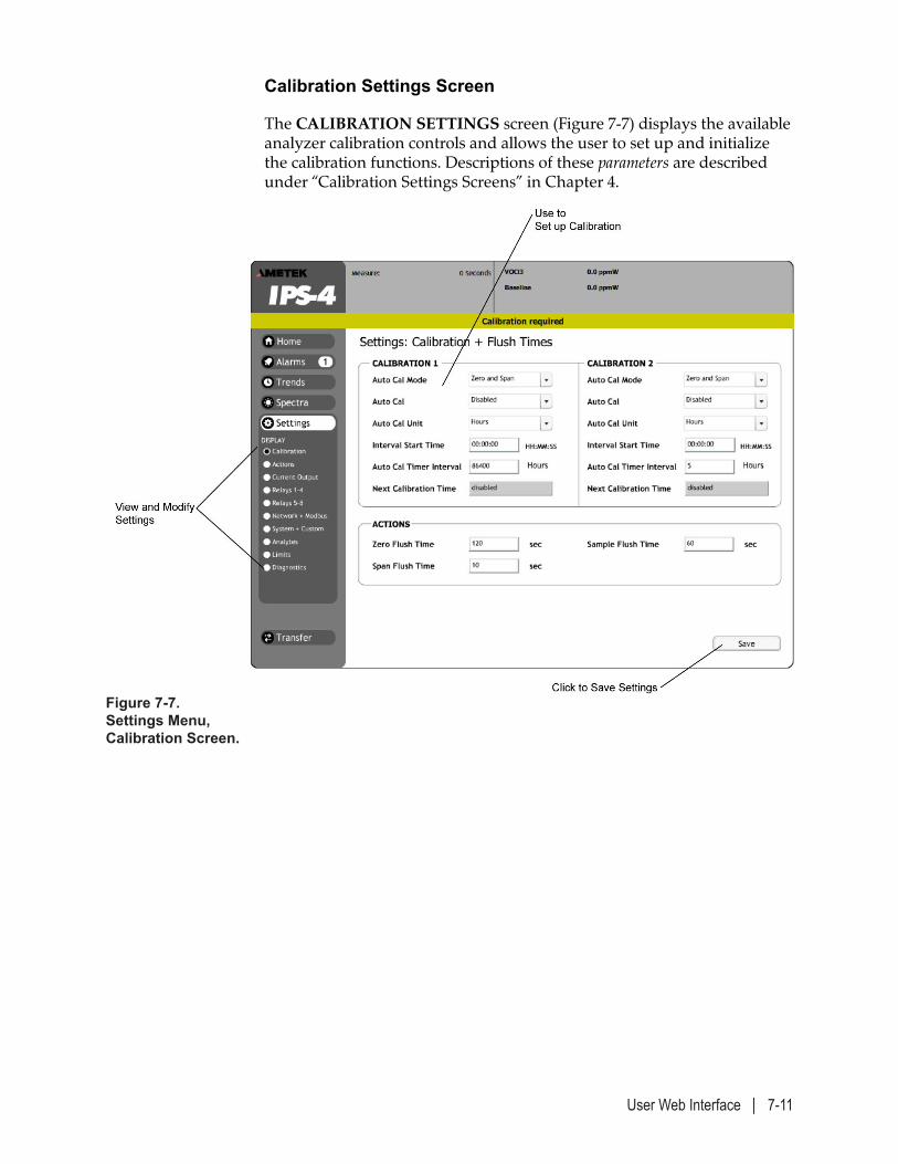
User Web Interface | 7-11
Figure 7-7. Settings Menu, Calibration Screen.
Calibration Settings Screen
The CALIBRATION SETTINGS screen (Figure 7-7) displays the available analyzer calibration controls and allows the user to set up and initialize the calibration functions. Descriptions of these parameters are described under “Calibration Settings Screens” in Chapter 4.
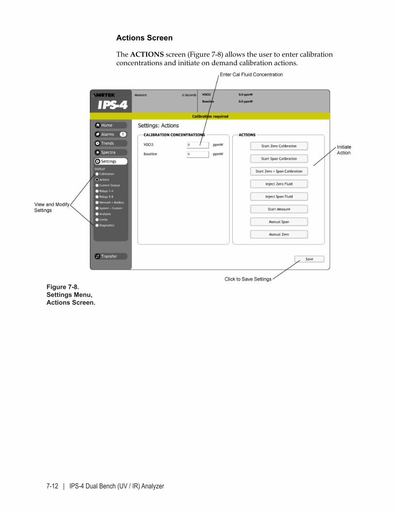
7-12 | IPS-4 Dual Bench (UV / IR) Analyzer
Actions Screen
The ACTIONS screen (Figure 7-8) allows the user to enter calibration concentrations and initiate on demand calibration actions.
Figure 7-8. Settings Menu, Actions Screen.
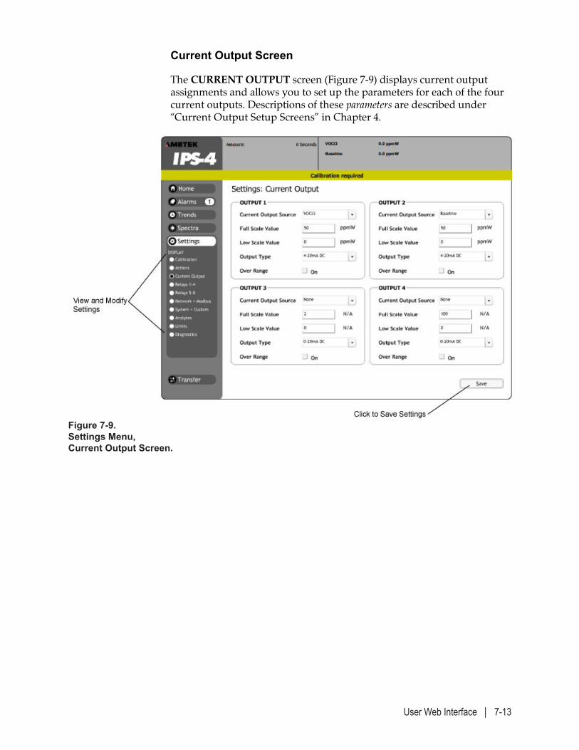
User Web Interface | 7-13
Current Output Screen
The CURRENT OUTPUT screen (Figure 7-9) displays current output assignments and allows you to set up the parameters for each of the four current outputs. Descriptions of these parameters are described under “Current Output Setup Screens” in Chapter 4.
Figure 7-9. Settings Menu, Current Output Screen.
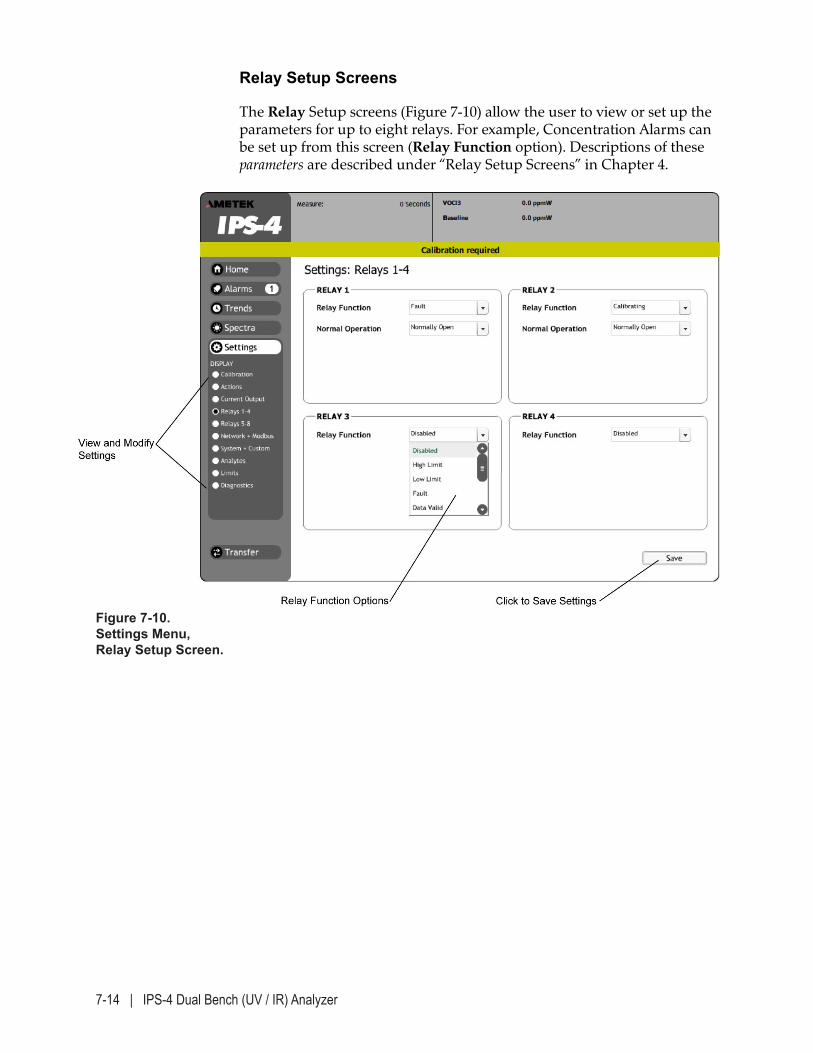
7-14 | IPS-4 Dual Bench (UV / IR) Analyzer
Relay Setup Screens
The Relay Setup screens (Figure 7-10) allow the user to view or set up the parameters for up to eight relays. For example, Concentration Alarms can be set up from this screen (Relay Function option). Descriptions of these parameters are described under “Relay Setup Screens” in Chapter 4.
Figure 7-10. Settings Menu, Relay Setup Screen.
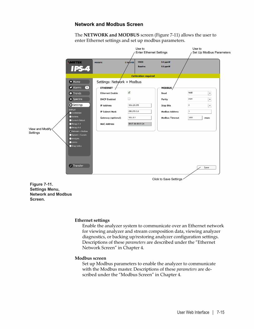
User Web Interface | 7-15
Network and Modbus Screen
The NETWORK and MODBUS screen (Figure 7-11) allows the user to enter Ethernet settings and set up modbus parameters.
Figure 7-11. Settings Menu, Network and Modbus Screen.
Ethernet settings Enable the analyzer system to communicate over an Ethernet network for viewing analyzer and stream composition data, viewing analyzer diagnostics, or backing up/restoring analyzer configuration settings. Descriptions of these parameters are described under the “Ethernet Network Screen” in Chapter 4.
Modbus screen Set up Modbus parameters to enable the analyzer to communicate with the Modbus master. Descriptions of these parameters are de-scribed under the “Modbus Screen” in Chapter 4.
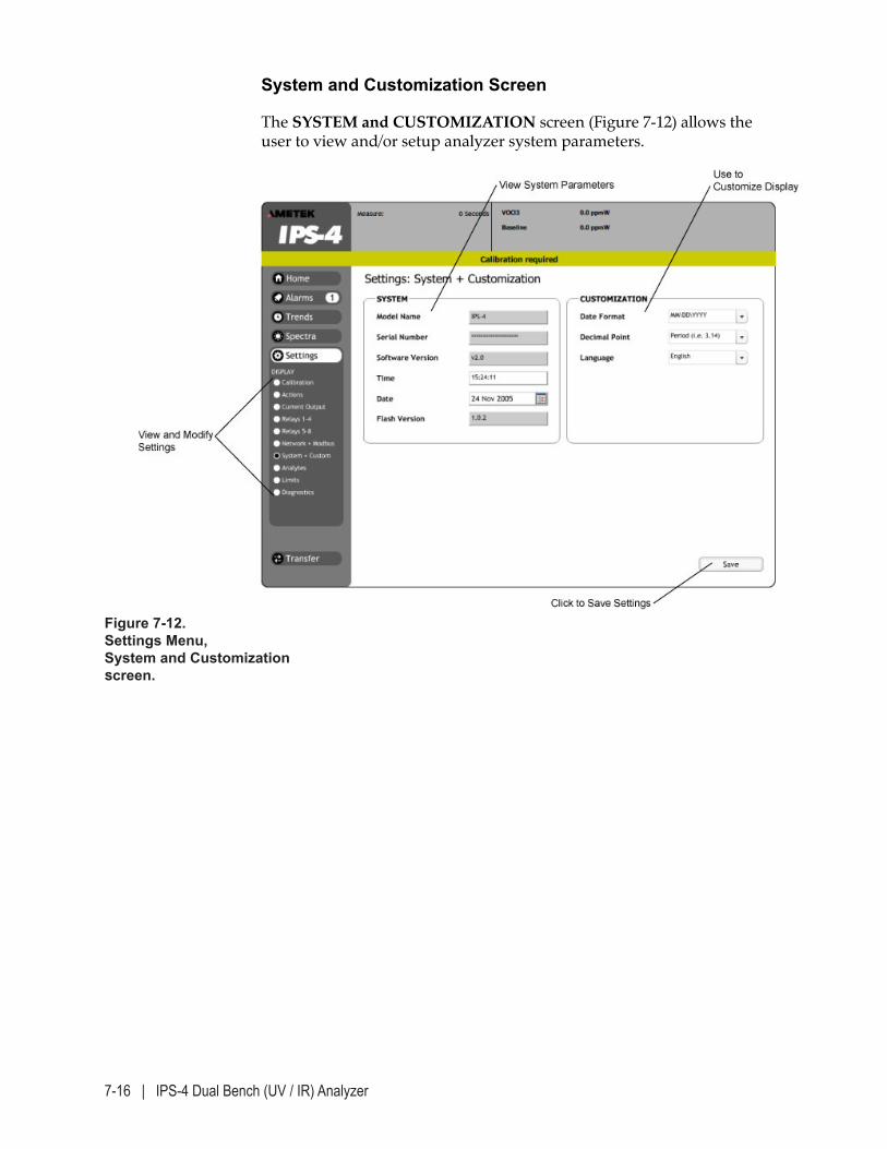
7-16 | IPS-4 Dual Bench (UV / IR) Analyzer
System and Customization Screen
The SYSTEM and CUSTOMIZATION screen (Figure 7-12) allows the user to view and/or setup analyzer system parameters.
Figure 7-12. Settings Menu, System and Customization Screen.
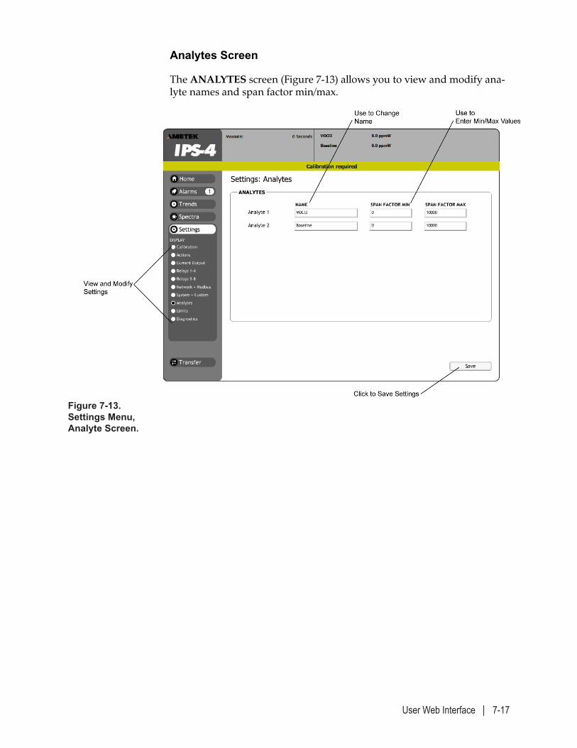
User Web Interface | 7-17
Analytes Screen
The ANALYTES screen (Figure 7-13) allows you to view and modify ana-lyte names and span factor min/max.
Figure 7-13. Settings Menu, Analyte Screen.
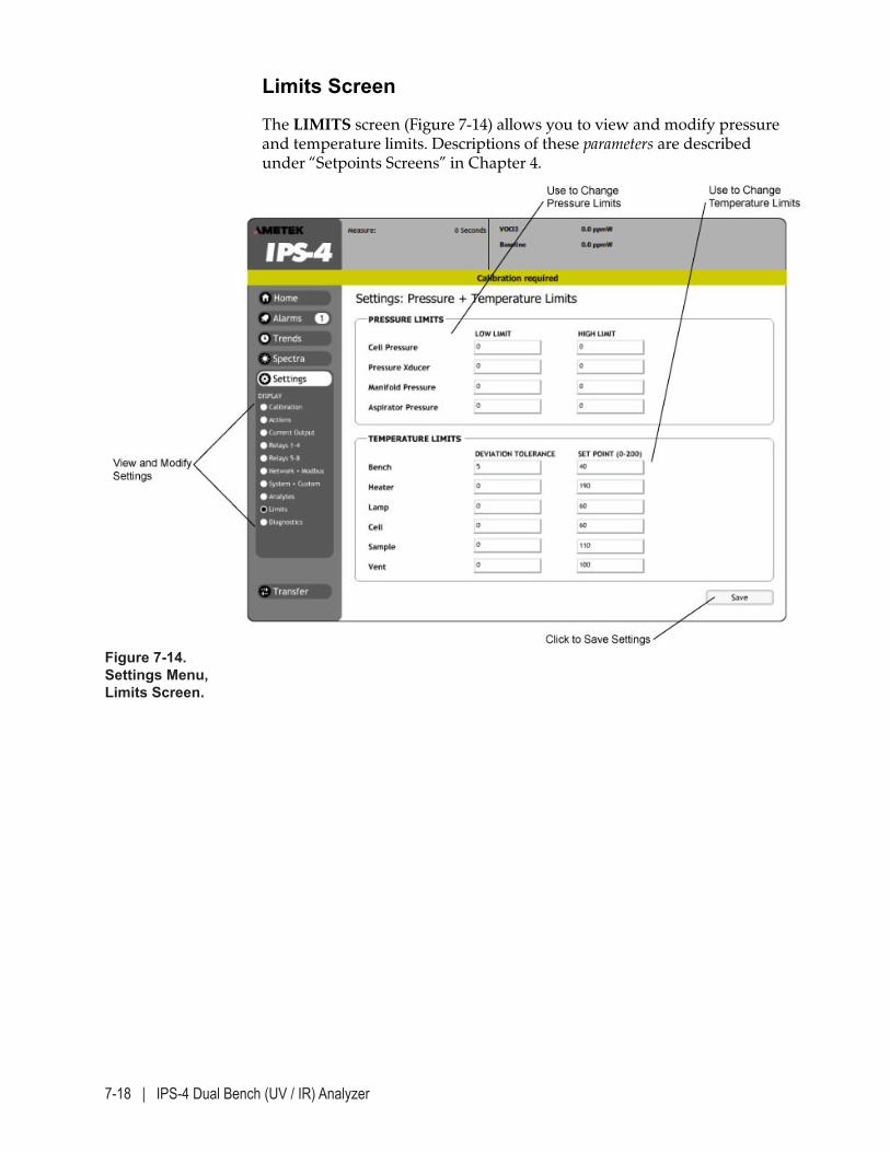
7-18 | IPS-4 Dual Bench (UV / IR) Analyzer
Limits Screen
The LIMITS screen (Figure 7-14) allows you to view and modify pressure and temperature limits. Descriptions of these parameters are described under “Setpoints Screens” in Chapter 4.
Figure 7-14. Settings Menu, Limits Screen.
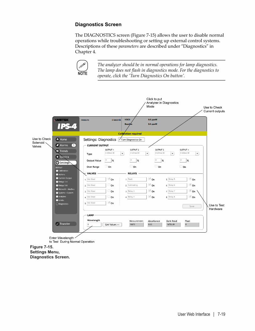
User Web Interface | 7-19
Diagnostics Screen
The DIAGNOSTICS screen (Figure 7-15) allows the user to disable normal operations while troubleshooting or setting up external control systems. Descriptions of these parameters are described under “Diagnostics” in Chapter 4.
The analyzer should be in normal operations for lamp diagnostics. The lamp does not flash in diagnostics mode. For the diagnostics to operate, click the ‘Turn Diagnostics On button’.
Figure 7-15. Settings Menu, Diagnostics Screen.
NOTE
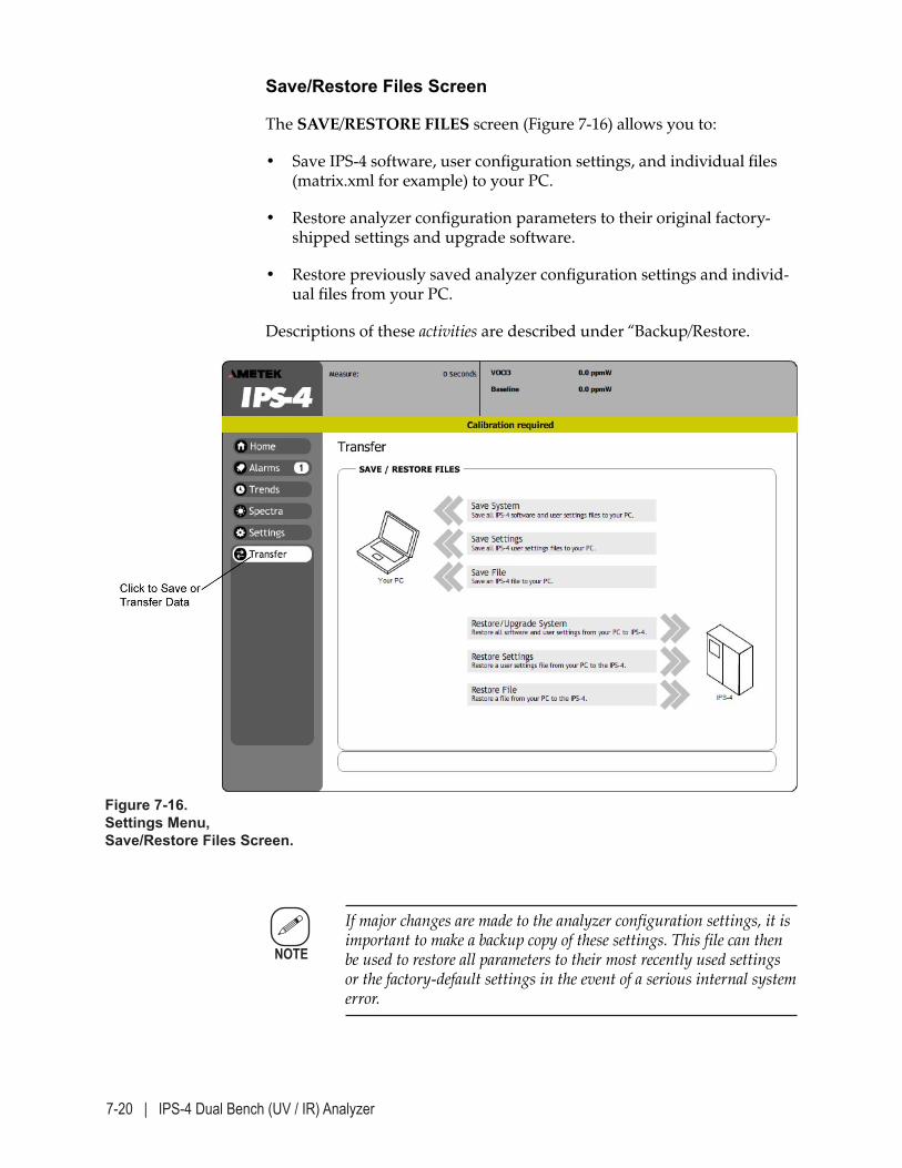
7-20 | IPS-4 Dual Bench (UV / IR) Analyzer
Save/Restore Files Screen
The SAVE/RESTORE FILES screen (Figure 7-16) allows you to:
• Save IPS-4 software, user configuration settings, and individual files (matrix.xml for example) to your PC.
• Restore analyzer configuration parameters to their original factory-shipped settings and upgrade software.
• Restore previously saved analyzer configuration settings and individ-ual files from your PC.
Descriptions of these activities are described under “Backup/Restore.
Figure 7-16. Settings Menu, Save/Restore Files Screen.
If major changes are made to the analyzer configuration settings, it is important to make a backup copy of these settings. This file can then be used to restore all parameters to their most recently used settings or the factory-default settings in the event of a serious internal system error.
NOTE
Modbus Communication Interface | 8-1
MODBUS COMMUNICATION INTERFACE
This chapter describes the customer serial communication interface on the IPS-4 Analyzer. The communication protocol implemented is Modicon Modbus as defined in “Modicon Modbus Protocol Reference Guide” (PI-MBUS-300 RevJ). The Modbus protocol transmission mode implemented is Remote Terminal Unit (RTU) with the analyzer operating as a slave device.
The IPS-4 Analyzer supports RS-485 serial communication standards. The physical communication connection between an IPS-4 analyzer and a cus-tomer DCS\SCADA\PLC\DAS or a general-purpose computer is RS-485. The analyzer RS-485 connection supports 2-wire multi-drop systems.
Hardware:
The jumpers on the CPU board J9 connector should be installed between the 1-2 and 3-4 pins.
The converter terminal marked TD(B) which is same as Tx+ should be connected to the CCB_J14 connector marked Tx+ (pin 3) on the Custom-er Connection Board, and TD(A) should be connected to Tx- (pin 4).
8-2 | IPS-4 Dual Bench (UV / IR) Analyzer
Configuration:
IPS4
IU2BAUD (105) is set by default to 9600
MBPARITY(113) default 1
MBSTOPBIT(114) default 1
MBUSADD (115) default 1
MBUSPORT(116) default 0
MBUSTO(117) default 3000
MBUSPORT should be set to 1 to enable MODBUS RTU operations.
MBUSPORT should be set to 4 to enable MODBUS TCP operations.
Make sure that you rebooted the analyzer after changing the MBUS-PORT parameter value to 1.
When designing a Modbus RS-485 multi-drop communication system with the IPS-4 Analyzer, the system designer should consider the follow-ing:
• The update rate is one time per minute or less. Polling of these regis-ters more frequently than once a second is not recommended.
• The maximum polling rate of a Modbus multi-drop system is deter-mined by a number of factors including the number of devices on the system, the number of registers being polled from each device, the baud rate in half-duplex operation.
• When operating in MODBUS TCP mode. Use TCP Port 502 for mod-bus communications.
• Modbus TCP is only available on software version:
2.05 or later (UV)
3.03 or later (Dual Bench)
Calculations, and possibly experimentation, are needed to attain optimal system operation.
NOTE
Modbus Communication Interface | 8-3
Analyzer Modbus Interface Parameters
A number of analyzer Modbus interface parameters need to be set up in order to establish communication with the Modbus master. These pa-rameters are accessed via the service port on the analyzer using a service program running on a PC.
Modbus Address
The analyzer needs to be assigned a Modbus slave address, which can be a number from 1 to 247.
Modbus Functions
As the Modbus protocol is designed for communication among Program-mable Logic Controllers (PLCs), not all Modbus function codes supported by a slave PLC are applicable to the IPS-4 analyzer. Only the following relevant function codes are implemented:
Code Description 03 read multiple holding registers (4x references) 06 write one holding register (4x references) 16 write multiple holding registers (4x references)
In accordance with MODBUS protocol specifications, all address referenc-es in Modbus messages are numbered relative to zero. For example, the first holding register in a Modbus slave being referenced as 40001 would be addressed as 0.
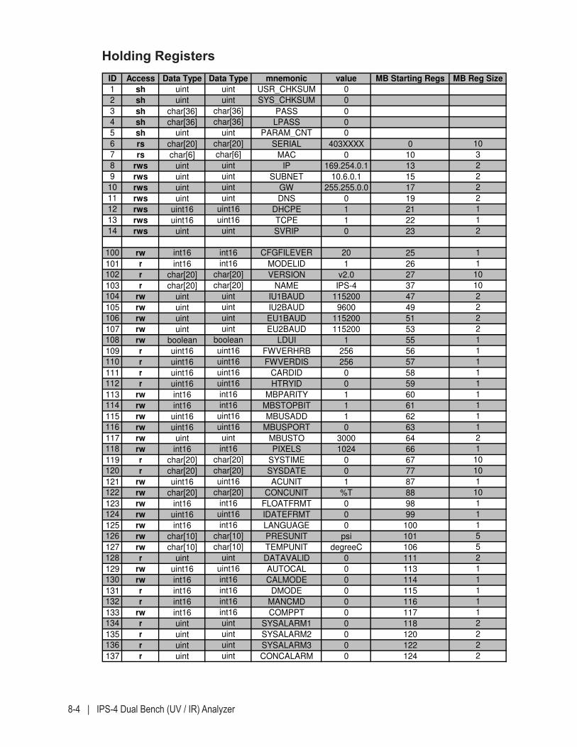
8-4 | IPS-4 Dual Bench (UV / IR) Analyzer
Holding RegistersID Access Data Type Data Type mnemonic value MB Starting Regs MB Reg Size
1 sh uint uint USR_CHKSUM 0
2 sh uint uint SYS_CHKSUM 0
3 sh char[36] char[36] PASS 0
4 sh char[36] char[36] LPASS 0
5 sh uint uint PARAM_CNT 0
6 rs char[20] char[20] SERIAL 403XXXX 0 10
7 rs char[6] char[6] MAC 0 10 3
8 rws uint uint IP 169.254.0.1 13 2
9 rws uint uint SUBNET 10.6.0.1 15 2
10 rws uint uint GW 255.255.0.0 17 2
11 rws uint uint DNS 0 19 2
12 rws uint16 uint16 DHCPE 1 21 1
13 rws uint16 uint16 TCPE 1 22 1
14 rws uint uint SVRIP 0 23 2
100 rw int16 int16 CFGFILEVER 20 25 1
101 r int16 int16 MODELID 1 26 1
102 r char[20] char[20] VERSION v2.0 27 10
103 r char[20] char[20] NAME IPS-4 37 10
104 rw uint uint IU1BAUD 115200 47 2
105 rw uint uint IU2BAUD 9600 49 2
106 rw uint uint EU1BAUD 115200 51 2
107 rw uint uint EU2BAUD 115200 53 2
108 rw boolean boolean LDUI 1 55 1
109 r uint16 uint16 FWVERHRB 256 56 1
110 r uint16 uint16 FWVERDIS 256 57 1
111 r uint16 uint16 CARDID 0 58 1
112 r uint16 uint16 HTRYID 0 59 1
113 rw int16 int16 MBPARITY 1 60 1
114 rw int16 int16 MBSTOPBIT 1 61 1
115 rw uint16 uint16 MBUSADD 1 62 1
116 rw uint16 uint16 MBUSPORT 0 63 1
117 rw uint uint MBUSTO 3000 64 2
118 rw int16 int16 PIXELS 1024 66 1
119 r char[20] char[20] SYSTIME 0 67 10
120 r char[20] char[20] SYSDATE 0 77 10
121 rw uint16 uint16 ACUNIT 1 87 1
122 rw char[20] char[20] CONCUNIT %T 88 10
123 rw int16 int16 FLOATFRMT 0 98 1
124 rw uint16 uint16 IDATEFRMT 0 99 1
125 rw int16 int16 LANGUAGE 0 100 1
126 rw char[10] char[10] PRESUNIT psi 101 5
127 rw char[10] char[10] TEMPUNIT degreeC 106 5
128 r uint uint DATAVALID 0 111 2
129 rw uint16 uint16 AUTOCAL 0 113 1
130 rw int16 int16 CALMODE 0 114 1
131 r int16 int16 DMODE 0 115 1
132 r int16 int16 MANCMD 0 116 1
133 rw int16 int16 COMPPT 0 117 1
134 r uint uint SYSALARM1 0 118 2
135 r uint uint SYSALARM2 0 120 2
136 r uint uint SYSALARM3 0 122 2
137 r uint uint CONCALARM 0 124 2
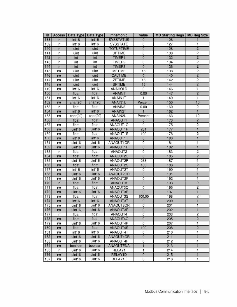
Modbus Communication Interface | 8-5
ID Access Data Type Data Type mnemonic value MB Starting Regs MB Reg Size
138 r int16 int16 SYSSTATUS 0 126 1
139 r int16 int16 SYSSTATE 0 127 1
140 r uint uint TOTUPTIME 0 128 2
141 r uint uint UPTIME 0 130 2
142 r int int TIMER1 0 132 2
143 r int int TIMER2 0 134 2
144 r int int TIMER3 0 136 2
145 rw uint uint MFTIME 15 138 2
146 rw uint uint CALTIME 0 140 2
147 rw uint uint ZFTIME 15 142 2
148 rw uint uint SFTIME 15 144 2
149 rw int16 int16 ANAHOLD 0 146 1
150 r float float ANAIN1 0.00 147 2
151 rw int16 int16 ANAIN1T 1 149 1
152 rw char[20] char[20] ANAIN1U Percent 150 10
153 r float float ANAIN2 0.00 160 2
154 rw int16 int16 ANAIN2T 1 162 1
155 rw char[20] char[20] ANAIN2U Percent 163 10
156 r float float ANAOUT1 0 173 2
157 rw float float ANAOUT1O 0 175 2
158 rw uint16 uint16 ANAOUT1P 261 177 1
159 rw float float ANAOUT1S 100 178 2
160 rw int16 int16 ANAOUT1T 0 180 1
161 rw uint16 uint16 ANAOUT1OR 0 181 1
162 rw uint16 uint16 ANAOUT1F 0 182 1
163 r float float ANAOUT2 0 183 2
164 rw float float ANAOUT2O 0 185 2
165 rw uint16 uint16 ANAOUT2P 263 187 1
166 rw float float ANAOUT2S 100 188 2
167 rw int16 int16 ANAOUT2T 0 190 1
168 rw uint16 uint16 ANAOUT2OR 0 191 1
169 rw uint16 uint16 ANAOUT2F 0 192 1
170 r float float ANAOUT3 0 193 2
171 rw float float ANAOUT3O 0 195 2
172 rw uint16 uint16 ANAOUT3P 0 197 1
173 rw float float ANAOUT3S 100.00 198 2
174 rw int16 int16 ANAOUT3T 0 200 1
175 rw uint16 uint16 ANAOUT3OR 0 201 1
176 rw uint16 uint16 ANAOUT3F 0 202 1
177 r float float ANAOUT4 0 203 2
178 rw float float ANAOUT4O 0 205 2
179 rw uint16 uint16 ANAOUT4P 0 207 1
180 rw float float ANAOUT4S 100 208 2
181 rw int16 int16 ANAOUT4T 0 210 1
182 rw uint16 uint16 ANAOUT4OR 0 211 1
183 rw uint16 uint16 ANAOUT4F 0 212 1
184 rw boolean boolean ANAOUTENA 1 213 1
185 r uint16 uint16 RELAY1 1 214 1
186 rw uint16 uint16 RELAY1D 0 215 1
187 rw uint16 uint16 RELAY1F 3 216 1

8-6 | IPS-4 Dual Bench (UV / IR) Analyzer
ID Access Data Type Data Type mnemonic value MB Starting Regs MB Reg Size
188 rw char[20] char[20] RELAY1NM Relay 1 217 10
189 rw uint16 uint16 RELAY1S 0 227 1
190 rw float float RELAY1V 0 228 2
191 r uint16 uint16 RELAY2 0 230 1
192 rw uint16 uint16 RELAY2D 0 231 1
193 rw uint16 uint16 RELAY2F 5 232 1
194 rw char[20] char[20] RELAY2NM Relay 2 233 10
195 rw uint16 uint16 RELAY2S 0 243 1
196 rw float float RELAY2V 0 244 2
197 r uint16 uint16 RELAY3 0 246 1
198 rw uint16 uint16 RELAY3D 0 247 1
199 rw uint16 uint16 RELAY3F 4 248 1
200 rw char[20] char[20] RELAY3NM Relay 3 249 10
201 rw uint16 uint16 RELAY3S 0 259 1
202 rw float float RELAY3V 0 260 2
203 r uint16 uint16 RELAY4 0 262 1
204 rw uint16 uint16 RELAY4D 0 263 1
205 rw uint16 uint16 RELAY4F 0 264 1
206 rw char[20] char[20] RELAY4NM Relay 4 265 10
207 rw uint16 uint16 RELAY4S 0 275 1
208 rw float float RELAY4V 0 276 2
209 r uint16 uint16 RELAY5 0 278 1
210 rw uint16 uint16 RELAY5D 0 279 1
211 rw uint16 uint16 RELAY5F 0 280 1
212 rw char[20] char[20] RELAY5NM Relay 5 281 10
213 rw uint16 uint16 RELAY5S 0 291 1
214 rw float float RELAY5V 0 292 2
215 r uint16 uint16 RELAY6 0 294 1
216 rw uint16 uint16 RELAY6D 0 295 1
217 rw uint16 uint16 RELAY6F 0 296 1
218 rw char[20] char[20] RELAY6NM Relay 6 297 10
219 rw uint16 uint16 RELAY6S 0 307 1
220 rw float float RELAY6V 0 308 2
221 r uint16 uint16 RELAY7 0 310 1
222 rw uint16 uint16 RELAY7D 0 311 1
223 rw uint16 uint16 RELAY7F 0 312 1
224 rw char[20] char[20] RELAY7NM Relay 7 313 10
225 rw uint16 uint16 RELAY7S 0 323 1
226 rw float float RELAY7V 0 324 2
227 r uint16 uint16 RELAY8 0 326 1
228 rw uint16 uint16 RELAY8D 0 327 1
229 rw uint16 uint16 RELAY8F 0 328 1
230 rw char[20] char[20] RELAY8NM Relay 8 329 10
231 rw uint16 uint16 RELAY8S 0 339 1
232 rw float float RELAY8V 0 340 2
233 rw boolean boolean RELAYENA 1 342 1
234 r uint16 uint16 VALVE1 1 343 1
235 rw char[20] char[20] VALVE1NM Valve 1 344 10
236 r uint16 uint16 VALVE2 0 354 1
237 rw char[20] char[20] VALVE2NM Valve 2 355 10
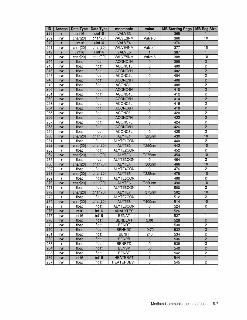
Modbus Communication Interface | 8-7
ID Access Data Type Data Type mnemonic value MB Starting Regs MB Reg Size
238 r uint16 uint16 VALVE3 0 365 1
239 rw char[20] char[20] VALVE3NM Valve 3 366 10
240 r uint16 uint16 VALVE4 0 376 1
241 rw char[20] char[20] VALVE4NM Valve 4 377 10
242 r uint16 uint16 VALVE5 1 387 1
243 rw char[20] char[20] VALVE5NM Valve 5 388 10
244 rw float float ACONC1H 0 398 2
245 rw float float ACONC1L 0 400 2
246 rw float float ACONC2H 0 402 2
247 rw float float ACONC2L 0 404 2
248 rw float float ACONC3H 0 406 2
249 rw float float ACONC3L 0 408 2
250 rw float float ACONC4H 0 410 2
251 rw float float ACONC4L 0 412 2
252 rw float float ACONC5H 0 414 2
253 rw float float ACONC5L 0 416 2
254 rw float float ACONC6H 0 418 2
255 rw float float ACONC6L 0 420 2
256 rw float float ACONC7H 0 422 2
257 rw float float ACONC7L 0 424 2
258 rw float float ACONC8H 0 426 2
259 rw float float ACONC8L 0 428 2
260 rw char[20] char[20] ALYTE1 T225nm 430 10
261 r float float ALYTE1CON 0 440 2
262 rw char[20] char[20] ALYTE2 T250nm 442 10
263 r float float ALYTE2CON 0 452 2
264 rw char[20] char[20] ALYTE3 T275nm 454 10
265 r float float ALYTE3CON 0 464 2
266 rw char[20] char[20] ALYTE4 T300nm 466 10
267 r float float ALYTE4CON 0 476 2
268 rw char[20] char[20] ALYTE5 T325nm 478 10
269 r float float ALYTE5CON 0 488 2
270 rw char[20] char[20] ALYTE6 T350nm 490 10
271 r float float ALYTE6CON 0 500 2
272 rw char[20] char[20] ALYTE7 T375nm 502 10
273 r float float ALYTE7CON 0 512 2
274 rw char[20] char[20] ALYTE8 T400nm 514 10
275 r float float ALYTE8CON 0 524 2
276 rw int16 int16 ANALYTES 8 526 1
277 rw int16 int16 BENAT 1 527 1
278 rw float float BENDEVT 5.00 528 2
279 rw float float BENDT 0 530 2
280 r float float BENHDC -0.70 532 2
281 rw float float BENIT 240 534 2
282 rw float float BENPB 5 536 2
283 r float float BENRTD 0 538 2
284 rw float float BENSP 50 540 2
285 rw float float BENST 5 542 2
286 rw int16 int16 HEATERAT 1 544 1
287 rw float float HEATERDEVT 0 545 2
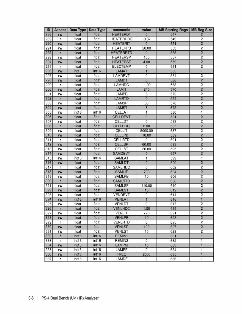
8-8 | IPS-4 Dual Bench (UV / IR) Analyzer
ID Access Data Type Data Type mnemonic value MB Starting Regs MB Reg Size
288 rw float float HEATERDT 0 547 2
289 r float float HEATERHDC -0.87 549 2
290 rw float float HEATERIT 0 551 2
291 rw float float HEATERPB 50.00 553 2
292 r float float HEATERRTD 0 555 2
293 rw float float HEATERSP 100 557 2
294 rw float float HEATERST 4.00 559 2
295 r float float ELECTEMP 0 561 2
296 rw int16 int16 LAMAT 1 563 1
297 rw float float LAMDEVT 0 564 2
298 rw float float LAMDT 0 566 2
299 r float float LAMHDC -1.00 568 2
300 rw float float LAMIT 240 570 2
301 rw float float LAMPB 5 572 2
302 r float float LAMRTD 0 574 2
303 rw float float LAMSP 60 576 2
304 rw float float LAMST 5 578 2
305 rw int16 int16 CELLAT 1 580 1
306 rw float float CELLDEVT 0 581 2
307 rw float float CELLDT 0 583 2
308 r float float CELLHDC 0.00 585 2
309 rw float float CELLIT 5000.00 587 2
310 rw float float CELLPB 10.00 589 2
311 r float float CELLRTD 0 591 2
312 rw float float CELLSP 60.00 593 2
313 rw float float CELLST 20.00 595 2
314 rw float float SAMDEVT 0 597 2
315 rw int16 int16 SAMLAT 1 599 1
316 rw float float SAMLDT 0 600 2
317 r float float SAMLHDC 0 602 2
318 rw float float SAMLIT 720 604 2
319 rw float float SAMLPB 10 606 2
320 r float float SAMLRTD 0 608 2
321 rw float float SAMLSP 110.00 610 2
322 rw float float SAMLST 15 612 2
323 rw float float VENDEVT 0 614 2
324 rw int16 int16 VENLAT 1 616 1
325 rw float float VENLDT 0 617 2
326 r float float VENLHDC 1.00 619 2
327 rw float float VENLIT 720 621 2
328 rw float float VENLPB 10 623 2
329 r float float VENLRTD 0 625 2
330 rw float float VENLSP 100 627 2
331 rw float float VENLST 15 629 2
332 r int16 int16 REMIN1 0 631 1
333 r int16 int16 REMIN2 0 632 1
334 rw int16 int16 LAMPM 15 633 1
335 rw int16 int16 LAMPF 0 634 1
336 rw int16 int16 FREQ 2000 635 1
337 r int16 int16 LAMDF 0 636 1
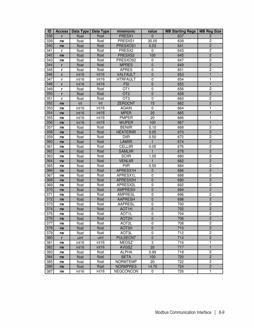
Modbus Communication Interface | 8-9
ID Access Data Type Data Type mnemonic value MB Starting Regs MB Reg Size
338 r float float PRESX1 0 637 2
339 rw float float PRESXS1 30.00 639 2
340 rw float float PRESXOS1 0.03 641 2
341 r float float PRESX2 0 643 2
342 rw float float PRESXS2 100 645 2
343 rw float float PRESXOS2 0 647 2
344 r float float MPRES 0 649 2
345 r float float APRES 0 651 2
346 r int16 int16 VALFAULT 0 653 1
347 r int16 int16 HTRFAULT 0 654 1
348 r int16 int16 FSI 0 655 1
349 r float float OT1 0 656 2
350 r float float OT2 0 658 2
351 r float float OT3 0 660 2
352 rw int int ZEROCNT 15 662 2
353 rw int16 int16 AGAIN 0 664 1
354 rw int16 int16 MPER 20 665 1
355 rw int16 int16 PMPER 20 666 1
356 rw int16 int16 WUPER 100 667 1
357 rw float float BENIIR 0.10 668 2
358 rw float float HEATERIIR 0.05 670 2
359 rw float float DIIR 0.50 672 2
360 rw float float LAMIIR 1 674 2
361 rw float float CELLIIR 0.05 676 2
362 rw float float SAMLIIR 1 678 2
363 rw float float SCIIR 1.00 680 2
364 rw float float VENLIIR 1 682 2
365 rw float float PIIR 0.50 684 2
366 rw float float APRESX1H 0 686 2
367 rw float float APRESX1L 0 688 2
368 rw float float APRESX2H 0 690 2
369 rw float float APRESX2L 0 692 2
370 rw float float AMPRESH 0 694 2
371 rw float float AMPRESL 0 696 2
372 rw float float AAPRESH 0 698 2
373 rw float float AAPRESL 0 700 2
374 rw float float AOT1H 0 702 2
375 rw float float AOT1L 0 704 2
376 rw float float AOT2H 0 706 2
377 rw float float AOT2L 0 708 2
378 rw float float AOT3H 0 710 2
379 rw float float AOT3L 0 712 2
380 r uint uint PULSECNT 0 714 2
381 rw int16 int16 MEDSZ 3 716 1
382 rw int16 int16 AVGSZ 20 717 1
383 rw float float ALPHA 0.99 718 2
384 rw float float BETA 100 720 2
385 rw float float NORMTEMP 20 722 2
386 rw float float NORMPRES 14.70 724 2
387 rw int16 int16 NEGCONCON 0 726 1
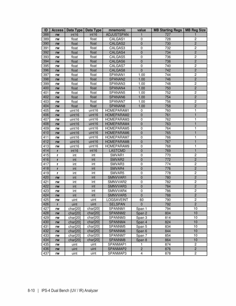
8-10 | IPS-4 Dual Bench (UV / IR) Analyzer
ID Access Data Type Data Type mnemonic value MB Starting Regs MB Reg Size
388 rw int16 int16 ADJUSTSPAN 1 727 1
389 rw float float CALGAS1 0 728 2
390 rw float float CALGAS2 0 730 2
391 rw float float CALGAS3 0 732 2
392 rw float float CALGAS4 0 734 2
393 rw float float CALGAS5 0 736 2
394 rw float float CALGAS6 0 738 2
395 rw float float CALGAS7 0 740 2
396 rw float float CALGAS8 0 742 2
397 rw float float SPANAN1 1.00 744 2
398 rw float float SPANAN2 1.00 746 2
399 rw float float SPANAN3 1.00 748 2
400 rw float float SPANAN4 1.00 750 2
401 rw float float SPANAN5 1.00 752 2
402 rw float float SPANAN6 1.00 754 2
403 rw float float SPANAN7 1.00 756 2
404 rw float float SPANAN8 1.00 758 2
405 rw uint16 uint16 HOMEPARAM1 0 760 1
406 rw uint16 uint16 HOMEPARAM2 0 761 1
407 rw uint16 uint16 HOMEPARAM3 0 762 1
408 rw uint16 uint16 HOMEPARAM4 0 763 1
409 rw uint16 uint16 HOMEPARAM5 0 764 1
410 rw uint16 uint16 HOMEPARAM6 0 765 1
411 rw uint16 uint16 HOMEPARAM7 0 766 1
412 rw uint16 uint16 HOMEPARAM8 0 767 1
413 rw uint16 uint16 HOMEPARAM9 0 768 1
414 r int16 int16 LASTCMD 0 769 1
415 r int int SMVAR1 0 770 2
416 r int int SMVAR2 0 772 2
417 r int int SMVAR3 0 774 2
418 r int int SMVAR4 0 776 2
419 r int int SMVAR5 0 778 2
420 rw int int SMNVVAR1 0 780 2
421 rw int int SMNVVAR2 0 782 2
422 rw int int SMNVVAR3 0 784 2
423 rw int int SMNVVAR4 0 786 2
424 rw int int SMNVVAR5 0 788 2
425 rw uint uint LOGSAVEINT 60 790 2
426 r uint uint SELSPAN 0 792 2
427 rw char[20] char[20] SPANNM1 Span 1 794 10
428 rw char[20] char[20] SPANNM2 Span 2 804 10
429 rw char[20] char[20] SPANNM3 Span 3 814 10
430 rw char[20] char[20] SPANNM4 Span 4 824 10
431 rw char[20] char[20] SPANNM5 Span 5 834 10
432 rw char[20] char[20] SPANNM6 Span 6 844 10
433 rw char[20] char[20] SPANNM7 Span 7 854 10
434 rw char[20] char[20] SPANNM8 Span 8 864 10
435 rw uint uint SPANMAP1 1 874 2
436 rw uint uint SPANMAP2 2 876 2
437 rw uint uint SPANMAP3 4 878 2
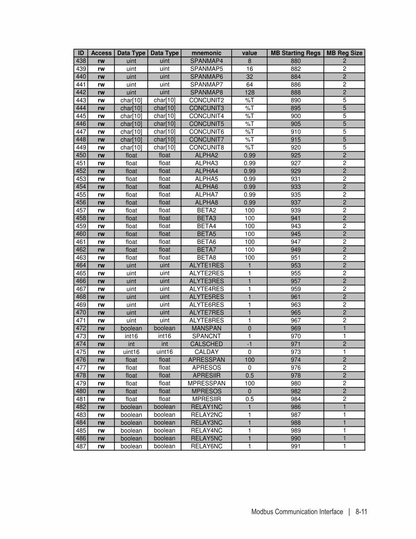
Modbus Communication Interface | 8-11
ID Access Data Type Data Type mnemonic value MB Starting Regs MB Reg Size
438 rw uint uint SPANMAP4 8 880 2
439 rw uint uint SPANMAP5 16 882 2
440 rw uint uint SPANMAP6 32 884 2
441 rw uint uint SPANMAP7 64 886 2
442 rw uint uint SPANMAP8 128 888 2
443 rw char[10] char[10] CONCUNIT2 %T 890 5
444 rw char[10] char[10] CONCUNIT3 %T 895 5
445 rw char[10] char[10] CONCUNIT4 %T 900 5
446 rw char[10] char[10] CONCUNIT5 %T 905 5
447 rw char[10] char[10] CONCUNIT6 %T 910 5
448 rw char[10] char[10] CONCUNIT7 %T 915 5
449 rw char[10] char[10] CONCUNIT8 %T 920 5
450 rw float float ALPHA2 0.99 925 2
451 rw float float ALPHA3 0.99 927 2
452 rw float float ALPHA4 0.99 929 2
453 rw float float ALPHA5 0.99 931 2
454 rw float float ALPHA6 0.99 933 2
455 rw float float ALPHA7 0.99 935 2
456 rw float float ALPHA8 0.99 937 2
457 rw float float BETA2 100 939 2
458 rw float float BETA3 100 941 2
459 rw float float BETA4 100 943 2
460 rw float float BETA5 100 945 2
461 rw float float BETA6 100 947 2
462 rw float float BETA7 100 949 2
463 rw float float BETA8 100 951 2
464 rw uint uint ALYTE1RES 1 953 2
465 rw uint uint ALYTE2RES 1 955 2
466 rw uint uint ALYTE3RES 1 957 2
467 rw uint uint ALYTE4RES 1 959 2
468 rw uint uint ALYTE5RES 1 961 2
469 rw uint uint ALYTE6RES 1 963 2
470 rw uint uint ALYTE7RES 1 965 2
471 rw uint uint ALYTE8RES 1 967 2
472 rw boolean boolean MANSPAN 0 969 1
473 rw int16 int16 SPANCNT 1 970 1
474 rw int int CALSCHED -1 971 2
475 rw uint16 uint16 CALDAY 0 973 1
476 rw float float APRESSPAN 100 974 2
477 rw float float APRESOS 0 976 2
478 rw float float APRESIIR 0.5 978 2
479 rw float float MPRESSPAN 100 980 2
480 rw float float MPRESOS 0 982 2
481 rw float float MPRESIIR 0.5 984 2
482 rw boolean boolean RELAY1NC 1 986 1
483 rw boolean boolean RELAY2NC 1 987 1
484 rw boolean boolean RELAY3NC 1 988 1
485 rw boolean boolean RELAY4NC 1 989 1
486 rw boolean boolean RELAY5NC 1 990 1
487 rw boolean boolean RELAY6NC 1 991 1
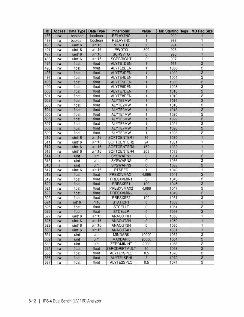
8-12 | IPS-4 Dual Bench (UV / IR) Analyzer
ID Access Data Type Data Type mnemonic value MB Starting Regs MB Reg Size
488 rw boolean boolean RELAY7NC 1 992 1
489 rw boolean boolean RELAY8NC 1 993 1
490 rw uint16 uint16 MENUTO 60 994 1
491 rw uint16 uint16 PWDTO 300 995 1
492 rw uint16 uint16 SCRSVTO 0 996 1
493 rw uint16 uint16 SCRBRIGHT 3 997 1
494 rw float float ALYTE1DEN 1 998 2
495 rw float float ALYTE2DEN 1 1000 2
496 rw float float ALYTE3DEN 1 1002 2
497 rw float float ALYTE4DEN 1 1004 2
498 rw float float ALYTE5DEN 1 1006 2
499 rw float float ALYTE6DEN 1 1008 2
500 rw float float ALYTE7DEN 1 1010 2
501 rw float float ALYTE8DEN 1 1012 2
502 rw float float ALYTE1MW 1 1014 2
503 rw float float ALYTE2MW 1 1016 2
504 rw float float ALYTE3MW 1 1018 2
505 rw float float ALYTE4MW 1 1020 2
506 rw float float ALYTE5MW 1 1022 2
507 rw float float ALYTE6MW 1 1024 2
508 rw float float ALYTE7MW 1 1026 2
509 rw float float ALYTE8MW 1 1028 2
510 rw uint16 uint16 SOFTCENTER1 39 1030 1
511 rw uint16 uint16 SOFTCENTER2 94 1031 1
512 rw uint16 uint16 SOFTCENTER3 152 1032 1
513 rw uint16 uint16 SOFTCENTER4 208 1033 1
514 r uint uint SYSWARN1 0 1034 2
515 r uint uint SYSWARN2 0 1036 2
516 r uint uint SYSWARN3 0 1038 2
517 rw uint16 uint16 PTSEED 1 1040 1
518 rw float float PRESXVMAX1 4.096 1041 2
519 rw float float PRESXVMIN1 0 1043 2
520 rw float float PRESXSF1 100 1045 2
521 rw float float PRESXVMAX2 4.096 1047 2
522 rw float float PRESXVMIN2 0 1049 2
523 rw float float PRESXSF2 100 1051 2
524 rw int16 int16 STATICPT 0 1053 1
525 rw float float STCELLT 0 1054 2
526 rw float float STCELLP 0 1056 2
527 rw uint16 uint16 ANAOUT1H 0 1058 1
528 rw uint16 uint16 ANAOUT2H 0 1059 1
529 rw uint16 uint16 ANAOUT3H 0 1060 1
530 rw uint16 uint16 ANAOUT4H 0 1061 1
531 rw uint uint MINDARK 10000 1062 2
532 rw uint uint MAXDARK 20000 1064 2
533 rw uint uint ZEROMININT 2000 1066 2
534 rw float float ZERODRIFTMULT 10 1068 2
535 rw float float ALYTE1SPLO 0.5 1070 2
536 rw float float ALYTE1SPHI 3 1072 2
537 rw float float ALYTE2SPLO 0.5 1074 2
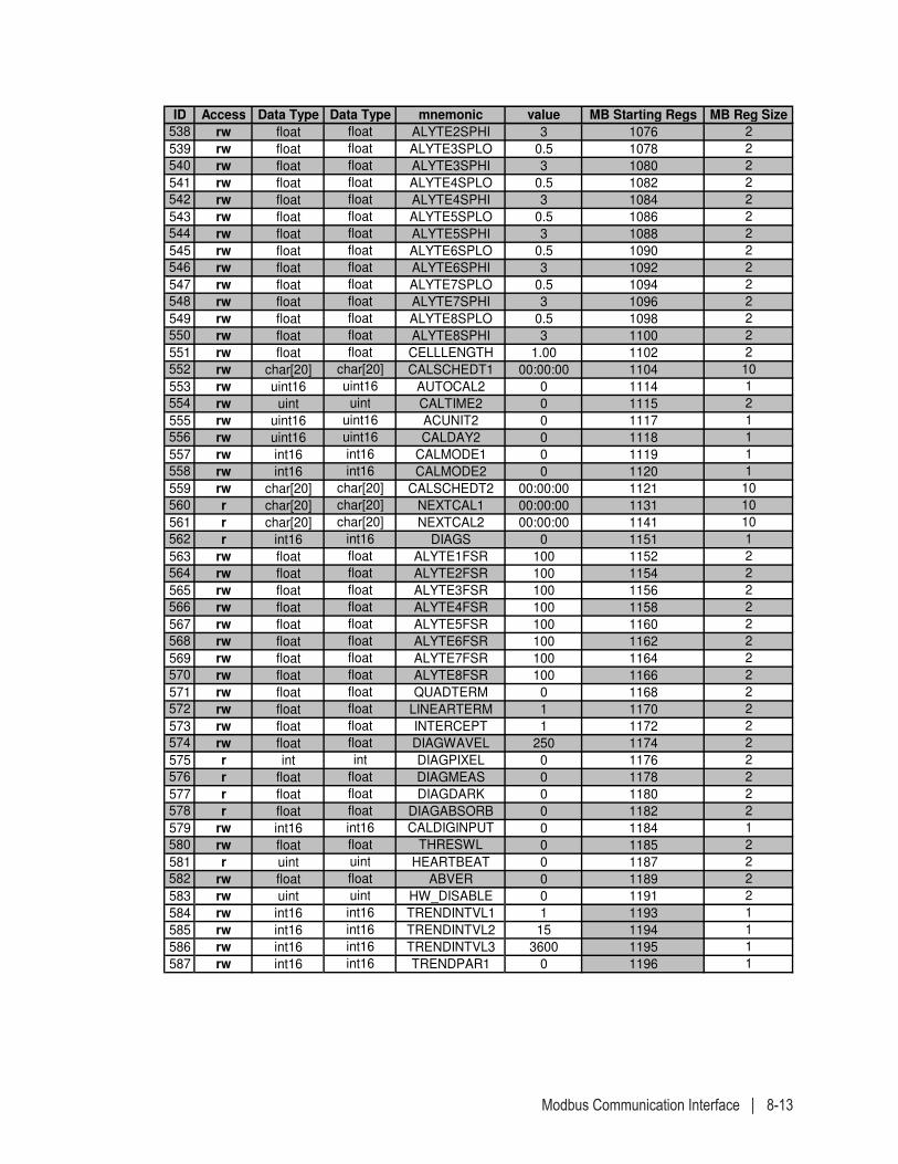
Modbus Communication Interface | 8-13
ID Access Data Type Data Type mnemonic value MB Starting Regs MB Reg Size
538 rw float float ALYTE2SPHI 3 1076 2
539 rw float float ALYTE3SPLO 0.5 1078 2
540 rw float float ALYTE3SPHI 3 1080 2
541 rw float float ALYTE4SPLO 0.5 1082 2
542 rw float float ALYTE4SPHI 3 1084 2
543 rw float float ALYTE5SPLO 0.5 1086 2
544 rw float float ALYTE5SPHI 3 1088 2
545 rw float float ALYTE6SPLO 0.5 1090 2
546 rw float float ALYTE6SPHI 3 1092 2
547 rw float float ALYTE7SPLO 0.5 1094 2
548 rw float float ALYTE7SPHI 3 1096 2
549 rw float float ALYTE8SPLO 0.5 1098 2
550 rw float float ALYTE8SPHI 3 1100 2
551 rw float float CELLLENGTH 1.00 1102 2
552 rw char[20] char[20] CALSCHEDT1 00:00:00 1104 10
553 rw uint16 uint16 AUTOCAL2 0 1114 1
554 rw uint uint CALTIME2 0 1115 2
555 rw uint16 uint16 ACUNIT2 0 1117 1
556 rw uint16 uint16 CALDAY2 0 1118 1
557 rw int16 int16 CALMODE1 0 1119 1
558 rw int16 int16 CALMODE2 0 1120 1
559 rw char[20] char[20] CALSCHEDT2 00:00:00 1121 10
560 r char[20] char[20] NEXTCAL1 00:00:00 1131 10
561 r char[20] char[20] NEXTCAL2 00:00:00 1141 10
562 r int16 int16 DIAGS 0 1151 1
563 rw float float ALYTE1FSR 100 1152 2
564 rw float float ALYTE2FSR 100 1154 2
565 rw float float ALYTE3FSR 100 1156 2
566 rw float float ALYTE4FSR 100 1158 2
567 rw float float ALYTE5FSR 100 1160 2
568 rw float float ALYTE6FSR 100 1162 2
569 rw float float ALYTE7FSR 100 1164 2
570 rw float float ALYTE8FSR 100 1166 2
571 rw float float QUADTERM 0 1168 2
572 rw float float LINEARTERM 1 1170 2
573 rw float float INTERCEPT 1 1172 2
574 rw float float DIAGWAVEL 250 1174 2
575 r int int DIAGPIXEL 0 1176 2
576 r float float DIAGMEAS 0 1178 2
577 r float float DIAGDARK 0 1180 2
578 r float float DIAGABSORB 0 1182 2
579 rw int16 int16 CALDIGINPUT 0 1184 1
580 rw float float THRESWL 0 1185 2
581 r uint uint HEARTBEAT 0 1187 2
582 rw float float ABVER 0 1189 2
583 rw uint uint HW_DISABLE 0 1191 2
584 rw int16 int16 TRENDINTVL1 1 1193 1
585 rw int16 int16 TRENDINTVL2 15 1194 1
586 rw int16 int16 TRENDINTVL3 3600 1195 1
587 rw int16 int16 TRENDPAR1 0 1196 1
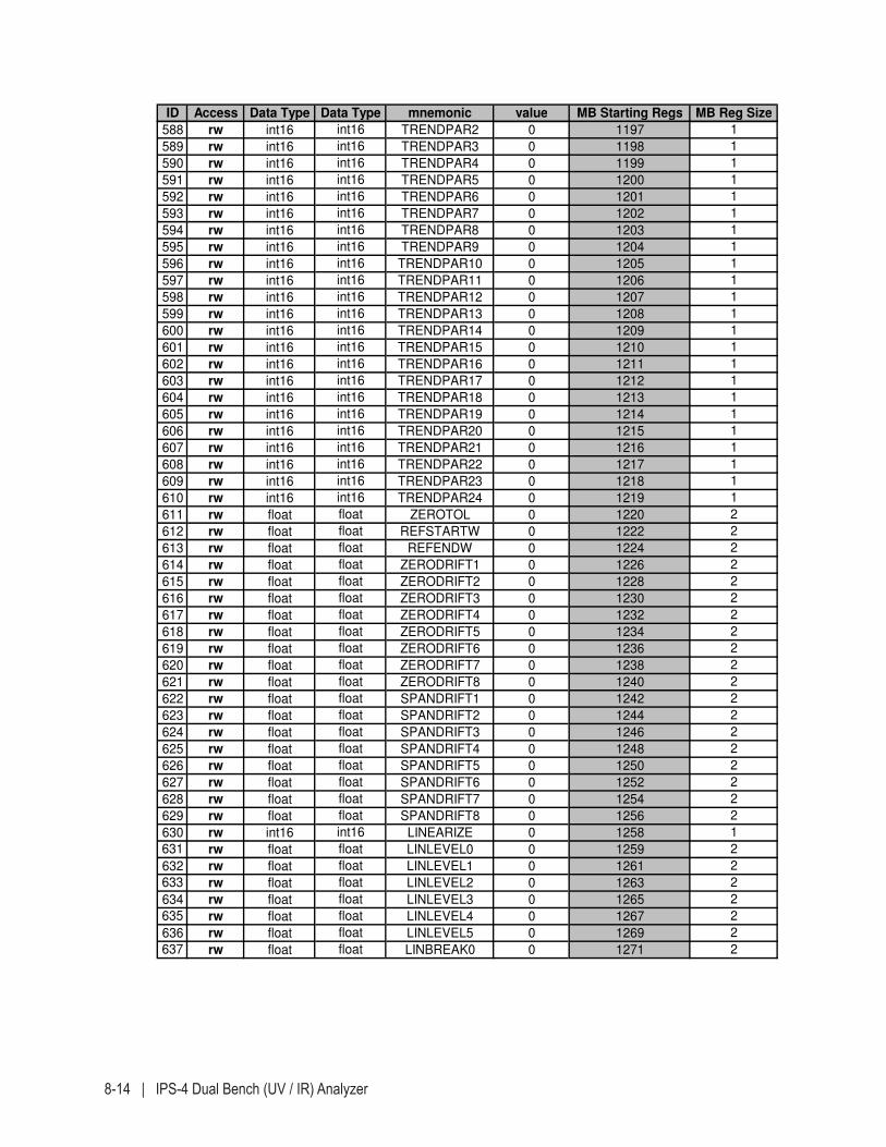
8-14 | IPS-4 Dual Bench (UV / IR) Analyzer
ID Access Data Type Data Type mnemonic value MB Starting Regs MB Reg Size
588 rw int16 int16 TRENDPAR2 0 1197 1
589 rw int16 int16 TRENDPAR3 0 1198 1
590 rw int16 int16 TRENDPAR4 0 1199 1
591 rw int16 int16 TRENDPAR5 0 1200 1
592 rw int16 int16 TRENDPAR6 0 1201 1
593 rw int16 int16 TRENDPAR7 0 1202 1
594 rw int16 int16 TRENDPAR8 0 1203 1
595 rw int16 int16 TRENDPAR9 0 1204 1
596 rw int16 int16 TRENDPAR10 0 1205 1
597 rw int16 int16 TRENDPAR11 0 1206 1
598 rw int16 int16 TRENDPAR12 0 1207 1
599 rw int16 int16 TRENDPAR13 0 1208 1
600 rw int16 int16 TRENDPAR14 0 1209 1
601 rw int16 int16 TRENDPAR15 0 1210 1
602 rw int16 int16 TRENDPAR16 0 1211 1
603 rw int16 int16 TRENDPAR17 0 1212 1
604 rw int16 int16 TRENDPAR18 0 1213 1
605 rw int16 int16 TRENDPAR19 0 1214 1
606 rw int16 int16 TRENDPAR20 0 1215 1
607 rw int16 int16 TRENDPAR21 0 1216 1
608 rw int16 int16 TRENDPAR22 0 1217 1
609 rw int16 int16 TRENDPAR23 0 1218 1
610 rw int16 int16 TRENDPAR24 0 1219 1
611 rw float float ZEROTOL 0 1220 2
612 rw float float REFSTARTW 0 1222 2
613 rw float float REFENDW 0 1224 2
614 rw float float ZERODRIFT1 0 1226 2
615 rw float float ZERODRIFT2 0 1228 2
616 rw float float ZERODRIFT3 0 1230 2
617 rw float float ZERODRIFT4 0 1232 2
618 rw float float ZERODRIFT5 0 1234 2
619 rw float float ZERODRIFT6 0 1236 2
620 rw float float ZERODRIFT7 0 1238 2
621 rw float float ZERODRIFT8 0 1240 2
622 rw float float SPANDRIFT1 0 1242 2
623 rw float float SPANDRIFT2 0 1244 2
624 rw float float SPANDRIFT3 0 1246 2
625 rw float float SPANDRIFT4 0 1248 2
626 rw float float SPANDRIFT5 0 1250 2
627 rw float float SPANDRIFT6 0 1252 2
628 rw float float SPANDRIFT7 0 1254 2
629 rw float float SPANDRIFT8 0 1256 2
630 rw int16 int16 LINEARIZE 0 1258 1
631 rw float float LINLEVEL0 0 1259 2
632 rw float float LINLEVEL1 0 1261 2
633 rw float float LINLEVEL2 0 1263 2
634 rw float float LINLEVEL3 0 1265 2
635 rw float float LINLEVEL4 0 1267 2
636 rw float float LINLEVEL5 0 1269 2
637 rw float float LINBREAK0 0 1271 2
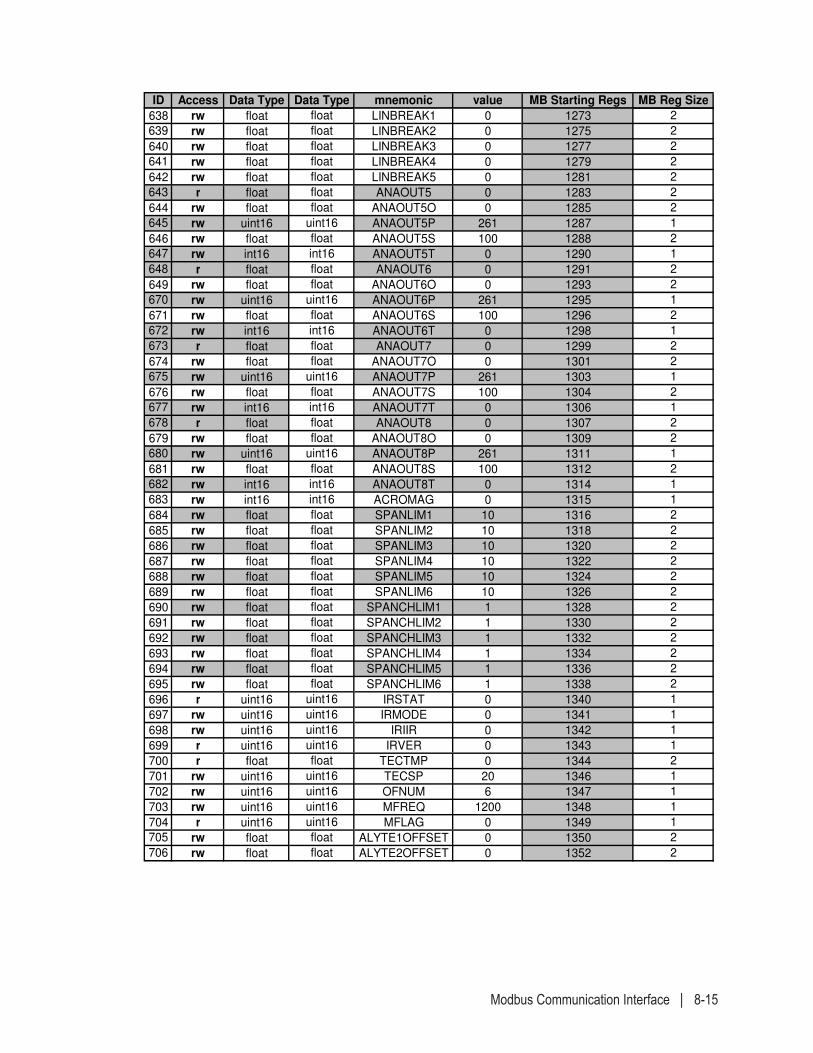
Modbus Communication Interface | 8-15
ID Access Data Type Data Type mnemonic value MB Starting Regs MB Reg Size
638 rw float float LINBREAK1 0 1273 2
639 rw float float LINBREAK2 0 1275 2
640 rw float float LINBREAK3 0 1277 2
641 rw float float LINBREAK4 0 1279 2
642 rw float float LINBREAK5 0 1281 2
643 r float float ANAOUT5 0 1283 2
644 rw float float ANAOUT5O 0 1285 2
645 rw uint16 uint16 ANAOUT5P 261 1287 1
646 rw float float ANAOUT5S 100 1288 2
647 rw int16 int16 ANAOUT5T 0 1290 1
648 r float float ANAOUT6 0 1291 2
649 rw float float ANAOUT6O 0 1293 2
670 rw uint16 uint16 ANAOUT6P 261 1295 1
671 rw float float ANAOUT6S 100 1296 2
672 rw int16 int16 ANAOUT6T 0 1298 1
673 r float float ANAOUT7 0 1299 2
674 rw float float ANAOUT7O 0 1301 2
675 rw uint16 uint16 ANAOUT7P 261 1303 1
676 rw float float ANAOUT7S 100 1304 2
677 rw int16 int16 ANAOUT7T 0 1306 1
678 r float float ANAOUT8 0 1307 2
679 rw float float ANAOUT8O 0 1309 2
680 rw uint16 uint16 ANAOUT8P 261 1311 1
681 rw float float ANAOUT8S 100 1312 2
682 rw int16 int16 ANAOUT8T 0 1314 1
683 rw int16 int16 ACROMAG 0 1315 1
684 rw float float SPANLIM1 10 1316 2
685 rw float float SPANLIM2 10 1318 2
686 rw float float SPANLIM3 10 1320 2
687 rw float float SPANLIM4 10 1322 2
688 rw float float SPANLIM5 10 1324 2
689 rw float float SPANLIM6 10 1326 2
690 rw float float SPANCHLIM1 1 1328 2
691 rw float float SPANCHLIM2 1 1330 2
692 rw float float SPANCHLIM3 1 1332 2
693 rw float float SPANCHLIM4 1 1334 2
694 rw float float SPANCHLIM5 1 1336 2
695 rw float float SPANCHLIM6 1 1338 2
696 r uint16 uint16 IRSTAT 0 1340 1
697 rw uint16 uint16 IRMODE 0 1341 1
698 rw uint16 uint16 IRIIR 0 1342 1
699 r uint16 uint16 IRVER 0 1343 1
700 r float float TECTMP 0 1344 2
701 rw uint16 uint16 TECSP 20 1346 1
702 rw uint16 uint16 OFNUM 6 1347 1
703 rw uint16 uint16 MFREQ 1200 1348 1
704 r uint16 uint16 MFLAG 0 1349 1
705 rw float float ALYTE1OFFSET 0 1350 2
706 rw float float ALYTE2OFFSET 0 1352 2
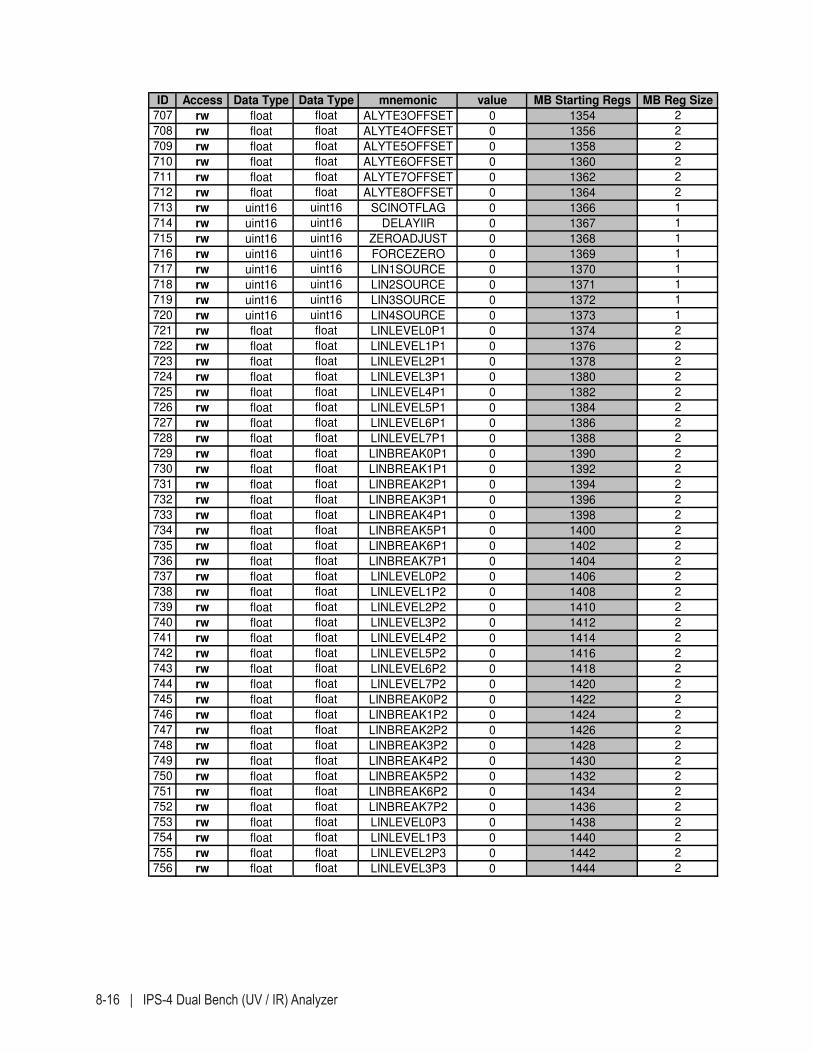
8-16 | IPS-4 Dual Bench (UV / IR) Analyzer
ID Access Data Type Data Type mnemonic value MB Starting Regs MB Reg Size
707 rw float float ALYTE3OFFSET 0 1354 2
708 rw float float ALYTE4OFFSET 0 1356 2
709 rw float float ALYTE5OFFSET 0 1358 2
710 rw float float ALYTE6OFFSET 0 1360 2
711 rw float float ALYTE7OFFSET 0 1362 2
712 rw float float ALYTE8OFFSET 0 1364 2
713 rw uint16 uint16 SCINOTFLAG 0 1366 1
714 rw uint16 uint16 DELAYIIR 0 1367 1
715 rw uint16 uint16 ZEROADJUST 0 1368 1
716 rw uint16 uint16 FORCEZERO 0 1369 1
717 rw uint16 uint16 LIN1SOURCE 0 1370 1
718 rw uint16 uint16 LIN2SOURCE 0 1371 1
719 rw uint16 uint16 LIN3SOURCE 0 1372 1
720 rw uint16 uint16 LIN4SOURCE 0 1373 1
721 rw float float LINLEVEL0P1 0 1374 2
722 rw float float LINLEVEL1P1 0 1376 2
723 rw float float LINLEVEL2P1 0 1378 2
724 rw float float LINLEVEL3P1 0 1380 2
725 rw float float LINLEVEL4P1 0 1382 2
726 rw float float LINLEVEL5P1 0 1384 2
727 rw float float LINLEVEL6P1 0 1386 2
728 rw float float LINLEVEL7P1 0 1388 2
729 rw float float LINBREAK0P1 0 1390 2
730 rw float float LINBREAK1P1 0 1392 2
731 rw float float LINBREAK2P1 0 1394 2
732 rw float float LINBREAK3P1 0 1396 2
733 rw float float LINBREAK4P1 0 1398 2
734 rw float float LINBREAK5P1 0 1400 2
735 rw float float LINBREAK6P1 0 1402 2
736 rw float float LINBREAK7P1 0 1404 2
737 rw float float LINLEVEL0P2 0 1406 2
738 rw float float LINLEVEL1P2 0 1408 2
739 rw float float LINLEVEL2P2 0 1410 2
740 rw float float LINLEVEL3P2 0 1412 2
741 rw float float LINLEVEL4P2 0 1414 2
742 rw float float LINLEVEL5P2 0 1416 2
743 rw float float LINLEVEL6P2 0 1418 2
744 rw float float LINLEVEL7P2 0 1420 2
745 rw float float LINBREAK0P2 0 1422 2
746 rw float float LINBREAK1P2 0 1424 2
747 rw float float LINBREAK2P2 0 1426 2
748 rw float float LINBREAK3P2 0 1428 2
749 rw float float LINBREAK4P2 0 1430 2
750 rw float float LINBREAK5P2 0 1432 2
751 rw float float LINBREAK6P2 0 1434 2
752 rw float float LINBREAK7P2 0 1436 2
753 rw float float LINLEVEL0P3 0 1438 2
754 rw float float LINLEVEL1P3 0 1440 2
755 rw float float LINLEVEL2P3 0 1442 2
756 rw float float LINLEVEL3P3 0 1444 2
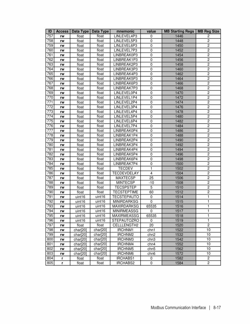
Modbus Communication Interface | 8-17
ID Access Data Type Data Type mnemonic value MB Starting Regs MB Reg Size
757 rw float float LINLEVEL4P3 0 1446 2
758 rw float float LINLEVEL5P3 0 1448 2
759 rw float float LINLEVEL6P3 0 1450 2
760 rw float float LINLEVEL7P3 0 1452 2
761 rw float float LINBREAK0P3 0 1454 2
762 rw float float LINBREAK1P3 0 1456 2
763 rw float float LINBREAK2P3 0 1458 2
764 rw float float LINBREAK3P3 0 1460 2
765 rw float float LINBREAK4P3 0 1462 2
766 rw float float LINBREAK5P3 0 1464 2
767 rw float float LINBREAK6P3 0 1466 2
768 rw float float LINBREAK7P3 0 1468 2
769 rw float float LINLEVEL0P4 0 1470 2
770 rw float float LINLEVEL1P4 0 1472 2
771 rw float float LINLEVEL2P4 0 1474 2
772 rw float float LINLEVEL3P4 0 1476 2
773 rw float float LINLEVEL4P4 0 1478 2
774 rw float float LINLEVEL5P4 0 1480 2
775 rw float float LINLEVEL6P4 0 1482 2
776 rw float float LINLEVEL7P4 0 1484 2
777 rw float float LINBREAK0P4 0 1486 2
778 rw float float LINBREAK1P4 0 1488 2
779 rw float float LINBREAK2P4 0 1490 2
780 rw float float LINBREAK3P4 0 1492 2
781 rw float float LINBREAK4P4 0 1494 2
782 rw float float LINBREAK5P4 0 1496 2
783 rw float float LINBREAK6P4 0 1498 2
784 rw float float LINBREAK7P4 0 1500 2
785 rw float float TECDEV 1 1502 2
786 rw float float TECDEVDELAY 4 1504 2
787 rw float float MAXTECSP 25 1506 2
788 rw float float MINTECSP -10 1508 2
789 rw float float TECSPSTEP 5 1510 2
790 rw float float TECSTEPTIME 60 1512 2
791 rw uint16 uint16 TECSTEPAUTO 0 1514 1
792 rw uint16 uint16 MINIRDARKSG 0 1515 1
793 rw uint16 uint16 MAXIRDARKSG 65535 1516 1
794 rw uint16 uint16 MINIRMEASSG 0 1517 1
795 rw uint16 uint16 MAXIRMEASSG 65535 1518 1
796 rw uint16 uint16 STEPAUTOZRO 0 1519 1
797 rw float float CELLLENGTH2 20 1520 2
798 rw char[20] char[20] IRCHNM1 chn1 1522 10
799 rw char[20] char[20] IRCHNM2 chn2 1532 10
800 rw char[20] char[20] IRCHNM3 chn3 1542 10
801 rw char[20] char[20] IRCHNM4 chn4 1552 10
802 rw char[20] char[20] IRCHNM5 chn5 1562 10
803 rw char[20] char[20] IRCHNM6 chn6 1572 10
804 r float float IRCHABS1 0 1582 2
805 r float float IRCHABS2 0 1584 2
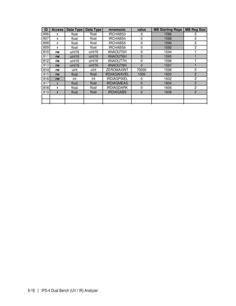
8-18 | IPS-4 Dual Bench (UV / IR) Analyzer
ID Access Data Type Data Type mnemonic value MB Starting Regs MB Reg Size
806 r float float IRCHABS3 0 1586 2
807 r float float IRCHABS4 0 1588 2
808 r float float IRCHABS5 0 1590 2
809 r float float IRCHABS6 0 1592 2
810 rw uint16 uint16 ANAOUT5H 0 1594 1
811 rw uint16 uint16 ANAOUT6H 0 1595 1
812 rw uint16 uint16 ANAOUT7H 0 1596 1
813 rw uint16 uint16 ANAOUT8H 0 1597 1
814 rw uint uint ZEROMAXINT 70000 1598 2
815 rw float float IRDIAGWAVEL 1000 1600 2
816 rw int int IRDIAGPIXEL 0 1602 2
817 r float float IRDIAGMEAS 0 1604 2
818 r float float IRDIAGDARK 0 1606 2
819 r float float IRDIAGABS 0 1608 2

Appendix A – Drawings | A-1
APPENDIX A – DRAWINGS
This Appendix includes many of the drawings that are included in the main body of this manual, as well as additional analyzer layout and wir-ing diagram drawings.
Drawings such as “Analyzer Mounting Details, Unistruts” and “Analyzer Overall Component Layout” are examples only; customer-specific Final “As-Built” drawings for your system are located in the analyzer Documen-tation Package.
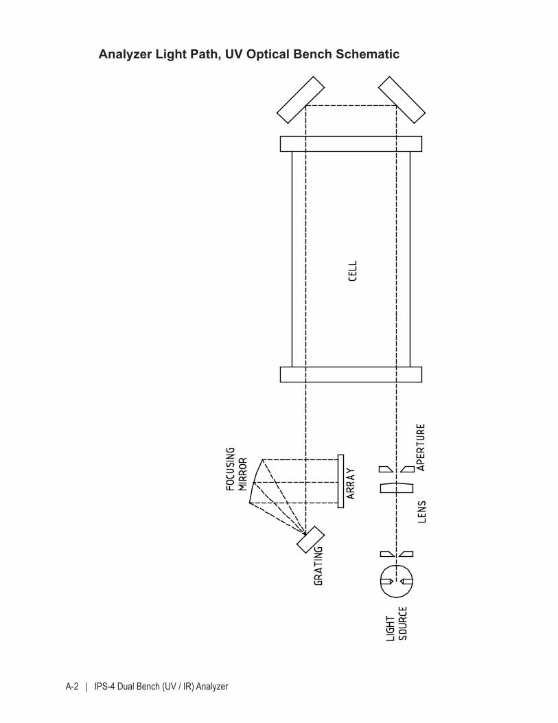
A-2 | IPS-4 Dual Bench (UV / IR) Analyzer
Analyzer Light Path, UV Optical Bench Schematic
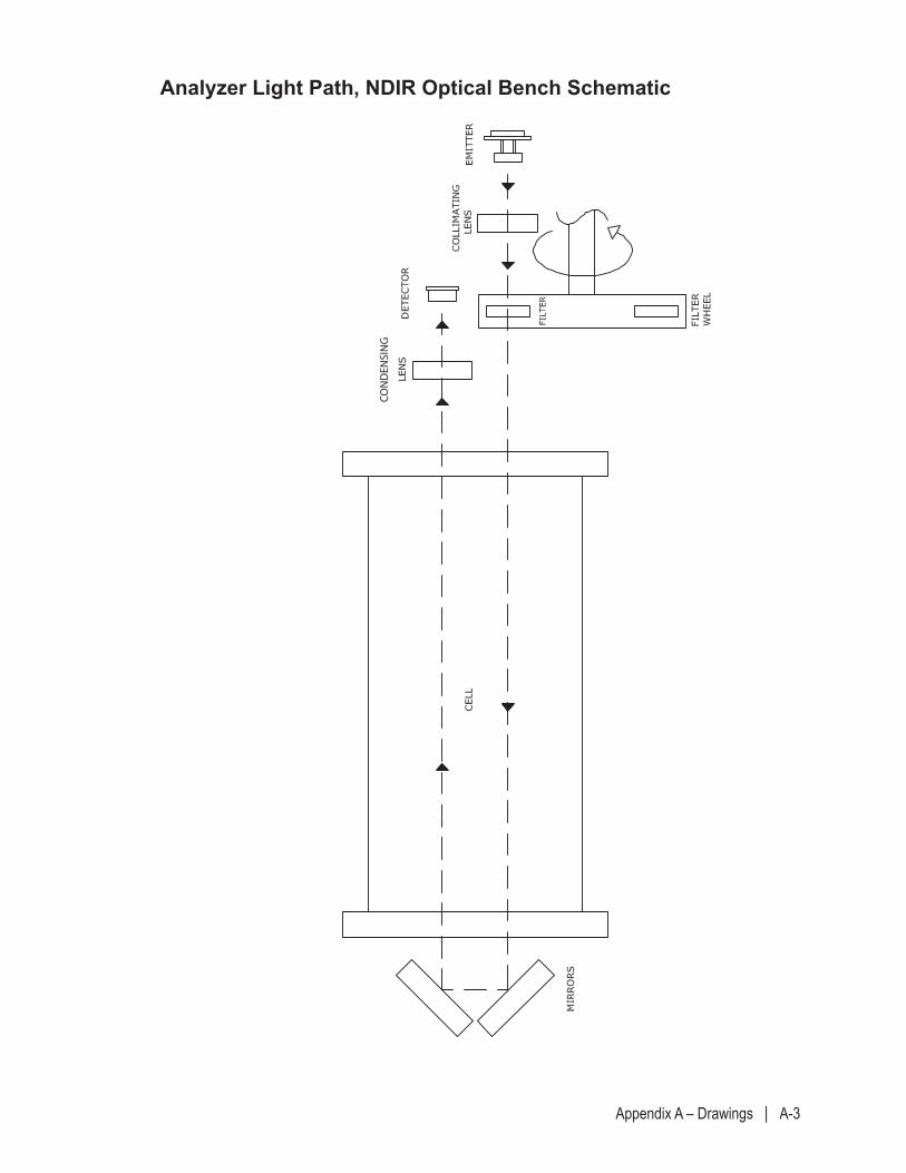
Appendix A – Drawings | A-3
Analyzer Light Path, NDIR Optical Bench Schematic
CONDENSING
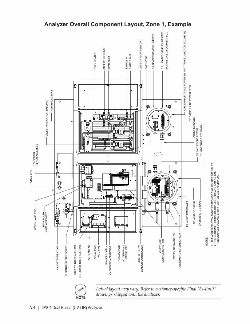
A-4 | IPS-4 Dual Bench (UV / IR) Analyzer
Analyzer Overall Component Layout, Zone 1, Example
MOD
CON
SYST
EMS/
SOCA
R HA
OR -
AZER
BAIJA
NMO
DEL I
PS-4
ANA
LYZE
R / F
IELD
UNI
T AR
RANG
EMEN
T BREV
.
WX-
1106
2-3-
3B
SAM
PLE
LIN
E D
ISC
ON
NEC
T BO
X
OVE
N H
EATE
R
SAM
PLE
OU
TSA
MPL
E IN
OVE
N E
NC
LOSU
RE
CEL
LS (A
PPLI
CAT
ION
SPE
CIF
IC)
BEN
CH
ASS
EMBL
Y
PUR
GE
UN
IT
XEN
ON
LAM
P PW
B
XEN
ON
FLA
SHLA
MP
ASSE
MBL
Y
ELEC
TRO
NIC
EN
CLO
SUR
E
DC
TER
MIN
AL A
SSEM
BLY
CU
STO
MER
CO
NN
ECTI
ON
S PW
B
POW
ER S
UPP
LY
DET
ECTO
R IN
TER
FAC
E PW
B
DIS
PLAY
INTE
RFA
CE
PWB
MC
U P
WB
REL
AY P
WB
ANAL
OG
PW
B
AC T
ERM
INAL
/M
AIN
FU
SES
PRES
SUR
E SW
ITC
HES
A1, I
NST
RU
MEN
T AI
R
C4,
HEA
TED
SAM
PLE
LIN
E R
TD
C5,
HEA
TED
SAM
PLE
LIN
E R
TD2
C3B
, SAM
PLE
TRAC
E PO
WER
TO
HEA
T TR
ACE
JUN
CTI
ON
BO
X (H
TJB)
P2, S
AMPL
E LI
NE
POW
ER F
EED
OVE
N V
ENT
UV
OPT
ICAL
CU
STO
MER
DIS
CO
NN
ECT
BOX
ARM
OR
ED C
ABLE
C7,
DIS
CR
ETE
SIG
NAL
C6,
AN
ALO
G S
IGN
AL
C2,
HAG
PR
OBE
RTD
SIN
GAL
C1,
HAG
PR
OBE
PO
WER
P1, A
NAL
YZER
PO
WER
A2, P
LAN
T N
2
ASPI
RAT
OR
DR
IVE
NO
TES:
1.
THE
ANAL
YZER
OVE
N A
ND
ELE
CTR
ON
ICS
ENC
LOSU
RES
AR
E 30
4 SS
.2.
TH
E C
UST
OM
ER S
IGN
AL D
ISC
ON
NEC
T BO
X AN
D S
AMPL
E LI
NE
D
ISC
ON
NEC
T BO
X AR
E EP
OXY
PAI
NTE
D C
AST
ALU
MIN
UM
.
SPAN
INLE
T
LOSS
OF
FLO
WSE
NSO
R C
ON
TRO
LLER
LOSS
OF
FLO
W S
ENSO
R
FV7
FV2
FV1
FV3
FV8
2019
/11/
07
Actual layout may vary. Refer to customer-specific Final “As-Built” drawings shipped with the analyzer.
NOTE
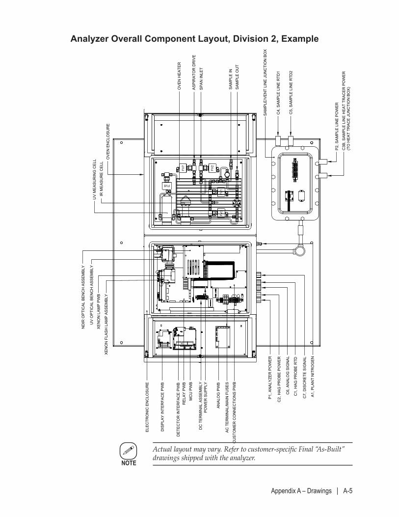
Appendix A – Drawings | A-5
Analyzer Overall Component Layout, Division 2, Example
OXY
USA
INC
. - P
EC S
EMIN
OLE
GAS
PLA
NT
MODE
L IPS
-4 AN
ALYZ
ER / F
IELD
UNIT
ARRA
NGEM
ENT (
SRU1
)
DREV
.
WX-
1108
1-1-
3B
SAM
PLE/
VEN
T LI
NE
JUN
CTI
ON
BO
X
XEN
ON
LAM
P PW
B
XEN
ON
FLA
SH L
AMP
ASSE
MBL
Y
ELEC
TRO
NIC
EN
CLO
SUR
E
DC
TER
MIN
AL A
SSEM
BLY
CU
STO
MER
CO
NN
ECTI
ON
S PW
B
POW
ER S
UPP
LY
DET
ECTO
R IN
TER
FAC
E PW
B
DIS
PLAY
INTE
RFA
CE
PWB
MC
U P
WB
REL
AY P
WB
ANAL
OG
PW
B
AC T
ERM
INAL
/MAI
N F
USE
S
C4,
SAM
PLE
LIN
E R
TD1
C5,
SAM
PLE
LIN
E R
TD2
C3B
, SAM
PLE
LIN
E H
EAT
TRAC
ER P
OW
ER(T
O H
EAT
TRAC
E JU
NC
TIO
N B
OX)
P2, S
AMPL
E LI
NE
POW
ER
ND
IR O
PTIC
AL B
ENC
H A
SSEM
BLY
UV
OPT
ICAL
BEN
CH
ASS
EMBL
Y
C7,
DIS
CR
ETE
SIG
NAL
C6,
AN
ALO
G S
IGN
AL
P1, A
NAL
YZER
PO
WER
C2,
HAG
PR
OBE
PO
WER
C1,
HAG
PR
OBE
RTD
A1, P
LAN
T N
ITR
OG
EN
FV7
FV2
FV1
FV3
FV8
OVE
N H
EATE
R
SAM
PLE
OU
TSA
MPL
E IN
ASPI
RAT
OR
DR
IVE
SPAN
INLE
T
OVE
N E
NC
LOSU
RE
UV
MEA
SUR
ING
CEL
L
IR M
EASU
RE
CEL
L
2019
/11/
28
Actual layout may vary. Refer to customer-specific Final “As-Built” drawings shipped with the analyzer.
NOTE
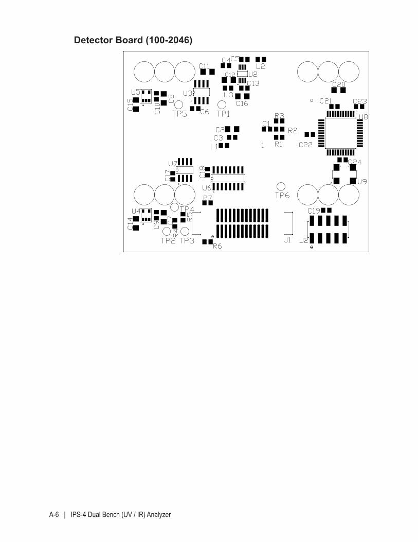
A-6 | IPS-4 Dual Bench (UV / IR) Analyzer
Detector Board (100-2046)
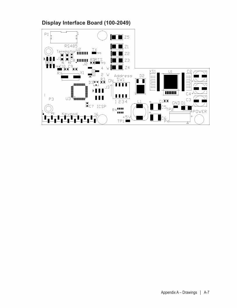
Appendix A – Drawings | A-7
Display Interface Board (100-2049)
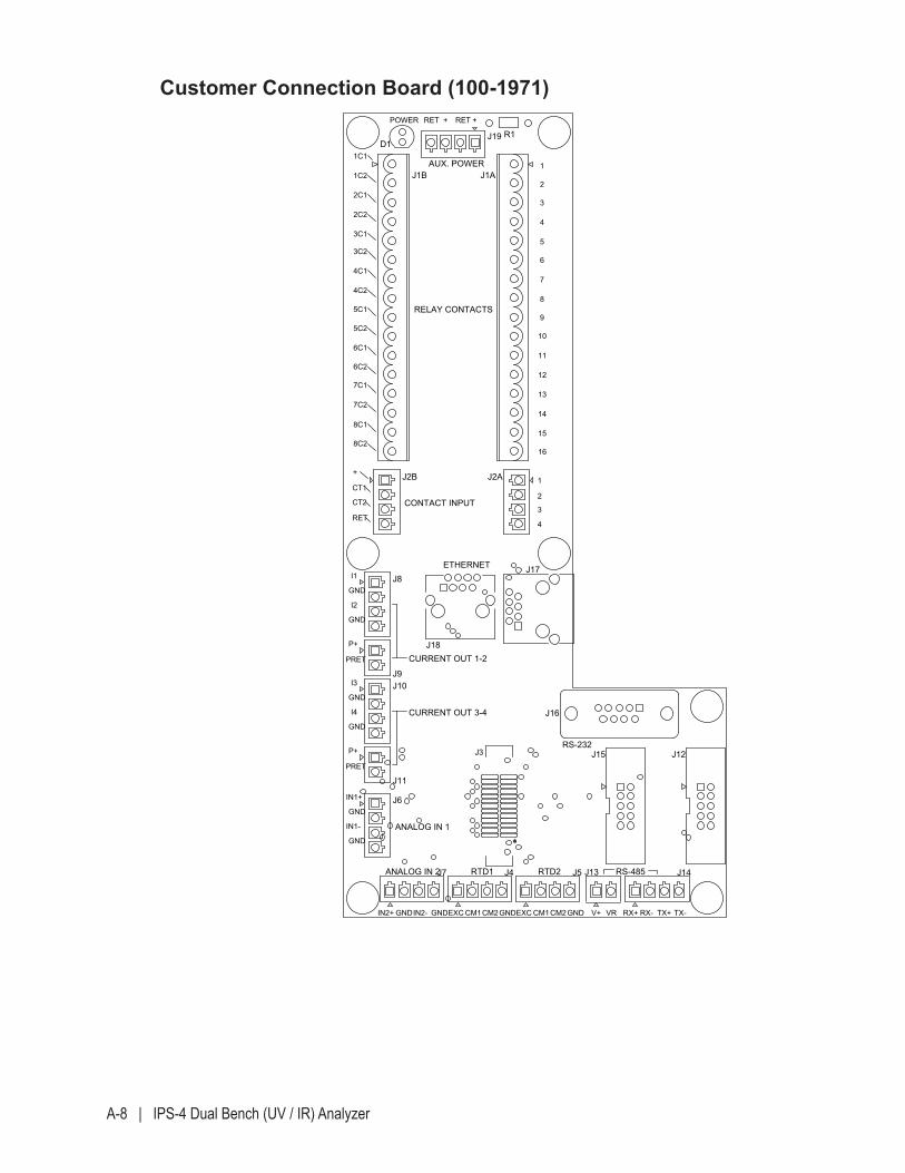
A-8 | IPS-4 Dual Bench (UV / IR) Analyzer
Customer Connection Board (100-1971)
PCA, C
USTO
MER
CO
NN
ECTIO
N
100-1971G REV.
IPS-4, RoH
S CO
MPLIAN
T
R1D1
J2B J2A
J9
J8
J11
J4 J13
J19
J18
J16
J5 J14J7
J6
J10
J3 J15 J12
J1B J1A
J17
1C1
2C1
2C2
3C2
4C1
5C1
5C2
6C2
7C1
7C2
8C1
8C2
CT11
CT2
RET3
I1
GND
I2
GND
PRET
I3
I4
P+
PRET
IN1+
GND
IN1-
GND
IN2+ GND CM1 GNDEXC CM2 V+ VR RX- TX-
1
2
4
5
7
8
10
12
13
15
16
ETHERNET
RS-232
IN2-GND EXC CM1CM2 GND TX+RX+
AUX. POWER
RELAY CONTACTS
CONTACT INPUT
CURRENT OUT 1-2
CURRENT OUT 3-4
ANALOG IN 1
1C2
+ +
3C1
4C2
6C1
+
2
4
P+
GND
GND
RETPOWER
3
RET
6
9
11
14
ANALOG IN 2 RTD1 RTD2 RS-485
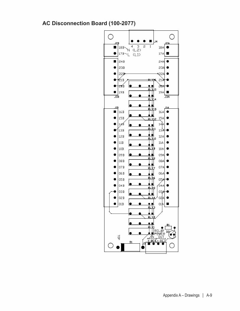
Appendix A – Drawings | A-9
AC Disconnection Board (100-2077)
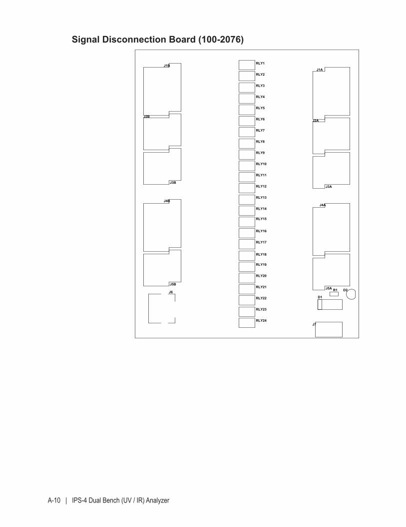
A-10 | IPS-4 Dual Bench (UV / IR) Analyzer
Signal Disconnection Board (100-2076)
RLY11
RLY12
RLY24
J3B
J5B
J6 D2
RLY1
RLY2
RLY4
RLY5
RLY6
RLY7
RLY10
RLY9
J3A
RLY13
RLY14
RLY15
RLY17
RLY18
RLY19
RLY20
RLY22
RLY23
D1
R1
J4B
RLY3
RLY16
RLY21
RLY8
J2A
J4A
J5A
J7
J1B
J2B
J1A
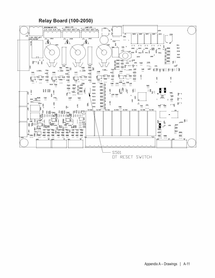
Appendix A – Drawings | A-11
Relay Board (100-2050)
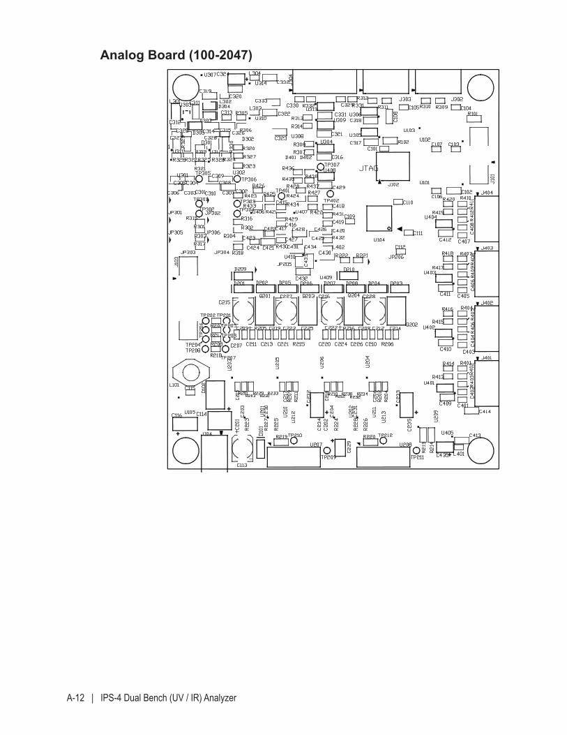
A-12 | IPS-4 Dual Bench (UV / IR) Analyzer
Analog Board (100-2047)
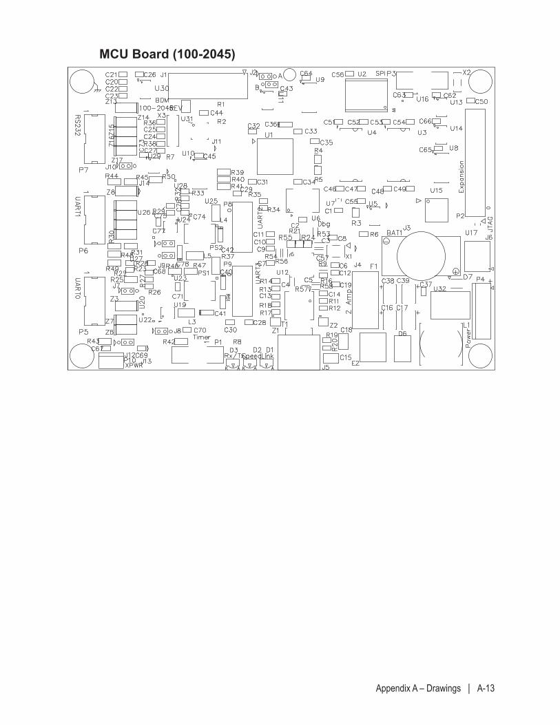
Appendix A – Drawings | A-13
MCU Board (100-2045)
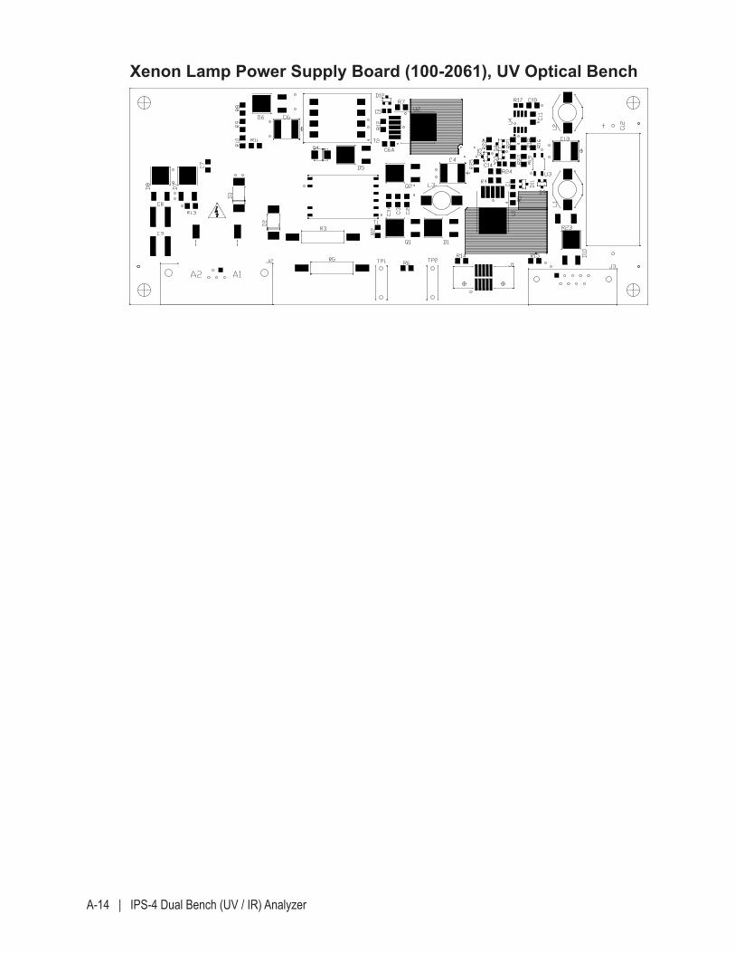
A-14 | IPS-4 Dual Bench (UV / IR) Analyzer
Xenon Lamp Power Supply Board (100-2061), UV Optical Bench
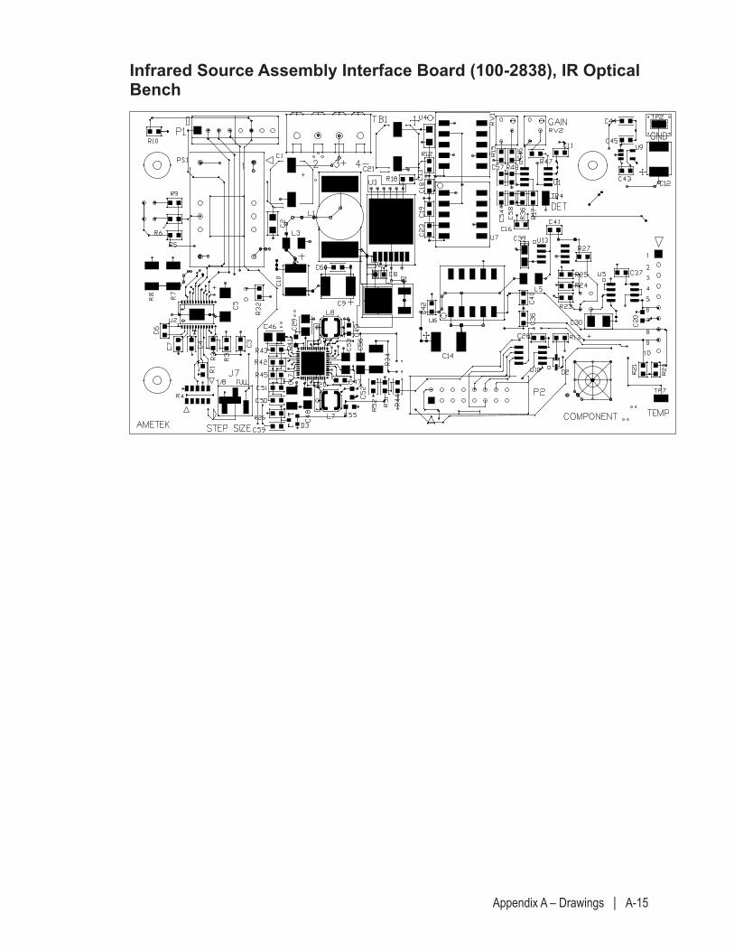
Appendix A – Drawings | A-15
Infrared Source Assembly Interface Board (100-2838), IR Optical Bench
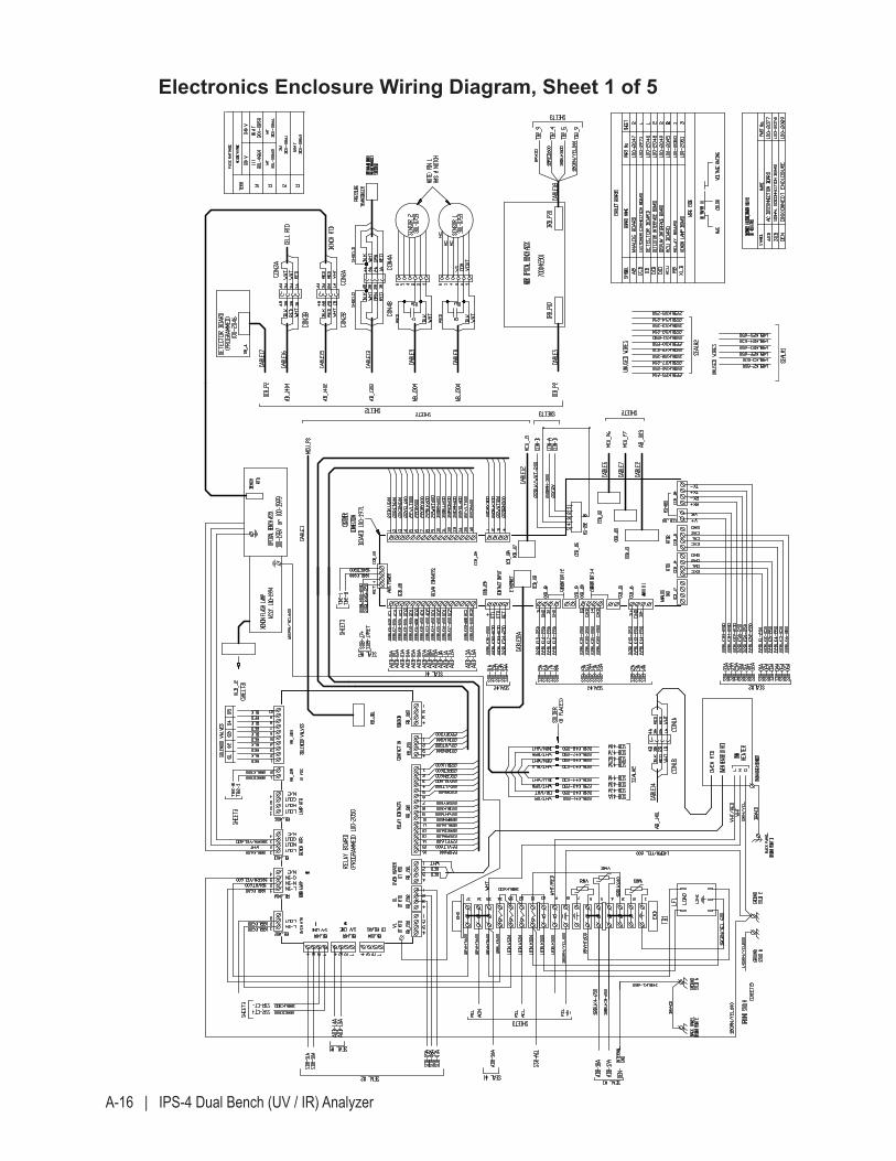
A-16 | IPS-4 Dual Bench (UV / IR) Analyzer
Electronics Enclosure Wiring Diagram, Sheet 1 of 5
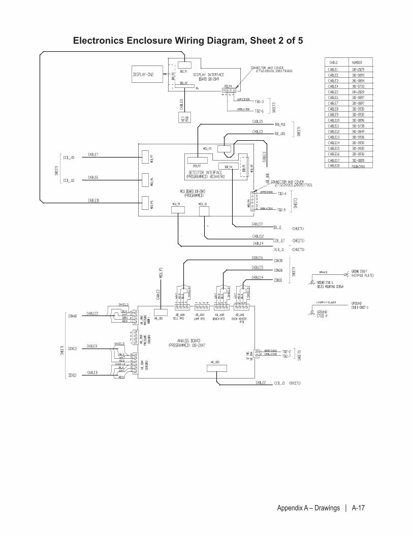
Appendix A – Drawings | A-17
Electronics Enclosure Wiring Diagram, Sheet 2 of 5
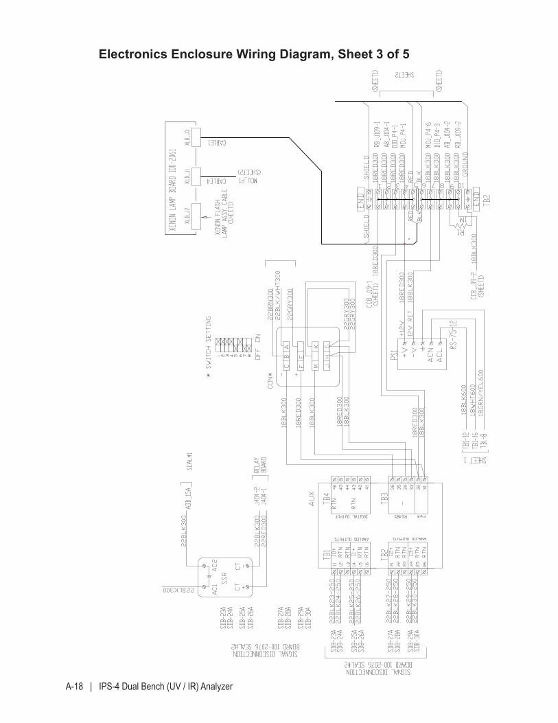
A-18 | IPS-4 Dual Bench (UV / IR) Analyzer
Electronics Enclosure Wiring Diagram, Sheet 3 of 5
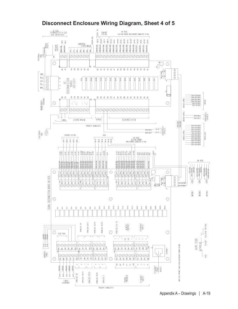
Appendix A – Drawings | A-19
Disconnect Enclosure Wiring Diagram, Sheet 4 of 5
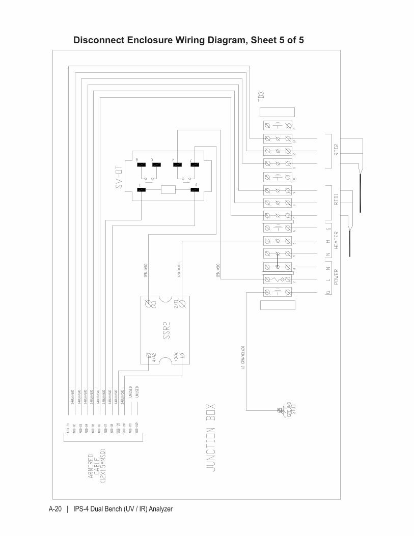
A-20 | IPS-4 Dual Bench (UV / IR) Analyzer
Disconnect Enclosure Wiring Diagram, Sheet 5 of 5
Supplemental Information | S-1
SUPPLEMENTAL INFORMATION
This section consists of information and documents that are not part of the main manual, but which describe and illustrate installation, operation, layout, and maintenance procedures for non-standard or optional equipment – and derivative analyzer models – that make up your analyzer and its sample system. “Supplemental Information – Where Can I Find It?” in Chapter 1 describes the documents listed below.
This section can include:
• Manual Supplements
• Analyzer Configuration Parameters sheet
• Signed Final QC (Quality Control) Document
• Optical Bench Calibration Summary Report (Pixel to Wavelength) Sheet
• Final As-Built drawings.
• Other customer-specific information may also be included (if applicable), such as Product Data Sheets, a Custom Spare Parts list, or analyzer Certificates.

S-2 | IPS-4 Dual Bench (UV / IR) Analyzer
This page intentionally left blank.
Related Documents