Page 1/44 IOM BiRotor b60_90 Installation & Operation Manual BiRotor Meters B060, B070, B080, & B090

Welcome message from author
This document is posted to help you gain knowledge. Please leave a comment to let me know what you think about it! Share it to your friends and learn new things together.
Transcript
Page 1/44IOM BiRotor b60_90
Installation & Operation Manual
BiRotor MetersB060, B070, B080, & B090

Page 2/44IOM BiRotor b60_90
Page 3/44IOM BiRotor b60_90
Table of Contents
Read Me First . . . . . . . . . . . . . . . . . . . . . . . . . . . . . . . . . . . . . . . . . . . . 4Essential Instructions . . . . . . . . . . . . . . . . . . . . . . . . . . . . . . . . . . . . . . . 5Receipt of Shipment . . . . . . . . . . . . . . . . . . . . . . . . . . . . . . . . . . . . . . . . 9Storage . . . . . . . . . . . . . . . . . . . . . . . . . . . . . . . . . . . . . . . . . . . . . . . 9Return of Shipment . . . . . . . . . . . . . . . . . . . . . . . . . . . . . . . . . . . . . . . . 9Introduction . . . . . . . . . . . . . . . . . . . . . . . . . . . . . . . . . . . . . . . . . . . . 10Specifi cations. . . . . . . . . . . . . . . . . . . . . . . . . . . . . . . . . . . . . . . . . . . 10Installation . . . . . . . . . . . . . . . . . . . . . . . . . . . . . . . . . . . . . . . . . . . . . 11Operation . . . . . . . . . . . . . . . . . . . . . . . . . . . . . . . . . . . . . . . . . . . . . .12Maintenance . . . . . . . . . . . . . . . . . . . . . . . . . . . . . . . . . . . . . . . . . . . .13Parts List . . . . . . . . . . . . . . . . . . . . . . . . . . . . . . . . . . . . . . . . . . . . . 18Troubleshooting . . . . . . . . . . . . . . . . . . . . . . . . . . . . . . . . . . . . . . . . . 37Warranty Claim Procedures . . . . . . . . . . . . . . . . . . . . . . . . . . . . . . . . . . . 43
Page 4/44IOM BiRotor b60_90
Read Me First
Notice
Brodie International, a Brodie Meter Co., LLC Company (“Brodie”) shall not be liable for technical or editorial errors in this manual or omissions from this manual. Brodie makes no warranties, express or implied, including the implied warranties of merchantability and fi tness for a particular purpose with respect to this manual and, in no event, shall Brodie be liable for any special or consequential damages including, but not limited to, loss of production, loss of profi ts, etc.
Product names used herein are for manufacturer or supplier identifi cation only and may be trademarks/registered trademarks of these companies.
The contents of this publication are presented for informational purposes only, and while every effort has been made to ensure their accuracy, they are not to be construed as warranties or guarantees, expressed or implied, regarding the products or services described herein or their use or applicability. We reserve the right to modify or improve the designs or specifi cations of such products at any time.
Brodie does not assume responsibility for the selection, use or maintenance of any product. Responsibility for proper selection, use and maintenance of any Brodie product remains solely with the purchaser and end-user.
Brodie InternationalStatesboro, Georgia, USA
All rights reserved. No part of this work may be reproduced or copied in any form or by any means - graphic, electronic or mechanical - without fi rst receiving the written permission of Brodie International, Statesboro, Georgia, USA.

Page 5/44IOM BiRotor b60_90
Essential Instructions
General
Brodie Meter Co., LLC designs, manufactures and tests its products to meet many international standards. As the instruments are sophisticated technical products they must be installed, used and maintained properly to ensure they continue to operate within their normal specifi cations. The following instructions must be adhered to and incorporated into onsite safety programs where possible.
Read all instructions prior to installing, operating or servicing the product. If the instruction manual is not the correct one telephone +1 912 489 0200. Retain the instruction manual for future reference.
If you do not understand any of the instructions, contact your local Brodie representative for clarifi cation.
Follow all warnings, cautions and instructions marked on or supplied with the product. It is the end users responsibility to operate the instrument with in the specifi cations as defi ned with in the instruction manual or marked on the instruments name plates.
Install the equipment as specifi ed in the installation instructions of the appropriate manual and in accordance to local and national codes.
To ensure proper performance, use qualifi ed personnel to install, operate, program and maintain the product.
Some types of equipment contain Carbon Steel, Cast Iron and/or Aluminium wetted parts, these instruments are not for use on water service.
It is the end users responsibility to assess the surface temperature of the device when it is in service, and if required take the necessary precautions to avoid personnel injury or damage to other equipment.
When replacement parts are required, ensure that qualifi ed people use replacement parts specifi ed by the manufacturer. Unauthorised parts and procedures can affect the products performance and place the safe operation of the process at risk. Look alike substitution may result in explosion, fi re, electrical hazards, improper operation or personnel injury.
Use of this equipment for any other purpose than it is intended for may result in property damage and/or serious personal injury or death.
Page 6/44IOM BiRotor b60_90
Although measurement transducers are not specifi cally included in the MID regulations as they do not form a complete measuring (system) instrument ref Article 1 and 4, Annex I and Annex MI-005. Brodie Meter Co., LLC implements the same stringent regulations for all products and tests to the same standards which are used for complete (systems) instruments.
The complete system must contain all the necessary components to meet the requirements of the local regulations. These components may include, pumps, air eliminators, strainers, valves, fl ow computers, etc.
The unit must be sealed in accordance with the local regulations; it is the end users responsibility to ensure this happens.
Flow measuring devices are provided with two labels which specify fl ow ranges. The name plate label which includes the factory serial number; details the operating fl ow range, this is the fl ow range the device will operate within without causing damage, and the custody transfer label; this label details the working fl ow range associated with a particular weights and measures approval.
It should be noted that these may not be the same; therefore in trade applications the fl ow ranges specifi ed on the custody transfer label should be followed.
Essential Instructions for Measuring Equipment Including the European Union (Directive 2004/22/EC MID)
Essential Instructions for Electrical Equipment Including the European Union (Directive 2004/108/EC and 2004/22/EC)
This unit contains Electrostatic sensitive circuit boards. Electrostatic safety precautions should be taken to prevent damage.
When connecting wiring it is good practice to use shielded cable. The shield should be connected to earth at the read out or control systems end of the cable; the other end of the shield should not be connected.
This wiring practice is mandatory in order to comply with the requirements for electromagnetic compatibility as per the EMC directive 2004/108/EC and MID 2004/22/EC of the council of the European Union.
It is the end users responsibility to ensure that all protective covers are in place to prevent electrical shock and/or personnel injury.

Page 7/44IOM BiRotor b60_90
Essential Instructions for Pressure Containing Equipment, Including the European Union (Directive 97/23/EC)
When installing the equipment the bolting must conform to the requirements of ASME B16.5 paragraph 5.3 and to the material requirements of ASME B16.5 Table 1B. Gaskets must conform to the requirements of ASME B16.20.
Although it is not expected for the device to be used in a service where it would come in to contact with unstable fl uids, it is the end users responsibility to assess any risks and take any precautions necessary.
It is the end users responsibility to ensure that piping and other attachments connected to the Brodie instrument do not place adverse stresses upon it, the design of the instrument has not been assessed for the effects of traffi c, wind or earthquake loadings.
It is the end users responsibility to ensure that the instrument is mounted when required on suitable supporting foundations.
It is the end users responsibility to install the device in a well designed system to avoid potential hazards such as water hammer, vacuum collapse or uncontrolled chemical reactions.
It is the end users responsibility to provide fi re protection measures and equipment in accordance with the local regulations.
It is the end users responsibility to install suitable straining and air/gas elimination systems.
The instrument has been designed without allowance for corrosion or other chemical attack. The end user should implement a periodic inspection and maintenance program to ensure that none of the instruments pressure containing components has been subject to any corrosion. It is possible to examine the instrument for evidence of corrosion through the inlet and the outlet.
When the ambient temperature is below the minimum operating temperature specifi ed on the device, it is the end users responsibility to ensure that the devise is warmed to an appropriated temperature before being pressurized.
Do not exceed the operating pressure and temperature limits of the instrument as stamped on the nameplates.
It is the customer’s responsibility to install this equipment in a system that provides adequate over pressure protection, and that limit pressure surges to 10% of the maximum allowable working pressure of the instrument.
It is the end users responsibility to provide fi re protection measures and equipment in accordance with the local regulations.
Page 8/44IOM BiRotor b60_90
Essential Instructions for Equipments To Be Used In Hazardous Locations, Including the European Union (Directive 94/9/EC)
Any Hazardous area approval applies to equipment without cable glands. When mounting the fl ameproof enclosure in a hazardous area only cable glands / conduit seals certifi ed to meet or exceed the rating of the equipment should be used, refer to the type approval documentation for further details. It is the end users responsibility to ensure this happens.
Cable glands and cable must be suitable for the operating temperature of the device under its rated conditions, this is especially important is the device has an operating temperature above 1580F (700C).
The meter has been provided with an approved sealing device in one of the cable entries, the other entry has been closed with a plastic cap plug. It is the end users responsibility to remove the cap plug and replace it with a suitable cable gland or conduit seal before the equipment is put into service.
It is the end users responsibility to ensure when the instrument is located in a hazardous area that all cable glands and conduit seals must be installed in accordance with the local codes and regulations.
It is the end users responsibility to ensure that before opening an electronic enclosure in a fl ammable atmosphere; all the electrical circuits must be interrupted.
If replacement of the screws which secure the sensor housing, the UMB cover of the electronic register and its cover are required, they must be replaced with either factory direct parts or M6-1 x 16 (6g) mm hex socket head screws of equal length. The screws must be made from stainless steel grade A1-70 or A2-70 and be torqued to a value of 55 in lbs upon installation, its is the end users responsibility to ensure this happens.
It is the end users responsibility to assess the maximum surface temperature of the device and the equipment the device is attached to and located next to as this may exceed the temperature ratings of the device itself. If this happens, additional safety precautions will need to be i mplemented by the end user.
Flame proof housings contain Aluminium; although the composition of these enclosures is carefully maintained to prevent any risk of an ignition source it is the end users responsibility to ensure that the housing is not struck by rusty tools or objects.
If the equipment is to be installed in an area where dust deposits and build up are to be expected, a maintenance plan should be arranged to include regular removal of the dust build up. This will prevent the dusts forming a possible source of ignition.
The power supply requirements for this product are specifi ed with in the operating and maintenance manual, it is the end users responsibility to operate the product with in these specifi ed limits.
The instrument contains surfaces that constitute fl ames paths, these surfaces should not contain any mars or scratches, if any are present the factory or the local representative should be contacted immediately to obtain a new housing as the safety of the enclosure may be impaired. It is the end users responsibility to inspect these surfaces every time the enclosure is opened.
When fl anged fl ame paths are reassembled the gap between them should be less than 0.0015” (0.038 mm) such that a +/- ” (12.5mm) wide feeler 0.0015” (0.038mm) gauge will not enter the gap more than 1/8” (3mm). It is the end users responsibility to ensure this happens each time the enclosure is reassembled.

Page 9/44IOM BiRotor b60_90
Receipt of ShipmentWhen the instrument is received, inspect the outside of the packing case for any damage that may have occurred during shipment. If the packing case is damaged notify the carrier immediately and follow their claim procedures. Any damage incurred during shipment is the carrier’s responsibility and is not part of the factory warranty.
If the packaging is undamaged locate the envelope containing the packing list, this will generally be on the outside of the box. Carefully remove all the contents from the packaging checking for any damage. Make certain spare or replacement parts are not discarded with the packing material.
Check the items against the packing list for correct parts and quantities. If any items are incorrect or damage please contact your sales representative immediately, quoting the sales order reference number.
Return of ShipmentTo be able to process returned goods quickly and effi ciently, it is IMPORTANT that you provide essential information. Do not return any assembly or part without an “R.M.A.” (Return Material Authorization). A letter describing the problem; corrective action (if any); and the work to be performed at the factory should be included with the shipment. “R.M.A.” forms can be obtained from the local Sales Agent or Brodie International.
If an instrument has been exposed to process fl uid, in addition to the RMA, a decontamination statement will be required.
A decontamination form is included in the back of this manual. Note: When an instrument is removed from service it must be thoroughly drained and hazardous substances neutralized. Any material removed from the meter must be disposed of in accordance with local regulations.
Placing the instrument upright on the inlet fl ange will aid drainage. Process connections must be sealed to prevent leakage of residual product during shipment. Contact the local carrier for information on requirements.
Any item must be securely packed and larger instruments mounted on wooden pallets or skids for shipment. The exterior of pallet mounted items should be protected by a suitable means such as a wooden crate.
Place a copy of the RMA inside the shipping container and attach it physically to the material being returned. A copy of your packing list should be placed inside an envelope and attached to the outside of the shipping container or placed inside the container.
Failure to follow the above procedures could possibly result in a considerable delay due to improperly or totally unidentifi ed items.
StorageBrodie International instruments are precision devices and should be handled and stored with care. The inlet and outlet covers should remain on the instrument until the unit is ready for installation.
If extended storage is required it is recommend thatthe instrument be placed in an environmentally controlled warehouse, if it is not possible, the instrument should be stored in a water proof lined wooden box, desiccant packs should be taped to the inside of the instrument end connections before they are sealed to reduce the effect of humidity, depending on the storage time it may also be preferable to use a compatible corrosion inhibitor.
Care should be taken to remove any storage protection items before installing the instrument.
If an instrument is removed from service for an extended period of time it should be fl ushed with an appropriate corrosion inhibitor before being place in long term storage as mentioned above. Ship the container to:
Brodie Meter Co., LLCProduct Service Department19267 Hwy. 301 NorthStatesboro, GA 30461Phone: 912-489-0200Fax: [email protected]
Page 10/44IOM BiRotor b60_90
Introduction
6.1 General
The Brodie BiRotor Meter is a precision made,accurate fl ow measurement device which utilizesthe positive displacement principle of operation.It is designed to measure crude and refi nedpetroleum products as well as many industrialliquids.
The standard meter consists of a measuring unitinstalled in an outer housing or case, an adjustorfor calibration and selected registration equipment.As product enters the intake of the measurementelement, two fi nely timed rotors divide the liquidinto precise segments of known volume andreturn those segments to the fl owing stream.During this transition, the rotation of the tworotors is directly proportional to volumetricthroughput. The rotors are always dynamicallybalanced, but hydraulically unbalanced, andhave no metal-to-metal contact with one anotheror the measuring unit housing. Volume indicationis determined by either mechanical outputgearing leading to registration devices, or by anelectrical output signal to remote registrationequipment.
The accuracy adjustor, located on the outputshaft of the counter drive gearing of themechanical meter, permits the operator to adjustoutput registration to read in exact units ofvolume. It allows for adjustments up to +/-3% ofmeter throughput in determining accuratemeasurement. The meter may be supplied withany of several accessory items including two stageelectric valves, preset counters, highfrequency pulse generators, impulse contactors,etc. These units provide various functions forlocal and/or remote control and readout.
Specifi cations
7.1 Materials of Construction
Housing: Welded Steel construction combining castings and drawn steel plates.
Measuring Unit Rotors: Heat Treated Aluminum (Standard) 6” Series 90 and 92 uses Cast Iron 3-Tooth Rotor Rotor Shafts: E.T.D.150 Rotor Bearings: Stainless Steel Body and End Covers: Cast Iron
Counter Base Plate (Not used on P-Series) Body: Steel O-Rings: VitonTM (Standard) Counter Base Drive Gears: Stainless Steel Drive Shafts: Stainless Steel Drive Shaft Ball Bearings: Stainless Steel Optional: All Ferrous Materials of Construction
NOTE: Before placing the meter into service reference the appropriate instruction manuals for all accessories. This includes hook-up, electrical wiring, and specifi cation requirements and restrictions.

Page 11/44IOM BiRotor b60_90
Installation8.1 General
The following is a general outline for the proper storage, shipment, installation, and start up of any Brodie BiRotor meter. Additional information on the proper use of Positive Displacement Meters can be obtained from API Standard 1101 -Measurement of Petroleum Liquid Hydrocarbons by Positive Displacement Meter.
8.2 Installation
WARNINGCompounds used in the making of elastomer gaskets, O-Rings and seals will, by nature, deteriorate over an extended period of time. This is dependent on elastomer material, frequency of operation and the product being measured. Extreme caution should be used when measuring volatile liquids or when using a meter that has been stored for an extended period of time. Loss of seal integrity can result in leakage, damage to the equipment and/or personal injury.
1. The BiRotor meter should be mounted on a secure foundation. Considerations for placement of a right angle adaptor and meter weight must be made when vertical installation is required.
2. Care should be taken to insure that the drain plug remains accessible. A valve may be installed on the drain line to facilitate draining of water and sediment from the meter. A lockable valve is recommended to reduce the chance of accidentally draining the meter. Any product drained from the meter, either manually or through a centralized drain system, must be disposed of in accordance with all local, state, and federal laws.
3. Skid foundations and process piping must be properly secured in order to minimize line vibration at the meter.
4. Process piping should not place strain on the meter.
5. Provisions should be made to insure that thermal explansion does not raise line pressure above the maximum pressure rating of the meter.
6. All process piping should be clean and free of debris to insure foreign material does not enter the meter.
7. A fl ow limiting valve should be installed downstream of the meter to maintain adequate back pressure and to protect the meter from excessive fl ow rates.
8. If require, an air eliminator should be installed upstream of the meter.
9. Do not allow water to remain in the meter. If water has entered the meter remove the inner unit and clean it with a light lubricating oil.
10. Standard fl ow through the meter is from left to right. If right to left fl ow is required, consult your local Brodie agent or an authorized repair center.
11. The bolt pattern on the meter accessories allows the meter accessory stack to be rotated in 90 degree increments. The required position should be selected prior to installing electrical service to the meter. Care should be taken not to damage the capillary tube on the temperature compensator if so equipped.
12. Isolation valves should be installed on both ends of the meter run to minimize product loss when removing any of the components from the line.
Page 12/44IOM BiRotor b60_90
The following recommendations should be considered when the meter is fi rst put into operation or any time that the meter has been drained.
1. If large volumes of debris are expected in the process piping during start up it is recommended that the measuring element be removed from the meter until the lines are free of pipe scale, weld beads and other types of foreign material. A spool piece may be used as a temporary replacement for the meter. The strainer basket should be removed to eliminate the possibility of rupturing.
2. Slowly introduce product into the meter. Open the upstream valve while the downstream valve remains closed.
3. Slowly bleed air from the system through the high point vent.
4. Once all air has been eliminated, slowly open the down-stream valve. Allow the meter to run at approximately 20 percent of the maximum rated fl ow for two minutes. Observe the rotation of the counter wheels to insure the meter is operating smoothly. Continue opening the downstream valve until it is fully open. Care should be taken to insure the maximum fl ow rate of the meter is not exceeded. Confi rm that the setting on the fl ow control valve is properly fi xed and is in control of the system.
9.1 Operation
CAUTIONDo not operate this meter in excess of the valuesstated in Specifi cations.
Brodie Meter Co., LLC has highly qualifi ed service techni-cians who are available to provide start up assistance. Con-tact Brodie or your local Brodie Authorized Repair Center if service assistance is required.
5. Do not close valves quickly. This can cause a pressure spike which can damage the meter.
6. Do not make adjustments to the meter or its accessories while the meter is turning. When adjuster settings are changed, a small batch should be run through the meter prior to making the next proving run. This allows the adjuster components to shift to the new setting.
7. Prove the meter in order to establish a meter factor under actual operating conditions. Proving records and other pertinent meter data should be retained in order to establish a performance history for the meter.
Operation
Page 13/44IOM BiRotor b60_90
Maintenance
WARNINGExtreme care must be exercised when the measuring chamber is exposed and handled. Hands must be kept clear of the timing gears, rotors and measuring chamber or serious personal injury can occur. Due to the precision balance of the rotors and timing gears, they can be set in motion easily. Keep hands clear of these parts at all times! At no time should hands be used to brace these.
10.1 General
The amount of maintenance necessary for effi cient meter performance depends upon such factors as:
1. Continuity of Operation - A meter which operates almost continuously, obviously will require more attention than one on intermittent duty.
2. Rate of Flow - The practical life of any piece of equipment is proportional to its speed of operation. A meter operating at, or close to, its maximum rating will naturally have a shorter life than one operating at a reduced rate.
3. Lubricating Value of Product - Other factors being equal, a meter handling a light lubricating oil will have a longer life than one measuring a dry motor fuel.
4. Cleanliness of Product - Abrasive solid matter accelerates meter wear.
Meters that are given a little attention regularly will deliver better performance and have a longer life than those that are not given any attention until they have failed. Frequently, a meter’s performance will depend, to a considerable extent, upon the proper functioning of the accessory equipment in the piping system. Following are listed some of the conditions and factors infl uencing meter performance:
1. A meter should be kept fi lled with the liquid it is measuring. Draining results in the formation of deposits and gums which increase the mechanical friction. Any leaky shut-off valves or check valves which would permit the meter to drain should be repaired or replaced.
2. A petroleum meter should be kept free of water. Usually, regular inspection and draining of storage tanks are suffi cient protection.
3. Clean the strainer basket frequently.
4. Soft closing loading valves or shock chambers for eliminating water hammer should be kept in good working order.
5. The valves and operating mechanism of an air eliminator should be inspected on a routine basis. Thisis especially true where a critical air condition exists. For this reason meter performance is dependent on proper air elimination. Factors leading to diffi cult valve and air eliminator operating conditions include: gum formationscaused by alternate wetting and drying, formation of corrosive vapors, and presence of salt air.
6. The counter of the meter should be given some protection during extreme weather conditions.
7. A meter taken out of service for any length of time should be fi lled with light lubricating oil.
8. Keep Brodie manuals available for reference.
Page 14/44IOM BiRotor b60_90
10.2 General Meter Disassembly
CAUTIONBefore performing any disassembly or reassemblyprocedures, all fl ow to meter should be off. All electrical connections to accessories should be disconnected. Service should be performed by trained and qualifi ed personnel only.
Cleanliness is of prime importance when working on a precision instrument. The work area should be clean and the meter parts thoroughly washed. All gaskets and O-rings should be removed and replaced. This policy will assure maximum performance from your Brodie BiRotor Meter at less expense and with greater accuracy.
WARNINGVerify that all pipeline/process fl uid has been removed from the meter. Failure to release pressure prior to servicing meter may result in personal injury and/or damage to meter.
10.3 Removing Measuring Unit
1. Remove drain plug and completely drain meter and replace plug.
2. Remove the Accuracy Adjustor and Counter Base Plate Assembly.
3. Remove Hex Nuts and Housing Cover from the Meter Housing.
4. Disconnect the Measuring Unit from the Meter Housing by fi rst removing the Screws, Washers and Seal Washers from the unit.
5. Carefully lift the Measuring Unit away from the meter body and place on a clean dry surface.
6. The measuring unit may now be inspected. In some cases, a thorough washing in a cleaning solvent or kerosene will be suffi cient to free the rotors of corrosion or foreign material and the unit may be reinstalled without further disassembly. In the event the rotors are blocked with solid matter, it will be necessary to remove the rotors and gear box assembly for further cleaning.
10.4 Disassembly of Measuring Units
WARNINGExtreme care must be exercised when the measuring chamber is exposed and handled. Hands must be kept clear of the timing gears, rotors and measuring chamber or serious personal injury can occur. Due to the precision balance of the rotors and timing gears, they can be set in motion easily. Keep hands clear of these parts at all times! At no time should hands be used to brace these
1. Position the Measuring Unit with the Front End Plate facing out in such away as to afford easy access. This will vary according to the size of the meter being ser-viced. It is recommended that a cradle type structure be used for the disassembly of most models.
2. Remove the two front Bearing Retainer Caps.
3. Remove the Drive Gear Assembly, Retainer Ring and Key (if applicable) and Bearings from the 3-Tooth Rotor.
4. Remove the Screw, Washer, Bearing Key and Bearings from the 4-Tooth Rotor. DO NOT remove the Front End Plate at this time.
5. Rotate the Measuring Unit, remove Screws from the Rear End Cover and separate from the Measuring Unit Body.
6. The Rotors and Rear End Cover can now be washed thoroughly with solvent or kerosene and inspected. If the Rotors show no evidence of contact with each other, and if the Timing Gears appear satisfactory, further disassembly will not be required.
Page 15/44IOM BiRotor b60_90
10.5 Removing Timing Gears and Rotors
Severe scoring of the Rotors, or grit in the Bearings, maynecessitate removal of the Rotors from the Rear End Cover.
1. Remove Lock Nut Retainer and Washer.
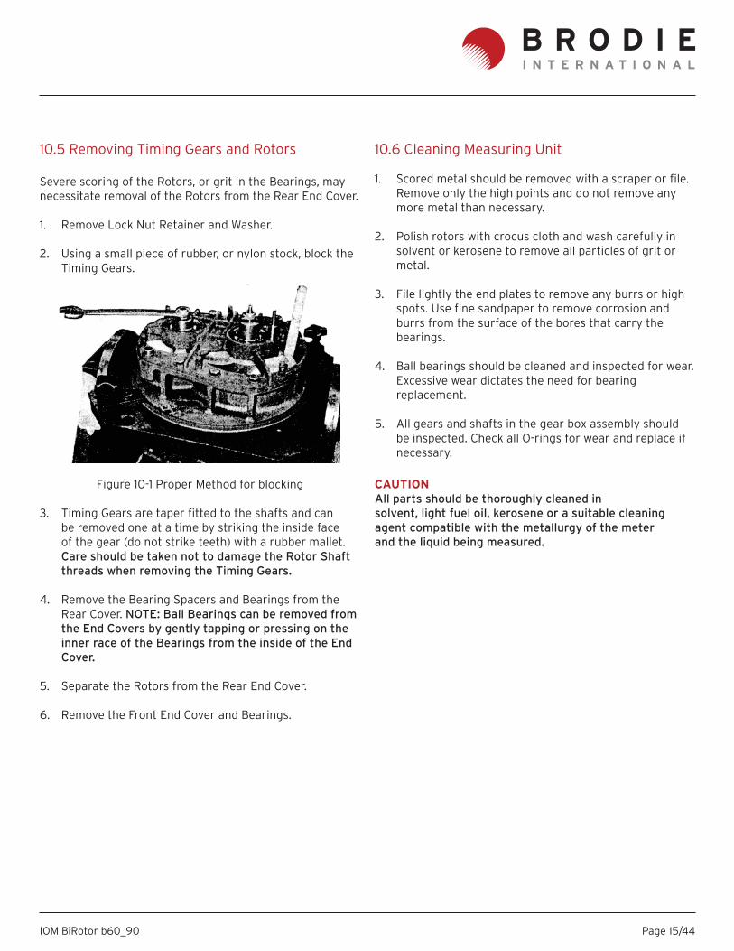
2. Using a small piece of rubber, or nylon stock, block the Timing Gears.
Figure 10-1 Proper Method for blocking
3. Timing Gears are taper fi tted to the shafts and can be removed one at a time by striking the inside face of the gear (do not strike teeth) with a rubber mallet.Care should be taken not to damage the Rotor Shaft threads when removing the Timing Gears.
4. Remove the Bearing Spacers and Bearings from the Rear Cover. NOTE: Ball Bearings can be removed from the End Covers by gently tapping or pressing on the inner race of the Bearings from the inside of the End Cover.
5. Separate the Rotors from the Rear End Cover.
6. Remove the Front End Cover and Bearings.
10.6 Cleaning Measuring Unit
1. Scored metal should be removed with a scraper or fi le. Remove only the high points and do not remove any more metal than necessary.
2. Polish rotors with crocus cloth and wash carefully in solvent or kerosene to remove all particles of grit or metal.
3. File lightly the end plates to remove any burrs or high spots. Use fi ne sandpaper to remove corrosion and burrs from the surface of the bores that carry the bearings.
4. Ball bearings should be cleaned and inspected for wear. Excessive wear dictates the need for bearing replacement.
5. All gears and shafts in the gear box assembly should be inspected. Check all O-rings for wear and replace if necessary.
CAUTIONAll parts should be thoroughly cleaned insolvent, light fuel oil, kerosene or a suitable cleaningagent compatible with the metallurgy of the meterand the liquid being measured.
Page 16/44IOM BiRotor b60_90
10.7 Reassembly of Measuring Unit
1. Lubricate all Bearings and O-Rings with a light weight oil.
2. Position the Measuring Unit Body and attach the Front End Plate by installing Screws.
3. Rotate the Measuring Unit Body and replace the Rotors in the proper slots with the tapered end of the Rotors upward.
4. Position and attach the Rear End Plate using the Screws previously removed.
5. Install the Bearings within the bearing bore of the Rear End Plate. NOTE: The slot on the outer race of the Ball Bearing must align with the Roll Pin in the bottom of the bearing bore.
6. Position a Bearing Retainer (B090) or Spacer over each Bearing and attach by installing Lock Washers and Screws.
7. Replace the Spacer Key (if applicable), Timing Gears, Lock Nut Retainer, Lock Washer and Screws. NOTE: The large Timing Gear fi ts on the 4-tooth Rotor. The short tab on the Spacer Key fi ts in the inner race of the Ball Bearings and the longer tab seats into the slot on the Timing Gear.
8. Replace Lock Washers and Lock Nuts. The tab on the Lock Washer must seat into the slot on the Timing Gear.
9. Rotate the body and install Bearings, Bearing Key, Snap Ring, Lock Washer and Screws onto the Front End Cover. NOTE: The tab on the Bearing Key must seat into the slot on the inner race of the Bearing.
Figure 10-2 Typical Rear End Plate/Bearing
10.8 Setting End Clearance
Note: End rotor clearance is not required on all models.Units requiring end rotor clearance can be identifi ed bythe presence of set screws on the face of Timing Gears.
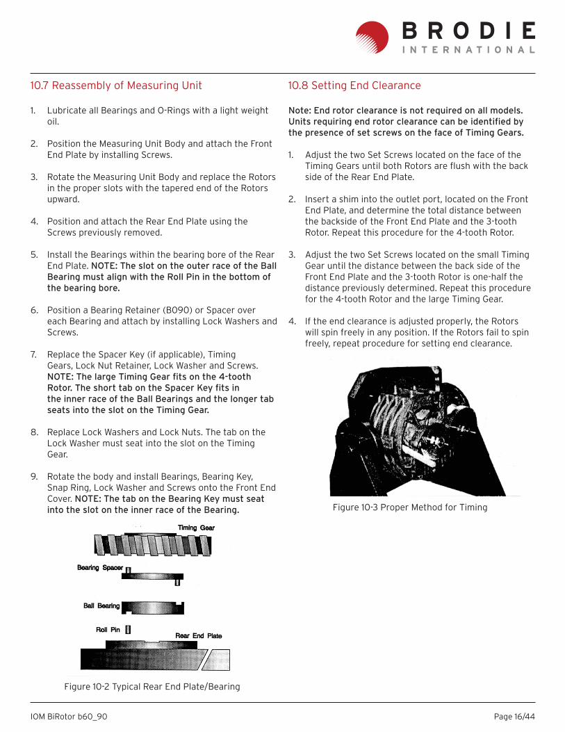
1. Adjust the two Set Screws located on the face of the Timing Gears until both Rotors are fl ush with the back side of the Rear End Plate.
2. Insert a shim into the outlet port, located on the Front End Plate, and determine the total distance between the backside of the Front End Plate and the 3-tooth Rotor. Repeat this procedure for the 4-tooth Rotor.
3. Adjust the two Set Screws located on the small Timing Gear until the distance between the back side of the Front End Plate and the 3-tooth Rotor is one-half the distance previously determined. Repeat this procedure for the 4-tooth Rotor and the large Timing Gear.
4. If the end clearance is adjusted properly, the Rotors will spin freely in any position. If the Rotors fail to spin freely, repeat procedure for setting end clearance.
Figure 10-3 Proper Method for Timing
Page 17/44IOM BiRotor b60_90
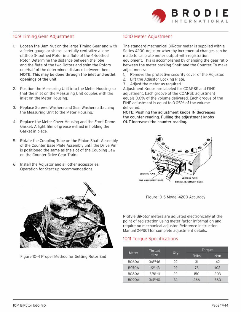
10.9 Timing Gear Adjustment
1. Loosen the Jam Nut on the large Timing Gear and with a feeler gauge or shims, carefully centralize a lobe of theb 3-toothed Rotor in a fl ute of the 4-toothed Rotor. Determine the distance between the lobe and the fl ute of the two Rotors and shim the Rotors one-half of the determined distance between them. NOTE: This may be done through the inlet and outlet openings of the unit.
2. Position the Measuring Unit into the Meter Housing so that the inlet on the Measuring Unit couples with the inlet on the Meter Housing.
3. Replace Screws, Washers and Seal Washers attaching the Measuring Unit to the Meter Housing.
4. Replace the Meter Cover Housing and the Front Dome Gasket. A light fi lm of grease will aid in holding the Gasket in place.
5. Rotate the Coupling Tube on the Pinion Shaft Assembly of the Counter Base Plate Assembly until the Drive Pin is positioned the same as the slot of the Coupling Jaw on the Counter Drive Gear Train.
6. Install the Adjustor and all other accessories. Operation for Start-up recommendations
Figure 10-4 Proper Method for Setting Rotor End
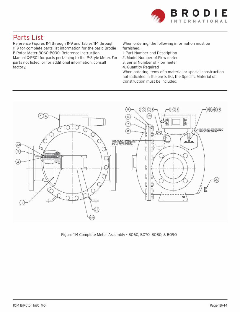
10.10 Meter Adjustment
The standard mechanical BiRotor meter is supplied with aSeries 4200 Adjustor whereby incremental changes can bemade to calibrate meter output with registration equipment. This is accomplished by changing the gear ratio between the meter packing Shaft and the Counter. To make adjustments:1. Remove the protective security cover of the Adjustor.2. Lift the Adjustor Locking Plate.3. Adjust the meter as required.Adjustment Knobs are labeled for COARSE and FINEadjustment. Each groove of the COARSE adjustmentequals 0.6% of the volume delivered. Each groove of theFINE adjustment is equal to 0.05% of the volumedelivered.NOTE: Pushing the adjustment knobs IN decreasesthe counter reading. Pulling the adjustment knobsOUT increases the counter reading.
P-Style BiRotor meters are adjusted electronically at thepoint of registration using meter factor information andrequire no mechanical adjustor. Reference InstructionManual X-PS01 for complete adjustment details.
Figure 10-5 Model 4200 Accuracy
10.11 Torque Specifi cations
Meter Thread Size Qty
Torque
ft-lbs N-m
B060A 3/8"-16 22 31 42
B070A 1/2"-13 22 75 102
B080A 5/8"-11 22 150 203
B090A 3/4"-10 32 266 360
Page 18/44IOM BiRotor b60_90
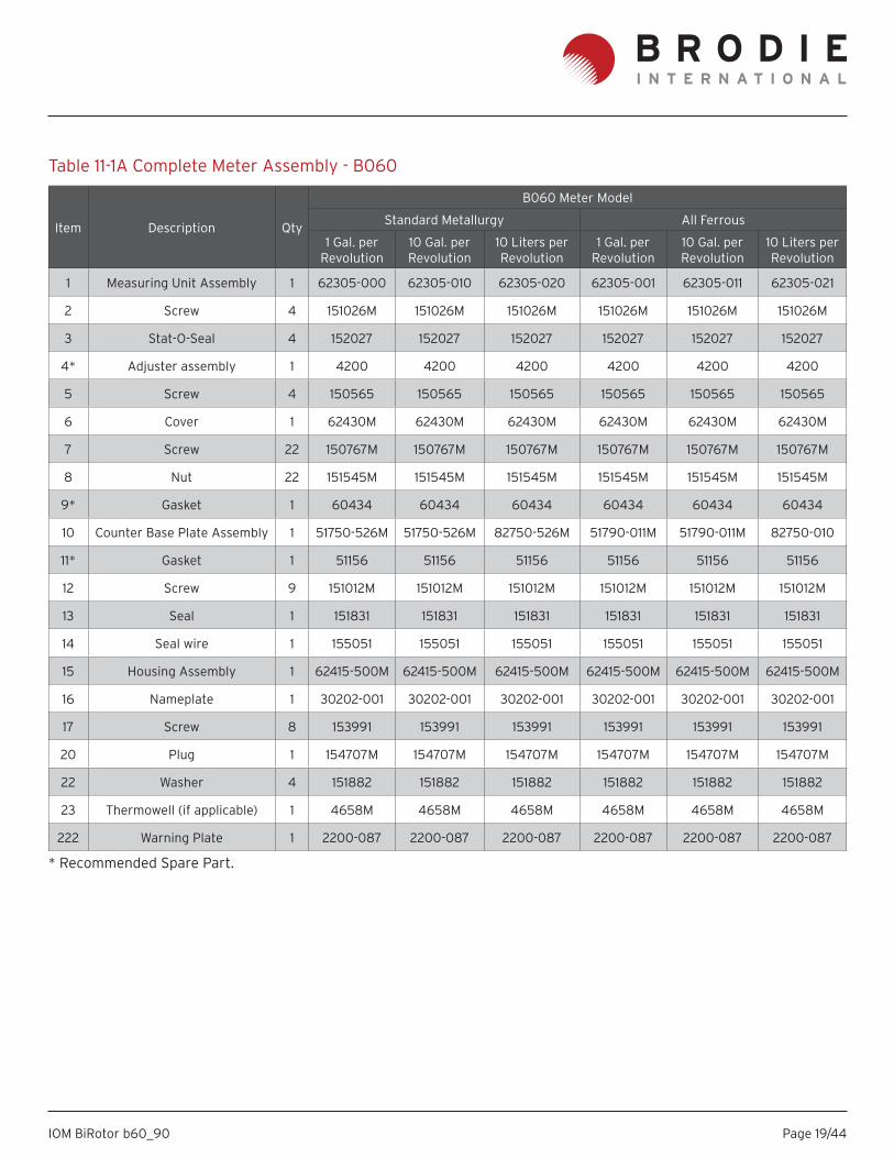
Parts ListReference Figures 11-1 through 11-9 and Tables 11-1 through11-9 for complete parts list information for the basic BrodieBiRotor Meter B060-B090. Reference InstructionManual X-PS01 for parts pertaining to the P-Style Meter. Forparts not listed, or for additional information, consult factory.
Figure 11-1 Complete Meter Assembly - B060, B070, B080, & B090
When ordering, the following information must be furnished.1. Part Number and Description2. Model Number of Flow meter3. Serial Number of Flow meter4. Quantity RequiredWhen ordering items of a material or special construction not indicated in the parts list, the Specifi c Material ofConstruction must be included.
Page 19/44IOM BiRotor b60_90
Item Description Qty
B060 Meter Model
Standard Metallurgy All Ferrous
1 Gal. per Revolution
10 Gal. per Revolution
10 Liters per Revolution
1 Gal. per Revolution
10 Gal. per Revolution
10 Liters per Revolution
1 Measuring Unit Assembly 1 62305-000 62305-010 62305-020 62305-001 62305-011 62305-021
2 Screw 4 151026M 151026M 151026M 151026M 151026M 151026M
3 Stat-O-Seal 4 152027 152027 152027 152027 152027 152027
4* Adjuster assembly 1 4200 4200 4200 4200 4200 4200
5 Screw 4 150565 150565 150565 150565 150565 150565
6 Cover 1 62430M 62430M 62430M 62430M 62430M 62430M
7 Screw 22 150767M 150767M 150767M 150767M 150767M 150767M
8 Nut 22 151545M 151545M 151545M 151545M 151545M 151545M
9* Gasket 1 60434 60434 60434 60434 60434 60434
10 Counter Base Plate Assembly 1 51750-526M 51750-526M 82750-526M 51790-011M 51790-011M 82750-010
11* Gasket 1 51156 51156 51156 51156 51156 51156
12 Screw 9 151012M 151012M 151012M 151012M 151012M 151012M
13 Seal 1 151831 151831 151831 151831 151831 151831
14 Seal wire 1 155051 155051 155051 155051 155051 155051
15 Housing Assembly 1 62415-500M 62415-500M 62415-500M 62415-500M 62415-500M 62415-500M
16 Nameplate 1 30202-001 30202-001 30202-001 30202-001 30202-001 30202-001
17 Screw 8 153991 153991 153991 153991 153991 153991
20 Plug 1 154707M 154707M 154707M 154707M 154707M 154707M
22 Washer 4 151882 151882 151882 151882 151882 151882
23 Thermowell (if applicable) 1 4658M 4658M 4658M 4658M 4658M 4658M
222 Warning Plate 1 2200-087 2200-087 2200-087 2200-087 2200-087 2200-087
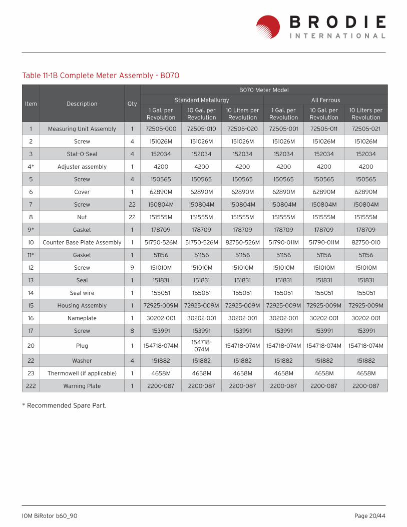
Table 11-1A Complete Meter Assembly - B060
* Recommended Spare Part.
Page 20/44IOM BiRotor b60_90
Item Description Qty
B070 Meter Model
Standard Metallurgy All Ferrous
1 Gal. per Revolution
10 Gal. per Revolution
10 Liters per Revolution
1 Gal. per Revolution
10 Gal. per Revolution
10 Liters per Revolution
1 Measuring Unit Assembly 1 72505-000 72505-010 72505-020 72505-001 72505-011 72505-021
2 Screw 4 151026M 151026M 151026M 151026M 151026M 151026M
3 Stat-O-Seal 4 152034 152034 152034 152034 152034 152034
4* Adjuster assembly 1 4200 4200 4200 4200 4200 4200
5 Screw 4 150565 150565 150565 150565 150565 150565
6 Cover 1 62890M 62890M 62890M 62890M 62890M 62890M
7 Screw 22 150804M 150804M 150804M 150804M 150804M 150804M
8 Nut 22 151555M 151555M 151555M 151555M 151555M 151555M
9* Gasket 1 178709 178709 178709 178709 178709 178709
10 Counter Base Plate Assembly 1 51750-526M 51750-526M 82750-526M 51790-011M 51790-011M 82750-010
11* Gasket 1 51156 51156 51156 51156 51156 51156
12 Screw 9 151010M 151010M 151010M 151010M 151010M 151010M
13 Seal 1 151831 151831 151831 151831 151831 151831
14 Seal wire 1 155051 155051 155051 155051 155051 155051
15 Housing Assembly 1 72925-009M 72925-009M 72925-009M 72925-009M 72925-009M 72925-009M
16 Nameplate 1 30202-001 30202-001 30202-001 30202-001 30202-001 30202-001
17 Screw 8 153991 153991 153991 153991 153991 153991
20 Plug 1 154718-074M 154718-074M 154718-074M 154718-074M 154718-074M 154718-074M
22 Washer 4 151882 151882 151882 151882 151882 151882
23 Thermowell (if applicable) 1 4658M 4658M 4658M 4658M 4658M 4658M
222 Warning Plate 1 2200-087 2200-087 2200-087 2200-087 2200-087 2200-087
Table 11-1B Complete Meter Assembly - B070
* Recommended Spare Part.
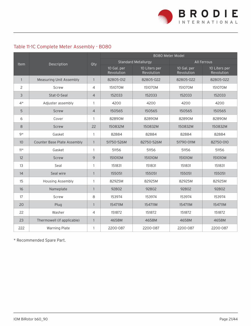
Page 21/44IOM BiRotor b60_90
Item Description Qty
B080 Meter Model
Standard Metallurgy All Ferrous
10 Gal. per Revolution
10 Liters per Revolution
10 Gal. per Revolution
10 Liters per Revolution
1 Measuring Unit Assembly 1 82805-012 82805-022 82805-022 82805-022
2 Screw 4 151070M 151070M 151070M 151070M
3 Stat-O-Seal 4 152033 152033 152033 152033
4* Adjuster assembly 1 4200 4200 4200 4200
5 Screw 4 150565 150565 150565 150565
6 Cover 1 82890M 82890M 82890M 82890M
8 Screw 22 150832M 150832M 150832M 150832M
9* Gasket 1 82884 82884 82884 82884
10 Counter Base Plate Assembly 1 51750-526M 82750-526M 51790-011M 82750-010
11* Gasket 1 51156 51156 51156 51156
12 Screw 9 151010M 151010M 151010M 151010M
13 Seal 1 151831 151831 151831 151831
14 Seal wire 1 155051 155051 155051 155051
15 Housing Assembly 1 82925M 82925M 82925M 82925M
16 Nameplate 1 92802 92802 92802 92802
17 Screw 8 153974 153974 153974 153974
20 Plug 1 154711M 154711M 154711M 154711M
22 Washer 4 151872 151872 151872 151872
23 Thermowell (if applicable) 1 4658M 4658M 4658M 4658M
222 Warning Plate 1 2200-087 2200-087 2200-087 2200-087
Table 11-1C Complete Meter Assembly - B080
* Recommended Spare Part.
Page 22/44IOM BiRotor b60_90
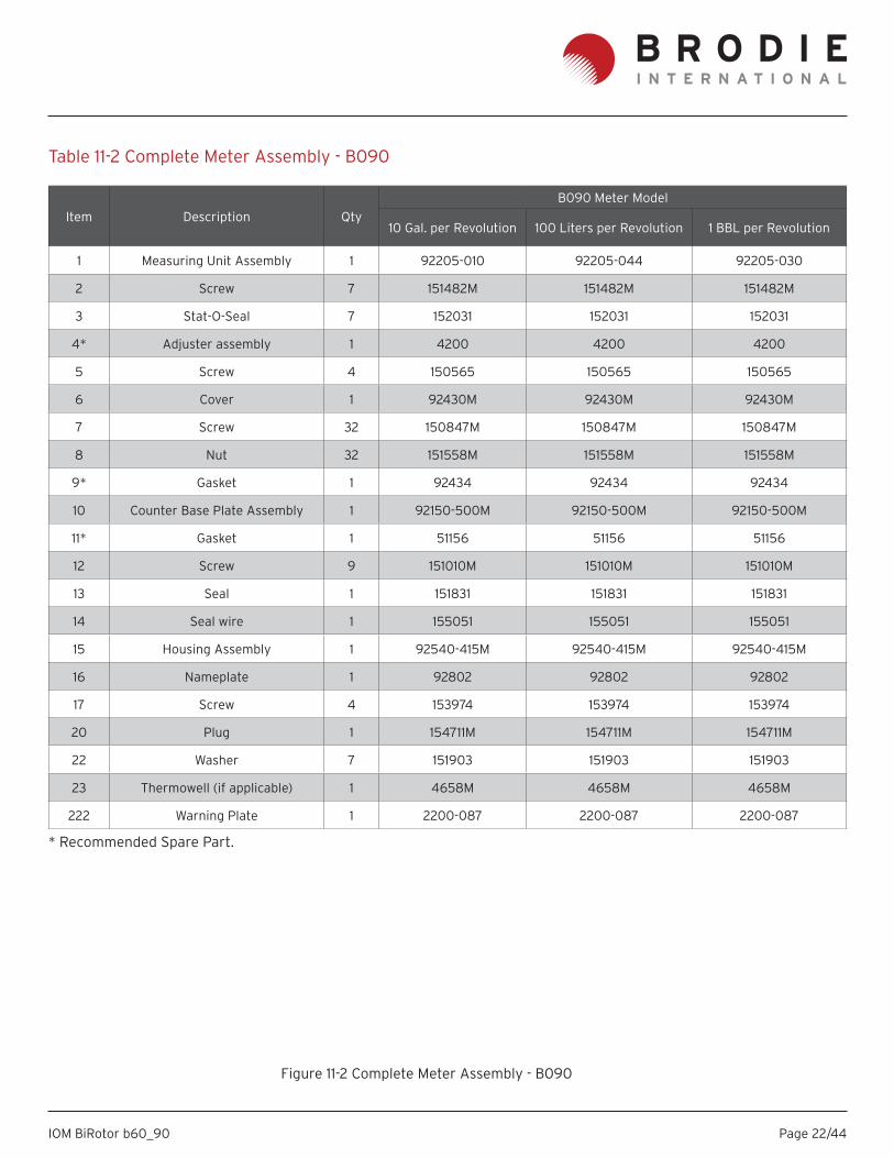
Figure 11-2 Complete Meter Assembly - B090
Table 11-2 Complete Meter Assembly - B090
* Recommended Spare Part.
Item Description QtyB090 Meter Model
10 Gal. per Revolution 100 Liters per Revolution 1 BBL per Revolution
1 Measuring Unit Assembly 1 92205-010 92205-044 92205-030
2 Screw 7 151482M 151482M 151482M
3 Stat-O-Seal 7 152031 152031 152031
4* Adjuster assembly 1 4200 4200 4200
5 Screw 4 150565 150565 150565
6 Cover 1 92430M 92430M 92430M
7 Screw 32 150847M 150847M 150847M
8 Nut 32 151558M 151558M 151558M
9* Gasket 1 92434 92434 92434
10 Counter Base Plate Assembly 1 92150-500M 92150-500M 92150-500M
11* Gasket 1 51156 51156 51156
12 Screw 9 151010M 151010M 151010M
13 Seal 1 151831 151831 151831
14 Seal wire 1 155051 155051 155051
15 Housing Assembly 1 92540-415M 92540-415M 92540-415M
16 Nameplate 1 92802 92802 92802
17 Screw 4 153974 153974 153974
20 Plug 1 154711M 154711M 154711M
22 Washer 7 151903 151903 151903
23 Thermowell (if applicable) 1 4658M 4658M 4658M
222 Warning Plate 1 2200-087 2200-087 2200-087
Page 23/44IOM BiRotor b60_90
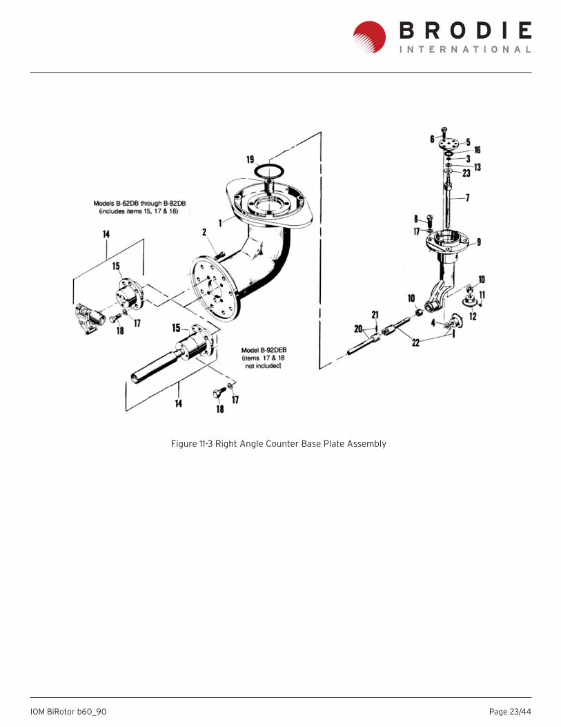
Figure 11-3 Right Angle Counter Base Plate Assembly
Page 24/44IOM BiRotor b60_90
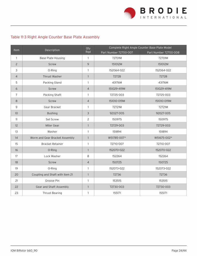
Table 11-3 Right Angle Counter Base Plate Assembly
Item DescriptionQtyRqd
Complete Right Angle Counter Base Plate Model
Part Number 72700-007 Part Number 72700-008
1 Base Plate Housing 1 72701M 72701M
2 Screw 9 151012M 151012M
3 O-Ring 1 152064-022 152064-022
4 Thrust Washer 1 72728 72728
5 Packing Gland 1 43176M 43176M
6 Screw 4 151029-419M 151029-419M
7 Packing Shaft 1 72725-003 72725-003
8 Screw 4 151010-019M 151010-019M
9 Gear Bracket 1 72721M 72721M
10 Bushing 3 92027-005 92027-005
11 Set Screw 2 150975 150975
12 Miter Gear 1 72729-003 72729-003
13 Washer 1 151894 151894
14 Worm and Gear Bracket Assembly 1 W51785-007* W51675-002*
15 Bracket Retainer 1 72710-007 72710-007
16 O-Ring 1 152070-022 152070-022
17 Lock Washer 8 152264 152264
18 Screw 4 150725 150725
19 O-Ring 1 152073-022 152073-022
20 Coupling and Shaft with item 21 1 72736 72736
21 Groove Pin 1 153515 153515
22 Gear and Shaft Assembly 1 72730-003 72730-003
23 Thrust Bearing 1 155171 155171
Page 25/44IOM BiRotor b60_90
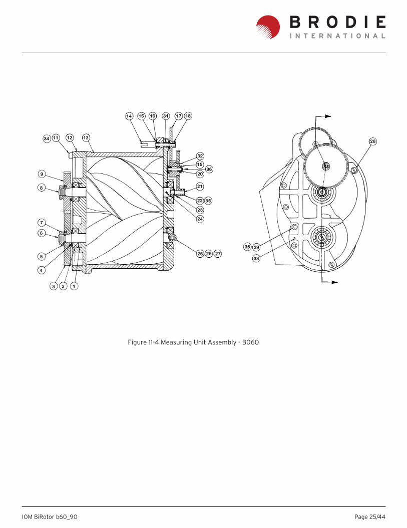
Figure 11-4 Measuring Unit Assembly - B060
Page 26/44IOM BiRotor b60_90
Item Description Qty
B060 Meter Model
Standard Metallurgy All Ferrous
1 Gal. per Revolution
10 Gal. per Revolution
10 Liters per Revolution
1 Gal. per Revolution
10 Gal. per Revolution
10 Liters per Revolution
Measuring Unit Assembly 62305-000 62305-010 62305-020 62305-001 62305-011 62305-021
1 PIN - Roll 4 153547 153547 153547 153547 153547 153547
2 BEARING BALL 4 *** *** *** *** *** ***
3 GEAR - DRIVE 4T ROTOR 1 *** *** *** *** *** ***
4 KEY - Bearing Spacing 2 60294 60294 60294 60294 60294 60294
5* LOCKWASHER 2 51593 51593 51593 51593 51593 51593
6 ROTOR 4T 1 ** ** ** ** ** **
7 LOCKNUT 2 60592 60592 60592 60592 60592 60592
8 ROTOR 3T 1 ** ** ** ** ** **
9 GEAR - DRIVE 3T ROTOR 1 *** *** *** *** *** ***
11 SCREW 8 151033M 151033M 151033M 151033M 151033M 151033M
12 REAR END PLATE 1 60266-015 60266-015 60266-015 60266-015 60266-015 60266-015
13 BODY - MEASURING UNIT 1 62212-000 62212-000 62212-000 62212-000 62212-000 62212-000
14 SHAFT, COUPLING JAW 1 72542 72542 72542 72542 72542 72542
15 WASHER 4 151907 151907 151907 151907 151907 151907
16 BEARING 3 155151 155151 155151 155151 155151 155151
17* DRIVE GEAR 1 62328 (50T) 62328 (50T) 62329 (53T) 62328 (50T) 62328 (50T) 62329 (53T)
18 SCREW - Set 2 151212 151212 151212 151212 151212 151212
20 RING - Retaining 1 156484 156484 156484 156484 156484 156484
21* SHAFT - STUB 1 51579 51579 51579 51579 51579 51579
22* DRIVE GEAR 1 60537 (55T) 60542 (14T) 60542 (14T) 60537 (55T) 60542 (14T) 60542 (14T)
23 RING - Retaining 1 153953 153953 153953 153953 153953 153953
24 GROOVE PIN 1 153636-019 153636-019 153636-019 153636-019 153636-019 153636-019
25 SCREW 1 150156 150156 150156 150156 150156 150156
26 WASHER 1 152270-019 152270-019 152270-019 152270-019 152270-019 152270-019
27 KEY - Bearing 2 60238 60238 60238 60238 60238 60238
28 SCREW - Dowel 4 51567 51567 51567 51567 51567 51567
29 SCREW 5 151010M 151010M 151010M 151010M 151010M 151010M
31 BEARING 1 155152 155152 155152 155152 155152 155152
32* COMPOUND GEAR ASSEMBLY 1 62330
(27T-24T)62335
(69T-24T)62335
(69T-24T)62330
(27T-24T)62335
(69T-24T)62335
(69T-24T)
33 FRONT END PLATE 1 60231-001 60231-001 60231-001 60231-001 60231-001 60231-001
34 WASHER 13 152113 152113 152113 152113 152113 152113
35 SCREW-SET 2 150975 150975 150975 150975 150975 150975
36 STUD - IDLER 1 60538-000 60538-000 60538-000 60538-000 60538-000 60538-000
37 GEAR COVER (NOT SHOWN) 1 616101 616101 616101 616101 616101 616101
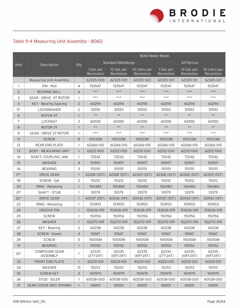
Table 11-4 Measuring Unit Assembly - B060
Page 27/44IOM BiRotor b60_90
* Recommended Spare Part.** Items 4 and 5 are supplied as a set. *** Timing gears are sold in matched sets and are included in the following service kits: W60591-026 (Viton F o-rings)W60591-016 (FluoroSilicon o-rings)W60591-120 (Low Swell Nitrile o-rings)W60591-023 (Low Temp Viton 1289) Service kits include timing gears, bearings and o-rings/gaskets.
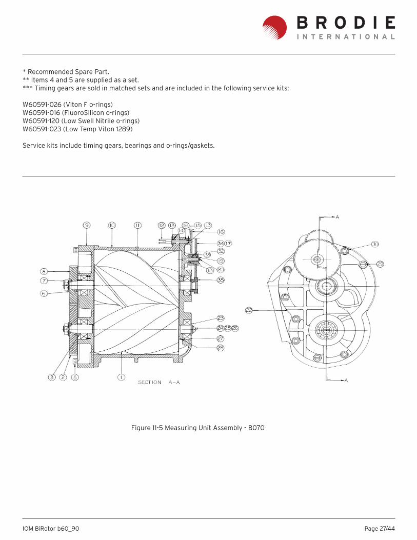
Figure 11-5 Measuring Unit Assembly - B070
Page 28/44IOM BiRotor b60_90
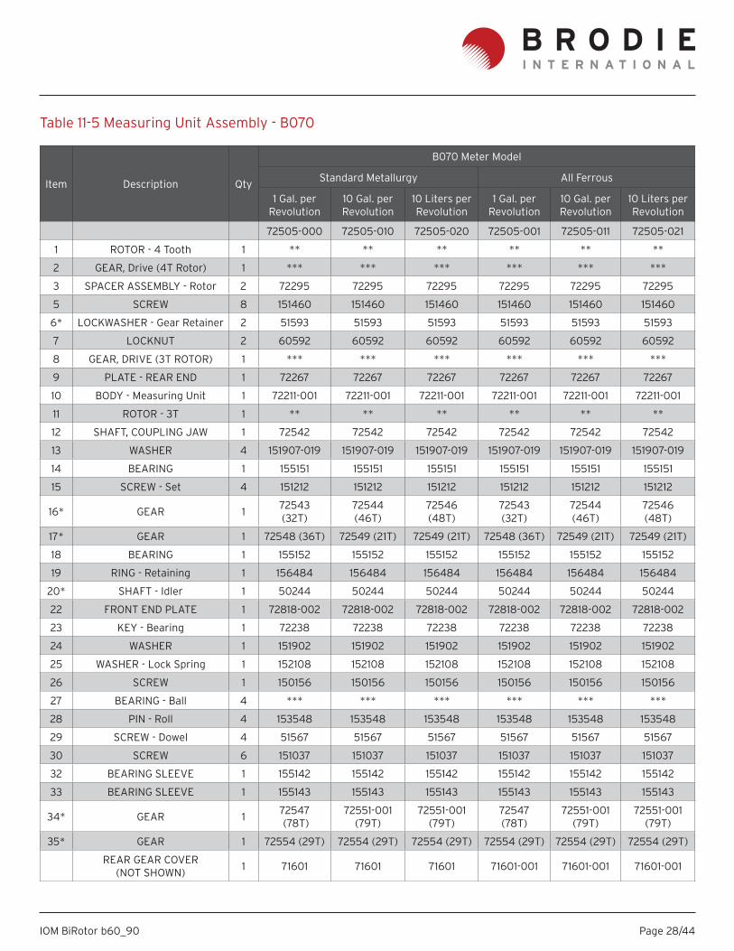
Table 11-5 Measuring Unit Assembly - B070
Item Description Qty
B070 Meter Model
Standard Metallurgy All Ferrous
1 Gal. per Revolution
10 Gal. per Revolution
10 Liters per Revolution
1 Gal. per Revolution
10 Gal. per Revolution
10 Liters per Revolution
72505-000 72505-010 72505-020 72505-001 72505-011 72505-021
1 ROTOR - 4 Tooth 1 ** ** ** ** ** **
2 GEAR, Drive (4T Rotor) 1 *** *** *** *** *** ***
3 SPACER ASSEMBLY - Rotor 2 72295 72295 72295 72295 72295 72295
5 SCREW 8 151460 151460 151460 151460 151460 151460
6* LOCKWASHER - Gear Retainer 2 51593 51593 51593 51593 51593 51593
7 LOCKNUT 2 60592 60592 60592 60592 60592 60592
8 GEAR, DRIVE (3T ROTOR) 1 *** *** *** *** *** ***
9 PLATE - REAR END 1 72267 72267 72267 72267 72267 72267
10 BODY - Measuring Unit 1 72211-001 72211-001 72211-001 72211-001 72211-001 72211-001
11 ROTOR - 3T 1 ** ** ** ** ** **
12 SHAFT, COUPLING JAW 1 72542 72542 72542 72542 72542 72542
13 WASHER 4 151907-019 151907-019 151907-019 151907-019 151907-019 151907-019
14 BEARING 1 155151 155151 155151 155151 155151 155151
15 SCREW - Set 4 151212 151212 151212 151212 151212 151212
16* GEAR 1 72543 (32T)
72544 (46T)
72546 (48T)
72543 (32T)
72544 (46T)
72546 (48T)
17* GEAR 1 72548 (36T) 72549 (21T) 72549 (21T) 72548 (36T) 72549 (21T) 72549 (21T)
18 BEARING 1 155152 155152 155152 155152 155152 155152
19 RING - Retaining 1 156484 156484 156484 156484 156484 156484
20* SHAFT - Idler 1 50244 50244 50244 50244 50244 50244
22 FRONT END PLATE 1 72818-002 72818-002 72818-002 72818-002 72818-002 72818-002
23 KEY - Bearing 1 72238 72238 72238 72238 72238 72238
24 WASHER 1 151902 151902 151902 151902 151902 151902
25 WASHER - Lock Spring 1 152108 152108 152108 152108 152108 152108
26 SCREW 1 150156 150156 150156 150156 150156 150156
27 BEARING - Ball 4 *** *** *** *** *** ***
28 PIN - Roll 4 153548 153548 153548 153548 153548 153548
29 SCREW - Dowel 4 51567 51567 51567 51567 51567 51567
30 SCREW 6 151037 151037 151037 151037 151037 151037
32 BEARING SLEEVE 1 155142 155142 155142 155142 155142 155142
33 BEARING SLEEVE 1 155143 155143 155143 155143 155143 155143
34* GEAR 1 72547 (78T)
72551-001 (79T)
72551-001 (79T)
72547 (78T)
72551-001 (79T)
72551-001 (79T)
35* GEAR 1 72554 (29T) 72554 (29T) 72554 (29T) 72554 (29T) 72554 (29T) 72554 (29T)
REAR GEAR COVER (NOT SHOWN) 1 71601 71601 71601 71601-001 71601-001 71601-001
Page 29/44IOM BiRotor b60_90
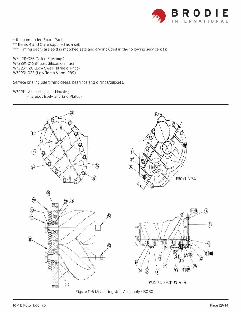
* Recommended Spare Part.** Items 4 and 5 are supplied as a set. *** Timing gears are sold in matched sets and are included in the following service kits: W72291-026 (Viton F o-rings)W72291-016 (FluoroSilicon o-rings)W72291-120 (Low Swell Nitrile o-rings)W72291-023 (Low Temp Viton 1289) Service kits include timing gears, bearings and o-rings/gaskets.
W72211 Measuring Unit Housing (includes Body and End Plates)
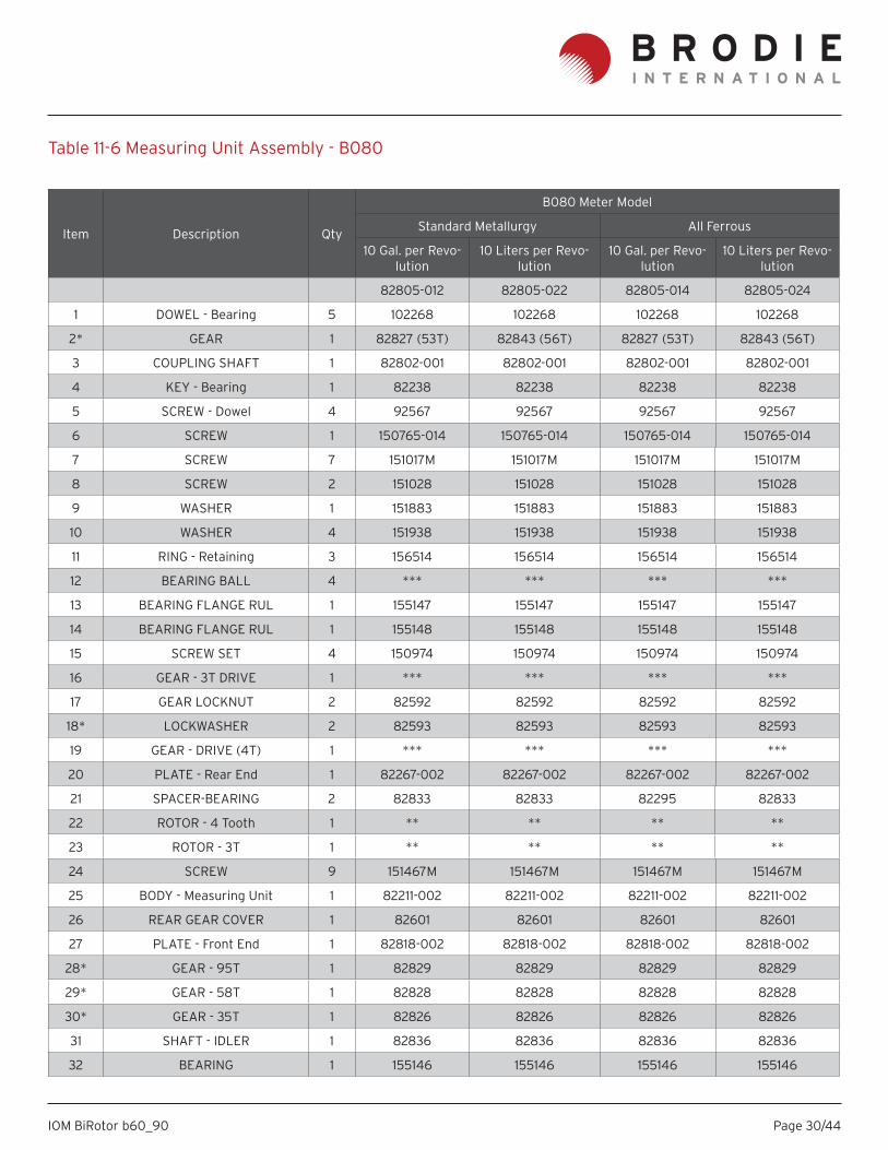
Figure 11-6 Measuring Unit Assembly - B080
Page 30/44IOM BiRotor b60_90
Item Description Qty
B080 Meter Model
Standard Metallurgy All Ferrous
10 Gal. per Revo-lution
10 Liters per Revo-lution
10 Gal. per Revo-lution
10 Liters per Revo-lution
82805-012 82805-022 82805-014 82805-024
1 DOWEL - Bearing 5 102268 102268 102268 102268
2* GEAR 1 82827 (53T) 82843 (56T) 82827 (53T) 82843 (56T)
3 COUPLING SHAFT 1 82802-001 82802-001 82802-001 82802-001
4 KEY - Bearing 1 82238 82238 82238 82238
5 SCREW - Dowel 4 92567 92567 92567 92567
6 SCREW 1 150765-014 150765-014 150765-014 150765-014
7 SCREW 7 151017M 151017M 151017M 151017M
8 SCREW 2 151028 151028 151028 151028
9 WASHER 1 151883 151883 151883 151883
10 WASHER 4 151938 151938 151938 151938
11 RING - Retaining 3 156514 156514 156514 156514
12 BEARING BALL 4 *** *** *** ***
13 BEARING FLANGE RUL 1 155147 155147 155147 155147
14 BEARING FLANGE RUL 1 155148 155148 155148 155148
15 SCREW SET 4 150974 150974 150974 150974
16 GEAR - 3T DRIVE 1 *** *** *** ***
17 GEAR LOCKNUT 2 82592 82592 82592 82592
18* LOCKWASHER 2 82593 82593 82593 82593
19 GEAR - DRIVE (4T) 1 *** *** *** ***
20 PLATE - Rear End 1 82267-002 82267-002 82267-002 82267-002
21 SPACER-BEARING 2 82833 82833 82295 82833
22 ROTOR - 4 Tooth 1 ** ** ** **
23 ROTOR - 3T 1 ** ** ** **
24 SCREW 9 151467M 151467M 151467M 151467M
25 BODY - Measuring Unit 1 82211-002 82211-002 82211-002 82211-002
26 REAR GEAR COVER 1 82601 82601 82601 82601
27 PLATE - Front End 1 82818-002 82818-002 82818-002 82818-002
28* GEAR - 95T 1 82829 82829 82829 82829
29* GEAR - 58T 1 82828 82828 82828 82828
30* GEAR - 35T 1 82826 82826 82826 82826
31 SHAFT - IDLER 1 82836 82836 82836 82836
32 BEARING 1 155146 155146 155146 155146
Table 11-6 Measuring Unit Assembly - B080
Page 31/44IOM BiRotor b60_90
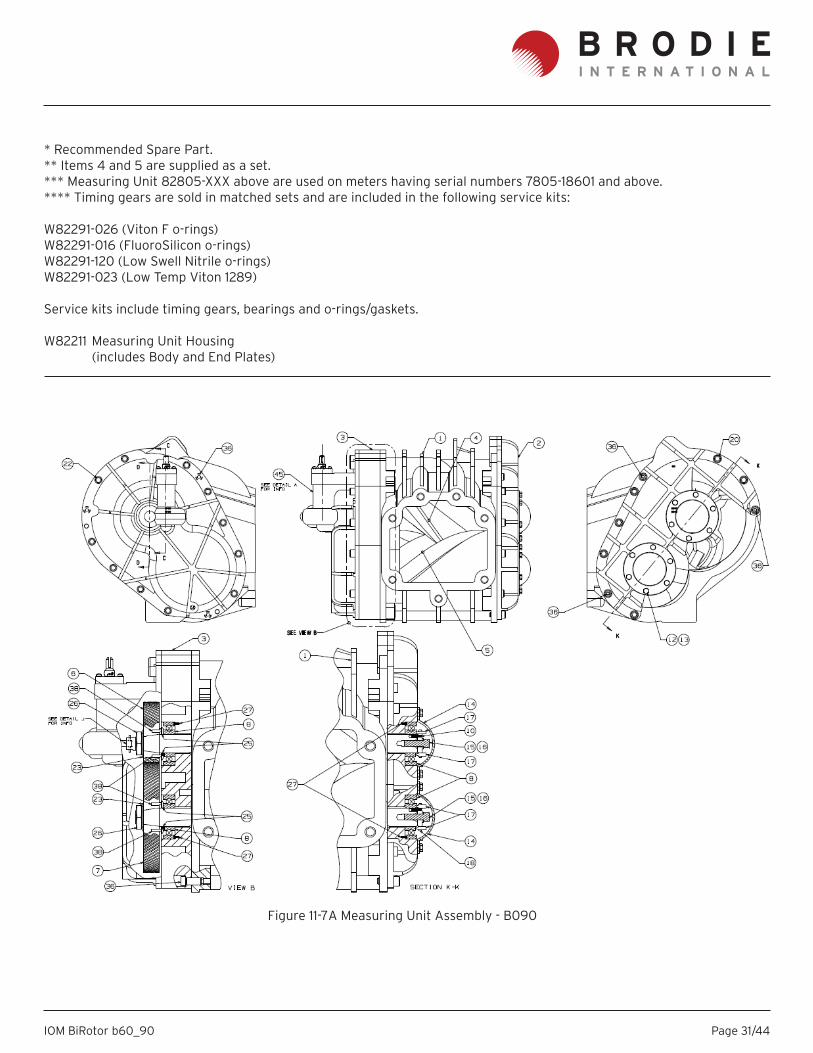
* Recommended Spare Part.** Items 4 and 5 are supplied as a set. *** Measuring Unit 82805-XXX above are used on meters having serial numbers 7805-18601 and above.**** Timing gears are sold in matched sets and are included in the following service kits: W82291-026 (Viton F o-rings)W82291-016 (FluoroSilicon o-rings)W82291-120 (Low Swell Nitrile o-rings)W82291-023 (Low Temp Viton 1289) Service kits include timing gears, bearings and o-rings/gaskets.
W82211 Measuring Unit Housing (includes Body and End Plates)
Figure 11-7A Measuring Unit Assembly - B090
Page 32/44IOM BiRotor b60_90
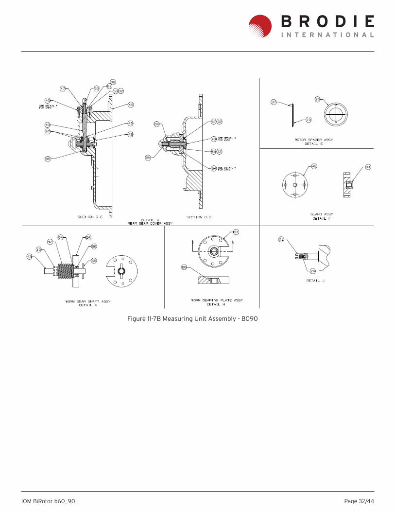
Figure 11-7B Measuring Unit Assembly - B090
Page 33/44IOM BiRotor b60_90
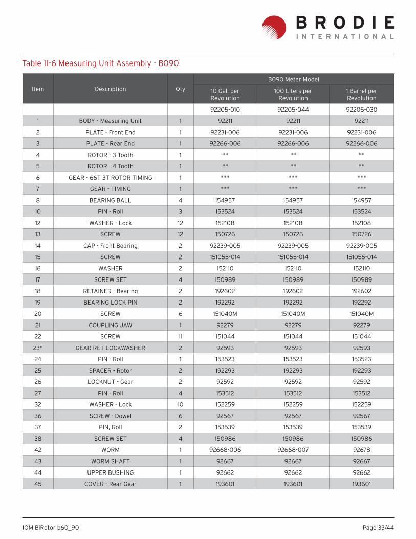
Table 11-6 Measuring Unit Assembly - B090
Item Description Qty
B090 Meter Model
10 Gal. per Revolution
100 Liters per Revolution
1 Barrel per Revolution
92205-010 92205-044 92205-030
1 BODY - Measuring Unit 1 92211 92211 92211
2 PLATE - Front End 1 92231-006 92231-006 92231-006
3 PLATE - Rear End 1 92266-006 92266-006 92266-006
4 ROTOR - 3 Tooth 1 ** ** **
5 ROTOR - 4 Tooth 1 ** ** **
6 GEAR - 66T 3T ROTOR TIMING 1 *** *** ***
7 GEAR - TIMING 1 *** *** ***
8 BEARING BALL 4 154957 154957 154957
10 PIN - Roll 3 153524 153524 153524
12 WASHER - Lock 12 152108 152108 152108
13 SCREW 12 150726 150726 150726
14 CAP - Front Bearing 2 92239-005 92239-005 92239-005
15 SCREW 2 151055-014 151055-014 151055-014
16 WASHER 2 152110 152110 152110
17 SCREW SET 4 150989 150989 150989
18 RETAINER - Bearing 2 192602 192602 192602
19 BEARING LOCK PIN 2 192292 192292 192292
20 SCREW 6 151040M 151040M 151040M
21 COUPLING JAW 1 92279 92279 92279
22 SCREW 11 151044 151044 151044
23* GEAR RET LOCKWASHER 2 92593 92593 92593
24 PIN - Roll 1 153523 153523 153523
25 SPACER - Rotor 2 192293 192293 192293
26 LOCKNUT - Gear 2 92592 92592 92592
27 PIN - Roll 4 153512 153512 153512
32 WASHER - Lock 10 152259 152259 152259
36 SCREW - Dowel 6 92567 92567 92567
37 PIN, Roll 2 153539 153539 153539
38 SCREW SET 4 150986 150986 150986
42 WORM 1 92668-006 92668-007 92678
43 WORM SHAFT 1 92667 92667 92667
44 UPPER BUSHING 1 92662 92662 92662
45 COVER - Rear Gear 1 193601 193601 193601
Page 34/44IOM BiRotor b60_90
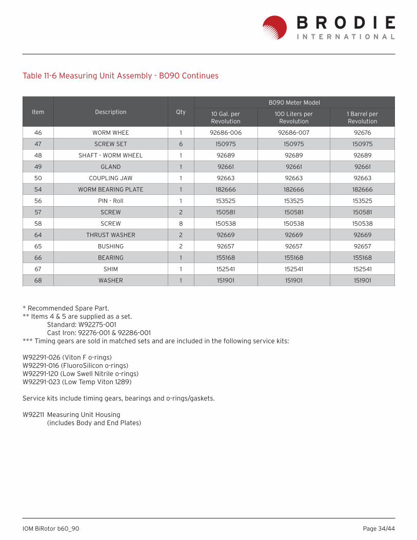
* Recommended Spare Part.** Items 4 & 5 are supplied as a set. Standard: W92275-001 Cast Iron: 92276-001 & 92286-001*** Timing gears are sold in matched sets and are included in the following service kits: W92291-026 (Viton F o-rings)W92291-016 (FluoroSilicon o-rings)W92291-120 (Low Swell Nitrile o-rings)W92291-023 (Low Temp Viton 1289)
Service kits include timing gears, bearings and o-rings/gaskets.
W92211 Measuring Unit Housing (includes Body and End Plates)
Item Description Qty
B090 Meter Model
10 Gal. per Revolution
100 Liters per Revolution
1 Barrel per Revolution
46 WORM WHEE 1 92686-006 92686-007 92676
47 SCREW SET 6 150975 150975 150975
48 SHAFT - WORM WHEEL 1 92689 92689 92689
49 GLAND 1 92661 92661 92661
50 COUPLING JAW 1 92663 92663 92663
54 WORM BEARING PLATE 1 182666 182666 182666
56 PIN - Roll 1 153525 153525 153525
57 SCREW 2 150581 150581 150581
58 SCREW 8 150538 150538 150538
64 THRUST WASHER 2 92669 92669 92669
65 BUSHING 2 92657 92657 92657
66 BEARING 1 155168 155168 155168
67 SHIM 1 152541 152541 152541
68 WASHER 1 151901 151901 151901
Table 11-6 Measuring Unit Assembly - B090 Continues
Page 35/44IOM BiRotor b60_90
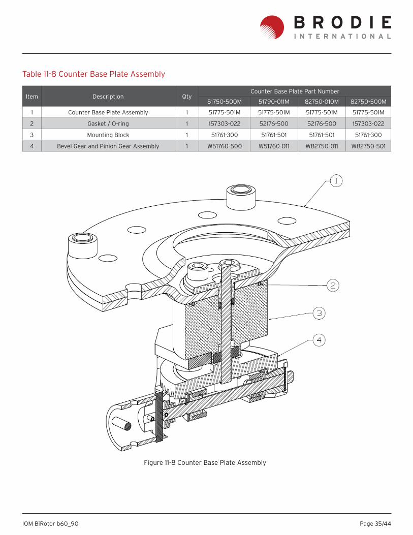
Item Description QtyCounter Base Plate Part Number
51750-500M 51790-011M 82750-010M 82750-500M
1 Counter Base Plate Assembly 1 51775-501M 51775-501M 51775-501M 51775-501M
2 Gasket / O-ring 1 157303-022 52176-500 52176-500 157303-022
3 Mounting Block 1 51761-300 51761-501 51761-501 51761-300
4 Bevel Gear and Pinion Gear Assembly 1 W51760-500 W51760-011 W82750-011 W82750-501
Table 11-8 Counter Base Plate Assembly
Figure 11-8 Counter Base Plate Assembly
Page 36/44IOM BiRotor b60_90
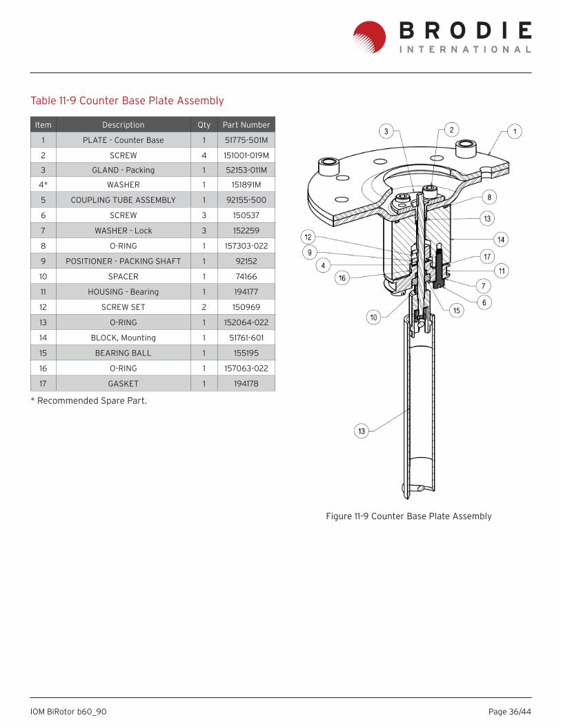
Item Description Qty Part Number
1 PLATE - Counter Base 1 51775-501M
2 SCREW 4 151001-019M
3 GLAND - Packing 1 52153-011M
4* WASHER 1 151891M
5 COUPLING TUBE ASSEMBLY 1 92155-500
6 SCREW 3 150537
7 WASHER - Lock 3 152259
8 O-RING 1 157303-022
9 POSITIONER - PACKING SHAFT 1 92152
10 SPACER 1 74166
11 HOUSING - Bearing 1 194177
12 SCREW SET 2 150969
13 O-RING 1 152064-022
14 BLOCK, Mounting 1 51761-601
15 BEARING BALL 1 155195
16 O-RING 1 157063-022
17 GASKET 1 194178
* Recommended Spare Part.
Table 11-9 Counter Base Plate Assembly
Figure 11-9 Counter Base Plate Assembly
Page 37/44IOM BiRotor b60_90
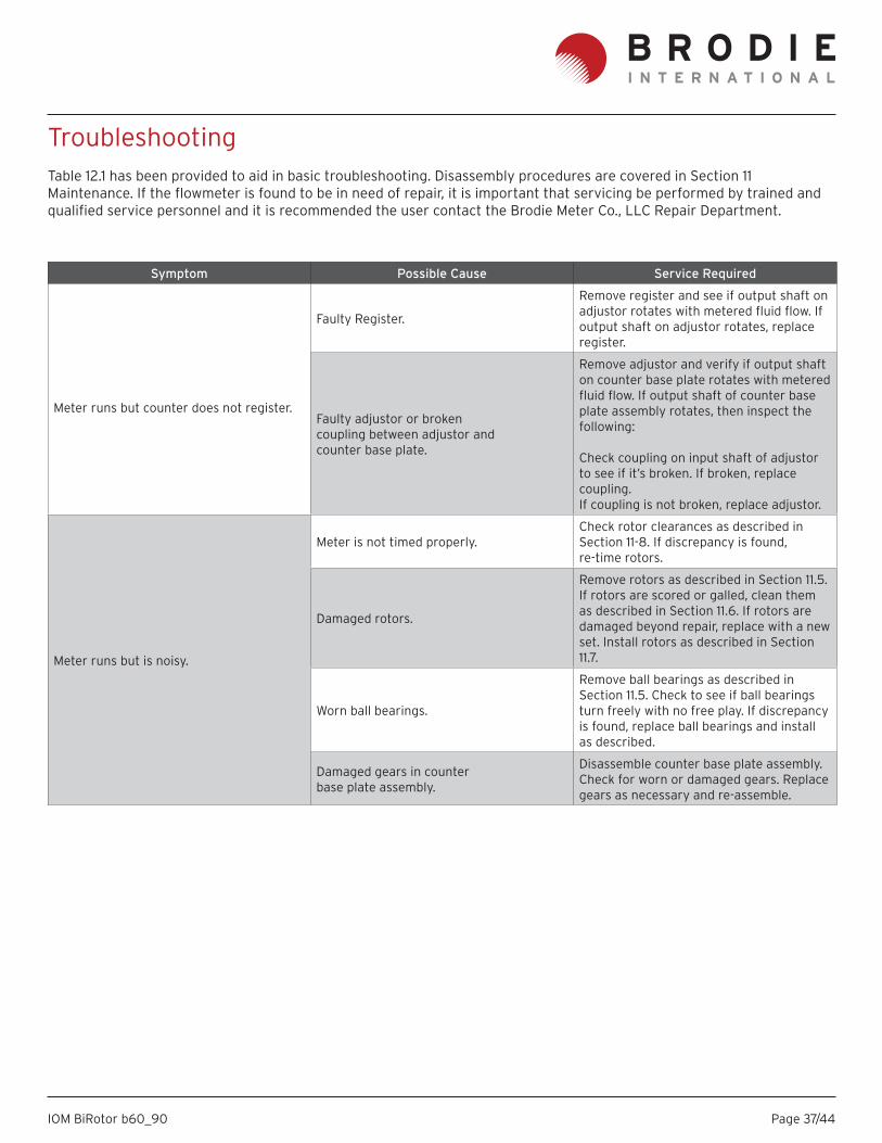
TroubleshootingTable 12.1 has been provided to aid in basic troubleshooting. Disassembly procedures are covered in Section 11 Maintenance. If the fl owmeter is found to be in need of repair, it is important that servicing be performed by trained and qualifi ed service personnel and it is recommended the user contact the Brodie Meter Co., LLC Repair Department.
Symptom Possible Cause Service Required
Meter runs but counter does not register.
Faulty Register.
Remove register and see if output shaft on adjustor rotates with metered fl uid fl ow. If output shaft on adjustor rotates, replace register.
Faulty adjustor or brokencoupling between adjustor andcounter base plate.
Remove adjustor and verify if output shaft on counter base plate rotates with metered fl uid fl ow. If output shaft of counter base plate assembly rotates, then inspect the following:
Check coupling on input shaft of adjustor to see if it’s broken. If broken, replace coupling.If coupling is not broken, replace adjustor.
Meter runs but is noisy.
Meter is not timed properly.Check rotor clearances as described in Section 11-8. If discrepancy is found, re-time rotors.
Damaged rotors.
Remove rotors as described in Section 11.5. If rotors are scored or galled, clean them as described in Section 11.6. If rotors are damaged beyond repair, replace with a new set. Install rotors as described in Section 11.7.
Worn ball bearings.
Remove ball bearings as described in Section 11.5. Check to see if ball bearings turn freely with no free play. If discrepancy is found, replace ball bearings and install as described.
Damaged gears in counterbase plate assembly.
Disassemble counter base plate assembly. Check for worn or damaged gears. Replace gears as necessary and re-assemble.

Page 38/44IOM BiRotor b60_90
Page 39/44IOM BiRotor b60_90
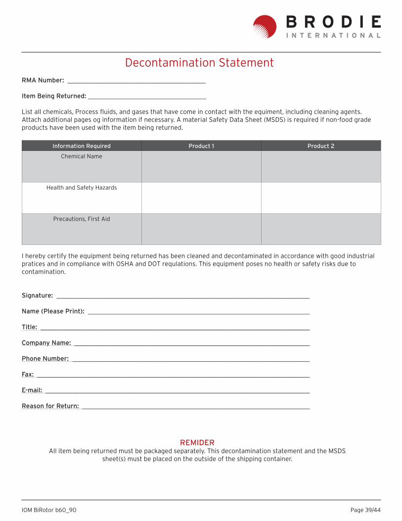
Decontamination StatementRMA Number: __________________________________________
Item Being Returned: ____________________________________
List all chemicals, Process fl uids, and gases that have come in contact with the equiment, including cleaning agents. Attach additional pages og information if necessary. A material Safety Data Sheet (MSDS) is required if non-food grade products have been used with the item being returned.
Information Required Product 1 Product 2
Chemical Name
Health and Safety Hazards
Precautions, First Aid
I hereby certify the equipment being returned has been cleaned and decontaminated in accordance with good industrial pratices and in compliance with OSHA and DOT requlations. This equipment poses no health or safety risks due to contamination.
Signature: _____________________________________________________________________________
Name (Please Print): ____________________________________________________________________
Title: ___________________________________________________________________________________
Company Name: ________________________________________________________________________
Phone Number: _________________________________________________________________________
Fax: ____________________________________________________________________________________
E-mail: _________________________________________________________________________________
Reason for Return: ______________________________________________________________________
REMIDERAll item being returned must be packaged separately. This decontamination statement and the MSDS
sheet(s) must be placed on the outside of the shipping container.

Page 40/44IOM BiRotor b60_90
Page 41/44IOM BiRotor b60_90
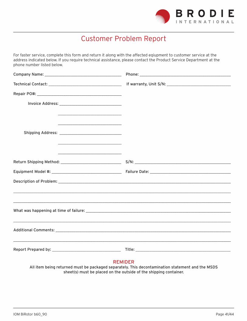
Customer Problem Report
Company Name: ______________________________________ Phone: ______________________________________________
Technical Contact: _____________________________________ If warranty, Unit S/N: ________________________________
Repair PO#: __________________________________________
Invoice Address: _______________________________
________________________________
________________________________
Shipping Address: _______________________________
________________________________
________________________________
Return Shipping Method: ______________________________ S/N: _________________________________________________
Equipment Model #: ___________________________________ Failure Date: _________________________________________
Description of Problem: ______________________________________________________________________________________
____________________________________________________________________________________________________________
____________________________________________________________________________________________________________
What was happening at time of failure: ________________________________________________________________________
____________________________________________________________________________________________________________
Additional Comments: ________________________________________________________________________________________
____________________________________________________________________________________________________________
Report Prepared by: __________________________________ Title: _______________________________________________
For faster service, complete this form and return it along with the affected eqiupment to customer service at the address indicated below. If you require technical assistance, please contact the Product Service Department at the phone number listed below.
REMIDERAll item being returned must be packaged separately. This decontamination statement and the MSDS
sheet(s) must be placed on the outside of the shipping container.

Page 42/44IOM BiRotor b60_90

Page 43/44IOM BiRotor b60_90
Warranty Claim Procedures
1. Limited WarrantySubject to the limitations contained in Section 2 herein and except as otherwise expressly provided herein, Brodie International, a Brodie Meter Co., LLC Company (“Brodie”) warrants that the fi rmware will execute the programming instructions provided by Brodie, and that the Goods-manu-factured or Services provided by “Brodie” will be free from defects in materials or workmanship under normal use and care until the expiration of the applicable warranty period.
Goods are warranted for twelve (12) months from the date of initial installation or eighteen (18) months from the date of shipment by “Brodie”, whichever period expires fi rst. Consumables and Services are warranted for a period of 90 days from the date of shipment or completion of the Services.
Products purchased by “Brodie” from a third party for resale to Buyer (“Resale Products”) shall carry only the warranty extended by the original manufacturer.
Buyer agrees that “Brodie” has no liability for Resale Products beyond making a reasonable commercial effort to arrange for procurement and shipping of the Resale Products.
If Buyer discovers any warranty defects and notifi es “Bro-die” thereof in writing during the applicable warranty peri-od, “Brodie” shall, at its option, promptly correct any errors that are found by “Brodie” in the fi rmware or Services, or repair or replace F. O. B. point of manufacture that portion of the Goods or fi rmware found by “Brodie” to be defective, or refund the purchase price of the defective portion of the Goods/Services.
All replacements or repairs necessitated by inadequate maintenance, normal wear and usage, unsuitable power sources, unsuitable environmental conditions, accident, misuse, improper installation, modifi cation, repair, storage
or handling, or any other cause not the fault of “Brodie” are not covered by this limited warranty, and shall be at Buyer’s expense.
“Brodie” shall not be obligated to pay any costs or charges incurred by Buyer or any other party except as may be agreed upon in writing in advance by an authorized “Bro-die” representative.
All costs of dismantling, reinstallation and freight and the time and expenses of “Brodie’s” personnel for site travel and diagnosis under this warranty clause shall be borne by Buyer unless accepted in writing by “Brodie”.
Goods repaired and parts replaced during the warranty period shall be in warranty for the remainder of the original warranty period or ninety (90) days, whichever is longer. This limited warranty is the only warranty made by Brodie and can be amended only in a writing signed by an autho-rized representative of “Brodie”.
Except as otherwise expressly provided in the Agreement, THERE ARE NO REPRESENTATIONS OR WARRANTIES OF ANY KIND, EXPRESS OR IMPLIED, AS TO MERCHANTABIL-ITY, FITNESS FOR PARTICULAR PURPOSE, OR ANY OTH-ER MATTER WITH RESPECT TO ANY OF THE GOODS OR SERVICES.
It is understood that - corrosion or erosion of materials is not covered by our guarantee.

Page 44/44IOM BiRotor b60_90
Brodie International
P.O. Box 450 (30459-0450)19267 Highway 301 NorthStatesboro, GA 30461 USA
Phone: +1 (912) 489-0200Fax: +1 (912) 489-0294
2. Limitation of remedy and liability
Brodie International, a Brodie Meter Co., LLC Company (“Brodie”) shall not be liable for damages caused by delay in performance.
The sole and exclusive remedy for breach of warranty here-under shall be limited to repair, correction, replacement or refund of purchase price under the limited warranty clause in Section 1 herein.
In no event, regardless of the form of the claim or cause of action (whether based in contract, infringement, negli-gence, strict liability, other tort or otherwise), shall “Bro-die’s” liability to buyer and/or its
customers exceed the price to buyer of the specifi c goods manufactured or services provided by Brodie giving rise to the claim or cause of action.
Buyer agrees that in no event shall Brodie’s liability to buyer and/or its customers extend to include incidental, consequential or punitive damages.
The term “consequential damages” shall include, but not be limited to, loss of anticipated profi ts, loss of use, loss of revenue and cost of capital.
Related Documents