I.O.M. #136 updated : 02/28/2018 INSTRUCTION MANUAL • INSTALLATION • OPERATION • MAINTENANCE Covers Models with LXT Series Instrument TEMPTEK, INC. 525 East Stop 18 Road Greenwood, IN 46143 317-887-6352 fax: 317-881-1277 Service Department fax: 317-885-8683 www.Temptek.com E-mail: [email protected] Model: Serial Number :

Welcome message from author
This document is posted to help you gain knowledge. Please leave a comment to let me know what you think about it! Share it to your friends and learn new things together.
Transcript

I.O.M. #136 updated : 02/28/2018
INSTRUCTION MANUAL • INSTALLATION • OPERATION • MAINTENANCE
Covers Models withLXT Series Instrument
TEMPTEK, INC.525 East Stop 18 Road Greenwood, IN 46143
317-887-6352 fax: 317-881-1277 Service Department fax: 317-885-8683
www.Temptek.comE-mail: [email protected]
Model:
Serial Number :


INSTRUCTION MANUALVeteran VT Series withTemptender Instrument
COVERING
INSTALLATIONOPERATION
MAINTENANCE
TEMPTEK, INC. 525 East Stop 18 Road Greenwood, IN 46143Phone: 317-887-6352 Fax: 317-881-1277 Service Department fax: 317-885-8683
www.Temptek.com E-mail: [email protected]
Temperature Control Unit : Veteran LXT Series
Page: 4TEMPTEK, INC.525 East Stop 18 Road Greenwood, Indiana 46142
317-887-6352 Fax: 317-881-1277Email: [email protected]
TABLE OF CONTENTS
1.0 GENERAL 7 1.1 Receiving Instructions 81.2 Introduction 81.3 Safety 8 1.4 Efficiency 91.5 Water Treatment 91.6 Components 10 2.0 INSTALLATION 132.1 General 142.2 To and from process connections 142.3 Water supply connection 152.4 Drain connection 152.5 Electrical connection 17
3.0 START UP SEQUENCE 21 3.1 General 22 3.2 System Fill / Operations 223.3 Instrument Operation : Basic Use 273.4 Instrument Operation : Basic Setup 333.5 Instrument Operation : Remote Setup 343.6 Instrument Operation : Features Setup 363.7 Instrument Operation : Machine Setup 383.8 Instrument Operation : Tools and Status 42 3.9 Shut Down / Disconnect 45
4.0 TROUBLESHOOTING 474.1 Unit will not start (Display is not Illuminated) 484.2 Unit will not start (Display is Illuminated) 484.3 Unit Stops 484.4 Unit Overheats 494.5 Unit Underheats 504.6 Pressure Relief Valve Leaks 514.7 Cooling Valve Fault 52
5.0 MAINTENANCE 53 5.1 Pump Seal Replacement 545.2 Heater Replacement 575.3 Cooling Valve Service 595.4 Voltage Change 655.5 Sensor Probe Service 665.6 Pressure Switch Service 665.7 Electronic Instrument Repair Policy And Procedure 675.8 Temperature Probe Calibration 685.9 Heater Contactor & Pump Motor Starter 69 6.0 COMPONENTS 71 6.1 Mechanical system 726.2 Electrical system 74

Temperature Control Unit : Veteran LXT Series
Page: 5TEMPTEK, INC.525 East Stop 18 Road Greenwood, Indiana 46142
317-887-6352 Fax: 317-881-1277Email: [email protected]
7.0 RELATED DRAWINGS 75 7.1 Physical 767.2 Circuit Schematic 777.3 Regulator / Bypass Installation 787.4 Dual Zone Dolly 797.5 Stacking Rack 80 8.0 APPENDIX 81 8.1 Model # And Suffix Coding 828.2 Interpretation Of Process Pressure Gauges 838.3 Mold Purge Operation 848.4 SPI Commands 868.5 Communications Cable 888.6 Optional Alarm Operation 898.7 AVTTM Valve Components 908.8 AS5 Pump Parts List - 1/2 HP to 1 HP 918.9 AS5 Pump Parts List - 1 1/2 HP to 3 HP 92

Page: 6
THIS PAGE INTENTIONALLY BLANK

Temperature Control Unit : Veteran LXT Series
Page: 7TEMPTEK, INC.525 East Stop 18 Road Greenwood, Indiana 46142
317-887-6352 Fax: 317-881-1277Email: [email protected]
1.0 GENERAL 1.1 Receiving Instructions 1.2 Introduction 1.3 Safety 1.4 Water Treatment 1.5 Components

Temperature Control Unit : Veteran LXT Series
Page: 8TEMPTEK, INC.525 East Stop 18 Road Greenwood, Indiana 46142
317-887-6352 Fax: 317-881-1277Email: [email protected]
1.1 RECEIVING INSTRUCTIONS
A. Temperature control units are generally shipped skid mounted, boxed and wrapped in plastic prior to shipment.
B. Unbox the unit before accepting delivery. Check for visible damage and document any evident damage on the delivery receipt or refuse the shipment. Shipping damage is the responsibility of the carrier.
C. In order to expedite payment for damages, should they occur, follow proper procedures and keep detailed records. Take photographs of any suspected damage.
1.2 INTRODUCTION
A. This manual covers temperature control units from 10 to 34 kW of heating capacity using the Veteran LXT Series microprocessor control instrument. The standard fluid operating temperature range for this temperature control unit is 32°F to 250°F for units. Consult the factory if you have questions about the operating range of your temperature control unit.
B. The intent of this manual is to serve as a guide in the installation, operation and maintenance of your temperature control unit. Improper installation can lead to equipment damage and poor performance. Failure to follow the installation, operation and maintenance instructions may result in damage to the unit that is not covered under the limited warranty. This manual is for standard products. The information contained in this manual is intended to be general in nature. The information is typical only and may not represent the actual unit purchased.
C. When calling for assistance from the Manufacturer’s Service Department, it is important to know the model and serial number of the particular unit. The model number includes critical unit information which is helpful when troubleshooting operating difficulties. The serial number allows the service team to locate manufacturing and testing records which can have additional information relating to a particular unit.
1.3 SAFETY
A. It is important to become thoroughly familiar with this manual and the operating characteristics of the unit.
B. It is the owner’s responsibility to assure proper operator training, installation, operation, and maintenance of the unit.
C. Observe all warning and safety placards applied to the unit. Failure to observe all warnings can result in serious injury or death to the operator and severe mechanical damage to the unit.
WARNING: This equipment contains hazardous voltages that can cause severe injury or death. Disconnect and lock out incoming power before installing or servicing the equipment.

Temperature Control Unit : Veteran LXT Series
Page: 9TEMPTEK, INC.525 East Stop 18 Road Greenwood, Indiana 46142
317-887-6352 Fax: 317-881-1277Email: [email protected]
D. Observe all safety precautions during installation, startup and service of this equipment due to the presence of high voltage. Only qualified personnel should install, startup and service this equipment.
E. When working on this equipment, observe precautions in literature and on tags, stickers and labels located on the equipment. Wear work gloves and safety glasses.
F. Before installing and operating the unit, be aware of and follow any local laws and codes that apply to the installation.
G. Samples of Warning Labels applied to typical temperature control units.
1. Alerts users to the danger of high voltage.
2. Alerts the user to possible explosive danger.
3. Alerts the user to a hot surface danger due to high operating temperatures.
CAUTION
WARNING
J5318-BF

Temperature Control Unit : Veteran LXT Series
Page: 10TEMPTEK, INC.525 East Stop 18 Road Greenwood, Indiana 46142
317-887-6352 Fax: 317-881-1277Email: [email protected]
WARNING: Improper water treatment will void unit warranty.
1.4 WATER TREATMENT
A. The fluid used in your temperature control unit will greatly effect its short and long-term operation. Lack of as well as improper water treatment can damage the temperature control unit by causing scale build-up, excessive corrosion and/or bacterial contamination. It is the equipment owner’s responsibility to prevent damage caused by poor water quality. The services of a water treatment professional is recommended.
B. The use of untreated or improperly treated water in a temperature control unit may result in scaling, erosion, corrosion, algae, bacteria or slime. The manufacturer recommends filtering the process water to prevent solids from plugging critical parts.
C. It is recommended that the services of a qualified water treatment specialist be engaged to determine what water treatment is required.
D. The Company assumes no responsibility for equipment failures which result from untreated or improperly treated water.
E. Do not use deionized water in this unit. Some customized units may be compatible with deionized water. Consult the factory before using deionized water.
1.5 COMPONENTS
Models with 10 & 16 kW heaters and 3/4 - 3 HP pumps (typical).
Models with 24 & 34 kW heaters and 5 - 7.5 HP pumps (typical).
Temperature Control Unit : Veteran LXT Series
Page: 11TEMPTEK, INC.525 East Stop 18 Road Greenwood, Indiana 46142
317-887-6352 Fax: 317-881-1277Email: [email protected]
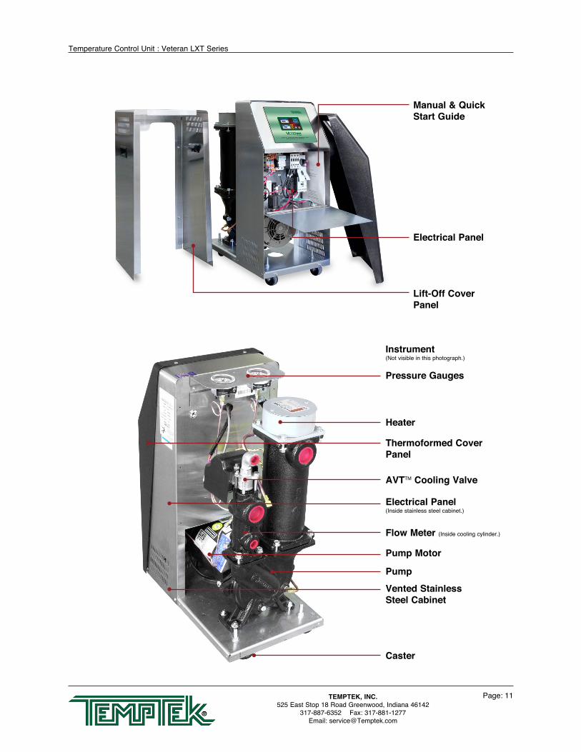
Manual & Quick Start Guide
Lift-Off Cover Panel
Electrical Panel
PumpVented StainlessSteel Cabinet
Pump Motor
Caster
Flow Meter (Inside cooling cylinder.)
AVTTM Cooling Valve
Electrical Panel(Inside stainless steel cabinet.)
Heater
Pressure Gauges
Thermoformed Cover Panel
Instrument(Not visible in this photograph.)
Temperature Control Unit : Veteran LXT Series
Page: 12TEMPTEK, INC.525 East Stop 18 Road Greenwood, Indiana 46142
317-887-6352 Fax: 317-881-1277Email: [email protected]
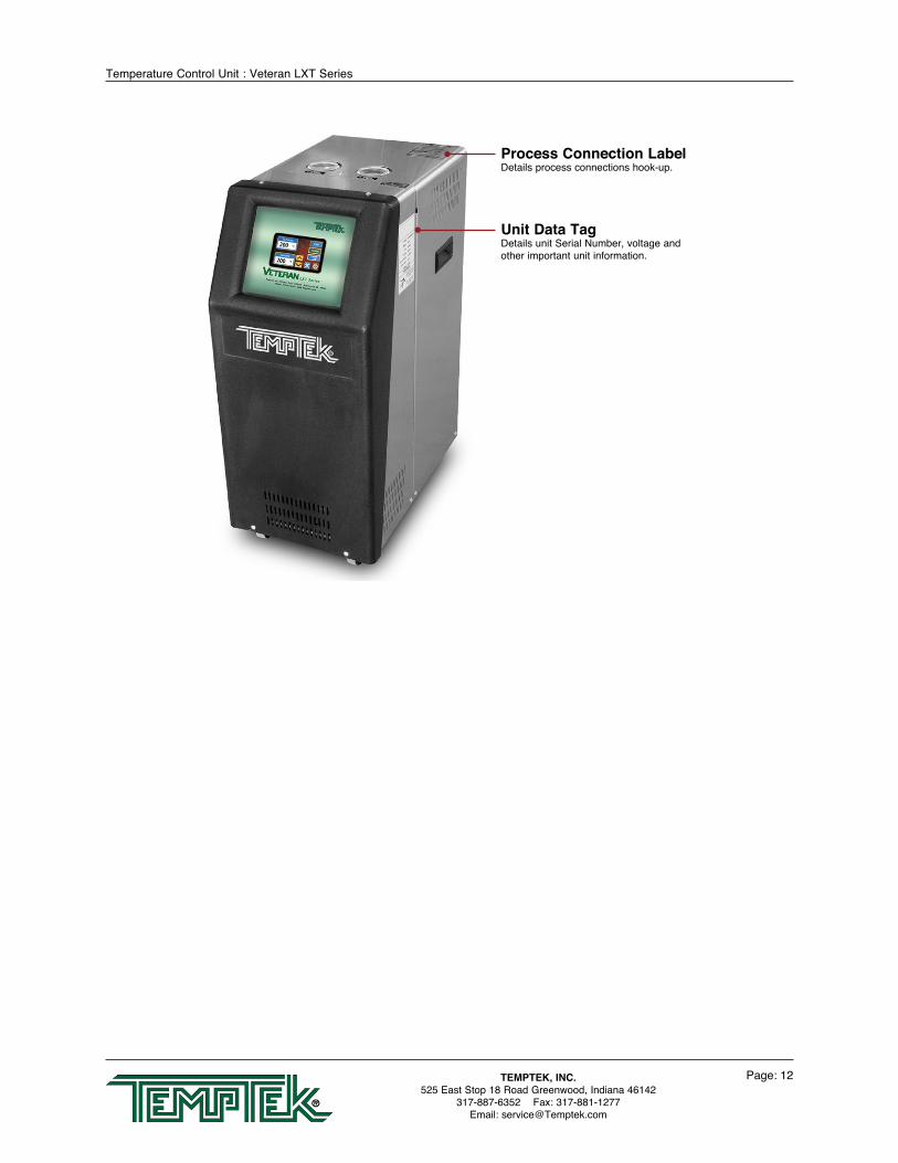
Process Connection LabelDetails process connections hook-up.
Unit Data TagDetails unit Serial Number, voltage and other important unit information.

Temperature Control Unit : Veteran LXT Series
Page: 13TEMPTEK, INC.525 East Stop 18 Road Greenwood, Indiana 46142
317-887-6352 Fax: 317-881-1277Email: [email protected]
2.0 INSTALLATION 2.1 General 2.2 To and From Process Connections 2.3 Water Supply Connection 2.4 Drain Connection 2.5 Electrical Connection

Temperature Control Unit : Veteran LXT Series
Page: 14TEMPTEK, INC.525 East Stop 18 Road Greenwood, Indiana 46142
317-887-6352 Fax: 317-881-1277Email: [email protected]
2.1 GENERAL
A. Care should be taken to use materials (hose, rigid piping, valves or filters) rated for the temperature and pressure duty of your unit. Most units have a maximum operating temperature of 300°F or less and a maximum pressure of 150 PSI. The unit is most efficient when full size plumbing is run from the unit connections to and from the process. If necessary, reduce the plumbing size at your process, not at the unit.
B. Be certain all process piping materials have the equivalent or larger diameter of the particular process connection.
2.2 TO AND FROM PROCESS CONNECTIONS
A. Connect the unit’s To Process port to the Water In port on the process manifold.
B. Connect the unit’s From Process port to the Water Out port on the process manifold.
C. Please note: Process water piping circuitry should be designed to avoid an excessive use of elbows and/or lengths of pipe or hose. If hose is the material of choice, avoid tight twists or curls and excessive lengths.
D. Valves and filters may be installed in the process water piping circuitry to facilitate service and maintenance, provided that such devices maintain the full inside diameter of the process connection. If installed, all such devices must be open and clean during unit operation.
Drain*
To Process
From Process
Water Supply**
*Connect Unit drain to plant’s open drain or tower water system return or chilled water system return.
**Connect Unit water supply to plant’s city water or well water source or tower water supply or chilled water supply.
*Drain
To Process
From Process
**Water Supply
Typical unit with 5 - 7½ horsepower pump and/or 24 - 34 kW heater.
Typical unit with ¾ - 3 horsepower pump and/or 10 - 16 kW heater.

Temperature Control Unit : Veteran LXT Series
Page: 15TEMPTEK, INC.525 East Stop 18 Road Greenwood, Indiana 46142
317-887-6352 Fax: 317-881-1277Email: [email protected]
2.3 WATER SUPPLY CONNECTION
A. Connect the unit’s Water Supply port to the plant’s city water, well water, tower water or chilled water supply.
B. Water supply pressure requirements vary with operating temperatures. The chart below shows the required operating water supply pressures for various operating process temperatures. The required water supply pressure retains process water in a liquid state at temperatures over 180°F. Failure to maintain the required water supply pressure will cause premature failure of and increase maintenance in susceptible areas such as the shaft seal and heater.
C. The factory recommended minimum operating water supply pressure requirement is 20 PSI or as shown in the chart above based on operating temperatures.
D. Static water supply pressure can be determined at the unit’s location by reading the unit’s 0-160 PSI pressure gauges when the unit’s pump motor is OFF.
E. If water supply pressure as read on the unit’s pressure gauges exceeds 75 PSI, a pressure reducing valve must be installed in the water supply line (refer to section 7.3 of this manual for installation information). The factory recommended ‘regulated pressure out’ is 55 PSI.
2.4 DRAIN CONNECTION:
A. Connect the unit’s DRAIN port to one of the following, determined by the water supply source:
1. Open drain for well or city water supply.
2. Tower water system return for tower system water supply.
3. Chilled water system return for chilled water system supply.
B. The factory recommends a minimum of 10 psi pressure differential between the water supply and drain line for proper cooling.
1. The amount of cooling provided by the unit depends on:
Typical pressure reducing valve installation (shown on S-925 model).
180°F20 PSI
190°F25 PSI
200°F30 PSI
210°F35 PSI
220°F40 PSI
230°F45 PSI
240°F50 PSI
250°F55 PSI
OPERATING TEMPERATURE
WATER SUPPLY PRESSURE
WARNING: Check local codes to determine proper use of back flow prevention device in water supply line.

Temperature Control Unit : Veteran LXT Series
Page: 16TEMPTEK, INC.525 East Stop 18 Road Greenwood, Indiana 46142
317-887-6352 Fax: 317-881-1277Email: [email protected]
a. The cooling valve size
b. The pressure differential across the valve
c. The temperature difference between the unit set point and the cooling water temperature
d. The cooling valve position
2. Consult factory when selecting the correct cooling valve for your application.
3. In general the standard ½” AVT modulating cooling valve will provide approximately 24,0000 Btu/hr (7 kW) of cooling per every 10°F difference between the cooling water temperature and the process set point based on 25 psi delta p across the cooling valve with ½” supply & return connections. Connecting the unit with ¾” or 1” cooling water supply and return connections will increase the cooling capacity of the unit.
C. For most applications, the drain line should not be valved. However, for installations with a pressurized drain system, it may be necessary to install a valve in the drain line. In such cases, the installed valve must be fully opened after installation and the valve handle removed to prevent operating the unit with a closed drain valve. The valve handle can be reattached to the valve body when it is necessary to close the valve.
D. CAUTION: The unit must never be operated with a closed drain line valve. A closed drain line valve prevents adequate system cooling and will lead to unit overheating. Overheating of the unit may lead to unit damage and/or serious personal injury.
2.5 ELECTRICAL CONNECTION
A. STANDARD MODELS
1. Electrical power supply requirements for standard units are identified on the equipment data tag. Verify that available voltage supply is the same as the unit’s voltage requirements.
WARNING: DO NOT CONNECT THE UNIT TO A VOLTAGE SUPPLY SOURCE NOT EQUAL TO THE UNIT’S VOLTAGE REQUIREMENTS AS SPECIFIED ON THE UNIT’S DATA PLATE.
Use of incorrect voltage will void the unit’s warranty and cause a significant hazard that may result in serious personal injury and/or unit damage.
Typical drain valve installation(Shown on S-925 model).
WARNING: Never operation the Temperature Control Unit with a closed drain.

Temperature Control Unit : Veteran LXT Series
Page: 17TEMPTEK, INC.525 East Stop 18 Road Greenwood, Indiana 46142
317-887-6352 Fax: 317-881-1277Email: [email protected]
2. For standard units with 10 and 16 KW heaters and up to 3 horsepower pumps, a four conductor cable, 10 foot in length, is provided for connection to an operator supplied fused disconnect.
3. For units with 24 and 34 KW heaters, the operator must provide a four conductor power cable and the fused disconnect.
4. The owner supplied fused disconnect must be sized and installed according to the unit’s power supply requirements and local electrical codes.
B. MODELS WITH FACTORY INCLUDED DISCONNECT SWITCH AND OTHER CUSTOM FEATURES
1. Some units may be customized and include a factory supplied power disconnect
switch and/or higher specification electrical enclosure. Electrical power supply requirements are identified on the equipment data tag. Verify that available voltage supply is the same as the unit’s voltage requirements.
WARNING: DO NOT connect the unit to a voltage supply source not equal to the unit’s voltage requirements as specified on the unit’s data plate. Use of incorrect voltage will void the unit’s warranty and cause a significant hazard that may result in damage to the unit or serious personal injury.
2. Appropriate conduit and fittings should be selected which will maintain the integrity of the cabinet.
3. Supply a power conductor sized according to the unit’s power supply requirements. Connect the power conductor to the unit’s power supply entry terminal block.
C. CONTROL CIRCUIT WIRING
1. The unit’s supplied control circuit is 110 volt, 1 phase, 60 cycle. The control circuit is supplied by the factory installed transformer. A control circuit fuse is provided.
WARNING: Do not connect the unit to a voltage supply not equal to the unit’s voltage requirements as specified on the unit’s data plate. Use of incorrect voltage will void the unit’s warranty and cause a significant hazard that may result in serious personal injury and unit damage.
WARNING: Electric Shock Hazard. High Voltage is present in the electrical cabinet. Disconnect power before servicing. Follow all facility lock-out tag-out procedures.
Typical control circuit transformer fuse

Temperature Control Unit : Veteran LXT Series
Page: 18TEMPTEK, INC.525 East Stop 18 Road Greenwood, Indiana 46142
317-887-6352 Fax: 317-881-1277Email: [email protected]
D. GENERAL
1. Make certain all ground connections to the unit are properly affixed. A proper connection to earth ground is required. A conduit ground is not a reliable conductor!
2. Make certain the power conductor, disconnecting means, and fusing are properly sized according to the unit’s power supply requirements.
3. Make certain all electrical connections are tightly affixed. Any loose wiring connections must be tighten before engaging the power supply.
4. Make certain no moisture or standing water is present inside the electrical cabinet.
WARNING: Check that all electrical connections are tight before starting.Disconnect power before servicing. Follow all facility lock-out tag-out procedures.
Typical electrical panel. Shown with thermoformed panel removed.

Temperature Control Unit : Veteran LXT Series
Page: 19TEMPTEK, INC.525 East Stop 18 Road Greenwood, Indiana 46142
317-887-6352 Fax: 317-881-1277Email: [email protected]
Power Entry
Low WaterPressure Switch
Control Transformer Pump Motor Controller
Terminal Strip Heater ContactorTransformerFuse Blocks
Typical Electrical Panel

Page: 20
THIS PAGE INTENTIONALLY BLANK

Temperature Control Unit : Veteran LXT Series
Page: 21TEMPTEK, INC.525 East Stop 18 Road Greenwood, Indiana 46142
317-887-6352 Fax: 317-881-1277Email: [email protected]
3.0 OPERATIONS 3.1 General 3.2 Machine Start Up and Operation 3.3 Instrument Operation : Basic Use 3.4 Instrument Operation : Basic Setup 3.5 Instrument Operation : Remote Setup 3.6 Instrument Operation : Features Setup 3.7 Instrument Operation : Machine Setup 3.8 Instrument Operation : Tools and Status 3.9 Shut Down Sequence
Temperature Control Unit : Veteran LXT Series
Page: 22TEMPTEK, INC.525 East Stop 18 Road Greenwood, Indiana 46142
317-887-6352 Fax: 317-881-1277Email: [email protected]
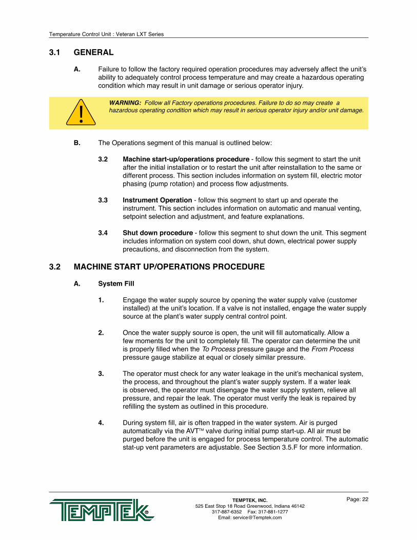
3.1 GENERAL
A. Failure to follow the factory required operation procedures may adversely affect the unit’s ability to adequately control process temperature and may create a hazardous operating condition which may result in unit damage or serious operator injury.
B. The Operations segment of this manual is outlined below:
3.2 Machine start-up/operations procedure - follow this segment to start the unit after the initial installation or to restart the unit after reinstallation to the same or different process. This section includes information on system fill, electric motor phasing (pump rotation) and process flow adjustments.
3.3 Instrument Operation - follow this segment to start up and operate the instrument. This section includes information on automatic and manual venting, setpoint selection and adjustment, and feature explanations.
3.4 Shut down procedure - follow this segment to shut down the unit. This segment includes information on system cool down, shut down, electrical power supply precautions, and disconnection from the system.
3.2 MACHINE START UP/OPERATIONS PROCEDURE
A. System Fill
1. Engage the water supply source by opening the water supply valve (customer installed) at the unit’s location. If a valve is not installed, engage the water supply source at the plant’s water supply central control point.
2. Once the water supply source is open, the unit will fill automatically. Allow a few moments for the unit to completely fill. The operator can determine the unit is properly filled when the To Process pressure gauge and the From Process pressure gauge stabilize at equal or closely similar pressure.
3. The operator must check for any water leakage in the unit’s mechanical system, the process, and throughout the plant’s water supply system. If a water leak is observed, the operator must disengage the water supply system, relieve all pressure, and repair the leak. The operator must verify the leak is repaired by refilling the system as outlined in this procedure.
4. During system fill, air is often trapped in the water system. Air is purged automatically via the AVTTM valve during initial pump start-up. All air must be purged before the unit is engaged for process temperature control. The automatic stat-up vent parameters are adjustable. See Section 3.5.F for more information.
WARNING: Follow all Factory operations procedures. Failure to do so may create a hazardous operating condition which may result in serious operator injury and/or unit damage.
Temperature Control Unit : Veteran LXT Series
Page: 23TEMPTEK, INC.525 East Stop 18 Road Greenwood, Indiana 46142
317-887-6352 Fax: 317-881-1277Email: [email protected]
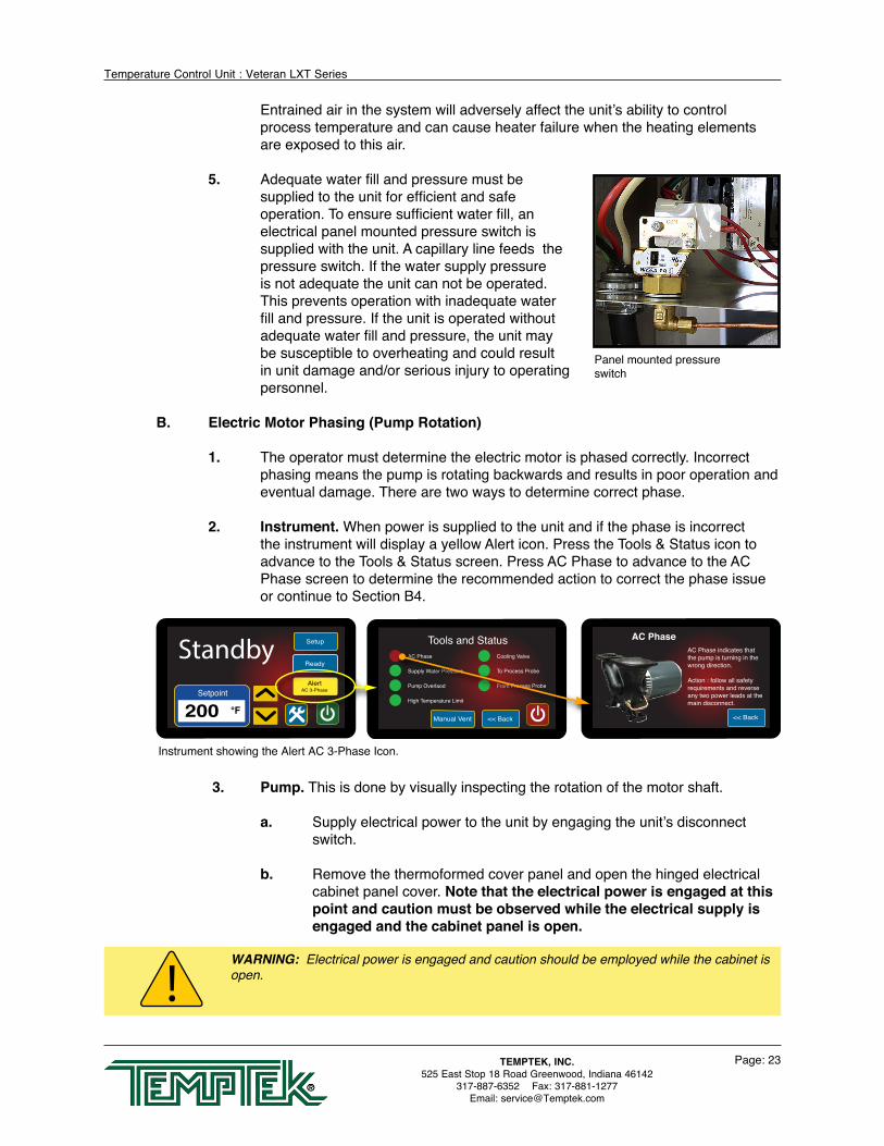
Entrained air in the system will adversely affect the unit’s ability to control process temperature and can cause heater failure when the heating elements are exposed to this air.
5. Adequate water fill and pressure must be supplied to the unit for efficient and safe operation. To ensure sufficient water fill, an electrical panel mounted pressure switch is supplied with the unit. A capillary line feeds the pressure switch. If the water supply pressure is not adequate the unit can not be operated. This prevents operation with inadequate water fill and pressure. If the unit is operated without adequate water fill and pressure, the unit may be susceptible to overheating and could result in unit damage and/or serious injury to operating personnel.
B. Electric Motor Phasing (Pump Rotation)
1. The operator must determine the electric motor is phased correctly. Incorrect phasing means the pump is rotating backwards and results in poor operation and eventual damage. There are two ways to determine correct phase.
2. Instrument. When power is supplied to the unit and if the phase is incorrect the instrument will display a yellow Alert icon. Press the Tools & Status icon to advance to the Tools & Status screen. Press AC Phase to advance to the AC Phase screen to determine the recommended action to correct the phase issue or continue to Section B4.
3. Pump. This is done by visually inspecting the rotation of the motor shaft.
a. Supply electrical power to the unit by engaging the unit’s disconnect switch.
b. Remove the thermoformed cover panel and open the hinged electrical cabinet panel cover. Note that the electrical power is engaged at this point and caution must be observed while the electrical supply is engaged and the cabinet panel is open.
Panel mounted pressure switch
Instrument showing the Alert AC 3-Phase Icon.
AlertAC 3-PhaseSetpoint
200 °F
Setup
ReadyStandby
<< BackManual Vent
AC Phase
Supply Water Pressure
Pump Overlaod
High Temperature Limit
Cooling Valve
To Process Probe
From Process Probe
Tools and Status AC PhaseAC Phase indicates thatthe pump is turning in thewrong direction.
Action : follow all safetyrequirements and reverseany two power leads at themain disconnect.
<< Back
WARNING: Electrical power is engaged and caution should be employed while the cabinet is open.

Temperature Control Unit : Veteran LXT Series
Page: 24TEMPTEK, INC.525 East Stop 18 Road Greenwood, Indiana 46142
317-887-6352 Fax: 317-881-1277Email: [email protected]
c. Locate the electric motor and identify the motor shaft inside the electric motor housing. The motor shaft can be seen through the vent slots in the motor housing or by removing the shaft cover.
d. On the instrument, quickly press the green Power icon and the quickly press the red Power off Icon twice.
e. Observe the motor shaft as it slows to a stop to identify the rotation. Correct rotation is “clockwise”, when viewed from the rear of the motor. Incorrect rotation is “counter-clockwise” when viewed from the rear of the motor. If the shaft does not rotate when the unit is started, the operator must identify the cause as outlined in this manual’s troubleshooting and repair section.
f. If the unit is phased correctly, continue with the start up procedure at step C. If the unit is phased incorrect, continue with step 2.
4. To correct unit phase:
a. Disengage the electrical power supply to the unit at the unit’s disconnect switch. Follow proper lockout procedures before proceeding.
b. Once the electrical power supply is disengaged, reverse any two power leads of the power cord at the fused disconnect terminals.
c. Note: The operator must reverse the power leads at the disconnect only and not at the power entry terminals on the unit’s electrical panel. The unit’s internal electrical system wiring is phased correctly at the factory and must not be altered in the field.
5. To verify pump rotation via pressure gauges. Start the unit and observe the pressure gauges. The To Process pressure will indicate 35-50 PSI more than the From Process pressure. In this state, the pump rotation is correct. If not evident the unit is not correctly phased and should be corrected as outlined in step 4.
DO NOT reverse power leads at the unit’s power entry.
Remove shaft cover to view the motor shaft.
Correct rotation is clockwise when viewed from the rear of the motor.

Temperature Control Unit : Veteran LXT Series
Page: 25TEMPTEK, INC.525 East Stop 18 Road Greenwood, Indiana 46142
317-887-6352 Fax: 317-881-1277Email: [email protected]
C. PROCESS FLOW ADJUSTMENTS
1. The operator must determine and set proper water flow rate for the most efficient and trouble free operation.
a. Water flow rate through the process is determined by the pressure losses in the process loop. Generally, higher flow rates result in turbulent flow achieving maximum temperature control.
b. If the flow rate exceeds the motor horsepower capacity, the electric motor will draw excessive amps. This is a result of the process loop’s ability to flow water at a greater rate than can be provided by the pump. This will eventually result in tripping the thermal motor overload relay (overload relays open) and the unit will shut down
c. The yellow Alert : Motor Overloads icon will display on the instrument. Press the Tools & Status icon to advance to the Tools & Status screen. Press Motor Overloads to advance to the informational screen for required action.
2. If an excessive flow situation is encountered and the motor overload circuit has tripped, the operator must manually reset the overload relay before operations can continue. This is done by opening the electrical panel cover, identifying the reset lever on the overload relay and pushing the reset lever “in” until the overloads are reset (evidenced by a “clicking” sound as the overloads reset).
3. If a motor overload situation persists, the operator must adjust the flow rate to match the system pressure loss (reduce flow rate) to prevent continual tripping of the overload relay. This procedure is outlined here:
a. Open electrical cabinet panel door. The panel cover is hinged and held open by a support cable. Note that the electrical power is engaged at this point and caution must be observed while the cabinet panel is open.
b. Identify the motor starter block. This block consists of the motor starter contactor and the overload relay.
WARNING: To correct phase ... switch power leads at the disconnect switch only.
Instrument showing the Alert Motor Overload Icon.
AlertMotor OverloadSetpoint
200 °F
Setup
ReadyStandby
<< BackManual Vent
AC Phase
Supply Water Pressure
Pump Overlaod
High Temperature Limit
Cooling Valve
To Process Probe
From Process Probe
Tools and Status Pump OverloadPump Overload error indicatesthe pump is drawing more current than it is rated for.
Action : reset the pump overload in the electrical panelafter following all safetyprocedures. Reduce the fluidflow rate.
<< Back
Motor Starter
Temperature Control Unit : Veteran LXT Series
Page: 26TEMPTEK, INC.525 East Stop 18 Road Greenwood, Indiana 46142
317-887-6352 Fax: 317-881-1277Email: [email protected]
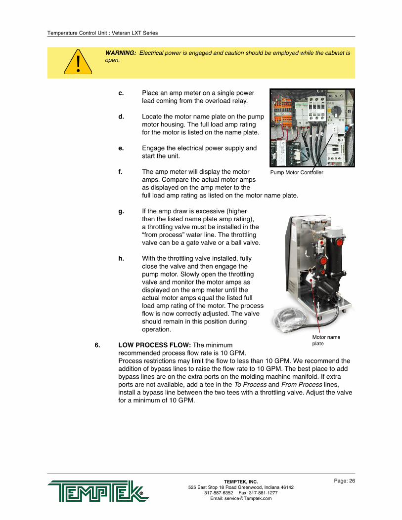
c. Place an amp meter on a single power lead coming from the overload relay.
d. Locate the motor name plate on the pump motor housing. The full load amp rating for the motor is listed on the name plate.
e. Engage the electrical power supply and start the unit.
f. The amp meter will display the motor amps. Compare the actual motor amps as displayed on the amp meter to the full load amp rating as listed on the motor name plate.
g. If the amp draw is excessive (higher than the listed name plate amp rating), a throttling valve must be installed in the “from process” water line. The throttling valve can be a gate valve or a ball valve.
h. With the throttling valve installed, fully close the valve and then engage the pump motor. Slowly open the throttling valve and monitor the motor amps as displayed on the amp meter until the actual motor amps equal the listed full load amp rating of the motor. The process flow is now correctly adjusted. The valve should remain in this position during operation.
6. LOW PROCESS FLOW: The minimum recommended process flow rate is 10 GPM. Process restrictions may limit the flow to less than 10 GPM. We recommend the addition of bypass lines to raise the flow rate to 10 GPM. The best place to add bypass lines are on the extra ports on the molding machine manifold. If extra ports are not available, add a tee in the To Process and From Process lines, install a bypass line between the two tees with a throttling valve. Adjust the valve for a minimum of 10 GPM.
Motor name plate
WARNING: Electrical power is engaged and caution should be employed while the cabinet is open.
Pump Motor Controller

Temperature Control Unit : Veteran LXT Series
Page: 27TEMPTEK, INC.525 East Stop 18 Road Greenwood, Indiana 46142
317-887-6352 Fax: 317-881-1277Email: [email protected]
3.3 INSTRUMENT OPERATION : BASIC USE
This unit features a touch screen interface panel. Press gently on the screen to navigate. Do not press the screen with tools or other foreign objects when navigating. A physically damaged screen voids the unit warranty.
A. STANDBY - UNIT POWERED BUT NOT RUNNING
1. When the correct electrical power and adequate water supply pressure are supplied, the unit can be started.
2. Ready. When the electrical power supply is engaged the display will illuminate.
The Standby Screen is displayed and shows the last selected Setpoint temperature. The Ready Indicator is shown if the unit is ready for operations. The Setup, Tools & Status and Power buttons are also displayed.
3. Alert. An Alert Indicator will display if there is an error or mechanical issue with the unit. Alerts are explained in detail elsewhere in this manual.
These Alerts prevent the unit from starting or operating and must be corrected
immediately.
• Water Pressure • Motor Overload • High Temperature
Setpoint
200 °F
Setup
ReadyStandby
The Standby Screen with Ready icon.
Touch Screen
Temperature Control Unit : Veteran LXT Series
Page: 28TEMPTEK, INC.525 East Stop 18 Road Greenwood, Indiana 46142
317-887-6352 Fax: 317-881-1277Email: [email protected]
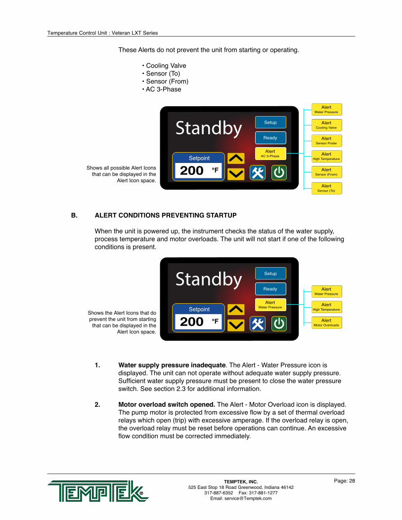
These Alerts do not prevent the unit from starting or operating.
• Cooling Valve • Sensor (To) • Sensor (From) • AC 3-Phase
B. ALERT CONDITIONS PREVENTING STARTUP
When the unit is powered up, the instrument checks the status of the water supply, process temperature and motor overloads. The unit will not start if one of the following conditions is present.
1. Water supply pressure inadequate. The Alert - Water Pressure icon is displayed. The unit can not operate without adequate water supply pressure. Sufficient water supply pressure must be present to close the water pressure switch. See section 2.3 for additional information.
2. Motor overload switch opened. The Alert - Motor Overload icon is displayed. The pump motor is protected from excessive flow by a set of thermal overload relays which open (trip) with excessive amperage. If the overload relay is open, the overload relay must be reset before operations can continue. An excessive flow condition must be corrected immediately.
AlertWater PressureSetpoint
200 °F
Setup
ReadyStandby
AlertMotor Overloads
AlertHigh Temperature
AlertWater Pressure
Shows the Alert Icons that do prevent the unit from starting that can be displayed in the
Alert Icon space.
AlertAC 3-PhaseSetpoint
200 °F
Setup
ReadyStandby
AlertSensor (From)
AlertSensor (To)
AlertHigh Temperature
AlertSensor Probe
AlertCooling Valve
AlertWater Pressure
Shows all possible Alert Icons that can be displayed in the
Alert Icon space.

Temperature Control Unit : Veteran LXT Series
Page: 29TEMPTEK, INC.525 East Stop 18 Road Greenwood, Indiana 46142
317-887-6352 Fax: 317-881-1277Email: [email protected]
3. High temperature limit switch open. The Alert - High Temperature icon is displayed. The unit is prevented from operating with process temperatures exceeding 256°F by the high temperature limit switch. This switch is installed in the To Process temperature sensor. If a high temperature condition exists, the unit must first cool down before the high temperature limit switch can automatically reset.
C. ALERT CONDITIONS NOT PREVENTING STARTUP
When the unit is powered up, the instrument also checks the status of the cooling valve, phase and sensor probes. Although the unit will start if one of these Alerts is present, it is in the best interest of machine efficiency and safety to correct these issue as soon as possible.
1. Sensor Probes: Two Alerts are possible concerning sensor probes. The Alert - Sensor (To) icon is displayed when the To Process sensor probe has issues. The Alert - Sensor (From) is displayed when the From Process sensor probe has issues. A possible cause of a probe issues is the probe service connection is wet. Locate the 2 pin (white plug) service connection, open and dry with compressed air. If this does not remove the error indication, inspect the probe wiring, which could be incorrect or damaged. Probe connections are at the instrument panel. Correct wiring is (from top to bottom) ‘white’ - ‘black’ - ‘white’ - ‘black’ - ‘red’ - ‘red’. If probe connections are correct and the error condition remains, the probe may be faulty and should be replaced.
2. Cooling Valve: Indicates the instrument cannot verify valve position. Refer to section 5.3 for service.
3. Phase: Follow the procedure outlined in section 3.2. paragraph B ‘Electric Motor Phasing’ to correct a phase error. If a phase error can not be cleared even though the pump motor is rotating correctly, the three phase monitor is defective and should be replaced. Disconnect the unit until a replacement is obtained.
D. STARTING AND STOPPING THE UNIT
The unit can be started by pressing the Green Power Icon. Please note the unit will not start if Alerts are displayed for Water Supply, Motor Overload or Hight Temperature.
AlertAC - 3 PhaseSetpoint
200 °F
Setup
ReadyStandby
AlertCooling Valve
AlertSensor (From)
AlertAC - 3 Phase
AlertSensor (To)
AlertSensor (From)
Shows the Alert Icons that do not prevent the unit from
starting that can be displayed in the Alert Icon space.
Temperature Control Unit : Veteran LXT Series
Page: 30TEMPTEK, INC.525 East Stop 18 Road Greenwood, Indiana 46142
317-887-6352 Fax: 317-881-1277Email: [email protected]
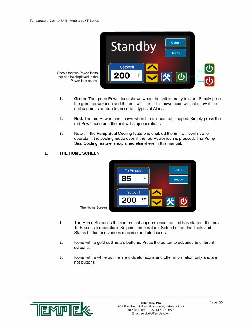
1. Green. The green Power icon shows when the unit is ready to start. Simply press the green power icon and the unit will start. This power icon will not show if the unit can not start due to an certain types of Alerts.
2. Red. The red Power Icon shows when the unit can be stopped. Simply press the red Power icon and the unit will stop operations.
3. Note : If the Pump Seal Cooling feature is enabled the unit will continue to operate in the cooling mode even if the red Power icon is pressed. The Pump Seal Cooling feature is explained elsewhere in this manual.
E. THE HOME SCREEN
1. The Home Screen is the screen that appears once the unit has started. It offers To Process temperature, Setpoint temperature, Setup button, the Tools and Status button and various machine and alert icons.
2. Icons with a gold outline are buttons. Press the button to advance to different screens.
3. Icons with a white outline are indicator icons and offer information only and are not buttons.
Setpoint
200 °F
Setup
ReadyStandby
Shows the two Power Icons that can be displayed in the
Power Icon space.
The Home Screen
Setpoint
200 °F
To Process
85 °F
Setup
Ready
Temperature Control Unit : Veteran LXT Series
Page: 31TEMPTEK, INC.525 East Stop 18 Road Greenwood, Indiana 46142
317-887-6352 Fax: 317-881-1277Email: [email protected]
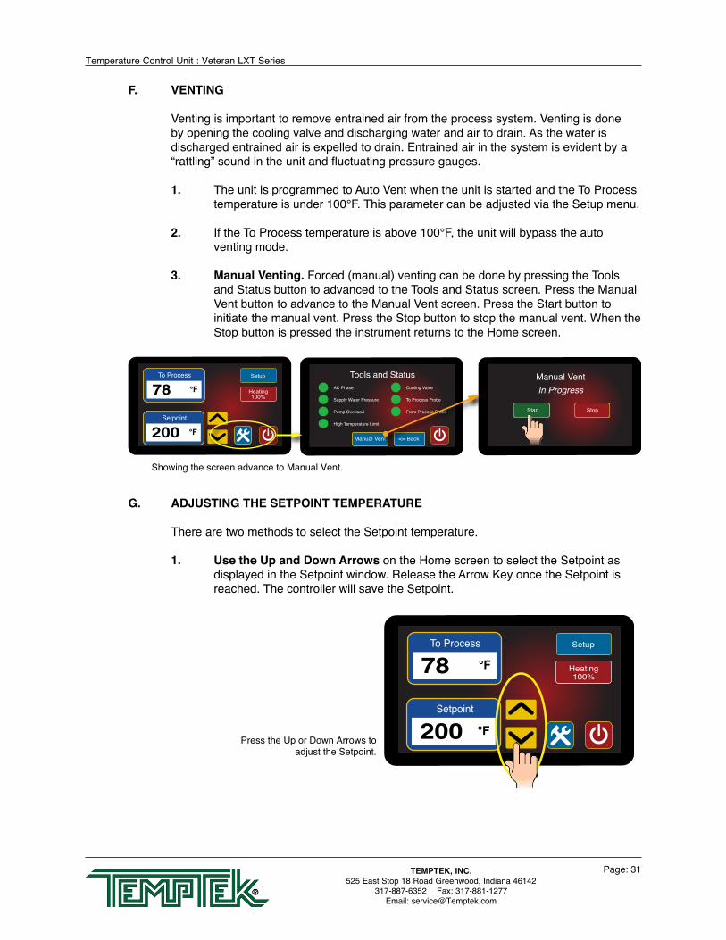
F. VENTING
Venting is important to remove entrained air from the process system. Venting is done by opening the cooling valve and discharging water and air to drain. As the water is discharged entrained air is expelled to drain. Entrained air in the system is evident by a “rattling” sound in the unit and fluctuating pressure gauges.
1. The unit is programmed to Auto Vent when the unit is started and the To Process temperature is under 100°F. This parameter can be adjusted via the Setup menu.
2. If the To Process temperature is above 100°F, the unit will bypass the auto venting mode.
3. Manual Venting. Forced (manual) venting can be done by pressing the Tools and Status button to advanced to the Tools and Status screen. Press the Manual Vent button to advance to the Manual Vent screen. Press the Start button to initiate the manual vent. Press the Stop button to stop the manual vent. When the Stop button is pressed the instrument returns to the Home screen.
G. ADJUSTING THE SETPOINT TEMPERATURE
There are two methods to select the Setpoint temperature.
1. Use the Up and Down Arrows on the Home screen to select the Setpoint as displayed in the Setpoint window. Release the Arrow Key once the Setpoint is reached. The controller will save the Setpoint.
To Process
78 °F
Setpoint
200 °F
Setup
Heating100%
<< BackManual Vent
AC Phase
Supply Water Pressure
Pump Overlaod
High Temperature Limit
Cooling Valve
To Process Probe
From Process Probe
Tools and Status
StopStart
Manual VentIn Progress
Showing the screen advance to Manual Vent.
Press the Up or Down Arrows to adjust the Setpoint.
To Process
78 °F
Setpoint
200 °F
Setup
Heating100%
Temperature Control Unit : Veteran LXT Series
Page: 32TEMPTEK, INC.525 East Stop 18 Road Greenwood, Indiana 46142
317-887-6352 Fax: 317-881-1277Email: [email protected]
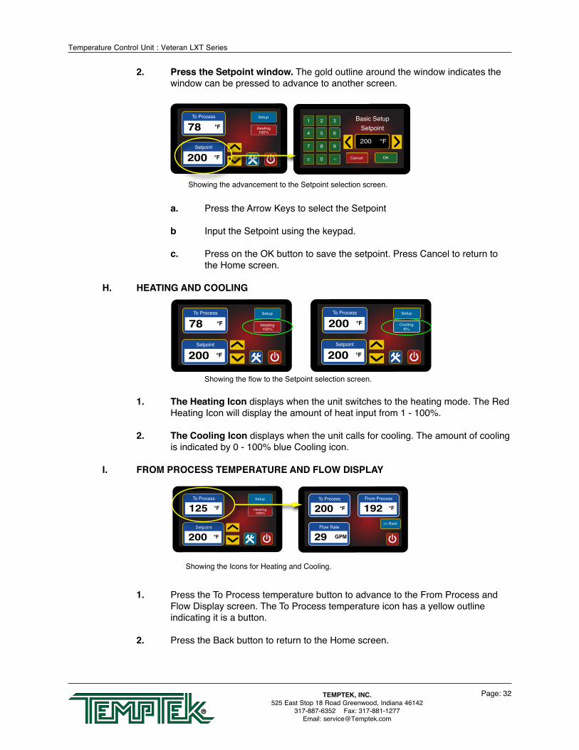
2. Press the Setpoint window. The gold outline around the window indicates the window can be pressed to advance to another screen.
a. Press the Arrow Keys to select the Setpoint
b Input the Setpoint using the keypad.
c. Press on the OK button to save the setpoint. Press Cancel to return to the Home screen.
H. HEATING AND COOLING
1. The Heating Icon displays when the unit switches to the heating mode. The Red Heating Icon will display the amount of heat input from 1 - 100%.
2. The Cooling Icon displays when the unit calls for cooling. The amount of cooling is indicated by 0 - 100% blue Cooling icon.
I. FROM PROCESS TEMPERATURE AND FLOW DISPLAY
1. Press the To Process temperature button to advance to the From Process and Flow Display screen. The To Process temperature icon has a yellow outline indicating it is a button.
2. Press the Back button to return to the Home screen.
To Process
125 °F
Setpoint
200 °F
Setup
Heating100%
To Process
200 °F
From Process
192 °F
Flow Rate
29 GPM
<< Back
To Process
200 °F
From Process
192 °F
Flow Rate
29 GPM
<< Back
Showing the Icons for Heating and Cooling.
To Process
78 °F
Setpoint
200 °F
Setup
Heating100%
<< BackManual Vent
AC Phase
Supply Water Pressure
Pump Overlaod
High Temperature Limit
Cooling Valve
To Process Probe
From Process Probe
Tools and Status
StopStart
Manual VentIn Progress
1 2 3
4 5 6
7 8 9
c 0 <<
200 °F
Cancel
Basic SetupSetpoint
OK
Showing the advancement to the Setpoint selection screen.
To Process
78 °F
Setpoint
200 °F
Setup
Heating100%
To Process
200 °F
Setpoint
200 °F
Setup
Cooling8%
Showing the flow to the Setpoint selection screen.

Temperature Control Unit : Veteran LXT Series
Page: 33TEMPTEK, INC.525 East Stop 18 Road Greenwood, Indiana 46142
317-887-6352 Fax: 317-881-1277Email: [email protected]
J. SETUP BUTTON AND SCREENS Setup, Advanced Setup and Machine Setup screens are displayed by pressing the blue
Setup button and advancing to the Basic Setup Screen. The Remote, Features and Machine items can be pressed to advance to those screens. The Setup button can be pressed any time it is displayed to advance to the Basic Setup screen and then to the other set up screens.
3.4 INSTRUMENT OPERATION : BASIC SETUP
A. This is the first screen in the Setup rotation of three screens. The Setup screen allows the user to configure a Low Flow Alarm along with High and Low temperature Deviation. Pressing the Home button will the user to the Home screen.
B. Low Flow Alarm. Press the yellow outline box next to Low Flow Alarm to select the value. Press OK to save the value and return to the Setup screen.
C. High and Low Deviation. Press the yellow outline boxes next to High Deviation or Low Deviation to select the respective value. A minimum temperature deviation of 5°F is recommended. An alert is provided when the current value is outside the specified range for approximately 1 minute. The High and Low temperature alert is set by entering a deviation from current setpoint and is not an absolute value. The deviation value follows any setpoint change. No need to reset the deviation values with the setpoint is changed.
To Process
125 °F
Setpoint
200 °F
Setup
Heating100%
Basic Remote Features Machine
Low Flow Alarm
10 High Deviation°F
0 GPM
10 Low Deviation°F
Basic Remote Features Machine
Interface
Pump SealCooling
Autovent
Max Setpoint
Alarm Output
Flow
Pump SealCooling
Autovent
Mold PugeEnable
Valve Size
Heat Only Mode SystemInformation
Showing the Setup screens • Basic • Remote • Features • Machine
To Process
125 °F
Setpoint
200 °F
Setup
Heating100% 10 High Devivation°F
10 Low Devivation°F
10 Low Flow AlarmGPM
<< Back
More
Setup
1 2 3
4 5 6
7 8 9
c 0 <<
0
Cancel OK
MachineConfigurationLow Flow Alarm
1 2 3
4 5 6
7 8 9
c 0 <<
0
Cancel OK
MachineConfiguration
High Deviation
1 2 3
4 5 6
7 8 9
c 0 <<
0
Cancel OK
MachineConfiguration
Low Deviation
Basic Remote Features Machine
Low Flow Alarm
10 High Deviation°F
0 GPM
10 Low Deviation°F

Temperature Control Unit : Veteran LXT Series
Page: 34TEMPTEK, INC.525 East Stop 18 Road Greenwood, Indiana 46142
317-887-6352 Fax: 317-881-1277Email: [email protected]
3.5 INSTRUMENT OPERATION : ADVANCED SETUP
A. The Remote Setup allows the user to customize the unit parameters for Second Setpoint, Remote Start/Stop, Remote Setpoint and Communications.
B. Pressing the Home button returns the user to the Home screen.
C. Second Setpoint. This screen allows the user to configure a second setpoint. A Second setpoint is a temperature the unit will control to for other purposes.
1. Enable. Select Yes or No. 2. Deviation. Press to advance to the Second Setpoint Deviation screen to select
the deviation temperature.3. Delay. Press to advance to the Second Setpoint Delay screen to select the delay
in seconds.
D. Remote Start/Stop. See factory for information on this item.
E. Remote Setpoint. This screen allows the user to configure the remote setpoint.
1. Special hardware is required for remote setpoint including a cable and box, which must be installed prior to selecting this parameter.
To Process
125 °F
Setpoint
200 °F
Setup
Heating100% 10 High Devivation°F
10 Low Devivation°F
10 Low Flow AlarmGPM
<< Back
More
Setup
<< Back
MoreSecond Setpoint Pump SealCooling
Communicatons Auto Vent
InterfaceRemoteSetpoint
Advanced SetupBasic Remote Features Machine
Low Flow Alarm
10 High Deviation°F
0 GPM
10 Low Deviation°F
Basic Remote Features Machine
Second Setpoint
RemoteStart/Stop
RemoteSetpoint
Communication
Showing the screen advance to the Remote Setup screen.
To Process
125 °F
Setpoint
200 °F
Setup
Heating100% 10 High Devivation°F
10 Low Devivation°F
10 Low Flow AlarmGPM
<< Back
More
Setup
<< Back
MoreSecond Setpoint Pump SealCooling
Communicatons Auto Vent
InterfaceRemoteSetpoint
Advanced Setup
No Enable
0 Deviation°F
0 Delaysec
<< Back
Second Setpoint
1 2 3
4 5 6
7 8 9
c 0 <<
0
Cancel OK
MachineConfiguration
Second Setpoint Delay
1 2 3
4 5 6
7 8 9
c 0 <<
0
Cancel OK
MachineConfiguration
Second Setpoint Deviation
Cancel OK
Second SetpointEnable
NoYes
Basic Remote Features Machine
Low Flow Alarm
10 High Deviation°F
0 GPM
10 Low Deviation°F
Basic Remote Features Machine
Second Setpoint
RemoteStart/Stop
RemoteSetpoint
Communication
Showing the screen advance to the Second Setpoint screens.

Temperature Control Unit : Veteran LXT Series
Page: 35TEMPTEK, INC.525 East Stop 18 Road Greenwood, Indiana 46142
317-887-6352 Fax: 317-881-1277Email: [email protected]
2. Select Yes or No. The selection donut will indicate the selection. Press OK to save the selection. Press Cancel to cancel the selection.
3. The factory default for Remote Setpoint is No.
D. Communications. This screen allows the user to configure the communications protocol. Select SPI, Modbus or Camac and press OK to save the selection.
The communication port is located near the top of the unit on the sheet metal panel.
1. SPI. This common protocol is used by many processors and auxiliary equipment.
2. Modbus. This network protocol.
3. Camac. This protocol is used with Milacron machinery.
To Process
125 °F
Setpoint
200 °F
Setup
Heating100% 10 High Devivation°F
10 Low Devivation°F
10 Low Flow AlarmGPM
<< Back
More
Setup
<< Back
MoreSecond Setpoint Pump SealCooling
Communicatons Auto Vent
InterfaceRemoteSetpoint
Advanced Setup
Cancel OK
Basic SetupRemote Setpoint Enable
NoYes
Basic Remote Features Machine
Low Flow Alarm
10 High Deviation°F
0 GPM
10 Low Deviation°F
Basic Remote Features Machine
Second Setpoint
RemoteStart/Stop
RemoteSetpoint
Communication
Showing the screen advance to the Remote Setpoint Enable screen.
To Process
125 °F
Setpoint
200 °F
Setup
Heating100% 10 High Devivation°F
10 Low Devivation°F
10 Low Flow AlarmGPM
<< Back
More
Setup
<< Back
MoreSecond Setpoint Pump SealCooling
Communicatons Auto Vent
InterfaceRemoteSetpoint
Advanced Setup
Cancel OK
Communication Protocol
ModbusSPI
Camac
Basic Remote Features Machine
Low Flow Alarm
10 High Deviation°F
0 GPM
10 Low Deviation°F
Basic Remote Features Machine
Second Setpoint
RemoteStart/Stop
RemoteSetpoint
Communication
Showing the screen advance to the Communication Protocol screen.
Typical location of the Communications port

Temperature Control Unit : Veteran LXT Series
Page: 36TEMPTEK, INC.525 East Stop 18 Road Greenwood, Indiana 46142
317-887-6352 Fax: 317-881-1277Email: [email protected]
3.6 INSTRUMENT OPERATION : FEATURES SETUP
A. This is the Features screen allows the operator to program settings for Interface, Pump Seal Cooling, Autovent, Screen Locking and Pump Stopped Alarm.
B. Pressing the Home button returns the user to the Home screen.
C. Interface. This screen allows the user to select language and units.
1. Press Language to advance to the Language/Ldioma screen. Select English or Spanish. The selection icon appears next to the selection. Press OK to save the selection. The default is English. Press Cancel to keep the selection as is and to close the screen.
2. Press Units to advance to the Units screen. Select Imperial or Metric. The selection icon appears next to the selection. The default is Imperial. Press OK to save the selection. The default is English. Press Cancel to keep the selection as
D. Pump Seal Cooling. This screen allows the user to configure the pump seal cooling parameter.
1. Pump seal cooling is a feature to automatically cool the unit before shut down, after the user has pressed the red Shut Down button.
To Process
125 °F
Setpoint
200 °F
Setup
Heating100%
English Language / Idioma
Imperial Units<< Back
User Interface
Cancel OK
Basic SetupLanguage / Idioma
English / IngélsSpanish / Español
Cancel OK
Basic SetupUnits
ImperialMetric
Basic Remote Features Machine
Low Flow Alarm
10 High Deviation°F
0 GPM
10 Low Deviation°F
Basic Remote Features Machine
Interface
Pump SealCooling
Autovent
Screen Locking
Pump StoppedAlarm
Showing screen advance to the Interface screens.
To Process
125 °F
Setpoint
200 °F
Setup
Heating100%
Basic Remote Features Machine
Low Flow Alarm
10 High Deviation°F
0 GPM
10 Low Deviation°F
Basic Remote Features Machine
Interface
Pump SealCooling
Autovent
Screen Locking
Pump StoppedAlarm
Showing the screen advance to the Remote Setup screen.

Temperature Control Unit : Veteran LXT Series
Page: 37TEMPTEK, INC.525 East Stop 18 Road Greenwood, Indiana 46142
317-887-6352 Fax: 317-881-1277Email: [email protected]
2. For example, if the unit is operating at a high temperature and the user presses the red Shut Down button, the unit will continue to operate in the cooling mode until the Pump Seal Cooling Temperature is reached or the Pump Seal Cooling Time has elapsed.
3. Pump Seal Cooling Enabled. Select Yes or No. The selection donut will indicate the selection. Press OK to save the selection. Press Cancel to cancel the selection. The factory default is Yes.
4. Pump Seal Cooling Temp. Select the temperature the unit will cool to when Pump Seal Cooling is enabled.
5. Pump Seal Cooling Time. Select the amount of time the unit will engage the Pump Seal Cooling feature.
6. Note. The Pump Seal Cooling will cool down to the selected temperature or the programed time, whichever occurs first.
E. Auto Vent. This screen allows the user to select the autovent temperature and duration.
1. As the factory default, when the unit is started and if the process temperature is under 100°F the unit will autovent for 30 seconds.
2. The user can configure this screen to set the temperature at which autovent can occur and the duration of the autovent.
F. Screen Locking. Please consult the factory on this feature
G. Pump Stopped Alarm. Please consult the factory on this feature
To Process
125 °F
Setpoint
200 °F
Setup
Heating100% 10 High Devivation°F
10 Low Devivation°F
10 Low Flow AlarmGPM
<< Back
More
Setup
<< Back
MoreSecond Setpoint Pump SealCooling
Communicatons Auto Vent
InterfaceRemoteSetpoint
Advanced Setup
Yes Enable
100 Temperature°F
45 Maximum Timesec
<< Back
Pump Seal Cooling
Cancel OK
Pump Seal CoolingEnable
NoYes
1 2 3
4 5 6
7 8 9
c 0 <<
0 °F
Cancel OK
MachineConfiguration
Pump Seal Cooling Temp1 2 3
4 5 6
7 8 9
c 0 <<
0 sec
Cancel OK
MachineConfiguration
Pump Seal Cooling Time
Basic Remote Features Machine
Low Flow Alarm
10 High Deviation°F
0 GPM
10 Low Deviation°F
Basic Remote Features Machine
Second Setpoint
RemoteStart/Stop
RemoteSetpoint
Communication
Basic Remote Features Machine
Interface
Pump SealCooling
Autovent
Screen Locking
Pump StoppedAlarm
Showing screen advance to the Pump Seal Cooling screens.
Temperature Control Unit : Veteran LXT Series
Page: 38TEMPTEK, INC.525 East Stop 18 Road Greenwood, Indiana 46142
317-887-6352 Fax: 317-881-1277Email: [email protected]
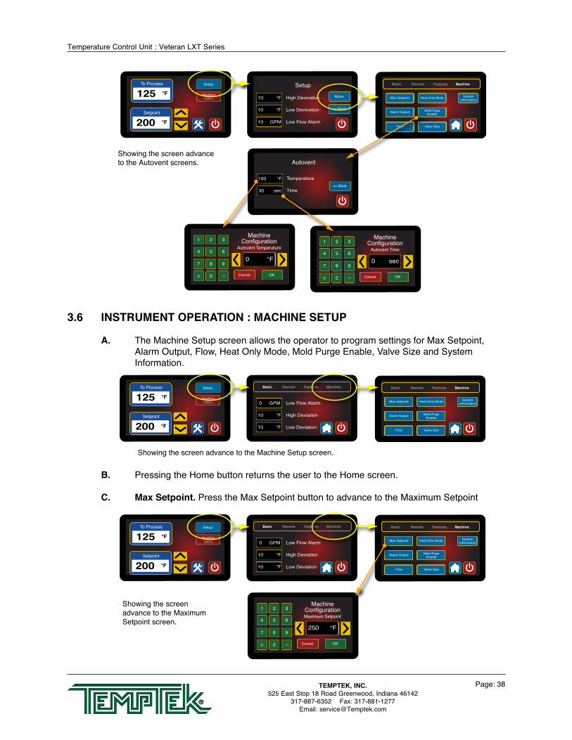
3.6 INSTRUMENT OPERATION : MACHINE SETUP
A. The Machine Setup screen allows the operator to program settings for Max Setpoint, Alarm Output, Flow, Heat Only Mode, Mold Purge Enable, Valve Size and System Information.
B. Pressing the Home button returns the user to the Home screen.
C. Max Setpoint. Press the Max Setpoint button to advance to the Maximum Setpoint
To Process
125 °F
Setpoint
200 °F
Setup
Heating100%
Basic Remote Features Machine
Low Flow Alarm
10 High Deviation°F
0 GPM
10 Low Deviation°F
Basic Remote Features Machine
Interface
Pump SealCooling
Autovent
Max Setpoint
Alarm Output
Flow
Pump SealCooling
Autovent
Mold PugeEnable
Valve Size
Heat Only Mode SystemInformation
Showing the screen advance to the Machine Setup screen.
To Process
125 °F
Setpoint
200 °F
Setup
Heating100%
1 2 3
4 5 6
7 8 9
c 0 <<
250 °F
Cancel OK
MachineConfigurationMaximum Setpoint
Basic Remote Features Machine
Low Flow Alarm
10 High Deviation°F
0 GPM
10 Low Deviation°F
Basic Remote Features Machine
Interface
Pump SealCooling
Autovent
Max Setpoint
Alarm Output
Flow
Pump SealCooling
Autovent
Mold PugeEnable
Valve Size
Heat Only Mode SystemInformation
Showing the screen advance to the Maximum Setpoint screen.
To Process
125 °F
Setpoint
200 °F
Setup
Heating100% 10 High Devivation°F
10 Low Devivation°F
10 Low Flow AlarmGPM
<< Back
More
Setup
<< Back
MoreSecond Setpoint Pump SealCooling
Communicatons Auto Vent
InterfaceRemoteSetpoint
Advanced Setup
Temperature100
Time
°F
30 sec<< Back
Autovent
1 2 3
4 5 6
7 8 9
c 0 <<
0 °F
Cancel OK
MachineConfiguration
Autovent Temperature1 2 3
4 5 6
7 8 9
c 0 <<
0 sec
Cancel OK
MachineConfiguration
Autovent Time
Basic Remote Features Machine
Interface
Pump SealCooling
Autovent
Max Setpoint
Alarm Output
Flow
Pump SealCooling
Autovent
Mold PugeEnable
Valve Size
Heat Only Mode SystemInformation
Showing the screen advance to the Autovent screens.

Temperature Control Unit : Veteran LXT Series
Page: 39TEMPTEK, INC.525 East Stop 18 Road Greenwood, Indiana 46142
317-887-6352 Fax: 317-881-1277Email: [email protected]
screen. This screen allows the user to select the maximum setpoint for the unit.
1. This feature is useful in some application where the setpoint must never be changed above a certain temperature. The Maximum Setpoint can never exceed 250°F in the Temptender unit. The factory default value is 250°F.
2. Use the keypad or the arrow keys to input the value and then press OK to save and return to the Machine Setup screen. Press Cancel to not save the new value and to return to the Machine Setup screen.
D. Alarm Output. Press the Alarm Output button to advance to the Alarm Output screen. This screen allows the user to select the manner of alarm signal.
Note: this selection requires additional hardware. See factory for details.
1. Audible Alert. Select if unit is equipped with an audible alarm.
2. Visual Alert. Select if unit is equipped with an visual alarm.
3. Process Out-Of-Spec. See factory for details about this item.
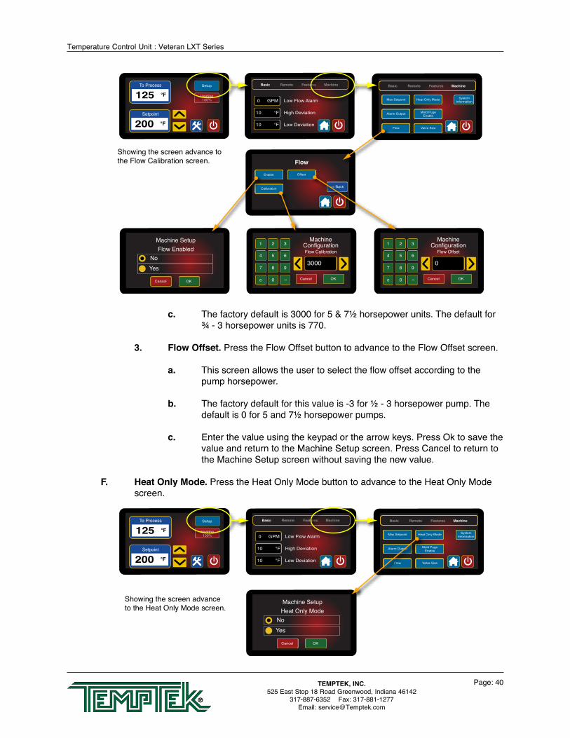
E. Flow. Press the Flow button to advance to the Flow screens. This screen allows the user to select parameters regarding the flow display.
1. Enabled. Select Yes to enable the flow display. Select No to disable.
2. Flow Calibration. Press the Flow Calibration button to advance to the Flow Calibration screen.
a. Using a reliable and accurate external flow meter the user can input the value in this screen to match the unit’s displayed flow to the external flow meter.
b Use the keypad or the arrow keys to input the value and then press OK to save and return to the Machine Setup screen. Press Cancel to return to the Machine Setup screen without saving the new value.
To Process
125 °F
Setpoint
200 °F
Setup
Heating100% 10 High Devivation°F
10 Low Devivation°F
10 Low Flow AlarmGPM
<< Back
More
Setup
<< Back
MoreSecond Setpoint Pump SealCooling
Communicatons Auto Vent
InterfaceRemoteSetpoint
Advanced Setup
1 2 3
4 5 6
7 8 9
c 0 <<
250 °F
Cancel OK
MachineConfigurationMaximum Setpoint
Basic Remote Features Machine
Low Flow Alarm
10 High Deviation°F
0 GPM
10 Low Deviation°F
Basic Remote Features Machine
Interface
Pump SealCooling
Autovent
Max Setpoint
Alarm Output
Flow
Pump SealCooling
Autovent
Mold PugeEnable
Valve Size
Heat Only Mode SystemInformation
Cancel OK
Alarm Output Mode
Visual AlertAudible Alert
Process out-of-spec
Showing the screen advance to the Alarm Output screen.
Temperature Control Unit : Veteran LXT Series
Page: 40TEMPTEK, INC.525 East Stop 18 Road Greenwood, Indiana 46142
317-887-6352 Fax: 317-881-1277Email: [email protected]
c. The factory default is 3000 for 5 & 7½ horsepower units. The default for ¾ - 3 horsepower units is 770.
3. Flow Offset. Press the Flow Offset button to advance to the Flow Offset screen.
a. This screen allows the user to select the flow offset according to the pump horsepower.
b. The factory default for this value is -3 for ½ - 3 horsepower pump. The default is 0 for 5 and 7½ horsepower pumps.
c. Enter the value using the keypad or the arrow keys. Press Ok to save the value and return to the Machine Setup screen. Press Cancel to return to the Machine Setup screen without saving the new value.
F. Heat Only Mode. Press the Heat Only Mode button to advance to the Heat Only Mode screen.
To Process
125 °F
Setpoint
200 °F
Setup
Heating100%
Cancel OK
Machine SetupHeat Only Mode
NoYes
Basic Remote Features Machine
Interface
Pump SealCooling
Autovent
Max Setpoint
Alarm Output
Flow
Pump SealCooling
Autovent
Mold PugeEnable
Valve Size
Heat Only Mode SystemInformation
Basic Remote Features Machine
Low Flow Alarm
10 High Deviation°F
0 GPM
10 Low Deviation°F
Showing the screen advance to the Heat Only Mode screen.
To Process
125 °F
Setpoint
200 °F
Setup
Heating100%
Basic Remote Features Machine
Low Flow Alarm
10 High Deviation°F
0 GPM
10 Low Deviation°F
Basic Remote Features Machine
Second Setpoint
RemoteStart/Stop
RemoteSetpoint
Communication
Basic Remote Features Machine
Interface
Pump SealCooling
Autovent
<< Back
Pump SealCoolingOffsetPump Seal
CoolingEnable
Pump SealCoolingCalibration
Flow
Basic Remote Features Machine
Interface
Pump SealCooling
Autovent
Max Setpoint
Alarm Output
Flow
Pump SealCooling
Autovent
Mold PugeEnable
Valve Size
Heat Only Mode SystemInformation
Cancel OK
Machine SetupFlow Enabled
NoYes
1 2 3
4 5 6
7 8 9
c 0 <<
3000
Cancel OK
MachineConfigurationFlow Calibration
1 2 3
4 5 6
7 8 9
c 0 <<
0
Cancel OK
MachineConfiguration
Flow Offset
Showing the screen advance to the Flow Calibration screen.
Temperature Control Unit : Veteran LXT Series
Page: 41TEMPTEK, INC.525 East Stop 18 Road Greenwood, Indiana 46142
317-887-6352 Fax: 317-881-1277Email: [email protected]
1. This screen allows the user to select the heat only mode. In this mode, the unit will only use the heater. The cooling valve will be disabled in this mode.
2. Press Yes or No to select the heat only mode. The selection donut indication displays next to the selection. Press Cancel to return to the Machine Setup screen without saving the new value.
3. The factory default value is No.
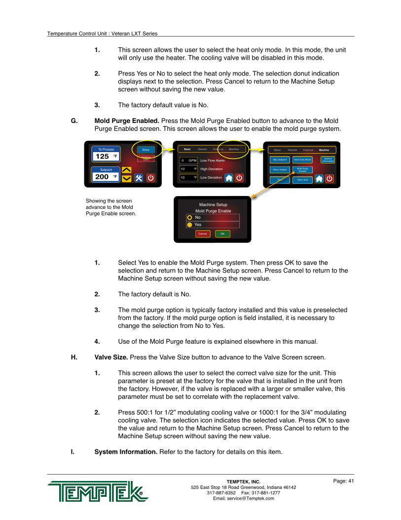
G. Mold Purge Enabled. Press the Mold Purge Enabled button to advance to the Mold Purge Enabled screen. This screen allows the user to enable the mold purge system.
1. Select Yes to enable the Mold Purge system. Then press OK to save the selection and return to the Machine Setup screen. Press Cancel to return to the Machine Setup screen without saving the new value.
2. The factory default is No.
3. The mold purge option is typically factory installed and this value is preselected from the factory. If the mold purge option is field installed, it is necessary to change the selection from No to Yes.
4. Use of the Mold Purge feature is explained elsewhere in this manual.
H. Valve Size. Press the Valve Size button to advance to the Valve Screen screen.
1. This screen allows the user to select the correct valve size for the unit. This parameter is preset at the factory for the valve that is installed in the unit from the factory. However, if the valve is replaced with a larger or smaller valve, this parameter must be set to correlate with the replacement valve.
2. Press 500:1 for 1/2” modulating cooling valve or 1000:1 for the 3/4” modulating cooling valve. The selection icon indicates the selected value. Press OK to save the value and return to the Machine Setup screen. Press Cancel to return to the Machine Setup screen without saving the new value.
I. System Information. Refer to the factory for details on this item.
To Process
125 °F
Setpoint
200 °F
Setup
Heating100%
Cancel OK
Machine SetupMold Purge EnableNoYes
Basic Remote Features Machine
Low Flow Alarm
10 High Deviation°F
0 GPM
10 Low Deviation°F
Basic Remote Features Machine
Interface
Pump SealCooling
Autovent
Max Setpoint
Alarm Output
Flow
Pump SealCooling
Autovent
Mold PugeEnable
Valve Size
Heat Only Mode SystemInformation
Showing the screen advance to the Mold Purge Enable screen.

Temperature Control Unit : Veteran LXT Series
Page: 42TEMPTEK, INC.525 East Stop 18 Road Greenwood, Indiana 46142
317-887-6352 Fax: 317-881-1277Email: [email protected]
3.7 INSTRUMENT OPERATION : TOOLS AND STATUS
A. Press the Tools and Status Button from the Home screen to advance to the Tools and Status screen. This screen gives the user insights into the operation and status of the unit.
1. A Green light indicate the item is functioning normally.
2. A Red light indicates the item is in a stop or error condition. Refer to the troubleshooting section for more information on items that have caused a stop or error condition.
B. Manual Vent. Press the Manual Vent button to advance to the Manual Vent screen. Press Start button to initiate the venting process. Press the Stop button to stop the manual vent cycle.
C. AC Phase. If the AC Phase light is red the unit is not correctly phase. Press AC Phase to advance to the AC Phase screen to determine the recommended action to correct the phase issue.
AlertAC 3-PhaseSetpoint
200 °F
Setup
ReadyStandby
<< BackManual Vent
AC Phase
Supply Water Pressure
Pump Overlaod
High Temperature Limit
Cooling Valve
To Process Probe
From Process Probe
Tools and Status AC PhaseAC Phase indicates thatthe pump is turning in thewrong direction.
Action : follow all safetyrequirements and reverseany two power leads at themain disconnect.
<< Back
Showing the screen advance to the AC Phase screen.
To Process
125 °F
Setpoint
200 °F
Setup
Heating100%
Cancel OK
Machine SetupValve Size
500:11000:1
Basic Remote Features Machine
Interface
Pump SealCooling
Autovent
Max Setpoint
Alarm Output
Flow
Pump SealCooling
Autovent
Mold PugeEnable
Valve Size
Heat Only Mode SystemInformation
Basic Remote Features Machine
Low Flow Alarm
10 High Deviation°F
0 GPM
10 Low Deviation°F
Showing the screen advance to the Valve Size screen.
To Process
125 °F
Setpoint
200 °F
Setup
Heating100%
<< BackManual Vent
AC Phase
Supply Water Pressure
Pump Overlaod
High Temperature Limit
Cooling Valve
To Process Probe
From Process Probe
Tools and Status AC PhaseAC Phase indicates thatthe pump is turning in thewrong direction.
Action : follow all safetyrequirements and reverseany two power leads at themain disconnect.
<< Back
Showing the screen advance to the Tools and Status screen.

Temperature Control Unit : Veteran LXT Series
Page: 43TEMPTEK, INC.525 East Stop 18 Road Greenwood, Indiana 46142
317-887-6352 Fax: 317-881-1277Email: [email protected]
1. A phase issue is usually detected at first start up. In the Standby screen an yellow AC 3-Phase icon will display. The unit will operate if the green Power button is pressed. However, the unit’s pump will operate backwards and there will be minimal flow to process.
2. A phase issue is caused by incorrect incoming power supply. To correct, follow all lock out tag out policies to shut down power to the unit at the disconnect. Reverse any two power wires at the disconnect to correct phase.
3. Do not reverse the unit’s internal wiring to correct a phase condition.
D. Supply Water Pressure. If the Supply Water Pressure light is red there is not enough water supply pressure to allow the unit to run. Press Supply Water Pressure to advance to the Supply Water Pressure screen to determine the recommended action to correct the issue.
1. The unit will not operate without adequate water supply pressure. Sufficient water supply pressure must be present to close the water pressure switch. See Section 2.3 for additional information.
2. At first start up this Alert will display and the unit will not start. If water supply pressure fails during operations, the Alert will show with an Error display on the Home scree.
3. Once adequate water supply pressure is established, the alert will clear automatically.
E. Pump Overload. If the Pump Overload light is red the pump overload is tripped. The
unit will not run if the motor overload is tripped. Press Pump Overload to advance to the Pump Overload informational screen for recommended actions.
1. The Home screen will display the yellow Alert for Motor Overloads. The unit will not run with a Motor Overload alert.
To Process
78 °F
Setpoint
200 °F
Setup
Heating100%
<< BackManual Vent
AC Phase
Supply Water Pressure
Pump Overlaod
High Temperature Limit
Cooling Valve
To Process Probe
From Process Probe
Tools and Status
StopStart
Manual VentIn Progress
Showing the screen advance to the Manual Vent screen.
AlertWater PressureSetpoint
200 °F
Setup
ReadyStandby
<< BackManual Vent
AC Phase
Supply Water Pressure
Pump Overlaod
High Temperature Limit
Cooling Valve
To Process Probe
From Process Probe
Tools and Status Supply Water PressureWater Supply Pressure Errorindicates that the incoming cooling water supply is belowthe minimum required.
Action : be sure that a watersupply is connection and anyvalves are open. Increasewater supplypressure. << Back
Showing the screen advance to the Supply Water Pressure screen.

Temperature Control Unit : Veteran LXT Series
Page: 44TEMPTEK, INC.525 East Stop 18 Road Greenwood, Indiana 46142
317-887-6352 Fax: 317-881-1277Email: [email protected]
This error is triggered by excessive flow causing the pump to draw more amps
then it is rated for. A throttling valve should be placed in the from process line to control flow.
2. At first start up this Alert will display and the unit will not start. If the motor overloads fail during operations, the Alert will show with an Error display on the Home scree.
3. Follow all safety precautions and plant lock out tag out policies to access the electrical panel. Reset the overload by pressing the reset lever.
F. High Temperature Limit. If the High Temperature Limit light is red the high temperature limit switch is tripped. The unit will not run if the high temperature limit is tripped. Press High Temperature Limit to advance to the High Temperature Limit informational screen for recommended actions.
1. The Home screen displays the yellow Alert for High Temp Limit. The unit will not run with a high temperature alert.
2. High temperature conditions are generally caused by inadequate water supply pressure, a defective cooling valve, an obstructed drain line or high back pressure in the drain. Determine the cause and correct. See the troubleshooting section of this manual for more information.
3. The high temperature limit switch will automatically reset as the unit cools.
G. Cooling Valve. If the Cooling Valve light is red the modulating cooling valve is experiencing problems. Press Cooling Valve to advance to the Cooling Valve
To Process
125 °F
Setpoint
200 °F
Setup
Heating100%
AlertHigh TemperatureSetpoint
200 °F
Setup
ReadyStandby
<< BackManual Vent
AC Phase
Supply Water Pressure
Pump Overlaod
High Temperature Limit
Cooling Valve
To Process Probe
From Process Probe
Tools and Status Hi Temperature LimitA high temperature limit errorindicates the Hi Temp Limithas tripped because thefluid temperature limit exceedsswitch setting.
Action : check for cause andallow the unit to cool beforeattempt to restart. << Back
Showing the screen advance to the High Temperature Limit screen.
To Process
125 °F
Setpoint
200 °F
Setup
Heating100%
AlertCooling ValveSetpoint
200 °F
Setup
ReadyStandby
<< BackManual Vent
AC Phase
Supply Water Pressure
Pump Overlaod
High Temperature Limit
Cooling Valve
To Process Probe
From Process Probe
Tools and Status Cooling ValveA Cooling Valve error indicatesvalve did not move to the closedposition when expected.
Action : Check the home positionswitch for obstructions or damage.Replace valve if indicated.
<< Back
Showing the screen advance to the Cooling Valve screen.
To Process
125 °F
Setpoint
200 °F
Setup
Heating100%
AlertMotor OverloadsSetpoint
200 °F
Setup
ReadyStandby
<< BackManual Vent
AC Phase
Supply Water Pressure
Pump Overlaod
High Temperature Limit
Cooling Valve
To Process Probe
From Process Probe
Tools and Status Pump OverloadPump Overload error indicatesthe pump is drawing more current than it is rated for.
Action : reset the pump overload in the electrical panelafter following all safetyprocedures. Reduce the fluidflow rate.
<< Back
Motor Starter
Showing the screen advance to the Pump Overload screen.
Temperature Control Unit : Veteran LXT Series
Page: 45TEMPTEK, INC.525 East Stop 18 Road Greenwood, Indiana 46142
317-887-6352 Fax: 317-881-1277Email: [email protected]
informational screen for recommended actions.
1. The Cooling Valve fault is caused when the valve can not find the ‘home’ position. Many times debris or other obstructions can cause this. If not, the valve could be defective and should be replaced.
2. The unit will continue to run even when a Cooling Valve Alert is present.
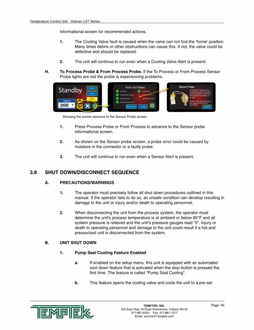
H. To Process Probe & From Process Probe. If the To Process or From Process Sensor Probe lights are red the probe is experiencing problems.
1. Press Process Probe or From Process to advance to the Sensor probe informational screen.
2. As shown on the Sensor probe screen, a probe error could be caused by moisture in the connector or a faulty probe.
3. The unit will continue to run even when a Sensor Alert is present.
3.8 SHUT DOWN/DISCONNECT SEQUENCE
A. PRECAUTIONS/WARNINGS
1. The operator must precisely follow all shut down procedures outlined in this manual. If the operator fails to do so, an unsafe condition can develop resulting in damage to the unit or injury and/or death to operating personnel.
2. When disconnecting the unit from the process system, the operator must determine the unit’s process temperature is at ambient or below 85°F and all system pressure is relieved and the unit’s pressure gauges read “0”. Injury or death to operating personnel and damage to the unit could result if a hot and pressurized unit is disconnected from the system.
B. UNIT SHUT DOWN
1. Pump Seal Cooling Feature Enabled
a. If enabled on the setup menu, this unit is equipped with an automated cool down feature that is activated when the stop button is pressed the first time. The feature is called “Pump Seal Cooling”.
b. This feature opens the cooling valve and cools the unit to a pre-set
To Process
125 °F
Setpoint
200 °F
Setup
Heating100%
AlertSensor (To)Setpoint
200 °F
Setup
ReadyStandby
<< BackManual Vent
AC Phase
Supply Water Pressure
Pump Overlaod
High Temperature Limit
Cooling Valve
To Process Probe
From Process Probe
Tools and Status Sensor ProbeA Probe error indicates that atemperature probe is reportingfaulty information. The Systemwill coast with no heating or cooling
Action : make sure connector isdry. Replace with a knowngood probe.
<< Back
Showing the screen advance to the Sensor Probe screen.

Temperature Control Unit : Veteran LXT Series
Page: 46TEMPTEK, INC.525 East Stop 18 Road Greenwood, Indiana 46142
317-887-6352 Fax: 317-881-1277Email: [email protected]
temperature or time which is programmed in the setup menu. This feature cools the unit down so that it is at a temperature where it can be safely removed from service.
c. Verify that the feature has cooled the unit to below 85°F before going to step 2 below.
If the temperature is still above 85°F to and follow the procedure listed in step 1.b before following steps 2 - 5 below.
If the temperature is below 85°F follow steps 2 - 5 below to override the automatic feature and stop the unit immediately. The red Shut Off button must be pressed twice to override the feature.
2. Stop operations by pressing the red Shut Off button.
3. Disengage the water supply to the unit by closing the water supply valve (if installed) or by turning off the water supply source at the central control point. If any residual pressure is evident open the pressure relief valve to dissipate.
4. Disengage the power at the fused disconnect. The display will go dark at this time.
5. Before disconnecting and removing the process circuitry, be certain all system pressure is vented and the pressure gauges read “0”. When the process circuitry is disconnected and removed from the unit, a small amount of water will be discharged from the unit. Please note that this water should not be warm or pressurized if all shut down and disconnecting procedures were followed. Remaining process water can be discharged by removing the pump casing drain plug.
6. Follow all lock out tag out requirements.
Pressure relief valve

Temperature Control Unit : Veteran LXT Series
Page: 47TEMPTEK, INC.525 East Stop 18 Road Greenwood, Indiana 46142
317-887-6352 Fax: 317-881-1277Email: [email protected]
4.0 TROUBLESHOOTING 4.1 Unit will not start (Display is not Illuminated) 4.2 Unit will not start (Display Illuminated) 4.3 Unit Stops 4.4 Unit Overheats 4.5 Unit Underheats 4.6 Pressure Relief Valve Leaks 4.7 Cooling Valve Fault
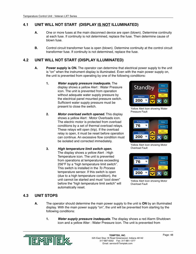
Temperature Control Unit : Veteran LXT Series
Page: 48TEMPTEK, INC.525 East Stop 18 Road Greenwood, Indiana 46142
317-887-6352 Fax: 317-881-1277Email: [email protected]
4.1 UNIT WILL NOT START (DISPLAY IS NOT ILLUMINATED)
A. One or more fuses at the main disconnect device are open (blown). Determine continuity at each fuse. If continuity is not determined, replace the fuse. Then determine cause of blown fuse.
B. Control circuit transformer fuse is open (blown). Determine continuity at the control circuit transformer fuse. If continuity is not determined, replace the fuse.
4.2 UNIT WILL NOT START (DISPLAY ILLUMINATED)
A. Power supply is ON. The operator can determine that electrical power supply to the unit is “on” when the instrument display is illuminated. Even with the main power supply on, the unit is prevented from operating by one of the following conditions:
1. Water supply pressure inadequate. The
display shows a yellow Alert : Water Pressure icon. The unit is prevented from operation without adequate water supply pressure by the electrical panel mounted pressure switch. Sufficient water supply pressure must be present to close the switch.
2. Motor overload switch opened. This display shows a yellow Alert : Motor Overloads icon. The electric motor is protected from overload conditions by a set of thermal overload relays. These relays will open (trip). If the overload relay is open, it must be reset before operation can continue. An excessive flow condition must be isolated and corrected immediately.
3. High temperature limit switch open. The display shows a yellow Alert : High Temperature icon. The unit is prevented from operations at temperatures exceeding 256°F by a “high temperature limit switch”. This switch is installed in the To Process temperature sensor. If this switch is open (due to a high temperature condition), the unit cannot be started and must “cool down” before the “high temperature limit switch” will automatically reset.
4.3 UNIT STOPS
A. The operator should determine the main power supply to the unit is ON by an illuminated display. With the main power supply “on”, the unit will be prevented from starting by the following conditions:
1. Water supply pressure inadequate. The display shows a red Alarm Shutdown icon and a yellow Alter : Water Pressure icon. The unit is prevented from
AlertWater PressureSetpoint
200 °F
Setup
StandbyStandby
Yellow Alert Icon showing Water Pressure Fault
To Process
76 °F
AlertMotor OverloadSetpoint
200 °F
Setup
Standby
Yellow Alert Icon showing Motor Overload Fault
To Process
76 °F
AlertHi TemperatureSetpoint
200 °F
Setup
Standby
Yellow Alert Icon showing Motor Overload Fault

Temperature Control Unit : Veteran LXT Series
Page: 49TEMPTEK, INC.525 East Stop 18 Road Greenwood, Indiana 46142
317-887-6352 Fax: 317-881-1277Email: [email protected]
operation without adequate water supply pressure by the electrical panel mounted pressure switch. Sufficient water supply pressure must be present to close the switch.
2. Motor overload switch opened. The display shows a red Alarm Shutdown icon and a yellow Alter : Motor Overloads icon. The electric motor is protected from overload conditions by a set of thermal overload relays. These relays will open (trip). If the overload relay is open, it must be reset before operation can continue. An excessive flow condition must be isolated and corrected immediately.
3. High temperature limit switch open. The display shows a red Alarm Shutdown icon and a yellow Alter : High Temperature icon. The unit is prevented from operations at temperatures exceeding 256°F by a “high temperature limit switch”. This switch is installed in the To Process temperature sensor. If this switch is open (due to a high temperature condition), the unit cannot be started and must “cool down” before the “high temperature limit switch” will automatically reset.
4.4 UNIT OVERHEATS
A. This is evidenced by To Process temperatures consistently above the selected setpoint temperature. Overheating is also evidenced by a To Process temperature that continues to escalate above the setpoint temperature with no apparent cooling action, even though the blue Cool icon is displayed. Extreme overheating is evidenced by To Process temperatures over 256°F (yellow Alert : High Temperature icon is displayed). The operator should check for the following conditions:
1. Inadequate water supply pressure. The unit must be supplied with adequate water flow to provide cooling when required. The minimum pressure differential between the water supply and drain to achieve full cooling capacity is 10 PSI. The minimum water supply pressure is 20 PSI. A drop in water supply pressure operation will cause the pump to stop and a safety fault to be displayed.
2. AVTTM modulating cooling valve defective. The instrument opens and closes the AVTTM cooling valve in incremental steps between 0 to 100% as prescribed by the current process load. A continual discharge stream of process water to drain is present under most operating conditions (except at full heat-up). This allows the unit to maintain virtual straight-line control of process water temperature. If the AVTTM valve becomes clogged with process water debris or scaled with mineral deposits, its operation is hindered or fully prevented and adequate process water discharge to drain is prevented. The operator must remove the AVTTM valve and remove any loose debris. Massive debris or scale deposits may necessitate replacement of the AVTTM valve. The procedure for servicing the
AlertWater PressureSetpoint
200 °F
Setup
AlarmShutdown
Error
Error Screen showoing Yellow Water Pressure Alert Icon
AlertMotor OverloadsSetpoint
200 °F
Setup
AlarmShutdown
Error
Error Screen showoing Yellow Motor Overload Alert Icon
AlertHigh TemperatureSetpoint
200 °F
Setup
AlarmShutdown
Error
Error Screen showoing Yellow Hight Temperature Alert Icon

Temperature Control Unit : Veteran LXT Series
Page: 50TEMPTEK, INC.525 East Stop 18 Road Greenwood, Indiana 46142
317-887-6352 Fax: 317-881-1277Email: [email protected]
AVTTM valve is outlined in Section 5.3 of this manual. Note: a defective cooling valve may not trigger a yellow Alert : Cooling Valve icon in all cases. The Alert is triggered when the motor movement is not aligned with the home switch.
3. Drain line obstruction. The operator must determine if the drain line is obstructed by the following conditions. Section 2.4 outlines the parameters of correct drain line installation.
a. Closed drain line valve. An installed but partially or fully closed valve in the drain line prevents full discharge to drain and contributes to an overheating condition. The operator should determine the drain line is open.
b. High drain back pressure. Pressurized plant drain lines will prevent flow to drain if the differential between the water supply pressure and the drain line pressure is inadequate. The factory recommended minimum differential is 20 psi. If the differential is less than the factory recommendation, plant service personnel should take measures to reduce drain line pressure.
4. Instrument defective. The instrument is life-tested and found to be field reliable. However, in the case where the instrument is determined to be defective, the operator contact the Service Department for information. The instrument is not a field serviceable component.
4.5 UNIT UNDERHEATS
A. This is evidence by operations with To Process temperatures consistently below the selected setpoint temperature.
1. Process water leakage. When the instrument engages the heater to elevate process temperature, the input of heat into the process can be offset by a defective AVTTM valve. If the AVTTM valve is defective, it may pass a larger than required stream to drain, thus providing unwanted cooling. A defective AVTTM valve should be repaired immediately.
2. Heater element failure. A failed heater element will not input adequate heat into the process to elevate the process water temperature. The operator must check the amps at the heater contactor with the contactor energized. Zero amps at the contactor indicate a failed heater or burnt wire connections. The operator should remove the failed heater and replace with a new heater according to the procedure outlined in section 5.2.
3. Unit capacity too low. This occurs when the process requires more heat than the unit is capable of producing. The only option in such cases is to install a unit with an adequate heater kW rating for the load.
4. Instrument defective. The instrument is life-tested and found to be field reliable. However, in the case where the instrument is determined to be defective, the operator contact the Service Department for information. The instrument is not a field serviceable component.

Temperature Control Unit : Veteran LXT Series
Page: 51TEMPTEK, INC.525 East Stop 18 Road Greenwood, Indiana 46142
317-887-6352 Fax: 317-881-1277Email: [email protected]
4.6 PRESSURE RELIEF VALVE LEAKS
A. The unit has a 150 psi pressure relief valve mounted in the cooling cylinder. If the valve is found to be leaking, the operator should check the following:
1. Water supply pressure exceeds 75 psi. The unit is designed to operate with water supply NOT exceeding 75 psi. See section 2.3 paragraph B for specific water supply pressure requirements at corresponding setpoint temperatures. If the plant water supply pressure exceeds 75 psi, the pressure relief valve may leak. Static water supply pressure can be determined at the unit’s location by reading the unit’s 0-160 PSI pressure gauges when the unit’s motor pump is off. If the water supply pressure at the unit’s location exceeds 75 PSI, a pressure reducing valve must be installed in the water supply line. The factory recommended ‘regulated pressure out’ is 55 PSI. Refer to section 7.3 for regulator installation drawing.
2. Back flow prevention device in water supply line. If a back flow prevention device (check valve, pressure regulator, closed valve) is installed in the water supply line, increased pressures from thermal expansion are unable to move into the water supply line. This will increase the unit’s internal pressure causing the pressure relief valve to leak. Refer to section 7.3 for regulator installation drawing.
3. Valve contamination. The pressure relief valve may become contaminated with water debris causing the valve not to close properly. If this is the case, flushing the valve for a moment will cleanse the seat and allow it to work properly. If flushing the valve does not remedy the leaking, the valve must be replaced.
4. Extreme internal system pressure. If the internal pressure in the unit is elevated, the pressure relief valve will leak as a safety measure to dissipate excessive pressure. If this is the case, the operator must determine why the system internal pressure is excessive and correct the condition.
4.7 COOLING VALVE FAULT
A. AVTTM FAULT. When power is applied, the AVTTM valve begins a ‘homing process’. The valve is turned forward and backward across a limit switch to establish the valve position. If valve position cannot be established, a fault will be displayed.
B. The display will show a yellow Alert : Cooling Valve icon.
C. Refer to section 5.3 for AVTTM service and repair instructions.
Cooling ValveA Cooling Valve error indicatesvalve did not move to the closedposition when expected.
Action : Check the home positionswitch for obstructions or damage.Replace valve if indicated.
<< Back

Page: 52
THIS PAGE INTENTIONALLY BLANK

Temperature Control Unit : Veteran LXT Series
Page: 53TEMPTEK, INC.525 East Stop 18 Road Greenwood, Indiana 46142
317-887-6352 Fax: 317-881-1277Email: [email protected]
5.0 SERVICE/MAINTENANCE 5.1 Pump Seal Replacement 5.2 Heater Replacement 5.3 Cooling Valve Service 5.4 Voltage Change 5.5 Sensor Probe Service 5.6 Pressure Switch Service 5.7 Electronic Instrument Repair Policy & Procedure 5.8 Temperature Probe Calibration 5.9 Heater Contactor & Pump Motor Starter

Temperature Control Unit : Veteran LXT Series
Page: 54TEMPTEK, INC.525 East Stop 18 Road Greenwood, Indiana 46142
317-887-6352 Fax: 317-881-1277Email: [email protected]
5.1 PUMP SEAL REPLACEMENT
A. Most units use a pump seal that is a carbon/ceramic shaft seal assembly including a stationary member, rotating member and tension spring (figure 5.1A).
B. The life cycle of the pump seal is determined by hours of use, operating temperature and water quality. Poor water quality is the primary reason for premature pump seal failure.
C. The operator should follow this procedure to replace the pump seal:
1. Disengage process operations and relieve all system pressure.
2. Disengage main power supply following all lock out tag out requirements. Verify the display is off.
3. Remove the lift-off access panel and set aside (Figure 5.1B).
4. Remove the thermoformed panel. It is attached to the stainless steel cabinet by 4 small screws (figure 5.1C).
5. Drain machine by removing the pump casing drain plug.
6. Remove the three motor wire leads from the motor wiring terminals. The operator should “map” the wire terminal locations to ensure correct rewiring. The power cord should be removed from the motor housing (figure 5.1D).
7. Locate and remove the 4 pump casing bolts. These bolts secure the motor and motor adapter to the pump casing (figure 5.1E).
8. Separate the motor and adapter from the pump casing to expose the pump impeller (figure 5.1F). Remove the motor and adapter from the unit and place on a workbench to continue the procedure.
9. Locate and remove the dust cap from the motor to expose slotted motor shaft. The motor shaft is free to rotate, but must be
Stationary member
Rotating Member Tension Spring
Figure 5.1A
Remove lift-off access panel
Figure 5.1B
Thermoformed panel removed and electrical cabinet open.
Figure 5.1C
Motor leads Figure 5.1D
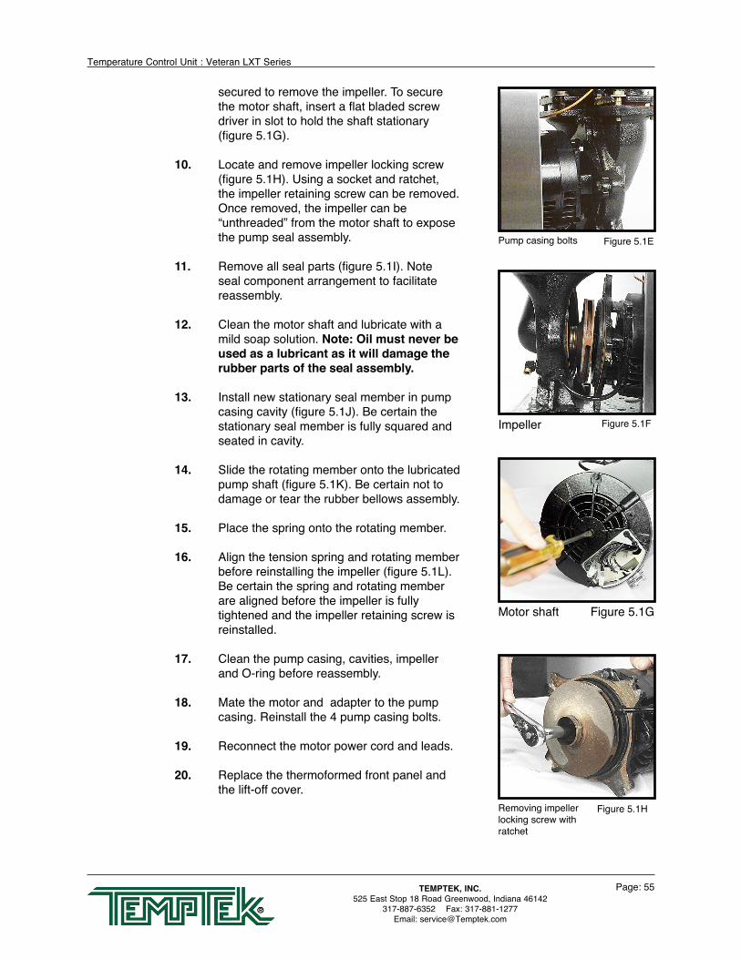
Temperature Control Unit : Veteran LXT Series
Page: 55TEMPTEK, INC.525 East Stop 18 Road Greenwood, Indiana 46142
317-887-6352 Fax: 317-881-1277Email: [email protected]
secured to remove the impeller. To secure the motor shaft, insert a flat bladed screw driver in slot to hold the shaft stationary (figure 5.1G).
10. Locate and remove impeller locking screw (figure 5.1H). Using a socket and ratchet, the impeller retaining screw can be removed. Once removed, the impeller can be “unthreaded” from the motor shaft to expose the pump seal assembly.
11. Remove all seal parts (figure 5.1I). Note seal component arrangement to facilitate reassembly.
12. Clean the motor shaft and lubricate with a mild soap solution. Note: Oil must never be used as a lubricant as it will damage the rubber parts of the seal assembly.
13. Install new stationary seal member in pump casing cavity (figure 5.1J). Be certain the stationary seal member is fully squared and seated in cavity.
14. Slide the rotating member onto the lubricated pump shaft (figure 5.1K). Be certain not to damage or tear the rubber bellows assembly.
15. Place the spring onto the rotating member.
16. Align the tension spring and rotating member before reinstalling the impeller (figure 5.1L). Be certain the spring and rotating member are aligned before the impeller is fully tightened and the impeller retaining screw is reinstalled.
17. Clean the pump casing, cavities, impeller and O-ring before reassembly.
18. Mate the motor and adapter to the pump casing. Reinstall the 4 pump casing bolts.
19. Reconnect the motor power cord and leads.
20. Replace the thermoformed front panel and the lift-off cover.
Pump casing bolts Figure 5.1E
Impeller Figure 5.1F
Motor shaft Figure 5.1G
Removing impeller locking screw with ratchet
Figure 5.1H

Temperature Control Unit : Veteran LXT Series
Page: 56TEMPTEK, INC.525 East Stop 18 Road Greenwood, Indiana 46142
317-887-6352 Fax: 317-881-1277Email: [email protected]
E. When this procedure is complete, the operator may restart the unit. In many cases, a new pump seal will experience a small amount of leakage for a short time. This is normal. After a few moments, the new seal will take seat and the leak will stop.
Seal components Figure 5.1I
Stationary member Figure 5.1J
Rotating member Figure 5.1K
Aligning impeller and spring
Figure 5.1L

Temperature Control Unit : Veteran LXT Series
Page: 57TEMPTEK, INC.525 East Stop 18 Road Greenwood, Indiana 46142
317-887-6352 Fax: 317-881-1277Email: [email protected]
5.2 HEATER REPLACEMENT
A. The heater is a flange mounted assembly and inserted into the cast cylinder tank and secured by 4 bolts (figure 5.2A).
B. The operator can determine if the heater requires replacement when the heater draws “0” amps or when a continuity check of each heater element is negative.
C. Generally, heaters fail due to low water flow, low water pressure, air in the system or defective heating elements.
D. The operator should follow this procedure to replace the heater:
1. Disengage operations and be certain all system pressure is relieved and the unit’s pressure gauges read “0”.
2. Disengage main power supply. Verify the Power light on the display is “off”.
3. Remove the lift-off access panel and set aside
4. Drain machine. The machine can be drained by removing the pump casing drain plug.
5. Remove heater’s junction box cover to locate wiring connections. The operator should note the wiring connections to ensure correct reinstallation (figure 5.2B).
6. Disconnect the three power leads from the heater terminals. Remove the power cord from the junction box.
7. Remove the 4 heater mounting bolts (figure 5.2C).
8. Remove heater (figure 5.2D).
9. Before the new heater is installed, the mating surface of the cast tank should be cleaned. Once cleaned, place the new heater gasket onto the tank mating surface. Coat the mating surface with a high temperature gasket sealant.
10. Set new heater into tank. Aligning the bolt pattern of the heater and tank flanges.
Heater Figure 5.2A
Heater mounting bolts Figure 5.2C
Heater wires Figure 5.2B
Remove heater Figure 5.2D

Temperature Control Unit : Veteran LXT Series
Page: 58TEMPTEK, INC.525 East Stop 18 Road Greenwood, Indiana 46142
317-887-6352 Fax: 317-881-1277Email: [email protected]
11. Replace the 4 heater mounting bolts. Alternate to the opposite bolt while tightening.
12. Reconnect the power cable to the heater terminals. Be certain to tighten the power cord junction box connector. Replace the junction box cover and the lift-off cover panel.
D. When complete, restart the unit.

Temperature Control Unit : Veteran LXT Series
Page: 59TEMPTEK, INC.525 East Stop 18 Road Greenwood, Indiana 46142
317-887-6352 Fax: 317-881-1277Email: [email protected]
5.3 AVTTM COOLING VALVE SERVICE
A. The AVTTM cooling valve is a two component assembly, consisting of the motor/gearbox and valve assembly, mated with a machined aluminum coupling. The AVTTM valve assembly is sheltered by an thermoformed drip cover (figure 5.3A). The drip cover is secured by two nuts and can be removed. When removed, the AVTTM valve components can be viewed (figure 5.3B).
B. The conditions that require servicing of the AVTTM modulating valve are as follows:
Home switch
Coupling
Valve
Motor / Gearbox
ABS drip cover
Cooling Cylinder One piece coupling
Square drive stem
Mounting flange
Stainless valve body
Figure 5.3B
1. Motor/gearbox assembly defective. This condition is evidenced by non-movement of the motor when prompted by the instrument. This is evident when power is engaged to the instrument. The instrument will turn the motor in an attempt to find “home base”. If no movement is
Figure 5.3A

Temperature Control Unit : Veteran LXT Series
Page: 60TEMPTEK, INC.525 East Stop 18 Road Greenwood, Indiana 46142
317-887-6352 Fax: 317-881-1277Email: [email protected]
observed, most likely the motor/gearbox assembly is defective. To be certain, remove the motor as outlined below, maintain the electrical connection and supply power to the instrument. If the motor does not turn, the motor/gearbox should be replaced. If the motor does turn, the operator can determine the valve assembly is defective.
2. Valve assembly defective. The valve assembly may become fouled with process debris or the internal components may be defective.
C. The components of the AVTTM valve can be serviced separately. To begin the AVTTM valve service procedure, proceed with steps 1 - 5:
1. Disengage process operations and verify all system pressure is relieved and the unit’s pressure gauges read “0”.
2. Disengage main power supply and verify the Power light on the display is “off”.
3. Remove the lift-off access panel and set aside.
4. Disconnect the valve wiring harness.
5. Remove the AVTTM valve’s drip cover.
D. To service the motor driver/gearbox components, continue with steps 6 - 12:
6. The motor/gearbox assembly is mounted to the valve bracket and is secured by 2 mounting screws.
NOTE: It will also be necessary to remove the 2 screws that secure the micro switch to completely remove the motor since they are hard wired together.
7. Remove the 2 mounting screws. The motor and gearbox will now be loose. Carefully separate the motor/gearbox from the attached coupling from the valve assembly.
8. Align the motor/gearbox and coupling to the valve assembly.
9. Align the motor/gearbox assembly mounting holes to the holes in the cooling cylinder. Replace the 2 mounting screws and loosely install the microswitch screws.
10. Reconnect the wiring harness. Home base is the reference point from which the controller is able to open the valve incrementally. If the unit is not able to find home, a valve fault “ULU” will appear in the Temperature display window. Adjust the home switch to clear the fault.
11. Adjusting the home switch. Apply power. The coupling should begin to turn. When the lobe on the coupling is directly under the roller for the microswitch, turn off the power. Adjust the microswitch so that the roller fully depresses the microswitch. Turn on the power and the valve should turn forward and backwards a few times and then stop at the home position.
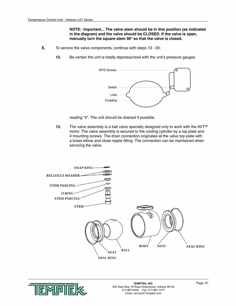
Temperature Control Unit : Veteran LXT Series
Page: 61TEMPTEK, INC.525 East Stop 18 Road Greenwood, Indiana 46142
317-887-6352 Fax: 317-881-1277Email: [email protected]
NOTE: Important... The valve stem should be in this position (as indicated in the diagram) and the valve should be CLOSED. If the valve is open, manually turn the square stem 90° so that the valve is closed.
E. To service the valve components, continue with steps 13 - 20:
12. Be certain the unit is totally depressurized with the unit’s pressure gauges
reading “0”. The unit should be drained if possible.
13. The valve assembly is a ball valve specially designed only to work with the AVTTM motor. The valve assembly is secured to the cooling cylinder by a top plate and 4 mounting screws. The drain connection originates at the valve top plate with a brass elbow and close nipple fitting. The connection can be maintained when servicing the valve.
CouplingLobe
Switch
MTG Screws

Temperature Control Unit : Veteran LXT Series
Page: 62TEMPTEK, INC.525 East Stop 18 Road Greenwood, Indiana 46142
317-887-6352 Fax: 317-881-1277Email: [email protected]
14. Remove the 4 mounting screws. The top plate, mounting bolts, valve assembly and the mounting plate with the attached micro-switch will now be loose. Carefully separate the valve from the motor/gearbox.
15. At this step, the valve can be rebuilt or replaced. To rebuild the valve, order PN 8764939, and install new stem packing O-ring, seal rings, and seats (see diagram below). Once the value is back together, continue with step 17:
16. Aligned the valve assembly coupling to the motor/gearbox and place on the cooling cylinder. A gasket or seal is not required.
17. Replace the top plate, the micro switch mounting plate and the 4 mounting bolts. Tighten the 4 mounting bolts alternating to the opposite bolts.
18. Once power is reapplied, the instrument will align the AVTTM modulating valve to “home base”. Home base is the reference point from which the controller is able to open the valve incrementally. Process operations can resume. If the unit is not able to find home, a valve fault ULU will appear in the temperature display. Readjust the home switch to clear the fault. Adjust the home switch as needed (as outlined in Step 11).
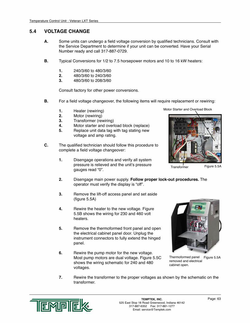
Temperature Control Unit : Veteran LXT Series
Page: 63TEMPTEK, INC.525 East Stop 18 Road Greenwood, Indiana 46142
317-887-6352 Fax: 317-881-1277Email: [email protected]
5.4 VOLTAGE CHANGE
A. Some units can undergo a field voltage conversion by qualified technicians. Consult with the Service Department to determine if your unit can be converted. Have your Serial Number ready and call 317-887-0729.
B. Typical Conversions for 1/2 to 7.5 horsepower motors and 10 to 16 kW heaters:
1. 240/3/60 to 480/3/602. 480/3/60 to 240/3/603. 480/3/60 to 208/3/60
Consult factory for other power conversions.
B. For a field voltage changeover, the following items will require replacement or rewiring:
1. Heater (rewiring)2. Motor (rewiring)3. Transformer (rewiring)4. Motor starter and overload block (replace)5. Replace unit data tag with tag stating new
voltage and amp rating.
C. The qualified technician should follow this procedure to complete a field voltage changeover:
1. Disengage operations and verify all system pressure is relieved and the unit’s pressure gauges read “0”.
2. Disengage main power supply. Follow proper lock-out procedures. The operator must verify the display is “off”.
3. Remove the lift-off access panel and set aside (figure 5.5A)
4. Rewire the heater to the new voltage. Figure 5.5B shows the wiring for 230 and 460 volt heaters.
5. Remove the thermoformed front panel and open the electrical cabinet panel door. Unplug the instrument connectors to fully extend the hinged panel.
6. Rewire the pump motor for the new voltage. Most pump motors are dual voltage. Figure 5.5C shows the wiring schematic for 240 and 480 voltages.
7. Rewire the transformer to the proper voltages as shown by the schematic on the transformer.
Thermoformed panel removed and electrical cabinet open.
Figure 5.5A
Transformer
Motor Starter and Overload Block
Figure 5.5A
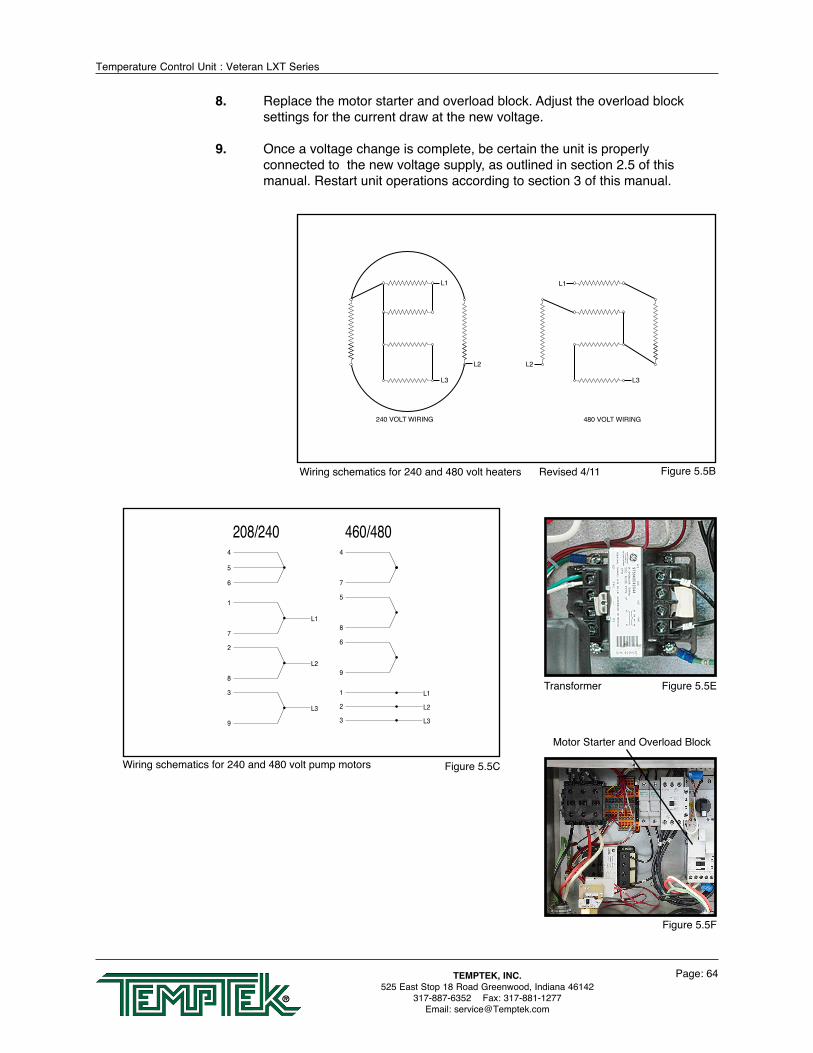
Temperature Control Unit : Veteran LXT Series
Page: 64TEMPTEK, INC.525 East Stop 18 Road Greenwood, Indiana 46142
317-887-6352 Fax: 317-881-1277Email: [email protected]
8. Replace the motor starter and overload block. Adjust the overload block settings for the current draw at the new voltage.
9. Once a voltage change is complete, be certain the unit is properly connected to the new voltage supply, as outlined in section 2.5 of this manual. Restart unit operations according to section 3 of this manual.
4
7
208/2404
5
6
1
L1
7
2
L2
8
3
L3
9
460/480
1 L1
2 L2
3 L3
5
8
6
9
Figure 5.5CWiring schematics for 240 and 480 volt pump motors
Figure 5.5BWiring schematics for 240 and 480 volt heaters Revised 4/11
Transformer Figure 5.5E
Motor Starter and Overload Block
Figure 5.5F

Temperature Control Unit : Veteran LXT Series
Page: 65TEMPTEK, INC.525 East Stop 18 Road Greenwood, Indiana 46142
317-887-6352 Fax: 317-881-1277Email: [email protected]
5.5 SENSOR PROBE SERVICE
A. The temperature probe is a temperature transducer. The transducer is embedded into a bulb well, which is threaded into the tank. The transducer converts the temperature of the water into a proportional current output, which the microprocessor controller reads, displays, and bases it controlling functions. The gain is automatically calibrated within the controller electronics, the zero adjustment potentiometer is located on the CPU.
B. Sensor probe errors are indicated by the Probe Alert on the instrument with a yellow Alert : Sensor (To) or Alert : Sensor (From) icon. When a sensor probe error is displayed, take the following steps to correct:
1. RECONNECTION. If the service connection becomes saturated with water simply unplug the connection, shake out the water and replug. If this was the problem, the yellow Alert icon will disappear. If not, continue with replacement.
2. REPLACEMENT. All factory supplied replacement probes are complete with the service connection. The unit uses two sensor probes. The “high temperature limit” safety switch is a part of the to process probe. To replace follow the procedure as outlined below:
a. Stop process operations as described in section 3.4 of this manual.
b. Determine that all process pressure is relieved and the unit’s pressure gauges read “0” pressure.
c. Drain the unit by removing the pump casing drain plug. The unit can be drained below the sensor probe mount if preferred.
d. Disconnect the sensor probe service plug.
e. Using a crescent wrench, remove the sensor probe from the cylinder. To install a new sensor probe continue as follows:
f. The new sensor probe threads should be lined with teflon tape and coated with leak preventative sealant. Using a crescent wrench, thread the new sensor into the machined boss of the cylinder.
g. Reconnect the service connection. Restart the unit as outlined in section 3 of this manual.
AlertSensor : ToSetpoint
200 °F
Setup
StandbyStandby
Service connection Figure 5.6A
Probe

Temperature Control Unit : Veteran LXT Series
Page: 66TEMPTEK, INC.525 East Stop 18 Road Greenwood, Indiana 46142
317-887-6352 Fax: 317-881-1277Email: [email protected]
5.6 PRESSURE SWITCH SERVICE
A. The unit is protected from low pressure operations by a pressure switch (figure 5.7A). This switch is mounted at the bottom of the electrical cabinet.
B. The switch will close and consent the control circuit when sufficient water supply pressure is presented. The switch is factory set to 20 psi.
C. If insufficient water supply pressure is present, the switch will open and prevent operations. A yellow Alert : Water Pressure icon will appear on the Display.
D. In cases where sufficient water supply pressure is present as indicated by the unit’s pressure gauges and the pump is “off”, and if the pressure switch fails to close, the pressure switch may be defective. To replace the pressure switch, follow the steps outlined:
1. Shut down unit operations according to section 3.4 in this manual. Be certain proper lock-out procedures are followed. Also, be certain system pressure is eliminated and the unit’s pressure gauges read “0” pressure.
2. Drain unit by removing the pump casing drain plug.
3. A capillary runs from the cooling cylinder to the pressure switch. Remove the capillary connection.
4. The brass elbow mounted on the pressure switch must be removed.
5. Remove the electrical connections to the pressure switch.
6. The pressure switch is mounted onto the electrical cabinet with two 1/2” nuts in series. Remove the nuts to remove the pressure switch. A new pressure switch from the factory should be installed by continuing with step 7.
7. Thread one 1/2” nut onto the pressure switch and then place the pressure switch through the panel in the original mounting hole. Thread the second 1/2” nut from the bottom of the pressure switch. Tighten to lock the pressure switch in place.
8. Install the brass elbow fitting. Teflon tape and leak preventative paste should be used to prevent water leakage. Install the capillary tube and resume operations.
Pressure switch Figure 5.7A

Temperature Control Unit : Veteran LXT Series
Page: 67TEMPTEK, INC.525 East Stop 18 Road Greenwood, Indiana 46142
317-887-6352 Fax: 317-881-1277Email: [email protected]
5.7 ELECTRONIC INSTRUMENT REPAIR POLICY AND PROCEDURE
A. All control instruments used in temperature control units are covered by the machine’s warranty. Proprietary ‘tailor made’ instrument are manufactured specifically for the unit.
B . IN WARRANTY SERVICE INCIDENT
1. Call the factory for diagnostic assistance.
2. If a control instrument is determined to be at fault, a new or reconditioned instrument will be sent as a replacement.
3. Return the defective instrument freight pre-paid for full credit. If the defective instrument is not returned you will need to pay for it.
C. OUT OF WARRANTY SERVICE INCIDENT
1. Call the factory for diagnostic assistance.
2. If a control instrument is determined to be at fault, there are 3 options.
a. Purchase a new instrument as a replacement.
b. Send your instrument back for repair, freight prepaid. For a nominal fee, your instrument will be repaired and returned.
c. Purchase a new instrument and repair the old one as a back up.
3. If you are sending your instrument back for repair, call the Service Department for more information. Do not disassemble the instrument.
D. Other Information:
1. Call the factory for current repair charges.
2. Repair warranty: 1 year.
3. Ship to Temptek, 525 East Stop 18 Road, Greenwood, IN 46143. Attention: Repairs (317-887-6352). Include in the shipping box: Part, purchase order, contact name, phone number, and symptom (if available).
4. For Priority service, send the instrument to the factory via overnight shipment. We usually repair these instruments the same day we receive them.

Temperature Control Unit : Veteran LXT Series
Page: 68TEMPTEK, INC.525 East Stop 18 Road Greenwood, Indiana 46142
317-887-6352 Fax: 317-881-1277Email: [email protected]
5.8 TEMPERATURE PROBE CALIBRATION
A. Equipment Needed:
1. Potentiometer adjustment tool / flat-blade screw driver (tip width of 0.050” or less works best
2. Temperature reference (ice water bath)
3. 1/2” plug
4. Digital thermometer
5. Screwdriver (chassis disassembly)
B. Setup:
1. Disengage process operations according to the procedure outlined in the unit manual. The operator must be certain all system pressure is relieved and unit pressure gauges read “0”.
2. Disengage main power supply.
3. Remove the “to process” temperature probe and insert a ½” plug in its place. 4. Prepare an ice bath (a cup of water with lots of ice). You should place a digital
thermometer in the ice bath to read the temperature of the bath. Place the probe in the ice bath.
C. Procedure:
1. Restart the instrument according to the procedures outlined in the unit manual.
2. Reduce the unit’s setpoint to its lowest setting.
3. The “to process” temperature on the display should equal the temperature of the ice bath as indicated by the digital thermometer. If not, change the calibration.
4. The calibration potentiometer is located on the top of the CPU board. To access it, open the electrical cabinet panel door. Caution must be employed when the electrical panel door is open since power is applied to unit.
5. Locate the “to process” calibration potentiometer using Figure 1 as a guide. Use the small screwdriver to turn the potentiometer.
6. Adjust the potentiometer until the “to process” temperature on the display equals the temperature of the ice bath.
WARNING: Electrical power is engaged and caution should be employed while the cabinet is open.
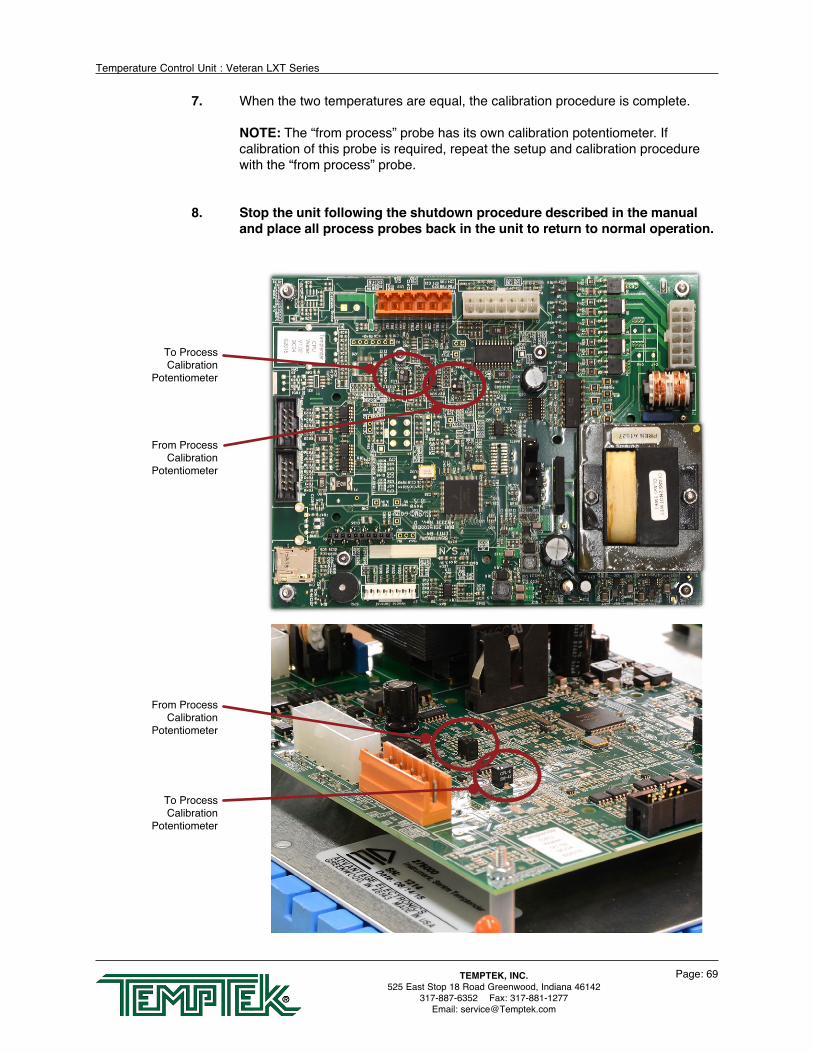
Temperature Control Unit : Veteran LXT Series
Page: 69TEMPTEK, INC.525 East Stop 18 Road Greenwood, Indiana 46142
317-887-6352 Fax: 317-881-1277Email: [email protected]
7. When the two temperatures are equal, the calibration procedure is complete.
NOTE: The “from process” probe has its own calibration potentiometer. If calibration of this probe is required, repeat the setup and calibration procedure with the “from process” probe.
8. Stop the unit following the shutdown procedure described in the manual and place all process probes back in the unit to return to normal operation.
To Process Calibration
Potentiometer
From Process Calibration
Potentiometer
From Process Calibration
Potentiometer
To Process Calibration
Potentiometer

Temperature Control Unit : Veteran LXT Series
Page: 70TEMPTEK, INC.525 East Stop 18 Road Greenwood, Indiana 46142
317-887-6352 Fax: 317-881-1277Email: [email protected]
5.9 HEATER CONTACTOR & PUMP MOTOR STARTER
A. The “standard” mechanical contactor for the heater will cycle proportionally to the amount of heat input required for the process and may cycle frequently.
B. This is a “wear” item that must be routinely inspected and replaced when the contacts begin to indicate wear/pitting.
C. Failure to maintain the contactor may result in overheating of the components and catastrophic electrical failure.
D. The “standard” mechanical pump motor starter must also be routinely inspected and
replaced when the contacts begin to indicate wear/pitting.
Typical electrical panel.
Typical Heater Contactor Typical Pump Motor Starter
WARNING: Failure to maintain the contactor may result in overheating of the components and catastrophic electrical failure.

Temperature Control Unit : Veteran LXT Series
Page: 71TEMPTEK, INC.525 East Stop 18 Road Greenwood, Indiana 46142
317-887-6352 Fax: 317-881-1277Email: [email protected]
6.0 COMPONENTS 6.1 Mechanical System 6.2 Electrical System

Temperature Control Unit : Veteran LXT Series
Page: 72TEMPTEK, INC.525 East Stop 18 Road Greenwood, Indiana 46142
317-887-6352 Fax: 317-881-1277Email: [email protected]
6.1 MECHANICAL SYSTEM
A. MOTOR/PUMP ASSEMBLY. The unit pump is a multi-component assembly serving to circulate water through the process system. The pump will increase the system pressure between 35 - 50 PSI over the plant water supply pressure. The pump is driven by an electrical motor.
1. Pump casing. The pump casing is an exclusive design. The casing is cast of iron and flanged to accept the heater/discharge and cooling tanks. The casing is the support element in the pump/motor assembly and is secured to the unit base (figure 6.1A).
2. Pump adapter. The pump adapter is the mating element between the pump casing the electric motor. The adapter is machined to accept the pump seal flush line. The stationary pump seal member is set in the seal cavity of the pump adapter (figure 6.1A).
3. Electrical motor. The electric motor is a dual voltage, 3 phase, ODP motor. The motor serves to turn the pump impeller creating process flow (figure 6.1A).
4. Impeller. The impeller is custom designed for the unit and creates the higher flow (gpm) from standard HP ratings (figure 6.1B).
5. Pump Seal. The pump seal prevents water leakage from the pump adapter. The seal is made up of three items: The stationary member (seated in the seal cavity), the rotating member (placed on the motor shaft) and the tension spring (figure 6.1C shows the stationary member only).
6. Pump seal flush. The pump seal flush is a flow diverter which serves to “cleanse” the pump seal assembly of debris which may lodge on the seal and create a leak (figure 6.1D).
B. HEATER. The heater is a dual voltage, flange mounted immersion heater set in the pump discharge cylinder. The heater elements have a stainless steel sheath. Electrical supply to the heater is provided via a mercury contactor (figure 6.1E).
C. HEATER/PUMP DISCHARGE CYLINDER. The heater/pump discharge cylinder is a custom cast tank. The tank is flanged mounted to the pump casing. Reinforced machined bosses accept the “to process/high temperature limit” sensor probe and the “to process” connection (figure 6.1E).
Electric Motor
Pump Casing
Figure 6.1APump Adapter
Impeller Figure 6.1B
Stationary member Figure 6.1C

Temperature Control Unit : Veteran LXT Series
Page: 73TEMPTEK, INC.525 East Stop 18 Road Greenwood, Indiana 46142
317-887-6352 Fax: 317-881-1277Email: [email protected]
D. COOLING CYLINDER. The cooling cylinder is a custom cast tank. The tank is flanged mounted to the pump casing. Reinforced machined bosses accept the pressure relief valve, the “from process” pressure gauge and pressure switch capillary connector, AVTTM modulating cooling valve, the “water supply connection” and the “from process” connection (figure 6.1F).
E. PRESSURE RELIEF VALVE. The pressure relief valve is a 150 psi relief valve serving to discharge excessive unit pressure to atmosphere. The valve can be manually activated by lifting the actuating lever (figure 6.1F).
F. AVTTM COOLING VALVE. The AVTTM valve is a patented design using a motor/gearbox assembly to open in minute increments from 0 to 100% a custom ball valve assembly. The AVTTM valve is controlled by custom programming of the instrument (figure 6.1F).
G. PRESSURE GAUGES. “To” and “from” process pressure gauges display the system pressure. “To process” pressure originates at the heat/pump discharge cylinder. “From process” pressure originates at the cooling cylinder. The gauges accurately display system pressures from 0 to 160 PSI (figure 6.1G).
H. CASTERS. The unit is mounted on 4 swivel ball bearing casters. The casters allow the unit to be portable and easily move from location to location.
I. STAINLESS STEEL CABINETRY. The stainless steel cabinetry prevents unsightly rust and metal decay. The electrical cabinet cover is hinged. The unit base is made of pressed steel with galvanized zinc coating. The lift off access panel is secured to the unit base by 5 screws (figure 6.1G).
6.2 ELECTRICAL SYSTEM
A. INSTRUMENT. The instrument is a custom designed and assembled microprocessor controller. The instrument is mounted to the electrical panel cover. The instrument controls the cycling of the heater, motor pump and AVTTM cooling valve. System and setpoint temperatures are displayed continually. System parameters are programmable..
B. TRANSFORMER. The transformer supplies 110 volts to the controlling instrument (figure 6.2B).
C. PUMP MOTOR CONTROLLER. The electrical motor
is engaged when the motor starter contacts close, on
Seal flush tube Figure 6.1D
Figure 6.1G
Figure 6.1F
AVT valve
Heater Figure 6.1EDischarge
tank
Temperature Control Unit : Veteran LXT Series
Page: 74TEMPTEK, INC.525 East Stop 18 Road Greenwood, Indiana 46142
317-887-6352 Fax: 317-881-1277Email: [email protected]
command by the instrument. The electric motor is protected from excessive amperage by a set of thermal overload relays, which open when excessive amperage “heats” the overloads and the relay opens (figure 6.2B).
D. HEATER CONTACTOR. The standard heater contactor is a mechanical style contactor.
On command from the instrument, the contactor will close and voltage will be supplied to the heater (figure 6.2B). The contactor use should be monitored and the contactor should be replaced as needed based on duty cycle. Some units are provided with a solid state contactor rather than the standard mechanical contactor.
E. PRESSURE SWITCH. The electric panel mounted pressure switch will close when sufficient pressure is supplied to the unit (20 psi). A closed pressure switch will consent the control circuit to the instrument controller to allow process operations (figure 6.2B).
F. SENSOR PROBES. The unit uses two sensor probes. The “to process” temperature sensor and the “high temperature limit” safety switch” are housed in the same assembly and mounted in the heater/pump discharge tank (figure 6.2C). The “from process” probe is mounted in the suction tank.
G. POWER CORD. On standard models with 10kW and 16kW heaters and 1 - 3 HP pumps are supplied with a 3 conductor with 1 ground wire sized for the unit and 10’ in length. Standard models with 24kW and 34kW heaters are not supplied with a power cord and the customer must provide a 3 conductor with 1 ground wire sized for the unit.

Temperature Control Unit : Veteran LXT Series
Page: 75TEMPTEK, INC.525 East Stop 18 Road Greenwood, Indiana 46142
317-887-6352 Fax: 317-881-1277Email: [email protected]
7.0 RELATED DRAWINGS 7.1 Physical 7.2 Circuit Schematic 7.3 Regulator / Bypass Installation 7.4 Dual Zone Dolly 7.5 Stacking Rack

Temperature Control Unit : Veteran LXT Series
Page: 76TEMPTEK, INC.525 East Stop 18 Road Greenwood, Indiana 46142
317-887-6352 Fax: 317-881-1277Email: [email protected]
7.1 PHYSICAL
To Process
Drain
Water Supply
From Process
Pressure Gauges
Right Side View
Left Side View Left Side View
Rear View
Instrument
12 1/2
26 5/8
19 1/2
Need to get B size print to include.

Temperature Control Unit : Veteran LXT Series
Page: 77TEMPTEK, INC.525 East Stop 18 Road Greenwood, Indiana 46142
317-887-6352 Fax: 317-881-1277Email: [email protected]
7.2 CIRCUIT SCHEMATIC
A
DRAIN CONNECTION
TO PROCESS SENSORHI TEMP SAFETY
TO PROCESSPRESSURE GAUGE
TO PROCESSCONNECTION
HEATER
DISCHARGE TANK
PUMP
PUMP SEAL FLUSH
DRAIN
FROM PROCESSPRESSURE GAUGE
PRESSURE RELIEFVALVE
AVT COOLING VALVEMOTOR/GEARBOX ASSEMBLY
AVTTM COOLING VALVECOUPLING
AVTTM COOLING VALVEBALL VALVE ASSEMBLY
FROM PROCESSCONNECTION
WATER SUPPLYCONNECTION
SUCTION TANK

Temperature Control Unit : Veteran LXT Series
Page: 78TEMPTEK, INC.525 East Stop 18 Road Greenwood, Indiana 46142
317-887-6352 Fax: 317-881-1277Email: [email protected]
7.3 REGULATOR/BYPASS INSTALLATION
WATERSUPPLY
PRESSURE REGULATOR VALVETYPE: WATTS U5B 1/2"25-75psi RANGE.
BYPASS VALVETYPE: WATTS BP-30 1/2"45-100psi RANGE.
DRAIN
FROM PROCESS
TO PROCESS

Temperature Control Unit : Veteran LXT Series
Page: 79TEMPTEK, INC.525 East Stop 18 Road Greenwood, Indiana 46142
317-887-6352 Fax: 317-881-1277Email: [email protected]
7.4 DUAL ZONE DOLLY
TO PROCESS CONNECTION
FROM PROCESS CONNECTION
WATER SUPPLY CONNECTION
WATER SUPPLY MANIFOLD
WATER SUPPLY MANIFOLD
CASTER
STRUCTURAL STEEL BASE
ELECTRICAL CABINET
WATER SUPPLY CONNECTIONTO SENTRA '1'
DRAIN CONNECTION TO SENTRA '1'
DRAIN CONNECTION TO SENTRA '2'
WATER SUPPLY CONNECTIONTO SENTRA '2'
WATER SUPPLY MANIFOLD CONNECTION
DRAIN MANIFOLD CONNECTION
WATER SUPPLYCONNECTION
DRAIN CONNECTION
DRAIN CONNECTION
FROM PROCESSCONNECTION
SENTRA '2"
SENTRA '1"
TO PROCESSCONNECTION
A. Molders often need to run different temperatures on each mold half to produce the best quality part.
B. The Company can provide a dual zone dolly that holds two standard single zone temperature control units to meet this need.
C. The dual zone dolly provides the convenience of a dual zone configuration while providing the economic first cost and ease of maintenance associated with independent single zone units.
D. Options:
• Single cooling water supply and drain connection• Single power supply connections
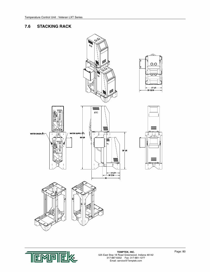
Temperature Control Unit : Veteran LXT Series
Page: 80TEMPTEK, INC.525 East Stop 18 Road Greenwood, Indiana 46142
317-887-6352 Fax: 317-881-1277Email: [email protected]
7.6 STACKING RACK

Temperature Control Unit : Veteran LXT Series
Page: 81TEMPTEK, INC.525 East Stop 18 Road Greenwood, Indiana 46142
317-887-6352 Fax: 317-881-1277Email: [email protected]
8.0 APPENDIX 8.1 Model # Coding 8.2 Interpretation of Process Pressure Gauges 8.3 Operation of Mold Purge 8.4 SPI Commands 8.5 Communication Cable 8.6 Optional Alarm Operation 8.7 AVTTM Valve Troubleshooting and Components 8.8 AS5 Pump Parts List - 1/2 hp to 1 hp 8.9 AS5 Pump Parts List - 1.5 hp to 3 hp
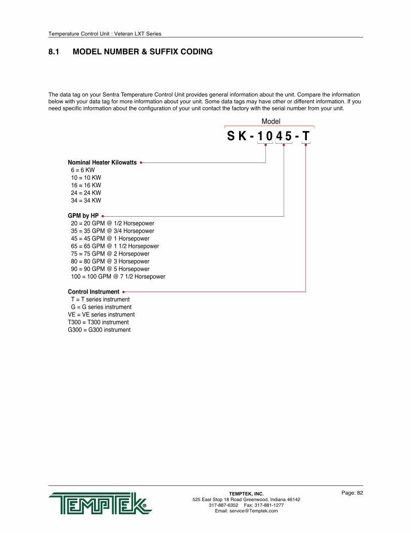
Temperature Control Unit : Veteran LXT Series
Page: 82TEMPTEK, INC.525 East Stop 18 Road Greenwood, Indiana 46142
317-887-6352 Fax: 317-881-1277Email: [email protected]
Nominal Heater Kilowatts 6 = 6 KW 10 = 10 KW 16 = 16 KW 24 = 24 KW 34 = 34 KW
GPM by HP 20 = 20 GPM @ 1/2 Horsepower 35 = 35 GPM @ 3/4 Horsepower 45 = 45 GPM @ 1 Horsepower 65 = 65 GPM @ 1 1/2 Horsepower 75 = 75 GPM @ 2 Horsepower 80 = 80 GPM @ 3 Horsepower 90 = 90 GPM @ 5 Horsepower 100 = 100 GPM @ 7 1/2 Horsepower
Control Instrument T = T series instrument G = G series instrumentVE = VE series instrumentT300 = T300 instrumentG300 = G300 instrument
The data tag on your Sentra Temperature Control Unit provides general information about the unit. Compare the information below with your data tag for more information about your unit. Some data tags may have other or different information. If you need specific information about the configuration of your unit contact the factory with the serial number from your unit.
Model
S K - 1 0 4 5 - T
8.1 MODEL NUMBER & SUFFIX CODING

Temperature Control Unit : Veteran LXT Series
Page: 83TEMPTEK, INC.525 East Stop 18 Road Greenwood, Indiana 46142
317-887-6352 Fax: 317-881-1277Email: [email protected]
8.2 INTERPRETATION OF PROCESS PRESSURE GAUGES
A. READ AVAILABLE WATER PRESSURE AT UNIT’S LOCATION. When a temperature control unit is attached to the process with the water supply on and the pump off, both gauges will read the water supply pressure at the unit’s location.
B. READ PRESSURE DROP ACROSS PROCESS (∆ P). With the pump on, the “to process” pressure gauge will rise to read the sum of the water supply pressure and pump generated pressure. The “from process” pressure gauge reads the effect of water supply pressure and pump suction pressure. The difference between the to and from process gauges is the pump generated circulating pressure... which is also equal to the pressure drop across the process.
C. PUMP ROTATION INDICATION. If the pump is running, and both gauges are “close” to same value, it is likely that the pump is rotating backward, or the pump is generating such a high flow that an overload condition will result.
D. PUMP MOTOR OVERLOAD CONDITION. If the ∆ P is low with the pump rotating correctly, then the flow rate is high, which probably will result in a motor overload. Refer to the representative pump curve below.
E. WATER HAMMER (COMPETITIVE SOLENOID VALVE UNITS). On competitive mold temperature controllers, when ∆ P gauges are supplied, the water hammer effect of on/off solenoid valves can be seen. When the solenoid valve is open, both to and from process pressure gauges will fall as the system depressurizes. When the valve closes, there will be a momentary spike that will be seen on both pressure gauges, then they will settle back to normal ∆ P values. This spike is called “water hammer”.
Pressure gauges
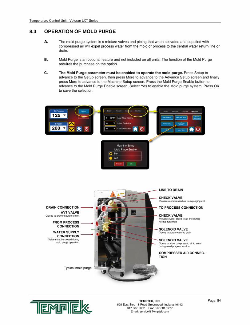
Temperature Control Unit : Veteran LXT Series
Page: 84TEMPTEK, INC.525 East Stop 18 Road Greenwood, Indiana 46142
317-887-6352 Fax: 317-881-1277Email: [email protected]
8.3 OPERATION OF MOLD PURGE
A. The mold purge system is a mixture valves and piping that when activated and supplied with compressed air will expel process water from the mold or process to the central water return line or drain.
B. Mold Purge is an optional feature and not included on all units. The function of the Mold Purge requires the purchase on the option.
C. The Mold Purge parameter must be enabled to operate the mold purge. Press Setup to advance to the Setup screen, then press More to advance to the Advance Setup screen and finally press More to advance to the Machine Setup screen. Press the Mold Purge Enable button to advance to the Mold Purge Enable screen. Select Yes to enable the Mold purge system. Press OK to save the selection.
Typical mold purge.
DRAIN CONNECTION
FROM PROCESS CONNECTION
AVT VALVEClosed to prevent purge of unit
WATER SUPPLYCONNECTION
Valve must be closed during mold purge operation
LINE TO DRAIN
CHECK VALVEPrevents compressed air from purging unit
TO PROCESS CONNECTION
CHECK VALVEPrevents water bleed to air line during normal run cycle
SOLENOID VALVEOpens to purge water to drain
SOLENOID VALVEOpens to allow compressed air to enter during mold purge operation
COMPRESSED AIR CONNEC-TION
To Process
125 °F
Setpoint
200 °F
Setup
Heating100%
Cancel OK
Machine SetupMold Purge EnableNoYes
Basic Remote Features Machine
Low Flow Alarm
10 High Deviation°F
0 GPM
10 Low Deviation°F
Basic Remote Features Machine
Interface
Pump SealCooling
Autovent
Max Setpoint
Alarm Output
Flow
Pump SealCooling
Autovent
Mold PugeEnable
Valve Size
Heat Only Mode SystemInformation
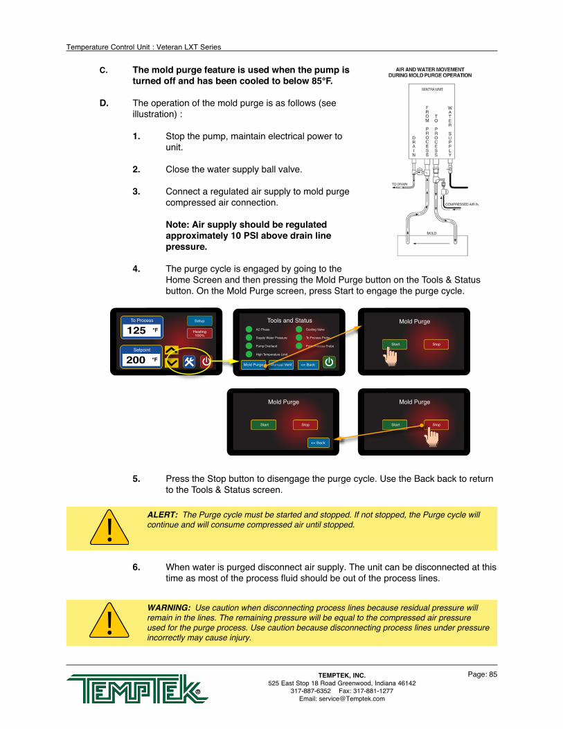
Temperature Control Unit : Veteran LXT Series
Page: 85TEMPTEK, INC.525 East Stop 18 Road Greenwood, Indiana 46142
317-887-6352 Fax: 317-881-1277Email: [email protected]
C. The mold purge feature is used when the pump is turned off and has been cooled to below 85°F.
D. The operation of the mold purge is as follows (see illustration) :
1. Stop the pump, maintain electrical power to unit.
2. Close the water supply ball valve.
3. Connect a regulated air supply to mold purge compressed air connection.
Note: Air supply should be regulated approximately 10 PSI above drain line pressure.
4. The purge cycle is engaged by going to the Home Screen and then pressing the Mold Purge button on the Tools & Status button. On the Mold Purge screen, press Start to engage the purge cycle.
5. Press the Stop button to disengage the purge cycle. Use the Back back to return to the Tools & Status screen.
6. When water is purged disconnect air supply. The unit can be disconnected at this time as most of the process fluid should be out of the process lines.
To Process
125 °F
Setpoint
200 °F
Setup
Heating100%
<< BackManual VentMold Purge
AC Phase
Supply Water Pressure
Pump Overlaod
High Temperature Limit
Cooling Valve
To Process Probe
From Process Probe
Tools and Status
StopStart
Mold Purge
StopStart
Mold Purge
StopStart
Mold Purge
<< Back
WARNING: Use caution when disconnecting process lines because residual pressure will remain in the lines. The remaining pressure will be equal to the compressed air pressure used for the purge process. Use caution because disconnecting process lines under pressure incorrectly may cause injury.
ALERT: The Purge cycle must be started and stopped. If not stopped, the Purge cycle will continue and will consume compressed air until stopped.
Temperature Control Unit : Veteran LXT Series
Page: 86TEMPTEK, INC.525 East Stop 18 Road Greenwood, Indiana 46142
317-887-6352 Fax: 317-881-1277Email: [email protected]
8.4 SPI COMMANDS
A. INTRODUCTION: In 1987 a group of member companies of the Society of the Plastics Industries began development of a communication protocol for use by their processing and auxiliary equipment. Their goal was to allow the exchange of information between various pieces of equipment from different manufacturers to be simple and reliable. The result of their work was released in 1990 and has made the interconnection of equipment much easier and straightforward. There are now over 40 companies that offer the SPI Protocol in their products. This document details the implementation of the SPI Protocol available in the some temperature controllers and some portable chillers.
B. PROTOCOL BASICS: The SPI Protocol is described by a 2 part specification. The largest portion of the SPI Protocol specification deals with how basic information is exchanged between equipment. The second part of the specification details the actual pieces of information exchanged using the protocol. Items such as Process Temperature, Process Setpoint and Process Status are detailed in this part. This FYI will list the commands that are supported.
C. EQUIPMENT SETUP: The setup of equipment to be connected in an SPI Protocol network is simple. Each device must have a unique address for its device type and it must use the same data transfer rate as the other pieces of equipment in the network. There are many acceptable ways used to ‘set’ the device address and data rate. The equipment provides access to the information via the front panel operators and displays. Other manufacturers may use internal DIP switches or jumpers.
A typical cell may be configured as follows:
Data Transfer Rate: 9600 bits per second (bps) Mold Temperature Controller (Qty 2): Addresses 1 and 2 Chiller (Qty 1): Address 1 Note in the above example that different device types may have the same address. This
is because the SPI Protocol uses the device type as part of its internal address.
D. NETWORK TROUBLESHOOTING: Troubleshooting a network is best done by verifying the setup of each piece of equipment and insuring that the network is installed with the correct electrical interconnection. Here are some basic things to do if equipment isn’t ‘talking’ as expected.
1. Verify that each piece of equipment is properly grounded to its power source.
2. Inspect cables inside and outside the electrical cabinet. Repair or replace as necessary. The cable scheme used by most manufacturers allows the communication signals to ‘pass through’ each piece of equipment. Therefore, when a piece of equipment is disconnected from the middle of the network, all the equipment ‘after’ that one will be disconnected, too. If a piece of equipment is being permanently removed, the device cables should be rearranged at the molding machine to reconnect the other equipment.
3. Check the Data Transfer Rate and Address of each piece of equipment. For example, if both Temperature Controllers have the same address, they will both try to ‘talk’ at the same time and garble each other’s data.
4. Verify the network is properly terminated and that it is configured as a ‘multi-

Temperature Control Unit : Veteran LXT Series
Page: 87TEMPTEK, INC.525 East Stop 18 Road Greenwood, Indiana 46142
317-887-6352 Fax: 317-881-1277Email: [email protected]
drop’. This is best achieved by following the molding machine manufacturer’s installation instructions and use extension cables provided by them or us.
5. Attach each device, singly, to the molding machine and see if it ‘talks’. Add additional devices until a problem is seen.
15 14 13 12 11 10 9 8 7 6 5 4 3 2 1 0
PROCESSING
ALARM - SYSTEM
ALARM - PROCESS
ALARM - MACHINE
ALARM - HIGH TEMPERATURE
ALARM - LOW TEMPERATURE
ALARM - LOW FLOW*
Temperature CONTROLLER SPI COMMANDS
POLL SELECT C1 C2 C1 C2 COMMAND DESCRIPTION 20 20 20 21 Echo Controller integrity command 20 20 Version Controller version command 20 30 20 31 Setpoint Desired process temperature 20 32 20 33 High temp Hi temperature deviation alarm 20 34 20 35 Low temp Low temperature deviation alarm 20 36 20 37 Flow Alarm Low flow alarm setpoint* 20 40 Status Process
15 14 13 12 11 10 9 8 7 6 5 4 3 2 1 0
PROCESSING
ALARM - SYSTEM
ALARM - PROCESS
ALARM - MACHINE
ALARM - HIGH TEMPERATURE
ALARM - LOW LOW PRESS
ALARM - HIGH CURRENT
ALARM - PHASE
POLL SELECT C1 C2 C1 C2 COMMAND DESCRIPTION 20 42 Status Machine 1
15 14 13 12 11 10 9 8 7 6 5 4 3 2 1 0
PROCESSING
ALARM - SYSTEM
ALARM - PROCESS
ALARM - MACHINE
ALARM - SENSOR
POLL SELECT C1 C2 C1 C2 COMMAND DESCRIPTION 20 44 Status Machine 2
15 14 13 12 11 10 9 8 7 6 5 4 3 2 1 0
ALARM - ACKNOWLEDGE
ALARM - ON/OFF
POLL SELECT C1 C2 C1 C2 COMMAND DESCRIPTION 20 48 20 49 Machine
15 14 13 12 11 10 9 8 7 6 5 4 3 2 1 0
MACHINE - ON/OFF
ON/OFF ALLOWED
ALARM - ACKNOWLEDGE
POLL SELECT C1 C2 C1 C2 COMMAND DESCRIPTION 20 4A 20 4B Protected mode - machine
POLL SELECT C1 C2 C1 C2 COMMAND DESCRIPTION 20 70 Temperature to process 20 72 Temperature from process* 20 78 Flow rate from unit GPM* 20 E0 Blanket Poll Returns: 20 30 Setpoint 20 32 High alarm deviation 20 34 Low alarm deviation 20 40 Status process 20 70 To process temperature

Temperature Control Unit : Veteran LXT Series
Page: 88TEMPTEK, INC.525 East Stop 18 Road Greenwood, Indiana 46142
317-887-6352 Fax: 317-881-1277Email: [email protected]
8.5 COMMUNICATIONS CABLE

Temperature Control Unit : Veteran LXT Series
Page: 89TEMPTEK, INC.525 East Stop 18 Road Greenwood, Indiana 46142
317-887-6352 Fax: 317-881-1277Email: [email protected]
CONDITIONS THAT TRIGGERAN ALARM OUTPUT ON MOLD
TEMPERATURE CONTROLLERS CONTROLLERCONDITION T G
Incorrect 3Ø power entry Yes No
Pump overload tripped Yes Yes
High temperature fault Yes Yes
Water supply pressure fault Yes Yes
Temperature deviation Yes Yes
AVT valve malfunction Yes Yes
Sensor probe malfunction Yes Yes
8.6 OPTIONAL ALARM OPERATION
A. The unit is standard with a 110 volt AC alarm output. The alarm output can be connected to customer provided alarm annunciation, plant-wide monitoring system or optional annunciation.
B. A beacon alarm is used when both visual and audible alarm annunciation is needed. The beacon is an integral light and buzzer assembly to provide high visibility in a busy, noisy shop. The beacon will signal until the alarm condition is acknowledged by the operator.
C. Audible Alarms provide a loud signal when an alarm condition is present. The audible alarm is mounted on the front cover of the unit.

Temperature Control Unit : Veteran LXT Series
Page: 90TEMPTEK, INC.525 East Stop 18 Road Greenwood, Indiana 46142
317-887-6352 Fax: 317-881-1277Email: [email protected]
8.7 AVTTM COOLING VALVE COMPONENTS
#8-3
2 Lo
ck N
utM
otor
Br
acke
t#8
-32
x 1/
2” H
ex
Hea
d Sc
rew
Valv
e C
oupl
ing
#8-3
2 x
3/4”
Hex
Hea
d Sc
rew
Gea
r Box
#4-4
0 x
3/4”
Hex
Hea
d Sc
rew
Hom
e Sw
itch
#4-4
0 Lo
ck N
ut
5/16
-18
x 2”
H
ex H
ead
Scre
w5/
16 L
ock
Was
her
#8-3
2 Lo
ck N
ut
#5/1
6-18
x 3
-3/8
” Th
read
ed R
od
Valv
e M
otor
Valv
e Bo
dy
Coo
ling
Cyl
inde
r
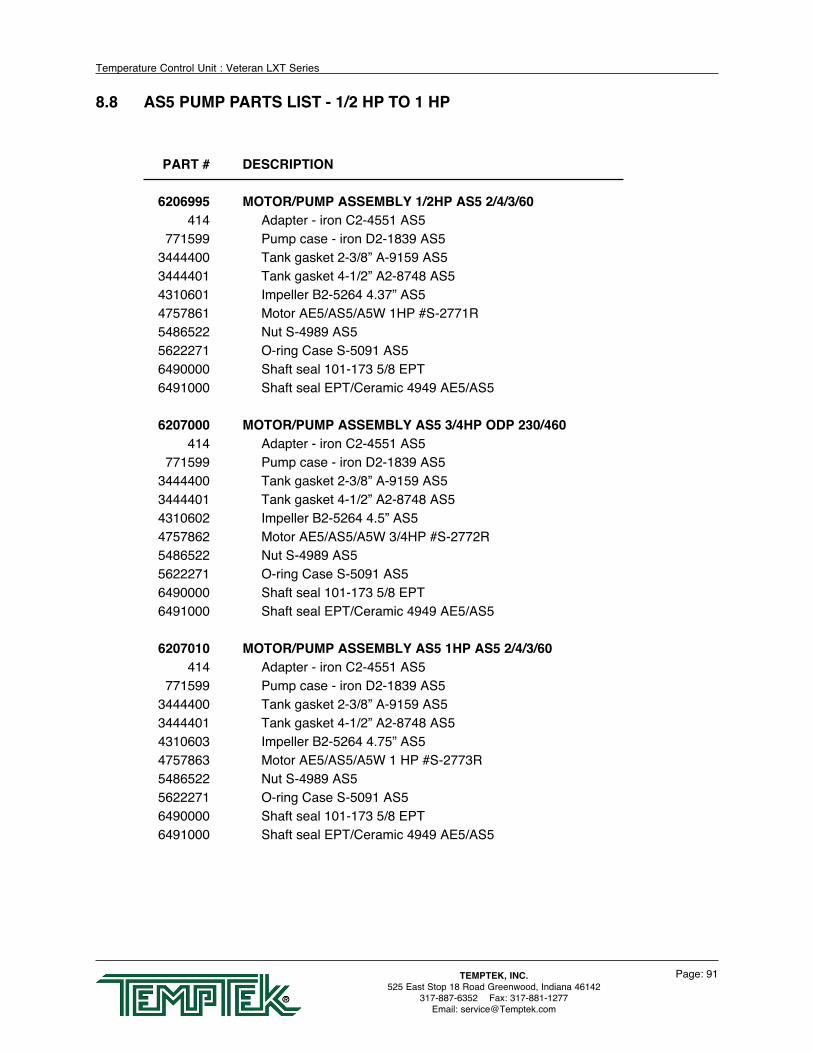
Temperature Control Unit : Veteran LXT Series
Page: 91TEMPTEK, INC.525 East Stop 18 Road Greenwood, Indiana 46142
317-887-6352 Fax: 317-881-1277Email: [email protected]
8.8 AS5 PUMP PARTS LIST - 1/2 HP TO 1 HP
PART # DESCRIPTION
6206995 MOTOR/PUMP ASSEMBLY 1/2HP AS5 2/4/3/60 414 Adapter - iron C2-4551 AS5 771599 Pump case - iron D2-1839 AS5 3444400 Tank gasket 2-3/8” A-9159 AS5 3444401 Tank gasket 4-1/2” A2-8748 AS5 4310601 Impeller B2-5264 4.37” AS5 4757861 Motor AE5/AS5/A5W 1HP #S-2771R 5486522 Nut S-4989 AS5 5622271 O-ring Case S-5091 AS5 6490000 Shaft seal 101-173 5/8 EPT 6491000 Shaft seal EPT/Ceramic 4949 AE5/AS5 6207000 MOTOR/PUMP ASSEMBLY AS5 3/4HP ODP 230/460 414 Adapter - iron C2-4551 AS5 771599 Pump case - iron D2-1839 AS5 3444400 Tank gasket 2-3/8” A-9159 AS5 3444401 Tank gasket 4-1/2” A2-8748 AS5 4310602 Impeller B2-5264 4.5” AS5 4757862 Motor AE5/AS5/A5W 3/4HP #S-2772R 5486522 Nut S-4989 AS5 5622271 O-ring Case S-5091 AS5 6490000 Shaft seal 101-173 5/8 EPT 6491000 Shaft seal EPT/Ceramic 4949 AE5/AS5 6207010 MOTOR/PUMP ASSEMBLY AS5 1HP AS5 2/4/3/60 414 Adapter - iron C2-4551 AS5 771599 Pump case - iron D2-1839 AS5 3444400 Tank gasket 2-3/8” A-9159 AS5 3444401 Tank gasket 4-1/2” A2-8748 AS5 4310603 Impeller B2-5264 4.75” AS5 4757863 Motor AE5/AS5/A5W 1 HP #S-2773R 5486522 Nut S-4989 AS5 5622271 O-ring Case S-5091 AS5 6490000 Shaft seal 101-173 5/8 EPT 6491000 Shaft seal EPT/Ceramic 4949 AE5/AS5

Temperature Control Unit : Veteran LXT Series
Page: 92TEMPTEK, INC.525 East Stop 18 Road Greenwood, Indiana 46142
317-887-6352 Fax: 317-881-1277Email: [email protected]
PART # DESCRIPTION
6207020 MOTOR/PUMP ASSEMBLY AS5 1.5HP 2/4/3/60 414 Adapter - iron C2-4551 AS5 771599 Pump case - iron D2-1839 AS5 3444400 Tank gasket 2-3/8” A-9159 AS5 3444401 Tank gasket 4-1/2” A2-8748 AS5 4310604 Impeller B2-5264 5.06” AS5 4757864 Motor AE5/AS5/A5W 1-1/2HP #S-2774R 5486522 Nut S-4989 AS5 5622271 O-ring Case S-5091 AS5 6490000 Shaft seal 101-173 5/8 EPT 6491000 Shaft seal EPT/Ceramic 4949 AE5/AS5
6207030 MOTOR/PUMP ASSEMBLY AS5 2HP 2/4/3/60 414 Adapter - iron C2-4551 AS5 771599 Pump case - iron D2-1839 AS5 3444400 Tank gasket 2-3/8” A-9159 AS5 3444401 Tank gasket 4-1/2” A2-8748 AS5 4310605 Impeller B2-5264 5.25” AS5 4757865 Motor AE5/AS5/A5W 2HP #S-2775R 5486522 Nut S-4989 AS5 5622271 O-ring Case S-5091 AS5 6490000 Shaft seal 101-173 5/8 EPT 6491000 Shaft seal EPT/Ceramic 4949 AE5/AS5
6207040 MOTOR/PUMP ASSEMBLY 3HP AS5 2/4/3/60 414 Adapter - iron C2-4551 AS5 771599 Pump case - iron D2-1839 AS5 3444400 Tank gasket 2-3/8” A-9159 AS5 3444401 Tank gasket 4-1/2” A2-8748 AS5 4310605 Impeller B2-5264 5.25” AS5 4757866 Motor AE5/AS5/A5W 3HP #4551R 5486522 Nut S-4989 AS5 5622271 O-ring Case S-5091 AS5 6490000 Shaft seal 101-173 5/8 EPT 6491000 Shaft seal EPT/Ceramic 4949 AE5/AS5
8.9 AS5 PUMP PARTS LIST - 1.5 HP TO 3 HP

END© 2018 Temptek, Inc.
RE 02282018

Related Documents