IOG 2830.50 This faucet complies with NSF61/9, ASME/ANSI A112.18.1 and CSA B 125 Standards. Este grifo se encuentra conforme con losestandares de NSF61/9, de ASME/ANSI A112.18.1 y de CSA B 125. 1 1-1/4" Ø(32mm ) max. 1-9/16" ( 40mm ) max. 3/8" Ø(9,5mm) pipe 8" ( 203mm ) 1-7/16" (37mm) 5" (128mm) 2-3/16" Ø(55mm) 2-5/16" Ø(58mm ) 1-3/8" Ø(35mm ) 15/16" ( 24mm ) 1-3/8" Ø(35mm) 15/16" Ø(24mm ) 1-9/16" Ø(40mm) max. 1-1/4" ( 32mm ) max. Rev. 4 June 2019

Welcome message from author
This document is posted to help you gain knowledge. Please leave a comment to let me know what you think about it! Share it to your friends and learn new things together.
Transcript

IOG 2830.50
This faucet complies with NSF61/9, ASME/ANSI A112.18.1and CSA B 125 Standards.Este grifo se encuentra conforme con losestandares de NSF61/9,de ASME/ANSI A112.18.1 y de CSA B 125.
1
1-1/4"Ø(32mm )
max
. 1-9
/16"
(40m
m)
max
.
3/8"Ø(9,5mm)pipe
8"(203mm )
1-7/
16"
(37m
m)
5"(1
28m
m)
2-3/16"Ø(55mm)
2-5/16"Ø(58mm )
1-3/8"Ø(35mm )
15/16"(24mm )
1-3/8"Ø(35mm)
15/16"Ø(24mm )
1-9/16"Ø(40mm)
max
. 1-1
/4"
(32m
m)
max
.
Rev. 4 June 2019

IOG 2830.50 Rev. 4 June 2019
This faucet complies with NSF61/9, ASME/ANSI A112.18.1and CSA B 125 Standards.Este grifo se encuentra conforme con losestandares de NSF61/9,de ASME/ANSI A112.18.1 y de CSA B 125.
2
2-1/
2” (6
3mm
)
2-7/8” (73mm)
2-5/
8” (6
7mm
)
3-9/16” (90mm)
C9
2-3/8” (60mm)
LM40
2-3/8” (60mm)
2-15/16” (75mm)
2” (5
1mm
)
LM42B
2-3/8” (60mm)
3” (76mm)
1-5/
8”(4
1mm
)
LM44
1-15/16”(60mm)
1-7/
8” (4
8mm
)
2-3/8” (60mm)
1-15/16”(48mm)
2-5/
8” (6
6mm
)
C14 LM37B
2-5/16” (59mm)
1-13/16”(46mm)
1-5/
16”
(34m
m)
LM41B
1-15/16”(50mm)
LM55B
1-3/4” (45mm)
1-5/
16”(
34m
m)
2-11/16” (68mm)
Ø 2-1/4” (57mm)
1-1/
16”(
27m
m)
MOD+

IOG 2830.50
This faucet complies with NSF61/9, ASME/ANSI A112.18.1and CSA B 125 Standards.Este grifo se encuentra conforme con losestandares de NSF61/9,de ASME/ANSI A112.18.1 y de CSA B 125.
3
1
10
2020
19
13
9
19
17
16
15
14
12
11
15
45
27
26
24
23
22
22
21
7
6
8
5
4
3
2
1
838
37
36
35
43
34b
32
33
42
41
40
29 31
39
29
28b
28a
34a
18
25
44
404142434445K1K2
O-RING SEAL JUNTA TÓRICAVALVE FLANGE BRIDA DE LA VÁLVULARUBBER WASHER ARANDELA DE GOMASCREW TORNILLOHEAD SPINDLE EXTENSIÓNDRAIN ASSEMBLY DESAGÜE AUTOMATICO5/64” (2mm) HEX KEY LLAVE ALLÉN 5/64” (2mm)SOCKET WRENCH LLAVE INGLESA
SLIDE WASHER ARANDELA DESLIZANTE
K2
K1
The drawing presents a sample lever (28).The levers may vary depending on the faucet design.
La figura representa la palanca ejemplar (28).Puede diferenciarse en función del modelo del grifo.
Rev. 4 June 2019

IOG 2830.50
This faucet complies with NSF61/9, ASME/ANSI A112.18.1and CSA B 125 Standards.Este grifo se encuentra conforme con losestandares de NSF61/9,de ASME/ANSI A112.18.1 y de CSA B 125.
4
~ESPANOLSee figs. 2.1 - 2.10
1. Check the label on the valve in order to identify hot water valve (red label) and cold water valve (blue label). Install the hot water valve on the left side of the spout, and the cold water valve on its right side.
2 Screw the nut (32) on the valve (35) and put metal gasket (33) and rubber gasket (42) - figure 2.1. Insert the valve through the installation opening from under the sink. From above, screw the valve flange (41) home, at the same time holding the valve (35) - figure 2.2. After proper positioning of the valve under the sink, screw the nut (32).
3 Put the knob handle base (31) on the base together with the sliding washer (39). Put the handle base in the correct position against thevalve flange (41) and secure it with a set screw (29) using the hex key supplied (K1) - figure 2.3-2.4.
4 Make sure the valve is in “closed” position by turning the valve spindle to the right (hot water valve (35) marked with red label) until you feel strong resistance. For the cold water valve (35) , marked with blue label, turn the valve spindle to the left.
5
6.
Ver. fig. 2.1 - 2.101. Comprobar el troquel en la válvula para identificar la válvula para el
agua caliente (etiqueta roja) y para el agua fría (etiqueta azul). Montar la válvula para el agua caliente al lado izquierdo del caño, la válvula para el agua fría - al lado derecho.
2. Atornillar la tuerca (32) en la válvula (35) y poner la junta de metal (33) y de caucho (42) - fig. 2.1. Por debajo del lavabo, en el orificio de montaje introducir la válvula (35). Sosteniendo la válvula (41) atornillar por encima la brida de la válvula (35) hasta sentir resistencia - fig. 2.2. Fijada la válvula en la posición adecuada, por debajo del lavabo, atornillar la tuerca (32).
3. En la superficie de montaje situar la base de la perilla (31) junto con la arandela deslizante (39). Situar la base en la posición adecuada en relación a la brida de la válvula (41) y proteger con el tornillo fijador (29) usando para ello la llave Allen que va incluido (K1) - fig.2.3-2.4.
4. Asegurarse de que la válvula está en la posición „válvula cerrada”, para ello girar el huso de la válvula hacia derecha (la válvula para el agua caliente (35) va señalado con etiqueta roja) hasta el momento de sentir resistencia clara. En caso de la válvula para agua fría (35) , señalada con etiqueta azul - girar el huso de la válvula hacia izquierda.
5.
6.
ENGLISH
1INSTALLATION OF VALVES AND LEVERS MONTAJE DE VÁLVULAS Y PALANCAS
Place the lever body (28) with the bolt (29) on the valve spindle extension (43) - fig. 2.5. Check, if you are able to obtain the required lever position, according to fig. 2.9. If you cannot position the lever (28) correctly in relation to the sink edge (you notice distinct shift of Δ angle to the required positioning - as shown on fig. 2.6) Take the lever (28) off the valve spindle extension (43) - see fig. 2.7. Loose the screw (44) and move the valve spindle extension (14) one tooth on valve head splines and screw the screw (44) back into position - fig. 2.8. Place the lever (28) on the valve spindle extension (43) and check the correct positioning of the lever (28) - fig. 2.9.
If the position of the lever (28) is proper, you may tighten the screw (29) using hex key (K1) according to the drawing 2.10. Then screw the lever arm (28) back on the screw (29) until you feel a strong resistance of the parts - fig. 2.10.However, if the position of the lever (28) is still incorrect, move the valve spindle extension (43) one more tooth on valve head splines and check the lever (28) positioning once again.
After installation of the hot water valve (35) and the lever (28), repeat the above mentioned steps for installing the cold water valve.
En la extensión del huso de la válvula (28) meter el cuerpo de la palanca (29) con tornillo (43) - fig. 2.5. Comprobar que es capaz de conseguir la configuración de la palanca conforme con el dibujo 2.9. Cuando no sea capaz de conseguir la configuración satisfactoria de la palanca (28) con relación al borde del lavabo (verás un claro cambio del ángulo Δ desde la configuraciónσn requerida - tal como en la figura 2.6) quite la palanca (28) de la extensión del huso de la válvula (44) - fig. 2.7. Destornillar el tornillo (44) y cambiar la extensión del huso de la válvula (43) un diente en la polichaveta de la cabeza de la válvula y volver a atornillar el tornillo (44) - fig. 2.8 . Volver a meter la palanca (28) en la extensión del huso de la válvula (43) y comprobar que la configuración de la palanca es correcta (28) - fig. 2.9.
Cuando la configuración de la palanca (28) sea adecuada, y atornillar el tornillo (29) con llave Allen (K1) según la fig. 2.10. Volver a atornillar el brazo de la palanca (28) el tornillo (29) hasta sentir resistencia - fig. 2.10.Cuando la configuración de la palanca (28) sigue siendo inadec-uada - cambiar la extensión del huso de la válvula (43) un diente más en la polichaveta de la cabeza de la válvula y volver a comprobar la configuración de la palanca (28).
Después de montar la válvula para el agua caliente (35) y la palanca (28) empezar el montaje de la válvula para el agua fría manteniendo la secuencia descrita arriba de los pasos de montaje.
2.1 2.2 2.3 2.4
35
32
3342 31
41
39
31
K1 29
41
324233
35
MAX.
1-9/
16"
(MAX.
40m
m)
(35)
Rev. 4 June 2019

IOG 2830.50
This faucet complies with NSF61/9, ASME/ANSI A112.18.1and CSA B 125 Standards.Este grifo se encuentra conforme con losestandares de NSF61/9,de ASME/ANSI A112.18.1 y de CSA B 125.
5
2.5 2.6 2.7
2.8 2.9 2.10
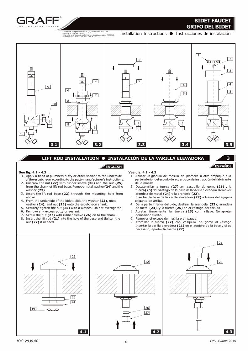
3.1 - 3.5 3.1 - 3.51.
2.
3.
4.
5.
6.
7.
8.
9.
1.
2.
3.
4.
5.
6.
7.
8.
9.
28
29
4328
44
45
28 28 29
K1
3.1 3.1
2
The drawing presents a sample lever (28).The levers may vary depending on the faucet design.
La figura representa la palanca ejemplar (28).Puede diferenciarse en función del modelo del grifo.
Rev. 4 June 2019
IOG 2830.50
This faucet complies with NSF61/9, ASME/ANSI A112.18.1and CSA B 125 Standards.Este grifo se encuentra conforme con losestandares de NSF61/9,de ASME/ANSI A112.18.1 y de CSA B 125.
3.1 3.2 3.3 3.4 3.5
4.1 4.2 4.3
6
4.1 - 4.3 4.1 - 4.31.
2.
3.
4.
5.6.6.7.8.
1.
2.
3.
4.
5.
6.7.
3
1
Rev. 4 June 2019

IOG 2830.50
This faucet complies with NSF61/9, ASME/ANSI A112.18.1and CSA B 125 Standards.Este grifo se encuentra conforme con losestandares de NSF61/9,de ASME/ANSI A112.18.1 y de CSA B 125.
7
5
5
5
6
1.
2.3.
4.
1.
2.
3.
4.
4
5
Rev. 4 June 2019
IOG 2830.50
This faucet complies with NSF61/9, ASME/ANSI A112.18.1and CSA B 125 Standards.Este grifo se encuentra conforme con losestandares de NSF61/9,de ASME/ANSI A112.18.1 y de CSA B 125.
8
ENGLISH~
ESPANOL
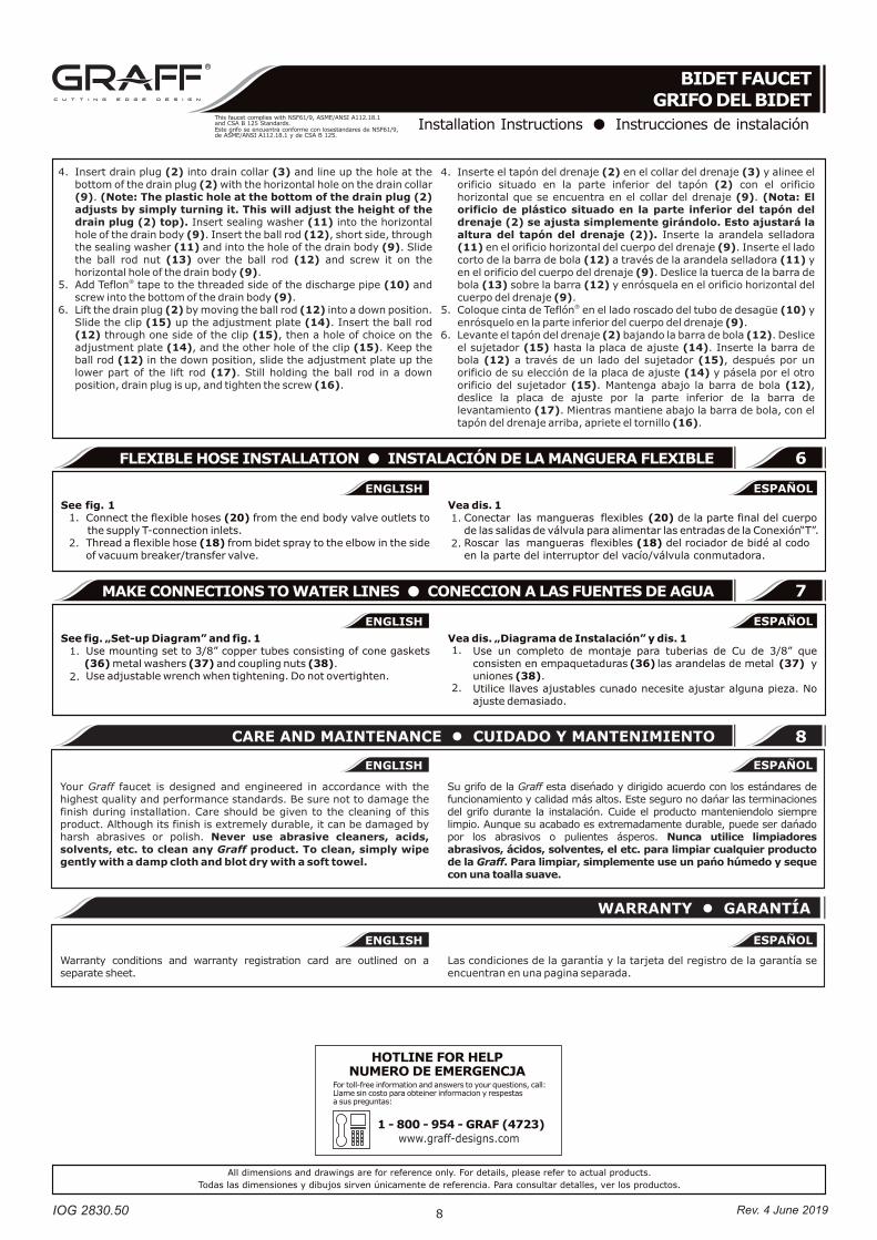
8CARE AND MAINTENANCE CUIDADO Y MANTENIMIENTO
ENGLISH~
ESPANOL
WARRANTY GARANTÍA
Your Graff faucet is designed and engineered in accordance with the highest quality and performance standards. Be sure not to damage the finish during installation. Care should be given to the cleaning of this product. Although its finish is extremely durable, it can be damaged by harsh abrasives or polish. Never use abrasive cleaners, acids, solvents, etc. to clean any Graff product. To clean, simply wipe gently with a damp cloth and blot dry with a soft towel.
Warranty conditions and warranty registration card are outlined on a separate sheet.
Su grifo de la Graff esta diseńado y dirigido acuerdo con los estándares de funcionamiento y calidad más altos. Este seguro no dańar las terminaciones del grifo durante la instalación. Cuide el producto manteniendolo siempre limpio. Aunque su acabado es extremadamente durable, puede ser dańado por los abrasivos o pulientes ásperos. Nunca utilice limpiadores abrasivos, ácidos, solventes, el etc. para limpiar cualquier producto de la Graff. Para limpiar, simplemente use un pańo húmedo y seque con una toalla suave.
Las condiciones de la garantía y la tarjeta del registro de la garantía se encuentran en una pagina separada.
1.
2.
1.
2.
1.
2.
1.
2.
6
7
Rev. 4 June 2019
www.graff-designs.com
Related Documents


