1 New Product I/O Relay Terminal G70V I/O Relay Terminals with 16 Points and Push-In Plus terminal blocks to Downsize Control Panels and Save Labor • I/O Relay Terminals with 16 points to mount G2RV Slim I/O Relays. • Push-In Plus terminal blocks are used to save wiring work in comparison with traditional screw terminals. (Wiring time is reduced by 60%* in comparison with traditional screw terminals.) • Work is reduced ever further with one-step cable connection to the PLC. • Diode provided for coil surge absorption. • Operation indicators for immediate recognition of I/O signal status. • Accepts G3RV Slim I/O SSRs. • Greatly reduce wiring work and maximize space efficiency with new models that provide internal connections between I/O terminals. (input models: 16 point/common, output models: 4 points/common) • DIN Track or screw mounting. * According to OMRON actual measurement data from November 2015. Model Number Legend For the most recent information on models that have been certified for safety standards, refer to your OMRON website. Refer to Safety Precautions on page 15. G70V - @ @ @ 16 P - @- @ (2) (1) (3) (4) (5) (6) (7) (For Input NPN) (For Output NPN) (For Input PNP) (For Output PNP) − Common PLC G70V (+) (−) X X PLC G70V (+) (−) + Common NPN transistor PLC G70V ( + ) ( −) + Common − Common X X PLC G70V (+) (−) PNP transistor (1) Mountable Relays S: Relays Z: Sockets (2) Input/Output Classification I: For input O: For output (3) I/O Specification C: Contacts (Applicable when (2) is O (for output) (relay output).) D: DC (Applicable when (2) is I (for input) (coil for input).) M: AC/DC (Applicable when (1) is Z (Sockets).) (4) Number of I/O Points 16: 16 points (5) Terminal Type P: Push-In Plus terminal blocks (6) Common Line on Connector Side Blank: NPN 1: PNP (7) Common Line on Terminal Block Side Blank: No internal connections C4: Every 4 points internally connected at terminal block bottom row C4-D: Every 4 points internally connected at terminal block middle row C16: 16 points internally connected

Welcome message from author
This document is posted to help you gain knowledge. Please leave a comment to let me know what you think about it! Share it to your friends and learn new things together.
Transcript

1
New Product
I/O Relay TerminalG70V
I/O Relay Terminals with 16 Points and Push-In Plus terminal blocks to Downsize Control Panels and Save Labor
• I/O Relay Terminals with 16 points to mount G2RV Slim I/O Relays.
• Push-In Plus terminal blocks are used to save wiring work in comparison with traditional screw terminals. (Wiring time is reduced by 60%* in comparison with traditional screw terminals.)
• Work is reduced ever further with one-step cable connection to the PLC.
• Diode provided for coil surge absorption.• Operation indicators for immediate recognition of I/O signal
status.• Accepts G3RV Slim I/O SSRs.• Greatly reduce wiring work and maximize space efficiency with new models that provide internal connections
between I/O terminals. (input models: 16 point/common, output models: 4 points/common)• DIN Track or screw mounting.* According to OMRON actual measurement data from November 2015.
Model Number Legend
For the most recent information on models that have been certified for safety standards, refer to your OMRON website.
Refer to Safety Precautions on page 15.
G70V - @ @ @ 16 P - @- @(2)(1) (3) (4) (5) (6) (7)
(For Input NPN)
(For Output NPN)
(For Input PNP)
(For Output PNP)
− Common
PLC G70V(+)
(−)
X X
PLC G70V(+)
(−)+ Common
NPNtransistor
PLC G70V(+)
(−)+ Common
− Common
X X
PLC G70V(+)
(−)
PNPtransistor
(1) Mountable RelaysS: RelaysZ: Sockets
(2) Input/Output ClassificationI: For inputO: For output
(3) I/O SpecificationC: Contacts
(Applicable when (2) is O (for output) (relay output).)D: DC (Applicable when (2) is I (for input) (coil for input).)M: AC/DC (Applicable when (1) is Z (Sockets).)
(4) Number of I/O Points16: 16 points
(5) Terminal TypeP: Push-In Plus terminal blocks
(6) Common Line on Connector SideBlank: NPN1: PNP
(7) Common Line on Terminal Block SideBlank: No internal connectionsC4: Every 4 points internally connected at terminal
block bottom rowC4-D: Every 4 points internally connected at terminal
block middle rowC16: 16 points internally connected

G70V
2
Ordering Information I/O Relay Terminals
*1.Mountable Relays: G2RV-1-S-AP-G DC21V.*2.Mountable Relays: G2RV-1-S-G DC21V.
I/O Terminal Sockets
Note: Relays are not mounted to the G70V-ZID/ZOM16P(-1) I/O Terminal Sockets. Combine the I/O Terminal Sockets with Slim I/O Relays or Slim I/O SSRs.* The G70V-ZOM16P-1-C4-D does not come with SSRs. Use Slim I/O SSRs (for DC: G3RV-D03SL).
Accessories (Order Separately)Mountable Relays
Note: To use Slim I/O SSRs, either remove the Slim I/O Relays to mount them or order a I/O Terminal Sockets and I/O SSRs separately and combine them.
*1.G2RV-1-S-AP-G Slim I/O Relays are mounted to G70V-SID16P(-1)(-C16) I/O Relay Terminals as a standard feature.*2.G2RV-1-S-G Slim I/O Relays are mounted to G70V-SOC16P(-1)(-C4) I/O Relay Terminals as a standard feature.*3. The G70V-ZOM16P-1-C4-D does not come with SSRs. Use Slim I/O SSRs (for DC: G3RV-D03SL).When ordering, designate the rated voltage.
Terminals Classification PointsCommon Line Rated
voltage ModelTerminal Block Side Connector Side
Push-In Plus terminal blocks
Input *1
16
No internal connectionsNPN (– common)
24 VDC
G70V-SID16P
PNP (+ common) G70V-SID16P-1
16 points internally connectedNPN (– common) G70V-SID16P-C16
PNP (+ common) G70V-SID16P-1-C16
Output *2
No internal connectionsNPN (+ common) G70V-SOC16P
PNP (– common) G70V-SOC16P-1
Every 4 points internally connected at terminal block bottom row
NPN (+ common) G70V-SOC16P-C4
PNP (– common) G70V-SOC16P-1-C4
Applicable I/O Relay Terminal ClassificationCommon Line
ModelTerminal Block Side Connector Side
G70V-SID16P
Input
No internal connectionsNPN (– common) G70V-ZID16P
G70V-SID16P-1 PNP (+ common) G70V-ZID16P-1
G70V-SID16P-C1616 points internally connected
NPN (– common) G70V-ZID16P-C16
G70V-SID16P-1-C16 PNP (+ common) G70V-ZID16P-1-C16
G70V-SOC16P
Output
No internal connectionsNPN (+ common) G70V-ZOM16P
G70V-SOC16P-1 PNP (– common) G70V-ZOM16P-1
G70V-SOC16P-C4 Every 4 points internally connected at terminal block bottom row
NPN (+ common) G70V-ZOM16P-C4
G70V-SOC16P-1-C4 PNP (– common) G70V-ZOM16P-1-C4
--- * Every 4 points internally connected at terminal block middle row PNP (– common) G70V-ZOM16P-1-C4-D
Applicable I/O Relay Terminal Classification Type Model
G70V-SID16P(-1)(-C16)G70V-ZID16P(-1)(-C16) Input Slim I/O Relays *1 G2RV-1-S-AP-G DC21
G70V-SOC16P(-1)(-C4)G70V-ZOM16P(-1)(-C4) Output
Slim I/O RelaysNo Latching Lever *2 G2RV-1-S-G DC21
Latching Lever G2RV-1-SI-G DC21
Slim I/O SSRsFor AC
Zero cross function G3RV-202S DC24
No zero cross function G3RV-202SL DC24
For DC G3RV-D03SL DC24
G70V-ZOM16P-1-C4-D *3 Output Slim I/O SSRs For DC G3RV-D03SL DC24

G70V
3
Cables for I/O Relay Terminals XW2Z-R• Cable with Loose Wire and Crimp Terminals: XW2Z-RY@C• Cable with Loose Wires: XW2Z-RA@C• Cable with connectors
• Fujitsu connectors (1:1): XW2Z-R@C(1:2): XW2Z-RI@C-@
XW2Z-RO@C-@(1:3): XW2Z-R@C-@-@
• MIL connectors (1:1): XW2Z-RI@CXW2Z-RO@C
(1:2): XW2Z-RI@-@-D@XW2Z-RM@-@-D@XW2Z-RO@-@-D1
Refer to Connecting Cables on page 17 for details.
Labels
Accessories for DIN Track Mounting
* These products must be ordered in sets of 10.
Refer to your OMRON website for details on the PFP-@.
Mounting Example Using the AccessoriesMounting to DIN Track
Appearance ModelMinimum order (sheet)
(quantity per sheet)
XW5Z-P2.5LB25
(1 sheet / 72 pieces)
Appearance Name ModelMinimum order
(quantity)
DIN Tracks
1 m PFP-100N
1
0.5 m PFP-50N
End Plate PFP-M
10
Spacer PFP-S
End PlatePFP-M
DIN TrackPFP-100N (1 m)PFP-50N (50 cm)
Label Enlarged view

G70V
4
SpecificationsCoil Ratings (Common to Input/Output per Relay)
Note: 1. The rated current and coil resistance are measured at a coil temperature of 23°C with a tolerance of ±15% for coil resistance.2. The operating characteristics are measured at a coil temperature of 23°C.3. The value for maximum voltage is the maximum value within the allowable voltage fluctuation range for the relay coil’s operating power
supply. Continuous operation at this voltage is not within product specifications.4. The rated current includes the current for the indicators on the I/O Relay Terminal.
Contact Ratings (G2RV-1-S-G I/O Relay)
* The above values are for a switching frequency of 120 operations/min.
Characteristics
Note: The above values are initial values.*1.Measurement: 1 A at 5 VDC.*2.Ambient temperature: 23°C.
Applicable Standards• UL 61010-2-201, CAN/CSA-C22.2 No.61010-2-201, TÜV (EN 61810-1)
Item Rated current (mA)
Coil resistance(Ω)
Mustoperate of
rated voltage
Mustrelease of rated
voltage
Maximumvoltage of rated
voltage
Power consumption
(mW)Rated voltage (V)
24 VDC 13.3 1575 80% max. 10% min. 110% Approx. 280
Classification For input For output
Item Resistive load (cosφ=1) Resistive load (cosφ=1) Inductive load(cosφ=0.4 L/R=7 ms)
Rated load 50 mA at 30 VAC50 mA at 36 VDC
6 A at 250 VAC6 A at 30 VDC
2.5 A at 250 VAC2 A at 30 VDC
Rated carry current 50 mA 6 A/point, 10 A/common
Max. switching voltage 30 VAC, 36 VDC 250 VAC, 125 VDC
Max. switching current 50 mA 6 A/point, 10 A/common
Maximum switching capacity --- 1,500 VA180 W
500 VA60 W
Error rate (reference value) * 1 mA at 100 mVDC 10 mA at 5 VDC
Electrical endurance 5,000,000 operations min. NO contacts: 70,000 operations min.NC contacts: 50,000 operations min.
Mechanical endurance 5,000,000 operations min. 5,000,000 operations min.
ItemModel G70V-SID16P(-1)(-C16)
(Input, DC coil)G70V-SOC16P(-1)(-C4)
(output, DC coil)
Contact form SPST-NO × 16 SPDT×16
Contact material Ag alloy + Au plating Ag alloy
Contact resistance *1 150 mΩ max.
Must Operate time *2 20 ms max.
Release time *2 40 ms max.
Max. switchingfrequency
Mechanical limit 18,000 operations/h
At rated load 1,800 operations/h (under rated load)
Insulation resistance 100 MΩ min.
Dielectric strength Between coil and contacts: 2,500 VAC for 1 min
Vibration resistance 100 m/s2
Shock resistance 100 m/s2, 3 times each in 6 directions along 3 axes
Noise immunity Noise level: 1.5 kV; pulse width: 100 ns to 1 μs
Ambient operating temperature −40 to 55°C (with no icing or condensation)
Ambient operating humidity 35% to 85%
LED colorPower supply Green
I/O Yellow
Weight Approx. 350 g Approx. 370 g

G70V
5
Engineering Data (Reference Value)Endurance Curve (NO Contacts)
Load Current vs. Ambient Temperature
Inrush Current Resistance: Non-repetitiveThe following graphs show the maximum inrush currents that can be withstood for non-repetitive operation. For repetitive operation, the figures should be reduced by half.
G70V-SOC16P(-1)(-C4)
Note: These data are actual measured values that were sampled from the production line and prepared in graph format, and are for reference purposes only. A relay is manufactured by mass production, and as a basic rule must be used with allowance made for a certain amount of deviation.
G70V-SOC16P(-1)(-C4) G3RV-202S DC24G3RV-202SL DC24
G3RV-D03 DC24
G3RV-202S DC24G3RV-202SL DC24
G3RV-D03 DC24
10
100
1000
0 2 4Switched current (A)
6
250 VAC resistive load30 VDC resistive load
30 VDC inductive load
250 VAC inductive load
Ope
ratio
ns (
× 10
3 )
-40
16 points ON
Single Relay
0
1
2
3
4
5
6
(A)
-20 0 20 25 40 5560Ambient Temperature
Load
Cur
rent
(A
)
-400
0.2
1
2
3
(A)
-20 0 20 25 40 55 60Ambient Temperature
Load
Cur
rent
(A
)
16 points ON
Single Relay
-400
1
0.5
2
3
(A)
-20 0 20 40 55 60Ambient Temperature
Load
Cur
rent
(A
)
16 points ON
Single Relay
40
35
30
25
20
15
10
5
010 30 50 100 300 500 1,000 3,000 5,000
Energized time (ms)
Inru
sh c
urre
nt (
A. P
eak) 40
35
30
25
20
15
10
5
010 30 50 100 300 500 1,000 3,000 5,000
Energized time (ms)
Inru
sh c
urre
nt (
A. P
eak)

G70V
6
Internal CircuitsG70V-SID16P(NPN input/– common)
Note: Pin numbers are indicated for convenience. The ▲ mark can be used to determine orientation.
G70V-SID16P-1(PNP input/+ common)
Note: Pin numbers are indicated for convenience. The ▲ mark can be used to determine orientation.
Terminal name Description
V (push-in power supply terminals)Unit power supply terminals (24 VDC)
G (push-in power supply terminals)
V (push-in I/O terminals)Relay-drive coil terminals (24 VDC)
G (push-in I/O terminals)
Terminal name Description
V (push-in power supply terminals)Unit power supply terminals (24 VDC)
G (push-in power supply terminals)
V (push-in I/O terminals)Relay-drive coil terminals (24 VDC)
G (push-in I/O terminals)
12345678+−
910111213141516+−
1
2
3
4
5
6
7
8
9
10
11
12
13
14
15
16
17
18
19
20
Connector pin No.mark
Relay No.
X
V
G
V
G
V
G
V
G
V
G
V
G
V
G
V
G
V
G
V
G
V
G
V
G
V
G
V
G
V
G
V
G
V
G
V
G
X X X X X X X X X X X X X X X
Push-in I/O terminals
Push-in power supply terminals
10
20
12345678
1112131415161718
919
X Input relaysG2RV-1-S-AP-G
Connectorpin No.
Connector Pin ConfigurationTop View
Relay No.
1
2
3
4
5
6
7
8
9
10
11
12
13
14
15
16
17
18
19
20
Connector pin No.mark
12345678−+
910111213141516−+
X
V
G
V
G
V
G
V
G
V
G
V
G
V
G
V
G
V
G
V
G
V
G
V
G
V
G
V
G
V
G
V
G
V
G
V
G
X X X X X X X X X X X X X X X
Push-in I/O terminals
Push-in power supply terminals
10
20
12345678
11121314151617189
19
X Input relaysG2RV-1-S-AP-G
Connectorpin No.
Connector Pin ConfigurationTop View

G70V
7
G70V-SID16P-C16(NPN input/– common)
Note: Pin numbers are indicated for convenience. The ▲ mark can be used to determine orientation.
G70V-SID16P-1-C16(PNP input/+ common)
Note: Pin numbers are indicated for convenience. The ▲ mark can be used to determine orientation.
Terminal name Description
V (push-in power supply terminals)Unit power supply terminals (24 VDC)
G (push-in power supply terminals)
V (push-in I/O terminals)Relay-drive coil terminals (24 VDC)
G (push-in I/O terminals)
Terminal name Description
V (push-in power supply terminals)Unit power supply terminals (24 VDC)
G (push-in power supply terminals)
V (push-in I/O terminals)Relay-drive coil terminals (24 VDC)
G (push-in I/O terminals)
X
V
G
V
G
V
G
V
G
V
G
V
G
V
G
V
G
V
G
V
G
V
G
V
G
V
G
V
G
V
G
V
G
V
G
V
G
X X X X X X X X X X X X X X X
10
20
12345678
1112131415161718
919
Push-in power supply terminals
X Input relaysG2RV-1-S-AP-G
Push-in I/O terminals
Connectorpin No.
Connector Pin ConfigurationTop View
12345678+−
910111213141516+−
1
2
3
4
5
6
7
8
9
10
11
12
13
14
15
16
17
18
19
20
Connector pin No.mark
Relay No.
12345678−+
910111213141516−+
1
2
3
4
5
6
7
8
9
10
11
12
13
14
15
16
17
18
19
20
Connector pin No.mark
Relay No.
X
V
G
V
G
V
G
V
G
V
G
V
G
V
G
V
G
V
G
V
G
V
G
V
G
V
G
V
G
V
G
V
G
V
G
V
G
X X X X X X X X X X X X X X X
10
20
12345678
1112131415161718
919
Push-in power supply terminals
Connectorpin No.
Push-in I/O terminals
X Input relaysG2RV-1-S-AP-G
Connector Pin ConfigurationTop View

G70V
8
G70V-SOC16P(NPN output/+ common)Note: A controller with an NPN transistor, common output can be connected to the G70V-SOC16P.
Note: Pin numbers are indicated for convenience. The ▲ mark can be used to determine orientation.
G70V-SOC16P-1(PNP output/- common)Note: A controller with a PNP transistor, + common output can be connected to the G70V-SOC16P-1.
Note: Pin numbers are indicated for convenience. The ▲ mark can be used to determine orientation.
Terminal name Description
V (push-in power supply terminals)Unit power supply terminals (24 VDC)
G (push-in power supply terminals)
11 to 81 (push-in I/O terminal common terminals)
Relay contact terminals12 to 82 (push-in I/O terminal NC terminals)
14 to 84 (push-in I/O terminal NO terminals)
Terminal name Description
V (push-in power supply terminals)Unit power supply terminals (24 VDC)
G (push-in power supply terminals)
11 to 81 (push-in I/O terminal common terminals)
Relay contact terminals12 to 82 (push-in I/O terminal NC terminals)
14 to 84 (push-in I/O terminal NO terminals)
1
2
3
4
5
6
7
8
9
10
11
12
13
14
15
16
17
18
19
20
Connector pin No.mark
Relay No.
12345678−+
910111213141516−+
X Output relaysG2RV-1-S-G
Connectorpin No.
12345678
111213141516171810209
19
11
14
12
21
24
22
31
34
32
41
44
42
51
54
52
61
64
62
71
74
72
81
84
82
11
14
12
21
24
22
31
34
32
41
44
42
51
54
52
61
64
62
71
74
72
81
84
82
V
G
V
G
Connector Pin ConfigurationTop View
1
2
3
4
5
6
7
8
9
10
11
12
13
14
15
16
17
18
19
20
Connector pin No.mark
Relay No.
12345678−+
910111213141516−+
X Output relaysG2RV-1-S-G
Connectorpin No.
12345678
11121314151617181020
919
11
14
12
21
24
22
31
34
32
41
44
42
51
54
52
61
64
62
71
74
72
81
84
82
11
14
12
21
24
22
31
34
32
41
44
42
51
54
52
61
64
62
71
74
72
81
84
82
V
G
V
G
Connector Pin ConfigurationTop View

G70V
9
G70V-SOC16P-C4(NPN output/+ common)Note: A controller with an NPN transistor, common output can be connected to the G70V-SOC16P-C4.
Note: Pin numbers are indicated for convenience. The ▲ mark can be used to determine orientation.
G70V-SOC16P-1-C4(PNP output/- common)Note: A controller with a PNP transistor, + common output can be connected to the G70V-SOC16P-1-C4.
Note: Pin numbers are indicated for convenience. The ▲ mark can be used to determine orientation.
Terminal name Description
V (push-in power supply terminals)Unit power supply terminals (24 VDC)
G (push-in power supply terminals)
11 to 81 (push-in I/O terminal common terminals)
Relay contact terminals12 to 82 (push-in I/O terminal NC terminals)
14 to 84 (push-in I/O terminal NO terminals)
Terminal name Description
V (push-in power supply terminals)Unit power supply terminals (24 VDC)
G (push-in power supply terminals)
11 to 81 (push-in I/O terminal common terminals)
Relay contact terminals12 to 82 (push-in I/O terminal NC terminals)
14 to 84 (push-in I/O terminal NO terminals)
12345678−+
910111213141516−+
1
2
3
4
5
6
7
8
9
10
11
12
13
14
15
16
17
18
19
20
Connector pin No.mark
Relay No.
12345678
11121314151617181020
919
11
14
12
21
24
22
31
34
32
41
44
42
51
54
52
61
64
62
71
74
72
81
84
82
11
14
12
21
24
22
31
34
32
41
44
42
51
54
52
61
64
62
71
74
72
81
84
82
V
G
V
G
Connectorpin No.
X Output relaysG2RV-1-S-G
Connector Pin ConfigurationTop View
12345678−+
910111213141516−+
1
2
3
4
5
6
7
8
9
10
11
12
13
14
15
16
17
18
19
20
Connector pin No.mark
Relay No.
12345678
11121314151617181020
919
11
14
12
21
24
22
31
34
32
41
44
42
51
54
52
61
64
62
71
74
72
81
84
82
11
14
12
21
24
22
31
34
32
41
44
42
51
54
52
61
64
62
71
74
72
81
84
82
V
G
V
G
X Output relaysG2RV-1-S-G
Connectorpin No.
Connector Pin ConfigurationTop View

G70V
10
G70V-ZOM16P-1-C4-D(PNP output/- common)Note: A controller with an PNP transistor, common output can be connected to the G70V-ZOM16P-1-C4-D.
Note: Pin numbers are indicated for convenience. The ▲ mark can be used to determine orientation.
* The G70V-ZOM16P-1-C4-D does not come with SSRs. Use Slim I/O SSRs (for DC: G3RV-D03SL).
Terminal name Description
V (push-in power supply terminals)Unit power supply terminals (24 VDC)
G (push-in power supply terminals)
11 to 81 (push-in I/O terminal SSR output terminal +)
SSR contact terminals12 to 82 (push-in I/O terminal Open terminal)
14 to 84 (push-in I/O terminal SSR output terminal -)
12345678−+
910111213141516−+
1
2
3
4
5
6
7
8
9
10
11
12
13
14
15
16
17
18
19
20
Connector pin No.mark
Relay No.
Connectorpin No.
X Output Relays*G3RV-D03SL (Relays sold separately.)
12345678
11121314151617181020
919
11
14
12
21
24
22
31
34
32
41
44
42
51
54
52
61
64
62
71
74
72
81
84
82
11
14
12
21
24
22
31
34
32
41
44
42
51
54
52
61
64
62
71
74
72
81
84
82
V
G
V
G
Connector Pin ConfigurationTop View
G70V
11
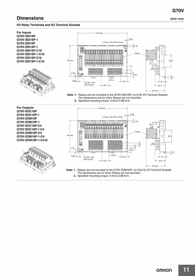
Dimensions (Unit: mm)
I/O Relay Terminals and I/O Terminal Sockets
For InputsG70V-SID16PG70V-SID16P-1G70V-ZID16PG70V-ZID16P-1G70V-SID16P-C16G70V-SID16P-1-C16G70V-ZID16P-C16G70V-ZID16P-1-C16
18.3
143 max.
4.35
4.35
4.2-dia. hole (M4 screw)
4.35
4.2-dia. hole (M4 screw)
4.35
10.26
7.5
20.2
5
35.2
4.1
16.7
29.9
56 max.
90 max.
Relay
Note: 1. Relays are not mounted to the G70V-ZID16P(-1)(-C16) I/O Terminal Sockets.The dimensions are for when Relays are not mounted.
2. Specified mounting torque: 0.59 to 0.98 N·m.
For OutputsG70V-SOC16PG70V-SOC16P-1G70V-ZOM16PG70V-ZOM16P-1G70V-SOC16P-C4G70V-SOC16P-1-C4G70V-ZOM16P-C4G70V-ZOM16P-1-C4G70V-ZOM16P-1-C4-D
Relay
143 max.
4.2-dia. hole (M4 screw)
90 max.
4.35
4.35
4.354.2-dia. hole (M4 screw)
4.35
20.2
518.24
7.8
10.26
7.8
35.2
4.1
16.7
29.9
56 max.
Note: 1. Relays are not mounted to the G70V-ZOM16P(-1)(-C4)(-D) I/O Terminal Sockets.The dimensions are for when Relays are not mounted.
2. Specified mounting torque: 0.59 to 0.98 N·m.

G70V
12
Terminal Arrangement/Internal ConnectionFor Inputs
For Outputs
Communications connector
Operation indicator (yellow)
DIN Track mounting hooks I/O Terminal Blocks
Power supply terminal block
Input Relays (G2RV-1-S-AP-G)
• Supply a power supply that meets the voltage specifications for both the Relays and I/O Relay Terminal to the V and G terminals.Make sure that the polarity is correct.The V terminals are positive and the G terminals are negative.
• Supply the rated voltage (24 VDC) of the Controller’s input circuit to the power supply input terminals (V and G). Use a power supply with low noise.
G70V-SID16PG70V-SID16P-1
V
G
V
G
V
G
V
G
V
G
V
G
V
G
V
G
V
G
V
G
V
G
V
G
V
G
V
G
V
G
V
G
V
G
V
G24 VDC
24 VDC
Communications connector
DIN Track mounting hooks I/O Terminal Blocks
Power supply terminal block Operation indicator (yellow)
Output Relays (G2RV-1-S-G)
• Supply a power supply that meets the voltage specifications for both the Relays and I/O Relay Terminal to the V and G terminals.Make sure that the polarity is correct.The V terminals are positive and the G terminals are negative.
• The terminals (11 to 81, 12 to 82, and 14 to 84) are contact outputs. Supply a suitable power supply for the loads.
• The power supply input terminals (V and G) supply power to both drive the Relays and to operate the Controller’s output transistors.Align the voltage specifications of the Controller and the I/O Relay Terminal.
G70V-SOC16PG70V-SOC16P-1
AC (DC power supply is also possible.)
L0 L1 L2 L3 L4 L5 L6 L7 L8 L9 L10 L11 L12 L13 L14 L15
12
14
11
22
24
21
32
34
31
42
44
41
52
54
51
62
64
61
72
74
71
82
84
81
12
14
11
22
24
21
32
34
31
42
44
41
52
54
51
62
64
61
72
74
71
82
84
81
24 VDC
V V
G G

G70V
13
For Inputs
For Outputs
Communications connector
Operation indicator (yellow)
DIN Track mounting hooks I/O Terminal Blocks
Power supply terminal block
Input Relays (G2RV-1-S-AP-G)
• Supply a power supply that meets the voltage specifications for both the Relays and I/O Relay Terminal to the V and G terminals.Make sure that the polarity is correct.The V terminals are positive and the G terminals are negative.
• Supply the rated voltage (24 VDC) of the Controller’s input circuit to the power supply input terminals (V and G). Use a power supply with low noise.
G70V-SID16P-C16G70V-SID16P-1-C16
24 VDC 24 VDC
24 VDC24 VDC
V
G
V
G
V
G
V
G
V
G
V
G
V
G
V
G
V
G
V
G
V
G
V
G
V
G
V
G
V
G
V
G
V
G
V
G
V
G
V
G
V
G
V
G
V
G
V
G
V
G
V
G
V
G
V
G
V
G
V
G
V
G
V
G
V
G
V
G
V
G
V
G
G70V-SID16P-C16 G70V-SID16P-1-C16
Communications connector
DIN Track mounting hooks I/O Terminal Blocks
Power supply terminal block Operation indicator (yellow)
Output Relays (G2RV-1-S-G)
• Supply a power supply that meets the voltage specifications for both the Relays and I/O Relay Terminal to the V and G terminals.Make sure that the polarity is correct.The V terminals are positive and the G terminals are negative.
• The terminals (11 to 81, 12 to 82, and 14 to 84) are contact outputs. Supply a suitable power supply for the loads.
• The power supply input terminals (V and G) supply power to both drive the Relays and to operate the Controller’s output transistors.Align the voltage specifications of the Controller and the I/O Relay Terminal.
G70V-SOC16P-C4G70V-SOC16P-1-C4
L0 L1 L2 L3 L4 L5 L6 L7 L8 L9 L10 L11 L12 L13 L14 L15
12
14
11
22
24
21
32
34
31
42
44
41
52
54
51
62
64
61
72
74
71
82
84
81
12
14
11
22
24
21
32
34
31
42
44
41
52
54
51
62
64
61
72
74
71
82
84
81
24 VDC
V V
G G
AC (DC power supply is also possible.)

G70V
14
For Outputs
Communications connector
DIN Track mounting hooks I/O Terminal Blocks
Power supply terminal block Operation indicator (yellow)
Output Relays*G3RV-D03SL (Relays sold separately.)
• Supply a power supply that meets the voltage specifications for both the Relays and I/O Relay Terminal to the V and G terminals.Make sure that the polarity is correct.The V terminals are positive and the G terminals are negative.
• The terminals (11 to 81 and 14 to 84) are contact outputs. Supply a suitable power supply for the loads. Make sure that polarity of the output terminal is correct.
• The power supply input terminals (V and G) supply power to both drive the Relays and to operate the Controller’s output transistors.Align the voltage specifications of the Controller and the I/O Relay Terminal.
G70V-ZOM16P-1-C4-D
L0 L1 L2 L3 L4 L5 L6 L7 L8 L9 L10 L11 L12 L13 L14 L15
12
14
11
22
24
21
32
34
31
42
44
41
52
54
51
62
64
61
72
74
71
82
84
81
12
14
11
22
24
21
32
34
31
42
44
41
52
54
51
62
64
61
72
74
71
82
84
81
V V
G G
24 VDC
DC
* The G70V-ZOM16P-1-C4-D does not come with SSRs. Use Slim I/O SSRs (for DC: G3RV-D03SL).

G70V
15
Safety PrecautionsBe sure to read The Safety Precautions for All I/O Relay Terminals in the website at the following URL: http://www.ia.omron.com/.
Warning Indications
Transportation• Do not transport the I/O Relay Terminal under the following
locations. Doing so may occasionally result in damage, malfunction, or deterioration of performance characteristics.• Locations subject to water or oil• Locations subject to high temperature or high humidity• Locations subject to condensation due to rapid changes in
temperature
Operating and Storage Environments• Do not use or store the I/O Relay Terminal in the following
locations. Doing so may result in damage, malfunction, or deterioration of performance characteristics.• Locations subject to rainwater or water splashes• Locations subject to exposure to water, oil, or chemicals• Locations subject to high temperature or high humidity• Locations subject to ambient storage temperatures outside the
range −40 to 65°C• Locations subject to ambient operating temperatures outside the
range −40 to 55°C• Locations subject to relative humidity outside the range 35% to
85% or locations in which condensation may occur due to rapid changes in temperature
• Locations subject to corrosive gases or inflammable gases• Locations subject to dust, salts, or iron, or locations where there
is salt damage• Locations subject to direct sunlight• Locations subject to shock or vibration
Installation and Mounting• Mount the I/O Relay Terminal in the specified direction. Otherwise
excessive heat generated by the I/O Relay Terminal may occasionally cause burning.
• Mount the I/O Relay Terminal firmly to a DIN Track. Otherwise, the I/O Relay Terminal may fall off.
• Do not handle the I/O Relay Terminal with oily or dusty (especially iron dust) hands.
• Make sure that there is no excessive ambient temperature rise due to the heat generation of the I/O Relay Terminal. If the I/O Relay Terminal is mounted inside a panel, install a fan so that the interior of the panel is fully ventilated.
Installation and Wiring• Use wires that are suited to the load current and voltage.
Otherwise, excessive heat generated by the wires may cause burning or may cause the wire covering to melt, possibly leading to electric shock.
• Do not use wires with a damaged outer covering. Otherwise, it may result in electric shock or ground leakage.
• Do not wire any wiring in the same duct or conduit as power or high-tension lines. Otherwise, inductive noise may damage the I/O Relay Terminal or cause it to malfunction.
• Do not apply a voltage or current that exceeds the rating to any terminal. Doing so may result in failure or burning.
Push-In Plus Terminal Blocks• Do not wire anything to the release holes.• Do not tilt or twist a flat-blade screwdriver while it is inserted into a
release hole on the terminal block. The terminal block may be damaged.
• Insert a flat-blade screwdriver into the release holes at an angle. The terminal block may be damaged if you insert the screwdriver straight in.
• Do not allow the flat-blade screwdriver to fall out while it is inserted into a release hole.
• Do not bend a wire past its natural bending radius or pull on it with excessive force. Doing so may cause the wire disconnection.
• Do not insert more than one wire into each terminal insertion hole.• To prevent wire materials from smoking or igniting, confirm wire
ratings and use the wiring materials given in the following table.
• Refer to the following table for wire sizes for external I/O devices according to the current flow.
Application• Select a load within the rated values. Not doing so may result in
malfunction, failure, or burning.• The I/O Relay Terminal may occasionally rupture if short-circuit
current flows. As protection against accidents due to short-circuiting, be sure to install protective devices, such as fuses and no-fuse breakers, on the power supply side.
• Use a power supply within the rated frequencies. Otherwise, malfunction, failure, or burning may occasionally occur.
• Minor electric shock may occasionally occur. Always turn OFF the power supply before performing wiring.
• Do not drop the I/O Relay Terminal or subject it to abnormal vibration or shock during transportation or mounting. Doing so may result in deterioration of performance, malfunction, or failure.
• Do not transport an I/O Relay Terminal when it is not packaged. Damage or failure may occur.
• Use a power supply with low noise.
Push-In Plus Terminal Blocks1. Connecting Wires to the Push-In Plus Terminal BlockPart Names of the Terminal Block
Connecting Wires with Ferrules and Solid WiresInsert the solid wire or ferrule straight into the terminal block until the end strikes the terminal block.
• If a wire is difficult to connect because it is too thin, use a flat-blade screwdriver in the same way as when connecting stranded wire.
Precautions for Safe Use
Supplementary comments on what to do or avoid doing, to use the product safely.
Precautions for Correct Use
Supplementary comments on what to do or avoid doing, to prevent failure to operate, malfunction, or undesirable effects on product performance.
Precautions for Safe Use
Recommended wire gauge Stripping length(Ferrules not used)
0.25 to 1.5mm2/AWG24 to 16 8 mm
AWG24 to AWG20 Maximum current flow: 6 A
AWG18 to AWG16 Maximum current flow: 10 A
Precautions for Correct Use
Release hole
Terminal (Insertion) hole
Release hole
Terminal (Insertion) hole
Ferrulesand solid wires

G70V
16
Connecting Stranded WiresUse the following procedure to connect the wires to the terminal block.1. Hold a flat-blade screwdriver at an angle and insert it into the
release hole.The angle should be between 10° and 15°. If the flat-blade screwdriver is inserted correctly, you will feel the spring in the release hole.
2. With the flat-blade screwdriver still inserted into the release hole, insert the wire into the terminal hole until it strikes the terminal block.
3. Remove the flat-blade screwdriver from the release hole.
Checking Connections• After the insertion, pull gently on the wire to make sure that it will
not come off and the wire is securely fastened to the terminal block.• If you use a ferrule with a conductor length of 10 mm, part of the
conductor may be visible after the ferrule is inserted into the terminal block, but the product insulation distance will still be satisfied.
2. Removing Wires from the Push-In Plus Terminal BlockUse the following procedure to remove wires from the terminal block.The same method is used to remove stranded wires, solid wires, and ferrules.1. Hold a flat-blade screwdriver at an angle and insert it into the
release hole.2. With the flat-blade screwdriver still inserted into the release hole,
remove the wire from the terminal insertion hole.3. Remove the flat-blade screwdriver from the release hole.
3. Recommended Ferrules and Crimp ToolsRecommended ferrules
Note: 1. Make sure that the outer diameter of the wire coating is smaller than the inner diameter of the insulation sleeve of the recommended ferrule.
2. Make sure that the ferrule processing dimensions conform to the following figures.
Recommended Flat-blade ScrewdriverUse a flat-blade screwdriver to connect and remove wires.Use the following flat-blade screwdriver.The following table shows manufacturers and models as of 2015/Dec.
* OMRON's exclusive purchase model XW4Z-00B is available to order as SZF 0-0.4 × 2.5 (manufactured by Phoenix Contact).
Flat-blade screwdriver
Stranded Wires
10 to 15°
13
2
1 3
2
Wire
Flat-blade screwdriver
10 to 15°
13
2
1 3
2
Applicable wire Ferrule
Conductor length (mm)
Stripping length[mm]
(Ferrules used)
Recommended ferrules
(mm2) (AWG)PhoenixContact product
Weidmuller product
Wago product
0.25 248 10 AI0,25-8 H0.25/12 FE-0.25-8N-YE
10 12 AI0,25-10 --- ---
0.34 228 10 AI0,34-8 H0.34/12 FE-0.34-8N-TQ
10 12 AI0,34-10 --- ---
0.5 208 10 AI0,5-8 H0.5/14 FE-0.5-8N-WH
10 12 AI0,5-10 H0.5/16 FE-0.5-10N-WH
0.75 188 10 AI0,75-8 H0.75/14 FE-0.75-8N-GY
10 12 AI0,75-10 H0.75/16 FE-0.75-10N-GY
1/1.25 18/178 10 AI1-8 H1.0/14 FE-1.0-8N-RD
10 12 AI1-10 H1.0/16 FE-1.0-10N-RD
1.25/1.5 17/168 10 AI1,5-8 H1.5/14 FE-1.5-8N-BK
10 12 AI1,5-10 H1.5/16 FE-1.5-10N-BK
Recommended crimp toolCRIMPFOX6CRIMPFOX6T-FCRIMPFOX10S
PZ6 roto Variocrimp4
Model Manufacturer
ESD0.40×2.5 Wera
SZS 0.4×2.5SZF 0-0.4×2.5 * Phoenix Contact
0.4×2.5×75 302 Wiha
AEF.2.5×75 Facom
210-719 Wago
SDI 0.4×2.5×75 Weidmuller
8 to 10 mm
1.9 mm max. 2.6 mm max.
Side
0.4 mm
2.5 mm dia.
2.5 mm
Front

G70V
17
Connecting CablesRefer to the datasheet for the XW2Z-R Cables for I/O Relay Terminals (Cat. No. G126).
Type Name I/O Classification Appearance Cable length L (mm) Models
Various devices
Cables with Loose Wires and Crimp Terminals
XW2Z-RY C
16 I/O points
1,000 XW2Z-RY100C
1,500 XW2Z-RY150C
2,000 XW2Z-RY200C
3,000 XW2Z-RY300C
5,000 XW2Z-RY500C
Cables with Loose Wires
XW2Z-RA C16 I/O points
2,000 XW2Z-RA200C
5,000 XW2Z-RA500C
Fujitsu connectors (24 pins)
Cables with Connectors (1:1)
XW2Z-R C
16 I/O points
1,000 XW2Z-R100C
1,500 XW2Z-R150C
2,000 XW2Z-R200C
3,000 XW2Z-R300C
5,000 XW2Z-R500C
Fujitsu connectors (40 pins)
Cables with Connectors (1:2)
XW2Z-RI C-XW2Z-RO C-
32 input points
(A) 1,000 (B) 750 XW2Z-RI100C-75
(A) 1,500 (B) 1,250 XW2Z-RI150C-125
(A) 2,000 (B) 1,750 XW2Z-RI200C-175
(A) 3,000 (B) 2,750 XW2Z-RI300C-275
(A) 5,000 (B) 4,750 XW2Z-RI500C-475
32 output points
(A) 1,000 (B) 750 XW2Z-RO100C-75
(A) 1,500 (B) 1,250 XW2Z-RO150C-125
(A) 2,000 (B) 1,750 XW2Z-RO200C-175
(A) 3,000 (B) 2,750 XW2Z-RO300C-275
(A) 5,000 (B) 4,750 XW2Z-RO500C-475
Fujitsu connectors (56 pins)
Cables with Connectors (1:3)
XW2Z-R C- -
48 I/O points
(A)1,500
(B)1,250
(C)1,000 XW2Z-R150C-125-100
(A)2,000
(B)1,750
(C)1,500 XW2Z-R200C-175-150
(A)3,000
(B)2,750
(C)2,500 XW2Z-R300C-275-250
MIL connectors (20 pins)
Cables with Connectors (1:1)
XW2Z-RI CXW2Z-RO C
16 I/O points
250 XW2Z-RI25C
500 XW2Z-RI50C
250 XW2Z-RO25C
500 XW2Z-RO50C
300L
A side B sideDevice end I/O Relay Terminal
300L
L
Straight length (without bends)
(120)
(A)
(B)
(270)
(B)
(C)
Straight length (without bends)
(120)
(A)
L

G70V
18
* These cables are used to connect to slave products for DeviceNet and other networks.
MIL connectors (40 pins)
Cables with Connectors (1:2)
XW2Z-RO - -D1, XW2Z-RI - -D1,XW2Z-RI - -D2,XW2Z-RM - -D1*,XW2Z-RM - -D2*
32 I/O points
(A) 500 (B) 250 XW2Z-RO50-25-D1
(A) 750 (B) 500 XW2Z-RO75-50-D1
(A) 1,000 (B) 750 XW2Z-RO100-75-D1
(A) 1,500 (B) 1,250 XW2Z-RO150-125-D1
(A) 2,000 (B) 1,750 XW2Z-RO200-175-D1
(A) 3,000 (B) 2,750 XW2Z-RO300-275-D1
(A) 5,000 (B) 4,750 XW2Z-RO500-475-D1
(A) 500 (B) 250 XW2Z-RI50-25-D1
(A) 750 (B) 500 XW2Z-RI75-50-D1
(A) 1,000 (B) 750 XW2Z-RI100-75-D1
(A) 1,500 (B) 1,250 XW2Z-RI150-125-D1
(A) 2,000 (B) 1,750 XW2Z-RI200-175-D1
(A) 3,000 (B) 2,750 XW2Z-RI300-275-D1
(A) 5,000 (B) 4,750 XW2Z-RI500-475-D1
(A) 500 (B) 250 XW2Z-RI50-25-D2
(A) 750 (B) 500 XW2Z-RI75-50-D2
16 inputs and 16 outputs(32 I/O points)
(A) 500 (B) 250 XW2Z-RM50-25-D1
(A) 750 (B) 500 XW2Z-RM75-50-D1
(A) 1,000 (B) 750 XW2Z-RM100-75-D1
(A) 1,500 (B) 1,250 XW2Z-RM150-125-D1
(A) 2,000 (B) 1,750 XW2Z-RM200-175-D1
(A) 3,000 (B) 2,750 XW2Z-RM300-275-D1
(A) 5,000 (B) 4,750 XW2Z-RM500-475-D1
(A) 500 (B) 250 XW2Z-RM50-25-D2
(A) 750 (B) 500 XW2Z-RM75-50-D2
Mitsubishi Electric PLCs with 32-point connectors (1:2)
Applicable models:For inputs: AX42, A1SX41, A1SX42, QX41, and QX42For outputs: AY42, A1SY41, A1SY42, QY41P, and QY42P
Mitsubishi Electric PLC Connecting Cables
XW2Z-RI C- -MNXW2Z-RO C- -MN
32 input points
(A) 1,000 (B) 750 XW2Z-RI100C-75-MN
(A) 1,500 (B) 1,250 XW2Z-RI150C-125-MN
(A) 2,000 (B) 1,750 XW2Z-RI200C-175-MN
(A) 3,000 (B) 2,750 XW2Z-RI300C-275-MN
32 output points
(A) 1,000 (B) 750 XW2Z-RO100C-75-MN
(A) 1,500 (B) 1,250 XW2Z-RO150C-125-MN
(A) 2,000 (B) 1,750 XW2Z-RO200C-175-MN
(A) 3,000 (B) 2,750 XW2Z-RO300C-275-MN
Schneider Electric PLCs with 32-point connectors (1:2)
Applicable models:For inputs: 140 DDI 353 00For outputs: 140 DDO 353 00
Schneider Electric PLC Connecting Cables
XW2Z-R@C-SCH-@
32 input points
500 XW2Z-R050C-SCH-A
1,000 XW2Z-R100C-SCH-A
2,000 XW2Z-R200C-SCH-A
3,000 XW2Z-R300C-SCH-A
5,000 XW2Z-R500C-SCH-A
32 output points
500 XW2Z-R050C-SCH-B
1,000 XW2Z-R100C-SCH-B
2,000 XW2Z-R200C-SCH-B
3,000 XW2Z-R300C-SCH-B
5,000 XW2Z-R500C-SCH-B
Schneider Electric PLCs with 16-point connectors (1:1)
Applicable models:For inputs: BMX DDI 1602For outputs: BMX DDO 1602
16 input points
500 XW2Z-R050C-SCH-C
1,000 XW2Z-R100C-SCH-C
2,000 XW2Z-R200C-SCH-C
3,000 XW2Z-R300C-SCH-C
5,000 XW2Z-R500C-SCH-C
16 output points
500 XW2Z-R050C-SCH-D
1,000 XW2Z-R100C-SCH-D
2,000 XW2Z-R200C-SCH-D
3,000 XW2Z-R300C-SCH-D
5,000 XW2Z-R500C-SCH-D
Type Name I/O Classification Appearance Cable length L (mm) Models
(B)Straight length (without bends)
(120)
(A)
A side B sideDevice end I/O Relay Terminal
(B)
Straight length (without bends)
(120)
(A)
Straight length (without bends)
(120)
(A)
(B)
L

G70V
19
Note: 1. Refer to Combinations of Connections starting on the next page.2. For connector pin diagrams and cable colors, refer to the wiring diagrams starting on page 4 of XW2Z-R Cables for I/O Relay Terminals
(Cat. No. G126).
Type Name I/O Classification Appearance Cable length L (mm) Models
Siemens PLCs with 32-point connectors (1:2)
Applicable models:For inputs: 6ES7 321-1BL00-0AA0For outputs: 6ES7 322-1BL00-0AA0
Siemens PLC Connecting Cables
XW2Z-R@C-SIM-@
32 input points
500 XW2Z-R050C-SIM-A
1,000 XW2Z-R100C-SIM-A
2,000 XW2Z-R200C-SIM-A
3,000 XW2Z-R300C-SIM-A
5,000 XW2Z-R500C-SIM-A
32 output points
500 XW2Z-R050C-SIM-B
1,000 XW2Z-R100C-SIM-B
2,000 XW2Z-R200C-SIM-B
3,000 XW2Z-R300C-SIM-B
5,000 XW2Z-R500C-SIM-B
Siemens PLCs with 16-point connectors (1:1)
Applicable models:For inputs: 6ES7 321-1BH02-0AA0
16 input points
500 XW2Z-R050C-SIM-C
1,000 XW2Z-R100C-SIM-C
2,000 XW2Z-R200C-SIM-C
3,000 XW2Z-R300C-SIM-C
5,000 XW2Z-R500C-SIM-C
Siemens PLCs with 32-point connectors (1:2)
Applicable models:For inputs: 6ES7 421-1BL-0AA0For outputs: 6ES7 422-1BL-0AA0
32 input points
500 XW2Z-R050C-SIM-D
1,000 XW2Z-R100C-SIM-D
2,000 XW2Z-R200C-SIM-D
3,000 XW2Z-R300C-SIM-D
5,000 XW2Z-R500C-SIM-D
32 output points
500 XW2Z-R050C-SIM-E
1,000 XW2Z-R100C-SIM-E
2,000 XW2Z-R200C-SIM-E
3,000 XW2Z-R300C-SIM-E
5,000 XW2Z-R500C-SIM-E
(B)Straight length (without bends)
(120)
(A)
A side B sideDevice end I/O Relay Terminal
L
(B)
Straight length (without bends)
(120)
(A)

G70V
20
Combinations of ConnectionsRefer to Combinations of Connections (PLC I/O Units, NX Series, CJ Series, and CS Series) starting on the next page. For combinations with other products, refer to I/O Relay Terminals and Connected Devices (Cat. No. J217) or to the datasheets for related products.
Connection PatternsPattern Configuration
A
B
D
E
F
I/O Relay Terminals
Connecting Cable
I/O Relay Terminals I/O Relay Terminals
Connecting Cable
I/O Relay TerminalsI/O Relay Terminals
Connecting Cable
I/O Relay TerminalsI/O Relay Terminals
Connecting Cable
I/O Relay Terminals
Connecting Cable

G70V
21
Combinations with NX Series
*1.The box @ is replaced by the cable length.*2.Either NPN inputs or PNP inputs can be used.
NX I/O Units Connection
pattern
XW2Z-R Cables G70V I/O Relay Terminals
I/O capacity Model External
connectors Polarity Specifications Model *1 Quantity required Specifications Model Quantity
required
Input Units
16 inputs NX-ID5142-5 1 MIL connector NPN or PNP F 1:1 for 16 inputs XW2Z-RO@C 1
Inputs *2
G70V-SID16P(-1)(-C16) 1
32 inputsNX-ID6142-5 1 MIL connector NPN or PNP
A
1:2 for 32 inputs
XW2Z-RO@-@-D1 1 G70V-SID16P(-1)(-C16) 2
NX-ID6142-6 1 Fujitsu connector NPN or PNP 1:2 for 32 inputs XW2Z-RI@C-@ 1 G70V-SID16P(-1)(-C16) 2
Output Units
16 outputs
NX-OD5121-5 1 MIL connector NPN
F
1:1 for 16 outputs XW2Z-RO@C 1 NPN outputs G70V-SOC16P(-C4) 1
NX-OD5256-5 1 MIL connector PNP 1:1 for 16 outputs XW2Z-RO@C 1 PNP outputs G70V-SOC16P-1(-C4) 1
32 outputs
NX-OD6121-5 1 MIL connector NPN
A
1:2 for 32 outputs
XW2Z-RO@-@-D1 1 NPN outputs G70V-SOC16P(-C4) 2
NX-OD6256-5 1 MIL connector PNP 1:2 for 32 outputs XW2Z-RO@-@-D1 1 PNP outputs G70V-SOC16P-1(-C4) 2
32 outputs NX-OD6121-6 1 Fujitsu connector NPN 1:2 for
32 outputs XW2Z-RO@C-@ 1 NPN outputs G70V-SOC16P(-C4) 2
Mixed I/O Units
16 inputs and 16 outputs
NX-MD6121-62 Fujitsu connectors(1 for 16 inputs and 1 for 16 outputs)
Outputs: NPN
Inputs: NPN or PNP
E
1:1 for 16 inputs or outputs
XW2Z-R@C 2
Inputs *2 G70V-SID16P(-1)(-C16) 1
NPN outputs G70V-SOC16P(-C4) 1
NX-MD6121-52 MIL connectors(1 for 16 inputs and 1 for 16 outputs)
Outputs: NPN
Inputs: NPN or PNP
1:1 for 16 inputs XW2Z-RO@C 1 Inputs *2 G70V-SID16P(-1)(-C16) 1
1:1 for 16 outputs XW2Z-RO@C 1 NPN outputs G70V-SOC16P(-C4) 1
NX-MD6256-52 MIL connectors(1 for 16 inputs and 1 for 16 outputs)
Outputs: PNP
Inputs: NPN or PNP
1:1 for 16 inputs XW2Z-RO@C 1 Inputs *2 G70V-SID16P(-1)(-C16) 1
1:1 for 16 outputs
XW2Z-RI@C 1 PNP outputs G70V-SOC16P-1(-C4) 1

G70V
22
Combinations with CJ Series
*1. The box @ is replaced by the cable length.*2.Either NPN inputs or PNP inputs can be used.
CJ1W I/O Units Connection
pattern
XW2Z-R Cables G70V I/O Relay Terminals
I/O capacity Model External
connectors Polarity Specifications Model *1 Quantity required Specifications Model Quantity
required
DC Input Units
32 inputs
CJ1W-ID231 1 Fujitsu connector NPN
A
1:2 for 32 inputs XW2Z-RI@C-@ 1
Inputs *2
G70V-SID16P(-1)(-C16) 2CJ1W-ID232 1 MIL connector NPN 1:2 for 32 inputs XW2Z-RO@-@-D1 1
CJ1W-ID233 1 MIL connector NPN1:2 for 32 inputs XW2Z-RO@-@-D1 1
64 inputsCJ1W-ID261
2 Fujitsu connectors(2, 32-point connectors) NPN
B
1:2 for 32 inputs XW2Z-RI@C-@ 1
G70V-SID16P(-1)(-C16) 4
CJ1W-ID262 2 MIL connectors(2, 32-point connectors) NPN 1:2 for
32 inputs XW2Z-RO@-@-D1 1
Transistor Output Units
32 outputs
CJ1W-OD231 1 Fujitsu connector Sinking (NPN)
A
1:2 for 32 outputs XW2Z-RO@C-@ 1
NPN outputs G70V-SOC16P(-C4) 2
CJ1W-OD233 1 MIL connector Sinking (NPN)
1:2 for 32 outputs XW2Z-RO@-@-D1 1
CJ1W-OD232 1 MIL connector Sourcing (PNP)
1:2 for 32 outputs XW2Z-RO@-@-D1 1 PNP outputs G70V-SOC16P-1(-C4) 2
CJ1W-OD234 1 MIL connector Sinking (NPN)
1:2 for 32 outputs
XW2Z-RO@-@-D1 1 NPN outputs G70V-SOC16P(-C4) 2
64 outputs
CJ1W-OD261 2 Fujitsu connectors(2, 32-point connectors)
Sinking (NPN)
B
1:2 for 32 outputs XW2Z-RO@C-@ 2 NPN outputs G70V-SOC16P(-C4) 4
CJ1W-OD262 2 MIL connectors(2, 32-point connectors)
Sourcing (PNP)
1:2 for 32 outputs XW2Z-RO@-@-D1 2 PNP outputs G70V-SOC16P-1(-C4) 4
CJ1W-OD263 2 MIL connectors(2, 32-point connectors)
Sinking (NPN)
1:2 for 32 outputs
XW2Z-RO@-@-D1 2 NPN outputs G70V-SOC16P(-C4) 4
DC Input/Transistor Output Units
16 inputs and 16 outputs
CJ1W-MD2312 Fujitsu connectors(1 for 16 inputs and 1 for 16 outputs)
Sinking (NPN)
E
1:1 for 16 inputs or outputs
XW2Z-R@C 2Inputs *2 G70V-SID16P(-1)(-C16) 1
NPN outputs G70V-SOC16P(-C4) 1
CJ1W-MD2332 MIL connectors(1 for 16 inputs and 1 for 16 outputs)
Sinking (NPN)
1:1 for 16 inputs XW2Z-RO@C 1 Inputs *2 G70V-SID16P(-1)(-C16) 1
1:1 for 16 outputs XW2Z-RO@C 1 NPN outputs G70V-SOC16P(-C4) 1
CJ1W-MD2322 MIL connectors(1 for 16 inputs and 1 for 16 outputs)
Sourcing (PNP)
1:1 for 16 inputs XW2Z-RO@C 1 Inputs *2 G70V-SID16P(-1)(-C16) 1
1:1 for 16 outputs XW2Z-RI@C 1 PNP outputs G70V-SOC16P-1(-C4) 1
32 inputs and 32 outputs
CJ1W-MD2612 Fujitsu connectors(1 for 32 inputs and 1 for 32 outputs)
Sinking (NPN)
B
1:2 for 16 inputs XW2Z-RI@C-@ 1 Inputs *2 G70V-SID16P(-1)(-C16) 2
1:2 for 16 outputs
XW2Z-RO@C-@ 1 NPN outputs G70V-SOC16P(-C4) 2
CJ1W-MD2632 MIL connectors(1 for 32 inputs and 1 for 32 outputs)
Sinking (NPN)
1:2 for 32 inputs XW2Z-RO@-@-D1 1 Inputs *2 G70V-SID16P(-1)(-C16) 2
1:2 for 32 outputs
XW2Z-RO@-@-D1 1 NPN outputs G70V-SOC16P(-C4) 2

G70V
23
Combinations with CS Series
*1.The box @ is replaced by the cable length.*2.Either NPN inputs or PNP inputs can be used.
Refer to the manuals for the connected PLC for the connections to I/O Units for OMRON PLCs.
CJ1W I/O Units Connection
pattern
XW2Z-R Cables G70V I/O Relay Terminals
I/O capacity Model External
connectors Polarity Specifications Model *1 Quantity required Specifications Model Quantity
required
DC Input Units
32 inputs CS1W-ID231 1 Fujitsu connector NPN A1:2 for 32 inputs XW2Z-RI@C-@ 1
Inputs *2
G70V-SID16P(-1)(-C16) 2
64 inputs CS1W-ID261 2 Fujitsu connectors(2, 32-point connectors) NPN B 1:2 for
32 inputsXW2Z-RI@C-@ 2 G70V-SID16P(-1)(-C16) 4
96 inputs CS1W-ID2912 Fujitsu connectors(2, 48-point connectors) NPN D
1:3 for 48 inputs or outputs
XW2Z-R@C-@-@ 2 G70V-SID16P(-1)(-C16) 6
Transistor Output Units
32 outputs
CS1W-OD231 1 Fujitsu connector Sinking (NPN)
A
1:2 for 32 outputs
XW2Z-RO@C-@ 1 NPN outputs G70V-SOC16P(-C4) 2
CS1W-OD232 1 Fujitsu connectorSourcing
(PNP)1:2 for 32 outputs
XW2Z-RO@C-@ 1 PNP outputs G70V-SOC16P-1(-C4) 2
64 outputs
CS1W-OD2612 Fujitsu connectors(2, 32-point connectors)
Sinking (NPN)
B
1:2 for 32 outputs XW2Z-RO@C-@ 2 NPN outputs G70V-SOC16P(-C4) 4
CS1W-OD262 2 Fujitsu connectors(2, 32-point connectors)
Sourcing (PNP)
1:2 for 32 outputs XW2Z-RO@C-@ 2 PNP outputs G70V-SOC16P-1(-C4) 4
96 outputs CS1W-OD291 2 Fujitsu connectors
(2, 48-point connectors)Sinking (NPN) D
1:3 for 48 inputs or outputs
XW2Z-R@C-@-@ 2 NPN outputs G70V-SOC16P(-C4) 6
DC Input/Transistor Output Units
32 inputs and 32 outputs
CS1W-MD261
2 Fujitsu connectors(1 for 32 inputs and 1 for 32 outputs)
Sinking (NPN)
B
1:2 for 32 inputs XW2Z-RI@C-@ 1 Inputs *2 G70V-SID16P(-1)(-C16) 2
1:2 for 32 outputs XW2Z-RO@C-@ 1 NPN outputs G70V-SOC16P(-C4) 2
CS1W-MD262
2 Fujitsu connectors(1 for 32 inputs and 1 for 32 outputs)
Sourcing (PNP)
1:2 for 32 inputs XW2Z-RI@C-@ 1 Inputs *2 G70V-SID16P(-1)(-C16) 2
1:2 for 32 outputs XW2Z-RO@C-@ 1 PNP outputs G70V-SOC16P-1(-C4) 2
48 inputs and 48 outputs
CS1W-MD291
2 Fujitsu connectors(1 for 48 inputs and 1 for 48 outputs)
Sinking (NPN)
D
1:3 for 48 inputs or outputs
XW2Z-R@C-@-@ 2Inputs *2 G70V-SID16P(-1)(-C16) 3
NPN outputs G70V-SOC16P(-C4) 3
CS1W-MD292
2 Fujitsu connectors(1 for 48 inputs and 1 for 48 outputs)
Sourcing (PNP)
1:3 for 48 inputs or outputs
XW2Z-R@C-@-@ 1 Inputs *2 G70V-SID16P(-1)(-C16) 3
---
Series Model Man. No. Manual Name
CS1 CS1G-CPU H, CS1H-CPU H W339 Programmable Controllers Operation Manual
CJ1 CJ1H-CPU H-R, CJ1G/H-CPU H, CJ1G-CPU P, CJ1M-CPU , CJ1G-CPU W393 CJ Series
Programmable Controllers Operation Manual
CJ2 CJ2H-CPU6 -EIP, CJ2H-CPU6 , CJ2M-CPU W472 CJ-series CJ2 CPU Unit Hardware User’s Manual
NJ NJ501- W500 NJ-series CPU Unit Hardware User's Manual
NX NX-ID , NX-IA , NX-OD , NX-OC , NX-MD W521 NX-series Digital I/O Units User’s Manual

MEMO
24

Terms and Conditions AgreementRead and understand this catalog.
Please read and understand this catalog before purchasing the products. Please consult your OMRON representative if you have any questions or comments.
Warranties.(a) Exclusive Warranty. Omron’s exclusive warranty is that the Products will be free from defects in materials and workmanship
for a period of twelve months from the date of sale by Omron (or such other period expressed in writing by Omron). Omron disclaims all other warranties, express or implied.
(b) Limitations. OMRON MAKES NO WARRANTY OR REPRESENTATION, EXPRESS OR IMPLIED, ABOUT NON-INFRINGEMENT, MERCHANTABILITY OR FITNESS FOR A PARTICULAR PURPOSE OF THE PRODUCTS. BUYER ACKNOWLEDGES THAT IT ALONE HAS DETERMINED THAT THE PRODUCTS WILL SUITABLY MEET THE REQUIREMENTS OF THEIR INTENDED USE.
Omron further disclaims all warranties and responsibility of any type for claims or expenses based on infringement by the Products or otherwise of any intellectual property right. (c) Buyer Remedy. Omron’s sole obligation hereunder shall be, at Omron’s election, to (i) replace (in the form originally shipped with Buyer responsible for labor charges for removal or replacement thereof) the non-complying Product, (ii) repair the non-complying Product, or (iii) repay or credit Buyer an amount equal to the purchase price of the non-complying Product; provided that in no event shall Omron be responsible for warranty, repair, indemnity or any other claims or expenses regarding the Products unless Omron’s analysis confirms that the Products were properly handled, stored, installed and maintained and not subject to contamination, abuse, misuse or inappropriate modification. Return of any Products by Buyer must be approved in writing by Omron before shipment. Omron Companies shall not be liable for the suitability or unsuitability or the results from the use of Products in combination with any electrical or electronic components, circuits, system assemblies or any other materials or substances or environments. Any advice, recommendations or information given orally or in writing, are not to be construed as an amendment or addition to the above warranty.
See http://www.omron.com/global/ or contact your Omron representative for published information.
Limitation on Liability; Etc.OMRON COMPANIES SHALL NOT BE LIABLE FOR SPECIAL, INDIRECT, INCIDENTAL, OR CONSEQUENTIAL DAMAGES, LOSS OF PROFITS OR PRODUCTION OR COMMERCIAL LOSS IN ANY WAY CONNECTED WITH THE PRODUCTS, WHETHER SUCH CLAIM IS BASED IN CONTRACT, WARRANTY, NEGLIGENCE OR STRICT LIABILITY.
Further, in no event shall liability of Omron Companies exceed the individual price of the Product on which liability is asserted.
Suitability of Use.Omron Companies shall not be responsible for conformity with any standards, codes or regulations which apply to the combination of the Product in the Buyer’s application or use of the Product. At Buyer’s request, Omron will provide applicable third party certification documents identifying ratings and limitations of use which apply to the Product. This information by itself is not sufficient for a complete determination of the suitability of the Product in combination with the end product, machine, system, or other application or use. Buyer shall be solely responsible for determining appropriateness of the particular Product with respect to Buyer’s application, product or system. Buyer shall take application responsibility in all cases.
NEVER USE THE PRODUCT FOR AN APPLICATION INVOLVING SERIOUS RISK TO LIFE OR PROPERTY OR IN LARGE QUANTITIES WITHOUT ENSURING THAT THE SYSTEM AS A WHOLE HAS BEEN DESIGNED TO ADDRESS THE RISKS, AND THAT THE OMRON PRODUCT(S) IS PROPERLY RATED AND INSTALLED FOR THE INTENDED USE WITHIN THE OVERALL EQUIPMENT OR SYSTEM.
Programmable Products.Omron Companies shall not be responsible for the user’s programming of a programmable Product, or any consequence thereof.
Performance Data.Data presented in Omron Company websites, catalogs and other materials is provided as a guide for the user in determining suitability and does not constitute a warranty. It may represent the result of Omron’s test conditions, and the user must correlate it to actual application requirements. Actual performance is subject to the Omron’s Warranty and Limitations of Liability.
Change in Specifications.Product specifications and accessories may be changed at any time based on improvements and other reasons. It is our practice to change part numbers when published ratings or features are changed, or when significant construction changes are made. However, some specifications of the Product may be changed without any notice. When in doubt, special part numbers may be assigned to fix or establish key specifications for your application. Please consult with your Omron’s representative at any time to confirm actual specifications of purchased Product.
Errors and Omissions.Information presented by Omron Companies has been checked and is believed to be accurate; however, no responsibility is assumed for clerical, typographical or proofreading errors or omissions.

Authorized Distributor:
In the interest of product improvement, specifications are subject to change without notice.
Cat. No. J215-E1-02 0317(0316)
© OMRON Corporation 2016-2017 All Rights Reserved.
OMRON Corporation Industrial Automation Company
OMRON ELECTRONICS LLC2895 Greenspoint Parkway, Suite 200 Hoffman Estates, IL 60169 U.S.A.Tel: (1) 847-843-7900/Fax: (1) 847-843-7787
Regional HeadquartersOMRON EUROPE B.V.Wegalaan 67-69, 2132 JD HoofddorpThe NetherlandsTel: (31)2356-81-300/Fax: (31)2356-81-388
Contact: www.ia.omron.comKyoto, JAPAN
OMRON ASIA PACIFIC PTE. LTD.No. 438A Alexandra Road # 05-05/08 (Lobby 2), Alexandra Technopark, Singapore 119967Tel: (65) 6835-3011/Fax: (65) 6835-2711
OMRON (CHINA) CO., LTD.Room 2211, Bank of China Tower, 200 Yin Cheng Zhong Road, PuDong New Area, Shanghai, 200120, ChinaTel: (86) 21-5037-2222/Fax: (86) 21-5037-2200
Related Documents