IO-NET PROGRAMMABLE CONTROLLER USER'S MANUAL DOCUMENT: LT0115 Issue 3.00 ......... 27 July 2006 The IO-NET Programmable Controller is a product of Tyco Safety Products 17 Mary Muller Drive Christchurch NEW ZEALAND Phone : +64-3-389-5096 Fax : +64-3-389-5938 COPYRIGHT (C) 1995, 2006 Information contained in this document is subject to copyright, and shall not be reproduced in any form whatsoever, or its contents disclosed to any third party, without the written consent of Tyco Safety Products. Information contained in this document is believed to be accurate and reliable, however Tyco Safety Products reserves the right to change the content without prior notice.

Welcome message from author
This document is posted to help you gain knowledge. Please leave a comment to let me know what you think about it! Share it to your friends and learn new things together.
Transcript
IO-NET PROGRAMMABLE CONTROLLER USER'S MANUAL
DOCUMENT: LT0115 Issue 3.00 ......... 27 July 2006
The IO-NET Programmable Controller is a product of
Tyco Safety Products 17 Mary Muller Drive
Christchurch NEW ZEALAND
Phone : +64-3-389-5096 Fax : +64-3-389-5938
COPYRIGHT (C) 1995, 2006 Information contained in this document is subject to copyright, and shall not be reproduced in any form whatsoever, or its contents disclosed to any third party, without the written consent of Tyco Safety Products. Information contained in this document is believed to be accurate and reliable, however Tyco Safety Products reserves the right to change the content without prior notice.
IO-NET Programmable Controller User's Manual Document: LT0115 Preface
Page ii 27 July 2006 Issue 3.00
NON-DISCLOSURE AGREEMENT Tyco Safety Products (THE COMPANY) and the User of this/these document(s) desire to share proprietary technical information concerning electronic systems. For this reason, the company is disclosing to the User information in the form of this/these document(s). In as much as the company considers this information to be proprietary and desires that it be maintained in confidence, it is hereby agreed by the User that such information shall be maintained in confidence by the User for a period of TEN YEARS after the issue date and only be used for the purpose for which it was supplied. During this period, the User shall not divulge such information to any third party without the prior written consent of the company and shall take reasonable efforts to prevent any unauthorised disclosure by its employees. However, the User shall not be required to keep such information in confidence if it was in their possession prior to its receipt from the company; if it is or becomes public knowledge without the fault of the User; or the information becomes available on an unrestricted basis from a third party having a legal right to disclose such information. The User's receipt and retention of this information constitutes acceptance of these terms. This information is copyright and shall not be reproduced in any form whatsoever.
END USER LIABILITY DISCLAIMER
The IO-NET Programmable Controller is able to be programmed by the User, making use of a programming facility and the functions therein. The Company, therefore cannot accept any responsibility as to the suitability of the functions generated by the user using the programming facility.
AS3548 NOTICE WARNING: This is a Class A product. In a domestic environment this product may
cause radio interference in which case the user may be required to take adequate measures.
Document: LT0115 VIGILANT IO-NET Programmable Controller User's Manual Preface
Issue 3.00 27 July 2006 Page iii
TABLE OF CONTENTS
Non-Disclosure Agreement ……………………………………………….ii End User Liability Disclaimer ……………………………………………….ii Amendment Log …………………………………………………………. v
CHAPTER 1 SYSTEM DESCRIPTION.............................................. 1-1
1.1 GENERAL................................................................................................1-2
1.2 REMOTE MIMIC PANELS.......................................................................1-3
1.3 POINT-TO-POINT NON-PROGRAMMED MODE ...................................1-4
1.4 STAND-ALONE PROGRAMMABLE CONTROLLER .............................1-5
1.5 AS1668 AIR HANDLING CONTROL FUNCTIONS.................................1-5
1.6 INSTALLATION OF SMARTCONFIG .....................................................1-6
1.7 SOFTWARE VERSION RELEASES .......................................................1-6
CHAPTER 2 SPECIFICATIONS........................................................ 2-1
2.1 GENERAL................................................................................................2-2
2.2 INPUT SPECIFICATIONS .......................................................................2-3
2.3 OUTPUT SPECIFICATIONS ...................................................................2-4
2.4 ORDERING CODES ................................................................................2-5
CHAPTER 3 GENERATING A SOURCE FILE ................................. 3-1
3.1 INTRODUCTION......................................................................................3-2
3.2 PROGRAMMABLE NETWORK PARAMETERS ....................................3-2
CHAPTER 4 PROGRAMMING A SOURCE FILE ............................. 4-1
4.1 RUNNING THE COMPILER/PROGRAMMER.........................................4-2
IO-NET Programmable Controller User's Manual Document: LT0115 Preface
Page iv 27 July 2006 Issue 3.00
CHAPTER 5 HARDWARE CONFIGURATION ................................. 5-1
5.1 WIRING OF THE IO-NET CONTROLLER...............................................5-2
5.2 INPUT WIRING ........................................................................................5-4
5.3 OUTPUT WIRING ....................................................................................5-5
5.4 RZDU DATA WIRING..............................................................................5-6
5.5 DIPSWITCH SETTINGS ON THE IO-NET CONTROLLER.....................5-8
5.6 SELECTING THE BAUD RATE FOR THE NETWORK ........................5-10
5.7 WIRING THE IO-NET PROGRAMMING MODULE ...............................5-11
CHAPTER 6 NON-PROGRAMMED MODE OPERATION............... 6-1
6.1 OPERATION IN NON-PROGRAMMED MODE.......................................6-2
CHAPTER 7 POWERING UP CONTROLLER OR NETWORK ....... 7-1
7.1 CONNECTING A NEW CONTROLLER ..................................................7-2
7.2 PROCEDURE AFTER POWER UP .........................................................7-2
7.3 NETWORK DIAGNOSTIC PROGRAM....................................................7-5
CHAPTER 8 DESIGNING AN IO-NET NETWORK........................... 8-1
8.1 RECOMMENDATIONS FOR NETWORK DESIGN .................................8-2
8.2 CONFIGURING THE MX4428 (F4000) FIP .............................................8-3
8.3 CONFIGURING THE F3200 FIP..............................................................8-5
8.4 SYSTEM RESPONSE AND TIMING .......................................................8-5
CHAPTER 9 SPECIALIST APPLICATIONS..................................... 9-1
9.1 USING THE J9 “NETWORK CONNECTOR”..........................................9-2
9.2 FIBRE-OPTIC MODEMS .........................................................................9-2
9.3 DIGITAL HUBS........................................................................................9-6
9.4 RS232 ADAPTER BOARDS..................................................................9-16
9.5 USING V-MODEM..................................................................................9-17
9.6 RADIOS .................................................................................................9-17
Document: LT0115 VIGILANT IO-NET Programmable Controller User's Manual Preface
Issue 3.00 27 July 2006 Page v
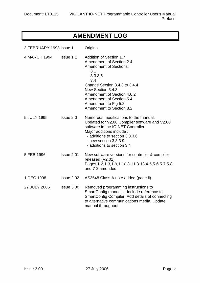
AMENDMENT LOG
3 FEBRUARY 1993 Issue 1 Original 4 MARCH 1994 Issue 1.1 Addition of Section 1.7
Amendment of Section 2.4 Amendment of Sections: 3.1 3.3.3.6 3.4 Change Section 3.4.3 to 3.4.4 New Section 3.4.3 Amendment of Section 4.6.2 Amendment of Section 5.4 Amendment to Fig 5.2 Amendment to Section 8.2
5 JULY 1995 Issue 2.0 Numerous modifications to the manual.
Updated for V2.00 Compiler software and V2.00 software in the IO-NET Controller. Major additions include : - additions to section 3.3.3.6 - new section 3.3.3.9 - additions to section 3.4
5 FEB 1996 Issue 2.01 New software versions for controller & compiler
released (V2.01). Pages 1-2,1-3,1-9,1-10,3-11,3-18,4-5,5-6,5-7,5-8 and 7-2 amended.
1 DEC 1998 Issue 2.02 AS3548 Class A note added (page ii). 27 JULY 2006 Issue 3.00 Removed programming instructions to
SmartConfig manuals. Include reference to SmartConfig Compiler. Add details of connecting to alternative communications media. Update manual throughout.

Document: LT0115 VIGILANT IO-NET Programmable Controller User's Manual System Description
Issue 3.00 27 July 2006 Page 1-1
Chapter 1 SYSTEM DESCRIPTION
1.1 GENERAL................................................................................................1-2
1.1.1 NON-PROGRAMMED MODE......................................................1-2 1.1.2 PROGRAMMED MODE...............................................................1-3
1.2 REMOTE MIMIC PANELS.......................................................................1-3
1.3 POINT-TO-POINT NON-PROGRAMMED MODE ...................................1-4
1.4 STAND-ALONE PROGRAMMABLE CONTROLLER .............................1-5
1.5 AS1668 AIR HANDLING CONTROL FUNCTIONS.................................1-5
1.6 INSTALLATION OF SMARTCONFIG .....................................................1-6
1.7 SOFTWARE VERSION RELEASES .......................................................1-6
1.7.1 IO-NET CONTROLLER................................................................1-6 1.7.2 IO-NET COMPILER (SF0088) .....................................................1-7 1.7.3 IO-NET TOOLS............................................................................1-8 1.7.4 SMARTCONFIG...........................................................................1-8
IO-NET Programmable Controller User's Manual Document: LT0115 System Description
Page 1-2 27 July 2006 Issue 3.00
1.1 GENERAL
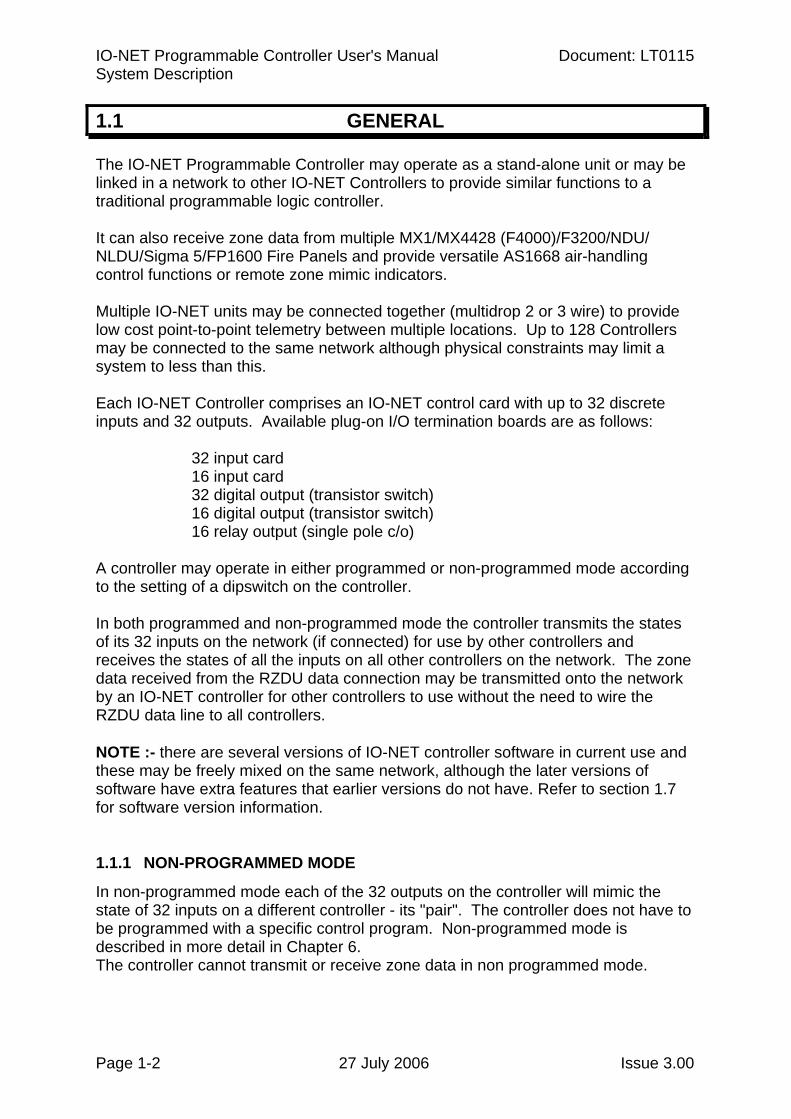
The IO-NET Programmable Controller may operate as a stand-alone unit or may be linked in a network to other IO-NET Controllers to provide similar functions to a traditional programmable logic controller. It can also receive zone data from multiple MX1/MX4428 (F4000)/F3200/NDU/ NLDU/Sigma 5/FP1600 Fire Panels and provide versatile AS1668 air-handling control functions or remote zone mimic indicators. Multiple IO-NET units may be connected together (multidrop 2 or 3 wire) to provide low cost point-to-point telemetry between multiple locations. Up to 128 Controllers may be connected to the same network although physical constraints may limit a system to less than this. Each IO-NET Controller comprises an IO-NET control card with up to 32 discrete inputs and 32 outputs. Available plug-on I/O termination boards are as follows:
32 input card 16 input card 32 digital output (transistor switch) 16 digital output (transistor switch) 16 relay output (single pole c/o)
A controller may operate in either programmed or non-programmed mode according to the setting of a dipswitch on the controller. In both programmed and non-programmed mode the controller transmits the states of its 32 inputs on the network (if connected) for use by other controllers and receives the states of all the inputs on all other controllers on the network. The zone data received from the RZDU data connection may be transmitted onto the network by an IO-NET controller for other controllers to use without the need to wire the RZDU data line to all controllers. NOTE :- there are several versions of IO-NET controller software in current use and these may be freely mixed on the same network, although the later versions of software have extra features that earlier versions do not have. Refer to section 1.7 for software version information. 1.1.1 NON-PROGRAMMED MODE
In non-programmed mode each of the 32 outputs on the controller will mimic the state of 32 inputs on a different controller - its "pair". The controller does not have to be programmed with a specific control program. Non-programmed mode is described in more detail in Chapter 6. The controller cannot transmit or receive zone data in non programmed mode.
Document: LT0115 VIGILANT IO-NET Programmable Controller User's Manual System Description
Issue 3.00 27 July 2006 Page 1-3
1.1.2 PROGRAMMED MODE
In programmed mode a specific control program is programmed into the controller and the state of the outputs on the controller is determined by logic expressions defined in the control program. The control program also includes the definition of network parameters which allow setting of values such as RTS (Request to Send) delays, etc. The control program also specifies whether the controller has an RZDU data input connected and whether it is to transmit that data onto the IO-NET network or not. In programmed mode the state of each output is set according to a logic expression which may include the state of: 1. Any of its own inputs 2. Any input on any other controller on the network 3. Any of its own outputs 4. Any zone on one or more compatible fire panels connected to the network. 5. Its own logic variables 6. Some system conditions such as network fault. 7. The state of a timer 8. The "scan status" of any IO-NET controller or fire panel. In programmed mode a control program is generated from a user source file and is programmed into the controller EPROM. A controller EPROM can be re-programmed a limited number of times, typically 8 to 12, depending on the size of the control program. Preparation, compiling and programming of the IO-NET controller program is now carried out using SmartConfig or SmartConfigLite V1.6 onwards. Refer to the SmartConfig on-line help or User Manuals for details. Examples of possible applications are described in the following sections.
1.2 REMOTE MIMIC PANELS
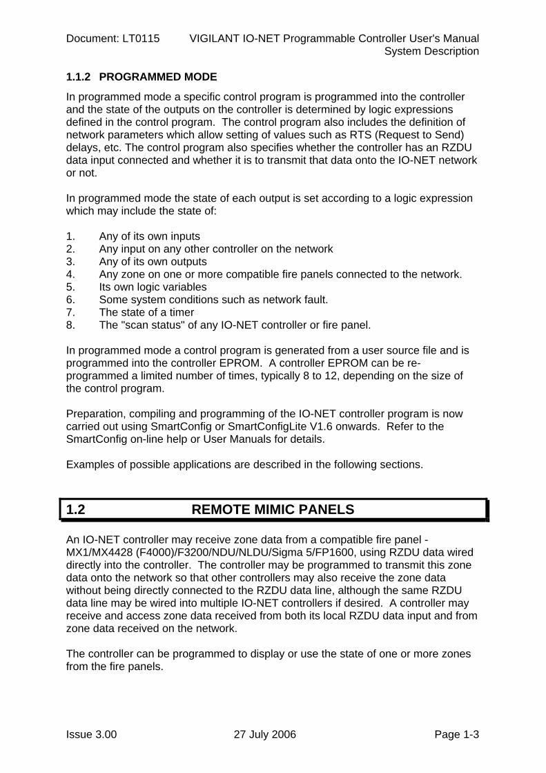
An IO-NET controller may receive zone data from a compatible fire panel - MX1/MX4428 (F4000)/F3200/NDU/NLDU/Sigma 5/FP1600, using RZDU data wired directly into the controller. The controller may be programmed to transmit this zone data onto the network so that other controllers may also receive the zone data without being directly connected to the RZDU data line, although the same RZDU data line may be wired into multiple IO-NET controllers if desired. A controller may receive and access zone data received from both its local RZDU data input and from zone data received on the network. The controller can be programmed to display or use the state of one or more zones from the fire panels.
IO-NET Programmable Controller User's Manual Document: LT0115 System Description
Page 1-4 27 July 2006 Issue 3.00
REMOTE MIMIC PANELS (CONTINUED) A local buzzer output can be turned on when a new alarm occurs and reset with a local pushbutton. An IO-NET Controller can be connected to both the RZDU bus and the IO-NET network, i.e., it can simultaneously receive data from a compatible fire panel as well as send and receive data on the IO-NET network. The limit on the number of IO-NET controllers which can be connected to the same RZDU data line is hardware dependent. Further details on using zone data are given in section 3.4 and 8. RZDU BUS │ 32 │ I/Ps ->┌───┐ │ │IO ├──┘ │NET├──┐ O/Ps <-└───┘ │ │ IO-NET │ network 32 │ I/Ps ->┌───┐ │ │IO ├──┤ │NET│ │ O/Ps <-└───┘ │ ├──────────────── To other IO-NET │ controllers if │ necessary. 32 │ I/Ps ->┌───┐ │ │IO ├──┘ │NET│ O/Ps <-└───┘
1.3 POINT-TO-POINT NON-PROGRAMMED MODE
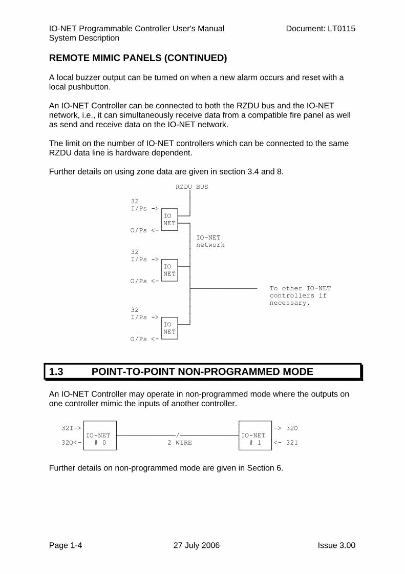
An IO-NET Controller may operate in non-programmed mode where the outputs on one controller mimic the inputs of another controller. ┌───────┐ ┌───────┐ 32I->│ │ │ │-> 32O │IO-NET ├──────────────/──────────────┤IO-NET │ 32O<-│ # 0 │ 2 WIRE │ # 1 │<- 32I └───────┘ └───────┘ Further details on non-programmed mode are given in Section 6.
Document: LT0115 VIGILANT IO-NET Programmable Controller User's Manual System Description
Issue 3.00 27 July 2006 Page 1-5
1.4 STAND-ALONE PROGRAMMABLE CONTROLLER
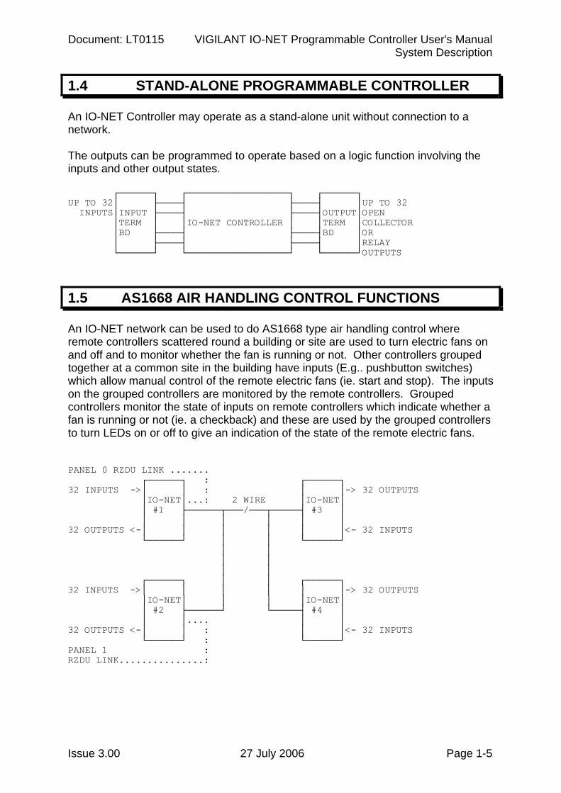
An IO-NET Controller may operate as a stand-alone unit without connection to a network. The outputs can be programmed to operate based on a logic function involving the inputs and other output states. ┌──────┐ ┌──────────────────┐ ┌──────┐ UP TO 32│ ├────┤ ├────┤ │UP TO 32 INPUTS│INPUT ├────┤ ├────┤OUTPUT│OPEN │TERM │ │IO-NET CONTROLLER │ │TERM │COLLECTOR │BD ├────┤ ├────┤BD │OR │ ├────┤ ├────┤ │RELAY └──────┘ └──────────────────┘ └──────┘OUTPUTS
1.5 AS1668 AIR HANDLING CONTROL FUNCTIONS
An IO-NET network can be used to do AS1668 type air handling control where remote controllers scattered round a building or site are used to turn electric fans on and off and to monitor whether the fan is running or not. Other controllers grouped together at a common site in the building have inputs (E.g.. pushbutton switches) which allow manual control of the remote electric fans (ie. start and stop). The inputs on the grouped controllers are monitored by the remote controllers. Grouped controllers monitor the state of inputs on remote controllers which indicate whether a fan is running or not (ie. a checkback) and these are used by the grouped controllers to turn LEDs on or off to give an indication of the state of the remote electric fans. PANEL 0 RZDU LINK ....... ┌──────┐ : ┌──────┐ 32 INPUTS ->│ │ : │ │-> 32 OUTPUTS │IO-NET│...: 2 WIRE │IO-NET│ │ #1 ├──────┬───/───┬─────┤ #3 │ │ │ │ │ │ │ 32 OUTPUTS <-│ │ │ │ │ │<- 32 INPUTS └──────┘ │ │ └──────┘ │ │ │ │ │ │ ┌──────┐ │ │ ┌──────┐ 32 INPUTS ->│ │ │ │ │ │-> 32 OUTPUTS │IO-NET│ │ │ │IO-NET│ │ #2 ├──────┘ └─────┤ #4 │ │ │.... │ │ 32 OUTPUTS <-│ │ : │ │<- 32 INPUTS └──────┘ : └──────┘ PANEL 1 : RZDU LINK...............:
IO-NET Programmable Controller User's Manual Document: LT0115 System Description
Page 1-6 27 July 2006 Issue 3.00
1.6 INSTALLATION OF SMARTCONFIG
The IO-NET programming facility is now built into SmartConfig (SF0278) and SmartConfigLite (SF0323). SmartConfig is available to Tyco employees only, and requires an electronic licence to run. SmartConfigLite is available to all IO-NET users. These products can be downloaded from http://www.tycosafetyproducts-anz.com/. For SmartConfigLite follow the link to the Tyco Safety Products NZ website. Both the above are executable files. Simply run them and follow the instructions to install the package on your PC. Programming instructions are included in the on-line help files or the following manuals: LT0332 SmartConfig User Manual LT0345 SmartConfigLite User Manual
1.7 SOFTWARE VERSION RELEASES
1.7.1 IO-NET CONTROLLER
IO-NET Controller V1.00 (February 1993) IO-NET Controller V1.01 (March 1994)
This version includes the capability of operating with either "Non-LCD RZDU protocol" or "LCD RZDU protocol". Refer to Sections 3.4.3 and 8.2.
For a controller which does not access any zone data (ie. does not receive RZDU data from an MX1/MX4428 (F4000)/F3200 Fire Panel) or is operating in non-programmed mode, there is no difference between Controller V1.00 software and Controller V1.01 software.
IO-NET Controller V1.02 (November 1994)
This version is operationally identical to V1.01 controller and was created to match a small change in a new release of the MOTOROLA MC68HC705C8 processor.
Document: LT0115 VIGILANT IO-NET Programmable Controller User's Manual System Description
Issue 3.00 27 July 2006 Page 1-7
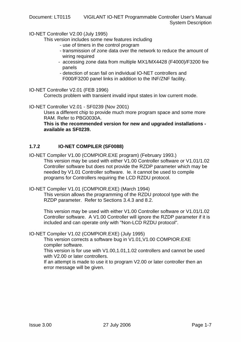
IO-NET Controller V2.00 (July 1995) This version includes some new features including - use of timers in the control program
- transmission of zone data over the network to reduce the amount of wiring required - accessing zone data from multiple MX1/MX4428 (F4000)/F3200 fire panels - detection of scan fail on individual IO-NET controllers and F000/F3200 panel links in addition to the INF/ZNF facility. IO-NET Controller V2.01 (FEB 1996) Corrects problem with transient invalid input states in low current mode. IO-NET Controller V2.01 - SF0239 (Nov 2001) Uses a different chip to provide much more program space and some more
RAM. Refer to PBG0030A. This is the recommended version for new and upgraded installations -
available as SF0239. 1.7.2 IO-NET COMPILER (SF0088)
IO-NET Compiler V1.00 (COMPIOR.EXE program) (February 1993.) This version may be used with either V1.00 Controller software or V1.01/1.02 Controller software but does not provide the RZDP parameter which may be needed by V1.01 Controller software. Ie. it cannot be used to compile programs for Controllers requiring the LCD RZDU protocol.
IO-NET Compiler V1.01 (COMPIOR.EXE) (March 1994)
This version allows the programming of the RZDU protocol type with the RZDP parameter. Refer to Sections 3.4.3 and 8.2.
This version may be used with either V1.00 Controller software or V1.01/1.02 Controller software. A V1.00 Controller will ignore the RZDP parameter if it is included and can operate only with "Non-LCD RZDU protocol".
IO-NET Compiler V1.02 (COMPIOR.EXE) (July 1995)
This version corrects a software bug in V1.01,V1.00 COMPIOR.EXE compiler software. This version is for use with V1.00,1.01,1.02 controllers and cannot be used with V2.00 or later controllers. If an attempt is made to use it to program V2.00 or later controller then an error message will be given.
IO-NET Programmable Controller User's Manual Document: LT0115 System Description
Page 1-8 27 July 2006 Issue 3.00
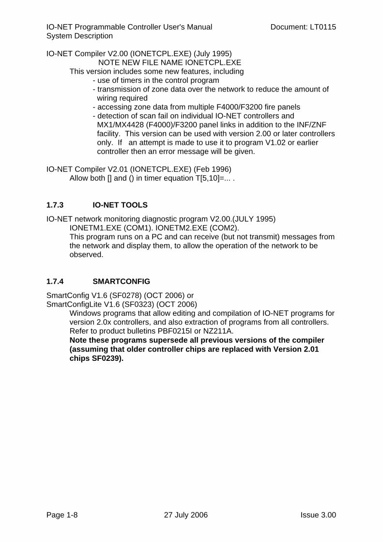
IO-NET Compiler V2.00 (IONETCPL.EXE) (July 1995) NOTE NEW FILE NAME IONETCPL.EXE
This version includes some new features, including - use of timers in the control program - transmission of zone data over the network to reduce the amount of wiring required - accessing zone data from multiple F4000/F3200 fire panels - detection of scan fail on individual IO-NET controllers and MX1/MX4428 (F4000)/F3200 panel links in addition to the INF/ZNF facility. This version can be used with version 2.00 or later controllers only. If an attempt is made to use it to program V1.02 or earlier controller then an error message will be given. IO-NET Compiler V2.01 (IONETCPL.EXE) (Feb 1996) Allow both [] and () in timer equation T[5,10]=... . 1.7.3 IO-NET TOOLS
IO-NET network monitoring diagnostic program V2.00.(JULY 1995) IONETM1.EXE (COM1). IONETM2.EXE (COM2). This program runs on a PC and can receive (but not transmit) messages from the network and display them, to allow the operation of the network to be observed.
1.7.4 SMARTCONFIG
SmartConfig V1.6 (SF0278) (OCT 2006) or SmartConfigLite V1.6 (SF0323) (OCT 2006)
Windows programs that allow editing and compilation of IO-NET programs for version 2.0x controllers, and also extraction of programs from all controllers. Refer to product bulletins PBF0215I or NZ211A. Note these programs supersede all previous versions of the compiler (assuming that older controller chips are replaced with Version 2.01 chips SF0239).
Document: LT0115 VIGILANT IO-NET Programmable Controller User's Manual Specifications
Issue 3.00 27 July 2006 Page 2-1
Chapter 2 SPECIFICATIONS
2.1 GENERAL................................................................................................2-2
2.2 INPUT SPECIFICATIONS .......................................................................2-3
2.3 OUTPUT SPECIFICATIONS ...................................................................2-4
2.4 ORDERING CODES ................................................................................2-5
IO-NET Programmable Controller User's Manual Document: LT0115 Specifications
Page 2-2 27 July 2006 Issue 3.00
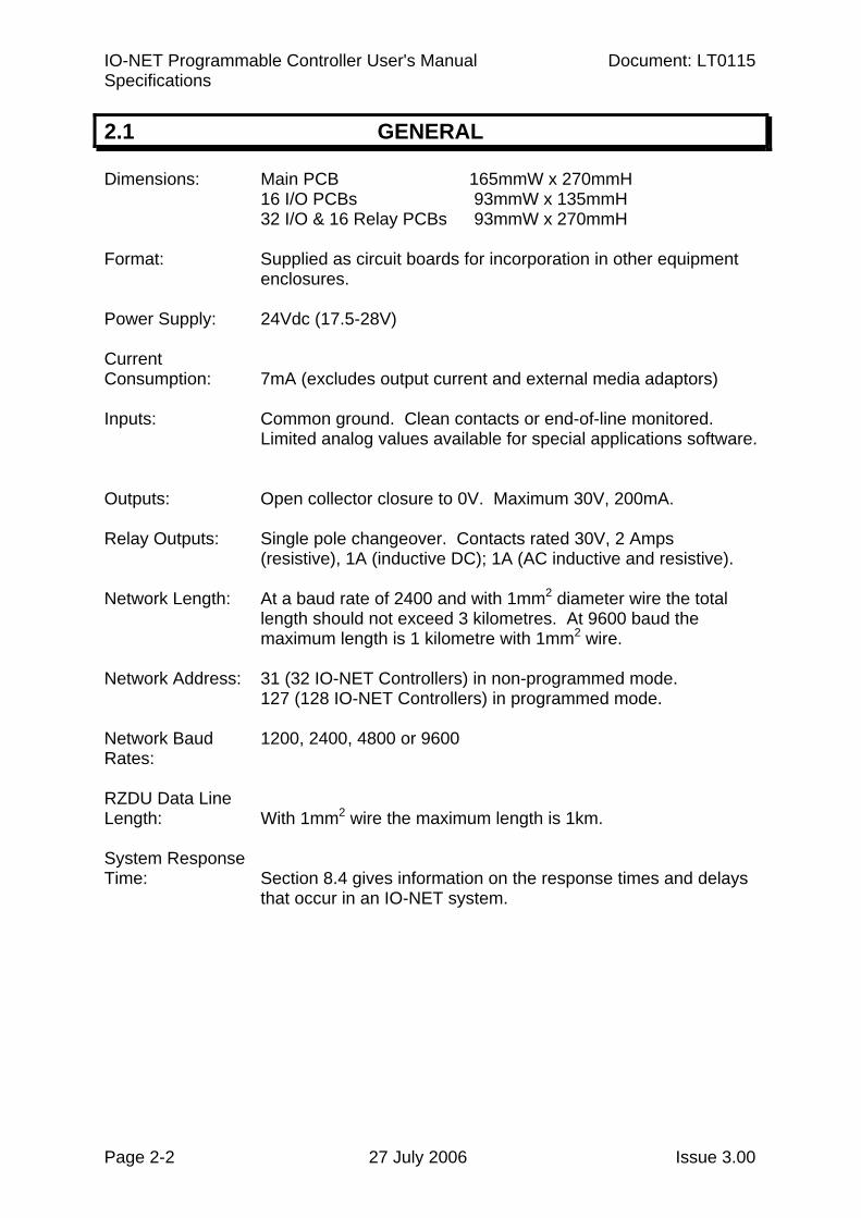
2.1 GENERAL
Dimensions: Main PCB 165mmW x 270mmH 16 I/O PCBs 93mmW x 135mmH 32 I/O & 16 Relay PCBs 93mmW x 270mmH
Format: Supplied as circuit boards for incorporation in other equipment
enclosures. Power Supply: 24Vdc (17.5-28V) Current Consumption: 7mA (excludes output current and external media adaptors) Inputs: Common ground. Clean contacts or end-of-line monitored.
Limited analog values available for special applications software.
Outputs: Open collector closure to 0V. Maximum 30V, 200mA. Relay Outputs: Single pole changeover. Contacts rated 30V, 2 Amps
(resistive), 1A (inductive DC); 1A (AC inductive and resistive). Network Length: At a baud rate of 2400 and with 1mm2 diameter wire the total
length should not exceed 3 kilometres. At 9600 baud the maximum length is 1 kilometre with 1mm2 wire.
Network Address: 31 (32 IO-NET Controllers) in non-programmed mode.
127 (128 IO-NET Controllers) in programmed mode. Network Baud 1200, 2400, 4800 or 9600 Rates: RZDU Data Line Length: With 1mm2 wire the maximum length is 1km. System Response Time: Section 8.4 gives information on the response times and delays
that occur in an IO-NET system.
Document: LT0115 VIGILANT IO-NET Programmable Controller User's Manual Specifications
Issue 3.00 27 July 2006 Page 2-3
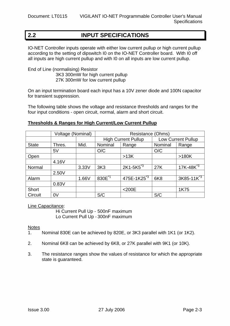
2.2 INPUT SPECIFICATIONS
IO-NET Controller inputs operate with either low current pullup or high current pullup according to the setting of dipswitch I0 on the IO-NET Controller board. With I0 off all inputs are high current pullup and with I0 on all inputs are low current pullup. End of Line (normalising) Resistor
3K3 300mW for high current pullup 27K 300mW for low current pullup
On an input termination board each input has a 10V zener diode and 100N capacitor for transient suppression. The following table shows the voltage and resistance thresholds and ranges for the four input conditions - open circuit, normal, alarm and short circuit. Thresholds & Ranges for High Current/Low Current Pullup Voltage (Nominal) Resistance (Ohms) High Current Pullup Low Current Pullup State Thres. Mid. Nominal Range Nominal Range 5V O/C O/C Open >13K >180K 4.16V Normal 3.33V 3K3 2K1-5K5*3 27K 17K-48K*3 2.50V Alarm 1.66V 830E*1 475E-1K25*3 6K8 3K85-11K*3
0.83V <200E 1K75 Short
Circuit 0V S/C S/C Line Capacitance:
Hi Current Pull Up - 500nF maximum Lo Current Pull Up - 300nF maximum
Notes 1. Nominal 830E can be achieved by 820E, or 3K3 parallel with 1K1 (or 1K2). 2. Nominal 6K8 can be achieved by 6K8, or 27K parallel with 9K1 (or 10K). 3. The resistance ranges show the values of resistance for which the appropriate
state is guaranteed.
IO-NET Programmable Controller User's Manual Document: LT0115 Specifications
Page 2-4 27 July 2006 Issue 3.00
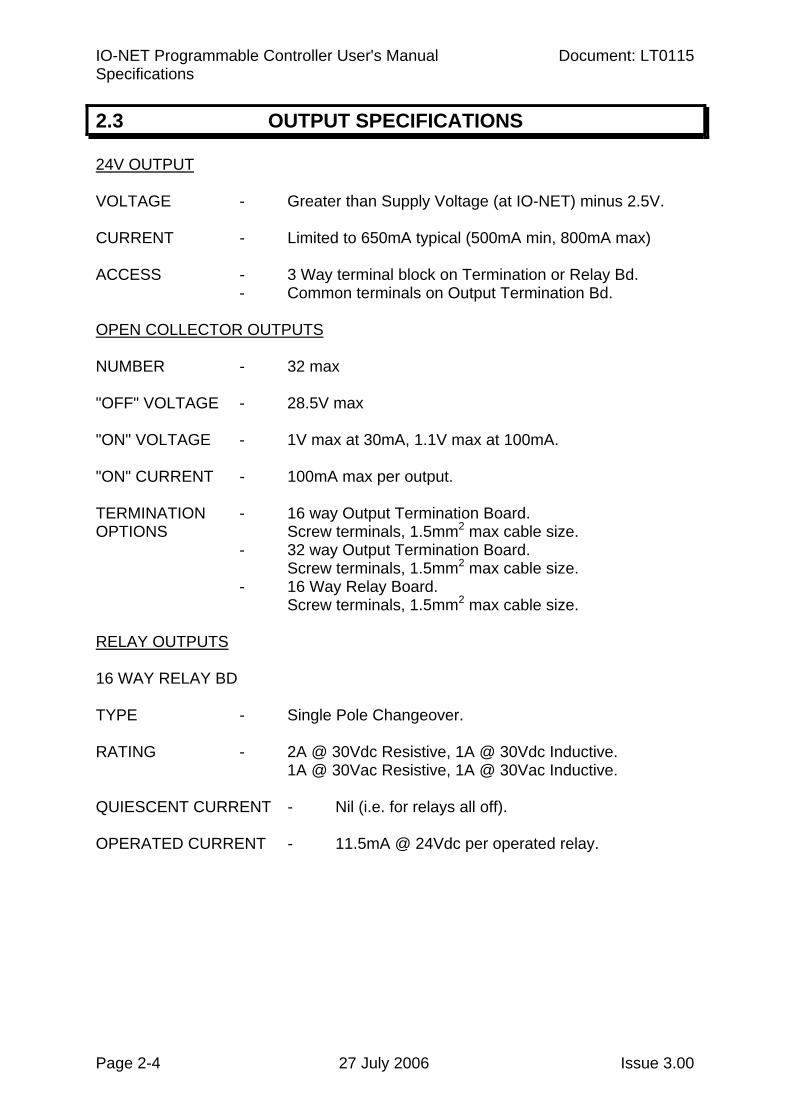
2.3 OUTPUT SPECIFICATIONS
24V OUTPUT VOLTAGE - Greater than Supply Voltage (at IO-NET) minus 2.5V. CURRENT - Limited to 650mA typical (500mA min, 800mA max) ACCESS - 3 Way terminal block on Termination or Relay Bd.
- Common terminals on Output Termination Bd. OPEN COLLECTOR OUTPUTS NUMBER - 32 max "OFF" VOLTAGE - 28.5V max "ON" VOLTAGE - 1V max at 30mA, 1.1V max at 100mA. "ON" CURRENT - 100mA max per output. TERMINATION - 16 way Output Termination Board. OPTIONS Screw terminals, 1.5mm2 max cable size.
- 32 way Output Termination Board. Screw terminals, 1.5mm2 max cable size.
- 16 Way Relay Board. Screw terminals, 1.5mm2 max cable size.
RELAY OUTPUTS 16 WAY RELAY BD TYPE - Single Pole Changeover.
RATING - 2A @ 30Vdc Resistive, 1A @ 30Vdc Inductive.
1A @ 30Vac Resistive, 1A @ 30Vac Inductive. QUIESCENT CURRENT - Nil (i.e. for relays all off). OPERATED CURRENT - 11.5mA @ 24Vdc per operated relay.
Document: LT0115 VIGILANT IO-NET Programmable Controller User's Manual Specifications
Issue 3.00 27 July 2006 Page 2-5
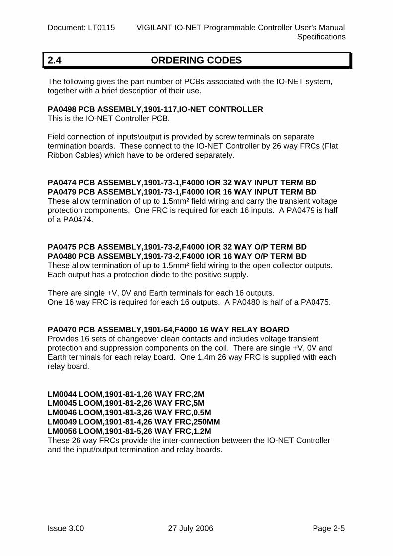
2.4 ORDERING CODES
The following gives the part number of PCBs associated with the IO-NET system, together with a brief description of their use. PA0498 PCB ASSEMBLY,1901-117,IO-NET CONTROLLER This is the IO-NET Controller PCB. Field connection of inputs\output is provided by screw terminals on separate termination boards. These connect to the IO-NET Controller by 26 way FRCs (Flat Ribbon Cables) which have to be ordered separately. PA0474 PCB ASSEMBLY,1901-73-1,F4000 IOR 32 WAY INPUT TERM BD PA0479 PCB ASSEMBLY,1901-73-1,F4000 IOR 16 WAY INPUT TERM BD These allow termination of up to 1.5mm² field wiring and carry the transient voltage protection components. One FRC is required for each 16 inputs. A PA0479 is half of a PA0474. PA0475 PCB ASSEMBLY,1901-73-2,F4000 IOR 32 WAY O/P TERM BD PA0480 PCB ASSEMBLY,1901-73-2,F4000 IOR 16 WAY O/P TERM BD These allow termination of up to 1.5mm² field wiring to the open collector outputs. Each output has a protection diode to the positive supply. There are single +V, 0V and Earth terminals for each 16 outputs. One 16 way FRC is required for each 16 outputs. A PA0480 is half of a PA0475. PA0470 PCB ASSEMBLY,1901-64,F4000 16 WAY RELAY BOARD Provides 16 sets of changeover clean contacts and includes voltage transient protection and suppression components on the coil. There are single +V, 0V and Earth terminals for each relay board. One 1.4m 26 way FRC is supplied with each relay board. LM0044 LOOM,1901-81-1,26 WAY FRC,2M LM0045 LOOM,1901-81-2,26 WAY FRC,5M LM0046 LOOM,1901-81-3,26 WAY FRC,0.5M LM0049 LOOM,1901-81-4,26 WAY FRC,250MM LM0056 LOOM,1901-81-5,26 WAY FRC,1.2M These 26 way FRCs provide the inter-connection between the IO-NET Controller and the input/output termination and relay boards.
IO-NET Programmable Controller User's Manual Document: LT0115 Specifications
Page 2-6 27 July 2006 Issue 3.00
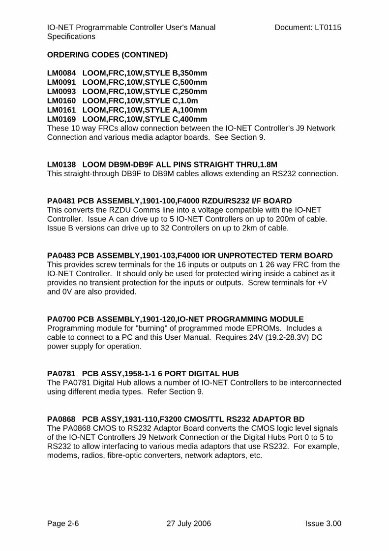
ORDERING CODES (CONTINED) LM0084 LOOM,FRC,10W,STYLE B,350mm LM0091 LOOM,FRC,10W,STYLE C,500mm LM0093 LOOM,FRC,10W,STYLE C,250mm LM0160 LOOM,FRC,10W,STYLE C,1.0m LM0161 LOOM,FRC,10W,STYLE A,100mm LM0169 LOOM,FRC,10W,STYLE C,400mm These 10 way FRCs allow connection between the IO-NET Controller’s J9 Network Connection and various media adaptor boards. See Section 9. LM0138 LOOM DB9M-DB9F ALL PINS STRAIGHT THRU,1.8M This straight-through DB9F to DB9M cables allows extending an RS232 connection. PA0481 PCB ASSEMBLY,1901-100,F4000 RZDU/RS232 I/F BOARD This converts the RZDU Comms line into a voltage compatible with the IO-NET Controller. Issue A can drive up to 5 IO-NET Controllers on up to 200m of cable. Issue B versions can drive up to 32 Controllers on up to 2km of cable. PA0483 PCB ASSEMBLY,1901-103,F4000 IOR UNPROTECTED TERM BOARD This provides screw terminals for the 16 inputs or outputs on 1 26 way FRC from the IO-NET Controller. It should only be used for protected wiring inside a cabinet as it provides no transient protection for the inputs or outputs. Screw terminals for +V and 0V are also provided. PA0700 PCB ASSEMBLY,1901-120,IO-NET PROGRAMMING MODULE Programming module for "burning" of programmed mode EPROMs. Includes a cable to connect to a PC and this User Manual. Requires 24V (19.2-28.3V) DC power supply for operation. PA0781 PCB ASSY,1958-1-1 6 PORT DIGITAL HUB The PA0781 Digital Hub allows a number of IO-NET Controllers to be interconnected using different media types. Refer Section 9. PA0868 PCB ASSY,1931-110,F3200 CMOS/TTL RS232 ADAPTOR BD The PA0868 CMOS to RS232 Adaptor Board converts the CMOS logic level signals of the IO-NET Controllers J9 Network Connection or the Digital Hubs Port 0 to 5 to RS232 to allow interfacing to various media adaptors that use RS232. For example, modems, radios, fibre-optic converters, network adaptors, etc.
Document: LT0115 VIGILANT IO-NET Programmable Controller User's Manual Specifications
Issue 3.00 27 July 2006 Page 2-7
ORDERING CODES (CONTINED) PA0880 PCB ASSY,1931-119,F3200,RS232-DB25 I/FACE The PA0880 RS232/DB25 adaptor converts the 10 way FRC signals from, say, the PA0868 board to a DB25 male connector suitable to plug into the OSD139AF fibre-optic modem. It also includes a simple 7V regulator that can power the fibre-optic modem, if required. SF0239 SOFTWARE IO-NET CONTROLLER V2.01 LARGE MEMORY "Blank" OTP microprocessor for IO-NET Controller. Factory programmed for non-programmed mode operation, but may be programmed by the user a number of times to have different programmed mode operation. SF0278 SOFTWARE SMARTCONFIG (V1.6 or later) or SF0323 SOFTWARE SMARTCONFIGLITE (V1.6 or later) Windows Compiler software and on-line user manuals. These support V2.00 or later Controllers, it is recommended that older controllers are replaced with SF0239. These products also allow extraction of programs from all versions of controller. LT0115 LITERATURE,1901-121,IO-NET USER MANUAL This document. Supplied with PA0700. LT0332 LIT SMARTCONFIG USER MANUAL A printed version of the manual included with SF0278. LT0345 LIT SMARTCONFIGLITE USER MANUAL A printed version of the manual included with SF0323. Other OSD139AF ASYNCHRONOUS RS232 MODEM (Multi-mode fibre) OSD139AFL ASYNCHRONOUS RS232 MODEM (Single-mode fibre) (See Optical Systems Design website at http://www.osd.com.au for product and ordering details).
IO-NET Programmable Controller User's Manual Document: LT0115 Specifications
Page 2-8 27 July 2006 Issue 3.00
THIS PAGE INTENTIONALLY LEFT BLANK
Document: LT0115 VIGILANT IO-NET Programmable Controller User's Manual Generating a Source File
Issue 3.00 27 July 2006 Page 3-1
Chapter 3 GENERATING A SOURCE FILE
3.1 INTRODUCTION......................................................................................3-2
3.2 PROGRAMMABLE NETWORK PARAMETERS ....................................3-2
3.2.1 LEADING RTS DELAY (LRTS) ....................................................3-2 3.2.2 TURNAROUND DELAY (TURN)..................................................3-2 3.2.3 NUMBER OF LEADING DUMMY $FF CHARACTERS (LDFF) ...3-2 3.2.4 NUMBER OF TRAILING $FF CHARACTERS (TRFF).................3-3 3.2.5 TRAILING RTS DELAY (TRTS) ...................................................3-3 3.2.6 END OF TRANSMIT IGNORE RX PERIOD (TIGN).....................3-3 3.2.7 CLAIM TOKEN SLOT TIME (CTST) ............................................3-3 3.2.8 CLAIM TOKEN CLEAR TIME (CTCT)..........................................3-3 3.2.9 INACTIVITY TIME (IACT) ............................................................3-3 3.2.10 RETRY DELAY 1 (RTD1).............................................................3-4 3.2.11 RETRY DELAY 2 (RTD2).............................................................3-4 3.2.12 RETRY SLOT TIME (RTST) ........................................................3-4 3.2.13 NUMBER OF RAPID RETRIES (NRRT) ......................................3-4 3.2.14 TOTAL NUMBER OF RETRIES (TNRT)......................................3-4 3.2.15 STATION ENTRY RATE (SENR).................................................3-5 3.2.16 DATA REFRESH RATE (DRFT) ..................................................3-5 3.2.17 STATUS DATA REQUIRED TIME (DRQT)..................................3-5 3.2.18 MAX STATION NUMBER (MXST) ...............................................3-5
IO-NET Programmable Controller User's Manual Document: LT0115 Generating a Source File
Page 3-2 27 July 2006 Issue 3.00
3.1 INTRODUCTION
You enter an IO-NET program into SmartConfig or SmartConfigLite. For further information, refer to the online help of these programs, or one of the following manuals. LT0332 LIT SMARTCONFIG USER MANUAL A printed version of the manual included with SmartConfig (SF0278). LT0345 LIT SMARTCONFIGLITE USER MANUAL A printed version of the manual included with SmartConfigLite (SF0323).
3.2 PROGRAMMABLE NETWORK PARAMETERS
IO-NET contains a number of programmable network parameters that can be set to adjust IO-NET’s operation to different network media, baud rates, transmission delays, etc. The following is a full list of the programmable network parameters and their function. For non-programmed mode, the default values for these parameters are detailed in Section 6.1. For programmed mode, there is a selection of standard network profiles in SmartConfig that can be used depending on the application. If necessary, a new network profile can be created with different values of the network parameters. 3.2.1 LEADING RTS DELAY (LRTS)
At the start of a transmission this is the length of time that RTS (Request To Send) is asserted for before starting to transmit. 3.2.2 TURNAROUND DELAY (TURN)
After receiving a message (and deciding to transmit), this is the length of time that a Controller waits before turning RTS on and starting its leading RTS delay. It is measured from the end of the message received, i.e. from the stop bit of the last byte received including the dummy $FF character which is sent in the case of a CRC of $FF $00. 3.2.3 NUMBER OF LEADING DUMMY $FF CHARACTERS (LDFF)
This sets the number of $FF characters to transmit at the start of a message after the leading RTS delay is up. Following these $FF characters, if any, the two header bytes $FF $02 will be transmitted. E.g. if this character is set to one, the sequence of characters transmitted is $FF $FF $02.
Document: LT0115 VIGILANT IO-NET Programmable Controller User's Manual Generating a Source File
Issue 3.00 27 July 2006 Page 3-3
3.2.4 NUMBER OF TRAILING $FF CHARACTERS (TRFF)
This is the number of $FF characters to transmit at the end of a message. The trailing RTS delay starts after all of these characters have been transmitted. 3.2.5 TRAILING RTS DELAY (TRTS)
This is length of time that the RTS (Request to Send) output is kept on after all characters of the message have been sent. 3.2.6 END OF TRANSMIT IGNORE RX PERIOD (TIGN)
This is the length of time for which received characters should be ignored/discarded after transmitting a message to ensure that a Controller receives none of its own transmission. The time starts from the end of the trailing RTS delay. 3.2.7 CLAIM TOKEN SLOT TIME (CTST)
Multiplied by the number of claim token slots, this gives the maximum range of the random times between transmission of claim token messages. Measured in tens of milliseconds. 3.2.8 CLAIM TOKEN CLEAR TIME (CTCT)
This is the length of time that a Controller remains quiet for after receiving a claim token message that is not addressed to itself. Measured in tens of milliseconds. Typically this value is changed for networks that have transmission delays (e.g. V-Modem). 3.2.9 INACTIVITY TIME (IACT)
This is the length of time for which if no valid message is received (excluding claim token or claim token reply) a Controller will enter the claim token state. Measured in seconds.
IO-NET Programmable Controller User's Manual Document: LT0115 Generating a Source File
Page 3-4 27 July 2006 Issue 3.00
3.2.10 RETRY DELAY 1 (RTD1)
This sets the length of time to wait for a reply after making a transmission. This time is measured from the end (stop bit) of the last byte of a transmission. Typically this value is changed for networks that have transmission delays (e.g. V-Modem). It needs to allow for the maximum transmission delay, processing delay, turnaround delay, etc. If no characters at all are received during this time the Controller will then retry. If one or more characters are received during this time then a Controller will delay its retry and will schedule the retry to be done at a time equal to Retry Delay 2 plus a random time measured from the last character received. Measured in tens of milliseconds. 3.2.11 RETRY DELAY 2 (RTD2)
Refer to Section 3.2.10. Measured in tens of milliseconds. 3.2.12 RETRY SLOT TIME (RTST)
When a random time is being used to schedule a retry, the length of the random time is equal to the value of Retry Delay 2 plus (a random number 0, 1, 2, 3 multiplied by the Retry Slot Time). The length of the retry slot must be long enough so that if two Controllers schedule their random retry to start one slot time apart the later Controller will have received at least one character (and thus reschedule its retry) of the transmission from the first Controller before it starts to transmit. Measured in tens of milliseconds. 3.2.13 NUMBER OF RAPID RETRIES (NRRT)
This is the number of retries to do after Retry Delay 1 if there is no response. After this number of retries have been done, a Controller will schedule its retries using a longer random time until the total number of retries it has done is equal to the parameter “Total Number of Retries”. 3.2.14 TOTAL NUMBER OF RETRIES (TNRT)
Refer to Section 3.2.13.
Document: LT0115 VIGILANT IO-NET Programmable Controller User's Manual Generating a Source File
Issue 3.00 27 July 2006 Page 3-5
3.2.15 STATION ENTRY RATE (SENR)
This parameter determines how often a Controller transmits a Controller entry message. Each time a Controller is passed the token, it may, or may not, do one Controller entry transmission before passing the token on. This parameter sets the number of “scans” before a Controller does a Controller entry transmission. E.g. if this parameter is 3 then every third time the Controller is passed the token it will do one Controller entry transmission. If a Controller has no disconnected stations between itself and its successor it will not do any Controller entry transmissions. E.g. if this parameter is set to 3 and a Controller has 5 disconnected addresses to poll, each disconnected address is polled at a rate of once every 15 scans. 3.2.16 DATA REFRESH RATE (DRFT)
For IO-NET Controllers this parameter determines how often the Controller transmits its circuit input status data when it passes the token. If a change of state has occurred on a circuit input a Controller will always transmit its status data (and for the next 2 token pass transmissions following as well). Measured in seconds. 3.2.17 STATUS DATA REQUIRED TIME (DRQT)
An IO-NET Controller must have received status data from all of the other Controllers it is interested in within this time or it will generate a network fault and issue a request for all Controllers to transmit their status data. 3.2.18 MAX STATION NUMBER (MXST)
This is the number of the highest address that a Controller will poll up to when it is doing claim token, successor search or Controller entry. It should be set to the highest possible address that could be used in the network. It must be at least equal to the highest address used, otherwise that IO-NET Controller will not be requested to join the network. Some allowance should be made for expansion, but making this parameter much larger than the highest address that could be used will reduce network performance, particularly on network start up.
IO-NET Programmable Controller User's Manual Document: LT0115 Generating a Source File
Page 3-6 27 July 2006 Issue 3.00
THIS PAGE INTENTIONALLY LEFT BLANK
Document: LT0115 VIGILANT IO-NET Programmable Controller User's Manual Programming A Source File
Issue 3.00 27 July 2006 Page 4-1
Chapter 4 PROGRAMMING A SOURCE FILE
4.1 RUNNING THE COMPILER/PROGRAMMER.........................................4-2
IO-NET Programmable Controller User's Manual Document: LT0115 Programming a Source File
Page 4-2 27 July 2006 Issue 3.00
4.1 RUNNING THE COMPILER/PROGRAMMER
An IO-NET program is edited, and the software chip (EPROM) programmed with SmartConfig or SmartConfigLite. Refer to the on-line help of these products, or to one of the following manuals. LT0332 LIT SMARTCONFIG USER MANUAL A printed version of the manual included with SF0278. LT0345 LIT SMARTCONFIGLITE USER MANUAL A printed version of the manual included with SF0323.
Document: LT0115 VIGILANT IO-NET Programmable Controller User's Manual Hardware Configuration
Issue 3.00 27 July 2006 Page 5-1
Chapter 5 HARDWARE CONFIGURATION
5.1 WIRING OF THE IO-NET CONTROLLER...............................................5-2
5.1.1 NETWORK WIRING.....................................................................5-2
5.2 INPUT WIRING ........................................................................................5-4
5.3 OUTPUT WIRING ....................................................................................5-5
5.3.1 OPEN COLLECTOR OUTPUTS ..................................................5-5 5.3.2 RELAY OUTPUTS .......................................................................5-5
5.4 RZDU DATA WIRING..............................................................................5-6
5.5 DIPSWITCH SETTINGS ON THE IO-NET CONTROLLER.....................5-8
5.6 SELECTING THE BAUD RATE FOR THE NETWORK ........................5-10
5.7 WIRING THE IO-NET PROGRAMMING MODULE ...............................5-11
IO-NET Programmable Controller User's Manual Document: LT0115 Hardware Configuration
Page 5-2 27 July 2006 Issue 3.00
5.1 WIRING OF THE IO-NET CONTROLLER
5.1.1 NETWORK WIRING
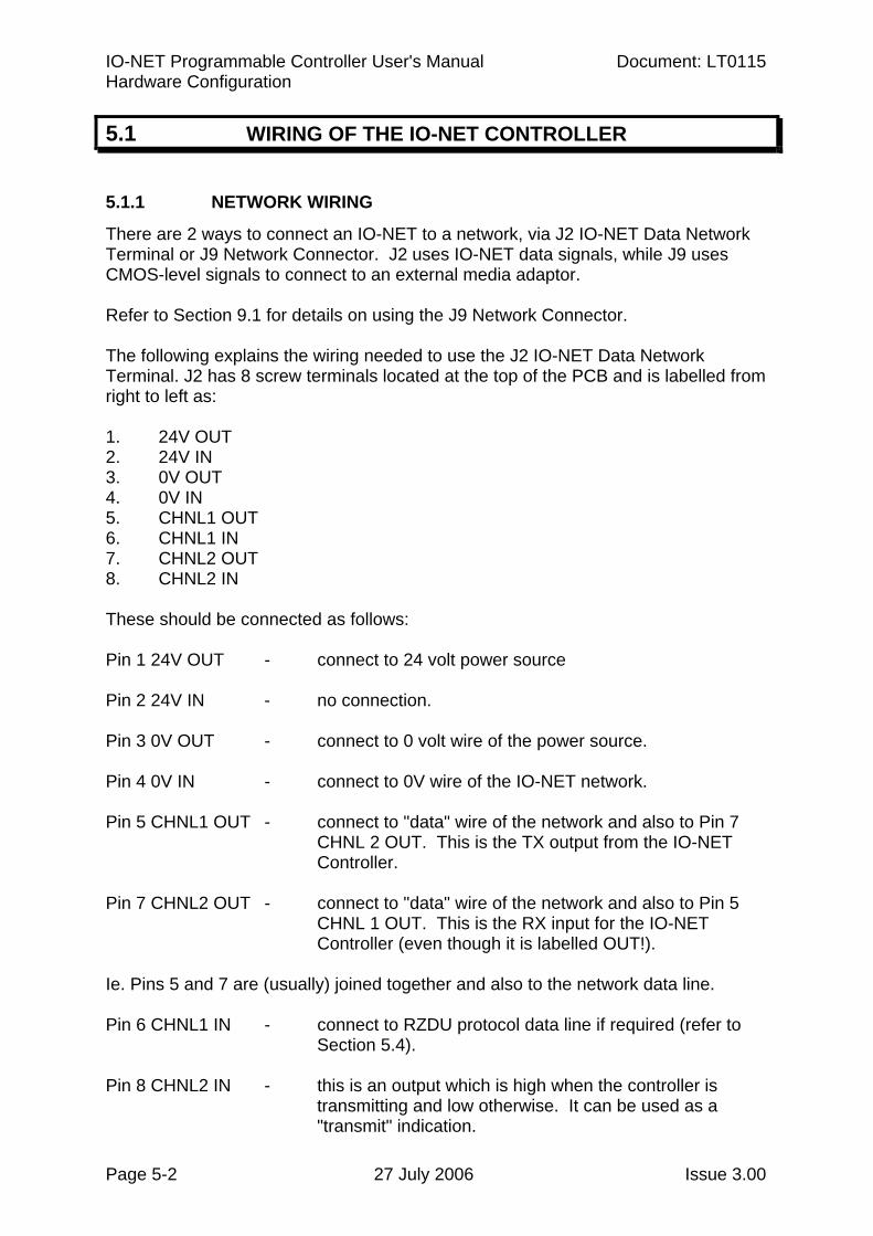
There are 2 ways to connect an IO-NET to a network, via J2 IO-NET Data Network Terminal or J9 Network Connector. J2 uses IO-NET data signals, while J9 uses CMOS-level signals to connect to an external media adaptor. Refer to Section 9.1 for details on using the J9 Network Connector. The following explains the wiring needed to use the J2 IO-NET Data Network Terminal. J2 has 8 screw terminals located at the top of the PCB and is labelled from right to left as: 1. 24V OUT 2. 24V IN 3. 0V OUT 4. 0V IN 5. CHNL1 OUT 6. CHNL1 IN 7. CHNL2 OUT 8. CHNL2 IN These should be connected as follows: Pin 1 24V OUT - connect to 24 volt power source Pin 2 24V IN - no connection. Pin 3 0V OUT - connect to 0 volt wire of the power source. Pin 4 0V IN - connect to 0V wire of the IO-NET network. Pin 5 CHNL1 OUT - connect to "data" wire of the network and also to Pin 7
CHNL 2 OUT. This is the TX output from the IO-NET Controller.
Pin 7 CHNL2 OUT - connect to "data" wire of the network and also to Pin 5
CHNL 1 OUT. This is the RX input for the IO-NET Controller (even though it is labelled OUT!).
Ie. Pins 5 and 7 are (usually) joined together and also to the network data line. Pin 6 CHNL1 IN - connect to RZDU protocol data line if required (refer to
Section 5.4). Pin 8 CHNL2 IN - this is an output which is high when the controller is
transmitting and low otherwise. It can be used as a "transmit" indication.
Document: LT0115 VIGILANT IO-NET Programmable Controller User's Manual Hardware Configuration
Issue 3.00 27 July 2006 Page 5-3
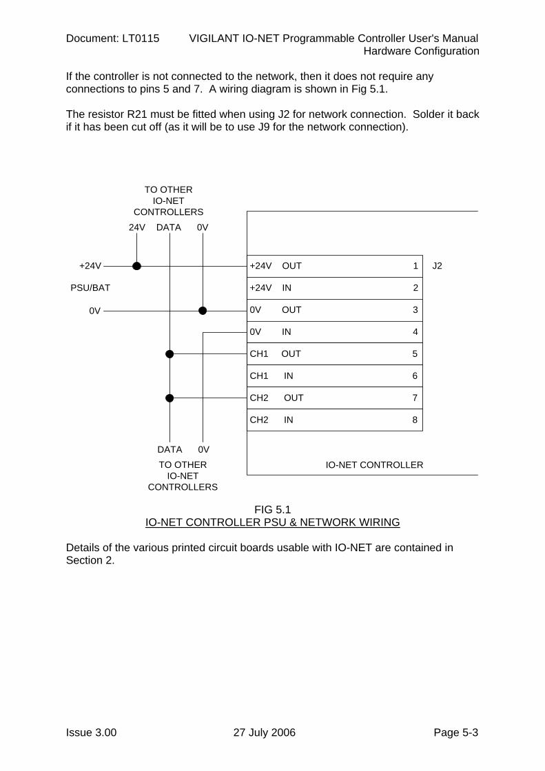
If the controller is not connected to the network, then it does not require any connections to pins 5 and 7. A wiring diagram is shown in Fig 5.1. The resistor R21 must be fitted when using J2 for network connection. Solder it back if it has been cut off (as it will be to use J9 for the network connection).
J2+24V OUT 1
+24V IN 2
0V OUT 3
0V IN 4
CH1 OUT 5
CH1 IN 6
CH2 OUT 7
CH2 IN 8
+24V
0V
PSU/BAT
0VDATATO OTHER
IO-NETCONTROLLERS
0VDATA
TO OTHERIO-NET
CONTROLLERS24V
IO-NET CONTROLLER
FIG 5.1 IO-NET CONTROLLER PSU & NETWORK WIRING
Details of the various printed circuit boards usable with IO-NET are contained in Section 2.
IO-NET Programmable Controller User's Manual Document: LT0115 Hardware Configuration
Page 5-4 27 July 2006 Issue 3.00
5.2 INPUT WIRING
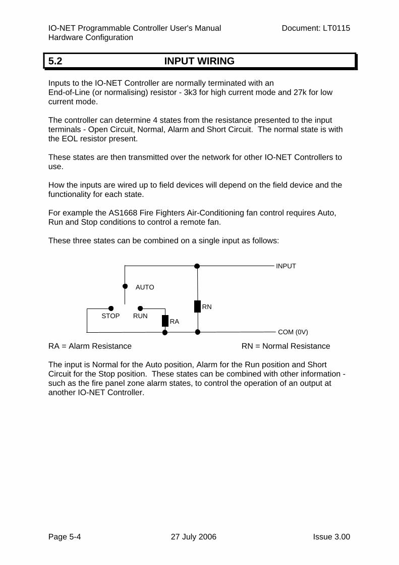
Inputs to the IO-NET Controller are normally terminated with an End-of-Line (or normalising) resistor - 3k3 for high current mode and 27k for low current mode. The controller can determine 4 states from the resistance presented to the input terminals - Open Circuit, Normal, Alarm and Short Circuit. The normal state is with the EOL resistor present. These states are then transmitted over the network for other IO-NET Controllers to use. How the inputs are wired up to field devices will depend on the field device and the functionality for each state. For example the AS1668 Fire Fighters Air-Conditioning fan control requires Auto, Run and Stop conditions to control a remote fan. These three states can be combined on a single input as follows: RA = Alarm Resistance RN = Normal Resistance The input is Normal for the Auto position, Alarm for the Run position and Short Circuit for the Stop position. These states can be combined with other information - such as the fire panel zone alarm states, to control the operation of an output at another IO-NET Controller.
COM (0V)
INPUT
RA
AUTO
STOP RUN RN
Document: LT0115 VIGILANT IO-NET Programmable Controller User's Manual Hardware Configuration
Issue 3.00 27 July 2006 Page 5-5
5.3 OUTPUT WIRING
5.3.1 OPEN COLLECTOR OUTPUTS
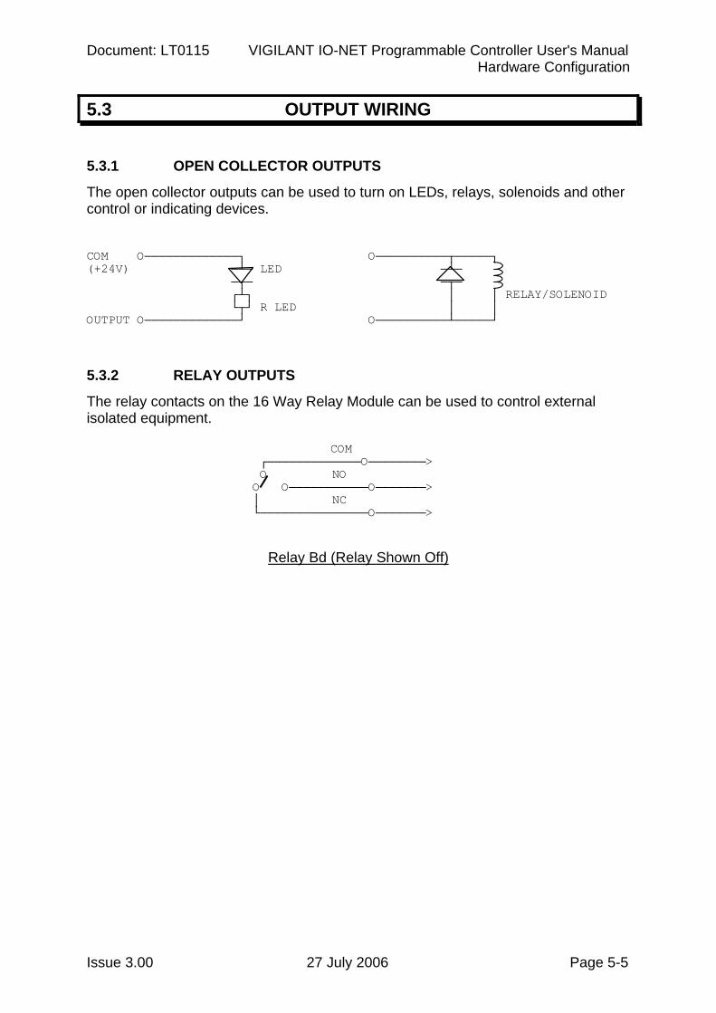
The open collector outputs can be used to turn on LEDs, relays, solenoids and other control or indicating devices. COM О─────────────┐ О──────────┬─────┐ (+24V) ─┴─ LED ─┴─ ─┬─ ─┬─ ┌┴┐ │ │ RELAY/SOLENOID └┬┘ R LED │ │ OUTPUT О─────────────┘ О──────────┴─────┘ 5.3.2 RELAY OUTPUTS
The relay contacts on the 16 Way Relay Module can be used to control external isolated equipment. COM ┌─────────────О────────> О NO О О───────────О───────> │ NC └───────────────О───────>
Relay Bd (Relay Shown Off)
IO-NET Programmable Controller User's Manual Document: LT0115 Hardware Configuration
Page 5-6 27 July 2006 Issue 3.00
5.4 RZDU DATA WIRING
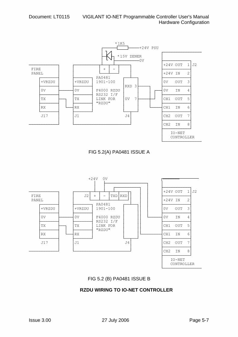
The IO-NET Controller can be connected to the RZDU data output of a compatible fire alarm panel - MX1/MX4428 (F4000)/F3200/NDU/ NLDU/Sigma 5/FP1600, with the use of the PA0481 RZDU/RS232 1901-100 Interface Board. This board isolates and converts the RZDU data bus signals to a voltage compatible with the IO-NET Controller. It can be powered from the same +24V supply as the IO-NET Controller. Issue A Rev 1 and Rev 2 versions of the Interface Board require the use of a 1k5 resistor and a 15 volt zener diode as shown in Fig 5.2(A). Issue B versions can be connected to 24 volts directly. The RXD output (J4 pin 3) or TXD output (J2 pin 3) of the RZDU/RS232 Interface Bd can drive a number of IO-NET Controllers over a maximum cable distance of 200 metres. Beyond this, the RZDU data cable should be extended and another RZDU/ RS232 Interface Bd used for the remote IO-NET Controllers. J4 pin 3 and J2 pin 3 are in fact the same signal, just labelled differently on the two connectors. An IO-NET controller with a local RZDU data connection can be programmed to transmit the zone data it receives from the RZDU input onto the IO-NET network for use by other controllers. This saves wiring the RZDU data line directly to all IO-NET controllers which need it. Multiple controllers, each connected to a different fire panel, may be programmed to transmit zone data onto the network. Each controller is programmed with a unique panel number for the zone data it receives on its RZDU input. NOTE transmitting zone data on to the network can slow the network down and for 1200 baud networks it may be preferable to wire the RZDU data line directly to controllers which need zone data. Refer to Section 8.4 for more detail on network time delays.
Document: LT0115 VIGILANT IO-NET Programmable Controller User's Manual Hardware Configuration
Issue 3.00 27 July 2006 Page 5-7
*1K5
┌────── ──────+24V PSU │ ┌──────────────── ├─┤ ├┐ *15V ZENER │ │ ├──────────0V ├───────────┐ ────────────┐ ┌──────────┬┴──┬─┴─┬────┐ │+24V OUT 1│J2 FIRE │ │ │ + │ - │ │ ├───────────┤ PANEL │ │ └───┴───┘ │ │+24V IN 2│ ┌───────┤ ├───────┐ PA0481 ┌──┴──┐ ├───────────┤ │+VRZDU │ │+VRZDU │ 1901-100 │ │ │0V OUT 3│ ├───────┤ ├───────┤ │RXD 3├────┐ ├───────────┤ │0V ├─────┤0V │ F4000 RZDU │ │ │ ┌──┤0V IN 4│ ├───────┤ ├───────┤ RS232 I/F │ │ │ │ ├───────────┤ │TX ├──┐ │TX │ LINK FOR │0V 7├────┼─┘ │CH1 OUT 5│ ├───────┤ │ ├───────┤ "RZDU" │ │ │ ├───────────┤ │RX │ └──┤RX │ │ │ └────┤CH1 IN 6│ └───────┤ ├───────┘ └──┬──┘ ├───────────┤ J17 │ │J1 J4│ │CH2 OUT 7│ │ │ │ ├───────────┤ ────────────┘ └───────────────────────┘ │CH2 IN 8│ ├───────────┘ │ IO-NET │ CONTROLLER └────────────────
FIG 5.2(A) PA0481 ISSUE A +24V 0V ─────── │ ├─────────────────┐ │ │ │ ┌──────────┐ │ ├───────────┐ ────────────┐ ┌──────┬─┴─┬─┴─┬─┴─┬───┬┐ │ │ │+24V OUT 1│J2 FIRE │ │ J2│ + │ - │TXD│RXD││ │ │ ├───────────┤ PANEL │ │ └───┴───┴───┴───┘│ │ │ │+24V IN 2│ ┌───────┤ ├───────┐ PA0481 ┌──┴──┐│ │ ├───────────┤ │+VRZDU │ │+VRZDU │ 1901-100 │ ││ │ │0V OUT 3│ ├───────┤ ├───────┤ │ ││ │ ├───────────┤ │0V ├─────┤0V │ F4000 RZDU │ ││ └─────┤0V IN 4│ ├───────┤ ├───────┤ RS232 I/F │ ││ ├───────────┤ │TX ├──┐ │TX │ LINK FOR │ ││ │CH1 OUT 5│ ├───────┤ │ ├───────┤ "RZDU" │ ││ ├───────────┤ │RX │ └──┤RX │ │ │└────────┤CH1 IN 6│ └───────┤ ├───────┘ └──┬──┘ ├───────────┤ J17 │ │J1 J4│ │CH2 OUT 7│ │ │ │ ├───────────┤ ────────────┘ └───────────────────────┘ │CH2 IN 8│ ├───────────┘ │ IO-NET │ CONTROLLER └────────────────
FIG 5.2 (B) PA0481 ISSUE B
RZDU WIRING TO IO-NET CONTROLLER
IO-NET Programmable Controller User's Manual Document: LT0115 Hardware Configuration
Page 5-8 27 July 2006 Issue 3.00
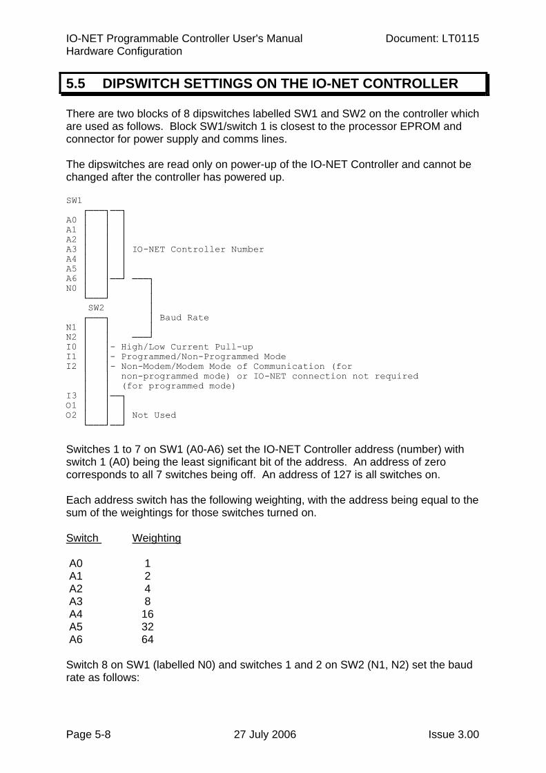
5.5 DIPSWITCH SETTINGS ON THE IO-NET CONTROLLER
There are two blocks of 8 dipswitches labelled SW1 and SW2 on the controller which are used as follows. Block SW1/switch 1 is closest to the processor EPROM and connector for power supply and comms lines. The dipswitches are read only on power-up of the IO-NET Controller and cannot be changed after the controller has powered up. SW1 ┌───┐──┐ A0 │ │ │ A1 │ │ │ A2 │ │ │ A3 │ │ │ IO-NET Controller Number A4 │ │ │ A5 │ │ │ A6 │ │──┘ ───┐ N0 │ │ │ └───┘ │ SW2 │ ┌───┐ │ Baud Rate N1 │ │ │ N2 │ │ ───┘ I0 │ │- High/Low Current Pull-up I1 │ │- Programmed/Non-Programmed Mode I2 │ │- Non-Modem/Modem Mode of Communication (for │ │ non-programmed mode) or IO-NET connection not required │ │ (for programmed mode) I3 │ │──┐ O1 │ │ │ O2 │ │ │ Not Used └───┘──┘ Switches 1 to 7 on SW1 (A0-A6) set the IO-NET Controller address (number) with switch 1 (A0) being the least significant bit of the address. An address of zero corresponds to all 7 switches being off. An address of 127 is all switches on. Each address switch has the following weighting, with the address being equal to the sum of the weightings for those switches turned on. Switch Weighting A0 1 A1 2 A2 4 A3 8 A4 16 A5 32 A6 64 Switch 8 on SW1 (labelled N0) and switches 1 and 2 on SW2 (N1, N2) set the baud rate as follows:
Document: LT0115 VIGILANT IO-NET Programmable Controller User's Manual Hardware Configuration
Issue 3.00 27 July 2006 Page 5-9
N2 N1 N0 Baud Rate off off off 9600 off off on 4800 off on off 2400 off on on 1200 on off off 600 on off on 300 on on off 150 on on on 75 Switch 3 on SW2 (labelled I0) selects either high current pullup or low current pullup. I0 = OFF = high current pullup I0 = ON = low current pullup Switch 4 on SW2 (labelled I1) selects either programmed or non-programmed mode. I1 OFF = programmed mode I1 ON = non-programmed mode Switch 5 on SW2 (labelled I2) is used for two different purposes depending on whether programmed mode or non-programmed mode is selected. When non-programmed mode is selected (switch I1 ON), switch I2 selects between modem operation and non-modem operation. When non-modem operation is selected, a default set of network parameters corresponding to 2400 baud or higher is used. When modem operation is selected a default set of network parameters corresponding to 1200 baud with modems is used. For non-programmed mode (I1 ON) I2 OFF = non-modem mode I2 ON = modem mode For programmed mode (I1 OFF) switch I2 must be switched OFF if connection to the IO-NET network is required and switched ON if no connection is required. Refer to Section 7.2.1. The setting of this dipswitch affects only the Status LED. Switches 6, 7, 8 on SW2 are not used.
IO-NET Programmable Controller User's Manual Document: LT0115 Hardware Configuration
Page 5-10 27 July 2006 Issue 3.00
5.6 SELECTING THE BAUD RATE FOR THE NETWORK
The baud rate for the network is selectable on dipswitches but not all of the baud rates which are selectable are practical. With a copper network 2400,4800 or 9600 baud would normally be used. At 2400 baud, with up to 24 stations on the network any (the first) change of state occurring on any controller input will be transmitted on the network and received by all other controllers within 1.2 seconds of the change of state occurring. Refer to Section 8.4 for more detail. The lower the baud rate, the longer the maximum data line length of the total network can be. A controller operating in non-programmed mode has a choice of 1200 baud with modems, or 2400, 4800, 9600 baud without modems. If a mixture of controllers operating in both programmed and non-programmed mode are on the same network, then it is important that the controllers in programmed mode use network parameters which match the controllers operating in non-programmed mode. Chapter 6 lists the default network parameters used in non-programmed mode.
Document: LT0115 VIGILANT IO-NET Programmable Controller User's Manual Hardware Configuration
Issue 3.00 27 July 2006 Page 5-11
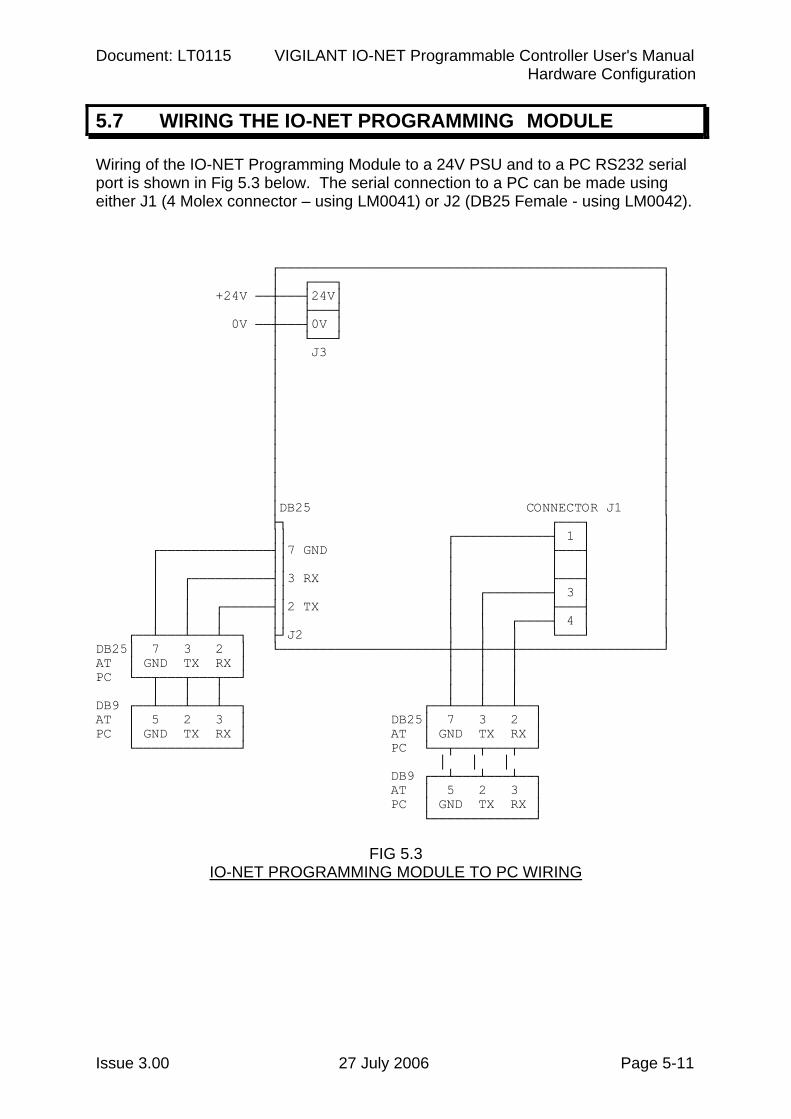
5.7 WIRING THE IO-NET PROGRAMMING MODULE
Wiring of the IO-NET Programming Module to a 24V PSU and to a PC RS232 serial port is shown in Fig 5.3 below. The serial connection to a PC can be made using either J1 (4 Molex connector – using LM0041) or J2 (DB25 Female - using LM0042). ┌────────────────────────────────────────────────┐ │ ┌───┐ │ +24V ──┼───┤24V│ │ │ ├───┤ │ 0V ──┼───┤0V │ │ │ └───┘ │ │ J3 │ │ │ │ │ │ │ │ │ │ │ │ │ │ │ │ │ │ │ │ │ │DB25 CONNECTOR J1 │ ├┐ ┌───┐ │ ││ ┌────────────┤ 1 │ │ ┌──────────────┤│7 GND │ ├───┤ │ │ ││ │ │ │ │ │ ┌──────────┤│3 RX │ ├───┤ │ │ │ ││ │ ┌────────┤ 3 │ │ │ │ ┌──────┤│2 TX │ │ ├───┤ │ │ │ │ ││ │ │ ┌────┤ 4 │ │ ┌──┴───┴───┴──┐ ├┘J2 │ │ │ └───┘ │ DB25│ 7 3 2 │ └─────────────────────┼───┼───┼──────────────────┘ AT │ GND TX RX │ │ │ │ PC └──┬───┬───┬──┘ │ │ │ │ │ │ │ │ │ DB9 ┌──┴───┴───┴──┐ ┌──┴───┴───┴──┐ AT │ 5 2 3 │ DB25│ 7 3 2 │ PC │ GND TX RX │ AT │ GND TX RX │ └─────────────┘ PC └──┬───┬───┬──┘ │ │ │ DB9 ┌──┴───┴───┴──┐ AT │ 5 2 3 │ PC │ GND TX RX │ └─────────────┘
FIG 5.3 IO-NET PROGRAMMING MODULE TO PC WIRING
IO-NET Programmable Controller User's Manual Document: LT0115 Hardware Configuration
Page 5-12 27 July 2006 Issue 3.00
THIS PAGE INTENTIONALLY LEFT BLANK
Document: LT0115 VIGILANT IO-NET Programmable Controller User's Manual Non-Programmed Mode Operation
Issue 3.00 27 July 2006 Page 6-1
Chapter 6 NON-PROGRAMMED MODE OPERATION
6.1 OPERATION IN NON-PROGRAMMED MODE.......................................6-2
IO-NET Programmable Controller User's Manual Document: LT0115 Non-Programmed Mode Operation
Page 6-2 27 July 2006 Issue 3.00
6.1 OPERATION IN NON-PROGRAMMED MODE
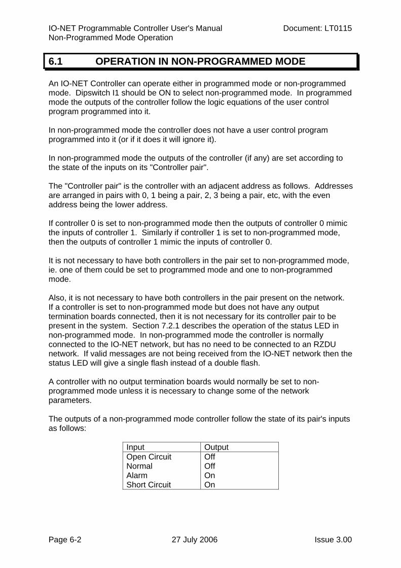
An IO-NET Controller can operate either in programmed mode or non-programmed mode. Dipswitch I1 should be ON to select non-programmed mode. In programmed mode the outputs of the controller follow the logic equations of the user control program programmed into it. In non-programmed mode the controller does not have a user control program programmed into it (or if it does it will ignore it). In non-programmed mode the outputs of the controller (if any) are set according to the state of the inputs on its "Controller pair". The "Controller pair" is the controller with an adjacent address as follows. Addresses are arranged in pairs with 0, 1 being a pair, 2, 3 being a pair, etc, with the even address being the lower address. If controller 0 is set to non-programmed mode then the outputs of controller 0 mimic the inputs of controller 1. Similarly if controller 1 is set to non-programmed mode, then the outputs of controller 1 mimic the inputs of controller 0. It is not necessary to have both controllers in the pair set to non-programmed mode, ie. one of them could be set to programmed mode and one to non-programmed mode. Also, it is not necessary to have both controllers in the pair present on the network. If a controller is set to non-programmed mode but does not have any output termination boards connected, then it is not necessary for its controller pair to be present in the system. Section 7.2.1 describes the operation of the status LED in non-programmed mode. In non-programmed mode the controller is normally connected to the IO-NET network, but has no need to be connected to an RZDU network. If valid messages are not being received from the IO-NET network then the status LED will give a single flash instead of a double flash. A controller with no output termination boards would normally be set to non-programmed mode unless it is necessary to change some of the network parameters. The outputs of a non-programmed mode controller follow the state of its pair's inputs as follows: Input Output Open Circuit
Normal Alarm Short Circuit
Off Off On On
Document: LT0115 VIGILANT IO-NET Programmable Controller User's Manual Non-Programmed Mode Operation
Issue 3.00 27 July 2006 Page 6-3
OPERATION OF NON-PROGRAMMED MODE (CONTINUED) A user control program can be written to duplicate the operation of non-programmed mode as follows (for a controller with address one): O1 = I1/1A OR I1/IS O2 = I1/2A OR I1/2S : : : : : : : : : O32 = I1/32A OR I1/32S In non-programmed mode (dipswitch I1 ON), dipswitch I2 selects one of two sets of default network parameters as follows: Dipswitch I2 ON = modem mode (1200 baud) Dipswitch I2 OFF = non-modem mode (2400 baud or higher) In non-modem mode (I2 off), the default parameter settings are suitable of 2400 baud or higher. The network parameters assigned for modem mode (I2 ON) are as follows: LRTS = 24 ; LEADING RTS DELAY 25 MILLISECONDS TURN = 0 ; TURN-AROUND DELAY 11 MILLISECONDS LDFF = 1 ; ONE LEADING DUMMY FF CHARACTER TRFF = 0 ; NO TRAILING FF TRTS = 0 ; TRAILING RTS DELAY 0 TIGN = 37 ; END TX IGNORE PERIOD 40 MILLISECONDS CTST = 30 CTCT = 30 IACT = 10 RTD1 = 12 RTD2 = 15 RTST = 11 NRRT = 3 TNRT = 6 SENR = 2 DRFT = 12 DRQT = 21 MXST = 31 ; MAX STATION = 31 Note that the maximum station is set to a value of 31.
IO-NET Programmable Controller User's Manual Document: LT0115 Non-Programmed Mode Operation
Page 6-4 27 July 2006 Issue 3.00
OPERATION OF NON-PROGRAMMED MODE (CONTINUED) The network parameters assigned for non-programmed mode, non-modem mode (I2 OFF) are: LRTS = 0 ; LEADING RTS DELAY ZERO TURN = 2 ; TURN-AROUND DELAY 2 MILLISECONDS LDFF = 0 TRFF = 0 TRTS = 0 ; TRAILING RTS DELAY 0 TIGN = 2 CTST = 12 CTCT = 12 IACT = 4 RTD1 = 4 RTD2 = 5 RTST = 2 NRRT = 3 TNRT = 6 SENR = 2 DRFT = 6 DRQT = 12 MXST = 31 ; MAX STATION = 31 The above parameter settings are suitable for 2400, 4800 or 9600 baud. If the default network parameters above are not suitable, then the controller must be run in programmed mode with the user control program specifying the desired network parameters and an appropriate control program to control the outputs. Refer to Section 3.2 for a description of all programmable network parameters.
Document: LT0115 VIGILANT IO-NET Programmable Controller User's Manual Powering Up Controller or Network
Issue 3.00 27 July 2006 Page 7-1
Chapter 7 POWERING UP CONTROLLER OR NETWORK
7.1 CONNECTING A NEW CONTROLLER ..................................................7-2
7.2 PROCEDURE AFTER POWER UP .........................................................7-2
7.2.1 STATUS LED ...............................................................................7-2 7.2.2 SELF TESTS ON START-UP.......................................................7-3 7.2.3 VERIFICATION OF NETWORK OPERATION.............................7-4
7.3 NETWORK DIAGNOSTIC PROGRAM....................................................7-5
IO-NET Programmable Controller User's Manual Document: LT0115 Powering Up Controller or Network
Page 7-2 27 July 2006 Issue 3.00
7.1 CONNECTING A NEW CONTROLLER
When a network of IO-NET Controllers is to be powered up the controllers may be powered up in any order as the network will automatically allow the addition of new controllers. Similarly, the network will keep operating if an IO-NET Controller is powered down or disconnected from the network. When a new controller is being added to a network the entire network does not have to be powered down. The network can be left running while the new controller is connected. 1. If connection to the network is required then connect the controller to the
network data line via the screw terminal connections labelled CHNL1 OUT and CHNL2 OUT.
2. If the controller is to be connected to a fire panel via the RZDU protocol data
line then connect the pin labelled CH1 IN (Pin 6) to the RZDU data line using the RZDU RS232 interface board (refer to Section 5.4).
3. Connect power via the screw terminals labelled 24V OUT and 0V OUT. NOTE :- There are several versions of controller software in current use and these may be freely mixed on the same network. e.g. if some controllers are version 1.00 and some are version 2.01 the network will operate correctly without any compatibility problems. Of course, later versions of software have some additional features that earlier versions did not have. Refer to section 1.7 for software version information.
7.2 PROCEDURE AFTER POWER UP
7.2.1 STATUS LED
A red status LED is located approximately in the centre of the IO-NET Controller PCB. For both programmed and non-programmed modes during normal operation with no faults the status LED will give a "double flash" every 2 seconds, ie. two blips, 100 milliseconds apart, every 2 seconds. If either a "zone network fault" (RZDU protocol connection) or an IO-NET network fault is present the status LED will give a single flash every 2 seconds. A zone network fault can occur only in programmed mode and the possible causes are described with the ZNF operand.
Document: LT0115 VIGILANT IO-NET Programmable Controller User's Manual Powering Up Controller or Network
Issue 3.00 27 July 2006 Page 7-3
STATUS LED (CONTINUED) An IO-NET network fault can occur as follows: 1. Non-programmed Mode.
For non-programmed mode a network fault will occur if either the controller is not receiving valid messages from the network, or if it is receiving valid messages from the network but not input information from its controller pair at regular intervals AND it has at least one output board connected. If it has no output boards connected, then it does not require any input information from its controller pair, but it still requires to receive valid messages from the network.
2. Programmed Mode.
In programmed mode the status LED will give a single flash every 2 seconds if there is an IO-NET network fault or a "zone network fault".
A dipswitch is used (I2 - switch 5 on SW2) to select whether connection to the IO-NET network is required. If no connection to the IO-NET network is required then dipswitch I2 should be switched ON to prevent an IO-NET network fault from occurring. Dipswitch I2 should be switched OFF if connection to the IO-NET network is required.
An IO-NET network fault will occur if connection to the network is required and either no valid messages are being received, or valid messages are being received, but input information is not being regularly received from all controllers whose inputs are included in the logic equations of this controller.
The setting of dipswitch I2 affects only the status LED. It does not affect the value returned by the INF parameter in a logic equation.
7.2.2 SELF TESTS ON START-UP
The controller performs some self tests on start-up and if any faults are found will indicate the fault by flashing the status LED rapidly at a certain rate. The controller will then attempt to restart the program. 1. Internal EPROM/RAM CRC checksum fault.
The status LED flashes once per second for 8 seconds but the LED is on for 800 milliseconds and off for 200 milliseconds each second ie. the on time is 4 times as long as the off time. If this fault occurs and does not clear itself the EPROM should be thrown away (but first check that the EPROM is installed correctly with no bent pins and no other problems such as a power supply fault).
IO-NET Programmable Controller User's Manual Document: LT0115 Powering Up Controller or Network
Page 7-4 27 July 2006 Issue 3.00
SELF TESTS ON START-UP (CONTINUED) 2. Fault with shift register circuitry on controller PCB.
At start-up a test is performed on the shift register circuitry. If a fault is found the status LED will flash at a rate of 10 flashes per second, 10 milliseconds on, 90 milliseconds off, for a period of 5 seconds, before re-starting. If this fault occurs, check that the processor EPROM is installed correctly with no bent pins.
3. Fault with user control program.
If the controller is operating in programmed mode, the EPROM contains a CRC checksum of the control program and this is checked on start-up. Also the controller checks for illegal instruction codes contained in the control program. Illegal instruction codes are not expected to occur and indicate a software bug either in the controller or in the PC compiler program.
If either of these faults occur, then the status LED will flash at a rate of five flashes every second for a period of ten seconds before restarting itself. The LED will be on for 10 milliseconds and off for 190 milliseconds.
If this fault occurs and does not clear itself, then check that the processor EPROM is installed correctly, etc. It may be possible to re-program the user control program into the EPROM and to try again or the EPROM may need to be thrown away and a new EPROM installed. If the problem still occurs with a new EPROM, then a copy of the user source file used and also the faulty EPROM should be returned to the manufacturer for evaluation.
7.2.3 VERIFICATION OF NETWORK OPERATION
If all controllers are connected and working correctly, they should all be giving a double flash on their status LED every 2 seconds. A single flash every 2 seconds indicates a fault is present. It may be that the fault is not with the controller giving the single flash but with some other controller not transmitting data correctly. Check that all controllers are set to the correct addresses and that no two controllers are at the same address. After commissioning a new system or making any changes to a network, all controllers should be checked that they are giving a double flash on their status LED. Also, if possible, each controller should be checked that it operates its outputs correctly according to the logic of its control program.
Document: LT0115 VIGILANT IO-NET Programmable Controller User's Manual Powering Up Controller or Network
Issue 3.00 27 July 2006 Page 7-5
7.3 NETWORK DIAGNOSTIC PROGRAM
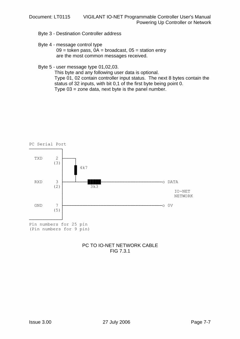
A diagnostic program is available which can be run on a Personal Computer or Laptop to allow the monitoring of the messages being transmitted on an IO-NET network. There are two executable files supplied with the old IO-NET compiler (SF0088), which can be downloaded from http://www.tycosafetyproducts-anz.com/, IONETM1.EXE which uses serial port COM1, and IONETM2.EXE which uses serial port COM2. Note that these programs are “DOS” programs, and were designed to work with older computers / laptops running MSDOS. They may work on many Windows laptops as long as a physical serial port is available, but they will not work with a USB to serial adapter. The PC/laptop serial port can be connected to the IO-NET network as shown in Figure 7.3.1. Take care when connecting "earthed" computers or laptops as there could be an earth fault on the IO-NET cables. Enter IONETM1 or IONETM2 to run the appropriate program. When the program is first started the user is prompted to select the baud rate of the IO-NET Network to be monitored. Following this different commands may be selected with single keystrokes as follows: M Press M to display the menu of single keystroke commands. Q Press Q to exit and return to DOS. Space Press SPACE to pause/resume the display of messages. While
paused, any received messages are discarded. H Press H to hold display output - the display of messages will stop but,
unlike the SPACE key, received messages are not discarded while the display is in hold mode. Press H to release from hold mode.
P Press P to change the baud rate. E Press E to display and then clear a count of the number of messages
that have been received with a crc error. D Press D at any time to stop or start the display of ALL messages
received - when display of ALL messages is enabled, it overrides the selections for individual stations which are set with the S command. When display of ALL messages is turned off, messages will be displayed according to the S command.
IO-NET Programmable Controller User's Manual Document: LT0115 Powering Up Controller or Network
Page 7-6 27 July 2006 Issue 3.00
S Press S to select a station (0-255) to which the following commands A,C and V will apply.
- press A to toggle (enable or disable) the display of all messages
received for station S. Enabling display of all messages will override the C & V settings.
- press C to toggle (enable or disable) display of messages for
station S ONLY when the message is DIFFERENT to the previous message received for station S.
- press V to toggle (enable or disable) the display of messages for
station S ONLY when the message contains point or zone data which is DIFFERENT from the previous status received for those points or zones.
The S and A,C,V commands can be used to get different combinations of messages for multiple stations displayed.
X,Y,Z,U The keys X,Y,Z and U are global commands that are applied to all
stations as if the user had entered the A (enable), A (disable), C or V commands respectively for all stations (0-255). I.e.
X Enable displaying of all messages for all stations (= A enable). Y Disable displaying of all messages for all stations (= A disable). Z Enable displaying of messages for all stations ONLY when the
message received is different to the previous message received for that station (= C enable).
U Enable displaying of messages for all stations which have CHANGING point or zone data (= V enable).
The Y command is used to undo the settings of A,C,V,X,Z, and U.
I.e. it turns everything off. By combining these commands and the A, C and V commands for various stations, it is possible to select the configuration of messages displayed.
B The B key can be used to select "byte mode" which displays every
character received and does not check for valid messages. The format of IO-NET messages is fully described in the IO-NET protocol manual. However, sufficient information is given here to determine which controller has sent the message; what the next controller in the token passing scheme is; the message control type; and the user message type and data if any. Messages are displayed starting with the byte count of the message and ending with the 2 CRC bytes of the message.
Byte 1 - count byte, number of bytes in the message, starting with the count byte but not including the 2 CRC bytes.
Byte 2 - Source Controller address
Document: LT0115 VIGILANT IO-NET Programmable Controller User's Manual Powering Up Controller or Network
Issue 3.00 27 July 2006 Page 7-7
Byte 3 - Destination Controller address Byte 4 - message control type
09 = token pass, 0A = broadcast, 05 = station entry are the most common messages received.
Byte 5 - user message type 01,02,03. This byte and any following user data is optional.
Type 01, 02 contain controller input status. The next 8 bytes contain the status of 32 inputs, with bit 0,1 of the first byte being point 0.
Type 03 = zone data, next byte is the panel number.
PC Serial Port ────────────┐ │ TXD 2 ├────┐ (3)│ │ │ █ 4k7 │ █ │ │ RXD 3 ├────┴────█████───────────────────────o DATA (2)│ 3k3 │ IO-NET │ NETWORK │ GND 7 ├─────────────────────────────────────o 0V (5)│ │ ────────────┘ Pin numbers for 25 pin (Pin numbers for 9 pin)
PC TO IO-NET NETWORK CABLE FIG 7.3.1
IO-NET Programmable Controller User's Manual Document: LT0115 Powering Up Controller or Network
Page 7-8 27 July 2006 Issue 3.00
THIS PAGE INTENTIONALLY LEFT BLANK
Document: LT0115 VIGILANT IO-NET Programmable Controller User's Manual Designing an IO-NET Network
Issue 3.00 27 July 2006 Page 8-1
Chapter 8 DESIGNING AN IO-NET NETWORK
8.1 RECOMMENDATIONS FOR NETWORK DESIGN .................................8-2
8.2 CONFIGURING THE MX4428 (F4000) FIP .............................................8-3
8.3 CONFIGURING THE F3200 FIP..............................................................8-5
8.4 SYSTEM RESPONSE AND TIMING .......................................................8-5
8.4.1 NETWORK TRANSMIT DELAY...................................................8-6 8.4.2 CONTROLLER STATUS INPUT SCAN RATE.............................8-8 8.4.3 CONTROLLER OUTPUT LOGIC EXECUTION TIME..................8-9 8.4.4 DELAY FROM INPUT CHANGE OF STATE TO OUTPUT COS .8-9 8.4.5 DELAY FROM ZONE CHANGE OF STATE TO OUTPUT COS 8-10
IO-NET Programmable Controller User's Manual Document: LT0115 Designing an IO-NET Network
Page 8-2 27 July 2006 Issue 3.00
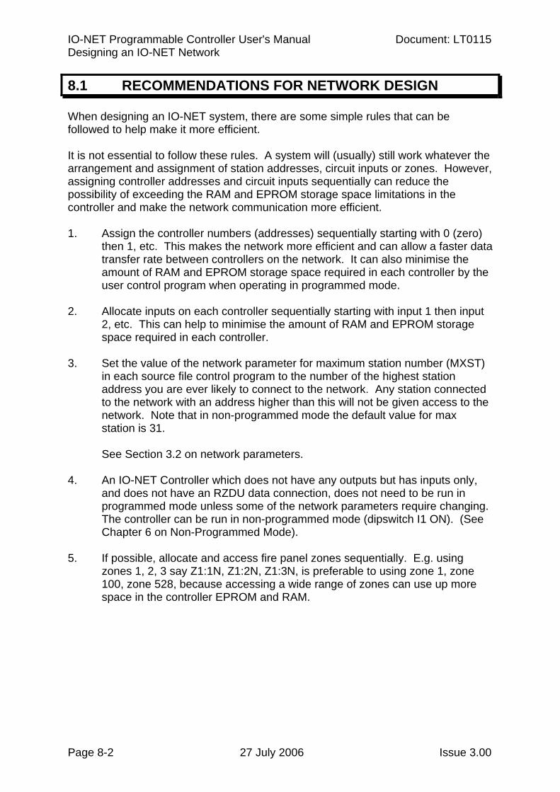
8.1 RECOMMENDATIONS FOR NETWORK DESIGN
When designing an IO-NET system, there are some simple rules that can be followed to help make it more efficient. It is not essential to follow these rules. A system will (usually) still work whatever the arrangement and assignment of station addresses, circuit inputs or zones. However, assigning controller addresses and circuit inputs sequentially can reduce the possibility of exceeding the RAM and EPROM storage space limitations in the controller and make the network communication more efficient. 1. Assign the controller numbers (addresses) sequentially starting with 0 (zero)
then 1, etc. This makes the network more efficient and can allow a faster data transfer rate between controllers on the network. It can also minimise the amount of RAM and EPROM storage space required in each controller by the user control program when operating in programmed mode.
2. Allocate inputs on each controller sequentially starting with input 1 then input
2, etc. This can help to minimise the amount of RAM and EPROM storage space required in each controller.
3. Set the value of the network parameter for maximum station number (MXST)
in each source file control program to the number of the highest station address you are ever likely to connect to the network. Any station connected to the network with an address higher than this will not be given access to the network. Note that in non-programmed mode the default value for max station is 31.
See Section 3.2 on network parameters.
4. An IO-NET Controller which does not have any outputs but has inputs only,
and does not have an RZDU data connection, does not need to be run in programmed mode unless some of the network parameters require changing. The controller can be run in non-programmed mode (dipswitch I1 ON). (See Chapter 6 on Non-Programmed Mode).
5. If possible, allocate and access fire panel zones sequentially. E.g. using
zones 1, 2, 3 say Z1:1N, Z1:2N, Z1:3N, is preferable to using zone 1, zone 100, zone 528, because accessing a wide range of zones can use up more space in the controller EPROM and RAM.
Document: LT0115 VIGILANT IO-NET Programmable Controller User's Manual Designing an IO-NET Network
Issue 3.00 27 July 2006 Page 8-3
8.2 CONFIGURING THE MX4428 (F4000) FIP
An IO-NET Controller may be connected to a number of types of fire indicator panels (FIP) to access the state of zones - zone alarm, zone fault and zone isolate. The zone data is output from the FIP using the RZDU communications protocol, which runs at 1200 baud. Some additional detail on the RZDU data connection is also given in Section 5.4. It is recommended that the version of F4000 FIP software be V1.36 or higher for NON-LCD fire panels, or be V2.06 or higher for LCD fire panels. It is necessary to configure the MX4428/F4000 FIP to ensure that it sends out all the necessary zone data on the RZDU port. Some types of F4000 systems (those with a liquid crystal display) allow the programming of the RZDU protocol type. This is done with the RP command from the CS menu. There are several different versions of F4000 systems in use, and the action required to configure the RZDU protocol link is not the same for all versions. The following procedure, if followed step by step, will work for all versions. Step 1 Use the ND (Number of Displays) command from the CS (Configure System) menu on the programmers terminal. When prompted, enter the number of zone display boards which are in use on the F4000 system or just press RETURN to leave the value unchanged. The current setting of this value is probably already correct. After entering a value for the Number of Display Boards, one of the following will occur:
A: You will be returned to the CS menu as there are no RZDUs programmed as connected.
Use the NR command in the CS menu to set the number of RZDUs to that which are actually connected, or if none are actually connected then set the value to 1 temporarily. Then return to the start of Step 1 and use the ND command again. This should now allow you to assign a value for the number of remote zone display boards (options B or C).
After completing Step 1, if there are no actual RZDUs connected, then use Step 2 to set the value back to zero. OR
IO-NET Programmable Controller User's Manual Document: LT0115 Designing an IO-NET Network
Page 8-4 27 July 2006 Issue 3.00
CONFIGURING THE MX4428 (F4000) FIP (CONTINUED) B: You will be prompted to enter the "largest number of display
boards at any RZDU". The number of zones for which data is transmitted on the RZDU protocol link is dependent on this value. If there are any actual RZDU devices present, then the value entered here will need to be at least the "largest number of display boards at any RZDU" but may need to be higher depending on the highest numbered zone accessed in any IO-NET Controller.
The value entered should be the higher of the largest number of display boards at any RZDU or the highest zone number accessed by any IO-NET Controller, minus 1, divided by 16, plus 1. = HZN-1 + 1
16 OR
C: You will be prompted to enter the number of the highest
numbered zone displayable by any RZDU. You should enter the highest numbered zone accessed at any RZDU OR at any IO-NET Controller.
Step 2 If you set the number of RZDUs to 1 as part of Step 1 A then, use the
NR command to set the number of RZDUs connected to zero if there are no actual RZDUs connected.
Step 3 If the RP command is available in the CS menu (type HE for help to
check) then use it to select the type of RZDU protocol required.
IO-NET controllers with software version 1.01 or later may be programmed to operate with either version of the protocol.
If the CS menu does not have an RP command then the F4000 panel will always transmit old "non-LCD RZDU protocol". Refer to Section 3.4.3 for programming the RZDU protocol type into the IO-NET controller.
If using SmartConfig to program the MX4428 set the “RZDU Max Zone” field on the System Page to the highest zone number needed of any RZDU device and select the appropriate protocol. After configuring the MX4428 (F4000) it is desirable, if possible, to check that the correct zone data is being sent to the IO-NET Controllers by creating a variety of conditions on the zones accessed by the controllers and testing the response of the controllers. The diagnostics facilities on the MX4428/F4000 programmers terminal can be used to check what data is being sent on the RZDU data link.

Document: LT0115 VIGILANT IO-NET Programmable Controller User's Manual Designing an IO-NET Network
Issue 3.00 27 July 2006 Page 8-5
CONFIGURING THE MX4428 (F4000) FIP (CONTINUED) If the zone is an Ancillary Control Zone (which is used to control one or more relays) then
Zpp:nnnA - returns TRUE if zone is activated and not isolated Zpp:nnnF - returns TRUE if supervision fault on zone and not isolated Zpp:nnnI - returns TRUE if the zone is isolated. Zpp:nnnN - returns TRUE if none of the above.
8.3 CONFIGURING THE F3200 FIP
An IO-NET controller may be connected to an F3200 FIP, which will transmit zone data in the RZDU format. The RZDU protocol type (LCD or NON-LCD) must be selected at the F3200 FIP using the keypad and program mode/system config/rzdu options in the menus - refer to the appropriate F3200 Installation & Programming Manual. An F3200 panel will always transmit data for all of the zones and relays that it has assigned. Refer to the appropriate F3200 Programming Manual for the particular version of F3200 software installed for details on how the F3200 maps its zones and relays to RDU zones. This is because the mapping was changed. The state of a relay can be accessed with
Zpp:nnnA - TRUE if relay activated and not isolated Zpp:nnnF - TRUE if supervision fault on relay and not isolated Zpp:nnnI - TRUE if the relay is isolated. Zpp:nnnN - TRUE if none of the above.
8.4 SYSTEM RESPONSE AND TIMING
The information given here may be used to estimate the time delay that will occur from the time of an input changing state to the new state of that input being received and used at another controller. The delay is affected by
1. the baud rate of the network 2. the number of stations on the network 3. the number of fire panels for which data is being transmitted onto the network. 4. the activity level on the network 5. the error/retry rate of the network 6. the number of gaps between adjacent station addresses – the more gaps then the more time is taken up doing station entry messages. For example, a configuration with stations 0,1,2,3,4 is more efficient than 0,3,6,8,9.
IO-NET Programmable Controller User's Manual Document: LT0115 Designing an IO-NET Network
Page 8-6 27 July 2006 Issue 3.00
8.4.1 NETWORK TRANSMIT DELAY
The average and approximate maximum delay before a controller has an opportunity to transmit on the network can be estimated from the information here. Under normal operation each controller will transmit in turn onto the network and the maximum time a station has to wait before being able to transmit is the sum of the maximum time each individual station takes. When each controller transmits, it will transmit one of the following:
1. no status data - it just passes the "token" on - this is an 8 byte
message - this includes the 2 byte header FF 02.
2. one or more messages of fire panel zone status data AND/OR a message containing the status of all of its 32 inputs. The message containing the status of its 32 inputs is a 17 byte message. Each message containing zone data is a maximum of 22 bytes and a controller may transmit more than one zone data message if it has more zone data to send then will fit into a single message. The transmission time to add on for zone status messages is given further below.
A controller does not normally transmit the status of its own inputs each time it transmits on the network. The network parameter DRFT has a default rate of every 6 seconds for this. A controller will transmit the status of its own inputs whenever it has a change of state to send, and also, if any one controller whose input status is needed by other controllers is actually "off the air" and not responding, then, every few seconds in one scan EVERY controller will transmit the status of its inputs (ie. this only happens in a fault condition). Hence each station may or may not transmit the status of its own inputs each time it transmits. For each baud rate, the data below gives a value at the end to add on if any zone data is being transmitted on the network. These figures assume mostly contiguous station addresses and little or no errors/retries - which is normal. 2400 baud rate. Transmit time per station when no input status data sent = 40 millisecs Transmit time per station when status data sent = 80 millisecs For 25 stations, maximum delay before station transmits = 2 seconds (worst case 25 times 80 msecs) - this is the maximum "scan time" of the network (plus zone status transmit time to be added) and assumes all stations transmit input status data. For 25 stations, typical delay before transmitting = 0 to 1.2 seconds i.e. average of 0.6 seconds. This assumes that an average of 4 stations per scan transmit input status data.
Document: LT0115 VIGILANT IO-NET Programmable Controller User's Manual Designing an IO-NET Network
Issue 3.00 27 July 2006 Page 8-7
NETWORK TRANSMIT DELAY (CONTINUED) If zone data is being transmitted on the network then, every 2 seconds, there is an additional amount of transmit time taken up on the network as follows.
1. For EACH F3200 panel for which zone data is being transmitted on the network - add 200 millisecs (2 messages containing the status of 32 zones every 2 seconds). This value is the same regardless of whether zone changes of state occur.
2. For EACH MX4428/F4000 panel for which zone data is being
transmitted on the network - add 100 millisecs (1 message containing the status of 16 zones every 2 seconds) - this is the rate for zone status refresh - OR, if multiple changes of state occur on zones, this value can be a maximum of 280 millisecs (requiring 3 messages of zone data sent on the network every 2 seconds).
4800 baud rate For 4800 baud the data rate is twice as fast so the transmit times and delays are (approximately) half the figures given for 2400 baud above. E.g. for 25 stations, the maximum delay before transmitting is 1 second and the typical delay is 0.3 seconds. If zone status is being transmitted the time taken up every 2 seconds is 100 msecs for each F3200 panel and 50 millisecs for each MX4428/F4000 panel. 9600 baud rate 9600 baud is twice as fast as 4800 baud so the figures for this are half again. E.g. for 25 stations the maximum delay is 0.5 seconds and the typical delay is 150 millisecs. 1200 baud rate The times for this are twice the 2400 baud rate figures. 1200 baud with modems The figures given here assume that the default network parameters in the 1200 Baud with modems network profile (or file NETPRMV3.12M) are being used. Transmit time per station when no input status data sent = 120 millisecs Transmit time per station when status data sent = 190 millisecs For 25 stations, maximum delay before station transmits = 4.75 seconds (worst case 25 times 190 msecs) - this is the maximum "scan time" of the network (plus zone status transmit time to be added) and assumes all stations transmit input status data.
IO-NET Programmable Controller User's Manual Document: LT0115 Designing an IO-NET Network
Page 8-8 27 July 2006 Issue 3.00
NETWORK TRANSMIT DELAY (CONTINUED) For 25 stations, typical delay before transmitting = 0 to 3.42 seconds i.e. average of 1.7 seconds. This assumes that an average of 6 stations per scan transmit input status data. If zone data is being transmitted on the network then, every 2 seconds, there is an additional amount of transmit time taken up on the network as follows.
1. For EACH F3200 panel for which zone data is being transmitted on the
network - add 520 millisecs (2 messages containing the status of 32 zones every 2 seconds). This value is the same regardless of whether zone changes of state occur.
2. For EACH MX4428/F4000 panel for which zone data is being
transmitted on the network - add 260 millisecs (1 message containing the status of 16 zones every 2 seconds) - this is the rate for zone status refresh - OR, if multiple changes of state occur on zones, this value can be a maximum of 730 millisecs (requiring 3 messages of zone data sent on the network every 2 seconds).
NOTE - for a network using 1200 baud modems the transmission of zone data takes up a significant amount of time on the network and if a controller does not get an opportunity to transmit often enough, it may have to continually discard some of the zone status data that it receives from its RZDU input - which could result in the status of some zones NEVER being transmitted on the network. 8.4.2 CONTROLLER STATUS INPUT SCAN RATE
The IO-NET controller reads the status of all 32 of its inputs every 300 milliseconds and any change of state which occurs must be present for two consecutive scans before being accepted as the new state of the input. Hence there is a maximum delay of 600 millisecs before the status of the input changes, and a minimum of 300 msecs. After the status changes there is a further delay before the new status is processed by the control program running in that controller (see section 8.4.3 below) and a delay before the new status is transmitted onto the network for other controllers to use as described in section 8.4.1 above.
Document: LT0115 VIGILANT IO-NET Programmable Controller User's Manual Designing an IO-NET Network
Issue 3.00 27 July 2006 Page 8-9
8.4.3 CONTROLLER OUTPUT LOGIC EXECUTION TIME
In non-programmed mode there is no output logic execution delay and the status of an output is physically updated within 10 milliseconds of the required input status being received from the network. In programmed mode, the IO-NET controller continually and repeatedly executes the output logic programmed into it. The time to execute one pass of all equations is dependent on the number and size of equations and also partly dependent on baud rate of the network and the rate of arrival of status data from other controllers - the faster the network baud rate, the slower the execution time of the output logic (because of higher interrupt and message processing overheads). A VERY ROUGH estimate of 1 millisecond per "operand" accessed in the control program can be used. For example, a moderate to large program accessing 200 operands would take about 200 milliseconds to complete one pass of all equations. An operand consists of Z1:5A or I1/32S or V12, etc. For example, the equation O32 = Z3:120A OR Z3:121A would be counted as accessing 2 operands. The physical state of the 32 outputs is updated at the completion of every pass through the entire output logic and also exactly every 100 milliseconds so this can add to the delay that can occur. 8.4.4 DELAY FROM INPUT CHANGE OF STATE TO OUTPUT COS
The network transmit delay, the input status scan rate and the output logic execution time all affect the delay which can occur from the time an input point physically changes to the time of a physical change on any output using that input status. For example, the maximum delay from an input changing state to an output on a different controller using that input state is the sum of
600 millisecs (input scan delay max) plus network delay max 500 msecs (9600 baud, 25 stations) plus 300 millisec output logic execution delay,
giving a total max delay of 1.4 seconds. The actual delay could range from about 0.5 seconds up to 1.4 seconds. For an input and output on the same controller don't include the network delay.
IO-NET Programmable Controller User's Manual Document: LT0115 Designing an IO-NET Network
Page 8-10 27 July 2006 Issue 3.00
8.4.5 DELAY FROM ZONE CHANGE OF STATE TO OUTPUT COS
If the state of the zone is being received via the IO-NET network rather than directly from the local RZDU input then the network delay described in section 8.4.1 above must be added to the time given here. An MX4428/F4000 or F3200 fire panel transmits exactly one message of zone status exactly every 2 seconds, plus there is also a 500 msec (max) delay for the transmit time of the RZDU message. Also, for an "LCD" type protocol FFCIF zone alarm events are transmitted ahead of zone status so there can be an additional delay of 2,4,6... seconds for 2,4,6 ... FFCIF zone alarm events. Assuming no FFCIF zone alarm event delay, then the delay is 2.5 seconds (max) before the status is received in the controller via its RZDU connection, plus 300 millisec output logic execution delay before the physical output changes, giving a total delay of 2.8 seconds. If the state of the zone is being received via the IO-NET network rather than directly from the local RZDU input then the network delay described in section 8.4.1 above must be added to the time given here. E.g. add 0.5 seconds for a 9600 baud/25 station network.
Document: LT0115 VIGILANT IO-NET Programmable Controller User's Manual Specialist Applications
Issue 3.00 27 July 2006 Page 9-1
Chapter 9 SPECIALIST APPLICATIONS
9.1 USING THE J9 “NETWORK CONNECTOR”..........................................9-2
9.2 FIBRE-OPTIC MODEMS .........................................................................9-2
9.2.1 CONFIGURATIONS.....................................................................9-2 9.2.2 WIRING & SETTING....................................................................9-4 9.2.3 PROGRAMMING .........................................................................9-5
9.3 DIGITAL HUBS........................................................................................9-6
9.3.1 INTRODUCTION..........................................................................9-6 9.3.2 IO-NET TO DIGITAL HUB VIA DIRECT CONNECTION..............9-9 9.3.3 IO-NET TO DIGITAL HUB VIA RS485 BOARD .........................9-10 9.3.4 IO-NET TO DIGITAL HUB VIA PA0865 BOARD .......................9-12 9.3.5 IO-NET TO DIGITAL HUB VIA FIBRE-OPTIC MODEMS ..........9-14 9.3.6 DIGITAL HUBS VIA FIBRE-OPTICS MODEMS ........................9-15
9.4 RS232 ADAPTER BOARDS..................................................................9-16
9.5 USING V-MODEM..................................................................................9-17
9.6 RADIOS .................................................................................................9-17
9.6.1 CONFIGURATIONS...................................................................9-17 9.6.2 WIRING & SETTING..................................................................9-18 9.6.3 PROGRAMMING .......................................................................9-18
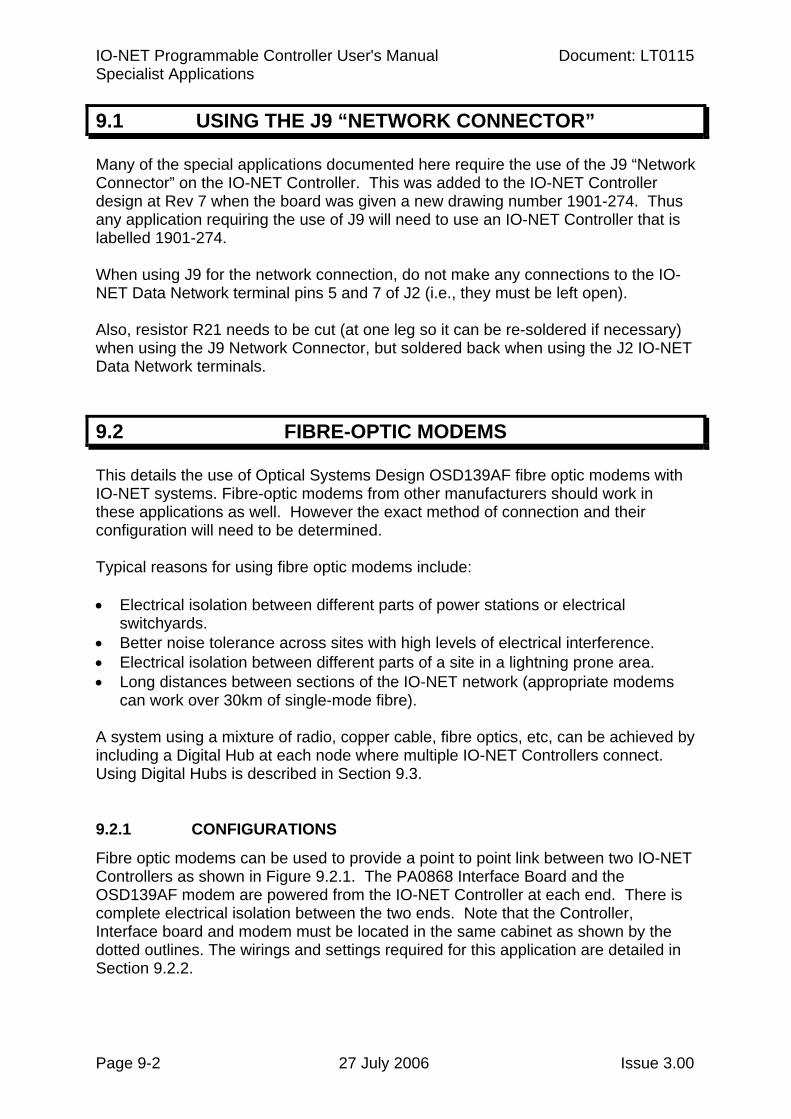
IO-NET Programmable Controller User's Manual Document: LT0115 Specialist Applications
Page 9-2 27 July 2006 Issue 3.00
9.1 USING THE J9 “NETWORK CONNECTOR”
Many of the special applications documented here require the use of the J9 “Network Connector” on the IO-NET Controller. This was added to the IO-NET Controller design at Rev 7 when the board was given a new drawing number 1901-274. Thus any application requiring the use of J9 will need to use an IO-NET Controller that is labelled 1901-274. When using J9 for the network connection, do not make any connections to the IO-NET Data Network terminal pins 5 and 7 of J2 (i.e., they must be left open). Also, resistor R21 needs to be cut (at one leg so it can be re-soldered if necessary) when using the J9 Network Connector, but soldered back when using the J2 IO-NET Data Network terminals.
9.2 FIBRE-OPTIC MODEMS
This details the use of Optical Systems Design OSD139AF fibre optic modems with IO-NET systems. Fibre-optic modems from other manufacturers should work in these applications as well. However the exact method of connection and their configuration will need to be determined. Typical reasons for using fibre optic modems include: • Electrical isolation between different parts of power stations or electrical
switchyards. • Better noise tolerance across sites with high levels of electrical interference. • Electrical isolation between different parts of a site in a lightning prone area. • Long distances between sections of the IO-NET network (appropriate modems
can work over 30km of single-mode fibre). A system using a mixture of radio, copper cable, fibre optics, etc, can be achieved by including a Digital Hub at each node where multiple IO-NET Controllers connect. Using Digital Hubs is described in Section 9.3. 9.2.1 CONFIGURATIONS
Fibre optic modems can be used to provide a point to point link between two IO-NET Controllers as shown in Figure 9.2.1. The PA0868 Interface Board and the OSD139AF modem are powered from the IO-NET Controller at each end. There is complete electrical isolation between the two ends. Note that the Controller, Interface board and modem must be located in the same cabinet as shown by the dotted outlines. The wirings and settings required for this application are detailed in Section 9.2.2.
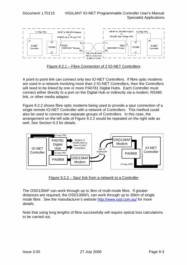
Document: LT0115 VIGILANT IO-NET Programmable Controller User's Manual Specialist Applications
Issue 3.00 27 July 2006 Page 9-3
Figure 9.2.1 – Fibre Connection of 2 IO-NET Controllers A point to point link can connect only two IO-NET Controllers. If fibre optic modems are used in a network involving more than 2 IO-NET Controllers, then the Controllers will need to be linked by one or more PA0781 Digital Hubs. Each Controller must connect either directly to a port on the Digital Hub or indirectly via a modem, RS485 link, or other media adaptor. Figure 9.2.2 shows fibre optic modems being used to provide a spur connection of a single remote IO-NET Controller with a network of Controllers. This method could also be used to connect two separate groups of Controllers. In this case, the arrangement on the left side of Figure 9.2.2 would be repeated on the right side as well. See Section 9.3 for details.
10 way FRC
10 way FRC
10 way FRC
pair of multimode
fibres
OSD139AF Modem
PA0868
IO-NET Controller
OSD139AF Modem
PA0781 Digital Hub
PA0868
Modem or RS485 links to other IO-NET
ControllersIO-NET Controller
Figure 9.2.2 – Spur link from a network to a Controller The OSD139AF can work through up to 3km of multi-mode fibre. If greater distances are required, the OSD139AFL can work through up to 30km of single mode fibre. See the manufacturer’s website http://www.osd.com.au/ for more details. Note that using long lengths of fibre successfully will require optical loss calculations to be carried out.
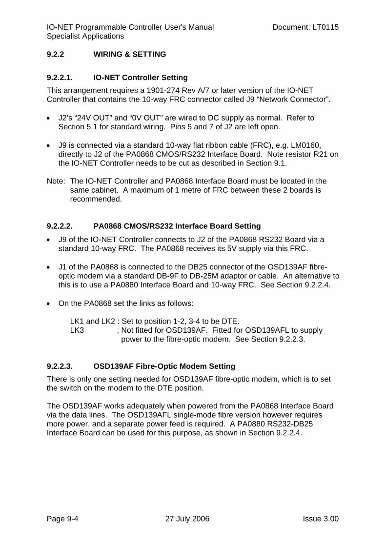
IO-NET Programmable Controller User's Manual Document: LT0115 Specialist Applications
Page 9-4 27 July 2006 Issue 3.00
9.2.2 WIRING & SETTING
9.2.2.1. IO-NET Controller Setting This arrangement requires a 1901-274 Rev A/7 or later version of the IO-NET Controller that contains the 10-way FRC connector called J9 “Network Connector”. • J2’s “24V OUT” and “0V OUT” are wired to DC supply as normal. Refer to
Section 5.1 for standard wiring. Pins 5 and 7 of J2 are left open.
• J9 is connected via a standard 10-way flat ribbon cable (FRC), e.g. LM0160, directly to J2 of the PA0868 CMOS/RS232 Interface Board. Note resistor R21 on the IO-NET Controller needs to be cut as described in Section 9.1.
Note: The IO-NET Controller and PA0868 Interface Board must be located in the
same cabinet. A maximum of 1 metre of FRC between these 2 boards is recommended.
9.2.2.2. PA0868 CMOS/RS232 Interface Board Setting • J9 of the IO-NET Controller connects to J2 of the PA0868 RS232 Board via a
standard 10-way FRC. The PA0868 receives its 5V supply via this FRC.
• J1 of the PA0868 is connected to the DB25 connector of the OSD139AF fibre-optic modem via a standard DB-9F to DB-25M adaptor or cable. An alternative to this is to use a PA0880 Interface Board and 10-way FRC. See Section 9.2.2.4.
• On the PA0868 set the links as follows:
LK1 and LK2 : Set to position 1-2, 3-4 to be DTE. LK3 : Not fitted for OSD139AF. Fitted for OSD139AFL to supply power to the fibre-optic modem. See Section 9.2.2.3.
9.2.2.3. OSD139AF Fibre-Optic Modem Setting There is only one setting needed for OSD139AF fibre-optic modem, which is to set the switch on the modem to the DTE position. The OSD139AF works adequately when powered from the PA0868 Interface Board via the data lines. The OSD139AFL single-mode fibre version however requires more power, and a separate power feed is required. A PA0880 RS232-DB25 Interface Board can be used for this purpose, as shown in Section 9.2.2.4.
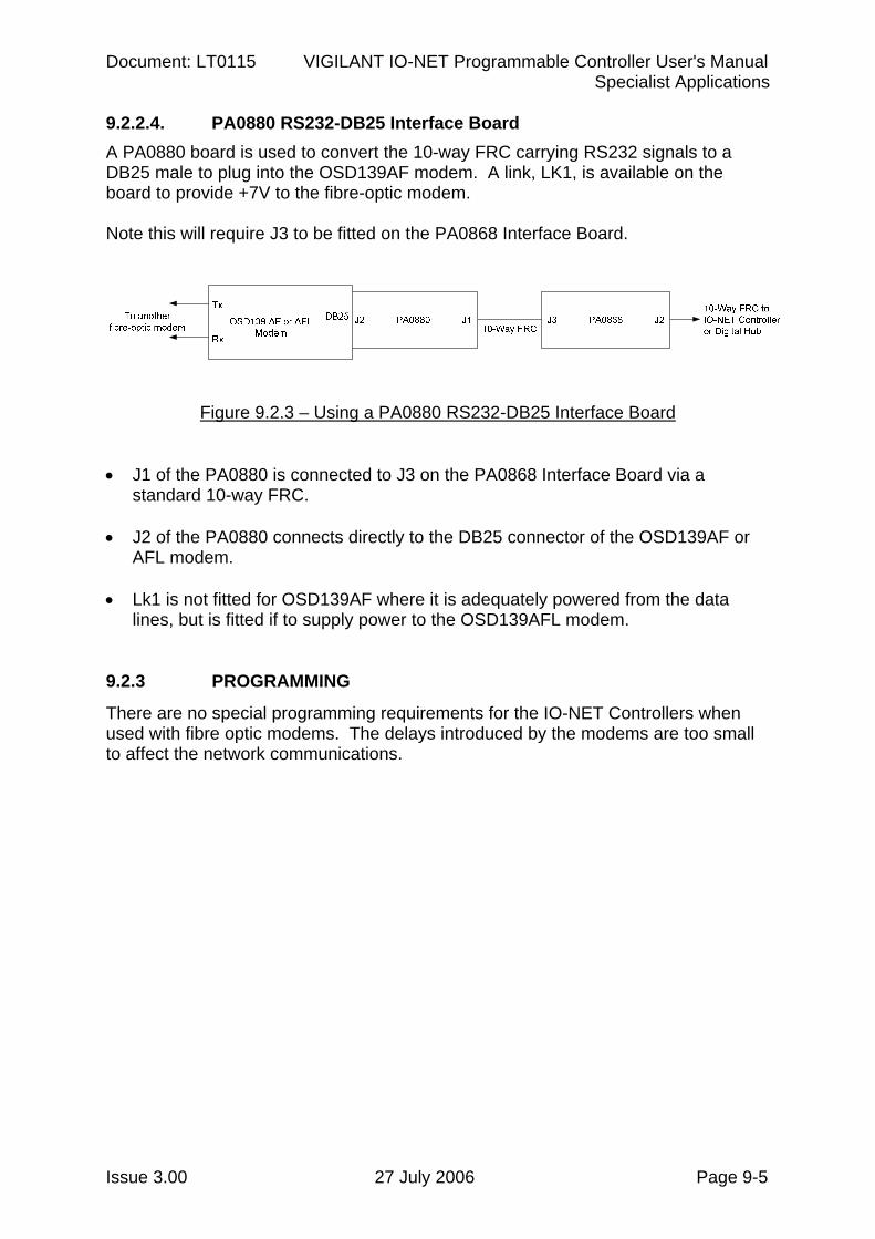
Document: LT0115 VIGILANT IO-NET Programmable Controller User's Manual Specialist Applications
Issue 3.00 27 July 2006 Page 9-5
9.2.2.4. PA0880 RS232-DB25 Interface Board A PA0880 board is used to convert the 10-way FRC carrying RS232 signals to a DB25 male to plug into the OSD139AF modem. A link, LK1, is available on the board to provide +7V to the fibre-optic modem. Note this will require J3 to be fitted on the PA0868 Interface Board.
Figure 9.2.3 – Using a PA0880 RS232-DB25 Interface Board • J1 of the PA0880 is connected to J3 on the PA0868 Interface Board via a
standard 10-way FRC.
• J2 of the PA0880 connects directly to the DB25 connector of the OSD139AF or AFL modem.
• Lk1 is not fitted for OSD139AF where it is adequately powered from the data lines, but is fitted if to supply power to the OSD139AFL modem.
9.2.3 PROGRAMMING
There are no special programming requirements for the IO-NET Controllers when used with fibre optic modems. The delays introduced by the modems are too small to affect the network communications.
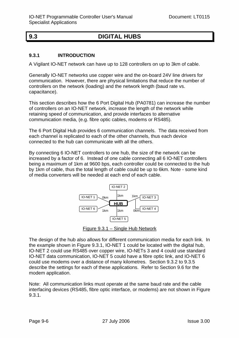
IO-NET Programmable Controller User's Manual Document: LT0115 Specialist Applications
Page 9-6 27 July 2006 Issue 3.00
9.3 DIGITAL HUBS
9.3.1 INTRODUCTION
A Vigilant IO-NET network can have up to 128 controllers on up to 3km of cable. Generally IO-NET networks use copper wire and the on-board 24V line drivers for communication. However, there are physical limitations that reduce the number of controllers on the network (loading) and the network length (baud rate vs. capacitance). This section describes how the 6 Port Digital Hub (PA0781) can increase the number of controllers on an IO-NET network, increase the length of the network while retaining speed of communication, and provide interfaces to alternative communication media, (e.g. fibre optic cables, modems or RS485). The 6 Port Digital Hub provides 6 communication channels. The data received from each channel is replicated to each of the other channels, thus each device connected to the hub can communicate with all the others. By connecting 6 IO-NET controllers to one hub, the size of the network can be increased by a factor of 6. Instead of one cable connecting all 6 IO-NET controllers being a maximum of 1km at 9600 bps, each controller could be connected to the hub by 1km of cable, thus the total length of cable could be up to 6km. Note - some kind of media converters will be needed at each end of each cable.
Figure 9.3.1 – Single Hub Network
The design of the hub also allows for different communication media for each link. In the example shown in Figure 9.3.1, IO-NET 1 could be located with the digital hub, IO-NET 2 could use RS485 over copper wire, IO-NETs 3 and 4 could use standard IO-NET data communication, IO-NET 5 could have a fibre optic link, and IO-NET 6 could use modems over a distance of many kilometres. Section 9.3.2 to 9.3.5 describe the settings for each of these applications. Refer to Section 9.6 for the modem application. Note: All communication links must operate at the same baud rate and the cable interfacing devices (RS485, fibre optic interface, or modems) are not shown in Figure 9.3.1.
1km
HUB0km
1km
1km
IO-NET 2
IO-NET 5
IO-NET 3
IO-NET 6
IO-NET 1
0km
1km
IO-NET 4
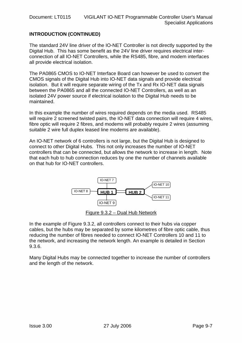
Document: LT0115 VIGILANT IO-NET Programmable Controller User's Manual Specialist Applications
Issue 3.00 27 July 2006 Page 9-7
INTRODUCTION (CONTINUED) The standard 24V line driver of the IO-NET Controller is not directly supported by the Digital Hub. This has some benefit as the 24V line driver requires electrical inter-connection of all IO-NET Controllers, while the RS485, fibre, and modem interfaces all provide electrical isolation. The PA0865 CMOS to IO-NET Interface Board can however be used to convert the CMOS signals of the Digital Hub into IO-NET data signals and provide electrical isolation. But it will require separate wiring of the Tx and Rx IO-NET data signals between the PA0865 and all the connected IO-NET Controllers, as well as an isolated 24V power source if electrical isolation to the Digital Hub needs to be maintained. In this example the number of wires required depends on the media used. RS485 will require 2 screened twisted pairs, the IO-NET data connection will require 4 wires, fibre optic will require 2 fibres, and modems will probably require 2 wires (assuming suitable 2 wire full duplex leased line modems are available). An IO-NET network of 6 controllers is not large, but the Digital Hub is designed to connect to other Digital Hubs. This not only increases the number of IO-NET controllers that can be connected, but allows the network to increase in length. Note that each hub to hub connection reduces by one the number of channels available on that hub for IO-NET controllers.
Figure 9.3.2 – Dual Hub Network
In the example of Figure 9.3.2, all controllers connect to their hubs via copper cables, but the hubs may be separated by some kilometres of fibre optic cable, thus reducing the number of fibres needed to connect IO-NET Controllers 10 and 11 to the network, and increasing the network length. An example is detailed in Section 9.3.6. Many Digital Hubs may be connected together to increase the number of controllers and the length of the network.
IO-NET 7
HUB 1
IO-NET 9
IO-NET 8 HUB 2
IO-NET 10
IO-NET 11
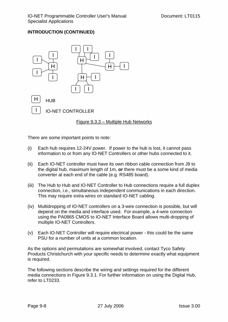
IO-NET Programmable Controller User's Manual Document: LT0115 Specialist Applications
Page 9-8 27 July 2006 Issue 3.00
INTRODUCTION (CONTINUED) HUB IO-NET CONTROLLER
Figure 9.3.3 – Multiple Hub Networks
There are some important points to note: (i) Each hub requires 12-24V power. If power to the hub is lost, it cannot pass
information to or from any IO-NET Controllers or other hubs connected to it.
(ii) Each IO-NET controller must have its own ribbon cable connection from J9 to the digital hub, maximum length of 1m, or there must be a some kind of media converter at each end of the cable (e.g. RS485 board).
(iii) The Hub to Hub and IO-NET Controller to Hub connections require a full duplex connection, i.e., simultaneous independent communications in each direction. This may require extra wires on standard IO-NET cabling.
(iv) Multidropping of IO-NET controllers on a 3-wire connection is possible, but will depend on the media and interface used. For example, a 4-wire connection using the PA0865 CMOS to IO-NET Interface Board allows multi-dropping of multiple IO-NET Controllers.
(v) Each IO-NET Controller will require electrical power - this could be the same PSU for a number of units at a common location.
As the options and permutations are somewhat involved, contact Tyco Safety Products Christchurch with your specific needs to determine exactly what equipment is required. The following sections describe the wiring and settings required for the different media connections in Figure 9.3.1. For further information on using the Digital Hub, refer to LT0233.
I
H
I I
I H
I I I
H
I
I
H I
I I
H
I
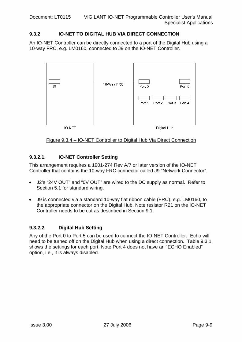
Document: LT0115 VIGILANT IO-NET Programmable Controller User's Manual Specialist Applications
Issue 3.00 27 July 2006 Page 9-9
9.3.2 IO-NET TO DIGITAL HUB VIA DIRECT CONNECTION
An IO-NET Controller can be directly connected to a port of the Digital Hub using a 10-way FRC, e.g. LM0160, connected to J9 on the IO-NET Controller.
Figure 9.3.4 – IO-NET Controller to Digital Hub Via Direct Connection
9.3.2.1. IO-NET Controller Setting This arrangement requires a 1901-274 Rev A/7 or later version of the IO-NET Controller that contains the 10-way FRC connector called J9 “Network Connector”. • J2’s “24V OUT” and “0V OUT” are wired to the DC supply as normal. Refer to
Section 5.1 for standard wiring.
• J9 is connected via a standard 10-way flat ribbon cable (FRC), e.g. LM0160, to the appropriate connector on the Digital Hub. Note resistor R21 on the IO-NET Controller needs to be cut as described in Section 9.1.
9.3.2.2. Digital Hub Setting Any of the Port 0 to Port 5 can be used to connect the IO-NET Controller. Echo will need to be turned off on the Digital Hub when using a direct connection. Table 9.3.1 shows the settings for each port. Note Port 4 does not have an “ECHO Enabled” option, i.e., it is always disabled.
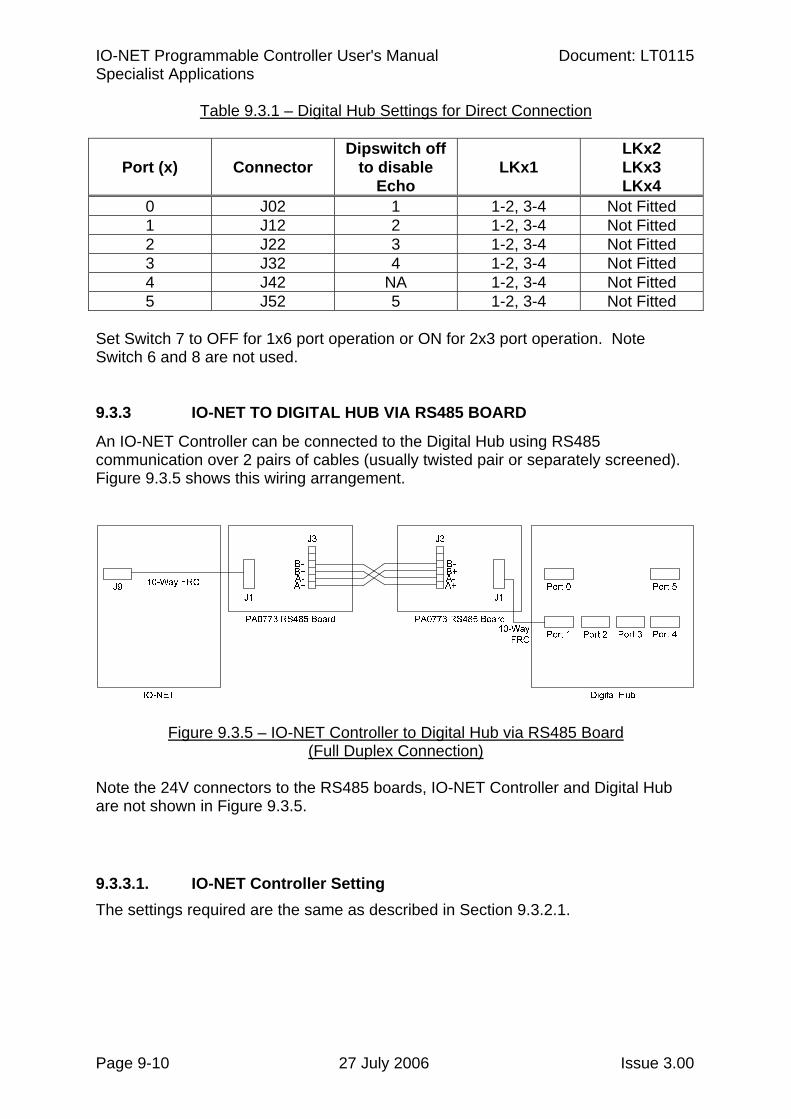
IO-NET Programmable Controller User's Manual Document: LT0115 Specialist Applications
Page 9-10 27 July 2006 Issue 3.00
Table 9.3.1 – Digital Hub Settings for Direct Connection
Port (x) Connector Dipswitch off
to disable Echo
LKx1 LKx2 LKx3 LKx4
0 J02 1 1-2, 3-4 Not Fitted 1 J12 2 1-2, 3-4 Not Fitted 2 J22 3 1-2, 3-4 Not Fitted 3 J32 4 1-2, 3-4 Not Fitted 4 J42 NA 1-2, 3-4 Not Fitted 5 J52 5 1-2, 3-4 Not Fitted
Set Switch 7 to OFF for 1x6 port operation or ON for 2x3 port operation. Note Switch 6 and 8 are not used. 9.3.3 IO-NET TO DIGITAL HUB VIA RS485 BOARD
An IO-NET Controller can be connected to the Digital Hub using RS485 communication over 2 pairs of cables (usually twisted pair or separately screened). Figure 9.3.5 shows this wiring arrangement.
Figure 9.3.5 – IO-NET Controller to Digital Hub via RS485 Board (Full Duplex Connection)
Note the 24V connectors to the RS485 boards, IO-NET Controller and Digital Hub are not shown in Figure 9.3.5.
9.3.3.1. IO-NET Controller Setting The settings required are the same as described in Section 9.3.2.1.
Document: LT0115 VIGILANT IO-NET Programmable Controller User's Manual Specialist Applications
Issue 3.00 27 July 2006 Page 9-11
9.3.3.2. RS485 Board Setting Only a full duplex, point to point connection can be used between the IO-NET Controller and Digital Hub. Set the DIP switches of the PA0711 or PA0773 RS485 board for 4-wire full duplex Rx/Tx always, as shown below.
Switch A B C D Setting ON ON OFF OFF
If a PA0711 RS485 board is used, it can be mounted directly onto the Digital Hub (Jx3 Molex connector), in which case the Digital Hub port used needs to have its LKx1 mini-jumps set to 1-2, 3-4 (no swap Tx/Rx). If a PA0711 RS485 board or a PA0773 RS485 board is connected via its FRC connector J1 and a 10-way FRC cable to the Digital Hub Jx2 socket, the Digital Hub port used needs to have its LKx1 mini-jumps set to 1-3, 2-4 (swap Tx/Rx). A 24V connection will also be required on the RS485 board. 9.3.3.3. Digital Hub Setting Any of the Port 0 to Port 5 can be used to connect to the IO-NET Controller, with the settings as per Table 9.3.2. Echo needs to be disabled for this application. Note Port 4 does not have an “ECHO Enabled” option, i.e., it is disabled by default.
Table 9.3.2 – Digital Hub Settings for RS485 Connection
LKx1 Port (x) Connector
Dipswitch off to disable
Echo Using
FRC Jx2 Using
MOLEX Jx3LKx3 LKx2
LKx4
0 J02 1 1-2, 3-4 1-3, 2-4 Fitted Not Fitted 1 J12 2 1-2, 3-4 1-3, 2-4 Fitted Not Fitted 2 J22 3 1-2, 3-4 1-3, 2-4 Fitted Not Fitted 3 J32 4 1-2, 3-4 1-3, 2-4 Fitted Not Fitted 4 J42 NA 1-2, 3-4 1-3, 2-4 Fitted Not Fitted 5 J52 5 1-2, 3-4 1-3, 2-4 Fitted Not Fitted
Set Switch 7 to OFF for 1x6 port operation or ON for 2x3 port operation. Note Switch 6 and 8 are not used.
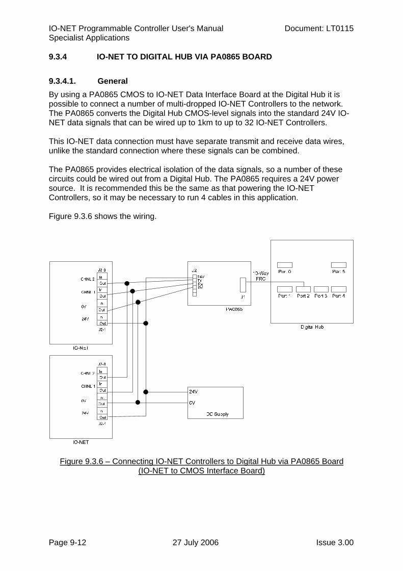
IO-NET Programmable Controller User's Manual Document: LT0115 Specialist Applications
Page 9-12 27 July 2006 Issue 3.00
9.3.4 IO-NET TO DIGITAL HUB VIA PA0865 BOARD
9.3.4.1. General By using a PA0865 CMOS to IO-NET Data Interface Board at the Digital Hub it is possible to connect a number of multi-dropped IO-NET Controllers to the network. The PA0865 converts the Digital Hub CMOS-level signals into the standard 24V IO-NET data signals that can be wired up to 1km to up to 32 IO-NET Controllers. This IO-NET data connection must have separate transmit and receive data wires, unlike the standard connection where these signals can be combined. The PA0865 provides electrical isolation of the data signals, so a number of these circuits could be wired out from a Digital Hub. The PA0865 requires a 24V power source. It is recommended this be the same as that powering the IO-NET Controllers, so it may be necessary to run 4 cables in this application. Figure 9.3.6 shows the wiring.
Figure 9.3.6 – Connecting IO-NET Controllers to Digital Hub via PA0865 Board (IO-NET to CMOS Interface Board)
Document: LT0115 VIGILANT IO-NET Programmable Controller User's Manual Specialist Applications
Issue 3.00 27 July 2006 Page 9-13
9.3.4.2. IO-NET Controller Setting The standard IO-NET Data Terminals J2-5 and J2-7 are used in this application – however they must not be joined together as per usual IO-NET data networking. When using the Digital Hub separate Tx and Rx circuits must be used. The wiring required on J2 is (refer to Figure 9.3.6): • “24V OUT” and “0V OUT” : Wired to DC supply as normal. • “CHNL2 OUT” J2-7 : Wired to “Tx” of J2 on PA0865. • “CHNL1 OUT” J2-5 : Wired to “Rx” of J2 on PA0865. 9.3.4.3. PA0865 IO-NET to CMOS Interface Board Setting The PA0865 board is used to convert the Digital Hub’s CMOS signal levels into an isolated IO-NET data connection. No special setting is required on the PA0865 board. A 10-way FRC cable is used to connect J1 of the PA0865 to the Digital Hub. 9.3.4.4. Digital Hub Setting The port on the Digital Hub needs to have its “ECHO” enabled if more than one IO-NET Controller is connected in parallel to one PA0865 IO-NET to CMOS Interface Board. Therefore Port 4 cannot be used because it does not have an “ECHO Enabled” option. Use Port 4 to interface via an PA0865 if only one IO-NET Controller is connected to that PA0865 board.
Table 9.3.3 – Digital Hub Settings for PA0865 CMOS IO-NET Interface
Port (x) Connector Dipswitch
on to enable Echo
LKx1 LKx2 LKx3 LKx4
0 J02 1 1-3, 2-4 Not Fitted Fitted 3-4 1 J12 2 1-3, 2-4 Not Fitted Fitted 3-4 2 J22 3 1-3, 2-4 Not Fitted Fitted 3-4 3 J32 4 1-3, 2-4 Not Fitted Fitted 3-4 4 J42 NA 1-3, 2-4 Not Fitted Fitted 3-4 5 J52 5 1-3, 2-4 Not Fitted Fitted 3-4
Set Switch 7 to OFF for 1x6 port operation or ON for 2x3 port operation. Note Switch 6 and 8 are not used.
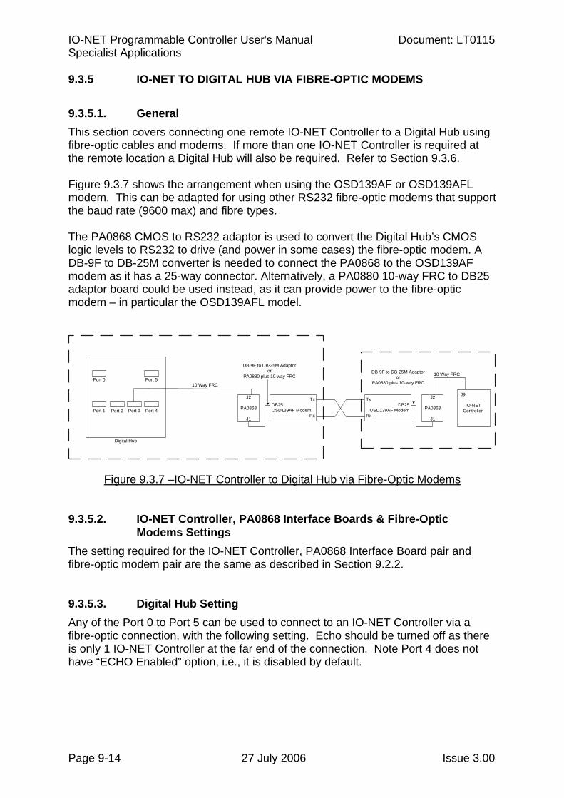
IO-NET Programmable Controller User's Manual Document: LT0115 Specialist Applications
Page 9-14 27 July 2006 Issue 3.00
9.3.5 IO-NET TO DIGITAL HUB VIA FIBRE-OPTIC MODEMS
9.3.5.1. General This section covers connecting one remote IO-NET Controller to a Digital Hub using fibre-optic cables and modems. If more than one IO-NET Controller is required at the remote location a Digital Hub will also be required. Refer to Section 9.3.6. Figure 9.3.7 shows the arrangement when using the OSD139AF or OSD139AFL modem. This can be adapted for using other RS232 fibre-optic modems that support the baud rate (9600 max) and fibre types. The PA0868 CMOS to RS232 adaptor is used to convert the Digital Hub’s CMOS logic levels to RS232 to drive (and power in some cases) the fibre-optic modem. A DB-9F to DB-25M converter is needed to connect the PA0868 to the OSD139AF modem as it has a 25-way connector. Alternatively, a PA0880 10-way FRC to DB25 adaptor board could be used instead, as it can provide power to the fibre-optic modem – in particular the OSD139AFL model.
J2
PA0868
J1
TxDB25 OSD139AF Modem
Rx
10 Way FRC
DB-9F to DB-25M Adaptor or
PA0880 plus 10-way FRC
TxDB25
OSD139AF ModemRx
J2
PA0868
J1
J9
IO-NET Controller
10 Way FRCDB-9F to DB-25M Adaptor or
PA0880 plus 10-way FRCPort 0 Port 5
Port 1 Port 4Port 2 Port 3
Digital Hub
Figure 9.3.7 –IO-NET Controller to Digital Hub via Fibre-Optic Modems 9.3.5.2. IO-NET Controller, PA0868 Interface Boards & Fibre-Optic
Modems Settings The setting required for the IO-NET Controller, PA0868 Interface Board pair and fibre-optic modem pair are the same as described in Section 9.2.2. 9.3.5.3. Digital Hub Setting Any of the Port 0 to Port 5 can be used to connect to an IO-NET Controller via a fibre-optic connection, with the following setting. Echo should be turned off as there is only 1 IO-NET Controller at the far end of the connection. Note Port 4 does not have “ECHO Enabled” option, i.e., it is disabled by default.
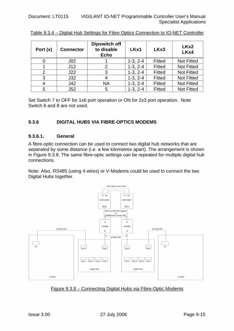
Document: LT0115 VIGILANT IO-NET Programmable Controller User's Manual Specialist Applications
Issue 3.00 27 July 2006 Page 9-15
Table 9.3.4 – Digital Hub Settings for Fibre Optics Connection to IO-NET Controller
Port (x) Connector Dipswitch off
to disable Echo
LKx1 LKx3 LKx2 LKx4
0 J02 1 1-3, 2-4 Fitted Not Fitted 1 J12 2 1-3, 2-4 Fitted Not Fitted 2 J22 3 1-3, 2-4 Fitted Not Fitted 3 J32 4 1-3, 2-4 Fitted Not Fitted 4 J42 NA 1-3, 2-4 Fitted Not Fitted 5 J52 5 1-3, 2-4 Fitted Not Fitted
Set Switch 7 to OFF for 1x6 port operation or ON for 2x3 port operation. Note Switch 6 and 8 are not used. 9.3.6 DIGITAL HUBS VIA FIBRE-OPTICS MODEMS
9.3.6.1. General A fibre-optic connection can be used to connect two digital hub networks that are separated by some distance (i.e. a few kilometres apart). The arrangement is shown in Figure 9.3.8. The same fibre-optic settings can be repeated for multiple digital hub connections. Note: Also, RS485 (using 4 wires) or V-Modems could be used to connect the two Digital Hubs together.
J1
PA0868
J2
Port 0 Port 5
Port 1 Port 4Port 2 Port 3
Digital Hub
J9Port 0 Port 5
Port 1 Port 4Port 2 Port 3
Digital Hub
J9
10-Way FRC 10-Way FRC
IO-NET IO-NET
Tx Rx
OSD139AF
DB25
J1
PA0868
J2
Tx Rx
OSD139AF
DB25
Fibre-Optic (cross-over)
DB-9F to DB-25M Adaptor or
PA0880 plus 10-way FRC
10-Way FRC
Figure 9.3.8 – Connecting Digital Hubs via Fibre-Optic Modems
IO-NET Programmable Controller User's Manual Document: LT0115 Specialist Applications
Page 9-16 27 July 2006 Issue 3.00
9.3.6.2. IO-NET Controller, PA0868 Interface Boards and Fibre-Optic Modems Settings
The setting required for the IO-NET Controller, PA0868 Interface Board pair and fibre-optic modem pairs are the same as described in Section 9.2.2. 9.3.6.3. Digital Hub Setting Table 9.3.5 shows the Digital Hub settings depending on which port of the Digital Hub is used to connect to the fibre-optic modem. Echo should be disabled for the connection to another Digital Hub.
Table 9.3.5 – Digital Hub Settings for Fibre Connection
Port (x) Connector Dipswitch off
to disable Echo
LKx1 LKx3 LKx2 LKx4
0 J02 1 1-3, 2-4 Fitted Not Fitted 1 J12 2 1-3, 2-4 Fitted Not Fitted 2 J22 3 1-3, 2-4 Fitted Not Fitted 3 J32 4 1-3, 2-4 Fitted Not Fitted 4 J42 NA 1-3, 2-4 Fitted Not Fitted 5 J52 5 1-3, 2-4 Fitted Not Fitted
Set Switch 7 to OFF for 1x6 port operation or ON for 2x3 port operation. Note Switch 6 and 8 are not used.
9.4 RS232 ADAPTER BOARDS
A PA0868 RS232 board can be used to convert the IO-NET communications to standard RS232, and allow an IO-NET Controller to connect to various other standard interface modules e.g. modems, microwave link, fibre-optic modem, etc. The wiring of the IO-NET board is as follows • DC supply is wired to the 24V OUT and 0V OUT terminals as normal. • CH1 OUT, CH2 IN terminals on J2 are left unconnected. • CH1 IN may be used to receive RZDU data as normal. • J9 is connected via a standard 10-way flat ribbon cable (FRC) such as LM0084 to
the PA0868 RS232 board. Plug one end of the FRC into J9 on the IO-NET board PA0498, and the other end into J2 of the PA0868 RS232 board. Refer to Section 9.1.
• Wiring to input and output termination boards is unchanged. If the RS232 board is connecting to a modem, links LK1 and LK2 on the RS232 board should be in the 1–2 and 3–4 positions. Note : The RS232 board will automatically get its power from the IO-NET Controller.
Document: LT0115 VIGILANT IO-NET Programmable Controller User's Manual Specialist Applications
Issue 3.00 27 July 2006 Page 9-17
9.5 USING V-MODEM
Two IO-NET Controllers, or an IO-NET Controller and one port of a digital hub, or two Digital Hubs, can be connected using two V-Modems, or possibly other third-party modems that support “leased line” operation. This would be useful to
• extend the distance between IO-NET Controllers • extend the distance between an IO-NET Controller and a digital hub • connect two disparate groups of IO-NET Controllers together • use a telephone-style circuit between IO-NET Controllers.
An RS232 board should be connected to the J9 connector of each IO-NET Controller as described above in Section 9.4. The V-Modem should be connected to the RS232 board by connecting J3 on the V-Modem to J1 on the RS232 board with the LM0166 supplied with the V-Modem. Refer to LT0243 for detailed instructions on setting up the V-Modem. It should be programmed for
• Leased line originate at one end • Leased line answer at the other end • No flow control • 2400 baud.
Whenever a V-Modem is used in a network, all IO-NET Controllers must operate in programmed mode with the network profile programmed as “V-Modem”. This includes longer time-outs to take account for the transmission delays in V-Modem. The IO-NET Controllers can not operate in non-programmed mode when V-Modem is used. The dipswitches need to be set to operate at 2400, programmed mode and network connection as detailed in Section 5.5. It was possible to connect multiple IO-NET controllers with 1830 modems, however the 1830 modem is no longer available.
9.6 RADIOS
The IO-NET system operates over copper wires, fibre optic modems and voice frequency modems; and also it can be used with radios. Some applications present difficulties in installing a physical network, and using radio could be the answer. Examples include: - Mobile equipment (e.g. loader or excavator) that has no trailing cable. - Long distances with no cables available or the cost to install cable is
prohibitive. - Scattered layout of remote units. - Cross-city communications. 9.6.1 CONFIGURATIONS
IO-NET Programmable Controller User's Manual Document: LT0115 Specialist Applications
Page 9-18 27 July 2006 Issue 3.00
A company called Cynet manufactures a radio modem (model 405U) that can be used with IO-NET. These radios work at UHF frequencies and provide line-of-sight communications. They do not require licences and are simple to install and configure for most applications. Only when high-gain directional antennas are needed might some radio engineering be required. The published data for these radios indicates distances greater than 5km can be achieved. Testing suggests that greater distances could be achieved with directional aerials mounted well above the ground and clear line of sight between the aerials. Also, additional units can be configured as repeaters to extend the coverage. Each IO-NET requires an RS232 interface to connect to the 405U radio. E.g. a PA0868 CMOS/RS232 interface with a 10 way FRC to the IO-NET Controller can be used. Refer to Figure 9.6.1. A system using a mixture of radio, copper cable, fibre optics, etc, can be achieved by including a Digital Hub at each node that has multiple IO-NET Controllers. 9.6.2 WIRING & SETTING
9.6.2.1. IO-NET Controller Setting This arrangement requires a 1901-274 Rev A/7 or later version of the IO-NET Controller. This contains the 10-way FRC connector J9 called “Network Connector”. • J2’s “24V OUT” and “0V OUT” are wired to DC supply as normal. Refer to
Section 5.1 for standard wiring. Pins 5 and 7 of J2 are left open.
• J9 is connected via a standard 10-way flat ribbon cable (FRC), e.g. LM0160, directly to J2 of the PA0868 CMOS/RS232 Interface Board, then to the 405U Radio Board. Note resistor R21 on the IO-NET Controller needs to be cut as described in Section 9.1.
9.6.2.2. PA0868 CMOS/RS232 Interface Board Setting The PA0868 can plug straight into the 405U radio, or a DB9 male to DB9 female straight through cable (e.g. LM0138) can be used to separate them. • Lk1 : 1-2, 3-4 • Lk2 and LK3 : Not fitted 9.6.2.3. 405U Radio Setting The 405U requires 24Vdc (@ 300mA transmitting, 80mA quiescent) to operate. For rough battery calculation purposes assume it draws 150mA. 9.6.3 PROGRAMMING
The radios need to be configured for this use. They should be programmed (refer to the 405U User Manual) for:
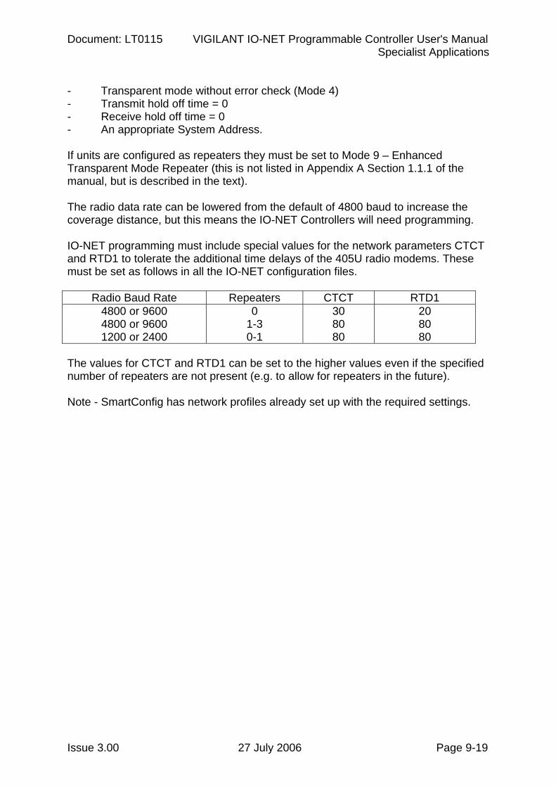
Document: LT0115 VIGILANT IO-NET Programmable Controller User's Manual Specialist Applications
Issue 3.00 27 July 2006 Page 9-19
- Transparent mode without error check (Mode 4) - Transmit hold off time = 0 - Receive hold off time = 0 - An appropriate System Address. If units are configured as repeaters they must be set to Mode 9 – Enhanced Transparent Mode Repeater (this is not listed in Appendix A Section 1.1.1 of the manual, but is described in the text). The radio data rate can be lowered from the default of 4800 baud to increase the coverage distance, but this means the IO-NET Controllers will need programming. IO-NET programming must include special values for the network parameters CTCT and RTD1 to tolerate the additional time delays of the 405U radio modems. These must be set as follows in all the IO-NET configuration files.
Radio Baud Rate Repeaters CTCT RTD1 4800 or 9600 0 30 20 4800 or 9600 1-3 80 80 1200 or 2400 0-1 80 80
The values for CTCT and RTD1 can be set to the higher values even if the specified number of repeaters are not present (e.g. to allow for repeaters in the future). Note - SmartConfig has network profiles already set up with the required settings.
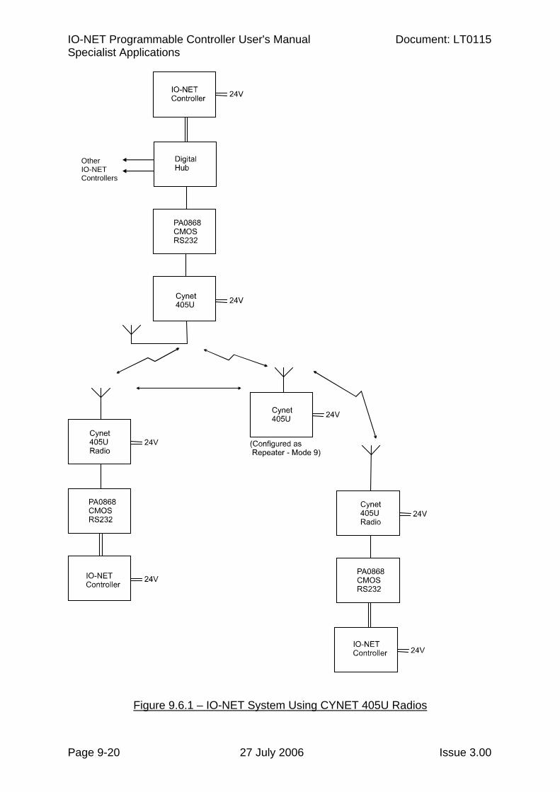
IO-NET Programmable Controller User's Manual Document: LT0115 Specialist Applications
Page 9-20 27 July 2006 Issue 3.00
Figure 9.6.1 – IO-NET System Using CYNET 405U Radios
Other IO-NET Controllers
Related Documents


![Programmable ECL IO with PCI DMAdyneng.com/pci_necl_xg1_man_a2.pdf · 2010. 12. 17. · The PCI-Serial-ECL has both ECL and TTL IO interfaced by a D100 connector. The TTL IO [11-0]](https://static.cupdf.com/doc/110x72/60cdf6110356bf51da2c3b32/programmable-ecl-io-with-pci-2010-12-17-the-pci-serial-ecl-has-both-ecl-and.jpg)