IO-540-K1A5 Series Illustrated Parts Catalog February 2015 ********NOTICE******** This parts catalog, PC-615-K1A5 Series (models IO-540-K1A5, IO-540-K1A5D) supersedes the previous IO-540-K1A5, IO-540-K1A5D model engines which are covered in PC-615. PC-615-K1A5 Series 652 Oliver Street Williamsport, PA 17701 © 2015

Welcome message from author
This document is posted to help you gain knowledge. Please leave a comment to let me know what you think about it! Share it to your friends and learn new things together.
Transcript
IO-540-K1A5 Series Illustrated Parts Catalog
February 2015
********NOTICE******** This parts catalog, PC-615-K1A5 Series (models IO-540-K1A5, IO-540-K1A5D) supersedes the previous IO-540-K1A5, IO-540-K1A5D model engines which are covered in PC-615.
PC-615-K1A5 Series 652 Oliver Street
Williamsport, PA 17701
© 2015

IO-540-K1A5 Series Illustrated Parts Catalog Lycoming Part Number: PC-615-K1A5 ©2015 Lycoming. All Rights Reserved. Lycoming and “Powered by Lycoming” are trademarks or registered trademarks of Lycoming. Lycoming Engines is a division of Avco Corporation. All brand and product names referenced in this publication are trademarks or registered trademarks of their respective companies.
For additional information: Mailing address: Lycoming Engines 652 Oliver Street Williamsport, PA 17701 U.S.A. Phone: Factory: U.S. and Canada toll free +1(800) 258-3279 International Customers +1(570) 323-6181 Sales Department: +1(570) 327-7278 Fax: +1(570) 327-7101 Lycoming’s regular business hours are Monday through Friday from 8:00 A.M.
through 5:00 P.M. Eastern Time (-5 GMT) Visit us on the World Wide Web at: http://www.lycoming.com
©2015

IO-540-K1A5 Series Illustrated Parts Catalog
Effectivity: IO-540-K1A5 Series Record of Revisions Copyright, Lycoming Engines Page iii Lycoming Engines is a division of Avco Corporation February 2015
********NOTICE******** This parts catalog, PC-615-K1A5 Series (models IO-540-K1A5, IO-540-K1A5D) supersedes the previous IO-540-K1A5, IO-540-K1A5D model engines which are covered in PC-615.
RECORD OF REVSIONS
NOTE: Service Documents override parts information in this document.
Rev No. Issue Date Initials Insertion Date

IO-540-K1A5 Series Illustrated Parts Catalog
Record of Revisions Effectivity: IO-540-K1A5 Series Page iv Copyright, Lycoming Engines February 2015 Lycoming Engines is a division of Avco Corporation
This page intentionally left blank.

IO-540-K1A5 Series Illustrated Parts Catalog
Effectivity: IO-540-K1A5 Series Table of Contents Copyright, Lycoming Engines Page v Lycoming Engines is a division of Avco Corporation February 2015
TABLE OF CONTENTS Subject Ch-Se-Su Page Date Frontal ________________________________________________________________________
Record of Revisions ............................................................... ........................... iii ................. 02/15
Table of Contents ................................................................... ........................... v ................. 02/15
Introduction ............................................................................ ........................... vii ................ 02/15
Abbreviations and Acronyms .................................................. ........................... xi ................. 02/15
Oversize and Undersize Part Listing ...................................... ........................... xiii ............... 02/15
Electrical Power _________________________________ 24-00 _________________________
AC Generation ...................................................................... 24-20
1. Alternator-Mounting-and-Attaching-Parts ...................... ........................... 0-1 .............. 02/15
Reciprocating Engine _____________________________ 72-00 _________________________
Front Section ........................................................................ 72-10
1. Propeller-Governor-Drive-Assembly ............................. ........................... 2-3 .............. 02/15
Power Section ...................................................................... 72-20
1. Crankcase-Assembly .................................................... ........................... 4-5 .............. 02/15
2. Crankcase-Related-Parts ............................................. ........................... 6-7 .............. 02/15
3. Crankshaft,-Counterweight,-Camshaft-and-Related-Parts ........................ 8-10 ............ 02/15
4. Crankshaft and Fuel Pump Idler Gears ......................... ........................... 12-13 .......... 02/15
5. Crankcase-Attaching-Parts ........................................... ........................... 14-15 .......... 02/15
Cylinder Section ................................................................... 72-30
1. Connecting-Rods,-Pistons-and-Ring-Assemblies ......... ........................... 16-17 .......... 02/15
2. Cylinder-Assembly ........................................................ ........................... 18-19 .......... 02/15
3. Valve-Assembly-and-Related-Parts .............................. ........................... 20-26 .......... 02/15
4. Cylinder-Related-Parts ................................................. ........................... 28-29 .......... 02/15
Lubrication System .............................................................. 72-50
1. Intake Pipes and Air Inlet Housing ................................ ........................... 30-31 .......... 02/15
2. Oil-Level-Gage-and-Engine-Mounting-Brackets ........... ........................... 32-33 .......... 02/15
3. Oil-Sump-and-Induction-Housing-Assembly ................. ........................... 34-36 .......... 02/15
Accessory Drives ................................................................. 72-60
1. Accessory-Housing-Assembly ...................................... ........................... 38-39 .......... 02/15
2. Oil-Pump-Assembly-and-Accessory-Housing-Attaching Parts .................. 40-41 .......... 02/15
IO-540-K1A5 Series Illustrated Parts Catalog
Table of Contents Effectivity: IO-540-K1A5 Series Page vi Copyright, Lycoming Engines February 2015 Lycoming Engines is a division of Avco Corporation
Subject Ch-Se-Su Page Date
Accessory Drives CONT 72-60
3. Fuel-Pump-Assembly-and-Attaching-Parts .................. ........................... 42-43 .......... 02/15
4. Vacuum-Pump-Drive-and-Oil-Cooler ............................ ........................... 44-45 .......... 02/15
5. Oil-Filter-Assembly-and-Oil-Cooler-Bypass-Valve ........ ........................... 46-47 .......... 02/15
Engine and Fuel Control __________________________ 73-00 _________________________
Fuel Distribution .................................................................. 73-10
1. Fuel-Injector,-Fuel Lines,-Manifold-Assembly-and-Pressure-Line ............ 48-50 .......... 02/15
Ignition Distribution System _______________________ 74-00 _________________________
Distribution .......................................................................... 74-20
1.Magnetos,-Magneto-Drives-and-Spark-Plugs ................ ........................... 52-55 .......... 02/15
Starting ________________________________________ 80-00 _________________________
Cranking ............................................................................... 80-10
1. Starter-Motor-and-Attaching-Parts ............................... ........................... 56-57 .......... 02/15
Service Kit Section…………………………………………………………….…….. 58-61……....02/15
Numerical Index ................................................................... ........................... 62-67……… 02/15

IO-540-K1A5 Series Illustrated Parts Catalog
Effectivity: IO-540-K1A5 Series Introduction Copyright, Lycoming Engines Page vii Lycoming Engines is a division of Avco Corporation February 2015
INTRODUCTION
DO NOT USE THIS CATALOG AS AN ASSEMBLY OR INSTALLATION DOCUMENT. THIS CATALOG MUST ONLY BE USED TO IDENTIFY PARTS IN CONJUNCTION WITH THE APPLICABLE OVERHAUL MANUAL.
Purpose of this Catalog
This Illustrated Parts Catalog contains a complete list of spare parts for the Lycoming IO-540-K1A5 Certified Series wide cylinder flange model engine.
How to use this Catalog
This catalog is based on the Air Transport Association (ATA) Spec100 format.
This catalog is frequently updated by Service Bulletins (SB) and Service Instructions (SI). The updated information will be incorporated into subsequent full revisions of this catalog.
The ATA two element numbering system provides consistency throughout various manuals. The bottom of each page (beyond the frontal section) contains a two element number (##-##). In the two element numbering, the first two digits represent a chapter, and the next two digits subdivide the material into a more specific section.
The ATA 100 format designates chapters by the numeric code. In the example below, Chapter 74 is for Ignition with a subsection 20 for Distribution.
EXAMPLE: 74 — 20 Chapter Section
Ignition Distribution
NOTE: Refer to the IPC Table of Contents for the sub-systems listed in each section.
Numerical Index
The Numerical Index is a single list of part numbers, names and their locations within the IPC. It is useful for locating parts when you only know the number of name of the part.
Description column
Indentation of a part name represents a lower level of assembly. Attaching parts have the same indentation level and are listed below the parts grouping or assembly they attach to. This column is often referred to as the “Nomenclature” on other ATA Spec manuals.
IO-540-K1A5 Series Illustrated Parts Catalog
Introduction Effectivity: IO-540-K1A5 Series Page viii Copyright, Lycoming Engines February 2015 Lycoming Engines is a division of Avco Corporation
Units per Assembly column
Where more than one assembly exists, this column contains the quantity of a specific part required in the build sequence of only one next higher assembly. The Letters “AR” represent “as required” for bulk items or non-illustrated select-from-range-parts. “RF” represents items listed for reference purposes only.
Cross-Reference list of Manufacturer Parts to Standard Part Numbers
Vendor Accessories
Parts coverage of Vendor Accessories used on Lycoming engines may be found in the appropriate Vendor’s Parts Catalog. A list of vendor’s addresses appears in the latest revision of Lycoming Service Letter No. L114.
Any reference in this document to the suppliers/part manufacturer’s product, by name, trademark, part number or other description is solely for the purpose of identification and does not indicate or infer that Lycoming accepts responsibility for quality control and/or airworthiness of parts, which do not pass through the Lycoming quality control system.
Environmental Compliance
Lycoming is concerned with preserving the environment. Lycoming strongly urges engine owners and repair/overhaul personnel to observe and comply with all federal, state, and local environmental regulations when solvents, paint, fuel, oil, chemicals, or other consumables are used in operating, maintaining, or overhauling an engine component. Please share our concern for, and commitment to a clean earth, clean water, and especially clean air for succeeding generations of flyers.

IO-540-K1A5 Series Illustrated Parts Catalog
Effectivity: IO-540-K1A5 Series Introduction Copyright, Lycoming Engines Page ix Lycoming Engines is a division of Avco Corporation February 2015
Perspective of References
In this manual, all references to locations of various components will be designated as if viewing the engine from the rear (or anti-propeller) end. The front of the engine is considered to be the propeller end and the oil sump is considered to be on the bottom of the engine. Cylinders are numbered from front to rear with the odd-numbered cylinders on the right-hand side. The firing order for this engine is 1-4-5-2-3-6.
Top View of Engine

IO-540-K1A5 Series Illustrated Parts Catalog
Introduction Effectivity: IO-540-K1A5 Series Page x Copyright, Lycoming Engines February 2015 Lycoming Engines is a division of Avco Corporation
How to Order Parts and Publications
An Oversize and Undersize Parts List is included in the frontal section of this catalog, to aid in ordering parts as necessary during overhaul.
Although the information contained in this parts catalog is up-to-date at time of publication, users are advised to procure current information through all Lycoming distributors or from the factory by subscription. Refer to the latest revision of Service Letter No. L114 for subscription information.
1. In order to expedite correct part shipments without delay:
a. Always specify the model and serial number of your engine.
b. Always specify part number, nomenclature and quantity required.
The SB and SI documents are available from Lycoming distributors, the factory, or by subscription.
Full Revisions of the Illustrated Parts Catalog are available from Lycoming distributors, or the factory.
Every effort has been made in preparing this manual to ensure its accuracy. However, any comments, suggestions, or corrections to this manual are welcome and must be directed in writing to:
Technical Publications Coordinator Lycoming Engines 652 Oliver Street Williamsport, PA 17701
NOTE: The owner of the manual is responsible for notifying the factory of a change of address.
Additionally, Lycoming has a Customer Service Hot Line to provide information and assistance to owners, operators, and maintenance personnel servicing Lycoming engines.
Call +1-800-258-3279 - U.S. and Canada toll free +1-570-323-6181 - International
8:00 A.M. – 5:00 P.M. EST (-5GMT)
Monday – Friday.
©2015 by Lycoming. “All Rights Reserved.” All Lycoming publications are to be considered copyrighted and may not be reproduced without permission of the company.

IO-540-K1A5 Series Illustrated Parts Catalog
Effectivity: IO-540-K1A5 Series Abbreviations and Acronyms Copyright, Lycoming Engines Page xi Lycoming Engines is a division of Avco Corporation February 2015
ABBREVIATIONS AND ACRONYMS
A
Adj. Adjustable
C
Cyl. Cylinder
F
Fill. Fillister
H
Hex. Hexagon
I
I.D. Inside Diameter
N
No. Number
O
O.D. Outside Diameter
S
Scav. Scavenge
T
Temp. Temperature
Thd. Thread
V
Vac. Vacuum
IO-540-K1A5 Series Illustrated Parts Catalog
Abbreviations and Acronyms Effectivity: IO-540-K1A5 Series Page xii Copyright, Lycoming Engines February 2015 Lycoming Engines is a division of Avco Corporation
This page intentionally left blank.

IO-540-K1A5 Series Illustrated Parts Catalog
Effectivity: IO-540-K1A5 Series Oversize and Undersize Parts Copyright, Lycoming Engines Page xiii Lycoming Engines is a division of Avco Corporation February 2015
OVERSIZE AND UNDERSIZE PARTS LISTING
NOTE When ordering oversize and undersize parts, be sure to specify the required oversize and undersize dimension along with the proper part number. For example, to order bearing P/N 18B23885 bearing in .003 in. undersize, order P/N 18B23885-M03. Undersize code letter is “M” while oversize code letter is “P”. These letters are then followed by the number designating the size in thousandths of an inch.
* See latest revision of Service Instruction No. 1256. Refer to Figure 9 items 4 and 5 for valve guides ** See latest revision of Service Instruction No. 1143 ♦ See latest revision of Service Instruction No. 1142 † See latest revision of Service Instruction No. 1324
Part No.
Description
Oversize (In.) Undersize (In.)
.0015
P02 .002
P05 .005
P10 .010
P15 .015
P20 .020
P30 .030
P40 .040
P50 .050
M03 .003
M06 .006
M10 .010
66670 BUSHING X
66713* GUIDE X X
66796 INSERT X
69796 STEPPED DOWEL X
LW-10647 STR. DOWEL X
16T19468 SEAT X X X
71903-A ** BUSHING
72155-S BUSHING X
75838 * GUIDE X X
73810 ♦ BUSHING X X X
14H21950 RING X
74241 RING X
75656-S BUSHING X
75657-S BUSHING X
LW-15628† SEAL X
LW-12688 SEAT X X X
18B23885 BEARING X X X
18E23886 BEARING X X X
LW-15628† SEAL
STD-1065 DOWEL X X
STD-2078 DOWEL X

IO-540-K1A5 Series Illustrated Parts Catalog
24-20 Effectivity: IO-540-K1A5 Series Page 0 Copyright, Lycoming Engines February 2015 Lycoming Engines is a division of Avco Corporation
Alternator Mounting and Attaching Parts Figure 1

IO-540-K1A5 Series Illustrated Parts Catalog
Effectivity: IO-540-K1A5 Series 24-20 Copyright, Lycoming Engines Page 1 Lycoming Engines is a division of Avco Corporation February 2015
FIGURE 1 - ALTERNATOR MOUNTING AND ATTACHING PARTS
Figure Item
Code Part Number Description
Units per Assembly
K1A5
1 07A21443 BRACKET, Alternator 1
2 73383 LOCKPLATE, 5/16 bolt x 1.00 spacing 1
3 LW-31-0.94 BOLT, 5/16-18 x 15/16 long, hex. head 2
4 LW-10729 LINK, Alternator adjusting 1
5 STD-35 WASHER, 5/16 plain 1
6 LW-31H0.88 BOLT, 5/16-18 x 7/8 long, hex. head, drilled 1
7 LW-31H0.88 BOLT, 5/16-18 x 7/8 long, hex. head, drilled 1
8 76908 STRUT, Alternator support 1

IO-540-K1A5 Series Illustrated Parts Catalog
72-10 Effectivity: IO-540-K1A5 Series Page 2 Copyright, Lycoming Engines February 2015 Lycoming Engines is a division of Avco Corporation
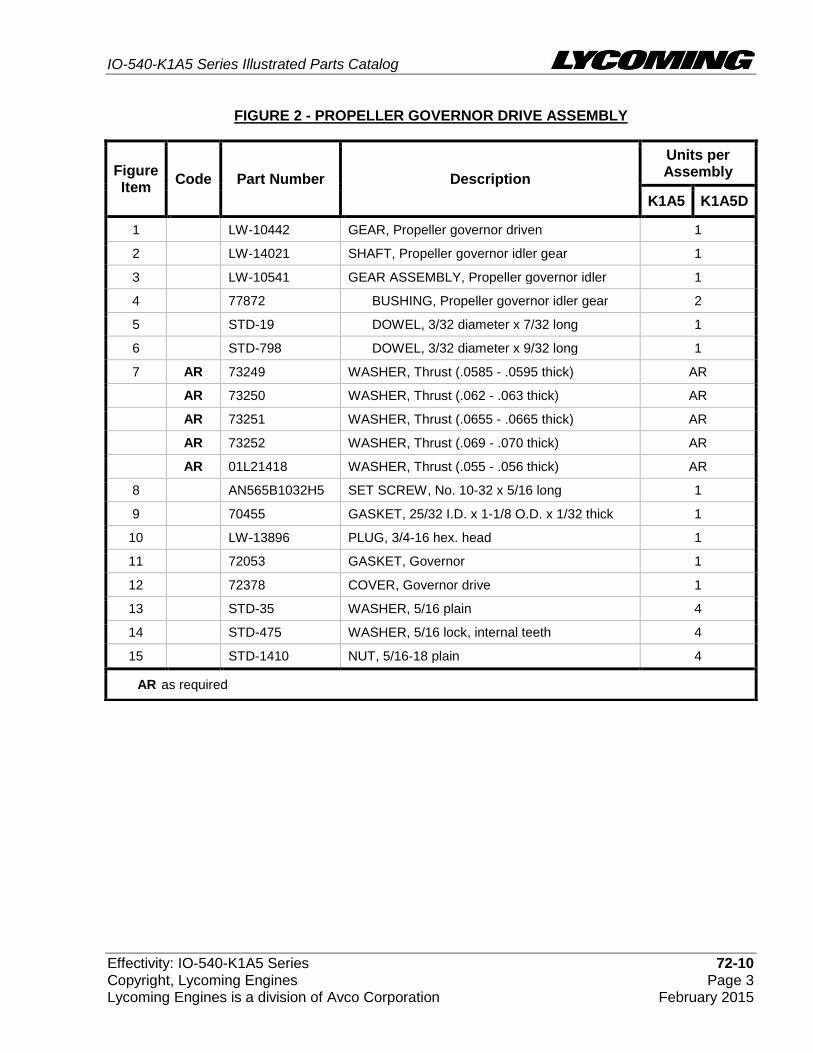
Propeller Governor Drive Assembly Figure 2
IO-540-K1A5 Series Illustrated Parts Catalog
Effectivity: IO-540-K1A5 Series 72-10 Copyright, Lycoming Engines Page 3 Lycoming Engines is a division of Avco Corporation February 2015
FIGURE 2 - PROPELLER GOVERNOR DRIVE ASSEMBLY
Figure Item
Code Part Number Description
Units per Assembly
K1A5 K1A5D
1 LW-10442 GEAR, Propeller governor driven 1
2 LW-14021 SHAFT, Propeller governor idler gear 1
3 LW-10541 GEAR ASSEMBLY, Propeller governor idler 1
4 77872 BUSHING, Propeller governor idler gear 2
5 STD-19 DOWEL, 3/32 diameter x 7/32 long 1
6 STD-798 DOWEL, 3/32 diameter x 9/32 long 1
7 AR 73249 WASHER, Thrust (.0585 - .0595 thick) AR
AR 73250 WASHER, Thrust (.062 - .063 thick) AR
AR 73251 WASHER, Thrust (.0655 - .0665 thick) AR
AR 73252 WASHER, Thrust (.069 - .070 thick) AR
AR 01L21418 WASHER, Thrust (.055 - .056 thick) AR
8 AN565B1032H5 SET SCREW, No. 10-32 x 5/16 long 1
9 70455 GASKET, 25/32 I.D. x 1-1/8 O.D. x 1/32 thick 1
10 LW-13896 PLUG, 3/4-16 hex. head 1
11 72053 GASKET, Governor 1
12 72378 COVER, Governor drive 1
13 STD-35 WASHER, 5/16 plain 4
14 STD-475 WASHER, 5/16 lock, internal teeth 4
15 STD-1410 NUT, 5/16-18 plain 4
AR as required
IO-540-K1A5 Series Illustrated Parts Catalog
72-20 Effectivity: IO-540-K1A5 Series Page 4 Copyright, Lycoming Engines February 2015 Lycoming Engines is a division of Avco Corporation
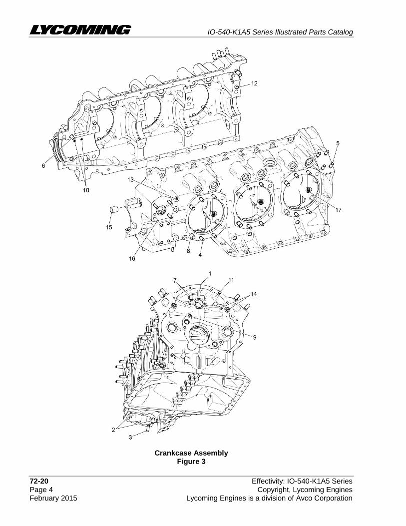
Crankcase Assembly Figure 3

IO-540-K1A5 Series Illustrated Parts Catalog
Effectivity: IO-540-K1A5 Series 72-20 Copyright, Lycoming Engines Page 5 Lycoming Engines is a division of Avco Corporation February 2015
FIGURE 3 - CRANKCASE ASSEMBLY
Figure Item
Code Part Number Description
Units per Assembly
K1A5 K1A5D
1 11F24020-S1-S KIT, CRANKCASE ASSEMBLY 1
P 11F24020-S1 CRANKCASE ASSEMBLY 1
11F24120-S1-S KIT, CRANKCASE ASSEMBLY-ROLLER LIFTER
1
P 11F24120-S1 CRANKCASE ASSEMBLY-ROLLER LIFTER 1
11F24120-D1-S KIT, CRANKCASE ASSEMBLY-ROLLER LIFTER
1
P 11F24120-D1 CRANKCASE ASSEMBLY-ROLLER LIFTER 1
2 31C-12 STUD, 5/16-18 x 1-1/2 long 2 2
3 31C-13 STUD, 5/16-18 x 1-5/8 long 1 1
4 38-13 STUD, 3/8-16 x 1-5/8 long 24 24
5 38-16 STUD, 3/8-16 x 2.00 long 8 8
6 38-22 STUD, 3/8-16 x 2-3/4 long 1 1
7 38D-17 STUD, 3/8-16 x 2-1/8 long, drilled 1 1
8 50-15 STUD, 1/2-13 x 1-7/8 long 12 12
9 01A23354 STUD, 5/16-18 x 1.00 long , drilled 1
10 69796 DOWEL, Crankshaft, front bearing 2 2
11 STD-514 DOWEL, 5/16 diameter x 1/2 long 2 2
12 STD-557 DOWEL, 1/2 diameter x 11/16 long 2 2
13 STD-1339 PLUG, 1/16-27 NPT, allen head 1 1
14 1102 PLUG, 1/8 pipe, allen head 4 4
15 72158 BUSHING, Governor drive idler shaft 1 1
16 31C-14 STUD, 5/16-18 x 1-3/4 long 4 4
31C-16 STUD, 5/16-18 x 2.00 long 4
17 73772 NOZZLE ASSEMBLY, Piston cooling 6 6
P Lycoming proprietary part. Listed for reference purposes only, cannot be purchased.
See latest revision of Service Instruction No. 1514 for shroud tube spring information.

IO-540-K1A5 Series Illustrated Parts Catalog
72-20 Effectivity: IO-540-K1A5 Series Page 6 Copyright, Lycoming Engines February 2015 Lycoming Engines is a division of Avco Corporation
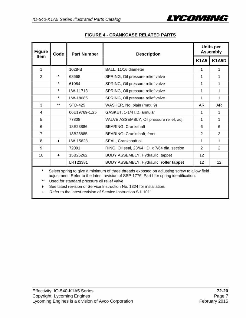
Crankcase Related Parts Figure 4
IO-540-K1A5 Series Illustrated Parts Catalog
Effectivity: IO-540-K1A5 Series 72-20 Copyright, Lycoming Engines Page 7 Lycoming Engines is a division of Avco Corporation February 2015
FIGURE 4 - CRANKCASE RELATED PARTS
Figure Item
Code Part Number Description
Units per Assembly
K1A5 K1A5D
1 1028-B BALL, 11/16 diameter 1 1
2 * 68668 SPRING, Oil pressure relief valve 1 1
* 61084 SPRING, Oil pressure relief valve 1 1
* LW-11713 SPRING, Oil pressure relief valve 1 1
* LW-18085 SPRING, Oil pressure relief valve 1 1
3 ** STD-425 WASHER, No. plain (max. 9) AR AR
4 06E19769-1.25 GASKET, 1-1/4 I.D. annular 1 1
5 77808 VALVE ASSEMBLY, Oil pressure relief, adj. 1 1
6 18E23886 BEARING, Crankshaft 6 6
7 18B23885 BEARING, Crankshaft, front 2 2
8 ♦ LW-15628 SEAL, Crankshaft oil 1 1
9 72091 RING, Oil seal, 23/64 I.D. x 7/64 dia. section 2 2
10 + 15B26262 BODY ASSEMBLY, Hydraulic tappet 12
LRT23381 BODY ASSEMBLY, Hydraulic roller tappet 12 12
* Select spring to give a minimum of three threads exposed on adjusting screw to allow field adjustment. Refer to the latest revision of SSP-1776, Part I for spring identification.
** Used for standard pressure oil relief valve
♦ See latest revision of Service Instruction No. 1324 for installation.
+ Refer to the latest revision of Service Instruction S.I. 1011
IO-540-K1A5 Series Illustrated Parts Catalog
72-20 Effectivity: IO-540-K1A5 Series Page 8 Copyright, Lycoming Engines February 2015 Lycoming Engines is a division of Avco Corporation
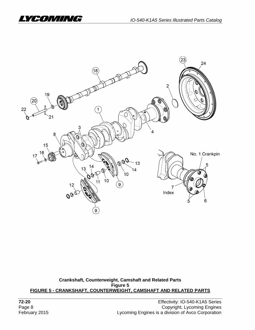
Crankshaft, Counterweight, Camshaft and Related Parts Figure 5
FIGURE 5 - CRANKSHAFT, COUNTERWEIGHT, CAMSHAFT AND RELATED PARTS
IO-540-K1A5 Series Illustrated Parts Catalog
Effectivity: IO-540-K1A5 Series 72-20 Copyright, Lycoming Engines Page 9 Lycoming Engines is a division of Avco Corporation February 2015
(continued on next page)
Figure Item
Code Part Number Description
Units per Assembly
K1A5 K1A5D
1 13F47727 CRANKSHAFT ASSEMBLY 1
13F47733 CRANKSHAFT ASSEMBLY 1
2 STD-1211 PLUG, 2.00 diameter expansion 1 1
3 73810 BUSHING, Crankshaft counterweight 4 4
4 60945 PLUG, 1-1/4 diameter 1 1
5 75656-S BUSHING, Propeller flange, long 4 4
6 72155-S BUSHING, Propeller flange, short 1 1
7 75657-S BUSHING, Propeller flange, indexing 1 1
8 STD-1065 DOWEL, Stepped, 5/16 & 1/4 dia. x 35/64 1 1
STD-2078 DOWEL, 3/8 dia. x 1/2 long 1 1
9 LW-19210 COUNTERWEIGHT ASSEMBLY 2 2
10 71903-A BUSHING, Dynamic counterweight 4 4
11 76788 ROLLER, Dynamic counterweight, 6.3 order 2 2
12 73648 ROLLER, Dynamic counterweight, 5.1 order 2 2
13 LW-14820 RING, Internal retaining 8 8
14 71907 WASHER, Dynamic counterweight 8 8
15 13S19647 GEAR, Crankshaft 1
13S19649 GEAR, Crankshaft 1
16 LW-18638 LOCKPLATE, Crankshaft gear 1
LW-10332 LOCKPLATE, Crankshaft gear 1
17 STD-2247 BOLT, 5/16-24 x 1.75 1
STD-2251 BOLT,1/2-20 UNF-3A x 1-19/32 hex head 1
18 15N23374 CAMSHAFT ASSEMBLY, roller lifter 1 1
LW-19340 CAMSHAFT ASSEMBLY 1
19 76118 SPACER, Tachometer shaft centering 1 1
20 76155 SHAFT ASSEMBLY, Tachometer 1 1
21 LW-18667 PIN, 3/16 diameter x 2-21/64 long 1 1
22 STD-2231 RING, Internal retaining 1 1

IO-540-K1A5 Series Illustrated Parts Catalog
72-20 Effectivity: IO-540-K1A5 Series Page 10 Copyright, Lycoming Engines February 2015 Lycoming Engines is a division of Avco Corporation
FIGURE 5 - CRANKSHAFT, COUNTERWEIGHT, CAMSHAFT AND RELATED PARTS CONTINUED
Figure Item
Code Part Number Description
Units per Assembly
K1A5 K1A5D
23 LW-16471 SUPPORT ASSEMBLY, Starter ring gear 1
72245 SUPPORT ASSEMBLY, Starter ring gear 1 1
24 72566 GEAR, Starter ring 1 1

IO-540-K1A5 Series Illustrated Parts Catalog
Effectivity: IO-540-K1A5 Series 72-20 Copyright, Lycoming Engines Page 11 Lycoming Engines is a division of Avco Corporation February 2015
This page intentionally left blank.
IO-540-K1A5 Series Illustrated Parts Catalog
72-20 Effectivity: IO-540-K1A5 Series Page 12 Copyright, Lycoming Engines February 2015 Lycoming Engines is a division of Avco Corporation
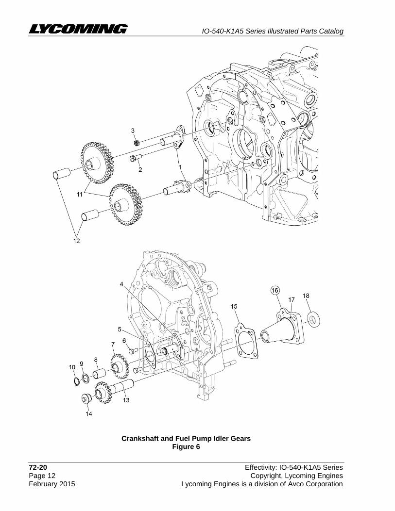
Crankshaft and Fuel Pump Idler Gears Figure 6

IO-540-K1A5 Series Illustrated Parts Catalog
Effectivity: IO-540-K1A5 Series 72-20 Copyright, Lycoming Engines Page 13 Lycoming Engines is a division of Avco Corporation February 2015
FIGURE 6 – CRANKSHAFT AND FUEL PUMP IDLER GEARS
Figure Item
Code Part Number Description
Units per Assembly
K1A5 K1A5D
1 LW-13795 SHAFT, Crankshaft idler gear 2
2 LW-31H0.88 BOLT, 5/16-18 x 7/8 long, hex head 3
3 STD-2168 NUT, 5/16-18 x NC-3, slotted shear 1
4 72246 SHAFT, Fuel pump idler gear 1
5 71667 LOCKPLATE 1/4 bolt x 1.75 spacing 1
6 LW-25-0.63 BOLT, 1/4-20 x 5/8 long, hex head 2
7 71664 GEAR ASSEMBLY, Fuel pump idler 1
LW-10324 GEAR ASSEMBLY, Fuel pump idler 1
8 77309 BUSHING, Crankshaft idler gear 1
9 70474 WASHER, Fuel pump thrust 1
10 STD-1737 RING, 9/16 diameter x 11/32 thk. ext. retaining 1
11 71668 GEAR ASSEMBLY, Crankshaft idler, plain 2
LW-10292 GEAR ASSEMBLY, Crankshaft idler, plain 2
LW-10297 GEAR ASSEMBLY, Crankshaft idler 2
12 67530 BUSHING, Crankshaft idler gear 2
13 72972 SHAFTGEAR ASSEMBLY, Fuel pump drive 1
LW-10329 SHAFTGEAR ASSEMBLY, Fuel pump 1
14 72962 THRUST BUTTON, gear drive 1
15 69164 GASKET, Fuel pump adapter 1 1
16 69159 ADAPTER ASSEMBLY, Fuel pump drive 1 1
17 STD-1774 PIN, 1/8 diameter x 1/4 long 1 1
18 STD-213 SEAL, Oil, 3/4 I.D. x 1-3/8 O.D. 1 1
IO-540-K1A5 Series Illustrated Parts Catalog
72-20 Effectivity: IO-540-K1A5 Series Page 14 Copyright, Lycoming Engines February 2015 Lycoming Engines is a division of Avco Corporation
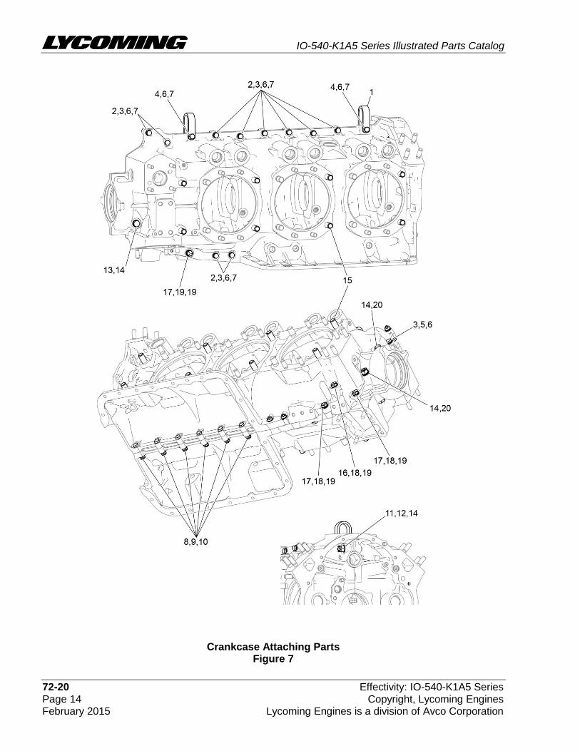
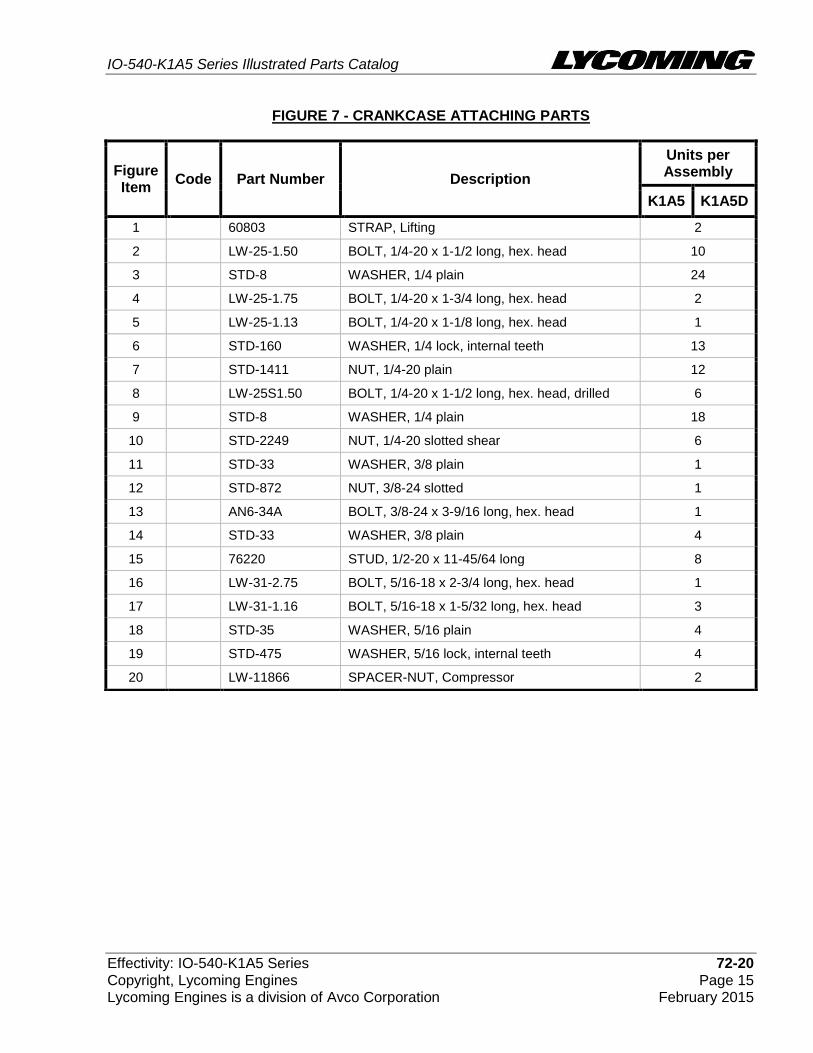
Crankcase Attaching Parts Figure 7
IO-540-K1A5 Series Illustrated Parts Catalog
Effectivity: IO-540-K1A5 Series 72-20 Copyright, Lycoming Engines Page 15 Lycoming Engines is a division of Avco Corporation February 2015
FIGURE 7 - CRANKCASE ATTACHING PARTS
Figure Item
Code Part Number Description
Units per Assembly
K1A5 K1A5D
1 60803 STRAP, Lifting 2
2 LW-25-1.50 BOLT, 1/4-20 x 1-1/2 long, hex. head 10
3 STD-8 WASHER, 1/4 plain 24
4 LW-25-1.75 BOLT, 1/4-20 x 1-3/4 long, hex. head 2
5 LW-25-1.13 BOLT, 1/4-20 x 1-1/8 long, hex. head 1
6 STD-160 WASHER, 1/4 lock, internal teeth 13
7 STD-1411 NUT, 1/4-20 plain 12
8 LW-25S1.50 BOLT, 1/4-20 x 1-1/2 long, hex. head, drilled 6
9 STD-8 WASHER, 1/4 plain 18
10 STD-2249 NUT, 1/4-20 slotted shear 6
11 STD-33 WASHER, 3/8 plain 1
12 STD-872 NUT, 3/8-24 slotted 1
13 AN6-34A BOLT, 3/8-24 x 3-9/16 long, hex. head 1
14 STD-33 WASHER, 3/8 plain 4
15 76220 STUD, 1/2-20 x 11-45/64 long 8
16 LW-31-2.75 BOLT, 5/16-18 x 2-3/4 long, hex. head 1
17 LW-31-1.16 BOLT, 5/16-18 x 1-5/32 long, hex. head 3
18 STD-35 WASHER, 5/16 plain 4
19 STD-475 WASHER, 5/16 lock, internal teeth 4
20 LW-11866 SPACER-NUT, Compressor 2
IO-540-K1A5 Series Illustrated Parts Catalog
72-30 Effectivity: IO-540-K1A5 Series Page 16 Copyright, Lycoming Engines February 2015 Lycoming Engines is a division of Avco Corporation
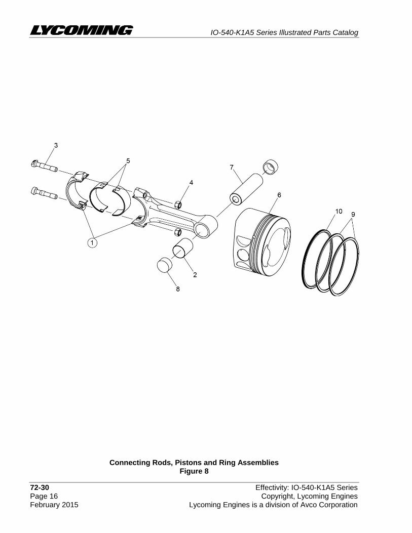
Connecting Rods, Pistons and Ring Assemblies Figure 8
IO-540-K1A5 Series Illustrated Parts Catalog
Effectivity: IO-540-K1A5 Series 72-30 Copyright, Lycoming Engines Page 17 Lycoming Engines is a division of Avco Corporation February 2015
FIGURE 8 - CONNECTING RODS, PISTONS AND RING ASSEMBLIES
Figure Item
Code Part Number Description
Units per Assembly
K1A5 K1A5D
1 LW-19332-S CONNECTING ROD ASSEMBLY 6
2 P LW-13923 BUSHING, Connecting rod, upper 6
3 P 14S23889 BOLT, Connecting rod 12
* LW-12596 BOLT, Connecting rod 12
4 LW-12186 NUT, Connecting rod bolt 12
5 18N26106 BEARING, Connecting rod 12
6 14D23908 PISTON, Compression ratio, 8.70:1 6
7 LW-14078 PIN, Piston 6
8 72198 PLUG, Piston pin 12
9 74241 RING, Piston compression 12
10 14H21950 RING, Piston, oil regulating, expander type 6
P Lycoming proprietary part. Listed for reference purposes only, cannot be purchased.
* Service use only.
IO-540-K1A5 Series Illustrated Parts Catalog
72-30 Effectivity: IO-540-K1A5 Series Page 18 Copyright, Lycoming Engines February 2015 Lycoming Engines is a division of Avco Corporation
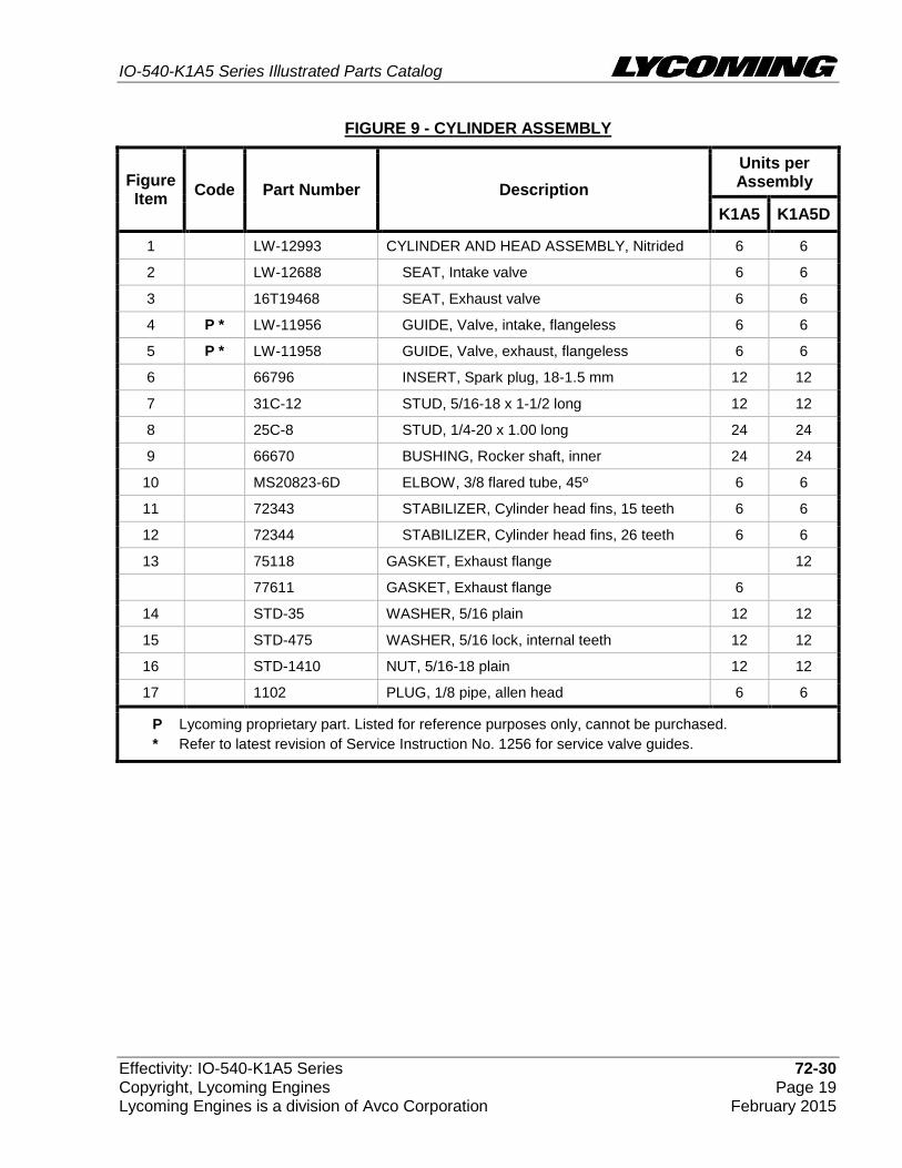
Cylinder Assembly Figure 9
IO-540-K1A5 Series Illustrated Parts Catalog
Effectivity: IO-540-K1A5 Series 72-30 Copyright, Lycoming Engines Page 19 Lycoming Engines is a division of Avco Corporation February 2015
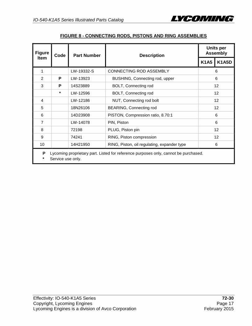
FIGURE 9 - CYLINDER ASSEMBLY
Figure Item
Code Part Number Description
Units per Assembly
K1A5 K1A5D
1 LW-12993 CYLINDER AND HEAD ASSEMBLY, Nitrided 6 6
2 LW-12688 SEAT, Intake valve 6 6
3 16T19468 SEAT, Exhaust valve 6 6
4 P * LW-11956 GUIDE, Valve, intake, flangeless 6 6
5 P * LW-11958 GUIDE, Valve, exhaust, flangeless 6 6
6 66796 INSERT, Spark plug, 18-1.5 mm 12 12
7 31C-12 STUD, 5/16-18 x 1-1/2 long 12 12
8 25C-8 STUD, 1/4-20 x 1.00 long 24 24
9 66670 BUSHING, Rocker shaft, inner 24 24
10 MS20823-6D ELBOW, 3/8 flared tube, 45º 6 6
11 72343 STABILIZER, Cylinder head fins, 15 teeth 6 6
12 72344 STABILIZER, Cylinder head fins, 26 teeth 6 6
13 75118 GASKET, Exhaust flange 12
77611 GASKET, Exhaust flange 6
14 STD-35 WASHER, 5/16 plain 12 12
15 STD-475 WASHER, 5/16 lock, internal teeth 12 12
16 STD-1410 NUT, 5/16-18 plain 12 12
17 1102 PLUG, 1/8 pipe, allen head 6 6
P Lycoming proprietary part. Listed for reference purposes only, cannot be purchased.
* Refer to latest revision of Service Instruction No. 1256 for service valve guides.

IO-540-K1A5 Series Illustrated Parts Catalog
72-30 Effectivity: IO-540-K1A5 Series Page 20 Copyright, Lycoming Engines February 2015 Lycoming Engines is a division of Avco Corporation
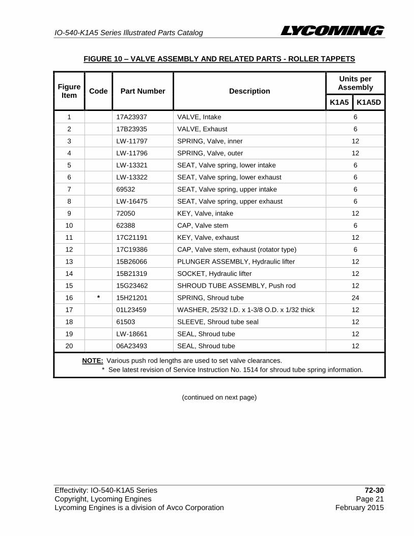
Valve Assembly and Related Parts – Roller Tappets Figure 10
IO-540-K1A5 Series Illustrated Parts Catalog
Effectivity: IO-540-K1A5 Series 72-30 Copyright, Lycoming Engines Page 21 Lycoming Engines is a division of Avco Corporation February 2015
FIGURE 10 – VALVE ASSEMBLY AND RELATED PARTS - ROLLER TAPPETS
(continued on next page)
Figure Item
Code Part Number Description
Units per Assembly
K1A5 K1A5D
1 17A23937 VALVE, Intake 6
2 17B23935 VALVE, Exhaust 6
3 LW-11797 SPRING, Valve, inner 12
4 LW-11796 SPRING, Valve, outer 12
5 LW-13321 SEAT, Valve spring, lower intake 6
6 LW-13322 SEAT, Valve spring, lower exhaust 6
7 69532 SEAT, Valve spring, upper intake 6
8 LW-16475 SEAT, Valve spring, upper exhaust 6
9 72050 KEY, Valve, intake 12
10 62388 CAP, Valve stem 6
11 17C21191 KEY, Valve, exhaust 12
12 17C19386 CAP, Valve stem, exhaust (rotator type) 6
13 15B26066 PLUNGER ASSEMBLY, Hydraulic lifter 12
14 15B21319 SOCKET, Hydraulic lifter 12
15 15G23462 SHROUD TUBE ASSEMBLY, Push rod 12
16 * 15H21201 SPRING, Shroud tube 24
17 01L23459 WASHER, 25/32 I.D. x 1-3/8 O.D. x 1/32 thick 12
18 61503 SLEEVE, Shroud tube seal 12
19 LW-18661 SEAL, Shroud tube 12
20 06A23493 SEAL, Shroud tube 12
NOTE: Various push rod lengths are used to set valve clearances.
* See latest revision of Service Instruction No. 1514 for shroud tube spring information.

IO-540-K1A5 Series Illustrated Parts Catalog
72-30 Effectivity: IO-540-K1A5 Series Page 22 Copyright, Lycoming Engines February 2015 Lycoming Engines is a division of Avco Corporation
FIGURE 10 - VALVE ASSEMBLY AND RELATED PARTS- ROLLER TAPPETS (CONT.)
Figure Item
Code Part Number Description
Units per Assembly
K1A5 K1A5D
21 AR * 15F19957-52 ROD ASSEMBLY, Push (A total of 12 required) AR
AR * 15F19957-53 ROD ASSEMBLY, Push (A total of 12 required) AR
AR * 15F19957-54 ROD ASSEMBLY, Push (A total of 12 required) AR
AR * 15F19957-55 ROD ASSEMBLY, Push (A total of 12 required) AR
AR * 15F19957-56 ROD ASSEMBLY, Push (A total of 12 required) AR
AR * 15F19957-57 ROD ASSEMBLY, Push (A total of 12 required) AR
AR * 15F19957-58 ROD ASSEMBLY, Push (A total of 12 required) AR
AR * 15F21362-18 ROD ASSEMBLY, Push (A total of 12 required) AR
AR * 15F21362-19 ROD ASSEMBLY, Push (A total of 12 required) AR
AR * 15F21362-20 ROD ASSEMBLY, Push (A total of 12 required) AR
AR * 15F21362-21 ROD ASSEMBLY, Push (A total of 12 required) AR
AR * 15F21362-22 ROD ASSEMBLY, Push (A total of 12 required) AR
AR * 15F21362-23 ROD ASSEMBLY, Push (A total of 12 required) AR
AR * 15F21362-24 ROD ASSEMBLY, Push (A total of 12 required) AR
22 ** 17F21186 ROCKER ASSEMBLY, Valve, intake 6
23 ** 17F21185 ROCKER ASSEMBLY, Valve, exhaust 6
24 71549 WASHER, Valve rocker 12
25 72626 SHAFT, Valve rocker 12
AR as required
* Various push rod lengths are used to set valve clearances. Refer to the latest revision of Service Instruction No. 1060 for complete push rod application.
** Due to the size of the area where the number is stamped, the last five digits may be all that is shown (21185 or 21186).

IO-540-K1A5 Series Illustrated Parts Catalog
Effectivity: IO-540-K1A5 Series 72-30 Copyright, Lycoming Engines Page 23 Lycoming Engines is a division of Avco Corporation February 2015
This page intentionally left blank.

IO-540-K1A5 Series Illustrated Parts Catalog
72-30 Effectivity: IO-540-K1A5 Series Page 24 Copyright, Lycoming Engines February 2015 Lycoming Engines is a division of Avco Corporation
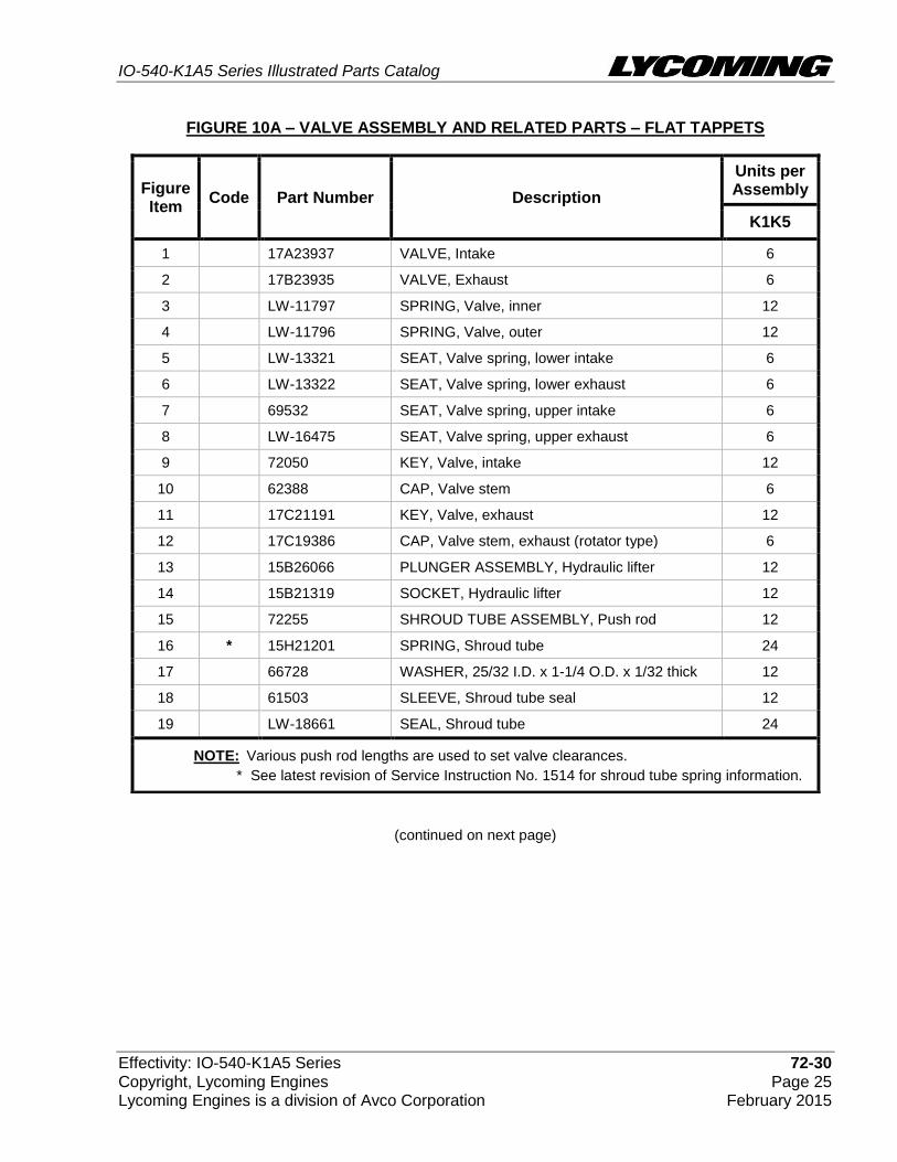
Valve Assembly and Related Parts- Flat Tappets Figure 10A
IO-540-K1A5 Series Illustrated Parts Catalog
Effectivity: IO-540-K1A5 Series 72-30 Copyright, Lycoming Engines Page 25 Lycoming Engines is a division of Avco Corporation February 2015
FIGURE 10A – VALVE ASSEMBLY AND RELATED PARTS – FLAT TAPPETS
(continued on next page)
Figure Item
Code Part Number Description
Units per Assembly
K1K5
1 17A23937 VALVE, Intake 6
2 17B23935 VALVE, Exhaust 6
3 LW-11797 SPRING, Valve, inner 12
4 LW-11796 SPRING, Valve, outer 12
5 LW-13321 SEAT, Valve spring, lower intake 6
6 LW-13322 SEAT, Valve spring, lower exhaust 6
7 69532 SEAT, Valve spring, upper intake 6
8 LW-16475 SEAT, Valve spring, upper exhaust 6
9 72050 KEY, Valve, intake 12
10 62388 CAP, Valve stem 6
11 17C21191 KEY, Valve, exhaust 12
12 17C19386 CAP, Valve stem, exhaust (rotator type) 6
13 15B26066 PLUNGER ASSEMBLY, Hydraulic lifter 12
14 15B21319 SOCKET, Hydraulic lifter 12
15 72255 SHROUD TUBE ASSEMBLY, Push rod 12
16 * 15H21201 SPRING, Shroud tube 24
17 66728 WASHER, 25/32 I.D. x 1-1/4 O.D. x 1/32 thick 12
18 61503 SLEEVE, Shroud tube seal 12
19 LW-18661 SEAL, Shroud tube 24
NOTE: Various push rod lengths are used to set valve clearances.
* See latest revision of Service Instruction No. 1514 for shroud tube spring information.
IO-540-K1A5 Series Illustrated Parts Catalog
72-30 Effectivity: IO-540-K1A5 Series Page 26 Copyright, Lycoming Engines February 2015 Lycoming Engines is a division of Avco Corporation
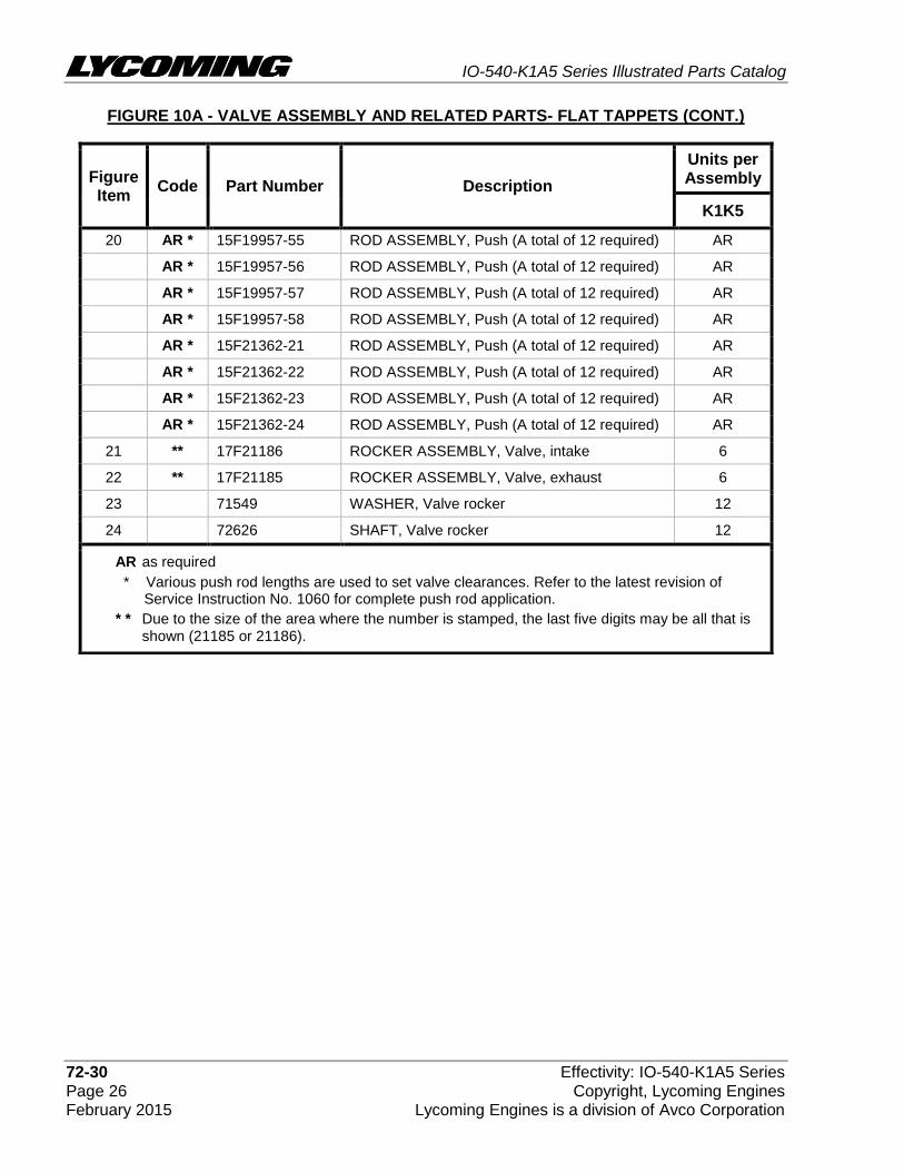
FIGURE 10A - VALVE ASSEMBLY AND RELATED PARTS- FLAT TAPPETS (CONT.)
Figure Item
Code Part Number Description
Units per Assembly
K1K5
20 AR * 15F19957-55 ROD ASSEMBLY, Push (A total of 12 required) AR
AR * 15F19957-56 ROD ASSEMBLY, Push (A total of 12 required) AR
AR * 15F19957-57 ROD ASSEMBLY, Push (A total of 12 required) AR
AR * 15F19957-58 ROD ASSEMBLY, Push (A total of 12 required) AR
AR * 15F21362-21 ROD ASSEMBLY, Push (A total of 12 required) AR
AR * 15F21362-22 ROD ASSEMBLY, Push (A total of 12 required) AR
AR * 15F21362-23 ROD ASSEMBLY, Push (A total of 12 required) AR
AR * 15F21362-24 ROD ASSEMBLY, Push (A total of 12 required) AR
21 ** 17F21186 ROCKER ASSEMBLY, Valve, intake 6
22 ** 17F21185 ROCKER ASSEMBLY, Valve, exhaust 6
23 71549 WASHER, Valve rocker 12
24 72626 SHAFT, Valve rocker 12
AR as required
* Various push rod lengths are used to set valve clearances. Refer to the latest revision of Service Instruction No. 1060 for complete push rod application.
* * Due to the size of the area where the number is stamped, the last five digits may be all that is shown (21185 or 21186).
IO-540-K1A5 Series Illustrated Parts Catalog
Effectivity: IO-540-K1A5 Series 72-30 Copyright, Lycoming Engines Page 27 Lycoming Engines is a division of Avco Corporation February 2015
This page intentionally left blank.
IO-540-K1A5 Series Illustrated Parts Catalog
72-30 Effectivity: IO-540-K1A5 Series Page 28 Copyright, Lycoming Engines February 2015 Lycoming Engines is a division of Avco Corporation
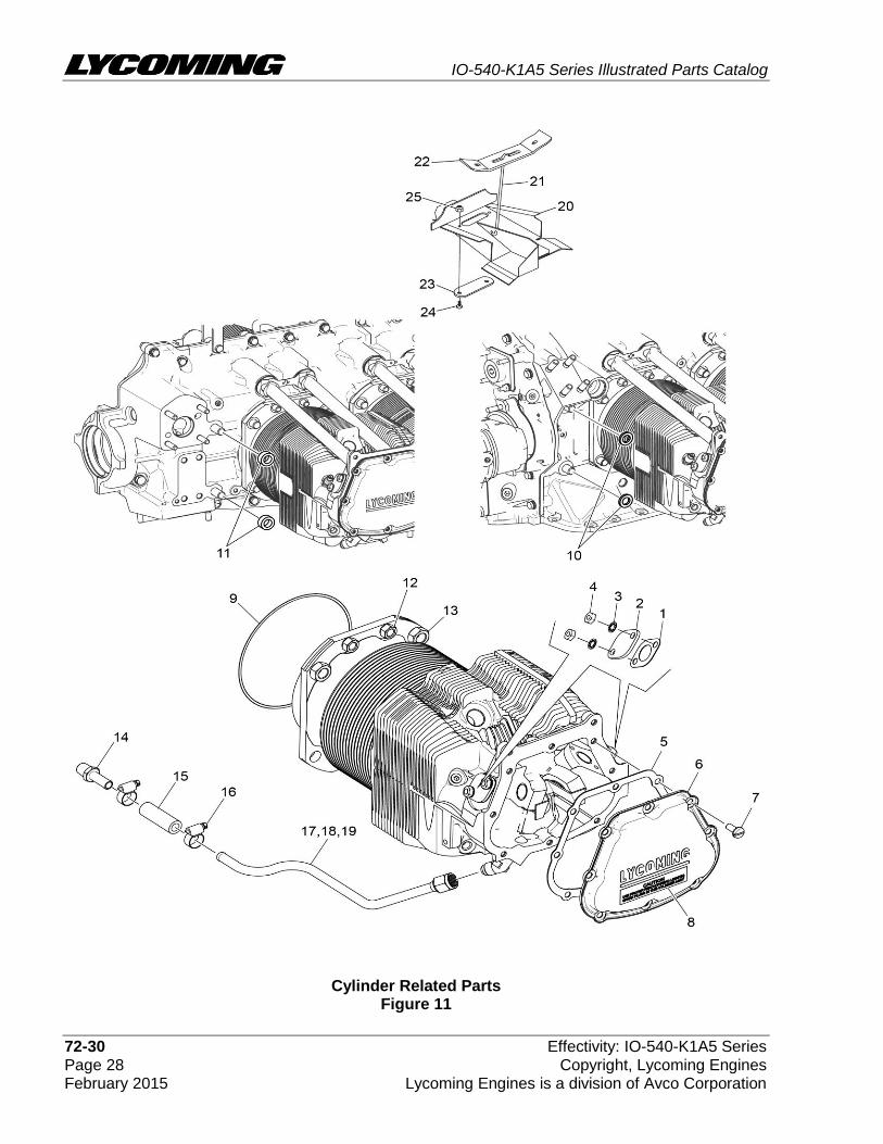
Cylinder Related Parts Figure 11

IO-540-K1A5 Series Illustrated Parts Catalog
Effectivity: IO-540-K1A5 Series 72-30 Copyright, Lycoming Engines Page 29 Lycoming Engines is a division of Avco Corporation February 2015
FIGURE 11 – CYLINDER RELATED PARTS
Figure Item
Code Part Number Description
Units per Assembly
K1A5 K1A5D
1 66732 GASKET, Valve rocker shaft cover 12
2 72710 COVER, Valve rocker shaft 12
3 STD-160 WASHER, 1/4 lock, internal teeth 24
4 STD-1411 NUT, 1/4-20 plain 24
5 67193 GASKET, Rocker box cover 6
6 68795 COVER ASSEMBLY, Rocker box 6
7 STD-1925 SCREW, 1/4-20 x 5/8 long, pan. head, self-locking
48
8 74494 PLATE, Spark plug reach caution 6
9 71481 RING, Oil seal, 3/32 diameter x 4-27/32 I.D. 6
10 77906 SPACER, 33/64 I.D. x 7/8 O.D. x 1/8 thick 2
11 74887 SPACER, 33/64 I.D. x 7/8 O.D. x 3/8 thick 2
12 383-B NUT, 3/8-24 plain 24
13 STD-2090 NUT, 1/2-20 plain 28
14 STD-684 NIPPLE, Straight, 3/8 I.D. hose 6
15 STD-2180 HOSE, 3/8 I.D. x 1-7/8 long 6
16 LW-15592-5-05 CLAMP, Hose 12
17 72702 TUBE ASSEMBLY,Cyl. head oil drain, cyl. no.1 1
18 72703 TUBE ASSEMBLY,Cyl. head oil drain, cyl. no. 2 1
19 73027 TUBE ASSEMBLY,Cyl. head oil drain, cyl. no. 3,4,5,6
4
20 75338 BAFFLE ASSEMBLY, Intercylinder 4
21 71610 HOOK, Intercylinder baffle retainer 4
22 71611 RETAINER, Intercylinder baffle 4
23 72834 COVER, Baffle, ignition cable hole 4
24 STD-692 SCREW, No. 10-32 x 1/2 long, round head 8
25 STD-670 LOCKNUT, No. 10-32 8
IO-540-K1A5 Series Illustrated Parts Catalog
72-50 Effectivity: IO-540-K1A5 Series Page 30 Copyright, Lycoming Engines February 2015 Lycoming Engines is a division of Avco Corporation
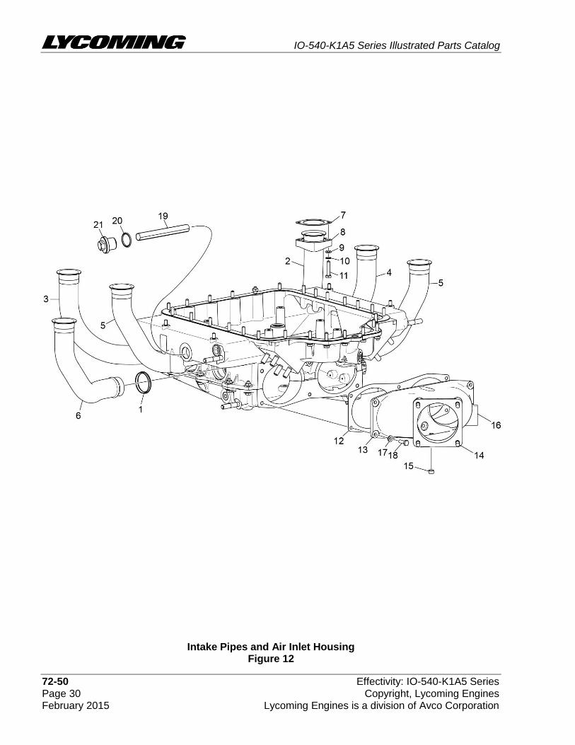
Intake Pipes and Air Inlet Housing Figure 12

IO-540-K1A5 Series Illustrated Parts Catalog
Effectivity: IO-540-K1A5 Series 72-50 Copyright, Lycoming Engines Page 31 Lycoming Engines is a division of Avco Corporation February 2015
FIGURE 12 – INTAKE PIPES AND AIR INLET HOUSING
Figure Item
Code Part Number Description
Units per Assembly
K1A5 K1A5D
1 72711 RING, Seal, intake pipes 6
2 LW-12191 PIPE, Intake, cylinder no. 1 1
3 LW-12192 PIPE, Intake, cylinder no. 2 1
4 LW-12193 PIPE, Intake, cylinder no. 3 1
5 LW-12194 PIPE, Intake, cylinders no. 4 and 5 2
6 LW-12195 PIPE, Intake, cylinder no. 6 1
7 71973 GASKET, 2 bolt flange, 1-13/16 I.D. 6
8 74360 FLANGE, Intake pipe, upper 6
9 STD-8 WASHER, 1/4 plain 12
10 STD-160 WASHER, 1/4 lock, internal teeth 12
11 LW-25-1.25 BOLT, 1/4-20 x 1-1/4 long, hex. head 12
12 72210 GASKET, Air throttle housing 1
13 * LW-16956 HOUSING ASSEMBLY, Air inlet 1
14 31C-14 STUD, 5/18 x 1.75 long 4
15 1102 PLUG, 1/8-27 NPT, allen head 1
16 STD-1353 INSERT, #10-24 UNC x 3/8 long 3
17 STD-8 WASHER, 1/4 plain 6
18 LW-25-0.81 BOLT, 1/4-20 x 13/16 long, hex. head 6
19 60422 SCREEN, Oil suction 1
20 06E19769-1.00 GASKET, Annular, 1.00 I.D. 1
21 LW-12545 PLUG, 5/8 hex head x 1.00-20 thread 1
* Assemble with pipe tap on right side of engine.
IO-540-K1A5 Series Illustrated Parts Catalog
72-50 Effectivity: IO-540-K1A5 Series Page 32 Copyright, Lycoming Engines February 2015 Lycoming Engines is a division of Avco Corporation
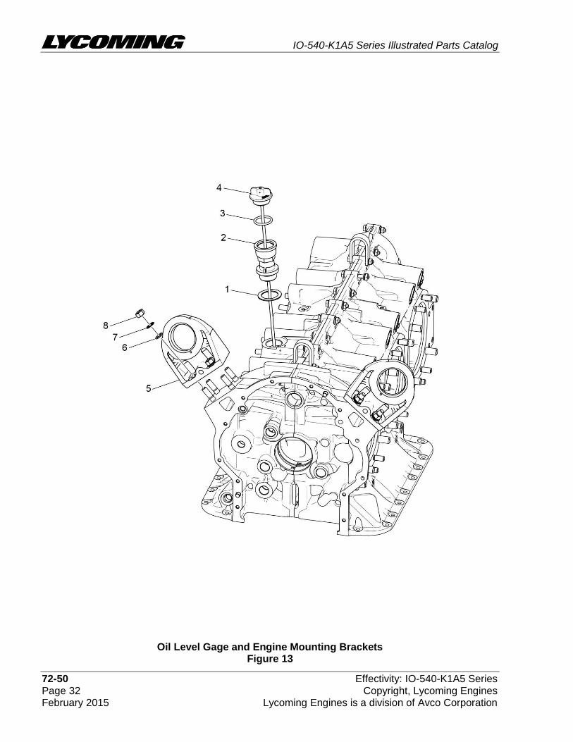
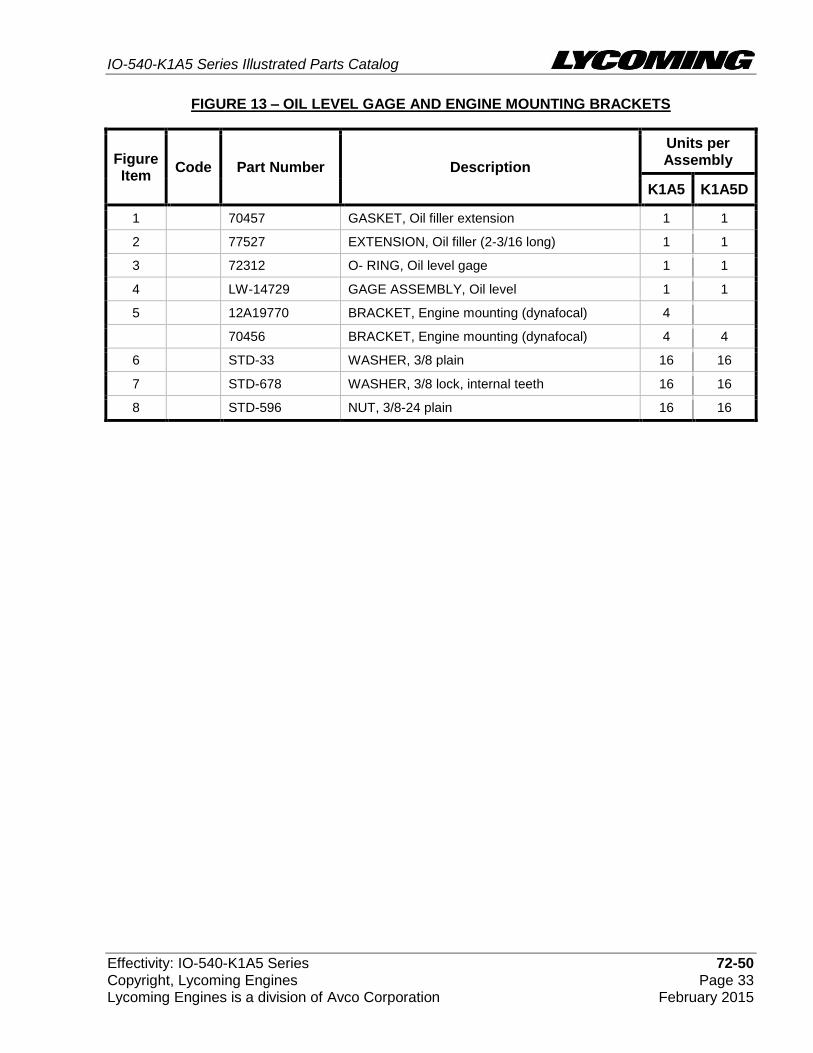
Oil Level Gage and Engine Mounting Brackets Figure 13
IO-540-K1A5 Series Illustrated Parts Catalog
Effectivity: IO-540-K1A5 Series 72-50 Copyright, Lycoming Engines Page 33 Lycoming Engines is a division of Avco Corporation February 2015
FIGURE 13 – OIL LEVEL GAGE AND ENGINE MOUNTING BRACKETS
Figure Item
Code Part Number Description
Units per Assembly
K1A5 K1A5D
1 70457 GASKET, Oil filler extension 1 1
2 77527 EXTENSION, Oil filler (2-3/16 long) 1 1
3 72312 O- RING, Oil level gage 1 1
4 LW-14729 GAGE ASSEMBLY, Oil level 1 1
5 12A19770 BRACKET, Engine mounting (dynafocal) 4
70456 BRACKET, Engine mounting (dynafocal) 4 4
6 STD-33 WASHER, 3/8 plain 16 16
7 STD-678 WASHER, 3/8 lock, internal teeth 16 16
8 STD-596 NUT, 3/8-24 plain 16 16

IO-540-K1A5 Series Illustrated Parts Catalog
72-50 Effectivity: IO-540-K1A5 Series Page 34 Copyright, Lycoming Engines February 2015 Lycoming Engines is a division of Avco Corporation
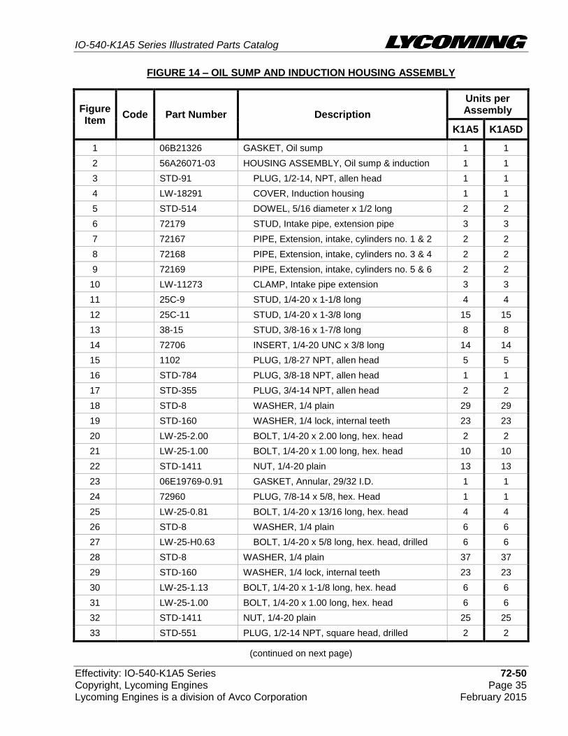
Oil Sump and Induction Housing Assembly Figure 14
IO-540-K1A5 Series Illustrated Parts Catalog
Effectivity: IO-540-K1A5 Series 72-50 Copyright, Lycoming Engines Page 35 Lycoming Engines is a division of Avco Corporation February 2015
FIGURE 14 – OIL SUMP AND INDUCTION HOUSING ASSEMBLY
(continued on next page)
Figure Item
Code Part Number Description
Units per Assembly
K1A5 K1A5D
1 06B21326 GASKET, Oil sump 1 1
2 56A26071-03 HOUSING ASSEMBLY, Oil sump & induction 1 1
3 STD-91 PLUG, 1/2-14, NPT, allen head 1 1
4 LW-18291 COVER, Induction housing 1 1
5 STD-514 DOWEL, 5/16 diameter x 1/2 long 2 2
6 72179 STUD, Intake pipe, extension pipe 3 3
7 72167 PIPE, Extension, intake, cylinders no. 1 & 2 2 2
8 72168 PIPE, Extension, intake, cylinders no. 3 & 4 2 2
9 72169 PIPE, Extension, intake, cylinders no. 5 & 6 2 2
10 LW-11273 CLAMP, Intake pipe extension 3 3
11 25C-9 STUD, 1/4-20 x 1-1/8 long 4 4
12 25C-11 STUD, 1/4-20 x 1-3/8 long 15 15
13 38-15 STUD, 3/8-16 x 1-7/8 long 8 8
14 72706 INSERT, 1/4-20 UNC x 3/8 long 14 14
15 1102 PLUG, 1/8-27 NPT, allen head 5 5
16 STD-784 PLUG, 3/8-18 NPT, allen head 1 1
17 STD-355 PLUG, 3/4-14 NPT, allen head 2 2
18 STD-8 WASHER, 1/4 plain 29 29
19 STD-160 WASHER, 1/4 lock, internal teeth 23 23
20 LW-25-2.00 BOLT, 1/4-20 x 2.00 long, hex. head 2 2
21 LW-25-1.00 BOLT, 1/4-20 x 1.00 long, hex. head 10 10
22 STD-1411 NUT, 1/4-20 plain 13 13
23 06E19769-0.91 GASKET, Annular, 29/32 I.D. 1 1
24 72960 PLUG, 7/8-14 x 5/8, hex. Head 1 1
25 LW-25-0.81 BOLT, 1/4-20 x 13/16 long, hex. head 4 4
26 STD-8 WASHER, 1/4 plain 6 6
27 LW-25-H0.63 BOLT, 1/4-20 x 5/8 long, hex. head, drilled 6 6
28 STD-8 WASHER, 1/4 plain 37 37
29 STD-160 WASHER, 1/4 lock, internal teeth 23 23
30 LW-25-1.13 BOLT, 1/4-20 x 1-1/8 long, hex. head 6 6
31 LW-25-1.00 BOLT, 1/4-20 x 1.00 long, hex. head 6 6
32 STD-1411 NUT, 1/4-20 plain 25 25
33 STD-551 PLUG, 1/2-14 NPT, square head, drilled 2 2
IO-540-K1A5 Series Illustrated Parts Catalog
72-50 Effectivity: IO-540-K1A5 Series Page 36 Copyright, Lycoming Engines February 2015 Lycoming Engines is a division of Avco Corporation
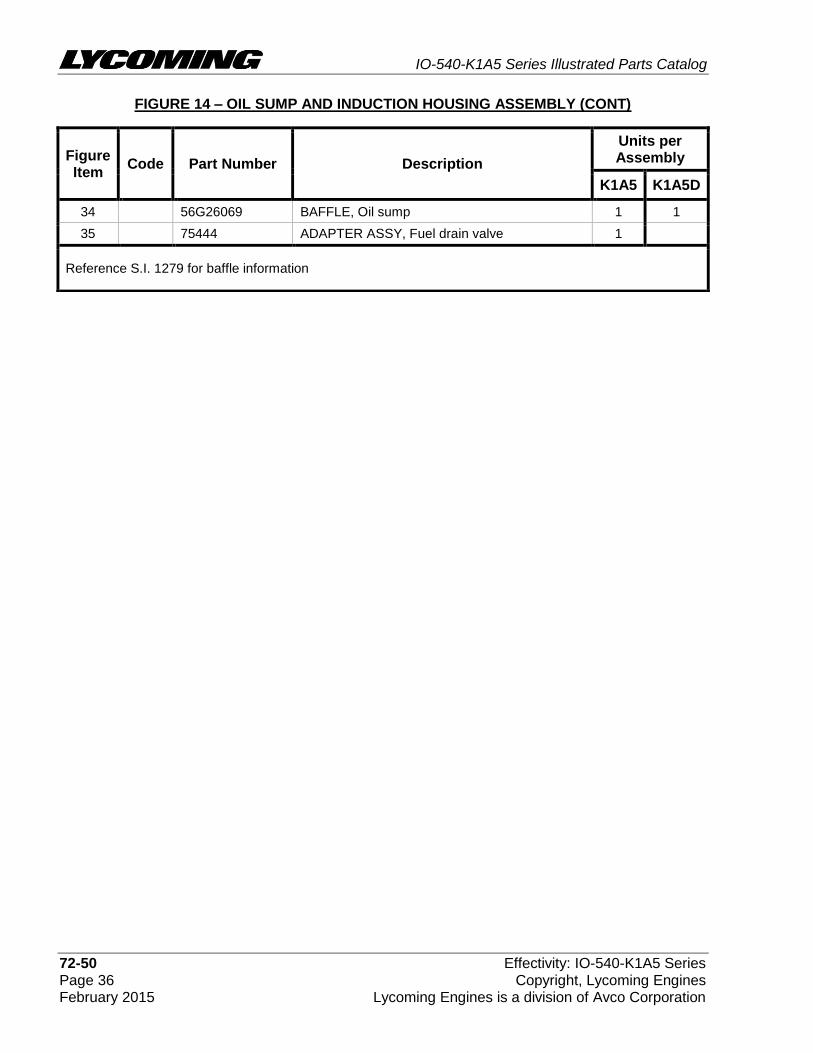
FIGURE 14 – OIL SUMP AND INDUCTION HOUSING ASSEMBLY (CONT)
Figure Item
Code Part Number Description
Units per Assembly
K1A5 K1A5D
34 56G26069 BAFFLE, Oil sump 1 1
35 75444 ADAPTER ASSY, Fuel drain valve 1
Reference S.I. 1279 for baffle information
IO-540-K1A5 Series Illustrated Parts Catalog
Effectivity: IO-540-K1A5 Series 72-50 Copyright, Lycoming Engines Page 37 Lycoming Engines is a division of Avco Corporation February 2015
This page intentionally left blank.
IO-540-K1A5 Series Illustrated Parts Catalog
72-60 Effectivity: IO-540-K1A5 Series Page 38 Copyright, Lycoming Engines February 2015 Lycoming Engines is a division of Avco Corporation
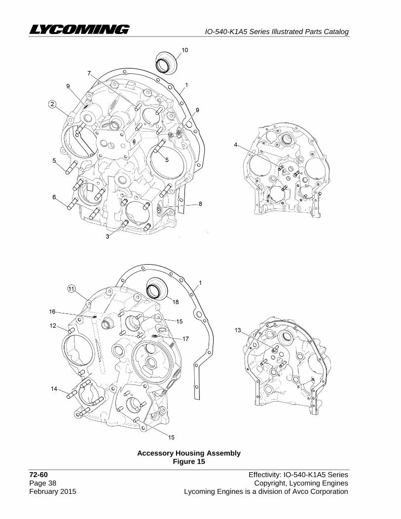
Accessory Housing Assembly Figure 15
IO-540-K1A5 Series Illustrated Parts Catalog
Effectivity: IO-540-K1A5 Series 72-60 Copyright, Lycoming Engines Page 39 Lycoming Engines is a division of Avco Corporation February 2015
FIGURE 15 – ACCESSORY HOUSING ASSEMBLY
Figure Item
Code Part Number Description
Units per Assembly
K1A5 K1A5D
1 73818 GASKET, Accessory housing 1 1
2 21C21541-02 HOUSING ASSEMBLY, Accessory 1
3 31C-12 STUD, 5/16-18 x 1-1/2 long 4
4 31CD-17 STUD, 5/16-18 x 2-1/8 long, drilled 3
5 31C-21 STUD, 5/16-18 x 2-5/8 long 4
6 31C-19 STUD, 5/16-18 x 2-3/8 long 4
7 25C-21 STUD, 1/4-20 x 2-5/8 long 4
8 STD-784 PLUG, 3/8-18 NPT, allen head 1
9 1102 PLUG, 1/8-27 NPT, allen head 4
10 76156 SHIELD, Oil accessory 1
11 21D21608-01 HOUSING ASSEMBLY, Accessory 1
12 31C-13 STUD, 5/16-18 x 1-5/8 long 2
13 31CD-20 STUD, 5/16-18 x 2-1/2 long, drilled 3
14 31C-19 STUD, 5/16-18 x 2-3/8 long 4
15 25C-12 STUD, 1/4-20 x 1-1/2 long 8
16 STD-1339 PLUG, 1/16-27 NPT, allen head 1
17 1102 PLUG, 1/8-27 NPT, allen head 1
18 76156 SHIELD, Oil accessory 1

IO-540-K1A5 Series Illustrated Parts Catalog
72-60 Effectivity: IO-540-K1A5 Series Page 40 Copyright, Lycoming Engines February 2015 Lycoming Engines is a division of Avco Corporation
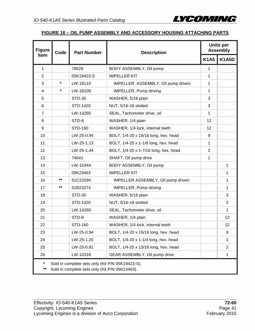
Oil Pump Assembly and Accessory Housing Attaching Parts Figure 16
IO-540-K1A5 Series Illustrated Parts Catalog
Effectivity: IO-540-K1A5 Series 72-60 Copyright, Lycoming Engines Page 41 Lycoming Engines is a division of Avco Corporation February 2015
FIGURE 16 – OIL PUMP ASSEMBLY AND ACCESSORY HOUSING ATTACHING PARTS
Figure Item
Code Part Number Description
Units per Assembly
K1A5 K1A5D
1 78528 BODY ASSEMBLY, Oil pump 1
2 05K19423-S IMPELLER KIT 1
3 * LW-18110 IMPELLER ASSEMBLY, Oil pump driven 1
4 * LW-18109 IMPELLER, Pump driving 1
5 STD-35 WASHER, 5/16 plain 3
6 STD-1420 NUT, 5/16-18 slotted 3
7 LW-14260 SEAL, Tachometer drive, oil 1
8 STD-8 WASHER, 1/4 plain 12
9 STD-160 WASHER, 1/4 lock, internal teeth 12
10 LW-25-0.94 BOLT, 1/4-20 x 15/16 long, hex. head 9
11 LW-25-1.13 BOLT, 1/4-20 x 1-1/8 long, hex. head 1
12 LW-25-1.44 BOLT, 1/4-20 x 1-7/16 long, hex. head 2
13 74641 SHAFT, Oil pump drive 1
14 LW-10344 BODY ASSEMBLY, Oil pump 1
15 05K23463 IMPELLER KIT 1
16 ** 51C23290 IMPELLER ASSEMBLY, Oil pump driven 1
17 ** 51B23274 IMPELLER, Pump driving 1
18 STD-35 WASHER, 5/16 plain 3
19 STD-1420 NUT, 5/16-18 slotted 3
20 LW-14260 SEAL, Tachometer drive, oil 1
21 STD-8 WASHER, 1/4 plain 12
22 STD-160 WASHER, 1/4 lock, internal teeth 12
23 LW-25-0.94 BOLT, 1/4-20 x 15/16 long, hex. head 9
24 LW-25-1.25 BOLT, 1/4-20 x 1-1/4 long, hex. head 1
25 LW-25-0.81 BOLT, 1/4-20 x 13/16 long, hex. head 2
26 LW-10318 GEAR ASSEMBLY, Oil pump drive 1
* Sold in complete sets only (Kit P/N 05K19423-S).
** Sold in complete sets only (Kit P/N 05K23463).

IO-540-K1A5 Series Illustrated Parts Catalog
72-60 Effectivity: IO-540-K1A5 Series Page 42 Copyright, Lycoming Engines February 2015 Lycoming Engines is a division of Avco Corporation
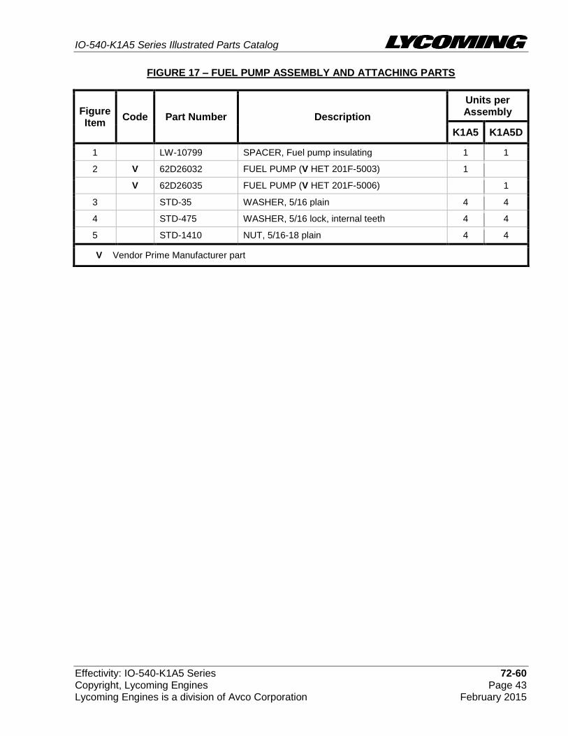
Fuel Pump Assembly and Attaching Parts Figure 17
IO-540-K1A5 Series Illustrated Parts Catalog
Effectivity: IO-540-K1A5 Series 72-60 Copyright, Lycoming Engines Page 43 Lycoming Engines is a division of Avco Corporation February 2015
FIGURE 17 – FUEL PUMP ASSEMBLY AND ATTACHING PARTS
Figure Item
Code Part Number Description
Units per Assembly
K1A5 K1A5D
1 LW-10799 SPACER, Fuel pump insulating 1 1
2 V 62D26032 FUEL PUMP (V HET 201F-5003) 1
V 62D26035 FUEL PUMP (V HET 201F-5006) 1
3 STD-35 WASHER, 5/16 plain 4 4
4 STD-475 WASHER, 5/16 lock, internal teeth 4 4
5 STD-1410 NUT, 5/16-18 plain 4 4
V Vendor Prime Manufacturer part
IO-540-K1A5 Series Illustrated Parts Catalog
72-60 Effectivity: IO-540-K1A5 Series Page 44 Copyright, Lycoming Engines February 2015 Lycoming Engines is a division of Avco Corporation
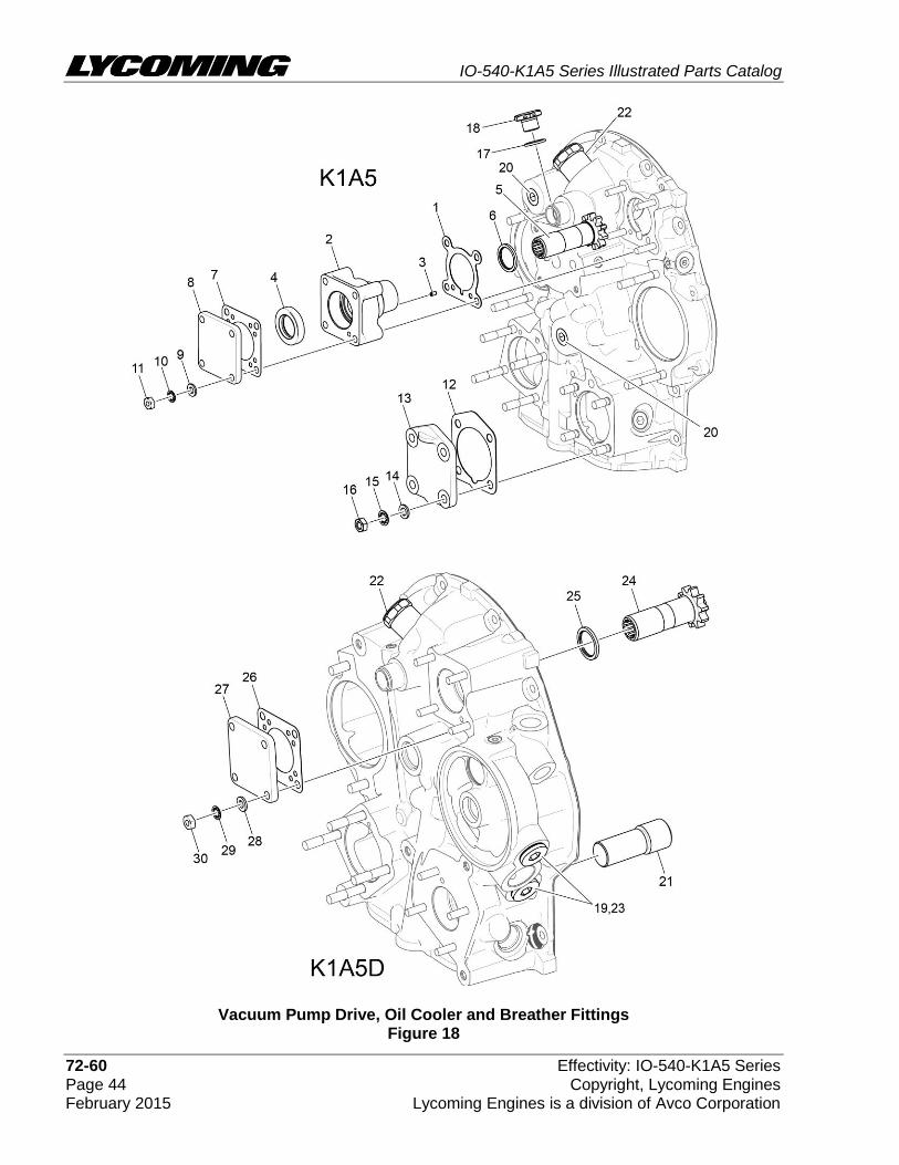
Vacuum Pump Drive, Oil Cooler and Breather Fittings Figure 18
IO-540-K1A5 Series Illustrated Parts Catalog
Effectivity: IO-540-K1A5 Series 72-60 Copyright, Lycoming Engines Page 45 Lycoming Engines is a division of Avco Corporation February 2015
FIGURE 18 – VACUUM PUMP DRIVE, OIL COOLER AND BREATHER FITTINGS
Figure Item
Code Part Number Description
Units per Assembly
K1A5 K1A5
D
1 61183 GASKET, Accessory adapter 1
2 67536 ADAPTER ASSEMBLY, Vacuum pump 1
3 STD-1774 PIN, 1/8 diameter x 1/4 long 1
4 06A19956 SEAL, Oil, 7/8 I.D. x 1-1/2 O.D. x 5/16 wide 1 1
5 72974 GEAR ASSEMBLY, Vacuum pump driven 1
6 71596 WASHER, Accessory drive gear 1
7 8313 GASKET, Vacuum pump 1 1
8 60430 COVER, Vacuum pump 1 1
9 STD-8 WASHER, 1/4 plain 4 4
10 STD-160 WASHER, 1/4 lock, internal teeth 4 4
11 STD-1411 NUT, 1/4-20 plain 4 4
12 69551 GASKET, Accessory drive adapter 1
13 69106 COVER, Governor drive adapter pad 1
14 STD-35 WASHER, 5/16 plain 4
15 STD-475 WASHER, 5/16 lock, internal teeth 4
16 STD-1410 NUT, 5/16-18 plain 4
17 06E19769-0.63 GASKET, Annular, 5/8 I.D. 1
18 62417 PLUG, Oil cooler by-pass 1
19 03C21720 PLUG, 7/8-14 thread 2
20 STD-784 PLUG, 3/8-18 NPT allen head 2
21 LW-10303 PLUG, Vacuum pump drive 1
22 72996 FITTING, Breather 1 1
23 MS29512-10 SEAL, Oil, 0.097 section x 0.706 2
24 LW-10307 GEAR ASSEMBLY, Accessory driven 1
25 71596 WASHER, Accessory drive gear 1
26 8313 GASKET, Vacuum pump 1
27 60430 COVER, Vacuum pump 1
28 STD-8 WASHER, 1/4 plain 4
29 STD-160 WASHER, 1/4 lock, internal teeth 4
30 STD-1411 NUT, 1/4-20 plain 4
IO-540-K1A5 Series Illustrated Parts Catalog
72-60 Effectivity: IO-540-K1A5 Series Page 46 Copyright, Lycoming Engines February 2015 Lycoming Engines is a division of Avco Corporation
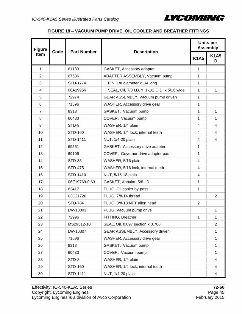
Oil Filter Assembly and Oil Cooler Bypass Valve Figure 19

IO-540-K1A5 Series Illustrated Parts Catalog
Effectivity: IO-540-K1A5 Series 72-60 Copyright, Lycoming Engines Page 47 Lycoming Engines is a division of Avco Corporation February 2015
FIGURE 19 – OIL FILTER ASSEMBLY AND OIL COOLER BYPASS VALVE
Figure Item
Code Part Number Description
Units per Assembly
K1A5 K1A5D
1 06B23862 GASKET, Oil filter adapter 1
2 77852 BASE ASSEMBLY, Oil filter 1
3 V LW-13215 OIL FILTER, Short, (V CH48110-1) 1
4 STD-8 WASHER, 1/4 plain 4
5 STD-160 WASHER, 1/4 lock, internal teeth 4
6 STD-1411 NUT, 1/4-20 plain 1
7 LW-25-1.00 BOLT, 1/4-20 x 1.00 long, hex. head 3
8 53E22144 VALVE ASSEMBLY with gasket, Temp. control, oil cooler bypass
1
9 25C-10 STUD, 1/4-20 x 1.25 long 1
10 05S21021 SPRING, Oil filter by-pass valve 1
11 55K21022 SPACER, Oil pressure by-pass valve 1
12 76539 SEAT, Oil relief valve 1
13 LW-10320 SLEEVE, Oil filter bypass valve 1
14 MS16625-1100 RING, Internal retaining, 1.00 dia. 1
15 V LW-13906 OIL FILTER, Short (V CH48103-1) 1
16 54E23093 KIT, Converter plate, oil filter 1
17 53E22144 VALVE ASSEMBLY with gasket, Temp. control, oil cooler bypass
1
V Vendor Prime Manufacturer part
IO-540-K1A5 Series Illustrated Parts Catalog
73-10 Effectivity: IO-540-K1A5 Series Page 48 Copyright, Lycoming Engines February 2015 Lycoming Engines is a division of Avco Corporation
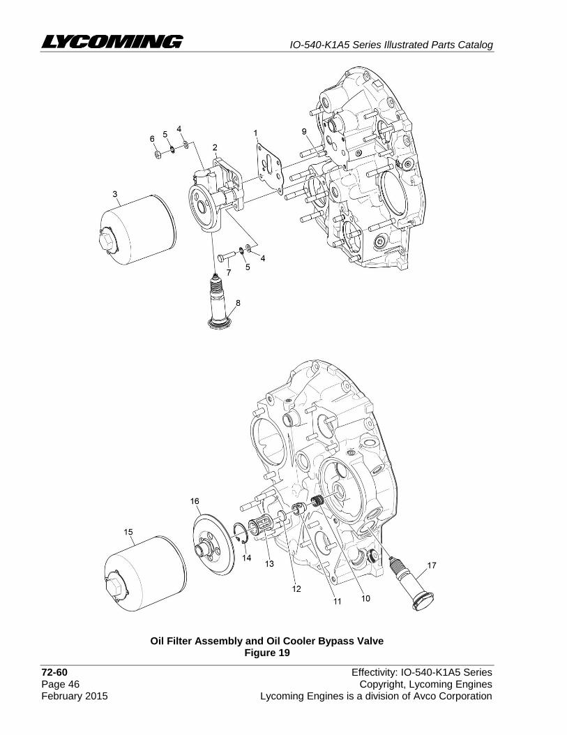
Fuel Injector, Fuel Lines, Manifold Assembly and Pressure Line Figure 20

IO-540-K1A5 Series Illustrated Parts Catalog
Effectivity: IO-540-K1A5 Series 73-10 Copyright, Lycoming Engines Page 49 Lycoming Engines is a division of Avco Corporation February 2015
FIGURE 20 – FUEL INJECTOR, FUEL LINES, MANIFOLD ASSEMBLY AND PRESSURE LINE
(continued on next page)
Figure Item
Code Part Number Description
Units per Assembly
K1A5 K1A5D
1 73032 GASKET, Air inlet 1 1
2 61M26410 FUEL INJECTOR (2524273-12) 1 1
3 76304 ELBOW, 45º 1 1
4 STD-35 WASHER, 5/16 plain 2 2
5 STD-1727 WASHER, Plain, 3/4 O.D. x 11/32 I.D. x 1/8 thick
2 2
6 STD-475 WASHER, 5/16 lock, internal teeth 4 4
7 STD-1410 NUT, 5/16-18, plain 4 4
8 63C26450 NOZZLE, Injection (2524864-2) 6 6
9 63B26719 MANIFOLD ASSEMBLY, Fuel 1 1
10 02G21446 NIPPLE, 1/8 NPT to 1/4 tube 1 1
11 STD-148 NIPPLE, Union, 1/8 NPT 4 4
12 AN791-2 ELBOW, Union, 45 º, 1/8 tube 2 2
13 MS20823-4 ELBOW, 1/8 NPT to 1/4 fl tube 1 1
14 63B26713 MANIFOLD ASSEMBLY, Fuel 1
15 02G21382 NIPPLE, Nozzle pressure gage 1
16 STD-148 NIPPLE, Union, 1/8 NPT 4
17 AN791-2 ELBOW, Union, 45 º, 1/8 tube 2
18 AN816-4 NIPPLE, 1/8 NPT to 1/4 tube 1
19 75009 BRACKET, Fuel manifold 1 1
20 STD-251 WASHER, #10, internal lock 4 4
21 STD-82 SCREW, #10-24 x 1/2 long, fill. head 4 4
22 STD-160 WASHER, 1/4 lock, internal teeth 1 1
23 LW-25-0.50 BOLT, 1/4-20 x 1/2 long, hex head 1 1
24 LW-12098-0-210 TUBE ASSEMBLY, Fuel injector line, cylinder no. 1
1 1
25 LW-12098-0-280 TUBE ASSEMBLY, Fuel injector line, cylinder no. 2
1 1
26 LW-12098-0-140 TUBE ASSEMBLY, Fuel injector line, cylinders no. 3 and 5
2 2

IO-540-K1A5 Series Illustrated Parts Catalog
73-10 Effectivity: IO-540-K1A5 Series Page 50 Copyright, Lycoming Engines February 2015 Lycoming Engines is a division of Avco Corporation
FIGURE 20 – FUEL INJECTOR, FUEL LINES, MANIFOLD ASSEMBLY
AND PRESSURE LINE (CONT)
Figure Item
Code Part Number Description
Units per Assembly
K1A5 K1A5D
27 LW-12098-0-210 TUBE ASSEMBLY, Fuel injector line, cylinders no. 4 and 6
2 2
28 LW-16266-10-75 CLAMP 8 8
29 LW-16266-10-13 CLAMP, 1/8 diameter for #10 screw 10 10
30 STD-860 SCREW, No. 10-32 x 5/8 long, fill. head 13 13
31 STD-425 WASHER, #10 plain 2 2
32 STD-670 LOCKNUT, No. 10-32 13 13
33 LW-12798-4S340 HOSE ASSEMBLY, 1/4 hose, straight 1 1
34 LW-16266-25-63 CLAMP, 5/8 I.D. x 1/4 diameter screw 1
35 LW-12799-6S110 HOSE ASSEMBLY, 3/8 hose, straight 1 1
36 MS20822-6 ELBOW, 1/4 NPT to 3/8 fl tube-9 1 1
37 LW-16266-10-13 CLAMP, 1/8 diameter for #10 screw 2 2
38 73136 BRACKET, extension, fuel injection line 4 4
39 LW-16266-25-50 CLAMP 1
40 MS20823-6 ELBOW, 1/4 NPT to 3/8 fl tube-4 1 1

IO-540-K1A5 Series Illustrated Parts Catalog
Effectivity: IO-540-K1A5 Series 73-10 Copyright, Lycoming Engines Page 51 Lycoming Engines is a division of Avco Corporation February 2015
This page intentionally left blank.
IO-540-K1A5 Series Illustrated Parts Catalog
74-20 Effectivity: IO-540-K1A5 Series Page 52 Copyright, Lycoming Engines February 2015 Lycoming Engines is a division of Avco Corporation
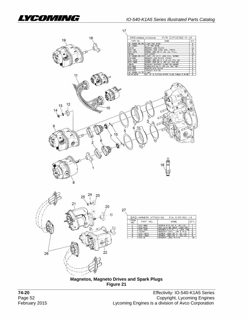
Magnetos, Magneto Drives and Spark Plugs Figure 21

IO-540-K1A5 Series Illustrated Parts Catalog
Effectivity: IO-540-K1A5 Series 74-20 Copyright, Lycoming Engines Page 53 Lycoming Engines is a division of Avco Corporation February 2015
FIGURE 21 -MAGNETOS, MAGNETO DRIVES AND SPARK PLUGS
Figure Item
Code Part Number Description
Units per Assembly
K1A5
1 73000 COUPLING, Magneto drive 1
2 68H22624 CUSHION, Magneto drive 4
3 62224 GASKET, Magneto adapter 2
4 LW-12707 ADAPTER, Magneto 2
5 LW-12681 GASKET, Magneto 2
6 LW-19096 GEAR RETAINER ASSEMBLY 2
7 67542 BALL BEARING 2
8 V 66LP-0SCNN MAGNETO, Plain, right, ( V Model No. 6350) 1
9 V 66LC35SDNN MAGNETO, Impulse, left, ( V Model No. 6351) 1
10 V 67U20636 HARNESS, Right, ( V Slick M-2960) 1
11 V 67U20637 HARNESS, Left, ( V Slick M-2959) 1
12 66M21195 CLAMP, Magneto 4
13 STD-475 WASHER, 5/16 lock, internal teeth 4
14 STD-1410 NUT, 5/16-18 plain 4
15 MS9245-44 COTTER PIN, 3/32 diameter x 3/4 long 2
16 V 1182-E7 SPARK PLUG, ( V Champion REM38E) 12
V 1182-F7 SPARK PLUG, ( V Champion RHM38E) 12
17 01P19762-4-16 BAG, Magneto harness attaching 1
18 73013 COUPLING, Magneto drive 1
19 V 66LR37SCNN MAGNETO, Retard, ( V Model No. 6393) 1
20 73636 COUPLING 1
21 V LW-349290-1 MAGNETO, Ignition ( V Model No. S6LN-1208)
1
22 V LW-349310-1 MAGNETO, Ignition ( V Model No. S6LN-1209)
1
23 66M19385 CLAMP, Magneto 4
24 STD-475 WASHER, 5/16 lock, internal teeth 4
25 STD-1410 NUT, 5/16-18 plain 4
26 67Y21895 HARNESS ASSY, ( V TCM 10-821684-40) 1
27 01P21501-13-56 BAG, Magneto harness attaching 1
V Vendor Prime Manufacturer part
IO-540-K1A5 Series Illustrated Parts Catalog
74-20 Effectivity: IO-540-K1A5 Series Page 54 Copyright, Lycoming Engines February 2015 Lycoming Engines is a division of Avco Corporation
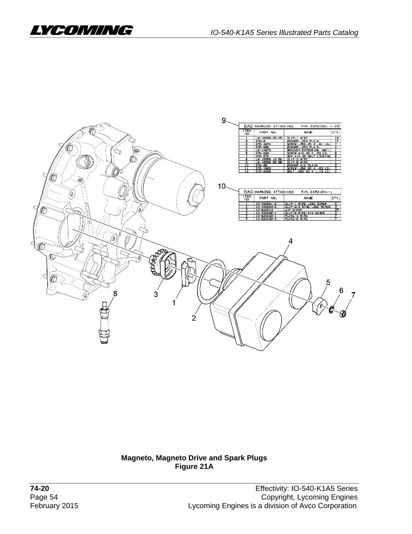
Magneto, Magneto Drive and Spark Plugs Figure 21A
IO-540-K1A5 Series Illustrated Parts Catalog
Effectivity: IO-540-K1A5 Series 74-20 Copyright, Lycoming Engines Page 55 Lycoming Engines is a division of Avco Corporation February 2015
FIGURE 21A -MAGNETO, MAGNETO DRIVE AND SPARK PLUGS
Figure Item
Code Part Number Description
Units per Assembly
K1A5D
1 68H22624 CUSHION, Magneto drive 2
2 LW-12681 GASKET, Magneto 1
3 LW-13899 GEAR RETAINER ASSEMBLY 1
4 V 66E21577 MAGNETO, Ignition system ( V Model No. 10-785126-107)
1
5 66M19385 CLAMP, Magneto 2
6 STD-475 WASHER, 5/16 lock, internal teeth 2
7 STD-1410 NUT, 5/16-18 plain 2
8 V 1182-F7 SPARK PLUG, ( V Champion RHM38E) 12
9 01P21501-1-29 BAG, Magneto harness attaching 1
10 01P21641-1 BAG, Magneto harness attaching 1
V Vendor Prime Manufacturer part

IO-540-K1A5 Series Illustrated Parts Catalog
81-10 Effectivity: IO-540-K1A5 Series Page 56 Copyright, Lycoming Engines February 2015 Lycoming Engines is a division of Avco Corporation
Starter Motor and Attaching Parts Figure 22
IO-540-K1A5 Series Illustrated Parts Catalog
Effectivity: IO-540-K1A5 Series 81-10 Copyright, Lycoming Engines Page 57 Lycoming Engines is a division of Avco Corporation February 2015
FIGURE 22 - STARTER MOTOR AND ATTACHING PARTS
Figure Item
Code Part Number Description
Units per Assembly
K1A5 K1A5D
1 V 31A26041 STARTER, 12V., 12/14 pitch pinion, (Kelly, V ERZ-8011)
1 1
2 STD-35 WASHER, 5/16 plain 4 4
3 STD-475 WASHER, 5/16 lock, internal teeth 4 4
4 LW-31-1.16 BOLT, 5/16-18 x 1-5/32 long, hex.head 1 1
5 STD-1410 NUT, 5/16-18 plain 3 3
6 V 31A22104 STARTER, 12V., (Sky Tec, V 149-12LS) 1 1
7 STD-475 WASHER, 5/16 lock, internal teeth 4 4
8 LW-31-0.94 BOLT, 5/16-18 x 15/16 long, hex.head 1 1
9 STD-1410 NUT, 5/16-18 plain 3 3
10 V 31A22100 STARTER, 12V., (Sky Tec, V 149-12PM) 1
11 STD-475 WASHER, 5/16 lock, internal teeth 4
12 LW-31-0.94 BOLT, 5/16-18 x 15/16 long, hex.head 1
13 STD-1410 NUT, 5/16-18 plain 3
V Vendor Prime Manufacturer part
NOTE: Refer to the latest revision of Service Instruction No. 1154 for complete listing of FAA approved starters, alternators, generators, regulators and relays.

IO-540-K1A5 Series Illustrated Parts Catalog
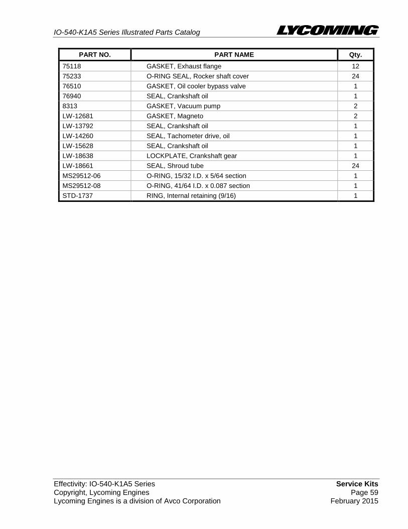
Service Kits Effectivity: IO-540-K1A5 Series Page 58 Copyright, Lycoming Engines February 2015 Lycoming Engines is a division of Avco Corporation
SERVICE KIT SECTION
SEAL AND GASKET SET
PART NO. PART NAME Qty.
73185-1 KIT - SEAL AND GASKET SET 1
06A19956 SEAL, Oil, 7/8 I.D. x 1-1/2 O.D. x 5/16 1
06A23493 SEAL, Shroud tube 12
06B21326 GASKET, Oil sump 1
06B23862 GASKET, Oil filler adapter 1
06E19769-0.50 GASKET, Annular 1/2 I.D. 6
06E19769-0.63 GASKET, Annular 5/8 I.D. 2
06E19769-0.91 GASKET, Annular, 0.906 I.D. 1
06E19769-1.00 GASKET, Annular, 1.00 I.D. 1
06E19769-1.25 GASKET, Annular, 1 1/4 I.D. 1
15H21201 SPRING, Shroud tube 24
1691-C GASKET, Fuel pump 1
61173 GASKET, Oil pressure housing 1
61183 GASKET, Accessory adapter 1
62224 GASKET, Magneto adapter 4
66732 GASKET, Valve rocker shaft cover 12
67193 GASKET, Rocker box cover 6
68315 GASKET, Accessory drive adapter 1
69164 GASKET, Fuel pump adapter 1
69551 GASKET, Accessory drive adapter 1
70455 GASKET, 25/32 I.D. x 1-1/8 O.D. x 1/32 thick 1
70457 GASKET, Oil filler extension 1
71450 GASKET, Rocker box cover 6
71481 RING, Oil seal, 3/32 diameter x 4-27/32 I.D. 6
71667 LOCKPLATE, 1/4 bolt x 1.75 2
71973 GASKET, 2 bolt flange, 1-13/16 I.D. 6
72053 GASKET, Governor 1
72075 SEAL, Oil, 29/64 I.D. x 3/32 section 8
72078 LOCKPLATE, 5/16 bolt x 1.33 2
72091 RING, Oil seal, 0.36 I.D. x 7/64 diameter 2
72210 GASKET, Air throttle housing 1
72312 RING, Oil seal, 1.00 x 1.30 1
72711 RING, Seal, intake pipes 6
73032 GASKET, Air inlet housing 1
73383 LOCKPLATE, 5/16 bolt x 1.00 2
73818 GASKET, Accessory housing 1
74065 RING, Oil level gage seal 1
74305 SEAL 1
IO-540-K1A5 Series Illustrated Parts Catalog
Effectivity: IO-540-K1A5 Series Service Kits Copyright, Lycoming Engines Page 59 Lycoming Engines is a division of Avco Corporation February 2015
PART NO. PART NAME Qty.
75118 GASKET, Exhaust flange 12
75233 O-RING SEAL, Rocker shaft cover 24
76510 GASKET, Oil cooler bypass valve 1
76940 SEAL, Crankshaft oil 1
8313 GASKET, Vacuum pump 2
LW-12681 GASKET, Magneto 2
LW-13792 SEAL, Crankshaft oil 1
LW-14260 SEAL, Tachometer drive, oil 1
LW-15628 SEAL, Crankshaft oil 1
LW-18638 LOCKPLATE, Crankshaft gear 1
LW-18661 SEAL, Shroud tube 24
MS29512-06 O-RING, 15/32 I.D. x 5/64 section 1
MS29512-08 O-RING, 41/64 I.D. x 0.087 section 1
STD-1737 RING, Internal retaining (9/16) 1
IO-540-K1A5 Series Illustrated Parts Catalog
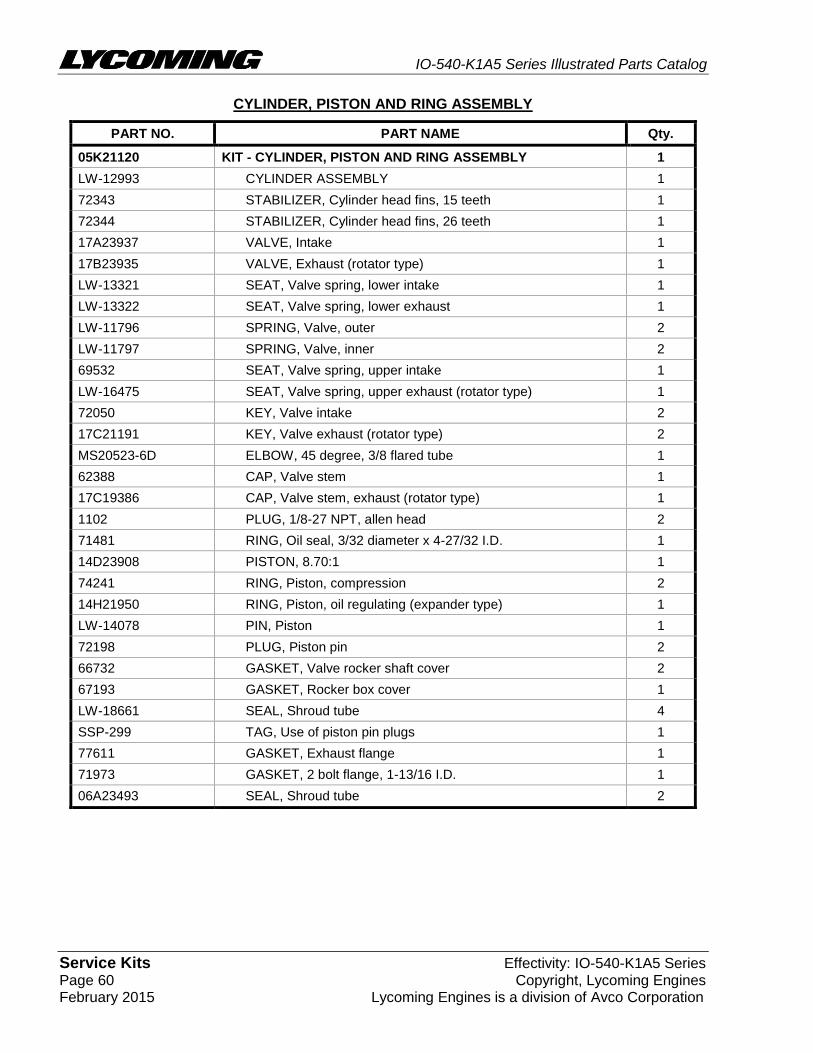
Service Kits Effectivity: IO-540-K1A5 Series Page 60 Copyright, Lycoming Engines February 2015 Lycoming Engines is a division of Avco Corporation
CYLINDER, PISTON AND RING ASSEMBLY
PART NO. PART NAME Qty.
05K21120 KIT - CYLINDER, PISTON AND RING ASSEMBLY 1
LW-12993 CYLINDER ASSEMBLY 1
72343 STABILIZER, Cylinder head fins, 15 teeth 1
72344 STABILIZER, Cylinder head fins, 26 teeth 1
17A23937 VALVE, Intake 1
17B23935 VALVE, Exhaust (rotator type) 1
LW-13321 SEAT, Valve spring, lower intake 1
LW-13322 SEAT, Valve spring, lower exhaust 1
LW-11796 SPRING, Valve, outer 2
LW-11797 SPRING, Valve, inner 2
69532 SEAT, Valve spring, upper intake 1
LW-16475 SEAT, Valve spring, upper exhaust (rotator type) 1
72050 KEY, Valve intake 2
17C21191 KEY, Valve exhaust (rotator type) 2
MS20523-6D ELBOW, 45 degree, 3/8 flared tube 1
62388 CAP, Valve stem 1
17C19386 CAP, Valve stem, exhaust (rotator type) 1
1102 PLUG, 1/8-27 NPT, allen head 2
71481 RING, Oil seal, 3/32 diameter x 4-27/32 I.D. 1
14D23908 PISTON, 8.70:1 1
74241 RING, Piston, compression 2
14H21950 RING, Piston, oil regulating (expander type) 1
LW-14078 PIN, Piston 1
72198 PLUG, Piston pin 2
66732 GASKET, Valve rocker shaft cover 2
67193 GASKET, Rocker box cover 1
LW-18661 SEAL, Shroud tube 4
SSP-299 TAG, Use of piston pin plugs 1
77611 GASKET, Exhaust flange 1
71973 GASKET, 2 bolt flange, 1-13/16 I.D. 1
06A23493 SEAL, Shroud tube 2
IO-540-K1A5 Series Illustrated Parts Catalog
Effectivity: IO-540-K1A5 Series Service Kits Copyright, Lycoming Engines Page 61 Lycoming Engines is a division of Avco Corporation February 2015
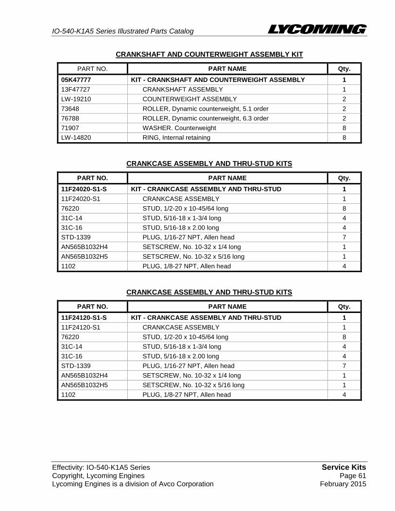
CRANKSHAFT AND COUNTERWEIGHT ASSEMBLY KIT
PART NO. PART NAME Qty.
05K47777 KIT - CRANKSHAFT AND COUNTERWEIGHT ASSEMBLY 1
13F47727 CRANKSHAFT ASSEMBLY 1
LW-19210 COUNTERWEIGHT ASSEMBLY 2
73648 ROLLER, Dynamic counterweight, 5.1 order 2
76788 ROLLER, Dynamic counterweight, 6.3 order 2
71907 WASHER. Counterweight 8
LW-14820 RING, Internal retaining 8
CRANKCASE ASSEMBLY AND THRU-STUD KITS
PART NO. PART NAME Qty.
11F24020-S1-S KIT - CRANKCASE ASSEMBLY AND THRU-STUD 1
11F24020-S1 CRANKCASE ASSEMBLY 1
76220 STUD, 1/2-20 x 10-45/64 long 8
31C-14 STUD, 5/16-18 x 1-3/4 long 4
31C-16 STUD, 5/16-18 x 2.00 long 4
STD-1339 PLUG, 1/16-27 NPT, Allen head 7
AN565B1032H4 SETSCREW, No. 10-32 x 1/4 long 1
AN565B1032H5 SETSCREW, No. 10-32 x 5/16 long 1
1102 PLUG, 1/8-27 NPT, Allen head 4
CRANKCASE ASSEMBLY AND THRU-STUD KITS
PART NO. PART NAME Qty.
11F24120-S1-S KIT - CRANKCASE ASSEMBLY AND THRU-STUD 1
11F24120-S1 CRANKCASE ASSEMBLY 1
76220 STUD, 1/2-20 x 10-45/64 long 8
31C-14 STUD, 5/16-18 x 1-3/4 long 4
31C-16 STUD, 5/16-18 x 2.00 long 4
STD-1339 PLUG, 1/16-27 NPT, Allen head 7
AN565B1032H4 SETSCREW, No. 10-32 x 1/4 long 1
AN565B1032H5 SETSCREW, No. 10-32 x 5/16 long 1
1102 PLUG, 1/8-27 NPT, Allen head 4
IO-540-K1A5 Series Illustrated Parts Catalog
Numerical Index Effectivity: IO-540-K1A5 Series Page 62 Copyright, Lycoming Engines February 2015 Lycoming Engines is a division of Avco Corporation
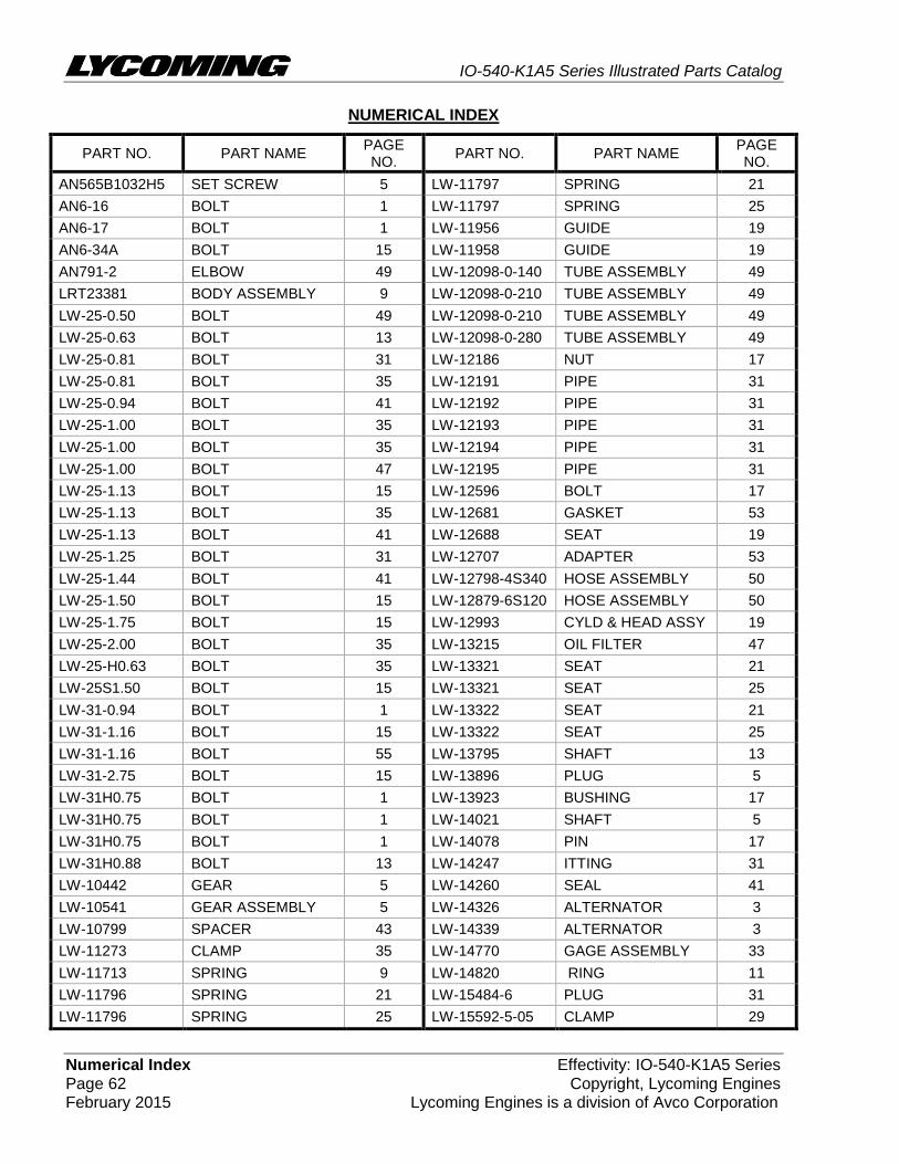
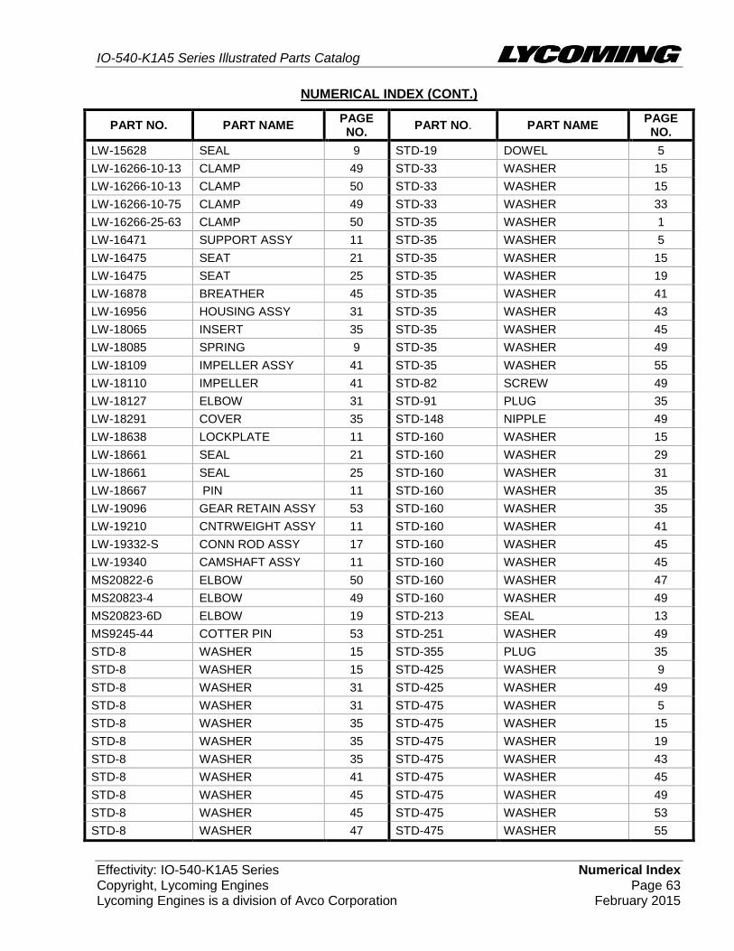
NUMERICAL INDEX
PART NO. PART NAME PAGE NO.
PART NO. PART NAME PAGE NO.
AN565B1032H5 SET SCREW 5 LW-11797 SPRING 21
AN6-16 BOLT 1 LW-11797 SPRING 25
AN6-17 BOLT 1 LW-11956 GUIDE 19
AN6-34A BOLT 15 LW-11958 GUIDE 19
AN791-2 ELBOW 49 LW-12098-0-140 TUBE ASSEMBLY 49
LRT23381 BODY ASSEMBLY 9 LW-12098-0-210 TUBE ASSEMBLY 49
LW-25-0.50 BOLT 49 LW-12098-0-210 TUBE ASSEMBLY 49
LW-25-0.63 BOLT 13 LW-12098-0-280 TUBE ASSEMBLY 49
LW-25-0.81 BOLT 31 LW-12186 NUT 17
LW-25-0.81 BOLT 35 LW-12191 PIPE 31
LW-25-0.94 BOLT 41 LW-12192 PIPE 31
LW-25-1.00 BOLT 35 LW-12193 PIPE 31
LW-25-1.00 BOLT 35 LW-12194 PIPE 31
LW-25-1.00 BOLT 47 LW-12195 PIPE 31
LW-25-1.13 BOLT 15 LW-12596 BOLT 17
LW-25-1.13 BOLT 35 LW-12681 GASKET 53
LW-25-1.13 BOLT 41 LW-12688 SEAT 19
LW-25-1.25 BOLT 31 LW-12707 ADAPTER 53
LW-25-1.44 BOLT 41 LW-12798-4S340 HOSE ASSEMBLY 50
LW-25-1.50 BOLT 15 LW-12879-6S120 HOSE ASSEMBLY 50
LW-25-1.75 BOLT 15 LW-12993 CYLD & HEAD ASSY 19
LW-25-2.00 BOLT 35 LW-13215 OIL FILTER 47
LW-25-H0.63 BOLT 35 LW-13321 SEAT 21
LW-25S1.50 BOLT 15 LW-13321 SEAT 25
LW-31-0.94 BOLT 1 LW-13322 SEAT 21
LW-31-1.16 BOLT 15 LW-13322 SEAT 25
LW-31-1.16 BOLT 55 LW-13795 SHAFT 13
LW-31-2.75 BOLT 15 LW-13896 PLUG 5
LW-31H0.75 BOLT 1 LW-13923 BUSHING 17
LW-31H0.75 BOLT 1 LW-14021 SHAFT 5
LW-31H0.75 BOLT 1 LW-14078 PIN 17
LW-31H0.88 BOLT 13 LW-14247 ITTING 31
LW-10442 GEAR 5 LW-14260 SEAL 41
LW-10541 GEAR ASSEMBLY 5 LW-14326 ALTERNATOR 3
LW-10799 SPACER 43 LW-14339 ALTERNATOR 3
LW-11273 CLAMP 35 LW-14770 GAGE ASSEMBLY 33
LW-11713 SPRING 9 LW-14820 RING 11
LW-11796 SPRING 21 LW-15484-6 PLUG 31
LW-11796 SPRING 25 LW-15592-5-05 CLAMP 29
IO-540-K1A5 Series Illustrated Parts Catalog
Effectivity: IO-540-K1A5 Series Numerical Index Copyright, Lycoming Engines Page 63 Lycoming Engines is a division of Avco Corporation February 2015
NUMERICAL INDEX (CONT.)
PART NO. PART NAME PAGE NO.
PART NO. PART NAME PAGE NO.
LW-15628 SEAL 9 STD-19 DOWEL 5
LW-16266-10-13 CLAMP 49 STD-33 WASHER 15
LW-16266-10-13 CLAMP 50 STD-33 WASHER 15
LW-16266-10-75 CLAMP 49 STD-33 WASHER 33
LW-16266-25-63 CLAMP 50 STD-35 WASHER 1
LW-16471 SUPPORT ASSY 11 STD-35 WASHER 5
LW-16475 SEAT 21 STD-35 WASHER 15
LW-16475 SEAT 25 STD-35 WASHER 19
LW-16878 BREATHER 45 STD-35 WASHER 41
LW-16956 HOUSING ASSY 31 STD-35 WASHER 43
LW-18065 INSERT 35 STD-35 WASHER 45
LW-18085 SPRING 9 STD-35 WASHER 49
LW-18109 IMPELLER ASSY 41 STD-35 WASHER 55
LW-18110 IMPELLER 41 STD-82 SCREW 49
LW-18127 ELBOW 31 STD-91 PLUG 35
LW-18291 COVER 35 STD-148 NIPPLE 49
LW-18638 LOCKPLATE 11 STD-160 WASHER 15
LW-18661 SEAL 21 STD-160 WASHER 29
LW-18661 SEAL 25 STD-160 WASHER 31
LW-18667 PIN 11 STD-160 WASHER 35
LW-19096 GEAR RETAIN ASSY 53 STD-160 WASHER 35
LW-19210 CNTRWEIGHT ASSY 11 STD-160 WASHER 41
LW-19332-S CONN ROD ASSY 17 STD-160 WASHER 45
LW-19340 CAMSHAFT ASSY 11 STD-160 WASHER 45
MS20822-6 ELBOW 50 STD-160 WASHER 47
MS20823-4 ELBOW 49 STD-160 WASHER 49
MS20823-6D ELBOW 19 STD-213 SEAL 13
MS9245-44 COTTER PIN 53 STD-251 WASHER 49
STD-8 WASHER 15 STD-355 PLUG 35
STD-8 WASHER 15 STD-425 WASHER 9
STD-8 WASHER 31 STD-425 WASHER 49
STD-8 WASHER 31 STD-475 WASHER 5
STD-8 WASHER 35 STD-475 WASHER 15
STD-8 WASHER 35 STD-475 WASHER 19
STD-8 WASHER 35 STD-475 WASHER 43
STD-8 WASHER 41 STD-475 WASHER 45
STD-8 WASHER 45 STD-475 WASHER 49
STD-8 WASHER 45 STD-475 WASHER 53
STD-8 WASHER 47 STD-475 WASHER 55
IO-540-K1A5 Series Illustrated Parts Catalog
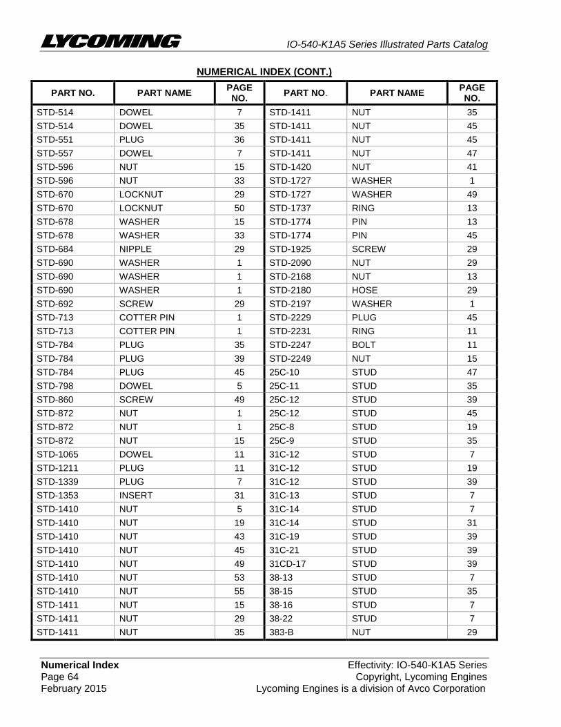
Numerical Index Effectivity: IO-540-K1A5 Series Page 64 Copyright, Lycoming Engines February 2015 Lycoming Engines is a division of Avco Corporation
NUMERICAL INDEX (CONT.)
PART NO. PART NAME PAGE NO.
PART NO. PART NAME PAGE NO.
STD-514 DOWEL 7 STD-1411 NUT 35
STD-514 DOWEL 35 STD-1411 NUT 45
STD-551 PLUG 36 STD-1411 NUT 45
STD-557 DOWEL 7 STD-1411 NUT 47
STD-596 NUT 15 STD-1420 NUT 41
STD-596 NUT 33 STD-1727 WASHER 1
STD-670 LOCKNUT 29 STD-1727 WASHER 49
STD-670 LOCKNUT 50 STD-1737 RING 13
STD-678 WASHER 15 STD-1774 PIN 13
STD-678 WASHER 33 STD-1774 PIN 45
STD-684 NIPPLE 29 STD-1925 SCREW 29
STD-690 WASHER 1 STD-2090 NUT 29
STD-690 WASHER 1 STD-2168 NUT 13
STD-690 WASHER 1 STD-2180 HOSE 29
STD-692 SCREW 29 STD-2197 WASHER 1
STD-713 COTTER PIN 1 STD-2229 PLUG 45
STD-713 COTTER PIN 1 STD-2231 RING 11
STD-784 PLUG 35 STD-2247 BOLT 11
STD-784 PLUG 39 STD-2249 NUT 15
STD-784 PLUG 45 25C-10 STUD 47
STD-798 DOWEL 5 25C-11 STUD 35
STD-860 SCREW 49 25C-12 STUD 39
STD-872 NUT 1 25C-12 STUD 45
STD-872 NUT 1 25C-8 STUD 19
STD-872 NUT 15 25C-9 STUD 35
STD-1065 DOWEL 11 31C-12 STUD 7
STD-1211 PLUG 11 31C-12 STUD 19
STD-1339 PLUG 7 31C-12 STUD 39
STD-1353 INSERT 31 31C-13 STUD 7
STD-1410 NUT 5 31C-14 STUD 7
STD-1410 NUT 19 31C-14 STUD 31
STD-1410 NUT 43 31C-19 STUD 39
STD-1410 NUT 45 31C-21 STUD 39
STD-1410 NUT 49 31CD-17 STUD 39
STD-1410 NUT 53 38-13 STUD 7
STD-1410 NUT 55 38-15 STUD 35
STD-1411 NUT 15 38-16 STUD 7
STD-1411 NUT 29 38-22 STUD 7
STD-1411 NUT 35 383-B NUT 29
IO-540-K1A5 Series Illustrated Parts Catalog
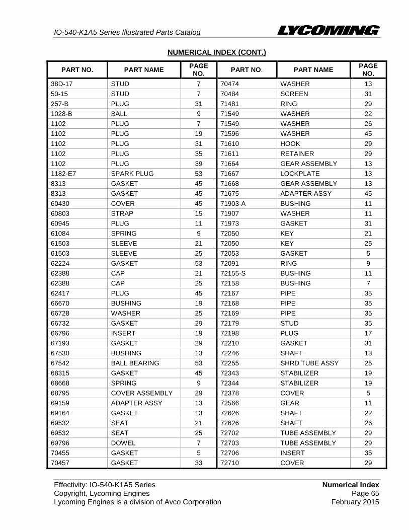
Effectivity: IO-540-K1A5 Series Numerical Index Copyright, Lycoming Engines Page 65 Lycoming Engines is a division of Avco Corporation February 2015
NUMERICAL INDEX (CONT.)
PART NO. PART NAME PAGE NO.
PART NO. PART NAME PAGE NO.
38D-17 STUD 7 70474 WASHER 13
50-15 STUD 7 70484 SCREEN 31
257-B PLUG 31 71481 RING 29
1028-B BALL 9 71549 WASHER 22
1102 PLUG 7 71549 WASHER 26
1102 PLUG 19 71596 WASHER 45
1102 PLUG 31 71610 HOOK 29
1102 PLUG 35 71611 RETAINER 29
1102 PLUG 39 71664 GEAR ASSEMBLY 13
1182-E7 SPARK PLUG 53 71667 LOCKPLATE 13
8313 GASKET 45 71668 GEAR ASSEMBLY 13
8313 GASKET 45 71675 ADAPTER ASSY 45
60430 COVER 45 71903-A BUSHING 11
60803 STRAP 15 71907 WASHER 11
60945 PLUG 11 71973 GASKET 31
61084 SPRING 9 72050 KEY 21
61503 SLEEVE 21 72050 KEY 25
61503 SLEEVE 25 72053 GASKET 5
62224 GASKET 53 72091 RING 9
62388 CAP 21 72155-S BUSHING 11
62388 CAP 25 72158 BUSHING 7
62417 PLUG 45 72167 PIPE 35
66670 BUSHING 19 72168 PIPE 35
66728 WASHER 25 72169 PIPE 35
66732 GASKET 29 72179 STUD 35
66796 INSERT 19 72198 PLUG 17
67193 GASKET 29 72210 GASKET 31
67530 BUSHING 13 72246 SHAFT 13
67542 BALL BEARING 53 72255 SHRD TUBE ASSY 25
68315 GASKET 45 72343 STABILIZER 19
68668 SPRING 9 72344 STABILIZER 19
68795 COVER ASSEMBLY 29 72378 COVER 5
69159 ADAPTER ASSY 13 72566 GEAR 11
69164 GASKET 13 72626 SHAFT 22
69532 SEAT 21 72626 SHAFT 26
69532 SEAT 25 72702 TUBE ASSEMBLY 29
69796 DOWEL 7 72703 TUBE ASSEMBLY 29
70455 GASKET 5 72706 INSERT 35
70457 GASKET 33 72710 COVER 29

IO-540-K1A5 Series Illustrated Parts Catalog
Numerical Index Effectivity: IO-540-K1A5 Series Page 66 Copyright, Lycoming Engines February 2015 Lycoming Engines is a division of Avco Corporation
NUMERICAL INDEX (CONT.)
PART NO. PART NAME PAGE NO.
PART NO. PART NAME PAGE NO.
72711 RING 31 77808 VALVE ASSEMBLY 9
72834 COVER 29 77852 BASE ASSEMBLY 47
72960 PLUG 35 77872 BUSHING 5
72962 THRUST BUTTON 13 77906 SPACER 29
72964 GEAR ASSEMBLY 45 78528 BODY ASSEMBLY 41
72972 SHAFTGEAR ASSY 13 01A23354 STUD 7
73000 COUPLING 53 01L21418 WASHER 5
73027 TUBE ASSEMBLY 29 01L23459 WASHER 21
73032 GASKET 49 01P19762-4-16 BAG 53
73136 BRACKET 50 02G21446 NIPPLE 49
73249 WASHER 5 05K19423-S IMPELLER KIT 41
73250 WASHER 5 06A19956 SEAL 45
73251 WASHER 5 06A23493 SEAL 21
73252 WASHER 5 06B21326 GASKET 35
73383 LOCKPLATE 1 06B23862 GASKET 47
73648 ROLLER 11 06E19769-0.63 GASKET 45
73772 NOZZLE ASSEMBLY 7 06E19769-0.91 GASKET 35
73810 BUSHING 11 06E19769-1.25 GASKET 9
73818 GASKET 39 07A19474 BRACKET 1
74065 "O" RING 33 07F23268 STRUT 1
74241 RING 17 11F24020-S1 CRANKCASE ASSY 7
74360 FLANGE 31 11F24120-S1 CRANKCASE ASSY 7
74494 PLATE 29 12A19770 BRACKET 33
74641 SHAFT 41 13F47727 CRANKSHAFT ASSY 11
74887 SPACER 29 13S19647 GEAR 11
75009 BRACKET 49 14D23908 PISTON 17
75118 GASKET 19 14H21950 RING 17
75338 BAFFLE ASSEMBLY 29 14S23889 BOLT 17
75380 LINK 1 15B21319 SOCKET 21
75656-S BUSHING 11 15B21319 SOCKET 25
75657-S BUSHING 11 15B26066 PLUNGER ASSY 21
75675 TUBE ASSEMBLY 33 15B26066 PLUNGER ASSY 25
76118 SPACER 11 15B26262 BODY ASSEMBLY 9
76155 SHAFT ASSEMBLY 11 15F19957-52 ROD ASSEMBLY 22
76220 STUD 15 15F19957-52 ROD ASSEMBLY 26
76304 ELBOW 49 15F19957-53 ROD ASSEMBLY 22
76534 SHIM 1 15F19957-53 ROD ASSEMBLY 26
76788 ROLLER 11 15F19957-54 ROD ASSEMBLY 22
77309 BUSHING 13 15F19957-54 ROD ASSEMBLY 26
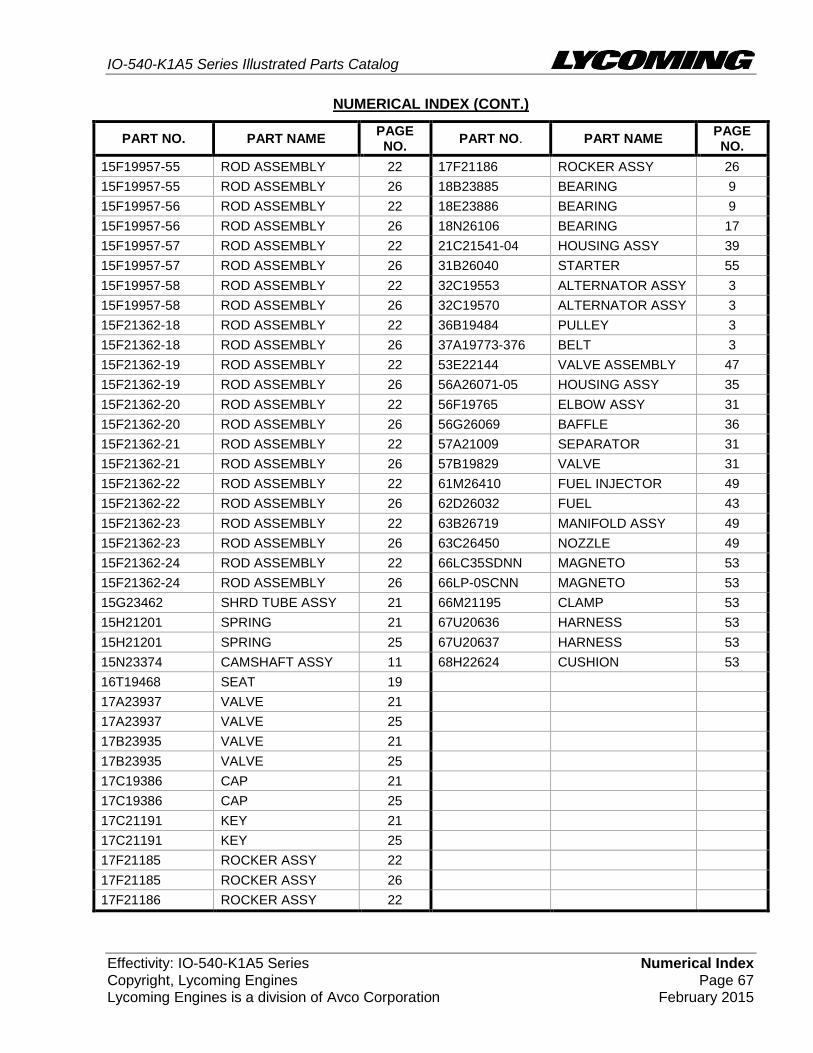
IO-540-K1A5 Series Illustrated Parts Catalog
Effectivity: IO-540-K1A5 Series Numerical Index Copyright, Lycoming Engines Page 67 Lycoming Engines is a division of Avco Corporation February 2015
NUMERICAL INDEX (CONT.)
PART NO. PART NAME PAGE NO.
PART NO. PART NAME PAGE NO.
15F19957-55 ROD ASSEMBLY 22 17F21186 ROCKER ASSY 26
15F19957-55 ROD ASSEMBLY 26 18B23885 BEARING 9
15F19957-56 ROD ASSEMBLY 22 18E23886 BEARING 9
15F19957-56 ROD ASSEMBLY 26 18N26106 BEARING 17
15F19957-57 ROD ASSEMBLY 22 21C21541-04 HOUSING ASSY 39
15F19957-57 ROD ASSEMBLY 26 31B26040 STARTER 55
15F19957-58 ROD ASSEMBLY 22 32C19553 ALTERNATOR ASSY 3
15F19957-58 ROD ASSEMBLY 26 32C19570 ALTERNATOR ASSY 3
15F21362-18 ROD ASSEMBLY 22 36B19484 PULLEY 3
15F21362-18 ROD ASSEMBLY 26 37A19773-376 BELT 3
15F21362-19 ROD ASSEMBLY 22 53E22144 VALVE ASSEMBLY 47
15F21362-19 ROD ASSEMBLY 26 56A26071-05 HOUSING ASSY 35
15F21362-20 ROD ASSEMBLY 22 56F19765 ELBOW ASSY 31
15F21362-20 ROD ASSEMBLY 26 56G26069 BAFFLE 36
15F21362-21 ROD ASSEMBLY 22 57A21009 SEPARATOR 31
15F21362-21 ROD ASSEMBLY 26 57B19829 VALVE 31
15F21362-22 ROD ASSEMBLY 22 61M26410 FUEL INJECTOR 49
15F21362-22 ROD ASSEMBLY 26 62D26032 FUEL 43
15F21362-23 ROD ASSEMBLY 22 63B26719 MANIFOLD ASSY 49
15F21362-23 ROD ASSEMBLY 26 63C26450 NOZZLE 49
15F21362-24 ROD ASSEMBLY 22 66LC35SDNN MAGNETO 53
15F21362-24 ROD ASSEMBLY 26 66LP-0SCNN MAGNETO 53
15G23462 SHRD TUBE ASSY 21 66M21195 CLAMP 53
15H21201 SPRING 21 67U20636 HARNESS 53
15H21201 SPRING 25 67U20637 HARNESS 53
15N23374 CAMSHAFT ASSY 11 68H22624 CUSHION 53
16T19468 SEAT 19
17A23937 VALVE 21
17A23937 VALVE 25
17B23935 VALVE 21
17B23935 VALVE 25
17C19386 CAP 21
17C19386 CAP 25
17C21191 KEY 21
17C21191 KEY 25
17F21185 ROCKER ASSY 22
17F21185 ROCKER ASSY 26
17F21186 ROCKER ASSY 22
Related Documents