October 2013 Volume 84 Number 10 rsi.aip.org Review of Scientific Instruments INVITED ARTICLE: Indenter materials for high temperature nanoindentation by J. M. Wheeler and J. Michler

Welcome message from author
This document is posted to help you gain knowledge. Please leave a comment to let me know what you think about it! Share it to your friends and learn new things together.
Transcript

October 2013 Volume 84 Number 10
rsi.aip.org
Review ofScientific Instruments
INVITED ARTICLE:Indenter materials for high temperature nanoindentation
by J. M. Wheeler and J. Michler

REVIEW OF SCIENTIFIC INSTRUMENTS 84, 101301 (2013)
Invited Article: Indenter materials for high temperature nanoindentationJ. M. Wheelera) and J. MichlerEmpa, Swiss Federal Laboratories for Materials Science and Technology, Laboratory for Mechanics ofMaterials and Nanostructures, Feuerwerkerstrasse 39, Thun CH-3602, Switzerland
(Received 19 June 2013; accepted 23 September 2013; published online 18 October 2013)
As nanoindentation at high temperatures becomes increasingly popular, a review of indenter materi-als for usage at high temperatures is instructive for identifying appropriate indenter-sample materialscombinations to prevent indenter loss or failure due to chemical reactions or wear during indentation.This is an important consideration for nanoindentation as extremely small volumes of reacted indentermaterial will have a significant effect on measurements. The high temperature hardness, elastic modu-lus, thermal properties, and chemical reactivities of diamond, boron carbide, silicon carbide, tungstencarbide, cubic boron nitride, and sapphire are discussed. Diamond and boron carbide show the best el-evated temperature hardness, while tungsten carbide demonstrates the lowest chemical reactivity withthe widest array of elements. © 2013 AIP Publishing LLC. [http://dx.doi.org/10.1063/1.4824710]
I. INTRODUCTION
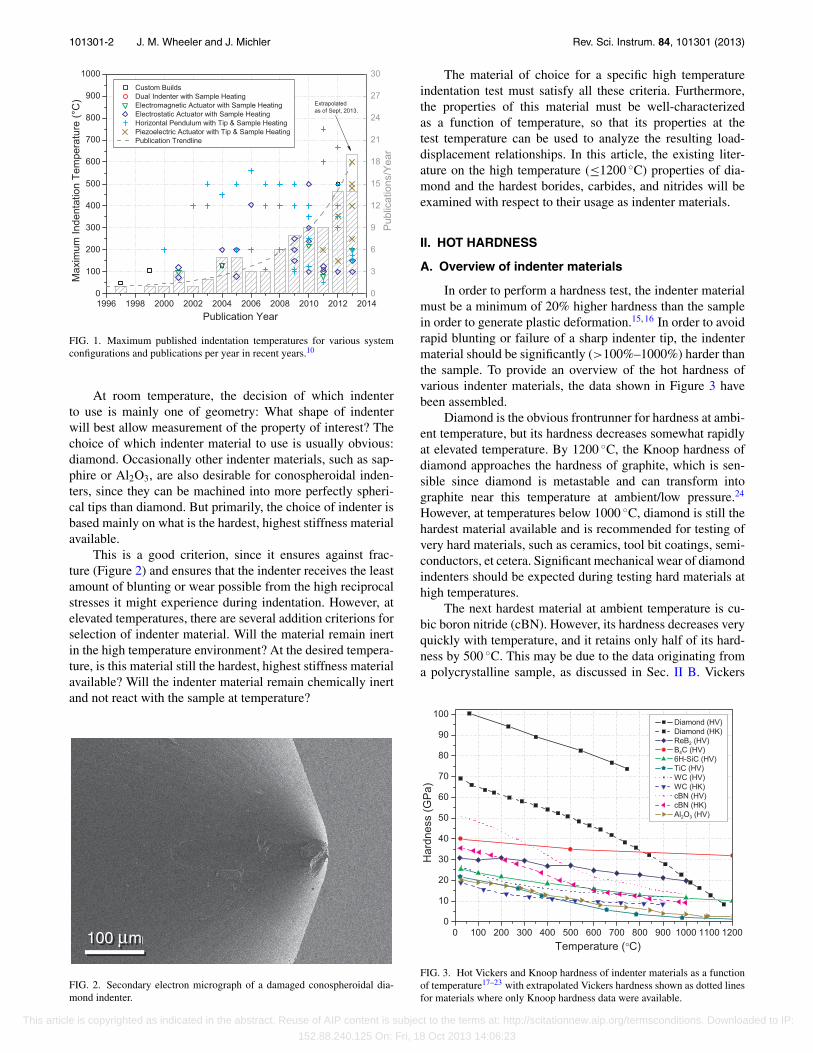
Elevated temperature nanomechanical testing techniques,predominantly nanoindentation and microcompression, arebecoming increasingly popular1–9 due to the lower cost ofsample manufacture and preparation, shrinking length scaleof devices, and higher speed of indentation testing. Mostcommercial nanoindentation system manufacturers now offera high temperature option, and these have had varying de-grees of success. The main factors determining the stabilityof a system during high temperature nanoindentation are thethermal controls implemented in the system:9 indenter and/orsample heating, water-cooling, heat-shielding, etc. These varybetween manufacturers due to the different thermal controlspossible with each system configuration. In Figure 1, the max-imum published indentation temperatures are shown for eachsystem configuration as a function of publication year. Also,the total number of high temperature nanoindentation papersper year,10 as of the publication of this work, is presented. Theincreasing trend in popularity/availability of elevated temper-ature nanoindentation is clear.
System configuration plays a significant role in the fea-sibility of high temperature nanoindentation. Nearly all in-strument developers are currently extending and advertisingincreased temperature ranges; however, here we will onlyconsider results published in peer-reviewed journals. Systemsfeaturing a horizontal pendulum were adapted for elevatedtemperature testing early on with both indenter and sampleheating. The horizontal pendulum allows convection to ver-tically remove heat from the sensor region, and using inden-ter and sample heating allows isothermal testing7 to preventthermal expansion during contact which results in thermaldrift. This system configuration has been the most prolificin high temperature nanoindentation publications thus far. Aplateau was observed in the maximum achieved temperatureat ∼500 ◦C for nearly a decade, due to the onset of oxida-tion of diamond indenters at ∼400 ◦C,11 but this was recentlyovercome using high vacuum techniques.8
a)E-mail: [email protected]
The second most prolific system configuration featuresan electrostatic actuator with heating only on the sample side.The electrostatic actuator is limited to lower forces, which ne-cessitates that the indenter itself has a low mass. This smallsize minimizes the dimensions for thermal expansion and al-lows for rapid thermal equilibration of the indenter mass. Thevertical arrangement of the system introduces the danger ofconvective heating of the sensors, but has been countered us-ing water-cooling and partial vacuum.4 Without active inden-ter heating, thermal drift is still an issue with this system,so testing is generally limited to short durations (1–10 s).New dynamic techniques12 may provide a countermeasure forthis, but significant temperature gradients will still likely bepresent, resulting in poor surface temperature precision.9, 13
Systems with electromagnetic actuators have been lim-ited to lower temperatures (∼200 ◦C) due to excessive ther-mal drift from heat flow between the heated sample and pas-sively heated indenter solenoid. Dynamic techniques12 havebeen demonstrated to counter thermal drift with this system,but the same temperature confidence issues remain.
Recently, two new system configurations have emerged.A system featuring dual indenters to provide active surfacereferencing to eliminate thermal drift and frame compliance14
has been successfully demonstrated at 110 ◦C. Another sys-tem features a piezoelectric actuator for displacement control,indenter tip and sample heating to prevent thermal drift, andwater-cooling of the system frame using an ethylene glycoland water mixture as coolant. It operates in situ in the scan-ning electron microscope allowing observation of deforma-tion mechanics, and the high vacuum of the electron micro-scope also prevents sample and indenter oxidation.9
The increasing popularity and availability of systems ca-pable of nanoindentation testing at high temperatures reintro-duces challenges for indenter material selection which wereaddressed during the first advent of hot hardness testing. Withthe smaller length scales and greater precision involved in in-strumented nanoindentation testing than hot hardness testing,a review of indenter materials and their properties with a viewtowards high temperature nanoindentation may be useful tomany practitioners.
0034-6748/2013/84(10)/101301/11/$30.00 © 2013 AIP Publishing LLC84, 101301-1
This article is copyrighted as indicated in the abstract. Reuse of AIP content is subject to the terms at: http://scitationnew.aip.org/termsconditions. Downloaded to IP:
152.88.240.125 On: Fri, 18 Oct 2013 14:06:23
101301-2 J. M. Wheeler and J. Michler Rev. Sci. Instrum. 84, 101301 (2013)
FIG. 1. Maximum published indentation temperatures for various systemconfigurations and publications per year in recent years.10
At room temperature, the decision of which indenterto use is mainly one of geometry: What shape of indenterwill best allow measurement of the property of interest? Thechoice of which indenter material to use is usually obvious:diamond. Occasionally other indenter materials, such as sap-phire or Al2O3, are also desirable for conospheroidal inden-ters, since they can be machined into more perfectly spheri-cal tips than diamond. But primarily, the choice of indenter isbased mainly on what is the hardest, highest stiffness materialavailable.
This is a good criterion, since it ensures against frac-ture (Figure 2) and ensures that the indenter receives the leastamount of blunting or wear possible from the high reciprocalstresses it might experience during indentation. However, atelevated temperatures, there are several addition criterions forselection of indenter material. Will the material remain inertin the high temperature environment? At the desired tempera-ture, is this material still the hardest, highest stiffness materialavailable? Will the indenter material remain chemically inertand not react with the sample at temperature?
100 µm100 µm
FIG. 2. Secondary electron micrograph of a damaged conospheroidal dia-mond indenter.
The material of choice for a specific high temperatureindentation test must satisfy all these criteria. Furthermore,the properties of this material must be well-characterizedas a function of temperature, so that its properties at thetest temperature can be used to analyze the resulting load-displacement relationships. In this article, the existing liter-ature on the high temperature (≤1200 ◦C) properties of dia-mond and the hardest borides, carbides, and nitrides will beexamined with respect to their usage as indenter materials.
II. HOT HARDNESS
A. Overview of indenter materials
In order to perform a hardness test, the indenter materialmust be a minimum of 20% higher hardness than the samplein order to generate plastic deformation.15, 16 In order to avoidrapid blunting or failure of a sharp indenter tip, the indentermaterial should be significantly (>100%–1000%) harder thanthe sample. To provide an overview of the hot hardness ofvarious indenter materials, the data shown in Figure 3 havebeen assembled.
Diamond is the obvious frontrunner for hardness at ambi-ent temperature, but its hardness decreases somewhat rapidlyat elevated temperature. By 1200 ◦C, the Knoop hardness ofdiamond approaches the hardness of graphite, which is sen-sible since diamond is metastable and can transform intographite near this temperature at ambient/low pressure.24
However, at temperatures below 1000 ◦C, diamond is still thehardest material available and is recommended for testing ofvery hard materials, such as ceramics, tool bit coatings, semi-conductors, et cetera. Significant mechanical wear of diamondindenters should be expected during testing hard materials athigh temperatures.
The next hardest material at ambient temperature is cu-bic boron nitride (cBN). However, its hardness decreases veryquickly with temperature, and it retains only half of its hard-ness by 500 ◦C. This may be due to the data originating froma polycrystalline sample, as discussed in Sec. II B. Vickers
FIG. 3. Hot Vickers and Knoop hardness of indenter materials as a functionof temperature17–23 with extrapolated Vickers hardness shown as dotted linesfor materials where only Knoop hardness data were available.
This article is copyrighted as indicated in the abstract. Reuse of AIP content is subject to the terms at: http://scitationnew.aip.org/termsconditions. Downloaded to IP:
152.88.240.125 On: Fri, 18 Oct 2013 14:06:23

101301-3 J. M. Wheeler and J. Michler Rev. Sci. Instrum. 84, 101301 (2013)
hardness (HV) was extrapolated for cBN and WC using thesame scaling ratio observed between Vickers and Knoop hard-ness (HK) in diamond. Boron carbide (B4C), silicon carbide(SiC), and tungsten carbide (WC) maintain their hardnessat elevated temperatures significantly better. Boron carbidemaintains its hot hardness best of all materials; by 900 ◦C,its hardness surpasses diamond.
Polycrystalline, sintered boride ceramics such as TiB2,ZrB2, and HfB2 have been used previously as high temper-ature indenter materials to good effect,22 but further singlecrystal data are needed for determining their suitability forhigh temperature nanoindentation. Single crystal hot hardnessdata are available for the hardest of the borides, Rhenium di-boride (ReB2), and it retains its high hardness very well at el-evated temperatures.23 However, apart from its hardness, veryfew of its single crystal properties are known as of yet. Dueto this lack of available data, borides will not be discussedfurther in this work despite their promising performance.
In summary, diamond and boron carbide appear to be thematerials of choice for indenting hard materials at elevatedtemperatures. However, additional concerns such as inden-ter/sample reactivity might make other materials with lowerhardness have a chemical advantage for indenting specificmaterials systems. This is further discussed in Sec. V.
B. Effect of single crystals vs. polycrystals
One shortcoming of Sec. II A is that the available lit-erature does not include single crystal data for cubic boronnitride. Since indenters for nano-scale measurements will al-most certainly be using a single crystal at the functional tipof the indenter, it is the single crystal plastic behavior whichis relevant for its high temperature indentation performance.The difference between single and polycrystalline behaviorin these materials at elevated temperatures has been wellillustrated18 for tungsten carbide – Figure 4.
Polycrystalline tungsten carbide is observed to be signif-icantly harder and show decreased temperature dependenceat low temperatures (<700 ◦C) compared to single crystalline
FIG. 4. Hot Knoop hardness of single crystal tungsten carbide of variousorientations and polycrystalline tungsten carbide.18
material. This is attributed to the additional difficulty of prop-agating dislocations across grain boundaries, so strength willalso be dependent on the grain size following Hall-Petchbehavior.
Single crystal behavior for WC is highly anisotropic withtemperature dependence also varying between various crystalorientations. This dependence will be less for cubic crystalsthan hexagonal indenter materials such as WC, Al2O3, and6H-SiC. This highlights the importance of correctly orientingthese crystals during indenter manufacture.
The cBN hot hardness values in Figure 3 are from a poly-crystalline sample with a 5 μm grain size.17 This might bepartially responsible for the relatively rapid decrease in hothardness with temperature observed. Higher hardnesses with-out a rapid decrease in hardness at high temperature were ob-served in finer grain size cBN; however, it is not possible tospeculate how a single crystal would behave. This suggeststhat nanocrystalline materials may have higher hardness withlower temperature dependence as well as effectively isotropicelastic properties, but it is likely that grain growth and lowertemperature onset of rapid hardness decrease would limit theirusefulness to lower temperatures.
C. New candidate indenter materials
Significant effort21, 25–29 has been made recently for cre-ating new superhard materials for industrial abrasives, hardcoatings, and various other applications. Several new ma-terials of high hardness have been discovered: ReB2,23, 25
B6O,30 BC5,26 BC2N,27 γ -Boron,28 and aggregated diamondnanorods.29 However, several challenges still remain beforethese materials can be considered as candidates for elevatedtemperature indenter materials: cost, availability of large sin-gle crystals, and knowledge of material properties at elevatedtemperatures.
III. ELASTIC MODULUS
A. Indentation modulus analysis
One of the chief advantages of instrumented indentationover previous hot hardness methods is the ability to extracthardness and elastic modulus without imaging of the residualimpression. This is achieved by measuring the stiffness of thecontact during unloading of the indenter to determine the con-tact area and from that the hardness and modulus. This can beachieved by various different analyses, but the standard anal-ysis is the one outlined by Oliver and Pharr.31 In this analysis,since the indenter tip is not perfectly rigid, it elastically de-forms simultaneously with the sample. Assuming the elasticconstants are isotropic, it can be shown that the apparent or“reduced” modulus, Er, is given by
Er =√
π
2B
S√Ap
, (1)
where B is a geometric constant, S is the contact stiffness, andAp is the contact area. This reduced modulus is the convo-lution of both the indenter and sample elastically deforming
This article is copyrighted as indicated in the abstract. Reuse of AIP content is subject to the terms at: http://scitationnew.aip.org/termsconditions. Downloaded to IP:
152.88.240.125 On: Fri, 18 Oct 2013 14:06:23
101301-4 J. M. Wheeler and J. Michler Rev. Sci. Instrum. 84, 101301 (2013)
during contact according to the relation
Er =((
1 − ν2s
)Es
+(1 − ν2
i
)Ei
)−1
, (2)
where Ei, ν i and Es, νs are the Young’s modulus and Poisson’sratio of the indenter and sample, respectively. This equationdemonstrates necessity of accurate knowledge of the indenterproperties in order to apply instrumented indentation to mea-sure the mechanical properties of a sample.
B. Temperature dependence of modulus
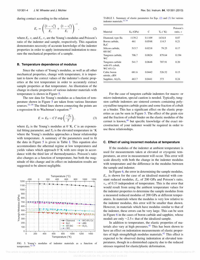
Since the values of Young’s modulus, as well as all othermechanical properties, change with temperature, it is impor-tant to know the correct values of the indenter’s elastic prop-erties at the test temperature in order to accurately extractsample properties at that temperature. An illustration of thechange in elastic properties of various indenter materials withtemperature is shown in Figure 5.
The raw data for Young’s modulus as a function of tem-perature shown in Figure 5 are taken from various literaturesources.32–39 The fitted lines shown connecting the points area regression fit to Wachtman’s equation:35
E = E0 − CT exp
(−T0
T
), (3)
where E0 is the Young’s modulus at 0 ◦K, C is an exponen-tial fitting parameter, and T0 is the elevated temperature in ◦Kwhere the Young’s modulus approaches a linear relationshipwith temperature. A summary of the parameters used to fitthe data in Figure 5 is given in Table I. This equation alsoaccommodates the athermal regime at low temperatures andyields values which approach 0 ◦K with zero slope in accor-dance with the third law of thermodynamics. Poisson’s ratioalso changes as a function of temperature, but both the mag-nitude of this change and its effect on indentation results aresuggested to be almost negligible.
FIG. 5. Young’s modulus of indenter materials as a function oftemperature.32–39
TABLE I. Summary of elastic parameters for Eqs. (2) and (3) for variousindenter materials.32–39
Poisson’sMaterial E0 (GPa) C T0 (◦K) ratio, ν
Diamond, type IIa 1139.2 0.1109 1434.8 0.07Boron carbide,B4C
461 0.0548 114.5 0.21
Silicon carbide,6H-SiC
515.7 0.0218 79.25 0.17
Tungsten carbide,WC
706.7 0.0824 879.64 0.194
Tungsten carbidewith 6% cobalt,WC-6% Co
541.7 0.0648 707.91 0.20
Cubic boronnitride, cBN
681.6 0.0442 526.52 0.15
Sapphire, Al2O3 463.7 0.0441 373 0.24
For the case of tungsten carbide indenters for macro- ormicro-indentation, special caution is needed. Typically, tung-sten carbide indenters are sintered cermets containing poly-crystalline tungsten carbide grains and some fraction of cobaltas a binder. This has a significant effect on the elastic prop-erties as can be seen in Figure 5. The effect of the grain sizeand the fraction of cobalt binder on the elastic modulus of thecermet is known,40 but specific knowledge of the exact mi-crostructure of your indenter would be required in order touse these relationships.
C. Effect of using incorrect modulus at temperature
If the modulus of the indenter at ambient temperature isused for measurements taken at elevated or cryogenic tem-peratures, an error in measurement will occur. This error willscale directly with both the change in the indenter moduluswith temperature and the difference in the modulus betweenthe sample and indenter.
In Figure 6, the error in determining the sample modulus,Es, is shown for the case of an idealised material with con-stant reduced modulus, Er, of 200 GPa and Poisson’s ratio,νs, of 0.33 independent of temperature. This is the error thatwould result from using the ambient temperature values forthe indenter properties to determine the sample modulus froma measured reduced modulus of 200 GPa at different temper-atures. In materials where the modulus is very low relative tothe indenter modulus, this error will be smaller than shown.However, in materials which have modulus similar to that ofthe indenter, these errors can be very large. This can be seenin Figure 6 in the cases of boron carbide and sapphire, whosemoduli are only ∼2.5× that of the idealized sample.
In addition to temperature, the elastic properties of ma-terials also vary at high pressures.41 This has been shown tohave an effect on indentation measurements of elastic proper-ties of high strength/high modulus materials.42 This effect isexpected to be observed during indentation at elevated tem-peratures, though in a diminished capacity due to the reducedstresses required for elastic/plastic deformation.
This article is copyrighted as indicated in the abstract. Reuse of AIP content is subject to the terms at: http://scitationnew.aip.org/termsconditions. Downloaded to IP:
152.88.240.125 On: Fri, 18 Oct 2013 14:06:23

101301-5 J. M. Wheeler and J. Michler Rev. Sci. Instrum. 84, 101301 (2013)
FIG. 6. Error in Young’s modulus measurements on a sample withEr = 200 GPa and νs = 0.33 from using room temperature values of indentermaterial moduli as a function of temperature.32–39
IV. THERMAL PROPERTIES AND EFFECTSON MEASUREMENT
A. Relationship of thermomechanicalproperties to drift
It is well known that the thermal properties of the sam-ple material, particularly thermal conductivity, have an effecton the magnitude of thermal drift during high temperature in-dentation. This has been shown to be due to the contact ther-mal drift being proportional to the amount of heat flow occur-ring across the contact.43 However, the thermal conductivityof the indenter also plays a role. The majority of the thermaldrift has been attributed to expansion within the shaft of theindenter,4 so the magnitude of the indenter’s expansion for agiven amount of heat or �L/q is a descriptive parameter forthe propensity of an indenter material to thermal drift. Theexpansion for per unit energy,
�L
q= L
CpαL
ρV, (4)
where L is the axial indenter length, q is the transferred heat,Cp is the specific heat, αL is the linear coefficient of thermal
expansion, ρ is the density, and V is the volume of the indentershaft. These properties are summarized in Table II for the var-ious indenter materials. The geometry of the indenter materialshaft is given to be 0.2 mm by 0.2 mm with an axial length of0.3 mm, which is then embedded during manufacture into aholder whose geometry is specific to the manufacturer of thenanoindentation system.
The amount of thermal expansion drift expected fromthe indenter shaft will now be a combination of the expan-sion per unit energy and the heat flow expected across theinterface, which is a function of the indenter and sample ma-terial’s thermal conductivity, the contact area, and thermalgradient.43 For an indent of a similar size on the same materialwith the same temperature difference, the various indentersshow mostly similar behavior. Diamond and cBN both con-duct heat extremely well, but their expansion per unit energyis very low. Whereas, boron carbide and sapphire are poorerconductors, but have high expansion per unit energy due totheir higher coefficients of thermal expansion. Silicon carbideappears to be significantly prone to thermal drift, since it hasboth high conductivity and high expansion per unit energy.The best performance is expected from tungsten carbide, be-cause it has both very low conductivity and low expansion perunit energy due to its high density.
B. Indenter geometry variation with temperature
Thermal expansion can also have an effect on the geom-etry of an indenter. For ideal self-symmetric indenters, suchas conical and pyramidal indenters, this effect would be nom-inally nil, except for any anisotropy in thermal expansion co-efficients causing a slight change in aspect ratio or equivalentcone angle. Some indenter materials with a hexagonal crys-tal structure, e.g., 6H-SiC and Al2O3, do have anisotropy inthermal expansion, but we will only consider isotropic expan-sion here. Since indenters cannot have ideal geometry, thereis always a blunt tip radius at the apex of the cone or pyramid.This radius will expand at elevated temperatures and producea proportional change in the area function of the indenter, ashas been previously discussed.3 Thus, the main considerationof the influence of thermal expansion on indenters, aside fromthermal drift related expansions, is the change in tip radius,whether the tip geometry is conical, pyramidal or spherical.
TABLE II. Summary of room temperature thermomechanical properties of various indenter materials.33, 36, 44–50
Thermal conductivity Thermal expansion Specific heat Density �L/qIndenter material (W m−1 ◦K−1) (10−6 ◦K−1) (J g−1 ◦K−1) (g/cm3) (nm/mJ)
Diamond, type IIa 2000 1.00 0.52 3.51 3.7Boron carbide,B4C
28 4.22 0.96 2.52 40.2
Silicon carbide,6H-SiC
490 2.77 0.66 3.21 14.2
Tungsten carbide,WC
29.3 10.17 0.18 15.8 2.9
Cubic boronnitride, cBN
1300 1.15 0.51 3.48 4.2
Sapphire, Al2O3 42 5.20 0.77 3.98 25.2
This article is copyrighted as indicated in the abstract. Reuse of AIP content is subject to the terms at: http://scitationnew.aip.org/termsconditions. Downloaded to IP:
152.88.240.125 On: Fri, 18 Oct 2013 14:06:23

101301-6 J. M. Wheeler and J. Michler Rev. Sci. Instrum. 84, 101301 (2013)
FIG. 7. Relative length change of various indenter materials compared toroom temperature along their principal crystallographic axis as a function oftemperature.33, 47–50
Over large variations in temperature, the coefficient ofthermal expansion (CTE) cannot be approximated as linear.In order to extract the relative amount change in length,L, due to thermal expansion (�L/L), the relationship of theCTE with temperature must be integrated. For the indentermaterials considered here, this relative change in dimensionor tip radius with respect to room temperature is shown inFigure 7. For most materials, this is ≤0.5% even by 1000 ◦C;however, sapphire and tungsten carbide show significantlymore expansion. The effect of this expansion on the projectedarea functions of Berkovich indenters with a 100 nm tip radiiand 10 μm radius spherical indenters is shown in Figure 8.
The differences between the Berkovich and the sphericalindenters’ changes in projected area at elevated temperaturescan be immediately observed in Figure 8. The spherical in-denters’ changes in area are initially directly equivalent to therelative length change observed in Figure 7 at this temperaturefor these materials, and only slight increases are observed atgreater depths due to the slight increases in radii.
FIG. 8. The percentage change in projected area at 500 ◦C for Berkovichindenters with a 100 nm tip radius and 10 μm spherical indenters composedof various indenter materials.
The Berkovich indenters initially start at the same values,due to the blunting of the tip radius, but then they rapidly de-crease down to near negligible levels as the effect of the self-symmetry becomes apparent at greater depths. The Berkovicharea function is approximated here using a piecewise functionwhere the region near the tip is approximated as a sphere per-fectly tangent to the end of a cone with an angle such that itsprojected area is equivalent to the Berkovich pyramid:
Ap = π (2Rhc − h2c) when hc ≤ R − R sin(θ ) (5)
and
Ap = π [(hc + hx) tan(θ )]2 when hc > R − R sin(θ ),(6)
where R is the tip radius, hc is the contact depth, hx is the ad-ditional depth to which an ideal cone tangent to the sphericaltip would extend: hx = R/sin (θ ) − R, and θ is the cone angle:70.32◦ for a Berkovich.
Maxima in the changes in area are observed at the tan-gent depth between the spherical tip and the cone. This is thetransition point between the spherical function, which has rel-atively larger areas at greater depths, and the self-similar con-ical function which has relatively the same areas at greaterdepths. As hc becomes �hx, the additional influence of hx inEq. (5) becomes negligible. The change in hx to accommodatethe change in R due to thermal expansion is the main sourceis deviation for the self-symmetric portions of the inden-ters. The piecewise function utilized here has the advantageof remaining accurate for low depths and/or large tip radii,whereas the continuous area function of Thurn and Cook51
used previously3 is not valid for depths where the contact ra-dius is less than the indenter radius.
The changes in projected area calculated for diamond aregreater than previously reported3 for similar temperature gra-dients, because the present analysis takes into account thechanges in coefficients of thermal expansion at elevated tem-perature rather than extrapolating a room temperature valueof CTE to elevated temperature. Also, the piecewise functionallows accurate calculation of changes in area at low depths.However, the trends of rapid decrease in �Ap/Ap with increas-ing depth are in good agreement with previous estimations.3
The maximum error expected due to thermal expansion is onthe order of 1%, and this is limited to indentations wherethe depth is ≤ the indenter radius. Most indenter materialsare only expected to have error on the order of 0.1%, whichis comparable to the accuracy of the typical indenter areafunction.
C. Methods for indenter temperature calibration
In order to minimize errors in displacement measure-ment due to expansions related to heat exchange between theindenter and sample at elevated temperatures, the tempera-tures of the indenter and the sample must be very preciselymatched. Since the thermocouples for monitoring the inden-ter temperature are always removed some distance away fromthe region of contact, a thermal gradient exists between thethermocouple and the tip of the indenter. This can result in er-rors in indenter set temperature on the order of 5%–40%.9 In
This article is copyrighted as indicated in the abstract. Reuse of AIP content is subject to the terms at: http://scitationnew.aip.org/termsconditions. Downloaded to IP:
152.88.240.125 On: Fri, 18 Oct 2013 14:06:23
101301-7 J. M. Wheeler and J. Michler Rev. Sci. Instrum. 84, 101301 (2013)
order to maintain accurate test temperatures, this temperaturegradient must be calibrated prior to testing. Two methods havebeen previously described43 for this: indentation into thermo-couples at high temperature and Raman spectroscopy. A thirdmethod might be use of a high resolution thermal camera cal-ibrated to the indenter material, but this has not been experi-mentally demonstrated yet.
Direct indentation of thermocouples at elevated tempera-ture allows contact to be achieved at a known surface tem-perature. Some error due to poor thermal coupling can al-ways be expected when a thermocouple is merely bonded toa surface by a high temperature adhesive, and directly indent-ing the thermocouple removes this uncertainty. Care must betaken in thermocouple type selection to prevent corrosion ofthe indenter. Platinum/rhodium-based thermocouples (TypesB, R, and S) are recommended for high temperature indentertemperature calibration for most indenter materials. Match-ing the indenter temperature to this known surface temper-ature can be achieved by either thermal displacement driftmeasurements7 or direct temperature shift measurements.43
In both cases, the technique involves varying either the in-denter or the sample temperature while leaving one of themconstant and performing a number of indentations at differ-ent relative temperatures. If the indenter is observed to drift inthe negative displacement direction or to increase in tempera-ture during contact, the indenter is presumed to be colder thanthe sample surface. If the indenter decreases in temperature ordrifts in the positive displacement direction than the indenter,then the indenter is presumed to be hotter than the sample sur-face. Thermal drift displacement measurements are addition-ally affected by stabilisation of the system frame and tempera-ture fluctuations during contact,9 so long stabilisation periodsand drift hold periods may be necessary to correctly match thesample and indenter by this method.7 After performing thistemperature matching procedure on a thermocouple at severaldifferent surface temperatures, the relationship between theknown surface temperatures from the thermocouple and thetemperatures at which the indenter apparently matches thesetemperatures can be ascertained.
Calibrating an indenter’s temperature via Raman spec-troscopy is somewhat simpler. However, the precision of thesemeasurements is typically limited to ∼10 ◦C. When using anindenter made from a material with a known Raman shift asa function of temperature, it is fairly straightforward to heatan indenter to some fixed set temperature, obtain a Ramanspectrum from the indenter and measure the peak shift, com-pare that peak shift to the literature, and determine the ac-tual temperature of the indenter according to the Raman shift.The relationships for Raman shift as a function of tempera-ture are available in the literature for many indenter materials:diamond,52–54 cBN,55, 56 and sapphire.57
V. CHEMICAL REACTIVITY
A. Indenter damage due to oxidation
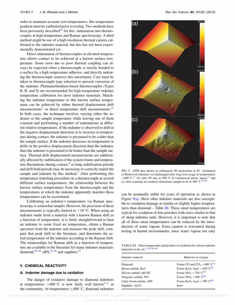
The danger of oxidative damage to diamond indentersat temperatures >400 ◦C is now fairly well known4, 11 inthe community. At temperatures ≤400 ◦C, diamond indenters
0.72 µm
1.28 µm
2.63 µm
0.00 µm
0.00 µm
0.00 µm
(a)
(b)
(c)
FIG. 9. AFM data shown as orthogonal 3D projections at 45◦ inclinationof Berkovich indenters (a) undamaged after long term usage at temperatures<400 ◦C,11 (b) after 90 min at 900 ◦C in commercial purity argon,11 and(c) after scanning an oxidized aluminium sample in air at 300 ◦C.61, 62
can be nominally stable for years of operation as shown inFigure 9(a). Most other indenter materials are also suscepti-ble to oxidation damage at similar or slightly higher tempera-tures than diamond – Table III. These onset temperatures aretypical for oxidation of fine powders with sizes similar to thatof sharp indenter radii. However, it is important to note thatall of these onset temperatures can be reduced by the intro-duction of water vapour. Extra caution is warranted duringtesting in humid environments, since water vapour not only
TABLE III. Onset temperature and product of oxidation for various indentermaterials in dry air.11, 44, 58–60
Indenter material Behavior in oxygen
Diamond Forms CO and CO2 >400 ◦C11
Boron carbide, B4C Forms B2O3 layer >450 ◦C58
Silicon carbide, 6H-SiC Forms SiO2 >750 ◦C59
Tungsten carbide, WC Forms WO3 >500 ◦C60
Cubic boron nitride, cBN Forms B2O3 layer >700 ◦C44
Sapphire, Al2O3 Inert
This article is copyrighted as indicated in the abstract. Reuse of AIP content is subject to the terms at: http://scitationnew.aip.org/termsconditions. Downloaded to IP:
152.88.240.125 On: Fri, 18 Oct 2013 14:06:23

101301-8 J. M. Wheeler and J. Michler Rev. Sci. Instrum. 84, 101301 (2013)
decreases the onset temperatures but also increases the oxida-tion rates.
For operation at temperatures higher than the onset tem-peratures in Table III, a high purity inert gas4, 7 or highvacuum8, 9 environment can be used to protect the inden-ter from oxygen. Otherwise, the indenter initially becomessmoothly blunted and then irregularly blunted as etch pitsand terraces form on the surface11 as seen in Figure 9(b).Partial vacuum4 (∼10−2 mbar) and commercial purity argon(30–45 ppm O2) atmospheres11 have been observed not to sig-nificantly boost onset temperatures for oxidation of diamond:oxidation of the diamond was observed between 400 and500 ◦C. High vacuum environments8, 9 (∼10−6 mbar) havebeen successful thus far in preventing oxidation of diamondindenters up to ∼700 ◦C; however, ultra high vacuum (UHV)may be necessary for testing with diamond at temperatures upto 1000 ◦C.
Another kind of “damage” due to oxidation can also oc-cur at lower temperatures. If indentations or scratches areperformed in a material which oxidizes, this surface oxidecan easily be transferred to the indenter tip61 as shown inFigure 9(c). This oxide contamination effectively blunts theindenter and introduces large errors into the diamond areafunction calibration. This form of contamination can stronglyadhere to the indenter and require the use of acids or indenta-tions into hard materials to remove it.
B. Potential for indenter damage from sample
Even if the indenter is sufficiently stiff and hard to indentthe sample material without significant mechanical bluntingor wear, the indenter could still be at risk to chemical reac-tions between itself and the sample. The classic example ofthis is the indentation of steel with a diamond indenter at hightemperature. Despite the extraordinary chemical stability ofdiamond, most exemplified by its complete resistance to at-tack by acids, the diamond disintegrates and reacts with thesteel to form Fe3C carbides. This process can completely de-stroy an indenter, as shown in Figure 10, to the point whereonly a remnant of where the indenter was can be observedafterwards. This demonstrates the necessity of using an ap-
10000 µµmm100 µm
FIG. 10. Secondary electron micrograph of the remnant of a diamond inden-ter after contact with a steel sample at 500 ◦C.
propriate indenter material for the various classes of samplematerials to ensure that the indenter remains chemically inertduring indentation.
However, this situation is complicated by the extremelyhigh stresses applied during indentation. An appropriate “ruleof thumb” for a maximum temperature for indentation withknown reactive indenter/sample combinations, such as stay-ing below the creep regime of the material or below the for-mation temperature of the carbide, remains elusive, since thetip can be destroyed at temperatures far below either of thesecriterions – Figure 10. In fact, high precision investigationsusing sharp diamond indenters on pure tungsten have shownsigns of blunting/reactivity even at room temperature,76 whichfurther suggests that these reactions occur over a continuumrather than starting at a particular onset temperature.
A systematic empirical study of the influence of stresson these solid state reactions has been avoided thus far dueto the prohibitive cost of the number of consumable indentersrequired to conduct such a study. However, some recent ad-vances have been made for studying the stress-assisted wearof single point diamond tools,63 which suggest stress assistedgraphitization at high cutting temperatures is the dominantmechanism. In the absence of knowledge of how this extrap-olates to the full temperature range and other indenter mate-rials, indenter/sample material combinations where reactionshave been observed to occur at any elevated temperature arerecommended to be avoided completely.
C. Reactivity of elemental indenter/samplecombinations
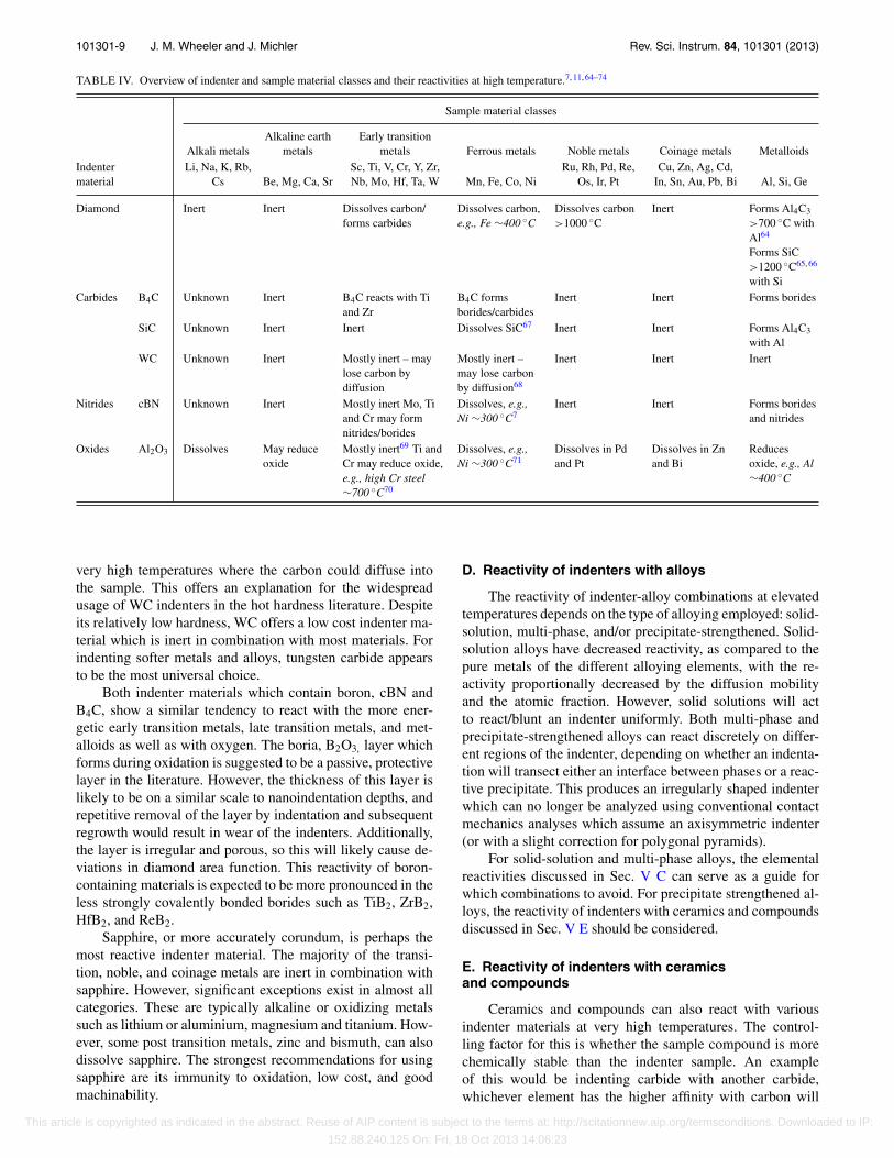
Some limited anecdotal information on safe temperatureregimes and indenter/sample material combinations for hightemperature indentation exists in the literature on hot hard-ness from the 1940s to 1960s, but much of this technical ex-pertise seems to have been lost. By combining the limitedpicture remaining from hot hardness literature with the liter-ature on high temperature wetting and metal-ceramic com-posite manufacture, a general picture of the reactivities ofvarious classes of indenter/sample material combinations hasbeen constructed – Table IV.
Diamond indenters show excellent resistance to materi-als which chemically attack indenters: alkali metals, alkalineearth metals, and metalloids. However, diamond is vulnera-ble to attack by materials which aggressively form carbidesor dissolve carbon: the early and late transition metals. Manyof the early transition metals have carbides with a high en-thalpy of formation, so diamond’s reactions with them maynot become rapid or apparent until very high temperature. Asdiscussed above, the details of the various reactions’ kineticsare not known with stress, so caution is suggested when usinga diamond indenter in combination with any of these metalseven at relatively low temperatures. Diamond is almost com-pletely inert in combination with the noble and coinage met-als, but the literature suggests that the noble metals can alsodissolve carbon at high temperatures.
Tungsten carbide appears to be the most chemically sta-ble of all the indenter materials. It only appears to be vul-nerable in combination with tungsten, titanium, and iron at
This article is copyrighted as indicated in the abstract. Reuse of AIP content is subject to the terms at: http://scitationnew.aip.org/termsconditions. Downloaded to IP:
152.88.240.125 On: Fri, 18 Oct 2013 14:06:23
101301-9 J. M. Wheeler and J. Michler Rev. Sci. Instrum. 84, 101301 (2013)
TABLE IV. Overview of indenter and sample material classes and their reactivities at high temperature.7, 11, 64–74
Sample material classes
Alkali metalsAlkaline earth
metalsEarly transition
metals Ferrous metals Noble metals Coinage metals MetalloidsIndentermaterial
Li, Na, K, Rb,Cs Be, Mg, Ca, Sr
Sc, Ti, V, Cr, Y, Zr,Nb, Mo, Hf, Ta, W Mn, Fe, Co, Ni
Ru, Rh, Pd, Re,Os, Ir, Pt
Cu, Zn, Ag, Cd,In, Sn, Au, Pb, Bi Al, Si, Ge
Diamond Inert Inert Dissolves carbon/forms carbides
Dissolves carbon,e.g., Fe ∼400 ◦C
Dissolves carbon>1000 ◦C
Inert Forms Al4C3
>700 ◦C withAl64
Forms SiC>1200 ◦C65, 66
with SiCarbides B4C Unknown Inert B4C reacts with Ti
and ZrB4C formsborides/carbides
Inert Inert Forms borides
SiC Unknown Inert Inert Dissolves SiC67 Inert Inert Forms Al4C3
with AlWC Unknown Inert Mostly inert – may
lose carbon bydiffusion
Mostly inert –may lose carbonby diffusion68
Inert Inert Inert
Nitrides cBN Unknown Inert Mostly inert Mo, Tiand Cr may formnitrides/borides
Dissolves, e.g.,Ni ∼300 ◦C7
Inert Inert Forms boridesand nitrides
Oxides Al2O3 Dissolves May reduceoxide
Mostly inert69 Ti andCr may reduce oxide,e.g., high Cr steel∼700 ◦C70
Dissolves, e.g.,Ni ∼300 ◦C71
Dissolves in Pdand Pt
Dissolves in Znand Bi
Reducesoxide, e.g., Al∼400 ◦C
very high temperatures where the carbon could diffuse intothe sample. This offers an explanation for the widespreadusage of WC indenters in the hot hardness literature. Despiteits relatively low hardness, WC offers a low cost indenter ma-terial which is inert in combination with most materials. Forindenting softer metals and alloys, tungsten carbide appearsto be the most universal choice.
Both indenter materials which contain boron, cBN andB4C, show a similar tendency to react with the more ener-getic early transition metals, late transition metals, and met-alloids as well as with oxygen. The boria, B2O3, layer whichforms during oxidation is suggested to be a passive, protectivelayer in the literature. However, the thickness of this layer islikely to be on a similar scale to nanoindentation depths, andrepetitive removal of the layer by indentation and subsequentregrowth would result in wear of the indenters. Additionally,the layer is irregular and porous, so this will likely cause de-viations in diamond area function. This reactivity of boron-containing materials is expected to be more pronounced in theless strongly covalently bonded borides such as TiB2, ZrB2,HfB2, and ReB2.
Sapphire, or more accurately corundum, is perhaps themost reactive indenter material. The majority of the transi-tion, noble, and coinage metals are inert in combination withsapphire. However, significant exceptions exist in almost allcategories. These are typically alkaline or oxidizing metalssuch as lithium or aluminium, magnesium and titanium. How-ever, some post transition metals, zinc and bismuth, can alsodissolve sapphire. The strongest recommendations for usingsapphire are its immunity to oxidation, low cost, and goodmachinability.
D. Reactivity of indenters with alloys
The reactivity of indenter-alloy combinations at elevatedtemperatures depends on the type of alloying employed: solid-solution, multi-phase, and/or precipitate-strengthened. Solid-solution alloys have decreased reactivity, as compared to thepure metals of the different alloying elements, with the re-activity proportionally decreased by the diffusion mobilityand the atomic fraction. However, solid solutions will actto react/blunt an indenter uniformly. Both multi-phase andprecipitate-strengthened alloys can react discretely on differ-ent regions of the indenter, depending on whether an indenta-tion will transect either an interface between phases or a reac-tive precipitate. This produces an irregularly shaped indenterwhich can no longer be analyzed using conventional contactmechanics analyses which assume an axisymmetric indenter(or with a slight correction for polygonal pyramids).
For solid-solution and multi-phase alloys, the elementalreactivities discussed in Sec. V C can serve as a guide forwhich combinations to avoid. For precipitate strengthened al-loys, the reactivity of indenters with ceramics and compoundsdiscussed in Sec. V E should be considered.
E. Reactivity of indenters with ceramicsand compounds
Ceramics and compounds can also react with variousindenter materials at very high temperatures. The control-ling factor for this is whether the sample compound is morechemically stable than the indenter sample. An exampleof this would be indenting carbide with another carbide,whichever element has the higher affinity with carbon will
This article is copyrighted as indicated in the abstract. Reuse of AIP content is subject to the terms at: http://scitationnew.aip.org/termsconditions. Downloaded to IP:
152.88.240.125 On: Fri, 18 Oct 2013 14:06:23

101301-10 J. M. Wheeler and J. Michler Rev. Sci. Instrum. 84, 101301 (2013)
deplete the other. However, at high temperatures, boron car-bide has been successfully used for indenting both boridesand carbides.22 Diamond, tantalum carbide and tungsten car-bide are suggested for indentation of oxides,22 nitrides, andsemiconductors.75
VI. SUMMARY
The literature properties of various indenter materialshave been reviewed with respect to their performance for hightemperature nanoindentation. Diamond and boron carbide arethe materials of choice for indenting hard materials at ele-vated temperatures due to their excellent retained hardness athigh temperatures. The temperature dependence of the elas-tic properties of the various indenter materials including for-mulae for their values has been given along with the possi-ble errors resulting from using incorrect values. The thermalproperties of the materials have been briefly described in re-lation to their impact on high temperature indentation behav-ior. The influence of thermal expansion on indenter tip ge-ometry was found to be negligible for most indenter materi-als, and methods for calibrating the thermal gradient betweenthe indenter tip and its temperature sensor were discussed.Lastly, the chemical reactivity of the indenter materials withvarious elements was reviewed. High to ultra-high vacuumis necessary to prevent oxidation of most indenter materialsabove ∼400 ◦C with the exception of sapphire. Tungsten car-bide showed the lowest reactivity of the indenter materialssurveyed and is likely the most universal solution for indenta-tion of metals and alloys without sample-indenter reactions.
ACKNOWLEDGMENTS
The authors would like to thank CSM Instruments SA,Pesaux, Switzerland for their support for the initial portionof this review and their continuing efforts to advance hightemperature nanoindentation technology. The authors wouldlike to thank the high temperature nanoindentation commu-nity for its support for this review and their contributions toTable IV. J.M.W. would like to acknowledge the assistanceof R.A. Oliver of the University of Cambridge, UK in acquir-ing the data for Figures 9(a) and 9(b). J.M.W. would espe-cially like to thank M. Monclus of IMDEA, Madrid, Spainfor the contribution of Figure 9(c) and R. Schwaiger of KIT,Karlsruhe, Germany for the inspiration and motivation for thisreview.
1B. D. Beake and J. F. Smith, Philos. Mag. A 82(10), 2179–2186 (2002).2C. A. Schuh, J. K. Mason, and A. C. Lund, Nature Mater. 4(8), 617–621(2005).
3C. A. Schuh, C. E. Packard, and A. C. Lund, J. Mater. Res. 21(3), 725–736(2006).
4J. C. Trenkle, C. E. Packard, and C. A. Schuh, Rev. Sci. Instrum. 81(7),073901 (2010).
5Z. Duan and A. Hodge, JOM 61(12), 32–36 (2009).6J. Milhans, D. S. Li, M. Khaleel, X. Sun, M. S. Al-Haik, A. Harris, and H.Garmestani, J. Power Sources 196(13), 5599–5603 (2011).
7N. M. Everitt, M. I. Davies, and J. F. Smith, Philos. Mag. 91(7–9), 1221–1244 (2011).
8S. Korte, R. J. Stearn, J. M. Wheeler, and W. J. Clegg, J. Mater. Res. 27(1),167–176 (2011).
9J. M. Wheeler and J. Michler, Rev. Sci. Instrum. 84(4), 045103 (2013).10B. V. Elsevier, SciVerse R© Scopus R©, September 2013, see http://www.
scopus.com/home.url.11J. M. Wheeler, R. A. Oliver, and T. W. Clyne, Diamond Relat. Mater.
19(11), 1348–1353 (2010).12V. Maier, B. Merle, M. Göken, and K. Durst, J. Mater. Res. 28, 1177–1188
(2013).13H. Lee, Y. Chen, A. Claisse, and C. Schuh, Exp. Mech. 53, 1201–1211
(2013).14X. Huang, J. Nohava, B. Zhang, and A. G. Ramirez, Int. J. Smart Nano
Mater. 2(1), 39–49 (2011).15F. P. Bowden and D. Tabor, The Friction and Lubrication of Solids
(Clarendon, Oxford, 1986).16D. Tabor, Br. J. Appl. Phys. 7, 159–166 (1956).17N. Novikov, Y. V. Sirota, V. Mal’Nev, and I. Petrusha, Diamond Relat.
Mater. 2(9), 1253–1256 (1993).18M. Lee, Metall. Trans. A 14(8), 1625–1629 (1983).19A. Atkins, Proc. R. Soc. London, Ser. A 292, 441 (1966).20T. Hirai and K. Niihara, J. Mater. Sci. 14(9), 2253–2255 (1979).21V. Mukhanov, O. Kurakevych, and V. Solozhenko, J. Superhard Mater.
32(3), 167–176 (2010).22R. D. Koester and D. P. Moak, J. Am. Ceram. Soc. 50(6), 290–296 (1967).23S. Otani, M. M. Korsukova, and T. Aizawa, J. Alloys Compd. 477(1–2),
L28–L29 (2009).24J. Qian, C. Pantea, J. Huang, T. W. Zerda, and Y. Zhao, Carbon 42(12–13),
2691–2697 (2004).25H.-Y. Chung, M. B. Weinberger, J. B. Levine, A. Kavner, J.-M. Yang, S. H.
Tolbert, and R. B. Kaner, Science 316(5823), 436–439 (2007).26V. L. Solozhenko, O. O. Kurakevych, D. Andrault, Y. Le Godec, and M.
Mezouar, Phys. Rev. Lett. 102(1), 015506 (2009).27Y. Zhang, H. Sun, and C. Chen, Phys. Rev. Lett. 93(19), 195504 (2004).28V. Solozhenko, O. Kurakevych, and A. Oganov, J. Superhard Mater. 30(6),
428–429 (2008).29N. Dubrovinskaia, L. Dubrovinsky, W. Crichton, F. Langenhorst, and A.
Richter, Appl. Phys. Lett. 87(8), 083106 (2005).30D. He, Y. Zhao, L. Daemen, J. Qian, T. Shen, and T. Zerda, Appl. Phys.
Lett. 81(4), 643–645 (2002).31W. C. Oliver and G. M. Pharr, J. Mater. Res. 7(6), 1564–1583 (1992).32F. Aguado and V. G. Baonza, Phys. Rev. B 73(2), 024111 (2006).33R. R. Reeber and K. Wang, J. Am. Ceram. Soc. 82(1), 129–135 (1999).34J. B. Wachtman and D. G. Lam, J. Am. Ceram. Soc. 42(5), 254–260
(1959).35J. B. Wachtman, Jr., W. E. Tefft, D. G. Lam, Jr., and C. S. Apstein, Phys.
Rev. 122(6), 1754–1759 (1961).36T. Goto, O. L. Anderson, I. Ohno, and S. Yamamoto, J. Geophys. Res.
94(B6), 7588–7602, doi:10.1029/JB094iB06p07588 (1989).37S. R. Murthy, J. Mater. Sci. Lett. 4(5), 603–605 (1985).38W. Köster and W. Rauscher, Z. Metallkd. 39, 111–120 (1948).39Z. Li and R. C. Bradt, Int. J. High Technol. Ceram. 4(1), 1–10 (1988).40H. Doi, Y. Fujiwara, K. Miyake, and Y. Oosawa, Metall. Mater. Trans. 1(5),
1417–1425 (1970).41M. N. Valdez, K. Umemoto, and R. M. Wentzcovitch, Appl. Phys. Lett.
101(17), 171902–171904 (2012).42N. Schwarzer, Philos. Mag. 92(13), 1631–1648 (2012).43J. M. Wheeler, P. Brodard, and J. Michler, Philos. Mag. 92(25–27), 3128–
3141 (2012).44A. W. Weimer, Carbide, Nitride and Boride Materials Synthesis and Pro-
cessing (Springer, 1997).45H. O. Pierson, Handbook of Carbon, Graphite, Diamond and Fullerenes
(Noyes publications, 1993).46G. A. Slack, J. Phys. Chem. Solids 34(2), 321–335 (1973).47R. Reeber and K. Wang, J. Electron. Mater. 25(1), 63–67 (1996).48G. A. Slack and S. F. Bartram, J. Appl. Phys. 46(1), 89–98 (1975).49F. Thévenot, J. Eur. Ceram. Soc. 6(4), 205–225 (1990).50J. B. Wachtman, T. G. Scuderi, and G. W. Cleek, J. Am. Ceram. Soc. 45(7),
319–323 (1962).51J. Thurn and R. F. Cook, J. Mater. Res. 17(5), 1143–1146 (2002).52P. Nayar, Proc. Math. Sci. 13(4), 284–290 (1941).53H. Herchen and M. A. Cappelli, Phys. Rev. B 43(14), 11740 (1991).54J. B. Cui, K. Amtmann, J. Ristein, and L. Ley, J. Appl. Phys. 83(12), 7929–
7933 (1998).55H. Herchen and M. A. Cappelli, Phys. Rev. B 47(21), 14193 (1993).56T. Kawamoto, K. N. Matsukage, T. Nagai, K. Nishimura, T. Mataki, S.
Ochiai, and T. Taniguchi, Rev. Sci. Instrum. 75(7), 2451–2454 (2004).
This article is copyrighted as indicated in the abstract. Reuse of AIP content is subject to the terms at: http://scitationnew.aip.org/termsconditions. Downloaded to IP:
152.88.240.125 On: Fri, 18 Oct 2013 14:06:23

101301-11 J. M. Wheeler and J. Michler Rev. Sci. Instrum. 84, 101301 (2013)
57M. Ashkin, J. H. Parker, Jr., and D. W. Feldman, Solid State Commun. 6(6),343–346 (1968).
58L. M. Litz and R. Mercuri, J. Electrochem. Soc. 110(8), 921–925(1963).
59J. Quanli, Z. Haijun, L. Suping, and J. Xiaolin, Ceram. Int. 33(2), 309–313(2007).
60A. S. Kurlov and A. I. Gusev, Int. J. Refract. Met. Hard Mater. 41, 300–307(2013).
61S. Lotfian, J. Molina-Aldareguia, K. Yazzie, J. Llorca, and N. Chawla, Phi-los. Mag. Lett. 92(8), 362–367 (2012).
62S. Lotfian, M. Rodríguez, K. Yazzie, N. Chawla, J. Llorca, and J. Molina-Aldareguía, Acta Mater. 61(12), 4439–4451 (2013).
63Z. Lai, D. Guojun, and Z. Ming, Int. J. Refract. Metals Hard Mater. 41,174–179 (2013).
64S. Kleiner, F. Khalid, P. Ruch, S. Meier, and O. Beffort, Scr. Mater. 55(4),291–294 (2006).
65M. G. S. Naylor and T. F. Page, J. Microsc. 130(JUN), 345–360 (1983).66T. F. Page, personal communication with J. M. Wheeler (20 March 2013).
67S. Kalogeropoulou, L. Baud, and N. Eustathopoulos, Acta Metall. Mater.43(3), 907–912 (1995).
68J. A. Arsecularatne, L. C. Zhang, and C. Montross, Int. J. Mach. ToolsManuf. 46(5), 482–491 (2006).
69C. H. Philleo and D. H. Sale, U. S. Army Weapons Command, DTIC ReportNo. SWERR-TR- 72-63, 1972.
70S. G. Roberts, personal communication with J. M. Wheeler (6 March 2013).71P. Hosemann, personal communication with J. M. Wheeler (21 March
2013).72N. Eustathopoulos, G. Nicholas and B. Drevet, Wettability at High Temper-
atures (Elsevier Science, 1999).73G. E. Spriggs, in Powder Metallurgy Data. Refractory, Hard and Inter-
metallic Materials, edited by P. Beiss, R. Ruthardt, and H. Warlimont(Springer, Berlin Heidelberg, 2012), Vol. 2A2, pp. 118–139.
74E. Paul, C. J. Evans, A. Mangamelli, M. L. McGlauflin, and R. S. Polvani,Precis. Eng. 18(1), 4–19 (1996).
75I. Yonenaga and T. Suzuki, Philos. Mag. Lett. 82(10), 535–542 (2002).76O. L. Warren, personal communication with J. M. Wheeler (6 March 2013).
This article is copyrighted as indicated in the abstract. Reuse of AIP content is subject to the terms at: http://scitationnew.aip.org/termsconditions. Downloaded to IP:
152.88.240.125 On: Fri, 18 Oct 2013 14:06:23
Related Documents


![Journal of Alloys and Compounds - University of Tennessee...2018/06/10 · recently by nanoindentation measurements [15]. In these experi-ments an indenter with a very sharp tip,](https://static.cupdf.com/doc/110x72/60df382b1a91b3695a2439a7/journal-of-alloys-and-compounds-university-of-tennessee-20180610-recently.jpg)