Investigations into Novel Multi-band Antenna Designs Ross Kyprianou 1 , Bobby Yau 2 , Aris Alexopoulos 1 , Akhilesh Verma 3 and Bevan D. Bates 3 1 Electronic Warfare and Radar Division Defence Science and Technology Organisation 2 Department of Electrical and Electronic Engineering University of Adelaide 3 Centre of Expertise in Phased Array and Microwave Radar Systems DSTO-TN-0719 ABSTRACT We investigate the possibility of using fractal geometry to construct radiating elements for phased array radar. We seek to understand whether the characteristics of individual fractal designs can give rise to multi-band or broadband performance and we do this by looking at Hilbert curves, log-periodic and circular-log-periodic radiating elements. We present the theory and discuss software that has been developed in order to model fractal elements and we present our findings accordingly. APPROVED FOR PUBLIC RELEASE

Welcome message from author
This document is posted to help you gain knowledge. Please leave a comment to let me know what you think about it! Share it to your friends and learn new things together.
Transcript

C L A S I F I C A D D D D D T I O N
Investigations into Novel Multi-band Antenna Designs
Ross Kyprianou1, Bobby Yau2, Aris Alexopoulos1, Akhilesh Verma3 and Bevan D. Bates3
1Electronic Warfare and Radar Division Defence Science and Technology Organisation
2Department of Electrical and Electronic Engineering University of Adelaide
3Centre of Expertise in Phased Array and Microwave Radar Systems
DSTO-TN-0719
ABSTRACT
We investigate the possibility of using fractal geometry to construct radiating elements for phased array radar. We seek to understand whether the characteristics of individual fractal designs can give rise to multi-band or broadband performance and we do this by looking at Hilbert curves, log-periodic and circular-log-periodic radiating elements. We present the theory and discuss software that has been developed in order to model fractal elements and we present our findings accordingly.
APPROVED FOR PUBLIC RELEASE

DSTO-TN-0719
Published by
Defence Science and Technology Organisation PO Box 1500 Edinburgh South Australia 5111
Telephone: (08) 8259 5555 Fax: (08) 8259 6567
© Commonwealth of Australia 2006 AR-013-750 August 2006
APPROVED FOR PUBLIC RELEASE

DSTO-TN-0719
This report describes investigations into some novel antenna designs, which were done via a collaboration between the Electronic Warfare and Radar Division and the University of Adelaide’s Department of Electrical and Electronic Engineering. The work was sponsored in part by the Electronic Warfare and Radar Division and in part by the Centre of Expertise in Phased Array and Microwave Radar Systems (CEPAMiR) Task 2.3.
The objectives of this project were twofold:
1) To investigate novel antenna designs such as fractal antennas and consider whether their performance and characteristics such as multi-band or broadband characteristics will make them more suitable for multiple applications such as radar, Elint and communications than more conventional designs.
2) Design a broadband or multi-band antenna element to see what range of matching and gain characteristics can be obtained in both the L-band (1260-1400 MHz) and S-band (3300-3500 MHz). The element will be considered for use in an antenna array configuration with a view to further enhancing the gain characteristics.
These objectives were achieved by both theoretical investigation and computer simulation. Future work will include endeavouring to modify the designs to incorporate dual polarisation, building the antennas, as well as experimental work that will use the manufactured antenna elements.
Investigations into Novel Multi-band Antenna Designs
EXECUTIVE SUMMARY

DSTO-TN-0719
Authors
Ross Kyprianou Electronic Warfare and Radar Division
Ross Kyprianou graduated from the University of Adelaide in 1985 with a Bachelor of Science degree in Pure Mathematics and Mathematical Physics. He went on to complete a Post Graduate Diploma in Computer Science in 1987. After a short period teaching secondary students in mathematics and science and working in various government positions, he joined DSTO in 1990 to function in a number of diverse roles including I.T management, software security, system and database administration and software design and implementation of radar models. During this time, he has worked in the research areas of target radar cross section, digital signal processing, inverse synthetic aperture radar and radar detection using both software modelling and mathematical analysis and techniques.
Bobby Yau University of Adelaide
Bobby Yau completed his Bachelor of Engineering (Computer Systems Engineering) at the University of Adelaide in 2001. He is currently completing his PhD in investigating the fading of HF radio signals propagating in the ionosphere. His research interests include: Radio wave propagation modelling, theoretical and numerical ray tracing, FMCW signal processing, RF systems and antenna designs.
Aris Alexopoulos Electronic Warfare and Radar Division
Dr Aris Alexopoulos is a theoretical physicist with first class Honours and PhD degrees. He works as a research scientist for the Defence Science and Technology Organisation (DSTO) in such areas as phased array radar, detection theory, electromagnetic propagation, quantum devices and non-linear and fractal electrodynamics.

DSTO-TN-0719
Akhilesh Verma Centre of Expertise in Phased Array and Microwave Radar Systems
Akhilesh Verma, BE (Electronics and Telecommunication-'88), MTech (Radar & Communication, '96), MS (Quality Management, '04). Worked for over 16 years in the Design & Development, trials, testing and commissioning of Naval Radar and Sonar systems for the Indian Navy. Currently pursuing PhD from the University of Adelaide in the field of Ultra Wideband Phased Array Radars with Shared Apertures.
Bevan Bates Centre of Expertise in Phased Array and Microwave Radar Systems
Bevan D. Bates obtained a PhD from the University of Queensland in 1983.Following a period of postdoctoral work at the NASA Jet Propulsion Laboratory in Pasadena, California, he joined the University of Melbourne as a lecturer and then senior lecturer in Electrical and Electronic Engineering. He is currently Professor of Phased Array and Microwave Radar Systems at the University of Adelaide on secondment from the Defence Science and Technology Organisation where he has worked for the past 17 years in a number of roles relating to radar and electronic warfare. His research interests include RF technologies, radar and electronic warfare systems, and systems integration.

DSTO-TN-0719
Contents
1. INTRODUCTION 1 1.1 Searching for Novel Curves 1
1.1.1 Motivation 1 1.1.2 Description 2 1.1.3 Research 2
2. CREATING DESIGNS AUTOMATICALLY 3
3. ELECTROMAGNETIC SIMULATION 4 3.1 Hilbert Curve Microstrip Antenna 4
3.1.1 Description 4 3.1.2 Performance Characteristics 6 3.1.3 Hilbert Antenna Conclusions 10
3.2 Log-periodic Microstrip Antenna 10 3.2.1 Description 10 3.2.2 Performance Characteristics 11 3.2.3 Log-periodic Antenna Conclusions 15
3.3 Circular Log-periodic Microstrip 15 3.3.1 Descriptions 15 3.3.2 Performance Characteristics 16 3.3.3 Circular Log-periodic Antenna Conclusions 20
4. FUTURE DIRECTIONS 20
APPENDIX A: FRACTAL THEORY 22 A.1 Introduction 22 A.2 Mathematical Preliminaries 22 A.3 Generating fractals: Iterated Function Systems 23
5. REFERENCES 27
DSTO-TN-0719
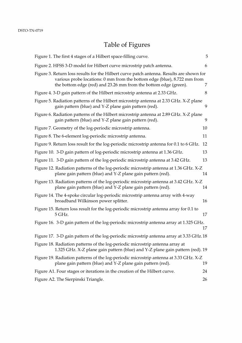
Table of Figures
Figure 1. The first 4 stages of a Hilbert space-filling curve. 5
Figure 2. HFSS 3-D model for Hilbert curve microstrip patch antenna. 6 Figure 3. Return loss results for the Hilbert curve patch antenna. Results are shown for
various probe locations: 0 mm from the bottom edge (blue), 8.722 mm from the bottom edge (red) and 23.26 mm from the bottom edge (green). 7
Figure 4. 3-D gain pattern of the Hilbert microstrip antenna at 2.33 GHz. 8 Figure 5. Radiation patterns of the Hilbert microstrip antenna at 2.33 GHz. X-Z plane
gain pattern (blue) and Y-Z plane gain pattern (red). 9
Figure 6. Radiation patterns of the Hilbert microstrip antenna at 2.89 GHz. X-Z plane gain pattern (blue) and Y-Z plane gain pattern (red). 9
Figure 7. Geometry of the log-periodic microstrip antenna. 10
Figure 8. The 6-element log-periodic microstrip antenna. 11 Figure 9. Return loss result for the log-periodic microstrip antenna for 0.1 to 6 GHz. 12 Figure 10. 3-D gain pattern of log-periodic microstrip antenna at 1.36 GHz. 13 Figure 11. 3-D gain pattern of the log-periodic microstrip antenna at 3.42 GHz. 13
Figure 12. Radiation patterns of the log-periodic microstrip antenna at 1.36 GHz. X-Z plane gain pattern (blue) and Y-Z plane gain pattern (red). 14
Figure 13. Radiation patterns of the log-periodic microstrip antenna at 3.42 GHz. X-Z plane gain pattern (blue) and Y-Z plane gain pattern (red). 14
Figure 14. The 4-spoke circular log-periodic microstrip antenna array with 4-way broadband Wilkinson power splitter. 16
Figure 15. Return loss result for the log-periodic microstrip antenna array for 0.1 to 5 GHz. 17
Figure 16. 3-D gain pattern of the log-periodic microstrip antenna array at 1.325 GHz. 17
Figure 17. 3-D gain pattern of the log-periodic microstrip antenna array at 3.33 GHz. 18
Figure 18. Radiation patterns of the log-periodic microstrip antenna array at 1.325 GHz. X-Z plane gain pattern (blue) and Y-Z plane gain pattern (red). 19
Figure 19. Radiation patterns of the log-periodic microstrip antenna at 3.33 GHz. X-Z plane gain pattern (blue) and Y-Z plane gain pattern (red). 19
Figure A1. Four stages or iterations in the creation of the Hilbert curve. 24
Figure A2. The Sierpinski Triangle. 26

DSTO-TN-0719
1
1. Introduction This report describes investigations into some novel antenna designs, which were done via a collaboration between the Electronic Warfare and Radar Division and the University of Adelaide’s Department of Electrical and Electronic Engineering. The work was sponsored in part by the Electronic Warfare and Radar Division and in part by the Centre of Expertise in Phased Array and Microwave Radar Systems (CEPAMiR) Task 2.3.
The objectives of this project were twofold:
1) To investigate novel antenna designs such as fractal antennas and consider whether their performance and characteristics such as multi-band or broadband characteristics will make them more suitable for multiple applications such as radar, Elint and communications than more conventional designs.
2) Design a broadband or multi-band antenna element to see what range of matching and gain characteristics can be obtained in both the L-band (1260-1400 MHz) and S-band (3300-3500 MHz). The element will be considered for use in an antenna array configuration with a view to further enhancing the gain characteristics.
These objectives were achieved by both theoretical investigation and computer simulation. Future work will include endeavouring to modify the designs to incorporate dual polarisation, building the antennas, as well as experimental work that will use the manufactured antenna elements.
The project was partitioned into a number of stages.
1) A search for curves and shapes that had potential for unique characteristics when incorporated into antenna designs.
2) Writing innovative custom software to bypass the task of manually creating multiple antenna designs. This software, once it was written, automatically generated antenna design project files as input to the electromagnetic simulation package, HFSS.
3) Using the custom software to automatically create a number of antenna design project files and performing full wave electromagnetic simulation for each design using HFSS. This was followed by design and simulation of log periodic designs.
Each of these stages is detailed below.
1.1 Searching for Novel Curves
1.1.1 Motivation One of the greatest driving forces in this antenna design research is the need for smaller antennas for use in defence and civilian communication. For antenna arrays in particular,

DSTO-TN-0719
2
we require the reduction of the overall size of the array so that mutual coupling is minimised while obtaining broadband characteristics. Mutual coupling between elements increases as elements are placed closer together (when trying to reduce overall array size) but this is reduced as elements are miniaturised.
Specific curves, such as fractals and space filling curves have high length to surface area ratios. One aim is for these curves to be incorporated in designs and to see if they can demonstrate similar characteristics to longer length antennas that would occupy larger areas. Given that these two classes of curves have (literally) an infinite number of members and in practice, hundreds of interesting candidates that have been extensively investigated mathematically, we decided to limit our investigation to these two classes.
Fractals are considered to have no characteristic size due to being multi-scaled copies of themselves and this property is considered responsible for the multi-band characteristics and compact size when used in antenna designs [Werner and Ganguly 2003]. There are opposing views expressing that the mutiscale geometry of fractals does not endow them uniquely with any properties they are highly regarded for and they are not particularly the best candidates for multi-band, compactness or any other properties [Gonzalez-Arbesu 2003], [Best 2001, 2002a, 2002b, 2003a, 2003b].
1.1.2 Description To formally define fractals and space filling curves requires the formalism of Hilbert Spaces and Iterated Function Systems. These are reviewed in Appendix A. Informally, we can describe fractals and space filling curves by comparing and contrasting them. For example, many fractals and space filling curves are both defined iteratively. Also both, by definition, are curves in the limit i.e. in theory they have infinite detail, although when used in practice, the “in-the-limit” process is truncated to make fabrication practical. In the case of fractals, the term pre-fractal is often used for curves produced by a finite number of iterations and of course, the properties of pre-fractals and fractals vary. For example, fractals are infinitely self similar where pre-fractals are only finitely self similar.
In contrast, only space filling curves fill a region (in the limit) and only fractals are multi-scaled versions of themselves. These ideas are described more fully and formally in [Barnsley 1993] and summarised in Appendix A.
There are also a number of overviews and introductions to the use of fractals in antenna and antenna array design, see [Werner et al 1999], [Werner and Mittra 2000] and [Werner and Ganguly 2003],
1.1.3 Research We discovered that many papers in this research area fall into one of two categories.
One category reports the antenna characteristics of a particular fractal or space filling curves as predicted by numerical analysis and/or of measurements of specific antenna designs. Usually written by proponents of fractal antennas, these papers make comparisons between a number of fractals designs with the implication that it has already been established that fractals are superior to conventional designs (for some purpose) and
DSTO-TN-0719
3
we only need to decide which fractal is best. Examples of these papers are [Anguera 2003, Zhu 2004]
The other category consists of researchers that are taking a more critical look at fractals. [Cohen 1997] observes that bending a wire into fractal shapes results in a high perimeter length in a small area that leads to multiple resonances but acknowledges that “fractal antennae obey the tradeoffs that all such antennas suffer: size for field strength; field strength for bandwidth. No small antenna, no matter what is promised, can give high gain, large bandwidth, and small size.”
Comparisons of a number of variations of the Hilbert and Peano space filling curves to the simpler meander-line monopole have been made in [Gonzalez-Arbesu 2003] and the conclusion is: when comparing quality factor and radiation efficiency against electrical size, the meander-line designs are superior.
Stephen Best [Best 2001, 2002a, 2002b, 2003a, 2003b] also reports in a number of papers, simple curves such as the meander-line and helix monopoles have the same or better properties compared to a number of fractals based on the Koch, Minkowski and Hilbert curves. The merit in this approach is that non-Euclidean designs (i.e. fractals) are compared with Euclidean designs (such as simple multiple bended lines) in order to establish which geometrical properties are likely to be responsible for the antenna characteristics.
All these researchers advocate that simple geometrical properties such as (wire) length rather than fractal properties such as fractal dimension (which is a measure of how much a fractal “covers” the region it occupies) are better indicators of antenna performance. ([Panoutsopoulos 2003] describes fractal dimension, specifically for two fractals, the Sierpinski Triangle and Square, as well as illustrating their multi-band characteristics).
2. Creating Designs Automatically Ansoft HFSS was the 3-D electromagnetic simulation software package that was chosen to perform simulations of the various antenna designs. It is a widely used package for antenna modelling and simulations.
In order to do the simulation, a 3-D model of the antenna structure called an antenna design project, needs to be built inside the HFSS 3-D Modeller window. The model can be built manually by using the HFSS graphic user interface. However this is a time consuming task, and particularly for intricate geometrical shapes such as fractals, it is extremely difficult and time consuming to manually draw the shapes especially to the required accuracy.
The solution to this problem was to generate the 3-D model automatically by using HFSS macros. A HFSS macro is a collection of HFSS commands arranged in the Visual Basic
DSTO-TN-0719
4
(VB) script format. We can generate a list of HFSS drawing commands with the required accuracy that will form the structure of the antenna.
We wrote custom software that we referred to as the HFSS Converter which was developed in the MATLAB programming language. This generated HFSS macros that contained HFSS commands to build intricate and complex geometric structures in HFSS 3-D Modeller. Vertices of the fractal shapes were calculated using MATLAB scripts, and by using the HFSS Converter, the set of vertices was translated into HFSS commands. Running the macro produces the 3-D structure of the antenna inside HFSS 3-D Modeller. The benefit of using the HFSS Converter was that to simulate the various fractal shapes in HFSS, all that is required to do is to generate the vertices that define the shape itself in MATLAB. As long as the vertices are defined properly, the HFSS Converter would handle the generation of the 3-D model in HFSS.
With the HFSS Converter completed, MATLAB scripts were written that generated vertices for a number of different fractal geometries, such as the Hilbert space-filling curve and Sierpinski triangle. Using the scripts and the HFSS Converter, a number of microstrip antennas based on Hilbert space-filling curve were simulated in HFSS. Matching performance and gain patterns were characterised. Also two variations of a Log-Periodic design were considered. The Log-Periodic antenna is a broadband antenna design with desirable gain characteristics. The Log-Periodic antenna and the corresponding array were designed and simulated on the basis of having a more conventional design and for comparison with the fractal constructions.
Descriptions, performance characteristics, gain patterns and conclusions follow in the next sections for each design.
3. Electromagnetic Simulation In this section, we give more detailed descriptions of the various antenna designs that were developed and simulated. The performance characteristics and the evaluation of the designs will also be discussed. In all the HFSS 3D antenna models in the simulations that are presented, the substrate dielectric is FR-4 Epoxy which has a relative permittivity of 4.4 and dielectric loss tangent of 0.02.
3.1 Hilbert Curve Microstrip Antenna
3.1.1 Description The Hilbert space-filling curve was the representative fractal antenna. The construction of the Hilbert curve is shown in Figure 1 for the first 3 iterations.

DSTO-TN-0719
5
Figure 1. The first 4 stages of a Hilbert space-filling curve.
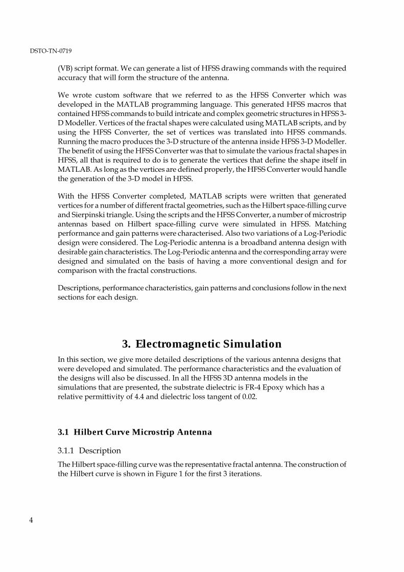
Using a square microstrip patch (52.16 mm) resonating at 1.3 GHz as the Stage 0 shape, we have produced a microstrip patch antenna in the shape of a Stage 1 Hilbert curve. The HFSS model for the Hilbert microstrip patch antenna is shown in Figure 2.
DSTO-TN-0719
6
Figure 2. HFSS 3-D model for Hilbert curve microstrip patch antenna.
3.1.2 Performance Characteristics Simulation of the Hilbert curve patch antenna was done with the feed-point at various positions along the centre axis (y-axis) of the shape. All simulations were done with a 50 Ω source feeding the antenna structure. The return loss characteristic for the various feed positions between 1 to 10 GHz is shown in Figure 3. It is evident from the plot that the Hilbert microstrip patch antenna exhibits multiple resonances, i.e. a multi-band characteristic, and that the feed position determines where those resonances are located. Note that the feed position at 8.722 mm from the bottom edge yields the best result, with good return loss at 2.33, 2.89 and 5.88 GHz.

DSTO-TN-0719
7
Figure 3. Return loss results for the Hilbert curve patch antenna. Results are shown for various probe locations: 0 mm from the bottom edge (blue), 8.722 mm from the bottom edge (red) and 23.26 mm from the bottom edge (green).
Gain characteristics shown in Figure 4 are for the Hilbert microstrip patch antenna with the feed position at 8.722 mm from the bottom edge. The 3-D radiation pattern shown in Figure 4, was captured for a frequency of 2.33 GHz.

DSTO-TN-0719
8
Figure 4. 3-D gain pattern of the Hilbert microstrip antenna at 2.33 GHz.
The x-z plane and y-z plane radiation patterns are shown in Figure 5. It is clear that the maximum gain of 11 dBi is achieved in the y-z plane at around 30 degrees from the z-axis. The gain pattern is quite uniform around the x-z plane, with the gain of around 6 dBi. The x-z plane and y-z plane radiation patterns for 2.89 GHz are shown in Figure 6. The patterns are quite different to those at 2.33 GHz, and the gain values are substantially lower in some cases.

DSTO-TN-0719
9
Figure 5. Radiation patterns of the Hilbert microstrip antenna at 2.33 GHz. X-Z plane gain pattern (blue) and Y-Z plane gain pattern (red).
Figure 6. Radiation patterns of the Hilbert microstrip antenna at 2.89 GHz. X-Z plane gain pattern (blue) and Y-Z plane gain pattern (red).

DSTO-TN-0719
10
3.1.3 Hilbert Antenna Conclusions Although the return loss and gain results of the Hilbert microstrip patch antenna are showing some desirable characteristics, there is the issue of designing the antenna to the desired resonant frequencies. As the location of the resonant points of the Hilbert microstrip antenna are determined by the geometric features of the shape that are not well understood at this stage, future work would be to investigate the correlation between the geometric features of the Hilbert fractal shape and the frequencies at which the Hilbert microstrip antenna resonates.
3.2 Log-periodic Microstrip Antenna The log-periodic microstrip antenna is a more conventional approach for the implementation of a broadband antenna. The basis of this design is the linear array of coplanar patch antennas, with the size and spacing of the patches increasing in a log-periodic manner. At any given frequency throughout the designed bandwidth, there will always be a number of the patch antennas resonating and radiating within the log-periodic array, thus producing the broadband characteristic [Hall 1980].
3.2.1 Description The geometry of the log-periodic microstrip antenna is shown in Figure 7.
Figure 7. Geometry of the log-periodic microstrip antenna.
The length L and width w of each antenna, as well as the spacing s between them increases along the array by the factor τ, as given by:
n
n
n
n
n
n
ss
ww
LL 111 +++ ===τ
w
L
s
DSTO-TN-0719
11
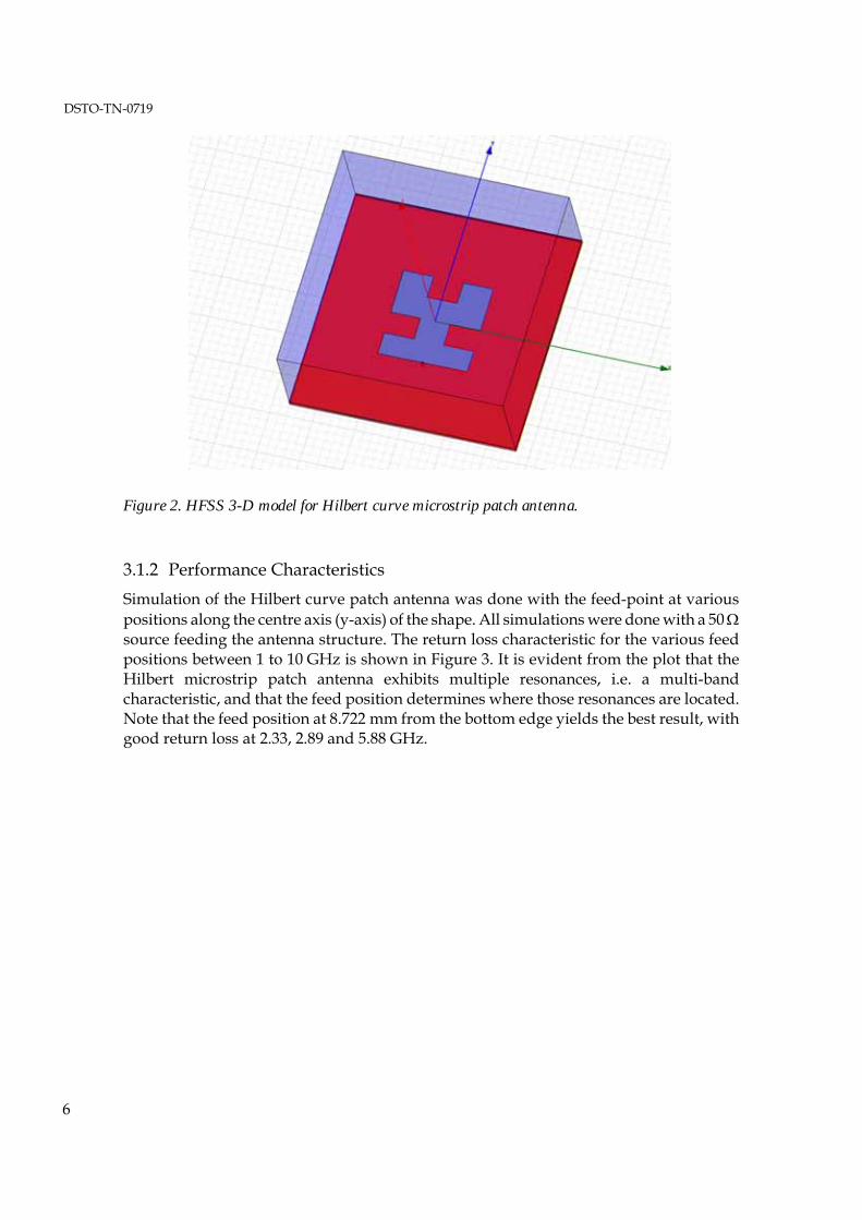
The six-element log-periodic microstrip antenna is shown in Figure 8. The smallest patch is designed to resonate at 3.4 GHz, i.e. L1 = 19.25 mm and w1 = 16 mm. For the biggest patch to be resonating at 1.32 GHz, the factor τ will need to be 1.208.
Therefore this antenna is designed to operate between the L-band and S-band. The microstrip patches on the upper substrate were proximity fed by the microstrip line on the lower substrate to further enhance the bandwidth [Balanis 2005]. The feed line was terminated in a matched load to absorb non-radiated power as may occur at the edges of the frequency band. The overall size of the antenna is 240 x 120 mm.
Figure 8. The 6-element log-periodic microstrip antenna.
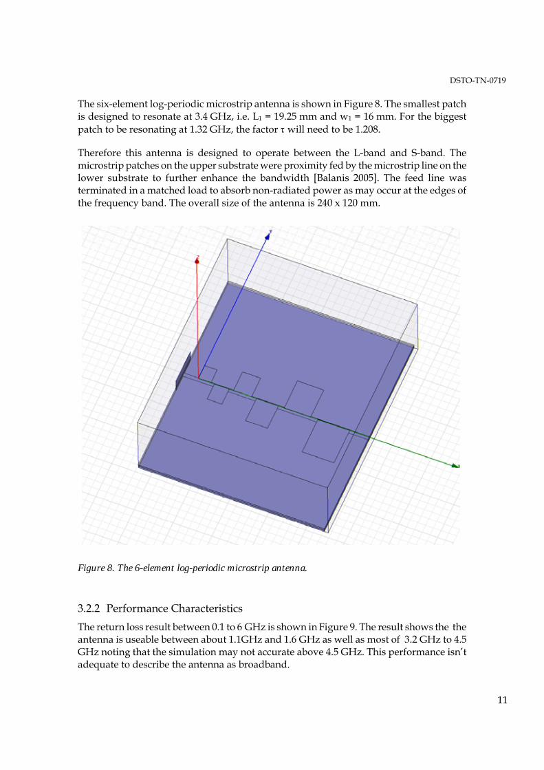
3.2.2 Performance Characteristics The return loss result between 0.1 to 6 GHz is shown in Figure 9. The result shows the the antenna is useable between about 1.1GHz and 1.6 GHz as well as most of 3.2 GHz to 4.5 GHz noting that the simulation may not accurate above 4.5 GHz. This performance isn’t adequate to describe the antenna as broadband.
DSTO-TN-0719
12
Figure 9. Return loss result for the log-periodic microstrip antenna for 0.1 to 6 GHz.
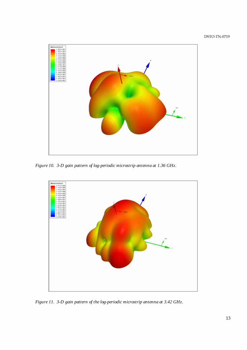
The 3-D gain patterns at 1.36 GHz and 3.42 GHz are shown in Figure 10 and Figure 11 respectively. The main beam of radiation for a log-periodic microstrip antenna should be directed perpendicularly outwards from the plane containing the microstrip patch elements. The 1.36 GHz gain pattern is showing a strong main beam slightly deviated from the z-axis. Referring to the radiation pattern showing in Figure 12, there is a strong spurious side-lobe as well as a deep null in the x-z plane pattern.
The radiation pattern of the log-periodic antenna at 3.42 GHz is shown in Figure 13. It can be seen that the pattern is much more regular compared to the 1.36 GHz, although the gain is only at around 3 dBi.
DSTO-TN-0719
13
Figure 10. 3-D gain pattern of log-periodic microstrip antenna at 1.36 GHz.
Figure 11. 3-D gain pattern of the log-periodic microstrip antenna at 3.42 GHz.

DSTO-TN-0719
14
Figure 12. Radiation patterns of the log-periodic microstrip antenna at 1.36 GHz. X-Z plane gain pattern (blue) and Y-Z plane gain pattern (red).
Figure 13. Radiation patterns of the log-periodic microstrip antenna at 3.42 GHz. X-Z plane gain pattern (blue) and Y-Z plane gain pattern (red).

DSTO-TN-0719
15
3.2.3 Log-periodic Antenna Conclusions The log-periodic antenna is showing some promise in obtaining the desired characteristics of the broadband antenna. However the following issues will need to be addressed:
1) Improving the return loss performance in the band between 1.36 GHz and 3.42 GHz. This can be done by introducing more elements in the log-periodic antenna, but at the cost of increasing in size.
2) The spurious radiation and strong side-lobe that are currently present in the 1.36 GHz gain pattern will need to be suppressed. Ideally the direction of maximum gain should be perpendicular to the plane of the antenna elements.
3) Increasing the absolute gain of the 3.42 GHz radiation pattern. This can be done by designing a more efficient resonator that will radiate more effectively at the higher frequency bands.
3.3 Circular Log-periodic Microstrip Antenna
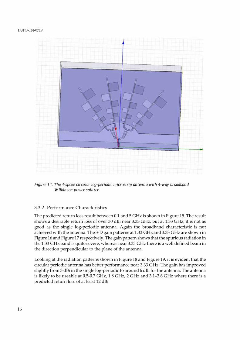
3.3.1 Descriptions Using the log-periodic microstrip antenna as a basis, the circular log-periodic microstrip antenna was developed. To maintain the same relative distance, in terms of wavelength, between the corresponding radiating elements in each branch, the “spokes” of the antenna are arranged around the circumference. For the current design there are 4 spokes with the corresponding element between the branches separated by half a wavelength. The model of the antenna is shown in Figure 14.
Each “spoke” of the antenna is fed equally via a 2-stage 4-way broadband Wilkinson power divider/combiner [Cohen 1968]. The phase remains constant between the feed to the 4 antenna spokes.
DSTO-TN-0719
16
Figure 14. The 4-spoke circular log-periodic microstrip antenna with 4-way broadband Wilkinson power splitter.
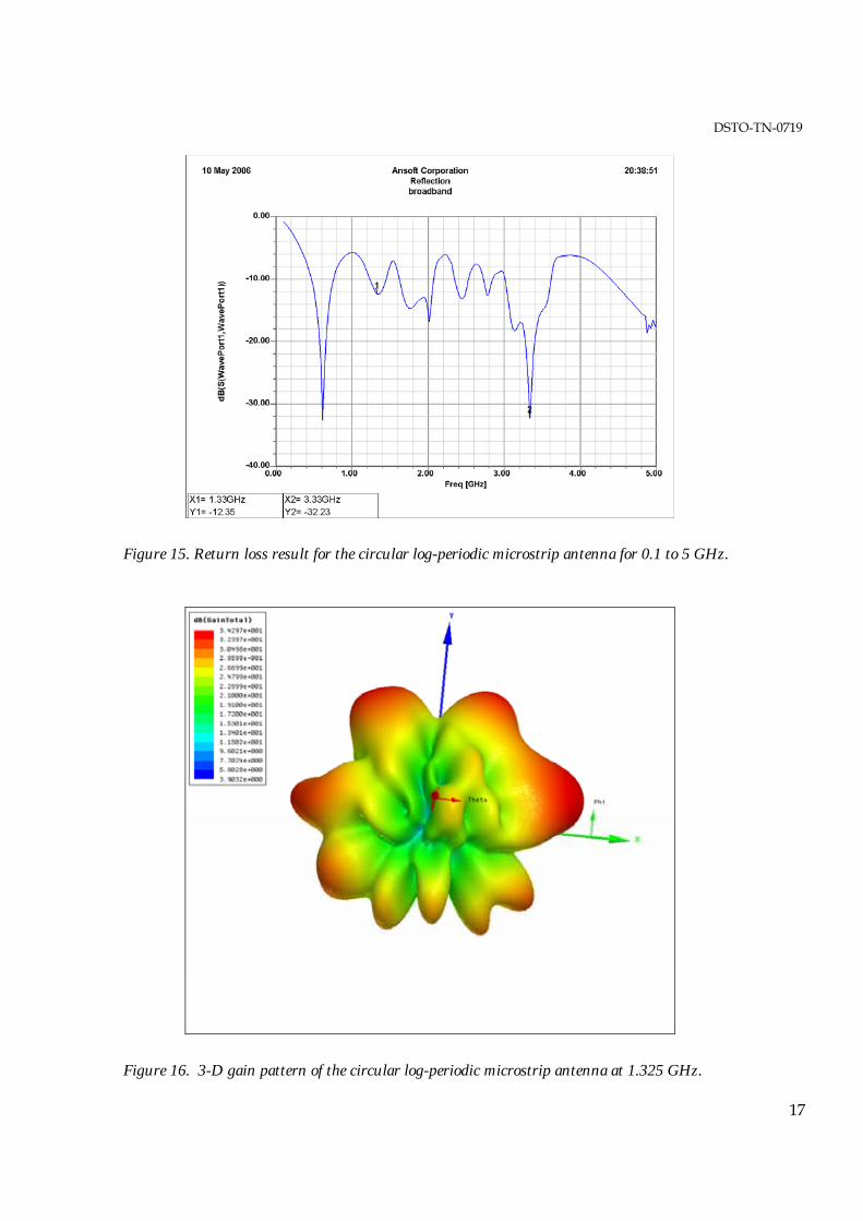
3.3.2 Performance Characteristics The predicted return loss result between 0.1 and 5 GHz is shown in Figure 15. The result shows a desirable return loss of over 30 dBi near 3.33 GHz, but at 1.33 GHz, it is not as good as the single log-periodic antenna. Again the broadband characteristic is not achieved with the antenna. The 3-D gain patterns at 1.33 GHz and 3.33 GHz are shown in Figure 16 and Figure 17 respectively. The gain pattern shows that the spurious radiation in the 1.33 GHz band is quite severe, whereas near 3.33 GHz there is a well defined beam in the direction perpendicular to the plane of the antenna.
Looking at the radiation patterns shown in Figure 18 and Figure 19, it is evident that the circular periodic antenna has better performance near 3.33 GHz. The gain has improved slightly from 3 dBi in the single log-periodic to around 6 dBi for the antenna. The antenna is likely to be useable at 0.5-0.7 GHz, 1.8 GHz, 2 GHz and 3.1–3.6 GHz where there is a predicted return loss of at least 12 dBi.
DSTO-TN-0719
17
Figure 15. Return loss result for the circular log-periodic microstrip antenna for 0.1 to 5 GHz.
Figure 16. 3-D gain pattern of the circular log-periodic microstrip antenna at 1.325 GHz.

DSTO-TN-0719
18
Figure 17. 3-D gain pattern of the log-periodic microstrip antenna array at 3.33 GHz.

DSTO-TN-0719
19
Figure 18. Radiation patterns of the circular log-periodic microstrip antenna at 1.325 GHz. X-Z plane gain pattern (blue) and Y-Z plane gain pattern (red).
Figure 19. Radiation patterns of the log-periodic microstrip antenna at 3.33 GHz. X-Z plane gain pattern (blue) and Y-Z plane gain pattern (red).

DSTO-TN-0719
20
3.3.3 Circular Log-periodic Antenna Conclusions There are two observations that can be drawn from the results:
By putting the single log-periodic into an circular structure, the gain characteristics for the higher frequency band have improved.
The problem of spurious radiation in the single log-periodic antenna at the lower frequency has been exasperated by the spoke arrangement.
Therefore it is important to improve the design of the single log-periodic antenna before using it in a branch structure.
4. Future Directions Further investigations into the fractal design will require establishing the extent of mutual coupling between elements when they are configured in an array. Determining the level of side-lobes in the orthogonal direction will give us a reasonable indication of this.
The current design of a log-periodic microstrip antenna is promising in terms of providing wideband performance (1-20 GHz), and dual polarisation. A number of possible changes to the current design need to be explored towards achieving the above objectives. Some of the suggested improvements to the current design are: -
(a) Feed Arrangement: In the current design of the Radiating Element (RE), the radiating patches are proximity coupled to the feed line. It is envisaged that direct feed or slot-coupled arrangement of feeding power to the radiating patches could improve the overall performance of the RE over the desired wideband.
(b) Dual Polarisation: It is proposed that by arranging four REs in North-South and East-West configuration, could meet the desired dual polarisation requirement. Simulation trials for the proposed configuration are pending.
(c) Variation of Substrate Permittivity ε: During the characterisation of the RE for the wideband operation; spurious radiations in the lower frequency band were observed from the smaller patches of the RE. It is considered that a careful examination of variation in the permittivity of the substrate over the wideband and optimisation of radiating patch size needs to be undertaken for suppressing the spurious radiations.
While efforts are in hand for improving the existing design of the log-periodic antenna, further research into fractal antenna arrays may prove more encouraging. Otherwise alternative approaches may need to be considered in order to obtain better performing broadband characteristics such as Vivaldi antennas.

DSTO-TN-0719
21
Research is being undertaken on the possibilities of using other configurations that promise 1-20 GHz wideband performance with dual polarisation. Preliminary study has indicated that arrays of “Bow-Tie” elements, notch elements and dielectric resonant array (configurations) could be considered as possible alternatives.
We also propose to fabricate a single log-periodic and Vivaldi antenna and undertake measurements to ascertain their overall performance/suitability. In addition the option of designing a multi-band array antenna for meeting the wideband and dual polarity objective is also being considered in parallel.

DSTO-TN-0719
22
Appendix A: Fractal Theory
A.1 Introduction Although fractals can be investigated informally, a formal framework leads to important concepts such as fractal dimension (which are integers for conventional Euclidean shapes and non-integers for fractals) and can be investigated for their relevance to antenna performance.
After reviewing metric spaces, some topological terms such as set distances, Cauchy sequences, complete and compact sets, we arrive at the so called space of fractals. We then continue with a look at iterated function systems and use this construct to define the Hilbert curve, used in the antenna design in the report and another well known fractal, known as the Sierpinski triangle. The Hilbert curve and Sierpinski triangle are two of the more popular shapes used in the investigation of fractal antennas.
The approach presented follows that in [Barnsley 93]. Far from just formal theory, it was the actual approach used in implementing the Matlab routines that created the fractals and the corresponding antenna designs.
Finally, theorems are stated without proofs and readers are referred to [Barnsley 93] for the proofs if needed.
A.2 Mathematical Preliminaries Definition: A metric space is a space X with a real function d: X x X → R called the metric or distance between two points x, y in X if
1) d(x,y) = d(y,x) for all x, y ⊆ X
2) d(x,y) ≥ 0 for all x, y ⊆ X, d(x,y) = 0 iif x = y
3) d(x,y) ≤ d(x,z) + d(z,y) for all x, y, z ⊆ X
Definition: A Cauchy sequence is a sequence xn of points in a metric space (X,d) if for any number ε > 0, there is an integer N > 0, such that
d(xn, xm) < ε for all n, m > N
Theorem: If a sequence of points xn in a metric space (X,d) converges to a point x ⊆ X then xn is a Cauchy sequence
Definition: A metric space (X,d) is complete if every Cauchy sequence converges to a point in X
Let S ⊆ X be a subset of a metric space (X,d). S is compact if every infinite sequence {xn} in S contains a subsequence having a limit in S.

DSTO-TN-0719
23
Definitions
Let (X,d) be a complete metric space and Ψ (X) denote the space whose points are the nonempty compact subsets of X
1) Let x ∈ X and B ∈ Ψ (X) then dP(x, B) = min( d(x,y): y ∈ B ) is the distance from the point x to the set B
2) Let A, B ∈ Ψ (X) then dS(A, B) = max( dP(x,B): x ∈ A ) is the distance from the set A to the set B
3) The Hausdorff distance between points (sets) A and B in Ψ (X) is h(A,B) = dS(A,B) v dS(B,A) (where v means maximum)
Theorem: h is a metric on the space Ψ (X)
Definition: (Ψ (X), h) is the “Space of Fractals”
Theorem: (Ψ (X), h) is a complete metric space
A.3 Generating fractals: Iterated Function Systems To generate fractals, in particular the Hilbert curve and Sierpinski Triangle, we look at the compact sets of the complete metric space (RxR, Euclidean) i.e. the space of points in the plane with the usual Euclidean distance as the metric.
We start with a subset A of the plane, known as the initiator, then iteratively apply an operation, the generator, on this subset until it converges to our fractal. Fractals generated like this are known as Iterated Function Systems (IFS).
The question we need to ask is: What kind of operator do we require which will result in the self-similar properties we want?
The answer is: Hutchinson operators
Hutchinson operators are defined in terms of affine transformations. An affine transformation is one of the form
' cos sin' sin cos
o
o
xx r s xyy r s y
φ θφ θ
− ⎛ ⎞⎛ ⎞ ⎛ ⎞⎛ ⎞= + ⎜ ⎟⎜ ⎟ ⎜ ⎟⎜ ⎟
⎝ ⎠ ⎝ ⎠⎝ ⎠ ⎝ ⎠ Note If 0 < r, s < 1 then it is called a contraction
if r = s = 1 and θ = φ , it is a rotation
if r = s = 1 and θ = φ = 0 it is a translation

DSTO-TN-0719
24
Finally, a Hutchinson Operator is a transformation over the subset A of the plane where
W[A] = w1 [A] U w2 [A] U . . . U wn [A]
and each wk [A] (k = 1..n) are affine transformations.
With this framework in place, we can now generate fractals. So how do we iteratively create our Hilbert curve?
Figure A1. Four stages or iterations in the creation of the Hilbert curve.
With a little thought, the transformations required to go from one stage to the next, are a combination (or union) of the following

DSTO-TN-0719
25
⎟⎟⎠
⎞⎜⎜⎝
⎛−−
+⎟⎟⎠
⎞⎜⎜⎝
⎛⋅⎟⎟
⎠
⎞⎜⎜⎝
⎛ −=⎟⎟
⎠
⎞⎜⎜⎝
⎛
⎟⎟⎠
⎞⎜⎜⎝
⎛+⎟⎟
⎠
⎞⎜⎜⎝
⎛⋅⎟⎟
⎠
⎞⎜⎜⎝
⎛=⎟⎟
⎠
⎞⎜⎜⎝
⎛
⎟⎟⎠
⎞⎜⎜⎝
⎛ −+⎟⎟
⎠
⎞⎜⎜⎝
⎛⋅⎟⎟
⎠
⎞⎜⎜⎝
⎛=⎟⎟
⎠
⎞⎜⎜⎝
⎛
⎟⎟⎠
⎞⎜⎜⎝
⎛−−
+⎟⎟⎠
⎞⎜⎜⎝
⎛⋅⎟⎟
⎠
⎞⎜⎜⎝
⎛−
=⎟⎟⎠
⎞⎜⎜⎝
⎛
2121
021210
2121
210021
2121
210021
2121
021210
4
3
2
1
yx
yx
w
yx
yx
w
yx
yx
w
yx
yx
w
Mathematically, this is expressed as
W[A] = w1 [A] U w2 [A] U w3 [A] U w4 [A]
To explain these transformations, w1 represents using the stage 0 shape (Figure A1 (a)) and scaling it by 1/2, rotating it by –π then translating it (-1/2 -1/2) i.e. halving its size, rotating it then moving it to the bottom left
In a similar way, the other three transformations each halve the size of the stage 0 shape and translate it to the other three corners. Note that w2 and w3 [A] don’t involve a rotation (or alternatively w2 and w3 we have rotation of 0) and w4 rotates the shape by π before translating it.
This process of resizing, rotation, and translation is repeating at each stage to get the next.
To look at another example, we can use the same technique to generate another fractal, the Sierpinski triangle.

DSTO-TN-0719
26
Figure A2. The Sierpinski Triangle.
The first six stages or iterations are illustrated here, using the initial solid black triangle as the initiator or starting point. In contrast to the Hilbert curve, we need only a union of three transformations of contractions and translations (no rotations).
The transformations required to go from one stage to the next, are
⎟⎟⎠
⎞⎜⎜⎝
⎛+⎟⎟
⎠
⎞⎜⎜⎝
⎛⋅⎟⎟
⎠
⎞⎜⎜⎝
⎛=⎟⎟
⎠
⎞⎜⎜⎝
⎛
⎟⎟⎠
⎞⎜⎜⎝
⎛+⎟⎟
⎠
⎞⎜⎜⎝
⎛⋅⎟⎟
⎠
⎞⎜⎜⎝
⎛=⎟⎟
⎠
⎞⎜⎜⎝
⎛
⎟⎟⎠
⎞⎜⎜⎝
⎛+⎟⎟
⎠
⎞⎜⎜⎝
⎛⋅⎟⎟
⎠
⎞⎜⎜⎝
⎛=⎟⎟
⎠
⎞⎜⎜⎝
⎛
021
210021
2141
210021
00
210021
3
2
1
yx
yx
w
yx
yx
w
yx
yx
w

DSTO-TN-0719
27
5. References Anguera, J et al. (2003) The fractal Hilbert monopole: A two dimensional wire, Microwave and Optical Letters, Vol. 36, No 2, January 2003
C. A. Balanis, “Antenna Theory,” Third edition, John Wiley & Sons, Inc, 2005, pp. 815.
Barnsley, M. F. (1993), Fractals Everywhere, Academic Press Inc., 2nd Ed.
Best, S. R. (2001), The Koch Fractal Monopole Antenna: The significance of fractal geometry in determining antenna performance, 25th Annual Antenna Applications Symposium, University of Illinois
Best, S. R. (2002a), On the Resonant Properties of the Koch Fractal and other Wire Monopole Antennas, IEEE Antennas and Wireless Propagation Letters, Vol. 1, 2002
Best, S. R. (2002b), A discussion of the effective volume and radiation properties of small non-Euclidean wire monopole antennas, 26th Annual Antenna Applications Symposium, University of Illinois
Best, S. R. (2003a), On the performance properties of the Koch fractal and other bent wire monopoles, IEEE Transactions on Antennas and Propagation, Vol. 51, No 6, June 2003
Best, S. R. (2003b), A comparison of resonant properties of small space-filling fractal antennas, IEEE Antennas and Wireless Propagation Letters, Vol. 2, 2003
Cohen N. (1995), Fractal Antennas Part l, Communications Quarterly, Summer 1995
Cohen N. (1996), Fractal Antennas Part 2, Communications Quarterly, Summer 1996
Cohen, N. (1997), Fractal Antenna Applications in Wireless Telecommunications, Electronics Industries Forum of New England, Professional Program Proceedings
Cohen S. B (1968), A class of broadband three-port TEM-mode hybrids, IEEE Transactions on Microwave Theory and Techniques, vol. MTT-16, February 1968, pp. 110-116.
Hall, P. S. (1980), New Wideband Microstrip Antenna Using Log-Periodic Technique, Electronic letters, 16, Vol 4, February 1980.
Panoutsopoulos, B. (2003), Printed circuit fractal antennas, Consumer Electronics, 2003. ICCE. 2003 IEEE International Conference on 17-19 June 2003
D. H. Werner and S. Ganguly (2003), An Overview of Fractal Antenna Engineering Research, IEEE Antennas and Propagation Magazine, 45, 1, February 2003
Werner, D.H. and Haupt, R. L. and Werner, P. L. (1999), Fractal Antenna Engineering: The theory and design of fractal antenna arrays

DSTO-TN-0719
28
Werner, D.H. and Mittra, R (2000), Frontiers in electromagnetics, New York : IEEE Press
Zhu J. (2004), Peano Antennas, IEEE Antennas and Wireless Propagation Letters, Vol. 3, 2004

DSTO-TN-0719
Investigations into Novel Multi-band Antenna Designs
Ross Kyprianou1, Bobby Yau2, Aris Alexopoulos1, Akhilesh Verma3 and Bevan D. Bates3
(DSTO-TN-07190719)
AUSTRALIA DEFENCE ORGANISATION No. of copies
S&T Program
Chief Defence Scientist 1 Deputy Chief Defence Scientist Policy 1 AS Science Corporate Management 1 Director General Science Policy Development 1 Counsellor Defence Science, London Doc Data Sheet Counsellor Defence Science, Washington Doc Data Sheet Scientific Adviser to MRDC, Thailand Doc Data Sheet Scientific Adviser Joint 1 Navy Scientific Adviser 1 Scientific Adviser – Army 1
r Force Scientific Adviser 1 Scientific Adviser to the DMO 1
Chief Electronic Warfare and Radar Division Doc Data Sht & Dist List
EWSTIS (soft copy for accession to EWSTIS Web site) 1 Research Leader, Maritime EW Doc Data Sht & Dist
List Research Leader, Air EW Doc Data Sht & Dist
List Research Leader, JIL EW Doc Data Sht & Dist
List Research Leader, Microwave Radar Doc Data Sht & Dist
List Head, ES Systems Doc Data Sheet Head, RF Countermeasures Doc Data Sheet Head, RF Technology Doc Data Sheet Head, Strategic and Land EW Doc Data Sheet Head, Aerospace Systems Doc Data Sheet Head, Maritime Systems Doc Data Sheet Head, EO Countermeasures Doc Data Sheet Head, EO Technology Doc Data Sheet Head, Radar Systems and Technologies Doc Data Sheet Head, Maritime Air Surface Doc Data Sheet Head, Maritime Surface Radar Doc Data Sheet

DSTO-TN-0719
Head, Radar Signatures Doc Data Sheet Task Manager: Dr Aris Alexopoulos, EWRD 5 printed Ross Kyprianou, EWRD 1 printed Bobby Yau, University of Adelaide 1 printed
Akhilesh Verma, Centre of Expertise in Phased Array & Microwave Radar Systems
1 printed
Dr Bevan D. Bates, Centre of Expertise in Phased Array & Microwave Radar Systems
1 printed
DSTO Library and Archives
Library Edinburgh 1 printed & Doc Data Sheet
Defence Archives 1 printed Library Canberra Doc Data Sheet
Capability Development Executive
Director General Maritime Development Doc Data Sheet Director General Capability and Plans Doc Data Sheet Assistant Secretary Investment Analysis Doc Data Sheet Director Capability Plans and Programming Doc Data Sheet
Chief Information Officer Group
Head Information Capability Management Division Doc Data Sheet Director General Australian Defence Simulation Office Doc Data Sheet AS Information Strategy and Futures Doc Data Sheet Director General Information Services Doc Data Sheet
Strategy Executive
Assistant Secretary Strategic Planning Doc Data Sheet Assistant Secretary International and Domestic Security Policy Doc Data Sheet
Navy
Maritime Operational Analysis Centre, Building 89/90 Garden Island Sydney NSW
Deputy Director (Operations) Deputy Director (Analysis)
Doc Data Sht & Dist List
Director General Navy Capability, Performance and Plans, Navy Headquarters
Doc Data Sheet
Director General Navy Strategic Policy and Futures, Navy Headquarters
Doc Data Sheet
Air Force SO (Science) - Headquarters Air Combat Group, RAAF Base, Williamtown NSW 2314
Doc Data Sht & Exec Summary
Staff Officer Science Surveillance and Response Group Doc Data Sht & Exec Summary
Army

DSTO-TN-0719
ABCA National Standardisation Officer Land Warfare Development Sector, Puckapunyal
Doc Data Sheet
J86 (TCS GROUP), DJFHQ Doc Data Sheet SO (Science) - Land Headquarters (LHQ), Victoria Barracks NSW Doc Data Sht & Exec
Summary SO (Science) - Special Operations Command (SOCOMD), R5-SB-15, Russell Offices Canberra
Doc Data Sht & Exec Summary
SO (Science), Deployable Joint Force Headquarters (DJFHQ) (L), Enoggera QLD
Doc Data Sheet
Joint Operations Command Director General Joint Operations Doc Data Sheet Chief of Staff Headquarters Joint Operations Command Doc Data Sheet Commandant ADF Warfare Centre Doc Data Sheet Director General Strategic Logistics Doc Data Sheet
Intelligence and Security Group AS Concepts, Capability and Resources 1 DGSTA , Defence Intelligence Organisation 1 Manager, Information Centre, Defence Intelligence Organisation 1 Director Advanced Capabilities Doc Data Sheet
Defence Materiel Organisation Deputy CEO Doc Data Sheet Head Aerospace Systems Division Doc Data Sheet Head Maritime Systems Division Doc Data Sheet Program Manager Air Warfare Destroyer Doc Data Sheet Guided Weapon & Explosive Ordnance Branch (GWEO) Doc Data Sheet CDR Joint Logistics Command Doc Data Sheet
OTHER ORGANISATIONS National Library of Australia 1 NASA (Canberra) 1
UNIVERSITIES AND COLLEGES
Australian Defence Force Academy Library Head of Aerospace and Mechanical Engineering
1 1
Hargrave Library, Monash University Doc Data Sheet
OUTSIDE AUSTRALIA
INTERNATIONAL DEFENCE INFORMATION CENTRES
US Defense Technical Information Center 1 UK Dstl Knowledge Services 1 Canada Defence Research Directorate R&D Knowledge & Information Management (DRDKIM)
1

DSTO-TN-0719
NZ Defence Information Centre 1
ABSTRACTING AND INFORMATION ORGANISATIONS Library, Chemical Abstracts Reference Service 1 Engineering Societies Library, US 1 Materials Information, Cambridge Scientific Abstracts, US 1 Documents Librarian, The Center for Research Libraries, US 1
INFORMATION EXCHANGE AGREEMENT PARTNERS
National Aerospace Laboratory, Japan 1 National Aerospace Laboratory, Netherlands 1
SPARES Total number of copies: 43 Printed: 16 PDF: 27
5 Printed

DSTO-TN-0719
Page classification: UNCLASSIFIED
DEFENCE SCIENCE AND TECHNOLOGY ORGANISATION
DOCUMENT CONTROL DATA 1. PRIVACY MARKING/CAVEAT (OF DOCUMENT)
2. TITLE Investigations into Novel Multi-band Antenna Designs
3. SECURITY CLASSIFICATION (FOR UNCLASSIFIED REPORTS THAT ARE LIMITED RELEASE USE (L) NEXT TO DOCUMENT CLASSIFICATION)
Document (U) Title (U) Abstract (U)
4. AUTHOR(S) Ross Kyprianou, Bobby Yau, Aris Alexopoulos, Akhilesh Verma and Bevan Bates
5. CORPORATE AUTHOR Defence Science and Technology Organisation PO Box 1500 Edinburgh SA 5111
6a. DSTO NUMBER DSTO-TN-0719
6b. AR NUMBER AR-013-750
6c. TYPE OF REPORT Technical Note
7. DOCUMENT DATE August 2006
8. FILE NUMBER 2006/1110178/1
9. TASK NUMBER RDI 03/255
10. TASK SPONSOR EWRD-MIT
11. NO. OF PAGES 28
12. NO. OF REFERENCES 18
13. URL on World Wide Web http://www.dsto.defence.gov.au/corporate/reports/DSTO-TN-0719.pdf
14. RELEASE AUTHORITY Chief, Electronic Warfare and Radar Division
15. SECONDARY RELEASE STATEMENT OF THIS DOCUMENT
Approved for Public Release OVERSEAS ENQUIRIES OUTSIDE STATED LIMITATIONS SHOULD BE REFERRED TO DOCUMENT EXCHANGE, PO BOX 1500, EDINBURGH, SA 5111, AUSTRALIA 16. DELIBERATE ANNOUNCEMENT
No Limitations
17. CASUAL ANNOUNCEMENT Yes 18. DSTO RESEARCH LIBRARY THESAURUS Antennas, Frequency variation, Fractals, Arrays 19. ABSTRACT We investigate the possibility of using fractal geometry to construct radiating elements for phased array radar. We seek to understand whether the characteristics of individual fractal designs can give rise to multi-band or broadband performance and we do this by looking at Hilbert curves, log-periodic and circular-log-periodic radiating elements. We present the theory and discuss software that has been developed in order to model fractal elements and we present our findings accordingly.
Page classification: UNCLASSIFIED
Related Documents