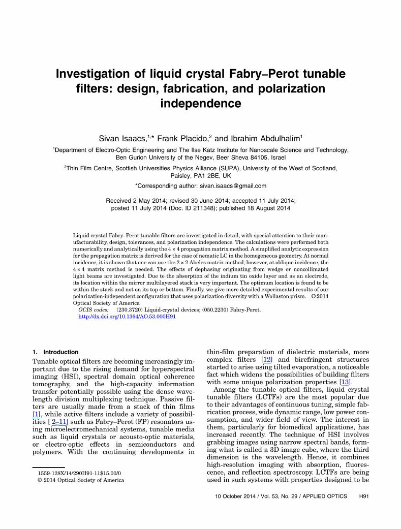
Investigation of liquid crystal Fabry–Perot tunable filters: design, fabrication, and polarization independence Sivan Isaacs, 1, * Frank Placido, 2 and Ibrahim Abdulhalim 1 1 Department of Electro-Optic Engineering and The Ilse Katz Institute for Nanoscale Science and Technology, Ben Gurion University of the Negev, Beer Sheva 84105, Israel 2 Thin Film Centre, Scottish Universities Physics Alliance (SUPA), University of the West of Scotland, Paisley, PA1 2BE, UK *Corresponding author: [email protected] Received 2 May 2014; revised 30 June 2014; accepted 11 July 2014; posted 11 July 2014 (Doc. ID 211348); published 18 August 2014 Liquid crystal Fabry–Perot tunable filters are investigated in detail, with special attention to their man- ufacturability, design, tolerances, and polarization independence. The calculations were performed both numerically and analytically using the 4 × 4 propagation matrix method. A simplified analytic expression for the propagation matrix is derived for the case of nematic LC in the homogeneous geometry. At normal incidence, it is shown that one can use the 2 × 2 Abeles matrix method; however, at oblique incidence, the 4 × 4 matrix method is needed. The effects of dephasing originating from wedge or noncollimated light beams are investigated. Due to the absorption of the indium tin oxide layer and as an electrode, its location within the mirror multilayered stack is very important. The optimum location is found to be within the stack and not on its top or bottom. Finally, we give more detailed experimental results of our polarization-independent configuration that uses polarization diversity with a Wollaston prism. © 2014 Optical Society of America OCIS codes: (230.3720) Liquid-crystal devices; (050.2230) Fabry-Perot. http://dx.doi.org/10.1364/AO.53.000H91 1. Introduction Tunable optical filters are becoming increasingly im- portant due to the rising demand for hyperspectral imaging (HSI), spectral domain optical coherence tomography, and the high-capacity information transfer potentially possible using the dense wave- length division multiplexing technique. Passive fil- ters are usually made from a stack of thin films [ 1], while active filters include a variety of possibil- ities [ 2– 11] such as Fabry–Perot (FP) resonators us- ing microelectromechanical systems, tunable media such as liquid crystals or acousto-optic materials, or electro-optic effects in semiconductors and polymers. With the continuing developments in thin-film preparation of dielectric materials, more complex filters [ 12] and birefringent structures started to arise using tilted evaporation, a noticeable fact which widens the possibilities of building filters with some unique polarization properties [ 13]. Among the tunable optical filters, liquid crystal tunable filters (LCTFs) are the most popular due to their advantages of continuous tuning, simple fab- rication process, wide dynamic range, low power con- sumption, and wider field of view. The interest in them, particularly for biomedical applications, has increased recently. The technique of HSI involves grabbing images using narrow spectral bands, form- ing what is called a 3D image cube, where the third dimension is the wavelength. Hence, it combines high-resolution imaging with absorption, fluores- cence, and reflection spectroscopy. LCTFs are being used in such systems with properties designed to be 1559-128X/14/290H91-11$15.00/0 © 2014 Optical Society of America 10 October 2014 / Vol. 53, No. 29 / APPLIED OPTICS H91

Welcome message from author
This document is posted to help you gain knowledge. Please leave a comment to let me know what you think about it! Share it to your friends and learn new things together.
Transcript
Investigation of liquid crystal Fabry–Perot tunablefilters: design, fabrication, and polarization
independence
Sivan Isaacs,1,* Frank Placido,2 and Ibrahim Abdulhalim1
1Department of Electro-Optic Engineering and The Ilse Katz Institute for Nanoscale Science and Technology,Ben Gurion University of the Negev, Beer Sheva 84105, Israel
2Thin Film Centre, Scottish Universities Physics Alliance (SUPA), University of the West of Scotland,Paisley, PA1 2BE, UK
*Corresponding author: [email protected]
Received 2 May 2014; revised 30 June 2014; accepted 11 July 2014;posted 11 July 2014 (Doc. ID 211348); published 18 August 2014
Liquid crystal Fabry–Perot tunable filters are investigated in detail, with special attention to their man-ufacturability, design, tolerances, and polarization independence. The calculations were performed bothnumerically and analytically using the 4 × 4 propagationmatrixmethod. A simplified analytic expressionfor the propagation matrix is derived for the case of nematic LC in the homogeneous geometry. At normalincidence, it is shown that one can use the 2 × 2 Abeles matrix method; however, at oblique incidence, the4 × 4 matrix method is needed. The effects of dephasing originating from wedge or noncollimatedlight beams are investigated. Due to the absorption of the indium tin oxide layer and as an electrode,its location within the mirror multilayered stack is very important. The optimum location is found to bewithin the stack and not on its top or bottom. Finally, we give more detailed experimental results of ourpolarization-independent configuration that uses polarization diversity with aWollaston prism. © 2014Optical Society of AmericaOCIS codes: (230.3720) Liquid-crystal devices; (050.2230) Fabry-Perot.http://dx.doi.org/10.1364/AO.53.000H91
1. Introduction
Tunable optical filters are becoming increasingly im-portant due to the rising demand for hyperspectralimaging (HSI), spectral domain optical coherencetomography, and the high-capacity informationtransfer potentially possible using the dense wave-length division multiplexing technique. Passive fil-ters are usually made from a stack of thin films[1], while active filters include a variety of possibil-ities [ 2–11] such as Fabry–Perot (FP) resonators us-ing microelectromechanical systems, tunable mediasuch as liquid crystals or acousto-optic materials,or electro-optic effects in semiconductors andpolymers. With the continuing developments in
thin-film preparation of dielectric materials, morecomplex filters [12] and birefringent structuresstarted to arise using tilted evaporation, a noticeablefact which widens the possibilities of building filterswith some unique polarization properties [13].
Among the tunable optical filters, liquid crystaltunable filters (LCTFs) are the most popular dueto their advantages of continuous tuning, simple fab-rication process, wide dynamic range, low power con-sumption, and wider field of view. The interest inthem, particularly for biomedical applications, hasincreased recently. The technique of HSI involvesgrabbing images using narrow spectral bands, form-ing what is called a 3D image cube, where the thirddimension is the wavelength. Hence, it combineshigh-resolution imaging with absorption, fluores-cence, and reflection spectroscopy. LCTFs are beingused in such systems with properties designed to be
1559-128X/14/290H91-11$15.00/0© 2014 Optical Society of America
10 October 2014 / Vol. 53, No. 29 / APPLIED OPTICS H91

optimum for the specific application; for example,measurements of the ratio between oxyhemoglobinand deoxyhemoglobin concentrations or blood andmelanin contents in skin tumors (i.e., Kaposi sar-coma or others) [14]. Other areas of potential appli-cation are for brain cancer detection [15] or, whencombined with endoscopy, for early detection ofesophagus and colon cancer. In other medical appli-cations, HSI is emerging as a new means of early ormore sensitive detection of changes in tissue that canbe used to define pathology, predict clinical outcomes,and adapt therapy. As a small, robust, camera-based,noninvasive device, an LCTF for HSI may be wellsuited to aid in defense against biological warfareor epidemic disease by providing early detection orconfirmation of disease and by monitoring the effi-cacy of vaccination or therapy. Crossover applica-tions exist in the evaluation and treatment ofemerging diseases. HSI is well suited to be a screen-ing tool to provide earlier or more accurate detectionof disease in an at-risk population to better treat andcontain disease. The interest in LCTFs using this va-riety of concepts was stimulated from their potentialuse in displays [4,16–18] and telecommunications[6,7,19,20]. The integration of LCTFs into imagingsystems started to emerge recently [21–25].
There are several concepts for LCTFs, startingfrom the classical concepts of Lyot [26] and Ohman[27] (LO), and Solc [28–31] and FP filters. In theLO filter, each retarder is between two parallel polar-izers with its e axis oriented azimuthally at 45°, andthe thickness is twice that of the preceding retarder.In the folded Solc filter, a collection of N similarretarders are arranged between two parallel polar-izers so that their e axis rocks back and forth atan angle equal to ϕ � �−1�j−1π∕4N with respect tothe polarizer axis. In the fan Solc filter, a collectionof N similar retarders is arranged between two par-allel polarizers so that their e axis twisted at an angleequals ϕ � �2j − 1�π∕4N with respect to the polarizeraxis. The most useful among these three concepts isthe LO filter, as it gives the narrowest peaks for arelatively small number of retarders. Its main disad-vantages are the low light throughput due to thelarge number of polarizers required, and the slowspeed due to the large thickness of the last retarder.The free spectral range (FSR) between the first- andsecond-order peaks is approximately λpeak∕2, withλpeak being the wavelength of the first-order peak.Thus, to cover the whole visible range, one shouldchoose λpeak ≈ 600 nm.
In an attempt to improve the performance of thefolded Solc filter, Leroy [32] has shown that withsome arrangement of the orientations of the waveplates in a folded Solc filter, one obtains a transferfunction equivalent to that of the LO filter. Evans[33,34] proposed an LO-type filter with wider angu-lar field of view by dividing each retarder into twohalves with a half-wave plate (HWP) in between.Lately [35], a reflective-type filter with polarizationconversion based on a Solc structure combined with
one-dimensional photonic crystal was proposed. Itwas also shown [36] that a stack of linearly twistedbirefringent plates with arbitrary successive twistangles acts as a spectral filter, assuming the totaltwist equals an odd integer of π∕2 and each plate actsas a full-wave plate. It was shown that there are sev-eral ways to choose the successive twist angle and getthe same transfer function. This filter is a generali-zation of the fan Solc filter, and its concept helps withimproved new designs and better understanding ofpolarization-birefringent filters. In order to avoidthe polarization dependence in FP LCTFs, the useof a polarization conversion mirror was also proposedrecently [37]. To increase the tuning range of LO-typefilters, an additional retarder between crossed polar-izers was introduced [38] that eliminated one inter-ference order. A modified LO filter in which thethicknesses of the retarders follow an arithmeticodd sequence, and each retarder is between crossedinstead of parallel polarizers, was introduced [39].The advantage of this type of filter is an increasein tuning range, but its disadvantages are thestronger side lobes and slightly lower peak value.
Another interesting concept for narrowband tuna-ble filtering is based on the guided mode resonance(GMR) structure. The GMR structure consists of agrating coupled waveguide that exhibits a sharp res-onant reflection peak when the wave vector of thefirst-order wave nearly coincides with the effectivewaveguide mode wave vector. Considering the LClayer as the top dielectric medium, variations of itsindex upon applying a voltage shifts the resonance.In principle, it is possible to optimize the GMR struc-ture to give more than 100 nm tuning with very nar-row peaks down to 0.1 nm. The optimizationprocedure for this type of filter can be found in ourrecent work [40].
The FP tunable filter consists of an LC retarder inbetween two mirrors, thus acting as a tunable cavitywhen the incident light excites the e wave. One of theadvantages of the FP LCTF is that it can give verynarrow peaks controlled by the reflectivity of themir-rors. Another advantage is the relatively high speedand high light throughput because one thin LC layeris required. One disadvantage of the FP LCTF is thatits manufacturability becomes more difficult whennarrowband is desired, as its performance dependsstrongly on the parallelism of the external plates.Optical flats with λ∕1000 are required for goodperformance of narrowband FP LCTFs. Anotherdisadvantage is the small FSR, which is up to fewtens of nm in the visible range and approaches100 nm in the near infrared (NIR) range. This orig-inates from the requirement of the cell gap (a fewmicrometers) to be small enough for fast tuningand large enough to be easily manufactured. Thegap imposes a high interference order, followingthe condition m � 2dne∕λpeak, while the FSR isFSR � λpeak∕m � 2dne∕m2. In the visible or NIRranges, m � 20–30 for a 10 μm gap, giving FSR �30–180 nm.
H92 APPLIED OPTICS / Vol. 53, No. 29 / 10 October 2014

The most commonly used configuration of LCTFthese days is the Lyot filter and the liquid crystalFabry–Perot (LCFP). Compared with the Lyot, theFP usually has narrow FWHM, higher transmit-tance, and even extended tuning range [41]. Atwisted nematic LC tunable filter was also demon-strated in the past [42]. The most common use ofLCs within the cavity is the nematic with homo-geneous alignment [7,43]; however, different typesof LCs within the cavity were used, such as twistednematics in plane-switching mode, ferroelectricliquid crystals, polymer dispersed liquid crystals[44], cholestric liquid crystals [45], and deformedhelix ferroelectric liquid crystals [6,46].
There are several works for modeling LCFPs. Anextended 2 × 2 Jones matrix method [47] was devel-oped; however, models based on this formalismneglect multiple reflections and are not valid foroblique incidence. In 2006, Marquez et al. publisheda new method considering multiple reflections, but itis limited to normal incidence [48]. The Abeles ma-trix method for characterizing FP is suitable sinceit takes into account multibeam interference in theisotropic layers. Since LC is an anisotropic layer, itis possible to use this method only in cases whereone mode is excited. A rigorous formalism for thecalculation of light propagation in anisotropic layersat any oblique angle is given by the 4 × 4 matrixmethod of Berreman [49], which gives the exact sol-ution for Maxwell’s equations. Analytical expres-sions for the propagation matrix were given byAbdulhalim [50]. In this work, we investigate thesimulation of LCFPs both using the Abeles andthe 4 × 4 matrix. For the antiparallel alignedLCFP, we give the analytic expression for the 4 × 4propagation matrix.
LCs have the disadvantage of being polarizationsensitive, a property which is undesirable for certainapplications. Polarization independence is importantin many cases when light throughput is important,as in HSI of scattering media, remote sensing froman airplane through the atmosphere or throughgreater distances from satellites, and fiber communi-cations when the polarization state entering the fil-ter is unknown. Several methods have been reportedto obtain polarization independence in LCFPs, suchas multiplexed structures where two orthogonalbeams pass through the filter at different positions[51,52], and hybrid aligned LCs where two regionsof the cell have orthogonal optic axes [53]. Twistednematic LCs that become polarization insensitiveat higher voltages were proposed by Patel and Lee[43]. In 1999, Lee et al. showed another way forpolarization independence with a hybrid anchoredLCFP [54]. Morita and Johnson suggested using aquarter-wave plate (QWP) on the mirror [55], whileAbdulhalim generalized this approach using anypolarization conversion mirror not limited to theuse of QWP [37]. Recently, a polarization-insensitiveFP was demonstrated based on polymer-stabilizedblue phase liquid crystals [40].
In this work, we discuss first the theoretical tools(Airy, Abeles method, and the 4 × 4 matrix method)which describe the behavior of LCFP and comparethe results to the analytical solutions at normaland oblique incidence. Since the indium-tin oxide(ITO) layer has absorption and its location affectsthe capacitance, we also investigate the effect of thelocation of the ITO layer within the multilayer stackof the mirrors, and finally we present a novel conceptfor polarization independence using a Wollastonprism for splitting the beam into two beams withorthogonal polarization components of arbitrary po-larized light, bringing them close on the device toavoid thickness variations and then mixing themby coupling to an optical fiber.
2. Simulation Methods of FP LCTF
The optical performance of the isotropic Fabry–Perotcavity can be simulated by Airy function for thetransmittance through a single isotropic dielectriclayer, and in a more rigorous manner when multi-layers are included, using Abeles matrices and the4 × 4 matrix method when the effects of theanisotropy need to be fully included. Assuming nolosses are present and the reflectance of the mirrorsis equal, the Airy function gives [56]
T � 1
1� F sin2 δ2
; (1)
where F � 4R∕�1 − R�2 and δ � 4πnd cos γ∕λ. R isthe reflectivity, n is the refractive index of the cavitybetween the mirrors, d is the thickness, and λ is thewavelength.
When more than one isotropic layer exists withinthe cavity, then the Abeles matrix method isrequired. The Abeles characteristic matrix of singleisotropic film is given by
M ��
cos δri sin δr
ηrisηr in δr cos δr
�; (2)
where δr � �2πnd cos γr�∕λ, γr is the angle of the in-cident light, n is the refractive index, and d is thethickness of each layer. When E⃗ is in the plane ofincidence (TM), then ηr �
������������μ0∕ε0
pnr∕ cos γr while
for TE polarization, ηr �������������ε0∕μ0
pnr cos γr.
The characteristic matrix of the wholemultilayer is calculated as the product M � Mn…
M1 ��m11m21
m12m22
�.
r � 2qaqam11 � qsm22 � qaqsm12 �m21
;
r � qam11 − qsm22 � qaqsm12 −m21
qam11 � qsm22 � qaqsm12 �m21;
qa � na cos γaqs � ns cos γs; (3)
where na is the refractive index of the ambient, γa isthe incidence angle, ns is the refractive index of the
10 October 2014 / Vol. 53, No. 29 / APPLIED OPTICS H93

substrate, and γs is the exit angle. The design of thefilter appears in Fig. 1.
When the cavity includes at least one anisotropiclayer, then the more rigorous 4 × 4 matrix approachis required. Exact solutions for light propagationthough an anisotropic medium can be obtained byBerreman 4 × 4 formalism, where a generalized fieldvector can be defined as ψT � �Ex;Hy; Ey;−Hx� [49],
dΨdz
� ik0ΔΨ; (4)
where the Δ matrix is
Δ �
0BBBB@−vx
εzxεzz
1 −
v2xεzz
−vxεzyεzz
0εxx −
εxzεzxεzz
−vxεxzεzz
εxy −εxzεzxεzz
00 0 0 1εyx −
εyzεzxεzz
−v εyzεzz
εyy − v2x −εyzεzyεz
0
1CCCCA. (5)
For the LC layer, the angle θ represents the tilt angleandΦ represents the azimuth angle between the pro-jection of the LC director and the x axis, which in ourcase is zero. The dielectric tensor components are
εxx � ε2 � δ cos2 ϕ;
εyy � ε2 � δ sin2 ϕ;
εzz � ε1 � �ε3 − ε1�cos2 θ;εxy � εyx � 0.5δ sin 2ϕ;
εxz � εzx � 0.5�ε3 − ε1� sin 2θ cos ϕ;
εyz � εzy � 0.5�ε3 − ε1� sin 2θ sin ϕ;
δ � ε1 cos2 θ� ε3 sin2 θ − ε2. (6)
For uniaxial LC, ε2 � ε3 ≠ ε1, and by choosing theplane of incidence to be xz, then vx � na sin γa, whereγa is the incidence angle.
The numerical solution to Eq. (4) is described byP�h� � exp�ik0hΔ�. For our case of having the opticaxis in the plane of incidence (Φ � 0), Abdulhalimderived the following analytic expressions for thepropagation matrix elements [50]:
P11 ��Δ11 −vz1�exp�ik0hvz3�− �Δ11 −vz3�exp�ik0hvz1�
vz3 −vz1;
P12 �Δ12�exp�ik0hvz3�−exp�ik0hvz1��
vz3−vz1;
P21 �Δ21�exp�ik0hvz3�−exp�ik0hvz1��
vz3−vz1;
P22 ��Δ11 −vz1�exp�ik0hvz1�− �Δ11 −vz3�exp�ik0hvz3�
vz3 −vz1;
P33 � cos�ik0hvz3�; P34 �i sin�ik0hvz2�
vz2;
P43 � ivz2 sin�ik0hvz2� P44 �P33; (7)
where vz1;3�0.5��Δ11�Δ22���������������������������������������������������Δ11−Δ22�2�4Δ12Δ21
p�
and vz2;4 � � ��������Δ43
p.
The nonzero elements of the propagation matrixfor the isotropic layer are given by [50]
P11 � P22 � P33 � P44 � cos�k0hvz1�;
P12 � ivz1 sin�k0hvz1�ε
;
P21 � iε sin�k0hvz1�vz1
;
P34 � P21
ε;
P43 � εP12 where vz1 � ��������������ε − v2x
q. (8)
For more details on this approach and expressionsfor reflection and transmission matrices, the readersare referred to Ref. [50].
For linearly polarized light at normal incidencewhich is parallel to the projection of the LC directoron the substrate plane, only one mode is excited (thee mode); then, the LC layer can be considered as anisotropic layer and the Abeles method gives the sameresult as the 4 × 4 matrix shown in Fig. 2. In thiscase, the pretilt angle was taken into consideration,which affects the effective refractive index. The Airyfunction gives approximately the same peak loca-tions but different heights because it considers onlythe single LC layer. However, at oblique incidence,coupling between the modes can arise and the Abelesmethod becomes invalid. In Fig. 3, we show results ofthe 4 × 4 matrix method using the two approaches,numerical and analytical, for the oblique angle. Itis shown that the analytic approach gives the sameexact results. Hence, this analytic 4 × 4 characteris-tic matrix can be used for simulating nematic LCFPswhen the optic axis remains in one plane.
Fig. 1. FP structure.
H94 APPLIED OPTICS / Vol. 53, No. 29 / 10 October 2014
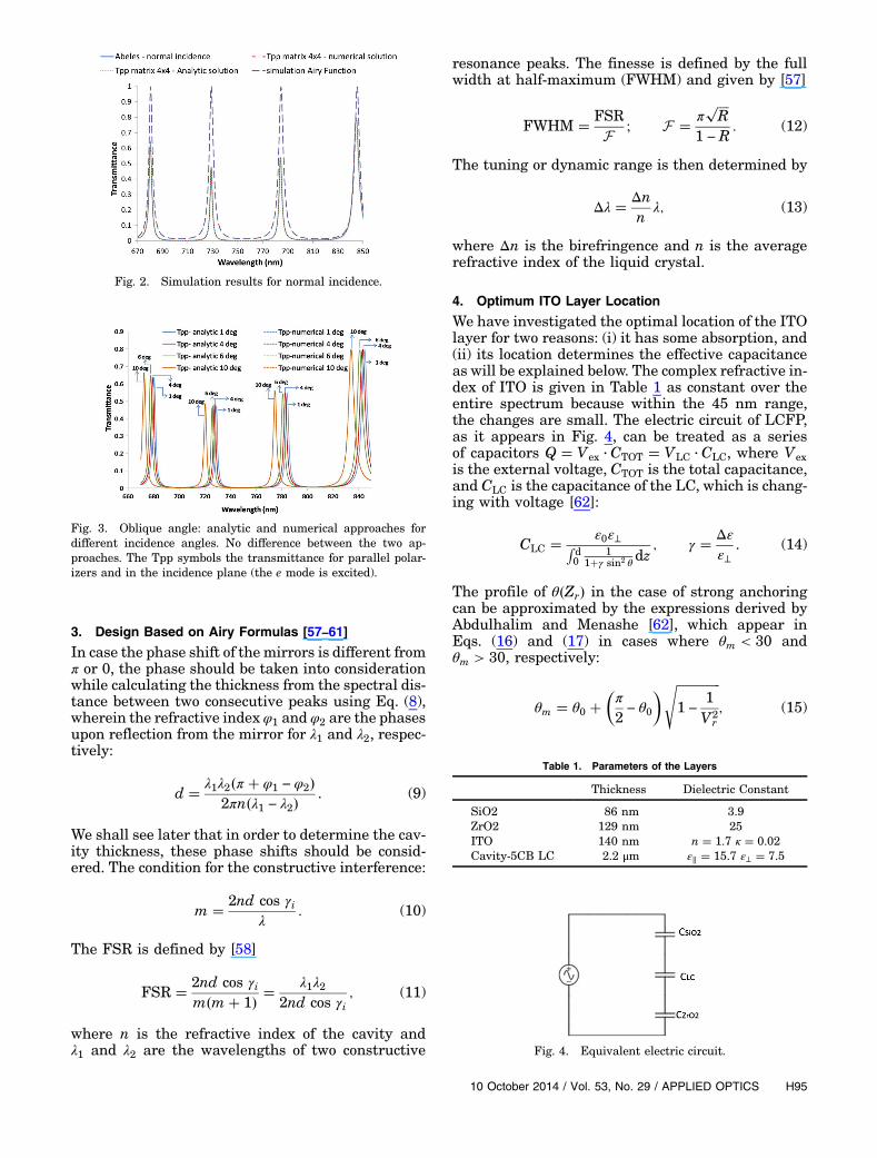
3. Design Based on Airy Formulas [57–61]
In case the phase shift of the mirrors is different fromπ or 0, the phase should be taken into considerationwhile calculating the thickness from the spectral dis-tance between two consecutive peaks using Eq. (8),wherein the refractive index φ1 and φ2 are the phasesupon reflection from the mirror for λ1 and λ2, respec-tively:
d � λ1λ2�π � φ1 − φ2�2πn�λ1 − λ2�
. (9)
We shall see later that in order to determine the cav-ity thickness, these phase shifts should be consid-ered. The condition for the constructive interference:
m � 2nd cos γiλ
: (10)
The FSR is defined by [58]
FSR � 2nd cos γim�m� 1� �
λ1λ22nd cos γi
; (11)
where n is the refractive index of the cavity andλ1 and λ2 are the wavelengths of two constructive
resonance peaks. The finesse is defined by the fullwidth at half-maximum (FWHM) and given by [57]
FWHM � FSRF
; F � ��R
p
1 − R: (12)
The tuning or dynamic range is then determined by
Δλ � Δnn
λ; (13)
where Δn is the birefringence and n is the averagerefractive index of the liquid crystal.
4. Optimum ITO Layer Location
We have investigated the optimal location of the ITOlayer for two reasons: (i) it has some absorption, and(ii) its location determines the effective capacitanceas will be explained below. The complex refractive in-dex of ITO is given in Table 1 as constant over theentire spectrum because within the 45 nm range,the changes are small. The electric circuit of LCFP,as it appears in Fig. 4, can be treated as a seriesof capacitors Q � Vex · CTOT � VLC · CLC, where Vexis the external voltage, CTOT is the total capacitance,and CLC is the capacitance of the LC, which is chang-ing with voltage [62]:
CLC � ε0ε⊥Rd0
11�γ sin2 θ
dz; γ � Δε
ε⊥. (14)
The profile of θ�Zr� in the case of strong anchoringcan be approximated by the expressions derived byAbdulhalim and Menashe [62], which appear inEqs. (16) and (17) in cases where θm < 30 andθm > 30, respectively:
θm � θ0 ��π
2− θ0
� ���������������1 −
1
V2r
s; (15)
Fig. 2. Simulation results for normal incidence.
Fig. 3. Oblique angle: analytic and numerical approaches fordifferent incidence angles. No difference between the two ap-proaches. The Tpp symbols the transmittance for parallel polar-izers and in the incidence plane (the e mode is excited).
Fig. 4. Equivalent electric circuit.
Table 1. Parameters of the Layers
Thickness Dielectric Constant
SiO2 86 nm 3.9ZrO2 129 nm 25ITO 140 nm n � 1.7 κ � 0.02Cavity-5CB LC 2.2 μm ε∥ � 15.7 ε⊥ � 7.5
10 October 2014 / Vol. 53, No. 29 / APPLIED OPTICS H95

θ�Zr� � θ0 � �θm�Vr� − θ0��arctan�exp�Zr∕χr�� � arctan�exp��1 − Zr�∕χr�� − arctan�exp�1∕χr�� − π∕4
2 arctan�exp�0.5∕χr�� � arctan�exp�1∕χr�� − π∕4
�; (16)
θ�Zr� � θ0 � �θm�Vr� − θ0��arctan�exp�Zr∕χr�� � arctan�exp��1 − Zr�∕χr�� − arctan�exp�1∕χr��
2 arctan�exp�0.5∕χr�� � arctan�exp�1∕χr��
�; (17)
where θm is the angle in the center of the cell, θo isthe pretilt, Vr is the applied voltage normalized tothe threshold voltage, and χr � 1∕�πVr�. For moreexplanations on Eqs. (16) and (17), the reader isreferred to Ref. [62].
If the ITO layer is inserted on top of the mirror theabsorption will be maximal, while if it is locatedunderneath the mirror as it appears in the stack,ITO∕�SiO2∕ZrO2�5∕LC∕�ZrO2∕SiO2�5∕ITO, part ofthe applied voltage then drops on the mirror. Thecapacitance (per unit area) is calculated by
C � ε
d; (18)
whereC, ε, and d are the capacitance, relative permit-tivity, and thickness, respectively. In our design, thetotal number of SiO2 and ZrO2 layers is 10 each.Hence, the total capacitance is calculated from
10CSiO2
� 10CZrO2
� 1CLC
� 1CTOT
. (19)
The parameters of the layers in the device appearin Table 1.
According to Vex � �VLCCLC�∕CTOT, the voltage re-quired to switch the LC increases by a factor of 2.35at low voltages and by a factor of 3.83 at high volt-ages. In order to avoid high voltage, the ITO layerswere located on top of the dielectric mirror. The loca-tion of the ITO between the dielectric layers affectsthe range of the mirrors, as is shown in Fig. 5, andtherefore affects the range of the F–P as we cansee in Fig. 6, which is calculated using Abeles matri-ces with the air cavity having a thickness of 2 μm.With the ITO layer kept away from the LC interface,the transmittance increases to 90%. This is becausenow the photons do not arrive to the ITO layer andget reflected back and forth by the periodic stack.Since ITO affects the mirror reflectance, the cavityfinesse is changing according to Eq. (11) and is shownin Fig. 7.
As shown in Fig. 5, the best location of the ITO isbetween the dielectric layers as it appears in the
Table 2. Parameters of the Filter
Thickness 2.2 μmR 0.9FSR 55 nmTuning range 45 nmFWHM 6 nm
Fig. 5. Mirror reflectance as a function of wavelength for differ-ent locations of the ITO layer in the stack.
Fig. 6. FP transmittance with air cavity as a function of wave-length for different locations of the ITO layer. The stacks showncorrespond to one mirror.
Fig. 7. Finesse as function of the location of the ITO.
H96 APPLIED OPTICS / Vol. 53, No. 29 / 10 October 2014

configuration �SiO2∕ZrO2�2∕ITO∕�SiO2∕ZrO2�3;however, the reflectance of the mirror decreasesand the range becomes narrower. By changing the ra-tio between the refractive indices of the dielectriclayers using ZrSe (nZrSe � 2.53) instead of ZrO2,the range of the mirrors can be broadened, as shownin Fig. 8. Hence, when considering the optimum de-sign for the ITO layer, the mirror structure needs tobe optimized as well. The effect of an absorptive layeron the FP peaks becomes larger as the reflectivity in-creases because then the photon lifetime within thecavity is larger.
5. Experimental Work
To construct the filter, we have used round glass sub-strates with flatness of λ∕20 and diameter of 2.5 cm,coated with dielectric mirrors containing five periodsof thin layers �SiO2∕ZrO2�5, and an ITO layer as thetransparent electrode. The dielectric coatings weredesigned to act as mirrors in the range of 700 to800 nm and reflectivity of 90%. To prepare the device,a thin layer (∼20–30 nm) of polymer photoalignmentlayer (ROC 108 from Rolic technologies) was depos-ited onto the mirrors using a spin-coating process.After baking the glasses for 60 min. at a temperatureof 230°C, we exposed the glasses to linearly polarizedUV light (280–360 nm) with intensity of 0.8(mW∕cm2� for 7 min. The top and bottom substrateswere assembled with 1.86� 0.34 μm silica spacers inan antiparallel configuration to obtain the homo-geneously aligned nematic LC; however, the thick-ness is usually determined by the spheres of thelargest thickness, which is apparently what we getin our case (measured cavity thickness of 2.2 μm).We have chosen the smallest spacers available to ob-tain the maximum FSR. The cell was filled in vac-uum with 5 CB at the isotropic phase (30°C). Therefractive index along the molecule axis (n∥) is1.68, and the ordinary refractive index (n⊥) is 1.52at 750 nm. Figure 9 shows the dispersion curve forn∥, no and the birefringence Δn.
The measurement of the transmittance for bothpolarizations appears in Fig. 10(a), which is smallerin the middle of the range than in the edges. The rea-son for this behavior is because the reflectance is
higher in the middle, and so narrower peaks areobtained, but the effect of the ITO absorption is thenhigher as the photon lifetime in the cavity increaseswith the reflectance. The parameters of the filter arementioned in Table 2.
With an applied electric field, the angle θ andtherefore ne are locally changing according to
ne � n⊥n∥∕���������������������������������������������n2⊥ cos
2 θ� n2∥ sin
2 θq
[63], and by thisthe transmittance is changing, as it appears inFig. 8(b). Because of the anchoring at the surfaces,a nonuniform profile θ�z� [Eqs. (14)–(16)] is obtainedwhen a field is applied, and therefore the integralRd0 ne�z�dz needs to be evaluated.In order to find the cavity thickness, we compared
the Airy equation, Abeles matrices, and the measure-ment at normal incidence (see Fig. 11), giving thethickness of 2.2 μm.With the Airy function, we didn’t
Fig. 8. Mirror spectral range is changing with different layers ofstacks.
Fig. 9. Dispersion of LC 5CB.
Fig. 10. (a) Measured transmittance for the polarized light alongthe molecular axis (blue-dashed) and perpendicular to it (red solidline). (b) Measurement of tuning for polarized light at differentvoltages.
10 October 2014 / Vol. 53, No. 29 / APPLIED OPTICS H97
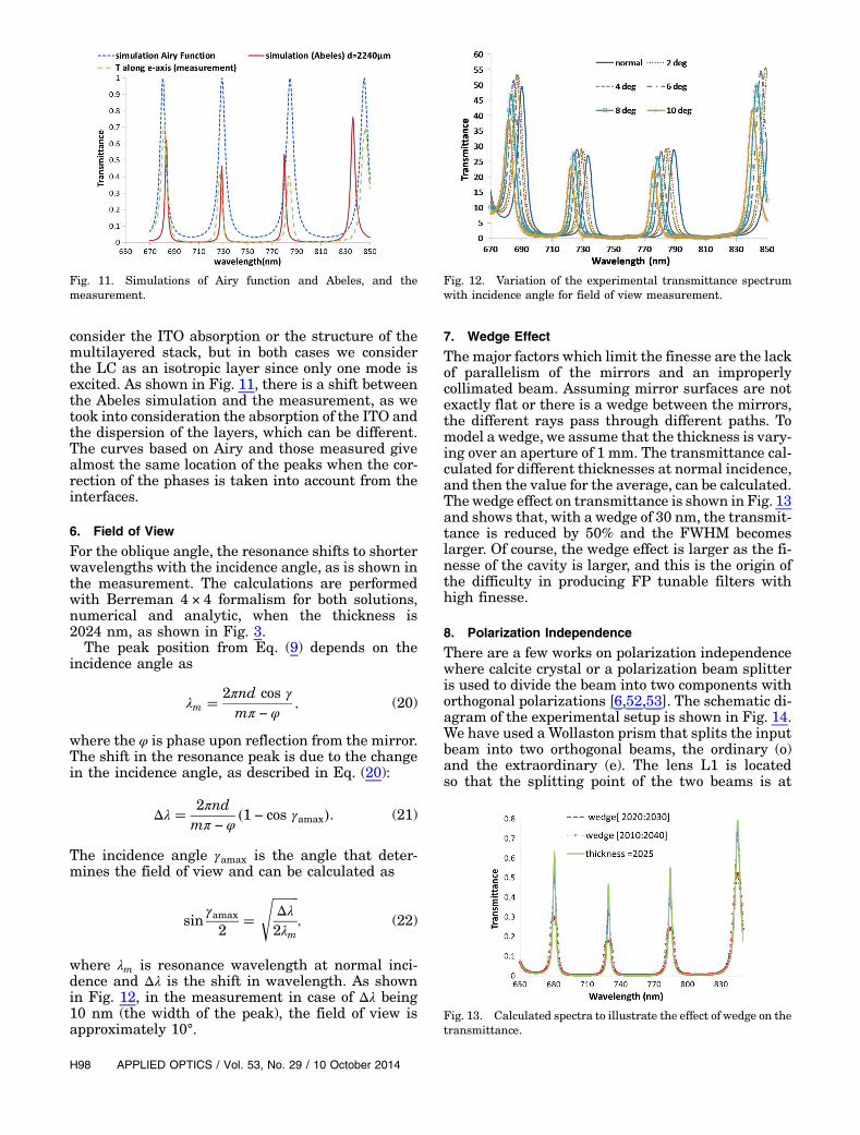
consider the ITO absorption or the structure of themultilayered stack, but in both cases we considerthe LC as an isotropic layer since only one mode isexcited. As shown in Fig. 11, there is a shift betweenthe Abeles simulation and the measurement, as wetook into consideration the absorption of the ITO andthe dispersion of the layers, which can be different.The curves based on Airy and those measured givealmost the same location of the peaks when the cor-rection of the phases is taken into account from theinterfaces.
6. Field of View
For the oblique angle, the resonance shifts to shorterwavelengths with the incidence angle, as is shown inthe measurement. The calculations are performedwith Berreman 4 × 4 formalism for both solutions,numerical and analytic, when the thickness is2024 nm, as shown in Fig. 3.
The peak position from Eq. (9) depends on theincidence angle as
λm � 2πnd cos γ
mπ − φ; (20)
where the φ is phase upon reflection from the mirror.The shift in the resonance peak is due to the changein the incidence angle, as described in Eq. (20):
Δλ � 2πndmπ − φ
�1 − cos γamax�. (21)
The incidence angle γamax is the angle that deter-mines the field of view and can be calculated as
sinγamax
2�
���������Δλ2λm
s; (22)
where λm is resonance wavelength at normal inci-dence and Δλ is the shift in wavelength. As shownin Fig. 12, in the measurement in case of Δλ being10 nm (the width of the peak), the field of view isapproximately 10°.
7. Wedge Effect
The major factors which limit the finesse are the lackof parallelism of the mirrors and an improperlycollimated beam. Assuming mirror surfaces are notexactly flat or there is a wedge between the mirrors,the different rays pass through different paths. Tomodel a wedge, we assume that the thickness is vary-ing over an aperture of 1 mm. The transmittance cal-culated for different thicknesses at normal incidence,and then the value for the average, can be calculated.The wedge effect on transmittance is shown in Fig. 13and shows that, with a wedge of 30 nm, the transmit-tance is reduced by 50% and the FWHM becomeslarger. Of course, the wedge effect is larger as the fi-nesse of the cavity is larger, and this is the origin ofthe difficulty in producing FP tunable filters withhigh finesse.
8. Polarization Independence
There are a few works on polarization independencewhere calcite crystal or a polarization beam splitteris used to divide the beam into two components withorthogonal polarizations [6,52,53]. The schematic di-agram of the experimental setup is shown in Fig. 14.We have used a Wollaston prism that splits the inputbeam into two orthogonal beams, the ordinary (o)and the extraordinary (e). The lens L1 is locatedso that the splitting point of the two beams is at
Fig. 11. Simulations of Airy function and Abeles, and themeasurement.
Fig. 12. Variation of the experimental transmittance spectrumwith incidence angle for field of view measurement.
Fig. 13. Calculated spectra to illustrate the effect of wedge on thetransmittance.
H98 APPLIED OPTICS / Vol. 53, No. 29 / 10 October 2014

its front focal plane to obtain two parallel beams. Theo polarization is transformed to e polarization using aLC variable HWP.We used the variable wave plate inorder to be able to adjust it to act as a HWP for anydesired wavelength in the range of interest. The dis-tance between these two parallel beams is 12 mmbut, to avoid the effect of LCTF thickness variation,we wanted these two beams as close as possible whenthey pass through the filter. In order to bring thebeams as close as possible, we used a combinationof two positive lenses L2 and L3, which have differ-ent focal lengths in a telescope configuration. Withthe ratio between the two focal lengths of 7∶1, weget the two beams within 2 mm of their centers.
In Fig. 15(a), the spectrum of each beam is shownseparately while blocking the other one. The wave-length difference between these two peaks is 3 nmdue to the LC thickness variation of 8 nm withinthe 2 mm separation of the two beams. The FWHM
widened to 9 nm, but with the advantage of having aworking polarization-independent LCFP withoutcritical requirement on the gap uniformity. For nar-rower filters, the tolerances are higher on the gapnonuniformity and also the beams should be broughtcloser to each other. When these two beams recom-bine, they simply add up and no interference effectsare observed due to the fact that their coherencelength is much smaller than the path lengthdifference.
In Fig. 15(b), the tuning for unpolarized light isshown. For Fig. 10(b), the incident polarized lightwas taken as a reference while, for Fig. 15(b), the un-polarized light was taken as a reference, whichexplains why it seems that the polarized light trans-mittance is higher than in the unpolarized case whenin fact 50% is lost in the polarizer.
9. Conclusions
A liquid crystal Fabry–Perot tunable filter was theo-retically analyzed in detail, with special attention tothe design, tolerances, and polarization independ-ence. At normal incidence, it is shown that one canuse the 2 × 2 Abeles matrix method; however, atoblique incidence, the 4 × 4matrix method is needed.The Airy formulas may be used at normal incidencebut the phase shift upon reflection from the mirrormultilayered stack needs to be considered. The calcu-lations were performed both numerically and ana-lytically using a simple algebraic expression forthe 4 × 4 propagation matrix for an anisotropic layerwhen the optic axis remains in the incidence plane.The effects of dephasing originating from a wedgeand noncollimated beam were investigated. Due tothe absorption of the ITO layer as a transparent elec-trode and due to the effective capacitance effects, itslocation within the mirror multilayered stack is veryimportant. The optimum location is found to bewithin the stack and not on its top or bottom. Finally,we give more detailed experimental results of ourpolarization-independent configuration that usepolarization diversity with a Wollaston prism.
We are grateful to Rolic, Basel, Switzerland forproviding the photoalignment polymers. This workis partially supported by the Israeli Ministry ofScience under the Tashtiot program.
References1. H. A. Macleod, Thin-Film Optical Filters, 2nd ed. (Macmillan,
1986).2. A. Yariv and P. Yeh, Optical Waves in Crystals (Wiley, 1984).3. W. J. Gunning, “Electro-optically tuned spectral filter: a
review,” Opt. Eng. 20, 206837 (1981).4. H. J. Masterson, G. D. Sharp, and K. M. Johnson, “Ferroelec-
tric liquid crystal tunable filter,” Opt. Lett. 14, 1249–1251(1989).
5. J. S. Patel and Y. Silberberg, “Anticrossing of polarizationmodes in liquid-crystal etalons,” Opt. Lett. 16, 1049–1051(1991).
6. J. S. Patel, “Electrically tunable ferroelectric liquid crystalFabry–Perot filter,” Opt. Lett 17, 456–458 (1992).
7. J. S. Patel, M. A. Saifi, D. W. Berreman, C. Lin, N.Andreadakis, and S. D. Lee, “Electrically tunable optical filter
Fig. 14. Setup used to obtain the polarization independence.
Fig. 15. (a) The red solid curve describes the transmittance of theo wave, which was rotated to the e wave using HWP, while thegreen dashed curve describes the transmittance of the e wave;the blue empty squares describe the recombination of the twobeams. (b) Measurement of tuning at different voltages for unpo-larized light.
10 October 2014 / Vol. 53, No. 29 / APPLIED OPTICS H99

for infrared wavelength using liquid crystals in Fabry–Perotetalon,” Appl. Phys. Lett. 57, 1718–1720 (1990).
8. M. W. Maeda, J. S. Patel, D. A. Smith, C. Lin, M. A. Saifi, andA. Von Lehman, “An electronically tunable fiber laser with aliquid-crystal etalon filter as the wavelength-tuning element,”IEEE Photon. Technol. Lett. 2, 787–789 (1990).
9. H. Yoda, Y. Ohtera, O. Hanaizomi, and S. Kawakami, “Analy-sis of polarization-insensitive tunable optical filter usingliquid crystal: connection formula and apparent paradox,”Opt. Quantum Electron. 29, 285–299 (1997).
10. R. Le Dantee, T. Benyattou, G. Guillot, A. Spisser, C.Seassal, J. L. Leclercq, P. Viktorovitch, D. Rondi, and R.Blondeau, “Tunable microcavity based on InP–air Braggmirrors,” IEEE J. Sel. Top. Quantum Electron. 5, 111–114(1999).
11. I. S. Nefedov and V. N. Gusyatnikov, “Optically controlledGaAs-GaAlAs photonic band gap structure,” J. Opt. A 2,344–347 (2000).
12. F. Placido, S. Moh, O. Duyar, and H. Z. Durosoy, “Complex op-tical filters by microwave-assisted dc magnetron sputtering,”in Plasma Polymers and Related Materials, M. Mutlu, ed.(Hacettepe University, 2005), pp. 68–74.
13. I. J. Hodgkinson and Q. H. Wu, Birefringent Thin Films andPolarizing Elements, 1st ed. (World Scientific, 1997), Chap. 4,p. 52.
14. B. S. Sorg, B. J. Moeller, O. Donovan, Y. T. Cao, and M. W.Dewhirst, “Hyperspectral imaging of hemoglobin saturationin tumor microvasculature and tumor hypoxia development,”J. Biomed. Opt. 10, 44004 (2005).
15. S. C. Gebhart, R. C. Thompson, and A. Mahadevan-Jansen,“Liquid-crystal tunable filter spectral imaging for brain tumordemarcation,” Appl. Opt. 46, 1896–1910 (2007).
16. S. Saeed, P. J. Bos, and Z. Li, “Amethod of generating full colorin a liquid crystal display using birefringent filters,” Jpn. J.Appl. Phys. 40, 3266–3271 (2001).
17. S. Saeed and P. J. Bos, “Synthesis of a color imagedisplay using birefringent filters,” Opt. Eng. 41, 167–175(2002).
18. S. Saeed and P. J. Bos, “Multispectrum, spatially addressablepolarization interference filter,” J. Opt. Soc. Am. A 19,2301–2312 (2002).
19. K. Hirabayshi and T. Kurokawa, “Liquid crystal devices foroptical communication and information processing systems,”Liq. Cryst. 14, 307–317 (1993).
20. A. Sneh and K. M. Johnson, “High speed continuously tunableliquid crystal filter for WDMnetworks,” J. Lightwave Technol.14, 1067–1080 (1996).
21. D. S. Mehta, M. Sugai, H. Hinosugi, S. Saito, M. Takeda, T.Kurokawa, H. Takahashi, M. Ando, M. Shishido, and T.Yoshizawa, “Simultaneous three dimensional step-heightmeasurement and high-resolution tomographic imaging witha spectral interferometric microscope,” Appl. Opt. 41,3874–3885 (2002).
22. M. Hauta-Kasari, K. Miyazawa, S. Toyooka, and J. Parkkinen,“Spectral vision system for measuring color images,” J. Opt.Soc. Am. A 16, 2352–2362 (1999).
23. H. R. Morris, C. C. Hoyt, and P. J. Treado, “Imaging spectrom-eters for fluorescence and Raman microscopy—acousto-opticand liquid-crystal tunable filters,” Appl. Moessbauer Spec-trosc. 48, 857–866 (1994).
24. T. Vo-Dinh, D. L. Stokes, M. B. Wabuyele, M. E. Martin, J. M.Song, R. Jagannathan, E. Michaud, R. J. Lee, and X. Pan, “Ahyperspectral imaging system for in vivo optical diagnosis,”IEEE Eng. Med. Biol. Mag 23(5), 40–49 (2004).
25. M. E. Martin, M. B. Wabuyele, M. Panjehpour, M. N. Phan,B. F. Overholt, and T. Vo-Dinh, “Hyperspectral fluorescenceimaging system for biomedical diagnostics,” Proc. SPIE6080, 60800 (2006).
26. B. Lyot, “Filter monochromatique polarisant et ses applica-tions en physique solaire,” Ann. Astrophys. (Paris) 7, 32–79(1944).
27. Y. Ohman, “On some new birefringent filter for solarresearch,” Arkiv foer Astronomi 2, 165 (1958).
28. I. Solc, “Birefringent chain filters,” Czechslov. Cosopis proFysiku 3, 366 (1953).
29. I. Solc, “Birefringent chain filters,” Czechslov. Cosopis proFysiku 4, 607–669 (1954).
30. I. Solc, “Birefringent chain filters,” Czechslov. Cosopis proFysiku 5, 114 (1955).
31. I. Solc, “Birefringent chain filters, J. Opt. Soc. Am. 55,621–625 (1965).
32. J.-L. Leroy, “Solc elements in Lyot-Ohman filters,” J. Opt.Paris 11, 293–304 (1980).
33. J. W. Evans, “The birefringent filter,” Publ. Astron. Soc. Pac.52, 305 (1940)
34. J. W. Evans, “The birefringent filter,” J. Opt. Soc. Am. 39,229–237 (1949).
35. I. Abdulhalim, “Reflective polarization conversion Fabry–Perot resonator using omnidirectional mirror of periodicanisotropic stack,” Opt. Commun. 215, 225–230 (2003).
36. I. Abdulhalim, “Polarized optical filtering from generallinearly twisted structures,”Opt. Commun. 267, 36–39 (2006).
37. I. Abdulhalim, “Polarization independent birefringent Fabry–Perot etalon having polarization conversion mirrors,” Opt.Commun. 282, 3052–3054 (2009).
38. O. Aharon and I. Abdulhalim, “Liquid crystal tunable filterwith extended free spectral range,” Opt. Express 17,11426–11433 (2009).
39. O. Aharon and I. Abdulhalim, “Birefringent tunable filterwith wide dynamic range,” Opt. Lett. 34, 2114–2116 (2009).
40. I. Abdulhalim, “Optimized guided mode resonant structure asthermooptic sensor and liquid crystal tunable filter,” Chin.Opt. Lett. 7, 667–670 (2009).
41. Z. Zheng, G. Yang, H. Li, and X. Liu, “Three stage Fabry–Perotliquid crystal tunable filter with extended spectral range,”Opt. Express 19, 2158–2164 (2011).
42. H. Tsuda, T. Yoshizawa, K. Hirabayashi, and T. Kurokawa,“Polarization-independent tunable liquid-crystal Fabry–Perotinterferometerfilters,”Jpn.J.Appl.Phys.35,2156–2163(1996).
43. J. S. Patel and S. D. Lee, “Electrically tunable and polarizationinsensitive Fabry–Perot etalon with a liquid-crystal film,”Appl. Phys. Lett. 58, 2491–2493 (1991).
44. C. C. Bowley, H. J. Yuan, and G. P. Crawford, “Morphology ofholographically-formed polymer dispersed liquid crystals(H-PDLC),” Mol. Cryst. Liq. Cryst. 331, 2069–2076 (1999).
45. H. Q. Xianyu, S. Faris, and G. P. Crawford, “In-plane switchingof cholesteric liquid crystals for visible and near-infraredapplications,” Appl. Opt. 43, 5006–5015 (2004).
46. W. K. Choi, A. B. Davey, T. D. Wilkinson, and W. A. Crossland,“Deformed helix ferroelectric liquid crystal Fabry–Perotetalons,” Mol. Cryst. Liq. Cryst. 304, 329–337 (1997).
47. Z. Ge, T. X. Wu, X. Zhu, and S.-T. Wu, “Reflective liquid crystaldisplay with asymmetric incident and exit angle,” J. Opt. Soc.Am. 22, 966–977 (2005).
48. A. Marquez, I. Moreno, J. Campos, and M. J. Yzuel, “Analysisof Fabry–Perot interference effects on modulation propertiesof liquid crystal display,” Opt. Commun. 265, 84–94 (2006).
49. D. W. Berreman, “Optics in stratified and anisotropic media4×4 matrix formulation,” J. Opt. Soc. Am. 62, 502–510 (1972).
50. I. Abdulhalim, “Analytic propagationmatrix method for linearoptics of arbitrary biaxial layered media,” J. Opt. A 1, 646–653(1999).
51. K. Hirabayashi, Y. Ohiso, and T. Kurokawa, “Polarization-independent tunable wavelength-selective filter using a liquidcrystal,” IEEE Photon. Technol. Lett. 3, 1091–1093 (1991).
52. K. Hirabayashi and T. Kurokawa, “A tunable polarization-independent liquid-crystal Fabry-Perot interferometer filter,”IEEE Photon. Technol. Lett. 4, 740–742 (1992).
53. J. S. Patel and M. W. Maeda, “Tunable polarization diversityliquid-crystal wavelength filter,” IEEE Photon. Technol. Lett.3, 739–740 (1991).
54. J.-H. Lee, H.-R. Kim, and S.-D. Lee, “Polarization-insensitivewavelength selection in an axially symmetric liquid-crystalFabry–Perot filter,” Appl. Phys. Lett. 75, 859–861 (1999).
55. Y. Morita and K. M. Johnson, “Polarization-insensitive tuna-ble liquid crystal Fabry–Perot filter incorporating polymerliquid crystal waveplates,” Proc. SPIE 3475, 152–162 (1998).
56. J. A. French,Design and Characterization of a Tunable Fabry-Perot Filter Using an Electro-optic Modulated Spacer Layer(ProQuest, 2007).
H100 APPLIED OPTICS / Vol. 53, No. 29 / 10 October 2014

57. H. Zhang, Y. Betremieux, J. Noto, and R. Kerr, “Novel tunableliquid crystal Fabry–Perot filters for fiber optical system,”Proc. SPIE 4583, 64–72 (2001).
58. D. Bonaccini, L. Casini, and P. Stefanini, “Fabry-Perot tunablefilter for the visible and near IR using nematic liquid crystal,”Proc. SPIE 1334, 221–230 (1990).
59. W. Vogel and M. Berroth, “Tunable liquid crystal Fabry-Perotfilters,” Proc. SPIE 4944, 293–302 (2003).
60. H. Chen, T. Huang, W. Shen, H. Li, and P. Gu, “Tunable opticalfilter based on liquid crystal Fabry-Perot etalon,” Proc. SPIE5280, 408–412 (2004).
61. M. Jiao, R. Qi, Z. Liu, and J. Xing, “Design of a liquid crystalFabry-Perot etalon and analysis of resonant mode splitting ofa birefringent Fabry-Perot etalon,” Proc. SPIE 5627, 473–480(2005).
62. I. Abdulhalim and D. Menashe, “Approximate analytic solu-tions for the director profile of homogeneously alignednematic liquid crystals,” Liq. Cryst. 37, 233–239 (2010).
63. K. Liu, H. Li, X. Zhang, D. Li, X. Jiang, C.-S. Xie, and T. Zhang,“Development and characterization of an electrically tunableliquid-crystal Fabry–Perot hyperspectral imaging device,” J.Appl. Remote Sens. 5, 1–15 (2011).
10 October 2014 / Vol. 53, No. 29 / APPLIED OPTICS H101
Related Documents