1 Abstract The main problems of weight saving for composite airframes are considered and substantiated in this paper. A new complex program for fast and confident composite structure weight estimation on the basis of the multilevel approach is described. The relationship between the composite aircraft structure weight and the physical characteristics of the resin was obtained on the basis of numerical and experimental results. An investigation of alternative “black metal” and “Frame” structure concepts for a flying wing aircraft has shown that the “frame” concept has more potential in weight saving for the resin currently available. Keywords: composite airframes, multidisciplinary design, resins, structure weight estimation, non-conventional concepts. 1 Introduction The problem of weight saving in aircraft structures does not lose its actuality throughout all history of civil aviation development and in essence it is one of the most important factors on maintenance of the progress of aviation technics. Structure weight is one of the key parameters which directly impacts transport efficiency of an aircraft, because it directly impacts on manufacturing and direct costs of aircrafts. On Figure 1 the graph illustrating tendency of transport efficiency of civil aircrafts for all period of aviation development is presented. This graph was prepared on the basis of materials presented in open publications in frame of FP6 NACRE project [1]. The transport efficiency was estimated as a value 1/c, where c is the cost of transportation of a one passenger on 1 km, at corresponding level of comfort, safety requirements and ecology demands. The relative value of transport efficiency is shown on the graph. Paper 56 Investigation of Lightweight Composite and Hybrid Primary Aircraft Structures A. Shanygin Central Aerohydrodynamic Institute (TsAGI) Zhukovsky, Moscow Region, Russia ©Civil-Comp Press, 2012 Proceedings of the Eleventh International Conference on Computational Structures Technology, B.H.V. Topping, (Editor), Civil-Comp Press, Stirlingshire, Scotland

Welcome message from author
This document is posted to help you gain knowledge. Please leave a comment to let me know what you think about it! Share it to your friends and learn new things together.
Transcript
1
Abstract The main problems of weight saving for composite airframes are considered and substantiated in this paper. A new complex program for fast and confident composite structure weight estimation on the basis of the multilevel approach is described. The relationship between the composite aircraft structure weight and the physical characteristics of the resin was obtained on the basis of numerical and experimental results. An investigation of alternative “black metal” and “Frame” structure concepts for a flying wing aircraft has shown that the “frame” concept has more potential in weight saving for the resin currently available. Keywords: composite airframes, multidisciplinary design, resins, structure weight estimation, non-conventional concepts.
1 Introduction The problem of weight saving in aircraft structures does not lose its actuality throughout all history of civil aviation development and in essence it is one of the most important factors on maintenance of the progress of aviation technics. Structure weight is one of the key parameters which directly impacts transport efficiency of an aircraft, because it directly impacts on manufacturing and direct costs of aircrafts. On Figure 1 the graph illustrating tendency of transport efficiency of civil aircrafts for all period of aviation development is presented. This graph was prepared on the basis of materials presented in open publications in frame of FP6 NACRE project [1]. The transport efficiency was estimated as a value 1/c, where c is the cost of transportation of a one passenger on 1 km, at corresponding level of comfort, safety requirements and ecology demands. The relative value of transport efficiency is shown on the graph.
Paper 56 Investigation of Lightweight Composite and Hybrid Primary Aircraft Structures A. Shanygin Central Aerohydrodynamic Institute (TsAGI) Zhukovsky, Moscow Region, Russia
©Civil-Comp Press, 2012 Proceedings of the Eleventh International Conference on Computational Structures Technology, B.H.V. Topping, (Editor), Civil-Comp Press, Stirlingshire, Scotland

2
Figure 1. Main stages of civil aircrafts development
The figure shows that now metal structures, having passed a way of 60-year-old evolution have reached the maximum of their efficiency mainly because of no real progress in structure weight saving. Further increase of weight efficiency (and, consequently, transport efficiency) is connected with new fibrous composite materials (CM) having high values of stress characteristics. For example, ultimate stress of current carbon fibers exceeds value σul.tension=500 kgs/mm2 that approximately 10 times more than those for modern aluminum alloys, whereas specific weight of fibres two times less. Composite materials are now widely used in aircraft secondary structures, but as for the primary (load-bearing) ones, no real success in weight saving have been reached so far. The experience which has been gained in TsAGI in frame of international and Russian projects such as NACRE, ALCAS, MAAXIMUS, CM-Fuselage, ALaSCA [2] etc. has shown that the main difficulties in weight saving are connected with essential misbalance between ultimate values of relative deformations of resins and fibers. This misbalance does not allow manufacturers to create the composite quasiisotropic materials equivalent by its properties to current metallic alloys. For this reason in frame of “Black metal” composite structure concept, which has metallic design concept and layout, it is very difficult to get high weight (and transport) efficiency of composite primary structures, because this design concept and layouts were created to realize maximally potentials of metallic alloys, but not of composite materials. The history shows that change of a constructive material inevitably leads to new design concepts and layouts and consequently, for the further progress of composite airframes it is necessary to search new design concepts and new layouts optimal for these concepts. This problem was a subject of research in the European Framework project FP6 NACRE, in Russian project CM-fuselage and in Collaborative project

3
ALaSCA. Search of so-called "pro-composite" concepts, i.e. the concepts allowing to realize high potential advantages of composite materials more efficiently than in frame of “Black metal” concept, is now considered by many scientific schools as one of perspective and promising directions in development of the next generation of airframes and space structures [3-5]. Development of the rational design concept and layout for composite aircrafts is a very difficult task that requires a special approach. In the present paper the approach and the method for searching rational concepts and layouts are described. This approach allows designers to take into account main problems concerning development of composite primary structures in forming new stress/strain criteria, manufacturing constraints and optimization algorithms for non-conventional composite structures, and also to estimate the impact of different design parameters on a structure weight of an airframe at the initial stage of designing. In this paper on the basis of numerical and experimental investigations the dependence of weight of composite primary structure on one of the critical design parameters, ultimate relative tensile strain of resin, has been obtained. It was shown that this parameter is the main one which directly impact on the weight efficiency for current composites.
2 The Main Problem of Weight Saving in Composite Airframes
To define the main directions of search of pro-composite airframes it is necessary to analyze the main disadvantages of "Black metal" composite concepts applying to current composite materials [6]. The analysis of Russian and European works on the given subjects shows that the main disadvantage of “Black metal” concept is that for current composites it is impossible to create high-effective composite panel similar to metallic one, i.e. the structure consisting of a thin skin and a thin-walled supporting set. Such type of an airframe structure element can realize almost all potential advantages of current metallic alloys first of all in: -harmonious combination high strength and high deformation properties; -high level of ultimate shear strain. The thin-walled supported panel is the top of evolution of metallic structure details in current airframes, such as panels, walls, ribs and frames. Due to the high deformation ability the metal skin is a good in bearing impact loads, and also allows designers to realize so-called postbuckling effect [7, 8]. This effect is used to increase the weight efficiency of thin metallic skin panels without losing their safety characteristics. Furthermore, the thin-walled, supported panel in metallic airframe is a hi-tech type of a structure both from manufacture and repair viewpoints. As for composite panels in frame of «Black metal» composite concept, unfortunately they have not got any advantages mentioned above as there is no industrial technology so far performing strong bonding between fibers, similar to welding of steel reinforcements in reinforced concrete, and consequently, carbon fibers can be bonded in a uniform structure only by the means of binding (resin). This is the root of many problems of using composite materials in airframe primary
4
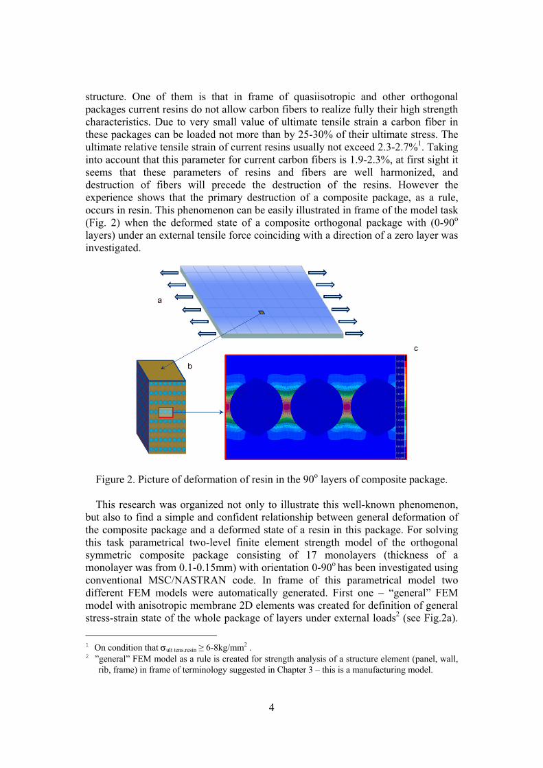
structure. One of them is that in frame of quasiisotropic and other orthogonal packages current resins do not allow carbon fibers to realize fully their high strength characteristics. Due to very small value of ultimate tensile strain a carbon fiber in these packages can be loaded not more than by 25-30% of their ultimate stress. The ultimate relative tensile strain of current resins usually not exceed 2.3-2.7%1. Taking into account that this parameter for current carbon fibers is 1.9-2.3%, at first sight it seems that these parameters of resins and fibers are well harmonized, and destruction of fibers will precede the destruction of the resins. However the experience shows that the primary destruction of a composite package, as a rule, occurs in resin. This phenomenon can be easily illustrated in frame of the model task (Fig. 2) when the deformed state of a composite orthogonal package with (0-90o
layers) under an external tensile force coinciding with a direction of a zero layer was investigated.
Figure 2. Picture of deformation of resin in the 90o layers of composite package.
This research was organized not only to illustrate this well-known phenomenon,
but also to find a simple and confident relationship between general deformation of the composite package and a deformed state of a resin in this package. For solving this task parametrical two-level finite element strength model of the orthogonal symmetric composite package consisting of 17 monolayers (thickness of a monolayer was from 0.1-0.15mm) with orientation 0-90o has been investigated using conventional MSC/NASTRAN code. In frame of this parametrical model two different FEM models were automatically generated. First one – “general” FEM model with anisotropic membrane 2D elements was created for definition of general stress-strain state of the whole package of layers under external loads2 (see Fig.2a). 1 On condition that σult tens.resin ≥ 6-8kg/mm2 . 2 ”general” FEM model as a rule is created for strength analysis of a structure element (panel, wall,
rib, frame) in frame of terminology suggested in Chapter 3 – this is a manufacturing model.
5
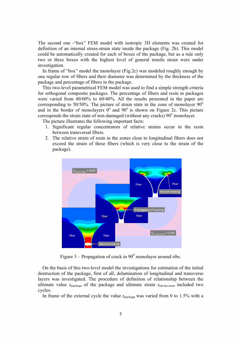
The second one -“box” FEM model with isotropic 3D elements was created for definition of an internal stress-strain state inside the package (Fig. 2b). This model could be automatically created for each of boxes of the package, but as a rule only two or three boxes with the highest level of general tensile strain were under investigation. In frame of “box” model the monolayer (Fig.2c) was modeled roughly enough by one regular row of fibers and their diameter was determined by the thickness of the package and percentage of fibers in the package. This two-level parametrical FEM model was used to find a simple strength criteria for orthogonal composite packages. The percentage of fibers and resin in packages were varied from 40/60% to 60/40%. All the results presented in the paper are corresponding to 50/50%. The picture of strain state in the zone of monolayer 90o and in the border of monolayers 0o and 90o is shown on Figure 2c. This picture corresponds the strain state of non-damaged (without any cracks) 90o monolayer. The picture illustrates the following important facts:
1. Significant regular concentrators of relative strains occur in the resin between transversal fibers.
2. The relative strain of resin in the zones close to longitudinal fibers does not exceed the strain of these fibers (which is very close to the strain of the package).
Figure 3 – Propagation of crack in 900 monolayer around ribs.
On the basis of this two-level model the investigations for estimation of the initial destruction of the package, first of all, delamination of longitudinal and transverse layers was investigated. The procedure of definition of relationship between the ultimate value εpackage of the package and ultimate strain εult.ten.resin included two cycles. In frame of the external cycle the value εpackage was varied from 0 to 1.5% with a

6
small increment. For each value of εpackage on the basis of iteration process the strain state of the “box” model, taking into account appearance and propagation of cracks, was investigated. During this internal cycle stiffness characteristics of the “box” model were being modified. In each subsequent calculation of the “box” FEM model elements where values of relative tension strain εult.ten.resin exceeded ultimate values of relative tension strain εult.ten.resin were being excluded from the model. Depending on parameters εpackage and ε ult.ten.resin propagation of cracks around the fiber either stops not reaching other cracks or causes delamination on the border of monolayers 0o and 90o. The procedure of numerical investigation of crack propagation depending on general deformation of the package εpackage = 0.5% and εult.ten.resin = 2.5% is shown on Figure 3. The subsequent calculation has shown that the value of “delamination” strain of the package was 0.7%. The results of numerical calculation on the basis on the two-level model showed that a simple deformational strength criterion for orthogonal packages (0-90o) could be formulated using the relationship between εpackage and ε ult.ten.resin (see Figure 4). According to this criterion the ultimate relative strain of the package can be found as a function of ultimate tensile strain of resin. This criterion turned out to be very convenient for carrying out fast preliminary analysis of strength of composite package in frame of weight estimation procedure at the initial stage of designing.
Figure 4 – Relationship between relative strain of the orthogonal package and ultimate relative tensile strain of resin.
For validation of the results of numerical analysis a number of experimental investigations of strength of composite specimens (with monolayers 0-90o) were been carried out using acoustic emission method (Figure 5). By the means of this

7
method strength characteristics of specimens were investigated (Figure 6). The non-destructive method of acoustic emission allows to identify the beginning of destruction inside the composite package on the basis of significant increase of acoustic emission level during the experimental investigation. For validation of the results described above 12 composite specimens consisting of 17 monolayers with thicknesses 0.1 ≥ t ≥ 0.15 mm were manufactured for testing. 6 of these specimens were manufactured using the resin with ε ult.ten.resin = 1.85%, other 6 specimens had εult.ten.resin = 2.5%. The ultimate relative stresses of these specimens were equal σult ten. resin = 6.5 kg/mm2 and 6.0 kg/mm2 respectively. Results of experimental testing for definition of beginning of delamination of monolayers (0/90o) have shown good coincidence (author didn’t expect such a good coincidence) with numerical investigation (which had been carried out before testing) both for brittle and more viscous resins. The results of these experiments are shown on Figure 4.
Figure 5 – Experimental investigation of composite specimen under tensile loading.
Figure 6 – Results of experimental investigation of composite specimen.

8
Experimental and numerical results have shown that for preliminary estimation of strength of orthogonal packages the following parameters of the package should be defined:
- relative tensile strain of the package (in all points of the composite skin); - ultimate tensile strain of the resin ε ult.ten. resin; - percentage of fibers and resin in the package.
For the orthogonal package where the percentage of resin and fibers 50/50% the ultimate tensile strain of the package can be defined as: ε ult.ten.package ≈ 0.25 εult.ten.resin. Such numerical-experimental investigations for quasiisotropic, ±45o and also for some other stacking sequences were carried out. It was shown that the delamination of 90o layers occurred approximately at the same level of relative tensile strain of the package both for orthogonal and quasiisotropic packages. The dependence of acoustic emission on deformation for quasiisotropic package with the ultimate tensile strain of resin εult. ten.resin = 1.85% is shown on Figure 7.
Figure 7 – The relationship between level of acoustic emission and relative tensile
strain of quasiisotropic package. On the basis on these investigations the database on deformation criteria for strength of composite skin have been created. Using this database for analysis of strength of skin under tension allowed to reduce significantly time needed to estimate the composite structure weight on the basis of general (manufacturing) FEM model. 3 Alternative Concepts of Composite Primary Structures Results of investigations given in Chapter 1 have shown that composite skin consisting of orthogonal monolayers is a rather poor primary structure element if

9
εult.ten.resin is less than 5-6%. It should be noted that because of low value of εult.ten.resin current composite packages are very bad also in taking impact strength. So it is difficult to expect to get high weight efficiency in frame of “Black metal” concept if the resin with good strength/strain characteristics: stress σult.ten.resin ≥ 8-9 kg/mm2 and strain εult.ten.resin ≈ 5-6% will not be created. As the significant improvement of properties of resins is not expected in the near future, the author suggests to focus the attention on searching new airframe structure concepts mentioned in Chapter 1, which could allow to avoid the problem. I.e. searching the concepts where the composite skin would be not a main primary structure element. Such pro-composite structure concepts exist and they are built on the basis on the “Frame” and the “lattice” concepts. The new approach to design of rocket structures applied when designing "Proton-M" rocket, has allowed scientists and engineers from CRISM, Khotkovo [9-12] to create lattice composite structures of the rocket units with weight saving from 28 to 50 %. The structure of a rocket unit made using the lattice composite technology is shown on Figure 8. Primary structure elements in this structure are lattice ribs having unidirectional placement of carbon fibers. Weight saving of this unit was more than 50% with respect to metallic (aluminum) prototype. There are also a number of examples of successful application of composite materials in high-loaded airframes. As a rule, all the concepts differ from traditional (“Black metal”) ones. Frame and lattice concepts can have high weight efficiency for “Flying wing” design concept (Figure 9), which is considered to be one of the prospective “pro- composite” concepts. Wing and fuselage in frame of this concepts are well integrated that allows to decrease the number of high-loaded joints in the primary structure.
Figure 8 – Rocket structure composite unit.
But in order to obtain high efficiency for “Flying wing” structure concept a rather difficult problem of interaction between the upper composite panels and aerodynamic flow should be solved.

10
Figure 9 – Flying wing structure concept. Skins of these panels under internal pressure loads are being deformed and started to impact on aerodynamic characteristics (first of all on a drag force) of the airplane. The additional primary structure weight needed to reduce the deformations out of the plane of the panels. In frame of the “Black metal” concept the skin bears this transverse and compression loads through bending. It is not good method to bear these loads and it would be more preferable for skin to bear these loads through tension. But for the composite skin consisting of monolayers with different fiber orientation and small values of ultimate relative tensile strain of resin it is impossible to realize this idea. To bear the tensile loads the skin should buckle without failure. Postbuckling behavior of a structure was studied well enough for the metal panels, and numerous results of the investigations showed that as a rule, at external loads P>Pcr, where Pcr is buckling force for skin the panel was not being destroyed because a redistribution of internal loads between the skin and stiffeners allowed keeping the load-carrying capability of the structure at a sufficient level with some degradation of structure's rigidity. As for composite panels this paper illustrates the real absence of possibility of using this effect in frame of conventional fuselage panel (Figure 10). On the Figure 11 the deformation of the composite skin in postbuckling state is shown. The postbuckling state corresponded to the external loads on panel equal λ = Pcr/Pult = 0.8 (not high postbuckling level), where Pcr is the critical load of skin buckling. Figure 11 illustrates that the skin after buckling was in tensile strain state and the real general tension strain of the skin in 90o monolayers was more than 0.5%. It means taking into account the investigation described in Chapter 1 that internal deformed state of this monolayer is close to failure (delamination). For this reason postbuckling effect is not permitted in conventional composite panels.

11
Figure 10 – Composite panel of fuselage unit.
Figure 11 – Postbuckling state of composite skin. The relationship between the weight and thickness of composite panel with quasiisotropic skin is shown on Figure 12. The relationship has been obtained by Dr. Victor Fomin (TsAGI) on the basis of the analytical method which had been validated in frame of FP6 ALCAS and FP7 MAAXIMUS EU projects. This relationship indicates that of “Black metal” concept using of postbuckling effect can’t give any advantages for εult.ten.resin < 5%. Therefore the concept when skin is a primary structure element it is impossible to realize the idea to bear pressurized loads through tension of skins. As for frame (lattice) concepts stiff and strong ribs made from composite material with unidirectional carbon fibers can bear all general loads (excluding external and internal pressure). As for the skin in this concept, it can be made from another structure material. The skin can be made from an elastic material, i.e. a viscous resin and high value of εult.ten.resin and low one of σult.ten.resin can be used. This skin will be good at bearing tension stresses. On Figure 13 difference in principles of bearing external loading between “Black metal” and “Frame” (lattice) concepts are shown.

12
Figure 12 – Relationship between thickness and weight of composite panel. Investigations presented in this chapter allowed author to simplify significantly the procedure of weight estimation of two alternative composite concepts mentioned above (Fig.13) and use simplified FEM models for the whole aircraft structure, as the problem of skin buckling should be excluded from the consideration for these two concepts. What about “Black metal” concept, it is caused by large value of thickness needed to bear the internal pressure through bending. As for “Frame” concept - due to absence of compression stiffness of elastic skin. This allowed to decrease significantly the labor input to numerical investigations for weight estimation of composite aircraft composite structure at the initial stage of design.
Figure 13 - Alternative structure concepts of Flying Wing composite aircraft.

13
4 Multilevel Approach to Weight Analysis of Airframe Primary Structure
The task of weight saving of composite airframes is one of the main problems in designing new generation aircraft structures. Taking into account the investigations described in Chapter 1, this task can be solved on the basis of the program complex on the basis of multilevel approach [6] to multidisciplinary design similar to weight estimation of metallic aircraft structures. Two main problems which prevented from fast and confident estimation have been removed and this removal was substantiated. The multilevel approach for designing new aircraft concepts was developed and validated in TsAGI to solve multidisciplinary tasks of finding optimal airframes at the initial stage of design. One of the main features of this algorithm is fast and confident procedure of weight estimation of aircraft structures. The procedure (approach) is based on the universal parametrical principle of forming four computational research models of different level of detailing (geometrical, mass, manufacturing and strength) in frame of the special database for the airplane structure. In Chapter 1 strength and manufacturing models were used to calculate stress/strain parameters of structure elements. Two more models (geometrical and mass) are used in this procedure to calculate aerodynamic characteristics and dynamic behavior of aircraft structures[13] respectively. The special database was created in accordance with the real procedure of creating airframes. The special database contains:
• statistical parameters of prototypes, including manufacturing constraints and weight parameters of secondary structure;
• stress/strain criteria and constraints on geometrical parameters. The database includes 4 main blocks, which are responsible for corresponding level of structure modeling (see Figure 14).
Figure 14 - Block-scheme of the multilevel algorithm.

14
Block 1 is responsible for manufacturing module which contains the information concerning the main structural elements of airframes (panels, frames, walls, attachments etc.). It is also responsible for the relationship between Strength and Manufacturing modules. Database of this block corresponds to the computational model of the Manufacturing level; in frame of this model by means of internal programs of Block 1 the main structural elements (panels, walls, ribs etc.) of the airframe are formed.
Block 2 is responsible for the mass module which contains the information concerning the main units of the airframe. It is responsible for the relationship between Manufacturing and Mass modules. Database of this block corresponds to the computational model of the Mass module; in frame of this model by means of internal programs of Block 2 the main units (structure boxes) of the airframe are formed.
Block 3 is responsible for the geometrical module which contains the information concerning the entire airframe. It is responsible for the relationship between Mass and Geometrical modules. Database of this block corresponds to the computational model of the Geometrical module; in frame of this model by means of internal programs of Block 3 the entire airframe is formed. Block 0 is responsible for the relationship between Geometrical and Strength modules and allows to realize redesign procedure.
Generally, the procedure of weight estimation consists of 4 stages. At the stage 1 on the basis of design parameters the weight of FEM strength model is calculated. This is the initial level for airframe weight parameters, because this weight is enough to bear all general load cases. At the stage 2, weights of all structure elements (panels, walls, frames) are under calculation. During this procedure by the means of database block 1 the primary weight is précised. At the stage 3. weights of all structure units (fuselage barrels, wing boxes etc.) are under calculation. During this procedure by the means of database block 2 in addition to weight of primary structure units, weights of secondary structure of units are added. And finally, by the means of database block 3 some weight corrections are performed at the level of the whole aircraft.
On the Figure 15 the procedure of the weight estimation of the airframe using the program complex is shown. Four different FEM models of the airframe are sequentially calculated to estimate structure weight using the information from the database of the prototypes.
The estimation of structure weight (G) for two alternative Flying wing concepts (“Black metal” and “Frame”, having take-off weight 150 t) has been carried out using the multilevel approach and the parametrical relationship between G and εult.ten.resin of resin was obtained (see Figure 16). The results indicate that it is difficult to have the weight benefits of composite structure related to metallic structure for current resins in frame of “Black metal” concept. As for “Frame” concept, there is a possibility to have weight saving up to 8-10%. But real benefits could be obtained only for higher values of εult.ten.resin close to 8%. In this case we can see no difference between these concepts. In this calculation the value of maximum tensile stress for resin was taken not less than 7 kg/mm2.

15
Figure 15 – Structure weight estimation procedure in frame of the multilevel approach by means of the special database.
Figure 16. Procedure of structure weight estimation in frame of the four-level algorithm
5 Conclusions The results of the investigation of composite aircrafts presented in this paper have shown that using current composite materials containing current carbon fibers and resin has given no real benefits in structure weight saving. The main reason is rather low stress/strain physical characteristics of current resins, which are usually used in composites as binders. It was shown that in order to have significant weight benefits the value of ultimate tension strain of resin must be at least two times more than for current resins (keeping values of resin ultimate tension stress at the same level about 6-8 kg/mm2).

16
The strength analysis of the composite package on the basis of parametrical two-level FEM model allowed to formulate a simple deformation criterion of strength for the composite skin with orthogonal and quasiisotropic stacking sequences. Investigation of non-linear behavior of composite skin (“Black metal” concept) have shown that using of postbuckling effect can’t give any advantages for εult.ten.resin < 5% . New “Frame” structure concepts for a Flying wing with elastic skin was suggested to solve the problem of favorable interaction between skin and aerodynamic flow without losing weight efficiency. Results of weight estimation of alternative “black metal” and “frame” structure concepts presented in the paper has shown that “Frame” concept can have more potential in weight saving even for current resin and for the resin with εult.ten.resin close to 8%. A short description of the multilevel approach for fast and confident estimation of non-conventional airframe weight at the initial stage of designing was included in the paper. References [1] “Global Market Forecast: The future of flying 2006-2025”, www.airbus.com. [2] Advanced Lattice Structures for Composite Airframes (ALaSCA) Project
Proposal – FP7-AAT-2010-RTD. [3] Toropov V.V., Filatov A.A., Polynkin A.A. Multiparameter structural
optimization using FEM and multipoint explicit approximations. Structural Optimization, vol. 6, 7-14, 1993.
[4] Toropov V.V., Alvarez L.F., Querin O.M. Applications of GA and GP to industrial design optimization and inverse problems. In: Waszczyszyn, Z. (ed.), Advances of Soft Computing in Engineering, Springer-Verlag, 2010, pp. 133-189.
[5] Gürdal Z., Gendron G. Optimal Design of Geodesically Stiffened Composite Cylindrical Shells, Composites Engineering, Vol. 3, No. 12, 1993, pp. 1131-1147.
[6] Shanygin A., Fomin V., Zamula G. Multilevel Approach For Strength and Weight Analyses of Composite Airframe Structure – Proceedings of 27th Congress of the International Council of the Aeronautical Sciences, France 2010.
[7] Djankhotov S., Fomin V., Zamula G. “Analytical and Experimental Research of Postbuckling Strength for Stiffened Composite Panels”, Papers of TsAGI, vol.2683, 2009.
[8] Fomin V., Ierusalimsky K., Zamula G. “Skin Postbuckling Behavior and its Influence on Stress-Strain State and Buckling of Composite Structures”,Papers of TsAGI, vol.2664, 2004.
[9] Barynin V.A., Bunakov V.A., Razin A.F., Vasiliev V.V. Aerospace Composite Lattice Structures. Proc. of the 120th Int. Conf. on Composite Materials, Paris, France, July 1999, (CD).

17
[10] Vasiliev V.V., Barynin V.A., Razin A.F. Composite Lattice Structures - Theory and Application. Proc. of the 3-th Int. Conf. on Composite Science and Technology, Durban, SA, January 2000. pp.177-198.
[11] Vasiliev V.V., Barynin V.A., Razin A.F., Khalimanovich B.I., Petrokovskii S.A. Anisogtide Composite Lattice Structures for Space Applications. Proc. of 11-th European Conf. on Space Structures Materials and Mechanical Testing, Toulouse, France, 2009 (CD).
[12] Vasiliev V.V., Razin A.F. Anisogrid Lattice Structures for Spacecraft and Aircraft Applications. Proc. of 15-th Int. Conf. on Composite Materials Durban, Scuath, Africa, 2005 (CD).
[13] Dubovikov E.A. Influence of Composite Wing Elasticity Parameters on Structure Weight – Proceedings of 27th Congress of the International Council of the Aeronautical Sciences, France 2010.
Related Documents

![A Structural Health Monitoring System Based on an Analysis ...webapp.tudelft.nl/proceedings/cst2012/pdf/maczak.pdf · structural vibrations and temperature fluctuations [2]. Both](https://static.cupdf.com/doc/110x72/5fec4f6e050a886324606899/a-structural-health-monitoring-system-based-on-an-analysis-structural-vibrations.jpg)


