Investigation of dimpled fins for heat transfer enhancement in compact heat exchangers Mohammad A. Elyyan, Ali Rozati, Danesh K. Tafti * High Performance Computational Fluids-Thermal Sciences and Engineering Laboratory, Mechanical Engineering Department, Virginia Polytechnic Institute and State University, Blacksburg, VA 24061, USA Received 23 March 2007; received in revised form 10 September 2007 Available online 5 November 2007 Abstract Direct and Large-Eddy simulations are conducted in a fin bank with dimples and protrusions over a Reynolds number range of Re H = 200 to 15,000, encompassing laminar, transitional and fully turbulent regimes. Two dimple-protrusion geometries are studied in which the same imprint pattern is investigated for two different channel heights or fin pitches, Case 1 with twice the fin pitch of Case 2. The smaller fin pitch configuration (Case 2) develops flow instabilities at Re H = 450, whereas Case 1 undergoes transition at Re H = 900. Case 2, exhibits higher Nusselt numbers and friction coefficients in the low Reynolds number regime before Case 1 transitions to turbulence, after which, the differences between the two decreases considerably in the fully turbulent regime. Vorticity generated within the dimple cavity and at the dimple rim contribute substantially to heat transfer augmentation on the dimple side, whereas flow impinge- ment and acceleration between protrusions contribute substantially on the protrusion side. While friction drag dominates losses in Case 1 at low Reynolds numbers, both form and friction drag contributed equally in Case 2. As the Reynolds number increases to fully turbu- lent flow, form drag dominates in both cases, contributing about 80% to the total losses. While both geometries are viable and compet- itive with other augmentation surfaces in the turbulent regime, Case 2 with larger feature sizes with respect to the fin pitch is more appropriate in the low Reynolds number regime Re H < 2000, which makes up most of the operating range of typical compact heat exchangers. Ó 2007 Elsevier Ltd. All rights reserved. Keywords: Dimples; Compact heat exchangers; LES 1. Introduction The science and engineering of air-side heat transfer enhancement plays a critical role in the design of compact heat exchangers. Typically, air-side resistance to heat trans- fer contributes between 80 and 90 percent of the total resis- tance to heat flow. Commonly, densely packed fins are used to increase the air-side surface area and also play the dual role of increasing the heat transfer coefficient. This is accomplished by using various topologies such that the thermal boundary layer is constantly regenerated either by interrupted surfaces and/or inducing self sustained flow oscillations. Wavy fins, offset strip fins, and louvered fins are common examples. An additional aspect which any design has to be sensitive to is the friction penalty of achieving enhanced heat transfer. Hence, surface topolo- gies which maximize heat transfer augmentation with min- imal friction penalty are sought. Recently surfaces imprinted with dimples or concave indentations have been researched extensively. One of the early investigations was conducted by Afansayev et al. [1], who investigated the effect of applying shallow dimples (d/D = 0.067) on flat plates on the overall heat transfer and pressure drop for turbulent flow. Significant heat transfer augmentation (30–40%) at negligible pressure drop augmentation was reported. Since then a number of experimental investigations have been conducted for differ- ent dimple geometries yielding heat transfer augmentation 0017-9310/$ - see front matter Ó 2007 Elsevier Ltd. All rights reserved. doi:10.1016/j.ijheatmasstransfer.2007.09.013 * Corresponding author. E-mail address: [email protected] (D.K. Tafti). URL: http:www.hpcfd.me.vt.edu (D.K. Tafti). www.elsevier.com/locate/ijhmt Available online at www.sciencedirect.com International Journal of Heat and Mass Transfer 51 (2008) 2950–2966

Welcome message from author
This document is posted to help you gain knowledge. Please leave a comment to let me know what you think about it! Share it to your friends and learn new things together.
Transcript
Available online at wwwsciencedirectcom
wwwelseviercomlocateijhmt
International Journal of Heat and Mass Transfer 51 (2008) 2950ndash2966
Investigation of dimpled fins for heat transfer enhancementin compact heat exchangers
Mohammad A Elyyan Ali Rozati Danesh K Tafti
High Performance Computational Fluids-Thermal Sciences and Engineering Laboratory Mechanical Engineering Department Virginia
Polytechnic Institute and State University Blacksburg VA 24061 USA
Received 23 March 2007 received in revised form 10 September 2007Available online 5 November 2007
Abstract
Direct and Large-Eddy simulations are conducted in a fin bank with dimples and protrusions over a Reynolds number range ofReH = 200 to 15000 encompassing laminar transitional and fully turbulent regimes Two dimple-protrusion geometries are studiedin which the same imprint pattern is investigated for two different channel heights or fin pitches Case 1 with twice the fin pitch of Case2 The smaller fin pitch configuration (Case 2) develops flow instabilities at ReH = 450 whereas Case 1 undergoes transition atReH = 900 Case 2 exhibits higher Nusselt numbers and friction coefficients in the low Reynolds number regime before Case 1 transitionsto turbulence after which the differences between the two decreases considerably in the fully turbulent regime Vorticity generated withinthe dimple cavity and at the dimple rim contribute substantially to heat transfer augmentation on the dimple side whereas flow impinge-ment and acceleration between protrusions contribute substantially on the protrusion side While friction drag dominates losses in Case 1at low Reynolds numbers both form and friction drag contributed equally in Case 2 As the Reynolds number increases to fully turbu-lent flow form drag dominates in both cases contributing about 80 to the total losses While both geometries are viable and compet-itive with other augmentation surfaces in the turbulent regime Case 2 with larger feature sizes with respect to the fin pitch is moreappropriate in the low Reynolds number regime ReH lt 2000 which makes up most of the operating range of typical compact heatexchangers 2007 Elsevier Ltd All rights reserved
Keywords Dimples Compact heat exchangers LES
1 Introduction
The science and engineering of air-side heat transferenhancement plays a critical role in the design of compactheat exchangers Typically air-side resistance to heat trans-fer contributes between 80 and 90 percent of the total resis-tance to heat flow Commonly densely packed fins are usedto increase the air-side surface area and also play the dualrole of increasing the heat transfer coefficient This isaccomplished by using various topologies such that thethermal boundary layer is constantly regenerated eitherby interrupted surfaces andor inducing self sustained flow
0017-9310$ - see front matter 2007 Elsevier Ltd All rights reserved
doi101016jijheatmasstransfer200709013
Corresponding authorE-mail address dtaftivtedu (DK Tafti)URL httpwwwhpcfdmevtedu (DK Tafti)
oscillations Wavy fins offset strip fins and louvered finsare common examples An additional aspect which anydesign has to be sensitive to is the friction penalty ofachieving enhanced heat transfer Hence surface topolo-gies which maximize heat transfer augmentation with min-imal friction penalty are sought
Recently surfaces imprinted with dimples or concaveindentations have been researched extensively One of theearly investigations was conducted by Afansayev et al[1] who investigated the effect of applying shallow dimples(dD = 0067) on flat plates on the overall heat transferand pressure drop for turbulent flow Significant heattransfer augmentation (30ndash40) at negligible pressuredrop augmentation was reported Since then a number ofexperimental investigations have been conducted for differ-ent dimple geometries yielding heat transfer augmentation
Nomenclature
D dimple imprint diameterCf fanning friction coefficientf non-dimensional frequency based on mean
velocity and fin pitchgij contravariant metric tensork thermal conductivityS stream-wise pitchP span-wise pitchH channel height or fin pitch (characteristic length
scale)Lx periodic length~n surface normal vectorNu Nusselt numberp fluctuating modified or homogenized pressurePr Prandtl numberq00 constant heat flux on channel wallsRes Reynolds number based on friction velocity (us)ReH Reynolds number based on mean flow velocityQx flow rate in the streamwise directiont non-dimensional time based on us and H
Time Non-dimensional time based on ub and H~u cartesian velocity vector
us friction velocity (characteristic velocity)ub mean flow velocity~x physical coordinatesb mean pressure gradientd dimple depthc mean temperature gradienth fluctuating modified or homogenized tempera-
tureX heat transfer surface area~n computational coordinates
Subscripts
b bulkDh based on the hydraulic diameter of the channelH based on channel heighto smooth channelt turbulent parameterss values based on friction velocity
Superscripts
+ wall coordinates dimensional quantities
MA Elyyan et al International Journal of Heat and Mass Transfer 51 (2008) 2950ndash2966 2951
factors of about 2ndash25 with low frictional losses comparedto other surfaces with flow turbulators [2]
Most experimental studies were conducted in the fullyturbulent flow regime the few low Reynolds number stud-ies conducted were mainly concerned with flow visualiza-tion which showed periodic and continuous shedding ofa primary vortex pair from the central portion of the dim-ple in addition to a secondary vortex pair shed from thespan-wise edges of the dimple (Mahmood et al [3] Ligraniet al [45]) Heat transfer distribution and local Nusseltnumber variation on the dimpled surface showed the exis-tence of a low heat transfer region in the upstream half ofthe dimple cavity followed by a high heat transfer region inthe downstream half Additional regions of high heat trans-fer were identified at the downstream rim of the dimple Anumber of studies have reported significant heat transferaugmentation at low pressure drop penalty (Mahmoodet al [3] Ligrani et al [5] Chyu et al [6] Moon et al[7] Burgess and Ligrani [8] and Ekkad and Nasir [9])
Study of the different geometrical factors resulted in theconclusion that the channel height to dimple imprint diam-eter ratio (HD) and the dimple depth to dimple imprintdiameter ratio (dD) play a significant role in the heattransfer and flow structure inside the domain Ligraniet al [4] reported that as HD decreased the secondary flowstructures and flow mixing intensified Nevertheless Moonet al [7] obtained almost a constant heat augmentationratio of 21 for a dimpled passage with HD = 037 074111 and 149 but their experiments were conducted inthe fully turbulent flow regime (Re 12000ndash60000) Bur-
gess and Ligrani [8] reported that both Nusselt number andfriction augmentation increased as (dD) increased
The use of two dimpled surfaces on opposite walls wasstudied by Borisov et al [10] where highest heat transferenhancement was reported at Re 2500 The use of dim-ples on rotating channel surfaces has been studied by Grif-fith et al [11] who reported a heat transfer augmentation of20 The effect of using spherical dimples and protrusionson opposite walls of the channel was studied by Ligraniet al [12] and Mahmood et al [13] where only the dimpledside of the channel was heated Intensified secondary flowstructures flow unsteadiness and heat transfer augmenta-tion were reported Moon et al [14] studied the effect ofgap clearance in a channel with protrusions only on oneside of the channel where heat distribution showed highheat transfer augmentation at the front of the protrusionand in the passage between protrusions
Numerical study of the problem of dimpled channel flowwas conducted by a number of researchers Wang et al[15] using laminar flow simulation identified a symmetric3D horseshoe vortex inside a single dimple Lin et al [16]Isaev and Leontrsquoev [17] Park et al [18] Won and Ligrani[19] and Park and Ligrani [20] used steady state ReynoldsAveraged Navier Stokes (RANS) modeling to study flowand heat transfer in dimpled channel in the turbulentregime All of the RANS calculations were done in thefully turbulent flow regime Patrick and Tafti [21] usedDirect Numerical Simulations (DNS) and Large-EddySimulations (LES) to predict the heat transfer and frictioncoefficient augmentation in a channel with one dimpled
2952 MA Elyyan et al International Journal of Heat and Mass Transfer 51 (2008) 2950ndash2966
wall at low Reynolds numbers (ReH = 50ndash2000) Elyyanet al [22] used LES to predict heat transfer and flow struc-ture in a channel with dimples and protrusions on oppositesides for a fully turbulent flow of ReH = 15000 RecentlyWang et al [23] used DNS to study turbulent flows overdimpled surfaces in a channel for different dimple depthsdiameter and densities They used a mesh density of 1283
in resolving 4ndash16 dimples in a channelThe objective of this paper is to investigate the low to
moderate Reynolds number flow regime typical of compactheat exchangers and beyond into the fully turbulentregime Most of the experimental work available is in thefully turbulent regime at very high Reynolds numbersThe flow regime in the current paper spans laminar steadytransitional and turbulent flow The geometry of interest isa channel with dimples and protrusions on opposite wallswhich is a realistic representation of dimpled fins in a heatexchanger The calculations presented here are unique in anumber of respects in extending the state-of-the-art in theapplication of DNS and LES to complex geometries ininvestigating the transitional and low to moderate Rey-nolds number turbulence regime which has not been stud-ied before for this geometry and finally leading to anenhanced understanding of heat transfer augmentationover dimpled and protruding surfaces by identifying thespatio-temporal evolution of flow variables and structures
2 Governing equations and computational model
The computational model assumes fully-developed flowand heat transfer and simulates a periodically repeatingspatial unit Both channel walls are heated by imposing aconstant heat flux (q00) boundary condition The governingflow and energy equations are non-dimensionalized by acharacteristic length scale which is chosen to be the heightof the channel or fin pitch (H) a characteristic velocityscale given by the friction velocity us frac14
ffiffiffiffiffiffiffiffiffiffiffiffiffiffiffiDP x=q
p and a
characteristic temperature scale given by q00Hk Theassumed periodicity of the domain in the streamwise orx-direction requires that the mean gradients of pressureand temperature be isolated from the fluctuating periodiccomponents as follows
P eth~x tTHORN frac14 P in bx thorn peth~x tTHORNT eth~x tTHORN frac14 T in thorn cx thorn heth~x tTHORN
eth1THORN
On substitution into the NavierndashStokes and energy equa-tions the non-dimensional time-dependent equations intransformed coordinates ~n frac14~neth~xTHORN take the following con-servative form1
Continuity
o
onj
ffiffiffigp
U j
frac14 0 eth2THORN
1 Henceforth all usage is in terms of non-dimensionalized values
Momentum
o
otffiffiffigp
ui
thorn o
onj
ffiffiffigp
Ujui
frac14 o
onj
ffiffiffigp eth~ajTHORNip
thorn o
onj
1
Resthorn 1
Rets
ffiffiffigp
gjk oui
onk
thorn ffiffiffi
gp
bdi1
eth3THORN
Energy
o
otffiffiffigp
h
thorn o
onj
ffiffiffigp
Ujh
frac14 o
onj
1
PrResthorn 1
PrtRets
ffiffiffigp
gjk ohonk
ffiffiffi
gp
cu1 eth4THORN
where ~ai are the contravariant basis vectors2ffiffiffigp
is theJacobian of the transformation gij are the elements ofthe contravariant metric tensor
ffiffiffigp
Uj frac14 ffiffiffigp eth~ajTHORNiui is the
contravariant flux vector ui is the Cartesian velocity vec-tor and h is the modified temperature The non-dimen-sional mean pressure gradient b is assumed to be unitywhereas c is calculated from a global energy balance asc = q00XRes PrQxLx More details about the modifiedfully-developed treatment can be found in Zhang et al [24]
Rets is the inverse of the non-dimensional turbulenteddy-viscosity and is modeled by the Smagorinsky modelas
1
Rets
frac14 C2s eth
ffiffiffigp THORN2=3jSj eth5THORN
where jSj is the magnitude of the resolved strain rate tensorgiven by jSj frac14
ffiffiffiffiffiffiffiffiffiffiffiffiffi2SikSik
p The Smagorinsky constant C2
s isobtained via the dynamic subgrid stress model [25] Theturbulent Prandtl number is assumed to have a constantvalue of 05 [26]
The governing equations for momentum and energy arediscretized with a conservative finite-volume formulationusing a second-order central difference scheme on a non-staggered grid topology The Cartesian velocities pressureand temperature are calculated and stored at the cell cen-ter whereas the contravariant fluxes are stored and calcu-lated at the cell faces A projection method is used for timeintegration The temporal advancement is performed intwo steps a predictor step which calculates an intermedi-ate velocity field and a corrector step which calculatesthe updated velocity at the new time step by satisfying dis-crete continuity
The computer program GenIDLEST (GeneralizedIncompressible Direct and Large-Eddy Simulations of Tur-bulence) used for these simulations has been applied exten-sively to study air-side heat transfer augmentation incompact heat exchangers eg Cui and Tafti [27] and in sta-tionary and rotating internal ducts used for cooling gas tur-bine blades eg Sewall et al [28] and other heat transfer
2 The notation eth~ajTHORNk is used to denote the kth component of vector ~ajeth~ajTHORNk frac14 onj=oxk
MA Elyyan et al International Journal of Heat and Mass Transfer 51 (2008) 2950ndash2966 2953
augmentation geometries with very close matches withexperiments in the literature Details about the algorithmfunctionality and capabilities can be found in Tafti [29]
3 Calculation of friction and heat transfer coefficients
Typically the calculations are initiated with some initialguess of the velocity and temperature field under theimposed pressure gradient and integrated in time till theflow and heat transfer adjust to the new conditions andreach a steady state In the unsteady regime the velocityand temperature fields are integrated further to obtain sta-tistical means Typical sampling times are 5ndash15 non-dimen-sional time units The mean fields are then used to presenttime-averaged data All results are non-dimensionalized bythe mean flow velocity ub and fin pitch H
To characterize the heat transfer we define a local Nus-selt number based on channel height as
Nu frac14 H q00=ethT s T refTHORNk
eth6THORN
where T s and T ref are the dimensional surface temperatures(time-mean when unsteady flow) and global reference tem-perature respectively In terms of non-dimensional quanti-ties the above can be re-written as
Nu frac14 1
hs href
eth7THORN
where hs is the local modified non-dimensional surface tem-perature and href is the reference modified non-dimensionaltemperature defined as
href frac14R RjujhdAxR RjujdAx
eth8THORN
The surface-averaged Nusselt number is obtained by inte-gration over the protrusion and dimple surface as
Nu frac14R R
dSR Rethh hrefTHORNdS
eth9THORN
where S denotes the heat transfer surfaceThe Fanning friction coefficient Cf is calculated as
Cf frac14ethDp=LxTHORNethDhTHORN
2q u2b
eth10THORN
After substituting the non-dimensional value of Dp=Lx asunity the expression reduces to
Cf frac14Dh
2u2b
eth11THORN
where ub is the bulk mean flow velocity obtained from thesimulation under the condition of the applied mean pres-sure gradient of unity Dh is the hydraulic diameter andits usual definition yields Dh = 18263 for both cases3
3 For a plain channel Dh = 2 However the dimple and protrusionincrease the wetted perimeter by a factor of 1095 for both cases
The heat transfer and friction augmentation ratios arecalculated based on baseline values In the present studythe laminar Fanning friction coefficient and Nusselt num-ber for flow between smooth parallel plates and the Petuk-hov and Gnielinski correlations for turbulent flow are usedto calculate the baseline Fanning friction coefficient andNusselt number respectively [30] The choice of correla-tions was made based on their validity and accuracy overthe range of Reynolds numbers of interest in this studyThe friction coefficient and Nusselt number for these corre-lations based on ReH are as follows
Cf0frac14 12
ReH
ReH lt 1500
Cf0frac14eth1580lnReH2185THORN2
15006ReH6 25106
Nu0frac14hHkfrac14 412 ReH lt 1500
Nu0frac14ethCf0
=2THORNethReH500THORNPr
1thorn127ethCf0=2THORN1=2ethPr2=31THORN
15006ReH6 25106
eth12THORN
Although the original forms of the equations are in termsof ReDh
they are rewritten here in terms of ReH assumingthat for a smooth channel Dh frac14 2H
4 Fin geometry
The fin geometry consists of two parallel plates withstaggered dimples and protrusions on opposite walls with-out any offset with respect to each other as shown inFig 1a Table 1 summarizes the two geometries tested InCase 1 the non-dimensional span-wise and stream-wisepitches are P = S = 162 and the dimple imprint diameterD = 10 with dimple depth d = 02 In Case 2 all the dim-ple dimensions are doubled with respect to the fin pitch orchannel height Physically this is representative of a sce-nario in which the dimensional fin pitch is decreased by afactor of two while keeping the physical dimensions ofthe dimple imprint geometry the same or conversely keep-ing the fin pitch the same and increasing the dimple dimen-sions by a factor of two Case 2 matches the experimentalset up of Mahmood et al [13]
5 Domain size and grid resolution
Under the assumption of fully-developed flow and heattransfer it is desirable to choose the smallest repetitive unitas the computational domain to minimize the computa-tional cost Moreover the selected computational domainshould be capable of capturing all the relevant physicalmodes in the solution If the imposed periodicity is toosmall a spatial domain the important modes pertinent tothe solution will not be captured To investigate thetrade-off between computational cost and accuracy an ini-tial study is conducted to investigate the effect of domainsize on the solution The smallest periodic domain which
Fig 1 (a) Dimpled channel geometry and (b) different computational domain sizes Domains 1 2 and 3
Table 1Non-dimensional geometry specifications
H = HH D = DH d = dH P = PH S = SH
Case 1 10 10 02 162 162Case 2 10 20 04 324 324
Table 2Effect of domain size on solution
Domain 1 2 3
Dimensions 1 P2 S 1 P S 1 P2 2S
of cells 933888 1867776 1867776ReH 3735 3714 3826NuNuo 272 267 257 Difference Reference 15 555Cf=Cf0
487 494 470 Difference Reference 15 35
2954 MA Elyyan et al International Journal of Heat and Mass Transfer 51 (2008) 2950ndash2966
can be constructed is Domain 1 (1 P2 S) as shown inFig 1b whereas Domain 2 (1 P S) and Domain 3(1 P2 2S) admit lower wave number solutions in thestream-wise and span-wise directions The domains andgrid sizes with friction and heat transfer augmentationresults are summarized in Table 2 at ReH = 3700 for Case1
The results in Table 2 show a difference of less than 3between Domain 1 and 2 and less than 56 betweenDomains 1 and 3 in time-averaged Nusselt number andfriction coefficient augmentations and hence Domain 1was deemed adequate to accurately represent the physicsof the flow and heat transfer
A hybrid structuredunstructured multi-block grid isused to discretize the computational domain with a totalmesh resolution of approximately 933 thousand computa-tional cells for Case 1 and 16 million cells for Case 2The grid is designed such that maximum resolution is pro-vided in the dimple (protrusion) and in the vicinity of thetop and bottom surfaces In the wall normal direction thefirst grid point is placed at D 65 104 near the twochannel walls An a-posteriori calculation of the local
MA Elyyan et al International Journal of Heat and Mass Transfer 51 (2008) 2950ndash2966 2955
friction velocity for Case 2 at the highest Reynolds numbershowed that the condition ythorn1 lt 1 is satisfied throughout onboth surfaces [22] In addition surface-averaged values ofthe wall parallel distribution is Dthorn== 15 at the highest Rey-nolds number simulated
In the two geometries the laminar to unsteady laminarregimes are treated in a direct simulation mode without anysubgrid model The LES model is only activated after theflow tends towards a chaotic turbulence like regime whichfor Case 1 is at ReH = 1000 and for Case 2 at ReH = 700 Itis noted that the dynamic model calculates a physically cor-rect eddy-viscosity based on the grid resolution and the tur-bulence length scales present in the flow From previouscalculations on similar mesh resolutions for a dimpledchannel [31] the subgrid modeling is expected to have anegligible effect on mean heat transfer and friction at leastup to ReH = 2000
6 Validation
For the purposes of this study a calculation was con-ducted to compare with the experimental data of Mahmoodet al [13] The experimental setup was similar to Case 2 withthe exception that only the dimpled surface was heated Toreplicate the experimental conditions a constant heat fluxboundary condition is applied to the dimpled surface andan adiabatic wall boundary condition is applied to the pro-trusion surface in the calculation The Reynolds numberbased on the channel height ReH is 14600
Table 3 summarizes the comparisons While the Nusseltnumber augmentation shows excellent agreement withexperiments the augmentation of Cf is more than twicethe value reported by Mahmood et al [13] To furtherinvestigate this discrepancy a calculation was conductedfor a channel with dimples on one side and a smooth wallon the other at ReH = 8160 The Nusselt number augmen-tation obtained by the calculation (NuNuo = 169) com-pared well with the experimental value of (NuNuo =183) reported by Mahmood et al [13] at ReH = 10200The predicted friction coefficient augmentation ofCf=Cf0
frac14 267 on the other hand was much higher thanthe value of 150 reported in [13] The good match in Nus-selt number augmentation ratio but the large irreconcilabledifference in friction augmentation is puzzling The samecomputational techniques have been used in ribbed ductflows to obtain friction augmentation in very close agree-ment with experiments [28] Additionally computationsin turbulent channel flow at ReH = 5600 show excellentagreement with friction and Nusselt number correlations(within 5ndash10) [22]
Table 3Comparison between numerical and experimental results
ReH NuNuo Cf=Cf0
Present study 14600 231 636Experimental [13] 15000 223 308
7 Results and discussion
71 Laminar flow and transition to turbulence
This section describes the typical mean flow features inthe laminar regime and the transition to turbulence Forthe two geometries investigated Case 1 and Case 2Fig 2 plots 3D streamlines injected near the dimple andprotrusion surfaces at nominal ReH = 250 In both casesthe flow is laminar at this Reynolds number At the dim-pled surface the flow accelerates as it approaches theupstream edge of the dimple where it separates forming arecirculating zone in the dimple The recirculating zoneextends to the downstream edge of the dimple where theseparated shear layer reattaches Upon reattachment theflow accelerates upward along the downstream rim ofthe dimple Part of the recirculating flow as it traversesthe side of the dimple decelerates loses momentum andis ejected along the side rims On the other side of the chan-nel the flow accelerates around and on the protrusion Theflow on the protrusions accelerates up to an angle of 70ndash80after which it decelerates up to 180 at low Reynolds num-ber no separation in the wake is observed
To identify the coherent vorticity in the present studythe vortex eduction technique proposed by Chong et al[33] In this method in regions dominated by vorticalmotion the velocity gradient tensor exhibits two eigen val-ues which are complex conjugates The magnitude of theeigenvalue is indicative of the strength of the vortex Thestructures identified by this method are referred to aslsquolsquocoherent vorticityrdquo in this paper and the magnitude ofthe eigenvalue as the strength of the coherent vortices
Fig 3 shows isosurfaces of coherent vorticity near thedimple and protrusion surface as a function of Reynoldsnumber and the corresponding velocity traces near the sur-face on the flat landing downstream of the dimple and inthe wake of the protrusion for Case 1 The beginning oftransition to turbulence is signaled by the break in symme-try of the 3D vorticity On the dimple coherent vorticity isgenerated at the upstream and downstream rims which ismostly the agglomeration of spanwise or z-directional vor-ticity On the protrusion side the calculated coherent vor-ticity is concentrated between protrusions and at theleading side of the protrusion in regions of high flow accel-eration In Case 1 a slight asymmetry is observed as earlyas ReH = 530 on the protrusion side of the channel (notshown) However the developing instability is not reflectedin the velocity signal in the wake of the protrusion AtReH = 790 the asymmetry gets stronger and the velocityin the wake of the protrusion and immediately downstreamof the dimple show a periodic fluctuation This is in spite ofthe fact that the coherent vorticity distribution at the dim-ple shows no visible asymmetry Hence it is concluded thatfor Case 1 the asymmetry which eventually leads to tran-sition to turbulence develops in the wake of the protrusionsand spreads to the rest of the domain By ReH = 990 theasymmetry spreads to the dimples as well and the flow is
Fig 2 Mean 3D velocity streamlines in laminar flow at nominal ReH of 250
2956 MA Elyyan et al International Journal of Heat and Mass Transfer 51 (2008) 2950ndash2966
well into the transitional regime with highly fluctuating andsomewhat intermittent signal
For Case 2 the structure of coherent vorticity is notice-ably different in the dimple (Fig 4) In this case the initialasymmetry in the flow appears earlier in the dimple This isinferred from the signal downstream of the dimple on theflat landing at ReH = 440 which exhibits a sinusoidal lowamplitude variation although no visible asymmetries arefound in the vorticity distribution on both sides ByReH = 480 the flow on both sides exhibits a chaotic struc-ture Hence Case 2 with a larger dimple depth and imprintdiameter transitions much earlier than Case 1 However thetransition to turbulence is more gradual and is not as sharpas that observed in Case 1
72 Turbulent flow regime
In the fully turbulent regime (ReH = 15000) Fig 5 themean flow streamlines show the existence of two vorticalstructures which together form the recirculation regioninside the dimple cavity These recirculation zones are sym-metrical about the dimple center-plane and the core of eachstructure is located in the upstream half of the dimple As
the flow Reynolds number increases the size of the recircu-lation zone shrinks this is due to early reattachment of theflow as the separated shear layer becomes more turbulentBetween the two cases Case 2 has a noticeably smallerreattachment length It is observed that as the flow ejectsfrom the dimple the rim curvature induces helicity to themean streamlines around the downstream rim of the dim-ple which manifests instantaneous helical vortices shedfrom the rim On the protrusion the flow accelerates onthe leading face and on deceleration leads to 3D separationwith a highly unsteady wake The boundary layer on theprotrusion separates earlier in Case 1 Additionallyanother small recirculation region just upstream of the pro-trusion can be identified as the flow slows down before itimpinges on the front of the protrusion
73 Coherent vorticity structure and magnitude
Coherent vortical structures and dynamics play animportant role in heat transfer enhancement [32] A sin-gle-valued isosurface (value 10) of coherent vorticity isshown in Fig 6 for nominal ReH = 1400 on the dimpleand protrusion side of the channel Comparing the density
Fig 3 Isosurfaces of the coherent vorticity for Case 1 with isosurface level = 10
MA Elyyan et al International Journal of Heat and Mass Transfer 51 (2008) 2950ndash2966 2957
of the educed structures between Cases 1 and 2 it is evidentthat Case 2 contains more turbulent eddies than does Case1 particularly on the dimple side of the channel Althoughdifficult to decipher in these snapshots vorticity shed fromthe separated shear layer in the dimple is ejected outfrom the reattachment region in the dimple cavity Onejection the vortices are stretched and tilted in thestream-wise direction as they come in contact with themainstream flow and are transported in the close vicinityof the flat landing downstream of the dimple Additionalvorticity is also generated as the flow ejects out over theside and downstream rims of the dimple cavity On the pro-
trusion side of the channel vorticity is mainly shed fromthe separated shear layers which form the wake vorticesThese observations on the flow dynamics in the dimple cav-ity generally agree with the flow visualization observationsmade by Won et al [34]
As the Reynolds number increases and the flow becomesmore turbulent the magnitude of the coherent vorticity alsoincreases Since the coherent vorticity in the domain is clo-sely linked to the level of heat transfer enhancement [32] itis useful to find a means of quantifying the variation of thecoherent vorticity with Reynolds number in the calculationdomain This is done by defining a volume-weighted
Fig 4 Isosurfaces of the coherent vorticity for Case 2 with isosurface level = 10
2958 MA Elyyan et al International Journal of Heat and Mass Transfer 51 (2008) 2950ndash2966
time-averaged coherent vorticity (W) in the domain whichis calculated by finding the time-mean of the instantaneouscoherent vorticity and then finding the volume average ofthat quantity over the whole calculation domain This isplotted in Fig 6c and shows that the time-mean volumeaveraged coherent vorticity increases with Reynolds num-ber and that it is higher in Case 2 than in Case 1 up to a Rey-nolds number of 2000 after which both geometries exhibitvery similar magnitudes For Case 1 there is a sharpincrease in coherent vorticity as the flow transitions to tur-bulence whereas Case 2 exhibits higher values for
ReH lt 1000 which increase gradually as the flow Reynoldsnumber increases
74 Turbulent kinetic energy and turbulent statistics
Fig 7 shows the Turbulent Kinetic Energy (TKE) nor-malized by the square of the mean velocity at a span-wise plane located at 02 D downstream of the edge ofthe dimple and a stream-wise plane at the centerline ofthe dimpleprotrusion Regions of high TKE values areobserved
Fig 5 Mean flow structures in turbulent flow at nominal ReH = 15000 for protrusion (left) and dimple (right) for (a) Case 1 and (b) Case 2
MA Elyyan et al International Journal of Heat and Mass Transfer 51 (2008) 2950ndash2966 2959
In the separated shear layer in the dimple where themainstream flow and recirculation region interact Close to the flat landing downstream of the dimple due
to the reattachment of the small scale vortices ejectedfrom the dimple cavity In the wake of the protrusion
While Case 1 exhibits slightly higher levels of TKE in thewake of the protrusion (possibly a result of the smallerwake region in Case 2) the TKE levels on the dimple sideare noticeably higher for Case 2 in the separated shearlayer and at the flat landing behind the dimple This isattributed to the larger dimple depth and the more intensevorticity generated in the dimple cavity
Fig 8 shows the effect of Reynolds number on the TKEprofile at a span-wise center-plane through the dimplelocated at 02 D downstream of the edge of the dimplepro-trusion Two major conclusions can be made from theseprofiles which are (i) There is a large increase in TKE lev-els near the respective channel surfaces in the wake of theprotrusion and on the flat landing behind the dimple asthe Reynolds number increases beyond ReH 1400 Theshift in the location of the peak value of TKE on the pro-
trusion side is a result of early separation at low Reynoldsnumbers which displaces the wake away from the surfaceBetween ReH = 9000 and 15000 the normalized profilesof TKE are quite similar indicating no change in the turbu-lent structure of the flow (ii) As observed earlier the TKElevel near the flat landing for Case 2 is substantially higherthan Case 1 However there is no substantial differencebetween the two cases on the protrusion side indicatingthat the increased depth of the protrusion does not haveany effect on the wake structure whereas the increaseddepth of the dimple produces more turbulence
Fig 8c shows the variation of volume averaged TKEwith Reynolds number much like the volume averagedcoherent vorticity plotted in Fig 6c It is observed thatCase 2 exhibits higher values than Case 1 over the fullrange of Reynolds numbers However it is noteworthy thatwhile the normalized TKE asymptotes to a near constantvalue after ReH = 4000 for Case 1 and ReH = 2000 forCase 2 the normalized coherent vorticity keeps increasingwith Reynolds number which as will be shown later corre-lates much better with the Nusselt number variation
Fig 9 shows representative component RMS profiles ofthe fluctuating velocities for Case 2 at the same location as
Fig 6 Isosurfaces of coherent vorticity (level = 10) at nominal ReH = 1400 for (a) Case 1 (b) Case 2 and (c) volume-weighted time-averaged coherentvorticity (W)
2960 MA Elyyan et al International Journal of Heat and Mass Transfer 51 (2008) 2950ndash2966
that in Fig 8 Near the walls on the dimple side the turbu-lent energy is dominated by the Urms component whichresults from the streamwise fluctuations produced by thesmall scale vorticity ejected from the dimple as well as thatproduced by the shear layer around the rim of the dimpleOn the protrusion side turbulent energy is highest in theWrms component which is a result of the highly unsteadylateral entrainment into the low pressure wake behind theprotrusion The three components exhibit isotropy in the
middle half of the channel but strong anisotropies are pres-ent in the distributions near the surfaces
75 Friction characteristics
Both friction drag and form or pressure drag contributeto the overall frictional losses Fig 10a shows the contribu-tion of form drag and friction drag to the total drag in thechannel as a function of Reynolds number for both
Fig 7 Normalized TKE distribution at nominal ReH = 15000 on (a) cross sectional cut at 02D downstream the dimple edge and (b) stream-wise cutacross the centerline of the domain
MA Elyyan et al International Journal of Heat and Mass Transfer 51 (2008) 2950ndash2966 2961
geometries In the laminar regime the pressure differentialacross the protrusion is small in the absence of separationIn the dimple cavity the pressure differential between thefore and aft side of the dimple is also small Hence atlow Reynolds numbers the shear or surface friction domi-nates the total losses As the Reynolds number increasesand flow separation and wake formation on the protrusionand separation and reattachment within the dimple inten-sify form losses start dominating over surface frictionThe trend is present in both geometries except that thetransition from a friction dominated pressure drop to aform dominated one occurs much earlier in Case 2(ReH = 400) than in Case 1 (ReH = 1200) and seems tobe correlated to the onset of unsteadiness in the two geom-etries At Reynolds numbers above 10000 the percentageform and friction drag asymptote to a near 80ndash20 split
Fig 10b shows a further breakdown of the percentagecontribution of form and friction drag on the dimple andprotrusion surfaces for the two cases The protrusion sur-face exhibits a distinct cross-over between form and fric-tion drag at ReH = 1500ndash2000 for both cases The dimple
surface on the other hand behaves differently WhereasCase 1 shows the crossover at ReH = 1000 the crossoverfor Case 2 occurs at a much lower Reynolds number Theseobservations lead to the conclusion that the losses on thedimpled surface are much more dependent on the onsetof unsteadiness than the surface with protrusions It is alsonoted that in both cases form losses on the dimple surfaceare larger than form losses on the surface with protrusionsWhile form losses on the protrusion surface assume fairlyconstant values beyond ReH = 5000 the correspondingform losses on the dimple side exhibit a steady increasewith Reynolds number This can be explained by postulat-ing that the protrusion wake dynamics (scaled by qu2
b)becomes Reynolds number independent much quicker thanthe dynamics of separation and reattachment in the dimplewhich is the primary contributor to form losses in the dim-ple In fact the asymptotic nature of form drag with Rey-nolds number agrees with the constancy of drag coefficientsfor flow over bluff bodies While the percentage form dragon the dimple side is larger in Case 2 than in Case 1 it isnoteworthy that on the protrusion side Case 1 exhibits a
Fig 8 Profile of TKE at 02D downstream of the dimple on the centerline for (a) Case 1 (b) Case 2 and (c) volume averaged TKE variation with ReH forboth cases
Fig 9 RMS profiles 02D downstream of the dimple on the centerline for Case 2
2962 MA Elyyan et al International Journal of Heat and Mass Transfer 51 (2008) 2950ndash2966
higher percentage form contribution to the total drag inspite of a larger protrusion in Case 2 This can be attrib-
uted to the formation of a smaller wake in Case 2 (seeFig 5)
Fig 10 Variation of form and friction drag contribution to overall pressure losses (a) Percentage form and friction contribution to overall losses (b)breakdown of contributions from dimple and protrusion surface and (c) variation of friction coefficient and augmentation ratio with Reynolds number
MA Elyyan et al International Journal of Heat and Mass Transfer 51 (2008) 2950ndash2966 2963
Fig 10c shows the variation of the friction coefficientand its augmentation over a smooth plain channel withReynolds number Case 2 exhibits higher friction coeffi-cients at low to moderate Reynolds numbers in the laminarand early turbulence regime but on the onset of turbulentflow in Case 1 the two friction coefficients are comparableto each other A striking feature of Case 2 is that there is nowell defined transition from laminar to turbulent flow inthe friction coefficient much like the variation in thetime-mean volume averaged coherent vorticity (W) inFig 6c Rather the friction coefficient behaves much likethat in a turbulent flow even at low Reynolds numbersThis behavior is consistent with observations on the onsetof instabilities which occur as early as ReH = 440 butwhich develop much more gradually than Case 1 On theother hand Case 1 exhibits a classical shape with a distinctlaminar region followed by transition and a fully turbulentregion Up to a ReH = 1000 Cf in Case 1 behaves muchlike that in a plain channel flow with augmentation ratios
ranging from 1 to 14 which increases to about 55 atReH = 10000
76 Heat transfer characteristics
Fig 11 shows the Nusselt number augmentation distri-bution on the dimple and protrusion surfaces for laminarflow at nominal ReH = 250 and turbulent flow at nominalReH = 15000 At ReH = 250 on the protrusion side theheat transfer coefficient attains a maximum at the apex ofthe protrusion for Case 1 where the flow reaches its max-imum velocity as it accelerates on the front half of the pro-trusion For Case 2 the region of augmentation spreads tothe sides of the protrusion due to the larger flow accelera-tion experienced between adjacent protrusions At the sametime the flat landing in the wake of the protrusion exhibitsa more pronounced deterioration in the Nusselt numberfor Case 2 On the dimple side Case 2 shows higher overallheat transfer augmentation within the dimple cavity
Fig 11 Distribution of Nusselt number augmentation
2964 MA Elyyan et al International Journal of Heat and Mass Transfer 51 (2008) 2950ndash2966
because of the smaller recirculation region Larger augmen-tation is also noticed on the flat landing downstream of thedimple which is influenced by the stronger flow ejectionout of the deeper cavity
The augmentation pattern on the dimple side remainsthe same as the Reynolds number increases toReH 15000 but changes considerably on the protrusionside The maximum augmentation shifts to the fore-sides ofthe protrusion as the bulk of the flow now acceleratesaround the sides of the protrusions An additional zoneof high augmentation is found in the wake of protrusionwhere the separated shear layer on the protrusion comesin the proximity of the flat landing Regions of low heattransfer are observed on the flat landing in front of the pro-trusion due to the development of secondary recirculationregions Whereas Case 1 has a higher heat transfer augmen-tation on the protrusion side compared to Case 2 theopposite trend is observed on the dimple side Within thedimple cavity regions of low heat transfer shrink consider-ably as the flow becomes turbulent For Case 2 atReH 15000 a small zone of low heat transfer appearsalong the downstream rim of the dimple as a result of therecirculation region that forms as the flow ejects out of
the dimple cavity The heat transfer augmentation reachesanother maximum as the flow reattaches to the fin surfaceat the flat landing downstream of the dimple
Fig 12 plots the variation of area-weighted time-aver-aged Nusselt number with Reynolds number Case 2 clearlyshows higher heat transfer coefficients up to ReH = 1000The higher Nusselt numbers is a result of the earlier onsetof unsteadiness in Case 2 combined with the more intenseflow impingement and acceleration on the protrusion Inthis range Case 1 shows little or no augmentation till theflow develops instabilities and transitions to turbulence Itis clear from these results that between the two geometriesCase 2 is more viable for heat transfer augmentation in thelow Reynolds number range less than ReH = 2000 The aug-mentation ratio peaks at 35 at ReH = 1200ndash1500 for Case 2and at 28 for Case 1 after which it decreases with the use ofturbulent baseline values for normalization As the flowreaches a fully turbulent state both geometries exhibit sim-ilar Nusselt number values (augmentation ratios between23 and 25) This agrees with the experimental resultsreported by Moon et al [7] where the Nusselt number aug-mentation exhibited a near constant value over 037 6 HD 6 149 in the fully turbulent regime
Fig 12 Variation of Nusselt number with ReH for Case 1 and Case 2
MA Elyyan et al International Journal of Heat and Mass Transfer 51 (2008) 2950ndash2966 2965
A clear correlation exists between the time-mean volumeaveraged coherent vorticty plotted in Fig 6 and the overallNusselt number Fig 12 At low Reynolds numbers beforetransition Case 1 exhibits a near constant magnitude ofnormalized vorticity which correlates with the near constantNusselt number In this range both vorticity and Nusseltnumber are higher in Case 2 than in Case 1 As the Rey-nolds number increases into the turbulent regime the Nus-selt numbers and coherent vorticity approach each other forthe two cases but increase with Reynolds number On theother hand as mentioned earlier normalized TKE not onlyapproaches a near constant value in the turbulent regimebut also remains higher in Case 2 unlike the trend in Nus-selt number This leads to the conclusion that trends incoherent vorticity magnitude is a better indicator of trendsin heat transfer augmentation than turbulent kinetic energy
8 Summary and conclusions
Direct and Large-Eddy Simulations are conducted in achannel with dimples and protrusions which is a realisticrepresentation of finned compact heat exchangers TheReynolds number range covers laminar transitional andfully turbulent regimes The same imprint pattern is inves-tigated for two different fin pitches Case 1 with twice thefin pitch of Case 2
It is established that Case 1 provides little or no augmen-tation in the steady laminar flow regime up to a ReH = 900before the flow transitions to turbulence Case 2 on theother hand provides some augmentation in the laminar
steady regime which lasts up to a ReH = 450 As a conse-quence in the low Reynolds number regime ReH lt 1000Case 2 exhibits superior augmentation properties How-ever once the flow becomes turbulent in Case 1 there isno substantial difference between the two geometries afterReH = 3000 Investigating the dynamics of heat transferaugmentation it was found that augmentation on the dim-pled surface was chiefly brought about by vortex impinge-ment in the reattachment region of the cavity The ejectionand redirection of these vortices and additional vortexshedding at the rim of the dimple was responsible for thehigh augmentation on the flat landing On the protrusionside flow impingement and acceleration between protru-sions played an important role in augmenting heat transferBased on the variation of coherent vorticity with Reynoldsnumber it was concluded that the magnitude of volume-weighted time-averaged coherent vorticity correlated betterwith Nusselt number than did the volume averaged turbu-lent kinetic energy
At low Reynolds number Case 2 exhibited much higherfriction losses than Case 1 but the difference decreasedconsiderably in the fully turbulent regime While frictiondrag dominated losses in Case 1 at low Reynolds numbersboth form and friction contributed equally in Case 2 Asthe Reynolds number increased to fully turbulent flowform drag dominated in both cases contributing about80 to the total losses Unexpectedly in Case 2 the dimplesurface contributed about 70 of the total form drag
In conclusion the dimpleprotrusion combination as aheat transfer enhancement surface produced mixed results
2966 MA Elyyan et al International Journal of Heat and Mass Transfer 51 (2008) 2950ndash2966
While both geometries are viable and competitive withother augmentation surfaces such as ribs in the turbulentregime Case 2 with the smaller fin pitch is more appropri-ate in the low Reynolds number regime ReH lt 2000 whichmakes up most of the operating range of typical compactheat exchangers
Acknowledgements
This work is a result of support provided by the USArmy RDECOM Fort Belvoir VA and Modine Manufac-turing Co Passenger Thermal Management Racine WIfor air-side heat transfer enhancement in next generationcompact heat exchangers The support is gratefullyacknowledged The calculations were performed onVirginia Techrsquos Terascale computing facility System-X
References
[1] VN Afanasyev YaP Chudnovsky AI Leontiev PS RoganovTurbulent flow friction and heat transfer characteristics for sphericalcavities on a flat plate Exp Therm Fluid Sci 7 (1) (1993) 1ndash8
[2] PM Ligrani MM Oliveira T Blaskovich Comparison of heattransfer augmentation techniques AIAA J 41 (3) (2003) 337ndash362
[3] GI Mahmood ML Hill DL Nelson PM Ligrani Local heattransfer and flow structure on and above a dimpled surface in achannel ASME Paper No 2000-GT-230
[4] PM Ligrani JL Harrison GI Mahmood ML Hill Flowstructure due to dimple depressions on a channel surface PhysFluids 13 (11) (2001) 3442ndash3451
[5] PM Ligrani N Burgess S Won Nusselt numbers and flowstructure on and above a shallow dimpled surface within a channelincluding effects of inlet turbulence intensity level J Turbomach 127(2005) 321ndash330
[6] MK Chyu Y Yu H Ding JP Downs FO Soechting Concavityenhanced heat transfer in an internal cooling passage ASME PaperNo 97-GT-437
[7] HK Moon TO OrsquoConnell B Glezer Channel height effect on heattransfer and friction in a dimpled passage J Eng Gas Turb Power122 (2) (2000) 307ndash313
[8] NK Burgess PM Ligrani Effects of dimple depth on Nusseltnumbers and friction factors for internal cooling channel ASMEPaper No GT2004-54232
[9] S Ekkad H Nasir Dimple enhanced heat transfer in high aspectratio channels J Enhanc Heat Transfer 10 (4) (2003) 395ndash405
[10] AK Borisov S Kobzar B Glezer Comparison of thermo-hydrauliccharacteristics for two types of dimpled surfaces ASME Paper NoGT2004-54204
[11] T Griffith L Al-Hadhrami JC Han Heat transfer in rotatingrectangular cooling channels (AR = 4) with dimples J Turbomach125 (3) (2003) 555ndash563
[12] PM Ligrani GI Mahmood JL Harrison CM Clayton DLNelson Flow structure and local Nusselt number variation in achannel with dimples and protrusions on opposite walls Int J HeatMass Transfer 44 (2001) 4413ndash4425
[13] GI Mahmood MZ Sabbagh PM Ligrani Heat transfer in achannel with dimples and protrusions on opposite walls J Thermo-phys Heat Transfer 15 (3) (2001) 275ndash283
[14] HK Moon T OrsquoConnel R Sharma Heat transfer enhancementusing a convex-patterned surface J Turbomach 125 (2) (2003) 274ndash280
[15] Z Wang KZ Yeo BC Khoo Numerical simulation of laminarchannel flow over dimpled surface AIAA Paper No AIAA 2003-3964
[16] YL Lin TI-P Shih MK Chyu Computations of flow and heattransfer in a channel with rows of hemispherical cavities ASMEPaper No 99-GT-263
[17] SA Isaev AI Leontrsquoev Numerical simulation of vortex enhance-ment of heat transfer under conditions of turbulent flow past aspherical dimple on the wall of a narrow channel High Temp 41 (5)(2003) 655ndash679
[18] J Park PR Desam PM Ligrani Numerical predictions of flowstructure above a dimpled surface in a channel Numer Heat TransferA 45 (1) (2004) 1ndash20
[19] S Won PM Ligrani Numerical predictions of flow structure andlocal Nusselt number ratios along and above dimpled surfaces withdifferent dimple depths in a channel Numer Heat Transfer A 46 (6)(2004) 549ndash570
[20] J Park PM Ligrani Numerical predictions of heat transfer andfluid flow characteristics for seven different dimpled surfaces in achannel Numer Heat Transfer A 47 (3) (2005) 209ndash232
[21] WV Patrick DK Tafti Computations of flow structures and heattransfer in a dimpled channel at low to moderate reynolds numberASME Paper No HT-FED2004-56171
[22] M Elyyan A Rozati DK Tafti Study of flow structures and heattransfer in parallel fins with dimples and protrusions using large eddysimulation ASME Paper No FEDSM2006-98113
[23] Z Wang KS Yeo BC Khoo DNS of low Reynolds numberturbulent flows in dimpled channels J Turbul 7 (37) (2006) 1ndash31
[24] L Zhang DK Tafti F Najjar S Balachander Computations offlow and heat transfer in parallel-plate fin heat exchangers on theCM-5 effects of flow unsteadiness and three-dimensionality Int JHeat Mass Transfer 40 (66) (1997) 1325ndash1341
[25] M Germano U Piomelli P Moin WH Cabot A dynamic subgrid-scale eddy viscosity model Phys Fluids 3 (1991) 1760ndash1765
[26] P Moin K Squires W Cabot S Lee A dynamic sub-grid-scalemodel for compressible turbulence and scalar transport Phys FluidsA 3 (11) (1991) 2746ndash2757
[27] J Cui DK Tafti Computations of flow and heat transfer in a three-dimensional multilouvered fin geometry Int J Heat Mass Transfer45 (2002) 5007ndash5023
[28] EA Sewall DK Tafti AB Graham KA Thole Experimentalvalidation of large eddy simulation of flow and heat transfer in astationary ribbed duct Int J Heat Fluid Flow 27 (2) (2006) 243ndash258
[29] DK Tafti GenIDLEST ndash A scalable parallel computational tool forsimulating complex turbulent flows Proc ASME Fluids EngineeringDivision-FED 256 (2001) 346ndash357
[30] FP Incropera DP DeWitt Fundamentals of Heat and MassTransfer fifth ed Wiley New York 1996 pp 463ndash493
[31] WV Patrick Computations of flow structure and heat transfer in adimpled channel at low to moderate Reynolds number Masterrsquosthesis Virginia Tech VA 2005
[32] DK Tafti J Cui Fin tube junction effects on flow and heat transferin flat tube multilouvered heat exchangers Int J Heat Mass Transfer45 (25) (2002) 5007ndash5023
[33] M Chong A Perry BJ Cantwell A general classification of three-dimensional flow fields Phys Fluids A 2 (1990) 765ndash777
[34] SY Won Q Zhang PM Ligrani Comparisons of flow structureabove dimpled surface with different dimple depths in a channelPhys Fluids 17 (4) (2005) 045105
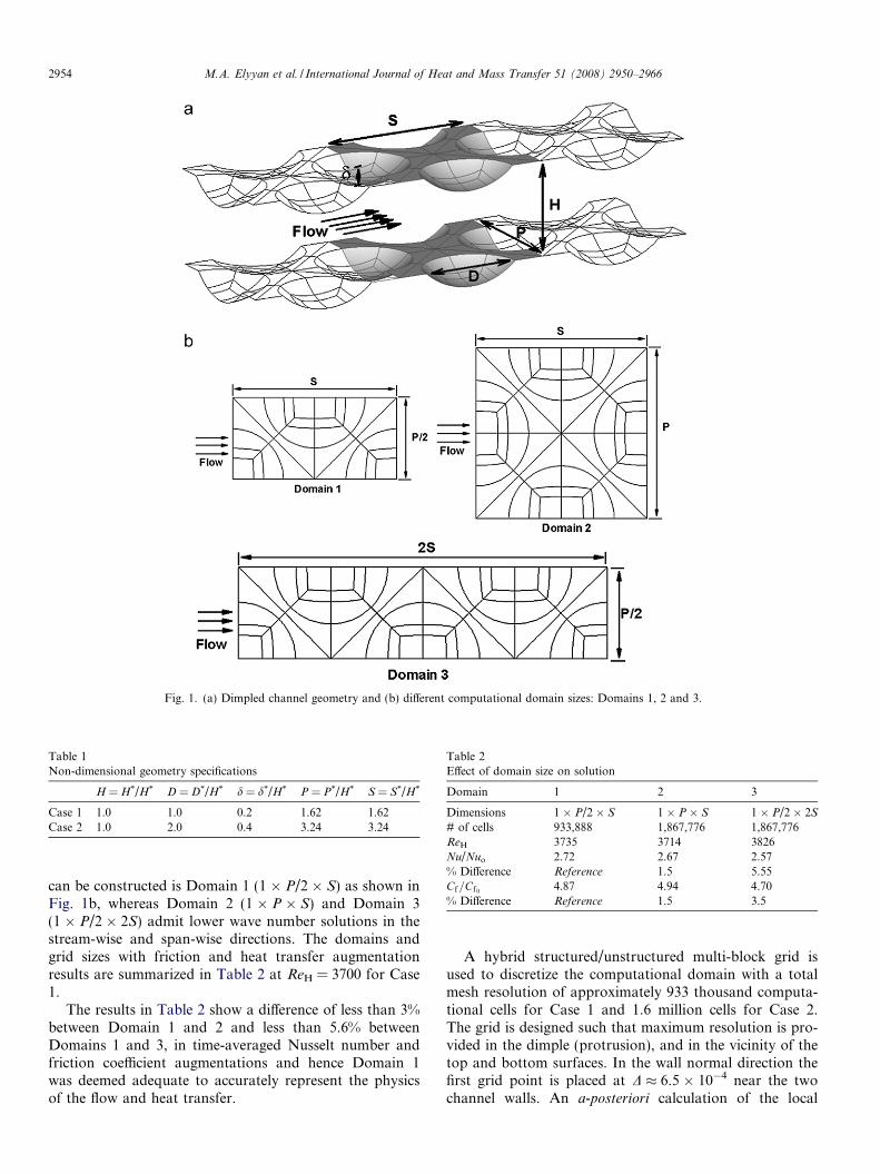
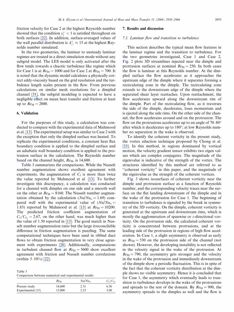
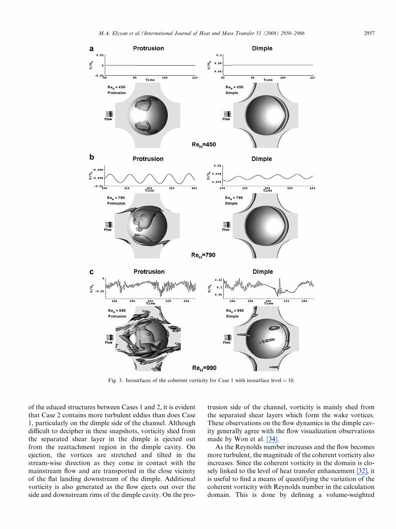
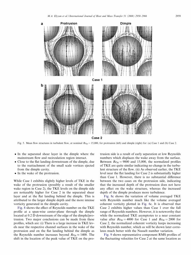
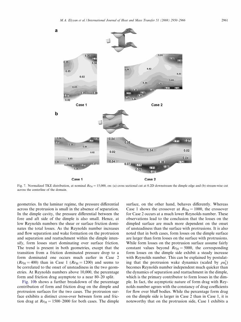
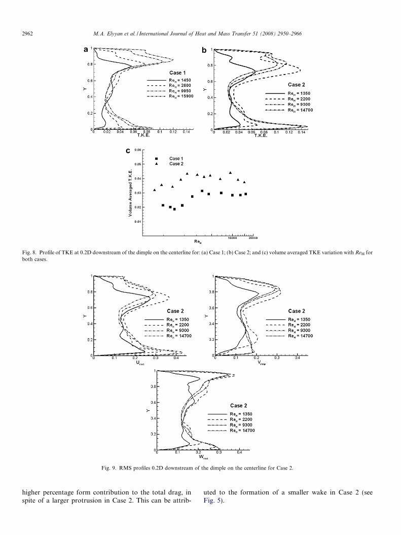
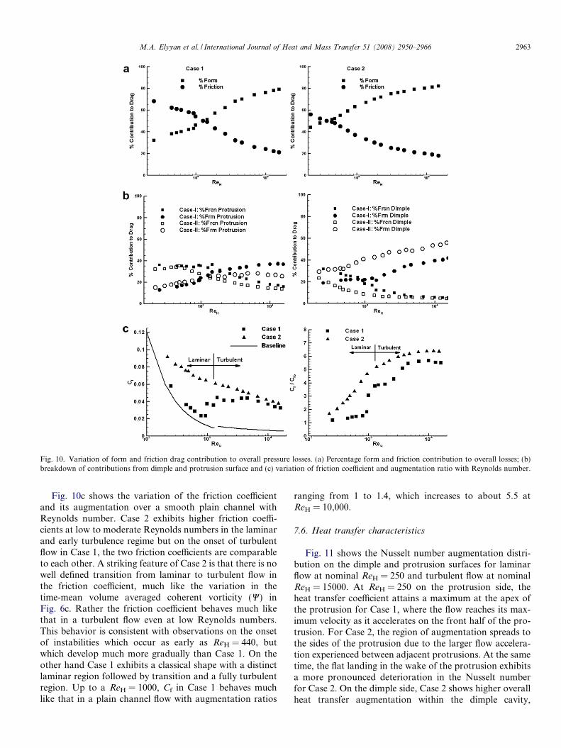
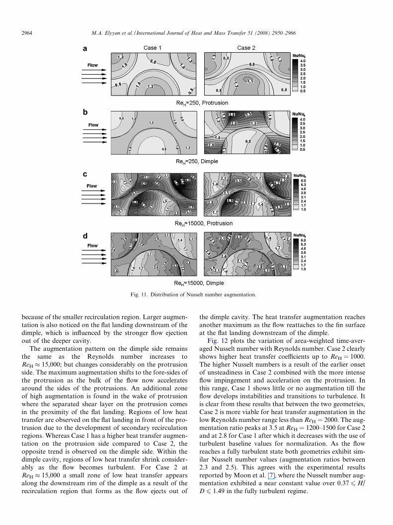
Related Documents