Electrical and Electronics Engineering: An International Journal (ELELIJ) Vol 2, No 4, November 2013 45 INVESTIGATION OF BEARING CURRENTS IN DUAL MODE OPERATION OF SYNCHRONOUS MACHINE WITH STATIC EXCITATION SYSTEM Arun Kumar Datta 1 , Manisha Dubey 2 and Shailendra Jain 3 1 Central Power Research Institute, Bhopal, India 2,3 Maulana Azad National Intitute of Technology, Bhopal, India ABSTRACT Days are gone for rotating exciters. Most of the machines those require field excitation are fed from static excitation system (SES). Static systems are prone to generate shaft voltage thereby causing the flow of bearing currents. This paper has presented a thyristor based SES in 12-pulse configuration. This SES is being applied on the field winding of a synchronous machine installed in a short circuit testing laboratory. This machine is of large capacity and without prime mover. SES along with static frequency converter makes this single machine to operate in dual mode (i.e. motor or generator). Functions of SES under different operational modes have been looked into this paper. Causes of generation of shaft voltage and bearing current in perspective with this machine under static excitation system are the main attraction of this paper. KEYWORDS Synchronous machines, shaft voltage, bearing current, static excitation, parasitic capacitance, electric discharge machining. 1.INTRODUCTION Any synchronous machine, be a motor or generator requires dc power in the rotor winding to magnetise the air gap. Four major options can be exercised to source this dc power: 1. Brushless excitation through rotating diodes and transformer. 2. Thyristor based controlled rectifier (static excitation system) feeding the rotor winding through sliprings and brushes. 3. Separate dc generator feeding the synchronous machine rotor through sliprings and brushes. 4. Rotating exciter coupled with the same shaft of the synchronous machine. The first option i.e. brushless excitation system is very much useful for a machine where the rotor field current requirement is low. But it has some design limitations for the large synchronous machine with high field current. In this case the option of static excitation system (SES) with rotor slipring and brushes are the best solution. But this method needs regular maintenance due to wear & tear in the carbon brushes and slip rings. Prior to invention of solid state devices, most of the machines were operated either with third or fourth option. But the later one was much popular.

Investigation of Bearing Currents in Dual Mode Operation of Synchronous Machine with Static Excitation System
Nov 28, 2015
Days are gone for rotating exciters. Most of the machines those require field excitation are fed from static excitation system (SES). Static systems are prone to generate shaft voltage thereby causing the flow of bearing currents. This paper has presented a thyristor based SES in 12-pulse configuration. This SES is being applied on the field winding of a synchronous machine installed in a short circuit testing laboratory.
This machine is of large capacity and without prime mover. SES along with static frequency converter makes this single machine to operate in dual mode (i.e. motor or generator). Functions of SES under
different operational modes have been looked into this paper. Causes of generation of shaft voltage and
bearing current in perspective with this machine under static excitation system are the main attraction of
this paper.
Welcome message from author
This document is posted to help you gain knowledge. Please leave a comment to let me know what you think about it! Share it to your friends and learn new things together.
Transcript
Electrical and Electronics Engineering: An International Journal (ELELIJ) Vol 2, No 4, November 2013
45
INVESTIGATION OF BEARING CURRENTS IN DUAL
MODE OPERATION OF SYNCHRONOUS MACHINE
WITH STATIC EXCITATION SYSTEM
Arun Kumar Datta1, Manisha Dubey
2 and Shailendra Jain
3
1Central Power Research Institute, Bhopal, India
2,3Maulana Azad National Intitute of Technology, Bhopal, India
ABSTRACT
Days are gone for rotating exciters. Most of the machines those require field excitation are fed from static
excitation system (SES). Static systems are prone to generate shaft voltage thereby causing the flow of
bearing currents. This paper has presented a thyristor based SES in 12-pulse configuration. This SES is
being applied on the field winding of a synchronous machine installed in a short circuit testing laboratory.
This machine is of large capacity and without prime mover. SES along with static frequency converter
makes this single machine to operate in dual mode (i.e. motor or generator). Functions of SES under
different operational modes have been looked into this paper. Causes of generation of shaft voltage and
bearing current in perspective with this machine under static excitation system are the main attraction of
this paper.
KEYWORDS
Synchronous machines, shaft voltage, bearing current, static excitation, parasitic capacitance, electric
discharge machining.
1.INTRODUCTION
Any synchronous machine, be a motor or generator requires dc power in the rotor winding to
magnetise the air gap. Four major options can be exercised to source this dc power:
1. Brushless excitation through rotating diodes and transformer.
2. Thyristor based controlled rectifier (static excitation system) feeding the rotor
winding through sliprings and brushes.
3. Separate dc generator feeding the synchronous machine rotor through sliprings and
brushes.
4. Rotating exciter coupled with the same shaft of the synchronous machine.
The first option i.e. brushless excitation system is very much useful for a machine where the rotor
field current requirement is low. But it has some design limitations for the large synchronous
machine with high field current. In this case the option of static excitation system (SES) with
rotor slipring and brushes are the best solution. But this method needs regular maintenance due to
wear & tear in the carbon brushes and slip rings. Prior to invention of solid state devices, most of
the machines were operated either with third or fourth option. But the later one was much
popular.
Electrical and Electronics Engineering: An International Journal (ELELIJ) Vol 2, No 4, November 2013
46
SES came into picture in the beginning of sixties. In the year 1962 it was designed and
experimented on a steam turbine generator [1]. Very quickly it started replacing the old rotating
exciter of existing power generators. The reason was design flexibility and easy retrofit for both
small and large machines. From the steam turbine generator it was even extended up to the
captive power plant in paper and pulp industries [2].
The negative aspect of SES is observed as the flow of bearing current due to the presence of shaft
voltage. Though the shaft voltage is a very common phenomenon since the invention of electric
machines, but it is more predominant in the case of machines with static supplies [3]. Static
sources generate shaft voltage by means of capacitive coupling, inductive couplings and common
mode voltage (CMV). It is well known that one of the causes of bearing failure is the flow of
unwanted current through it. Many literature suggested different converter topologies [4-6] and
various filtering techniques [7-9] to minimise the CMV. In spite of several drawbacks in static devices no other systems are better than SES for not only this machine but for others too.
The bearing current studied in this paper has been noticed on a synchronous machine installed in
a short circuit test laboratory. Short circuit test is carried out on electrical power equipment to
check its practical performances in case of actual faults. These tests are performed as per the
various national and international standards. A high power three phase alternator is necessary to
conduct the short circuit tests. The alternator here is 1500MVA, 12.5kV, 69kA rating and without
prime mover. Static excitation system along with static frequency converter makes this machine
to start as a motor and thereafter converting to alternator to deliver power for the short circuit
tests.
This paper gives the detailed analysis of static excitation system and its behaviour in motor &
generator mode. Causes of generation of shaft voltage and flow of bearing current in this
synchronous machine are also looked into this paper.
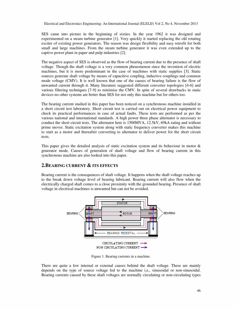
2.BEARING CURRENT & ITS EFFECTS
Bearing current is the consequences of shaft voltage. It happens when the shaft voltage reaches up
to the break down voltage level of bearing lubricant. Bearing current will also flow when the
electrically charged shaft comes to a close proximity with the grounded bearing. Presence of shaft
voltage in electrical machines is unwanted but can not be avoided.
Figure 1. Bearing currents in a machine.
There are quite a few internal or external causes behind the shaft voltage. These are mainly
depends on the type of source voltage fed to the machine i.e., sinusoidal or non-sinusoidal.
Bearing currents caused by these shaft voltages are normally circulating or non-circulating types

Electrical and Electronics Engineering: An International Journal (ELELIJ) Vol 2, No 4, November 2013
47
(fig.1). Both may also appear simultaneously depending on the supply source. Circulating current
makes a close loop around rotor, shaft, bearing, stator frame to the other end of the bearing and
shaft [10-12]. But the non-circulating current is a discharge mode current through ground.
Machine bearings are normally capable of withstanding a small amount of current. If the current
level is high and impulse in nature then bearing erosion takes place. It is commonly known as fluting or Electric Discharge Machining (EDM) [13]. As a result, bearing, shaft and nearby metal
surfaces become rough due to pittings on it (fig.2). EDM also creates electromagnetic
interferences [14] in the neighbouring electronic circuits.
Figure 2. Bearing & shaft erosion.
3.MACHINE & ASSOCIATED SYSTEM
The 200 ton weight synchronous machine is installed on a specially built concrete foundation. Its 3000 rpm rotor weighing approximately 40 ton is supported by two journal bearings on each end.
Figure 3. Synchronous machine with connected systems.
Electrical and Electronics Engineering: An International Journal (ELELIJ) Vol 2, No 4, November 2013
48
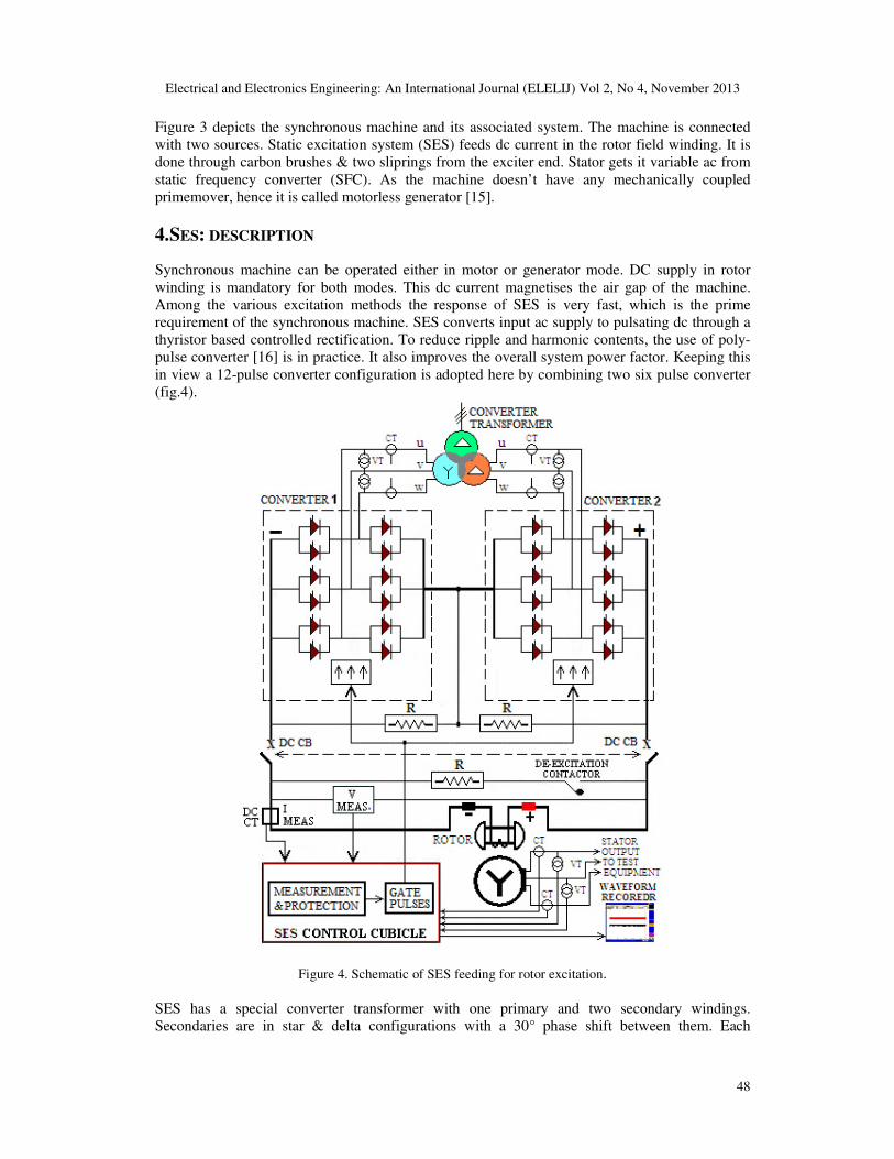
Figure 3 depicts the synchronous machine and its associated system. The machine is connected
with two sources. Static excitation system (SES) feeds dc current in the rotor field winding. It is
done through carbon brushes & two sliprings from the exciter end. Stator gets it variable ac from
static frequency converter (SFC). As the machine doesn’t have any mechanically coupled
primemover, hence it is called motorless generator [15].
4.SES: DESCRIPTION
Synchronous machine can be operated either in motor or generator mode. DC supply in rotor
winding is mandatory for both modes. This dc current magnetises the air gap of the machine.
Among the various excitation methods the response of SES is very fast, which is the prime
requirement of the synchronous machine. SES converts input ac supply to pulsating dc through a
thyristor based controlled rectification. To reduce ripple and harmonic contents, the use of poly-
pulse converter [16] is in practice. It also improves the overall system power factor. Keeping this
in view a 12-pulse converter configuration is adopted here by combining two six pulse converter
(fig.4).
Figure 4. Schematic of SES feeding for rotor excitation.
SES has a special converter transformer with one primary and two secondary windings.
Secondaries are in star & delta configurations with a 30° phase shift between them. Each
Electrical and Electronics Engineering: An International Journal (ELELIJ) Vol 2, No 4, November 2013
49
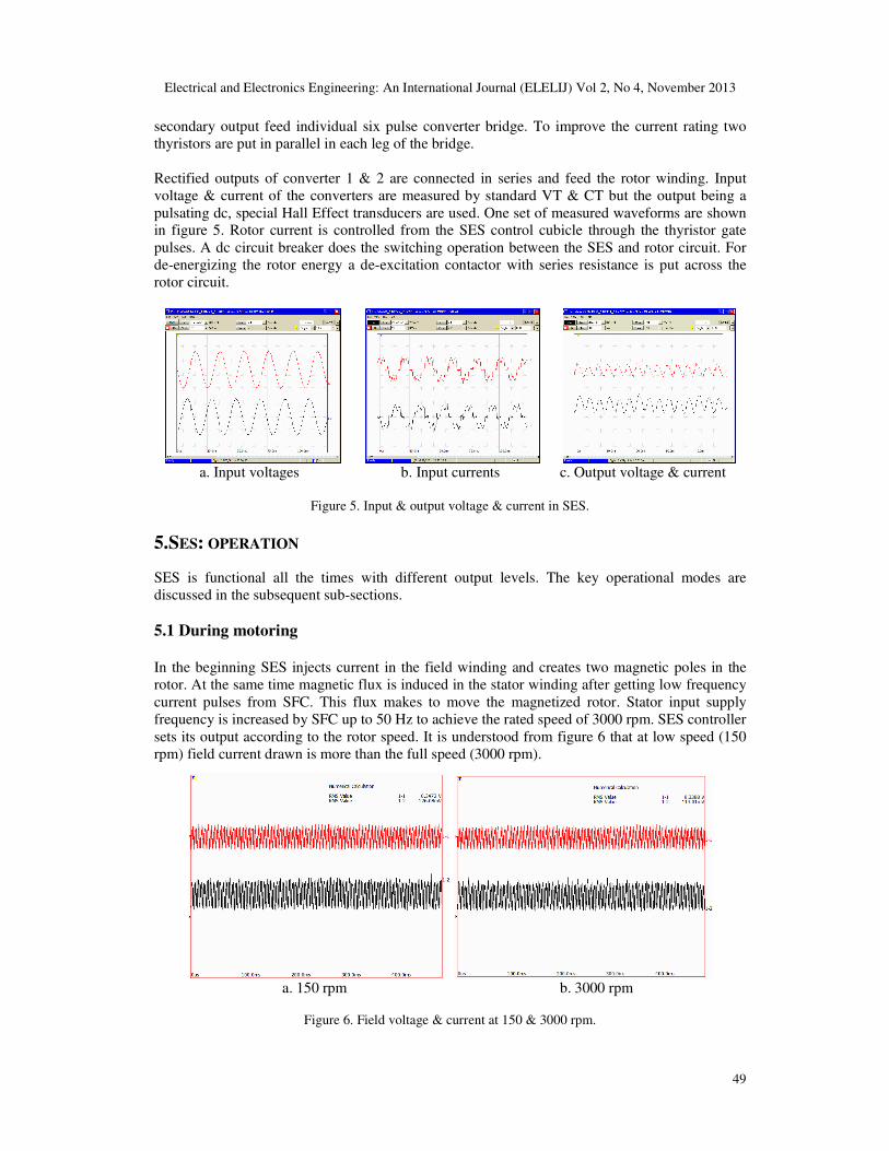
secondary output feed individual six pulse converter bridge. To improve the current rating two
thyristors are put in parallel in each leg of the bridge.
Rectified outputs of converter 1 & 2 are connected in series and feed the rotor winding. Input
voltage & current of the converters are measured by standard VT & CT but the output being a
pulsating dc, special Hall Effect transducers are used. One set of measured waveforms are shown in figure 5. Rotor current is controlled from the SES control cubicle through the thyristor gate
pulses. A dc circuit breaker does the switching operation between the SES and rotor circuit. For
de-energizing the rotor energy a de-excitation contactor with series resistance is put across the
rotor circuit.
a. Input voltages b. Input currents c. Output voltage & current
Figure 5. Input & output voltage & current in SES.
5.SES: OPERATION
SES is functional all the times with different output levels. The key operational modes are
discussed in the subsequent sub-sections.
5.1 During motoring
In the beginning SES injects current in the field winding and creates two magnetic poles in the
rotor. At the same time magnetic flux is induced in the stator winding after getting low frequency
current pulses from SFC. This flux makes to move the magnetized rotor. Stator input supply
frequency is increased by SFC up to 50 Hz to achieve the rated speed of 3000 rpm. SES controller
sets its output according to the rotor speed. It is understood from figure 6 that at low speed (150
rpm) field current drawn is more than the full speed (3000 rpm).
a. 150 rpm b. 3000 rpm
Figure 6. Field voltage & current at 150 & 3000 rpm.

Electrical and Electronics Engineering: An International Journal (ELELIJ) Vol 2, No 4, November 2013
50
5.2 During generating
The basic purpose of the machine is to generate power for short circuit test. For this, the machine
has to be converted to generator from motor at is full speed. This is done in two steps. In the first
step stator input supply is blocked and in the second step the SES sets the field current
proportional to the required stator output voltage. As the rotor is spinning, machine behaves as an
alternator and is ready to supply required power in short circuit test. During the short circuit test
period, the generator output voltage & current are adjusted by SES with the feedback from VT &
CT (fig.4). Figure 7 shows the response plot at SES controller during the short circuit test on a
circuit breaker. Actual voltage and current waveforms for this test conducted with this generator
are shown in figure 8.
Figure 7. Response at the SES controller during test. Figure 8. Generator I & V during test.
6.PHENOMENON OF ELECTRIC DISCHARGE MACHINING (EDM)
It has already been mentioned that static supply is the main source of shaft voltage. SES output is
not pure dc rather it is pulsating in nature. It has also steep steps (high dv/dt) due to thyristors
commutation (fig.5.c). FFT analysis (fig.9) on the rotor current and voltage reveals that dc
waveforms contain multiple numbers of harmonics.
Figure 9. FFT on rotor voltage & current waveforms.
Electrical and Electronics Engineering: An International Journal (ELELIJ) Vol 2, No 4, November 2013
51
In the presence of insulating material, air and lubricating oil as dielectric medium and copper
windings as conductor, parasitic capacitances are formed at many places in the machine. This is
the reason that every part of the machine including the source is coupled to each other through
distributed capacitances. These capacitances may form between stator to ground, stator to rotor,
stator to shaft, rotor to shaft, bearing to ground, cable to ground and also supply source to ground.
Capacitive coupling gets stronger with the presence of higher harmonics (as Xc=1/2πfC). Leakage current (Ic=C.dv/dt) flows all along the stator and rotor windings [14] due to this parasitic
capacitance C and high dv/dt. This leakage current generates high frequency flux. Harmonics and
other high frequency spikes in the stator and rotor power supply also generate high frequency
fluxes. These cumulative fluxes link with winding, core, frame, shaft, and other metallic parts. In
this way the inductive coupling is formed. Capacitive and inductive couplings together give an
additive effect for generation of shaft voltages for this long shaft machine. When these voltages
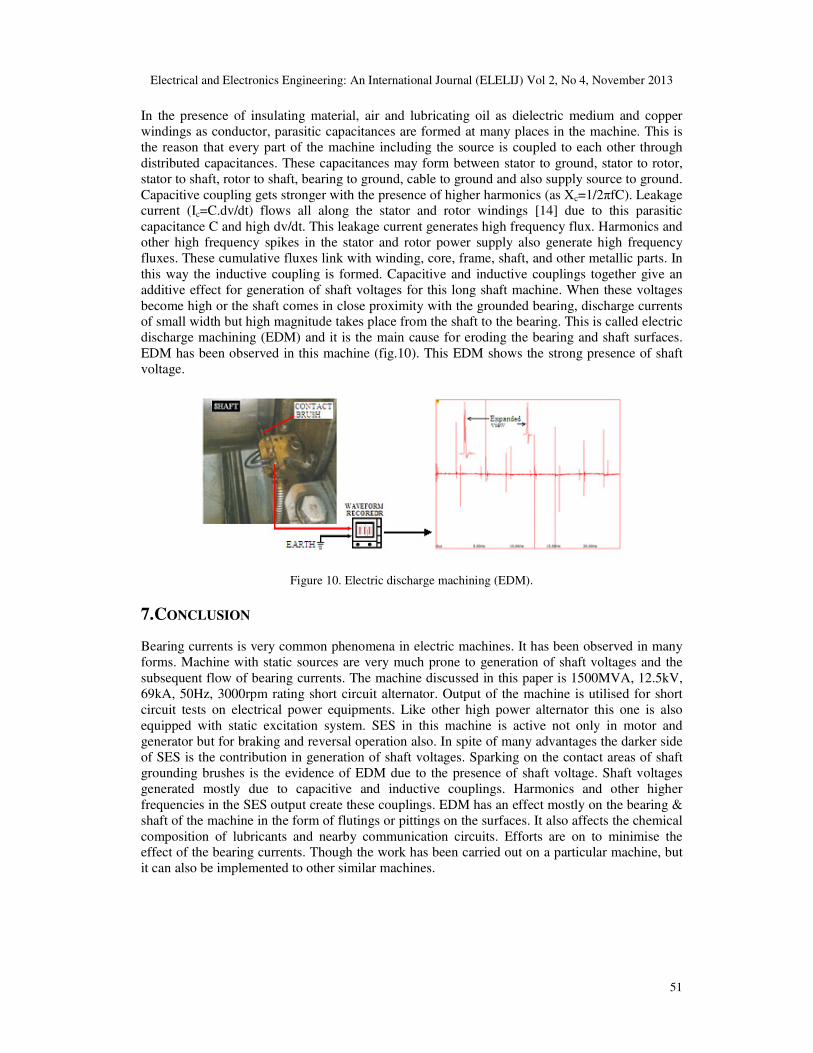
become high or the shaft comes in close proximity with the grounded bearing, discharge currents of small width but high magnitude takes place from the shaft to the bearing. This is called electric
discharge machining (EDM) and it is the main cause for eroding the bearing and shaft surfaces.
EDM has been observed in this machine (fig.10). This EDM shows the strong presence of shaft
voltage.
Figure 10. Electric discharge machining (EDM).
7.CONCLUSION
Bearing currents is very common phenomena in electric machines. It has been observed in many
forms. Machine with static sources are very much prone to generation of shaft voltages and the
subsequent flow of bearing currents. The machine discussed in this paper is 1500MVA, 12.5kV,
69kA, 50Hz, 3000rpm rating short circuit alternator. Output of the machine is utilised for short
circuit tests on electrical power equipments. Like other high power alternator this one is also
equipped with static excitation system. SES in this machine is active not only in motor and
generator but for braking and reversal operation also. In spite of many advantages the darker side
of SES is the contribution in generation of shaft voltages. Sparking on the contact areas of shaft
grounding brushes is the evidence of EDM due to the presence of shaft voltage. Shaft voltages
generated mostly due to capacitive and inductive couplings. Harmonics and other higher
frequencies in the SES output create these couplings. EDM has an effect mostly on the bearing &
shaft of the machine in the form of flutings or pittings on the surfaces. It also affects the chemical
composition of lubricants and nearby communication circuits. Efforts are on to minimise the effect of the bearing currents. Though the work has been carried out on a particular machine, but
it can also be implemented to other similar machines.

Electrical and Electronics Engineering: An International Journal (ELELIJ) Vol 2, No 4, November 2013
52
ACKNOWLEDGEMENT Authors are thankful to the management of Central Power Research Institute, India for supporting
this work.
REFERENCES
[1] L. J. Lane, D. F. Rogers, P. A. Vance, “Design and Tests of a Static Excitation System for Industrial
and Utility Steam Turbine-Generators”, pp.1077-1085, A.I.E.E., 1962.
[2] R.C. Schaefer, “Applying Static Excitation Systems”, pp. 41-49, IEEE Industry Application
Magazine Nov/Dec1998.
[3] Datta Arun Kumar, Dubey Manisha, Jain Shailendra, "Study of shaft voltage & bearing currents in
electrical machines," IEEE Students' Conference on Electrical, Electronics and Computer Science
(SCEECS), pp.1-4, 1-2 March 2012.
[4] Zhu, N.; Xu, D.; Wu, B.; Zargari, N. R.; Kazerani, M.; Liu, F.; , "Common mode voltage reduction
methods for current-source converters in medium-voltage drives,", IEEE Transactions on Power
Electronics, vol.28, no.2, pp.995-1006, Feb. 2013.
[5] R. S. Kanchan, P. N. Tekwani, and K. Gopakumar, "Three-level inverter scheme with common
mode voltage elimination and DC link capacitor voltage balancing for an open-end winding
induction motor drive," IEEE Transactions on Power Electronics, vol. 21, pp. 1676-1683, 2006.
[6] M. R. Baiju, K. K. Mohapatra, R. S. Kanchan, and K. Gopakumar, “A dual two-level inverter
scheme with common mode voltage elimination for an induction motor drive”, IEEE Transactions
on Power Electronics, vol. 19, no. 3, pp. 794-805, May 2004.
[7] Yuen, K. K.-F.; Chung, H. S.-H.; Cheung, V. S.-P.; , "An active low-loss motor terminal filter for
overvoltage suppression and common-mode current reduction" IEEE Transactions on Power
Electronics, vol.27, no.7, pp.3158-3172, July 2012.
[8] Zhao, Z.; Zhong, Y.; Gao, H.; Yuan, L.; Lu, T.; , "Hybrid selective harmonic elimination PWM for
common-mode voltage reduction in three-level neutral-point-clamped inverters for variable speed
induction drives," IEEE Transactions on Power Electronics, vol.27, no.3, pp.1152-1158, March
2012.
[9] Akagi, H.; Isozaki, K.; , "A hybrid active filter for a three-phase 12-pulse diode rectifier used as the
front end of a medium-voltage motor drive", IEEE Transactions on Power Electronics, vol.27, no.1,
pp.69-77, Jan. 2012.
[10] Shaotang Chen, T. A. Lipo, “Circulating type motor bearing current in inverter drives”, IEEE
Industry Applications Magazine, pp. 32-38, January/February 1998.
[11 ]Muetze A. and Binder A., "Calculation of circulating bearing currents in machines of inverter-based
drive systems", IEEE Transactions on Industrial Electronics, vol. 54, no. 2, pp. 932-938, April 2007.
[12] Muetze A., “On a new type of inverter-induced bearing current in large drives with one journal
bearing” IEEE Transactions on Industry Applications, vol. 46, no. 1, pp.240-248, January/February
2010.
[13] Sidney Bell, Timothy J. Cookson, Steven A. Cope, Richard A. Epperly, Annika Fischer, David W.
Schlegel, and Gary L. Skibinski, “Experience with variable-frequency drives and motor bearing
reliability”, IEEE Transactions on Industry Applications, vol. 37, no. 5, pp.1438-1446,
September/October 2001.
[14] Robert B., Fisher, P.E., “Introduction of Static Frequency Converters on SEPTA’s 25Hz Commuter
Rail System”, pp.149-155, IEEE.
[15] Datta Arun Kumar, Ansari M. A., Mondal N. R., Raghavaiah B. V. “A Novel Use of Power
Electronics: Prime Mover-less Alternator with Static Drive & Excitation System” International
Journal of Electronics & Communication Technology, Vol. 3, Issue 1, pp. 472-475, January - March
2012.
[16] Tsorng-Juu Liang, et al, “Analysis of 12 Pulse Phase Control AC/DC Converter”, IEEE 1999
International Conference on Power Electronics and Drive Systems, PEDS'99, pp.779-783, July 1999,
Hong Kong.
Electrical and Electronics Engineering: An International Journal (ELELIJ) Vol 2, No 4, November 2013
53
AUTHORS
Arun Kumar Datta graduated in Electrical Engineering in 1992 from Govt. Engineering
College, Bilaspur in India. In 1990 he did his post graduation (M.Tech.) from MACT
(REC), Bhopal, India. In March 1993 he joined Central Power Research Institute (CPRI)
India and looking after the Operation & Maintenance of two 1500MVA short circuit
generator plant and 33kV substation at Bhopal unit. He is also the Deputy Quality
Assurance Co-ordinator of CPRI Bhopal unit. He had undergone training at the works of
M/s. Alsthom, France. He is a Certified Energy Auditor from Bureau of Energy
Efficiency (BEE) and also a member of Institution of Engineers (India). He has attended
many International & National Conferences and has many papers on his credential. Other
than his regular assignments he is also pursuing Ph.D. from Maulana Azad National
Institute of Technology (MANIT), Bhopal.
Manisha Dubey was born in Jabalpur in India on 15th December 1968. She received her
B.E (Electrical), M.Tech. (Power Systems) and Ph.D (Electrical Engg.) in 1990, 1997 and
2006 respectively. She is working as Professor at the Department of Electrical Engineering,
National Institute of Technology, Bhopal, India. Her research interests include power
systems, Genetic Algorithms, Fuzzy Logic systems and application of Soft Computing
Techniques in power system dynamics and control. She is the life member of IEEE, IE &
ISTE, etc.
Shailendra Jain received the B.E. degree in electrical engineering from Samrat Ashok
Technological Institute Vidisha (SATI), India, in 1990, the M.E. degree in power electronics
from Shri Govindram Seksaria Institute of Technology and Science, Indore, India, in 1994,
the Ph.D. degree from the Indian Institute of Technology, Roorkee, India, in 2003, and the
PDF from the University of Western Ontario, London, ON, Canada, in 2007. He is a
Professor in the Department of Electrical Engineering, National Institute of Technology,
Bhopal, India. His research interests include power electronics and electric drives, power
quality improvement, active power filters, high-power-factor converters, and fuel-cell-
based distributed generation. Dr. Jain was a recipient of the “Career Award for Young
Teachers” from the All India Council for Technical Education (AICTE), New Delhi,
India, for the year 2003–2004.
Related Documents