EX/P3-6 1 Investigation of Argon Seeding Effects under Different Magnetic Configurations in L mode Plasma in EAST L.Y. Xiang 1 , H.Y. Guo 1, 2 , M. Wischmeier 3 , Z.W. Wu 1 , L. Wang 1 ,Y.M. Duan 1 , K.F Gan 1 , B. Lu 1 , Y.J. Chen 1 and EAST team 1 Institute of Plasma Physics, Chinese Academy of Sciences, P.O. Box 1126,Hefei,P.R. China 2 General Atomics. PO Box 85608, San Diego, CA 92186-5608, USA 3 Max Planck Institute for Plasma Physics, D-85748 Garching, Germany E-mail: lyxiang @ipp.ac.cn Abstract. Impurity seeding with argon under different magnetic configurations is explored in EAST tokamak with B B ion drift directing toward the lower divertor. Argon was introduced in a small amount from the lower outer target into the plasma. The magnetic configuration went through double null (DN), lower single null (LSN) and upper single null (USN) configurations during the discharge. In the experiment, the peak heat flux to the lower outer target during the LSN phase is generally over 2 times of that during the DN phase. After argon was seeded, the outboard divertor was in the conduction limited regime. The heat flux to outer target reduced by about 30% after argon seeding in both DN and LSN configurations but hardly changed in the USN phase. In the DN and USN phase the radiation increase highly peaked in the core plasma. Zeff exhibited the stongest increase in the DN phase by about 0.4 and only increased marginally in LSN and USN phase after argon seeding. While in all cases small amount of argon seeding caused main plasma XUV (extra ultra-violet) radiation to increase by over 30% the plasma stored energy and energy confinement time didn’t change in any configuration. 1. Introduction A radiative cooling scenario is going to be adopted by ITER and DEMO to protect divertor targets from being damaged by impinging heat flux exceeding tolerable values [1]. Argon, neon and nitrogen are commonly chosen to be the seeded impurity as they are recycling impurities [2]. Argon as a medium Z species can radiate at higher temperature than carbon and nitrogen and is expected to act as a core radiator to reduce the power flux across the seperatrix into the scape-off-layer, SOL. A combination of argon and nitrogen seeding can further reduce the heat flux onto divertor plates with argon radiating in the main plasma and nitrogen radiating mainly in the divertor and SOL region, as proposed in [3]. However the core confinement should not degrade too much due to the increased radiation in the confined region. Encouraging results have been obtained in ASDEX-U [4], DIII-D [5], JET-ILW [6], JT-60 [7] and C-MOD [8], where not only cold divertor conditions are obtained but also good core confinement is maintained or even improved simultaneously, as observed in ASDEX-U [9] and in the JET-ILW [10]. The LSN configuration is the magnetic equilibrium widely used in present tokamaks and will be adopted in ITER operation. It has better symmetric share of qt, the target heat flux, between inner and outer targets than DN [11]. The connection length between midplane and divertor

Welcome message from author
This document is posted to help you gain knowledge. Please leave a comment to let me know what you think about it! Share it to your friends and learn new things together.
Transcript
EX/P3-61
Investigation of Argon Seeding Effects under Different Magnetic
Configurations in Lmode Plasma in EAST
L.Y. Xiang 1, H.Y. Guo1, 2, M. Wischmeier 3, Z.W. Wu1, L. Wang1,Y.M. Duan1, K.F Gan1, B.Lu1, Y.J. Chen1 and EAST team
1Institute of Plasma Physics, Chinese Academy of Sciences, P.O. Box 1126,Hefei,P.R. China2General Atomics. PO Box 85608, San Diego, CA 92186-5608, USA3Max Planck Institute for Plasma Physics, D-85748 Garching, GermanyE-mail: [email protected]
Abstract. Impurity seeding with argon under different magnetic configurations is explored in EAST tokamakwith BB ion drift directing toward the lower divertor. Argon was introduced in a small amount from thelower outer target into the plasma. The magnetic configuration went through double null (DN), lower single null(LSN) and upper single null (USN) configurations during the discharge. In the experiment, the peak heat flux tothe lower outer target during the LSN phase is generally over 2 times of that during the DN phase. After argonwas seeded, the outboard divertor was in the conduction limited regime. The heat flux to outer target reduced byabout 30% after argon seeding in both DN and LSN configurations but hardly changed in the USN phase. In theDN and USN phase the radiation increase highly peaked in the core plasma. Zeff exhibited the stongest increasein the DN phase by about 0.4 and only increased marginally in LSN and USN phase after argon seeding. Whilein all cases small amount of argon seeding caused main plasma XUV (extra ultra-violet) radiation to increase byover 30% the plasma stored energy and energy confinement time didn’t change in any configuration.
1. Introduction
A radiative cooling scenario is going to be adopted by ITER and DEMO to protect divertortargets from being damaged by impinging heat flux exceeding tolerable values [1]. Argon,neon and nitrogen are commonly chosen to be the seeded impurity as they are recyclingimpurities [2]. Argon as a medium Z species can radiate at higher temperature than carbonand nitrogen and is expected to act as a core radiator to reduce the power flux across theseperatrix into the scape-off-layer, SOL. A combination of argon and nitrogen seeding canfurther reduce the heat flux onto divertor plates with argon radiating in the main plasma andnitrogen radiating mainly in the divertor and SOL region, as proposed in [3]. However thecore confinement should not degrade too much due to the increased radiation in the confinedregion. Encouraging results have been obtained in ASDEX-U [4], DIII-D [5], JET-ILW [6],JT-60 [7] and C-MOD [8], where not only cold divertor conditions are obtained but also goodcore confinement is maintained or even improved simultaneously, as observed in ASDEX-U[9] and in the JET-ILW [10].The LSN configuration is the magnetic equilibrium widely used in present tokamaks and willbe adopted in ITER operation. It has better symmetric share of qt, the target heat flux, betweeninner and outer targets than DN [11]. The connection length between midplane and divertor

EX/P3-62
targets in the LSN configuration is about twice as long as in DN [12]. The DN configurationcan distribute the power flux flowing out of the sepeatrix into both the lower and upperdivertor but the inner to outer target asymmetry is quite large [11]. The DN configuration alsoallows for a higher triangularity and hence potentially higher energy confinement and β, asdemonstrated in DIII-D [13, 14].EAST tokamak allows for divertor operation under DN, LSN and USN configurations. Due toincompatibility with lithium coating on EAST, nitrogen is excluded as seeding impurity. OnEAST argon is currently chosen as the seeding impurity. We have investigated the effect ofargon seeding under DN and LSN configurations, as well as the influence of argon seedingposition for better control of target heat load, and the results are presented here.The paper is arranged as follows. Section 2 introduces the experimental setup. Section 3presents the experimental results on argon seeding in different plasma configurations and atdifferent puffing locations. The papaer concludes discussing the obtained experimentalresults.
Figure 1. Left: double null configuration of shot 41617 at 2.5 s. Lines of sight of two AXUV arrays areshown in magenta, covering the main plasma region. Arrangement of probes at the 4 targets (LI, LO,UI, UO) are also shown. Middle: lower single null configuration of shot 41617 at 5.0 s and lines ofsight of visible bremsstrahlung diagnostic in cyan. Right: upper single null configuration of shot41617 at 8.5 s. Argon and fueling gas injection location is illustrated in green and orange arrows.
2. Experimental setup
The magnetic configuration was changed from DN to LSN and then to USN within onedischarge with argon puffed from lower outer target, as shown in Fig. 1. This allows us toinvestigate on one hand the effects of argon seeding in different configurations, i.e DN andLSN, and on the other hand the effects of the argon puff locations, namely divertor target inLSN and upstream in USN. Here upstream refers to near half way between two targets inUSN in the SOL.Different configurations are distinguished by different dRsep values, Fig. 2 (a). Here dRsep =RL - RU, where RL and RU are the radius of the lower divertor seperatrix and the upper divertorseperatrix at the outer midplane. For the DN configuration in this definition, dRsep=0.00 m.But there is uncertainty in equilibrium reconstruction which is not taken into consideration

EX/P3-63
here. It is a disconnected double-null in the experiment. The LSN and USN configurationshave dRsep=-0.02 m and dRsep =+0.02 m respectively.The toroidal field Bt was 2.0 T with BB ion drift directing downward. Plasma current Ipwas 0.4 MA and core line averaged density was 2.5x10¹⁹ /m3. The LHCD (low-hybrid currentdrive) heating power was 1.25 MW and Ohmic heating power was in range of 0.18-0.3 MW.Some key diagnostics used in this study are also shown in Fig. 1. The two 16-channelabsolute Extra Ultra Violet (AXUV) photodiodes can measure the main plasma radiation inthe range of 0.2 nm to 124 nm. The ion flux and heat flux reaching the divertor plates aremeasured by 74 Langmuir probes embedded into all 4 divertor targets. Infrared camera (IR)measures power deposition at lower outer divertor with a temperal resolution of 20 ms. SoftX-ray spectrometer viewing from the very core region to the edge monitors impurity lineradiation. The effective ion charge Zeff is measured by visible bremsstrahlung diagnosticwhose lines of sight is shown in fig. 1 and has a time resolution of 0.05 ms and a spatialresolution of less than 2.5 cm. During the experiment the cryo-pump behind the lower outertarget was active.
Figure 2. Time evolution of plasma parameters for shot 41617, moving through double null, lowersingle null to upper signle null in the discharge.
3. Experimental results
The plasma was always in L-mode in our experiment. Argon was puffed at the beginning ofeach phase for 80ms, Fig. 2 (a), (f). There is about 400 ms between the start of argon puffingand the increase in argon line radiation in the plasma, which means it takes argon about 400ms to travel from the valve until it can be seen by the soft X-ray spectrometer.
(a)
(b)
(c)
(d)
(e)
(f)
EX/P3-64
Fig. 2 shows the time evolution of some global plasma parameters with the divertorconfiguration being varied among DN, LSN and USN. Plasma density was not identical in the3 phases with LSN phase having slightly higher density than DN and USN. A similar patternis also seen for the plasma stored energy Wdia, and energy confinement time. For all thedivertor configurations, it appears that the argon puff did not cause confinement degradation.
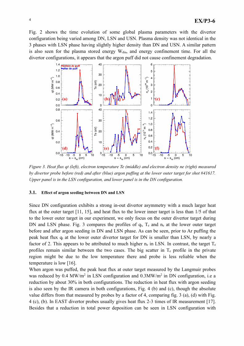
Figure 3. Heat flux qt (left), electron temperature Te (middle) and electron density ne (right) measuredby divertor probe before (red) and after (blue) argon puffing at the lower outer target for shot #41617.Upper panel is in the LSN configuration, and lower panel is in the DN configuration.
3.1. Effect of argon seeding between DN and LSN
Since DN configuration exhibits a strong in-out divertor asymmetry with a much larger heatflux at the outer target [11, 15], and heat flux to the lower inner target is less than 1/5 of thatto the lower outer target in our experiment, we only focus on the outer divertor target duringDN and LSN phase. Fig. 3 compares the profiles of qt, Te and ne at the lower outer targetbefore and after argon seeding in DN and LSN phase. As can be seen, prior to Ar puffing thepeak heat flux qt at the lower outer divertor target for DN is smaller than LSN, by nearly afactor of 2. This appears to be attributed to much higher ne in LSN. In contrast, the target Te
profiles remain similar between the two cases. The big scatter in Te profile in the privateregion might be due to the low temperature there and probe is less reliable when thetemperature is low [16].When argon was puffed, the peak heat flux at outer target measured by the Langmuir probeswas reduced by 0.4 MW/m2 in LSN configuration and 0.3MW/m2 in DN configuration, i.e areduction by about 30% in both configurations. The reduction in heat flux with argon seedingis also seen by the IR camera in both configurations, Fig. 4 (b) and (c), though the absolutevalue differs from that measured by probes by a factor of 4, comparing fig. 3 (a), (d) with Fig.4 (c), (b). In EAST divertor probes usually gives heat flux 2-3 times of IR measurement [17].Besides that a reduction in total power deposition can be seen in LSN configuration with
(a) (b) (c)
(f)(e)(d)

EX/P3-65
argon seeding in Fig. 4 (a).The AXUV measurement reveals that there was about 50% increase in the main plasmaradiation after argon seeding in all 3 configurations, as shown in Fig. 6 (a). From Fig. 6 (c)and (d), one can see that the increase was highest in the core region. Fig. 6 (d) shows thepercentage of radiation increase in each chord with argon seeding respectively in 3 phases.
Figure 4. (a) Total power deposition atlower outer target during the dischargemeasured by IR camera. (b) and (c) are theheat flux measured by IR camera to lowerouter target before (red) and after (magenta)argon seedin in the DN and LSN phaserespectively. The IR viewing area at loweroutet divertor is also indicated.
And in the DN configuration the percentage is higher everywhere, especially in the core, thanin the LSN configuration. There was a comparable transient increase in Zeff after argon puff inDN and LSN phase. The difference in the core Zeff level before and after the transient increaseis about 0.4 in the DN configuration and only marginal in the LSN phase, Fig. 5 (a).Impurtity line emission measured by soft X-ray spectrometer is given in Fig. 5 (b). Clearly,there is a significant increase in Ar XVI line radiation after each argon puff. As a referencecarbon and oxygen emissions are shown.
Figure 5. Left. Argon puff in each phase appears to lead to a transient increase in Zeff. Right. Argonseeding causes ArXVI line radiation in the core region to increase in all 3 configurations.
(a)
(b)
(c)
(a) (b)
DN
LSN

EX/P3-66
3.2. Comparison between Ar injection from divertor (LSN) and upstream (USN)
In this experiment upstream is hotter than divertor. Thus we studied the effects of argon beingpuffed from divertor and from upstream. Though the XUV radiation power is lower in USNthan in LSN both before and after argon seeding, Fig. 6 (a) and (c), the increase in radiationpower after argon puff is, however, larger in USN, Fig. 6 (d).The transient increase of Zeff in USN phase is the laregest among all 3 phases, Fig. 5 (b). Butafter the transicient increase, Zeff was about the same level in USN and LSN. Ar XVI lineradiation in both USN and LSN after argon seeding follows similar trends.While in LSN configuration argon seeding cooled the outer target, it hardly had effect on theupper outer target in the USN configuration, Fig. 7 (d), (e), (f). Though there was significantincrease in radiation following argon seeding, as in the LSN phase, both the heat flux and thetemperature at upper outer target remain similar. Since the heating power is about the same inLSN and USN, and the radiation power and the plasma stored energy, Fig. 2 (d), is lower inUSN, we infer that more power was deposited onto the plasma facing surfaces.
Figure 6. (a) Measured main plasma radiation power; (b) argon puff control signal; (c)chord-integrated radiation intensity profile before and after argon seeding in all 3 configurations; (d)the increase in AXUV chord-integrated XUV radiation from each chord after argon seedingrespectively in 3 phases.
Discussion and summary
Divertor heat load. Divertor probes are homogeneously distributed along the targets with thedistance between two neighboring probes being 1.5cm at inner targets and 1.0cm at outertargets. We estimate the power load to the targets from probe data using the formula in [18].The sheath heat transmission factor used in probe data evaluation is 7. From the estimation we
(a))
(c)
(d)(b)

EX/P3-67
obtained that the power load at the lower outer target reduced from about 0.4 MW to about0.3 MW in the LSN configuration with argon seeding.
Figure 7. Heat flux qt (left), electron temperature Te (middle) and electron density ne (right) measuredby divertor probe before (red) and after (blue) argon puffing at the lower outer target for shot #41617.Upper panel is in the LSN configuration, and lower panel is in the USN configuration..These values correspond to that measured by IR camera, see Fig. 4 (a). Thus we carried outthe estimation for the other targets where IR camera was absent and obtain the total depositedpower at plates. Before argon seeding, the power load is 0.7MW at 2 lower targets in LSNconfiguration, 0.6 MW at 2 upper targets in USN configuration, and 0.5 MW at 2 outer targetsin DN configuration. After argon seeding the power loads became 0.6 MW in LSN, 0.6 MWin USN and 0.5 MW in the DN configuration. Thus, argon seeding caused the most significantreduction in the total deposited power in LSN and in the other two configurations there wasessentially no reduction of total power load.Radiation. Since argon ionizes and radiates at relatively high temperature, it is possible thatargon seeding enhances the XUV radiation significantly all over the main plasma but not atthe X-point and the divertor. In the DN and USN phases, the XUV radiation increase fromeach chord is high and is peaked in the core region while in the LSN configuration theradiation increase in each chord is more flat. This may indicate that : (1) argon accumulationat core is less severe in the LSN configuration than in DN; (2) argon seeding from divertor ismore preferable than from upstream SOL. After each argon puff, Zeff first increases rapidlythen decays to a relatively stable level, slightly higher than the level before argon seeding. Inthe DN phase the difference between the Zeff levels before and after the transient increase ismost significant, being 0.4. Meanwhile, argon line radiation intensity keeps increasing aftershort pulse of argon puffing. While in the other 2 phases, argon line radiation will go downafter increasing for about 1 s. These further support the argument that in the LSNconfiguration the core plasma is less susceptible to argon seeding from divertor than in DN.Simulation work using an edge plasma modelling code, e.g SOLPS [19], can offer extra
(a)
(d) (e)
(b) (c)
(f)
EX/P3-68
insight into radiation distribution, impurity distribution, and neutral compression in divertoretc. if the code is sufficiently validated against other available diagnostic data. RelatedSOLPS modelling is currently being carried out.Summary. A series of experiments in which the plasma configuration was changed from DNto LSN and finally to USN with the same pulsed argon puff were carried out in EAST. Initialresults might indicate that LSN is preferable due to the finding that it has a smaller totaldeposition power, less severe core impurity concentration and a comparable reduction in peakheat flux comparing to DN. The analysis focused on two different argon puffing locations, i.eupstream and divertor, shows that in USN configuration a subtle reduction of the heat flux andthe deposited power is observed while the radiation increase peaks in the core. This is almostin contrast to LSN with the argon puff. But the LSN and USN configuration differ in pumpingcondition in the divertor region and the BB ion drift direction. A new experiment whichhas argon puffed from midplane and divertor in LSN configuration with increased argonamount will be carried out. SOLPS simulations that are currently carried out will be used tointerpret these experiment findings.
Reference
[1] M. Shimada et al Nucl. Fusion 47 (2007) S1-S17[2] ITER physics basis, Nuclear Fusion, 39 (12) 2137–2638(1999)[3] A. Kallenbach et al EFDA–JET–CP(12)06/07[4] A. Kallenbach et al Nucl. Fusion 52 (2012) 122003[5] Jackson G L et al 2002 Nucl. Fusion 42 28[6] P Dumortier et alPlasma Phys. Control. Fusion 44 (2002) 1845–1861[7] Nucl. Fusion 49 (2009) 115010 N. Asakura et al[8] M.L. Reinke et al. / Journal of Nuclear Materials 415 (2011) S340–S344[9] A. Kallenbach et al Plasma Phys. Control. Fusion 55 (2013) 124041[10] C. Giroun et al Nucl. Fusion 53 (2013) 113025[11] C S Pitcher and P C Stangeby Plasma Phys. Control. Fusion 39 (1997) 779-930[12] Chris Stoafer, Tokamak Divertor System, 2011[13] T.W. Petire Nucl. Fusion 48 (2008) 045010[14] T.W. Petrie Nucl. Fusion 46 (2006) 57-63[15] T.W. Petrie et al Nucl. Fusion 43 (2003) 910-913[16] J. Horacek et al. Journal of Nuclear Materials 313-316 (2003) 931-935[17] Liu S C et al 2014 Phys. Plasmas 21 022509[18] S. Jachmich et al. EFDA-JET-CP(07) 03/45[19] R. Schneider et al Contrib. Plasma Phys. 46, No. 1-2 (2006)
Related Documents