1 Copyright © 2013 by ASME Proceedings of HT2013 ASME Summer Heat Transfer Conference July 14-19, 2013, Minneapolis, MN, USA HT2013-17150 Investigation of Applicability of Using Water Mist for Cooling High-Pressure Turbine Components via Rotor Cavity Feed Channels Reda Ragab and Ting Wang Energy Conversion and Conservation Center University of New Orleans New Orleans, Louisiana, USA ABSTRACT Mist cooling has been considered as a potential means to significantly enhance cooling the hot components of a gas turbine. However, it is a great challenge to transport mist to locations where cooling is needed due to the high temperature environment and rotating components in the gas turbines. One plausible way is to transport high-pressure water to the rotor cover-plate cavity via a feed channel passing through the vane. The high-pressure water is then atomized to fine droplets (mist) that can be used to cool the rotor cover-plate cavity and possibly the blades as well. This study is focused on investigating whether pressurized liquid water can resist boiling during its transportation through the hot vane and gas turbine interior walls. Both 1-D empirical correlations and a 3- D flow computational scheme are used. Results show what could happen during the water transport in the feed channel with various inlet and boundary conditions. Conditions that can avoid boiling have been identified. Keywords: gas turbine cooling, mist cooling, two-phase flow heat transfer, boiling model. NOMENCLATURE A b Wall area covered by nucleating bubble (m 2 ) A i Interfacial area (m 2 ) C P,l C P,v Liquid and vapor heat capacities (J/kg.K) D b Bubble diameter (mm) D bw Bubble departure diameter (m) f bw Bubble departure frequency H lv Latent heat, (J/kg) k l Liquid thermal conductivity, (W/m-K) L Channel length, (m) N w Nucleate site density Nu Nusselt number (hL/k) P Operating pressure, (atm). Re l , Re v Liquid and vapor Reynolds numbers (ud/ν) T Temperature, (K) ∆T sub Liquid subcool = T sat - T l ∆T sup Wall superheat = T w -T sat V f Vapor volume fraction. Greek Letters μ Dynamic viscosity, (Pa-s) α Phase volume fraction (V f ) ν Kinematic viscosity, (m 2 /s) ρ Density, (kg/m 3 ) τ Shear stress, (N/m 2 ), Time scale, (s) Subscripts b Bubble, Bulk C Convection E Evaporation Q Quenching I Liquid-vapor interface sat Saturation sp. Single phase. sub Subcool w Wall INTRODUCTION Gas turbines play a vital role in today’s industrialized society for generating power for various needs. As the demands for power increase, the power output and thermal efficiency of gas turbines must also increase. One method of increasing both the power output and thermal efficiency of the engine is to increase the turbine inlet temperature. In the modern advanced gas turbines, the turbine inlet temperature (TIT) can be as high as 1500°C; however, this temperature exceeds the melting temperature of the metal airfoils. As the TIT increases, the temperature of other engine components like seals, cavities, and rotor disks also increase. This situation gives rise to increased thermal stresses and greatly reduces the components’ life expectancy and reliability. Therefore, it is imperative that the hot engine components are cooled so they can withstand these extreme temperatures. Cooling air around 600K is typically extracted from the compressor and passes through the different engine components. With appropriate implementation of cooling schemes, the temperature of the different engine components can be reduced to a permissible level suitable for reliable operation of the engine. The film

Welcome message from author
This document is posted to help you gain knowledge. Please leave a comment to let me know what you think about it! Share it to your friends and learn new things together.
Transcript

1 Copyright © 2013 by ASME
Proceedings of HT2013
ASME Summer Heat Transfer Conference July 14-19, 2013, Minneapolis, MN, USA
HT2013-17150
Investigation of Applicability of Using Water Mist for Cooling High-Pressure Turbine Components via Rotor Cavity Feed Channels
Reda Ragab and Ting Wang
Energy Conversion and Conservation Center University of New Orleans
New Orleans, Louisiana, USA
ABSTRACT Mist cooling has been considered as a potential means to
significantly enhance cooling the hot components of a gas turbine. However, it is a great challenge to transport mist to locations where cooling is needed due to the high temperature environment and rotating components in the gas turbines. One plausible way is to transport high-pressure water to the rotor cover-plate cavity via a feed channel passing through the vane. The high-pressure water is then atomized to fine droplets (mist) that can be used to cool the rotor cover-plate cavity and possibly the blades as well. This study is focused on investigating whether pressurized liquid water can resist boiling during its transportation through the hot vane and gas turbine interior walls. Both 1-D empirical correlations and a 3-D flow computational scheme are used. Results show what could happen during the water transport in the feed channel with various inlet and boundary conditions. Conditions that can avoid boiling have been identified.
Keywords: gas turbine cooling, mist cooling, two-phase flow heat transfer, boiling model. NOMENCLATURE Ab Wall area covered by nucleating bubble (m2) Ai Interfacial area (m2) CP,l CP,v Liquid and vapor heat capacities (J/kg.K) Db Bubble diameter (mm) Dbw Bubble departure diameter (m) fbw Bubble departure frequency Hlv Latent heat, (J/kg) kl Liquid thermal conductivity, (W/m-K) L Channel length, (m) Nw Nucleate site density Nu Nusselt number (hL/k) P Operating pressure, (atm). Rel, Rev Liquid and vapor Reynolds numbers (ud/ν) T Temperature, (K) ∆Tsub Liquid subcool = Tsat- Tl ∆Tsup Wall superheat = Tw-Tsat Vf Vapor volume fraction.
Greek Letters µ Dynamic viscosity, (Pa-s) α Phase volume fraction (Vf) ν Kinematic viscosity, (m2/s) ρ Density, (kg/m3) τ Shear stress, (N/m2), Time scale, (s) Subscripts b Bubble, Bulk C Convection E Evaporation Q Quenching I Liquid-vapor interface sat Saturation sp. Single phase. sub Subcool w Wall INTRODUCTION
Gas turbines play a vital role in today’s industrialized society for generating power for various needs. As the demands for power increase, the power output and thermal efficiency of gas turbines must also increase. One method of increasing both the power output and thermal efficiency of the engine is to increase the turbine inlet temperature. In the modern advanced gas turbines, the turbine inlet temperature (TIT) can be as high as 1500°C; however, this temperature exceeds the melting temperature of the metal airfoils. As the TIT increases, the temperature of other engine components like seals, cavities, and rotor disks also increase. This situation gives rise to increased thermal stresses and greatly reduces the components’ life expectancy and reliability. Therefore, it is imperative that the hot engine components are cooled so they can withstand these extreme temperatures. Cooling air around 600K is typically extracted from the compressor and passes through the different engine components. With appropriate implementation of cooling schemes, the temperature of the different engine components can be reduced to a permissible level suitable for reliable operation of the engine. The film

cooling technique has been applied in modern gas turbines since the 1980s to protect the hot turbine components, such as turbine blades and vanes, from hot flue gases. As there is a need to continuously increase the turbine inlet temperature to improve gas turbine performance, continuous improvement of film cooling effectiveness is essential.
2 Copyright © 2013 by ASME
As the working gas temperature continuously increases to augment thermal efficiency, new cooling techniques are needed to surpass incremental improvements of conventional gas turbine cooling technologies. A promising technology to enhance film cooling is to inject water mist into the coolant flow. Each droplet acts as a cooling sink and flies over a distance before it completely vaporizes. This “distributed cooling” characteristic allows controlled cooling by manipulating different sizes of injected water droplets. The enhanced cooling is attributed to many factors: (a) The flow temperature is reduced mainly due to droplet evaporation and partially due to larger specific heats of water and water vapor; (b) the droplets’ interactions with the flow augments turbulent mixing; (c) the sudden expansion of water vapor volume (about 900%) from fast liquid evaporation when liquid droplets touch a hot wall introduces an expulsive momentum thrust that also enhances mixing and convective heat transfer; and (d) the brief period that the liquid droplet is in contact with the hot surface provides an enhanced wall heat transfer through direct heat conduction. Another important merit of employing mist film cooling is that some larger droplets can fly longer and evaporate farther into the downstream region where the single phase air film cooling becomes less effective.
There have been numerous studies in the past decades that have focused on mist film cooling over flat surfaces or turbine airfoil surfaces with streamwise coolant injection (e.g., [1-14]). While most of the above studies were conducted at lab conditions of low temperatures and pressures, their results showed that the mist film cooling is a promising and effective cooling technique. However, all the previous studies focused only on investigating the mist cooling performance, none of them studied how to transport the mist to the target component sites or answered the question of whether is it possible to transport water mist to different engine components at real engine conditions. In other words, can the mist survive the extremely hot conditions inside the flow passages in the gas turbine and be successfully delivered to the needed sites? A series of CFD research has been undertaken by the authors to answer this question. The first study [15] was performed using CFD (computational fluid dynamics) to investigate the possibility of transporting water mist to vanes of a high pressure turbine stage under real operating conditions. The droplets could travel from the injection location, located in the air cooling duct, coming from the compressor discharge, all the way to the film holes at the vane surface. The results showed that water droplets of 30 µm and 10% mass loading ratio of the cooling air were able to survive and reach the film cooling holes of Frame 7 turbine vanes with an average diameter of 10 μm. Furthermore, calculations showed that these survived droplets will be able to complete the external film cooling around the vane surface. Although the research is only numerical, the results are very encouraging and, to a
great extent, are sufficient to encourage experimental validation of the CFD results.
Background
Figure 1 shows a schematic diagram of a typical two stage high pressure film cooled turbine. The relatively cold compressor air (600K) is bled from the compressor discharge through the cooling air passage where it enters the cooling channels inside the turbine vanes to cool the vanes' walls, which are toasted by extremely hot flu gas at about 1300K (2350oF). Eventually, the air exits the film cooling holes to form a protective layer around the external vane surface to prevent it from direct contact with the hot gases. To retrofit this existing turbine with the mist cooling techniques, it is proposed that atomizers be located at a short distance just upstream of the vane's leading edge. The water mist is to be injected at the inlet of the cooling air passage along the casing. The tubing of the high-pressure water is directly inserted through the turbine casing. For the rotor, the situation is a bit difficult because of the rotation. The exact path of the compressed water tubing depends on the engine design and how the cooling air is fed to the rotor film holes [15-19].
air/ water mist air/ water mist
Compressed Water
Compressed Water Feed Pipe
Air-Assisted Atomizer
Mid Comp. Bleed Compressed Water
Compressor Exit Bleed
Interstage Seal
Compressor Exit Bleed
air/ water mist
Stator Rotor
air/ water mist
Figure 1 Schematic of a mist cooled turbine with mist injected through the cooling air passages [17].
Basically, there are two main designs. In one of the designs, the cooling air is supplied to the first rotor blades through the second stage vane through a diaphragm box inboard of the airfoil inner endwall. This Outboard Air Supply route is shown in Figure 2a marked with the blue arrow. Although this passage is not considered in this study, it is important to highlight it as an alternative passage and is currently investigated separated for another paper.
Figure 2a Heavy frame turbine secondary flow regions [20]

In the other design of the Onboard Air Supply passage, the cooling air, which is bled from the compressor exit, is introduced to a preswirl nozzle where it is accelerated tangentially in the direction of the rotor rotation. This acceleration reduces the relative total temperature of the cooling air and hence increases the film cooling efficiency and components lifetime. The performance of this preswirl nozzle is crucial for the engine components’ life expectancy. It is believed that a 20° increase in relative total temperature of the air fed to the rotor is sufficient to reduce component lives by as much as 50% [16]. This motivates the current study by routing the mist through preswirl nozzle and rotor disk cavity. In this second design, the atomizer is proposed to be located somewhere in the preswirl nozzle chamber, as shown in Fig. 1. To deliver the compressed water to that proposed location, a feed channel is inserted through the turbine casing and passes through the engine stationary part (first vane) all the way to the atomizer, as shown in Fig. 1.
To deliver the compressed water to the proposed location, a feed channel is inserted through the turbine casing and passes through the engine stationary part (first vane) all the way to the atomizer. Now, the compressed water is introduced to the atomizer through the feed channel, and the atomized water droplets will mix with the compressor bled cooling air to form a mixture of air/mist. This mixture will serve in cooling the blade disc and the seals and will travel through the rotor cover-plate cavity to, hopefully, reach the rotor blades. Based on this description of the mechanism used to deliver the compressed water to the atomizer location, the geometry of the channel along with the operating boundary conditions are introduced in Figure 3 below.
3 Copyright © 2013 by ASME
After the previous clarification and description of the mechanism of the mist cooling for the rotor blades, some new questions arise. Will boiling occur as the feed channel passes through the extremely hot vane? Typically, the boiling phenomenon is undesirable in gas turbine engines for many reasons: (a) Boiling is an unstable phenomenon which causes vibrations and generates structural stresses. The problem is further exacerbated in the case of high speed rotating machinery like turbines; (b) Boiling converts a fraction of the compressed liquid water into vapor, which will adversely affect the atomization process in the atomizer and lead to reduced mist cooling.
Boiling is a complex phenomenon and its modeling is a challenging task. Figure 2b shows a conventional textbook schematic for the basic phenomenon occurring in forced convection boiling, which exemplifies what would happen when a liquid is forced over a heated surface like that in the feed channel studied in this paper. Onset of Nucleate boiling (ONB) and Onset of Significant Boiling (OSB) are two important physical phenomena that the CFD code could reasonably predict, although not always successfully. According to the temperature of the liquid, convective boiling can be classified as Saturated boiling and Subcooled boiling. Saturated boiling occurs on surfaces immersed in a liquid which is at the saturation temperature. In subcooled boiling, the average liquid temperature stays below the saturation value, producing local boiling at the wall (surface- or micro-boiling) with subsequent condensation of the vapor as it
departs the wall and moves into the colder bulk of the fluid. The physics of boiling implies the formation of bubbles on the hot surface, surface boiling, which happens when the surface temperature is slightly above the saturation temperature of the single phase liquid medium. Vapor bubbles form at the nucleation sites on the wall, and they continue to increase in size. With the continuous addition of heat, bubbles detach and separate from the wall surface. As the degree of subcooling decreases along the channel and, consequently, so also does the rate of condensation, the steam bubbles formed will be able to penetrate further into the subcooled flow core, increasing the turbulent transport of heat and changing the pattern of temperature distribution over the cross section of the flow core. After more bubbles are generated, a bubbly flow regime, with velocity higher than the single phase liquid velocity, will form. As depicted in Fig. 2b, the bulk boiling evolves until all the liquid changes to superheated vapor. Again, different physics in each regime requires different sub-models to be adequately predicted.
Heated Wall DbW
Tbulk
TSat
Departing bubble TW
OSB
ONB
Saturated
Subcooled
Superheated Layer
Bubble nucleating site
(a) (b) Figure 2b Conceptual picture of forced convective boiling (a) different phase-change regimes with a uniform heat flux boundary condition [24] (b) subcooled boiling schematic
It is more challenging, in the meantime, to have a generalized multiphase CFD model for boiling flow and heat transfer. Most of the sub-models proposed so far account only partially for the relevant physics such as the onset of nucleate boiling (ONB), departure from nucleate boiling (DNB), critical heat flux (CHF) and post dry-out. This situation is further complicated when considering critical heat flux conditions as flow regime transitions need to be taken into consideration [21-23].
Over the last decade or so, the Eulerian multifluid method with the so-called RPI wall boiling model, developed by Kurul & Podowski in Rensselaer Polytechnic Institute [25], has been established as a recognized modeling approach for mechanistic prediction of boiling phenomena. Attempts have since been made to extend this approach towards modeling CHF and post-dryout. Indeed, such boiling models have been implemented in designing heat exchangers and nuclear equipment [25-32]. However, it is commonly recognized that though promising, all the CFD multiphase boiling modeling approaches are still at the stage of development and validation when dealing with the prediction of practical boiling flow and heat transfer. Efforts to further improve the model accuracy and numerical robustness are ongoing.

OBJECTIVE AND SCOPE The purpose of the current work is to use CFD to predict
whether boiling will occur in the feed channel. If it does, the inception of boiling phenomenon will be examined and the design parameters will be customized to minimize, or suppress, the boiling to ensure that the feed water will be transported to the atomizer in a state suitable for effective atomization. Hence, the mist/air cooling technique will work for cooling the rotating components and seals. Since the two-phase boiling phenomena and CFD predication capability have been well developed in heat transfer community with applications in heat exchanger design and nuclear industry, it is not the purpose of this paper to thoroughly study the boiling phenomena and its modeling issues. Thus, the methodology is to use the available capabilities of existing CFD codes to reasonably predict boiling. This will help to identify potential technical issues that could challenge implementation of the mist/cooling technique in real gas environment.
In the sections below, the general governing equations and physical models are first presented. They are followed by a brief description of the numerical approach to deal with the boiling flow. The Rensselaer Polytechnic Institute's (RPI) model is then employed through a systematic study of a benchmark case with boiling flow in an axisymmetric circular channel. After validation of the benchmark case, the model is applied to predict boiling in the current problem, which is very close in physics and operating conditions to the benchmark case. Parametric study is then performed to include changing factors that affect boiling. Before conducting numerical simulations, it is customary to use simple 1-D empirical correlations to provide an estimate of the boiling phenomenon that may occur in the feed channel under the benchmark operating condition. The 1-D result also provides a guidance for parametric study in CFD simulation. The 1-D model selected is a well known empirical correlation frequently used in convection heat transfer calculations.
4 Copyright © 2013 by ASME
Figure 3 shows a schematic of the feed channel to be used and represents the studied geometry, for the numerical model, in this paper. The feed channel is proposed to be of ¼ inch ID and 75 cm long with a pressure of 1000 Psi (68 atm). Under the operating conditions of a Frame 7 engine, as will be detailed later, the flow conditions are specified in Fig. 3.
Gravity
TS = 650 K
Twi = 473 K Patz = 68 atm mw = 0.01907 Kg/s Heat Flux?
ID = ¼ in L = 75 cm
Figure 3 Geometry and flow conditions in the simulated pressurized liquid water feed channel
ONE-DIMENSIONAL MODEL A quick estimate of single phase water temperature in a
heated channel can be done using a one-dimensional model equation. The purpose is to have an estimate of the conditions of water at the end of the feed channel. A simple and well documented model of Dittus-Boelter [33] will be used. For the
present study of a typical Frame 7 engine the total air mass flow rate is approximately 445 kg/s with 3% of that mass flow directed for cooling the 70 rotors in the first stage of the high pressure turbine. Air mass flow rate for each rotor cooling channel can be calculated as 0.1907 Kg/s. Liquid water equivalent of 10% of the cooling air mass flow, i.e., 0.01907 kg/s, is added for mist cooling for each feed channel. For the ¼ inch feed channel with 1000 psia operating pressure, the water velocity, Reynolds number, and Prandtl number are 0.696 m/s, 27,300, and 0.948, respectively. Nusselt number can be calculated using Dittus-Boelter Equation 1 [33] as
follows:
DK
. (1)
(Valid for Turbulent, fully developed flows, 0.6 ≤ Pr ≤ 160; ReD ≥ 10,000; L/D ≥ 10; and n= 0.4 for heating (Tw > Tm ))
Finally, the water mean temperature distribution inside the channel, without boiling, can be calculated from the following equation [33]:
∆T∆T
T T ,T T
exp PC
(2)
Where Tw = 650 K is the wall temperature (assumed), and P is the channel perimeter.
Figure 4 shows the mean water temperature distribution inside the feed channel using the one-dimensional single phase model for different inlet water temperatures. Although it is not correct to use a single phase model to calculate the average liquid temperature for a flow that may undergo boiling, it serves as a good tool to indicate if boiling will occur by examining if the liquid temperature will rise above the saturation temperature. Based on this principle, three water inlet temperatures (473 K, 350 K, and 300K) are assigned; the single phase liquid temperature distributions along the channel are shown in Fig. 4. The exit temperatures of these cases are 609 K, 578 K, and 566K, respectively. Comparing them with the saturation temperature 558 K at 1000 psia, this means that phase change will happen in the first two cases, but only mild phase change will happen in the end of the channel. This also implies that an inlet water temperature less than 300K could avoid boiling.
Tw = 650 K
Tm (x)
Figure 4 One-dimensional calculation of water mean temperature distribution for different water inlet temperatures
5 ME
Copyright © 2013 by AS
CFD CALCULATIONS The simple one-dimensional calculation results showed
that the phase change process is likely to happen. To obtain more detailed results, comprehensive CFD calculations are performed with the RPI wall boiling model included. Mathematical Modeling
In case of boiling, the vapor volume fraction increases to a limit exceeding the underlying assumptions of being a discrete phase (Vf > 0.1). This requires that both vapor bubbles and liquid are modeled as separate phases. The present Eulerian/Eulerian multiphase boiling model has been developed to predict boiling within the CFD solver ANSYS/FLUENT 14.0. A set of governing equations for n-phase multi-fluid flows is solved. Wall boiling phenomenon is modeled using the mechanistic RPI boiling model. A range of sub-models are considered to model the interfacial momentum, mass and heat transfer, and turbulence-bubble interactions. The detailed governing two-phase governing equations can be referred to ANSYS/FLUENT manual [34] and are not repeated here. The descriptions of the mathematical models for boiling are presented next. Wall Boiling Model
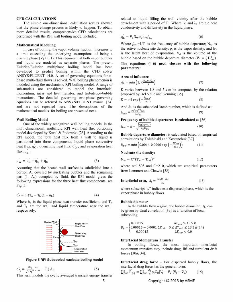
One of the widely recognized wall boiling models is the multi-dimensional, multifluid RPI wall heat flux portioning model developed by Kurul & Podowski [25]. According to the RPI model, the total heat flux from a wall to liquid is partitioned into three components: liquid phase convective heat flux, qC
" ; quenching heat flux, qQ" ; and evaporation heat
ux : fl , qE"
qW
" qC" qQ
" qE" (3)
Assuming that the heated wall surface is subdivided into a portion Ab covered by nucleating bubbles and the remaining part (1- Ab) occupied by fluid, the RPI model gives the following expressions for the three heat flux components, see Fig. 5: qC
" h T T 1 A (4)
Where hc is the liquid phase heat transfer coefficient, and Tw and Tl are the wall and liquid temperature near the wall, respectively.
Tbulk
TSat
Quenching Heat Flux
Heated Wall
TW
Evaporation Heat Flux
Single Phase Heat Flux
F ur cooled nucleate boiling model ig e 5 RPI Sub
qQ"
T
T T A (5)
This term models the cyclic averaged transient energy transfer
related to liquid filling the wall vicinity after the bubble detachment with a period of T. Where, kl and λl are the heat
n ty a iffusivity in the liquid phase. co ductivi nd d qE
" V N ρ h (6)
Where fbw =1/T is the frequency of bubble departure; Nw is the active nucleate site density; ρv is the vapor density; and hfv is the latent heat of evaporation. Vd is the volume of the bubble based on the bubble departure diameter (V D ). The equations (4-6) need closure with the following parameters: Area of influence
1, K N D (7)
K varies between 1.8 and 5 can be computed by the relation e le and Kenning [35] proposed by D l Val
4.8 (8)
A Ja is the suJ CP, T
nd bcooled Jacob number, which is defined as: (9)
Frequency of bubb
T
le departure: is calculated as [36]
D (10)
Bubble departure diameter: is calculated based on empirical el uk [corr ations by Tolubinski and Kostanch
0.0014, 0.0006 ∆.
37] (11)
Nucleate sit density:
N C T T (12)
e
where n=1.805 and C=210, which are empirical parameters from Lemmert and Chawla [38]. Interfacial area, (13)
where subscript “d” indicates a dispersed phase, which is the vapor phase in bubbly flows. Bubble diameter
In the bubbly flow regime, the bubble diameter, Db, can be given by Unal correlation [39] as a function of local subcooling
0.00015 ∆ 13.5 0.00015 0.0001 ∆ 0 ∆ 13.5
0.00015 ∆ 0.0(14)
Interfacial Momentum Transfer
In boiling flows, the most important interfacial momentum transfers may include drag, lift and turbulent drift forces [30& 34]. In fa l dr orce – For dispersed buinterfacial drag force has the general form: ∑ R
ter cia ag f bbly flows, the
∑ A ρ CD|V V | v v (15)

where the drag coefficient CD can be computed by various models [34]. In facial lift force –The interfacial lform (acting on a secondary phase P in a pri
(16)
ter ift force has the general mary phase q):
In most cases, the lift force is insignificant compared to the drag force. The coefficient for the interfacial lift force is calculated using a correlation proposed by Moraga et al. [40] Turbulence drift force – The turbulent drift force is
s calculated a [32] FTD FTD CTDρ k α (17)
6 Copyright © 2013 by ASME
kc is the turbulent kinetic energy of a continuous phase (liquid). The turbulent disperse coefficient CTD is, by default, set to 1.0. Interfacial Heat and Mass Transfer
As bubbles departure from a wall and move towards subcooled regions, there is heat and mass transfer from the bubbles to the liquid. The interface (vapor)-liquid heat
fin transfer is de ed as q A h T T (18) Wher lt is based on the Ranh
D
e h z-Marshall correlation [41] 2 0.6Re . Pr . (19)
The interface (liquid)-vapor heat transfer is calculated using the method proposed by Lavieville et al. [27]. It is assumed that the vapor retains the saturation temperature by
/ nsation. The formulation is as follows: rapid evaporation condeq C , T T (20)
δt is the time scale and is by default set to 0.05s Wall–vapor mass transfer – The evaporation mass flow is
pl d at the cell ne the heated wall and it is derived from aporati heat f x, equation (6), as follows:
ap ie arthe ev on lu
mEE"
CP, T T (21)
Interfacial mass transfer – The interfacial mass transfer depends directly on the interfacial heat transfers. Assuming that all the heat transferred to the interface is used in mass transfer (i.e. evaporation or condensation), the interfacial mass
e n as: transfer rate can b writte
m m m" "
(22)
RPI Model Validation In the gas turbine arrangement, the inward channel shown
in Fig. 1 is directed in all the directions circumferentially, For the model validation benchmark case, an upward flow of subcooled water through a heated vertical pipe is selected, experimentally studied by Bartolemei and Chanturiya [42]. The validation case is very similar to that is studied in this paper, and the validation presents a good foundation for the
upcoming investigations. The pipe has a diameter of 15.4mm and a length of 2m. The experiments were carried out under the operating pressure of 45bar. The subcooled water, with a subcooling of 60K, enters from the bottom side and travels upwards through the tube. The heat flux applied on the tube surface is uniform and has the value of 570 kW/m2. The inlet mass flux is 900 kg/m2-sec, and the Reynolds number is about 104,210. A 2D axisymmetric computational model of 7,815 cells has been constructed for the purpose of this validation. Three different turbulence models were selected for the computations--namely, The RNG K-ε Model, the Reynolds Stress Model (RSM), and the Shear Stress Transport K-ω Model (SSTK-ω). The liquid temperature distribution at the pipe axis is used for comparison as shown in Figure 6.
Figure 6 Validation of the experiment of [42] using the RPI model.
Although all the models under-predicted the liquid temperature near the middle of the pipe (≈ 0.8 m), the SST k-ω turbulence model was the most accurate, as shown in Figure 6. This departure at 0.8 m happens at the point where bulk boiling starts. The departure depends mainly on the near wall treatment method. This indicates that SST k-ω turbulence model offers the best performance in this case. One possible explanation is that in the SST k-ω model, the wall approximation approach is scaled with local near-wall grids, while in all the other turbulence models, the wall treatment method is chosen in advance, which may not be suitable for the two-phase flow development in this study. More information about the SST k-ω model and its transport equations can be found in [30] and [34]. From this validation, it can be stated that the SST k-ω model seems to give an overall better solution. The grid sensitivity study shows that the results between using 7815 cells and 22,872 cells are within 1.7 %. This validation serves as a good foundation for further investigations in this study for gas turbine cooling applications. The Computational Domain
The computational domain consists of a feed channel proposed to transport the compressed liquid water from the turbine outer casing through the vane to the atomizer located below the vane pedestal to achieve the mist generation, as shown in Fig. 3. The channel is 0.00635 m (¼ in) inside diameter and 0.75 m long. The channel is vertical with water at a pressure of 68 atm flowing upward. As the problem is axisymmetric, the domain simulated is only a 2-D slice with a
460
480
500
520
540
0 0.5 1 1.5 2
Tempe
rature (K
)
Position (m)
Exp. [42] SST K‐ωRNG k‐ε RSM

width equal to the channel radius. 2-D axisymmetric solutions are known to be a cost effective alternative for analyzing full 3-D simulations. The computational domain and the mesh used are depicted in Fig. 7.
7 Copyright © 2013 by ASME
Gravity
TS = 650 K
Inlet
Heat Flux? Heated Wall
Mesh
Conjugate Wall
Axsisymmetric Line
Figure 7 The computational domain, boundary types, and meshes Boundary Conditions
The primary phase is water with properties varies with temperature, and the secondary phase is vapor with properties fixed at saturation temperature (558 K) and pressure at 1000 psi (68 atm). The boiling phenomenon is studied at comparable real working conditions of a Frame 7 gas turbine engine. As explained before in the 1D analysis, the water velocity, Reynolds number, and Prandtl number can be calculated as 0.696 m/s, 27300, and 0.948, respectively.
Based on the previous calculations, the velocity of 0.696 is imposed as a boundary condition at inlet for the liquid phase. Liquid water is preheated to 473 K before entering the channel to avoid potential "thermal shock" on the thermal stresses on the casing or vane walls. This pre-heat condition of water can be relaxed if thermal shock is not an issue. Mist cooling will be more effective if no pre-heat is imposed. For the vapor phase, zero vapor is assigned at the inlet. The turbulence parameters at inlet are specified in terms of the turbulence intensity, TI, of 4 % and the hydraulic diameter, HD, equal to channel diameter of 0.00635m. At exit, the static pressure of 68 atm is imposed (design parameter). The outer wall is assumed isothermal with a temperature of 650 K (an estimate in Frame 7 engines), while the inner wall is assigned as a conjugate wall (separating the fluid and the solid zones). The parameters used in base case are summarized in Table 1. A parametric study is performed to investigate the effect of wall temperature, water pressure, inlet water subcool temperature, and channel length on the boiling characteristics in the feed channel as summarized in Table 2. As mentioned earlier, the purpose of the parametric study is to seek available means to suppress boiling by customizing the design parameters of the feed channel like the four parameters listed in Table 2.
Table 1 The base case values
Parameter Value Water (Primary Phase) Water inlet velocity 0.696 m/s Water inlet temperature 473 K Operating pressure 68 atm (Tsat=558 K) Inlet subcooling 85 K Channel length 0.75 m Channel wall temperature 650 K Vapor (Secondary Phase) Vapor inlet velocity 0 m/s Vapor Temperature 558 K
Table 2 The matrix of parametric studies
Case Tw (K) P (atm) ∆Tsub L (m) 1 600 2 625 Base case 650 68 85 0.75 3 665 4 60 Base case 650 68 85 0.75 5 80 6 110 7 15 Base case 650 68 85 0.75 8 110 9 208 10 0.50 Base case 650 68 85 0.75 11 1.00
Meshing and Simulation Procedure
The computational domain is constructed by structured hexahedral elements as shown in Fig. 7. The computational domain geometry is decomposed into 2 sub-regions: one for the solid zone and the other is for the fluid zone. As boiling flow is strongly affected by local mechanisms in the turbulent boundary layer near the heated wall, more intensive meshes are used near the walls, especially on the fluid side. A value of y+ ≈30 is considered reasonable for the standard wall function approach selected. Wall function approach was selected as a cost effective alternative to Enhanced Wall Modeling approach, which is extremely computationally demanding. Four mesh densities from 6K to 41K are tested for solution independence, and the base case is solved for every mesh. The results are compared in Fig. 8. The most important solution variable in the current study is the vapor volume fraction, so it is selected as a criterion for comparison. Figure 8 shows that the variation in the values of the calculated vapor volume fraction is negligible when the mesh size is doubled from 20K cells to 41K cells. Therefore, this mesh of 41 K cells is selected for the subsequent analyses.
Figure 8 Mesh sensitivity analysis The simulation is carried out using the commercial CFD
software ANSYS14.0 from ANSYS, Inc. The simulation uses the segregated solver, which employs an implicit pressure-correction scheme and decouples the momentum and energy equations. The phase coupled SIMPLE algorithm is used to
0
0.2
0.4
0.6
0.8
0 0.15 0.3 0.45 0.6 0.75
Vf(‐)
Position (m)
41K Cells 20K Cells13K Cells 6K Cells

8 Copyright © 2013 by ASME
couple the pressure and velocity. Second order upwind scheme is selected for spatial discretization of the convective terms. The computation is conducted for each phase simultaneously, and the interphase exchange terms (lift, drag, and heat and mass transfer) are used to couple the two phases.
The problem is treated as a transient, liquid-vapor two-phase turbulent flow with boiling occurring on the heated wall. The liquid phase properties are assumed to vary with the liquid temperature, while the saturation properties are used for the vapor phase. The saturation temperature is around 558 K. Heat conduction equation is solved in the conjugate solid region to give the temperature distribution inside the channel wall. Time periodic solution is obtained after 20 seconds, approximately 666 time steps but the solution is continued to 1000 time steps to ensure full convergence. Time periodic solution is judged by the variation of local solution variables at exit of the domain as well as by the values of residuals. Variations of vapor volume fraction and mass flow rate imbalance, with time, are taken as convergence criteria.
For numerical accuracy, the second order upwind scheme is used for spatial discretization. A time step size is calculated based on the reasonable Courant number criterion. The Courant Number can be roughly estimated for 1D case as u∆t/∆x, where u is the air velocity, ∆t is the time step size, and ∆x is the length interval for the computational cell. As the numerical scheme employed is implicit, which is unconditionally stable, a high Courant number of 40 can be used to achieve faster convergence. Accordingly, a time step size of 0.03 s is calculated and used for the calculations (based on the velocity and mesh size intervals in the base case). To make sure that the solution is independent of the size of the time step, a sensitivity study is performed. Different time steps are used to reproduce the base case solution, and the results are compared with the original time step size results. Results of the time step size analysis are shown in Table 3. It is clear that the solution is time step size independent because increasing or decreasing the time step size an order of magnitude has a negligible effect on the solution variables (≈ 0.1 % change).
Table 3 Time step size (s) sensitivity study results
Time Step Size (s) 0.003 0.03 0.3 Exit Vf 0.5747 0.5741 0.5743 Exit liquid static temp. 557.31 557.33 557.32
RESULTS AND DISCUSSION Baseline Case Results
In the current work, a numerical simulation is performed with the baseline case conditions shown in Table 1. The flow field is solved for both phases until a time periodic solution is obtained. Results are shown here for the baseline case.
Figure 9 shows the contour of vapor volume fraction, liquid static temperature, and vapor static temperature, respectively. As the channel is too long compared to its diameter, only three selected parts of the tube representing inlet, middle, and exit sections are displayed for clarity. As shown in Fig. 9a, volume fraction is zero at the inlet, as there
is no vapor entering the domain, and then starts to increases in the middle of the channel until it reaches the highest value at the channel exit. Of course, the vapor volume fraction starts to increase near the wall as the boiling starts from the wall where the nucleation sites exist until bulk boiling happens. Figure 9b shows the mass flow averaged liquid static temperature increasing from the inlet value of 473 K to the saturation value of 558K at exit. The effect of wall superheat is clear at the exit section of the channel where a thin layer of liquid is slightly above the saturation temperature. As we solve the conjugate heat transfer problem, the temperature distribution inside the channel wall is also shown. Figure 9c shows that the vapor temperature is fixed at the saturation value of 558K, which is a characteristic and a basic feature of subcooled boiling.
Figure 10 shows the variation of temperature and volume fraction with position through the channel (axial variation). A wealth of physics related to boiling is presented in this figure which warrants a detailed description. The nucleation sites formed on the inner wall are the places where bubbles originally form (where surface- or micro-boiling happens). This happens when the inner wall temperature exceeds the saturation temperature, as marked with (ONB). Bubbles detach from the surface with continuous addition of heat and start to form the bubbly flow regime, as marked with (OSB) in Fig. 10. Penetration of vapor bubbles into the channel core and the accompanied heat and mass transfer exchange cause the Bulk Boiling to happen.
First of all, it is important to mention that the outer wall temperature of 650 K, not shown in figure, is the main driver for boiling as it provides the energy of vaporization. The continuous consumption of heat, used in vaporization, prevents the inner wall temperature from increasing dramatically (burning or boiling crisis). Thus, it is clear that the static temperature of the inner wall (Ts-wall) , as calculated from the liquid layer attached to the wall, starts to increase from the inlet value of 473K to 10 degrees of superheat (Tw-Tsat), which is a unique feature of subcooled boiling, as shown schematically in Fig. 3. The point at which the inner wall temperature exceeds the saturation temperature (x ≈ 0.05 m) is considered the ONB where micro-boiling occurs and where nucleation sites start to appear. It takes a while until bubbles grow and detach from the surface declaring that significant boiling has started. At x ≈ 0.12 m, the vapor volume fraction at the wall (Vf-wall) starts to increase which is considered the OSB point. At x ≈ 0.52 m, boiling increases and droplets travel to the core of the channel without condensation. As the degree of subcooling decreases along the channel and, consequently, so also does the rate of condensation, the steam bubbles formed will be able to penetrate further into the subcooled flow core, increasing the turbulent transport of heat and changing the pattern of temperature distribution over the cross section of the flow core. The static temperature distribution at the channel axis (Taxis) and the bulk liquid temperature (Tb) starts to coincide, declaring that bulk boiling has started. Accordingly, vapor bubbles start to appear at the core of the channel causing the vapor volume fraction at the channel axis (Vf-axis) to increase dramatically due to the bulk boiling.
9
Copyright © 2013 by ASME
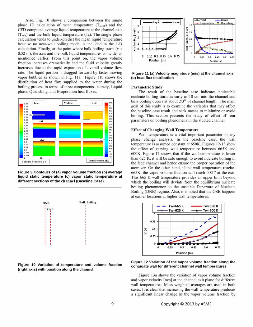
Also, Fig. 10 shows a comparison between the single phase 1D calculation of mean temperature (Tm-SP) and the CFD computed average liquid temperature at the channel axis (Taxis) and the bulk liquid temperature (Tb). The single phase calculation tends to under-predict the mean liquid temperature because no near-wall boiling model is included in the 1-D calculation. Finally, at the point where bulk boiling starts (x ≈ 0.52 m), the axis and the bulk liquid temperatures coincide, as mentioned earlier. From this point on, the vapor volume fraction increases dramatically and the fluid velocity greatly increases due to the rapid expansion of overall volume flow rate. The liquid portion is dragged forward by faster moving vapor bubbles as shown in Fig. 11a. Figure 11b shows the distribution of heat flux supplied to the water during the boiling process in terms of three components--namely, Liquid phase, Quenching, and Evaporation heat fluxes.
(a)
(c)
(b)
Temperature (K)Volume Fraction (-)
Inlet Exit Middle
Figure 9 Contours of (a) vapor volume fraction (b) average liquid static temperature (c) vapor static temperature at different sections of the channel (Baseline Case)
ONB
OSB
Bulk Boiling
Figure 10 Variation of temperature and volume fraction (right axis) with position along the channel
Figure 11 (a) Velocity magnitude (m/s) at the channel axis (b) heat flux distribution Parametric Study
The result of the baseline case indicates noticeable nucleate boiling starts as early as 10 cm into the channel and bulk boiling occurs at about 2/3rd of channel length. The main goal of this study is to examine the variables that may affect the baseline case result and seek means to minimize or avoid boiling. This section presents the study of effect of four parameters on boiling phenomena in the studied channel.
Effect of Changing Wall Temperature
Wall temperature is a vital important parameter in any phase change analysis. In the baseline case, the wall temperature is assumed constant at 650K. Figures 12-13 show the effect of varying wall temperature between 665K and 600K. Figure 12 shows that if the wall temperature is lower than 625 K, it will be safe enough to avoid nucleate boiling in the feed channel and hence ensure the proper operation of the atomizer. On the other hand, if the wall temperature reaches 665K, the vapor volume fraction will reach 0.817 at the exit. This 665 K wall temperature provides an upper limit beyond which the boiling will deviate from the equilibrium nucleate boiling phenomenon to the unstable Departure of Nucleate Boiling (DNB) regime. Also, it is noted that the OSB happens at earlier locations at higher wall temperatures.
Figure 12 Variation of the vapor volume fraction along the conjugate wall for different channel wall temperatures
Figure 13a shows the variation of vapor volume fraction
and vapor velocity [m/s] at the channel exit plane for different wall temperatures. Mass weighted averages are used in both cases. It is clear that increasing the wall temperature produces a significant linear change in the vapor volume fraction by
0
0.25
0.5
0.75
1
0 0.15 0.3 0.45 0.6 0.75
Vf (‐)
Position (m)
Tw=665 K Tw=650 K Tw=625 K Tw=600 K

producing more vapor bubbles. These vapor bubbles move through the channel core with velocities faster than the liquid phase velocity. Vapor velocity at exit is almost linearly increasing with the wall temperature as well. Due to the momentum exchange between the liquid and the vapor phases, the liquid phase velocity is accordingly increasing with wall temperature, as shown in Fig. 13b. In the same figure, the exit liquid phase temperature (K), at the secondary axis, also increases until it reaches the saturation temperature.
Figure 13 Variation at the channel exit plane for different wall temperatures. (a) Vf and vapor velocity V (secondary axis) (b) Liquid velocity V and liquid static temperature Ts,l (secondary axis) Effect of Changing the Channel Length
The effect of changing the channel length is studied to account for the location of the atomizer for different engines designs. The results in Fig. 14 show that the longer the channel length, the higher the vapor volume fraction is. This is expected as longer channel provides a longer residence time for the liquid phase to change into vapor. One interesting note is that the OSB is independent of the channel length as it occurs at x ≈ 0.12 m for the three cases. It is interesting to notice that the vapor volume fraction at a specific axial location is proportional to the channel length (from x=0.25 to x= 0.5). This proportionality reflects an aspect of the elliptic behavior of the solved system of governing equations. This elliptic behavior is responsible for transmitting the disturbances further upstream of the channel, against the flow direction, in this subsonic flow case. Similar results are obtained for exit velocity and temperature. These results are important as it gives a way to control the exit conditions of the channel to match the desired atomizer design.
Figure 14 Variation of vapor volume fraction along the conjugate wall for three different channel lengths.
Effect of Inlet Subcooling
Subcooling temperature indicates the temperature below the saturated temperature; therefore, the higher the subcooling temperature, the lower the preheating being employed. In real gas turbines, it is a matter of caution by feeding cold water directly to a highly heated engine component, like the proposed feed channel in Fig. 1 due to the concern on potential "thermal shock" that could cause large thermal stress near the feeding entrance. Thus, in the baseline case the water is preheated to 473K (or 85K subcooling form Tsat = 558K) to minimize the potential thermal shock by assuming that the water is introduced after the gas turbine reaches full load to help reduce compressed air extraction for cooling. However, a smart-control algorithm for controlling water feeding rate can be implemented during gas turbine start-up process from cold. In this way, the feed water can be fed at room temperature during the ramping process and the material temperature surrounding the feed channel will gradually adjusted, not reaching as high as the current operating condition without the feed channel. Without going through the complexity of conducting a transient study from start-up engine from cold, the analysis is performed by simply reducing the water inlet temperature but keeping the wall temperature at 650K. Figure 15a shows that inlet subcooling of 15 K (or high preheating) greatly accelerates the boiling process, which occurs directly at the channel inlet. As the degree of subcooling decreases along the channel and, consequently, so also does the rate of condensation, the steam bubbles formed will be able to penetrate further into the subcooled flow core, increasing the turbulent transport of heat and changing the pattern of temperature distribution over the cross section of the flow core. Also, Fig. 15a shows that the vapor exit volume fraction is inversely proportional to the degree of subcooling. This result is also important as it gives a way to control the exit conditions of the channel to match the desired atomizer design. Finally, Fig. 15 a shows that the inlet subcooling of 208K (Inlet temperature = 350 K) will completely suppress the boiling process. This helps to indicate a threshold for the boiling process to start under the current operating conditions and serves to introduce a boiling-free flow. However, the boiling results for highly subcooled cases (∆Tsub > 100 ) should be taken with care because the RPI model is not validated in these cases [25, 34]. Comparing with the result of 1-D model, again, it shows that 1-D model over-predicts the water temperature distribution. The 1-D model predicts that the temperature inside the channel will rise above the saturation and boiling would occur. This is due to the lack of near-wall boiling model in the 1-D model as discussed earlier when Fig. 10 was examined.
Effect of Changing Operating Pressure Operating pressure is one of the important parameters that
will directly affect not only the boiling process, but also the atomizer performance. Normally, a higher pressure is desirable for both processes as it suppresses boiling and enhances the atomization process.
Figure 15b shows, as expected, that increasing the pressure to 110 bar is sufficient to suppress the boiling process with a subcool temperature at 85 K (Tin = 473 K) as it gives an
0
0.25
0.5
0.75
1
0 0.25 0.5 0.75 1
Vf(‐)
Position (m)
L = 1 m L = 0.75 m L = 0.5 m
10 Copyright © 2013 by ASME

average vapor volume fraction of 0.0025 at exit. The case of 60 bar is very close to the unstable DNB regime.
(b) (a)
P = 68 bar Tsat=558 K
∆Tsub= 85 K
11 Copyright © 2013 by ASME
Figure 15 Variation of the vapor volume fraction along the conjugate wall for different (a) inlet subcooling (b) operating pressures Effect of Gravity
Since the gravity can be in any direction in the actual gas turbine geometry, it is important to investigate its effect on the results. As the channel is vertical, the problem is solved with flow in the upward and the downward directions. The effect of gravity direction on the vapor volume fraction generated is shown in Figure 16. The vapor volume fraction at exit is slightly higher at exit in case of the downward flow.
Figure 16 Effect of gravity on the vapor volume fraction at the contact wall PRACTICAL ISSUES
It is commonly known that boiling can be suppressed by reducing the inlet water temperature, increasing the pressure, or reducing the wall temperature. The above analyses provide the actual values for the pressure, wall temperature, and threshold inlet water temperature for suppressing the boiling.
The analyses indicate that keeping the wall temperature less than 600K is an effective means in suppressing boiling, yet it is also the only parameter that cannot be modulated because it is subjected to the engine operating conditions. Thus, in order to keep the wall temperatures less than 600 K, it is important to position the channel in a suitable place. Before the positioning of the channel is determined, it will be interesting to study the effect of the change in the number of feed channels on boiling. The baseline case is repeated with two additional numbers of channels and the results are shown in Fig. 17. Figure 16 shows that decreasing the number of channels from 70 to 16, will suppress boiling completely (with
Tw = 650 K in the base case). The reason of choosing 16 channels is that 16 is a factor of 48 (the number of vanes). Thus, every channel serves 3 vanes.
Figure 17 Effect of reducing number of channels on the vapor volume fraction at the contact wall
The following list of some practical issues and proposed
solutions follows from the above results:
1. To modulate the wall temperature to lower than 600 K, the feed channel may pass through the vane cavity all the way to the atomizer. The reason for this is that the vane cavity carries the compressor cooling air at 600 K. Knowing that Frame 7FA has 48 vanes in the first stage of the HP turbine, the number of feed channels reduces to 48 instead of 70. This situation will increase the mass flow rate and velocity in the channel to 0.0278 kg/s, 1.077 m/s, respectively. As shown in Fig. 17, this will produce a relatively desired (i.e., little to no boiling) working environment. Further safety can be achieved if only 16 channels are used to carry the compressed water, as this completely prevents boiling. Furthermore, if the system will be used in conjunction with a mist cooled vane, the vane cavity temperature will be around 400 K, as investigated in [15]. These conditions are more certain to prevent any boiling.
2. Although operating pressures above 110 bars are recommended to suppress boiling, they may cause flash evaporation of atomized droplets. Flash evaporation may happen once the droplets are injected in the low pressure preswirl chamber (≈ 18 bar, 600 K). Further investigation is required to estimate its possibility and impact.
CONCLUSIONS
The present work proposes a method to implement a liquid water transport mechanism to provide mist cooling technique to the rotating engine components by inserting a feed channel in the engine body. The expected boiling is predicted by using the Eulerian multi-fluid model in the CFD solver ANSYS/FLUENT in conjunction with the RPI wall boiling model. The conclusions are summarized as follows: • It is feasible to have highly pressurized water transported
to the internal engine cooling passages and be further atomized as mist for turbine component cooling.
• Reducing wall temperature below 600K surrounding the feed channel is an effective parameter on suppressing boiling.
0
0.25
0.5
0.75
1
0 0.15 0.3 0.45 0.6 0.75
Vf(‐)
Position (m)
Upward flow Downward flow
0
0.25
0.5
0.75
1
0 0.15 0.3 0.45 0.6 0.75
Vf
Position (m)
70 Pipes (BC) 48 Pipes 16 Pipes

12 Copyright © 2013 by ASME
• Higher operating pressures (≈ 110 bar), higher inlet subcooling (≈ 210K), and shorter channel lengths (≈ 0.5 m) leads to boiling free flows. A combination of these parameter values can be used with further optimization.
• The 1-D model gives a simple and fast method to calculate the water temperature distribution through the feed channel. However, the 1-D model tends to over-predict the temperature distribution in the channel and, thus, under-predict the inlet temperature that boiling could occur due to lack of near-wall boiling model in the 1-D model. Further investigation is required to study the potential of
thermal stresses and the droplet distribution in the rotating components. ACKNOWLEDGEMENT
The authors want to thank Louisiana Governor’s Energy Initiative to support this project via the Louisiana Board of Regents and the Clean Power and Research Energy Consortium (CPERC).
REFERENCES [1] Takagi, T. and Ogasawara, M., 1974, “Some
Characteristics of Heat and Mass Transfer in Binary Mist Flow,” Proceedings of 5th Intl. Heat Transfer Conf., Tokyo, No. 4, pp.350-354.
[2] Mori, Y., Hijikata, K. and Yasunaga, T., 1982, “Mist Cooling of Very Hot Tubules with Reference to Through-Hole Cooling of Gas Turbine Blades,” Intl. J. Heat Mass Transfer, Vol. 25, No.9, pp.1271-1278.
[3] Janssen, J.M., Florschuetz, L.W. and Fizdon, J.P., 1986, “Heat Transfer to Two-Phase Air/Water Mixtures Flowing in Small Tubes with Inlet Disequilibrium,” NASA CR 175076.
[4] Guo, T., Wang, T., and Gaddis, J. L., 2000, ‘‘Mist/Steam Cooling in a Heated Horizontal Tube Parts I, and II’’ ASME J. Turbomach., Vol. 122, pp. 360–374.
[5] Nazarov, A. D., Serov, A. F., Terekhov, V. I., and Sharov K. A., 2009,”Experimental Investigation of Evaporative Pulse-Spray Impingement Cooling,” J. of Eng. Physics and Thermophysics, Vol. 82, No. 6, pp. 1184-1190.
[6] Pakhomov, M. A., and Terekhov, V. I., 2010,”Enhancement of an Impingement Heat Transfer between Turbulent Mist Jet and Flat Surface,” Int. J. of Heat and Mass Transfer, Vol. 53, pp. 3156-3165.
[7] Wang, T., Gaddis, J. L., and Li, X., 2005,” Mist/steam Heat Transfer of Multiple Rows of Impinging Jets,” Int. J. Heat and Mass Transfer, Vol. 48, pp. 5179-5191.
[8] Nirmalan, N.V., Weaver, J.A. and Hylton, L.D., 1996, “An Experimental Study of Turbine Vane Heat Transfer with Water-Air Cooling,” ASME paper No. 96-GT-381, Proc. of the ASME Turbo Expo 1996, Birmingham, UK, June 10-13, 1996.
[9] Li, X. and Wang, T., 2006, “Simulation of Film Cooling Enhancement with Mist Injection”, J. of Heat Transfer, Vol. 128 (6), pp.509-519.
[10] Li, X., and Wang, T, 2007, “Effects of Various Modeling on Mist Film Cooling", ASME Journal of Heat Transfer, Vol. 129, pp. 472-482.
[11] Wang, T., and Li, X., 2008, "Mist Film Cooling Simulation at Gas Turbine Operating Conditions", Int. J. of Heat and Mass Transfer, Vol. 51, pp. 5305-5317, 2008.
[12] Li, X., and Wang, T., 2008, "Two-Phase Flow Simulation of Mist Film Cooling on Turbine Blades with Conjugate Internal Cooling", ASME Journal of Heat Transfer, Vol. 130, pp.102901/1-8
[13] Dhanasekaran, T. S. and Wang, T., "Simulation of Mist Film Cooling on Rotating Gas Turbine Blades," ASME Journal of Heat Transfer, vol. 134, 011501/1-11, Jan. 2012
[14] Dhanasekaran, T. S. and Wang, T., 2011, “Mist/air Cooling in a Two-Pass Rectangular Rotating Channel with 45-deg Angled Rib Turbulators,” ASME Paper No. GT2011-45954, Proceedings of ASME Turbo Expo2011, Vancouver, Canada, June 6-10, 2011
[15] Ragab, R., and Wang, T., 2012,” An Investigation of Applicability of Transporting Water Mist for Cooling Turbine Vanes,” ASME Paper GT2012-70110. Proceedings of Turbo Expo 2012, June 11-15, 2012, Copenhagen, Denmark.
[16] Snowsill G.D. and Young C., 2006, "The Application of CFD to Underpin the Design of Gas Turbine Pre-Swirl Systems", ASME IGTI, ASME Paper GT2006-90443.
[17] Kurzke, J., 2007 “Gas Turbine Details 5” http://www.gasturb.de/Free/Manuals/GasTurbDetails5.pdf
[18] Gupta, A. K., Ramerth, D., and Ramachandran, D., 2008,”Numerical Simulation of TOBI Flow – Analysis of the Cavity between a Seal-Plate and HPT Disk with Pumping Vanes,” ASME paper GT2008-50739, Proceedings of ASME Turbo Expo 2008, Power for Land, Sea and Air, Berlin, Germany, June 9-13, 2008.
[19] El-Sadi, H., Guevremont, G., Marini, R., and Girgis, S., 2007,”CFD Study of HPT Blade Cooling Flow Supply Systems,” ASME paper No. GT2007-27228, Proceedings of the ASME Turbo Expo 2007, Montreal, Canada, May 14-17, 2007.
[20] Dennis, R. 2006, “The Gas Turbine Handbook,” U.S. Department of Energy.
[21] Bestion, D., 2007, “Review of available data for validation of NURESIM two phase CFD software applied to CHF investigations,” The 12th International Topical Meeting on Nuclear Reactor Thermal Hydraulics (NURETH-12), Sheraton Station Square, Pittsburgh, Pennsylvania, U.S.A., Sept. 30-Oct.4, 2007
[22] Anglart, H., Ji, W., and Gu, C-Y, 1997, “Numerical simulation of multidimensional two-phase boiling flow in rod bundles”, NURETH8, Kyoto, Japan, 1997.
[23] Lu, J., Tryggvason, G. and Thomas, S., 2008, “Direct numerical simulations of nucleate boiling”,

13 Copyright © 2013 by ASME
IMECE2008-67444, ASME International Mechanical Engineering Congress and Exposition October 31-November 6, 2008, Boston.
[24] http://www.thermopedia.com/content/605 [25] Kurul, N., and Podowski, M.Z., 1991, “On the
modeling of multidimensional effects in boiling channels”, Proceedings of the 27th National Heat Transfer Conference, Minneapolis, MN, USA, July 1991.
[26] Burns, A., Egorov, Y. and Zwart, P., 2007, “Wall Boiling Model”, CFX12.0 Solver, 2007.
[27] Lavieville, J., Quemerais, E., Mimouni, S., Boucker, M., and Mechitoua, N., 2005 “NEPTUNE CFD V1.0Theory Manual”, EDF 2005.
[28] Tentner, A., Lo, S. and Kozlov, V., 2006, “Advances in computational fluid dynamics modeling of two-phase flow in a boiling water reactor fuel assembly”, Proceedings of ICONE14, Int. Conf. on Nuclear Engineering, July 17-20, Miami, Florida, 2006.
[29] Ioilev, A., 2007, “Advances in the modeling of cladding heat transfer and critical heat flux in boiling water reactor fuel assembly”, NURETH-12, Pittsburgh, Pennsylvania, USA, 2007.
[30] Li, H., Vasquez, S. and Spicka, P., 2010, “Advanced computational modeling of multiphase boiling flow and heat transfer”, IMECE2010-38785, Vancouver, Canada, 2010.
[31] Macek, J. and Vyskocil, L., 2008, “Simulation of critical heat flux experiments in NEPTUNE_CFD code”, Research Article, Science and Technology of Nuclear Installations, Volume 2008.
[32] Troshko, A.A. and Hassan, Y.A., 2001,“A two-equation turbulence model of turbulent bubbly flow,” Int. J. Multiphase Flow, Vol. 22(11), pp.1965-2000, 2001.
[33] Incropera, F.P., and DeWitt, D.P., 2002, “Fundamentals of heat and Mass Transfer,”5th ed., John Wiley& Sons, New York.
[34] Multiphase Flows, Theory Guide, ANSYS FLUENT 14.0 Documentation, 2010.
[35] Del Valle, V. H. and Kenning, D. B. R., 1985, “Subcooled flow boiling at high heat flux”, International Journal of Heat and Mass Transfer, Vol. 28, No. 10, pp. 1907-1920, 1985.
[36] Cole, R., 1960, “A Photographic study of pool boiling in the region of the critical heat flux”, AICHE J. 6, 533-542, 1960.
[37] Tolubinski, V. I. and Kostanchuk, D.M., 1970,“Vapor bubbles growth rate and heat transfer intensity at subcooled water boiling”, International Heat Transfer Conference, Paris, France, 1970.
[38] Lemmert, M. and Chawla, J.M., 1977, “Influence of flow velocity on surface boiling heat transfer coefficient”, Heat Transfer and Boiling (Eds. E. Hahne and U. Grigull), Academic Press, 1977.
[39] Unal, H.C., 1976, “Maximum bubble diameter, maximum bubble growth time and bubble growth rate during subcooled nucleate flow boiling of water up to 17.7”, Int. J. Heat Mass Transfer, vol.19, pp.643-649.
[40] F. J. Moraga, R. T. Bonetto and R. T. Lahey, 1999, "Lateral forces on spheres in turbulent uniform shear flow". Int. J. of Multiphase Flow. 25. 1321–1372. 1999.
[41] Ranz, W. E. and Marshall Jr. W. R., 1952, “Evaporation from Drops Part I, and II”, Chem. Eng. Prog, Vol. 48, pp. 141-146, and pp. 173-180.
[42] Bartolemei, G.G. and Chanturiya, V.M., 1967, “Experimental study of true void fraction when boiling subcooled water in vertical tubes”, Therm. Eng., Vol.14 (2), pp.123-128.
Related Documents