Case study Investigating the failure of bevel gears in an aircraft engine Nauman A. Siddiqui a , K.M. Deen b, *, M. Zubair Khan a , R. Ahmad b a National Engineering and Scientific Commission (NESCOM), 2801 Islamabad, Pakistan b Department of Metallurgy & Materials Engineering, CEET, University of the Punjab, 54590 Lahore, Pakistan 1. Introduction The failure of any component in an aircraft structure and/or engine may cause accidents leading to loss of human lives. Most of the reported cases in aircrafts are related with the failure of engine power transmission components. [1–6] To transmit power from one component of a mechanical system to another; gears are the efficient and effective machines. From a simple car to giant cruises and aircrafts there is perhaps any machine which operates without gears. There are many designs of gears which are manufactured depending upon their functionality, system requirements and operating conditions. These include spur gears, hypoid gears, spiral and straight bevel gears. [3] Many gear failures occur due to design errors, manufacturing faults, maintenance, inspection, inevitable repetitive stresses resulting in surface fatigue, wear and deterioration of lubricant properties. In this study the cause of failure of bevel gears in an engine train of an aircraft has been investigated to avoid such jeopardize in future. 2. Brief history A training aircraft was flying at 4500 ft altitude at a fixed power setting of 85% RPM. After 45 min flight sudden change in engine noise and drop in RPM was experienced. Relight was attempted at 18% RPM, but it remained unsuccessful by dropping of RPM to zero. However, safe landing was made at the airport through single engine (Safe Flight Operation) SFO pattern. It was revealed that straight cut (bevel) miter gears (both Drive and Driven) were failed in the engine assembly. The engine assembly has an overhauling life cycle of 500 flying hours but no life was defined for bevel gears. The bevel gears had been failed after 381.2 h since their last magnetic particle inspection. A detailed study of damage gear tooth has been conducted to evaluate the Case Studies in Engineering Failure Analysis 1 (2013) 24–31 A R T I C L E I N F O Article history: Received 13 December 2012 Accepted 20 December 2012 Available online 8 January 2013 Keywords: Fatigue Hardness Gears Overloading Fracture * Corresponding author. Tel.: +92 429 9232256; fax: +92 429 9231159. E-mail addresses: [email protected], [email protected] (K.M. Deen). Contents lists available at SciVerse ScienceDirect Case Studies in Engineering Failure Analysis jou r nal h o mep age: w ww.els evier .co m/lo c ate/c sef a 2213-2902 ß 2013 Elsevier Ltd. http://dx.doi.org/10.1016/j.csefa.2012.12.001 Open access under CC BY-NC-ND license.

Welcome message from author
This document is posted to help you gain knowledge. Please leave a comment to let me know what you think about it! Share it to your friends and learn new things together.
Transcript
Case Studies in Engineering Failure Analysis 1 (2013) 24–31
Contents lists available at SciVerse ScienceDirect
Case Studies in Engineering Failure Analysis
jou r nal h o mep age: w ww.els evier . co m/lo c ate /c sef a
Case study
Investigating the failure of bevel gears in an aircraft engine
Nauman A. Siddiqui a, K.M. Deen b,*, M. Zubair Khan a, R. Ahmad b
a National Engineering and Scientific Commission (NESCOM), 2801 Islamabad, Pakistanb Department of Metallurgy & Materials Engineering, CEET, University of the Punjab, 54590 Lahore, Pakistan
A R T I C L E I N F O
Article history:
Received 13 December 2012
Accepted 20 December 2012
Available online 8 January 2013
Keywords:
Fatigue
Hardness
Gears
Overloading
Fracture
1. Introduction
The failure of any component in an aircraft structure and/or engine may cause accidents leading to loss of human lives.Most of the reported cases in aircrafts are related with the failure of engine power transmission components. [1–6] Totransmit power from one component of a mechanical system to another; gears are the efficient and effective machines. Froma simple car to giant cruises and aircrafts there is perhaps any machine which operates without gears. There are manydesigns of gears which are manufactured depending upon their functionality, system requirements and operatingconditions. These include spur gears, hypoid gears, spiral and straight bevel gears. [3] Many gear failures occur due to designerrors, manufacturing faults, maintenance, inspection, inevitable repetitive stresses resulting in surface fatigue, wear anddeterioration of lubricant properties. In this study the cause of failure of bevel gears in an engine train of an aircraft has beeninvestigated to avoid such jeopardize in future.
2. Brief history
A training aircraft was flying at 4500 ft altitude at a fixed power setting of 85% RPM. After 45 min flight sudden change inengine noise and drop in RPM was experienced. Relight was attempted at 18% RPM, but it remained unsuccessful by dropping ofRPM to zero. However, safe landing was made at the airport through single engine (Safe Flight Operation) SFO pattern. It wasrevealed that straight cut (bevel) miter gears (both Drive and Driven) were failed in the engine assembly. The engine assemblyhas an overhauling life cycle of 500 flying hours but no life was defined for bevel gears. The bevel gears had been failed after381.2 h since their last magnetic particle inspection. A detailed study of damage gear tooth has been conducted to evaluate the
* Corresponding author. Tel.: +92 429 9232256; fax: +92 429 9231159.
E-mail addresses: [email protected], [email protected] (K.M. Deen).
2213-2902 � 2013 Elsevier Ltd.
http://dx.doi.org/10.1016/j.csefa.2012.12.001
Open access under CC BY-NC-ND license.
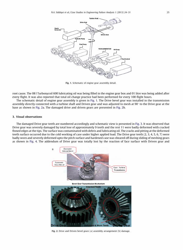
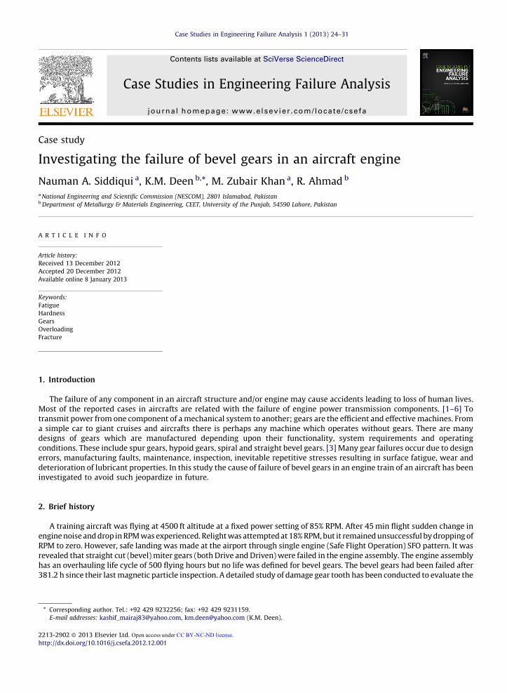
Fig. 1. Schematic of engine gear assembly detail.
N.A. Siddiqui et al. / Case Studies in Engineering Failure Analysis 1 (2013) 24–31 25
root cause. The 08 l Turbonycoil 600 lubricating oil was being filled in the engine gear box and 01 litre was being added afterevery flight. It was also reported that total oil change practice had been performed for every 100 flight hours.
The schematic detail of engine gear assembly is given in Fig. 1. The Drive bevel gear was installed in the transmissionassembly directly connected with a turbine shaft and Driven gear and was adjusted to mesh at 908 to the Drive gear at thebase as shown in Fig. 2a. The damaged drive and driven gears are presented in Fig. 2b.
3. Visual observations
The damaged Drive gear teeth are numbered accordingly and schematic view is presented in Fig. 3. It was observed thatDrive gear was severely damaged by total lose of approximately 9 teeth and the rest 11 were badly deformed with crackedfinned edges at the tips. The surface was contaminated with debris and lubricating oil. The cracks and pitting at the deformedteeth surface occurred due to the cold working of case under higher applied load. The Drive gear teeth (2, 3, 4, 5, 6, 7) werebadly worn and severely deformed upto the pitch surface and hardened case was sheared off during sliding of meshing gearsas shown in Fig. 4. The addendum of Drive gear was totally lost by the reaction of face surface with Driven gear and
Fig. 2. Drive and Driven bevel gears (a) assembly arrangement (b) damage.
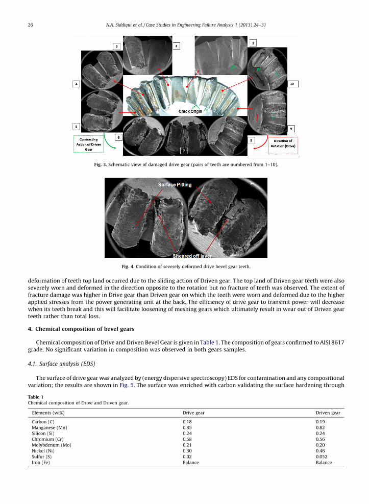
Fig. 3. Schematic view of damaged drive gear (pairs of teeth are numbered from 1–10).
Fig. 4. Condition of severely deformed drive bevel gear teeth.
N.A. Siddiqui et al. / Case Studies in Engineering Failure Analysis 1 (2013) 24–3126
deformation of teeth top land occurred due to the sliding action of Driven gear. The top land of Driven gear teeth were alsoseverely worn and deformed in the direction opposite to the rotation but no fracture of teeth was observed. The extent offracture damage was higher in Drive gear than Driven gear on which the teeth were worn and deformed due to the higherapplied stresses from the power generating unit at the back. The efficiency of drive gear to transmit power will decreasewhen its teeth break and this will facilitate loosening of meshing gears which ultimately result in wear out of Driven gearteeth rather than total loss.
4. Chemical composition of bevel gears
Chemical composition of Drive and Driven Bevel Gear is given in Table 1. The composition of gears confirmed to AISI 8617grade. No significant variation in composition was observed in both gears samples.
4.1. Surface analysis (EDS)
The surface of drive gear was analyzed by (energy dispersive spectroscopy) EDS for contamination and any compositionalvariation; the results are shown in Fig. 5. The surface was enriched with carbon validating the surface hardening through
Table 1
Chemical composition of Drive and Driven gear.
Elements (wt%) Drive gear Driven gear
Carbon (C) 0.18 0.19
Manganese (Mn) 0.85 0.82
Silicon (Si) 0.24 0.24
Chromium (Cr) 0.58 0.56
Molybdenum (Mo) 0.21 0.20
Nickel (Ni) 0.30 0.46
Sulfur (S) 0.02 0.052
Iron (Fe) Balance Balance
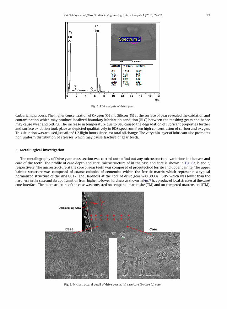
Fig. 5. EDS analysis of drive gear.
N.A. Siddiqui et al. / Case Studies in Engineering Failure Analysis 1 (2013) 24–31 27
carburizing process. The higher concentration of Oxygen (O) and Silicon (Si) at the surface of gear revealed the oxidation andcontamination which may produce localized boundary lubrication condition (BLC) between the meshing gears and hencemay cause wear and pitting. The increase in temperature due to BLC caused the degradation of lubricant properties furtherand surface oxidation took place as depicted qualitatively in EDS spectrum from high concentration of carbon and oxygen.This situation was aroused just after 81.2 flight hours since last total oil change. The very thin layer of lubricant also promotesnon uniform distribution of stresses which may cause fracture of gear teeth.
5. Metallurgical investigation
The metallography of Drive gear cross section was carried out to find out any microstructural variations in the case andcore of the teeth. The profile of case depth and core, microstructure of in the case and core is shown in Fig. 6a, b and c,respectively. The microstructure at the core of gear teeth was composed of proeutectiod ferrite and upper bainite. The upperbainite structure was composed of coarse colonies of cementite within the ferritic matrix which represents a typicalnormalized structure of the AISI 8617. The Hardness at the core of drive gear was 393.4 � 5HV which was lower than thehardness in the case and abrupt transition from higher to lower hardness as shown in Fig. 7 has produced local stresses at the case/core interface. The microstructure of the case was consisted on tempered martensite (TM) and un-tempered martensite (UTM).
Fig. 6. Microstructural detail of drive gear at (a) case/core (b) case (c) core.
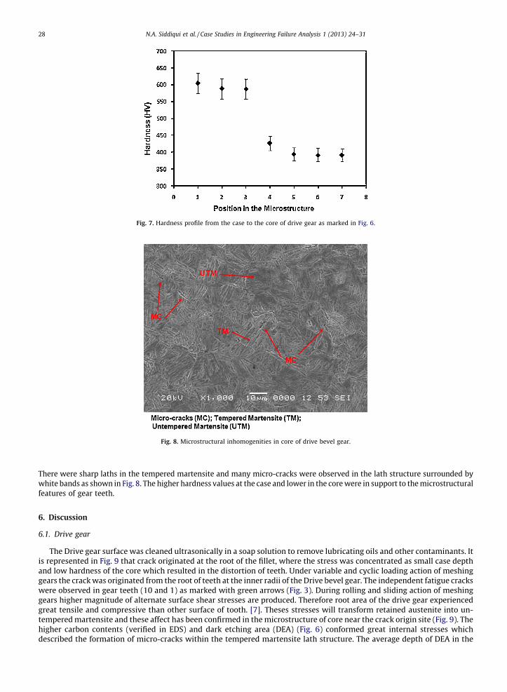
Fig. 7. Hardness profile from the case to the core of drive gear as marked in Fig. 6.
Fig. 8. Microstructural inhomogenities in core of drive bevel gear.
N.A. Siddiqui et al. / Case Studies in Engineering Failure Analysis 1 (2013) 24–3128
There were sharp laths in the tempered martensite and many micro-cracks were observed in the lath structure surrounded bywhite bands as shown in Fig. 8. The higher hardness values at the case and lower in the core were in support to the microstructuralfeatures of gear teeth.
6. Discussion
6.1. Drive gear
The Drive gear surface was cleaned ultrasonically in a soap solution to remove lubricating oils and other contaminants. Itis represented in Fig. 9 that crack originated at the root of the fillet, where the stress was concentrated as small case depthand low hardness of the core which resulted in the distortion of teeth. Under variable and cyclic loading action of meshinggears the crack was originated from the root of teeth at the inner radii of the Drive bevel gear. The independent fatigue crackswere observed in gear teeth (10 and 1) as marked with green arrows (Fig. 3). During rolling and sliding action of meshinggears higher magnitude of alternate surface shear stresses are produced. Therefore root area of the drive gear experiencedgreat tensile and compressive than other surface of tooth. [7]. Theses stresses will transform retained austenite into un-tempered martensite and these affect has been confirmed in the microstructure of core near the crack origin site (Fig. 9). Thehigher carbon contents (verified in EDS) and dark etching area (DEA) (Fig. 6) conformed great internal stresses whichdescribed the formation of micro-cracks within the tempered martensite lath structure. The average depth of DEA in the
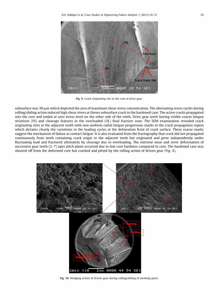
Fig. 9. Crack originating site at the root of drive gear.
N.A. Siddiqui et al. / Case Studies in Engineering Failure Analysis 1 (2013) 24–31 29
subsurface was 30 mm which depicted the area of maximum shear stress concentration. The alternating stress cycles duringrolling/sliding action induced high shear stress at theses subsurface crack in the hardened case. The active cracks propagatedinto the core and ended at zero stress level on the other side of the teeth. Drive gear teeth having visible coarse fatiguestriations (FS) and cleavage features in the overloaded (OL) final fracture zone. The SEM examination revealed crackoriginating sites at the adjacent tooth with non-uniform radial fatigue progression marks in the crack propagation regionwhich dictates clearly the variations in the loading cycles at the delineation front of crack surface. These coarse markssuggest the mechanism of failure as contact fatigue. It is also evaluated from the fractography that crack did not propagatedcontinuously from teeth containing crack origin to the adjacent teeth but originated and grew independently underfluctuating load and fractured ultimately by cleavage due to overloading. The extreme wear and sever deformation ofsuccessive gear teeth (2–7) upto pitch plane occurred due to low core hardness compared to core. The hardened case wassheared off from the deformed core but cracked and pitted by the rolling action of driven gear (Fig. 4).
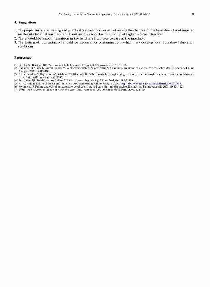
Fig. 10. Wedging action of Driven gear during rolling/sliding of meshing gears.
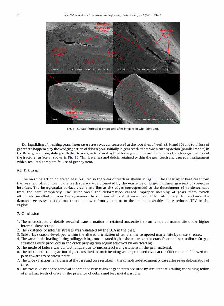
Fig. 11. Surface features of driven gear after interaction with drive gear.
N.A. Siddiqui et al. / Case Studies in Engineering Failure Analysis 1 (2013) 24–3130
During sliding of meshing gears the greater stress was concentrated at the root sites of teeth (8, 9, and 10) and total lose ofgear teeth happened by the wedging action of driven gear. Initially in gear teeth, there was a cutting action (parallel marks) inthe Drive gear during sliding with the Driven gear followed by final tearing of teeth core containing clear cleavage features atthe fracture surface as shown in Fig. 10. This lost mass and debris retained within the gear teeth and caused misalignmentwhich resulted complete failure of gear system.
6.2. Driven gear
The meshing action of Driven gear resulted in the wear of teeth as shown in Fig. 11. The shearing of hard case fromthe core and plastic flow at the teeth surface was promoted by the existence of larger hardness gradient at core/caseinterface. The intergranular surface cracks and fins at the edges corresponded to the detachment of hardened casefrom the core completely. The sever wear and deformation caused improper meshing of gears teeth whichultimately resulted in non homogeneous distribution of local stresses and failed ultimately. For instance thedamaged gears system did not transmit power from generator to the engine assembly hence reduced RPM in theengine.
7. Conclusion
1. T
he microstructural details revealed transformation of retained austenite into un-tempered martensite under higherinternal shear stress.2. T
he existence of internal stresses was validated by the DEA in the case. 3. S ubsurface cracks developed within the altered orientation of laths in the tempered martensite by these stresses. 4. T he variation in loading during rolling/sliding concentrated higher shear stress at the crack front and non-uniform fatiguestriations were produced in the crack propagation region followed by overloading.
5. T he mode of failure was contact fatigue due to microstructural variations in the gear material. 6. T he continuous rolling action of gears resulted in tooth bending which produced crack at the fillet root and followed thepath towards zero stress point.
7. T he wide variation in hardness at the case and core resulted in the complete detachment of case after sever deformation ofcore.
8. T he excessive wear and removal of hardened case at driven gear teeth occurred by simultaneous rolling and sliding actionof meshing teeth of drive in the presence of debris and lost metal particles.
N.A. Siddiqui et al. / Case Studies in Engineering Failure Analysis 1 (2013) 24–31 31
8. Suggestions
1. T
he proper surface hardening and post heat treatment cycles will eliminate the chances for the formation of un-temperedmartensite from retained austenite and micro-cracks due to build up of higher internal stresses.2. T
here would be smooth transition in the hardness from core to case at the interface. 3. T he testing of lubricating oil should be frequent for contaminations which may develop local boundary lubricationconditions.
References
[1] Findlay SJ, Harrison ND. Why aircraft fail? Materials Today 2002;5(November (11)):18–25.[2] Bhaumik SK, Sujata M, Suresh Kumar M, Venkataswamy MA, Parameswara MA. Failure of an intermediate gearbox of a helicopter. Engineering Failure
Analysis 2007;14:85–100.[3] Ramachandran V, Raghuram AC, Krishnan RV, Bhaumik SK. Failure analysis of engineering structures: methodologies and case histories. In: Materials
park. Ohio: ASM International; 2005.[4] Fernandes PJL. Tooth bending fatigue failures in gears. Engineering Failure Analysis 1996;3:219.[5] Asi O. Fatigue failure of helical gear in a gearbox. Engineering Failure Analysis 2005. http://dx.doi.org/10.1016/j.engfailanal.2005.07.020.[6] Myounggu P. Failure analysis of an accessory bevel gear installed on a J69 turbojet engine. Engineering Failure Analysis 2003;10:371–82.[7] Scott Hyde R. Contact fatigue of hardened steels ASM handbook, vol. 19. Ohio: Metal Park; 2003. p. 1749.
Related Documents


![Bevel Gears in ProE[1]](https://static.cupdf.com/doc/110x72/543da9fbb1af9f3d0a8b4920/bevel-gears-in-proe1.jpg)

