Investigating Cartilage Investigating Cartilage Stress Stress Dennis Cody November 22, 2004

Investigating Cartilage Stress Dennis Cody November 22, 2004.
Dec 21, 2015
Welcome message from author
This document is posted to help you gain knowledge. Please leave a comment to let me know what you think about it! Share it to your friends and learn new things together.
Transcript

Investigating Cartilage StressInvestigating Cartilage Stress
Dennis Cody
November 22, 2004

OutlineOutline
History PTC & Pro/Engineer Stanford
VA – Investigation of Stress in Cartilage Description of Patellofemoral Pain. Determine when bone can be assumed rigid. Understand apparent discrepancies in literature.
PTC Stanford VA
Parametric Technology Parametric Technology CorporationCorporation
5 years in Quality Assurance – Senior QAE
Software: Pro/Engineer, Pro/Mechanica, Pro/Intralink
Transition to new defect tracking database
Desire to enhance people’s lives and health
PTC

Stanford – Design and Prototype Stanford – Design and Prototype Tools for Surgical ProcedureTools for Surgical Procedure
Implant pegs: placement, depth, diameter, angle
Method of creating peg holes
Tools: Cutting Block Depth Resection Gauge Drilling Template Template Impactor
Posterior Peg Impactor Tibial Trial Tibial Spacer
PTC Stanford

OutlineOutline
History PTC & Pro/Engineer Stanford
VA – Investigation of Stress in Cartilage Description of Patellofemoral Pain. Determine when bone can be assumed rigid. Understand apparent discrepancies in literature.
PTC Stanford VA

OutlineOutline
Determine when bone can be assumed rigid.Understand apparent discrepancies in
literature.
When looking at stresses in cartilage:
PTC Stanford VA

Motivation - PFPSMotivation - PFPS
What is PF Pain Syndrome?Anterior knee painAssociated with repetitive
exerciseCause difficult to determine
Muscle imbalanceAttachmentBone shape, alignment…
http://www.medicalmultimediagroup.com
Background Methods Results

ObjectiveObjective
Obtain PF joint data in young adult volunteers using non-invasive techniques. Kinematics Kinetics Contact areas Stresses
Focus: From static MR Images, create a finite element model that can be used for analyses
Background Methods Results
VA

HypothesisHypothesis
Subjects with PF pain will have elevated cartilage stresses (compared to age and activity matched subjects without PF Pain), either because of increased PF forces and/or decreased PF contact areas.
Assumption to test: When looking at patellar and femoral cartilage stresses due to physiological loads, the underlying bone can be treated as a rigid material.
Background Methods Results
VA

BackgroundBackground
Modeling and solving models with bone elements is expensive.Some studies consider bone as a rigid material. (Li et al., 2001, Zhang et al., 1999)
Others consider the bone elements.(Beaupré et al., 2000, Brown et al., 1984)
Background Methods Results
VA

Background – Previous WorkBackground – Previous Work
3D Model of tibio-femoral joint (Donahue et al., 2002)
Model with bone Model with rigid backing No difference of more than 2%
Background Methods Results
VA

Background – Previous WorkBackground – Previous Work
Ideal model with plug and indentor (Brown et al., 1984)
Cancellous bone modulus value impacts effect of rigid implant in bone
Impactor has small radius smaller than in PF joint?
Background Methods Results
VA

Background – Previous WorkBackground – Previous Work
Author Section Thickness (mm) Modulus (MPa)Beaupré Cartilage 3 6
Subchondral 1 2000
Cancellous 16 200
Brown Cartilage ~ 1.25 3.45-20.7
Subchondral ~ 2.85 2070 - 13800
Cancellous ~ 13 34.5 - 690
Donahue Cartilage 3D model of 30 yr old specimen,
varying thickness
15
Subchondral 6900 - 20000
Cancellous 400
Background Methods Results
VA

MethodsMethods
Contact formulation
Plane Strain
Cancellous modulus
Subchondral bone thickness
Cartilage bone interface radius
Background Methods Results
Figure modified from Beaupré et al., 2000.
VA

ModelModel
Model hemisphere contacting a plate (axisymmetric)Allows curved and flat surfaceTwo models: Cartilage and bone
elements
Background Methods Results
VA

ModelModel
Model hemisphere contacting a plate (axisymmetric)Allows curved and flat surfaceTwo models: Cartilage and bone
elements Cartilage with rigid
backing
Background Methods Results
VA

Methods – Plane StrainMethods – Plane Strain
Master-Slave surface
Background Methods Results
VA

Methods – Plane StrainMethods – Plane Strain
Master-Slave surface
Hertz contact
Background Methods Results
Remove ABAQUS Series
VA

Master-Slave surface
Hertz contact
Compare with results from Beaupré’s PE model
Methods – Plane StrainMethods – Plane Strain
Background Methods Results
VA

Methods – Plane StrainMethods – Plane Strain
Master-Slave surface
Hertz contact
Comparison with results from Beaupré’s PE model.
PE vs.
Background Methods Results
VA

Methods – AxisymmetricMethods – Axisymmetric
Master-Slave surface
Hertz contact
Comparison with results from Beaupré’s PE model.
PE vs. Axisymmetric
Background Methods Results
VA
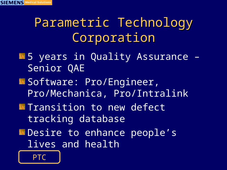
Stress With Stress With RadiusRadius
σ1-max = 432 kPa
σ 2-max = 396 kPa
σ 3-max = 401 kPa
σ 4-max = 407 kPa
σ 7-max = 414 kPa
σ 8-max = 420 kPa
r
2r
2r
r
FF
FF
1-max 5-max 3.8%
2-max 6-max 4.4%
3-max 7-max 3.2%
4-max 8-max 3.2%
1-max
3-max= 1.08
5-max
7-max= 1.08 0%
2-max
4-max= .97
6-max
8-max= 0.98 1%
=?
=?
r = 20.5 mm2r = 40.5mmF = 230NCart thk = 3.5 mmSubch bone = 0.5 mmCanc modulus = 600 MPa
Background Methods Results
?=
?=
?=
?=
VA
σ5-max = 449 kPa
σ6-max = 413 kPa

Stress With Stress With LoadLoad
σ5-max = 300 kPa
σ6-max = 294 kPa
σ7-max = 414 kPa
σ8-max = 420 kPa
σ3-max = 401 kPa
σ4-max = 407 kPa
F
σ1-max = 292 kPa
σ2-max = 286 kPa
F 2F
2F
1-max 5-max 2.8%
2-max 6-max 2.6%
3-max 7-max 3.2%
4-max 8-max 3.2%
1-max
3-max= 0.73
5-max
7-max= 0.72 1%
2-max
4-max= 0.70
6-max
8-max= 0.70 0%
=?
=?
r = 40.5 mmF = 115N2F = 230NCart thk = 3.5 mmSubch bone = 0.5 mmCanc modulus = 600 MPa
Background Methods Results
?=
?=
?=
?=
VA

Stress PatternsStress Patterns
Background Methods Results
VA

Trends in ResultsTrends in Results
Background Methods Results
Modulus (MPa)
Thickness (mm)
Octahedral Shear Hydrostatic OI
600 3 1.72% 0.68% 0.53%
600 1 1.37% 1.32% 0.87%
200 3 3.77% 1.36% 0.30%
200 1 6.99% 3.36% 1.12%
34.5 3 10.1% 3.47% 0.34%
34.5 1 40.1% 15.8% 4.21%
OI : Osteogenic Index = k * σOctahedral Shear + σHydrostatic (k = 0.35)
VA

SummarySummary
Contact model ran successfully in Abaqus
Rigid assumption valid for healthy young subjects, probably not for osteoporotic subjects
Model differences explain difference in results

Thank YouThank You
Related Documents


![Cartilage - facultymembers.sbu.ac.irfacultymembers.sbu.ac.ir/rajabi/ppt toPDF/Cartilage [Compatibility Mode].pdfFibrocartilage • Fibrous Cartilage • is a form of connective tissue](https://static.cupdf.com/doc/110x72/6012989a4318862a0e5813ae/cartilage-topdfcartilage-compatibility-modepdf-fibrocartilage-a-fibrous.jpg)