International Journal of Technology 11(7)1388-1396 (2020) Received July 2020 / Revised November 2020 / Accepted December 2020 International Journal of Technology http://ijtech.eng.ui.ac.id Investigated on Thermal Design of Computer Cooling System with the Effective Length of Cascade Heat Pipe Wayan Nata Septiadi 1,2* , Komang Wahyu Tri Prasetia 3 , Made Ricki Murti 1,2 , I Gusti Ketut Sukadana 1,2 , Fazlur Rahman 3 , Gerardo Janitra Puriadi Putra 3 , Komang Manik Marianti 3 1 Department of Mechanical Engineering, Udayana University, Kampus UNUD Bukit Jimbaran, Badung, Bali 80361, Indonesia 2 Heat Transfer Laboratory, Department of Mechanical Engineering, Udayana University, Kampus UNUD Bukit Jimbaran, Badung, Bali 80361, Indonesia 3 Undergraduate Student of Mechanical Engineering Study Program, Udayana University, Kampus UNUD Bukit Jimbaran, Badung, Bali 80361, Indonesia Abstract. Developments in recent electronics result in electronic components that produce heat, namely, Central Processing Units (CPUs). One solution to this problem is using a heat pipe. In this study, a cascade straight heat pipe (CSHP) is analyzed as a CPU cooling system with three effective lengths: 20 cm, 23 cm, and 26 cm. The first workload provided was Idle; the processor only ran the operating system without a software load, so that the processor utilization was only 1-10%. The second was full load, where the processor utilization was 95-100%. The CSHP-based CPU-cooling system with an effective length of 20 cm was able to reach processor temperatures of up to 43.32 o C (idle) and 63.62 o C (full load). For the effective length of 23 cm, processor temperatures of 46.99 o C idle) and 64.81 o C full load was attained. Lastly, while using the effective length of 26 cm, processor temperatures of 50.67 o C idle and 65.21 o C full load were reached. CPU cooling systems using CSHP are thermally resistant when in idle conditions; respectively, the temperatures for the effective lengths of 20 cm, 23 cm, and 26 cm are 0.168 o C/W, 0.197 o C/W, and 0.223 o C/W. In contrast, for the same effective lengths, the thermal resistance at full load was 0.262 o C/W, 0.236 o C/W, and 0.224 o C/W, respectively. Overall, the cascade heat pipe shows better cooling performance than a stock cooler. Keywords: Cascade heat pipe; Cooling system; Effective length; Thermal resistance 1. Introduction For several decades, the development of electronics, especially in terms of computers, has been experiencing very rapid progress (Septiadi et al., 2019). One such computer component that is progressing quite rapidly is the CPU (Brenner, 2007). The development of CPUs, i.e., smart technology with smaller, lighter dimensions with improved performance and efficiency, is advancing that stated by Cai et al., and Terrado et al., at research by Chen and Huang (2017). The development of smart technology has had an impact on certain computer components, producing heat flux and leading to overheating, which must be dissipated to ensure the performance and life of the computer system (Paiva and Mantelli, 2015). * Corresponding author’s email: [email protected], [email protected], Tel.: +62-361-703321 doi: 10.14716/ijtech.v11i7.4499

Welcome message from author
This document is posted to help you gain knowledge. Please leave a comment to let me know what you think about it! Share it to your friends and learn new things together.
Transcript

International Journal of Technology 11(7)1388-1396 (2020) Received July 2020 / Revised November 2020 / Accepted December 2020
International Journal of Technology http://ijtech.eng.ui.ac.id
Investigated on Thermal Design of Computer Cooling System with the Effective Length of Cascade Heat Pipe Wayan Nata Septiadi1,2*, Komang Wahyu Tri Prasetia3, Made Ricki Murti1,2, I Gusti Ketut Sukadana1,2, Fazlur Rahman3, Gerardo Janitra Puriadi Putra3, Komang Manik Marianti3 1Department of Mechanical Engineering, Udayana University, Kampus UNUD Bukit Jimbaran, Badung, Bali 80361, Indonesia 2Heat Transfer Laboratory, Department of Mechanical Engineering, Udayana University, Kampus UNUD Bukit Jimbaran, Badung, Bali 80361, Indonesia 3Undergraduate Student of Mechanical Engineering Study Program, Udayana University, Kampus UNUD Bukit Jimbaran, Badung, Bali 80361, Indonesia Abstract. Developments in recent electronics result in electronic components that produce heat, namely, Central Processing Units (CPUs). One solution to this problem is using a heat pipe. In this study, a cascade straight heat pipe (CSHP) is analyzed as a CPU cooling system with three effective lengths: 20 cm, 23 cm, and 26 cm. The first workload provided was Idle; the processor only ran the operating system without a software load, so that the processor utilization was only 1-10%. The second was full load, where the processor utilization was 95-100%. The CSHP-based CPU-cooling system with an effective length of 20 cm was able to reach processor temperatures of up to 43.32oC (idle) and 63.62oC (full load). For the effective length of 23 cm, processor temperatures of 46.99oC idle) and 64.81oC full load was attained. Lastly, while using the effective length of 26 cm, processor temperatures of 50.67oC idle and 65.21oC full load were reached. CPU cooling systems using CSHP are thermally resistant when in idle conditions; respectively, the temperatures for the effective lengths of 20 cm, 23 cm, and 26 cm are 0.168oC/W, 0.197oC/W, and 0.223oC/W. In contrast, for the same effective lengths, the thermal resistance at full load was 0.262oC/W, 0.236oC/W, and 0.224oC/W, respectively. Overall, the cascade heat pipe shows better cooling performance than a stock cooler. Keywords: Cascade heat pipe; Cooling system; Effective length; Thermal resistance
1. Introduction
For several decades, the development of electronics, especially in terms of computers, has been experiencing very rapid progress (Septiadi et al., 2019). One such computer component that is progressing quite rapidly is the CPU (Brenner, 2007). The development of CPUs, i.e., smart technology with smaller, lighter dimensions with improved performance and efficiency, is advancing that stated by Cai et al., and Terrado et al., at research by Chen and Huang (2017). The development of smart technology has had an impact on certain computer components, producing heat flux and leading to overheating, which must be dissipated to ensure the performance and life of the computer system (Paiva and Mantelli, 2015).
*Corresponding author’s email: [email protected], [email protected], Tel.: +62-361-703321 doi: 10.14716/ijtech.v11i7.4499

Septiadi et al. 1389
In its development, various methods have been attempted to overcome the CPU cooling system problem. One of them involves the use of a heat pipe (Kusumah et al., 2019). A heat pipe is considered a very high-thermal conductance device (Reay et al., 2013) and is a type of high-efficiency passive heat-transfer technology. Heat pipes have a structure allowing high thermal conductivity and transfer while maintaining uniform temperatures between the evaporator and condenser (Jouhara et al., 2017). Research and development on heat pipe shapes have been conducted by several researchers; for example, loop heat pipes (Maydanik et al., 2018), U-shaped heat pipes (Kusuma et al., 2019), L-shaped heat pipes (Putra and Ariantara, 2017), flat heat pipes (Arya et al., 2018), oscillating heat pipes (Zhou et al., 2018), etc. The high heat dissipated from the condenser is proof that heat pipe technology has not reached its maximum potential (Putra et al., 2013).
Modification and enhancement of heat pipes have been performed in recent decades. Fins are some of the common things applied to heat pipes to enhance heat transfer by adding more surface area in the condenser (Ibrahim et al., 2018). According to Huang et al. (2019), fin surface area is affecting the capability of heat pipes to absorb heat; the temperature distribution is increasing as fin surface areas increase due to higher heat absorption. Normally, heat collected in the fin dissipates into the air via natural convection; consequently, the surrounding air temperature rises. This temperature rise can affect the thermal resistance between the fin and the air (Xie et al., 2020). In order to ensure the heat dissipation rate, an electric-powered fan is commonly used to improve the cooling performance by increasing airflow to the heatsink (Xiao et al., 2017). The deficiency of using a fan with a CSHP is that the heat from the CPU absorbed through the evaporator at level I is not released directly into the environment. The absorbed heat is then transferred to the heat pipe evaporator level II and finally discharged through the level II condenser, and theoretically, the temperature of the heat discharged will be smaller. Therefore, the use of electric-powered fans is no longer beneficial (Septiadi and Putra, 2014).
Modification on cascade heat pipe is conducted to enhance the thermal performance. An experiment with a loop heat pipe for high heat transfer capacity has been conducted by Maydanik et al. (2018). The result stated that after thermal tests, the loop heat pipe improves power and heat transfer-distance significantly without additional energy source (Maydanik et al., 2018). The effect of the heat pipe effective length also affects the velocity of the mass flow rate along the pipe, which also affects the final heat dissipation generated by the CPU (Muhammaddiyah et al., 2018; Winarta et al., 2019). Tan et al. (2005) conducted an analytical study of flat plate heat pipe effective length using a point source approach. They stated that heat source could affect heat pipe effective length through the formulation provided in the research. The heat pipe maximum capillary heat transport limit and heat pipe optimum heat source position can be determined through the effective heat transport length (Tan et al., 2005).
In order to improve the CSHP performance, an analysis of the CSHP effective length was conducted. This research aims to find the effective length of CSHP so it could handle the maximum heat produced by the CPU without fan assistance while still paying attention to space availability inside the case. 2. Methods
This study used copper heat pipes of 160 mm lengths and 4 mm hydraulic diameters filled with copper sintered powder wicks. The CPU used in this experiment is an Intel Core i5-4570T 2C/4T 35W TDP processor which specified at processor’s base frequency in high and complex load. The apparatus components used to test the result of effective length on a CSHP-based CPU cooling system are: Data Acquisition (DAQ), K-type Thermocouple, Processor, Motherboard, and DC Power Supply.

1390 Investigated on Thermal Design of Computer Cooling System with the Effective Length of Cascade Heat Pipe
In order to get the CPU temperature, the CPU was stressed by a workload. The workload given to the Intel Core i5 processor was either idle load or full load. At idle load, the processor only runs the operating system, utilizing only 1-10% of its computing power, while at full load, 90-100% of the threads inside the processor are utilized. This procedure is conducted by manipulating the power given to the processor using the software, CPU-Z. The effective length was divided into three variations: 20 cm, 23 cm, and 26 cm. The thermocouple was placed at the measurement point connected to the NI-9123 + cDAQ-9174 module, which was connected to the Natural Instrument (NI) LabView software. The thermocouple was calibrated beforehand to a 0.02oC accuracy.
The temperature data obtained was then used to calculate the thermal resistance via Equation 1:
𝑅ℎ𝑝 =𝑇𝑒−𝑇𝑐
𝑄 (1)
where R is thermal resistance, (W/oC) Te is the evaporator temperature, Tc is the condenser temperature, and Q is the workload (W).
The effective length is used to calculate variations in velocity along the heat pipe. The speed of the vapor and liquid at the beginning of the evaporator is zero. They increase linearly due to evaporation at the beginning of the adiabatic process which is a process that arise without transfer of heat and mass between the system and its environment, before becoming constant during the diabatic process which is a thermodynamic state of change of a system in which the system exchanges energy with its surrounding by virtue of a temperature difference. In the condenser, condensation causes the vapor and liquid velocity to decrease linearly to zero at the end of the condenser. To calculate varying speeds, the effective length is used to calculate the decrease in vapor and liquid pressure. The effective length is given by the formula:
𝐿𝑒𝑓𝑓 =𝐿𝑒𝑣𝑎+𝐿𝑐𝑜𝑛
2+ 𝐿𝑎𝑑𝑡 (2)
where Leff is the effective length (cm), Leva is the evaporator length (cm), Lcon is the condenser length, and Ladt is the adiabatic length in centimeters. The effective lengths used in this research are 20 cm, 23 cm, and 26 cm. Figure 1 shows a CSHP design. Based on the design, CSHPs consist of two stacked heat pipes.
Figure 1 Design of CSHP The first-level heat pipe has an L shape, with processor mounting at the evaporator area. The heat pipe takes heat from the CPU and transfers it into the condenser area. The

Septiadi et al. 1391
heat released from the first-level heat pipe condenser is then transferred into the second-level heat pipe evaporator. The first-level condenser and the second-level evaporator are stacked and fastened by a brace. This section is known as the adiabatic area. The brace is also installed as an isolator to reduce heat loss from the first-level heat pipe condenser. The heat transferred to the second-level evaporator is further transferred to the heat sink. This design is expected to dissipate the maximum heat produced by the CPU without fan assistance. Figure 2 shows the experimental setup of a CHSP test.
Figure 2 Schematic of The Experimental Setup
3. Results and Discussion
The experiment was carried out under idle conditions at 12, and full load at 35W. The non-cascade cooling system here uses stock cooling and fanless stock cooling to determine the difference between stock cooling with and without a fan. Contrastingly, the cascade cooling system uses CSHPs with effective lengths of 20 cm, 23 cm, and 26 cm.
Based on the results provided in Table 1, it can be seen that the cascade system is able to reduce the CPU operational processor temperature below 70oC; precisely, 63.62oC for the 20 cm effective length, 64.81oC for the 23 cm effective length, and 65.21oC for the 26 cm effective length.
Table 1 Cooling temperature
Workload Temperature (oC)
T0 T1 T2 T3 T4 T5 T6
Stock cooling Idle 42.66 35.91 35.49 35.29 35.08 33.21 28.58 Full Load 53.85 34.26 33.54 31.75 32.30 30.78 29.89 Fan-less stock cooling Idle 47.81 39.54 37.90 37.50 36.40 35.09 29.06 Full Load 71.36 61.88 56.67 54.52 53.32 45.45 29.07 CSHP length effective 20 cm Idle 43.33 38.27 36.70 36.29 36.01 33.99 29.19 Full Load 63.62 52.46 46.82 43.28 40.07 34.83 29.19
CSHP length effective 23 cm Idel Idle 46.99 40.08 38.80 38.37 38.11 36.16 29.24 Full Load 64.81 49.31 45.75 44.04 42.83 37.91 29.28
CSHP length effective 26 cm temperature Idle 48.67 42.60 41.26 40.97 40.60 38.35 29.29 Full Load 65.21 49.33 46.51 45.19 43.43 38.90 29.16
1392 Investigated on Thermal Design of Computer Cooling System with the Effective Length of Cascade Heat Pipe
In terms of condenser operational temperature in the CPU cooling system test, it is seen that the cascade system is able to affect the CPU operational temperature at full load, producing a safe CPU temperature less than 50oC; precisely, 43.28oC for the 20 cm effective length, 45.04oC for the 23 cm effective length, and 45.79oC for the 26 cm effective length. As noticed in the figures, the lowest condenser temperature was in the cascade cooling system using the 20 cm effective length (43.28oC).
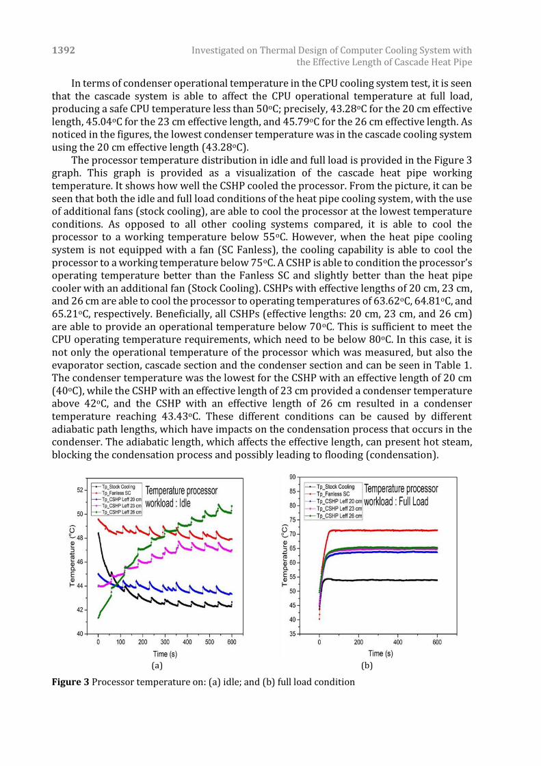
The processor temperature distribution in idle and full load is provided in the Figure 3 graph. This graph is provided as a visualization of the cascade heat pipe working temperature. It shows how well the CSHP cooled the processor. From the picture, it can be seen that both the idle and full load conditions of the heat pipe cooling system, with the use of additional fans (stock cooling), are able to cool the processor at the lowest temperature conditions. As opposed to all other cooling systems compared, it is able to cool the processor to a working temperature below 55oC. However, when the heat pipe cooling system is not equipped with a fan (SC Fanless), the cooling capability is able to cool the processor to a working temperature below 75oC. A CSHP is able to condition the processor’s operating temperature better than the Fanless SC and slightly better than the heat pipe cooler with an additional fan (Stock Cooling). CSHPs with effective lengths of 20 cm, 23 cm, and 26 cm are able to cool the processor to operating temperatures of 63.62oC, 64.81oC, and 65.21oC, respectively. Beneficially, all CSHPs (effective lengths: 20 cm, 23 cm, and 26 cm) are able to provide an operational temperature below 70oC. This is sufficient to meet the CPU operating temperature requirements, which need to be below 80oC. In this case, it is not only the operational temperature of the processor which was measured, but also the evaporator section, cascade section and the condenser section and can be seen in Table 1. The condenser temperature was the lowest for the CSHP with an effective length of 20 cm (40oC), while the CSHP with an effective length of 23 cm provided a condenser temperature above 42oC, and the CSHP with an effective length of 26 cm resulted in a condenser temperature reaching 43.43oC. These different conditions can be caused by different adiabatic path lengths, which have impacts on the condensation process that occurs in the condenser. The adiabatic length, which affects the effective length, can present hot steam, blocking the condensation process and possibly leading to flooding (condensation).
(a) (b)
Figure 3 Processor temperature on: (a) idle; and (b) full load condition
Septiadi et al. 1393
The effective length also affected the condensate path that leads to the evaporator, so that if the adiabatic path is too long under certain conditions, the condensate would be late reaching the evaporator. Simultaneously, a lot of hot steam would reach the condenser, which would cause a build-up of heat in the condenser. In this cascade model, the differences in adiabatic lengths affected the lengths of the condenser level 1 and the evaporator level 2, which affected the heat transfer that occurs. The 20-cm effective length provided the best conditions, which was able to meet the operational temperature below 80oC. The output temperature in the condenser was close to the ambient temperature or not too much high than the ambient temperature, which was at 40.07oC.
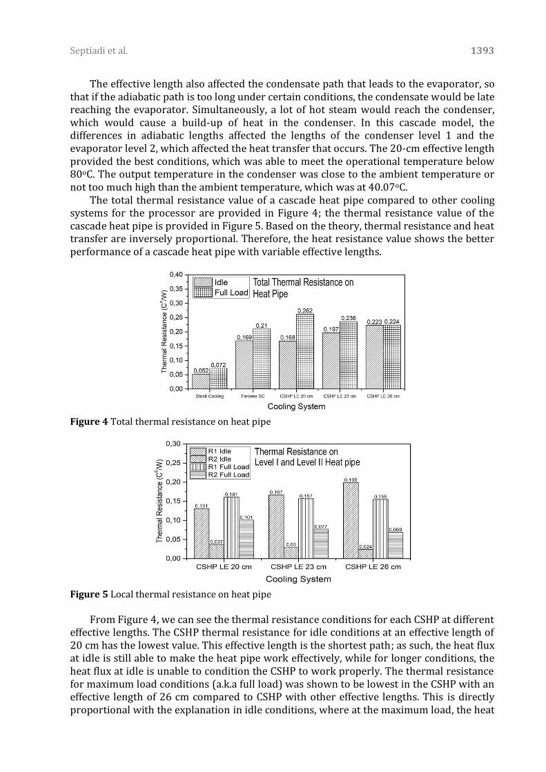
The total thermal resistance value of a cascade heat pipe compared to other cooling systems for the processor are provided in Figure 4; the thermal resistance value of the cascade heat pipe is provided in Figure 5. Based on the theory, thermal resistance and heat transfer are inversely proportional. Therefore, the heat resistance value shows the better performance of a cascade heat pipe with variable effective lengths.
Figure 4 Total thermal resistance on heat pipe
Figure 5 Local thermal resistance on heat pipe
From Figure 4, we can see the thermal resistance conditions for each CSHP at different
effective lengths. The CSHP thermal resistance for idle conditions at an effective length of 20 cm has the lowest value. This effective length is the shortest path; as such, the heat flux at idle is still able to make the heat pipe work effectively, while for longer conditions, the heat flux at idle is unable to condition the CSHP to work properly. The thermal resistance for maximum load conditions (a.k.a full load) was shown to be lowest in the CSHP with an effective length of 26 cm compared to CSHP with other effective lengths. This is directly proportional with the explanation in idle conditions, where at the maximum load, the heat

1394 Investigated on Thermal Design of Computer Cooling System with the Effective Length of Cascade Heat Pipe
pipe conditions all work in two phases. The higher adiabatic length is able to overcome the steam flow that has accumulated in the condenser due to the rapidity of hot steam reaching the condenser. This also avoids the occurrence of flooding condensation in the condenser, which is one of the causes of increasing thermal resistance.
The cascade thermal resistance appears to be higher than the non-cascade cooling system. This phenomenon occurred because the non-cascade uses only one heat pipe, while the cascade circuit uses two heat pipes with their own thermal resistance, which with the addition of a heat pipe in a cooling system circuit causes the increase of the thermal resistance in the cooling system circuit. Subsequently, the cascade circuit has a higher thermal resistance than the non-cascade cooling system (Seo et al., 2017).
As a result of the boiling effect, nucleation did not reach the evaporation condition because, in the idle condition, the heat pipe did not function at its optimum performance; only a portion of the fluid evaporated, which tends to inhibit the rate of vapor flow, resulting in an increase in thermal resistance (Septiadi et al., 2020). This phenomenon can be seen in Figure 5. The highest thermal resistance of 0.199oC/W occurs in the first-level heat pipe of the effective cascade-cooling system with an effective length of 26 cm. Testing for full load conditions performed between effective length ratios, effective lengths of 20 cm had a slightly higher total thermal resistance compared to other effective length ratios. At the optimum performance of the full load heat pipes, an effective length of 20 cm had the longest cascade area that can inhibit heat transfer from level I heat pipes to level II heat pipes. It is not surprising that the 20 cm effective length had a slightly higher amount of total thermal resistance than the CSHP cooling system with effective lengths of 23 cm and 26 cm.
The thermal resistance shows similar results with Wang et al.’s (2011) experiment, which stated that the evaporator section length affects thermal resistance. From the results obtained in particular research, the increasing evaporator length increased the heat transfer limit but decreased the thermal resistance. This phenomenon occurred because, at the same heat load, the heat flux increased in the shorter evaporator length and led to intense partial evaporation. Partial evaporation produced more vapor, so the evaporator and condenser sections experienced large pressure differences, which blocked the condensed working fluid relaying stream back to the evaporator section. This could lead to a high-temperature difference between the evaporator and condenser sections and cause higher thermal resistance (Wang et al., 2011). In addition, this could also explain the resultant graph in Figure 3a, showing that regarding the CSHP, the processor temperature started at a lower temperature than the stock cooler. But with increasing time, each of the straight cascade heat pipes showed different results. The processor temperature increased about 10oC in the CSHP with a 26 cm effective length but decreased about 1.5oC in the CSHP with a 20 cm effective length. 4. Conclusions
An experiment was conducted to analyze the effective length of cascade heat pipes as CPU cooling systems. This experiment was carried out to find the most effective cascade heat pipe length so that fan assistance for CPU cooling is not required.
The effective length ratio affects the rate of heat transfer in a CSHP as a CPU cooling system, where a smaller effective length variable has a higher heat transfer rate, and a higher effective length ratio has a lower heat transfer rate. This is due to the distance the fluid travels along with the length of the heat pipe. A cascade heat pipe’s effective length also influences the thermal resistance of the system. A shorter cascade heat pipe effective

Septiadi et al. 1395
length results in higher thermal resistance and vice versa due to intense partial evaporation.
Cascade straight heat pipes show better cooling performance than stock coolers without fan assistance. Cascade straight heat pipes with 20-cm effective lengths have the best cooling performance among CSHPs. According to the results, CSHPs are applicable to replace conventional fan-assisted heat pipes as cooling devices for CPUs. Modification and improvement of CSHPs can vary the working fluid and heatsink design for better cooling performance. Acknowledgements
Thanks go to the Ministry of Technology and Higher Education and the Udayana Institute for Research and Community Service for their financial support through the 2019 Penelitian Terapan Unggulan Perguruan Tinggi (PTUPT) scheme with contract number 492.29/UN14.4.A/LT/2019. References
Arya, A., Sarafraz, M.M., Shahmiri, S., Madani, S.A.H., Nikkhah, V., Nakhjavani, S.M., 2018. Thermal Performance Analysis of a Flat Heat Pipe Working with Carbon Nanotube-Water Nanofluid for Cooling of a High Heat Flux Heater. Heat and Mass Transfer, Volume 54(4), pp. 985–997
Brenner, S., 2007. Law in an Era of Smart Technology. London: Oxford University Press Chen, Q., Huang, Y., 2017. Scale Effects on Evaporative Heat Transfer in Carbon Nanotube
Wick in Heat Pipes. International Journal of Heat and Mass Transfer, Volume 111, pp. 852–859
Huang, D.-S., Chen, T.-C., Tsai, L.-T., Lin, M.-T., 2019. Design of Fins with a Grooved Heat Pipe for Dissipation of Heat From High-Powered Automotive LED Headlights. Energy Conversion and Management, Volume 180, pp. 550–558
Ibrahim, T.K., Mohammed, M.N., Mohammed, M.K., Najafi, G., Sidik, N.A.C., Basrawi, F., Abdalla, A.N., Hoseini, S.S., 2018. Experimental Study on the Effect of Perforations Shapes on Vertical Heated Fins Performance under Forced Convection Heat Transfer. International Journal of Heat and Mass Transfer, Volume 118, pp. 832–846
Jouhara, H., Chauhan, A., Nannou, T., Almahmoud, S., Delpech, B., Wrobel, L.C., 2017. Heat Pipe Based Systems - Advances and Applications. Energy, Volume 128, pp. 729–754
Kusuma, M.H., Setiorini, U., Putri, T.A.R., Antariksawan, G.A.R., Juarsa, M., 2019. Effective Thermal Conductivity of U-shaped Heat Pipe. IOP Conference Series: Materials Science and Engineering, Volume 550(1), p. 12004
Kusumah, A., Hakim, I., Sukarno, R., Rachman, F.F., Putra, N., 2019. The Application of U-Shape Heat Pipe Heat Exchanger to Reduce Relative Humidity for Energy Conservation in Heating, Ventilation, and Air Conditioning (HVAC) Systems. International Journal of Technololgy, Volume 10(6), pp. 1202–1210
Maydanik, Y., Pastukhov, V., Chernysheva, M., 2018. Development and Investigation of a Loop Heat Pipe with a High Heat-Transfer Capacity. Applied Thermal Engineering, Volume 130, pp. 1052–1061
Muhammaddiyah, S., Winarta, A., Putra, N., 2018. Experimental Study of Multi-fin Heat Pipe Heat Exchanger for Energy Efficiency in Operating Room Air Systems. International Journal of Technology, Volume 9(2), pp. 422–429
Paiva, K.V, Mantelli, M.B.H., 2015. Wire-plate and Sintered Hybrid Heat Pipes: Model and Experiments. International Journal of Thermal Sciences, Volume 93, pp. 36–51

1396 Investigated on Thermal Design of Computer Cooling System with the Effective Length of Cascade Heat Pipe
Putra, N., Ariantara, B., 2017. Electric Motor Thermal Management System using L-Shaped Flat Heat Pipes. Applied Thermal Engineering, Volume 126, pp. 1156–1163
Putra, N., Septiadi, W.N., Irwansyah, R., 2013. Effect of Concentration and Loading Fluid of Nanofluids on the Thermal Resistance of Sintered Powder Wick Heat Pipe. Advanced Materials Research, Volume 651, pp. 728–735
Reay, D., McGlen, R., Kew, P., 2013. Heat Pipes: Theory, Design and Applications. UK: Butterworth-Heinemann
Seo, Y.M., Park, Y.G., Ha, M.Y., 2017. Effect of Variation in Length of the Conventional Heat Pipe on the Thermal Performance. In: 13th International Conference on Heat Trasnfer, Fluid Mechanics and Thermodynamics. Portoroz, Slovenia. 17-19 July 2017. http://hdl.handle.net/2263/62448
Septiadi, W.N., Ula, W.A.W., Wulandari, I., Tnunay, I.A., Murti, M.R., 2019. Thermal Resistance Analysis of Central Processing Unit Cooling System based on Cascade Straight Heat Pipe. IOP Conference Series: Materials Science and Engineering, Volume 539(1), p. 12036
Septiadi, W.N., Astawa, K., Arvikadewi, I.G.A.P., Febraldo, D., Putra, G.J.P., 2020. Boiling Phenomenon of Graphene Nano-Coating Wick Heat Pipe. Evergreen Joint Journal of Novel Carbon Resource Science & Green Asia Strategy, Volume 7(2), pp. 297–302
Septiadi, W.N., Putra, N., 2014. Heat Pipe Technology: Theory, Design and Application. Iowa, USA: UI-PRESS
Tan, B.K., Wong, T.N., Ooi, K.T., 2005. Analytical Effective Length Study of a Flat Plate Heat Pipe using Point Source Approach. Applied Thermal Engineering, Volume 25(14–15), pp. 2272–2284
Wang, S., Chen, J., Hu, Y., Zhang, W., 2011. Effect of Evaporation Section and Condensation Section Length on Thermal Performance of Flat Plate Heat Pipe. Applied Thermal Engineering, Volume 31(14–15), pp. 2367–2373
Winarta, A., Putra, N., Koestoer, R.A., Pamitran, A.S., Hakim, I.I., 2019. Experimental Investigation of a Large Scale-oscillating Heat Pipe at Different Inclinations. International Journal of Technology, Volume 10(2), pp. 258–268
Xiao, C., Liao, H., Wang, Y., Li, J., Zhu, W., 2017. A Novel Automated Heat-pipe Cooling Device for High-power LEDs. Applied Thermal Engineering, Volume 111, pp. 1320–1329
Xie, L., Yuan, X., Wang, W., 2020. Thermal Modeling of Fan-cooled Plate-fin Heatsink Considering Air Temperature Rise for Virtual Prototyping of Power Electronics. IEEE Transactions on Components, Packaging and Manufacturing Technology, Volume 10(11), pp. 1829–1839. https://doi.org/10.1109/TCPMT.2020.2009156
Zhou, Y., Cui, X., Weng, J., Shi, S., Han, H., Chen, C., 2018. Experimental Investigation of the Heat Transfer Performance of an Oscillating Heat Pipe with Graphene Nanofluids. Powder Technology, Volume 332, pp. 371–380
Related Documents


