INVERTERS: The Investigation to the Presenter: Dr Gawie van der Merwe static as well as mobile applications sinewave inverter range for the use in optimal topology to the designing of a

INVERTERS: The Investigation to the Presenter: Dr Gawie van der Merwe static as well as mobile applications sinewave inverter range for the use in optimal.
Dec 11, 2015
Welcome message from author
This document is posted to help you gain knowledge. Please leave a comment to let me know what you think about it! Share it to your friends and learn new things together.
Transcript
INVERTERS: The Investigation to the
Presenter: Dr Gawie van der Merwe
static as well as mobile applicationssinewave inverter range for the use inoptimal topology to the designing of a
Copyright: Dr Gawie van der Merwe www.planmypower.co.za
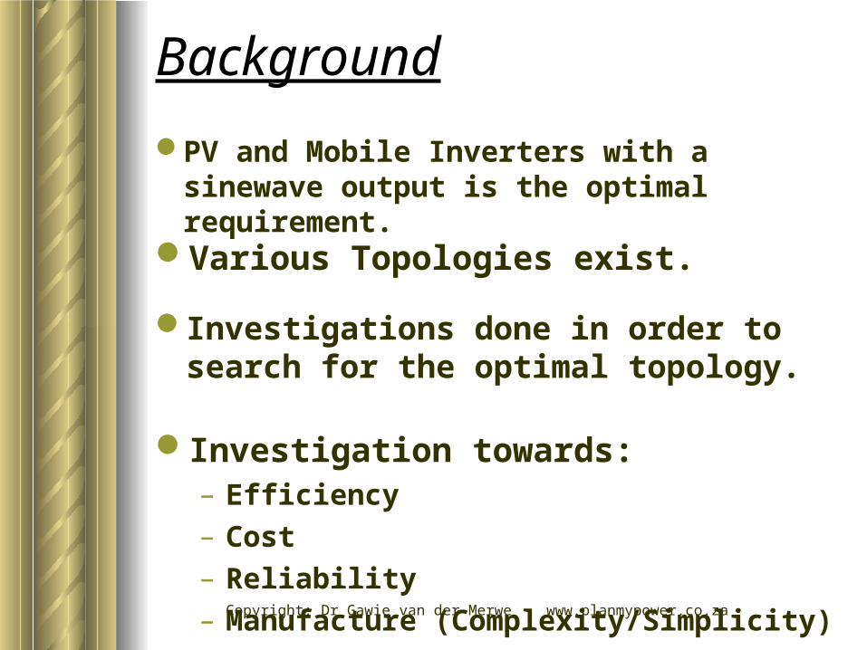
Background
Investigation towards:– Efficiency– Cost– Reliability– Manufacture (Complexity/Simplicity)
Investigations done in order to search for the optimal topology.
Various Topologies exist.
PV and Mobile Inverters with a sinewave output is the optimal requirement.
Copyright: Dr Gawie van der Merwe www.planmypower.co.za
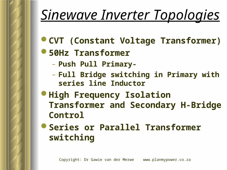
Sinewave Inverter Topologies
CVT (Constant Voltage Transformer)50Hz Transformer
– Push Pull Primary- – Full Bridge switching in Primary with series
line Inductor
High Frequency Isolation Transformer and Secondary H-Bridge Control
Series or Parallel Transformer switching

Copyright: Dr Gawie van der Merwe www.planmypower.co.za
A) Constant Voltage Transformer
SINEWAVE OUTPUT
BATTERY
CVT
Transformer
Inverter “push-pull”
Resonantcomponents
(Ferro Resonant Transformer)
Copyright: Dr Gawie van der Merwe www.planmypower.co.za
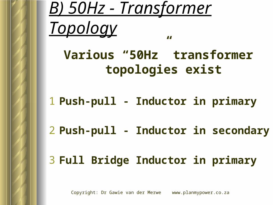
B) 50Hz - Transformer Topology
Various “50Hz” transformer topologies exist
3 Full Bridge Inductor in primary
1 Push-pull - Inductor in primary
2 Push-pull - Inductor in secondary

Copyright: Dr Gawie van der Merwe www.planmypower.co.za
-10 0 10 20 30
-400
-200
0
200
400
-3
-2
-1
0
1
2
3
TIME (5MS/DIV)
VO
LTA
GE (
V)
CU
RR
EN
T (
A)
CURRENT
VOLTAGE
VOLTAGE AND CURRENTLINEAR LOAD
50Hz TRANSFORMER
-10 0 10 20 30
-400
-200
0
200
400
-8
-6
-4
-2
0
2
4
6
8
TIME (5MS/DIV)
VO
LTA
GE (
V)
CU
RR
EN
T (
A)
CURRENT
VOLTAGE
VOLTAGE AND CURRENTNON-LINEAR LOAD
50Hz TRANSFORMER

Copyright: Dr Gawie van der Merwe www.planmypower.co.za
Topology B1
SINEWAVE OUTPUT
BATTERY
INDUCTOR
SINE-REF
FEEDBACK
ERROR AMP
SAWTOOTH
DRIVE CIRCUITAND CONTROLLATCH
TOROID
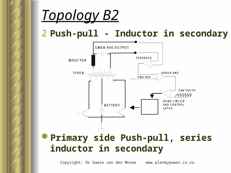
1 Push-pull - Inductor in primary

Copyright: Dr Gawie van der Merwe www.planmypower.co.za
Topology B1
Disadvantages– Voltage overshoot over devices - leads to
voltage rating increase - Reduction in efficiency
– No-, or limited control over free running inductor current
– “Skewing” of transformer often occur.
Advantages– Simple manufacture & design
– Mosfet drive circuit referred to ground
SINEWAVE OUTPUT
BATTERY
INDUCTOR
SINE-REF
FEEDBACK
ERROR AMP
SAWTOOTH
DRIVE CIRCUITAND CONTROLLATCH
TOROID
1 Push-pull - Inductor in primary
Copyright: Dr Gawie van der Merwe www.planmypower.co.za
Primary side Push-pull, series inductor in secondary
SINEWAVE OUTPUT
BATTERY
SINE-REF
FEEDBACK
ERROR AMP
SAWTOOTH
DRIVE CIRCUITAND CONTROLLATCH
TOROID
INDUCTOR
Topology B22 Push-pull - Inductor in secondary

Copyright: Dr Gawie van der Merwe www.planmypower.co.za
Topology B2
Advantages– Simple manufacture & design
– Mosfet drive circuit referred to ground
Disadvantages– Voltage overshoot over devices - leads to
voltage rating increase - Reduction in efficiency
– No-, or limited control over free running inductor current
– “Skewing” of transformer often occur.
SINEWAVE OUTPUT
BATTERY
SINE-REF
FEEDBACK
ERROR AMP
SAWTOOTH
DRIVE CIRCUITAND CONTROLLATCH
TOROID
INDUCTOR
2 Push-pull - Inductor in secondary
Copyright: Dr Gawie van der Merwe www.planmypower.co.zaMost popular used topology
SINEWAVE OUTPUT
SINE-REF
FEEDBACK
ERROR AMP
SAWTOOTH
DRIVE CIRCUITAND CONTROLLATCH
TOROID
INDUCTOR
BATTERY
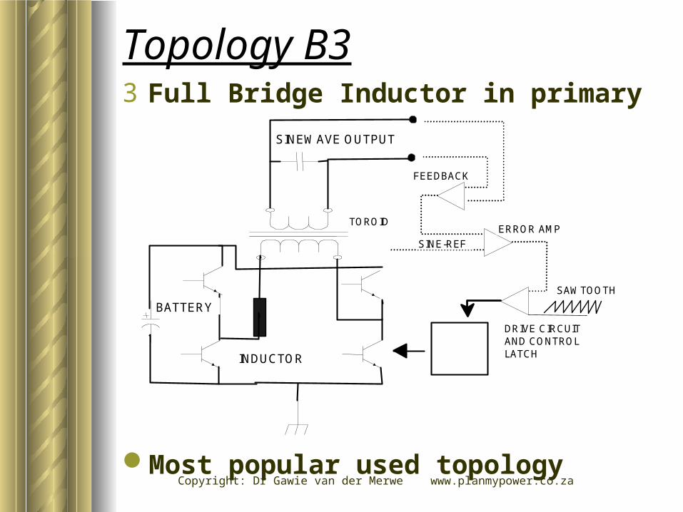
Topology B33 Full Bridge Inductor in primary

Copyright: Dr Gawie van der Merwe www.planmypower.co.za
Advantages– Complete control over primary side inductor
current– Uni-as well as bi-polar pwm control strategy
possible– Simple manufacturing
Topology B3
Disadvantages– System design is more complex– Inverter efficiency is load dependent
SINEWAVE OUTPUT
SINE-REF
FEEDBACK
ERROR AMP
SAWTOOTH
DRIVE CIRCUITAND CONTROLLATCH
TOROID
INDUCTOR
BATTERY
3 Full Bridge Inductor in primary

Copyright: Dr Gawie van der Merwe www.planmypower.co.za
C) High Frequency Isolation
SAWTOOTH
TOROID
INDUCTOR
BATTERY
SINEWAVE OUTPUT
ERROR AMP
SINE-REF
FEEDBACKDRIVE CIRCUITAND CONTROLLATCH
PRIMARY SIDE DEVICESCONTROLLED TO OFFERA FIXED DC LINK VOLTAGE
Copyright: Dr Gawie van der Merwe www.planmypower.co.za
High frequency isolation reduce physical size– Direct output control leads to better
output waveform control and reduced distortion
C) High Frequency Isolation Transformer with full H-bridge Control on Secondary
Copyright: Dr Gawie van der Merwe www.planmypower.co.za
-10 0 10 20 30-400
-200
0
200
400
-4
-2
0
2
4
TIME (5MS/DIV)
VO
LTA
GE (
V)
CU
RR
EN
T (
A)
CURRENT
VOLTAGE
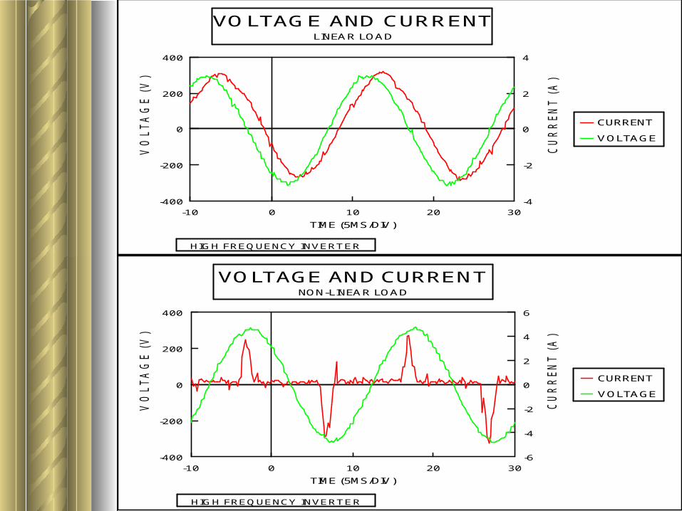
VOLTAGE AND CURRENTLINEAR LOAD
HIGH FREQUENCY INVERTER
-10 0 10 20 30-400
-200
0
200
400
-6
-4
-2
0
2
4
6
TIME (5MS/DIV)
VO
LTA
GE (
V)
CU
RR
EN
T (
A)
CURRENT
VOLTAGE
VOLTAGE AND CURRENTNON-LINEAR LOAD
HIGH FREQUENCY INVERTER

Copyright: Dr Gawie van der Merwe www.planmypower.co.za
Advantages– Units generally more mobile– Possible to limit battery current drawn to a
“smooth DC”– Good efficiency with a non linear load
High Frequency Isolation Transformer
Disadvantages– Design is complex– Manufacture is complex– High cost
Copyright: Dr Gawie van der Merwe www.planmypower.co.za
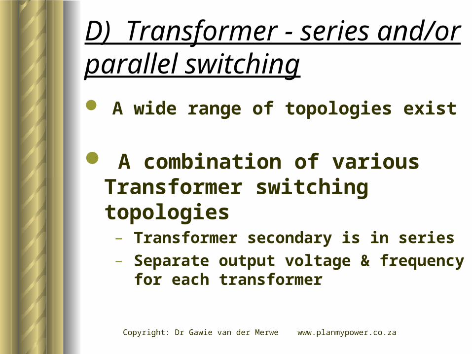
A wide range of topologies exist
D) Transformer - series and/or parallel switching
A combination of various Transformer switching topologies
– Transformer secondary is in series– Separate output voltage & frequency for
each transformer

Copyright: Dr Gawie van der Merwe www.planmypower.co.za
BATTERY
(B)(A) (C)
(A+B+C) =
SINEWAVEOUTPUT
Transformer-series and/or parallel switching

Copyright: Dr Gawie van der Merwe www.planmypower.co.za
-10 0 10 20 30-400
-200
0
200
400
TIME (5MS/DIV)
VO
LTA
GE (
V)
VOLTAGE
VOLTAGE OUTPUT OF MULTI TRANSFORMERINVERTER
MATRIX TRANSFORMER INVERTER
-10 0 10 20 30-400
-200
0
200
400
TIME (5MS/DIV)
VO
LTA
GE (
V)
VOLTAGE
ZOOM INTO VOLTAGE STEPS
MATRIX INVERTER

Copyright: Dr Gawie van der Merwe www.planmypower.co.za
Advantages– High running to overload ratio is – Very popular design– Advantages for motor startup– High efficiency
Transformer -series and/or parallel switching
Disadvantages– Control complex– Manufacturing is complex– Inverter is big and bulky
Copyright: Dr Gawie van der Merwe www.planmypower.co.za
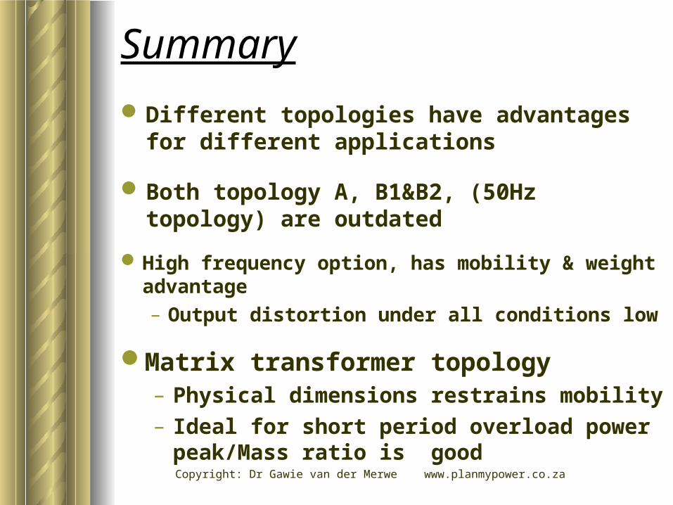
Summary
Different topologies have advantages for different applications
Both topology A, B1&B2, (50Hz topology) are outdated
High frequency option, has mobility & weight advantage– Output distortion under all conditions low
Matrix transformer topology– Physical dimensions restrains mobility– Ideal for short period overload power
peak/Mass ratio is good
Copyright: Dr Gawie van der Merwe www.planmypower.co.za
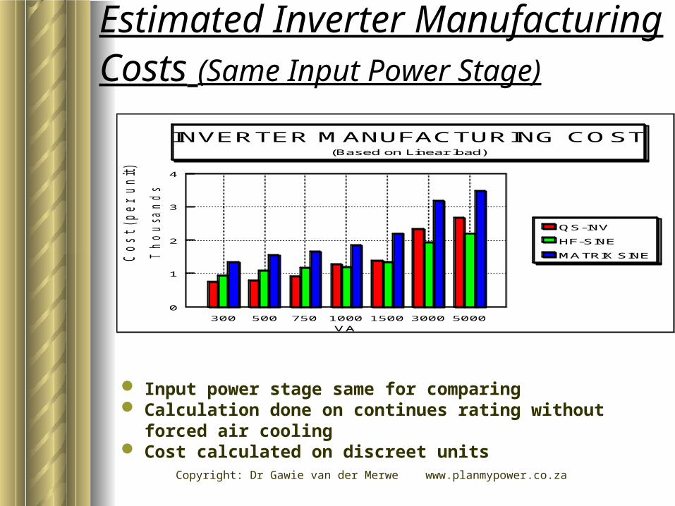
Estimated Inverter Manufacturing Costs (Same Input Power Stage)
0
1
2
3
4
Th
ou
sa
nd
s
VA
Cost (per u
nit)
300 500 750 1000 1500 3000 5000
QS-INV
HF-SINE
MATRIX SINE
INVERTER MANUFACTURING COST(Based on Linear load)
Input power stage same for comparing Calculation done on continues rating without forced air
cooling Cost calculated on discreet units

Copyright: Dr Gawie van der Merwe www.planmypower.co.za
Non linear load as a % of total power consumption
Non linear loads - high percentage on power application below 1Kva typical loads, computer, fluorescent lights, video
Higher power application, more resistive, i.e. Microwave, Hairdryer etc. < 1Kva most sensitive to PV applications
0
20
40
60
80
100
POWER INVERTER
LO
AD
PR
OB
AB
ILIT
Y
100 1000 2000 3000
NON-LINEARLOAD LINEAR LOADS
NON LINEAR LOAD AS % OF FULL POWER(TYPICAL APPLICATIONS)

Copyright: Dr Gawie van der Merwe www.planmypower.co.za
0
2
4
6
8
POWER
SY
STEM
EFFIC
IEN
CY
LO
SS
ES
%
100.00 1000.00 2000.00 3000.00
HF TOPOLOGY
50HZ TOPOLOGY
WEIGHTED % SYSTEM LOSSES AS RESULT OF NON-LINEAR LOAD
(LOSSES DUE TO INVERTER CHOICE)
0 1 2 3 40
5
10
15
20
Thousands
POWER INVERTER (WATT)
EFFIC
IEN
Y L
OS
S (
%)
HF TOPOLOGY
50HZ TOPOLOGY
INVERTER EFFICIENCY LOSS DUE TO NON-LINEAR LOAD
ASSUMPTION 100% LOADSAME POWER STAGE DESIGN
Copyright: Dr Gawie van der Merwe www.planmypower.co.za
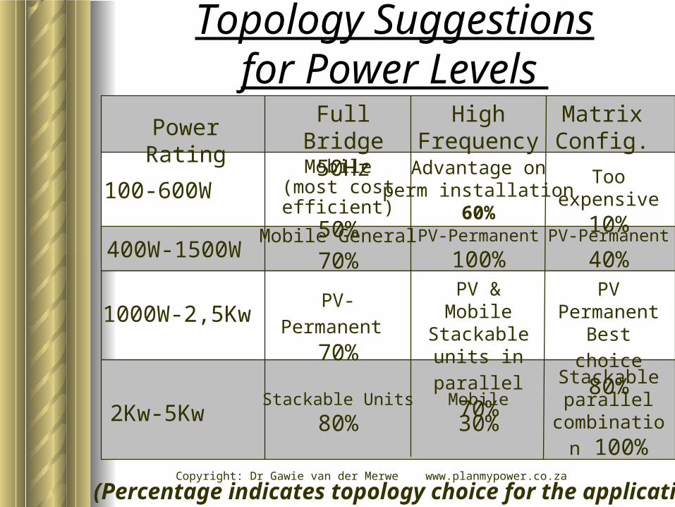
Topology Suggestionsfor Power Levels
Power RatingHigh
FrequencyFull Bridge
50HzMatrix Config.
100-600WMobile (most cost efficient)
50%
Advantage onperm installation
60%
Too expensive
10%
400W-1500WMobile General
70%PV-Permanent
100%PV-Permanent
40%
1000W-2,5Kw PV-Permanent 70%
PV & MobileStackable units
in parallel 70%
PV Permanent
Best choice 80%
2Kw-5Kw
Stackable parallel
combination 100%
Stackable Units
80%Mobile
30%
(Percentage indicates topology choice for the application)
Related Documents