Inverter Air-cooled screw chillers EWAD330-520AJYNN/S EWAD330-520AJYNN/X 50Hz – Refrigerant: R-134a Installation, Operation and Maintenance Manual D – 511 C - 08/10 A - EN

Welcome message from author
This document is posted to help you gain knowledge. Please leave a comment to let me know what you think about it! Share it to your friends and learn new things together.
Transcript

Inverter Air-cooled screw chillers EWAD330-520AJYNN/S EWAD330-520AJYNN/X 50Hz – Refrigerant: R-134a
Installation, Operation and Maintenance Manual D – 511 C - 08/10 A - EN

D - 511 C - 08/10 A - EN page 2/64
IMPORTANT
This Manual is a technical aid but does not represent a binding offer for Daikin. Daikin has drawn up this Manual to the best of its knowledge. The content cannot be held as explicitly or implicitly guaranteed as complete, precise or reliable. All data and specifications contained herein may be modified without notice. The data communicated at the moment of the order shall hold firm. Daikin shall assume no liability whatsoever for any direct or indirect damage, in the widest sense of the term, ensuing from or connected with the use and/or interpretation of this Manual. The entire content is protected by Daikin copyright.
Key to symbols
Important note: failure to respect the instruction can damage the unit or compromise functioning
Note regarding safety in general or respect of laws and regulations
Note regarding electrical safety

D - 511 C – 08/10 A - EN page 3/64
Contents General Information .......................................................................................................................................................... 5
Acceptance of the machine ............................................................................................................................................ 5 Checks ........................................................................................................................................................................... 5 Purpose of the manual ................................................................................................................................................... 5 Warning .......................................................................................................................................................................... 5 Nomenclature ................................................................................................................................................................. 6
Specifications.................................................................................................................................................................... 7 Sound pressure level ...................................................................................................................................................... 13 Operating limits............................................................................................................................................................... 14
Storage......................................................................................................................................................................... 14 Operation...................................................................................................................................................................... 14
Mechanical installation................................................................................................................................................... 16 Transport ...................................................................................................................................................................... 16 Responsibility ............................................................................................................................................................... 16 Safety ........................................................................................................................................................................... 16 Handling and lifting....................................................................................................................................................... 16 Positioning and assembly............................................................................................................................................. 18 Minimum space requirements ...................................................................................................................................... 18 Acoustic protection ....................................................................................................................................................... 20 Water pipes .................................................................................................................................................................. 20 Water treatment............................................................................................................................................................ 21 Protection of the evaporator and the heat recovery exchangers against frost.............................................................. 21 Installation of the flow meter......................................................................................................................................... 22 Hydronic kit (optional)................................................................................................................................................... 23
Electrical installation ...................................................................................................................................................... 28 General specifications .................................................................................................................................................. 28 Electrical components .................................................................................................................................................. 30 Electrical wiring ............................................................................................................................................................ 30 Electrical resistances.................................................................................................................................................... 30 Electricity supply for the pumps.................................................................................................................................... 30 Water pump control ...................................................................................................................................................... 31 On/ Off remote control unit – Electrical wiring .............................................................................................................. 31 Overboost unit – Electrical connection ......................................................................................................................... 31 Double Setpoint – Electrical wiring ............................................................................................................................... 31 External resetting of the water Setpoint – Electrical wiring (Optional) .......................................................................... 31 Unit limitation – Electrical wiring (Optional) .................................................................................................................. 31 The VFD and related problems .................................................................................................................................... 33
The operating principle of the VFD ..................................................................................................................... 34 The problem with harmonics............................................................................................................................... 34
Operation ......................................................................................................................................................................... 37 Operator’s responsibility ............................................................................................................................................... 37 Description of the machine ........................................................................................................................................... 37 Description of the refrigeration cycle ............................................................................................................................ 37 Description of the refrigeration cycle with partial heat recovery.................................................................................... 39 Control of the partial recovery circuit and installation recommendations ...................................................................... 39 Description of refrigeration cycle operating with total heat recovery............................................................................. 41 Control of the total heat recovery circuit ....................................................................................................................... 41 Compressor.................................................................................................................................................................. 43 The compression process ............................................................................................................................................ 43 Control of refrigeration capacity.................................................................................................................................... 45
Pre-start-up checks......................................................................................................................................................... 46 General......................................................................................................................................................................... 46 Units with an external water pump ............................................................................................................................... 47 Units with a built-in water pump.................................................................................................................................... 47 Electrical power supply................................................................................................................................................. 47 Imbalance in power supply voltage .............................................................................................................................. 47 Power supply for electrical resistances......................................................................................................................... 48
Start-up procedure.......................................................................................................................................................... 49 Turning on the machine................................................................................................................................................ 49 Seasonal shutdown ...................................................................................................................................................... 50 Starting up after seasonal shutdown ............................................................................................................................ 50
System maintenance ...................................................................................................................................................... 51 General......................................................................................................................................................................... 51 Compressor maintenance ............................................................................................................................................ 51 Lubrication.................................................................................................................................................................... 52 Routine maintenance ................................................................................................................................................... 53

D - 511 C - 08/10 A - EN page 4/64
Replacement of filter dryer ........................................................................................................................................... 53 Procedure for replacement of the filter dryer cartridge ................................................................................................. 53 Replacement of the oil filter .......................................................................................................................................... 54 Refrigerant charge........................................................................................................................................................ 56 Refrigerant filling procedure ......................................................................................................................................... 57
Standard checks ............................................................................................................................................................. 58 Temperature and pressure sensors ............................................................................................................................. 58
Test sheet ........................................................................................................................................................................ 59 Water side measurements............................................................................................................................................ 59 Refrigerant side measurements ................................................................................................................................... 59 Electrical measurements .............................................................................................................................................. 59
Service and limited warranty.......................................................................................................................................... 60 Periodic obligatory checks and starting up of appliances under pressure ............................................................... 61 Important information on the refrigerant used ............................................................................................................. 62
Index of tables Table 1 - Acceptable water quality limits ...................................................................................................................... 21 Table 2 - Electrical data for the EWAD~AJYNN/S (+OPRN),/X (+OPRN,+ OPLN)....................................................... 29 Table 3 - Electrical data of optional pumps .................................................................................................................. 30 Table 4 - Typical working conditions with compressors at 100%............................................................................... 49 Table 5 - Routine maintenance programme.................................................................................................................. 53 Table 6 - Pressure/Temperature..................................................................................................................................... 57
Index of Figures Fig. 1 - Operating range - EWAD~AJYNN/S (+OPRN),/X (+OPRN,+ OPLN) ................................................................ 15 Fig. 2 - Lifting the unit..................................................................................................................................................... 17 Fig. 3 - Minimum distances for machine maintenance ................................................................................................ 18 Fig. 4 - Minimum recommended installation distances ............................................................................................... 19 Fig. 5 - Water connection of the heat recovery system ............................................................................................... 21 Fig. 6 - Setting the safety flow meter ............................................................................................................................. 22 Fig. 7 - Single or twin pump hydronic kit ...................................................................................................................... 23 Fig. 8 - Low discharge head pump group (optional accessory) – Discharge head diagrams for EWAD~AJYNN/S (+OPRN),/X (+OPRN,+ OPLN) ......................................................................................................................................... 24 Fig. 9 - High discharge head pump group (optional accessory) – Discharge head diagrams for EWAD~AJYNN/S (+OPRN),/X (+OPRN,+ OPLN) ......................................................................................................................................... 25 Fig. 10 - Loss of evaporator load - EWAD~AJYNN/S (+OPRN),/X (+OPRN,+ OPLN).................................................. 27 Fig. 11 - User connection to the M3 interface terminal board ..................................................................................... 32 Fig. 12 - Power absorbed by the compressor depending on the load........................................................................ 33 Fig. 13 - Typical diagram of a VFD ................................................................................................................................. 34 Fig. 14 - Harmonics on the grid...................................................................................................................................... 35 Fig. 15 - Harmonic content with and without line inductance ..................................................................................... 36 Fig. 16 - Harmonic content varying according to the percentage of non-linear charges ......................................... 36 Fig. 17 - Refrigeration circuit of unit EWAD~AJYNN/S,/X ............................................................................................ 38 Fig. 18 - Refrigeration circuit of unit EWAD~AJYNN/S, /X with partial heat recovery............................................... 40 Fig. 19 - Refrigeration circuit of unit EWAD~AJYNN/S, /X with total heat recovery .................................................. 42 Fig. 20 - Image of the compressor Fr3100..................................................................................................................... 43 Fig. 21 - Compression process ...................................................................................................................................... 44 Fig. 22 - Front and rear view of compressor Fr 3100 ................................................................................................... 55

D - 511 C – 08/10 A - EN page 5/64
General Information
IMPORTANT The machines described in this manual represent a valuable investment. Maximum care should be taken to ensure correct installation and to maintain them in good running order. A maintenance contract with an authorised service centre is highly recommended, to guarantee efficient trouble-free service.
ATTENTION This manual describes the features and standard procedures for the complete series of units. All the units are delivered together with electrical diagrams and dimensional drawings, with size and weight of each model. WIRING DIAGRAM AND DIMENSIONAL DRAWINGS MUST BE CONSIDERED ESSENTIAL PARTS OF THIS MANUAL In the case of discrepancy between this manual and the wiring diagram or the dimensional diagram, the latter two documents must be considered valid.
Acceptance of the machine When the machine is delivered to the place of installation, it must immediately be inspected for damage. All components described in the delivery note must be carefully inspected and checked; any damage must be reported to the carrier. Before unloading the machine, check that the model and the voltage shown on the identity plate correspond to your order. The manufacturer shall accept no liability for any damage which comes to light after acceptance of the machine. Checks For your own protection in case the machine is incomplete (missing parts) or has been damaged during transport, carry out the following checks upon receipt of the machine:
a) Before accepting the machine, check every single component of the supply. Check for any damage. b) If the machine has been damaged, do not remove the damaged parts. A series of photographs can help to as
certain responsibility. c) Immediately report the extent of the damage to the transport company and request them to inspect the
machine. d) Immediately inform the dealer of the extent of the damage to allow the latter to arrange for the necessary
repairs. Under no circumstances must the damage be repaired before being inspected by a representative of the transport company.
Purpose of the manual The purpose of this manual is to allow the installer and the qualified operator to carry out all operations necessary to ensure correct installation and maintenance of the machine without running the risk of harm to persons, animals or property. The manual is an important documentary aid to qualified persons, but cannot substitute them. All actions must be carried out by trained and qualified personnel, in compliance with local laws and regulations. Warning This Manual is an informative aid but does not represent a binding offer for Daikin. Daikin has drawn up this Manual to the best of its knowledge. The content cannot be held as explicitly or implicitly guaranteed as complete, precise or reliable. All data and specifications contained herein may be modified without notice. Daikin shall assume no liability whatsoever for any direct or indirect damage, in the widest sense of the term, ensuing from or connected with the use and/or interpretation of this Manual. The entire content is protected by Daikin copyright.

D - 511 C - 08/10 A - EN page 6/64
Nomenclature EWA D 330 AJ YN N /S
Machine type ERA: Air-cooled condensing unit EWW: Water cooled packaged water chiller EWL: Remote condenser water chiller EWA: Air-cooled chiller, cooling only EWY: Air-cooled chiller, heat pump EWC: Air-cooled chiller, cooling only with centrifugal fan EWT: Air-cooled chiller, cooling only with heat recovery Refrigerant D: R-134a P: R-407C Q: R-410A Capacity class in kW (cooling) Always 3-digit code Cap < 50 kW: not rounded: example: 37 kW => 037 50 < Cap < 999 kW: rounded 0/5: 536 kW => 535 Cap > 999 kW use C-symbol (C=100): example: 2578 kW => C26 Model series first character : letter A, B,…: major modification second character : letter A,B,... : minor modification DENV letter J-W… : minor modification New Series Voltage V1: ~ / 220 - 240 V / 50 Hz V3: 1~ / 230 V / 50 Hz T1: 3~ / 230 V / 50 Hz W1: 3N~ / 400 V / 50 Hz Y1: 3~ / 380-415 V / 50 Hz YN: 3~ / 400 V / 50 Hz Hydraulic module/Heat recovery version/Pump & electrical options (Consult Selection software) N: No Hydraulic components M: Modular A-V: Combination of specific options Option regarding efficiency version, sound version /H: High ambient version /A: High efficiency version /Q: Extra low noise version /Z: High efficiency and Extra low noise version /S : Inverter Standard Seasonal Efficiency version /X : Inverter High Seasonal Efficiency version

D - 511 C – 08/10 A - EN page 7/64
Specifications TECHNICAL SPECIFICATIONS EWAD~AJYNN/S 330 360 400 420 Capacity Cooling 329 358 395 423
Type Stepless Capacity control Minimum capacity % 13.5% 13.5% 13.5% 13.5%
Unit power input Cooling kW 120 136 147 159 EER 2,74 2,63 2,68 2,66 ESEER 4,59 4,60 4,55 4,59
Colour RAL7032 Casing Material Galvanized and painted steel sheet
Height mm 2355 2355 2355 2355 Width mm 2224 2224 2224 2224 Dimensions Unit Depth mm 4352 4352 5252 5252
Unit kg 4190 4190 4590 4590 Weight Operating Weight kg 4440 4440 4840 4840 Unit Kg 4340 4340 4740 4740 Weight (OPRN) Operating Weight kg 4590 4590 4990 4990 Type Single Pass Shell&Tube Water volume l 271 264 264 256 Nominal water flow rate Cooling l/min 943 1026 1132 1213 Nominal Water pressure drop Cooling kPa 60 61 72 67
Water heat exchanger
Insulation material Closed cell foam elastomer Air heat exchanger Type Louvered fins
Type Axial Drive VFD driven Diameter mm 800 800 800 800 Nominal air flow m³/min 1960 1960 2450 2450
Quantity 8 8 10 10 Speed in cooling rpm 700 700 700 700
Fan
Model Motor output in cool. W 1133 1133 1133 1133
Type Semi-hermetic single screw compressor
Oil charge l 26 26 26 26 Compressor
Quantity 2 2 2 2 Sound Power Cooling dBA 102,8 102,8 103,2 103,2 Sound level Sound Pressure Cooling dBA 83,0 83,0 83,0 83,0 Sound Power Cooling dBA 96,9 96,9 97,3 97,3 Sound level (OPRN) Sound Pressure Cooling dBA 77,0 77,0 77,0 77,0 Refrigerant type R-134a R-134a R-134a R-134a Refrigerant charge kg 80 80 100 100 Refrigerant circuit N. of circuits 2 2 2 2
Piping connections Evaporator water inlet/outlet 168,3 168,3 168,3 168,3 Safety devices High discharge pressure (pressure switch) Safety devices High discharge pressure (transducer) Safety devices Low suction pressure (transducer) Safety devices Compressor overload (Kriwan) Safety devices High discharge temperature Safety devices Low oil pressure Safety devices Low pressure ratio Safety devices High oil pressure drop Safety devices Phase monitor Safety devices Emergency stop
Notes Cooling capacity, unit power input in cooling and EER are based on the following conditions: evaporator 12°C/7°C; ambient 35°C.

D - 511 C - 08/10 A - EN page 8/64
TECHNICAL SPECIFICATIONS EWAD~AJYNN/S 460 490 520 Capacity Cooling kW 459 488 515
Type Stepless Capacity control Minimum capacity % 13.5% 13.5% 13.5%
Unit power input Cooling kW 168 181 193 EER 2,74 2,71 2,67 ESEER 4,57 4,70 4,60
Colour RAL7032 Casing Material Galvanized and painted steel sheet
Height mm 2355 2355 2355 Width mm 2224 2224 2224 Dimensions Unit Depth mm 6152 6152 6152
Unit kg 5070 5070 5070 Weight Operating Weight kg 5320 5320 5320 Unit Kg 5220 5220 5220 Weight (OPRN) Operating Weight kg 5470 5470 5470 Type Single Pass Shell&Tube Water volume l 256 248 248 Nominal water flow rate Cooling l/min 1316 1399 1476 Nominal Water pressure drop Cooling kPa 78 69 76
Water heat exchanger
Insulation material Closed cell foam elastomer Air heat exchanger Type Louvered fins
Type Axial Drive VFD driven Diameter mm 800 800 800 Nominal air flow m³/min 2940 2940 2940
Quantity 12 12 12 Speed in cooling rpm 700 700 700
Fan
Model Motor output in cool. W 1133 1133 1133
Type Semi-hermetic single screw compressor
Oil charge l 26 26 26 Compressor
Quantity 2 2 2 Sound Power Cooling dBA 103,6 103,6 103,6 Sound level Sound Pressure Cooling dBA 83,5 83,5 83,5 Sound Power Cooling dBA 98,2 98,2 98,2 Sound level (OPRN) Sound Pressure Cooling dBA 77,5 77,5 77,5 Refrigerant type R-134a R-134a R-134a Refrigerant charge kg 120 120 120 Refrigerant circuit N. of circuits 2 2 2
Piping connections Evaporator water inlet/outlet 168.3 168.3 168.3 Safety devices High discharge pressure (pressure switch) Safety devices High discharge pressure (transducer) Safety devices Low suction pressure (transducer) Safety devices Compressor overload (Kriwan) Safety devices High discharge temperature Safety devices Low oil pressure Safety devices Low pressure ratio Safety devices High oil pressure drop Safety devices Phase monitor Safety devices Emergency stop
Notes Cooling capacity, unit power input in cooling and EER are based on the following conditions: evaporator 12°C/7°C; ambient 35°C.

D - 511 C – 08/10 A - EN page 9/64
ELECTRICAL SPECIFICATIONS EWAD~AJYNN/S 330 360 400 420
Phase 3 3 3 3 Frequency Hz 50 50 50 50 Voltage V 400 400 400 400
Minimum % -10% -10% -10% -10% Power Supply
Voltage Tolerance Maximum % +10% +10% +10% +10%
Maximum starting current A 232 250 251 278 Nominal running current cooling A 194 220 239 258 Maximum running current A 322 322 328 358 Maximum current for wires sizing A 355 355 361 394
Unit
Min displacement power factor at nominal conditions 0,98 0,98 0,98 0,98
Fans Nominal running current in cooling A 22,4 22,4 28,0 28,0 Phase 3 3 3 3 Voltage V 400 400 400 400
Minimum % -10% -10% -10% -10% Voltage Tolerance Maximum % +10% +10% +10% +10%
Maximum running current A 150+150 150+150 150+150 150+150
Compressor
Starting method Inverter ELECTRICAL SPECIFICATIONS EWAD~AJYNN/S 460 490 520
Phase 3 3 3 Frequency Hz 50 50 50 Voltage V 400 400 400
Minimum % -10% -10% -10% Power Supply
Voltage Tolerance Maximum % +10% +10% +10%
Maximum starting current A 297 311 316 Nominal running current cooling A 273 292 312 Maximum running current A 394 394 394 Maximum current for wires sizing A 433 433 433
Unit
Min displacement power factor at nominal conditions 0,98 0,98 0,98
Fans Nominal running current in cooling A 33,6 33,6 33,6 Phase 3 3 3 Voltage V 400 400 400
Minimum % -10% -10% -10% Voltage Tolerance Maximum % +10% +10% +10%
Maximum running current A 180+180 180+180 180+180
Compressor
Starting method Inverter
Allowed voltage tolerance ± 10%. Voltage unbalance between phases must be within ± 3%. Maximum starting current: starting current of biggest compressor + 75% of maximum current of the other compressor + fans current for the circuit at 75%. Maximum starting current referred to installation with 25kA short circuit current Nominal current in cooling mode is referred to installation with 25kA short circuit current and is based on the following conditions: evaporator 12°C/7°C; ambient 35°C; compressors + fans current. Maximum Running Current is referred to installation with 25kA short circuit and is based on max compressor absorbed current in its envelope Maximum unit current for wires sizing is referred to installation with 25kA short circuit current and is based on minimum allowed voltage Maximum current for wires sizing: (compressors full load ampere + fans current) x 1,1.
Notes
Minimum displacement power factor is referred to installation with 25kA short circuit

D - 511 C - 08/10 A - EN page 10/64
TECHNICAL SPECIFICATIONS EWAD~AJYNN/X 330 360 400 420 Capacity Cooling 329 358 395 423
Type Stepless Capacity control Minimum capacity % 13.5% 13.5% 13.5% 13.5%
Unit power input Cooling kW 118 135 145 157 EER 2,78 2,66 2,73 2,70 ESEER 4,79 4,82 4,78 4,84
Colour RAL7032 Casing Material Galvanized and painted steel sheet
Height mm 2355 2355 2355 2355 Width mm 2224 2224 2224 2224 Dimensions Unit Depth mm 4352 4352 5252 5252
Unit kg 4190 4190 4590 4590 Weight Operating Weight kg 4440 4440 4840 4840 Unit Kg 4340 4340 4740 4740 Weight (OPRN) Operating Weight Kg 4590 4590 4990 4990 Unit Kg 4390 4390 4790 4790 Weight (OPLN) Operating Weight kg 4640 4640 5040 5040 Type Single Pass Shell&Tube Water volume l 271 264 264 256 Nominal water flow rate Cooling l/min 943 1026 1132 1213 Nominal Water pressure drop Cooling kPa 60 61 72 67
Water heat exchanger
Insulation material Closed cell foam elastomer Air heat exchanger Type Louvered fins
Type Axial Drive DC Inverter (Brushless) Diameter mm 800 800 800 800 Nominal air flow m³/min 1960 1960 2450 2450
Quantity 8 8 10 10 Speed in cooling rpm 700 700 700 700
Fan
Model Motor output in cool. W 900 900 900 900
Type Semi-hermetic single screw compressor
Oil charge l 26 26 26 26 Compressor
Quantity 2 2 2 2 Sound Power Cooling dBA 102,8 102,8 103,2 103,2 Sound level (ST) Sound Pressure Cooling dBA 83,0 83,0 83,0 83,0 Sound Power Cooling dBA 96,9 96,9 97,3 97,3 Sound level (LN) Sound Pressure Cooling dBA 77,0 77,0 77,0 77,0 Sound Power Cooling dBA 92,9 92,9 93,3 93,3 Sound level (XN) Sound Pressure Cooling dBA 73,0 73,0 73,0 73,0 Refrigerant type R-134a R-134a R-134a R-134a Refrigerant charge kg 80 80 100 100 Refrigerant circuit N. of circuits 2 2 2 2
Piping connections Evaporator water inlet/outlet 168.3 168.3 168.3 168.3 Safety devices High discharge pressure (pressure switch) Safety devices High discharge pressure (transducer) Safety devices Low suction pressure (transducer) Safety devices Compressor overload (Kriwan) Safety devices High discharge temperature Safety devices Low oil pressure Safety devices Low pressure ratio Safety devices High oil pressure drop Safety devices Phase monitor Safety devices Emergency stop
Notes Cooling capacity, unit power input in cooling and EER are based on the following conditions: evaporator 12°C/7°C; ambient 35°C.

D - 511 C – 08/10 A - EN page 11/64
TECHNICAL SPECIFICATIONS EWAD~AJYNN/X 460 490 520 Capacity Cooling kW 459 488 515
Type Stepless Capacity control Minimum capacity % 13.5% 13.5% 13.5%
Unit power input Cooling kW 165 178 190 EER 2,79 2,75 2,71 ESEER 4,81 5,01 4,84
Colour RAL7032 Casing Material Galvanized and painted steel sheet
Height mm 2355 2355 2355 Width mm 2224 2224 2224 Dimensions Unit Depth mm 6152 6152 6152
Unit kg 5070 5070 5070 Weight ST Operating Weight kg 5320 5320 5320 Unit Kg 5220 5220 5220 Weight LN Operating Weight Kg 5470 5470 5470 Unit Kg 5270 5270 5270 Weight XN Operating Weight kg 5520 5520 5520 Type Single Pass Shell&Tube Water volume l 256 248 248 Nominal water flow rate Cooling l/min 1316 1399 1476 Nominal Water pressure drop Cooling kPa 78 69 76
Water heat exchanger
Insulation material Closed cell foam elastomer Air heat exchanger Type Louvered fins
Type Axial Drive DC Inverter (Brushless) Diameter mm 800 800 800 Nominal air flow m³/min 2940 2940 2940
Quantity 12 12 12 Speed in cooling rpm 700 700 700
Fan
Model Motor output in cool. W 900 900 900
Type Semi-hermetic single screw compressor
Oil charge l 26 26 26 Compressor
Quantity 2 2 2 Sound Power Cooling dBA 103,6 103,6 103,6 Sound level (ST) Sound Pressure Cooling dBA 83,5 83,5 83,5 Sound Power Cooling dBA 98,2 98,2 98,2 Sound level (LN) Sound Pressure Cooling dBA 77,5 77,5 77,5 Sound Power Cooling dBA 94,2 94,2 94,2 Sound level (XN) Sound Pressure Cooling dBA 73,5 73,5 73,5 Refrigerant type R-134a R-134a R-134a Refrigerant charge kg 120 120 120 Refrigerant circuit N. of circuits 2 2 2
Piping connections Evaporator water inlet/outlet 168.3 168.3 168.3 Safety devices High discharge pressure (pressure switch) Safety devices High discharge pressure (transducer) Safety devices Low suction pressure (transducer) Safety devices Compressor overload (Kriwan) Safety devices High discharge temperature Safety devices Low oil pressure Safety devices Low pressure ratio Safety devices High oil pressure drop Safety devices Phase monitor Safety devices Emergency stop
Notes Cooling capacity, unit power input in cooling and EER are based on the following conditions: evaporator 12°C/7°C; ambient 35°C.

D - 511 C - 08/10 A - EN page 12/64
ELECTRICAL SPECIFICATIONS EWAD~AJYNN/X 330 360 400 420
Phase 3 3 3 3 Frequency Hz 50 50 50 50 Voltage V 400 400 400 400
Minimum % -10% -10% -10% -10% Power Supply
Voltage Tolerance Maximum % +10% +10% +10% +10%
Maximum starting current A 232 244 251 278 Nominal running current cooling A 183 209 225 244 Maximum running current A 311 311 314 344
Unit
Maximum current for wires sizing A 342 342 345 378 Fans Nominal running current in cooling A 11.2 11.2 14.0 14.0
Phase 3 3 3 3 Voltage V 400 400 400 400
Minimum % -10% -10% -10% -10% Voltage Tolerance Maximum % +10% +10% +10% +10%
Maximum running current A 150+150 150+150 150+150 150+150
Compressor
Starting method Inverter ELECTRICAL SPECIFICATIONS EWAD~AJYNN/X 460 490 520
Phase 3 3 3 Frequency Hz 50 50 50 Voltage V 400 400 400
Minimum % -10% -10% -10% Power Supply
Voltage Tolerance Maximum % +10% +10% +10%
Maximum starting current A 297 302 316 Nominal running current cooling A 256 275 295 Maximum running current A 377 377 377
Unit
Maximum current for wires sizing A 414 414 414 Fans Nominal running current in cooling A 33.6 33.6 33.6
Phase 3 3 3 Voltage V 400 400 400
Minimum % -10% -10% -10% Voltage Tolerance Maximum % +10% +10% +10%
Maximum running current A 180+180 180+180 180+180
Compressor
Starting method Inverter
Allowed voltage tolerance ± 10%. Voltage unbalance between phases must be within ± 3%. Maximum starting current: starting current of biggest compressor + 75% of maximum current of the other compressor + fans current for the circuit at 75%. Maximum starting current referred to installation with 25kA short circuit current Nominal current in cooling mode is referred to installation with 25kA short circuit current and is based on the following conditions: evaporator 12°C/7°C; ambient 35°C; compressors + fans current. Maximum Running Current is referred to installation with 25kA short circuit and is based on max compressor absorbed current in its envelope Maximum unit current for wires sizing is referred to installation with 25kA short circuit current and is based on minimum allowed voltage Maximum current for wires sizing: (compressors full load ampere + fans current) x 1,1.
Notes
Minimum displacement power factor is referred to installation with 25kA short circuit

D - 511 C – 08/10 A - EN page 13/64
Sound pressure level EWAD~AJYNN/S / EWAD~AJYNN/X
Sound pressure level at 1 m from the unit in semispheric free field (rif. 2 x 10⁻⁵ Pa) Power Unit size 63 Hz 125 Hz 250 Hz 500 Hz 1000 Hz 2000 Hz 4000 Hz 8000 Hz dB(A) dB(A) 330 79.1 77.8 79.0 77.6 80.0 76.1 65.6 56.6 83.0 102.8 360 79.1 77.8 79.0 77.6 80.0 76.1 65.6 56.6 83.0 102.8 400 79.1 77.8 79.0 77.6 80.0 76.1 65.6 56.6 83.0 103.2 420 79.1 77.8 79.0 77.6 80.0 76.1 65.6 56.6 83.0 103.2 460 79.6 78.3 79.5 78.1 80.6 76.6 65.6 56.6 83.5 103.6 490 79.6 78.3 79.5 78.1 80.6 76.6 65.6 56.6 83.5 103.6 520 79.6 78.3 79.5 78.1 80.6 76.6 65.6 56.6 83.5 103.6
Note: The values are according to ISO 3744 and are referred to: evaporator 12/7° C, air ambient 35° C, full load operation. EWAD~AJYNN/S (+OPRN) - EWAD~AJYNN/X (+OPRN)
Sound pressure level at 1 m from the unit in semispheric free field (rif. 2 x 10⁻⁵ Pa) Power Unit size 63 Hz 125 Hz 250 Hz 500 Hz 1000 Hz 2000 Hz 4000 Hz 8000 Hz dB(A) dB(A) 330 78.4 73.5 73.5 71.8 73.9 69.9 59.6 50.7 77.0 96.9 360 78.4 73.5 73.5 71.8 73.9 69.9 59.6 50.7 77.0 96.9 400 78.4 73.5 73.5 71.8 73.9 69.9 59.6 50.7 77.0 97.3 420 78.4 73.5 73.5 71.8 73.9 69.9 59.6 50.7 77.0 97.3 460 78.4 74.0 74.0 72.3 74.4 70.3 60.1 50.7 77.5 98.2 490 78.4 74.0 74.0 72.3 74.4 70.3 60.1 50.7 77.5 98.2 520 78.4 74.0 74.0 72.3 74.4 70.3 60.1 50.7 77.5 98.2
Note: The values are according to ISO 3744 and are referred to: evaporator 12/7° C, air ambient 35° C, full load operation. EWAD~AJYNN/X + OPLN
Sound pressure level at 1 m from the unit in semispheric free field (rif. 2 x 10⁻⁵ Pa) Power Unit size 63 Hz 125 Hz 250 Hz 500 Hz 1000 Hz 2000 Hz 4000 Hz 8000 Hz dB(A) dB(A) 330 77.0 70.8 70.0 68.0 69.8 65.6 55.6 46.7 73.0 92.9 360 77.0 70.8 70.0 68.0 69.8 65.6 55.6 46.7 73.0 92.9 400 77.0 70.8 70.0 68.0 69.8 65.6 55.6 46.7 73.0 93.3 420 77.0 70.8 70.0 68.0 69.8 65.6 55.6 46.7 73.0 93.3 460 77.3 71.3 70.5 68.7 70.3 66.1 56.0 46.8 73.5 94.2 490 77.3 71.3 70.5 68.7 70.3 66.1 56.0 46.8 73.5 94.2 520 77.3 71.3 70.5 68.7 70.3 66.1 56.0 46.8 73.5 94.2
Note: The values are according to ISO 3744 and are referred to: evaporator 12/7° C, air ambient 35° C, full load operation.

D - 511 C - 08/10 A - EN page 14/64
Operating limits Storage The units can be stored under the following environmental conditions: Minimum ambient temperature : -10°C Maximum ambient temperature : 53°C Maximum relative humidity : 95% non-condensing
ATTENTION Storage at a lower temperature than the minimum indicated can cause damage to certain parts including the electronic control unit and its LCD display.
ATTENTION Storage at a higher temperature than that indicated will cause the safety valves on the suction valves of the compressors to open.
ATTENTION Storage in a condensed atmosphere can damage the electronic components.
Operation The unit must operate within the limits indicated in the following diagram.
ATTENTION Operating outside the limits indicated may trigger the protection devices and interrupt functioning of the unit and, in extreme cases, may damage the unit. For any doubts, consult the manufacturer.
The operating limits refer to a fully charged machine.

D - 511 C – 08/10 A - EN page 15/64
Fig. 1 - Operating range - EWAD~AJYNN/S (+OPRN),/X (+OPRN,+ OPLN)
-15
-10
-5
0
5
10
15
20
25
30
35
40
45
50
-10 -9 -8 -7 -6 -5 -4 -3 -2 -1 0 1 2 3 4 5 6 7 8 9 10 11 12 13 14 15 16 17
ELWT (°C)
Am
b. T
emp
(°C
)
OPERATION WITH GLYCOL
FAN SPEED REGULATION
ONLY
Temperature of water leaving evaporator
Tem
pera
ture
of a
ir en
terin
g co
nden
ser
Functioning with water and glycol
Functioning only with fan speed regulation

D - 511 C - 08/10 A - EN page 16/64
Mechanical installation Transport It is necessary to ensure the stability of the machine during transport. If the machine is transported with a wooden bar placed on the machine base, this must be removed only on reaching the final destination. Responsibility The manufacturer declines all present and future responsibility for any harm to persons, animals or property caused by the negligence of operators who fail to respect or who misinterpret the installation and maintenance instructions given in this manual. All safety appliances must be correctly and periodically checked, in compliance with local laws and regulations on safety and environmental protection. Safety The machine must be firmly anchored to the ground. It is of fundamental importance to respect the warnings given in the following list, which, however, is not to be considered as exhaustive: - The machine must be raised only at the lifting points on the base of the machine indicated in yellow. Only these points
can support the whole weight of the unit. - Do not allow unauthorised and/or unqualified persons access to the machine. - Access to the electrical components is forbidden until the main switch of the machine has been switched off and the
electricity supply has thus been cut off. - Access to the electrical components is forbidden without the use of an insulating platform. Do not switch on the
electrical components if there is water and/or humidity. - All action on the cooling circuit and on the components under pressure must be carried out only by qualified personnel. - Replacement of a compressor or addition of lubricating oil must be carried out by qualified personnel only. - Sharp corners and the surface of the condensing section can potentially cause injuries. Avoid direct contact. - Cut off the electricity supply from the machine at the main switch before carrying out any action on the cooling fans
and/or compressors. Failure to respect this rule can cause serious bodily harm. - Do not introduce solid bodies inside the water pipes when connecting the machine to the water supply. - A mechanical filter must be fitted on the water pipe at the entrance of the heat exchanger. - The machine is supplied with safety valves installed on both the high-pressure and the low-pressure sides of the
refrigerant circuit.
ATTENTION Before carrying out any operation on the machine, read the instruction and operating manual carefully. Installation and maintenance must be carried out only by qualified personnel who are familiar with legal provisions and local regulations, who have had specific training and who have experience of this type of appliance.
ATTENTION The machine must not be installed in any place which can be considered dangerous during maintenance, such as (but not only) surfaces with no parapet or railings or without adequate space.
Handling and lifting Avoid blows and/or jolts when unloading from the lorry and handling the machine. Do not push or pull any part of the machine except the base frame. Prevent the machine from sliding on the lorry to prevent damage to the panels and the base frame. Avoid any part of the machine from falling during unloading and/or handling; such falls can cause serious damage. All units of the series are provided with six lifting points marked in yellow. Use only these points for lifting the unit, as indicated in Figure 2.

D - 511 C – 08/10 A - EN page 17/64
Fig. 2 - Lifting the unit
ATTENTION Both the lifting ropes and the spacer and/or equalizer bar must be dimensioned to safely support the weight of the machine. Check the weight of the unit on the machine identification plate. The weights indicated in the “Technical Data” table in the “General Information” chapter refer to standard units without any additional optional elements. Your particular machine could have accessories which increase the overall weight (pumps, batteries, copper/copper parts etc.)
ATTENTION The machine must be lifted with maximum care and attention. Avoid sudden movements and lift the machine very slowly, always keeping it level.
Method for removing the machine from the
container. Optional Container Kit

D - 511 C - 08/10 A - EN page 18/64
Positioning and assembly All units are designed for outdoor installation on terraces or on the ground provided the area is free from obstacles which can hinder the flow of air to the condensing batteries. The machine must be installed on a strong, perfectly level foundation; if the machine is installed on a terrace or on the roof, it may be necessary to place it on beams in order to distribute the weight. For installation on the ground, prepare a strong cement base at least 250 mm wider and longer than the machine. The foundation must also be strong enough to support the weight of the machine as declared in the technical sheet. If the machine is installed in a place easily accessible to persons and animals, it is advisable to install protective grills around the batteries and the compressor section. To guarantee optimum performance of the machine in the place of installation, the following precautions and warnings must be respected: • Avoid recirculation of the air flow • Make sure no obstacles hinder the air flow • The free circulation of air is necessary to guarantee correct suction and expulsion. • Make sure the flooring is strong and compact in order to reduce sound emissions and vibration as much as possible. • Avoid installing the machine in particularly dusty environments in order to avoid dirtying the condensation batteries. • The water in the plant must be particularly clean and all traces of oil or rust must be removed. A mechanical water
filter must be installed in the pipe which supplies the unit with water. Minimum space requirements It is of fundamental importance to respect the minimum distances for all units, in order to guarantee optimum ventilation of the condensing batteries. Reduced installation space could reduce normal air flow with significant reduction in the performance of the machine and a considerable increase in electricity consumption. In deciding the position of the machine and guaranteeing correct air flow, it is important to bear in mind that the recirculation of hot air and lack of ventilation to the air condensers must be avoided. Both these factors can cause an increase in condensation pressure which will result in reduced energy efficiency and reduced refrigerating capacity. Thanks to the shape of the air condensers, the unit is less sensitive to inefficient air distribution. In addition, the software calculates the operating conditions of the machine and optimises load in abnormal functioning conditions. Each side of the machine must be accessible for post-installation maintenance. Figure 8 shows the minimum space required. Vertical expulsion of the air must not be obstructed as this would significantly reduce capacity and efficiency. If the machine is positioned in a place surrounded by walls or obstacles as high as the machine, these must be at least 2500 mm from the machine. If the obstacles are higher, the machine must be installed at a distance of at least 3000 mm. If the machine is installed without respecting the recommended distances from walls and/or obstacles, the hot air may recirculate and/or the air condensers may be insufficiently ventilated, causing reduced capacity and efficiency.
Fig. 3 - Minimum distances for machine maintenance

D - 511 C – 08/10 A - EN page 19/64
In any case, the microprocessor will allow the machine to adapt to new conditions, producing the maximum capacity available (which will, however, be less than the nominal capacity of the machine) even if the free space at the side of the machine is less than that recommended. When two or more machines are positioned one beside the other, there must be a distance of at least 3600 mm between the condensation batteries. For other solutions, consult the authorised technicians.
Fig. 4 - Minimum recommended installation distances

D - 511 C - 08/10 A - EN page 20/64
Acoustic protection When it is particularly necessary to control the sound level, pay maximum attention to insulating the machine from the base by the suitable application of anti-vibration devices (available as an optional accessory). In addition, install flexible joints on the water connections. Water pipes The piping must be designed with as few curves as possible and as few upward-flow sections as possible; in this way the cost of the system will be considerably reduced and performance will be improved. The water plant should contain:
1. Anti-vibration supports to reduce the transmission of the vibrations to the basic structure. 2. Cut-off valves to cut off the machine from the water system during maintenance or repairs. 3. A manual or automatic air bleeding device at the highest point of the plant. A drainage device at the lowest point
of the plant. Neither the evaporator nor the heat recovery device must be positioned at the highest point of the plant.
4. A device to maintain the pressure of the water system (expansion tank, etc.). 5. Water temperature and pressure indicators positioned on the machine, in aid of maintenance and servicing
operations. 6. A filter or other device to remove extraneous particles from the water before entering the pump (consult the
pump manufacturer’s recommendations for the correct size of the filter to avoid cavitation). The use of a filter will prolong the life of the pump and will maintain the water system in the best conditions.
7. Another filter must be fitted on the water pipe at the machine water input point, near the evaporator and the heat recovery device (if installed). The filter prevents solid particles from entering the heat exchanger, which could damage it or reduce heat exchange capacity.
8. The shell and tube heat exchanger has an electrical resistance with a thermostat to prevent the water from freezing even at temperatures as low as -25°C. All the other water pipes outside the machine must be thermally insulated to prevent freezing.
9. The water must be removed from the heat recovery device during the winter period unless a sufficient percentage of an ethylene glycol mixture is introduced into the water circuit.
10. If the machine is installed in place of another, the whole water system must be drained and cleaned before installing the new unit. Regular analysis of the water and correct chemical treatment is recommended before starting up the new machine.
11. If glycol is added to the water in the circuit as an anti-freeze solution, make sure that the suction pressure is lower; machine performance will be reduced and loss of water pressure will be greater. All machine protection systems, such as anti-freeze and low pressure protection, must be reset.
Before thermally insulating the water pipes, make sure that there are no leaks.

D - 511 C – 08/10 A - EN page 21/64
Fig. 5 - Water connection of the heat recovery system
ATTENTION Install a mechanical filter at the entry of every heat exchanger. If mechanical filters are not installed, solid particles and/or welding slag may enter the heat exchanger. The installation of a filter with a mesh with holes no larger than 0.5 mm in diameter is recommended. The manufacturer cannot be maintained responsible for any damage to the exchangers if mechanical filters are not installed.
Water treatment Before starting up the machine, clean the water circuit. Dirt, scale, corrosion residue and other foreign material can accumulate in the heat exchanger and reduce heat transfer capacity. Falls in pressure can also increase, consequently reducing water flow. Therefore, correct water treatment will reduce the risk of corrosion, erosion, furring, etc. The most suitable water treatment depends on the type of plant and the characteristics of the local water used. The manufacturer cannot be held liable for damages or malfunctioning of appliances caused by failure to treat the water or by incorrectly treated water.
Table 1 - Acceptable water quality limits PH (25°C) 6.8-8,0 Total hardness (mg CaCO3 / l) < 200 Electricity conductibility μS/cm (25°C) <800 Iron (mg Fe / l) < 1.0 Chloride ion (mg Cl - / l) <200 Sulphate ion (mg S2 - / l) None Sulphate ion (mg SO2
4 - / l) <200 Ammonium ion (mg NH4
+ / l) < 1.0 Alkalinity (mg CaCO3 / l) <100 Silica (mg SiO2 / l) < 50 Protection of the evaporator and the heat recovery exchangers against frost For protection against frost, all the evaporators are provided with a thermostatically controlled electrical resistance which gives adequate protection in temperatures as low as -25°C. However, this method is not the only system of protection against frost, apart from draining the heat exchangers completely and purging them with an anti-freeze solution. Two or more methods of protection should be foreseen during the design phase of the entire system, e.g.:
1. Continual circulation of water flow in the pipes and the exchangers. 2. The addition of an adequate quantity of glycol in the water circuit. 3. Additional thermal insulation and heating of exposed pipes. 4. Drainage of the heat exchanger during the winter season.
The installer and/or local personnel appointed to provide for maintenance are responsible for ensuring that two or more of the above anti-freeze methods are applied. Carry out routine checks to ensure that the system is constantly protected against freezing. If the above described protection methods are not implemented, certain machine components could be damaged. Damage due to freezing is not covered by guarantee.

D - 511 C - 08/10 A - EN page 22/64
Installation of the flow meter To guarantee an adequate flow of water through the evaporator, it is essential to install a flow meter on the water circuit. The flow meter can be installed on either the water input pipe or the water output pipe. The purpose of the flow meter is to stop the machine if there is an interruption in the water flow, thus preventing the evaporator from freezing. If the machine is provided with total heat recovery, another flow meter must be installed to guarantee the water flow before machine functioning changes to heat recovery mode. The flow meter on the recovery circuit prevents the machine from switching off because of high pressure. A flow meter suitably chosen for this purpose, identified by code number 131035072, is available as an optional accessory. The said flow meter is of the blade type and is suitable for outdoor applications even in extreme conditions (IP67) and for pipes with a diameter from 1” to 5”. The flow meter has a free contact which must be electrically wired to terminals 8 and 23 of terminal board M3 (check on the machine electrical diagram for further information). For further information on positioning and setting the device, read the instruction sheet inside the packaging of the appliance.
Fig. 6 - Setting the safety flow meter
3” 83 mm 4” 107 mm 5” 134 mm 6” 162 mm
�5
For 3” � 6” pipes Use blade b = 29 mm Setting of sensitivity level for
triggering off the flow meter

D - 511 C – 08/10 A - EN page 23/64
Hydronic kit (optional) The hydronic kit, which is an optional accessory, available for this series of machines, can be composed of a single pump or twin pumps to be fitted on the water pipes. On the basis of the choice made when the machine is ordered, the kit could have the configuration shown in figure 7.
Fig. 7 - Single or twin pump hydronic kit
12 3 5 6
71
412 3 5 6
7 1
4
Single hydronic pump kit
Twin pump hydronic kit
1 Victaulic valve 2 Safety water valve 3 Connection collector 4 Anti-frose electrical resistance 5 Water pump (single or twin) 6 Expansion tank (24 lt) (*) 7 Automatic filler group (*) Check that the volume of the expansion tube is
sufficient to compensate the entire plant. Otherwise add another expansion valve with an adequate capacity.
N.B.: The positioning of the components and the layout
of the pipes is only indicative. The construction of every single unit may be different from that in the figure

D - 511 C - 08/10 A - EN page 24/64
Fig. 8 - Low discharge head pump group (optional accessory) – Discharge head diagrams for EWAD~AJYNN/S (+OPRN),/X (+OPRN,+ OPLN)
0.0
12.5
25.0
37.5
50.0
62.5
75.0
87.5
100.0
112.5
125.0
137.5
150.0
162.5
175.0
187.5
200.0
212.5
10 11 12 13 14 15 16 17 18 19 20 21 22 23 24 25 26 27 28 29 30
A
BC
D
0.0
12.5
25.0
37.5
50.0
62.5
75.0
87.5
100.0
112.5
125.0
137.5
150.0
162.5
175.0
187.5
200.0
212.5
225.0
10 11 12 13 14 15 16 17 18 19 20 21 22 23 24 25 26 27 28 29 30
A B
C
D
Useful static discharge head: Static discharge head of the pump subtracted from evaporator pressure drop
Water flow (l/s)
Use
ful s
tatic
dis
char
ge h
ead
(kPa
)
A – Size 330 B – Size 360 – 400 C – Size 420 – 460 D – Size 490 – 520
Water flow (l/s)
Use
ful s
tatic
dis
char
ge h
ead
(kPa
)
A – Size 330 B – Size 360 – 400 C – Size 420 – 460 D – Size 490 – 520

D - 511 C – 08/10 A - EN page 25/64
Fig. 9 - High discharge head pump group (optional accessory) – Discharge head diagrams for EWAD~AJYNN/S (+OPRN),/X (+OPRN,+ OPLN)
0.012.525.037.550.062.575.087.5
100.0112.5125.0137.5150.0162.5175.0187.5200.0212.5225.0237.5250.0262.5
10 11 12 13 14 15 16 17 18 19 20 21 22 23 24 25 26 27 28 29 30
A B
C
D
0.012.525.037.550.062.575.087.5
100.0112.5125.0137.5150.0162.5175.0187.5200.0212.5225.0237.5250.0262.5275.0
10.0 11.0 12.0 13.0 14.0 15.0 16.0 17.0 18.0 19.0 20.0 21.0 22.0 23.0 24.0 25.0 26.0 27.0 28.0 29.0 30.0
AB
C
D
Useful static discharge head: Static discharge head of the pump subtracted from evaporator pressure drop
Water flow (l/s)
Use
ful s
tatic
dis
char
ge h
ead
(kPa
)
Water flow (l/s)
Use
ful s
tatic
dis
char
ge h
ead
(kPa
)
A – Size 330 B – Size 360 – 400 C – Size 420 – 460 D – Size 490 – 520
A – Size 330 B – Size 360 – 400 C – Size 420 – 460 D – Size 490 – 520

D - 511 C - 08/10 A - EN page 26/64
Cooling circuit safety valve Each system has a safety valve installed on each circuit of both the evaporator and the condenser. The purpose of the valves is to discharge the refrigerant contained in the circuit in the case of malfunctioning.
ATTENTION The unit is designed for outdoor installation. However, check that there is adequate air circulation around the machine. If the machine is installed in a closed or semi-covered place, damage may be caused by inhaling the refrigerant gas. Avoid the release of the refrigerant into the atmosphere. The safety valves must be connected to the outdoor environment. The installer is responsible for connecting the safety valves to the drainage pipes and for their correct dimensioning.

D - 511 C – 08/10 A - EN page 27/64
Fig. 10 - Loss of evaporator load - EWAD~AJYNN/S (+OPRN),/X (+OPRN,+ OPLN)
Reference A B C D E F G
Size 330 360 400 420 460 490 520

D - 511 C - 08/10 A - EN page 28/64
Electrical installation General specifications
ATTENTION All electrical connections to the machine must comply with the laws and regulations in force. All installation, operating and maintenance activities must be carried out by qualified personnel. Refer to the specific electrical diagram of the machine that you have bought and which has been sent together with the unit. If the specific electrical diagram is missing or has been mislaid, contact your dealer who will send you a copy.
ATTENTION Use only copper conductors. Any other type of conductor can cause overheating or corrosion at the connection points and damage the unit. To prevent interference, control wires must be separate from power supply wires. Therefore use different ducts for the control wires.
ATTENTION Before taking any action, switch off the main switch to cut off electricity to the machine. When the machine is off but the disconnecting switch is in the closed position, unused circuits are always live. Never open the terminal board box of the compressors unless the main switch of the machine has been switched off.
ATTENTION The units of the series are provided with non-linear high power electrical components (the VFD of the power supply for the compressors, which introduce higher harmonics, can cause considerable dispersion to earth, of around 2 A). The electricity supply system protection must take the above values into account.

D - 511 C – 08/10 A - EN page 29/64
Table 2 - Electrical data for the EWAD~AJYNN/S (+OPRN),/X (+OPRN,+ OPLN)
Unit Compressors Fans Control Max. fan current Magneto-thermal fan
switch Unit size Max.
current for wire size (1)
Max. current for start up
(2)
Displacement power factor
(3)
Size of cut off switch
Short circuit current
Icc
N Max. current of compressors circ. 1/ circ. 2
Compressor re-start current circ. 1 / circ. 2
Size of compressor
fuses type gG NH0/NH1
circ.1 / circ. 2
N
STD version
Seasonal high
efficiency version
STD version
Seasonal high
efficiency version
A A A kA A A A A A A A A A A VA A
330 355 231 >0.95 400 25 2 150 150 150 150 200 200 8 22.4 11.2 2.2 – 3.2 1.4 – 2 500 1.25 360 355 250 >0.95 400 25 2 150 150 150 150 200 200 8 22.4 11.2 2.2 – 3.2 1.4 – 2 500 1.25 400 361 251 >0.95 400 25 2 150 150 150 150 200 200 10 28.0 14.0 2.2 – 3.2 1.4 – 2 500 1.25 420 394 278 >0.95 630 25 2 150 180 150 180 200 250 10 28.0 14.0 2.2 – 3.2 1.4 – 2 500 1.25 460 433 297 >0.95 630 25 2 180 180 180 180 250 250 12 33.6 16.8 2.2 – 3.2 1.4 – 2 500 1.25 490 433 311 >0.95 630 25 2 180 180 180 180 250 250 12 33.6 16.8 2.2 – 3.2 1.4 – 2 500 1.25 520 433 316 >0.95 630 25 2 180 180 180 180 250 250 12 33.6 16.8 2.2 – 3.2 1.4 – 2 500 1.25
(1) FLA compressors + FLA fans (2) Start up current of the largest compressor + 75% of nominal current of the other compressor + nominal fan current (3) Displacement power factor under all operating conditions

D - 511 C – 08/10 A - EN page 30/64
Electrical components All the electrical power and interface connections are indicated on the electrical diagram provided with the machine. The installer must supply the following components:
- Power supply wires (dedicated conduits) - Interconnection and interface wires (dedicated conduits) - Magneto-thermal switch of adequate dimensions (see electrical data).
Electrical wiring
Power circuit: Connect the electricity supply wires directly to the terminals of the main On-Off switch on the control panel of the machine. Holes must be made in the access panel of the same diameter as the cross section of the wire used together with its cable gland. A flexible duct containing the three power supply phases plus the earth wire may also be used. In any case, total protection against the possibility of water leaking into the connection points must be ensured. Control circuit: Every machine of the series has an auxiliary transformer on the 400/ 230V control circuit. Therefore, no additional power supply wire is needed for the control devices. Only if the optional separate accumulation tank is requested must the optional anti-freeze electrical resistance be supplied with electricity separately.
Electrical resistances The machine has an electrical resistance to protect against frost installed directly in the evaporator. Each circuit also has an electrical resistance installed in the compressor in order to keep the oil hot and to thus avoid transmigration of the refrigerant into the compressor. Obviously the functioning of the electrical resistance is guaranteed only if constantly supplied with electricity. If electricity cannot be supplied to the machine during the winter period, at least two of the procedures described in the paragraph on “Protection of the evaporator and the heat recovery exchangers against freezing” in the “Mechanical installation" section must be implemented. Electricity supply for the pumps On request, the machine can be provided with a completely wired pumping kit controlled by the machine's microprocessor. In this case, no additional control is necessary.
Table 3 - Electrical data of optional pumps
Single pump
Twin pumps
330 – 400 4 5.5 8 10.1 EWAD~AJYNN/S EWAD~AJYNN/X
420 – 520 5.5 7.5 10.1 13.7
Motor power
KW
Current absorbed by motor
A Version
Unit model Low discharge
head
High discharge head
Low discharge head
High discharge head
330 – 400 4 5.5 8 10.1 EWAD~AJYNN/S EWAD~AJYNN/X
420 – 520 5.5 7.5 10.1 13.7
Motor power
KW
Current absorbed by motor
A Version
Unit model Low discharge
head
High discharge head
Low discharge head
High discharge head

D - 511 C – 08/10 A - EN page 31/64
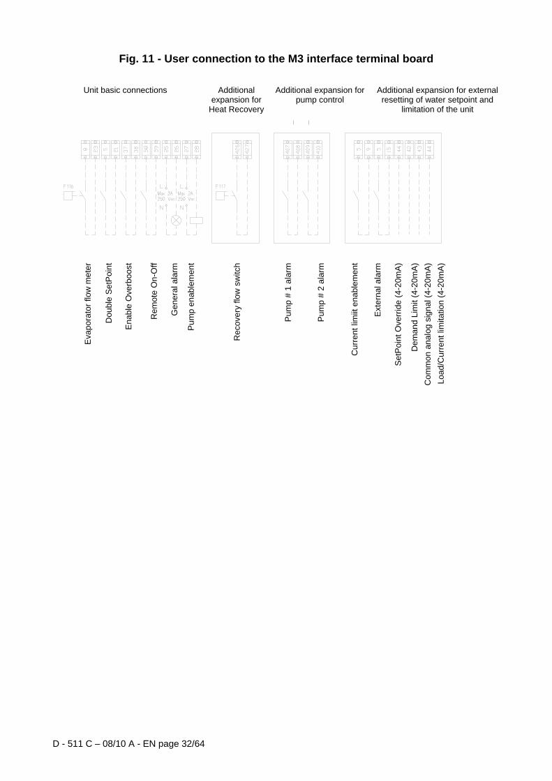
If the system uses pumps which are external to the machine (not supplied with the unit), fit a magneto-thermal switch and a command contactor on the power supply line of each pump. Water pump control Connect the power supply of the command contactor coil to terminals 27 and 28 (pump #1) on the terminal board M3, to an electricity supply with the same voltage as the pump switch coil. The terminals, in fact, are linked to a free contact on the microprocessor. The microprocessor contact has the following commutation capacity: Maximum voltage: 250 Vac Maximum current: 2 A Resistive - 2 A Inductive Reference standard: EN 60730-1 The above-described connection allows the water pump to be automatically controlled by the microprocessor. It is good practice to install a potentially free contact on the magneto-thermal switch of the pump and to connect it in series to the flow switch contact. Alarm relay – Electrical wiring The unit is provided with a free digital socket, which changes state every time there is an alarm in one of the cooling circuits. Connect this signal, terminals 25 and 26 of terminal board M3, to an external visual or acoustic alarm or to the BMS in order to monitor functioning; consult the electrical diagram of the machine for the wiring. On/ Off remote control unit – Electrical wiring The machine has a digital socket which allows for remote control of the machine: terminals 58 and 59 of terminal board M3. This socket can be connected to a start-up timer device, a switch or a BMS. When switched on, the microprocessor starts the start-up sequence, switching on first the water pump and then the compressors. When switched off, the microprocessor starts the sequence for switching off the machine. The contact must be free. Overboost unit – Electrical connection The machine has a digital socket which allows for machine overboost, i.e. compressor functioning at a higher than nominal frequency (75Hz) when permitted by the function's thermodynamic conditions, even if the environmental temperature is below 35°C (the overboost is automatic for temperatures higher than 35°C). Connect a switch between terminals 37 and 38 of terminal board M3, to activate the overboost function. The contact must be free. Double Setpoint – Electrical wiring The Double Setpoint, by means of an intermediate switch, allows for changing the machine setpoint from one to another of two values previously set on the unit control panel. For example, the machine can be set to produce ice during the night and for standard functioning during the day. Connect a timer switch between terminals 5 and 21 of terminal board M3. The contact must be free. External resetting of the water Setpoint – Electrical wiring (Optional) The local setpoint of the machine can be varied by means of an external 4-20ma analogue signal. The microprocessor, once enabled, allows for varying the setpoint of the local value set, up to a maximum difference of 3°C; 4ma corresponds to a resetting of 0°C, 20ma corresponds to the maximum difference. The signal wire must be connected directly to terminals 44 and 43 of terminal board M3. The signal wire must be of the shielded type and must not pass near the power supply wires in order to avoid disturbing the electronic controller. Unit limitation – Electrical wiring (Optional) The machine microprocessor allows for limiting potential by means of two different criteria:
- Load limitation: the load can be varied by an external signal of 4-20ma issued by a BMS. The signal wire must be connected directly to terminals 42 and 43 of terminal board M3. The signal wire must be of the shielded type and must not pass near the power supply wires in order to avoid disturbing the electronic controller.
- Current limitation: the load of the machine can be varied by means of a 4-20ma signal issued by an external device. In this case, current control limits must be set on the microprocessor so that the microprocessor issues the value of the current measured and limits the same. The signal wire must be connected directly to terminals 44 and 43 of terminal board M3. The signal wire must be of the shielded type and must not pass near the power supply wires in order to avoid disturbing the electronic controller. A digital socket allows for enabling correct limitation at any moment. Connect the enabling switch or the clock (free contact) to terminals 5 and 9.
Attention: the two options cannot be enabled simultaneously. The setting of one function excludes the other.
D - 511 C – 08/10 A - EN page 32/64
Fig. 11 - User connection to the M3 interface terminal board
Unit basic connections Additional expansion for
Heat Recovery
Additional expansion for pump control
Additional expansion for external resetting of water setpoint and
limitation of the unit
Eva
pora
tor f
low
met
er
Dou
ble
Set
Poi
nt
Ena
ble
Ove
rboo
st
Rem
ote
On-
Off
Gen
eral
ala
rm
Pum
p en
able
men
t
Rec
over
y flo
w s
witc
h
Pum
p #
1 al
arm
Pum
p #
2 al
arm
Cur
rent
lim
iit e
nabl
emen
t
Ext
erna
l ala
rm
Set
Poi
nt O
verri
de (4
-20m
A)
Dem
and
Lim
it (4
-20m
A)
Com
mon
ana
log
sign
al (4
-20m
A)Lo
ad/C
urre
nt li
mita
tion
(4-2
0mA
)

D - 511 C – 08/10 A - EN page 33/64
The VFD and related problems The units described in this manual use a VFD (Variable Frequency Driver) to vary the compressor rotation speed and consequently the refrigerant charge generated, maintaining the efficiency of the compressor itself at extremely high levels compared to other methods of capacity unloading. Fig. 12 illustrates the power absorbed by a typical single-screw compressor, depending on the load developed by the compressor, in the classic solution of unloading using slides and with speed variation
Fig. 12 - Power absorbed by the compressor depending on the load
25
40
55
70
85
100
115
130
25 40 55 70 85 100 115 130
Compressor charge (%)
Partialisation slide Speed variation
Pow
er A
bsor
bed
(%)

D - 511 C – 08/10 A - EN page 34/64
Notice how the nominal power is always lower (by up to 30%) in the case of speed variation compared to the use of unloading slides. furthermore, in the case of speed variation, the compressor can rotate at higher than nominal speeds and thus develop a load of more than 100%, which is obviously impossible with fixed speed rotation, thus recovering any loss in yield due to unfavourable environmental conditions (such as high environmental temperature). The operating principle of the VFD The VFD (also known as an “inverter”) is an electronic power device designed to vary the speed of rotation of induction motors. The motors revolve at a practically fixed rpm speed which depends only on the frequency of the power supply (f) and on the torque rotation number (p), as per the following formula:
pfrpm 60⋅
=
(In fact, for the motor to produce torque, the rotation speed, known as the speed of synchronism, must be slightly less than that calculated above.) To vary the speed of rotation of an induction motor, the supply frequency of the same therefore needs to vary. The VFD does this, starting with a fixed grid frequency (50 Hz for European power grid, 60 Hz for the US) operating in three steps:
- step one involves a rectifier to transform the alternating current into direct current, which is typically achieved using a diode rectifier bridge (leading solutions use bridges with SCR)
- step two involves charging the condensers (direct current bus, also known as a DC-Link) - step three involves the reconstruction of the alternating current (a genuine inverter) by means of a transistor
bridge (normally IGBT) with variable voltage and frequency values, set by the control system. The voltage is in fact the result of a high-frequency PWM modulation (in the range of a few kHz) from which the fundamental variable frequency component is taken (typically 0-100 Hz).
Fig. 13 - Typical diagram of a VFD
The problem with harmonics The rectifier bridge of a VFD requires current from the grid that is not purely sinusoidal. Indeed, due to the presence of diodes, which are non-linear components, the current absorbed by a rectifier bridge has a higher frequency than the frequency of the power grid. Such components are known as harmonics: in the case of a power supply at 50 Hz, the component at 50 Hz is defined as the fundamental harmonic, while the second harmonic is the component at 100 Hz, the third harmonic is the component at 150 Hz, and so on. (In the case of a power supply at 60 Hz, the fundamental component is that at 60 Hz, the second that at 120 Hz, the third is that at 180 Hz, and so on.)

D - 511 C – 08/10 A - EN page 35/64
Fig. 14 - Harmonics on the grid
Since the rectifier bridge sees before it a direct current stage, the current taken is practically in phase with the voltage. However, the formula below no longer applies
ϕcos3 ⋅⋅⋅= IVPact NO because the harmonic components in excess of the fundamental harmonic do not contribute to the active power. Several values therefore need to be defined: Displacement Power Factor
ϕcos=DPF Power Factor (total power)
DPFIIPF ⋅= 1
The Power Factor takes into account both phase displacement as well as harmonic content, expressed as a ratio of the fundamental component I1 to the current and the overall effective value. It actually expresses which part of the input current is converted into active power. It is worth mentioning that in the absence of an inverter or electronic devices in general, the DPF and PF are the same. Moreover, many electricity boards only take into account the DPF, since the harmonic content is not measured, but only the absorption of active and reactive power. Another measuring index for the harmonics in the grid is provided by the harmonic distortion coefficient THDi (Total Harmonic Distortion):
21
21
2
III
THDi−
=
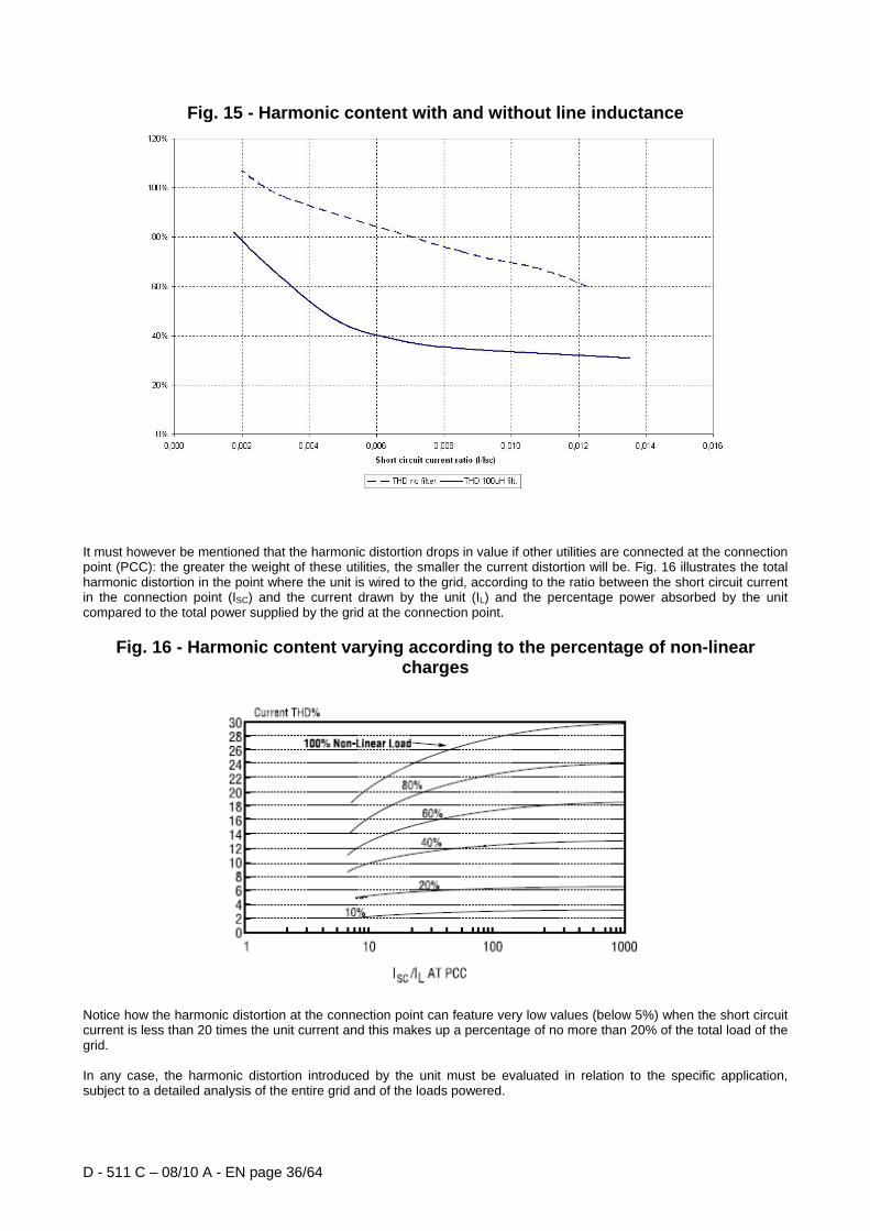
In a VFD without remedial devices, harmonic distortion can reach values of more than 100% (i.e. the harmonic components can, all together, reach more than the fundamental component). To reduce the harmonic content of the current (and so the THD), the units illustrated in this manual are equipped with line inductance. Since the harmonic content depends on the ratio of the current required by the VFD to the short-circuit current in the wiring point, for a given plant, the THD varies according to the machine absorption. For example, fig. 14 illustrates the value of the THD with or without a filter inductance, for different values of the ratio of VFD current to the short-circuit current in the wiring point.
D - 511 C – 08/10 A - EN page 36/64
Fig. 15 - Harmonic content with and without line inductance
It must however be mentioned that the harmonic distortion drops in value if other utilities are connected at the connection point (PCC): the greater the weight of these utilities, the smaller the current distortion will be. Fig. 16 illustrates the total harmonic distortion in the point where the unit is wired to the grid, according to the ratio between the short circuit current in the connection point (ISC) and the current drawn by the unit (IL) and the percentage power absorbed by the unit compared to the total power supplied by the grid at the connection point.
Fig. 16 - Harmonic content varying according to the percentage of non-linear charges
Notice how the harmonic distortion at the connection point can feature very low values (below 5%) when the short circuit current is less than 20 times the unit current and this makes up a percentage of no more than 20% of the total load of the grid. In any case, the harmonic distortion introduced by the unit must be evaluated in relation to the specific application, subject to a detailed analysis of the entire grid and of the loads powered.
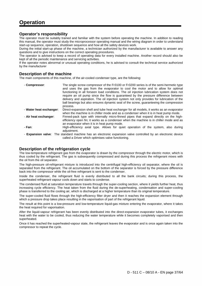
D - 511 C – 08/10 A - EN page 37/64
Operation Operator’s responsibility The operator must be suitably trained and familiar with the system before operating the machine. In addition to reading this manual, the operator must study the microprocessor operating manual and the wiring diagram in order to understand start-up sequence, operation, shutdown sequence and how all the safety devices work. During the initial start-up phase of the machine, a technician authorized by the manufacturer is available to answer any questions and to give instructions on the correct operating procedures. The operator is advised to keep a record of operating data for every installed machine. Another record should also be kept of all the periodic maintenance and servicing activities. If the operator notes abnormal or unusual operating conditions, he is advised to consult the technical service authorized by the manufacturer Description of the machine The main components of this machine, of the air-cooled condenser type, are the following:
- Compressor: The single screw compressor of the Fr3100 or Fr3200 series is of the semi-hermetic type and uses the gas from the evaporator to cool the motor and to allow for optimal functioning in all forseen load conditions. The oil injection lubrication system does not require an oil pump since the flow is guaranteed by the pressure difference between delivery and aspiration. The oil injection system not only provides for lubrication of the ball bearings but also ensures dynamic seal of the screw, guaranteeing the compression process.
- Water heat exchanger: Direct-expansion shell and tube heat exchanger for all models, it works as an evaporator when the machine is in chiller mode and as a condenser when it is in heat pump mode.
- Air heat exchanger: Finned-pack type with internally micro-finned pipes that expand directly on the high-efficiency open fin; it works as a condenser when the machine is in chiller mode and as an evaporator when it is in heat pump mode.
- Fan: High-efficiency axial type. Allows for quiet operation of the system, also during adjustment.
- Expansion valve: The standard machine has an electronic expansion valve controlled by an electronic device called a Driver which optimises valve functioning.
Description of the refrigeration cycle The low-temperature refrigerant gas from the evaporator is drawn by the compressor through the electric motor, which is thus cooled by the refrigerant. The gas is subsequently compressed and during this process the refrigerant mixes with the oil from the oil separator. The high-pressure oil-refrigerant mixture is introduced into the centrifugal high-efficiency oil separator, where the oil is separated from the refrigerant. The oil accumulated on the bottom of the separator is forced by the pressure difference back into the compressor while the oil-free refrigerant is sent to the condenser. Inside the condenser, the refrigerant fluid is evenly distributed to all the bank circuits; during this process, the superheated refrigerant vapour cools down and starts to condense. The condensed fluid at saturation temperature travels through the super-cooling section, where it yields further heat, thus increasing cycle efficiency. The heat taken from the fluid during the de-superheating, condensation and super-cooling phase is transferred to the cooling air, which is discharged at a higher temperature than its original temperature. The super-cooled fluid flows through the high-efficiency filter dryer and then it reaches the expansion element through which a pressure drop takes place resulting in the vaporisation of part of the refrigerant liquid. The result at this point is a low-pressure and low-temperature liquid-gas mixture entering the evaporator, where it takes the heat required for vaporisation. After the liquid-vapour refrigerant has been evenly distributed into the direct-expansion evaporator tubes, it exchanges heat with the water to be cooled, thus reducing the water temperature while it becomes completely vaporised and then superheated. Once it has reached the superheated-vapour state, the refrigerant leaves the evaporator and is once again taken into the compressor to repeat the cycle.

D - 511 C – 08/10 A - EN page 38/64
Fig. 17 - Refrigeration circuit of unit EWAD~AJYNN/S,/X
1. Single screw compressor 13. Direct expansion evaporator 2. Non-return valve 14. Low pressure safety valve 3. Compressor delivery valve 15. Compressor aspiration valve 4. High pressure safety valve 16. Charge coupling with valve 5. Condensing battery ST1-2 Aspiration temperature sensor 6. Integrated super-cooling section WL1-2. Oil pressure transducer 7. Axial fan WO1-2. Oil pressure transducer 8. Cut-off tap of liquid circuit WH1-2. High pressure transducer 9. Drying filter WD1-2. Discharge /oil temperature sensor 10. Liquid and humidity indicator F13. High-pressure switch 11. Electronic expansion valve WIE. Temperature sensor of water entering the unit 12. Solenoid valve to inject liquid WOE. Discharged water temperature sensor (*) Water entry and exit points are indicative. Refer to the machine drawing giving dimensions for exact
hydraulic connection of the partial heat recovery exchangers.
11 11 10
9
8
6
5
7
13
12 12
9
10
8
5
6
7
4 4 3 3
2 2
1 1
15 14 14
15
16 16
16 16
16

D - 511 C – 08/10 A - EN page 39/64
Description of the refrigeration cycle with partial heat recovery The low-temperature refrigerant gas from the evaporator is drawn by the compressor through the electric motor, which is thus cooled by the refrigerant. The gas is subsequently compressed and during this process the refrigerant mixes with the oil from the oil separator. The high-pressure oil-refrigerant mixture is introduced into the centrifugal high-efficiency oil separator, where the oil is separated from the refrigerant. The oil accumulated on the bottom of the separator is forced by the pressure difference back into the compressor while the oil-free refrigerant is sent to the partial recovery heat exchanger where it cools down by reducing its superheat temperature while warming the water which travels through the heat exchanger. After leaving the exchanger the refrigerant fluid enters the condenser bank where it is condensed by forced ventilation. The condensed fluid at saturation temperature travels through the super-cooling section, where it yields further heat, thus increasing cycle efficiency. The super-cooled fluid flows through the high-efficiency filter dryer and then it reaches the expansion element through which a pressure drop takes place resulting in the vaporisation of part of the refrigerant liquid. The result at this point is a low-pressure and low-temperature liquid-gas mixture entering the evaporator, where it takes the heat required for vaporisation. After the liquid-vapour refrigerant has been evenly distributed into the direct-expansion evaporator tubes, it exchanges heat with the water to be cooled, thus reducing the water temperature while it becomes completely vaporised and then superheated. Once it has reached the superheated-vapour state, the refrigerant leaves the evaporator and is once again taken into the compressor to repeat the cycle.
Control of the partial recovery circuit and installation recommendations The partial heat recovery system is not managed and/or controlled by the machine. The installer should follow the suggestions below for best system performance and reliability:
1) Install a mechanical filter on the inlet pipe of the heat exchangers 2) Install shut-off valves to isolate the heat exchanger from the water system during periods of inactivity or
system maintenance. 3) Install a drain valve to allow the heat exchanger to be emptied if the air temperature is expected to fall
below 0°C during periods of inactivity of the machine. 4) Install flexible anti-vibration joints on the heat recovery water inlet and outlet piping, so that
transmission of vibrations, and therefore of noise, to the water system is kept as low as possible. 5) Do not load exchanger joints with the weight of the heat recovery piping. The water joints of the
exchangers are not designed to support the weight of the piping. 6) Should heat recovery water temperature be lower than ambient temperature, it is advisable to switch
off the heat recovery water pump 3 minutes after having switched off the last compressor.
ATTENTION Partial heat recovery, which exploits the cooling of the gas entering the unit has been designed as an additional source of external heat; in fact, the availability of recovered heat is guaranteed only with a cooling circuit which functions when cooled water is requested. In particular, it cannot function correctly if the water entering the exchanger is cooler than 40°C for periods exceeding the normal time needed for the system to reach normal running conditions (about 15 minutes): functioning for prolonged periods under such conditions can cause malfunctions in the cooling circuit and will trigger off the protective devices. The installer must also ensure that the temperature of the water in the recovery circuit reaches the minimum value allowed as soon as possible. For the same reasons, there must be no water flowing through the exchanger when the cooling circuit is switched off.

D - 511 C – 08/10 A - EN page 40/64
Fig. 18 - Refrigeration circuit of unit EWAD~AJYNN/S, /X with partial heat recovery
1. Single screw compressor 14. Low pressure safety valve 2. Non-return valve 15. Compressor aspiration valve 3. Compressor delivery valve 16. Charge coupling with valve 4. High pressure safety valve 17. Partial heat recovery exchanger (*) 5. Condensing battery ST1-2 Aspiration temperature sensor 6. Integrated super-cooling section WL1-2. Oil pressure transducer 7. Axial fan WO1-2. Oil pressure transducer 8. Cut-off tap of liquid circuit WH1-2. High pressure transducer 9. Drying filter WD1-2. Discharge /oil temperature sensor 10. Liquid and humidity indicator F13. High-pressure switch 11. Electronic expansion valve WIE. Temperature sensor of water entering the unit 12. Solenoid valve to inject liquid WOE. Discharged water temperature sensor 13. Direct expansion evaporator (*) Water entry and exit points are indicative. Refer to the machine drawing giving dimensions for exact
hydraulic connection of the partial heat recovery exchangers.
11 11 10
9
8
6
5
7
13
12 12
9
10
8
5
6
7
4 4 3 3
2 2
1 1
15 14 14
15
16 16
16 16
16
17 17

D - 511 C – 08/10 A - EN page 41/64
Description of refrigeration cycle operating with total heat recovery The low-temperature refrigerant gas from the evaporator is drawn by the compressor through the electric motor, which is thus cooled by the refrigerant. The gas is subsequently compressed and during this process the refrigerant mixes with the oil from the oil separator. The high-pressure oil-refrigerant mixture is introduced into the centrifugal high-efficiency oil separator, where the oil is separated from the refrigerant. The oil accumulated on the bottom of the separator is forced by the pressure difference back into the compressor while the oil-free refrigerant is sent to the three-way valve. If the heat recovery switch Q7 is positioned on Heating and the temperature of heat recovery water is below its setpoint value, the three-way valve will direct the flow towards the heat recovery exchanger where the gas will be forced through. The superheated refrigerant fluid is distributed into the shell and tubes heat recovery condenser and during this process it undergoes cooling and condensation. The condensed fluid at saturation temperature travels through the super-cooling section, where it yields further heat, thus increasing cycle efficiency. Heat drawn from the fluid during the de-superheating, condensation and super-cooling process is transferred to the heat recovery water, which is thus heated. The super-cooled fluid flows through the high-efficiency filter dryer and the liquid receiver, and then it reaches the expansion element through which a pressure drop takes place resulting in the vaporisation of part of the refrigerant liquid. The result at this point is a low-pressure and low-temperature liquid-gas mixture entering the evaporator, where it takes the heat required for vaporisation. After the liquid-vapour refrigerant has been evenly distributed into the direct-expansion evaporator tubes, it exchanges heat with the water to be cooled, thus reducing the water temperature while it becomes completely vaporised and then superheated. Once it has reached the superheated-vapour state, the refrigerant leaves the evaporator and is once again taken into the compressor to repeat the cycle. During the heating cycle, the condenser bank is emptied through a capillary pipe connected to the suction line, thus re-establishing the proper refrigerant charge and filling the liquid receiver. Once the water from the heat recovery condensers has reached the setpoint temperature in accordance with a PID function, the circuit three-way valve changes over and the refrigerant discharged by the compressor is then sent to the condenser bank for normal cooling operation of evaporator water. At the same time, the fans of the corresponding condenser section start. Control of the total heat recovery circuit Units designed for total heat recovery differ from the basic version in that they include the following additional components for each circuit:
Gas/Water shell and tube heat exchanger complete with safety valve and 10 mm thermal insulation (20 mm on request).
Three-way valve for Heating/ Cooling cycle switching. Non-return valves. Compensation liquid receiver. Additional electronic expansion card. Sensors for temperature control of heat recovery water. Q7 switch for activation of the heat recovery circuit.

D - 511 C – 08/10 A - EN page 42/64
Fig. 19 - Refrigeration circuit of unit EWAD~AJYNN/S, /X with total heat recovery
1. Single screw compressor 15. Compressor aspiration valve 2. Non-return valve 16. Charge coupling with valve 3. Compressor delivery valve 17. Liquid receiver 4. High pressure safety valve 18. Three way valve of heat recovery cycle exchanger 5. Condensing battery 19. Heat recovery exchanger 6. Integrated super-cooling section WL1-2. Oil pressure transducer 7. Axial fan WO1-2. Oil pressure transducer 8. Cut-off tap of liquid circuit WH1-2. High pressure transducer 9. Drying filter WD1-2. Discharge /oil temperature sensor 10. Liquid and humidity indicator F13. High-pressure switch 11. Electronic expansion valve WIE. Temperature sensor of water entering the unit 12. Solenoid valve to inject liquid WOE. Discharged water temperature sensor 13. Direct expansion evaporator W10 Temperature sensor of water entering heat recovery
device (*) 14. Low pressure safety valve W11 Temperature sensor of water leaving heat recovery
device (*) (*) Sensors W10 and W11 must be positioned on the same pipes connecting the recovery devices. Positioned by the customer.
11 11
10
18
8
6
5
7
13 12 12
18
10
8
5
6
7
4 4
3 3
2 2
1 1
15 14 14
15
16 16
16 16
16
4 4 4 4
9 9 17 17
2 2 2
2
2 2
19 19
8 8
2 2

D - 511 C – 08/10 A - EN page 43/64
Compressor The single screw compressor is of the semi-hermetic type with asynchronic three-phase two-pole motor fitted directly on the main shaft. The gas sucked in from the evaporator cools the electric motor before entering the suction vents. The electric motor contains two temperature sensors immerged in the coils, which constantly monitor motor temperature. If the temperature of the coils reaches high values (120°C), a special external appliance linked to the sensors and to the electronic controller deactivates the corresponding compressor. There are only two rotating parts and the compressor has no other parts with eccentric and/or alternative movement. The basic components are therefore only the main rotor and the satellites which cause the compression, which fit perfectly against each other. The compressor of the Fr3100 series has a single satellite positioned vertically in the upper part of the screw. Compression seal is guaranteed by a special, suitably shaped, composite material positioned between the satellites. The main shaft on which the main rotor is fitted is supported by 2 ball bearings. The system thus composed is balanced both statistically and dynamically before assembly.
Fig. 20 - Image of the compressor Fr3100
A large access cover on the upper part of the compressor allows for fast and easy compressor maintenance. The compression process With the single screw compressor, the process of suction, compression and discharge takes place continuously thanks to the upper satellite. In this process, the gas sucked in penetrates the profile between the rotor, the teeth of the upper satellite and the compressor body. The volume is gradually reduced, compressing the refrigerant. The gas compressed at high pressure is thus discharged into the integrated oil separator. In the separator the gas/oil mixture separates and the oil collects in a cavity in the lower part of the compressor, to then be injected into the compression mechanisms to guarantee the seal under pressure and lubrication of the bearings.

D - 511 C – 08/10 A - EN page 44/64
1.
1. e 2. Aspiration
The spiral grooves ‘a’, ‘b’ and ‘c’ of the main rotor make contact at one end with the suction cavity which is closed by the tooth of the upper satellite. As the main rotor turns, the effective length of the spiral groove increases, increasing the volume in contact with the suction chamber. Figure 1 clearly shows the process. As groove ‘a’ takes the position of grooves ‘b’ and ‘c’, the volume increases inducing the suction vapour to enter the groove.
As the main rotor continues to turn the groove which was open to the suction is occupied by the satellite tooth. This operation coincides with each groove which is gradually closed by the main rotor.
Once the gas is enclosed in the groove and the separate suction chamber, the aspiration process is completed.
2.
3. Compression
As the main rotor turns, the volume of gas entrapped in the spiral groove of the screw is reduced as the length decreases, and the compression phase begins.
3.
4. Discharge
When the satellite tooth approaches the end of the spiral groove, the vapour entrapped reaches the maximum pressure near the triangular opening of the discharge hatch. The compression phase ends immediately and the gas is sent to the discharge collector. The satellite tooth continues to push the vapour until the volume in the spiral groove reaches the minimum value, the compression process is repeated for every spiral groove of the screw at every rotation.
4.
The oil separator is not shown
Fig. 21 - Compression process
c
b a
c
a b
c
b a
a b
Discharge of gas
a
b
Gas
asp
iratio
n
b a
c

D - 511 C – 08/10 A - EN page 45/64
Control of refrigeration capacity Compressor capacity is controlled by varying the rotation speed, by means of the VFD within a range of 1200 and 4500 rpm; compressor capacity thus varies approximately between 27% and 100% of nominal capacity. If needed and if allowed by compressor functioning conditions, compressor rotation speed can be pushed up to 5400 rmp, reaching 120% nominal capacity (“overboost” condition). Overboost limit depends on maximum power issued by the VFD and by respect of reliable functioning conditions of the compressor; it can therefore vary according to environmental temperature and the temperature of the chilled water. The unloading slides, typical of screw compressors, are only used when starting and stopping the compressor, thus guaranteeing minimum torque resistance and therefore minimum restart current.

D - 511 C – 08/10 A - EN page 46/64
Pre-start-up checks General Once the machine has been installed, use the following procedure to check correct execution:
ATTENTION Switch off the power supply of the machine before performing any checks. Since the condensers are inside the VFD, at the exit, there is voltage for a few minutes even after the electricity supply has been switched off. Wait until the VFD LEDs go out before working on the unit. In case of doubt, consult the VFD manual instructions. Failure to respect these rules (cutting off power and failing to wait) can cause the operator serious harm or even death.
Inspect all the electrical connections to the power circuits and to the compressors including the contactors, fuse carriers and electrical terminals and check that they are clean and well secured. Even though these checks are carried out at the factory on every machine that is shipped, vibrations during transportation may loosen some electrical connections.
ATTENTION Check that the electrical terminals of cables are well tightened. A loose cable can overheat and give rise to problems with the compressors.
Open delivery, liquid, liquid injection and suction (if installed) valves.
ATTENTION Do not start up the compressors if the delivery, liquid, liquid injection or suction valves are closed. Failure to open these valves may cause serious damage to the compressor.
Put all the thermal-magnetic switches of the fans (from F16 through F20 and from F26 through F30) in the On position.
IMPORTANT If the magneto-thermal switches are inadvertently left on, when switched on again both compressors will block at high pressure. The high pressure alarm can be reset by opening the compressor chamber and resetting the mechanical high-pressure pressure switch.
Check the power supply voltage at the general door-block disconnector switch terminals. The power supply voltage must be the same as that on the nameplate. Maximum allowed tolerance ± 10%. Voltage imbalance between the three phases must not exceed ± 3%. The unit comes with a factory-supplied phase monitor that prevents compressors from starting in the event of wrong phase sequence. Properly connect the electrical terminals to the disconnector switch so as to ensure alarm-free operation. If the phase monitor triggers an alarm once the machine has been powered, just invert two phases at the general disconnector switch supply (unit power supply). Never invert the electrical wiring on the monitor.
ATTENTION Starting up with the wrong sequence of phases can irreparably compromise the functioning of certain components. Ensure that phases L1, L2 and L3 correspond in sequence to R, S and T.
Fill the water circuit and remove air from the system’s highest point and open the air valve above the evaporator shell. Remember to close it again after filling. The design pressure on the water side of the evaporator is 10.0 bars. Never exceed this pressure at any time during the life of the machine.

D - 511 C – 08/10 A - EN page 47/64
IMPORTANT Before putting the machine into operation, clean the water circuit. Dirt, scaling, corrosion residue and other foreign material can accumulate in the heat exchanger and reduce heat transfer capacity. Pressure drops can also increase, consequently reducing water flow. Therefore, correct water treatment reduces the risk of corrosion, erosion, furring, etc. The most suitable water treatment depends on the type of plant and the characteristics of the local water used. The manufacturer is not responsible for damage or bad operation of the apparatus resulting from failure to treat water or from incorrectly treated water.
Units with an external water pump Start the water pump and check the water system for any leaks; repair these if necessary. While the water pump is in operation, adjust the water flow until the design pressure drop for the evaporator is reached. Adjust the flow switch trigger point (not factory-supplied), to ensure operation of the machine within a ± 20% flow range. Units with a built-in water pump This procedure foresees factory installation of the optional single -or twin- water pump kit. Check that switches Q0, Q1 and Q2 are in the open position (Off or 0). Also check that the magneto-thermal switch Q12 in the electrical panel control area is in the Off position. Close the general Q10 door-block switch on the main board and move the Q12 switch to the On position.
ATTENTION From this moment onwards, the machine will be under electrical power. Use extreme caution during subsequent operations. A lack of attention during subsequent operations may cause serious personal injury
Single pump To start the water pump, press the microprocessor On/Off button and wait for the unit On message to
appear on the display. Turn the Q0 switch to the On (or 1) position to start the water pump. Adjust the water flow until the evaporator design pressure drop is reached. Adjust the flow switch (not included) at this point, to ensure that the machine operates within a ± 20% flow range.
Twin pumps The system foresees the use of a twin pump with two motors, one as a backup. The microprocessor
enables one of the two pumps when the necessary number of hours and start-ups so require. To start one of the water pumps, press the microprocessor On/Off button and wait for the Unit On message to appear on the display. Turn the Q0 switch to the On (or 1) position to start the water pump. Adjust the water flow until the evaporator design pressure drop is reached. Adjust the flow switch (not included) at this point, to ensure that the machine operates within a ± 20% flow range. To start up the second pump, keep on for at least 5 minutes, then turn off the Q0 switch and wait until the first pump stops. Turn on the Q0 switch again to start up the second pump. By means of the microprocessor keyboard, which pump is given priority for start-up can be established. See the microprocessor manual for the relative procedure.
Electrical power supply The machine’s power supply voltage must be the same as that specified on the nameplate ± 10% while the voltage imbalance between phases must not be in excess of ± 3%. Measure the voltage between phases and if the value does not fall within the established limits, correct it before starting the machine.
ATTENTION Provide suitable power supply voltage. Unsuitable power supply voltage could cause malfunction of the control components and undesired triggering of the thermal protection devices, along with a considerable reduction in the life of the contactors and electric motors.
Imbalance in power supply voltage In a three-phase system, excessive imbalance between the phases causes overheating of the motor. The maximum allowed voltage imbalance is 3%, calculated as follows:

D - 511 C – 08/10 A - EN page 48/64
Imbalance %: %_____100max=
− xVaverage
VaverageV
Example: the three phases measure respectively 383, 386 and 392 Volts, the average is: 383+386+392 = 387 Volts 3 thus the imbalance percentage is
%29.1100387
387392=
− x below the maximum allowed (3%)
Power supply for electrical resistances Each compressor has an electrical resistance located in the lower part of the compressor. This is to warm the lubricating oil and thus avoid the mixing of refrigerant fluid within. It is therefore necessary to ensure that the resistances are powered at least 24 hours before the planned start-up time. To ensure that they are activated, it is sufficient to keep the machine on by closing the general disconnecting switch Q10. The microprocessor, however, has a series of sensors that prevent the compressor from being started up when the oil temperature is not at least 5°C above the saturation temperature corresponding to the current pressure. Keep the Q0, Q1, Q2 and Q12 switches in the Off (or 0) position until the machine is to be started up.

D - 511 C – 08/10 A - EN page 49/64
Start-up procedure Turning on the machine 1. With the general switch Q10 closed, check that switches Q0, Q1, Q2 and Q12 are in the Off (or 0) position. 2. Close the magneto-thermal switch Q12 and wait for the microprocessor and the control to start. Check that the oil
temperature is warm enough. The oil temperature must be at least 5 °C above the saturation temperature of the refrigerant in the compressor. If the oil is not warm enough, it will not be possible to start the compressors and the phrase “Oil Heating” will appear on the microprocessor display.
3. If the machine does not have its own inbuilt pump, start up the external water pump. 4. Put the Q0 switch in the On position and wait for “Unit-On/ Compressor Stand-By” to appear on the display.
If the water pump has been supplied with the machine, the microprocessor should start it up. 5. Check that the evaporator pressure drop is the same as the design pressure drop and correct it if necessary. The
pressure drop must be measured at the factory-supplied charge connections placed on the evaporator piping. Do not measure the pressure drop at points where any valves and/or filters are interposed.
6. Only at the first start-up, put the Q0 switch in the Off position to check that the water pump stays on for three minutes before it stops (the on-board pump and the external pump as the case may be).
7. Put the Q0 switch in the On position once again. 8. Check that the local temperature setpoint is set to the required value by pressing the Set button. 9. Turn the Q1 switch to On (or 1) to start compressor #1. 10. When the compressor is working, wait 1 minute until the system has stabilised itself. In this period, the operator will
perform a series of operations, to empty the evaporator (pre-purge) to guarantee safe start up. 11. At the end of the Pre-Purge, the microprocessor will start loading the compressor, now running, in order to reduce
the outlet water temperature. Check the proper functioning of the capacity control by measuring the compressor’s electrical current consumption.
12. Check refrigerant evaporation and condensation pressure. 13. Check that the cooling fans start up when the condensation pressure rises. 14. Once the system has stabilized, check that the liquid sight glass located on the pipe to the expansion valve is
completely full (no bubbles) and that the humidity indicator shows “Dry”. Any bubbles inside the liquid sight glass might indicate a low refrigerant level or an excessive pressure drop through the filter dryer or an expansion valve that is blocked at the full open position.
15. In addition to checking the liquid sight glass, check the circuit operating parameters by verifying: a) Superheating of refrigerant at compressor suction b) Superheating of refrigerant at compressor discharge c) Super-cooling of liquid coming out of the condenser banks d) Evaporation pressure e) Condensation pressure Except for liquid temperature and suction temperature for machines with a thermostatic valve, which require the use of an external thermometer, all other measurements can be carried out by reading the relevant values directly on the on-board microprocessor display.
16. Turn the Q2 switch to On (or 1) to start compressor #2. 17. Repeat steps 10 through 15 for the second circuit. 18. To turn off the machine temporarily (daily or weekend shutdown) turn the Q0 switch to Off (or 0) or open the remote
contact between terminals 58 and 59 on M3 terminal board (Installation of remote switch to be carried out by the customer). The microprocessor will activate the shutdown procedure, which requires several seconds. Three minutes after the compressors have been shut down, the microprocessor will shut down the pump. Do not switch off the main power supply so as not to de-activate the electrical resistances of the compressors and the evaporator.
Table 4 - Typical working conditions with compressors at 100%
Economised cycle? Suction superheating Discharge superheating
Liquid super-cooling
NO 5 - 7 °C 20 -25 °C 5 - 6 °C YES 5 - 7 °C 18 - 23 °C 15 - 20 °C

D - 511 C – 08/10 A - EN page 50/64
IMPORTANT The symptoms of a low refrigerant charge are:
• low evaporation pressure • high suction and discharge superheating (outside the aforesaid limits) • Low super-cooling value
In this case, add R134a refrigerant to the relevant circuit. The system has been provided with a charge connection between the expansion valve and the evaporator. Charge refrigerant until working conditions return to normal. Remember to reposition the valve cover when finished.
IMPORTANT If the machine is not supplied with a built-in pump, do not shut down the external pump until 3 minutes have elapsed after the last compressor has shut down. Early shutdown of the pump triggers a water-flow failure alarm.
Seasonal shutdown 1. Turn switches Q1 and Q2 to the Off (or 0) position to shut down the compressors, using the normal pump-down
procedure. 2. After the compressors have been shut down, turn switch Q0 to Off (or 0) and wait for the built-in water pump to shut
down. If the water pump is managed externally, wait for 3 minutes after the compressors have shut down before turning off the pump.
3. Open the Q12 (Off position) magneto-thermal switch inside the control section of the electrical board then open the general disconnector switch Q10 to cut off the machine’s power supply entirely.
4. Close the compressor intake valves (if any) and delivery valves and also the valves located on the liquid and liquid injection line.
5. Place a warning sign on every switch that has been opened, advising opening all the valves before starting the compressors.
6. If no water and glycol mixture has been introduced into the system, discharge all the water from the evaporator and from the connected piping if the machine is to remain inactive during the winter season. One must remember that once the machine’s power supply has been cut off, the anti-freeze electrical resistance cannot function. Do not leave the evaporator and piping exposed to the atmosphere during the entire period of inactivity.
Starting up after seasonal shutdown 1. With the general disconnector switch open, make sure that all the electrical connections, cables, terminals and
screws are well tightened to ensure good electrical contact. 2. Verify that the power supply voltage applied to the machine is within ± 10% of the nominal nameplate voltage and
that the voltage imbalance between phases is within ± 3% range. 3. Verify that all control devices are in good condition and functioning and that there is a suitable thermal load for start-
up. 4. Verify that all the connection valves are well tightened and that there are no refrigerant leaks. Always reposition the
valve covers. 5. Verify that switches Q0, Q1, Q2 and Q12 are in the open position (Off). Turn the general disconnector switch Q10
to the On position. Doing this will turn on the electrical resistances of the compressors. Wait at least 12 hours for them to warm up.
6. Open all suction, delivery, liquid and liquid injection valves. Always reposition valve covers. 7. Open the water valves to fill the system and vent the air from the evaporator through the vent valve installed on its
shell. Verify that there are no water leaks from the piping.

D - 511 C – 08/10 A - EN page 51/64
System maintenance
ATTENTION All routine and extraordinary maintenance activities on the machine must be carried out solely by qualified personnel who are familiar with the machine characteristics, operation and maintenance procedures, and who are aware of the safety requirements and risks involved.
ATTENTION The causes of repeated shutdowns deriving from triggering of safety devices must be investigated and corrected. Re-starting the unit after simply resetting the alarm can seriously damage the equipment.
ATTENTION A correct refrigerant and oil charge is essential for optimal operation of the machine and for environmental protection. Any oil and refrigerant recovery must conform to legislation in force.
General
IMPORTANT Besides the checks suggested in the routine maintenance program, in order to grant the highest levels of performance and efficiency and to prevent malfunctioning, it is recommended to schedule periodical inspection and checks of the unit, to be carried out by qualified personnel, as follows: 4 inspections per year (1 every 3 months) for units running about 365 days per year; 2 inspections per year (1 at seasonal start-up and the second one in the middle of the season) for units running about 180 days per year with seasonal operation 1 annual visit per unit for seasonal use of about 90 days/year (on seasonal start-up)
It is important that during initial start-up and periodically during operation, routine verifications and checks are performed. These must also include verification of suction and condensation pressure and visual inspection of the sight glass installed on the liquid line. Verify through the built-in microprocessor that the machine operates within the normal superheating and super-cooling values. A recommended routine maintenance programme is shown at the end of this chapter while a form for collecting operational data can be found at the end of this manual. Weekly recording of all the machine’s operating parameters is recommended. Collecting this data will be very useful to the technicians in the event that technical assistance is called for. Compressor maintenance
IMPORTANT Since the compressor is of the semi-hermetic type, it requires no scheduled maintenance. However, for granting the highest levels of performance and efficiency and for preventing malfunctions, it is recommended that a visual check for wear in the satellite and clearances between main screw and the satellite is carried out every 10,000 running hours. Such an inspection must be carried out by qualified and trained personnel.
The analysis of vibrations is a good method for verifying the mechanical conditions of the compressor. Verification of vibration readings immediately after start-up and periodically on an annual basis is recommended. The compressor load must be similar to the previous measurement’s load to ensure measurement reliability.

D - 511 C – 08/10 A - EN page 52/64
Lubrication The units do not require a routine procedure for lubrication of components. The fan bearings are permanently lubricated, therefore no additional lubrication is needed. Compressor oil is of the synthetic type and is highly hygroscopic. It is therefore advised to limit its exposure to the atmosphere during storage and filling. It is recommended that the oil be exposed to the atmosphere for no more than 10 minutes. The compressor oil filter is located under the oil separator (delivery side). Its replacement is advised when its pressure drop exceeds 2.0 bars. The pressure drop across the oil filter is the difference between the compressor discharge pressure and the oil pressure. Both these pressures can be monitored through the microprocessor for both compressors.
Fig. 22 - Installation of control devices for Fr3100 compressor
Oil filter High
pressure transducer
Oil transducer (hidden side)
High pressure switch
Solenoid discharge valve “A”
Solenoid discharge valve “B”
Oil temperature sensor/ Delivery

D - 511 C – 08/10 A - EN page 53/64
Routine maintenance
Table 5 - Routine maintenance programme
List of Activities
Weekly
Monthly (Note 1)
Yearly
(Note 2) General: Reading of operating data (Note 3) X Visual inspection of machine for any damage and/or loosening X Verification of thermal insulation integrity X Clean and paint where necessary X Analysis of water (Note 6) X Electrical: Check correction functioning of on-board instrumentation X Verify contact wear – Replace if necessary X Verify that all electrical terminals are tight – Tighten if necessary X Clean inside the electrical control board X Visual inspection of components for any signs of overheating X Verify operation of compressor and electrical resistance X Measure compressor motor insulation using the Megger X Cooling circuit: Check for any refrigerant leakage X Check on refrigerant flow using the liquid inspection window, which must be full
X
Check on filter dryer pressure drop X Verify oil filter pressure drop (Note 5) X Analyse compressor vibrations X Analyse compressor oil acidity (Note 7) X Condenser section: Clean condenser batteries (Note 4) X Check that the fans are well anchored X Check on the battery fins – Comb if necessary X Notes: 1) Monthly activities include all the weekly ones. 2) The annual (or early season) activities include all weekly and monthly activities. 3) Machine operating values should be read on a daily basis thus keeping high observation standards. 4) It may be necessary to clean the batteries more frequently if there are many particles in the air. 5) Replace the oil filter when the pressure drop across it reaches 2.0 bars. 6) Check for any dissolved metals. 7) TAN (Total Acid Number) : ≤0.10 : No action
Between 0.10 and 0.19: Replace anti-acid filters and re-check after 1,000 running hours. Continue to replace filters until the TAN is lower than 0.10. >0.19 : Replace oil, oil filter and filter dryer. Check at regular intervals.
Replacement of filter dryer It is strongly advised that the filter dryer cartridges be replaced in the event of a considerable pressure drop across the filter or if bubbles are observed through the liquid sight glass while the super-cooling value is within the accepted limits. Replacement of the cartridges is advised when the pressure drop across the filter reaches 50 kPa with the compressor under full load. The cartridges must also be replaced when the humidity indicator in the liquid sight glass changes colour and shows excessive humidity, or when the periodic oil test reveals the presence of acidity (TAN is too high). Procedure for replacement of the filter dryer cartridge
ATTENTION Ensure proper water flow through the evaporator during the entire servicing period. Interrupting the water flow during this procedure would cause the evaporator to freeze with a consequent breakage of its internal piping.

D - 511 C – 08/10 A - EN page 54/64
1. Shut down the relevant compressor by turning the Q1 or Q2 switch to Off. 2. Wait until the compressor has stopped and close the valve located on the liquid line. 3. Start the relevant compressor by turning the Q1 or Q2 switch to On. 4. Check the relevant evaporation pressure on the microprocessor display. 5. When the evaporation pressure reaches 100 kPa turn the Q1 or Q2 switch again to turn off the
compressor. 6. Once the compressor has stopped, place a label on the compressor start-up switch that it is under
maintenance, to prevent undesired start-ups. 7. Close the compressor suction valve (if any). 8. Using a recovery unit, remove surplus refrigerant from the liquid filter until atmospheric pressure is
reached. The refrigerant must be stored in a suitable and clean container.
ATTENTION To protect the environment, do not release removed refrigerant into the atmosphere. Always use a recovery and storage device.
9. Balance internal pressure with external pressure by pressing the vacuum pump valve installed on the filter
cover. 10. Remove the filter dryer cover. 11. Remove the filter elements. 12. Install the new filter elements in the filter. 13. Replace the cover gasket. Do not allow any mineral oil onto the filter gasket so as not to contaminate the
circuit. Use only compatible oil for this purpose (POE). 14. Close the filter cover. 15. Connect the vacuum pump to the filter and pull vacuum to 230 Pa. 16. Close the vacuum pump valve. 17. Recharge the filter with the refrigerant recovered during emptying. 18. Open the liquid line valve. 19. Open the suction valve (if any). 20. Start the compressor by turning switch Q1 or Q2.
Replacement of the oil filter
ATTENTION The lubrication system has been designed to keep most of the oil charge inside the compressor. During operation, however, a small amount of oil circulates freely in the system, conveyed by the refrigerant. The amount of replacement oil going into the compressor should therefore be equal to the quantity removed rather than the amount stated on the nameplate; this will avoid excess of oil during the following start-up. The quantity of oil removed from the compressor must be measured after having allowed the refrigerant present in the oil to evaporate for a suitable amount of time. To reduce the refrigerant content in the oil to a minimum, it is advised that the electrical resistances be kept on and that the oil be removed only when it has reached a temperature of 35/45°C.
ATTENTION
The replacement of the oil filter requires careful attention with regard to oil recovery; the oil must not be exposed to the air for more than about 30 minutes. In case of doubt, verify oil acidity or, if it is not possible to carry out the measurement, replace the charge of lubricant with fresh oil stored in sealed tanks or in a way that meets supplier specifications.
The compressor oil filter is located under the oil separator (delivery side). Its replacement is advised when its pressure drop exceeds 2.0 bars. The pressure drop across the oil filter is the difference between the compressor discharge pressure and the oil pressure. Both these pressures can be monitored through the microprocessor for both compressors.
Necessary materials:
Oil filter Code 7384-188 – Quantity 1 Gasket kit Code 128810988 – Quantity 1
Compatible oils:
Mobile Eal Arctic 68

D - 511 C – 08/10 A - EN page 55/64
ICI Emkarate RL 68H For complete refilling of oil, 13 litres are required.
Replacement of the oil filter 1) Switch off both compressors turning switches Q1 and Q2 to the Off position. 2) Turn the Q0 switch to Off and wait until the circulation pumps stops, then turn off the main switch Q10 to cut off
electricity to the machine. 3) Place a notice on the main switch handle to prevent it being accidentally switched on. 4) Close the suction, delivery and liquid injection valves. 5) Connect the recovery unit to the compressor and recover the refrigerant inside into an adequate and clean
storage container. 6) Evacuate the refrigerant until the internal pressure has reached a negative pressure (compared to atmospheric
pressure). In this way the quantity of refrigerant released into the air is reduced to a minimum. 7) Remove the oil contained in the compressor by opening the tap under the motor. 8) Remove the oil filter cover and remove the filtering element. 9) Replace the o-rings of the cover and of the inner coupling. Do not lubricate the O-rings with mineral oil in order
to avoid polluting the system. 10) Insert a new filtering element 11) Replace the filter cover and tighten the screws. The screws must be tightened alternately and progressively with
a torque of 60Nm. 12) Fill up through the upper oil input of the oil separator. Because the ester oil is highly hygroscopic, the oil must be
added as quickly as possible. Do not leave the ester oil exposed to the atmosphere for more than 10 minutes. 13) Close the oil cap. 14) Connect the vacuum pump and bring the compressor value down to 230 Pa. 15) When the said vacuum is reached, close the vacuum pump tap. 16) Open the delivery, suction and injection taps of the system liquid. 17) Disconnect the vacuum pump from the compressor. 18) Remove the warning notice previously placed on the main switch. 19) Turn on the main switch Q10 to supply electricity to the machine. 20) Start up the machine according to the previously described start up procedure.
Fig. 22 - Front and rear view of compressor Fr 3100
Position of oil drainage tap.
Position of electrical
resistance for heating oil
Low pressure measurement
point
Oil filter cover
Maximum oil level
Oil transducer
Minimum oil level
Oil temperature
sensor
Liquid injection
Suction side Delivery side
Oil cap for filling

D - 511 C – 08/10 A - EN page 56/64
Refrigerant charge
ATTENTION The units have been designed to operate with R134a refrigerant. DO NOT USE refrigerants other than R134a.
ATTENTION The addition or removal of refrigerant gas must be carried out in compliance with the laws and regulations in force.
ATTENTION When refrigerant gas is added to or removed from the system, ensure correct water flow through the evaporator for the entire adding/removing time. Interrupting the water flow during this procedure would cause the evaporator to freeze with a consequent breakage of its internal piping. Damage caused by freezing makes the warranty void.
ATTENTION
Removal of the refrigerant and replenishing operations must be performed by technicians who are qualified to use the appropriate materials for this unit. Unsuitable maintenance can result in uncontrolled losses in pressure and fluid. Do not disperse the refrigerant and lubricating oil in the environment. Always be equipped with a suitable recovery system.
The units are delivered with a full refrigerant charge, but in some cases it might be necessary to replenish the machine in situ.
ATTENTION
Always verify the causes of a loss of refrigerant. Repair the system if necessary then refill it.
The machine can be replenished under any stable load condition (preferably between 70 and 100%) and under any ambient temperature condition (preferably above 20°C). The machine should be kept running for at least 5 minutes to allow the fan steps, and thus the condensation pressure, to stabilise. About 15% of the unit batteries are dedicated to super-cooling the refrigerant liquid. The super-cooling temperature is about 5-6°C (10-15°C for economised machines). Once the super-cooling section has been completely filled, additional refrigerant will not increase system efficiency. However, a small additional quantity of refrigerant (1-2 kg) makes the system slightly less sensitive. Note: Super-cooling varies according to the number of fans running and requires a few minutes to stabilise. However, super-cooling should not fall below 3°C under any conditions. The super-cooling value may also change slightly as the water temperature and the suction superheating vary. One of the following two scenarios can arise in a machine without refrigerant:
1. If the refrigerant level is slightly low, a flow of bubbles can be seen through the liquid sight glass. Replenish the circuit as described in the replenishment procedure.
2. If the gas level in the machine is moderately low, the corresponding circuit could have some low-pressure stops. Replenish the corresponding circuit as described in the replenishment procedure.

D - 511 C – 08/10 A - EN page 57/64
Refrigerant filling procedure 1) If the machine has lost refrigerant, it is necessary to first establish the causes before carrying out any
replenishment operation. The leak must be found and repaired. Oil stains are a good indicator, as they can appear in the vicinity of a leak. However, this is not necessarily always a good search criterion. Searching with soap and water can be a good method for medium to large leaks, while an electronic leak detector is required to find small leaks.
2) Add refrigerant to the system through the service valve located on the suction pipe or through the Schrader valve located on the evaporator inlet pipe.
3) The refrigerant can be added under any load condition between 25 and 100% of the system capacity. Suction superheating must be between 4 and 6°C.
4) Add enough refrigerant to fill the liquid sight glass entirely, so that no flow of bubbles can be seen anymore. Add an extra 2 - 3 kg of refrigerant as a reserve, to fill the super-cooler if the compressor is operating at 50 – 100% load.
5) Check the super-cooling value by reading the liquid pressure and the liquid temperature near the expansion valve. The super-cooling value must be between 4 and 8°C, and between 10 and 15°C for economised machines. The super-cooling value will be above 50% and below 75 and 100% of the load.
6) With environmental temperatures above 16°C, all fans must be on. 7) Overloading of the system will increase compressor discharge pressure due to excessively full pipes in the
condensing section.
Table 6 - Pressure/Temperature Pressure/Temperature table for HFC-134a
°C Bar °C Bar °C Bar °C Bar
-14 0.71 12 3.43 38 8.63 64 17.47
-12 0.85 14 3.73 40 9.17 66 18.34
-10 1.01 16 4.04 42 9.72 68 19.24
-8 1.17 18 4.37 44 10.30 70 20.17
-6 1.34 20 4.72 46 10.90 72 21.13
-4 1.53 22 5.08 48 11.53 74 22.13
-2 1.72 24 5.46 50 12.18 76 23.16
0 1.93 26 5.85 52 13.85 78 24.23
2 2.15 28 6.27 54 13.56 80 25.33
4 2.38 30 6.70 56 14.28 82 26.48
6 2.62 32 7.15 58 15.04 84 27.66
8 2.88 34 7.63 60 15.82 86 28.88
10 3.15 36 8.12 62 16.63 88 30.14

D - 511 C – 08/10 A - EN page 58/64
Standard checks Temperature and pressure sensors The unit comes factory-equipped with all the sensors listed below. Periodically check that their measurements are correct by means of reference instruments (manometers, thermometers); correct the wrong readings as necessary using the microprocessor keypad. Well-calibrated sensors ensure better efficiency for the machine and a longer lifetime. Note: refer to the microprocessor operating and maintenance manual for a complete description of applications, settings and adjustments. All sensors are preassembled and connected to the microprocessor. The descriptions of each sensor are listed below: Outlet water temperature sensor – This sensor is located on the evaporator outlet water connection and is used by the microprocessor to control the machine load depending on the system’s thermal load. It also helps control the evaporator’s anti-freeze protection. Inlet water temperature sensor – This sensor is located on the evaporator inlet water connection and is used for monitoring the return water temperature. External temperature sensor – Optional. This sensor allows for monitoring the temperature of the external air which can be visualised on the microprocessor display. It is also used for carrying out the “OAT setpoint override”. Compressor discharge pressure transducer – This is installed on every compressor and allows the monitoring of the discharge pressure and the control of the fans. Should the condensation pressure increase, the microprocessor will control the compressor load in order to allow it to function even if the compressor gas flow must be reduced. It contributes to complementing the oil control logic. Oil pressure transducer - This is installed on every compressor and allows for monitoring the oil pressure. The microprocessor uses this sensor to inform the operator on the conditions of the oil filter and on how the lubrication system is functioning. By working together with the high- and low-pressure transducers, it protects the compressor from problems deriving from poor lubrication. Low-pressure transducer – This is installed on every compressor and allows for monitoring the compressor suction pressure along with low pressure alarms. It contributes to complementing the oil control logic. Suction sensor – This is installed optionally (if the electronic expansion valve has been requested) on each compressor, and allows for monitoring the suction temperature. The microprocessor uses the signal from this sensor to control the electronic expansion valve. Compressor discharge temperature sensor – This is installed on each compressor and allows for monitoring compressor discharge temperature and oil temperature. The microprocessor uses the signal from this sensor to control the liquid injection and to shut down the compressor in case the discharge temperature reaches 110°C. It also protects the compressor from pumping liquid refrigerant at start-up.

D - 511 C – 08/10 A - EN page 59/64
Test sheet It is recommended that the following operational data are recorded periodically in order to verify the correct functioning of the machine over the time. These data will also be extremely useful to the technicians who will be performing routine and/or extraordinary maintenance on the machine. Water side measurements Chilled water setpoint °C _________ Evaporator outlet water temperature °C _________ Evaporator inlet water temperature °C _________ Evaporator pressure drop kPa _________ Evaporator water flow rate m3/h _________ Refrigerant side measurements Circuit #1: Compressor Load _____ % No. of fans running _____ No. of expansion valve cycles (only electronic) _____ Refrigerant/ Oil pressures Evaporation pressure _____ Bar Condensation pressure _____ Bar Oil pressure _____ Bar Refrigerant temperature Evaporation saturated temperature _____ °C Suction gas pressure _____ °C Suction superheating _____ °C Condensation saturated temperature _____ °C Discharge superheating _____ °C Liquid temperature _____ °C Super-cooling _____ °C Circuit #2 Compressor Load _____ % No. of fans running _____ No. of expansion valve cycles (only electronic) _____ Refrigerant/ Oil pressures Evaporation pressure _____ Bar Condensation pressure _____ Bar Oil pressure _____ Bar Refrigerant temperature Evaporation saturated temperature _____ °C Suction gas pressure _____ °C Suction superheating _____ °C Condensation saturated temperature _____ °C Discharge superheating _____ °C Liquid temperature _____ °C Super-cooling _____ °C External air temperature _____ °C Electrical measurements Analysis of unit voltage imbalance: Phases: RS ST RT _____ V _____ V _____ V
Imbalance %: %_____100max=
− xVaverage
VaverageV
Current of compressors – Phases: R S T
Compressor #1 _____ A _____ A _____ A Compressor #2 _____ A _____ A _____ A
Current for fans: #1 _____ A #2 _____ A #3 _____ A #4 _____ A #5 _____ A #6 _____ A #7 _____ A #8 _____ A

D - 511 C – 08/10 A - EN page 60/64
Service and limited warranty Unless otherwise specified, all machines are factory-tested and guaranteed for 12 months as of the first start-up or 18 months as of delivery. These machines have been developed and constructed according to high quality standards ensuring years of fault-free operation. It is important, however, to ensure proper and periodic maintenance in accordance with all the procedures listed in this manual. We strongly advise stipulating a maintenance contract with a service authorized by the manufacturer in order to ensure efficient and problem-free service, thanks to the expertise and experience of our personnel. It must also be taken into consideration that the unit requires maintenance also during the warranty period. It must be borne in mind that operating the machine in an inappropriate manner, beyond its operating limits or not performing proper maintenance according to this manual can void the warranty. Observe the following points in particular, in order to conform to warranty limits:
1. The machine cannot function beyond the specified limits 2. The electrical power supply must be within the voltage limits and without voltage harmonics or sudden changes. 3. The three-phase power supply must not have an imbalance between phases exceeding 3%. The machine must
stay turned off until the electrical problem has been solved. 4. No safety device, whether mechanical, electrical or electronic must be disabled or overridden. 5. The water used for filling the water circuit must be clean and suitably treated. A mechanical filter must be
installed at the point closest to the evaporator inlet. 6. Unless there is a specific agreement at the time of ordering, the evaporator water flow rate must never be above
120% and below 80% of the nominal flow rate.

D - 511 C – 08/10 A - EN page 61/64
Periodic obligatory checks and starting up of appliances under pressure The units are included in category IV of the classification established by the regulation PED 97/23. For chillers belonging to this category, Italian Min. Decree no. 329 of 01/12/2004 prescribes that the units installed in Italy must be inspected by “authorised subjects” at three-year intervals, the first inspection being when started up. The obligatory checks may be requested from TÜV Italia s.r.l.*, awarded PED certification in 2002 (registration n. 0948) (Italian Lgs. Decree n.93 of 25/02/2000) and authorised by the Italian Ministry of Productive Activities, pursuant to circular 23/05/2005, to carry out the periodic inspections of appliances under pressure and starting up of the same.
TÜV Italia s.r.l. Via Carducci 125/ed.23 I-20099 Sesto San Giovanni (MI) Tel.: +39 02 24130 1 Fax: +39 02 24130316 Email: [email protected] Site: www.tuv.it

D - 511 C – 08/10 A - EN page 62/64
Important information on the refrigerant used This product contains fluorinated gases which create the greenhouse effect, governed by the Kyoto Protocol. Do not release such gases into the atmosphere. Type of refrigerant: R134a GWP(1) value: 1300 (1) GWP=Global warming potential The quantity of refrigerant is indicated on the identity plate with the name of the unit. Periodic inspections may be necessary to check on refrigerant leaks, pursuant to local and/or European regulations. For further information, contact your local dealer.

D - 511 C – 08/10 A - EN page 63/64

D - 511 C – 08/10 A - EN page 64/64
We reserve the right to make changes in design and construction at any time without notice, thus the cover picture is not binding.
Inverter Air-cooled screw chillers EWAD330-520AJYNN/S EWAD330-520AJYNN/X DAIKIN EUROPE N.V. Zandvoordestraat 300 B-8400 Ostend – Belgium
www.daikineurope.com D – 511 C - 08/10 A - EN
Daikin Europe N.V. is participating in the EUROVENT Certification Programme. Products are as listed in the EUROVENT Directory of Certified Products.
Daikin units comply with the European regulations that guarantee the safety of the product.
Related Documents