Journal of Physics: Conference Series OPEN ACCESS Inverse design-momentum, a method for the preliminary design of horizontal axis wind turbines To cite this article: L Battisti et al 2007 J. Phys.: Conf. Ser. 75 012013 View the article online for updates and enhancements. You may also like Effect of lean mode of blade trailing edge on hydraulic performance for double- suction centrifugal pump C Y Wang, F J Wang, Z C Zou et al. - Three-dimensional inverse method for aerodynamic optimization in compressor W Yang - Development of a pump-turbine runner based on multiobjective optimization W Xuhe, Z Baoshan, T Lei et al. - This content was downloaded from IP address 14.42.242.223 on 03/12/2021 at 04:58

Welcome message from author
This document is posted to help you gain knowledge. Please leave a comment to let me know what you think about it! Share it to your friends and learn new things together.
Transcript

Journal of Physics Conference Series
OPEN ACCESS
Inverse design-momentum a method for thepreliminary design of horizontal axis wind turbinesTo cite this article L Battisti et al 2007 J Phys Conf Ser 75 012013
View the article online for updates and enhancements
You may also likeEffect of lean mode of blade trailing edgeon hydraulic performance for double-suction centrifugal pumpC Y Wang F J Wang Z C Zou et al
-
Three-dimensional inverse method foraerodynamic optimization in compressorW Yang
-
Development of a pump-turbine runnerbased on multiobjective optimizationW Xuhe Z Baoshan T Lei et al
-
This content was downloaded from IP address 1442242223 on 03122021 at 0458
Inverse design-momentum a method for the preliminary design of horizontal axis wind turbines
L Battisti13 G Soraperra2 R Fedrizzi1 and L Zanne1 1 DIMS - Dept of Mechanical and Structural Engineering University of Trento via Mesiano 77 38050 Trento Italy 2 TOZZI NORD wind turbines via S Sebastian snc 38100 Trento Italy
E-mail lorenzobattistiingunitnit
Abstract Wind turbine rotor prediction methods based on generalized momentum theory BEM routinely used in industry and vortex wake methods demand the use of airfoil tabulated data and geometrical specifications such as the blade spanwise chord distribution They belong to the category of ldquodirect designrdquo methods When on the other hand the geometry is deduced from some design objective we refer to ldquoinverse designrdquo methods This paper presents a method for the preliminary design of wind turbine rotors based on an inverse design approach For this purpose a generalized theory was developed without using classical tools such as BEM Instead it uses a simplified meridional flow analysis of axial turbomachines and is based on the assumption that knowing the vortex distribution and appropriate boundary conditions is tantamount to knowing the velocity distribution The simple conservation properties of the vortex components consistently cope with the forces and specific work exchange expressions through the rotor The method allows for rotor arbitrarily radial load distribution and includes the wake rotation and expansion Radial pressure gradient is considered in the wake The capability of the model is demonstrated first by a comparison with the classical actuator disk theory in investigating the consistency of the flow field then the model is used to predict the blade planform of a commercial wind turbine Based on these validations the authors postulate the use of a different vortex distribution (ie not-uniform loading) for blade design and discuss the effect of such choices on blade chord and twist force distribution and power coefficient In addition to the methods straightforward application to the pre-design phase the model clearly shows the link between blade geometry and performance allowing quick preliminary evaluation of non uniform loading on blade structural characteristics
1 Introduction The design of wind turbine rotors and the aerodynamic prediction of horizontal axis wind turbine (HAWT) performance are done mainly by using a synthesis of two separate models one to compute the features of the flow field extending far upstream and far downstream from the turbine (the far flow field) and the other (the rotorrsquos near flow field) to analyze the rotors interaction with said field Either the momentum method (in which the rotor is considered as an actuator disk) or vortex methods are used to calculate the global flow field [1-8] The actuator disc concept relies on the principle that 3 Corresponding author
The Science of Making Torque from Wind IOP PublishingJournal of Physics Conference Series 75 (2007) 012013 doi1010881742-6596751012013
ccopy 2007 IOP Publishing Ltd 1
rotors can be represented with equivalent forces distributed over a permeable disc of zero thickness in a flow domain The flow conditions just upstream from the rotor disk plane will form the lsquoinflowrsquo condition for the rotor determining the aerodynamic forces on the blades The calculation is conjugate in the sense that the magnitude of these forces (eg in terms of pressure drop across the actuator disk) provides the input required for the analysis of the global flow field The methods reveals some weaknesses due to the inherent assumptions (most of them based on the original Glauert hypothesis [9]) which can penalize the reliability and accuracy of the solution in particular the prediction of the flow in the inboard part of the rotor Glauert by considering the wake rotation as a loss implicitly disregards the dependence of the radial pressure variation on the wake rotation as a consequence that reduced CP are obtained for decreasing tip speed ratios This problem was analyzed by de Vries [10] who concluded that for the uniformly loaded disk the cancellation of the power loss due to the wake rotation had the effect of increasing the power conversion Also application of vortex methods [11] indicates that the local non-dimensional thrust is increased towards the root section
In a recent paper Sharpe [12] presented a general momentum theory based on an actuator disk modeling of a rotor with blades having radially uniform circulation and including the effect of wake rotation and expansion The work emphasizes the fact that the angular velocity of an air particle in the wake will cause a centrifugal force which has to be balanced by a radial pressure gradient imparted to the particle and hence to the streamline This effect is apparently low for high tip speed ratios but becomes very evident for low tip speed ratios determining higher power coefficients than those predicted by the simple actuator disk momentum theory which assumes that the pressure in the wake is uniformly atmospheric A wide analysis of the problem of including the pressure gradient associated to wake rotation is included in a section of a recent Risoslash report of research in aeroelasticity [13] The non-uniform loading of rotor disk is approached analytically by Conway [14-15] who developed a method able to treat any load distribution with bounded radial gradient
The inclusion of the effect of pressure gradient is particularly important when the loading expressed as tangential velocity or vortex structures can be specified from the blade designer Since different tangential velocity distributions will give rise to different radial pressure distributions in the rotating wake the mass flow through the disk can be varied
The paper investigates the effect of different non-uniform loading specifications on the rotor These loads cases will determine different geometries of the blades to accomplish the vortex structure associated with such prescribed loads To perform the investigation a model of rotating and expanding wake has been developed for the far flow field while an adaptation of the isentropic radial equilibrium methods used for axial rotor design in turbomachinery has been implemented The model can easily be extended to include the effect of viscous losses (non-isentropic radial equilibrium) The model uses neither actuator disk theory to model the flow field nor classical BEM theory to model the loads and power output To investigate the effect of not-uniform loading on blade geometry instead of the usual direct or problem analysis methods where the fluid-dynamic performance is obtained from a turbine of known blade geometry we take the opposite approach specifying a design goal for the blade such as the loading distribution along the blade span with a view to arriving at a synthesis of the blade planform (chord twist angles) to meet this specification Tangential forces axial forces momenta and power are readily evaluated A given specification will naturally give rise to a particular blade planform This approach for the lsquoinversersquo or lsquodesignrsquo problem method for wind turbine rotor design has been named by the authors Inverse DesignndashMomentum (ID-M) Method A general theoretical explanation of the model is given below also presenting some preliminary results
2 The general feature of the model The inverse problem method generates the calculation procedure shown in table 1 where the main steps are compared with those adopted for conventional direct design problem methods to clarity the basic difference of the two approaches In the latter the blades aerodynamic features and geometry are assumed a priori and the rotors performance is analyzed The aerodynamic performance of the
The Science of Making Torque from Wind IOP PublishingJournal of Physics Conference Series 75 (2007) 012013 doi1010881742-6596751012013
2
profiles CL and CD are drawn from tables once the profile and the chord have been chosen Alternatively given the blades geometry either panel methods or CFD tools are used to obtain the aerodynamic performance [16] The early selection of the profile determines the aerodynamic and structural behavior of the blade and thus the whole rotor and turbine architecture Using this approach means the designer must be fully aware of the implications for the rotors design of selecting a given profile and chord distribution This approach is not very suitable for pre-design purposes or for adapting the rotor design to some non-standard design objective (such as a low tip speed ratio)
From the flow field point of view the flow field is divided in two macro regions The first is called turbinersquos near field and it consists on the control volume enveloping the rotor (and described by the model of paragraph 3) This volume is confined by sections 1 and 2 of the streamtube of figure 1 Within this volume the prescribed vortex distribution structure determines the flow deflection and the velocity triangles virtually imparted by the blades for a tentative inflow velocity The far flow field (described in paragraph 4) envelops the rotor upstream and downstream flow field and is confined by sections 0 and 1 and 2 and 3 of the streamtube respectively Some properties of the latter flow field (far upstream inlet flow areas and downstream outlet velocity) are revised until it accommodates the specified flow structure past the blades (near flow field) After obtaining the match the local flow deflection and solidity determine the length of the chord according to a minimum loss criterion (see paragraph 5) The calculation flow path is reported in Appendix A Blade masses and stresses can be estimated reasonably accurately using simple models [1718] A further step along the design path (not described here - it will be considered in the future completion of the model) involves selecting the blade profiles that satisfy the specified flow deflection At this stage real mass distributions and losses are considered and an optimization procedure is required possibly ending with a new profile
Table 1 Comparison between main steps for inverse (left) and direct (right) design
Calculate local flow field (rotor close field) Calculate global field (rotor far field)
Predict TCCP TP
Create profiles
INVERSE METHOD
Calculate blade layout ( )()( rrc θ )
Equate momentum and blade element forces
DIRECT (CONVENTIONAL) METHOD
Assign DZV 0Ω
Predict masses and loads Predict masses and loads
Assign )(rW or a given objective function
Assign DZV 0Ω
Assign
( Re ) ( Re ) ( ) ( )θL Dt tC AOA C AOA c r rc c
Predict TCCP TP
The Science of Making Torque from Wind IOP PublishingJournal of Physics Conference Series 75 (2007) 012013 doi1010881742-6596751012013
3
Assuming an axially symmetrical flow in an incompressible fluid of negligible viscosity the mass conservation and the equations of motion in the radial circumferential and axial directions are (with reference to figure 1)
0
D3
Vz
Vt
Vr
Vt
Vr
sec D
1 2
Figure 1 Representation of the annular stream tube
0dGdz
= (1)
( ) ( ) ( )01 z rr z z
d rV d V d VVdp F V Vdr r dr dr dz
θθ
ρ= + + + (2a)
( ) ( )10 r zd rV d rV
F V Vr dr dz
θ θθ
= + +
(2b)
( ) ( ) ( )01 z rz r r
d rV d V d VVdp F V Vdz r dz dr dz
θθ
ρ= + minus + (2c)
When the equations are applied to axial stations outside the rotor disk the blade forces are zero We further assume that in any arbitrary rotor upstream and downstream station the radial motion is small and the pressure gradient is essentially due to the whirling motion alone Given such assumptions equations (2a b c) give for any arbitrary station
( ) ( )01 zz
d rV d VVdp Vdr r dr dr
θθρ
= + (3a)
( )0
d rVdz
θ = (3b)
( )0
21 d rVrVdp
dz dzrθθ
ρ= (3c)
Equation (3a) is known as the equation of isentropic radial equilibrium this condition establishes the radial pressure gradient needed to provide the centripetal force for maintaining a curved flow path outside the rotor Equation (3b) states that the momentum of the tangential velocity is conserved in the axial direction Equation (3c) with the help of equation (3b) becomes
The Science of Making Torque from Wind IOP PublishingJournal of Physics Conference Series 75 (2007) 012013 doi1010881742-6596751012013
4
01 0dpdzρ
= (4c)
which establishes the stagnation pressure conservation along a streamline
2 21 1 const2 2z
p V Vθρ+ + = (4d)
This equation reflects the loss of pressure associated with wake rotation The model thus includes the effect of wake rotation and expansion
3 The turbines near field (the vortex model of the turbine) At the rotor a vortex flow distribution can be set as
n bV arrθ = + (5)
where a b and n are constants This vortex distribution should be imparted by the blade planform From the radial equilibrium equation it is clear that the vortex flow distribution and thus also the radial distribution of specific work (loading) can be controlled by an educated selection of the constants a b and n Some relevant vortex distributions are the free vortex ( 1= minusn ) and the forced vortex ( 0=n )
The free-vortex flow distribution is characterized by a uniform radial loading of the rotor and the axial velocity Vz is constant for all radial streamlines When other kinds of vortex are specified the axial velocity Vz will vary from the hub to the tip of the blade with consequent changes in the velocity triangles
Let us move on now to consider the problem of how to analyze the three-dimensional flow past a wind turbine rotor Assuming that the cascade and meridional flow structures can provide a manageable design framework the wind turbine can be converted into a cascade row as in figure 2 The full three-dimensional flow can be treated for practical purposes as an axial symmetrical or circumferentially averaged lsquomeridional flowrsquo and a series of superimposed lsquocascadersquo flows to define the blade profiles at selected sections from hub to tip The physical domain is divided into annular streamtubes each characterized by a velocity triangle at any axial station
In figure 2 the deflection of the current line due to interaction with the rotor is represented by means of inletoutlet velocity triangles taken close to the leading and trailing edges planes All angles measured from the axial direction are taken as positive Absolute and relative angles (and tangential velocities) ahead of the rotor are measured as positive when measured in the direction of rotation Absolute and relative angles (and tangential velocities) downstream of the rotor are measured as positive when measured against the direction of rotation The tangential force exerted by the blades at a generic radius r equals the change in the tangential moment and we can write
( )1 2( )θ θ θ= +F r G V V (6)
and by expanding the mass flow we can write
( ) ( )2 1 2 1 1 ( ) tan tanz m z m z mF r V s V V V s Vθ θ θρ ρ α α ρ= sdot sdot sdot + = sdot sdot sdot + = sdot Γ (7)
The Science of Making Torque from Wind IOP PublishingJournal of Physics Conference Series 75 (2007) 012013 doi1010881742-6596751012013
5
the blade spacing ( see figure 2) being
2π
=rs
Z (8)
Mean velocities in the axial and tangential plane are given by
1 2 2
z zz m
V VV
+=
2 1 2m
V VV θ θ
θminus
=
and the mean angle of the flow past the profile by
1
tan m
mz m
VV
θα minus =
(9)
Since the blade is moving at a peripheral speed rΩ the specific work done at the radius of the generic blade element is written as
( )1 2 1 1 2 1 2 1( ) (tan tan ) (tan tan )θ θ α α β β= Ω sdot + = Ω sdot sdot + = Ω sdot sdot minusz zW r r V V r V r V (10)
r
Ωr
w1
w2
ΩrV2
Rotor Plane
s
β1
β2α2
s
V1
α1
Figure 2 Transformation of wind turbine rotor in a cascade row
The Science of Making Torque from Wind IOP PublishingJournal of Physics Conference Series 75 (2007) 012013 doi1010881742-6596751012013
6
It also holds
( ) rW rs
Ω sdot Γ=
The velocity triangles at each radius are calculated by composing the velocity vectors
= Ω +w r V The flow angles are given by
111
1tan θβ minus Ω minus
= z
r VV
(11)
1
tan m
mz D
r VV
θβ minus Ω +=
(12)
212
2tan θβ minus Ω +
= z
r VV
(13)
For an incompressible flow at radius r with zero pre-whirl upstream from the rotor ( 1 0Vθ = 01 =α ) and frictionless flow we can write
2( ) θ= Ω sdotW r r V (14) The swirl angle is
12
1
( )tanα minus = Ω sdot z
W rr V
(15)
With the aid of the expressions in equation (5) the relationship between the vortex flow structure and the specific work is established as follows
( ) = Ω sdot +
n bW r r arr
(16)
From now on the required specific work or vortex structure can be considered as equivalent The axial force is given by applying the momentum equation in the direction of z
( ) ( ) ( )1 2 1 2 1 2( ) ρ= minus sdot + sdot sdot sdot minus = minus sdotz z m z zF r p p s V s V V p p s (17)
The static pressure is given as a function of the total pressure
( ) ( ) ( )2 2 0 0 2 21 2 1 2 1 2 1 2
1 12 2
op p V V p p V V pρ ρminus = sdot minus + minus = sdot minus + ∆ (18)
so we can write
0 0 2 21 2 2( ) ( ) tan α= minus sdot +z z mF r p p s V
The Science of Making Torque from Wind IOP PublishingJournal of Physics Conference Series 75 (2007) 012013 doi1010881742-6596751012013
7
and we ultimately obtain
0 0 21 2 2
1( ) ( )2 θρ= minus sdot + sdot sdotzF r p p s V s (19)
4 Far flow field The velocity Vz1 appearing in the equations describing the turbines near field is not known because it depends on the far upstream velocity distribution V0 and the specific work extracted from the rotor W Near and far flow fields have to be matched and to do so we apply the energy conservation equation to each elementary streamtube Each station is discretized in concentric rings Along each streamline the conservation equation for the upstream and downstream regions is given by
212ρ
+ =
p V const (20)
while for the streamlines crossing the region enveloping the rotor the following holds
2 21 21 2
1 12 2ρ ρ
+ minus + =
p pV V W (21)
The momentum equation applied again for the whole streamtube gives
( ) ( ) ( )1 3
1 2 3 0 3 0 3 3ρ minus = minus + minus int int z z zA Ap p dA V V V p p dA (22)
5 Blade architecture We define the tangential force coefficient as
( ) 22 1 2
max2 tan tan cosy
z
F sCF c
θ
θβ β β= = sdot minus (23)
We assume that cz is approximately related to the actual chord by
cos β= sdotz mc c (24) Although not usually applied for applications where the s c ratio is far higher than 1 the results of Zweifel [19] to turbine rotors can be used to select an initial estimate of s c and thus deduce the chord distribution for the local spanwise solidity Due to the physics onto which the correlation has been deduced this approach can be satisfactory for the preliminary design phase and 08=yC was adopted here Since the velocity triangles are at this stage known at each station the chord distribution is readily generated The lift coefficient is given by
2 12 (tan tan )cos tanL m D msC Cc
β β β β= minus + (25)
6 Results and discussion The model presented here was implemented with a Matlabreg code The program converges rapidly and in a robust way with a few iterations down to tip speed ratios of about 1
The Science of Making Torque from Wind IOP PublishingJournal of Physics Conference Series 75 (2007) 012013 doi1010881742-6596751012013
8
The far flow field was solved both with ID-M method and the simple actuator disk momentum theory for constant loading and disregarding tip losses and the results compared In figure 3 the dotted line indicates the ID-M solution while the full line describes the actuator disk The specific work distribution was set at 89 along the non-dimensional disk radius and is adimensionalized to the far upstream kinetic energy The tip speed ratio used for the simulation was 3=λ The constant specific work (or constant total pressure) distribution corresponds to the free vortex solution The ID-M predicts an increase in the pressure gradient at the rotor hub (fig 3a) which deviates from the constant gradient predicted by the actuator disk method This gradient is due to the tangential velocity becoming higher and higher as the root is approached (fig 3b) As a consequence the axial velocity also increases towards the hub (fig 3b) leading to an increase in the air mass ingested by the rotor which results in a higher thrust coefficient (fig 3c) and power coefficient (fig 3d) which exceeds the Lanchester-Betz limit As the tip speed ratio increases the lesser magnitude of the tangential velocity attenuates the effect of the pressure gradient in the wake and the power coefficient asymptotically approaches the solution of the actuator disk Sharpe [12] presented similar results Our ID-M model completes his analysis by showing that these power coefficients exceeding the Lanchester-Betz limit are obtained at the expense of a dramatic increase in the chords which far exceed the disks diameter at the hub leading to unrealistic solutions
0 02 04 06 08 10
05
1
15
2
25
r R
(p1-p
2) q
0
0 02 04 06 08 10
05
1
15
r R
V
V0
a b
0 2 4 6 80
05
1
15
λ
CT
0 2 4 6 80
02
04
06
08
λ
CP
c d
Figure 3 Comparison between the actuator disk and the ID-M model for λ = 30 dotted line - ID-M solution full line - actuator disk 3a - pressure gradient 3b - velocities 3c - CT 3d - CP
The ID-M model was validated using data for a known wind turbine the GAIA WIND [20] which is a two-bladed downstream wind turbine the main characteristics of which are listed in table 2
Table 2 Main characteristics of the GAIA wind turbine
Rated power 11 kW Rotor diameter 13 m Tower high 182 m Rotors speed 56 rpm Profiles NACA 44XX
Vz
Vθ
The Science of Making Torque from Wind IOP PublishingJournal of Physics Conference Series 75 (2007) 012013 doi1010881742-6596751012013
9
The geometrical data for the rotor (not shown in table 2) were input in a conventional direct design method employing the BEM code where the CD was set to zero The output of the BEM in terms of specific work distribution along the blade was successively used as input for the ID-M model The chord distribution generated is shown in figure 4a A satisfactory consistency was found between the virtual and the real chord the maximum overestimation being of the order of 15 The twist angle shown in figure 4b was calculated on the assumption that the lift produced by the virtual deflection calculated using the ID-M method is the same as that given by a flat plate The following equation was used
1sen ( )2 2πθ β
πminusminus= minus minus L ID M
mC
(26)
The data reveal a good match with the real distribution indicating that the ID-M method affords sufficiently accurate results for NACA profiles for preliminary design purposes
0 02 04 06 08 10
02
04
06
08
1
cc ga
iah
ub
rR
0 02 04 06 08 1
0
02
04
06
08
1
θθ g
aia
hub
rR
a b Figure 4 Comparison of the real GAIA wind turbine chord (4a) and the twist angle (4b) distribution with the virtual ID-M method results along the blade span normalized to the values taken at the hub full line ndash GAIA real data dotted line ndash ID-M simulation data
After comparing the model with the classical actuator disk-BEM method and validating it for a real case further numerical tests were carried out to show how competitive designs may be postulated for different types of vortex flow structure In particular we compared the free vortex design distribution with other than free vortex swirl distributions Three distributions were selected with the free vortex ( 1= minusn ) taken for reference the forced vortex 0=n and a mixed vortex (ab=3 n=-13) A three-bladed turbine at 6λ = was used for the simulation Figure 5 shows the effect of these choices on some of the relevant parameters eg the specific work distribution the axial and tangential velocity the cumulative CP the static pressure difference across the disk the tangential and normal forces the flow angle and the flow deflection ( 1 2β βminus ) at the rotor disk and the chord (equation 24) and twist (equation 26) distribution
The three vortex distributions determine very different specific work distributions along the blade the forced vortex implies a quadratic increase in the specific work with radius This causes the axial velocity to increase towards the hub The pressure difference is quite small at the hub partly because of the low specific work demand and partly because of the low tangential velocity at the hub The flow deflection remains small and this blade appears to be less loaded in the flapwise direction The CP is much lower than with the free vortex distribution and does not exceed 04 because the increase in the mass flow towards the hub cannot compensate for the reduction in specific work imparted by the vortex structure Looking at the blade planform the forced vortex determines an increasing chord from hub to tip accompanied by a very slender shape and poses the conflicting design option between a less aerodynamically performing blade and a lightweight structure The mixed vortex structure entails
The Science of Making Torque from Wind IOP PublishingJournal of Physics Conference Series 75 (2007) 012013 doi1010881742-6596751012013
10
a specific work distribution that increases towards the tip This solution also leads to a greater axial velocity towards the hub with a more pronounced flow deflection The axial and tangential forces are much the same unless the specific work produced at the inner sections is smaller than with the free vortex distribution and the CP is correspondingly similar but a little lower Mixed vortex structures can generate almost constant chord distributions for segments of the blade at least and the small loss in power could be offset by simple technological solutions in the blades manufacture
0 02 04 06 08 10
05
1
W
05V
02
0 02 04 06 08 10
05
1
VDz
V
0a b rR
0 02 04 06 08 10
02
04
06
P
05 ρ
AV
03
0 02 04 06 08 10
05
1
(p1-p
2) q
0
c d
0 02 04 06 08 10
1
2
F t q 0R
0 02 04 06 08 10
1
2
R
F n q 0R
e f
0 02 04 06 08 10
20
40
60
80
β m [d
eg]
r R
0 02 04 06 08 10
5
10
15
β 1- β2 [d
eg]
g h
0 02 04 06 08 10
01
02
r R
C
R
0 02 04 06 08 1
0
10
20
30
40
50
r R
θ [d
eg]
i l
Figure 5 Effect of different choice of the vortex distribution on flow forces and power for λ = 6 Z = 3 full line ndash free vortex dashed line ndash forced vortex dashdotted line ndash mixed vortex 5a ndash work distribution 5b ndash axial velocity 5c ndash CP 5d ndash pressure gradient 5e - tangential force 5f ndash normal forces 5g ndash mean relative flow angle 5h ndash flow deflection 5i ndash chord distribution 5l ndash twist distribution
The Science of Making Torque from Wind IOP PublishingJournal of Physics Conference Series 75 (2007) 012013 doi1010881742-6596751012013
11
As a final consideration vortex structures that are not free seem to determine a worse rotor performance in ideal conditions but with lower forces in the spanwise and flapwise direction and a lower flow deflection especially in the hub regions The blade planform is quite specific moreover and is characterized by much more twisted smaller chord blades with a different taper
Conclusion The ID-M method presented here is adapted from the usual formulation of the inverse design method for axial turbomachinery stage design for not confined flows which includes the wake rotation and expansion It uses the vortex flow distribution to model the flow field past a wind turbine blade while the inflow conditions are obtained by applying the energy and momentum conservation to the global flow field This innovative approach to the design of wind turbine rotors has been shown to produce reliable flow fields and a realistic blade layout starting from an arbitrarily specific work distribution It also clearly links the effects of the required rotor performance on the rotor geometry and the global flow field
The design characteristics of a conventional wind turbine rotor of known performance obtained using a conventional Actuator disk-BEM model were used as input in the ID-M method to validate the suitability of the approach
Another relevant point to make is that if we were to depart from the initial design constraint of the same specific work at all radii we could select a wide range of vortex designs to obtain a specific design goal to control the geometry and thus the spanwise mass distribution and the loads on the rotor A trade-off between performance and rotor architecture is clearly evident Moreover different vortex structures will have a different impact on the wake deficit in the downstream flow field
These preliminary results demonstrate that the method has potential The next steps will be taken to improve the theory in order to include the radial velocity component and the tip losses
Nomenclature a = vortex constant A = area AOA = angle of attack b = vortex constant c = blade chord CD = drag coefficient CL = lift coefficient CP = power coefficient CT = thrust coefficient Cy = tangential force coefficient D = diameter F = force G = mass flow n = vortex constant p = pressure r = radius Re = Reynolds number s = blade spacing t = blade thickness T = thrust V = absolute velocity w = relative velocity W = specific work Z = number of blades
Greeks α = angle of absolute velocity to the axial direction
β = angle of relative velocity to the axial direction λ = tip speed ratio θ = blade twist ρ = air density Γ = circulation single blade Ω = angular velocity
Subscripts 0 = far upstream station 1 = rotor inlet station 2 = rotor outlet station 3 = far downstream station D = middle rotor station hub = root ID-M = inverse design momentum method m = mean max = maximum r = radial component z = axial component θ = tangential component gaia = referring to GAIA WIND turbine
Superscripts 0 = total conditions
The Science of Making Torque from Wind IOP PublishingJournal of Physics Conference Series 75 (2007) 012013 doi1010881742-6596751012013
12
Acknowledgments The authors thank Mr Johnny Andringa managing director of GAIA wind turbine for the kind collaboration in supplying data of the GAIA 11 kW grid connected wind turbine
References [1] Hansen M O L Soslashrensen J N Voutsinas S Soslashrensen N and Madsen H Aa 2006 State of the art
in wind turbine aerodynamics and aeroelasticity Progress in Aerospace Sciences 42 285-330 [2] Snel H 1998 Review of the present status of rotor aerodynamics Wind Energy 1 46-69 [3] Snel H van Holten Th 1995 Review of recent aerodynamical research on wind turbines with
relevance to rotorcraft Aerodynamics and Aerocoustics of Rotorcraft AGARD CP 552 pp 7-11 [4] Hansen C and Butterfield C P 1993 Aerodynamics of horizontal axis wind turbines Ann Rev
Fluid Mech 25 115-149 [5] Soslashrensen J N Shen W Z and Munduate X 1998 Analysis of wake states by a full-field actuator
disc model Wind Energy 1 73-88 [6] Soslashrensen J N and Kock C W 1995 A model for unsteady rotor aerodynamics J Wind Eng Ind
Aerodyn 58 259-275 [7] Shen W Z Mikkelsen R Soslashrensen J N and Bak C 2005 Tip loss corrections for wind turbine
computations Wind Energy 8 457-475 [8] Mikkelsen R 2003 Actuator disc methods applied to wind turbines MEK-FM-PHD 2003-02 [9] Glauert H 1963 Airplane Propellors Volume IV in Aerodynamics Theory edited by Williams
Frederick Durand The Dover Edition [10] de Vries O 1979 Fluid dynamic aspects of wind energy conversion AGARDograph AG-243 [11] Oslashye S 1990 A simple vortex model In Proc of the third IEA Symposium on the Aerodynamics
of Wind Turbines ETSU Harwell p 41-515 [12] Sharpe D J 2004 A general momentum theory applied to an energy extracting actuator disc
Wind Energy 7 177-188 [13] Risoslash-R-1559(EN) 2006 Research in Aeroelasticity EFP-2005 Wind Energy Department Edited
by Christian Bak [14] Conway J T 1995 Analytical Solutions for the Actuator Disk with Variable Radial Distribution
of Load J Fluid Mech Vol 297 pp 327-355 [15] Conway J T 1998 Exact Actuator Disk Solutions for Non-uniform Heavy Loading and
Slipstream Contraction J Fluid Mech Vol 365 pp 235-267 [16] Soslashrensen J N 1993 A survey of CFD methods in rotor aerodynamics 7th IEA Symp On
Aerodynamics of Wind Turbines (Lyngby November 1993) [17] Milborrow D J 1982 Performance blade loads and size limits for horizontal axis wind turbines
4th BWEA Wind Energy Conversion (Cranfield BHRA) [18] Battisti L and Soraperra G 2007 Analysis and application of pre-design methods for HAWT
rotors Proc of EWEC (Milan 7-10 May 2007) [19] Zweifel O 1945 The spacing of turbomachine blading especially with large angular deflections
Brown Boweri Rev Dec 436-44 [20] wwwgaia-windcom
The Science of Making Torque from Wind IOP PublishingJournal of Physics Conference Series 75 (2007) 012013 doi1010881742-6596751012013
13
Appendix A
The Science of Making Torque from Wind IOP PublishingJournal of Physics Conference Series 75 (2007) 012013 doi1010881742-6596751012013
14
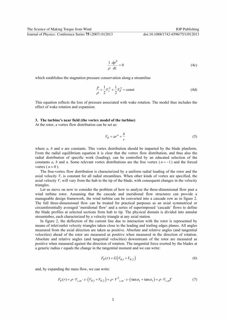
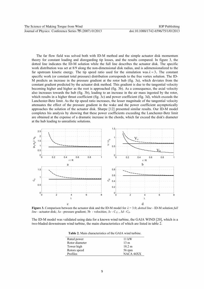
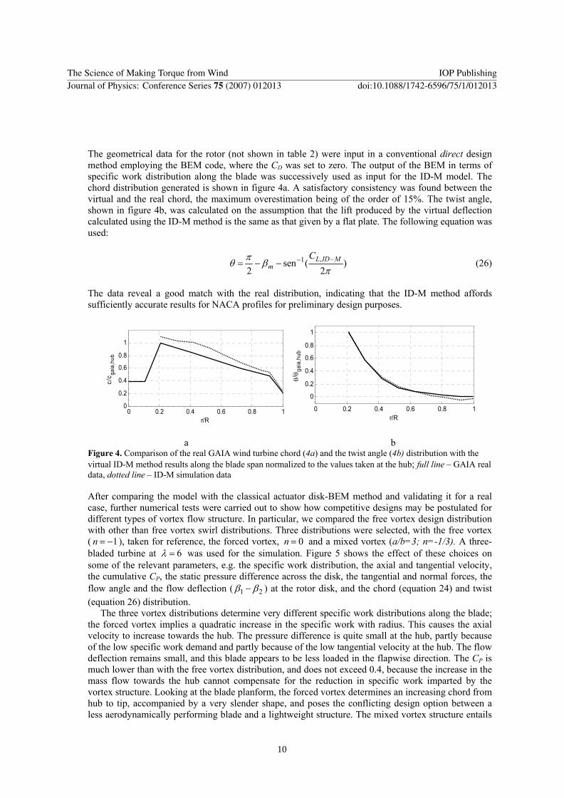

Appendix A
The Science of Making Torque from Wind IOP PublishingJournal of Physics Conference Series 75 (2007) 012013 doi1010881742-6596751012013
14
Related Documents